JP7287962B2 - Sterilizer - Google Patents
Sterilizer Download PDFInfo
- Publication number
- JP7287962B2 JP7287962B2 JP2020531459A JP2020531459A JP7287962B2 JP 7287962 B2 JP7287962 B2 JP 7287962B2 JP 2020531459 A JP2020531459 A JP 2020531459A JP 2020531459 A JP2020531459 A JP 2020531459A JP 7287962 B2 JP7287962 B2 JP 7287962B2
- Authority
- JP
- Japan
- Prior art keywords
- chamber
- heated base
- air
- heating element
- temperature
- Prior art date
- Legal status (The legal status is an assumption and is not a legal conclusion. Google has not performed a legal analysis and makes no representation as to the accuracy of the status listed.)
- Active
Links
Images


Classifications
-
- A—HUMAN NECESSITIES
- A61—MEDICAL OR VETERINARY SCIENCE; HYGIENE
- A61L—METHODS OR APPARATUS FOR STERILISING MATERIALS OR OBJECTS IN GENERAL; DISINFECTION, STERILISATION OR DEODORISATION OF AIR; CHEMICAL ASPECTS OF BANDAGES, DRESSINGS, ABSORBENT PADS OR SURGICAL ARTICLES; MATERIALS FOR BANDAGES, DRESSINGS, ABSORBENT PADS OR SURGICAL ARTICLES
- A61L2/00—Methods or apparatus for disinfecting or sterilising materials or objects other than foodstuffs or contact lenses; Accessories therefor
- A61L2/02—Methods or apparatus for disinfecting or sterilising materials or objects other than foodstuffs or contact lenses; Accessories therefor using physical phenomena
- A61L2/04—Heat
- A61L2/06—Hot gas
- A61L2/07—Steam
-
- A—HUMAN NECESSITIES
- A61—MEDICAL OR VETERINARY SCIENCE; HYGIENE
- A61L—METHODS OR APPARATUS FOR STERILISING MATERIALS OR OBJECTS IN GENERAL; DISINFECTION, STERILISATION OR DEODORISATION OF AIR; CHEMICAL ASPECTS OF BANDAGES, DRESSINGS, ABSORBENT PADS OR SURGICAL ARTICLES; MATERIALS FOR BANDAGES, DRESSINGS, ABSORBENT PADS OR SURGICAL ARTICLES
- A61L2/00—Methods or apparatus for disinfecting or sterilising materials or objects other than foodstuffs or contact lenses; Accessories therefor
- A61L2/24—Apparatus using programmed or automatic operation
-
- F—MECHANICAL ENGINEERING; LIGHTING; HEATING; WEAPONS; BLASTING
- F26—DRYING
- F26B—DRYING SOLID MATERIALS OR OBJECTS BY REMOVING LIQUID THEREFROM
- F26B21/00—Arrangements or duct systems, e.g. in combination with pallet boxes, for supplying and controlling air or gases for drying solid materials or objects
- F26B21/06—Controlling, e.g. regulating, parameters of gas supply
-
- F—MECHANICAL ENGINEERING; LIGHTING; HEATING; WEAPONS; BLASTING
- F26—DRYING
- F26B—DRYING SOLID MATERIALS OR OBJECTS BY REMOVING LIQUID THEREFROM
- F26B3/00—Drying solid materials or objects by processes involving the application of heat
- F26B3/02—Drying solid materials or objects by processes involving the application of heat by convection, i.e. heat being conveyed from a heat source to the materials or objects to be dried by a gas or vapour, e.g. air
- F26B3/04—Drying solid materials or objects by processes involving the application of heat by convection, i.e. heat being conveyed from a heat source to the materials or objects to be dried by a gas or vapour, e.g. air the gas or vapour circulating over or surrounding the materials or objects to be dried
-
- F—MECHANICAL ENGINEERING; LIGHTING; HEATING; WEAPONS; BLASTING
- F26—DRYING
- F26B—DRYING SOLID MATERIALS OR OBJECTS BY REMOVING LIQUID THEREFROM
- F26B9/00—Machines or apparatus for drying solid materials or objects at rest or with only local agitation; Domestic airing cupboards
- F26B9/003—Small self-contained devices, e.g. portable
-
- A—HUMAN NECESSITIES
- A61—MEDICAL OR VETERINARY SCIENCE; HYGIENE
- A61L—METHODS OR APPARATUS FOR STERILISING MATERIALS OR OBJECTS IN GENERAL; DISINFECTION, STERILISATION OR DEODORISATION OF AIR; CHEMICAL ASPECTS OF BANDAGES, DRESSINGS, ABSORBENT PADS OR SURGICAL ARTICLES; MATERIALS FOR BANDAGES, DRESSINGS, ABSORBENT PADS OR SURGICAL ARTICLES
- A61L2202/00—Aspects relating to methods or apparatus for disinfecting or sterilising materials or objects
- A61L2202/10—Apparatus features
- A61L2202/11—Apparatus for generating biocidal substances, e.g. vaporisers, UV lamps
-
- A—HUMAN NECESSITIES
- A61—MEDICAL OR VETERINARY SCIENCE; HYGIENE
- A61L—METHODS OR APPARATUS FOR STERILISING MATERIALS OR OBJECTS IN GENERAL; DISINFECTION, STERILISATION OR DEODORISATION OF AIR; CHEMICAL ASPECTS OF BANDAGES, DRESSINGS, ABSORBENT PADS OR SURGICAL ARTICLES; MATERIALS FOR BANDAGES, DRESSINGS, ABSORBENT PADS OR SURGICAL ARTICLES
- A61L2202/00—Aspects relating to methods or apparatus for disinfecting or sterilising materials or objects
- A61L2202/10—Apparatus features
- A61L2202/12—Apparatus for isolating biocidal substances from the environment
- A61L2202/122—Chambers for sterilisation
-
- A—HUMAN NECESSITIES
- A61—MEDICAL OR VETERINARY SCIENCE; HYGIENE
- A61L—METHODS OR APPARATUS FOR STERILISING MATERIALS OR OBJECTS IN GENERAL; DISINFECTION, STERILISATION OR DEODORISATION OF AIR; CHEMICAL ASPECTS OF BANDAGES, DRESSINGS, ABSORBENT PADS OR SURGICAL ARTICLES; MATERIALS FOR BANDAGES, DRESSINGS, ABSORBENT PADS OR SURGICAL ARTICLES
- A61L2202/00—Aspects relating to methods or apparatus for disinfecting or sterilising materials or objects
- A61L2202/10—Apparatus features
- A61L2202/14—Means for controlling sterilisation processes, data processing, presentation and storage means, e.g. sensors, controllers, programs
-
- A—HUMAN NECESSITIES
- A61—MEDICAL OR VETERINARY SCIENCE; HYGIENE
- A61L—METHODS OR APPARATUS FOR STERILISING MATERIALS OR OBJECTS IN GENERAL; DISINFECTION, STERILISATION OR DEODORISATION OF AIR; CHEMICAL ASPECTS OF BANDAGES, DRESSINGS, ABSORBENT PADS OR SURGICAL ARTICLES; MATERIALS FOR BANDAGES, DRESSINGS, ABSORBENT PADS OR SURGICAL ARTICLES
- A61L2202/00—Aspects relating to methods or apparatus for disinfecting or sterilising materials or objects
- A61L2202/10—Apparatus features
- A61L2202/15—Biocide distribution means, e.g. nozzles, pumps, manifolds, fans, baffles, sprayers
-
- A—HUMAN NECESSITIES
- A61—MEDICAL OR VETERINARY SCIENCE; HYGIENE
- A61L—METHODS OR APPARATUS FOR STERILISING MATERIALS OR OBJECTS IN GENERAL; DISINFECTION, STERILISATION OR DEODORISATION OF AIR; CHEMICAL ASPECTS OF BANDAGES, DRESSINGS, ABSORBENT PADS OR SURGICAL ARTICLES; MATERIALS FOR BANDAGES, DRESSINGS, ABSORBENT PADS OR SURGICAL ARTICLES
- A61L2202/00—Aspects relating to methods or apparatus for disinfecting or sterilising materials or objects
- A61L2202/20—Targets to be treated
- A61L2202/23—Containers, e.g. vials, bottles, syringes, mail
Description
本発明は、滅菌装置、特に、哺乳瓶およびその関連部品を滅菌するための装置に関する。 The present invention relates to a sterilization device, in particular a device for sterilizing baby bottles and their associated parts.
乳幼児が1歳前後になるまでは全ての授乳用具を毎回の使用前に滅菌することが必要と考えられている。例えば、哺乳瓶は、乳首や蓋を含むその関連パーツと共に、使用前には無菌でなければならない。毎使用前の滅菌は、用具上に存在するいかなる細菌をも死滅させることを確実にし、そのため、用具の使用によって乳幼児が病気になることを避けるのに役立つ。 Until the infant is around one year of age, it is considered necessary to sterilize all feeding equipment before each use. For example, baby bottles, along with their associated parts including nipples and lids, must be sterile prior to use. Sterilization before each use ensures that any bacteria present on the device is killed, thus helping to avoid sickness in infants from use of the device.
授乳用具の滅菌には、電気式蒸気滅菌器、電子レンジ蒸気滅菌器、煮沸器、および冷水滅菌を含む様々な方法がある。理解されるように、授乳用具は頻繁に使用されるため、このような用具を頻繁に滅菌する必要がある。したがって、たいていのユーザには単純で使い易い滅菌装置が好まれ、便利さから電気式蒸気滅菌器に頼るユーザが多い。 There are various methods of sterilizing nursing equipment, including electric steam sterilizer, microwave steam sterilizer, boiler, and cold water sterilization. As will be appreciated, due to the frequent use of nursing devices, there is a need to frequently sterilize such devices. Therefore, most users prefer a simple and easy-to-use sterilizer, and many rely on electric steam sterilizers for their convenience.
電気式蒸気滅菌器は、一般的には、調理台に置かれ得る独立型の装置である。それらは、水を沸騰させることによって、装置に収容された授乳用具のそばを通過する蒸気を発生させるよう機能する。この蒸気が授乳用具を滅菌し、用具上に存在し得るほぼ全ての細菌を殺す。いったん十分な蒸気が発生すると、かつ/または、授乳用具を滅菌するのに十分な時間にわたって蒸気が用具のそばを通過すると、装置はオフにされ、内容物を放冷および乾燥させる。一般的な電気式蒸気滅菌器は、水を加熱して蒸気を発生させるのに、比較的低出力の発熱体を利用する。低出力の発熱体を使用する結果、滅菌工程はかなりの時間を要し得る。さらに、滅菌工程が完了すると、用具の乾燥および冷却に長い時間がかかり得る。乳幼児の性質および授乳ルーティン上、ユーザは、一般的に、用具が乾燥するのを長時間待っているわけにはいかないため、このことが問題となり得る。 Electric steam sterilizers are generally stand-alone devices that can be placed on the countertop. They function by boiling water to generate steam that passes by the feeding implements contained in the device. This steam sterilizes the feeding device and kills nearly all bacteria that may be on the device. Once enough steam has been generated and/or the steam has passed by the feeding device for a time sufficient to sterilize it, the device is turned off, allowing the contents to cool and dry. A typical electric steam sterilizer utilizes a relatively low power heating element to heat water and generate steam. As a result of using low power heating elements, the sterilization process can take a considerable amount of time. Furthermore, once the sterilization process is complete, it can take a long time to dry and cool the equipment. This can be a problem because, due to the nature of infants and feeding routines, users generally cannot afford to wait too long for the device to dry.
より高性能な電気式蒸気滅菌装置は、乾燥工程のスピードアップを助けるために装置に空気を送り込むファンをさらに備える。これらの装置は、乾燥時間は短縮されるが、より基本的な上述の装置に比べると高価である。これらの装置のコストは、ファンを設けることによって増加しているだけでなく、滅菌の終了時とファンの始動時を制御する、関連の電子制御器によっても増加している。 Higher performance electric steam sterilizers also include fans that force air through the device to help speed up the drying process. These devices provide faster drying times, but are more expensive than the more basic devices described above. The cost of these devices is increased not only by the provision of the fan, but also by the associated electronic controllers that control when sterilization ends and when the fan starts.
本発明は、上記の問題を解決または少なくとも軽減することを目的としており、対象物を滅菌するための装置であって、
電気発熱体と熱連通(thermal communication)する被加熱ベースを備えた、滅菌対象物を収容するためのチャンバと、
上記チャンバに空気を送り込むように構成された押込空気流装置と、
上記電気発熱体および上記押込空気流装置に電力を供給するように構成された電源回路と、
上記電源回路において上記電気発熱体と直列に配置され、上記被加熱ベースの温度を検出するために上記装置内に配置された、熱機械制御器と、
上記電源回路において上記押込空気流装置と直列に配置され、上記被加熱ベースの温度を検出するために上記装置内に配置された、感熱スイッチと、を備え、
上記装置は、上記電気発熱体が上記電源回路を介して電力を供給されることにより上記被加熱ベースを加熱し、それにより使用時には上記チャンバ内の水を加熱して上記対象物を滅菌するための蒸気を発生させる滅菌モードで動作するように構成され、上記熱機械制御器は、上記熱機械制御器が上記被加熱ベースの第1の所定温度を検出すると、上記電気発熱体への電力供給を遮断することにより上記滅菌モードを終了させるように構成され、
上記装置は、さらに、上記押込空気流装置が上記電源回路を介して電力を供給されることにより上記チャンバに空気を送り込む乾燥モードで動作するように構成され、上記感熱スイッチは、上記感熱スイッチが上記チャンバ内の水の実質的に全てが蒸気に変換されたことを示す上記被加熱ベースの第2の所定温度を検出すると、上記押込空気流装置への電力供給を接続することにより上記乾燥モードを開始させるように構成された、装置を提供する。
SUMMARY OF THE INVENTION The present invention aims to solve or at least alleviate the above problems, and provides a device for sterilizing objects, comprising:
a chamber for containing an object to be sterilized, comprising a heated base in thermal communication with an electric heating element;
a forced airflow device configured to force air into the chamber;
a power circuit configured to power the electric heating element and the forced air flow device;
a thermomechanical controller disposed in the power supply circuit in series with the electrical heating element and disposed within the device for sensing the temperature of the heated base;
a thermal switch disposed in the power supply circuit in series with the forced airflow device and disposed within the device for sensing the temperature of the heated base;
The apparatus heats the heated base as the electric heating element is powered through the power supply circuit, thereby heating the water in the chamber in use to sterilize the object. wherein the thermomechanical controller powers the electric heating element when the thermomechanical controller detects a first predetermined temperature of the heated base is configured to end the sterilization mode by shutting off the
The apparatus is further configured to operate in a dry mode in which the forced airflow device is powered through the power supply circuit to force air into the chamber, and the thermal switch is configured to upon detecting a second predetermined temperature of the heated base indicating that substantially all of the water in the chamber has been converted to steam, the drying mode by connecting a power supply to the forced airflow device; to provide an apparatus configured to initiate the
上記装置は、蒸気を生成してチャンバに収容された対象物を滅菌する滅菌モードとチャンバに空気を送り込んで滅菌済みの対象物を乾燥させる乾燥モードの2つのモードで有効に動作する。高価で複雑な電子制御器を動作制御のために利用する従来技術の装置とは異なり、本発明に係る装置は、滅菌モードの制御に熱機械制御器を利用し、乾燥モードの制御に感熱スイッチを利用する。これらの2つの構成要素が互いに独立して動作することが有利である。これらの比較的単純で安価な構成要素を設けることは、装置のコスト削減に役立ち、また、装置の信頼性も向上させ得る。さらに、下記においてより詳細に説明するように、これらの単純な構成要素の構成が実際に装置の比較的高度な制御を可能にする。 The apparatus effectively operates in two modes, a sterilization mode in which steam is generated to sterilize the objects contained in the chamber, and a drying mode in which air is forced into the chamber to dry the sterilized objects. Unlike prior art devices that utilize expensive and complex electronic controllers to control motion, the device of the present invention utilizes a thermomechanical controller to control the sterilization mode and a thermal switch to control the drying mode. take advantage of Advantageously, these two components operate independently of each other. Providing these relatively simple and inexpensive components can help reduce the cost of the device and also improve the reliability of the device. Moreover, as will be described in more detail below, the configuration of these simple components actually allows for relatively sophisticated control of the device.
滅菌モードは、電気発熱体が通電されてベースを加熱してチャンバ内の水を沸騰させる場合の蒸気の活発な生成が特徴であることが理解されるであろう。しかしながら、滅菌モードは、チャンバ内の水の実質的に全てが蒸気に変換された時点、すなわち、被加熱ベースが空焚きになった時点以降も継続してもよい。蒸気が活発に生成されなくなっても、チャンバに蒸気が存在する限り、滅菌は継続し得る。さらに、乾燥モードは、押込空気流装置が通電されてチャンバに空気を送り込む場合の押込空気流の活発な生成が特徴であることが理解されるであろう。下記の説明から明らかなように、滅菌モードと乾燥モードは時間的に重複してもよい。いくつかの実施形態では、滅菌モードが終了した時に乾燥モードが開始されてもよい。しかしながら、様々な実施形態では、滅菌モードの終了から乾燥モードの開始までの間に時間的な遅延が生じる。 It will be appreciated that the sterilization mode is characterized by vigorous production of steam when an electric heating element is energized to heat the base and boil the water in the chamber. However, the sterilization mode may continue beyond the point at which substantially all of the water in the chamber has been converted to steam, i.e., the heated base has become dry-fired. Sterilization can continue as long as steam is present in the chamber, even if steam is no longer actively generated. Further, it will be appreciated that the dry mode is characterized by vigorous production of forced airflow when the forced airflow device is energized to pump air into the chamber. As will be apparent from the discussion below, the sterilization and drying modes may overlap in time. In some embodiments, the drying mode may begin when the sterilization mode ends. However, in various embodiments there is a time delay between the end of the sterilization mode and the start of the drying mode.
感熱スイッチは、チャンバ内の水の実質的に全てが蒸気に変換されたことを示す被加熱ベースの第2の所定温度を検出すると乾燥モードを開始させるように構成される。水が加熱されて蒸気に変換されるにつれて、装置内の水位が徐々に減少することが理解されるであろう。多くの実施形態では、被加熱ベースは発熱体からの熱を急速に拡散し、そのため、実際上は、被加熱ベースは完全に「空焚き」になり、昇温し始める。つまり、被加熱ベースは、すぐに均一な温度になり、「空焚き」状態を示すために用いられる第2の所定温度が被加熱ベースのどの部分からも検出され得る。しかしながら、水がまだチャンバ内に存在しているが被加熱ベースを完全に覆うには不十分な量であるという程度まで水位が低下する場合があることが予想される。その結果、被加熱ベースに接触して残っている水が水溜りを形成しやすいため、被加熱ベースの表面に乾燥した部分ができる。当業者に理解されるように、被加熱ベースの乾燥した部分の温度は、いくらかの沸騰水によって依然として覆われている部分よりも速く上昇する。感熱スイッチが被加熱ベースのうちのある特定の領域の温度に対してより高い感応性(sensitive)を有する場合であって、かつ、この領域が乾燥している場合、その温度は、非常に少量の水が被加熱ベースの他の領域に接触したまま残っていたとしても、第2の所定温度まで上昇し得る。したがって、水の実質的に全てが蒸気に変換された時点とは、上記の状況も包含するものである。 A thermal switch is configured to initiate the drying mode upon detecting a second predetermined temperature of the heated base indicating that substantially all of the water in the chamber has been converted to vapor. It will be appreciated that the water level within the device will gradually decrease as the water is heated and converted to steam. In many embodiments, the heated base quickly dissipates heat from the heating element, so that in effect the heated base is completely "dry-fired" and begins to heat up. That is, the heated base quickly reaches a uniform temperature, and a second predetermined temperature used to indicate a "dry-fire" condition can be detected from any portion of the heated base. However, it is expected that the water level may drop to the extent that water is still present in the chamber but in an amount insufficient to completely cover the heated base. As a result, water remaining in contact with the heated base tends to form puddles, resulting in dry areas on the surface of the heated base. As will be appreciated by those skilled in the art, dry portions of the heated base will rise in temperature faster than portions still covered by some boiling water. If the thermal switch is more sensitive to the temperature of a particular area of the heated base, and if this area is dry, the temperature will be very small. of water remaining in contact with other areas of the heated base can still rise to the second predetermined temperature. Therefore, the point in time when substantially all of the water has been converted to steam also includes the above situation.
熱機械制御器と感熱スイッチとは、それぞれ、被加熱ベースの温度を検出するように構成される。好ましい一組の実施形態では、熱機械制御器と感熱スイッチとは、それぞれ独立して被加熱ベースに熱接触(thermal contact)して配置される。これは、実際上、例えば被加熱ベース上に直接装着されることによる直接熱接触であってもよく、例えば放熱板等の伝熱媒体を介した間接熱接触であってもよい。 The thermomechanical controller and the thermal switch are each configured to detect the temperature of the heated base. In a preferred set of embodiments, the thermomechanical controller and the thermal switch are each independently placed in thermal contact with the heated base. In practice, this may be direct thermal contact, for example by mounting directly on the heated base, or indirect thermal contact, for example via a heat transfer medium such as a heat sink.
出願人は、所望の滅菌および乾燥が達成される滅菌モードの終了温度と乾燥モードの開始温度に様々な順列(permutations)が存在すると認識している。しかしながら、一組の実施形態では、第1の所定温度も、チャンバ内の水の実質的に全てが蒸気に変換されたことを示す。好ましくは、第1の所定温度は、ちょうど上記水の実質的に全てが蒸気に変換された時点の被加熱ベースの温度を示す。言い換えれば、熱機械制御器が「空焚き」状態、すなわち、上記水の実質的に全てが蒸気に変換されたことを検出すると、熱機械制御器は電気発熱体への電力供給を遮断して滅菌モードを終了させる。上記に従って第1の所定温度を設定することによって、上記装置の過熱を防止することで、上記装置に過度なダメージが与えられることが回避されることがわかった。 Applicants recognize that there are various permutations of the ending temperature of the sterilization mode and the starting temperature of the drying mode that achieve the desired sterilization and drying. However, in one set of embodiments, the first predetermined temperature also indicates that substantially all of the water in the chamber has been converted to steam. Preferably, the first predetermined temperature represents the temperature of the heated base just when substantially all of said water has been converted to steam. In other words, when the thermomechanical controller detects a "dry-fire" condition, i.e., substantially all of the water has been converted to steam, the thermomechanical controller cuts power to the electric heating element. Exit sterilization mode. It has been found that by setting the first predetermined temperature in accordance with the above, overheating of the device is prevented, thereby avoiding excessive damage to the device.
一般的に、使用時に、被加熱ベースの温度は、100℃~105℃辺り(おそらく、温度が検出される厳密な場所に応じて異なる)まで上昇し、チャンバ内にまだ水が存在する滅菌モードの間はずっとそのままである。上記水の全てが蒸気に変換されるとすぐに、被加熱ベースは、その熱を放熱する媒体が無いため、急速に昇温する。上記装置は、上記装置の様々な構成要素を収容するプラスチック体を備え得る。したがって、過度に高温になる被加熱ベースは、プラスチック体に危険を及ぼし得る。このため、水の全てが蒸気に変換されたのと同時に電気発熱体への電力を遮断する熱機械制御器を設けることにより、被加熱ベースが過熱することが防止されるため、上記装置にダメージが与えられることが回避される。いくつかの実施形態では、第1の所定温度は125~155℃に設定される。これは熱機械制御器によって検出される温度であり、当然のことながら、被加熱ベースが均一な温度分布を有していない場合もある。 Typically, during use, the temperature of the heated base will rise to around 100°C-105°C (perhaps depending on the exact location where the temperature is sensed) and a sterilization mode where there is still water in the chamber. remains the same throughout. As soon as all of the water has been converted to steam, the heated base heats up rapidly because there is no medium to dissipate the heat. The device may comprise a plastic body that houses the various components of the device. Thus, a heated base that becomes too hot can pose a hazard to the plastic body. Thus, by providing a thermomechanical controller that cuts off power to the electric heating element as soon as all of the water has been converted to steam, the heated base is prevented from overheating, thus damaging the device. is avoided. In some embodiments, the first predetermined temperature is set between 125-155°C. This is the temperature sensed by the thermomechanical controller and, of course, the heated base may not have a uniform temperature distribution.
当業者に理解されるように、熱機械制御器によって検出される温度は、熱機械制御器が被加熱ベースに熱接触して配置される方法に大きく依存し得る。例えば、熱機械制御器が被加熱ベースの直接加熱される部分に熱接触して配置される場合は、第1の所定温度は、熱機械制御器が被加熱ベースの直接加熱される部分から離れた部分に熱接触して配置される場合よりも高い温度に設定され得る。これは、直接加熱される部分が発熱体の温度に対してより高い感応性を有し、被加熱ベースの平均温度よりも高い温度になるためである。熱機械制御器が被加熱ベースの直接加熱される部分からさらに離れた被加熱ベースの部分に熱接触して配置される場合、発熱体からの熱が被加熱ベースを通じて熱機械制御器に放散されるまでにより長い時間を要し、それゆえ、熱機械制御器によって検出される温度は被加熱ベースの平均温度よりもかなり低くなりやすい。したがって、このように配置される場合、第1の所定温度はより低く設定され得る。熱機械制御器と被加熱ベースとの熱接触の程度も、所与の位置において検出される温度に影響し得る。同じ推論は、以下でさらに説明するように、感熱スイッチによって検出される温度に関しても当てはまる。 As will be appreciated by those skilled in the art, the temperature sensed by the thermomechanical controller can be highly dependent on how the thermomechanical controller is placed in thermal contact with the heated base. For example, if the thermomechanical controller is placed in thermal contact with the directly heated portion of the heated base, the first predetermined temperature may be such that the thermomechanical controller is separated from the directly heated portion of the heated base. It can be set to a higher temperature than if it were placed in thermal contact with the part. This is because the directly heated part has a higher sensitivity to the temperature of the heating element, resulting in a higher temperature than the average temperature of the heated base. When the thermomechanical controller is placed in thermal contact with a portion of the heated base further away from the directly heated portion of the heated base, heat from the heating element is dissipated through the heated base to the thermomechanical controller. The temperature detected by the thermomechanical controller is likely to be significantly lower than the average temperature of the heated base. Therefore, when arranged in this way, the first predetermined temperature can be set lower. The degree of thermal contact between the thermomechanical controller and the heated base can also affect the temperature sensed at a given location. The same reasoning applies with respect to temperatures sensed by thermal switches, as further explained below.
熱機械制御器と感熱スイッチとは、被加熱ベースの同一部分の温度を独立して検出するように装置内に配置されてもよい。しかしながら、各構成要素を被加熱ベースの全く同一の部分に対して感応性を有するように搭載するのは困難なことがある。そのため、一組の実施形態では、熱機械制御器と感熱スイッチとが、被加熱ベースの異なる部分の温度に対して感応性を有するように構成される。理解されるように、これらの部分の検出温度は、例えばそれぞれの電気発熱体への近さに応じて異なっていてもよく、あるいは、これらの部分の検出温度は同等であってもよい。 The thermomechanical controller and the thermal switch may be arranged in the device to independently detect the temperature of the same portion of the heated base. However, it can be difficult to mount each component sensitively to the exact same portion of the heated base. Thus, in one set of embodiments, the thermomechanical controller and the thermal switch are configured to be sensitive to the temperature of different portions of the heated base. As will be appreciated, the sensed temperatures of these portions may differ, eg, depending on their proximity to the respective electrical heating element, or the sensed temperatures of these portions may be the same.
当業者に理解されるように、上記水の実質的に全てが蒸気に変換された時点に対応する厳密な検出温度は、周囲気圧を含む様々な要因によって決まる。第1および第2の所定温度は、経験的に、例えばありそうな環境条件に基づいて、決定されてもよい。 As will be appreciated by those skilled in the art, the exact sensed temperature corresponding to when substantially all of the water has been converted to steam depends on a variety of factors, including ambient pressure. The first and second predetermined temperatures may be determined empirically, eg, based on likely environmental conditions.
熱機械制御器は、手動でリセットされるまでは電気発熱体を電源から切断したままにしておくように構成されてもよい。熱機械制御器は、第1の所定温度が検出されると動作させられるトリップレバーを含んでいてもよい。この温度が、被加熱ベースが冷めるとリセットするバイメタルアクチュエータによって検出された場合でも、トリップレバーの動作により、例えばユーザが上記装置を再始動させるために手動のオンスイッチを操作して制御器がリセットされるまでは、電源が再接続されないことが確実になる。このような熱機械制御器はよく知られている。上記熱機械制御器は、出願人のUシリーズの制御器の1つであってもよい。 The thermomechanical controller may be configured to keep the electric heating element disconnected from the power source until manually reset. The thermomechanical controller may include a trip lever that is activated when the first predetermined temperature is detected. Even if this temperature is detected by a bimetallic actuator that resets as the heated base cools, operation of the trip lever causes the controller to reset, e.g., when the user operates a manual ON switch to restart the device. It is certain that the power will not be reconnected until the Such thermomechanical controllers are well known. The thermomechanical controller may be one of Applicant's U-series controllers.
一般的な電気発熱体の性質により、電気発熱体が電源から切断されたとき、電気発熱体内には、放散して被加熱ベースをさらに加熱することが可能な余熱が残っていることが多い。その結果、一般的に、滅菌モードが終了したとき、被加熱ベースの検出温度は上昇し続ける。出願人は、この余熱を乾燥モードに利用できると認識している。押込空気流装置がチャンバに空気を送り込むとき、空気は、被加熱ベースのそばを通過し、該ベースから熱を取り出して、チャンバ内の空気を加熱し、それゆえ、乾燥工程を加速させる。水の実質的に全てが蒸気に変換されたと同時に電気発熱体が電源から切断される上記の実施形態の代替的な実施形態では、第1の所定温度は、上記水の実質的に全てが蒸気に変換された時点を示す検出温度よりも高い温度に設定され得る。言い換えれば、電気発熱体は、水の全てが蒸気に変換された後も一定期間動作状態にある。このような実施形態では、第1の所定温度は155℃よりも高く設定され得る。このことは、電気発熱体が発生させる熱を、該ベースを加熱し続けてチャンバ内の空気を加熱して乾燥工程を加速させるために使用し得るため、有利である。当然のことながら、この実施形態では、電気発熱体が電源から最終的に切断されたとき、被加熱ベースは、同様に、発熱体の余熱によりチャンバ内の空気を加熱し続ける。 Due to the nature of typical electric heating elements, when the electric heating element is disconnected from the power supply, there is often residual heat left in the electric heating element that can be dissipated to further heat the heated base. As a result, the sensed temperature of the heated base generally continues to rise when the sterilization mode ends. Applicant recognizes that this residual heat can be utilized for the drying mode. When the forced airflow device forces air into the chamber, the air passes by the heated base and extracts heat from the base to heat the air in the chamber, thus accelerating the drying process. In an alternative embodiment to the above embodiment in which the electric heating element is disconnected from the power supply at the same time that substantially all of the water is converted to steam, the first predetermined temperature is can be set to a temperature higher than the detection temperature indicating the time point of conversion to . In other words, the electric heating element remains in operation for a period of time after all of the water has been converted to steam. In such embodiments, the first predetermined temperature may be set above 155°C. This is advantageous because the heat generated by the electric heating element can be used to keep the base heated and heat the air in the chamber to speed up the drying process. Of course, in this embodiment, when the electric heating element is finally disconnected from the power supply, the heated base likewise continues to heat the air in the chamber from the residual heat of the heating element.
乾燥モードを開始させるために用いられる第2の所定温度は、水の実質的に全てが蒸気に変換されたことを示すが、必ずしもこれが最初に起こった温度とは限らない。例えば、被加熱ベースについて125~155℃の検出温度が、上記水の実質的に全てが蒸気に変換された時点を表すと経験的に定められてもよいが、第2の所定温度はより高い値に設定されてもよい。感熱スイッチが熱機械制御器と同一または同等の被加熱ベースの部分に対して感熱性を有するように構成される実施形態では、第2の所定温度は、175~195℃以上、好ましくは、例えば190℃に設定され得る。これらの実施形態では、滅菌モードの終了から乾燥モードの開始までの間に時間的な遅延が生じ得る。125~155℃の検出温度で水の実質的に全てが蒸気に変換されていることがわかっているとすれば、175℃では水の実質的に全てが蒸気に変換されているはずであることが理解されるであろう。したがって、第2の所定温度は、単に、乾燥モードの開始時にチャンバ内に液体の水が実質的に残っていないことを示す検出温度である。ただし、感熱スイッチが、被加熱ベースのうちの熱機械制御器が感応性を有する部分よりも電気発熱体による直接加熱の度合いが低くその部分よりも低温となる部分に対して、感応性を有するように構成される実施形態では、第2の所定温度は、このより低温の領域に対応するように調整されてもよい。一組のこのような実施形態では、第2の所定温度は、115~140℃、好ましくは、例えば130℃に設定される。そのため、実際の検出温度は第1の所定温度よりも低くなるかもしれないが、第2の所定温度は、被加熱ベースのより高い平均温度と同等であってもよい。これらの実施形態でも、滅菌モードの終了から乾燥モードの開始までの間に時間的な遅延が生じてもよい。 The second predetermined temperature used to initiate the drying mode indicates that substantially all of the water has been converted to steam, although this is not necessarily the temperature at which this first occurred. For example, a sensed temperature of 125-155° C. for the heated base may be empirically determined to represent the point at which substantially all of the water has been converted to steam, while the second predetermined temperature is higher. value. In embodiments in which the thermal switch is configured to be thermally sensitive to the same or similar portion of the heated base as the thermomechanical controller, the second predetermined temperature is 175-195° C. or higher, preferably, for example It can be set at 190°C. In these embodiments, there may be a time delay between ending the sterilization mode and starting the drying mode. If it is known that substantially all of the water is converted to steam at the detected temperature of 125-155°C, then substantially all of the water should be converted to steam at 175°C. will be understood. Therefore, the second predetermined temperature is simply the detected temperature indicating that substantially no liquid water remains in the chamber at the start of the drying mode. However, the thermal switch is sensitive to a portion of the heated base that is directly heated by the electric heating element to a lesser extent than that portion to which the thermomechanical controller is sensitive and that is cooler than that portion. In embodiments configured to, the second predetermined temperature may be adjusted to correspond to this lower temperature region. In one set of such embodiments, the second predetermined temperature is set at 115-140°C, preferably 130°C, for example. As such, the second predetermined temperature may be equivalent to the higher average temperature of the heated base, although the actual sensed temperature may be lower than the first predetermined temperature. Also in these embodiments, there may be a time delay between the end of the sterilization mode and the start of the drying mode.
熱機械制御器と感熱スイッチとが、被加熱ベースの実質的に同一部分、または被加熱ベースの実質的に同一温度である同等部分、に対して感応性を有するように構成される実施形態では、第1および第2の所定温度が同一温度に設定され得る、すなわち、滅菌モードが終了するとすぐに乾燥モードが始まる。しかしながら、好ましい一組の実施形態では、第2の所定温度は、第1の所定温度よりも高い。言い換えれば、上記装置は、当初は滅菌モードで動作し、第1の所定温度に達するとこのモードが終了し、その後少しの遅延が生じ、その間に被加熱ベースの温度が第2の所定温度まで上昇し、乾燥モードが開始されるというように構成される。第1および第2の所定温度は、上記の動作順序を達成するために、例えば熱機械制御器と感熱スイッチとの相対的な感熱度に応じて、調整され得ることが理解されるであろう。このため、少なくともいくつかの実施形態では、第1の所定温度と第2の所定温度とは、滅菌モードが終了してから乾燥モードが開始されるまでの間に時間的な遅延が生じるように選択される。 In embodiments in which the thermomechanical controller and the thermal switch are configured to be sensitive to substantially the same portion of the heated base, or equivalent portions of the heated base that are at substantially the same temperature. , the first and the second predetermined temperature can be set to the same temperature, ie the drying mode starts as soon as the sterilization mode ends. However, in a preferred set of embodiments, the second predetermined temperature is higher than the first predetermined temperature. In other words, the device initially operates in sterilization mode and exits this mode when the first predetermined temperature is reached, followed by a short delay during which the temperature of the heated base rises to the second predetermined temperature. It is configured such that it rises and the drying mode is initiated. It will be appreciated that the first and second predetermined temperatures may be adjusted, for example, depending on the relative heat sensitivities of the thermomechanical controller and the thermal switch, to achieve the above sequence of operations. . Thus, in at least some embodiments, the first predetermined temperature and the second predetermined temperature are such that there is a time delay between the termination of the sterilization mode and the initiation of the drying mode. selected.
いくつかの例では、上記装置は、対象物が十分に乾燥しているとユーザが考えた場合に手動でオフにされて乾燥モードを終了させてもよい。しかしながら、これにはユーザの介入が必要である。いくつかの例では、乾燥モードをタイマーによって終了させてもよい。しかしながら、これは制御回路に余分な複雑さを与えるものである。出願人は、上記装置が自動的に乾燥モードを終了させる単純かつ有効な方法を考え出した。一組の実施形態では、感熱スイッチは、上記装置内の対象物が乾燥して冷めたことを示す第3の所定温度を検出すると押込空気流装置への電力供給を遮断することによって乾燥モードを終了させるように構成される。感熱スイッチが被加熱ベースのうちの熱機械制御器と同じ部分、または同等の部分、に対して感応性を有するさらなる一組の実施形態では、第3の所定温度は140~160℃、好ましくは150℃に設定される。同様に、感熱スイッチが被加熱ベースのうちの熱機械制御器よりも低温の部分に対して感応性を有するさらなる一組の実施形態では、第3の所定温度は80~100℃、好ましくは90℃に設定される。出願人は、被加熱ベースの温度がこの範囲または好ましい温度まで下がれば、上記装置内の対象物は十分に乾燥しているはずであり、チャンバの温度が十分に低くなっており、ユーザが上記装置から対象物を取り出して使用し得ると認識している。第3の所定温度の厳密な値は、乾燥時間を変更するために調整され得る。 In some examples, the device may be manually turned off to exit drying mode when the user considers the object to be sufficiently dry. However, this requires user intervention. In some examples, the drying mode may be terminated by a timer. However, this adds extra complexity to the control circuit. Applicants have devised a simple and effective way for the device to automatically exit the drying mode. In one set of embodiments, the thermal switch activates the drying mode by cutting power to the forced airflow device upon detecting a third predetermined temperature indicating that the objects in the device have dried and cooled. configured to terminate. In a further set of embodiments in which the thermal switch is sensitive to the same portion of the heated base as the thermomechanical controller, or an equivalent portion, the third predetermined temperature is 140-160°C, preferably Set to 150°C. Similarly, in a further set of embodiments in which the thermal switch is sensitive to a cooler portion of the heated base than the thermomechanical controller, the third predetermined temperature is 80-100°C, preferably 90°C. °C. Applicant believes that once the temperature of the heated base drops to this range or preferred temperature, the objects in the apparatus should be sufficiently dry and the temperature of the chamber is low enough to allow the user to We recognize that we can take objects out of the device and use them. The exact value of the third predetermined temperature can be adjusted to change the drying time.
感熱スイッチを電源への接続および電源からの切断を行うための手段として用いることによって、乾燥モードを開始および終了させるための単純で費用効果の高い解決策が得られる。このため、上記装置は、乾燥モードの動作期間を制御するためのタイマーに依存するものではないことが理解されるであろう。好ましくは、感熱スイッチは、感熱アクチュエータによって動作させられる常開型スイッチを含む。感熱アクチュエータは、第2の所定温度(例えば、感熱スイッチが被加熱ベースのうちの熱機械制御器よりも低温の部分に対して感応性を有する実施形態では、115~140℃)を検出すると、該スイッチを閉じるように動作し得る。感熱アクチュエータは、第3の所定温度(例えば、90℃)を検出するとスイッチを再び開くように動作し得る。感熱アクチュエータは、「1/2インチディスク」として一般に知られるバイメタルアクチュエータであってもよい。 Using a thermal switch as the means for connecting and disconnecting from the power supply provides a simple and cost effective solution for starting and ending the drying mode. As such, it will be appreciated that the apparatus does not rely on a timer to control the duration of the drying mode of operation. Preferably, the thermal switch comprises a normally open switch operated by a thermal actuator. When the thermal actuator detects a second predetermined temperature (eg, 115-140° C. in embodiments in which the thermal switch is sensitive to a cooler portion of the heated base than the thermomechanical controller), It may act to close the switch. The thermal actuator may operate to reopen the switch upon detection of a third predetermined temperature (eg, 90°C). The thermal actuator may be a bimetallic actuator commonly known as a "1/2 inch disk".
電気発熱体は、被加熱ベースに直接装着されてもよい。しかしながら、出願人は、電気発熱体からの熱を被加熱ベースにより均一に分散させ、ひいてはチャンバ内の水をより均一に加熱するためには、電気発熱体と被加熱ベースとの間に放熱板を設けることが有利であると認識している。そのため、一組の実施形態では、チャンバは、被加熱ベースと電気発熱体との間に配置された放熱板をさらに備える。 The electric heating element may be attached directly to the heated base. However, Applicants believe that in order to more evenly distribute the heat from the electric heating element and thus more evenly heat the water in the chamber, a heat sink between the electric heating element and the heated base is required. We recognize that it is advantageous to provide Thus, in one set of embodiments, the chamber further comprises a heat sink positioned between the heated base and the electrical heating element.
電気発熱体は、熱を生成して被加熱ベースに伝達するための、任意の適切な形状を有する任意の適切な電気発熱体であり得る。しかしながら、円弧状の電気発熱体を使用することが特に有利である。そのため、一組の実施形態では、電気発熱体は、円弧形状に構成され、該円弧形状の第1端および第2端を規定する電気的終端(いわゆる「コールドテール」)を備える。この種の電気発熱体を設けることは、電気発熱体の中心に熱機械制御器を設置し得る空隙が形成されるため、特に有利である。この領域に熱機械制御器を設置することは、被加熱ベースの温度に対する感度の高い制御を行うことを確実にでき、上記装置を小型に維持するのにも役立つ。 The electrical heating element can be any suitable electrical heating element having any suitable shape for generating and transferring heat to the heated base. However, it is particularly advantageous to use arc-shaped electric heating elements. Thus, in one set of embodiments, the electrical heating element is configured in the shape of an arc with electrical terminations (so-called "cold tails") defining first and second ends of the arc. Providing an electric heating element of this kind is particularly advantageous because a gap is formed in the center of the electric heating element in which a thermomechanical controller can be installed. Placing the thermomechanical controller in this area ensures sensitive control over the temperature of the heated base and also helps keep the device compact.
さらに、円弧状の電気発熱体を設けることによって、被加熱ベースのうちの間接加熱される部分がコールドテール間に位置することになる。さらなる一組の実施形態では、感熱スイッチは、上記電気的終端間の被加熱ベースの温度を検出するように構成される。感熱スイッチをこの間接加熱される部分に配置することは、感熱スイッチが被加熱ベース全体の温度を示し、電気発熱体自体の温度に対してはより感応性が低くなるため、有利である。被加熱ベースの温度はチャンバ内の水の温度にもチャンバ内に水が無いことにもより直接的に対応するため、電気発熱体ではなく被加熱ベースの温度を感知することによって、チャンバ内の水の状態がより正確に示される。前述のように、感熱スイッチを被加熱ベースのうちのより低温の部分に対して有効に感応性を有するように構成する場合は、それでもなお第2の所定温度が水の全てが蒸気に変換されたことを示すように第2の所定温度をそれに応じて調整することが必要である。第3の所定温度の設定も同様である。 Furthermore, by providing an arcuate electric heating element, the indirectly heated portion of the heated base is positioned between the cold tails. In a further set of embodiments, the thermal switch is configured to detect the temperature of the heated base between said electrical ends. Placing the thermal switch in this indirectly heated portion is advantageous because the thermal switch indicates the temperature of the entire heated base and is less sensitive to the temperature of the electrical heating element itself. By sensing the temperature of the heated base rather than the electric heating element, the temperature of the heated base corresponds more directly to the temperature of the water in the chamber and to the absence of water in the chamber. Water conditions are shown more accurately. As noted above, if the thermal switch is configured to be effectively sensitive to the cooler portion of the heated base, the second predetermined temperature will still be such that all of the water is converted to steam. It is necessary to adjust the second predetermined temperature accordingly. The setting of the third predetermined temperature is similar.
電気発熱体は、単一の発熱体を含んでいてもよく、複数の発熱体を含んでいてもよい。電気発熱体は、シーズ発熱体であってもよく、厚膜発熱体であってもよい。 The electric heating element may contain a single heating element or may contain a plurality of heating elements. The electric heating element may be a sheathed heating element or a thick film heating element.
感熱スイッチの機能は、発熱体からの余熱が被加熱ベースによって乾燥後のチャンバに分散された後で、押込空気流装置への電力供給を接続することである。押込空気流装置は、その後、蓄熱された熱を循環させることができる。 The function of the thermal switch is to connect the power supply to the forced airflow device after the residual heat from the heating element has been dissipated by the heated base into the chamber after drying. A forced airflow device can then circulate the stored heat.
押込空気流装置は、上記装置内の任意の適切な位置、例えばチャンバの基部または上部、に配置され得る。しかしながら、好ましい一組の実施形態では、押込空気流装置はチャンバの側壁に配置される。 The forced airflow device may be placed at any suitable location within the device, such as at the base or top of the chamber. However, in a preferred set of embodiments, the forced airflow device is located on the side wall of the chamber.
押込空気流装置は、チャンバ内に既に存在する空気の方向を変えてチャンバ中に向かわせるように構成されてもよい。しかしながら、好ましい一組の実施形態では、押込空気流装置は、上記装置が置かれた環境からの空気をチャンバに送り込むように構成される。有効に「新鮮な」空気をこのように導入することは、チャンバ内の空気よりもチャンバに導入された空気の方が湿度が低い、すなわち、含水率が低いためにより湿度が高い空気を追い出すのに役立ち、かつ、上記装置内の水分を取り込む能力がより高いために乾燥工程を加速させるのに役立つため、有利であることがわかった。 The forced airflow device may be configured to redirect air already present in the chamber into the chamber. However, in a preferred set of embodiments, the forced airflow device is configured to force air into the chamber from the environment in which the device is placed. This introduction of "fresh" air effectively means that the air introduced into the chamber is less humid than the air in the chamber, i. It has been found to be advantageous as it helps in the drying process and speeds up the drying process due to the higher ability to pick up moisture in the device.
押込空気流装置は、チャンバに空気を押し込むための任意の適切な装置を備えていてもよい。一組の実施形態では、押込空気流装置は電動ファンを備える。電動ファンは、直流ファンであってもよいが、直流電源を設ける必要がなくなるので交流ファンであることが好ましい。あるいは、押込空気流装置は、ファンがない空気ポンプ、例えば、容積式ポンプを備えていてもよい。 The forced airflow device may comprise any suitable device for forcing air into the chamber. In one set of embodiments, the forced airflow device comprises an electric fan. The electric fan may be a DC fan, but is preferably an AC fan because it eliminates the need to provide a DC power supply. Alternatively, the forced airflow device may comprise a fanless air pump, such as a positive displacement pump.
押込空気流装置は、単にチャンバに空気を押し込むことにより、対象物を乾燥させるのに十分となる空気の乱流を発生させるものであってもよい。しかしながら、一組の実施形態では、上記装置は、押込空気流装置の下流に位置し、空気をチャンバの特定の部分に向かわせるための空気方向付け手段をさらに備える。さらなる一組の実施形態では、空気方向付け手段は、空気の第1の部分をチャンバの上側部分に向かわせ、かつ/または、空気の第2の部分をチャンバの中央部分に向かわせ、かつ/または、空気の第3の部分をチャンバの下側部分に向かわせるように構成される。本出願人は、空気をこのように方向付けることは、様々な理由から特に有利であると認識している。空気をチャンバの上部に向かわせることは、チャンバ内の空気と蒸気とを、例えば蓋に通気口が設けられている場合は該通気口から、上記装置の外に向かわせるのに役立つ。このようにしてチャンバから蒸気を外に出すことは、チャンバの内容物を乾燥させるのに役立つ。さらに、空気をチャンバの下側部分に向かわせることによって、空気が被加熱ベースに接触して被加熱ベースから熱または余熱を取り出し、それによって被加熱ベースを冷却するとともに空気を加熱し、この空気が乾燥工程を支援する。空気方向付け手段は、空気流の方向付けが可能な任意の適切な構造によって提供され得る。一組の実施形態では、空気方向付け手段は、空気流を方向付けるために1つまたは複数の羽根を備えたバッフルによって提供される。 A forced airflow device may simply force air into the chamber, thereby creating air turbulence sufficient to dry the object. However, in one set of embodiments, the apparatus further comprises air directing means located downstream of the forced airflow apparatus for directing the air to specific portions of the chamber. In a further set of embodiments, the air directing means directs a first portion of air toward an upper portion of the chamber and/or directs a second portion of air toward a central portion of the chamber, and/ Alternatively, it is configured to direct the third portion of air toward the lower portion of the chamber. Applicants have recognized that directing the air in this manner is particularly advantageous for a variety of reasons. Directing air to the top of the chamber helps to direct air and vapor in the chamber out of the device, for example through vents in the lid, if provided. Draining the vapor out of the chamber in this manner helps dry the contents of the chamber. Further, by directing the air toward the lower portion of the chamber, the air contacts the heated base and extracts heat or residual heat from the heated base, thereby cooling the heated base and heating the air, and assists the drying process. The air directing means may be provided by any suitable structure capable of directing airflow. In one set of embodiments, the air directing means is provided by a baffle with one or more vanes to direct the airflow.
代替的な一組の実施形態では、空気方向付け手段は、チャンバ内で押込空気流装置の下流に配置されて、押込空気流装置によって駆動された空気の少なくとも一部分を、使用時のチャンバに収容された対象物上および/または対象物内に直接向かわせる導管を備える。さらなる一組の実施形態では、導管は、押込空気流装置によって駆動された空気の全てを方向付ける。乾燥モードにおいては、対象物の濡れた部分に細菌が増殖するのを避けるために各対象物の全体を完全に乾燥させることが重要である。したがって、空気の少なくとも一部分をチャンバ内の対象物内に向かわせることによって、対象物のいかなる内部表面をもより容易に乾燥させることができる。 In an alternative set of embodiments, the air directing means is positioned within the chamber downstream of the forced airflow device to contain at least a portion of the air driven by the forced airflow device into the chamber during use. a conduit that is directed directly onto and/or into the object to be placed. In a further set of embodiments, the conduit directs all of the air driven by the forced airflow device. In dry mode, it is important to thoroughly dry the entirety of each object to avoid bacterial growth on wet parts of the object. Therefore, by directing at least a portion of the air into the object within the chamber, any internal surface of the object can be more easily dried.
上記装置の主な目的はチャンバ内に置かれた対象物を滅菌することであるであるため、チャンバが、特に滅菌モードの終了後には、無菌状態であることを確実にすることが重要である。理解されるように、乾燥モードにおいてチャンバに空気を送り込むことで、上記装置の内部の滅菌済み対象物が空中浮遊菌の通過によって汚染されるリスクが高まるというリスクがある。そのため、一組の実施形態では、上記装置は、押込空気流装置によって送り込まれる空気をろ過するように構成されたエアフィルタをさらに備える。エアフィルタは、任意の適切なフィルタ、例えば、高性能微粒子フィルタ(HEPAフィルタ)であってよい。 Since the main purpose of the device is to sterilize the objects placed in the chamber, it is important to ensure that the chamber is sterile, especially after the sterilization mode has ended. . As will be appreciated, there is a risk that by pumping air into the chamber in the dry mode, the sterilized objects inside the device will run the risk of being contaminated by passage of airborne bacteria. As such, in one set of embodiments, the apparatus further comprises an air filter configured to filter air pumped by the forced airflow device. The air filter may be any suitable filter, such as a high efficiency particulate filter (HEPA filter).
エアフィルタは、押込空気流装置の上流に配置され得る。しかしながら、有利な一組の実施形態では、エアフィルタは押込空気流装置の下流に配置される。出願人は、エアフィルタを押込空気流装置の下流に配置することが複数の理由から有利であると認識している。例えば、押込空気流装置によってチャンバに送り込まれる空気の全てがろ過されることが確実である。さらに、この下流の位置においては、エアフィルタは、滅菌モードにおけるバッフルとして、蒸気が押込空気流装置を通ってチャンバから漏出することを防止するために作用することも可能である。蒸気が押込空気流装置を逆流するのを防止することは、蒸気がチャンバ内にとどまって内容物を滅菌することを確実にするのに役立つが、水分が押込空気流装置に到達することを防止するのにも役立ち、ひいては、その電気部品が水分によるダメージを受けることを回避する。その上、エアフィルタのそばを通過する蒸気がエアフィルタも加熱し、有利には、そのことによってエアフィルタ自体が滅菌され得る。 An air filter may be positioned upstream of the forced airflow device. However, in one advantageous set of embodiments, the air filter is arranged downstream of the forced airflow device. Applicants recognize that locating the air filter downstream of the forced airflow device is advantageous for several reasons. For example, it is ensured that all the air forced into the chamber by the forced airflow device is filtered. Additionally, in this downstream position, the air filter can also act as a baffle in sterilization mode to prevent steam from escaping the chamber through the forced airflow device. Preventing steam from flowing back through the forced airflow device helps ensure that the steam stays in the chamber and sterilizes the contents, but prevents moisture from reaching the forced airflow device. It also helps to protect the electrical components from moisture damage. Moreover, the steam passing by the air filter also heats the air filter, which advantageously allows the air filter itself to be sterilized.
前述のように、特に上記装置が授乳用具の滅菌に用いられる場合には、迅速な滅菌・乾燥工程が有利であり、そのため、上記装置はチャンバ内の水を急速に沸騰させて蒸気を発生させる能力を有することが望ましい。一組の実施形態では、電気発熱体は、2kW以上、好ましくは2~3kW、理想的には約3kWの出力を有する。高出力の電気発熱体を設けることによって、チャンバ内の水の量にもよるが、上記装置が水を急速に沸騰させて蒸気を迅速に発生させることが可能になりやすい。さらに、高出力の発熱体は、乾燥モードにおいて循環させることができる大量の余熱も提供する。 As mentioned above, a rapid sterilization and drying process is advantageous, especially if the device is used for sterilizing breastfeeding equipment, so that the device quickly boils the water in the chamber to generate steam. Ability is desirable. In one set of embodiments, the electric heating element has a power output of 2 kW or more, preferably 2-3 kW, ideally about 3 kW. By providing a high power electrical heating element, depending on the amount of water in the chamber, it is likely that the device will be able to boil the water quickly to produce steam quickly. In addition, high power heating elements also provide a large amount of residual heat that can be circulated in drying mode.
チャンバ内の水の量によって水を沸騰するまで加熱するのに要する時間とそれ以後に水の全てを蒸気に変換するのに要する時間とが決まるため、チャンバ内の水の量は上記装置の滅菌モードでの動作時間の長さに影響する。チャンバ内の水の量は、蒸気に変換された場合に対象物の全てを滅菌するのに十分な多さでなければならない。そのため、一組の実施形態では、チャンバは、滅菌モードで沸騰させるための水を50~150ml、好ましくは、100ml収容できるように構成される。出願人は、この水量は、蒸気に変換するのに十分な量であり、かつ、滅菌モードを比較的短時間にするのに十分に少ない量であるため、特に適切であると認識している。 The amount of water in the chamber determines the time it takes to heat the water to boiling and then the time it takes to convert all of the water to steam, so the amount of water in the chamber determines the sterilization of the device. Affects the length of time the mode is active. The amount of water in the chamber must be large enough to sterilize all objects when converted to steam. Therefore, in one set of embodiments, the chamber is configured to accommodate 50-150 ml, preferably 100 ml, of water for boiling in sterile mode. Applicants have found this amount of water to be particularly suitable as it is sufficient to convert to steam and low enough to allow the sterilization mode to be relatively short. .
被加熱ベースは、使用時にチャンバ内で水を加熱することが可能な任意の適切な形態をとり得る。例えば、被加熱ベースは、チャンバの基部において平板の形態であってもよい。しかしながら、好ましい一組の実施形態では、被加熱ベースは、その中心に、水を収容するための窪みを備える。この窪みは、被加熱ベースに水が滞留する凹んだ部分を有効に形成する。出願人は、適切な大きさを有する窪みを設け、その窪みだけを満たすかもしくは窪みを少し越えるのに足りるだけの水が上記装置に注水されることによって、滅菌モードが開始されるとチャンバ内の水の全てがすぐに加熱され、その結果、蒸気が急速に発生すると認識している。このことは、窪みとチャンバの十分な部分とが満たされるように上記装置に大量の水を注ぐのとは対照的である。それは、窪みの中の水とは違ってチャンバ内の水の部分は被加熱ベースに直接接触せず、それゆえ、蒸気を発生させるのにより長い時間がかかるためである。 The heated base may take any suitable form capable of heating water within the chamber when in use. For example, the heated base may be in the form of a flat plate at the base of the chamber. However, in a preferred set of embodiments the heated base comprises a depression in its center for containing water. This depression effectively forms a recessed portion of the heated base in which water stagnates. Applicants have found that by providing an appropriately sized depression, and sufficient water to fill the depression or slightly exceed the depression, the device is flooded with water to fill the chamber when the sterilization mode is initiated. It is recognized that all of the water in the tank heats up quickly and steam is generated quickly as a result. This is in contrast to pouring so much water into the device that the recess and a sufficient portion of the chamber are filled. This is because, unlike the water in the depression, the portion of water in the chamber does not directly contact the heated base and therefore takes longer to generate steam.
蒸気の発生速度、ひいては上記装置の滅菌モードでの動作時間は、少なくとも部分的に、チャンバからの蒸気の漏れやすさとチャンバ内の圧力とによって決まる。一組の実施形態では、上記装置は、チャンバを閉じるように構成された蓋をさらに備える。蓋を設けることは、チャンバからの蒸気の漏れを少なくとも制限してチャンバ内の圧力を高めるのに役立つ。そのため、この蓋は、蒸気の発生速度を上げて滅菌モードの動作時間を短縮するように作用する。前述のように、上記装置が対象物の滅菌に要する時間を短縮することは一般的に好ましい。 The rate of steam generation, and thus the operating time of the device in the sterilization mode, is determined, at least in part, by the steam leakiness of the chamber and the pressure within the chamber. In one set of embodiments, the apparatus further comprises a lid configured to close the chamber. Providing a lid helps to at least limit the escape of steam from the chamber to increase the pressure within the chamber. As such, this lid acts to increase the rate of steam generation and shorten the operating time of the sterilization mode. As noted above, it is generally desirable for the device to reduce the time required to sterilize an object.
蓋を設けることがチャンバ内の圧力を高めて蒸気の発生速度を上げるのに役立つ一方で、圧力の上昇が大き過ぎないことが重要である。圧力の上昇が大き過ぎると、上記装置にダメージを与えるか、高圧下のチャンバから熱い蒸気が噴出してユーザに危害を及ぼすためである。そのため、一組の実施形態では、蓋は、チャンバから蒸気を流出させるように構成された少なくとも1つの通気口を備える。蓋の通気口は、滅菌モードの間にいくらかの蒸気を漏出させて圧力が潜在的に危険なレベルまで上昇することを防止する。さらに、該少なくとも1つの通気口は、空気が強制的にチャンバに送り込まれる乾燥モードにおいて蒸気と空気を上記装置から漏出させるための手段も提供する。 While providing a lid helps increase the pressure in the chamber to increase the rate of steam generation, it is important that the pressure increase is not too great. If the pressure rises too much, it will either damage the device or cause the user to be harmed by hot steam blowing out of the high pressure chamber. As such, in one set of embodiments, the lid includes at least one vent configured to allow vapor to exit the chamber. A vent in the lid prevents any steam from escaping during the sterilization mode and increasing pressure to potentially dangerous levels. Additionally, the at least one vent also provides a means for escaping vapor and air from the apparatus in a dry mode in which air is forced into the chamber.
チャンバに収容される対象物は、単にチャンバに入れて、被加熱ベースに載せるだけであってもよい。しかしながら、被加熱ベースは一般的に高温に達するため、対象物をこのように配置することは、該対象物がダメージを受ける結果となり得る。そのため、一組の実施形態では、上記装置は、対象物を被加熱ベースから離して支持するための支持構造をさらに備える。滅菌対象物を被加熱ベースから離して支持する支持構造は、対象物が被加熱ベースによってダメージを受けることを防止するのに役立つ。 Objects contained in the chamber may simply be placed in the chamber and placed on the heated base. However, since the heated base typically reaches high temperatures, placing the object in this manner can result in damage to the object. Thus, in one set of embodiments, the apparatus further comprises a support structure for supporting the object off the heated base. A support structure that supports the object to be sterilized away from the heated base helps prevent the object from being damaged by the heated base.
支持構造は、対象物を支持するための任意の適切な手段であり得、例えば、支持構造は、対象物を吊るすための手段、例えば、チャンバの上部から吊り下げられたフックを備える。しかしながら、一組の実施形態では、支持構造は、対象物を被加熱ベースから離して支持するためにチャンバ内に配置された少なくとも1つのトレイ部材を備える。さらなる一組の実施形態では、上記装置は、複数のトレイ部材を備える。これらのトレイ部材は、対象物をトレイ部材上に支持するのを支援するために支持機能を備えていてもよい。例えば、トレイ部材は、乳幼児の哺乳瓶等の特定の対象物を支持するための大きさおよび形状を有する複数のボスを備えていてもよい。 The support structure may be any suitable means for supporting the object, for example the support structure comprises means for suspending the object, eg hooks suspended from the top of the chamber. However, in one set of embodiments, the support structure comprises at least one tray member positioned within the chamber for supporting the object off the heated base. In a further set of embodiments, the apparatus comprises a plurality of tray members. These tray members may include support features to assist in supporting objects on the tray members. For example, the tray member may include a plurality of bosses sized and shaped to support a particular object, such as an infant's bottle.
上記装置内で発生させた蒸気がチャンバ中を流れて滅菌中の対象物のそばを通過するには、蒸気が支持構造を通り抜けなければならない。少なくとも1つのトレイ部材を備える実施形態では、該少なくとも1つのトレイ部材は、蒸気を通り抜けさせるように構成された少なくとも1つの孔を備えることが好ましい。さらに、支持機能を備えた少なくとも1つのトレイ部材を備える実施形態では、該支持機能を貫通する孔、または少なくとも該支持機能に隣接する孔が、該支持機能に設けられることが好ましい。例えば、支持機能がボスを含む場合は、ボスを貫通する孔が存在し得る。理解されるように、哺乳瓶等の対象物を逆さにして、すなわち、哺乳瓶の開口部の口にボスが入り込んだ状態で、ボスに置くと、孔によって、蒸気が瓶の中に流れ込み、瓶の内側を滅菌することができる。あるいは、孔が例えばボスとして形成された支持機能に隣接して配置されている場合は、瓶を、瓶の口が少なくとも部分的に孔も覆うようにボスに被せてもよい。上記の例と同様に、これにより、蒸気が瓶の内側に流れ込むことが可能になる。 In order for the steam generated within the apparatus to flow through the chamber and past the object being sterilized, it must pass through the support structure. In embodiments comprising at least one tray member, the at least one tray member preferably comprises at least one aperture configured to allow steam to pass therethrough. Furthermore, in embodiments comprising at least one tray member with a support feature, it is preferred that the support feature is provided with a hole through or at least adjacent to the support feature. For example, if the support features include bosses, there may be holes through the bosses. As will be appreciated, when an object such as a baby bottle is placed upside down on the boss, i.e. with the boss in the mouth of the opening of the baby bottle, the hole allows steam to flow into the bottle and The inside of the bottle can be sterilized. Alternatively, if the hole is arranged adjacent to a support feature formed, for example, as a boss, the bottle may be placed over the boss so that the mouth of the bottle at least partially also covers the hole. Similar to the example above, this allows steam to flow inside the bottle.
導管と、貫通孔または少なくとも隣接する孔が設けられた支持機能を有する少なくとも1つのトレイ部材とを備えた空気方向付け手段を備える実施形態では、空気方向付け手段の導管は、孔に直接接続されることが好ましい。したがって、これにより、対象物、例えば瓶が支持機能上に置かれたときに、空気が対象物の内側に向かわせられて乾燥工程を支援することが確実になる。そのような一組の実施形態では、導管は孔の一部、例えば孔の半分に、空気を導管に接続されていない孔の別の部分から孔の外に出し得るように、接続されることが好ましい。孔から流れ出た空気は、さらに進んで被加熱ベースのそばを通過することによって加熱し、その後、チャンバ内の他の対象物の周りを通過する。 In embodiments comprising air directing means comprising conduits and at least one tray member having a supporting function provided with through holes or at least adjacent holes, the conduits of the air directing means are directly connected to the holes. preferably. This therefore ensures that when an object, eg a bottle, is placed on the support feature, air is directed towards the inside of the object to assist the drying process. In one set of such embodiments, the conduit is connected to a portion of the hole, such as one half of the hole, such that air can exit the hole from another portion of the hole that is not connected to the conduit. is preferred. The air flowing out of the holes is further heated by passing by the heated base and then passing around other objects in the chamber.
前述のように、押込空気流装置が動作状態にある乾燥工程を加速させるために、被加熱ベースが乾燥モードにおいて動作を継続してもよく、あるいは、被加熱ベースの余熱を利用してもよい。出願人は、追加の電気発熱体を設けることによって乾燥モードがさらに加速され得ると認識している。そのため、別の一組の実施形態では、上記装置は、電源回路において押込空気流装置と直列に配置され、それによって乾燥モードの動作時に動作するように構成された、追加の電気発熱体をさらに備える。追加の電気発熱体は、チャンバ内の空気を加熱することが可能なように、上記装置内の任意の適切な位置に配置され得る。例えば、追加の発熱体は、チャンバの中に配置されてチャンバ内の空気にさらされてもよく、例えば、浸漬発熱体であってもよい。あるいは、追加の発熱体は、押込空気流装置によって方向付けられた空気流中に直接設けられてもよい、すなわち、押込空気流装置のすぐ下流に設けられてもよい。有利には、この構成において、押込空気流によって方向付けられた空気の全てが加熱される。追加の発熱体は、任意の適切な種類のもの、例えば、シーズ発熱体やコイル状の線材からなる発熱体であってもよい。乾燥モード時にチャンバ内の空気を加熱するために追加の発熱体を設けることによって、押込空気流装置によってチャンバ中を循環させられる空気の温度が上昇し、そのように温度が上昇することで、上記装置内の対象物上に凝縮した水がより早く乾く。 As previously mentioned, the heated base may continue to operate in the drying mode, or the residual heat of the heated base may be utilized to accelerate the drying process with the forced airflow device in operation. . Applicants recognize that the drying mode can be further accelerated by providing additional electrical heating elements. Therefore, in another set of embodiments, the apparatus further includes an additional electric heating element arranged in series with the forced airflow device in the power supply circuit and thereby configured to operate during the drying mode of operation. Prepare. Additional electrical heating elements may be placed at any suitable location within the device so as to be able to heat the air within the chamber. For example, additional heating elements may be placed in the chamber and exposed to the air in the chamber, such as immersion heating elements. Alternatively, the additional heating element may be provided directly in the airflow directed by the forced airflow device, ie immediately downstream of the forced airflow device. Advantageously, in this configuration all of the air directed by the forced air flow is heated. The additional heating element may be of any suitable type, such as a sheathed heating element or a coiled wire heating element. By providing an additional heating element to heat the air in the chamber during the drying mode, the temperature of the air circulated through the chamber by the forced airflow device is increased, such temperature increase Water condensed on objects in the device dries faster.
ここで、添付図面を参照しながら、本発明のいくつかの好適な実施形態を単に例示の目的で説明する。添付図面において、
図1は、本発明の一実施形態に係る装置の等角図を示し、
図2は、図1に示す装置の背面図を示し、
図3は、図1に示す装置の正面から見た断面図を示し、
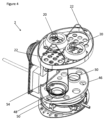
図4は、外壁と蓋とを取り除いた図1に示す装置の等角図を示し、
図5は、図3および図4に示す被加熱ベースプレートの下側から見た図を示し、
図6は、図1~図5に示す装置用の電源回路を示し、
図7は、装置の他の部分から分離された空気流方向付け手段を示し、
図8は、図7に示す空気流方向付け手段の断面図を示し、
図9は、3つの異なる装置の加熱/滅菌時間と乾燥時間との関係のグラフを示し、
図10は、本発明の代替的な一実施形態に係る装置の等角図を示し、
図11は、図10の装置の側面から見た断面図を示し、
図12は、バッフルおよび下側支持トレイの下側から見た図を示し、
図13は、図12に示すバッフルおよび下側支持トレイの同じ下側から見た図をベースプレートが取り付けられた状態で示す。
Some preferred embodiments of the invention will now be described, by way of example only, with reference to the accompanying drawings. In the accompanying drawings:
1 shows an isometric view of an apparatus according to one embodiment of the invention,
2 shows a rear view of the device shown in FIG. 1,
3 shows a cross-sectional view from the front of the apparatus shown in FIG. 1,
Figure 4 shows an isometric view of the device shown in Figure 1 with the outer wall and lid removed;
Figure 5 shows a view from the underside of the heated base plate shown in Figures 3 and 4;
Figure 6 shows a power supply circuit for the device shown in Figures 1-5,
Figure 7 shows the airflow directing means isolated from the rest of the device;
Figure 8 shows a cross-sectional view of the airflow directing means shown in Figure 7;
FIG. 9 shows a graph of heating/sterilization time versus drying time for three different devices;
Figure 10 shows an isometric view of an apparatus according to an alternative embodiment of the invention;
Figure 11 shows a cross-sectional side view of the device of Figure 10;
FIG. 12 shows a view from the underside of the baffle and lower support tray;
FIG. 13 shows the same bottom view of the baffle and lower support tray shown in FIG. 12 with the base plate attached.
図1に、対象物、具体的には哺乳瓶とそれらの関連パーツとを滅菌するための装置2を示す。装置2は、蓋6によって上部が閉じられたメインチャンバ4を画定する外壁3を備える。蓋6は、装置2に収容された対象物がユーザに見えるように、透明または半透明であってもよい。蓋6は、装置2内で発生させた蒸気を逃がすように構成された一連の通気口8を備える。装置2の背面には、交流電動ファン10の形態の押込空気流生成装置が配置されている。ファン10は、空気取入口ガード12によって保護されている。この構成要素については後でさらなる図面を参照しながら説明する。装置2は、装置2に電力を提供するために任意の適切な電源に接続され得る電源コード14を備える。
Figure 1 shows an
装置2は、チャンバ4の上部に配置された上棚16をさらに備える。上棚16は、蒸気がチャンバ4から上棚16を通り抜けて蓋6によって画定された空間へと流入することを可能にする複数の孔18を備える。この特定の実施形態では、装置2は、哺乳瓶およびそれらの関連パーツを滅菌するのに適しており、それゆえ、図示するように、上棚16の上部には、乳首20や瓶蓋22を含むいくつかの哺乳瓶パーツが置かれる。蓋6は、これらのパーツを収容できるような大きさを有している。また、上棚16には、各パーツを所定の場所に固定するために用いられ得る締付リング24も設けられている。図示した実施形態では、締付リング24は、乳首20を所定の位置に固定するために用いられている。装置2は、装置をオンオフするために用いることができる電源スイッチ26をさらに備える。図示した実施形態は、交流電動ファン10を利用するものであるが、これを直流電動ファン、例えば12Vまたは24Vの直流ファンに置き換えることは容易にできる。そのような実施形態では、直流ファンに電力を供給するための直流電源(図示せず)が装置2の背面のハウジング28内に配置され得る。直流電源はAC-DC電源によって提供されてもよい。
使用時には、後でさらなる図面を参照しながらより詳細に説明するように、チャンバ4内で蒸気が生成され、それにより、蒸気がチャンバ4内の対象物を滅菌する。チャンバ4内で生成された蒸気は、上棚16の孔18も通り抜けて乳首20や瓶蓋22のそばを通過し、それらを滅菌する。
In use, steam is generated within the
図2は、図1に示す装置2の背面図を示す。ファン10と関連の空気取入口ガード12とが装置2の背面に装着されていることがわかる。ファン10に電力を供給するための12V電源(図示せず)を収容するハウジング28は、該12V電源の過熱を防止するために冷却用通気口30を備える。図示した実施形態では、通気口30は、ハウジング28に設けられた一連の孔を含む。
FIG. 2 shows a rear view of the
図3は、正面から見た装置2の断面図を示す。図3は、装置2の内部構成要素を示している。図3からわかるように、チャンバ4は、外壁3によって画定される。外壁3は、その下側部分に、内向きに突出する環状部32を含む。この内向きに突出する環状部32がその中心に孔を有効に画定していることが理解されるであろう。図3に示す実施形態では、この孔は被加熱ベース34によって塞がれている。被加熱ベース34は、チャンバ4の底を封止するように、内向きに突出する環状部32に篏合するベースプレート36を備える。ベースプレート36は、皿状に形成されており、それにより、水が滞留し得る窪み38をチャンバ4の底に形成している。ベースプレート36の下面には放熱板40が装着されている。放熱板40の下方に、シーズ発熱体42が装着されている。シーズ発熱体42とベースプレート36との間に挟まれた放熱板40の目的は、熱をベースプレート36全体にわたってより均一に分散させることである。後述する図面から明らかになるように、シーズ発熱体42は円弧状の形状であるため、その中心には空隙がある。この空隙内に熱機械制御器44が装着されており、シーズ発熱体42を連動制御するように構成されている。
FIG. 3 shows a cross-sectional view of the
被加熱ベース34の鉛直上方には、被加熱ベース34から間隔を置いて、下棚46が配置されている。下棚46は、後述する図面においてより明確に示される一連の孔48を備える。下棚46は、滅菌対象物を支持するための、鉛直上方に延びる複数のボス50も備える。下棚46は、複数の下方に延出する脚52によって、チャンバ4内に装着される。脚52は、外壁3の内向きに突出する環状部32に載せられており、下棚46をチャンバ4内で支持している。脚52は、被加熱ベース34と下棚46との間にエアスペースが確保されるように十分な長さを有している。理解されるように、下棚46を装置2、例えば外壁3、に物理的に装着するのではなくチャンバ4内に載置することによって、必要に応じて、例えば、下棚46の下方の空間にアクセスするために、ユーザが下トレイ46を取り外すことがより容易になり得る。図3では見えないが、下棚46は、下棚46の周りに等角度で配置された複数の脚52を備えていてもよい。あるいは、下棚46には、別々の脚52ではなく、連続したリムが設けられてもよい。
A
上述のように、下棚46は複数のボス50を備える。ボス50は、滅菌対象物を下棚46上に位置決めするために用いられ得る。図3に示すように、ボス50は、瓶54の口56に入る形状および大きさを有しているため、瓶54を位置決めするのに用いられ得る。複数のボス50を設けることによって、ユーザがチャンバ4内に瓶50を位置決めしやすくなり得る。そのうえ、後述する図面においてより明確にわかるように、ボス50はそれぞれ、下棚46を貫通する孔48を備えており、蒸気を通り抜けさせる。そのため、有利には、瓶54をボス50に被せて置くことによって、装置2が蒸気を発生させたときに蒸気がボス50に位置する孔48を介して瓶54の内部に送り込まれることが確実になり、それにより、瓶54の内部が滅菌されることが確実になる。図3から明らかなように、外壁3は、図示するような一対の哺乳瓶を収めるのに適切な大きさを有するチャンバ4を画定するような寸法を有している。
As mentioned above,
チャンバ4の内部の奥に、バッフル57の形態の空気流方向付け手段が見える。バッフル57は、ファン10(図3では見えない)からの空気を、チャンバ4中に、様々な方向に向かわせる。バッフルの下には、ファン10からの空気をチャンバ4への流入前にろ過するように構成されたエアフィルタ(やはり見えない)がある。エアフィルタは、任意の適切なフィルタ、例えば、高性能微粒子フィルタ(HEPAフィルタ)であってよい。
Deep inside the
外壁3の上部に上棚16が取り付けられている。上棚16は、外壁3の内側面の外周溝60に係合する外周フランジ58を備える。外壁3および/または上棚16の材料の固有の柔軟性によって、外壁3に対する上棚16の着脱は、フランジ58と溝60との係合を介して容易に行うことができる。
An upper shelf 16 is attached to the upper part of the
図4は、装置2の斜視図を示す。ただし、装置2の内部構成要素をより明確に示すために、外壁3と蓋6とが取り除かれている。図4からわかるように、下棚46のボス50内に位置決めされた孔48は、孔48を通り抜けた蒸気が瓶54に流入するようになっている。さらに、上棚16には、上棚16の表面の大部分にわたって分散された複数の孔18が、乳首20や瓶蓋22がどこに置かれるかに関係なく蒸気がそれらの内部表面に到達してそれらを滅菌することが可能なように、設けられている。
4 shows a perspective view of the
図5は、被加熱ベース34とその関連構成要素との下側から見た図であり、装置のその他の構成要素は明瞭化のために取り除かれている。図5からより明確にわかるように、被加熱ベース34は、放熱板40が取り付けられたベースプレート36を備える。放熱板40の外周領域の周りに、円弧状の形状に沿うシーズ発熱体42が取り付けられている。シーズ発熱体42は、任意の適切な手段、例えば、ろう付けまたは溶接により放熱板40に取り付けられてもよい。シーズ発熱体42は、電力源、例えば、図6の電源回路に係るものかその他のもの、に接続され得る「コールドテール」すなわち電気的終端62を両方の端に備える。
FIG. 5 is an underside view of
放熱板40には、円弧状のシーズ発熱体42によって画定される中央空隙の内側に配置された熱機械制御器44が取り付けられている。熱機械制御器44は、放熱板40の温度に対する感応性を有し、被加熱ベース34の温度を検出するように構成された一対のバイメタルアクチュエータ(図5では見えない)を備える。バイメタルアクチュエータは、熱機械制御器44内の電気スイッチに接続され、シーズ発熱体42への電力を接続・遮断する。
Mounted to the
図5では、シーズ発熱体42のコールドテール62間のスペースにおいて放熱板40に取り付けられた感熱スイッチ64も見えている。感熱スイッチ64は、一般に入手可能な1/2インチディスク等のバイメタルアクチュエータであってもよい。感熱スイッチ64は、ファン10と直列に電気接続され得る第1の電気端子66と第2の電気端子68とを備える。したがって、感熱スイッチ64は、それによりファン10への電力の接続を制御する。
Also visible in FIG. 5 is
図6は、装置2に用いられ得る電源回路を概略的に示す。該電気回路は、ライブ電源レール70とニュートラル電源レール72とを備える。ライブ電源レール70とニュートラル電源レール72との間にシーズ発熱体42が接続されている。シーズ発熱体42は、熱機械制御器44に電気的に接続されている。熱機械制御器44は、シーズ発熱体42の一端に接続された第1のバイメタルスイッチ74と、シーズ発熱体42の他端に接続された第2のバイメタルスイッチ76とを備える。熱機械制御器44は、第1の光インジケータ80とも直列に接続されたオン/オフスイッチ78も備える。第1の光インジケータ80は、例えばLEDである。
FIG. 6 schematically shows a power supply circuit that can be used in the
ライブ電源レール70とニュートラル電源レール72との間には電動ファン10も接続されている。感熱スイッチ64がファン10と直列に電気接続されている。また、第2の光インジケータ81がファン10と並列に電気接続されている。
当業者に理解されるように、オン/オフスイッチ78がオン位置に切り替えられると、発熱体42は、電力を受け取り始め、滅菌モードで加熱する。感熱スイッチ64は、乾燥モードを開始する温度が検出されるまではファン10に電力が供給されないように、常開型である。下記において、電源回路の動作をより詳細に説明する。
As will be appreciated by those skilled in the art, when the on/off
図7は、装置2の他の構成要素から分離されたバッフル57を示し、図8は、側面から見たバッフル57の断面図を示す。図7および図8からわかるように、バッフル57は、一連の平行な羽根82を備える。
FIG. 7 shows the
空気は、バッフル57の第1のガイド壁84および第2のガイド壁86によって方向付けられる。これらのガイド壁は次第に羽根82に至っている。第1のガイド壁84は、羽根82の上部から斜め下方に延び、第2のガイド壁は、羽根82の下部から斜め上方に延びている。これらのガイド壁82および84は、バッフル57を通過する空気を3つの部分、すなわち上向きに進む部分88と中央を進む部分90と下向きに進む部分92とに有効に分割する。したがって、バッフル57がファン10の下流に置かれた場合は、ファン10によってバッフル57へ向かって押し込まれた空気が3つの部分に分けられ、チャンバ4の上側部分、中央部分、および下側部分へ向かわせられる。このようにしてチャンバ4中に空気を向かわせることは、装置の乾燥工程を加速させるのを支援し、それによって、瓶54や乳首20や蓋22をより早く再使用することを可能にする。
Air is directed by
図9は、装置2が滅菌モードおよび乾燥モードに費やす時間を示す実験データのグラフを示す。グラフは、時間に対する温度の3つのプロット図を示す。温度は、感熱スイッチ64の位置で計測された被加熱ベース34の温度である。プロット図のそれぞれについて、0秒から約60秒までの期間は滅菌モードでの装置2の動作に対応している。このモードでは、温度は100℃辺りまで上昇し、沸騰水の全てが蒸気に変換されるまでそのままである。この時点、つまり約60秒において、水の全てが沸騰して無くなり、蒸気を発生させている。すると、被加熱ベース34の温度は、その熱を放散させる媒体が無いため、急速に上昇する。このことは、プロット図において60秒以降の急激な温度上昇として見ることができる。この時点で、熱機械制御器44上のバイメタルスイッチ74および76が空焚き状態を迅速に検出(第1の所定温度、例えば105℃の検出による)し、シーズ発熱体42への電力供給を止める。シーズ発熱体42に電力が供給されなくなる一方で、被加熱ベース34の温度は、シーズ発熱体42内の余熱により上昇し続ける。感熱スイッチ64は、第2の所定温度、例えば120℃を検出すると、ファン10を始動させる。これにより、プロット図において示されるように、装置内が冷却される。この冷却は乾燥モードに相当する。
FIG. 9 shows a graph of experimental data showing the time spent by
線92は、ファン10が無い、すなわち、乾燥段階を支援するファンを有さない装置2の時間に対する温度を示す。このプロット図からわかるように、装置2においては、温度が100℃よりも低くなるまでに著しく時間がかかる、すなわち、乾燥モードは長い時間を要する。線94は、12Vのファンが用いられた装置の時間に対する温度を示す。ファンを有さない装置と比較すると、チャンバの温度がかなり速く低下し、そのため、チャンバ4の内容物がより早く乾燥することがわかる。線96は、24Vが採用された装置の時間に対する温度を示す。この装置においては、チャンバの温度が12Vのファンを用いる装置よりも早く零点未満の温度まで低下し、そのため、乾燥工程をさらに加速させていることがわかる。したがって、冷却時間はファンの出力に応じて調整される。
ここで、図1~図8を参照しながら、装置2の動作について説明する。ユーザは、何本かの哺乳瓶とそれらの関連部品を滅菌したい場合、まず、装置2の蓋6を取り外す必要がある。蓋を取り外したら、上棚16の外周リム58と装置2の外壁3の外周溝60との係合を解除することによって、上棚16を取り外すことができる。上棚16を取り外したら、その後、ユーザには次の2つの選択肢がある。まず、チャンバ4に水を加える前にチャンバ4から下棚46を取り外すことが可能である。あるいは、下棚46には孔48があるため、チャンバ4に水を注いで水が孔48から被加熱ベース34上に流れるようにするだけでもよい。
The operation of the
好ましくは、ユーザが下棚46の高さを越えない量の水を加えるだけでよいように、チャンバ4の大きさが決められ、かつ/または、下棚46が構成される。このことは、水が沸騰して蒸気を発生させたときに蒸気がすぐにチャンバ内の全ての対象物のそばを通過することができるため、有利である。しかしながら、このことは必須ではなく、チャンバ4には、より大量の水、すなわち、チャンバ内で滅菌中の対象物が少なくとも部分的に浸かる量が注水されてもよい。理解されるように、この場合は、水が沸騰蒸発して蒸気がチャンバ4内の対象物のいくらかの部分に接近し得るようになるまでにより長くかかり、そのため、滅菌工程により長い時間がかかり得る。装置は、例えば、計量された水をチャンバ4に投入するための器具、例えば水差しを備えていてもよい。あるいは、チャンバ4が、チャンバ4への注水時にユーザの助けとなる注水量目盛りを備えていてもよい。
Preferably, the
ユーザが所要量の水をチャンバ4に加えたら、次いで、滅菌対象物を挿入し得る。図示した実施形態では、チャンバ4は、哺乳瓶54を収容できるような大きさを有しており、したがって、ユーザは、各瓶54の口56をボス50のうちの1つに位置合わせして被せることで、哺乳瓶54を挿入し得る。図示した実施形態では、チャンバ4は、2つの瓶54を収容できるような大きさを有している。瓶54を挿入したら、次いで、ユーザは、上棚16を元の場所に戻す。上棚16を所定の位置に固定したら、他の対象物、例えば、乳首20や蓋22を上棚16の上に置いてもよい。乳首20が所定の位置に置かれたら、締付リング24を取り付けることによってそれらを所定の位置に固定し得る。最後に、ユーザは蓋6を取り付けてチャンバ4を閉じることができる。
Once the user has added the required amount of water to
理解されるように、装置への注水および滅菌対象物の挿入に関する上記の各ステップが行われる順序は、特定のユーザまたは滅菌対象物に応じて異なっていてもよい。上記ではチャンバ4に注水するための2つの選択肢について述べたが、それらの代わりに、ユーザが、まず全ての滅菌対象物を装置2に挿入した後で水を加えることを選択してもよい。これは、上棚16および下棚46に水を通り抜けさせる孔18および孔48がそれぞれ設けられていることによって可能である。
It will be appreciated that the order in which the above steps of irrigating the device and inserting the object to be sterilized may be performed in a different order depending on the particular user or object to be sterilized. Although two options for irrigating the
その後、ユーザは、スイッチ26を操作することによって滅菌工程を開始し得る。スイッチ26が、例えばスイッチ26の押下げにより操作されると、シーズ発熱体42に電力が供給される。チャンバ4内の未加熱の水の存在が、バイメタルアクチュエータ74および76が以前の使用後にリセットされていることを保証する。よって、シーズ発熱体42は、ベースプレート36を加熱する放熱板40を加熱する。ベースプレート36の窪み38に滞留する水が、この水に熱接触する水と共に、ベースプレート36によって加熱される。この水は、沸騰して蒸気を発生させる時点まで加熱され、その後、蒸気は水面を出て、チャンバ4の下棚46の孔48を通り抜けてチャンバ内を上昇する。この蒸気は、瓶54のそばを通過することでそれらを滅菌する。いくらかの蒸気は、さらに上昇し、上棚16の孔18を通り抜けて、蓋6内に上昇し、乳首20と蓋20のそばを通過することでそれらを滅菌する。いくらかの蒸気は、蓋6の上部の通気口8から流出し得る。このようにして蒸気を逃すことによって、装置2内の圧力上昇を回避する。
The user can then initiate the sterilization process by operating
被加熱ベース34は、水の全てが蒸気に変換されるまで、チャンバ4内の水を加熱し続ける。この時点で、装置は、被加熱ベース34からの熱を放散させる水が残っていない空焚き状況で有効に動作している。その結果、被加熱ベース34の温度は、急速に上昇し始める。被加熱ベース34の温度が第1の所定温度、例えば、空焚きスイッチオフ温度に達した時点で、バイメタルスイッチ74および76の少なくとも一方が動作して、シーズ発熱体42への電力供給を止める。すると、バイメタルスイッチ74および76の一方の動作によって、スイッチ78もオフ位置にリセットされ、それにより、熱機械制御器44をリセットする。したがって、当業者に理解されるように、このようにして熱機械制御器44がリセットされることによって、バイメタルスイッチ74および76がリセットされた際に発熱体がオンに戻ることが回避される。
シーズ発熱体42内の余熱により、被加熱ベース34の温度は、図9のグラフに見られるように、上昇し続ける。被加熱ベース34が第2の所定温度に達すると、感熱スイッチ64が閉じ、それにより、ファン10をオンにする。前述のように、第2の所定温度は120℃に設定され得る。この温度は、チャンバ4内の水の実質的に全てが蒸気に変換されたことを保証するものであり、余熱を乾燥モードにおいて利用するためにベース34に蓄熱しておくことが可能なように、第1の所定温度よりも高く設定される。第2の光インジケータ81も点灯される。これにより、ファン10は、チャンバ4に空気を押し込むように動作する。ファン10によって押し込まれた空気は、バッフル57によってチャンバ4の全ての部分に向かわせられる。チャンバ4の下側部分に向かわせた空気は、被加熱ベース34にぶつかって、被加熱ベース34から熱を取り出す。この加熱された空気は、その後、チャンバ4の残りの部分をくまなく循環し、瓶54や乳首20や蓋22を乾燥させるのを支援する。これらのパーツ上に凝縮した水分が乾くのを支援する。空気がチャンバ4に押し込まれるため、チャンバ4内に既に存在していた湿り空気と蒸気は、蓋6の通気口8を通って装置2から押し出される。このようにしてチャンバ4から蒸気を追い出すことによって、乾燥工程が加速される。
Due to the residual heat in the
ファン10は、被加熱ベース34の温度が、感熱スイッチ64が再び開いてファン10への電力供給を停止させるリセット温度まで低下するまで、動作し続ける。このリセット温度は、例えば90℃に設定され得る。この時点で、第2の光インジケータ81も消され、乾燥モードが完了する。その後、ユーザは、蓋6を取り外し、滅菌済みの対象物を使用に備えて装置2の内部から取り出し得る。
The
図10は、本発明の代替的な実施形態に係る装置102の等角図を示す。明瞭化のため、装置102の内部構成要素をより明確に表示するために本体と蓋とが取り除かれている。装置102は、本質的には上述の装置2と同じであるが、空気を概ねチャンバ4に送り込むバッフル57に代えて、本実施形態は、ファン110からの空気を内部導管に沿って下棚146上のボス150に設けられた孔148に向かわせるように構成された空気方向付け手段157を備える。図10は、空気方向付け手段157が各孔148を貫通して延びる立設ガイド196を備える様子を示す。立設ガイド196は、孔148を2つの部分、すなわち、空気方向付け手段157によって提供される導管と流体連通する第1の部分148’と、チャンバ104の残りの部分と流体連通する第2の部分148”とに有効に分割する。当業者に理解されるように、瓶(図示せず)をボス150に被せて置くと、立設ガイド196が瓶の口に入り込む。空気がファン110によって押し込まれると、該空気は、空気方向付け手段157の内部導管によって、孔148を通って瓶の内部に直接送られる。空気は、孔148の第1の部分148’を通って瓶に流入し、瓶の中を通過し、孔148の第2の部分148”からチャンバ104内に押し出される。本実施形態では、空気方向付け手段157によってボス150に向かわされた空気は、瓶から追い出された後、被加熱ベースにのみぶつかる。
FIG. 10 shows an isometric view of
図11は、側面から見た装置102の断面図を示し、空気方向付け手段157によって画定される内部導管に沿わされる空気の空気流路をより明確に示している。導管に沿った空気流路は、矢印198によって示されている。ファン110によって押し込まれた空気は、空気方向付け手段157によって、垂直流路200が内部に形成された導管を流下させられる。空気は、次いで、下棚146の下面に沿って延びる導管の水平流路202に沿って、孔148に向かわせられる。水平流路202は、図13により明確に示すベースプレート204によってその基底が閉じられている。押し込まれた空気は、この水平流路202に沿って流れた後、ボス150に設けられた孔148の第1の部分148’を通って上方へ向かわせられる。
FIG. 11 shows a cross-sectional view of
図12は、下から見た空気方向付け手段157および下棚146の等角図を示す。本実施形態では、空気方向付け手段157と下棚146とは一体部品として形成される。しかしながら、これは必須ではなく、空気方向付け手段157と下棚146とは、組み付け可能な別個の部品として設けられてもよい。図12からわかるように、垂直流路200は、水平流路202の中まで延びて、連続した導管を形成している。図12は、水平流路202が2つの枝路、第1の枝路202’および第2の枝路202”に分かれる様子も示している。水平流路202の各枝路202’、202”は、空気をそれぞれのボス150(反対側)のそれぞれの孔148に向かわせる。
FIG. 12 shows an isometric view of air directing means 157 and
空気を枝路202’および202”に沿って流れさせるために、水平流路202の基底をベースプレート204によって閉じている。これは図13からわかる。ベースプレート204は、任意の適切な手段、例えばネジによって取り付けることができる。これに加えて、図13には図示していないが、垂直流路200は、装置102の他の構成要素、例えば装置102の本体によって閉じられている。あるいは、垂直流路200は、ベースプレート204と同様の閉止板によって閉じられていてもよい。
In order to allow air to flow along the branches 202' and 202'', the base of the
Claims (21)
電気発熱体と熱連通する被加熱ベースを備えた、滅菌対象物を収容するためのチャンバと、
前記チャンバに空気を送り込むように構成された押込空気流装置と、
前記電気発熱体および前記押込空気流装置に電力を供給するように構成された電源回路と、
前記電源回路において前記電気発熱体と直列に配置され、前記被加熱ベースの温度を検出するために前記装置内に配置された、熱機械制御器と、
前記電源回路において前記押込空気流装置と直列に配置され、前記被加熱ベースの温度を検出するために前記装置内に配置された、感熱スイッチと、を備え、
前記装置は、前記電気発熱体が前記電源回路を介して電力を供給されることにより前記被加熱ベースを加熱し、それにより使用時には前記チャンバ内の水を加熱して前記対象物を滅菌するための蒸気を発生させる滅菌モードで動作するように構成され、前記熱機械制御器は、前記熱機械制御器が前記被加熱ベースの第1の所定温度を検出すると、前記電気発熱体への電力供給を遮断することにより前記滅菌モードを終了させるように構成され、 前記装置は、さらに、前記押込空気流装置が前記電源回路を介して電力を供給されることにより前記チャンバに空気を送り込む乾燥モードで動作するように構成され、前記感熱スイッチは、前記感熱スイッチが前記チャンバ内の水の実質的に全てが蒸気に変換されたことを示す前記被加熱ベースの第2の所定温度を検出すると、前記押込空気流装置への電力供給を接続することにより前記乾燥モードを開始させるように構成され、
前記装置は、前記電源回路において前記押込空気流装置と直列に配置される追加の電気発熱体をさらに備え、これにより前記追加の電気発熱体は前記乾燥モードにおいて動作するように構成された、装置。 A device for sterilizing an object, comprising:
a chamber for containing an object to be sterilized, comprising a heated base in thermal communication with an electric heating element;
a forced airflow device configured to force air into the chamber;
a power circuit configured to power the electric heating element and the forced airflow device;
a thermomechanical controller disposed in the power supply circuit in series with the electrical heating element and disposed within the device for sensing the temperature of the heated base;
a thermal switch disposed in the power supply circuit in series with the forced airflow device and disposed within the device for sensing the temperature of the heated base;
The apparatus heats the heated base by the electric heating element being powered through the power supply circuit, thereby heating water in the chamber in use to sterilize the object. wherein the thermomechanical controller powers the electric heating element when the thermomechanical controller detects a first predetermined temperature of the heated base and the device is further in a dry mode in which the forced airflow device is powered through the power circuit to force air into the chamber. configured to operate, wherein the thermal switch detects a second predetermined temperature of the heated base indicating that substantially all of the water in the chamber has been converted to steam; configured to initiate said drying mode by connecting a power supply to a forced airflow device ;
The apparatus further comprises an additional electrical heating element arranged in series with the forced airflow device in the power supply circuit, whereby the additional electrical heating element is configured to operate in the drying mode. .
Applications Claiming Priority (3)
| Application Number | Priority Date | Filing Date | Title |
|---|---|---|---|
| GB1720442.1 | 2017-12-07 | ||
| GB1720442.1A GB2571507B (en) | 2017-12-07 | 2017-12-07 | Sterilising device |
| PCT/GB2018/053544 WO2019111003A1 (en) | 2017-12-07 | 2018-12-06 | Sterilising device |
Publications (3)
| Publication Number | Publication Date |
|---|---|
| JP2021505280A JP2021505280A (en) | 2021-02-18 |
| JP2021505280A5 JP2021505280A5 (en) | 2022-01-11 |
| JP7287962B2 true JP7287962B2 (en) | 2023-06-06 |
Family
ID=61007174
Family Applications (1)
| Application Number | Title | Priority Date | Filing Date |
|---|---|---|---|
| JP2020531459A Active JP7287962B2 (en) | 2017-12-07 | 2018-12-06 | Sterilizer |
Country Status (5)
| Country | Link |
|---|---|
| US (1) | US11925714B2 (en) |
| JP (1) | JP7287962B2 (en) |
| CN (1) | CN111683690A (en) |
| GB (1) | GB2571507B (en) |
| WO (1) | WO2019111003A1 (en) |
Families Citing this family (4)
| Publication number | Priority date | Publication date | Assignee | Title |
|---|---|---|---|---|
| EP4111114A4 (en) * | 2020-02-28 | 2024-03-13 | Susan Nicole Grimes | Hair extension and wig drying device |
| DE102020112782A1 (en) * | 2020-05-12 | 2021-11-18 | Michael Markus Heckmann | Device and method for steam disinfection of products |
| CN111700486B (en) * | 2020-05-26 | 2022-05-17 | 青岛海尔智慧厨房电器有限公司 | Steam box and control method thereof |
| US20220080069A1 (en) * | 2020-09-16 | 2022-03-17 | Cynthia Conner | Card Sanitizer and Method |
Citations (4)
| Publication number | Priority date | Publication date | Assignee | Title |
|---|---|---|---|---|
| JP2004248873A (en) | 2003-02-20 | 2004-09-09 | Sanyo Electric Co Ltd | High-pressure steam sterilizer |
| US20070003461A1 (en) | 2005-07-01 | 2007-01-04 | Daewoo Electronics Corporation | Multi-functional child care storage having a steam sterilizing compartment |
| JP2008534905A (en) | 2005-03-29 | 2008-08-28 | デーウー・エレクトロニクス・コーポレイション | Multifunctional storage for childcare |
| WO2010106348A2 (en) | 2009-05-20 | 2010-09-23 | Strix Limited | Heaters |
Family Cites Families (15)
| Publication number | Priority date | Publication date | Assignee | Title |
|---|---|---|---|---|
| JPS5947284B2 (en) | 1979-03-12 | 1984-11-17 | ラマント・ジエイ・セイツ | heating device |
| JPS5935244Y2 (en) * | 1979-07-12 | 1984-09-29 | 松下精工株式会社 | Baby bottle sterilizer dryer |
| DE3013016A1 (en) * | 1980-04-03 | 1981-10-08 | Brown, Boveri & Cie Ag, 6800 Mannheim | RELEASE SYSTEM OF A SELF-SWITCH TO INTERRUPT A CIRCUIT |
| FR2529633B1 (en) | 1982-07-02 | 1985-09-13 | Michelin & Cie | MATERIAL FOR FORMING A JOINT BETWEEN TWO BODIES, OUTSIDE THEIR INTERFACE; METHODS FOR MAKING ASSEMBLIES WITH SUCH MATERIAL; SETS SO OBTAINED |
| US6080968A (en) | 1994-06-09 | 2000-06-27 | Strix Limited | Liquid heating vessels |
| CN2627640Y (en) | 2003-05-18 | 2004-07-21 | 张拯华 | Electric utensil overheat protective device |
| GB2411837A (en) | 2004-03-12 | 2005-09-14 | Vogue Internat Ltd | Steriliser for baby feeding or care products |
| WO2006068393A1 (en) * | 2004-12-22 | 2006-06-29 | Daewoo Electronics Corporation | Multi-functional child care storage and inner case thereof |
| US7713471B2 (en) | 2005-10-31 | 2010-05-11 | Codman Neuro Sciences Sarl | System for protecting circuitry in high-temperature environments |
| RU2334447C1 (en) | 2007-02-13 | 2008-09-27 | Общество с ограниченной ответственностью "Сибовар" | Foodstuff thermal treatment device (versions) |
| RU2396091C2 (en) * | 2008-10-27 | 2010-08-10 | Общество с ограниченной ответственностью научно-производственная фирма "Костромская медтехника" (ООО НПФ "Костромская медтехника") | Steam steriliser |
| DE102011114899A1 (en) * | 2011-10-05 | 2013-04-11 | Michael Markus Heckmann | Household appliance for disinfecting and drying |
| CN202859702U (en) * | 2012-09-06 | 2013-04-10 | 青岛兴邦电子电器有限公司 | Intelligent steam heater |
| CN206979753U (en) * | 2017-01-14 | 2018-02-09 | 江西安姆特母婴用品有限公司 | A kind of disinfecting drying apparatus |
| CN107234078A (en) * | 2017-07-12 | 2017-10-10 | 桐乡市瑞远纺织有限公司 | A kind of cleaning device of medicine equipment |
-
2017
- 2017-12-07 GB GB1720442.1A patent/GB2571507B/en active Active
-
2018
- 2018-12-06 CN CN201880088902.1A patent/CN111683690A/en active Pending
- 2018-12-06 JP JP2020531459A patent/JP7287962B2/en active Active
- 2018-12-06 US US16/770,286 patent/US11925714B2/en active Active
- 2018-12-06 WO PCT/GB2018/053544 patent/WO2019111003A1/en active Application Filing
Patent Citations (4)
| Publication number | Priority date | Publication date | Assignee | Title |
|---|---|---|---|---|
| JP2004248873A (en) | 2003-02-20 | 2004-09-09 | Sanyo Electric Co Ltd | High-pressure steam sterilizer |
| JP2008534905A (en) | 2005-03-29 | 2008-08-28 | デーウー・エレクトロニクス・コーポレイション | Multifunctional storage for childcare |
| US20070003461A1 (en) | 2005-07-01 | 2007-01-04 | Daewoo Electronics Corporation | Multi-functional child care storage having a steam sterilizing compartment |
| WO2010106348A2 (en) | 2009-05-20 | 2010-09-23 | Strix Limited | Heaters |
Also Published As
| Publication number | Publication date |
|---|---|
| US11925714B2 (en) | 2024-03-12 |
| WO2019111003A1 (en) | 2019-06-13 |
| CN111683690A (en) | 2020-09-18 |
| GB2571507A (en) | 2019-09-04 |
| JP2021505280A (en) | 2021-02-18 |
| US20210145991A1 (en) | 2021-05-20 |
| GB201720442D0 (en) | 2018-01-24 |
| GB2571507B (en) | 2022-02-09 |
Similar Documents
| Publication | Publication Date | Title |
|---|---|---|
| JP7287962B2 (en) | Sterilizer | |
| BR202016026015Y1 (en) | FOOD VAPORIZER | |
| RU2672611C2 (en) | Apparatus for preparing food with high degree of thermal protection | |
| US7378067B2 (en) | Apparatus for retaining and heat sanitizing articles | |
| RU2754410C2 (en) | Improved steaming accessory for heating and/or steaming food products contained in container | |
| ES2747785T3 (en) | Device for heating and / or cooking meat products | |
| AU2002240484A1 (en) | Apparatus for retaining and heat sanitizing articles | |
| JP2021505280A5 (en) | ||
| US6558640B1 (en) | Household product sanitizer | |
| KR101761490B1 (en) | Container drying unit | |
| CN210697261U (en) | Drying milk warmer | |
| CN211723061U (en) | Steam drying apparatus | |
| JP4930533B2 (en) | rice cooker | |
| CN211884628U (en) | Steam drying machine | |
| CN211625911U (en) | Multifunctional steam dryer | |
| CN111110881A (en) | Steam drying machine | |
| JP2010214035A5 (en) | ||
| CN216702987U (en) | Disinfection apparatus | |
| AU5173190A (en) | Vapour-heated chamber | |
| JP6641133B2 (en) | Cooker | |
| CN217510318U (en) | Cooking apparatus | |
| KR200170825Y1 (en) | Apparatus for convection in a detachable electric cooker pan | |
| EP3400968A1 (en) | An apparatus and a method of sterilizing and drying at least one article | |
| KR20060086675A (en) | Heating device for steaming cooking | |
| JP2009066441A (en) | Electric pot |
Legal Events
| Date | Code | Title | Description |
|---|---|---|---|
| A521 | Request for written amendment filed |
Free format text: JAPANESE INTERMEDIATE CODE: A523 Effective date: 20211203 |
|
| A621 | Written request for application examination |
Free format text: JAPANESE INTERMEDIATE CODE: A621 Effective date: 20211203 |
|
| A977 | Report on retrieval |
Free format text: JAPANESE INTERMEDIATE CODE: A971007 Effective date: 20221130 |
|
| A131 | Notification of reasons for refusal |
Free format text: JAPANESE INTERMEDIATE CODE: A131 Effective date: 20221215 |
|
| A521 | Request for written amendment filed |
Free format text: JAPANESE INTERMEDIATE CODE: A523 Effective date: 20230306 |
|
| TRDD | Decision of grant or rejection written | ||
| A01 | Written decision to grant a patent or to grant a registration (utility model) |
Free format text: JAPANESE INTERMEDIATE CODE: A01 Effective date: 20230509 |
|
| A61 | First payment of annual fees (during grant procedure) |
Free format text: JAPANESE INTERMEDIATE CODE: A61 Effective date: 20230525 |
|
| R150 | Certificate of patent or registration of utility model |
Ref document number: 7287962 Country of ref document: JP Free format text: JAPANESE INTERMEDIATE CODE: R150 |