JP7282761B2 - Low-latency decimator and interpolator filter - Google Patents
Low-latency decimator and interpolator filter Download PDFInfo
- Publication number
- JP7282761B2 JP7282761B2 JP2020522813A JP2020522813A JP7282761B2 JP 7282761 B2 JP7282761 B2 JP 7282761B2 JP 2020522813 A JP2020522813 A JP 2020522813A JP 2020522813 A JP2020522813 A JP 2020522813A JP 7282761 B2 JP7282761 B2 JP 7282761B2
- Authority
- JP
- Japan
- Prior art keywords
- signal
- filter
- noise
- sample frequency
- delay
- Prior art date
- Legal status (The legal status is an assumption and is not a legal conclusion. Google has not performed a legal analysis and makes no representation as to the accuracy of the status listed.)
- Active
Links
Images


Classifications
-
- G—PHYSICS
- G10—MUSICAL INSTRUMENTS; ACOUSTICS
- G10K—SOUND-PRODUCING DEVICES; METHODS OR DEVICES FOR PROTECTING AGAINST, OR FOR DAMPING, NOISE OR OTHER ACOUSTIC WAVES IN GENERAL; ACOUSTICS NOT OTHERWISE PROVIDED FOR
- G10K11/00—Methods or devices for transmitting, conducting or directing sound in general; Methods or devices for protecting against, or for damping, noise or other acoustic waves in general
- G10K11/16—Methods or devices for protecting against, or for damping, noise or other acoustic waves in general
- G10K11/175—Methods or devices for protecting against, or for damping, noise or other acoustic waves in general using interference effects; Masking sound
- G10K11/178—Methods or devices for protecting against, or for damping, noise or other acoustic waves in general using interference effects; Masking sound by electro-acoustically regenerating the original acoustic waves in anti-phase
- G10K11/1785—Methods, e.g. algorithms; Devices
- G10K11/17855—Methods, e.g. algorithms; Devices for improving speed or power requirements
-
- H—ELECTRICITY
- H04—ELECTRIC COMMUNICATION TECHNIQUE
- H04R—LOUDSPEAKERS, MICROPHONES, GRAMOPHONE PICK-UPS OR LIKE ACOUSTIC ELECTROMECHANICAL TRANSDUCERS; DEAF-AID SETS; PUBLIC ADDRESS SYSTEMS
- H04R3/00—Circuits for transducers, loudspeakers or microphones
- H04R3/04—Circuits for transducers, loudspeakers or microphones for correcting frequency response
-
- G—PHYSICS
- G10—MUSICAL INSTRUMENTS; ACOUSTICS
- G10K—SOUND-PRODUCING DEVICES; METHODS OR DEVICES FOR PROTECTING AGAINST, OR FOR DAMPING, NOISE OR OTHER ACOUSTIC WAVES IN GENERAL; ACOUSTICS NOT OTHERWISE PROVIDED FOR
- G10K11/00—Methods or devices for transmitting, conducting or directing sound in general; Methods or devices for protecting against, or for damping, noise or other acoustic waves in general
- G10K11/16—Methods or devices for protecting against, or for damping, noise or other acoustic waves in general
- G10K11/175—Methods or devices for protecting against, or for damping, noise or other acoustic waves in general using interference effects; Masking sound
- G10K11/178—Methods or devices for protecting against, or for damping, noise or other acoustic waves in general using interference effects; Masking sound by electro-acoustically regenerating the original acoustic waves in anti-phase
- G10K11/1787—General system configurations
- G10K11/17885—General system configurations additionally using a desired external signal, e.g. pass-through audio such as music or speech
-
- G—PHYSICS
- G10—MUSICAL INSTRUMENTS; ACOUSTICS
- G10L—SPEECH ANALYSIS OR SYNTHESIS; SPEECH RECOGNITION; SPEECH OR VOICE PROCESSING; SPEECH OR AUDIO CODING OR DECODING
- G10L21/00—Processing of the speech or voice signal to produce another audible or non-audible signal, e.g. visual or tactile, in order to modify its quality or its intelligibility
- G10L21/02—Speech enhancement, e.g. noise reduction or echo cancellation
- G10L21/0208—Noise filtering
- G10L21/0216—Noise filtering characterised by the method used for estimating noise
-
- H—ELECTRICITY
- H04—ELECTRIC COMMUNICATION TECHNIQUE
- H04R—LOUDSPEAKERS, MICROPHONES, GRAMOPHONE PICK-UPS OR LIKE ACOUSTIC ELECTROMECHANICAL TRANSDUCERS; DEAF-AID SETS; PUBLIC ADDRESS SYSTEMS
- H04R1/00—Details of transducers, loudspeakers or microphones
- H04R1/10—Earpieces; Attachments therefor ; Earphones; Monophonic headphones
- H04R1/1083—Reduction of ambient noise
-
- G—PHYSICS
- G10—MUSICAL INSTRUMENTS; ACOUSTICS
- G10K—SOUND-PRODUCING DEVICES; METHODS OR DEVICES FOR PROTECTING AGAINST, OR FOR DAMPING, NOISE OR OTHER ACOUSTIC WAVES IN GENERAL; ACOUSTICS NOT OTHERWISE PROVIDED FOR
- G10K2210/00—Details of active noise control [ANC] covered by G10K11/178 but not provided for in any of its subgroups
- G10K2210/30—Means
- G10K2210/301—Computational
- G10K2210/3028—Filtering, e.g. Kalman filters or special analogue or digital filters
- G10K2210/30281—Lattice filters
-
- G—PHYSICS
- G10—MUSICAL INSTRUMENTS; ACOUSTICS
- G10K—SOUND-PRODUCING DEVICES; METHODS OR DEVICES FOR PROTECTING AGAINST, OR FOR DAMPING, NOISE OR OTHER ACOUSTIC WAVES IN GENERAL; ACOUSTICS NOT OTHERWISE PROVIDED FOR
- G10K2210/00—Details of active noise control [ANC] covered by G10K11/178 but not provided for in any of its subgroups
- G10K2210/30—Means
- G10K2210/301—Computational
- G10K2210/3051—Sampling, e.g. variable rate, synchronous, decimated or interpolated
-
- G—PHYSICS
- G10—MUSICAL INSTRUMENTS; ACOUSTICS
- G10L—SPEECH ANALYSIS OR SYNTHESIS; SPEECH RECOGNITION; SPEECH OR VOICE PROCESSING; SPEECH OR AUDIO CODING OR DECODING
- G10L21/00—Processing of the speech or voice signal to produce another audible or non-audible signal, e.g. visual or tactile, in order to modify its quality or its intelligibility
- G10L21/02—Speech enhancement, e.g. noise reduction or echo cancellation
- G10L21/0208—Noise filtering
- G10L21/0216—Noise filtering characterised by the method used for estimating noise
- G10L2021/02161—Number of inputs available containing the signal or the noise to be suppressed
- G10L2021/02163—Only one microphone
-
- H—ELECTRICITY
- H04—ELECTRIC COMMUNICATION TECHNIQUE
- H04R—LOUDSPEAKERS, MICROPHONES, GRAMOPHONE PICK-UPS OR LIKE ACOUSTIC ELECTROMECHANICAL TRANSDUCERS; DEAF-AID SETS; PUBLIC ADDRESS SYSTEMS
- H04R2460/00—Details of hearing devices, i.e. of ear- or headphones covered by H04R1/10 or H04R5/033 but not provided for in any of their subgroups, or of hearing aids covered by H04R25/00 but not provided for in any of its subgroups
- H04R2460/01—Hearing devices using active noise cancellation
-
- H—ELECTRICITY
- H04—ELECTRIC COMMUNICATION TECHNIQUE
- H04R—LOUDSPEAKERS, MICROPHONES, GRAMOPHONE PICK-UPS OR LIKE ACOUSTIC ELECTROMECHANICAL TRANSDUCERS; DEAF-AID SETS; PUBLIC ADDRESS SYSTEMS
- H04R3/00—Circuits for transducers, loudspeakers or microphones
Description
本願は、2017年10月31日に出願された米国仮出願62/579,809の利益と優先権を主張するものであり、参照することによりその全体が本願に組み込まれる。 This application claims the benefit of and priority to U.S. Provisional Application No. 62/579,809, filed October 31, 2017, which is hereby incorporated by reference in its entirety.
本願は、全体としてはデジタル信号処理のためのシステム及び方法に関するものであり、より具体的には、例えば動的ノイズキャンセレーションシステムにおける、サンプルレート変換に関する。 This application relates generally to systems and methods for digital signal processing, and more particularly to sample rate conversion, eg, in dynamic noise cancellation systems.
デジタル信号を様々なデジタルコンポーネント及び処理に適した異なるサンプルレートに変換することは広く知られている。例えば、所望の信号品質、必要な帯域、遅延に対する要求、処理の経済性、利用可能なシリコン面積、その他の考慮に応じて、デジタル信号処理システムが異なるサンプリングレートを用いることは一般的である。音声処理システムにおいては、低遅延と高性能を実現するために異なるサンプルレートが用いられ得る。例えば、デジタル動的ノイズキャンセレーション(ANC)システムでは、音声処理とANC処理が、異なるサンプルレートで行われてANCシステムの帯域を増加させることがある(例えば、“Understanding Active Noise Cancellation”、Colin H. Hansen、ISBN 0415231922参照)。 It is well known to convert digital signals into various digital components and different sample rates suitable for processing. For example, it is common for digital signal processing systems to use different sampling rates depending on desired signal quality, required bandwidth, delay requirements, processing economics, available silicon area, and other considerations. Different sample rates may be used in audio processing systems to achieve low latency and high performance. For example, in digital dynamic noise cancellation (ANC) systems, audio processing and ANC processing may occur at different sample rates to increase the bandwidth of the ANC system (see, e.g., "Understanding Active Noise Cancellation," Colin H. Hansen, ISBN 0415231922).
しかしながら、オーバーサンプルドコンバータ構成を用いるシステムでは、均一な遅延で信号を結合する際に問題がある。一つの解決方法は、アナログ領域で処理を行い、これにより、デジタルオーバーサンプルド処理に関連する遅延の問題を回避することである。しかしながら、これでは、典型的には広い周波数範囲に渡って対応する能力が制限されるし、他の解決方法では、周波数分解能が制限され、また、不所望なノイズの低減が制限されることになる。更に、これらの解決方法は、しばしば、コンポーネントの変更に鋭敏であり実装依存性がある。前述の観点から、オーバーサンプルドコンバータ構成を用いた動的ノイズキャンセレーション処理のためのシステム及び方法の改良には継続したニーズがある。 However, systems using oversampled converter configurations have problems combining signals with uniform delay. One solution is to perform the processing in the analog domain, thereby avoiding the delay problems associated with digital oversampled processing. However, this typically limits the ability to cover over a wide frequency range, and other solutions suffer from limited frequency resolution and limited unwanted noise reduction. Become. Moreover, these solutions are often sensitive to component changes and implementation dependent. In view of the foregoing, there is a continuing need for improved systems and methods for dynamic noise cancellation processing using oversampled converter configurations.
低遅延動的ノイズキャンセレーション(ANC)を行うためのシステム及び方法がここに開示されている。様々な実施形態において、システムが、環境ノイズを検知し、ノイズ信号を生成するように動作可能な音声センサと、音声信号を受け取り、インターポレーションフィルタによって該音声信号を処理し、第1サンプル周波数を有する主音声信号を生成する音声処理パスと、該ノイズ信号を受け取り、対応するアンチノイズ信号を生成するように動作可能な動的ノイズキャンセレーションプロセッサと、該アンチノイズ信号を受け取り、該第1サンプル周波数を有するアップサンプリング後アンチノイズ信号を生成するように動作可能であって、オーバーフローを回避するように該アンチノイズ信号の最上位ビットを拡張するように動作可能な符号拡張段と、該アップサンプリング後アンチノイズ信号のビット数を低減するクリッピングを行うように動作可能なリミッターとを備える直接インターポレータと、該主音声信号とアップサンプリング後アンチノイズ信号を受け取って結合し、結合出力信号を生成する加算器と、該結合出力信号を処理する低遅延フィルタとを備えている。 A system and method for low-delay dynamic noise cancellation (ANC) are disclosed herein. In various embodiments, a system includes an audio sensor operable to detect environmental noise and generate a noise signal; receive an audio signal; process the audio signal with an interpolation filter; a dynamic noise cancellation processor operable to receive the noise signal and generate a corresponding anti-noise signal; receive the anti-noise signal; a sign extension stage operable to generate an upsampled antinoise signal having a sample frequency and operable to extend the most significant bits of the antinoise signal to avoid overflow; a direct interpolator comprising a limiter operable to clip to reduce the number of bits of a sampled anti-noise signal; An adder for generating and a low delay filter for processing the combined output signal.
いくつかの実施形態では、低遅延フィルタが複数のフィルタを備えており、各フィルタは、異なるサンプル周波数でフィルタリングを行う。低遅延フィルタは、直列配置で設けられた複数の格子波フィルタを備えていてもよい。各格子波フィルタのそれぞれは、異なる周波数帯を処理する。いくつかの実施形態では、サンプル周波数が、各連続するフィルタにおいて整数ステップで増加される。格子波フィルタが複数の遅延要素を備えていてもよく、特定の出力サンプル周波数での直接サンプリングが、複数のフィルタをインターレースすることで行われてもよい。一つの実装では、N個の遅延要素がリフレクター部(2ポートアダプタ)に設けられ、1つのパスがN/2個の遅延要素で遅延され、他のパスは、入力信号に直接接続されている。ここで、Nは、一連の2の累乗数に等しい。他の実装では、格子波フィルタが、それぞれがN個の単位遅延で遅延される複数のリフレクター要素を備えている1つのパスと(Nは、1より大きい整数)、M個の遅延要素(Mは、1より大きい整数)によって遅延される1つのパスとを含む2つのパスを備えている。いくつかの実施形態では、動的ノイズキャンセレーションプロセッサが、更に、動的キャンセレーションプロセッサによってアンチノイズ信号を得るように動作可能である。ここで、フィルタ係数は、時間領域又は周波数領域で動作してfiltered-X最小二乗法処理によって計算されてもよい。 In some embodiments, the low delay filter comprises multiple filters, each filtering at a different sample frequency. The low delay filter may comprise a plurality of lattice wave filters provided in a series arrangement. Each grating wave filter processes a different frequency band. In some embodiments, the sample frequency is increased by integer steps in each successive filter. A grating wave filter may comprise multiple delay elements, and direct sampling at a particular output sample frequency may be achieved by interlacing multiple filters. In one implementation, N delay elements are provided in the reflector section (2-port adapter), one path is delayed by N/2 delay elements, and the other path is directly connected to the input signal. . where N equals a series of powers of two. In another implementation, the grating wave filter has one path with multiple reflector elements each delayed by N unit delays (N is an integer greater than 1) and M delay elements (M has two paths, one of which is delayed by an integer greater than 1). In some embodiments, the dynamic noise cancellation processor is further operable to obtain an anti-noise signal by the dynamic noise cancellation processor. Here, the filter coefficients may be computed by a filtered-X least-squares process operating in the time domain or frequency domain.
様々な実施形態で、システムは、第1サンプル周波数を有する主音声信号を受け取って処理するように動作可能な音声処理パスと、該主音声信号を第2サンプリング周波数にダウンサンプリングするように動作可能なデシメータを備える動的ノイズキャンセレーションパスと、該主音声信号とノイズ信号を該第2サンプル周波数で受け取り、該第2サンプル周波数を有するアンチノイズ信号を生成するように動作可能な動的ノイズキャンセレーションプロセッサと、該アンチノイズ信号を該第1サンプル周波数にアップサンプリングするように動作可能なインターポレータと、該アンチノイズ信号と該主音声信号とを該第1サンプル周波数で結合するように動作可能な加算器とを備えている。デシメータとインターポレータは、それぞれ、対応する複数のサンプル周波数でフィルタイングを行うように動作可能な複数のフィルタを備えている。 In various embodiments, a system includes an audio processing path operable to receive and process a primary audio signal having a first sampling frequency, and an audio processing path operable to downsample the primary audio signal to a second sampling frequency. and a dynamic noise cancellation path operable to receive the primary audio signal and the noise signal at the second sample frequency and produce an anti-noise signal having the second sample frequency. an interpolator operable to upsample the antinoise signal to the first sample frequency; and an interpolator operable to combine the antinoise signal and the main audio signal at the first sample frequency. possible adders. The decimator and interpolator each comprise a plurality of filters operable to filter at a corresponding plurality of sample frequencies.
いくつかの実施形態では、動的ノイズキャンセレーションパスと音声処理パスのそれぞれが、均一な遅延を可能にするように配置された複数の遅延要素を備えるオーバーサンプルド格子フィルタを備えている。当該システムは、更に、環境ノイズを検知し、対応する電気信号を生成するように動作可能なマイクロホンと、該第2サンプル周波数で前記ノイズ信号を生成する低遅延デシメータとを備えていてもよい。当該システムは、更に、該第1サンプル周波数に整合する入出力サンプル周波数を有し、該動的ノイズキャンセレーションパスに設けられたインターポレータによって生成された偽イメージ(aliased image)を除去するように動作可能なオーバーサンプルドインターポレーションフィルタを備えていてもよい。いくつかの実施形態では、前記複数のフィルタのそれぞれが、各段が2倍で動作サンプルレートを変化させる多段格子波フィルタ構成を備えていてもよい。デシメータとインターポレータは、それぞれ、オーバーフローを回避するように受信信号の最上位ビットを拡張するように動作可能な符号拡張段と、出力ビット数を低減するクリッピングを行うように動作可能なリミッターとを備えていてもよい。 In some embodiments, the dynamic noise cancellation path and the audio processing path each comprise an oversampled lattice filter comprising multiple delay elements arranged to allow uniform delay. The system may further comprise a microphone operable to sense environmental noise and generate a corresponding electrical signal, and a low delay decimator to generate the noise signal at the second sample frequency. The system further has an input and output sample frequency matching the first sample frequency to remove aliased images produced by an interpolator in the dynamic noise cancellation path. may also include an oversampled interpolation filter operable to In some embodiments, each of said plurality of filters may comprise a multi-stage grating wave filter configuration with each stage varying the operating sample rate by a factor of two. The decimator and interpolator are respectively a sign extension stage operable to extend the most significant bits of the received signal to avoid overflow and a limiter operable to clip to reduce the number of output bits. may be provided.
様々な実施形態において、方法が、環境ノイズを検知し、ノイズ信号を生成することと、インターポレータフィルタによって音声信号を処理して第1サンプル周波数を有する主音声信号を生成することと、前記ノイズ信号から第2サンプル周波数を有するアンチノイズ信号を生成することと、前記アンチノイズ信号を直接内挿して、前記第1サンプル周波数を有するアップサンプリング後アンチノイズ信号を生成することと、該主音声信号と該アップサンプリング後アンチノイズ信号とを結合して結合出力信号を生成することと、該結合出力信号を低遅延フィルタで処理することとを含む。ここで、直接内挿することは、オーバーフローを回避するようにアンチノイズ信号の最上位ビットを拡張し、ANCリファレンスを内挿係数に等しいゲイン係数で乗算することと、アップサンプリング後アンチノイズ信号の出力ビットの数をクリッピングして減らすこととを含む。 In various embodiments, a method includes detecting environmental noise and generating a noise signal; processing an audio signal with an interpolator filter to generate a primary audio signal having a first sample frequency; generating an anti-noise signal having a second sample frequency from a noise signal; directly interpolating the anti-noise signal to generate an upsampled anti-noise signal having the first sample frequency; combining a signal and the upsampled anti-noise signal to produce a combined output signal; and processing the combined output signal with a low delay filter. Here, the direct interpolation involves extending the most significant bits of the anti-noise signal to avoid overflow, multiplying the ANC reference by a gain factor equal to the interpolation factor, and clipping to reduce the number of output bits.
いくつかの実施形態では、当該方法は、更に、直列配置で設けられた複数の格子波フィルタを適用することを含む。ここで、該複数の格子波フィルタのそれぞれは、各連続するフィルタで次々に変更された異なるサンプル周波数を処理する。該複数の格子波フィルタを適用することは、複数の遅延要素を適用することを含んでいてもよい。特定の出力サンプル周波数での直接サンプリングが、複数のフィルタをインターレースすることで行われてもよい。様々な実施形態において、該主音声信号を間引いて該主音声信号を該第2サンプル周波数にダウンサンプリングすることと、該ノイズ信号から該第2サンプル周波数を有するアンチノイズ信号を生成することが、更に、ダウンサンプリングされた主音声信号を分析することを含んでいてもよい。いくつかの実施形態では、当該方法において、該ノイズ信号から該第2サンプル周波数を有する該アンチノイズ信号を生成することが、filtered-X最小二乗法処理を用いてフィルタ係数を計算することを備えている。 In some embodiments, the method further comprises applying a plurality of grating wave filters provided in a series arrangement. Here, each of the plurality of grating wave filters processes a different sample frequency that is changed in turn with each successive filter. Applying the plurality of grating wave filters may include applying a plurality of delay elements. Direct sampling at a particular output sample frequency may be done by interlacing multiple filters. In various embodiments, decimating the primary audio signal to downsample the primary audio signal to the second sample frequency; and generating an anti-noise signal having the second sample frequency from the noise signal comprises: Further, it may include analyzing the downsampled main audio signal. In some embodiments, the method wherein generating the anti-noise signal having the second sample frequency from the noise signal comprises calculating filter coefficients using a filtered-X least-squares process. ing.
本発明の範囲は、クレームによって規定され、該クレームは参照することで本項に組み込まれる。本発明のより完全な理解は、その追加的な利点の実現と共に、下記の1以上の実施形態の詳細な説明を考慮することによって当業者に与えられるであろう。初めに簡単に説明する添付図面のシートを参照する。 The scope of the invention is defined by the claims, which are incorporated into this section by reference. A more complete understanding of the invention, as well as the realization of additional advantages thereof, will be provided to those skilled in the art from a consideration of the detailed description of one or more of the embodiments below. Reference is made to the accompanying drawing sheets, which will be briefly described at the outset.
本開示の観点及びその利点は、以下の図面とそれに続く詳細な説明を参照することで、より良く理解可能である。類似の参照符号が1以上の図面に図示されている類似の構成要素を識別するために用いられており、それらの図示は、本開示の実施形態を図示する目的のものであり、限定する目的のものではないと理解されるべきである。図面における部材は、必ずしも寸法通りではなく、その代わり、本開示の原理を明確に図示するように強調がなされている。 Aspects of the present disclosure and its advantages can be better understood with reference to the following drawings and detailed description that follow. Like reference numerals have been used to identify like components illustrated in one or more of the drawings, and the illustrations are for the purposes of illustrating embodiments of the present disclosure and for purposes of limitation. It should be understood that it is not intended for The elements in the drawings are not necessarily to scale, emphasis instead being placed upon clearly illustrating the principles of the disclosure.
本開示の様々な実施形態に従って、動的ノイズキャンセレーションフィルタにおいて低遅延かつ高音質の音声出力を達成するためのシステム及び方法が開示される。 According to various embodiments of the present disclosure, systems and methods are disclosed for achieving low-latency, high-quality audio output in dynamic noise cancellation filters.
ノイズキャンセレーション及びノイズ低減技術は、騒音の多い環境におけるユーザ体験を向上するために様々な応用で用いられている。1つのアプローチでは、ヘッドホン、ヘッドセット、イヤホンのようなリスニングデバイスが、環境ノイズを検知する1以上の音声センサと、アンチノイズ信号を生成してユーザに対する環境ノイズをキャンセル又は低減する動的ノイズキャンセレーション処理回路を備えている。生成されたアンチノイズ信号がノイズ外乱の反対に等しい(これによりノイズをキャンセルする)一方で、所望の音声、例えば、高忠実音源からの再生には最小の外乱しかないことが望まれる。環境ノイズの望ましい減衰を得るためには、ANCシステムは、受け取ったノイズ信号を低遅延で処理して元のノイズ信号に対して最小の位相シフトしかない反転出力信号を生成し、広い帯域でノイズキャンセレーションを行うように設計される。多くの音声を聞く環境では、約20kHzのノイズ低減帯域を得るためには、約10μsの遅延のフィードバック信号が使用可能であるが、実際に得られる帯域は、ノイズキャンセレーションシステムのトポロジーと実際の音響システムに依存している。 Noise cancellation and noise reduction techniques are used in various applications to enhance user experience in noisy environments. In one approach, a listening device such as a headphone, headset, or earpiece incorporates one or more audio sensors to detect environmental noise and dynamic noise cancellation to generate an anti-noise signal to cancel or reduce environmental noise to the user. It has a ration processing circuit. While the generated anti-noise signal is equal to the inverse of the noise disturbance (thus canceling the noise), it is desirable that the desired sound, eg, reproduction from a high fidelity source, has minimal disturbance. To obtain the desired attenuation of the environmental noise, the ANC system processes the received noise signal with low delay to produce an inverted output signal with minimal phase shift with respect to the original noise signal and broadband noise Designed for cancellation. In many listening environments, a feedback signal with a delay of about 10 μs can be used to obtain a noise reduction bandwidth of about 20 kHz, but the actual bandwidth obtained depends on the topology of the noise cancellation system and the actual application. Depends on your sound system.
本開示の様々な実施形態は、高音質音声再生システムにおいてオーバーサンプルドコンバータを用いるノイズキャンセレーションシステムを対象としている。一実施形態では、デルタ-シグマ・アナログ-デジタルコンバータ(ADC)とデジタル-アナログコンバータ(DAC)とが音声信号処理に用いられる。ナイキストサンプルレートコンバータと比較すると、デルタ-シグマコンバータは、高サンプルレートを用いており、アナログ信号部品において精度を要求しないので、一般に、実装が安価である。したがって、コストと処理の観点の両方から、ナイキスト基準によって要求されるより高いサンプルレートでノイズキャンセレーションを行うことはしばしば有利であり、これは、より広いノイズキャンセレーション帯域を得るために使用可能である。 Various embodiments of the present disclosure are directed to noise cancellation systems that use oversampled converters in high quality audio reproduction systems. In one embodiment, delta-sigma analog-to-digital converters (ADCs) and digital-to-analog converters (DACs) are used for audio signal processing. Compared to Nyquist sample rate converters, delta-sigma converters are generally cheaper to implement because they use high sample rates and do not require precision in analog signal components. Therefore, both from a cost and processing standpoint, it is often advantageous to perform noise cancellation at a higher sample rate than required by the Nyquist criterion, which can be used to obtain a wider noise cancellation band. be.
多レート信号処理の1つの問題は、遅延の増大の可能性である。ANCシステムでは、キャンセルすべき環境ノイズと同相のアンチノイズ信号を生成するためには、測定されたノイズ(不所望な信号)と高忠実音声(所望の信号)の両方について、時間に正確なリファレンスを動的ノイズ処理システムに提供することが望ましい。いくつかの実施形態では、係数の変更に鋭敏ではないことが知られている格子波フィルタが、乗算を要しない簡単なフィルタソルーションを得るために用いられる。低遅延を得るためには、フィルタ次数が低いことが望まれるが、これは、不幸にも帯域外の信号の減衰が少ない特性を有することがあり、良好な帯域外減衰が望まれる高音質音声信号については問題になり得る。 One problem with multi-rate signal processing is the potential for increased delay. In an ANC system, a time-accurate reference is required for both the measured noise (the unwanted signal) and the high-fidelity speech (the desired signal) in order to generate an anti-noise signal that is in-phase with the environmental noise to be canceled. to the dynamic noise processing system. In some embodiments, lattice wave filters, which are known to be insensitive to coefficient changes, are used to obtain a simple filter solution requiring no multiplications. In order to obtain low delay, a low filter order is desired, but this unfortunately can have the property of low attenuation of out-of-band signals, and for high-quality speech where good out-of-band attenuation is desired. Signals can be a problem.
本開示の実施形態による動的ノイズキャンセレーション(ANC)を実施するシステム100を、図1を参照して説明する。システム100は、ノイズキャンセリングヘッドホン、イヤホン、又は、環境からノイズを検出してノイズをキャンセルする信号を生成する他のシステムにおいて実装され得る。システム100は、1以上のノイズ源からの環境ノイズを検出し、検出したノイズを表す対応電気信号を生成する少なくとも1つのマイクロホン102又は他の音声センサを備えている。様々な実施形態において、該少なくとも1つのマイクロホン102は、フィードフォワード、フィードバック、又は、フィードフォワード/フィードバック複合ANCシステムに配置され得る。マイクロホン102の出力は、オーバーサンプリングされたデジタルビットストリーム(例えば1ビットデジタルマイクロホンからの出力)であってもよく、該オーバーサンプリングされたデジタル音声信号を生成するためにプリアンプと(単一ビット又は多ビットの)デルタ-シグマコンバータとに供給されるアナログ信号であってもよい。デジタル音声信号は、低遅延ANCプロセッサ106への入力のために、多段格子波フィルタのような低遅延デシメータ104によって低いサンプルレートに間引きされる。
A
低遅延ANCプロセッサ106は、マイクロホン102によって検出された環境ノイズに対応するアンチノイズ信号を生成する。ANCプロセッサ106は、また、音声リファレンス信号として用いられる、時間に正確な音声再生信号を高音質音声再生プロセッサ108から受け取る。様々な実施形態において、ANCプロセッサ106は、内部フィルタノードの時間領域又は周波数領域での更新を用いて、スピーカー114から再生された所望の音声をも含み得るマイクロホン信号から環境ノイズを動的にフィルタリングする。例えば、ANCプロセッサ106は、filtered-x 最小二乗法 (FXLMS) アルゴリズムを実行して、環境ノイズをフィルタリングで除去するようにフィルタ係数を動的に修正してもよい。低遅延を得るために、有限インパルス応答 (FIR) トポロジーがしばしば用いられ、一方では、ノイズのパワースペクトルにかなりの広がりがある場合でも高速に対応できるように、フィルタ更新が、しばしば周波数領域で行われる。これによれば、如何なる主要なノードよりもエネルギー含有量が相当に小さい周波数においてさえ、周波数領域で信号を分離することにより高速に対応することが可能になる。逆周波数変換が、対応する重みを時間領域に変換するために用いられてもよい。
Low-
音声再生プロセッサ108は、例えばスピーカー114のような音声出力を介した再生のために所望の音声信号(ここでは主音声信号ともいう)を生成する。所望の音声信号は、ソースファイル(例えば、記録された音楽又は動画ファイル)や、ボイスオーバーIPシステムにおける近端のマイクロホン又は遠端のマイクロホンから受け取った音声信号のような、他のソースからの出力から生成されてもよい。所望の音声信号は、加算器110によってANCプロセッサ106により出力されるアンチノイズ信号と結合される。これらの信号を加算した出力は、低遅延インターポレータ112を用いてフィルタリング及びアップコンバートされてスピーカー114(レシーバと呼ばれることもある)に出力される。
簡潔さのために、図1にはいくつかの標準的な部品、例えば、マイクロホンプリアンプ、MEMSマイクロホンにおいて用いられ得るマイクロホン高電圧ポンプ、低ノイズ電源ユニット、スピーカーアンプ、電源、その他のシステム100の部品が、図示されていないと理解されよう。これらの部品は、当業者には知られており、様々な実際のシステム実装においては含められ得るが、ここでは、処理パスを図示するうえで明確さのために省略されている。
For simplicity, FIG. 1 shows some standard components such as a microphone preamplifier, a microphone high voltage pump that may be used in MEMS microphones, a low noise power supply unit, a speaker amplifier, a power supply, and
システム100の様々な実施形態では、高忠実性音声信号とANC出力信号の両方が同じ低いサンプルレート(例えば、192kHz)で表され、よって、処理パスにおける低遅延が設計の目標である場合には、いずれもが、同じ低忠実性インターポレーションフィルタで処理される。処理サンプルレートを増大させることは可能であるが、これは、設計の電力消費と物理的大きさを顕著に増大させるであろう。よって、音声再生のための高音質インターポレーションフィルタと、ANC処理のための低遅延フィルタパス(ここでは、動的ノイズキャンセレーションパスとも呼ぶ)を同時に組み合わせることができることが望まれる。これは、動的ノイズキャンセレーション(ANC)のためのシステム200の構成要素を図示する図2の実施形態に図示されているようにして実施され得る。
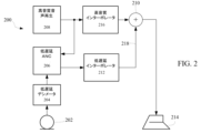
In various embodiments of
システム200は、マイクロホン202と、低遅延デシメータ204と、ノイズ信号を受け取りアンチノイズ信号を生成するための低遅延ANCプロセッサ206とを備えている。アンチノイズ信号は、加算器210によって高音質音声信号(ここでは、主音声信号とも呼ばれる)と組み合わせるべきアンチノイズ信号218を生成するために低遅延インターポレータ212に供給される。高音質音声は、高音質音声再生208により、ANCリファレンス信号として用いるためにANCプロセッサ206に供給される。図示されるように、高音質音声信号とノイズ信号は、効率的なANC処理に適した同じ低サンプルレート(例えば、192kHz)である。高音質インターポレータ216(「高音質」の意味は、システムの要求に応じた十分なダイナミックレンジ、減衰量などを含む)は、スピーカー214に出力するための高音質音声信号のサンプリングレートを増大し、高音質音声信号処理パスに遅延を加える。ANCプロセッサ206は、音声出力の、時間に正確な音声リファレンスを用いるので、(ブロック208と206から出力される)これらの2つの信号の異なる信号処理パスには、(即ち、それぞれ、フィルタ212と216を介する)異なる信号処理パスが存在し、これは、内部の群遅延に差異を生じさせ、ANC処理ユニットにおける最善ではない対応となる。ブロック212と216とで遅延が異なると、信号の位相がずれ、ノイズキャンセレーションの性能が劣化する。よって、図1のシステムに関する問題は、単に、高忠実度インターポレータ216と低遅延インターポレーションフィルタ212からの出力を加えることでは解決できない。したがって、システム100もシステム200のいずれも、ANC信号のための低遅延パスとリファレンス音声信号のための高忠実度信号パスの両方を提供しながら、ANCシステムのための時間に正確なリファレンスの問題を解決するものではない。
ANC信号のための低遅延パスとリファレンス音声信号のための高忠実度信号パスの両方を提供しながら、ANCシステムのための時間に正確なリファレンスを提供するシステム300の実施形態が、図3に示されている。マイクロホン302、低遅延デシメータ304、低遅延ANCプロセッサ306、高音質音声再生プロセッサ308、高音質インターポレータ316とスピーカー314は、前に議論した図1、図2に図示されているように実装されてもよい。高音質音声再生プロセッサ308は、高音質インターポレータ316(即ち、高忠実度インターポレーションフィルタ)に供給される高音質音声信号を生成する。高い電力消費、過剰な複雑性又は遅延の相違に関する問題を回避するために、高音質インターポレーションフィルタの高忠実度オーバーサンプルド出力は、フィルタリングすることなく動作する(即ち、N個ごとにサンプルを選択する)デシメータ318によってN個おきに間引きされる。帯域外の信号が高音質インターポレータ316によって除去され、よって信号帯域は不変であるから、フィルタリング(例えば、アンチエイリアシング)は必要ない。ANCプロセッサ306の出力信号(アンチノイズ信号)は、高音質音声信号の周波数に整合するように、インターポレータ320において、より高い周波数にN倍で直接にアップサンプリングされる。一実施形態では、出力信号は、元のサンプルのそれぞれの間に、0に等しいN-1個のサンプルを挿入することで高い周波数にアップアンプリングされる。この動作は、元のノイズ信号の複数の鏡像エイリアスを導入するであろう。アンチノイズ信号は、加算器310によって高忠実度オーバーサンプルド出力と結合され、その結合出力信号は、低遅延インターポレータ312に送られる。
An embodiment of a
この実施形態における低遅延インターポレータ312は、最初の音声出力のN倍の高いサンプルレートで動作するオーバーサンプルドインターポレータであり、ANCプロセッサ306からの直接的に内挿された信号から出力される偽イメージを除去する一方で、元のオーバーサンプルされた高忠実度オーバーサンプルド音声信号は、偽イメージはすでに高音質インターポレータによって除去されているので、そのまま通過する。オーバーサンプルドインターポレータ312は、各フィルタセクションの内部に追加の遅延要素を加えることで実装されてもよい。即ち、各フィルタセクションは、N倍、N/2倍、N/4倍の低いサンプル周波数で動作する元のフィルタ構成と同じ周波数応答を得るために、元の遅延要素のN倍、N/2倍、N/4倍等の遅延要素を備えている。更に、フィルタ要素が元のサンプルレートのN倍の非常に高いサンプルレートで更新され、これによりフィルタの群遅延を最適にするので、このフィルタ構成は、実際の実装における問題を解決する。この場合、異なるサンプルレート(即ち、異なるサンプル周波数)を有するシステム間で値を転送するときにしばしば遅延を与えることがある、実際のレジスタ転送レベルでの実装に起因する追加の遅延を導入することなく、理論的な性能が得られることがある。図3に示されている一般的な解決手法において、格子波フィルタ以外のフィルタ構成が使用されてもよく、如何なる解決手法も、これらに限定されるべきではない。
The low-
様々な実施形態において、オーバーサンプルドインターポレータフィルタは、同じ入出力サンプル周波数を有しており、低遅延デシメーションフィルタとしても使用可能であり、これにより、入力パスの遅延を低減することで更に遅延を低減することができる。それは、本質的には非常に低い遅延と広い帯域を有するローパスフィルタであり、高忠実性の用途では第2のデシメーションパスを追加することができる。 In various embodiments, the oversampled interpolator filter has the same input and output sample frequencies and can also be used as a low-delay decimation filter, thereby reducing the input path delay and further Delay can be reduced. It is essentially a low pass filter with very low delay and wide bandwidth, and a second decimation pass can be added for high fidelity applications.
様々な実装について、該フィルタは、帯域外の減衰の観点から理想的であろう応答を有するフィルタを最初に設計し、更に、該フィルタの出力における実際の信号-ノイズ比(SNR)を向上するように係数を調節し、これにより用いられているデルタ-シグマコンバータの実際のノイズ成形を考慮に入れながら該フィルタを最適化することで最適化されてもよい。更に、実際の実装において乗算を除去し、これによりシリコン面積、コスト及び電力消費を顕著に低減するように、係数が切り捨てられてもよい。 For various implementations, the filter is first designed with a response that would be ideal in terms of out-of-band attenuation, further improving the actual signal-to-noise ratio (SNR) at the output of the filter. , thereby optimizing the filter while taking into account the actual noise shaping of the delta-sigma converter being used. Additionally, the coefficients may be truncated to eliminate multiplication in the actual implementation, thereby significantly reducing silicon area, cost and power consumption.
ここでは、オーバーサンプルドフィルタ実装400の実施形態を、図4を参照しながら説明する。前に議論したように、デジタルANCフィードバックループにおいて低遅延、低電力、低シリコン面積及び高性能を得るためには、音声処理とANC処理とを異なるサンプルレートで行うことは利点であり得る。図示された実施形態では、音声信号は、3.072Mhzのレートでサンプリングされ、ANC処理はより低い192kHzのレートで行われる。ただし、システム要求に従って他のサンプリングレートが使用され得ることは理解されよう。音声処理自身は、ANC(192kHz)と同じレート又はより低いレート、例えば48kHzで行われてもよい。しかしながら、オーバーサンプルドコンバータ構成を用いる場合には、これらの信号を均一な遅延で結合する際に問題がある。デシメーションパスは別に実施可能であるが、AND処理と音声パスとを均一な遅延で結合する際には問題が生じ得る。もし、インターポレーションパスが低遅延に合わせて最適化されたなら、帯域外鏡像イメージを音声パスからあまり減衰させないであろうし、同様に、もし音声パスを向上させるために遅延について妥協すれば、帯域とANC性能が悪くなる。
An embodiment of an
音声信号とANCアンチノイズ信号との、高い音声音質と低く均一なパス遅延の両方を得るために、図4の実施形態は、両方のパスで均一な遅延を実現可能なトポロジーのオーバーサンプルドインターポレータを備えている。図示されているように、高音質音声入力信号は、48kHzでサンプリングされ、ハーフバンドフィルタ(セクションS1、S2)によって192kHzにアップサンプリングされる。インターポレーションフィルタ416は、偽鏡像イメージを除去し、該信号を16倍で、3.072MHzの出力音声サンプルレートにアップサンプリングする高音質インターポレータである。音声信号は音声処理パスでフィルタリングされ、音声信号とアンチノイズ信号の結合は、オーバーサンプルされた出力周波数(3.072MHz)で行われる。この実施形態では、短いANC遅延と十分な音声鏡像の減衰が同時に達成される。様々な実施形態において、音声パスは、元のパスの後で(即ち、アンチノイズ信号との結合の後で)フィルタリングされ、これは、最も高い周波数をやや減衰し、更に、帯域外ノイズを低減することがある。ANCオーバーサンプルドインターポレータによる音声信号の不所望な帯域内の減衰は、信号のアップサンプリングが発生する前に行われる小さなイコライゼーションによって訂正可能である。様々な実施形態において、低遅延格子波フィルタが、ループにおける遅延を最小化するようにオーバーサンプルドインターポレータフィルタに用いられる。該オーバーサンプルドインターポレーションフィルタは、ANCのためのノイズ信号パスにおける間引きのために、このパスにおいても低遅延を確保するように、少しだけ変更して使用され得る。即ち、マイクロホンから間引き後出力へのデジタル信号は、オーバーサンプルドインターポレータと類似の構造のオーバーサンプルドデシメータを用いて処理される。
In order to obtain both high speech quality and low uniform path delay for speech and ANC anti-noise signals, the embodiment of FIG. Equipped with a poller. As shown, the high quality audio input signal is sampled at 48 kHz and upsampled to 192 kHz by half-band filters (sections S1, S2).
図示された実施形態では、ANC処理は、192kHzのサンプルレートで行われる。音声信号は、ANC処理のための192kHzのリファレンス信号を生成するために、デシメータ418によってN=16個ごとに間引きされる(即ち、16個おきにサンプルを抜き出す)。ANCプロセッサ406は、192kHzのアンチノイズ信号を出力し、該アンチノイズ信号は、加算器410によって音声信号と結合される3.072MHzのアンチノイズ信号を生成するために、インターポレータ420によってN=16倍でアップサンプリングされる。実際の実装では、セクションS3とブロック420からの低周波のエネルギーレベルが整合していることを確保するためにインターポレータ420の後に乗算器を含んでいてもよい。この乗算器は、図4には図示されていない。乗算器は、典型的には、単なるビットのシフトからなる(例えば、16倍の乗算について4回シフト)。このように、インターポレータ420は、単に、サンプルの間にゼロを挿入することからなるのではなく、更に、内挿レートと同じ倍率で各出力サンプルを乗じる。一実施形態では、信号はフィルタリングされずに内挿されるので、内挿されたアンチノイズ信号は、複数の偽イメージを含んでいる。次に、オーバーサンプルドインタポレーションフィルタ412(セクションS5、S6、S7、S8)は、結合された信号から帯域外イメージを除去する一方で、音声信号を通過帯域においてフィルタリングせずに通過させる。オーバーサンプルドインターポレータフィルタ412のそれぞれは、異なる数の内部遅延(例えば、8、4、2、1)を有しており、これにより、該フィルタは、異なる速度で動作して逐次に帯域外イメージを除去する。このようにして、ANC信号と音声信号は、全周波数で同一の群遅延を有し、これにより、高品質なノイズ抑制を可能にする。
In the illustrated embodiment, ANC processing is performed at a sample rate of 192 kHz. The audio signal is decimated every N=16 (ie, every 16th sample is taken) by
ここに開示した実施形態は、従来のシステムに対して数多くの利点を提供することは当業者には理解されるであろう。実施形態は、遅延を低くかつうまく制御し、ANCと音声パスとを別々にフィルタンリングすることを可能にし、加算点の後で両方のパスの遅延を同一にすることを可能にする。 Those skilled in the art will appreciate that the embodiments disclosed herein provide numerous advantages over conventional systems. Embodiments provide low and well controlled delay, allow filtering the ANC and voice paths separately, and allow the delay of both paths to be the same after the summation point.
一実施形態では、24小数ビットの語長が、従来の音声コンポーネントと直接に接続するために用いられ、1つのオーバーフロービットを含む25ビットの内部表現が用いられる。理論的には、あらゆる状況でオーバーフローを回避するためには2つまでのオーバーフロービットが必要であるかもしれないが、実際の実装では、1つのオーバーフロービットで十分であり得る。音声コンポーネントは、フィルタに直接に接続されてもよい。ANCプロセッサは、フィルタに直接に接続されてもよい。一実施形態では、ノードX3(ノードX3は、以下の図面に図示されている)の最下位ビット(LSB)は、全てのオーバーサンプルドフィルタでリミットサイクルを回避するためにゼロに設定される。テストによれば、選択されたデルタ-シグマコンバータのダイナミックレンジが既に限定されているという状況では、(25ビットではなく)22ビットしか用いられなくてもSNRの顕著な劣化は見られなかった。フィルタS5~S8は、図4において、S5、S6、S7、S8の順序で図示されているが、これらのフィルタの、オーバーサンプリングされているという性質により、これらのフィルタの異なる配列も用いられてもよいことが理解されよう。 In one embodiment, a word length of 24 fractional bits is used to connect directly with conventional speech components, and a 25-bit internal representation is used, including one overflow bit. Theoretically, up to two overflow bits may be needed to avoid overflow in all situations, but in practical implementations one overflow bit may be sufficient. Audio components may be connected directly to filters. The ANC processor may be directly connected to the filter. In one embodiment, the least significant bit (LSB) of node X3 (node X3 is illustrated in the following figures) is set to zero to avoid limit cycles in all oversampled filters. Tests have shown that in situations where the dynamic range of the chosen delta-sigma converter is already limited, no significant degradation in SNR was observed when only 22 bits (rather than 25 bits) were used. Filters S5-S8 are illustrated in FIG. 4 in the order S5, S6, S7, S8, but due to the oversampled nature of these filters, different arrangements of these filters may also be used. It should be understood that
図5を参照して、ここでは、オーバーサンプルドインターポレーションフィルタのトポロジーの実施形態を説明する。この実施形態では、図4のセクションS5におけるインターポレーションフィルタのような格子波インターポレーションフィルタ500は、16倍にオーバーサンプリングされた音声信号とアンチノイズ信号とを受け取る。該オーバーサンプルドインターポレーションフィルタは、同一の入出力サンプル周波数を有している。該インターポレータをより高いサンプルレートで動作させることにより、ANCプロセッサからの直接に内挿された信号によって生成された偽イメージを除去することが可能になる一方で、元のオーバーサンプリングされた高忠実性のオーバーサンプルド音声信号は、既に偽イメージが除去されているので、事実上、そのまま通過するであろう。オーバーサンプルドインターポレータは、最初の音声出力のN倍の、より高いサンプル周波数で動作し、各フィルタセクションの内部に追加の遅延要素を追加することで実装される。即ち、各フィルタセクションは、N倍、N/2倍、N/4倍の、より低いサンプル周波数で動作する元のフィルタ構成と同じ周波数応答を得るために、元の遅延要素の、それぞれ、N倍(図5に図示されている)、N/2倍、N/4倍等の遅延要素を含んでいる。更に、このフィルタ構成は、フィルタ要素が元のサンプルレートのN倍の非常に高いサンプルレートで更新され、これにより、フィルタの群速度を最適にすることを可能にする(即ち、理論的な性能が得られ得る)ため、実際の実装における問題を解決する。遅延として用いられる任意の整数である一般解について、この解決手法は、各リフレクタセクションにおいて1又は2時間単位の内部遅延を有する古くからある格子波フィルタの一般化とみることもできる。
Referring to FIG. 5, an embodiment of an oversampled interpolation filter topology is now described. In this embodiment, a lattice
このフィルタの伝達関数は、下記のノード方程式を参照して導き出すことが可能である:
Y0 = X0 z-N
X1 = X0 + X2z-2N = X0 + (X1-X3) z-2N = X0 + X1z-2N - X3z-2N
X1 = (X0-X3z-2N)/(1-z-2N)
X3 = X2 z-2N +γX1 = (X1-X3) z-2N+γX1
X3(1+z-2N) = (z-2N+γ)X1 = (z-2N+γ)(X0-X3z-2N)/(1-z-2N)
X3(1+z-2N)(1-z-2N) + X3(z-2N+γ) z-2N = (z-2N+γ)X0
X3 = (z-2N+γ)X0/(1+γz-2N)
Out = Y0 + X3 = X0 z-N + X3 = X0(γ+z-N+z-2N+γz-3N)/(1+γz-2N)
図5に図示されたN=8のフィルタについては、
Out = Y0 + X3 = X0 z-8 + X3 = X0(γ+z-8+z-16+γz-24)/(1+γz-16).
The transfer function of this filter can be derived by referring to the following node equations:
Y0 = X0z -N
X1 = X0 + X2z - 2N = X0 + ( X1 - X3 )z- 2N = X0 + X1z - 2N - X3z - 2N
X1 = ( X0 - X3z - 2N )/(1-z -2N )
X3 = X2z - 2N + γX1 =( X1 - X3 )z -2N + γX1
X 3 (1+z -2N ) = (z -2N +γ)X 1 = (z -2N +γ)(X 0 -X 3 z -2N )/(1-z -2N )
X 3 (1+z -2N )(1-z -2N ) + X 3 (z -2N +γ) z -2N = (z -2N +γ)X 0
X 3 = (z −2N +γ)X 0 /(1+γz −2N )
Out = Y 0 + X 3 = X 0 z -N + X 3 = X 0 (γ+z -N +z -2N +γz -3N )/(1+γz -2N )
For the N=8 filter illustrated in FIG.
Out = Y 0 + X 3 = X 0 z -8 + X 3 = X 0 (γ+z -8 +z -16 +γz -24 )/(1+γz -16 ).
γの値は、フィルタカットオフ周波数を決定するであろう。γの値は、まず、阻止帯域での減衰を最大化し、通過帯域での減衰を最小化することから見出された。しかしながら、既定のデルタ-シグマコンバータ構成からの出力のSNRを最適化することによって少し良い値を発見可能である。なぜなら、これは、このコンバータの実際のノイズ成形も考慮に入れるであろうからである。この最適化の後、0.346656であるγの値が得られた。格子波フィルタの低い感受性により、この値は、下記の値:γ = 1/4 + 1/16 + 1/64 + 1/128を用いて、少しの加算/シフト演算によって近似され得る。この近似を行った場合でも、浮遊小数点で乗算とγの最適値を用いることと比較しても固定小数点演算を用いながら0.1dBのSNRの減少しか起こらなかった。このように、完全な乗算演算は、シフトをハードのワイヤで行うと共に3つの加算に置換可能であり、これは、顕著にシリコン面積と電力を節約する。この実装では、フィルタにおいて偽の小振幅振動を発生させるリミットサイクルの問題を回避するために、ノードX3からの最下位ビット(LSB)出力を0に設定することによって非線形性が意図的に導入されている。図5の8倍オーバーサンプルドインターポレータの周波数応答と群遅延とが、それぞれ、図6A、図6Bに図示されている。 The value of γ will determine the filter cutoff frequency. The value of γ was first found by maximizing the attenuation in the stopband and minimizing the attenuation in the passband. However, slightly better values can be found by optimizing the SNR of the output from a given delta-sigma converter configuration. since this would also take into account the actual noise shaping of this converter. After this optimization, a value of γ of 0.346656 was obtained. Due to the low sensitivity of grating wave filters, this value can be approximated by a few add/shift operations using the following values: γ = 1/4 + 1/16 + 1/64 + 1/128. Even with this approximation, only 0.1 dB reduction in SNR occurred while using fixed point arithmetic compared to using multiplication and the optimum value of γ in floating point. Thus, the full multiplication operation can be replaced with three additions with hard-wired shifts, which saves significant silicon area and power. In this implementation, a nonlinearity is intentionally introduced by setting the least significant bit (LSB) output from node X3 to 0 to avoid limit cycle problems that cause spurious small-amplitude oscillations in the filter. It is The frequency response and group delay of the 8× oversampled interpolator of FIG. 5 are illustrated in FIGS. 6A and 6B, respectively.
図7を参照して、図4のセクションS6での使用に適したオーバーサンプルドインターポレータトポロジー700の実施形態が図示されている。図示のように、格子波インターポレーションフィルタは、4倍でオーバーサンプリングされ、伝達関数は次のように計算される(N=4):
Out = Y0 + X3 = X0 z-4 + X3 = X0(γ+z-4+z-8+γz-12)/(1+γz-8)
このフィルタは、元のサンプル周波数の4倍で動作する単位遅延を有するフィルタのように振る舞い、4倍でオーバーサンプリングされた信号の処理を可能にする。図7のインターポレータの周波数応答と群遅延とが、それぞれ、図8A、図8Bに図示されている。
Referring to FIG. 7, an embodiment of an
Out = Y 0 + X 3 = X 0 z -4 + X 3 = X 0 (γ+z -4 +z -8 +γz -12 )/(1+γz -8 )
This filter behaves like a filter with unit delay operating at four times the original sample frequency, allowing the processing of signals oversampled by a factor of four. The frequency response and group delay of the interpolator of FIG. 7 are illustrated in FIGS. 8A and 8B, respectively.
図9を参照して、図4のフィルタS7としての使用に適したオーバーサンプルドインターポレータトポロジー900の実施形態が図示されている。図示のように、格子波インターポレーションフィルタは、2倍でオーバーサンプリングされ、伝達関数は下記のように計算される(N=2):
Out = Y0 + X3 = X0 z-2 + X3 = X0(γ+z-2+z-4+γz-6)/(1+γz-4)
図9の2倍オーバーサンプルドインターポレータの周波数応答と群遅延とが、それぞれ、図10A、図10Bに図示されている。
Referring to FIG. 9, an embodiment of an
Out = Y 0 + X 3 = X 0 z -2 + X 3 = X 0 (γ+z -2 +z -4 +γz -6 )/(1+γz -4 )
The frequency response and group delay of the 2× oversampled interpolator of FIG. 9 are illustrated in FIGS. 10A and 10B, respectively.
図11を参照して、図4のセクションS8における使用に適したオーバーサンプルドインターポレータ1100の実施形態が図示されている。図示のように、最終段の格子波インターポレーションフィルタは、直接フィルタ(即ち、オーバーサンプリング無し)であり、伝達関数は、次のように計算される(N=1):
Out = Y0 + X3 = X0 z-1 + X3 = X0(γ+z-1+z-2+γz-3)/(1+γz-2)
図11の直接インターポレータの周波数応答と群遅延とが、それぞれ、図12A、図12Bに図示されている。
Referring to FIG. 11, an embodiment of an
Out = Y 0 + X 3 = X 0 z -1 + X 3 = X 0 (γ+z -1 +z -2 +γz -3 )/(1+γz -2 )
The frequency response and group delay of the direct interpolator of FIG. 11 are illustrated in FIGS. 12A and 12B, respectively.
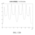
フィルタチェーン全体(即ち、図4のセクションS5~S8)の結合した応答が、図13A~図13Eに図示されている。図13A~図13Cは、様々な音声帯域での全体としての周波数応答を図示している。図13D、図13Eは、サンプル周波数を3072kHzとしたときの、フィルタチェーン全体の全体としての群遅延を図示している。図13Eを参照して、ある実施形態では、音声帯域0~20kHzにおける群遅延の変化は、4.87~4.99μs(14.95~15.34入力サンプル)の間で変化し、3%未満である。 The combined response of the entire filter chain (ie sections S5-S8 of FIG. 4) is illustrated in FIGS. 13A-13E. Figures 13A-13C illustrate the overall frequency response in various audio bands. 13D and 13E illustrate the overall group delay of the entire filter chain when the sample frequency is 3072 kHz. Referring to FIG. 13E, in one embodiment, the change in group delay in the 0-20 kHz audio band varies between 4.87-4.99 μs (14.95-15.34 input samples) and is 3% is less than
図14を参照して、ここでは、デシメータとしての使用に適した例示的なフィルタ配置1400を説明する。この実施形態では、本開示の低遅延オーバーサンプルドインタポレーションフィルタは、オーバーサンプルドデシメータフィルタとして用いられる。インターポレーションフィルタからの一つの相違点は、出力が16個おきに間引かれることである。図は、低遅延の結合を確保するために信号が異なるパスを取り、高音質音声が維持される例示的な構成を図示している。様々な実施形態において、各段は、2分の1ずつサンプルレートを低減しながら(即ち、これらのセクションを3072、1536、769、384kHzで動作させながら)、全てのセクションをN=1で実装し、多段多レート信号処理を用いることで、又は、オーバーサンプルドデシメータを低い周波数、例えば、1536又は768kHzで動作させることで、ほとんど同じ遅延を持ちながらゲート数が少ないデシメーションフィルタを実装することができる。なぜなら、遅延の大部分は、多くの数の内部遅延を有するこれらのセクションにおいて発生するからである。同様に、もし、非常にわずかに高音質音声を妥協してもよいのであれば、最終出力よりも低い周波数、例えば、3072kHzの最終出力について1536kHzで音声とANC信号との加算を行い、これにより、顕著にゲート数を減らし、電力消費を減らすことができる。更に、各段が信号を同じ低遅延格子波フィルタ(N=1)を用いて2倍にアップサンプルする多段多レートインタポレータを設計することもできる。これは、ゲート数が少ないという利点があるが、実際の実装においてはセクション間のわずかな遅延による、わずかに大きい遅延がある。
Referring to FIG. 14, an
図15を参照して、ここでは、本開示の実施形態による群遅延の測定について説明する。群遅延は、単一のサイン波(例えば、1kHzのトーン)を用いて、又は、複数のサイン波(例えば、1-95kHzの範囲)を用いて測定可能である。単一のサイン波の群遅延を分析するために、単一のプロットが、オーバーサンプリングされたサイン波(1kHz、サンプリング周波数3072kHz)の入力および出力で作成されてもよい。コンピュータプログラムは、例えば、グラフ上で拡大するズーム機能を用いたマニュアルでの比較によって入力サイン波を出力と比較するように作成可能である。その代わりに、群遅延は、ある周波数帯(例えば、1~95kHz,各トーンは1kHz離れている)を用い、スペクトル法(例えば、入出力データの位相の推定)を用いて群遅延を計算するプログラムを用いて正確に計算可能である。元の入力が出力と比較され、群遅延が周波数の関数として提供されることがある。 周波数の関数としての位相は、入力及び出力データに対して高速フーリエ変換(FFT)を行ってこれらの値を減算することで得ることができる。位相エイリアシングの問題を回避するために、位相φは、群遅延の計算に用いられるまで、そのままに置いておいてもよい。群遅延ΔTは、ΔT=-φ/(2πf)から計算可能である。ここでfは周波数である。 Referring to FIG. 15, group delay measurements according to embodiments of the present disclosure will now be described. Group delay can be measured with a single sine wave (eg, 1 kHz tone) or with multiple sine waves (eg, 1-95 kHz range). To analyze the group delay of a single sine wave, a single plot may be made with the input and output of an oversampled sine wave (1 kHz, sampling frequency 3072 kHz). A computer program can be created to compare the input sine wave to the output by manual comparison, for example using a zoom function to magnify on the graph. Instead, the group delay uses a frequency band (eg, 1-95 kHz, with each tone separated by 1 kHz) and uses spectral methods (eg, estimating the phase of the input and output data) to calculate the group delay. It can be calculated accurately using a program. The original input may be compared to the output and the group delay provided as a function of frequency. Phase as a function of frequency can be obtained by performing a Fast Fourier Transform (FFT) on the input and output data and subtracting these values. To avoid phase aliasing problems, the phase φ may be left alone until it is used in the group delay calculation. Group delay ΔT can be calculated from ΔT=−φ/(2πf). where f is the frequency.
図16A~Cを参照して、ここでは、デシメータの実施形態を説明する。図16Aは、アナログ-デジタルコンバータからデジタル音声入力を受け取り、2分の1に減じたサンプリングレートで音声信号を出力するように構成されたデシメータ1600を図示している。図示された実施形態は、処理中の内部オーバーフローに関する問題を回避するように間引きを行ったときに含まれる追加の構成要素を図示している。初段1602は、図16Bに図示されており、22ビットへの符号拡張を含んでおり、即ち、オーバーフローを回避するように最上位ビット(MSB)を拡張し、下位ビットをゼロに設定して、コンバータからの制約された数のビットとフィルタで用いられる内部での精密性との間のインタフェースとしてふるまう。デシメータ1600は、電力消費を低減するために2つの処理パス(Y0及びX0)が2分の1の入力サンプルレートで計算されることを除けば図11のインターポレータと同様に構成されている。ノードX2に続く二重遅延Z-2でさえ、レジスタ空間と電力を節約するために、入力サンプルレートの半分で更新される単一の遅延要素を用いて実装され得る。図示された実施形態では、デシメータ1600の全てのノードは、2つのオーバーフロービットと20の小数ビットを含む22ビットである。一実施形態では、γ1の値が1/4+1/16+1/64+1/128であり、乗算がないトポロジーのために用いられている。最終段は、ハードによるクリッピングを行い、20ビットの出力を生成するリミッター1604(図16Cに図示されている)を備えている。リミッターは最上位の3ビットが同一であるか否かをチェックすることで動作する。もしそうなら、元の下位ビットが直接的に出力にコピーされる。しかしながら、もし、上位3ビットが、その全てが同一ではない場合には、オーバーフロー条件が検知され、すべての下位ビットがMSBの反転値になり、2の補数表記で可能な最極値を表す。オーバーフロービットの数は他の値が選択可能である。
With reference to Figures 16A-C, embodiments of decimators are now described. FIG. 16A illustrates a
図17A~Cを参照して、ここでは、インターポレータの実施形態を説明する。図17Aは、動的ノイズキャンセレーションプロセッサからデジタル音声入力を受け取って2倍のより高いサンプリングレートを有する音声信号を出力するように構成されたインターポレータ1700を図示している。図示されている実施形態は、処理中のオーバーフローに関する問題を回避するように内挿を行う場合に含まれる追加の構成要素を図示している。初段1702(ここでは、符号拡張段とも呼ばれる)が図17Bに図示されており、22ビットへの符号拡張(即ち、MSBを拡張して下位ビットをゼロに設定する)を含んでいる。図示された実施形態では、インターポレータ1700の全てのノードは、2つのオーバーフロービットと2つの小数ビットとを含む22ビットである。一実施形態では、γ1の値は1/4+1/16+1/64+1/128であり、乗算がない実装において用いられる。最終段は、ハードによるクリッピングを行い20ビットの出力を生成するリミッター1704(図17Cに図示されており、図16Cに類似している)を備えている。
With reference to Figures 17A-C, embodiments of interpolators are now described. FIG. 17A illustrates an
図18を参照して、1以上の実施形態による、汎用のオーバーサンプルド格子波フィルタのトポロジー1800が図示されている。図示されているように、汎用のフィルタトポロジー1800は、複数の遅延要素(遅延N、2N)を内部に持つ構成(2ポートアダプタ)を図示している。稼働中、該オーバーサンプルドフィルタは、xN遅延要素(例えば、2x、4x、8x、16x等)を備えており、該フィルタは、ナイキストのサンプリング基準によって要求されるよりも高い周波数で動作される。入力ストリームは、低い周波数でやってくる多くのストリームとして読み取られ、該信号は、これらの遅延によって「泡立つ」。例えば、元の予期されたサンプルレートの2倍で信号を処理するために、該フィルタは、2倍の遅延を含んでおり、2倍のレートで動作する。再帰的なシステムとして、信号がシステムにおいて周回し、フィルタは、その追加の遅延のおかげでオーバーサンプリングされた信号を処理することができる。様々な実施形態において、ここに開示された概念は、遅延(M,N)及び(2、2N)が用いられ得るということを含むように拡張され得る。ここで、MとNは、任意の正の整数である。言い換えれば、これは、多フェーズIIRフィルタのように動作する。
Referring to FIG. 18, a generic oversampled lattice
ここでは、図19~22を参照しながら、様々な実装の実施形態を説明する。図19Aは、格子波フィルタ構成を用いたデシメータ1900を図示している。図19Bは、格子波フィルタ構成を用いたインターポレータ1950を図示している。図19A及びBに図示されているように、各パスは、すべての周波数を通過させる1以上の直列接続された(2ポートアダプタに基づく)オールパスフィルタを表している。様々な実施形態において、オールパスフィルタは、位相においてのみ信号を変化させる単位応答を持つフィルタである。図20Aは、格子波フィルタの単一セクション2000(単一の2ポートアダプタ)を図示しており、図20Bは、2ポートアダプタ2050の例示的な実装を図示している。図21、22は、遅延要素の数が任意である(例えば、N>2)実施形態を図示している。図21は、複数の遅延要素と複数のオールパスフィルタとを備えるオーバーサンプルドデシメータ/インターポレータのための一般的な格子波フィルタ構成2100を図示している。図示されているように、フィルタの次数はN(2K+3)+Mである。これらは再帰的フィルタであるけれども、2より多い遅延要素を選択することで、元の伝達関数の複数の鏡像が得られることがある。これは、効率的な高速なフィルタ構成のために用いられ得る。図22は、他のフィルタからの出力を処理する複数のフィルタを備えるオーバーサンプルドデシメータ/インターポレータのための一般的な格子波フィルタ構成2200を図示している。1又は2よりも多い遅延要素を用いることで、2の値よりも高い倍率の直接的な間引き又は内挿に有益であることがある複数の鏡像が得られることがある。いくつかの実施形態では、最終出力ノードで2つのフィルタパスを、加算するのではなく減算することで、同様のアプローチを用いてハイパスフィルタが得られることがある。
Various implementation embodiments are now described with reference to FIGS. FIG. 19A illustrates a
前記の実施形態では、オーバーサンプルド格子波フィルタの特定の構成が提示されている。元の格子波フィルタには多くのトポロジーがあることは公知の文献によく知られている(例えば、2ポートアダプタの複数の例については、L. Gasci, “Explicit Formulas for Lattice Wave Digital Filters”, IEEE Trans. Circuits and Systems, Jan 1985, Fig.9 参照)。実施形態は、ここに述べられたトポロジーに限定されるべきではなく、前述されたすべてをも含んでいる。例えば、2より高次のオーバーサンプリング比を有するこれらの既存の構成の複数の遅延要素、又は、一般的な用途の数において2より多い複数の遅延要素の使用を含んでいる。 In the above embodiments, specific configurations of oversampled lattice wave filters are presented. It is well known in the public literature that there are many topologies for original lattice wave filters (e.g., for several examples of two-port adapters, see L. Gasci, "Explicit Formulas for Lattice Wave Digital Filters", IEEE Trans. Circuits and Systems, Jan 1985, Fig. 9). Embodiments should not be limited to the topologies described here, but also include all previously described. For example, multiple delay elements in these existing configurations with oversampling ratios higher than two, or the use of multiple delay elements greater than two in a number of common applications.
当てはまる場合、本開示によって提供されている様々な実施形態は、ハードウェア、ソフトウェア、又は、ハードウェアとソフトウェアの組み合わせを用いて実施され得る。また、当てはまる場合には、ここに提示した様々なハードウェア部品及び/又はロジック部品は、本開示の範囲から離れずに、ソフトウェア、ハードウェア及び/又はその両方を備える複合部品に組み合わされることがある。当てはまる場合、ここに提示されている様々なハードウェア部品及び/又はロジック部品は、本開示の範囲から離れずに、ソフトウェア、ハードウェア及び/又はその両方を備えるサブ部品に分離されることがある。加えて、当てはまる場合には、ソフトウェア部品は、ハードウェア部品として実施され得るし、また逆も同様であると考えられる。 Where applicable, various embodiments provided by this disclosure may be implemented using hardware, software, or a combination of hardware and software. Also, where applicable, the various hardware and/or logic components presented herein could be combined into composite components comprising software, hardware and/or both without departing from the scope of the present disclosure. be. Where applicable, the various hardware and/or logic components presented herein may be separated into sub-components comprising software, hardware and/or both without departing from the scope of the present disclosure. . Additionally, where applicable, software components may be implemented as hardware components, and vice versa.
前述の開示は、本開示を、開示されている、まさにその形態や特定の使用分野に限定することを意図したものではない。したがって、明示的に記載され、又は、本願に示唆されているものの何れであっても、様々な代替の実施形態及び/又は本開示の変形例が、本開示に照らして可能であると考えられる。例えば、ここに開示された低遅延デシメータと低遅延インターポレータは、動的ノイズキャンセレーションシステムを参照して説明しているが、ここに開示された低遅延フィルタは、他の信号処理システムにおいても使用され得ると理解されよう。本開示の上記された実施形態をもってすれば、当業者は、本開示の範囲から離れることなく形態及び詳細において変更がなされ得ると認識するであろう。したがって、本開示は、クレームによってのみ限定される。 The foregoing disclosure is not intended to limit the present disclosure to the precise forms disclosed or to any particular field of use. Accordingly, various alternative embodiments and/or variations of the present disclosure, whether expressly stated or suggested herein, are believed to be possible in light of the present disclosure. . For example, although the low-delay decimator and low-delay interpolator disclosed herein are described with reference to a dynamic noise cancellation system, the low-delay filter disclosed herein may be used in other signal processing systems. can also be used. Given the above-described embodiments of the present disclosure, those skilled in the art will recognize that changes may be made in form and detail without departing from the scope of the present disclosure. Accordingly, the disclosure is limited only by the claims.
Claims (21)
音声信号を受け取り、インターポレーションフィルタによって前記音声信号を処理し、第1サンプル周波数を有する主音声信号を生成するように動作可能な音声処理パスと、
前記ノイズ信号を受け取り、対応するアンチノイズ信号を生成するように動作可能な動的ノイズキャンセレーションプロセッサと、
前記アンチノイズ信号を受け取り、偽イメージをフィルタリングせずに、前記第1サンプル周波数を有するアップサンプリング後アンチノイズ信号を生成するように動作可能な直接インターポレータと、
前記主音声信号と前記アップサンプリング後アンチノイズ信号とを受け取り、結合出力信号を生成するように動作可能な加算器と、
前記結合出力信号を処理して、前記偽イメージを除去するように動作可能な低遅延フィルタと、
を備える
システム。 an audio sensor operable to detect environmental noise and generate a noise signal;
an audio processing path operable to receive an audio signal and process the audio signal with an interpolation filter to produce a primary audio signal having a first sample frequency;
a dynamic noise cancellation processor operable to receive the noise signal and generate a corresponding anti-noise signal;
a direct interpolator that receives the anti-noise signal and is operable to produce an up-sampled anti-noise signal having the first sample frequency without filtering false images ;
a summer operable to receive the main audio signal and the upsampled anti-noise signal and produce a combined output signal;
a low-delay filter operable to process the combined output signal to remove the artifacts ;
system.
請求項1に記載のシステム。 2. The system of claim 1, wherein the low delay filter comprises multiple filters each filtering at a different sample frequency.
前記複数の格子波フィルタのそれぞれは、異なる周波数帯域を処理する
請求項2に記載のシステム。 The low-delay filter comprises a plurality of lattice wave filters arranged in series,
3. The system of claim 2, wherein each of the plurality of grating wave filters processes a different frequency band.
請求項3に記載のシステム。 4. The system of claim 3, wherein the sample frequency is increased by an integer multiple with each successive filter.
特定の出力サンプル周波数での直接サンプリングが、複数のフィルタをインターレースすることで行われる
請求項3または4に記載のシステム。 The grating wave filter comprises a plurality of delay elements,
5. A system according to claim 3 or 4, wherein direct sampling at a particular output sample frequency is done by interlacing multiple filters.
Nは、1連の2の累乗数である
請求項5に記載のシステム。 N delay elements are provided in the reflector section (2-port adapter), one path is delayed by N/2 delay elements, the other path is directly connected to the input signal,
6. The system of claim 5, wherein N is a series of powers of two.
請求項3~6のいずれか1項に記載のシステム。 Each grating wave filter has one path with multiple reflector elements (two-port adapters), each delayed by N unit delays, where N is an integer greater than 1, and M A system according to any one of claims 3 to 6, comprising two paths, one path containing a delay element and one path containing a delay element.
請求項1~7のいずれか1項に記載のシステム。 8. The dynamic noise cancellation processor of any one of claims 1-7, wherein the dynamic noise cancellation processor is further operable to obtain the anti-noise signal by calculating filter coefficients using a filtered-X least squares process. System as described.
請求項1~8のいずれか1項に記載のシステム。 a sign extension stage operable for the direct interpolator to extend the most significant bits of the antinoise signal to avoid overflow; and clipping to reduce the number of bits in the upsampled antinoise signal. and a limiter operable to do so.
A system according to any one of claims 1-8.
前記主音声信号を第2サンプル周波数にダウンサンプリングするように動作可能なデシメータと、前記第2サンプル周波数で前記主音声信号とノイズ信号とを受け取り前記第2サンプル周波数を有するアンチノイズ信号を生成するように動作可能な動的ノイズキャンセレーションプロセッサと、前記アンチノイズ信号を偽イメージをフィルタリングせずに、前記第1サンプル周波数にアップサンプリングするように動作可能なインターポレータとを備える動的ノイズキャンセレーションパスと、
前記アンチノイズ信号と前記主音声信号とを前記第1サンプル周波数で結合するように動作可能な加算器と、
前記結合された前記アンチノイズ信号と前記主音声信号とを処理して、前記偽イメージを除去するように動作可能な低遅延フィルタと、
を備える動的ノイズキャンセレーションシステムを更に備え、
前記デシメータが、第1格子波フィルタを備え、前記インターポレータが、N個の遅延要素とM個の遅延要素をそれぞれ備える2つのパスを有する第2格子波フィルタを備えている、システム。 an audio processing path for receiving and processing a primary audio signal having a first sample frequency;
a decimator operable to downsample the primary audio signal to a second sample frequency; and receiving the primary audio signal and a noise signal at the second sample frequency to generate an anti-noise signal having the second sample frequency. and an interpolator operable to upsample the anti-noise signal to the first sample frequency without filtering false images. a ration pass;
a summer operable to combine the anti-noise signal and the main audio signal at the first sample frequency;
a low-delay filter operable to process the combined anti-noise signal and the main audio signal to remove the artifacts;
further comprising a dynamic noise cancellation system comprising
The system wherein the decimator comprises a first grating wave filter and the interpolator comprises a second grating wave filter having two paths each comprising N delay elements and M delay elements.
複数のリフレクター要素(2ポートアダプタ)を備え、各リフレクター要素がN個(Nは、2より大きい整数)の遅延要素によって遅延される第1パスと、
M個(Mは、1より大きい整数)の遅延要素によって遅延される第2パスとを備える、請求項11記載のシステム。 The first grating wave filter is
a first path comprising a plurality of reflector elements (two-port adapters), each reflector element being delayed by N delay elements (where N is an integer greater than 2);
12. The system of claim 11, comprising a second path delayed by M delay elements, where M is an integer greater than 1.
を更に備える
請求項12に記載のシステム。 13. The system of Claim 12, further comprising a microphone configured to detect environmental noise and generate a corresponding electrical signal, and a low delay decimator to generate the noise signal at the second sample frequency.
前記オーバーサンプルドインターポレーションフィルタが、前記動的ノイズキャンセレーションパスの前記インターポレータによって生成された偽イメージを除去するように動作可能である
請求項12または13に記載のシステム。 further comprising an oversampled interpolation filter having input and output sample frequencies matching said first sample frequency, said oversampled interpolation filter generated by said interpolator of said dynamic noise cancellation path; 14. A system according to claim 12 or 13 , operable to remove false images.
請求項12~14のいずれか1項に記載のシステム。 15. The first grating wave filter and the second grating wave filter each comprise a multi-stage grating wave filter configuration with each stage varying the operating sample rate by a factor of two. The system described in .
請求項15に記載のシステム。 Each of the decimator and interpolator is operable to extend the most significant bits of a received signal to avoid overflow, and operable to clip to reduce the number of output bits. 16. The system of claim 15 , comprising a possible limiter.
インターポレーションフィルタで音声信号を処理して第1サンプル周波数を有する主音声信号を生成することと、
前記ノイズ信号から第2サンプル周波数を有するアンチノイズ信号を生成することと、
前記アンチノイズ信号を直接内挿することで、偽イメージをフィルタリングせずに、前記第1サンプル周波数を有するアップサンプリング後アンチノイズ信号を生成することと、
前記主音声信号と前記アップサンプリング後アンチノイズ信号とを結合して結合出力信号を生成することと、
低遅延フィルタで前記結合出力信号を処理して、前記偽イメージを除去することと
を含む
方法。 detecting environmental noise to generate a noise signal;
processing the audio signal with an interpolation filter to produce a primary audio signal having a first sample frequency;
generating an anti-noise signal having a second sample frequency from the noise signal;
directly interpolating the anti-noise signal to generate an up-sampled anti-noise signal having the first sample frequency without filtering false images ;
combining the primary audio signal and the upsampled anti-noise signal to produce a combined output signal;
processing the combined output signal with a low-delay filter to remove the artifacts .
前記格子波フィルタのそれぞれが、各連続するフィルタで逐次に変化する異なるサンプル周波数を処理する
請求項17に記載の方法。 filtering comprises applying a plurality of grating wave filters provided in a series arrangement;
18. The method of claim 17 , wherein each grating wave filter processes a different sample frequency that varies sequentially with each successive filter.
請求項17または18に記載の方法。 Directly interpolating includes extending the most significant bits of the anti-noise signal to avoid overflow and clipping to reduce the number of output bits of the up-sampled anti-noise signal. 19. A method according to claim 17 or 18 .
前記ノイズ信号から前記第2サンプル周波数を有する前記アンチノイズ信号を生成することは、更に、ダウンサンプリングされた前記主音声信号を分析することを含む
請求項17~19のいずれか1項に記載の方法。 further comprising decimating the primary audio signal to downsample the primary audio signal to the second sample frequency;
20. The method of any one of claims 17-19 , wherein generating the anti-noise signal having the second sample frequency from the noise signal further comprises analyzing the down-sampled main audio signal. Method.
請求項17~20のいずれか1項に記載の方法。 21. Any one of claims 17 to 20 , wherein generating the anti-noise signal having the second sample frequency from the noise signal includes calculating filter coefficients using filtered-X least squares processing. described method.
Applications Claiming Priority (3)
| Application Number | Priority Date | Filing Date | Title |
|---|---|---|---|
| US201762579809P | 2017-10-31 | 2017-10-31 | |
| US62/579,809 | 2017-10-31 | ||
| PCT/US2018/058574 WO2019089845A1 (en) | 2017-10-31 | 2018-10-31 | Low delay decimator and interpolator filters |
Publications (3)
| Publication Number | Publication Date |
|---|---|
| JP2021501359A JP2021501359A (en) | 2021-01-14 |
| JP2021501359A5 JP2021501359A5 (en) | 2021-09-30 |
| JP7282761B2 true JP7282761B2 (en) | 2023-05-29 |
Family
ID=66245756
Family Applications (1)
| Application Number | Title | Priority Date | Filing Date |
|---|---|---|---|
| JP2020522813A Active JP7282761B2 (en) | 2017-10-31 | 2018-10-31 | Low-latency decimator and interpolator filter |
Country Status (5)
| Country | Link |
|---|---|
| US (1) | US10904661B2 (en) |
| EP (1) | EP3704796B1 (en) |
| JP (1) | JP7282761B2 (en) |
| CN (1) | CN111566934B (en) |
| WO (1) | WO2019089845A1 (en) |
Families Citing this family (3)
| Publication number | Priority date | Publication date | Assignee | Title |
|---|---|---|---|---|
| EP3747004A1 (en) * | 2018-02-01 | 2020-12-09 | Cirrus Logic International Semiconductor, Ltd. | Active noise cancellation (anc) system with selectable sample rates |
| TWI760676B (en) * | 2020-01-07 | 2022-04-11 | 瑞昱半導體股份有限公司 | Audio playback apparatus and method having noise-canceling mechanism |
| CN112929780A (en) * | 2021-03-08 | 2021-06-08 | 头领科技(昆山)有限公司 | Audio chip and earphone of processing of making an uproar falls |
Citations (4)
| Publication number | Priority date | Publication date | Assignee | Title |
|---|---|---|---|---|
| JP2004120182A (en) | 2002-09-25 | 2004-04-15 | Sanyo Electric Co Ltd | Decimation filter and interpolation filter |
| JP2008250270A (en) | 2007-03-02 | 2008-10-16 | Sony Corp | Signal processing apparatus and signal processing method |
| JP2013532308A (en) | 2010-06-01 | 2013-08-15 | クゥアルコム・インコーポレイテッド | System, method, device, apparatus and computer program product for audio equalization |
| JP2014519758A (en) | 2011-06-03 | 2014-08-14 | シラス ロジック、インコーポレイテッド | Adaptive noise canceling architecture for personal audio devices |
Family Cites Families (12)
| Publication number | Priority date | Publication date | Assignee | Title |
|---|---|---|---|---|
| JP3416477B2 (en) * | 1997-08-22 | 2003-06-16 | 三洋電機株式会社 | Delta-sigma D / A converter |
| US6442581B1 (en) * | 1999-09-21 | 2002-08-27 | Creative Technologies Ltd. | Lattice structure for IIR and FIR filters with automatic normalization |
| US8094046B2 (en) * | 2007-03-02 | 2012-01-10 | Sony Corporation | Signal processing apparatus and signal processing method |
| GB0725111D0 (en) | 2007-12-21 | 2008-01-30 | Wolfson Microelectronics Plc | Lower rate emulation |
| US8135140B2 (en) * | 2008-11-20 | 2012-03-13 | Harman International Industries, Incorporated | System for active noise control with audio signal compensation |
| EP2216774B1 (en) * | 2009-01-30 | 2015-09-16 | Harman Becker Automotive Systems GmbH | Adaptive noise control system and method |
| US8737636B2 (en) * | 2009-07-10 | 2014-05-27 | Qualcomm Incorporated | Systems, methods, apparatus, and computer-readable media for adaptive active noise cancellation |
| US10115386B2 (en) * | 2009-11-18 | 2018-10-30 | Qualcomm Incorporated | Delay techniques in active noise cancellation circuits or other circuits that perform filtering of decimated coefficients |
| US8526628B1 (en) * | 2009-12-14 | 2013-09-03 | Audience, Inc. | Low latency active noise cancellation system |
| CN104040888B (en) * | 2012-01-10 | 2018-07-10 | 思睿逻辑国际半导体有限公司 | Multirate filter system |
| EP3201911A1 (en) * | 2014-09-30 | 2017-08-09 | Avnera Corporation | Acoustic processor having low latency |
| US9609451B2 (en) * | 2015-02-12 | 2017-03-28 | Dts, Inc. | Multi-rate system for audio processing |
-
2018
- 2018-10-31 WO PCT/US2018/058574 patent/WO2019089845A1/en unknown
- 2018-10-31 CN CN201880084913.2A patent/CN111566934B/en active Active
- 2018-10-31 JP JP2020522813A patent/JP7282761B2/en active Active
- 2018-10-31 US US16/177,308 patent/US10904661B2/en active Active
- 2018-10-31 EP EP18873787.8A patent/EP3704796B1/en active Active
Patent Citations (4)
| Publication number | Priority date | Publication date | Assignee | Title |
|---|---|---|---|---|
| JP2004120182A (en) | 2002-09-25 | 2004-04-15 | Sanyo Electric Co Ltd | Decimation filter and interpolation filter |
| JP2008250270A (en) | 2007-03-02 | 2008-10-16 | Sony Corp | Signal processing apparatus and signal processing method |
| JP2013532308A (en) | 2010-06-01 | 2013-08-15 | クゥアルコム・インコーポレイテッド | System, method, device, apparatus and computer program product for audio equalization |
| JP2014519758A (en) | 2011-06-03 | 2014-08-14 | シラス ロジック、インコーポレイテッド | Adaptive noise canceling architecture for personal audio devices |
Non-Patent Citations (1)
| Title |
|---|
| Hakan Johansson,DESIGN OF BIRECIPROCAL LINEAR-PHASE LATTICE WAVE DIGITAL FILTERS,[online],1996年01月,p.1-17, <URL:https://www.researchgate.net/profile/Lars-Wanhammar/publication/229026953_Design_of_bireciprocal_linear-phase_lattice_wave_digital_filters/links/09e4150642f182b5fe000000/Design-of-bireciprocal-linear-phase-lattice-wave-digital-filters.pdf>,[令和4年7月25日検索],インターネット |
Also Published As
| Publication number | Publication date |
|---|---|
| CN111566934B (en) | 2024-04-09 |
| CN111566934A (en) | 2020-08-21 |
| JP2021501359A (en) | 2021-01-14 |
| EP3704796A4 (en) | 2021-10-27 |
| EP3704796A1 (en) | 2020-09-09 |
| US10904661B2 (en) | 2021-01-26 |
| EP3704796B1 (en) | 2024-03-06 |
| WO2019089845A1 (en) | 2019-05-09 |
| US20190132679A1 (en) | 2019-05-02 |
Similar Documents
| Publication | Publication Date | Title |
|---|---|---|
| US8611551B1 (en) | Low latency active noise cancellation system | |
| JP5897739B2 (en) | Delay circuits in other circuits or active noise cancellation circuits that perform decimated coefficient filtering | |
| US8953813B2 (en) | Reduced delay digital active noise cancellation | |
| JP4882773B2 (en) | Signal processing apparatus and signal processing method | |
| US8848935B1 (en) | Low latency active noise cancellation system | |
| JP7282761B2 (en) | Low-latency decimator and interpolator filter | |
| KR20080041585A (en) | Digital filter circuit, digital filter program and noise canceling system | |
| WO2009155696A1 (en) | System and method for processing a signal with a filter employing fir and iir elements | |
| US20040263363A1 (en) | Rational sample rate conversion | |
| US5805715A (en) | Method and apparatus for compensating multi-resolution linear distortion | |
| JP2021501359A5 (en) | ||
| Lopes | Low-delay and low-cost sigma-delta adaptive controller for active noise control | |
| JP4549535B2 (en) | Digital processing device for frequency filtering with simplified calculation | |
| US10755721B1 (en) | Multichannel, multirate, lattice wave filter systems and methods | |
| JP2007235502A (en) | Audio communication system | |
| JP2002300007A (en) | Sampling frequency converter | |
| US10848131B1 (en) | Low power lattice wave filter systems and methods | |
| JPH0732343B2 (en) | Asynchronous sampling frequency conversion method | |
| US20240054988A1 (en) | Reduced Complexity Implementation for Acoustic Noise Canceling | |
| JP4443533B2 (en) | Phase management device in sampling frequency converter |
Legal Events
| Date | Code | Title | Description |
|---|---|---|---|
| A711 | Notification of change in applicant |
Free format text: JAPANESE INTERMEDIATE CODE: A711 Effective date: 20210526 |
|
| A521 | Request for written amendment filed |
Free format text: JAPANESE INTERMEDIATE CODE: A523 Effective date: 20210708 |
|
| A621 | Written request for application examination |
Free format text: JAPANESE INTERMEDIATE CODE: A621 Effective date: 20210708 |
|
| A977 | Report on retrieval |
Free format text: JAPANESE INTERMEDIATE CODE: A971007 Effective date: 20220721 |
|
| A131 | Notification of reasons for refusal |
Free format text: JAPANESE INTERMEDIATE CODE: A131 Effective date: 20220816 |
|
| A601 | Written request for extension of time |
Free format text: JAPANESE INTERMEDIATE CODE: A601 Effective date: 20221114 |
|
| A521 | Request for written amendment filed |
Free format text: JAPANESE INTERMEDIATE CODE: A523 Effective date: 20230116 |
|
| TRDD | Decision of grant or rejection written | ||
| A01 | Written decision to grant a patent or to grant a registration (utility model) |
Free format text: JAPANESE INTERMEDIATE CODE: A01 Effective date: 20230418 |
|
| A61 | First payment of annual fees (during grant procedure) |
Free format text: JAPANESE INTERMEDIATE CODE: A61 Effective date: 20230517 |
|
| R150 | Certificate of patent or registration of utility model |
Ref document number: 7282761 Country of ref document: JP Free format text: JAPANESE INTERMEDIATE CODE: R150 |