JP7280965B2 - Nasal Spray/Injection Nozzles and Nasal Rest Products - Google Patents
Nasal Spray/Injection Nozzles and Nasal Rest Products Download PDFInfo
- Publication number
- JP7280965B2 JP7280965B2 JP2021551676A JP2021551676A JP7280965B2 JP 7280965 B2 JP7280965 B2 JP 7280965B2 JP 2021551676 A JP2021551676 A JP 2021551676A JP 2021551676 A JP2021551676 A JP 2021551676A JP 7280965 B2 JP7280965 B2 JP 7280965B2
- Authority
- JP
- Japan
- Prior art keywords
- spray
- injection nozzle
- nasal
- nasal spray
- nose
- Prior art date
- Legal status (The legal status is an assumption and is not a legal conclusion. Google has not performed a legal analysis and makes no representation as to the accuracy of the status listed.)
- Active
Links
Images


Classifications
-
- A—HUMAN NECESSITIES
- A61—MEDICAL OR VETERINARY SCIENCE; HYGIENE
- A61M—DEVICES FOR INTRODUCING MEDIA INTO, OR ONTO, THE BODY; DEVICES FOR TRANSDUCING BODY MEDIA OR FOR TAKING MEDIA FROM THE BODY; DEVICES FOR PRODUCING OR ENDING SLEEP OR STUPOR
- A61M11/00—Sprayers or atomisers specially adapted for therapeutic purposes
-
- A—HUMAN NECESSITIES
- A61—MEDICAL OR VETERINARY SCIENCE; HYGIENE
- A61M—DEVICES FOR INTRODUCING MEDIA INTO, OR ONTO, THE BODY; DEVICES FOR TRANSDUCING BODY MEDIA OR FOR TAKING MEDIA FROM THE BODY; DEVICES FOR PRODUCING OR ENDING SLEEP OR STUPOR
- A61M15/00—Inhalators
- A61M15/08—Inhaling devices inserted into the nose
- A61M15/085—Fixing means therefor
-
- A—HUMAN NECESSITIES
- A61—MEDICAL OR VETERINARY SCIENCE; HYGIENE
- A61M—DEVICES FOR INTRODUCING MEDIA INTO, OR ONTO, THE BODY; DEVICES FOR TRANSDUCING BODY MEDIA OR FOR TAKING MEDIA FROM THE BODY; DEVICES FOR PRODUCING OR ENDING SLEEP OR STUPOR
- A61M11/00—Sprayers or atomisers specially adapted for therapeutic purposes
- A61M11/006—Sprayers or atomisers specially adapted for therapeutic purposes operated by applying mechanical pressure to the liquid to be sprayed or atomised
- A61M11/007—Syringe-type or piston-type sprayers or atomisers
-
- A—HUMAN NECESSITIES
- A61—MEDICAL OR VETERINARY SCIENCE; HYGIENE
- A61M—DEVICES FOR INTRODUCING MEDIA INTO, OR ONTO, THE BODY; DEVICES FOR TRANSDUCING BODY MEDIA OR FOR TAKING MEDIA FROM THE BODY; DEVICES FOR PRODUCING OR ENDING SLEEP OR STUPOR
- A61M11/00—Sprayers or atomisers specially adapted for therapeutic purposes
- A61M11/02—Sprayers or atomisers specially adapted for therapeutic purposes operated by air or other gas pressure applied to the liquid or other product to be sprayed or atomised
-
- A—HUMAN NECESSITIES
- A61—MEDICAL OR VETERINARY SCIENCE; HYGIENE
- A61M—DEVICES FOR INTRODUCING MEDIA INTO, OR ONTO, THE BODY; DEVICES FOR TRANSDUCING BODY MEDIA OR FOR TAKING MEDIA FROM THE BODY; DEVICES FOR PRODUCING OR ENDING SLEEP OR STUPOR
- A61M11/00—Sprayers or atomisers specially adapted for therapeutic purposes
- A61M11/06—Sprayers or atomisers specially adapted for therapeutic purposes of the injector type
- A61M11/08—Pocket atomisers of the injector type
-
- A—HUMAN NECESSITIES
- A61—MEDICAL OR VETERINARY SCIENCE; HYGIENE
- A61M—DEVICES FOR INTRODUCING MEDIA INTO, OR ONTO, THE BODY; DEVICES FOR TRANSDUCING BODY MEDIA OR FOR TAKING MEDIA FROM THE BODY; DEVICES FOR PRODUCING OR ENDING SLEEP OR STUPOR
- A61M15/00—Inhalators
- A61M15/0001—Details of inhalators; Constructional features thereof
- A61M15/0021—Mouthpieces therefor
-
- A—HUMAN NECESSITIES
- A61—MEDICAL OR VETERINARY SCIENCE; HYGIENE
- A61M—DEVICES FOR INTRODUCING MEDIA INTO, OR ONTO, THE BODY; DEVICES FOR TRANSDUCING BODY MEDIA OR FOR TAKING MEDIA FROM THE BODY; DEVICES FOR PRODUCING OR ENDING SLEEP OR STUPOR
- A61M15/00—Inhalators
- A61M15/0028—Inhalators using prepacked dosages, one for each application, e.g. capsules to be perforated or broken-up
-
- A—HUMAN NECESSITIES
- A61—MEDICAL OR VETERINARY SCIENCE; HYGIENE
- A61M—DEVICES FOR INTRODUCING MEDIA INTO, OR ONTO, THE BODY; DEVICES FOR TRANSDUCING BODY MEDIA OR FOR TAKING MEDIA FROM THE BODY; DEVICES FOR PRODUCING OR ENDING SLEEP OR STUPOR
- A61M15/00—Inhalators
- A61M15/0001—Details of inhalators; Constructional features thereof
- A61M15/0021—Mouthpieces therefor
- A61M15/0025—Mouthpieces therefor with caps
-
- A—HUMAN NECESSITIES
- A61—MEDICAL OR VETERINARY SCIENCE; HYGIENE
- A61M—DEVICES FOR INTRODUCING MEDIA INTO, OR ONTO, THE BODY; DEVICES FOR TRANSDUCING BODY MEDIA OR FOR TAKING MEDIA FROM THE BODY; DEVICES FOR PRODUCING OR ENDING SLEEP OR STUPOR
- A61M15/00—Inhalators
- A61M15/0091—Inhalators mechanically breath-triggered
-
- A—HUMAN NECESSITIES
- A61—MEDICAL OR VETERINARY SCIENCE; HYGIENE
- A61M—DEVICES FOR INTRODUCING MEDIA INTO, OR ONTO, THE BODY; DEVICES FOR TRANSDUCING BODY MEDIA OR FOR TAKING MEDIA FROM THE BODY; DEVICES FOR PRODUCING OR ENDING SLEEP OR STUPOR
- A61M2205/00—General characteristics of the apparatus
- A61M2205/58—Means for facilitating use, e.g. by people with impaired vision
- A61M2205/586—Ergonomic details therefor, e.g. specific ergonomics for left or right-handed users
-
- A—HUMAN NECESSITIES
- A61—MEDICAL OR VETERINARY SCIENCE; HYGIENE
- A61M—DEVICES FOR INTRODUCING MEDIA INTO, OR ONTO, THE BODY; DEVICES FOR TRANSDUCING BODY MEDIA OR FOR TAKING MEDIA FROM THE BODY; DEVICES FOR PRODUCING OR ENDING SLEEP OR STUPOR
- A61M2206/00—Characteristics of a physical parameter; associated device therefor
- A61M2206/10—Flow characteristics
- A61M2206/16—Rotating swirling helical flow, e.g. by tangential inflows
-
- A—HUMAN NECESSITIES
- A61—MEDICAL OR VETERINARY SCIENCE; HYGIENE
- A61M—DEVICES FOR INTRODUCING MEDIA INTO, OR ONTO, THE BODY; DEVICES FOR TRANSDUCING BODY MEDIA OR FOR TAKING MEDIA FROM THE BODY; DEVICES FOR PRODUCING OR ENDING SLEEP OR STUPOR
- A61M2206/00—Characteristics of a physical parameter; associated device therefor
- A61M2206/10—Flow characteristics
- A61M2206/20—Flow characteristics having means for promoting or enhancing the flow, actively or passively
-
- A—HUMAN NECESSITIES
- A61—MEDICAL OR VETERINARY SCIENCE; HYGIENE
- A61M—DEVICES FOR INTRODUCING MEDIA INTO, OR ONTO, THE BODY; DEVICES FOR TRANSDUCING BODY MEDIA OR FOR TAKING MEDIA FROM THE BODY; DEVICES FOR PRODUCING OR ENDING SLEEP OR STUPOR
- A61M2210/00—Anatomical parts of the body
- A61M2210/06—Head
- A61M2210/0618—Nose
Description
本発明は、鼻腔内に薬剤を投与するための点鼻用噴霧・噴射ノズルに関すると共に、点鼻用レスト品に関する。 TECHNICAL FIELD The present invention relates to a nasal spray/injection nozzle for administering a drug into the nasal cavity, and also to a nasal rest product.
従前から薬剤の投与手段として、液剤を噴霧・噴射デバイスに充填して、内腔および体表面上の粘膜および皮膚に噴霧または噴射して投与する方法は広く利用されている。特に、鼻腔内投与型薬剤は広く利用されている。 Conventionally, as a drug administration means, a method of filling a spray/injection device with a liquid drug and spraying or spraying it onto the mucous membranes and skin on the body surface and internal cavities has been widely used. In particular, intranasal drugs are widely used.
粘膜への噴霧・噴射投与型薬剤、特に鼻腔内投与型薬剤のメリットとしては、(1)早い吸収により即効性が期待できること、(2)肝臓の初回通過に起因する薬剤の分解を回避することができること、(3)胃酸や消化管酵素などの消化管中での薬剤分解を回避することができること、(4)高い生物学的利用率により薬剤の低用量化が可能となること、(5)注射と比較して非侵襲的投与ルートであること、(6)自分で治療することができること、(7)薬剤を直接血液循環あるいは中枢神経系に到達させること、(8)鼻粘膜には非特異的防御機構に基づく特異的免疫防御機構が備わっており、経鼻ワクチンの可能性を有することなどを挙げることができる。 Advantages of spray/injection-type drugs to the mucosa, especially intranasal-type drugs, are (1) expected to be effective due to rapid absorption, and (2) avoiding the degradation of the drug caused by the first pass through the liver. (3) the ability to avoid drug degradation in the gastrointestinal tract, such as gastric acid and gastrointestinal enzymes; (6) the ability to self-medicate; (7) direct delivery of drugs to the blood circulation or central nervous system; (8) the nasal mucosa; It is equipped with a specific immune defense mechanism based on a non-specific defense mechanism, and has the potential to be used as an intranasal vaccine.
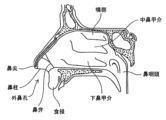
鼻腔内投与型薬剤は、呼吸部(例えば、鼻甲介)に対して噴射することで、鼻炎治療などの局所作用を期待するものが主である。鼻腔内投与型薬剤は、免疫応答のより高い鼻咽頭関連リンパ組織に対する薬剤投与、および中枢への薬剤送達を目的とした嗅部(例えば、嗅粘膜)に対する薬剤投与などにも利用されてきている。 Intranasally administered medicines are mainly expected to have local effects such as treatment of rhinitis by injecting them into respiratory parts (for example, nasal turbinates). Intranasal drugs have also been used for drug delivery to the nasopharyngeal-associated lymphoid tissue, where immune response is higher, and to the olfactory region (e.g., olfactory mucosa) for central drug delivery. .
点鼻用噴霧・噴射デバイスは、薬剤を収容する容器、噴霧・噴射ノズル、および当該ノズルを経由して容器から定量噴霧を送達するための機構(例えば、アクチュエータ)を含む。点鼻用噴霧・噴射デバイスとしては、これまでの汎用されている常套的点鼻噴霧スプレーに加えて、シリンジ型噴霧・噴射デバイスおよびエアレス型噴霧・噴射デバイスなどが挙げられる。 A nasal spray-ejection device includes a container containing a medicament, a spray-ejection nozzle, and a mechanism (eg, an actuator) for delivering a metered spray from the container through the nozzle. Nasal spray/injection devices include syringe type spray/injection devices, airless type spray/injection devices, and the like, in addition to conventional nasal sprays that have been widely used.
点鼻用噴霧・噴射デバイスにおいて、例えば、噴霧・噴射ノズル形態の適正化によって噴霧・噴射密度の均一性などを向上させた点鼻用噴霧・噴射ノズルを用いたシリンジ型噴霧・噴射デバイスが開示されている(特許文献1参照)。また、投与角度を所望の範囲に制御できる上方排圧エアレス型噴霧・噴射デバイスが開示されている(特許文献2参照)。 Disclosed is a syringe-type spray/injection device using a nasal spray/injection device in which, for example, uniformity of spray/injection density is improved by optimizing the shape of the spray/injection nozzle. (See Patent Document 1). Further, an upward exhaust pressure airless spray/injection device capable of controlling the administration angle within a desired range is disclosed (see Patent Document 2).
噴霧・噴射デバイスでは、意図した領域への薬剤送達の点で更に改良できる余地があることを本発明者は見出した。より具体的には、点鼻用噴霧・噴射ノズルを用いた薬剤噴霧・噴射において鼻腔内の標的部位に対する薬剤到達特性をより向上させることができることを見出した。 The inventors have found that nebulization and ejection devices can be further improved in terms of drug delivery to the intended area. More specifically, the present inventors have found that drug delivery characteristics to target sites in the nasal cavity can be further improved in drug spraying/injection using a nasal spray/injection nozzle.
本発明はかかる事情に鑑みて為されたものである。即ち、本発明の主たる目的は、鼻腔内の標的部位に対する薬剤到達特性をより向上させることができる点鼻用噴霧・噴射ノズルを提供することである。 The present invention has been made in view of such circumstances. That is, the main object of the present invention is to provide a nasal spray/injection nozzle capable of further improving drug delivery characteristics to target sites in the nasal cavity.
本願発明者は、従来技術の延長線上で対応するのではなく、新たな方向で対処することによって上記課題の解決を試みた。その結果、上記主たる目的が達成された点鼻用噴霧・噴射ノズルの発明に至った。 The inventors of the present application have tried to solve the above problems by taking a new approach rather than by extending the conventional technology. As a result, the present invention has led to the invention of a spray/injection nozzle for nasal application that achieves the above main object.
本発明では、ノズル噴出孔が形成された先端部と、外鼻孔の周辺部に当接可能なノーズレストとを有して成る点鼻用噴霧・噴射ノズルが提供される。 The present invention provides a spray/injection nozzle for nasal application, which has a tip portion in which a nozzle ejection hole is formed, and a nose rest that can come into contact with the periphery of the outer nostril.
本発明に係る点鼻用噴霧・噴射ノズルは、鼻腔内の標的部位に対する薬剤到達特性をより向上させることができる。なお、本明細書に記載されている効果はあくまでも例示であって限定されるものでなく、また、付加的な効果があってもよい。 INDUSTRIAL APPLICABILITY The nasal spray/injection nozzle according to the present invention can further improve drug delivery characteristics to target sites in the nasal cavity. Note that the effects described in this specification are merely examples and are not limited, and additional effects may be provided.
[本開示の基礎となった知見等]
従前の噴霧・噴射デバイスは、種々の複雑な鼻腔内構造に適用した形態でない場合がある。例えば、従前の鼻弁周辺の狭い鼻腔領域により薬剤がトラップされ、標的領域への十分な薬剤送達が得られない場合がある(図47参照)。ここでいう「標的領域」は、点鼻用噴霧・噴射ノズルの噴霧・噴射対象となる領域(例えば、少なくとも鼻粘膜呼吸部、鼻咽頭または嗅部などの鼻腔内の領域)などを指す。[Knowledge, etc. on which this disclosure is based]
Conventional nebulizing and spraying devices may not be configured to accommodate a variety of complex intranasal structures. For example, the narrow nasal region around the traditional nasal valves may trap the drug, resulting in poor drug delivery to the target area (see Figure 47). The term “target region” as used herein refers to a region to be sprayed/sprayed by a nasal spray/injection nozzle (for example, at least a region in the nasal cavity such as the nasal respiratory region, nasopharynx, or olfactory region).
例えば、点鼻用噴霧・噴射デバイスにおいて噴霧・噴射ノズルの挿入位置が浅すぎると、鼻弁などにより噴霧・噴射された薬剤がトラップされる虞がある。一方、噴霧・噴射ノズルの挿入位置が深すぎると、標的領域に対する薬剤の噴射角度が狭くなり、当該標的領域の広範囲に薬剤が送達できない虞がある。 For example, if the insertion position of the spray/injection nozzle in the nasal spray/injection device is too shallow, the sprayed/injected drug may be trapped by the nasal valve or the like. On the other hand, if the insertion position of the spray/injection nozzle is too deep, the injection angle of the medicine with respect to the target area becomes narrow, and there is a possibility that the medicine cannot be delivered to a wide range of the target area.
そこで本発明者は、複雑な鼻腔内構造に適用し得る点鼻用噴霧・噴射ノズルのより適正化された形態などを考慮するに至った。 Therefore, the present inventor has considered a more optimized form of nasal spray/injection nozzle that can be applied to a complicated intranasal structure.
以下、添付図面を参照して、本開示に係る発明を実施するための実施形態を説明する。説明する実施形態は、本開示に係る発明の技術思想を具体化するためのものであって、特定的な記載がない限り、本開示に係る発明を以下で説明するものに限定しない。
各図面中、同一の機能を有する部材には、同一符号を付している場合がある。要点の説明または理解の容易性を考慮して、便宜上実施形態に分けて示す場合があるが、異なる実施形態で示した構成の部分的な置換または組み合わせは可能である。また、後述の実施形態では、前述と共通の事柄についての記述を省略し、異なる点についてのみ説明する。特に、同様の構成による同様の作用効果については、実施形態ごとには逐次言及しないものとする。各図面が示す部材の大きさや位置関係等は、説明を明確にするため、誇張して示している場合もある。Hereinafter, embodiments for carrying out the invention according to the present disclosure will be described with reference to the accompanying drawings. The described embodiments are for embodying the technical idea of the invention according to the present disclosure, and unless there is a specific description, the invention according to the present disclosure is not limited to what is described below.
In each drawing, members having the same function may be given the same reference numerals. In consideration of the explanation of the main points or the ease of understanding, the embodiments may be divided for convenience, but the configurations shown in different embodiments can be partially replaced or combined. In addition, in the embodiments described later, the description of matters common to those described above is omitted, and only the points of difference will be described. In particular, similar actions and effects due to similar configurations will not be mentioned sequentially for each embodiment. The sizes and positional relationships of members shown in each drawing may be exaggerated for clarity of explanation.
実施態様の説明において、理解を容易にするために方向を表す用語(例えば「上下方向」、「水平方向(左右方向)」、「奥行方向」、「近位側」、および「遠位側」など)を適宜用いるが、これらは説明のためのものであって、これらの用語は本発明を限定するものでない。また、各添付図面において、同様の構成部品は同様の参照符号を用いて図示している。 In describing the embodiments, directional terms (e.g., “vertical direction”, “horizontal direction (right-left direction)”, “depth direction”, “proximal side”, and “distal side”) are used for ease of understanding. etc.) are used where appropriate, but these terms are for the purpose of description and are not intended to limit the invention. Also, in each of the attached drawings, similar components are illustrated using similar reference numerals.
本明細書でいう「上下方向」、「水平方向(左右方向)」および「奥行方向」は、それぞれ図中における上下方向、水平方向および奥行方向に相当する。例えば「上下方向」について、鉛直方向下向き(すなわち、重力が働く方向)が「下方向」に相当し、その逆向きが「上方向」に相当すると捉えてもよい。 "Vertical direction", "horizontal direction (lateral direction)" and "depth direction" as used herein correspond to the vertical direction, horizontal direction and depth direction in the drawing, respectively. For example, with respect to the "vertical direction", the vertical downward direction (that is, the direction in which gravity acts) corresponds to the "downward direction", and the opposite direction corresponds to the "upward direction".
本明細書でいう「側面視」とは、点鼻用噴霧・噴射ノズルの長尺方向に対する略垂直方向から捉えた場合の形態(例えば、図1A~図1Cなどに示される形態)に基づいている。すなわち、点鼻用噴霧・噴射ノズルの軸方向に対して略垂直となる方向において外側から当該ノズルを視た場合の形態に基づいている。 "Side view" as used in this specification is based on the form (for example, forms shown in FIGS. 1A to 1C, etc.) when viewed from a direction substantially perpendicular to the longitudinal direction of the nasal spray/injection nozzle. there is That is, it is based on the form when the nozzle is viewed from the outside in a direction substantially perpendicular to the axial direction of the nose spray/injection nozzle.
本明細書でいう「上面視」とは、点鼻用噴霧・噴射ノズルにおけるノズル噴出孔側から捉えた場合の形態(例えば、図2A~図2Dなどに示される形態)に基づいている。すなわち、点鼻用噴霧・噴射ノズルの軸方向に沿って外側から点鼻用噴霧・噴射ノズル(例えば、そのノズル噴出孔側)を視た場合の形態に基づいている。 The term “top view” used in this specification is based on the form of the nasal spray/injection nozzle viewed from the nozzle outlet side (for example, the forms shown in FIGS. 2A to 2D). That is, it is based on the form when the nasal spray/injection nozzle (for example, the nozzle ejection port side) is viewed from the outside along the axial direction of the nasal spray/injection nozzle.
本明細書でいう「略」とは、全部あるいは完全にではないが、それに近い状態であることを指す。例えば「略楕円形状」とは、当業者がかかる形状について、厳密な意味で楕円であると認識する形状に必ずしも限定されず、非厳密であるものの楕円であることを認識し得る形状も含む。例えば、楕円輪郭の一部が他の形状の輪郭となっている形状であったとしても、当業者がかかる形状を楕円であることを認識し得る形状も含む。 As used herein, the term "approximately" refers to a state close to, but not completely, completely. For example, the term "substantially elliptical" is not necessarily limited to a shape that a person skilled in the art recognizes as an ellipse in a strict sense, but also includes a shape that can be recognized as an ellipse in a loose sense. For example, even if a part of the elliptical outline is the outline of another shape, it also includes a shape that a person skilled in the art can recognize as an ellipse.
本明細書でいう「径」とは、対象を上面視した場合の形状における円、楕円、内接円または内接楕円の径を指してよい。ここで、「内接円」または「内接楕円」とは、多角形の内部にある最大面積の円または楕円を指す。そのような径が複数考えられる場合には、そのうちの最大径を指す。 As used herein, "diameter" may refer to the diameter of a circle, ellipse, inscribed circle, or inscribed ellipse in the shape of an object viewed from above. As used herein, "inscribed circle" or "inscribed ellipse" refers to the maximum area circle or ellipse inside the polygon. If there are multiple such diameters, the maximum diameter among them is indicated.
図示する例示態様でいえば、「径」は、対象が真円の場合は直径D1を指し(図2A参照)、対象が楕円の場合は長径D1を指し(図2B参照)、対象が正方形の場合はその内接円の直径D1を指し(図2C参照)、または対象が矩形の場合はその内接楕円の長径D1を指すものであってよい(図2D参照)。In the illustrated exemplary embodiment, "diameter" refers to the diameter D1 if the object is a perfect circle (see FIG. 2A), the major axis D1 if the object is an ellipse (see FIG. 2B), and the object is If the object is a square, it may refer to the diameter D1 of its inscribed circle (see FIG. 2C), or if the object is a rectangle, it may refer to the major axis D1 of its inscribed ellipse (see FIG. 2D).
[本発明に係る点鼻用噴霧・噴射ノズルの特徴] [Characteristics of nasal spray/injection nozzle according to the present invention]
本発明の点鼻用噴霧・噴射ノズルは、流体物を外部へと吐出できるノズル品である。特に、本発明の点鼻用噴霧・噴射ノズルは、好ましくは噴霧および/または噴射の形態を伴って薬剤に代表される流体物を吐出できるノズル品である。 The nasal spray/injection nozzle of the present invention is a nozzle product capable of discharging a fluid substance to the outside. In particular, the nasal spray/injection nozzle of the present invention is preferably a nozzle product capable of ejecting a fluid substance represented by a drug in the form of spray and/or jet.
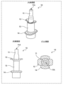
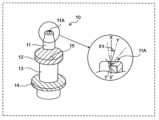
本発明に係る点鼻用噴霧・噴射ノズルは、噴出孔が形成された先端部と、外鼻孔の周辺部に当接可能なノーズレストとを有して成る。図1A~図1Cに示す例示態様でいえば、点鼻用噴霧・噴射ノズル10は、ノズル噴出孔11Aが形成された先端部11と、ノーズレスト12とを有している。
A nasal spray/injection nozzle according to the present invention comprises a tip portion having a spout hole formed thereon and a nose rest capable of coming into contact with the peripheral portion of the outer nostril. 1A to 1C, a nasal spray/
本発明に係る点鼻用噴霧・噴射ノズル品は、特に制限はないものの、例えば樹脂材、ガラス材、金属材またはセラミック材などから形成されていてよい。ある好適な一例では、点鼻用噴霧・噴射ノズルは樹脂品(例えば、樹脂成形品)となっている。 The nasal spray/spray nozzle product according to the present invention is not particularly limited, but may be made of, for example, a resin material, glass material, metal material, ceramic material, or the like. In one preferred example, the nasal spray/injection nozzle is a resin product (for example, a resin molded product).
本発明に係る点鼻用噴霧・噴射ノズルは、その内部または内側にて中空部分を有し得る。例えば、本発明に係る点鼻用噴霧・噴射ノズル10の先端部11の内部または内側に中空部分が形成されている。そのような中空部分は、ノズル噴出孔と連通したものであることが好ましい。また、そのような点鼻用噴霧・噴射ノズルの内部・内側の中空部分は、ノズル噴出孔と対向する側で外部と連通していてよい。換言すれば、点鼻用噴霧・噴射ノズルは、ノズル噴出孔と軸方向で対向する端部が開口端の形態を有していてよい。
The nasal spray/spray nozzle according to the invention may have a hollow portion inside or inside it. For example, a hollow portion is formed inside or inside the
図1Aなどに示す形態のように、例えば、先端部11とノーズレスト12とは、点鼻用噴霧・噴射ノズル10の軸方向に互いに隣接するように連結されている。ここで「軸」とは、点鼻用噴霧・噴射ノズルの中央部分を長手方向に沿って貫くような仮想直線を指している。
As in the form shown in FIG. 1A and the like, for example, the
点鼻用噴霧・噴射ノズル10は、その近位側(すなわち、使用時に鼻に対して相対的に近くに位置する側)から、ノズル噴出孔を備えた先端部11、ノーズレスト12、およびノズル本体部13が、この順で配置されている。これらは内部・内側に中空部分を有する部材となっていてよい。例えば、先端部11は、その内部に中空部分を有し、ノズル噴出孔を備えた閉鎖端とそれに対向する開口端を有して成る部材となっていてよい。ノズル本体部13は、その内部に中空部分を有し、両端が互いに対向する開口端を有する部材となっていてよい。ノーズレスト12は、その内側に中空部分を有するように、例えば全体としてリング形状またはそれが一部切り欠かれた一部切欠きのリング形状を有して成る部材であってよい。
The nasal spray/
ノズル噴出孔を備えた先端部11、ノーズレスト12、およびノズル本体部13は、互いに一体となって点鼻用噴霧・噴射ノズル10を成していてよい(図1Aなど参照)。図示する形態から分かるように、ノーズレスト12は、先端部11および/または本体部13に対して、その周縁に付加的に加えられた部分又は部材とみなしてもよい。また、先端部11と本体部13とを互い一体化した単一部材(例えば、内部に中空を有する筒状部材)とみなし、その部材に対してノーズレスト12が設けられていると捉えてもよい(例えば、そのような一体化した部材の外周面にノーズレスト12として突出部が設けられていると捉えることもできる)。
The
点鼻用噴霧・噴射ノズル10において、先端部11は、ノーズレスト12から点鼻用噴霧・噴射ノズル10の軸方向に延在するように設けられている(図1Aなど参照)。ノーズレスト12は、点鼻用噴霧・噴射ノズル10の軸方向から外側に延出または突出している(図4など参照)。ここで、「外側」とは、例えば、点鼻用噴霧・噴射ノズル10の軸方向に対して略垂直となる放射線状の方向に相当する。
In the nasal spray/
ノーズレスト12は、その少なくとも一部が外鼻孔の周辺部に当接することができる。これにより点鼻用噴霧・噴射ノズルの使用時にて当該ノズルの安定化をより好適に図ることが可能となり、鼻腔内の標的部位への薬剤到達特性をより向上させることができる。例えば、本発明の点鼻用噴霧・噴射ノズルによって、標的部位への薬剤の到達率をより向上させることができる。特定の理論に拘束されるわけではないが、このような薬剤到達特性の向上は、点鼻用噴霧・噴射ノズルの使用時における当該ノズルの向き(角度、例えば鼻中隔に対して平行または垂直な面との間で形成される角度)および/またはノズルの先端部の鼻腔内に対する挿入長さなどがより好適に固定化または安定化されることが要因として考えられる。
At least a portion of the
また、ある好適な態様では、ノーズレスト12によって、鼻腔内に挿入される点鼻用噴霧・噴射ノズル10の部位を好ましくは略先端部11のみに制限できる。換言すれば、鼻腔内に挿入される点鼻用噴霧・噴射ノズル10の長さを、おおよそ先端部11の長さ寸法Lとすることができる。すなわち、ノズル噴出孔11Aを鼻腔内で適切に位置付けることができる。鼻腔内でのノズル噴出孔の挿入深さが適切になるともいえる。したがって、点鼻用噴霧・噴射ノズルが用いられることで、複雑な鼻腔内構造であっても標的領域へと薬剤を好適に送達させることができる。例えば、ノーズレストの少なくとも一部を外鼻孔の周辺部に当接させることによって、鼻腔内のノズル噴出孔の挿入位置をより適切に決定づけることができる。よって、挿入位置が浅すぎない一方で深すぎることもなく薬剤の送達を行うことができ、標的領域の広範囲に薬剤を到達させ易くなる。
In a preferred embodiment, the
本明細書でいう「ノズル」は、液体物の方向を定める、好ましくは薬剤(例えば、液剤、ゲル剤)の流れる方向を定めるためのものであって、その先端に設けられた孔から薬剤等の液体物を吐出(噴霧または噴射)させるものである。よって、ノズルは、その内部に先端孔と連通する中空部を好ましくは有している(当該中空部はノズル開口端とも連通し得る)。なお、ノズルは、「スパウト」、「薬剤噴霧・噴射のための部材」または「噴霧・噴射供給のための部材」などと称されてもよい。 The "nozzle" as used herein is for determining the direction of a liquid substance, preferably for determining the direction of flow of a drug (e.g., liquid drug, gel drug). to discharge (spray or jet) the liquid. Therefore, the nozzle preferably has a hollow portion inside that communicates with the tip hole (the hollow portion may also communicate with the nozzle opening end). The nozzle may also be referred to as a "spout", a "member for spraying/injecting a drug", or a "member for spraying/injecting supply".
本明細書でいう「外鼻孔の周辺部」は、外鼻孔の周辺に存在する鼻の部分を指す(「外鼻孔」は図38および図47参照のこと)。例えば「外鼻孔の周辺部」は、鼻尖、鼻柱、鼻翼、食禄および内鼻孔の壁面などから成る群から選択される少なくとも1つを指す。 As used herein, the term "nostril periphery" refers to the portion of the nose that exists around the nostrils (see FIGS. 38 and 47 for "nostrils"). For example, the “periphery of the nostrils” refers to at least one selected from the group consisting of the tip of the nose, the bridge of the nose, the wings of the nose, the esophagus, the walls of the inner nostrils, and the like.
本明細書でいう「当接」は、押すように接することを指す。本明細書でいう「当接」は、例えば、「押止」、「滑止」、「掛止」および「係止」などから成る群から選択される少なくとも1つの態様を包含する。 As used herein, "abutting" refers to making contact as if pushing. "Abutment" as used herein includes, for example, at least one mode selected from the group consisting of "stopping", "anti-slipping", "latching", and "locking".
本明細書でいう「先端部」は、点鼻用噴霧・噴射ノズルにおいて鼻腔内に挿入され得る部分を指す。先端部11は、点鼻用噴霧・噴射ノズル10において近位側に位置付けられ、少なくとも外鼻孔よりも小さい径を有することが好ましい(図1Aなど参照)。
As used herein, "tip" refers to the portion of a nasal spray/spray nozzle that can be inserted into the nasal cavity. The
点鼻用噴霧・噴射ノズル10の上面視において、先端部11の幅寸法、例えば図示するような径D2(図2A参照)は、3mm以上10mm以下であってよい。先端部の径D2が3mm以上であることで、十分なノズル噴出孔径を確保することができる。また、先端部の径D2が10mm以下であることで、点鼻用噴霧・噴射ノズルを鼻腔内に挿入する場合に、先端部11が内鼻孔の壁面に接触することを防止し易くなる。先端部11の径D2は、3mm以上9mm以下であることが好ましく、例えば3mm以上7mm以下である。In a top view of the nasal spray/
ここでいう「径D2」は、先端部11において、点鼻用噴霧・噴射ノズル10の軸方向に沿って平均化した径とみなしてよい。例えば、先端部11において、軸方向沿いの任意の3箇所の径の平均値である。The “diameter D 2 ” referred to here may be regarded as a diameter averaged along the axial direction of the nose spray/
ノズル噴出孔11Aが形成された面(すなわち、点鼻用噴霧・噴射ノズル10の近位端面)の径は、先端部11において最も小さくしてよく、例えば3mm以上10mm以下、3mm以上9mm以下あるいは3.5mm以上8.5mm以下などであってよい。このように近位端面の寸法にすることによって、鼻腔内に先端部をよりスムーズに挿入し易くなり、結果として薬剤到達特性の向上に寄与し得る。
The diameter of the surface on which the
点鼻用噴霧・噴射ノズル10の上面視において、ノズル噴出孔11Aの径、例えば図示するような径D3(図2A参照)は、0.15mm以上0.60mm以下であってよい。かかる径D3を上述する範囲とすることで、薬剤の噴射角度がより適切な角度となり易くなる。ノズル噴出孔11Aの径D3は、0.20mm以上0.45mm以下であることが好ましく、例えば0.25mm以上0.30mm以下である。In a top view of the nose spray/
点鼻用噴霧・噴射ノズル10の側面視において、先端部11は長さ寸法Lを有する(図1A参照)。ここで「長さ寸法L」とは、先端部11の軸方向の長さ寸法(すなわち、長手寸法)を指す。より具体的には、「長さ寸法L」は、ノーズレスト12の近位側端の部分からノズル噴出孔11Aが形成された面までの長さに相当する。図6Aを参照して説明すると、「長さ寸法L」は、点鼻用噴霧・噴射ノズル10の最先端(すなわち、ノズル端面)からノーズレスト12の近位側端12Eまでの軸方向に沿った長さ寸法Lである。
In a side view of the nasal spray/
点鼻用噴霧・噴射ノズル10の側面視において、ノズル軸方向に沿った先端部11の長さ寸法Lは、5mm以上30mm以下であってよい(図1Aなど参照)。かかる寸法が5mm以上であることで、鼻弁などによりトラップされる薬剤量をより減じ易くなる。また、かかる寸法が30mm以下であることで、標的領域に対する薬剤の噴射角度をより広角とすることができ、標的領域の広範囲に薬剤を送達することができる。先端部の長さ寸法は、7mm以上25mm以下であることが好ましく、例えば10mm以上25mm以下、7mm以上18mm以下、8mm以上17mm以下、9mm以上16mm以下、または10mm以上15mm以下である。
In a side view of the nose spray/
先端部は、鼻腔内に挿入することができる形態であれば、いずれの形態であってよい。例えば、先端部は、略円柱状であってよく、その近位端に向かって先細る略円錐状(すなわち、ノズル噴出孔に向かって先細る略円錐状)であってもよい。また、内鼻孔の壁面との接触による痛みを軽減するように、先端部における近位端は丸みを帯びていてもよい。換言すれば、先端部における近位端は面取りされたような形状を有していてよい。 The tip may be of any shape as long as it can be inserted into the nasal cavity. For example, the tip may be generally cylindrical and may be generally conical that tapers toward its proximal end (ie, generally conical that tapers toward the nozzle orifice). The proximal end of the tip may also be rounded to reduce pain from contact with the walls of the nostrils. In other words, the proximal end of the tip may have a chamfered shape.
本明細書でいう「ノーズレスト」は、点鼻用噴霧・噴射ノズルにおいて外鼻孔の周辺部に当接される部分を含んで成る部材を指す(より具体的には、点鼻用噴霧・噴射ノズルをその先端部側から外鼻孔へと挿入した際に外鼻孔の周辺部に当接される部分を含んで成る部材を指す)。本発明におけるノーズレストは、その少なくとも一部が外鼻孔の周辺部に当接できるように外側へと突出または延在している部材である。ノーズレストは「鼻挿入時ストッパー」などと称されてもよい。好ましくは、ノーズレストは、それを外鼻孔の周辺部に当接させることで、点鼻用噴霧・噴射ノズルが鼻腔内にさらに挿入されないようにするノズル部分又は部材である。 The term "nose rest" as used herein refers to a member comprising a portion of a nasal spray/injection nozzle that is in contact with the periphery of the nostril (more specifically, nasal spray/injection It refers to a member that includes a part that abuts on the periphery of the nostril when the nozzle is inserted into the nostril from the tip side thereof). The nose rest in the present invention is a member that protrudes or extends outward so that at least a portion of the nose rest can come into contact with the periphery of the nostril. A nose rest may also be referred to as a "stopper for nasal insertion" or the like. Preferably, the nose rest is a nozzle portion or member that abuts the perimeter of the nostril to prevent further insertion of the nasal spray/jet nozzle into the nasal cavity.
ノーズレスト12は、点鼻用噴霧・噴射ノズル10において、先端部11に対して相対的に遠位側に位置付けられる(図1Aなど参照)。すなわち、ノーズレスト12は、点鼻用噴霧・噴射ノズルにおいて、先端部11よりも使用時に鼻穴に対して相対的に離れた位置に設けられている。より具体的には、図示するように、ノーズレスト12は、先端部11の遠位側にてその先端部11に隣接するように又は先端部11に直接的もしくは間接的に連結するように設けられていてよい。ノーズレストは、点鼻用噴霧・噴射ノズルにおいて先端部と一体化した部分又は部材であってよく、あるいは、別部材または別個のパーツとして点鼻用噴霧・噴射ノズルに対して取り付けられるものであってもよい。先端部とノーズレストとが互いに一体化している場合、それらは互いに同じ材質から成っていてもよいし、あるいは、互いに異なる材質から成っていてもよい。
ノーズレスト12は、その少なくとも一部が、外鼻孔の周辺部に当接することができるのであれば、いずれの形態であってよい。すなわち、点鼻用噴霧・噴射ノズル10を挿入した際に、ノーズレスト12が外鼻孔の周辺部に押し当たり、それによって、点鼻用噴霧・噴射ノズル10のさらなる挿入が阻止されるのに資する形態であれば、いずれの形態であってよい。ある好適な態様において、ノーズレストの一部のみが外鼻孔の周辺部に押し当たるようになっていてよい。つまり、ノーズレストの一部のみが外鼻孔の周辺部に当接できるようにノーズレストが外側へと突出または延在していてよい。ノーズレストの一部のみが外鼻孔の周辺部に押し当たることによって、点鼻用噴霧・噴射ノズル10のさらなる挿入が阻止されつつ、点鼻用噴霧・噴射ノズル10の向きおよび/または角度が好適に調整され易くなる。
The
一実施態様では、点鼻用噴霧・噴射ノズル10の上面視において、ノーズレスト12の外輪郭が、先端部11の外輪郭の少なくとも一部を囲っていてよい。例えば、点鼻用噴霧・噴射ノズル10の上面視において、ノーズレスト12の輪郭、特に外輪郭が、先端部11の輪郭、特に外輪郭を囲うように位置付けられている(図1A、図2A~図2Dおよび図3A~3D参照)。例えば、点鼻用噴霧・噴射ノズル10において、ノーズレスト12は略鍔状および略フランジ状に外側へと延在していてよい。
In one embodiment, the outer contour of the
上述のような構成とすることで、使用時にてノーズレストの少なくとも一部と外鼻孔の周辺部との接触面積をより大きくすることができる。よって、点鼻用噴霧・噴射ノズルを外鼻孔にしっかりと押し当てることができ、ひいては、より好適にノズル噴出孔の挿入位置を決定づけることができる。 With the configuration as described above, the contact area between at least part of the nose rest and the periphery of the nostrils can be increased during use. Therefore, the spray/injection nozzle for nasal drops can be firmly pressed against the nostril, and the insertion position of the nozzle ejection hole can be determined more appropriately.
点鼻用噴霧・噴射ノズル10の上面視において、ノーズレスト12は、略円形状、略楕円形状、多角形状および面取りされた多角形状などであってよく、さらには、それらから一部切り欠かれたような形状であってもよく、また、そのような形状においてノズル位置が中心から偏心したようなものであってもよい。図2A~図2Dおよび図3A~図3D参照のこと。別の切り口でいえば、(点鼻用噴霧・噴射ノズルの斜視視および/または側面図において)ノーズレストは、略平板状、略円盤状、略ドーム状、略円錐状、略楕円錐状およびその他異形状などを有していてよい。
When viewed from the top of the nose spray/
一実施態様では、点鼻用噴霧・噴射ノズル10の上面視において、ノーズレスト12は略楕円形状を有していてよい(図2B参照)。すなわち、点鼻用噴霧・噴射ノズル10の上面視において、ノーズレスト12は、対向する2つの方向において突出している形状を有している。例えば、ノーズレストは、略ドーム状または略楕円錐状であってよい。
In one embodiment, the
上述のような構成とすることで、当該ノーズレストを外鼻孔の周辺部の形状に沿わせ易くなる。それによって、外鼻孔の周辺部に対する当接性、および点鼻用噴霧・噴射ノズルのハンドリング性をより高めることができる。 With the configuration as described above, the nose rest can easily conform to the shape of the periphery of the nostril. As a result, it is possible to further improve the contactability with the periphery of the nostrils and the handleability of the nasal spray/injection nozzle.
点鼻用噴霧・噴射ノズル10の上面視において、ノーズレスト12の幅寸法、例えば図示するような径D1(図2A~図2D参照)は、10mm以上50mm以下であってよい。かかる径が10mm以上であることで、外鼻孔への当接性をより高め易くなる。また、かかる径が50mm以下であることで、点鼻用噴霧・噴射ノズル10のハンドリング性をより高め易くなる。ノーズレスト12の径D1は、12mm以上40mm以下であってよく、例えば15mm以上30mm以下である。In a top view of the nose spray/
ここでいう「径D1」は、ノーズレスト12における最大幅寸法、例えば最大径とみなしてよい。例えば、上述するように、ノーズレスト12を上面視した場合の形状における円、楕円、内接円または内接楕円の径を指してよい。The “diameter D 1 ” referred to here may be regarded as the maximum width dimension of the
別法にて、ノーズレスト12は、外鼻孔を掛止するような凹凸形状、略十手形状、略鉗子形状および略クリップ形状などであってもよい(図1Bおよび図1C参照)。
Alternatively, the
図4~図17は、本発明に係る点鼻用噴霧・噴射ノズルの種々の実施態様をそれぞれ例示している。具体的には、図4および図5は、シリンジ型噴霧・噴射デバイスに用いる点鼻用噴霧・噴射ノズルをそれぞれ例示している。また、図6~図13および図15~図17は、上方排圧エアレス型噴霧・噴射デバイスに用いる点鼻用噴霧・噴射ノズルをそれぞれ例示している。 Figures 4 to 17 each illustrate various embodiments of nasal spray/spray nozzles according to the present invention. Specifically, Figures 4 and 5 respectively illustrate a nasal spray/spray nozzle for use in a syringe-type spray/spray device. Figures 6-13 and 15-17 respectively illustrate nasal spray/spray nozzles for use in the upward exhaust pressure airless spray/spray device.
一実施態様では、ノーズレスト12がノズル噴出孔11Aに向かって減径する部分を有していてよい(図4Bなど参照)。ノーズレストがノズル噴出孔に向かって漸次減径してよく、あるいは、ステップ状に減径してもよい。図4Bなどに示される例では、ノーズレストがノズル噴出孔に向かって漸次減径する(例えば、全体的に漸次幅寸法を減じる)部分を少なくとも有している。そのような構成とすることで、当接時にてノーズレストと外鼻孔の周辺部との接触面積がより大きなものとなり易くなる。また、点鼻用噴霧・噴射ノズル10を鼻腔内に挿入する場合に、減径する部分が内鼻孔の壁面により好適に適合し易くもなる。
In one embodiment, the
つまり、ノーズレスト12の減径部分によって、点鼻用噴霧・噴射ノズル10を内鼻孔の壁面にしっかりと押し当てることができ、特に好適にノズル噴出孔11Aの挿入位置および方向を決定づけ易くなる。また、点鼻用噴霧・噴射ノズル10を鼻腔内に挿入する際の内鼻孔の壁面に生じる衝撃を低減でき、患者等の使用者に生じる痛みなどの不快感を減じ易くなる。
That is, the reduced diameter portion of the
一実施態様では、先端部がノズル噴出孔に向かって漸次的に先細る部分を少なくとも有していてよい。例えば、図6Bに示すように、先端部11がノズル噴出孔11Aに向かって漸次的に先細る形状を有していてよい。そのような構成とすることで、点鼻用噴霧・噴射ノズル10を鼻腔内に挿入する場合に、先端部11が内鼻孔の壁面に不都合に接触することを防止し易くなる。
In one embodiment, the tip may have at least a portion that tapers gradually toward the nozzle outlet. For example, as shown in FIG. 6B, the
先端部11およびノーズレスト12などは、側面視にて、直線状に減径(または増径)していてよく、曲線状に減径(または増径)していてもよく、ステップ状に減径(または増径)していてもよく、直線状と曲線状とが混在しつつ減径(または増径)していてもよい。図6に示す例示態様でいえば、ノーズレスト12の方が、先端部11よりも減径の程度(例えば、漸次減径の程度)が大きくなっていてよい。別の切り口でいえば、ノーズレスト12の方が、先端部11よりも点鼻用噴霧・噴射ノズル10の軸に対する垂直な面に対して成す角度がより小さくなっていてよい。
When viewed from the side, the
シリンジ型噴霧・噴射デバイスに用いる点鼻用噴霧・噴射ノズル10において、ノズル本体部13にシリンジ接合用突出部13’が設けられていてよく(図4参照)、設けられていなくてもよい(図5参照)。ハンドリング性向上を特に重視する観点でいえば、点鼻用噴霧・噴射ノズル10において、シリンジ接合用突出部13’が設けられていることが好ましい。かかるシリンジ接合用突出部13’の径としては、例えば5mm以上15mm未満である。なお、図示するように、シリンジ接合用突出部13’は、点鼻用噴霧・噴射ノズル10の本体部の下方端に設けられていてよい。つまり、点鼻用噴霧・噴射ノズルの遠位端にシリンジ接合用突出部が設けられていてよい。
In the nasal spray/
一実施態様では、ノーズレスト12が略楕円形状を有していてよい(図7参照)。すなわち、ノーズレスト12の上面視形状が略楕円形状となっている。そのような構成とすることで、点鼻用噴霧・噴射ノズル10を鼻腔内に挿入する際に、外鼻孔の周辺部(特に、鼻翼、鼻柱および食禄)にノーズレスト12をより適合させ易くなる。
In one embodiment,
一実施態様では、ノーズレスト12が略花弁形状を有していてよい(図8および図9参照)。そのような構成とすることで、点鼻用噴霧・噴射ノズル10を鼻腔内に挿入する際に、挿入する鼻腔側の鼻翼、および他方の鼻腔側の内鼻孔の壁面にノーズレスト12が掛止され易くなる。
In one embodiment,
上述の態様において、ノーズレスト12の略花弁形状の先端がノズル噴出孔11Aの方向へ湾曲していてよい(図9参照)。そのような構成とすることで、点鼻用噴霧・噴射ノズル10を鼻腔内に挿入する際に、挿入する鼻腔側の鼻翼、および他方の鼻腔側の内鼻孔の壁面にノーズレスト12をより一層掛止し易くなる。
In the above-described aspect, the substantially petal-shaped tip of the
一実施態様では、ノーズレスト12とノズル本体部13とが段差を有していなくてよい(図10参照)。つまり、ノーズレスト12の外側面とノズル本体部13との外側面は互いに一体的に連続していてよい。かかる態様は、ノーズレスト12の外面とノズル本体部13との外面とが面一になっているともいえる。そのような構成とすることで、例えば一体成型にて点鼻用噴霧・噴射ノズルを製造する場合において製造工程をより簡易なものにできる。
In one embodiment, the
一実施態様では、点鼻用噴霧・噴射ノズル10からノーズレスト12が着脱可能な部材となっていてよい(図11参照)。すなわち、点鼻用噴霧・噴射ノズル10からノーズレスト12が取り外し可能になっていてよい。そのような構成とすることで、点鼻用噴霧・噴射ノズル10とノーズレスト12とを別工程にて製造することができる。また、使用者の個々の鼻に合わせてノーズレストの形状を適宜カスタマイズできる。取り外し可能なノーズレスト12は、樹脂材であってよい。取り外し可能なノーズレスト12と先端部11とが互いに別の材質(例えば、互いに異なる樹脂材)から成っていてもよい。かかる場合、例えば、ノーズレスト12をよりクッション性のある材料(例えば、軟質樹脂材、エラストマー材)から製造すること等ができる。
In one embodiment, the
一実施態様では、ノーズレストにおいて、相対的に急峻な面と相対的に非急峻な面とが含まれていてよい。例えば、図12Bおよび図13Bに示されるように、ノーズレスト12がノズル噴出孔11Aに向かって減径する部分を有し、かかる減径する部分において、相対的に急峻な面および相対的に非急峻な面が含まれていてよい。つまり、ノーズレストでは、レスト面の傾斜の程度が局所的に異なっていてもよい。
In one embodiment, the nose rest may include a relatively steep surface and a relatively non-steep surface. For example, as shown in FIGS. 12B and 13B, the
換言すれば、点鼻用噴霧・噴射ノズル10の側面視において、ノーズレスト12が先端部11に向かって漸次的に変化する輪郭を有するところ、かかる漸次的な変化が相対的に大きい箇所と相対的に小さい箇所とが存在していてよい(図12Bおよび図13B参照)。
In other words, when the nasal spray/
図12Bおよび図13Bに示す例示態様でいえば、ノーズレスト12において、相対的に急峻な面12S1と、相対的に緩やかな面12S2とが含まれている。より具体的には、点鼻用噴霧・噴射ノズル10の軸に対する垂直な面(水平面)に対して傾斜面12S1が角度θ1(すなわち、図12Bおよび図13BにおけるV-V’とW1-W1’とが成す角θ1)を成しており、水平面に対して傾斜面12S2が角度θ1’(すなわち、V-V’とW2-W2’とが成す角θ1’)を成している。ここで、角度θ1は、角度θ1’よりも大きくなっている。12B and 13B, the
上述のような傾斜面12S2または12S1を外鼻孔の周辺部に当接させることよって、点鼻用噴霧・噴射ノズルを鼻腔内に挿入する場合に、ノズル噴出孔の方向(角度)を種々の標的領域に合わせることができる。ここで、ノズル噴出孔11Aの方向を種々の標的領域に合わせるべく、傾斜面12S2に関する角度θ1’または傾斜面12S1に関する角度θ1を調整してよい(図12Bおよび図13B参照)。By bringing the inclined surface 12S2 or 12S1 as described above into contact with the periphery of the nostril, the direction (angle) of the nozzle ejection hole can be varied when inserting the nasal spray/injection nozzle into the nasal cavity. can be tailored to the target area of Here, the angle θ 1 ′ with respect to slanted surface 12S 2 or the angle θ 1 with respect to slanted surface 12S 1 may be adjusted to orient
あくまでも例示にすぎないが、上述のような相対的に緩やかな傾斜面12S2を食禄の周辺部(すなわち、食禄ならびに/または食禄側の鼻柱および/もしくは鼻翼)に当接させてよく、鼻突の周辺部(すなわち、鼻突ならびに/または鼻突側の鼻柱および/もしくは鼻翼)に当接させてもよい(食禄および鼻突などは図47など参照)。Although this is merely an example, the relatively gentle inclined surface 12S2 as described above is brought into contact with the periphery of the goroku (that is, the corpuscle and/or the nasal bridge and/or the nasal alar on the corpuscle side). Often, it may abut on the periphery of the nose bridge (ie, the nose bridge and/or the nasal bridge and/or nasal alar on the side of the nose bridge) (see FIG. 47, etc., for bulges and nose bridges, etc.).
点鼻用噴霧・噴射ノズルの噴霧・噴射対象となる標的領域が呼吸部または嗅部である場合、角度θ1’は、例えば5°以上20°以下であってよい。例えば、標的領域が呼吸部である場合、相対的に緩やかな傾斜面12S2を食禄の周辺部に当接させることが好ましい。また、標的領域が嗅部である場合、相対的に緩やかな傾斜面12S2を鼻突の周辺部に当接させることが好ましい。When the target region to be sprayed/sprayed by the nasal spray/spray nozzle is the respiratory part or the sniffing part, the angle θ 1 ′ may be, for example, 5° or more and 20° or less. For example, if the target area is the respiratory area, it is preferable to bring the relatively gently inclined surface 12S2 into contact with the periphery of the food. Moreover, when the target region is the olfactory region, it is preferable to bring the relatively gentle inclined surface 12S2 into contact with the periphery of the nose bridge.
一実施態様では、ノーズレスト12が、局所的な厚み差を有していてよい。例えば相対的に急峻な傾斜面および相対的に非急峻な傾斜面などに起因して、ノーズレスト12が、相対的に肉薄な部分および相対的に肉薄な部分を有していてよい。かかる場合、点鼻用噴霧・噴射ノズル10の上面視において、ノーズレスト12の厚みが点対称の関係を有していないともいえる。
In one embodiment, the
上述のような局所的な厚み差を有するノーズレストを、外鼻孔の周辺部に当接させることよって、点鼻用噴霧・噴射ノズルを鼻腔内に挿入する際に、ノズル噴出孔の方向(角度)を種々の標的領域に合わせることができる。ここで、ノズル噴出孔の方向を種々の標的領域に合わせるべく、かかる厚み差を調整してよい。 By bringing the nose rest having the local thickness difference as described above into contact with the periphery of the nostril, the direction (angle ) can be tailored to different target regions. Here, such thickness differences may be adjusted to orient the nozzle orifices to different target areas.
つまり、ノーズレスト12の相対的に肉薄な部分または肉厚な部分を外鼻孔の周辺に当接させる場合、「肉薄または肉厚な部分」とそれが当接する「外鼻孔の周辺におけるレスト接触領域」との関係によって、点鼻用噴霧・噴射ノズルの噴霧・噴射対象となる標的領域を所望の領域にしやすくできる(図14A~14D、特に図14B~14D参照)。例えば、ノーズレスト12の相対的に肉薄な部分を食禄またはその周辺部に当接させると、地平線に対してより垂直方向に点鼻用噴霧・噴射ノズルを挿入し易くなる。よって、点鼻用噴霧・噴射ノズルの噴霧・噴射対象となる標的領域が、好ましくは嗅部となり得る。その一方、ノーズレスト12の相対的に肉厚な部分を食禄の周辺またはその周縁部に当接させると、地平線に対してより水平方向に点鼻用噴霧・噴射ノズルを挿入し易くなる。よって、点鼻用噴霧・噴射ノズルの噴霧・噴射対象となる標的領域が、好ましくは鼻咽頭となり得る。
That is, when the relatively thin or thick portion of the
なお、局所的な厚み差を有するノーズレスト12については種々の形態が考えられ、例えば図15に示されるような形態であってよい。つまり、図12および図13に示されるノーズレストの側面視輪郭からその一部が徐されたような形態(より具体的には、相対的に肉厚な部分における側面視輪郭が少なくとも一部除されたような形態)であってもよい。図15に示すようなノーズレストの場合、点鼻用噴霧・噴射ノズルを鼻腔内により好適に挿入し易くなる場合があり、あるいは、ノーズレストの相対的に肉薄な部分をより好適に所望の外鼻孔の周辺に当接させ易くなる場合がある(図14Cおよび14D参照)。
Various forms are possible for the
一実施態様では、点鼻用噴霧・噴射ノズル10の軸に対して、ノズル噴出孔11Aの噴射方向が角度θ2またはθ3を成していてよい(図16および図17参照)。より具体的には、点鼻用噴霧・噴射ノズル10の軸X-X’と、ノズル噴出孔11Aを形成する面に対する法線Y-Y’(すなわち、ノズル噴出孔11Aの噴射方向)とが角度θ2またはθ3を成している。In one embodiment, the injection direction of the
ノズル噴出孔11Aを形成する面に対する法線Y-Y’は、点鼻用噴霧・噴射ノズル10の軸X-X’に対して先端部11を湾曲または屈曲させることで角度θ2を成していてよい(図16Aおよび図16B参照)。ここでいう「湾曲」または「屈曲」は、予め湾曲または屈曲された形態でもよく、使用時に随時、湾曲または屈曲することが可能な構成であってもよい。The normal line YY' to the surface forming the
または、ノズル噴出孔11Aを形成する面に対する法線Y-Y’は、点鼻用噴霧・噴射ノズル10の軸X-X’に対してノズル噴出孔11Aを斜め方向に開口させることで角度θ3を成していてもよい(図17参照)。Alternatively, the normal line YY' to the surface forming the
角度θ2およびθ3(図16Bおよび図17参照)は、ノーズレスト12における外鼻孔の周辺部と当接する部分(例えば、図16Aにおける15の部分)が向く方向に対して成されていてよい。換言すれば、角度θ2およびθ3は、図16Bおよび図17における上下方向に対して成されていてよい。そのような構成とすることで、種々の鼻腔内構造における標的領域へと好適に薬剤を送達させ易くなる。The angles θ 2 and θ 3 (see FIGS. 16B and 17) may be formed with respect to the direction in which the portion of the
上述の態様において、標的領域が呼吸部または嗅部である場合、角度θ2およびθ3は、5°以上15°以下であることが好ましい。例えば、標的領域が呼吸部である場合、ノズル噴出孔の開口方向(例えば、図16Bにおける右方向)に対応するノーズレストの部分を外鼻孔の周辺部に当接させることが好ましい。また、標的領域が嗅部である場合、ノズル噴出孔の開口方向に対する反対方向(例えば、図16Bにおける左方向)に対応するノーズレストの部分を外鼻孔の周辺部に当接させることが好ましい。In the above aspect, when the target region is the respiratory or olfactory region, the angles θ 2 and θ 3 are preferably 5° or more and 15° or less. For example, when the target area is the respiratory part, it is preferable to bring the part of the nose rest corresponding to the opening direction of the nozzle ejection hole (for example, the right direction in FIG. 16B) into contact with the periphery of the nostril. Moreover, when the target region is the olfactory region, it is preferable to bring the portion of the nose rest corresponding to the direction opposite to the opening direction of the nozzle ejection hole (eg, the left direction in FIG. 16B) into contact with the periphery of the nostril.
標的領域が鼻咽頭である場合、角度θ2およびθ3は5°以上15°以下であってよい。ここで、例えばノズル噴出孔の開口方向に対応するノーズレストの部分を外鼻孔の周辺部に当接させることが好ましい。If the target area is the nasopharynx, angles θ 2 and θ 3 may be greater than or equal to 5° and less than or equal to 15°. Here, for example, it is preferable to bring the portion of the nose rest corresponding to the opening direction of the nozzle ejection hole into contact with the peripheral portion of the outer nostril.
角度θ2およびθ3(図16Bおよび図17参照)は、ノーズレスト12における外鼻孔の周辺部と当接する部分が向く方向の略垂直方向に対して成されていてよい。換言すれば、角度θ2およびθ3は、図16Bおよび図17における奥行方向に対して成されているようなものであってもよい。そのような構成とすることで、鼻腔内構造における標的領域へと好適に薬剤を送達することができる。特に、薬剤が鼻中隔方向または鼻翼方向に噴射することを好適に防止することができる。The angles θ 2 and θ 3 (see FIGS. 16B and 17) may be formed substantially perpendicular to the direction in which the portion of the
上述の態様において、角度θ2およびθ3は5°以上15°以下であってよい。ここで、例えばノズル噴出孔の開口方向に対する略垂直方向(例えば、図16Bにおける奥行方向)に対応するノーズレストの部分を外鼻孔の周辺部に当接させることが好ましい。In the above aspect, the angles θ 2 and θ 3 may be between 5° and 15°. Here, for example, it is preferable to bring the portion of the nose rest corresponding to the direction substantially perpendicular to the opening direction of the nozzle ejection hole (eg, the depth direction in FIG. 16B) into contact with the periphery of the nostril.
誤使用防止のために、点鼻用噴霧・噴射ノズルは、適合面(特に、点鼻用噴霧・噴射ノズルを外鼻孔に挿入した際に、外鼻孔の周辺部と適合し得る面)または向きマーカーを有していてよい。適合面15または向きマーカー15は、点鼻用噴霧・噴射ノズル10の任意の箇所に設けられてよく、例えばノーズレスト12に設けられてよい(図13、図16および図17参照)。
To prevent misuse, nasal spray/spray nozzles should have a compatible surface (especially a surface that fits around the nostrils when the nasal spray/spray nozzle is inserted into the nostrils) or oriented. May have markers. The matching
一実施態様では、上述する適合面が切欠き部または接触板が成していてよい。換言すれば、ノーズレストが外鼻孔の周辺部と接する又は適合するための切欠き部または接触板を有していてよい。 In one embodiment, the mating surface mentioned above may be a notch or a contact plate. In other words, the nose rest may have cutouts or contact plates for contacting or conforming to the perimeter of the nostrils.
切欠き部は、外鼻孔の周辺部(例えば、鼻柱、鼻翼および食禄)と適合することができる形態であれば、いずれの形態であってよい。かかる形態は、例えば鼻翼、鼻柱または食禄の形状に合わせた切欠き部15であってよい(図13参照)。
The notch may be of any shape that can fit around the nostrils (eg, the bridge of the nose, alar and ridge). Such a form may be, for example, a
切欠き部を有するノーズレストの形状は、例えばノーズレストが上面視にて略楕円形状である場合、かかる略楕円形状の輪郭の一部が、元の形状と比して切り欠かれた形状であってよい。換言すれば、切欠き部によってもたらされる面(例えば、図13における面15a)は、平面および/または局面を含んでいてよい。例えば、「切欠き部」は、「凹状部」および「U状部」などであってもよい。
For example, when the nose rest has a substantially elliptical shape when viewed from above, a portion of the substantially elliptical outline is cut away from the original shape. It's okay. In other words, the surface provided by the notch (eg,
接触板もまた、外鼻孔の周辺部と適合することができる形態であれば、いずれの形態であってよい。かかる形態は、例えば鼻翼、鼻柱または食禄の形状に合わせた接触板15であってよい(図16参照)。
The contact plate can also be of any shape that can fit around the nostrils. Such a form may be, for example, a
ここで「接触板」とは、例えば凹状およびU状などの形状であってよい。接触板は、ノーズレストの外輪郭の一部が凹状およびU状などの形状に形成されていてよく、別部材(例えば、エラストマー材)がノーズレストに取り付けられていてもよい。 Here, the "contact plate" may be, for example, concave and U-shaped. The contact plate may be formed such that a portion of the outer contour of the nose rest is concave, U-shaped, or the like, and a separate member (eg, an elastomeric material) may be attached to the nose rest.
一実施態様では、点鼻用噴霧・噴射ノズルの上面視において、先端部11の軸とノーズレスト12の中心とは互いにずれた偏心関係を有してよい(図18A~18D参照)。つまり、点鼻用噴霧・噴射ノズルの軸に対してノーズレストが偏心した状態で設けられていてよい。ここでいう「中心」とは、例えばノーズレストの重心などであってよい。このようなノーズレストの中心は、上面視において、例えば、互いに直交する方向の2つの幅寸法の中間に相当するポイントであってよい(図18A~18D参照)。かかる態様では、先端部11の周囲に位置するノーズレスト12において、一方の側が他方の側よりも相対的に広範に延在していてよい(例えば、図18A~18Dに示されるように、互いに対向する一方の側が他方の側よりも相対的に広範に延在していてよい)。図18B~18Cに示す態様でいえば、点鼻用噴霧・噴射ノズルの上面視において、先端部11の軸が位置するラインを境に互いに対向するノーズレストの一方の長辺領域12MLが他方の長辺領域12NLよりも大きくなっていてよい。先端部を挟んで互いに対向するノーズレストの領域の大きさ(扁平領域のサイズ)が一方と他方とで互いに異なっていてよいともいえる。図18A~18Dに示す例示態様でいえば、相対的に幅寸法が大きい幅狭部分12Mと、相対的に幅寸法が小さい幅広部分12Nとがノーズレストに設けられることになる。このようなノーズレストでは、点鼻用噴霧・噴射ノズルを外鼻孔の周辺部に当接させた際、先端部を所望の向き・角度に調整し易くなる。つまり、使用時における点鼻用噴霧・噴射ノズルの向き・角度特性が向上し得る。例えば、ノーズレストの幅広部分12Mが相対的に上側(即ち、鼻突側)に位置付けられるように使用される場合、先端部をより立てた向き、すなわち、図46Aの角度αがより大きくなる向きに点鼻用噴霧・噴射ノズルを配置し易くなり(図22A参照)、鼻腔内の上側の領域(例えば、嗅部)に対して薬剤を噴霧・噴射し易くなる。その逆で、ノーズレストの幅広部分12Mが相対的に下側(即ち、食禄側)に位置付けられるように使用される場合、先端部をより寝かせた向き、すなわち、図46Aの角度αがより小さくなる向きに点鼻用噴霧・噴射ノズルを配置し易くなり(図22B参照)、鼻腔内の下側または奥側の領域(例えば、鼻咽頭)に対して薬剤を噴霧・噴射し易くなる。In one embodiment, the axis of the
一実施態様では、点鼻用噴霧・噴射ノズルの上面視において、先端部の外輪郭は、その一部がノーズレストの外輪郭によって囲まれていない非包囲部分を有していてよい。つまり、点鼻用噴霧・噴射ノズルの軸に対してノーズレストが大きく偏心した状態で設けられていてよい。かかる態様では、図19A~19Dに示すように、先端部11の外輪郭11Pは、ノーズレスト12の外輪郭12Pによりその全てが包囲されておらず、先端部11の外輪郭11Pの一箇所だけ非包囲部分11P2が存在している。かかる場合、先端部の外輪郭11Pは、包囲部分11P1と非包囲部分11P2とから構成されていてよい。このような態様では、使用時における点鼻用噴霧・噴射ノズルの向き・角度特性がより好適に向上し易くなる。In one embodiment, in a top view of the nasal spray/injection nozzle, the outer contour of the tip may have a non-surrounding portion, a portion of which is not surrounded by the outer contour of the nose rest. That is, the nose rest may be provided with a large eccentricity with respect to the axis of the nose spray/injection nozzle. In such an embodiment, as shown in FIGS. 19A-19D, the
一実施態様では、点鼻用噴霧・噴射ノズルの上面視において、ノーズレストの外輪郭が一方の側部に弧形状を有していてよい。つまり、図20A~20Cに示すように、ノーズレスト12の外輪郭12Pの少なくとも一部は、直線的な輪郭でなく、丸みを帯びたものとなっていてよい。図20Aは、外輪郭12Pの全てが弧形状を有するノーズレストの例であり、図20Bおよび20Cは、外輪郭12の一部が弧形状を有するノーズレストの例である。かかる実施形態において、ノーズレストの外輪郭の互いに対向する一方の側部と他方の側部とは互いに曲率を異にするものであってもよい。例えば、図20Cの例示態様では、ノーズレストの外輪郭12Pの互いに対向する一方の側部12P1と他方の側部12P2について側部12P1の方が側部12P2よりも相対的に曲率が小さくなっている(つまり、側部12P1の方が側部12P2よりも相対的に緩やかな曲線となっている)。このようにノーズレストの外輪郭が弧形状を有すると、使用時における点鼻用噴霧・噴射ノズルの向き・角度特性がより好適に向上し易くなる。つまり、かかる態様ではノーズレストの上面視形状が角張っていない。ノーズレストが角張っていると、その部分が点鼻用噴霧・噴射ノズルの使用に際して不都合に使用者の鼻に干渉してしまう場合がある。よって、ノーズレストの外輪郭が一方の側部に弧形状を有する態様は、角張っている態様よりも使用時の点鼻用噴霧・噴射ノズルの向き・角度をより好適に変え易い又は調整し易くなる。In one embodiment, in a top view of the nasal spray/injection nozzle, the outer contour of the nose rest may have an arc shape on one side. That is, as shown in FIGS. 20A to 20C, at least part of the
なお、ノーズレストのそのような弧形状の外輪郭は、上述の偏心設置の態様と組み合わせて用いてよい。例えば、図21Aおよび21Bに示すように、点鼻用噴霧・噴射ノズルの上面視において、ノーズレストの外輪郭のうち非包囲部11P2の両側にて延在する部分12PT,12PUが弧形状を有していてよい。これにより、使用時にて点鼻用噴霧・噴射ノズルの向き・角度を変えやすくなる効果が顕在化し易くなる。特に図21Bに示すように、そのように非包囲部11P2の両側で延在する部分12PT,12PUが楕円弧の形状を有していてよい。また、非包囲部11P2の両側で延在する部分12PT,12PUは、上面視にて、非包囲部11P2を中心に互いに対称的な形状を有していてもよい。このようなノーズレスト12は、その上面視の全体形状が、例えば“豆”状となっていてもよい(図21B参照)。このような態様では、使用時における点鼻用噴霧・噴射ノズルの向き・角度を変えやすくなる効果がさらに顕在化し得る。It should be noted that such an arc-shaped profile of the nose rest may be used in combination with the eccentric mounting aspect described above. For example, as shown in FIGS. 21A and 21B, in a top view of the nose spray/injection nozzle,
図21Bに示されるノーズレストの使用態様の一例を図22Aおよび図22Bに示しておく。図示されるように、標的領域に応じてノーズレスト12の向きを反転させて使用できる。図22Aの使用態様では、鼻腔内の上側の領域(例えば、嗅部)に対して薬剤を到達させ易くなる一方、図22Bの使用態様では、鼻腔内の下側または奥側の領域(例えば、鼻咽頭)に対して薬剤を到達させ易くなる。
An example of usage of the nose rest shown in FIG. 21B is shown in FIGS. 22A and 22B. As shown, the reverse orientation of the
一実施態様では、ノーズレストの近位側の面は、ドーム形状を有していてよい。つまり、図23A~23C(特に図23Bおよび23C)に例示するように、ノーズレスト12は、その側面視において、角張っておらず、近位側の表面が全体的に曲面から構成されていてよい。このような態様では、使用時の点鼻用噴霧・噴射ノズルの向き・角度を変えやすくなるだけでなく、ノーズレストから受ける抵抗感などに起因した使用者の不快感が低減され得る。
In one embodiment, the proximal surface of the nose rest may have a dome shape. That is, as illustrated in FIGS. 23A-23C (especially FIGS. 23B and 23C), the
ある1つの例示態様に係る点鼻用噴霧・噴射ノズル10を図24に示す。図24に示される点鼻用噴霧・噴射ノズル10に設けられたノーズレスト12は、上記の特徴を有している。具体的には、先端部11の軸とノーズレスト12の中心とは互いにずれた偏心関係を有しており、先端部11の外輪郭は、その一部がノーズレスト12の外輪郭により囲まれていない非包囲部分を有している。また、ノーズレスト12の近位側の面はドーム形状を有している。ノーズレスト12は、その上面視において、先端部の外輪郭の非包囲部11P2の両側にて延在する部分12PT,12PUが楕円弧の形状を有している(図21B参照)。このようなノーズレスト12は、先端部11および/またはノズル本体部13に対して予め一体化していてよいものの、先端部11および/またはノズル本体部13に対して着脱可能となっていてもよい。図25には、着脱可能なノーズレスト12を示す。このようなノーズレスト12は、例えばスナップフィット式に先端部11および/またはノズル本体部13に取り付けられてもよい。具体的には、ノーズレスト12の側方開口12Gを介してノーズレスト12の側方から着脱が行われてよい。A nasal spray/
ノーズレスト12の着脱についていえば、種々の態様が考えられる。ノーズレスト112を先端部の近位端から被せるように取り付けてもよい。これは、着脱可能なノーズレスト12において図25に示されるような側方開口12Gがない場合に特に考えられる態様である。また、図26Bに示すように、ノーズレスト12の内壁に設けた凹部12Wを利用してもよい。凹部12Wと相補的に係合可能な凸部を先端部11および/またはノズル本体部13に設ければ、それらの係合(例えば篏合)を通じてノーズレスト12の着脱を行うことができる。凹部と凸部との設置は逆も可能である。つまり、ノーズレスト12の内壁に凸部が設けられ、先端部11および/またはノズル本体部13に凹部が設けられてもよい。
Various modes are conceivable for attachment and detachment of the
一実施態様では、点鼻用噴霧・噴射ノズル10が、指を掛けるフィンガーレスト14をさらに有して成っていてよい(図6および図7など参照)。換言すれば、点鼻用噴霧・噴射ノズル10は、ノーズレストに起因した第1増径部12およびフィンガーレストに起因した第2増径部14を有して成っていてもよい。
In one embodiment, the nasal spray/
本明細書でいう「フィンガーレスト」とは、広義には、点鼻用噴霧・噴射ノズルの使用時に指を掛ける部分であり、狭義には、点鼻用噴霧・噴射ノズルを鼻腔内に挿入する際に指を掛ける部分を指す。そのような観点から、フィンガーレストは「指掛け部」または「フィンガーグリップ」などと称されてもよい。本発明では、フィンガーレストは、点鼻用噴霧・噴射ノズルにおいて、ノーズレストよりも相対的に遠位側に設けられている。例えば、点鼻用噴霧・噴射ノズル10において、フィンガーレストに起因した第2増径部14とノーズレストに起因した第1増径部12とがノズル軸方向に沿って互いに離隔して設けられているところ、第2増径部14が第1増径部12よりも相対的に遠位側に設けられている。
The term "finger rest" as used herein broadly refers to a part on which a finger is placed when using the nasal spray/injection nozzle, and in a narrow sense, the nasal spray/injection nozzle is inserted into the nasal cavity. It refers to the part that you put your finger on. From such a point of view, the finger rest may be called a "finger rest" or a "finger grip". In the present invention, the finger rest is provided relatively distal to the nose rest in the nasal spray/injection nozzle. For example, in the nose spray/
点鼻用噴霧・噴射ノズルがフィンガーレストを有することで、薬剤噴射におけるハンドリング性をより高めることができる。 Since the nose spray/injection nozzle has a finger rest, it is possible to further improve the handleability in drug injection.
フィンガーレストは、指を掛けることができる形態であれば、いずれの形態であってよい。例えば、点鼻用噴霧・噴射ノズル10の上面視において、フィンガーレスト14の外輪郭が、先端部11の外輪郭の少なくとも一部を囲うように位置付けられていてよい(図6Cなど参照)。そのような構成とすることで、点鼻用噴霧・噴射ノズル10の操作方向に指を容易に動かせるように指をフィンガーレスト14に掛けることができる(図6B参照)。フィンガーレストは、例えば厚みが一定の部材から成っていてよい。
The finger rest may have any form as long as it is a form on which a finger can be put. For example, in a top view of the nose spray/
点鼻用噴霧・噴射ノズル10の上面視において、フィンガーレスト14は、略円形状、略楕円形状、多角形状および面取りされた多角形状などであってよい(図27A~図27G参照)。
In a top view of the nose spray/
ハンドリング性をより重視する観点などからは、フィンガーレスト14は、上面視形状として、略楕円形状または略矩形状であってよい(図27Bおよび図27C参照)。また、フィンガーレスト14は、フィンガーガイド14’を備えていてよい(図27Dおよび図27E参照)。そのような構成とすることで、指を掛ける位置を決定づけ易くなる。それによって、好適にノズル噴出孔の挿入位置および方向を決定づけ易くなる。なお、図27A~27Eはあくまでも例示にすぎず、フィンガーレスト14は、例えば図27Fおよび図27Gに示されるような上面視形状を有していてもよい。
From the viewpoint of placing greater importance on handling performance, the
点鼻用噴霧・噴射ノズル10の上面視において、フィンガーレスト14の幅寸法、例えば図示するような径D4は、15mm以上60mm以下であってよい(図27A~図27G参照)。かかる径が15mm以上であることで、指の掛止性をより高めることができる。また、かかる径が60mm以下であることで、点鼻用噴霧・噴射ノズル10のハンドリング性をより高めることができる。フィンガーレスト14の径D4は、17mm以上50mm以下であることが好ましく、例えば20mm以上45mm以下である。In a top view of the nasal spray/
ここでいう「径D4」は、フィンガーレスト14における最大径とみなしてよい。例えば、上述するように、フィンガーレスト14を上面視した場合の形状における円、楕円、内接円または内接楕円の径を指してよい。フィンガーレスト14がフィンガーガイド14’を備える場合(例えば、図27Dおよび図27E参照)、フィンガーレスト14からフィンガーガイド14’を除いた形状における円、楕円、内接円または内接楕円の径を指してよい。The “diameter D 4 ” referred to here may be regarded as the maximum diameter of the
一実施態様では、点鼻用噴霧・噴射ノズル10の上面視において、ノーズレスト12の径N-N’と、フィンガーレスト14の径F-F’とが略直交している(図7C参照)。そのような構成とすることで、鼻腔内のノズル噴出孔11Aの方向をより一層決定づけ易くなる。
In one embodiment, the diameter NN' of the
ここでいう「略直交」は、必ずしも完全な90°である必要はない。例えば、「略直交」は90°±10°の範囲であってよい。図示される形態では、ノーズレスト12の径N-N’と、フィンガーレスト14の径F-F’とが90°を成している(図7C参照)。
The "substantially orthogonal" here does not necessarily have to be a perfect 90°. For example, "substantially orthogonal" may range from 90°±10°. In the illustrated form, the diameter NN' of the
上述の態様において、点鼻用噴霧・噴射ノズル10の上面視において、ノーズレスト12の長径N-N’と、フィンガーレスト14の長径F-F’とが略直交していてよい。具体的には、ノーズレスト12およびフィンガーレスト14は、上面視形状として略楕円形状または略矩形状であり、それぞれの長径が互いに略直交していてよい。
In the above-described embodiment, when the nose spray/
換言すれば、点鼻用噴霧・噴射ノズル10の上面視において、ノーズレスト12とフィンガーレスト14とが、略十字形状を成していてよいといえる(図7C参照)。ここで、長径N-N’および長径F-F’は、それぞれ線対称となるように(すなわち、それぞれの長径が中心で交差するように)略十字形状となっていることが好ましい。
In other words, it can be said that the
換言すれば、点鼻用噴霧・噴射ノズル10の上面視において、ノーズレスト12およびフィンガーレスト14がそれぞれオーバーラップしているものの、ノーズレスト12の2つの非オーバーラップ部12A1および12A2の対向方向と、フィンガーレスト14の2つの非オーバーラップ部14A1および14A2の対向方向とが互いに略直交していてよい(図7C参照)。In other words, in a top view of the nose spray/
上述のような構成とすることで、外鼻孔に対する点鼻用噴霧・噴射ノズルの位置合わせをより容易に、かつより正確に行い易くなる。つまり、鼻腔内のノズル噴出孔11Aの方向を特に決定づけ易くなる。
With the configuration as described above, it becomes easier and more accurate to align the nasal spray/injection nozzle with the nostril. That is, it becomes particularly easy to determine the direction of the
一実施態様では、点鼻用噴霧・噴射ノズル10の上面視において、ノーズレスト12と、フィンガーレスト14との軸が一致していてよい(図7Cなど参照)。換言すれば、ノーズレスト12およびフィンガーレスト14は、点鼻用噴霧・噴射ノズル10における同一の軸を有していてよい。そのような構成とすることで、点鼻用噴霧・噴射ノズル10のハンドリング性をより一層高め易くなる。
In one embodiment, the axis of the
一実施態様では、点鼻用噴霧・噴射ノズル10の側面視において、ノーズレスト12と、フィンガーレスト14との離隔寸法Oは、10mm以上50mm以下であってよく、例えば10mm以上30mm以下である(図7B参照)。換言すれば、点鼻用噴霧・噴射ノズル10におけるノズル本体部13又はその一部に相当する部分の長さ寸法Oが10mm以上50mm以下であってよく、例えば10mm以上30mm以下である。
In one embodiment, in a side view of the nose spray/
上述する寸法が10mm以上であることで、フィンガーレストに指を掛けた際に、指がノーズレストに干渉することを防止し易くなる。また、かかる寸法が50mm以下であることで、薬剤噴射におけるハンドリング性を特に高め易くなる。 When the above dimension is 10 mm or more, it becomes easy to prevent the finger from interfering with the nose rest when the finger is put on the finger rest. In addition, when the dimension is 50 mm or less, it becomes easy to particularly improve the handleability in medicine ejection.
ノーズレストとフィンガーレストとの離隔寸法は、点鼻用噴霧・噴射ノズルを自身が使用する場合と第三者に使用する場合とで違っていてもよい。点鼻用噴霧・噴射ノズルを自分自身に対して用いる場合、ノーズレストとフィンガーレストとの離隔寸法Oは例えば15mm以上30mm以下であることが好ましく、例えば15mm以上25mm以下である。一方、点鼻用噴霧・噴射ノズルを第三者に対して用いる場合、ノーズレストとフィンガーレストとの離隔寸法Oは50mm以上70mm以下であってよい。 The distance between the nose rest and the finger rest may be different between when the nasal spray/injection nozzle is used by oneself and when used by a third party. When the nose spray/injection nozzle is used for oneself, the distance O between the nose rest and the finger rest is preferably 15 mm or more and 30 mm or less, for example 15 mm or more and 25 mm or less. On the other hand, when the nose spray/injection nozzle is used for a third person, the distance O between the nose rest and the finger rest may be 50 mm or more and 70 mm or less.
(点鼻用噴霧・噴射デバイス)
本発明に係る点鼻用噴霧・噴射ノズルを用いた点鼻用噴霧・噴射デバイスとして、常套的噴霧・噴射スプレーに加えて点鼻用噴霧・噴射ノズルを上方排圧エアレス型噴霧・噴射デバイスまたはシリンジ型噴霧・噴射デバイスに組み込んだものが挙げられる。ここでは、上方排圧エアレス型噴霧・噴射デバイスおよびシリンジ型噴霧・噴射デバイスについて詳細しておく。(Nasal spray/injection device)
As a nasal spray/injection device using the nasal spray/injection nozzle according to the present invention, in addition to the conventional spray/injection spray, the nasal spray/injection nozzle is an upward exhaust pressure airless type spray/injection device or One that is incorporated into a syringe-type atomizing/injecting device is included. Here, the upper exhaust pressure airless type spraying/injection device and the syringe type spraying/injection device are described in detail.
(上方排圧エアレス型噴霧・噴射デバイス)
図28は、本発明の一実施態様に係る点鼻用噴霧・噴射ノズル10を備えた上方排圧エアレス型噴霧・噴射デバイス100の実施態様を例示している。上方排圧エアレス型噴霧・噴射デバイス100の使用に際しては、保護キャップ110が取り外される。噴霧・噴射デバイス100は、保護キャップ110を外し、噴霧・噴射デバイス100の頭部に装着されたポンプ120の環状操作部130(すなわち、点鼻用噴霧・噴射ノズル10のフィンガーレスト14)を押し下げることにより、容器140内からポンプ120の吸引室150に吸引した内容物を噴射孔より外部に噴出させると共に、容器140内のエアを排気するように吸引に連動して上方へ摺動する摺動底蓋本体160を備え、その摺動底蓋本体160の周囲に容器内周面141に圧接してシール状態で移動するポンプ120の環状外周面部(すなわち、上側環状外周面部121および下側環状外周面部122)が形成されている上方排圧エアレス型噴霧・噴射デバイス100である。(Upward exhaust pressure airless type atomization/injection device)
FIG. 28 illustrates an embodiment of an upper exhaust pressure airless spray/
換言すれば、上方排圧エアレス型噴霧・噴射デバイスは、薬剤を収容する容器、当該容器から薬剤を吸引するポンプ、および薬剤を噴出する点鼻用噴霧・噴射ノズルがこの順に流体連通されて成り、かかるポンプは、容器から薬剤を吸引して点鼻用噴霧・噴射ノズルから噴出させると共に、容器内のエアを排気するように吸引に連動して上方へ摺動する摺動底蓋本体を備える。 In other words, the upward exhaust pressure airless spray/injection device is composed of a container containing a drug, a pump for sucking the drug from the container, and a nasal spray/injection nozzle for spraying the drug, which are fluidly connected in this order. Such a pump is provided with a sliding bottom lid main body that slides upward in conjunction with suction so as to suck the medicine from the container and eject it from the nasal spray/injection nozzle, and to exhaust the air in the container. .
図29に示すように、上方排圧エアレス型噴霧・噴射デバイス100は、無駄なスペースを取り除くためのリング190を装填し、更に通常平らな摺動底蓋本体160に一定の角度を持たせている。それによって、上方排圧エアレス型噴霧・噴射デバイス100内のエアが抜けやすくなり、使用終了時の薬剤の残存量を非常に少なくすることができる。
As shown in FIG. 29, the upward exhaust pressure airless spraying and spraying
上述のような特徴を有する上方排圧エアレス型噴霧・噴射デバイスは、通常の医薬品としての噴霧量または噴射量の精度が担保されている。この摺動底蓋本体の一定の角度は、小さいと薬剤充てん時、容器本体の肩部分に空隙が残り、大きいと摺動底蓋の裾野部分に空隙が残り、不都合である。その角度は5以上30°以下が好ましく、さらに好ましくは15以上25°以下である。 The upward exhaust pressure airless spray/injection device having the features described above guarantees the spray amount or the accuracy of the injection amount as a normal pharmaceutical product. If the fixed angle of the sliding bottom cover body is too small, a gap will remain in the shoulder portion of the container body when the medicine is filled, and if it is too large, a gap will remain in the skirt portion of the sliding bottom cover, which is inconvenient. The angle is preferably 5 to 30 degrees, more preferably 15 to 25 degrees.
また、上述する上方排圧エアレス型噴霧・噴射デバイスは、外気を取り込むシステムではないため、外気による微生物汚染を受けにくいという医薬薬剤として極めて有用な特性も有しており、必要以上の防腐剤や保存剤を要しないという安全性や製造コストの面からも極めて優れた経鼻投与システムである。 In addition, since the above-mentioned upward exhaust pressure airless spray/injection device is not a system that takes in outside air, it has the extremely useful characteristic as a pharmaceutical agent that it is not susceptible to microbial contamination by outside air. It is a nasal administration system that is extremely superior in terms of safety and manufacturing cost because it does not require a preservative.
本発明に係る上方排圧エアレス型噴霧・噴射デバイスでは、いずれの投与角度であっても噴霧・噴射可能することができ、より好適なノズル使用に資する(図30A~30F参照)。つまり、上述の噴霧・噴射デバイスの投与角度は0°から360°のいずれの角度または角度の範囲でも使用することができる。例えば点鼻用の場合、上記のスプレー型点鼻薬剤を、投与体位(頭部の角度)とスプレー容器との投与角度を種々変化させて使用することができる。すなわち、角度0°付近から45°以上90°以下、更には180°まで噴霧・噴射可能である。 The upward exhaust pressure airless spray/injection device according to the present invention can spray/inject at any administration angle, which contributes to more suitable nozzle use (see FIGS. 30A to 30F). That is, any angle or range of angles from 0° to 360° can be used for the dosing angle of the atomizing and ejecting device described above. For example, in the case of nasal drops, the spray-type nasal drug can be used by variously changing the administration position (head angle) and the administration angle with respect to the spray container. That is, spraying/injection is possible from the vicinity of an angle of 0° to 45° or more and 90° or less, or even 180°.
ここで、頭を後ろに倒し容器投与角度を65°以上180°以下で使用することにより、鼻甲介(鼻道)が平行方向から垂直方向へ変化していくことになり、最初に鼻甲介の先端部分に分散させて付着させることができると考えられ、鼻甲介に捕捉沈着した薬剤は、重力による流れと粘膜を覆う繊毛細胞の繊毛運動により後方に運ばれ、鼻甲介広範囲に薬剤がいきわたることになる。 Here, by tilting the head backward and using the container administration angle at 65° or more and 180° or less, the nasal turbinate (nasal meatus) changes from the parallel direction to the vertical direction, and the nasal turbinate first It is thought that it is possible to disperse and adhere to the tip part, and the drug trapped and deposited in the nasal turbinate is transported backward by the flow due to gravity and the ciliary movement of the ciliary cells covering the mucous membrane, and the drug spreads widely over the nasal turbinate. become.
したがって、投与体位とスプレー容器との投与角度としては、0°以上180°以下のいずれの角度でもよく、好ましくは45°以上180°以下、更に好ましくは65°以上180°以下、最も好ましくは135°付近の鼻甲介(鼻道)が垂直方向であり、鼻甲介の広範囲に薬剤を行き渡る角度が最も有利で望ましい。また投与の際の姿勢は、起立状態、座位、仰臥位、横臥位等いずれでもよく、本発明の点鼻薬剤はいずれの投与角度でも使用することができる。 Therefore, the administration angle between the administration position and the spray container may be any angle of 0° or more and 180° or less, preferably 45° or more and 180° or less, more preferably 65° or more and 180° or less, most preferably 135°. The nasal turbinate (nasal meatus) near ° is vertical, and the angle that spreads the drug over a wide area of the nasal turbinate is the most advantageous and desirable. The posture for administration may be standing, sitting, supine, or lying down, and the nasal medicine of the present invention can be used at any administration angle.
(シリンジ型噴霧・噴射デバイス)
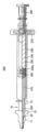
図31は、本発明の一実施態様に係る点鼻用噴霧・噴射ノズル10を備えたシリンジ型噴霧・噴射デバイス200の実施態様を例示している。シリンジ型噴霧・噴射デバイス200は、シリンジバレル220を備えたシリンジ本体230と、シリンジ本体230のシリンジバレル220内に挿通されるプランジャロッド240と、プランジャロッド240の遠位端に設けた固定部240aを介して取り付けられるピストン260と、シリンジ本体230の近位端の周りに配設されたフィンガーレスト270とを有して成る。より具体的には、図31に示すように、シリンジ型噴霧・噴射デバイス200は、薬剤210を充填可能なシリンジバレル220を有する合成樹脂またはガラスから成るシリンジ本体230と、シリンジ本体230のシリンジバレル220内に挿通されるプランジャロッド240と、プランジャロッド240の遠位端に設けた固定部240aを介して取り付けられ、シリンジバレル220内に摺動してシリンジバレル220内の薬剤をシリンジ本体230の遠位側の先端開口部250から送出するためのピストン260と、医者等の施術者の指から加わった力をプランジャロッド240に伝えるシリンジ本体230の近位端の周りに配設されたフィンガーレスト270と、プランジャ操作部280とを有する。(Syringe-type nebulization/injection device)
FIG. 31 illustrates an embodiment of a syringe-type spray-
シリンジ型噴霧・噴射デバイス200は、図31に示すように、シリンジ本体230の先端開口部250に対向して配置される点鼻用噴霧・噴射ノズル10をさらに有する。ここで、点鼻用噴霧・噴射ノズル10は、図4に例示した点鼻用噴霧・噴射ノズル10であってよい。点鼻用噴霧・噴射ノズル10は、その先端部11への汚染物質および機械的衝撃から保護するための保護キャップ(図示せず)をさらに有していてもよい。保護キャップは、ノズル全体を覆うように構成されていてよく、または先端部のみを覆うように構成されていてもよい。
The syringe-type spray/
図32Aおよび図32Bは、本発明の一実施態様に係る点鼻用噴霧・噴射ノズル10の概略的構成を示す部分破断分解斜視図である。図示するように、点鼻用噴霧・噴射ノズル10は、ノズル噴出孔21が形成されたノズル噴出端面11Bを有する中空のノズル本体部13と、ノズル本体部13内に配設される中実の充填ロッド(充填棒)30とを有する。図32Aおよび図32Bは、充填ロッド30がノズル本体部13に配設または挿入される前後の状態を示すものである。ノズル本体部13のノズル噴出端面11Bは略円形状を有し、ノズル噴出孔11Aはノズル噴出端面11Bの中心に形成されている。
32A and 32B are partially broken exploded perspective views showing a schematic configuration of a nasal spray/
図33Aは、図32Bに示す点鼻用噴霧・噴射ノズル10を、ノズル噴出孔11Aを通る垂直面で見たときの垂直断面図である。図33B~図33Dはそれぞれ、図33AのB-B線、C-C線、およびD-D線から見たときの水平断面図である。中空のノズル本体部13は、その内壁20が略円筒形状の内部空間22を形成し、内部空間22は、図33Cおよび図33Dに示すように、中空のノズル本体部13のノズル噴出孔11Aにより近いノズル小径部23と、充填ロッド30のロッド大径部34が挿入されるノズル大径部24と、内部空間22の径がノズル大径部24からノズル小径部23に向かって連続的または段階的に小さくなるように形成されたノズル肩部25とを有する。
FIG. 33A is a vertical cross-sectional view of the nasal spray/
一方、ノズル本体部13に挿入される中実の充填ロッド30は、その外壁31がノズル本体部13の内壁20(内部空間22)とほぼ相補的な外形形状を有し、図32A、図33Cおよび図33Dに示すように、ロッド大径部34およびロッド小径部33の径がロッド大径部34からロッド小径部33に向かって連続的または段階的に小さくなるように形成されたロッド肩部35とを有する。
On the other hand, the
なお、図32Aに示すように、ノズル本体部13の内壁20には突起部21を設け、充填ロッド30の外壁31には突起部21を受容する凹部32を設け、充填ロッド30をノズル本体部13の内部空間22に挿入したとき、突起部21と凹部32とが適合して、確実に固定できるように構成することが好ましい。
32A, the
また、図32A、図32Bおよび図33A~図33Dから明らかなように、充填ロッド30は、ロッド小径部33およびロッド大径部34において周方向に間隔を設けて配置された複数の溝部36、37を有する。また充填ロッド30は、ノズル肩部25とロッド肩部35との間に隙間38(図33A)が形成されるようにノズル本体部13に挿入される。したがって、図32Bのようにアセンブリされた点鼻用噴霧・噴射ノズル10は、溝部36、37および隙間38により流体連通可能なノズルチャンバ39が形成され、シリンジ本体230の先端開口部250から送出された薬剤210を、ノズルチャンバ39を介して点鼻用噴霧・噴射ノズル10のノズル噴出端面11Bまで案内することができる。
32A, 32B, and 33A to 33D, the filling
さらに充填ロッド30は、図33Bに示すように、点鼻用噴霧・噴射ノズル10のノズル噴出端面11Bに対向する渦流形成部40を有する。渦流形成部40は、ロッド小径部33の各溝部36から流入した薬剤210がノズル本体部13のノズル噴出孔11Aから噴射される前に渦流を形成するように構成されている。具体的には、渦流形成部40を構成するロッド小径部33の端部部分がノズル噴出孔11Aの垂直中心軸から位置ずれした方向に延びるように形成されている。このように薬剤210がノズル噴出孔11Aから噴射される前に渦流を形成することにより、薬剤の噴射角度を拡大させ、薬剤をより均一に噴霧・噴射することができる。
Furthermore, as shown in FIG. 33B, the filling
なお、図33Cおよび図33Dから明らかなように、ロッド小径部33の溝部36をロッド大径部34の溝部37より小さく設計して、ノズル噴出孔11Aから噴射される前の渦流形成部40内の薬剤の圧力を増大させることが好ましい。またロッド大径部34およびロッド小径部33の径がロッド大径部34からロッド小径部33に向かって連続的または段階的に小さくなるように設計したことから、患者等の使用者の鼻腔内に深く挿入しやすくして、使用者の下鼻甲介付近およびその深部に対する薬剤の噴霧・噴射を容易にすることができる。すなわちロッド小径部33の径は、使用者に恐怖感を与えることなく、使用者の鼻孔より十分に小さいものであることが好ましい。
As is clear from FIGS. 33C and 33D, the
換言すれば、シリンジ型噴霧・噴射デバイスは、薬剤を収容するシリンジ本体と、かかるシリンジ本体に流体連通する点鼻用噴霧・噴射ノズルとを有して成り、シリンジ本体は、薬剤を噴出するためのプランジャロッドおよびピストン、ならびにプランジャロッドと連動するフィンガーレストおよびプランジャ操作部を備え、点鼻用噴霧・噴射ノズルは、当該ノズル内に配設される充填ロッド、充填ロッドとノズル内壁との間に形成されノズル噴出孔との間で流体連通するノズルチャンバとをさらに備える。 In other words, a syringe-type spray/injection device comprises a syringe body containing a medicament and a nasal spray/injection nozzle in fluid communication with the syringe body, the syringe body for ejecting the medicament. A plunger rod and a piston, and a finger rest and a plunger operating part that interlock with the plunger rod. A nozzle chamber formed and in fluid communication with the nozzle orifice.
図34は、本発明の一実施態様に係る点鼻用噴霧・噴射ノズル10を備えるシリンジ型噴霧・噴射デバイス200を示す。図34の態様において、点鼻用噴霧・噴射ノズル10がノーズレスト12を有し、シリンジ本体230がフィンガーレスト270を有する。
FIG. 34 shows a syringe-type spray-
また、点鼻用噴霧・噴射ノズル10の上面視において、ノーズレスト12およびフィンガーレスト14の外輪郭がそれぞれ、先端部11の外輪郭を囲うように位置付けられている。そのような構成とすることで、点鼻用噴霧・噴射ノズル10の操作方向に指を容易に動かせるように当接することができる
Further, in top view of the nose spray/
一実施態様では、点鼻用噴霧・噴射ノズル10におけるノーズレスト12、およびシリンジ本体230におけるフィンガーレスト14が略楕円形状または略矩形状であってよい(図35参照)。また、ノーズレスト12およびフィンガーレスト14の長径が直交している。
In one embodiment, the
上述の態様において、点鼻用噴霧・噴射ノズル10の上面視において、ノーズレスト12の長径と、フィンガーレスト14の長径とが略直交していてよい。具体的には、ノーズレスト12およびフィンガーレスト14は、略楕円形状または略矩形状であり、それぞれの長径が互いに略直交していてよい。
In the above-described aspect, the long diameter of the
換言すれば、点鼻用噴霧・噴射ノズル10の上面視において、ノーズレスト12とフィンガーレスト14とが略十字形状を成している。ここで、ノーズレスト12およびフィンガーレスト14の長径は、それぞれ線対称となるように略十字形状となっていてよい。
In other words, the
換言すれば、点鼻用噴霧・噴射ノズル10の上面視において、ノーズレスト12およびフィンガーレスト14がそれぞれオーバーラップしているものの、ノーズレスト12の2つの非オーバーラップ部の対向方向と、フィンガーレスト14の2つの非オーバーラップ部の対向方向とが略直交していてよい。
In other words, in the top view of the nose spray/
上述のような構成とすることで、後述するように、外鼻孔に対する点鼻用噴霧・噴射ノズルの位置合わせをより容易に、かつより正確に行い易くなる。つまり、鼻腔内のノズル噴出孔11Aの方向を特に決定づけ易くなる。
With the configuration as described above, as will be described later, it becomes easier and more accurate to align the nasal spray/injection nozzle with the nostril. That is, it becomes particularly easy to determine the direction of the
(本発明のレスト品)
本発明の技術思想に従えば、例えば図36に示されるような点鼻用レスト品300も考えられる。かかるレスト品300は、外鼻孔の周辺部に当接可能なノーズレスト12と、フィンガーレスト14とを有して成り、例えば、常套的噴霧・噴射スプレー、上方排圧エアレス型噴霧・噴射デバイスまたはシリンジ型噴霧・噴射デバイス(以下では、総称して「噴霧・噴射デバイス」とも呼ぶ)に対して装着できるようになっている。つまり、レスト品300は、噴霧・噴射デバイスのためのパーツ品であり、かかるデバイスに対してノーズレスト12およびフィンガーレスト14を供するパーツ品となっている。(Rest product of the present invention)
According to the technical idea of the present invention, for example, a
図36に示されるように、レスト品300では、ノーズレスト12とフィンガーレスト14とが一体化している。より具体的には、例えば、筒状部分350を介して、ノーズレスト12とフィンガーレスト14とが連結されている。このようなレスト品300を噴霧・噴射デバイスに被せることによって(好ましくはそのノズル側からレスト品300を被せることによって)、当該デバイスにノーズレスト12とフィンガーレスト14との双方を供することができる。例えば、レスト品300の筒状部分350の内側に上方排圧エアレス型噴霧・噴射デバイスまたはシリンジ型噴霧・噴射デバイスの胴部分が位置付けられるようにレスト品300を被せると、シリンジ型噴霧・噴射デバイスにノーズレスト12とフィンガーレスト14とを好適に供することができる。
As shown in FIG. 36, in the
本発明に係るレスト品300では、ノーズレスト12およびフィンガーレスト14が略楕円形状または略矩形状であってよく、そのようなノーズレスト12およびフィンガーレスト14の長径が直交していてよい(図36参照)。つまり、レスト品300の上面視において、ノーズレスト12とフィンガーレスト14とが略十字形状を成していてよい。また、レスト品300の上面視において、ノーズレスト12およびフィンガーレスト14がそれぞれオーバーラップしているものの、ノーズレスト12の2つの非オーバーラップ部の対向方向と、フィンガーレスト14の2つの非オーバーラップ部の対向方向とが略直交していてよい。このようなノズル品が用いられることによって、外鼻孔に対する点鼻用噴霧・噴射ノズルの位置合わせをより容易に、かつより正確に行うことができる。なお、図36の態様に示されるように、シリンジ型噴霧・噴射デバイスに対して用いられるレスト品300では、ノーズレスト12とフィンガーレスト14との離隔寸法は、例えば50mm~80mm程度であってよい。
In the
(薬剤の特性について)
上述した点鼻用噴霧・噴射デバイスに用いられる薬剤の製剤物性(pH、粘度、表面張力、浸透圧等)には特に制限されない、特に粘度は噴霧・噴射特性に大きな影響を与えるが特に制限されない。それゆえ、当該薬剤は、例えば液状、ゲル状またはスラリー状の形態を有している。例えば、薬剤の粘度は1mPa・s以上5000Pa・s以下であってよく、ある態様では250Pa・s以上2500Pa・s以下である。(Regarding drug characteristics)
There are no particular restrictions on the formulation physical properties (pH, viscosity, surface tension, osmotic pressure, etc.) of the drug used in the nasal spray/injection device described above. In particular, the viscosity greatly affects the spray/injection characteristics, but is not particularly limited. . The agent thus has, for example, a liquid, gel or slurry form. For example, the viscosity of the drug may be from 1 mPa·s to 5000 Pa·s, and in one embodiment from 250 Pa·s to 2500 Pa·s.
薬剤の粘度が250Pa・s以下であると、せっかく標的領域に送達させても液だれが生じ当該領域から流失してしまう傾向が出やすくなる。5000Pa・s以上であると、ノズル噴出孔から薬剤が膜を形成した状態(すなわち、狭拡散領域)の噴射孔から所定の距離(C)51が長くなり、膜が破膜しにくくなるため、標的領域に薬剤をより好適に滞留させ易くなる。 If the viscosity of the drug is 250 Pa·s or less, even if the drug is delivered to the target area, it tends to drip and flow out from the target area. When it is 5000 Pa·s or more, the predetermined distance (C) 51 from the injection hole in which the drug forms a film from the nozzle ejection hole (that is, the narrow diffusion region) is long, and the film is less likely to break. This makes it easier for the drug to stay more favorably in the target area.
(噴霧・噴射デバイスの使用方法)
図37は、図7に示す点鼻用噴霧・噴射ノズル10を備える上方排圧エアレス型噴霧・噴射デバイス100の使用方法を例示している。すなわち、図37に示す点鼻用噴霧・噴射ノズル10は、ノーズレスト12およびフィンガーレスト14を有している。(Method of using spray/injection device)
FIG. 37 illustrates the use of the upward pressure airless spray/
使用者は、例えば以下の手順で噴霧・噴射デバイス100を使用する。
(1)フィンガーレスト14におけるノズル本体部13を挟んで対向する位置に、2本の指(例えば、人差し指および中指)をそれぞれ配置する。
(2)配置した2本の指が並列する方向と、鼻柱の長手方向とが略平行となるように、点鼻用噴霧・噴射ノズル10を位置付ける。
(3)点鼻用噴霧・噴射ノズル10の先端部11を鼻腔内に挿入する。ここで、ノーズレスト12が外鼻孔の周辺部(例えば、鼻柱および鼻翼など)に圧着するまで、先端部11を挿入する(図37および図38参照)。
(4)フィンガーレスト14を点鼻用噴霧・噴射ノズル10の遠位側(図示する操作方向側)に向けて押すことで、鼻腔内に薬剤を噴射させる。A user uses the spray/
(1) Two fingers (for example, an index finger and a middle finger) are placed at positions facing each other across the nozzle
(2) The nasal spray/
(3) Insert the
(4) By pushing the
ここで、図37に示す点鼻用噴霧・噴射ノズル10は、ノーズレスト12の長径N-N’とフィンガーレスト14の長径F-F’とが略直交していてよい(図7C参照)。そのような点鼻用噴霧・噴射ノズル10を(2)の手順で位置付けると、ノーズレスト12の長径方向と鼻柱および鼻翼を結ぶ方向とが必然的に略一致し易くなる(図38参照)。それによって、ノーズレスト12と鼻柱および鼻翼とがより一層適合する。
Here, in the nose spray/
図39は、上述する手順で鼻腔内に挿入された点鼻用噴霧・噴射ノズル10の一態様を示す。
図39に示すように、ノーズレスト12が外鼻孔の周辺部に当接されることで、鼻弁周辺の狭い鼻腔領域を先端部11または噴射される薬剤50が通過し得るように、ノズル噴出孔11Aの挿入位置および方向を決定づけ易くなる。よって、標的領域の薬剤到達率がより高くなり易くなったり、および/または、標的領域(例えば、呼吸部、嗅部または鼻咽頭)の広範囲に薬剤を送達し易くなる。FIG. 39 shows one aspect of the nasal spray/
As shown in FIG. 39, the
噴射される薬剤50は、噴射直後の狭拡散領域51、およびかかる狭拡散領域51に比して微細な液滴になっていく広拡散領域52を含む(図40参照)。特定の理論に拘束される訳ではないが、噴射直後の薬剤は外縁に膜が形成されており収束された状態であるが、一定の噴射距離を通過すると膜が破壊されて微細な液滴になると考えられる。具体的には、ノズル噴出孔11Aからの噴射距離Cが5mm以上15mm以下の位置を境界として、薬剤の膜が破壊され微細な液滴に変化し得る。
The
標的領域の広範囲に薬剤を送達するためには、鼻弁周辺の狭い鼻腔領域を先端部11または噴射される薬剤50の狭拡散領域51が通過し得ることが重要である(図39および図40参照)。ここで、外鼻孔から鼻弁までの距離は約20mmであることが知られている。
In order to deliver the drug over a wide area of the target area, it is important that the
本発明に係る点鼻用噴霧・噴射ノズル10における先端部11の長さ寸法は例えば、5mm以上30mm以下であるため、先端部11または薬剤50の狭拡散領域51を通過させることができる。
Since the
鼻弁周辺の鼻腔内壁への接触を防ぐ観点および標的領域の広範囲に薬剤を送達する観点から、鼻弁周辺の狭い鼻腔領域を噴射される薬剤50の狭拡散領域51のみが通過することが好ましい(図39および図40参照)。
From the viewpoint of preventing contact with the inner wall of the nasal cavity around the nasal valve and delivering the drug over a wide range of target areas, it is preferable that only the
上述の態様とするために、先端部11の長さ寸法は、例えば10mm以上25mm以下、7mm以上18mm以下、8mm以上17mm以下、9mm以上16mm以下、または10mm以上15mm以下(一つの例示として15mm近傍)であってよい。ここで先端部11の長さ寸法とは、ノーズレスト12の近位端からノズル噴出孔11Aが形成された面までの長さを指す。
In order to achieve the above aspect, the length dimension of the
特に、先端部11の長さ寸法が上記寸法であると、ノズル噴出孔11Aを鼻弁直前に位置付けられ易くなり、鼻弁周辺の狭い鼻腔領域を噴射される薬剤50が狭拡散領域51を通過し易くなる。また、ノズル噴出孔11Aから標的領域までの距離を十分にとれるため、より効果的に標的領域の広範囲に薬剤を送達し易くなる。
In particular, when the length dimension of the
以上、本発明の実施形態について説明してきたが、あくまでも典型例を例示したに過ぎない。従って、本発明はこれに限定されず、種々の態様が考えられることを当業者は容易に理解されよう。 Although the embodiments of the present invention have been described above, they are merely examples of typical examples. Therefore, those skilled in the art will easily understand that the present invention is not limited to this, and that various aspects are conceivable.
例えば、図12および図13を参照して厚み差を有するノーズレスト12について説明した。かかる厚み差を有するノーズレスト12は、その上面(近位側の面)が部分的または全体的に傾斜しているが、そのような傾斜形態は、種々の態様で具現化することができる。例えば、ノーズレスト12の面が傾斜する態様は、図41および図42に示すようなものであってもよい。つまり、図41Bおよび図42Bに示すような側面視において、一定厚み(実質的に一定厚み)を有するノーズレスト12が先端部11の軸に直交する方向に対して角度を成して傾いて設けられてもよい。
For example, the
また、上記の説明では、“標的領域”なる表現を用いたが、本発明は必ずしもそれに限定されない。標的領域と実質的に同義となる“標的部位”なる表現が用いられてもよい。つまり、標的領域に代えて又はそれに加えて、標的部位なる表現と共に本発明を理解してもよい。なお、鼻炎などが想定される場合、標的部位が鼻甲介(下鼻甲介および/または中鼻甲介)となってよい。例えば、アレルギー性鼻炎等の鼻甲介が腫脹して鼻閉状態となっている場合、本発明の点鼻用噴霧・噴射ノズルの使用によって下鼻甲介、中鼻甲介に到達する薬剤の到達率を高くできる。また、鼻腔の広い呼吸部鼻粘膜を介する鼻粘膜吸収による全身効果が期待される点鼻製剤を用いる場合、標的部位が鼻腔中間部位となっていてよい。鼻咽頭の強い免疫応答性を利用して経鼻ワクチンによる抗体産生効果を期待する点鼻製剤が用いられる場合、標的部位が鼻咽頭部位となってよい。さらには、嗅粘膜から直接脳に通じる経路が知られていることから、嗅粘膜に到達する薬剤の量を向上させることは鼻から脳への薬物送達の可能性を高めることにつながるので、中枢神経系への効果を期待する点鼻製剤が用いられる場合には、標的部位が嗅粘膜となってよい。 Moreover, although the above description uses the expression "target region", the present invention is not necessarily limited thereto. The term "target site" may be used, which is substantially synonymous with target region. That is, the invention may be understood with the term target site instead of or in addition to the target region. If rhinitis or the like is assumed, the target site may be the nasal turbinate (inferior nasal turbinate and/or middle nasal turbinate). For example, when the nasal turbinates are swollen due to allergic rhinitis, etc., and the nasal congestion is caused, the use of the nasal spray/injection nozzle of the present invention reduces the delivery rate of the drug reaching the lower and middle nasal turbinates. can be high In addition, when using a nasal preparation that is expected to have a systemic effect due to absorption through the nasal mucosa of the respiratory part, which has a wide nasal cavity, the target site may be the middle part of the nasal cavity. In the case of using a nasal drop formulation that expects the antibody production effect of an intranasal vaccine by utilizing the strong immune responsiveness of the nasopharynx, the target site may be the nasopharynx. Furthermore, since a direct route from the olfactory mucosa to the brain is known, increasing the amount of drug reaching the olfactory mucosa will lead to an increase in the possibility of drug delivery from the nose to the brain. When nasal preparations expected to have effects on the nervous system are used, the target site may be the olfactory mucosa.
さらに、上記の説明では、点鼻用噴霧・噴射ノズルの外側構造を中心に説明したが、その内部構造または内側構造は、特に制限されず、常套の点鼻用噴霧・噴射ノズルと同様であってもよい。つまり、点鼻用噴霧・噴射ノズルの内部構造・内側構造は、ノズル機能(例えば、薬剤の噴霧・噴射)に資するものであれば、特に制限はされず、いずれの構造であってもよい。 Furthermore, in the above description, the outer structure of the nasal spray/injection nozzle has been mainly described, but the internal structure or the inner structure is not particularly limited, and may be the same as a conventional nasal spray/injection nozzle. may In other words, the internal structure/inner structure of the nasal spray/injection nozzle is not particularly limited as long as it contributes to the nozzle function (for example, spray/injection of medicine), and any structure may be used.
本発明に関連する実施例を説明する。 An embodiment related to the present invention will be described.
点鼻用噴霧・噴射ノズルを模した以下の供試ノズルを用いて実証試験を行った。
● 比較例1:ノーズレストを備えていない点鼻用噴霧・噴射ノズル(図43A参照)
・ノズル噴出孔が形成された面の径寸法:8mm
・噴霧量:100mg(噴霧量100mgのポンプに装着して使用)
● 比較例2:ノーズレストを備えていない点鼻用噴霧・噴射ノズル(図43B参照)
・ノズル噴出孔が形成された面の径寸法:4mm
・噴霧量:100mg(噴霧量100mgのポンプに装着して使用)
● 比較例3:ノーズレストを備えていない点鼻用噴霧・噴射ノズル(図43C参照)
・ノズル噴出孔が形成された面の径寸法:4.5mm
・噴霧量:250mg(1.0mLのシリンジバレルにセットして使用)
● 実施例1:ノーズレスが備えられたこと以外は比較例1と同じ点鼻用噴霧
・噴射ノズル(図44A参照)
・先端部の長さ寸法が10mmまたは15mmとなるようにノーズレストを設けた。
● 実施例2:ノーズレスが備えられたこと以外は比較例2と同じ点鼻用噴霧
・噴射ノズル(図44B参照)
・先端部の長さ寸法が15mmとなるようにノーズレストを設けた。
● 実施例3:ノーズレスが備えられたこと以外は比較例3と同じ点鼻用噴霧
・噴射ノズル(図44C参照)
・先端部の長さ寸法が10mm、15mmまたは20mmとなるようにノーズレストを設けた。A demonstration test was conducted using the following test nozzles imitating nasal spray/injection nozzles.
● Comparative Example 1 : Nasal spray/injection nozzle without nose rest (see Fig. 43A)
・Diameter of the surface where the nozzle ejection hole is formed: 8 mm
・Amount of spray: 100 mg (used by attaching to a pump with a spray amount of 100 mg)
● Comparative Example 2 : Nasal spray/injection nozzle without nose rest (see Fig. 43B)
・Diameter of the surface where the nozzle ejection hole is formed: 4 mm
・Amount of spray: 100 mg (used by attaching to a pump with a spray amount of 100 mg)
● Comparative Example 3 : Nasal spray/injection nozzle without nose rest (see Fig. 43C)
・Diameter of the surface where the nozzle ejection hole is formed: 4.5 mm
・Amount of spray: 250 mg (set in a 1.0 mL syringe barrel and used)
● Example 1 : The same nasal spray/injection nozzle as in Comparative Example 1 except that a noseless device was provided (see FIG. 44A)
・The nose rest is provided so that the length of the tip is 10 mm or 15 mm.
● Example 2 : The same nasal spray/injection nozzle as in Comparative Example 2 except that a noseless device was provided (see FIG. 44B)
・The nose rest is provided so that the length of the tip is 15 mm.
● Example 3 : The same nasal spray/injection nozzle as in Comparative Example 3 except that a noseless device was provided (see FIG. 44C)
・The nose rest was provided so that the length of the tip was 10 mm, 15 mm or 20 mm.
噴霧状態の確認
点鼻用噴霧・噴射を用いて薬剤の噴霧状態を確認した。液状薬剤は、質量を測定するため、沈着部位での強い付着性が必要であることから、東興薬品工業株式会社の登録特許5185109に記載された製法に準じて調製した。上記のいずれの点鼻用噴霧・噴射ノズルも噴霧角度および薬剤粘度に依らず微細な霧の状態で十分に噴霧されることを確認できた。
具体的には、上記の比較例1~3および実施例1~3のいずれの点鼻用噴霧・噴射ノズルであっても、噴霧角度および薬剤粘度に依らず、液滴径分布は10~100μmの範囲に70%以上の噴霧状態となることを確認した。 Confirmation of atomization state The atomization state of the drug was confirmed using nasal spray/injection. The liquid drug was prepared according to the manufacturing method described in Toko Pharmaceutical Co., Ltd.'s registered patent 5185109, since it is necessary to have strong adhesion at the deposition site in order to measure the mass. It was confirmed that any of the above nasal spray/injection nozzles sufficiently sprayed in a fine mist state regardless of the spray angle and drug viscosity.
Specifically, in any of the nasal spray/injection nozzles of Comparative Examples 1 to 3 and Examples 1 to 3, the droplet size distribution is 10 to 100 μm, regardless of the spray angle and drug viscosity. It was confirmed that the atomization state was 70% or more in the range of .
ノーズレストの効果確認の試験
シリコン製3D鼻腔モデル[株式会社高研製](図45参照)を使用した。試験時に鼻腔モデルに使用される点鼻用噴霧・噴射ノズルの噴出孔位置および角度は図46に示す。図46Aでは、鼻中隔と平行となる面に対して成す角度の“角度α”が示され、図46Bでは、鼻中隔に垂直となる面に対して成す角度の“角度β”が示されている。 Test for confirmation of effect of nose rest A silicon 3D nasal cavity model [manufactured by Koken Co., Ltd.] (see Fig. 45) was used. The nozzle positions and angles of the nasal spray/injection nozzles used in the nasal cavity model during the test are shown in FIG. In FIG. 46A, an "angle α" is shown for a plane parallel to the nasal septum, and FIG. 46B is an "angle β" for a plane perpendicular to the nasal septum.
噴霧対象の標的部位が“鼻甲介”となる場合、下鼻甲介・中鼻甲介の先端部に取り外し可能な衝立をセットした。点鼻用噴霧・噴射ノズルによる薬剤の噴霧前後における衝立の質量を測定し、その差から衝立への沈着量を求めると共に、その衝立より後位の鼻中隔に沈着した薬剤質量を測定し、鼻甲介に薬剤が到達した量とした。噴霧対象の標的部位が“鼻腔中間部位”となる場合、鼻腔の中央部で垂直に切断した鼻腔モデルの後部断面に沈着した薬剤質量を測定し、鼻腔中間部位に薬剤が到達した量とした。噴霧対象の標的部位が“鼻咽頭部位”となる場合、鼻腔モデルの後部(後面)の鼻咽頭部で垂直に切断したモデルの後部断面に沈着した薬剤質量を測定し、鼻咽頭部位に薬剤が到達した量とした。噴霧対象の標的部位が“嗅粘膜部位”となる場合、鼻腔モデルの上部を平行に切断した鼻腔モデルの上部断面に沈着した薬剤質量を測定し、嗅粘膜部位に薬剤が到達した量とした。
標的部位に薬剤が到達した量の噴霧量に対する割合から「標的部位到達率」を算出した。また、試験は複数回で行ったところ、標的部位到達率のバラツキを把握するためRSD(相対標準偏差)を求めた。When the target site to be sprayed was the "nasal turbinate", removable screens were set at the tips of the inferior and middle nasal turbinates. Measure the mass of the screen before and after spraying the drug with the nasal spray/injection nozzle, determine the amount of deposition on the screen from the difference, and measure the mass of the drug deposited on the nasal septum behind the screen. The amount reached by the drug was defined as When the target site to be sprayed is the "mid-nasal cavity", the mass of the drug deposited in the posterior section of the nasal cavity model cut vertically at the center of the nasal cavity is measured, and the amount of the drug that reaches the mid-nasal cavity is defined as the amount. When the target site for spraying is the nasopharynx, the amount of drug deposited in the posterior section of the model cut vertically at the posterior (rear) nasopharynx of the nasal cavity model is measured to determine whether the drug is in the nasopharynx. It is the amount reached. When the target site to be sprayed is the "olfactory mucosa site", the mass of the drug deposited in the upper cross section of the nasal cavity model cut parallel to the upper part of the nasal cavity model was measured, and the amount of the drug that reached the olfactory mucosa site was determined.
The "target site delivery rate" was calculated from the ratio of the amount of the drug that reached the target site to the spray amount. In addition, when the test was conducted multiple times, the RSD (relative standard deviation) was obtained in order to grasp the variation in the rate of reaching the target site.
結果を表1~16に示す。 The results are shown in Tables 1-16.


表1~16に示されるように、ノーズレストを備えた点鼻用噴霧・噴射ノズル(実施例1~3)では、ノーズレストを備えていない点鼻用噴霧・噴射ノズル(比較例1~3)よりも標的部位への薬剤到達率が高くなることが分かった。また、ノーズレストを備えた点鼻用噴霧・噴射ノズル(実施例1~3)は、ノーズレストを備えていない点鼻用噴霧・噴射ノズル(比較例1~3)よりも薬剤到達率のバラツキを抑えられることも分かった。つまり、本発明に係る点鼻用噴霧・噴射ノズルは、より向上した薬剤到達特性を有することを確認することができた。 As shown in Tables 1 to 16, the nasal spray/injection nozzles with a nose rest (Examples 1 to 3) did not have a nose rest (Comparative Examples 1 to 3). ), it was found that the delivery rate of the drug to the target site was higher than that of In addition, the nasal spray/injection nozzles with a nose rest (Examples 1 to 3) showed more variation in drug delivery rate than the nasal spray/injection nozzles without a nose rest (Comparative Examples 1 to 3). It was also found that the In other words, it was confirmed that the nose spray/injection nozzle according to the present invention has improved drug delivery characteristics.
本発明に係る点鼻用噴霧・噴射ノズルは、複雑な鼻腔内構造において、より好適な標的領域への薬剤送達性を有し得る。具体的には、ノーズレストを外鼻孔の周辺部に当接させることによって、鼻腔内のノズル噴出孔の挿入位置を決定づけることができる。それによって、標的領域の広範囲に薬剤を送達することができ、より高い薬効が得られる点鼻用噴霧・噴射式の医療用デバイスを実現することができる。 The nasal spray/injection nozzle according to the present invention can have more favorable drug delivery to target areas in complex intranasal structures. Specifically, the insertion position of the nozzle ejection hole in the nasal cavity can be determined by bringing the nose rest into contact with the periphery of the external nostril. As a result, it is possible to deliver a drug to a wide range of target regions, and realize a nasal spray/jet type medical device capable of obtaining higher efficacy.
10:点鼻用噴霧・噴射ノズル
11:先端部
11A:ノズル噴出孔
11B:ノズル噴出端面
12:ノーズレスト
12E:ノーズレストの近位側の端部
12S:ノーズレストの傾斜面
13:ノズル本体部
13’:シリンジ接合用突出部
14:フィンガーレスト
14’:フィンガーガイド
15:挿入方向マーカー
15a:切欠き面
20:ノズル本体部の内壁
21:突起部
22:内部空間
23:ノズル小径部
24:ノズル大径部
25:ノズル肩部、
30:充填ロッド(充填棒)
31:充填ロッドの外壁
32:凹部
33:ロッド小径部
34:ロッド大径部
35:ロッド肩部
36、37:溝部
38:隙間
39:ノズルチャンバ
40:渦流形成部
50:噴射される薬剤
51:狭拡散領域
52:広拡散領域
100:上方排圧エアレス型噴霧・噴射デバイス
110:保護キャップ
120:ポンプ
121:上側環状外周面部
122:下側環状外周面部
130:環状操作部(フィンガーレスト)
140:薬剤容器
141:内周面
150:吸引室
160:摺動底蓋本体
170:固定底蓋
180:通気孔
190:リング
200:シリンジ型噴霧・噴射デバイス
210:薬剤
220:シリンジバレル
230:シリンジ本体
240:プランジャロッド
240a:固定部
250:先端開口部
260:ピストン
270:フィンガーレスト
280:プランジャ操作部
300:点鼻用レスト品
350:筒状部分10: Nasal Spray/Injection Nozzle 11:
30: Filling rod (filling rod)
31: Outer Wall of Filling Rod 32: Recess 33: Rod Small Diameter Portion 34: Rod Large Diameter Portion 35:
140: Drug Container 141: Inner Peripheral Surface 150: Suction Chamber 160: Sliding Bottom Lid Main Body 170: Fixed Bottom Lid 180: Ventilation Hole 190: Ring 200: Syringe Type Atomization/Injection Device 210: Medicine 220: Syringe Barrel 230: Syringe Body 240:
Claims (17)
ノズル噴出孔が形成された先端部と、外鼻孔の周辺部に当接可能なノーズレストとを有して成り、
前記点鼻用噴霧・噴射ノズルの上面視において、前記先端部の軸と前記ノーズレストの中心とは互いにずれた偏心関係を有すると共に、前記先端部の外輪郭は、その一部が前記ノーズレストの外輪郭によって囲まれていない非包囲部分を有し、
前記点鼻用噴霧・噴射ノズルの上面視において、前記ノーズレストの前記外輪郭のうち前記非包囲部分の両側にて延在する部分が弧形状を有しており、前記ノーズレストの前記外輪郭は互いに対向する一方の側部と他方の側部とが互いに曲率を異にする部分を有する、点鼻用噴霧・噴射ノズル。 A nasal spray/injection nozzle,
It has a tip portion in which a nozzle ejection hole is formed, and a nose rest that can abut on the periphery of the outer nostril,
In a top view of the nose spray/injection nozzle, the axis of the tip portion and the center of the nose rest have an eccentric relationship with each other, and the outer contour of the tip portion is part of the nose rest. has an unenclosed portion not enclosed by the outer contour of
In a top view of the nose spray/injection nozzle, portions of the outer contour of the nose rest that extend on both sides of the non-surrounding portion have an arc shape, and the outer contour of the nose rest is a spray/injection nozzle for nasal application, in which one side portion and the other side portion facing each other have portions with different curvatures .
Applications Claiming Priority (3)
| Application Number | Priority Date | Filing Date | Title |
|---|---|---|---|
| JP2019181591 | 2019-10-01 | ||
| JP2019181591 | 2019-10-01 | ||
| PCT/JP2020/037930 WO2021066195A1 (en) | 2019-10-01 | 2020-09-30 | Nasal spray injection nozzle and rest product for administration of nasal drops |
Publications (2)
| Publication Number | Publication Date |
|---|---|
| JPWO2021066195A1 JPWO2021066195A1 (en) | 2021-04-08 |
| JP7280965B2 true JP7280965B2 (en) | 2023-05-24 |
Family
ID=75338211
Family Applications (1)
| Application Number | Title | Priority Date | Filing Date |
|---|---|---|---|
| JP2021551676A Active JP7280965B2 (en) | 2019-10-01 | 2020-09-30 | Nasal Spray/Injection Nozzles and Nasal Rest Products |
Country Status (12)
| Country | Link |
|---|---|
| US (1) | US20220249787A1 (en) |
| EP (1) | EP4039296A4 (en) |
| JP (1) | JP7280965B2 (en) |
| KR (1) | KR20220097884A (en) |
| CN (1) | CN114401759A (en) |
| AU (1) | AU2020361110A1 (en) |
| BR (1) | BR112022001949A2 (en) |
| CA (1) | CA3150830A1 (en) |
| IL (1) | IL291321A (en) |
| MX (1) | MX2022003973A (en) |
| TW (1) | TW202128241A (en) |
| WO (1) | WO2021066195A1 (en) |
Families Citing this family (7)
| Publication number | Priority date | Publication date | Assignee | Title |
|---|---|---|---|---|
| WO2021069972A1 (en) * | 2019-10-11 | 2021-04-15 | Rocket Science Health Corp. | Intranasal drug delivery device, system, and process |
| JP1706573S (en) * | 2021-02-15 | 2022-02-01 | Nasal sprayer | |
| TW202339792A (en) * | 2021-12-02 | 2023-10-16 | 日商東興藥品工業股份有限公司 | Formulation for nasal vaccine spray which is sprayed to both of nasal mucosa and nasopharynx as targets. |
| GB202202890D0 (en) * | 2022-03-02 | 2022-04-13 | Consort Medical Ltd | Improvements relating to nasal pieces |
| US11759586B1 (en) * | 2022-04-13 | 2023-09-19 | Ferrer Medical Innovations, LLC | Nasal spray bottle with improved nozzle and system of application |
| US20230381800A1 (en) * | 2022-05-31 | 2023-11-30 | Oyster Point Pharma, Inc. | Nasal spray guide |
| KR102540159B1 (en) * | 2023-03-09 | 2023-06-02 | 백영진 | Nasal catheter with guide wall |
Citations (5)
| Publication number | Priority date | Publication date | Assignee | Title |
|---|---|---|---|---|
| JP2002510225A (en) | 1997-06-18 | 2002-04-02 | バルワー エス.アー. | Nasal applicator and dispenser device using the same |
| JP3112243U (en) | 2005-05-02 | 2005-08-04 | 中部浄化工業株式会社 | Propolis liquid sprayer |
| WO2009057572A1 (en) | 2007-10-30 | 2009-05-07 | Daikyo Seiko, Ltd. | Prefilled nasal drop appliance |
| JP2012135535A (en) | 2010-12-27 | 2012-07-19 | Yoshino Kogyosho Co Ltd | Injector |
| JP2018187412A (en) | 2010-11-12 | 2018-11-29 | ウルフ トリー メディカル インコーポレイテッド | Sprayer for nose treatment |
Family Cites Families (8)
| Publication number | Priority date | Publication date | Assignee | Title |
|---|---|---|---|---|
| JPS5561905A (en) | 1978-11-06 | 1980-05-10 | Hitachi Ltd | Regeneration of porous filter body |
| JP2509214Y2 (en) * | 1990-04-09 | 1996-08-28 | 伸晃化学株式会社 | Nasal drops container adapter |
| FR2739294B1 (en) * | 1995-09-29 | 1998-01-16 | Lhd Lab Hygiene Dietetique | NASAL SAFETY TIP |
| US20020174865A1 (en) * | 2001-03-01 | 2002-11-28 | Gatton Brian M. | Nasal spray apparatus and system |
| CN101426531A (en) | 2006-04-21 | 2009-05-06 | 东兴药品工业株式会社 | Sprayable gel-type skin/mucosa-adhesive preparation and administration system using the preparation |
| JP6322844B2 (en) * | 2014-06-25 | 2018-05-16 | 東興薬品工業株式会社 | Nasal spray nozzle used for medical syringes |
| ITUB20152886A1 (en) * | 2015-08-05 | 2017-02-05 | Eleuterio Pollini | SECURITY DEVICE FOR NASAL IRRIGATION |
| IT201600080879A1 (en) * | 2016-08-01 | 2018-02-01 | Giorgio Mezzoli | REGULATOR |
-
2020
- 2020-09-30 KR KR1020227013555A patent/KR20220097884A/en active Search and Examination
- 2020-09-30 JP JP2021551676A patent/JP7280965B2/en active Active
- 2020-09-30 CN CN202080062099.1A patent/CN114401759A/en active Pending
- 2020-09-30 TW TW109134165A patent/TW202128241A/en unknown
- 2020-09-30 MX MX2022003973A patent/MX2022003973A/en unknown
- 2020-09-30 BR BR112022001949A patent/BR112022001949A2/en unknown
- 2020-09-30 WO PCT/JP2020/037930 patent/WO2021066195A1/en unknown
- 2020-09-30 EP EP20870726.5A patent/EP4039296A4/en active Pending
- 2020-09-30 CA CA3150830A patent/CA3150830A1/en active Pending
- 2020-09-30 AU AU2020361110A patent/AU2020361110A1/en active Pending
-
2022
- 2022-03-13 IL IL291321A patent/IL291321A/en unknown
- 2022-03-30 US US17/708,976 patent/US20220249787A1/en active Pending
Patent Citations (5)
| Publication number | Priority date | Publication date | Assignee | Title |
|---|---|---|---|---|
| JP2002510225A (en) | 1997-06-18 | 2002-04-02 | バルワー エス.アー. | Nasal applicator and dispenser device using the same |
| JP3112243U (en) | 2005-05-02 | 2005-08-04 | 中部浄化工業株式会社 | Propolis liquid sprayer |
| WO2009057572A1 (en) | 2007-10-30 | 2009-05-07 | Daikyo Seiko, Ltd. | Prefilled nasal drop appliance |
| JP2018187412A (en) | 2010-11-12 | 2018-11-29 | ウルフ トリー メディカル インコーポレイテッド | Sprayer for nose treatment |
| JP2012135535A (en) | 2010-12-27 | 2012-07-19 | Yoshino Kogyosho Co Ltd | Injector |
Also Published As
| Publication number | Publication date |
|---|---|
| TW202128241A (en) | 2021-08-01 |
| CA3150830A1 (en) | 2021-04-08 |
| CN114401759A (en) | 2022-04-26 |
| EP4039296A4 (en) | 2023-10-25 |
| US20220249787A1 (en) | 2022-08-11 |
| MX2022003973A (en) | 2022-04-26 |
| IL291321A (en) | 2022-05-01 |
| WO2021066195A1 (en) | 2021-04-08 |
| AU2020361110A1 (en) | 2022-05-26 |
| BR112022001949A2 (en) | 2022-05-03 |
| JPWO2021066195A1 (en) | 2021-04-08 |
| KR20220097884A (en) | 2022-07-08 |
| EP4039296A1 (en) | 2022-08-10 |
Similar Documents
| Publication | Publication Date | Title |
|---|---|---|
| JP7280965B2 (en) | Nasal Spray/Injection Nozzles and Nasal Rest Products | |
| US10682477B2 (en) | Dosing system for an inhalation device | |
| US6321942B1 (en) | Discharge device for flowable media using a thrust piston pump | |
| US7819342B2 (en) | Atomizer for dispensing liquids for medical purposes | |
| US7284713B2 (en) | System comprising a nozzle and a fixing means therefor | |
| US20210030711A1 (en) | Nasal drug delivery device and method of making same | |
| JPH03198866A (en) | Disposable adaptor of intranasal spray container for viscous liquid | |
| TW201739478A (en) | Sealed liquid reservoir for a nebulizer | |
| US7077831B2 (en) | Ophthalmic fluid dispenser | |
| JP2023176024A (en) | Methods and devices for delivering atropine to eye as micro-dose stream of droplets | |
| EP3565489B1 (en) | Device for administration of compositions to the eustachian tube | |
| KR20160070105A (en) | Device for delivery of an aerosol substance | |
| TW201627021A (en) | Metered dose eyedropper and method of administering a metered dose onto the surface of the eye | |
| WO2023013597A1 (en) | Nasal spray/injection nozzle | |
| JP7240575B2 (en) | Liquid ejection device and dosing device | |
| KR20230131226A (en) | Liquid dispensing device and dosing device | |
| JPH09140797A (en) | Medicator for nostril | |
| CN117504101A (en) | Multipurpose spraying device |
Legal Events
| Date | Code | Title | Description |
|---|---|---|---|
| A621 | Written request for application examination |
Free format text: JAPANESE INTERMEDIATE CODE: A621 Effective date: 20220624 |
|
| A131 | Notification of reasons for refusal |
Free format text: JAPANESE INTERMEDIATE CODE: A131 Effective date: 20221122 |
|
| A521 | Request for written amendment filed |
Free format text: JAPANESE INTERMEDIATE CODE: A523 Effective date: 20230120 |
|
| TRDD | Decision of grant or rejection written | ||
| A01 | Written decision to grant a patent or to grant a registration (utility model) |
Free format text: JAPANESE INTERMEDIATE CODE: A01 Effective date: 20230425 |
|
| A61 | First payment of annual fees (during grant procedure) |
Free format text: JAPANESE INTERMEDIATE CODE: A61 Effective date: 20230512 |
|
| R150 | Certificate of patent or registration of utility model |
Ref document number: 7280965 Country of ref document: JP Free format text: JAPANESE INTERMEDIATE CODE: R150 |