JP7279950B2 - Ventilation system for top rail - Google Patents
Ventilation system for top rail Download PDFInfo
- Publication number
- JP7279950B2 JP7279950B2 JP2020201531A JP2020201531A JP7279950B2 JP 7279950 B2 JP7279950 B2 JP 7279950B2 JP 2020201531 A JP2020201531 A JP 2020201531A JP 2020201531 A JP2020201531 A JP 2020201531A JP 7279950 B2 JP7279950 B2 JP 7279950B2
- Authority
- JP
- Japan
- Prior art keywords
- ventilation
- wall
- ventilation member
- plate
- passage
- Prior art date
- Legal status (The legal status is an assumption and is not a legal conclusion. Google has not performed a legal analysis and makes no representation as to the accuracy of the status listed.)
- Active
Links
Images


Description
本発明は、 建造物の外壁材と外壁材の上方を覆う笠木との間に配置される笠木用換気装置に関する。 TECHNICAL FIELD The present invention relates to a headboard ventilation system that is arranged between an outer wall material of a building and a topboard that covers the upper part of the outer wall material.
特許文献1では、建造物の外壁材と外壁材の上方を覆う笠木との間に配置される笠木用換気装置を提案している。 Japanese Patent Laid-Open No. 2004-100010 proposes a ventilation system for a top rail which is arranged between an outer wall material of a building and a top rail covering the upper part of the outer wall material.
しかし、特許文献1では、各々が凹凸断面形状を有する合成樹脂シートを複数積層した状態で熱融着によって相互に接続して一体化され、一方側面から他方側面へ貫通する通気孔が多数形成された換気部材によって、通気性能と防水性能を確保している。 However, in Patent Document 1, a plurality of synthetic resin sheets each having an uneven cross-sectional shape are laminated and connected to each other by heat sealing to form a large number of ventilation holes penetrating from one side to the other side. Ventilation material ensures ventilation and waterproof performance.
本発明は、このような換気部材を用いることなく、換気孔から流入する雨水を換気部材後面板に至ることを防止できる笠木用換気装置を提供することを目的とする。 SUMMARY OF THE INVENTION It is an object of the present invention to provide a ventilation system for top rails that can prevent rainwater flowing through ventilation holes from reaching the rear plate of the ventilation member without using such a ventilation member.
請求項1記載の本発明の笠木用換気装置は、建造物の外壁下地材81の上部に配置される上枠材82と、前記外壁下地材81の外面に配置される通気胴縁83と、前記通気胴縁83の外面に配置される外壁材84と、前記上枠材82及び前記外壁材84の上方を覆う笠木85とを有するパラペット80に用いられ、前記外壁材84と前記笠木85との間に配置されて前記通気胴縁83を上昇した空気を換気孔27から排出する笠木用換気装置であって、前記外壁材84と前記笠木85との間に配置される換気部材20、20xが、換気部材底面板21の前端から立ち上げた換気部材前面板22と、前記換気部材前面板22の上端から後方に延出させた換気部材天面板23と、前記換気部材底面板21の後端側から立ち上げた内部防水壁25とからなり、前記換気部材前面板22には、前記換気孔27が形成され、前記換気孔27を、高さ方向が幅方向より短い長孔とし、前記換気部材前面板22の幅方向に前記換気孔27が複数形成され、前記換気部材底面板21と前記換気部材天面板23との間に、前記通気胴縁83を上昇した前記空気が通過する換気通路Aが形成され、前記内部防水壁25を、前記換気通路Aに配置し、前記内部防水壁25の上端を前記内部防水壁25の下端よりも前記換気部材前面板22に近接させ、前記内部防水壁25の前記上端を、前記換気孔27よりも高い位置としたことを特徴とする。
請求項2記載の本発明は、請求項1に記載の笠木用換気装置において、前記換気部材前面板22は前記外壁材84より前方に位置することを特徴とする。
The headboard ventilation system of the present invention according to claim 1 comprises an
According to a second aspect of the present invention, in the first aspect of the headboard ventilation system, the ventilation
本発明の笠木用換気装置によれば、内部防水壁の上端を内部防水壁の下端よりも換気部材前面板に近接させ、内部防水壁の上端を、換気孔よりも高い位置とすることで、換気孔から流入する雨水を換気部材後面板に至ることを防止できる。 According to the top rail ventilation system of the present invention, the upper end of the internal waterproof wall is closer to the ventilation member front plate than the lower end of the internal waterproof wall, and the upper end of the internal waterproof wall is positioned higher than the ventilation hole, It is possible to prevent rainwater flowing from the ventilation holes from reaching the ventilation member rear plate.
本発明の第1の実施の形態による笠木用換気装置は、外壁材と笠木との間に配置される換気部材が、換気部材底面板の前端から立ち上げた換気部材前面板と、換気部材前面板の上端から後方に延出させた換気部材天面板と、換気部材底面板の後端側から立ち上げた内部防水壁とからなり、換気部材前面板には、換気孔が形成され、換気孔を、高さ方向が幅方向より短い長孔とし、換気部材前面板の幅方向に換気孔が複数形成され、換気部材底面板と換気部材天面板との間に、通気胴縁を上昇した空気が通過する換気通路が形成され、内部防水壁を、換気通路に配置し、内部防水壁の上端を内部防水壁の下端よりも換気部材前面板に近接させ、内部防水壁の上端を、換気孔よりも高い位置としたものである。本実施の形態によれば、換気孔から流入する雨水を換気部材後面板に至ることを防止できる。 A ventilation device for topping according to a first embodiment of the present invention comprises: a ventilation member disposed between an outer wall material and a topping; It consists of a ventilation member top panel extending rearward from the upper end of the front panel and an internal waterproof wall raised from the rear end side of the ventilation member bottom panel, and ventilation holes are formed in the ventilation member front panel, The ventilation hole is an elongated hole whose height direction is shorter than its width direction, and a plurality of ventilation holes are formed in the width direction of the ventilation member front plate, and the ventilation rib is raised between the ventilation member bottom plate and ventilation member top plate . The internal waterproof wall is arranged in the ventilation passage so that the upper end of the internal waterproof wall is closer to the ventilation member front plate than the lower end of the internal waterproof wall, and the upper end of the internal waterproof wall is It is positioned higher than the ventilation holes. According to the present embodiment, it is possible to prevent rainwater flowing from the ventilation holes from reaching the rear plate of the ventilation member.
本発明の第2の実施の形態は、第1の実施の形態による笠木用換気装置において、換気部材前面板は外壁材より前方に位置するものである。本実施の形態によれば、換気通路の奥行寸法を大きくできることで、換気通路に流入した雨水を換気通路に留めることができ、屋内に雨水が浸入することはない。 According to a second embodiment of the present invention, in the headboard ventilation system according to the first embodiment, the front panel of the ventilation member is located forward of the outer wall material. According to this embodiment, the depth dimension of the ventilation passage can be increased, so that the rainwater that has flowed into the ventilation passage can be retained in the ventilation passage, and the rainwater will not enter the room.
以下本発明の一実施例による笠木用換気装置について説明する。
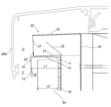
図1は本発明の一実施例による笠木用換気装置の断面図、斜視図、及び同笠木用換気装置を建造物の屋上やベランダの外壁として用いられるパラペットに設置した状態を示す断面図である。
図1(a)は同笠木用換気装置の断面図、図1(b)は同笠木用換気装置の斜視図、図1(c)は同笠木用換気装置を建造物の屋上やベランダの外壁として用いられるパラペットに設置した状態を示す断面図を示している。
A ventilating device for heading according to an embodiment of the present invention will be described below.
FIG. 1 is a cross-sectional view and a perspective view of a ventilation system for a top board according to an embodiment of the present invention, and a cross-sectional view showing a state in which the ventilation system for a top board is installed on a parapet used as the roof of a building or the outer wall of a veranda. .
Fig. 1(a) is a cross-sectional view of the ventilation system for the same top, Fig. 1(b) is a perspective view of the ventilation system for the same top, and Fig. 1(c) is a ventilation system for the same top. Fig. 10 shows a cross-sectional view showing the state installed on a parapet used as a
図1(c)に示す建造物のパラペット80は、外壁下地材81の上部に配置される上枠材82と、外壁下地材81の外面に配置される通気胴縁83と、通気胴縁83の外面に配置される外壁材84と、上枠材82及び外壁材84の上方を覆う笠木85とを有している。
笠木85は、上枠材82及び外壁材84の上部を覆う天面部85aと、天面部85aから垂下して外壁材84の側方に配置される垂下部材85bとを有している。
本実施例による笠木用換気装置は、建造物の外壁材84の上方で、外壁材84より外方に配置される垂下部材85bより内方に配置される。
A
The
The headboard ventilation system according to this embodiment is arranged above the
本実施例による笠木用換気装置は、外壁材84の上端を覆う気密部材10と、気密部材10の上方に配置される換気部材20とを備えている。本実施例における気密部材10は、見切縁10Aで構成されている。
見切縁10Aは、外壁材84の上端を覆う見切縁上面板11と、見切縁上面板11の前端から垂下させた見切縁前面板12と、見切縁上面板11の後端から垂下させた見切縁後面板13とからなる。見切縁後面板13の鉛直方向長さは、見切縁前面板12の鉛直方向長さより長く、見切縁前面板12の鉛直方向長さの1.5倍から3倍の長さが好ましい。見切縁前面板12の下部には後方側に折り曲げられて折返し部12aを形成し、見切縁後面板13の下部には前方側に折り曲げられて折返し部13aを形成している。
The headboard ventilation system according to this embodiment includes an
The
換気部材20は、気密部材10の上面となる見切縁上面板11の上面に対向して配置される換気部材底面板21と、換気部材底面板21の前端から立ち上げた換気部材前面板22と、換気部材前面板22の上端から後方に延出させた換気部材天面板23と、換気部材天面板23の後端から垂下させた換気部材後面板24と、換気部材底面板21の後端から立ち上げた内部防水壁25とからなる。
換気部材前面板22には、換気孔27が形成されている。換気孔27は、高さ方向が幅方向より短い長孔であり、幅方向に複数形成されている。
換気部材底面板21より上方であって換気部材天面板23より下方で、換気部材前面板22の後方であって換気部材後面板24の前方に換気通路Aが形成される。
内部防水壁25は、換気通路Aに設けている。
内部防水壁25の上端は、内部防水壁25の下端よりも換気部材前面板22に近接させ、内部防水壁25の上端は、換気孔27よりも高い位置としている。
The
A
A ventilation passage A is formed above the ventilation
The internal
The upper end of the internal
第1防水パッキン31は、見切縁上面板11の上面に配置され、第2防水パッキン32は、見切縁後面板13の前面に配置される。
第1防水パッキン31及び第2防水パッキン32は、発泡性のゴム又は樹脂素材であり、防水性能と耐久性能が高いEPDMゴムや熱可塑性エラストマーが好ましい。
第1防水パッキン31及び第2防水パッキン32は、見切縁10Aの幅方向長さと同じ長さで帯状に成形されており、粘着剤によって見切縁10Aに固定される。
第1防水パッキン31は、見切縁上面板11の奥行方向の中央部に配置することが好ましい。
第2防水パッキン32は、見切縁前面板12の下端以下の位置に配置することが好ましい。
第1防水パッキン31は、図1(c)に示す施工時には、見切縁上面板11と換気部材底面板21との間で圧縮されて施工される。
また、第2防水パッキン32は、図1(c)に示す施工時には、見切縁後面板13の前面と外壁材84との間で圧縮されて施工される。
The first
The first
The first
The first
The second
The first
1(c), the second
図2は図1(c)の要部拡大断面図である。
本実施例による笠木用換気装置は、見切縁上面板11の奥行寸法L1を外壁材84の厚さL2よりも大きくすることで、見切縁前面板12と外壁材84との間に水切空間Bを形成している。
また、本実施例による笠木用換気装置は、見切縁上面板11の前端は、換気部材底面板21の前端より前方に突出させている。そして、見切縁前面板12と垂下部材85bとの間には、気密部材側通気路Cが形成され、換気部材前面板22と垂下部材85bとの間には、換気部材側通気路Dが形成される。
従って、換気部材側通気路Dは、気密部材側通気路Cよりも、通気路奥行き寸法が大きく、換気部材側通気路Dと気密部材側通気路Cとの通気路奥行き寸法を異ならせている。
FIG. 2 is an enlarged sectional view of a main portion of FIG. 1(c).
In the top rail ventilation system according to this embodiment, the depth dimension L1 of the parting edge
Also, in the ventilation system for topping according to the present embodiment, the front end of the parting
Therefore, the ventilation member-side air passage D has a larger ventilation passage depth than the airtight member-side air passage C, and the ventilation member-side air passage D and the airtight member-side air passage C have different depths. .
本実施例によれば、内部防水壁25の上端を内部防水壁25の下端よりも換気部材前面板22に近接させ、内部防水壁25の上端を、換気孔27よりも高い位置とすることで、換気孔27から流入する雨水を換気部材後面板24に至ることを防止できる。
また、本実施例によれば、第1防水パッキン31により見切縁上面板11と換気部材底面板21との間の防水を行い、第2防水パッキン32により見切縁後面板13の前面と外壁材84との間の防水を行うため、外壁材84の上端と換気部材20との間での防水性能を確保でき、外壁材84に沿って上昇する雨水は、水切空間Bに導かれ、見切縁前面板12に沿って落下するために、換気部材前面板22には導かれず、換気孔27から換気通路Aに流入しないので防水性能に優れる。
According to this embodiment, the upper end of the internal
Further, according to this embodiment, the first
また、本実施例によれば、雨水は、気密部材側通気路C及び換気部材側通気路Dを上昇しなければ換気孔27に至らないため、換気通路Aに流入しにくく、更に防水性に優れる。
また、本実施例によれば、換気部材側通気路Dと気密部材側通気路Cとの通気路奥行き寸法を異ならせることで、雨水の流速が変化するため乱流が発生し、雨水は換気通路Aに流入しにくい。
In addition, according to the present embodiment, rainwater does not reach the ventilation holes 27 unless it rises through the airtight member side air passage C and the ventilation member side air passage D, so it is difficult for rainwater to flow into the ventilation passage A, and furthermore, it is waterproof. Excellent.
In addition, according to the present embodiment, by making the ventilation channel depth dimension of the ventilation member side ventilation channel D and the airtight member side ventilation channel C different, the flow velocity of rainwater changes and turbulence occurs, and the rainwater is ventilated. It is difficult to flow into passage A.
本実施例による笠木用換気装置は、換気部材前面板22は外壁材84より前方に位置させ、換気部材後面板24は外壁材84より後方に位置させている。
従って、換気通路Aの奥行寸法を大きくでき、換気通路Aに流入した雨水を換気通路Aに留めることができ、屋内に雨水が浸入することはない。
In the headboard ventilation system according to this embodiment, the ventilation
Therefore, the depth dimension of the ventilation passage A can be increased, rainwater flowing into the ventilation passage A can be retained in the ventilation passage A, and rainwater will not enter the room.
また、本実施例による笠木用換気装置は、内部防水壁25の上端を内部防水壁25の下端よりも換気部材前面板22に近接させており、換気孔27から流入する雨水を換気部材後面板24に至ることを防止できる。
なお、本実施例による笠木用換気装置では、通気胴縁83を上昇した空気は、換気通路Aを通過して換気孔27から排出される。
In addition, in the top rail ventilation system according to this embodiment, the upper end of the internal
In addition, in the ventilation system for top boards according to this embodiment, the air that has risen through the
図3は本実施例による笠木用換気装置の施工の一部を示す説明図である。
図3(a)に示すように、外壁下地材81に透湿防水シート51を貼る。
そして、図3(b)に示すように、透湿防水シート51を貼った外壁下地材81に換気部材20を、留め具52によって留め付ける。
換気部材20を外壁下地材81に留め付けた後に、図3(c)に示すように、通気胴縁83を、換気部材20の上から外壁下地材81に留め付ける。
このように、換気部材後面板24を、外壁材84よりも建造物側に配置される外壁下地材81に留め付けることで、換気部材後面板24を強固に取り付けることができるとともに、通気胴縁83を外壁下地材81に取り付ける際に、換気部材20を通気胴縁83で外壁下地材81に挟み込むことができる。
FIG. 3 is an explanatory view showing a part of the construction of the ventilation system for top rails according to this embodiment.
As shown in FIG. 3( a ), a moisture-permeable
Then, as shown in FIG. 3B, the
After fixing the
In this way, by fastening the ventilation member
図4は本発明の他の実施例による笠木用換気装置を示し、図4(a)は同笠木用換気装置の断面図、図4(b)は同笠木用換気装置の斜視図、図4(c)は同笠木用換気装置を建造物の屋上やベランダの外壁として用いられるパラペットに設置した状態を示す断面図を示している。なお、上記実施例と同一の機能部材には同一符号を付して説明を省略する。
本実施例による笠木用換気装置は、気密部材10Bを、バックアップ材10Ba及びシーリング材10Bbによって形成している他は、上記実施例と同一である。
4A and 4B show a topboard ventilation device according to another embodiment of the present invention, FIG. 4A is a cross-sectional view of the same headboard ventilation device, FIG. 4B is a perspective view of the same headboard ventilation device, and FIG. (c) is a cross-sectional view showing a state in which the ventilation system for the top rail is installed on the roof of a building or on a parapet used as the outer wall of a veranda. The functional members that are the same as those in the above embodiment are given the same reference numerals, and the description thereof is omitted.
The headboard ventilation system according to this embodiment is the same as the above embodiment except that the
本実施例によれば、内部防水壁25の上端を内部防水壁25の下端よりも換気部材前面板22に近接させ、内部防水壁25の上端を、換気孔27よりも高い位置とすることで、換気孔27から流入する雨水を換気部材後面板24に至ることを防止できる。
また、本実施例によれば、雨水は、気密部材側通気路C及び換気部材側通気路Dを上昇しなければ換気孔27に至らないため、換気通路Aに流入しにくく、更に防水性に優れる。
また、本実施例によれば、換気部材側通気路Dと気密部材側通気路Cとの通気路奥行き寸法を異ならせることで、雨水の流速が変化するため乱流が発生し、雨水は換気通路Aに流入しにくい。
According to this embodiment, the upper end of the internal
In addition, according to the present embodiment, rainwater does not reach the ventilation holes 27 unless it rises through the airtight member side air passage C and the ventilation member side air passage D, so it is difficult for rainwater to flow into the ventilation passage A, and furthermore, it is waterproof. Excellent.
In addition, according to the present embodiment, by making the ventilation channel depth dimension of the ventilation member side ventilation channel D and the airtight member side ventilation channel C different, the flow velocity of rainwater changes and turbulence occurs, and the rainwater is ventilated. It is difficult to flow into passage A.
本実施例による笠木用換気装置は、換気部材前面板22は外壁材84より前方に位置させ、換気部材後面板24は外壁材84より後方に位置させている。
従って、換気通路Aの奥行寸法を大きくでき、換気通路Aに流入した雨水を換気通路Aに留めることができ、屋内に雨水が浸入することはない。
In the headboard ventilation system according to this embodiment, the ventilation
Therefore, the depth dimension of the ventilation passage A can be increased, rainwater flowing into the ventilation passage A can be retained in the ventilation passage A, and rainwater will not enter the room.
また、本実施例による笠木用換気装置は、内部防水壁25の上端を内部防水壁25の下端よりも換気部材前面板22に近接させており、換気孔27から流入する雨水を換気部材後面板24に至ることを防止できる。
なお、本実施例による笠木用換気装置では、通気胴縁83を上昇した空気は、換気通路Aを通過して換気孔27から排出される。
In addition, in the top rail ventilation system according to this embodiment, the upper end of the internal
In addition, in the ventilation system for top boards according to this embodiment, the air that has risen through the
図5は本発明の更に他の実施例による笠木用換気装置を建造物の屋上やベランダの外壁として用いられるパラペットに設置した状態を示す断面図を示している。なお、図1及び図2に示す実施例と同一の機能部材には同一符号を付して説明を省略する。
本実施例による笠木用換気装置は、図2に示すような水切空間Bを形成していない他は、上記実施例と同一である。
すなわち、本実施例では、見切縁前面板12は外壁材84に当接させている。
FIG. 5 is a cross-sectional view showing a state in which a top rail ventilation system according to still another embodiment of the present invention is installed on a parapet used as the roof of a building or the outer wall of a veranda. 1 and 2 are denoted by the same reference numerals, and descriptions thereof are omitted.
The headboard ventilation system according to this embodiment is the same as the above embodiment except that the drainage space B as shown in FIG. 2 is not formed.
That is, in this embodiment, the parting
本実施例によれば、内部防水壁25の上端を内部防水壁25の下端よりも換気部材前面板22に近接させ、内部防水壁25の上端を、換気孔27よりも高い位置とすることで、換気孔27から流入する雨水を換気部材後面板24に至ることを防止できる。
また、本実施例によれば、第1防水パッキン31により見切縁上面板11と換気部材底面板21との間の防水を行い、第2防水パッキン32により見切縁後面板13の前面と外壁材84との間の防水を行うため、外壁材84の上端と換気部材20との間での防水性能を確保できる。
According to this embodiment, the upper end of the internal
Further, according to this embodiment, the first
また、本実施例によれば、雨水は、気密部材側通気路C及び換気部材側通気路Dを上昇しなければ換気孔27に至らないため、換気通路Aに流入しにくく、更に防水性に優れる。
また、本実施例によれば、換気部材側通気路Dと気密部材側通気路Cとの通気路奥行き寸法を異ならせることで、雨水の流速が変化するため乱流が発生し、雨水は換気通路Aに流入しにくい。
In addition, according to the present embodiment, rainwater does not reach the ventilation holes 27 unless it rises through the airtight member side air passage C and the ventilation member side air passage D, so it is difficult for rainwater to flow into the ventilation passage A, and furthermore, it is waterproof. Excellent.
In addition, according to the present embodiment, by making the ventilation channel depth dimension of the ventilation member side ventilation channel D and the airtight member side ventilation channel C different, the flow velocity of rainwater changes and turbulence occurs, and the rainwater is ventilated. It is difficult to flow into passage A.
本実施例による笠木用換気装置は、換気部材前面板22は外壁材84より前方に位置させ、換気部材後面板24は外壁材84より後方に位置させている。
従って、換気通路Aの奥行寸法を大きくでき、換気通路Aに流入した雨水を換気通路Aに留めることができ、屋内に雨水が浸入することはない。
In the headboard ventilation system according to this embodiment, the ventilation
Therefore, the depth dimension of the ventilation passage A can be increased, rainwater flowing into the ventilation passage A can be retained in the ventilation passage A, and rainwater will not enter the room.
また、本実施例による笠木用換気装置は、内部防水壁25の上端を内部防水壁25の下端よりも換気部材前面板22に近接させており、換気孔27から流入する雨水を換気部材後面板24に至ることを防止できる。
なお、本実施例による笠木用換気装置では、通気胴縁83を上昇した空気は、換気通路Aを通過して換気孔27から排出される。
In addition, in the top rail ventilation system according to this embodiment, the upper end of the internal
In addition, in the ventilation system for top boards according to this embodiment, the air that has risen through the
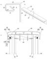
図6は本発明の笠木用換気装置に用いる換気部材の他の実施例を示し、図6(a)は組図、図6(b)は分離図である。
図6に示す換気部材20Xは、上記実施例で説明した換気部材20に代えて用いることができる。
6A and 6B show another embodiment of the ventilation member used in the ventilator for topping of the present invention, where FIG. 6(a) is an assembled drawing and FIG. 6(b) is a separated drawing.
A ventilation member 20X shown in FIG. 6 can be used in place of the
換気部材20Xは、気密部材10の上面となる見切縁上面板11の上面に対向して配置される換気部材底面板21と、換気部材底面板21の前端から立ち上げた換気部材前面板22と、換気部材前面板22の上端から後方に延出させた換気部材天面板23と、換気部材天面板23の後端から垂下させた換気部材後面板24と、換気部材底面板21の後端から立ち上げた内部防水壁25とからなる。
換気部材前面板22には、換気孔27が形成されている。換気孔27は、高さ方向が幅方向より短い長孔であり、幅方向に複数形成されている。
換気部材底面板21より上方であって換気部材天面板23より下方で、換気部材前面板22の後方であって換気部材後面板24の前方に換気通路Aが形成される。
換気部材底面板21の後端には、換気部材底面板21の後端から立ち上げた底面立上板21xを形成している。
内部防水壁25の上端には前方下方に折り曲げた支持片25xを形成し、内部防水壁25の下端には後方上方に折り曲げた支持片25yを形成している。また、内部防水壁25の上部には通路孔25zを形成している。通路孔25zの下端は、換気孔27の上端よりも高い位置に形成している。支持片25xは換気部材前面板22に当接し、支持片25yは底面立上板21xに当接させる。
このように、内部防水壁25の上端を換気部材前面板22の上部に当接させ、内部防水壁25の下端を底面立上板21xの下部に当接させることで、内部防水壁25を別部材とすることができ、換気通路A内に内部防水壁25を位置決めしやすい。
The ventilation member 20X includes a ventilation
A
A ventilation passage A is formed above the ventilation
A rear end of the ventilation
The upper end of the internal
In this manner, the upper end of the internal
本発明は、外壁通気層の出口としての陸屋根やバルコニーの笠木下に用いる換気装置に適している。 INDUSTRIAL APPLICABILITY The present invention is suitable for a ventilator used under the coping of a flat roof or balcony as the outlet of the outer wall ventilation layer.
10 気密部材
10A 見切縁
10B 気密部材
10Ba バックアップ材
10Bb シーリング材
11 見切縁上面板
12 見切縁前面板
12a 折返し部
13 見切縁後面板
13a 折返し部
20 換気部材
20x 換気部材
21 換気部材底面板
21x 底面立上板
22 換気部材前面板
23 換気部材天面板
24 換気部材後面板
25 内部防水壁
25x 支持片
25y 支持片
25z 通路孔
27 換気孔
31 第1防水パッキン
32 第2防水パッキン
51 透湿防水シート
52 留め具
80 パラペット
81 外壁下地材
82 上枠材
83 通気胴縁
84 外壁材
85 笠木
85a 天面部
85b 垂下部材
A 換気通路
B 水切空間
C 気密部材側通気路
D 換気部材側通気路
L1 奥行寸法
L2 厚さ
10
Claims (2)
前記外壁材と前記笠木との間に配置される換気部材が、
換気部材底面板の前端から立ち上げた換気部材前面板と、
前記換気部材前面板の上端から後方に延出させた換気部材天面板と、
前記換気部材底面板の後端側から立ち上げた内部防水壁と
からなり、
前記換気部材前面板には、前記換気孔が形成され、
前記換気孔を、高さ方向が幅方向より短い長孔とし、
前記換気部材前面板の幅方向に前記換気孔が複数形成され、
前記換気部材底面板と前記換気部材天面板との間に、前記通気胴縁を上昇した前記空気が通過する換気通路が形成され、
前記内部防水壁を、前記換気通路に配置し、
前記内部防水壁の上端を前記内部防水壁の下端よりも前記換気部材前面板に近接させ、
前記内部防水壁の前記上端を、前記換気孔よりも高い位置とした
ことを特徴とする笠木用換気装置。 An upper frame member placed on top of an exterior wall base member of a building, a ventilation furring strip placed on the outer surface of the outer wall base member, an outer wall member placed on the outer surface of the ventilation furring strip, and the upper frame member . and a headboard that covers the upper side of the outer wall material, and is disposed between the outer wall material and the topboard, and exhausts the air that has risen through the ventilation furrings from ventilation holes. There is
A ventilation member arranged between the outer wall material and the top rail,
a ventilation member front plate raised from the front end of the ventilation member bottom plate;
a ventilation member top panel extending rearward from the upper end of the ventilation member front panel ;
and an internal waterproof wall raised from the rear end side of the bottom plate of the ventilation member,
The ventilation member front plate is formed with the ventilation hole,
The ventilation hole is an elongated hole whose height direction is shorter than its width direction,
A plurality of ventilation holes are formed in the width direction of the ventilation member front plate,
A ventilation passage is formed between the bottom plate of the ventilation member and the top plate of the ventilation member, through which the air that has ascended the ventilation furring passes ,
placing the internal waterproof wall in the ventilation passage;
bringing the upper end of the internal waterproof wall closer to the front panel of the ventilation member than the lower end of the internal waterproof wall;
A ventilator for a coping, wherein the upper end of the internal waterproof wall is positioned higher than the ventilation hole.
ことを特徴とする請求項1に記載の笠木用換気装置。
The front panel of the ventilation member is located forward of the outer wall material.
2. The ventilating device for headboard according to claim 1 , characterized in that:
Priority Applications (2)
| Application Number | Priority Date | Filing Date | Title |
|---|---|---|---|
| JP2020201531A JP7279950B2 (en) | 2020-12-04 | 2020-12-04 | Ventilation system for top rail |
| JP2023075568A JP2023086998A (en) | 2020-12-04 | 2023-05-01 | Ventilation device for top rail |
Applications Claiming Priority (1)
| Application Number | Priority Date | Filing Date | Title |
|---|---|---|---|
| JP2020201531A JP7279950B2 (en) | 2020-12-04 | 2020-12-04 | Ventilation system for top rail |
Related Child Applications (1)
| Application Number | Title | Priority Date | Filing Date |
|---|---|---|---|
| JP2023075568A Division JP2023086998A (en) | 2020-12-04 | 2023-05-01 | Ventilation device for top rail |
Publications (3)
| Publication Number | Publication Date |
|---|---|
| JP2022089267A JP2022089267A (en) | 2022-06-16 |
| JP2022089267A5 JP2022089267A5 (en) | 2023-01-19 |
| JP7279950B2 true JP7279950B2 (en) | 2023-05-23 |
Family
ID=81989246
Family Applications (2)
| Application Number | Title | Priority Date | Filing Date |
|---|---|---|---|
| JP2020201531A Active JP7279950B2 (en) | 2020-12-04 | 2020-12-04 | Ventilation system for top rail |
| JP2023075568A Pending JP2023086998A (en) | 2020-12-04 | 2023-05-01 | Ventilation device for top rail |
Family Applications After (1)
| Application Number | Title | Priority Date | Filing Date |
|---|---|---|---|
| JP2023075568A Pending JP2023086998A (en) | 2020-12-04 | 2023-05-01 | Ventilation device for top rail |
Country Status (1)
| Country | Link |
|---|---|
| JP (2) | JP7279950B2 (en) |
Families Citing this family (12)
| Publication number | Priority date | Publication date | Assignee | Title |
|---|---|---|---|---|
| JP7235153B2 (en) * | 2017-12-29 | 2023-03-08 | 株式会社三洋物産 | game machine |
| JP7235154B2 (en) * | 2018-02-15 | 2023-03-08 | 株式会社三洋物産 | game machine |
| JP7231076B2 (en) * | 2018-03-08 | 2023-03-01 | 株式会社三洋物産 | game machine |
| JP2020130466A (en) * | 2019-02-15 | 2020-08-31 | 株式会社三洋物産 | Game machine |
| JP7234740B2 (en) * | 2019-03-28 | 2023-03-08 | 株式会社三洋物産 | game machine |
| JP7234741B2 (en) * | 2019-03-28 | 2023-03-08 | 株式会社三洋物産 | game machine |
| JP7234760B2 (en) * | 2019-04-11 | 2023-03-08 | 株式会社三洋物産 | game machine |
| JP7234761B2 (en) * | 2019-04-11 | 2023-03-08 | 株式会社三洋物産 | game machine |
| JP2023063369A (en) * | 2022-01-07 | 2023-05-09 | 株式会社三洋物産 | game machine |
| JP2023053387A (en) * | 2022-02-04 | 2023-04-12 | 株式会社三洋物産 | game machine |
| JP2023060269A (en) * | 2022-04-01 | 2023-04-27 | 株式会社三洋物産 | game machine |
| JP2023060270A (en) * | 2022-04-01 | 2023-04-27 | 株式会社三洋物産 | game machine |
Citations (7)
| Publication number | Priority date | Publication date | Assignee | Title |
|---|---|---|---|---|
| JP2012102486A (en) | 2010-11-08 | 2012-05-31 | Tookoo:Kk | Parapet ventilation structure |
| JP2014031709A (en) | 2012-07-11 | 2014-02-20 | Misawa Homes Co Ltd | Ventilation structure of building |
| JP2016089577A (en) | 2014-11-11 | 2016-05-23 | 株式会社トーコー | Ventilator for parapet |
| JP2017002551A (en) | 2015-06-09 | 2017-01-05 | 倉敷紡績株式会社 | Ventilation structure and ventilation material of building |
| JP2017133265A (en) | 2016-01-29 | 2017-08-03 | ケイミュー株式会社 | Parapet ventilation structure and ventilation metal fitting |
| JP2017133274A (en) | 2016-01-29 | 2017-08-03 | ケイミュー株式会社 | Ventilation structure of exterior wall and ventilation member for use in the same |
| JP2017197961A (en) | 2016-04-27 | 2017-11-02 | 城東テクノ株式会社 | Ventilation material and ventilation structure |
-
2020
- 2020-12-04 JP JP2020201531A patent/JP7279950B2/en active Active
-
2023
- 2023-05-01 JP JP2023075568A patent/JP2023086998A/en active Pending
Patent Citations (7)
| Publication number | Priority date | Publication date | Assignee | Title |
|---|---|---|---|---|
| JP2012102486A (en) | 2010-11-08 | 2012-05-31 | Tookoo:Kk | Parapet ventilation structure |
| JP2014031709A (en) | 2012-07-11 | 2014-02-20 | Misawa Homes Co Ltd | Ventilation structure of building |
| JP2016089577A (en) | 2014-11-11 | 2016-05-23 | 株式会社トーコー | Ventilator for parapet |
| JP2017002551A (en) | 2015-06-09 | 2017-01-05 | 倉敷紡績株式会社 | Ventilation structure and ventilation material of building |
| JP2017133265A (en) | 2016-01-29 | 2017-08-03 | ケイミュー株式会社 | Parapet ventilation structure and ventilation metal fitting |
| JP2017133274A (en) | 2016-01-29 | 2017-08-03 | ケイミュー株式会社 | Ventilation structure of exterior wall and ventilation member for use in the same |
| JP2017197961A (en) | 2016-04-27 | 2017-11-02 | 城東テクノ株式会社 | Ventilation material and ventilation structure |
Also Published As
| Publication number | Publication date |
|---|---|
| JP2023086998A (en) | 2023-06-22 |
| JP2022089267A (en) | 2022-06-16 |
Similar Documents
| Publication | Publication Date | Title |
|---|---|---|
| JP7279950B2 (en) | Ventilation system for top rail | |
| JP2022089267A5 (en) | ||
| JP2023086998A5 (en) | ||
| US10538919B2 (en) | Spaced vent for metal roofs | |
| JP5806179B2 (en) | Eave sky ventilation structure | |
| JP2013108314A (en) | Cap piece lower ventilation structure | |
| JP5849256B2 (en) | Ventilation structure | |
| US8528270B2 (en) | Fascia vent | |
| JP6867110B2 (en) | Ventilation material and ventilation structure | |
| JP5259000B1 (en) | Kasagi lower ventilation structure | |
| JP4880084B1 (en) | Eaves ventilation structure | |
| US2777381A (en) | Roof ventilating devices | |
| JP7149673B1 (en) | ventilation structure | |
| JP4914967B1 (en) | Ventilation rain presser | |
| JP4960159B2 (en) | Nasal cover | |
| JP2022089268A (en) | Exterior wall material top ventilation arrangement | |
| JP6962542B2 (en) | Kasagi structure | |
| JP5269264B1 (en) | Kasagi lower ventilation structure | |
| JP6803609B2 (en) | Ventilation structure | |
| JP6393605B2 (en) | Joint structure | |
| JP5457862B2 (en) | Venting material and exterior wall structure of buildings | |
| JP7148951B2 (en) | Ventilation cross plate and ventilation roof using the same | |
| JP6653720B2 (en) | Kasagi structure and ventilation member | |
| JP6927839B2 (en) | Eaves structure | |
| JP2023146208A (en) | ventilation structure |
Legal Events
| Date | Code | Title | Description |
|---|---|---|---|
| A521 | Request for written amendment filed |
Free format text: JAPANESE INTERMEDIATE CODE: A523 Effective date: 20230106 |
|
| A621 | Written request for application examination |
Free format text: JAPANESE INTERMEDIATE CODE: A621 Effective date: 20230106 |
|
| A871 | Explanation of circumstances concerning accelerated examination |
Free format text: JAPANESE INTERMEDIATE CODE: A871 Effective date: 20230106 |
|
| TRDD | Decision of grant or rejection written | ||
| A01 | Written decision to grant a patent or to grant a registration (utility model) |
Free format text: JAPANESE INTERMEDIATE CODE: A01 Effective date: 20230404 |
|
| A61 | First payment of annual fees (during grant procedure) |
Free format text: JAPANESE INTERMEDIATE CODE: A61 Effective date: 20230501 |
|
| R150 | Certificate of patent or registration of utility model |
Ref document number: 7279950 Country of ref document: JP Free format text: JAPANESE INTERMEDIATE CODE: R150 |