JP7272946B2 - Fishing rods and draw-type fishing rod sets - Google Patents
Fishing rods and draw-type fishing rod sets Download PDFInfo
- Publication number
- JP7272946B2 JP7272946B2 JP2019235478A JP2019235478A JP7272946B2 JP 7272946 B2 JP7272946 B2 JP 7272946B2 JP 2019235478 A JP2019235478 A JP 2019235478A JP 2019235478 A JP2019235478 A JP 2019235478A JP 7272946 B2 JP7272946 B2 JP 7272946B2
- Authority
- JP
- Japan
- Prior art keywords
- rod
- cover member
- fishing
- base rod
- base
- Prior art date
- Legal status (The legal status is an assumption and is not a legal conclusion. Google has not performed a legal analysis and makes no representation as to the accuracy of the status listed.)
- Active
Links
Images


Classifications
-
- A—HUMAN NECESSITIES
- A01—AGRICULTURE; FORESTRY; ANIMAL HUSBANDRY; HUNTING; TRAPPING; FISHING
- A01K—ANIMAL HUSBANDRY; CARE OF BIRDS, FISHES, INSECTS; FISHING; REARING OR BREEDING ANIMALS, NOT OTHERWISE PROVIDED FOR; NEW BREEDS OF ANIMALS
- A01K87/00—Fishing rods
-
- A—HUMAN NECESSITIES
- A01—AGRICULTURE; FORESTRY; ANIMAL HUSBANDRY; HUNTING; TRAPPING; FISHING
- A01K—ANIMAL HUSBANDRY; CARE OF BIRDS, FISHES, INSECTS; FISHING; REARING OR BREEDING ANIMALS, NOT OTHERWISE PROVIDED FOR; NEW BREEDS OF ANIMALS
- A01K87/00—Fishing rods
- A01K87/04—Fishing-line guides on rods, e.g. tips
Description
本発明は、振出式の釣竿及び振出式の釣竿セットに関する。 The present invention relates to a swing-out fishing rod and a swing-out fishing rod set.
従来、振出式の釣竿が知られている。振出式の釣竿は、元竿杆の内部に複数本の竿杆を収納しており、元竿杆の内部から各竿杆を順次引き出し、大径竿杆の先端に小径竿杆の後端を継合することで使用される。このような振出式の釣竿は、並継竿と比較すると持ち運びが便利であるという利点があり、全ての竿杆を元竿杆に収納した状態で、その先端側には、例えば、特許文献1,2に開示されているような保護カバーやトップカバーを取り付けて、収納した竿杆が突出しないようにしている。 Conventionally, a swing-type fishing rod is known. A swing-out type fishing rod stores a plurality of rods inside a base rod. Used by splicing. Such a swing-out fishing rod has the advantage of being more convenient to carry than a parallel rod. , 2 to prevent the stored rods from protruding.
また、近年の魚釣りでは、長尺竿の持ち運びが大変なことや、運搬が運送会社の制限によって運送できない、更には、運送費が高騰している等の理由から、運搬時に短い仕舞寸法にできる釣竿(モバイルロッドとも称する)が注目を浴びている。このようなモバイルロッドは、バッグや小物入れ等に収納できるように元竿杆を短くすると共に、多数本の竿杆を収納しており、釣りをしたいときに手軽に使用できるように構成されている。 In addition, in recent fishing, it is difficult to carry a long rod, transportation is not possible due to restrictions by shipping companies, and transportation costs are rising. Fishing rods (also called mobile rods) have received much attention. Such a mobile rod has a short base rod so that it can be stored in a bag or an accessory case, and has a large number of rods, so that it can be easily used when fishing. there is
上記したような振出式の釣竿に装着される保護カバーやトップカバー(以下、保護カバーと称する)は、収納時に竿杆が不用意に突出したり損傷することを防止し、更には、釣糸が挿通される釣糸ガイドが装着されている釣竿では、釣糸ガイドが破損等しないように保護する役目を果たしている。このような保護カバーは、釣りを行なう際、どこか他の場所で保管する必要があるが、紛失したり、地面において踏んで破損等してしまうと、保護カバー無しの状態で釣竿を保管することとなり、運搬時等において、竿杆や釣糸ガイドを破損するという問題が生じる。また、釣りをする際、保護カバーは、必要のない部品になってしまうため、保管や取扱いが不便でもある。 A protective cover or a top cover (hereinafter referred to as a protective cover) attached to the swing-out type fishing rod as described above prevents the rod from carelessly protruding or being damaged when stored, and furthermore, prevents the fishing line from being inserted. In the case of a fishing rod equipped with a fishing line guide, the fishing line guide plays a role of protecting the fishing line guide from damage. Such a protective cover needs to be stored somewhere else when fishing, but if it is lost or damaged by stepping on the ground, the fishing rod must be stored without the protective cover. As a result, there arises a problem that the rod and the fishing line guide are damaged during transportation. Moreover, when fishing, the protective cover becomes an unnecessary component, which is inconvenient to store and handle.
さらに、モバイルロッドでは、上記した問題点があることに加え、仕舞寸法を小さくしようとすると、元竿杆を短くする必要があり、このような構成では、グリップ部分が短かくなると共に使用時の全長が短くなってしまい、使用状態が制限される等、操作性が低下するという問題が生じる。 Furthermore, in addition to the above-mentioned problems, the mobile rod needs to be shortened in order to reduce the size of the final rod. Since the total length is shortened, there arises a problem that the operability is deteriorated, for example, the state of use is restricted.
本発明は、上記した問題に着目してなされたものであり、使用時に保護カバーが紛失したり破損等することなく、運搬性及び操作性が良好な振出式の釣竿、及び、釣竿セットを提供することを目的とする。 The present invention has been made in view of the above-described problems, and provides a swing-out fishing rod and a fishing rod set that are easy to carry and operate, and that the protective cover is not lost or damaged during use. intended to
上記した目的を達成するために、本発明は、複数の竿杆を収納する元竿杆を備え、収納された各竿杆を振出式に継合する振出式の釣竿であって、前記元竿杆に対して前記複数の竿杆が突出しないように被着されるカバー部材を有し、前記カバー部材は、前記元竿杆の後端に対して着脱可能なグリップを構成することを特徴とする。 In order to achieve the above object, the present invention provides a swing-out fishing rod that includes a base rod that houses a plurality of rods, and joins each of the housed rods in a swing-out manner, the base rod A cover member is provided so that the plurality of rods do not protrude from the rods, and the cover member constitutes a grip that can be attached to and detached from the rear end of the base rod. do.
上記した構成の振出式の釣竿は、元竿杆に収納される複数の竿杆を突出させないカバー部材が、元竿杆の後端に対して着脱可能なグリップを構成(兼用)するため、実釣時において、カバー部材が紛失するようなことはない。また、元竿杆に対してカバー部材をグリップとして装着する構成であるため、使用時は、元竿杆を長くすることができ、かつ、収納時には、カバー部材となるため、運搬性及び使用時の操作性が向上する。 In the above swing-out fishing rod, the cover member that does not project the plurality of rods stored in the base rod constitutes (also serves as) a grip that can be attached to and detached from the rear end of the base rod. The cover member will not be lost during fishing. In addition, since the cover member is attached to the base rod as a grip, the base rod can be lengthened during use, and since it becomes a cover member when stored, it is easy to transport and use. operability is improved.
また、上記した目的を達成するために、本発明は、複数の竿杆を収納する元竿杆を備え、収納された各竿杆を振出式に継合する振出式の釣竿セットであり、前記元竿杆に対して前記複数の竿杆が突出しないように着脱可能に被着されると共に、前記元竿杆の後端に対して着脱可能なグリップを構成する筒状のカバー部材を設け、前記カバー部材に開口係止部を設け、この開口係止部に挿通される保持部材を備えたことを特徴とする。 Further, in order to achieve the above object, the present invention provides a swing-out fishing rod set that includes a base rod for housing a plurality of rods, and joins each of the housed rods in a swing-out manner. A cylindrical cover member is detachably attached to the base rod so that the plurality of rods do not protrude, and constitutes a grip that is detachable with respect to the rear end of the base rod, The cover member is provided with an opening engaging portion, and a holding member inserted through the opening engaging portion is provided.
上記した釣竿セットは、元竿杆に収納される複数の竿杆を突出させないカバー部材が、元竿杆の後端に対して着脱可能なグリップを構成するため、実釣時において、カバー部材が紛失するようなことはない。また、元竿杆に対してカバー部材をグリップとして装着する構成であるため、使用時は、元竿杆を長くすることができ、かつ、収納時には、元竿杆に装着されるカバー部材を、開口係止部に挿通される保持部材によって保持するため、運搬性及び使用時の操作性が向上する。 In the fishing rod set described above, the cover member that does not project the plurality of rods housed in the base rod constitutes a grip that can be attached to and detached from the rear end of the base rod. You will never lose it. In addition, since the cover member is attached to the base rod as a grip, the base rod can be lengthened when used, and the cover member attached to the base rod can be used as a grip when stored. Since it is held by the holding member inserted through the opening engaging portion, the portability and operability during use are improved.
本発明によれば、使用時に保護カバーが紛失したり破損等することなく、運搬性及び操作性が良好な振出式の釣竿、及び、振出式の釣竿セットが得られる。 According to the present invention, it is possible to obtain a swing-out fishing rod and a swing-out fishing rod set that are easy to transport and operate without the loss or damage of the protective cover during use.
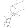
図1から図3は、本発明に係る釣竿の第1の実施形態を示す図であり、図1(a)は複数の竿杆の収納状態を示す部分断面図、図1(b)は収納状態の斜視図、図2は、図1に示す釣竿の複数の竿杆の一部を振り出した使用状態を示す斜視図、そして、図3は、図1に示す釣竿の使用状態でのグリップ部分を示す図であり、図3(a)は部分断面図、図3(b)は斜視図である。
1 to 3 are diagrams showing a first embodiment of a fishing rod according to the present invention, FIG. 1(a) being a partial cross-sectional view showing a plurality of rods stored, and FIG. FIG. 2 is a perspective view of the fishing rod shown in FIG. 1 in use with a portion of the plurality of rods swung out, and FIG. 3 is a grip portion of the fishing rod shown in FIG. 1 in use. FIG. 3 (a) is a partial cross-sectional view, and FIG. 3 (b) is a perspective view.
本発明の釣竿1は、公知のように、複数の竿杆6a,6b,6c,6d,6e……6Nを順次振り出して、大径の竿杆の先端に小径の竿杆の基端を継合させる振出式に構成されており、複数の竿杆は、大径の竿杆内に順次収納され、全ての竿杆が最も大径の竿杆(元竿杆)5の内部に収納された状態となっている。本発明では、元竿杆5の内部に収納される竿杆の本数(継合本数)については任意であり、N本(竿杆6a~竿杆6N)の竿杆が順次大径の竿杆に収納され、最も小径の竿杆6Nが穂先竿杆となっている。
なお、図1(a)及び図2では、収納される竿杆の全てを図示していない。また、図1(a)では、分かりやすくするために、収納される竿杆を示しているが、元竿杆5に後述するカバー部材30が装着されて元竿杆が覆われるため、露出することはない(図1(b)参照)。さらに、本実施形態の釣竿は、リールシート及び釣糸ガイドを備えており、スピニングリール及び両軸受リールの両タイプのリールが使用できる構成となっている。このため、スピニングリールを使用する場合、リールシート及び釣糸ガイドが下方側に向くように使用され、両軸受リールを使用する場合、リールシート及び釣糸ガイドが上方側に向くように使用される。
As is well known, the
1(a) and 2 do not show all of the rods to be housed. In addition, in FIG. 1(a), for the sake of clarity, the housed rod is shown, but since the
本実施形態の釣竿1は、上記したように、スピニングリール、両軸受型リール等のリールを装着して使用可能な構成となっており、各竿杆の先端部分には、リールから繰り出される釣糸を挿通させる釣糸ガイド8,8a~8Nが取り付けられている。この場合、釣糸ガイド8Nは、いわゆる穂先ガイドとなっている。また、図1(a)では、図2において示す元竿杆5に装着される釣糸ガイド8が示されていないが、この釣糸ガイド8は、後述するように着脱式に構成されている。また、釣糸ガイドの一部には遊動ガイドが含まれていても良い。
As described above, the
上記した元竿杆5及び元竿杆5に収納される複数の竿杆6a~6Nは、公知のように繊維強化樹脂製の管状体として構成されており、例えば、強化繊維(主に炭素繊維やガラス繊維等)に、エポキシ樹脂等の合成樹脂を含浸した繊維強化樹脂のプリプレグシートを芯金(マンドレル)に巻回し加熱工程を経た後、脱芯するなど、定法に従って形成されている。前記穂先竿杆6Nについては、管状体以外にも、中実ソリッド、或いは、ソリッド体と管状体の組み合わせで構成されていても良い。
The above-described
前記元竿杆5には、リールが装着されるリールシート7が設けられている。リールシート7は、元竿杆5の基端領域に設けられており、公知のように、リール脚が載置されるリール脚載置部7aと、その前後に配設されてリール脚を締め付けるフード部7b,7cとを備えている。本実施形態では、後方側のフード部7cが固定フードとなっており、前方側のフード部7bが軸方向に移動する移動フードとなっている(以下、移動フード7b、固定フード7cと称する)。
The
前記固定フード7cは、元竿杆5の基端部の外周面に固定されており、リール脚載置部7aに向けて開口する受入穴7caを備えている。また、移動フード7bは、リール脚載置部7aに向けて開口する受入穴7baを備えている(受入穴7baは360°に亘って開口していても良い)。前記移動フード7bは、元竿杆5に設けられた雄螺子部に対して螺合する雌螺子部が形成された操作部7bbを備えており、リール脚載置部7aにリール脚を載置しながら後方側を固定フード7cの受入穴7caに嵌入し、操作部7bbを回転操作することで、リール脚は、移動フード7bの受入穴7baと固定フード7cの受入穴7caとで締め付け固定される。なお、リールシートの構成、移動フードの移動機構等については公知であるため、詳細な説明については省略する。
The fixed
元竿杆5は、前記固定フード7cの後端側が軸方向に突出しており、その突出部5aに下栓(尻栓)10が取り付けられている。下栓10は、図4に示すようにキャップ状に形成されており、その後端面10aには空気孔10bが形成されている。下栓10の周壁10cの内面には、前記突出部5aに形成された雄螺子部に螺合する雌螺子部10dが設けられている。この雌螺子部10dは、周壁10cの内面に直接形成しても良いし、図4に示すように、周壁10cに圧入固定される環状体10eの内面に形成されたものであっても良い。また、周壁10cの外周面には、後述するカバー部材30の開口端部を圧入して固定し易いようにリング状の凹凸10fが複数個形成されている(圧入構造が形成されている)。すなわち、下栓10は、元竿杆5の後端の開口を閉塞すると共に、カバー部材30の後端の開口を閉塞する機能を有する。
なお、下栓10の内面は、螺合構造ではなく圧入構造であっても良いし、下栓10の外面は、圧入構造ではなく螺合構造であっても良い。
The
The inner surface of the
前記元竿杆5の後端開口部分には、キャップ部材12が着脱可能に固定されている。このキャップ部材12は、元竿杆5から下栓10を取り外し、これをカバー部材30に取り付けするに際して、収納された竿杆を落下させない機能を有する。このキャップ部材12の後端面には、空気抜き用の開口12aを形成しておくことが好ましい。
A
前記元竿杆5には、従来の振出式の釣竿における保護カバーとしての機能(元竿杆内に収納された複数の竿杆の突出を防止する機能)を果たすカバー部材30が着脱可能に装着されている。このカバー部材30は、元竿杆5から取り外すことができ、元竿杆5の後端部に装着することで、実釣時に握持、保持される、いわゆるグリップとしての機能を兼ね備えている。
To the
以下、カバー部材30の構成について具体的に説明する。
本実施形態のカバー部材30は、前記元竿杆5に対して軸方向に沿って被せられるように(元竿杆5を覆うように)筒状体で構成されており、収納状態で棒状になるように構成されている。筒状体の断面形状については、多角形、円、楕円等、特に限定されることはないが、元竿杆5が断面円形の管状体であるため、デザイン及び外観等を考慮して、円筒形状(断面円形)に形成することが好ましい。また、材質についても特に限定されることはなく、例えば、元竿杆5、及び、これに収納される複数の竿杆6a~6Nと同じ材料、アルミ、SUS等の各種金属、樹脂、繊維強化樹脂等で形成されていても良く、必要に応じて塗装や物理的な蒸着、化学的な蒸着などの各種表面処理を施して外観を向上させても良い。或いは、グリップとしての機能を兼ね備えることから、通常のグリップと同様、例えば、EVA、コルク等の柔軟性のある素材を被着して、握持、保持性を向上させても良い。
The configuration of the
The
前記円筒形状のカバー部材30は、元竿杆5の先端側から軸方向から被せるように被着することから、カバー部材30と元竿杆5には、カバー部材30を被着した際、両者を固定する固定構造が設けられている。本実施形態のカバー部材30は、元竿杆5に設けられた前記リールシート7を露出させる位置まで被せることが可能に構成されており、固定構造は、カバー部材30を圧入して、元竿杆5との間の摩擦力で固定するよう構成されている。
Since the
具体的には、前記移動フード7bの外表面、及び、移動フードの操作部7bbの前側に装着されたリング部材の外表面に、それぞれリング状の凹凸5A,5Bを形成し、その部分で、カバー部材30の開口内面、及び、先端側の内面が圧入、固定できるように構成されている。このため、カバー部材30を元竿杆5に被着して固定すると、前記リールシート7のリール脚載置部7aが露出した状態となる。
なお、カバー部材30と元竿杆5の固定構造、固定位置、固定方法については特に限定されることはなく、螺合構造で固定しても良いし、爪による係止構造等、適宜変形することが可能である。
Specifically, ring-shaped projections and
The fixing structure, fixing position, and fixing method of the
本実施形態のカバー部材30の先端には、上栓40が着脱可能に設けられている。上栓40は、カバー部材30の先端開口に対して圧入可能であり、本実施形態では、上栓40の本体41に雄螺子部41aを形成しておき、この部分をカバー部材30の先端に固定されている雌螺子部材32に螺合することで着脱可能に固定されるようになっている。また、上栓40の本体41には、後述するリング状の保持部材70(図8参照)に係止してセット化できるように、開口係止部41bが形成されている。この開口係止部41bは、保持部材70が挿通できるような構造であれば良く、図8に示すように、リング部材72を介して保持部材70に係止する等、適宜変形することが可能である。
なお、上栓40は、カバー部材30の先端の開口内面に圧入して固定する構造であっても良い。また、カバー部材30は、上栓40を設けることなく、複数の竿杆の突出を防止するだけの構造であっても良い。このような構成では、カバー部材30のいずれかに開口係止部を設けておけば良い。
An
Note that the
上記したカバー部材30は、軸長方向に所定の長さL1を備えており、図2及び図3に示すように、元竿杆5の後端に取り付けることにより、釣竿として、長さL1のグリップを構成する。すなわち、従来の振出式の釣竿では、握持、保持される部分は、長さLの元竿杆5の領域となっていたが、カバー部材30を元竿杆5の後端に取り付けることで、実釣時の釣竿は、カバー部材30の長さL1分だけ伸ばすことが可能となる(操作方法については後述する)。
The above-described
本実施形態の釣竿は、上記したようにリールが装着可能に構成されており、各竿杆には、リールから繰り出される釣糸を挿通させる釣糸ガイドが装着されている。この場合、被着されるカバー部材30は、装着された釣糸ガイドとの間で干渉しないように構成することが好ましい。例えば、両軸受型リールの場合、装着される釣糸ガイドの高さはそれほど高くなくても良いため、前記カバー部材30を元竿杆5に被着しても、カバー部材30と釣糸ガイドは干渉しないようにすることが可能である。或いは、カバー部材30の径を多少、大きくすることで、そのような干渉を防止することも可能である。
As described above, the fishing rod of this embodiment is configured to be mountable with a reel, and each rod is equipped with a fishing line guide through which a fishing line drawn out from the reel is inserted. In this case, it is preferable that the
ただし、スピニングリールを装着する場合、図2及び図3に示すように、釣糸ガイド(特に基端側の釣糸ガイド8)の高さは高くなり、元竿杆5に被着されるカバー部材30との間で干渉する可能性が生じる。上記したように、カバー部材30の径を大径化することで干渉を防ぐことも可能であるが、干渉が生じる釣糸ガイドを竿杆に対して着脱可能に構成することで、カバー部材30を大径化する必要性がなくなる。例えば、元竿杆5の先端に装着される釣糸ガイド8の高さが高い場合、図6に示すように、元竿杆5の先端に差込開口5eを有する膨出部5dを設けておき、この部分に釣糸ガイド8の脚部8Aを圧入して着脱可能な構造としても良い。
However, when a spinning reel is attached, as shown in FIGS. 2 and 3, the height of the fishing line guide (especially the
このような着脱式の釣糸ガイド8は、釣糸が挿通される釣糸挿通孔8Bや、場合によっては軽量化を図るための開口8Cが形成されるため、図8に示すように、この部分を利用してリング状の保持部材70に係止することが可能である。
なお、着脱式に構成される釣糸ガイドは、複数であっても良い。また、干渉する釣糸ガイドを各竿杆に対して着脱する方式にするのではなく、折曲可能な構成にして収納時に倒伏させることで、カバー部材30は、釣糸ガイドとの間で干渉しないように構成することも可能である。本実施形態の釣竿は、上記したように、スピニングリール及び両軸受リールの両タイプのリールが使用可能であるため、元竿杆5に着脱可能な釣糸ガイドは、スピニングリール用として高さが高いもの(釣糸ガイド8)、及び、両軸受リール用として高さが低いもの(図8、図10に示す釣糸ガイド18)がセット化されている。
Such a detachable
A plurality of detachable fishing line guides may be provided. In addition, instead of detachably attaching the interfering fishing line guides to each rod, the
上記した釣竿は、釣法等に応じて各種の形態で使用することが可能であり、例えば、ベイトリールを使用するルアーフィッシング等では、リールを装着する部分に対応して指を掛けることが可能なトリガーを設けることが好ましい。本実施形態では、元竿杆5に対してトリガー50が着脱式に固定できるように構成されている(図2、図3に示す釣竿及び釣糸ガイドの向きは、スピニングリール対応となっているが、便宜上、トリガー50についても示してある)。
The above-described fishing rod can be used in various forms according to the fishing method, etc. For example, in lure fishing using a bait reel, it is possible to hook a finger on the part where the reel is attached. It is preferable to provide a trigger such as In this embodiment, the
トリガー50は、元竿杆5のリールシート7が設けられる位置に対応して、着脱可能に配設することができ、装着されるリール(両軸受型リール)を元竿杆5と共に保持した際に、指が掛けられるように、固定フード7cの部分に装着されることが好ましい。本実施形態では、元竿杆5の後端に設けられた前記突出部5aの部分に装着可能に構成されており、図7に示すように、突出部5aが嵌合される開口51と指掛け部52を備えた構成となっている。
The
このようなトリガー50は、下栓10を元竿杆5から外し、開口51を突出部5aに嵌合させ、この状態でカバー部材30を突出部5aに取り付けることで、カバー部材30と元竿杆5との間に挟持、固定することが可能である。このような着脱構造では、トリガー50の指掛け部52の周方向の位置をずらして固定することができるため、釣竿の使用態様(釣竿のシェイキング等)に応じて最適な位置でトリガー50を配設することが可能となる。
With such a
また、トリガー50は、元竿杆の突出部5aに嵌合する開口51が設けられているため、上記した上栓40、釣糸ガイド7と同様、図8に示すように、この部分を利用してリング状の保持部材70に係止してセット化することが可能である。
この保持部材70は、実釣時に使用される釣竿、及び、その構成要素(釣糸ガイド、トリガー、上栓、その他の小物類など)に設けられた開口係止部に挿通して、これらを一体化するものであり、実釣時に用いられる釣竿や構成要素を紛失等させることなく、持ち運びが容易となるように用いられる部材である。保持部材70については、リング状の部材、例えば、カラビナ型のフック等で構成することが好ましく、ズボンのベルト装着部分に取り付ける等することで、運搬時及び使用時の取扱性の向上が図れる。特に、モバイル式の釣竿セット(仕舞寸法が30cm程度以下のロッド)では、全長を短くして取扱性が向上するようになる。
Since the
The holding
本実施形態では、釣竿セットの構成として、図8に示すように、保持部材70に対しては、スピニングリール用として高さが高い釣糸ガイド8、及び、両軸受リール用として高さが低い釣糸ガイド18を保持している。この釣糸ガイド18は、釣糸ガイド8と同様、保持部材70を挿通させる釣糸挿通孔18B及び元竿杆5の差込開口5eに圧入する脚部18Aを備えている。また、トリガーについても、図8に示すように、例えば、指掛け部56が多少湾曲した大きめのトリガー55のように、好みに応じてタイプの異なるものを保持しても良い。
In this embodiment, as a configuration of the fishing rod set, as shown in FIG. A
次に、上記した釣竿1の使用例について説明する。
図1(a)(b)に示すように、未使用状態では、カバー部材30は、元竿杆5に対して被着された状態(リールシート領域を除いて元竿杆の外周面を覆う固定状態)となっており、釣竿としての仕舞寸法は、カバー部材30の軸方向長さL1に加え、露出するリールシート7までの長さ(下栓10を加えた長さ)となる。
本実施形態では、リールシート7が露出した構成であることから、竿杆の収納状態となる仕舞寸法でリールを装着したまま運搬等することが可能である。この場合、図8に示すように、上栓40は、保持部材70に係止されており、また、釣糸ガイド8、トリガー50も併せて保持部材70に係止されるため、釣竿セットとしての運搬や取扱性が向上し、釣竿として必要な構成部材を紛失することが防止される。
Next, a usage example of the above-described
As shown in FIGS. 1(a) and 1(b), in the unused state, the
In the present embodiment, since the
釣竿を使用する際、カバー部材30を元竿杆5から取り外して、そのまま元竿杆5の基端部に取り付ける(図2及び図3参照)。本実施形態では、カバー部材30の先端を元竿杆5の基端部に取り付ける構成であるため、前記上栓40は取り外され、カバー部材30の先端は開口状態にされる。また、元竿杆5に取り付けられている下栓10も元竿杆5の後端から取り外される。下栓10を取り外しても、元竿杆の後端にはキャップ部材12が取り付けられているため、カバー部材の取り付け作業中に収納されている竿杆が脱落することはない。
When using the fishing rod, the
元竿杆5から取り外され、かつ、上栓40が取り外されたカバー部材30は、上記したように、先端側に上栓40と螺合する雌螺子部材32が形成されており、この部分がそのまま元竿杆の突出部5aに形成された雄螺子部に螺合するようになっている。両者が結合されることで、元竿杆5の後端側には、カバー部材30によって、長さL1のグリップが形成される(図2、図3参照)。また、元竿杆5の先端に釣糸ガイド8(スピニングリールの場合)、或いは、釣糸ガイド18(両軸受リールの場合;図8参照)が固定されると共に、必要に応じて元竿杆5とカバー部材30との間にトリガー50、或いは、トリガー55が固定され、元竿杆5から取り外された下栓10は、カバー部材30の後端開口の内周面に圧入、固定される(下栓10のリング状の凹凸10fにカバー部材の後端開口が圧入されて、開口縁が段部10f´に当て付いて固定される)。
The
カバー部材30が元竿杆5の後端に取り付けられてグリップとしての機能を果たすことで、従来の保護カバーのように、実釣時に紛失するようなことはない。また、グリップとして元竿杆5に取り付けることで、元竿杆5の長さが長くなり、振出式の釣竿として、仕舞寸法が短くコンパクトな状態にもかかわらず、実際の使用時には、元竿杆が長くなって操作性の向上が図れるようになる。さらに、図1に示すように、収納状態がコンパクトになるため、嵩張ることもなく、持ち運びが容易になる。
なお、図2及び図3に示す使用状態から図1に示すように収納する場合、グリップ状態となっているカバー部材30を元竿杆5の後端から取り外すと共に、下栓10を取り外し、各竿杆を元竿杆5に収納してカバー部材30を軸方向から被着すれば良い。この際、下栓10を元竿杆5の後端に固定してカバー部材30の被着操作を行なっても、上記したように、キャップ部材12の後端面には、空気抜き用の開口12aが形成されており、かつ、下栓10にも空気孔10bが形成されているため、カバー部材30の挿入時に空気が抜け、容易に被着操作を行なうことができる。
Since the
1 from the state of use shown in FIGS. 2 and 3, the
上記したカバー部材30と元竿杆5との長さ関係については、適宜、変形することが可能である。例えば、図1に示すように、カバー部材30の寸法L1を長くして、元竿杆5の先端との間で空洞部を長くしても良い。この場合、カバー部材30の内部に柔軟性のある部材(図示せず)を取着しておき、元竿杆5の先端から収納されている竿杆が飛び出さないようにすることが好ましい。或いは、カバー部材30の内部に仕切り構造を設けておき、各種の小物(仕掛け等)を収容できるように構成しても良い。カバー部材30の軸方向の寸法L1については、元竿杆5の軸方向の寸法L以上(L1>L)にすることで、元竿杆5を短くしつつ、グリップ長さを十分確保することができ、コンパクト性と魚釣り操作性を向上することが可能となる。
The length relationship between the
図9及び図10は、本発明に係る釣竿の第2の実施形態を示す図であり、図9(a)は複数の竿杆の収納状態を示す部分断面図、図9(b)は収納状態の斜視図、図10は、図9に示す釣竿の使用状態でのグリップ部分を示す図であり、図10(a)は部分断面図、図10(b)は斜視図である。 9 and 10 are diagrams showing a second embodiment of a fishing rod according to the present invention, where FIG. 9(a) is a partial cross-sectional view showing a plurality of rods stored, and FIG. FIG. 10 is a perspective view of the state, and FIG. 10 is a view showing the grip portion of the fishing rod shown in FIG. 9 in use, FIG. 10(a) being a partial cross-sectional view, and FIG. 10(b) being a perspective view.
上記した第1の実施形態では、カバー部材30は、リールシート7を露出させるように構成されていたが、本実施形態では、元竿杆5に被せた状態で、元竿杆5の基端部で固定されるようになっている。具体的には、固定フード7cの外表面に、リング状の凹凸5Cを形成しておき、その部分で、カバー部材30の開口内面が圧入、固定できるように構成されている。このため、カバー部材30を元竿杆5に被着して固定すると、前記リールシート7は露出することはなく覆われた状態となる。
このような構成では、仕舞寸法を更に短くすることができ、取扱性、運搬性の向上が図れるようになる。なお、この実施形態の釣竿は、両軸受リールが装着されるものとして、元竿杆5には、高さが低い釣糸ガイド18が装着されており、また、大きめのトリガー55が装着されている。
In the above-described first embodiment, the
With such a configuration, the final size can be further shortened, and the handling and transportability can be improved. The fishing rod of this embodiment is assumed to be equipped with a dual-bearing reel, and the
以上、本発明の実施形態について説明したが、本発明は、上記した実施の形態に限定されることはなく、例えば、以下のように種々変形することが可能である。
上記した実施形態では、リールが装着される釣竿を例示したが、リールシート及び釣糸ガイドを備えていない通常の振出式の釣竿として構成することが可能である。また、スピニングリール専用の釣竿、両軸受リール専用の釣竿として構成しても良い。
前記カバー部材30については、その先端部分を元竿杆5の基端部に固定する構造としたが、カバー部材の後端部分を元竿杆5の基端部に固定する構造としても良い。
前記カバー部材30の長さについては、適宜変形することができ、例えば、元竿杆5と略同じ長さにして、全長に亘って被着する構造にすることで、釣竿としてコンパクト化(モバイル化)が図れ、かつ、使用時に長くして使用することができ、取扱性の向上が図れる。
前記カバー部材30の元竿杆5に対する固定方法については、圧入構造、螺合構造、クランプ等による構造等、適宜変形することが可能であり、その固定位置についても適宜変形することが可能である。
前記カバー部材30の形状については、元竿杆5に収納される竿杆の飛び出しを防止し、元竿杆のグリップとして機能されれば、形状、長さ等適宜変形することが可能である。
釣竿セットとしては、保持部材70を必須の構成要素にするのではなく、釣竿、釣糸ガイド、トリガー等に、まとめてセット化することが可能な開口係止部を設けた構成であっても良い。
Although the embodiments of the present invention have been described above, the present invention is not limited to the above-described embodiments, and various modifications can be made, for example, as follows.
In the above-described embodiment, the fishing rod to which the reel is attached was exemplified, but it is possible to configure the fishing rod as a normal swing-out type fishing rod that does not have a reel seat and a fishing line guide. Alternatively, the fishing rod may be configured as a fishing rod exclusively for a spinning reel or a fishing rod exclusively for a dual-bearing reel.
The
The length of the
The method of fixing the
As for the shape of the
As a fishing rod set, instead of using the holding
1 釣竿
5 元竿杆
6a~6N 竿杆
7 リールシート
8,8a~8N,18 釣糸ガイド
10 下栓
30 カバー部材
40 上栓
50,55 トリガー
1
Claims (9)
前記元竿杆に対して前記複数の竿杆が突出しないように被着されるカバー部材を有し、
前記カバー部材は、前記元竿杆の後端に対して着脱可能なグリップを構成し、
前記カバー部材を前記元竿杆の後端に装着する際、前記元竿杆の後端の突出部に嵌合する開口を具備したトリガーを配設し、前記開口を突出部に嵌合することで前記カバー部材と元竿杆との間に前記トリガーを挟持したことを特徴とする振出式の釣竿。 A swing-out fishing rod comprising a base rod for storing a plurality of rods, and jointing the stored rods in a swing-out manner,
a cover member that is attached so that the plurality of rods do not protrude from the base rod;
The cover member constitutes a grip that can be attached to and detached from the rear end of the base rod,
When the cover member is attached to the rear end of the base rod, a trigger having an opening to be fitted to the rear end projection of the base rod is provided, and the opening is fitted to the projection. A swing-out type fishing rod characterized in that the trigger is sandwiched between the cover member and the base rod .
前記筒状体は、前記元竿杆に被せて前記リールシートを露出させた状態で元竿杆に固定されることを特徴とする請求項2に記載の振出式の釣竿。 The base rod has a reel seat on which a reel is mounted,
3. The swing-out fishing rod according to claim 2, wherein the cylindrical body is fixed to the base rod with the reel seat exposed by covering the base rod.
前記筒状体は、前記元竿杆に被着した際、前記釣糸ガイドと干渉しないことを特徴とする請求項2から4のいずれか1項に記載の振出式の釣竿。 A plurality of fishing line guides for guiding the fishing line are attached to the rod housed in the original rod,
The swing-out fishing rod according to any one of claims 2 to 4, wherein the cylindrical body does not interfere with the fishing line guide when attached to the base rod.
前記元竿杆に対して前記複数の竿杆が突出しないように着脱可能に被着されると共に、前記元竿杆の後端に対して着脱可能なグリップを構成する筒状のカバー部材を設け、
前記カバー部材には、保持部材が挿通される開口係止部が設けられており、
前記カバー部材を前記元竿杆の後端に装着する際、前記元竿杆の後端の突出部に嵌合する開口を具備したトリガーを配設し、前記開口を突出部に嵌合することで前記カバー部材と元竿杆との間に前記トリガーを挟持し、
前記トリガーは、前記保持部材に保持可能であることを特徴とする振出式の釣竿セット。 A draw-out type fishing rod set comprising a base rod for storing a plurality of rods and jointing each of the stored rods in a draw-out manner,
A cylindrical cover member is detachably attached to the base rod so that the plurality of rods do not protrude, and constitutes a grip detachable from the rear end of the base rod. ,
The cover member is provided with an opening locking portion through which the holding member is inserted,
When the cover member is attached to the rear end of the base rod, a trigger having an opening to be fitted to the rear end projection of the base rod is provided, and the opening is fitted to the projection. sandwiching the trigger between the cover member and the base rod,
A swing-out fishing rod set, wherein the trigger can be held by the holding member.
前記開口係止部は、前記上栓に形成されていることを特徴とする請求項6に記載の振出式の釣竿セット。 An upper plug that is detachable and does not project the plurality of rods can be detachably attached to the end surface of the cover member,
7. A swing-out fishing rod set according to claim 6, wherein said opening engaging portion is formed in said upper plug.
前記カバー部材を前記元竿杆に被着した際に前記カバー部材と干渉する釣糸ガイドは、竿杆に対して着脱可能であると共に、前記保持部材に保持可能であることを特徴とする請求項6又は7に記載の振出式の釣竿セット。 A plurality of fishing line guides for guiding the fishing line are attached to the rod housed in the original rod,
The fishing line guide, which interferes with the cover member when the cover member is attached to the base rod, is detachable from the rod and can be held by the holding member. A swing-out fishing rod set according to 6 or 7.
Priority Applications (3)
| Application Number | Priority Date | Filing Date | Title |
|---|---|---|---|
| JP2019235478A JP7272946B2 (en) | 2019-12-26 | 2019-12-26 | Fishing rods and draw-type fishing rod sets |
| CN202011422227.7A CN113040105A (en) | 2019-12-26 | 2020-12-08 | Fishing rod and pull-out fishing rod kit |
| JP2022196031A JP2023016998A (en) | 2019-12-26 | 2022-12-08 | Fishing rod, and shake-out type fishing rod set |
Applications Claiming Priority (1)
| Application Number | Priority Date | Filing Date | Title |
|---|---|---|---|
| JP2019235478A JP7272946B2 (en) | 2019-12-26 | 2019-12-26 | Fishing rods and draw-type fishing rod sets |
Related Child Applications (1)
| Application Number | Title | Priority Date | Filing Date |
|---|---|---|---|
| JP2022196031A Division JP2023016998A (en) | 2019-12-26 | 2022-12-08 | Fishing rod, and shake-out type fishing rod set |
Publications (3)
| Publication Number | Publication Date |
|---|---|
| JP2021101687A JP2021101687A (en) | 2021-07-15 |
| JP2021101687A5 JP2021101687A5 (en) | 2022-02-08 |
| JP7272946B2 true JP7272946B2 (en) | 2023-05-12 |
Family
ID=76508072
Family Applications (2)
| Application Number | Title | Priority Date | Filing Date |
|---|---|---|---|
| JP2019235478A Active JP7272946B2 (en) | 2019-12-26 | 2019-12-26 | Fishing rods and draw-type fishing rod sets |
| JP2022196031A Pending JP2023016998A (en) | 2019-12-26 | 2022-12-08 | Fishing rod, and shake-out type fishing rod set |
Family Applications After (1)
| Application Number | Title | Priority Date | Filing Date |
|---|---|---|---|
| JP2022196031A Pending JP2023016998A (en) | 2019-12-26 | 2022-12-08 | Fishing rod, and shake-out type fishing rod set |
Country Status (2)
| Country | Link |
|---|---|
| JP (2) | JP7272946B2 (en) |
| CN (1) | CN113040105A (en) |
Families Citing this family (2)
| Publication number | Priority date | Publication date | Assignee | Title |
|---|---|---|---|---|
| JP2023064293A (en) * | 2021-10-26 | 2023-05-11 | グローブライド株式会社 | fishing rod |
| JP2023124443A (en) * | 2022-02-25 | 2023-09-06 | グローブライド株式会社 | fishing rod |
Citations (3)
| Publication number | Priority date | Publication date | Assignee | Title |
|---|---|---|---|---|
| US5259140A (en) | 1991-01-29 | 1993-11-09 | Epperson Frank E | Telescoping fishing rod assembly |
| JP2003125677A (en) | 2001-10-22 | 2003-05-07 | Shimano Inc | Top cover for spinning rod |
| JP5841166B2 (en) | 2010-12-22 | 2016-01-13 | ザ プロクター アンド ギャンブルカンパニー | Foil stamping parts with asymmetric edges |
Family Cites Families (15)
| Publication number | Priority date | Publication date | Assignee | Title |
|---|---|---|---|---|
| JPS5913826Y2 (en) * | 1981-09-11 | 1984-04-23 | 富士工業株式会社 | fishing rod trigger |
| JPH039653Y2 (en) * | 1987-02-09 | 1991-03-11 | ||
| JPH044527Y2 (en) * | 1987-06-05 | 1992-02-10 | ||
| JPH0531900Y2 (en) * | 1987-09-25 | 1993-08-17 | ||
| JPH08280302A (en) * | 1995-04-17 | 1996-10-29 | Fuji Kogyo Kk | Top cover for mounting on fishing rod |
| CA2314673C (en) * | 1999-09-16 | 2004-11-02 | Leroy Sledge | Interchangeable system for fishing rods |
| JP3904995B2 (en) * | 2002-08-29 | 2007-04-11 | ダイワ精工株式会社 | Tip protection cover |
| JP2005168393A (en) * | 2003-12-11 | 2005-06-30 | Shimano Inc | Top cover for fishing rod |
| JP2007151412A (en) * | 2005-11-30 | 2007-06-21 | Daiwa Seiko Inc | Fishing rod protection cover |
| JP4824601B2 (en) * | 2007-02-22 | 2011-11-30 | 富士工業株式会社 | Tip protection cover for guided swing paddle |
| JP5240997B2 (en) * | 2008-05-20 | 2013-07-17 | 株式会社シマノ | Top cover and fishing rod equipped with the top cover |
| JP2014147329A (en) * | 2013-01-31 | 2014-08-21 | Globeride Inc | Holder for carrying upper plug of fishing rod |
| KR101584931B1 (en) * | 2015-01-23 | 2016-01-13 | 후지코교 가부시기가이샤 | Fishing rod tip protector and fishing rod with the same |
| JP2018148812A (en) * | 2017-03-10 | 2018-09-27 | 株式会社シマノ | Ear tip holder and fishing rod protector |
| CN209073286U (en) * | 2018-10-29 | 2019-07-09 | 王超 | A kind of Portable fishing rod |
-
2019
- 2019-12-26 JP JP2019235478A patent/JP7272946B2/en active Active
-
2020
- 2020-12-08 CN CN202011422227.7A patent/CN113040105A/en active Pending
-
2022
- 2022-12-08 JP JP2022196031A patent/JP2023016998A/en active Pending
Patent Citations (3)
| Publication number | Priority date | Publication date | Assignee | Title |
|---|---|---|---|---|
| US5259140A (en) | 1991-01-29 | 1993-11-09 | Epperson Frank E | Telescoping fishing rod assembly |
| JP2003125677A (en) | 2001-10-22 | 2003-05-07 | Shimano Inc | Top cover for spinning rod |
| JP5841166B2 (en) | 2010-12-22 | 2016-01-13 | ザ プロクター アンド ギャンブルカンパニー | Foil stamping parts with asymmetric edges |
Also Published As
| Publication number | Publication date |
|---|---|
| CN113040105A (en) | 2021-06-29 |
| JP2023016998A (en) | 2023-02-02 |
| JP2021101687A (en) | 2021-07-15 |
Similar Documents
| Publication | Publication Date | Title |
|---|---|---|
| JP2023016998A (en) | Fishing rod, and shake-out type fishing rod set | |
| WO2005074679A1 (en) | Spinning reel | |
| JP5337131B2 (en) | Reel sheet for spinning reel | |
| JP7252912B2 (en) | Draw-out fishing rod set | |
| JP7197527B2 (en) | swing-out fishing rod | |
| US9572334B2 (en) | Fishing reel equipped with hidden line stopper | |
| US20210076902A1 (en) | Lint roller | |
| JP5905925B2 (en) | Fishing reel with fishhook holding means | |
| JP7307012B2 (en) | swing-out fishing rod | |
| US20100072013A1 (en) | Cord reel electric cord with plug for handheld appliance | |
| JP7272986B2 (en) | Fishing rods and draw-type fishing rod sets | |
| US20180070572A1 (en) | Container Mountable On A Fishing Rod | |
| JP7464395B2 (en) | Fishing rod trigger and fishing rod | |
| JP7315502B2 (en) | Fishing rod balancer and swing-out fishing rod | |
| WO2023074398A1 (en) | Fishing rod | |
| US20160198688A1 (en) | Telescoping Fishing Rod Assembly | |
| KR101002261B1 (en) | Lock for bicycles | |
| JP2001057829A (en) | Tip protective cover for guide-equipped shaking fishing rod mounted with fishing rod length regulation mechanism | |
| JP2001269084A (en) | Fishing rod | |
| JP3779588B2 (en) | Fishing rod top cover and fishing rod | |
| JP4338287B2 (en) | Pin on reel | |
| JP3448330B2 (en) | Device for winding | |
| JP4392727B2 (en) | Punch | |
| JP2782617B2 (en) | Top plug for through fishing rod | |
| JPH11127737A (en) | Fishing rod protective equipment |
Legal Events
| Date | Code | Title | Description |
|---|---|---|---|
| A521 | Request for written amendment filed |
Free format text: JAPANESE INTERMEDIATE CODE: A523 Effective date: 20220131 |
|
| A621 | Written request for application examination |
Free format text: JAPANESE INTERMEDIATE CODE: A621 Effective date: 20220131 |
|
| A977 | Report on retrieval |
Free format text: JAPANESE INTERMEDIATE CODE: A971007 Effective date: 20221014 |
|
| A131 | Notification of reasons for refusal |
Free format text: JAPANESE INTERMEDIATE CODE: A131 Effective date: 20221020 |
|
| A521 | Request for written amendment filed |
Free format text: JAPANESE INTERMEDIATE CODE: A523 Effective date: 20221208 |
|
| A131 | Notification of reasons for refusal |
Free format text: JAPANESE INTERMEDIATE CODE: A131 Effective date: 20230105 |
|
| A521 | Request for written amendment filed |
Free format text: JAPANESE INTERMEDIATE CODE: A523 Effective date: 20230303 |
|
| TRDD | Decision of grant or rejection written | ||
| A01 | Written decision to grant a patent or to grant a registration (utility model) |
Free format text: JAPANESE INTERMEDIATE CODE: A01 Effective date: 20230406 |
|
| A61 | First payment of annual fees (during grant procedure) |
Free format text: JAPANESE INTERMEDIATE CODE: A61 Effective date: 20230427 |
|
| R150 | Certificate of patent or registration of utility model |
Ref document number: 7272946 Country of ref document: JP Free format text: JAPANESE INTERMEDIATE CODE: R150 |