JP7271457B2 - game machine - Google Patents
game machine Download PDFInfo
- Publication number
- JP7271457B2 JP7271457B2 JP2020014285A JP2020014285A JP7271457B2 JP 7271457 B2 JP7271457 B2 JP 7271457B2 JP 2020014285 A JP2020014285 A JP 2020014285A JP 2020014285 A JP2020014285 A JP 2020014285A JP 7271457 B2 JP7271457 B2 JP 7271457B2
- Authority
- JP
- Japan
- Prior art keywords
- game
- passage forming
- guide passage
- forming portion
- screw member
- Prior art date
- Legal status (The legal status is an assumption and is not a legal conclusion. Google has not performed a legal analysis and makes no representation as to the accuracy of the status listed.)
- Active
Links
Images


Classifications
-
- Y—GENERAL TAGGING OF NEW TECHNOLOGICAL DEVELOPMENTS; GENERAL TAGGING OF CROSS-SECTIONAL TECHNOLOGIES SPANNING OVER SEVERAL SECTIONS OF THE IPC; TECHNICAL SUBJECTS COVERED BY FORMER USPC CROSS-REFERENCE ART COLLECTIONS [XRACs] AND DIGESTS
- Y02—TECHNOLOGIES OR APPLICATIONS FOR MITIGATION OR ADAPTATION AGAINST CLIMATE CHANGE
- Y02E—REDUCTION OF GREENHOUSE GAS [GHG] EMISSIONS, RELATED TO ENERGY GENERATION, TRANSMISSION OR DISTRIBUTION
- Y02E60/00—Enabling technologies; Technologies with a potential or indirect contribution to GHG emissions mitigation
- Y02E60/10—Energy storage using batteries
Landscapes
- Pinball Game Machines (AREA)
Description
本発明は、遊技が可能な遊技機に関する。 The present invention relates to a game machine capable of playing games.
遊技機の一例であるパチンコ遊技機において、遊技場に設置された遊技島から供給される遊技媒体を貯留可能な貯留部と、遊技媒体を払出すことが可能な払出装置(払出部)と、貯留部に供給された遊技媒体を払出部に誘導する誘導通路を形成する誘導通路形成部と、を備え、これら貯留部や誘導通路形成部がねじ部材により遊技枠に取付けられたもの等があった(例えば、特許文献1参照)。
In a pachinko game machine, which is an example of a game machine, a storage unit capable of storing game media supplied from a game island installed in a game hall, a payout device (payout unit) capable of paying out game media, and a guide passage forming portion that forms a guide passage for guiding the game media supplied to the storage portion to the payout portion, and the storage portion and the guide passage forming portion are attached to the game frame by screw members. (See
上記特許文献1に記載の遊技機では、これら貯留部や誘導通路形成部を遊技枠に取付けるためのねじ部材や遊技島の内部に取付けられたねじ部材等が外れて、貯留部や誘導通路形成部に落下した場合、遊技媒体とともにねじ部材が払出装置に混入してしまい、遊技媒体を正常に払出しすることができなくなったり、払出装置が故障したり、あるいは、遊技媒体とともにねじ部材が遊技者に払出されたりすることがあるという問題があった。
In the game machine described in
本発明は、このような問題点に着目してなされたもので、払出部にねじ部材が混入することを防止することができる遊技機を提供することを目的とする。 SUMMARY OF THE INVENTION It is an object of the present invention to provide a game machine capable of preventing a screw member from entering a payout portion.
手段Aの遊技機は、
遊技者にとって有利な有利状態に制御可能な遊技機であって、
始動領域と、
遊技者が操作可能な操作手段と、
前記操作手段が振動する振動演出を実行可能な振動演出実行手段と、
前記振動演出に応じて発光演出を実行可能な発光演出実行手段と、
遊技媒体を貯留可能な貯留部と、
遊技媒体を払出すことが可能な払出部と、
上面が開口し、前記貯留部の遊技媒体を前記払出部に誘導する誘導通路を形成する誘導通路形成部と、
前記誘導通路形成部の上側を覆うように設けられるとともに遊技媒体が流下する方向の一端が湾曲形状で形成されるねじ落下制限部と、
を備え、
前記払出部から払出された遊技媒体を用いて遊技が可能であり、該遊技媒体が前記始動領域に進入したことに基づいて前記振動演出を実行可能であり、
前記ねじ落下制限部は、該ねじ落下制限部上に落下した遊技媒体が滞留せずに、かつ該ねじ落下制限部上に落下したねじ部材が前記誘導通路形成部へ落下せずに該ねじ落下制限部上に滞留可能に構成されるとともに、前記湾曲形状で形成されている箇所からねじ部材を該ねじ落下制限部外に落下可能であり、
前記振動演出に応じて実行される前記発光演出の発光態様と、該振動演出が実行されるタイミングとに応じて、前記有利状態に制御される割合が異なる、
ことを特徴としている。
手段アの遊技機は、
遊技者にとって有利な有利状態に制御可能な遊技機であって、
始動領域と、
遊技者が操作可能な操作手段と、
前記操作手段が振動する振動演出を実行可能な振動演出実行手段と、
前記振動演出に応じて発光演出を実行可能な発光演出実行手段と、
遊技媒体を貯留可能な貯留部と、
遊技媒体を払出すことが可能な払出部と、
上面が開口し、前記貯留部の遊技媒体を前記払出部に誘導する誘導通路を形成する誘導通路形成部と、
前記誘導通路形成部の上側を覆うように設けられるとともに一部が湾曲形状で形成されるねじ落下制限部と、
を備え、
前記払出部から払出された遊技媒体を用いて遊技が可能であり、該遊技媒体が前記始動領域に進入したことに基づいて前記振動演出を実行可能であり、
前記ねじ落下制限部は、該ねじ落下制限部上に落下した遊技媒体が滞留せずに、かつ該ねじ落下制限部上に落下したねじ部材が前記誘導通路形成部へ落下せずに該ねじ落下制限部上に滞留可能に構成されるとともに、前記湾曲形状で形成されている箇所からねじ部材を落下可能であり、
前記振動演出に応じて実行される前記発光演出の発光態様と、該振動演出が実行されるタイミングとに応じて、前記有利状態に制御される割合が異なる、
ことを特徴としている。
手段1の遊技機は、
遊技者にとって有利な有利状態(例えば大当り遊技状態など)に制御可能な遊技機(例えば、パチンコ遊技機1)であって、
遊技媒体(例えば、遊技球P)を貯留可能な貯留部(例えば、球タンク形成部201)と、
遊技媒体を払出すことが可能な払出部(例えば、払出装置200)と、
上面が開口し、前記貯留部の遊技媒体を前記払出部に誘導する誘導通路(例えば、第1誘導通路や第2誘導通路)を形成する誘導通路形成部(例えば、第1誘導通路形成部202や第2誘導通路形成部204)と、
前記誘導通路形成部の上面の一部を覆うように設けられたカバー部(例えば、第1カバー体310、第2カバー体320、第3カバー体330)と、
を備え、
前記カバー部に、該カバー部上に落下したねじ部材(例えば、ねじ部材N1~N6、N11~N16)の前記誘導通路形成部への落下を制限するための所定制限部(例えば、長孔316A~316C、凹溝326A~326C、凹部336)が設けられ(図22、図24参照)、
前記誘導通路形成部に、該誘導通路形成部に落下したねじ部材の前記払出部への移動を制限するための特定制限部(例えば、孔部271A~271H)が複数設けられており(図11、図12、図27参照)、
さらに、
遊技者が操作可能な操作手段(例えばスティックコントローラ31A、プッシュボタン31Bなど)と、
前記操作手段が振動する振動演出として、所定振動演出(例えば操作部演出パターンに含まれる振動パターンによる振動モータ131の駆動など)と特殊振動演出(例えば可変表示演出制御パターンに含まれる振動制御データによる振動モータ131の駆動など)とを実行可能な振動演出実行手段(例えばステップAKS203にて決定された操作部演出制御パターンや可変表示演出制御パターンの振動制御データを用いてステップS172の可変表示中演出処理を実行する演出制御用CPU120など)と、
前記所定振動演出に伴い前記操作手段を発光させる発光演出(例えば操作部演出パター
ンに含まれる発光色によるレバーランプ9B1およびボタンランプ9B2の発光など)を
実行可能な発光演出実行手段(例えばステップAKS203にて決定された操作部演出制御パターンのランプ制御データを用いてステップS172の可変表示中演出処理を実行する演出制御用CPU120など)と、
遊技の進行に応じて特定演出(例えばSPリーチAのリーチ演出、大当り確定報知、大当り種別抽選など)を実行可能な特定演出実行手段(例えばステップAKS203にて決定された可変表示演出制御パターンに基づいてステップS172の可変表示中演出処理を実行する演出制御用CPU120など)と、を備え、
前記所定振動演出が実行されないときよりも、前記所定振動演出が実行されるときの方が、前記有利状態に制御される割合が高く(例えば操作部演出パターンなどに応じた大当り信頼度など)、
前記所定振動演出に伴う前記発光演出の発光態様と、該所定振動演出が実行されたタイミングとに応じて、前記有利状態に制御される割合が異なり(例えば操作部演出パターンに含まれる発光色と操作部演出パターンの用途に応じた大当り信頼度など)、
前記振動演出実行手段は、前記特定演出の実行に伴い前記特殊振動演出を実行可能であり(例えば期間AKZ01~AKZ05における振動演出の実行など)、
前記所定振動演出と、前記特殊振動演出とで振動態様が異なる(例えば振動パターンAKV41~AKV44とは異なる振動パターンAKV01~AKV03など)
ことを特徴としている。
この特徴によれば、カバー部上に落下したねじ部材が誘導通路形成部内に落下することを防止することができる。また、振動演出の実行に注目させて、遊技興趣を向上させることができる。
The game machine of means A is
A gaming machine that can be controlled in an advantageous state advantageous to a player,
a starting region;
an operation means that can be operated by a player;
a vibration effect execution means capable of executing a vibration effect in which the operation means vibrates;
a light emitting effect executing means capable of executing a light emitting effect in accordance with the vibration effect;
a storage section capable of storing game media;
a payout unit capable of paying out game media;
a guide passage forming portion having an open upper surface and forming a guide passage for guiding the game media in the storage portion to the payout portion;
a screw drop limiter provided so as to cover the upper side of the guide passage forming portion and having one end formed in a curved shape in the direction in which the game medium flows down;
with
A game can be played using the game medium paid out from the payout unit, and the vibration effect can be executed based on entry of the game medium into the start area,
The screw drop-limiting portion prevents the game medium falling on the screw drop-limiting portion from staying and the screw member dropped on the screw drop-limiting portion to drop into the guide passage forming portion. The screw member is configured to be able to stay on the restricting portion, and the screw member can drop out of the screw drop restricting portion from the portion formed in the curved shape,
Depending on the light emission mode of the light emission effect executed according to the vibration effect and the timing at which the vibration effect is executed, the ratio of being controlled to the advantageous state is different.
It is characterized by
The game machine of means a is
A gaming machine that can be controlled in an advantageous state advantageous to a player,
a starting region;
an operation means that can be operated by a player;
a vibration effect execution means capable of executing a vibration effect in which the operation means vibrates;
a light emitting effect executing means capable of executing a light emitting effect in accordance with the vibration effect;
a storage section capable of storing game media;
a payout unit capable of paying out game media;
a guide passage forming portion having an open upper surface and forming a guide passage for guiding the game media in the storage portion to the payout portion;
a screw drop restricting portion that is provided so as to cover the upper side of the guide passage forming portion and that is partly formed in a curved shape;
with
A game can be played using the game medium paid out from the payout unit, and the vibration effect can be executed based on entry of the game medium into the start area,
The screw drop-limiting portion prevents the game medium falling on the screw drop-limiting portion from staying and the screw member dropped on the screw drop-limiting portion to drop into the guide passage forming portion. The screw member is configured to be able to stay on the restriction portion, and the screw member can drop from the portion formed in the curved shape,
Depending on the light emission mode of the light emission effect executed according to the vibration effect and the timing at which the vibration effect is executed, the ratio of being controlled to the advantageous state is different.
It is characterized by
The game machine of
A game machine (for example, a pachinko game machine 1) that can be controlled to an advantageous state (for example, a jackpot game state) that is advantageous to a player,
a storage section (eg, ball tank forming section 201) capable of storing game media (eg, game ball P);
a payout unit (e.g., payout device 200) capable of paying out game media;
A guide passage forming portion (for example, the first guide passage forming portion 202) that has an open upper surface and forms a guide passage (for example, a first guide passage or a second guide passage) that guides game media in the storage portion to the payout portion. and second guide passage forming portion 204),
a cover part (eg,
with
A predetermined limiting portion (for example,
A plurality of specific restricting portions (for example,
moreover,
Operation means (for example,
As the vibration effects for vibrating the operating means, a predetermined vibration effect (for example, driving the
Light-emitting effect execution means (for example, in step AKS203) capable of executing a light-emitting effect (for example, light emission of the lever lamp 9B1 and the button lamp 9B2 in the light emission color included in the operation part effect pattern) that causes the operation means to emit light in accordance with the predetermined vibration effect
A specific effect execution means (for example, based on the variable display effect control pattern determined in step AKS203) that can execute a specific effect (for example, reach effect of SP reach A, notification of jackpot determination, jackpot type lottery, etc.) according to the progress of the game
When the predetermined vibration effect is executed, the ratio of control to the advantageous state is higher than when the predetermined vibration effect is not executed (for example, the reliability of the big hit according to the operation part effect pattern, etc.),
Depending on the light emission mode of the light emission effect accompanying the predetermined vibration effect and the timing at which the predetermined vibration effect is executed, the ratio of control to the advantageous state differs (for example, the light emission color included in the operation unit effect pattern jackpot reliability according to the application of the operation part production pattern, etc.),
The vibration performance execution means can execute the special vibration performance in conjunction with the execution of the specific performance (for example, execution of vibration performance in periods AKZ01 to AKZ05),
Vibration modes differ between the predetermined vibration effect and the special vibration effect (for example, vibration patterns AKV01 to AKV03 different from vibration patterns AKV41 to AKV44, etc.)
It is characterized by
According to this feature, it is possible to prevent the screw member that has fallen on the cover portion from falling into the guide passage forming portion. In addition, it is possible to improve the amusement of the game by making the player pay attention to the execution of the vibration presentation.
また、後述する発明を実施するための形態には、以下の手段2の遊技機に係る発明が含まれる。従来より、遊技機において、特開2007-38019号公報に示されているような、打球発射ハンドルに振動手段を設ける技術があった。しかしながら、このような遊技機にあっては、振動による演出の興趣向上に改善の余地があり、この点に鑑み、振動による演出を実行する場合に遊技興趣を向上させる遊技機の提供が求められている。
Further, the embodiments for carrying out the invention described later include an invention relating to a game machine of
手段2の遊技機は、
遊技者にとって有利な有利状態(例えば大当り遊技状態など)に制御可能な遊技機(例えばパチンコ遊技機1など)であって、
遊技者が操作可能な操作手段(例えばスティックコントローラ31A、プッシュボタン31Bなど)と、
前記操作手段が振動する振動演出として、所定振動演出(例えば操作部演出パターンに含まれる振動パターンによる振動モータ131の駆動など)と特殊振動演出(例えば可変表示演出制御パターンに含まれる振動制御データによる振動モータ131の駆動など)とを実行可能な振動演出実行手段(例えばステップAKS203にて決定された操作部演出制御パターンや可変表示演出制御パターンの振動制御データを用いてステップS172の可変表示中演出処理を実行する演出制御用CPU120など)と、
前記所定振動演出に伴い前記操作手段を発光させる発光演出(例えば操作部演出パターンに含まれる発光色によるレバーランプ9B1およびボタンランプ9B2の発光など)を実行可能な発光演出実行手段(例えばステップAKS203にて決定された操作部演出制御パターンのランプ制御データを用いてステップS172の可変表示中演出処理を実行する演出制御用CPU120など)と、
遊技の進行に応じて特定演出(例えばSPリーチAのリーチ演出、大当り確定報知、大当り種別抽選など)を実行可能な特定演出実行手段(例えばステップAKS203にて決定された可変表示演出制御パターンに基づいてステップS172の可変表示中演出処理を実行する演出制御用CPU120など)と、を備え、
前記所定振動演出が実行されないときよりも、前記所定振動演出が実行されるときの方が、前記有利状態に制御される割合が高く(例えば操作部演出パターンなどに応じた大当り信頼度など)、
前記所定振動演出に伴う前記発光演出の発光態様と、該所定振動演出が実行されたタイミングとに応じて、前記有利状態に制御される割合が異なり(例えば操作部演出パターンに含まれる発光色と操作部演出パターンの用途に応じた大当り信頼度など)、
前記振動演出実行手段は、前記特定演出の実行に伴い前記特殊振動演出を実行可能であり(例えば期間AKZ01~AKZ05における振動演出の実行など)、
前記所定振動演出と、前記特殊振動演出とで振動態様が異なる(例えば振動パターンAKV41~AKV44とは異なる振動パターンAKV01~AKV03など)。
このような構成によれば、振動演出の振動態様や発光演出の発光態様、振動演出の実行タイミングに注目させて、遊技興趣を向上させることができる。
The game machine of
A game machine (for example, a
Operation means (for example,
As the vibration effects for vibrating the operating means, a predetermined vibration effect (for example, driving the
Light-emitting effect executing means (for example, in step AKS203) capable of executing a light-emitting effect (e.g., light emission of the lever lamp 9B1 and the button lamp 9B2 in a light-emitting color included in the operation part effect pattern) that causes the operation means to emit light in accordance with the predetermined vibration effect
A specific effect executing means (for example, based on the variable display effect control pattern determined in step AKS203) that can execute a specific effect (for example, reach effect of SP reach A, notification of jackpot determination, jackpot type lottery, etc.) according to the progress of the game
When the predetermined vibration effect is executed, the ratio of control to the advantageous state is higher than when the predetermined vibration effect is not executed (for example, the reliability of the big hit according to the operation part effect pattern, etc.),
Depending on the light emission mode of the light emission effect accompanying the predetermined vibration effect and the timing at which the predetermined vibration effect is executed, the ratio of control to the advantageous state differs (for example, the light emission color included in the operation unit effect pattern jackpot reliability according to the application of the operation part production pattern, etc.),
The vibration performance execution means can execute the special vibration performance in conjunction with the execution of the specific performance (for example, execution of vibration performance in periods AKZ01 to AKZ05),
The vibration mode differs between the predetermined vibration effect and the special vibration effect (for example, vibration patterns AKV01 to AKV03 different from the vibration patterns AKV41 to AKV44, etc.).
According to such a configuration, it is possible to improve the amusement of the game by making the player pay attention to the vibration mode of the vibration effect, the light emission mode of the light emission effect, and the execution timing of the vibration effect.
尚、本発明は、本発明の請求項に記載された発明特定事項のみを有するものであっても良いし、本発明の請求項に記載された発明特定事項とともに該発明特定事項以外の構成を有するものであっても良い。 The present invention may include only the matters specifying the invention described in the claims of the present invention, or may include the matters specifying the invention described in the claims of the present invention together with the matters specifying the invention other than the matters specifying the invention. It may have.
本発明に係る遊技機を実施するための形態を図面に基づいて以下に説明する。 A mode for carrying out the gaming machine according to the present invention will be described below with reference to the drawings.
(形態)
形態1の遊技機は、
遊技媒体(例えば、遊技球P)を貯留可能な貯留部(例えば、球タンク形成部201)と、
遊技媒体を払出すことが可能な払出部(例えば、払出装置200)と、
上面が開口し、前記貯留部の遊技媒体を前記払出部に誘導する誘導通路(例えば、第1誘導通路や第2誘導通路)を形成する誘導通路形成部(例えば、第1誘導通路形成部202や第2誘導通路形成部204)と、
を備える
ことを特徴としている。
(form)
The game machine of
a storage section (eg, ball tank forming section 201) capable of storing game media (eg, game ball P);
a payout unit (for example, payout device 200) capable of paying out game media;
A guide passage forming portion (for example, a first guide passage forming portion 202) that has an open upper surface and forms a guide passage (for example, a first guide passage or a second guide passage) that guides game media in the storage portion to the payout portion. and second guide passage forming portion 204),
It is characterized by having
形態2の遊技機は、形態1に記載の遊技機であって、
前記誘導通路形成部の上面の一部を覆うように設けられたカバー部(例えば、第1カバー体310のカバー部314、第2カバー体320のカバー部324、第3カバー体330のカバー部334)を備え、
前記カバー部に、該カバー部上に落下したねじ部材(例えば、ねじ部材N1~N6、N11~N16)の前記誘導通路形成部(例えば、第1誘導通路形成部202)への落下を制限するための所定制限部(例えば、長孔316A~316C、凹溝326A~326C、凹部336)が設けられている(図22、図24参照)
ことを特徴としている。
この特徴によれば、カバー部上に落下したねじ部材が誘導通路形成部内に落下することを防止することができる。
The gaming machine of
A cover portion (for example, the
The cover restricts screw members (for example, screw members N1 to N6 and N11 to N16) that have fallen on the cover from falling onto the guide passage forming portion (for example, the first guide passage forming portion 202). Predetermined restricting portions (for example,
It is characterized by
According to this feature, it is possible to prevent the screw member that has fallen on the cover portion from falling into the guide passage forming portion.
形態3の遊技機は、形態2に記載の遊技機であって、
前記所定制限部(例えば、長孔316A~316C、凹溝326A~326C、凹部336)は、前記カバー部上に落下した遊技媒体を滞留させることなく該カバー部上から落下可能に設けられている
ことを特徴としている。
この特徴によれば、所定制限部に遊技媒体が滞留することがなく、常にねじ部材を滞留させることが可能な状態を維持できるため、カバー部上に落下したねじ部材が誘導通路形成部内に落下することを防止することができる。
The gaming machine of
The predetermined restricting portions (for example,
According to this feature, the game medium does not stay in the predetermined restricting portion, and a state in which the screw member can always stay can be maintained. can be prevented.
形態4の遊技機は、形態2または3に記載の遊技機であって、
前記所定制限部は、前記カバー部上に落下したねじ部材(例えば、ねじ部材N1~N6、N11~N16)を該カバー部上に滞留させることが可能な第1滞留部(例えば、長孔316A~316C)と第2滞留部(例えば、凹溝326A~326C)とを含み、
前記第2滞留部は、前記第1滞留部よりも前記払出部(例えば、払出装置200)に近い位置に設けられ、該第1滞留部よりも大きい(L22B>L21)
ことを特徴としている。
この特徴によれば、払出部に近づくにつれてねじ部材が滞留部に滞留されやすくなるため、カバー部上に落下したねじ部材が移動して誘導通路形成部内に落下することを防止することができる。
The gaming machine of
The predetermined restricting portion has a first retention portion (eg,
The second retention section is provided at a position closer to the dispensing section (for example, dispensing device 200) than the first retention section, and is larger than the first retention section (L22B>L21).
It is characterized by
According to this feature, the screw member is more likely to be retained in the retaining portion as the dispensing portion is approached, so that it is possible to prevent the screw member that has fallen on the cover portion from moving and falling into the guide passage forming portion.
形態5の遊技機は、形態1~4のいずれかに記載の遊技機であって、
前記誘導通路形成部(例えば、第1誘導通路形成部202)に、該誘導通路形成部に落下したねじ部材(例えば、ねじ部材N1~N6、N11~N16)の前記払出部(例えば、払出装置200)への移動を制限するための特定制限部(例えば、孔部271A~271H)が複数設けられている(図12、図27参照)
ことを特徴としている。
この特徴によれば、誘導通路形成部内に混入したねじ部材が払出部に混入することを防止することができる。
The gaming machine of
The dispensing portion (eg, dispensing device) of the screw members (eg, screw members N1 to N6, N11 to N16) dropped into the guiding passage forming portion (eg, the first guiding passage forming portion 202) 200) are provided with a plurality of specific restriction portions (for example, holes 271A to 271H) (see FIGS. 12 and 27).
It is characterized by
According to this feature, it is possible to prevent the screw member that has entered the guide passage forming portion from entering the delivery portion.
形態6の遊技機は、形態5に記載の遊技機であって、
前記特定制限部は、複数の孔部(例えば、孔部271A~271H)であり、
前記複数の孔部のうち少なくとも2以上の孔部は、前記誘導通路形成部に混入したねじ部材を前記払出部に到達する前に前記誘導通路形成部外に落下させることが可能な大きさを有する(L11>L2、図11参照)
ことを特徴としている。
この特徴によれば、誘導通路形成部にねじ部材が混入しても孔部から誘導通路形成部外に落下させることができるため、誘導通路形成部内に混入したねじ部材が払出部に混入することを防止することができる。また、誘導通路形成部内に混入したねじ部材により遊技媒体の流下が阻害されることを防止することができる。
The gaming machine of
The specific restriction portion is a plurality of holes (for example, holes 271A to 271H),
At least two or more of the plurality of holes have a size that allows the screw member mixed in the guide passage forming portion to drop outside the guide passage forming portion before reaching the dispensing portion. have (L11>L2, see FIG. 11)
It is characterized by
According to this feature, even if a screw member is mixed in the guide passage forming portion, it can be dropped out of the guide passage forming portion from the hole, so that the screw member mixed in the guide passage forming portion will not be mixed in the delivery portion. can be prevented. In addition, it is possible to prevent the screw member from entering the guide passage forming portion from obstructing the flow of the game medium.
形態7の遊技機は、形態6に記載の遊技機であって、
前記複数の孔部は、それぞれ大きさが異なり、
前記複数の孔部のうち最も大きい所定孔部は、前記払出部に最も近い位置に設けられている(例えば、孔部271Hの左右寸法L12は他の孔部271A~271Gの左右寸法より大きい。図12参照)
ことを特徴としている。
この特徴によれば、所定孔部からねじ部材を好適に誘導通路形成部外に落下させることができるため、誘導通路形成部内に落下したねじ部材が払出部に混入することを防止することができる。
The gaming machine of
The plurality of holes have different sizes,
A predetermined hole that is the largest among the plurality of holes is provided at a position closest to the dispensing portion (for example, the lateral dimension L12 of the
It is characterized by
According to this feature, the screw member can be suitably dropped from the predetermined hole to the outside of the guide passage forming portion, so that the screw member dropped into the guide passage forming portion can be prevented from being mixed into the dispensing portion. .
形態8の遊技機は、形態6または7に記載の遊技機であって、
前記誘導通路形成部(例えば、第1誘導通路形成部202)の上面において前記カバー部(例えば、第1カバー体310のカバー部314、第2カバー体320のカバー部324、第3カバー体330のカバー部334)により覆われていない非被覆領域(例えば、非被覆領域350)があり、
複数の前記特定制限部のうち少なくとも一部(例えば、孔部271B~271H)は、前記誘導通路形成部における前記非被覆領域に対応する位置に設けられている(図27参照)
ことを特徴としている。
この特徴によれば、ねじ部材が非被覆領域から誘導通路形成部に混入しても、孔部から誘導通路形成部外に落下させることができる。
The gaming machine of
The cover portion (for example, the
At least some of the plurality of specific restricting portions (for example, holes 271B to 271H) are provided at positions corresponding to the uncovered regions in the guide passage forming portion (see FIG. 27).
It is characterized by
According to this feature, even if the screw member enters the guide passage-forming portion from the uncovered region, it can be dropped out of the guide passage-forming portion through the hole.
形態9の遊技機は、形態1~8のいずれかに記載の遊技機であって、
前記貯留部(例えば、球タンク形成部201)が設けられた遊技枠(例えば、遊技機用枠3)を備え、
前記貯留部は、
前記遊技枠の所定部(例えば、第1突出部224)の上面側に配置され、
前記所定部の上面との間にねじ部材が進入しないように該所定部の上面に近接または当接している(L30<L1、図19(B)参照)
ことを特徴としている。
この特徴によれば、ねじ部材が遊技枠の所定部と貯留部との間に入り込んで部材が破損してしまうことを防止することができる。
The gaming machine of
A game frame (for example, a game machine frame 3) provided with the storage portion (for example, a ball tank forming portion 201),
The reservoir is
Arranged on the upper surface side of a predetermined portion (for example, the first projecting portion 224) of the game frame,
It is close to or in contact with the upper surface of the predetermined portion so that the screw member does not enter between it and the upper surface of the predetermined portion (L30<L1, see FIG. 19B).
It is characterized by
According to this feature, it is possible to prevent the screw member from entering between the predetermined portion of the game frame and the storage portion and damaging the member.
形態10の遊技機は、形態1~9のいずれかに記載の遊技機であって、
前記誘導通路形成部(例えば、第1誘導通路形成部202)よりも下方位置に取付けられる第1基板(例えば、主基板11、演出制御基板12など)と、
前記誘導通路形成部よりも上方位置に取付けられる第2基板(例えば、ターミナル基板210)と、
を備え、
前記第1基板はねじ部材を用いた取付方法により取付けられる一方で、前記第2基板はねじ部材を用いた取付方法とは異なる取付方法により取付けられる(例えば、基板ケース11A,12Aなどはねじ部材により遊技盤2に取付けられる一方で、ターミナル基板210は、ねじ部材とは異なる取付手段としての複数の規制部235及び係止部236からなる係止手段を用いて基板取付枠211に取付けられる。図17参照)
ことを特徴としている。
この特徴によれば、誘導通路形成部内に落下したねじ部材が払出部に混入することを防止することができる。
The gaming machine of
A first board (e.g.,
a second substrate (for example, a terminal substrate 210) attached at a position above the guide passage forming portion;
with
The first board is mounted by a mounting method using screw members, while the second board is mounted by a mounting method different from the mounting method using screw members (for example, the
It is characterized by
According to this feature, it is possible to prevent the screw member that has fallen into the guide passage forming portion from being mixed into the delivery portion.
形態11の遊技機は、形態10に記載の遊技機であって、
前記第2基板は、所定の信号を前記遊技機の外部に出力するための配線(例えば、ケーブルC)が接続される外部出力用基板(例えば、ターミナル基板210)であり、
前記第1基板は、前記外部出力用基板よりも接続される配線数が少ない(例えば、第1誘導通路形成部202の上方に設けられる第1基板としてのターミナル基板210の複数の接続孔部231に接続可能なケーブルCの接続本数は第1本数(例えば、20本)とされている一方で、第1誘導通路形成部202の下方に設けられる主基板11や演出制御基板12などの第2基板にも各々の信号線が接続されるが、第1本数より少ない本数である第2本数(例えば、10本)とされている。)
ことを特徴としている。
この特徴によれば、接続する配線数が多く配線接続作業の際に外力が加わりやすい第2基板がねじ部材で取付けられないことで、外部出力用基板に外力が加わることによりねじ部材が外れて誘導通路形成部内に落下することを防止することができる。
The gaming machine of
The second board is an external output board (e.g., terminal board 210) to which a wiring (e.g., cable C) for outputting a predetermined signal to the outside of the gaming machine is connected,
The first substrate has a smaller number of wirings to be connected than the external output substrate (for example, the plurality of connection holes 231 of the
It is characterized by
According to this feature, the second board, which has a large number of wires to be connected and is likely to be subjected to an external force during the wiring connection work, cannot be attached with a screw member. It is possible to prevent falling into the guide passage forming portion.
形態12の遊技機は、形態10または11に記載の遊技機であって、
前記貯留部(例えば、球タンク形成部201)が設けられた遊技枠(例えば、遊技機用枠3)と、
前記外部出力用基板を前記遊技枠に取付けるための取付枠(例えば、基板取付枠211)と、
を備え、
前記取付枠は、該取付枠に落下したねじ部材の前記誘導通路形成部への移動を制限するための取付枠制限部(例えば、凹部242)を有する
ことを特徴としている。
この特徴によれば、外部出力用基板の取付枠を利用して、誘導通路形成部内に落下したねじ部材が払出部に混入することを防止することができる。
The gaming machine of
a game frame (for example, the game machine frame 3) provided with the storage portion (for example, the ball tank forming portion 201);
a mounting frame (for example, a board mounting frame 211) for mounting the external output board to the game frame;
with
The mounting frame is characterized by having a mounting frame restricting portion (for example, recessed portion 242) for restricting the movement of the screw member that has fallen onto the mounting frame to the guide passage forming portion.
According to this feature, the mounting frame of the external output board can be utilized to prevent the screw member that has fallen into the guide passage forming portion from being mixed into the dispensing portion.
形態13の遊技機は、形態1~12のいずれかに記載の遊技機であって、
前記誘導通路形成部(例えば、第1誘導通路形成部202)の周辺に、該誘導通路形成部に向けて移動してきたねじ部材(例えば、ねじ部材N1~N6、N11~N16)の前記誘導通路形成部への落下を制限するための特別制限部(例えば、凹部280,290,214,242,243)が設けられている(図22(C)、図23(A)(B)、図24参照)
ことを特徴としている。
この特徴によれば、ねじ部材が誘導通路形成部内に落下することを防止することができる。
The gaming machine of
The guide passages of the screw members (for example, screw members N1 to N6, N11 to N16) that have moved toward the guide passage forming portion (for example, the first guide passage forming portion 202) around the guide passage forming portion (for example, the first guide passage forming portion 202) Special restricting portions (for example, recessed
It is characterized by
According to this feature, it is possible to prevent the screw member from falling into the guide passage forming portion.
形態14の遊技機は、形態13に記載の遊技機であって、
前記特別制限部は、前記誘導通路形成部(例えば、第1誘導通路形成部202)に向けて移動してきたねじ部材(例えば、ねじ部材N1~N6、N11~N16)を該誘導通路形成部に到達する前に滞留させることが可能な特別滞留部(例えば、凹部280,290,214,242,243)であり、被取付部に取付けられたねじ部材の下方に設けられ、
前記被取付部から外れたが前記特別滞留部に滞留しなかったねじ部材が前記カバー部に向けて移動可能である(図22(C)、図23(A)(B)、図24参照)
ことを特徴としている。
この特徴によれば、被取付部から外れたねじ部材が誘導通路形成部内に落下することを防止することができる。
The gaming machine of
The special restricting portion moves the screw members (for example, screw members N1 to N6, N11 to N16) that have moved toward the guide passage forming portion (for example, the first guide passage forming portion 202) to the guide passage forming portion. A special retention portion (for example, recesses 280, 290, 214, 242, 243) that can be retained before reaching, and is provided below the screw member attached to the attached portion,
A threaded member that has been detached from the attached portion but has not been retained in the special retention portion can move toward the cover portion (see FIGS. 22(C), 23(A), (B), and 24).
It is characterized by
According to this feature, it is possible to prevent the screw member detached from the attached portion from falling into the guide passage forming portion.
形態15の遊技機は、形態13または14に記載の遊技機であって、
前記特別滞留部は、ねじ部材の少なくとも一部を収容可能な凹部(例えば、凹部280,290,214,242,243)であり、
前記凹部の深さは、ねじ部材が収容された状態において該ねじ部材の一部が突出する深さである(図22(C)、図23(A)(B)、図24参照)
ことを特徴としている。
この特徴によれば、凹部に滞留したねじ部材を容易に取出すことができる。
The gaming machine of
the special retention portion is a recess (for example, recesses 280, 290, 214, 242, 243) capable of accommodating at least a portion of the screw member;
The depth of the recess is the depth to which a portion of the screw member protrudes when the screw member is accommodated (see FIGS. 22(C), 23(A), (B), and 24).
It is characterized by
According to this feature, the screw member retained in the recess can be easily taken out.
形態16の遊技機は、形態1~15のいずれかに記載の遊技機であって、
前記誘導通路形成部(例えば、第1誘導通路形成部202)の上面の一部を覆うように設けられたカバー部(例えば、第3カバー体330のカバー部334)を備え、
前記カバー部は、前記払出部側に向けて下方に傾斜するように設けられ、
前記カバー部における傾斜方向の前記払出部側に、該カバー部上に落下したねじ部材を該カバー部に滞留させることが可能な特定部(例えば、球止め部材340)が設けられている(図15、図26、図27参照)
ことを特徴としている。
この特徴によれば、誘導通路形成部内に落下したねじ部材が払出部に混入することを防止することができる。
The gaming machine of form 16 is the gaming machine according to any one of
A cover portion (for example, the
The cover portion is provided so as to incline downward toward the dispensing portion side,
A specific portion (for example, a ball stop member 340) capable of retaining a screw member that has fallen onto the cover portion is provided on the payout portion side of the cover portion in the inclined direction (see FIG. 15, Figures 26 and 27)
It is characterized by
According to this feature, it is possible to prevent the screw member that has fallen into the guide passage forming portion from being mixed into the delivery portion.
形態17の遊技機は、形態16に記載の遊技機であって、
前記特定部(例えば、球止め部材340)は、前記誘導通路形成部(例えば、第1誘導通路形成部202)の遊技媒体(例えば、遊技球P)を流下可能とする第1状態と、前記誘導通路形成部の遊技媒体を流下困難または流下不能とする第2状態と、に変化可能であり(例えば、回動部341が起立位置に位置し、前壁部341Aがスリット344から上方に逸脱して第1誘導通路形成部202の遊技球を第2誘導通路形成部204に流下可能とする第1状態と、回動部341が傾倒位置に位置し、前壁部341Aがスリット344に挿入され遊技球に接触可能となり、第1誘導通路形成部202の遊技球を第2誘導通路形成部204に流下不能(または流下困難)とする第2状態と、に変化可能とされている。)、
前記特定部が前記第2状態のときの方が、前記第1状態のときよりもねじ部材が滞留しやすい(図26参照)
ことを特徴としている。
この特徴によれば、誘導通路形成部内に落下したねじ部材が払出部に混入することを防止することができる。
The gaming machine of form 17 is the gaming machine according to form 16,
The specific part (for example, the ball stopping member 340) has a first state in which the game medium (for example, the game ball P) of the guide path forming part (for example, the first guide path forming part 202) can flow down; It can be changed to a second state in which the game medium in the guide passage forming portion is difficult to flow down or cannot flow down (for example, the rotating
When the specific portion is in the second state, the screw member tends to stay more easily than when it is in the first state (see FIG. 26).
It is characterized by
According to this feature, it is possible to prevent the screw member that has fallen into the guide passage forming portion from being mixed into the delivery portion.
形態18の遊技機は、形態16または17に記載の遊技機であって、
前記カバー部は、
前記カバー部上に落下したねじ部材を該カバー部上に滞留させることが可能な滞留部(例えば、長孔316A~316C、凹溝326A~326C、凹部336)が設けられた第1カバー部(例えば、第1カバー体310のカバー部324、第2カバー体320のカバー部324)と、
前記第1カバー部とは異なり前記特定部が設けられた第2カバー部(例えば、第3カバー体330のカバー部334)と、
を含む
ことを特徴としている。
この特徴によれば、誘導通路形成部内に落下したねじ部材が払出部に混入することを防止することができる。
The gaming machine of form 18 is the gaming machine according to form 16 or 17,
The cover part
A first cover portion (for example,
a second cover portion (for example, the
It is characterized by including
According to this feature, it is possible to prevent the screw member that has fallen into the guide passage forming portion from being mixed into the delivery portion.
形態19の遊技機は、形態18に記載の遊技機であって、
前記第2カバー部(例えば、第3カバー体330のカバー部334)は、緩み止め部(例えば、フランジ部F)を有するねじ部材(例えば、ねじ部材N16)にて取付けられている(図8参照)
ことを特徴としている。
この特徴によれば、誘導通路形成部内に落下したねじ部材が払出部に混入することを防止することができる。
The gaming machine of form 19 is the gaming machine according to form 18,
The second cover portion (for example,
It is characterized by
According to this feature, it is possible to prevent the screw member that has fallen into the guide passage forming portion from being mixed into the delivery portion.
形態20の遊技機は、形態1~19のいずれかに記載の遊技機であって、
前記貯留部(例えば、球タンク形成部201)が設けられた遊技枠(例えば、遊技機用枠3)を備え、
前記貯留部は、緩み止め部を有するねじ部材(例えば、ねじ部材N11~N14)によって複数個所で前記遊技枠に取付けられ、
前記貯留部及び前記誘導通路形成部(例えば、第1誘導通路形成部202)を前記遊技枠に取付けるためのねじ部材は、該遊技枠から外れても前記誘導通路形成部外に落下するように取付けられている(図8参照)
ことを特徴としている。
この特徴によれば、貯留部を取付けるねじ部材を遊技枠から外れにくくする一方で、貯留部と誘導通路形成部を取付けるねじ部材は、外れたとしても誘導通路形成部外に落下するため、誘導通路形成部内に落下したねじ部材が払出部に混入することを防止することができる。
The gaming machine of
A game frame (for example, a game machine frame 3) provided with the storage portion (for example, a ball tank forming portion 201),
The storage portion is attached to the game frame at a plurality of locations by screw members (for example, screw members N11 to N14) having locking portions,
A screw member for attaching the storage portion and the guiding passage forming portion (for example, the first guiding passage forming portion 202) to the game frame is designed to fall outside the guiding passage forming portion even if the screw member is disengaged from the game frame. Installed (see Figure 8)
It is characterized by
According to this feature, the screw member that attaches the storage portion is made difficult to come off from the game frame, and the screw member that attaches the storage portion and the guide passage formation portion falls outside the guide passage formation portion even if it comes off. It is possible to prevent the threaded member that has fallen into the passage forming portion from being mixed into the delivery portion.
形態21の遊技機は、形態20に記載の遊技機であって、
前記貯留部(例えば、球タンク形成部201)及び前記誘導通路形成部(例えば、第1誘導通路形成部202)を前記遊技枠(例えば、遊技機用枠3)に取付けるための複数のねじ部材のうち、前記遊技機の周縁部近傍の所定ねじ部材(例えば、ねじ部材N12)は、アース線(例えば、アース線226)を取付けるためのねじ部材と兼用されている(図8参照)
ことを特徴としている。
この特徴によれば、ねじ部材を減らすことができるため、誘導通路形成部内に落下したねじ部材が払出部に混入することを防止することができる。
The gaming machine of
A plurality of screw members for attaching the storage portion (for example, the ball tank forming portion 201) and the guide passage forming portion (for example, the first guide passage forming portion 202) to the game frame (for example, the game machine frame 3) Of these, a predetermined screw member (for example, screw member N12) near the periphery of the game machine is also used as a screw member for attaching a ground wire (for example, ground wire 226) (see FIG. 8).
It is characterized by
According to this feature, since the number of screw members can be reduced, it is possible to prevent the screw members that have fallen into the guide passage forming portion from being mixed into the delivery portion.
形態22の遊技機は、形態20または21に記載の遊技機であって、
前記貯留部(例えば、球タンク形成部201)を前記遊技枠(例えば、遊技機用枠3)に取付けるためのねじ部材(例えば、ねじ部材N11~N14)は、該遊技枠を補強するための金属部材(例えば、金属板222)に取付けられている(図8参照)
ことを特徴としている。
この特徴によれば、貯留部を強固に取付けることができる。
The gaming machine of
The screw members (for example, screw members N11 to N14) for attaching the storage portion (for example, the ball tank forming portion 201) to the game frame (for example, the game machine frame 3) are provided to reinforce the game frame. Attached to a metal member (for example, a metal plate 222) (see FIG. 8)
It is characterized by
According to this feature, the reservoir can be firmly attached.
形態23の遊技機は、形態20~22のいずれかに記載の遊技機であって、
前記遊技枠(例えば、遊技機用枠3)における前記誘導通路形成部(例えば、第1誘導通路形成部202)の上方位置に取付けられているねじ部材(例えば、ねじ部材N3~N6)は、前記緩み止め部を有するねじ部材とは異なるねじ部材である
ことを特徴としている。
この特徴によれば、誘導通路形成部内に落下したねじ部材が払出部に混入することを防止することができる。
The gaming machine of
Screw members (for example, screw members N3 to N6) attached to positions above the guide passage forming portion (for example, the first guide passage forming portion 202) in the game frame (for example, the game machine frame 3) are The screw member is different from the screw member having the locking portion.
According to this feature, it is possible to prevent the screw member that has fallen into the guide passage forming portion from being mixed into the delivery portion.
形態24の遊技機は、形態20~23のいずれかに記載の遊技機であって、
前記遊技枠(例えば、遊技機用枠3)に着脱可能な遊技盤(例えば、遊技盤2)を備え、
前記遊技盤における前記誘導通路形成部(例えば、第1誘導通路形成部202)よりも下方の領域には、落下してきたねじ部材を流下させることが可能な傾斜面(例えば、カバー体220の上壁部220H)が設けられている(図18~図20、図27参照)
ことを特徴としている。
この特徴によれば、誘導通路形成部から遊技盤に落下したねじ部材が跳ねて再び誘導通路形成部に混入されることを防止することができる。
The gaming machine of form 24 is the gaming machine according to any one of
A game board (e.g., game board 2) detachable from the game frame (e.g., game machine frame 3) is provided,
In the area below the guide passage forming portion (for example, the first guide passage forming portion 202) in the game board, there is an inclined surface (for example, the upper portion of the cover body 220) that allows the falling screw member to flow down.
It is characterized by
According to this feature, it is possible to prevent the screw member that has dropped from the guide passage forming portion onto the game board to bounce and be mixed into the guide passage forming portion again.
形態25の遊技機は、形態1~24のいずれかに記載の遊技機であって、
前記誘導通路形成部(例えば、第1誘導通路形成部202)の上面の一部を覆うように設けられたカバー部(例えば、変形例1のカバー部360)を備え、
前記誘導通路形成部は、
一側方(例えば、左側方)に向けて下側に傾斜するように延設される第1通路形成部(例えば、第1誘導通路形成部202)と、
前記第1通路形成部の下側の端部から下方に向けて延設される第2通路形成部(例えば、第2誘導通路形成部204)と、
を有し、
前記カバー部は、該カバー部上に落下したねじ部材が移動して下側の端部から前記誘導通路形成部外に落下するように前記第1通路形成部に沿って設けられる(図29(A)参照)
ことを特徴としている。
この特徴によれば、誘導通路形成部内に落下したねじ部材が払出部に混入することを防止することができる。
The gaming machine of
A cover portion (for example, the
The guide passage forming portion is
a first passage forming portion (e.g., first guide passage forming portion 202) extending downward toward one side (e.g., left side);
a second passage forming portion (for example, a second guide passage forming portion 204) extending downward from the lower end of the first passage forming portion;
has
The cover portion is provided along the first passage forming portion so that the screw member dropped onto the cover portion moves and falls outside the guide passage forming portion from the lower end (Fig. 29 ( A) See)
It is characterized by
According to this feature, it is possible to prevent the screw member that has fallen into the guide passage forming portion from being mixed into the delivery portion.
形態26の遊技機は、形態2~25のいずれかに記載の遊技機であって、
前記カバー部(例えば、変形例1のカバー部360)における前記所定制限部(例えば、凹部361)の近傍位置に、前記誘導通路形成部に対し交差するように配線(例えば、ケーブルCH)が設けられている(図29(B)参照)
ことを特徴としている。
この特徴によれば、ねじ部材が配線に引っ掛かり所定制限部に滞留しやすくなる。
The gaming machine of form 26 is the gaming machine according to any one of
A wiring (for example, a cable CH) is provided so as to cross the guide passage forming portion at a position near the predetermined restriction portion (for example, the concave portion 361) in the cover portion (for example, the
It is characterized by
According to this feature, the screw member is likely to get caught on the wiring and remain in the predetermined restricting portion.
(パチンコ遊技機1の構成等)
まず、パチンコ遊技機1の構成を説明する。尚、以下の説明においては、遊技者が位置する方向をパチンコ遊技機1の前方とし、その反対の方向を後方とする。また、パチンコ遊技機1の前方に位置する遊技者から見たときの上下左右の方向を基準として説明する。
(Structure of
First, the configuration of the
図1は、パチンコ遊技機1の正面図であり、主要部材の配置レイアウトを示す。パチンコ遊技機(遊技機)1は、大別して、遊技盤面を構成する遊技盤(ゲージ盤)2と、遊技盤2を支持固定する遊技機用枠(台枠)3とから構成されている。遊技盤2には、遊技領域Yが形成され、この遊技領域Yには、遊技媒体としての遊技球が、所定の打球発射装置から発射されて打ち込まれる。また、遊技機用枠3には、ガラス窓50aを有するガラス扉枠50が左側辺を中心として回動可能に設けられ、該ガラス扉枠50により遊技領域Yを開閉できるようになっており、ガラス扉枠50を閉鎖したときにガラス窓50aを通して遊技領域Yを透視できるようになっている。
FIG. 1 is a front view of the
図1に示すように、遊技盤2は、アクリル樹脂、ポリカーボネート樹脂、メタクリル樹脂等の透光性を有する合成樹脂材にて正面視略四角形状に形成され、前面である遊技盤面に障害釘(図示略)やガイドレール2b等が設けられた盤面板と、該盤面板の背面側に一体的に取付けられるスペーサ部材と、から構成されている。尚、遊技盤2は、ベニヤ板等の非透光性部材にて正面視略四角形状に構成され、前面である遊技盤面に障害釘(図示略)やガイドレール2b等が設けられた盤面板にて構成されていてもよい。
As shown in FIG. 1, the
遊技盤2の所定位置(図1に示す例では、遊技領域Yの左下)には、複数種類の特別識別情報としての特別図柄(特図ともいう。)の可変表示(特図ゲームともいう)を行う、第1特別図柄表示装置4A及び第2特別図柄表示装置4Bが設けられている。これらは、それぞれ、7セグメントのLEDなどからなる。特別図柄は、「0」~「9」を示す数字や「-」などの点灯パターンなどにより表される。特別図柄には、LEDを全て消灯したパターンが含まれてもよい。
At a predetermined position of the game board 2 (in the example shown in FIG. 1, the bottom left of the game area Y), special symbols (also called special symbols) as special identification information of a plurality of types are variably displayed (also called a special symbol game). A first special
尚、特別図柄の「可変表示」とは、例えば、複数種類の特別図柄を変動可能に表示することである(後述の他の図柄についても同じ)。変動としては、複数の図柄の更新表示、複数の図柄のスクロール表示、1以上の図柄の変形、1以上の図柄の拡大/縮小などがある。特別図柄や後述の普通図柄の変動では、複数種類の特別図柄又は普通図柄が更新表示される。後述の飾り図柄の変動では、複数種類の飾り図柄がスクロール表示又は更新表示されたり、1以上の飾り図柄が変形や拡大/縮小されたりする。尚、変動には、ある図柄を点滅表示する態様も含まれる。可変表示の最後には、表示結果として所定の特別図柄が停止表示(導出又は導出表示などともいう)される(後述の他の図柄の可変表示についても同じ)。尚、可変表示を変動表示、変動と表現する場合がある。 Incidentally, the "variable display" of the special symbols means, for example, that a plurality of types of special symbols are displayed in a variable manner (the same applies to other symbols described later). Variations include updating display of a plurality of patterns, scrolling display of a plurality of patterns, deformation of one or more patterns, enlargement/reduction of one or more patterns, and the like. In the variation of special symbols and normal symbols, which will be described later, a plurality of types of special symbols or normal symbols are updated and displayed. In the variation of decorative patterns, which will be described later, a plurality of types of decorative patterns are scrolled or updated, and one or more decorative patterns are deformed or enlarged/reduced. Incidentally, the variation includes a mode of blinking a certain symbol. At the end of the variable display, a predetermined special symbol is stopped and displayed (also referred to as derivation or derivation display) as a display result (the same applies to variable display of other symbols to be described later). Variable display may be expressed as variable display or variation.
尚、第1特別図柄表示装置4Aにおいて可変表示される特別図柄を「第1特図」ともいい、第2特別図柄表示装置4Bにおいて可変表示される特別図柄を「第2特図」ともいう。また、第1特図を用いた特図ゲームを「第1特図ゲーム」といい、第2特図を用いた特図ゲームを「第2特図ゲーム」ともいう。尚、特別図柄の可変表示を行う特別図柄表示装置は1種類であってもよい。
The special symbols variably displayed on the first special
遊技盤2における遊技領域Yの中央付近には画像表示装置5が設けられている。画像表示装置5は、例えばLCD(液晶表示装置)や有機EL(Electro Luminescence)等から構成され、各種の演出画像を表示する。画像表示装置5は、プロジェクタ及びスクリーンから構成されていてもよい。画像表示装置5には、各種の演出画像が表示される。尚、遊技盤2における開口2cには枠状のセンター飾り枠51が設けられている。
An
例えば、画像表示装置5の画面上では、第1特図ゲームや第2特図ゲームと同期して、特別図柄とは異なる複数種類の装飾識別情報としての飾り図柄(数字などを示す図柄など)の可変表示が行われる。ここでは、第1特図ゲームまたは第2特図ゲームに同期して、「左」、「中」、「右」の各飾り図柄表示エリア5L、5C、5Rにおいて飾り図柄が可変表示(例えば上下方向のスクロール表示や更新表示)される。尚、同期して実行される特図ゲーム及び飾り図柄の可変表示を総称して単に可変表示ともいう。
For example, on the screen of the
画像表示装置5の画面上には、実行が保留されている可変表示に対応する保留表示や、実行中の可変表示に対応するアクティブ表示を表示するための表示エリアが設けられていてもよい。保留表示およびアクティブ表示を総称して可変表示に対応する可変表示対応表示ともいう。
A display area may be provided on the screen of the
保留されている可変表示の数は保留記憶数ともいう。第1特図ゲームに対応する保留記憶数を第1保留記憶数、第2特図ゲームに対応する保留記憶数を第2保留記憶数ともいう。また、第1保留記憶数と第2保留記憶数との合計を合計保留記憶数ともいう。 The number of variable representations that are reserved is also referred to as the number of reserved memories. The reserved memory number corresponding to the first special game is also referred to as the first reserved memory number, and the reserved memory number corresponding to the second special game is also referred to as the second reserved memory number. The sum of the first reserved memory count and the second reserved memory count is also referred to as the total reserved memory count.
また、遊技盤2の所定位置(図1に示す例では、遊技領域の左下)には、複数のLEDを含んで構成された第1保留表示器25Aと第2保留表示器25Bとが設けられ、第1保留表示器25Aは、LEDの点灯個数によって、第1保留記憶数を表示し、第2保留表示器25Bは、LEDの点灯個数によって、第2保留記憶数を表示する。
In addition, at a predetermined position of the game board 2 (in the example shown in FIG. 1, the bottom left of the game area), a
画像表示装置5の下方には、入賞球装置6Aと、可変入賞球装置6Bとが設けられている。
Below the
入賞球装置6Aは、例えば所定の玉受部材によって常に遊技球が進入可能な一定の開放状態に保たれる第1始動入賞口を形成する。第1始動入賞口に遊技球が進入したときには、所定個(例えば3個)の賞球が払い出されるとともに、第1特図ゲームが開始され得る。
Winning
可変入賞球装置6B(普通電動役物)は、ソレノイド81(図2参照)によって閉鎖状態と開放状態とに変化する第2始動入賞口を形成する。可変入賞球装置6Bは、例えば、ソレノイド81によって開閉駆動される始動入賞口扉を備え、ソレノイド81がオフ状態であるときに始動入賞口扉が閉鎖位置となることにより、第2始動入賞口に遊技球が進入しない閉鎖状態になる(第2始動入賞口が閉鎖状態になるともいう。)。その一方で、可変入賞球装置6Bは、ソレノイド81がオン状態であるときに始動入賞口扉が開放位置となることにより、第2始動入賞口に遊技球が進入できる開放状態になる(第2始動入賞口が開放状態になるともいう。)。第2始動入賞口に遊技球が進入したときには、所定個(例えば3個)の賞球が払い出されるとともに、第2特図ゲームが開始され得る。なお、可変入賞球装置6Bは、閉鎖状態と開放状態とに変化するものであればよく、一対の可動翼片を有する電動チューリップ型役物を備えるものに限定されない。また、第2始動入賞口に遊技球が進入したときには、所定個(例えば3個)の賞球が払い出されるとともに、第2特図ゲームが開始され得る。
The variable winning
遊技盤2の所定位置(図1に示す例では、遊技領域の左右下方4箇所)には、所定の玉受部材によって常に一定の開放状態に保たれる一般入賞口10が設けられる。この場合には、一般入賞口10のいずれかに進入したときには、所定個数(例えば10個)の遊技球が賞球として払い出される。
At predetermined positions of the game board 2 (in the example shown in FIG. 1, four positions on the left and right sides of the game area), there are provided general winning holes 10 which are always kept open by predetermined ball receiving members. In this case, when the player enters one of the general winning
入賞球装置6Aと可変入賞球装置6Bの間には、大入賞口を有する特別可変入賞球装置7が設けられている。特別可変入賞球装置7は、ソレノイド82(図2参照)によって開閉駆動される大入賞口扉を備え、その大入賞口扉によって開放状態と閉鎖状態とに変化する特定領域としての大入賞口を形成する。
A special variable winning
一例として、特別可変入賞球装置7では、大入賞口扉用(特別電動役物用)のソレノイド82がオフ状態であるときに大入賞口扉が大入賞口を閉鎖状態として、遊技球が大入賞口に進入(通過)できなくなる。その一方で、特別可変入賞球装置7では、大入賞口扉用のソレノイド82がオン状態であるときに大入賞口扉が大入賞口を開放状態として、遊技球が大入賞口に進入しやすくなる。
As an example, in the special variable winning
大入賞口に遊技球が進入したときには、所定個数(例えば14個)の遊技球が賞球として払い出される。大入賞口に遊技球が進入したときには、例えば第1始動入賞口や第2始動入賞口及び一般入賞口10に遊技球が進入したときよりも多くの賞球が払い出される。
When game balls enter the big winning hole, a predetermined number (for example, 14) of game balls are paid out as prize balls. When the game balls enter the big winning hole, more prize balls are paid out than when the game balls enter the first starting winning hole, the second starting winning hole and the general winning
一般入賞口を含む各入賞口に遊技球が進入することを「入賞」ともいう。特に、始動口(第1始動入賞口、第2始動入賞口始動口)への入賞を始動入賞ともいう。 Entering a game ball into each winning hole including general winning holes is also called "winning". In particular, winning a prize to a starting opening (first starting winning opening, second starting winning opening starting opening) is also referred to as starting winning.
遊技盤2の所定位置(図1に示す例では、遊技領域Yの左下)には、普通図柄表示器20が設けられている。一例として、普通図柄表示器20は、7セグメントのLEDなどからなり、特別図柄とは異なる複数種類の普通識別情報としての普通図柄の可変表示を行う。普通図柄は、「0」~「9」を示す数字や「-」などの点灯パターンなどにより表される。普通図柄には、LEDを全て消灯したパターンが含まれてもよい。このような普通図柄の可変表示は、普図ゲームともいう。
A
画像表示装置5の右方には、遊技球が通過可能な通過ゲート41が設けられている。遊技球が通過ゲート41を通過したことに基づき、普図ゲームが実行される。
A
普通図柄表示器20の下方には、普図保留表示器25Cが設けられている。普図保留表示器25Cは、例えば4個のLEDを含んで構成され、実行が保留されている普図ゲームの数である普図保留記憶数をLEDの点灯個数により表示する。
Below the
遊技盤2の表面には、上記の構成以外にも、遊技球の流下方向や速度を変化させる風車及び多数の障害釘が設けられている。遊技領域Yの最下方には、いずれの入賞口にも進入しなかった遊技球が取り込まれるアウト口(図示略)が設けられている。
The surface of the
遊技機用枠3の左右上部位置には、効果音等を再生出力するためのスピーカ8L、8Rが設けられており、さらに遊技領域Y周辺部には、遊技効果用の遊技効果ランプ9が設けられている。遊技効果ランプ9は、LEDを含んで構成されている。
遊技盤2の所定位置(図1では図示略)には、演出に応じて動作する可動体32が設けられている。
At a predetermined position (not shown in FIG. 1) of the
遊技機用枠3の右下部位置には、遊技球を打球発射装置により遊技領域Yに向けて発射するために遊技者等によって操作される打球操作ハンドル(操作ノブ)30が設けられている。
A ball hitting operation handle (operation knob) 30 operated by a player or the like in order to shoot a game ball toward the game area Y by the ball shooting device is provided at the lower right portion of the
遊技領域Yの下方における遊技機用枠3の所定位置には、賞球として払い出された遊技球や所定の球貸機により貸し出された遊技球を、打球発射装置へと供給可能に保持(貯留)する打球供給皿(上皿)が設けられている。上皿の下方には、上皿満タン時に賞球が払い出される払出口が設けられている。尚、打球供給皿(下皿)が設けられていてもよい。
At a predetermined position of the
遊技領域Yの下方における遊技機用枠3の所定位置には、遊技者が把持して傾倒操作が可能なスティックコントローラ31Aが取付けられている。スティックコントローラ31Aには、遊技者が押下操作可能なトリガボタンが設けられている。スティックコントローラ31Aに対する操作は、コントローラセンサユニット35A(図2参照)により検出される。
At a predetermined position of the
遊技領域Yの下方における遊技機用枠3の所定位置には、遊技者が押下操作などにより所定の指示操作を可能なプッシュボタン31Bが設けられている。プッシュボタン31Bに対する操作は、プッシュセンサ35B(図2参照)により検出される。
At a predetermined position of the
パチンコ遊技機1では、遊技者の動作(操作等)を検出する検出手段として、スティックコントローラ31Aやプッシュボタン31Bが設けられるが、これら以外の検出手段が設けられていてもよい。
The
(遊技の進行の概略)
パチンコ遊技機1が備える打球操作ハンドル30への遊技者による回転操作により、遊技球が遊技領域Yに向けて発射される。遊技球が通過ゲート41を通過すると、普通図柄表示器20による普図ゲームが開始される。尚、前回の普図ゲームの実行中の期間等に遊技球が通過ゲート41を通過した場合(遊技球が通過ゲート41を通過したが当該通過に基づく普図ゲームを直ちに実行できない場合)には、当該通過に基づく普図ゲームは所定の上限数(例えば4)まで保留される。
(Overview of Game Progress)
A game ball is shot toward a game area Y by a player's rotation operation of a ball-hitting operation handle 30 provided in the
この普図ゲームでは、特定の普通図柄(普図当り図柄)が停止表示されれば、普通図柄の表示結果が「普図当り」となる。その一方、確定普通図柄として、普図当り図柄以外の普通図柄(普図ハズレ図柄)が停止表示されれば、普通図柄の表示結果が「普図ハズレ」となる。「普図当り」となると、可変入賞球装置6Bを所定期間開放状態とする開放制御が行われる(第2始動入賞口が開放状態になる)。
In this normal pattern game, if a specific normal pattern (normal pattern per pattern) is stopped and displayed, the display result of the normal pattern becomes "normal pattern per pattern". On the other hand, if a normal pattern (normal pattern losing pattern) other than the normal pattern per pattern is stop-displayed as the determined normal pattern, the display result of the normal pattern becomes "normal pattern losing". When it comes to "normal game", the variable winning
入賞球装置6Aに形成された第1始動入賞口に遊技球が進入すると、第1特別図柄表示装置4Aによる第1特図ゲームが開始される。
When a game ball enters the first starting winning hole formed in the winning
可変入賞球装置6Bに形成された第2始動入賞口に遊技球が進入すると、第2特別図柄表示装置4Bによる第2特図ゲームが開始される。
When the game ball enters the second starting winning hole formed in the variable winning
尚、特図ゲームの実行中の期間や、後述する大当り遊技状態や小当り遊技状態に制御されている期間に、遊技球が始動入賞口へ進入(入賞)した場合(始動入賞が発生したが当該始動入賞に基づく特図ゲームを直ちに実行できない場合)には、当該進入に基づく特図ゲームは所定の上限数(例えば4)までその実行が保留される。 In addition, when the game ball enters (wins) the start winning opening during the period during execution of the special game or during the period when it is controlled to the big win game state or the small win game state described later (although the start winning has occurred) If the special game based on the starting prize cannot be executed immediately), the execution of the special game based on the entry is suspended up to a predetermined upper limit number (for example, 4).
特図ゲームにおいて、確定特別図柄として特定の特別図柄(大当り図柄、例えば「7」、後述の大当り種別に応じて実際の図柄は異なる。)が停止表示されれば、「大当り」となり、大当り図柄とは異なる所定の特別図柄(小当り図柄、例えば「2」)が停止表示されれば、「小当り」となる。また、大当り図柄や小当り図柄とは異なる特別図柄(ハズレ図柄、例えば「-」)が停止表示されれば「ハズレ」となる。 In the special symbol game, if a specific special symbol (a big hit symbol, for example, "7", the actual symbol differs depending on the type of the big hit described below) is stopped and displayed as a fixed special symbol, it becomes a "big win" and a big winning symbol. If a predetermined special symbol (a small winning symbol, for example, "2") different from the symbol is stop-displayed, it becomes a "small winning". Also, if a special symbol (losing symbol, for example, "-") different from the big-hit symbol or the small-hit symbol is stop-displayed, it becomes "losing".
特図ゲームでの表示結果が「大当り」になった後には、遊技者にとって有利な有利状態として大当り遊技状態に制御される。特図ゲームでの表示結果が「小当り」になった後には、小当り遊技状態に制御される。 After the display result in the special game becomes "big win", the game is controlled to a big win game state as an advantageous state for the player. After the display result in the special game becomes "minor win", it is controlled to the small win game state.
大当り遊技状態においては、遊技者は、遊技球を大入賞口に進入させることで、賞球を得ることができる。従って、大当り遊技状態は、遊技者にとって有利な状態である。大当り遊技状態におけるラウンド数が多い程、また、開放上限期間が長い程遊技者にとって有利となる。 In the jackpot game state, the player can get a prize ball by entering the game ball into the big winning hole. Therefore, the jackpot gaming state is an advantageous state for the player. The larger the number of rounds in the jackpot game state and the longer the upper limit period of opening, the more advantageous the player is.
尚、「大当り」には、大当り種別が設定されている。例えば、大入賞口の開放態様(ラウンド数や開放上限期間)や、大当り遊技状態後の遊技状態(後述の、通常状態、時短状態、確変状態など)を複数種類用意し、これらに応じて大当り種別が設定されている。大当り種別として、多くの賞球を得ることができる大当り種別や、賞球の少ない又はほとんど賞球を得ることができない大当り種別が設けられていてもよい。 In addition, a jackpot type is set in the "jackpot". For example, a plurality of types of opening modes (number of rounds and upper limit period of opening) of the big winning opening and game states after the jackpot game state (normal state, time saving state, variable probability state, etc. described later) are prepared, and the jackpot is obtained according to these. type is set. As the jackpot type, there may be provided a jackpot type in which a large number of prize balls can be obtained, and a jackpot type in which a small number of prize balls or almost no prize balls can be obtained.
小当り遊技状態では、特別可変入賞球装置7により形成される大入賞口が所定の開放態様で開放状態となる。例えば、小当り遊技状態では、一部の大当り種別のときの大当り遊技状態と同様の開放態様(大入賞口の開放回数が上記ラウンド数と同じであり、かつ、大入賞口の閉鎖タイミングも同じ等)で大入賞口が開放状態となる。尚、大当り種別と同様に、「小当り」にも小当り種別を設けてもよい。
In the small winning game state, the big winning opening formed by the special variable winning
大当り遊技状態が終了した後は、上記大当り種別に応じて、時短状態や確変状態に制御されることがある。 After the jackpot game state is finished, depending on the jackpot type, it may be controlled to a time-saving state or a variable probability state.
時短状態では、平均的な特図変動時間(特図を変動させる期間)を通常状態よりも短縮させる制御(時短制御)が実行される。時短状態では、平均的な普図変動時間(普図を変動させる期間)を通常状態よりも短縮させたり、普図ゲームで「普図当り」となる確率を通常状態よりも向上させる等により、第2始動入賞口に遊技球が進入しやすくなる制御(高開放制御、高ベース制御)も実行される。時短状態は、特別図柄(特に第2特別図柄)の変動効率が向上する状態であるので、遊技者にとって有利な状態である。 In the time saving state, the control (time saving control) that shortens the average special figure fluctuation time (period of varying the special figure) than the normal state is executed. In the time-saving state, by shortening the average normal figure fluctuation time (the period during which the normal figure is changed) than in the normal state, and by improving the probability of becoming a "normal figure hit" in the general figure game than in the normal state, etc. Control (high opening control, high base control) that makes it easier for game balls to enter the second start winning opening is also executed. Since the time-saving state is a state in which the variation efficiency of the special symbols (especially the second special symbols) is improved, it is an advantageous state for the player.
確変状態(確率変動状態)では、時短制御に加えて、表示結果が「大当り」となる確率が通常状態よりも高くなる確変制御が実行される。確変状態は、特別図柄の変動効率が向上することに加えて「大当り」となりやすい状態であるので、遊技者にとってさらに有利な状態である。 In the variable probability state (probability variable state), in addition to the time-saving control, the variable probability control in which the probability that the display result is a "jackpot" is higher than in the normal state is executed. The variable probability state is a state in which the variation efficiency of the special symbols is improved, and in addition, a "big hit" is likely to occur, so it is a further advantageous state for the player.
時短状態や確変状態は、所定回数の特図ゲームが実行されたことと、次回の大当り遊技状態が開始されたこと等といった、いずれか1つの終了条件が先に成立するまで継続する。所定回数の特図ゲームが実行されたことが終了条件となるものを、回数切り(回数切り時短、回数切り確変等)ともいう。 The time saving state and the variable probability state are continued until one of the end conditions such as execution of the special game for a predetermined number of times and start of the next big win game state is established first. The end condition that the special figure game of a predetermined number of times has been executed is also referred to as a number cut (number cut time reduction, number cut probability variable, etc.).
通常状態とは、遊技者にとって有利な大当り遊技状態等の有利状態、時短状態、確変状態等の特別状態以外の遊技状態のことであり、普図ゲームにおける表示結果が「普図当り」となる確率及び特図ゲームにおける表示結果が「大当り」となる確率などのパチンコ遊技機1が、パチンコ遊技機1の初期設定状態(例えばシステムリセットが行われた場合のように、電源投入後に所定の復帰処理を実行しなかったとき)と同一に制御される状態である。
The normal state means a game state other than a special state such as an advantageous state such as a jackpot game state that is advantageous to the player, a time saving state, a variable probability state, etc., and the display result in the normal game is "normal game". The
確変制御が実行されている状態を高確状態、確変制御が実行されていない状態を低確状態ともいう。時短制御が実行されている状態を高ベース状態、時短制御が実行されていない状態を低ベース状態ともいう。これらを組み合わせて、時短状態は低確高ベース状態、確変状態は高確高ベース状態、通常状態は低確低ベース状態などともいわれる。高確状態かつ低ベース状態は高確低ベース状態ともいう。 The state in which probability variable control is executed is also called a high probability state, and the state in which probability variable control is not executed is also called a low probability state. A state in which time-saving control is performed is also referred to as a high-based state, and a state in which time-saving control is not performed is also referred to as a low-based state. Combining these, the short-time state is also called a low-probability-high base state, the probability-variable state is a high-probability-high base state, and the normal state is a low-probability-low base state. The high probability state and the low base state are also referred to as the high probability low base state.
小当り遊技状態が終了した後は、遊技状態の変更が行われず、特図ゲームの表示結果が「小当り」となる以前の遊技状態に継続して制御される(但し、「小当り」発生時の特図ゲームが、上記回数切りにおける上記所定回数目の特図ゲームである場合には、当然遊技状態が変更される)。尚、特図ゲームの表示結果として「小当り」がなくてもよい。 After the small win game state is over, the game state is not changed, and the game state before the display result of the special figure game becomes "small win" is continuously controlled (however, "small win" occurs). If the special game at the time is the special game for the predetermined number of times in the above cut, the game state is naturally changed). In addition, there may not be a "small hit" as a display result of a special figure game.
尚、遊技状態は、大当り遊技状態中に遊技球が特定領域(例えば、大入賞口内の特定領域)を通過したことに基づいて、変化してもよい。例えば、遊技球が特定領域を通過したとき、その大当り遊技状態後に確変状態に制御してもよい。 Incidentally, the game state may change based on the fact that the game ball has passed through a specific area (for example, a specific area within the big winning opening) during the jackpot game state. For example, when the game ball passes through the specific area, it may be controlled to the probability variable state after the big hit game state.
(演出の進行など)
パチンコ遊技機1では、遊技の進行に応じて種々の演出(遊技の進行状況を報知したり、遊技を盛り上げたりする演出)が実行される。当該演出について以下説明する。なお、当該演出は、画像表示装置5に各種の演出画像を表示することによって行われるが、当該表示に加えて、または当該表示に代えて、スピーカ8L、8Rからの音声出力、遊技効果ランプ9の点灯や消灯、可動体32の動作、あるいは、これらの一部または全部を含む任意の演出装置を用いた演出として行われてもよい。
(Progress of production, etc.)
In the
遊技の進行に応じて実行される演出として、画像表示装置5に設けられた「左」、「中」、「右」の飾り図柄表示エリア5L、5C、5Rでは、第1特図ゲーム又は第2特図ゲームが開始されることに対応して、飾り図柄の可変表示が開始される。第1特図ゲームや第2特図ゲームにおいて表示結果(確定特別図柄ともいう。)が停止表示されるタイミングでは、飾り図柄の可変表示の表示結果となる確定飾り図柄(3つの飾り図柄の組合せ)も停止表示(導出)される。 As an effect executed according to the progress of the game, the first special game or the second In response to the start of the 2 special figure game, the variable display of the decoration pattern is started. At the timing when the display result (also called fixed special pattern) is stopped and displayed in the first special game or the second special game, a fixed decorative pattern (combination of three decorative patterns), which is the display result of variable display of decorative patterns, is displayed. ) is also stopped (derived).
飾り図柄の可変表示が開始されてから終了するまでの期間では、飾り図柄の可変表示の態様が所定のリーチ態様となる(リーチが成立する)ことがある。ここで、リーチ態様とは、画像表示装置5の画面上にて停止表示された飾り図柄が後述の大当り組合せの一部を構成しているときに未だ停止表示されていない飾り図柄については可変表示が継続している態様などのことである。
During the period from the start of the variable display of the decorative design to the end of the variable display, the variable display of the decorative design may be in a predetermined ready-to-win state (ready-to-win state is established). Here, the ready-to-win mode means that when the decorative symbols stopped and displayed on the screen of the
また、飾り図柄の可変表示中に上記リーチ態様となったことに対応してリーチ演出が実行される。パチンコ遊技機1では、演出態様に応じて表示結果(特図ゲームの表示結果や飾り図柄の可変表示の表示結果)が「大当り」となる割合(大当り信頼度、大当り期待度とも呼ばれる。)が異なる複数種類のリーチ演出が実行される。リーチ演出には、例えば、ノーマルリーチと、ノーマルリーチよりも大当り信頼度の高いスーパーリーチと、がある。
Further, a ready-to-win effect is executed in response to the above-described ready-to-win mode during the variable display of decorative symbols. In the
特図ゲームの表示結果が「大当り」となるときには、画像表示装置5の画面上において、飾り図柄の可変表示の表示結果として、予め定められた大当り組合せとなる確定飾り図柄が導出される(飾り図柄の可変表示の表示結果が「大当り」となる)。一例として、「左」、「中」、「右」の飾り図柄表示エリア5L、5C、5Rにおける所定の有効ライン上に同一の飾り図柄(例えば、「7」等)が揃って停止表示される。
When the display result of the special game is a "big hit", a fixed decorative pattern that is a predetermined big hit combination is derived as a display result of the variable display of decorative patterns on the screen of the image display device 5 (decoration The display result of the variable display of the pattern becomes a "jackpot"). As an example, the same decoration patterns (for example, "7" etc.) are stop-displayed together on predetermined effective lines in the "left", "middle" and "right" decoration
大当り遊技状態の終了後に確変状態に制御される「確変大当り」である場合には、奇数の飾り図柄(例えば、「7」等)が揃って停止表示され、大当り遊技状態の終了後に確変状態に制御されない「非確変大当り(通常大当り)」である場合には、偶数の飾り図柄(例えば、「6」等)が揃って停止表示されるようにしてもよい。この場合、奇数の飾り図柄を確変図柄、偶数の飾り図柄を非確変図柄(通常図柄)ともいう。非確変図柄でリーチ態様となった後に、最終的に「確変大当り」となる昇格演出を実行するようにしてもよい。 In the case of a ``variable probability big hit'' controlled to a variable probability state after the end of the big win game state, odd decorative patterns (for example, "7" etc.) are stopped and displayed together, and the variable probability state is entered after the end of the big win game state. In the case of an uncontrolled "non-probability variable jackpot (normal jackpot)", even-numbered decorative symbols (for example, "6") may be stopped and displayed together. In this case, odd-numbered decorative patterns are also called probability variable patterns and even-numbered decorative patterns are also called non-probable variable patterns (normal patterns). After becoming a ready-to-win mode with non-probability variation symbols, a promotion performance may be executed to finally become a "probability variation big hit".
特図ゲームの表示結果が「小当り」となるときには、画像表示装置5の画面上において、飾り図柄の可変表示の表示結果として、予め定められた小当り組合せとなる確定飾り図柄(例えば、「1 3 5」等)が導出される(飾り図柄の可変表示の表示結果が「小当り」となる)。一例として、「左」、「中」、「右」の飾り図柄表示エリア5L、5C、5Rにおける所定の有効ライン上にチャンス目を構成する飾り図柄が停止表示される。尚、特図ゲームの表示結果が、一部の大当り種別(小当り遊技状態と同様の態様の大当り遊技状態の大当り種別)の「大当り」となるときと、「小当り」となるときとで、共通の確定飾り図柄が導出表示されてもよい。
When the display result of the special figure game is "small hit", on the screen of the
特図ゲームの表示結果が「ハズレ」となる場合には、飾り図柄の可変表示の態様がリーチ態様とならずに、飾り図柄の可変表示の表示結果として、非リーチ組合せの確定飾り図柄(「非リーチハズレ」ともいう。)が停止表示される(飾り図柄の可変表示の表示結果が「非リーチハズレ」となる)ことがある。また、表示結果が「ハズレ」となる場合には、飾り図柄の可変表示の態様がリーチ態様となった後に、飾り図柄の可変表示の表示結果として、大当り組合せでない所定のリーチ組合せ(「リーチハズレ」ともいう)の確定飾り図柄が停止表示される(飾り図柄の可変表示の表示結果が「リーチハズレ」となる)こともある。 If the display result of the special game is "Loss", the variable display mode of the decorative pattern does not become the ready-to-win mode, and the fixed decorative pattern of the non-reach combination (" Also referred to as "non-reach loss".) may be stopped (the display result of the variable display of the decorative pattern becomes "non-reach loss"). In addition, when the display result is "losing", after the mode of variable display of the decorative pattern becomes the ready-to-win mode, the display result of the variable display of the decorative pattern is a predetermined ready-to-win combination ("reach losing") that is not a big hit combination. (Also called) fixed decorative pattern is displayed stop (the display result of the variable display of the decorative pattern is "reach lost").
パチンコ遊技機1が実行可能な演出には、上記の可変表示対応表示(保留表示やアクティブ表示)を表示することも含まれる。また、他の演出として、例えば、大当り信頼度を予告する予告演出等が飾り図柄の可変表示中に実行される。予告演出には、実行中の可変表示における大当り信頼度を予告する予告演出や、実行前の可変表示(実行が保留されている可変表示)における大当り信頼度を予告する先読み予告演出がある。先読み予告演出として、可変表示対応表示(保留表示やアクティブ表示)の表示態様を通常とは異なる態様に変化させる演出が実行されるようにしてもよい。
The effects that can be executed by the
また、画像表示装置5において、飾り図柄の可変表示中に飾り図柄を一旦仮停止させた後に可変表示を再開させることで、1回の可変表示を擬似的に複数回の可変表示のように見せる擬似連演出を実行するようにしてもよい。
Also, in the
大当り遊技状態中にも、大当り遊技状態を報知する大当り中演出が実行される。大当り中演出としては、ラウンド数を報知する演出や、大当り遊技状態の価値が向上することを示す昇格演出が実行されてもよい。また、小当り遊技状態中にも、小当り遊技状態を報知する小当り中演出が実行される。尚、小当り遊技状態中と、一部の大当り種別(小当り遊技状態と同様の態様の大当り遊技状態の大当り種別で、例えばその後の遊技状態を高確状態とする大当り種別)での大当り遊技状態とで、共通の演出を実行することで、現在が小当り遊技状態中であるか、大当り遊技状態中であるかを遊技者に分からないようにしてもよい。そのような場合であれば、小当り遊技状態の終了後と大当り遊技状態の終了後とで共通の演出を実行することで、高確状態であるか低確状態であるかを識別できないようにしてもよい。 During the big winning game state, the performance during the big winning is executed to report the big winning game state. As the effect during the big win, the effect of notifying the number of rounds or the promotion effect indicating that the value of the big win game state is improved may be executed. Also, during the small-hit game state, an effect during the small-hit game for notifying the small-hit game state is executed. In addition, during the small-hit game state, some big-hit types (jackpot types in the same manner as the small-hit game state, for example, the jackpot type in which the subsequent game state is a high probability state) By executing a common performance in both states, the player may not know whether the current state is a small win game state or a big win game state. In such a case, by executing a common performance after the end of the small winning game state and after the end of the big winning game state, it is made impossible to distinguish whether the state is a high probability state or a low probability state. may
また、例えば特図ゲーム等が実行されていないときには、画像表示装置5にデモ(デモンストレーション)画像が表示される(客待ちデモ演出が実行される)。 Further, for example, when a special game or the like is not being executed, a demonstration (demonstration) image is displayed on the image display device 5 (customer waiting demonstration effect is executed).
(基板構成)
パチンコ遊技機1には、例えば図2に示すような主基板11、演出制御基板12、音声制御基板13、ランプ制御基板14、中継基板15などが搭載されている。その他にも、パチンコ遊技機1の背面には、例えば払出制御基板37(図3参照)、情報端子基板、発射制御基板、電源基板91(図3参照)などといった、各種の基板が配置されている。
(Substrate configuration)
The
主基板11は、メイン側の制御基板であり、パチンコ遊技機1における上記遊技の進行(特図ゲームの実行(保留の管理を含む)、普図ゲームの実行(保留の管理を含む)、大当り遊技状態、小当り遊技状態、遊技状態など)を制御する機能を有する。主基板11は、遊技制御用マイクロコンピュータ100、スイッチ回路110、ソレノイド回路111などを有する。
The
主基板11に搭載された遊技制御用マイクロコンピュータ100は、例えば1チップのマイクロコンピュータであり、ROM(Read Only Memory)101と、RAM(Random Access Memory)102と、CPU(Central Processing Unit)103と、乱数回路104と、I/O(Input/Output port)105とを備える。
The
CPU103は、ROM101に記憶されたプログラムを実行することにより、遊技の進行を制御する処理(主基板11の機能を実現する処理)を行う。このとき、ROM101が記憶する各種データ(後述の変動パターン、後述の演出制御コマンド、後述の各種決定を行う際に参照される各種テーブルなどのデータ)が用いられ、RAM102がメインメモリとして使用される。RAM102は、その一部または全部がパチンコ遊技機1に対する電力供給が停止しても、所定期間記憶内容が保存されるバックアップRAMとなっている。尚、ROM101に記憶されたプログラムの全部又は一部をRAM102に展開して、RAM102上で実行するようにしてもよい。
The
また、CPU103は、第1始動入賞や第2始動入賞があったか否かを判定し、入賞があった場合には、特図表示結果判定用、大当り種別判定用、変動パターン判定用などの乱数値をそれぞれ抽出して、第1特図保留記憶部や第2特図保留記憶部における空きエントリの最上位に格納(記憶)する始動入賞処理を実行する。
In addition, the
また、CPU103は、第1特図保留記憶部や第2特図保留記憶部に記憶されている保留データの有無などに基づいて特図ゲームを開始するか否かの判定や、特図表示結果判定用の乱数値を示す数値データに基づき、特別図柄や演出図柄の変動表示結果を「大当り」とするか否かを、その変動表示結果が導出表示される前に決定(事前決定)する特別図柄通常処理を実行する。つまり、CPU103は、特図ゲームの変動表示を開始するときに、始動入賞が発生したときに記憶した乱数値に基づいて、当該変動表示の表示結果として大当り表示結果を導出表示するか否かを決定(抽選)する処理を実行する。
Further, the
乱数回路104は、遊技の進行を制御するときに使用される各種の乱数値(遊技用乱数)を示す数値データを更新可能にカウントする。遊技用乱数は、CPU103が所定のコンピュータプログラムを実行することで更新されるもの(ソフトウェアで更新されるもの)であってもよい。
The
I/O105は、例えば各種信号(後述の検出信号)が入力される入力ポートと、各種信号(第1特別図柄表示装置4A、第2特別図柄表示装置4B、普通図柄表示器20、第1保留表示器25A、第2保留表示器25B、普図保留表示器25Cなどを制御(駆動)する信号、ソレノイド駆動信号)を伝送するための出力ポートとを含んで構成される。
The I/
スイッチ回路110は、遊技球検出用の各種スイッチ(ゲートスイッチ21、始動口スイッチ(第1始動口スイッチ22Aおよび第2始動口スイッチ22B)、カウントスイッチ23)からの検出信号(遊技球が通過又は進入してスイッチがオンになったことを示す検出信号など)を取り込んで遊技制御用マイクロコンピュータ100に伝送する。検出信号の伝送により、遊技球の通過又は進入が検出されたことになる。
The
ソレノイド回路111は、遊技制御用マイクロコンピュータ100からのソレノイド駆動信号(例えば、ソレノイド81やソレノイド82をオンする信号など)を、普通電動役物用のソレノイド81や大入賞口扉用のソレノイド82に伝送する。
主基板11(遊技制御用マイクロコンピュータ100)は、遊技の進行の制御の一部として、遊技の進行に応じて演出制御コマンド(遊技の進行状況等を指定(通知)するコマンド)を演出制御基板12に供給する。主基板11から出力された演出制御コマンドは、中継基板15により中継され、演出制御基板12に供給される。当該演出制御コマンドには、例えば主基板11における各種の決定結果(例えば、特図ゲームの表示結果(大当り種別を含む。)、特図ゲームを実行する際に使用される変動パターン(詳しくは後述))、遊技の状況(例えば、可変表示の開始や終了、大入賞口の開放状況、入賞の発生、保留記憶数、遊技状態)、エラーの発生等を指定するコマンド等が含まれる。
The main board 11 (game control microcomputer 100), as part of the control of the progress of the game, produces a production control command (a command to specify (notify) the progress of the game, etc.) according to the progress of the game. 12. The effect control command output from the
演出制御基板12は、主基板11とは独立したサブ側の制御基板であり、演出制御コマンドを受信し、受信した演出制御コマンドに基づいて演出(遊技の進行に応じた種々の演出であり、可動体32の駆動、エラー報知、電断復旧の報知等の各種報知を含む)を実行する機能を有する。
The
演出制御基板12には、演出制御用CPU120と、ROM121と、RAM122と、表示制御部123と、乱数回路124と、I/O125とが搭載されている。
The
演出制御用CPU120は、ROM121に記憶されたプログラムを実行することにより、表示制御部123とともに演出を実行するための処理(演出制御基板12の上記機能を実現するための処理であり、実行する演出の決定等を含む)を行う。このとき、ROM121が記憶する各種データ(各種テーブルなどのデータ)が用いられ、RAM122がメインメモリとして使用される。
The
演出制御用CPU120は、コントローラセンサユニット35Aやプッシュセンサ35Bからの検出信号(遊技者による操作を検出したときに出力される信号であり、操作内容を適宜示す信号)に基づいて演出の実行を表示制御部123に指示することもある。
The
表示制御部123は、VDP(Video Display Processor)、CGROM(Character Generator ROM)、VRAM(Video RAM)などを備え、演出制御用CPU120からの演出の実行指示に基づき、演出を実行する。
The
表示制御部123は、演出制御用CPU120からの演出の実行指示に基づき、実行する演出に応じた映像信号を画像表示装置5に供給することで、演出画像を画像表示装置5に表示させる。表示制御部123は、さらに、演出画像の表示に同期した音声出力や、遊技効果ランプ9の点灯/消灯を行うため、音指定信号(出力する音声を指定する信号)を音声制御基板13に供給したり、ランプ信号(ランプの点灯/消灯態様を指定する信号)をランプ制御基板14に供給したりする。また、表示制御部123は、可動体32を動作させる信号を当該可動体32または当該可動体32を駆動する駆動回路に供給する。
The
音声制御基板13は、スピーカ8L、8Rを駆動する各種回路を搭載しており、当該音指定信号に基づきスピーカ8L、8Rを駆動し、当該音指定信号が指定する音声をスピーカ8L、8Rから出力させる。
The
ランプ制御基板14は、遊技効果ランプ9を駆動する各種回路を搭載しており、当該ランプ信号に基づき遊技効果ランプ9を駆動し、当該ランプ信号が指定する態様で遊技効果ランプ9を点灯/消灯する。このようにして、表示制御部123は、音声出力、ランプの点灯/消灯を制御する。
The
なお、音声出力、ランプの点灯/消灯の制御(音指定信号やランプ信号の供給等)、可動体32の制御(可動体32を動作させる信号の供給等)は、演出制御用CPU120が実行するようにしてもよい。
The
乱数回路124は、各種演出を実行するために使用される各種の乱数値(演出用乱数)を示す数値データを更新可能にカウントする。演出用乱数は、演出制御用CPU120が所定のコンピュータプログラムを実行することで更新されるもの(ソフトウェアで更新されるもの)であってもよい。
The
演出制御基板12に搭載されたI/O125は、例えば主基板11などから伝送された演出制御コマンドを取り込むための入力ポートと、各種信号(映像信号、音指定信号、ランプ信号)を伝送するための出力ポートとを含んで構成される。
I /
演出制御基板12、音声制御基板13、ランプ制御基板14といった、主基板11以外の基板をサブ基板ともいう。パチンコ遊技機1のようにサブ基板が機能別に複数設けられていてもよいし、1のサブ基板が複数の機能を有するように構成してもよい。
Boards other than the
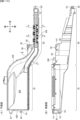
(パチンコ遊技機の背面構造)
次に、図3~図7に基づいて、パチンコ遊技機1の背面構造について説明する。図3は、パチンコ遊技機を示す背面図である。図4は、パチンコ遊技機を示す左側面図である。図5は、遊技盤が取付けられた遊技機用枠を示す平面図である。図6は、パチンコ遊技機を斜め後ろから見た状態を示す斜視図である。図7は、遊技機枠から遊技盤が取外された状態を示す斜視図である。尚、図5~図7においてガラス扉枠50の図示は省略している。
(Back structure of pachinko machine)
Next, the rear structure of the
図3~図7に示すように、パチンコ遊技機1は、遊技盤2と、遊技盤2が着脱可能に設けられる遊技機用枠3と、遊技機用枠3の左側辺を中心として該遊技機用枠3の前面を開閉可能に設けられたガラス扉枠50と、遊技機用枠3を左側辺を中心として開閉可能に支持する四角枠状の外枠60と、を有し、遊技場に設置された遊技島(図示略)に外枠60を固定することにより遊技島に設置できるようになっている。
As shown in FIGS. 3 to 7, the
遊技機用枠3の背面上部には、遊技島(図示略)の内部に設けられた遊技球(以下、遊技球Pと言うこともある)の循環経路から補給装置150(図3、図4参照)を介して供給される遊技球を貯留可能な貯留部を形成する球タンク形成部201と、球タンク形成部201に貯留された遊技球を左側に向けて誘導する第1誘導通路を形成する第1誘導通路形成部202と、からなる第1通路形成体203が、遊技機用枠3の上辺部3Aに沿うように左右方向に延設されている。また、第1誘導通路形成部202の上方位置には、後述するターミナル基板210が設けられている。
At the upper back of the
補給装置150は、遊技島の循環経路の遊技球を誘導可能なノズル等からなる誘導部材150Aと、該誘導部材150Aにより導かれた遊技球を所定数(例えば、10個など)ずつ送出することが可能なスプロケット(図示略)、該スプロケットを駆動する駆動源(図示略)、外枠60の開口が遊技機用枠3により閉鎖される閉鎖状態であるときに該遊技機用枠3に押圧されるレバースイッチ(図示略)と、を有し、閉鎖状態においてレバースイッチ(図示略)が遊技機用枠3にて押圧されているときにはスプロケットにて送出された遊技球が球タンク形成部201に落下可能となり、開放状態においてレバースイッチ(図示略)が遊技機用枠3にて押圧されていないときにはスプロケットにて送出された遊技球が落下不能に保持される。そして、外枠60が閉鎖状態であるときに球タンク形成部201に貯留されている遊技球数が減少すると、駆動源によりスプロケットが回転して遊技球が所定個数ずつ送出され球タンク形成部201に供給されるようになっている。また、補給装置150は、複数の部材を複数のねじ部材(図示略)により組付けることによりケース体150Bが構成され、該ケース体150Bが複数のねじ部材(図示略)を用いて遊技島の所定個所に固設されている。
The
また、第1誘導通路形成部202により左側に誘導された遊技球を下方に誘導する第2誘導通路を形成する第2誘導通路形成部204と、第2誘導通路形成部204により誘導された遊技球を払出すことが可能な払出部を構成する払出装置200と、払出装置200により払出された遊技球を上皿に誘導する、つまり、遊技者に遊技球を払出すための払出通路を形成する払出通路形成部205と、第2誘導通路形成部204により誘導された遊技球を払出装置200から払出通路形成部205に払出すことなく、パチンコ遊技機1の外部に排出するためにパチンコ遊技機1の背面側下部に設けられた図示しない排出部(図示略)に誘導する球抜き通路を形成する球抜き通路形成部206と、からなる第2通路形成体207が、遊技機用枠3の背面左側辺部に沿うように上下方向に延設されている。
In addition, a second guide
払出装置200は、略直方体状に形成されるケース体からなり、内部には遊技球を所定球数(例えば、1球)ずつ払い出すためのスプロケット、該スプロケットを回転させるための払出モータ、遊技球の流路を払出通路と球抜き通路とに切り替え可能な切替弁、該切替弁の切り替え操作を行うための操作レバー等が設けられている。また、遊技機用枠3の背面下部には、電源基板91が収納された基板ケース91Aや払出制御基板37が収納された基板ケース37A等が設けられている。
The
尚、本実施の形態では、第2誘導通路の所定個所に遊技球を検出可能な球切れスイッチ(図示略)が設けられており、CPU103は、球切れスイッチ(図示略)からの検出信号の入力状態に基づいて、払出装置200の上流側の第2誘導通路に払出すための遊技球があるか否かを常時監視している。そして、球切れスイッチ(図示略)のオフ状態が所定時間以上継続した場合、球詰まりなど何らかの理由で遊技球が払出装置200に供給されていない、つまり、補給エラーが発生したと判定し、払出装置200による払出動作を中止する。また、主基板11に接続される所定の表示器(図示略)にて補給エラー表示を行うとともに、補給エラーコマンドを演出制御基板12に出力することで、演出制御用CPU120にガラス扉枠50の前面所定個所に設けられた遊技効果ランプ9をエラー態様にて発光させるなどして、補給エラーが生じている旨の報知処理を実行可能である。
In this embodiment, a ball break switch (not shown) capable of detecting a game ball is provided at a predetermined position of the second guide path, and the
図7に示すように、遊技機用枠3の略中央部に形成された開口部221には、遊技機用枠3の前面側から遊技盤2が着脱可能に配置される。遊技盤2は、前述した盤面板及びスペーサ部材からなる板状体2aと、板状体2aの前面側に設けられる各種遊技用部品(例えば、障害釘や入賞装置など)や、板状体2aの背面側に設けられる画像表示装置5、可動体32を有する演出装置や、演出制御基板12が収納された基板ケース12A、主基板11が収納された基板ケース11A等の電子部品や、板状部及び演出装置や電子部品等を保護するカバー体220と、を含む構造体とされている。
As shown in FIG. 7, the
尚、基板ケース11A,12A,91A,37Aは、透明な合成樹脂材からなるベース部材とカバー部材とにより各基板を内部に収納可能に構成され、これらのうち基板ケース11A,12Aにあっては、各々1個または複数のねじ部材N20,N21(図3参照)により遊技機用枠3または遊技盤2に取付けられ、基板ケース91A,37Aは係止手段(図示略)により遊技機用枠3または遊技盤2に取付けられている。また、カバー体220は、透明な合成樹脂材により前面が開口する箱状に形成され、背面の一部は右側辺を中心として回動可能な開閉部220Aとされ、遊技盤2の背面の一部を開閉可能とされている。
The
図4~図6に示すように、遊技機用枠3の背面に設けられた第1通路形成体203、第2通路形成体207と、遊技盤2の背面を構成するカバー体220は、遊技機用枠3により外枠60を閉鎖した状態において、外枠60よりも後方に突出する。特に第1通路形成体203は、球タンク形成部201の上面開口が遊技機用枠3の背面上部における外枠60の上板の後方位置に配置されるように設けられていることで、パチンコ遊技機1の外枠60を遊技島(図示略)に固定した状態において、遊技島の上方の循環経路から補給装置150を介して球タンク形成部201に遊技球を供給できるようになっている。
As shown in FIGS. 4 to 6, a first
(第1通路形成体203の取付構造)
次に、第1通路形成体203の遊技機用枠3への取付構造について、図8及び図9に基づいて説明する。図8は、通路形成体の遊技機用枠への取付構造を示す分解斜視図である。図9は、遊技機用枠の背面上部を示す拡大背面図である。
(Mounting Structure of First Passage Forming Body 203)
Next, the mounting structure of the first
図8及び図9に示すように、遊技機用枠3は、正面視略長方形状をなす枠体であり、遊技盤2を取付けるための開口部221が形成されており、開口部221の上方の上辺部3Aの背面には、補強用の金属板222が左右方向に向けて設けられている。また、金属板222の背面には、第1通路形成体203を遊技機用枠3に取付けるための取付部材223が取付けられている。
As shown in FIGS. 8 and 9, the
取付部材223は、合成樹脂材により金属板222を背面側から被覆可能に形成され、前後方向を向く複数の取付孔H1~H5に背面側から取付けたねじ部材N1~N5を、金属板222に形成された複数のねじ孔に各々螺入することで金属板222に取付けられている。取付部材223の右側には、板状の第1突出部224が後方に向けて突設され、取付部材223の左側には、上壁部225A、後壁部225B及び左右の側壁部225Cからなる立体状の第2突出部225が後方に向けて突設されている。
The mounting
第1突出部224は、第2突出部225の上壁部225Aより下方位置から後方に向けて突出しており、その上側には球タンク形成部201が配置される。また、第2突出部225の後壁部225Bの後側には、第1誘導通路形成部202が配置されるとともに、その上側には、ターミナル基板210を取付けるための基板取付枠211が取付けられている。基板取付枠211は、下辺から下方に突設された係止片212を後壁部225Bに形成された係止孔213に挿入した状態で、上部に形成された取付孔H6に背面側から取付けたねじ部材N6を、取付部材223に形成されたねじ孔に螺入することで取付部材223に取付けられる。
The first projecting
このように取付部材223は、後方に突出する第1突出部224と第2突出部225とを有することで、遊技盤2の上方を覆うように形成されている。よって、遊技島の上部から球タンク形成部201に供給される遊技球などが遊技盤2内に進入することが防止されている。つまり、取付部材223は遊技盤2の保護カバーとして機能している。
Thus, the mounting
第1通路形成体203は、複数の取付孔H11~H14に背面側から取付けたねじ部材N11~N14、及び取付孔H15に上側から取付けたねじ部材N15を、取付部材223に形成された複数のねじ孔に各々螺入することで取付部材223に取付けられている。尚、取付孔H12に取付けるねじ部材N12は、第1通路形成体203に帯電した電気を除去するためのアース線226を第1通路形成体203に取付けるためのねじ部材と兼用されている。また、第1通路形成体203の上部には、後述する第1カバー体310、第2カバー体320、第3カバー体330が取付けられている。第3カバー体330は、取付孔H16に上方から取付けたねじ部材N16を第1通路形成体203の後壁に形成されたねじ孔に螺入することで第1通路形成体203に取付けられている。
The first
上記したねじ部材N1~N6、N11~N16は、図8中拡大図に示すように、雄ねじ部NSと頭部NHとからなり、このうち、ねじ部材N1、N2、N11~N16は、頭部の座面に緩み止め部としてのフランジ部Fが一体に形成されたフランジ付きねじとされ、座面の接地面積を広くして摩擦力を高めることで、ねじ部材N3~N6に比べて緩みにくいねじ部材とされている。 As shown in the enlarged view of FIG. 8, the threaded members N1 to N6 and N11 to N16 include a male threaded portion NS and a head portion NH. It is a flanged screw in which a flange part F as a locking part is integrally formed on the bearing surface of the screw, and by increasing the contact area of the bearing surface and increasing the frictional force, it is difficult to loosen compared to the screw members N3 to N6. It is considered as a screw member.
例えば、各ねじ部材N1~N6、N11~N16の雄ねじ部NSの直径L1は約1~3mm、頭部NHの直径L2は約4~7mmとされ、フランジ部Fの直径L3は、頭部NHの直径L2よりも長寸で約8~10mmとされている。 For example, the diameter L1 of the male screw portion NS of each screw member N1 to N6, N11 to N16 is approximately 1 to 3 mm, the diameter L2 of the head NH is approximately 4 to 7 mm, and the diameter L3 of the flange portion F is approximately 4 to 7 mm. 8 to 10 mm longer than the diameter L2.
尚、ねじ部材N1~N6、N11~N16の大きさ、種類などは任意であり、直径L1~L3の寸法も上記した寸法に限定されるものではない。また、フランジ付きねじからなるねじ部材N1、N2、N11~N16は、フランジ部F(座金)が一体に形成されたねじ部材であるが、フランジ部Fの替わりに、ねじ部材とは別個のワッシャをねじ部材に装着して取付けてもよく、フランジ部Fやワッシャが本発明の緩み止め部を構成する。また、ねじ部材は、ビスやボルト等、緩むと被取付部から離脱してしまう部材を含むものとする。また、緩み止め部は、頭部NHやフランジ部F(座金)の裏面に凹凸状に形成された頭部NHの回止め部や接着剤等も含まれる。 The sizes and types of the screw members N1 to N6 and N11 to N16 are arbitrary, and the dimensions of the diameters L1 to L3 are not limited to those described above. The screw members N1, N2, N11 to N16, which are flanged screws, are screw members integrally formed with a flange portion F (washer). may be attached to the screw member, and the flange portion F and the washer constitute the locking portion of the present invention. Further, the screw member includes a member such as a screw or a bolt that separates from the attached portion when loosened. In addition, the locking portion includes a locking portion for the head NH formed unevenly on the back surface of the head NH and the flange portion F (washer), an adhesive, and the like.
図8及び図9に示すように、第1通路形成体203は、遊技島の上方から供給される遊技球を球タンク形成部201にて受止めて貯留する必要があるとともに、第1誘導通路において球詰まりなどが発生しにくいように、また、球詰まりが発生した場合にこれを容易に解消することができるように上面が開放する凹状に形成されている。
As shown in FIGS. 8 and 9, the first
また、球タンク形成部201にて上下方向に重なって滞留する遊技球が第1誘導通路形成部202に流入していく箇所には第1カバー体310や第2カバー体320が上面を被覆するように配置され、また、第1誘導通路形成部202から第2誘導通路形成部204に流入していく箇所には第3カバー体330が上面を被覆するように配置されることで、遊技球が整流されるようになっている。しかし、第1通路形成体203の上面開口の一部はこれら第1カバー体310、第2カバー体320及び第3カバー体330により被覆されるが、球タンク形成部201及び非被覆領域350(図27参照)の上面開口は開放されている。
In addition, a
一方、第1通路形成体203の周辺近傍には、遊技機用枠3や取付部材223に取付けられる複数のねじ部材N1~N6、N11~N16が配置されている。また、遊技島に固定されるパチンコ遊技機1の上方には、遊技島を構成する躯体などを組付けるためのねじ部材(図示略)や、遊技島の内部に配置される各種装置(例えば、補給装置150など)等を躯体などに取付けるためのねじ部材(図示略)や、各種装置のケース体を構成する複数の部材を組付けるための複数のねじ部材などが多数配置されている。
On the other hand, in the vicinity of the periphery of the first
これらねじ部材は、遊技島やパチンコ遊技機1に生じる振動や衝撃などにより緩んで抜け落ちてしまうと、振動や衝撃あるいは遊技機用枠3の開閉などにより転がって、球タンク形成部201や第1誘導通路形成部202の非被覆領域350から内部に落下して遊技球の誘導通路に混入する可能性がある。特に補給装置150などは、図3及び図4に示すように球タンク形成部201の直上近傍に配置されており、また、所定個数の遊技球を球タンク形成部201に送出することで遊技島の循環経路から新たな遊技球が供給される際や、遊技機用枠3が開閉する際に振動が生じやすい装置であるため、補給装置150を遊技島の躯体などに取付けるためのねじ部材(図示略)や、補給装置150のケース体150Bを構成する複数の部材を組付けるための複数のねじ部材が振動により緩んで抜け落ちた場合、球タンク形成部201や第1誘導通路形成部202内に落下する可能性が極めて高い。
If these screw members are loosened and fall off due to vibration or shock generated in the game island or the
そして、球タンク形成部201や第1誘導通路形成部202にねじ部材が落下すると、遊技球の流下とともに払出装置200側に向けて移動し、最終的に払出装置200に混入する可能がある。このように払出装置200にねじ部材が進入すると、スプロケットや切換え弁がねじ部材により損傷したり、球詰まりが生じて払出モータに負荷がかかり故障したり、あるいは、遊技球とともにねじ部材が遊技者に払出されてしまい、遊技者に違和感や不信感を与えてしまう虞があった。
Then, when the screw member drops into the ball
そこで本実施の形態では、以下に説明するように、第1誘導通路形成部202に落下したねじ部材が払出装置200に混入して払出装置200が破損、故障したり、遊技球とともにねじ部材が遊技者に払出されることを抑制するために様々な対策が施されている。
Therefore, in the present embodiment, as described below, the screw member that has fallen into the first guide
(第1通路形成体203)
次に、第1通路形成体203について、図10~図16に基づいて説明する。図10は、(A)は第1通路形成体を示す平面図、(B)は第1通路形成体を示す背面図である。図11は、(A)は図10(A)のA-A断面図、(B)は図10(A)のB-B断面図、(C)は図10(A)のC-C断面図である。図12は、(A)は第1誘導通路形成部を示す平面図、(B)は(A)のD-D断面図である。図13は、(A)は第1カバー体を示す平面図、(B)は(A)のE-E断面図、(C)は(A)のF-F断面図である。図14は、(A)は第2カバー体を示す平面図、(B)は(A)のG-G断面図、(C)は(A)のH-H断面図である。図15は、(A)は第3カバー体を示す平面図、(B)は(A)のI-I断面図、(C)は(A)のJ-J断面図、(D)は第3カバー体を示す斜視図、(E)は球止め部材を示す斜視図である。図16は、(A)は球止め部材が第1状態である状態を示す第1誘導通路形成部を示す縦断面図、(B)は球止め部材が第2状態である状態を示す第1誘導通路形成部を示す縦断面図である。
(First passage forming body 203)
Next, the first
図10~図12に示すように、第1通路形成体203は、導電性を有する合成樹脂材により、底壁部203Aと該底壁部203Aの周縁に立設される立壁部203Bとにより上面が開口する凹状または凹溝状に形成され、右側に配置される球タンク形成部201と、左側に配置される第1誘導通路形成部202とを有する。球タンク形成部201は、平面視横長長方形状に形成され、第1誘導通路形成部202は、球タンク形成部201の左側から斜め後方に向けて延びる上流部と左右方向に延びる下流部とからなる。球タンク形成部201の前後方向の寸法は、第1誘導通路形成部202の前後方向の寸法よりも長寸とされており、第1誘導通路形成部202よりも多くの遊技球を貯留可能とされている。また、底壁部203Aは、球タンク形成部201の左側から第1誘導通路形成部202の右側に向けて漸次下方に傾斜するように形成されているため、球タンク形成部201に供給された遊技球は、球タンク形成部201及び第1誘導通路形成部202を左側に向けて自然流下するようになっている。
As shown in FIGS. 10 to 12, the first
球タンク形成部201の右側の立壁部203Bの外面には上下方向を向く取付片261が突設されており、取付片261には前後方向を向く取付孔H11,H12が上下に形成されている。また、取付片261の後側には取付片265が突設されており、取付片265には上下方向を向く取付孔H15が形成されている。第1誘導通路形成部202の左側の立壁部203Bの外面には上下方向を向く取付片262が突設されており、取付片262には前後方向を向く取付孔H14が形成されている。第1誘導通路形成部202の上流部の前側の立壁部203Bの外面には水平壁部264が前方に向けて突設されている。水平壁部264の前辺には取付片263が立設されており、取付片263には前後方向を向く取付孔H13が形成されている。
A mounting
そして第1通路形成体203は、これら取付孔H11~H15に取付けた複数のねじ部材N11~N15を取付部材223に形成されたねじ孔に螺入することで遊技機用枠3に取付けられる。また、水平壁部264の上面における取付片263の後方近傍位置には、平面視略四角形状をなす凹部280が形成されている。
The first
図11及び図12に示すように、第1誘導通路形成部202の上流部における底壁部203Aと後側の立壁部203Bとの角部には、孔部270A,270Bが形成されている(図11(A)参照)。孔部271A,271Bの下流側(左側)における底壁部203Aの前後方向の略中央位置には、孔部271A~271Hが下流側に向けて複数形成されている。また、第1誘導通路形成部202の下流側端部の底壁部203Aには、下方の第2誘導通路形成部204に遊技球を落下させるための連絡孔272が貫通して形成されている。
As shown in FIGS. 11 and 12,
第1誘導通路形成部202の途中には、遊技球を前後方向に蛇行させながら左側に向けて流下させる蛇行部273が形成されており、複数の孔部271A~271Hのうち孔部271B~271Fが蛇行部273に対応する位置に形成されている。このような蛇行部273を設けることで後続球による球圧が増大しないようにしている。
A meandering
また、第1誘導通路形成部202の前後の立壁部203B,203B下部の離間寸法L10は、遊技球の直径2R(約11mm)よりも長寸で、直径2Rの2倍の寸法(約22mm)よりも短寸とされている(11mm<L10<22mm)。つまり、第1誘導通路形成部202は、遊技球を下流側に向けて1列で誘導可能に形成されている。
In addition, the distance L10 between the front and rear
孔部271A,271Bを除く孔部271A~271Hの前後寸法L11は、前述したねじ部材N3~N6の頭部NHの直径L2より若干長いため(L11>L2)、後述するようにねじ部材N3~N6が第1誘導通路形成部202に混入した場合でも孔部271A~271Hからねじ部材N3~N6が落下可能とされている。また、最下流側に形成された孔部271Hは、他の孔部271A~271Gと比べて左右寸法L12(遊技球の流下方向の寸法)が最も長いため、ねじ部材N3~N6が連絡孔272に到達する前に確実に第1誘導通路形成部202外へ落下させることができる。
Since the longitudinal dimension L11 of the
つまり、これら孔部271A~271Hは、第1誘導通路形成部202に落下したねじ部材N3~N6の払出装置200への移動を制限するための特定制限部を構成している。尚、これら複数の孔部271A~271Hからは、ねじ部材以外のゴミや埃、あるいは何らかの部材等も落下可能であるため、これらにより球詰まりが生じることが防止される。
In other words, these
(第1カバー体310)
図13(A)~図13(C)に示すように、第1カバー体310は、球タンク形成部201の前側の立壁部203Bの上端縁に沿うように延設され、立壁部203Bの上端に上方から嵌合可能な断面視下向きコ字形をなす取付部311と、取付部311の右側から後側に向けて延設される立壁部312と、立壁部312の下部から右側(球タンク形成部201側)に向けて下方に傾斜するように延びる板状の球押え部313と、立壁部312の下部から左側(第1誘導通路形成部202側)に向けて延びるカバー部314と、取付部311の前側及びカバー部314の前後側に弾性変形可能に形成された複数の係止部315A~315Dと、から主に構成される。
(First cover body 310)
As shown in FIGS. 13A to 13C, the
このように構成された第1カバー体310は、立壁部312を球タンク形成部201と第1誘導通路形成部202との境目付近に配置した状態で、取付部311を球タンク形成部201の前側の立壁部203Bの上端に上方から嵌合させることで、複数の係止部315A~315Dが立壁部203Bの外面に形成された被係止部317(図18参照)に弾性的に係止することで第1通路形成体203に取付けられる。取付けられた状態において、球押え部313が球タンク形成部201の下流側の一部を上方から被覆するように配置されるとともに、カバー部314が第1誘導通路形成部202の上流側の一部を上方から被覆するとともに、カバー部314の上面が第1誘導通路形成部202側に向けて僅かに下方に傾斜するように配置される(図9参照)。
The
第1カバー体310が第1通路形成体203に取付けられた状態において、球押え部313が球タンク形成部201側に配置されることで、遊技島(図示略)から球タンク形成部201に供給された遊技球が上下方向に積み重なるように貯留した場合でも、遊技球が第1誘導通路形成部202側に流下していく際に球押え部313により下側に向けて押えられることで整流されるようになっている。
When the
カバー部314には、平面視横長長方形状をなす左右方向に延びる長孔316A~316Cが、互いに平行をなすように列状に配置された状態で上下に貫通して形成されている。各長孔316A~316Cは、前後寸法L21が全て同一とされ、前後寸法L21は、遊技球の直径2Rよりも短寸であり、かつ、前述したねじ部材N1~N6,N11~N16の頭部NHの直径L2よりも短寸となっている(L21<2R、L21<L2)。つまり、長孔316A~316Cは、遊技球及びねじ部材N1~N6,N11~N16を落下不能な大きさに形成されている。尚、カバー部314の下面における各長孔316A~316Cの周縁からは補強用のリブが垂下されている。
In the
また、長孔316A~316Cは遊技球の流下方向に沿うように延設されているため、図13(B)(C)に示すように、長孔316A~316Cの上部に遊技球Pが落下した場合、遊技球Pは流下方向(左側)に向けて移動可能である。
In addition, since the
(第2カバー体320)
図14(A)~図14(C)に示すように、第2カバー体320は、第1誘導通路形成部202の上流部に沿うように形成された板状のカバー部324と、カバー部324の前後側に弾性変形可能に形成された複数の係止部325A,325Bと、から主に構成され、カバー部324の右側端部を第1カバー体310のカバー部314の左側端部に近接させた状態で、複数の係止部325A,325Bが立壁部302Bの外面に形成された被係止部317(図20参照)に弾性的に係止することで、第1通路形成体203に取付けられる。取付けられた状態において、カバー部324が第1誘導通路形成部202の上流側の一部を上方から被覆するとともに、遊技球の流下方向に向けて下方に傾斜するように配置される(図9参照)。
(Second cover body 320)
As shown in FIGS. 14A to 14C, the
カバー部324の上面には、左右方向に延びる凹溝326A~326Cが、互いに列状に配置された状態で形成されている。各凹溝326A~326Cは、前後寸法L22A~L22Cが各々異なるが、各々遊技球の直径2Rよりも短寸とされている(L22A~L22C<2R)。尚、前後寸法が最も長い中央の凹溝326Bの前後寸法L22Bは、前述したねじ部材N1~N6,N11~N16の頭部NHの直径L2よりも長寸となっている(L22B>L2)。つまり、凹溝326Bは、遊技球を収容不能、かつ、ねじ部材N1~N6,N11~N16を収容可能な大きさに形成されている。また、凹溝326Bの前後寸法L22Bは、カバー部314の長孔316A~316Cの前後寸法L21よりも長寸とされている(L22B>L21)。
On the upper surface of the
また、凹溝326Aの前後寸法L22Aと凹溝326Cの前後寸法L22Cは、ねじ部材N1~N6,N11~N16の雄ねじ部NSの直径L1よりも長寸であるため(L22B>L1、L22C>L1)、少なくとも雄ねじ部NSを収容可能な大きさとされている。
In addition, since the front-rear dimension L22A of the recessed
また、凹溝326A~326Cは遊技球の流下方向に沿うように延設され、かつ、遊技球の流下方向に向けて下方に傾斜するように配置されるため、図14(B)(C)に示すように、凹溝326A~326Cの上部に遊技球Pが落下した場合、遊技球Pが流下方向(左側)に向けて誘導される。
In addition, since the
(第3カバー体330)
図15(A)~図15(C)及び図16に示すように、第3カバー体330は、第1誘導通路形成部202の下流部に沿うように形成された板状のカバー部334と、カバー部334の左端の前後側に弾性変形可能に形成された複数の係止部335A~335Dと、背面における係止部335C,335Dの間に突設されねじ部材N15が上方から取付けられる取付孔H15が形成された取付部331と、カバー部334の上面左端部に設けられた球止め部材340と、から主に構成され、カバー部324の左端の複数の係止部335A~335Dを立壁部302Bの外面に形成された被係止部317(図20参照)に弾性的に係止するとともに、取付孔H15に取付けたねじ部材N15を立壁部203Bの外面に設けられたねじ孔に螺入することで第1通路形成体203に取付けられる。取付けられた状態において、カバー部334が第1誘導通路形成部202の下流部を上方から被覆するとともに、遊技球の流下方向に向けて下方に傾斜するように配置される(図9参照)。
(Third cover body 330)
As shown in FIGS. 15A to 15C and 16, the
カバー部334は、左側から右側に向けて斜め上方に延びるように延設されており、上面における右端部から左側に向けて所定深さの凹部336が延設されている。右側の一部は蛇行部273に差し掛かるため、蛇行部273の形状に対応して形成されている。また、凹部336に対応する位置には、平面視横長コ字形をなすスリット337が形成されることで、左端側が上下方向に揺動するように弾性変形可能な整流板338が形成されているとともに、右端部には、右側に向けて下方に傾斜する傾斜板部339が形成されていることで、上下に積み重なった遊技球Pを底壁部203Aに向けて押し付けるように誘導しながら均すことができるようになっている(図16参照)。
The
凹部336の前後寸法L23は、遊技球の直径2Rよりも長寸とされ、また、前述したねじ部材N1~N6,N11~N16の頭部NHの直径L2よりも長寸となっている(L23>2R、L23>L2)。つまり、凹部336は、遊技球P及びねじ部材N1~N6,N11~N16の頭部NHを収容可能な大きさに形成されている。また、凹部336の前後寸法L23は、カバー部324の凹溝326Bの前後寸法L22Bよりも長寸とされている(L23>L22B)。
The front-rear dimension L23 of the
また、凹部336は遊技球の流下方向に沿うように延設され、かつ、遊技球の流下方向に向けて下方に傾斜するように配置されるため、図15(D)に示すように、凹部336の上部に遊技球Pが落下した場合、遊技球Pが流下方向(左側)に向けて誘導される。
In addition, since the
また、スリット337の前後寸法L24は、前述したねじ部材N1~N6,N11~N16の頭部NHの直径L2よりも短寸となっているため(L24<L2)、ねじ部材N1~N6,N11~N16がスリット337から落下することはない。
In addition, since the longitudinal dimension L24 of the
球止め部材340は、背面視略三角形状をなす板状の前壁部341Aと、前壁部341Aの背面側に配置される後壁部341Bと、前壁部341Aと後壁部341Bとを接続する左壁部341Cと、左壁部341Cの上端に突設される突壁部341Dと、を有する回動部341と、前後方向を向く円筒状の軸部342と、から構成される。カバー部334の上面左側には、軸部342の前後端を回動可能に支持する軸受部343A,343Bが立設されている。また、カバー部334における軸受部343Aの右側には、前壁部341Aを挿入可能なスリット344が貫通して形成されている。
The
図16に示すように、第3カバー体330は、第1通路形成体203に取付けた状態において、カバー部324により第1誘導通路形成部202の下流部の上方が被覆される。カバー部324は、下流側(左側)に向けて底壁部203Aに近づくように下方に傾斜するように配置されるため、第1誘導通路形成部202内で上下に積み重なっている遊技球Pを流下させながら均していき、最終的に連絡孔272から1個ずつ流出させることができるようにする。特に、整流板338は、遊技球が接触したときに弾性変形可能であることで、球詰まりが生じない程度に遊技球を下方に押し付けるように均していく(整流していく)。
As shown in FIG. 16 , when the
(球止め部材340)
球止め部材340は、図16(A)に示すように、回動部341が上方に起立する起立位置と右側に傾倒する傾倒位置との間で回動可能とされており、回動部341が起立位置に位置し、前壁部341Aがスリット344から上方に逸脱して第1誘導通路形成部202の遊技球を第2誘導通路形成部204に流下可能とする第1状態と、回動部341が傾倒位置に位置し、前壁部341Aがスリット344に挿入され遊技球に接触可能となり、第1誘導通路形成部202の遊技球を第2誘導通路形成部204に流下不能(または流下困難)とする第2状態、つまり、球止め状態と、に変化可能とされている。
(Ball stop member 340)
As shown in FIG. 16A, the
このように球止め部材340を第2状態とすることで、第2誘導通路形成部204への遊技球の進入を規制することができるため、この状態で第2誘導通路形成部204内の遊技球を抜き取り、払出装置200を取外して点検または交換したりすることが可能となる。
By setting the
また、図16(A)に示すように、球止め部材340が第1状態にあるときには、回動部341の右側が開放し、前壁部341A、後壁部341B、左壁部341Cからなる平面視略コ字形の壁部により囲まれた空間部が、後述するようにねじ部材N1~N6,N11~N16が滞留可能な滞留部として機能する。一方、図16(B)に示すように、球止め部材340が第2状態にあるときには、回動部341が傾倒してしまうが、突壁部341Dが通路を横切るように起立状態で位置するため、後述するようにねじ部材N1~N6,N11~N16を突壁部341Dの右側に滞留させることが可能となる。
Further, as shown in FIG. 16A, when the
(ターミナル基板210)
次に、ターミナル基板210について、図17に基づいて図8を参照しながら説明する。図17は、(A)はターミナル基板が取付けられた基板取付枠を示す斜視図、(B)は(A)のK-K断面、(C)は(B)のL-L断面図である。
(Terminal board 210)
Next, the
図8及び図17に示すように、ターミナル基板210は、背面視横長長方形状をなし、背面には、主基板11等と繋がる信号線ケーブル(図示略)が着脱されるケーブル接続部(図示略)と、ホールコンピュータ等の外部装置に繋がる複数本のケーブルC(図3参照)を接続するための複数の接続孔部231が設けられた実装部材232と、が実装されている。実装部材232の内部における各接続孔部231に対応する位置には、各ケーブルCの先端を挟持するための接続ピンチ(図示略)が設けられている。この接続ピンチを閉じる方向、即ちケーブルCの先端を挟持する方向に付勢するためのバネ(図示略)が設けられている。そして、実装部材232には、バネ(図示略)の付勢力に抗して各接続ピンチ(図示略)を開放させるための操作部233が複数設けられている。
As shown in FIGS. 8 and 17, the
第1誘導通路形成部202の上方に設けられる第1基板としてのターミナル基板210の複数の接続孔部231に接続可能なケーブルCの接続本数は第1本数(例えば、20本)とされている一方で、第1誘導通路形成部202の下方に設けられる主基板11や演出制御基板12などの第2基板にも各々の信号線が接続されるが、第1本数より少ない本数である第2本数(例えば、10本)とされている。
The number of cables C that can be connected to the plurality of connection holes 231 of the
この操作部233は、各接続孔部231に対応して複数設けられ、側面視で略鉤状をなし、その基端側を揺動軸として前後方向に揺動される。前述の接続ピンチ(図示略)を開放させる際には、操作部233を上方または下方に押圧操作をして操作部233を揺動させることで接続ピンチ(図示略)を開放される。そして、接続ピンチが開放された状態で接続孔部231にケーブルCの先端を挿入し、操作部233の押圧操作をやめると、バネ(図示略)の付勢力によって接続ピンチが閉じるようになり、ケーブルCが保持されるようになる。尚、左右方向に並んだ各操作部233は、所定の操作部233を押圧操作する際に、隣り合う操作部233が押圧操作の邪魔にならないように、左右方向に交互に異なる形状となっている。
A plurality of the
基板取付枠211は、下辺から下方に突設された係止片212を後壁部225Bに形成された係止孔213に挿入した状態で、上部に形成された取付孔H6に背面側から取付けたねじ部材N6を、取付部材223に形成されたねじ孔に螺入することで取付部材223に取付けられる。また、基板取付枠211には、横長長方形状の開口部234が形成されている。
The
基板取付枠211の内面には、前面側から挿入したターミナル基板210の周縁に係止することで、ターミナル基板210の前方への移動を規制する複数の規制部235と、規制部235により前方への移動が規制されたターミナル基板210の周縁に前面側から弾性的に係止可能な複数の係止部236と、ターミナル基板210の周縁に当接して配置位置を決定する位置決め片237と、を有する。よって、ターミナル基板210は、基板取付枠211の前面側から挿入し、複数の規制部235にて前方への移動が規制された状態で係止部236が弾性的に係止することで基板取付枠211に取付けられる。つまり、ターミナル基板210は、ねじ部材とは異なる取付手段としての複数の規制部235及び係止部236を用いて(ねじ部材を用いた取付方法とは異なる取付方法にて)基板取付枠211に取付けられる。
On the inner surface of the
ターミナル基板210は、ケーブルCを接続可能な接続孔部231が複数形成されているため、複数本のケーブルCを接続孔部231に接続する配線作業時において、各ケーブルCに対応する操作部233を操作する必要がある。また、パチンコ遊技機1が遊技島に固定されている状態において、遊技場の店員等が点検等のために遊技機用枠3を開放すると、遊技島の上部から垂下されるケーブルCが外枠60の前方に引き回されて接続部に張力がかかることがある。つまり、ターミナル基板210は取付部に負荷がかかりやすいことで、ねじ部材により基板取付枠211や取付部材223に取付けるとねじ部材が緩んで外れやすくなるため、ねじ部材を用いない取付方法にて取付けている。
Since the
また、ターミナル基板210が基板取付枠211に取付けられた状態において、ターミナル基板210の接続孔部231や操作部233が開口部234から背面側に臨むようになっている(図17(A)参照)。また、複数の操作部233が後方に向けて略水平に突出するため、後述するようにこれら左右に並設される複数の操作部233によりねじ部材N3~N6を保持することができる。また、ターミナル基板210の下部と基板取付枠211の前部との間に、ねじ部材N3~N6を収容可能な凹部242が形成される。
In addition, when the
(ねじ部材N1~N16の取付状態)
次に、ねじ部材N1~N16の取付状態について、図18~図21に基づいて説明する。図18は、遊技枠の背面における球タンク部の周辺を斜め後ろから見た状態を示す斜視図である。図19は、(A)は遊技枠の背面における球タンク部の周辺を示す平面図、(B)は(A)のM-M断面図である。図20は、遊技枠の背面における第1誘導通路形成部の周辺を斜め後ろから見た状態を示す斜視図である。図21は、遊技枠の背面における第1誘導通路形成部の周辺を示す平面図である。図22は、(A)は図21のN-N断面図、(B)はねじ部材の回転状態を示す図、(C)は図21のO-O断面図である。図23は、(A)は図21のP-P断面図、(B)は図21のQ-Q断面図である。図24は、図21のR-R断面図である。図25は、図21のS-S断面図である。図26は、(A)は球止め部材が第1状態であるときのねじ部材の滞留状態、(B)は(A)のT-T断面図、(C)は球止め部材が第2状態であるときのねじ部材の滞留状態、(D)は(C)のU-U断面図である。図27は、ねじ部材の移動状況を示す第1誘導通路形成部の縦断面図である。図28は、カバー部上の遊技球の移動状態を示す第1誘導通路形成部の縦断面図である。
(Mounting state of screw members N1 to N16)
Next, the mounting state of the screw members N1 to N16 will be described with reference to FIGS. 18 to 21. FIG. FIG. 18 is a perspective view showing a state where the periphery of the ball tank portion on the back surface of the game frame is seen obliquely from behind. 19, (A) is a plan view showing the periphery of the ball tank portion on the back of the game frame, and (B) is a cross-sectional view taken along line MM of (A). FIG. 20 is a perspective view showing a state in which the periphery of the first guide passage forming portion on the back surface of the game frame is seen obliquely from behind. FIG. 21 is a plan view showing the periphery of the first guide passage forming portion on the back side of the game frame. 22, (A) is a sectional view taken along line NN of FIG. 21, (B) is a view showing the rotating state of the screw member, and (C) is a sectional view taken along line OO of FIG. 23, (A) is a sectional view taken along line PP of FIG. 21, and (B) is a sectional view taken along line QQ of FIG. 24 is a cross-sectional view taken along line RR of FIG. 21. FIG. 25 is a cross-sectional view taken along line SS of FIG. 21. FIG. FIG. 26 shows (A) the retention state of the screw member when the ball stopper is in the first state, (B) is a TT sectional view of (A), and (C) is the ball stopper in the second state. (D) is a UU cross-sectional view of (C). FIG. 27 is a vertical cross-sectional view of the first guide passage forming portion showing movement of the screw member. FIG. 28 is a vertical cross-sectional view of the first guide passage forming portion showing the moving state of the game ball on the cover portion.
図9、図18及び図19(A)に示すように、遊技機用枠3の背面における球タンク形成部201及びその周辺には、取付部材223を金属板222に取付けるためのねじ部材N1~N2や、第1通路形成体203を取付部材223に取付けるためのねじ部材N11,N12,N15が取付けられている。
As shown in FIGS. 9, 18 and 19(A), screw members N1 to N1 for attaching the mounting
詳しくは、ねじ部材N1,N2は、球タンク形成部201から右側に離れ、かつ、球タンク形成部201における立壁部203Bの上端縁よりも下方位置において、背面側から前方に向けて取付けられているため、パチンコ遊技機1に生じた振動や衝撃などによりねじ部材N1,N2が緩んで後方に抜け落ちたとしても、図18に示すように球タンク形成部201内に落下する可能性は極めて低い。
Specifically, the screw members N1 and N2 are attached forward from the back side at a position away from the sphere
ねじ部材N11,N12は、球タンク形成部201の右側の立壁部203Bの外面で、かつ、球タンク形成部201の上端縁よりも下方位置において、背面側から前方に向けて取付けられているため、パチンコ遊技機1に生じた振動や衝撃などによりねじ部材N11,N12が緩んで後方に抜け落ちたとしても、図18に示すように球タンク形成部201内に落下する可能性は極めて低い。
The screw members N11 and N12 are attached forward from the back side on the outer surface of the right standing
ねじ部材N15は、球タンク形成部201の右側の立壁部203Bの外面で、かつ、球タンク形成部201の上端縁よりも下方位置において、上側から下方に向けて取付けられているため、パチンコ遊技機1に生じた振動や衝撃などによりねじ部材N15が緩んで上方に抜け落ちたとしても、図18に示すように球タンク形成部201内に落下する可能性は極めて低い。
The screw member N15 is attached downward from the upper side on the outer surface of the right standing
また、ねじ部材N1,N2,N11,N12,N15は、遊技島の上方の循環経路から補給装置150により供給される遊技球を受止めて貯留するとともに多数の遊技球の荷重がかかる球タンク形成部201の周辺に配置されていることで、振動や衝撃が生じやすいので、被取付部との接地面積が大きく緩みが生じにくいフランジ付きねじ部材が使用されている。
Further, the screw members N1, N2, N11, N12 and N15 receive and store the game balls supplied from the
また、球タンク形成部201の周辺のねじ部材N1,N2,N11,N12,N15は、緩んで抜け落ちても球タンク形成部201内に落下しにくい位置、つまり、球タンク形成部201の上面開口よりも下方に配置されているので、遊技島の上方の循環経路から補給装置150により供給される遊技球を受止めて貯留するために上方が開口する球タンク形成部201内に混入することが抑制されている。
Further, the screw members N1, N2, N11, N12, and N15 around the sphere
また、図19(B)に示すように、球タンク形成部201は、取付部材223において後方に向けて突出する板状の第1突出部224の上面側に近接(または当接でもよい)して配置されており、底壁部203Aと第1突出部224との間の隙間L30は、ねじ部材の雄ねじ部NSの直径L1よりも短寸とされていることで(L30<L1)、底壁部203Aと第1突出部224との間にねじ部材が挟まって球タンク形成部201の近傍に保持されてしまうことはほぼない。
Further, as shown in FIG. 19B, the sphere
また、球タンク形成部201の底壁部203Aの後部とカバー体220の上壁部220Hとの間に形成された隙間L31は、フランジ付きねじ部材の頭部L2やフランジ部Fの直径L3よりも長寸とされていることで(L3>L2)、隙間L31にフランジ付きねじ部材が挟まって球タンク形成部201の近傍に保持されてしまうことはほぼない。
Further, the gap L31 formed between the rear portion of the
また、図18及び図19(B)に示すように、仮にねじ部材N15が被取付部としての取付孔H15から抜け落ちてカバー体220の上壁部220H上に落下した場合、上壁部220Hは、背面側に向けて下方に傾斜していることで、落下したねじ部材N15は後方または左方のいずれかに流下するため、球タンク形成部201の近傍に保持されてしまうことはほぼない。よって、落下したねじ部材N15が球タンク形成部201の下方に設けられた各基板ケース11A,12A,37A,91A内に混入し、基板の配線に接触して断線等を生じさせることを抑制できる。
Further, as shown in FIGS. 18 and 19B, if the screw member N15 slips out of the mounting hole H15 as the mounted portion and falls onto the
一方、図9、図20及び図21(A)に示すように、第1誘導通路形成部202及びその周辺には、取付部材223を金属板222に取付けるためのねじ部材N3~N5と、基板取付枠211を取付部材223に取付けるためのねじ部材N6と、第1通路形成体203を取付部材223に取付けるためのねじ部材N13,N14と、第3カバー体330を第1誘導通路形成部202に取付けるためのねじ部材N16と、が取付けられている。
On the other hand, as shown in FIGS. 9, 20 and 21A, screw members N3 to N5 for attaching the mounting
詳しくは、ねじ部材N3~N6は、第1誘導通路形成部202から前側に離れ、かつ、第1誘導通路形成部202における立壁部203Bの上端縁よりも上方位置において、背面側から前方に向けて取付けられており、また、ねじ部材N3~N6各々の取付位置と第1誘導通路形成部202との間には、取付部材223の第2突出部225が配置されていることで、ねじ部材N3~N6各々の取付位置から第1誘導通路形成部202まではある程度離れているが、第2突出部225の上壁部225Aは背面側に向けて下方に傾斜しているため、パチンコ遊技機1に生じた振動や衝撃などによりねじ部材N3~N6が緩んで後方に抜け落ちた場合、図20に示すように第2突出部225の上壁部225A上を後方に向けて移動して第1誘導通路形成部202内に落下する可能性が高い。
Specifically, the screw members N3 to N6 are separated from the first guide
図20~図22に示すように、ねじ部材N3は、取付部材223において、第1誘導通路形成部202の上流部から前方に離れ、かつ、立壁部203Bの上端縁よりも上方位置に形成された取付孔H3に取付けられている。また、上壁部225Aの上面における取付孔H3に対応する位置には、ねじ部材N3を取付孔H3に取付ける際に頭部NHとの干渉を避けるための凹溝227が後方に向けて直線状に延設されている。尚、凹溝227は、後側に向けて左右幅が先細りとなり浅くなるように形成されているが、上壁部225Aの上面が背面側に向けて下方に傾斜していることで、凹溝227の底面は略水平(または背面側に向けて僅かに下方に傾斜している)となっている。
As shown in FIGS. 20 to 22, the screw member N3 is formed in the mounting
よって、パチンコ遊技機1に生じた振動や衝撃などによりねじ部材N3が緩んで後方に抜け落ちた場合、第2突出部225の上壁部225A上における凹溝227に落下する可能性が高い(図22(A)参照)。また、凹溝227に落下したねじ部材N3は、振動や衝撃が生じたときに後方に向けて直線状に移動するように案内されやすいが、凹溝227は後方に向けて略水平であるため、凹溝227以外の領域に比べてねじ部材N3が後方に移動しにくい。つまり、凹溝227は、第1誘導通路形成部202に向けて移動するねじ部材N3の第1誘導通路形成部202への落下を制限するための特別制限部を構成している。
Therefore, when the screw member N3 is loosened and falls out backward due to vibration or shock generated in the
ここで、ねじ部材N3を含む全てのねじ部材は、頭部NHと雄ねじ部NSとからなることで、平坦面状の上壁部225Aの上面に落下すると頭部NHの周縁と雄ねじ部NSの先端との2点が接した状態(図22(A)参照)で傾倒する姿勢になることが多いため、図22(B)に示すように傾倒したねじ部材N3は、振動や衝撃が生じたときに、雄ねじ部NSの先端を中心として頭部NHが首を振るように回転して向きが変わることがある。よって、上壁部225Aの上面における凹溝227以外の平坦面に落下した場合や、凹溝227の後端から逸脱した場合は、後方に向けて直線的に移動することもあれば、頭部NHが首を振るように回転することで左側または右側に曲がるように移動することもある。すなわち、図20において矢印で示すように、後方に向けて右側に曲がるように移動した場合は第1カバー体310上に落下する可能性が高く、後方に向けて直線的に移動した場合は第2カバー体320上に落下する可能性が高く、後方に向けて左側に曲がるように移動した場合は第1誘導通路の手前の水平壁部264上に落下する可能性が高い。
Here, all the screw members including the screw member N3 are composed of the head NH and the male threaded portion NS. In many cases, the screw member N3 is tilted in a state in which two points with the tip are in contact (see FIG. 22(A)), so that the tilted screw member N3 as shown in FIG. Occasionally, the head NH swings around the tip of the male threaded portion NS and changes direction. Therefore, if it falls on a flat surface other than the
図20及び図21に示すように、取付孔H3から抜け落ちたねじ部材N3は、凹溝227の後端まで案内された後、後方に向けて右側に曲がるように移動した場合、第1カバー体310のカバー部314上に落下する可能性が高い。図22(A)に示すように、カバー部314上にねじ部材N3が落下すると、ねじ部材N3は、長孔316A~316Cに対し雄ねじ部NSが交差するように傾倒したり、雄ねじ部NSが長孔316A~316Cのいずれかに挿入されるが頭部NHが抜け落ちずに係止されることで、カバー部314から第1誘導通路形成部202内に落下せずにカバー部314上に滞留することになる。つまり、長孔316A~316Cは、第1誘導通路形成部202の上面の一部を覆うように設けられたカバー部314上に落下したねじ部材N3の第1誘導通路形成部202への落下を制限するための所定制限部を構成している。
As shown in FIGS. 20 and 21, when the screw member N3 that has fallen out of the mounting hole H3 is guided to the rear end of the recessed
また、図20及び図21に示すように、凹溝227の後端まで案内された後、後方に向けて直線的に移動した場合、第2カバー体320のカバー部324上または第1通路形成体203の水平壁部264上に落下する可能性が高い。図22(C)に示すように、カバー部324上にねじ部材N3が落下すると、ねじ部材N3は、凹溝326A~326Cに対し雄ねじ部NSが交差するように傾倒したり、雄ねじ部NSや頭部NHの一部が凹溝326A~326C内に収容されることで、カバー部324から第1誘導通路形成部202内に落下せずにカバー部324上に滞留することになる。つまり、凹溝326A~326Cは、第1誘導通路形成部202の上面の一部を覆うように設けられたカバー部324上に落下したねじ部材N3の第1誘導通路形成部202への落下を制限するための所定制限部を構成している。
Also, as shown in FIGS. 20 and 21, when the
また、第2突出部225の後壁部225Bと第1誘導通路形成部202との間に設けられた第1通路形成体203の水平壁部264上に落下した場合は、水平壁部264上に傾倒した状態で滞留する。つまり、水平壁部264側が、後壁部225Bと第1誘導通路形成部202との間において、上壁部225A及び立壁部203Bの上端縁よりも下方に配置されていることで、上壁部225A、立壁部203B及び水平壁部264により上方が開放する凹部290が形成されているため、この凹部290内に収容され滞留することになる。つまり、凹部290は、第1誘導通路形成部202の周辺である取付孔H3と第1誘導通路形成部202との間に設けられ、第1誘導通路形成部202に向けて移動してきたねじ部材N3の第1誘導通路形成部202への落下を制限するための特別制限部を構成している。
In addition, when falling onto the
図20及び図21に示すように、ねじ部材N13は、第1通路形成体203において、第1誘導通路形成部202の上流部から前方に離れ、かつ、立壁部203Bの上端縁よりもやや上方位置である取付片263に形成された取付孔H13に取付けられている。よって、パチンコ遊技機1に生じた振動や衝撃などによりねじ部材N13が緩んで後方に抜け落ちた場合、水平壁部264における取付孔H13の後側近傍に形成された凹部280に落下する可能性が高い(図23(A)参照)。詳しくは、水平壁部264が、取付片263と第1誘導通路形成部202との間において、上壁部225A及び立壁部203Bの上端縁よりも下方に配置されていることで、上壁部225A、立壁部203B及び水平壁部264により上方が開放する凹部290内における取付孔H13の近傍に、凹部290より小さい凹部280が形成されているため、この凹部280内に収容され滞留することになる。
As shown in FIGS. 20 and 21, in the first
また、図20及び図23(B)に示すように、パチンコ遊技機1に生じた振動や衝撃などによりねじ部材N13が緩んで後方に抜け落ちた場合、水平壁部264の左側下方に配置された基板取付枠211の右側付近に設けられた凹部214に落下して滞留することもある。つまり、凹部214は、第1誘導通路形成部202の周辺である取付孔H13と第1誘導通路形成部202との間に設けられ、第1誘導通路形成部202に向けて移動してきたねじ部材N13の第1誘導通路形成部202への落下を制限するための特別制限部を構成している。
Further, as shown in FIGS. 20 and 23B, when the screw member N13 is loosened and falls backward due to vibration or shock generated in the
図20及び図21に示すように、ねじ部材N4は、取付部材223において、第1誘導通路形成部202の下流部から前方に離れ、かつ、立壁部203Bの上端縁よりも上方位置に形成された取付孔H4に取付けられている。よって、パチンコ遊技機1に生じた振動や衝撃などによりねじ部材N4が緩んで後方に抜け落ちた場合、第2突出部225の上壁部225A上に落下する可能性が高い(図24参照)。
As shown in FIGS. 20 and 21, the screw member N4 is formed in the mounting
図20、図21及び図24に示すように、取付孔H4から抜け落ちたねじ部材N4は、後方に向けて右側に曲がるように移動した場合、後方に向けて直線的に移動した場合、後方に向けて右側に曲がるように移動した場合のいずれにおいても、図24に示すように、上壁部225A上から基板取付枠211の上壁部211Hの後端から落下する。上壁部211Hの後端から落下したねじ部材N4は、開口部234から内部に進入して、基板取付枠211とターミナル基板210とにより形成される凹部242に収容され滞留するか、基板取付枠211と立壁部203Bとの間に形成される凹部243に雄ねじ部NSが挿入されるが頭部NHが抜け落ちずに係止されることで滞留する可能性がある。つまり、凹部242や凹部243は、第1誘導通路形成部202の周辺である取付孔H4と第1誘導通路形成部202との間に設けられ、第1誘導通路形成部202に向けて移動してきたねじ部材N4の第1誘導通路形成部202への落下を制限するための特別制限部を構成している。
As shown in FIGS. 20, 21 and 24, the screw member N4 that has fallen out of the mounting hole H4 moves backward when it bends to the right, moves backward linearly, and moves backward. As shown in FIG. 24, in any of the cases where the board is turned to the right, it falls from the rear end of the
尚、図24に示すように、ねじ部材N4が上壁部211Hの後端から落下したときに、複数の操作部233上にねじ部材N4が保持されることもある。また、パチンコ遊技機1が遊技島に固定された状態では、複数の接続孔部231に接続された複数本のケーブルCが遊技島の上部から垂下されているため(図3参照)、これらケーブルCによりねじ部材N4の上壁部211Hの後端からの落下が防止されることもある。つまり、操作部233やケーブルCは、第1誘導通路形成部202の周辺である取付孔H4と第1誘導通路形成部202との間に設けられ、第1誘導通路形成部202に向けて移動してきたねじ部材N4の第1誘導通路形成部202への落下を制限するための特別制限部を構成している。
Incidentally, as shown in FIG. 24, when the screw member N4 drops from the rear end of the
また、ねじ部材N4が、取付孔H4から抜け落ちて後方に向けて右側に曲がるように移動した後、立壁部203Bを越えた場合は、第1誘導通路形成部202の上面開口において第1カバー体310、第2カバー体320及び第3カバー体330のいずれにも被覆されない、第2カバー体320と第3カバー体330との間に設けられた非被覆領域350から第1誘導通路形成部202に落下する。第1誘導通路形成部202に落下したねじ部材N4は、遊技球Pの流下に応じて下流側に向けて移動しながら遊技球の間から抜け落ちて底壁部203Aに近づいていくので、第1誘導通路形成部202における非被覆領域350に対応する位置に形成された孔部271B~271Dのいずれかから落下して第1誘導通路形成部202外へ排出される。
Further, when the screw member N4 falls out of the mounting hole H4 and moves rearward so as to bend to the right, and then crosses the
また、これら孔部271B~271Dのいずれかから落下しなかった場合でも、最終的には、孔部271A~271Hのいずれかから落下して第1誘導通路形成部202外へ排出される。つまり、孔部271A~271Hは、球タンク形成部201または第1誘導通路形成部202に落下したねじ部材N4の払出装置200への移動を制限するための特定制限部を構成している。
Further, even if it does not fall from any one of the
一方、ねじ部材N4が、取付孔H4から抜け落ちて後方に向けて左側に曲がるように移動した後、立壁部203Bを越えた場合は、第3カバー体330のカバー部334上の凹部336上に落下することで、カバー部334から第1誘導通路形成部202内に落下せずに凹部336に収容され滞留することになる。つまり、凹部336は、第1誘導通路形成部202の上面の一部を覆うように設けられたカバー部334上に落下したねじ部材N4の第1誘導通路形成部202への落下を制限するための所定制限部を構成している。
On the other hand, when the screw member N4 falls out of the mounting hole H4 and moves backward and bends to the left, and then crosses the standing
図20及び図21に示すように、ねじ部材N6は、基板取付枠211において、第1誘導通路形成部202の下流部から前方に離れ、かつ、立壁部203Bの上端縁よりも上方位置に形成された取付孔H6に取付けられている。よって、パチンコ遊技機1に生じた振動や衝撃などによりねじ部材N6が緩んで後方に抜け落ちた場合、基板取付枠211の上壁部211H上に落下する可能性が高い(図25参照)。
As shown in FIGS. 20 and 21, the screw member N6 is formed in the
図20、図21及び図25に示すように、取付孔H6から抜け落ちたねじ部材N6は、後方に向けて延設された複数のリブ211Aにより後方に向けて直線的に移動するように案内された後、右側に曲がるように移動した場合、図25に示すように、第3カバー体330のカバー部334上における球止め部材340の上流側近傍位置に落下する。図16にて説明したように、カバー部334は、下流側(払出装置200側)に向けて下方に傾斜するように第1誘導通路形成部202の上面開口を被覆するため、カバー部334上における球止め部材340の上流側近傍位置に落下したねじ部材N6は、下流側に向けて移動する可能性が高い。
As shown in FIGS. 20, 21 and 25, the screw member N6 that has fallen out of the mounting hole H6 is guided by a plurality of
下流側に移動したねじ部材N6は、図26に示すように、カバー部334における傾斜下位側である下流側端部(左側端部)に設けられた球止め部材340に当接し、下流側(左側)への移動が規制されることでカバー部334上に滞留する。
As shown in FIG. 26, the screw member N6 that has moved downstream comes into contact with the
具体的には、図26(A)(B)に示すように、球止め部材340が第1状態である場合は、回動部341の右側が開放し、前壁部341A、後壁部341B、左壁部341Cからなる平面視略コ字形の壁部により囲まれた空間部にねじ部材N6を滞留させることができるため、ねじ部材N6をカバー部334上から落下させることなく保持しておくことができる。一方、図26(C)(D)に示すように、球止め部材340が第2状態にあるときには、突壁部341Dが通路を横切るように起立状態で位置するため、ねじ部材N6を突壁部341Dの右側に滞留させることができるため、ねじ部材N6をカバー部334上から落下させることなく保持しておくことができる。
Specifically, as shown in FIGS. 26A and 26B, when the
尚、第2状態では、突壁部341Dが傾斜方向に対し交差するように配置されるだけで、前後側が開放されているため移動が規制されたねじ部材N6が後方または前方に落下する可能があるのに対し、第1状態では、移動を規制したねじ部材N6の前後左側が前壁部341A、後壁部341B、左壁部341Cにより覆われているため、移動を規制したねじ部材N6の左側にのみ左壁部341Cが位置する第2状態よりも確実に滞留させておくことができる。つまり、球止め部材340は、カバー部334における傾斜方向の払出装置200側に設けられ、該カバー部334上に落下したねじ部材N6を該カバー部334に滞留させることが可能な特定部を構成している。
In the second state, the projecting
図20及び図21に示すように、ねじ部材N5は、取付部材223において、第1誘導通路形成部202の下流部から前右側方に離れ、かつ、立壁部203Bの上端縁よりも上方位置に形成された取付孔H5に取付けられているが、取付孔H5の真後ろには第1誘導通路形成部202が配置されておらず、また、第2突出部225の上壁部225Aも途中で切りかかれてしまっているので、振動や衝撃などによりねじ部材N5が緩んで後方に抜け落ちた場合、第2突出部225の上壁部225Aに落下するが、第1誘導通路形成部202に到達する前に上壁部225Aから第1誘導通路形成部202外へ落下してしまう可能性が高い。
As shown in FIGS. 20 and 21, the threaded member N5 is separated from the downstream portion of the first guide
また、ねじ部材N16は、第3カバー体330において、第1誘導通路形成部202の後側で、かつ、立壁部203Bの上端縁よりも下方位置に形成された取付孔H16に取付けられているため、振動や衝撃などによりねじ部材N5が緩んで後方に抜け落ちた場合、第1誘導通路形成部202内に落下することなく、第1誘導通路形成部202外へ落下してしまう可能性が高い。
The screw member N16 is attached to an attachment hole H16 formed in the
(作用・効果)
以上説明したように、本実施の形態におけるパチンコ遊技機1にあっては、図27に示すように、遊技機用枠3における第1誘導通路形成部202よりも上方位置に設けられたねじ部材N3~N6等が、パチンコ遊技機1に生じた振動や衝撃などにより緩みが生じて抜け落ち、振動や衝撃あるいは遊技機用枠3の開閉などにより上壁部225A上を後方へ移動した後、カバー部314,324,334上に落下したときには、長孔316A~316C、凹溝326A~326C、凹部336や球止め部材340により、第1誘導通路形成部202への落下が制限されることで、カバー部314,324,334から第1誘導通路形成部202内に落下することなくカバー部314,324,334上に滞留する可能性が高いため、第1誘導通路形成部202内に落下したねじ部材が移動して払出装置200に混入することを抑制できる。また、長孔316A~316Cや凹溝326A~326Cの左側(下流側)端部には立壁部が形成されているため、ねじ部材が左側に移動してきても第1誘導通路形成部202内への落下を好適に防止できる。
(action/effect)
As described above, in the
また、図28に示すように、第1誘導通路形成部202の上面において、非被覆領域350を除く領域については、カバー部314,324,334により被覆されているが、球タンク形成部201に補給された遊技球がこぼれるなどして上流部側のカバー部314,324上に乗ってしまった場合でも、長孔316A~316Cや凹溝326A~326Cの前後寸法は遊技球Pの直径2Rよりも狭いことで、遊技球Pは左側に向けて転動した後、カバー部324の左端部から非被覆領域350に落下して第1誘導通路形成部202内に戻されるようになっている。
Further, as shown in FIG. 28 , on the upper surface of the first guide
よって、カバー部314,324上に乗ってしまった遊技球を第1誘導通路形成部202内に戻すことができるだけでなく、長孔316A~316Cや凹溝326A~326Cに遊技球Pが滞留していることで、落下してきたねじ部材Nが滞留するスペースが制限されてしまったり、滞留している遊技球に接触して非被覆領域350から第1誘導通路形成部202内に落下してしまうことを防止することができる。
Therefore, not only can the game ball that has landed on the
また、遊技球がカバー部334上に落下した場合は、カバー部334上を左側に向けて流下して球止め部材340により流下が規制されるか、あるいは第1誘導通路形成部202外へ落下する。
In addition, when the game ball falls on the
また、第1滞留部としての長孔316A~316Cと第2滞留部としての凹溝326A~326Cとにおいて、凹溝326Bは、長孔316A~316Cよりも払出装置200に近い位置に設けられ、該長孔316Bの前後寸法L22よりも前後寸法L22Bが大きい(L22B>L21)。このようにすることで、払出装置200に近づくにつれてねじ部材が滞留部に滞留されやすくなるため、カバー部314,324上に落下したねじ部材が移動して第1誘導通路形成部202内に落下することを防止することができる。
In addition, in the
一方、カバー部314,324,334上に落下して滞留しているねじ部材N3~N6が、振動や衝撃などにより移動して、カバー部324とカバー部334との間に設けられた非被覆領域350から第1誘導通路形成部202内に落下した場合や、あるいは、ねじ部材N4のように、上壁部225A上を後方へ移動した後、非被覆領域350から第1誘導通路形成部202内にダイレクトに落下した場合でも、第1誘導通路形成部202内の遊技球Pの流下に応じて、下流側に向けて移動しながら遊技球の間から抜け落ちて底壁部203Aに近づいていくことで、孔部271A~271Hのいずれかから落下して第1誘導通路形成部202外へ排出されるため、第1誘導通路形成部202内に落下したねじ部材が移動して払出装置200に混入することを抑制できる。
On the other hand, the screw members N3 to N6 that have fallen and stayed on the
また、底壁部203Aに形成された複数の孔部271A~271Hは、第1誘導通路形成部202における中流部(蛇行部273付近)から下流部にかけて形成されており、球タンク形成部201に近い位置に形成された孔部270A,270Bと孔部271A~271Hのうち最も上流側の孔部271Aと間には、孔部が形成されていない領域がある。このように、第1誘導通路形成部202における上流部に複数の孔部が形成されていない領域が形成されていることで、球タンク形成部201からの遊技球が上下に積み重なった状態で流下することで球圧がかかる第1誘導通路形成部202における上流部付近の底壁部203Aの強度低下を好適に防止できる。
A plurality of
また、このように第1誘導通路形成部202に孔部が形成されていない領域が形成されることで、第1誘導通路形成部202から落下したねじ部材がカバー体220の後壁部に形成された放熱孔220B(図6参照)などからカバー体220の内部に進入することを適度に抑えることができる。
In addition, by forming a region in which no holes are formed in the first guide
また、第1誘導通路形成部202において孔部が形成されていない領域に対応する位置に第1カバー体310や第2カバー体320が設けられることで、第1誘導通路形成部202にねじ部材が落下することを抑制することができるとともに、第1誘導通路形成部202に落下したねじ部材が第1誘導通路形成部202外へ落下せずに払出装置200に混入してしまうことを抑制することができる。
In addition, by providing the
また、複数の孔部271A~271Hのうち最も大きい孔部271Hは、払出装置200に最も近い位置に設けられていることで、孔部271Hからねじ部材を好適に第1誘導通路形成部202外に落下させることができるため、第1誘導通路形成部202内に落下したねじ部材が払出装置200に混入することを防止することができる。
In addition, the
詳しくは、図27に示すように、球タンク形成部201や非被覆領域350から第1誘導通路形成部202内にねじ部材が落下した場合、球タンク形成部201や非被覆領域350では遊技球が上下に積み重なっている状態であるため、ねじ部材は遊技球の上部に位置していることが多いが、孔部271Hは、カバー部334の整流板338の下流側に配置されている、つまり、遊技球が上下1段に整流される位置に配置されているため、ねじ部材が孔部271Hに落下しやすい。よって、第1誘導通路形成部202内に落下したねじ部材が払出装置200に混入することを防止することができる。
Specifically, as shown in FIG. 27, when a screw member falls into the first guide
また、複数の孔部271B~271Hのうち少なくとも一部の孔部271B~271Dは、第1誘導通路形成部202における非被覆領域350に対応する位置に設けられているため、ねじ部材が非被覆領域350から第1誘導通路形成部202に混入しても、孔部271B~271Dから第1誘導通路形成部202外に落下させることができる。
Further, since at least some of the
さらに、複数の孔部271B~271Hのうち少なくとも一部の孔部271E~271Hは、第1誘導通路形成部202における非被覆領域350よりも払出装置200側に設けられていることで、上記のように非被覆領域350から第1誘導通路形成部202に落下した遊技球が孔部271B~271Dに到達しない場合でも、遊技球の流下とともに移動しながら下方に近づいて孔部271E~271Hから落下する確率が高くなるため、第1誘導通路形成部202内に落下したねじ部材が払出装置200に混入することを防止することができる。
Furthermore, at least some of the
また、図22(C)、図23(A)(B)、図24に示すように、第1誘導通路形成部202に向けて移動してきたねじ部材N3~N6を該第1誘導通路形成部202に到達する前に滞留させることが可能な特別滞留部としての凹部280,290,214,242,243は、被取付部としての取付孔H3~H6に取付けられたねじ部材N3~N6の下方に設けられ、取付孔H3~H6から外れたが凹部280,290,214,242,243に滞留しなかったねじ部材N3~N6がカバー部314,324,334に向けて移動可能であることで、取付孔H3~H6から外れたねじ部材N3~N6が第1誘導通路形成部202内に落下することを防止することができる。
Further, as shown in FIGS. 22C, 23A, 23B, and 24, the screw members N3 to N6 that have moved toward the first guide
また、凹部280,290,214,242,243の深さは、ねじ部材N3~N6が収容された状態においてねじ部材N3~N6の一部が突出する深さであるため、凹部280,290,214,242,243に滞留したねじ部材N3~N6を容易に取出すことができる。
Further, since the depths of the
また、凹部280,290,214,242,243や、上記した長孔316A~316C、凹溝326A~326C、凹部336は、落下してきたねじ部材の第1誘導通路形成部202への落下を規制(または阻害)するだけでなく、第1誘導通路形成部202外に滞留させておくことが可能な滞留部であることで、遊技場の店員等が点検等を行う際にねじ部材を発見することが可能となるため、いずれのねじ部材が外れてしまったのかを特定しやすくなるので、ねじ部材の払出装置200への混入に対する対処策を講じやすくなる。
In addition, the
また、特定部としての球止め部材340は、回動部341が起立位置に位置し、前壁部341Aがスリット344から上方に逸脱して第1誘導通路形成部202の遊技球を第2誘導通路形成部204に流下可能とする第1状態と、回動部341が傾倒位置に位置し、前壁部341Aがスリット344に挿入され遊技球に接触可能となり、第1誘導通路形成部202の遊技球を第2誘導通路形成部204に流下不能(または流下困難)とする第2状態と、に変化可能とされており、球止め部材340が第2状態のときの方が、第1状態のときよりもねじ部材が滞留しやすい形態となっていることで、第1誘導通路形成部202内に落下したねじ部材が払出装置200に混入することを防止することができる。
Further, the
より詳しくは、球止め部材340を第2状態とするのは、前述したように、第1誘導通路や第2誘導通路内の遊技球を抜き出すとき、つまり、遊技場の店員等がパチンコ遊技機1の点検やメンテナンス作業を行うときであるのに対し、球止め部材340を第1状態とするのはパチンコ遊技機1が稼働状態であるとき、つまり、遊技場の店員等が監視できないときであるため、このような状態においてねじ部材が第1誘導通路形成部202内に混入することを好適に防止することができる。
More specifically, the reason why the
また、球タンク形成部201は、緩み止め部としてのフランジ部Fを有するねじ部材N11~N14によって複数個所で遊技機用枠3に取付けられ、球タンク形成部201及び第1誘導通路形成部202を遊技機用枠3に取付けるためのねじ部材N11~N14は、該遊技機用枠3から外れても第1誘導通路形成部202外に落下するように、第1誘導通路形成部202や球タンク形成部201の立壁部203Bの上端縁よりも下方位置に取付けられている。よって、球タンク形成部201を取付けるねじ部材N11~N14は振動や遊技球の重量がかかり緩みやすいので、フランジ付きねじ部材として遊技機用枠3から外れにくくする一方で、球タンク形成部201及び第1誘導通路形成部202を取付けるねじ部材N11~N14は、外れたとしても第1誘導通路形成部202外に落下するため、第1誘導通路形成部202内に落下したねじ部材が払出装置200に混入することを防止することができる。
In addition, the sphere
また、球タンク形成部201及び第1誘導通路形成部202を遊技機用枠3に取付けるための複数のねじ部材のうち、パチンコ遊技機1の周縁部近傍の所定ねじ部材(例えば、ねじ部材N12)は、アース線(例えば、アース線226)を取付けるためのねじ部材と兼用されていることで、ねじ部材(部品点数)を減らすことができるため、第1誘導通路形成部202内に落下したねじ部材が払出装置200に混入することを防止することができる。尚、アース線ではなく、球タンク形成部201及び第1誘導通路形成部202以外の所定部材を取付けるねじ部材と兼用してもよい。
Further, among the plurality of screw members for attaching the ball
また、球タンク形成部201を遊技機用枠3に取付けるためのねじ部材N11~N14は、該遊技機用枠3を補強するための金属板222に取付けられていることで、球タンク形成部201を強固に取付けることができるとともに、振動が発生しにくくなるのでねじ部材の緩みを好適に抑制することができる。
Further, the screw members N11 to N14 for attaching the ball
また、遊技機用枠3における第1誘導通路形成部202の上方位置に取付けられているねじ部材N3~N6は、フランジ部Fを有しない頭部NHの直径が小さいねじ部材であることで、第1誘導通路形成部202内に落下した場合でも、孔部271A~271Hから落下させやすいため、ねじ部材が払出装置200に混入することを防止することができる。
Further, the screw members N3 to N6 attached to the upper position of the first guide
また、図19(B)、図27に示すように、遊技機用枠3に着脱可能な遊技盤2における第1誘導通路形成部202よりも下方の領域には、落下してきたねじ部材を後方または払出装置200側に流下させることが可能な傾斜面(例えば、カバー体220の上壁部220H)が第1誘導通路形成部202に対し隙間を隔てて設けられていることで、カバー体220の上壁部220Hに落下したねじ部材が跳ねて再び第1誘導通路形成部202に混入されることを防止することができる。
Further, as shown in FIGS. 19(B) and 27, in the area below the first guide
また、特に図示はしないが、基板ケース11A,12A,37A,91Aは、カバー体220の後壁部よりも後方に突出しないように設けられており、カバー体220の上壁部220Hに落下したねじ部材は後方または払出装置200側に流下するように案内されることで、上壁部220Hに落下したねじ部材が下方に配置された基板ケース11A,12A,37A,91A内に落下することを防止できる。
Also, although not shown, the
また、カバー体220は、遊技盤2の背面側に設けられた画像表示装置5、可動体を有する演出用装置、演出制御基板12を被覆するように設けられることで、これらの駆動源から生じる熱を放出する複数の放熱孔220Bが後壁部の上部に形成されているが(図6参照)、これら放熱孔220Bは、ねじ部材の雄ねじ部NSは挿入可能であっても、少なくとも頭部NHを挿入不能な大きさであることが好ましい。また、第1誘導通路形成部202の直下に配置される上壁部220Hは、上方の孔部270A,270B、271A~271Hからねじ部材が落下してくる可能性が高いため、放熱孔220Bは、少なくとも上壁部220Hにおいて孔部270A,270B、271A~271Hに対応しない位置に形成するか、上壁部220H以外の部位(例えば、後壁部など)に形成することが好ましい。このようにすることで、落下してきたねじ部材がカバー体220内に落下して画像表示装置5、可動体を有する演出用装置、演出制御基板12などに悪影響を及ぼすことを抑制できる。
In addition, the
(変形例1)
次に、本発明の変形例1について、図29に基づいて説明する。図29は、(A)は変形例としてのカバー部を示す概略背面図、(B)はケーブルがカバー部に交差するように配線された状態を示す概略背面図である。
(Modification 1)
Next,
前記実施の形態では、球タンク形成部201の遊技球を払出装置200に誘導する誘導通路を形成する誘導通路形成部は、左側方に向けて下側に傾斜するように延設される第1誘導通路形成部202と、第1誘導通路形成部202の下側の左端部から下方に向けて延設される第2誘導通路形成部204と、を有し、第1誘導通路形成部202の上面の一部を覆うように設けられた第3カバー体330のカバー部334は、図16に示すように、左端部の上面に球止め部材340が上方に突出するように設けられていることで、カバー部334上を左側に移動するねじ部材Nを受止めて滞留可能に構成されている形態を例示したが、本発明はこれに限定されるものではなく、本変形例1のカバー部360のように、カバー部360の左端部360Rが、下方の第2誘導通路形成部204に向けて湾曲するR形状に形成されていてもよい。
In the above-described embodiment, the guiding passage forming portion that forms the guiding passage for guiding the game balls of the ball
このようにすることで、カバー部360上に落下した遊技球Pやねじ部材Nは、左端部側に向けて移動した場合、カバー部360上に滞留することなく、第1誘導通路形成部202の左端部からダイレクトに第1誘導通路形成部202外に落下するため、ねじ部材Nが払出装置200に混入することを防止することができる。
By doing so, the game ball P and the screw member N that have fallen onto the
また、図29(B)に示すように、カバー部360の上面に、ねじ部材Nを滞留させることが可能な凹部361が形成されたものにおいて、カバー部360における凹部361の近傍位置に、第1誘導通路形成部202における遊技球の流下方向に対し交差するようにケーブルCHが設けられていてもよい。
Further, as shown in FIG. 29B, in the
このようにすることで、凹部361に滞留したが傾斜により移動する可能性があるねじ部材Nや遊技球Pを、ケーブルCにより移動を規制することで滞留させておくことができる。
By doing so, the movement of the screw member N and the game ball P, which are retained in the recessed
(変形および応用に関する説明)
例えば、前記実施の形態では、ねじ部材として、パチンコ遊技機1の遊技機用枠3に取付部材223や第1通路形成体203等を取付けるためのねじ部材N1~6、N11~16や、パチンコ遊技機1の他の個所に取付けられるねじ部材(図示略)や、遊技島を構成する躯体などを組付けるためのねじ部材(図示略)や、遊技島の内部に配置される各種装置(例えば、補給装置150など)等を躯体などに取付けるためのねじ部材(図示略)等を対象とした形態を例示したが、本発明はこれに限定されるものではなく、遊技機の製造時や遊技場でのメンテナンス時などにおいて取付けを忘れるなど何らかの理由でパチンコ遊技機1に残留してしまったねじ部材等の全てのねじ部材が対象可能であるが、少なくともパチンコ遊技機1に予め取付けられているねじ部材が払出装置200へ混入することを防止できるようになっていることが好ましい。
(description of variations and applications)
For example, in the above-described embodiment, screw members N1 to 6 and N11 to 16 for attaching the mounting
また、前記実施の形態では、遊技媒体を貯留可能な貯留部として、底壁部203Aと立壁部Bとにより上面が開口する箱状に形成された球タンク形成部201を適用した形態を例示したが、本発明はこれに限定されるものではなく、貯留部は遊技球を貯留可能であれば、上記球タンク形成部201のように第1誘導通路形成部202の前後寸法よりも前後寸法が長いものでなくてもよく、第1誘導通路形成部202と前後寸法がほぼ同一または短いものであってもよい。また、補給装置150から供給される遊技球を受止め可能であれば、必ずしも上面は開放されていなくてもよい。
Further, in the above-described embodiment, as a storage portion capable of storing game media, the sphere
また、前記実施の形態では、遊技媒体を払出すことが可能な払出部として、回転可能なスプロケットにより遊技球を払出し可能な払出装置200を適用した形態を例示したが、本発明はこれに限定されるものではなく、スプロケット以外の部材により遊技球を払出し可能な払出装置であってもよい。
In the above-described embodiment, the
また、前記実施の形態では、上面が開口し、貯留部の遊技媒体を払出部に誘導する誘導通路を形成する誘導通路形成部として、底壁部203Aと立壁部203Bとにより上面が開口する凹溝状に形成された第1誘導通路形成部202を適用した形態を例示したが、本発明はこれに限定されるものではなく、上面の一部に開口が形成された筒状部材からなる誘導通路形成部であってもよく、形状や大きさ等は種々に変更可能である。尚、球タンク形成部201と幅寸法(前後寸法)が略同一または大きくてもよく、遊技球を複数列で流下可能に誘導するものでもよい。
Further, in the above-described embodiment, the
また、前記実施の形態では、遊技球を貯留可能な貯留部としての球タンク形成部201と、上面が開口し、球タンク形成部201の遊技球を払出装置200に誘導する第1誘導通路を形成する第1誘導通路形成部202とが一体成型されている形態を例示したが、本発明はこれに限定されるものではなく、球タンク形成部201と第1誘導通路形成部202とが別個の部材をねじ部材などにより組付けることにより一体に形成されていてもよい。この場合、球タンク形成部201と第1誘導通路形成部202とを組付けるねじ部材についても本発明のねじ部材の対象となる。
Further, in the above-described embodiment, the ball
また、前記実施の形態では、第1誘導通路形成部202の上面開口からねじ部材が混入しうる形態を例示したが、本発明はこれに限定されるものではなく、第1誘導通路形成部202の立壁側に形成された孔部や切欠部等からねじ部材が混入しうるものであってもよい。また、第2誘導通路形成部204についてもねじ部材が混入しうる場合、ねじ部材の第2誘導通路形成部204への落下を制限するための所定制限部や、第2誘導通路形成部204に落下したねじ部材の払出装置200への移動を制限するための特定制限部等を設けてもよい。
Further, in the above-described embodiment, the form in which the screw member can enter from the top opening of the first guide
また、前記実施の形態では、第1誘導通路形成部202の上面の一部を覆うように設けられたカバー部として、第1カバー体310、第2カバー体320、第3カバー体330を適用した形態を例示したが、本発明はこれに限定されるものではなく、第1誘導通路形成部202の上面の全領域がカバー部により被覆されていてもよい。
Further, in the above-described embodiment, the
また、前記実施の形態では、第1誘導通路形成部202の上面の一部の領域を覆うカバー部は、第1誘導通路形成部202とは別個の部材にて構成されていてもよいし、第1誘導通路形成部202と予め一体に形成されていてもよい。つまり、第1誘導通路形成部202が予め四角筒状に形成されているものであってもよい。
Further, in the above-described embodiment, the cover portion that covers a partial region of the upper surface of the first guide
また、前記実施の形態では、カバー部314,324,334上に落下したねじ部材の第1誘導通路形成部202への落下を制限するための所定制限部として、ねじ部材をカバー部上に滞留させることが可能な孔部としての長孔316A~316Cや、凹部としての凹溝326A~326Cや凹部336を適用した形態を例示したが、本発明はこれに限定されるものではなく、ねじ部材のカバー部上からの落下を規制(または阻害)可能な落下規制部(落下阻害部)や、カバー部上でのねじ部材の移動を規制(または阻害)可能な移動規制部(移動阻害部)や、ねじ部材をカバー部上から第1誘導通路形成部202外へ落下可能に誘導する傾斜面などの落下誘導部等であってもよい。尚、落下や移動を規制または阻害可能な手段としては、凸部や凹部だけでなく、金属製のねじ部材を吸着可能な磁石や、ねじ部材を粘着可能な粘着部などであってもよい。
Further, in the above-described embodiment, the screw member is retained on the cover portion as a predetermined limiting portion for limiting the drop of the screw member dropped onto the
つまり、カバー部314,324,334上に落下したねじ部材の第1誘導通路形成部202への落下を制限するための所定制限部とは、ねじ部材の第1誘導通路形成部202への落下を不能とするものだけでなく、落下を困難とすることができるものであればよい。
In other words, the predetermined limit portion for limiting the drop of the screw member dropped onto the
また、前記実施の形態では、第1誘導通路形成部202に設けられ、該第1誘導通路形成部202に落下したねじ部材の払出装置200への移動を制限するための特定制限部として、複数の孔部271A~271Hを適用した形態を例示したが、本発明はこれに限定されるものではなく、第1誘導通路形成部202に落下したねじ部材の払出装置200側への移動を規制(または阻害)可能な移動規制部(移動阻害部)であってもよい。尚、払出装置200側への移動を規制または阻害可能な手段としては、凸部や凹部だけでなく、金属製のねじ部材を吸着可能な磁石や、ねじ部材を粘着可能な粘着部などであってもよく、これらは遊技球の流下に影響しない位置(例えば、底壁部203Aと立壁部203Bとの間の角部など、遊技球が接触しない部分)に設けることが好ましい。
Further, in the above-described embodiment, a plurality of specific restricting portions are provided in the first guiding
つまり、第1誘導通路形成部202に設けられ、該第1誘導通路形成部202に落下したねじ部材の払出装置200への移動を制限するための特定制限部とは、ねじ部材の払出装置200側への移動を制限できるものであれば、必ずしも第1誘導通路形成部202に混入したねじ部材の払出装置200側への移動を不能とするものだけでなく、移動を困難とすることができるものであればよい。
That is, the specific restricting portion provided in the first guide
また、第1誘導通路形成部202に設けられた特定制限部により、第1誘導通路形成部202に落下したねじ部材の払出装置200への移動が制限(規制、阻害)された場合、移動が制限され第1誘導通路内に滞留しているねじ部材により遊技球の流下も制限されてしまい球詰まりが生じる可能性が高い。球詰まりが生じた場合、前述したように補給エラー報知が実行されることで、遊技場の店員等が遊技機用枠3を開放して背面にある球タンク形成部201や第1誘導通路形成部202における遊技球の状況を目視により点検する可能性が高い。このとき、ねじ部材が払出装置200まで移動せずに第1誘導通路形成部202に滞留していることで、球詰まりの原因がねじ部材であったことを店員等が特定しやすくなるので、適切な対処を行うことが可能となる。
Further, when the movement of the screw member that has fallen into the first guide
また、前記実施の形態では、複数の孔部271A~271Hが全てねじ部材を落下可能な大きさを有する形態を例示したが、本発明はこれに限定されるものではなく、複数の孔部271A~271Hのうち少なくとも2以上の孔部がねじ部材を落下可能に形成されていれば、他の孔部はねじ部材を落下可能でなくてもよい。また、複数の孔部271A~271Hの形状、大きさは任意であり、上記した形態に限らず種々に変更可能である。
Further, in the above-described embodiment, all of the plurality of
また、前記実施の形態では、第1誘導通路形成部202よりも下方位置に取付けられる第1基板として、主基板11、演出制御基板12を適用した形態を例示したが、本発明はこれに限定されるものではなく、中継基板など他の基板も対象としてもよい。
Further, in the above-described embodiment, the
また、前記実施の形態では、第1誘導通路形成部202よりも上方位置に取付けられる第2基板として、ターミナル基板210を適用した形態を例示したが、本発明はこれに限定されるものではなく、第2基板として、中継基板など他の基板も対象としてもよい。
In the above-described embodiment, the
また、前記実施の形態では、第1基板としての主基板11、演出制御基板12は、これら基板が収納される基板ケース11A,12Aがねじ部材N20,N21により遊技盤2に取付けられる形態を例示したが、本発明はこれに限定されるものではなく、第1基板としての上記各種基板が基板ケースを介すことなく直接遊技盤2や遊技機用枠3に取付けられていてもよい。
Further, in the above-described embodiment, the
また、前記実施の形態では、第1基板としての主基板11、演出制御基板12は、各基板が収納される基板ケース11A,12Aがねじ部材N20,N21にて、つまり、ねじ部材を用いた取付方法により遊技盤2に取付けられ、第2基板としてのターミナル基板210は、ねじ部材とは異なる取付手段としての複数の規制部235及び係止部236からなる係止手段を用いて、つまり、ねじ部材を用いた取付方法とは異なる取付方法により基板取付枠211に取付けられる形態を例示したが、本発明はこれに限定されるものではなく、ラッチ部材などによる係止手段や、カシメピンなどによる取付手段や、接着剤などによる接着手段等を含むものであってもよい。
Further, in the above-described embodiment, the
また、前記実施の形態では、第1誘導通路形成部202の周辺に設けられ、該第1誘導通路形成部202に向けて移動してきたねじ部材の第1誘導通路形成部202への落下を制限するための特別制限部として、凹部280,290,214,242,243を適用した形態を例示したが、本発明はこれに限定されるものではなく、ねじ部材の第1誘導通路形成部202への落下を規制(または阻害)可能な落下規制部(落下阻害部)や、第1誘導通路形成部202へのねじ部材の移動を規制(または阻害)可能な移動規制部(移動阻害部)や、ねじ部材を第1誘導通路形成部202外へ落下可能に誘導する傾斜面などの落下誘導部等であってもよい。尚、第1誘導通路形成部202への落下や移動を規制または阻害可能な手段としては、凸部や凹部だけでなく、金属製のねじ部材を吸着可能な磁石や、ねじ部材を粘着可能な粘着部などであってもよい。
Further, in the above-described embodiment, the screw member is provided around the first guide
つまり、外れたねじ部材の第1誘導通路形成部202への落下を制限するための特別制限部とは、ねじ部材の第1誘導通路形成部202への落下を不能とするものだけでなく、落下を困難とすることができるものであればよい。例えば、落下規制部(落下阻害部)としての凸部や、移動規制部(移動阻害部)としての凹部や孔部などが、上壁部225Aなどの所定位置に設けられていればよい。
In other words, the special restricting portion for restricting the falling of the detached screw member to the first guide
また、前記実施の形態では、特別制限部としての凹部280,290,214,242,243などが設けられる第1誘導通路形成部202の周辺が、前側の立壁部203Bの近傍位置である形態を例示したが、本発明はこれに限定されるものではなく、少なくともねじ部材が取付けられる被取付部(取付孔)と誘導通路形成部との間であれば、必ずしも立壁部203Bの近傍位置に設けられていなくてもよく、例えば、ねじ部材の被取付部と誘導通路形成部との間において誘導通路形成部よりも被取付部に近い位置に設けられていてもよい。
Further, in the above-described embodiment, the periphery of the first guide
また、前記実施の形態では、カバー部334における傾斜方向の払出装置200側に、該カバー部334上に落下したねじ部材N6を該カバー部334に滞留させることが可能な特定部として、第1誘導通路形成部202の遊技球を流下可能とする第1状態と、流下困難または流下不能とする第2状態と、に変化可能な球止め部材340を適用した形態を例示したが、本発明はこれに限定されるものではなく、カバー部334における傾斜方向の払出装置200側(傾斜下位側)に設けられる部材であれば、球止め機能を有していなくても、ねじ部材の移動を規制(または阻害)可能な凸部や立壁部、配線押えなどであってもよい。
Further, in the above-described embodiment, the first Although the form which applied the
また、前記実施の形態では、特定部としての球止め部材340が、カバー部334における傾斜方向の払出装置200側に設けられている形態を例示したが、本発明はこれに限定されるものではなく、特定部は、一のカバー部における払出装置200側の端部に設けられていれば、カバー部314,324の払出装置200側の端部に設けられていてもよい。
Further, in the above-described embodiment, the
また、前記実施の形態では、特定部としての球止め部材340が、カバー部334とは別個の部材にて構成されている形態を例示したが、本発明はこれに限定されるものではなく、カバー部334を構成する部材の一部に特定部(球止め部)が一体的に形成されていてもよい。
Further, in the above-described embodiment, the
また、前記実施の形態では、緩み止め部の一例として、ねじ部材N1、N2、N11~N16の頭部NHよりも大径であり該頭部NHに一体に形成されたフランジ部F(座金)を適用した形態を例示したが、本発明はこれに限定されるものではなく、フランジ部Fの替わりに、ねじ部材とは別個に形成されねじ部材に装着可能なワッシャなどでもよいし、頭部NHやフランジ部F(座金)の裏面に凹凸状に形成された頭部NHの回止め部や接着剤等も含まれる。また、ねじ部材は、ドライバなどの工具により取付け可能なものだけでなく、蝶ねじであってもよいし、ビスやボルト等、緩むと被取付部から離脱してしまう部材を含む。 Further, in the above embodiment, as an example of the locking portion, the flange portion F (washer) having a larger diameter than the head portion NH of the screw members N1, N2, N11 to N16 and integrally formed with the head portion NH However, the present invention is not limited to this, instead of the flange portion F, a washer or the like that is formed separately from the screw member and can be attached to the screw member may be used, or the head Also included are the anti-rotation portion of the head NH formed in an uneven shape on the back surface of the NH and the flange portion F (washer), an adhesive agent, and the like. Moreover, the threaded member is not limited to one that can be attached with a tool such as a screwdriver, but may be a thumbscrew, or includes a member such as a screw or a bolt that separates from the attached portion when loosened.
また、前記実施の形態では、貯留部としての球タンク形成部201は、緩み止め部であるフランジ部Fを有するねじ部材N11~N14によって複数個所で遊技機用枠3に取付けられ、球タンク形成部201及び第1誘導通路形成部202を遊技機用枠3に取付けるためのねじ部材N11~N14は、該遊技機用枠3から外れても第1誘導通路形成部202外に落下するように、第1誘導通路形成部202や球タンク形成部201の立壁部203Bの上端縁よりも下方位置に取付けられている形態を例示したが、本発明はこれに限定されるものではなく、第1誘導通路形成部202や球タンク形成部201の立壁部203Bの上端縁よりも上方位置であっても、例えば、第1誘導通路形成部202や球タンク形成部201の直上位置から水平方向にずれた非直上位置に取付けられていれば、ねじ部材が第1誘導通路形成部202にダイレクトに落下することを防止できる。また、落下したねじ部材が所定の誘導部(例えば、上壁部225Aに形成された凹溝など)などにより、第1誘導通路形成部202外に落下するように誘導されるようになっていてもよい。
Further, in the above-described embodiment, the ball
また、前記実施の形態における所定制限部、特定制限部、特別制限部、特定部は、パチンコ遊技機1に取付けられているねじ部材N1~N6、N11~N16だけでなく、遊技島などパチンコ遊技機1以外のねじ部材についての払出装置200への移動を制限または規制(阻害)する形態を例示したが、本発明はこれに限定されるものではなく、少なくともパチンコ遊技機1に取付けられているねじ部材N1~N6、N11~N16、さらには第1誘導通路形成部202や球タンク形成部201の上方位置に取付けられているねじ部材N3~N6についての払出装置200への移動を制限または規制(阻害)可能な大きさや形態にて形成されていることが好ましい。
Further, the predetermined restriction portion, the specific restriction portion, the special restriction portion, and the specific portion in the above-described embodiments are not only the screw members N1 to N6 and N11 to N16 attached to the
(特徴部053SG)
次に、本発明に係る特徴部053SGにおける遊技機を実施するための形態について、図30-1~図30-24に基づいて説明する。
(Characteristic part 053SG)
Next, a form for implementing a gaming machine in the characterizing part 053SG according to the present invention will be described with reference to FIGS. 30-1 to 30-24.
特徴部053SGにおける遊技機は、遊技場等に設置されるパチンコ遊技機や、スロットマシンなどであり、特に、図30-1に示すように、遊技の制御を行う遊技制御用マイクロコンピュータが搭載された遊技制御基板を備える。尚、以下に説明する遊技機として、上記実施の形態のパチンコ遊技機1が適用可能であり、遊技制御基板は、上記実施の形態の主基板11、演出制御基板は演出制御基板12が適用可能である。
The game machine in the characteristic part 053SG is a pachinko game machine or a slot machine installed in a game hall or the like, and in particular, as shown in FIG. Equipped with a game control board. As the game machine described below, the
遊技制御基板には、図30-1に示すように、各種スイッチやセンサ等の遊技の進行に応じた入力状況を検出する複数の入力部品が接続されている。入力部品は、例えば、遊技者による操作を検出する検出スイッチ、遊技球やメダル等の遊技媒体の通過を検出する検出スイッチ、リールなどの遊技に用いられる可動物の位置を特定するセンサ、遊技者の有利度等の各種設定に用いられる検出スイッチ、ドアの開放や異常等を検出する検出スイッチなどである。 As shown in FIG. 30-1, the game control board is connected with a plurality of input components such as various switches and sensors for detecting input conditions according to the progress of the game. Input components include, for example, detection switches that detect operations by the player, detection switches that detect the passage of game media such as game balls and medals, sensors that specify the positions of movable objects used in games such as reels, detection switches used for various settings such as the degree of advantage of the door, and detection switches for detecting door opening, abnormalities, and the like.
また、遊技制御基板には、図30-1に示すように、これら入力部品からの入力信号を検出する入力回路が搭載されており、入力回路による入力部品からの入力信号の検出状況が特定される入力データが遊技制御用マイクロコンピュータに伝送されることで遊技制御用マイクロコンピュータによる遊技の制御に用いられる。 In addition, the game control board, as shown in FIG. 30-1, is equipped with an input circuit that detects the input signal from these input components, and the detection status of the input signal from the input component by the input circuit is specified. The input data is transmitted to the game control microcomputer and used for game control by the game control microcomputer.
また、遊技制御基板には、図30-1に示すように、表示器やLED、モータ、ソレノイド等の遊技の進行に応じた出力制御を行う複数の出力部品が接続されている。出力部品は、例えば、抽選結果に応じた表示を行う表示器、遊技の進行状況や遊技機の状態を表示する表示器、遊技者に対して操作態様を指示する表示器、遊技者所有の価値を表示する表示器、遊技状態を示すLED、異常の発生を報知するLED、リールや可変入賞装置などの遊技に用いられる可動部を動作させるモータ、ソレノイドなどである。 In addition, as shown in FIG. 30-1, the game control board is connected to a plurality of output components such as indicators, LEDs, motors, solenoids, etc., which perform output control according to the progress of the game. Output components include, for example, a display that displays according to the lottery result, a display that displays the progress of the game and the state of the gaming machine, a display that instructs the player on the operation mode, and a value owned by the player. , an LED that indicates the game state, an LED that notifies the occurrence of an abnormality, a motor, a solenoid, and the like that operate movable parts used in the game, such as reels and variable winning devices.
また、遊技制御基板には、図30-1に示すように、遊技制御用マイクロコンピュータから伝送される出力データに基づいて対応する出力部品に対して出力信号を出力する出力回路が設けられており、遊技制御用マイクロコンピュータは、出力回路に出力データを伝送することにより、遊技の進行に応じた出力部品の制御を行う。 In addition, the game control board, as shown in FIG. 30-1, is provided with an output circuit that outputs an output signal to the corresponding output component based on the output data transmitted from the game control microcomputer. , the game control microcomputer transmits output data to the output circuit, thereby controlling the output components according to the progress of the game.
また、遊技制御用マイクロコンピュータと、入力回路及び出力回路は、データバスを介して接続されており、入力回路から遊技制御用マイクロコンピュータへの入力データの伝送及び遊技制御用マイクロコンピュータから出力回路への出力データの伝送は、共用のデータバスを介して行われる。 In addition, the game control microcomputer, the input circuit and the output circuit are connected via a data bus, and input data is transmitted from the input circuit to the game control microcomputer and from the game control microcomputer to the output circuit. The transmission of the output data of is through a shared data bus.
また、全ての入力回路が共用のデータバスを介して接続されているのではなく、一部の入力回路は、データバスを介すことなく直接遊技制御用マイクロコンピュータに接続され、共用のデータバスを介することなく入力回路から遊技制御用マイクロコンピュータへの入力データが伝送されるようになっている。 Also, not all input circuits are connected via a shared data bus, but some input circuits are connected directly to the game control microcomputer without a data bus, and are connected to a shared data bus. Input data is transmitted from the input circuit to the game control microcomputer without going through.
尚、出力回路については、いずれも共用のデータバスを介して接続される構成であるが、一部の出力回路が、データバスを介すことなく直接遊技制御用マイクロコンピュータに接続され、共用のデータバスを介することなく遊技制御用マイクロコンピュータから出力回路へ出力データが伝送される構成でも良い。 The output circuits are all connected via a shared data bus. The configuration may be such that the output data is transmitted from the game control microcomputer to the output circuit without passing through the data bus.
また、データバスは、外部出力端子に接続されており、遊技制御用マイクロコンピュータからの出力データが外部出力信号として外部機器に対して出力されるようになっており、外部機器では、外部出力信号として出力された出力データを用いて遊技機の性能等を検査することが可能とされている。 In addition, the data bus is connected to an external output terminal, and the output data from the game control microcomputer is output to the external device as an external output signal. It is possible to inspect the performance of the game machine using the output data output as.
次に、本発明の遊技機が備える遊技制御基板について以下の実施例1~3を用いて説明する。 Next, the game control board provided in the gaming machine of the present invention will be explained using the following Examples 1 to 3.
実施例1における遊技制御基板の構造について説明する。遊技制御基板は、一方の面に電子部品が実装され、他方の面には電子部品が実装されず、電子部品が備える端子がハンダ付けされる構成であり、以下では、電子部品が実装される面を実装面と呼び、電子部品が実装されず、電子部品が備える端子がハンダ付けされる面をハンダ面と呼ぶ。 The structure of the game control board in Example 1 will be described. The game control board has electronic components mounted on one surface and no electronic components mounted on the other surface, and has a configuration in which the terminals of the electronic components are soldered. The surface is called a mounting surface, and the surface on which no electronic component is mounted and terminals of the electronic component are soldered is called a soldering surface.
図30-2は、本実施例における遊技制御基板の実装面を示す図であり、図30-3は、本実施例における遊技制御基板のハンダ面を示す図である。図30-2及び図30-3に示すように、遊技制御基板は、縦方向に延びる一対の短辺と横方向に延びる一対の長辺とからなる長方形状であり、絶縁性を有するプリント板によって構成される。また、遊技制御基板には、実装面とハンダ面を貫通するスルーホールが複数形成されているとともに、遊技制御基板の実装面及びハンダ面には、スルーホールを適宜連結するように導電体で構成された複数の配線パターンが形成されている。また、遊技制御基板の実装面及びハンダ面の配線パターンが形成されていない領域には、絶縁体で構成された絶縁領域及び導電体で形成され、グランドを構成するグランド領域が形成されている。グランド領域は、遊技制御基板の実装面及びハンダ面において配線パターン及び絶縁領域が形成された領域以外のほぼ全域にわたって形成されたベタグランドである。 FIG. 30-2 is a diagram showing the mounting surface of the game control board in this embodiment, and FIG. 30-3 is a diagram showing the soldering surface of the game control board in this embodiment. As shown in FIGS. 30-2 and 30-3, the game control board has a rectangular shape consisting of a pair of short sides extending in the vertical direction and a pair of long sides extending in the horizontal direction, and has an insulating printed board. Consists of In addition, the game control board is formed with a plurality of through holes passing through the mounting surface and the soldering surface, and the mounting surface and the soldering surface of the game control board are configured with conductors so as to appropriately connect the through holes. A plurality of wiring patterns are formed. In addition, in the area where the wiring pattern is not formed on the mounting surface and the soldering surface of the game control board, a ground area is formed by an insulating area made of an insulator and a conductor and forming a ground. The ground area is a solid ground formed over almost the entire area other than the area where the wiring pattern and the insulating area are formed on the mounting surface and the soldering surface of the game control board.
図30-2に示すように、実装面には、縦方向に延びる配線パターンが横方向に延びる配線パターンの割合よりも多く配置されており、一方、図30-3に示すように、ハンダ面には、横方向に延びる配線パターンが縦方向に延びる配線パターンの割合よりも多く配置されている。このため、縦方向に延びる配線パターンが実装面に集約され、横方向に延びる配線パターンがハンダ面に集約されることとなり、縦方向に延びる配線パターンと横方向に延びる配線パターンが交差する場合に配線パターンを迂回する等の設計を極力減らせるようになっている。 As shown in FIG. 30-2, wiring patterns extending in the vertical direction are arranged on the mounting surface in a larger proportion than wiring patterns extending in the horizontal direction, and on the other hand, as shown in FIG. , more wiring patterns extending in the horizontal direction are arranged than wiring patterns extending in the vertical direction. Therefore, the wiring patterns extending in the vertical direction are concentrated on the mounting surface, and the wiring patterns extending in the horizontal direction are concentrated on the soldering surface. Designs such as bypassing wiring patterns can be reduced as much as possible.
また、図30-3に示すように、ハンダ面に配置された配線パターンは、長辺と同じ横方向に延びる配線が多いため、実装面に配置された配線パターンよりも配線パターンの距離が長くなるものが多いが、前述のように、電子部品は実装面にのみ実装され、ハンダ面には実装されることがなく、ハンダ面に配置された比較的距離の長い配線パターンが電子部品によって阻害されることが回避されている。 Further, as shown in FIG. 30-3, the wiring pattern arranged on the solder surface has many wires extending in the same horizontal direction as the long side, so the wiring pattern distance is longer than the wiring pattern arranged on the mounting surface. However, as mentioned above, electronic components are mounted only on the mounting surface, not on the soldering surface, and the relatively long wiring pattern placed on the soldering surface is obstructed by the electronic components. is avoided.
また、ハンダ面に形成された配線パターンを分岐させる際に、分岐先の配線パターンのうち一方はハンダ面に形成され、他方はスルーホールを通じて実装面に形成されるようになっており、分岐先の一方の配線パターンを迂回させたり、分岐先の一方の配線パターンと他方の配線パターンとを同一面で交差させたりすることなく分岐されるようになっている。 Further, when branching the wiring pattern formed on the solder surface, one of the branched wiring patterns is formed on the solder surface and the other is formed on the mounting surface through the through holes. One wiring pattern of the branch destination is detoured, and the one wiring pattern of the branch destination and the other wiring pattern do not cross each other on the same plane.
図30-4は、本実施例における遊技制御基板に入力回路及び出力回路が実装された状態の実装面を示す図である。 FIG. 30-4 is a diagram showing the mounting surface of the game control board in the present embodiment in which the input circuit and the output circuit are mounted.
図30-4に示すように、遊技制御基板の実装面には、前述した遊技制御用マイクロコンピュータや入力回路、出力回路等の電子部品が実装されている。これらの電子部品は、一の方向に並ぶ複数の端子からなる端子列が一列または複数列を備える電子部品を含む。そして、これらの端子列を備える電子部品は、その多くが、遊技制御基板の長辺に沿って、すなわち横方向に並ぶように配置されている。前述のように、実装面では、縦方向に延びる配線パターンの割合が多く、端子列を備える電子部品は、多くの場合、遊技制御基板の長辺にそって、すなわち横方向に並ぶように配置されることで、縦方向に延びる配線パターンの方向を変えることなく、そのまま横方向に並ぶ端子列に接続させることができるようになっている。 As shown in FIG. 30-4, electronic components such as the aforementioned game control microcomputer, input circuit, and output circuit are mounted on the mounting surface of the game control board. These electronic components include electronic components having one or more terminal rows each composed of a plurality of terminals arranged in one direction. Most of the electronic components having these terminal rows are arranged along the long side of the game control board, that is, in the horizontal direction. As mentioned above, on the mounting surface, there is a large percentage of wiring patterns extending in the vertical direction, and electronic components with terminal rows are often arranged along the long side of the game control board, that is, arranged in the horizontal direction. By doing so, it is possible to directly connect the wiring pattern extending in the vertical direction to the terminal rows arranged in the horizontal direction without changing the direction of the wiring pattern.
また、端子列を備える電子部品のうち入力回路及び出力回路は、図30-4に示すように、長方形状に形成されるとともに、短辺側の一方に凹状の切欠が設けられるとともに、表面に型番が印字されており、切欠の向きと型番の印字方向により部品の向きが特定できるようになっている。そして、図30-4に示すように、入力回路は、図30-4中において切欠が左側となり、かつ型番の印字方向が左から右に向かう方向となるように配置される一方、出力回路は、図30-4中において切欠が右向きとなり、かつ型番の印字方向が右から左に向かう方向となるように配置されており、これらの電子部品が切欠の位置及び型番の印字方向によって入力回路であるか、出力回路であるか、が特定可能とされている。 30-4, the input circuit and the output circuit among the electronic components having a terminal row are formed in a rectangular shape and provided with a recessed notch on one of the short sides, and on the surface The model number is printed so that the orientation of the part can be specified by the orientation of the notch and the printing direction of the model number. As shown in FIG. 30-4, the input circuit is arranged so that the notch is on the left side in FIG. 30-4 and the model number is printed from left to right. 30-4, the notch faces right and the model number is printed from right to left. It is possible to specify whether the circuit is present or whether it is an output circuit.
図30-5は、本実施例における遊技制御基板のハンダ面に形成されたデータバスの構成を示す図であり、図30-6は、本実施例における遊技制御基板の実装面においてデータバスから分岐した配線パターンを示す図である。 FIG. 30-5 is a diagram showing the configuration of the data bus formed on the soldering surface of the game control board in this embodiment, and FIG. It is a figure which shows the wiring pattern which branched.
遊技制御基板には、前述のように入力回路から遊技制御用マイクロコンピュータへの入力データの伝送及び遊技制御用マイクロコンピュータから出力回路への出力データの伝送に共用されるデータバスが形成されている。本実施例の遊技制御基板に形成されたデータバスは、ハンダ面に形成された横方向に延びる8本の配線パターンにて構成されており、図30-5に示すように、遊技制御基板の左側に実装された遊技制御用マイクロコンピュータの端子が接続されるスルーホールから右側に向けて横方向に延びるように形成された8本の配線パターンからなる。データバスと入力回路、出力回路等の電子部品とは、図30-6に示すように、スルーホールを通して実装面側に分岐し、上下方向に向けて縦方向に延びるように形成された配線パターンにより接続される。 The game control board is formed with a data bus shared for transmission of input data from the input circuit to the game control microcomputer and transmission of output data from the game control microcomputer to the output circuit as described above. . The data bus formed on the game control board of this embodiment is composed of eight wiring patterns extending in the horizontal direction formed on the solder surface, and as shown in FIG. It consists of eight wiring patterns formed so as to extend laterally toward the right side from through holes to which terminals of a game control microcomputer mounted on the left side are connected. As shown in FIG. 30-6, the data bus, input circuits, output circuits, and other electronic components are connected to a wiring pattern formed so as to branch out to the mounting surface side through through holes and extend vertically in the vertical direction. connected by
このように遊技制御用マイクロコンピュータと横方向に離れた入力回路、出力回路等の電子部品とをデータバスを介して接続する場合に、まず、遊技制御用マイクロコンピュータの端子が横方向に延びるハンダ面のデータバスに接続され、電子部品が実装される位置でスルーホールを通して電子部品に向けて縦方向に延びる実装面側の配線パターンに分岐し、電子部品と接続されることとなる。このため、データバスから分岐した配線パターンを迂回する必要がなく、遊技制御用マイクロコンピュータと横方向に離れた電子部品とを効率良く接続することができる。また、データバスを構成する配線パターンが、電子部品が実装されないハンダ面に形成されるので、データバスへの電子部品からのノイズの影響を受け難く、さらに、データバスと電子部品とは、スルーホールを通して実装面側に分岐した配線パターンにより接続されるので、実装面側の配線パターンが短くなり、この間の電子部品からのノイズの影響も受け難いようになっている。 When connecting the game control microcomputer and electronic components such as input circuits and output circuits separated in the horizontal direction through the data bus, first, the terminals of the game control microcomputer extend in the horizontal direction. It is connected to a data bus on the surface, branches to a wiring pattern on the mounting surface side extending vertically toward the electronic component through a through hole at a position where the electronic component is mounted, and is connected to the electronic component. Therefore, it is not necessary to bypass the wiring pattern branched from the data bus, and it is possible to efficiently connect the game control microcomputer and the electronic parts separated in the horizontal direction. In addition, since the wiring pattern forming the data bus is formed on the solder surface on which electronic components are not mounted, the data bus is less likely to be affected by noise from the electronic components. Since the wiring pattern branched to the mounting surface side through the hole is used for connection, the wiring pattern on the mounting surface side is shortened, and the influence of noise from the electronic components during this period is reduced.
図30-5に示すように、データバスを構成する横方向に延びる配線パターンは、一直線上に形成されるのではなく、横方向に延びる複数の配線パターンに分割して形成されている。分割されたそれぞれの配線パターンの長さ(L1~L8)は、データバスにおいてデータを伝送する際のバスクロック(データバスでデータを伝送する際に用いる周波数)に応じて共振が最大となるアンテナ長(λ(バスクロック)/2)よりも短く形成されている。このため、データバスを構成する配線パターンがバスクロックに対応するアンテナ長となって、共振により意図しない電波を発してしまうことが防止されるようになっている。さらに、バスクロックに対応するアンテナ長の1/2の長さとなった場合にも、基板の表面に反射して強い共振が発生してしまうことがあるため、分割されたそれぞれの配線パターンの長さ(L1~L8)は、バスクロックに応じて共振が最大となるアンテナ長の1/2とならない長さに形成されており、基板の表面に反射することにより強い共振が発生してしまい、電波を発してしまうことも防止されるようになっている。 As shown in FIG. 30-5, the wiring patterns extending in the horizontal direction forming the data bus are not formed in a straight line, but divided into a plurality of wiring patterns extending in the horizontal direction. The length of each divided wiring pattern (L1 to L8) is an antenna that maximizes resonance according to the bus clock (frequency used when transmitting data on the data bus) when transmitting data on the data bus. It is formed shorter than the length (λ (bus clock)/2). Therefore, it is possible to prevent the wiring pattern forming the data bus from having an antenna length corresponding to the bus clock and unintentionally emitting radio waves due to resonance. Furthermore, even if the length of the antenna is half the length corresponding to the bus clock, it may reflect off the surface of the substrate and cause strong resonance. The lengths (L1 to L8) are formed to a length that is not half the antenna length at which resonance is maximized according to the bus clock. Emission of radio waves is also prevented.
また、バスクロックは、実装される遊技制御用マイクロコンピュータや発振器によって異なるが、分割されたそれぞれの配線パターンの長さ(L1~L8)は、そのうち想定される最大周波数となるバスクロックに応じて共振が最大となるアンテナ長よりも短く、さらに最大周波数となるバスクロックに応じて共振が最大となるアンテナ長の1/2とならない長さとなるように形成されている。このため、想定される最大周波数未満のバスクロックでデータが伝送される場合でも、意図しない電波を発生してしまうことが防止されるようになっている。 In addition, the bus clock varies depending on the game control microcomputer and the oscillator to be installed, but the length of each divided wiring pattern (L1 to L8) depends on the bus clock, which is the maximum frequency assumed among them. The length of the antenna is shorter than the length of the antenna that maximizes resonance, and the length of the antenna is less than half the length of the antenna that maximizes resonance according to the bus clock that has the maximum frequency. Therefore, even when data is transmitted with a bus clock frequency lower than the expected maximum frequency, unintended radio waves are prevented from being generated.
図30-5に示すように、データバスを構成する複数に分割された横方向の配線パターン同士は、斜め右方向または斜め左方向、すなわち複数に分割された横方向の配線パターンの方向とは異なる方向に延びる配線パターンを挟んで接続されている。また、複数に分割された横方向の配線パターンと斜め右方向または斜め左方向の配線パターンとは、鈍角に屈曲して接続されている。このため、配線パターンの屈曲部分から意図しない電波を発してしまうことが防止される。 As shown in FIG. 30-5, a plurality of divided horizontal wiring patterns forming a data bus are arranged in an oblique right direction or an oblique left direction. They are connected across wiring patterns extending in different directions. Further, the wiring pattern in the horizontal direction and the wiring pattern in the oblique right direction or the oblique left direction are connected while being bent at an obtuse angle. Therefore, it is possible to prevent unintended emission of radio waves from the bent portion of the wiring pattern.
また、図30-5に示すように、複数に分割された横方向の配線パターン同士を接続する斜め方向の配線パターン上に設けられたスルーホール(図30-5に示すA~F)を通して実装面側の配線パターン(図30-6に示すA~Fに接続される配線パターン)に分岐するようになっており、複数に分割された横方向の配線パターン同士を接続する斜め方向の配線パターンを利用してデータバスを構成する配線パターンが分岐されるようになっている。 Also, as shown in FIG. 30-5, through holes (A to F shown in FIG. 30-5) provided on oblique wiring patterns that connect a plurality of divided horizontal wiring patterns are used for mounting. Wiring patterns on the surface side (wiring patterns connected to A to F shown in FIG. 30-6) are branched, and oblique wiring patterns that connect the divided horizontal wiring patterns to each other. are used to branch the wiring pattern that constitutes the data bus.
尚、実施例1における遊技制御基板では、横方向の配線パターンの長さを共振が最大となるアンテナ長よりも短くするために、横方向の配線パターンを複数の配線パターンに分割するとともに、複数に分割された横方向の配線パターン同士を同じハンダ面上に形成された斜め方向の配線パターンにより接続する構成であるが、複数に分割された横方向の配線パターン同士を実装面側に形成された配線パターンにより接続する構成、すなわち横方向の配線パターンの長さを共振が最大となるアンテナ長よりも短くなるように、横方向の配線パターンをハンダ面と実装面に交互に形成する構成としても良い。このような構成においては、横方向の配線パターンがハンダ面または実装面から他方の面に切り替わる箇所で分岐させることが好ましく、このような構成とすることで、分岐後の配線パターンを迂回したり、同一面上で交差させることなくデータバスを構成する配線パターンを分岐させることが可能となる。 In addition, in the game control board in the first embodiment, in order to make the length of the wiring pattern in the horizontal direction shorter than the antenna length that maximizes resonance, the wiring pattern in the horizontal direction is divided into a plurality of wiring patterns, and a plurality of In this configuration, the horizontal wiring patterns divided into two are connected to each other by oblique wiring patterns formed on the same soldering surface. In other words, horizontal wiring patterns are alternately formed on the soldering surface and the mounting surface so that the horizontal wiring pattern length is shorter than the antenna length at which resonance is maximized. Also good. In such a configuration, it is preferable to branch the wiring pattern in the horizontal direction at the point where the wiring pattern is switched from the soldering surface or the mounting surface to the other surface. , the wiring patterns forming the data bus can be branched without intersecting on the same plane.
図30-7は、本実施例における遊技制御基板の実装面に形成されたグランド領域の構成を示す図であり、図30-8は、本実施例における遊技制御基板のハンダ面に形成されたグランド領域の構成を示す図である。 Figure 30-7 is a diagram showing the configuration of the ground area formed on the mounting surface of the game control board in this embodiment, Figure 30-8 is formed on the solder surface of the game control board in this embodiment FIG. 4 is a diagram showing the configuration of a ground area;
図30-7及び図30-8に示すように、遊技制御基板の実装面及びハンダ面において配線パターン及び絶縁領域が形成された領域以外のほぼ全域にわたってグランド領域が形成されている。遊技制御基板に形成されたグランド領域は、絶縁領域を介して電気的に隔てられた第1グランド領域と第2グランド領域とから構成される。実装面及びハンダ面のいずれにおいても、第1グランド領域は遊技制御基板の左側の領域に形成され、第2グランド領域は遊技制御基板の右側の領域に形成される。 As shown in FIGS. 30-7 and 30-8, the ground area is formed over almost the entire area other than the area where the wiring pattern and the insulating area are formed on the mounting surface and soldering surface of the game control board. The ground area formed on the game control board comprises a first ground area and a second ground area electrically separated via an insulating area. In both the mounting surface and the soldering surface, the first ground area is formed in the left area of the game control board, and the second ground area is formed in the right area of the game control board.
また、図30-7に示すように、遊技制御用マイクロコンピュータや入力回路、出力回路等、低電圧(本実施例では、Vcc(+5V))の信号が伝達される配線パターンが接続される電子部品(低電圧部品)は第1グランド領域が形成された左側の領域に実装され、低電圧部品のグランド端子は第1グランド領域に接続される。一方、モータやソレノイド等を動作させるための駆動回路等、高電圧(本実施例では、VLD(+24V))の信号が伝達される配線パターンが接続される電子部品(高電圧部品)は第2グランド領域が形成された右側の領域に実装され、高電圧部品のグランド端子は、第2グランド領域に接続される。このため、グランド領域を介して高電圧部品から低電圧部品に意図しない電流が逆流してしまうことが防止される。また、第1グランド領域と第2グランド領域が遊技制御基板の対向する辺側にそれぞれ形成されているので、一時的に電位差が生じても互いに干渉することが防止される。 In addition, as shown in FIG. 30-7, a wiring pattern that transmits a low voltage (Vcc (+5 V) in this embodiment) signal such as a game control microcomputer, an input circuit, an output circuit, etc. is connected. Electronic components (low-voltage components) are mounted on the left area where the first ground area is formed, and ground terminals of the low-voltage components are connected to the first ground area. On the other hand, electronic parts (high voltage parts) to which wiring patterns for transmitting high voltage (VLD (+24 V) in this embodiment) signals are connected, such as drive circuits for operating motors, solenoids, etc. It is mounted on the right area where two ground areas are formed, and the ground terminal of the high voltage component is connected to the second ground area. This prevents unintended reverse flow of current from the high voltage component to the low voltage component via the ground area. In addition, since the first ground area and the second ground area are formed on opposite side sides of the game control board, interference with each other is prevented even if a potential difference occurs temporarily.
また、図30-9に示すように、第1グランド領域と第2グランド領域との間には、コンデンサが設けられているため、このコンデンサによって第1グランド領域と第2グランド領域との間に一時的に電位差が生じても一方のグランド領域から他方のグランド領域に電流が流れてしまうことが防止される。 In addition, as shown in FIG. 30-9, a capacitor is provided between the first ground area and the second ground area. Even if a potential difference occurs temporarily, current is prevented from flowing from one ground area to the other ground area.
また、図30-7及び図30-8に示すように、実装面及びハンダ面には、第1グランド領域と第2グランド領域との間に配線パターンが形成されない絶縁領域が形成され、第1グランド領域と第2グランド領域が電気的に隔てられるようになっている。さらに、実装面における第1グランド領域及び第2グランド領域と、ハンダ面における第1グランド領域及び第2グランド領域と、が重なるように形成されているとともに、実装面において第1グランド領域と第2グランド領域を隔てる絶縁領域と、ハンダ面において第1グランド領域と第2グランド領域を隔てる絶縁領域も重なるように形成されているため、実装面及びハンダ面の一方の面から他方の面に対して一時的に電位差が生じても互いに干渉することが防止されるようになっている。 Further, as shown in FIGS. 30-7 and 30-8, an insulating region in which no wiring pattern is formed is formed between the first ground region and the second ground region on the mounting surface and the soldering surface. The ground area and the second ground area are electrically separated. Further, the first ground region and the second ground region on the mounting surface and the first ground region and the second ground region on the soldering surface are formed so as to overlap each other, and the first ground region and the second ground region on the mounting surface are formed so as to overlap each other. Since the insulating region that separates the ground regions and the insulating region that separates the first ground region and the second ground region on the solder surface are also formed so as to overlap each other, from one surface of the mounting surface and the solder surface to the other surface Mutual interference is prevented even if a potential difference occurs temporarily.
図30-10は、本実施例における遊技制御基板の実装面に実装されたコネクタの構成を示す図であり、図30-11は、本実施例における遊技制御基板のハンダ面に形成されたコネクタ周辺の配線パターンを示す図であり、図30-12は、本実施例における遊技制御基板が基板ケースに収納された状態を示す図である。 30-10 is a diagram showing the configuration of the connector mounted on the mounting surface of the game control board in this embodiment, FIG. 30-11 is a connector formed on the soldering surface of the game control board in this embodiment FIG. 30-12 is a diagram showing a peripheral wiring pattern, and FIG. 30-12 is a diagram showing a state in which the game control board in this embodiment is housed in the board case.
図30-10に示すように、遊技制御基板には、実装面の下辺寄りに、遊技制御基板外部からの配線を接続するための複数のコネクタCN1~CN7が実装されている。遊技制御基板からの配線には、抽選の契機となる信号、抽選確率等の遊技者にとっての有利度を規定する設定値を変更可能な状態へ移行させるための信号、設定値を変更するための信号、遊技者にとって有利な情報を外部の表示器に表示させる信号等、遊技の有利度に関連する信号が入力または出力される配線、エラーの解除操作の検出信号が入力される配線、バックアップ電源の供給ラインとしての配線が含まれる。 As shown in FIG. 30-10, the game control board has a plurality of connectors CN1 to CN7 mounted near the lower side of the mounting surface for connecting wires from the outside of the game control board. In the wiring from the game control board, there are a signal that triggers the lottery, a signal that changes the set value that defines the advantage for the player such as the probability of the lottery, and a signal that changes the set value. Wiring for inputting or outputting signals related to the degree of advantage in the game, such as signals, signals for displaying information advantageous to the player on an external display, wiring for inputting the detection signal of the error cancellation operation, backup power supply wiring as a supply line for
図30-10に示すように、コネクタCN1~CN7に設けられた端子は、実装面、すなわちコネクタCN1~CN7が実装された側の面に形成された配線パターンには直接接続されず、図30-11に示すように、ハンダ面、すなわちコネクタCN1~CN7が実装された面とは反対側の面に形成された配線パターンに接続される。一方、図30-10に示すように、実装面におけるコネクタCN1~CN7の実装部分の周辺には、配線パターンは形成されておらず、その周辺には、コネクタナンバ等のコネクタに関する情報が印字されている。尚、コネクタCN1~CN7の実装部分の周辺に印字される情報は、コネクタナンバに限らず、端子の数やコネクタの方向、接続先に関する情報等が印字される構成でも良い。 As shown in FIG. 30-10, the terminals provided on the connectors CN1 to CN7 are not directly connected to the wiring patterns formed on the mounting surface, that is, the surface on which the connectors CN1 to CN7 are mounted. -11, it is connected to a wiring pattern formed on the solder side, that is, the side opposite to the side on which the connectors CN1 to CN7 are mounted. On the other hand, as shown in FIG. 30-10, no wiring pattern is formed around the mounting portion of the connectors CN1 to CN7 on the mounting surface, and information about the connector such as the connector number is printed therearound. ing. The information printed around the mounting portions of the connectors CN1 to CN7 is not limited to the connector number, and may be configured to print the number of terminals, the direction of the connector, the connection destination, and the like.
図30-11に示すように、ハンダ面においてコネクタCN1~CN7に設けられた端子と接続された配線パターンは、端子と接続された側とは反対側の端部においてスルーホールを通して実装面の配線パターンに接続される。特に、図30-10及び図30-11に示すa~hのスルーホールは、電子部品の端子が接続されるスルーホールであり、コネクタCN1~CN7に設けられた端子と接続された配線パターンが最初に電子部品に接続される箇所に設けられている。このため、電子部品へ接続するためのスルーホールを利用してハンダ面から実装面の配線パターンに接続させることができる。 As shown in FIG. 30-11, the wiring pattern connected to the terminals provided on the connectors CN1 to CN7 on the solder surface passes through the through holes at the end opposite to the side connected to the terminals, and the wiring on the mounting surface passes through. connected to the pattern. In particular, the through holes a to h shown in FIGS. 30-10 and 30-11 are through holes to which the terminals of electronic components are connected, and the wiring patterns connected to the terminals provided in the connectors CN1 to CN7 are It is provided at the place where it is first connected to the electronic component. Therefore, it is possible to connect from the solder surface to the wiring pattern on the mounting surface using the through holes for connecting to the electronic component.
図30-12(A)(B)に示すように、遊技制御基板は、基板ケースに収納された状態で遊技機に取付けられる。基板ケースは、ワンウェイネジ、封印シールまたは溶着等により封止可能とされており、一度封止されると、痕跡を残すことなく開放することが困難な構成である。このため、遊技制御基板を基板ケースに収納した状態で遊技機に取り付けることで、遊技制御基板に対する不正が防止される構造となっている。 As shown in FIGS. 30-12(A) and 30-12(B), the game control board is attached to the game machine while being accommodated in the board case. The substrate case can be sealed by a one-way screw, sealing seal, welding, or the like, and once sealed, it is difficult to open without leaving a trace. Therefore, by attaching the game control board to the game machine in a state where it is housed in the board case, it has a structure that prevents fraudulent use of the game control board.
また、図30-12(A)(B)に示すように、基板ケースには、遊技制御基板を収納した状態においてコネクタCN1~CN7周辺の領域を被覆する被覆部が設けられている。一方、図30-10に示すように、遊技制御基板の実装面のうち基板ケースの被覆部によって被覆される領域には、配線パターンが形成されず、当該領域を避けて配線パターンが形成されている。被覆部には、コネクタCN1~CN7とほぼ同形の挿通孔が設けられており、これら挿通孔を通してコネクタCN1~CN7が外部に露呈し、外部からの配線を接続可能とされている。 In addition, as shown in FIGS. 30-12 (A) and (B), the substrate case is provided with a covering portion that covers the area around the connectors CN1 to CN7 when the game control substrate is housed. On the other hand, as shown in FIG. 30-10, the wiring pattern is not formed in the area covered by the covering portion of the board case of the mounting surface of the game control board, and the wiring pattern is formed avoiding the area. there is The covering portion is provided with insertion holes having substantially the same shape as the connectors CN1 to CN7, and the connectors CN1 to CN7 are exposed to the outside through these insertion holes so that wiring from the outside can be connected.
このように基板ケースに遊技制御基板を収納した場合でも、コネクタCN1~CN7を外部からの配線と接続するため、コネクタCN1~CN7の周囲に若干の隙間が生じることとなるが、コネクタCN1~CN7に設けられた端子は、実装面、すなわちコネクタCN1~CN7が実装された側の面に形成された配線パターンには直接接続されず、ハンダ面、すなわちコネクタCN1~CN7が実装された面とは反対側の面に形成された配線パターンに接続されるようになっており、基板ケースよりコネクタCN1~CN7が露呈する部分の周囲からコネクタCN1~CN7の端子に接続される配線パターンを短絡させたり断線されたりする不正行為が防止されるようになっている。 Even when the game control board is housed in the board case in this way, since the connectors CN1 to CN7 are connected to wiring from the outside, a slight gap is generated around the connectors CN1 to CN7. are not directly connected to the wiring patterns formed on the mounting surface, that is, the surface on which the connectors CN1 to CN7 are mounted, and are not directly connected to the solder surface, that is, the surface on which the connectors CN1 to CN7 are mounted. It is designed to be connected to the wiring pattern formed on the opposite side, and the wiring pattern connected to the terminals of the connectors CN1 to CN7 is short-circuited from the periphery of the portion where the connectors CN1 to CN7 are exposed from the substrate case. Fraudulent acts such as disconnection are prevented.
また、実装面におけるコネクタCN1~CN7の実装部分の周辺は基板ケースの被覆部によって被覆されるとともに、被覆部により被覆される領域には、コネクタCN1~CN7に設けられた端子に接続される配線パターンを含むいずれの配線パターンも形成されず、コネクタCN1~CN7に設けられた端子に接続された配線パターンは、被覆部以外の領域で実装面の配線パターンに接続されるようになっており、基板ケースよりコネクタCN1~CN7が露呈する部分の周囲からコネクタCN1~CN7の端子に接続される配線パターンを短絡させたり断線されたりする不正行為が確実に防止されるようになっている。 In addition, the periphery of the mounting portion of the connectors CN1 to CN7 on the mounting surface is covered by the covering portion of the board case, and the area covered by the covering portion includes wiring connected to the terminals provided on the connectors CN1 to CN7. No wiring patterns including patterns are formed, and the wiring patterns connected to the terminals provided in the connectors CN1 to CN7 are connected to the wiring patterns on the mounting surface in areas other than the covering portion, It is possible to reliably prevent fraudulent acts such as short-circuiting or disconnection of the wiring patterns connected to the terminals of the connectors CN1 to CN7 from the periphery of the portions where the connectors CN1 to CN7 are exposed from the board case.
図30-13は、本実施例における遊技制御基板に実装された遊技制御用マイクロコンピュータへのバックアップ電源の供給に係る回路図である。 FIG. 30-13 is a circuit diagram relating to the supply of backup power to the game control microcomputer mounted on the game control board in this embodiment.
図30-13に示すように、Vcc(+5V)は、電源基板にて生成されるとともに、遊技制御基板に搭載された遊技制御用マイクロコンピュータの電源入力端子Vccに接続される。また、Vcc(+5V)は、電源基板において遊技制御用マイクロコンピュータに供給されるラインと分岐し、逆流防止用ダイオードを介して充電用コンデンサに接続されており、逆流防止用ダイオードと充電用コンデンサとの間で分岐したラインが遊技制御用マイクロコンピュータのバックアップ電源入力端子VBBに接続される。 As shown in FIG. 30-13, Vcc (+5V) is generated by the power board and connected to the power input terminal Vcc of the game control microcomputer mounted on the game control board. In addition, Vcc (+5V) is branched from the line supplied to the game control microcomputer on the power supply board, and is connected to the charging capacitor through the backflow prevention diode, and the backflow prevention diode and the charging capacitor A line branched between is connected to the backup power supply input terminal VBB of the game control microcomputer.
電力が供給されている間は、Vcc(+5V)が遊技制御用マイクロコンピュータの駆動用電源として供給されるとともに、充電用コンデンサに充電される。一方、電力の供給が停止した場合には、Vcc(+5V)の供給が停止することで、充電用コンデンサに充電されたバックアップ電源VBBが遊技制御用マイクロコンピュータに供給されるようになっており、遊技制御用マイクロコンピュータは、バックアップ電源VBBの供給を受けることで、遊技制御用マイクロコンピュータが備えるRAMに格納されたデータが保持されるようになっている。尚、本実施例では、バックアップ電源が、遊技制御基板外の電源基板から供給される構成であるが、遊技制御基板内に設けられた回路から供給される構成でも良い。 While the power is being supplied, Vcc (+5V) is supplied as a drive power source for the game control microcomputer, and the charging capacitor is charged. On the other hand, when the power supply is stopped, the supply of Vcc (+5V) is stopped, so that the backup power supply VBB charged in the charging capacitor is supplied to the game control microcomputer, The game control microcomputer is supplied with the backup power supply VBB so that the data stored in the RAM of the game control microcomputer is retained. In this embodiment, the backup power supply is configured to be supplied from a power supply board outside the game control board, but may be configured to be supplied from a circuit provided within the game control board.
図30-14は、本実施例における遊技制御基板のハンダ面に形成された電源供給用の配線パターンを示す図であり、図30-15は、本実施例における遊技制御基板の実装面に形成された配線パターンとハンダ面に形成された電源供給用の配線パターンとの関係を示す図である。 30-14 is a diagram showing a wiring pattern for power supply formed on the solder surface of the game control board in this embodiment, and FIG. 30-15 is formed on the mounting surface of the game control board in this embodiment. FIG. 10 is a diagram showing the relationship between the wiring pattern formed on the soldered surface and the wiring pattern for power supply formed on the solder surface;
図30-14に示すように、遊技制御基板のハンダ面には、電源供給用ラインを構成する配線パターンとして、通常電源を供給する配線パターンVcc1~3と、バックアップ電源を供給する配線パターンVBBと、が形成されている。配線パターンVcc1~3は、図30-14及び図30-15に示すように、ハンダ面に形成された配線パターンと実装面に形成された配線パターンとによって構成され、遊技制御基板に実装された電子部品に接続される。一方、配線パターンVBBは、図30-14に示すように、ハンダ面に形成された配線パターンのみから構成される。すなわち配線パターンVBBは、実装面に形成された配線パターンと接続されることなく、ハンダ面に形成された配線パターンのみを通って遊技制御用マイクロコンピュータのバックアップ電源入力端子VBBに接続される。すなわち、電源基板からのバックアップ電源VBBが供給される配線パターンVBBはハンダ面のみに形成されている。このため、バックアップ電源VBBが供給される配線パターンVBBは、実装面に実装された電子部品を迂回する必要がなく、遊技制御用マイクロコンピュータまでの配線パターンの距離を短くできるため、外部からのノイズを受けにくく、ノイズによってRAMに記憶されているデータが破損してしまうことが防止されるようになっている。 As shown in FIG. 30-14, on the soldering surface of the game control board, wiring patterns Vcc1 to 3 for supplying normal power and wiring patterns VBB for supplying backup power are provided as wiring patterns constituting power supply lines. , are formed. The wiring patterns Vcc1 to 3, as shown in FIGS. 30-14 and 30-15, are configured by a wiring pattern formed on the solder surface and a wiring pattern formed on the mounting surface, and are mounted on the game control board. Connected to electronic components. On the other hand, the wiring pattern VBB, as shown in FIG. 30-14, consists only of wiring patterns formed on the solder surface. That is, the wiring pattern VBB is connected to the backup power input terminal VBB of the game control microcomputer only through the wiring pattern formed on the soldering surface without being connected to the wiring pattern formed on the mounting surface. That is, the wiring pattern VBB supplied with the backup power supply VBB from the power supply board is formed only on the solder surface. Therefore, the wiring pattern VBB to which the backup power supply VBB is supplied does not need to detour the electronic parts mounted on the mounting surface, and the distance of the wiring pattern to the game control microcomputer can be shortened, so that noise from the outside can be reduced. This prevents the data stored in the RAM from being corrupted by noise.
また、図30-15に示すように、実装面において、ハンダ面側に配線パターンVBBが形成された部分には、ベタグランドが形成されている。このため、実装面に形成されたベタグランドによってノイズが遮断されることで、ハンダ面側の配線パターンVBBがノイズの影響を受けにくいようになっている。また、図30-15に示すように、ハンダ面に形成された配線パターンのうち、バックアップ電源を供給する配線パターンVBBの方が、通常電源を供給する配線パターンVcc1~3よりも、実装面側の対応する領域において実装面側に形成された配線パターン、特に信号の伝送に用いられる配線パターンと交差する箇所が少なくなる位置に形成されている。このため、実装面側に形成された信号の伝送に用いられる配線パターンからのバックアップ電源が供給される配線パターンVBBに対するノイズの影響が極力抑えられるようになっている。 Further, as shown in FIG. 30-15, on the mounting surface, a solid ground is formed in the portion where the wiring pattern VBB is formed on the solder surface side. Therefore, the wiring pattern VBB on the solder surface side is less susceptible to noise because the solid ground formed on the mounting surface blocks noise. Further, as shown in FIG. 30-15, among the wiring patterns formed on the solder surface, the wiring pattern VBB for supplying the backup power is closer to the mounting surface than the wiring patterns Vcc1 to 3 for supplying the normal power. In the region corresponding to , the wiring pattern formed on the mounting surface side, especially the wiring pattern used for signal transmission, is formed at a position where there are few crossing points. Therefore, the influence of noise on the wiring pattern VBB to which backup power is supplied from the wiring pattern used for signal transmission formed on the mounting surface side is suppressed as much as possible.
尚、本実施例では、ハンダ面に形成された配線パターンのうち、バックアップ電源を供給する配線パターンVBBの方が、通常電源を供給する配線パターンVcc1~3よりも、実装面側の対応する領域において実装面側に形成された信号の伝送に用いられる配線パターンと交差する箇所が少なくなる位置に形成される構成であるが、ハンダ面に形成された配線パターンのうち、抽選の契機となる信号等、遊技者の利益に関わる信号が伝送される配線パターンの方が、出力部品の制御を行う信号等、直接遊技者の履歴に関わらない信号が伝送される配線パターンよりも、実装面側の対応する領域において実装面側に形成された信号の伝送に用いられる配線パターンと交差する箇所が少なくなる位置に形成される構成とすることで、実装面側に形成された信号の伝送に用いられる配線パターンからの遊技者の利益に関わる信号が伝送される配線パターンに対するノイズの影響が極力抑えられる。 In the present embodiment, among the wiring patterns formed on the soldering surface, the wiring pattern VBB for supplying the backup power supply is located in the corresponding region on the mounting surface side rather than the wiring patterns Vcc1 to 3 for supplying the normal power supply. is formed at a position where there are few intersections with the wiring pattern used for signal transmission formed on the mounting surface side. For example, a wiring pattern that transmits a signal related to the player's profit is closer to the mounting surface than a wiring pattern that transmits a signal that is not directly related to the player's history, such as a signal for controlling output parts. In the corresponding area, the wiring pattern used for signal transmission formed on the mounting surface side is formed at a position where there are few crossing points, so that the signal formed on the mounting surface side can be used for transmission. The influence of noise on the wiring pattern, through which the signal related to the profit of the player is transmitted from the wiring pattern, is suppressed as much as possible.
また、ハンダ面に形成された配線パターンのうち、遊技制御用マイクロコンピュータに対するリセット信号が伝送される配線パターンや遊技制御用マイクロコンピュータに対して動作クロックを与える配線パターン等の比較的重要度の高い信号が伝送される配線パターンの方が、その他の信号が伝送される配線パターンよりも、実装面側の対応する領域において実装面側に形成された信号の伝送に用いられる配線パターンと交差する箇所が少なくなる位置に形成される構成とすることで、実装面側に形成された信号の伝送に用いられる配線パターンからの比較的重要度の高い信号が伝送される配線パターンに対するノイズの影響が極力抑えられる。 In addition, among the wiring patterns formed on the solder surface, the wiring pattern that transmits the reset signal to the game control microcomputer and the wiring pattern that gives the operation clock to the game control microcomputer are relatively important. A place where a wiring pattern for signal transmission intersects a wiring pattern used for signal transmission formed on the mounting surface side in a corresponding region on the mounting surface side rather than a wiring pattern for transmitting other signals. By adopting a configuration in which the noise is reduced, the influence of noise on the wiring pattern used for signal transmission formed on the mounting surface side and transmitting signals of relatively high importance is minimized. suppressed.
図30-16は、遊技制御基板をスロットマシンに取付けた状況の一例を示す図である。スロットマシンには、液晶表示器や演出の制御を行う演出制御基板、複数のリールからなるリールユニット、メダルの払出を行うホッパーユニット等の遊技に関連する遊技部品が搭載されている。そして、遊技制御基板をスロットマシンに取り付ける場合には、遊技制御基板は、実装面側、すなわちバックアップ電源が供給される配線パターンVBBが形成されたハンダ面とは反対側の面が遊技部品側に配置されるように取り付けられる。このような構成とすることで、バックアップ電源が供給される配線パターンVBBに対する遊技部品から発せられるノイズの影響が抑えられる。 FIG. 30-16 is a diagram showing an example of a situation in which the game control board is attached to the slot machine. The slot machine is equipped with game parts related to games such as a liquid crystal display, an effect control board for controlling effects, a reel unit consisting of a plurality of reels, and a hopper unit for paying out medals. When the game control board is attached to the slot machine, the game control board has the mounting surface side, that is, the surface opposite to the solder surface on which the wiring pattern VBB to which the backup power is supplied is formed on the game component side. Mounted to be positioned. By adopting such a configuration, the influence of noise emitted from the game parts on the wiring pattern VBB to which the backup power supply is supplied can be suppressed.
図30-17は、遊技制御基板をパチンコ遊技機に取付けた状況の一例を示す図である。パチンコ遊技機は、遊技場に設置される際に、他のパチンコ遊技機等の他の遊技装置と、背面同士が向き合う態様で設置されることが多い。そして、遊技制御基板をパチンコ遊技機に取り付ける場合には、遊技制御基板は、実装面側、すなわちバックアップ電源が供給される配線パターンVBBが形成されたハンダ面とは反対側の面が他の遊技装置側に配置されるように取り付けられる。このような構成とすることで、バックアップ電源が供給される配線パターンVBBに対する他の遊技装置から発せられるノイズの影響が抑えられる。 FIG. 30-17 is a diagram showing an example of a situation in which the game control board is attached to the pachinko game machine. When the pachinko gaming machine is installed in a game arcade, it is often installed in such a manner that the back faces of other gaming machines such as other pachinko gaming machines face each other. When the game control board is attached to the pachinko game machine, the game control board has a mounting surface side, that is, a surface opposite to the solder surface on which the wiring pattern VBB to which the backup power is supplied is formed. It is attached so that it is arranged on the device side. By adopting such a configuration, the influence of noise emitted from other game machines on the wiring pattern VBB to which the backup power supply is supplied can be suppressed.
(作用効果1)
本実施例の遊技制御基板は、実装面とハンダ面の双方に配線パターンが形成されるとともに、実装面に形成される配線パターンは、第1方向(上下方向)に延びる配線パターンの割合が第1方向と異なる第2方向(左右方向)に延びる配線パターンの割合よりも多く、ハンダ面に形成される配線パターンは、第2方向(左右方向)に延びる配線パターンの割合が第1方向(上下方向)に延びる配線パターンの割合よりも多いことを特徴としている。このような構成によれば、第1方向(上下方向)に延びる配線パターンが実装面に集約され、第2方向(左右方向)に延びる配線パターンがハンダ面に集約されることで、第1方向(上下方向)に延びる配線パターンと第2方向(左右方向)に延びる配線パターンが交差する場合に配線パターンを迂回する等の設計を極力減らすことができる。
(Effect 1)
In the game control board of this embodiment, wiring patterns are formed on both the mounting surface and the soldering surface, and the wiring pattern formed on the mounting surface has a ratio of the wiring pattern extending in the first direction (vertical direction). The ratio of the wiring patterns extending in the second direction (horizontal direction) different from the first direction (horizontal direction) is higher than that of the wiring patterns extending in the second direction (horizontal direction). direction). According to such a configuration, the wiring patterns extending in the first direction (vertical direction) are concentrated on the mounting surface, and the wiring patterns extending in the second direction (horizontal direction) are concentrated on the soldering surface. When the wiring pattern extending in the (vertical direction) and the wiring pattern extending in the second direction (horizontal direction) intersect, design such as bypassing the wiring pattern can be reduced as much as possible.
本実施例の遊技制御基板は、第1方向(上下方向)に延びる1対の辺(左辺及び右辺)と第2方向(左右方向)に延びる1対の辺(上辺及び下辺)とからなる四角形状であることを特徴としている。このような構成によれば、遊技制御基板の形状に沿って配線パターンを無駄なく形成することができる。 The game control board of this embodiment is a quadrilateral consisting of a pair of sides (left side and right side) extending in a first direction (vertical direction) and a pair of sides (upper side and lower side) extending in a second direction (horizontal direction). It is characterized by its shape. According to such a configuration, the wiring pattern can be formed along the shape of the game control board without waste.
本実施例の遊技制御基板は、複数の端子からなる端子列を備える電子部品が、端子列が第2方向(左右方向)に並ぶように配置されることを特徴としている。このような構成によれば、第1方向(左右方向)に延びる配線パターンをそのまま電子部品に接続することができる。 The game control board of this embodiment is characterized in that an electronic component having a terminal row consisting of a plurality of terminals is arranged so that the terminal rows are arranged in the second direction (horizontal direction). According to such a configuration, the wiring pattern extending in the first direction (horizontal direction) can be directly connected to the electronic component.
本実施例の遊技制御基板は、第1方向(上下方向)に延びる1対の短辺(左辺及び右辺)と前記第2方向(左右方向)に延びる1対の長辺(上辺及び下辺)とからなる長方形状であり、実装面のみに電子部品が実装され、ハンダ面には電子部品が実装されないことを特徴としている。このような構成によれば、ハンダ面において距離が長くなり得る第2方向(左右方向)の配線パターンを電子部品によって阻害されることなく形成することができる。 The game control board of this embodiment includes a pair of short sides (left side and right side) extending in the first direction (vertical direction) and a pair of long sides (upper side and lower side) extending in the second direction (horizontal direction). It is characterized in that the electronic component is mounted only on the mounting surface and the electronic component is not mounted on the soldering surface. According to such a configuration, it is possible to form a wiring pattern in the second direction (horizontal direction), in which the distance can be long on the solder surface, without being obstructed by the electronic component.
本実施例の遊技制御基板は、配線パターンが、1の配線パターンから2の配線パターンに分岐する配線パターンを含み、分岐先の2の配線パターンのうち一方の配線パターンは実装面に形成され、他方の配線パターンはハンダ面に形成されることを特徴としている。このような構成によれば、分岐先の一方の配線パターンを迂回させたり、分岐先の一方の配線パターンと他方の配線パターンとを同一面で交差させたりする必要がなく、好適に配線パターンを形成することができる。 In the game control board of the present embodiment, the wiring pattern includes a wiring pattern branching from one wiring pattern to two wiring patterns, one of the two wiring patterns at the branch destination is formed on the mounting surface, The other wiring pattern is characterized in that it is formed on the solder surface. With such a configuration, it is not necessary to detour one of the wiring patterns at the branch destination, or to cross the one wiring pattern at the branch destination with the other wiring pattern on the same plane. can be formed.
(作用効果2)
本実施例の遊技制御基板は、特定方向(左右方向)に離れた第1端子(遊技制御用マイクロコンピュータの端子)と第2端子(入力回路、出力回路の端子)を接続し、特定信号(入力データ、出力データ)の送信に用いられる特定配線パターン(データバス)が形成され、特定配線パターン(データバス)は、特定方向(左右方向)に延びる直線の配線パターンからなる複数の配線パターンに分割して形成され、特定方向(左右方向)に延びる直線の配線パターンが各々特定信号(入力データ、出力データ)の周波数(バスクロック)に応じたアンテナ長である特定長さ(λ/2)よりも短く形成されることを特徴としている。このような構成によれば、特定配線パターン(データバス)が特定方向(左右方向)に延びる直線の配線パターンからなる複数の配線パターンに分割して形成され、特定方向(左右方向)に延びる直線の配線パターンは各々特定信号(入力データ、出力データ)の周波数(バスクロック)に応じたアンテナ長である特定長さ(λ/2)よりも短く形成されることで、特定配線パターン(データバス)が特定信号(入力データ、出力データ)の周波数(バスクロック)に応じたアンテナ長となることを防止し、意図しない電波を発してしまうことを防止できる。
(Effect 2)
The game control board of the present embodiment connects the first terminal (terminal of the game control microcomputer) and the second terminal (terminal of the input circuit, output circuit) separated in a specific direction (horizontal direction), and a specific signal ( A specific wiring pattern (data bus) used for transmitting input data and output data) is formed, and the specific wiring pattern (data bus) is formed of a plurality of wiring patterns consisting of straight wiring patterns extending in a specific direction (horizontal direction). Each linear wiring pattern formed by division and extending in a specific direction (horizontal direction) has a specific length (λ/2), which is an antenna length corresponding to the frequency (bus clock) of a specific signal (input data, output data). It is characterized by being formed shorter than According to such a configuration, a specific wiring pattern (data bus) is divided into a plurality of wiring patterns each composed of a straight wiring pattern extending in a specific direction (horizontal direction), and a straight line extending in a specific direction (horizontal direction) is formed. Each wiring pattern is formed shorter than a specific length (λ/2), which is an antenna length corresponding to the frequency (bus clock) of a specific signal (input data, output data), so that the specific wiring pattern (data bus ) can be prevented from becoming an antenna length corresponding to the frequency (bus clock) of the specific signal (input data, output data), and unintended radio waves can be prevented from being emitted.
本実施例の遊技制御基板は、特定方向(左右方向)に延びる直線の配線パターン同士が、特定方向(左右方向)と異なる方向(斜め方向)に延びる配線パターンにより接続されることを特徴としている。このような構成によれば、特定配線パターン(データバス)を簡単な構造で特定方向(左右方向)に延びる直線の配線パターンに分割することができる。 The game control board of this embodiment is characterized in that straight wiring patterns extending in a specific direction (horizontal direction) are connected by wiring patterns extending in a direction (diagonal direction) different from the specific direction (horizontal direction). . According to such a configuration, a specific wiring pattern (data bus) can be divided into straight wiring patterns extending in a specific direction (horizontal direction) with a simple structure.
尚、本実施例の遊技制御基板は、特定方向(左右方向)に延びる直線の配線パターン同士が、特定方向(左右方向)と異なる方向(斜め方向)に延びる配線パターンにより接続される構成であるが、実装面とハンダ面に配線パターンが形成され、特定方向(左右方向)に延びる直線の配線パターンが、実装面とハンダ面に交互に形成される構成としても良い。このような構成においても、特定配線パターン(データバス)を簡単な構造で特定方向(左右方向)に延びる直線の配線パターンに分割することができる。 In addition, the game control board of the present embodiment has a configuration in which straight wiring patterns extending in a specific direction (horizontal direction) are connected by a wiring pattern extending in a direction (diagonal direction) different from the specific direction (horizontal direction). Alternatively, wiring patterns may be formed on the mounting surface and the soldering surface, and linear wiring patterns extending in a specific direction (horizontal direction) may be alternately formed on the mounting surface and the soldering surface. Also in such a configuration, a specific wiring pattern (data bus) can be divided into straight wiring patterns extending in a specific direction (horizontal direction) with a simple structure.
本実施例の遊技制御基板は、特定配線パターン(データバス)が、特定方向(左右方向)に延びる一の配線パターンと他の配線パターンの間で特定配線パターン(データバス)とは異なる配線パターンに分岐することを特徴としている。このような構成によれば、特定方向に延びる一の配線パターンと他の配線パターンとの間を利用して特定配線パターン(データバス)を好適に分岐させることができる。 In the game control board of the present embodiment, the specific wiring pattern (data bus) is different from the specific wiring pattern (data bus) between one wiring pattern extending in a specific direction (horizontal direction) and the other wiring pattern. It is characterized by branching into According to such a configuration, the specific wiring pattern (data bus) can be preferably branched by utilizing the space between one wiring pattern extending in the specific direction and another wiring pattern.
本実施例の遊技制御基板は、特定方向(左右方向)に延びる直線の配線パターンが各々特定信号(入力データ、出力データ)の最大周波数(バスクロックとして想定される最大周波数)に応じたアンテナ長である特定長さ(λ/2)よりも短く形成されることを特徴としている。このような構成によれば、特定方向(左右方向)に延びる直線の配線パターンの長さが、特定信号(入力データ、出力データ)の最大周波数に対応するアンテナ長よりも短いので、最大周波数以下で信号が送信されても意図しない電波を発してしまうことを防止できる。 In the game control board of this embodiment, the straight wiring pattern extending in a specific direction (horizontal direction) has an antenna length corresponding to the maximum frequency (maximum frequency assumed as a bus clock) of each specific signal (input data, output data) It is characterized in that it is formed shorter than a specific length (λ/2). According to such a configuration, since the length of the straight wiring pattern extending in the specific direction (horizontal direction) is shorter than the antenna length corresponding to the maximum frequency of the specific signal (input data, output data), It is possible to prevent unintended radio waves from being emitted even if a signal is transmitted by
本実施例の遊技制御基板は、特定方向に延びる直線の配線パターンが、特定信号(入力データ、出力データ)の周波数(バスクロック)に応じたアンテナ長である特定長さ(λ/2)の1/2(λ/4)とならない長さであることを特徴としている。このような構成によれば、特定方向(左右方向)に延びる直線の配線パターンが特定長さ(λ/2)の1/2となり、基板の表面からの反射によって強い共振が発生してしまうことがないので、意図しない電波を発してしまうことを防止できる。 In the game control board of this embodiment, the straight wiring pattern extending in a specific direction has a specific length (λ/2), which is the antenna length corresponding to the frequency (bus clock) of the specific signal (input data, output data). It is characterized in that the length is not 1/2 (λ/4). According to such a configuration, the straight wiring pattern extending in the specific direction (horizontal direction) is 1/2 of the specific length (λ/2), and strong resonance occurs due to reflection from the surface of the substrate. Therefore, it is possible to prevent unintended emission of radio waves.
(作用効果3)
本実施例の遊技制御基板は、第1電圧(Vcc(+5V))の信号が伝達される配線パターンが接続される第1電子部品(低電圧部品)と、第2電圧(VDL(+24V))の信号が伝達される配線パターンが接続される第2電子部品(高電圧部品)と、が実装され、第1電子部品(低電圧部品)は第1グランド領域に接続され、第2電子部品(高電圧部品)は第1グランド領域と絶縁部によって隔てられた第2グランド領域に接続されることを特徴としている。このような構成によれば、第1電圧(Vcc(+5V))の信号が伝達される配線パターンが接続される第1電子部品(低電圧部品)は第1グランド領域に接続され、第2電圧(VDL(+24V))の信号が伝達される配線パターンが接続される第2電子部品(高電圧部品)は第1グランド領域と絶縁部(絶縁領域)によって隔てられた第2グランド領域に接続されるので、グランドを介して意図しない電流が逆流してしまうことを防止できる。
(Effect 3)
The game control board of the present embodiment includes a first electronic component (low voltage component) to which a wiring pattern for transmitting a signal of a first voltage (Vcc (+5V)) is connected, and a second voltage (VDL (+24V)). A second electronic component (high-voltage component) to which a wiring pattern for transmitting a signal of is connected is mounted, the first electronic component (low-voltage component) is connected to the first ground area, and the second electronic component ( The high voltage component) is characterized by being connected to a second ground area separated from the first ground area by an insulator. According to such a configuration, the first electronic component (low voltage component) to which the wiring pattern through which the signal of the first voltage (Vcc (+5V) is transmitted) is connected is connected to the first ground area, and the second voltage is A second electronic component (high-voltage component) to which a wiring pattern for transmitting a signal of (VDL (+24V)) is connected is connected to a second ground region separated from the first ground region by an insulating portion (insulating region). Therefore, it is possible to prevent an unintended reverse flow of current through the ground.
尚、本実施例の遊技制御基板は、第1電圧(Vcc(+5V))の信号が伝達される配線パターンが接続される第1電子部品(低電圧部品)が第1グランド領域に接続され、第2電圧(VDL(+24V))の信号が伝達される配線パターンが接続される第2電子部品(高電圧部品)が第1グランド領域と絶縁部によって隔てられた第2グランド領域に接続される構成であるが、第1電子部品と、第2電子部品と、で接続される配線パターンを流れる電流差が大きい構成において、第1電子部品が第1グランド領域に接続され、第2電子部品が第1グランド領域と絶縁部によって隔てられた第2グランド領域に接続される構成としても良く、このような構成とすることで、第1電子部品と、第2電子部品と、で接続される配線パターンを流れる電流差が大きい場合でも、第1電子部品は第1グランド領域に接続され、第2電子部品は第2グランド領域に接続されるので、グランドを介して意図しない電流が逆流してしまうことを防止できる。 In addition, in the game control board of the present embodiment, the first electronic component (low voltage component) to which the wiring pattern for transmitting the signal of the first voltage (Vcc (+5V)) is connected is connected to the first ground area, A second electronic component (high-voltage component), to which a wiring pattern that transmits a signal of a second voltage (VDL (+24 V)) is connected, is connected to a second ground region separated from the first ground region by an insulating portion. Regarding the configuration, in a configuration in which there is a large difference in the current flowing through the wiring pattern that connects the first electronic component and the second electronic component, the first electronic component is connected to the first ground area, and the second electronic component is connected to the first ground area. It may be configured to be connected to a second ground region separated from the first ground region by an insulating portion. Even if the current difference between the patterns is large, the first electronic component is connected to the first ground area and the second electronic component is connected to the second ground area, so that an unintended reverse current flows through the ground. can be prevented.
本実施例の遊技制御基板は、第1グランド領域と第2グランド領域の間にコンデンサが設けられていることを特徴としている。このような構成によれば、コンデンサによって第1グランド領域と第2グランド領域との間に一時的に電位差が生じても一方のグランド領域から他方のグランド領域に電流が流れてしまうことを防止できる。 The game control board of this embodiment is characterized in that a capacitor is provided between the first ground area and the second ground area. According to such a configuration, it is possible to prevent a current from flowing from one ground area to the other ground area even if a potential difference occurs temporarily between the first ground area and the second ground area due to the capacitor. .
本実施例の遊技制御基板は、一辺側(左側)に第1グランド領域が形成され、一辺に対向する他辺側(右側)に第2グランド領域が形成され、第1電子部品(低電圧部品)は第1グランド領域に実装され、第2電子部品(高電圧部品)は第2グランド領域に実装されることを特徴としている。このような構成によれば、第1グランド領域と第2グランド領域が遊技制御基板の対向する辺側にそれぞれ形成されているので、一時的に電位差が生じても互いに干渉することを防止できる。 In the game control board of the present embodiment, a first ground area is formed on one side (left side), a second ground area is formed on the other side (right side) opposite to one side, and a first electronic component (low voltage component ) is mounted in the first ground area, and the second electronic component (high voltage component) is mounted in the second ground area. According to such a configuration, since the first ground area and the second ground area are formed on the opposite sides of the game control board, they can be prevented from interfering with each other even if a potential difference occurs temporarily.
本実施例の遊技制御基板は、実装面及びハンダ面の双方に、第1グランド領域と第2グランド領域との間に配線パターンが形成されない非配線パターン領域(絶縁領域)が形成されていることを特徴としている。このような構成によれば、第1グランド領域と第2グランド領域の間の絶縁性を高めることができる。 In the game control board of this embodiment, a non-wiring pattern area (insulating area) in which no wiring pattern is formed between the first ground area and the second ground area is formed on both the mounting surface and the solder surface. is characterized by With such a configuration, the insulation between the first ground region and the second ground region can be enhanced.
尚、本実施例の遊技制御基板は、実装面及びハンダ面の双方に、第1グランド領域と第2グランド領域との間に非配線パターン領域(絶縁領域)が形成される構成であるが、少なくとも実装面及びハンダ面のうち少なくとも一方の面に、第1グランド領域と第2グランド領域との間に非配線パターン領域(絶縁領域)が形成される構成であっても、第1グランド領域と第2グランド領域の間の絶縁性を高めることができる。 In addition, the game control board of this embodiment has a configuration in which a non-wiring pattern area (insulating area) is formed between the first ground area and the second ground area on both the mounting surface and the solder surface. Even in a configuration in which a non-wiring pattern area (insulating area) is formed between the first ground area and the second ground area on at least one of the mounting surface and the solder surface, the first ground area and the Insulation between the second ground regions can be enhanced.
本実施例の遊技制御基板は、実装面における第1グランド領域及び第2グランド領域と、ハンダ面における第1グランド領域及び第2グランド領域と、はそれぞれ対応する領域に形成されており、実装面の非配線パターン領域(絶縁領域)とハンダ面の非配線パターン領域(絶縁領域)も対応する領域に形成されていることを特徴としている。このような構成によれば、実装面及びハンダ面の一方の面から他方の面に対して一時的に電位差が生じても互いに干渉することを防止できる。 In the game control board of this embodiment, the first ground area and the second ground area on the mounting surface and the first ground area and the second ground area on the solder surface are formed in areas corresponding to each other. and the non-wiring pattern area (insulating area) of the solder surface are also formed in corresponding areas. According to such a configuration, it is possible to prevent mutual interference even if a potential difference is temporarily generated from one surface of the mounting surface and the solder surface to the other surface.
(作用効果4)
本実施例の遊技制御基板は、基板ケースに収納された状態で遊技機に取付けられ、実装面には遊技制御基板外部からの配線を取付けるためのコネクタ(コネクタCN1~CN7)が実装され、コネクタ(コネクタCN1~CN7)の端子はハンダ面に形成された配線パターンと接続されることを特徴としている。このような構成によれば、コネクタ(コネクタCN1~CN7)の端子がコネクタ(コネクタCN1~CN7)が実装された実装面ではなく、反対側のハンダ面に形成された配線パターンと接続されるので、基板ケースよりコネクタ(コネクタCN1~CN7)が露呈する部分の周囲からコネクタ(コネクタCN1~CN7)の端子に接続される配線パターンを短絡させたり断線されたりする不正行為を防止することができる。
(Effect 4)
The game control board of this embodiment is attached to the game machine while being housed in the board case, and connectors (connectors CN1 to CN7) for attaching wiring from the outside of the game control board are mounted on the mounting surface. The terminals of (connectors CN1 to CN7) are characterized in that they are connected to wiring patterns formed on the solder surface. According to such a configuration, the terminals of the connectors (connectors CN1 to CN7) are connected not to the mounting surface on which the connectors (connectors CN1 to CN7) are mounted, but to the wiring pattern formed on the opposite solder surface. It is possible to prevent fraudulent acts such as short-circuiting or disconnection of wiring patterns connected to the terminals of the connectors (connectors CN1 to CN7) from the periphery of the portions where the connectors (connectors CN1 to CN7) are exposed from the board case.
本実施例の遊技制御基板は、コネクタ(コネクタCN1~CN7)に接続される配線が、遊技の有利度に関連する配線(設定値を変更可能な状態へ移行させるための信号、設定値を変更するための信号、遊技者にとって有利な情報を外部の表示器に表示させる信号等が入力または出力される配線)を含むことを特徴としている。このような構成によれば、遊技の有利度に関連する不正行為を防止できる。 In the game control board of this embodiment, the wiring connected to the connector (connectors CN1 to CN7) is connected to the wiring related to the advantage of the game (signal for changing the setting value to a changeable state, changing the setting value (wiring for inputting or outputting signals for displaying information advantageous to the player on an external display). According to such a configuration, it is possible to prevent cheating related to game advantage.
本実施例の遊技制御基板は、実装面におけるコネクタ(コネクタCN1~CN7)の実装部分の周辺には当該コネクタ(コネクタCN1~CN7)に関する情報(コネクタナンバ)が表示されることを特徴としている。このような構成によれば、コネクタ(コネクタCN1~CN7)の端子はハンダ面に形成された配線パターンに接続され、実装面においてコネクタ(コネクタCN1~CN7)の実装部分の周辺には配線パターンが形成されないため、この部分にコネクタ(コネクタCN1~CN7)に関する情報(コネクタナンバ)を表示することで、実装面における配線パターンが形成されない部分を有効に利用することができる。 The game control board of this embodiment is characterized in that information (connector number) on the connectors (connectors CN1 to CN7) is displayed around the mounting portions of the connectors (connectors CN1 to CN7) on the mounting surface. According to such a configuration, the terminals of the connectors (connectors CN1 to CN7) are connected to wiring patterns formed on the solder surface, and wiring patterns are formed around the mounting portions of the connectors (connectors CN1 to CN7) on the mounting surface. Since the wiring pattern is not formed, by displaying information (connector number) on the connectors (connectors CN1 to CN7) in this portion, the portion where the wiring pattern is not formed on the mounting surface can be effectively used.
本実施例の遊技制御基板は、基板ケースが、コネクタ(コネクタCN1~CN7)周辺の領域を被覆する被覆部を備えており、コネクタ(コネクタCN1~CN7)の端子に接続される配線パターンは、被覆部に被覆されている領域においてハンダ面に形成されることを特徴としている。このような構成によれば、コネクタ(コネクタCN1~CN7)周辺部においてもコネクタ(コネクタCN1~CN7)の端子に接続される配線パターンが実装面に形成されることがないので、基板ケースよりコネクタ(コネクタCN1~CN7)が露呈する部分の周囲からコネクタ(コネクタCN1~CN7)の端子に接続される配線パターンを短絡させたり断線されたりする不正行為を確実に防止することができる。 In the game control board of the present embodiment, the board case has a covering portion covering the area around the connectors (connectors CN1 to CN7), and the wiring patterns connected to the terminals of the connectors (connectors CN1 to CN7) are: It is characterized in that it is formed on the solder surface in the region covered by the covering portion. With such a configuration, wiring patterns connected to the terminals of the connectors (connectors CN1 to CN7) are not formed on the mounting surface even in the periphery of the connectors (connectors CN1 to CN7). (Connectors CN1 to CN7) can be reliably prevented from fraudulent actions such as short-circuiting or disconnection of wiring patterns connected to the terminals of the connectors (connectors CN1 to CN7) from the exposed portions.
本実施例の遊技制御基板は、コネクタ(コネクタCN1~CN7)の端子に接続される配線パターンが、最初に電子部品に接続される箇所で実装面の配線パターンに接続されることを特徴としている。このような構成によれば、電子部品へ接続するためのスルーホールを利用して実装面の配線パターンに接続させることができる。 The game control board of this embodiment is characterized in that the wiring pattern connected to the terminals of the connectors (connectors CN1 to CN7) is connected to the wiring pattern on the mounting surface at the point where it is first connected to the electronic component. . According to such a configuration, it is possible to connect to the wiring pattern on the mounting surface using the through holes for connecting to the electronic component.
(作用効果5)
本実施例の遊技制御基板は、実装面には、記憶手段(RAM)を有する遊技制御用マイクロコンピュータを含む複数の電子部品が搭載され、ハンダ面には、電子部品が搭載されず、遊技制御用マイクロコンピュータは、配線パターンにより供給される特定電源(バックアップ電源(VBB))により記憶手段(RAM)の記憶内容を保持可能であり、特定電源(バックアップ電源(VBB))を遊技制御用マイクロコンピュータへ供給する配線パターン(VBB)は、ハンダ面のみに形成されていることを特徴としている。このような構成によれば、特定電源(バックアップ電源(VBB))を遊技制御用マイクロコンピュータへ供給する配線パターンは、電子部品が搭載されないハンダ面のみに形成されているので、電子部品を迂回して形成する必要がなく、配線パターンの距離を短くできるため、外部からのノイズを受けにくく、ノイズによって記憶手段(RAM)に記憶されているデータが破損してしまうことを防止できる。
(Effect 5)
In the game control board of the present embodiment, a plurality of electronic components including a game control microcomputer having storage means (RAM) are mounted on the mounting surface, and no electronic components are mounted on the solder surface. The microcomputer for is capable of holding the stored contents of the storage means (RAM) by a specific power supply (backup power supply (VBB)) supplied by the wiring pattern, and the specific power supply (backup power supply (VBB)) is a game control microcomputer. The wiring pattern (VBB) to be supplied to is characterized in that it is formed only on the solder surface. According to such a configuration, the wiring pattern that supplies the specific power supply (backup power supply (VBB)) to the game control microcomputer is formed only on the solder surface on which electronic components are not mounted, bypassing the electronic components. Since the distance of the wiring pattern can be shortened, it is difficult to receive noise from the outside, and the data stored in the memory means (RAM) can be prevented from being damaged by the noise.
本実施例の遊技制御基板は、実装面側が遊技に関連する遊技部品(液晶表示器や演出の制御を行う演出制御基板等)側に配置されるように取付けられることを特徴としている。このような構成によれば、特定電源(バックアップ電源(VBB))を遊技制御用マイクロコンピュータへ供給する配線パターン(VBB)に対する遊技部品から発せられるノイズの影響を防ぐことができる。 The game control board of the present embodiment is characterized in that the mounting surface side is attached so as to be placed on the side of the game components (liquid crystal display, effect control board for controlling effects, etc.) related to the game. According to such a configuration, it is possible to prevent the influence of noise emitted from the game parts on the wiring pattern (VBB) for supplying the specific power supply (backup power supply (VBB)) to the game control microcomputer.
本実施例の遊技制御基板は、実装面側が他の遊技装置(他の遊技機)側に配置されるように取付けられることを特徴としている。このような構成によれば、特定電源(バックアップ電源(VBB))を遊技制御用マイクロコンピュータへ供給する配線パターン(VBB)に対する他の遊技装置から発せられるノイズの影響を防ぐことができる。 The game control board of this embodiment is characterized in that it is attached so that the mounting surface side is arranged on the other game device (another game machine) side. According to such a configuration, it is possible to prevent the wiring pattern (VBB) for supplying the specific power supply (backup power supply (VBB)) to the game control microcomputer from the influence of noise emitted from other game machines.
本実施例の遊技制御基板は、ハンダ面において特定電源(バックアップ電源(VBB))を遊技制御用マイクロコンピュータに供給する配線パターン(VBB)が設けられる領域に対応する実装面側の領域にはベタグランドが形成されていることを特徴としている。このような構成によれば、実装面に形成されたベタグランドにより実装面側からのノイズを遮断することができる。 In the game control board of this embodiment, the area on the mounting surface side corresponding to the area provided with the wiring pattern (VBB) that supplies the specific power supply (backup power supply (VBB)) to the game control microcomputer on the solder surface is solid. A ground is formed. According to such a configuration, noise from the mounting surface side can be blocked by the solid ground formed on the mounting surface.
本実施例の遊技制御基板は、特定電源(バックアップ電源(VBB))を遊技制御用マイクロコンピュータに供給する配線パターン(VBB)は、他の電源を供給する配線パターン(Vcc1~3)よりも、実装面側の対応する領域で信号を送信する配線パターンと交差する箇所が少ないことを特徴としている。このような構成によれば、実装面側で信号を送信する配線パターンからのノイズの影響を極力防ぐことができる。 In the game control board of this embodiment, the wiring pattern (VBB) that supplies a specific power supply (backup power supply (VBB)) to the game control microcomputer is more It is characterized in that there are few intersections with the wiring pattern for transmitting signals in the corresponding area on the mounting surface side. According to such a configuration, it is possible to prevent the influence of noise from the wiring pattern for transmitting signals on the mounting surface side as much as possible.
以上、本発明の実施例1を図面により説明してきたが、本発明はこの実施例に限定されるものではなく、本発明の主旨を逸脱しない範囲における変更や追加があっても本発明に含まれることは言うまでもない。
例えば、本実施例では、本発明に係る構成を遊技の制御を行う遊技制御基板に適用した例について説明しているが、遊技機に搭載される他の基板、例えば、演出の制御を行う基板、遊技媒体や遊技用価値の付与に関する制御を行う基板、さらには、基板同士を中継する基板等に対して本発明に係る構成を適用しても良い。 For example, in the present embodiment, an example in which the configuration according to the present invention is applied to a game control board for controlling a game has been described. The configuration according to the present invention may also be applied to a board for controlling game media and the provision of game values, a board for relaying between boards, and the like.
実施例2における遊技制御基板の構造について説明する。遊技制御基板は、実施例1と同様に、一方の面に電子部品が実装され、他方の面には電子部品が実装されず、電子部品が備える端子がハンダ付けされる構成である。尚、実施例2における遊技制御基板の構成は、実施例1における遊技制御基板の構成と基本的な構成は同じであり、ここでは、主に実施例1の遊技制御基板と異なる構成について説明する。 The structure of the game control board in Example 2 will be described. As in the first embodiment, the game control board has electronic parts mounted on one side, no electronic parts mounted on the other side, and terminals of the electronic parts are soldered. The configuration of the game control board in the second embodiment is basically the same as the configuration of the game control board in the first embodiment, and here, mainly the configuration different from the game control board in the first embodiment will be described. .
図30-18は、実施例1における遊技制御基板の実装面を示す図であり、図30-19は、本実施例における遊技制御基板のハンダ面を示す図である。 30-18 is a view showing the mounting surface of the game control board in Example 1, and FIG. 30-19 is a view showing the soldering surface of the game control board in this example.
図30-18及び図30-19に示すように、遊技制御基板は、縦方向に延びる一対の短辺と横方向に延びる一対の長辺とからなる長方形状であり、絶縁性を有するプリント板によって構成される。また、遊技制御基板には、スルーホールが複数形成されているとともに、遊技制御基板の実装面及びハンダ面には、スルーホールを適宜連結するように複数の配線パターンが形成されている。また、遊技制御基板の実装面及びハンダ面の配線パターンが形成されていない領域には、絶縁領域及びグランド領域が形成されている。 As shown in FIGS. 30-18 and 30-19, the game control board has a rectangular shape consisting of a pair of short sides extending in the vertical direction and a pair of long sides extending in the horizontal direction, and has an insulating printed board. Consists of A plurality of through holes are formed in the game control board, and a plurality of wiring patterns are formed in the mounting surface and the soldering surface of the game control board so as to appropriately connect the through holes. In addition, an insulating area and a ground area are formed in the area where the wiring pattern of the mounting surface and the soldering surface of the game control board is not formed.
実施例2における遊技制御基板においても、実施例1の遊技制御基板と同様に、入力回路及び出力回路が実装されており、これら入力回路及び出力回路は、長方形状に形成されるとともに、短辺側の一方に凹状の切欠が設けられるとともに、表面に型番が印字されており、切欠の向きと型番の印字方向により部品の向きが特定できるようになっている。そして、入力回路は、図中において切欠が左側となり、かつ型番の印字方向が左から右に向かう方向となるように配置される一方、出力回路は、図中において切欠が右向きとなり、かつ型番の印字方向が右から左に向かう方向となるように配置されており、これらの電子部品が切欠の位置及び型番の印字方向によって入力回路であるか、出力回路であるか、が特定可能とされている。 Also in the game control board in the second embodiment, similarly to the game control board in the first embodiment, an input circuit and an output circuit are mounted. A concave notch is provided on one side, and the model number is printed on the surface, so that the orientation of the part can be specified by the direction of the notch and the direction of printing the model number. The input circuit is arranged so that the cutout is on the left side in the figure and the model number is printed from left to right, while the output circuit is arranged so that the cutout is on the right side in the figure and the model number is printed. It is arranged so that the printing direction is from right to left, and it is possible to identify whether these electronic components are input circuits or output circuits by the position of the notch and the printing direction of the model number. there is
図30-20は、本実施例における遊技制御基板のハンダ面に形成されたデータバスの構成を示す図であり、図30-21は、本実施例における遊技制御基板の実装面においてデータバスから分岐した配線パターンを示す図である。 FIG. 30-20 is a diagram showing the configuration of the data bus formed on the soldering surface of the game control board in this embodiment, and FIG. It is a figure which shows the wiring pattern which branched.
遊技制御基板には、入力回路から遊技制御用マイクロコンピュータへの入力データの伝送及び遊技制御用マイクロコンピュータから出力回路への出力データの伝送に共用されるデータバスが形成されている。本実施例の遊技制御基板に形成されたデータバスは、ハンダ面に形成された横方向に延びる8本の配線パターンにて構成されており、図30-20に示すように、遊技制御基板の左側に実装された遊技制御用マイクロコンピュータの端子が接続されるスルーホールから右側に向けて横方向に延びるように形成された8本の配線パターンからなる。データバスと入力回路及び出力回路とは、図30-21に示すように、スルーホールを通して実装面側に分岐し、上下方向に向けて縦方向に延びるように形成された配線パターンにより接続される。 The game control board is formed with a data bus that is shared for transmission of input data from the input circuit to the game control microcomputer and transmission of output data from the game control microcomputer to the output circuit. The data bus formed on the game control board of this embodiment is composed of eight wiring patterns extending in the horizontal direction formed on the solder surface, and as shown in FIGS. It consists of eight wiring patterns formed so as to extend laterally toward the right side from through holes to which terminals of a game control microcomputer mounted on the left side are connected. As shown in FIG. 30-21, the data bus, the input circuit and the output circuit are connected by a wiring pattern formed to branch to the mounting surface side through the through hole and extend vertically in the vertical direction. .
このように遊技制御用マイクロコンピュータと横方向に離れた入力回路及び出力回路とをデータバスを介して接続する場合に、まず、遊技制御用マイクロコンピュータの端子が横方向に延びるハンダ面のデータバスに接続され、入力回路または出力回路が実装される位置でスルーホールを通して入力回路または出力回路に向けて縦方向に延びる実装面側の配線パターンに分岐し、入力回路または出力回路と接続されることとなる。このため、データバスから分岐した配線パターンを迂回する必要がなく、遊技制御用マイクロコンピュータと横方向に離れた入力回路及び出力回路とを効率良く接続することができる。また、データバスを構成する配線パターンが、電子部品が実装されないハンダ面に形成されるので、データバスへの電子部品からのノイズの影響を受け難く、さらに、データバスと入力回路及び出力回路とは、スルーホールを通して実装面側に分岐した配線パターンにより接続されるので、実装面側の配線パターンが短くなり、この間の電子部品からのノイズの影響も受け難いようになっている。 When connecting the game control microcomputer and the laterally separated input and output circuits via the data bus, first, the terminal of the game control microcomputer extends in the lateral direction on the data bus on the solder surface. at the position where the input circuit or output circuit is mounted, branch to the wiring pattern on the mounting surface side extending in the vertical direction toward the input circuit or output circuit through the through hole, and connect to the input circuit or output circuit becomes. Therefore, there is no need to bypass the wiring pattern branched from the data bus, and the game control microcomputer can be efficiently connected to the laterally separated input and output circuits. In addition, since the wiring pattern forming the data bus is formed on the solder surface on which electronic components are not mounted, the data bus is less susceptible to noise from the electronic components. are connected by wiring patterns branched to the mounting surface side through through-holes, the wiring pattern on the mounting surface side is shortened and is less susceptible to noise from the electronic components during this period.
また、図30-22に示すように、データバスには、データバスに接続されるいずれの入力回路及び出力回路よりも遊技制御用マイクロコンピュータに近い位置においてノイズ除去回路と接続されるようになっており、遊技制御用マイクロコンピュータに対してデータバスに乗ったノイズが影響し難いようになっている。 Also, as shown in FIG. 30-22, the data bus is connected to the noise elimination circuit at a position closer to the game control microcomputer than any input circuit or output circuit connected to the data bus. This makes it difficult for noise on the data bus to affect the game control microcomputer.
また、遊技制御基板には、図30-20に示すように、図中上辺側の近傍に遊技制御基板の外部からの配線を接続するためのコネクタCN10~CN17が実装されるとともに、データバスを構成する配線パターンは、遊技制御基板の図中下辺寄りの領域、すなわちコネクタCN10~CN17が実装される一辺側と対向する他辺側寄りの領域に形成されている。このため、遊技制御基板の外部の電子部品と信号の入出力が行われるコネクタCN10~CN17とデータバスとの間に入力回路や出力回路等の電子部品を実装する領域が広く担保されるようになっている。 In addition, as shown in FIG. 30-20, on the game control board, connectors CN10 to CN17 for connecting wires from the outside of the game control board are mounted in the vicinity of the upper side in the figure, and a data bus is installed. The wiring pattern is formed in an area near the lower side of the game control board in the figure, that is, in an area near the other side opposite to the one side on which the connectors CN10 to CN17 are mounted. For this reason, a wide area for mounting electronic parts such as input circuits and output circuits is ensured between the data bus and the connectors CN10 to CN17 for signal input/output with electronic parts outside the game control board. It's becoming
図30-20及び図30-21に示すように、遊技制御基板には、遊技の制御に用いられる入力部品のうち比較的重要度の低い第1入力部品からの入力信号(抽選の契機とならないセンサやスイッチの検出信号など)の入力を検出する第1入力回路、第1入力部品よりも重要度の高い第2入力部品からの入力信号(抽選の契機となるセンサやスイッチの検出信号、有利度を規定する設定値を変更する検出信号など)の入力を検出する第2入力回路、遊技制御用マイクロコンピュータからの出力データに基づき、ソレノイドやモータ等、遊技の進行に応じて可動部の動作を行う第1出力部品に対して出力信号を出力する第1出力回路、遊技制御用マイクロコンピュータからの出力データに基づき、各種表示器やLED等、遊技の進行に応じた表示を行う第2出力部品に対して出力信号を出力する第2出力回路、遊技制御用マイクロコンピュータからの出力データに基づき、遊技制御基板に実装され、一定期間において遊技を行った際の払出率等、当該遊技機の性能を表示する性能表示器に対して出力信号を出力する第3出力回路が実装されている。 As shown in FIGS. 30-20 and 30-21, the game control board has an input signal from the first input component, which has relatively low importance among the input components used for game control (not triggering the lottery). A first input circuit that detects the input of a sensor or switch detection signal, etc.), an input signal from a second input component that is more important than the first input component (sensor or switch detection signal that triggers the lottery, an advantageous A second input circuit that detects input such as a detection signal that changes the set value that defines the speed, based on the output data from the game control microcomputer, the operation of the movable parts such as solenoids and motors according to the progress of the game A first output circuit that outputs an output signal to the first output component that performs the second output that displays according to the progress of the game, such as various indicators and LEDs, based on the output data from the game control microcomputer A second output circuit that outputs output signals to parts, based on the output data from the game control microcomputer, is mounted on the game control board, and the payout rate when playing the game for a certain period of time, etc. A third output circuit is implemented for outputting an output signal to a performance indicator for displaying performance.
これらの入力回路及び出力回路のうち第1出力回路、第1出力回路、第2出力回路及び第3出力回路は、データバスに接続され、入力データの伝送及び出力データの伝送がデータバスを介して行われる。 A first output circuit, a first output circuit, a second output circuit, and a third output circuit among these input circuits and output circuits are connected to a data bus, and transmission of input data and transmission of output data are performed via the data bus. is done.
図30-20に示すように、ハンダ面において遊技制御用マイクロコンピュータの端子に接続されたデータバスを構成する配線パターンは、複数の箇所でスルーホールを通して実装面側に分岐し、実装面において縦方向に形成された配線パターンに接続される。図30-21に示すように、図中Mの位置でスルーホールを通して実装面側に分岐した配線パターンは第1入力回路の端子と接続される。また、図中Nの位置でスルーホールを通して実装面側に分岐した配線パターンは第3出力回路の端子と接続される。また、図中O、Pの位置でスルーホールを通して実装面側に分岐した配線パターンは第1出力回路の端子と接続される。また、図中Qの位置でスルーホールを通して接続された実装面側の配線パターンは、第2出力回路の端子と接続されるとともに、実装面上で分岐し、一部の配線パターンは、そのまま外部出力端子に接続され、残りの配線パターンは、図中Rの位置で一度スルーホールを通してハンダ面側の配線パターンに接続され、図中Sの位置で再度スルーホールを通して実装面側の配線パターンに接続されて外部出力端子に接続される。 As shown in FIG. 30-20, the wiring pattern that constitutes the data bus connected to the terminal of the game control microcomputer on the solder surface branches to the mounting surface side through through holes at multiple points, and is vertically mounted on the mounting surface. It is connected to the wiring pattern formed in the direction. As shown in FIG. 30-21, the wiring pattern branched to the mounting surface side through the through hole at the position M in the figure is connected to the terminal of the first input circuit. Further, the wiring pattern branched to the mounting surface through the through hole at the position N in the figure is connected to the terminal of the third output circuit. Wiring patterns branched to the mounting surface through through holes at positions O and P in the figure are connected to the terminals of the first output circuit. Further, the wiring pattern on the mounting surface side connected through the through hole at the position Q in the drawing is connected to the terminal of the second output circuit and branches on the mounting surface. The remaining wiring pattern is connected to the wiring pattern on the solder side once through the through hole at the position R in the figure, and is connected to the wiring pattern on the mounting side through the through hole again at the position S in the figure. and connected to the external output terminal.
図30-20及び図30-21に示すように、共用のデータバスによって接続される入力回路及び出力回路のうち入力回路は、出力回路よりも遊技制御用マイクロコンピュータまでの配線パターンの長さが短くなるようにデータバスに接続されている。このため、遊技の制御に用いられる入力データがノイズ等の影響を受け難いようになっている。 As shown in FIGS. 30-20 and 30-21, the input circuit of the input circuit and output circuit connected by a shared data bus has a wiring pattern length from the output circuit to the game control microcomputer. It is connected to the data bus so that it is short. Therefore, the input data used for game control is less susceptible to noise and the like.
また、図30-20及び図30-21に示すように、共用のデータバスによって接続される複数の出力回路うち遊技の進行に応じて可動部の動作を行う第1出力部品に対して出力信号を出力する第1出力回路は、遊技の進行に応じた表示を行う第2出力部品に対して出力信号を出力する第2出力回路よりも遊技制御用マイクロコンピュータまでの配線パターンの長さが短くなるようにデータバスに接続されている。このため、出力データがノイズ等の影響を受けることで遊技の進行に応じた可動部の動作に影響を与えてしまうことが防止されるようになっている。 Further, as shown in FIGS. 30-20 and 30-21, among a plurality of output circuits connected by a shared data bus, an output signal is output to a first output component that operates a movable portion according to the progress of the game. has a shorter wiring pattern length to the game control microcomputer than the second output circuit that outputs the output signal to the second output component that displays according to the progress of the game. are connected to the data bus so that Therefore, it is possible to prevent the output data from being affected by noise or the like, which affects the operation of the movable portion according to the progress of the game.
また、図30-20及び図30-21に示すように、共用のデータバスによって接続される複数の出力回路うち性能表示器に対して出力信号を出力する第3出力回路は、性能表示器以外の遊技の進行に応じた表示を行う表示器(第2出力部品)に対して出力信号を出力する第2出力回路よりも遊技制御用マイクロコンピュータまでの配線パターンの長さが短くなるようにデータバスに接続されている。このため、不正部品の配置等による性能表示の内容改変の不正がされ難いようになっている。 Further, as shown in FIGS. 30-20 and 30-21, among the plurality of output circuits connected by the shared data bus, the third output circuit that outputs the output signal to the performance indicator is Data so that the length of the wiring pattern to the game control microcomputer is shorter than the second output circuit that outputs the output signal to the display (second output component) that performs display according to the progress of the game Connected to a bus. For this reason, it is difficult to tamper with the contents of the performance display by arranging illegal parts or the like.
また、図30-21に示すように、ハンダ面側のデータバスを構成する配線パターンから、図中Qの位置でスルーホールを通して接続された実装面側の配線パターンが、遊技の進行に応じた出力を行う第2出力部品に対して出力信号を出力する第2出力回路の端子に接続されるとともに、実装面状で分岐し、分岐した配線パターンが遊技の進行に応じた出力信号を外部機器に対して出力するための外部出力端子に接続される。このように、ハンダ面に形成されたデータバスからスルーホールを通して接続された実装面の配線パターンを利用して実装面側で遊技の進行に応じた出力を行うために第2出力回路に接続される配線パターンと遊技の進行に応じた出力信号を外部機器に対して出力するための外部出力端子に接続される配線パターンに分岐させるので、第2出力回路に接続される配線パターン、外部出力端子に接続される配線パターンそれぞれに分岐させるために実装面に形成されたデータバスからハンダ面側に分岐させる必要がないので、配線パターンが簡素に形成される。 Also, as shown in FIGS. 30-21, the wiring pattern on the mounting surface side, which is connected through a through-hole at the position Q in the drawing, from the wiring pattern constituting the data bus on the soldering surface side, changes according to the progress of the game. It is connected to the terminal of the second output circuit that outputs the output signal to the second output component that outputs, and branches on the mounting surface, and the branched wiring pattern outputs the output signal according to the progress of the game to the external device It is connected to an external output terminal for outputting to. In this way, by utilizing the wiring pattern on the mounting surface connected through the through holes from the data bus formed on the soldering surface, the wiring pattern is connected to the second output circuit in order to output according to the progress of the game on the mounting surface side. and the wiring pattern connected to the external output terminal for outputting the output signal according to the progress of the game to the external device. Since it is not necessary to branch to the soldering surface side from the data bus formed on the mounting surface in order to branch to each wiring pattern connected to the wiring pattern, the wiring pattern is formed simply.
尚、ハンダ面側のデータバスを構成する配線パターンからスルーホールを通して接続された実装面側の配線パターンが、遊技の進行に応じた出力を行う第2出力部品に対して出力信号を出力する第2出力回路の端子に接続されるとともに、実装面状で分岐し、分岐した配線パターンが遊技の進行に応じた出力信号を外部機器に対して出力するための出力回路に接続される構成としても良く、このような構成であっても、ハンダ面に形成されたデータバスからスルーホールを通して接続された実装面の配線パターンを利用して実装面側で遊技の進行に応じた出力を行うために第2出力回路に接続される配線パターンと遊技の進行に応じた出力信号を外部機器に対して出力するための出力回路に接続される配線パターンに分岐させることで、複数の出力回路に接続される配線パターンそれぞれに分岐させるために実装面に形成されたデータバスからハンダ面側に分岐させる必要がないので、配線パターンが簡素に形成される。 The wiring pattern on the mounting surface side, which is connected through a through hole from the wiring pattern constituting the data bus on the soldering surface side, outputs an output signal to a second output component that outputs according to the progress of the game. It may be configured such that it is connected to terminals of two output circuits, and branched on the mounting surface, and the branched wiring pattern is connected to an output circuit for outputting an output signal according to the progress of the game to an external device. Even with such a configuration, it is desirable to use the wiring pattern on the mounting surface connected through the through-holes from the data bus formed on the soldering surface, so that the output corresponding to the progress of the game can be performed on the mounting surface side. By branching the wiring pattern connected to the second output circuit and the wiring pattern connected to the output circuit for outputting the output signal according to the progress of the game to the external device, it is connected to a plurality of output circuits. Since it is not necessary to branch to the soldering surface side from the data bus formed on the mounting surface for branching to each wiring pattern, the wiring pattern can be formed simply.
入力回路のうち第2入力回路は、データバスに接続されず、データバスを介することなく、直接遊技制御用マイクロコンピュータに対して入力データの伝送が行われる。図30-21に示すように、実装面において遊技制御用マイクロコンピュータの端子と接続された配線パターンは、図中Tの位置で一度スルーホールを通してハンダ面側の配線パターンに接続され、図中Uの位置で再度スルーホールを通して実装面側の配線パターンに接続され、第2入力回路の端子に接続される。 Among the input circuits, the second input circuit is not connected to the data bus and transmits input data directly to the game control microcomputer without going through the data bus. As shown in FIG. 30-21, the wiring pattern connected to the terminal of the game control microcomputer on the mounting surface is connected to the wiring pattern on the solder surface side through the through hole once at the position of T in the figure, U in the figure It is connected to the wiring pattern on the mounting surface side again through the through hole at the position of , and is connected to the terminal of the second input circuit.
このように、遊技の制御に用いられる入力部品のうち比較的重要度の低い第1入力部品からの入力信号の入力を検出する第1入力回路は、データバスを介して遊技制御用マイクロコンピュータと接続される一方で、第1入力部品よりも重要度の高い第2入力部品からの入力信号の入力を検出する第2入力回路は、データバスに接続されず、データバスを介することなく、直接遊技制御用マイクロコンピュータと接続されるようになっており、第2入力部品からの入力信号に基づく入力データは、他の入力回路から入力データや出力回路への出力データが伝送されるデータバスを介さずに遊技制御用マイクロコンピュータに伝送されるので、重要な入力信号に基づく入力データが他の入力回路から入力データや出力回路への出力データの影響を受けることなく、遊技制御用マイクロコンピュータに伝送されることとなる。 Thus, the first input circuit for detecting the input of the input signal from the first input component, which is relatively less important among the input components used for game control, communicates with the game control microcomputer via the data bus. A second input circuit that is connected but detects input of an input signal from a second input component having higher importance than the first input component is not connected to the data bus and is directly connected without going through the data bus. It is designed to be connected to a game control microcomputer, and the input data based on the input signal from the second input component is transmitted through the data bus through which the input data from other input circuits and the output data to the output circuit are transmitted. Since it is transmitted to the game control microcomputer without intermediary, the input data based on the important input signal is transmitted to the game control microcomputer without being affected by the input data from other input circuits or the output data to the output circuit. It will be transmitted.
(作用効果6)
本実施例の遊技制御基板は、入力回路からの入力データの遊技制御用マイクロコンピュータへの伝送及び遊技制御用マイクロコンピュータからの出力データの出力回路への伝送に共用されるデータバスが形成されており、入力回路は、出力回路よりも遊技制御用マイクロコンピュータまでの配線パターンが短くなるようにデータバスに接続されることを特徴としている。このような構成によれば、遊技制御用マイクロコンピュータの制御に用いられる電子部品(入力部品)からの入力信号に基づく入力データを遊技制御用マイクロコンピュータに伝送する入力回路が、遊技制御用マイクロコンピュータから伝送された出力データに基づいて電子部品(出力部品)に対して出力信号を出力する出力回路よりも遊技制御用マイクロコンピュータまでの配線パターンが短くなるようにデータバスに接続されるので、入力データがノイズ等の影響を受けることを防止できる。
(Effect 6)
In the game control board of this embodiment, a data bus is formed for transmission of input data from the input circuit to the game control microcomputer and transmission of output data from the game control microcomputer to the output circuit. The input circuit is characterized in that it is connected to the data bus so that the wiring pattern to the game control microcomputer is shorter than the output circuit. According to such a configuration, the input circuit for transmitting the input data based on the input signal from the electronic component (input component) used for controlling the game control microcomputer to the game control microcomputer is the game control microcomputer Since it is connected to the data bus so that the wiring pattern to the game control microcomputer is shorter than the output circuit that outputs the output signal to the electronic component (output component) based on the output data transmitted from the input Data can be prevented from being affected by noise or the like.
尚、本実施例の遊技制御基板は、入力回路が、出力回路よりも遊技制御用マイクロコンピュータまでの配線パターンが短くなるようにデータバスに接続される構成であるが、出力回路が、入力回路よりも遊技制御用マイクロコンピュータまでの配線パターンが短くなるようにデータバスに接続される構成としても良く、このような構成とすることで、遊技制御用マイクロコンピュータから伝送された出力データに基づいて電子部品(出力部品)に対して出力信号を出力する出力回路が、遊技制御用マイクロコンピュータの制御に用いられる電子部品(入力部品)からの入力信号に基づく入力データを遊技制御用マイクロコンピュータに伝送する入力回路よりも遊技制御用マイクロコンピュータまでの配線パターンが短くなるようにデータバスに接続されるので、出力データがノイズ等の影響を受けることを防止できる。 The game control board of this embodiment is configured such that the input circuit is connected to the data bus so that the wiring pattern to the game control microcomputer is shorter than the output circuit. It may be configured to be connected to the data bus so that the wiring pattern to the game control microcomputer is shorter than, and with such a configuration, based on the output data transmitted from the game control microcomputer An output circuit that outputs an output signal to an electronic component (output component) transmits input data based on an input signal from an electronic component (input component) used to control the game control microcomputer to the game control microcomputer. Since the wiring pattern to the game control microcomputer is connected to the data bus so that the wiring pattern to the game control microcomputer is shorter than the input circuit, it is possible to prevent the output data from being affected by noise or the like.
本実施例の遊技制御基板は、入力回路からの入力データの遊技制御用マイクロコンピュータへの伝送及び遊技制御用マイクロコンピュータからの出力データの出力回路への伝送に共用されるデータバスが形成されており、出力回路は、遊技制御用マイクロコンピュータから伝送された出力データに基づいて遊技の進行に応じた可動部の動作を行う第1出力部品に対して出力信号を出力する第1出力回路と、遊技制御用マイクロコンピュータから伝送された出力データに基づいて遊技の進行に応じた表示を行う第2出力部品に対して出力信号を出力する第2出力回路と、を含み、第1出力回路は、第2出力回路よりも遊技制御用マイクロコンピュータまでの配線パターンが短くなるようにデータバスに接続されることを特徴としている。このような構成によれば、遊技の進行に応じた可動部の動作を行う第1出力部品に対して出力信号を出力する第1出力回路が、遊技の進行に応じた表示を行う第2出力部品に対して出力信号を出力する第2出力回路よりも遊技制御用マイクロコンピュータまでの配線パターンが短くなるようにデータバスに接続されるので、出力データがノイズ等の影響を受けることで遊技の進行に応じた可動部の動作に影響を与えてしまうことを防止できる。 In the game control board of this embodiment, a data bus is formed which is shared for transmission of input data from the input circuit to the game control microcomputer and transmission of output data from the game control microcomputer to the output circuit. a first output circuit for outputting an output signal to a first output component that operates a movable portion according to the progress of a game based on output data transmitted from a game control microcomputer; a second output circuit for outputting an output signal to a second output component that displays according to the progress of the game based on the output data transmitted from the game control microcomputer, the first output circuit comprising: It is characterized in that it is connected to the data bus so that the wiring pattern to the game control microcomputer is shorter than the second output circuit. According to such a configuration, the first output circuit that outputs the output signal to the first output component that operates the movable portion according to the progress of the game outputs the second output that displays according to the progress of the game. Since the wiring pattern to the game control microcomputer is connected to the data bus so that the wiring pattern to the game control microcomputer is shorter than the second output circuit that outputs the output signal to the part, the output data is affected by noise etc. It is possible to prevent the operation of the movable part according to the progress from being affected.
尚、本実施例の遊技制御基板は、第1出力回路が、第2出力回路よりも遊技制御用マイクロコンピュータまでの配線パターンが短くなるようにデータバスに接続される構成であるが、第2出力回路が、第1出力回路よりも遊技制御用マイクロコンピュータまでの配線パターンが短くなるようにデータバスに接続される構成としても良く、このような構成とすることで、遊技の進行に応じた表示を行う第2出力部品に対して出力信号を出力する第2出力回路が、遊技の進行に応じた可動部の動作を行う第1出力部品に対して出力信号を出力する第1出力回路よりも遊技制御用マイクロコンピュータまでの配線パターンが短くなるようにデータバスに接続されるので、出力データがノイズ等の影響を受けることで遊技の進行に応じた表示に影響を与えてしまうことを防止できる。 In addition, the game control board of the present embodiment is configured such that the first output circuit is connected to the data bus so that the wiring pattern to the game control microcomputer is shorter than that of the second output circuit. The output circuit may be connected to the data bus so that the wiring pattern to the game control microcomputer is shorter than the first output circuit. A second output circuit that outputs an output signal to a second output component that performs display, and a first output circuit that outputs an output signal to a first output component that operates a movable portion according to the progress of a game. Also, since the wiring pattern to the game control microcomputer is connected to the data bus so as to be short, it is possible to prevent the output data from being affected by noise, etc., and affecting the display according to the progress of the game. can.
また、実施例1の遊技制御基板のように、遊技制御用マイクロコンピュータが配置される左側に、低電圧部品が実装される第1グランド領域が形成され、右側に高電圧部品が実装される第2グランド領域が形成される場合に、遊技の進行に応じた可動部の動作を行う第1出力部品に対して出力信号を出力する第1出力回路は高電圧部品に属することが多いことから第2グランド領域に実装され、遊技の進行に応じた表示を行う第2出力部品に対して出力信号を出力する第2出力回路は低電圧部品に属することが多いことから第1グランド領域に実装されることとなる。このような構成においては、第2出力回路が、第1出力回路よりも遊技制御用マイクロコンピュータまでの配線パターンが短くなるようにデータバスに接続される構成とし、第2出力回路を第1グランド領域に実装させることで、低電圧部品である第2出力回路を、高電圧部品である第1出力回路とともに第2グランド領域に実装させる必要がなく、第2出力回路に負荷がかかることを防止できる。 Also, like the game control board of the first embodiment, a first ground area where low voltage components are mounted is formed on the left side where the game control microcomputer is arranged, and a first ground area where high voltage components are mounted on the right side. When two ground areas are formed, the first output circuit that outputs an output signal to the first output component that operates the movable portion according to the progress of the game often belongs to the high voltage component. The second output circuit, which is mounted in the second ground area and outputs an output signal to the second output part that displays according to the progress of the game, is often mounted in the first ground area because it belongs to the low voltage parts. The Rukoto. In such a configuration, the second output circuit is configured to be connected to the data bus so that the wiring pattern to the game control microcomputer is shorter than the first output circuit, and the second output circuit is connected to the first ground. By mounting the second output circuit in the area, it is not necessary to mount the second output circuit, which is a low-voltage component, in the second ground area together with the first output circuit, which is a high-voltage component, thereby preventing a load from being applied to the second output circuit. can.
本実施例の遊技制御基板は、入力回路からの入力データの遊技制御用マイクロコンピュータへの伝送及び遊技制御用マイクロコンピュータからの出力データの出力回路への伝送に共用されるデータバスが形成されており、実装面のみに電子部品が実装されるとともに、ハンダ面にデータバスが形成され、データバスからスルーホールを通して接続された実装面の配線パターンを、実装面において遊技の進行に応じた出力を行うための第2出力回路に接続される配線パターンと遊技の進行に応じた出力信号を外部機器に対して出力する外部出力端子に接続される配線パターンに分岐することを特徴としている。このような構成によれば、ハンダ面に形成されたデータバスからスルーホールを通して接続された実装面の配線パターンを利用して実装面側で遊技の進行に応じた出力を行うための第2出力回路に接続される配線パターンと遊技の進行に応じた出力信号を外部機器に対して出力するための外部出力端子に接続される配線パターンに分岐させるので、これらの配線パターンそれぞれに分岐させるためにハンダ面に形成されたデータバスから実装面側に分岐させる必要がないので、配線パターンを簡素に形成することができる。 In the game control board of this embodiment, a data bus is formed which is shared for transmission of input data from the input circuit to the game control microcomputer and transmission of output data from the game control microcomputer to the output circuit. Electronic parts are mounted only on the mounting surface, and a data bus is formed on the soldering surface, and the wiring pattern on the mounting surface connected from the data bus through through holes is used to output output according to the progress of the game on the mounting surface. The wiring pattern is branched into a wiring pattern connected to a second output circuit for playing the game and a wiring pattern connected to an external output terminal for outputting an output signal according to the progress of the game to an external device. According to such a configuration, the second output for outputting according to the progress of the game on the mounting surface side using the wiring pattern on the mounting surface connected through the through holes from the data bus formed on the solder surface. Since the wiring pattern connected to the circuit and the wiring pattern connected to the external output terminal for outputting the output signal according to the progress of the game to the external device are branched, in order to branch to each of these wiring patterns Since there is no need to branch from the data bus formed on the soldering surface to the mounting surface side, the wiring pattern can be formed simply.
本実施例の遊技制御基板は、入力回路からの入力データの遊技制御用マイクロコンピュータへの伝送及び遊技制御用マイクロコンピュータからの出力データの出力回路への伝送に共用されるデータバスが形成されており、遊技制御用マイクロコンピュータの制御に用いられる第1入力部品からの入力信号に基づく入力データを遊技制御用マイクロコンピュータに伝送する第1入力回路と、遊技制御用マイクロコンピュータの制御に用いられる第2入力部品からの入力信号に基づく入力データを遊技制御用マイクロコンピュータに伝送する第2入力回路と、遊技制御用マイクロコンピュータから伝送された出力データに基づいて第1出力部品、第2出力部品に対して出力信号を出力する第1出力回路、第2出力回路と、を含み、第1入力回路、第1出力回路及び第2出力回路は、データバスを介して遊技制御用マイクロコンピュータに接続され、第2入力回路は、データバスを介さずに遊技制御用マイクロコンピュータに接続されることを特徴としている。このような構成によれば、第2入力部品からの入力信号に基づく入力データは、他の入力回路からの入力データや出力回路への出力データが伝送されるデータバスを介さずに遊技制御用マイクロコンピュータに伝送されるので、重要な入力信号に基づく入力データを他の入力回路からの入力データや出力回路への出力データの影響を受けることなく、遊技制御用マイクロコンピュータに伝送することができる。 In the game control board of this embodiment, a data bus is formed which is shared for transmission of input data from the input circuit to the game control microcomputer and transmission of output data from the game control microcomputer to the output circuit. A first input circuit for transmitting input data based on an input signal from a first input component used for controlling the game control microcomputer to the game control microcomputer, and a first input circuit used for controlling the game control microcomputer A second input circuit that transmits input data based on the input signal from the 2 input components to the game control microcomputer, and a first output component and a second output component based on the output data transmitted from the game control microcomputer It includes a first output circuit and a second output circuit that output an output signal, and the first input circuit, the first output circuit and the second output circuit are connected to a game control microcomputer via a data bus. , the second input circuit is characterized in that it is connected to a game control microcomputer without a data bus. According to such a configuration, the input data based on the input signal from the second input component is used for game control without passing through the data bus through which the input data from other input circuits and the output data to the output circuit are transmitted. Since it is transmitted to the microcomputer, the input data based on the important input signal can be transmitted to the game control microcomputer without being affected by the input data from other input circuits or the output data to the output circuit. .
本実施例の遊技制御基板は、実装面のみに電子部品が実装されるとともに、ハンダ面にデータバスが形成されることを特徴としている。このような構成によれば、データバスへの電子部品からのノイズの影響を防ぐことができる。 The game control board of this embodiment is characterized in that electronic components are mounted only on the mounting surface and a data bus is formed on the solder surface. With such a configuration, it is possible to prevent the data bus from being affected by noise from electronic components.
本実施例の遊技制御基板は、データバスと入力回路及び出力回路とは、スルーホールを通してデータバスが形成されたハンダ面とは反対側の実装面に分岐した配線パターンにより接続されることを特徴としている。このような構成によれば、データバスから入力回路及び出力回路までの配線パターンの距離が短くなるため、ノイズの影響を軽減することができる。 The game control board of this embodiment is characterized in that the data bus, the input circuit and the output circuit are connected to each other by a branched wiring pattern on the mounting surface opposite to the soldering surface on which the data bus is formed through through-holes. and According to such a configuration, since the distance of the wiring pattern from the data bus to the input circuit and the output circuit is shortened, the influence of noise can be reduced.
本実施例の遊技制御基板は、一辺側(上辺側)の近傍に基板外部からの配線を取付けるためのコネクタ(コネクタCN10~CN17)が実装されるとともに、データバスは遊技制御基板における一辺と対向する他辺(下辺)寄りの領域に形成されていることを特徴としている。このような構成によれば、コネクタ(コネクタCN10~CN17)とデータバスとの間に入力回路や出力回路等の電子部品を実装する領域を担保できるので、基板領域を有効に活用することができる。 In the game control board of this embodiment, connectors (connectors CN10 to CN17) for attaching wiring from the outside of the board are mounted near one side (upper side), and the data bus faces one side of the game control board. It is characterized in that it is formed in a region closer to the other side (lower side) than the other side. According to such a configuration, an area for mounting electronic components such as an input circuit and an output circuit can be secured between the connectors (connectors CN10 to CN17) and the data bus, so that the substrate area can be effectively utilized. .
本実施例の遊技制御基板は、遊技機の性能を表示する性能表示器が実装され、性能表示器に対して出力信号を出力する第3出力回路は、他の表示器に対して出力信号を出力する第2出力回路よりも遊技制御用マイクロコンピュータまでの配線パターンが短くなるようにデータバスに接続されることを特徴としている。このような構成によれば、性能表示器に対して出力信号を出力する第3出力回路が、他の表示器に対して出力信号を出力する第2出力回路よりも遊技制御用マイクロコンピュータまでの配線パターンが短いことで、不正部品の配置等による表示内容改変の不正等を困難にできる。 In the game control board of this embodiment, a performance indicator for displaying the performance of the gaming machine is mounted, and the third output circuit for outputting an output signal to the performance indicator outputs an output signal to another indicator. It is characterized in that it is connected to the data bus so that the wiring pattern to the game control microcomputer is shorter than the output second output circuit. According to such a configuration, the third output circuit that outputs the output signal to the performance display device, the second output circuit that outputs the output signal to the other display device to the game control microcomputer Since the wiring pattern is short, it is possible to make it difficult to modify display contents by arranging illegal parts.
本実施例の遊技制御基板は、入力回路と出力回路とが、部品の向きが異なるように実装されることを特徴としている。このような構成によれば、入力回路と出力回路の違いを容易に把握することができる。 The game control board of the present embodiment is characterized in that the input circuit and the output circuit are mounted so that the component orientations are different. According to such a configuration, it is possible to easily grasp the difference between the input circuit and the output circuit.
本実施例の遊技制御基板は、データバスは、入力回路及び出力回路よりも遊技制御用マイクロコンピュータに近い位置でノイズ除去回路と接続されることを特徴としている。このような構成によれば、遊技制御用マイクロコンピュータに対するノイズの影響を防止することができる。 The game control board of this embodiment is characterized in that the data bus is connected to the noise elimination circuit at a position closer to the game control microcomputer than the input circuit and the output circuit. According to such a configuration, it is possible to prevent the influence of noise on the game control microcomputer.
以上、本発明の実施例2を説明してきたが、本発明はこの実施例2に限定されるものではなく、本発明の主旨を逸脱しない範囲における変更や追加があっても本発明に含まれることは言うまでもない。また、実施例1と同一もしくは類似する構成については、実施例1で説明したものと同様の効果を有するものである。また、実施例1について例示した変形例についても実施例2に適用可能である。 Although the second embodiment of the present invention has been described above, the present invention is not limited to this second embodiment, and any changes or additions within the scope of the present invention are included in the present invention. Needless to say. Also, the same or similar configuration as the first embodiment has the same effects as those described in the first embodiment. Further, the modified example exemplified for the first embodiment can also be applied to the second embodiment.
実施例3における遊技制御基板の構造について説明する。遊技制御基板は、実施例1、2と同様に、一方の面に電子部品が実装され、他方の面には電子部品が実装されず、電子部品が備える端子がハンダ付けされる構成である。尚、実施例3における遊技制御基板は、実装される電子部品及びスルーホールの構造に特徴を有するものであり、ここでは、電子部品及びスルーホールの構造について説明する。 The structure of the game control board in Example 3 will be described. As in the first and second embodiments, the game control board has electronic parts mounted on one side, no electronic parts mounted on the other side, and terminals of the electronic parts are soldered. It should be noted that the game control board in Example 3 is characterized by the structure of the mounted electronic components and the through holes, and here, the structure of the electronic components and the through holes will be described.
図30-23は、実施例3における遊技制御基板に実装される特定電子部品の構造を示す斜視図であり、(A)は、特定電子部品の上方からの斜視図であり、(B)は、特定電子部品の下方からの斜視図である。 30-23 are perspective views showing the structure of the specific electronic component mounted on the game control board in Example 3, (A) is a perspective view from above of the specific electronic component, and (B) is a , and a perspective view from below of the specific electronic component.
特定電子部品は、キースイッチ等の比較的大型の電子部品であり、特定電子部品の下部には、図30-23(A)(B)に示すように、特定電子部品の基板への固定を目的とし、特定電子部品の信号や電力の伝搬には用いられない固定用端子1、2と、基板の配線パターンと接続され、特定電子部品の信号や電力の伝搬に用いられる接続用端子と、が設けられる。また、特定電子部品の側面における固定用端子1、2の上方には、当該特定電子部品の型番が刻印または印字されている。
The specified electronic component is a relatively large electronic component such as a key switch, and below the specified electronic component, as shown in FIGS. For the purpose, fixing
尚、本実施例では、特定電子部品として固定用端子と、接続用端子の双方を備えるキースイッチを例示しているが、他の電子部品を特定電子部品として適用しても良いし、また、固定用端子を備えず、接続用端子のみ備える電子部品を特定電子部品として適用しても良い。 In this embodiment, a key switch having both a fixing terminal and a connection terminal is exemplified as the specific electronic component, but other electronic components may be applied as the specific electronic component. An electronic component having only connection terminals without fixing terminals may be applied as the specific electronic component.
遊技制御基板に設けられたスルーホールは、通常スルーホールと、特定スルーホールと、からなる。通常スルーホールは、図30-24(A)に示すように、ハンダ面からスルーホールの内周面にかけて導電体である銅メッキ処理が施されることで、スルーホールが実装面とハンダ面とで導通するスルーホールである。一方、特定スルーホールは、図30-24(B)に示すように、スルーホールの内周面には銅メッキ処理が施されず、スルーホールが実装面とハンダ面とで導通しないスルーホールである。 The through-holes provided in the game control board consist of normal through-holes and specific through-holes. As shown in Fig. 30-24(A), a normal through-hole is plated with copper, which is a conductor, from the solder surface to the inner peripheral surface of the through-hole. It is a through hole that conducts at On the other hand, as shown in FIG. 30-24(B), a specific through-hole is a through-hole in which the inner peripheral surface of the through-hole is not copper-plated and the through-hole does not conduct between the mounting surface and the soldering surface. be.
通常スルーホールにハンダ面側からハンダ付けする場合には、図30-24(A)に示すように、スルーホール内に銅メッキ処理が施されているため、スルーホール内のハンダが実装面までフローアップするが、特定スルーホールにハンダ面側からハンダ付けする場合には、図30-24(B)に示すように、スルーホール内に銅メッキ処理が施されていないため、スルーホール内をハンダがフローアップせず、ハンダが実装面まで到達しないようになっている。 Normally, when soldering to the through-hole from the soldering surface side, as shown in Fig. 30-24(A), since the inside of the through-hole is copper-plated, the solder inside the through-hole does not reach the mounting surface. Although it will flow up, when soldering to a specific through hole from the soldering surface side, as shown in FIG. The solder does not flow up and the solder does not reach the mounting surface.
本実施例において特定電子部品は、固定用端子1、2が特定スルーホールに挿通され、接続用端子が通常スルーホールに挿通され、ハンダ面側からハンダ付けすることにより固定される。
In this embodiment, the specific electronic component is fixed by inserting the
このように、固定用端子1、2は、特定スルーホールに挿通され、ハンダ面側からハンダ付けにより固定されるので、ハンダが実装面に到達しないので、ハンダ付けした際に、ハンダが特定電子部品の実装される実装面側に上がりすぎて、固定用端子1、2の上方に印字または刻印された型番がハンダによって隠れてしまう等の不具合を防止できる。
In this way, the
特に、型番がハンダによって隠れてしまうことにより部品が不正に交換されても発見できない虞があり、また、型式試験において型番が隠れていると、部品構成の特定ができず試験を通らず、認可を受けることができなくなる虞や、遊技店への設置時において型番が確認できないことで遊技店への設置が認められない虞があるが、上部に型番が印字または刻印された端子を特定スルーホールにて固定することで、このような不具合を防止することができる。 In particular, if the model number is hidden by solder, even if the part is illegally replaced, there is a risk that it will not be discovered. Also, if the model number is hidden in the model test, it will not be possible to specify the component configuration, and the test will not be approved. There is a risk that the terminal will not be able to receive the terminal, or that installation at the amusement arcade will not be approved because the model number cannot be confirmed at the time of installation at the amusement arcade. Such a problem can be prevented by fixing with .
一方、固定用端子1、2は、特定電子部品の信号や電力の伝搬には用いられない端子であるため、特定スルーホールでハンダ付けした際に、電気的接続が弱くなっても問題が生じることがない。一方で、接続用端子は、通常スルーホールに挿通され、ハンダ面側からハンダ付けにより固定されるので、ハンダが実装面まで到達することで電気的接続を確実にすることができる。
On the other hand, since the
(作用効果7)
本実施例の遊技制御基板は、実装面とハンダ面のうち実装面に複数の電子部品が実装されるとともに、実装面とハンダ面に配線パターンが形成されており、複数の電子部品は、実装面とハンダ面を貫通するスルーホールに端子を挿通させ、スルーホールと端子をハンダ付けすることで固定され、複数の電子部品のうち特定電子部品が固定される特定スルーホールが形成されており、特定スルーホールは、実装面ハンダ面が導通せず、特定電子部品の端子がハンダ面からハンダ付けされたときにハンダが実装面に到達しないことを特徴としている。このような構成によれば、特定スルーホールは、実装面とハンダ面が導通せず、特定電子部品の端子がハンダ面からハンダ付けされたときにハンダが実装面に到達しないので、ハンダ付けした際に、ハンダが電子部品の実装される実装面側に上がりすぎて不具合の原因となることを防止できる。
(Effect 7)
In the game control board of this embodiment, a plurality of electronic components are mounted on the mounting surface of the mounting surface and the soldering surface, and wiring patterns are formed on the mounting surface and the soldering surface. A specific through-hole is formed in which a specific electronic component among a plurality of electronic components is fixed by inserting a terminal into the through-hole penetrating the surface and the soldering surface and soldering the through-hole and the terminal, The specific through-hole is characterized in that the solder surface of the mounting surface does not conduct and the solder does not reach the mounting surface when the terminal of the specific electronic component is soldered from the solder surface. According to such a configuration, the specific through-hole does not allow electrical continuity between the mounting surface and the soldering surface, and when the terminal of the specific electronic component is soldered from the soldering surface, the solder does not reach the mounting surface. In this case, it is possible to prevent the solder from rising too much toward the mounting surface on which the electronic component is mounted and causing a problem.
本実施例の遊技制御基板は、特定スルーホールに特定電子部品の固定用の端子(固定用端子1、2)が挿通されてハンダ付けされることを特徴としている。このような構成によれば、特定スルーホールは、特定スルーホールにハンダ付けされるのは、特定電子部品の固定用の端子(固定用端子1、2)であるため、ハンダが実装面に到達しないことで電気的接続が弱くなっても問題が生じることがない。
The game control board of this embodiment is characterized in that the terminals for fixing the specific electronic parts (fixing
尚、本実施例の遊技制御基板は、特定スルーホールに特定電子部品の固定用の端子(固定用端子1、2)が挿通されてハンダ付けされる構成であるが、特定スルーホールに特定電子部品の信号や電力を伝搬する端子(接続用端子)が挿通されてハンダ付けされる構成としても良く、このような構成によれば、ハンダが電子部品の実装される実装面側に上がりすぎて特定電子部品の信号や電力を伝搬する端子が他の端子とショートしてしまうことなどによる不具合を防止できる。
In addition, the game control board of the present embodiment has a configuration in which the terminals (fixing
本実施例の遊技制御基板は、特定電子部品の型番が、端子(固定用端子1、2)の上方に表示(印字または刻印)されていることを特徴としている。このような構成によれば、ハンダが電子部品の実装される実装面側に上がりすぎて特定電子部の型番が隠れてしまうことを防止できる。
The game control board of this embodiment is characterized in that the model number of the specific electronic component is displayed (printed or stamped) above the terminals (fixing
以上、本発明の実施例3を説明してきたが、本発明はこの実施例3に限定されるものではなく、本発明の主旨を逸脱しない範囲における変更や追加があっても本発明に含まれることは言うまでもない。また、実施例1、2と同一もしくは類似する構成については、実施例1、2で説明したものと同様の効果を有するものである。また、実施例1、2について例示した変形例についても実施例3に適用可能である。 Although the third embodiment of the present invention has been described above, the present invention is not limited to this third embodiment, and any changes or additions within the scope of the present invention are included in the present invention. Needless to say. In addition, the same or similar configurations as those of the first and second embodiments have the same effects as those described in the first and second embodiments. Moreover, the modifications illustrated in the first and second embodiments are also applicable to the third embodiment.
(特徴部053SGの発明)
以上説明したように、特徴部053SGには、以下に示す発明が含まれている。つまり、従来、例えば、特開2016-93428号公報等に記載されたもののように、パチンコ遊技機やスロットマシン等の遊技機は、電子機器が実装された基板を備えるものが一般的であり、この種の基板には、CPU等の制御手段と他の電子機器との間で一のデータバスを用いてデータの入出力を行うものが提案されている。この種の基板においては、配線パターンの設計に関して種々の課題が存在している。そこで、基板の配線パターンが好適に形成された遊技機を提供することを目的として、特徴部053SGの(1)の遊技機は、
遊技が可能な遊技機であって、
制御手段(遊技制御用マイクロコンピュータ)と、前記制御手段(遊技制御用マイクロコンピュータ)の制御に用いられる電子部品(入力部品)からの入力信号に基づく入力データを前記制御手段(遊技制御用マイクロコンピュータ)に伝送する入力回路と、前記制御手段(遊技制御用マイクロコンピュータ)から伝送された出力データに基づいて電子部品(出力部品)に対して出力信号を出力する出力回路と、が実装されるとともに、配線パターンが形成された基板(遊技制御基板)を備え、
前記配線パターンは、前記入力回路からの入力データの前記制御手段(遊技制御用マイクロコンピュータ)への伝送及び前記制御手段(遊技制御用マイクロコンピュータ)からの出力データの前記出力回路への伝送に共用されるデータバスを含み、
前記入力回路は、前記出力回路よりも前記制御手段(遊技制御用マイクロコンピュータ)までの配線パターンが短くなるように前記データバスに接続される
ことを特徴としている。
この特徴によれば、制御手段の制御に用いられる電子部品からの入力信号に基づく入力データを制御手段に伝送する入力回路が、制御手段から伝送された出力データに基づいて電子部品に対して出力信号を出力する出力回路よりも制御手段までの配線パターンが短くなるようにデータバスに接続されるので、入力データがノイズ等の影響を受けることを防止できる。
(Invention of characteristic part 053SG)
As described above, the characteristic portion 053SG includes the following inventions. That is, conventionally, for example, as described in JP-A-2016-93428, etc., game machines such as pachinko game machines and slot machines generally have a board on which electronic devices are mounted, A substrate of this type has been proposed in which data is input/output using a single data bus between control means such as a CPU and other electronic equipment. In this type of substrate, there are various problems regarding the design of wiring patterns. Therefore, for the purpose of providing a game machine in which the wiring pattern of the board is preferably formed, the game machine of (1) of the characteristic part 053SG is
A game machine capable of playing,
Control means (game control microcomputer) and electronic components (input components) used for controlling the control means (game control microcomputer) Input data based on input signals from the control means (game control microcomputer) ), and an output circuit that outputs an output signal to an electronic component (output component) based on the output data transmitted from the control means (game control microcomputer) is mounted. , equipped with a board (game control board) on which a wiring pattern is formed,
The wiring pattern is shared for transmission of input data from the input circuit to the control means (game control microcomputer) and transmission of output data from the control means (game control microcomputer) to the output circuit. including a data bus that
The input circuit is connected to the data bus so that the wiring pattern to the control means (game control microcomputer) is shorter than the output circuit.
According to this feature, the input circuit that transmits input data based on the input signal from the electronic component used for controlling the control means to the control means outputs to the electronic component based on the output data transmitted from the control means. Since the data bus is connected so that the wiring pattern to the control means is shorter than the output circuit for outputting the signal, it is possible to prevent the input data from being affected by noise or the like.
特徴部053SGの(2)の遊技機は、(1)に記載の遊技機であって、
前記基板(遊技制御基板)は、第1面(実装面)のみに電子部品が実装されるとともに、第2面(ハンダ面)に前記データバスが形成される
ことを特徴としている。
この特徴によれば、データバスへの電子部品からのノイズの影響を防ぐことができる。
The gaming machine (2) of the characteristic part 053SG is the gaming machine according to (1),
The substrate (game control substrate) is characterized in that electronic components are mounted only on the first surface (mounting surface), and the data bus is formed on the second surface (solder surface).
According to this feature, it is possible to prevent the influence of noise from electronic components on the data bus.
特徴部053SGの(3)の遊技機は、(1)または(2)に記載の遊技機であって、
前記データバスと前記入力回路及び前記出力回路とは、スルーホールを通して前記データバスが形成された面(ハンダ面)とは反対側の面(実装面)に分岐した配線パターンにより接続される
ことを特徴としている。
この特徴によれば、データバスから入力回路及び出力回路までの配線パターンの距離が短くなるため、ノイズの影響を軽減することができる。
特徴部053SGの(4)の遊技機は、(1)~(3)のいずれかに記載の遊技機であって、
前記基板(遊技制御基板)には、一辺側(上辺側)の近傍に前記基板外部からの配線を取付けるためのコネクタ(コネクタCN10~CN17)が実装されるとともに、前記データバスは前記基板(遊技制御基板)における前記一辺と対向する他辺(下辺)寄りの領域に形成されている
ことを特徴としている。
この特徴によれば、コネクタとデータバスとの間に入力回路や出力回路等の電子部品を実装する領域を担保できるので、基板領域を有効に活用することができる。
The gaming machine of (3) of the characteristic part 053SG is the gaming machine according to (1) or (2),
The data bus, the input circuit, and the output circuit are connected through a through-hole to a surface (mounting surface) opposite to the surface on which the data bus is formed (solder surface) by a branched wiring pattern. Characterized by
According to this feature, since the distance of the wiring pattern from the data bus to the input circuit and the output circuit is shortened, the influence of noise can be reduced.
The gaming machine of (4) of the characteristic part 053SG is the gaming machine according to any one of (1) to (3),
Connectors (connectors CN10 to CN17) for attaching wiring from the outside of the board are mounted near one side (upper side) of the board (game control board), and the data bus is connected to the board (game control board). It is characterized in that it is formed in a region near the other side (lower side) facing the one side of the control board).
According to this feature, since an area for mounting electronic components such as an input circuit and an output circuit can be secured between the connector and the data bus, the board area can be effectively utilized.
特徴部053SGの(5)の遊技機は、(1)~(4)のいずれかに記載の遊技機であって、
前記基板(遊技制御基板)には、前記遊技機の性能を表示する性能表示器が実装され、
前記性能表示器に対して出力信号を出力する出力回路(第3出力回路)は、他の表示器に対して出力信号を出力する出力回路(第2出力回路)よりも前記制御手段(遊技制御用マイクロコンピュータ)までの配線パターンが短くなるように前記データバスに接続される
ことを特徴としている。
この特徴によれば、性能表示器に対して出力信号を出力する出力回路が、他の表示器に対して出力信号を出力する出力回路よりも制御手段までの配線パターンが短いことで、不正部品の配置等による表示内容改変の不正等を困難にできる。
The gaming machine of (5) of the characteristic part 053SG is the gaming machine according to any one of (1) to (4),
A performance indicator for displaying the performance of the game machine is mounted on the board (game control board),
The output circuit (third output circuit) that outputs an output signal to the performance indicator is more likely than the output circuit (second output circuit) that outputs an output signal to another indicator. (microcomputer) is connected to the data bus so that the wiring pattern is short.
According to this feature, the output circuit for outputting the output signal to the performance indicator has a shorter wiring pattern to the control means than the output circuit for outputting the output signal to the other indicators. It is possible to make it difficult to illegally alter the display content by arranging the
特徴部053SGの(6)の遊技機は、(1)~(5)のいずれかに記載の遊技機であって、
前記入力回路と前記出力回路とは、部品の向きが異なるように前記基板に実装される
ことを特徴としている。
この特徴によれば、入力回路と出力回路の違いを容易に把握することができる。
The gaming machine of (6) of the characteristic part 053SG is the gaming machine according to any one of (1) to (5),
It is characterized in that the input circuit and the output circuit are mounted on the substrate so that the component directions are different.
According to this feature, it is possible to easily grasp the difference between the input circuit and the output circuit.
特徴部053SGの(7)の遊技機は、(1)~(6)のいずれかに記載の遊技機であって、
前記データバスは、前記入力回路及び前記出力回路よりも前記制御手段(遊技制御用マイクロコンピュータ)に近い位置でノイズ除去回路と接続される
ことを特徴としている。
この特徴によれば、制御手段に対するノイズの影響を防止することができる。
The gaming machine of (7) of the characteristic part 053SG is the gaming machine according to any one of (1) to (6),
The data bus is connected to the noise elimination circuit at a position closer to the control means (game control microcomputer) than the input circuit and the output circuit.
According to this feature, it is possible to prevent the influence of noise on the control means.
特徴部053SGの(8)の遊技機は、
遊技が可能な遊技機であって、
制御手段(遊技制御用マイクロコンピュータ)と、前記制御手段(遊技制御用マイクロコンピュータ)の制御に用いられる電子部品(入力部品)からの入力信号に基づく入力データを前記制御手段(遊技制御用マイクロコンピュータ)に伝送する入力回路と、前記制御手段(遊技制御用マイクロコンピュータ)から伝送された出力データに基づいて電子部品(出力部品)に対して出力信号を出力する出力回路と、が実装されるとともに、配線パターンが形成された基板(遊技制御基板)を備え、
前記配線パターンは、前記入力回路からの入力データの前記制御手段(遊技制御用マイクロコンピュータ)への伝送及び前記制御手段(遊技制御用マイクロコンピュータ)からの出力データの前記出力回路への伝送に共用されるデータバスを含み、
前記出力回路は、前記制御手段(遊技制御用マイクロコンピュータ)から伝送された出力データに基づいて遊技の進行に応じた可動部の動作を行う第1電子部品(第1出力部品)に対して出力信号を出力する第1出力回路(第1出力回路)と、前記制御手段(遊技制御用マイクロコンピュータ)から伝送された出力データに基づいて遊技の進行に応じた表示を行う第2電子部品(第2出力部品)に対して出力信号を出力する第2出力回路(第2出力回路)と、を含み、
前記第1出力回路(第1出力回路)は、前記第2出力回路(第2出力回路)よりも前記制御手段(遊技制御用マイクロコンピュータ)までの配線パターンが短くなるように前記データバスに接続される
ことを特徴としている。
この特徴によれば、遊技の進行に応じた可動部の動作を行う第1電子部品に対して出力信号を出力する第1出力回路が、遊技の進行に応じた表示を行う第2電子部品に対して出力信号を出力する第2出力回路よりも制御手段までの配線パターンが短くなるようにデータバスに接続されるので、出力データがノイズ等の影響を受けることで遊技の進行に応じた可動部の動作に影響を与えてしまうことを防止できる。
The game machine of (8) of the characteristic part 053SG is
A game machine capable of playing,
Control means (game control microcomputer) and electronic components (input components) used for controlling the control means (game control microcomputer) Input data based on input signals from the control means (game control microcomputer) ), and an output circuit that outputs an output signal to an electronic component (output component) based on the output data transmitted from the control means (game control microcomputer) is mounted. , equipped with a board (game control board) on which a wiring pattern is formed,
The wiring pattern is shared for transmission of input data from the input circuit to the control means (game control microcomputer) and transmission of output data from the control means (game control microcomputer) to the output circuit. including a data bus that
The output circuit outputs to the first electronic component (first output component) that operates the movable portion according to the progress of the game based on the output data transmitted from the control means (game control microcomputer) A first output circuit (first output circuit) for outputting a signal, and a second electronic component (second a second output circuit (second output circuit) that outputs an output signal to the second output component),
The first output circuit (first output circuit) is connected to the data bus so that the wiring pattern to the control means (game control microcomputer) is shorter than the second output circuit (second output circuit) It is characterized by being
According to this feature, the first output circuit that outputs the output signal to the first electronic component that operates the movable portion according to the progress of the game is connected to the second electronic component that displays the display according to the progress of the game. On the other hand, since the wiring pattern to the control means is connected to the data bus so that the wiring pattern to the control means is shorter than that of the second output circuit for outputting the output signal, the output data is affected by noise and the like, so that the output data can move according to the progress of the game. It is possible to prevent the operation of the unit from being affected.
特徴部053SGの(9)の遊技機は、
遊技が可能な遊技機であって、
制御手段(遊技制御用マイクロコンピュータ)と、前記制御手段(遊技制御用マイクロコンピュータ)の制御に用いられる電子部品(入力部品)からの入力信号に基づく入力データを前記制御手段(遊技制御用マイクロコンピュータ)に伝送する入力回路と、前記制御手段(遊技制御用マイクロコンピュータ)から伝送された出力データに基づいて電子部品(出力部品)に対して出力信号を出力する出力回路と、が実装されるとともに、配線パターンが形成された基板(遊技制御基板)を備え、
前記配線パターンは、前記入力回路からの入力データの前記制御手段(遊技制御用マイクロコンピュータ)への伝送及び前記制御手段(遊技制御用マイクロコンピュータ)からの出力データの前記出力回路への伝送に共用されるデータバスを含み、
前記基板(遊技制御基板)は、第1面(実装面)のみに電子部品が実装されるとともに、第2面(ハンダ面)に前記データバスが形成され、前記データバスからスルーホールを通して接続された前記第1面(実装面)の配線パターンを、前記第1面(実装面)において遊技の進行に応じた出力を行うための第1配線パターン(第2出力回路に接続される配線パターン)と遊技の進行に応じた出力信号を外部機器に対して出力するための第2配線パターン(外部出力端子に接続される配線パターン)に分岐する
ことを特徴としている。
この特徴によれば、第2面に形成されたデータバスからスルーホールを通して接続された第1面の配線パターンを利用して第1面側で遊技の進行に応じた出力を行うための第1配線パターンと遊技の進行に応じた出力信号を外部機器に対して出力するための第2配線パターンに分岐させるので、第1配線パターン、第2配線パターンそれぞれに分岐させるために第2面に形成されたデータバスから第1面側に分岐させる必要がないので、配線パターンを簡素に形成することができる。
The game machine of (9) of the characteristic part 053SG is
A game machine capable of playing,
Control means (game control microcomputer) and electronic components (input components) used for controlling the control means (game control microcomputer) Input data based on input signals from the control means (game control microcomputer) ), and an output circuit that outputs an output signal to an electronic component (output component) based on the output data transmitted from the control means (game control microcomputer) is mounted. , equipped with a board (game control board) on which a wiring pattern is formed,
The wiring pattern is shared for transmission of input data from the input circuit to the control means (game control microcomputer) and transmission of output data from the control means (game control microcomputer) to the output circuit. including a data bus that
The board (game control board) has electronic components mounted only on the first surface (mounting surface), and the data bus is formed on the second surface (solder surface), and is connected from the data bus through through holes. The first wiring pattern (wiring pattern connected to the second output circuit) for outputting the wiring pattern on the first surface (mounting surface) according to the progress of the game on the first surface (mounting surface). and a second wiring pattern (wiring pattern connected to the external output terminal) for outputting an output signal according to the progress of the game to an external device.
According to this feature, the wiring pattern on the first surface connected to the data bus formed on the second surface through the through-hole is used to output the output according to the progress of the game on the first surface side. Since the output signal corresponding to the wiring pattern and the progress of the game is branched to the second wiring pattern for outputting to the external device, it is formed on the second surface to branch to the first wiring pattern and the second wiring pattern respectively. Since there is no need to branch from the data bus to the first surface side, the wiring pattern can be formed simply.
特徴部053SGの(10)の遊技機は、
遊技が可能な遊技機であって、
制御手段(遊技制御用マイクロコンピュータ)と、前記制御手段(遊技制御用マイクロコンピュータ)の制御に用いられる電子部品(入力部品)からの入力信号に基づく入力データを前記制御手段(遊技制御用マイクロコンピュータ)に伝送する入力回路と、前記制御手段(遊技制御用マイクロコンピュータ)から伝送された出力データに基づいて電子部品(出力部品)に対して出力信号を出力する出力回路と、が実装されるとともに、配線パターンが形成された基板(遊技制御基板)を備え、
前記配線パターンは、前記入力回路からの入力データの前記制御手段(遊技制御用マイクロコンピュータ)への伝送及び前記制御手段(遊技制御用マイクロコンピュータ)からの出力データの前記出力回路への伝送に共用されるデータバスを含み、
前記制御手段(遊技制御用マイクロコンピュータ)の制御に用いられる第1電子部品(第1入力部品)からの入力信号に基づく入力データを前記制御手段(遊技制御用マイクロコンピュータ)に伝送する第1入力回路(第1入力回路)と、前記制御手段(遊技制御用マイクロコンピュータ)の制御に用いられる第2電子部品(第2入力部品)からの入力信号に基づく入力データを前記制御手段(遊技制御用マイクロコンピュータ)に伝送する第2入力回路(第2入力回路)と、前記制御手段(遊技制御用マイクロコンピュータ)から伝送された出力データに基づいて第3電子部品(第1出力部品、第2出力部品)に対して出力信号を出力する出力回路(第1出力回路、第2出力回路)と、を含み、
前記第1入力回路(第1入力回路)及び前記出力回路(第1出力回路、第2出力回路)は、前記データバスを介して前記制御手段(遊技制御用マイクロコンピュータ)に接続され、
前記第2入力回路(第2入力回路)は、前記データバスを介さずに前記制御手段(遊技制御用マイクロコンピュータ)に接続される
ことを特徴としている。
この特徴によれば、第2電子部品からの入力信号に基づく入力データは、他の入力回路からの入力データや出力回路への出力データが伝送されるデータバスを介さずに制御手段に伝送されるので、重要な入力信号に基づく入力データを他の入力回路からの入力データや出力回路への出力データの影響を受けることなく、制御手段に伝送することができる。
The game machine of (10) of the characteristic part 053SG is
A game machine capable of playing,
Control means (game control microcomputer) and electronic components (input components) used for controlling the control means (game control microcomputer) Input data based on input signals from the control means (game control microcomputer) ), and an output circuit that outputs an output signal to an electronic component (output component) based on the output data transmitted from the control means (game control microcomputer) is mounted. , equipped with a board (game control board) on which a wiring pattern is formed,
The wiring pattern is shared for transmission of input data from the input circuit to the control means (game control microcomputer) and transmission of output data from the control means (game control microcomputer) to the output circuit. including a data bus that
A first input for transmitting input data based on an input signal from a first electronic component (first input component) used for controlling the control means (game control microcomputer) to the control means (game control microcomputer) Input data based on input signals from a circuit (first input circuit) and a second electronic component (second input component) used for controlling the control means (game control microcomputer) is input to the control means (game control A second input circuit (second input circuit) to be transmitted to a microcomputer), and a third electronic component based on the output data transmitted from the control means (game control microcomputer) (first output component, second output an output circuit (first output circuit, second output circuit) that outputs an output signal to the component),
The first input circuit (first input circuit) and the output circuit (first output circuit, second output circuit) are connected to the control means (game control microcomputer) via the data bus,
The second input circuit (second input circuit) is connected to the control means (game control microcomputer) without passing through the data bus.
According to this feature, the input data based on the input signal from the second electronic component is transmitted to the control means without passing through the data bus through which the input data from other input circuits and the output data to the output circuit are transmitted. Therefore, input data based on important input signals can be transmitted to the control means without being affected by input data from other input circuits or output data to the output circuit.
特徴部053SGの(11)の遊技機は、
遊技が可能な遊技機であって、
制御手段(遊技制御用マイクロコンピュータ)と、前記制御手段(遊技制御用マイクロコンピュータ)の制御に用いられる電子部品(入力部品)からの入力信号に基づく入力データを前記制御手段(遊技制御用マイクロコンピュータ)に伝送する入力回路と、前記制御手段(遊技制御用マイクロコンピュータ)から伝送された出力データに基づいて電子部品(出力部品)に対して出力信号を出力する出力回路と、が実装されるとともに、配線パターンが形成された基板(遊技制御基板)を備え、
前記配線パターンは、前記入力回路からの入力データの前記制御手段(遊技制御用マイクロコンピュータ)への伝送及び前記制御手段(遊技制御用マイクロコンピュータ)からの出力データの前記出力回路への伝送に共用されるデータバスを含み、
前記出力回路は、前記入力回路よりも前記制御手段(遊技制御用マイクロコンピュータ)までの配線パターンが短くなるように前記データバスに接続される
ことを特徴としている。
この特徴によれば、制御手段から伝送された出力データに基づいて電子部品に対して出力信号を出力する出力回路が、制御手段の制御に用いられる電子部品からの入力信号に基づく入力データを前記制御手段に伝送する入力回路よりも制御手段までの配線パターンが短くなるようにデータバスに接続されるので、出力データがノイズ等の影響を受けることを防止できる。
The game machine of (11) of the characteristic part 053SG is
A game machine capable of playing,
Control means (game control microcomputer) and electronic components (input components) used for controlling the control means (game control microcomputer) Input data based on input signals from the control means (game control microcomputer) ), and an output circuit that outputs an output signal to an electronic component (output component) based on the output data transmitted from the control means (game control microcomputer) is mounted. , equipped with a board (game control board) on which a wiring pattern is formed,
The wiring pattern is shared for transmission of input data from the input circuit to the control means (game control microcomputer) and transmission of output data from the control means (game control microcomputer) to the output circuit. including a data bus that
The output circuit is connected to the data bus so that the wiring pattern to the control means (game control microcomputer) is shorter than the input circuit.
According to this feature, the output circuit for outputting an output signal to the electronic component based on the output data transmitted from the control means outputs the input data based on the input signal from the electronic component used for controlling the control means. Since the wiring pattern to the control means is connected to the data bus so that the wiring pattern to the control means is shorter than the input circuit for transmission to the control means, it is possible to prevent the output data from being affected by noise or the like.
特徴部053SGの(12)の遊技機は、
遊技が可能な遊技機であって、
制御手段(遊技制御用マイクロコンピュータ)と、前記制御手段(遊技制御用マイクロコンピュータ)の制御に用いられる電子部品(入力部品)からの入力信号に基づく入力データを前記制御手段(遊技制御用マイクロコンピュータ)に伝送する入力回路と、前記制御手段(遊技制御用マイクロコンピュータ)から伝送された出力データに基づいて電子部品(出力部品)に対して出力信号を出力する出力回路と、が実装されるとともに、配線パターンが形成された基板(遊技制御基板)を備え、
前記配線パターンは、前記入力回路からの入力データの前記制御手段(遊技制御用マイクロコンピュータ)への伝送及び前記制御手段(遊技制御用マイクロコンピュータ)からの出力データの前記出力回路への伝送に共用されるデータバスを含み、
前記出力回路は、前記制御手段(遊技制御用マイクロコンピュータ)から伝送された出力データに基づいて遊技の進行に応じた可動部の動作を行う第1電子部品(第1出力部品)に対して出力信号を出力する第1出力回路(第1出力回路)と、前記制御手段(遊技制御用マイクロコンピュータ)から伝送された出力データに基づいて遊技の進行に応じた表示を行う第2電子部品(第2出力部品)に対して出力信号を出力する第2出力回路(第2出力回路)と、を含み、
前記第2出力回路(第2出力回路)は、前記第1出力回路(第1出力回路)よりも前記制御手段(遊技制御用マイクロコンピュータ)までの配線パターンが短くなるように前記データバスに接続される
ことを特徴としている。
この特徴によれば、遊技の進行に応じた表示を行う第2電子部品に対して出力信号を出力する第2出力回路が、遊技の進行に応じた可動部の動作を行う第1電子部品に対して出力信号を出力する第1出力回路よりも制御手段までの配線パターンが短くなるようにデータバスに接続されるので、出力データがノイズ等の影響を受けることで遊技の進行に応じた表示に影響を与えてしまうことを防止できる。
The game machine of (12) of the characteristic part 053SG is
A game machine capable of playing,
Control means (game control microcomputer) and electronic components (input components) used for controlling the control means (game control microcomputer) Input data based on input signals from the control means (game control microcomputer) ), and an output circuit that outputs an output signal to an electronic component (output component) based on the output data transmitted from the control means (game control microcomputer) is mounted. , equipped with a board (game control board) on which a wiring pattern is formed,
The wiring pattern is shared for transmission of input data from the input circuit to the control means (game control microcomputer) and transmission of output data from the control means (game control microcomputer) to the output circuit. including a data bus that
The output circuit outputs to the first electronic component (first output component) that operates the movable portion according to the progress of the game based on the output data transmitted from the control means (game control microcomputer) A first output circuit (first output circuit) for outputting a signal, and a second electronic component (second a second output circuit (second output circuit) that outputs an output signal to the second output component),
The second output circuit (second output circuit) is connected to the data bus so that the wiring pattern to the control means (game control microcomputer) is shorter than the first output circuit (first output circuit) It is characterized by being
According to this feature, the second output circuit for outputting an output signal to the second electronic component that performs display according to the progress of the game is connected to the first electronic component that operates the movable portion according to the progress of the game. On the other hand, since the wiring pattern to the control means is connected to the data bus so that the wiring pattern to the control means is shorter than the first output circuit for outputting the output signal, the output data is affected by noise and the like, so that the display corresponding to the progress of the game is displayed. can be prevented from affecting
前記実施の形態では、遊技機の一例としてパチンコ遊技機1を例示しているが、本発明はこれに限定されるものではなく、例えば、予め定められた球数の遊技球が遊技機内部に循環可能に内封され、遊技者による貸出要求に応じて貸し出された貸出球や、入賞に応じて付与された賞球数が加算される一方、遊技に使用された遊技球数が減算されて記憶される、所謂、封入式遊技機にも本発明を適用可能である。これら封入式遊技機においては遊技球ではなく得点やポイントが遊技者に付与されるので、これら付与される得点やポイントが遊技価値に該当する。
In the above embodiment, the
また、前記実施の形態では、遊技媒体の一例として、球状の遊技球(パチンコ球)が適用されていたが、球状の遊技媒体に限定されるものではなく、例えば、メダル等の非球状の遊技媒体であってもよい。 Further, in the above-described embodiment, a spherical game ball (pachinko ball) is used as an example of the game medium, but the game medium is not limited to a spherical game medium. It may be a medium.
また、前記実施の形態では、遊技機の一例としてパチンコ遊技機が適用されていたが、例えば遊技用価値を用いて1ゲームに対して所定数の賭数を設定することによりゲームが開始可能となるとともに、各々が識別可能な複数種類の図柄を変動表示可能な変動表示装置に変動表示結果が導出されることにより1ゲームが終了し、該変動表示装置に導出された変動表示結果に応じて入賞が発生可能とされたスロットマシンにも適用可能である。 Further, in the above embodiment, a pachinko gaming machine is used as an example of a gaming machine. In addition, one game is completed by deriving a variable display result to a variable display device capable of variable display of a plurality of types of individually identifiable symbols, and according to the variable display result derived to the variable display device. It can also be applied to slot machines in which prizes can be generated.
本発明の遊技機は、遊技媒体を封入し入賞の発生に基づいて得点を付与する封入式遊技機やスロットマシンなどにも適用することができる。また、遊技が可能な遊技機とは、少なくとも遊技を行うものであれば良く、パチンコ遊技機やスロットマシンに限らず、一般ゲーム機であっても良い。 The gaming machine of the present invention can also be applied to enclosed gaming machines, slot machines, etc., in which game media are enclosed and points are awarded based on the occurrence of winnings. Also, the gaming machine capable of playing a game is at least one that performs a game, and is not limited to a pachinko gaming machine or a slot machine, and may be a general gaming machine.
本発明は、以上に説明したものに限られるものではない。また、その具体的な構成は、上述の実施形態や後述の他の形態例に加えて、本発明の要旨を逸脱しない範囲における変更や追加があってもこの発明に含まれる。 The present invention is not limited to what has been described above. In addition to the above-described embodiment and other embodiments described later, the specific configuration is included in the present invention even if it is modified or added without departing from the scope of the present invention.
また、上述した実施の形態及び各変形例に示した構成、後述の形態例及び各変形例に示した構成のうち、全部又は一部の構成を任意に組み合わせることとしてもよい。 Moreover, among the configurations shown in the above-described embodiment and each modified example, and the configurations shown in later-described embodiment examples and each modified example, all or part of the configurations may be arbitrarily combined.
なお、今回開示された上述の実施形態及び後述の形態はすべての点で例示であって制限的なものではないと考えられるべきである。この発明の範囲は上述の説明及び後述の説明ではなく特許請求の範囲によって示され、特許請求の範囲と均等な意味および範囲内でのすべての変更が含まれることが意図される。 In addition, it should be considered that the above-mentioned embodiment disclosed this time and the below-mentioned form are examples in all respects, and are not restrictive. The scope of the present invention is indicated by the scope of the claims rather than the above description and the description below, and is intended to include all modifications within the meaning and scope equivalent to the scope of the claims.
本発明の遊技機としては、他にも、遊技者にとって有利な有利状態(例えば大当り遊技状態など)に制御可能な遊技機(例えば、パチンコ遊技機1)であって、遊技媒体(例えば、遊技球P)を貯留可能な貯留部(例えば、球タンク形成部201)と、遊技媒体を払出すことが可能な払出部(例えば、払出装置200)と、上面が開口し、前記貯留部の遊技媒体を前記払出部に誘導する誘導通路(例えば、第1誘導通路や第2誘導通路)を形成する誘導通路形成部(例えば、第1誘導通路形成部202や第2誘導通路形成部204)と、前記誘導通路形成部の上面の一部を覆うように設けられたカバー部(例えば、第1カバー体310、第2カバー体320、第3カバー体330)と、を備え、前記カバー部に、該カバー部上に落下したねじ部材(例えば、ねじ部材N1~N6、N11~N16)の前記誘導通路形成部への落下を制限するための所定制限部(例えば、長孔316A~316C、凹溝326A~326C、凹部336)が設けられ(図22、図24参照)、前記誘導通路形成部に、該誘導通路形成部に落下したねじ部材の前記払出部への移動を制限するための特定制限部(例えば、孔部271A~271H)が複数設けられており(図11、図12、図27参照)、さらに、遊技者が操作可能な操作手段(例えばスティックコントローラ31A、プッシュボタン31Bなど)と、前記操作手段が振動する振動演出として、所定振動演出(例えば操作部演出パターンに含まれる振動パターンによる振動モータ131の駆動など)と特殊振動演出(例えば可変表示演出制御パターンに含まれる振動制御データによる振動モータ131の駆動など)とを実行可能な振動演出実行手段(例えばステップAKS203にて決定された操作部演出制御パターンや可変表示演出制御パターンの振動制御データを用いてステップS172の可変表示中演出処理を実行する演出制御用CPU120など)と、前記所定振動演出に伴い前記操作手段を発光させる発光演出(例えば操作部演出パターンに含まれる発光色によるレバーランプ9B1およびボタンランプ9B2の発光など)を実行可能な発光演出実行手段(例えばステップAKS203にて決定された操作部演出制御パターンのランプ制御データを用いてステップS172の可変表示中演出処理を実行する演出制御用CPU120など)と、遊技の進行に応じて特定演出(例えばSPリーチAのリーチ演出、大当り確定報知、大当り種別抽選など)を実行可能な特定演出実行手段(例えばステップAKS203にて決定された可変表示演出制御パターンに基づいてステップS172の可変表示中演出処理を実行する演出制御用CPU120など)と、を備え、前記所定振動演出が実行されないときよりも、前記所定振動演出が実行されるときの方が、前記有利状態に制御される割合が高く(例えば操作部演出パターンなどに応じた大当り信頼度など)、前記所定振動演出に伴う前記発光演出の発光態様と、該所定振動演出が実行されたタイミングとに応じて、前記有利状態に制御される割合が異なり(例えば操作部演出パターンに含まれる発光色と操作部演出パターンの用途に応じた大当り信頼度など)、前記振動演出実行手段は、前記特定演出の実行に伴い前記特殊振動演出を実行可能であり(例えば期間AKZ01~AKZ05における振動演出の実行など)、前記所定振動演出と、前記特殊振動演出とで振動態様が異なる(例えば振動パターンAKV41~AKV44とは異なる振動パターンAKV01~AKV03など)遊技機が挙げられる。
The gaming machine of the present invention also includes a gaming machine (for example, a pachinko gaming machine 1) that can be controlled to an advantageous state (for example, a jackpot game state) that is advantageous to the player, and a game medium (for example, a game A storage portion (for example, a ball tank forming portion 201) capable of storing a ball P), a payout portion (for example, a payout device 200) capable of paying out game media, and a top surface of which is open so that a game in the storage portion can be played. a guide passage forming portion (for example, a first guide
このような構成によれば、カバー部上に落下したねじ部材が誘導通路形成部内に落下することを防止することができる。また、誘導通路形成部内に混入したねじ部材が払出部に混入することを防止することができる。また、振動演出の振動態様や発光演出の発光態様、振動演出の実行タイミングに注目させて、遊技興趣を向上させることができる。 According to such a configuration, it is possible to prevent the screw member that has fallen on the cover portion from falling into the guide passage forming portion. Further, it is possible to prevent the threaded member that has entered the guide passage forming portion from entering the delivery portion. In addition, the game interest can be improved by making the player pay attention to the vibration mode of the vibration performance, the light emission mode of the light emission performance, and the execution timing of the vibration performance.
つまり、誘導通路形成部内や払出部にねじ部材が落下、混入することを防止することにより故障しにくい遊技機とすることができるとともに、所定振動演出が有利状態に制御される割合が高い発光態様、振動演出の実行タイミングで実行されるかどうかや、特定演出の実行に伴って特殊振動演出が実行されるかどうかに注目させることができるので、遊技興趣を向上させることができる。すなわち、遊技場に設置したときに故障しにくく遊技者の興味をひきやすい遊技機を提供することができる。 In other words, it is possible to make the game machine less likely to break down by preventing the screw member from falling and being mixed in the guide passage forming portion and the payout portion, and the light emitting mode in which the predetermined vibration effect is controlled in an advantageous state at a high rate. Since it is possible to draw attention to whether or not the vibration performance is executed at the execution timing of the vibration performance and whether or not the special vibration performance is to be executed along with the execution of the specific performance, the amusement of the game can be improved. That is, it is possible to provide a game machine that is less likely to break down when installed in a game arcade and that easily attracts the interest of players.
さらに、誘導通路形成部内や払出部にねじ部材が落下、混入することを防止でき、また、遊技興趣を向上させることができる遊技機の形態の一例として、遊技者にとって有利な有利状態(例えば大当り遊技状態など)に制御可能な遊技機(例えばパチンコ遊技機1など)であって、遊技者が操作可能な操作手段(例えばスティックコントローラ31A、プッシュボタン31Bなど)と、前記操作手段が振動する振動演出として、所定振動演出(例えば操作部演出パターンに含まれる振動パターンによる振動モータ131の駆動など)と特殊振動演出(例えば可変表示演出制御パターンに含まれる振動制御データによる振動モータ131の駆動など)とを実行可能な振動演出実行手段(例えばステップAKS203にて決定された操作部演出制御パターンや可変表示演出制御パターンの振動制御データを用いてステップS172の可変表示中演出処理を実行する演出制御用CPU120など)と、前記所定振動演出に伴い前記操作手段を発光させる発光演出(例えば操作部演出パターンに含まれる発光色によるレバーランプ9B1およびボタンランプ9B2の発光など)を実行可能な発光演出実行手段(例えばステップAKS203にて決定された操作部演出制御パターンのランプ制御データを用いてステップS172の可変表示中演出処理を実行する演出制御用CPU120など)と、遊技の進行に応じて特定演出(例えばSPリーチAのリーチ演出、大当り確定報知、大当り種別抽選など)を実行可能な特定演出実行手段(例えばステップAKS203にて決定された可変表示演出制御パターンに基づいてステップS172の可変表示中演出処理を実行する演出制御用CPU120など)と、を備え、前記所定振動演出が実行されないときよりも、前記所定振動演出が実行されるときの方が、前記有利状態に制御される割合が高く(例えば操作部演出パターンなどに応じた大当り信頼度など)、前記所定振動演出に伴う前記発光演出の発光態様と、該所定振動演出が実行されたタイミングとに応じて、前記有利状態に制御される割合が異なり(例えば操作部演出パターンに含まれる発光色と操作部演出パターンの用途に応じた大当り信頼度など)、前記振動演出実行手段は、前記特定演出の実行に伴い前記特殊振動演出を実行可能であり(例えば期間AKZ01~AKZ05における振動演出の実行など)、前記所定振動演出と、前記特殊振動演出とで振動態様が異なる(例えば振動パターンAKV41~AKV44とは異なる振動パターンAKV01~AKV03など)遊技機が挙げられる。以下に、これらの遊技機の形態例の一例を他の形態例として説明する。
Furthermore, as an example of a form of a game machine that can prevent the screw member from falling and being mixed into the guide passage forming portion and the payout portion and that can improve the game interest, an advantageous state (for example, a big win) for the player is provided. A gaming machine (e.g.,
図31は、パチンコ遊技機1の正面図であり、主要部材の配置レイアウトを示す。パチンコ遊技機(遊技機)1は、大別して、遊技盤面を構成する遊技盤(ゲージ盤)2と、遊技盤2を支持固定する遊技機用枠(台枠)3とから構成されている。遊技盤2には、遊技領域が形成され、この遊技領域には、遊技媒体としての遊技球が、所定の打球発射装置から発射されて打ち込まれる。
FIG. 31 is a front view of the
なお、特別図柄の「可変表示」とは、例えば、複数種類の特別図柄を変動可能に表示することである(後述の他の図柄についても同じ)。変動としては、複数の図柄の更新表示、複数の図柄のスクロール表示、1以上の図柄の変形、1以上の図柄の拡大/縮小などがある。特別図柄や後述の普通図柄の変動では、複数種類の特別図柄又は普通図柄が更新表示される。後述の飾り図柄の変動では、複数種類の飾り図柄がスクロール表示又は更新表示されたり、1以上の飾り図柄が変形や拡大/縮小されたりする。なお、変動には、ある図柄を点滅表示する態様も含まれる。可変表示の最後には、表示結果として所定の特別図柄が停止表示(導出または導出表示などともいう)される(後述の他の図柄の可変表示についても同じ)。なお、可変表示を変動表示、変動と表現する場合がある。 The "variable display" of special symbols means, for example, that a plurality of types of special symbols are variably displayed (the same applies to other symbols described later). Variations include updating display of a plurality of patterns, scrolling display of a plurality of patterns, deformation of one or more patterns, enlargement/reduction of one or more patterns, and the like. In the variation of special symbols and normal symbols, which will be described later, a plurality of types of special symbols or normal symbols are updated and displayed. In the variation of decorative patterns, which will be described later, a plurality of types of decorative patterns are scrolled or updated, and one or more decorative patterns are deformed or enlarged/reduced. Note that the variation also includes a mode in which a certain symbol is displayed blinking. At the end of the variable display, a predetermined special symbol is stopped and displayed (also referred to as derivation or derivation display) as a display result (the same applies to variable display of other symbols to be described later). Variable display may be expressed as variable display or variation.
なお、第1特別図柄表示装置4Aにおいて可変表示される特別図柄を「第1特図」ともいい、第2特別図柄表示装置4Bにおいて可変表示される特別図柄を「第2特図」ともいう。また、第1特図を用いた特図ゲームを「第1特図ゲーム」といい、第2特図を用いた特図ゲームを「第2特図ゲーム」ともいう。なお、特別図柄の可変表示を行う特別図柄表示装置は1種類であってもよい。
The special symbols variably displayed on the first special
遊技盤2における遊技領域の中央付近には画像表示装置5が設けられている。画像表示装置5は、例えばLCD(液晶表示装置)や有機EL(Electro Luminescence)等から構成され、各種の演出画像を表示する。画像表示装置5は、プロジェクタおよびスクリーンから構成されていてもよい。画像表示装置5には、各種の演出画像が表示される。
An
例えば、画像表示装置5の画面上では、第1特図ゲームや第2特図ゲームと同期して、特別図柄とは異なる複数種類の装飾識別情報としての飾り図柄(数字などを示す図柄など)の可変表示が行われる。ここでは、第1特図ゲームまたは第2特図ゲームに同期して、「左」、「中」、「右」の各飾り図柄表示エリア5L、5C、5Rにおいて飾り図柄が可変表示(例えば上下方向のスクロール表示や更新表示)される。なお、同期して実行される特図ゲームおよび飾り図柄の可変表示を総称して単に可変表示ともいう。
For example, on the screen of the
画像表示装置5の画面上には、実行が保留されている可変表示に対応する保留表示や、実行中の可変表示に対応するアクティブ表示を表示するための表示エリアが設けられていてもよい。保留表示およびアクティブ表示を総称して可変表示に対応する可変表示対応表示ともいう。
A display area may be provided on the screen of the
保留されている可変表示の数は保留記憶数ともいう。第1特図ゲームに対応する保留記憶数を第1保留記憶数、第2特図ゲームに対応する保留記憶数を第2保留記憶数ともいう。第1保留記憶数と第2保留記憶数との合計を合計保留記憶数ともいう。 The number of variable representations that are reserved is also referred to as the number of reserved memories. The reserved memory number corresponding to the first special game is also referred to as the first reserved memory number, and the reserved memory number corresponding to the second special game is also referred to as the second reserved memory number. The sum of the first reserved memory number and the second reserved memory number is also referred to as the total reserved memory number.
遊技盤2の所定位置には、複数のLEDを含んで構成された第1保留表示器25Aと第2保留表示器25Bとが設けられている。第1保留表示器25Aは、LEDの点灯個数によって、第1保留記憶数を表示する。第2保留表示器25Bは、LEDの点灯個数によって、第2保留記憶数を表示する。
At predetermined positions on the
画像表示装置5の下方には、入賞球装置6Aと、可変入賞球装置6Bとが設けられている。
Below the
入賞球装置6Aは、例えば所定の玉受部材によって常に遊技球が進入可能な一定の開放状態に保たれる第1始動入賞口を形成する。第1始動入賞口に遊技球が進入したときには、所定個(例えば3個)の賞球が払い出されるとともに、第1特図ゲームが開始され得る。
Winning
可変入賞球装置6B(普通電動役物)は、ソレノイド81(図33参照)によって閉鎖状態と開放状態とに変化する第2始動入賞口を形成する。可変入賞球装置6Bは、例えば、一対の可動翼片を有する電動チューリップ型役物を備え、ソレノイド81がオフ状態であるときに可動翼片が垂直位置となることにより、当該可動翼片の先端が入賞球装置6Aに近接し、第2始動入賞口に遊技球が進入しない閉鎖状態になる(第2始動入賞口が閉鎖状態になるともいう。)。その一方で、可変入賞球装置6Bは、ソレノイド81がオン状態であるときに可動翼片が傾動位置となることにより、第2始動入賞口に遊技球が進入できる開放状態になる(第2始動入賞口が開放状態になるともいう。)。第2始動入賞口に遊技球が進入したときには、所定個(例えば3個)の賞球が払い出されるとともに、第2特図ゲームが開始され得る。なお、可変入賞球装置6Bは、閉鎖状態と開放状態とに変化するものであればよく、電動チューリップ型役物を備えるものに限定されない。
The variable winning
遊技盤2の所定位置(図31に示す例では、遊技領域の左右下方4箇所)には、所定の玉受部材によって常に一定の開放状態に保たれる一般入賞口10が設けられる。この場合には、一般入賞口10のいずれかに進入したときには、所定個数(例えば10個)の遊技球が賞球として払い出される。
At predetermined positions of the game board 2 (in the example shown in FIG. 31, four places on the lower left and right sides of the game area), there are provided general winning holes 10 which are always kept in a constant open state by predetermined ball receiving members. In this case, when the player enters one of the general winning
入賞球装置6Aと可変入賞球装置6Bの下方には、大入賞口を有する特別可変入賞球装置7が設けられている。特別可変入賞球装置7は、ソレノイド82(図33参照)によって開閉駆動される大入賞口扉を備え、その大入賞口扉によって開放状態と閉鎖状態とに変化する特定領域としての大入賞口を形成する。
Below the winning
一例として、特別可変入賞球装置7では、大入賞口扉用(特別電動役物用)のソレノイド82がオフ状態であるときに大入賞口扉が大入賞口を閉鎖状態として、遊技球が大入賞口に進入(通過)できなくなる。その一方で、特別可変入賞球装置7では、大入賞口扉用のソレノイド82がオン状態であるときに大入賞口扉が大入賞口を開放状態として、遊技球が大入賞口に進入しやすくなる。
As an example, in the special variable winning
大入賞口に遊技球が進入したときには、所定個数(例えば14個)の遊技球が賞球として払い出される。大入賞口に遊技球が進入したときには、例えば第1始動入賞口や第2始動入賞口および一般入賞口10に遊技球が進入したときよりも多くの賞球が払い出される。
When game balls enter the big winning hole, a predetermined number (for example, 14) of game balls are paid out as prize balls. When the game balls enter the big winning hole, more prize balls are paid out than when the game balls enter the first starting winning hole, the second starting winning hole and the general winning
一般入賞口10を含む各入賞口に遊技球が進入することを「入賞」ともいう。特に、始動口(第1始動入賞口、第2始動入賞口)への入賞を始動入賞ともいう。
Entering a game ball into each winning hole including the general winning
遊技盤2の所定位置(図31に示す例では、遊技領域の左側方)には、普通図柄表示器20が設けられている。一例として、普通図柄表示器20は、7セグメントのLEDなどからなり、特別図柄とは異なる複数種類の普通識別情報としての普通図柄の可変表示を行う。普通図柄は、「0」~「9」を示す数字や「-」などの点灯パターンなどにより表される。普通図柄には、LEDを全て消灯したパターンが含まれてもよい。このような普通図柄の可変表示は、普図ゲームともいう。
A
画像表示装置5の左方には、遊技球が通過可能な通過ゲート41が設けられている。遊技球が通過ゲート41を通過したことに基づき、普図ゲームが実行される。
A
普通図柄表示器20の上方には、普図保留表示器25Cが設けられている。普図保留表示器25Cは、例えば4個のLEDを含んで構成され、実行が保留されている普図ゲームの数である普図保留記憶数をLEDの点灯個数により表示する。
Above the
遊技盤2の表面には、上記の構成以外にも、遊技球の流下方向や速度を変化させる風車および多数の障害釘が設けられている。遊技領域の最下方には、いずれの入賞口にも進入しなかった遊技球が取り込まれるアウト口が設けられている。
The surface of the
遊技機用枠3の左右上部位置には、効果音等を再生出力するためのスピーカ8L、8Rが設けられており、さらに遊技領域周辺部には、遊技効果用の遊技効果ランプ9が設けられている。遊技効果ランプ9は、LEDを含んで構成されている。
遊技盤2の所定位置(図31では図示略)には、演出に応じて動作する可動体32が設けられている。
At a predetermined position (not shown in FIG. 31) of the
遊技機用枠3の右下部位置には、遊技球を打球発射装置により遊技領域に向けて発射するために遊技者等によって操作される打球操作ハンドル(操作ノブ)が設けられている。
At the lower right position of the
遊技領域の下方における遊技機用枠3の所定位置には、賞球として払い出された遊技球や所定の球貸機により貸し出された遊技球を、打球発射装置へと供給可能に保持(貯留)する打球供給皿(上皿)が設けられている。上皿の下方には、上皿満タン時に賞球が払い出される打球供給皿(下皿)が設けられている。
At a predetermined position of the
遊技領域の下方における遊技機用枠3の所定位置には、遊技者が把持して傾倒操作が可能なスティックコントローラ31Aが取り付けられている。スティックコントローラ31Aには、遊技者が押下操作可能なトリガボタンが設けられている。スティックコントローラ31Aに対する操作は、コントローラセンサユニット35A(図33参照)により検出される。
A
遊技領域の下方における遊技機用枠3の所定位置には、遊技者が押下操作などにより所定の指示操作を可能なプッシュボタン31Bが設けられている。プッシュボタン31Bに対する操作は、プッシュセンサ35B(図33参照)により検出される。
At a predetermined position of the
パチンコ遊技機1では、遊技者の動作(操作等)を検出する検出手段として、スティックコントローラ31Aやプッシュボタン31Bが設けられるが、これら以外の検出手段が設けられていてもよい。
The
図32は、パチンコ遊技機1の背面斜視図である。パチンコ遊技機1の背面には、基板ケース201に収納された主基板11が搭載されている。主基板11には、設定キー51や設定切替スイッチ52が設けられている。設定キー51は、設定変更状態または設定確認状態に切り替えるための錠スイッチとして機能する。設定切替スイッチ52は、設定変更状態において大当りの当選確率や出玉率等の設定値を変更するための設定スイッチとして機能する。設定キー51や設定切替スイッチ52は、例えば電源基板17の所定位置といった、主基板11の外部に取り付けられてもよい。
32 is a rear perspective view of the
主基板11の背面中央には、表示モニタ29が配置され、表示モニタ29の側方には表示切替スイッチ30が配置されている。表示モニタ29は、例えば7セグメントのLED表示装置を用いて、構成されていればよい。表示モニタ29および表示切替スイッチ30は、遊技機用枠3を開放した状態で遊技盤2の裏面側を視認した場合に、主基板11を視認する際の正面に配置されている。
A display monitor 29 is arranged in the center of the back surface of the
表示モニタ29は、例えば連比や役比、ベースなどの入賞情報を表示可能である。連比は、賞球合計数のうち第1大入賞口および第2大入賞口(アタッカー)への入賞による賞球数が占める割合である。役比は、賞球合計数のうち第2始動入賞口(電チュー)への入賞による賞球数と第1大入賞口および第2大入賞口(アタッカー)への入賞による賞球数が占める割合である。ベースは、打ち出した遊技球数に対する賞球合計数が占める割合である。設定変更状態や設定確認状態であるときに、表示モニタ29は、パチンコ遊技機1における設定値を表示可能である。表示モニタ29は、設定変更状態や設定確認状態であるときに、変更や確認の対象となる設定値などを表示可能であればよい。
The display monitor 29 can display winning information such as consecutive ratios, role ratios, and bases. The consecutive ratio is the ratio of the number of prize balls to the total number of prize balls to the first and second big prize openings (attackers). Of the total number of prize balls, the number of prize balls won by winning the 2nd starting prize mouth (electric chew) and the number of prize balls by winning the 1st big prize mouth and the 2nd big prize mouth (attacker) account for the total number of prize balls. percentage. The base is the ratio of the total number of prize balls to the number of game balls launched. The display monitor 29 can display the setting values in the
設定キー51や設定切替スイッチ52は、遊技機用枠3を閉鎖した状態であるときに、パチンコ遊技機1の正面側から操作が不可能となっている。遊技機用枠3には、ガラス窓を有するガラス扉枠3aが回動可能に設けられ、ガラス扉枠3aにより遊技領域を開閉可能に構成されている。ガラス扉枠3aを閉鎖したときに、ガラス窓を通して遊技領域を透視可能である。
The setting
パチンコ遊技機1において、縦長の方形枠状に形成された外枠1aの右端部には、セキュリティカバー500Aが取り付けられている。セキュリティカバー500Aは、遊技機用枠3を閉鎖したときに、設定キー51や設定切替スイッチ52を含む基板ケース201の右側部を、背面側から被覆する。セキュリティカバー500Aは、短片500Aaおよび長片500Abを含む略L字状の部材であり、透明性を有する合成樹脂により構成されていればよい。
In the
(遊技の進行の概略)
パチンコ遊技機1が備える打球操作ハンドルへの遊技者による回転操作により、遊技球が遊技領域に向けて発射される。遊技球が通過ゲート41を通過すると、普通図柄表示器20による普図ゲームが開始される。なお、前回の普図ゲームの実行中の期間等に遊技球が通過ゲート41を通過した場合(遊技球が通過ゲート41を通過したが当該通過に基づく普図ゲームを直ちに実行できない場合)には、当該通過に基づく普図ゲームは所定の上限数(例えば4)まで保留される。
(Overview of Game Progress)
A game ball is shot toward a game area by a player's rotation operation of a ball-hitting operation handle provided in the pachinko game machine 1.例文帳に追加When the game ball passes through the
この普図ゲームでは、特定の普通図柄(普図当り図柄)が停止表示されれば、普通図柄の表示結果が「普図当り」となる。その一方、確定普通図柄として、普図当り図柄以外の普通図柄(普図ハズレ図柄)が停止表示されれば、普通図柄の表示結果が「普図ハズレ」となる。「普図当り」となると、可変入賞球装置6Bを所定期間開放状態とする開放制御が行われる(第2始動入賞口が開放状態になる)。
In this normal pattern game, if a specific normal pattern (normal pattern per pattern) is stopped and displayed, the display result of the normal pattern becomes "normal pattern per pattern". On the other hand, if a normal pattern (normal pattern losing pattern) other than the normal pattern per pattern is stop-displayed as the determined normal pattern, the display result of the normal pattern becomes "normal pattern losing". When it comes to "normal game", the variable winning
入賞球装置6Aに形成された第1始動入賞口に遊技球が進入すると、第1特別図柄表示装置4Aによる第1特図ゲームが開始される。
When a game ball enters the first starting winning hole formed in the winning
可変入賞球装置6Bに形成された第2始動入賞口に遊技球が進入すると、第2特別図柄表示装置4Bによる第2特図ゲームが開始される。
When the game ball enters the second starting winning hole formed in the variable winning
なお、特図ゲームの実行中の期間や、後述する大当り遊技状態や小当り遊技状態に制御されている期間に、遊技球が始動入賞口へ進入(入賞)した場合(始動入賞が発生したが当該始動入賞に基づく特図ゲームを直ちに実行できない場合)には、当該進入に基づく特図ゲームは所定の上限数(例えば4)までその実行が保留される。 In addition, when the game ball enters (wins) the start winning opening during the period during which the special game is running, or during the period when it is controlled to the big win game state or the small win game state described later (although the start win has occurred If the special game based on the starting prize cannot be executed immediately), the execution of the special game based on the entry is suspended up to a predetermined upper limit number (for example, 4).
特図ゲームにおいて、確定特別図柄として特定の特別図柄(大当り図柄、例えば「7」、後述の大当り種別に応じて実際の図柄は異なる。)が停止表示されれば、「大当り」となり、大当り図柄とは異なる所定の特別図柄(小当り図柄、例えば「2」)が停止表示されれば、「小当り」となる。また、大当り図柄や小当り図柄とは異なる特別図柄(ハズレ図柄、例えば「-」)が停止表示されれば「ハズレ」となる。 In the special symbol game, if a specific special symbol (a big hit symbol, for example, "7", the actual symbol differs depending on the type of the big hit described below) is stopped and displayed as a fixed special symbol, it becomes a "big win" and a big winning symbol. If a predetermined special symbol (a small winning symbol, for example, "2") different from the symbol is stop-displayed, it becomes a "small winning". Also, if a special symbol (losing symbol, for example, "-") different from the big-hit symbol or the small-hit symbol is stop-displayed, it becomes "losing".
特図ゲームでの表示結果が「大当り」になった後には、遊技者にとって有利な有利状態として大当り遊技状態に制御される。特図ゲームでの表示結果が「小当り」になった後には、小当り遊技状態に制御される。 After the display result in the special game becomes "big win", the game is controlled to a big win game state as an advantageous state for the player. After the display result in the special game becomes "minor win", it is controlled to the small win game state.
大当り遊技状態では、特別可変入賞球装置7により形成される大入賞口が所定の態様で開放状態となる。当該開放状態は、所定期間(例えば29秒間や1.8秒間)の経過タイミングと、大入賞口に進入した遊技球の数が所定個数(例えば9個)に達するまでのタイミングと、のうちのいずれか早いタイミングまで継続される。前記所定期間は、1ラウンドにおいて大入賞口を開放することができる上限期間であり、以下、開放上限期間ともいう。このように大入賞口が開放状態となる1のサイクルをラウンド(ラウンド遊技)という。大当り遊技状態では、当該ラウンドが所定の上限回数(15回や2回)に達するまで繰り返し実行可能となっている。
In the jackpot game state, the jackpot formed by the special variable winning
大当り遊技状態においては、遊技者は、遊技球を大入賞口に進入させることで、賞球を得ることができる。従って、大当り遊技状態は、遊技者にとって有利な状態である。大当り遊技状態におけるラウンド数が多い程、また、開放上限期間が長い程遊技者にとって有利となる。 In the jackpot game state, the player can get a prize ball by entering the game ball into the big winning hole. Therefore, the jackpot gaming state is an advantageous state for the player. The larger the number of rounds in the jackpot game state and the longer the upper limit period of opening, the more advantageous the player is.
なお、「大当り」には、大当り種別が設定されている。例えば、大入賞口の開放態様(ラウンド数や開放上限期間)や、大当り遊技状態後の遊技状態(通常状態、時短状態、確変状態など)を複数種類用意し、これらに応じて大当り種別が設定されている。大当り種別として、多くの賞球を得ることができる大当り種別や、賞球の少ない大当り種別、または、ほとんど賞球を得ることができない大当り種別が設けられていてもよい。 In addition, a jackpot type is set in the "jackpot". For example, multiple types of opening modes (number of rounds and upper limit period of opening) of the big winning opening and game states after the jackpot game state (normal state, time saving state, variable probability state, etc.) are prepared, and the jackpot type is set according to these It is As the jackpot types, there may be provided a jackpot type with which many prize balls can be obtained, a jackpot type with few prize balls, or a jackpot type with which few prize balls can be obtained.
小当り遊技状態では、特別可変入賞球装置7により形成される大入賞口が所定の開放態様で開放状態となる。例えば、小当り遊技状態では、一部の大当り種別のときの大当り遊技状態と同様の開放態様(大入賞口の開放回数が上記ラウンド数と同じであり、かつ、大入賞口の閉鎖タイミングも同じ等)で大入賞口が開放状態となる。なお、大当り種別と同様に、「小当り」にも小当り種別を設けてもよい。
In the small winning game state, the big winning opening formed by the special variable winning
大当り遊技状態が終了した後は、上記大当り種別に応じて、時短状態や確変状態に制御されることがある。 After the jackpot game state is finished, depending on the jackpot type, it may be controlled to a time-saving state or a variable probability state.
時短状態では、平均的な特図変動時間(特図を変動させる期間)を通常状態よりも短縮させる制御(時短制御)が実行される。時短状態では、平均的な普図変動時間(普図を変動させる期間)を通常状態よりも短縮させたり、普図ゲームで「普図当り」となる確率を通常状態よりも向上させる等により、第2始動入賞口に遊技球が進入しやすくなる制御(高開放制御、高ベース制御)も実行される。時短状態は、特別図柄(特に第2特別図柄)の変動効率が向上する状態であるので、遊技者にとって有利な状態である。 In the time saving state, the control (time saving control) that shortens the average special figure fluctuation time (period of varying the special figure) than the normal state is executed. In the time-saving state, by shortening the average normal figure fluctuation time (the period during which the normal figure is changed) than in the normal state, and by improving the probability of becoming a "normal figure hit" in the general figure game than in the normal state, etc. Control (high opening control, high base control) that makes it easier for game balls to enter the second start winning opening is also executed. Since the time-saving state is a state in which the variation efficiency of the special symbols (especially the second special symbols) is improved, it is an advantageous state for the player.
確変状態(確率変動状態)では、時短制御に加えて、表示結果が「大当り」となる確率が通常状態よりも高くなる確変制御が実行される。確変状態は、特別図柄の変動効率が向上することに加えて「大当り」となりやすい状態であるので、遊技者にとってさらに有利な状態である。 In the variable probability state (probability variable state), in addition to the time-saving control, the variable probability control in which the probability that the display result is a "jackpot" is higher than in the normal state is executed. The variable probability state is a state in which the variation efficiency of the special symbols is improved, and in addition, a "big hit" is likely to occur, so it is a further advantageous state for the player.
時短状態や確変状態は、所定回数の特図ゲームが実行されたことと、次回の大当り遊技状態が開始されたこと等といった、いずれか1つの終了条件が先に成立するまで継続する。所定回数の特図ゲームが実行されたことが終了条件となるものを、回数切り(回数切り時短、回数切り確変等)ともいう。 The time saving state and the variable probability state are continued until one of the end conditions such as execution of the special game for a predetermined number of times and start of the next big win game state is established first. The end condition that the special figure game of a predetermined number of times has been executed is also referred to as a number cut (number cut time reduction, number cut probability variable, etc.).
通常状態とは、遊技者にとって有利な大当り遊技状態等の有利状態、時短状態、確変状態等の特別状態以外の遊技状態のことであり、普図ゲームにおける表示結果が「普図当り」となる確率および特図ゲームにおける表示結果が「大当り」となる確率などのパチンコ遊技機1が、パチンコ遊技機1の初期設定状態(例えばシステムリセットが行われた場合のように、電源投入後に所定の復帰処理を実行しなかったとき)と同一に制御される状態である。
The normal state means a game state other than a special state such as an advantageous state such as a jackpot game state that is advantageous to the player, a time saving state, a variable probability state, etc., and the display result in the normal game is "normal game". The
確変制御が実行されている状態を高確状態、確変制御が実行されていない状態を低確状態ともいう。時短制御が実行されている状態を高ベース状態、時短制御が実行されていない状態を低ベース状態ともいう。これらを組み合わせて、時短状態は低確高ベース状態、確変状態は高確高ベース状態、通常状態は低確低ベース状態などともいわれる。高確状態かつ低ベース状態は高確低ベース状態ともいう。 The state in which probability variable control is executed is also called a high probability state, and the state in which probability variable control is not executed is also called a low probability state. A state in which time-saving control is performed is also referred to as a high-based state, and a state in which time-saving control is not performed is also referred to as a low-based state. Combining these, the short-time state is also called a low-probability-high base state, the probability-variable state is a high-probability-high base state, and the normal state is a low-probability-low base state. The high probability state and the low base state are also referred to as the high probability low base state.
小当り遊技状態が終了した後は、遊技状態の変更が行われず、特図ゲームの表示結果が「小当り」となる以前の遊技状態に継続して制御される(但し、「小当り」発生時の特図ゲームが、上記回数切りにおける上記所定回数目の特図ゲームである場合には、当然遊技状態が変更される)。なお、特図ゲームの表示結果として「小当り」がなくてもよい。 After the small win game state is over, the game state is not changed, and the game state before the display result of the special figure game becomes "small win" is continuously controlled (however, "small win" occurs). If the special game at the time is the special game for the predetermined number of times in the above cut, the game state is naturally changed). In addition, there may not be a "small hit" as a display result of a special figure game.
なお、遊技状態は、大当り遊技状態中に遊技球が特定領域(例えば、大入賞口内の特定領域)を通過したことに基づいて、変化してもよい。例えば、遊技球が特定領域を通過したとき、その大当り遊技状態後に確変状態に制御してもよい。 In addition, the game state may change based on the fact that the game ball has passed through a specific area (for example, a specific area within the big winning opening) during the jackpot game state. For example, when the game ball passes through the specific area, it may be controlled to the probability variable state after the big hit game state.
(演出の進行など)
パチンコ遊技機1では、遊技の進行に応じて種々の演出(遊技の進行状況を報知したり、遊技を盛り上げたりする演出)が実行される。当該演出について以下説明する。なお、当該演出は、画像表示装置5に各種の演出画像を表示することによって行われるが、当該表示に加えて、または当該表示に代えて、スピーカ8L、8Rからの音声出力、遊技効果ランプ9の点灯や消灯、可動体32の動作、あるいは、これらの一部または全部を含む任意の演出装置を用いた演出として行われてもよい。
(Progress of production, etc.)
In the
遊技の進行に応じて実行される演出として、画像表示装置5に設けられた「左」、「中」、「右」の飾り図柄表示エリア5L、5C、5Rでは、第1特図ゲームまたは第2特図ゲームが開始されることに対応して、飾り図柄の可変表示が開始される。第1特図ゲームや第2特図ゲームにおいて表示結果(確定特別図柄ともいう。)が停止表示されるタイミングでは、飾り図柄の可変表示の表示結果となる確定飾り図柄(3つの飾り図柄の組合せ)も停止表示(導出)される。
As an effect executed according to the progress of the game, in the “left”, “middle”, and “right” decorative
飾り図柄の可変表示が開始されてから終了するまでの期間では、飾り図柄の可変表示の態様が所定のリーチ態様となる(リーチが成立する)ことがある。ここで、リーチ態様とは、画像表示装置5の画面上にて停止表示された飾り図柄が後述の大当り組合せの一部を構成しているときに未だ停止表示されていない飾り図柄については可変表示が継続している態様などのことである。
During the period from the start of the variable display of the decorative design to the end of the variable display, the variable display of the decorative design may be in a predetermined ready-to-win state (ready-to-win state is established). Here, the ready-to-win mode means that when the decorative symbols stopped and displayed on the screen of the
また、飾り図柄の可変表示中に上記リーチ態様となったことに対応してリーチ演出が実行される。パチンコ遊技機1では、演出態様に応じて表示結果(特図ゲームの表示結果や飾り図柄の可変表示の表示結果)が「大当り」となる割合(大当り信頼度、大当り期待度とも呼ばれる。)が異なる複数種類のリーチ演出が実行される。リーチ演出には、例えば、ノーマルリーチと、ノーマルリーチよりも大当り信頼度の高いスーパーリーチと、がある。
Further, a ready-to-win effect is executed in response to the above-described ready-to-win mode during the variable display of decorative symbols. In the
特図ゲームの表示結果が「大当り」となるときには、画像表示装置5の画面上において、飾り図柄の可変表示の表示結果として、予め定められた大当り組合せとなる確定飾り図柄が導出される(飾り図柄の可変表示の表示結果が「大当り」となる)。一例として、「左」、「中」、「右」の飾り図柄表示エリア5L、5C、5Rにおける所定の有効ライン上に同一の飾り図柄(例えば、「7」等)が揃って停止表示される。
When the display result of the special game is a "big hit", a fixed decorative pattern that is a predetermined big hit combination is derived as a display result of the variable display of decorative patterns on the screen of the image display device 5 (decoration The display result of the variable display of the pattern becomes a "jackpot"). As an example, the same decoration patterns (for example, "7" etc.) are stop-displayed together on predetermined effective lines in the "left", "middle" and "right" decoration
大当り遊技状態の終了後に確変状態に制御される「確変大当り」である場合には、奇数の飾り図柄(例えば、「7」等)が揃って停止表示され、大当り遊技状態の終了後に確変状態に制御されない「非確変大当り(通常大当り)」である場合には、偶数の飾り図柄(例えば、「6」等)が揃って停止表示されるようにしてもよい。この場合、奇数の飾り図柄を確変図柄、偶数の飾り図柄を非確変図柄(通常図柄)ともいう。非確変図柄でリーチ態様となった後に、最終的に「確変大当り」となる昇格演出を実行するようにしてもよい。 In the case of a ``variable probability big hit'' controlled to a variable probability state after the end of the big win game state, odd decorative patterns (for example, "7" etc.) are stopped and displayed together, and the variable probability state is entered after the end of the big win game state. In the case of an uncontrolled "non-probability variable jackpot (normal jackpot)", even-numbered decorative symbols (for example, "6") may be stopped and displayed together. In this case, odd-numbered decorative patterns are also called probability variable patterns and even-numbered decorative patterns are also called non-probable variable patterns (normal patterns). After becoming a ready-to-win mode with non-probability variation symbols, a promotion performance may be executed to finally become a "probability variation big hit".
特図ゲームの表示結果が「小当り」となるときには、画像表示装置5の画面上において、飾り図柄の可変表示の表示結果として、予め定められた小当り組合せとなる確定飾り図柄(例えば、「1 3 5」等)が導出される(飾り図柄の可変表示の表示結果が「小当り」となる)。一例として、「左」、「中」、「右」の飾り図柄表示エリア5L、5C、5Rにおける所定の有効ライン上にチャンス目を構成する飾り図柄が停止表示される。なお、特図ゲームの表示結果が、一部の大当り種別(小当り遊技状態と同様の態様の大当り遊技状態の大当り種別)の「大当り」となるときと、「小当り」となるときとで、共通の確定飾り図柄が導出表示されてもよい。
When the display result of the special figure game is "small hit", on the screen of the
特図ゲームの表示結果が「ハズレ」となる場合には、飾り図柄の可変表示の態様がリーチ態様とならずに、飾り図柄の可変表示の表示結果として、非リーチ組合せの確定飾り図柄(「非リーチハズレ」ともいう。)が停止表示される(飾り図柄の可変表示の表示結果が「非リーチハズレ」となる)ことがある。また、表示結果が「ハズレ」となる場合には、飾り図柄の可変表示の態様がリーチ態様となった後に、飾り図柄の可変表示の表示結果として、大当り組合せでない所定のリーチ組合せ(「リーチハズレ」ともいう)の確定飾り図柄が停止表示される(飾り図柄の可変表示の表示結果が「リーチハズレ」となる)こともある。 If the display result of the special game is "Loss", the variable display mode of the decorative pattern does not become the ready-to-win mode, and the fixed decorative pattern of the non-reach combination (" Also referred to as "non-reach loss".) may be stopped (the display result of the variable display of the decorative pattern becomes "non-reach loss"). In addition, when the display result is "losing", after the mode of variable display of the decorative pattern becomes the ready-to-win mode, the display result of the variable display of the decorative pattern is a predetermined ready-to-win combination ("reach losing") that is not a big hit combination. (Also called) fixed decorative pattern is displayed stop (the display result of the variable display of the decorative pattern is "reach lost").
パチンコ遊技機1が実行可能な演出には、上記の可変表示対応表示(保留表示やアクティブ表示)を表示することも含まれる。また、他の演出として、例えば、大当り信頼度を予告する予告演出等が飾り図柄の可変表示中に実行される。予告演出には、実行中の可変表示における大当り信頼度を予告する予告演出や、実行前の可変表示(実行が保留されている可変表示)における大当り信頼度を予告する先読予告演出がある。先読予告演出として、可変表示対応表示(保留表示やアクティブ表示)の表示態様を通常とは異なる態様に変化させる演出が実行されるようにしてもよい。
The effects that can be executed by the
また、画像表示装置5において、飾り図柄の可変表示中に飾り図柄を一旦仮停止させた後に可変表示を再開させることで、1回の可変表示を擬似的に複数回の可変表示のように見せる擬似連演出を実行するようにしてもよい。
Also, in the
大当り遊技状態中にも、大当り遊技状態を報知する大当り中演出が実行される。大当り中演出としては、ラウンド数を報知する演出や、大当り遊技状態の価値が向上することを示す昇格演出が実行されてもよい。また、小当り遊技状態中にも、小当り遊技状態を報知する小当り中演出が実行される。なお、小当り遊技状態中と、一部の大当り種別(小当り遊技状態と同様の態様の大当り遊技状態の大当り種別で、例えばその後の遊技状態を高確状態とする大当り種別)での大当り遊技状態とで、共通の演出を実行することで、現在が小当り遊技状態中であるか、大当り遊技状態中であるかを遊技者に分からないようにしてもよい。そのような場合であれば、小当り遊技状態の終了後と大当り遊技状態の終了後とで共通の演出を実行することで、高確状態であるか低確状態であるかを識別できないようにしてもよい。 Even during the big winning game state, the performance during the big winning is executed for informing the big winning game state. As the effect during the big win, the effect of notifying the number of rounds or the promotion effect indicating that the value of the big win game state is improved may be executed. In addition, even during the small winning game state, the effect during the small winning to report the small winning game state is executed. In addition, during the small-hit game state, some of the big-hit types (in the big-hit type of the big-hit game state in the same manner as the small-hit game state, for example, the jackpot type in which the subsequent game state is a high probability state) By executing a common effect in both states, the player may not know whether the current state is the small winning game state or the big winning game state. In such a case, by executing a common performance after the end of the small win game state and after the end of the big win game state, it is made impossible to distinguish whether the state is a high probability state or a low probability state. may
また、例えば特図ゲーム等が実行されていないときには、画像表示装置5にデモ(デモンストレーション)画像が表示される(客待ちデモ演出が実行される)。 Further, for example, when a special game or the like is not being executed, a demonstration (demonstration) image is displayed on the image display device 5 (customer waiting demonstration effect is executed).
(基板構成)
パチンコ遊技機1には、例えば図33に示すような主基板11、演出制御基板12、音声制御基板13、ランプ制御基板14、中継基板15などが搭載されている。その他にも、パチンコ遊技機1の背面には、例えば払出制御基板、情報端子基板、発射制御基板などといった、各種の基板が配置されている。さらには、電源基板17も搭載されている。各種制御基板は、導体パターンが形成されて電気部品を実装可能なプリント配線板などの電子回路基板だけでなく、電子回路基板に電気部品が実装されて特定の電気的機能を実現するように構成された電子回路実装基板を含む概念である。
(Substrate configuration)
The
パチンコ遊技機1では、商用電源などの外部電源におけるAC100Vといった交流電源からの電力を、電源基板17により主基板11や演出制御基板12などの各種制御基板を含めた電気部品に供給可能である。電源基板17は、例えば交流(AC)を直流(DC)に変換するための整流回路、所定の直流電圧を特定の直流電圧(例えば直流12Vや直流5Vなど)に変換するための電源回路などを備えている。
In the
主基板11は、メイン側の制御基板であり、パチンコ遊技機1における上記遊技の進行(特図ゲームの実行(保留の管理を含む)、普図ゲームの実行(保留の管理を含む)、大当り遊技状態、小当り遊技状態、遊技状態など)を制御する機能を有する。主基板11は、遊技制御用マイクロコンピュータ100、スイッチ回路110、ソレノイド回路111などを有する。
The
主基板11に搭載された遊技制御用マイクロコンピュータ100は、例えば1チップのマイクロコンピュータであり、ROM(Read Only Memory)101と、RAM(Random Access Memory)102と、CPU(Central Processing Unit)103と、乱数回路104と、I/O(Input/Output port)105とを備える。
The
CPU103は、ROM101に記憶されたプログラムを実行することにより、遊技の進行を制御する処理(主基板11の機能を実現する処理)を行う。このとき、ROM101が記憶する各種データ(後述の変動パターン、後述の演出制御コマンド、後述の各種決定を行う際に参照される各種テーブルなどのデータ)が用いられ、RAM102がメインメモリとして使用される。RAM102は、その一部または全部がパチンコ遊技機1に対する電力供給が停止しても、所定期間記憶内容が保存されるバックアップRAMとなっている。なお、ROM101に記憶されたプログラムの全部または一部をRAM102に展開して、RAM102上で実行するようにしてもよい。
The
乱数回路104は、遊技の進行を制御するときに使用される各種の乱数値(遊技用乱数)を示す数値データを更新可能にカウントする。遊技用乱数は、CPU103が所定のコンピュータプログラムを実行することで更新されるもの(ソフトウェアで更新されるもの)であってもよい。
The
I/O105は、例えば各種信号(後述の検出信号)が入力される入力ポートと、各種信号(第1特別図柄表示装置4A、第2特別図柄表示装置4B、普通図柄表示器20、第1保留表示器25A、第2保留表示器25B、普図保留表示器25Cなどを制御(駆動)する信号、ソレノイド駆動信号)を伝送するための出力ポートとを含んで構成される。
The I/
スイッチ回路110は、遊技球検出用の各種スイッチ(ゲートスイッチ21、始動口スイッチ(第1始動口スイッチ22Aおよび第2始動口スイッチ22B)、カウントスイッチ23)からの検出信号(遊技球が通過または進入してスイッチがオンになったことを示す検出信号など)を取り込んで遊技制御用マイクロコンピュータ100に伝送する。検出信号の伝送により、遊技球の通過または進入が検出されたことになる。
The
スイッチ回路110には、電源基板17からのリセット信号、電源断信号、クリア信号が取り込まれて遊技制御用マイクロコンピュータ100に伝送される。リセット信号は、遊技制御用マイクロコンピュータ100などの制御回路を動作停止状態とするための動作停止信号であり、電源監視回路、ウォッチドッグタイマ内蔵IC、システムリセットICのいずれかを用いて出力可能であればよい。電源断信号は、パチンコ遊技機1において用いられる所定電源電圧が所定値を超えるとオフ状態となり、所定電源電圧が所定値以下になった期間が電断基準時間以上まで継続したときにオン状態となる。クリア信号は、例えば電源基板17に設けられたクリアスイッチに対する押下操作などに応じてオン状態となる。
The
ソレノイド回路111は、遊技制御用マイクロコンピュータ100からのソレノイド駆動信号(例えば、ソレノイド81やソレノイド82をオンする信号など)を、普通電動役物用のソレノイド81や大入賞口扉用のソレノイド82に伝送する。
主基板11には、表示モニタ29、表示切替スイッチ30、設定キー51、設定切替スイッチ52、扉開放センサ90が接続されている。扉開放センサ90は、ガラス扉枠3aを含めた遊技機用枠3の開放を検知する。
A
主基板11(遊技制御用マイクロコンピュータ100)は、遊技の進行の制御の一部として、遊技の進行に応じて演出制御コマンド(遊技の進行状況等を指定(通知)するコマンド)を演出制御基板12に供給する。主基板11から出力された演出制御コマンドは、中継基板15により中継され、演出制御基板12に供給される。当該演出制御コマンドには、例えば主基板11における各種の決定結果(例えば、特図ゲームの表示結果(大当り種別を含む。)、特図ゲームを実行する際に使用される変動パターン(詳しくは後述))、遊技の状況(例えば、可変表示の開始や終了、大入賞口の開放状況、入賞の発生、保留記憶数、遊技状態)、エラーの発生等を指定するコマンド等が含まれる。
The main board 11 (game control microcomputer 100), as part of the control of the progress of the game, produces a production control command (a command to specify (notify) the progress of the game, etc.) according to the progress of the game. 12. The effect control command output from the
演出制御基板12は、主基板11とは独立したサブ側の制御基板であり、演出制御コマンドを受信し、受信した演出制御コマンドに基づいて演出(遊技の進行に応じた種々の演出であり、可動体32の駆動、エラー報知、電断復旧の報知等の各種報知を含む)を実行する機能を有する。
The
演出制御基板12には、演出制御用CPU120と、ROM121と、RAM122と、表示制御部123と、乱数回路124と、I/O125とが搭載されている。
The
演出制御用CPU120は、ROM121に記憶されたプログラムを実行することにより、表示制御部123とともに演出を実行するための処理(演出制御基板12の上記機能を実現するための処理であり、実行する演出の決定等を含む)を行う。このとき、ROM121が記憶する各種データ(各種テーブルなどのデータ)が用いられ、RAM122がメインメモリとして使用される。
The
演出制御用CPU120は、コントローラセンサユニット35Aやプッシュセンサ35Bからの検出信号(遊技者による操作を検出したときに出力される信号であり、操作内容を適宜示す信号)に基づいて演出の実行を表示制御部123に指示することもある。
The
表示制御部123は、VDP(Video Display Processor)、CGROM(Character Generator ROM)、VRAM(Video RAM)などを備え、演出制御用CPU120からの演出の実行指示に基づき、演出を実行する。
The
表示制御部123は、演出制御用CPU120からの演出の実行指示に基づき、実行する演出に応じた映像信号を画像表示装置5に供給することで、演出画像を画像表示装置5に表示させる。表示制御部123は、さらに、演出画像の表示に同期した音声出力や、遊技効果ランプ9の点灯/消灯を行うため、音指定信号(出力する音声を指定する信号)を音声制御基板13に供給したり、ランプ信号(ランプの点灯/消灯態様を指定する信号)をランプ制御基板14に供給したりする。また、表示制御部123は、可動体32を動作させる信号を当該可動体32または当該可動体32を駆動する駆動回路に供給する。
The
音声制御基板13は、スピーカ8L、8Rを駆動する各種回路を搭載しており、当該音指定信号に基づきスピーカ8L、8Rを駆動し、当該音指定信号が指定する音声をスピーカ8L、8Rから出力させる。
The
ランプ制御基板14は、遊技効果ランプ9を駆動する各種回路を搭載しており、当該ランプ信号に基づき遊技効果ランプ9を駆動し、当該ランプ信号が指定する態様で遊技効果ランプ9を点灯/消灯する。このようにして、表示制御部123は、音声出力、ランプの点灯/消灯を制御する。
The
なお、音声出力、ランプの点灯/消灯の制御(音指定信号やランプ信号の供給等)、可動体32の制御(可動体32を動作させる信号の供給等)は、演出制御用CPU120が実行するようにしてもよい。
The
乱数回路124は、各種演出を実行するために使用される各種の乱数値(演出用乱数)を示す数値データを更新可能にカウントする。演出用乱数は、演出制御用CPU120が所定のコンピュータプログラムを実行することで更新されるもの(ソフトウェアで更新されるもの)であってもよい。
The
演出制御基板12に搭載されたI/O125は、例えば主基板11などから伝送された演出制御コマンドを取り込むための入力ポートと、各種信号(映像信号、音指定信号、ランプ信号)を伝送するための出力ポートとを含んで構成される。
I /
演出制御基板12、音声制御基板13、ランプ制御基板14といった、主基板11以外の基板をサブ基板ともいう。パチンコ遊技機1のようにサブ基板が機能別に複数設けられていてもよいし、1のサブ基板が複数の機能を有するように構成してもよい。
Boards other than the
(動作)
次に、パチンコ遊技機1の動作(作用)を説明する。
(motion)
Next, the operation (action) of the
(主基板11の主要な動作)
まず、主基板11における主要な動作を説明する。パチンコ遊技機1に対して電力供給が開始されると、遊技制御用マイクロコンピュータ100が起動し、CPU103によって遊技制御メイン処理が実行される。図34は、主基板11におけるCPU103が実行する遊技制御メイン処理を示すフローチャートである。
(Major operations of the main substrate 11)
First, main operations in the
図34に示す遊技制御メイン処理において、CPU103は、まず、割込禁止に設定する(ステップS1)。続いて、必要な初期設定を行う(ステップS2)。初期設定には、スタックポインタの設定、内蔵デバイス(CTC(カウンタ/タイマ回路)、パラレル入出力ポート等)のレジスタ設定、RAM102をアクセス可能状態にする設定等が含まれる。
In the game control main process shown in FIG. 34, the
次いで、復旧条件が成立したか否かを判定する(ステップS3)。復旧条件は、クリア信号がオフ状態であり、バックアップデータがあり、バックアップRAMが正常である場合に、成立可能である。パチンコ遊技機1の電力供給が開始されたときに、例えば電源基板17に設けられたクリアスイッチが押下操作されていれば、オン状態のクリア信号が遊技制御用マイクロコンピュータ100に入力される。このようなオン状態のクリア信号が入力されている場合には、ステップS3にて復旧条件が成立していないと判定すればよい。バックアップデータは、遊技制御用のバックアップRAMとなるRAM102に保存可能であればよい。ステップS3では、バックアップデータの有無やデータ誤りの有無などを確認あるいは検査して、復旧条件が成立し得るか否かを判定すればよい。
Next, it is determined whether or not the recovery condition is satisfied (step S3). The recovery condition can be satisfied when the clear signal is in the OFF state, there is backup data, and the backup RAM is normal. When the power supply to the
復旧条件が成立した場合には(ステップS3;Yes)、復旧処理(ステップS4)を実行した後に、設定確認処理(ステップS5)を実行する。ステップS4の復旧処理により、RAM102の記憶内容に基づいて作業領域の設定が行われる。RAM102に記憶されたバックアップデータを用いて作業領域を設定することで、電力供給が停止したときの遊技状態に復旧し、例えば特別図柄の変動中であった場合には、停止前の状態から特別図柄の変動を再開可能であればよい。
If the restoration condition is satisfied (step S3; Yes), after executing the restoration process (step S4), the setting confirmation process (step S5) is executed. The work area is set based on the contents stored in the
復旧条件が成立しなかった場合には(ステップS3;No)、初期化処理(ステップS6)を実行した後に、設定変更処理(ステップS7)を実行する。ステップS6の初期化処理は、RAM102に記憶されるフラグ、カウンタ、バッファをクリアするクリア処理を含み、クリア処理の実行により作業領域に初期値が設定される。
If the recovery condition is not satisfied (step S3; No), the initialization process (step S6) is performed, and then the setting change process (step S7) is performed. The initialization processing in step S6 includes clear processing for clearing the flags, counters, and buffers stored in the
ステップS5の設定確認処理では、予め定められた設定確認条件が成立したか否かを判定する。設定確認条件は、例えば電力供給が開始されたときに、扉開放センサ90からの検出信号がオン状態であるとともに設定キー51がオン操作されている場合に成立する。ステップS5の設定確認処理が実行されるのは、ステップS3において、クリア信号がオフ状態であることを含めた復旧条件が成立した場合である。したがって、設定確認条件が成立し得るのは、クリア信号がオフ状態である場合となるので、クリア信号がオフ状態であることも、設定確認条件に含めることができる。
In the setting confirmation process of step S5, it is determined whether or not a predetermined setting confirmation condition is satisfied. The setting confirmation condition is established, for example, when the detection signal from the
ステップS5の設定確認処理において設定確認条件が成立した場合には、パチンコ遊技機1において設定されている設定値を確認可能な設定確認状態となり、主基板11から演出制御基板12に対して、設定確認開始コマンドが送信される。設定確認状態においては、パチンコ遊技機1にて設定されている設定値を表示モニタ29の表示により確認することが可能となっている。設定確認状態を終了するときには、主基板11から演出制御基板12に対して、設定確認終了コマンドが送信される。
When the setting confirmation condition is satisfied in the setting confirmation process of step S5, the setting confirmation state is entered in which the setting value set in the
パチンコ遊技機1が設定確認状態であるときには、パチンコ遊技機1における遊技の進行を停止させる遊技停止状態としてもよい。遊技停止状態であるときには、打球操作ハンドルの操作による遊技球の発射、各種スイッチによる遊技球の検出などが停止され、また、第1特別図柄表示装置4Aや第2特別図柄表示装置4B、普通図柄表示器20において、ハズレ図柄などを停止表示したり、ハズレ図柄とは異なる遊技停止状態に対応した表示が行われたりするように制御すればよい。設定確認状態が終了するときには、これに伴う遊技停止状態も終了すればよい。
When the
ステップS7の設定変更処理では、予め定められた設定変更条件が成立したか否かを判定する。設定変更条件は、例えば電力供給が開始されたときに、扉開放センサ90からの検出信号がオン状態であるとともに設定キー51がオン操作されている場合に成立する。設定変更条件は、クリア信号がオン状態であることを含んでいてもよい。
In the setting change process of step S7, it is determined whether or not a predetermined setting change condition is satisfied. The setting change condition is satisfied, for example, when the detection signal from the
ステップS7の設定変更処理において設定変更条件が成立した場合には、パチンコ遊技機1において設定されている設定値を変更可能な設定変更状態となり、主基板11から演出制御基板12に対して、設定変更開始コマンドが送信される。設定変更状態においては、表示モニタ29に設定値が表示され、設定切替スイッチ52の操作を検出するごとに表示モニタ29に表示している数値を順次更新して表示する。その後、設定キー51が遊技場の係員などによる操作でオフとなったことに基づいて、表示モニタ29に表示されている設定値をRAM102のバックアップ領域に格納(更新記憶)するとともに、表示モニタ29を消灯させる。設定変更状態を終了するときには、主基板11から演出制御基板12に対して、設定変更終了コマンドが送信される。
When the setting change condition is established in the setting change process of step S7, the setting change state is set in which the setting value set in the
パチンコ遊技機1が設定変更状態であるときには、設定確認状態であるときと同様に、パチンコ遊技機1を遊技停止状態としてもよい。設定変更状態が終了するときには、これに伴う遊技停止状態も終了すればよい。
When the
演出制御基板12側では、設定確認開始コマンドや設定変更開始コマンドを受信すると、設定確認中である旨や設定変更中である旨を報知する制御が行われてもよい。例えば、画像表示装置5において所定の画像を表示したり、スピーカ8L、8Rから所定の音を出力したり、遊技効果ランプ9といった発光部材を所定の態様により発光させたりしてもよい。
On the
クリア信号は、例えば電源基板17に設けられたクリアスイッチの押下操作などによりオン状態となる。したがって、電力供給が開始されたときに、扉開放センサ90からの検出信号がオンであるとともに設定キー51がオンである場合には、クリアスイッチがオンであればステップS6の初期化処理とともにステップS7の設定変更処理が実行されて設定変更状態に制御可能となり、クリアスイッチがオフであればステップS4の復旧処理とともにステップS5の設定確認処理が実行されて設定確認状態に制御可能となる。電力供給が開始されたときに、扉開放センサ90からの検出信号がオフである場合、または設定キー51がオフである場合には、クリアスイッチがオンであればステップS6の初期化処理が実行される一方で設定変更状態には制御されず、クリアスイッチがオフであればステップS4の復旧処理が実行される一方で設定確認状態には制御されない。
The clear signal is turned on by pressing a clear switch provided on the power supply board 17, for example. Therefore, if the detection signal from the
設定確認処理または設定変更処理を実行した後に、CPU103は、乱数回路104を初期設定する乱数回路設定処理を実行する(ステップS8)。そして、所定時間(例えば2ms)毎に定期的にタイマ割込がかかるように遊技制御用マイクロコンピュータ100に内蔵されているCTCのレジスタの設定を行い(ステップS9)、割込みを許可する(ステップS10)。その後、ループ処理に入る。以後、所定時間(例えば2ms)ごとにCTCから割込み要求信号がCPU103へ送出され、CPU103は定期的にタイマ割込み処理を実行することができる。
After executing the setting confirmation process or the setting change process, the
こうした遊技制御メイン処理を実行したCPU103は、CTCからの割込み要求信号を受信して割込み要求を受け付けると、図35のフローチャートに示す遊技制御用タイマ割込み処理を実行する。図35に示す遊技制御用タイマ割込み処理を開始すると、CPU103は、まず、所定のスイッチ処理を実行することにより、スイッチ回路110を介してゲートスイッチ21、第1始動口スイッチ22A、第2始動口スイッチ22B、カウントスイッチ23といった各種スイッチからの検出信号の受信の有無を判定する(ステップS21)。続いて、所定のメイン側エラー処理を実行することにより、パチンコ遊技機1の異常診断を行い、その診断結果に応じて必要ならば警告を発生可能とする(ステップS22)。この後、所定の情報出力処理を実行することにより、例えばパチンコ遊技機1の外部に設置されたホール管理用コンピュータに供給される大当り情報(大当りの発生回数等を示す情報)、始動情報(始動入賞の回数等を示す情報)、確率変動情報(確変状態となった回数等を示す情報)などのデータを出力する(ステップS23)。
When the
情報出力処理に続いて、主基板11の側で用いられる遊技用乱数の少なくとも一部をソフトウェアにより更新するための遊技用乱数更新処理を実行する(ステップS24)。この後、CPU103は、特別図柄プロセス処理を実行する(ステップS25)。CPU103がタイマ割込み毎に特別図柄プロセス処理を実行することにより、特図ゲームの実行および保留の管理や、大当り遊技状態や小当り遊技状態の制御、遊技状態の制御などが実現される。
Following the information output process, a game random number update process for updating at least part of the game random numbers used on the
特別図柄プロセス処理に続いて、普通図柄プロセス処理が実行される(ステップS26)。CPU103がタイマ割込み毎に普通図柄プロセス処理を実行することにより、ゲートスイッチ21からの検出信号に基づく(通過ゲート41に遊技球が通過したことに基づく)普図ゲームの実行および保留の管理や、「普図当り」に基づく可変入賞球装置6Bの開放制御などを可能にする。普図ゲームの実行は、普通図柄表示器20を駆動することにより行われ、普図保留表示器25Cを点灯させることにより普図保留数を表示する。
Following the special symbol process, the normal symbol process is executed (step S26). The
普通図柄プロセス処理を実行した後、遊技制御用タイマ割込み処理の一部として、電断が発生したときの処理、賞球を払い出すための処理等などが行われてもよい。その後、CPU103は、コマンド制御処理を実行する(ステップS27)。CPU103は、上記各処理にて演出制御コマンドを送信設定することがある。ステップS27のコマンド制御処理では、送信設定された演出制御コマンドを演出制御基板12などのサブ側の制御基板に対して伝送させる処理が行われる。コマンド制御処理を実行した後には、割込みを許可してから、遊技制御用タイマ割込み処理を終了する。
After executing the normal symbol process processing, as part of the game control timer interrupt processing, processing when power failure occurs, processing for paying out prize balls, and the like may be performed. After that, the
図36は、特別図柄プロセス処理として、図35に示すステップS25にて実行される処理の一例を示すフローチャートである。この特別図柄プロセス処理において、CPU103は、まず、始動入賞判定処理を実行する(ステップS101)。
FIG. 36 is a flow chart showing an example of the process executed in step S25 shown in FIG. 35 as the special symbol process process. In this special symbol process process, the
始動入賞判定処理では、始動入賞の発生を検出し、RAM102の所定領域に保留情報を格納し保留記憶数を更新する処理が実行される。始動入賞が発生すると、表示結果(大当り種別を含む)や変動パターンを決定するための乱数値が抽出され、保留情報として記憶される。また、抽出した乱数値に基づいて、表示結果や変動パターンを先読判定する処理が実行されてもよい。保留情報や保留記憶数を記憶した後には、演出制御基板12に始動入賞の発生、保留記憶数、先読判定等の判定結果を指定するための演出制御コマンドを送信するための送信設定が行われる。こうして送信設定された始動入賞時の演出制御コマンドは、例えば特別図柄プロセス処理が終了した後、図35に示すステップS27のコマンド制御処理が実行されることなどにより、主基板11から演出制御基板12に対して伝送される。
In the starting winning determination process, the occurrence of starting winning is detected, and the process of storing the pending information in a predetermined area of the
ステップS101にて始動入賞判定処理を実行した後、CPU103は、RAM102に設けられた特図プロセスフラグの値に応じて、ステップS110~S120の処理のいずれかを選択して実行する。なお、特別図柄プロセス処理の各処理(ステップS110~S120)では、各処理に対応した演出制御コマンドを演出制御基板12に送信するための送信設定が行われる。
After executing the starting winning determination process in step S101, the
ステップS110の特別図柄通常処理は、特図プロセスフラグの値が“0”(初期値)のときに実行される。この特別図柄通常処理では、保留情報の有無などに基づいて、第1特図ゲームまたは第2特図ゲームを開始するか否かの判定が行われる。また、特別図柄通常処理では、表示結果決定用の乱数値に基づき、特別図柄や飾り図柄の表示結果を「大当り」または「小当り」とするか否かや「大当り」とする場合の大当り種別を、その表示結果が導出表示される以前に決定(事前決定)する。さらに、特別図柄通常処理では、決定された表示結果に対応して、特図ゲームにおいて停止表示させる確定特別図柄(大当り図柄や小当り図柄、ハズレ図柄のいずれか)が設定される。その後、特図プロセスフラグの値が“1”に更新され、特別図柄通常処理は終了する。なお、第2特図を用いた特図ゲームが第1特図を用いた特図ゲームよりも優先して実行されるようにしてもよい(特図2優先消化ともいう)。また、第1始動入賞口および第2始動入賞口への遊技球の入賞順序を記憶し、入賞順に特図ゲームの開始条件を成立させるようにしてもよい(入賞順消化ともいう)。 The special symbol normal process of step S110 is executed when the value of the special symbol process flag is "0" (initial value). In this special symbol normal process, it is determined whether or not to start the first special symbol game or the second special symbol game based on the presence or absence of pending information. In addition, in the special symbol normal processing, based on the random number value for determining the display result, whether or not the display result of the special symbol or the decorative symbol is a "big hit" or "small hit", and the type of the big hit in the case of "big hit". is determined (predetermined) before the display result is derived and displayed. Furthermore, in the special symbol normal process, a fixed special symbol (any one of a big hit symbol, a small winning symbol, or a losing symbol) to be stopped and displayed in the special symbol game is set according to the determined display result. After that, the value of the special figure process flag is updated to "1", and the special symbol normal process ends. In addition, the special figure game using the second special figure may be executed with priority over the special figure game using the first special figure (also called special figure 2 priority digestion). Also, the winning order of the game balls to the first start winning opening and the second starting winning opening may be stored, and the start condition of the special game may be established in the order of winning (also called winning order).
乱数値に基づき各種の決定を行う場合には、ROM101に格納されている各種のテーブル(乱数値と比較される決定値が決定結果に割り当てられているテーブル)が参照される。主基板11における他の決定、演出制御基板12における各種の決定についても同じである。演出制御基板12においては、各種のテーブルがROM121に格納されている。
When making various decisions based on random numbers, various tables stored in the ROM 101 (tables in which decision values to be compared with random numbers are assigned to decision results) are referred to. Other decisions on the
ステップS111の変動パターン設定処理は、特図プロセスフラグの値が“1”のときに実行される。この変動パターン設定処理には、表示結果を「大当り」または「小当り」とするか否かの事前決定結果等に基づき、変動パターン決定用の乱数値を用いて変動パターンを複数種類のいずれかに決定する処理などが含まれている。変動パターン設定処理では、変動パターンを決定したときに、特図プロセスフラグの値が“2”に更新され、変動パターン設定処理は終了する。 The variation pattern setting process of step S111 is executed when the value of the special figure process flag is "1". In this variation pattern setting process, one of a plurality of variation patterns is selected using random numbers for determining the variation pattern based on the result of pre-determination as to whether the display result is a "big hit" or a "small hit." including the process of determining In the variation pattern setting process, when the variation pattern is determined, the value of the special figure process flag is updated to "2", and the variation pattern setting process ends.
変動パターンは、特図ゲームの実行時間(特図変動時間)(飾り図柄の可変表示の実行時間でもある)や、飾り図柄の可変表示の態様(リーチの有無等)、飾り図柄の可変表示中の演出内容(リーチ演出の種類等)を指定するものであり、可変表示パターンとも呼ばれる。 The variation pattern is the execution time of the special game (special figure fluctuation time) (also the execution time of the variable display of the decorative pattern), the form of variable display of the decorative pattern (whether or not there is reach, etc.), and the variable display of the decorative pattern It specifies the content of the production (type of reach production, etc.), and is also called a variable display pattern.
ステップS112の特別図柄変動処理は、特図プロセスフラグの値が“2”のときに実行される。この特別図柄変動処理には、第1特別図柄表示装置4Aや第2特別図柄表示装置4Bにおいて特別図柄を変動させるための設定を行う処理や、その特別図柄が変動を開始してからの経過時間を計測する処理などが含まれている。また、計測された経過時間が変動パターンに対応する特図変動時間に達したか否かの判定も行われる。そして、特別図柄の変動を開始してからの経過時間が特図変動時間に達したときには、特図プロセスフラグの値が“3”に更新され、特別図柄変動処理は終了する。
The special symbol variation process of step S112 is executed when the value of the special symbol process flag is "2". This special symbol variation processing includes a process of setting for varying the special symbols in the first special
ステップS113の特別図柄停止処理は、特図プロセスフラグの値が“3”のときに実行される。この特別図柄停止処理には、第1特別図柄表示装置4Aや第2特別図柄表示装置4Bにて特別図柄の変動を停止させ、特別図柄の表示結果となる確定特別図柄を停止表示(導出)させるための設定を行う処理が含まれている。そして、表示結果が「大当り」である場合には特図プロセスフラグの値が“4”に更新される。その一方で、大当りフラグがオフであり、表示結果が「小当り」である場合には、特図プロセスフラグの値が“8”に更新される。また、表示結果が「ハズレ」である場合には、特図プロセスフラグの値が“0”に更新される。表示結果が「小当り」または「ハズレ」である場合、時短状態や確変状態に制御されているときであって、回数切りの終了成立する場合には、遊技状態も更新される。特図プロセスフラグの値が更新されると、特別図柄停止処理は終了する。
The special symbol stop processing of step S113 is executed when the value of the special symbol process flag is "3". In this special symbol stop processing, the first special
ステップS114の大当り開放前処理は、特図プロセスフラグの値が“4”のときに実行される。この大当り開放前処理には、表示結果が「大当り」となったことなどに基づき、大当り遊技状態においてラウンドの実行を開始して大入賞口を開放状態とするための設定を行う処理などが含まれている。大入賞口を開放状態とするときには、大入賞口扉用のソレノイド82に対してソレノイド駆動信号を供給する処理が実行される。このときには、例えば大当り種別がいずれであるかに対応して、大入賞口を開放状態とする開放上限期間や、ラウンドの上限実行回数を設定する。これらの設定が終了すると、特図プロセスフラグの値が“5”に更新され、大当り開放前処理は終了する。
The jackpot opening preprocessing of step S114 is executed when the value of the special figure process flag is "4". This jackpot opening pre-processing includes processing for making settings for starting the execution of the round in the jackpot game state and opening the jackpot, based on the fact that the display result is "jackpot". is When opening the big winning opening, a process of supplying a solenoid driving signal to the
ステップS115の大当り開放中処理は、特図プロセスフラグの値が“5”のときに実行される。この大当り開放中処理には、大入賞口を開放状態としてからの経過時間を計測する処理や、その計測した経過時間やカウントスイッチ23によって検出された遊技球の個数などに基づいて、大入賞口を開放状態から閉鎖状態に戻すタイミングとなったか否かを判定する処理などが含まれている。そして、大入賞口を閉鎖状態に戻すときには、大入賞口扉用のソレノイド82に対するソレノイド駆動信号の供給を停止させる処理などを実行した後、特図プロセスフラグの値が“6”に更新し、大当り開放中処理を終了する。
The process during jackpot opening of step S115 is performed when the value of a special figure process flag is "5". In this process during the opening of the big win, there is a process of measuring the elapsed time from opening the big winning hole, and based on the measured elapsed time and the number of game balls detected by the
ステップS116の大当り開放後処理は、特図プロセスフラグの値が“6”のときに実行される。この大当り開放後処理には、大入賞口を開放状態とするラウンドの実行回数が設定された上限実行回数に達したか否かを判定する処理や、上限実行回数に達した場合に大当り遊技状態を終了させるための設定を行う処理などが含まれている。そして、ラウンドの実行回数が上限実行回数に達していないときには、特図プロセスフラグの値が“5”に更新される一方、ラウンドの実行回数が上限実行回数に達したときには、特図プロセスフラグの値が“7”に更新される。特図プロセスフラグの値が更新されると、大当り解放後処理は終了する。 The jackpot opening post-processing of step S116 is executed when the value of the special figure process flag is "6". This jackpot opening post-processing includes processing for determining whether or not the number of executions of rounds in which the jackpot is opened has reached a set upper limit number of executions, and processing for judging whether or not the number of executions of rounds in which the jackpot is opened has reached a set upper limit number of executions. It includes processing to make settings for terminating . Then, when the number of executions of the round has not reached the upper limit number of executions, the value of the special process flag is updated to "5", while when the number of executions of the round reaches the upper limit number of executions, the special process flag The value is updated to "7". When the value of the special figure process flag is updated, the jackpot release post-processing ends.
ステップS117の大当り終了処理は、特図プロセスフラグの値が“7”のときに実行される。この大当り終了処理には、大当り遊技状態の終了を報知する演出動作としてのエンディング演出が実行される期間に対応した待ち時間が経過するまで待機する処理や、大当り遊技状態の終了に対応して確変制御や時短制御を開始するための各種の設定を行う処理などが含まれている。こうした設定が行われたときには、特図プロセスフラグの値が“0”に更新され、大当り終了処理は終了する。 The jackpot end processing of step S117 is executed when the value of the special figure process flag is "7". This jackpot end processing includes a process of waiting until the waiting time corresponding to the period in which the ending production as a production operation for informing the end of the jackpot game state has passed, and a probability change corresponding to the end of the jackpot game state. It includes processing for performing various settings for starting control and time saving control. When such setting is performed, the value of the special figure process flag is updated to "0", and the jackpot end processing is terminated.
ステップS118の小当り開放前処理は、特図プロセスフラグの値が“8”のときに実行される。この小当り開放前処理には、表示結果が「小当り」となったことに基づき、小当り遊技状態において大入賞口を開放状態とするための設定を行う処理などが含まれている。このときには、特図プロセスフラグの値が“9”に更新され、小当り開放前処理は終了する。 Small hit opening pretreatment of step S118 is executed when the value of the special figure process flag is "8". This small hit opening pre-processing includes a process of setting to open the big winning opening in the small win game state based on the display result being "small win". At this time, the value of the special figure process flag is updated to "9", and the small hit opening preprocessing ends.
ステップS119の小当り開放中処理は、特図プロセスフラグの値が“9”のときに実行される。この小当り開放中処理には、大入賞口を開放状態としてからの経過時間を計測する処理や、その計測した経過時間などに基づいて、大入賞口を開放状態から閉鎖状態に戻すタイミングとなったか否かを判定する処理などが含まれている。大入賞口を閉鎖状態に戻して小当り遊技状態の終了タイミングとなったときには、特図プロセスフラグの値が“10”に更新され、小当り開放中処理は終了する。 Small hit during opening processing of step S119 is executed when the value of the special figure process flag is "9". In this process during opening of the small prize, there is a process of measuring the elapsed time from opening the big winning opening, and the timing of returning the big winning opening from the open state to the closed state based on the measured elapsed time. It includes processing for determining whether or not When the big winning opening is returned to the closed state and the end timing of the small winning game state comes, the value of the special figure process flag is updated to "10", and the small winning open processing is ended.
ステップS120の小当り終了処理は、特図プロセスフラグの値が“10”のときに実行される。この小当り終了処理には、小当り遊技状態の終了を報知する演出動作が実行される期間に対応した待ち時間が経過するまで待機する処理などが含まれている。ここで、小当り遊技状態が終了するときには、小当り遊技状態となる以前のパチンコ遊技機1における遊技状態を継続させる。小当り遊技状態の終了時における待ち時間が経過したときには、特図プロセスフラグの値が“0”に更新され、小当り終了処理は終了する。
Small hit end processing of step S120 is executed when the value of the special figure process flag is "10". This small-hit end processing includes a process of waiting until the waiting time corresponding to the period during which the effect operation for informing the end of the small-hit game state is executed elapses. Here, when the small winning game state ends, the game state in the
パチンコ遊技機1は、設定値に応じて大当りの当選確率や出玉率が変わる構成とされている。例えば、特別図柄プロセス処理の特別図柄通常処理において、設定値に応じた表示結果判定テーブル(当選確率)を用いることにより、大当りの当選確率や出玉率が変わるようになっている。例えば設定値は1~6の6段階からなり、6が最も大当りの当選確率が高く、6、5、4、3、2、1の順に値が小さくなるほど大当りの当選確率が低くなる。この例において、設定値として6が設定されている場合には遊技者にとって最も有利度が高く、6、5、4、3、2、1の順に値が小さくなるほど有利度が段階的に低くなる。設定値に応じて大当りの当選確率が変われば、出玉率も設定値に応じて変わってもよい。大当りの当選確率は設定値にかかわらず一定であるのに対し、大当り遊技状態におけるラウンド数が設定値に応じて変わってもよい。パチンコ遊技機1は、遊技者にとっての有利度が異なる複数の設定値のうちいずれかを設定可能に構成されていればよい。パチンコ遊技機1において設定されている設定値は、主基板11の側から演出制御基板12の側へ設定値指定コマンドが送信されることにより通知される。
The
図37は、表示結果判定テーブルの構成例を示している。図37(A)は、変動特図が第1特図である場合に用いられる第1特図用表示結果判定テーブルの構成例を示し、図37(B)は、変動特図が第2特図である場合に用いられる第2特図用表示結果判定テーブルの構成例を示している。表示結果判定テーブルは、ROM101に記憶されているデータの集まりである。表示結果判定テーブルでは、設定値に応じて、乱数値MR1と比較される当り判定値が特別図柄の可変表示結果である特図表示結果に割り当てられている。乱数値MR1は、表示結果決定用の乱数値であり、0~65535の範囲でランダムに値が更新される。表示結果判定テーブルとして、第1特図と第2特図とで共通の表示結果判定テーブルを用いるようにしてもよい。
FIG. 37 shows a configuration example of a display result determination table. Figure 37 (A) shows a configuration example of the display result determination table for the first special figure used when the variation special figure is the first special figure, and Figure 37 (B) shows that the variation special figure is the second special figure. It shows a configuration example of the display result determination table for the second special figure used when it is a figure. A display result determination table is a collection of data stored in the
表示結果判定テーブルにおいては、遊技状態が確変状態(高確状態)であるときに、通常状態または時短状態(低確状態)であるときよりも多くの判定値が、「大当り」の特図表示結果に割り当てられている。これにより、パチンコ遊技機1において確変制御が行われる確変状態といった高確状態であるときには、通常状態または時短状態といった低確状態であるときに比べて、大当り遊技状態に制御すると決定される確率が高くなる。
In the display result determination table, when the gaming state is a probability variable state (high probability state), more judgment values than when it is a normal state or a time saving state (low probability state), "big hit" special figure display assigned to the result. Thereby, when it is a high probability state such as a probability variable state in which probability variable control is performed in the
第1特図用表示結果判定テーブルにおいては、遊技状態や設定値にかかわらず、特図表示結果を「小当り」として小当り遊技状態に制御すると決定される確率が同一値となるように判定値が割り当てられている。第2特図用表示結果判定テーブルにおいては、遊技状態や設定値にかかわらず、特図表示結果を「小当り」として小当り遊技状態に制御すると決定される確率が第1特図用表示結果判定テーブルとは異なる同一値となるように判定値が割り当てられている。なお、設定値に応じて特図表示結果を「小当り」として小当り遊技状態に制御すると決定される確率を異ならせてもよい。変動特図にかかわらず特図表示結果を「小当り」として小当り遊技状態に制御すると決定される確率を同一確率としてもよい。 In the first special figure display result determination table, regardless of the game state or setting value, it is determined so that the probability that the special figure display result will be "small hit" and controlled to the small win game state will be the same value. has been assigned a value. In the second special figure display result determination table, regardless of the game state or setting value, the probability that the special figure display result is controlled to the small hit game state as "small hit" is the first special figure display result Determination values are assigned so as to be the same values different from those in the determination table. In addition, depending on the set value, the probability that the special figure display result is controlled to the small hit game state as the "small hit" may be changed. The probability that the special figure display result is controlled to the small winning game state as "small hit" regardless of the variation special figure may be the same probability.
第1特図用表示結果判定テーブルおよび第2特図用表示結果判定テーブルでは、遊技状態が通常状態または時短状態の場合に、当り判定値のうち1020から1237までの範囲が、設定値にかかわらず大当りを判定するための大当り判定値の共通数値範囲に設定されている。設定値が1の場合は、1020から1237までが「大当り」に割り当てられ、大当りを判定するための大当り判定値の共通数値範囲のみが設定されている一方で、設定値2~設定値6の場合は、大当り判定値の共通数値範囲から連続するように、1238から各設定値に応じた数値範囲が大当り判定値の非共通数値範囲に設定されている。
In the display result determination table for the first special figure and the display result determination table for the second special figure, when the game state is the normal state or the time saving state, the range from 1020 to 1237 of the hit judgment value is set regardless of the set value It is set to the common numerical range of the jackpot determination value for judging the jackpot. When the set value is 1, 1020 to 1237 are assigned to the "jackpot", and only the common numerical range of the jackpot determination value for judging the jackpot is set, while the
第1特図用表示結果判定テーブルおよび第2特図用表示結果判定テーブルでは、遊技状態が確変状態の場合に、当り判定値のうち1020から1346までの範囲が、設定値にかかわらず大当りを判定するための大当り判定値の共通数値範囲に設定されている。設定値が1の場合は、1020から1346までが「大当り」に割り当てられることで、大当りを判定するための大当り判定値の共通数値範囲のみが設定され、その一方で、設定値2~設定値6の場合は、大当り判定値の共通数値範囲から連続するように、1346から各設定値に応じた数値範囲が大当り判定値の非共通数値範囲に設定される。
In the display result determination table for the first special figure and the display result determination table for the second special figure, when the game state is the variable probability state, the range from 1020 to 1346 of the hit determination values is a big hit regardless of the set value. It is set to the common numerical range of the jackpot judgment value for judging. When the set value is 1, by assigning 1020 to 1346 to the "jackpot", only the common numerical range of the jackpot determination value for judging the jackpot is set, while the
第1特図用表示結果判定テーブルでは、遊技状態が通常状態または時短状態である場合に、当り判定値のうち32767から33094までの範囲が、設定値にかかわらず小当りを判定するための小当り判定値の共通数値範囲に設定されている。小当り判定値は、設定値が1~6のいずれである場合にも、大当り判定値の共通数値範囲および非共通数値範囲とは異なる数値範囲に設定されている。これにより、小当り判定値の数値範囲が各設定値に応じて変化する大当り判定値の範囲に重複することが防止されている。 In the first special figure display result determination table, when the gaming state is the normal state or the time saving state, the range from 32767 to 33094 of the hit determination values is a small value for determining a small hit regardless of the set value. It is set in the common numerical range of the hit judgment value. The small-hit determination value is set to a numerical range different from the common numerical range and non-common numerical range of the big-hit determination value, regardless of whether the set value is 1-6. This prevents the numerical range of the small-hit determination value from overlapping with the range of the big-hit determination value that varies according to each set value.
第1特図用表示結果判定テーブルでは、遊技状態が確変状態である場合に、遊技状態が通常状態または時短状態である場合と同じく、当り判定値のうち32767から33094までの範囲が、設定値にかかわらず小当りを判定するための小当り判定値の共通数値範囲に設定されている。小当り判定値は、設定値が1~6のいずれである場合にも、大当り判定値の共通数値範囲および非共通数値範囲とは異なる数値範囲に設定されている。これにより、小当り判定値の数値範囲が各設定値に応じて変化する大当り判定値の範囲に重複することが防止されている。 In the first special figure display result determination table, when the gaming state is a variable probability state, the range from 32767 to 33094 in the hit determination value is the set value Regardless, it is set to a common numerical range of the small hit determination value for judging the small hit. The small hit determination value is set to a numerical range different from the common numerical range and non-common numerical range of the big hit determination value, regardless of whether the set value is 1-6. This prevents the numerical range of the small-hit determination value from overlapping the range of the big-hit determination value that varies according to each set value.
第2特図用表示結果判定テーブルでは、遊技状態が通常状態または時短状態である場合に、当り判定値のうち32767から33421までの範囲が、設定値にかかわらず小当りを判定するための小当り判定値の共通数値範囲に設定されている。小当り判定値は、設定値が1~6のいずれである場合にも、大当り判定値の共通数値範囲および非共通数値範囲とは異なる数値範囲に設定されている。これにより、小当り判定値の数値範囲が各設定値に応じて変化する大当り判定値の範囲に重複することが防止されている。 In the second special figure display result determination table, when the gaming state is the normal state or the time saving state, the range from 32767 to 33421 of the hit determination values is a small value for determining a small hit regardless of the set value. It is set in the common numerical range of the hit judgment value. The small hit determination value is set to a numerical range different from the common numerical range and non-common numerical range of the big hit determination value, regardless of whether the set value is 1-6. This prevents the numerical range of the small-hit determination value from overlapping the range of the big-hit determination value that varies according to each set value.
第2特図用表示結果判定テーブルでは、遊技状態が確変状態である場合に、遊技状態が通常状態または時短状態である場合と同じく、当り判定値のうち32767から33421までの範囲が、設定値にかかわらず小当りを判定するための小当り判定値の共通数値範囲に設定されている。小当り判定値は、設定値が1~6のいずれである場合にも、大当り判定値の共通数値範囲および非共通数値範囲とは異なる数値範囲に設定されている。これにより、小当り判定値の数値範囲が各設定値に応じて変化する大当り判定値の範囲に重複することが防止されている。 In the second special figure display result determination table, when the gaming state is a variable probability state, the range from 32767 to 33421 of the hit determination value is the set value Regardless, it is set to a common numerical range of the small hit determination value for judging the small hit. The small hit determination value is set to a numerical range different from the common numerical range and non-common numerical range of the big hit determination value, regardless of whether the set value is 1-6. This prevents the numerical range of the small-hit determination value from overlapping the range of the big-hit determination value that varies according to each set value.
パチンコ遊技機1に設定可能な設定値は、5個以下や7個以上であってもよい。パチンコ遊技機1に設定される設定値が小さいほど遊技者にとって有利となるようにしてもよい。パチンコ遊技機1に設定される設定値に応じて遊技性が変化するようにしてもよい。例えば、パチンコ遊技機1に設定される設定値が1である場合は、通常状態での大当り確率が1/320、確変状態が65%の割合でループする遊技性(いわゆる確変ループタイプ)とし、パチンコ遊技機1に設定されている設定値が2である場合は、通常状態での大当り確率が1/200、大当り遊技中に遊技球が、特別可変入賞球装置7の内部に設けられた所定スイッチを通過することに基づいて大当り遊技終了後の遊技状態を確変状態に制御する一方で、変動特図に応じて大当り遊技中に遊技球が所定スイッチを通過する割合が異なる遊技性(いわゆるV確変タイプ)とし、パチンコ遊技機1に設定されている設定値が3である場合は、大当り確率が1/320で小当り確率が1/50であり、高ベース中(時短制御中)に遊技球が特別可変入賞球装置7の内部に設けられた所定スイッチを通過することに基づいて大当り遊技状態に制御する遊技性(いわゆる1種2種混合タイプ)としてもよい。パチンコ遊技機1に設定されている設定値が1~3のいずれかである場合は遊技性が同一であるが、これら設定値が1~3のいずれかである場合よりも大当り確率や小当り確率が高い一方で大当り遊技中に獲得可能な賞球数が少ない設定(例えば、パチンコ遊技機1に設定されている設定値が4~6のいずれかである場合)を設けてもよい。設定値に応じて遊技性を変化させる場合は、共通のスイッチを異なる用途に使用してもよい。具体的には、設定値が1~3の場合は、特別可変入賞球装置7内に設けられた所定スイッチを演出用スイッチ(遊技球が所定領域を通過する毎に所定の演出を実行するためのスイッチ)として使用し、設定値が4~6の場合は、所定スイッチを遊技用スイッチ(遊技球が所定スイッチを通過したことに基づいて遊技状態を確変状態や大当り遊技状態に制御するためのスイッチ)として使用してもよい。
The set values that can be set in the
大当り種別は、大当り種別判定テーブルにおける判定値の割当てに基づいて、設定値に応じて異なる割合で決定されてもよい。あるいは、大当り種別は、設定値にかかわらず共通の割合で決定されてもよい。変動パターンは、変動パターン判定テーブルにおける判定値の割当てに基づいて、設定値に応じて異なる割合で決定されてもよい。あるいは、変動パターンは、設定値にかかわらず共通の割合で決定されてもよい。設定値に応じてノーマルリーチやスーパーリーチの実行割合が異なることで、ノーマルリーチやスーパーリーチが実行される頻度により設定値が示唆されてもよい。あるいは、設定値にかかわらずノーマルリーチやスーパーリーチの実行割合は共通であってもよい。その他、設定値に応じて、異なる割合で任意の設定示唆演出を実行可能としたものであってもよい。 The jackpot type may be determined at different ratios depending on the set value based on the assignment of the determination value in the jackpot type determination table. Alternatively, the jackpot type may be determined at a common rate regardless of the set value. The variation pattern may be determined at different ratios according to the set values based on the allocation of the determination values in the variation pattern determination table. Alternatively, the variation pattern may be determined with a common ratio regardless of the set value. A set value may be suggested by the frequency with which normal reach and super reach are performed by having the execution ratio of normal reach and super reach differ according to a set value. Alternatively, regardless of the setting value, the execution ratio of normal reach and super reach may be common. In addition, it may be possible to execute arbitrary setting suggestion effects at different ratios according to the set values.
(演出制御基板12の主要な動作)
次に、演出制御基板12における主要な動作を説明する。演出制御基板12では、電源基板等から電源電圧の供給を受けると、演出制御用CPU120が起動して、図38のフローチャートに示すような演出制御メイン処理を実行する。図38に示す演出制御メイン処理を開始すると、演出制御用CPU120は、まず、所定の初期化処理を実行して(ステップS71)、RAM122のクリアや各種初期値の設定、また演出制御基板12に搭載されたCTC(カウンタ/タイマ回路)のレジスタ設定等を行う。また、初期動作制御処理を実行する(ステップS72)。初期動作制御処理では、可動体32を駆動して初期位置に戻す制御、所定の動作確認を行う制御といった可動体32の初期動作を行う制御が実行される。
(Major operations of production control board 12)
Next, main operations in the
その後、タイマ割込みフラグがオンとなっているか否かの判定を行う(ステップS73)。タイマ割込みフラグは、例えばCTCのレジスタ設定に基づき、所定時間(例えば2ミリ秒)が経過するごとにオン状態にセットされる。このとき、タイマ割込みフラグがオフであれば(ステップS73;No)、ステップS73の処理を繰り返し実行して待機する。 After that, it is determined whether or not the timer interrupt flag is turned on (step S73). The timer interrupt flag is set to ON every time a predetermined time (for example, 2 milliseconds) elapses based on, for example, a CTC register setting. At this time, if the timer interrupt flag is off (step S73; No), the process of step S73 is repeated and waits.
また、演出制御基板12の側では、所定時間が経過するごとに発生するタイマ割込みとは別に、主基板11からの演出制御コマンドを受信するための割込みが発生する。この割込みは、例えば主基板11からの演出制御INT信号がオン状態となることにより発生する割込みである。演出制御INT信号がオン状態となることによる割込みが発生すると、演出制御用CPU120は、自動的に割込み禁止に設定するが、自動的に割込み禁止状態にならないCPUを用いている場合には、割込み禁止命令(DI命令)を発行することが望ましい。演出制御用CPU120は、演出制御INT信号がオン状態となることによる割込みに対応して、例えば所定のコマンド受信割込み処理を実行する。このコマンド受信割込み処理では、I/O125に含まれる入力ポートのうちで、中継基板15を介して主基板11から送信された制御信号を受信する所定の入力ポートより、演出制御コマンドを取り込む。このとき取り込まれた演出制御コマンドは、例えばRAM122に設けられた演出制御コマンド受信用バッファに格納する。その後、演出制御用CPU120は、割込み許可に設定してから、コマンド受信割込み処理を終了する。
Further, on the side of the
ステップS73にてタイマ割込みフラグがオンである場合には(ステップS73;Yes)、タイマ割込みフラグをクリアしてオフ状態にするとともに(ステップS74)、コマンド解析処理を実行する(ステップS75)。コマンド解析処理では、例えば主基板11の遊技制御用マイクロコンピュータ100から送信されて演出制御コマンド受信用バッファに格納されている各種の演出制御コマンドを読み出した後に、その読み出された演出制御コマンドに対応した設定や制御などが行われる。例えば、どの演出制御コマンドを受信したかや演出制御コマンドが特定する内容等を演出制御プロセス処理等で確認できるように、読み出された演出制御コマンドをRAM122の所定領域に格納したり、RAM122に設けられた受信フラグをオンしたりする。また、演出制御コマンドが遊技状態を特定する場合、遊技状態に応じた背景の表示を表示制御部123に指示してもよい。
If the timer interrupt flag is ON at step S73 (step S73; Yes), the timer interrupt flag is cleared to be turned off (step S74), and command analysis processing is executed (step S75). In the command analysis process, for example, after reading various effect control commands that are transmitted from the
ステップS75にてコマンド解析処理を実行した後には、演出制御プロセス処理を実行する(ステップS76)。演出制御プロセス処理では、例えば画像表示装置5の表示領域における演出画像の表示動作、スピーカ8L、8Rからの音声出力動作、遊技効果ランプ9および装飾用LEDといった装飾発光体における点灯動作、可動体32の駆動動作といった、各種の演出装置を動作させる制御が行われる。また、各種の演出装置を用いた演出動作の制御内容について、主基板11から送信された演出制御コマンド等に応じた判定や決定、設定などが行われる。
After executing the command analysis process in step S75, the effect control process process is executed (step S76). In the effect control process processing, for example, the display operation of the effect image in the display area of the
ステップS76の演出制御プロセス処理に続いて、演出用乱数更新処理が実行され(ステップS77)、演出制御基板12の側で用いられる演出用乱数の少なくとも一部がソフトウェアにより更新される。その後、ステップS73の処理に戻る。ステップS73の処理に戻る前に、他の処理が実行されてもよい。
Random number update processing for production|presentation is performed following the production|presentation control process process of step S76 (step S77), and at least one part of the random number for production|presentation used by the production|
図39は、演出制御プロセス処理として、図38のステップS76にて実行される処理の一例を示すフローチャートである。図39に示す演出制御プロセス処理において、演出制御用CPU120は、まず、先読予告設定処理を実行する(ステップS161)。先読予告設定処理では、例えば、主基板11から送信された始動入賞時の演出制御コマンドに基づいて、先読予告演出を実行するための判定や決定、設定などが行われる。また、当該演出制御コマンドから特定される保留記憶数に基づき保留表示を表示するための処理が実行される。
FIG. 39 is a flow chart showing an example of processing executed in step S76 of FIG. 38 as the effect control process processing. In the effect control process shown in FIG. 39, the
ステップS161の処理を実行した後、演出制御用CPU120は、例えばRAM122に設けられた演出プロセスフラグの値に応じて、以下のようなステップS170~S177の処理のいずれかを選択して実行する。
After executing the process of step S161, the
ステップS170の可変表示開始待ち処理は、演出プロセスフラグの値が“0”(初期値)のときに実行される処理である。この可変表示開始待ち処理は、主基板11から可変表示の開始を指定するコマンドなどを受信したか否かに基づき、画像表示装置5における飾り図柄の可変表示を開始するか否かを判定する処理などを含んでいる。画像表示装置5における飾り図柄の可変表示を開始すると判定された場合、演出プロセスフラグの値を“1”に更新し、可変表示開始待ち処理を終了する。
The process of waiting for the start of variable display in step S170 is a process executed when the value of the effect process flag is "0" (initial value). This variable display start waiting process is a process of determining whether or not to start variable display of decorative patterns on the
ステップS171の可変表示開始設定処理は、演出プロセスフラグの値が“1”のときに実行される処理である。この可変表示開始設定処理では、演出制御コマンドにより特定される表示結果や変動パターンに基づいて、飾り図柄の可変表示の表示結果(確定飾り図柄)、飾り図柄の可変表示の態様、リーチ演出や各種予告演出などの各種演出の実行の有無やその態様や実行開始タイミングなどを決定する。そして、その決定結果等を反映した演出制御パターン(表示制御部123に演出の実行を指示するための制御データの集まり)を設定する。その後、設定した演出制御パターンに基づいて、飾り図柄の可変表示の実行開始を表示制御部123に指示し、演出プロセスフラグの値を“2”に更新し、可変表示開始設定処理を終了する。表示制御部123は、飾り図柄の可変表示の実行開始の指示により、画像表示装置5において、飾り図柄の可変表示を開始させる。
The variable display start setting process in step S171 is a process executed when the value of the effect process flag is "1". In this variable display start setting process, based on the display result and variation pattern specified by the effect control command, the display result of the variable display of the decorative pattern (determined decorative pattern), the form of the variable display of the decorative pattern, the ready-to-win effect, and various other Whether or not to execute various effects such as advance notice effects, its mode, execution start timing, etc. are determined. Then, an effect control pattern (collection of control data for instructing the
ステップS172の可変表示中演出処理は、演出プロセスフラグの値が“2”のときに実行される処理である。この可変表示中演出処理において、演出制御用CPU120は、表示制御部123を指示することで、ステップS171にて設定された演出制御パターンに基づく演出画像を画像表示装置5の表示画面に表示させることや、可動体32を駆動させること、音声制御基板13に対する指令(効果音信号)の出力によりスピーカ8L、8Rから音声や効果音を出力させること、ランプ制御基板14に対する指令(電飾信号)の出力により遊技効果ランプ9や装飾用LEDを点灯/消灯/点滅させることといった、飾り図柄の可変表示中における各種の演出制御を実行する。こうした演出制御を行った後、例えば演出制御パターンから飾り図柄の可変表示終了を示す終了コードが読み出されたこと、あるいは、主基板11から確定飾り図柄を停止表示させることを指定するコマンドを受信したことなどに対応して、飾り図柄の表示結果となる確定飾り図柄を停止表示させる。確定飾り図柄を停止表示したときには、演出プロセスフラグの値が“3”に更新され、可変表示中演出処理は終了する。
The effect process during variable display in step S172 is a process executed when the value of the effect process flag is "2". In this variable display effect processing, the
ステップS173の特図当り待ち処理は、演出プロセスフラグの値が“3”のときに実行される処理である。この特図当り待ち処理において、演出制御用CPU120は、主基板11から大当り遊技状態または小当り遊技状態を開始することを指定する演出制御コマンドの受信があったか否かを判定する。そして、大当り遊技状態または小当り遊技状態を開始することを指定する演出制御コマンドを受信したきに、そのコマンドが大当り遊技状態の開始を指定するものであれば、演出プロセスフラグの値を“6”に更新する。これに対して、そのコマンドが小当り遊技状態の開始を指定するものであれば、演出プロセスフラグの値を小当り中演出処理に対応した値である“4”に更新する。また、大当り遊技状態または小当り遊技状態を開始することを指定するコマンドを受信せずに、当該コマンドの受信待ち時間が経過したときには、特図ゲームにおける表示結果が「ハズレ」であったと判定して、演出プロセスフラグの値を初期値である“0”に更新する。演出プロセスフラグの値を更新すると、特図当り待ち処理を終了する。
The special figure per waiting process of step S173 is a process executed when the value of the production process flag is "3". In this special figure per waiting process, the
ステップS174の小当り中演出処理は、演出プロセスフラグの値が“4”のときに実行される処理である。この小当り中演出処理において、演出制御用CPU120は、例えば小当り遊技状態における演出内容に対応した演出制御パターン等を設定し、その設定内容に基づく小当り遊技状態における各種の演出制御を実行する。また、小当り中演出処理では、例えば主基板11から小当り遊技状態を終了することを指定するコマンドを受信したことに対応して、演出プロセスフラグの値を小当り終了演出に対応した値である“5”に更新し、小当り中演出処理を終了する。
The production process during a small hit in step S174 is a process executed when the value of the production process flag is "4". In this small-hit middle production process, the
ステップS175の小当り終了演出処理は、演出プロセスフラグの値が“5”のときに実行される処理である。この小当り終了演出処理において、演出制御用CPU120は、例えば小当り遊技状態の終了などに対応した演出制御パターン等を設定し、その設定内容に基づく小当り遊技状態の終了時における各種の演出制御を実行する。その後、演出プロセスフラグの値を初期値である“0”に更新し、小当り終了演出処理を終了する。
The small hit end production process of step S175 is a process executed when the value of the production process flag is "5". In this small hit end effect processing, the
ステップS176の大当り中演出処理は、演出プロセスフラグの値が“6”のときに実行される処理である。この大当り中演出処理において、演出制御用CPU120は、例えば大当り遊技状態における演出内容に対応した演出制御パターン等を設定し、その設定内容に基づく大当り遊技状態における各種の演出制御を実行する。また、大当り中演出処理では、例えば主基板11から大当り遊技状態を終了することを指定するコマンドを受信したことに対応して、演出プロセスフラグの値をエンディング演出処理に対応した値である“7”に更新し、大当り中演出処理を終了する。
The effect process during the big hit in step S176 is a process executed when the value of the effect process flag is "6". In this big-hit production process, the
ステップS177のエンディング演出処理は、演出プロセスフラグの値が“7”のときに実行される処理である。このエンディング演出処理において、演出制御用CPU120は、例えば大当り遊技状態の終了などに対応した演出制御パターン等を設定し、その設定内容に基づく大当り遊技状態の終了時におけるエンディング演出の各種の演出制御を実行する。その後、演出プロセスフラグの値を初期値である“0”に更新し、エンディング演出処理を終了する。
The ending effect process of step S177 is a process executed when the value of the effect process flag is "7". In this ending effect processing, the
(基本説明の変形例)
この発明は、上記基本説明で説明したパチンコ遊技機1に限定されず、本発明の趣旨を逸脱しない範囲で、様々な変形および応用が可能である。
(Modified example of basic explanation)
The present invention is not limited to the
上記基本説明のパチンコ遊技機1は、入賞の発生に基づいて所定数の遊技媒体を景品として払い出す払出式遊技機であったが、遊技媒体を封入し入賞の発生に基づいて得点を付与する封入式遊技機であってもよい。
The
特別図柄の可変表示中に表示されるものは1種類の図柄(例えば、「-」を示す記号)だけで、当該図柄の表示と消灯とを繰り返すことによって可変表示を行うようにしてもよい。さらに可変表示中に当該図柄が表示されるものも、可変表示の停止時には、当該図柄が表示されなくてもよい(表示結果としては「-」を示す記号が表示されなくてもよい)。 Only one type of pattern (for example, a symbol indicating "-") is displayed during the variable display of the special pattern, and the variable display may be performed by repeating the display and extinguishing of the relevant pattern. Further, even if the pattern is displayed during the variable display, the pattern may not be displayed when the variable display is stopped (the symbol indicating "-" may not be displayed as a display result).
上記基本説明では、遊技機としてパチンコ遊技機1を示したが、メダルが投入されて所定の賭け数が設定され、遊技者による操作レバーの操作に応じて複数種類の図柄を回転させ、遊技者によるストップボタンの操作に応じて図柄を停止させたときに停止図柄の組合せが特定の図柄の組み合わせになると、所定数のメダルが遊技者に払い出されるゲームを実行可能なスロット機(例えば、ビッグボーナス、レギュラーボーナス、RT、AT、ART、CZ(以下、ボーナス等)のうち1以上を搭載するスロット機)にも本発明を適用可能である。
In the above basic explanation, the
本発明を実現するためのプログラムおよびデータは、パチンコ遊技機1に含まれるコンピュータ装置などに対して、着脱自在の記録媒体により配布・提供される形態に限定されるものではなく、予めコンピュータ装置などの有する記憶装置にインストールしておくことで配布される形態を採っても構わない。さらに、本発明を実現するためのプログラムおよびデータは、通信処理部を設けておくことにより、通信回線等を介して接続されたネットワーク上の、他の機器からダウンロードすることによって配布する形態を採っても構わない。
The program and data for realizing the present invention are not limited to being distributed/provided on a detachable recording medium to the computer device or the like included in the
そして、ゲームの実行形態も、着脱自在の記録媒体を装着することにより実行するものだけではなく、通信回線等を介してダウンロードしたプログラムおよびデータを、内部メモリ等に一旦格納することにより実行可能とする形態、通信回線等を介して接続されたネットワーク上における、他の機器側のハードウェア資源を用いて直接実行する形態としてもよい。さらには、他のコンピュータ装置等とネットワークを介してデータの交換を行うことによりゲームを実行するような形態とすることもできる。 The game can be executed not only by inserting a detachable recording medium, but also by temporarily storing programs and data downloaded via a communication line or the like in an internal memory or the like. Alternatively, it may be directly executed using hardware resources of other devices on a network connected via a communication line or the like. Furthermore, the game may be executed by exchanging data with another computer device or the like via a network.
なお、本明細書において、演出の実行割合などの各種割合の比較の表現(「高い」、「低い」、「異ならせる」などの表現)は、一方が「0%」の割合であることを含んでもよい。例えば、一方が「0%」の割合で、他方が「100%」の割合または「100%」未満の割合であることも含む。 In this specification, expressions for comparing various ratios such as the execution ratio of effects (expressions such as “high”, “low”, “different”) indicate that one is a ratio of “0%”. may contain. For example, one of them may have a ratio of “0%” and the other may have a ratio of “100%” or less than “100%”.
(設定示唆演出に関する特徴部の説明)
以下、パチンコ遊技機1における設定示唆演出に関する特徴部について説明する。この特徴部では、可変表示の実行中に、所定割合でパチンコ遊技機1における設定値を示唆する設定示唆演出を実行可能である。
(Description of characteristic part regarding setting suggestion effect)
Characteristic portions relating to setting suggestion effects in the
図40-1は、可変表示開始設定処理として、演出制御プロセス処理のステップS171にて実行される処理の一例を示すフローチャートである。可変表示開始設定処理では、停止図柄決定処理が実行される(ステップS201)。停止図柄決定処理では、飾り図柄の可変表示における最終停止図柄といった、飾り図柄の可変表示において停止表示される飾り図柄の組合せが決定される。停止図柄決定処理に続いて、予告演出決定処理が実行される(ステップS202)。予告演出決定処理は、有利示唆演出に含まれる予告演出を決定可能とする。 FIG. 40-1 is a flowchart showing an example of processing executed in step S171 of the effect control process processing as the variable display start setting processing. In the variable display start setting process, a stop symbol determination process is executed (step S201). In the stop symbol determination process, a combination of decorative symbols to be stopped and displayed in the variable display of the decorative symbols, such as the final stop symbol in the variable display of the decorative symbols, is determined. Following the stop symbol determination process, the advance notice effect determination process is executed (step S202). The advance notice effect determination processing makes it possible to decide the advance notice effect included in the advantageous suggesting effect.
予告演出決定処理が実行された後には、演出制御パターンを予め用意された複数パターンのいずれかに決定する(ステップS203)。演出制御パターンは、特図変動時演出制御パターン、予告演出制御パターン、その他、各種の演出実行を制御するための制御パターンなどを含んでいればよい。例えば変動パターン指定コマンドで示された変動パターンなどに対応して、複数用意された特図変動時演出制御パターンのいずれかを選択し、使用パターンとしてセットする。また、ステップS202の予告演出決定処理による決定結果に対応して、複数用意された予告演出制御パターンのいずれかを選択し、使用パターンとしてセットしてもよい。なお、特図変動時演出制御パターン、予告演出制御パターンとして、別個の演出制御パターンをセットするものに限定されず、各演出の実行設定の組合せに対応した1の演出制御パターンをセットするものであってもよい。 After the announcement effect determination process is executed, the effect control pattern is determined to be one of a plurality of patterns prepared in advance (step S203). The production control pattern may include a special figure fluctuation time production control pattern, a notice production control pattern, and other control patterns for controlling various production executions. For example, corresponding to the variation pattern indicated by the variation pattern designation command, select one of the prepared special figure variation production control patterns and set it as a usage pattern. Further, one of a plurality of prepared notice effect control patterns may be selected and set as a use pattern in accordance with the determination result of the notice effect determination process in step S202. In addition, it is not limited to setting a separate production control pattern as the special figure fluctuation time production control pattern and the notice production control pattern, but one production control pattern corresponding to the combination of execution setting of each production is set. There may be.
ステップS203により演出制御パターンが決定されると、例えば変動パターン指定コマンドにより指定された変動パターンに対応して、RAM122の所定領域(演出制御タイマ設定部など)に設けられた演出制御プロセスタイマの初期値を設定する(ステップS204)。また、画像表示装置5の画面上にて飾り図柄などの変動を開始させるための設定を行う(ステップS205)。このときには、ステップS203にて決定された演出制御パターン(特図変動時演出制御パターン)に含まれる表示制御データが指定する表示制御指令を表示制御部123のVDPに対して伝送させることなどにより、画像表示装置5の画面上に設けられた「左」、「中」、「右」の各飾り図柄表示エリア5L、5C、5Rにて飾り図柄の変動を開始させればよい。
When the production control pattern is determined by step S203, for example, corresponding to the variation pattern specified by the variation pattern specification command, the initialization of the production control process timer provided in a predetermined area (production control timer setting unit, etc.) of RAM122 A value is set (step S204). Also, a setting is made to start changing the decoration pattern on the screen of the image display device 5 (step S205). At this time, by transmitting the display control command specified by the display control data included in the production control pattern (special figure fluctuation production control pattern) determined in step S203 to the VDP of the
続いて、可変表示開始時の保留表示更新設定を行う(ステップS206)。例えば、画像表示装置5の画面上に設けられた保留表示エリアにおいて、保留番号「1」に対応した表示部位(左端の表示部位)を消去(消化)するとともに、他の保留番号「2」~「4」などに対応した表示部位にある保留表示を1つずつ左方向に移動(シフト)させる。これにより、保留表示のシフトが行われる。画像表示装置5の画面上に設けられたアクティブ表示部では、保留表示エリアにおいて消去(消化)した保留表示に対応したアクティブ表示が行われるようにすればよい。なお、保留記憶数が「0」であるときに、第1始動入賞や第2始動入賞の発生に基づいて直ちに可変表示が開始される場合には、保留表示を更新することなく、アクティブ表示エリアにおけるアクティブ表示を更新するための設定が行われてもよい。その後、演出プロセスフラグの値を可変表示中演出処理に対応した値である“2”に更新してから(ステップS207)、可変表示開始設定処理を終了する。
Subsequently, a pending display update setting at the start of variable display is set (step S206). For example, in the pending display area provided on the screen of the
図40-2は、停止図柄決定処理として、可変表示開始設定処理のステップS201にて実行される処理の一例を示すフローチャートである。停止図柄決定処理では、スーパーリーチのリーチ演出が実行されるか否かを判定する(ステップS221)。スーパーリーチのリーチ演出が実行されるか否かは、例えば主基板11から伝送された変動パターン指定コマンドで示された変動パターンに基づいて判定可能である。
FIG. 40-2 is a flowchart showing an example of the process executed in step S201 of the variable display start setting process as the stop symbol determination process. In the stop symbol determination process, it is determined whether or not the ready-to-win effect of super ready-to-win is executed (step S221). Whether or not the reach performance of super reach is executed can be determined based on the variation pattern indicated by the variation pattern specification command transmitted from the
スーパーリーチのリーチ演出が実行されない場合には(ステップS221;No)、非リーチ時やノーマルリーチ時の最終停止図柄を決定して(ステップS222)、停止図柄決定処理を終了する。非リーチ時には、可変表示結果が「ハズレ」になる。ノーマルリーチ時には、可変表示結果が「大当り」になる場合と、可変表示結果が「ハズレ」になる場合とが含まれている。飾り図柄の可変表示の態様がリーチ態様とならない非リーチ時には、最終停止図柄として、非リーチ組合せの確定飾り図柄が停止表示される。非リーチ時の最終停止図柄は、「左」および「右」の飾り図柄表示エリア5L、5Rで異なる(不一致の)飾り図柄となるように決定される。可変表示結果が「ハズレ」になるノーマルリーチ時には、リーチハズレ時の最終停止図柄として、リーチハズレ組合せの確定飾り図柄が停止表示される。リーチハズレ時の最終停止図柄は、「左」および「右」の飾り図柄表示エリア5L、5Rで同一の(一致する)飾り図柄となるように決定される。可変表示結果が「大当り」になるノーマルリーチ時には、大当り時の最終停止図柄として、大当り組合せの確定飾り図柄が停止表示される。大当り時の最終停止図柄は、「左」、「中」、「右」の飾り図柄表示エリア5L、5C、5Rにて同一の(一致する)飾り図柄となるように決定される。
When the ready-to-win effect of super ready-to-win is not executed (step S221; No), the final stop symbol for non-reach or normal reach is determined (step S222), and the stop symbol determination process is terminated. During non-reach, the variable display result is "losing". The normal reach includes a case where the variable display result is "big hit" and a case where the variable display result is "loss". In the non-ready-to-win state in which the variable display mode of the decoration design does not become the ready-to-win mode, the fixed decoration design of the non-ready-to-win combination is stop-displayed as the final stop design. The final stop symbol at the time of non-reach is determined so that the "left" and "right" ornamental
スーパーリーチのリーチ演出が実行される場合には(ステップS221;Yes)、スーパーリーチ時の最終停止図柄を決定する(ステップS223)。スーパーリーチ時には、可変表示結果が「大当り」になる場合と、可変表示結果が「ハズレ」になる場合とが含まれている。可変表示結果が「ハズレ」になるスーパーリーチ時には、リーチハズレ時の最終停止図柄として、リーチハズレ組合せの確定飾り図柄が停止表示される。可変表示結果が「大当り」になる大当り時には、大当り時の最終停止図柄として、大当り組合せの確定飾り図柄が停止表示される。 When the ready-to-win effect of super-ready-to-win is executed (step S221; Yes), the final stop symbol for super-to-win is determined (step S223). At the time of super reach, there are cases where the variable display result is "big hit" and cases where the variable display result is "loss". At the time of super reach when the variable display result is "losing", the determined decoration pattern of the reach losing combination is stop-displayed as the final stop pattern at the time of reaching losing. When the variable display result is "big win", the determined decoration pattern of the big win combination is stop-displayed as the final stop pattern at the time of the big win.
スーパーリーチ時には、可変表示結果が「大当り」になるか「ハズレ」になるかにかかわらず、「左」および「右」の飾り図柄表示エリア5L、5Rで同一の(一致する)飾り図柄が、確定飾り図柄として停止表示される。このようなリーチハズレ組合せや大当り組合せを構成する左右の飾り図柄は、リーチ図柄ともいう。リーチ図柄として決定可能な飾り図柄は、例えば1~7の数字に対応する7種類の飾り図柄といった、複数種類の飾り図柄を含んでいればよい。数字に対応する飾り図柄は、数字を示す演出画像のみであってもよいし、数字に加えて各種のキャラクタを示す演出画像であってもよい。リーチ図柄は、リーチ図柄決定用の乱数値を示す数値データに基づいて、ROM121に予め記憶されて用意されたリーチ図柄決定テーブルを参照することなどにより、複数の飾り図柄のいずれかに決定されるようにすればよい。リーチ図柄決定用の乱数値を示す数値データは、RAM122に設けられたランダムカウンタや乱数回路124の一方または両方を用いて、更新可能であればよい。
At the time of super reach, regardless of whether the variable display result is "big hit" or "losing", the same (matching) decorative design in the "left" and "right" decorative
リーチ図柄決定テーブルでは、可変表示結果が「ハズレ」であるか「大当り」であるかに応じて、リーチ図柄となる飾り図柄に割り当てられた判定値の個数が異なっていてもよい。例えば、可変表示結果が「ハズレ」である場合には、1の数字に対応する飾り図柄の決定割合が最も高くなり、2の数字、3の数字、4の数字、5の数字、6の数字となるに従って、飾り図柄の決定割合が低くなり、7の数字に対応する飾り図柄の決定割合が最も低くなる。これに対し、可変表示結果が「大当り」である場合には、1の数字に対応する飾り図柄の決定割合が最も低くなり、2の数字、3の数字、4の数字、5の数字、6の数字となるに従って、飾り図柄の決定割合が高くなり、7の数字に対応する飾り図柄の決定割合が最も高くなる。このような決定割合の設定では、7の数字に対応する飾り図柄がリーチ図柄として停止表示された場合に、可変表示結果が「大当り」となり大当り遊技状態に制御される割合が最も高くなり、6の数字、5の数字、4の数字、3の数字、2の数字となるに伴い、リーチ図柄として停止表示された場合の可変表示結果が「大当り」となり大当り遊技状態に制御される割合が低くなり、1の数字に対応する飾り図柄がリーチ図柄として停止表示された場合の可変表示結果が「大当り」となり大当り遊技状態に制御される割合が最も低くなる。なお、リーチ図柄決定テーブルでは、可変表示結果が「ハズレ」であるか「大当り」であるかにかかわらず、リーチ図柄となる飾り図柄に割り当てられた判定値の個数が同じであってもよい。リーチ図柄となる飾り図柄ごとに割り当てられた判定値の個数が異なってもよいし、リーチ図柄となる飾り図柄にかかわらず割り当てられた判定値の個数が同じであってもよい。大当り種別に応じて、リーチ図柄となる飾り図柄の決定割合が異なってもよい。
In the ready-to-win pattern determination table, the number of determination values assigned to the decorative symbols to be ready-to-win symbols may differ depending on whether the variable display result is "losing" or "big win". For example, when the variable display result is "losing", the determination rate of the decoration pattern corresponding to the
ステップS223に続いて、決定されたリーチ図柄は7の数字に対応する飾り図柄であるか否かを判定する(ステップS224)。このとき、リーチ図柄が7以外の数字に対応する飾り図柄であれば(ステップS224;No)、停止図柄決定処理を終了する。リーチ図柄が7の数字に対応する飾り図柄である場合には(ステップS224;Yes)、設定示唆演出を実行するか否かに応じた設定示唆演出の有無を決定する(ステップS225)。設定示唆演出は、設定示唆演出実行決定用の乱数値を示す数値データに基づいて、ROM121に予め記憶されて用意された設定示唆演出実行決定テーブルを参照することなどにより、実行の有無が決定されるようにすればよい。設定示唆演出実行決定用の乱数値を示す数値データは、RAM122に設けられたランダムカウンタや乱数回路124の一方または両方を用いて、更新可能であればよい。設定示唆演出の有無として、設定示唆演出を実行しない「演出なし」、または、設定示唆演出を実行する「演出あり」のうちで、いずれかに決定される。
After step S223, it is determined whether or not the determined ready-to-win pattern is a decorative pattern corresponding to the number 7 (step S224). At this time, if the reach symbol is a decoration symbol corresponding to a number other than 7 (step S224; No), the stop symbol determination process is terminated. If the ready-to-win pattern is a decorative pattern corresponding to the number 7 (step S224; Yes), the presence or absence of setting suggestion effect is determined according to whether or not setting suggestion effect is to be executed (step S225). Whether or not to execute the setting suggestion effect is determined by, for example, referring to a setting suggestion effect execution determination table stored in advance in the
ステップS225の決定結果に基づいて、設定示唆演出を実行する「演出あり」に決定されたか否かを判定する(ステップS226)。設定示唆演出を実行しない「演出なし」に決定された場合には(ステップS226;No)、停止図柄決定処理を終了する。「演出あり」に決定された場合には(ステップS226;Yes)、パチンコ遊技機1に設定されている設定値を特定する(ステップS227)。演出制御用CPU120は、パチンコ遊技機1の電源投入時に、主基板11の側から送信された設定値通知コマンドを受信し、通知された設定値をRAM122の所定領域に格納すればよい。これにより、ステップS227では、RAM122に格納されている設定値を特定すればよい。
Based on the result of determination in step S225, it is determined whether or not it has been determined that "with effect" for executing the setting suggestion effect (step S226). If it is determined that the setting suggestion effect is not to be executed, that is, "no effect" (step S226; No), the stop symbol determination process is terminated. When it is determined that "there is an effect" (step S226; Yes), the setting value set in the
ステップS227に続いて、設定示唆パターンを決定してから(ステップS228)、停止図柄決定処理を終了する。設定示唆パターンは、設定示唆パターン決定用の乱数値を示す数値データに基づいて、ROM121に予め記憶されて用意された設定示唆パターン決定テーブルを参照することなどにより、複数の設定示唆パターンのうちいずれかに決定されるようにすればよい。設定示唆パターン決定用の乱数値を示す数値データは、RAM122に設けられたランダムカウンタや乱数回路124の一方または両方を用いて、更新可能であればよい。
Following step S227, after determining the suggested setting pattern (step S228), the stop symbol determination process is terminated. The suggested setting pattern is determined by referring to a suggested setting pattern determination table stored in advance in the
図40-3は、設定示唆演出実行決定テーブルに関する設定例を示している。例えばROM121には、設定示唆演出実行決定テーブルとして、図40-3に示す決定テーブルTA01を構成するテーブルデータが予め記憶されている。停止図柄決定処理のステップS225では、決定テーブルTA01を参照することなどにより、設定示唆演出の有無が決定される。決定テーブルTA01では、可変表示結果が「ハズレ」であるか「大当り」であるかに応じて、設定示唆演出の有無に割り当てられた判定値の個数が異なっている。例えば、可変表示結果が「大当り」である場合には、可変表示結果が「ハズレ」である場合よりも、設定示唆演出を実行する「演出あり」の決定割合が高くなる。このような決定割合の設定では、設定示唆演出が実行された場合に、設定示唆演出が実行されない場合よりも、可変表示結果が「大当り」となり大当り遊技状態に制御される割合が高くなる。なお、設定示唆演出実行決定テーブルでは、可変表示結果が「ハズレ」であるか「大当り」であるかにかかわらず、設定示唆演出の有無に割り当てられた判定値の個数が同じであってもよい。
FIG. 40-3 shows a setting example regarding the setting suggestion effect execution determination table. For example, the
図40-4(A)は、設定示唆パターンの構成例を示している。この実施例では、複数の設定示唆パターンとして、4つのパターンRE-0~パターンRE3が設けられている。これらの設定示唆パターンは、図柄表示色を変化させるか否かや、変化させる場合の表示色に応じて、示唆内容が異なっている。図柄表示色は、リーチ図柄として停止表示された飾り図柄の表示色であり、通常表示色となる赤色の他に、銅色、銀色、金色を含む示唆表示色に変化可能である。パターンRE-0は、図柄表示色を変化させず、遊技者にとって有利な設定値である期待度が低いことを示唆する。パターンRE-1は、図柄表示色を銅色に変化させ、設定値が2以上であることの確定を示唆する。パターンRE-2は、図柄表示色を銀色に変化させ、遊技者にとって有利な設定値である期待度が高いことを示唆する。パターンRE-3は、図柄表示色を金色に変化させ、最高の設定値となる6であることの確定を示唆する。このように、リーチ図柄を用いた設定示唆演出では、図柄表示色が変化したか否かや、変化後の図柄表示色に応じて、パチンコ遊技機1における設定値に関する示唆を行うことができる。
FIG. 40-4(A) shows a configuration example of a setting suggestion pattern. In this embodiment, four patterns RE-0 to RE3 are provided as a plurality of setting suggestion patterns. These setting suggestion patterns have different suggested contents depending on whether or not the symbol display color is to be changed, and the display color when it is to be changed. The symbol display color is a display color of a decorative symbol stopped and displayed as a ready-to-win symbol, and can be changed to suggestive display colors including copper color, silver color, and gold color in addition to the normal display color red. The pattern RE-0 does not change the symbol display color, suggesting that the player has a low expectation, which is an advantageous set value. Pattern RE-1 changes the symbol display color to copper, suggesting that the set value is 2 or more. Pattern RE-2 changes the symbol display color to silver, suggesting that the player has a high degree of expectation, which is a set value that is advantageous to the player. Pattern RE-3 changes the symbol display color to gold, suggesting confirmation of 6, which is the highest setting. In this way, in the setting suggestion effect using the ready-to-win pattern, it is possible to suggest the set value in the
図40-4(B)は、設定示唆パターン決定テーブルに関する設定例を示している。例えばROM121には、設定示唆パターン決定テーブルとして、図40-4(B)に示す決定テーブルTA11を構成するテーブルデータが予め記憶されている。停止図柄決定処理のステップS228では、決定テーブルTA11を参照することなどにより、設定示唆パターンが決定される。決定テーブルTA11では、パチンコ遊技機1において設定されている設定値に応じて、設定示唆パターンの決定結果に割り当てられた判定値の個数が異なっている部分がある。
FIG. 40-4(B) shows a setting example regarding the setting suggestion pattern determination table. For example, the
リーチ図柄を用いた設定示唆演出が実行される場合に、リーチ図柄が7の数字に対応した飾り図柄となることから、大当り遊技状態に制御される割合が高い。そして、設定示唆演出がパターンRE-0で実行される場合は遊技者にとって有利な設定値である期待度が低く、設定示唆演出がパターンRE-1で実行される場合は設定値が2以上であることが確定する。また、設定示唆演出がパターンRE-2で実行される場合は遊技者にとって有利な設定値である期待度が高く、設定示唆演出がパターンRE-3で実行される場合は最高の設定値となる6であることが確定する。このように、飾り図柄の可変表示の態様がリーチ態様となった場合のリーチ図柄には、7以外の数に対応した飾り図柄といった大当り遊技状態の制御に関する示唆を行う図柄表示態様と、7の数字に対応した飾り図柄といった大当り遊技状態の制御に関する示唆を行うとともにパチンコ遊技機1において設定されている設定値に関する示唆を行う図柄表示態様とが含まれている。リーチ図柄が7の数字に対応した飾り図柄の場合には、リーチ図柄が通常表示色で表示されることで大当り遊技状態の制御に関する示唆を行った後に、図柄表示色が変更されることで、大当り遊技状態の制御に関する示唆を継続して行うとともに設定値に関する示唆を行うことになる。
When the setting suggesting performance using the ready-to-win pattern is executed, the ready-to-win pattern becomes a decoration pattern corresponding to the
設定示唆演出は、パチンコ遊技機1において設定されている設定値に応じて、演出態様が異なるように実行可能である。例えば、パチンコ遊技機1において設定されている設定値が1である場合には、設定示唆パターンがパターンRE-1に決定されないので、図柄表示色が銅色に変更されることがない。このように、パチンコ遊技機1において設定されている設定値が1以外であるか否かに応じて、リーチ図柄が7の数字に対応する飾り図柄である場合の図柄表示態様として、図柄表示色が銅色に変更されるか否かが異なる。パチンコ遊技機1において設定されている設定値が6以外である場合には、設定示唆パターンがパターンRE-3に決定されないので、図柄表示色が金色に変更されることがない。このように、パチンコ遊技機において設定されている設定値が6であるか否かに応じて、リーチ図柄が7の数字に対応する飾り図柄である場合の図柄表示態様として、図柄表示色が金色に変更されるか否かが異なる。
The setting-suggestion effect can be executed in different effect modes according to the setting values set in the pachinko game machine 1.例文帳に追加For example, when the setting value set in the
設定示唆演出は、リーチ図柄として停止表示された飾り図柄の表示色である図柄表示色を変更するものに代えて、あるいは、図柄表示色を変更するものに加えて、リーチ図柄として停止表示された飾り図柄の形状や模様といった、リーチ態様における任意の態様を変更するものであってもよい。あるいは、背景画像や外枠画像その他の任意の演出画像の表示、スピーカ8L、8Rによる音声の出力、遊技効果ランプ9や装飾用LEDといった装飾発光体の点灯、演出用可動部材の動作、これらの一部または全部の組合せといった、任意の演出装置による演出態様を変更するものであってもよい。設定示唆演出その他のパチンコ遊技機1における任意の演出は、演出制御に関連する任意のデータ、演出制御に関連しない任意のデータ、あるいは、これらを組み合わせたデータが、演出実行用として予め定められた単一または複数の条件式を満足する場合に、実行可能であればよい。図柄表示色を変更する演出は、変更演出ともいう。
The setting suggesting effect is instead of changing the symbol display color, which is the display color of the decoration symbol stopped and displayed as the ready-to-win symbol, or in addition to changing the symbol display color. Any aspect of the reach aspect, such as the shape and pattern of the decoration pattern, may be changed. Alternatively, display of a background image, an outer frame image, or any other effect image, output of sound from the
複数の設定示唆パターンには、大当り遊技状態に制御される場合にのみ決定可能なパターンと、大当り遊技状態に制御されない場合にも決定可能なパターンとが、含まれていてもよい。例えば、パターンRE-0とパターンRE-1は、可変表示結果が「ハズレ」である場合にも、所定割合で決定可能となるのに対し、パターンRE-2とパターンRE-3は、可変表示結果が「大当り」である場合にのみ所定割合で決定可能となり、可変表示結果が「ハズレ」である場合には決定不可能となるようにしてもよい。この場合に、パターンRE-2は、パチンコ遊技機1において設定されている設定値にかかわらず、共通の割合で決定されるのに対し、パターンRE-3は、パチンコ遊技機1において設定されている設定値に応じて、異なる割合で決定されてもよい。
The plurality of setting suggestion patterns may include a pattern that can be determined only when the game is controlled to the big win game state, and a pattern that can be determined even when the game is not controlled to the big win game state. For example, pattern RE-0 and pattern RE-1 can be determined at a predetermined ratio even when the variable display result is "loss", whereas pattern RE-2 and pattern RE-3 are variable display. It may be possible to make the decision possible only when the result is a "big hit" and to make the decision impossible when the variable display result is a "loss". In this case, the pattern RE-2 is determined at a common ratio regardless of the setting value set in the
図40-5は、可変表示中演出処理として、演出制御プロセス処理のステップS172にて実行される処理の一例を示すフローチャートである。可変表示中演出処理では、例えば演出制御プロセスタイマのタイマ値などに基づいて、変動パターンに対応した可変表示時間である特図変動時間が経過したか否かを判定する(ステップS241)。可変表示時間が経過していないと判定された場合には(ステップS241;No)、可変表示の進行に伴い各種演出を実行するための制御が行われる。演出制御用CPU120は、可変表示開始設定処理のステップS203にて決定された演出制御パターンから読み出した制御データに基づいて、各種指令を作成する。この指令を、表示制御部123や音声制御基板13、ランプ制御基板14などに対して伝送させる。これにより、画像表示装置5の画面上に所定の演出画像を表示させることや、スピーカ8L、8Rから所定の効果音を出力させること、遊技効果ランプ9および装飾用LEDを点灯や消灯や点滅させること、可動体32などの演出用可動部材を動作させること、あるいは、これらの一部または全部を組み合わせることで、所定の演出装置にて各種演出を実行できればよい。
FIG. 40-5 is a flow chart showing an example of the process executed in step S172 of the effect control process process as the effect process during variable display. In the variable display production process, for example, based on the timer value of the production control process timer, it is determined whether or not the special figure fluctuation time, which is the variable display time corresponding to the fluctuation pattern, has elapsed (step S241). When it is determined that the variable display time has not elapsed (step S241; No), control is performed to execute various effects as the variable display progresses. The
可変表示中演出処理では、予告演出期間であるか否かを判定する(ステップS242)。予告演出期間である場合には(ステップS242;Yes)、予告演出を実行する制御が行われる(ステップS243)。予告演出期間ではない場合や(ステップS242;No)、ステップS243の制御を行った後には、リーチ演出期間であるか否かを判定する(ステップS244)。リーチ演出期間である場合には(ステップS244;Yes)、リーチ演出を実行する制御が行われる(ステップS245)。ステップS245の制御により、リーチ図柄となる飾り図柄が停止表示されてから、図柄表示色の変更後におけるリーチ演出を実行する場合に、大当り遊技状態の制御に関する示唆を行うとともに、パチンコ遊技機1の設定値に関する示唆を行うことができる。
In the effect processing during variable display, it is determined whether or not it is the advance notice effect period (step S242). If it is the notice effect period (step S242; Yes), control is performed to execute the notice effect (step S243). If it is not the notice effect period (step S242; No), or after performing the control of step S243, it is determined whether or not it is the ready-to-win effect period (step S244). When it is the ready-to-win effect period (step S244; Yes), control to execute the ready-to-win effect is performed (step S245). By the control of step S245, when the ready-to-win performance after changing the symbol display color is executed after the decoration pattern to be the ready-to-win pattern is stop-displayed, suggestions regarding the control of the jackpot game state are made, and the
リーチ演出期間ではない場合や(ステップS244;No)、ステップS245の制御を行った後には、変更演出期間であるか否かを判定する(ステップS246)。変更演出期間は、リーチ図柄を用いた設定示唆演出が実行される場合に、図柄表示色を変更する演出の実行期間として、予め定められていればよい。変更演出期間である場合には(ステップS246;Yes)、変更演出を実行する制御が行われる(ステップS247)。変更演出期間ではない場合や(ステップS246;No)、ステップS247の制御を行った後には、例えば変動パターンに対応して決定された演出制御パターンにおける設定などに基づいて、その他、飾り図柄の可変表示動作を含めた可変表示中における演出を実行するための制御を行ってから(ステップS248)、可変表示中演出処理を終了する。 When it is not the ready-to-win effect period (step S244; No), or after performing the control of step S245, it is determined whether or not it is the change effect period (step S246). The change effect period may be determined in advance as an effect execution period for changing the symbol display color when the setting suggestion effect using the ready-to-win pattern is executed. When it is the change effect period (step S246; Yes), control to execute the change effect is performed (step S247). If it is not a change effect period (step S246; No), after performing the control of step S247, for example, based on the setting in the effect control pattern determined corresponding to the variation pattern, etc. In addition, the variable of the decorative pattern After performing control for executing an effect during the variable display including the display operation (step S248), the effect processing during the variable display is terminated.
変更演出期間は、変更演出の演出態様に応じて、異なる時間長に設定されてもよい。例えばパターンRE-0の場合には変更演出期間が最も短い第1期間に設定され、パターンRE-1の場合には変更演出期間が第1期間よりも長い第2期間に設定され、パターンRE-2の場合には変更演出期間が第2期間よりも長い第3期間に設定され、パターンRE-3の場合には変更演出期間が最も長い第4期間に設定されてもよい。一般的に遊技者は、有利なことを報知する演出(有利な演出)が実行された場合、その演出の画像または動画を、遊技者が所有する携帯端末にて撮影し、それをSNS(Social Networking Service)等の会員登録制のウェブサイトや、インターネット動画供給サイト等に投稿する傾向にある。しかしながら、このような有利な演出の実行期間が短いと、適切な撮影時間を確保できないという問題が生じる。その一方で、不利な場合にも行われることの多い演出(不利な演出)については、撮影意欲を喚起しないため、不利な演出の実行期間が長いと、かえって遊技者に不快感を与えてしまうという問題がある。そこで、有利な演出についての実行期間を長くして撮影時間を確保するとともに、不利な演出については有利な演出よりも実行期間を短くして不快感を低減させるようにする。これにより、遊技者にとって有利な演出が実行された場合に、遊技者が見逃すことを防止できるとともに、撮影時間を確保することができる。また、撮影時間を確保できることにより、撮影された画像や動画がインターネット上で遊技者により公開され、パチンコ遊技機1に対する公衆の興味を高めることができる。加えて、多くの場合に、どの遊技場のどのパチンコ遊技機1にて撮影したものかも含めて公開されることにより、遊技場側からすれば、遊技者により遊技場の宣伝が行われたことになる。このように、パチンコ遊技機1の設定値に関する示唆が行われた場合に撮影時間を確保することにより、遊技者のみならず、遊技場側にも相乗的な効果をもたらすことになる。
The change effect period may be set to different time lengths according to the effect mode of the change effect. For example, in the case of pattern RE-0, the change effect period is set to the shortest first period, and in the case of pattern RE-1, the change effect period is set to the second period longer than the first period, and the pattern RE- In the case of
可変表示時間が経過した場合には(ステップS241;Yes)、主基板11から伝送される図柄確定コマンドの受信があったか否かを判定する(ステップS249)。図柄確定コマンドの受信がなければ(ステップS249;No)、可変表示中演出処理を終了して待機する。なお、可変表示時間が経過した後、図柄確定コマンドを受信することなく所定時間が経過した場合には、図柄確定コマンドを正常に受信できなかったことに対応して、所定のエラー処理が実行されるようにしてもよい。図柄確定コマンドの受信があった場合には(ステップS249;Yes)、飾り図柄の可変表示において表示結果となる最終停止図柄(確定飾り図柄)を導出表示させる制御を行う(ステップS250)。続いて、大当り開始指定コマンド受信待ち時間として予め定められた一定時間を設定する(ステップS251)。また、演出プロセスフラグの値を特図当り待ち処理に対応した値である“3”に更新してから(ステップS252)、可変表示中演出処理を終了する。
When the variable display time has elapsed (step S241; Yes), it is determined whether or not a design confirmation command transmitted from the
図40-6は、設定示唆演出の実行例を示している。図40-6(A)は、飾り図柄の可変表示の態様がリーチ態様でリーチ成立となる演出実行例HD101を示している。「左」と「右」の飾り図柄表示エリア5L、5Rには7の数字に対応する飾り図柄が停止表示されることで、リーチ成立となりノーマルリーチのリーチ演出が実行される。図40-6(B)は、ノーマルリーチのリーチ演出がスーパーリーチのリーチ演出に移行するリーチ発展となる演出実行例HD102を示している。画像表示装置5の表示画面では飾り図柄が縮小表示され、スーパーリーチのリーチ演出における演出画像の表示が行われる。図40-6(C)は、設定示唆演出となる変更演出が実行される演出実行例HD103を示している。停止表示されているリーチ図柄に重畳して、変更演出に対応する演出表示が表示される。また、「図柄表示色変更!!」といったメッセージを報知する演出画像が表示されることで、図柄表示色を変更する示唆が行われる。
FIG. 40-6 shows an execution example of the setting suggestion effect. FIG. 40-6(A) shows an effect execution example HD101 in which the form of variable display of decorative symbols is the ready-to-win mode and ready-to-win is established. When the decoration pattern corresponding to the
図40-6(D1)は、パターンRE-0により図柄表示色が変化しない演出実行例HD111を示している。図40-6(D2)は、パターンRE-1により図柄表示色が銅色に変化する演出実行例HD112を示している。図40-6(D3)は、パターンRE-2により図柄表示色が銀色に変化する演出実行例HD113を示している。図40-6(D4)は、パターンRE-3により図柄表示色が金色に変化する演出実行例HD113を示している。演出実行例HD111では、パターンRE-0によりリーチ図柄の表示色が変化せず、通常表示色である赤色のまま変更されない。このように図柄表示色が変更されない失敗演出(ガセ演出)が実行され、遊技者にとって有利な設定値である期待度が低いことを示唆する。演出実行例HD112では、パターンRE-1によりリーチ図柄の表示色が銅色に変更されることで、設定値が2以上であることの確定を示唆する。演出実行例HD113では、パターンRE-2によりリーチ図柄の表示色が銀色に変更されることで、遊技者にとって有利な設定値である期待度が高いことを示唆する。演出実行例HD114では、パターンRE-3によりリーチ図柄の表示色が金色に変更されることで、最高の設定値となる6の確定を示唆する。 FIG. 40-6 (D1) shows an effect execution example HD111 in which the pattern display color does not change due to the pattern RE-0. FIG. 40-6 (D2) shows an effect execution example HD112 in which the pattern display color changes to copper by the pattern RE-1. FIG. 40-6 (D3) shows an effect execution example HD113 in which the symbol display color changes to silver by the pattern RE-2. FIG. 40-6 (D4) shows an effect execution example HD113 in which the symbol display color changes to gold according to the pattern RE-3. In the effect execution example HD111, the display color of the ready-to-win pattern does not change due to the pattern RE-0, and remains red, which is the normal display color. In this way, a failure effect (fake effect) in which the symbol display color is not changed is executed, suggesting that the player's expectation, which is an advantageous set value, is low. In effect execution example HD112, pattern RE-1 changes the display color of the ready-to-win pattern to copper, suggesting that the set value is 2 or more. In effect execution example HD113, pattern RE-2 changes the display color of the ready-to-win pattern to silver, suggesting that the player has a high expectation, which is a set value that is advantageous to the player. In effect execution example HD114, pattern RE-3 changes the display color of the ready-to-win pattern to gold, suggesting that 6, which is the highest set value, is fixed.
設定示唆演出は、リーチ図柄の表示色を変更可能な変更演出の他にも、例えば擬似連演出や先読み予告演出など、任意の演出によって大当り期待度を示唆するとともに、パチンコ遊技機1の設定値に関する示唆を行うことができるようにしてもよい。可変表示の実行中に、大当り遊技状態の制御に関する示唆を行った後に、パチンコ遊技機1の設定値に関する示唆を行うことができる演出であってもよい。任意の演出を実行する場合に、大当り遊技状態の制御に関する示唆を行った後、大当り遊技状態の制御に関する示唆を継続して行う場合と、大当り遊技状態の制御に関する示唆を継続して行うとともにパチンコ遊技機1の設定値に関する示唆を行う場合とを含むものであってもよい。任意の演出を実行する場合に、大当り遊技状態の制御に関する示唆を行った後、その示唆が終了する場合と、大当り遊技状態の制御に関する示唆を継続して行うとともにパチンコ遊技機1の設定値に関する示唆を行う場合とを含むものであってもよい。
The setting suggesting effect suggests the degree of expectation for a big hit by any desired effect such as a pseudo continuous effect or a pre-reading notice effect, in addition to a change effect in which the display color of the ready-to-win pattern can be changed, and the set value of the
パチンコ遊技機1の設定値に関する示唆は、パチンコ遊技機1における設定値を示唆するものに限定されず、例えばパチンコ遊技機1における設定値が変更されたか否かを示唆するものであってもよい。例えば、複数の設定示唆パターンは、パチンコ遊技機1における設定値が変更されたか否かに応じて、決定割合が異なるパターンが含まれてもよい。パチンコ遊技機1における設定値が変更された場合に、高い割合で決定されるパターンの演出態様による示唆が行われることで、設定値の変更があったことを遊技者が認識できるように、演出を多様化して遊技興趣を向上させることができる。
The suggestion about the setting value of the
可変表示の実行中には、大当り遊技状態の制御に関する示唆を行う一方で、パチンコ遊技機1の設定値に関する示唆を行わないようにしてもよい。その後、可変表示の表示結果が「大当り」となった場合に、大当り開始演出(ファンファーレ演出)や大当り中演出(第1ラウンドや第2ラウンドに対応する演出など)の実行に伴い、パチンコ遊技機1の設定値に関する示唆を行うようにしてもよい。大当り遊技状態の制御に関する示唆を行うことなく、パチンコ遊技機1の設定値に関する示唆が行われる場合があってもよい。
During execution of the variable display, suggestions regarding the control of the jackpot game state may be made, while suggestions regarding the set values of the
大当り遊技状態の制御に関する示唆の一部または全部に代えて、あるいは、大当り遊技状態の制御に関する示唆の一部または全部とともに、大当り遊技状態とは異なる遊技者にとって有利な状態の制御に関する示唆を行うものであってもよい。例えば、大当り遊技状態の終了後に制御される確変状態に関する示唆を行うものであってもよい。その他、有利状態として、遊技者にとって有利な任意の遊技価値が付与される状態に関して、制御されるか否かなどに応じた示唆を行うものであってもよい。 In place of part or all of the suggestion about the control of the big win game state, or together with part or all of the suggestion about the control of the big win game state, a suggestion about control of a state advantageous to the player different from the big win game state is provided. can be anything. For example, it may suggest a variable probability state to be controlled after the end of the jackpot gaming state. In addition, as the advantageous state, a suggestion may be made according to whether or not control is to be performed regarding a state in which an arbitrary game value that is advantageous to the player is awarded.
(特徴部10SHの説明)
次に、この実施の形態の特徴部10SHについて説明する。
(Description of Characteristic Portion 10SH)
Next, the characterizing portion 10SH of this embodiment will be described.
特徴部10SHに係る遊技機は、遊技者にとって有利な有利状態に制御可能な遊技機である。例えば、パチンコ遊技機1は、前述のとおり、遊技者にとって有利な大当り遊技状態に制御可能である。
The gaming machine related to the characteristic part 10SH is a gaming machine that can be controlled to an advantageous state for the player. For example, the
特徴部10SHに係る遊技機は、遊技者が操作可能な操作手段を備える。例えば、パチンコ遊技機1は、遊技者が押下操作等により所定の指示操作を可能なプッシュボタン31Bを備える。
The gaming machine related to the characteristic portion 10SH includes operation means that can be operated by the player. For example, the
特徴部10SHに係る遊技機は、操作手段が振動する振動演出を実行可能な振動演出実行手段を備える。例えば、演出制御用CPU120は、プッシュボタン31Bが振動する振動演出を実行可能である。
The game machine related to the characteristic portion 10SH includes vibration effect executing means capable of executing a vibration effect in which the operation means vibrates. For example, the
特徴部10SHに係る遊技機は、遊技者の視線を操作手段に誘導する視線誘導演出を実行可能な視線誘導演出実行手段を備える。例えば、演出制御用CPU120は、遊技者の視線をプッシュボタン31Bに誘導する視線誘導演出を実行可能である。
The gaming machine related to the characteristic part 10SH includes a line-of-sight guidance effect executing means capable of executing a line-of-sight guidance effect for guiding the player's line of sight to the operation means. For example, the
特徴部10SHに係る遊技機は、振動演出が実行されないときよりも、振動演出が実行されるときの方が、有利状態に制御される期待度が高い。例えば、パチンコ遊技機1は、振動演出が実行されないときよりも、振動演出が実行されるときの方が、大当り信頼度が高い。
The game machine according to the characteristic part 10SH is expected to be controlled in an advantageous state when the vibration effect is executed rather than when the vibration effect is not executed. For example, the
特徴部10SHに係る振動演出実行手段は、第1タイミングと、第1タイミングよりも後の第2タイミングと、において、振動演出を実行可能である。例えば、演出制御用CPU120は、飾り図柄の可変表示が開始されたタイミングT1と、リーチが成立したタイミングT2と、のうちのいずれかのタイミングと、タイミングT1、タイミングT2よりも後の、ノーマルリーチのリーチ演出を実行中のタイミングT3と、スーパーリーチのリーチ演出を実行中のタイミングT4と、のうちのいずれかのタイミングと、において、振動演出を実行可能である。
The vibration effect execution means related to the characteristic part 10SH can execute the vibration effect at the first timing and the second timing after the first timing. For example, the
特徴部10SHに係る振動演出実行手段は、第1タイミングであるか第2タイミングであるかにかかわらず、共通の態様で振動演出を実行可能である。例えば、演出制御用CPU120は、タイミングT1とタイミングT2とのうちのいずれかのタイミングであるか、タイミングT3とタイミングT4とのうちのいずれかのタイミングであるか、にかかわらず、プッシュボタン31Bの振動時間と発光色とが共通する態様で振動演出を実行可能である。
The vibration effect executing means related to the characteristic portion 10SH can execute the vibration effect in a common manner regardless of whether it is the first timing or the second timing. For example, the
特徴部10SHに係る視線誘導演出実行手段は、第1タイミングにおいて視線誘導演出を実行しない。例えば、演出制御用CPU120は、タイミングT1とタイミングT2とにおいて視線誘導演出を実行しない。
The line-of-sight guidance effect executing means related to the characteristic portion 10SH does not execute the line-of-sight guidance effect at the first timing. For example, the
特徴部10SHに係る視線誘導演出実行手段は、第2タイミングにおいて振動演出が実行される前に視線誘導演出を実行可能である。例えば、演出制御用CPU120は、タイミングT3とタイミングT4とにおいて振動演出が実行される前に視線誘導演出を実行可能である。
The line-of-sight guidance effect executing means related to the characteristic portion 10SH can execute the line-of-sight guidance effect before the vibration effect is executed at the second timing. For example, the
特徴部10SHに係る振動演出実行手段は、視線誘導演出が実行されているときに振動演出を実行可能である。例えば、演出制御用CPU120は、視線誘導演出が実行されているときに振動演出を実行可能である。
The vibration effect executing means related to the characteristic part 10SH can execute the vibration effect when the visual guidance effect is being executed. For example, the
特徴部10SHに係る遊技機は、振動演出とも視線誘導演出とも異なる特定演出を実行可能な特定演出実行手段を備える。例えば、演出制御用CPU120は、スーパーリーチのリーチ演出を実行可能である。
The game machine related to the characteristic part 10SH includes a specific effect execution means capable of executing a specific effect different from the vibration effect and the line-of-sight guidance effect. For example, the
特徴部10SHに係る振動演出実行手段は、特定演出が実行されているときに振動演出を実行可能である。例えば、演出制御用CPU120は、スーパーリーチのリーチ演出が実行されているときに振動演出を実行可能である。
The vibration effect executing means related to the characteristic part 10SH can execute the vibration effect when the specific effect is being executed. For example, the
特徴部10SHに係る遊技機は、表示を行う表示手段を備える。例えば、パチンコ遊技機1は、各種の演出画像を表示する画像表示装置5を備える。
The gaming machine related to the characteristic portion 10SH includes display means for displaying. For example, the
特徴部10SHに係る視線誘導演出の表示は、所定情報の表示よりもプライオリティが低く、所定情報とは異なる情報の表示よりもプライオリティが高い。例えば、視線誘導演出の演出画像は、常時小図柄や保留数表示、各種のエラー報知よりもプライオリティが低く、保留表示やアクティブ表示、背景画像、飾り図柄よりもプライオリティが高い。 The display of the line-of-sight guidance effect related to the characteristic portion 10SH has a lower priority than the display of the predetermined information and a higher priority than the display of information different from the predetermined information. For example, the performance image of the line-of-sight guidance effect has a lower priority than the constant small pattern, the pending number display, and various error notifications, and has a higher priority than the pending display, the active display, the background image, and the decoration pattern.
(パチンコ遊技機1の構成等)
図41-1は、特徴部10SHに係るパチンコ遊技機1の正面図であり、主要部材の配置レイアウトを示す。
(Structure of
FIG. 41-1 is a front view of the
プッシュボタン31Bは、透光性のある部材によって形成されており、プッシュボタン31Bの内部には遊技効果用の遊技効果ランプ9Bが設けられている。このような構成によれば、遊技効果ランプ9Bが点灯することにより、プッシュボタン31Bを発光させることができる。
The
また、プッシュボタン31Bは、振動モータ131の駆動により、振動可能に構成されている。振動モータ131は、例えば、重心に偏りがある錘がモータ軸に設けられた偏心モータで構成され、プッシュボタン31Bの内部や接近した位置に設けられる。なお、プッシュボタン31Bの振動態様を多彩にするために、複数の振動モータ131を設けるようにしてもよい。
Further, the
遊技領域の下方における遊技機用枠3の所定位置には、遊技効果用の遊技効果ランプ9L、9Rが設けられている。遊技効果ランプ9Lは、プッシュボタン31Bの左側に設けられており、パチンコ遊技機1の中央から外側に向かって左右に延びている。同様に、遊技効果ランプ9Rは、プッシュボタン31Bの右側に設けられており、パチンコ遊技機1の中央から外側に向かって左右に延びている。遊技効果ランプ9L、9Rには、遊技効果ランプ9L、9Rの延在方向に沿って、複数のLEDが内蔵されている。
(基板構成)
図41-2は、特徴部10SHに係るパチンコ遊技機1に搭載された各種の制御基板等を示す構成図である。
(Substrate configuration)
FIG. 41-2 is a configuration diagram showing various control boards and the like installed in the
表示制御部123は、演出画像の表示に同期して遊技効果ランプ9B、9L、9Rの点灯/消灯を行うため、ランプ信号をランプ制御基板14に供給する。ランプ制御基板14は、遊技効果ランプ9B、9L、9Rを駆動する各種回路を搭載しており、ランプ信号に基づき遊技効果ランプ9B、9L、9Rを駆動し、ランプ信号が指定する態様で遊技効果ランプ9B、9L、9Rを点灯/消灯する。このようにして、表示制御部123は、ランプの点灯/消灯を制御する。なお、ランプの点灯/消灯の制御は、演出制御用CPU120が実行するようにしてもよい。
The
パチンコ遊技機1には、例えば、モータ制御基板130が搭載されている。表示制御部123は、演出画像の表示に同期して振動モータ131を駆動するため、モータ信号をモータ制御基板130に供給する。モータ制御基板130は、振動モータ131を駆動する各種回路を搭載しており、モータ信号が指定する態様で振動モータ131を駆動する。このようにして、表示制御部123は、振動モータ131を制御する。なお、振動モータ131の制御は、演出制御用CPU120が実行するようにしてもよい。
The pachinko
(可変表示開始設定処理)
図41-3は、特徴部10SHに係る可変表示開始設定処理の一例を示すフローチャートである。演出制御用CPU120は、図39の可変表示開始設定処理にて、図41-3に示す処理を実行する。
(Variable display start setting process)
FIG. 41-3 is a flowchart showing an example of variable display start setting processing related to the characteristic portion 10SH. The
まず、演出制御用CPU120は、これから実行する可変表示の変動パターン、及びこれから実行する可変表示の表示結果に基づいて、最終停止図柄を決定する(ステップ10SHS1)。変動パターン及び表示結果は、可変表示開始時に主基板11から伝送され、コマンド解析処理で解析された演出制御コマンドによって特定される。最終停止図柄は、変動パターンと表示結果との組み合わせに応じてROM121に予め用意されており、抽選等により決定される。抽選は、ここでは、乱数値、及びROM121に予め用意されたテーブルによる決定方法をいう。乱数値は、乱数回路124又は演出用乱数更新処理で更新される演出用乱数の1つを使用する。
First, the
その後、演出制御用CPU120は、振動演出の実行の有無と、振動演出を実行するときの振動演出の実行パターンと、を決定する(ステップ10SHS2)。振動演出とは、プッシュボタン31Bが振動する演出である。この実施の形態の演出制御用CPU120は、予告演出と連動しない振動演出を実行可能である。ステップ10SHS2の処理では、演出制御用CPU120は、乱数値、及びROM121に予め用意されたテーブルによる抽選により、振動演出の実行の有無と、振動演出を実行するときの振動演出の実行パターンと、を決定する。
After that, the
ステップ10SHS2の抽選において参照されるテーブルでは、振動演出が実行されるときには振動演出が実行されないときよりも大当り信頼度が高くなり、振動演出を実行するときには振動演出の実行パターンに応じて大当り信頼度が異なるように、乱数値と比較される決定値が、振動演出の有無と、振動演出を実行するときの振動演出の実行パターンと、の決定結果に割り当てられていればよい。 In the table referred to in the lottery of step 10SHS2, when the vibration performance is executed, the reliability of the big win becomes higher than when the vibration performance is not executed, and when the vibration performance is executed, the reliability of the big win depends on the execution pattern of the vibration performance. is different, the determination value to be compared with the random value may be assigned to the determination result of the presence or absence of the vibration performance and the execution pattern of the vibration performance when the vibration performance is executed.
ここで、ある演出Aの大当り信頼度は、例えば、(表示結果が「大当り」となるときに演出Aが実行される確率)×(表示結果が「大当り」となる確率)/{(表示結果が「大当り」となるときに演出Aが実行される確率)×(表示結果が「大当り」となる確率)+(表示結果が「大当り」とならないときに演出Aが実行される確率)×(表示結果が「大当り」とならない確率)}によって算出される。 Here, the reliability of a certain effect A is, for example, (the probability that the effect A will be executed when the display result is a “big hit”)×(the probability that the display result will be a “big hit”)/{(display result Probability that production A will be executed when is a "jackpot") x (Probability that the display result will be a "jackpot") + (Probability that production A will be executed when the display result is not a "jackpot") x ( Probability that the display result will not be a "big hit")}.
したがって、ステップ10SHS2の抽選において参照されるテーブルでは、振動演出の実行パターンに応じた大当り信頼度が所定の値となるように、表示結果が「大当り」となるときに各実行パターンの振動演出が実行される確率と、表示結果が「大当り」とならないときに各実行パターンの振動演出が実行される確率と、が規定されていればよい。 Therefore, in the table referred to in the lottery of step 10SHS2, the vibration effect of each execution pattern is displayed when the display result is "big win" so that the reliability of the big win corresponding to the execution pattern of the vibration effect becomes a predetermined value. It is sufficient if the probability of execution and the probability of execution of the vibration effect of each execution pattern when the display result is not a "big win" are defined.
(振動演出の内容と大当り信頼度)
図41-4は、振動演出の内容と大当り信頼度の一例を示す説明図である。この実施の形態の演出制御用CPU120は、振動演出の実行タイミングと、振動演出によるプッシュボタン31Bの振動時間と、振動演出によるプッシュボタン31Bの発光色と、の組み合わせに応じて、実行パターンSE1~SE10の複数種類の振動演出を実行可能である。
(Details of vibration production and reliability of jackpot)
FIG. 41-4 is an explanatory diagram showing an example of the content of the vibration effect and the reliability of the big win. The
この実施の形態の演出制御用CPU120は、飾り図柄の可変表示が開始されたタイミングT1と、リーチが成立したタイミングT2と、のうちのいずれかのタイミングにおいて、振動演出を実行可能である。即ち、演出制御用CPU120は、飾り図柄の可変表示が開始されたタイミングT1において振動演出を実行するときには、リーチが成立したタイミングT2において振動演出を実行しない。また、演出制御用CPU120は、リーチが成立したタイミングT2において振動演出を実行するときには、飾り図柄の可変表示が開始されたタイミングT1において振動演出を実行しない。この実施の形態の演出制御用CPU120は、飾り図柄の可変表示が開始されたタイミングT1における振動演出として、実行パターンSE1~SE3の振動演出を実行可能である。また、この実施の形態の演出制御用CPU120は、リーチが成立したタイミングT2における振動演出として、実行パターンSE4の振動演出を実行可能である。
The
また、この実施の形態の演出制御用CPU120は、タイミングT1、タイミングT2よりも後の、ノーマルリーチのリーチ演出を実行中のタイミングT3と、スーパーリーチのリーチ演出を実行中のタイミングT4と、のうちのいずれかのタイミングにおいて、振動演出を実行可能である。即ち、演出制御用CPU120は、ノーマルリーチのリーチ演出を実行中のタイミングT3において振動演出を実行するときには、スーパーリーチのリーチ演出を実行中のタイミングT4において振動演出を実行しない。また、演出制御用CPU120は、スーパーリーチのリーチ演出を実行中のタイミングT4において振動演出を実行するときには、ノーマルリーチのリーチ演出を実行中のタイミングT3において振動演出を実行しない。この実施の形態の演出制御用CPU120は、ノーマルリーチのリーチ演出を実行中のタイミングT3における振動演出として、実行パターンSE5~SE7の振動演出を実行可能である。また、この実施の形態の演出制御用CPU120は、スーパーリーチのリーチ演出を実行中のタイミングT4における振動演出として、実行パターンSE8~SE10の振動演出を実行可能である。
In addition, the
このような構成によれば、スーパーリーチのリーチ演出が実行されているときに振動演出が実行されることがあるため、興趣を向上させることができる。 According to such a configuration, since the vibrating effect may be executed while the ready-to-win effect of the super reach is being executed, it is possible to improve the amusement.
また、この実施の形態の演出制御用CPU120は、飾り図柄の可変表示が開始されたタイミングT1であるか、ノーマルリーチのリーチ演出を実行中のタイミングT3であるか、スーパーリーチのリーチ演出を実行中のタイミングT4であるか、にかかわらず、プッシュボタン31Bを1.5秒間にわたり振動させると共にプッシュボタン31Bを白色に発光させる態様の振動演出と、プッシュボタン31Bを3秒間にわたり振動させると共にプッシュボタン31Bを赤色に発光させる態様の振動演出と、を実行可能である。この実施の形態の演出制御用CPU120は、プッシュボタン31Bを1.5秒間にわたり振動させると共にプッシュボタン31Bを白色に発光させる態様の振動演出として、実行パターンSE1、SE5、SE8の振動演出を実行可能である。また、この実施の形態の演出制御用CPU120は、プッシュボタン31Bを3秒間にわたり振動させると共にプッシュボタン31Bを赤色に発光させる態様の振動演出として、実行パターンSE2、SE6、SE9の振動演出を実行可能である。
In addition, the
また、この実施の形態の演出制御用CPU120は、振動演出を実行可能ないずれのタイミングであるかにかかわらず、プッシュボタン31Bを3秒間にわたり振動させると共にプッシュボタン31Bを虹色に発光させる態様の振動演出を実行可能である。この実施の形態の演出制御用CPU120は、プッシュボタン31Bを3秒間にわたり振動させると共にプッシュボタン31Bを虹色に発光させる態様の振動演出として、実行パターンSE3、SE4、SE7、SE10の振動演出を実行可能である。
In addition, the
そして、この実施の形態では、プッシュボタン31Bを1.5秒間にわたり振動させると共にプッシュボタン31Bを白色に発光させる態様の振動演出が実行されるときよりも、プッシュボタン31Bを3秒間にわたり振動させると共にプッシュボタン31Bを赤色に発光させる態様の振動演出が実行されるときの方が、大当り信頼度が高い。また、この実施の形態では、プッシュボタン31Bを3秒間にわたり振動させると共にプッシュボタン31Bを虹色に発光させる態様の振動演出の大当り信頼度は100%であり、表示結果が「大当り」となることを確定的に報知する。
In this embodiment, the
このような構成によれば、プッシュボタン31Bが振動したときに、プッシュボタン31Bが何色に発光しているかと、プッシュボタン31Bが何秒間にわたって振動するかに注目させることができる。
According to such a configuration, when the
また、この実施の形態では、プッシュボタン31Bを1.5秒間にわたり振動させると共にプッシュボタン31Bを白色に発光させる態様の振動演出が実行されるときと、プッシュボタン31Bを3秒間にわたり振動させると共にプッシュボタン31Bを赤色に発光させる態様の振動演出が実行されるときには、その振動演出の実行タイミングによって、大当り信頼度が異なる。例えば、同じ態様の振動演出であっても、ノーマルリーチのリーチ演出を実行中のタイミングT3において実行されるときよりも、飾り図柄の可変表示が開始されたタイミングT1において実行されるときの方が、大当り信頼度が高い。また、同じ態様の振動演出であっても、飾り図柄の可変表示が開始されたタイミングT1において実行されるときよりも、スーパーリーチのリーチ演出を実行中のタイミングT4において実行されるときの方が、大当り信頼度が高い。
Further, in this embodiment, when the vibration effect of vibrating the
このような構成によれば、飾り図柄の可変表示が開始されたタイミングT1において振動演出が実行されることに対する期待感を高めることができる。また、タイミングT1において振動演出が実行されなかったときに飾り図柄の可変表示の態様が所定のリーチ態様となった場合、ノーマルリーチのリーチ演出を実行中のタイミングT3ではなく、スーパーリーチのリーチ演出を実行中のタイミングT4において振動演出が実行されることに対する期待感を高めることができる。そして、実際に、ノーマルリーチのリーチ演出を実行中のタイミングT3において振動演出が実行されなかったときには、スーパーリーチのリーチ演出を実行中のタイミングT4において振動演出が実行されることに対する期待感をより高めることができる。 According to such a configuration, it is possible to heighten expectations for the execution of the vibration effect at the timing T1 at which the variable display of the decoration pattern is started. Further, when the mode of variable display of decorative patterns becomes a predetermined ready-to-win mode when the vibration effect is not executed at the timing T1, the ready-to-reach effect of the super ready-to-win is performed instead of the ready-to-reach effect of the normal reach at the time T3 during execution of the ready-to-reach effect. It is possible to heighten expectations for the execution of the vibration presentation at timing T4 during execution. Then, when the vibrating performance is not actually executed at the timing T3 during execution of the ready-to-win performance of the normal reach, the expectation for the execution of the vibration performance at the timing T4 during execution of the ready-to-reach performance of the super ready-to-reach is heightened. be able to.
なお、ノーマルリーチのリーチ演出を実行中のタイミングT3において実行可能な振動演出の大当り信頼度は、ノーマルリーチの信頼度よりも高くなっていればよい。また、複数種類のノーマルリーチのリーチ演出を実行可能であり、ノーマルリーチのリーチ演出の種類によって大当り信頼度が異なる場合、ノーマルリーチのリーチ演出を実行中のタイミングT3において実行可能な振動演出の大当り信頼度は、そのときに実行されているノーマルリーチのリーチ演出の大当り信頼度よりも高くなっているか、いずれの種類のノーマルリーチのリーチ演出の大当り信頼度よりも高くなっていればよい。 Incidentally, the reliability of the big hit of the vibrating effect that can be executed at the timing T3 during execution of the ready-to-win effect of the normal reach should be higher than the reliability of the normal reach. In addition, it is possible to execute a plurality of types of ready-to-win productions of normal reach, and if the reliability of the big hit differs depending on the type of ready-to-win production of normal reach, the reliability of the big hit of vibration production that can be executed at timing T3 during execution of the ready-to-win production of normal reach is , it may be higher than the hit reliability of the ready-to-win performance of the normal reach executed at that time, or higher than the hit reliability of any kind of ready-to-win performance of the normal reach.
同様に、スーパーリーチのリーチ演出を実行中のタイミングT4において実行可能な振動演出の大当り信頼度は、スーパーリーチの信頼度よりも高くなっていればよい。また、複数種類のスーパーリーチのリーチ演出を実行可能であり、スーパーリーチのリーチ演出の種類によって大当り信頼度が異なる場合、スーパーリーチのリーチ演出を実行中のタイミングT4において実行可能な振動演出の大当り信頼度は、そのときに実行されているスーパーリーチのリーチ演出の大当り信頼度よりも高くなっているか、いずれの種類のスーパーリーチのリーチ演出の大当り信頼度よりも高くなっていればよい。 Similarly, the reliability of the big hit of the vibrating effect that can be executed at the timing T4 during execution of the ready-to-win effect of the super-reach should be higher than the reliability of the super-ready-to-win. Further, it is possible to execute a plurality of types of ready-to-win performances of super ready-to-win, and when the reliability of the big hit differs depending on the type of ready-to-win performance of super ready-to-win, the big hit of vibrating performance to be executed at timing T4 during execution of the ready-to-win performance of super ready-to-win. The reliability should be higher than the big win reliability of the ready-to-win performance of the super ready-to-win being executed at that time, or higher than the big-hit reliability of any kind of ready-to-win performance of the super ready-to-win.
このような構成によれば、ノーマルリーチのリーチ演出を実行中のタイミングT3において実行可能な振動演出や、スーパーリーチのリーチ演出を実行中のタイミングT4において実行可能な振動演出を、チャンスアップの演出とすることができる。 According to such a configuration, the vibration effect that can be executed at the timing T3 during execution of the ready-to-win effect of the normal reach and the vibration effect that can be executed at the timing T4 during execution of the ready-to-reach effect of the super ready-to-win can be regarded as the chance-up effect. can do.
また、この実施の形態では、リーチが成立したタイミングT2において振動演出が実行されるときには、必ず、プッシュボタン31Bを3秒間にわたり振動させると共にプッシュボタン31Bを虹色に発光させる態様の振動演出が実行され、表示結果が「大当り」となることが確定的に報知される。
Further, in this embodiment, when the vibration effect is executed at the timing T2 when reach is established, the vibration effect is always executed in which the
このような構成によれば、飾り図柄の可変表示が開始されたタイミングT1ではなく、リーチが成立したタイミングT2において振動演出が実行されることに対する期待感を高めることができる。そして、実際に、飾り図柄の可変表示が開始されたタイミングT1において振動演出が実行されなかったときには、リーチが成立したタイミングT2において振動演出が実行されることに対する期待感をより高めることができる。 According to such a configuration, it is possible to heighten expectations for the execution of the vibration effect at the timing T2 when the ready-to-win state is established, not at the timing T1 when the variable display of the decoration pattern is started. Then, when the vibration performance is actually not executed at the timing T1 when the variable display of the decoration pattern is started, the expectation for the execution of the vibration performance at the timing T2 when the ready-to-win is established can be further heightened.
このように、この実施の形態では、飾り図柄の可変表示の進行に伴って、振動演出が実行されることに対する期待感を複雑に変化させていくことができる。 As described above, in this embodiment, it is possible to intricately change the sense of expectation for the execution of the vibration effect as the variable display of the decoration pattern progresses.
また、プッシュボタン31Bを3秒間にわたり振動させると共にプッシュボタン31Bを虹色に発光させる態様の振動演出が実行される確率を、他の態様の振動演出が実行される確率と比較して十分に低く規定することにより、表示結果が「大当り」となることが確定的に報知されたときの興趣を高めることができる。
In addition, the probability of executing the vibration effect in which the
また、この実施の形態では、振動演出としてプッシュボタン31Bを振動させるときには、プッシュボタン31Bを必ず発光させている。
Further, in this embodiment, when the
このような構成によれば、プッシュボタン31Bが振動していることを視覚的に認識させることができ、プッシュボタン31Bが振動していることを認識させる機会を高めることができる。
With such a configuration, it is possible to visually recognize that the
図41-3の説明に戻り、その後、演出制御用CPU120は、ステップ10SHS2の決定結果によれば、今回の可変表示における、ノーマルリーチのリーチ演出を実行中のタイミングT3と、スーパーリーチのリーチ演出を実行中のタイミングT4と、のうちのいずれかのタイミングにおいて、振動演出を実行するか否かを判定する(ステップ10SHS3)。
Returning to the description of FIG. 41-3, after that, according to the determination result of step 10SHS2, the
そして、ノーマルリーチのリーチ演出を実行中のタイミングT3と、スーパーリーチのリーチ演出を実行中のタイミングT4と、のうちのいずれかのタイミングにおいて、振動演出を実行する場合(ステップ10SHS3;Yes)、演出制御用CPU120は、視線誘導演出の実行の有無を決定する(ステップ10SHS4)。視線誘導演出とは、遊技者の視線をプッシュボタン31Bに誘導する演出である。ステップ10SHS4の処理では、演出制御用CPU120は、乱数値、及びROM121に予め用意されたテーブルによる抽選により、視線誘導演出の実行の有無を決定する。ステップ10SHS4の処理にて参照されるテーブルでは、視線誘導演出の有無の決定割合が、いずれの態様の振動演出が実行されるかにかかわらず設定されている。つまり、演出制御用CPU120は、今回の振動演出がいずれの態様であるかにかかわらず同じ割合で、視線誘導演出の有無を決定する。
Then, when the vibration effect is executed at one of the timing T3 during execution of the ready-to-win effect of normal reach and the timing T4 during execution of the ready-to-win effect of super reach (step 10SHS3; Yes), effect The
このように、この実施の形態では、ノーマルリーチのリーチ演出を実行中のタイミングT3と、スーパーリーチのリーチ演出を実行中のタイミングT4と、のうちのいずれかのタイミングにおいて、振動演出を実行する場合に、視線誘導演出を実行可能である。 Thus, in this embodiment, when the vibration effect is executed at either timing T3 during execution of the ready-to-win effect of normal reach or timing T4 during execution of the ready-to-win effect of super ready-to-win. In addition, it is possible to execute the line-of-sight guidance effect.
このような構成によれば、振動演出が実行される前にプッシュボタン31Bに注目させることができるので、振動演出による興趣を十分に高めることができる。
According to such a configuration, it is possible to draw attention to the
一方、飾り図柄の可変表示が開始されたタイミングT1と、リーチが成立したタイミングT2と、のうちのいずれかのタイミングにおいて、振動演出を実行する場合、視線誘導演出を実行しない。 On the other hand, when the vibration performance is executed at either timing T1 when variable display of decorative patterns is started or timing T2 when ready-to-win is established, visual guidance performance is not executed.
ここで、表示結果が導出表示されるときに、「はずれ」の表示結果が表示された後、救済演出が実行されて、真の表示結果が導出表示されることがある。そのため、前回の可変表示の表示結果が導出表示されて、今回の可変表示が開始されているにもかかわらず、飾り図柄の可変表示が開始されたタイミングT1において視線誘導演出が実行されると、前回の可変表示において救済演出が実行されているかのような誤解を与えてしまう可能性がある。これに対し、この実施の形態では、飾り図柄の可変表示が開始されたタイミングT1においては視線誘導演出を実行しないので、そのような誤解を与えてしまうことを防止することができる。 Here, when the display result is derived and displayed, the true display result may be derived and displayed after the display result of "missing" is displayed. Therefore, even though the display result of the previous variable display is derived and displayed and the current variable display is started, when the visual guidance effect is executed at the timing T1 when the variable display of the decoration pattern is started, There is a possibility of causing a misunderstanding as if a relief effect was being executed in the previous variable display. On the other hand, in this embodiment, since the line-of-sight guidance effect is not executed at the timing T1 when the variable display of the decoration pattern is started, such misunderstanding can be prevented.
また、リーチが成立したタイミングT2において視線誘導演出が実行されると、飾り図柄の可変表示の態様が所定のリーチ態様となったことを適切に認識させることができない可能性がある。これに対し、この実施の形態では、リーチが成立したタイミングT2においては視線誘導演出を実行しないので、飾り図柄の可変表示の態様が所定のリーチ態様となったことを適切に認識させることができる。 Also, if the line-of-sight guidance effect is executed at the timing T2 at which the ready-to-win state is established, there is a possibility that it may not be possible to appropriately recognize that the state of variable display of decorative symbols has become the predetermined ready-to-win state. On the other hand, in this embodiment, since the line-of-sight guidance effect is not executed at the timing T2 when the ready-to-win state is established, it is possible to properly recognize that the state of variable display of the decoration pattern has become the predetermined ready-to-win state. .
図41-3の説明に戻り、ノーマルリーチのリーチ演出を実行中のタイミングT3と、スーパーリーチのリーチ演出を実行中のタイミングT4と、のうちのいずれかのタイミングにおいて、振動演出を実行しない場合(ステップ10SHS3;No)、又はステップ10SHS4の処理を実行した後、演出制御用CPU120は、リーチ演出等のその他の演出の実行の有無や、実行する演出の態様等を決定する(ステップ10SHS5)。具体的には、抽選により予告演出等の各種演出の実行の有無やその態様等を決定する。このとき、今回の表示結果や今回の変動パターン等に応じて抽選での決定割合を異ならせることにより、予告演出等の実行の有無やその態様に応じて大当り信頼度を異ならせる。また、今回のパターンがリーチを指定するものである場合には、その変動パターンが指定するリーチ演出を実行すると決定する。
Returning to the description of FIG. 41-3, when the vibration effect is not executed at one of the timing T3 during execution of the reach effect of normal reach and the timing T4 during execution of reach effect of super reach ( Step 10SHS3; No) or after executing the process of step 10SHS4, the
その後、演出制御用CPU120は、実行すると決定した演出の開始タイミングを設定する(10SHS6)。具体的に、演出制御用CPU120は、今回の変動パターンに対応する特図変動時間に応じたタイマ値を、演出制御プロセスタイマに初期値として設定すると共に、実行すると決定した演出の種類や態様等を特定する演出特定データと、演出の実行タイミングを演出制御プロセスタイマのタイマ値との比較により示す実行タイミング特定タイマ値と、を対応付けてRAM122のタイマ値格納領域に格納する。演出制御用CPU120は、実行すると決定した演出が複数ある場合には、各演出について、演出特定データと実行タイミング特定タイマ値とをタイマ値格納領域に格納する。
Thereafter, the
その後、演出制御用CPU120は、今回の変動パターンが指定する態様、且つ、決定した最終停止図柄を導出する飾り図柄の可変表示の実行開始の指示を表示制御部123に供給する(10SHS7)。表示制御部123は、指示を受け、飾り図柄の可変表示を開始させる。なお、このとき、可変表示対応表示の表示を更新してもよい。
After that, the
その後、演出プロセスフラグの値を「2」に更新してから(ステップ10SHS8)、可変表示開始設定処理を終了する。 Thereafter, after updating the value of the effect process flag to "2" (step 10SHS8), the variable display start setting process is terminated.
(振動演出と視線誘導演出の実行タイミングと演出期間)
図41-5は、振動演出と視線誘導演出の実行タイミングと演出期間の一例を示す図である。演出制御用CPU120は、前述のとおり、飾り図柄の可変表示が開始されたタイミングT1と、リーチが成立したタイミングT2と、のうちのいずれかのタイミングにおいて、振動演出を実行可能である。また、演出制御用CPU120は、前述のとおり、ノーマルリーチのリーチ演出を実行中のタイミングT3と、スーパーリーチのリーチ演出を実行中のタイミングT4と、のうちのいずれかのタイミングにおいて、振動演出を実行可能である。
(Execution timing and production period of vibration production and gaze guidance production)
FIG. 41-5 is a diagram showing an example of execution timings and presentation periods of the vibration presentation and the line-of-sight guidance presentation. As described above, the
また、演出制御用CPU120は、前述のとおり、ノーマルリーチのリーチ演出を実行中のタイミングT3と、スーパーリーチのリーチ演出を実行中のタイミングT4と、のうちのいずれかのタイミングにおいて振動演出を実行する場合、その前に視線誘導演出を実行可能である。
In addition, as described above, the
この実施の形態の演出制御用CPU120は、ノーマルリーチのリーチ演出を実行中のタイミングT3において振動演出を実行する前に視線誘導演出を実行する場合、タイミングT3の4秒前に視線誘導演出を開始し、タイミングT3となったときに振動演出を開始する。同様に、この実施の形態の演出制御用CPU120は、スーパーリーチのリーチ演出を実行中のタイミングT4において振動演出を実行する前に視線誘導演出を実行する場合、タイミングT4の4秒前に視線誘導演出を開始し、タイミングT4となったときに振動演出を開始する。この実施の形態の視線誘導演出の演出期間は、5秒間である。したがって、振動演出は、最初の1秒間、視線誘導演出が実行されているときに実行されることになる。
The
このような構成によれば、振動演出と視線誘導演出との一体感が生じるため、演出効果を高めることができる。 According to such a configuration, since the sense of unity between the vibration effect and the line-of-sight guidance effect is generated, the effect of the effect can be enhanced.
(演出動作例)
図41-6、図41-7は、振動演出と視線誘導演出の演出動作例を示す図である。この演出動作例では、スーパーリーチのリーチ演出を実行中のタイミングT4において振動演出を実行する例について説明する。
(Example of production operation)
FIGS. 41-6 and 41-7 are diagrams showing an example of the effect operation of the vibration effect and the line-of-sight guidance effect. In this production operation example, an example of executing the vibration production at timing T4 during execution of the ready-to-win production of super reach will be described.
演出制御用CPU120は、複数種類のスーパーリーチのリーチ演出を実行可能である。演出制御用CPU120は、スーパーリーチのリーチ演出において、そのスーパーリーチの種類に対応する背景画像を表示する。この例では、図41-6(A)に示すように、スーパーリーチの種類に対応する背景画像として、「山の景色」の背景画像10SHYが表示されている。
The
また、演出制御用CPU120は、スーパーリーチのリーチ演出を開始すると、リーチが成立したときに停止表示された飾り図柄を縮小させて表示する。この例では、図41-6(A)に示すように、リーチが成立したときに「左」の飾り図柄表示エリア5Lに停止表示された飾り図柄を縮小させた「左」のリーチ飾り図柄10SH5Lと、リーチが成立したときに「右」の飾り図柄表示エリア5Rに停止表示された飾り図柄を縮小させた「右」のリーチ飾り図柄10SH5Rと、が表示されている。
In addition, when the ready-to-win effect of super-ready-to-win is started, the
また、画像表示装置5の画面の左下隅部には、「左」、「中」、「右」の飾り図柄表示エリア5L、5C、5Rよりも小さい小図柄表示エリア10SHKが設けられている。小図柄表示エリア10SHKでは、特別図柄や飾り図柄の可変表示と同期して、小図柄の可変表示が行われる。小図柄を示す演出画像は、報知情報画像ともいう。したがって、画像表示装置5の画面上に設けられた小図柄表示エリア10SHKでは、報知情報画像となる小図柄を示す演出画像の可変表示が行われ、表示結果となる確定小図柄を示す演出画像が導出される。
A small pattern display area 10SHK smaller than the "left", "middle" and "right" decorative
このように、画像表示装置5の画面上では、飾り図柄とは異なる小図柄の可変表示が行われる。飾り図柄の可変表示が開始されてから表示結果となる確定飾り図柄が導出されるまでの期間では、小図柄の可変表示が一定の表示態様で継続して行われ、画面上から消えたり遮蔽物で遮蔽されたりすることがない。したがって、小図柄表示エリア10SHKは、常に視認可能となるように構成され、遊技者は、小図柄表示エリア10SHKにおける小図柄の可変表示を、常に視認することができる。小図柄表示エリア10SHKにて可変表示される小図柄は、常時小図柄あるいは演出用小図柄ともいう。小図柄表示エリア10SHKでは、例えば、飾り図柄において数字を示す部位と同様に数字を示す図柄といった、複数種類の飾り図柄のそれぞれと一部又は全部が共通する表示態様で、各々が識別可能な複数種類の小図柄を示す演出画像が、報知情報画像として可変表示されてもよい。なお、小図柄は、飾り図柄が非表示のときのみ表示されるようにしてもよい。例えば、飾り図柄の可変表示がリーチ態様で表示された後に、かかる飾り図柄の可変表示に代えて、図41-6(A)に示すように、小図柄の可変表示が画像表示装置5の画面の左下隅部に表示されるようにしてもよい。
In this manner, on the screen of the
なお、特別図柄と飾り図柄、更には普通図柄に次ぐ第4図柄が設けられ、特別図柄や飾り図柄の可変表示と同期して、第4図柄の可変表示が行われることがある。第4図柄の可変表示は、例えば、画像表示装置5の画面上又は画面外に設けられた第4図柄表示エリアにて、特定の表示色で一定の時間間隔にて表示と非表示とを繰り返す表示制御を継続することによって実現される。但し、第4図柄の可変表示における表示結果と比べた場合に、小図柄の可変表示における表示結果は、遊技者が認識し易い態様で表示されるようにしてもよい。
In addition, a special pattern, a decorative pattern, and a fourth pattern next to the normal pattern are provided, and the variable display of the fourth pattern may be performed in synchronization with the variable display of the special pattern and the decorative pattern. The variable display of the fourth pattern is, for example, in a fourth pattern display area provided on or outside the screen of the
また、第1特別図柄表示装置4Aや第2特別図柄表示装置4Bは、例えば、図41-1に示すように、パチンコ遊技機1における遊技領域の右側方といった、画像表示装置5の表示画面とは離れた位置に設けられている。そのため、画像表示装置5における表示による演出に注目している遊技者は、第1特別図柄表示装置4Aや第2特別図柄表示装置4Bにおける表示状態を確認し難くなり、特別図柄の可変表示が進行中であるか否かや、表示結果が導出されたか否かを認識することが困難になる場合がある。これに対し、画像表示装置5の画面上に設けられた小図柄表示エリア10SHKにおいて小図柄の可変表示を行い、その表示結果を導出することで、可変表示が進行中であるか否かや、表示結果が導出されたか否かを、遊技者が認識し易い態様で表示することができる。
Also, the first special
また、この例では、実行が保留されている可変表示に対応する保留表示を表示するための保留表示エリア10SHHと、実行中の可変表示に対応するアクティブ表示を表示するためのアクティブ表示エリア10SHAと、が表示されている。なお、スーパーリーチのリーチ演出が実行されているときには、保留表示エリア10SHHとアクティブ表示エリア10SHAとを表示しないようにしてもよい。 In this example, a suspended display area 10SHH for displaying suspended display corresponding to the variable display whose execution is suspended, and an active display area 10SHA for displaying active display corresponding to the variable display being executed. , is displayed. Incidentally, when the ready-to-win effect of super ready-to-win is being executed, the reservation display area 10SHH and the active display area 10SHA may not be displayed.
また、画像表示装置5の画面の左隅部には、保留数表示エリア10SHHSが設けられている。保留数表示エリア10SHHSでは、保留表示エリア10SHHと同様、特図ゲームに対応する飾り図柄の可変表示の保留数が特定可能に表示される。その表示態様は、算用数字で表示される態様である。
A pending number display area 10SHHS is provided at the left corner of the screen of the
そして、演出制御用CPU120は、前述のとおり、スーパーリーチのリーチ演出を実行中のタイミングT4の4秒前になると、視線誘導演出を実行する。演出制御用CPU120は、視線誘導演出として、例えば、視覚的な演出効果を利用して遊技者の視線をプッシュボタン31Bに誘導する演出を実行する。
Then, as described above, the
この例では、演出制御用CPU120は、まず、図41-6(B)に示すように、ハンマーを持ったキャラクタを模したキャラクタ画像10SHCと、プッシュボタン31Bを模したボタン画像10SHBと、を表示する。
In this example, the
そして、演出制御用CPU120は、図41-6(B)~(D)に示すように、キャラクタがハンマーを振り上げる動作を行うようにキャラクタ画像10SHCの態様を変化させる。このとき、演出制御用CPU120は、キャラクタがハンマーを振り上げる動作に合わせて、図41-6(B)~(D)に示すように、遊技効果ランプ9L、9Rに内蔵されているLEDを、内側から外側に光点が移動するように点灯させる。
Then, the
その後、演出制御用CPU120は、図41-7(E)、(F)に示すように、キャラクタがハンマーを振り下ろす動作を行うようにキャラクタ画像10SHCの態様を変化させる。このとき、演出制御用CPU120は、キャラクタがハンマーを振り下ろす動作に合わせて、図41-7(E)、(F)に示すように、遊技効果ランプ9L、9Rに内蔵されているLEDを、外側から内側に光点が移動するように点灯させる。
Thereafter, the
その後、演出制御用CPU120は、図41-7(G)に示すように、タイミングT4となったときに、キャラクタが振り下ろしたハンマーがボタン画像10SHBにぶつかり、ボタン画像10SHBから星を模した複数の「星」のエフェクト画像10SHSが飛び散るように各種画像の態様を変化させる。また、演出制御用CPU120は、図41-7(G)に示すように、タイミングT4となったときに、振動演出を開始し、プッシュボタン31Bを振動させると共に、プッシュボタン31Bに内蔵されている遊技効果ランプ9Bと、遊技効果ランプ9L、9Rと、を点灯させる。
After that, as shown in FIG. 41-7(G), the
そして、タイミングT4の1秒後、演出制御用CPU120は、図41-7(H)に示すように、視線誘導演出を終了する。その後、演出制御用CPU120は、振動演出によるプッシュボタン31Bの振動時間が経過したときに、振動演出を終了し、プッシュボタン31Bの振動を停止させると共に、プッシュボタン31Bに内蔵されている遊技効果ランプ9Bと、遊技効果ランプ9L、9Rと、を消灯させる。
Then, one second after the timing T4, the
ここで、プッシュボタン31Bは、例えば、図41-1に示すように、パチンコ遊技機1における遊技領域の下方といった、画像表示装置5の表示画面とは離れた位置に設けられている。そのため、画像表示装置5における表示による演出に注目している遊技者は、プッシュボタン31Bの状態を確認し難くなり、プッシュボタン31Bが振動しているか否かや、プッシュボタン31Bが点灯しているか否かを認識することが困難になる場合がある。これに対し、振動演出が実行される前に、画像表示装置5の画面上にて視線誘導演出を実行することで、プッシュボタン31Bが振動する前にプッシュボタン31Bに注目させることができ、プッシュボタン31Bの振動を好適に認識させて振動演出による興趣を十分に高めることができる。
Here, the
なお、視線誘導演出の表示のプライオリティは、常時小図柄や保留数表示よりも低く設定されている。このプライオリティの設定は、複数のレイヤのうち、常時小図柄や保留数表示を表示するレイヤよりも背面側のレイヤにて、視線誘導演出の表示を行うことにより実現可能である。 In addition, the priority of the display of the line-of-sight guidance effect is always set lower than the small pattern and the display of the number of reservations. This priority setting can be realized by displaying a line-of-sight guidance effect in a layer on the back side of the layer that always displays the small patterns and the display of the number of reservations among the plurality of layers.
この例では、図41-7(G)に示すように、小図柄表示エリア10SHKに表示されている常時小図柄よりも背面側に「星」のエフェクト画像10SHSが表示されており、視線誘導演出の表示である「星」のエフェクト画像10SHSは、常時小図柄よりもプライオリティが低いといえる。 In this example, as shown in FIG. 41-7(G), the "star" effect image 10SHS is always displayed on the back side of the small pattern displayed in the small pattern display area 10SHK. It can be said that the effect image 10SHS of the "star", which is the display of , always has a lower priority than the small pattern.
また、この例では、図41-7(G)に示すように、保留数表示エリア10SHHSに表示されている保留数表示よりも背面側に「星」のエフェクト画像10SHSが表示されており、視線誘導演出の表示である「星」のエフェクト画像10SHSは、保留数表示よりもプライオリティが低いといえる。 Further, in this example, as shown in FIG. 41-7 (G), the effect image 10SHS of the "star" is displayed on the back side of the number of reservations displayed in the number of reservations display area 10SHHS, and the line of sight It can be said that the effect image 10SHS of the "star", which is the display of the induction effect, has a lower priority than the display of the number of reservations.
一方、視線誘導演出の表示のプライオリティは、保留表示やアクティブ表示、背景画像、飾り図柄よりも高く設定されている。このプライオリティの設定は、複数のレイヤのうち、背景画像や飾り図柄を表示するレイヤよりも前面側のレイヤにて、視線誘導演出の表示を行うことにより実現可能である。 On the other hand, the priority of the visual guidance effect display is set higher than the pending display, the active display, the background image, and the decoration pattern. This priority setting can be realized by displaying a line-of-sight guidance effect in a layer on the front side of a layer that displays a background image or a decorative pattern among a plurality of layers.
この例では、図41-6(B)~図41-7(G)に示すように、「山の景色」の背景画像10SHYよりも前面側にキャラクタ画像10SHCとボタン画像10SHBが表示されており、視線誘導演出の表示であるキャラクタ画像10SHCとボタン画像10SHBは、「山の景色」の背景画像10SHYよりもプライオリティが高いといえる。 In this example, as shown in FIGS. 41-6(B) to 41-7(G), the character image 10SHC and the button image 10SHB are displayed in front of the background image 10SHY of "mountain scenery". It can be said that the character image 10SHC and the button image 10SHB, which are displays for the visual guidance effect, have a higher priority than the background image 10SHY of the "mountain scenery".
また、この例では、図41-6(D)に示すように、「左」のリーチ飾り図柄10SH5Lと「右」のリーチ飾り図柄10SH5Rよりも前面側にキャラクタ画像10SHCのハンマーが表示されており、視線誘導演出の表示であるキャラクタ画像10SHCは、「左」のリーチ飾り図柄10SH5Lと「右」のリーチ飾り図柄10SH5Rよりもプライオリティが高いといえる。 In this example, as shown in FIG. 41-6(D), the hammer of the character image 10SHC is displayed in front of the "left" reach decoration pattern 10SH5L and the "right" reach decoration pattern 10SH5R. It can be said that the character image 10SHC, which is the display of the line-of-sight guidance effect, has a higher priority than the "left" ready-to-win decoration symbol 10SH5L and the "right" ready-to-win decoration symbol 10SH5R.
また、この例では、図41-6(D)に示すように、「左」のリーチ飾り図柄10SH5Lと「右」のリーチ飾り図柄10SH5Rよりも前面側に「星」のエフェクト画像10SHSが表示されており、視線誘導演出の表示である「星」のエフェクト画像10SHSは、「左」のリーチ飾り図柄10SH5Lと「右」のリーチ飾り図柄10SH5Rよりもプライオリティが高いといえる。 Also, in this example, as shown in FIG. 41-6(D), a "star" effect image 10SHS is displayed in front of the "left" reach decoration pattern 10SH5L and the "right" reach decoration pattern 10SH5R. Therefore, it can be said that the effect image 10SHS of the "star", which is the display of the line-of-sight guidance effect, has a higher priority than the "left" reach decoration pattern 10SH5L and the "right" reach decoration pattern 10SH5R.
また、この例では、図41-6(G)に示すように、保留表示エリア10SHHに表示されている保留表示よりも前面側に「星」のエフェクト画像10SHSが表示されており、視線誘導演出の表示である「星」のエフェクト画像10SHSは、保留表示よりもプライオリティが高いといえる。 Further, in this example, as shown in FIG. 41-6(G), the "star" effect image 10SHS is displayed on the front side of the suspension display displayed in the suspension display area 10SHH, and the line of sight guidance effect It can be said that the effect image 10SHS of the "star", which is the display of , has a higher priority than the reserved display.
また、この例では、図41-6(G)に示すように、アクティブ表示エリア10SHAに表示されているアクティブ表示よりも前面側に「星」のエフェクト画像10SHSが表示されており、視線誘導演出の表示である「星」のエフェクト画像10SHSは、アクティブ表示よりもプライオリティが高いといえる。 Further, in this example, as shown in FIG. 41-6(G), the effect image 10SHS of "star" is displayed in front of the active display displayed in the active display area 10SHA, and the line-of-sight guidance effect is displayed. It can be said that the effect image 10SHS of the "star", which is the display of , has a higher priority than the active display.
このような構成によれば、視線誘導演出が実行されているときに、常時小図柄や保留数表示の視認性を好適に確保しつつ、視線誘導演出の視認性を目立たせることができる。 According to such a configuration, when the line-of-sight guidance effect is being executed, the visibility of the line-of-sight guidance effect can be made conspicuous while always suitably ensuring the visibility of the small pattern and the display of the number of reservations.
また、この例では、図41-6(B)~図41-7(G)に示すように、視線誘導演出が実行されているときに、視線誘導演出の表示と、視線誘導演出の表示よりもプライオリティが高い常時小図柄や保留数表示と、を明るく表示し、その他の表示を暗く表示している。 Further, in this example, as shown in FIGS. 41-6(B) to 41-7(G), when the visual guidance effect is being executed, the Also, the display of small patterns and the number of pending items, which have high priority, are displayed brightly, and the other displays are displayed darkly.
このような構成によれば、視線誘導演出が実行されているときに、常時小図柄や保留数表示の視認性をより好適に確保しつつ、視線誘導演出の視認性をより目立たせることができる。 According to such a configuration, when the line-of-sight guidance effect is being executed, the visibility of the line-of-sight guidance effect can be made more conspicuous while always ensuring the visibility of the small pattern and the display of the number of reservations more preferably. .
(特徴部10SHの変形例)
特徴部10SHに係る発明は、上記実施の形態で説明したパチンコ遊技機1に限定されず、本発明の趣旨を逸脱しない範囲で、様々な変形及び応用が可能である。
(Modified example of characteristic portion 10SH)
The invention relating to the characteristic portion 10SH is not limited to the
例えば図41-3のステップ10SHS4の処理にて参照されるテーブルにおいて、視線誘導演出の有無の決定割合が、いずれの態様の振動演出が実行されるかに応じて設定されていてもよい。この場合に、演出制御用CPU120は、今回の振動演出が、プッシュボタン31Bを1.5秒間にわたり振動させると共にプッシュボタン31Bを白色に発光させる態様の振動演出であるか、プッシュボタン31Bを3秒間にわたり振動させると共にプッシュボタン31Bを赤色に発光させる態様の振動演出であるか、プッシュボタン31Bを3秒間にわたり振動させると共にプッシュボタン31Bを虹色に発光させる態様の振動演出であるか、に応じて異なる割合で、視線誘導演出の有無を決定してもよい。ここでは、プッシュボタン31Bを3秒間にわたり振動させると共にプッシュボタン31Bを赤色に発光させる態様の振動演出が実行される場合に、視線誘導演出を実行し易い。また、プッシュボタン31Bを3秒間にわたり振動させると共にプッシュボタン31Bを虹色に発光させる態様の振動演出が実行される場合には、視線誘導演出を必ず実行する。つまり、視線誘導演出が実行される場合の方が、実行されない場合よりも、より大当り信頼度が高い振動演出の実行割合が高い。このような構成によれば、視線誘導演出が実行されることによって、より大当り信頼度が高い振動演出が実行されることに対する期待感を向上させることができる。
For example, in the table referred to in the processing of step 10SHS4 in FIG. 41-3, the determination ratio of presence/absence of visual guidance effect may be set according to which mode of vibration effect is to be executed. In this case, the
演出制御用CPU120は、予告演出と連動する振動演出を実行可能とするようにしてもよい。この場合には、予告演出と連動する振動演出として、連動する予告演出と、振動演出によるプッシュボタン31Bの振動時間と、振動演出によるプッシュボタン31Bの発光色と、の組み合わせに応じて、複数種類の振動演出を実行可能であってもよい。演出制御用CPU120は、可動体32の動作態様により、実行中の可変表示における大当り信頼度を予告する役物予告演出を実行可能である。そして、演出制御用CPU120は、高信頼度の役物予告演出と連動する振動演出を実行可能である。この振動演出は、可動体32の動作に同期させてプッシュボタン31Bを振動させると共に、プッシュボタン31Bを白色に発光させる演出である。なお、この場合における振動演出の大当り信頼度は、連動する役物予告演出の大当り信頼度よりも高くなっていればよい。このような構成によれば、振動演出を、役物予告演出におけるチャンスアップの演出とすることができる。
The
また、演出制御用CPU120は、高信頼度のその他の予告演出と連動する振動演出を実行可能であってもよい。この振動演出は、予告演出にて表示される映像に同期させてプッシュボタン31Bを振動させると共に、プッシュボタン31Bを白色に発光させる演出である。なお、この場合における振動演出の大当り信頼度は、連動する予告演出の大当り信頼度よりも高くなっていればよい。このような構成によれば、振動演出を、予告演出におけるチャンスアップの演出とすることができる。
In addition, the
また、パチンコ遊技機1は、大当り組合せとなる確定飾り図柄が導出された後に、例えば、特定の通過ゲートや入賞口といったパチンコ遊技機1の遊技領域に設けられた特定の領域を遊技球が通過したことにより、大当り遊技状態が開始されるものであってもよい。その場合、演出制御用CPU120は、特定の領域を通過した遊技球が検出されたときに、大当り遊技状態にて実行されるラウンドの上限回数を報知するラウンド抽選演出を実行可能である。そして、演出制御用CPU120は、ラウンド抽選演出と連動する振動演出を実行可能であってもよい。この振動演出は、ラウンド抽選演出においてラウンドの上限回数が報知されるときに、プッシュボタン31Bを3秒間にわたり振動させると共にプッシュボタン31Bを白色に発光させる態様の演出であり、大当り遊技状態にて実行されるラウンドの上限回数が、複数の選択肢のうちの最小ラウンド数ではないことを報知する。あるいは、振動演出として、ラウンド抽選演出においてラウンドの上限回数が報知されるときに、プッシュボタン31Bを3秒間にわたり振動させると共にプッシュボタン31Bを虹色に発光させる態様の演出を実行することで、大当り遊技状態にて実行されるラウンドの上限回数が、複数の選択肢のうちの最高ラウンド数であることを確定的に報知してもよい。このような構成によれば、ラウンド抽選演出と連動する振動演出に対する注目を高めることができる。
In addition, in the
演出制御用CPU120は、エラー報知処理を実行可能であってもよい。エラー報知処理では、主基板11からエラーが発生したことを通知するエラーコマンドを受信したときや、演出制御基板12におけるエラーが検出されたときに、エラーに対応するエラー報知を実行する。エラー報知処理では、エラーが検出されたときに、エラーに対応したエラー報知画像を画像表示装置5に表示する処理や、エラー報知音声をスピーカ8L、8Rから出力する処理が実行されればよい。演出制御用CPU120は、視線誘導演出を実行しているときに、エラーに対応したエラー報知画像を画像表示装置5に表示可能である。その場合、視線誘導演出の表示は、エラー報知画像の表示よりもプライオリティが低ければよい。このような構成によれば、エラー報知画像を表示するときに視線誘導演出が実行されていても、エラー報知画像の視認性を好適に確保することができる。
The
振動演出におけるプッシュボタン31Bの振動時間は、視線誘導演出が実行されるときと、視線誘導演出が実行されないときとで、異なっていてもよい。例えば、視線誘導演出が実行されるときには、視線誘導演出が実行されないときよりも、振動演出におけるプッシュボタン31Bの振動時間が長くなるようにすれば、視線誘導演出が実行されて振動演出が実行されたときの興趣を向上させることができる。また、例えば、視線誘導演出が実行されないときには、視線誘導演出が実行されるときよりも、振動演出におけるプッシュボタン31Bの振動時間が長くなるようにすれば、視線誘導演出が実行されなかったとしても、プッシュボタン31Bが振動していることを認識させ易い。
The vibration time of the
振動演出におけるプッシュボタン31Bの振動時間は、あるタイミングを基準にして、その基準となるタイミングよりも前のタイミングと、基準となるタイミングよりも後のタイミングと、において異なるようにしてもよい。例えば、振動演出におけるプッシュボタン31Bの振動時間を、リーチが成立したタイミングT2を基準にして、タイミングT2よりも前のタイミングとなる飾り図柄の可変表示が開始されたタイミングT1では1.5秒間とし、タイミングT2よりも後のタイミングとなるノーマルリーチのリーチ演出を実行中のタイミングT3やスーパーリーチのリーチ演出を実行中のタイミングT4では3秒間とする等、あるタイミングを基準にして、その基準となるタイミングよりも前のタイミングにおける振動時間よりも、基準となるタイミングよりも後のタイミングにおける振動時間の方が、長くなるようにすればよい。このような構成によれば、基準となるタイミングよりも後に振動演出が実行されたときの演出効果を高めることができる。
The vibration time of the
プッシュボタン31Bの振動の強さに応じて、振動演出の大当り信頼度が異なるようにしてもよい。例えば、プッシュボタン31Bを、第1の強さで振動させるときと、第1の強さよりも大きい第2の強さで振動させるときと、があり、プッシュボタン31Bを第2の強さで振動させるときには、プッシュボタン31Bを第1の強さで振動させるときよりも、振動演出の大当り信頼度が高くなるようにすればよい。このような構成によれば、プッシュボタン31Bが振動したときの振動の強さに注目させることができる。
Depending on the strength of the vibration of the
振動演出の実行パターンと大当り信頼度は、第1機種のパチンコ遊技機1と、第1機種とは異なる第2機種のパチンコ遊技機1とで、共通していてもよい。このような構成によれば、第1機種のパチンコ遊技機1と、第2機種のパチンコ遊技機1と、において、それぞれ実行される振動演出の実行パターンと大当り信頼度のばらつきをなくすことができ、遊技者の違和感が生じないようにすることができる。
The execution pattern of the vibration performance and the reliability of the big win may be common between the
実行前の可変表示における大当り信頼度を予告する先読み予告演出として振動演出を実行するようにしてもよい。このような構成によれば、振動演出を実行する機会を増やすことができる。 A vibrating effect may be executed as a pre-reading foretelling effect for foretelling the reliability of the big hit in the variable display before execution. According to such a configuration, it is possible to increase the chances of executing the vibration effect.
これに加えて、先読み予告演出として振動演出を実行する場合には、先読み予告演出としての振動演出におけるプッシュボタン31Bの振動態様が、第1態様であるときと、第2態様であるときとで、先読み予告の対象となる実行前の可変表示における大当り信頼度が異なっていてもよい。例えば、先読み予告演出としての振動演出におけるプッシュボタン31Bの振動態様が、所定時間にわたって継続して振動する態様であるときと、所定時間にわたって振動のオンとオフとを繰り返す態様であるときとで、先読み予告の対象となる実行前の可変表示における大当り信頼度が異なるようにする。このような構成によれば、先読み予告演出としての振動演出に対する注目を高めることができる。
In addition to this, when the vibration effect is executed as the pre-reading notice effect, the vibration mode of the
あるいは、先読み予告演出として振動演出を実行する場合には、先読み予告演出としての振動演出の実行タイミングは、実行中の可変表示における大当り信頼度を予告する予告演出としての振動演出を実行可能な複数のタイミングのうち、いずれか一のタイミングでのみ実行可能としてもよい。例えば、先読み予告演出としての振動演出は、飾り図柄の可変表示が開始されたタイミングT1でのみ実行可能とする。このような構成によれば、先読み予告としての振動演出を実行可能なタイミングとは異なるタイミングにおいて振動演出が実行されたときに、実行中の可変表示における大当り信頼度を予告する予告演出として振動演出が実行されたことを好適に認識させることができる。 Alternatively, when the vibration effect is executed as the pre-reading notice effect, the execution timing of the vibration effect as the pre-reading notice effect is a plurality of vibration effects that can be executed as the notice effect for notifying the reliability of the big hit in the variable display being executed. may be executed only at one of the timings of . For example, the vibration effect as the pre-reading notice effect can be executed only at the timing T1 when the variable display of the decoration pattern is started. According to such a configuration, when the vibration performance is executed at a timing different from the timing at which the vibration performance as the foreseeing notice can be executed, the vibration performance is the foretelling performance for foretelling the reliability of the big hit in the variable display being executed. has been executed.
実行中の可変表示における大当り信頼度を予告する予告演出としての振動演出を実行可能なタイミングにおいて、先読み予告演出として振動演出を実行する場合には、実行中の可変表示における大当り信頼度を予告する予告演出としての振動演出におけるプッシュボタン31Bの振動時間や振動態様と、先読み予告演出としての振動演出におけるプッシュボタン31Bの振動時間や振動態様とを、異ならせてもよい。例えば、飾り図柄の可変表示が開始されたタイミングT1において先読み予告演出としての振動演出を実行可能とする場合、実行中の可変表示における大当り信頼度を予告する予告演出としての振動演出におけるプッシュボタン31Bの振動時間を3秒間とし、先読み予告演出としての振動演出におけるプッシュボタン31Bの振動時間を1.5秒間とする。あるいは、実行中の可変表示における大当り信頼度を予告する予告演出としての振動演出におけるプッシュボタン31Bの振動態様を所定時間にわたって継続して振動する態様とし、先読み予告演出としての振動演出におけるプッシュボタン31Bの振動態様を所定時間にわたって振動のオンとオフとを繰り返す態様とする。このような構成によれば、実行中の可変表示における大当り信頼度を予告する予告演出としての振動演出を実行可能なタイミングにおいて、先読み予告演出としての振動演出を実行可能とする場合に、いずれの振動演出が実行されたのかを容易に認識させることができる。
At the timing at which the vibration performance as the advance notice effect which gives notice of the reliability of the big hit in the variable display during execution can be executed, when the vibration effect is executed as the foreseeing notice effect, the reliability of the big win in the variable display under execution is announced. The vibration time and vibration mode of the
第1機種のパチンコ遊技機1と、第1機種とは異なる第2機種のパチンコ遊技機1とで、振動演出の実行パターンと大当り信頼度とを共通にする場合には、特定タイミングにおいて実行される振動演出について、第1機種のパチンコ遊技機1にて実行される振動演出の態様と、第2機種のパチンコ遊技機1にて実行される振動演出の態様と、が異なっていても、大当り信頼度が共通していてもよい。例えば、リーチが成立したタイミングT2において実行される振動演出について、第1機種のパチンコ遊技機1にて実行される特定演出におけるプッシュボタン31Bの発光態様と、第2機種のパチンコ遊技機1にて実行される振動演出におけるプッシュボタン31Bの発光態様と、が異なっていても、大当り信頼度は100%とする。このような構成によれば、パチンコ遊技機1の機種が異なっていても、特定のタイミングにおいて振動演出が実行されることに対する期待感を高めることができる。
When the
振動演出におけるプッシュボタン31Bの振動時間は、例えば、視線誘導演出が実行されないときであれば、そのときに実行される演出の映像に合うように調整されるようにしてもよい。例えば、リーチが成立したタイミングT2において、リーチが成立したことを報知する報知演出を実行する場合、報知演出の映像が表示されている期間においてプッシュボタン31Bを振動させる振動演出とする。このような構成によれば、視線誘導演出が実行されない場合でも、振動演出と、そのときに実行されている演出との一体感が生じるため、演出効果を高めることができる。
The vibration time of the
第1機種のパチンコ遊技機1と、第1機種とは異なる第2機種のパチンコ遊技機1とで、振動演出の実行パターンと大当り信頼度とを共通にする場合には、同じ実行パターンの振動演出について、大当り信頼度の下限値のみを保障するようにしてもよい。このような構成によれば、例えば、振動演出を他の演出のチャンスアップの演出として実行するような場合に、他の演出の大当り信頼度との関係において、振動演出の大当り信頼度を柔軟に調整しつつも、遊技者の違和感が生じ難くすることができる。
When the
振動演出を、タイミングT1~T4とは異なるタイミングにおいて実行可能であってもよい。例えば、演出制御用CPU120は、飾り図柄の可変表示の態様がリーチ態様となった後に、大当り組合せでない所定のリーチ組合せの飾り図柄を仮停止表示した後、そのリーチ態様よりも大当り信頼度の高いリーチ態様に発展することを煽る煽り演出を実行可能である。煽り演出が実行された後、大当り信頼度の高いリーチ態様に発展する場合と、大当り信頼度の高いリーチ態様に発展せずに表示結果が「はずれ」となる場合と、がある。大当り信頼度の高いリーチ態様に発展する場合、演出制御用CPU120は、煽り演出の演出結果として大当り信頼度の高いリーチ態様に発展することを報知する煽り成功演出を実行する。一方、大当り信頼度の高いリーチ態様に発展せずに表示結果が「はずれ」となる場合、演出制御用CPU120は、煽り演出の演出結果として大当り信頼度の高いリーチ態様に発展しないことを報知する煽り失敗演出を実行する。このような煽り演出を実行するにあたり、演出制御用CPU120は、煽り成功演出を実行するタイミングにおいて、振動演出を実行可能である。このような構成によれば、煽り成功演出が実行されたときの興趣を向上させることができる。
The vibration effect may be executed at timings different from the timings T1 to T4. For example, the
煽り成功演出を実行するタイミングにおいて実行可能な振動演出におけるプッシュボタン31Bの振動時間は、煽り成功演出の映像に合うように調整されるようにしてもよい。このような構成によれば、煽り成功演出が実行されたときの興趣をより向上させることができる。
The vibration time of the
煽り成功演出を実行するタイミングにおいて実行可能な振動演出におけるプッシュボタン31Bの発光色は、他のタイミングにおいて実行可能な複数種類の実行パターンの振動演出のうち、大当り信頼度が最も低い実行パターンの振動演出におけるプッシュボタン31Bを発光色と同じ発光色としてもよい。このような構成によれば、煽り成功演出が実行されたときに、大当り信頼度の高いリーチ態様に発展しても表示結果が「はずれ」となる可能性があるところ、大当り信頼度を過度に高めてしまうことを抑制することができる。
The luminescent color of the
また、演出制御用CPU120は、表示結果が「大当り」となる場合、飾り図柄の可変表示の表示結果となる確定飾り図柄を停止表示する直前のタイミングにおいて、振動演出を実行可能である。このような構成によれば、確定飾り図柄が停止表示される直前のタイミングにおける興趣を向上させることができるだけでなく、振動演出そのものに対する期待感が高まり、その他のタイミングにおいても、振動演出が実行されたときの興趣を向上させることができる。
In addition, when the display result is a "big hit", the
第1機種のパチンコ遊技機1と、第1機種とは異なる第2機種のパチンコ遊技機1とで、振動演出の実行パターンと大当り信頼度とを共通にする場合には、遊技者に対する有利度が異なる複数種類の大当り種別のうち、有利度が最も高い大当り種別とは異なる大当り種別の「大当り」となる場合にも、振動演出におけるプッシュボタン31Bの発光色が「虹色」となり得るようにする。このような構成によれば、振動演出におけるプッシュボタン31Bの発光色が「虹色」となったときに、有利度が最も高い大当り種別の「大当り」となるかのような誤解を与えないようにすることができる。
When the
大当り種別の別による遊技者に対する有利度が2種類しかない場合には、振動演出におけるプッシュボタン31Bの発光色が「虹色」となる実行パターンを設けないようにしてもよい。このような構成によれば、振動演出においてプッシュボタン31Bが「虹色」に発光したにもかかわらず、遊技者に対する有利度が低い大当り種別の「大当り」となることを防止することができ、振動演出に対する期待感が損なわれてしまうことを防止することができる。
If there are only two types of advantages for the player depending on the type of jackpot, the execution pattern in which the light emission color of the
演出制御用CPU120は、視線誘導演出として、聴覚的な演出効果を利用して遊技者の視線をプッシュボタン31Bに誘導するようにしてもよい。例えば、演出制御用CPU120は、振動演出が実行されているときに特定の効果音を出力するようにした上で、視線誘導演出として、その特定の効果音を、小さい音量から徐々に大きい音量に変化するように出力する。このような構成によれば、視覚的な演出効果を利用した視線誘導演出を認識困難な遊技者を、操作手段が振動する前に操作手段に注目させることができる。
The
設定値に応じて大当りの当選確率が変わる構成とする場合には、同じ実行パターンの振動演出であっても、第1設定値であるときと、第1設定値とは異なる第2設定値であるときとで、その実行パターンの振動演出の大当り信頼度が異なっていてもよい。例えば、同じ実行パターンの振動演出であっても、設定値「6」であるときには、設定値「1」であるときよりも、その実行パターンの振動演出の大当り信頼度が高くなっていればよい。このような構成によれば、振動演出が実行されて表示結果が「大当り」となった場合、有利度の高い設定値であることに対する期待感を高めることができる。 When the winning probability of the big win is changed according to the set value, the first set value and the second set value different from the first set value can be used even in the same execution pattern of the vibration performance. The reliability of the big hit of the vibration performance of the execution pattern may be different from one time to another. For example, even in the vibration performance of the same execution pattern, when the set value is "6", the reliability of the big hit of the vibration performance of the execution pattern should be higher than when the set value is "1". . According to such a configuration, when the vibration effect is executed and the display result is a "big hit", it is possible to increase the expectation that the set value is highly advantageous.
設定値に応じて大当りの当選確率が変わる構成とする場合には、第1設定値であるときと、第1設定値とは異なる第2設定値であるときとで、振動演出におけるプッシュボタン31Bの振動時間や発光色が異なっていてもよい。このような構成によれば、振動演出によって、設定値を示唆することができる。例えば、「1」~「3」のうちのいずれかの設定値であるときと、「4」~「6」のうちのいずれかの設定値であるときとで、振動演出におけるプッシュボタン31Bの振動時間や発光色が異なっていればよい。このような構成によれば、振動演出によって、遊技者にとって最も有利度の高い設定値「6」である可能性のある高設定であるか否かを示唆することができる。また、例えば、奇数の設定値であるときと、偶数の設定値であるときとで、振動演出におけるプッシュボタン31Bの振動時間や発光色が異なっていればよい。このような構成によれば、振動演出によって、遊技者にとって最も有利度の高い設定値「6」である可能性のある偶数の設定値であるか否かを示唆することができる。
When the winning probability of the big win is changed according to the set value, the
リーチが成立したタイミングT2においても、プッシュボタン31Bを1.5秒間にわたり振動させると共にプッシュボタン31Bを白色に発光させる態様の振動演出と、プッシュボタン31Bを3秒間にわたり振動させると共にプッシュボタン31Bを赤色に発光させる態様の振動演出と、を実行可能としてもよい。このような構成によれば、リーチが成立したタイミングT2においても、振動演出が実行されることに対する注目のみならず、振動演出が実行されたときの態様に注目させることができる。
At the timing T2 when the reach is established, the
リーチが成立したタイミングT2においても、プッシュボタン31Bを1.5秒間にわたり振動させると共にプッシュボタン31Bを白色に発光させる態様の振動演出と、プッシュボタン31Bを3秒間にわたり振動させると共にプッシュボタン31Bを赤色に発光させる態様の振動演出と、を実行可能とする場合には、飾り図柄の可変表示が開始されたタイミングT1と、リーチが成立したタイミングT2と、のいずれのタイミングにおいても振動演出が実行されることがあってもよい。その場合、タイミングT1とタイミングT2とのいずれのタイミングにおいてもプッシュボタン31Bを3秒間にわたり振動させると共にプッシュボタン31Bを虹色に発光させる態様の振動演出が実行されなかったとしても、タイミングT1における振動演出の実行パターンと、タイミングT2における振動演出の実行パターンとの組み合わせが、特定の組み合わせとなることによって、表示結果が「大当り」となることを確定的に報知するようにしてもよい。このような構成によれば、飾り図柄の可変表示が開始されたタイミングT1において振動演出が実行されたときに、プッシュボタン31Bを3秒間にわたり振動させると共にプッシュボタン31Bを虹色に発光させる態様の振動演出が実行されなかったとしても、リーチが成立したタイミングT2において振動演出が実行されることに対する期待感を高めることができるだけでなく、タイミングT2における振動演出の態様に対する注目をより高めることができる。
At the timing T2 when the reach is established, the
ノーマルリーチのリーチ演出を実行中のタイミングT3と、スーパーリーチのリーチ演出を実行中のタイミングT4と、のいずれのタイミングにおいても振動演出が実行されることがあってもよい。その場合、タイミングT3とタイミングT4とのいずれのタイミングにおいてもプッシュボタン31Bを3秒間にわたり振動させると共にプッシュボタン31Bを虹色に発光させる態様の振動演出が実行されなかったとしても、タイミングT3における振動演出の実行パターンと、タイミングT4における振動演出の実行パターンとの組み合わせが、特定の組み合わせとなることによって、表示結果が「大当り」となることを確定的に報知するようにしてもよい。このような構成によれば、ノーマルリーチのリーチ演出を実行中のタイミングT3において振動演出が実行されたときに、プッシュボタン31Bを3秒間にわたり振動させると共にプッシュボタン31Bを虹色に発光させる態様の振動演出が実行されなかったとしても、スーパーリーチのリーチ演出を実行中のタイミングT4において振動演出が実行されることに対する期待感を高めることができるだけでなく、タイミングT4における振動演出の態様に対する注目をより高めることができる。
The vibration effect may be executed at either timing T3 during execution of the ready-to-win effect of normal reach and timing T4 during execution of the ready-to-win effect of super ready-to-win. In that case, even if the vibration effect of vibrating the
表示結果が「大当り」となることを確定的に報知する態様の振動演出におけるプッシュボタン31Bの振動時間や振動態様は、表示結果が「大当り」となることを確定的に報知しない態様の振動演出におけるプッシュボタン31Bの振動時間や振動態様とは異なるようにしてもよい。例えば、表示結果が「大当り」となることを確定的に報知する態様の振動演出におけるプッシュボタン31Bの振動時間を、表示結果が「大当り」となることを確定的に報知しない態様の振動演出におけるプッシュボタン31Bの振動時間よりも長い振動時間とする。あるいは、表示結果が「大当り」となることを確定的に報知しない態様の振動演出におけるプッシュボタン31Bの振動態様が単調であるのに対し、表示結果が「大当り」となることを確定的に報知する態様の振動演出では、プッシュボタン31Bを所定の拍子に合わせて振動させる。このような構成によれば、表示結果が「大当り」となることを確定的に報知する態様の振動演出が、特別な振動演出であることを認識させ易くすることができる。
The vibration duration and vibration mode of the
ノーマルリーチのリーチ演出を実行中のタイミングT3や、スーパーリーチのリーチ演出を実行中のタイミングT4において振動演出を実行する場合、視線誘導演出が必ず実行されるようにしてもよい。このような構成によれば、リーチ演出が実行されていることに起因する、表示結果が「大当り」となることに対する期待感を、操作手段の振動が好適に認識されることにより、好適に高めることができる。 When the vibrating effect is executed at the timing T3 during execution of the ready-to-reach effect of normal reach or the timing T4 during execution of the ready-to-reach effect of super ready-to-win, the line-of-sight guidance effect may be executed without fail. According to such a configuration, the expectation that the display result will be a "big hit" due to the execution of the ready-to-win effect is favorably increased by favorably recognizing the vibration of the operating means. be able to.
飾り図柄の可変表示が開始されたタイミングT1と、リーチが成立したタイミングT2と、のうちのいずれかのタイミングにおいて、振動演出を実行する場合に、ノーマルリーチのリーチ演出を実行中のタイミングT3と、スーパーリーチのリーチ演出を実行中のタイミングT4と、のうちのいずれかのタイミングにおいて、振動演出を実行可能としてもよい。その場合、タイミングT3やタイミングT4において実行される振動演出におけるッシュボタン31Bの振動時間や発光色が、タイミングT1やタイミングT2において実行される振動演出におけるプッシュボタン31Bの振動時間や発光色よりも成り下がらないように、換言すれば、タイミングT3やタイミングT4において実行される振動演出の大当り信頼度が、タイミングT1やタイミングT2において実行される振動演出の大当り信頼度よりも成り下がらないように、タイミングT3やタイミングT4において実行可能な振動演出の実行パターンを制限するようにしてもよい。例えば、タイミングT1において、実行パターンSE2の振動演出が実行されるときには、タイミングT3において実行パターンSE5の振動演出が実行されることと、タイミングT4において実行パターンSE8の振動演出が実行されることと、を制限する。このような構成によれば、一の可変表示において複数回の振動演出が実行される場合に、大当り信頼度の信憑性を下げないようにすることができる。
A timing T3 during execution of a ready-to-win performance of a normal ready-to-win when a vibrating performance is to be executed at one of the timing T1 at which the variable display of decorative patterns is started and the timing T2 at which the ready-to-win is established; The vibrating effect may be executed at either timing T4 during execution of the ready-to-win effect of super reach. In that case, the vibration duration and luminescence color of the
予告演出に連動する振動演出を実行可能とする場合には、予告演出に連動する振動演出の態様と、予告演出に連動しない振動演出の態様と、が異なっていてもよい。例えば、予告演出に連動する振動演出では、連動する予告演出において流れる音楽の拍子に合わせてプッシュボタン31Bを振動させる。また、例えば、役物予告演出に連動する振動演出では、役物が動作するときの効果音に合わせてプッシュボタン31Bを振動させる。また、例えば、予告演出に連動する振動演出では、予告演出に連動しない振動演出におけるプッシュボタン31Bの発光色とは異なる色で、プッシュボタン31Bを発光させる。このような構成によれば、振動演出が実行されたときに、その振動演出が、予告演出に連動するものであるか、予告演出に連動しないものであるか、を認識させ易くすることができる。
When the vibration performance interlocking with the foretelling performance is executable, the mode of the vibration performance interlocking with the foretelling performance and the mode of the vibration performance not interlocking with the foretelling performance may be different. For example, in the vibration effect interlocked with the advance notice effect, the
プレゼントボックス演出を実行可能としてもよい。その場合、プレゼントボックスが開くと、開いたプレゼントボックスから、図41-6(B)に示すような、ハンマーを持ったキャラクタが飛び出し、視線誘導演出が実行されるようにしてもよい。このような構成によれば、プレゼントボックス演出が実行されることに起因して、視線誘導演出が実行されて振動演出が実行されることに対する期待感を高めることができる。 A present box presentation may be made executable. In that case, when the present box is opened, a character holding a hammer may pop out from the opened present box as shown in FIG. According to such a configuration, it is possible to heighten expectations for execution of the visual guidance effect and the vibration effect due to the execution of the present box effect.
プッシュボタン31Bを操作させる操作演出を実行可能である場合に、この操作演出では、プッシュボタン31Bの操作が有効な操作有効期間において、プッシュボタン31Bの操作が有効であることを報知するために、プッシュボタン31Bを点灯させるようにしてもよい。その場合、振動演出におけるプッシュボタン31Bを点灯態様とは異なる態様で、プッシュボタン31Bを点灯させる。例えば、振動演出においてプッシュボタン31Bを点灯させる場合には、プッシュボタン31Bを振動させる3秒間にわたり連続してプッシュボタン31Bを赤色に発光させる振動演出用の点灯態様となるように制御してもよい。これに対し、操作演出においてプッシュボタン31Bを点灯させる場合には、操作有効期間であるときにプッシュボタン31Bを150ミリ秒ごとに赤色の発光(点灯)と非発光(消灯)とで切り替えるボタン操作示唆用の点灯態様となるように制御してもよい。このような構成によれば、プッシュボタン31Bの操作が有効であることを好適に報知することができる。なお、スティックコントローラ31Aの操作レバーの操作が有効なレバー操作有効期間において、操作レバーの操作が有効であることを報知するために、スティックコントローラ31Aの操作レバーを点灯させるようにしてもよい。この場合には、レバー操作有効期間であるときにスティックコントローラ31Aの操作レバーを発光させるレバー操作示唆用の点灯態様となるように制御すればよい。レバー操作示唆用の点灯態様は、ボタン操作示唆用の点灯態様と共通の点灯態様であってもよいし、ボタン操作示唆用の点灯態様とは異なる点灯態様であってもよい。
When it is possible to execute an operation effect for operating the
例えば、特図ゲーム等が実行されていないときには、プッシュボタン31B等が遊技者によって操作されることにより、例えば、実行される演出の音量設定、出力される楽曲や背景の種類の設定、画像表示装置5の輝度設定、遊技効果ランプ9等の各種ランプの輝度設定等、演出に関する設定が変更可能であってもよい。なお、例えば、メニュー画面からいずれの演出設定を変更するのかを選択可能としてもよいし、遊技者が望む変更項目に対応して異なる操作を行うようにし、その操作に対応する設定が変更されるようにしてもよい。また、特図ゲーム等が実行されていないときに、演出に関する設定を変更可能であることを報知するために、プッシュボタン31Bを点灯させるようにしてもよい。その場合、振動演出におけるプッシュボタン31Bを点灯態様や、操作演出におけるプッシュボタン31Bを点灯態様とは異なる態様でプッシュボタン31Bを点灯させる。このような構成によれば、演出に関する設定を変更可能であることを好適に報知することができる。
For example, when the special game or the like is not being executed, the
(特徴部10SHに係る手段の説明)
特徴部10SHに関連して、遊技者にとって有利な有利状態に制御可能であり、遊技者が操作可能な操作手段が振動する振動演出を実行可能な遊技機が提案されている(例えば、特開2019-051075号公報参照)。
(Description of means related to characteristic portion 10SH)
In relation to the characteristic portion 10SH, there has been proposed a gaming machine that can be controlled to an advantageous state for the player and that can execute a vibration effect in which an operation means that the player can operate vibrates (for example, Japanese Laid-Open Patent Application 2019-051075).
一般的に、遊技者は、可変表示や各種演出が表示されている表示手段を視ながら遊技を行っている。そのため、操作手段が遊技者の視界に入っていない場合、振動演出が実行されても操作手段が振動していることを認識させることができない可能性がある。その場合、振動演出による興趣を十分に高めることができない。 In general, a player plays a game while looking at display means on which variable displays and various effects are displayed. Therefore, when the operation means is out of sight of the player, there is a possibility that the player cannot recognize that the operation means is vibrating even if the vibration effect is executed. In that case, it is not possible to sufficiently enhance the interest of the vibration presentation.
そこで、振動演出が実行される前に遊技手段に注目させ、振動演出による興趣を十分に高めるため、特徴部10SHに係る手段1の遊技機は、遊技者にとって有利な有利状態に制御可能な遊技機であって(例えば、パチンコ遊技機1は、遊技者にとって有利な大当り遊技状態に制御可能であること等)、遊技者が操作可能な操作手段と(例えば、パチンコ遊技機1は、遊技者が押下操作等により所定の指示操作を可能なプッシュボタン31Bを備えること等)、前記操作手段が振動する振動演出を実行可能な振動演出実行手段と(例えば、演出制御用CPU120は、プッシュボタン31Bが振動する振動演出を実行可能であること等)、遊技者の視線を前記操作手段に誘導する視線誘導演出を実行可能な視線誘導演出実行手段と(例えば、演出制御用CPU120は、遊技者の視線をプッシュボタン31Bに誘導する視線誘導演出を実行可能であること等)、を備え、前記振動演出が実行されないときよりも、前記振動演出が実行されるときの方が、前記有利状態に制御される期待度が高く(例えば、パチンコ遊技機1は、振動演出が実行されないときよりも、振動演出が実行されるときの方が、大当り信頼度が高いこと等)、前記振動演出実行手段は、第1タイミングと、該第1タイミングよりも後の第2タイミングと、において、前記振動演出を実行可能であり(例えば、演出制御用CPU120は、飾り図柄の可変表示が開始されたタイミングT1と、リーチが成立したタイミングT2と、のうちのいずれかのタイミングと、タイミングT1、タイミングT2よりも後の、ノーマルリーチのリーチ演出を実行中のタイミングT3と、スーパーリーチのリーチ演出を実行中のタイミングT4と、のうちのいずれかのタイミングと、において、振動演出を実行可能であること等)、前記第1タイミングであるか前記第2タイミングであるかにかかわらず、共通の態様で前記振動演出を実行可能であり(例えば、演出制御用CPU120は、タイミングT1とタイミングT2とのうちのいずれかのタイミングであるか、タイミングT3とタイミングT4とのうちのいずれかのタイミングであるか、にかかわらず、プッシュボタン31Bの振動時間と発光色とが共通する態様で振動演出を実行可能であること等)、前記視線誘導演出実行手段は、前記第1タイミングにおいて前記視線誘導演出を実行せず(例えば、演出制御用CPU120は、タイミングT1とタイミングT2とにおいて視線誘導演出を実行しないこと等)、前記第2タイミングにおいて前記振動演出が実行される前に前記視線誘導演出を実行可能である(例えば、演出制御用CPU120は、タイミングT3とタイミングT4とにおいて振動演出が実行される前に視線誘導演出を実行可能であること等)、ことを特徴とする。
Therefore, in order to make the game means pay attention before the vibration effect is executed and to sufficiently enhance the interest of the vibration effect, the game machine of the
このような構成によれば、振動演出が実行される前に操作手段に注目させ、振動演出による興趣を十分に高めることができる。 According to such a configuration, it is possible to draw attention to the operation means before the vibration effect is executed, and to sufficiently enhance the interest of the vibration effect.
特徴部10SHに係る手段2の遊技機は、手段1の遊技機において、前記振動演出実行手段は、前記視線誘導演出が実行されているときに前記振動演出を実行可能である(例えば、演出制御用CPU120は、視線誘導演出が実行されているときに振動演出を実行可能であること等)、ようにしてもよい。
The game machine of the
このような構成によれば、振動演出と視線誘導演出との一体感が生じるため、演出効果を高めることができる。 According to such a configuration, since the sense of unity between the vibration effect and the line-of-sight guidance effect is generated, the effect of the effect can be enhanced.
特徴部10SHに係る手段3の遊技機は、手段1又は手段2の遊技機において、前記振動演出とも前記視線誘導演出とも異なる特定演出を実行可能な特定演出実行手段(例えば、演出制御用CPU120は、スーパーリーチのリーチ演出を実行可能であること等)、を備え、前記振動演出実行手段は、前記特定演出が実行されているときに前記振動演出を実行可能である(例えば、演出制御用CPU120は、スーパーリーチのリーチ演出が実行されているときに振動演出を実行可能であること等)、ようにしてもよい。
The game machine of
このような構成によれば、特定演出が実行されているときに振動演出が実行されることがあるため、興趣を向上させることができる。 According to such a configuration, since the vibration effect may be executed while the specific effect is being executed, the interest can be improved.
特徴部10SHに係る手段4の遊技機は、手段1から手段3のいずれかの遊技機において、表示を行う表示手段(例えば、パチンコ遊技機1は、各種の演出画像を表示する画像表示装置5を備えること等)、を備え、前記視線誘導演出の表示は、所定情報の表示よりもプライオリティが低く、該所定情報とは異なる情報の表示よりもプライオリティが高い(例えば、視線誘導演出の演出画像は、常時小図柄や保留数表示、各種のエラー報知よりもプライオリティが低く、保留表示やアクティブ表示、背景画像、飾り図柄よりもプライオリティが高いこと等)、ようにしてもよい。
The game machine of
このような構成によれば、視線誘導演出が実行されているときに、所定情報の視認性を好適に確保しつつ、視線誘導演出の視認性を目立たせることができる。 According to such a configuration, it is possible to make the visibility of the line-of-sight guidance effect stand out while suitably ensuring the visibility of the predetermined information when the line-of-sight guidance effect is being executed.
特徴部10SHに係る手段5の遊技機は、手段1から手段4のいずれかの遊技機において、前記振動演出実行手段は、第1態様の前記振動演出と、該第1態様よりも前記有利状態に制御される期待度が高いことを示唆する第2態様の前記振動演出と、を実行可能であり(例えば、演出制御用CPU120は、プッシュボタン31Bを1.5秒間にわたり振動させると共にプッシュボタン31Bを白色に発光させる態様の振動演出と、プッシュボタン31Bを3秒間にわたり振動させると共にプッシュボタン31Bを赤色に発光させる態様の振動演出と、を実行可能であり、プッシュボタン31Bを1.5秒間にわたり振動させると共にプッシュボタン31Bを白色に発光させる態様の振動演出が実行されるときよりも、プッシュボタン31Bを3秒間にわたり振動させると共にプッシュボタン31Bを赤色に発光させる態様の振動演出が実行されるときの方が、大当り信頼度が高いこと等)、前記視線誘導演出が実行される場合、前記第1態様の振動演出よりも前記第2態様の振動演出の方が実行され易い(例えば、パチンコ遊技機1においては、視線誘導演出が実行される場合、プッシュボタン31Bを1.5秒間にわたり振動させると共にプッシュボタン31Bを白色に発光させる態様の振動演出よりも、プッシュボタン31Bを3秒間にわたり振動させると共にプッシュボタン31Bを赤色に発光させる態様の振動演出の方が実行され易いこと等)、ようにしてもよい。
The game machine of the
このような構成によれば、視線誘導演出が実行されることによって、第2態様の振動演出が実行されることに対する期待感を向上させることができる。 According to such a configuration, it is possible to improve the sense of expectation for the execution of the vibration effect of the second mode by executing the visual guidance effect.
(特徴部の関連付けに係る説明)
特徴部10SHに係る各構成は、他の特徴部に係る各構成の一部又は全部と、適宜、組み合わせられてもよい。このように組み合わせられた特徴部、あるいは組み合わせられていない個別の特徴部について、他の特徴部に係る各構成の一部又は全部と、適宜、組み合わせられてもよい。
(Explanation related to association of characteristic parts)
Each configuration related to the characteristic portion 10SH may be appropriately combined with part or all of each configuration related to another characteristic portion. Features that are combined in this way or individual features that are not combined may be appropriately combined with part or all of each configuration related to other features.
(特徴部48AK~50AKの説明)
図42-1は、特徴部48AK~50AKに関する演出装置の構成例を示している。この構成例において、画像表示装置5の表示画面と重複する前方側の下方縁部である下端前方には、可動演出装置となる演出用の可動体32が設けられている。可動体32は、例えばリンク機構を介して動作用モータに連結されていればよい。可動体32は、動作用モータからの動力が伝達されることにより、画像表示装置5の前方側にて、初期位置と、初期位置とは異なる位置とに変更可能となる。可動体32は、例えば動作用ソレノイド、その他の一般的なアクチュエータからの動力により位置を変更可能となるものであってもよい。
(Description of characteristic portions 48AK to 50AK)
FIG. 42-1 shows a configuration example of a rendering device relating to characteristic portions 48AK to 50AK. In this configuration example, a
可動体32は、枠部と窓部とを備えている。可動体32の枠部は、装飾部材を用いて構成され、遊技者が画像表示装置5の表示画面を視認できないように被覆可能な構成を有している。可動体32の窓部は、透過性のあるガラスまたは合成樹脂を用いて、あるいは単純な開口として形成され、遊技者が画像表示装置5の表示画面を視認できるように透視可能な構成を有している。
The
遊技効果ランプ9は、上枠ランプ9Cを構成する複数のLEDと、左枠ランプ9Mを構成する複数のLEDと、右枠ランプ9Nを構成する複数のLEDとを含んでいればよい。上枠ランプ9Cは、遊技機用枠3において、遊技領域の上方における所定位置に設けられる。左枠ランプ9Mは、遊技機用枠3において、遊技領域の左方における所定位置に設けられる。右枠ランプ9Nは、遊技機用枠3において、遊技領域の右方における所定位置に設けられる。
The
遊技効果ランプ9は、レバーランプ9B1を構成する複数のLEDと、ボタンランプ9B2を構成する複数のLEDとを含んでいればよい。レバーランプ9B1は、スティックコントローラ31Aの操作桿(操作レバー)に内蔵されている複数のLEDにより構成される。ボタンランプ9B2は、プッシュボタン31Bの内部に設けられている複数のLEDにより構成される。スティックコントローラ31Aの操作レバーやプッシュボタン31Bは、一部または全部が透光性のある部材によって形成されていればよい。これにより、レバーランプ9B1が点灯することで、スティックコントローラ31Aの操作レバーを発光させることができる。また、ボタンランプ9B2が点灯することで、プッシュボタン31Bを発光させることができる。
The
例えばスティックコントローラ31Aの操作レバーとプッシュボタン31Bとは、一体的に形成され、振動モータ131の駆動により、スティックコントローラ31Aの操作レバーおよびプッシュボタン31Bが振動可能に構成されている。振動モータ131は、プッシュボタン31Bの内部や近接した位置に設けられてもよいし、スティックコントローラ31Aの操作レバーに内蔵されたり、操作レバーの根本位置に設けられたりしてもよい。スティックコントローラ31Aの操作レバーおよびプッシュボタン31Bの振動態様を多様化するために、複数の振動モータ131を設けるようにしてもよい。
For example, the operation lever of the
パチンコ遊技機1では、可変表示結果が所定割合で「大当り」となり大当り遊技状態に制御されることを示唆する示唆演出として、振動演出に伴う発光演出が含まれる操作部演出を実行可能である。操作部演出に含まれる振動演出では、振動モータ131の駆動により、スティックコントローラ31Aの操作レバーおよびプッシュボタン31Bが、振動パターンに応じた振動態様で振動する。操作部演出に含まれる発光演出では、レバーランプ9B1およびボタンランプ9B2の点灯により、スティックコントローラ31Aの操作レバーおよびプッシュボタン31Bを、振動演出に伴い発光させる。なお、操作部演出に含まれる発光演出では、レバーランプ9B1とボタンランプ9B2とのうち一方の点灯により、スティックコントローラ31Aの操作レバーとプッシュボタン31Bとのうち一方を、振動演出に伴い発光させてもよい。例えば、ボタンランプ9B2のみの点灯により、プッシュボタン31Bのみを、振動演出に伴い発光させてもよい。
In the
図42-2(A)は、操作部演出を実行するために用いられる操作部演出パターンの設定例を示している。この設定例では、複数の操作部演出パターンとして、操作部演出パターンAKC01~AKC03、AKC11~ACK13、AKC21、AKC22、AKC31、AKC32、AKC41が予め用意されている。各操作部演出パターンに対応して、発光色、振動パターン、大当り信頼度、用途が設定されている。操作部演出パターンに対応した発光色は、操作部演出に含まれる発光演出において、スティックコントローラ31Aの操作レバーおよびプッシュボタン31Bを発光させる場合の発光態様を示している。操作部演出パターンに対応した振動パターンは、操作部演出に含まれる振動演出において、スティックコントローラ31Aの操作レバーおよびプッシュボタン31Bが振動する場合の振動態様を示している。操作部演出パターンに対応した大当り信頼度は、操作部演出パターンに応じた操作部演出が実行された場合に、可変表示結果が「大当り」となり大当り遊技状態に制御される割合を示している。操作部演出パターンに対応した用途は、操作部演出が実行されるタイミングを、操作部演出パターンごとに示している。
FIG. 42-2(A) shows a setting example of an operation part effect pattern used for executing an operation part effect. In this setting example, operation unit effect patterns AKC01 to AKC03, AKC11 to ACK13, AKC21, AKC22, AKC31, AKC32, and AKC41 are prepared in advance as a plurality of operation unit effect patterns. Emission color, vibration pattern, jackpot reliability, and application are set for each operation part production pattern. The light emission color corresponding to the operation part effect pattern indicates the light emission mode when the operation lever of the
操作部演出は、例えば、事前変動開始時、対象変動開始時、リーチ成立時、リーチ発展時、当否報知煽り時といった、可変表示の進行に伴う複数のタイミングにて実行可能である。事前変動開始時は、操作部演出による示唆の対象となる可変表示よりも前に実行される可変表示の開始に対応するタイミングである。対象変動開始時は、操作部演出による示唆の対象となる可変表示の開始に対応するタイミングである。リーチ成立時は、可変表示がリーチ態様になる場合と対応したタイミングである。リーチ発展時は、スーパーリーチのリーチ演出に伴い発展演出が実行される場合と対応したタイミングである。発展演出は、ノーマルリーチのリーチ演出が実行された後に、スーパーリーチのリーチ演出が実行されること(リーチの発展)を報知する演出である。当否報知煽り時は、スーパーリーチのリーチ演出を実行中に、可変表示結果が「大当り」となるか否かを報知する当否報知演出より前の煽り演出と対応したタイミングである。 The operation part effect can be executed at a plurality of timings associated with the progress of the variable display, such as, for example, when the pre-variation starts, when the target variation starts, when the reach is established, when the reach develops, and when the winner is announced. The preliminary change start time is the timing corresponding to the start of the variable display that is executed before the variable display to be suggested by the operation unit presentation. The target variation start time is the timing corresponding to the start of the variable display that is the target of the suggestion by the operation unit presentation. When the ready-to-win state is established, the timing corresponds to the case where the variable display is in the ready-to-win mode. The ready-to-win development time is a timing corresponding to the case where the developing effect is executed along with the ready-to-reach effect of the super reach. The development effect is a effect for notifying that the ready-to-reach effect of super reach is executed after the ready-to-reach effect of normal reach is executed (development of reach). The winning/failure notification fanning time is a timing corresponding to the fanning performance prior to the winning/failure reporting performance for informing whether or not the variable display result becomes a ``jackpot'' during execution of the ready-to-win performance of super ready-to-win.
図42-2(A)に示した設定例では、複数のタイミングに応じた操作部演出の実行に使用可能な複数の操作部演出パターンが、予め用意されている。また、操作部演出を実行可能な複数のタイミングに応じて、異なる操作部演出パターンが使用可能となるように設定されている。 In the setting example shown in FIG. 42-2(A), a plurality of operating part effect patterns that can be used for executing operating part effects corresponding to a plurality of timings are prepared in advance. Further, it is set so that different operation part effect patterns can be used according to a plurality of timings at which the operation part effects can be executed.
スーパーリーチのリーチ演出が実行される場合には、ノーマルリーチのリーチ演出だけが実行されてスーパーリーチのリーチ演出が実行されない場合などに比べて、大当り信頼度が高くなる。スーパーリーチのリーチ演出が実行されて大当り組合せの確定飾り図柄が導出されるか否かに応じて、大当り遊技状態に制御されるか否かを報知できる。スーパーリーチのリーチ演出は、例えばSPリーチAを含めた複数のリーチ演出が予め用意されていればよい。それぞれのリーチ演出は、互いに演出態様が異なる演出を含むものであればよい。それぞれのリーチ演出は、互いに演出態様が共通の演出を含んでいてもよい。それぞれのリーチ演出に応じた大当り信頼度となるように、可変表示結果が「大当り」である場合の決定割合と、可変表示結果が「大当り」ではない場合の決定割合とが、設定されていればよい。変動パターン決定用の乱数値を用いて、変動パターン決定テーブルを参照することにより決定された変動パターンに応じて、リーチ演出の有無、スーパーリーチのリーチ演出の有無、リーチ演出における演出態様などが、設定可能になればよい。 When the ready-to-win performance of super ready-to-win is executed, the reliability of big win is higher than when only the ready-to-win performance of normal ready-to-win is executed and the ready-to-win performance of super ready-to-win is not executed. Depending on whether or not the ready-to-win performance of super-reach is executed and the determined decoration pattern of the big-win combination is derived, it is possible to notify whether or not to be controlled to the big-win game state. As for the reach performance of the super reach, a plurality of reach performances including, for example, the SP reach A may be prepared in advance. Each ready-to-win effect may include effects having different effects from each other. Each ready-to-win effect may include effects having a common effect mode. The decision ratio when the variable display result is "jackpot" and the decision ratio when the variable display result is not "jackpot" are set so that the reliability of the jackpot is according to each reach production. Just do it. Using a random value for determining the variation pattern, depending on the variation pattern determined by referring to the variation pattern determination table, presence or absence of reach production, presence or absence of reach production of super reach, production mode in reach production, etc. It would be nice if it could be set.
操作部演出は、例えばリーチ演出など、可変表示を含めた遊技の進行に応じて実行可能な特定演出にかかわらず、可変表示結果が「大当り」となるか否かに応じた所定割合で、実行の有無を決定可能である。このような特定演出にかかわらず実行可能な操作部演出は、単体操作部演出ともいう。これに対し、特定演出に伴いスティックコントローラ31Aの操作レバーおよびプッシュボタン31Bを、発光させたり振動させたりする演出を実行する場合がある。このような特定演出に伴う発光や振動による演出は、特定連動演出ともいう。
Regardless of specific effects that can be executed according to the progress of the game including the variable display, such as the ready-to-win effect, the operation part effect is executed at a predetermined rate depending on whether the variable display result is a "big hit" or not. It is possible to determine the presence or absence of An operation part effect that can be executed regardless of such a specific effect is also called a single operation part effect. On the other hand, there is a case where an effect is executed in which the operation lever of the
図42-2(B)は、特定連動演出を実行する場合の設定例を示している。この設定例では、SPリーチAのリーチ演出における可動体動作、画像表示、楽曲再生、あるいは、大当り確定報知、大当り種別抽選CH1、CH2といった、複数の特定演出に伴い特定連動演出を実行する場合の発光色や振動パターンが設定されている。特定連動演出における発光色は、特定演出の内容に対応して設定され、特定演出の一部としてスティックコントローラ31Aの操作レバーおよびプッシュボタン31Bを発光させることができればよい。特定連動演出における振動パターンは、特定演出の内容に対応して設定され、特定演出の一部としてスティックコントローラ31Aの操作レバーおよびプッシュボタン31Bを振動させることができればよい。このように、特定連動演出は、特定演出の一部として実行可能なので、大当り信頼度は特定演出と共通であり、独自の大当り信頼度が設定されたものではない。特定連動演出におけるスティックコントローラ31Aの操作レバーおよびプッシュボタン31Bの振動は、特定演出の実行に伴い実行可能な特殊振動演出に含まれる。特定連動演出におけるスティックコントローラ31Aの操作レバーおよびプッシュボタン31Bの発光は、特定演出の実行に伴い実行可能な特定発光演出に含まれる。
FIG. 42-2(B) shows a setting example when executing a specific interlocking effect. In this setting example, when executing a specific interlocking effect with a plurality of specific effects such as movable body operation, image display, music playback in the reach effect of SP reach A, or jackpot confirmation notification, jackpot type lottery CH1, CH2 Emission color and vibration pattern are set. The emission color in the specific interlocking effect is set according to the content of the specific effect, and it is sufficient that the control lever of the
SPリーチAのリーチ演出は、例えば大当り信頼度が40%程度であればよい。大当り種別抽選CH1は、ラウンド数が最小(例えば4ラウンドなど)となる第1大当り種別とは異なる大当り種別になる場合に実行可能な抽選演出であればよい。大当り種別抽選CH2は、ラウンド数が最大(例えば16ラウンドなど)の第2大当り種別となる場合に実行可能な抽選演出であればよい。なお、大当り種別抽選CH1、CH2は、大当り遊技状態の終了後における時短制御や確変制御の有無や終了条件に応じた大当り種別に関する抽選演出であってもよいし、大当り遊技状態において先に報知したラウンド数よりも増加したラウンド数となるランクアップの有無や増加量に関する抽選演出であってもよい。大当り種別抽選CH1、CH2として、V入賞アタッカーにおけるV入賞口に入賞した遊技球に基づいて、大当り遊技状態の終了後には確変状態に制御可能となる場合に、V入賞アタッカーの開放有無や開放時間、開放回数、あるいは、確変制御の終了条件などに応じて、有利度が異なる大当り遊技状態に関する抽選演出を実行可能であってもよい。V入賞アタッカーに遊技球が進入することによるV入賞の発生に基づいて、小当り遊技状態から大当り遊技状態に制御可能となる場合に、V入賞アタッカーの開放有無や開放時間、開放回数、あるいは、V入賞の発生後に制御される大当り遊技状態のラウンド数などに応じて、有利度が異なる小当り遊技状態や大当り遊技状態に関する抽選演出を実行可能であってもよい。 The reach performance of the SP reach A may be, for example, about 40% of the jackpot reliability. The jackpot type lottery CH1 may be a drawing effect that can be executed when the jackpot type is different from the first jackpot type with the minimum number of rounds (for example, 4 rounds). The jackpot type lottery CH2 may be a lottery effect that can be executed when the number of rounds is the second jackpot type with the maximum number of rounds (for example, 16 rounds). Incidentally, the jackpot type lotteries CH1 and CH2 may be a lottery performance related to the jackpot type according to the presence or absence of time reduction control and variable probability control after the jackpot game state is finished, and the end conditions, or may be previously notified in the jackpot game state. A lottery effect relating to the presence or absence of a rank-up and the amount of increase in which the number of rounds is greater than the number of rounds may be used. As jackpot type lotteries CH1 and CH2, based on the game ball that has entered the V prize opening of the V prize attacker, when it is possible to control the probability variable state after the jackpot game state is over, whether or not the V prize attacker is opened and the opening time. , The number of times of opening, or depending on the termination conditions of the variable probability control, etc., it may be possible to execute a lottery effect related to the jackpot gaming state with different advantages. When it is possible to control from a small winning game state to a big winning game state based on the occurrence of V winning by the game ball entering the V winning attacker, whether or not the V winning attacker is opened, the opening time, the number of times of opening, or Depending on the number of rounds of the big win game state controlled after the occurrence of the V prize, it may be possible to execute a lottery effect related to the small win game state and the big win game state with different degrees of advantage.
V入賞アタッカーを開放可能な遊技状態が開始されるまでは、振動弱監視状態に制御され、その後、V入賞アタッカーを開放可能な遊技状態の開始からV入賞アタッカーに遊技球が進入することによるV入賞の発生までの期間において、振動強監視状態に制御されるとともに、スティックコントローラ31Aの操作レバーおよびプッシュボタン31Bを振動させないように制御してもよい。そして、V入賞が発生した場合には、振動弱監視状態に制御されるとともに、スティックコントローラ31Aの操作レバーおよびプッシュボタン31Bの振動を含めた演出が実行されてもよい。振動強監視状態は振動エラーを検出しやすい状態であり、振動弱監視状態は振動強監視状態よりも振動エラーを検出しにくい状態である。遊技者が振動を発生させることによる不正のおそれが多い期間において、振動強監視状態に制御する。これに対し、遊技者が振動を発生させることによる不正のおそれが少ない期間において、振動弱監視状態に制御する。振動エラーが検出された場合には、演出制御用CPU120の制御などにより、警報画像の表示、警報音出力、警報ランプの点灯、警報信号の出力、あるいは、これらの一部または全部の組合せといった、異常の発生を報知する制御が実行可能であればよい。振動エラーが検出された場合には、遊技制御用マイクロコンピュータ100におけるCPU103の制御などにより、パチンコ遊技機1を遊技停止状態としてもよい。これにより、適切に振動の監視を行うとともに不適切な異常判定によって振動エラーが報知されたり遊技停止状態となることによる遊技興趣の低下を抑制できる。
Until the game state in which the V winning attacker can be released is started, control is performed in a weak vibration monitoring state, and after that, from the start of the game state in which the V winning attacker can be released, the V by entering the game ball into the V winning attacker. During the period until a prize is won, the strong vibration monitoring state may be set, and the control lever of the
図42-3は、振動パターンの設定内容を示している。スティックコントローラ31Aの操作レバーおよびプッシュボタン31Bの振動態様に応じて、複数の振動パターンが予め用意されている。図42-3(A)は、操作部演出に含まれる振動演出を実行するために用いられる振動パターンAKV01~AKV03、AKV11、AKV12、AKV21、AKV22、AKV31を示している。図42-3(B)は、特定連動演出に含まれる特殊振動演出を実行するために用いられる振動パターンAKV41~AKV44を示している。
FIG. 42-3 shows the setting contents of the vibration pattern. A plurality of vibration patterns are prepared in advance according to the vibration mode of the operation lever of the
振動パターンAKV01では、300ミリ秒ごとにオン期間とオフ期間を交互に3回繰り返す振動態様となる。振動パターンAKV01による振動演出は、事前変動開始時に実行可能な操作部演出パターンAKC01による操作部演出に含まれている。その一方で、振動パターンAKV01による振動演出は、事前変動開始時とは異なるタイミングにおいて実行可能な操作部演出には含まれていない。操作部演出パターンAKC01による操作部演出では、振動演出に伴いスティックコントローラ31Aの操作レバーおよびプッシュボタン31Bを発光させる発光演出における発光色が白色になる。
The vibration pattern AKV01 is a vibration mode in which the ON period and the OFF period are alternately repeated three times every 300 milliseconds. The vibration effect by the vibration pattern AKV01 is included in the operation part effect by the operation part effect pattern AKC01 that can be executed at the start of the preliminary fluctuation. On the other hand, the vibration effect by the vibration pattern AKV01 is not included in the operation part effect that can be executed at a timing different from the time of starting the preliminary fluctuation. In the operation part effect by the operation part effect pattern AKC01, the emission color in the light emission effect in which the operation lever of the
振動パターンAKV02では、1500ミリ秒にわたりオン期間が継続する振動態様となる。振動パターンAKV02による振動演出は、事前変動開始時に実行可能な操作部演出パターンAKC02、AKC03による操作部演出に含まれている。また、振動パターンAKV02による振動演出は、対象変動開始時に実行可能な操作部演出パターンAKC11による操作部演出に含まれている。他方において、振動パターンAKV02による振動演出は、事前変動開始時や対象変動開始時とは異なるタイミングにおいて実行可能な操作部演出には含まれていない。操作部演出パターンAKC02による操作部演出では、振動演出に伴いスティックコントローラ31Aの操作レバーおよびプッシュボタン31Bを発光させる発光演出における発光色が赤色になる。操作部演出パターンAKC03による操作部演出では、振動演出に伴いスティックコントローラ31Aの操作レバーおよびプッシュボタン31Bを発光させる発光演出における発光色が虹色になる。操作部演出パターンAKC11による操作部演出では、振動演出に伴いスティックコントローラ31Aの操作レバーおよびプッシュボタン31Bを発光させる発光演出における発光色が白色になる。
The vibration pattern AKV02 is a vibration mode in which the ON period continues for 1500 milliseconds. The vibration effect by the vibration pattern AKV02 is included in the operation part effects by the operation part effect patterns AKC02 and AKC03 that can be executed at the start of the preliminary fluctuation. Also, the vibration effect by the vibration pattern AKV02 is included in the operation part effect by the operation part effect pattern AKC11 that can be executed at the start of the target variation. On the other hand, the vibration effect by the vibration pattern AKV02 is not included in the operation part effects that can be executed at timings different from the start of the preliminary variation and the start of the target variation. In the operation part effect by the operation part effect pattern AKC02, the emission color in the light emission effect in which the operation lever of the
振動パターンAKV03では、3000ミリ秒にわたりオン期間が継続する振動態様となる。振動パターンAKV03による振動演出は、対象変動開始時に実行可能な操作部演出パターンAKC12、AKC13による操作部演出に含まれている。その一方で、振動パターンAKV03による操作部演出は、対象変動開始時とは異なるタイミングにおいて実行可能な操作部演出には含まれていない。操作部演出パターンAKC12による操作部演出では、振動演出に伴いスティックコントローラ31Aの操作レバーおよびプッシュボタン31Bを発光させる発光演出における発光色が赤色になる。操作部演出パターンAKC13による操作部演出では、振動演出に伴いスティックコントローラ31Aの操作レバーおよびプッシュボタン31Bを発光させる発光演出における発光色が虹色になる。
The vibration pattern AKV03 is a vibration mode in which the ON period continues for 3000 milliseconds. The vibration effect by the vibration pattern AKV03 is included in the operation part effects by the operation part effect patterns AKC12 and AKC13 that can be executed at the start of the target variation. On the other hand, the operation part presentation by the vibration pattern AKV03 is not included in the operation part presentation that can be executed at a timing different from the target variation start time. In the operation part effect by the operation part effect pattern AKC12, the emission color in the light emission effect in which the operation lever of the
振動パターンAKV11では、リーチ成立時の演出AKR1にあわせたオン期間の振動態様となる。振動パターンAKV11による振動演出は、リーチ成立時に実行可能な操作部演出パターンAKC21による操作部演出に含まれている。その一方で、振動パターンAKV11による振動演出は、リーチ成立時とは異なるタイミングにおいて実行可能な操作部演出には含まれていない。操作部演出パターンAKC21による操作部演出では、振動演出に伴いスティックコントローラ31Aの操作レバーおよびプッシュボタン31Bを発光させる発光演出における発光色が桃色になる。
In the vibration pattern AKV11, the ON period vibration mode is matched with the effect AKR1 when the ready-to-win state is established. The vibration effect by the vibration pattern AKV11 is included in the operation part effect by the operation part effect pattern AKC21 that can be executed when the reach is established. On the other hand, the vibration effect by the vibration pattern AKV11 is not included in the operation part effects that can be executed at a timing different from when the ready-to-win state is established. In the operation part effect by the operation part effect pattern AKC21, the light emission color in the light emission effect in which the operation lever of the
振動パターンAKV12では、リーチ成立時の演出AKR2にあわせたオン期間の振動態様となる。振動パターンAKV12による振動演出は、リーチ成立時に実行可能な操作部演出パターンAKC22による操作部演出に含まれている。その一方で、振動パターンAKV12による振動演出は、リーチ成立時とは異なるタイミングにおいて実行可能な操作部演出には含まれていない。操作部演出パターンAKC22による操作部演出では、振動演出に伴いスティックコントローラ31Aの操作レバーおよびプッシュボタン31Bを発光させる発光演出における発光色が橙色になる。
In the vibration pattern AKV12, it becomes a vibration mode of the ON period in accordance with the effect AKR2 when the ready-to-win state is established. The vibration effect by the vibration pattern AKV12 is included in the operation part effect by the operation part effect pattern AKC22 that can be executed when the reach is established. On the other hand, the vibration effect by the vibration pattern AKV12 is not included in the operation part effect that can be executed at a timing different from when the ready-to-win state is established. In the operation part effect by the operation part effect pattern AKC22, the emission color in the light emission effect in which the operation lever of the
なお、リーチ成立時の操作部演出に含まれる振動演出として、リーチ成立時とは異なるタイミングにおいて実行可能な操作部演出に含まれる振動演出と、共通する振動パターンによる演出が実行されてもよい。例えば、リーチ成立時に実行可能な操作部演出パターンAKC21による操作部演出に含まれる振動演出として、振動パターンAKV02による振動演出を実行可能であってもよい。また、リーチ成立時に実行可能な操作部演出パターンAKC22による操作部演出に含まれる振動演出として、振動パターンAKV03による振動演出を実行可能であってもよい。これらの場合には、リーチ成立時に実行される操作部演出と、事前変動開始時や対象変動開始時に実行される操作部演出とで、振動演出の振動態様が共通である場合を設けることになる。このように、操作部演出を実行するタイミングが異なる場合に、振動演出の振動態様が共通であることで、演出の制御負担や制御データの増大を、防止できるようにしてもよい。 As the vibration effect included in the operation part effect when the ready-to-win state is established, the vibration effect included in the operation part effect that can be executed at a timing different from the time when the ready-to-win state is established and the effect by a common vibration pattern may be executed. For example, as the vibration effect included in the operation part effect by the operation part effect pattern AKC21 executable when ready-to-win is established, the vibration effect by the vibration pattern AKV02 may be executable. Further, as the vibration effect included in the operation part effect by the operation part effect pattern AKC22 executable when ready-to-win is established, the vibration effect by the vibration pattern AKV03 may be executable. In these cases, there is a case where the vibration mode of the vibration presentation is common between the operation section presentation executed when the ready-to-win state is established and the operation section presentation executed at the time of the start of the preliminary fluctuation or the start of the target fluctuation. . In this way, when the timings for executing the operation section effects are different, the vibration mode of the vibration effects is common, so that the increase in the control load of the effects and the control data may be prevented.
振動パターンAKV21では、リーチ発展時の演出AKS1にあわせたオン期間の振動態様となる。振動パターンAKV21による振動演出は、リーチ発展時に実行可能な操作部演出パターンAKC31による操作部演出に含まれている。その一方で、振動パターンAKV21による振動演出は、リーチ発展時とは異なるタイミングにおいて実行可能な操作部演出には含まれていない。操作部演出パターンAKC31による操作部演出では、振動演出に伴いスティックコントローラ31Aの操作レバーおよびプッシュボタン31Bを発光させる発光演出における発光色が白色になる。
In the vibration pattern AKV21, it becomes a vibration mode of the ON period according to the production AKS1 at the time of reach development. The vibration effect by the vibration pattern AKV21 is included in the operation part effect by the operation part effect pattern AKC31 that can be executed at the time of reach development. On the other hand, the vibration effect by the vibration pattern AKV21 is not included in the operation part effect that can be executed at a timing different from the reach development time. In the operation part effect by the operation part effect pattern AKC31, the emission color in the light emission effect in which the operation lever of the
振動パターンAKV22では、リーチ発展時の演出AKS2にあわせたオン期間の振動態様となる。振動パターンAKV22による振動演出は、リーチ発展時に実行可能な操作部演出パターンAKC32による操作部演出に含まれている。その一方で、振動パターンAKV22による振動演出は、リーチ発展時とは異なるタイミングにおいて実行可能な操作部演出には含まれていない。操作部演出パターンAKC32による操作部演出では、振動演出に伴いスティックコントローラ31Aおよびプッシュボタン31Bを発光させる発光演出における発光色が白色になる。
In the vibration pattern AKV22, it becomes a vibration mode of the on period in accordance with the production AKS2 at the time of reach development. The vibration effect by the vibration pattern AKV22 is included in the operation part effect by the operation part effect pattern AKC32 that can be executed when the reach develops. On the other hand, the vibration presentation by the vibration pattern AKV22 is not included in the operation section presentation that can be executed at a timing different from the reach development time. In the operation part effect by the operation part effect pattern AKC32, the light emission color in the light emission effect in which the
なお、リーチ発展時の操作部演出に含まれる振動演出として、リーチ発展時とは異なるタイミングにおいて実行可能な操作部演出に含まれる振動演出と、共通する振動パターンによる演出が実行されてもよい。例えば、リーチ発展時に実行可能な操作部演出パターンAKC31による操作部演出に含まれる振動演出として、振動パターンAKV02による振動演出を実行可能であってもよい。また、リーチ発展時に実行可能な操作部演出パターンAKC32による操作部演出に含まれる振動演出として、振動パターンAKV03による振動演出を実行可能であってもよい。これらの場合には、リーチ発展時に実行される操作部演出と、事前変動開始時や対象変動開始時に実行される操作部演出とで、振動演出の振動態様が共通である場合を設けることになる。このように、操作部演出を実行するタイミングが異なる場合に、振動演出の振動態様が共通であることで、演出の制御負担や制御データの増大を、防止できるようにしてもよい。 As the vibration effect included in the operation part effect at the time of reach development, the vibration effect included in the operation part effect that can be executed at a timing different from that at the time of reach development and the effect with a common vibration pattern may be executed. For example, as the vibration effect included in the operation part effect by the operation part effect pattern AKC31 that can be executed when the reach develops, the vibration effect by the vibration pattern AKV02 may be executable. Further, as the vibration effect included in the operation part effect by the operation part effect pattern AKC32 that can be executed at the time of reach development, the vibration effect by the vibration pattern AKV03 may be executed. In these cases, there is a case where the vibration mode of the vibration effect is common between the operation part effect executed when the reach develops and the operation part effect executed when the pre-variation starts or when the target change starts. . In this way, when the timings of executing the operation section effects are different, the vibration mode of the vibration effects is common, so that the control burden of the effects and the increase in the control data may be prevented.
振動パターンAKV31では、1500ミリ秒以上にわたりオン期間が継続する振動態様となる。例えば、1500ミリ秒にわたりオン期間が継続した後に、有効検出期間においてスティックコントローラ31Aの操作レバーまたはプッシュボタン31Bに対する操作となる遊技者の動作が検出されるまで、さらにオン期間が継続する振動態様となればよい。振動パターンAKV31による振動演出は、当否報知煽り時に実行可能な操作部演出パターンAKC41による操作部演出に含まれている。その一方で、振動パターンAKV31による振動演出は、当否報知煽り時とは異なるタイミングにおいて実行可能な操作部演出には含まれていない。操作部演出パターンAKC41による操作部演出では、振動演出に伴いスティックコントローラ31Aおよびプッシュボタン31Bを発光させる発光演出における発光色が金色になる。
The vibration pattern AKV31 is a vibration mode in which the ON period continues for 1500 milliseconds or longer. For example, after the ON period continues for 1,500 milliseconds, the ON period continues until the player's action to operate the operation lever of the
なお、振動パターンAKV31による振動演出が実行される場合に、有効検出期間を設けるか否かは、例えばリーチ演出の種類といった、可変表示に伴い実行される演出の種類に応じて、異ならせてもよい。有効検出期間を設ける場合には、スティックコントローラ31Aの操作レバーやプッシュボタン31Bを150ミリ秒ごとに金色の発光(点灯)と非発光(消灯)とで切り替える操作示唆用の発光態様となるように制御してもよい。なお、有効検出期間を設けない場合には、スティックコントローラ31Aの操作レバーやプッシュボタン31Bを振動させる期間にわたり連続して金色に発光させる振動演出用の発光態様となるように制御してもよい。これに対し、有効検出期間を設ける場合には、スティックコントローラ31Aの操作レバーやプッシュボタン31Bを150ミリ秒ごとに金色とは異なる赤色の発光(点灯)と非発光(消灯)とで切り替える操作示唆用の発光態様となるように制御してもよい。150ミリ秒ごとに発光と非発光とで切り替える発光態様の発光演出を実行することにより、振動演出を実行しつつ、スティックコントローラ31Aの操作レバーやプッシュボタン31Bを操作する動作が有効であることを、遊技者に対して示唆することができる。あるいは、ランプ制御データを設定可能な複数のランプレイヤを用いて、発光制御の優先度を異ならせてもよい。例えば、第1ランプレイヤには通常操作示唆用の発光態様として、スティックコントローラ31Aの操作レバーやプッシュボタン31Bを150ミリ秒ごとに赤色の発光(点灯)と非発光(消灯)とで切り替える発光態様とするランプ制御データを設定する。第2ランプレイヤには特別操作示唆用の発光態様として、スティックコントローラ31Aの操作レバーやプッシュボタン31Bを5000ミリ秒の有効検出期間にわたり連続して金色に発光させる発光態様とするランプ制御データを設定する。そして、第2ランプレイヤに設定されたランプ制御データによるレバーランプ9B1およびボタンランプ9B2の発光制御を、第1ランプレイヤに設定されたランプ制御データによるレバーランプ9B1およびボタンランプ9B2の発光制御よりも優先して実行する。これにより、通常操作示唆用の発光態様よりも、特別操作示唆用の発光態様の方が、優先的に発光演出の発光態様となるように制御してもよい。
It should be noted that whether or not to provide an effective detection period when the vibration effect by the vibration pattern AKV31 is executed may be changed according to the type of effect to be executed with the variable display, such as the type of ready-to-win effect. good. When providing an effective detection period, the operating lever of the
スーパーリーチとなる複数のリーチ演出は、大当り信頼度が比較的に高い強SPリーチと、大当り信頼度が比較的に低い弱SPリーチとを含んでいてもよい。強SPリーチのリーチ演出では、スティックコントローラ31Aの操作レバーまたはプッシュボタン31Bに対する操作となる遊技者の動作が検出されることによる動作検出演出を実行した後に当否報知演出が実行される。このような強SPリーチのリーチ演出に応じた振動演出が実行される場合には、有効検出期間においてスティックコントローラ31Aの操作レバーまたはプッシュボタン31Bに対する操作となる遊技者の動作が検出されるまでオン期間が継続する振動態様となればよい。弱SPリーチのリーチ演出では、動作検出演出を実行せずに当否報知演出が実行される。このような弱SPリーチのリーチ演出に応じた振動演出が実行される場合には、当否報知演出より1500ミリ秒以上前に、振動パターンAKV31による振動態様となればよい。なお、強SPリーチのリーチ演出が実行される場合の操作部演出と、弱SPリーチのリーチ演出が実行される場合の操作演出とで、振動演出の振動態様が異なる場合を設けてもよい。例えば、強SPリーチのリーチ演出が実行される場合の操作部演出に含まれる振動演出として、有効検出期間である5000ミリ秒にわたり連続してスティックコントローラ31Aの操作レバーやプッシュボタン31Bを振動させるオン期間となる振動態様に制御してもよい。あるいは、強SPリーチのリーチ演出が実行される場合の操作部演出に含まれる振動演出として、有効検出期間であるときにスティックコントローラ31Aの操作レバーやプッシュボタン31Bを150ミリ秒ごとに振動させるオン期間と振動させないオフ期間とで切り替える振動態様に制御してもよい。これに対し、弱SPリーチのリーチ演出が実行される場合の操作部演出に含まれる振動演出として、スティックコントローラ31Aの操作レバーやプッシュボタン31Bを2000ミリ秒にわたり連続して振動させるオン期間となる振動態様に制御してもよい。強SPリーチのリーチ演出が実行される場合の操作部演出と、弱SPリーチのリーチ演出が実行される場合の操作演出とで、発光演出の発光態様が異なる場合を設けてもよい。例えば、強SPリーチのリーチ演出が実行される場合の操作部演出に含まれる発光演出として、有効検出期間であるときにスティックコントローラ31Aの操作レバーやプッシュボタン31Bを150ミリ秒ごとに金色の発光(点灯)と非発光(消灯)とで切り替える発光態様となるように制御してもよい。これに対し、弱SPリーチのリーチ演出が実行される場合の操作部演出に含まれる発光演出として、スティックコントローラ31Aの操作レバーやプッシュボタン31Bを振動させる2000ミリ秒にわたり連続してスティックコントローラ31Aの操作レバーやプッシュボタン31Bを金色に発光させる発光態様となるように制御してもよい。
A plurality of ready-to-win performances to be super ready-to-win may include a strong SP ready-to-win with a relatively high jackpot reliability and a weak SP ready-to-win with a relatively low big-hit reliability. In the ready-to-win effect of the strong SP reach, the hit/fail notification effect is executed after the action detection effect is executed by detecting the action of the player operating the operation lever of the
振動パターンAKV41では、SPリーチAのリーチ演出における可動体動作と連動したオン期間の振動態様となる。振動パターンAKV42では、SPリーチAのリーチ演出における画面表示と連動したオン期間の振動態様となる。振動パターンAKV43では、SPリーチAのリーチ演出における楽曲再生と連動したオン期間の振動態様となる。振動パターンAKV44では、3000ミリ秒以上にわたりオン期間が継続する振動態様となる。 In the vibration pattern AKV41, it becomes a vibration mode of the ON period interlocked with the movable body operation in the reach effect of the SP reach A. In the vibration pattern AKV42, it becomes a vibration mode of the ON period interlocked with the screen display in the SP reach A reach performance. In the vibration pattern AKV43, it becomes a vibration mode of the ON period interlocked with the music reproduction in the SP reach A reach effect. The vibration pattern AKV44 is a vibration mode in which the ON period continues for 3000 milliseconds or longer.
振動パターンAKV41による振動は、SPリーチAのリーチ演出における可動体動作とともに実行される特定連動演出に含まれた特殊振動演出となる。SPリーチAのリーチ演出における可動体動作とともに実行される特定連動演出では、スティックコントローラ31Aの操作レバーおよびプッシュボタン31Bの振動に伴い特定発光演出における発光色が青色になる。振動パターンAKV42による振動は、SPリーチAのリーチ演出における画像表示とともに実行される特定連動演出に含まれた特殊振動演出となる。SPリーチAのリーチ演出における画像表示とともに実行される特定連動演出では、スティックコントローラ31Aの操作レバーおよびプッシュボタン31Bの振動に伴い特定発光演出における発光色が金色になる。振動パターンAKV43による振動は、SPリーチAのリーチ演出における楽曲再生とともに実行される特定連動演出に含まれた特殊振動演出となる。SPリーチAのリーチ演出における楽曲再生とともに実行される特定連動演出では、スティックコントローラ31Aの操作レバーおよびプッシュボタン31Bの振動に伴い特定発光演出における発光色が青色から赤色を経て金色へと変化する。
The vibration by the vibration pattern AKV41 is a special vibration effect included in the specific interlocking effect executed together with the movable body motion in the reach effect of SP reach A. In the specific interlocking effect executed together with the movable body motion in the reach effect of the SP reach A, the emission color in the specific light emitting effect becomes blue as the operation lever of the
振動パターンAKV44による振動は、大当り確定報知とともに実行される特定連動演出に含まれた特殊振動演出となる場合と、大当り種別抽選CH1、CH2とともに実行される特定連動演出に含まれた特殊振動演出となる場合と、がある。大当り確定報知とともに実行される特定連動演出では、スティックコントローラ31Aの操作レバーおよびプッシュボタン31Bの振動に伴い特定発光演出における発光色が虹色になる。大当り種別抽選CH1とともに実行される特定連動演出では、スティックコントローラ31Aの操作レバーおよびプッシュボタン31Bの振動に伴い特定発光演出における発光色が白色になる。大当り種別抽選CH2とともに実行される特定連動演出では、スティックコントローラ31Aの操作レバーおよびプッシュボタン31Bの振動に伴い特定発光演出における発光色が虹色になる。
The vibration by the vibration pattern AKV44 is a special vibration performance included in the specific interlocking performance executed together with the notification of the confirmation of the big hit, and a special vibration performance included in the specific interlocking performance executed together with the jackpot type lottery CH1, CH2. There are cases and cases. In the specific interlocking effect executed together with the notification of the confirmation of the big hit, the light emission color in the specific light emitting effect becomes rainbow with the vibration of the operation lever of the
図42-4は、スティックコントローラ31Aの操作レバーおよびプッシュボタン31Bを、振動および発光させることによる演出の実行例を示している。ここでは、スティックコントローラ31Aの操作レバーおよびプッシュボタン31Bの発光色に応じて、複数の演出実行例AKA01~AKA07が示されている。なお、スティックコントローラ31Aの操作レバーに設けられたレバーランプ9B1と、プッシュボタン31Bに設けられたボタンランプ9B2とは、通常発光状態において、発光輝度が低く設定された通常発光輝度で、発光色が白色になるように発光していればよい。あるいは、通常発光状態において、レバーランプ9B1とボタンランプ9B2とが発光しない非発光に設定されてもよい。
FIG. 42-4 shows an execution example of an effect by vibrating and lighting the operation lever of the
演出実行例AKA01は、スティックコントローラ31Aの操作レバーおよびプッシュボタン31Bを白色に発光させる発光演出を実行する場合である。操作部演出パターンAKC01、AKC11、AKC31、AKC32のいずれかによる操作部演出を実行する場合には、発光色が白色になる。操作部演出パターンAKC01は、事前変動開始時に操作部演出を実行する場合に使用可能である。操作部演出パターンAKC11は、対象変動開始時に操作部演出を実行する場合に使用可能である。操作部演出パターンAKC31、AKC32は、いずれもリーチ発展時に操作部演出を実行する場合に使用可能である。操作部演出パターンAKC01、AKC11、AKC31、AKC32による操作部演出は、いずれも大当り信頼度が50%以上である。操作部演出パターンAKC01による操作部演出は、振動パターンAKV01による振動演出を含んでいる。操作部演出パターンAKC11による操作部演出は、振動パターンAKV02による振動演出を含んでいる。操作部演出パターンAKC31による操作部演出は、振動パターンAKV21による振動演出を含んでいる。操作部演出パターンAKC32による操作部演出は、振動パターンAKV22による振動演出を含んでいる。特定演出として大当り種別抽選CH1を実行する場合にも、発光色が白色になる。
Effect execution example AKA01 is a case of executing a lighting effect in which the operation lever of
演出実行例AKA02は、スティックコントローラ31Aの操作レバーおよびプッシュボタン31Bを赤色に発光させる発光演出を実行する場合である。操作部演出パターンAKC02、AKC12のいずれかによる操作部演出を実行する場合には、発光色が赤色になる。操作部演出パターンAKC02は、事前変動開始時に操作部演出を実行する場合に使用可能である。操作部演出パターンAKC12は、対象変動開始時に操作部演出を実行する場合に使用可能である。操作部演出パターンAKC02、AKC12による操作部演出は、いずれも大当り信頼度が70%以上である。操作部演出パターンAKC02による操作部演出は、振動パターンAKV02による振動演出を含んでいる。操作部パターンAKC12による操作部演出は、振動パターンAKV03による振動演出を含んでいる。特定演出としてSPリーチAの楽曲再生を実行する場合にも、発光色が赤色になる演出期間を含んでいる。
Effect execution example AKA02 is a case of executing a light emission effect in which the operating lever of
演出実行例AKA03は、スティックコントローラ31Aの操作レバーおよびプッシュボタン31Bを虹色に発光させる発光演出を実行する場合である。操作部演出パターンAKC03、AKC13のいずれかによる操作部演出を実行する場合には、発光色が虹色になる。操作部演出パターンAKC03は、事前変動開始時に操作部演出を実行する場合に使用可能である。操作部演出パターンAKC13は、対象変動開始時に操作部演出を実行する場合に使用可能である。操作部演出パターンAKC03、AKC13による操作部演出は、いずれも大当り信頼度が100%である。操作部演出パターンAKC03による操作部演出は、振動パターンAKV02による振動演出を含んでいる。操作部演出パターンAKC13による操作部演出は、振動パターンAKV03による振動演出を含んでいる。特定演出として大当り確定報知や大当り種別抽選CH2を実行する場合にも、発光色が虹色になる。
Effect execution example AKA03 is a case of executing a lighting effect in which the operating lever of
演出実行例AKA04は、スティックコントローラ31Aの操作レバーおよびプッシュボタン31Bを桃色に発光させる発光演出を実行する場合である。操作部演出パターンAKC21による操作部演出を実行する場合には、発光色が桃色になる。操作部演出パターンAKC21は、リーチ発展時に操作部演出を実行する場合に使用可能である。操作部演出パターンAKC21による操作部演出は、大当り信頼度が100%である。操作部演出パターンAKC21による操作部演出は、振動パターンAKV11による振動演出を含んでいる。
Effect execution example AKA04 is a case of executing a light emitting effect in which the operation lever of
演出実行例AKA05は、スティックコントローラ31Aの操作レバーおよびプッシュボタン31Bを橙色に発光させる発光演出を実行する場合である。操作部演出パターンAKC22による操作部演出を実行する場合には、発光色が橙色になる。操作部演出パターンAKC22は、リーチ発展時に操作部演出を実行する場合に使用可能である。操作部演出パターンAKC22による操作部演出は、大当り信頼度が100%である。操作部演出パターンAKC22による操作部演出は、振動パターンAKV12による振動演出を含んでいる。
Effect execution example AKA05 is a case of executing a light-emitting effect in which the operating lever of
演出実行例AKV06は、スティックコントローラ31Aの操作レバーおよびプッシュボタン31Bを青色に発光させる発光演出を実行する場合である。操作部演出を実行する場合に、発光色が青色になることはない。特定演出としてSPリーチAの可動体動作を実行する場合に、発光色が青色になる。また、特定演出としてSPリーチAの楽曲再生を実行する場合にも、発光色が青色になる演出期間を含んでいる。
Effect execution example AKV06 is a case of executing a light emission effect in which the operating lever of
演出実行例AKV07は、スティックコントローラ31Aの操作レバーおよびプッシュボタン31Bを金色に発光させる発光演出を実行する場合である。操作部演出パターンAKC41による操作部演出を実行する場合には、発光色が金色になる。操作部演出パターンAKC41は、当否報知煽り時に操作部演出を実行する場合に使用可能である。操作部演出パターンAKC41による操作部演出は、大当り信頼度が100%である。操作部演出パターンAKC41による操作部演出は、振動パターンAKV31による振動演出を含んでいる。特定演出としてSPリーチAの画像表示を実行する場合に、発光色が金色になる。また、特定演出としてSPリーチAの楽曲再生を実行する場合にも、発光色が金色になる演出期間を含んでいる。
Effect execution example AKV07 is a case of executing a light-emitting effect in which the operation lever of the
このように、スティックコントローラ31Aの操作レバーおよびプッシュボタン31Bの発光色は、操作部演出の実行タイミングや大当り信頼度、振動演出における振動態様に応じて、異なる場合や、共通する場合がある。発光色の他に、例えば、発光時間、発光回数(点滅回数)、発光周期(点滅周期)、発光輝度といった、任意の発光態様は、操作部演出の実行タイミングや大当り信頼度、振動演出における振動態様に応じて、異なる場合や、共通する場合があってもよい。
As described above, the operation lever of the
操作部演出は、事前変動開始時に実行される場合に、先読予告演出や連続予告演出として実行可能である。先読予告演出は、示唆の対象となる可変表示よりも前に可変表示結果が「大当り」となるか否かを示唆する。連続予告演出は、可変表示結果が「大当り」となるか否かを、示唆の対象となる可変表示以前に実行される複数回の可変表示にわたり連続して示唆する。連続予告演出は、保留記憶数ごとの連続演出パターンを用いて実行可能である。ここでの保留記憶数は、始動入賞時の特図保留記憶数であればよい。保留記憶数ごとの連続演出パターンとしては、残余回数ごとの演出態様に応じて、複数の連続演出パターンが予め用意されている。残余回数は、始動入賞時の特図保留記憶数が設定され、可変表示が実行されるごとに1減算される。そして、示唆の対象となる可変表示が実行される場合には、残余回数が「0」になる。 The operation part effect can be executed as a pre-reading forewarning effect or a continuous forewarning effect when it is executed at the start of the preliminary fluctuation. The pre-reading advance notice effect suggests whether or not the variable display result will be a "jackpot" before the variable display to be suggested. The continuous advance notice effect continuously indicates whether or not the result of the variable display will be a "jackpot" over a plurality of variable displays executed before the variable display to be suggested. A continuous advance notice effect can be executed using a continuous effect pattern for each number of reserved memories. The number of reserved memories here may be the number of special figure reserved memories at the time of starting winning. As the continuous effect pattern for each number of reserved memories, a plurality of continuous effect patterns are prepared in advance according to the effect mode for each remaining number of times. The remaining number of times is set to the special figure reservation memory number at the time of starting winning, and is subtracted by 1 each time the variable display is executed. Then, when the variable display to be suggested is executed, the remaining number of times becomes "0".
図42-5は、連続予告演出を実行するために用いられる連続演出パターンの設定例を示している。連続演出パターンは、例えば連続演出パターン決定用の乱数値を用いて、保留記憶数に応じた連続演出パターン決定テーブルを参照し、入賞時判定結果に応じて、乱数値に一致する決定値が割り当てられている決定結果を判定することにより、決定されるようにすればよい。 FIG. 42-5 shows a setting example of a continuous effect pattern used for executing the continuous advance notice effect. For the continuous effect pattern, for example, using a random number value for determining the continuous effect pattern, refer to the continuous effect pattern determination table according to the number of pending memories, and according to the winning determination result, the determined value that matches the random value is assigned. It may be determined by judging the determination result that is given.
図42-5(A)は、保留記憶数が「2」である場合に使用可能な連続演出パターンAKD01~AKD06を示している。連続演出パターンAKD01による連続予告演出では、残余回数が「1」であるときに操作部演出パターンAKC01による操作部演出が実行され、残余回数が「0」であるときに操作部演出パターンAKC11による操作部演出が実行される。連続演出パターンAKD02による連続予告演出では、残余回数が「1」であるときに操作部演出パターンAKC01による操作部演出が実行され、残余回数が「0」であるときに操作部演出パターンAKC12による操作部演出が実行される。連続演出パターンAKD03による連続予告演出では、残余回数が「1」であるときに操作部演出パターンAKC02による操作部演出が実行され、残余回数が「0」であるときに操作部演出パターンAKC12による操作部演出が実行される。連続演出パターンAKD04による連続予告演出では、残余回数が「1」であるときに操作部演出パターンAKC01による操作部演出が実行され、残余回数が「0」であるときに操作部演出パターンAKC13による操作部演出が実行される。連続演出パターンAKD05による連続予告演出では、残余回数が「1」であるときに操作部演出パターンAKC02による操作部演出が実行され、残余回数が「0」であるときに操作部演出パターンAKC13による操作部演出が実行される。連続演出パターンAKD06による連続予告演出では、残余回数が「1」であるときに操作部演出パターンAKC03による操作部演出が実行され、残余回数が「0」であるときに操作部演出パターンAKC13による操作部演出が実行される。 FIG. 42-5(A) shows continuous effect patterns AKD01 to AKD06 that can be used when the reserved storage number is "2". In the continuous advance notice effect by the continuous effect pattern AKD01, the operation part effect by the operation part effect pattern AKC01 is executed when the remaining number of times is "1", and the operation by the operation part effect pattern AKC11 is executed when the remaining number of times is "0". A part production is executed. In the continuous announcement effect by the continuous effect pattern AKD02, the operation part effect by the operation part effect pattern AKC01 is executed when the remaining number of times is "1", and the operation by the operation part effect pattern AKC12 is executed when the remaining number of times is "0". A part production is executed. In the continuous announcement effect by the continuous effect pattern AKD03, the operation part effect by the operation part effect pattern AKC02 is executed when the remaining number of times is "1", and the operation by the operation part effect pattern AKC12 is executed when the remaining number of times is "0". A part production is executed. In the continuous advance notice effect by the continuous effect pattern AKD04, the operation part effect by the operation part effect pattern AKC01 is executed when the remaining number of times is "1", and the operation by the operation part effect pattern AKC13 is executed when the remaining number of times is "0". A part production is executed. In the continuous announcement effect by the continuous effect pattern AKD05, the operation part effect by the operation part effect pattern AKC02 is executed when the remaining number of times is "1", and the operation by the operation part effect pattern AKC13 is executed when the remaining number of times is "0". A part production is executed. In the continuous advance notice effect by the continuous effect pattern AKD06, the operation part effect by the operation part effect pattern AKC03 is executed when the remaining number of times is "1", and the operation by the operation part effect pattern AKC13 is executed when the remaining number of times is "0". A part production is executed.
図42-5(B)は、保留記憶数が「3」である場合に使用可能な連続演出パターンAKD11~AKD16を示している。連続演出パターンAKD11~AKD16による連続予告演出では、残余回数が「2」または「1」であるときに、連続演出パターンAKC01~AKC03のいずれかによる操作部演出が実行され、残余回数が「0」であるときに、連続演出パターンAKC11~AKC13のいずれかによる操作部演出が実行される。 FIG. 42-5(B) shows continuous effect patterns AKD11 to AKD16 that can be used when the reserved storage number is "3". In the continuous advance notice effect by the continuous effect patterns AKD11 to AKD16, when the remaining number of times is "2" or "1", the operation section effect is executed by one of the continuous effect patterns AKC01 to AKC03, and the remaining number of times is "0". When , an operation section effect is executed by any one of the continuous effect patterns AKC11 to AKC13.
図42-5(C)は、保留記憶数が「4」である場合に使用可能な連続演出パターンAKD21~AKD26を示している。連続演出パターンAKD21~AKD26による連続予告演出では、残余回数が「1」~「3」のいずれかであるときに、連続演出パターンAKC01~AKC03のいずれかによる操作部演出が実行され、残余回数が「0」であるときに、連続演出パターンAKC11~AKC13のいずれかによる操作部演出が実行される。 FIG. 42-5(C) shows continuous effect patterns AKD21 to AKD26 that can be used when the reserved storage number is "4". In the continuous advance notice effect by the continuous effect patterns AKD21 to AKD26, when the remaining number of times is any one of "1" to "3", the operation part effect by any of the continuous effect patterns AKC01 to AKC03 is executed, and the remaining number of times is When it is "0", the operation part effect by any one of the continuous effect patterns AKC11 to AKC13 is executed.
図42-6は、先読予告設定処理として、図39のステップS161にて実行可能な処理の一例を示すフローチャートである。図42-6に示す先読予告設定処理において、演出制御用CPU120は、先読予告条件が成立したか否かを判定する(ステップAKS101)。先読予告条件は、連続予告演出となる先読予告演出を実行可能になる条件として、予め設定されていればよい。ステップAKS101では、始動入賞時に伝送される演出制御コマンド(始動口入賞指定コマンド、保留記憶数通知コマンド、入賞時判定結果コマンド)を受信したか否かを判定する。コマンド受信がない場合には、先読予告条件は不成立であると判定する。コマンド受信がある場合には、受信したコマンドによる通知内容を特定し、例えば入賞時判定結果コマンドによる通知内容として、入賞時判定結果を特定する。
FIG. 42-6 is a flow chart showing an example of processing that can be executed in step S161 of FIG. 39 as the pre-reading notice setting processing. In the pre-reading notice setting process shown in FIG. 42-6, the
入賞時判定結果は、始動入賞時に抽出された遊技用乱数を用いて、可変表示結果が「大当り」に決定されるか否かや、変動パターンが特定の変動パターンに決定されるか否かを、特別図柄プロセス処理のステップS101にて実行される始動入賞判定処理により判定した結果であればよい。入賞時判定結果として、例えば、大当り、ハズレ時スーパーリーチ確定、ハズレ時リーチ確定、ハズレ時一般のうち、いずれかを示す場合があればよい。大当りの入賞時判定結果は、表示結果決定用の乱数値が大当り判定範囲内である場合に対応して、大当り遊技状態に制御される場合に対応した判定結果である。ハズレ時スーパーリーチ確定の入賞時判定結果は、大当り遊技状態に制御されない場合に対応した判定結果に含まれ、変動パターン決定用の乱数値がハズレ時のスーパーリーチ確定範囲内である場合に対応した判定結果である。ハズレ時リーチ確定の入賞時判定結果は、大当り遊技状態に制御されない場合に対応した判定結果に含まれ、変動パターン決定用の乱数値がハズレ時のリーチ確定範囲内である場合に対応した判定結果である。ハズレ時一般の入賞時判定結果は、大当り遊技状態に制御されない場合に対応した判定結果に含まれ、変動パターン決定用の乱数値がハズレ時のスーパーリーチ確定範囲内でもリーチ確定範囲内でもない場合に対応した判定結果である。 The determination result at the time of winning determines whether or not the variable display result is determined to be a "jackpot" and whether or not the variation pattern is determined to be a specific variation pattern, using the game random numbers extracted at the start of the winning. , The result determined by the starting winning determination process executed in step S101 of the special symbol process process may be used. As the judgment result at the time of winning, for example, any one of the big win, determination of super reach at the time of loss, determination of reach at the time of loss, and general at the time of loss may be indicated. The determination result at the time of winning a big hit is a determination result corresponding to the case of being controlled to the big win game state corresponding to the case where the random number for determining the display result is within the big win determination range. Winning judgment result of super reach determination at the time of loss is included in the judgment result corresponding to the case where it is not controlled to the jackpot game state, and corresponds to the case where the random number for determining the fluctuation pattern is within the super reach determination range at the time of loss This is the judgment result. Winning determination result of reach determination at the time of loss is included in the determination result corresponding to the case where it is not controlled to the jackpot game state, and the determination result corresponding to the case where the random number for determining the fluctuation pattern is within the reach determination range at the time of loss is. If the judgment result at the time of general winning at the time of loss is included in the judgment result corresponding to the case where it is not controlled to the jackpot game state, and the random number value for determining the fluctuation pattern is neither within the confirmation range of super reach nor within the confirmation range of reach at the time of loss is a determination result corresponding to
入賞時判定結果が大当り、ハズレ時スーパーリーチ確定のいずれかである場合に、先読予告条件が成立可能であればよい。また、今回の入賞時判定結果が大当り、ハズレ時スーパーリーチ確定のいずれかであるとともに、保留記憶に対応する前回までの入賞時判定結果が、すべてハズレ時一般である場合に、先読予告条件が成立可能であってもよい。なお、既に連続予告演出となる先読予告演出の実行が開始されるように設定されている場合には、先読予告条件が成立しないように制限してもよい。 It suffices if the pre-reading notice condition can be satisfied when the result of determination at the time of winning is either a big hit or determination of super reach at the time of loss. In addition, if the judgment result at the time of winning this time is either a big hit or a super reach determination at the time of loss, and the judgment results at the time of winning up to the previous time corresponding to the pending memory are all general at the time of loss, the pre-reading notice condition can be established. In addition, in the case where the execution of the pre-reading notice effect, which is a continuous notice effect, has already been set to start, the pre-reading notice condition may be restricted so as not to be satisfied.
先読予告条件が成立しない場合には(ステップAKS101;No)、先読予告設定処理を終了する。先読予告条件が成立した場合には(ステップAKS101;Yes)、先読予告実行の有無を決定する(ステップAKS102)。例えば、先読予告実行決定用の乱数値を示す数値データを抽出し、入賞時判定結果に応じて、ROM121に予め記憶されて用意された先読予告実行決定テーブルを参照することなどにより、先読予告実行の有無として、先読予告演出を実行するか否かを決定すればよい。ステップAKS102では、先読予告演出を実行しない場合における「実行なし」、あるいは先読予告演出を実行する場合における「実行あり」のうちで、いずれかに決定される。このときの決定結果について、「実行あり」に決定されたか否かを判定する(ステップAKS103)。
If the pre-reading notice condition is not satisfied (step AKS101; No), the pre-reading notice setting process is terminated. If the pre-reading notice condition is satisfied (step AKS101; Yes), it is determined whether or not to execute the pre-reading notice (step AKS102). For example, by extracting numerical data indicating a random number value for determining the execution of pre-reading notice, and referring to a pre-reading notice execution determination table stored in advance in the
先読予告演出を実行しない「実行なし」に決定された場合には(ステップAKS103;No)、先読予告設定処理を終了する。先読予告演出を実行する「実行あり」に決定された場合には(ステップAKS103;Yes)、残余回数を設定する(ステップAKS104)。ステップAKS104では、保留記憶数を残余回数として設定すればよい。続いて、連続演出パターンを決定する(ステップAKS105)。例えば、連続演出パターン決定用の乱数値を示す数値データを抽出し、入賞時判定結果に応じて、ROM121に予め記憶されて用意された連続演出パターン決定テーブルを参照することなどにより、連続演出パターンを複数パターンのいずれかに決定すればよい。
If it is determined that the pre-reading advance notice effect is not to be executed (step AKS103; No), the pre-reading notice setting process is terminated. If it is determined that the pre-reading advance notice effect is to be executed (step AKS103; Yes), the remaining number of times is set (step AKS104). At step AKS104, the number of pending memories may be set as the remaining number of times. Subsequently, a continuous effect pattern is determined (step AKS105). For example, by extracting numerical data indicating a random number value for determining a continuous effect pattern, and referring to a continuous effect pattern determination table stored in advance in the
ステップAKS105にて連続演出パターンを決定した後には、先読予告中設定を行い(ステップAKS106)、先読予告設定処理を終了する。ステップAKS106では、例えばRAM122の所定領域(演出制御フラグ設定部など)に設けられた先読予告中フラグをオン状態にセットすればよい。 After the continuous effect pattern is determined in step AKS105, setting during pre-reading notice is performed (step AKS106), and the pre-reading notice setting process is terminated. In step AKS106, for example, a pre-reading notice in-progress flag provided in a predetermined area of the RAM 122 (production control flag setting section, etc.) may be set to an ON state.
このような先読予告設定処理では、入賞時判定結果が大当り、ハズレ時スーパーリーチ確定のいずれかである場合に、ステップAKS101における先読予告条件が成立可能となり、ステップAKS102による先読予告実行の有無やステップAKS105による連続演出パターンを、決定可能になる。そして、入賞時判定結果が大当りの場合には、入賞時判定結果がハズレ時スーパーリーチ確定の場合よりも高い割合で、ステップAKS102により先読予告演出を実行する「実行あり」に決定されてもよい。また、ステップAKS105では、入賞時判定結果が大当りの場合に、入賞時判定結果がハズレ時スーパーリーチ確定の場合とは異なる割合で、連続演出パターンが決定されるようにすればよい。こうして、先読判定結果となる入賞時判定結果に基づいて、先読予告演出となる連続予告演出を実行可能であればよい。
In such a pre-reading notice setting process, when the result of determination at the time of winning is either a big win or a super reach at the time of losing, the pre-reading notice condition in step AKS101 can be satisfied, and the pre-reading notice execution in step AKS102 is possible. It becomes possible to determine the presence or absence of a continuous effect pattern by step AKS105. When the judgment result at the time of winning is a big hit, even if it is decided to "execute" to execute the pre-reading notice effect by
図42-7は、可変表示開始設定処理として、図39のステップS171にて実行可能な処理の一例を示すフローチャートである。図42-7に示す可変表示開始設定処理において、演出制御用CPU120は、飾り図柄の可変表示結果としての確定飾り図柄となる最終停止図柄などを決定する(ステップAKS201)。演出制御用CPU120は、主基板11から伝送された変動パターン指定コマンドで示された変動パターンや、可変表示結果通知コマンドで示された可変表示結果といった、可変表示内容に基づいて、最終停止図柄を決定すればよい。変動パターン指定コマンドや表示結果通知コマンドは、特別図柄プロセス処理のステップS111にて変動パターン設定処理が実行されたときに、特別図柄の変動開始時におけるコマンドの送信設定が行われることなどにより、主基板11から演出制御基板12に対して送信される。変動パターン指定コマンドは、使用パターンとして決定された変動パターンを指定する演出制御コマンドである。可変表示結果通知コマンドは、特図表示結果決定用の乱数値を用いて決定された可変表示結果を指定する演出制御コマンドである。一例として、変動パターンや可変表示結果の組合せに応じた可変表示内容には、「非リーチ(ハズレ)」、「リーチ(ハズレ)」、「非確変(大当り)」、「確変(大当り)」があればよい。
FIG. 42-7 is a flow chart showing an example of processing that can be executed in step S171 of FIG. 39 as the variable display start setting processing. In the variable display start setting process shown in FIG. 42-7, the
可変表示内容が「非リーチ(ハズレ)」の場合には、飾り図柄の可変表示状態がリーチ状態にはならずに、非リーチ組合せの確定飾り図柄が停止表示されて、可変表示の表示結果が「ハズレ」となる。可変表示内容が「リーチ(ハズレ)」の場合には、飾り図柄の可変表示状態がリーチ状態となった後に、リーチハズレ組合せの確定飾り図柄が停止表示されて、可変表示の表示結果が「ハズレ」となる。可変表示内容が「非確変(大当り)」の場合には、可変表示の表示結果が「大当り」となり、大当り遊技状態の終了後における遊技状態が時短状態となる。可変表示内容が「確変(大当り)」の場合には、可変表示の表示結果が「大当り」となり、大当り遊技状態の終了後における遊技状態が確変状態となる。 If the variable display content is "non-reach (losing)", the variable display state of the decorative pattern will not be in the ready-to-win state, and the fixed decorative pattern of the non-reach combination will be stopped and displayed, and the display result of the variable display will be It becomes a "failure". When the variable display content is "ready (losing)", after the variable display state of the decorative pattern becomes the ready-to-win state, the determined decorative pattern of the ready-to-lose combination is stopped and displayed, and the display result of the variable display is "losing". becomes. When the variable display content is "unprobability variable (big win)", the display result of the variable display becomes "big win", and the game state after the big win game state is a time saving state. When the variable display content is "variable probability (big win)", the display result of the variable display becomes "big win", and the game state after the end of the big win game state becomes the variable probability state.
ステップAKS201では、例えば可変表示内容が「非確変(大当り)」である場合に、最終停止図柄として同一の偶数図柄で揃った確定飾り図柄の組合せを決定する。また、可変表示内容が「確変(大当り)」である場合には、最終停止図柄として同一の奇数図柄で揃った確定飾り図柄の組合せを決定可能であればよい。可変表示内容が「リーチ(ハズレ)」の場合には、最終停止図柄としてリーチはずれ組合せとなる確定飾り図柄の組合せを決定する。可変表示内容が「非リーチ(ハズレ)」の場合には、最終停止図柄として非リーチはずれ組合せとなる確定飾り図柄の組合せを決定する。確定飾り図柄の組合せを決定するときには、例えば図柄決定用の乱数値となる数値データを抽出し、可変表示内容に応じて、ROM121に予め記憶されて用意された図柄決定テーブルを参照することで、飾り図柄の停止図柄を決定すればよい。
In step AKS201, for example, when the variable display content is "non-probability variation (big hit)", a combination of fixed decorative symbols of the same even number symbol is determined as the final stop symbol. In addition, when the variable display content is "probability variation (big hit)", it is sufficient if a combination of fixed decorative symbols of the same odd-numbered symbols can be determined as the final stop symbol. When the variable display content is "reach (loss)", a combination of fixed decoration symbols that will be a combination of reach loss as the final stop symbol is determined. When the variable display content is "non-reach (losing)", a combination of fixed decorative symbols that is a non-reach losing combination is determined as the final stop symbol. When determining the combination of fixed decoration patterns, for example, numerical data that is a random number value for design determination is extracted, and according to the variable display content, by referring to a pattern determination table that is stored in advance in the
最終停止図柄などを決定した後には、操作部演出を決定する(ステップAKS202)。ステップAKS202では、先読予告演出を実行中であるか否かを判定する。例えば先読予告中フラグがオンである場合に、先読予告演出を実行中であると判定すればよい。先読予告演出を実行中である場合には、残余回数を1減算して、減算後の残余回数と連続演出パターンに応じて、操作部演出パターンを決定すればよい。連続演出パターンは、先読予告設定処理のステップAKS105にて決定されたものが、RAM122の所定領域に記憶されていればよい。減算後の残余回数が「0」である場合には、先読予告中フラグをクリアしてオフ状態にすればよい。 After determining the final stop pattern, etc., the operating section effect is determined (step AKS202). At step AKS202, it is determined whether or not the pre-reading announcement effect is being executed. For example, when the pre-reading notice flag is ON, it may be determined that the pre-reading notice effect is being executed. When the pre-reading advance notice effect is being executed, the remaining number of times is subtracted by 1, and the operating part effect pattern is determined according to the remaining number of times after the subtraction and the continuous effect pattern. As for the continuous effect pattern, the one determined in step AKS105 of the pre-reading notice setting process may be stored in a predetermined area of the RAM122. If the remaining number of times after the subtraction is "0", the pre-reading notice in-progress flag should be cleared and turned off.
ステップAKS202では、先読予告演出を実行中でないと判定された場合に、今回の可変表示に対応した操作部演出の有無や操作部演出パターンを、所定割合で決定すればよい。例えば、操作部演出決定用の乱数値を示す数値データを抽出し、可変表示結果が「大当り」となるか否かに応じて、RAM121に予め記憶されて用意された操作部演出決定テーブルを参照することなどにより、操作部演出を実行するか否かという操作部演出の有無と、操作部演出を実行する場合に用いられる操作部演出パターンとを、決定することができればよい。今回の可変表示に対応した操作部演出は、先読予告演出を実行中でないと判定された場合に実行可能となり、先読予告演出を実行中であると判定された場合には実行不可となる。したがって、今回の可変表示に対応した操作部演出は、先読予告演出に含まれる操作部演出が実行される可変表示という範囲において、その可変表示の実行中には実行不可となるように、限界となる制限が設けられる。
In step AKS202, if it is determined that the pre-reading announcement effect is not being executed, the presence or absence of the operation part effect and the operation part effect pattern corresponding to the variable display of this time may be determined at a predetermined rate. For example, numerical data indicating a random number value for determining the operation part effect is extracted, and depending on whether or not the variable display result is a "jackpot", a prepared operation part effect determination table stored in advance in the
ステップAKS202では、変動パターンに基づいて特定演出に伴い特殊振動演出を含む特定連動演出が実行される場合には、操作部演出の実行を制限してもよい。例えば、SPリーチAのリーチ演出が実行される場合には、いずれのタイミングでも操作部演出を実行しないと決定することで、操作部演出の実行を制限してもよい。この場合には、SPリーチAのリーチ演出が実行される可変表示という範囲において、その可変表示を実行中には全部の操作部演出が実行不可となるように、限界となる制限が設けられる。あるいは、SPリーチAのリーチ演出が実行される場合には、対象変動開始時やリーチ成立時に対応するタイミングにおいて操作部演出を所定割合で実行することに決定可能である一方で、リーチ発展時や当否報知煽り時に対応するタイミングにおいて操作部演出を実行しないと決定することで、操作部演出の実行を制限してもよい。この場合には、SPリーチAのリーチ演出が実行される可変表示という範囲において、その可変表示の実行中には一部の操作部演出が実行不可となるように、限界となる制限が設けられる。その他、特定演出が実行される可変表示という範囲において、その可変表示の実行中には一部または全部の操作部演出が実行されにくいように、限界となる制限が設けられてもよい。このように、ステップAKS202により操作部演出を決定する演出制御用CPU120は、特殊振動演出が実行される場合に、振動演出を含む操作部演出の実行を制限することができる。
In step AKS202, when a specific interlocking effect including a special vibration effect is executed along with the specific effect based on the variation pattern, execution of the operation part effect may be restricted. For example, when the ready-to-reach effect of SP reach A is executed, execution of the operation part effect may be restricted by determining not to execute the operation part effect at any timing. In this case, within the range of the variable display in which the ready-to-win effect of the SP reach A is executed, a limitation is provided as a limit so that all the operation part effects cannot be executed while the variable display is being executed. Alternatively, when the reach performance of SP reach A is executed, it is possible to decide to execute the operation part performance at a predetermined ratio at the timing corresponding to the start of target fluctuation or the establishment of reach, while at the time of development of reach or Execution of the operation part presentation may be restricted by determining not to perform the operation part presentation at the timing corresponding to the winning/failure notification. In this case, within the range of the variable display in which the SP reach A ready-to-reach effect is executed, a limitation is provided so that some operation part effects cannot be executed during the execution of the variable display. . In addition, in the range of variable display in which a specific effect is executed, a limit may be provided so that part or all of the operation section effect is difficult to execute while the variable display is being executed. Thus, the
なお、ステップAKS202により操作部演出を決定する場合のうち、変動パターンまたは入賞時判定結果などに基づいて特定演出とは異なる特別演出が実行される場合には、特別演出が実行されない場合よりも、可変表示の実行中に一部または全部の操作部演出が実行されやすいように、操作部演出の決定割合が設定されてもよい。 In the case of determining the operation part effect in step AKS202, when a special effect different from the specific effect is executed based on the variation pattern or the result of determination at the time of winning, more than when the special effect is not executed. A determination ratio of the operation part effects may be set so that part or all of the operation part effects are likely to be executed during execution of the variable display.
操作部演出を決定した後には、演出制御パターンを予め用意された複数パターンのいずれかに決定する(ステップAKS203)。例えば、演出制御用CPU120は、変動パターン指定コマンドで示された変動パターンなどに対応して、複数用意された演出制御パターン(可変表示演出制御パターン)のいずれかを選択し、使用パターンとしてセットする。また、演出制御用CPU120は、ステップAKS202により決定された操作部演出に対応して、複数用意された演出制御パターン(操作部演出制御パターン)のいずれかを選択し、使用パターンとしてセットしてもよい。また、例えばRAM122の所定領域(演出制御タイマ設定部など)に設けられた演出制御プロセスタイマの初期値を設定する(ステップAKS204) 。そして、画像表示装置5の画面上にて飾り図柄などの変動を開始させる(ステップAKS205)。このときには、例えばステップAKS203にて決定された演出制御パターン(可変表示演出制御パターン)に含まれる表示制御データが指定する表示制御指令を表示制御部123のVDPに対して伝送させることなどにより、画像表示装置5の画面上に設けられた「左」、「中」、「右」の各飾り図柄表示エリア5L、5C、5Rにて飾り図柄の変動を開始させればよい。
After determining the operation part effect, one of a plurality of patterns prepared in advance is determined as the effect control pattern (step AKS203). For example, the
変動開始の設定を行った後には、可変表示の開始に対応して、保留表示などを更新するための設定を行う(ステップAKS206)。保留表示などを更新した後には、演出プロセスフラグの値を可変表示中演出処理に対応した値である“2”に更新してから(ステップAKS207)、可変表示開始設定処理を終了する。 After setting the start of the variable display, settings are made for updating the pending display and the like in response to the start of the variable display (step AKS206). After updating the pending display, etc., the value of the effect process flag is updated to "2" corresponding to the effect process during variable display (step AKS207), and then the variable display start setting process is terminated.
図42-8は、演出制御パターンの構成例を示している。演出制御パターンは、図42-8(A)に示す可変表示演出制御パターンと、図42-8(B)に示す操作部演出制御パターンと、を含んでいる。図42-8(A)に示す可変表示演出制御パターンは、変動パターン指定コマンドで示された変動パターンなどに対応して、飾り図柄の可変表示が開始されてから終了するまでに各種演出の実行を制御するために用いられる制御データを含んでいる。図42-8(B)に示す操作部演出制御パターンは、操作部演出の実行を制御するために用いられる制御データを含んでいる。 FIG. 42-8 shows a configuration example of an effect control pattern. The production control pattern includes a variable display production control pattern shown in FIG. 42-8(A) and an operation unit production control pattern shown in FIG. 42-8(B). The variable display effect control pattern shown in FIG. 42-8(A) executes various effects from the start to the end of the variable display of decorative patterns corresponding to the variation pattern indicated by the variation pattern designation command. contains control data used to control the The operation part effect control pattern shown in FIG. 42-8(B) includes control data used for controlling the execution of the operation part effect.
可変表示演出制御パターンは、例えば、演出制御プロセスタイマ判定値、表示制御データ、音声制御データ、ランプ制御データ、操作検出制御データ、振動制御データ、終了コードなどを含んだプロセスデータから構成されている。演出制御プロセスタイマ判定値は、演出制御プロセスタイマの格納値である演出制御プロセスタイマ値と比較される値(判定値)であって、各演出動作の実行時間(演出時間)に対応した判定値が予め設定されている。なお、演出制御プロセスタイマ判定値に代えて、例えば主基板11から所定の演出制御コマンドを受信したことや、演出制御用CPU120において演出動作を制御するための処理として所定の処理が実行されたことといった、所定の制御内容や処理内容に対応して、演出制御の切替タイミング等を示すデータが設定されていてもよい。
The variable display effect control pattern is composed of process data including, for example, effect control process timer judgment value, display control data, sound control data, lamp control data, operation detection control data, vibration control data, end code, etc. . The production control process timer judgment value is a value (judgment value) that is compared with the production control process timer value, which is the stored value of the production control process timer, and is a judgment value corresponding to the execution time (production time) of each production operation. is preset. In place of the production control process timer determination value, for example, a predetermined production control command is received from the
表示制御データには、例えば飾り図柄の可変表示中における各飾り図柄の変動態様を示すデータといった、画像表示装置5の画面上における演出画像の表示態様を示すデータが含まれている。すなわち、表示制御データは、画像表示装置5の画面上における演出画像の表示動作を指定するデータである。音声制御データには、例えば飾り図柄の可変表示に連動した効果音等の出力態様を示すデータといった、スピーカ8L、8Rからの音声出力態様を示すデータが含まれている。すなわち、音声制御データは、スピーカ8L、8Rからの音声出力動作を指定するデータである。可変表示演出制御パターンのランプ制御データには、例えば遊技効果ランプ9や装飾用LEDといった発光体について、飾り図柄の可変表示中における発光駆動態様を示すデータが含まれている。すなわち、可変表示演出制御パターンのランプ制御データは、飾り図柄の可変表示中における発光体の発光態様を指定するデータである。
The display control data includes data indicating the display mode of the effect image on the screen of the
操作検出制御データには、例えばスティックコントローラ31Aの操作レバーに対する傾倒操作やトリガボタンに対する指示操作、あるいはプッシュボタン31Bに対する押下操作といった、遊技者の動作を有効に検出する有効検出期間や、各々の動作を有効に検出した場合における演出動作の制御内容等を指定するデータといった、遊技者の動作検出に応じた演出動作態様を示すデータが含まれている。可変表示演出制御パターンの振動制御データには、例えば飾り図柄の可変表示中における振動モータ131のオン期間や駆動態様を示すデータが含まれている。すなわち、可変表示演出制御パターンの振動制御データは、変動パターンに対応した飾り図柄の可変表示中において、スティックコントローラ31Aの操作レバーおよびプッシュボタン31Bの振動態様を指定するデータである。
The operation detection control data includes, for example, an effective detection period for effectively detecting a player's operation, such as a tilting operation on the operation lever of the
なお、これらの制御データは、全ての演出制御パターンに含まれなければならないものではなく、各演出制御パターンによる演出動作の内容に応じて、一部の制御データを含んで構成される演出制御パターンがあってもよい。また、演出制御パターンに含まれる複数種類のプロセスデータでは、各タイミングで実行される演出動作の内容に応じて、それぞれのプロセスデータを構成する制御データの種類が異なっていてもよい。すなわち、表示制御データや音声制御データ、ランプ制御データ、操作検出制御データ、振動制御データの全部を含んで構成されたプロセスデータもあれば、これらの一部を含んで構成されたプロセスデータもあってよい。さらに、例えば可動体32の動作態様を示す可動体制御データといった、その他の各種制御データが含まれることがあってもよい。
It should be noted that these control data do not have to be included in all the production control patterns, but the production control pattern that includes some control data according to the content of the production operation by each production control pattern. There may be Further, in the plurality of types of process data included in the production control pattern, the types of control data forming each process data may differ according to the content of the production operation executed at each timing. That is, some process data includes all of display control data, sound control data, lamp control data, operation detection control data, and vibration control data, while other process data includes some of these data. you can Furthermore, various other control data such as movable body control data indicating the operation mode of the
演出制御プロセス処理のステップS172における可変表示中演出処理では、演出制御プロセスタイマ値が更新されるごとに、演出制御プロセスタイマ判定値のいずれかと合致したか否かの判定を行い、合致した場合には、対応する各種の制御データに応じた演出動作の制御を行う。こうして、演出制御用CPU120は、演出制御パターンに含まれるプロセスデータ#1~プロセスデータ#n(nは任意の整数)の内容に従って、演出装置(画像表示装置5、スピーカ8L、8R、遊技効果ランプ9や装飾用LED等の発光体、振動モータ131、可動体32など)の制御を進行させる。なお、各プロセスデータ#1~プロセスデータ#nにおいて、演出制御プロセスタイマ判定値#1~#nと対応付けられた表示制御データ#1~表示制御データ#n、音声制御データ#1~音声制御データ#n、ランプ制御データ#1~ランプ制御データ#n、操作検出制御データ#1~操作検出制御データ#n、振動制御データ#1~振動制御データ#nは、演出装置における演出動作の制御内容を示し、演出制御の実行を指定する演出制御実行データ#1~演出制御実行データ#nを構成する。
In the production process during variable display in step S172 of the production control process process, each time the production control process timer value is updated, it is determined whether or not it matches with any of the production control process timer determination values, and if it matches controls performance operations according to various corresponding control data. Thus, the effect control CPU120, according to the contents of the
操作部演出制御パターンは、例えば、演出制御プロセスタイマ判定値、ランプ制御データ、振動制御データなどを含んだプロセスデータから構成されている。操作部演出制御パターンのランプ制御データには、例えばレバーランプ9B1およびボタンランプ9B2といった、操作部演出における発光体の点灯動作態様を示すデータが含まれている。すなわち、操作部演出制御パターンのランプ制御データは、操作部演出に含まれる発光演出において、スティックコントローラ31Bの操作レバーおよびプッシュボタン31Bを発光させる場合の発光態様を指定するデータである。操作部演出制御パターンの振動制御データには、例えば振動モータ131の駆動といった、操作部演出における振動発生装置のオン期間や駆動態様を示すデータが含まれている。すなわち、操作部演出制御パターンの振動制御データは、操作部演出に含まれる振動演出において、スティックコントローラ31Bの操作レバーおよびプッシュボタン31Bを振動させる場合の振動態様を指定するデータである。
The operation section effect control pattern is composed of process data including, for example, effect control process timer determination value, lamp control data, vibration control data, and the like. The lamp control data of the operation part effect control pattern includes data indicating the lighting operation mode of the light emitters in the operation part effect, such as the lever lamp 9B1 and the button lamp 9B2. That is, the lamp control data of the operation part effect control pattern is data specifying the lighting mode when the operation lever of the
図42-9は、振動演出実行例AKE01において、操作部演出を実行可能なタイミングの設定例を示している。タイミングAKT01~AKT03は、事前変動となる飾り図柄の可変表示が開始される場合に対応して、事前変動開始時の操作部演出を実行可能なタイミングである。例えば先読予告設定処理のステップAKS105にて連続演出パターンを決定した場合には、残余回数に応じて、事前変動開始時となるタイミングAKT01~AKT03の一部または全部において、操作部演出を実行することができる。例えば、残余回数が「3」である場合にはタイミングAKT01において操作部演出を実行可能であり、残余回数が「2」である場合にはタイミングAKT02において操作部演出を実行可能であり、残余回数が「1」である場合にはタイミングAKT03において操作部演出を実行可能である。 FIG. 42-9 shows a setting example of the timing at which the operation section effect can be executed in the vibration effect execution example AKE01. Timings AKT01 to AKT03 correspond to the start of the variable display of decorative symbols as the preliminary variation, and are timings at which the operation section presentation at the start of the preliminary variation can be executed. For example, when the continuous effect pattern is determined in step AKS105 of the pre-reading notice setting process, depending on the remaining number of times, the operation part effect is executed at some or all of the timings AKT01 to AKT03 at which the advance fluctuation starts. be able to. For example, when the remaining number of times is "3", the operation part effect can be executed at timing AKT01, and when the remaining number of times is "2", the operation part effect can be executed at timing AKT02, and the remaining number of times is is "1", it is possible to execute the operation section effect at the timing AKT03.
図42-9に示すタイミングAKT11は、対象変動となる飾り図柄の可変表示が開始される場合に対応して、対象変動開始時の操作部演出を実行可能なタイミングである。例えば先読予告設定処理のステップAKS105にて連続演出パターンを決定した場合には、事前変動開始時となるタイミングAKT01~AKT03の一部または全部において、残余回数に応じた操作部演出パターンによる操作部演出を実行した後、対象変動開始時となるタイミングAKT11では、残余回数が「0」に応じた操作部演出パターンによる操作部演出を実行することができる。また、対象変動開始時となるタイミングAKT11において、操作部演出を実行可能になる場合がある。具体的には、ステップAKS202により、操作部演出パターンAKC11~AKC13のいずれかに決定された場合に、対象変動開始時となるタイミングAKT11において、決定された操作部演出パターンによる操作部演出を実行することができる。 Timing AKT11 shown in FIG. 42-9 corresponds to the start of the variable display of decorative symbols to be the target variation, and is the timing at which the operation section effect at the start of the target variation can be executed. For example, when the continuous effect pattern is determined in step AKS105 of the pre-reading notice setting process, the operation part by the operation part effect pattern according to the remaining number of times in part or all of the timings AKT01 to AKT03 that are the timing of the advance fluctuation start At the timing AKT11 when the target variation starts after the execution of the effect, the operation part effect according to the operation part effect pattern corresponding to the remaining number of times "0" can be executed. Also, at the timing AKT11, which is the time when the target variation starts, there is a case where the operation part effect can be executed. Specifically, when any one of the operation part effect patterns AKC11 to AKC13 is determined in step AKS202, the operation part effect by the determined operation part effect pattern is executed at the timing AKT11, which is the target variation start time. be able to.
タイミングAKT01~AKT03あるいはタイミングAKT11のように、飾り図柄の可変表示が開始される場合に対応したタイミングは、飾り図柄の可変表示が開始されると同時に操作部演出を実行可能であってもよいし、飾り図柄の可変表示が開始されてから一定期間が経過したときに操作部演出を実行可能であってもよい。このように、飾り図柄の可変表示が開始される場合に対応したタイミングは、飾り図柄の可変表示が開始されることにより到達可能な任意のタイミングであればよい。 Timings corresponding to the start of the variable display of decorative patterns, such as timings AKT01 to AKT03 or timing AKT11, may be capable of executing the operation section effect at the same time as the variable display of decorative patterns is started. , it may be possible to execute the operation section effect when a certain period of time has passed since the variable display of the decoration pattern was started. In this way, the timing corresponding to the start of the variable display of the decorative design may be any timing that can be reached by the start of the variable display of the decorative design.
図42-9に示すタイミングAKT12~AKT14は、今回の可変表示に対応した操作部演出として、リーチ成立時の操作部演出、リーチ発展時の操作部演出、当否報知煽り時の操作部演出を、それぞれ実行可能なタイミングである。例えば可変表示開始設定処理のステップAKS202にて決定された操作部演出パターンにより、リーチ成立時となるタイミングAKT12において操作部演出を実行可能になる場合と、リーチ発展時となるタイミングAKT13において操作部演出を実行可能になる場合と、当否報知煽り時となるタイミングAKT14において操作部演出を実行可能になる場合とがある。具体的には、ステップAKS202により、操作部演出パターンAKC21、AKC22のいずれかに決定された場合に、リーチ成立時となるタイミングAKT12において、決定された操作部演出パターンによる操作部演出を実行することができる。また、ステップAKS202により、操作部演出パターンAKC31、AKC32のいずれかに決定された場合に、リーチ発展時となるタイミングAKT13において、決定された操作部演出パターンによる操作部演出を実行することができる。あるいは、ステップASK202により、操作部演出パターンAKC41に決定された場合に、当否報知煽り時となるタイミングAKT14において、決定された操作部演出パターンによる操作部演出を実行することができる。 Timings AKT12 to AKT14 shown in FIG. 42-9 are the operation part effects corresponding to the variable display of this time. These are the timings when each can be executed. For example, according to the operation part effect pattern determined in step AKS202 of the variable display start setting process, the operation part effect can be executed at the timing AKT12 when the reach is established, and the operation part effect can be executed at the timing AKT13 when the reach is developed. can be executed, and there are cases where the operation section effect can be executed at the timing AKT14, which is the timing of the success/fail notification. Specifically, in step AKS202, when one of the operation part production patterns AKC21 and AKC22 is determined, at timing AKT12 when reach is established, the operation part production pattern is executed according to the determined operation part production pattern. can be done. Further, when either of the operation part effect patterns AKC31 and AKC32 is determined in step AKS202, the operation part effect by the determined operation part effect pattern can be executed at the timing AKT13 when the ready-to-win situation develops. Alternatively, when the operation part effect pattern AKC41 is determined in step ASK202, the operation part effect pattern can be executed at the timing AKT14, which is the timing of the success/failure notification.
図42-10は、操作部演出パターンAKC01による操作部演出の制御例を示している。操作部演出パターンAKC01による操作部演出は、図42-10(A)に示す発光色が白色になる発光演出と、図42-10(B)に示す振動パターンAKV01による振動演出と、を含み、事前変動開始時となるタイミングAKT01~AKT03にて実行可能である。振動パターンAKV01による振動演出は、図42-10(B)に示すように、300ミリ秒ごとにオン期間とオフ期間を交互に3回繰り返す振動態様となる。この振動演出に伴う発光演出は、図42-10(A)に示すように、振動演出のオン期間にあわせて、レバーランプ9B1およびボタンランプ9B2が白色で発光する。振動演出のオフ期間では、レバーランプ9B1およびボタンランプ9B2が非発光となり消灯すればよい。振動演出のオン期間にあわせて発光色が白色になる発光演出は、300ミリ秒のオン期間において、例えば30ミリ秒ごとに白色の発光輝度が高い第1輝度と発光輝度が低い第2輝度とを交互に繰り返すことで、白色の発光輝度が周期的に変化してもよい。 FIG. 42-10 shows a control example of the operation part effect by the operation part effect pattern AKC01. The operation part effect by the operation part effect pattern AKC01 includes a light emission effect in which the emission color becomes white shown in FIG. 42-10(A) and a vibration effect by the vibration pattern AKV01 shown in FIG. It can be executed at timings AKT01 to AKT03, which are the timings when the pre-variation starts. As shown in FIG. 42-10(B), the vibration presentation by the vibration pattern AKV01 is a vibration mode in which the on period and the off period are alternately repeated three times every 300 milliseconds. As shown in FIG. 42-10(A), the light emission effect associated with this vibration effect is such that the lever lamp 9B1 and the button lamp 9B2 emit white light in accordance with the ON period of the vibration effect. In the OFF period of the vibration presentation, the lever lamp 9B1 and the button lamp 9B2 are turned off and extinguished. The light emission effect that changes the light emission color to white according to the ON period of the vibration effect is, for example, a first luminance with a high white light emission luminance and a second luminance with a low light emission luminance every 30 milliseconds during an on period of 300 milliseconds. may be alternately repeated to periodically change the luminance of the white light.
図42-11は、操作部演出パターンAKC02、AKC03による操作部演出の制御例を示している。操作部演出パターンAKC02による操作部演出は、図42-11(A)に示す発光色が赤色になる発光演出と、図42-11(B)に示す振動パターンAKV02による振動演出と、を含み、事前変動開始時となるタイミングAKT01~AKT03にて実行可能である。操作部演出パターンAKC03による操作部演出は、図42-11(A)に示す発光色が虹色になる発光演出と、図42-11(B)に示す振動パターンAKV02による振動演出と、を含み、事前変動開始時となるタイミングAKT01~AKT03にて実行可能である。振動パターンAKV02による振動演出は、図42-11(B)に示すように、1500ミリ秒のオン期間が継続する振動態様となる。この振動演出に伴う発光演出は、図42-11(A)に示すように、振動演出のオン期間にあわせて、操作部演出パターンAKC02であればレバーランプ9B1およびボタンランプ9B2が赤色で連続的に発光し、操作部演出パターンAKC03であればレバーランプ9B1およびボタンランプ9B2が虹色で発光する。例えばレバーランプ9B1およびボタンランプ9B2を構成する複数のLEDは、赤、赤紫、青紫、青、緑、黄、橙の発光色が、経過時間や発光位置に応じて遷移させて発光することで、レバーランプ9B1およびボタンランプ9B2が虹色で発光すればよい。レバーランプ9B1およびボタンランプ9B2における発光位置は、例えばレバーランプ9B1の上部と下部と、ボタンランプ9B2の全体といった、複数の区画を指定可能であり、各区画に応じて発光時間や発光色、発光輝度の一部または全部を設定可能であればよい。 FIG. 42-11 shows a control example of the operation part presentation by the operation part presentation patterns AKC02 and AKC03. The operation part effect by the operation part effect pattern AKC02 includes a light emission effect in which the emission color becomes red shown in FIG. 42-11(A) and a vibration effect by the vibration pattern AKV02 shown in FIG. It can be executed at timings AKT01 to AKT03, which are the timings when the pre-variation starts. The operation part effect by the operation part effect pattern AKC03 includes the light emission effect in which the emission color becomes rainbow color shown in FIG. 42-11(A) and the vibration effect by the vibration pattern AKV02 shown in FIG. 42-11(B). , at timings AKT01 to AKT03, which are the start times of the pre-variation. The vibration presentation by the vibration pattern AKV02 is a vibration mode in which the ON period of 1500 milliseconds continues, as shown in FIG. 42-11(B). As shown in FIG. 42-11(A), the light emitting effect associated with this vibration effect is such that the lever lamp 9B1 and the button lamp 9B2 are continuously red in the operation part effect pattern AKC02 in accordance with the ON period of the vibration effect. If it is the operating section effect pattern AKC03, the lever lamp 9B1 and the button lamp 9B2 emit light in rainbow colors. For example, the plurality of LEDs that make up the lever lamp 9B1 and the button lamp 9B2 emit light with red, reddish purple, bluish purple, blue, green, yellow, and orange transitions according to the elapsed time and the light emitting position. , the lever lamp 9B1 and the button lamp 9B2 should emit rainbow colors. As for the light emitting positions of the lever lamp 9B1 and the button lamp 9B2, it is possible to specify a plurality of sections, for example, the upper and lower portions of the lever lamp 9B1 and the entire button lamp 9B2. All or part of the luminance can be set.
図42-12は、操作部演出パターンAKC11による操作部演出の制御例を示している。操作部演出パターンAKC11による操作部演出は、図42-12(A)に示す発光色が白色になる発光演出と、図42-12(B)に示す振動パターンAKV02による振動演出と、を含み、対象変動開始時となるタイミングAKT11にて実行可能である。振動パターンAKV02による振動演出は、図42-12(B)に示すように、1500ミリ秒のオン期間が継続する振動態様となる。この振動演出に伴う発光演出は、図42-12(A)に示すように、振動演出のオン期間にあわせて、レバーランプ9B1およびボタンランプ9B2が白色で発光する。振動演出のオン期間にあわせて発光色が白色になる発光演出は、1500ミリ秒のオン期間において、例えば30ミリ秒ごとに白色の発光輝度が高い第1輝度と発光輝度が低い第2輝度とを交互に繰り返すことで、白色の発光輝度が周期的に変化してもよい。 FIG. 42-12 shows a control example of the operation part effect by the operation part effect pattern AKC11. The operation part effect by the operation part effect pattern AKC11 includes a light emission effect in which the emission color becomes white shown in FIG. 42-12(A) and a vibration effect by the vibration pattern AKV02 shown in FIG. It can be executed at the timing AKT11 when the target variation starts. The vibration presentation by the vibration pattern AKV02 is a vibration mode in which the ON period of 1500 milliseconds continues, as shown in FIG. 42-12(B). As shown in FIG. 42-12(A), the light emission effect associated with this vibration effect is such that the lever lamp 9B1 and the button lamp 9B2 emit white light in accordance with the ON period of the vibration effect. The light emission effect in which the light emission color changes to white according to the ON period of the vibration effect is, for example, a first luminance with a high white light emission luminance and a second luminance with a low light emission luminance every 30 milliseconds during an on period of 1500 milliseconds. may be alternately repeated to periodically change the luminance of the white light.
図42-13は、操作部演出パターンAKC12、AKC13による操作部演出の制御例を示している。操作部演出パターンAKC12による操作部演出は、図42-13(A)に示す発光色が赤色になる発光演出と、図42-13(B)に示す振動パターンAKV03による振動演出と、を含み、対象変動開始時となるタイミングAKT11にて実行可能である。操作部演出パターンAKC13による操作部演出は、図42-13(A)に示す発光色が虹色になる発光演出と、図42-13(B)に示す振動パターンAKV03による振動演出と、を含み、対象変動開始時となるタイミングAKT11にて実行可能である。振動パターンAKV03による振動演出は、図42-13(B)に示すように、3000ミリ秒のオン期間が継続する振動態様となる。この振動演出に伴う発光演出は、図42-13(A)に示すように、振動演出のオン期間にあわせて、操作部演出パターンAKC12であればレバーランプ9B1およびボタンランプ9B2が赤色で断続的に発光し、操作部演出パターンAKC13であればレバーランプ9B1およびボタンランプ9B2が虹色で発光する。例えばレバーランプ9B1およびボタンランプ9B2は、振動演出のオン期間において、20ミリ秒ごとに赤色の発光輝度が高い第1輝度と発光輝度が低い第2輝度とを交互に繰り返すことで、赤色の発光輝度が周期的に変化してもよい。この場合には、操作部演出パターンAKC11による操作部演出に含まれる発光演出よりも、操作部演出パターンAKC12による操作部演出に含まれる発光演出の方が、短い周期で発光輝度を変化させる発光態様となる。このように、発光演出の演出態様として、発光色だけでなく発光周期を異ならせることにより、大当り信頼度を示唆できるようにしてもよい。なお、振動演出のオン期間において、例えば20ミリ秒ごとに赤色の発光と非発光とを交互に繰り返すことで、赤色で断続的に発光してもよい。発光演出の演出態様として、発光周期は共通である一方で、発光色を異ならせることにより、大当り信頼度を示唆可能であってもよい。こうして、例えば発光演出における発光色が異なる場合に、発光周期を共通化することで、発光演出の制御負担を軽減できればよい。 FIG. 42-13 shows a control example of the operation part presentation by the operation part presentation patterns AKC12 and AKC13. The operation part effect by the operation part effect pattern AKC12 includes a light emission effect in which the emission color becomes red shown in FIG. 42-13(A) and a vibration effect by the vibration pattern AKV03 shown in FIG. It can be executed at the timing AKT11 when the target variation starts. The operation part effect by the operation part effect pattern AKC13 includes a light emission effect in which the emission color becomes rainbow color shown in FIG. 42-13(A) and a vibration effect by the vibration pattern AKV03 shown in FIG. 42-13(B). , at timing AKT11, which is the time when the target variation starts. The vibration presentation by the vibration pattern AKV03 is a vibration mode in which the ON period of 3000 milliseconds continues, as shown in FIG. 42-13(B). As shown in FIG. 42-13(A), the light emitting effect associated with this vibration effect is intermittent with the lever lamp 9B1 and the button lamp 9B2 in red if the operation part effect pattern AKC12 is matched with the ON period of the vibration effect. , and if it is the operating section effect pattern AKC13, the lever lamp 9B1 and the button lamp 9B2 emit rainbow colors. For example, the lever lamp 9B1 and the button lamp 9B2 alternately repeat a first luminance with a high emission luminance of red and a second luminance with a low emission luminance every 20 milliseconds during the ON period of the vibration effect, thereby emitting red light. The brightness may change periodically. In this case, the light emission effect included in the operation part effect by the operation part effect pattern AKC12 changes the light emission brightness at a shorter period than the light emission effect included in the operation part effect by the operation part effect pattern AKC11. becomes. As described above, as a rendering mode of the lighting rendering, not only the lighting color but also the lighting period may be changed so as to indicate the reliability of the big win. It should be noted that red light may be emitted intermittently by alternately repeating red light emission and non-light emission every 20 milliseconds during the ON period of the vibration effect. As an effect mode of the light emission effect, while the light emission period is common, the light emission color may be made different to indicate the reliability of the big win. In this way, for example, when the luminescent colors in the luminous effects are different, it is sufficient to reduce the burden of controlling the luminous effects by standardizing the luminescence cycle.
図42-14は、操作部演出パターンAKC21による操作部演出の制御例を示している。操作部演出パターンAKC21による操作部演出は、リーチ成立時となるタイミングAKT12において、図42-14(A)に示すリーチ成立時演出となる演出AKR1に対応して実行可能であり、図42-14(B)に示す発光色が桃色になる発光演出と、図42-14(C)に示す振動パターンAKV11による振動演出と、を含む。リーチ成立時演出となる演出AKR1は、例えば画像表示装置5の表示画面において、リーチラインを示す演出画像を表示する演出であってもよいし、リーチ成立に応じた背景画像を表示する演出であってもよく、その他、リーチ成立に伴う任意の演出であればよい。振動パターンAKV11による振動演出は、図42-14(C)に示すように、所定時間(例えば100ミリ秒)ごとにオン期間とオフ期間を交互に複数回繰り返す振動態様となる。この振動演出に伴う発光演出は、図42-14(B)に示すように、振動演出のオン期間にあわせて、レバーランプ9B1およびボタンランプ9B2が桃色で発光する。振動演出のオフ期間では、レバーランプ9B1およびボタンランプ9B2が非発光となり消灯すればよい。
FIG. 42-14 shows a control example of the operation part effect by the operation part effect pattern AKC21. The operation part effect by the operation part effect pattern AKC21 can be executed in response to the effect AKR1 which becomes the effect when the reach is established shown in FIG. 42-14(C) includes a light emission effect in which the light emission color becomes pink and a vibration effect by the vibration pattern AKV11 shown in FIG. 42-14(C). The effect AKR1, which is the effect when the reach is established, may be, for example, a effect of displaying a effect image showing the reach line on the display screen of the
図42-15は、操作部演出パターンAKC22による操作部演出の制御例を示している。操作部演出パターンAKC22による操作部演出は、リーチ成立時となるタイミングAKT12において、図42-15(A)に示すリーチ成立時演出となる演出AKR2に対応して実行可能であり、図42-15(B)に示す発光色が橙色になる発光演出と、図42-15(C)に示す振動パターンAKV12による振動演出と、を含む。リーチ成立時演出となる演出AKR2は、例えば画像表示装置5の表示画面において、リーチラインを示す演出画像を表示する演出であってもよいし、リーチ成立に応じた背景画像を表示する演出であってもよく、その他、リーチ成立に伴う任意の演出であればよい。リーチ成立時演出となる演出AKR1と演出AKR2とで、演出態様が異なっていればよい。振動パターンAKV12による振動演出は、図42-15(C)に示すように、第1振動オン時間(例えば100ミリ秒)のオン期間と第1振動オフ時間(例えば100ミリ秒)のオフ期間を交互に2回繰り返した後、第2振動オン時間(例えば250ミリ秒)のオン期間と、第3振動オン時間(例えば500ミリ秒)のオン期間とを含む振動態様となる。この振動演出に伴う発光演出は、図42-15(B)に示すように、振動演出のオン期間にあわせて、レバーランプ9B1およびボタンランプ9B2が橙色で発光する。振動演出のオフ期間では、レバーランプ9B1およびボタンランプ9B2が非発光となり消灯すればよい。また、振動演出のオン期間が異なる振動オン時間となる場合に、レバーランプ9B1およびボタンランプ9B2の発光パターンを異ならせてもよい。例えば、第1振動オン時間のオン期間では、レバーランプ9B1およびボタンランプ9B2が連続的に橙色で発光する。これに対し、第2振動オン時間や第3振動オン時間のオン期間では、レバーランプ9B1およびボタンランプ9B2が断続的に橙色で発光する。レバーランプ9B1およびボタンランプ9B2は、第2振動オン時間や第3振動オン時間のオン期間において、20ミリ秒ごとに橙色の発光と非発光とを交互に繰り返すことで、橙色で断続的に発光すればよい。
FIG. 42-15 shows a control example of the operation part effect by the operation part effect pattern AKC22. The operation part effect by the operation part effect pattern AKC22 can be executed in response to the effect AKR2 which becomes the effect when the ready-to-win state is established shown in FIG. 42-15(C) includes a light emission effect in which the light emission color is orange, and a vibration effect by the vibration pattern AKV12 shown in FIG. 42-15(C). The effect AKR2, which is the effect when ready-to-win is established, may be, for example, a effect of displaying an effect image showing the reach line on the display screen of the
操作部演出パターンAKC31、AKC32による操作部演出は、リーチ発展時となるタイミングAKT13において、リーチ発展時演出となる演出AKS1、AKS2に対応して実行可能であり、発光色が白色になる発光演出と、振動パターンAKV21、AKV22による振動演出と、を含む。振動パターンAKV21による振動演出は、操作部演出パターンAKC31の場合に、演出AKS1にあわせたオン期間の振動態様となる。振動パターンAKV22による振動演出は、操作部演出パターンAKC32の場合に、演出AKS2にあわせたオン期間の振動態様となる。これらの振動演出に伴う発光演出は、操作部演出パターンAKC31、AKC32のいずれの場合にも、振動演出のオン期間にあわせて、レバーランプ9B1およびボタンランプ9B2が白色で発光する。 The operation part effects by the operation part effect patterns AKC31 and AKC32 can be executed corresponding to the effects AKS1 and AKS2 which are the effects when the reach develops at the timing AKT13 when the reach develops, and the luminous effects in which the emission color becomes white. , and a vibration performance by the vibration patterns AKV21 and AKV22. In the case of the operation part production pattern AKC31, the vibration production by the vibration pattern AKV21 becomes a vibration mode of the ON period corresponding to the production AKS1. In the case of the operation part production pattern AKC32, the vibration production by the vibration pattern AKV22 becomes a vibration mode of the ON period according to the production AKS2. As for the light emission effect associated with these vibration effects, the lever lamp 9B1 and the button lamp 9B2 emit white light in accordance with the ON period of the vibration effect in any of the operation part effect patterns AKC31 and AKC32.
操作部演出パターンAKC41による操作部演出は、当否報知煽り時となるタイミングAKT14において、当否煽り演出に対応して実行可能であり、発光色が金色になる発光演出と、振動パターンAKV31による振動演出と、を含む。振動パターンAKV31による振動演出は、オン期間が1500ミリ秒以上の振動態様となる。この振動演出に伴う発光演出は、振動演出のオン期間にあわせて、レバーランプ9B1およびボタンランプ9B2が金色で発光する。 The operation part effect by the operation part effect pattern AKC41 can be executed corresponding to the win/fail effect at the timing AKT14 when the win/fail notification effect is performed. ,including. The vibration presentation by the vibration pattern AKV31 is a vibration mode in which the ON period is 1500 milliseconds or longer. In the light emitting effect associated with this vibration effect, the lever lamp 9B1 and the button lamp 9B2 emit gold light in accordance with the ON period of the vibration effect.
図42-12および図42-13に示すように、対象変動開始時となるタイミングAKT11において実行可能な操作部演出のうちで、振動演出に伴う発光演出の発光態様は、発光色が白色になる場合と、発光色が白色とは異なる赤色や虹色になる場合と、を含み、発光色が白色になる場合には振動パターンAKV02による振動演出が実行され、発光色が赤色や虹色になる場合には振動パターンAKV02とは異なる振動パターンAKV03による振動演出が実行される。したがって、発光色が白色になる場合と、発光色が赤色や虹色になる場合とで、振動演出の振動態様が異なる。このように、操作部演出を実行するタイミングが共通である場合に、発光演出の発光態様に応じて、振動演出の振動態様が異なることで、スティックコントローラ31Aやプッシュボタン31Bといった操作部材を用いた演出を適切に多様化して、遊技興趣を向上させることができる。なお、発光色が赤色になる場合と、発光色が虹色になる場合とでは、いずれも共通の振動パターンAKV03による振動演出が実行される。つまり、発光色が赤色になる場合と、発光色が虹色になる場合とで、振動演出の振動態様が共通である。こうして、操作部演出を実行するタイミングが共通である場合に、発光演出の発光態様にかかわらず、振動演出の振動態様が共通である場合を設けてもよい。
As shown in FIGS. 42-12 and 42-13, among the operation section effects that can be executed at the timing AKT11 when the target variation starts, the light emission mode of the light emission effect associated with the vibration effect is white. , and when the emission color is red or iridescent, which is different from white, and when the emission color is white, the vibration effect by the vibration pattern AKV02 is executed, and the emission color becomes red or iridescent. In this case, a vibration effect is executed with a vibration pattern AKV03 different from the vibration pattern AKV02. Therefore, the vibration mode of the vibration effect differs between when the luminescent color is white and when the luminescent color is red or rainbow. In this way, when the timing of executing the operation part effect is common, the vibration mode of the vibration effect is different according to the light emission mode of the light emission effect, so that the operation member such as the
対象変動開始時となるタイミングAKT11において実行可能な操作部演出は、操作部演出パターンAKC11による操作部演出といった、振動パターンAKV02による振動演出に伴い発光色が白色になる発光演出を実行するものを含んでいる。リーチ発展時となるタイミングAKT13において実行可能な操作部演出は、操作部演出パターンAKC31、AKC32による操作部演出といった、振動パターンAKV21、AKV22による振動演出に伴い発光色が白色になる発光演出が実行されるものを含んでいる。このように、対象変動開始時となるタイミングAKT11において実行される操作部演出と、リーチ発展時となるタイミングAKT13において実行される操作部演出とで、発光色が共通である白色になり、振動演出の振動態様が異なる場合を設けている。こうして、操作部演出を実行するタイミングが異なる場合に、発光演出の発光態様が共通であるのに対し、振動演出の振動態様が異なることで、スティックコントローラ31Aやプッシュボタン31Bといった操作部材を用いた演出を適切に多様化して、遊技興趣を向上させることができる。なお、対象変動開始時となるタイミングAKT11において実行可能な操作部演出は、操作部演出パターンAKC12、AKC13による操作部演出といった、発光色が赤色や虹色になる発光演出を実行するものも含んでいる。この場合のように、対象変動開始時となるタイミングAKT11において実行される操作部演出と、リーチ発展時となるタイミングAKT13において実行される操作部演出とで、発光演出の発光態様が異なり、振動演出の振動態様も異なる場合を設けてもよい。発光色が白色になる場合のように、対象変動開始時となるタイミングAKT11において実行される操作部演出は、リーチ発展時となるタイミングAKT13において実行される操作部演出と、発光演出の発光態様が共通であるものを含んでいる。また、発光色が赤色や虹色になる場合のように、対象変動開始時となるタイミングAKT11において実行される操作部演出は、リーチ発展時となるタイミングAKT13において実行される操作部演出と、発光演出の発光態様が異なるものを含んでいてもよい。リーチ発展時となるタイミングAKT13において実行される操作部演出は、対象変動開始時となるタイミングAKT11において実行される操作部演出と、発光演出の発光態様が異なるものを含んでいなくてもよい。
The operation part effects that can be executed at the timing AKT11, which is the start time of the target variation, include the operation part effects with the operation part effect pattern AKC11, and the execution of the light emission effect in which the emission color becomes white with the vibration effect with the vibration pattern AKV02. I'm in. Operation part effects that can be executed at timing AKT13 when reach develops include operation part effects using operation part effects patterns AKC31 and AKC32. contains something In this way, the operation part effect executed at the timing AKT11 when the target variation starts and the operation part effect executed at the timing AKT13 when the reach develops become white, which is the common emission color, and the vibration effect are different. In this way, when the timing of executing the operation part effect is different, the light emitting mode of the light emitting effect is common, whereas the vibration mode of the vibration effect is different, so that the operation member such as the
リーチ成立時となるタイミングAKT12において実行可能な操作部演出は、操作部演出パターンAKC21、AKC22による操作部演出といった、振動パターンAKV11、AKV12による振動演出に伴い発光色が桃色や橙色になる発光演出を実行するものを含んでいる。これらの操作部演出は、いずれも大当り信頼度が100%である。当否報知煽り時となるタイミングAKT14において実行可能な操作部演出は、操作部演出パターンAKC41による操作部演出といった、振動パターンAKV31による振動演出に伴い発光色が金色になる発光演出を実行するものを含んでいる。この操作部演出は、大当り信頼度が100%である。このように、リーチ成立時となるタイミングAKT12において実行される操作部演出と、当否報知煽り時となるタイミングAKT14において実行される操作部演出とで、大当り信頼度が100%で共通となり、振動演出の振動態様が異なる場合を設けている。また、リーチ成立時となるタイミングAKT12において実行される操作部演出と、当否報知煽り時となるタイミングAKT14において実行される操作部演出とで、発光色が異なり、振動演出の振動態様が異なる。こうして、操作部演出を実行するタイミングが異なる場合に、大当り信頼度が共通であるのに対し、振動演出の振動態様が異なることで、あるいは、発光演出の発光態様が異なることで、スティックコントローラ31Aやプッシュボタン31Bといった操作部材を用いた演出を適切に多様化して、遊技興趣を向上させることができる。
At the timing AKT12 when reach is established, the operation part effects that can be executed are the operation part effects with the operation part effects patterns AKC21 and AKC22, and the light emission effects that change the light emission color to pink or orange with the vibration effects of the vibration patterns AKV11 and AKV12. Contains what to do. All of these operating part effects have a jackpot reliability of 100%. The operation part effects that can be executed at the timing AKT14, which is the timing of the winning/failure notification, include the operation part effects with the operation part effect pattern AKC41, such as the operation part effects with the vibration pattern AKV31. I'm in. This operating part presentation has a jackpot reliability of 100%. In this way, the operation part performance executed at the timing AKT12 when the ready-to-win is established and the operation part performance performed at the timing AKT14 when the success/failure notification is inflated, the reliability of the big hit is common at 100%, and the vibration performance are different. Further, the operating part effect executed at the timing AKT12 when the ready-to-win state is established and the operating part effect executed at the timing AKT14 when the success/failure notification is inflicted have different emission colors and different vibration modes of the vibration effects. In this way, when the timings for executing the operation part effects are different, the reliability of the big hit is common, but the vibration mode of the vibration effect is different, or the light emission mode of the light emission effect is different, so that the
対象変動開始となるタイミングAKT11において実行可能な操作部演出は、操作部演出パターンAKC11~AKC13による操作部演出といった、振動パターンAKV02、AKV03による振動演出に伴い発光色が白色や赤色や虹色になる発光演出を実行するものを含んでいる。リーチ成立時となるタイミングAKT12において実行可能な操作部演出は、操作部演出パターンAKC21、AKC22による操作部演出といった、振動パターンAKV11、AKV12による振動演出に伴い発光色が桃色や橙色になる発光演出を実行するものを含んでいる。このように、対象変動開始時となるタイミングAKT11において実行される操作部演出と、リーチ成立時となるタイミングAKT12において実行される操作部演出とで、発光演出の発光態様が異なり、振動演出の振動態様が異なる場合を設けている。こうして、操作部演出を実行するタイミングが異なる場合に、発光演出の発光態様が異なり、振動演出の振動態様が異なることで、スティックコントローラ31Aやプッシュボタン31Bといった操作部材を用いた演出を適切に多様化して、遊技興趣を向上させることができる。 The operation part effects that can be executed at the timing AKT11, which is the start of the target variation, include the operation part effects with the operation part effects patterns AKC11 to AKC13. Includes those that perform lighting effects. At the timing AKT12 when reach is established, the operation part effects that can be executed are the operation part effects with the operation part effects patterns AKC21 and AKC22, and the light emission effects that change the light emission color to pink or orange with the vibration effects of the vibration patterns AKV11 and AKV12. Contains what to do. In this way, the light emission mode of the light emission effect is different between the operation part effect executed at the timing AKT11 when the target variation starts and the operation part effect executed at the timing AKT12 when the reach is established, and the vibration of the vibration effect. A case where the mode is different is provided. In this way, when the timing of executing the operation part effect is different, the light emitting mode of the light emitting effect is different, and the vibration mode of the vibration effect is different. It is possible to improve the game interest.
リーチ成立時となるタイミングAKT12において実行可能な操作部演出は、操作部演出パターンAKC21、AKC22による操作部演出といった、振動パターンAKV11、AKV12による振動演出に伴い発光色が桃色や橙色になる発光演出を実行するものを含んでいる。リーチ発展時となるタイミングAKT13において実行可能な操作部演出は、操作部演出パターンAKC31、AKC32による操作部演出といった、振動パターンAKV21、AKV22による振動演出に伴い発光色が白色になる発光演出を実行するものを含んでいる。このように、リーチ成立時となるタイミングAKT12において実行される操作部演出と、リーチ発展時となるタイミングAKT13において実行される操作部演出とで、発光演出の発光態様が異なり、振動演出の振動態様が異なる場合を設けている。こうして、操作部演出を実行するタイミングが異なる場合に、発光演出の発光態様が異なること、あるいは、振動演出の振動態様が異なることで、スティックコントローラ31Aやプッシュボタン31Bといった操作部材を用いた演出を適切に多様化して、遊技興趣を向上させることができる。なお、リーチ成立時となるタイミングAKT12において実行可能な操作部演出は、発光色が白色になる発光演出を実行するものを含んでいてもよい。また、リーチ発展時となるタイミングAKT13において実行可能な操作部演出は、発光色が桃色や橙色になる発光演出を実行するものを含んでいてもよい。これらにより、操作部演出を実行するタイミングが異なる場合には、発光演出の発光態様が共通でも、振動演出の振動態様が異なることで、スティックコントローラ31Aやプッシュボタン31Bといった操作部材を用いた演出を適切に多様化して、遊技興趣を向上させることができる。
At the timing AKT12 when reach is established, the operation part effects that can be executed are the operation part effects with the operation part effects patterns AKC21 and AKC22, and the light emission effects that change the light emission color to pink or orange with the vibration effects of the vibration patterns AKV11 and AKV12. Contains what to do. The operation part effects that can be executed at the timing AKT13 when the reach develops include the operation part effects with the operation part effects patterns AKC31 and AKC32, and the light emission effects that change the emission color to white with the vibration effects with the vibration patterns AKV21 and AKV22. contains things. In this way, the light emitting mode of the light emitting effect is different between the operating part effect executed at the timing AKT12 when the reach is established and the operating part effect performed at the timing AKT13 when the ready reach develops, and the vibration mode of the vibration effect. There are different cases. In this way, when the timing of executing the operation part production is different, the lighting mode of the lighting production is different, or the vibration mode of the vibration production is different. Appropriate diversification can improve game interest. Note that the operation section effects that can be executed at the timing AKT12 when the ready-to-win state is established may include execution of a light emission effect in which the light emission color becomes white. Also, the operation section effects that can be executed at the timing AKT13 when the reach is developed may include execution of a light emission effect in which the light emission color becomes pink or orange. As a result, when the timing of executing the operation part production is different, even if the light emission mode of the light emission production is the same, the vibration mode of the vibration production is different, so that the production using the operation member such as the
事前変動開始時となるタイミングAKT01~AKT03において操作部演出が実行された場合の大当り信頼度は、操作部演出パターンに応じて、50%以上、70%以上、100%のいずれかとなる。対象変動開始時となるタイミングAKT11において操作部演出が実行された場合の大当り信頼度は、操作部演出パターンに応じて、50%以上、70%以上、100%のいずれかとなる。リーチ成立時となるタイミングAKT12において操作部演出が実行された場合の大当り信頼度は、操作部演出パターンにかかわらず100%となる。リーチ発展時となるタイミングAKT13において操作部演出が実行された場合の大当り信頼度は、操作部演出パターンにかかわらず50%以上となる。当否報知煽り時となるタイミングAKT14において操作部演出が実行された場合の大当り信頼度は100%となる。したがって、操作部演出が実行された場合の大当り信頼度は、振動演出に伴う発光演出の発光態様と、振動演出が実行されたタイミングとに応じて、異なる場合がある。また、振動演出に伴う発光演出の発光態様に応じて、振動演出の振動態様が異なる場合がある。なお、振動演出の振動態様は、オン期間の長さに応じた振動の時間、振動モータ131の駆動による振動強度、オン期間とオフ期間の組合せ、振動強度における強振動と弱振動の組合せ、その他、スティックコントローラ31Aの操作レバーやプッシュボタン31Bといった操作部材を振動させる任意の振動パターンが異なることにより、異ならせることができればよい。
The jackpot reliability when the operation part performance is executed at the timings AKT01 to AKT03 which are the timings of the start of the advance fluctuation is 50% or more, 70% or more, or 100% depending on the operation part performance pattern. The jackpot reliability when the operation part performance is executed at the timing AKT11 which is the target variation start time is any one of 50% or more, 70% or more, or 100% according to the operation part performance pattern. The reliability of the big hit when the operation part performance is executed at the timing AKT12 when the ready-to-win state is established becomes 100% regardless of the operation part performance pattern. The reliability of the jackpot when the operation part performance is executed at the timing AKT13 when the reach is developed is 50% or more regardless of the operation part performance pattern. The reliability of the big hit becomes 100% when the operation part presentation is executed at the timing AKT14 which is the timing of the success/failure notification. Therefore, the jackpot reliability when the operation section effect is executed may differ depending on the light emitting mode of the light emitting effect accompanying the vibration effect and the timing when the vibration effect is executed. Further, the vibration mode of the vibration effect may differ depending on the light emission mode of the light emission effect accompanying the vibration effect. Note that the vibration mode of the vibration presentation includes the duration of the vibration corresponding to the length of the ON period, the vibration intensity by driving the
遊技の進行に応じて実行可能な複数の特定演出は、SPリーチAのリーチ演出における可動体動作、画像表示、楽曲再生、あるいは、大当り確定報知、大当り種別抽選CH1、CH2を含んでいる。SPリーチAのリーチ演出は、例えば大当り信頼度が40%程度である。そのため、操作部演出による振動演出が実行される方が、SPリーチAのリーチ演出が実行されるよりも、大当り信頼度が高くなり、実行された際に大当り遊技状態に制御される割合が高くなる。SPリーチAのリーチ演出における可動体動作、画像表示、楽曲再生は、いずれもリーチ演出の一部として実行されるので、個別に大当り信頼度を有するものではない。また、大当り確定報知は、可変表示結果が「大当り」となることを確定的に報知する演出である。大当り種別抽選CH1、CH2は、大当り遊技状態に制御される場合に対応して、ラウンド数などに応じた大当り種別の抽選演出である。大当り確定報知や大当り種別抽選CH1、CH2は、可変表示結果が「大当り」となり大当り遊技状態に制御されることを、遊技者が疑いなく認識し得る点において、SPリーチAのリーチ演出などのような大当り信頼度を有する演出とは相違している。このように、複数の特定演出のうちで、大当り信頼度を有する特定演出について、その特定演出が実行されるよりも、操作部演出による振動演出が実行される方が、大当り信頼度が高くなるように設定されていればよい。また、操作部演出による振動演出が実行されないときよりも、操作部演出による振動演出が実行されるときの方が、大当り信頼度が高くなるように設定されている。 A plurality of specific effects that can be executed according to the progress of the game include movable body motion, image display, music reproduction, big win determination notification, and big win type lotteries CH1 and CH2 in the reach performance of SP reach A. The reach effect of the SP reach A has, for example, a jackpot reliability of about 40%. Therefore, when the vibration performance by the operation part performance is executed, the reliability of the big hit becomes higher than when the reach performance of the SP reach A is executed, and the ratio of being controlled to the big win game state when it is executed is high. Become. Movable body motion, image display, and music reproduction in the ready-to-win effect of SP reach-A are all executed as part of the ready-to-win effect, so they do not individually have the reliability of big hits. Also, the big hit decision notification is an effect for definitely notifying that the variable display result will be a "big hit". The jackpot type lotteries CH1 and CH2 are jackpot type lottery effects corresponding to the number of rounds, etc., corresponding to the case of being controlled to the jackpot gaming state. The jackpot confirmation notification and jackpot type lottery CH1, CH2 are similar to the reach performance of SP reach A in that the player can recognize without a doubt that the variable display result is "jackpot" and the game state is controlled to the jackpot. It is different from the production having a big hit reliability. In this way, among a plurality of specific performances, the reliability of the big win is higher when the vibration performance by the performance of the operating part is executed than when the specific performance is executed with the reliability of the big win. It should be set as follows. Further, the reliability of the big hit is set to be higher when the vibration performance by the operation part performance is executed than when the vibration performance by the operation part performance is not executed.
図42-16は、遊技効果ランプ9を発光させることによる演出の実行例を示している。遊技効果ランプ9は、レバーランプ9B1やボタンランプ9B2とは異なる上枠ランプ9C、左枠ランプ9M、右枠ランプ9Nを含んでいる。ここでは、発光による演出の実行態様に応じて、複数の演出実行例AKF01~AKF04が示されている。
FIG. 42-16 shows an execution example of an effect by making the
演出実行例AKF01は、画像表示装置5の背景表示が白色の表示色である場合に、上枠ランプ9C、左枠ランプ9M、右枠ランプ9Nを、背景表示にあわせた白色に発光させる一方で、スティックコントローラ31Aの操作レバーおよびプッシュボタン31Bを、操作部演出における発光演出により赤色に発光させている。例えば操作部演出パターンAKC02、AKC12のいずれかによる操作部演出は、振動演出に伴い発光色が赤色になる発光演出を含んでいる。
In the effect execution example AKF01, when the background display of the
演出実行例AKF02は、画像表示装置5の背景表示が赤色の表示色である場合に、上枠ランプ9C、左枠ランプ9M、右枠ランプ9Nを、背景表示にあわせた赤色に発光させる一方で、スティックコントローラ31Aの操作レバーおよびプッシュボタン31Bを、操作部演出における発光演出により虹色に発光させている。例えば操作部演出パターンAKC03、AKC13のいずれかによる操作部演出は、振動演出に伴い発光色が虹色になる発光演出を含んでいる。
In the effect execution example AKF02, when the background display of the
演出実行例AKF03は、画像表示装置5の背景表示が左側から右側に向かって黒色から白色の表示色に変化する場合に、上枠ランプ9C、左枠ランプ9M、右枠ランプ9Nを、背景表示にあわせた黒色から白色に変化するよう発光させる一方で、スティックコントローラ31Aの操作レバーおよびプッシュボタン31Bを、操作部演出における発光演出により白色に発光させている。例えば操作部演出パターンAKC01、AKC11、AKC31、AKC32のいずれかによる操作部演出は、振動演出に伴い発光色が白色になる発光演出を含んでいる。
In effect execution example AKF03, when the background display of
演出実行例AKF04は、画像表示装置5の文字表示が青色の表示色である場合に、上枠ランプ9C、左枠ランプ9M、右枠ランプ9Nを、文字表示にあわせた青色に発光させる一方で、スティックコントローラ31Aの操作レバーおよびプッシュボタン31Bを、操作部演出における発光演出により白色に発光させている。例えば操作部演出パターンAKC01、AKC11、AKC31、AKC32のいずれかによる操作部演出は、振動演出に伴い発光色が白色になる発光演出を含んでいる。
In the effect execution example AKF04, when the character display on the
例えば画像表示装置5の背景表示や文字表示、その他、任意の演出画像を表示することによる所定演出は、飾り図柄の可変表示を含めた遊技の進行に応じて実行可能である。演出制御プロセス処理のステップS172にて実行される可変表示中演出処理では、可変表示開始設定処理のステップAKS203にて決定された可変表示演出制御パターンから読み出した制御データを用いて、可変表示などの遊技の進行に応じて所定演出を実行する制御が行われる。この制御データには、画像表示装置5の表示を制御するための表示制御データと、上枠ランプ9C、左枠ランプ9M、右枠ランプ9Nの発光を制御するランプ制御データとが、含まれている。こうした所定演出を実行中に、操作部演出が実行された場合には、レバーランプ9B1およびボタンランプ9B2により、スティックコントローラ31Aの操作レバーおよびプッシュボタン31Bを、操作部演出における振動演出に伴う発光演出の発光態様で発光可能である。演出制御プロセス処理のステップS172にて実行される可変表示中演出処理では、可変表示開始設定処理のステップAKS203にて決定された操作部演出制御パターンから読み出した制御データを用いて、操作部演出を実行する制御が行われる。この制御データには、レバーランプ9B1、ボタンランプ9B2の発光を制御するランプ制御データと、振動モータ131を駆動することによりスティックコントローラ31Aの操作レバーおよびプッシュボタン31Bの振動を制御する振動制御データとが、含まれている。このような操作部演出における振動演出に伴う発光演出に対し、上枠ランプ9C、左枠ランプ9M、右枠ランプ9Nは、所定演出に伴い操作部演出の発光演出とは異なる発光態様で発光可能である。このように、スティックコントローラ31Aの操作レバーやプッシュボタン31Bといった操作部材と、上枠ランプ9C、左枠ランプ9M、右枠ランプ9Nなど他の発光部材とで、発光態様を異ならせることにより、発光による演出を適切に多様化して、遊技興趣を向上させることができる。
For example, the background display and character display of the
所定演出は、画像表示装置5の画面表示に加えて、あるいは、画像表示装置5の画面表示に代えて、スピーカ8L、8Rの音声出力により実行可能であってもよい。この場合に、上枠ランプ9C、左枠ランプ9M、右枠ランプ9Nを、例えばBGMなどの音声出力にあわせた発光色に発光させる一方で、スティックコントローラ31Aの操作レバーおよびプッシュボタン31Bを、操作部演出における発光演出の発光色に発光させてもよい。例えば、スピーカ8L、8Rにより遊技者が赤色の印象を受けるメッセージとなる音声を出力する場合に、上枠ランプ9C、左枠ランプ9M、右枠ランプ9Nを、音声出力にあわせた赤色に発光させる一方で、スティックコントローラ31Aの操作レバーおよびプッシュボタン31Bを、操作部演出における発光演出により白色に発光させることがあってもよい。このようにしても、スティックコントローラ31Aの操作レバーやプッシュボタン31Bといった操作部材と、上枠ランプ9C、左枠ランプ9M、右枠ランプ9Nなど他の発光部材とで、発光態様を異ならせることにより、発光による演出を適切に多様化して、遊技興趣を向上させることができる。所定演出は、画像表示装置5の画面表示を暗転させるとともに、スピーカ8L、8Rによる音声出力の停止に加えて、上枠ランプ9C、左枠ランプ9M、右枠ランプ9Nなどを非発光(消灯)としてもよい。この所定演出が実行される場合に、スティックコントローラ31Aの操作レバーおよびプッシュボタン31Bを、操作部演出における振動演出により振動させてもよい。こうした所定演出の実行中に操作部演出が実行されることにより、スティックコントローラ31Aの操作レバーやプッシュボタン31Bといった操作部材を振動させる振動演出に対して、遊技者の注目度がより一層に高められて、遊技興趣を向上させることができる。
In addition to the screen display of the
図42-17は、振動演出実行例AKE02において、特定連動演出を実行可能な演出期間の設定例を示している。期間AKZ01は、SPリーチAのリーチ演出における可動体動作に伴い、振動パターンAKV41による特殊振動演出を含む特定連動演出が実行可能となる期間である。期間AKZ01において実行可能な特定連動演出は、振動パターンAKV41による特殊振動演出に伴い、スティックコントローラ31Aの操作レバーおよびプッシュボタン31Bの発光色が青色になる特定発光演出を含んでいる。期間AKZ02は、SPリーチAのリーチ演出における画像表示に伴い、振動パターンAKV42による特殊振動演出を含む特定連動演出が実行可能となる期間である。期間AKZ02において実行可能な特定連動演出は、振動パターンAKV42による特殊振動演出に伴いスティックコントローラ31Aの操作レバーおよびプッシュボタン31Bの発光色が金色になる特定発光演出を含んでいる。期間AKZ03は、SPリーチAのリーチ演出における楽曲再生に伴い、振動パターンAKV43による特殊振動演出を含む特定連動演出が実行可能となる期間である。期間AKZ03において実行可能な特定連動演出は、振動パターンAKV43による特殊振動演出に伴いスティックコントローラ31Aの操作レバーおよびプッシュボタン31Bの発光色が青色から赤色を経て金色に変化する特定発光演出を含んでいる。
FIG. 42-17 shows a setting example of an effect period in which the specific interlocking effect can be executed in the vibration effect execution example AKE02. The period AKZ01 is a period during which a specific interlocking effect including a special vibration effect by the vibration pattern AKV41 can be executed in accordance with the action of the movable body in the reach effect of the SP reach A. The specific interlocking effect that can be executed in the period AKZ01 includes a specific light emitting effect in which the operating lever of the
期間AKZ04は、大当り確定報知に伴い、振動パターンAKV44による特殊振動演出を含む特定連動演出が実行可能となる期間である。期間AKZ04において実行可能な特定連動演出は、振動パターンAKV44による特殊振動演出に伴いスティックコントローラ31Aの操作レバーおよびプッシュボタン31Bの発光色が虹色になる特定発光演出を含んでいる。なお、大当り確定報知は、飾り図柄の表示結果となる確定飾り図柄を停止表示すること、リーチ演出において味方キャラクタが敵方キャラクタとのバトルに勝利する場面の演出画像を表示すること、スピーカ8L、8Rにより大当り確定の報知音を出力すること、遊技効果ランプ9に含まれる大当り確定の報知ランプを点灯させること、あるいは、これらの一部または全部の組合せにより、遊技者が大当りを認識可能な任意の報知を実行する場合であればよい。
The period AKZ04 is a period during which a specific interlocking effect including a special vibration effect by the vibration pattern AKV44 can be executed along with the notification of the determination of the big hit. The specific interlocking effect that can be executed in the period AKZ04 includes a specific light emitting effect in which the control lever of the
なお、当否報知煽り時となるタイミングAKT14において実行される操作部演出パターンAKC41による操作部演出に続けて、大当り確定報知に伴う期間AKZ04における特定連動演出が実行されてもよい。この場合には、操作部演出により遊技者の期待感を高めたまま、大当り確定報知に伴う特定連動演出を実行することで、演出の印象を高めて、遊技興趣を向上させることができる。このような操作部演出に続けて特定連動演出を実行する場合に、操作部演出と、特定連動演出とで、振動演出や特殊振動演出の振動態様を異ならせたり、発光演出や特定発光演出の発光態様を異ならせたりしてもよい。例えば振動演出と特殊振動演出とで、振動強度を異ならせてもよい。発光演出と特定発光演出とで、発光輝度を異ならせてもよい。こうした振動態様や発光態様を異ならせて演出のメリハリを持たせることで、操作部演出と特定連動演出との区別を容易に認識可能にして、演出を適切に多様化し、遊技興趣を向上させることができる。 It should be noted that, following the operation part effect by the operation part effect pattern AKC41 executed at the timing AKT14 which is the time of winning/failure notification, the specific interlocking effect in the period AKZ04 associated with the big hit confirmation notification may be executed. In this case, the impression of the performance can be enhanced and the amusement of the game can be improved by executing the specific interlocking performance accompanying the announcement of the determination of the big win while the expectation of the player is heightened by the performance of the operation part. When the specific interlocking effect is executed following such an operation part effect, the vibration mode of the vibration effect or the special vibration effect is changed between the operation part effect and the specific interlocking effect, or the light emission effect or the specific light emission effect is changed. The light emission modes may be varied. For example, the vibration intensity may be different between the vibration effect and the special vibration effect. The light emission luminance may be different between the light emission effect and the specific light emission effect. To make it possible to easily recognize the distinction between the operation part performance and the specific interlocking performance by making the vibration mode and the light emission mode different to give a sharpness to the performance, to appropriately diversify the performance, and to improve the amusement of the game. can be done.
期間AKZ05は、大当り種別抽選CH1、CH2に伴い、振動パターンAKV44による特殊振動演出を含む特定連動演出が実行可能となる期間である。期間AKZ05において実行可能な特定連動演出は、大当り種別抽選CH1が実行される場合に、振動パターンAKV44による特殊振動演出に伴いスティックコントローラ31Aの操作レバーおよびプッシュボタン31Bの発光色が白色になる特定発光演出を含んでいる。期間AKZ05において実行可能な特定連動演出は、大当り種別抽選CH2が実行される場合に、振動パターンAKV44による特殊振動演出に伴いスティックコントローラ31Aの操作レバーおよびプッシュボタン31Bの発光色が虹色になる特定発光演出を含んでいる。
The period AKZ05 is a period during which a specific interlocking effect including a special vibration effect by the vibration pattern AKV44 can be executed in association with the jackpot type lotteries CH1 and CH2. The specific interlocking effect that can be executed in the period AKZ05 is a specific light emission in which the operation lever of the
図42-18~図42-20は、SPリーチAのリーチ演出が実行される場合を示している。図42-18は、SPリーチAのリーチ演出における可動体動作が実行される場合の演出実行例AKG01~AKG03を示している。図42-19は、SPリーチAのリーチ演出における画像表示が実行される場合の演出実行例AKG11~AKG13を示している。図42-20は、SPリーチAのリーチ演出における楽曲再生が実行される場合の演出実行例AKG21~AKG23を示している。 FIGS. 42-18 to 42-20 show the case where SP reach A reach effect is executed. FIG. 42-18 shows production execution examples AKG01 to AKG03 when the movable body motion is executed in the SP reach A reach production. FIG. 42-19 shows production execution examples AKG11 to AKG13 when image display is executed in the SP reach A reach production. FIG. 42-20 shows production execution examples AKG21 to AKG23 when music reproduction is executed in the SP reach A reach production.
飾り図柄の可変表示がリーチ態様となり、ノーマルリーチのリーチ演出が実行されているときには、可動体32の位置が初期位置から変更されない。可動体32の初期位置は、画像表示装置5の表示画面に対して下端前方となる位置であればよい。続いて、リーチ発展によりSPリーチAのリーチ演出が開始されると、演出実行例AKG01のように、可動体32の位置が、初期位置から変更されることで、可動体動作が行われる。このときには、可動体32の位置が初期位置から上方に直線移動あるいは平行移動することで変更され、可動体32の内側に設けられた窓部に対応する画像表示装置5の表示位置では、「SPリーチA」といったメッセージを示す演出画像が表示される。その後、可動体32の位置変更が継続することで、演出実行例AKG02のように、可動体32の位置が、画像表示装置5の表示画面における中央付近を通過する。このときには、可動体32の窓部に対応する画像表示装置5の表示位置では、「この変動は・・・」といったメッセージを示す演出画像が表示される。
The position of the
演出実行例AKG01、AKG02のような可動体動作となる可動体32の位置変更に伴い、特定連動演出を実行して、スティックコントローラ31Aの操作レバーおよびプッシュボタン31Bを、振動とともに発光させる。SPリーチAのリーチ演出における可動体動作とともに実行される特定連動演出は、図42-17に示された期間AKZ01において、振動パターンAKV41による特殊振動演出と、発光色が青色になる特定発光演出と、を含んでいる。さらに可動体32の位置変更が継続して、演出実行例AKG03のように、可動体32の位置が、画像表示装置5の表示画面における上端前方に達したときには、期間AKZ01における特定連動演出が終了する。なお、例えば可動体32の位置が初期位置である表示画面に対して下端前方から上端前方に達するまでに対応する期間AKZ01は2500ミリ秒であり、この期間AKZ01にわたり連続してスティックコントローラ31Aの操作レバーやプッシュボタン31Bを振動させるオン期間となる振動態様で特殊振動演出を実行してもよい。あるいは、期間AKZ01であるときに、スティックコントローラ31Aの操作レバーやプッシュボタン31Bを250ミリ秒ごとに振動させるオン期間と振動させないオフ期間とで切り替える振動態様で特殊振動演出を実行してもよい。また、期間AKZ01にわたり連続してスティックコントローラ31Aの操作レバーやプッシュボタン31Bを青色に発光させる発光態様で特定発光演出を実行してもよい。あるいは、期間AKZ01であるときに、スティックコントローラ31Aの操作レバーやプッシュボタン31Bを250ミリ秒ごとに青色の発光(点灯)と非発光(消灯)とで切り替える発光態様で特定発光演出を実行してもよい。
Along with the position change of the
演出実行例AKG01~AKG03のようなSPリーチAのリーチ演出における可動体動作が実行される場合に、上枠ランプ9C、左枠ランプ9M、右枠ランプ9Nは、例えば可動体32の位置が変更されることに伴い、下方から上方に向かい発光色や発光輝度が次第に変化する発光パターンで発光してもよい。例えば、上枠ランプ9C、左枠ランプ9M、右枠ランプ9Nは、可動体32の位置が変更されるときに、発光色が青色になり、発光輝度が高さと時間に応じてウェーブ状に変化するように発光すればよい。
When the movable body motion in the reach effect of SP reach A such as the effect execution examples AKG01 to AKG03 is executed, the
演出実行例AKG03のように可動体動作が終了した後に、SPリーチAのリーチ演出における画像表示として、演出実行例AKG11のように、画像表示装置5の表示画面における演出画像の表示が行われる。このときには、例えば「激アツ」というメッセージを示す文字表示が、金色の表示色で行われる。また、演出実行例AKG12のように、文字表示の周囲にエフェクト画像を付加して表示することができる。
After the movable body motion is completed as in the effect execution example AKG03, the effect image is displayed on the display screen of the
演出実行例AKG11、AKG12のような画像表示となる演出画像の表示に伴い、特定連動演出を実行して、スティックコントローラ31Aの操作レバーおよびプッシュボタン31Bを、振動とともに発光させる。SPリーチAのリーチ演出における画像表示とともに実行される特定連動演出は、図42-17に示された期間AKZ02において、振動パターンAKV42による特殊振動演出と、発光色が金色になる特定発光演出と、を含んでいる。メッセージを示す文字表示が終了して、演出実行例AKG13のように、文字表示とは異なるリーチ演出における演出画像の表示が開始されたときには、期間AKZ02における特定連動演出が終了する。なお、例えば「激アツ」というメッセージを示す文字表示に対応する期間AKZ02は1000ミリ秒であり、この期間AKZ02にわたり連続してスティックコントローラ31Aの操作レバーやプッシュボタン31Bを振動させるオン期間となる振動態様で特殊振動演出を実行してもよい。また、期間AKZ02であるときに、スティックコントローラ31Aの操作レバーやプッシュボタン31Bを10ミリ秒ごとに金色の発光輝度が高い第1輝度と発光輝度が低い第2輝度とを交互に繰り返す発光態様で特定発光演出を実行してもよい。
Along with the display of the effect image that becomes the image display such as the effect execution examples AKG11 and AKG12, the specific interlocking effect is executed, and the operation lever of the
演出実行例AKG11~AKG13のようなSPリーチAのリーチ演出における画像表示が実行される場合に、上枠ランプ9C、左枠ランプ9M、右枠ランプ9Nは、例えば画像表示装置5の表示画面における画像表示や、スティックコントローラ31Aの操作レバーおよびプッシュボタン31Bの発光色にあわせて、発光色が金色になればよい。例えば演出実行例AKG11、AKG12のような画像表示となる演出画像の表示に伴い、上枠ランプ9C、左枠ランプ9M、右枠ランプ9Nは、発光色が金色になり、演出実行例AKG13のような演出画像の表示が開始されたときには、金色とは異なる発光色で発光すればよい。
When the image display in the reach effect of the SP reach A such as the effect execution examples AKG11 to AKG13 is executed, the
演出実行例AKG13のような演出画像の表示が開始された後に、SPリーチAのリーチ演出における楽曲再生として、演出実行例AKG21のように、スピーカ8L、8Rにより楽曲フレーズPH01の音声を出力させる。続いて、演出実行例AKG22のように、スピーカ8L、8Rにより楽曲フレーズPH02の音声を出力させる。その後、演出実行例AKG23のように、スピーカ8L、8Rにより楽曲フレーズPH03の音声を出力させる。このように、演出の進行に応じて複数の楽曲フレーズPH01~PH03の音声を順番に出力させることで、SPリーチAのリーチ演出における全体の楽曲再生を実行できればよい。
After the display of the effect image as in the effect execution example AKG13 is started, the sound of the music phrase PH01 is output from the
演出実行例AKG21~AKG23のような楽曲再生となる音声の出力に伴い、特定連動演出を実行して、スティックコントローラ31Aの操作レバーおよびプッシュボタン31Bを、振動とともに発光させる。SPリーチAのリーチ演出における楽曲再生とともに実行される特定連動演出は、図42-17に示された期間AKZ03において、振動パターンAKV43による特殊振動演出と、発光色が青色から赤色に変化し、さらに赤色から金色に変化する特定発光演出と、を含んでいる。演出実行例AKG21では、楽曲フレーズPH01の音声出力に対応して、発光色が青色になる特定発光演出を実行する。演出実行例AKG22では、楽曲フレーズPH02の音声出力に対応して、発光色が赤色になる特定発光演出を実行する。演出実行例AKG23では、楽曲フレーズPH03の音声出力に対応して、発光色が金色になる特定発光演出を実行する。このように、演出の進行に応じて複数の楽曲フレーズPH01~PH03の音声が順番に出力されることに伴い、発光色が複数色に変化する特定発光演出を実行できればよい。
Along with the output of the sound for music reproduction, such as the production execution examples AKG21 to AKG23, a specific interlocking production is executed, and the operation lever of the
図42-21は、楽曲再生実行例AKH01として、演出の進行に伴い音階が順番に変化する場合を示している。この場合には、例えば図42-21(A)に示すように、楽曲再生に伴い特定連動演出を実行可能な期間AKZ03において、ド、レ、ミ、ファ、ソ、ラ、シ、ドの各音階に対応する音声が、スピーカ8L、8Rにより出力される。ここで、最後に出力されるドの音階は、最初に出力されるドの音階よりも、1オクターブ高い音程であればよい。
FIG. 42-21 shows a case where the musical scale changes in order as the performance progresses as a music reproduction execution example AKH01. In this case, for example, as shown in FIG. 42-21(A), during the period AKZ03 in which the specific interlocking effect can be executed with the reproduction of the music, Sounds corresponding to the scale are output from the
このような楽曲再生に伴う特定連動演出は、図42-21(B)に示すように発光色が変化する特定発光演出となる発光演出と、図42-21(C)に示す振動パターンによる特殊振動演出となる振動演出と、を含み、楽曲再生に対応した期間AKZ03において実行可能である。図42-21(C)に示す振動演出は、各音階に対応する音声の出力期間にあわせて、オン期間とオフ期間を交互に複数回繰り返す振動態様となる。この特殊振動演出に伴う特定発光演出は、図42-21(B)に示すように、各音階に対応する音声の出力期間および特殊振動演出のオン期間にあわせて、レバーランプ9B1およびボタンランプ9B2の発光色が、青色と赤色と金色とで順番に変化する。音声出力の停止期間および特殊振動演出のオフ期間では、レバーランプ9B1およびボタンランプ9B2が非発光となり消灯すればよい。なお、各音階に対応する音声の出力期間では、音階ごとに特定発光演出の発光態様を異ならせてもよい。例えば、最初に出力されるドの音階である期間にわたり連続してスティックコントローラ31Aの操作レバーやプッシュボタン31Bを青色に発光させる。次に、レの音階である期間においてスティックコントローラ31Aの操作レバーやプッシュボタン31Bを赤色の発光輝度が高い第1輝度と発光輝度が低い第2輝度とを交互に繰り返す発光態様で発光させる。その後、ミの音階である期間においてスティックコントローラ31Aの操作レバーやプッシュボタン31Bを金色の発光(点灯)と非発光(消灯)とで切り替える発光態様で発光させる。このように、各音階に応じた発光色ごとに発光量が異なる発光態様となることで、演出を適切に多様化して、遊技興趣を向上させることができる。
Such a specific interlocking effect associated with music playback includes a specific lighting effect in which the light emitting color changes as shown in FIG. and a vibration effect that is a vibration effect, and can be executed in a period AKZ03 corresponding to music reproduction. The vibration effect shown in FIG. 42-21(C) is a vibration mode in which the ON period and the OFF period are alternately repeated multiple times in accordance with the output period of the sound corresponding to each scale. As shown in FIG. 42-21(B), the specific light emission effect associated with this special vibration effect is performed by lever lamp 9B1 and button lamp 9B2 in accordance with the output period of the sound corresponding to each scale and the ON period of the special vibration effect. The color of the emitted light changes in order between blue, red, and gold. The lever lamp 9B1 and the button lamp 9B2 do not emit light and are extinguished during the stop period of the sound output and the OFF period of the special vibration effect. It should be noted that, in the output period of the sound corresponding to each scale, the lighting mode of the specific lighting effect may be changed for each scale. For example, the operation lever of the
SPリーチAのリーチ演出は、変動パターン指定コマンドで指定された変動パターンなどに対応して、可変表示演出制御パターンから読み出した制御データを用いることにより、実行可能に制御される。図42-8(A)に示された可変表示演出制御パターンは、ランプ制御データや振動制御データにより、SPリーチAのリーチ演出における可動体動作、画像表示、楽曲再生などの特定演出に伴い、特定連動演出を実行可能に設定されている。特定連動演出では、振動パターンAKV41~AKV44のいずれかによる特殊振動演出を実行可能である。これらの振動パターンAKV41~AKV44のいずれかによる特殊振動演出と、操作部演出における振動パターンによる振動演出とでは、振動態様が異なる。このように、特定演出にかかわらず実行可能な操作部演出における振動演出と、特定演出の実行に伴い実行可能な特定連動演出における特殊振動演出とで、振動態様が異なることで、スティックコントローラ31Aやプッシュボタン31Bといった操作部材を用いた演出を適切に多様化して、遊技興趣を向上させることができる。
The reach effect of SP reach A is controlled to be executable by using the control data read from the variable display effect control pattern corresponding to the variation pattern specified by the variation pattern specification command. The variable display effect control pattern shown in FIG. 42-8 (A) is based on lamp control data and vibration control data, and is accompanied by specific effects such as movable body operation, image display, and music playback in the reach effect of SP reach A. It is set to be able to execute a specific interlocking effect. In the specific interlocking effect, a special vibration effect can be executed by any one of the vibration patterns AKV41 to AKV44. The special vibration effect by any of these vibration patterns AKV41 to AKV44 and the vibration effect by the vibration pattern in the operation part effect are different in vibration mode. In this way, the vibration mode is different between the vibration effect in the operation section effect that can be executed regardless of the specific effect and the special vibration effect in the specific interlocking effect that can be executed in accordance with the execution of the specific effect. It is possible to appropriately diversify the performance using the operation member such as the
操作部演出を実行する場合には、スティックコントローラ31Aの操作レバーおよびプッシュボタン31Bを振動させる振動演出に伴い、レバーランプ9B1およびボタンランプ9B2を用いてスティックコントローラ31Aの操作レバーおよびプッシュボタン31Bを発光させる発光演出が実行される。特定連動演出を実行する場合には、スティックコントローラ31Aの操作レバーおよびプッシュボタン31Bを振動させる特殊振動演出に伴い、レバーランプ9B1およびボタンランプ9B2を用いてスティックコントローラ31Aの操作レバーおよびプッシュボタン31Bを発光させる特定発光演出が実行される。スティックコントローラ31Aの操作レバーおよびプッシュボタン31Bといった操作部材の振動と発光を含んだ演出を実行することにより、例えば画像表示装置5の表示画面における画像表示に注目していた遊技者は、画像表示とは異なる操作部材の振動や発光を認識することで、演出の意外性が高められる。
When executing the operation part effect, the operation lever of the
図42-17に示された期間AKZ01では、SPリーチAのリーチ演出における可動物動作となる可動体32の動作に伴い、振動パターンAKV41による特殊振動演出を含む特定連動演出が実行可能となる。このように、可動体32の動作期間中において特殊振動演出を実行できることで、スティックコントローラ31Aやプッシュボタン31Bといった操作部材を用いた演出を適切に多様化して、遊技興趣を向上させることができる。
In the period AKZ01 shown in FIG. 42-17, with the motion of the
図42-17に示された期間AKZ04では、大当り確定報知に伴い、振動パターンAKV44による特殊振動演出を含む特定連動演出が実行可能となる。このように、大当り遊技状態に制御されることの報知に伴い特殊振動演出を実行できることで、スティックコントローラ31Aやプッシュボタン31Bといった操作部材を用いた演出を適切に多様化して、遊技興趣を向上させることができる。
During the period AKZ04 shown in FIG. 42-17, with the announcement of the confirmation of the big hit, the specific interlocking performance including the special vibration performance by the vibration pattern AKV44 can be executed. In this way, by being able to execute the special vibration performance in accordance with the notification of the control to the jackpot game state, the performance using the operation members such as the
特定連動演出は、振動パターンAKV41~AKV44のいずれかによる特殊振動演出に伴い、レバーランプ9B1およびボタンランプ9B2が発光することによる特定発光演出を含んでいる。そして、操作部演出における振動演出に伴う発光演出と、特定連動演出における特殊振動演出に伴う特定発光演出とでは、発光色などの発光態様が異なる。このように、操作部演出と特定連動演出とに応じて発光態様を異ならせることで、スティックコントローラ31Aやプッシュボタン31Bといった操作部材を用いた演出を適切に多様化して、遊技興趣を向上させることができる。
The specific interlocking effect includes a specific light emitting effect by emitting light from the lever lamp 9B1 and the button lamp 9B2 along with the special vibration effect by any of the vibration patterns AKV41 to AKV44. A light emission mode such as a light emission color is different between the light emission effect accompanying the vibration effect in the operation part effect and the specific light emission effect accompanying the special vibration effect in the specific interlocking effect. In this way, by differentiating the light emitting mode according to the operation part effect and the specific interlocking effect, the effects using the operation members such as the
図42-10および図42-11に示すように、事前変動開始時となるタイミングAKT01~AKT03において実行可能な操作部演出のうちで、振動演出に伴う発光演出の発光態様は、発光色が白色になる場合と、発光色が白色とは異なる赤色や虹色になる場合とを含み、発光色が白色になる場合には振動パターンAKV01による振動演出が実行され、発光色が赤色や虹色になる場合には振動パターンAKV02による振動演出が実行される。図42-12および図42-13に示すように、対象変動開始時となるタイミングAKT11において実行可能な操作部演出のうちで、振動演出に伴う発光演出の発光態様は、発光色が白色になる場合と、発光色が白色とは異なる赤色や虹色になる場合とを含み、発光色が白色になる場合には振動パターンAKV02による振動演出が実行され、発光色が赤色や虹色になる場合には振動パターンAKV03による振動演出が実行される。したがって、事前変動開始時となるタイミングAKT01~AKT03において実行可能な操作部演出の振動演出と、対象変動開始時となるタイミングAKT11において実行可能な操作部演出の振動演出とで、実行されるタイミングが異なるとともに、振動態様が異なる。また、事前変動開始時となるタイミングAKT01において実行可能な操作部演出の振動演出と、対象変動開始時となるタイミングAKT11において実行可能な操作部演出の振動演出とで、発光色が白色と赤色と虹色のいずれかになることで、発光演出の発光態様が共通である。このように、操作部演出を実行するタイミングが異なる場合に、振動演出の振動態様が異なる一方で、発光演出の発光態様が共通になる場合を設けることで、スティックコントローラ31Aやプッシュボタン31Bといった操作部材を用いた演出を適切に多様化して、遊技興趣を向上させることができる。 As shown in FIGS. 42-10 and 42-11, among the operation section effects that can be executed at timings AKT01 to AKT03, which are the start times of advance fluctuation, the light emission mode of the light emission effect associated with the vibration effect is white. , and the case where the emission color becomes red or rainbow color, which is different from white, and when the emission color becomes white, the vibration effect by the vibration pattern AKV01 is executed, and the emission color becomes red or rainbow color. In that case, a vibration effect is executed according to the vibration pattern AKV02. As shown in FIGS. 42-12 and 42-13, among the operation section effects that can be executed at the timing AKT11 when the target variation starts, the light emission mode of the light emission effect associated with the vibration effect is white. and cases where the emission color is red or iridescent, which is different from white, and when the emission color becomes white, the vibration effect by the vibration pattern AKV02 is executed, and when the emission color becomes red or iridescent. , the vibration effect is executed by the vibration pattern AKV03. Therefore, the vibration effect of the operation part effect that can be executed at the timings AKT01 to AKT03 that is the start of the preliminary fluctuation and the vibration effect of the operation part effect that can be executed at the timing AKT11 that is the start of the target fluctuation. As well as being different, the vibration mode is also different. In addition, the vibration effect of the operation part effect that can be executed at the timing AKT01 that is the start time of the preliminary fluctuation and the vibration effect of the operation part effect that can be executed at the timing AKT11 that is the time of the start of the target fluctuation, and the light emission color is white and red. By becoming one of the rainbow colors, the light emission mode of the light emission effect is common. In this way, when the timing of executing the operation part effect is different, the vibration mode of the vibration effect is different, while the light emission mode of the light emission effect is common. It is possible to appropriately diversify the performance using the member and improve the game interest.
事前変動開始時となるタイミングAKT01~AKT03において実行可能な操作部演出の振動演出は、先読判定結果となる入賞時判定結果に基づいて、対象変動開始時となるタイミングAKT11において操作部演出が実行される可変表示より前の可変表示において実行される。このように、操作部演出が実行されるタイミングを異ならせることで、スティックコントローラ31Aやプッシュボタン31Bといった操作部材を用いた演出を適切に多様化して、遊技興趣を向上させることができる。
Vibration effects of operation part effects that can be executed at timings AKT01 to AKT03, which are the start times of advance fluctuations, are executed at timing AKT11, which is the start time of target fluctuations, based on the result of winning judgment, which is the result of pre-reading judgment. Executed in the variable presentation prior to the variable presentation to be executed. In this way, by varying the timing at which the operation part effects are executed, the effects using the operation members such as the
図42-10および図42-11に示すように、事前変動開始時となるタイミングAKT01~AKT03において実行可能な操作部演出のうちで、振動演出に伴う発光演出の発光態様は、発光色が白色になる場合と、発光色が白色とは異なる赤色や虹色になる場合とを含み、発光色が白色になる場合には振動パターンAKV01による振動演出が実行され、発光色が赤色や虹色になる場合には振動パターンAKV02による振動演出が実行される。したがって、発光色が白色になる場合と、発光色が赤色や虹色になる場合とで、振動演出の振動態様が異なる。このように、操作部演出を実行するタイミングが共通である場合に、発光演出の発光態様に応じて、振動演出の振動態様が異なることで、スティックコントローラ31Aやプッシュボタン31Bといった操作部材を用いた演出を適切に多様化して、遊技興趣を向上させることができる。なお、発光色が赤色になる場合と、発光色が虹色になる場合とでは、いずれも共通の振動パターンAKV02による振動演出が実行される。したがって、発光色が赤色になる場合と、発光色が虹色になる場合とで、振動演出の振動態様が共通である。このように、操作部演出を実行するタイミングが共通である場合に、発光演出の発光態様にかかわらず、振動演出の振動態様が共通である場合を設けてもよい。
As shown in FIGS. 42-10 and 42-11, among the operation section effects that can be executed at timings AKT01 to AKT03, which are the start times of advance fluctuation, the light emission mode of the light emission effect associated with the vibration effect is white. , and the case where the emission color becomes red or rainbow color, which is different from white, and when the emission color becomes white, the vibration effect by the vibration pattern AKV01 is executed, and the emission color becomes red or rainbow color. In that case, a vibration effect is executed by the vibration pattern AKV02. Therefore, the vibration mode of the vibration effect differs between when the luminescent color is white and when the luminescent color is red or rainbow. In this way, when the timing of executing the operation part effect is common, the vibration mode of the vibration effect is different according to the light emission mode of the light emission effect, so that the operation member such as the
連続予告演出を実行するために用いられる連続演出パターンは、残余回数が「0」以外の場合と、残余回数が「0」の場合とに応じて、発光演出における発光色が異なる操作部演出パターンを含むものがある。例えば図42-5(A)に示された連続演出パターンAKD02は、残余回数が「1」である場合の操作部演出パターンAKC01と、残余回数が「0」の場合の操作部演出パターンAKC12と、を含んでいる。操作部演出パターンAKC01による操作部演出は、発光色が白色になる発光演出を含んでいる。操作部演出パターンAKC12による操作部演出は、発光色が赤色になる発光演出を含んでいる。したがって、事前変動開始時となるタイミングAKT01~AKT03において実行可能な操作部演出の振動演出に伴う発光演出と、対象変動開始時となるタイミングAKT11において実行可能な操作部演出の振動演出に伴う発光演出とで、発光態様が異なる。このように、操作部演出を実行するタイミングが異なる場合に、発光演出の発光態様が異なる場合を設けることで、スティックコントローラ31Aやプッシュボタン31Bといった操作部材を用いた演出を適切に多様化して、遊技興趣を向上させることができる。 The continuous effect pattern used for executing the continuous advance notice effect is an operation part effect pattern in which the light emission color in the light emission effect differs depending on whether the remaining number of times is other than '0' or when the remaining number of times is '0'. There are things that contain For example, the continuous effect pattern AKD02 shown in FIG. 42-5(A) includes an operating part effect pattern AKC01 when the remaining number of times is "1" and an operating part effect pattern AKC12 when the remaining number of times is "0". , contains The operation part presentation by the operation part presentation pattern AKC01 includes a light emission presentation in which the emission color is white. The operation part effect by the operation part effect pattern AKC12 includes a light emission effect in which the light emission color becomes red. Therefore, the light emission effect accompanying the vibration effect of the operation part effect that can be executed at timings AKT01 to AKT03 that is the start of the preliminary fluctuation, and the light emission effect that is accompanied by the vibration effect of the operation part effect that can be executed at the timing AKT11 that is the start of the target fluctuation , the light emission mode is different. In this way, when the timing of executing the operation part effect is different, the light emitting mode of the light emitting effect is different. A game interest can be improved.
連続予告演出を実行するために用いられる連続演出パターンでは、残余回数が多い場合に対応する操作部演出パターンの大当り信頼度よりも、残余回数が少ない場合に対応する操作部演出パターンの大当り信頼度の方が、低下したものになることを防止するように設定されている。例えば図42-5(A)に示された連続演出パターンにおいて、残余回数が「1」である場合の操作部演出パターンAKC02であれば、残余回数が「0」である場合の操作部演出パターンとして、操作部演出パターンAKC11になることを防止するように設定されている。残余回数が「1」である場合の操作部演出パターンAKC03であれば、残余回数が「0」である場合の操作部演出パターンとして、操作部演出パターンAKC11や操作部演出パターンAKC12になることを防止するように設定されている。これにより、事前変動開始時に大当り信頼度が高い操作部演出が先に実行されたにもかかわらず、対象変動開始時などに大当り信頼度が低い操作部演出が後に実行されることを防止するので、遊技者の期待感を低下させることがなく、遊技興趣の低下を防止することができる。 In the continuous performance pattern used for executing the continuous advance notice performance, the reliability of the big hit of the operation part performance pattern corresponding to the small number of remaining times is higher than the reliability of the big win of the operation part performance pattern corresponding to the large number of remaining times. is set to prevent it from becoming degraded. For example, in the continuous effect pattern shown in FIG. 42-5(A), if the operating part effect pattern AKC02 when the remaining number of times is "1", the operating part effect pattern when the remaining number of times is "0" , so as to prevent the operation unit effect pattern AKC11. If it is the operation part effect pattern AKC03 when the remaining number of times is "1", the operation part effect pattern AKC11 or the operation part effect pattern AKC12 is assumed as the operation part effect pattern when the remaining number of times is "0". configured to prevent As a result, even though the operating part performance with high reliability of the big win is executed first at the start of the advance fluctuation, the performance of the operating part with low reliability of the big win is prevented from being executed later at the start of the target fluctuation. Therefore, it is possible to prevent a decline in the interest in the game without lowering the player's expectations.
また、図42-10および図42-11に示すように、事前変動開始時となるタイミングAKT01~AKT03において実行可能な操作部演出のうちで、振動演出に伴う発光演出の発光態様は、発光色が白色になる場合と、発光色が白色とは異なる赤色や虹色になる場合とを含み、発光色が白色になる場合には振動パターンAKV01による振動演出のオン期間とオフ期間にあわせて発光と非発光とが繰り返され、発光色が赤色になる場合には振動パターンAKV02による振動演出のオン期間にあわせて連続的に発光する。図42-12および図42-13に示すように、対象変動開始時となるタイミングAKT11において実行可能な操作部演出のうちで、振動演出に伴う発光演出の発光態様は、発光色が白色になる場合と、発光色が白色とは異なる赤色や虹色になる場合とを含み、発光色が白色になる場合には振動パターンAKV02による振動演出のオン期間にあわせて発光し、発光色が赤色になる場合には振動パターンAKV03による振動演出のオン期間にあわせて断続的に発光する。振動パターンAKV01~AKV03による振動演出では互いにオン期間の設定が異なるので、発光演出における発光期間といった発光態様が異なることになる。このようにしても、操作部演出を実行するタイミングが異なる場合に、発光演出の発光態様が異なる場合を設けることができればよい。 Further, as shown in FIGS. 42-10 and 42-11, among the operation section effects that can be executed at timings AKT01 to AKT03, which are the timings when the preliminary fluctuation starts, the light emission mode of the light emission effect accompanying the vibration effect is the light emission color. When the light emission color becomes white, and when the light emission color becomes red or rainbow color different from white, when the light emission color becomes white, it emits light according to the ON period and OFF period of the vibration effect by the vibration pattern AKV01. and non-light emission are repeated, and when the light emission color becomes red, light is continuously emitted in accordance with the ON period of the vibration presentation by the vibration pattern AKV02. As shown in FIGS. 42-12 and 42-13, among the operation section effects that can be executed at the timing AKT11 when the target variation starts, the light emission mode of the light emission effect associated with the vibration effect is white. When the luminous color is white, it emits light according to the ON period of the vibration effect by the vibration pattern AKV02, and the luminous color changes to red. In this case, light is emitted intermittently according to the ON period of the vibration presentation by the vibration pattern AKV03. Since the setting of the ON period is different between the vibration effects by the vibration patterns AKV01 to AKV03, the light emission mode such as the light emission period in the light emission effect is different. Even in this way, it is sufficient if the light emitting mode of the light emitting effect is different when the timing of executing the operating part effect is different.
(特徴部48AK~50AKの変形例)
操作部演出について、実行されるタイミング、振動演出の振動態様、発光演出の発光態様、大当り信頼度は、パチンコ遊技機1の仕様などに応じて、任意に設定可能である。特定連動演出について、実行されるタイミング、特殊振動演出の振動態様、特定発光演出の発光態様、大当り信頼度は、パチンコ遊技機1の仕様などに応じて、任意に設定可能である。
(Modified example of characteristic portions 48AK to 50AK)
With respect to the operation part effect, the timing to be executed, the vibration mode of the vibration effect, the light emission mode of the light emission effect, and the reliability of the big win can be arbitrarily set according to the specifications of the
操作部演出について、実行されるタイミング、振動演出の振動態様、発光演出の発光態様、大当り信頼度は、パチンコ遊技機1の設定値に応じて異ならせてもよいし、パチンコ遊技機1の設定値に応じて異なる割合で決定されてもよい。特定連動演出について、実行されるタイミング、特殊振動演出の振動態様、特定発光演出の発光態様、大当り信頼度は、パチンコ遊技機1の設定値に応じて異ならせてもよいし、パチンコ遊技機1の設定値に応じて異なる割合で決定されてもよい。その他、操作部演出について、実行されるタイミング、振動演出の振動態様、発光演出の発光態様、大当り信頼度は、パチンコ遊技機1における遊技に関する任意の有利度に応じて異ならせてもよいし、そのような有利度に応じて異なる割合で決定されてもよい。特定連動演出について、実行されるタイミング、特殊振動演出の振動態様、特定発光演出の発光態様、大当り信頼度は、パチンコ遊技機1における遊技に関する任意の有利度に応じて異ならせてもよいし、そのような有利度に応じて異なる割合で決定されてもよい。
With respect to the performance of the operation part, the timing to be executed, the vibration mode of the vibration performance, the light emission mode of the light emission performance, and the reliability of the big win may be changed according to the setting values of the
操作部演出を実行するタイミングが異なる場合と共通である場合とで、振動演出の振動態様が異なる場合と共通である場合、発光演出の発光態様が異なる場合と共通である場合、大当り信頼度が異なる場合と共通である場合など、各場合の組合せは、パチンコ遊技機1の仕様などに応じて、任意に設定可能である。操作部演出と特定連動演出とで、実行されるタイミングが異なる場合と共通である場合、振動演出や特殊振動演出の振動態様が異なる場合と共通である場合、発光演出や特定発光演出の発光態様が異なる場合と共通である場合など、各場合の組合せは、パチンコ遊技機1の仕様などに応じて、任意に設定可能である。なお、振動演出の振動態様が異なる場合に、発光演出の発光態様を共通化することで、発光演出の制御負担を軽減できればよい。発光演出の発光態様が異なる場合に、振動演出の振動態様を共通化することで、振動演出の制御負担を軽減できればよい。振動演出における一部の振動態様が異なる場合に、その振動演出における他の振動態様を共通化することで、振動演出の制御負担を軽減できればよい。例えば、振動演出における振動強度が異なる場合に、振動演出における振動周期を共通化することで、振動演出の制御負担を軽減できればよい。発光演出における一部の発光態様が異なる場合に、その発光演出にける他の発光態様を共通化することで、発光演出の制御負担を軽減できればよい。例えば、発光演出における発光色が異なる場合に、発光演出における発光周期を共通化することで、発光演出の制御負担を軽減できればよい。特殊振動演出の振動態様や、特定発光演出の発光態様についても、同様の共通化により、制御負担を軽減できればよい。
When the timing of executing the operation part production is different and common, when the vibration mode of the vibration production is different and common, and when the light emission mode of the light emission production is different and common, the reliability of the big hit is increased. The combination of each case, such as the case of being different and the case of being common, can be arbitrarily set according to the specifications of the
可変表示の実行中に加えて、あるいは、可変表示の実行中に代えて、小当り遊技状態や大当り遊技状態といった任意の遊技状態に制御されている場合に、操作部演出や特定連動演出を実行可能にしてもよい。例えば小当り遊技状態に制御されている場合には、V入賞アタッカーの開放有無や開放時間、開放回数、あるいは、V入賞の発生後に制御される大当り遊技状態のラウンド数などに応じて、所定割合で操作部演出を実行可能であってもよい。大当り遊技状態に制御される場合には、大当り遊技状態の終了後における時短制御や確変制御の有無や終了条件、大当り遊技状態において先に報知したラウンド数よりも増加したラウンド数となるランクアップの有無や増加量などに応じて、所定割合で操作部演出を実行可能であってもよい。小当り遊技状態や大当り遊技状態における可動物動作、画像表示、楽曲再生といった、特定演出に伴い特定連動演出を実行可能であってもよい。 In addition to the execution of the variable display, or instead of the execution of the variable display, when it is controlled to an arbitrary game state such as a small winning game state or a big winning game state, an operation part performance or a specific interlocking performance is executed. It may be possible. For example, when it is controlled in a small winning game state, a predetermined ratio is determined according to whether or not the V winning attacker is opened, the opening time, the number of times it is opened, or the number of rounds of the big winning game state controlled after the occurrence of the V winning. It may be possible to execute the operation section effect with . When it is controlled to the jackpot game state, the presence or absence of time reduction control and probability variable control after the jackpot game state is finished, the end condition, and the number of rounds increased from the number of rounds previously notified in the jackpot game state. Depending on the presence or absence, the amount of increase, or the like, it may be possible to execute the operation section presentation at a predetermined ratio. It may be possible to execute a specific interlocking effect along with a specific effect such as movable object operation, image display, and music reproduction in the small winning game state or the big winning game state.
特定連動演出を実行可能な特定演出は、可変表示の実行に応じて実行可能な任意の演出であってもよいし、可変表示の実行にかかわらず実行可能な任意の演出であってもよい。例えば、リーチ演出とは異なり、所定割合で可変表示の表示結果が「大当り」となり大当り遊技状態に制御されることを示唆する示唆演出が実行される場合に、一部または全部の演出期間において特定連動演出を実行可能であってもよい。 The specific effect that can be executed in the specific interlocking effect may be any effect that can be executed according to the execution of the variable display, or any effect that can be executed regardless of the execution of the variable display. For example, unlike the ready-to-win effect, when the display result of the variable display becomes a "big hit" at a predetermined rate and a suggestive effect is executed to suggest that the game state is controlled to a big win, a specific effect is specified in part or all of the effect period It may be possible to execute an interlocking effect.
任意の演出状態に制御されている場合に、操作部演出や特定連動演出を実行可能にしてもよい。例えば特別演出モードとなる演出状態に制御されている場合には、特別演出モードとは異なる演出モードとなる演出状態に制御されている場合よりも、高い割合で操作部演出や特定連動演出を実行可能であってもよい。 It may be possible to execute an operation section effect or a specific interlocked effect when the control is in an arbitrary effect state. For example, when it is controlled to a production state that is a special production mode, the operating part production and specific interlocking production are executed at a higher rate than when it is controlled to a production state that is a production mode different from the special production mode. It may be possible.
振動や発光による演出を実行可能な操作部材は、遊技者の動作を検出可能に構成された任意の動作検出部材であればよい。例えば回動操作が可能なジョグダイアルに対する操作を検出するセンサであってもよいし、タッチパネルに対する接触操作や押圧操作を検出するものであってもよい。また、例えば赤外線センサや超音波センサ、CCDセンサ、CMOSセンサのように、遊技者による所定の動作を検出できるセンサを用いてもよい。所定のカメラを用いて遊技者の手などを撮影した結果を解析(ビデオ式モーションキャプチャ)して、遊技者による動作を検出できるようにしてもよい。その他、遊技者による所定の動作を機械的、電気的、あるいは、電磁的に、検出できる任意の構成であればよい。このような動作検出部材とともに、遊技者が手などを接触可能な接触部材を設けて、動作検出部材とともに、あるいは、動作検出部材とは別に、接触部材を振動させたり発光させたりしてもよい。 The operation member capable of executing the effect by vibration or light emission may be any motion detection member configured to be able to detect the motion of the player. For example, it may be a sensor that detects an operation on a jog dial that can be rotated, or a sensor that detects a touch operation or a press operation on a touch panel. Also, a sensor capable of detecting a predetermined action by the player, such as an infrared sensor, an ultrasonic sensor, a CCD sensor, or a CMOS sensor, may be used. A predetermined camera may be used to photograph the player's hands, etc., and the results may be analyzed (video motion capture) to detect the actions of the player. In addition, any configuration that can mechanically, electrically, or electromagnetically detect a predetermined action by a player may be used. Along with such an action detection member, a contact member that a player can contact with a hand or the like may be provided, and the contact member may vibrate or emit light together with the action detection member or separately from the action detection member. .
操作部演出に含まれる振動演出は、特徴部48AKにおける振動演出と、特徴部49AKにおける所定振動演出と、特徴部50AKにおける第1振動演出および第2振動演出と、に対応し得る。操作部演出に含まれる振動演出のうち、事前変動開始時となるタイミングAKT01~AKT03において実行可能な操作部演出に含まれる振動演出は、特徴部50AKにおける第1振動演出に対応し得る。操作部演出に含まれる振動演出のうち、対象変動開始時となるタイミングAKT11において実行可能な操作部演出に含まれる振動演出は、特徴部50AKにおける第2振動演出に対応し得る。操作部演出に含まれる発光演出は、特徴部48AKにおける振動演出に伴う発光演出と、特徴部49AKにおける所定振動演出に伴う発光演出と、特徴部50AKにおける第1振動演出および第2振動演出に伴う発光演出とに、対応し得る。操作部演出に含まれる発光演出のうち、事前変動開始時となるタイミングAKT01~AKT03において実行可能な操作部演出に含まれる振動演出に伴う発光演出は、特徴部50AKにおける第1振動演出に伴う発光演出に対応し得る。操作部演出に含まれる発光演出のうち、対象変動開始時となるタイミングAKT11において実行可能な操作部演出に含まれる振動演出に伴う発光演出は、特徴部50AKにおける第2振動演出に伴う発光演出に対応し得る。特定連動演出に含まれる特殊振動演出は、特徴部49AKにおける特殊振動演出に対応し得る。 The vibration effects included in the operation part effect can correspond to the vibration effect in the characteristic portion 48AK, the predetermined vibration effect in the characteristic portion 49AK, and the first vibration effect and the second vibration effect in the characteristic portion 50AK. Of the vibration effects included in the operation part effects, the vibration effects included in the operation part effects that can be executed at the timings AKT01 to AKT03 at which the pre-fluctuation starts can correspond to the first vibration effects in the feature part 50AK. Of the vibration effects included in the operation part effects, the vibration effect included in the operation part effects that can be executed at the timing AKT11 at which the target variation starts can correspond to the second vibration effect in the characteristic part 50AK. The light emission effects included in the operation part effect are the light emission effect accompanying the vibration effect in the characteristic portion 48AK, the light emission effect accompanying the predetermined vibration effect in the characteristic portion 49AK, and the first vibration effect and the second vibration effect in the characteristic portion 50AK. It can correspond to light emission production. Of the light emission effects included in the operation part effects, the light emission effects associated with the vibration effects included in the operation part effects that can be executed at the timings AKT01 to AKT03 at which the preliminary fluctuation starts are the light emission associated with the first vibration effects in the feature part 50AK. Able to handle performances. Among the light-emitting effects included in the operation part effects, the light-emitting effect accompanying the vibration effect included in the operation part effect that can be executed at the timing AKT11 when the target variation starts is the light-emitting effect accompanying the second vibration effect in the characteristic part 50AK. can handle. The special vibration effect included in the specific interlocking effect can correspond to the special vibration effect in the characteristic portion 49AK.
また、上記した各特徴部や変形例においては、時短状態(高ベース状態)への移行については、必ず特別可変入賞球装置7が作動する大当り状態や小当り状態を経由して移行する形態を例示しているが、本発明はこれに限定されるものではなく、例えば、特別図柄として時短図柄が導出表示された場合に、特別可変入賞球装置7を作動させることなく時短状態(高ベース状態)に移行するようにしてもよい。
In addition, in each characteristic part and modification described above, regarding the transition to the time saving state (high base state), there is a form to shift via the big hit state or small hit state in which the special variable winning
尚、上記した時短図柄としては、これらの時短図柄をはずれ図柄の一部としてもよいし、小当り図柄の一部としてもよい。 In addition, as the above-described time-saving symbols, these time-saving symbols may be used as part of the winning symbols or may be used as part of the small winning symbols.
また、時短図柄の導出表示に関する抽選処理を行う場合には、これらの抽選処理に、時短図柄抽選用の専用の乱数を用いて抽選を実行してもよいし、はずれ図柄の抽選乱数や大当り図柄の抽選乱数や小当り図柄の抽選乱数、大当り抽選判定用乱数、転落抽選の抽選乱数等の他の抽選を行う乱数を用いて抽選を行うようにしてもよい。 In addition, when performing the lottery process related to the derivation display of the time saving pattern, the lottery may be executed using a random number dedicated to the time saving pattern lottery in these lottery processes, or the lottery random number of the lost pattern and the big hit pattern lottery random numbers, small winning pattern lottery random numbers, big win lottery determination random numbers, fall lottery lottery random numbers, and other random numbers for other lotteries may be used for lottery.
また、これら時短図柄については、複数種類の図柄であってよいとともに、その他の図柄である小当り図柄やはずれ図柄で表示される図柄の組み合わせと併用してもよい。尚、この場合、併用する小当り図柄によって時短状態の移行の有無を決定してもよい。但し、時短図柄に当選した場合に、更に抽選によって時短状態への移行の有無を抽選することや、時短回数を抽選することは行わない。 In addition, these time-saving symbols may be a plurality of types of symbols, and may be used in combination with other symbols such as small winning symbols or winning symbols. In addition, in this case, the presence or absence of transition to the time saving state may be determined according to the small winning symbol to be used together. However, when the time-saving pattern is won, the lottery for the presence or absence of transition to the time-saving state is not performed by lottery, and the number of times of time-saving is not drawn.
また、時短図柄の抽選を行う場合であって、設定値を変更可能である場合には、設定値に応じて時短図柄の抽選確率は変化しない、つまり、全ての設定値において時短図柄の抽選確率は同一とするが、これら時短図柄の抽選確率を第1特図と第2特図とで異なる確率としてもよい。 In addition, in the case of performing the lottery of the time-saving design, if the setting value can be changed, the lottery probability of the time-saving design does not change according to the setting value, that is, the lottery probability of the time-saving design in all the setting values are the same, but the lottery probabilities of these time-saving symbols may be different probabilities between the first special symbol and the second special symbol.
また、時短図柄の抽選を行う場合の乱数取得のタイミングについては、専用の乱数を使用する場合であっても、他の乱数を使用する場合であっても、始動口(第1始動入賞口、第2始動入賞口)への入賞時でよい。 Also, regarding the timing of random number acquisition when drawing time-saving symbols, even if a dedicated random number is used or another random number is used, the start opening (first start winning opening, 2nd starting prize opening) is acceptable.
また、時短図柄の抽選を行う場合の当選については、専用の乱数(時短抽選乱数)を用いる場合は専用の乱数(時短抽選乱数)による抽選結果を当選値とし、時短図柄の抽選に小当り図柄乱数を用いる場合は特定の小当り図柄乱数値を当選値とし、時短図柄の抽選に転落抽選判定値用乱数を用いる場合は転落抽選判定値用乱数を当選値とすることができるとともに、構造物を用いた抽選、例えば、特別可変入賞球装置7内部に時短領域を設け、該時短領域を遊技球が通過したことを時短図柄の当選としてもよい。
In addition, regarding the winning of the time-saving design lottery, when using a dedicated random number (time-saving lottery random number), the lottery result by the dedicated random number (time-saving lottery random number) is used as the winning value, and the lottery of the time-saving design is a small hit design. When a random number is used, a specific small winning pattern random number is used as the winning value, and when the random number for the falling lottery judgment value is used for the lottery of the time saving pattern, the random number for the falling lottery judgment value can be used as the winning value. For example, a time-saving area may be provided inside the special variable winning
尚、時短図柄の抽選を、構造物を用いて行う場合において小当り図柄が時短図柄を併用する際に、時短状態の可変表示回数(時短回数)は、時短領域の通過の有無で変化しないようにする。 In addition, when the lottery of the time saving pattern is performed using a structure, when the small hit pattern uses the time saving pattern together, the variable display number of the time saving state (time saving number) does not change depending on whether or not the time saving area passes to
また、時短図柄の抽選を行う場合の当選については、時短図柄の抽選にはずれ図柄乱数を用いる場合は特定のはずれ図柄乱数値を当選値とし、時短図柄の抽選に大当り図柄乱数を用いる場合は特定の大当り図柄乱数値を当選値とすることができる。但し、これらの乱数値を当選値とする場合には、設定によって大当り確率以外の性能に差異がでることから、設定値の変更が不能なものに限り可能である。 In addition, regarding the winning in the case of lottery of time-saving patterns, if random numbers are used for the lottery of time-saving patterns, a specific random number will be the winning value. A jackpot pattern random number value can be used as a winning value. However, if these random numbers are used as winning values, performances other than the big hit probability differ depending on the setting, so it is possible only if the setting value cannot be changed.
また、時短図柄の抽選結果の判定タイミングは、大当り判定後のタイミングにおいて実行すればよい。尚、時短図柄の抽選は、抽選に使用する乱数値がいずれの乱数値であっても、時短状態(高ベース)や高確率時においては実行せずに、低確率低ベース状態においてのみ実行する。但し、既に、時短状態となっている状態で、時短図柄が導出表示された場合に、時短回数の再セットや抽選しないことのずれであっても、遊技機毎に決まっていればよい。 Further, the judgment timing of the lottery result of the time saving pattern may be executed at the timing after the big hit judgment. In addition, the time-saving pattern lottery is executed only in the low-probability low-base state, without executing it in the time-saving state (high base) or high probability, regardless of which random value is used for the lottery. . However, when the time saving pattern is derived and displayed in the state of already being in the time saving state, even if the number of times of time saving is reset or the lottery is not performed, it is sufficient if it is determined for each game machine.
また、時短図柄が導出表示されたときの時短回数については、当選値(図柄)と遊技状態毎に応じて、予め定められた複数の時短回数をもつことができる。また、時短図柄毎に時短の付与条件を異なるようにすることもできる。 In addition, as for the number of times of time saving when the time saving pattern is derived and displayed, it is possible to have a plurality of predetermined number of times of time saving according to the winning value (symbol) and each game state. Moreover, it is also possible to make the condition for providing time saving different for each time saving pattern.
また、時短図柄に応じて時短回数が異なるときには、特図1と特図2で、時短図柄の振り分け抽選を変更することができる。 Moreover, when the number of times of time saving differs according to the time saving pattern, the special figure 1 and the special figure 2 can change the allocation lottery of the time saving pattern.
また、同一の時短図柄が導出表示されたときでも、その時の遊技状態に応じて付与される時短回数が異なるようにしてもよい。ただし、遊技状態に対して予め定められたものであることを要する。 Further, even when the same time saving pattern is derived and displayed, the number of times of time saving given may differ according to the game state at that time. However, it is required that it is predetermined for the game state.
また、低確率低ベース状態における時短図柄の抽選結果として「時短回数0回」の抽選結果を含めることができる。 In addition, the lottery result of "zero number of times of time saving" can be included as the lottery result of the time saving pattern in the low-probability low base state.
また、時短終了図柄の導出抽選(時短終了抽選)を実行し、時短回数を時短開始後において時短終了図柄が導出表示されるまで、或いは大当り図柄が導出表示されるまでの回数としてもよい。つまり、時短の回数を設定せずに、原則、無制限としてもよい。 Also, a derivation lottery for time saving end patterns (time saving end lottery) may be executed, and the number of times of time saving may be the number of times until the time saving end patterns are derived and displayed after the start of time saving or until the big win patterns are derived and displayed. In other words, without setting the number of times of time saving, in principle, it may be unlimited.
また、時短図柄により制御される時短状態と、大当りの発生によって制御される時短状態とで、時短回数や付与条件を異なるようにしてもよい。 In addition, the number of times of time saving and the provision conditions may be different between the time saving state controlled by the time saving pattern and the time saving state controlled by the occurrence of the big hit.
また、時短図柄が導出表示された場合において時短状態に制御されるタイミングは、時短図柄の図柄確定時間が経過した時点となる。但し、時短図柄の抽選に小当り図柄乱数を用いる場合にあって、小当りに当選して時短状態に移行する場合には、小当りの動作終了時が時短状態に制御されるタイミングとなる。 Further, when the time saving pattern is derived and displayed, the timing to be controlled to the time saving state is the time when the pattern fixing time of the time saving pattern has passed. However, when a small winning pattern random number is used for the lottery of the time saving pattern, and when the small winning is won and shifts to the time saving state, the timing of controlling to the time saving state is the end of the small winning operation.
また、構造物を用いた抽選の場合に時短状態に制御されるタイミングは、構造物を動作させる遊技状態(例えば、小当り状態)における構造物の動作終了時のタイミングとなる。 Also, in the case of lottery using structures, the timing of control to the time-saving state is the timing of the completion of the operation of the structures in the game state (for example, small winning state) in which the structures are operated.
また、大当り後において所定の可変表示回数に亘って高確率低ベース状態に制御される遊技機(所謂、規定回数確変機(ST機))の場合に、遊技場の開店時に高確率低ベース状態であり、該高確率低ベース状態が規定回数の可変表示が実行されて終了した後、時短状態に制御するようにしてもよい。 In addition, in the case of a game machine controlled to a high-probability low-base state over a predetermined number of variable display times after a big hit (so-called specified number-of-times probability variable machine (ST machine)), a high-probability low-base state when the amusement center is opened. , and after the high-probability low-base state is executed a specified number of times of variable display and ends, control may be performed to the time-saving state.
また、時短リミッタ機能を搭載する場合にあって、時短図柄が導出表示された場合には、時短リミッタの回数を更新する。 In addition, when the time saving pattern is derived and displayed when the time saving limiter function is installed, the number of times of the time saving limiter is updated.
また、時短図柄の図柄確定時間を、他の図柄の図柄確定時間と異なる時間としてもよい。 Also, the design fixing time of the time saving pattern may be different from the design fixing time of the other patterns.
(特徴部48AKの課題解決手段および効果)
遊技者にとって有利な有利状態に制御可能な遊技機であって、遊技者が操作可能な操作手段と、操作手段が振動する振動演出を実行可能な振動演出実行手段と、振動演出に伴い操作手段を発光させる発光演出を実行可能な発光演出実行手段と、を備え、振動演出が実行されないときよりも、振動演出が実行されるときの方が、有利状態に制御される割合が高く、振動演出に伴う発光演出の発光態様と、該振動演出が実行されたタイミングとに応じて、有利状態に制御される割合が異なり、振動演出に伴う発光演出の発光態様に応じて、該振動演出の振動態様が異なる。ここで、有利状態は、例えば大当り遊技状態などであればよい。遊技機は、例えばパチンコ遊技機1などであればよい。操作手段は、例えばスティックコントローラ31A、プッシュボタン31Bなどであればよい。振動演出は、例えば操作部演出パターンに含まれる振動パターンによる振動モータ131の駆動などであればよい。振動演出実行手段は、例えばステップAKS203にて決定された操作部演出制御パターンの振動制御データを用いてステップS172の可変表示中演出処理を実行する演出制御用CPU120などであればよい。発光演出は、例えば操作部演出パターンに含まれる発光色によるレバーランプ9B1およびボタンランプ9B2の発光などであればよい。発光演出実行手段は、例えばステップAKS203にて決定された操作部演出制御パターンのランプ制御データを用いてステップS172の可変表示中演出処理を実行する演出制御用CPU120などであればよい。振動演出が実行されたときの方が有利状態に制御される割合が高いことは、例えば操作部演出パターンなどに応じた大当り信頼度などであればよい。発光演出の発光態様と振動演出が実行されたタイミングとに応じて有利状態に制御される割合が異なることは、例えば操作部演出パターンに含まれる発光色と操作部演出パターンの用途に応じた大当り信頼度などであればよい。発光演出の発光態様に応じて振動演出の振動態様が異なることは、例えば操作部演出パターンAKC01~AKC03、AKC11~AKC13に含まれる発光色と振動パターンAKV01~AKV03などであればよい。
このような構成によれば、振動演出の振動態様や発光演出の発光態様、振動演出の実行タイミングに注目させて、遊技興趣を向上させることができる。
(Problem Solving Means and Effect of Characteristic Portion 48AK)
A game machine capable of being controlled to an advantageous state advantageous to a player, comprising an operation means operable by the player, a vibration performance execution means capable of executing a vibration performance in which the operation means vibrates, and an operation means accompanied by the vibration performance. and a light emitting effect executing means capable of executing a light emitting effect to emit light, and the rate of control to an advantageous state is higher when the vibration effect is executed than when the vibration effect is not executed, and the vibration effect Depending on the light emission mode of the light emission effect accompanying the vibration effect and the timing at which the vibration effect is executed, the ratio of being controlled to the advantageous state is different, and the vibration of the vibration effect is generated according to the light emission mode of the light emission effect accompanying the vibration effect. The mode is different. Here, the advantageous state may be, for example, a jackpot game state. The gaming machine may be, for example, the
According to such a configuration, it is possible to improve the amusement of the game by making the player pay attention to the vibration mode of the vibration effect, the light emission mode of the light emission effect, and the execution timing of the vibration effect.
振動演出実行手段は、可変表示が開始されるタイミングにおいて振動演出を実行可能であってもよい。ここで、可変表示が開始されるタイミングは、例えばタイミングAKT01~AKT03、AKT11などであればよい。
このような構成においては、振動演出を実行可能なタイミングを多様化して、遊技興趣を向上させることができる。
The vibration effect executing means may be capable of executing the vibration effect at the timing when the variable display is started. Here, the timing at which the variable display is started may be, for example, timings AKT01 to AKT03, AKT11, or the like.
With such a configuration, it is possible to diversify the timings at which the vibration effect can be executed, thereby improving the game interest.
振動演出実行手段は、可変表示がリーチ態様になるタイミングにおいて振動演出を実行可能であってもよい。ここで、可変表示がリーチ態様になるタイミングは、例えばタイミングAKT12などであればよい。
このような構成においては、振動演出を実行可能なタイミングを多様化して、遊技興趣を向上させることができる。
The vibration effect executing means may be capable of executing the vibration effect at the timing when the variable display becomes the ready-to-reach mode. Here, the timing at which the variable display changes to the reach mode may be timing AKT12, for example.
With such a configuration, it is possible to diversify the timings at which the vibration effect can be executed, thereby improving the game interest.
振動演出実行手段は、可変表示がリーチ態様となった後に発展演出が実行されるタイミングにおいて振動演出を実行可能であってもよい。ここで、発展演出が実行されるタイミングは、例えばタイミングAKT13などであればよい。
このような構成においては、振動演出を実行可能なタイミングを多様化して、遊技興趣を向上させることができる。
The vibration effect executing means may be capable of executing the vibration effect at the timing when the development effect is executed after the variable display becomes the ready-to-win mode. Here, the timing at which the development effect is executed may be, for example, timing AKT13.
With such a configuration, it is possible to diversify the timings at which the vibration effect can be executed, thereby improving the game interest.
振動演出実行手段は、有利状態に制御されるか否かを報知する報知演出が実行されるタイミングにおいて振動演出を実行可能であってもよい。ここで、報知演出が実行されるタイミングは、例えばタイミングAKT14などであればよい。
このような構成においては、振動演出を実行可能なタイミングを多様化して、遊技興趣を向上させることができる。
The vibration effect executing means may be capable of executing the vibration effect at the timing at which the notification effect for informing whether or not the control is to be performed in an advantageous state is executed. Here, the timing at which the notification effect is executed may be, for example, timing AKT14.
With such a configuration, it is possible to diversify the timings at which the vibration effect can be executed, thereby improving the game interest.
可変表示が開始されるタイミングにおいて実行可能な振動演出に伴う発光演出の発光態様は、第1発光態様と、該第1発光態様とは異なる第2発光態様とを含み、発光演出が第1発光態様で実行される場合と、発光演出が第2発光態様で実行される場合とで、振動演出の振動態様が異なってもよい。ここで、第1発光態様は、例えば発光色が白色の場合であればよい。第2発光態様は、例えば発光色が赤色や虹色の場合であればよい。振動態様が異なることは、例えば振動パターンAKV03とは異なる振動パターンAKV02の場合などであればよい。
このような構成においては、振動演出の振動態様や発光演出の発光態様を多様化して、遊技興趣を向上させることができる。
The light emitting mode of the light emitting effect accompanying the vibration effect that can be executed at the timing when the variable display is started includes a first light emitting mode and a second light emitting mode different from the first light emitting mode, and the light emitting effect is the first light emitting. The vibration mode of the vibration effect may be different between the case where the light emission effect is executed in the second light emission mode and the case where the light emission effect is executed in the second light emission mode. Here, the first light emission mode may be, for example, a case where the light emission color is white. The second emission mode may be, for example, a case where the emission color is red or iridescent. The difference in the vibration mode may be, for example, the case of the vibration pattern AKV02 different from the vibration pattern AKV03.
In such a configuration, it is possible to diversify the vibration mode of the vibration effect and the light emission mode of the light emission effect, thereby improving the amusement of the game.
可変表示が開始されるタイミングにおいて実行される振動演出と、可変表示がリーチ態様となった後に発展演出が実行されるタイミングにおいて実行される振動演出とで、発光演出の発光態様が共通であり、振動態様が異なってもよい。ここで、発光態様が共通であることは、例えば発光色が白色の場合などであればよい。振動態様が異なることは、例えば振動パターンAKV21、AKV22とは異なる振動パターンAKV02の場合などであればよい。
このような構成においては、タイミングに応じた振動演出の振動態様を多様化して、遊技興趣を向上させることができる。
The vibration effect executed at the timing when the variable display is started and the vibration effect executed at the timing when the development effect is executed after the variable display becomes the ready-to-reach mode have a common light emission mode of the light emission effect, Vibration modes may differ. Here, the common light emission mode may be, for example, a case where the light emission color is white. The different vibration mode may be, for example, the vibration pattern AKV02 different from the vibration patterns AKV21 and AKV22.
With such a configuration, it is possible to diversify the vibration mode of the vibration presentation according to the timing, and to improve the amusement of the game.
可変表示がリーチ態様になるタイミングにおいて実行される振動演出と、報知演出が実行されるタイミングにおいて実行される振動演出とで、実行された際に有利状態に制御される割合は共通であり、振動態様が異なってもよい。ここで、有利状態に制御される割合が共通であることは、例えば大当り信頼度が100%である場合などであればよい。振動態様が異なることは、例えば振動パターンAKV31とは異なる振動パターンAKV11、AKV12の場合などであればよい。
このような構成においては、タイミングに応じた振動演出の振動態様を多様化して、遊技興趣を向上させることができる。
The vibration effect executed at the timing when the variable display becomes the ready-to-reach mode and the vibration effect executed at the timing when the notification effect is executed have a common ratio of being controlled to an advantageous state when executed. Aspects may vary. Here, the fact that the rate of being controlled to be in an advantageous state is common may be, for example, the case where the reliability of the big hit is 100%. The different vibration modes may be, for example, vibration patterns AKV11 and AKV12 different from the vibration pattern AKV31.
With such a configuration, it is possible to diversify the vibration mode of the vibration presentation according to the timing, and to improve the amusement of the game.
可変表示が開始されるタイミングにおいて実行される振動演出と、可変表示がリーチ態様になるタイミングにおいて実行される振動演出とで、発光演出の発光態様が異なり、振動態様が異なってもよい。ここで、発光態様が異なることは、例えば発光色が桃色や橙色の場合とは異なる白色や赤色や虹色の場合などであればよい。異なる振動態様は、例えば振動パターンAKV11、AKV12とは異なる振動パターンAKV02、AKV03の場合などであればよい。
このような構成においては、タイミングに応じた振動演出の振動態様や発光演出の発光態様を多様化して、遊技興趣を向上させることができる。
The light emitting mode of the light emitting effect may be different between the vibration effect executed at the timing when the variable display is started and the vibration effect executed at the timing when the variable display is in the ready-to-reach mode, and the vibration mode may be different. Here, the difference in light emission mode may be, for example, white, red, or rainbow colors, which are different from pink or orange colors. The different vibration modes may be, for example, vibration patterns AKV02 and AKV03 different from the vibration patterns AKV11 and AKV12.
In such a configuration, it is possible to diversify the vibration mode of the vibration effect and the light emission mode of the light emission effect according to the timing, thereby improving the game interest.
可変表示がリーチ態様になるタイミングにおいて実行される振動演出と、可変表示がリーチ態様となった後に発展演出が実行されるタイミングにおいて実行される振動演出とで、振動態様が異なってもよい。ここで、振動態様が異なることは、例えば振動パターンAKV21、AKV22とは異なる振動パターンAKV11、AKV12の場合などであればよい。
このような構成においては、タイミングに応じた振動演出の振動態様を多様化して、遊技興趣を向上させることができる。
The vibration mode may be different between the vibration performance executed at the timing when the variable display becomes the ready-to-win state and the vibration performance executed at the timing for executing the development performance after the variable display becomes the ready-to-reach state. Here, the different vibration modes may be, for example, the vibration patterns AKV11 and AKV12 different from the vibration patterns AKV21 and AKV22.
With such a configuration, it is possible to diversify the vibration mode of the vibration presentation according to the timing, and to improve the amusement of the game.
操作手段を発光させる第1発光手段と、第1発光手段とは異なる第2発光手段と、遊技の進行に応じて所定演出を実行可能な所定演出実行手段と、を備え、所定演出の実行中に振動演出が実行された場合に、第1発光手段は振動演出に伴う発光演出の発光態様で発光可能であり、第2発光手段は所定演出に伴い発光演出とは異なる発光態様で発光可能であってもよい。ここで、第1発光手段は、例えばレバーランプ9B1、ボタンランプ9B2などであればよい。第2発光手段は、例えば上枠ランプ9C、左枠ランプ9M、右枠ランプ9Nなどであればよい。所定演出は、例えば背景画像や文字画像の表示などであればよい。所定演出実行手段は、例えば画像表示装置5などであればよい。振動演出に応じた発光態様は、例えば操作部演出パターンに含まれる発光色などであればよい。所定演出に応じた発光態様は、例えば可変表示演出制御パターンに含まれるランプ制御データに応じた発光態様などであればよい。
このような構成においては、第1発光手段や第2発光手段による発光態様を多様化して、遊技興趣を向上させることができる。
It comprises a first light emitting means for causing the operation means to emit light, a second light emitting means different from the first light emitting means, and a predetermined effect executing means capable of executing a predetermined effect according to the progress of the game, and the predetermined effect is being executed. When the vibration effect is executed at the time, the first light emitting means can emit light in a light emitting mode of the light emitting effect accompanying the vibration effect, and the second light emitting means can emit light in a light emitting mode different from the light emitting effect according to the predetermined effect. There may be. Here, the first light emitting means may be, for example, a lever lamp 9B1, a button lamp 9B2, or the like. The second light emitting means may be, for example, the
With such a configuration, it is possible to diversify the lighting modes of the first light emitting means and the second light emitting means, thereby improving the amusement of the game.
遊技者の視線を操作手段に誘導する視線誘導演出を実行可能な視線誘導演出実行手段を備え、振動演出実行手段は、第1タイミングと、該第1タイミングよりも後の第2タイミングと、において、振動演出を実行可能であり、第1タイミングであるか第2タイミングであるかにかかわらず、共通の振動態様で振動演出を実行可能であり、視線誘導演出実行手段は、第1タイミングにおいて視線誘導演出を実行せず、第2タイミングにおいて振動演出が実行される前に視線誘導演出を実行可能であってもよい。ここで、視線誘導演出実行手段は、例えば遊技効果ランプ9L、9Rなどであればよい。第1タイミングは、例えばタイミングT1、T2などであればよい。第2タイミングは、例えばタイミングT3、T4などであればよい。共通の振動態様は、例えば振動時間が1.5秒や3秒である場合などであればよい。第1タイミングにおいて視線誘導演出を実行しない場合は、例えばステップ10SHS3にてタイミングT1、T2の場合などであればよい。第2タイミングにおいて視線誘導演出を実行可能な場合は、例えばステップ10SHS3にてタイミングT3、T4の場合などであればよい。
このような構成においては、操作手段の振動を好適に認識させて振動演出による興趣を十分に高めることができる。
A line-of-sight guidance effect execution means capable of executing a line-of-sight guidance effect for guiding the player's line of sight to the operation means is provided, and the vibration effect execution means performs the vibration effect at a first timing and a second timing after the first timing. , the vibration effect can be executed, and regardless of whether it is the first timing or the second timing, the vibration effect can be executed in a common vibration mode, and the line of sight guidance effect executing means is capable of executing the line of sight at the first timing It may be possible to execute the line-of-sight guidance effect before the vibration effect is executed at the second timing without executing the guidance effect. Here, the line-of-sight guidance effect executing means may be, for example, the
With such a configuration, the vibration of the operation means can be appropriately recognized, and the interest of the vibration presentation can be sufficiently enhanced.
(特徴部49AKの課題解決手段および効果)
遊技者にとって有利な有利状態に制御可能な遊技機であって、遊技者が操作可能な操作手段と、操作手段が振動する振動演出として、所定振動演出と特殊振動演出とを実行可能な振動演出実行手段と、所定振動演出に伴い操作手段を発光させる発光演出を実行可能な発光演出実行手段と、遊技の進行に応じて特定演出を実行可能な特定演出実行手段と、を備え、所定振動演出が実行されないときよりも、所定振動演出が実行されるときの方が、有利状態に制御される割合が高く、所定振動演出に伴う発光演出の発光態様と、該所定振動演出が実行されたタイミングとに応じて、有利状態に制御される割合が異なり、振動演出実行手段は、特定演出の実行に伴い特殊振動演出を実行可能であり、所定振動演出と、特殊振動演出とで振動態様が異なる。ここで、有利状態は、例えば大当り遊技状態などであればよい。遊技機は、例えばパチンコ遊技機1などであればよい。操作手段は、例えばスティックコントローラ31A、プッシュボタン31Bなどであればよい。所定振動演出は、例えば操作部演出パターンに含まれる振動パターンによる振動モータ131の駆動などであればよい。特殊振動演出は、例えば可変表示演出制御パターンに含まれる振動制御データによる振動モータ131の駆動などであればよい。振動演出実行手段は、例えばステップAKS203にて決定された操作部演出制御パターンや可変表示演出制御パターンの振動制御データを用いてステップS172の可変表示中演出処理を実行する演出制御用CPU120などであればよい。発光演出は、例えば操作部演出パターンに含まれる発光態色によるレバーランプ9B1およびボタンランプ9B2の発光などであればよい。発光演出実行手段は、例えばステップAKS203にて決定された操作部演出制御パターンのランプ制御データを用いてステップS172の可変表示中演出処理を実行する演出制御用CPU120などであればよい。特定演出は、例えばSPリーチAのリーチ演出、大当り確定報知、大当り種別抽選などであればよい。特定演出実行手段は、例えばステップAKS203にて決定された可変表示演出制御パターンに基づいてステップS172の可変表示中演出処理を実行する演出制御用CPU120などであればよい。所定振動演出が実行されるときの方が有利状態に制御される割合が高いことは、例えば操作部演出パターンなどに応じた大当り信頼度などであればよい。発光演出の発光態様と所定振動演出が実行されたタイミングとに応じて有利状態に制御される割合が異なることは、例えば操作部演出パターンに含まれる発光色と操作部演出パターンの用途に応じた大当り信頼度などであればよい。特殊振動演出を実行可能であることは、例えば期間AKZ01~AKZ05における振動演出の実行などであればよい。所定振動演出と特殊振動演出とで振動態様が異なることは、例えば振動パターンAKV41~AKV44とは異なる振動パターンAKV01~AKV03などであればよい。
このような構成によれば、振動演出の振動態様や発光演出の発光態様、振動演出の実行タイミングに注目させて、遊技興趣を向上させることができる。
(Problem Solving Means and Effect of Characteristic Portion 49AK)
A game machine capable of being controlled in an advantageous state advantageous to a player, comprising an operation means operable by the player and a vibration performance capable of executing a predetermined vibration performance and a special vibration performance as vibration performance in which the operation means vibrates. Execution means, light emitting effect executing means capable of executing light emitting effect of causing operation means to emit light according to predetermined vibration effect, and specific effect executing means capable of executing specific effect according to the progress of a game, wherein the predetermined vibration effect is provided. The ratio of control to an advantageous state is higher when the predetermined vibration performance is executed than when is not executed, and the light emission mode of the light emission performance accompanying the predetermined vibration performance and the timing when the predetermined vibration performance is executed The ratio of control to an advantageous state differs depending on the state, the vibration performance executing means can execute the special vibration performance along with the execution of the specific performance, and the vibration mode differs between the predetermined vibration performance and the special vibration performance. . Here, the advantageous state may be, for example, a jackpot game state. The gaming machine may be, for example, the
According to such a configuration, it is possible to improve the amusement of the game by making the player pay attention to the vibration mode of the vibration effect, the light emission mode of the light emission effect, and the execution timing of the vibration effect.
振動演出実行手段は、可変表示が開始されるタイミングにおいて所定振動演出を実行可能であってもよい。ここで、可変表示が開始されるタイミングは、例えばタイミングAKT01~AKT03、AKT11などであればよい。
このような構成においては、振動演出を実行可能なタイミングを多様化して、遊技興趣を向上させることができる。
The vibration effect executing means may be capable of executing a predetermined vibration effect at the timing when the variable display is started. Here, the timing at which the variable display is started may be, for example, timings AKT01 to AKT03, AKT11, or the like.
With such a configuration, it is possible to diversify the timings at which the vibration effect can be executed, thereby improving the game interest.
振動演出実行手段は、可変表示がリーチ態様になるタイミングにおいて所定振動演出を実行可能であってもよい。ここで、可変表示がリーチ態様になるタイミングは、例えばタイミングAKT12などであればよい。
このような構成においては、振動演出を実行可能なタイミングを多様化して、遊技興趣を向上させることができる。
The vibration effect executing means may be capable of executing a predetermined vibration effect at the timing when the variable display becomes the ready-to-win mode. Here, the timing at which the variable display changes to the reach mode may be timing AKT12, for example.
With such a configuration, it is possible to diversify the timings at which the vibration effect can be executed, thereby improving the game interest.
振動演出実行手段は、可変表示がリーチ態様となった後に発展演出が実行されるタイミングにおいて所定振動演出を実行可能であってもよい。ここで、発展演出が実行されるタイミングは、例えばタイミングAKT13などであればよい。
このような構成においては、振動演出を実行可能なタイミングを多様化して、遊技興趣を向上させることができる。
The vibration effect executing means may be capable of executing a predetermined vibration effect at the timing when the development effect is executed after the variable display becomes the ready-to-win state. Here, the timing at which the development effect is executed may be, for example, timing AKT13.
With such a configuration, it is possible to diversify the timings at which the vibration effect can be executed, thereby improving the game interest.
振動演出実行手段は、有利状態に制御されるか否かを報知する報知演出が実行されるタイミングにおいて所定振動演出を実行可能であってもよい。ここで、報知演出が実行されるタイミングは、例えばタイミングAKT14などであればよい。
このような構成においては、振動演出を実行可能なタイミングを多様化して、遊技興趣を向上させることができる。
The vibration effect executing means may be capable of executing a predetermined vibration effect at the timing at which the notification effect for informing whether or not the control is to be performed in an advantageous state is executed. Here, the timing at which the notification effect is executed may be, for example, timing AKT14.
With such a configuration, it is possible to diversify the timings at which the vibration effect can be executed, thereby improving the game interest.
可変表示が開始されるタイミングにおいて実行可能な所定振動演出に伴う発光演出の発光態様は、第1発光態様と、該第1発光態様とは異なる第2発光態様とを含み、発光演出が第1発光態様で実行される場合と、発光演出が第2発光態様で実行される場合とで、所定振動演出の振動態様が異なってもよい。ここで、第1発光態様は、例えば発光色が白色の場合であればよい。第2発光態様は、例えば発光色が赤色や虹色の場合であればよい。異なる振動態様は、例えば振動パターンAKV03とは異なる振動パターンAKV02などであればよい。
このような構成においては、振動演出の振動態様や発光演出の発光態様を多様化して、遊技興趣を向上させることができる。
The light emitting mode of the light emitting effect associated with the predetermined vibration effect that can be executed at the timing when the variable display is started includes a first light emitting mode and a second light emitting mode different from the first light emitting mode, and the light emitting mode is the first light emitting mode. The vibration mode of the predetermined vibration effect may be different between when it is performed in the light emission mode and when the light emission effect is performed in the second light emission mode. Here, the first light emission mode may be, for example, a case where the light emission color is white. The second emission mode may be, for example, a case where the emission color is red or iridescent. The different vibration mode may be, for example, a vibration pattern AKV02 different from the vibration pattern AKV03.
In such a configuration, it is possible to diversify the vibration mode of the vibration effect and the light emission mode of the light emission effect, thereby improving the amusement of the game.
可変表示が開始されるタイミングにおいて実行される所定振動演出と、可変表示がリーチ態様となった後に発展演出が実行されるタイミングにおいて実行される所定振動演出とで、発光演出の発光態様が共通であり、振動態様が異なってもよい。ここで、発光態様が共通であることは、例えば発光色が白色の場合などであればよい。振動態様が異なることは、例えば振動パターンAKV21、AKV22とは異なる振動パターンAKV02の場合などであればよい。
このような構成においては、タイミングに応じた振動演出の振動態様を多様化して、遊技興趣を向上させることができる。
The predetermined vibration effect executed at the timing when the variable display is started and the predetermined vibration effect executed at the timing when the development effect is executed after the variable display becomes the ready-to-reach mode have a common light emission mode of the light emission effect. Yes, and the vibration mode may be different. Here, the common light emission mode may be, for example, a case where the light emission color is white. The different vibration mode may be, for example, the vibration pattern AKV02 different from the vibration patterns AKV21 and AKV22.
With such a configuration, it is possible to diversify the vibration mode of the vibration presentation according to the timing, and to improve the amusement of the game.
可変表示がリーチ態様になるタイミングにおいて実行される所定振動演出と、報知演出が実行されるタイミングにおいて実行される所定振動演出とで、実行された際に有利状態に制御される割合は共通であり、振動態様が異なってもよい。ここで、有利状態に制御される割合が共通であることは、例えば大当り信頼度が100%である場合などであればよい。振動態様が異なることは、例えば振動パターンAKV31とは異なる振動パターンAKV11、AKV12の場合などであればよい。
このような構成においては、タイミングに応じた振動演出の振動態様を多様化して、遊技興趣を向上させることができる。
The predetermined vibration effect executed at the timing when the variable display becomes the ready-to-reach mode and the predetermined vibration effect executed at the timing when the notification effect is executed have the same ratio of being controlled to an advantageous state when executed. , the vibration mode may be different. Here, the fact that the rate of being controlled to be in an advantageous state is common may be, for example, the case where the reliability of the big win is 100%. The different vibration modes may be, for example, vibration patterns AKV11 and AKV12 different from the vibration pattern AKV31.
With such a configuration, it is possible to diversify the vibration mode of the vibration presentation according to the timing, and to improve the amusement of the game.
可変表示が開始されるタイミングにおいて実行される所定振動演出と、可変表示がリーチ態様になるタイミングにおいて実行される所定振動演出とで、発光演出の発光態様が異なり、振動態様が異なってもよい。ここで、発光態様が異なることは、例えば発光色が桃色や橙色の場合とは異なる白色や赤色や虹色の場合などであればよい。異なる振動態様は、例えば振動パターンAKV11、AKV12とは異なる振動パターンAKV02、AKV03の場合などであればよい。
このような構成においては、タイミングに応じた振動演出の振動態様や発光演出の発光態様を多様化して、遊技興趣を向上させることができる。
A predetermined vibration effect executed at the timing when the variable display is started and a predetermined vibration effect executed at the timing when the variable display becomes the ready-to-reach mode may differ in the light emission mode of the light emission performance and in the vibration mode. Here, the difference in light emission mode may be, for example, white, red, or rainbow colors, which are different from pink or orange colors. The different vibration modes may be, for example, vibration patterns AKV02 and AKV03 different from the vibration patterns AKV11 and AKV12.
In such a configuration, it is possible to diversify the vibration mode of the vibration effect and the light emission mode of the light emission effect according to the timing, thereby improving the game interest.
可変表示がリーチ態様になるタイミングにおいて実行される所定振動演出と、可変表示がリーチ態様となった後に発展演出が実行されるタイミングにおいて実行される所定振動演出とで、振動態様が異なってもよい。ここで、異なる振動態様は、例えば振動パターンAKV21、AKV22とは異なる振動パターンAKV11、AKV12などであればよい。
このような構成においては、タイミングに応じた振動演出の振動態様を多様化して、遊技興趣を向上させることができる。
The vibration mode may be different between the predetermined vibration effect executed at the timing when the variable display changes to the ready-to-reach mode and the predetermined vibration effect executed at the timing to execute the development effect after the variable display changes to the ready-to-reach mode. . Here, the different vibration modes may be, for example, vibration patterns AKV11 and AKV12 that are different from the vibration patterns AKV21 and AKV22.
With such a configuration, it is possible to diversify the vibration mode of the vibration presentation according to the timing, and to improve the amusement of the game.
操作手段を発光させる第1発光手段と、第1発光手段とは異なる第2発光手段と、遊技の進行に応じて所定演出を実行可能な所定演出実行手段と、を備え、所定演出の実行中に所定振動演出が実行された場合に、第1発光手段は所定振動演出に伴う発光演出の発光態様で発光可能であり、第2発光手段は所定演出に伴い発光演出とは異なる発光態様で発光可能であってもよい。ここで、第1発光手段は、例えばレバーランプ9B1、ボタンランプ9B2などであればよい。第2発光手段は、例えば上枠ランプ9C、左枠ランプ9M、右枠ランプ9Nなどであればよい。所定演出は、例えば背景画像や文字画像の表示などであればよい。所定演出実行手段は、例えば画像表示装置5などであればよい。振動演出に応じた発光態様は、例えば操作部演出パターンに含まれる発光色などであればよい。所定演出に応じた発光態様は、例えば可変表示演出制御パターンに含まれるランプ制御データに応じた発光態様などであればよい。
このような構成においては、第1発光手段や第2発光手段による発光態様を多様化して、遊技興趣を向上させることができる。
It comprises a first light emitting means for causing the operation means to emit light, a second light emitting means different from the first light emitting means, and a predetermined effect executing means capable of executing a predetermined effect according to the progress of the game, and the predetermined effect is being executed. When the predetermined vibration effect is executed at the time, the first light emitting means can emit light in a light emitting mode of the light emitting effect accompanying the predetermined vibration effect, and the second light emitting means can emit light in a light emitting mode different from the light emitting effect according to the predetermined effect. It may be possible. Here, the first light emitting means may be, for example, a lever lamp 9B1, a button lamp 9B2, or the like. The second light emitting means may be, for example, the
With such a configuration, it is possible to diversify the lighting modes of the first light emitting means and the second light emitting means, thereby improving the amusement of the game.
遊技者の視線を操作手段に誘導する視線誘導演出を実行可能な視線誘導演出実行手段を備え、振動演出実行手段は、第1タイミングと、該第1タイミングよりも後の第2タイミングと、において、所定振動演出を実行可能であり、第1タイミングであるか第2タイミングであるかにかかわらず、共通の振動態様で所定振動演出を実行可能であり、視線誘導演出実行手段は、第1タイミングにおいて視線誘導演出を実行せず、第2タイミングにおいて所定振動演出が実行される前に視線誘導演出を実行可能であってもよい。ここで、視線誘導演出実行手段は、例えば遊技効果ランプ9L、9Rなどであればよい。第1タイミングは、例えばタイミングT1、T2などであればよい。第2タイミングは、例えばタイミングT3、T4などであればよい。共通の振動態様は、例えば振動時間が1.5秒や3秒である場合などであればよい。第1タイミングにおいて視線誘導演出を実行しない場合は、例えばステップ10SHS3にてタイミングT1、T2の場合などであればよい。第2タイミングにおいて視線誘導演出を実行可能な場合は、例えばステップ10SHS3にてタイミングT3、T4の場合などであればよい。
このような構成においては、操作手段の振動を好適に認識させて振動演出による興趣を十分に高めることができる。
A line-of-sight guidance effect execution means capable of executing a line-of-sight guidance effect for guiding the player's line of sight to the operation means is provided, and the vibration effect execution means performs the vibration effect at a first timing and a second timing after the first timing. , a predetermined vibration effect can be executed, regardless of whether it is the first timing or the second timing, the predetermined vibration effect can be executed in a common vibration mode, and the visual guidance effect execution means is capable of executing the predetermined vibration effect at the first timing , the visual guidance effect may be executed before the predetermined vibration effect is executed at the second timing without executing the visual guidance effect. Here, the line-of-sight guidance effect executing means may be, for example, the
With such a configuration, the vibration of the operation means can be appropriately recognized, and the interest of the vibration presentation can be sufficiently enhanced.
所定振動演出が実行される方が、特定演出が実行されるよりも、有利状態に制御される割合が高くてもよい。ここで、有利状態に制御される割合は、例えばSPリーチAのリーチ演出が実行される場合よりも高い50%以上の大当り期待度などであればよい。
このような構成においては、所定振動演出に対する遊技者の期待感を高めて、遊技興趣を向上させることができる。
The ratio of control to an advantageous state may be higher when the predetermined vibration effect is executed than when the specific effect is executed. Here, the ratio controlled to the advantageous state may be, for example, a jackpot expectation level of 50% or more, which is higher than when the SP reach A reach effect is executed.
With such a configuration, it is possible to heighten the player's sense of expectation for the predetermined vibration effect and improve the game interest.
特定演出実行手段は、特定演出として可動部材を動作させる演出を実行可能であり、振動演出実行手段は、可動部材の動作期間中において特殊振動演出を実行可能であってもよい。ここで、可動部材を動作させる演出は、例えば演出実行例AKG01~AKG03などであればよい。可動部材の動作期間中における特殊振動演出は、例えば振動パターンAKV41による振動演出などであればよい。
このような構成においては、振動演出を多様化して、遊技興趣を向上させることができる。
The specific effect executing means can execute the effect of operating the movable member as the specific effect, and the vibration effect executing means can execute the special vibration effect during the operation period of the movable member. Here, the effects for moving the movable member may be, for example, the effects execution examples AKG01 to AKG03. The special vibration effect during the operation period of the movable member may be, for example, a vibration effect using the vibration pattern AKV41.
With such a configuration, it is possible to diversify the vibration effects and improve the amusement of the game.
振動演出実行手段は、有利状態に制御されることの報知に伴い特殊振動演出を実行可能であってもよい。ここで、有利状態に制御されることの報知は、例えば大当り確定報知などであればよい。この報知に伴う特殊振動演出は、例えば振動パターンAKV44による振動演出などであればよい。
このような構成においては、振動演出を多様化して、遊技興趣を向上させることができる。
The vibration effect executing means may be capable of executing a special vibration effect in response to notification of being controlled in an advantageous state. Here, the notification of being controlled in an advantageous state may be, for example, a jackpot determination notification or the like. The special vibration effect that accompanies this notification may be, for example, a vibration effect using the vibration pattern AKV44.
With such a configuration, it is possible to diversify the vibration effects and improve the amusement of the game.
発光演出実行手段は、特殊振動演出に伴い操作手段を発光させる特定発光演出を実行可能であり、所定振動演出に伴う発光演出と、特殊振動演出に伴う特定発光演出とで、発光態様が異なってもよい。ここで、特定発光演出は、例えば可変表示演出制御パターンに含まれるランプ制御データによるレバーランプ9B1、ボタンランプ9B2の発光などであればよい。発光態様が異なることは、例えば発光色が青色や金色や青色から赤色を経て金色に変化する場合とは異なる発光色が白色や赤色や虹色の場合などであればよい。
このような構成によれば、振動演出に伴う発光演出を多様化して、遊技興趣を向上させることができる。
The light emitting effect executing means is capable of executing a specific light emitting effect of causing the operating means to emit light in conjunction with the special vibration effect, and the light emitting effect associated with the predetermined vibration effect and the specific light emitting effect associated with the special vibration effect differ in light emission mode. good too. Here, the specific light emission effect may be, for example, light emission of the lever lamp 9B1 and the button lamp 9B2 based on the lamp control data included in the variable display effect control pattern. The different luminescence mode may be, for example, a case where the luminescence color is white, red, or iridescent, rather than a case where the luminescence color changes from blue, gold, or blue to gold via red.
According to such a configuration, it is possible to diversify the light emitting effect accompanying the vibration effect and improve the game interest.
特殊振動演出が実行される場合に、所定振動演出の実行を制限する制限手段を備えてもよい。ここで、制限手段は、例えばステップAKS202により操作部演出を決定するときの演出制御用CPU120などであればよい。
このような構成によれば、振動演出を適切に実行して、遊技興趣を向上させることができる。
A limiting means may be provided for limiting the execution of the predetermined vibration effect when the special vibration effect is executed. Here, the restricting means may be, for example, the
According to such a configuration, it is possible to appropriately execute the vibration effect and improve the game interest.
(特徴部50AKの課題解決手段および効果)
遊技者にとって有利な有利状態に制御可能な遊技機であって、遊技者が操作可能な操作手段と、操作手段が振動する振動演出として、第1振動演出と第2振動演出とを実行可能な振動演出実行手段と、振動演出に伴い操作手段を発光させる発光演出を実行可能な発光演出実行手段と、を備え、振動演出が実行されないときよりも、振動演出が実行されるときの方が、有利状態に制御される割合が高く、振動演出に伴う発光演出の発光態様に応じて、有利状態に制御される割合が異なり、第1振動演出と、第2振動演出とで、実行されるタイミングが異なるとともに、振動態様が異なり、第1振動演出と、第2振動演出とで、発光演出の発光態様が共通である。ここで、有利状態は、例えば大当り遊技状態などであればよい。遊技機は、例えばパチンコ遊技機1などであればよい。操作手段は、例えばスティックコントローラ31A、プッシュボタン31Bなどであればよい。第1振動演出は、例えば操作部演出パターンAKC01~AKC03に含まれる振動パターンAKV01、AKV02による振動モータ131の駆動などであればよい。第2振動演出は、例えば操作部演出パターンAKC11~AKC13に含まれる振動パターンAKV02、AKV03による駆動モータ131の駆動などであればよい。振動演出実行手段は、例えばステップAKS203にて決定された操作部演出制御パターンの振動制御データを用いてステップS172の可変表示中演出処理を実行する演出制御用CPU120などであればよい。発光演出は、例えば操作部演出パターンに含まれる発光色によるレバーランプ9B1およびボタンランプ9B2の発光などであればよい。発光演出実行手段は、例えばステップAKS203にて決定された操作部演出制御パターンのランプ制御データを用いてステップS172の可変表示中演出処理を実行する演出制御用CPU120などであればよい。振動演出が実行されたときの方が有利状態に制御される割合が高いことは、例えば操作部演出パターンなどに応じた大当り信頼度などであればよい。振動演出に伴う発光演出の発光態様に応じて有利状態に制御される割合が異なることは、例えば操作部演出パターンに含まれる発光色に応じた大当り信頼度などであればよい。第1振動演出と第2振動演出とで実行されるタイミングが異なることは、例えば対象変動開始のタイミングAKT11とは異なる事前変動開始のタイミングAKT01~AKT03などであればよい。第1振動演出と第2振動演出とで振動態様が異なることは、例えば振動パターンAKV03とは異なる振動パターンAKV01などであればよい。第1振動演出と第2振動演出とで発光演出の発光態様が共通であることは、例えば操作部演出パターンAKC01~AKC03、AKC11~AKC13に含まれる発光色が白色や赤色や虹色である場合などであればよい。
このような構成によれば、振動演出の振動態様や発光演出の発光態様、振動演出の実行タイミングに注目させて、遊技興趣を向上させることができる。
(Problem Solving Means and Effect of Characteristic Portion 50AK)
A game machine capable of being controlled in an advantageous state advantageous to a player, and capable of executing a first vibration performance and a second vibration performance as a vibration performance in which an operation means operable by the player and the operation means vibrates. A vibration performance execution means and a light emission performance execution means capable of executing a light emission performance for causing the operation means to emit light along with the vibration performance are provided, and when the vibration performance is executed, the vibration performance is more effective than when the vibration performance is not executed. The ratio of control to an advantageous state is high, and the ratio of control to an advantageous state differs according to the light emission mode of the light emission effect accompanying the vibration effect, and the timing of execution between the first vibration effect and the second vibration effect. are different, the vibration mode is also different, and the light emission mode of the light emission performance is common between the first vibration performance and the second vibration performance. Here, the advantageous state may be, for example, a jackpot game state. The gaming machine may be, for example, the
According to such a configuration, it is possible to improve the amusement of the game by making the player pay attention to the vibration mode of the vibration effect, the light emission mode of the light emission effect, and the execution timing of the vibration effect.
振動演出実行手段は、可変表示が開始されるタイミングにおいて第2振動演出を実行可能であってもよい。ここで、可変表示が開始されるタイミングは、例えば対象変動開始のタイミングAKT11などであればよい。
このような構成においては、振動演出を実行可能なタイミングを多様化して、遊技興趣を向上させることができる。
The vibration effect executing means may be capable of executing the second vibration effect at the timing when the variable display is started. Here, the timing at which the variable display is started may be, for example, the target variation start timing AKT11.
With such a configuration, it is possible to diversify the timings at which the vibration effect can be executed, thereby improving the game interest.
振動演出実行手段は、可変表示がリーチ態様になるタイミングにおいて第2振動演出を実行可能であってもよい。ここで、可変表示がリーチ態様になるタイミングは、例えばタイミングAKT12などであればよい。
このような構成においては、振動演出を実行可能なタイミングを多様化して、遊技興趣を向上させることができる。
The vibration effect executing means may be capable of executing the second vibration effect at the timing when the variable display becomes the reach state. Here, the timing at which the variable display changes to the reach mode may be timing AKT12, for example.
With such a configuration, it is possible to diversify the timings at which the vibration effect can be executed, thereby improving the game interest.
振動演出実行手段は、可変表示がリーチ態様となった後に発展演出が実行されるタイミングにおいて第2振動演出を実行可能であってもよい。ここで、発展演出が実行されるタイミングは、例えばタイミングAKT13などであればよい。
このような構成においては、振動演出を実行可能なタイミングを多様化して、遊技興趣を向上させることができる。
The vibration effect executing means may be capable of executing the second vibration effect at the timing at which the development effect is executed after the variable display becomes the ready-to-win mode. Here, the timing at which the development effect is executed may be, for example, timing AKT13.
With such a configuration, it is possible to diversify the timings at which the vibration effect can be executed, thereby improving the game interest.
振動演出実行手段は、有利状態に制御されるか否かを報知する報知演出が実行されるタイミングにおいて第2振動演出を実行可能であってもよい。ここで、報知演出が実行されるタイミングは、例えばタイミングAKT14などであればよい。
このような構成においては、振動演出を実行可能なタイミングを多様化して、遊技興趣を向上させることができる。
The vibration effect executing means may be capable of executing the second vibration effect at the timing at which the notification effect for informing whether or not the control is to be performed in the advantageous state is executed. Here, the timing at which the notification effect is executed may be, for example, timing AKT14.
With such a configuration, it is possible to diversify the timings at which the vibration effect can be executed, thereby improving the game interest.
可変表示が開始されるタイミングにおいて実行可能な第2振動演出に伴う発光演出の発光態様は、第1発光態様と、該第1発光態様とは異なる第2発光態様とを含み、発光演出が第1発光態様で実行される場合と、発光演出が第2発光態様で実行される場合とで、第2振動演出の振動態様が異なってもよい。ここで、第1発光態様は、例えば発光色が白色の場合であればよい。第2発光態様は、例えば発光色が赤色や虹色の場合であればよい。振動態様が異なることは、例えば振動パターンAKV03とは異なる振動パターンAKV02の場合などであればよい。
このような構成においては、振動演出の振動態様や発光演出の発光態様を多様化して、遊技興趣を向上させることができる。
The light emitting mode of the light emitting effect accompanying the second vibration effect that can be executed at the timing when the variable display is started includes a first light emitting mode and a second light emitting mode different from the first light emitting mode, and the light emitting mode is the second light emitting mode. The vibration mode of the second vibration effect may be different between the case where the first light emission mode is executed and the case where the light emission effect is executed in the second light emission mode. Here, the first light emission mode may be, for example, a case where the light emission color is white. The second emission mode may be, for example, a case where the emission color is red or iridescent. The difference in the vibration mode may be, for example, the case of the vibration pattern AKV02 different from the vibration pattern AKV03.
With such a configuration, it is possible to diversify the vibration mode of the vibration effect and the light emission mode of the light emission effect, thereby improving the amusement of the game.
可変表示が開始されるタイミングにおいて実行される第2振動演出と、可変表示がリーチ態様となった後に発展演出が実行されるタイミングにおいて実行される第2振動演出とで、発光演出の発光態様が共通であり、振動態様が異なってもよい。ここで、発光態様が共通であることは、例えば発光色が白色の場合などであればよい。振動態様が異なることは、例えば振動パターンAKV21、AKV22とは異なる振動パターンAKV02の場合などであればよい。
このような構成においては、タイミングに応じた振動演出の振動態様を多様化して、遊技興趣を向上させることができる。
The light emitting mode of the light emitting effect is the second vibration effect executed at the timing when the variable display is started and the second vibration effect executed at the timing when the development effect is executed after the variable display becomes the ready-to-reach mode. They are common, and the vibration mode may be different. Here, the common light emission mode may be, for example, a case where the light emission color is white. The difference in the vibration mode may be, for example, the vibration pattern AKV02, which is different from the vibration patterns AKV21 and AKV22.
With such a configuration, it is possible to diversify the vibration mode of the vibration presentation according to the timing, and to improve the amusement of the game.
可変表示がリーチ態様になるタイミングにおいて実行される第2振動演出と、報知演出が実行されるタイミングにおいて実行される第2振動演出とで、実行された際に有利状態に制御される割合は共通であり、振動態様が異なってもよい。ここで、有利状態に制御される割合が共通であることは、例えば大当り信頼度が100%である場合などであればよい。振動態様が異なることは、例えば振動パターンAKV31とは異なる振動パターンAKV11、AKV12の場合などであればよい。
このような構成においては、タイミングに応じた振動演出の振動態様を多様化して、遊技興趣を向上させることができる。
The second vibration effect executed at the timing when the variable display becomes the reach mode and the second vibration effect executed at the timing when the notification effect is executed have the same ratio of being controlled to an advantageous state when executed. , and the vibration mode may be different. Here, the fact that the rate of being controlled to be in an advantageous state is common may be, for example, the case where the reliability of the big win is 100%. The different vibration modes may be, for example, vibration patterns AKV11 and AKV12 different from the vibration pattern AKV31.
With such a configuration, it is possible to diversify the vibration mode of the vibration presentation according to the timing, and to improve the amusement of the game.
可変表示が開始されるタイミングにおいて実行される第2振動演出と、可変表示がリーチ態様になるタイミングにおいて実行される第2振動演出とで、発光演出の発光態様が異なり、振動態様が異なってもよい。ここで、発光態様が異なることは、例えば発光色が桃色や橙色の場合とは異なる白色や赤色や虹色の場合などであればよい。異なる振動態様は、例えば振動パターンAKV11、AKV12とは異なる振動パターンAKV02、AKV03の場合などであればよい。
このような構成においては、タイミングに応じた振動演出の振動態様や発光演出の発光態様を多様化して、遊技興趣を向上させることができる。
The second vibration effect executed at the timing when the variable display is started and the second vibration effect executed at the timing when the variable display becomes the ready-to-reach mode are different in the light emission mode of the light emission effect, and even if the vibration mode is different. good. Here, the difference in light emission mode may be, for example, white, red, or rainbow colors, which are different from pink or orange colors. The different vibration modes may be, for example, vibration patterns AKV02 and AKV03 different from the vibration patterns AKV11 and AKV12.
In such a configuration, it is possible to diversify the vibration mode of the vibration effect and the light emission mode of the light emission effect according to the timing, thereby improving the game interest.
可変表示がリーチ態様になるタイミングにおいて実行される第2振動演出と、可変表示がリーチ態様となった後に発展演出が実行されるタイミングにおいて実行される第2振動演出とで、振動態様が異なってもよい。ここで、振動態様が異なることは、例えば振動パターンAKV21、AKV22とは異なる振動パターンAKV11、AKV12の場合などであればよい。
このような構成においては、タイミングに応じた振動演出の振動態様を多様化して、遊技興趣を向上させることができる。
The second vibration effect executed at the timing when the variable display changes to the ready-to-reach mode and the second vibration effect executed at the timing to execute the development effect after the variable display changes to the ready-to-reach mode have different vibration modes. good too. Here, the different vibration modes may be, for example, the vibration patterns AKV11 and AKV12 different from the vibration patterns AKV21 and AKV22.
With such a configuration, it is possible to diversify the vibration mode of the vibration presentation according to the timing, and to improve the amusement of the game.
操作手段を発光させる第1発光手段と、第1発光手段とは異なる第2発光手段と、遊技の進行に応じて所定演出を実行可能な所定演出実行手段と、を備え、所定演出の実行中に第2振動演出が実行された場合に、第1発光手段は第2振動演出に伴う発光演出の発光態様で発光可能であり、第2発光手段は所定演出に伴い発光演出とは異なる発光態様で発光可能であってもよい。ここで、第1発光手段は、例えばレバーランプ9B1、ボタンランプ9B2などであればよい。第2発光手段は、例えば上枠ランプ9C、左枠ランプ9M、右枠ランプ9Nなどであればよい。所定演出は、例えば背景画像や文字画像の表示などであればよい。所定演出実行手段は、例えば画像表示装置5などであればよい。振動演出に応じた発光態様は、例えば操作部演出パターンに含まれる発光色などであればよい。所定演出に応じた発光態様は、例えば可変表示演出制御パターンに含まれるランプ制御データに応じた発光態様などであればよい。
このような構成においては、第1発光手段や第2発光手段による発光態様を多様化して、遊技興趣を向上させることができる。
The game machine comprises a first light emitting means for causing the operation means to emit light, a second light emitting means different from the first light emitting means, and a predetermined effect executing means capable of executing a predetermined effect according to the progress of the game, and the predetermined effect is being executed. When the second vibration effect is executed in the second vibration effect, the first light emitting means can emit light in the light emission mode of the light emission effect accompanying the second vibration effect, and the second light emitting means can emit light in a light emission mode different from the light emission effect according to the predetermined effect. It may be possible to emit light at Here, the first light emitting means may be, for example, a lever lamp 9B1, a button lamp 9B2, or the like. The second light emitting means may be, for example, the
With such a configuration, it is possible to diversify the light emission modes of the first light emitting means and the second light emitting means, thereby improving the amusement of the game.
遊技者の視線を操作手段に誘導する視線誘導演出を実行可能な視線誘導演出実行手段を備え、振動演出実行手段は、第1タイミングと、該第1タイミングよりも後の第2タイミングと、において、第2振動演出を実行可能であり、第1タイミングであるか第2タイミングであるかにかかわらず、共通の振動態様で第2振動演出を実行可能であり、視線誘導演出実行手段は、第1タイミングにおいて視線誘導演出を実行せず、第2タイミングにおいて第2振動演出が実行される前に視線誘導演出を実行可能であってもよい。ここで、視線誘導演出実行手段は、例えば遊技効果ランプ9L、9Rなどであればよい。第1タイミングは、例えばタイミングT1、T2などであればよい。第2タイミングは、例えばタイミングT3、T4などであればよい。共通の振動態様は、例えば振動時間が1.5秒や3秒である場合などであればよい。第1タイミングにおいて視線誘導演出を実行しない場合は、例えばステップ10SHS3にてタイミングT1、T2の場合などであればよい。第2タイミングにおいて視線誘導演出を実行可能な場合は、例えばステップ10SHS3にてタイミングT3、T4の場合などであればよい。
このような構成においては、操作手段の振動を好適に認識させて振動演出による興趣を十分に高めることができる。
A line-of-sight guidance effect execution means capable of executing a line-of-sight guidance effect for guiding the player's line of sight to the operation means is provided, and the vibration effect execution means performs the vibration effect at a first timing and a second timing after the first timing. , the second vibration effect can be executed, regardless of whether it is the first timing or the second timing, the second vibration effect can be executed in a common vibration mode, and the visual guidance effect execution means is capable of executing the second vibration effect The visual guidance effect may not be executed at the first timing, and the visual guidance effect may be executed at the second timing before the second vibration effect is executed. Here, the line-of-sight guidance effect executing means may be, for example, the
With such a configuration, the vibration of the operation means can be appropriately recognized, and the interest of the vibration presentation can be sufficiently enhanced.
振動演出実行手段は、先読判定結果に基づいて、第2振動演出が実行される可変表示より前の可変表示において第1振動演出を実行可能であってもよい。ここで、保留記憶に対応する可変表示より前の可変表示は、例えば事前変動となる可変表示などであればよい。 The vibration effect executing means may be capable of executing the first vibration effect in the variable display before the variable display in which the second vibration effect is executed, based on the result of the prefetch determination. Here, the variable display prior to the variable display corresponding to the reserved storage may be, for example, a variable display that is pre-variable.
第1振動演出に伴う発光演出の発光態様は、第1振動時発光態様と、該第1振動時発光態様とは異なる第2振動時発光態様とを含み、発光演出が第1振動時発光態様で実行されるときと、発光演出が第2振動時発光態様で実行されるときとで、第1振動演出の振動態様が異なってもよい。ここで、第1振動時発光態様は、例えば発光色が白色の場合であればよい。第2振動時発光態様は、例えば発光色が赤色や虹色の場合であればよい。振動態様が異なることは、例えば振動パターンAKV02とは異なる振動パターンAKV01の場合などであればよい。
このような構成においては、振動演出の振動態様や発光演出の発光態様を多様化して、遊技興趣を向上させることができる。
The light emitting mode of the light emitting effect associated with the first vibration effect includes a light emitting mode during the first vibration and a light emitting mode during the second vibration different from the light emitting mode during the first vibration, and the light emitting effect is the light emitting mode during the first vibration. The vibration mode of the first vibration effect may be different between when it is executed in and when the light emission effect is executed in the light emission mode during the second vibration. Here, the first vibration-time light emission mode may be, for example, a case where the light emission color is white. The second mode of light emission during vibration may be, for example, a case where the light emission color is red or rainbow. The difference in the vibration mode may be, for example, the case of the vibration pattern AKV01 different from the vibration pattern AKV02.
With such a configuration, it is possible to diversify the vibration mode of the vibration effect and the light emission mode of the light emission effect, thereby improving the amusement of the game.
第1振動演出に伴う発光演出と、第2振動演出に伴う発光演出とで、発光態様が異なってもよい。ここで、発光態様が異なることは、例えば連続演出パターンに応じて残余回数が「0」以外の場合に残余回数が「0」の場合とは異なる操作部演出パターンの発光色となる場合などであればよい。
このような構成においては、振動演出に伴う発光演出の発光態様を多様化して、遊技興趣を向上させることができる。
The light emission mode may be different between the light emission effect accompanying the first vibration effect and the light emission effect accompanying the second vibration effect. Here, the difference in the light emission mode is, for example, when the remaining number of times is other than "0" according to the continuous effect pattern, the light emission color of the operation part effect pattern is different from that when the remaining number of times is "0". I wish I had.
With such a configuration, it is possible to diversify the light emission mode of the light emission effect associated with the vibration effect and improve the game interest.
(特徴部48AK~50AKの関連付けに係る説明)
特徴部48AK~50AKに係る各構成は、他の特徴部に係る各構成の一部又は全部と、適宜、組み合わせられてもよい。このように組み合わせられた特徴部、あるいは組み合わせられていない個別の特徴部について、他の特徴部に係る各構成の一部又は全部と、適宜、組み合わせられてもよい。
(Explanation regarding association of characteristic portions 48AK to 50AK)
Each configuration related to the characteristic portions 48AK to 50AK may be appropriately combined with a part or all of each configuration related to other characteristic portions. Features that are combined in this way or individual features that are not combined may be appropriately combined with part or all of each configuration related to other features.
1 パチンコ遊技機
2 遊技盤
3 遊技機用枠
5 画像表示装置
9 遊技効果ランプ
9B1 レバーランプ
9B2 ボタンランプ
9C 上枠ランプ
9M 左枠ランプ
9N 右枠ランプ
11 主基板
12 演出制御基板
31A スティックコントローラ
31B プッシュボタン
32 可動体
100 遊技制御用マイクロコンピュータ
120 演出制御用CPU
131 振動モータ
200 払出装置
202 第1誘導通路形成部
201 球タンク形成部
203 第1通路形成体
210 ターミナル基板
220 カバー体
271A~271H 孔部
314,324,334 カバー部
340 球止め部材
N1~6,11~16 ねじ部材
1
131
Claims (1)
始動領域と、
遊技者が操作可能な操作手段と、
前記操作手段が振動する振動演出を実行可能な振動演出実行手段と、
前記振動演出に応じて発光演出を実行可能な発光演出実行手段と、
遊技媒体を貯留可能な貯留部と、
遊技媒体を払出すことが可能な払出部と、
上面が開口し、前記貯留部の遊技媒体を前記払出部に誘導する誘導通路を形成する誘導通路形成部と、
前記誘導通路形成部の上側を覆うように設けられるとともに遊技媒体が流下する方向の一端が湾曲形状で形成されるねじ落下制限部と、
を備え、
前記払出部から払出された遊技媒体を用いて遊技が可能であり、該遊技媒体が前記始動領域に進入したことに基づいて前記振動演出を実行可能であり、
前記ねじ落下制限部は、該ねじ落下制限部上に落下した遊技媒体が滞留せずに、かつ該ねじ落下制限部上に落下したねじ部材が前記誘導通路形成部へ落下せずに該ねじ落下制限部上に滞留可能に構成されるとともに、前記湾曲形状で形成されている箇所からねじ部材を該ねじ落下制限部外に落下可能であり、
前記振動演出に応じて実行される前記発光演出の発光態様と、該振動演出が実行されるタイミングとに応じて、前記有利状態に制御される割合が異なる、
ことを特徴とする遊技機。 A gaming machine that can be controlled in an advantageous state advantageous to a player,
a starting region;
an operation means that can be operated by a player;
a vibration effect execution means capable of executing a vibration effect in which the operation means vibrates;
a light emitting effect executing means capable of executing a light emitting effect in accordance with the vibration effect;
a storage section capable of storing game media;
a payout unit capable of paying out game media;
a guide passage forming portion having an open upper surface and forming a guide passage for guiding the game media in the storage portion to the payout portion;
a screw drop limiter provided so as to cover the upper side of the guide passage forming portion and having one end formed in a curved shape in the direction in which the game medium flows down ;
with
A game can be played using the game medium paid out from the payout unit, and the vibration effect can be executed based on entry of the game medium into the start area,
The screw drop-limiting portion prevents game media that have fallen on the screw drop-limiting portion from accumulating and the screw member that has dropped on the screw drop-limiting portion to fall to the guide passage forming portion. The screw member is configured to be able to stay on the restricting portion, and the screw member can drop out of the screw drop restricting portion from the portion formed in the curved shape,
Depending on the light emission mode of the light emission effect executed according to the vibration effect and the timing at which the vibration effect is executed, the ratio of being controlled to the advantageous state is different.
A gaming machine characterized by:
Priority Applications (1)
| Application Number | Priority Date | Filing Date | Title |
|---|---|---|---|
| JP2020014285A JP7271457B2 (en) | 2020-01-31 | 2020-01-31 | game machine |
Applications Claiming Priority (1)
| Application Number | Priority Date | Filing Date | Title |
|---|---|---|---|
| JP2020014285A JP7271457B2 (en) | 2020-01-31 | 2020-01-31 | game machine |
Publications (3)
| Publication Number | Publication Date |
|---|---|
| JP2021119917A JP2021119917A (en) | 2021-08-19 |
| JP2021119917A5 JP2021119917A5 (en) | 2022-05-27 |
| JP7271457B2 true JP7271457B2 (en) | 2023-05-11 |
Family
ID=77270164
Family Applications (1)
| Application Number | Title | Priority Date | Filing Date |
|---|---|---|---|
| JP2020014285A Active JP7271457B2 (en) | 2020-01-31 | 2020-01-31 | game machine |
Country Status (1)
| Country | Link |
|---|---|
| JP (1) | JP7271457B2 (en) |
Cited By (1)
| Publication number | Priority date | Publication date | Assignee | Title |
|---|---|---|---|---|
| JP7326182B2 (en) | 2020-02-12 | 2023-08-15 | 株式会社三共 | game machine |
Citations (5)
| Publication number | Priority date | Publication date | Assignee | Title |
|---|---|---|---|---|
| JP2017012560A (en) | 2015-07-02 | 2017-01-19 | 株式会社三共 | Game machine |
| JP2018114141A (en) | 2017-01-19 | 2018-07-26 | 京楽産業.株式会社 | Game machine |
| JP2019005020A (en) | 2017-06-22 | 2019-01-17 | 株式会社三共 | Game machine |
| JP6563056B1 (en) | 2018-02-28 | 2019-08-21 | 株式会社大一商会 | Game machine |
| JP7055773B2 (en) | 2019-06-25 | 2022-04-18 | 株式会社三共 | Pachinko machine |
Family Cites Families (1)
| Publication number | Priority date | Publication date | Assignee | Title |
|---|---|---|---|---|
| JP2020014286A (en) * | 2018-07-13 | 2020-01-23 | 新電元工業株式会社 | Power supply device |
-
2020
- 2020-01-31 JP JP2020014285A patent/JP7271457B2/en active Active
Patent Citations (5)
| Publication number | Priority date | Publication date | Assignee | Title |
|---|---|---|---|---|
| JP2017012560A (en) | 2015-07-02 | 2017-01-19 | 株式会社三共 | Game machine |
| JP2018114141A (en) | 2017-01-19 | 2018-07-26 | 京楽産業.株式会社 | Game machine |
| JP2019005020A (en) | 2017-06-22 | 2019-01-17 | 株式会社三共 | Game machine |
| JP6563056B1 (en) | 2018-02-28 | 2019-08-21 | 株式会社大一商会 | Game machine |
| JP7055773B2 (en) | 2019-06-25 | 2022-04-18 | 株式会社三共 | Pachinko machine |
Cited By (1)
| Publication number | Priority date | Publication date | Assignee | Title |
|---|---|---|---|---|
| JP7326182B2 (en) | 2020-02-12 | 2023-08-15 | 株式会社三共 | game machine |
Also Published As
| Publication number | Publication date |
|---|---|
| JP2021119917A (en) | 2021-08-19 |
Similar Documents
| Publication | Publication Date | Title |
|---|---|---|
| JP7242591B2 (en) | game machine | |
| JP7128788B2 (en) | game machine | |
| JP7289765B2 (en) | game machine | |
| JP7200080B2 (en) | game machine | |
| JP7314028B2 (en) | game machine | |
| JP7200079B2 (en) | game machine | |
| JP7128789B2 (en) | game machine | |
| JP7114543B2 (en) | game machine | |
| JP7114544B2 (en) | game machine | |
| JP7214608B2 (en) | game machine | |
| JP7271457B2 (en) | game machine | |
| JP7191877B2 (en) | game machine | |
| JP7214668B2 (en) | game machine | |
| JP7214670B2 (en) | game machine | |
| JP7200151B2 (en) | game machine | |
| JP7200152B2 (en) | game machine | |
| JP7358212B2 (en) | gaming machine | |
| JP7358213B2 (en) | gaming machine | |
| JP7155181B2 (en) | game machine | |
| JP7319177B2 (en) | game machine | |
| JP7297639B2 (en) | game machine | |
| JP7335824B2 (en) | game machine | |
| JP7335825B2 (en) | game machine | |
| JP7184739B2 (en) | game machine | |
| JP7289805B2 (en) | game machine |
Legal Events
| Date | Code | Title | Description |
|---|---|---|---|
| A521 | Request for written amendment filed |
Free format text: JAPANESE INTERMEDIATE CODE: A523 Effective date: 20220519 |
|
| A621 | Written request for application examination |
Free format text: JAPANESE INTERMEDIATE CODE: A621 Effective date: 20220519 |
|
| A871 | Explanation of circumstances concerning accelerated examination |
Free format text: JAPANESE INTERMEDIATE CODE: A871 Effective date: 20220519 |
|
| A977 | Report on retrieval |
Free format text: JAPANESE INTERMEDIATE CODE: A971007 Effective date: 20220810 |
|
| A131 | Notification of reasons for refusal |
Free format text: JAPANESE INTERMEDIATE CODE: A131 Effective date: 20220818 |
|
| A521 | Request for written amendment filed |
Free format text: JAPANESE INTERMEDIATE CODE: A523 Effective date: 20221007 |
|
| A131 | Notification of reasons for refusal |
Free format text: JAPANESE INTERMEDIATE CODE: A131 Effective date: 20221220 |
|
| A521 | Request for written amendment filed |
Free format text: JAPANESE INTERMEDIATE CODE: A523 Effective date: 20230202 |
|
| TRDD | Decision of grant or rejection written | ||
| A01 | Written decision to grant a patent or to grant a registration (utility model) |
Free format text: JAPANESE INTERMEDIATE CODE: A01 Effective date: 20230425 |
|
| A61 | First payment of annual fees (during grant procedure) |
Free format text: JAPANESE INTERMEDIATE CODE: A61 Effective date: 20230426 |
|
| R150 | Certificate of patent or registration of utility model |
Ref document number: 7271457 Country of ref document: JP Free format text: JAPANESE INTERMEDIATE CODE: R150 |