JP7184739B2 - game machine - Google Patents
game machine Download PDFInfo
- Publication number
- JP7184739B2 JP7184739B2 JP2019229868A JP2019229868A JP7184739B2 JP 7184739 B2 JP7184739 B2 JP 7184739B2 JP 2019229868 A JP2019229868 A JP 2019229868A JP 2019229868 A JP2019229868 A JP 2019229868A JP 7184739 B2 JP7184739 B2 JP 7184739B2
- Authority
- JP
- Japan
- Prior art keywords
- game
- passage forming
- guide passage
- forming portion
- state
- Prior art date
- Legal status (The legal status is an assumption and is not a legal conclusion. Google has not performed a legal analysis and makes no representation as to the accuracy of the status listed.)
- Active
Links
Images


Landscapes
- Pinball Game Machines (AREA)
- Display Devices Of Pinball Game Machines (AREA)
Description
本発明は、遊技が可能な遊技機に関する。 The present invention relates to a game machine capable of playing games.
遊技機の一例であるパチンコ遊技機において、遊技場に設置された遊技島から供給される遊技媒体を貯留可能な貯留部と、遊技媒体を払出すことが可能な払出装置(払出部)と、貯留部に供給された遊技媒体を払出部に誘導する誘導通路を形成する誘導通路形成部と、を備え、これら貯留部や誘導通路形成部がねじ部材により遊技枠に取付けられたもの等があった(例えば、特許文献1参照)。
In a pachinko game machine, which is an example of a game machine, a storage unit capable of storing game media supplied from a game island installed in a game hall, a payout device (payout unit) capable of paying out game media, and a guide passage forming portion that forms a guide passage for guiding the game media supplied to the storage portion to the payout portion, and the storage portion and the guide passage forming portion are attached to the game frame by screw members. (See
上記特許文献1に記載の遊技機では、これら貯留部や誘導通路形成部を遊技枠に取付けるためのねじ部材や遊技島の内部に取付けられたねじ部材等が外れて、貯留部や誘導通路形成部に落下した場合、遊技媒体とともにねじ部材が払出装置に混入してしまい、遊技媒体を正常に払出しすることができなくなったり、払出装置が故障したり、あるいは、遊技媒体とともにねじ部材が遊技者に払出されたりすることがあるという問題があった。
In the game machine described in
本発明は、このような問題点に着目してなされたもので、払出部にねじ部材が混入することを防止することができる遊技機を提供することを目的とする。 SUMMARY OF THE INVENTION It is an object of the present invention to provide a game machine capable of preventing a screw member from entering a payout portion.
手段1の遊技機は、
遊技者にとって有利な有利状態(例えば、大当り遊技状態)に制御可能であるとともに、遊技者にとって有利な特別状態(例えば、時短状態(高確高ベース状態や低確高ベース状態))に制御可能な遊技機(例えば、パチンコ遊技機1)であって、
遊技の進行を制御可能な遊技制御手段(例えば、CPU103)と、
前記遊技制御手段から送信される制御情報(例えば、図41-2に示す演出制御コマンド)にもとづいて演出を制御可能な演出制御手段(例えば、演出制御用CPU120)と、
前記通常状態から前記特別状態に制御された後再度前記通常状態に制御されるまでの有利期間(例えば、連荘状態の期間)において発生した前記有利状態の回数が特定回数に達しているとき(例えば、連荘回数が第1判定回数である「5」以上であるとき)に所定数値データを第1の値(例えば、「0」)から第2の値(例えば、「1」や「2」)へ更新可能な更新手段(例えば、CPU103が図41-13に示す出玉状態判定処理を実行する部分)と、
遊技媒体(例えば、遊技球P)を貯留可能な貯留部(例えば、球タンク形成部201)と、
遊技媒体を払出すことが可能な払出部(例えば、払出装置200)と、
上面が開口し、前記貯留部の遊技媒体を前記払出部に誘導する誘導通路(例えば、第1誘導通路や第2誘導通路)を形成する誘導通路形成部(例えば、第1誘導通路形成部202や第2誘導通路形成部204)と、
前記誘導通路形成部の上側に設けられたねじ落下制限部(例えば、第1カバー体310、第2カバー体320、第3カバー体330)と、
遊技媒体が進入容易な第1状態と、遊技媒体が進入不能または困難な第2状態とに変化可能な可変手段(例えば特別可変入賞球装置7など)と、
前記誘導通路形成部を流下する遊技媒体の流下を制限する制限手段と、
を備え、
前記ねじ落下制限部は、該ねじ落下制限部上に落下した遊技媒体が滞留せずに、かつ該ねじ落下制限部上に落下したねじ部材(例えば、ねじ部材N1~N6、N11~N16)が前記誘導通路形成部へ落下せずに該ねじ落下制限部上に滞留可能(例えば、長孔316A~316C、凹溝326A~326C、凹部336、(図11、図12、図27参照)、凹部280,290,214,242,243、図22(C)、図23(A)(B)、
図24参照))に構成されている、
ことを特徴としている。
この特徴によれば、カバー部上に落下したねじ部材が誘導通路形成部内に落下することを防止することができる。また、遊技興趣を向上できる。
The game machine of
Controllable to an advantageous state (for example, jackpot game state) that is advantageous to the player, and controllable to a special state that is advantageous to the player (for example, a time-saving state (high-probability-high base state or low-probability-high base state)). A gaming machine (for example, a pachinko gaming machine 1),
A game control means (for example, CPU 103) capable of controlling the progress of the game;
Control information transmitted from the game control means (for example, production control command shown in FIG. 41-2) Production control means (for example, production control CPU120) capable of controlling production based on,
When the number of times of the advantageous state that occurred during the advantageous period (for example, the period of continuous residence state) after being controlled from the normal state to the special state until being controlled again to the normal state has reached a specific number of times ( For example, when the number of consecutive residences is "5" or more, which is the first determination number of times), the predetermined numerical data is changed from a first value (eg, "0") to a second value (eg, "1" or "2"). ”) can be updated (for example, the part where the
a storage section (eg, ball tank forming section 201) capable of storing game media (eg, game ball P);
a payout unit (e.g., payout device 200) capable of paying out game media;
A guide passage forming portion (for example, the first guide passage forming portion 202) that has an open upper surface and forms a guide passage (for example, a first guide passage or a second guide passage) that guides game media in the storage portion to the payout portion. and second guide passage forming portion 204),
a screw drop limiting portion (for example,
variable means (e.g., special variable winning ball device 7) capable of changing between a first state in which game media can easily enter and a second state in which game media cannot enter or is difficult to enter;
limiting means for limiting the flow of game media flowing down the guide passage forming portion;
with
The screw drop-limiting portion prevents game media that have fallen on the screw drop-limiting portion from remaining and screw members (for example, screw members N1 to N6, N11 to N16) that have fallen on the screw drop-limiting portion Can stay on the screw drop limiting portion without falling into the guide passage forming portion (for example,
See FIG. 24))
It is characterized by
According to this feature, it is possible to prevent the screw member that has fallen on the cover portion from falling into the guide passage forming portion. In addition, the amusement of the game can be improved.
また、後述する発明を実施するための形態には、以下の手段2の遊技機に係る発明が含まれる。従来より、遊技機において、特開2016-83580号公報に示されているような、通常状態よりも有利状態である大当り状態に制御されやすい特別状態である高確率状態(確変状態)に所定回数の可変表示回数に亘って制御されるものがあった。しかしながら、このような遊技機にあっては、高確率状態(確変状態)が終了するまでに、再度高確率状態(確変状態)に制御される有利状態(大当り状態)が繰り返し発生することによって、多量の遊技媒体である遊技球が短期間にて付与されてしまう場合があり、遊技者の射幸心を過度に煽ってしまう畏れがあるという問題があり、この点に鑑み、短期間に過度の遊技価値が付与されて射幸性が過度に高まってしまうことを防ぐことのできる遊技機の提供が求められている。
Further, the embodiments for carrying out the invention described later include an invention relating to a game machine of
手段2の遊技機は、
遊技者にとって有利な有利状態(例えば、大当り遊技状態)に制御可能であるとともに、通常状態と該通常状態よりも前記有利状態に制御されやすい特別状態(例えば、時短状態(高確高ベース状態や低確高ベース状態))に制御可能な遊技機(例えば、パチンコ遊技機1)であって、
遊技の進行を制御可能な遊技制御手段(例えば、CPU103)と、
前記遊技制御手段から送信される制御情報(例えば、図41-2に示す演出制御コマンド)にもとづいて演出を制御可能な演出制御手段(例えば、演出制御用CPU120)と、
前記通常状態から前記有利状態または前記特別状態のいずれかに制御されたときから前記通常状態に一度も制御されていない有利期間(例えば、連荘状態の期間)において発生した前記有利状態の回数が特定回数に達しているとき(例えば、連荘回数が第1判定回数である「5」以上であるとき)に所定数値データを第1の値(例えば、「0」)から第2の値(例えば、「1」や「2」)へ更新可能な更新手段(例えば、CPU103が図41-13に示す出玉状態判定処理を実行する部分)と、
前記所定数値データが前記第2の値であるときに、単位期間において付与される遊技価値の付与速度が低下するように調整する調整手段(例えば、図41-13及び図41-21に示すように、CPU103が出玉状態判定処理において出玉状態フラグ値を「1」や「2」にセットすることによって大当り遊技中のファンファーレ演出期間、インターバル期間、エンディング演出期間を長期化する部分)と、
を備え、
前記遊技制御手段は、前記所定数値データが前記第2の値であることを特定可能な制御情報を前記演出制御手段に送信可能であって(例えば、図41-13に示すように、CPU103がステップ162SGS17の処理で出玉状態指定コマンドの送信設定を実行した後、図35に示すコマンド制御処理を実行する部分)、
前記演出制御手段は、前記所定数値データが前記第2の値であることを特定可能な制御情報にもとづいた演出制御を実行可能である(例えば、図41-27及び図41-28に示すように、演出制御用CPU120は、予告演出決定処理において、受信した出玉状態指定コマンドから出玉状態を特定し、該特定した出玉状態に応じた予告演出種別決定用テーブルを用いて可変表示中に予告演出を実行するか否か及び実行する予告演出の演出種別を決定可能な部分)、
ことを特徴としている。
この特徴によれば、所定数値データが第2の値であるときにおいて遊技価値の付与速度を低下させる調整が実行されるため、所定数値データが第2の値であるときにおいて短期間に過度の遊技価値が付与されて射幸性が過度に高まってしまうことを防ぐことができるとともに、所定数値データが第2の値であるか否かに対応した演出制御を実行できるので、遊技興趣を向上できる。
The gaming machine of
It is possible to control to an advantageous state (for example, a jackpot game state) that is advantageous for the player, and a special state (for example, a time-saving state (high probability high base state or A game machine (for example, a pachinko game machine 1) that can be controlled to a low probability base state)),
A game control means (for example, CPU 103) capable of controlling the progress of the game;
Control information transmitted from the game control means (for example, production control command shown in FIG. 41-2) Production control means (for example, production control CPU120) capable of controlling production based on,
The number of times the advantageous state occurred during an advantageous period (for example, a continuous state period) during which the normal state was never controlled to the normal state after being controlled from the normal state to either the advantageous state or the special state When the specified number of times is reached (for example, when the number of consecutive residences is "5" or more, which is the first judgment number), the predetermined numerical data is changed from the first value (for example, "0") to the second value (for example, "0"). For example, update means (for example, the part where the
Adjusting means (for example, as shown in FIG. 41-13 and FIG. 2, the
with
The game control means can transmit control information that can specify that the predetermined numerical data is the second value to the effect control means (for example, as shown in FIG. 41-13, the
The effect control means can execute effect control based on control information that can specify that the predetermined numerical data is the second value (for example, as shown in FIGS. 41-27 and 41-28 In addition, in the notice effect determination process, the
It is characterized by
According to this feature, when the predetermined numerical data is the second value, the adjustment is executed to reduce the speed at which the game value is given. It is possible to prevent gambling property from excessively increasing due to the impartation of game value, and to improve the amusement of the game because performance control corresponding to whether or not the predetermined numerical data is the second value can be executed. .
尚、本発明は、本発明の請求項に記載された発明特定事項のみを有するものであっても良いし、本発明の請求項に記載された発明特定事項とともに該発明特定事項以外の構成を有するものであっても良い。 The present invention may include only the matters specifying the invention described in the claims of the present invention, or may include the matters specifying the invention described in the claims of the present invention together with the matters specifying the invention other than the matters specifying the invention. It may have.
本発明に係る遊技機を実施するための形態を図面に基づいて以下に説明する。 A mode for carrying out the gaming machine according to the present invention will be described below with reference to the drawings.
(形態)
形態1の遊技機は、
遊技媒体(例えば、遊技球P)を貯留可能な貯留部(例えば、球タンク形成部201)と、
遊技媒体を払出すことが可能な払出部(例えば、払出装置200)と、
上面が開口し、前記貯留部の遊技媒体を前記払出部に誘導する誘導通路(例えば、第1誘導通路や第2誘導通路)を形成する誘導通路形成部(例えば、第1誘導通路形成部202や第2誘導通路形成部204)と、
を備える
ことを特徴としている。
(form)
The game machine of
a storage section (eg, ball tank forming section 201) capable of storing game media (eg, game ball P);
a payout unit (e.g., payout device 200) capable of paying out game media;
A guide passage forming portion (for example, the first guide passage forming portion 202) that has an open upper surface and forms a guide passage (for example, a first guide passage or a second guide passage) that guides game media in the storage portion to the payout portion. and second guide passage forming portion 204),
It is characterized by having
形態2の遊技機は、形態1に記載の遊技機であって、
前記誘導通路形成部の上面の一部を覆うように設けられたカバー部(例えば、第1カバー体310のカバー部314、第2カバー体320のカバー部324、第3カバー体330のカバー部334)を備え、
前記カバー部に、該カバー部上に落下したねじ部材(例えば、ねじ部材N1~N6、N11~N16)の前記誘導通路形成部(例えば、第1誘導通路形成部202)への落下を制限するための所定制限部(例えば、長孔316A~316C、凹溝326A~326C、凹部336)が設けられている(図22、図24参照)
ことを特徴としている。
この特徴によれば、カバー部上に落下したねじ部材が誘導通路形成部内に落下することを防止することができる。
The gaming machine of
A cover portion (for example, the
The cover restricts screw members (for example, screw members N1 to N6 and N11 to N16) dropped on the cover from falling to the guide passage forming portion (for example, the first guide passage forming portion 202). Predetermined restricting portions (for example,
It is characterized by
According to this feature, it is possible to prevent the screw member that has fallen on the cover portion from falling into the guide passage forming portion.
形態3の遊技機は、形態2に記載の遊技機であって、
前記所定制限部(例えば、長孔316A~316C、凹溝326A~326C、凹部336)は、前記カバー部上に落下した遊技媒体を滞留させることなく該カバー部上から落下可能に設けられている
ことを特徴としている。
この特徴によれば、所定制限部に遊技媒体が滞留することがなく、常にねじ部材を滞留させることが可能な状態を維持できるため、カバー部上に落下したねじ部材が誘導通路形成部内に落下することを防止することができる。
The gaming machine of
The predetermined restricting portions (for example,
According to this feature, the game medium does not stay in the predetermined restricting portion, and a state in which the screw member can always stay can be maintained. can be prevented.
形態4の遊技機は、形態2または3に記載の遊技機であって、
前記所定制限部は、前記カバー部上に落下したねじ部材(例えば、ねじ部材N1~N6、N11~N16)を該カバー部上に滞留させることが可能な第1滞留部(例えば、長孔316A~316C)と第2滞留部(例えば、凹溝326A~326C)とを含み、
前記第2滞留部は、前記第1滞留部よりも前記払出部(例えば、払出装置200)に近い位置に設けられ、該第1滞留部よりも大きい(L22B>L21)
ことを特徴としている。
この特徴によれば、払出部に近づくにつれてねじ部材が滞留部に滞留されやすくなるため、カバー部上に落下したねじ部材が移動して誘導通路形成部内に落下することを防止することができる。
The gaming machine of
The predetermined restricting portion has a first retention portion (eg,
The second retention section is provided at a position closer to the dispensing section (for example, dispensing device 200) than the first retention section, and is larger than the first retention section (L22B>L21).
It is characterized by
According to this feature, the screw member is more likely to be retained in the retaining portion as the dispensing portion is approached, so that it is possible to prevent the screw member that has fallen on the cover portion from moving and falling into the guide passage forming portion.
形態5の遊技機は、形態1~4のいずれかに記載の遊技機であって、
前記誘導通路形成部(例えば、第1誘導通路形成部202)に、該誘導通路形成部に落下したねじ部材(例えば、ねじ部材N1~N6、N11~N16)の前記払出部(例えば、払出装置200)への移動を制限するための特定制限部(例えば、孔部271A~271H)が複数設けられている(図12、図27参照)
ことを特徴としている。
この特徴によれば、誘導通路形成部内に混入したねじ部材が払出部に混入することを防止することができる。
The gaming machine of
The dispensing portion (eg, dispensing device) of the screw members (eg, screw members N1 to N6, N11 to N16) dropped into the guiding passage forming portion (eg, the first guiding passage forming portion 202) 200) are provided with a plurality of specific restriction portions (for example, holes 271A to 271H) (see FIGS. 12 and 27).
It is characterized by
According to this feature, it is possible to prevent the screw member that has entered the guide passage forming portion from entering the delivery portion.
形態6の遊技機は、形態5に記載の遊技機であって、
前記特定制限部は、複数の孔部(例えば、孔部271A~271H)であり、
前記複数の孔部のうち少なくとも2以上の孔部は、前記誘導通路形成部に混入したねじ部材を前記払出部に到達する前に前記誘導通路形成部外に落下させることが可能な大きさを有する(L11>L2、図11参照)
ことを特徴としている。
この特徴によれば、誘導通路形成部にねじ部材が混入しても孔部から誘導通路形成部外に落下させることができるため、誘導通路形成部内に混入したねじ部材が払出部に混入することを防止することができる。また、誘導通路形成部内に混入したねじ部材により遊技媒体の流下が阻害されることを防止することができる。
The gaming machine of
The specific restriction portion is a plurality of holes (for example, holes 271A to 271H),
At least two or more of the plurality of holes have a size that allows the screw member mixed in the guide passage forming portion to drop outside the guide passage forming portion before reaching the dispensing portion. have (L11>L2, see FIG. 11)
It is characterized by
According to this feature, even if a screw member is mixed in the guide passage forming portion, it can be dropped out of the guide passage forming portion from the hole. can be prevented. In addition, it is possible to prevent the screw member from entering the guide passage forming portion from obstructing the flow of the game medium.
形態7の遊技機は、形態6に記載の遊技機であって、
前記複数の孔部は、それぞれ大きさが異なり、
前記複数の孔部のうち最も大きい所定孔部は、前記払出部に最も近い位置に設けられている(例えば、孔部271Hの左右寸法L12は他の孔部271A~271Gの左右寸法より大きい。図12参照)
ことを特徴としている。
この特徴によれば、所定孔部からねじ部材を好適に誘導通路形成部外に落下させることができるため、誘導通路形成部内に落下したねじ部材が払出部に混入することを防止することができる。
The gaming machine of
The plurality of holes have different sizes,
A predetermined hole that is the largest among the plurality of holes is provided at a position closest to the dispensing portion (for example, the lateral dimension L12 of the
It is characterized by
According to this feature, the screw member can be suitably dropped from the predetermined hole to the outside of the guide passage forming portion, so that the screw member dropped into the guide passage forming portion can be prevented from being mixed into the dispensing portion. .
形態8の遊技機は、形態6または7に記載の遊技機であって、
前記誘導通路形成部(例えば、第1誘導通路形成部202)の上面において前記カバー部(例えば、第1カバー体310のカバー部314、第2カバー体320のカバー部324、第3カバー体330のカバー部334)により覆われていない非被覆領域(例えば、非被覆領域350)があり、
複数の前記特定制限部のうち少なくとも一部(例えば、孔部271B~271H)は、前記誘導通路形成部における前記非被覆領域に対応する位置に設けられている(図27参照)
ことを特徴としている。
この特徴によれば、ねじ部材が非被覆領域から誘導通路形成部に混入しても、孔部から誘導通路形成部外に落下させることができる。
The gaming machine of
The cover portion (for example, the
At least some of the plurality of specific restricting portions (for example, holes 271B to 271H) are provided at positions corresponding to the uncovered regions in the guide passage forming portion (see FIG. 27).
It is characterized by
According to this feature, even if the screw member enters the guide passage-forming portion from the uncoated region, it can be dropped out of the guide passage-forming portion through the hole.
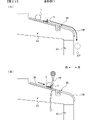
形態9の遊技機は、形態1~8のいずれかに記載の遊技機であって、
前記貯留部(例えば、球タンク形成部201)が設けられた遊技枠(例えば、遊技機用枠3)を備え、
前記貯留部は、
前記遊技枠の所定部(例えば、第1突出部224)の上面側に配置され、
前記所定部の上面との間にねじ部材が進入しないように該所定部の上面に近接または当接している(L30<L1、図19(B)参照)
ことを特徴としている。
この特徴によれば、ねじ部材が遊技枠の所定部と貯留部との間に入り込んで部材が破損してしまうことを防止することができる。
The gaming machine of
A game frame (for example, a game machine frame 3) provided with the storage portion (for example, a ball tank forming portion 201),
The reservoir is
Arranged on the upper surface side of a predetermined portion (for example, the first projecting portion 224) of the game frame,
It is close to or in contact with the upper surface of the predetermined portion so that the screw member does not enter between it and the upper surface of the predetermined portion (L30<L1, see FIG. 19B).
It is characterized by
According to this feature, it is possible to prevent the screw member from entering between the predetermined portion of the game frame and the storage portion and damaging the member.
形態10の遊技機は、形態1~9のいずれかに記載の遊技機であって、
前記誘導通路形成部(例えば、第1誘導通路形成部202)よりも下方位置に取付けられる第1基板(例えば、主基板11、演出制御基板12など)と、
前記誘導通路形成部よりも上方位置に取付けられる第2基板(例えば、ターミナル基板210)と、
を備え、
前記第1基板はねじ部材を用いた取付方法により取付けられる一方で、前記第2基板はねじ部材を用いた取付方法とは異なる取付方法により取付けられる(例えば、基板ケース11A,12Aなどはねじ部材により遊技盤2に取付けられる一方で、ターミナル基板210は、ねじ部材とは異なる取付手段としての複数の規制部235及び係止部236からなる係止手段を用いて基板取付枠211に取付けられる。図17参照)
ことを特徴としている。
この特徴によれば、誘導通路形成部内に落下したねじ部材が払出部に混入することを防止することができる。
The gaming machine of
A first board (e.g.,
a second substrate (for example, a terminal substrate 210) attached at a position above the guide passage forming portion;
with
The first board is mounted by a mounting method using screw members, while the second board is mounted by a mounting method different from the mounting method using screw members (for example, the
It is characterized by
According to this feature, it is possible to prevent the screw member that has fallen into the guide passage forming portion from being mixed into the delivery portion.
形態11の遊技機は、形態10に記載の遊技機であって、
前記第2基板は、所定の信号を前記遊技機の外部に出力するための配線(例えば、ケーブルC)が接続される外部出力用基板(例えば、ターミナル基板210)であり、
前記第1基板は、前記外部出力用基板よりも接続される配線数が少ない(例えば、第1誘導通路形成部202の上方に設けられる第1基板としてのターミナル基板210の複数の接続孔部231に接続可能なケーブルCの接続本数は第1本数(例えば、20本)とされている一方で、第1誘導通路形成部202の下方に設けられる主基板11や演出制御基板12などの第2基板にも各々の信号線が接続されるが、第1本数より少ない本数である第2本数(例えば、10本)とされている。)
ことを特徴としている。
この特徴によれば、接続する配線数が多く配線接続作業の際に外力が加わりやすい第2基板がねじ部材で取付けられないことで、外部出力用基板に外力が加わることによりねじ部材が外れて誘導通路形成部内に落下することを防止することができる。
The gaming machine of
The second board is an external output board (e.g., terminal board 210) to which a wiring (e.g., cable C) for outputting a predetermined signal to the outside of the gaming machine is connected,
The first substrate has a smaller number of wirings to be connected than the external output substrate (for example, the plurality of connection holes 231 of the
It is characterized by
According to this feature, the second board, which has a large number of wires to be connected and is likely to be subjected to an external force during the wiring connection work, cannot be attached with a screw member. It is possible to prevent falling into the guide passage forming portion.
形態12の遊技機は、形態10または11に記載の遊技機であって、
前記貯留部(例えば、球タンク形成部201)が設けられた遊技枠(例えば、遊技機用枠3)と、
前記外部出力用基板を前記遊技枠に取付けるための取付枠(例えば、基板取付枠211)と、
を備え、
前記取付枠は、該取付枠に落下したねじ部材の前記誘導通路形成部への移動を制限するための取付枠制限部(例えば、凹部242)を有する
ことを特徴としている。
この特徴によれば、外部出力用基板の取付枠を利用して、誘導通路形成部内に落下したねじ部材が払出部に混入することを防止することができる。
The gaming machine of
a game frame (for example, the game machine frame 3) provided with the storage portion (for example, the ball tank forming portion 201);
a mounting frame (for example, a board mounting frame 211) for mounting the external output board to the game frame;
with
The mounting frame is characterized by having a mounting frame restricting portion (for example, recessed portion 242) for restricting the movement of the screw member dropped onto the mounting frame to the guide passage forming portion.
According to this feature, the attachment frame of the external output board can be used to prevent the screw member that has fallen into the guide passage forming portion from entering the dispensing portion.
形態13の遊技機は、形態1~12のいずれかに記載の遊技機であって、
前記誘導通路形成部(例えば、第1誘導通路形成部202)の周辺に、該誘導通路形成部に向けて移動してきたねじ部材(例えば、ねじ部材N1~N6、N11~N16)の前記誘導通路形成部への落下を制限するための特別制限部(例えば、凹部280,290,214,242,243)が設けられている(図22(C)、図23(A)(B)、図24参照)
ことを特徴としている。
この特徴によれば、ねじ部材が誘導通路形成部内に落下することを防止することができる。
The gaming machine of
The guide passages of the screw members (for example, screw members N1 to N6, N11 to N16) moved toward the guide passage forming portion (for example, the first guide passage forming portion 202) around the guide passage forming portion (for example, the first guide passage forming portion 202) Special restricting portions (for example, recessed
It is characterized by
According to this feature, it is possible to prevent the screw member from falling into the guide passage forming portion.
形態14の遊技機は、形態13に記載の遊技機であって、
前記特別制限部は、前記誘導通路形成部(例えば、第1誘導通路形成部202)に向けて移動してきたねじ部材(例えば、ねじ部材N1~N6、N11~N16)を該誘導通路形成部に到達する前に滞留させることが可能な特別滞留部(例えば、凹部280,290,214,242,243)であり、被取付部に取付けられたねじ部材の下方に設けられ、
前記被取付部から外れたが前記特別滞留部に滞留しなかったねじ部材が前記カバー部に向けて移動可能である(図22(C)、図23(A)(B)、図24参照)
ことを特徴としている。
この特徴によれば、被取付部から外れたねじ部材が誘導通路形成部内に落下することを防止することができる。
The gaming machine of
The special restricting portion moves the screw members (for example, screw members N1 to N6, N11 to N16) that have moved toward the guide passage forming portion (for example, the first guide passage forming portion 202) to the guide passage forming portion. A special retention portion (for example, recessed
A threaded member that has been detached from the attached portion but has not been retained in the special retention portion can move toward the cover portion (see FIGS. 22(C), 23(A), (B), and 24).
It is characterized by
According to this feature, it is possible to prevent the screw member detached from the attached portion from falling into the guide passage forming portion.
形態15の遊技機は、形態13または14に記載の遊技機であって、
前記特別滞留部は、ねじ部材の少なくとも一部を収容可能な凹部(例えば、凹部280,290,214,242,243)であり、
前記凹部の深さは、ねじ部材が収容された状態において該ねじ部材の一部が突出する深さである(図22(C)、図23(A)(B)、図24参照)
ことを特徴としている。
この特徴によれば、凹部に滞留したねじ部材を容易に取出すことができる。
The gaming machine of
the special retention portion is a recess (for example, recesses 280, 290, 214, 242, 243) capable of accommodating at least a portion of the screw member;
The depth of the recess is the depth to which a portion of the screw member protrudes when the screw member is accommodated (see FIGS. 22(C), 23(A), (B), and 24).
It is characterized by
According to this feature, the screw member retained in the recess can be easily taken out.
形態16の遊技機は、形態1~15のいずれかに記載の遊技機であって、
前記誘導通路形成部(例えば、第1誘導通路形成部202)の上面の一部を覆うように設けられたカバー部(例えば、第3カバー体330のカバー部334)を備え、
前記カバー部は、前記払出部側に向けて下方に傾斜するように設けられ、
前記カバー部における傾斜方向の前記払出部側に、該カバー部上に落下したねじ部材を該カバー部に滞留させることが可能な特定部(例えば、球止め部材340)が設けられている(図15、図26、図27参照)
ことを特徴としている。
この特徴によれば、誘導通路形成部内に落下したねじ部材が払出部に混入することを防止することができる。
The gaming machine of form 16 is the gaming machine according to any one of
A cover portion (for example, the
The cover portion is provided so as to incline downward toward the dispensing portion side,
A specific portion (for example, a ball stop member 340) capable of retaining a screw member that has fallen onto the cover portion is provided on the payout portion side of the cover portion in the inclined direction (see FIG. 15, Figures 26 and 27)
It is characterized by
According to this feature, it is possible to prevent the screw member that has fallen into the guide passage forming portion from being mixed into the delivery portion.
形態17の遊技機は、形態16に記載の遊技機であって、
前記特定部(例えば、球止め部材340)は、前記誘導通路形成部(例えば、第1誘導通路形成部202)の遊技媒体(例えば、遊技球P)を流下可能とする第1状態と、前記誘導通路形成部の遊技媒体を流下困難または流下不能とする第2状態と、に変化可能であり(例えば、回動部341が起立位置に位置し、前壁部341Aがスリット344から上方に逸脱して第1誘導通路形成部202の遊技球を第2誘導通路形成部204に流下可能とする第1状態と、回動部341が傾倒位置に位置し、前壁部341Aがスリット344に挿入され遊技球に接触可能となり、第1誘導通路形成部202の遊技球を第2誘導通路形成部204に流下不能(または流下困難)とする第2状態と、に変化可能とされている。)、
前記特定部が前記第2状態のときの方が、前記第1状態のときよりもねじ部材が滞留しやすい(図26参照)
ことを特徴としている。
この特徴によれば、誘導通路形成部内に落下したねじ部材が払出部に混入することを防止することができる。
The gaming machine of form 17 is the gaming machine according to form 16,
The specific part (for example, the ball stopping member 340) has a first state in which the game medium (for example, the game ball P) of the guide path forming part (for example, the first guide path forming part 202) can flow down; It can be changed to a second state in which the game medium in the guide passage forming portion is difficult to flow down or cannot flow down (for example, the rotating
When the specific portion is in the second state, the screw member tends to stay more easily than when it is in the first state (see FIG. 26).
It is characterized by
According to this feature, it is possible to prevent the screw member that has fallen into the guide passage forming portion from being mixed into the delivery portion.
形態18の遊技機は、形態16または17に記載の遊技機であって、
前記カバー部は、
前記カバー部上に落下したねじ部材を該カバー部上に滞留させることが可能な滞留部(例えば、長孔316A~316C、凹溝326A~326C、凹部336)が設けられた第1カバー部(例えば、第1カバー体310のカバー部324、第2カバー体320のカバー部324)と、
前記第1カバー部とは異なり前記特定部が設けられた第2カバー部(例えば、第3カバー体330のカバー部334)と、
を含む
ことを特徴としている。
この特徴によれば、誘導通路形成部内に落下したねじ部材が払出部に混入することを防止することができる。
The gaming machine of form 18 is the gaming machine according to form 16 or 17,
The cover part
A first cover portion (for example,
a second cover portion (for example, the
It is characterized by including
According to this feature, it is possible to prevent the screw member that has fallen into the guide passage forming portion from being mixed into the delivery portion.
形態19の遊技機は、形態18に記載の遊技機であって、
前記第2カバー部(例えば、第3カバー体330のカバー部334)は、緩み止め部(例えば、フランジ部F)を有するねじ部材(例えば、ねじ部材N16)にて取付けられている(図8参照)
ことを特徴としている。
この特徴によれば、誘導通路形成部内に落下したねじ部材が払出部に混入することを防止することができる。
The gaming machine of form 19 is the gaming machine according to form 18,
The second cover portion (for example, the
It is characterized by
According to this feature, it is possible to prevent the screw member that has fallen into the guide passage forming portion from being mixed into the delivery portion.
形態20の遊技機は、形態1~19のいずれかに記載の遊技機であって、
前記貯留部(例えば、球タンク形成部201)が設けられた遊技枠(例えば、遊技機用枠3)を備え、
前記貯留部は、緩み止め部を有するねじ部材(例えば、ねじ部材N11~N14)によって複数個所で前記遊技枠に取付けられ、
前記貯留部及び前記誘導通路形成部(例えば、第1誘導通路形成部202)を前記遊技枠に取付けるためのねじ部材は、該遊技枠から外れても前記誘導通路形成部外に落下するように取付けられている(図8参照)
ことを特徴としている。
この特徴によれば、貯留部を取付けるねじ部材を遊技枠から外れにくくする一方で、貯留部と誘導通路形成部を取付けるねじ部材は、外れたとしても誘導通路形成部外に落下するため、誘導通路形成部内に落下したねじ部材が払出部に混入することを防止することができる。
The gaming machine of
A game frame (for example, a game machine frame 3) provided with the storage portion (for example, a ball tank forming portion 201),
The storage portion is attached to the game frame at a plurality of locations by screw members (for example, screw members N11 to N14) having locking portions,
A screw member for attaching the storage portion and the guiding passage forming portion (for example, the first guiding passage forming portion 202) to the game frame is designed to fall outside the guiding passage forming portion even if the screw member is disengaged from the game frame. Installed (see Figure 8)
It is characterized by
According to this feature, the screw member that attaches the storage portion is made difficult to come off from the game frame, and the screw member that attaches the storage portion and the guide passage formation portion falls outside the guide passage formation portion even if it comes off. It is possible to prevent the threaded member that has fallen into the passage forming portion from being mixed into the delivery portion.
形態21の遊技機は、形態20に記載の遊技機であって、
前記貯留部(例えば、球タンク形成部201)及び前記誘導通路形成部(例えば、第1誘導通路形成部202)を前記遊技枠(例えば、遊技機用枠3)に取付けるための複数のねじ部材のうち、前記遊技機の周縁部近傍の所定ねじ部材(例えば、ねじ部材N12)は、アース線(例えば、アース線226)を取付けるためのねじ部材と兼用されている(図8参照)
ことを特徴としている。
この特徴によれば、ねじ部材を減らすことができるため、誘導通路形成部内に落下したねじ部材が払出部に混入することを防止することができる。
The gaming machine of
A plurality of screw members for attaching the storage portion (for example, the ball tank forming portion 201) and the guide passage forming portion (for example, the first guide passage forming portion 202) to the game frame (for example, the game machine frame 3) Of these, a predetermined screw member (for example, screw member N12) near the periphery of the game machine is also used as a screw member for attaching a ground wire (for example, ground wire 226) (see FIG. 8).
It is characterized by
According to this feature, since the number of screw members can be reduced, it is possible to prevent the screw members that have fallen into the guide passage forming portion from being mixed into the delivery portion.
形態22の遊技機は、形態20または21に記載の遊技機であって、
前記貯留部(例えば、球タンク形成部201)を前記遊技枠(例えば、遊技機用枠3)に取付けるためのねじ部材(例えば、ねじ部材N11~N14)は、該遊技枠を補強するための金属部材(例えば、金属板222)に取付けられている(図8参照)
ことを特徴としている。
この特徴によれば、貯留部を強固に取付けることができる。
The gaming machine of
Screw members (for example, screw members N11 to N14) for attaching the storage portion (for example, ball tank forming portion 201) to the game frame (for example, game machine frame 3) are provided for reinforcing the game frame. Attached to a metal member (for example, a metal plate 222) (see FIG. 8)
It is characterized by
According to this feature, the reservoir can be firmly attached.
形態23の遊技機は、形態20~22のいずれかに記載の遊技機であって、
前記遊技枠(例えば、遊技機用枠3)における前記誘導通路形成部(例えば、第1誘導通路形成部202)の上方位置に取付けられているねじ部材(例えば、ねじ部材N3~N6)は、前記緩み止め部を有するねじ部材とは異なるねじ部材である
ことを特徴としている。
この特徴によれば、誘導通路形成部内に落下したねじ部材が払出部に混入することを防止することができる。
The gaming machine of
Screw members (for example, screw members N3 to N6) attached to positions above the guide passage forming portion (for example, the first guide passage forming portion 202) in the game frame (for example, the game machine frame 3) are It is a screw member different from the screw member having the locking portion.
According to this feature, it is possible to prevent the screw member that has fallen into the guide passage forming portion from being mixed into the delivery portion.
形態24の遊技機は、形態20~23のいずれかに記載の遊技機であって、
前記遊技枠(例えば、遊技機用枠3)に着脱可能な遊技盤(例えば、遊技盤2)を備え、
前記遊技盤における前記誘導通路形成部(例えば、第1誘導通路形成部202)よりも下方の領域には、落下してきたねじ部材を流下させることが可能な傾斜面(例えば、カバー体220の上壁部220H)が設けられている(図18~図20、図27参照)
ことを特徴としている。
この特徴によれば、誘導通路形成部から遊技盤に落下したねじ部材が跳ねて再び誘導通路形成部に混入されることを防止することができる。
The gaming machine of
A game board (e.g., game board 2) detachable from the game frame (e.g., game machine frame 3) is provided,
In the area below the guide passage forming portion (for example, the first guide passage forming portion 202) in the game board, there is an inclined surface (for example, the upper portion of the cover body 220) that allows the falling screw member to flow down.
It is characterized by
According to this feature, it is possible to prevent the screw member that has dropped from the guide passage forming portion onto the game board to bounce and be mixed into the guide passage forming portion again.
形態25の遊技機は、形態1~24のいずれかに記載の遊技機であって、
前記誘導通路形成部(例えば、第1誘導通路形成部202)の上面の一部を覆うように設けられたカバー部(例えば、変形例1のカバー部360)を備え、
前記誘導通路形成部は、
一側方(例えば、左側方)に向けて下側に傾斜するように延設される第1通路形成部(例えば、第1誘導通路形成部202)と、
前記第1通路形成部の下側の端部から下方に向けて延設される第2通路形成部(例えば、第2誘導通路形成部204)と、
を有し、
前記カバー部は、該カバー部上に落下したねじ部材が移動して下側の端部から前記誘導通路形成部外に落下するように前記第1通路形成部に沿って設けられる(図29(A)参照)
ことを特徴としている。
この特徴によれば、誘導通路形成部内に落下したねじ部材が払出部に混入することを防止することができる。
The gaming machine of
A cover portion (for example, the
The guide passage forming portion is
a first passage forming portion (e.g., first guide passage forming portion 202) extending downward toward one side (e.g., left side);
a second passage forming portion (for example, a second guide passage forming portion 204) extending downward from the lower end of the first passage forming portion;
has
The cover portion is provided along the first passage forming portion so that the screw member dropped onto the cover portion moves and falls outside the guide passage forming portion from the lower end (Fig. 29 ( A) See)
It is characterized by
According to this feature, it is possible to prevent the screw member that has fallen into the guide passage forming portion from being mixed into the delivery portion.
形態26の遊技機は、形態2~25のいずれかに記載の遊技機であって、
前記カバー部(例えば、変形例1のカバー部360)における前記所定制限部(例えば、凹部361)の近傍位置に、前記誘導通路形成部に対し交差するように配線(例えば、ケーブルCH)が設けられている(図29(B)参照)
ことを特徴としている。
この特徴によれば、ねじ部材が配線に引っ掛かり所定制限部に滞留しやすくなる。
The gaming machine of form 26 is the gaming machine according to any one of
A wiring (for example, a cable CH) is provided so as to cross the guide passage forming portion at a position near the predetermined restriction portion (for example, the recessed portion 361) in the cover portion (for example, the
It is characterized by
According to this feature, the screw member is likely to get caught on the wiring and remain in the predetermined restricting portion.
(パチンコ遊技機1の構成等)
まず、パチンコ遊技機1の構成を説明する。尚、以下の説明においては、遊技者が位置する方向をパチンコ遊技機1の前方とし、その反対の方向を後方とする。また、パチンコ遊技機1の前方に位置する遊技者から見たときの上下左右の方向を基準として説明する。
(Structure of
First, the configuration of the
図1は、パチンコ遊技機1の正面図であり、主要部材の配置レイアウトを示す。パチンコ遊技機(遊技機)1は、大別して、遊技盤面を構成する遊技盤(ゲージ盤)2と、遊技盤2を支持固定する遊技機用枠(台枠)3とから構成されている。遊技盤2には、遊技領域Yが形成され、この遊技領域Yには、遊技媒体としての遊技球が、所定の打球発射装置から発射されて打ち込まれる。また、遊技機用枠3には、ガラス窓50aを有するガラス扉枠50が左側辺を中心として回動可能に設けられ、該ガラス扉枠50により遊技領域Yを開閉できるようになっており、ガラス扉枠50を閉鎖したときにガラス窓50aを通して遊技領域Yを透視できるようになっている。
FIG. 1 is a front view of the
図1に示すように、遊技盤2は、アクリル樹脂、ポリカーボネート樹脂、メタクリル樹脂等の透光性を有する合成樹脂材にて正面視略四角形状に形成され、前面である遊技盤面に障害釘(図示略)やガイドレール2b等が設けられた盤面板と、該盤面板の背面側に一体的に取付けられるスペーサ部材と、から構成されている。尚、遊技盤2は、ベニヤ板等の非透光性部材にて正面視略四角形状に構成され、前面である遊技盤面に障害釘(図示略)やガイドレール2b等が設けられた盤面板にて構成されていてもよい。
As shown in FIG. 1, the
遊技盤2の所定位置(図1に示す例では、遊技領域Yの左下)には、複数種類の特別識別情報としての特別図柄(特図ともいう。)の可変表示(特図ゲームともいう)を行う、第1特別図柄表示装置4A及び第2特別図柄表示装置4Bが設けられている。これらは、それぞれ、7セグメントのLEDなどからなる。特別図柄は、「0」~「9」を示す数字や「-」などの点灯パターンなどにより表される。特別図柄には、LEDを全て消灯したパターンが含まれてもよい。
At a predetermined position of the game board 2 (in the example shown in FIG. 1, the bottom left of the game area Y), special symbols (also called special symbols) as special identification information of a plurality of types are variably displayed (also called a special symbol game). A first special
尚、特別図柄の「可変表示」とは、例えば、複数種類の特別図柄を変動可能に表示することである(後述の他の図柄についても同じ)。変動としては、複数の図柄の更新表示、複数の図柄のスクロール表示、1以上の図柄の変形、1以上の図柄の拡大/縮小などがある。特別図柄や後述の普通図柄の変動では、複数種類の特別図柄又は普通図柄が更新表示される。後述の飾り図柄の変動では、複数種類の飾り図柄がスクロール表示又は更新表示されたり、1以上の飾り図柄が変形や拡大/縮小されたりする。尚、変動には、ある図柄を点滅表示する態様も含まれる。可変表示の最後には、表示結果として所定の特別図柄が停止表示(導出又は導出表示などともいう)される(後述の他の図柄の可変表示についても同じ)。尚、可変表示を変動表示、変動と表現する場合がある。 Incidentally, the "variable display" of the special symbols means, for example, that a plurality of types of special symbols are displayed in a variable manner (the same applies to other symbols described later). Variations include updating display of a plurality of patterns, scrolling display of a plurality of patterns, deformation of one or more patterns, enlargement/reduction of one or more patterns, and the like. In the variation of special symbols and normal symbols, which will be described later, a plurality of types of special symbols or normal symbols are updated and displayed. In the variation of decorative patterns, which will be described later, a plurality of types of decorative patterns are scrolled or updated, and one or more decorative patterns are deformed or enlarged/reduced. Incidentally, the variation includes a mode of blinking a certain symbol. At the end of the variable display, a predetermined special symbol is stopped and displayed (also referred to as derivation or derivation display) as a display result (the same applies to variable display of other symbols to be described later). Variable display may be expressed as variable display or variation.
尚、第1特別図柄表示装置4Aにおいて可変表示される特別図柄を「第1特図」ともいい、第2特別図柄表示装置4Bにおいて可変表示される特別図柄を「第2特図」ともいう。また、第1特図を用いた特図ゲームを「第1特図ゲーム」といい、第2特図を用いた特図ゲームを「第2特図ゲーム」ともいう。尚、特別図柄の可変表示を行う特別図柄表示装置は1種類であってもよい。
The special symbols variably displayed on the first special
遊技盤2における遊技領域Yの中央付近には画像表示装置5が設けられている。画像表示装置5は、例えばLCD(液晶表示装置)や有機EL(Electro Luminescence)等から構成され、各種の演出画像を表示する。画像表示装置5は、プロジェクタ及びスクリーンから構成されていてもよい。画像表示装置5には、各種の演出画像が表示される。尚、遊技盤2における開口2cには枠状のセンター飾り枠51が設けられている。
An
例えば、画像表示装置5の画面上では、第1特図ゲームや第2特図ゲームと同期して、特別図柄とは異なる複数種類の装飾識別情報としての飾り図柄(数字などを示す図柄など)の可変表示が行われる。ここでは、第1特図ゲームまたは第2特図ゲームに同期して、「左」、「中」、「右」の各飾り図柄表示エリア5L、5C、5Rにおいて飾り図柄が可変表示(例えば上下方向のスクロール表示や更新表示)される。尚、同期して実行される特図ゲーム及び飾り図柄の可変表示を総称して単に可変表示ともいう。
For example, on the screen of the
画像表示装置5の画面上には、実行が保留されている可変表示に対応する保留表示や、実行中の可変表示に対応するアクティブ表示を表示するための表示エリアが設けられていてもよい。保留表示およびアクティブ表示を総称して可変表示に対応する可変表示対応表示ともいう。
A display area may be provided on the screen of the
保留されている可変表示の数は保留記憶数ともいう。第1特図ゲームに対応する保留記憶数を第1保留記憶数、第2特図ゲームに対応する保留記憶数を第2保留記憶数ともいう。また、第1保留記憶数と第2保留記憶数との合計を合計保留記憶数ともいう。 The number of variable representations that are reserved is also referred to as the number of reserved memories. The reserved memory number corresponding to the first special game is also referred to as the first reserved memory number, and the reserved memory number corresponding to the second special game is also referred to as the second reserved memory number. The sum of the first reserved memory count and the second reserved memory count is also referred to as the total reserved memory count.
また、遊技盤2の所定位置(図1に示す例では、遊技領域の左下)には、複数のLEDを含んで構成された第1保留表示器25Aと第2保留表示器25Bとが設けられ、第1保留表示器25Aは、LEDの点灯個数によって、第1保留記憶数を表示し、第2保留表示器25Bは、LEDの点灯個数によって、第2保留記憶数を表示する。
In addition, at a predetermined position of the game board 2 (in the example shown in FIG. 1, the bottom left of the game area), a
画像表示装置5の下方には、入賞球装置6Aと、可変入賞球装置6Bとが設けられている。
Below the
入賞球装置6Aは、例えば所定の玉受部材によって常に遊技球が進入可能な一定の開放状態に保たれる第1始動入賞口を形成する。第1始動入賞口に遊技球が進入したときには、所定個(例えば3個)の賞球が払い出されるとともに、第1特図ゲームが開始され得る。 Winning ball device 6A, for example, forms a first starting winning opening that is kept in a constant open state in which game balls can enter, for example, by a predetermined ball receiving member. When a game ball enters the first start winning hole, a predetermined number (for example, three) of prize balls are paid out, and the first special game can be started.
可変入賞球装置6B(普通電動役物)は、ソレノイド81(図2参照)によって閉鎖状態と開放状態とに変化する第2始動入賞口を形成する。可変入賞球装置6Bは、例えば、ソレノイド81によって開閉駆動される始動入賞口扉を備え、ソレノイド81がオフ状態であるときに始動入賞口扉が閉鎖位置となることにより、第2始動入賞口に遊技球が進入しない閉鎖状態になる(第2始動入賞口が閉鎖状態になるともいう。)。その一方で、可変入賞球装置6Bは、ソレノイド81がオン状態であるときに始動入賞口扉が開放位置となることにより、第2始動入賞口に遊技球が進入できる開放状態になる(第2始動入賞口が開放状態になるともいう。)。第2始動入賞口に遊技球が進入したときには、所定個(例えば3個)の賞球が払い出されるとともに、第2特図ゲームが開始され得る。なお、可変入賞球装置6Bは、閉鎖状態と開放状態とに変化するものであればよく、一対の可動翼片を有する電動チューリップ型役物を備えるものに限定されない。また、第2始動入賞口に遊技球が進入したときには、所定個(例えば3個)の賞球が払い出されるとともに、第2特図ゲームが開始され得る。
The variable winning ball device 6B (ordinary electric accessory) forms a second starting winning hole that changes between a closed state and an open state by a solenoid 81 (see FIG. 2). For example, the variable winning ball device 6B includes a starting winning opening door that is driven to open and close by a
遊技盤2の所定位置(図1に示す例では、遊技領域の左右下方4箇所)には、所定の玉受部材によって常に一定の開放状態に保たれる一般入賞口10が設けられる。この場合には、一般入賞口10のいずれかに進入したときには、所定個数(例えば10個)の遊技球が賞球として払い出される。
At predetermined positions of the game board 2 (in the example shown in FIG. 1, four positions on the left and right sides of the game area), there are provided general winning holes 10 which are always kept open by predetermined ball receiving members. In this case, when the player enters one of the general winning
入賞球装置6Aと可変入賞球装置6Bの間には、大入賞口を有する特別可変入賞球装置7が設けられている。特別可変入賞球装置7は、ソレノイド82(図2参照)によって開閉駆動される大入賞口扉を備え、その大入賞口扉によって開放状態と閉鎖状態とに変化する特定領域としての大入賞口を形成する。
A special variable winning
一例として、特別可変入賞球装置7では、大入賞口扉用(特別電動役物用)のソレノイド82がオフ状態であるときに大入賞口扉が大入賞口を閉鎖状態として、遊技球が大入賞口に進入(通過)できなくなる。その一方で、特別可変入賞球装置7では、大入賞口扉用のソレノイド82がオン状態であるときに大入賞口扉が大入賞口を開放状態として、遊技球が大入賞口に進入しやすくなる。
As an example, in the special variable winning
大入賞口に遊技球が進入したときには、所定個数(例えば14個)の遊技球が賞球として払い出される。大入賞口に遊技球が進入したときには、例えば第1始動入賞口や第2始動入賞口及び一般入賞口10に遊技球が進入したときよりも多くの賞球が払い出される。
When game balls enter the big winning hole, a predetermined number (for example, 14) of game balls are paid out as prize balls. When the game balls enter the big winning hole, more prize balls are paid out than when the game balls enter the first starting winning hole, the second starting winning hole and the general winning
一般入賞口を含む各入賞口に遊技球が進入することを「入賞」ともいう。特に、始動口(第1始動入賞口、第2始動入賞口始動口)への入賞を始動入賞ともいう。 Entering a game ball into each winning hole including general winning holes is also called "winning". In particular, winning a prize to a starting opening (first starting winning opening, second starting winning opening starting opening) is also referred to as starting winning.
遊技盤2の所定位置(図1に示す例では、遊技領域Yの左下)には、普通図柄表示器20が設けられている。一例として、普通図柄表示器20は、7セグメントのLEDなどからなり、特別図柄とは異なる複数種類の普通識別情報としての普通図柄の可変表示を行う。普通図柄は、「0」~「9」を示す数字や「-」などの点灯パターンなどにより表される。普通図柄には、LEDを全て消灯したパターンが含まれてもよい。このような普通図柄の可変表示は、普図ゲームともいう。
A
画像表示装置5の右方には、遊技球が通過可能な通過ゲート41が設けられている。遊技球が通過ゲート41を通過したことに基づき、普図ゲームが実行される。
A
普通図柄表示器20の下方には、普図保留表示器25Cが設けられている。普図保留表示器25Cは、例えば4個のLEDを含んで構成され、実行が保留されている普図ゲームの数である普図保留記憶数をLEDの点灯個数により表示する。
Below the
遊技盤2の表面には、上記の構成以外にも、遊技球の流下方向や速度を変化させる風車及び多数の障害釘が設けられている。遊技領域Yの最下方には、いずれの入賞口にも進入しなかった遊技球が取り込まれるアウト口(図示略)が設けられている。
The surface of the
遊技機用枠3の左右上部位置には、効果音等を再生出力するためのスピーカ8L、8Rが設けられており、さらに遊技領域Y周辺部には、遊技効果用の遊技効果ランプ9が設けられている。遊技効果ランプ9は、LEDを含んで構成されている。
遊技盤2の所定位置(図1では図示略)には、演出に応じて動作する可動体32が設けられている。
At a predetermined position (not shown in FIG. 1) of the
遊技機用枠3の右下部位置には、遊技球を打球発射装置により遊技領域Yに向けて発射するために遊技者等によって操作される打球操作ハンドル(操作ノブ)30が設けられている。
A ball hitting operation handle (operation knob) 30 operated by a player or the like in order to shoot a game ball toward the game area Y by the ball shooting device is provided at the lower right portion of the
遊技領域Yの下方における遊技機用枠3の所定位置には、賞球として払い出された遊技球や所定の球貸機により貸し出された遊技球を、打球発射装置へと供給可能に保持(貯留)する打球供給皿(上皿)が設けられている。上皿の下方には、上皿満タン時に賞球が払い出される払出口が設けられている。尚、打球供給皿(下皿)が設けられていてもよい。
At a predetermined position of the
遊技領域Yの下方における遊技機用枠3の所定位置には、遊技者が把持して傾倒操作が可能なスティックコントローラ31Aが取付けられている。スティックコントローラ31Aには、遊技者が押下操作可能なトリガボタンが設けられている。スティックコントローラ31Aに対する操作は、コントローラセンサユニット35A(図2参照)により検出される。
At a predetermined position of the
遊技領域Yの下方における遊技機用枠3の所定位置には、遊技者が押下操作などにより所定の指示操作を可能なプッシュボタン31Bが設けられている。プッシュボタン31Bに対する操作は、プッシュセンサ35B(図2参照)により検出される。
At a predetermined position of the
パチンコ遊技機1では、遊技者の動作(操作等)を検出する検出手段として、スティックコントローラ31Aやプッシュボタン31Bが設けられるが、これら以外の検出手段が設けられていてもよい。
The
(遊技の進行の概略)
パチンコ遊技機1が備える打球操作ハンドル30への遊技者による回転操作により、遊技球が遊技領域Yに向けて発射される。遊技球が通過ゲート41を通過すると、普通図柄表示器20による普図ゲームが開始される。尚、前回の普図ゲームの実行中の期間等に遊技球が通過ゲート41を通過した場合(遊技球が通過ゲート41を通過したが当該通過に基づく普図ゲームを直ちに実行できない場合)には、当該通過に基づく普図ゲームは所定の上限数(例えば4)まで保留される。
(Overview of Game Progress)
A game ball is shot toward a game area Y by a player's rotation operation of a ball-hitting operation handle 30 provided in the
この普図ゲームでは、特定の普通図柄(普図当り図柄)が停止表示されれば、普通図柄の表示結果が「普図当り」となる。その一方、確定普通図柄として、普図当り図柄以外の普通図柄(普図ハズレ図柄)が停止表示されれば、普通図柄の表示結果が「普図ハズレ」となる。「普図当り」となると、可変入賞球装置6Bを所定期間開放状態とする開放制御が行われる(第2始動入賞口が開放状態になる)。 In this normal pattern game, if a specific normal pattern (normal pattern per pattern) is stopped and displayed, the display result of the normal pattern becomes "normal pattern per pattern". On the other hand, if a normal pattern (normal pattern losing pattern) other than the normal pattern per pattern is stop-displayed as the determined normal pattern, the display result of the normal pattern becomes "normal pattern losing". When it comes to "normal game", the variable winning ball device 6B is opened for a predetermined period of time and the opening control is performed (the second start winning opening is opened).
入賞球装置6Aに形成された第1始動入賞口に遊技球が進入すると、第1特別図柄表示装置4Aによる第1特図ゲームが開始される。
When a game ball enters the first starting winning hole formed in the winning ball device 6A, the first special symbol game by the first special
可変入賞球装置6Bに形成された第2始動入賞口に遊技球が進入すると、第2特別図柄表示装置4Bによる第2特図ゲームが開始される。
When the game ball enters the second starting winning hole formed in the variable winning ball device 6B, the second special symbol game by the second special
尚、特図ゲームの実行中の期間や、後述する大当り遊技状態や小当り遊技状態に制御されている期間に、遊技球が始動入賞口へ進入(入賞)した場合(始動入賞が発生したが当該始動入賞に基づく特図ゲームを直ちに実行できない場合)には、当該進入に基づく特図ゲームは所定の上限数(例えば4)までその実行が保留される。 In addition, when the game ball enters (wins) the start winning opening during the period during execution of the special game or during the period when it is controlled to the big win game state or the small win game state described later (although the start winning has occurred) If the special game based on the starting prize cannot be executed immediately), the execution of the special game based on the entry is suspended up to a predetermined upper limit number (for example, 4).
特図ゲームにおいて、確定特別図柄として特定の特別図柄(大当り図柄、例えば「7」、後述の大当り種別に応じて実際の図柄は異なる。)が停止表示されれば、「大当り」となり、大当り図柄とは異なる所定の特別図柄(小当り図柄、例えば「2」)が停止表示されれば、「小当り」となる。また、大当り図柄や小当り図柄とは異なる特別図柄(ハズレ図柄、例えば「-」)が停止表示されれば「ハズレ」となる。 In the special symbol game, if a specific special symbol (a big hit symbol, for example, "7", the actual symbol differs depending on the type of the big hit described below) is stopped and displayed as a fixed special symbol, it becomes a "big win" and a big winning symbol. If a predetermined special symbol (a small winning symbol, for example, "2") different from the symbol is stop-displayed, it becomes a "small winning". Also, if a special symbol (losing symbol, for example, "-") different from the big-hit symbol or the small-hit symbol is stop-displayed, it becomes "losing".
特図ゲームでの表示結果が「大当り」になった後には、遊技者にとって有利な有利状態として大当り遊技状態に制御される。特図ゲームでの表示結果が「小当り」になった後には、小当り遊技状態に制御される。 After the display result in the special game becomes "big win", the game is controlled to a big win game state as an advantageous state for the player. After the display result in the special game becomes "minor win", it is controlled to the small win game state.
大当り遊技状態においては、遊技者は、遊技球を大入賞口に進入させることで、賞球を得ることができる。従って、大当り遊技状態は、遊技者にとって有利な状態である。大当り遊技状態におけるラウンド数が多い程、また、開放上限期間が長い程遊技者にとって有利となる。 In the jackpot game state, the player can get a prize ball by entering the game ball into the big winning hole. Therefore, the jackpot gaming state is an advantageous state for the player. The larger the number of rounds in the jackpot game state and the longer the upper limit period of opening, the more advantageous the player is.
尚、「大当り」には、大当り種別が設定されている。例えば、大入賞口の開放態様(ラウンド数や開放上限期間)や、大当り遊技状態後の遊技状態(後述の、通常状態、時短状態、確変状態など)を複数種類用意し、これらに応じて大当り種別が設定されている。大当り種別として、多くの賞球を得ることができる大当り種別や、賞球の少ない又はほとんど賞球を得ることができない大当り種別が設けられていてもよい。 In addition, a jackpot type is set in the "jackpot". For example, a plurality of types of opening modes (number of rounds and upper limit period of opening) of the big winning opening and game states after the jackpot game state (normal state, time saving state, variable probability state, etc. described later) are prepared, and the jackpot is obtained according to these. type is set. As the jackpot type, there may be provided a jackpot type in which a large number of prize balls can be obtained, and a jackpot type in which a small number of prize balls or almost no prize balls can be obtained.
小当り遊技状態では、特別可変入賞球装置7により形成される大入賞口が所定の開放態様で開放状態となる。例えば、小当り遊技状態では、一部の大当り種別のときの大当り遊技状態と同様の開放態様(大入賞口の開放回数が上記ラウンド数と同じであり、かつ、大入賞口の閉鎖タイミングも同じ等)で大入賞口が開放状態となる。尚、大当り種別と同様に、「小当り」にも小当り種別を設けてもよい。
In the small winning game state, the big winning opening formed by the special variable winning
大当り遊技状態が終了した後は、上記大当り種別に応じて、時短状態や確変状態に制御されることがある。 After the jackpot game state is finished, depending on the jackpot type, it may be controlled to a time-saving state or a variable probability state.
時短状態では、平均的な特図変動時間(特図を変動させる期間)を通常状態よりも短縮させる制御(時短制御)が実行される。時短状態では、平均的な普図変動時間(普図を変動させる期間)を通常状態よりも短縮させたり、普図ゲームで「普図当り」となる確率を通常状態よりも向上させる等により、第2始動入賞口に遊技球が進入しやすくなる制御(高開放制御、高ベース制御)も実行される。時短状態は、特別図柄(特に第2特別図柄)の変動効率が向上する状態であるので、遊技者にとって有利な状態である。 In the time saving state, the control (time saving control) that shortens the average special figure fluctuation time (period of varying the special figure) than the normal state is executed. In the time-saving state, by shortening the average normal figure fluctuation time (the period during which the normal figure is changed) than in the normal state, and by improving the probability of becoming a "normal figure hit" in the general figure game than in the normal state, etc. Control (high opening control, high base control) that makes it easier for game balls to enter the second start winning opening is also executed. Since the time-saving state is a state in which the variation efficiency of the special symbols (especially the second special symbols) is improved, it is an advantageous state for the player.
確変状態(確率変動状態)では、時短制御に加えて、表示結果が「大当り」となる確率が通常状態よりも高くなる確変制御が実行される。確変状態は、特別図柄の変動効率が向上することに加えて「大当り」となりやすい状態であるので、遊技者にとってさらに有利な状態である。 In the variable probability state (probability variable state), in addition to the time-saving control, the variable probability control in which the probability that the display result is a "jackpot" is higher than in the normal state is executed. The variable probability state is a state in which the variation efficiency of the special symbols is improved, and in addition, a "big hit" is likely to occur, so it is a further advantageous state for the player.
時短状態や確変状態は、所定回数の特図ゲームが実行されたことと、次回の大当り遊技状態が開始されたこと等といった、いずれか1つの終了条件が先に成立するまで継続する。所定回数の特図ゲームが実行されたことが終了条件となるものを、回数切り(回数切り時短、回数切り確変等)ともいう。 The time saving state and the variable probability state are continued until one of the end conditions such as execution of the special game for a predetermined number of times and start of the next big win game state is established first. The end condition that the special figure game of a predetermined number of times has been executed is also referred to as a number cut (number cut time reduction, number cut probability variable, etc.).
通常状態とは、遊技者にとって有利な大当り遊技状態等の有利状態、時短状態、確変状態等の特別状態以外の遊技状態のことであり、普図ゲームにおける表示結果が「普図当り」となる確率及び特図ゲームにおける表示結果が「大当り」となる確率などのパチンコ遊技機1が、パチンコ遊技機1の初期設定状態(例えばシステムリセットが行われた場合のように、電源投入後に所定の復帰処理を実行しなかったとき)と同一に制御される状態である。
The normal state means a game state other than a special state such as an advantageous state such as a jackpot game state that is advantageous to the player, a time saving state, a variable probability state, etc., and the display result in the normal game is "normal game". The
確変制御が実行されている状態を高確状態、確変制御が実行されていない状態を低確状態ともいう。時短制御が実行されている状態を高ベース状態、時短制御が実行されていない状態を低ベース状態ともいう。これらを組み合わせて、時短状態は低確高ベース状態、確変状態は高確高ベース状態、通常状態は低確低ベース状態などともいわれる。高確状態かつ低ベース状態は高確低ベース状態ともいう。 The state in which probability variable control is executed is also called a high probability state, and the state in which probability variable control is not executed is also called a low probability state. A state in which time-saving control is performed is also referred to as a high-based state, and a state in which time-saving control is not performed is also referred to as a low-based state. Combining these, the short-time state is also called a low-probability-high base state, the probability-variable state is a high-probability-high base state, and the normal state is a low-probability-low base state. The high probability state and the low base state are also referred to as the high probability low base state.
小当り遊技状態が終了した後は、遊技状態の変更が行われず、特図ゲームの表示結果が「小当り」となる以前の遊技状態に継続して制御される(但し、「小当り」発生時の特図ゲームが、上記回数切りにおける上記所定回数目の特図ゲームである場合には、当然遊技状態が変更される)。尚、特図ゲームの表示結果として「小当り」がなくてもよい。 After the small win game state is over, the game state is not changed, and the game state before the display result of the special figure game becomes "small win" is continuously controlled (however, "small win" occurs). If the special game at the time is the special game for the predetermined number of times in the above cut, the game state is naturally changed). In addition, there may not be a "small hit" as a display result of a special figure game.
尚、遊技状態は、大当り遊技状態中に遊技球が特定領域(例えば、大入賞口内の特定領域)を通過したことに基づいて、変化してもよい。例えば、遊技球が特定領域を通過したとき、その大当り遊技状態後に確変状態に制御してもよい。 Incidentally, the game state may change based on the fact that the game ball has passed through a specific area (for example, a specific area within the big winning opening) during the jackpot game state. For example, when the game ball passes through the specific area, it may be controlled to the probability variable state after the big hit game state.
(演出の進行など)
パチンコ遊技機1では、遊技の進行に応じて種々の演出(遊技の進行状況を報知したり、遊技を盛り上げたりする演出)が実行される。当該演出について以下説明する。なお、当該演出は、画像表示装置5に各種の演出画像を表示することによって行われるが、当該表示に加えて、または当該表示に代えて、スピーカ8L、8Rからの音声出力、遊技効果ランプ9の点灯や消灯、可動体32の動作、あるいは、これらの一部または全部を含む任意の演出装置を用いた演出として行われてもよい。
(Progress of production, etc.)
In the
遊技の進行に応じて実行される演出として、画像表示装置5に設けられた「左」、「中」、「右」の飾り図柄表示エリア5L、5C、5Rでは、第1特図ゲーム又は第2特図ゲームが開始されることに対応して、飾り図柄の可変表示が開始される。第1特図ゲームや第2特図ゲームにおいて表示結果(確定特別図柄ともいう。)が停止表示されるタイミングでは、飾り図柄の可変表示の表示結果となる確定飾り図柄(3つの飾り図柄の組合せ)も停止表示(導出)される。 As an effect executed according to the progress of the game, the first special game or the second In response to the start of the 2 special figure game, the variable display of the decoration pattern is started. At the timing when the display result (also called fixed special pattern) is stopped and displayed in the first special game or the second special game, a fixed decorative pattern (combination of three decorative patterns), which is the display result of variable display of decorative patterns, is displayed. ) is also stopped (derived).
飾り図柄の可変表示が開始されてから終了するまでの期間では、飾り図柄の可変表示の態様が所定のリーチ態様となる(リーチが成立する)ことがある。ここで、リーチ態様とは、画像表示装置5の画面上にて停止表示された飾り図柄が後述の大当り組合せの一部を構成しているときに未だ停止表示されていない飾り図柄については可変表示が継続している態様などのことである。
During the period from the start of the variable display of the decorative design to the end of the variable display, the variable display of the decorative design may be in a predetermined ready-to-win state (ready-to-win state is established). Here, the ready-to-win mode means that when the decorative symbols stopped and displayed on the screen of the
また、飾り図柄の可変表示中に上記リーチ態様となったことに対応してリーチ演出が実行される。パチンコ遊技機1では、演出態様に応じて表示結果(特図ゲームの表示結果や飾り図柄の可変表示の表示結果)が「大当り」となる割合(大当り信頼度、大当り期待度とも呼ばれる。)が異なる複数種類のリーチ演出が実行される。リーチ演出には、例えば、ノーマルリーチと、ノーマルリーチよりも大当り信頼度の高いスーパーリーチと、がある。
Further, a ready-to-win effect is executed in response to the above-described ready-to-win mode during the variable display of decorative symbols. In the
特図ゲームの表示結果が「大当り」となるときには、画像表示装置5の画面上において、飾り図柄の可変表示の表示結果として、予め定められた大当り組合せとなる確定飾り図柄が導出される(飾り図柄の可変表示の表示結果が「大当り」となる)。一例として、「左」、「中」、「右」の飾り図柄表示エリア5L、5C、5Rにおける所定の有効ライン上に同一の飾り図柄(例えば、「7」等)が揃って停止表示される。
When the display result of the special game is a "big hit", a fixed decorative pattern that is a predetermined big hit combination is derived as a display result of the variable display of decorative patterns on the screen of the image display device 5 (decoration The display result of the variable display of the pattern becomes a "jackpot"). As an example, the same decoration patterns (for example, "7" etc.) are stop-displayed together on predetermined effective lines in the "left", "middle" and "right" decoration
大当り遊技状態の終了後に確変状態に制御される「確変大当り」である場合には、奇数の飾り図柄(例えば、「7」等)が揃って停止表示され、大当り遊技状態の終了後に確変状態に制御されない「非確変大当り(通常大当り)」である場合には、偶数の飾り図柄(例えば、「6」等)が揃って停止表示されるようにしてもよい。この場合、奇数の飾り図柄を確変図柄、偶数の飾り図柄を非確変図柄(通常図柄)ともいう。非確変図柄でリーチ態様となった後に、最終的に「確変大当り」となる昇格演出を実行するようにしてもよい。 In the case of a ``variable probability big hit'' controlled to a variable probability state after the end of the big win game state, odd decorative patterns (for example, "7" etc.) are stopped and displayed together, and the variable probability state is entered after the end of the big win game state. In the case of an uncontrolled "non-probability variable jackpot (normal jackpot)", even-numbered decorative symbols (for example, "6") may be stopped and displayed together. In this case, odd-numbered decorative patterns are also called probability variable patterns and even-numbered decorative patterns are also called non-probable variable patterns (normal patterns). After becoming a ready-to-win mode with non-probability variation symbols, a promotion performance may be executed to finally become a "probability variation big hit".
特図ゲームの表示結果が「小当り」となるときには、画像表示装置5の画面上において、飾り図柄の可変表示の表示結果として、予め定められた小当り組合せとなる確定飾り図柄(例えば、「1 3 5」等)が導出される(飾り図柄の可変表示の表示結果が「小当り」となる)。一例として、「左」、「中」、「右」の飾り図柄表示エリア5L、5C、5Rにおける所定の有効ライン上にチャンス目を構成する飾り図柄が停止表示される。尚、特図ゲームの表示結果が、一部の大当り種別(小当り遊技状態と同様の態様の大当り遊技状態の大当り種別)の「大当り」となるときと、「小当り」となるときとで、共通の確定飾り図柄が導出表示されてもよい。
When the display result of the special figure game is "small hit", on the screen of the
特図ゲームの表示結果が「ハズレ」となる場合には、飾り図柄の可変表示の態様がリーチ態様とならずに、飾り図柄の可変表示の表示結果として、非リーチ組合せの確定飾り図柄(「非リーチハズレ」ともいう。)が停止表示される(飾り図柄の可変表示の表示結果が「非リーチハズレ」となる)ことがある。また、表示結果が「ハズレ」となる場合には、飾り図柄の可変表示の態様がリーチ態様となった後に、飾り図柄の可変表示の表示結果として、大当り組合せでない所定のリーチ組合せ(「リーチハズレ」ともいう)の確定飾り図柄が停止表示される(飾り図柄の可変表示の表示結果が「リーチハズレ」となる)こともある。 If the display result of the special game is "Loss", the variable display mode of the decorative pattern does not become the ready-to-win mode, and the fixed decorative pattern of the non-reach combination (" Also referred to as "non-reach loss".) may be stopped (the display result of the variable display of the decorative pattern becomes "non-reach loss"). In addition, when the display result is "losing", after the mode of variable display of the decorative pattern becomes the ready-to-win mode, the display result of the variable display of the decorative pattern is a predetermined ready-to-win combination ("reach losing") that is not a big hit combination. (Also called) fixed decorative pattern is displayed stop (the display result of the variable display of the decorative pattern is "reach lost").
パチンコ遊技機1が実行可能な演出には、上記の可変表示対応表示(保留表示やアクティブ表示)を表示することも含まれる。また、他の演出として、例えば、大当り信頼度を予告する予告演出等が飾り図柄の可変表示中に実行される。予告演出には、実行中の可変表示における大当り信頼度を予告する予告演出や、実行前の可変表示(実行が保留されている可変表示)における大当り信頼度を予告する先読み予告演出がある。先読み予告演出として、可変表示対応表示(保留表示やアクティブ表示)の表示態様を通常とは異なる態様に変化させる演出が実行されるようにしてもよい。
The effects that can be executed by the
また、画像表示装置5において、飾り図柄の可変表示中に飾り図柄を一旦仮停止させた後に可変表示を再開させることで、1回の可変表示を擬似的に複数回の可変表示のように見せる擬似連演出を実行するようにしてもよい。
Also, in the
大当り遊技状態中にも、大当り遊技状態を報知する大当り中演出が実行される。大当り中演出としては、ラウンド数を報知する演出や、大当り遊技状態の価値が向上することを示す昇格演出が実行されてもよい。また、小当り遊技状態中にも、小当り遊技状態を報知する小当り中演出が実行される。尚、小当り遊技状態中と、一部の大当り種別(小当り遊技状態と同様の態様の大当り遊技状態の大当り種別で、例えばその後の遊技状態を高確状態とする大当り種別)での大当り遊技状態とで、共通の演出を実行することで、現在が小当り遊技状態中であるか、大当り遊技状態中であるかを遊技者に分からないようにしてもよい。そのような場合であれば、小当り遊技状態の終了後と大当り遊技状態の終了後とで共通の演出を実行することで、高確状態であるか低確状態であるかを識別できないようにしてもよい。 During the big winning game state, the performance during the big winning is executed to report the big winning game state. As the effect during the big win, the effect of notifying the number of rounds or the promotion effect indicating that the value of the big win game state is improved may be executed. Also, during the small-hit game state, an effect during the small-hit game for notifying the small-hit game state is executed. In addition, during the small-hit game state, some big-hit types (jackpot types in the same manner as the small-hit game state, for example, the jackpot type in which the subsequent game state is a high probability state) By executing a common performance in both states, the player may not know whether the current state is a small win game state or a big win game state. In such a case, by executing a common performance after the end of the small winning game state and after the end of the big winning game state, it is made impossible to distinguish whether the state is a high probability state or a low probability state. may
また、例えば特図ゲーム等が実行されていないときには、画像表示装置5にデモ(デモンストレーション)画像が表示される(客待ちデモ演出が実行される)。 Further, for example, when a special game or the like is not being executed, a demonstration (demonstration) image is displayed on the image display device 5 (customer waiting demonstration effect is executed).
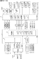
(基板構成)
パチンコ遊技機1には、例えば図2に示すような主基板11、演出制御基板12、音声制御基板13、ランプ制御基板14、中継基板15などが搭載されている。その他にも、パチンコ遊技機1の背面には、例えば払出制御基板37(図3参照)、情報端子基板、発射制御基板、電源基板91(図3参照)などといった、各種の基板が配置されている。
(Substrate configuration)
The
主基板11は、メイン側の制御基板であり、パチンコ遊技機1における上記遊技の進行(特図ゲームの実行(保留の管理を含む)、普図ゲームの実行(保留の管理を含む)、大当り遊技状態、小当り遊技状態、遊技状態など)を制御する機能を有する。主基板11は、遊技制御用マイクロコンピュータ100、スイッチ回路110、ソレノイド回路111などを有する。
The
主基板11に搭載された遊技制御用マイクロコンピュータ100は、例えば1チップのマイクロコンピュータであり、ROM(Read Only Memory)101と、RAM(Random Access Memory)102と、CPU(Central Processing Unit)103と、乱数回路104と、I/O(Input/Output port)105とを備える。
The
CPU103は、ROM101に記憶されたプログラムを実行することにより、遊技の進行を制御する処理(主基板11の機能を実現する処理)を行う。このとき、ROM101が記憶する各種データ(後述の変動パターン、後述の演出制御コマンド、後述の各種決定を行う際に参照される各種テーブルなどのデータ)が用いられ、RAM102がメインメモリとして使用される。RAM102は、その一部または全部がパチンコ遊技機1に対する電力供給が停止しても、所定期間記憶内容が保存されるバックアップRAMとなっている。尚、ROM101に記憶されたプログラムの全部又は一部をRAM102に展開して、RAM102上で実行するようにしてもよい。
The
また、CPU103は、第1始動入賞や第2始動入賞があったか否かを判定し、入賞があった場合には、特図表示結果判定用、大当り種別判定用、変動パターン判定用などの乱数値をそれぞれ抽出して、第1特図保留記憶部や第2特図保留記憶部における空きエントリの最上位に格納(記憶)する始動入賞処理を実行する。
In addition, the
また、CPU103は、第1特図保留記憶部や第2特図保留記憶部に記憶されている保留データの有無などに基づいて特図ゲームを開始するか否かの判定や、特図表示結果判定用の乱数値を示す数値データに基づき、特別図柄や演出図柄の変動表示結果を「大当り」とするか否かを、その変動表示結果が導出表示される前に決定(事前決定)する特別図柄通常処理を実行する。つまり、CPU103は、特図ゲームの変動表示を開始するときに、始動入賞が発生したときに記憶した乱数値に基づいて、当該変動表示の表示結果として大当り表示結果を導出表示するか否かを決定(抽選)する処理を実行する。
Further, the
乱数回路104は、遊技の進行を制御するときに使用される各種の乱数値(遊技用乱数)を示す数値データを更新可能にカウントする。遊技用乱数は、CPU103が所定のコンピュータプログラムを実行することで更新されるもの(ソフトウェアで更新されるもの)であってもよい。
The
I/O105は、例えば各種信号(後述の検出信号)が入力される入力ポートと、各種信号(第1特別図柄表示装置4A、第2特別図柄表示装置4B、普通図柄表示器20、第1保留表示器25A、第2保留表示器25B、普図保留表示器25Cなどを制御(駆動)する信号、ソレノイド駆動信号)を伝送するための出力ポートとを含んで構成される。
The I/
スイッチ回路110は、遊技球検出用の各種スイッチ(ゲートスイッチ21、始動口スイッチ(第1始動口スイッチ22Aおよび第2始動口スイッチ22B)、カウントスイッチ23)からの検出信号(遊技球が通過又は進入してスイッチがオンになったことを示す検出信号など)を取り込んで遊技制御用マイクロコンピュータ100に伝送する。検出信号の伝送により、遊技球の通過又は進入が検出されたことになる。
The
ソレノイド回路111は、遊技制御用マイクロコンピュータ100からのソレノイド駆動信号(例えば、ソレノイド81やソレノイド82をオンする信号など)を、普通電動役物用のソレノイド81や大入賞口扉用のソレノイド82に伝送する。
主基板11(遊技制御用マイクロコンピュータ100)は、遊技の進行の制御の一部として、遊技の進行に応じて演出制御コマンド(遊技の進行状況等を指定(通知)するコマンド)を演出制御基板12に供給する。主基板11から出力された演出制御コマンドは、中継基板15により中継され、演出制御基板12に供給される。当該演出制御コマンドには、例えば主基板11における各種の決定結果(例えば、特図ゲームの表示結果(大当り種別を含む。)、特図ゲームを実行する際に使用される変動パターン(詳しくは後述))、遊技の状況(例えば、可変表示の開始や終了、大入賞口の開放状況、入賞の発生、保留記憶数、遊技状態)、エラーの発生等を指定するコマンド等が含まれる。
The main board 11 (game control microcomputer 100), as part of the control of the progress of the game, produces a production control command (a command to specify (notify) the progress of the game, etc.) according to the progress of the game. 12. The effect control command output from the
演出制御基板12は、主基板11とは独立したサブ側の制御基板であり、演出制御コマンドを受信し、受信した演出制御コマンドに基づいて演出(遊技の進行に応じた種々の演出であり、可動体32の駆動、エラー報知、電断復旧の報知等の各種報知を含む)を実行する機能を有する。
The
演出制御基板12には、演出制御用CPU120と、ROM121と、RAM122と、表示制御部123と、乱数回路124と、I/O125とが搭載されている。
The
演出制御用CPU120は、ROM121に記憶されたプログラムを実行することにより、表示制御部123とともに演出を実行するための処理(演出制御基板12の上記機能を実現するための処理であり、実行する演出の決定等を含む)を行う。このとき、ROM121が記憶する各種データ(各種テーブルなどのデータ)が用いられ、RAM122がメインメモリとして使用される。
The
演出制御用CPU120は、コントローラセンサユニット35Aやプッシュセンサ35Bからの検出信号(遊技者による操作を検出したときに出力される信号であり、操作内容を適宜示す信号)に基づいて演出の実行を表示制御部123に指示することもある。
The
表示制御部123は、VDP(Video Display Processor)、CGROM(Character Generator ROM)、VRAM(Video RAM)などを備え、演出制御用CPU120からの演出の実行指示に基づき、演出を実行する。
The
表示制御部123は、演出制御用CPU120からの演出の実行指示に基づき、実行する演出に応じた映像信号を画像表示装置5に供給することで、演出画像を画像表示装置5に表示させる。表示制御部123は、さらに、演出画像の表示に同期した音声出力や、遊技効果ランプ9の点灯/消灯を行うため、音指定信号(出力する音声を指定する信号)を音声制御基板13に供給したり、ランプ信号(ランプの点灯/消灯態様を指定する信号)をランプ制御基板14に供給したりする。また、表示制御部123は、可動体32を動作させる信号を当該可動体32または当該可動体32を駆動する駆動回路に供給する。
The
音声制御基板13は、スピーカ8L、8Rを駆動する各種回路を搭載しており、当該音指定信号に基づきスピーカ8L、8Rを駆動し、当該音指定信号が指定する音声をスピーカ8L、8Rから出力させる。
The
ランプ制御基板14は、遊技効果ランプ9を駆動する各種回路を搭載しており、当該ランプ信号に基づき遊技効果ランプ9を駆動し、当該ランプ信号が指定する態様で遊技効果ランプ9を点灯/消灯する。このようにして、表示制御部123は、音声出力、ランプの点灯/消灯を制御する。
The
なお、音声出力、ランプの点灯/消灯の制御(音指定信号やランプ信号の供給等)、可動体32の制御(可動体32を動作させる信号の供給等)は、演出制御用CPU120が実行するようにしてもよい。
The
乱数回路124は、各種演出を実行するために使用される各種の乱数値(演出用乱数)を示す数値データを更新可能にカウントする。演出用乱数は、演出制御用CPU120が所定のコンピュータプログラムを実行することで更新されるもの(ソフトウェアで更新されるもの)であってもよい。
The
演出制御基板12に搭載されたI/O125は、例えば主基板11などから伝送された演出制御コマンドを取り込むための入力ポートと、各種信号(映像信号、音指定信号、ランプ信号)を伝送するための出力ポートとを含んで構成される。
I /
演出制御基板12、音声制御基板13、ランプ制御基板14といった、主基板11以外の基板をサブ基板ともいう。パチンコ遊技機1のようにサブ基板が機能別に複数設けられていてもよいし、1のサブ基板が複数の機能を有するように構成してもよい。
Boards other than the
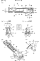
(パチンコ遊技機の背面構造)
次に、図3~図7に基づいて、パチンコ遊技機1の背面構造について説明する。図3は、パチンコ遊技機を示す背面図である。図4は、パチンコ遊技機を示す左側面図である。図5は、遊技盤が取付けられた遊技機用枠を示す平面図である。図6は、パチンコ遊技機を斜め後ろから見た状態を示す斜視図である。図7は、遊技機枠から遊技盤が取外された状態を示す斜視図である。尚、図5~図7においてガラス扉枠50の図示は省略している。
(Back structure of pachinko machine)
Next, the rear structure of the
図3~図7に示すように、パチンコ遊技機1は、遊技盤2と、遊技盤2が着脱可能に設けられる遊技機用枠3と、遊技機用枠3の左側辺を中心として該遊技機用枠3の前面を開閉可能に設けられたガラス扉枠50と、遊技機用枠3を左側辺を中心として開閉可能に支持する四角枠状の外枠60と、を有し、遊技場に設置された遊技島(図示略)に外枠60を固定することにより遊技島に設置できるようになっている。
As shown in FIGS. 3 to 7, the
遊技機用枠3の背面上部には、遊技島(図示略)の内部に設けられた遊技球(以下、遊技球Pと言うこともある)の循環経路から補給装置150(図3、図4参照)を介して供給される遊技球を貯留可能な貯留部を形成する球タンク形成部201と、球タンク形成部201に貯留された遊技球を左側に向けて誘導する第1誘導通路を形成する第1誘導通路形成部202と、からなる第1通路形成体203が、遊技機用枠3の上辺部3Aに沿うように左右方向に延設されている。また、第1誘導通路形成部202の上方位置には、後述するターミナル基板210が設けられている。
At the upper back of the
補給装置150は、遊技島の循環経路の遊技球を誘導可能なノズル等からなる誘導部材150Aと、該誘導部材150Aにより導かれた遊技球を所定数(例えば、10個など)ずつ送出することが可能なスプロケット(図示略)、該スプロケットを駆動する駆動源(図示略)、外枠60の開口が遊技機用枠3により閉鎖される閉鎖状態であるときに該遊技機用枠3に押圧されるレバースイッチ(図示略)と、を有し、閉鎖状態においてレバースイッチ(図示略)が遊技機用枠3にて押圧されているときにはスプロケットにて送出された遊技球が球タンク形成部201に落下可能となり、開放状態においてレバースイッチ(図示略)が遊技機用枠3にて押圧されていないときにはスプロケットにて送出された遊技球が落下不能に保持される。そして、外枠60が閉鎖状態であるときに球タンク形成部201に貯留されている遊技球数が減少すると、駆動源によりスプロケットが回転して遊技球が所定個数ずつ送出され球タンク形成部201に供給されるようになっている。また、補給装置150は、複数の部材を複数のねじ部材(図示略)により組付けることによりケース体150Bが構成され、該ケース体150Bが複数のねじ部材(図示略)を用いて遊技島の所定個所に固設されている。
The
また、第1誘導通路形成部202により左側に誘導された遊技球を下方に誘導する第2誘導通路を形成する第2誘導通路形成部204と、第2誘導通路形成部204により誘導された遊技球を払出すことが可能な払出部を構成する払出装置200と、払出装置200により払出された遊技球を上皿に誘導する、つまり、遊技者に遊技球を払出すための払出通路を形成する払出通路形成部205と、第2誘導通路形成部204により誘導された遊技球を払出装置200から払出通路形成部205に払出すことなく、パチンコ遊技機1の外部に排出するためにパチンコ遊技機1の背面側下部に設けられた図示しない排出部(図示略)に誘導する球抜き通路を形成する球抜き通路形成部206と、からなる第2通路形成体207が、遊技機用枠3の背面左側辺部に沿うように上下方向に延設されている。
In addition, a second guide
払出装置200は、略直方体状に形成されるケース体からなり、内部には遊技球を所定球数(例えば、1球)ずつ払い出すためのスプロケット、該スプロケットを回転させるための払出モータ、遊技球の流路を払出通路と球抜き通路とに切り替え可能な切替弁、該切替弁の切り替え操作を行うための操作レバー等が設けられている。また、遊技機用枠3の背面下部には、電源基板91が収納された基板ケース91Aや払出制御基板37が収納された基板ケース37A等が設けられている。
The
尚、本実施の形態では、第2誘導通路の所定個所に遊技球を検出可能な球切れスイッチ(図示略)が設けられており、CPU103は、球切れスイッチ(図示略)からの検出信号の入力状態に基づいて、払出装置200の上流側の第2誘導通路に払出すための遊技球があるか否かを常時監視している。そして、球切れスイッチ(図示略)のオフ状態が所定時間以上継続した場合、球詰まりなど何らかの理由で遊技球が払出装置200に供給されていない、つまり、補給エラーが発生したと判定し、払出装置200による払出動作を中止する。また、主基板11に接続される所定の表示器(図示略)にて補給エラー表示を行うとともに、補給エラーコマンドを演出制御基板12に出力することで、演出制御用CPU120にガラス扉枠50の前面所定個所に設けられた遊技効果ランプ9をエラー態様にて発光させるなどして、補給エラーが生じている旨の報知処理を実行可能である。
In this embodiment, a ball break switch (not shown) capable of detecting a game ball is provided at a predetermined position of the second guide path, and the
図7に示すように、遊技機用枠3の略中央部に形成された開口部221には、遊技機用枠3の前面側から遊技盤2が着脱可能に配置される。遊技盤2は、前述した盤面板及びスペーサ部材からなる板状体2aと、板状体2aの前面側に設けられる各種遊技用部品(例えば、障害釘や入賞装置など)や、板状体2aの背面側に設けられる画像表示装置5、可動体32を有する演出装置や、演出制御基板12が収納された基板ケース12A、主基板11が収納された基板ケース11A等の電子部品や、板状部及び演出装置や電子部品等を保護するカバー体220と、を含む構造体とされている。
As shown in FIG. 7, the
尚、基板ケース11A,12A,91A,37Aは、透明な合成樹脂材からなるベース部材とカバー部材とにより各基板を内部に収納可能に構成され、これらのうち基板ケース11A,12Aにあっては、各々1個または複数のねじ部材N20,N21(図3参照)により遊技機用枠3または遊技盤2に取付けられ、基板ケース91A,37Aは係止手段(図示略)により遊技機用枠3または遊技盤2に取付けられている。また、カバー体220は、透明な合成樹脂材により前面が開口する箱状に形成され、背面の一部は右側辺を中心として回動可能な開閉部220Aとされ、遊技盤2の背面の一部を開閉可能とされている。
The
図4~図6に示すように、遊技機用枠3の背面に設けられた第1通路形成体203、第2通路形成体207と、遊技盤2の背面を構成するカバー体220は、遊技機用枠3により外枠60を閉鎖した状態において、外枠60よりも後方に突出する。特に第1通路形成体203は、球タンク形成部201の上面開口が遊技機用枠3の背面上部における外枠60の上板の後方位置に配置されるように設けられていることで、パチンコ遊技機1の外枠60を遊技島(図示略)に固定した状態において、遊技島の上方の循環経路から補給装置150を介して球タンク形成部201に遊技球を供給できるようになっている。
As shown in FIGS. 4 to 6, a first
(第1通路形成体203の取付構造)
次に、第1通路形成体203の遊技機用枠3への取付構造について、図8及び図9に基づいて説明する。図8は、通路形成体の遊技機用枠への取付構造を示す分解斜視図である。図9は、遊技機用枠の背面上部を示す拡大背面図である。
(Mounting Structure of First Passage Forming Body 203)
Next, the mounting structure of the first
図8及び図9に示すように、遊技機用枠3は、正面視略長方形状をなす枠体であり、遊技盤2を取付けるための開口部221が形成されており、開口部221の上方の上辺部3Aの背面には、補強用の金属板222が左右方向に向けて設けられている。また、金属板222の背面には、第1通路形成体203を遊技機用枠3に取付けるための取付部材223が取付けられている。
As shown in FIGS. 8 and 9, the
取付部材223は、合成樹脂材により金属板222を背面側から被覆可能に形成され、前後方向を向く複数の取付孔H1~H5に背面側から取付けたねじ部材N1~N5を、金属板222に形成された複数のねじ孔に各々螺入することで金属板222に取付けられている。取付部材223の右側には、板状の第1突出部224が後方に向けて突設され、取付部材223の左側には、上壁部225A、後壁部225B及び左右の側壁部225Cからなる立体状の第2突出部225が後方に向けて突設されている。
The mounting
第1突出部224は、第2突出部225の上壁部225Aより下方位置から後方に向けて突出しており、その上側には球タンク形成部201が配置される。また、第2突出部225の後壁部225Bの後側には、第1誘導通路形成部202が配置されるとともに、その上側には、ターミナル基板210を取付けるための基板取付枠211が取付けられている。基板取付枠211は、下辺から下方に突設された係止片212を後壁部225Bに形成された係止孔213に挿入した状態で、上部に形成された取付孔H6に背面側から取付けたねじ部材N6を、取付部材223に形成されたねじ孔に螺入することで取付部材223に取付けられる。
The first projecting
このように取付部材223は、後方に突出する第1突出部224と第2突出部225とを有することで、遊技盤2の上方を覆うように形成されている。よって、遊技島の上部から球タンク形成部201に供給される遊技球などが遊技盤2内に進入することが防止されている。つまり、取付部材223は遊技盤2の保護カバーとして機能している。
Thus, the mounting
第1通路形成体203は、複数の取付孔H11~H14に背面側から取付けたねじ部材N11~N14、及び取付孔H15に上側から取付けたねじ部材N15を、取付部材223に形成された複数のねじ孔に各々螺入することで取付部材223に取付けられている。尚、取付孔H12に取付けるねじ部材N12は、第1通路形成体203に帯電した電気を除去するためのアース線226を第1通路形成体203に取付けるためのねじ部材と兼用されている。また、第1通路形成体203の上部には、後述する第1カバー体310、第2カバー体320、第3カバー体330が取付けられている。第3カバー体330は、取付孔H16に上方から取付けたねじ部材N16を第1通路形成体203の後壁に形成されたねじ孔に螺入することで第1通路形成体203に取付けられている。
The first
上記したねじ部材N1~N6、N11~N16は、図8中拡大図に示すように、雄ねじ部NSと頭部NHとからなり、このうち、ねじ部材N1、N2、N11~N16は、頭部の座面に緩み止め部としてのフランジ部Fが一体に形成されたフランジ付きねじとされ、座面の接地面積を広くして摩擦力を高めることで、ねじ部材N3~N6に比べて緩みにくいねじ部材とされている。 As shown in the enlarged view of FIG. 8, the threaded members N1 to N6 and N11 to N16 include a male threaded portion NS and a head portion NH. It is a flanged screw in which a flange part F as a locking part is integrally formed on the bearing surface of the screw, and by increasing the contact area of the bearing surface and increasing the frictional force, it is difficult to loosen compared to the screw members N3 to N6. It is considered as a screw member.
例えば、各ねじ部材N1~N6、N11~N16の雄ねじ部NSの直径L1は約1~3mm、頭部NHの直径L2は約4~7mmとされ、フランジ部Fの直径L3は、頭部NHの直径L2よりも長寸で約8~10mmとされている。 For example, the diameter L1 of the male screw portion NS of each screw member N1 to N6, N11 to N16 is approximately 1 to 3 mm, the diameter L2 of the head NH is approximately 4 to 7 mm, and the diameter L3 of the flange portion F is approximately 4 to 7 mm. 8 to 10 mm longer than the diameter L2.
尚、ねじ部材N1~N6、N11~N16の大きさ、種類などは任意であり、直径L1~L3の寸法も上記した寸法に限定されるものではない。また、フランジ付きねじからなるねじ部材N1、N2、N11~N16は、フランジ部F(座金)が一体に形成されたねじ部材であるが、フランジ部Fの替わりに、ねじ部材とは別個のワッシャをねじ部材に装着して取付けてもよく、フランジ部Fやワッシャが本発明の緩み止め部を構成する。また、ねじ部材は、ビスやボルト等、緩むと被取付部から離脱してしまう部材を含むものとする。また、緩み止め部は、頭部NHやフランジ部F(座金)の裏面に凹凸状に形成された頭部NHの回止め部や接着剤等も含まれる。 The sizes and types of the screw members N1 to N6 and N11 to N16 are arbitrary, and the dimensions of the diameters L1 to L3 are not limited to those described above. The screw members N1, N2, N11 to N16, which are flanged screws, are screw members integrally formed with a flange portion F (washer). may be attached to the screw member, and the flange portion F and the washer constitute the locking portion of the present invention. Further, the screw member includes a member such as a screw or a bolt that separates from the attached portion when loosened. In addition, the locking portion includes a locking portion for the head NH formed unevenly on the back surface of the head NH and the flange portion F (washer), an adhesive, and the like.
図8及び図9に示すように、第1通路形成体203は、遊技島の上方から供給される遊技球を球タンク形成部201にて受止めて貯留する必要があるとともに、第1誘導通路において球詰まりなどが発生しにくいように、また、球詰まりが発生した場合にこれを容易に解消することができるように上面が開放する凹状に形成されている。
As shown in FIGS. 8 and 9, the first
また、球タンク形成部201にて上下方向に重なって滞留する遊技球が第1誘導通路形成部202に流入していく箇所には第1カバー体310や第2カバー体320が上面を被覆するように配置され、また、第1誘導通路形成部202から第2誘導通路形成部204に流入していく箇所には第3カバー体330が上面を被覆するように配置されることで、遊技球が整流されるようになっている。しかし、第1通路形成体203の上面開口の一部はこれら第1カバー体310、第2カバー体320及び第3カバー体330により被覆されるが、球タンク形成部201及び非被覆領域350(図27参照)の上面開口は開放されている。
In addition, a
一方、第1通路形成体203の周辺近傍には、遊技機用枠3や取付部材223に取付けられる複数のねじ部材N1~N6、N11~N16が配置されている。また、遊技島に固定されるパチンコ遊技機1の上方には、遊技島を構成する躯体などを組付けるためのねじ部材(図示略)や、遊技島の内部に配置される各種装置(例えば、補給装置150など)等を躯体などに取付けるためのねじ部材(図示略)や、各種装置のケース体を構成する複数の部材を組付けるための複数のねじ部材などが多数配置されている。
On the other hand, in the vicinity of the periphery of the first
これらねじ部材は、遊技島やパチンコ遊技機1に生じる振動や衝撃などにより緩んで抜け落ちてしまうと、振動や衝撃あるいは遊技機用枠3の開閉などにより転がって、球タンク形成部201や第1誘導通路形成部202の非被覆領域350から内部に落下して遊技球の誘導通路に混入する可能性がある。特に補給装置150などは、図3及び図4に示すように球タンク形成部201の直上近傍に配置されており、また、所定個数の遊技球を球タンク形成部201に送出することで遊技島の循環経路から新たな遊技球が供給される際や、遊技機用枠3が開閉する際に振動が生じやすい装置であるため、補給装置150を遊技島の躯体などに取付けるためのねじ部材(図示略)や、補給装置150のケース体150Bを構成する複数の部材を組付けるための複数のねじ部材が振動により緩んで抜け落ちた場合、球タンク形成部201や第1誘導通路形成部202内に落下する可能性が極めて高い。
If these screw members are loosened and fall off due to vibration or shock generated in the game island or the
そして、球タンク形成部201や第1誘導通路形成部202にねじ部材が落下すると、遊技球の流下とともに払出装置200側に向けて移動し、最終的に払出装置200に混入する可能がある。このように払出装置200にねじ部材が進入すると、スプロケットや切換え弁がねじ部材により損傷したり、球詰まりが生じて払出モータに負荷がかかり故障したり、あるいは、遊技球とともにねじ部材が遊技者に払出されてしまい、遊技者に違和感や不信感を与えてしまう虞があった。
Then, when the screw member drops into the ball
そこで本実施の形態では、以下に説明するように、第1誘導通路形成部202に落下したねじ部材が払出装置200に混入して払出装置200が破損、故障したり、遊技球とともにねじ部材が遊技者に払出されることを抑制するために様々な対策が施されている。
Therefore, in the present embodiment, as described below, the screw member that has fallen into the first guide
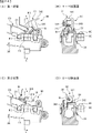
(第1通路形成体203)
次に、第1通路形成体203について、図10~図16に基づいて説明する。図10は、(A)は第1通路形成体を示す平面図、(B)は第1通路形成体を示す背面図である。図11は、(A)は図10(A)のA-A断面図、(B)は図10(A)のB-B断面図、(C)は図10(A)のC-C断面図である。図12は、(A)は第1誘導通路形成部を示す平面図、(B)は(A)のD-D断面図である。図13は、(A)は第1カバー体を示す平面図、(B)は(A)のE-E断面図、(C)は(A)のF-F断面図である。図14は、(A)は第2カバー体を示す平面図、(B)は(A)のG-G断面図、(C)は(A)のH-H断面図である。図15は、(A)は第3カバー体を示す平面図、(B)は(A)のI-I断面図、(C)は(A)のJ-J断面図、(D)は第3カバー体を示す斜視図、(E)は球止め部材を示す斜視図である。図16は、(A)は球止め部材が第1状態である状態を示す第1誘導通路形成部を示す縦断面図、(B)は球止め部材が第2状態である状態を示す第1誘導通路形成部を示す縦断面図である。
(First passage forming body 203)
Next, the first
図10~図12に示すように、第1通路形成体203は、導電性を有する合成樹脂材により、底壁部203Aと該底壁部203Aの周縁に立設される立壁部203Bとにより上面が開口する凹状または凹溝状に形成され、右側に配置される球タンク形成部201と、左側に配置される第1誘導通路形成部202とを有する。球タンク形成部201は、平面視横長長方形状に形成され、第1誘導通路形成部202は、球タンク形成部201の左側から斜め後方に向けて延びる上流部と左右方向に延びる下流部とからなる。球タンク形成部201の前後方向の寸法は、第1誘導通路形成部202の前後方向の寸法よりも長寸とされており、第1誘導通路形成部202よりも多くの遊技球を貯留可能とされている。また、底壁部203Aは、球タンク形成部201の左側から第1誘導通路形成部202の右側に向けて漸次下方に傾斜するように形成されているため、球タンク形成部201に供給された遊技球は、球タンク形成部201及び第1誘導通路形成部202を左側に向けて自然流下するようになっている。
As shown in FIGS. 10 to 12, the first
球タンク形成部201の右側の立壁部203Bの外面には上下方向を向く取付片261が突設されており、取付片261には前後方向を向く取付孔H11,H12が上下に形成されている。また、取付片261の後側には取付片265が突設されており、取付片265には上下方向を向く取付孔H15が形成されている。第1誘導通路形成部202の左側の立壁部203Bの外面には上下方向を向く取付片262が突設されており、取付片262には前後方向を向く取付孔H14が形成されている。第1誘導通路形成部202の上流部の前側の立壁部203Bの外面には水平壁部264が前方に向けて突設されている。水平壁部264の前辺には取付片263が立設されており、取付片263には前後方向を向く取付孔H13が形成されている。
A mounting
そして第1通路形成体203は、これら取付孔H11~H15に取付けた複数のねじ部材N11~N15を取付部材223に形成されたねじ孔に螺入することで遊技機用枠3に取付けられる。また、水平壁部264の上面における取付片263の後方近傍位置には、平面視略四角形状をなす凹部280が形成されている。
The first
図11及び図12に示すように、第1誘導通路形成部202の上流部における底壁部203Aと後側の立壁部203Bとの角部には、孔部270A,270Bが形成されている(図11(A)参照)。孔部271A,271Bの下流側(左側)における底壁部203Aの前後方向の略中央位置には、孔部271A~271Hが下流側に向けて複数形成されている。また、第1誘導通路形成部202の下流側端部の底壁部203Aには、下方の第2誘導通路形成部204に遊技球を落下させるための連絡孔272が貫通して形成されている。
As shown in FIGS. 11 and 12,
第1誘導通路形成部202の途中には、遊技球を前後方向に蛇行させながら左側に向けて流下させる蛇行部273が形成されており、複数の孔部271A~271Hのうち孔部271B~271Fが蛇行部273に対応する位置に形成されている。このような蛇行部273を設けることで後続球による球圧が増大しないようにしている。
A meandering
また、第1誘導通路形成部202の前後の立壁部203B,203B下部の離間寸法L10は、遊技球の直径2R(約11mm)よりも長寸で、直径2Rの2倍の寸法(約22mm)よりも短寸とされている(11mm<L10<22mm)。つまり、第1誘導通路形成部202は、遊技球を下流側に向けて1列で誘導可能に形成されている。
In addition, the distance L10 between the front and rear
孔部271A,271Bを除く孔部271A~271Hの前後寸法L11は、前述したねじ部材N3~N6の頭部NHの直径L2より若干長いため(L11>L2)、後述するようにねじ部材N3~N6が第1誘導通路形成部202に混入した場合でも孔部271A~271Hからねじ部材N3~N6が落下可能とされている。また、最下流側に形成された孔部271Hは、他の孔部271A~271Gと比べて左右寸法L12(遊技球の流下方向の寸法)が最も長いため、ねじ部材N3~N6が連絡孔272に到達する前に確実に第1誘導通路形成部202外へ落下させることができる。
Since the longitudinal dimension L11 of the
つまり、これら孔部271A~271Hは、第1誘導通路形成部202に落下したねじ部材N3~N6の払出装置200への移動を制限するための特定制限部を構成している。尚、これら複数の孔部271A~271Hからは、ねじ部材以外のゴミや埃、あるいは何らかの部材等も落下可能であるため、これらにより球詰まりが生じることが防止される。
In other words, these
(第1カバー体310)
図13(A)~図13(C)に示すように、第1カバー体310は、球タンク形成部201の前側の立壁部203Bの上端縁に沿うように延設され、立壁部203Bの上端に上方から嵌合可能な断面視下向きコ字形をなす取付部311と、取付部311の右側から後側に向けて延設される立壁部312と、立壁部312の下部から右側(球タンク形成部201側)に向けて下方に傾斜するように延びる板状の球押え部313と、立壁部312の下部から左側(第1誘導通路形成部202側)に向けて延びるカバー部314と、取付部311の前側及びカバー部314の前後側に弾性変形可能に形成された複数の係止部315A~315Dと、から主に構成される。
(First cover body 310)
As shown in FIGS. 13A to 13C, the
このように構成された第1カバー体310は、立壁部312を球タンク形成部201と第1誘導通路形成部202との境目付近に配置した状態で、取付部311を球タンク形成部201の前側の立壁部203Bの上端に上方から嵌合させることで、複数の係止部315A~315Dが立壁部203Bの外面に形成された被係止部317(図18参照)に弾性的に係止することで第1通路形成体203に取付けられる。取付けられた状態において、球押え部313が球タンク形成部201の下流側の一部を上方から被覆するように配置されるとともに、カバー部314が第1誘導通路形成部202の上流側の一部を上方から被覆するとともに、カバー部314の上面が第1誘導通路形成部202側に向けて僅かに下方に傾斜するように配置される(図9参照)。
The
第1カバー体310が第1通路形成体203に取付けられた状態において、球押え部313が球タンク形成部201側に配置されることで、遊技島(図示略)から球タンク形成部201に供給された遊技球が上下方向に積み重なるように貯留した場合でも、遊技球が第1誘導通路形成部202側に流下していく際に球押え部313により下側に向けて押えられることで整流されるようになっている。
When the
カバー部314には、平面視横長長方形状をなす左右方向に延びる長孔316A~316Cが、互いに平行をなすように列状に配置された状態で上下に貫通して形成されている。各長孔316A~316Cは、前後寸法L21が全て同一とされ、前後寸法L21は、遊技球の直径2Rよりも短寸であり、かつ、前述したねじ部材N1~N6,N11~N16の頭部NHの直径L2よりも短寸となっている(L21<2R、L21<L2)。つまり、長孔316A~316Cは、遊技球及びねじ部材N1~N6,N11~N16を落下不能な大きさに形成されている。尚、カバー部314の下面における各長孔316A~316Cの周縁からは補強用のリブが垂下されている。
In the
また、長孔316A~316Cは遊技球の流下方向に沿うように延設されているため、図13(B)(C)に示すように、長孔316A~316Cの上部に遊技球Pが落下した場合、遊技球Pは流下方向(左側)に向けて移動可能である。
In addition, since the
(第2カバー体320)
図14(A)~図14(C)に示すように、第2カバー体320は、第1誘導通路形成部202の上流部に沿うように形成された板状のカバー部324と、カバー部324の前後側に弾性変形可能に形成された複数の係止部325A,325Bと、から主に構成され、カバー部324の右側端部を第1カバー体310のカバー部314の左側端部に近接させた状態で、複数の係止部325A,325Bが立壁部302Bの外面に形成された被係止部317(図20参照)に弾性的に係止することで、第1通路形成体203に取付けられる。取付けられた状態において、カバー部324が第1誘導通路形成部202の上流側の一部を上方から被覆するとともに、遊技球の流下方向に向けて下方に傾斜するように配置される(図9参照)。
(Second cover body 320)
As shown in FIGS. 14A to 14C, the
カバー部324の上面には、左右方向に延びる凹溝326A~326Cが、互いに列状に配置された状態で形成されている。各凹溝326A~326Cは、前後寸法L22A~L22Cが各々異なるが、各々遊技球の直径2Rよりも短寸とされている(L22A~L22C<2R)。尚、前後寸法が最も長い中央の凹溝326Bの前後寸法L22Bは、前述したねじ部材N1~N6,N11~N16の頭部NHの直径L2よりも長寸となっている(L22B>L2)。つまり、凹溝326Bは、遊技球を収容不能、かつ、ねじ部材N1~N6,N11~N16を収容可能な大きさに形成されている。また、凹溝326Bの前後寸法L22Bは、カバー部314の長孔316A~316Cの前後寸法L21よりも長寸とされている(L22B>L21)。
On the upper surface of the
また、凹溝326Aの前後寸法L22Aと凹溝326Cの前後寸法L22Cは、ねじ部材N1~N6,N11~N16の雄ねじ部NSの直径L1よりも長寸であるため(L22B>L1、L22C>L1)、少なくとも雄ねじ部NSを収容可能な大きさとされている。
In addition, since the front-rear dimension L22A of the recessed
また、凹溝326A~326Cは遊技球の流下方向に沿うように延設され、かつ、遊技球の流下方向に向けて下方に傾斜するように配置されるため、図14(B)(C)に示すように、凹溝326A~326Cの上部に遊技球Pが落下した場合、遊技球Pが流下方向(左側)に向けて誘導される。
In addition, since the
(第3カバー体330)
図15(A)~図15(C)及び図16に示すように、第3カバー体330は、第1誘導通路形成部202の下流部に沿うように形成された板状のカバー部334と、カバー部334の左端の前後側に弾性変形可能に形成された複数の係止部335A~335Dと、背面における係止部335C,335Dの間に突設されねじ部材N15が上方から取付けられる取付孔H15が形成された取付部331と、カバー部334の上面左端部に設けられた球止め部材340と、から主に構成され、カバー部324の左端の複数の係止部335A~335Dを立壁部302Bの外面に形成された被係止部317(図20参照)に弾性的に係止するとともに、取付孔H15に取付けたねじ部材N15を立壁部203Bの外面に設けられたねじ孔に螺入することで第1通路形成体203に取付けられる。取付けられた状態において、カバー部334が第1誘導通路形成部202の下流部を上方から被覆するとともに、遊技球の流下方向に向けて下方に傾斜するように配置される(図9参照)。
(Third cover body 330)
As shown in FIGS. 15A to 15C and 16, the
カバー部334は、左側から右側に向けて斜め上方に延びるように延設されており、上面における右端部から左側に向けて所定深さの凹部336が延設されている。右側の一部は蛇行部273に差し掛かるため、蛇行部273の形状に対応して形成されている。また、凹部336に対応する位置には、平面視横長コ字形をなすスリット337が形成されることで、左端側が上下方向に揺動するように弾性変形可能な整流板338が形成されているとともに、右端部には、右側に向けて下方に傾斜する傾斜板部339が形成されていることで、上下に積み重なった遊技球Pを底壁部203Aに向けて押し付けるように誘導しながら均すことができるようになっている(図16参照)。
The
凹部336の前後寸法L23は、遊技球の直径2Rよりも長寸とされ、また、前述したねじ部材N1~N6,N11~N16の頭部NHの直径L2よりも長寸となっている(L23>2R、L23>L2)。つまり、凹部336は、遊技球P及びねじ部材N1~N6,N11~N16の頭部NHを収容可能な大きさに形成されている。また、凹部336の前後寸法L23は、カバー部324の凹溝326Bの前後寸法L22Bよりも長寸とされている(L23>L22B)。
The front-rear dimension L23 of the
また、凹部336は遊技球の流下方向に沿うように延設され、かつ、遊技球の流下方向に向けて下方に傾斜するように配置されるため、図15(D)に示すように、凹部336の上部に遊技球Pが落下した場合、遊技球Pが流下方向(左側)に向けて誘導される。
In addition, since the
また、スリット337の前後寸法L24は、前述したねじ部材N1~N6,N11~N16の頭部NHの直径L2よりも短寸となっているため(L24<L2)、ねじ部材N1~N6,N11~N16がスリット337から落下することはない。
In addition, since the longitudinal dimension L24 of the
球止め部材340は、背面視略三角形状をなす板状の前壁部341Aと、前壁部341Aの背面側に配置される後壁部341Bと、前壁部341Aと後壁部341Bとを接続する左壁部341Cと、左壁部341Cの上端に突設される突壁部341Dと、を有する回動部341と、前後方向を向く円筒状の軸部342と、から構成される。カバー部334の上面左側には、軸部342の前後端を回動可能に支持する軸受部343A,343Bが立設されている。また、カバー部334における軸受部343Aの右側には、前壁部341Aを挿入可能なスリット344が貫通して形成されている。
The
図16に示すように、第3カバー体330は、第1通路形成体203に取付けた状態において、カバー部324により第1誘導通路形成部202の下流部の上方が被覆される。カバー部324は、下流側(左側)に向けて底壁部203Aに近づくように下方に傾斜するように配置されるため、第1誘導通路形成部202内で上下に積み重なっている遊技球Pを流下させながら均していき、最終的に連絡孔272から1個ずつ流出させることができるようにする。特に、整流板338は、遊技球が接触したときに弾性変形可能であることで、球詰まりが生じない程度に遊技球を下方に押し付けるように均していく(整流していく)。
As shown in FIG. 16 , when the
(球止め部材340)
球止め部材340は、図16(A)に示すように、回動部341が上方に起立する起立位置と右側に傾倒する傾倒位置との間で回動可能とされており、回動部341が起立位置に位置し、前壁部341Aがスリット344から上方に逸脱して第1誘導通路形成部202の遊技球を第2誘導通路形成部204に流下可能とする第1状態と、回動部341が傾倒位置に位置し、前壁部341Aがスリット344に挿入され遊技球に接触可能となり、第1誘導通路形成部202の遊技球を第2誘導通路形成部204に流下不能(または流下困難)とする第2状態、つまり、球止め状態と、に変化可能とされている。
(Ball stop member 340)
As shown in FIG. 16A, the
このように球止め部材340を第2状態とすることで、第2誘導通路形成部204への遊技球の進入を規制することができるため、この状態で第2誘導通路形成部204内の遊技球を抜き取り、払出装置200を取外して点検または交換したりすることが可能となる。
By setting the
また、図16(A)に示すように、球止め部材340が第1状態にあるときには、回動部341の右側が開放し、前壁部341A、後壁部341B、左壁部341Cからなる平面視略コ字形の壁部により囲まれた空間部が、後述するようにねじ部材N1~N6,N11~N16が滞留可能な滞留部として機能する。一方、図16(B)に示すように、球止め部材340が第2状態にあるときには、回動部341が傾倒してしまうが、突壁部341Dが通路を横切るように起立状態で位置するため、後述するようにねじ部材N1~N6,N11~N16を突壁部341Dの右側に滞留させることが可能となる。
Further, as shown in FIG. 16A, when the
(ターミナル基板210)
次に、ターミナル基板210について、図17に基づいて図8を参照しながら説明する。図17は、(A)はターミナル基板が取付けられた基板取付枠を示す斜視図、(B)は(A)のK-K断面、(C)は(B)のL-L断面図である。
(Terminal board 210)
Next, the
図8及び図17に示すように、ターミナル基板210は、背面視横長長方形状をなし、背面には、主基板11等と繋がる信号線ケーブル(図示略)が着脱されるケーブル接続部(図示略)と、ホールコンピュータ等の外部装置に繋がる複数本のケーブルC(図3参照)を接続するための複数の接続孔部231が設けられた実装部材232と、が実装されている。実装部材232の内部における各接続孔部231に対応する位置には、各ケーブルCの先端を挟持するための接続ピンチ(図示略)が設けられている。この接続ピンチを閉じる方向、即ちケーブルCの先端を挟持する方向に付勢するためのバネ(図示略)が設けられている。そして、実装部材232には、バネ(図示略)の付勢力に抗して各接続ピンチ(図示略)を開放させるための操作部233が複数設けられている。
As shown in FIGS. 8 and 17, the
第1誘導通路形成部202の上方に設けられる第1基板としてのターミナル基板210の複数の接続孔部231に接続可能なケーブルCの接続本数は第1本数(例えば、20本)とされている一方で、第1誘導通路形成部202の下方に設けられる主基板11や演出制御基板12などの第2基板にも各々の信号線が接続されるが、第1本数より少ない本数である第2本数(例えば、10本)とされている。
The number of cables C that can be connected to the plurality of connection holes 231 of the
この操作部233は、各接続孔部231に対応して複数設けられ、側面視で略鉤状をなし、その基端側を揺動軸として前後方向に揺動される。前述の接続ピンチ(図示略)を開放させる際には、操作部233を上方または下方に押圧操作をして操作部233を揺動させることで接続ピンチ(図示略)を開放される。そして、接続ピンチが開放された状態で接続孔部231にケーブルCの先端を挿入し、操作部233の押圧操作をやめると、バネ(図示略)の付勢力によって接続ピンチが閉じるようになり、ケーブルCが保持されるようになる。尚、左右方向に並んだ各操作部233は、所定の操作部233を押圧操作する際に、隣り合う操作部233が押圧操作の邪魔にならないように、左右方向に交互に異なる形状となっている。
A plurality of the
基板取付枠211は、下辺から下方に突設された係止片212を後壁部225Bに形成された係止孔213に挿入した状態で、上部に形成された取付孔H6に背面側から取付けたねじ部材N6を、取付部材223に形成されたねじ孔に螺入することで取付部材223に取付けられる。また、基板取付枠211には、横長長方形状の開口部234が形成されている。
The
基板取付枠211の内面には、前面側から挿入したターミナル基板210の周縁に係止することで、ターミナル基板210の前方への移動を規制する複数の規制部235と、規制部235により前方への移動が規制されたターミナル基板210の周縁に前面側から弾性的に係止可能な複数の係止部236と、ターミナル基板210の周縁に当接して配置位置を決定する位置決め片237と、を有する。よって、ターミナル基板210は、基板取付枠211の前面側から挿入し、複数の規制部235にて前方への移動が規制された状態で係止部236が弾性的に係止することで基板取付枠211に取付けられる。つまり、ターミナル基板210は、ねじ部材とは異なる取付手段としての複数の規制部235及び係止部236を用いて(ねじ部材を用いた取付方法とは異なる取付方法にて)基板取付枠211に取付けられる。
On the inner surface of the
ターミナル基板210は、ケーブルCを接続可能な接続孔部231が複数形成されているため、複数本のケーブルCを接続孔部231に接続する配線作業時において、各ケーブルCに対応する操作部233を操作する必要がある。また、パチンコ遊技機1が遊技島に固定されている状態において、遊技場の店員等が点検等のために遊技機用枠3を開放すると、遊技島の上部から垂下されるケーブルCが外枠60の前方に引き回されて接続部に張力がかかることがある。つまり、ターミナル基板210は取付部に負荷がかかりやすいことで、ねじ部材により基板取付枠211や取付部材223に取付けるとねじ部材が緩んで外れやすくなるため、ねじ部材を用いない取付方法にて取付けている。
Since the
また、ターミナル基板210が基板取付枠211に取付けられた状態において、ターミナル基板210の接続孔部231や操作部233が開口部234から背面側に臨むようになっている(図17(A)参照)。また、複数の操作部233が後方に向けて略水平に突出するため、後述するようにこれら左右に並設される複数の操作部233によりねじ部材N3~N6を保持することができる。また、ターミナル基板210の下部と基板取付枠211の前部との間に、ねじ部材N3~N6を収容可能な凹部242が形成される。
In addition, when the
(ねじ部材N1~N16の取付状態)
次に、ねじ部材N1~N16の取付状態について、図18~図21に基づいて説明する。図18は、遊技枠の背面における球タンク部の周辺を斜め後ろから見た状態を示す斜視図である。図19は、(A)は遊技枠の背面における球タンク部の周辺を示す平面図、(B)は(A)のM-M断面図である。図20は、遊技枠の背面における第1誘導通路形成部の周辺を斜め後ろから見た状態を示す斜視図である。図21は、遊技枠の背面における第1誘導通路形成部の周辺を示す平面図である。図22は、(A)は図21のN-N断面図、(B)はねじ部材の回転状態を示す図、(C)は図21のO-O断面図である。図23は、(A)は図21のP-P断面図、(B)は図21のQ-Q断面図である。図24は、図21のR-R断面図である。図25は、図21のS-S断面図である。図26は、(A)は球止め部材が第1状態であるときのねじ部材の滞留状態、(B)は(A)のT-T断面図、(C)は球止め部材が第2状態であるときのねじ部材の滞留状態、(D)は(C)のU-U断面図である。図27は、ねじ部材の移動状況を示す第1誘導通路形成部の縦断面図である。図28は、カバー部上の遊技球の移動状態を示す第1誘導通路形成部の縦断面図である。
(Mounting state of screw members N1 to N16)
Next, the mounting state of the screw members N1 to N16 will be described with reference to FIGS. 18 to 21. FIG. FIG. 18 is a perspective view showing a state where the periphery of the ball tank portion on the back surface of the game frame is seen obliquely from behind. 19, (A) is a plan view showing the periphery of the ball tank portion on the back of the game frame, and (B) is a cross-sectional view taken along line MM of (A). FIG. 20 is a perspective view showing a state in which the periphery of the first guide passage forming portion on the back surface of the game frame is seen obliquely from behind. FIG. 21 is a plan view showing the periphery of the first guide passage forming portion on the back side of the game frame. 22, (A) is a sectional view taken along line NN of FIG. 21, (B) is a view showing a rotating state of the screw member, and (C) is a sectional view taken along line OO of FIG. 23, (A) is a sectional view taken along line PP of FIG. 21, and (B) is a sectional view taken along line QQ of FIG. 24 is a cross-sectional view taken along line RR of FIG. 21. FIG. 25 is a cross-sectional view taken along line SS of FIG. 21. FIG. FIG. 26 shows (A) the retention state of the screw member when the ball stopper is in the first state, (B) is a TT sectional view of (A), and (C) is the ball stopper in the second state. (D) is a UU cross-sectional view of (C). FIG. 27 is a vertical cross-sectional view of the first guide passage forming portion showing movement of the screw member. FIG. 28 is a vertical cross-sectional view of the first guide passage forming portion showing the moving state of the game ball on the cover portion.
図9、図18及び図19(A)に示すように、遊技機用枠3の背面における球タンク形成部201及びその周辺には、取付部材223を金属板222に取付けるためのねじ部材N1~N2や、第1通路形成体203を取付部材223に取付けるためのねじ部材N11,N12,N15が取付けられている。
As shown in FIGS. 9, 18 and 19(A), screw members N1 to N1 for attaching the mounting
詳しくは、ねじ部材N1,N2は、球タンク形成部201から右側に離れ、かつ、球タンク形成部201における立壁部203Bの上端縁よりも下方位置において、背面側から前方に向けて取付けられているため、パチンコ遊技機1に生じた振動や衝撃などによりねじ部材N1,N2が緩んで後方に抜け落ちたとしても、図18に示すように球タンク形成部201内に落下する可能性は極めて低い。
Specifically, the screw members N1 and N2 are attached forward from the back side at a position away from the sphere
ねじ部材N11,N12は、球タンク形成部201の右側の立壁部203Bの外面で、かつ、球タンク形成部201の上端縁よりも下方位置において、背面側から前方に向けて取付けられているため、パチンコ遊技機1に生じた振動や衝撃などによりねじ部材N11,N12が緩んで後方に抜け落ちたとしても、図18に示すように球タンク形成部201内に落下する可能性は極めて低い。
The screw members N11 and N12 are attached forward from the back side on the outer surface of the right standing
ねじ部材N15は、球タンク形成部201の右側の立壁部203Bの外面で、かつ、球タンク形成部201の上端縁よりも下方位置において、上側から下方に向けて取付けられているため、パチンコ遊技機1に生じた振動や衝撃などによりねじ部材N15が緩んで上方に抜け落ちたとしても、図18に示すように球タンク形成部201内に落下する可能性は極めて低い。
The screw member N15 is attached downward from the upper side on the outer surface of the right standing
また、ねじ部材N1,N2,N11,N12,N15は、遊技島の上方の循環経路から補給装置150により供給される遊技球を受止めて貯留するとともに多数の遊技球の荷重がかかる球タンク形成部201の周辺に配置されていることで、振動や衝撃が生じやすいので、被取付部との接地面積が大きく緩みが生じにくいフランジ付きねじ部材が使用されている。
Further, the screw members N1, N2, N11, N12 and N15 receive and store the game balls supplied from the
また、球タンク形成部201の周辺のねじ部材N1,N2,N11,N12,N15は、緩んで抜け落ちても球タンク形成部201内に落下しにくい位置、つまり、球タンク形成部201の上面開口よりも下方に配置されているので、遊技島の上方の循環経路から補給装置150により供給される遊技球を受止めて貯留するために上方が開口する球タンク形成部201内に混入することが抑制されている。
Further, the screw members N1, N2, N11, N12, and N15 around the sphere
また、図19(B)に示すように、球タンク形成部201は、取付部材223において後方に向けて突出する板状の第1突出部224の上面側に近接(または当接でもよい)して配置されており、底壁部203Aと第1突出部224との間の隙間L30は、ねじ部材の雄ねじ部NSの直径L1よりも短寸とされていることで(L30<L1)、底壁部203Aと第1突出部224との間にねじ部材が挟まって球タンク形成部201の近傍に保持されてしまうことはほぼない。
Further, as shown in FIG. 19B, the sphere
また、球タンク形成部201の底壁部203Aの後部とカバー体220の上壁部220Hとの間に形成された隙間L31は、フランジ付きねじ部材の頭部L2やフランジ部Fの直径L3よりも長寸とされていることで(L3>L2)、隙間L31にフランジ付きねじ部材が挟まって球タンク形成部201の近傍に保持されてしまうことはほぼない。
Further, the gap L31 formed between the rear portion of the
また、図18及び図19(B)に示すように、仮にねじ部材N15が被取付部としての取付孔H15から抜け落ちてカバー体220の上壁部220H上に落下した場合、上壁部220Hは、背面側に向けて下方に傾斜していることで、落下したねじ部材N15は後方または左方のいずれかに流下するため、球タンク形成部201の近傍に保持されてしまうことはほぼない。よって、落下したねじ部材N15が球タンク形成部201の下方に設けられた各基板ケース11A,12A,37A,91A内に混入し、基板の配線に接触して断線等を生じさせることを抑制できる。
Further, as shown in FIGS. 18 and 19B, if the screw member N15 slips out of the mounting hole H15 as the mounted portion and falls onto the
一方、図9、図20及び図21(A)に示すように、第1誘導通路形成部202及びその周辺には、取付部材223を金属板222に取付けるためのねじ部材N3~N5と、基板取付枠211を取付部材223に取付けるためのねじ部材N6と、第1通路形成体203を取付部材223に取付けるためのねじ部材N13,N14と、第3カバー体330を第1誘導通路形成部202に取付けるためのねじ部材N16と、が取付けられている。
On the other hand, as shown in FIGS. 9, 20 and 21A, screw members N3 to N5 for attaching the mounting
詳しくは、ねじ部材N3~N6は、第1誘導通路形成部202から前側に離れ、かつ、第1誘導通路形成部202における立壁部203Bの上端縁よりも上方位置において、背面側から前方に向けて取付けられており、また、ねじ部材N3~N6各々の取付位置と第1誘導通路形成部202との間には、取付部材223の第2突出部225が配置されていることで、ねじ部材N3~N6各々の取付位置から第1誘導通路形成部202まではある程度離れているが、第2突出部225の上壁部225Aは背面側に向けて下方に傾斜しているため、パチンコ遊技機1に生じた振動や衝撃などによりねじ部材N3~N6が緩んで後方に抜け落ちた場合、図20に示すように第2突出部225の上壁部225A上を後方に向けて移動して第1誘導通路形成部202内に落下する可能性が高い。
Specifically, the screw members N3 to N6 are separated from the first guide
図20~図22に示すように、ねじ部材N3は、取付部材223において、第1誘導通路形成部202の上流部から前方に離れ、かつ、立壁部203Bの上端縁よりも上方位置に形成された取付孔H3に取付けられている。また、上壁部225Aの上面における取付孔H3に対応する位置には、ねじ部材N3を取付孔H3に取付ける際に頭部NHとの干渉を避けるための凹溝227が後方に向けて直線状に延設されている。尚、凹溝227は、後側に向けて左右幅が先細りとなり浅くなるように形成されているが、上壁部225Aの上面が背面側に向けて下方に傾斜していることで、凹溝227の底面は略水平(または背面側に向けて僅かに下方に傾斜している)となっている。
As shown in FIGS. 20 to 22, the screw member N3 is formed in the mounting
よって、パチンコ遊技機1に生じた振動や衝撃などによりねじ部材N3が緩んで後方に抜け落ちた場合、第2突出部225の上壁部225A上における凹溝227に落下する可能性が高い(図22(A)参照)。また、凹溝227に落下したねじ部材N3は、振動や衝撃が生じたときに後方に向けて直線状に移動するように案内されやすいが、凹溝227は後方に向けて略水平であるため、凹溝227以外の領域に比べてねじ部材N3が後方に移動しにくい。つまり、凹溝227は、第1誘導通路形成部202に向けて移動するねじ部材N3の第1誘導通路形成部202への落下を制限するための特別制限部を構成している。
Therefore, when the screw member N3 is loosened and falls out backward due to vibration or shock generated in the
ここで、ねじ部材N3を含む全てのねじ部材は、頭部NHと雄ねじ部NSとからなることで、平坦面状の上壁部225Aの上面に落下すると頭部NHの周縁と雄ねじ部NSの先端との2点が接した状態(図22(A)参照)で傾倒する姿勢になることが多いため、図22(B)に示すように傾倒したねじ部材N3は、振動や衝撃が生じたときに、雄ねじ部NSの先端を中心として頭部NHが首を振るように回転して向きが変わることがある。よって、上壁部225Aの上面における凹溝227以外の平坦面に落下した場合や、凹溝227の後端から逸脱した場合は、後方に向けて直線的に移動することもあれば、頭部NHが首を振るように回転することで左側または右側に曲がるように移動することもある。すなわち、図20において矢印で示すように、後方に向けて右側に曲がるように移動した場合は第1カバー体310上に落下する可能性が高く、後方に向けて直線的に移動した場合は第2カバー体320上に落下する可能性が高く、後方に向けて左側に曲がるように移動した場合は第1誘導通路の手前の水平壁部264上に落下する可能性が高い。
Here, all the screw members including the screw member N3 are composed of the head NH and the male threaded portion NS. In many cases, the screw member N3 is tilted in a state in which two points with the tip are in contact (see FIG. 22(A)), so that the tilted screw member N3 as shown in FIG. Occasionally, the head NH swings around the tip of the male threaded portion NS and changes direction. Therefore, if it falls on a flat surface other than the
図20及び図21に示すように、取付孔H3から抜け落ちたねじ部材N3は、凹溝227の後端まで案内された後、後方に向けて右側に曲がるように移動した場合、第1カバー体310のカバー部314上に落下する可能性が高い。図22(A)に示すように、カバー部314上にねじ部材N3が落下すると、ねじ部材N3は、長孔316A~316Cに対し雄ねじ部NSが交差するように傾倒したり、雄ねじ部NSが長孔316A~316Cのいずれかに挿入されるが頭部NHが抜け落ちずに係止されることで、カバー部314から第1誘導通路形成部202内に落下せずにカバー部314上に滞留することになる。つまり、長孔316A~316Cは、第1誘導通路形成部202の上面の一部を覆うように設けられたカバー部314上に落下したねじ部材N3の第1誘導通路形成部202への落下を制限するための所定制限部を構成している。
As shown in FIGS. 20 and 21, when the screw member N3 that has fallen out of the mounting hole H3 is guided to the rear end of the recessed
また、図20及び図21に示すように、凹溝227の後端まで案内された後、後方に向けて直線的に移動した場合、第2カバー体320のカバー部324上または第1通路形成体203の水平壁部264上に落下する可能性が高い。図22(C)に示すように、カバー部324上にねじ部材N3が落下すると、ねじ部材N3は、凹溝326A~326Cに対し雄ねじ部NSが交差するように傾倒したり、雄ねじ部NSや頭部NHの一部が凹溝326A~326C内に収容されることで、カバー部324から第1誘導通路形成部202内に落下せずにカバー部324上に滞留することになる。つまり、凹溝326A~326Cは、第1誘導通路形成部202の上面の一部を覆うように設けられたカバー部324上に落下したねじ部材N3の第1誘導通路形成部202への落下を制限するための所定制限部を構成している。
Also, as shown in FIGS. 20 and 21, when the
また、第2突出部225の後壁部225Bと第1誘導通路形成部202との間に設けられた第1通路形成体203の水平壁部264上に落下した場合は、水平壁部264上に傾倒した状態で滞留する。つまり、水平壁部264側が、後壁部225Bと第1誘導通路形成部202との間において、上壁部225A及び立壁部203Bの上端縁よりも下方に配置されていることで、上壁部225A、立壁部203B及び水平壁部264により上方が開放する凹部290が形成されているため、この凹部290内に収容され滞留することになる。つまり、凹部290は、第1誘導通路形成部202の周辺である取付孔H3と第1誘導通路形成部202との間に設けられ、第1誘導通路形成部202に向けて移動してきたねじ部材N3の第1誘導通路形成部202への落下を制限するための特別制限部を構成している。
In addition, when falling onto the
図20及び図21に示すように、ねじ部材N13は、第1通路形成体203において、第1誘導通路形成部202の上流部から前方に離れ、かつ、立壁部203Bの上端縁よりもやや上方位置である取付片263に形成された取付孔H13に取付けられている。よって、パチンコ遊技機1に生じた振動や衝撃などによりねじ部材N13が緩んで後方に抜け落ちた場合、水平壁部264における取付孔H13の後側近傍に形成された凹部280に落下する可能性が高い(図23(A)参照)。詳しくは、水平壁部264が、取付片263と第1誘導通路形成部202との間において、上壁部225A及び立壁部203Bの上端縁よりも下方に配置されていることで、上壁部225A、立壁部203B及び水平壁部264により上方が開放する凹部290内における取付孔H13の近傍に、凹部290より小さい凹部280が形成されているため、この凹部280内に収容され滞留することになる。
As shown in FIGS. 20 and 21, in the first
また、図20及び図23(B)に示すように、パチンコ遊技機1に生じた振動や衝撃などによりねじ部材N13が緩んで後方に抜け落ちた場合、水平壁部264の左側下方に配置された基板取付枠211の右側付近に設けられた凹部214に落下して滞留することもある。つまり、凹部214は、第1誘導通路形成部202の周辺である取付孔H13と第1誘導通路形成部202との間に設けられ、第1誘導通路形成部202に向けて移動してきたねじ部材N13の第1誘導通路形成部202への落下を制限するための特別制限部を構成している。
Further, as shown in FIGS. 20 and 23B, when the screw member N13 is loosened and falls backward due to vibration or shock generated in the
図20及び図21に示すように、ねじ部材N4は、取付部材223において、第1誘導通路形成部202の下流部から前方に離れ、かつ、立壁部203Bの上端縁よりも上方位置に形成された取付孔H4に取付けられている。よって、パチンコ遊技機1に生じた振動や衝撃などによりねじ部材N4が緩んで後方に抜け落ちた場合、第2突出部225の上壁部225A上に落下する可能性が高い(図24参照)。
As shown in FIGS. 20 and 21, the screw member N4 is formed in the mounting
図20、図21及び図24に示すように、取付孔H4から抜け落ちたねじ部材N4は、後方に向けて右側に曲がるように移動した場合、後方に向けて直線的に移動した場合、後方に向けて右側に曲がるように移動した場合のいずれにおいても、図24に示すように、上壁部225A上から基板取付枠211の上壁部211Hの後端から落下する。上壁部211Hの後端から落下したねじ部材N4は、開口部234から内部に進入して、基板取付枠211とターミナル基板210とにより形成される凹部242に収容され滞留するか、基板取付枠211と立壁部203Bとの間に形成される凹部243に雄ねじ部NSが挿入されるが頭部NHが抜け落ちずに係止されることで滞留する可能性がある。つまり、凹部242や凹部243は、第1誘導通路形成部202の周辺である取付孔H4と第1誘導通路形成部202との間に設けられ、第1誘導通路形成部202に向けて移動してきたねじ部材N4の第1誘導通路形成部202への落下を制限するための特別制限部を構成している。
As shown in FIGS. 20, 21 and 24, the screw member N4 that has fallen out of the mounting hole H4 moves backward when it bends to the right, moves backward linearly, and moves backward. As shown in FIG. 24, in any of the cases where the board is turned to the right, it falls from the rear end of the
尚、図24に示すように、ねじ部材N4が上壁部211Hの後端から落下したときに、複数の操作部233上にねじ部材N4が保持されることもある。また、パチンコ遊技機1が遊技島に固定された状態では、複数の接続孔部231に接続された複数本のケーブルCが遊技島の上部から垂下されているため(図3参照)、これらケーブルCによりねじ部材N4の上壁部211Hの後端からの落下が防止されることもある。つまり、操作部233やケーブルCは、第1誘導通路形成部202の周辺である取付孔H4と第1誘導通路形成部202との間に設けられ、第1誘導通路形成部202に向けて移動してきたねじ部材N4の第1誘導通路形成部202への落下を制限するための特別制限部を構成している。
Incidentally, as shown in FIG. 24, when the screw member N4 drops from the rear end of the
また、ねじ部材N4が、取付孔H4から抜け落ちて後方に向けて右側に曲がるように移動した後、立壁部203Bを越えた場合は、第1誘導通路形成部202の上面開口において第1カバー体310、第2カバー体320及び第3カバー体330のいずれにも被覆されない、第2カバー体320と第3カバー体330との間に設けられた非被覆領域350から第1誘導通路形成部202に落下する。第1誘導通路形成部202に落下したねじ部材N4は、遊技球Pの流下に応じて下流側に向けて移動しながら遊技球の間から抜け落ちて底壁部203Aに近づいていくので、第1誘導通路形成部202における非被覆領域350に対応する位置に形成された孔部271B~271Dのいずれかから落下して第1誘導通路形成部202外へ排出される。
Further, when the screw member N4 falls out of the mounting hole H4 and moves rearward so as to bend to the right, and then crosses the
また、これら孔部271B~271Dのいずれかから落下しなかった場合でも、最終的には、孔部271A~271Hのいずれかから落下して第1誘導通路形成部202外へ排出される。つまり、孔部271A~271Hは、球タンク形成部201または第1誘導通路形成部202に落下したねじ部材N4の払出装置200への移動を制限するための特定制限部を構成している。
Further, even if it does not fall from any one of the
一方、ねじ部材N4が、取付孔H4から抜け落ちて後方に向けて左側に曲がるように移動した後、立壁部203Bを越えた場合は、第3カバー体330のカバー部334上の凹部336上に落下することで、カバー部334から第1誘導通路形成部202内に落下せずに凹部336に収容され滞留することになる。つまり、凹部336は、第1誘導通路形成部202の上面の一部を覆うように設けられたカバー部334上に落下したねじ部材N4の第1誘導通路形成部202への落下を制限するための所定制限部を構成している。
On the other hand, when the screw member N4 falls out of the mounting hole H4 and moves backward and bends to the left, and then crosses the standing
図20及び図21に示すように、ねじ部材N6は、基板取付枠211において、第1誘導通路形成部202の下流部から前方に離れ、かつ、立壁部203Bの上端縁よりも上方位置に形成された取付孔H6に取付けられている。よって、パチンコ遊技機1に生じた振動や衝撃などによりねじ部材N6が緩んで後方に抜け落ちた場合、基板取付枠211の上壁部211H上に落下する可能性が高い(図25参照)。
As shown in FIGS. 20 and 21, the screw member N6 is formed in the
図20、図21及び図25に示すように、取付孔H6から抜け落ちたねじ部材N6は、後方に向けて延設された複数のリブ211Aにより後方に向けて直線的に移動するように案内された後、右側に曲がるように移動した場合、図25に示すように、第3カバー体330のカバー部334上における球止め部材340の上流側近傍位置に落下する。図16にて説明したように、カバー部334は、下流側(払出装置200側)に向けて下方に傾斜するように第1誘導通路形成部202の上面開口を被覆するため、カバー部334上における球止め部材340の上流側近傍位置に落下したねじ部材N6は、下流側に向けて移動する可能性が高い。
As shown in FIGS. 20, 21 and 25, the screw member N6 that has fallen out of the mounting hole H6 is guided by a plurality of
下流側に移動したねじ部材N6は、図26に示すように、カバー部334における傾斜下位側である下流側端部(左側端部)に設けられた球止め部材340に当接し、下流側(左側)への移動が規制されることでカバー部334上に滞留する。
As shown in FIG. 26, the screw member N6 that has moved downstream comes into contact with the
具体的には、図26(A)(B)に示すように、球止め部材340が第1状態である場合は、回動部341の右側が開放し、前壁部341A、後壁部341B、左壁部341Cからなる平面視略コ字形の壁部により囲まれた空間部にねじ部材N6を滞留させることができるため、ねじ部材N6をカバー部334上から落下させることなく保持しておくことができる。一方、図26(C)(D)に示すように、球止め部材340が第2状態にあるときには、突壁部341Dが通路を横切るように起立状態で位置するため、ねじ部材N6を突壁部341Dの右側に滞留させることができるため、ねじ部材N6をカバー部334上から落下させることなく保持しておくことができる。
Specifically, as shown in FIGS. 26A and 26B, when the
尚、第2状態では、突壁部341Dが傾斜方向に対し交差するように配置されるだけで、前後側が開放されているため移動が規制されたねじ部材N6が後方または前方に落下する可能があるのに対し、第1状態では、移動を規制したねじ部材N6の前後左側が前壁部341A、後壁部341B、左壁部341Cにより覆われているため、移動を規制したねじ部材N6の左側にのみ左壁部341Cが位置する第2状態よりも確実に滞留させておくことができる。つまり、球止め部材340は、カバー部334における傾斜方向の払出装置200側に設けられ、該カバー部334上に落下したねじ部材N6を該カバー部334に滞留させることが可能な特定部を構成している。
In the second state, the projecting
図20及び図21に示すように、ねじ部材N5は、取付部材223において、第1誘導通路形成部202の下流部から前右側方に離れ、かつ、立壁部203Bの上端縁よりも上方位置に形成された取付孔H5に取付けられているが、取付孔H5の真後ろには第1誘導通路形成部202が配置されておらず、また、第2突出部225の上壁部225Aも途中で切りかかれてしまっているので、振動や衝撃などによりねじ部材N5が緩んで後方に抜け落ちた場合、第2突出部225の上壁部225Aに落下するが、第1誘導通路形成部202に到達する前に上壁部225Aから第1誘導通路形成部202外へ落下してしまう可能性が高い。
As shown in FIGS. 20 and 21, the threaded member N5 is separated from the downstream portion of the first guide
また、ねじ部材N16は、第3カバー体330において、第1誘導通路形成部202の後側で、かつ、立壁部203Bの上端縁よりも下方位置に形成された取付孔H16に取付けられているため、振動や衝撃などによりねじ部材N5が緩んで後方に抜け落ちた場合、第1誘導通路形成部202内に落下することなく、第1誘導通路形成部202外へ落下してしまう可能性が高い。
The screw member N16 is attached to an attachment hole H16 formed in the
(作用・効果)
以上説明したように、本実施の形態におけるパチンコ遊技機1にあっては、図27に示すように、遊技機用枠3における第1誘導通路形成部202よりも上方位置に設けられたねじ部材N3~N6等が、パチンコ遊技機1に生じた振動や衝撃などにより緩みが生じて抜け落ち、振動や衝撃あるいは遊技機用枠3の開閉などにより上壁部225A上を後方へ移動した後、カバー部314,324,334上に落下したときには、長孔316A~316C、凹溝326A~326C、凹部336や球止め部材340により、第1誘導通路形成部202への落下が制限されることで、カバー部314,324,334から第1誘導通路形成部202内に落下することなくカバー部314,324,334上に滞留する可能性が高いため、第1誘導通路形成部202内に落下したねじ部材が移動して払出装置200に混入することを抑制できる。また、長孔316A~316Cや凹溝326A~326Cの左側(下流側)端部には立壁部が形成されているため、ねじ部材が左側に移動してきても第1誘導通路形成部202内への落下を好適に防止できる。
(action/effect)
As described above, in the
また、図28に示すように、第1誘導通路形成部202の上面において、非被覆領域350を除く領域については、カバー部314,324,334により被覆されているが、球タンク形成部201に補給された遊技球がこぼれるなどして上流部側のカバー部314,324上に乗ってしまった場合でも、長孔316A~316Cや凹溝326A~326Cの前後寸法は遊技球Pの直径2Rよりも狭いことで、遊技球Pは左側に向けて転動した後、カバー部324の左端部から非被覆領域350に落下して第1誘導通路形成部202内に戻されるようになっている。
Further, as shown in FIG. 28 , on the upper surface of the first guide
よって、カバー部314,324上に乗ってしまった遊技球を第1誘導通路形成部202内に戻すことができるだけでなく、長孔316A~316Cや凹溝326A~326Cに遊技球Pが滞留していることで、落下してきたねじ部材Nが滞留するスペースが制限されてしまったり、滞留している遊技球に接触して非被覆領域350から第1誘導通路形成部202内に落下してしまうことを防止することができる。
Therefore, not only can the game ball that has landed on the
また、遊技球がカバー部334上に落下した場合は、カバー部334上を左側に向けて流下して球止め部材340により流下が規制されるか、あるいは第1誘導通路形成部202外へ落下する。
In addition, when the game ball falls on the
また、第1滞留部としての長孔316A~316Cと第2滞留部としての凹溝326A~326Cとにおいて、凹溝326Bは、長孔316A~316Cよりも払出装置200に近い位置に設けられ、該長孔316Bの前後寸法L22よりも前後寸法L22Bが大きい(L22B>L21)。このようにすることで、払出装置200に近づくにつれてねじ部材が滞留部に滞留されやすくなるため、カバー部314,324上に落下したねじ部材が移動して第1誘導通路形成部202内に落下することを防止することができる。
In addition, in the
一方、カバー部314,324,334上に落下して滞留しているねじ部材N3~N6が、振動や衝撃などにより移動して、カバー部324とカバー部334との間に設けられた非被覆領域350から第1誘導通路形成部202内に落下した場合や、あるいは、ねじ部材N4のように、上壁部225A上を後方へ移動した後、非被覆領域350から第1誘導通路形成部202内にダイレクトに落下した場合でも、第1誘導通路形成部202内の遊技球Pの流下に応じて、下流側に向けて移動しながら遊技球の間から抜け落ちて底壁部203Aに近づいていくことで、孔部271A~271Hのいずれかから落下して第1誘導通路形成部202外へ排出されるため、第1誘導通路形成部202内に落下したねじ部材が移動して払出装置200に混入することを抑制できる。
On the other hand, the screw members N3 to N6 that have fallen and stayed on the
また、底壁部203Aに形成された複数の孔部271A~271Hは、第1誘導通路形成部202における中流部(蛇行部273付近)から下流部にかけて形成されており、球タンク形成部201に近い位置に形成された孔部270A,270Bと孔部271A~271Hのうち最も上流側の孔部271Aと間には、孔部が形成されていない領域がある。このように、第1誘導通路形成部202における上流部に複数の孔部が形成されていない領域が形成されていることで、球タンク形成部201からの遊技球が上下に積み重なった状態で流下することで球圧がかかる第1誘導通路形成部202における上流部付近の底壁部203Aの強度低下を好適に防止できる。
A plurality of
また、このように第1誘導通路形成部202に孔部が形成されていない領域が形成されることで、第1誘導通路形成部202から落下したねじ部材がカバー体220の後壁部に形成された放熱孔220B(図6参照)などからカバー体220の内部に進入することを適度に抑えることができる。
In addition, by forming a region in which no holes are formed in the first guide
また、第1誘導通路形成部202において孔部が形成されていない領域に対応する位置に第1カバー体310や第2カバー体320が設けられることで、第1誘導通路形成部202にねじ部材が落下することを抑制することができるとともに、第1誘導通路形成部202に落下したねじ部材が第1誘導通路形成部202外へ落下せずに払出装置200に混入してしまうことを抑制することができる。
In addition, by providing the
また、複数の孔部271A~271Hのうち最も大きい孔部271Hは、払出装置200に最も近い位置に設けられていることで、孔部271Hからねじ部材を好適に第1誘導通路形成部202外に落下させることができるため、第1誘導通路形成部202内に落下したねじ部材が払出装置200に混入することを防止することができる。
In addition, the
詳しくは、図27に示すように、球タンク形成部201や非被覆領域350から第1誘導通路形成部202内にねじ部材が落下した場合、球タンク形成部201や非被覆領域350では遊技球が上下に積み重なっている状態であるため、ねじ部材は遊技球の上部に位置していることが多いが、孔部271Hは、カバー部334の整流板338の下流側に配置されている、つまり、遊技球が上下1段に整流される位置に配置されているため、ねじ部材が孔部271Hに落下しやすい。よって、第1誘導通路形成部202内に落下したねじ部材が払出装置200に混入することを防止することができる。
Specifically, as shown in FIG. 27, when a screw member falls into the first guide
また、複数の孔部271B~271Hのうち少なくとも一部の孔部271B~271Dは、第1誘導通路形成部202における非被覆領域350に対応する位置に設けられているため、ねじ部材が非被覆領域350から第1誘導通路形成部202に混入しても、孔部271B~271Dから第1誘導通路形成部202外に落下させることができる。
Further, since at least some of the
さらに、複数の孔部271B~271Hのうち少なくとも一部の孔部271E~271Hは、第1誘導通路形成部202における非被覆領域350よりも払出装置200側に設けられていることで、上記のように非被覆領域350から第1誘導通路形成部202に落下した遊技球が孔部271B~271Dに到達しない場合でも、遊技球の流下とともに移動しながら下方に近づいて孔部271E~271Hから落下する確率が高くなるため、第1誘導通路形成部202内に落下したねじ部材が払出装置200に混入することを防止することができる。
Furthermore, at least some of the
また、図22(C)、図23(A)(B)、図24に示すように、第1誘導通路形成部202に向けて移動してきたねじ部材N3~N6を該第1誘導通路形成部202に到達する前に滞留させることが可能な特別滞留部としての凹部280,290,214,242,243は、被取付部としての取付孔H3~H6に取付けられたねじ部材N3~N6の下方に設けられ、取付孔H3~H6から外れたが凹部280,290,214,242,243に滞留しなかったねじ部材N3~N6がカバー部314,324,334に向けて移動可能であることで、取付孔H3~H6から外れたねじ部材N3~N6が第1誘導通路形成部202内に落下することを防止することができる。
Further, as shown in FIGS. 22C, 23A, 23B, and 24, the screw members N3 to N6 that have moved toward the first guide
また、凹部280,290,214,242,243の深さは、ねじ部材N3~N6が収容された状態においてねじ部材N3~N6の一部が突出する深さであるため、凹部280,290,214,242,243に滞留したねじ部材N3~N6を容易に取出すことができる。
Further, since the depths of the
また、凹部280,290,214,242,243や、上記した長孔316A~316C、凹溝326A~326C、凹部336は、落下してきたねじ部材の第1誘導通路形成部202への落下を規制(または阻害)するだけでなく、第1誘導通路形成部202外に滞留させておくことが可能な滞留部であることで、遊技場の店員等が点検等を行う際にねじ部材を発見することが可能となるため、いずれのねじ部材が外れてしまったのかを特定しやすくなるので、ねじ部材の払出装置200への混入に対する対処策を講じやすくなる。
In addition, the
また、特定部としての球止め部材340は、回動部341が起立位置に位置し、前壁部341Aがスリット344から上方に逸脱して第1誘導通路形成部202の遊技球を第2誘導通路形成部204に流下可能とする第1状態と、回動部341が傾倒位置に位置し、前壁部341Aがスリット344に挿入され遊技球に接触可能となり、第1誘導通路形成部202の遊技球を第2誘導通路形成部204に流下不能(または流下困難)とする第2状態と、に変化可能とされており、球止め部材340が第2状態のときの方が、第1状態のときよりもねじ部材が滞留しやすい形態となっていることで、第1誘導通路形成部202内に落下したねじ部材が払出装置200に混入することを防止することができる。
Further, the
より詳しくは、球止め部材340を第2状態とするのは、前述したように、第1誘導通路や第2誘導通路内の遊技球を抜き出すとき、つまり、遊技場の店員等がパチンコ遊技機1の点検やメンテナンス作業を行うときであるのに対し、球止め部材340を第1状態とするのはパチンコ遊技機1が稼働状態であるとき、つまり、遊技場の店員等が監視できないときであるため、このような状態においてねじ部材が第1誘導通路形成部202内に混入することを好適に防止することができる。
More specifically, the reason why the
また、球タンク形成部201は、緩み止め部としてのフランジ部Fを有するねじ部材N11~N14によって複数個所で遊技機用枠3に取付けられ、球タンク形成部201及び第1誘導通路形成部202を遊技機用枠3に取付けるためのねじ部材N11~N14は、該遊技機用枠3から外れても第1誘導通路形成部202外に落下するように、第1誘導通路形成部202や球タンク形成部201の立壁部203Bの上端縁よりも下方位置に取付けられている。よって、球タンク形成部201を取付けるねじ部材N11~N14は振動や遊技球の重量がかかり緩みやすいので、フランジ付きねじ部材として遊技機用枠3から外れにくくする一方で、球タンク形成部201及び第1誘導通路形成部202を取付けるねじ部材N11~N14は、外れたとしても第1誘導通路形成部202外に落下するため、第1誘導通路形成部202内に落下したねじ部材が払出装置200に混入することを防止することができる。
In addition, the sphere
また、球タンク形成部201及び第1誘導通路形成部202を遊技機用枠3に取付けるための複数のねじ部材のうち、パチンコ遊技機1の周縁部近傍の所定ねじ部材(例えば、ねじ部材N12)は、アース線(例えば、アース線226)を取付けるためのねじ部材と兼用されていることで、ねじ部材(部品点数)を減らすことができるため、第1誘導通路形成部202内に落下したねじ部材が払出装置200に混入することを防止することができる。尚、アース線ではなく、球タンク形成部201及び第1誘導通路形成部202以外の所定部材を取付けるねじ部材と兼用してもよい。
Further, among the plurality of screw members for attaching the ball
また、球タンク形成部201を遊技機用枠3に取付けるためのねじ部材N11~N14は、該遊技機用枠3を補強するための金属板222に取付けられていることで、球タンク形成部201を強固に取付けることができるとともに、振動が発生しにくくなるのでねじ部材の緩みを好適に抑制することができる。
Further, the screw members N11 to N14 for attaching the ball
また、遊技機用枠3における第1誘導通路形成部202の上方位置に取付けられているねじ部材N3~N6は、フランジ部Fを有しない頭部NHの直径が小さいねじ部材であることで、第1誘導通路形成部202内に落下した場合でも、孔部271A~271Hから落下させやすいため、ねじ部材が払出装置200に混入することを防止することができる。
Further, the screw members N3 to N6 attached to the upper position of the first guide
また、図19(B)、図27に示すように、遊技機用枠3に着脱可能な遊技盤2における第1誘導通路形成部202よりも下方の領域には、落下してきたねじ部材を後方または払出装置200側に流下させることが可能な傾斜面(例えば、カバー体220の上壁部220H)が第1誘導通路形成部202に対し隙間を隔てて設けられていることで、カバー体220の上壁部220Hに落下したねじ部材が跳ねて再び第1誘導通路形成部202に混入されることを防止することができる。
Further, as shown in FIGS. 19(B) and 27, in the area below the first guide
また、特に図示はしないが、基板ケース11A,12A,37A,91Aは、カバー体220の後壁部よりも後方に突出しないように設けられており、カバー体220の上壁部220Hに落下したねじ部材は後方または払出装置200側に流下するように案内されることで、上壁部220Hに落下したねじ部材が下方に配置された基板ケース11A,12A,37A,91A内に落下することを防止できる。
Also, although not shown, the
また、カバー体220は、遊技盤2の背面側に設けられた画像表示装置5、可動体を有する演出用装置、演出制御基板12を被覆するように設けられることで、これらの駆動源から生じる熱を放出する複数の放熱孔220Bが後壁部の上部に形成されているが(図6参照)、これら放熱孔220Bは、ねじ部材の雄ねじ部NSは挿入可能であっても、少なくとも頭部NHを挿入不能な大きさであることが好ましい。また、第1誘導通路形成部202の直下に配置される上壁部220Hは、上方の孔部270A,270B、271A~271Hからねじ部材が落下してくる可能性が高いため、放熱孔220Bは、少なくとも上壁部220Hにおいて孔部270A,270B、271A~271Hに対応しない位置に形成するか、上壁部220H以外の部位(例えば、後壁部など)に形成することが好ましい。このようにすることで、落下してきたねじ部材がカバー体220内に落下して画像表示装置5、可動体を有する演出用装置、演出制御基板12などに悪影響を及ぼすことを抑制できる。
In addition, the
(変形例1)
次に、本発明の変形例1について、図29に基づいて説明する。図29は、(A)は変形例としてのカバー部を示す概略背面図、(B)はケーブルがカバー部に交差するように配線された状態を示す概略背面図である。
(Modification 1)
Next,
前記実施の形態では、球タンク形成部201の遊技球を払出装置200に誘導する誘導通路を形成する誘導通路形成部は、左側方に向けて下側に傾斜するように延設される第1誘導通路形成部202と、第1誘導通路形成部202の下側の左端部から下方に向けて延設される第2誘導通路形成部204と、を有し、第1誘導通路形成部202の上面の一部を覆うように設けられた第3カバー体330のカバー部334は、図16に示すように、左端部の上面に球止め部材340が上方に突出するように設けられていることで、カバー部334上を左側に移動するねじ部材Nを受止めて滞留可能に構成されている形態を例示したが、本発明はこれに限定されるものではなく、本変形例1のカバー部360のように、カバー部360の左端部360Rが、下方の第2誘導通路形成部204に向けて湾曲するR形状に形成されていてもよい。
In the above-described embodiment, the guiding passage forming portion that forms the guiding passage for guiding the game balls of the ball
このようにすることで、カバー部360上に落下した遊技球Pやねじ部材Nは、左端部側に向けて移動した場合、カバー部360上に滞留することなく、第1誘導通路形成部202の左端部からダイレクトに第1誘導通路形成部202外に落下するため、ねじ部材Nが払出装置200に混入することを防止することができる。
By doing so, the game ball P and the screw member N that have fallen onto the
また、図29(B)に示すように、カバー部360の上面に、ねじ部材Nを滞留させることが可能な凹部361が形成されたものにおいて、カバー部360における凹部361の近傍位置に、第1誘導通路形成部202における遊技球の流下方向に対し交差するようにケーブルCHが設けられていてもよい。
Further, as shown in FIG. 29B, in the
このようにすることで、凹部361に滞留したが傾斜により移動する可能性があるねじ部材Nや遊技球Pを、ケーブルCにより移動を規制することで滞留させておくことができる。
By doing so, the movement of the screw member N and the game ball P, which are retained in the recessed
(変形および応用に関する説明)
例えば、前記実施の形態では、ねじ部材として、パチンコ遊技機1の遊技機用枠3に取付部材223や第1通路形成体203等を取付けるためのねじ部材N1~6、N11~16や、パチンコ遊技機1の他の個所に取付けられるねじ部材(図示略)や、遊技島を構成する躯体などを組付けるためのねじ部材(図示略)や、遊技島の内部に配置される各種装置(例えば、補給装置150など)等を躯体などに取付けるためのねじ部材(図示略)等を対象とした形態を例示したが、本発明はこれに限定されるものではなく、遊技機の製造時や遊技場でのメンテナンス時などにおいて取付けを忘れるなど何らかの理由でパチンコ遊技機1に残留してしまったねじ部材等の全てのねじ部材が対象可能であるが、少なくともパチンコ遊技機1に予め取付けられているねじ部材が払出装置200へ混入することを防止できるようになっていることが好ましい。
(description of variations and applications)
For example, in the above-described embodiment, screw members N1 to 6 and N11 to 16 for attaching the mounting
また、前記実施の形態では、遊技媒体を貯留可能な貯留部として、底壁部203Aと立壁部Bとにより上面が開口する箱状に形成された球タンク形成部201を適用した形態を例示したが、本発明はこれに限定されるものではなく、貯留部は遊技球を貯留可能であれば、上記球タンク形成部201のように第1誘導通路形成部202の前後寸法よりも前後寸法が長いものでなくてもよく、第1誘導通路形成部202と前後寸法がほぼ同一または短いものであってもよい。また、補給装置150から供給される遊技球を受止め可能であれば、必ずしも上面は開放されていなくてもよい。
Further, in the above-described embodiment, as a storage portion capable of storing game media, the sphere
また、前記実施の形態では、遊技媒体を払出すことが可能な払出部として、回転可能なスプロケットにより遊技球を払出し可能な払出装置200を適用した形態を例示したが、本発明はこれに限定されるものではなく、スプロケット以外の部材により遊技球を払出し可能な払出装置であってもよい。
In the above-described embodiment, the
また、前記実施の形態では、上面が開口し、貯留部の遊技媒体を払出部に誘導する誘導通路を形成する誘導通路形成部として、底壁部203Aと立壁部203Bとにより上面が開口する凹溝状に形成された第1誘導通路形成部202を適用した形態を例示したが、本発明はこれに限定されるものではなく、上面の一部に開口が形成された筒状部材からなる誘導通路形成部であってもよく、形状や大きさ等は種々に変更可能である。尚、球タンク形成部201と幅寸法(前後寸法)が略同一または大きくてもよく、遊技球を複数列で流下可能に誘導するものでもよい。
Further, in the above-described embodiment, the
また、前記実施の形態では、遊技球を貯留可能な貯留部としての球タンク形成部201と、上面が開口し、球タンク形成部201の遊技球を払出装置200に誘導する第1誘導通路を形成する第1誘導通路形成部202とが一体成型されている形態を例示したが、本発明はこれに限定されるものではなく、球タンク形成部201と第1誘導通路形成部202とが別個の部材をねじ部材などにより組付けることにより一体に形成されていてもよい。この場合、球タンク形成部201と第1誘導通路形成部202とを組付けるねじ部材についても本発明のねじ部材の対象となる。
Further, in the above-described embodiment, the ball
また、前記実施の形態では、第1誘導通路形成部202の上面開口からねじ部材が混入しうる形態を例示したが、本発明はこれに限定されるものではなく、第1誘導通路形成部202の立壁側に形成された孔部や切欠部等からねじ部材が混入しうるものであってもよい。また、第2誘導通路形成部204についてもねじ部材が混入しうる場合、ねじ部材の第2誘導通路形成部204への落下を制限するための所定制限部や、第2誘導通路形成部204に落下したねじ部材の払出装置200への移動を制限するための特定制限部等を設けてもよい。
Further, in the above-described embodiment, the form in which the screw member can enter from the top opening of the first guide
また、前記実施の形態では、第1誘導通路形成部202の上面の一部を覆うように設けられたカバー部として、第1カバー体310、第2カバー体320、第3カバー体330を適用した形態を例示したが、本発明はこれに限定されるものではなく、第1誘導通路形成部202の上面の全領域がカバー部により被覆されていてもよい。
Further, in the above-described embodiment, the
また、前記実施の形態では、第1誘導通路形成部202の上面の一部の領域を覆うカバー部は、第1誘導通路形成部202とは別個の部材にて構成されていてもよいし、第1誘導通路形成部202と予め一体に形成されていてもよい。つまり、第1誘導通路形成部202が予め四角筒状に形成されているものであってもよい。
Further, in the above-described embodiment, the cover portion that covers a partial region of the upper surface of the first guide
また、前記実施の形態では、カバー部314,324,334上に落下したねじ部材の第1誘導通路形成部202への落下を制限するための所定制限部として、ねじ部材をカバー部上に滞留させることが可能な孔部としての長孔316A~316Cや、凹部としての凹溝326A~326Cや凹部336を適用した形態を例示したが、本発明はこれに限定されるものではなく、ねじ部材のカバー部上からの落下を規制(または阻害)可能な落下規制部(落下阻害部)や、カバー部上でのねじ部材の移動を規制(または阻害)可能な移動規制部(移動阻害部)や、ねじ部材をカバー部上から第1誘導通路形成部202外へ落下可能に誘導する傾斜面などの落下誘導部等であってもよい。尚、落下や移動を規制または阻害可能な手段としては、凸部や凹部だけでなく、金属製のねじ部材を吸着可能な磁石や、ねじ部材を粘着可能な粘着部などであってもよい。
Further, in the above-described embodiment, the screw member is retained on the cover portion as a predetermined limiting portion for limiting the drop of the screw member dropped onto the
つまり、カバー部314,324,334上に落下したねじ部材の第1誘導通路形成部202への落下を制限するための所定制限部とは、ねじ部材の第1誘導通路形成部202への落下を不能とするものだけでなく、落下を困難とすることができるものであればよい。
In other words, the predetermined limit portion for limiting the drop of the screw member dropped onto the
また、前記実施の形態では、第1誘導通路形成部202に設けられ、該第1誘導通路形成部202に落下したねじ部材の払出装置200への移動を制限するための特定制限部として、複数の孔部271A~271Hを適用した形態を例示したが、本発明はこれに限定されるものではなく、第1誘導通路形成部202に落下したねじ部材の払出装置200側への移動を規制(または阻害)可能な移動規制部(移動阻害部)であってもよい。尚、払出装置200側への移動を規制または阻害可能な手段としては、凸部や凹部だけでなく、金属製のねじ部材を吸着可能な磁石や、ねじ部材を粘着可能な粘着部などであってもよく、これらは遊技球の流下に影響しない位置(例えば、底壁部203Aと立壁部203Bとの間の角部など、遊技球が接触しない部分)に設けることが好ましい。
Further, in the above-described embodiment, a plurality of specific restricting portions are provided in the first guiding
つまり、第1誘導通路形成部202に設けられ、該第1誘導通路形成部202に落下したねじ部材の払出装置200への移動を制限するための特定制限部とは、ねじ部材の払出装置200側への移動を制限できるものであれば、必ずしも第1誘導通路形成部202に混入したねじ部材の払出装置200側への移動を不能とするものだけでなく、移動を困難とすることができるものであればよい。
That is, the specific restricting portion provided in the first guide
また、第1誘導通路形成部202に設けられた特定制限部により、第1誘導通路形成部202に落下したねじ部材の払出装置200への移動が制限(規制、阻害)された場合、移動が制限され第1誘導通路内に滞留しているねじ部材により遊技球の流下も制限されてしまい球詰まりが生じる可能性が高い。球詰まりが生じた場合、前述したように補給エラー報知が実行されることで、遊技場の店員等が遊技機用枠3を開放して背面にある球タンク形成部201や第1誘導通路形成部202における遊技球の状況を目視により点検する可能性が高い。このとき、ねじ部材が払出装置200まで移動せずに第1誘導通路形成部202に滞留していることで、球詰まりの原因がねじ部材であったことを店員等が特定しやすくなるので、適切な対処を行うことが可能となる。
Further, when the movement of the screw member that has fallen into the first guide
また、前記実施の形態では、複数の孔部271A~271Hが全てねじ部材を落下可能な大きさを有する形態を例示したが、本発明はこれに限定されるものではなく、複数の孔部271A~271Hのうち少なくとも2以上の孔部がねじ部材を落下可能に形成されていれば、他の孔部はねじ部材を落下可能でなくてもよい。また、複数の孔部271A~271Hの形状、大きさは任意であり、上記した形態に限らず種々に変更可能である。
Further, in the above-described embodiment, all of the plurality of
また、前記実施の形態では、第1誘導通路形成部202よりも下方位置に取付けられる第1基板として、主基板11、演出制御基板12を適用した形態を例示したが、本発明はこれに限定されるものではなく、中継基板など他の基板も対象としてもよい。
Further, in the above-described embodiment, the
また、前記実施の形態では、第1誘導通路形成部202よりも上方位置に取付けられる第2基板として、ターミナル基板210を適用した形態を例示したが、本発明はこれに限定されるものではなく、第2基板として、中継基板など他の基板も対象としてもよい。
In the above-described embodiment, the
また、前記実施の形態では、第1基板としての主基板11、演出制御基板12は、これら基板が収納される基板ケース11A,12Aがねじ部材N20,N21により遊技盤2に取付けられる形態を例示したが、本発明はこれに限定されるものではなく、第1基板としての上記各種基板が基板ケースを介すことなく直接遊技盤2や遊技機用枠3に取付けられていてもよい。
Further, in the above-described embodiment, the
また、前記実施の形態では、第1基板としての主基板11、演出制御基板12は、各基板が収納される基板ケース11A,12Aがねじ部材N20,N21にて、つまり、ねじ部材を用いた取付方法により遊技盤2に取付けられ、第2基板としてのターミナル基板210は、ねじ部材とは異なる取付手段としての複数の規制部235及び係止部236からなる係止手段を用いて、つまり、ねじ部材を用いた取付方法とは異なる取付方法により基板取付枠211に取付けられる形態を例示したが、本発明はこれに限定されるものではなく、ラッチ部材などによる係止手段や、カシメピンなどによる取付手段や、接着剤などによる接着手段等を含むものであってもよい。
Further, in the above-described embodiment, the
また、前記実施の形態では、第1誘導通路形成部202の周辺に設けられ、該第1誘導通路形成部202に向けて移動してきたねじ部材の第1誘導通路形成部202への落下を制限するための特別制限部として、凹部280,290,214,242,243を適用した形態を例示したが、本発明はこれに限定されるものではなく、ねじ部材の第1誘導通路形成部202への落下を規制(または阻害)可能な落下規制部(落下阻害部)や、第1誘導通路形成部202へのねじ部材の移動を規制(または阻害)可能な移動規制部(移動阻害部)や、ねじ部材を第1誘導通路形成部202外へ落下可能に誘導する傾斜面などの落下誘導部等であってもよい。尚、第1誘導通路形成部202への落下や移動を規制または阻害可能な手段としては、凸部や凹部だけでなく、金属製のねじ部材を吸着可能な磁石や、ねじ部材を粘着可能な粘着部などであってもよい。
Further, in the above-described embodiment, the screw member is provided around the first guide
つまり、外れたねじ部材の第1誘導通路形成部202への落下を制限するための特別制限部とは、ねじ部材の第1誘導通路形成部202への落下を不能とするものだけでなく、落下を困難とすることができるものであればよい。例えば、落下規制部(落下阻害部)としての凸部や、移動規制部(移動阻害部)としての凹部や孔部などが、上壁部225Aなどの所定位置に設けられていればよい。
In other words, the special restricting portion for restricting the falling of the detached screw member to the first guide
また、前記実施の形態では、特別制限部としての凹部280,290,214,242,243などが設けられる第1誘導通路形成部202の周辺が、前側の立壁部203Bの近傍位置である形態を例示したが、本発明はこれに限定されるものではなく、少なくともねじ部材が取付けられる被取付部(取付孔)と誘導通路形成部との間であれば、必ずしも立壁部203Bの近傍位置に設けられていなくてもよく、例えば、ねじ部材の被取付部と誘導通路形成部との間において誘導通路形成部よりも被取付部に近い位置に設けられていてもよい。
Further, in the above-described embodiment, the periphery of the first guide
また、前記実施の形態では、カバー部334における傾斜方向の払出装置200側に、該カバー部334上に落下したねじ部材N6を該カバー部334に滞留させることが可能な特定部として、第1誘導通路形成部202の遊技球を流下可能とする第1状態と、流下困難または流下不能とする第2状態と、に変化可能な球止め部材340を適用した形態を例示したが、本発明はこれに限定されるものではなく、カバー部334における傾斜方向の払出装置200側(傾斜下位側)に設けられる部材であれば、球止め機能を有していなくても、ねじ部材の移動を規制(または阻害)可能な凸部や立壁部、配線押えなどであってもよい。
Further, in the above-described embodiment, the first Although the form which applied the
また、前記実施の形態では、特定部としての球止め部材340が、カバー部334における傾斜方向の払出装置200側に設けられている形態を例示したが、本発明はこれに限定されるものではなく、特定部は、一のカバー部における払出装置200側の端部に設けられていれば、カバー部314,324の払出装置200側の端部に設けられていてもよい。
Further, in the above-described embodiment, the
また、前記実施の形態では、特定部としての球止め部材340が、カバー部334とは別個の部材にて構成されている形態を例示したが、本発明はこれに限定されるものではなく、カバー部334を構成する部材の一部に特定部(球止め部)が一体的に形成されていてもよい。
Further, in the above-described embodiment, the
また、前記実施の形態では、緩み止め部の一例として、ねじ部材N1、N2、N11~N16の頭部NHよりも大径であり該頭部NHに一体に形成されたフランジ部F(座金)を適用した形態を例示したが、本発明はこれに限定されるものではなく、フランジ部Fの替わりに、ねじ部材とは別個に形成されねじ部材に装着可能なワッシャなどでもよいし、頭部NHやフランジ部F(座金)の裏面に凹凸状に形成された頭部NHの回止め部や接着剤等も含まれる。また、ねじ部材は、ドライバなどの工具により取付け可能なものだけでなく、蝶ねじであってもよいし、ビスやボルト等、緩むと被取付部から離脱してしまう部材を含む。 Further, in the above embodiment, as an example of the locking portion, the flange portion F (washer) having a larger diameter than the head portion NH of the screw members N1, N2, N11 to N16 and integrally formed with the head portion NH However, the present invention is not limited to this, instead of the flange portion F, a washer or the like that is formed separately from the screw member and can be attached to the screw member may be used, or the head Also included are the anti-rotation portion of the head NH formed in an uneven shape on the back surface of the NH and the flange portion F (washer), an adhesive agent, and the like. Moreover, the threaded member is not limited to one that can be attached with a tool such as a screwdriver, but may be a thumbscrew, or includes a member such as a screw or a bolt that separates from the attached portion when loosened.
また、前記実施の形態では、貯留部としての球タンク形成部201は、緩み止め部であるフランジ部Fを有するねじ部材N11~N14によって複数個所で遊技機用枠3に取付けられ、球タンク形成部201及び第1誘導通路形成部202を遊技機用枠3に取付けるためのねじ部材N11~N14は、該遊技機用枠3から外れても第1誘導通路形成部202外に落下するように、第1誘導通路形成部202や球タンク形成部201の立壁部203Bの上端縁よりも下方位置に取付けられている形態を例示したが、本発明はこれに限定されるものではなく、第1誘導通路形成部202や球タンク形成部201の立壁部203Bの上端縁よりも上方位置であっても、例えば、第1誘導通路形成部202や球タンク形成部201の直上位置から水平方向にずれた非直上位置に取付けられていれば、ねじ部材が第1誘導通路形成部202にダイレクトに落下することを防止できる。また、落下したねじ部材が所定の誘導部(例えば、上壁部225Aに形成された凹溝など)などにより、第1誘導通路形成部202外に落下するように誘導されるようになっていてもよい。
Further, in the above-described embodiment, the ball
また、前記実施の形態における所定制限部、特定制限部、特別制限部、特定部は、パチンコ遊技機1に取付けられているねじ部材N1~N6、N11~N16だけでなく、遊技島などパチンコ遊技機1以外のねじ部材についての払出装置200への移動を制限または規制(阻害)する形態を例示したが、本発明はこれに限定されるものではなく、少なくともパチンコ遊技機1に取付けられているねじ部材N1~N6、N11~N16、さらには第1誘導通路形成部202や球タンク形成部201の上方位置に取付けられているねじ部材N3~N6についての払出装置200への移動を制限または規制(阻害)可能な大きさや形態にて形成されていることが好ましい。
Further, the predetermined restriction portion, the specific restriction portion, the special restriction portion, and the specific portion in the above-described embodiments are not only the screw members N1 to N6 and N11 to N16 attached to the
(特徴部053SG)
次に、本発明に係る特徴部053SGにおける遊技機を実施するための形態について、図30-1~図30-24に基づいて説明する。
(Characteristic part 053SG)
Next, the form for implementing the game machine in the characterizing portion 053SG according to the present invention will be described with reference to FIGS. 30-1 to 30-24.
特徴部053SGにおける遊技機は、遊技場等に設置されるパチンコ遊技機や、スロットマシンなどであり、特に、図30-1に示すように、遊技の制御を行う遊技制御用マイクロコンピュータが搭載された遊技制御基板を備える。尚、以下に説明する遊技機として、上記実施の形態のパチンコ遊技機1が適用可能であり、遊技制御基板は、上記実施の形態の主基板11、演出制御基板は演出制御基板12が適用可能である。
The game machine in the characteristic part 053SG is a pachinko game machine or a slot machine installed in a game hall or the like, and in particular, as shown in FIG. Equipped with a game control board. As the game machine described below, the
遊技制御基板には、図30-1に示すように、各種スイッチやセンサ等の遊技の進行に応じた入力状況を検出する複数の入力部品が接続されている。入力部品は、例えば、遊技者による操作を検出する検出スイッチ、遊技球やメダル等の遊技媒体の通過を検出する検出スイッチ、リールなどの遊技に用いられる可動物の位置を特定するセンサ、遊技者の有利度等の各種設定に用いられる検出スイッチ、ドアの開放や異常等を検出する検出スイッチなどである。 As shown in FIG. 30-1, the game control board is connected with a plurality of input components such as various switches and sensors for detecting input conditions according to the progress of the game. Input components include, for example, detection switches that detect operations by the player, detection switches that detect the passage of game media such as game balls and medals, sensors that specify the positions of movable objects used in games such as reels, detection switches used for various settings such as the degree of advantage of the door, and detection switches for detecting door opening, abnormalities, and the like.
また、遊技制御基板には、図30-1に示すように、これら入力部品からの入力信号を検出する入力回路が搭載されており、入力回路による入力部品からの入力信号の検出状況が特定される入力データが遊技制御用マイクロコンピュータに伝送されることで遊技制御用マイクロコンピュータによる遊技の制御に用いられる。 In addition, the game control board, as shown in FIG. 30-1, is equipped with an input circuit that detects the input signal from these input components, and the detection status of the input signal from the input component by the input circuit is specified. The input data is transmitted to the game control microcomputer and used for game control by the game control microcomputer.
また、遊技制御基板には、図30-1に示すように、表示器やLED、モータ、ソレノイド等の遊技の進行に応じた出力制御を行う複数の出力部品が接続されている。出力部品は、例えば、抽選結果に応じた表示を行う表示器、遊技の進行状況や遊技機の状態を表示する表示器、遊技者に対して操作態様を指示する表示器、遊技者所有の価値を表示する表示器、遊技状態を示すLED、異常の発生を報知するLED、リールや可変入賞装置などの遊技に用いられる可動部を動作させるモータ、ソレノイドなどである。 In addition, as shown in FIG. 30-1, the game control board is connected to a plurality of output components such as indicators, LEDs, motors, solenoids, etc., which perform output control according to the progress of the game. Output components include, for example, a display that displays according to the lottery result, a display that displays the progress of the game and the state of the gaming machine, a display that instructs the player on the operation mode, and a value owned by the player. , an LED that indicates the game state, an LED that notifies the occurrence of an abnormality, a motor, a solenoid, and the like that operate movable parts used in the game, such as reels and variable winning devices.
また、遊技制御基板には、図30-1に示すように、遊技制御用マイクロコンピュータから伝送される出力データに基づいて対応する出力部品に対して出力信号を出力する出力回路が設けられており、遊技制御用マイクロコンピュータは、出力回路に出力データを伝送することにより、遊技の進行に応じた出力部品の制御を行う。 In addition, the game control board, as shown in FIG. 30-1, is provided with an output circuit that outputs an output signal to the corresponding output component based on the output data transmitted from the game control microcomputer. , the game control microcomputer transmits output data to the output circuit, thereby controlling the output components according to the progress of the game.
また、遊技制御用マイクロコンピュータと、入力回路及び出力回路は、データバスを介して接続されており、入力回路から遊技制御用マイクロコンピュータへの入力データの伝送及び遊技制御用マイクロコンピュータから出力回路への出力データの伝送は、共用のデータバスを介して行われる。 In addition, the game control microcomputer, the input circuit and the output circuit are connected via a data bus, and input data is transmitted from the input circuit to the game control microcomputer and from the game control microcomputer to the output circuit. The transmission of the output data of is through a shared data bus.
また、全ての入力回路が共用のデータバスを介して接続されているのではなく、一部の入力回路は、データバスを介すことなく直接遊技制御用マイクロコンピュータに接続され、共用のデータバスを介することなく入力回路から遊技制御用マイクロコンピュータへの入力データが伝送されるようになっている。 Also, not all input circuits are connected via a shared data bus, but some input circuits are connected directly to the game control microcomputer without a data bus, and are connected to a shared data bus. Input data is transmitted from the input circuit to the game control microcomputer without going through.
尚、出力回路については、いずれも共用のデータバスを介して接続される構成であるが、一部の出力回路が、データバスを介すことなく直接遊技制御用マイクロコンピュータに接続され、共用のデータバスを介することなく遊技制御用マイクロコンピュータから出力回路へ出力データが伝送される構成でも良い。 The output circuits are all connected via a shared data bus. The configuration may be such that the output data is transmitted from the game control microcomputer to the output circuit without passing through the data bus.
また、データバスは、外部出力端子に接続されており、遊技制御用マイクロコンピュータからの出力データが外部出力信号として外部機器に対して出力されるようになっており、外部機器では、外部出力信号として出力された出力データを用いて遊技機の性能等を検査することが可能とされている。 In addition, the data bus is connected to an external output terminal, and the output data from the game control microcomputer is output to the external device as an external output signal. It is possible to inspect the performance of the game machine using the output data output as.
次に、本発明の遊技機が備える遊技制御基板について以下の実施例1~3を用いて説明する。 Next, the game control board provided in the gaming machine of the present invention will be explained using the following Examples 1 to 3.
実施例1における遊技制御基板の構造について説明する。遊技制御基板は、一方の面に電子部品が実装され、他方の面には電子部品が実装されず、電子部品が備える端子がハンダ付けされる構成であり、以下では、電子部品が実装される面を実装面と呼び、電子部品が実装されず、電子部品が備える端子がハンダ付けされる面をハンダ面と呼ぶ。 The structure of the game control board in Example 1 will be described. The game control board has electronic components mounted on one surface and no electronic components mounted on the other surface, and has a configuration in which the terminals of the electronic components are soldered. The surface is called a mounting surface, and the surface on which no electronic component is mounted and terminals of the electronic component are soldered is called a soldering surface.
図30-2は、本実施例における遊技制御基板の実装面を示す図であり、図30-3は、本実施例における遊技制御基板のハンダ面を示す図である。図30-2及び図30-3に示すように、遊技制御基板は、縦方向に延びる一対の短辺と横方向に延びる一対の長辺とからなる長方形状であり、絶縁性を有するプリント板によって構成される。また、遊技制御基板には、実装面とハンダ面を貫通するスルーホールが複数形成されているとともに、遊技制御基板の実装面及びハンダ面には、スルーホールを適宜連結するように導電体で構成された複数の配線パターンが形成されている。また、遊技制御基板の実装面及びハンダ面の配線パターンが形成されていない領域には、絶縁体で構成された絶縁領域及び導電体で形成され、グランドを構成するグランド領域が形成されている。グランド領域は、遊技制御基板の実装面及びハンダ面において配線パターン及び絶縁領域が形成された領域以外のほぼ全域にわたって形成されたベタグランドである。 FIG. 30-2 is a diagram showing the mounting surface of the game control board in this embodiment, and FIG. 30-3 is a diagram showing the soldering surface of the game control board in this embodiment. As shown in FIGS. 30-2 and 30-3, the game control board has a rectangular shape consisting of a pair of short sides extending in the vertical direction and a pair of long sides extending in the horizontal direction, and has an insulating printed board. Consists of In addition, the game control board is formed with a plurality of through holes passing through the mounting surface and the soldering surface, and the mounting surface and the soldering surface of the game control board are configured with conductors so as to appropriately connect the through holes. A plurality of wiring patterns are formed. In addition, in the area where the wiring pattern is not formed on the mounting surface and the soldering surface of the game control board, a ground area is formed by an insulating area made of an insulator and a conductor and forming a ground. The ground area is a solid ground formed over almost the entire area other than the area where the wiring pattern and the insulating area are formed on the mounting surface and the soldering surface of the game control board.
図30-2に示すように、実装面には、縦方向に延びる配線パターンが横方向に延びる配線パターンの割合よりも多く配置されており、一方、図30-3に示すように、ハンダ面には、横方向に延びる配線パターンが縦方向に延びる配線パターンの割合よりも多く配置されている。このため、縦方向に延びる配線パターンが実装面に集約され、横方向に延びる配線パターンがハンダ面に集約されることとなり、縦方向に延びる配線パターンと横方向に延びる配線パターンが交差する場合に配線パターンを迂回する等の設計を極力減らせるようになっている。 As shown in FIG. 30-2, wiring patterns extending in the vertical direction are arranged on the mounting surface in a larger proportion than wiring patterns extending in the horizontal direction, and on the other hand, as shown in FIG. , more wiring patterns extending in the horizontal direction are arranged than wiring patterns extending in the vertical direction. Therefore, the wiring patterns extending in the vertical direction are concentrated on the mounting surface, and the wiring patterns extending in the horizontal direction are concentrated on the soldering surface. Designs such as bypassing wiring patterns can be reduced as much as possible.
また、図30-3に示すように、ハンダ面に配置された配線パターンは、長辺と同じ横方向に延びる配線が多いため、実装面に配置された配線パターンよりも配線パターンの距離が長くなるものが多いが、前述のように、電子部品は実装面にのみ実装され、ハンダ面には実装されることがなく、ハンダ面に配置された比較的距離の長い配線パターンが電子部品によって阻害されることが回避されている。 Further, as shown in FIG. 30-3, the wiring pattern arranged on the solder surface has many wires extending in the same horizontal direction as the long side, so the wiring pattern distance is longer than the wiring pattern arranged on the mounting surface. However, as mentioned above, electronic components are mounted only on the mounting surface, not on the soldering surface, and the relatively long wiring pattern placed on the soldering surface is obstructed by the electronic components. is avoided.
また、ハンダ面に形成された配線パターンを分岐させる際に、分岐先の配線パターンのうち一方はハンダ面に形成され、他方はスルーホールを通じて実装面に形成されるようになっており、分岐先の一方の配線パターンを迂回させたり、分岐先の一方の配線パターンと他方の配線パターンとを同一面で交差させたりすることなく分岐されるようになっている。 Further, when branching the wiring pattern formed on the solder surface, one of the branched wiring patterns is formed on the solder surface and the other is formed on the mounting surface through the through holes. One wiring pattern of the branch destination is detoured, and the one wiring pattern of the branch destination and the other wiring pattern do not cross each other on the same plane.
図30-4は、本実施例における遊技制御基板に入力回路及び出力回路が実装された状態の実装面を示す図である。 FIG. 30-4 is a diagram showing the mounting surface of the game control board in the present embodiment in which the input circuit and the output circuit are mounted.
図30-4に示すように、遊技制御基板の実装面には、前述した遊技制御用マイクロコンピュータや入力回路、出力回路等の電子部品が実装されている。これらの電子部品は、一の方向に並ぶ複数の端子からなる端子列が一列または複数列を備える電子部品を含む。そして、これらの端子列を備える電子部品は、その多くが、遊技制御基板の長辺に沿って、すなわち横方向に並ぶように配置されている。前述のように、実装面では、縦方向に延びる配線パターンの割合が多く、端子列を備える電子部品は、多くの場合、遊技制御基板の長辺にそって、すなわち横方向に並ぶように配置されることで、縦方向に延びる配線パターンの方向を変えることなく、そのまま横方向に並ぶ端子列に接続させることができるようになっている。 As shown in FIG. 30-4, electronic components such as the aforementioned game control microcomputer, input circuit, and output circuit are mounted on the mounting surface of the game control board. These electronic components include electronic components having one or more terminal rows each composed of a plurality of terminals arranged in one direction. Most of the electronic components having these terminal rows are arranged along the long side of the game control board, that is, in the horizontal direction. As mentioned above, on the mounting surface, there is a large percentage of wiring patterns extending in the vertical direction, and electronic components with terminal rows are often arranged along the long side of the game control board, that is, arranged in the horizontal direction. By doing so, it is possible to directly connect the wiring pattern extending in the vertical direction to the terminal rows arranged in the horizontal direction without changing the direction of the wiring pattern.
また、端子列を備える電子部品のうち入力回路及び出力回路は、図30-4に示すように、長方形状に形成されるとともに、短辺側の一方に凹状の切欠が設けられるとともに、表面に型番が印字されており、切欠の向きと型番の印字方向により部品の向きが特定できるようになっている。そして、図30-4に示すように、入力回路は、図30-4中において切欠が左側となり、かつ型番の印字方向が左から右に向かう方向となるように配置される一方、出力回路は、図30-4中において切欠が右向きとなり、かつ型番の印字方向が右から左に向かう方向となるように配置されており、これらの電子部品が切欠の位置及び型番の印字方向によって入力回路であるか、出力回路であるか、が特定可能とされている。 30-4, the input circuit and the output circuit among the electronic components having a terminal row are formed in a rectangular shape and provided with a recessed notch on one of the short sides, and on the surface The model number is printed so that the orientation of the part can be specified by the orientation of the notch and the printing direction of the model number. As shown in FIG. 30-4, the input circuit is arranged so that the notch is on the left side in FIG. 30-4 and the model number is printed from left to right. 30-4, the notch faces right and the model number is printed from right to left. It is possible to specify whether the circuit is present or whether it is an output circuit.
図30-5は、本実施例における遊技制御基板のハンダ面に形成されたデータバスの構成を示す図であり、図30-6は、本実施例における遊技制御基板の実装面においてデータバスから分岐した配線パターンを示す図である。 FIG. 30-5 is a diagram showing the configuration of the data bus formed on the soldering surface of the game control board in this embodiment, and FIG. It is a figure which shows the wiring pattern which branched.
遊技制御基板には、前述のように入力回路から遊技制御用マイクロコンピュータへの入力データの伝送及び遊技制御用マイクロコンピュータから出力回路への出力データの伝送に共用されるデータバスが形成されている。本実施例の遊技制御基板に形成されたデータバスは、ハンダ面に形成された横方向に延びる8本の配線パターンにて構成されており、図30-5に示すように、遊技制御基板の左側に実装された遊技制御用マイクロコンピュータの端子が接続されるスルーホールから右側に向けて横方向に延びるように形成された8本の配線パターンからなる。データバスと入力回路、出力回路等の電子部品とは、図30-6に示すように、スルーホールを通して実装面側に分岐し、上下方向に向けて縦方向に延びるように形成された配線パターンにより接続される。 The game control board is formed with a data bus shared for transmission of input data from the input circuit to the game control microcomputer and transmission of output data from the game control microcomputer to the output circuit as described above. . The data bus formed on the game control board of this embodiment is composed of eight wiring patterns extending in the horizontal direction formed on the solder surface, and as shown in FIG. It consists of eight wiring patterns formed so as to extend laterally toward the right side from through holes to which terminals of a game control microcomputer mounted on the left side are connected. As shown in FIG. 30-6, the data bus, input circuits, output circuits, and other electronic components are connected to a wiring pattern formed so as to branch out to the mounting surface side through through holes and extend vertically in the vertical direction. connected by
このように遊技制御用マイクロコンピュータと横方向に離れた入力回路、出力回路等の電子部品とをデータバスを介して接続する場合に、まず、遊技制御用マイクロコンピュータの端子が横方向に延びるハンダ面のデータバスに接続され、電子部品が実装される位置でスルーホールを通して電子部品に向けて縦方向に延びる実装面側の配線パターンに分岐し、電子部品と接続されることとなる。このため、データバスから分岐した配線パターンを迂回する必要がなく、遊技制御用マイクロコンピュータと横方向に離れた電子部品とを効率良く接続することができる。また、データバスを構成する配線パターンが、電子部品が実装されないハンダ面に形成されるので、データバスへの電子部品からのノイズの影響を受け難く、さらに、データバスと電子部品とは、スルーホールを通して実装面側に分岐した配線パターンにより接続されるので、実装面側の配線パターンが短くなり、この間の電子部品からのノイズの影響も受け難いようになっている。 When connecting the game control microcomputer and electronic components such as input circuits and output circuits separated in the horizontal direction through the data bus, first, the terminals of the game control microcomputer extend in the horizontal direction. It is connected to a data bus on the surface, branches to a wiring pattern on the mounting surface side extending vertically toward the electronic component through a through hole at a position where the electronic component is mounted, and is connected to the electronic component. Therefore, it is not necessary to bypass the wiring pattern branched from the data bus, and it is possible to efficiently connect the game control microcomputer and the electronic parts separated in the horizontal direction. In addition, since the wiring pattern forming the data bus is formed on the solder surface on which electronic components are not mounted, the data bus is less likely to be affected by noise from the electronic components. Since the wiring pattern branched to the mounting surface side through the hole is used for connection, the wiring pattern on the mounting surface side is shortened, and the influence of noise from the electronic components during this period is reduced.
図30-5に示すように、データバスを構成する横方向に延びる配線パターンは、一直線上に形成されるのではなく、横方向に延びる複数の配線パターンに分割して形成されている。分割されたそれぞれの配線パターンの長さ(L1~L8)は、データバスにおいてデータを伝送する際のバスクロック(データバスでデータを伝送する際に用いる周波数)に応じて共振が最大となるアンテナ長(λ(バスクロック)/2)よりも短く形成されている。このため、データバスを構成する配線パターンがバスクロックに対応するアンテナ長となって、共振により意図しない電波を発してしまうことが防止されるようになっている。さらに、バスクロックに対応するアンテナ長の1/2の長さとなった場合にも、基板の表面に反射して強い共振が発生してしまうことがあるため、分割されたそれぞれの配線パターンの長さ(L1~L8)は、バスクロックに応じて共振が最大となるアンテナ長の1/2とならない長さに形成されており、基板の表面に反射することにより強い共振が発生してしまい、電波を発してしまうことも防止されるようになっている。 As shown in FIG. 30-5, the wiring patterns extending in the horizontal direction forming the data bus are not formed in a straight line, but divided into a plurality of wiring patterns extending in the horizontal direction. The length of each divided wiring pattern (L1 to L8) is an antenna that maximizes resonance according to the bus clock (frequency used when transmitting data on the data bus) when transmitting data on the data bus. It is formed shorter than the length (λ (bus clock)/2). Therefore, it is possible to prevent the wiring pattern forming the data bus from having an antenna length corresponding to the bus clock and unintentionally emitting radio waves due to resonance. Furthermore, even if the length of the antenna is half the length corresponding to the bus clock, it may reflect off the surface of the substrate and cause strong resonance. The lengths (L1 to L8) are formed to a length that is not half the antenna length at which resonance is maximized according to the bus clock. Emission of radio waves is also prevented.
また、バスクロックは、実装される遊技制御用マイクロコンピュータや発振器によって異なるが、分割されたそれぞれの配線パターンの長さ(L1~L8)は、そのうち想定される最大周波数となるバスクロックに応じて共振が最大となるアンテナ長よりも短く、さらに最大周波数となるバスクロックに応じて共振が最大となるアンテナ長の1/2とならない長さとなるように形成されている。このため、想定される最大周波数未満のバスクロックでデータが伝送される場合でも、意図しない電波を発生してしまうことが防止されるようになっている。 In addition, the bus clock varies depending on the game control microcomputer and the oscillator to be installed, but the length of each divided wiring pattern (L1 to L8) depends on the bus clock, which is the maximum frequency assumed among them. The length of the antenna is shorter than the length of the antenna that maximizes resonance, and the length of the antenna is less than half the length of the antenna that maximizes resonance according to the bus clock that has the maximum frequency. Therefore, even when data is transmitted with a bus clock frequency lower than the expected maximum frequency, unintended radio waves are prevented from being generated.
図30-5に示すように、データバスを構成する複数に分割された横方向の配線パターン同士は、斜め右方向または斜め左方向、すなわち複数に分割された横方向の配線パターンの方向とは異なる方向に延びる配線パターンを挟んで接続されている。また、複数に分割された横方向の配線パターンと斜め右方向または斜め左方向の配線パターンとは、鈍角に屈曲して接続されている。このため、配線パターンの屈曲部分から意図しない電波を発してしまうことが防止される。 As shown in FIG. 30-5, a plurality of divided horizontal wiring patterns forming a data bus are arranged in an oblique right direction or an oblique left direction. They are connected across wiring patterns extending in different directions. Further, the wiring pattern in the horizontal direction and the wiring pattern in the oblique right direction or the oblique left direction are connected while being bent at an obtuse angle. Therefore, it is possible to prevent unintended emission of radio waves from the bent portion of the wiring pattern.
また、図30-5に示すように、複数に分割された横方向の配線パターン同士を接続する斜め方向の配線パターン上に設けられたスルーホール(図30-5に示すA~F)を通して実装面側の配線パターン(図30-6に示すA~Fに接続される配線パターン)に分岐するようになっており、複数に分割された横方向の配線パターン同士を接続する斜め方向の配線パターンを利用してデータバスを構成する配線パターンが分岐されるようになっている。 Also, as shown in FIG. 30-5, through holes (A to F shown in FIG. 30-5) provided on oblique wiring patterns that connect a plurality of divided horizontal wiring patterns are used for mounting. Wiring patterns on the surface side (wiring patterns connected to A to F shown in FIG. 30-6) are branched, and oblique wiring patterns that connect the divided horizontal wiring patterns to each other. are used to branch the wiring pattern that constitutes the data bus.
尚、実施例1における遊技制御基板では、横方向の配線パターンの長さを共振が最大となるアンテナ長よりも短くするために、横方向の配線パターンを複数の配線パターンに分割するとともに、複数に分割された横方向の配線パターン同士を同じハンダ面上に形成された斜め方向の配線パターンにより接続する構成であるが、複数に分割された横方向の配線パターン同士を実装面側に形成された配線パターンにより接続する構成、すなわち横方向の配線パターンの長さを共振が最大となるアンテナ長よりも短くなるように、横方向の配線パターンをハンダ面と実装面に交互に形成する構成としても良い。このような構成においては、横方向の配線パターンがハンダ面または実装面から他方の面に切り替わる箇所で分岐させることが好ましく、このような構成とすることで、分岐後の配線パターンを迂回したり、同一面上で交差させることなくデータバスを構成する配線パターンを分岐させることが可能となる。 In addition, in the game control board in the first embodiment, in order to make the length of the wiring pattern in the horizontal direction shorter than the antenna length that maximizes resonance, the wiring pattern in the horizontal direction is divided into a plurality of wiring patterns, and a plurality of In this configuration, the horizontal wiring patterns divided into two are connected to each other by oblique wiring patterns formed on the same soldering surface. In other words, horizontal wiring patterns are alternately formed on the soldering surface and the mounting surface so that the horizontal wiring pattern length is shorter than the antenna length at which resonance is maximized. Also good. In such a configuration, it is preferable to branch the wiring pattern in the horizontal direction at the point where the wiring pattern is switched from the soldering surface or the mounting surface to the other surface. , the wiring patterns forming the data bus can be branched without intersecting on the same plane.
図30-7は、本実施例における遊技制御基板の実装面に形成されたグランド領域の構成を示す図であり、図30-8は、本実施例における遊技制御基板のハンダ面に形成されたグランド領域の構成を示す図である。 Figure 30-7 is a diagram showing the configuration of the ground area formed on the mounting surface of the game control board in this embodiment, Figure 30-8 is formed on the solder surface of the game control board in this embodiment FIG. 4 is a diagram showing the configuration of a ground area;
図30-7及び図30-8に示すように、遊技制御基板の実装面及びハンダ面において配線パターン及び絶縁領域が形成された領域以外のほぼ全域にわたってグランド領域が形成されている。遊技制御基板に形成されたグランド領域は、絶縁領域を介して電気的に隔てられた第1グランド領域と第2グランド領域とから構成される。実装面及びハンダ面のいずれにおいても、第1グランド領域は遊技制御基板の左側の領域に形成され、第2グランド領域は遊技制御基板の右側の領域に形成される。 As shown in FIGS. 30-7 and 30-8, the ground area is formed over almost the entire area other than the area where the wiring pattern and the insulating area are formed on the mounting surface and soldering surface of the game control board. The ground area formed on the game control board comprises a first ground area and a second ground area electrically separated via an insulating area. In both the mounting surface and the soldering surface, the first ground area is formed in the left area of the game control board, and the second ground area is formed in the right area of the game control board.
また、図30-7に示すように、遊技制御用マイクロコンピュータや入力回路、出力回路等、低電圧(本実施例では、Vcc(+5V))の信号が伝達される配線パターンが接続される電子部品(低電圧部品)は第1グランド領域が形成された左側の領域に実装され、低電圧部品のグランド端子は第1グランド領域に接続される。一方、モータやソレノイド等を動作させるための駆動回路等、高電圧(本実施例では、VLD(+24V))の信号が伝達される配線パターンが接続される電子部品(高電圧部品)は第2グランド領域が形成された右側の領域に実装され、高電圧部品のグランド端子は、第2グランド領域に接続される。このため、グランド領域を介して高電圧部品から低電圧部品に意図しない電流が逆流してしまうことが防止される。また、第1グランド領域と第2グランド領域が遊技制御基板の対向する辺側にそれぞれ形成されているので、一時的に電位差が生じても互いに干渉することが防止される。 In addition, as shown in FIG. 30-7, a wiring pattern that transmits a low voltage (Vcc (+5 V) in this embodiment) signal such as a game control microcomputer, an input circuit, an output circuit, etc. is connected. Electronic components (low-voltage components) are mounted on the left area where the first ground area is formed, and ground terminals of the low-voltage components are connected to the first ground area. On the other hand, electronic parts (high voltage parts) to which wiring patterns for transmitting high voltage (VLD (+24 V) in this embodiment) signals are connected, such as drive circuits for operating motors, solenoids, etc. It is mounted on the right area where two ground areas are formed, and the ground terminal of the high voltage component is connected to the second ground area. This prevents unintended reverse flow of current from the high voltage component to the low voltage component via the ground area. In addition, since the first ground area and the second ground area are formed on opposite side sides of the game control board, interference with each other is prevented even if a potential difference occurs temporarily.
また、図30-9に示すように、第1グランド領域と第2グランド領域との間には、コンデンサが設けられているため、このコンデンサによって第1グランド領域と第2グランド領域との間に一時的に電位差が生じても一方のグランド領域から他方のグランド領域に電流が流れてしまうことが防止される。 In addition, as shown in FIG. 30-9, a capacitor is provided between the first ground area and the second ground area. Even if a potential difference occurs temporarily, current is prevented from flowing from one ground area to the other ground area.
また、図30-7及び図30-8に示すように、実装面及びハンダ面には、第1グランド領域と第2グランド領域との間に配線パターンが形成されない絶縁領域が形成され、第1グランド領域と第2グランド領域が電気的に隔てられるようになっている。さらに、実装面における第1グランド領域及び第2グランド領域と、ハンダ面における第1グランド領域及び第2グランド領域と、が重なるように形成されているとともに、実装面において第1グランド領域と第2グランド領域を隔てる絶縁領域と、ハンダ面において第1グランド領域と第2グランド領域を隔てる絶縁領域も重なるように形成されているため、実装面及びハンダ面の一方の面から他方の面に対して一時的に電位差が生じても互いに干渉することが防止されるようになっている。 Further, as shown in FIGS. 30-7 and 30-8, an insulating region in which no wiring pattern is formed is formed between the first ground region and the second ground region on the mounting surface and the soldering surface. The ground area and the second ground area are electrically separated. Further, the first ground region and the second ground region on the mounting surface and the first ground region and the second ground region on the soldering surface are formed so as to overlap each other, and the first ground region and the second ground region on the mounting surface are formed so as to overlap each other. Since the insulating region that separates the ground regions and the insulating region that separates the first ground region and the second ground region on the solder surface are also formed so as to overlap each other, from one surface of the mounting surface and the solder surface to the other surface Mutual interference is prevented even if a potential difference occurs temporarily.
図30-10は、本実施例における遊技制御基板の実装面に実装されたコネクタの構成を示す図であり、図30-11は、本実施例における遊技制御基板のハンダ面に形成されたコネクタ周辺の配線パターンを示す図であり、図30-12は、本実施例における遊技制御基板が基板ケースに収納された状態を示す図である。 30-10 is a diagram showing the configuration of the connector mounted on the mounting surface of the game control board in this embodiment, FIG. 30-11 is a connector formed on the soldering surface of the game control board in this embodiment FIG. 30-12 is a diagram showing a peripheral wiring pattern, and FIG. 30-12 is a diagram showing a state in which the game control board in this embodiment is housed in the board case.
図30-10に示すように、遊技制御基板には、実装面の下辺寄りに、遊技制御基板外部からの配線を接続するための複数のコネクタCN1~CN7が実装されている。遊技制御基板からの配線には、抽選の契機となる信号、抽選確率等の遊技者にとっての有利度を規定する設定値を変更可能な状態へ移行させるための信号、設定値を変更するための信号、遊技者にとって有利な情報を外部の表示器に表示させる信号等、遊技の有利度に関連する信号が入力または出力される配線、エラーの解除操作の検出信号が入力される配線、バックアップ電源の供給ラインとしての配線が含まれる。 As shown in FIG. 30-10, the game control board has a plurality of connectors CN1 to CN7 mounted near the lower side of the mounting surface for connecting wires from the outside of the game control board. In the wiring from the game control board, there are a signal that triggers the lottery, a signal that changes the set value that defines the advantage for the player such as the probability of the lottery, and a signal that changes the set value. Wiring for inputting or outputting signals related to the degree of advantage in the game, such as signals, signals for displaying information advantageous to the player on an external display, wiring for inputting the detection signal of the error cancellation operation, backup power supply wiring as a supply line for
図30-10に示すように、コネクタCN1~CN7に設けられた端子は、実装面、すなわちコネクタCN1~CN7が実装された側の面に形成された配線パターンには直接接続されず、図30-11に示すように、ハンダ面、すなわちコネクタCN1~CN7が実装された面とは反対側の面に形成された配線パターンに接続される。一方、図30-10に示すように、実装面におけるコネクタCN1~CN7の実装部分の周辺には、配線パターンは形成されておらず、その周辺には、コネクタナンバ等のコネクタに関する情報が印字されている。尚、コネクタCN1~CN7の実装部分の周辺に印字される情報は、コネクタナンバに限らず、端子の数やコネクタの方向、接続先に関する情報等が印字される構成でも良い。 As shown in FIG. 30-10, the terminals provided on the connectors CN1 to CN7 are not directly connected to the wiring patterns formed on the mounting surface, that is, the surface on which the connectors CN1 to CN7 are mounted. -11, it is connected to a wiring pattern formed on the solder side, that is, the side opposite to the side on which the connectors CN1 to CN7 are mounted. On the other hand, as shown in FIG. 30-10, no wiring pattern is formed around the mounting portion of the connectors CN1 to CN7 on the mounting surface, and information about the connector such as the connector number is printed therearound. ing. The information printed around the mounting portions of the connectors CN1 to CN7 is not limited to the connector number, and may be configured to print the number of terminals, the direction of the connector, the connection destination, and the like.
図30-11に示すように、ハンダ面においてコネクタCN1~CN7に設けられた端子と接続された配線パターンは、端子と接続された側とは反対側の端部においてスルーホールを通して実装面の配線パターンに接続される。特に、図30-10及び図30-11に示すa~hのスルーホールは、電子部品の端子が接続されるスルーホールであり、コネクタCN1~CN7に設けられた端子と接続された配線パターンが最初に電子部品に接続される箇所に設けられている。このため、電子部品へ接続するためのスルーホールを利用してハンダ面から実装面の配線パターンに接続させることができる。 As shown in FIG. 30-11, the wiring pattern connected to the terminals provided on the connectors CN1 to CN7 on the solder surface passes through the through holes at the end opposite to the side connected to the terminals, and the wiring on the mounting surface passes through. connected to the pattern. In particular, the through holes a to h shown in FIGS. 30-10 and 30-11 are through holes to which the terminals of electronic components are connected, and the wiring patterns connected to the terminals provided in the connectors CN1 to CN7 are It is provided at the place where it is first connected to the electronic component. Therefore, it is possible to connect from the solder surface to the wiring pattern on the mounting surface using the through holes for connecting to the electronic component.
図30-12(A)(B)に示すように、遊技制御基板は、基板ケースに収納された状態で遊技機に取付けられる。基板ケースは、ワンウェイネジ、封印シールまたは溶着等により封止可能とされており、一度封止されると、痕跡を残すことなく開放することが困難な構成である。このため、遊技制御基板を基板ケースに収納した状態で遊技機に取り付けることで、遊技制御基板に対する不正が防止される構造となっている。 As shown in FIGS. 30-12(A) and 30-12(B), the game control board is attached to the game machine while being accommodated in the board case. The substrate case can be sealed by a one-way screw, sealing seal, welding, or the like, and once sealed, it is difficult to open without leaving a trace. Therefore, by attaching the game control board to the game machine in a state where it is housed in the board case, it has a structure that prevents fraudulent use of the game control board.
また、図30-12(A)(B)に示すように、基板ケースには、遊技制御基板を収納した状態においてコネクタCN1~CN7周辺の領域を被覆する被覆部が設けられている。一方、図30-10に示すように、遊技制御基板の実装面のうち基板ケースの被覆部によって被覆される領域には、配線パターンが形成されず、当該領域を避けて配線パターンが形成されている。被覆部には、コネクタCN1~CN7とほぼ同形の挿通孔が設けられており、これら挿通孔を通してコネクタCN1~CN7が外部に露呈し、外部からの配線を接続可能とされている。 In addition, as shown in FIGS. 30-12 (A) and (B), the substrate case is provided with a covering portion that covers the area around the connectors CN1 to CN7 when the game control substrate is housed. On the other hand, as shown in FIG. 30-10, the wiring pattern is not formed in the area covered by the covering portion of the board case of the mounting surface of the game control board, and the wiring pattern is formed avoiding the area. there is The covering portion is provided with insertion holes having substantially the same shape as the connectors CN1 to CN7, and the connectors CN1 to CN7 are exposed to the outside through these insertion holes so that wiring from the outside can be connected.
このように基板ケースに遊技制御基板を収納した場合でも、コネクタCN1~CN7を外部からの配線と接続するため、コネクタCN1~CN7の周囲に若干の隙間が生じることとなるが、コネクタCN1~CN7に設けられた端子は、実装面、すなわちコネクタCN1~CN7が実装された側の面に形成された配線パターンには直接接続されず、ハンダ面、すなわちコネクタCN1~CN7が実装された面とは反対側の面に形成された配線パターンに接続されるようになっており、基板ケースよりコネクタCN1~CN7が露呈する部分の周囲からコネクタCN1~CN7の端子に接続される配線パターンを短絡させたり断線されたりする不正行為が防止されるようになっている。 Even when the game control board is housed in the board case in this way, since the connectors CN1 to CN7 are connected to wiring from the outside, a slight gap is generated around the connectors CN1 to CN7. are not directly connected to the wiring patterns formed on the mounting surface, that is, the surface on which the connectors CN1 to CN7 are mounted, and are not directly connected to the solder surface, that is, the surface on which the connectors CN1 to CN7 are mounted. It is designed to be connected to the wiring pattern formed on the opposite side, and the wiring pattern connected to the terminals of the connectors CN1 to CN7 is short-circuited from the periphery of the portion where the connectors CN1 to CN7 are exposed from the substrate case. Fraudulent acts such as disconnection are prevented.
また、実装面におけるコネクタCN1~CN7の実装部分の周辺は基板ケースの被覆部によって被覆されるとともに、被覆部により被覆される領域には、コネクタCN1~CN7に設けられた端子に接続される配線パターンを含むいずれの配線パターンも形成されず、コネクタCN1~CN7に設けられた端子に接続された配線パターンは、被覆部以外の領域で実装面の配線パターンに接続されるようになっており、基板ケースよりコネクタCN1~CN7が露呈する部分の周囲からコネクタCN1~CN7の端子に接続される配線パターンを短絡させたり断線されたりする不正行為が確実に防止されるようになっている。 In addition, the periphery of the mounting portion of the connectors CN1 to CN7 on the mounting surface is covered by the covering portion of the board case, and the area covered by the covering portion includes wiring connected to the terminals provided on the connectors CN1 to CN7. No wiring patterns including patterns are formed, and the wiring patterns connected to the terminals provided in the connectors CN1 to CN7 are connected to the wiring patterns on the mounting surface in areas other than the covering portion, It is possible to reliably prevent fraudulent acts such as short-circuiting or disconnection of the wiring patterns connected to the terminals of the connectors CN1 to CN7 from the periphery of the portions where the connectors CN1 to CN7 are exposed from the board case.
図30-13は、本実施例における遊技制御基板に実装された遊技制御用マイクロコンピュータへのバックアップ電源の供給に係る回路図である。 FIG. 30-13 is a circuit diagram relating to the supply of backup power to the game control microcomputer mounted on the game control board in this embodiment.
図30-13に示すように、Vcc(+5V)は、電源基板にて生成されるとともに、遊技制御基板に搭載された遊技制御用マイクロコンピュータの電源入力端子Vccに接続される。また、Vcc(+5V)は、電源基板において遊技制御用マイクロコンピュータに供給されるラインと分岐し、逆流防止用ダイオードを介して充電用コンデンサに接続されており、逆流防止用ダイオードと充電用コンデンサとの間で分岐したラインが遊技制御用マイクロコンピュータのバックアップ電源入力端子VBBに接続される。 As shown in FIG. 30-13, Vcc (+5V) is generated by the power board and connected to the power input terminal Vcc of the game control microcomputer mounted on the game control board. In addition, Vcc (+5V) is branched from the line supplied to the game control microcomputer on the power supply board, and is connected to the charging capacitor through the backflow prevention diode, and the backflow prevention diode and the charging capacitor A line branched between is connected to the backup power supply input terminal VBB of the game control microcomputer.
電力が供給されている間は、Vcc(+5V)が遊技制御用マイクロコンピュータの駆動用電源として供給されるとともに、充電用コンデンサに充電される。一方、電力の供給が停止した場合には、Vcc(+5V)の供給が停止することで、充電用コンデンサに充電されたバックアップ電源VBBが遊技制御用マイクロコンピュータに供給されるようになっており、遊技制御用マイクロコンピュータは、バックアップ電源VBBの供給を受けることで、遊技制御用マイクロコンピュータが備えるRAMに格納されたデータが保持されるようになっている。尚、本実施例では、バックアップ電源が、遊技制御基板外の電源基板から供給される構成であるが、遊技制御基板内に設けられた回路から供給される構成でも良い。 While the power is being supplied, Vcc (+5V) is supplied as a drive power source for the game control microcomputer, and the charging capacitor is charged. On the other hand, when the power supply is stopped, the supply of Vcc (+5V) is stopped, so that the backup power supply VBB charged in the charging capacitor is supplied to the game control microcomputer, The game control microcomputer is supplied with the backup power supply VBB so that the data stored in the RAM of the game control microcomputer is retained. In this embodiment, the backup power supply is configured to be supplied from a power supply board outside the game control board, but may be configured to be supplied from a circuit provided within the game control board.
図30-14は、本実施例における遊技制御基板のハンダ面に形成された電源供給用の配線パターンを示す図であり、図30-15は、本実施例における遊技制御基板の実装面に形成された配線パターンとハンダ面に形成された電源供給用の配線パターンとの関係を示す図である。 30-14 is a diagram showing a wiring pattern for power supply formed on the solder surface of the game control board in this embodiment, and FIG. 30-15 is formed on the mounting surface of the game control board in this embodiment. FIG. 10 is a diagram showing the relationship between the wiring pattern formed on the soldered surface and the wiring pattern for power supply formed on the solder surface;
図30-14に示すように、遊技制御基板のハンダ面には、電源供給用ラインを構成する配線パターンとして、通常電源を供給する配線パターンVcc1~3と、バックアップ電源を供給する配線パターンVBBと、が形成されている。配線パターンVcc1~3は、図30-14及び図30-15に示すように、ハンダ面に形成された配線パターンと実装面に形成された配線パターンとによって構成され、遊技制御基板に実装された電子部品に接続される。一方、配線パターンVBBは、図30-14に示すように、ハンダ面に形成された配線パターンのみから構成される。すなわち配線パターンVBBは、実装面に形成された配線パターンと接続されることなく、ハンダ面に形成された配線パターンのみを通って遊技制御用マイクロコンピュータのバックアップ電源入力端子VBBに接続される。すなわち、電源基板からのバックアップ電源VBBが供給される配線パターンVBBはハンダ面のみに形成されている。このため、バックアップ電源VBBが供給される配線パターンVBBは、実装面に実装された電子部品を迂回する必要がなく、遊技制御用マイクロコンピュータまでの配線パターンの距離を短くできるため、外部からのノイズを受けにくく、ノイズによってRAMに記憶されているデータが破損してしまうことが防止されるようになっている。 As shown in FIG. 30-14, on the soldering surface of the game control board, wiring patterns Vcc1 to 3 for supplying normal power and wiring patterns VBB for supplying backup power are provided as wiring patterns constituting power supply lines. , are formed. The wiring patterns Vcc1 to 3, as shown in FIGS. 30-14 and 30-15, are configured by a wiring pattern formed on the solder surface and a wiring pattern formed on the mounting surface, and are mounted on the game control board. Connected to electronic components. On the other hand, the wiring pattern VBB, as shown in FIG. 30-14, consists only of wiring patterns formed on the solder surface. That is, the wiring pattern VBB is connected to the backup power input terminal VBB of the game control microcomputer only through the wiring pattern formed on the soldering surface without being connected to the wiring pattern formed on the mounting surface. That is, the wiring pattern VBB supplied with the backup power supply VBB from the power supply board is formed only on the solder surface. Therefore, the wiring pattern VBB to which the backup power supply VBB is supplied does not need to detour the electronic parts mounted on the mounting surface, and the distance of the wiring pattern to the game control microcomputer can be shortened, so that noise from the outside can be reduced. This prevents the data stored in the RAM from being corrupted by noise.
また、図30-15に示すように、実装面において、ハンダ面側に配線パターンVBBが形成された部分には、ベタグランドが形成されている。このため、実装面に形成されたベタグランドによってノイズが遮断されることで、ハンダ面側の配線パターンVBBがノイズの影響を受けにくいようになっている。また、図30-15に示すように、ハンダ面に形成された配線パターンのうち、バックアップ電源を供給する配線パターンVBBの方が、通常電源を供給する配線パターンVcc1~3よりも、実装面側の対応する領域において実装面側に形成された配線パターン、特に信号の伝送に用いられる配線パターンと交差する箇所が少なくなる位置に形成されている。このため、実装面側に形成された信号の伝送に用いられる配線パターンからのバックアップ電源が供給される配線パターンVBBに対するノイズの影響が極力抑えられるようになっている。 Further, as shown in FIG. 30-15, on the mounting surface, a solid ground is formed in the portion where the wiring pattern VBB is formed on the solder surface side. Therefore, the wiring pattern VBB on the solder surface side is less susceptible to noise because the solid ground formed on the mounting surface blocks noise. Further, as shown in FIG. 30-15, among the wiring patterns formed on the solder surface, the wiring pattern VBB for supplying the backup power is closer to the mounting surface than the wiring patterns Vcc1 to 3 for supplying the normal power. In the region corresponding to , the wiring pattern formed on the mounting surface side, especially the wiring pattern used for signal transmission, is formed at a position where there are few crossing points. Therefore, the influence of noise on the wiring pattern VBB to which backup power is supplied from the wiring pattern used for signal transmission formed on the mounting surface side is suppressed as much as possible.
尚、本実施例では、ハンダ面に形成された配線パターンのうち、バックアップ電源を供給する配線パターンVBBの方が、通常電源を供給する配線パターンVcc1~3よりも、実装面側の対応する領域において実装面側に形成された信号の伝送に用いられる配線パターンと交差する箇所が少なくなる位置に形成される構成であるが、ハンダ面に形成された配線パターンのうち、抽選の契機となる信号等、遊技者の利益に関わる信号が伝送される配線パターンの方が、出力部品の制御を行う信号等、直接遊技者の履歴に関わらない信号が伝送される配線パターンよりも、実装面側の対応する領域において実装面側に形成された信号の伝送に用いられる配線パターンと交差する箇所が少なくなる位置に形成される構成とすることで、実装面側に形成された信号の伝送に用いられる配線パターンからの遊技者の利益に関わる信号が伝送される配線パターンに対するノイズの影響が極力抑えられる。 In the present embodiment, among the wiring patterns formed on the soldering surface, the wiring pattern VBB for supplying the backup power supply is located in the corresponding region on the mounting surface side rather than the wiring patterns Vcc1 to 3 for supplying the normal power supply. is formed at a position where there are few intersections with the wiring pattern used for signal transmission formed on the mounting surface side. For example, a wiring pattern that transmits a signal related to the player's profit is closer to the mounting surface than a wiring pattern that transmits a signal that is not directly related to the player's history, such as a signal for controlling output parts. In the corresponding area, the wiring pattern used for signal transmission formed on the mounting surface side is formed at a position where there are few crossing points, so that the signal formed on the mounting surface side can be used for transmission. The influence of noise on the wiring pattern, through which the signal related to the profit of the player is transmitted from the wiring pattern, is suppressed as much as possible.
また、ハンダ面に形成された配線パターンのうち、遊技制御用マイクロコンピュータに対するリセット信号が伝送される配線パターンや遊技制御用マイクロコンピュータに対して動作クロックを与える配線パターン等の比較的重要度の高い信号が伝送される配線パターンの方が、その他の信号が伝送される配線パターンよりも、実装面側の対応する領域において実装面側に形成された信号の伝送に用いられる配線パターンと交差する箇所が少なくなる位置に形成される構成とすることで、実装面側に形成された信号の伝送に用いられる配線パターンからの比較的重要度の高い信号が伝送される配線パターンに対するノイズの影響が極力抑えられる。 In addition, among the wiring patterns formed on the solder surface, the wiring pattern that transmits the reset signal to the game control microcomputer and the wiring pattern that gives the operation clock to the game control microcomputer are relatively important. A place where a wiring pattern for signal transmission intersects a wiring pattern used for signal transmission formed on the mounting surface side in a corresponding region on the mounting surface side rather than a wiring pattern for transmitting other signals. By adopting a configuration in which the noise is reduced, the influence of noise on the wiring pattern used for signal transmission formed on the mounting surface side and transmitting signals of relatively high importance is minimized. suppressed.
図30-16は、遊技制御基板をスロットマシンに取付けた状況の一例を示す図である。スロットマシンには、液晶表示器や演出の制御を行う演出制御基板、複数のリールからなるリールユニット、メダルの払出を行うホッパーユニット等の遊技に関連する遊技部品が搭載されている。そして、遊技制御基板をスロットマシンに取り付ける場合には、遊技制御基板は、実装面側、すなわちバックアップ電源が供給される配線パターンVBBが形成されたハンダ面とは反対側の面が遊技部品側に配置されるように取り付けられる。このような構成とすることで、バックアップ電源が供給される配線パターンVBBに対する遊技部品から発せられるノイズの影響が抑えられる。 FIG. 30-16 is a diagram showing an example of a situation in which the game control board is attached to the slot machine. The slot machine is equipped with game parts related to games such as a liquid crystal display, an effect control board for controlling effects, a reel unit consisting of a plurality of reels, and a hopper unit for paying out medals. When the game control board is attached to the slot machine, the game control board has the mounting surface side, that is, the surface opposite to the solder surface on which the wiring pattern VBB to which the backup power is supplied is formed on the game component side. Mounted to be positioned. By adopting such a configuration, the influence of noise emitted from the game parts on the wiring pattern VBB to which the backup power supply is supplied can be suppressed.
図30-17は、遊技制御基板をパチンコ遊技機に取付けた状況の一例を示す図である。パチンコ遊技機は、遊技場に設置される際に、他のパチンコ遊技機等の他の遊技装置と、背面同士が向き合う態様で設置されることが多い。そして、遊技制御基板をパチンコ遊技機に取り付ける場合には、遊技制御基板は、実装面側、すなわちバックアップ電源が供給される配線パターンVBBが形成されたハンダ面とは反対側の面が他の遊技装置側に配置されるように取り付けられる。このような構成とすることで、バックアップ電源が供給される配線パターンVBBに対する他の遊技装置から発せられるノイズの影響が抑えられる。 FIG. 30-17 is a diagram showing an example of a situation in which the game control board is attached to the pachinko game machine. When the pachinko gaming machine is installed in a game arcade, it is often installed in such a manner that the back faces of other gaming machines such as other pachinko gaming machines face each other. When the game control board is attached to the pachinko game machine, the game control board has a mounting surface side, that is, a surface opposite to the solder surface on which the wiring pattern VBB to which the backup power is supplied is formed. It is attached so that it is arranged on the device side. By adopting such a configuration, the influence of noise emitted from other game machines on the wiring pattern VBB to which the backup power supply is supplied can be suppressed.
(作用効果1)
本実施例の遊技制御基板は、実装面とハンダ面の双方に配線パターンが形成されるとともに、実装面に形成される配線パターンは、第1方向(上下方向)に延びる配線パターンの割合が第1方向と異なる第2方向(左右方向)に延びる配線パターンの割合よりも多く、ハンダ面に形成される配線パターンは、第2方向(左右方向)に延びる配線パターンの割合が第1方向(上下方向)に延びる配線パターンの割合よりも多いことを特徴としている。このような構成によれば、第1方向(上下方向)に延びる配線パターンが実装面に集約され、第2方向(左右方向)に延びる配線パターンがハンダ面に集約されることで、第1方向(上下方向)に延びる配線パターンと第2方向(左右方向)に延びる配線パターンが交差する場合に配線パターンを迂回する等の設計を極力減らすことができる。
(Effect 1)
In the game control board of this embodiment, wiring patterns are formed on both the mounting surface and the soldering surface, and the wiring pattern formed on the mounting surface has a ratio of the wiring pattern extending in the first direction (vertical direction). The ratio of the wiring patterns extending in the second direction (horizontal direction) different from the first direction (horizontal direction) is higher than that of the wiring patterns extending in the second direction (horizontal direction). direction). According to such a configuration, the wiring patterns extending in the first direction (vertical direction) are concentrated on the mounting surface, and the wiring patterns extending in the second direction (horizontal direction) are concentrated on the soldering surface. When the wiring pattern extending in the (vertical direction) and the wiring pattern extending in the second direction (horizontal direction) intersect, design such as detouring the wiring pattern can be reduced as much as possible.
本実施例の遊技制御基板は、第1方向(上下方向)に延びる1対の辺(左辺及び右辺)と第2方向(左右方向)に延びる1対の辺(上辺及び下辺)とからなる四角形状であることを特徴としている。このような構成によれば、遊技制御基板の形状に沿って配線パターンを無駄なく形成することができる。 The game control board of this embodiment is a quadrilateral consisting of a pair of sides (left side and right side) extending in a first direction (vertical direction) and a pair of sides (upper side and lower side) extending in a second direction (horizontal direction). It is characterized by its shape. According to such a configuration, the wiring pattern can be formed along the shape of the game control board without waste.
本実施例の遊技制御基板は、複数の端子からなる端子列を備える電子部品が、端子列が第2方向(左右方向)に並ぶように配置されることを特徴としている。このような構成によれば、第1方向(左右方向)に延びる配線パターンをそのまま電子部品に接続することができる。 The game control board of this embodiment is characterized in that an electronic component having a terminal row consisting of a plurality of terminals is arranged so that the terminal rows are arranged in the second direction (horizontal direction). According to such a configuration, the wiring pattern extending in the first direction (horizontal direction) can be directly connected to the electronic component.
本実施例の遊技制御基板は、第1方向(上下方向)に延びる1対の短辺(左辺及び右辺)と前記第2方向(左右方向)に延びる1対の長辺(上辺及び下辺)とからなる長方形状であり、実装面のみに電子部品が実装され、ハンダ面には電子部品が実装されないことを特徴としている。このような構成によれば、ハンダ面において距離が長くなり得る第2方向(左右方向)の配線パターンを電子部品によって阻害されることなく形成することができる。 The game control board of this embodiment includes a pair of short sides (left side and right side) extending in the first direction (vertical direction) and a pair of long sides (upper side and lower side) extending in the second direction (horizontal direction). It is characterized in that the electronic component is mounted only on the mounting surface and the electronic component is not mounted on the soldering surface. According to such a configuration, it is possible to form a wiring pattern in the second direction (horizontal direction), in which the distance can be long on the solder surface, without being obstructed by the electronic component.
本実施例の遊技制御基板は、配線パターンが、1の配線パターンから2の配線パターンに分岐する配線パターンを含み、分岐先の2の配線パターンのうち一方の配線パターンは実装面に形成され、他方の配線パターンはハンダ面に形成されることを特徴としている。このような構成によれば、分岐先の一方の配線パターンを迂回させたり、分岐先の一方の配線パターンと他方の配線パターンとを同一面で交差させたりする必要がなく、好適に配線パターンを形成することができる。 In the game control board of the present embodiment, the wiring pattern includes a wiring pattern branching from one wiring pattern to two wiring patterns, one of the two wiring patterns at the branch destination is formed on the mounting surface, The other wiring pattern is characterized in that it is formed on the solder surface. With such a configuration, it is not necessary to detour one of the wiring patterns at the branch destination, or to cross the one wiring pattern at the branch destination with the other wiring pattern on the same plane. can be formed.
(作用効果2)
本実施例の遊技制御基板は、特定方向(左右方向)に離れた第1端子(遊技制御用マイクロコンピュータの端子)と第2端子(入力回路、出力回路の端子)を接続し、特定信号(入力データ、出力データ)の送信に用いられる特定配線パターン(データバス)が形成され、特定配線パターン(データバス)は、特定方向(左右方向)に延びる直線の配線パターンからなる複数の配線パターンに分割して形成され、特定方向(左右方向)に延びる直線の配線パターンが各々特定信号(入力データ、出力データ)の周波数(バスクロック)に応じたアンテナ長である特定長さ(λ/2)よりも短く形成されることを特徴としている。このような構成によれば、特定配線パターン(データバス)が特定方向(左右方向)に延びる直線の配線パターンからなる複数の配線パターンに分割して形成され、特定方向(左右方向)に延びる直線の配線パターンは各々特定信号(入力データ、出力データ)の周波数(バスクロック)に応じたアンテナ長である特定長さ(λ/2)よりも短く形成されることで、特定配線パターン(データバス)が特定信号(入力データ、出力データ)の周波数(バスクロック)に応じたアンテナ長となることを防止し、意図しない電波を発してしまうことを防止できる。
(Effect 2)
The game control board of the present embodiment connects the first terminal (terminal of the game control microcomputer) and the second terminal (terminal of the input circuit, output circuit) separated in a specific direction (horizontal direction), and a specific signal ( A specific wiring pattern (data bus) used for transmitting input data and output data) is formed, and the specific wiring pattern (data bus) is formed of a plurality of wiring patterns consisting of straight wiring patterns extending in a specific direction (horizontal direction). Each linear wiring pattern formed by division and extending in a specific direction (horizontal direction) has a specific length (λ/2), which is an antenna length corresponding to the frequency (bus clock) of a specific signal (input data, output data). It is characterized by being formed shorter than According to such a configuration, a specific wiring pattern (data bus) is divided into a plurality of wiring patterns each composed of a straight wiring pattern extending in a specific direction (horizontal direction), and a straight line extending in a specific direction (horizontal direction) is formed. Each wiring pattern is formed shorter than a specific length (λ/2), which is an antenna length corresponding to the frequency (bus clock) of a specific signal (input data, output data), so that the specific wiring pattern (data bus ) can be prevented from becoming an antenna length corresponding to the frequency (bus clock) of the specific signal (input data, output data), and unintended radio waves can be prevented from being emitted.
本実施例の遊技制御基板は、特定方向(左右方向)に延びる直線の配線パターン同士が、特定方向(左右方向)と異なる方向(斜め方向)に延びる配線パターンにより接続されることを特徴としている。このような構成によれば、特定配線パターン(データバス)を簡単な構造で特定方向(左右方向)に延びる直線の配線パターンに分割することができる。 The game control board of this embodiment is characterized in that straight wiring patterns extending in a specific direction (horizontal direction) are connected by wiring patterns extending in a direction (diagonal direction) different from the specific direction (horizontal direction). . According to such a configuration, a specific wiring pattern (data bus) can be divided into straight wiring patterns extending in a specific direction (horizontal direction) with a simple structure.
尚、本実施例の遊技制御基板は、特定方向(左右方向)に延びる直線の配線パターン同士が、特定方向(左右方向)と異なる方向(斜め方向)に延びる配線パターンにより接続される構成であるが、実装面とハンダ面に配線パターンが形成され、特定方向(左右方向)に延びる直線の配線パターンが、実装面とハンダ面に交互に形成される構成としても良い。このような構成においても、特定配線パターン(データバス)を簡単な構造で特定方向(左右方向)に延びる直線の配線パターンに分割することができる。 In addition, the game control board of the present embodiment has a configuration in which straight wiring patterns extending in a specific direction (horizontal direction) are connected by a wiring pattern extending in a direction (diagonal direction) different from the specific direction (horizontal direction). Alternatively, wiring patterns may be formed on the mounting surface and the soldering surface, and linear wiring patterns extending in a specific direction (horizontal direction) may be alternately formed on the mounting surface and the soldering surface. Also in such a configuration, a specific wiring pattern (data bus) can be divided into straight wiring patterns extending in a specific direction (horizontal direction) with a simple structure.
本実施例の遊技制御基板は、特定配線パターン(データバス)が、特定方向(左右方向)に延びる一の配線パターンと他の配線パターンの間で特定配線パターン(データバス)とは異なる配線パターンに分岐することを特徴としている。このような構成によれば、特定方向に延びる一の配線パターンと他の配線パターンとの間を利用して特定配線パターン(データバス)を好適に分岐させることができる。 In the game control board of the present embodiment, the specific wiring pattern (data bus) is different from the specific wiring pattern (data bus) between one wiring pattern extending in a specific direction (horizontal direction) and the other wiring pattern. It is characterized by branching into According to such a configuration, the specific wiring pattern (data bus) can be preferably branched by utilizing the space between one wiring pattern extending in the specific direction and another wiring pattern.
本実施例の遊技制御基板は、特定方向(左右方向)に延びる直線の配線パターンが各々特定信号(入力データ、出力データ)の最大周波数(バスクロックとして想定される最大周波数)に応じたアンテナ長である特定長さ(λ/2)よりも短く形成されることを特徴としている。このような構成によれば、特定方向(左右方向)に延びる直線の配線パターンの長さが、特定信号(入力データ、出力データ)の最大周波数に対応するアンテナ長よりも短いので、最大周波数以下で信号が送信されても意図しない電波を発してしまうことを防止できる。 In the game control board of this embodiment, the straight wiring pattern extending in a specific direction (horizontal direction) has an antenna length corresponding to the maximum frequency (maximum frequency assumed as a bus clock) of each specific signal (input data, output data) It is characterized in that it is formed shorter than a specific length (λ/2). According to such a configuration, since the length of the straight wiring pattern extending in the specific direction (horizontal direction) is shorter than the antenna length corresponding to the maximum frequency of the specific signal (input data, output data), It is possible to prevent unintended radio waves from being emitted even if a signal is transmitted by
本実施例の遊技制御基板は、特定方向に延びる直線の配線パターンが、特定信号(入力データ、出力データ)の周波数(バスクロック)に応じたアンテナ長である特定長さ(λ/2)の1/2(λ/4)とならない長さであることを特徴としている。このような構成によれば、特定方向(左右方向)に延びる直線の配線パターンが特定長さ(λ/2)の1/2となり、基板の表面からの反射によって強い共振が発生してしまうことがないので、意図しない電波を発してしまうことを防止できる。 In the game control board of this embodiment, the straight wiring pattern extending in a specific direction has a specific length (λ/2), which is the antenna length corresponding to the frequency (bus clock) of the specific signal (input data, output data). It is characterized in that the length is not 1/2 (λ/4). According to such a configuration, the straight wiring pattern extending in the specific direction (horizontal direction) is 1/2 of the specific length (λ/2), and strong resonance occurs due to reflection from the surface of the substrate. Therefore, it is possible to prevent unintended emission of radio waves.
(作用効果3)
本実施例の遊技制御基板は、第1電圧(Vcc(+5V))の信号が伝達される配線パターンが接続される第1電子部品(低電圧部品)と、第2電圧(VDL(+24V))の信号が伝達される配線パターンが接続される第2電子部品(高電圧部品)と、が実装され、第1電子部品(低電圧部品)は第1グランド領域に接続され、第2電子部品(高電圧部品)は第1グランド領域と絶縁部によって隔てられた第2グランド領域に接続されることを特徴としている。このような構成によれば、第1電圧(Vcc(+5V))の信号が伝達される配線パターンが接続される第1電子部品(低電圧部品)は第1グランド領域に接続され、第2電圧(VDL(+24V))の信号が伝達される配線パターンが接続される第2電子部品(高電圧部品)は第1グランド領域と絶縁部(絶縁領域)によって隔てられた第2グランド領域に接続されるので、グランドを介して意図しない電流が逆流してしまうことを防止できる。
(Effect 3)
The game control board of the present embodiment includes a first electronic component (low voltage component) to which a wiring pattern for transmitting a signal of a first voltage (Vcc (+5V)) is connected, and a second voltage (VDL (+24V)). A second electronic component (high-voltage component) to which a wiring pattern for transmitting a signal of is connected is mounted, the first electronic component (low-voltage component) is connected to the first ground area, and the second electronic component ( The high voltage component) is characterized by being connected to a second ground area separated from the first ground area by an insulator. According to such a configuration, the first electronic component (low voltage component) to which the wiring pattern through which the signal of the first voltage (Vcc (+5V) is transmitted) is connected is connected to the first ground area, and the second voltage is A second electronic component (high-voltage component) to which a wiring pattern for transmitting a signal of (VDL (+24V)) is connected is connected to a second ground region separated from the first ground region by an insulating portion (insulating region). Therefore, it is possible to prevent an unintended reverse flow of current through the ground.
尚、本実施例の遊技制御基板は、第1電圧(Vcc(+5V))の信号が伝達される配線パターンが接続される第1電子部品(低電圧部品)が第1グランド領域に接続され、第2電圧(VDL(+24V))の信号が伝達される配線パターンが接続される第2電子部品(高電圧部品)が第1グランド領域と絶縁部によって隔てられた第2グランド領域に接続される構成であるが、第1電子部品と、第2電子部品と、で接続される配線パターンを流れる電流差が大きい構成において、第1電子部品が第1グランド領域に接続され、第2電子部品が第1グランド領域と絶縁部によって隔てられた第2グランド領域に接続される構成としても良く、このような構成とすることで、第1電子部品と、第2電子部品と、で接続される配線パターンを流れる電流差が大きい場合でも、第1電子部品は第1グランド領域に接続され、第2電子部品は第2グランド領域に接続されるので、グランドを介して意図しない電流が逆流してしまうことを防止できる。 In addition, in the game control board of the present embodiment, the first electronic component (low voltage component) to which the wiring pattern for transmitting the signal of the first voltage (Vcc (+5V)) is connected is connected to the first ground area, A second electronic component (high-voltage component), to which a wiring pattern that transmits a signal of a second voltage (VDL (+24 V)) is connected, is connected to a second ground region separated from the first ground region by an insulating portion. Regarding the configuration, in a configuration in which there is a large difference in the current flowing through the wiring pattern that connects the first electronic component and the second electronic component, the first electronic component is connected to the first ground area, and the second electronic component is connected to the first ground area. It may be configured to be connected to a second ground region separated from the first ground region by an insulating portion. Even if the current difference between the patterns is large, the first electronic component is connected to the first ground area and the second electronic component is connected to the second ground area, so that an unintended reverse current flows through the ground. can be prevented.
本実施例の遊技制御基板は、第1グランド領域と第2グランド領域の間にコンデンサが設けられていることを特徴としている。このような構成によれば、コンデンサによって第1グランド領域と第2グランド領域との間に一時的に電位差が生じても一方のグランド領域から他方のグランド領域に電流が流れてしまうことを防止できる。 The game control board of this embodiment is characterized in that a capacitor is provided between the first ground area and the second ground area. According to such a configuration, it is possible to prevent a current from flowing from one ground area to the other ground area even if a potential difference occurs temporarily between the first ground area and the second ground area due to the capacitor. .
本実施例の遊技制御基板は、一辺側(左側)に第1グランド領域が形成され、一辺に対向する他辺側(右側)に第2グランド領域が形成され、第1電子部品(低電圧部品)は第1グランド領域に実装され、第2電子部品(高電圧部品)は第2グランド領域に実装されることを特徴としている。このような構成によれば、第1グランド領域と第2グランド領域が遊技制御基板の対向する辺側にそれぞれ形成されているので、一時的に電位差が生じても互いに干渉することを防止できる。 In the game control board of the present embodiment, a first ground area is formed on one side (left side), a second ground area is formed on the other side (right side) opposite to one side, and a first electronic component (low voltage component ) is mounted in the first ground area, and the second electronic component (high voltage component) is mounted in the second ground area. According to such a configuration, since the first ground area and the second ground area are formed on the opposite sides of the game control board, they can be prevented from interfering with each other even if a potential difference occurs temporarily.
本実施例の遊技制御基板は、実装面及びハンダ面の双方に、第1グランド領域と第2グランド領域との間に配線パターンが形成されない非配線パターン領域(絶縁領域)が形成されていることを特徴としている。このような構成によれば、第1グランド領域と第2グランド領域の間の絶縁性を高めることができる。 In the game control board of this embodiment, a non-wiring pattern area (insulating area) in which no wiring pattern is formed between the first ground area and the second ground area is formed on both the mounting surface and the solder surface. is characterized by With such a configuration, the insulation between the first ground region and the second ground region can be enhanced.
尚、本実施例の遊技制御基板は、実装面及びハンダ面の双方に、第1グランド領域と第2グランド領域との間に非配線パターン領域(絶縁領域)が形成される構成であるが、少なくとも実装面及びハンダ面のうち少なくとも一方の面に、第1グランド領域と第2グランド領域との間に非配線パターン領域(絶縁領域)が形成される構成であっても、第1グランド領域と第2グランド領域の間の絶縁性を高めることができる。 In addition, the game control board of this embodiment has a configuration in which a non-wiring pattern area (insulating area) is formed between the first ground area and the second ground area on both the mounting surface and the solder surface. Even in a configuration in which a non-wiring pattern area (insulating area) is formed between the first ground area and the second ground area on at least one of the mounting surface and the solder surface, the first ground area and the Insulation between the second ground regions can be enhanced.
本実施例の遊技制御基板は、実装面における第1グランド領域及び第2グランド領域と、ハンダ面における第1グランド領域及び第2グランド領域と、はそれぞれ対応する領域に形成されており、実装面の非配線パターン領域(絶縁領域)とハンダ面の非配線パターン領域(絶縁領域)も対応する領域に形成されていることを特徴としている。このような構成によれば、実装面及びハンダ面の一方の面から他方の面に対して一時的に電位差が生じても互いに干渉することを防止できる。 In the game control board of this embodiment, the first ground area and the second ground area on the mounting surface and the first ground area and the second ground area on the solder surface are formed in areas corresponding to each other. and the non-wiring pattern area (insulating area) of the solder surface are also formed in corresponding areas. According to such a configuration, it is possible to prevent mutual interference even if a potential difference is temporarily generated from one surface of the mounting surface and the solder surface to the other surface.
(作用効果4)
本実施例の遊技制御基板は、基板ケースに収納された状態で遊技機に取付けられ、実装面には遊技制御基板外部からの配線を取付けるためのコネクタ(コネクタCN1~CN7)が実装され、コネクタ(コネクタCN1~CN7)の端子はハンダ面に形成された配線パターンと接続されることを特徴としている。このような構成によれば、コネクタ(コネクタCN1~CN7)の端子がコネクタ(コネクタCN1~CN7)が実装された実装面ではなく、反対側のハンダ面に形成された配線パターンと接続されるので、基板ケースよりコネクタ(コネクタCN1~CN7)が露呈する部分の周囲からコネクタ(コネクタCN1~CN7)の端子に接続される配線パターンを短絡させたり断線されたりする不正行為を防止することができる。
(Effect 4)
The game control board of this embodiment is attached to the game machine while being housed in the board case, and connectors (connectors CN1 to CN7) for attaching wiring from the outside of the game control board are mounted on the mounting surface. The terminals of (connectors CN1 to CN7) are characterized in that they are connected to wiring patterns formed on the solder surface. According to such a configuration, the terminals of the connectors (connectors CN1 to CN7) are connected not to the mounting surface on which the connectors (connectors CN1 to CN7) are mounted, but to the wiring pattern formed on the opposite solder surface. It is possible to prevent fraudulent acts such as short-circuiting or disconnection of wiring patterns connected to the terminals of the connectors (connectors CN1 to CN7) from the periphery where the connectors (connectors CN1 to CN7) are exposed from the board case.
本実施例の遊技制御基板は、コネクタ(コネクタCN1~CN7)に接続される配線が、遊技の有利度に関連する配線(設定値を変更可能な状態へ移行させるための信号、設定値を変更するための信号、遊技者にとって有利な情報を外部の表示器に表示させる信号等が入力または出力される配線)を含むことを特徴としている。このような構成によれば、遊技の有利度に関連する不正行為を防止できる。 In the game control board of this embodiment, the wiring connected to the connector (connectors CN1 to CN7) is connected to the wiring related to the advantage of the game (signal for changing the setting value to a changeable state, changing the setting value (wiring for inputting or outputting signals for displaying information advantageous to the player on an external display). According to such a configuration, it is possible to prevent cheating related to game advantage.
本実施例の遊技制御基板は、実装面におけるコネクタ(コネクタCN1~CN7)の実装部分の周辺には当該コネクタ(コネクタCN1~CN7)に関する情報(コネクタナンバ)が表示されることを特徴としている。このような構成によれば、コネクタ(コネクタCN1~CN7)の端子はハンダ面に形成された配線パターンに接続され、実装面においてコネクタ(コネクタCN1~CN7)の実装部分の周辺には配線パターンが形成されないため、この部分にコネクタ(コネクタCN1~CN7)に関する情報(コネクタナンバ)を表示することで、実装面における配線パターンが形成されない部分を有効に利用することができる。 The game control board of this embodiment is characterized in that information (connector number) on the connectors (connectors CN1 to CN7) is displayed around the mounting portions of the connectors (connectors CN1 to CN7) on the mounting surface. According to such a configuration, the terminals of the connectors (connectors CN1 to CN7) are connected to wiring patterns formed on the solder surface, and wiring patterns are formed around the mounting portions of the connectors (connectors CN1 to CN7) on the mounting surface. Since the wiring pattern is not formed, by displaying information (connector number) on the connectors (connectors CN1 to CN7) in this portion, the portion where the wiring pattern is not formed on the mounting surface can be effectively used.
本実施例の遊技制御基板は、基板ケースが、コネクタ(コネクタCN1~CN7)周辺の領域を被覆する被覆部を備えており、コネクタ(コネクタCN1~CN7)の端子に接続される配線パターンは、被覆部に被覆されている領域においてハンダ面に形成されることを特徴としている。このような構成によれば、コネクタ(コネクタCN1~CN7)周辺部においてもコネクタ(コネクタCN1~CN7)の端子に接続される配線パターンが実装面に形成されることがないので、基板ケースよりコネクタ(コネクタCN1~CN7)が露呈する部分の周囲からコネクタ(コネクタCN1~CN7)の端子に接続される配線パターンを短絡させたり断線されたりする不正行為を確実に防止することができる。 In the game control board of the present embodiment, the board case has a covering portion covering the area around the connectors (connectors CN1 to CN7), and the wiring patterns connected to the terminals of the connectors (connectors CN1 to CN7) are: It is characterized in that it is formed on the solder surface in the region covered by the covering portion. With such a configuration, wiring patterns connected to the terminals of the connectors (connectors CN1 to CN7) are not formed on the mounting surface even in the periphery of the connectors (connectors CN1 to CN7). (Connectors CN1 to CN7) can be reliably prevented from fraudulent actions such as short-circuiting or disconnection of wiring patterns connected to the terminals of the connectors (connectors CN1 to CN7) from the exposed portions.
本実施例の遊技制御基板は、コネクタ(コネクタCN1~CN7)の端子に接続される配線パターンが、最初に電子部品に接続される箇所で実装面の配線パターンに接続されることを特徴としている。このような構成によれば、電子部品へ接続するためのスルーホールを利用して実装面の配線パターンに接続させることができる。 The game control board of this embodiment is characterized in that the wiring pattern connected to the terminals of the connectors (connectors CN1 to CN7) is connected to the wiring pattern on the mounting surface at the point where it is first connected to the electronic component. . According to such a configuration, it is possible to connect to the wiring pattern on the mounting surface using the through holes for connecting to the electronic component.
(作用効果5)
本実施例の遊技制御基板は、実装面には、記憶手段(RAM)を有する遊技制御用マイクロコンピュータを含む複数の電子部品が搭載され、ハンダ面には、電子部品が搭載されず、遊技制御用マイクロコンピュータは、配線パターンにより供給される特定電源(バックアップ電源(VBB))により記憶手段(RAM)の記憶内容を保持可能であり、特定電源(バックアップ電源(VBB))を遊技制御用マイクロコンピュータへ供給する配線パターン(VBB)は、ハンダ面のみに形成されていることを特徴としている。このような構成によれば、特定電源(バックアップ電源(VBB))を遊技制御用マイクロコンピュータへ供給する配線パターンは、電子部品が搭載されないハンダ面のみに形成されているので、電子部品を迂回して形成する必要がなく、配線パターンの距離を短くできるため、外部からのノイズを受けにくく、ノイズによって記憶手段(RAM)に記憶されているデータが破損してしまうことを防止できる。
(Effect 5)
In the game control board of this embodiment, a plurality of electronic components including a game control microcomputer having storage means (RAM) are mounted on the mounting surface, and no electronic components are mounted on the solder surface. The microcomputer for is capable of holding the stored contents of the storage means (RAM) by a specific power supply (backup power supply (VBB)) supplied by the wiring pattern, and the specific power supply (backup power supply (VBB)) is a game control microcomputer The wiring pattern (VBB) to be supplied to is characterized in that it is formed only on the solder surface. According to such a configuration, since the wiring pattern that supplies the specific power supply (backup power supply (VBB)) to the game control microcomputer is formed only on the solder surface on which electronic components are not mounted, it bypasses the electronic components. Since the distance of the wiring pattern can be shortened, it is difficult to receive noise from the outside, and it is possible to prevent the data stored in the storage means (RAM) from being damaged by the noise.
本実施例の遊技制御基板は、実装面側が遊技に関連する遊技部品(液晶表示器や演出の制御を行う演出制御基板等)側に配置されるように取付けられることを特徴としている。このような構成によれば、特定電源(バックアップ電源(VBB))を遊技制御用マイクロコンピュータへ供給する配線パターン(VBB)に対する遊技部品から発せられるノイズの影響を防ぐことができる。 The game control board of the present embodiment is characterized in that the mounting surface side is attached so as to be placed on the side of the game components (liquid crystal display, effect control board for controlling effects, etc.) related to the game. According to such a configuration, it is possible to prevent the influence of noise emitted from the game parts on the wiring pattern (VBB) for supplying the specific power supply (backup power supply (VBB)) to the game control microcomputer.
本実施例の遊技制御基板は、実装面側が他の遊技装置(他の遊技機)側に配置されるように取付けられることを特徴としている。このような構成によれば、特定電源(バックアップ電源(VBB))を遊技制御用マイクロコンピュータへ供給する配線パターン(VBB)に対する他の遊技装置から発せられるノイズの影響を防ぐことができる。 The game control board of this embodiment is characterized in that it is attached so that the mounting surface side is arranged on the other game device (another game machine) side. According to such a configuration, it is possible to prevent the wiring pattern (VBB) for supplying the specific power supply (backup power supply (VBB)) to the game control microcomputer from the influence of noise emitted from other game machines.
本実施例の遊技制御基板は、ハンダ面において特定電源(バックアップ電源(VBB))を遊技制御用マイクロコンピュータに供給する配線パターン(VBB)が設けられる領域に対応する実装面側の領域にはベタグランドが形成されていることを特徴としている。このような構成によれば、実装面に形成されたベタグランドにより実装面側からのノイズを遮断することができる。 In the game control board of this embodiment, the area on the mounting surface side corresponding to the area provided with the wiring pattern (VBB) that supplies the specific power supply (backup power supply (VBB)) to the game control microcomputer on the solder surface is solid. A ground is formed. According to such a configuration, noise from the mounting surface side can be blocked by the solid ground formed on the mounting surface.
本実施例の遊技制御基板は、特定電源(バックアップ電源(VBB))を遊技制御用マイクロコンピュータに供給する配線パターン(VBB)は、他の電源を供給する配線パターン(Vcc1~3)よりも、実装面側の対応する領域で信号を送信する配線パターンと交差する箇所が少ないことを特徴としている。このような構成によれば、実装面側で信号を送信する配線パターンからのノイズの影響を極力防ぐことができる。 In the game control board of this embodiment, the wiring pattern (VBB) that supplies a specific power supply (backup power supply (VBB)) to the game control microcomputer is more It is characterized in that there are few intersections with the wiring pattern for transmitting signals in the corresponding area on the mounting surface side. According to such a configuration, it is possible to prevent the influence of noise from the wiring pattern for transmitting signals on the mounting surface side as much as possible.
以上、本発明の実施例1を図面により説明してきたが、本発明はこの実施例に限定されるものではなく、本発明の主旨を逸脱しない範囲における変更や追加があっても本発明に含まれることは言うまでもない。
例えば、本実施例では、本発明に係る構成を遊技の制御を行う遊技制御基板に適用した例について説明しているが、遊技機に搭載される他の基板、例えば、演出の制御を行う基板、遊技媒体や遊技用価値の付与に関する制御を行う基板、さらには、基板同士を中継する基板等に対して本発明に係る構成を適用しても良い。 For example, in the present embodiment, an example in which the configuration according to the present invention is applied to a game control board for controlling a game has been described. The configuration according to the present invention may also be applied to a board for controlling game media and the provision of game values, a board for relaying between boards, and the like.
実施例2における遊技制御基板の構造について説明する。遊技制御基板は、実施例1と同様に、一方の面に電子部品が実装され、他方の面には電子部品が実装されず、電子部品が備える端子がハンダ付けされる構成である。尚、実施例2における遊技制御基板の構成は、実施例1における遊技制御基板の構成と基本的な構成は同じであり、ここでは、主に実施例1の遊技制御基板と異なる構成について説明する。 The structure of the game control board in Example 2 will be described. As in the first embodiment, the game control board has electronic parts mounted on one side, no electronic parts mounted on the other side, and terminals of the electronic parts are soldered. The configuration of the game control board in the second embodiment is basically the same as the configuration of the game control board in the first embodiment, and here, mainly the configuration different from the game control board in the first embodiment will be described. .
図30-18は、実施例1における遊技制御基板の実装面を示す図であり、図30-19は、本実施例における遊技制御基板のハンダ面を示す図である。 30-18 is a view showing the mounting surface of the game control board in Example 1, and FIG. 30-19 is a view showing the soldering surface of the game control board in this example.
図30-18及び図30-19に示すように、遊技制御基板は、縦方向に延びる一対の短辺と横方向に延びる一対の長辺とからなる長方形状であり、絶縁性を有するプリント板によって構成される。また、遊技制御基板には、スルーホールが複数形成されているとともに、遊技制御基板の実装面及びハンダ面には、スルーホールを適宜連結するように複数の配線パターンが形成されている。また、遊技制御基板の実装面及びハンダ面の配線パターンが形成されていない領域には、絶縁領域及びグランド領域が形成されている。 As shown in FIGS. 30-18 and 30-19, the game control board has a rectangular shape consisting of a pair of short sides extending in the vertical direction and a pair of long sides extending in the horizontal direction, and has an insulating printed board. Consists of A plurality of through holes are formed in the game control board, and a plurality of wiring patterns are formed in the mounting surface and the soldering surface of the game control board so as to appropriately connect the through holes. In addition, an insulating area and a ground area are formed in the area where the wiring pattern of the mounting surface and the soldering surface of the game control board is not formed.
実施例2における遊技制御基板においても、実施例1の遊技制御基板と同様に、入力回路及び出力回路が実装されており、これら入力回路及び出力回路は、長方形状に形成されるとともに、短辺側の一方に凹状の切欠が設けられるとともに、表面に型番が印字されており、切欠の向きと型番の印字方向により部品の向きが特定できるようになっている。そして、入力回路は、図中において切欠が左側となり、かつ型番の印字方向が左から右に向かう方向となるように配置される一方、出力回路は、図中において切欠が右向きとなり、かつ型番の印字方向が右から左に向かう方向となるように配置されており、これらの電子部品が切欠の位置及び型番の印字方向によって入力回路であるか、出力回路であるか、が特定可能とされている。 Also in the game control board in the second embodiment, similarly to the game control board in the first embodiment, an input circuit and an output circuit are mounted. A concave notch is provided on one side, and the model number is printed on the surface, so that the orientation of the part can be specified by the direction of the notch and the direction of printing the model number. The input circuit is arranged so that the cutout is on the left side in the figure and the model number is printed from left to right, while the output circuit is arranged so that the cutout is on the right side in the figure and the model number is printed. It is arranged so that the printing direction is from right to left, and it is possible to identify whether these electronic components are input circuits or output circuits by the position of the notch and the printing direction of the model number. there is
図30-20は、本実施例における遊技制御基板のハンダ面に形成されたデータバスの構成を示す図であり、図30-21は、本実施例における遊技制御基板の実装面においてデータバスから分岐した配線パターンを示す図である。 FIG. 30-20 is a diagram showing the configuration of the data bus formed on the soldering surface of the game control board in this embodiment, and FIG. It is a figure which shows the wiring pattern which branched.
遊技制御基板には、入力回路から遊技制御用マイクロコンピュータへの入力データの伝送及び遊技制御用マイクロコンピュータから出力回路への出力データの伝送に共用されるデータバスが形成されている。本実施例の遊技制御基板に形成されたデータバスは、ハンダ面に形成された横方向に延びる8本の配線パターンにて構成されており、図30-20に示すように、遊技制御基板の左側に実装された遊技制御用マイクロコンピュータの端子が接続されるスルーホールから右側に向けて横方向に延びるように形成された8本の配線パターンからなる。データバスと入力回路及び出力回路とは、図30-21に示すように、スルーホールを通して実装面側に分岐し、上下方向に向けて縦方向に延びるように形成された配線パターンにより接続される。 The game control board is formed with a data bus that is shared for transmission of input data from the input circuit to the game control microcomputer and transmission of output data from the game control microcomputer to the output circuit. The data bus formed on the game control board of this embodiment is composed of eight wiring patterns extending in the horizontal direction formed on the solder surface, and as shown in FIGS. It consists of eight wiring patterns formed so as to extend laterally toward the right side from through holes to which terminals of a game control microcomputer mounted on the left side are connected. As shown in FIG. 30-21, the data bus, the input circuit and the output circuit are connected by a wiring pattern formed to branch to the mounting surface side through the through hole and extend vertically in the vertical direction. .
このように遊技制御用マイクロコンピュータと横方向に離れた入力回路及び出力回路とをデータバスを介して接続する場合に、まず、遊技制御用マイクロコンピュータの端子が横方向に延びるハンダ面のデータバスに接続され、入力回路または出力回路が実装される位置でスルーホールを通して入力回路または出力回路に向けて縦方向に延びる実装面側の配線パターンに分岐し、入力回路または出力回路と接続されることとなる。このため、データバスから分岐した配線パターンを迂回する必要がなく、遊技制御用マイクロコンピュータと横方向に離れた入力回路及び出力回路とを効率良く接続することができる。また、データバスを構成する配線パターンが、電子部品が実装されないハンダ面に形成されるので、データバスへの電子部品からのノイズの影響を受け難く、さらに、データバスと入力回路及び出力回路とは、スルーホールを通して実装面側に分岐した配線パターンにより接続されるので、実装面側の配線パターンが短くなり、この間の電子部品からのノイズの影響も受け難いようになっている。 When connecting the game control microcomputer and the laterally separated input and output circuits via the data bus, first, the terminal of the game control microcomputer extends in the lateral direction on the data bus on the solder surface. at the position where the input circuit or output circuit is mounted, branch to the wiring pattern on the mounting surface side extending in the vertical direction toward the input circuit or output circuit through the through hole, and connect to the input circuit or output circuit becomes. Therefore, there is no need to bypass the wiring pattern branched from the data bus, and the game control microcomputer can be efficiently connected to the laterally separated input and output circuits. In addition, since the wiring pattern forming the data bus is formed on the solder surface on which electronic components are not mounted, the data bus is less susceptible to noise from the electronic components. are connected by wiring patterns branched to the mounting surface side through through-holes, the wiring pattern on the mounting surface side is shortened and is less susceptible to noise from the electronic components during this period.
また、図30-22に示すように、データバスには、データバスに接続されるいずれの入力回路及び出力回路よりも遊技制御用マイクロコンピュータに近い位置においてノイズ除去回路と接続されるようになっており、遊技制御用マイクロコンピュータに対してデータバスに乗ったノイズが影響し難いようになっている。 Also, as shown in FIG. 30-22, the data bus is connected to the noise elimination circuit at a position closer to the game control microcomputer than any input circuit or output circuit connected to the data bus. This makes it difficult for noise on the data bus to affect the game control microcomputer.
また、遊技制御基板には、図30-20に示すように、図中上辺側の近傍に遊技制御基板の外部からの配線を接続するためのコネクタCN10~CN17が実装されるとともに、データバスを構成する配線パターンは、遊技制御基板の図中下辺寄りの領域、すなわちコネクタCN10~CN17が実装される一辺側と対向する他辺側寄りの領域に形成されている。このため、遊技制御基板の外部の電子部品と信号の入出力が行われるコネクタCN10~CN17とデータバスとの間に入力回路や出力回路等の電子部品を実装する領域が広く担保されるようになっている。 In addition, as shown in FIG. 30-20, on the game control board, connectors CN10 to CN17 for connecting wires from the outside of the game control board are mounted in the vicinity of the upper side in the figure, and a data bus is installed. The wiring pattern is formed in an area near the lower side of the game control board in the figure, that is, in an area near the other side opposite to the one side on which the connectors CN10 to CN17 are mounted. For this reason, a wide area for mounting electronic parts such as input circuits and output circuits is ensured between the data bus and the connectors CN10 to CN17 for signal input/output with electronic parts outside the game control board. It's becoming
図30-20及び図30-21に示すように、遊技制御基板には、遊技の制御に用いられる入力部品のうち比較的重要度の低い第1入力部品からの入力信号(抽選の契機とならないセンサやスイッチの検出信号など)の入力を検出する第1入力回路、第1入力部品よりも重要度の高い第2入力部品からの入力信号(抽選の契機となるセンサやスイッチの検出信号、有利度を規定する設定値を変更する検出信号など)の入力を検出する第2入力回路、遊技制御用マイクロコンピュータからの出力データに基づき、ソレノイドやモータ等、遊技の進行に応じて可動部の動作を行う第1出力部品に対して出力信号を出力する第1出力回路、遊技制御用マイクロコンピュータからの出力データに基づき、各種表示器やLED等、遊技の進行に応じた表示を行う第2出力部品に対して出力信号を出力する第2出力回路、遊技制御用マイクロコンピュータからの出力データに基づき、遊技制御基板に実装され、一定期間において遊技を行った際の払出率等、当該遊技機の性能を表示する性能表示器に対して出力信号を出力する第3出力回路が実装されている。 As shown in FIGS. 30-20 and 30-21, the game control board has an input signal from the first input component, which has relatively low importance among the input components used for game control (not triggering the lottery). A first input circuit that detects the input of a sensor or switch detection signal, etc.), an input signal from a second input component that is more important than the first input component (sensor or switch detection signal that triggers the lottery, an advantageous A second input circuit that detects input such as a detection signal that changes the set value that defines the speed, based on the output data from the game control microcomputer, the operation of the movable parts such as solenoids and motors according to the progress of the game A first output circuit that outputs an output signal to the first output component that performs the second output that displays according to the progress of the game, such as various indicators and LEDs, based on the output data from the game control microcomputer A second output circuit that outputs output signals to parts, based on the output data from the game control microcomputer, is mounted on the game control board, and the payout rate when playing the game for a certain period of time, etc. A third output circuit is implemented for outputting an output signal to a performance indicator for displaying performance.
これらの入力回路及び出力回路のうち第1出力回路、第1出力回路、第2出力回路及び第3出力回路は、データバスに接続され、入力データの伝送及び出力データの伝送がデータバスを介して行われる。 A first output circuit, a first output circuit, a second output circuit, and a third output circuit among these input circuits and output circuits are connected to a data bus, and transmission of input data and transmission of output data are performed via the data bus. is done.
図30-20に示すように、ハンダ面において遊技制御用マイクロコンピュータの端子に接続されたデータバスを構成する配線パターンは、複数の箇所でスルーホールを通して実装面側に分岐し、実装面において縦方向に形成された配線パターンに接続される。図30-21に示すように、図中Mの位置でスルーホールを通して実装面側に分岐した配線パターンは第1入力回路の端子と接続される。また、図中Nの位置でスルーホールを通して実装面側に分岐した配線パターンは第3出力回路の端子と接続される。また、図中O、Pの位置でスルーホールを通して実装面側に分岐した配線パターンは第1出力回路の端子と接続される。また、図中Qの位置でスルーホールを通して接続された実装面側の配線パターンは、第2出力回路の端子と接続されるとともに、実装面上で分岐し、一部の配線パターンは、そのまま外部出力端子に接続され、残りの配線パターンは、図中Rの位置で一度スルーホールを通してハンダ面側の配線パターンに接続され、図中Sの位置で再度スルーホールを通して実装面側の配線パターンに接続されて外部出力端子に接続される。 As shown in FIG. 30-20, the wiring pattern that constitutes the data bus connected to the terminal of the game control microcomputer on the solder surface branches to the mounting surface side through through holes at multiple points, and is vertically mounted on the mounting surface. It is connected to the wiring pattern formed in the direction. As shown in FIG. 30-21, the wiring pattern branched to the mounting surface side through the through hole at the position M in the figure is connected to the terminal of the first input circuit. Further, the wiring pattern branched to the mounting surface through the through hole at the position N in the figure is connected to the terminal of the third output circuit. Wiring patterns branched to the mounting surface through through holes at positions O and P in the figure are connected to the terminals of the first output circuit. Further, the wiring pattern on the mounting surface side connected through the through hole at the position Q in the drawing is connected to the terminal of the second output circuit and branches on the mounting surface. The remaining wiring pattern is connected to the wiring pattern on the solder side once through the through hole at the position R in the figure, and is connected to the wiring pattern on the mounting side through the through hole again at the position S in the figure. and connected to the external output terminal.
図30-20及び図30-21に示すように、共用のデータバスによって接続される入力回路及び出力回路のうち入力回路は、出力回路よりも遊技制御用マイクロコンピュータまでの配線パターンの長さが短くなるようにデータバスに接続されている。このため、遊技の制御に用いられる入力データがノイズ等の影響を受け難いようになっている。 As shown in FIGS. 30-20 and 30-21, the input circuit of the input circuit and output circuit connected by a shared data bus has a wiring pattern length from the output circuit to the game control microcomputer. It is connected to the data bus so that it is short. Therefore, the input data used for game control is less susceptible to noise and the like.
また、図30-20及び図30-21に示すように、共用のデータバスによって接続される複数の出力回路うち遊技の進行に応じて可動部の動作を行う第1出力部品に対して出力信号を出力する第1出力回路は、遊技の進行に応じた表示を行う第2出力部品に対して出力信号を出力する第2出力回路よりも遊技制御用マイクロコンピュータまでの配線パターンの長さが短くなるようにデータバスに接続されている。このため、出力データがノイズ等の影響を受けることで遊技の進行に応じた可動部の動作に影響を与えてしまうことが防止されるようになっている。 Further, as shown in FIGS. 30-20 and 30-21, among a plurality of output circuits connected by a shared data bus, an output signal is output to a first output component that operates a movable portion according to the progress of the game. has a shorter wiring pattern length to the game control microcomputer than the second output circuit that outputs the output signal to the second output component that displays according to the progress of the game. are connected to the data bus so that Therefore, it is possible to prevent the output data from being affected by noise or the like, which affects the operation of the movable portion according to the progress of the game.
また、図30-20及び図30-21に示すように、共用のデータバスによって接続される複数の出力回路うち性能表示器に対して出力信号を出力する第3出力回路は、性能表示器以外の遊技の進行に応じた表示を行う表示器(第2出力部品)に対して出力信号を出力する第2出力回路よりも遊技制御用マイクロコンピュータまでの配線パターンの長さが短くなるようにデータバスに接続されている。このため、不正部品の配置等による性能表示の内容改変の不正がされ難いようになっている。 Further, as shown in FIGS. 30-20 and 30-21, among the plurality of output circuits connected by the shared data bus, the third output circuit that outputs the output signal to the performance indicator is Data so that the length of the wiring pattern to the game control microcomputer is shorter than the second output circuit that outputs the output signal to the display (second output component) that performs display according to the progress of the game Connected to a bus. For this reason, it is difficult to tamper with the contents of the performance display by arranging illegal parts or the like.
また、図30-21に示すように、ハンダ面側のデータバスを構成する配線パターンから、図中Qの位置でスルーホールを通して接続された実装面側の配線パターンが、遊技の進行に応じた出力を行う第2出力部品に対して出力信号を出力する第2出力回路の端子に接続されるとともに、実装面状で分岐し、分岐した配線パターンが遊技の進行に応じた出力信号を外部機器に対して出力するための外部出力端子に接続される。このように、ハンダ面に形成されたデータバスからスルーホールを通して接続された実装面の配線パターンを利用して実装面側で遊技の進行に応じた出力を行うために第2出力回路に接続される配線パターンと遊技の進行に応じた出力信号を外部機器に対して出力するための外部出力端子に接続される配線パターンに分岐させるので、第2出力回路に接続される配線パターン、外部出力端子に接続される配線パターンそれぞれに分岐させるために実装面に形成されたデータバスからハンダ面側に分岐させる必要がないので、配線パターンが簡素に形成される。 Also, as shown in FIGS. 30-21, the wiring pattern on the mounting surface side, which is connected through a through-hole at the position Q in the drawing, from the wiring pattern constituting the data bus on the soldering surface side, changes according to the progress of the game. It is connected to the terminal of the second output circuit that outputs the output signal to the second output component that outputs, and branches on the mounting surface, and the branched wiring pattern outputs the output signal according to the progress of the game to the external device It is connected to an external output terminal for outputting to. In this way, by utilizing the wiring pattern on the mounting surface connected through the through holes from the data bus formed on the soldering surface, the wiring pattern is connected to the second output circuit in order to output according to the progress of the game on the mounting surface side. and the wiring pattern connected to the external output terminal for outputting the output signal according to the progress of the game to the external device. Since it is not necessary to branch to the soldering surface side from the data bus formed on the mounting surface in order to branch to each wiring pattern connected to the wiring pattern, the wiring pattern is formed simply.
尚、ハンダ面側のデータバスを構成する配線パターンからスルーホールを通して接続された実装面側の配線パターンが、遊技の進行に応じた出力を行う第2出力部品に対して出力信号を出力する第2出力回路の端子に接続されるとともに、実装面状で分岐し、分岐した配線パターンが遊技の進行に応じた出力信号を外部機器に対して出力するための出力回路に接続される構成としても良く、このような構成であっても、ハンダ面に形成されたデータバスからスルーホールを通して接続された実装面の配線パターンを利用して実装面側で遊技の進行に応じた出力を行うために第2出力回路に接続される配線パターンと遊技の進行に応じた出力信号を外部機器に対して出力するための出力回路に接続される配線パターンに分岐させることで、複数の出力回路に接続される配線パターンそれぞれに分岐させるために実装面に形成されたデータバスからハンダ面側に分岐させる必要がないので、配線パターンが簡素に形成される。 The wiring pattern on the mounting surface side, which is connected through a through hole from the wiring pattern constituting the data bus on the soldering surface side, outputs an output signal to a second output component that outputs according to the progress of the game. It may be configured such that it is connected to terminals of two output circuits, and branched on the mounting surface, and the branched wiring pattern is connected to an output circuit for outputting an output signal according to the progress of the game to an external device. Even with such a configuration, it is desirable to use the wiring pattern on the mounting surface connected through the through-holes from the data bus formed on the soldering surface, so that the output corresponding to the progress of the game can be performed on the mounting surface side. By branching the wiring pattern connected to the second output circuit and the wiring pattern connected to the output circuit for outputting the output signal according to the progress of the game to the external device, it is connected to a plurality of output circuits. Since it is not necessary to branch to the soldering surface side from the data bus formed on the mounting surface for branching to each wiring pattern, the wiring pattern can be formed simply.
入力回路のうち第2入力回路は、データバスに接続されず、データバスを介することなく、直接遊技制御用マイクロコンピュータに対して入力データの伝送が行われる。図30-21に示すように、実装面において遊技制御用マイクロコンピュータの端子と接続された配線パターンは、図中Tの位置で一度スルーホールを通してハンダ面側の配線パターンに接続され、図中Uの位置で再度スルーホールを通して実装面側の配線パターンに接続され、第2入力回路の端子に接続される。 Among the input circuits, the second input circuit is not connected to the data bus and transmits input data directly to the game control microcomputer without going through the data bus. As shown in FIG. 30-21, the wiring pattern connected to the terminal of the game control microcomputer on the mounting surface is connected to the wiring pattern on the solder surface side through the through hole once at the position of T in the figure, U in the figure It is connected to the wiring pattern on the mounting surface side again through the through hole at the position of , and is connected to the terminal of the second input circuit.
このように、遊技の制御に用いられる入力部品のうち比較的重要度の低い第1入力部品からの入力信号の入力を検出する第1入力回路は、データバスを介して遊技制御用マイクロコンピュータと接続される一方で、第1入力部品よりも重要度の高い第2入力部品からの入力信号の入力を検出する第2入力回路は、データバスに接続されず、データバスを介することなく、直接遊技制御用マイクロコンピュータと接続されるようになっており、第2入力部品からの入力信号に基づく入力データは、他の入力回路から入力データや出力回路への出力データが伝送されるデータバスを介さずに遊技制御用マイクロコンピュータに伝送されるので、重要な入力信号に基づく入力データが他の入力回路から入力データや出力回路への出力データの影響を受けることなく、遊技制御用マイクロコンピュータに伝送されることとなる。 Thus, the first input circuit for detecting the input of the input signal from the first input component, which is relatively less important among the input components used for game control, communicates with the game control microcomputer via the data bus. A second input circuit that is connected but detects input of an input signal from a second input component having higher importance than the first input component is not connected to the data bus and is directly connected without going through the data bus. It is designed to be connected to a game control microcomputer, and the input data based on the input signal from the second input component is transmitted through the data bus through which the input data from other input circuits and the output data to the output circuit are transmitted. Since it is transmitted to the game control microcomputer without intermediary, the input data based on the important input signal is transmitted to the game control microcomputer without being affected by the input data from other input circuits or the output data to the output circuit. It will be transmitted.
(作用効果6)
本実施例の遊技制御基板は、入力回路からの入力データの遊技制御用マイクロコンピュータへの伝送及び遊技制御用マイクロコンピュータからの出力データの出力回路への伝送に共用されるデータバスが形成されており、入力回路は、出力回路よりも遊技制御用マイクロコンピュータまでの配線パターンが短くなるようにデータバスに接続されることを特徴としている。このような構成によれば、遊技制御用マイクロコンピュータの制御に用いられる電子部品(入力部品)からの入力信号に基づく入力データを遊技制御用マイクロコンピュータに伝送する入力回路が、遊技制御用マイクロコンピュータから伝送された出力データに基づいて電子部品(出力部品)に対して出力信号を出力する出力回路よりも遊技制御用マイクロコンピュータまでの配線パターンが短くなるようにデータバスに接続されるので、入力データがノイズ等の影響を受けることを防止できる。
(Effect 6)
In the game control board of this embodiment, a data bus is formed which is shared for transmission of input data from the input circuit to the game control microcomputer and transmission of output data from the game control microcomputer to the output circuit. The input circuit is characterized in that it is connected to the data bus so that the wiring pattern to the game control microcomputer is shorter than the output circuit. According to such a configuration, the input circuit for transmitting the input data based on the input signal from the electronic component (input component) used for the control of the game control microcomputer to the game control microcomputer, the game control microcomputer Since it is connected to the data bus so that the wiring pattern to the game control microcomputer is shorter than the output circuit that outputs the output signal to the electronic component (output component) based on the output data transmitted from the input Data can be prevented from being affected by noise or the like.
尚、本実施例の遊技制御基板は、入力回路が、出力回路よりも遊技制御用マイクロコンピュータまでの配線パターンが短くなるようにデータバスに接続される構成であるが、出力回路が、入力回路よりも遊技制御用マイクロコンピュータまでの配線パターンが短くなるようにデータバスに接続される構成としても良く、このような構成とすることで、遊技制御用マイクロコンピュータから伝送された出力データに基づいて電子部品(出力部品)に対して出力信号を出力する出力回路が、遊技制御用マイクロコンピュータの制御に用いられる電子部品(入力部品)からの入力信号に基づく入力データを遊技制御用マイクロコンピュータに伝送する入力回路よりも遊技制御用マイクロコンピュータまでの配線パターンが短くなるようにデータバスに接続されるので、出力データがノイズ等の影響を受けることを防止できる。 The game control board of this embodiment is configured such that the input circuit is connected to the data bus so that the wiring pattern to the game control microcomputer is shorter than the output circuit. It may be configured to be connected to the data bus so that the wiring pattern to the game control microcomputer is shorter than, and with such a configuration, based on the output data transmitted from the game control microcomputer An output circuit that outputs an output signal to an electronic component (output component) transmits input data based on an input signal from an electronic component (input component) used to control the game control microcomputer to the game control microcomputer. Since the wiring pattern to the game control microcomputer is connected to the data bus so that the wiring pattern to the game control microcomputer is shorter than the input circuit, it is possible to prevent the output data from being affected by noise or the like.
本実施例の遊技制御基板は、入力回路からの入力データの遊技制御用マイクロコンピュータへの伝送及び遊技制御用マイクロコンピュータからの出力データの出力回路への伝送に共用されるデータバスが形成されており、出力回路は、遊技制御用マイクロコンピュータから伝送された出力データに基づいて遊技の進行に応じた可動部の動作を行う第1出力部品に対して出力信号を出力する第1出力回路と、遊技制御用マイクロコンピュータから伝送された出力データに基づいて遊技の進行に応じた表示を行う第2出力部品に対して出力信号を出力する第2出力回路と、を含み、第1出力回路は、第2出力回路よりも遊技制御用マイクロコンピュータまでの配線パターンが短くなるようにデータバスに接続されることを特徴としている。このような構成によれば、遊技の進行に応じた可動部の動作を行う第1出力部品に対して出力信号を出力する第1出力回路が、遊技の進行に応じた表示を行う第2出力部品に対して出力信号を出力する第2出力回路よりも遊技制御用マイクロコンピュータまでの配線パターンが短くなるようにデータバスに接続されるので、出力データがノイズ等の影響を受けることで遊技の進行に応じた可動部の動作に影響を与えてしまうことを防止できる。 In the game control board of this embodiment, a data bus is formed which is shared for transmission of input data from the input circuit to the game control microcomputer and transmission of output data from the game control microcomputer to the output circuit. a first output circuit for outputting an output signal to a first output component that operates a movable portion according to the progress of a game based on output data transmitted from a game control microcomputer; a second output circuit for outputting an output signal to a second output component that displays according to the progress of the game based on the output data transmitted from the game control microcomputer, the first output circuit comprising: It is characterized in that it is connected to the data bus so that the wiring pattern to the game control microcomputer is shorter than the second output circuit. According to such a configuration, the first output circuit that outputs the output signal to the first output component that operates the movable portion according to the progress of the game outputs the second output that displays according to the progress of the game. Since the wiring pattern to the game control microcomputer is connected to the data bus so that the wiring pattern to the game control microcomputer is shorter than the second output circuit that outputs the output signal to the part, the output data is affected by noise etc. It is possible to prevent the operation of the movable part according to the progress from being affected.
尚、本実施例の遊技制御基板は、第1出力回路が、第2出力回路よりも遊技制御用マイクロコンピュータまでの配線パターンが短くなるようにデータバスに接続される構成であるが、第2出力回路が、第1出力回路よりも遊技制御用マイクロコンピュータまでの配線パターンが短くなるようにデータバスに接続される構成としても良く、このような構成とすることで、遊技の進行に応じた表示を行う第2出力部品に対して出力信号を出力する第2出力回路が、遊技の進行に応じた可動部の動作を行う第1出力部品に対して出力信号を出力する第1出力回路よりも遊技制御用マイクロコンピュータまでの配線パターンが短くなるようにデータバスに接続されるので、出力データがノイズ等の影響を受けることで遊技の進行に応じた表示に影響を与えてしまうことを防止できる。 In addition, the game control board of the present embodiment is configured such that the first output circuit is connected to the data bus so that the wiring pattern to the game control microcomputer is shorter than that of the second output circuit. The output circuit may be connected to the data bus so that the wiring pattern to the game control microcomputer is shorter than the first output circuit. A second output circuit that outputs an output signal to a second output component that performs display, and a first output circuit that outputs an output signal to a first output component that operates a movable portion according to the progress of a game. Also, since the wiring pattern to the game control microcomputer is connected to the data bus so as to be short, it is possible to prevent the output data from being affected by noise, etc., and affecting the display according to the progress of the game. can.
また、実施例1の遊技制御基板のように、遊技制御用マイクロコンピュータが配置される左側に、低電圧部品が実装される第1グランド領域が形成され、右側に高電圧部品が実装される第2グランド領域が形成される場合に、遊技の進行に応じた可動部の動作を行う第1出力部品に対して出力信号を出力する第1出力回路は高電圧部品に属することが多いことから第2グランド領域に実装され、遊技の進行に応じた表示を行う第2出力部品に対して出力信号を出力する第2出力回路は低電圧部品に属することが多いことから第1グランド領域に実装されることとなる。このような構成においては、第2出力回路が、第1出力回路よりも遊技制御用マイクロコンピュータまでの配線パターンが短くなるようにデータバスに接続される構成とし、第2出力回路を第1グランド領域に実装させることで、低電圧部品である第2出力回路を、高電圧部品である第1出力回路とともに第2グランド領域に実装させる必要がなく、第2出力回路に負荷がかかることを防止できる。 Also, like the game control board of the first embodiment, a first ground area where low voltage components are mounted is formed on the left side where the game control microcomputer is arranged, and a first ground area where high voltage components are mounted on the right side. When two ground areas are formed, the first output circuit that outputs an output signal to the first output component that operates the movable portion according to the progress of the game often belongs to the high voltage component. The second output circuit, which is mounted in the second ground area and outputs an output signal to the second output part that displays according to the progress of the game, is often mounted in the first ground area because it belongs to the low voltage parts. The Rukoto. In such a configuration, the second output circuit is configured to be connected to the data bus so that the wiring pattern to the game control microcomputer is shorter than the first output circuit, and the second output circuit is connected to the first ground. By mounting the second output circuit in the area, it is not necessary to mount the second output circuit, which is a low-voltage component, in the second ground area together with the first output circuit, which is a high-voltage component, thereby preventing a load from being applied to the second output circuit. can.
本実施例の遊技制御基板は、入力回路からの入力データの遊技制御用マイクロコンピュータへの伝送及び遊技制御用マイクロコンピュータからの出力データの出力回路への伝送に共用されるデータバスが形成されており、実装面のみに電子部品が実装されるとともに、ハンダ面にデータバスが形成され、データバスからスルーホールを通して接続された実装面の配線パターンを、実装面において遊技の進行に応じた出力を行うための第2出力回路に接続される配線パターンと遊技の進行に応じた出力信号を外部機器に対して出力する外部出力端子に接続される配線パターンに分岐することを特徴としている。このような構成によれば、ハンダ面に形成されたデータバスからスルーホールを通して接続された実装面の配線パターンを利用して実装面側で遊技の進行に応じた出力を行うための第2出力回路に接続される配線パターンと遊技の進行に応じた出力信号を外部機器に対して出力するための外部出力端子に接続される配線パターンに分岐させるので、これらの配線パターンそれぞれに分岐させるためにハンダ面に形成されたデータバスから実装面側に分岐させる必要がないので、配線パターンを簡素に形成することができる。 In the game control board of this embodiment, a data bus is formed which is shared for transmission of input data from the input circuit to the game control microcomputer and transmission of output data from the game control microcomputer to the output circuit. Electronic parts are mounted only on the mounting surface, and a data bus is formed on the soldering surface, and the wiring pattern on the mounting surface connected from the data bus through through holes is used to output output according to the progress of the game on the mounting surface. The wiring pattern is branched into a wiring pattern connected to a second output circuit for playing the game and a wiring pattern connected to an external output terminal for outputting an output signal according to the progress of the game to an external device. According to such a configuration, the second output for outputting according to the progress of the game on the mounting surface side using the wiring pattern on the mounting surface connected through the through holes from the data bus formed on the solder surface. Since the wiring pattern connected to the circuit and the wiring pattern connected to the external output terminal for outputting the output signal according to the progress of the game to the external device are branched, in order to branch to each of these wiring patterns Since there is no need to branch from the data bus formed on the soldering surface to the mounting surface side, the wiring pattern can be formed simply.
本実施例の遊技制御基板は、入力回路からの入力データの遊技制御用マイクロコンピュータへの伝送及び遊技制御用マイクロコンピュータからの出力データの出力回路への伝送に共用されるデータバスが形成されており、遊技制御用マイクロコンピュータの制御に用いられる第1入力部品からの入力信号に基づく入力データを遊技制御用マイクロコンピュータに伝送する第1入力回路と、遊技制御用マイクロコンピュータの制御に用いられる第2入力部品からの入力信号に基づく入力データを遊技制御用マイクロコンピュータに伝送する第2入力回路と、遊技制御用マイクロコンピュータから伝送された出力データに基づいて第1出力部品、第2出力部品に対して出力信号を出力する第1出力回路、第2出力回路と、を含み、第1入力回路、第1出力回路及び第2出力回路は、データバスを介して遊技制御用マイクロコンピュータに接続され、第2入力回路は、データバスを介さずに遊技制御用マイクロコンピュータに接続されることを特徴としている。このような構成によれば、第2入力部品からの入力信号に基づく入力データは、他の入力回路からの入力データや出力回路への出力データが伝送されるデータバスを介さずに遊技制御用マイクロコンピュータに伝送されるので、重要な入力信号に基づく入力データを他の入力回路からの入力データや出力回路への出力データの影響を受けることなく、遊技制御用マイクロコンピュータに伝送することができる。 In the game control board of this embodiment, a data bus is formed which is shared for transmission of input data from the input circuit to the game control microcomputer and transmission of output data from the game control microcomputer to the output circuit. A first input circuit for transmitting input data based on an input signal from a first input component used for controlling the game control microcomputer to the game control microcomputer, and a first input circuit used for controlling the game control microcomputer A second input circuit that transmits input data based on the input signal from the 2 input components to the game control microcomputer, and a first output component and a second output component based on the output data transmitted from the game control microcomputer It includes a first output circuit and a second output circuit that output an output signal, and the first input circuit, the first output circuit and the second output circuit are connected to a game control microcomputer via a data bus. , the second input circuit is characterized in that it is connected to a game control microcomputer without a data bus. According to such a configuration, the input data based on the input signal from the second input component is used for game control without passing through the data bus through which the input data from other input circuits and the output data to the output circuit are transmitted. Since it is transmitted to the microcomputer, the input data based on the important input signal can be transmitted to the game control microcomputer without being affected by the input data from other input circuits or the output data to the output circuit. .
本実施例の遊技制御基板は、実装面のみに電子部品が実装されるとともに、ハンダ面にデータバスが形成されることを特徴としている。このような構成によれば、データバスへの電子部品からのノイズの影響を防ぐことができる。 The game control board of this embodiment is characterized in that electronic components are mounted only on the mounting surface and a data bus is formed on the solder surface. With such a configuration, it is possible to prevent the data bus from being affected by noise from electronic components.
本実施例の遊技制御基板は、データバスと入力回路及び出力回路とは、スルーホールを通してデータバスが形成されたハンダ面とは反対側の実装面に分岐した配線パターンにより接続されることを特徴としている。このような構成によれば、データバスから入力回路及び出力回路までの配線パターンの距離が短くなるため、ノイズの影響を軽減することができる。 The game control board of this embodiment is characterized in that the data bus, the input circuit and the output circuit are connected to each other by a branched wiring pattern on the mounting surface opposite to the soldering surface on which the data bus is formed through through-holes. and According to such a configuration, since the distance of the wiring pattern from the data bus to the input circuit and the output circuit is shortened, the influence of noise can be reduced.
本実施例の遊技制御基板は、一辺側(上辺側)の近傍に基板外部からの配線を取付けるためのコネクタ(コネクタCN10~CN17)が実装されるとともに、データバスは遊技制御基板における一辺と対向する他辺(下辺)寄りの領域に形成されていることを特徴としている。このような構成によれば、コネクタ(コネクタCN10~CN17)とデータバスとの間に入力回路や出力回路等の電子部品を実装する領域を担保できるので、基板領域を有効に活用することができる。 In the game control board of this embodiment, connectors (connectors CN10 to CN17) for attaching wiring from the outside of the board are mounted near one side (upper side), and the data bus faces one side of the game control board. It is characterized in that it is formed in a region closer to the other side (lower side) than the other side. According to such a configuration, an area for mounting electronic components such as an input circuit and an output circuit can be secured between the connectors (connectors CN10 to CN17) and the data bus, so that the substrate area can be effectively utilized. .
本実施例の遊技制御基板は、遊技機の性能を表示する性能表示器が実装され、性能表示器に対して出力信号を出力する第3出力回路は、他の表示器に対して出力信号を出力する第2出力回路よりも遊技制御用マイクロコンピュータまでの配線パターンが短くなるようにデータバスに接続されることを特徴としている。このような構成によれば、性能表示器に対して出力信号を出力する第3出力回路が、他の表示器に対して出力信号を出力する第2出力回路よりも遊技制御用マイクロコンピュータまでの配線パターンが短いことで、不正部品の配置等による表示内容改変の不正等を困難にできる。 In the game control board of this embodiment, a performance indicator for displaying the performance of the gaming machine is mounted, and the third output circuit for outputting an output signal to the performance indicator outputs an output signal to another indicator. It is characterized in that it is connected to the data bus so that the wiring pattern to the game control microcomputer is shorter than the output second output circuit. According to such a configuration, the third output circuit that outputs the output signal to the performance display device, the second output circuit that outputs the output signal to the other display device to the game control microcomputer Since the wiring pattern is short, it is possible to make it difficult to modify display contents by arranging illegal parts.
本実施例の遊技制御基板は、入力回路と出力回路とが、部品の向きが異なるように実装されることを特徴としている。このような構成によれば、入力回路と出力回路の違いを容易に把握することができる。 The game control board of the present embodiment is characterized in that the input circuit and the output circuit are mounted so that the component orientations are different. According to such a configuration, it is possible to easily grasp the difference between the input circuit and the output circuit.
本実施例の遊技制御基板は、データバスは、入力回路及び出力回路よりも遊技制御用マイクロコンピュータに近い位置でノイズ除去回路と接続されることを特徴としている。このような構成によれば、遊技制御用マイクロコンピュータに対するノイズの影響を防止することができる。 The game control board of this embodiment is characterized in that the data bus is connected to the noise elimination circuit at a position closer to the game control microcomputer than the input circuit and the output circuit. According to such a configuration, it is possible to prevent the influence of noise on the game control microcomputer.
以上、本発明の実施例2を説明してきたが、本発明はこの実施例2に限定されるものではなく、本発明の主旨を逸脱しない範囲における変更や追加があっても本発明に含まれることは言うまでもない。また、実施例1と同一もしくは類似する構成については、実施例1で説明したものと同様の効果を有するものである。また、実施例1について例示した変形例についても実施例2に適用可能である。 Although the second embodiment of the present invention has been described above, the present invention is not limited to this second embodiment, and any changes or additions within the scope of the present invention are included in the present invention. Needless to say. Also, the same or similar configuration as the first embodiment has the same effects as those described in the first embodiment. Further, the modified example exemplified for the first embodiment can also be applied to the second embodiment.
実施例3における遊技制御基板の構造について説明する。遊技制御基板は、実施例1、2と同様に、一方の面に電子部品が実装され、他方の面には電子部品が実装されず、電子部品が備える端子がハンダ付けされる構成である。尚、実施例3における遊技制御基板は、実装される電子部品及びスルーホールの構造に特徴を有するものであり、ここでは、電子部品及びスルーホールの構造について説明する。 The structure of the game control board in Example 3 will be described. As in the first and second embodiments, the game control board has electronic parts mounted on one side, no electronic parts mounted on the other side, and terminals of the electronic parts are soldered. It should be noted that the game control board in Example 3 is characterized by the structure of the mounted electronic components and the through holes, and here, the structure of the electronic components and the through holes will be described.
図30-23は、実施例3における遊技制御基板に実装される特定電子部品の構造を示す斜視図であり、(A)は、特定電子部品の上方からの斜視図であり、(B)は、特定電子部品の下方からの斜視図である。 30-23 are perspective views showing the structure of the specific electronic component mounted on the game control board in Example 3, (A) is a perspective view from above of the specific electronic component, and (B) is a , and a perspective view from below of the specific electronic component.
特定電子部品は、キースイッチ等の比較的大型の電子部品であり、特定電子部品の下部には、図30-23(A)(B)に示すように、特定電子部品の基板への固定を目的とし、特定電子部品の信号や電力の伝搬には用いられない固定用端子1、2と、基板の配線パターンと接続され、特定電子部品の信号や電力の伝搬に用いられる接続用端子と、が設けられる。また、特定電子部品の側面における固定用端子1、2の上方には、当該特定電子部品の型番が刻印または印字されている。
The specified electronic component is a relatively large electronic component such as a key switch, and below the specified electronic component, as shown in FIGS. For the purpose, fixing
尚、本実施例では、特定電子部品として固定用端子と、接続用端子の双方を備えるキースイッチを例示しているが、他の電子部品を特定電子部品として適用しても良いし、また、固定用端子を備えず、接続用端子のみ備える電子部品を特定電子部品として適用しても良い。 In this embodiment, a key switch having both a fixing terminal and a connection terminal is exemplified as the specific electronic component, but other electronic components may be applied as the specific electronic component. An electronic component having only connection terminals without fixing terminals may be applied as the specific electronic component.
遊技制御基板に設けられたスルーホールは、通常スルーホールと、特定スルーホールと、からなる。通常スルーホールは、図30-24(A)に示すように、ハンダ面からスルーホールの内周面にかけて導電体である銅メッキ処理が施されることで、スルーホールが実装面とハンダ面とで導通するスルーホールである。一方、特定スルーホールは、図30-24(B)に示すように、スルーホールの内周面には銅メッキ処理が施されず、スルーホールが実装面とハンダ面とで導通しないスルーホールである。 The through-holes provided in the game control board consist of normal through-holes and specific through-holes. As shown in Fig. 30-24(A), a normal through-hole is plated with copper, which is a conductor, from the solder surface to the inner peripheral surface of the through-hole. It is a through hole that conducts at On the other hand, as shown in FIG. 30-24(B), a specific through-hole is a through-hole in which the inner peripheral surface of the through-hole is not copper-plated and the through-hole does not conduct between the mounting surface and the soldering surface. be.
通常スルーホールにハンダ面側からハンダ付けする場合には、図30-24(A)に示すように、スルーホール内に銅メッキ処理が施されているため、スルーホール内のハンダが実装面までフローアップするが、特定スルーホールにハンダ面側からハンダ付けする場合には、図30-24(B)に示すように、スルーホール内に銅メッキ処理が施されていないため、スルーホール内をハンダがフローアップせず、ハンダが実装面まで到達しないようになっている。 Normally, when soldering to the through-hole from the soldering surface side, as shown in Fig. 30-24(A), since the inside of the through-hole is copper-plated, the solder inside the through-hole does not reach the mounting surface. Although it will flow up, when soldering to a specific through hole from the soldering surface side, as shown in FIG. The solder does not flow up and the solder does not reach the mounting surface.
本実施例において特定電子部品は、固定用端子1、2が特定スルーホールに挿通され、接続用端子が通常スルーホールに挿通され、ハンダ面側からハンダ付けすることにより固定される。
In this embodiment, the specific electronic component is fixed by inserting the
このように、固定用端子1、2は、特定スルーホールに挿通され、ハンダ面側からハンダ付けにより固定されるので、ハンダが実装面に到達しないので、ハンダ付けした際に、ハンダが特定電子部品の実装される実装面側に上がりすぎて、固定用端子1、2の上方に印字または刻印された型番がハンダによって隠れてしまう等の不具合を防止できる。
In this way, the
特に、型番がハンダによって隠れてしまうことにより部品が不正に交換されても発見できない虞があり、また、型式試験において型番が隠れていると、部品構成の特定ができず試験を通らず、認可を受けることができなくなる虞や、遊技店への設置時において型番が確認できないことで遊技店への設置が認められない虞があるが、上部に型番が印字または刻印された端子を特定スルーホールにて固定することで、このような不具合を防止することができる。 In particular, if the model number is hidden by solder, even if the part is illegally replaced, there is a risk that it will not be discovered. Also, if the model number is hidden in the model test, it will not be possible to specify the component configuration, and the test will not be approved. There is a risk that the terminal will not be able to receive the terminal, or that installation at the amusement arcade will not be approved because the model number cannot be confirmed at the time of installation at the amusement arcade. Such a problem can be prevented by fixing with .
一方、固定用端子1、2は、特定電子部品の信号や電力の伝搬には用いられない端子であるため、特定スルーホールでハンダ付けした際に、電気的接続が弱くなっても問題が生じることがない。一方で、接続用端子は、通常スルーホールに挿通され、ハンダ面側からハンダ付けにより固定されるので、ハンダが実装面まで到達することで電気的接続を確実にすることができる。
On the other hand, since the
(作用効果7)
本実施例の遊技制御基板は、実装面とハンダ面のうち実装面に複数の電子部品が実装されるとともに、実装面とハンダ面に配線パターンが形成されており、複数の電子部品は、実装面とハンダ面を貫通するスルーホールに端子を挿通させ、スルーホールと端子をハンダ付けすることで固定され、複数の電子部品のうち特定電子部品が固定される特定スルーホールが形成されており、特定スルーホールは、実装面ハンダ面が導通せず、特定電子部品の端子がハンダ面からハンダ付けされたときにハンダが実装面に到達しないことを特徴としている。このような構成によれば、特定スルーホールは、実装面とハンダ面が導通せず、特定電子部品の端子がハンダ面からハンダ付けされたときにハンダが実装面に到達しないので、ハンダ付けした際に、ハンダが電子部品の実装される実装面側に上がりすぎて不具合の原因となることを防止できる。
(Effect 7)
In the game control board of this embodiment, a plurality of electronic components are mounted on the mounting surface of the mounting surface and the soldering surface, and wiring patterns are formed on the mounting surface and the soldering surface. A specific through-hole is formed in which a specific electronic component among a plurality of electronic components is fixed by inserting a terminal into the through-hole penetrating the surface and the soldering surface and soldering the through-hole and the terminal, The specific through-hole is characterized in that the solder surface of the mounting surface does not conduct and the solder does not reach the mounting surface when the terminal of the specific electronic component is soldered from the solder surface. According to such a configuration, the specific through-hole does not allow electrical continuity between the mounting surface and the soldering surface, and when the terminal of the specific electronic component is soldered from the soldering surface, the solder does not reach the mounting surface. In this case, it is possible to prevent the solder from rising too much toward the mounting surface on which the electronic component is mounted and causing a problem.
本実施例の遊技制御基板は、特定スルーホールに特定電子部品の固定用の端子(固定用端子1、2)が挿通されてハンダ付けされることを特徴としている。このような構成によれば、特定スルーホールは、特定スルーホールにハンダ付けされるのは、特定電子部品の固定用の端子(固定用端子1、2)であるため、ハンダが実装面に到達しないことで電気的接続が弱くなっても問題が生じることがない。
The game control board of this embodiment is characterized in that the terminals for fixing the specific electronic parts (fixing
尚、本実施例の遊技制御基板は、特定スルーホールに特定電子部品の固定用の端子(固定用端子1、2)が挿通されてハンダ付けされる構成であるが、特定スルーホールに特定電子部品の信号や電力を伝搬する端子(接続用端子)が挿通されてハンダ付けされる構成としても良く、このような構成によれば、ハンダが電子部品の実装される実装面側に上がりすぎて特定電子部品の信号や電力を伝搬する端子が他の端子とショートしてしまうことなどによる不具合を防止できる。
In addition, the game control board of the present embodiment has a configuration in which the terminals (fixing
本実施例の遊技制御基板は、特定電子部品の型番が、端子(固定用端子1、2)の上方に表示(印字または刻印)されていることを特徴としている。このような構成によれば、ハンダが電子部品の実装される実装面側に上がりすぎて特定電子部の型番が隠れてしまうことを防止できる。
The game control board of this embodiment is characterized in that the model number of the specific electronic component is displayed (printed or stamped) above the terminals (fixing
以上、本発明の実施例3を説明してきたが、本発明はこの実施例3に限定されるものではなく、本発明の主旨を逸脱しない範囲における変更や追加があっても本発明に含まれることは言うまでもない。また、実施例1、2と同一もしくは類似する構成については、実施例1、2で説明したものと同様の効果を有するものである。また、実施例1、2について例示した変形例についても実施例3に適用可能である。 Although the third embodiment of the present invention has been described above, the present invention is not limited to this third embodiment, and any changes or additions within the scope of the present invention are included in the present invention. Needless to say. In addition, the same or similar configurations as those of the first and second embodiments have the same effects as those described in the first and second embodiments. Moreover, the modifications illustrated in the first and second embodiments are also applicable to the third embodiment.
(特徴部053SGの発明)
以上説明したように、特徴部053SGには、以下に示す発明が含まれている。つまり、従来、例えば、特開2016-93428号公報等に記載されたもののように、パチンコ遊技機やスロットマシン等の遊技機は、電子機器が実装された基板を備えるものが一般的であり、この種の基板には、CPU等の制御手段と他の電子機器との間で一のデータバスを用いてデータの入出力を行うものが提案されている。この種の基板においては、配線パターンの設計に関して種々の課題が存在している。そこで、基板の配線パターンが好適に形成された遊技機を提供することを目的として、特徴部053SGの(1)の遊技機は、
遊技が可能な遊技機であって、
制御手段(遊技制御用マイクロコンピュータ)と、前記制御手段(遊技制御用マイクロコンピュータ)の制御に用いられる電子部品(入力部品)からの入力信号に基づく入力データを前記制御手段(遊技制御用マイクロコンピュータ)に伝送する入力回路と、前記制御手段(遊技制御用マイクロコンピュータ)から伝送された出力データに基づいて電子部品(出力部品)に対して出力信号を出力する出力回路と、が実装されるとともに、配線パターンが形成された基板(遊技制御基板)を備え、
前記配線パターンは、前記入力回路からの入力データの前記制御手段(遊技制御用マイクロコンピュータ)への伝送及び前記制御手段(遊技制御用マイクロコンピュータ)からの出力データの前記出力回路への伝送に共用されるデータバスを含み、
前記入力回路は、前記出力回路よりも前記制御手段(遊技制御用マイクロコンピュータ)までの配線パターンが短くなるように前記データバスに接続される
ことを特徴としている。
この特徴によれば、制御手段の制御に用いられる電子部品からの入力信号に基づく入力データを制御手段に伝送する入力回路が、制御手段から伝送された出力データに基づいて電子部品に対して出力信号を出力する出力回路よりも制御手段までの配線パターンが短くなるようにデータバスに接続されるので、入力データがノイズ等の影響を受けることを防止できる。
(Invention of characteristic part 053SG)
As described above, the characteristic portion 053SG includes the following inventions. That is, conventionally, for example, as described in JP-A-2016-93428, etc., game machines such as pachinko game machines and slot machines generally have a board on which electronic devices are mounted, A substrate of this type has been proposed in which data is input/output using a single data bus between control means such as a CPU and other electronic equipment. In this type of substrate, there are various problems regarding the design of wiring patterns. Therefore, for the purpose of providing a game machine in which the wiring pattern of the board is preferably formed, the game machine of (1) of the characteristic part 053SG is
A game machine capable of playing,
Control means (game control microcomputer) and electronic components (input components) used for controlling the control means (game control microcomputer) Input data based on input signals from the control means (game control microcomputer) ), and an output circuit that outputs an output signal to an electronic component (output component) based on the output data transmitted from the control means (game control microcomputer) is mounted. , equipped with a board (game control board) on which a wiring pattern is formed,
The wiring pattern is shared for transmission of input data from the input circuit to the control means (game control microcomputer) and transmission of output data from the control means (game control microcomputer) to the output circuit. including a data bus that
The input circuit is connected to the data bus so that the wiring pattern to the control means (game control microcomputer) is shorter than the output circuit.
According to this feature, the input circuit that transmits input data based on the input signal from the electronic component used for controlling the control means to the control means outputs to the electronic component based on the output data transmitted from the control means. Since the data bus is connected so that the wiring pattern to the control means is shorter than the output circuit for outputting the signal, it is possible to prevent the input data from being affected by noise or the like.
特徴部053SGの(2)の遊技機は、(1)に記載の遊技機であって、
前記基板(遊技制御基板)は、第1面(実装面)のみに電子部品が実装されるとともに、第2面(ハンダ面)に前記データバスが形成される
ことを特徴としている。
この特徴によれば、データバスへの電子部品からのノイズの影響を防ぐことができる。
The gaming machine (2) of the characteristic part 053SG is the gaming machine according to (1),
The substrate (game control substrate) is characterized in that electronic components are mounted only on the first surface (mounting surface), and the data bus is formed on the second surface (solder surface).
According to this feature, it is possible to prevent the influence of noise from electronic components on the data bus.
特徴部053SGの(3)の遊技機は、(1)または(2)に記載の遊技機であって、
前記データバスと前記入力回路及び前記出力回路とは、スルーホールを通して前記データバスが形成された面(ハンダ面)とは反対側の面(実装面)に分岐した配線パターンにより接続される
ことを特徴としている。
この特徴によれば、データバスから入力回路及び出力回路までの配線パターンの距離が短くなるため、ノイズの影響を軽減することができる。
特徴部053SGの(4)の遊技機は、(1)~(3)のいずれかに記載の遊技機であって、
前記基板(遊技制御基板)には、一辺側(上辺側)の近傍に前記基板外部からの配線を取付けるためのコネクタ(コネクタCN10~CN17)が実装されるとともに、前記データバスは前記基板(遊技制御基板)における前記一辺と対向する他辺(下辺)寄りの領域に形成されている
ことを特徴としている。
この特徴によれば、コネクタとデータバスとの間に入力回路や出力回路等の電子部品を実装する領域を担保できるので、基板領域を有効に活用することができる。
The gaming machine of (3) of the characteristic part 053SG is the gaming machine according to (1) or (2),
The data bus, the input circuit, and the output circuit are connected through a through-hole to a surface (mounting surface) opposite to the surface on which the data bus is formed (solder surface) by a branched wiring pattern. Characterized by
According to this feature, since the distance of the wiring pattern from the data bus to the input circuit and the output circuit is shortened, the influence of noise can be reduced.
The gaming machine of (4) of the characteristic part 053SG is the gaming machine according to any one of (1) to (3),
Connectors (connectors CN10 to CN17) for attaching wiring from the outside of the board are mounted near one side (upper side) of the board (game control board), and the data bus is connected to the board (game control board). It is characterized in that it is formed in a region near the other side (lower side) facing the one side of the control board).
According to this feature, since an area for mounting electronic components such as an input circuit and an output circuit can be secured between the connector and the data bus, the board area can be effectively utilized.
特徴部053SGの(5)の遊技機は、(1)~(4)のいずれかに記載の遊技機であって、
前記基板(遊技制御基板)には、前記遊技機の性能を表示する性能表示器が実装され、
前記性能表示器に対して出力信号を出力する出力回路(第3出力回路)は、他の表示器に対して出力信号を出力する出力回路(第2出力回路)よりも前記制御手段(遊技制御用マイクロコンピュータ)までの配線パターンが短くなるように前記データバスに接続される
ことを特徴としている。
この特徴によれば、性能表示器に対して出力信号を出力する出力回路が、他の表示器に対して出力信号を出力する出力回路よりも制御手段までの配線パターンが短いことで、不正部品の配置等による表示内容改変の不正等を困難にできる。
The gaming machine of (5) of the characteristic part 053SG is the gaming machine according to any one of (1) to (4),
A performance indicator for displaying the performance of the game machine is mounted on the board (game control board),
The output circuit (third output circuit) that outputs an output signal to the performance indicator is more likely than the output circuit (second output circuit) that outputs an output signal to another indicator. (microcomputer) is connected to the data bus so that the wiring pattern is short.
According to this feature, the output circuit for outputting the output signal to the performance indicator has a shorter wiring pattern up to the control means than the output circuit for outputting the output signal to the other indicators. It is possible to make it difficult to illegally alter the display content by arranging the
特徴部053SGの(6)の遊技機は、(1)~(5)のいずれかに記載の遊技機であって、
前記入力回路と前記出力回路とは、部品の向きが異なるように前記基板に実装される
ことを特徴としている。
この特徴によれば、入力回路と出力回路の違いを容易に把握することができる。
The gaming machine of (6) of the characteristic part 053SG is the gaming machine according to any one of (1) to (5),
It is characterized in that the input circuit and the output circuit are mounted on the substrate so that the component directions are different.
According to this feature, it is possible to easily grasp the difference between the input circuit and the output circuit.
特徴部053SGの(7)の遊技機は、(1)~(6)のいずれかに記載の遊技機であって、
前記データバスは、前記入力回路及び前記出力回路よりも前記制御手段(遊技制御用マイクロコンピュータ)に近い位置でノイズ除去回路と接続される
ことを特徴としている。
この特徴によれば、制御手段に対するノイズの影響を防止することができる。
The gaming machine of (7) of the characteristic part 053SG is the gaming machine according to any one of (1) to (6),
The data bus is connected to the noise elimination circuit at a position closer to the control means (game control microcomputer) than the input circuit and the output circuit.
According to this feature, it is possible to prevent the influence of noise on the control means.
特徴部053SGの(8)の遊技機は、
遊技が可能な遊技機であって、
制御手段(遊技制御用マイクロコンピュータ)と、前記制御手段(遊技制御用マイクロコンピュータ)の制御に用いられる電子部品(入力部品)からの入力信号に基づく入力データを前記制御手段(遊技制御用マイクロコンピュータ)に伝送する入力回路と、前記制御手段(遊技制御用マイクロコンピュータ)から伝送された出力データに基づいて電子部品(出力部品)に対して出力信号を出力する出力回路と、が実装されるとともに、配線パターンが形成された基板(遊技制御基板)を備え、
前記配線パターンは、前記入力回路からの入力データの前記制御手段(遊技制御用マイクロコンピュータ)への伝送及び前記制御手段(遊技制御用マイクロコンピュータ)からの出力データの前記出力回路への伝送に共用されるデータバスを含み、
前記出力回路は、前記制御手段(遊技制御用マイクロコンピュータ)から伝送された出力データに基づいて遊技の進行に応じた可動部の動作を行う第1電子部品(第1出力部品)に対して出力信号を出力する第1出力回路(第1出力回路)と、前記制御手段(遊技制御用マイクロコンピュータ)から伝送された出力データに基づいて遊技の進行に応じた表示を行う第2電子部品(第2出力部品)に対して出力信号を出力する第2出力回路(第2出力回路)と、を含み、
前記第1出力回路(第1出力回路)は、前記第2出力回路(第2出力回路)よりも前記制御手段(遊技制御用マイクロコンピュータ)までの配線パターンが短くなるように前記データバスに接続される
ことを特徴としている。
この特徴によれば、遊技の進行に応じた可動部の動作を行う第1電子部品に対して出力信号を出力する第1出力回路が、遊技の進行に応じた表示を行う第2電子部品に対して出力信号を出力する第2出力回路よりも制御手段までの配線パターンが短くなるようにデータバスに接続されるので、出力データがノイズ等の影響を受けることで遊技の進行に応じた可動部の動作に影響を与えてしまうことを防止できる。
The game machine of (8) of the characteristic part 053SG is
A game machine capable of playing,
Control means (game control microcomputer) and electronic components (input components) used for controlling the control means (game control microcomputer) Input data based on input signals from the control means (game control microcomputer) ), and an output circuit that outputs an output signal to an electronic component (output component) based on the output data transmitted from the control means (game control microcomputer) is mounted. , equipped with a board (game control board) on which a wiring pattern is formed,
The wiring pattern is shared for transmission of input data from the input circuit to the control means (game control microcomputer) and transmission of output data from the control means (game control microcomputer) to the output circuit. including a data bus that
The output circuit outputs to the first electronic component (first output component) that operates the movable portion according to the progress of the game based on the output data transmitted from the control means (game control microcomputer) A first output circuit (first output circuit) for outputting a signal, and a second electronic component (second a second output circuit (second output circuit) that outputs an output signal to the second output component),
The first output circuit (first output circuit) is connected to the data bus so that the wiring pattern to the control means (game control microcomputer) is shorter than the second output circuit (second output circuit) It is characterized by being
According to this feature, the first output circuit that outputs the output signal to the first electronic component that operates the movable portion according to the progress of the game is connected to the second electronic component that displays the display according to the progress of the game. On the other hand, since the wiring pattern to the control means is connected to the data bus so that the wiring pattern to the control means is shorter than that of the second output circuit for outputting the output signal, the output data is affected by noise and the like, so that the output data can move according to the progress of the game. It is possible to prevent the operation of the unit from being affected.
特徴部053SGの(9)の遊技機は、
遊技が可能な遊技機であって、
制御手段(遊技制御用マイクロコンピュータ)と、前記制御手段(遊技制御用マイクロコンピュータ)の制御に用いられる電子部品(入力部品)からの入力信号に基づく入力データを前記制御手段(遊技制御用マイクロコンピュータ)に伝送する入力回路と、前記制御手段(遊技制御用マイクロコンピュータ)から伝送された出力データに基づいて電子部品(出力部品)に対して出力信号を出力する出力回路と、が実装されるとともに、配線パターンが形成された基板(遊技制御基板)を備え、
前記配線パターンは、前記入力回路からの入力データの前記制御手段(遊技制御用マイクロコンピュータ)への伝送及び前記制御手段(遊技制御用マイクロコンピュータ)からの出力データの前記出力回路への伝送に共用されるデータバスを含み、
前記基板(遊技制御基板)は、第1面(実装面)のみに電子部品が実装されるとともに、第2面(ハンダ面)に前記データバスが形成され、前記データバスからスルーホールを通して接続された前記第1面(実装面)の配線パターンを、前記第1面(実装面)において遊技の進行に応じた出力を行うための第1配線パターン(第2出力回路に接続される配線パターン)と遊技の進行に応じた出力信号を外部機器に対して出力するための第2配線パターン(外部出力端子に接続される配線パターン)に分岐する
ことを特徴としている。
この特徴によれば、第2面に形成されたデータバスからスルーホールを通して接続された第1面の配線パターンを利用して第1面側で遊技の進行に応じた出力を行うための第1配線パターンと遊技の進行に応じた出力信号を外部機器に対して出力するための第2配線パターンに分岐させるので、第1配線パターン、第2配線パターンそれぞれに分岐させるために第2面に形成されたデータバスから第1面側に分岐させる必要がないので、配線パターンを簡素に形成することができる。
The game machine of (9) of the characteristic part 053SG is
A game machine capable of playing,
Control means (game control microcomputer) and electronic components (input components) used for controlling the control means (game control microcomputer) Input data based on input signals from the control means (game control microcomputer) ), and an output circuit that outputs an output signal to an electronic component (output component) based on the output data transmitted from the control means (game control microcomputer) is mounted. , equipped with a board (game control board) on which a wiring pattern is formed,
The wiring pattern is shared for transmission of input data from the input circuit to the control means (game control microcomputer) and transmission of output data from the control means (game control microcomputer) to the output circuit. including a data bus that
The board (game control board) has electronic components mounted only on the first surface (mounting surface), and the data bus is formed on the second surface (solder surface), and is connected from the data bus through through holes. The first wiring pattern (wiring pattern connected to the second output circuit) for outputting the wiring pattern on the first surface (mounting surface) according to the progress of the game on the first surface (mounting surface). and a second wiring pattern (wiring pattern connected to the external output terminal) for outputting an output signal according to the progress of the game to an external device.
According to this feature, the wiring pattern on the first surface connected to the data bus formed on the second surface through the through-hole is used to output the output according to the progress of the game on the first surface side. Since the output signal corresponding to the wiring pattern and the progress of the game is branched to the second wiring pattern for outputting to the external device, it is formed on the second surface to branch to the first wiring pattern and the second wiring pattern respectively. Since there is no need to branch from the data bus to the first surface side, the wiring pattern can be formed simply.
特徴部053SGの(10)の遊技機は、
遊技が可能な遊技機であって、
制御手段(遊技制御用マイクロコンピュータ)と、前記制御手段(遊技制御用マイクロコンピュータ)の制御に用いられる電子部品(入力部品)からの入力信号に基づく入力データを前記制御手段(遊技制御用マイクロコンピュータ)に伝送する入力回路と、前記制御手段(遊技制御用マイクロコンピュータ)から伝送された出力データに基づいて電子部品(出力部品)に対して出力信号を出力する出力回路と、が実装されるとともに、配線パターンが形成された基板(遊技制御基板)を備え、
前記配線パターンは、前記入力回路からの入力データの前記制御手段(遊技制御用マイクロコンピュータ)への伝送及び前記制御手段(遊技制御用マイクロコンピュータ)からの出力データの前記出力回路への伝送に共用されるデータバスを含み、
前記制御手段(遊技制御用マイクロコンピュータ)の制御に用いられる第1電子部品(第1入力部品)からの入力信号に基づく入力データを前記制御手段(遊技制御用マイクロコンピュータ)に伝送する第1入力回路(第1入力回路)と、前記制御手段(遊技制御用マイクロコンピュータ)の制御に用いられる第2電子部品(第2入力部品)からの入力信号に基づく入力データを前記制御手段(遊技制御用マイクロコンピュータ)に伝送する第2入力回路(第2入力回路)と、前記制御手段(遊技制御用マイクロコンピュータ)から伝送された出力データに基づいて第3電子部品(第1出力部品、第2出力部品)に対して出力信号を出力する出力回路(第1出力回路、第2出力回路)と、を含み、
前記第1入力回路(第1入力回路)及び前記出力回路(第1出力回路、第2出力回路)は、前記データバスを介して前記制御手段(遊技制御用マイクロコンピュータ)に接続され、
前記第2入力回路(第2入力回路)は、前記データバスを介さずに前記制御手段(遊技制御用マイクロコンピュータ)に接続される
ことを特徴としている。
この特徴によれば、第2電子部品からの入力信号に基づく入力データは、他の入力回路からの入力データや出力回路への出力データが伝送されるデータバスを介さずに制御手段に伝送されるので、重要な入力信号に基づく入力データを他の入力回路からの入力データや出力回路への出力データの影響を受けることなく、制御手段に伝送することができる。
The game machine of (10) of the characteristic part 053SG is
A game machine capable of playing,
Control means (game control microcomputer) and electronic components (input components) used for controlling the control means (game control microcomputer) Input data based on input signals from the control means (game control microcomputer) ), and an output circuit that outputs an output signal to an electronic component (output component) based on the output data transmitted from the control means (game control microcomputer) is mounted. , equipped with a board (game control board) on which a wiring pattern is formed,
The wiring pattern is shared for transmission of input data from the input circuit to the control means (game control microcomputer) and transmission of output data from the control means (game control microcomputer) to the output circuit. including a data bus that
A first input for transmitting input data based on an input signal from a first electronic component (first input component) used for controlling the control means (game control microcomputer) to the control means (game control microcomputer) Input data based on input signals from a circuit (first input circuit) and a second electronic component (second input component) used for controlling the control means (game control microcomputer) is input to the control means (game control A second input circuit (second input circuit) to be transmitted to a microcomputer), and a third electronic component based on the output data transmitted from the control means (game control microcomputer) (first output component, second output an output circuit (first output circuit, second output circuit) that outputs an output signal to the component),
The first input circuit (first input circuit) and the output circuit (first output circuit, second output circuit) are connected to the control means (game control microcomputer) via the data bus,
The second input circuit (second input circuit) is connected to the control means (game control microcomputer) without passing through the data bus.
According to this feature, the input data based on the input signal from the second electronic component is transmitted to the control means without passing through the data bus through which the input data from other input circuits and the output data to the output circuit are transmitted. Therefore, input data based on important input signals can be transmitted to the control means without being affected by input data from other input circuits or output data to the output circuit.
特徴部053SGの(11)の遊技機は、
遊技が可能な遊技機であって、
制御手段(遊技制御用マイクロコンピュータ)と、前記制御手段(遊技制御用マイクロコンピュータ)の制御に用いられる電子部品(入力部品)からの入力信号に基づく入力データを前記制御手段(遊技制御用マイクロコンピュータ)に伝送する入力回路と、前記制御手段(遊技制御用マイクロコンピュータ)から伝送された出力データに基づいて電子部品(出力部品)に対して出力信号を出力する出力回路と、が実装されるとともに、配線パターンが形成された基板(遊技制御基板)を備え、
前記配線パターンは、前記入力回路からの入力データの前記制御手段(遊技制御用マイクロコンピュータ)への伝送及び前記制御手段(遊技制御用マイクロコンピュータ)からの出力データの前記出力回路への伝送に共用されるデータバスを含み、
前記出力回路は、前記入力回路よりも前記制御手段(遊技制御用マイクロコンピュータ)までの配線パターンが短くなるように前記データバスに接続される
ことを特徴としている。
この特徴によれば、制御手段から伝送された出力データに基づいて電子部品に対して出力信号を出力する出力回路が、制御手段の制御に用いられる電子部品からの入力信号に基づく入力データを前記制御手段に伝送する入力回路よりも制御手段までの配線パターンが短くなるようにデータバスに接続されるので、出力データがノイズ等の影響を受けることを防止できる。
The game machine of (11) of the characteristic part 053SG is
A game machine capable of playing,
Control means (game control microcomputer) and electronic components (input components) used for controlling the control means (game control microcomputer) Input data based on input signals from the control means (game control microcomputer) ), and an output circuit that outputs an output signal to an electronic component (output component) based on the output data transmitted from the control means (game control microcomputer) is mounted. , equipped with a board (game control board) on which a wiring pattern is formed,
The wiring pattern is shared for transmission of input data from the input circuit to the control means (game control microcomputer) and transmission of output data from the control means (game control microcomputer) to the output circuit. including a data bus that
The output circuit is connected to the data bus so that the wiring pattern to the control means (game control microcomputer) is shorter than the input circuit.
According to this feature, the output circuit for outputting an output signal to the electronic component based on the output data transmitted from the control means outputs the input data based on the input signal from the electronic component used for controlling the control means. Since the wiring pattern to the control means is connected to the data bus so that the wiring pattern to the control means is shorter than the input circuit for transmission to the control means, it is possible to prevent the output data from being affected by noise or the like.
特徴部053SGの(12)の遊技機は、
遊技が可能な遊技機であって、
制御手段(遊技制御用マイクロコンピュータ)と、前記制御手段(遊技制御用マイクロコンピュータ)の制御に用いられる電子部品(入力部品)からの入力信号に基づく入力データを前記制御手段(遊技制御用マイクロコンピュータ)に伝送する入力回路と、前記制御手段(遊技制御用マイクロコンピュータ)から伝送された出力データに基づいて電子部品(出力部品)に対して出力信号を出力する出力回路と、が実装されるとともに、配線パターンが形成された基板(遊技制御基板)を備え、
前記配線パターンは、前記入力回路からの入力データの前記制御手段(遊技制御用マイクロコンピュータ)への伝送及び前記制御手段(遊技制御用マイクロコンピュータ)からの出力データの前記出力回路への伝送に共用されるデータバスを含み、
前記出力回路は、前記制御手段(遊技制御用マイクロコンピュータ)から伝送された出力データに基づいて遊技の進行に応じた可動部の動作を行う第1電子部品(第1出力部品)に対して出力信号を出力する第1出力回路(第1出力回路)と、前記制御手段(遊技制御用マイクロコンピュータ)から伝送された出力データに基づいて遊技の進行に応じた表示を行う第2電子部品(第2出力部品)に対して出力信号を出力する第2出力回路(第2出力回路)と、を含み、
前記第2出力回路(第2出力回路)は、前記第1出力回路(第1出力回路)よりも前記制御手段(遊技制御用マイクロコンピュータ)までの配線パターンが短くなるように前記データバスに接続される
ことを特徴としている。
この特徴によれば、遊技の進行に応じた表示を行う第2電子部品に対して出力信号を出力する第2出力回路が、遊技の進行に応じた可動部の動作を行う第1電子部品に対して出力信号を出力する第1出力回路よりも制御手段までの配線パターンが短くなるようにデータバスに接続されるので、出力データがノイズ等の影響を受けることで遊技の進行に応じた表示に影響を与えてしまうことを防止できる。
The game machine of (12) of the characteristic part 053SG is
A game machine capable of playing,
Control means (game control microcomputer) and electronic components (input components) used for controlling the control means (game control microcomputer) Input data based on input signals from the control means (game control microcomputer) ), and an output circuit that outputs an output signal to an electronic component (output component) based on the output data transmitted from the control means (game control microcomputer) is mounted. , equipped with a board (game control board) on which a wiring pattern is formed,
The wiring pattern is shared for transmission of input data from the input circuit to the control means (game control microcomputer) and transmission of output data from the control means (game control microcomputer) to the output circuit. including a data bus that
The output circuit outputs to the first electronic component (first output component) that operates the movable portion according to the progress of the game based on the output data transmitted from the control means (game control microcomputer) A first output circuit (first output circuit) for outputting a signal, and a second electronic component (second a second output circuit (second output circuit) that outputs an output signal to the second output component),
The second output circuit (second output circuit) is connected to the data bus so that the wiring pattern to the control means (game control microcomputer) is shorter than the first output circuit (first output circuit) It is characterized by being
According to this feature, the second output circuit for outputting an output signal to the second electronic component that performs display according to the progress of the game is connected to the first electronic component that operates the movable portion according to the progress of the game. On the other hand, since the wiring pattern to the control means is connected to the data bus so that the wiring pattern to the control means is shorter than the first output circuit for outputting the output signal, the output data is affected by noise and the like, so that the display corresponding to the progress of the game is displayed. can be prevented from affecting
前記実施の形態では、遊技機の一例としてパチンコ遊技機1を例示しているが、本発明はこれに限定されるものではなく、例えば、予め定められた球数の遊技球が遊技機内部に循環可能に内封され、遊技者による貸出要求に応じて貸し出された貸出球や、入賞に応じて付与された賞球数が加算される一方、遊技に使用された遊技球数が減算されて記憶される、所謂、封入式遊技機にも本発明を適用可能である。これら封入式遊技機においては遊技球ではなく得点やポイントが遊技者に付与されるので、これら付与される得点やポイントが遊技価値に該当する。
In the above embodiment, the
また、前記実施の形態では、遊技媒体の一例として、球状の遊技球(パチンコ球)が適用されていたが、球状の遊技媒体に限定されるものではなく、例えば、メダル等の非球状の遊技媒体であってもよい。 Further, in the above-described embodiment, a spherical game ball (pachinko ball) is used as an example of the game medium, but the game medium is not limited to a spherical game medium. It may be a medium.
また、前記実施の形態では、遊技機の一例としてパチンコ遊技機が適用されていたが、例えば遊技用価値を用いて1ゲームに対して所定数の賭数を設定することによりゲームが開始可能となるとともに、各々が識別可能な複数種類の図柄を変動表示可能な変動表示装置に変動表示結果が導出されることにより1ゲームが終了し、該変動表示装置に導出された変動表示結果に応じて入賞が発生可能とされたスロットマシンにも適用可能である。 Further, in the above embodiment, a pachinko gaming machine is used as an example of a gaming machine. In addition, one game is completed by deriving a variable display result to a variable display device capable of variable display of a plurality of types of individually identifiable symbols, and according to the variable display result derived to the variable display device. It can also be applied to slot machines in which prizes can be generated.
本発明の遊技機は、遊技媒体を封入し入賞の発生に基づいて得点を付与する封入式遊技機やスロットマシンなどにも適用することができる。また、遊技が可能な遊技機とは、少なくとも遊技を行うものであれば良く、パチンコ遊技機やスロットマシンに限らず、一般ゲーム機であっても良い。 The gaming machine of the present invention can also be applied to enclosed gaming machines, slot machines, etc., in which game media are enclosed and points are awarded based on the occurrence of winnings. Also, the gaming machine capable of playing a game is at least one that performs a game, and is not limited to a pachinko gaming machine or a slot machine, and may be a general gaming machine.
本発明は、以上に説明したものに限られるものではない。また、その具体的な構成は、上述の実施形態や後述の他の形態例に加えて、本発明の要旨を逸脱しない範囲における変更や追加があってもこの発明に含まれる。 The present invention is not limited to what has been described above. In addition to the above-described embodiment and other embodiments described later, the specific configuration is included in the present invention even if it is modified or added without departing from the scope of the present invention.
また、上述した実施の形態及び各変形例に示した構成、後述の形態例及び各変形例に示した構成のうち、全部又は一部の構成を任意に組み合わせることとしてもよい。 Moreover, among the configurations shown in the above-described embodiment and each modified example, and the configurations shown in later-described embodiment examples and each modified example, all or part of the configurations may be arbitrarily combined.
なお、今回開示された上述の実施形態及び後述の形態はすべての点で例示であって制限的なものではないと考えられるべきである。この発明の範囲は上述の説明及び後述の説明ではなく特許請求の範囲によって示され、特許請求の範囲と均等な意味および範囲内でのすべての変更が含まれることが意図される。 In addition, it should be considered that the above-mentioned embodiment disclosed this time and the below-mentioned form are examples in all respects, and are not restrictive. The scope of the present invention is indicated by the scope of the claims rather than the above description and the description below, and is intended to include all modifications within the meaning and scope equivalent to the scope of the claims.
本発明の遊技機としては、他にも、遊技者にとって有利な有利状態(例えば、大当り遊技状態)に制御可能であるとともに、通常状態と該通常状態よりも前記有利状態に制御されやすい特別状態(例えば、時短状態(高確高ベース状態や低確高ベース状態))に制御可能な遊技機(例えば、パチンコ遊技機1)であって、遊技媒体(例えば、遊技球P)を貯留可能な貯留部(例えば、球タンク形成部201)と、遊技媒体を払出すことが可能な払出部(例えば、払出装置200)と、上面が開口し、前記貯留部の遊技媒体を前記払出部に誘導する誘導通路(例えば、第1誘導通路や第2誘導通路)を形成する誘導通路形成部(例えば、第1誘導通路形成部202や第2誘導通路形成部204)と、前記誘導通路形成部の上面の一部を覆うように設けられたカバー部(例えば、第1カバー体310、第2カバー体320、第3カバー体330)と、を備え、前記カバー部に、該カバー部上に落下したねじ部材(例えば、ねじ部材N1~N6、N11~N16)の前記誘導通路形成部への落下を制限するための所定制限部(例えば、長孔316A~316C、凹溝326A~326C、凹部336)が設けられ(図22、図24参照)、前記誘導通路形成部に、該誘導通路形成部に落下したねじ部材の前記払出部への移動を制限するための特定制限部(例えば、孔部271A~271H)が複数設けられており(図11、図12、図27参照)、前記所定制限部(例えば、長孔316A~316C、凹溝326A~326C、凹部336)は、前記カバー部上に落下した遊技媒体を滞留させることなく該カバー部上から落下可能に設けられており、さらに、遊技の進行を制御可能な遊技制御手段(例えば、CPU103)と、前記遊技制御手段から送信される制御情報(例えば、図41-2に示す演出制御コマンド)にもとづいて演出を制御可能な演出制御手段(例えば、演出制御用CPU120)と、前記通常状態から前記有利状態または前記特別状態のいずれかに制御されたときから前記通常状態に一度も制御されていない有利期間(例えば、連荘状態の期間)において発生した前記有利状態の回数が特定回数に達しているとき(例えば、連荘回数が第1判定回数である「5」以上であるとき)に所定数値データを第1の値(例えば、「0」)から第2の値(例えば、「1」や「2」)へ更新可能な更新手段(例えば、CPU103が図41-13に示す出玉状態判定処理を実行する部分)と、前記所定数値データが前記第2の値であるときに、単位期間において付与される遊技価値の付与速度が低下するように調整する調整手段(例えば、図41-13及び図41-21に示すように、CPU103が出玉状態判定処理において出玉状態フラグ値を「1」や「2」にセットすることによって大当り遊技中のファンファーレ演出期間、インターバル期間、エンディング演出期間を長期化する部分)と、を備え、前記遊技制御手段は、前記所定数値データが前記第2の値であることを特定可能な制御情報を前記演出制御手段に送信可能であって(例えば、図41-13に示すように、CPU103がステップ162SGS17の処理で出玉状態指定コマンドの送信設定を実行した後、図35に示すコマンド制御処理を実行する部分)、前記演出制御手段は、前記所定数値データが前記第2の値であることを特定可能な制御情報にもとづいた演出制御を実行可能である(例えば、図41-27及び図41-28に示すように、演出制御用CPU120は、予告演出決定処理において、受信した出玉状態指定コマンドから出玉状態を特定し、該特定した出玉状態に応じた予告演出種別決定用テーブルを用いて可変表示中に予告演出を実行するか否か及び実行する予告演出の演出種別を決定可能な部分)遊技機が挙げられる。
In addition, the gaming machine of the present invention can be controlled to an advantageous state (for example, a jackpot game state) that is advantageous to the player, and a special state that is more likely to be controlled to the advantageous state than the normal state and the normal state. (For example, a game machine (for example, pachinko game machine 1) that can be controlled in a time-saving state (high-probability-high base state or low-probability-high base state), and can store game media (for example, game balls P) A storage section (for example, a ball tank forming section 201), a payout section (for example, a payout device 200) capable of paying out game media, and an upper surface that is open to guide the game media in the storage section to the payout section. a guide passage forming portion (for example, a first guide
このような構成によれば、カバー部上に落下したねじ部材が誘導通路形成部内に落下することを防止することができる。また、誘導通路形成部内に混入したねじ部材が払出部に混入することを防止することができる。また、所定制限部に遊技媒体が滞留することがなく、常にねじ部材を滞留させることが可能な状態を維持できるため、カバー部上に落下したねじ部材が誘導通路形成部内に落下することを防止することができる。また、所定数値データが第2の値であるときにおいて遊技価値の付与速度を低下させる調整が実行されるため、所定数値データが第2の値であるときにおいて短期間に過度の遊技価値が付与されて射幸性が過度に高まってしまうことを防ぐことができるとともに、所定数値データが第2の値であるか否かに対応した演出制御を実行できるので、遊技興趣を向上できる。 According to such a configuration, it is possible to prevent the screw member that has fallen on the cover portion from falling into the guide passage forming portion. Further, it is possible to prevent the threaded member that has entered the guide passage forming portion from entering the delivery portion. In addition, since the game medium does not stay in the predetermined restricting portion and the screw member can be kept in a state where it can always stay, the screw member that has fallen on the cover portion is prevented from falling into the guide passage forming portion. can do. In addition, when the predetermined numerical data is the second value, adjustment is made to reduce the speed at which the game value is given. It is possible to prevent the gambling nature from being excessively increased due to the fact that the predetermined numerical data is the second value or not, so that the performance control can be executed, so that the game interest can be improved.
つまり、誘導通路形成部内や払出部にねじ部材が落下、混入することを防止することにより故障しにくい遊技機とすることができるとともに、遊技価値の付与速度を低下させる調整(例えば、変動パターン選択において遊技価値の付与速度を低下させない場合よりも可変表示時間が長くなるようにする調整)が実行されたときに該調整に応じた演出が行われるため、短期間に過度の遊技価値が付与されることを防ぎながら遊技興趣の低下を防止できる。すなわち、遊技場に設置したときに故障しにくく適度な射幸性で遊技者の興味をひきやすい遊技機を提供することができる。 In other words, it is possible to make the game machine less likely to break down by preventing the screw member from falling and being mixed in the guide passage forming part or the payout part, and adjusting the speed of giving the game value (for example, selecting a variation pattern) When the adjustment to make the variable display time longer than the case where the game value imparting speed is not reduced) is executed, an effect is performed according to the adjustment, so excessive game value is imparted in a short period of time. It is possible to prevent the deterioration of the game interest while preventing the That is, it is possible to provide a game machine that is hard to break down when installed in a game arcade, and that easily attracts the interest of players with a suitable gambling property.
さらに、誘導通路形成部内や払出部にねじ部材が落下、混入することを防止でき、また、射幸性が過度に高まってしまうことを防ぐことができるとともに遊技興趣を向上できる遊技機の形態の一例として、遊技者にとって有利な有利状態(例えば、大当り遊技状態)に制御可能であるとともに、通常状態と該通常状態よりも前記有利状態に制御されやすい特別状態(例えば、時短状態(高確高ベース状態や低確高ベース状態))に制御可能な遊技機(例えば、パチンコ遊技機1)であって、遊技の進行を制御可能な遊技制御手段(例えば、CPU103)と、前記遊技制御手段から送信される制御情報(例えば、図41-2に示す演出制御コマンド)にもとづいて演出を制御可能な演出制御手段(例えば、演出制御用CPU120)と、前記通常状態から前記有利状態または前記特別状態のいずれかに制御されたときから前記通常状態に一度も制御されていない有利期間(例えば、連荘状態の期間)において発生した前記有利状態の回数が特定回数に達しているとき(例えば、連荘回数が第1判定回数である「5」以上であるとき)に所定数値データを第1の値(例えば、「0」)から第2の値(例えば、「1」や「2」)へ更新可能な更新手段(例えば、CPU103が図41-13に示す出玉状態判定処理を実行する部分)と、前記所定数値データが前記第2の値であるときに、単位期間において付与される遊技価値の付与速度が低下するように調整する調整手段(例えば、図41-13及び図41-21に示すように、CPU103が出玉状態判定処理において出玉状態フラグ値を「1」や「2」にセットすることによって大当り遊技中のファンファーレ演出期間、インターバル期間、エンディング演出期間を長期化する部分)と、を備え、前記遊技制御手段は、前記所定数値データが前記第2の値であることを特定可能な制御情報を前記演出制御手段に送信可能であって(例えば、図41-13に示すように、CPU103がステップ162SGS17の処理で出玉状態指定コマンドの送信設定を実行した後、図35に示すコマンド制御処理を実行する部分)、前記演出制御手段は、前記所定数値データが前記第2の値であることを特定可能な制御情報にもとづいた演出制御を実行可能である(例えば、図41-27及び図41-28に示すように、演出制御用CPU120は、予告演出決定処理において、受信した出玉状態指定コマンドから出玉状態を特定し、該特定した出玉状態に応じた予告演出種別決定用テーブルを用いて可変表示中に予告演出を実行するか否か及び実行する予告演出の演出種別を決定可能な部分)遊技機が挙げられる。以下に、これらの遊技機の形態例の一例を他の形態例として説明する。
Furthermore, it is possible to prevent the screw member from falling into the guiding passage forming portion and the payout portion, and to prevent the gambling property from being excessively increased, and at the same time, it is possible to improve the game amusement. As, it is possible to control to an advantageous state (for example, a jackpot game state) that is advantageous for the player, and a special state (for example, a time-saving state (high probability high base A game machine (for example, pachinko game machine 1) that can be controlled to a state and a low probability base state)), and is transmitted from a game control means (for example, CPU 103) capable of controlling the progress of the game, and the game control means Based on the control information (for example, the production control command shown in FIG. 41-2), production control means (for example, production control CPU 120), and from the normal state to the advantageous state or the special state When the number of times of the advantageous state occurring in the advantageous period (for example, the period of the continuous state) during which the control to the normal state has not been performed even once since being controlled to any one of them reaches a specific number (for example, the continuous state When the number of times is "5" or more, which is the first determination number of times), the predetermined numerical data is updated from a first value (eg, "0") to a second value (eg, "1" or "2") Possible update means (for example, a portion where the CPU 103 executes the ball-out state determination process shown in FIG. 41-13), and the game value given in the unit period when the predetermined numerical data is the second value (For example, as shown in FIG. 41-13 and FIG. (a part for prolonging the fanfare effect period, the interval period, and the ending effect period during the jackpot game by setting the game control means to the second value); It is possible to transmit identifiable control information to the effect control means (for example, as shown in FIG. part for executing the command control process shown in ), the effect control means can execute effect control based on control information that can specify that the predetermined numerical data is the second value (for example, FIG. As shown in 41-27 and FIG. 41-28, the
[形態]
形態A1の遊技機は、
遊技者にとって有利な有利状態(例えば、大当り遊技状態)に制御可能であるとともに、通常状態と該通常状態よりも前記有利状態に制御されやすい特別状態(例えば、時短状態(高確高ベース状態や低確高ベース状態))に制御可能な遊技機(例えば、パチンコ遊技機1)であって、
前記通常状態から前記有利状態または前記特別状態のいずれかに制御されたときから前記通常状態に一度も制御されていない有利期間(例えば、連荘状態の期間)において発生した前記有利状態の回数が特定回数に達しているとき(例えば、連荘回数が第1判定回数である「5」以上であるとき)に所定数値データを第1の値(例えば、「0」)から第2の値(例えば、「1」や「2」)へ更新可能な更新手段(例えば、CPU103が図41-13に示す出玉状態判定処理を実行する部分)と
前記所定数値データが前記第2の値であるときに、単位期間において付与される遊技価値の付与速度が低下するように調整する調整手段(例えば、図41-13及び図41-21に示すように、CPU103が出玉状態判定処理において出玉状態フラグ値を「1」や「2」にセットすることによって大当り遊技中のファンファーレ演出期間、インターバル期間、エンディング演出期間を長期化する部分)と、を備え、
前記更新手段は、終了条件が成立するときに前記所定数値データを前記第2の値から前記第1の値へ更新する(例えば、図41-13に示すように、CPU103が出玉状態フラグを「1」にセットしたときに同じくセットした判定後可変表示残回数が0となったことに基づいて出玉状態フラグを「0」にセットする部分)、
ことを特徴としている。
この特徴によれば、所定数値データが第2の値であるときにおいて遊技価値の付与速度を低下させる調整が実行されるため、所定数値データが第2の値であるときにおいて短期間に過度の遊技価値が付与されて射幸性が過度に高まってしまうことを防ぐことができる。
[form]
The game machine of form A1 is
It is possible to control to an advantageous state (for example, a jackpot game state) that is advantageous for the player, and a special state (for example, a time-saving state (high probability high base state or A game machine (for example, a pachinko game machine 1) that can be controlled to a low probability base state)),
The number of times the advantageous state occurred during an advantageous period (for example, a continuous state period) during which the normal state was never controlled to the normal state after being controlled from the normal state to either the advantageous state or the special state When the specified number of times is reached (for example, when the number of consecutive residences is "5" or more, which is the first judgment number), the predetermined numerical data is changed from the first value (for example, "0") to the second value (for example, "0"). (for example, "1" or "2") update means (for example, the part where the
The updating means updates the predetermined numerical data from the second value to the first value when the termination condition is satisfied (for example, as shown in FIG. The part where the ball output status flag is set to "0" based on the variable display remaining count after judgment that was set to "1" as well becomes 0),
It is characterized by
According to this feature, when the predetermined numerical data is the second value, the adjustment is executed to reduce the speed at which the game value is given. It is possible to prevent gambling from excessively increasing due to the addition of game value.
特徴部162SGの形態A2の遊技機は、形態A1に記載の遊技機であって、
可変表示を実行し、可変表示結果が特定結果(例えば、大当り)となったときに前記有利状態に制御可能な遊技機であって、
前記調整手段は、前記所定数値データが前記第2の値であるときにおいて実行される可変表示の可変表示期間が、前記所定数値データが前記第1の値であるときにおいて実行される可変表示の可変表示期間よりも長くなるように調整する(例えば、図41-8に示すように、出玉状態フラグの値が「1」や「2」であるとき(第1高出玉状態や第2高出玉状態であるとき)は、出玉状態フラグの値が「0」であるとき(低出玉状態であるとき)よりも各変動パターンにおける特図可変表示時間が長く設定されている部分)、
ことを特徴としている。
この特徴によれば、可変表示期間が長くなることによって所定数値データが第2の値であるときにおいて発生する有利状態の時間間隔を長くできるので、所定数値データが第2の値であるときにおける遊技価値の付与速度を、有利状態にて付与される遊技価値を低減することなく低下させることができる。
The gaming machine of the form A2 of the characterizing part 162SG is the gaming machine according to the form A1,
A gaming machine that executes variable display and can be controlled to the advantageous state when the variable display result is a specific result (for example, a big win),
The adjusting means is configured such that a variable display period of variable display executed when the predetermined numerical data is the second value is a variable display period of variable display executed when the predetermined numerical data is the first value. Adjust to be longer than the variable display period (for example, as shown in FIG. 41-8, when the value of the ball output state flag is “1” or “2” (first high ball output state or second When it is in a high ball output state), the special figure variable display time in each variation pattern is set longer than when the value of the ball output state flag is "0" (when it is in a low ball output state) ),
It is characterized by
According to this feature, the length of the variable display period makes it possible to lengthen the time interval of the advantageous state that occurs when the predetermined numerical data is the second value. The game value imparting speed can be reduced without reducing the game value imparted in an advantageous state.
特徴部162SGの形態A3の遊技機は、形態A1または形態A2に記載の遊技機であって、
前記有利状態は、遊技価値が付与可能である付与可能期間(例えば、図41-20に示すように、大入賞口が開放状態となる各ラウンド遊技の期間)と遊技価値が付与不能である付与不能期間(例えば、図41-20に示すように、大入賞口が閉鎖状態となるファンファーレ演出期間、インターバル期間、エンディング演出期間)とを含み、
前記調整手段は、前記所定数値データが前記第2の値であるときにおいて制御される前記有利状態の付与不能期間を前記所定数値データが前記第1の値であるときにおいて制御される前記有利状態の付与不能期間よりも長くなるように調整する(例えば、図41-21に示すように、出玉状態フラグの値が「1」や「2」である場合は、出玉状態フラグの値が「0」である場合よりも大当り遊技中におけるファンファーレ演出期間、インターバル期間、エンディング期間が長く設定されている部分)、
ことを特徴としている。
この特徴によれば、遊技価値が付与されない付与不能期間が長くなることによって、所定数値データが第2の値であるときにおける遊技価値の付与速度を低下させることができる。
The gaming machine of form A3 of characterizing part 162SG is the gaming machine according to form A1 or form A2,
The advantageous state includes a grantable period during which game value can be granted (for example, the period of each round game in which the big winning opening is open as shown in FIG. 41-20) and a grant during which game value cannot be granted. Impossible period (for example, as shown in FIG. 41-20, fanfare production period, interval period, ending production period in which the big winning opening is closed)
The adjusting means adjusts the advantageous state grant disable period controlled when the predetermined numerical data is the second value and the advantageous state controlled when the predetermined numerical data is the first value. (For example, as shown in FIG. 41-21, if the value of the ball output status flag is "1" or "2", the value of the ball output status flag is A part where the fanfare effect period, the interval period, and the ending period are set longer during the jackpot game than in the case of "0"),
It is characterized by
According to this feature, the non-granting period during which the game value is not granted is lengthened, so that the speed of granting the game value when the predetermined numerical data is the second value can be reduced.
特徴部162SGの形態A4の遊技機は、形態A1~形態A3のいずれかに記載の遊技機であって、
前記有利状態を、第1有利状態(例えば、確変大当りB)と該第1有利状態よりも付与される遊技価値の大きさが大きい第2有利状態(例えば、確変大当りA)のいずれとするかを決定可能な有利状態種別決定手段(例えば、CPU103が図41-16に示す特別図柄通常処理において大当り種別を決定する処理(ステップ162SGS154)を実行する部分)を備え、
前記調整手段は、前記所定数値データが前記第2の値であるときにおいて前記有利状態種別決定手段によって前記第1有利状態が決定される割合が、前記所定数値データが前記第1の値であるときにおいて前記有利状態種別決定手段によって前記第1有利状態が決定される割合よりも高くなるように調整する(例えば、変形例162SG-1に示すように、出玉状態が高出玉状態である場合は、出玉状態が低出玉状態である場合よりも大当り種別として確変大当りAの決定割合を低下させるとともに確変大当りBの決定割合を高める部分)、
ことを特徴としている。
この特徴によれば、所定数値データが第2の値であるときにおいては付与される遊技価値の大きさが小さい第1有利状態が決定されやすくなるため、所定数値データが第2の値であるときにおいて付与される遊技価値の大きさを低減できるので、結果として所定数値データが第2の値であるときにおける遊技価値の付与速度を低下させることができる。
The gaming machine of form A4 of the characteristic portion 162SG is the gaming machine according to any one of forms A1 to A3,
Which of the first advantageous state (for example, the variable probability big win B) and the second advantageous state (for example, the variable probability big win A) in which the game value given is larger than the first advantageous state is the advantageous state? Advantageous state type determination means (for example,
The adjusting means adjusts the rate at which the first advantageous state is determined by the advantageous state type determining means when the predetermined numerical data is the second value, and the predetermined numerical data is the first value. When the rate is higher than the rate at which the first advantageous state is determined by the advantageous state type determining means (for example, as shown in Modified Example 162SG-1, the ball output state is a high ball output state In this case, the part that lowers the determination ratio of the variable probability big hit A as the jackpot type and increases the determination ratio of the variable probability big hit B than when the ball output state is the low ball output state),
It is characterized by
According to this feature, when the predetermined numerical data is the second value, the first advantageous state in which the game value to be awarded is small is likely to be determined, so the predetermined numerical data is the second value. Since the magnitude of the game value to be given can be reduced when the predetermined numerical data is the second value, the speed of giving the game value can be reduced.
特徴部162SGの形態A5の遊技機は、形態A1~形態A4のいずれかに記載の遊技機であって、
前記調整手段は、前記所定数値データが前記第2の値であるときにおいて前記有利期間終了決定手段によって有利期間の終了が決定される割合が、前記所定数値データが前記第1の値であるときにおいて前記有利期間終了決定手段によって有利期間の終了が決定される割合よりも高くなるように調整する(例えば、変形例162SG-2に示すように、高出玉状態において低出玉状態よりも大当り種別を非確変大当りに決定する割合を高める部分や、高出玉状態において低出玉状態よりも転落抽選に当選する割合を高める部分)、
ことを特徴としている。
この特徴によれば、所定数値データが前記第2の値であるときにおいては有利期間の終了が決定され易くなって通常状態に制御されやすくなるため、特別状態を介して連続する有利状態の発生回数を低減することができるので、結果として所定数値データが前記第2の値であるときにおける遊技価値の付与速度を低下させることができる。
The gaming machine of the form A5 of the characterizing part 162SG is the gaming machine according to any one of the forms A1 to A4,
When the predetermined numerical data is the second value, the rate at which the advantageous period end determining means determines the end of the advantageous period is adjusted so that when the predetermined numerical data is the first value is adjusted to be higher than the rate at which the end of the advantageous period is determined by the advantageous period end determination means (for example, as shown in Modified Example 162SG-2, the jackpot is higher in the high ball state than in the low ball state) The part that increases the percentage of determining the type to be a non-variable jackpot, and the part that increases the percentage of winning the falling lottery in the high ball state than in the low ball state),
It is characterized by
According to this feature, when the predetermined numerical data is the second value, it is easier to determine the end of the advantageous period, and it is easier to control to the normal state, so that the advantageous state continues through the special state. Since the number of times can be reduced, as a result, the speed at which the game value is given when the predetermined numerical data is the second value can be reduced.
特徴部162SGの形態A6の遊技機は、形態A1~形態A5のいずれかに記載の遊技機であって、
前記終了条件は、前記更新手段によって前記所定数値データが前記第1の値から前記第2の値へ更新された後に前記有利期間において発生した前記有利状態の発生回数が終了判定回数に達したことである(例えば、変形例162SG-3に示すように、第1高出玉状態や第2高出玉状態に制御されてから100回の可変表示が実行されたことを条件に第1高出玉状態や第2高出玉状態を低出玉状態に制御する部分)、
ことを特徴としている。
この特徴によれば、所定数値データが第1の値から前第2の値へ更新された後において終了判定回数の有利状態が有利期間において発生したときに調整を終了することができる。
The gaming machine of form A6 of the characteristic portion 162SG is the gaming machine according to any one of forms A1 to A5,
The termination condition is that the number of occurrences of the advantageous state during the advantageous period after the predetermined numerical data is updated from the first value to the second value by the update means reaches the number of termination determinations. (For example, as shown in Modified Example 162SG-3, the first high-ball output condition is that the variable display is executed 100 times after being controlled to the first high-ball output state or the second high-ball output state. The part that controls the ball state and the second high ball state to the low ball state),
It is characterized by
According to this feature, after the predetermined numerical data is updated from the first value to the previous second value, the adjustment can be terminated when the advantageous state of the end determination count occurs in the advantageous period.
特徴部162SGの形態A7の遊技機は、形態A1~形態A6のいずれかに記載の遊技機であって、
可変表示を実行し、可変表示結果が特定結果(例えば、大当り)となったときに前記有利状態に制御可能な遊技機であって、
前記終了条件は、前記更新手段によって前記所定数値データが前記第1の値から前記第2の値へ更新された後に実行された可変表示の回数が終了判定回数に達したこと(例えば、判定後可変表示残回数としてセットされた値である「100」が100回の可変表示の実行によって「0」となること)である、
ことを特徴としている。
この特徴によれば所定数値データが第1の値から前第2の値へ更新された後において終了判定回数の可変表示が実行されたときに調整を終了することができる。
The gaming machine of form A7 of the characteristic portion 162SG is the gaming machine according to any one of forms A1 to A6,
A gaming machine that executes variable display and can be controlled to the advantageous state when the variable display result is a specific result (for example, a big win),
The end condition is that the number of times of variable display executed after the predetermined numerical data is updated from the first value to the second value by the updating means reaches the number of times of end determination (for example, after determination "100", which is the value set as the remaining number of variable displays, becomes "0" by executing the
It is characterized by
According to this feature, the adjustment can be terminated when the end determination count is variably displayed after the predetermined numerical data is updated from the first value to the previous second value.
特徴部162SGの形態A8の遊技機は、形態A1~形態A7のいずれかに記載の遊技機であって、
前記終了条件は、前記更新手段によって前記所定数値データが前記第1の値から前記第2の値へ更新された後に遊技に使用された遊技価値の大きさが終了判定の大きさに達したことである(例えば、変形例162SG-4に示すように、出玉状態フラグの値を「1」にセットしてから、連荘状態の期間中に各入賞口へ入賞した遊技球やアウト口に進入した遊技球の合計数が所定個数(例えば、1000球)に達したことにもとづいて出玉状態フラグの値を「0」にセットする部分)、
ことを特徴としている。
この特徴によれば、所定数値データが第1の値から前第2の値へ更新された後において遊技に使用された遊技価値の大きさが終了判定の大きさに達したときに調整を終了することができる。
The gaming machine of the form A8 of the characterizing part 162SG is the gaming machine according to any one of the forms A1 to A7,
The termination condition is that the magnitude of the game value used in the game reaches the magnitude of termination determination after the predetermined numerical data is updated from the first value to the second value by the updating means. (For example, as shown in modification 162SG-4, after setting the value of the ball output state flag to "1", during the period of the continuous state state A part that sets the value of the output ball status flag to "0" based on the total number of game balls entering reaching a predetermined number (for example, 1000 balls);
It is characterized by
According to this feature, after the predetermined numerical data is updated from the first value to the previous second value, the adjustment is terminated when the magnitude of the game value used in the game reaches the magnitude of the termination determination. can do.
特徴部162SGの形態A9の遊技機は、形態A1~形態A8のいずれかに記載の遊技機であって、
遊技機への電力供給が停止されても前記所定数値データの値を保持可能な記憶手段(例えば、RAM102)と、
遊技機への電力供給が開始されたときに、所定条件の成立にもとづいて前記記憶手段の記憶内容を初期化する初期化手段(例えば、パチンコ遊技機1の起動時にCPU103が図41-11に示す遊技制御メイン処理を実行するとき、復旧条件が成立していないことにもとづいて(ステップS3;N)、ステップS6a及びステップS6bの処理を実行する部分)と、
を備え、
前記初期化手段によって前記記憶手段の記憶内容が初期化された場合に、前記所定数値データに前記第1の値が設定される(例えば、図41-11に示すように、CPU103がステップS6bの処理にて出玉状態フラグの値として低出玉状態に対応する「0」をセットする部分)、
ことを特徴としている。
この特徴によれば、電源供給開始時に調整が行われてしまうことを防ぐことができる。
The gaming machine of form A9 of the characteristic portion 162SG is the gaming machine according to any one of forms A1 to A8,
storage means (for example, RAM 102) capable of holding the value of the predetermined numerical data even when power supply to the game machine is stopped;
When the power supply to the gaming machine is started, initialization means for initializing the storage contents of the storage means based on the establishment of a predetermined condition (for example, when the
with
When the memory contents of the storage means are initialized by the initialization means, the first value is set to the predetermined numerical data (for example, as shown in FIG. 41-11, the
It is characterized by
According to this feature, it is possible to prevent adjustment from being performed at the start of power supply.
特徴部162SGの形態A10の遊技機は、形態A1~形態A9のいずれかに記載の遊技機であって、
遊技機への電力供給が停止されても前記所定数値データの値を保持可能な記憶手段(例えば、RAM102)を備え、
遊技機への電力供給が開始されたときに、前記記憶手段に保持された前記所定数値データの値にもとづいて前記所定数値データを復旧する(例えば、パチンコ遊技機1の起動時にCPU103が図41-11に示す遊技制御メイン処理を実行するとき、復旧条件が成立していれば(ステップS3;Y)、バックアップデータによる出玉状態フラグの更新処理を含む復旧処理(ステップS4)を実行することにより、電断発生時に高出玉状態であった場合には高出玉状態に復旧し、電断発生時に低出玉状態であった場合には低出玉状態に復旧する部分)、
ことを特徴としている。
この特徴によれば、電断の発生時の所定数値データが第2の値であれば、電断復旧時に調整を継続することができる。
The gaming machine of the form A10 of the characteristic portion 162SG is the gaming machine according to any one of the forms A1 to A9,
A storage means (for example, a RAM 102) capable of holding the value of the predetermined numerical data even when power supply to the gaming machine is stopped;
When the power supply to the game machine is started, the predetermined numerical data is restored based on the value of the predetermined numerical data held in the storage means (for example, when the
It is characterized by
According to this feature, if the predetermined numerical data at the time of occurrence of the power failure is the second value, the adjustment can be continued when the power failure is restored.
特徴部162SGの形態A11の遊技機は、形態A1~形態A10のいずれかに記載の遊技機であって、
前記所定数値データが前記第2の値であることを報知可能な報知手段(例えば、図41-13に示すように、CPU103が出玉状態判定処理において、ステップS162SG06の処理で出玉状態フラグの値を「1」にセットした後に、ステップ162SG08の処理で高出玉状態報知LED162SG071の点灯を開始する部分)を備える、
ことを特徴としている。
所定数値データが第2の値であることにより調整がおこなわれていることを認識することができる。
The gaming machine of the form A11 of the characteristic portion 162SG is the gaming machine according to any one of the forms A1 to A10,
Notifying means capable of notifying that the predetermined numerical data is the second value (for example, as shown in FIG. 41-13, in the
It is characterized by
It can be recognized that the adjustment is being performed by the predetermined numerical data being the second value.
特徴部162SGの形態A12の遊技機は、形態A11に記載の遊技機であって、
遊技の進行を制御可能な遊技制御手段(例えば、CPU103)と、
前記遊技制御手段によって発光が制御される複数の発光部(例えば、第1特別図柄表示装置4A及び第2特別図柄表示装置4B、普通図柄表示器20、高出玉状態報知LED162SG071)を有する発光手段と、を備え、
前記報知は、前記発光部を発光させることによって行われる(例えば、高出玉状態報知LED162SG071の点灯によって高出玉状態を報知する部分)、
ことを特徴としている。
この特徴によれば、遊技制御手段による他の発光部と共通した発光制御によって報知を行うことができる。
The gaming machine of the form A12 of the characterizing part 162SG is the gaming machine according to the form A11,
A game control means (for example, CPU 103) capable of controlling the progress of the game;
Light emitting means having a plurality of light emitting units whose light emission is controlled by the game control means (for example, first special
The notification is performed by causing the light-emitting unit to emit light (for example, the part that notifies the high-ball state by lighting the high-ball state notification LED 162SG071),
It is characterized by
According to this feature, it is possible to perform notification by light emission control common to other light emission units by the game control means.
特徴部162SGの形態A13の遊技機は、形態A1~形態A12のいずれかに記載の遊技機であって、
遊技の進行を制御可能な遊技制御手段(例えば、CPU103)と、
前記遊技制御手段から送信される制御情報(例えば、図41-2に示す演出制御コマンド)にもとづいて演出を制御可能な演出制御手段(例えば、演出制御用CPU120)と、
を備え、
前記遊技制御手段は、前記所定数値データが前記第2の値であることを特定可能な制御情報を前記演出制御手段に送信可能であって(例えば、図41-13に示すように、CPU103がステップ162SGS17の処理で出玉状態指定コマンドの送信設定を実行した後、図35に示すコマンド制御処理を実行する部分)、
前記演出制御手段は、前記所定数値データが前記第2の値であることを特定可能な制御情報にもとづいた演出制御を実行可能である(例えば、図41-27及び図41-28に示すように、演出制御用CPU120は、予告演出決定処理において、受信した出玉状態指定コマンドから出玉状態を特定し、該特定した出玉状態に応じた予告演出種別決定用テーブルを用いて可変表示中に予告演出を実行するか否か及び実行する予告演出の演出種別を決定可能な部分)、
ことを特徴としている。
この特徴によれば、所定数値データが第2の値であるか否かに対応した演出制御を実行できるので、遊技興趣を向上できる。
The gaming machine of the form A13 of the characteristic portion 162SG is the gaming machine according to any one of the forms A1 to A12,
A game control means (for example, CPU 103) capable of controlling the progress of the game;
Control information transmitted from the game control means (for example, production control command shown in FIG. 41-2) Production control means (for example, production control CPU120) capable of controlling production based on,
with
The game control means can transmit control information that can specify that the predetermined numerical data is the second value to the effect control means (for example, as shown in FIG. 41-13, the
The effect control means can execute effect control based on control information that can specify that the predetermined numerical data is the second value (for example, as shown in FIGS. 41-27 and 41-28 In addition, in the notice effect determination process, the
It is characterized by
According to this feature, the effect control corresponding to whether or not the predetermined numerical data is the second value can be executed, so that the amusement of the game can be improved.
特徴部162SGの形態A14の遊技機は、形態A1~形態A13のいずれかに記載の遊技機であって、
前記有利状態に制御される可能性が高いことを示唆可能な特定演出(例えば、リーチ演出)と、該特定演出の実行を予告する予告演出(例えば、先読予告演出)とを実行可能な演出実行手段(例えば、演出制御用CPU120)を備え、
前記演出実行手段は、前記更新手段によって前記所定数値データが前記第2の値から前記第1の値へ更新される前の所定期間において、前記予告演出の実行を制限する(例えば、図41-23に示すように、演出制御用CPU120は、先読予告設定処理のステップ162SGS242bの処理において判定後可変表示残回数が先読み制限回数以下であるか否かを判定し、判定後可変表示残回数が先読み制限回数以下である場合(ステップ162SGS242b;Y)は先読予告演出を実行しない部分)、
ことを特徴としている。
この特徴によれば、所定数値データが第2の値から第1の値に更新されたことにより調整が実行されなくなることによって予告演出が不適切となってしまうことを防止できる。
The gaming machine of the form A14 of the characteristic portion 162SG is the gaming machine according to any one of the forms A1 to A13,
A specific effect (for example, ready-to-win effect) that can suggest that the possibility of being controlled to the advantageous state is high, and a notice effect (for example, pre-reading notice effect) that foretells the execution of the specific effect. Execution means (for example, effect control CPU 120),
The effect executing means limits execution of the advance notice effect during a predetermined period before the predetermined numerical data is updated from the second value to the first value by the updating means (for example, FIG. 41- 23, the
It is characterized by
According to this feature, it is possible to prevent the advance notice effect from becoming inappropriate due to the adjustment not being executed due to the update of the predetermined numerical data from the second value to the first value.
(パチンコ遊技機1の構成等)
図31は、パチンコ遊技機1の正面図であり、主要部材の配置レイアウトを示す。パチンコ遊技機(遊技機)1は、大別して、遊技盤面を構成する遊技盤(ゲージ盤)2と、遊技盤2を支持固定する遊技機用枠(台枠)3とから構成されている。遊技盤2には、遊技領域が形成され、この遊技領域には、遊技媒体としての遊技球が、所定の打球発射装置から発射されて打ち込まれる。
(Structure of
FIG. 31 is a front view of the
なお、特別図柄の「可変表示」とは、例えば、複数種類の特別図柄を変動可能に表示することである(後述の他の図柄についても同じ)。変動としては、複数の図柄の更新表示、複数の図柄のスクロール表示、1以上の図柄の変形、1以上の図柄の拡大/縮小などがある。特別図柄や後述の普通図柄の変動では、複数種類の特別図柄又は普通図柄が更新表示される。後述の飾り図柄の変動では、複数種類の飾り図柄がスクロール表示又は更新表示されたり、1以上の飾り図柄が変形や拡大/縮小されたりする。なお、変動には、ある図柄を点滅表示する態様も含まれる。可変表示の最後には、表示結果として所定の特別図柄が停止表示(導出または導出表示などともいう)される(後述の他の図柄の可変表示についても同じ)。なお、可変表示を変動表示、変動と表現する場合がある。 The "variable display" of special symbols means, for example, that a plurality of types of special symbols are variably displayed (the same applies to other symbols described later). Variations include updating display of a plurality of patterns, scrolling display of a plurality of patterns, deformation of one or more patterns, enlargement/reduction of one or more patterns, and the like. In the variation of special symbols and normal symbols, which will be described later, a plurality of types of special symbols or normal symbols are updated and displayed. In the variation of decorative patterns, which will be described later, a plurality of types of decorative patterns are scrolled or updated, and one or more decorative patterns are deformed or enlarged/reduced. Note that the variation also includes a mode in which a certain symbol is displayed blinking. At the end of the variable display, a predetermined special symbol is stopped and displayed (also referred to as derivation or derivation display) as a display result (the same applies to variable display of other symbols to be described later). Variable display may be expressed as variable display or variation.
なお、第1特別図柄表示装置4Aにおいて可変表示される特別図柄を「第1特図」ともいい、第2特別図柄表示装置4Bにおいて可変表示される特別図柄を「第2特図」ともいう。また、第1特図を用いた特図ゲームを「第1特図ゲーム」といい、第2特図を用いた特図ゲームを「第2特図ゲーム」ともいう。なお、特別図柄の可変表示を行う特別図柄表示装置は1種類であってもよい。
The special symbols variably displayed on the first special
遊技盤2における遊技領域の中央付近には画像表示装置5が設けられている。画像表示装置5は、例えばLCD(液晶表示装置)や有機EL(Electro Luminescence)等から構成され、各種の演出画像を表示する。画像表示装置5は、プロジェクタおよびスクリーンから構成されていてもよい。画像表示装置5には、各種の演出画像が表示される。
An
例えば、画像表示装置5の画面上では、第1特図ゲームや第2特図ゲームと同期して、特別図柄とは異なる複数種類の装飾識別情報としての飾り図柄(数字などを示す図柄など)の可変表示が行われる。ここでは、第1特図ゲームまたは第2特図ゲームに同期して、「左」、「中」、「右」の各飾り図柄表示エリア5L、5C、5Rにおいて飾り図柄が可変表示(例えば上下方向のスクロール表示や更新表示)される。なお、同期して実行される特図ゲームおよび飾り図柄の可変表示を総称して単に可変表示ともいう。
For example, on the screen of the
画像表示装置5の画面上には、実行が保留されている可変表示に対応する保留表示や、実行中の可変表示に対応するアクティブ表示を表示するための表示エリアが設けられていてもよい。保留表示およびアクティブ表示を総称して可変表示に対応する可変表示対応表示ともいう。
A display area may be provided on the screen of the
保留されている可変表示の数は保留記憶数ともいう。第1特図ゲームに対応する保留記憶数を第1保留記憶数、第2特図ゲームに対応する保留記憶数を第2保留記憶数ともいう。第1保留記憶数と第2保留記憶数との合計を合計保留記憶数ともいう。 The number of variable representations that are reserved is also referred to as the number of reserved memories. The reserved memory number corresponding to the first special game is also referred to as the first reserved memory number, and the reserved memory number corresponding to the second special game is also referred to as the second reserved memory number. The sum of the first reserved memory number and the second reserved memory number is also referred to as the total reserved memory number.
遊技盤2の所定位置には、複数のLEDを含んで構成された第1保留表示器25Aと第2保留表示器25Bとが設けられている。第1保留表示器25Aは、LEDの点灯個数によって、第1保留記憶数を表示する。第2保留表示器25Bは、LEDの点灯個数によって、第2保留記憶数を表示する。
At predetermined positions on the
画像表示装置5の下方には入賞球装置6Aが設けられており、該入賞球装置6Aの右側方には、可変入賞球装置6Bが設けられている。
A winning ball device 6A is provided below the
入賞球装置6Aは、例えば所定の玉受部材によって常に遊技球が進入可能な一定の開放状態に保たれる第1始動入賞口を形成する。第1始動入賞口に遊技球が進入したときには、所定個(例えば3個)の賞球が払い出されるとともに、第1特図ゲームが開始され得る。 Winning ball device 6A, for example, forms a first starting winning opening that is kept in a constant open state in which game balls can enter, for example, by a predetermined ball receiving member. When a game ball enters the first start winning hole, a predetermined number (for example, three) of prize balls are paid out, and the first special game can be started.
可変入賞球装置6B(普通電動役物)は、ソレノイド81(図33参照)によって閉鎖状態と開放状態とに変化する第2始動入賞口を形成する。可変入賞球装置6Bは、例えば、一対の可動翼片を有する電動チューリップ型役物を備え、ソレノイド81がオフ状態であるときに可動翼片が垂直位置となることにより、当該可動翼片の先端が入賞球装置6Aに近接し、第2始動入賞口に遊技球が進入しない閉鎖状態になる(第2始動入賞口が閉鎖状態になるともいう。)。その一方で、可変入賞球装置6Bは、ソレノイド81がオン状態であるときに可動翼片が傾動位置となることにより、第2始動入賞口に遊技球が進入できる開放状態になる(第2始動入賞口が開放状態になるともいう。)。第2始動入賞口に遊技球が進入したときには、所定個(例えば3個)の賞球が払い出されるとともに、第2特図ゲームが開始され得る。なお、可変入賞球装置6Bは、閉鎖状態と開放状態とに変化するものであればよく、電動チューリップ型役物を備えるものに限定されない。 The variable winning ball device 6B (ordinary electric accessory) forms a second starting winning hole that changes between a closed state and an open state by a solenoid 81 (see FIG. 33). The variable winning ball device 6B is provided with, for example, an electric tulip-shaped accessory having a pair of movable winglets. comes close to the winning ball device 6A, and the closed state in which the game balls do not enter the second starting winning opening (also referred to as the second starting winning opening being closed). On the other hand, the variable winning ball device 6B is in an open state in which the game ball can enter the second start winning opening (second start It is also said that the prize-winning mouth is open.). When the game ball enters the second start winning hole, a predetermined number (for example, three) of prize balls are paid out, and the second special game can be started. Note that the variable winning ball device 6B may be any device that changes between a closed state and an open state, and is not limited to a device provided with an electric tulip-shaped accessory.
遊技盤2の所定位置(図31に示す例では、遊技領域の左下方3箇所と可変入賞球装置6Bの上方1箇所)には、所定の玉受部材によって常に一定の開放状態に保たれる一般入賞口10が設けられる。この場合には、一般入賞口10のいずれかに進入したときには、所定個数(例えば10個)の遊技球が賞球として払い出される。
Predetermined positions of the game board 2 (in the example shown in FIG. 31, three positions on the lower left side of the game area and one position above the variable winning ball device 6B) are always kept in a constant open state by predetermined ball receiving members. A general winning
入賞球装置6Aと可変入賞球装置6Bとの間には、大入賞口を有する特別可変入賞球装置7が設けられている。特別可変入賞球装置7は、ソレノイド82(図33参照)によって開閉駆動される大入賞口扉を備え、その大入賞口扉によって開放状態と閉鎖状態とに変化する特定領域としての大入賞口を形成する。
A special variable winning
一例として、特別可変入賞球装置7では、大入賞口扉用(特別電動役物用)のソレノイド82がオフ状態であるときに大入賞口扉が大入賞口を閉鎖状態として、遊技球が大入賞口に進入(通過)できなくなる。その一方で、特別可変入賞球装置7では、大入賞口扉用のソレノイド82がオン状態であるときに大入賞口扉が大入賞口を開放状態として、遊技球が大入賞口に進入しやすくなる。
As an example, in the special variable winning
大入賞口に遊技球が進入したときには、所定個数(例えば14個)の遊技球が賞球として払い出される。大入賞口に遊技球が進入したときには、例えば第1始動入賞口や第2始動入賞口および一般入賞口10に遊技球が進入したときよりも多くの賞球が払い出される。
When game balls enter the big winning hole, a predetermined number (for example, 14) of game balls are paid out as prize balls. When the game balls enter the big winning hole, more prize balls are paid out than when the game balls enter the first starting winning hole, the second starting winning hole and the general winning
一般入賞口10を含む各入賞口に遊技球が進入することを「入賞」ともいう。特に、始動口(第1始動入賞口、第2始動入賞口)への入賞を始動入賞ともいう。
Entering a game ball into each winning hole including the general winning
遊技盤2の所定位置(図31に示す例では、遊技領域の左下方)には、普通図柄表示器20が設けられている。一例として、普通図柄表示器20は、7セグメントのLEDなどからなり、特別図柄とは異なる複数種類の普通識別情報としての普通図柄の可変表示を行う。普通図柄は、「0」~「9」を示す数字や「-」などの点灯パターンなどにより表される。普通図柄には、LEDを全て消灯したパターンが含まれてもよい。このような普通図柄の可変表示は、普図ゲームともいう。
A
画像表示装置5の右方には、遊技球が通過可能な通過ゲート41が設けられている。遊技球が通過ゲート41を通過したことに基づき、普図ゲームが実行される。
A
普通図柄表示器20の下方には、普図保留表示器25Cが設けられている。普図保留表示器25Cは、例えば4個のLEDを含んで構成され、実行が保留されている普図ゲームの数である普図保留記憶数をLEDの点灯個数により表示する。
Below the
遊技盤2の表面には、上記の構成以外にも、遊技球の流下方向や速度を変化させる風車および多数の障害釘が設けられている。遊技領域の最下方には、いずれの入賞口にも進入しなかった遊技球が取り込まれるアウト口が設けられている。
The surface of the
遊技機用枠3の左右上部位置には、効果音等を再生出力するためのスピーカ8L、8Rが設けられている。遊技機用枠3における画像表示装置5の上方位置にはメインランプ9aが設けられており、該メインランプ9aの左右には、遊技領域を包囲するように枠ランプ9bが設けられている。更に、遊技盤2における特別可変入賞球装置7の近傍位置にはアタッカランプ9cが設けられている。
遊技盤2の所定位置(図31では画像表示装置5の上方位置)には、演出に応じて動作する可動体32が設けられている。また、可動体32には、可動体ランプ9dが設けられている。該可動体ランプ9dと前述したメインランプ9a、枠ランプ9b、アタッカランプ9cとは纏めて遊技効果ランプ9と呼称する場合がある。尚、これらメインランプ9a、枠ランプ9b、アタッカランプ9c、可動体ランプ9dは、LEDを含んで構成されている。
At a predetermined position of the game board 2 (a position above the
遊技機用枠3の右下部位置には、遊技球を打球発射装置により遊技領域に向けて発射するために遊技者等によって操作される打球操作ハンドル(操作ノブ)30が設けられている。
A ball hitting operation handle (operation knob) 30 operated by a player or the like to shoot a game ball toward the game area from the ball shooting device is provided at the lower right portion of the
遊技領域の下方における遊技機用枠3の所定位置には、賞球として払い出された遊技球や所定の球貸機により貸し出された遊技球を、打球発射装置へと供給可能に保持(貯留)する打球供給皿(上皿)が設けられている。尚、遊技機用枠3には、上皿とは別に、上皿満タン時に賞球が払い出される払出部(打球供給皿)を設けてもよい。
At a predetermined position of the
遊技領域の下方における遊技機用枠3の所定位置には、遊技者が把持して傾倒操作が可能なスティックコントローラ31Aが取り付けられている。スティックコントローラ31Aには、遊技者が押下操作可能なトリガボタンが設けられている。スティックコントローラ31Aに対する操作は、コントローラセンサユニット35A(図33参照)により検出される。
A
遊技領域の下方における遊技機用枠3の所定位置には、遊技者が押下操作などにより所定の指示操作を可能なプッシュボタン31Bが設けられている。プッシュボタン31Bに対する操作は、プッシュセンサ35B(図33参照)により検出される。
At a predetermined position of the
パチンコ遊技機1では、遊技者の動作(操作等)を検出する検出手段として、スティックコントローラ31Aやプッシュボタン31Bが設けられるが、これら以外の検出手段が設けられていてもよい。
The
図32は、パチンコ遊技機1の背面斜視図である。パチンコ遊技機1の背面には、基板ケース201に収納された主基板11が搭載されている。主基板11には、設定キー51や設定切替スイッチ52が設けられている。設定キー51は、設定変更状態または設定確認状態に切り替えるための錠スイッチとして機能する。設定切替スイッチ52は、設定変更状態において大当りの当選確率や出玉率等の設定値を変更するための設定スイッチとして機能する。設定キー51や設定切替スイッチ52は、例えば電源基板17の所定位置といった、主基板11の外部に取り付けられてもよい。
32 is a rear perspective view of the
主基板11の背面中央には、表示モニタ29が配置され、表示モニタ29の側方には表示切替スイッチ31が配置されている。表示モニタ29は、例えば7セグメントのLED表示装置を用いて、構成されていればよい。表示モニタ29および表示切替スイッチ31は、遊技機用枠3を開放した状態で遊技盤2の裏面側を視認した場合に、主基板11を視認する際の正面に配置されている。
A display monitor 29 is arranged in the center of the back surface of the
表示モニタ29は、例えば連比や役比、ベースなどの入賞情報を表示可能である。連比は、賞球合計数のうち大入賞口(アタッカー)への入賞による賞球数が占める割合である。役比は、賞球合計数のうち第2始動入賞口(電チュー)への入賞による賞球数と大入賞口(アタッカー)への入賞による賞球数が占める割合である。ベースは、打ち出した遊技球数に対する賞球合計数が占める割合である。設定変更状態や設定確認状態であるときに、表示モニタ29は、パチンコ遊技機1における設定値を表示可能である。表示モニタ29は、設定変更状態や設定確認状態であるときに、変更や確認の対象となる設定値などを表示可能であればよい。
The display monitor 29 can display winning information such as consecutive ratios, role ratios, and bases. Consecutive ratio is the ratio of the number of prize balls in the big prize opening (attacker) to the total number of prize balls. The role ratio is the ratio of the total number of prize balls to the number of prize balls awarded to the second starting prize opening (electric chew) and the number of prize balls awarded to the large prize opening (attacker). The base is the ratio of the total number of prize balls to the number of game balls launched. The display monitor 29 can display the setting values in the
設定キー51や設定切替スイッチ52は、遊技機用枠3を閉鎖した状態であるときに、パチンコ遊技機1の正面側から操作が不可能となっている。遊技機用枠3には、ガラス窓を有するガラス扉枠3aが回動可能に設けられ、ガラス扉枠3aにより遊技領域を開閉可能に構成されている。ガラス扉枠3aを閉鎖したときに、ガラス窓を通して遊技領域を透視可能である。
The setting
パチンコ遊技機1において、縦長の方形枠状に形成された外枠1aの右端部には、セキュリティカバー50Aが取り付けられている。セキュリティカバー50Aは、遊技機用枠3を閉鎖したときに、設定キー51や設定切替スイッチ52を含む基板ケース201の右側部を、背面側から被覆する。セキュリティカバー50Aは、短片50Aaおよび長片50Abを含む略L字状の部材であり、透明性を有する合成樹脂により構成されていればよい。
In the
(遊技の進行の概略)
パチンコ遊技機1が備える打球操作ハンドル30への遊技者による回転操作により、遊技球が遊技領域に向けて発射される。遊技球が通過ゲート41を通過すると、普通図柄表示器20による普図ゲームが開始される。なお、前回の普図ゲームの実行中の期間等に遊技球が通過ゲート41を通過した場合(遊技球が通過ゲート41を通過したが当該通過に基づく普図ゲームを直ちに実行できない場合)には、当該通過に基づく普図ゲームは所定の上限数(例えば4)まで保留される。
(Overview of Game Progress)
A game ball is shot toward a game area by a player's rotating operation of a ball-hitting operation handle 30 provided in the
この普図ゲームでは、特定の普通図柄(普図当り図柄)が停止表示されれば、普通図柄の表示結果が「普図当り」となる。その一方、確定普通図柄として、普図当り図柄以外の普通図柄(普図ハズレ図柄)が停止表示されれば、普通図柄の表示結果が「普図ハズレ」となる。「普図当り」となると、可変入賞球装置6Bを所定期間開放状態とする開放制御が行われる(第2始動入賞口が開放状態になる)。 In this normal pattern game, if a specific normal pattern (normal pattern per pattern) is stopped and displayed, the display result of the normal pattern becomes "normal pattern per pattern". On the other hand, if a normal pattern (normal pattern losing pattern) other than the normal pattern per pattern is stop-displayed as the determined normal pattern, the display result of the normal pattern becomes "normal pattern losing". When it comes to "normal game", the variable winning ball device 6B is opened for a predetermined period of time and the opening control is performed (the second start winning opening is opened).
入賞球装置6Aに形成された第1始動入賞口に遊技球が進入すると、第1特別図柄表示装置4Aによる第1特図ゲームが開始される。
When a game ball enters the first starting winning hole formed in the winning ball device 6A, the first special symbol game by the first special
可変入賞球装置6Bに形成された第2始動入賞口に遊技球が進入すると、第2特別図柄表示装置4Bによる第2特図ゲームが開始される。
When the game ball enters the second starting winning hole formed in the variable winning ball device 6B, the second special symbol game by the second special
なお、特図ゲームの実行中の期間や、後述する大当り遊技状態や小当り遊技状態に制御されている期間に、遊技球が始動入賞口へ進入(入賞)した場合(始動入賞が発生したが当該始動入賞に基づく特図ゲームを直ちに実行できない場合)には、当該進入に基づく特図ゲームは所定の上限数(例えば4)までその実行が保留される。 In addition, when the game ball enters (wins) the start winning opening during the period during which the special game is running, or during the period when it is controlled to the big win game state or the small win game state described later (although the start win has occurred If the special game based on the starting prize cannot be executed immediately), the execution of the special game based on the entry is suspended up to a predetermined upper limit number (for example, 4).
特図ゲームにおいて、確定特別図柄として特定の特別図柄(大当り図柄、例えば「7」、後述の大当り種別に応じて実際の図柄は異なる。)が停止表示されれば、「大当り」となり、大当り図柄とは異なる所定の特別図柄(小当り図柄、例えば「2」)が停止表示されれば、「小当り」となる。また、大当り図柄や小当り図柄とは異なる特別図柄(ハズレ図柄、例えば「-」)が停止表示されれば「ハズレ」となる。 In the special symbol game, if a specific special symbol (a big hit symbol, for example, "7", the actual symbol differs depending on the type of the big hit described below) is stopped and displayed as a fixed special symbol, it becomes a "big win" and a big winning symbol. If a predetermined special symbol (a small winning symbol, for example, "2") different from the symbol is stop-displayed, it becomes a "small winning". Also, if a special symbol (losing symbol, for example, "-") different from the big-hit symbol or the small-hit symbol is stop-displayed, it becomes "losing".
特図ゲームでの表示結果が「大当り」になった後には、遊技者にとって有利な有利状態として大当り遊技状態に制御される。特図ゲームでの表示結果が「小当り」になった後には、小当り遊技状態に制御される。 After the display result in the special game becomes "big win", the game is controlled to a big win game state as an advantageous state for the player. After the display result in the special game becomes "minor win", it is controlled to the small win game state.
大当り遊技状態では、特別可変入賞球装置7により形成される大入賞口が所定の態様で開放状態となる。当該開放状態は、所定期間(例えば29秒間や1.8秒間)の経過タイミングと、大入賞口に進入した遊技球の数が所定個数(例えば9個)に達するまでのタイミングと、のうちのいずれか早いタイミングまで継続される。前記所定期間は、1ラウンドにおいて大入賞口を開放することができる上限期間であり、以下、開放上限期間ともいう。このように大入賞口が開放状態となる1のサイクルをラウンド(ラウンド遊技)という。大当り遊技状態では、当該ラウンドが所定の上限回数(15回や2回)に達するまで繰り返し実行可能となっている。
In the jackpot game state, the jackpot formed by the special variable winning
大当り遊技状態においては、遊技者は、遊技球を大入賞口に進入させることで、賞球を得ることができる。従って、大当り遊技状態は、遊技者にとって有利な状態である。大当り遊技状態におけるラウンド数が多い程、また、開放上限期間が長い程遊技者にとって有利となる。 In the jackpot game state, the player can get a prize ball by entering the game ball into the big winning hole. Therefore, the jackpot gaming state is an advantageous state for the player. The larger the number of rounds in the jackpot game state and the longer the upper limit period of opening, the more advantageous the player is.
なお、「大当り」には、大当り種別が設定されている。例えば、大入賞口の開放態様(ラウンド数や開放上限期間)や、大当り遊技状態後の遊技状態(通常状態、時短状態、確変状態など)を複数種類用意し、これらに応じて大当り種別が設定されている。大当り種別として、多くの賞球を得ることができる大当り種別や、賞球の少ない大当り種別、または、ほとんど賞球を得ることができない大当り種別が設けられていてもよい。 In addition, a jackpot type is set in the "jackpot". For example, multiple types of opening modes (number of rounds and upper limit period of opening) of the big winning opening and game states after the jackpot game state (normal state, time saving state, variable probability state, etc.) are prepared, and the jackpot type is set according to these It is As the jackpot types, there may be provided a jackpot type with which many prize balls can be obtained, a jackpot type with few prize balls, or a jackpot type with which few prize balls can be obtained.
小当り遊技状態では、特別可変入賞球装置7により形成される大入賞口が所定の開放態様で開放状態となる。例えば、小当り遊技状態では、一部の大当り種別のときの大当り遊技状態と同様の開放態様(大入賞口の開放回数が上記ラウンド数と同じであり、かつ、大入賞口の閉鎖タイミングも同じ等)で大入賞口が開放状態となる。なお、大当り種別と同様に、「小当り」にも小当り種別を設けてもよい。
In the small winning game state, the big winning opening formed by the special variable winning
大当り遊技状態が終了した後は、上記大当り種別に応じて、時短状態や確変状態に制御されることがある。 After the jackpot game state is finished, depending on the jackpot type, it may be controlled to a time-saving state or a variable probability state.
時短状態では、平均的な特図変動時間(特図を変動させる期間)を通常状態よりも短縮させる制御(時短制御)が実行される。時短状態では、平均的な普図変動時間(普図を変動させる期間)を通常状態よりも短縮させたり、普図ゲームで「普図当り」となる確率を通常状態よりも向上させる等により、第2始動入賞口に遊技球が進入しやすくなる制御(高開放制御、高ベース制御)も実行される。時短状態は、特別図柄(特に第2特別図柄)の変動効率が向上する状態であるので、遊技者にとって有利な状態である。 In the time saving state, the control (time saving control) that shortens the average special figure fluctuation time (period of varying the special figure) than the normal state is executed. In the time-saving state, by shortening the average normal figure fluctuation time (the period during which the normal figure is changed) than in the normal state, and by improving the probability of becoming a "normal figure hit" in the general figure game than in the normal state, etc. Control (high opening control, high base control) that makes it easier for game balls to enter the second start winning opening is also executed. Since the time-saving state is a state in which the variation efficiency of the special symbols (especially the second special symbols) is improved, it is an advantageous state for the player.
確変状態(確率変動状態)では、時短制御に加えて、表示結果が「大当り」となる確率が通常状態よりも高くなる確変制御が実行される。確変状態は、特別図柄の変動効率が向上することに加えて「大当り」となりやすい状態であるので、遊技者にとってさらに有利な状態である。 In the variable probability state (probability variable state), in addition to the time-saving control, the variable probability control in which the probability that the display result is a "jackpot" is higher than in the normal state is executed. The variable probability state is a state in which the variation efficiency of the special symbols is improved, and in addition, a "big hit" is likely to occur, so it is a further advantageous state for the player.
時短状態や確変状態は、所定回数の特図ゲームが実行されたことと、次回の大当り遊技状態が開始されたこと等といった、いずれか1つの終了条件が先に成立するまで継続する。所定回数の特図ゲームが実行されたことが終了条件となるものを、回数切り(回数切り時短、回数切り確変等)ともいう。 The time saving state and the variable probability state are continued until one of the end conditions such as execution of the special game for a predetermined number of times and start of the next big win game state is established first. The end condition that the special figure game of a predetermined number of times has been executed is also referred to as a number cut (number cut time reduction, number cut probability variable, etc.).
通常状態とは、遊技者にとって有利な大当り遊技状態等の有利状態、時短状態、確変状態等の特別状態以外の遊技状態のことであり、普図ゲームにおける表示結果が「普図当り」となる確率および特図ゲームにおける表示結果が「大当り」となる確率などのパチンコ遊技機1が、パチンコ遊技機1の初期設定状態(例えばシステムリセットが行われた場合のように、電源投入後に所定の復帰処理を実行しなかったとき)と同一に制御される状態である。
The normal state means a game state other than a special state such as an advantageous state such as a jackpot game state that is advantageous to the player, a time saving state, a variable probability state, etc., and the display result in the normal game is "normal game". The
確変制御が実行されている状態を高確状態、確変制御が実行されていない状態を低確状態ともいう。時短制御が実行されている状態を高ベース状態、時短制御が実行されていない状態を低ベース状態ともいう。これらを組み合わせて、時短状態は低確高ベース状態、確変状態は高確高ベース状態、通常状態は低確低ベース状態などともいわれる。高確状態かつ低ベース状態は高確低ベース状態ともいう。 The state in which probability variable control is executed is also called a high probability state, and the state in which probability variable control is not executed is also called a low probability state. A state in which time-saving control is performed is also referred to as a high-based state, and a state in which time-saving control is not performed is also referred to as a low-based state. Combining these, the short-time state is also called a low-probability-high base state, the probability-variable state is a high-probability-high base state, and the normal state is a low-probability-low base state. The high probability state and the low base state are also referred to as the high probability low base state.
小当り遊技状態が終了した後は、遊技状態の変更が行われず、特図ゲームの表示結果が「小当り」となる以前の遊技状態に継続して制御される(但し、「小当り」発生時の特図ゲームが、上記回数切りにおける上記所定回数目の特図ゲームである場合には、当然遊技状態が変更される)。なお、特図ゲームの表示結果として「小当り」がなくてもよい。 After the small win game state is over, the game state is not changed, and the game state before the display result of the special figure game becomes "small win" is continuously controlled (however, "small win" occurs). If the special game at the time is the special game for the predetermined number of times in the above cut, the game state is naturally changed). In addition, there may not be a "small hit" as a display result of a special figure game.
なお、遊技状態は、大当り遊技状態中に遊技球が特定領域(例えば、大入賞口内の特定領域)を通過したことに基づいて、変化してもよい。例えば、遊技球が特定領域を通過したとき、その大当り遊技状態後に確変状態に制御してもよい。
(演出の進行など)
In addition, the game state may change based on the fact that the game ball has passed through a specific area (for example, a specific area within the big winning opening) during the jackpot game state. For example, when the game ball passes through the specific area, it may be controlled to the probability variable state after the big hit game state.
(Progress of production, etc.)
パチンコ遊技機1では、遊技の進行に応じて種々の演出(遊技の進行状況を報知したり、遊技を盛り上げたりする演出)が実行される。当該演出について以下説明する。なお、当該演出は、画像表示装置5に各種の演出画像を表示することによって行われるが、当該表示に加えて、または当該表示に代えて、スピーカ8L、8Rからの音声出力、遊技効果ランプ9の点灯や消灯、可動体32の動作、あるいは、これらの一部または全部を含む任意の演出装置を用いた演出として行われてもよい。
In the
遊技の進行に応じて実行される演出として、画像表示装置5に設けられた「左」、「中」、「右」の飾り図柄表示エリア5L、5C、5Rでは、第1特図ゲームまたは第2特図ゲームが開始されることに対応して、飾り図柄の可変表示が開始される。第1特図ゲームや第2特図ゲームにおいて表示結果(確定特別図柄ともいう。)が停止表示されるタイミングでは、飾り図柄の可変表示の表示結果となる確定飾り図柄(3つの飾り図柄の組合せ)も停止表示(導出)される。
As an effect executed according to the progress of the game, in the “left”, “middle”, and “right” decorative
飾り図柄の可変表示が開始されてから終了するまでの期間では、飾り図柄の可変表示の態様が所定のリーチ態様となる(リーチが成立する)ことがある。ここで、リーチ態様とは、画像表示装置5の画面上にて停止表示された飾り図柄が後述の大当り組合せの一部を構成しているときに未だ停止表示されていない飾り図柄については可変表示が継続している態様などのことである。
During the period from the start of the variable display of the decorative design to the end of the variable display, the variable display of the decorative design may be in a predetermined ready-to-win state (ready-to-win state is established). Here, the ready-to-win mode means that when the decorative symbols stopped and displayed on the screen of the
また、飾り図柄の可変表示中に上記リーチ態様となったことに対応してリーチ演出が実行される。パチンコ遊技機1では、演出態様に応じて表示結果(特図ゲームの表示結果や飾り図柄の可変表示の表示結果)が「大当り」となる割合(大当り信頼度、大当り期待度とも呼ばれる。)が異なる複数種類のリーチ演出が実行される。リーチ演出には、例えば、ノーマルリーチと、ノーマルリーチよりも大当り信頼度の高いスーパーリーチと、がある。
Further, a ready-to-win effect is executed in response to the above-described ready-to-win mode during the variable display of decorative symbols. In the
特図ゲームの表示結果が「大当り」となるときには、画像表示装置5の画面上において、飾り図柄の可変表示の表示結果として、予め定められた大当り組合せとなる確定飾り図柄が導出される(飾り図柄の可変表示の表示結果が「大当り」となる)。一例として、「左」、「中」、「右」の飾り図柄表示エリア5L、5C、5Rにおける所定の有効ライン上に同一の飾り図柄(例えば、「7」等)が揃って停止表示される。
When the display result of the special game is a "big hit", a fixed decorative pattern that is a predetermined big hit combination is derived as a display result of the variable display of decorative patterns on the screen of the image display device 5 (decoration The display result of the variable display of the pattern becomes a "jackpot"). As an example, the same decoration patterns (for example, "7" etc.) are stop-displayed together on predetermined effective lines in the "left", "middle" and "right" decoration
大当り遊技状態の終了後に確変状態に制御される「確変大当り」である場合には、奇数の飾り図柄(例えば、「7」等)が揃って停止表示され、大当り遊技状態の終了後に確変状態に制御されない「非確変大当り(通常大当り)」である場合には、偶数の飾り図柄(例えば、「6」等)が揃って停止表示されるようにしてもよい。この場合、奇数の飾り図柄を確変図柄、偶数の飾り図柄を非確変図柄(通常図柄)ともいう。非確変図柄でリーチ態様となった後に、最終的に「確変大当り」となる昇格演出を実行するようにしてもよい。 In the case of a ``variable probability big hit'' controlled to a variable probability state after the end of the big win game state, odd decorative patterns (for example, "7" etc.) are stopped and displayed together, and the variable probability state is entered after the end of the big win game state. In the case of an uncontrolled "non-probability variable jackpot (normal jackpot)", even-numbered decorative symbols (for example, "6") may be stopped and displayed together. In this case, odd-numbered decorative patterns are also called probability variable patterns and even-numbered decorative patterns are also called non-probable variable patterns (normal patterns). After becoming a ready-to-win mode with non-probability variation symbols, a promotion performance may be executed to finally become a "probability variation big hit".
特図ゲームの表示結果が「小当り」となるときには、画像表示装置5の画面上において、飾り図柄の可変表示の表示結果として、予め定められた小当り組合せとなる確定飾り図柄(例えば、「1 3 5」等)が導出される(飾り図柄の可変表示の表示結果が「小当り」となる)。一例として、「左」、「中」、「右」の飾り図柄表示エリア5L、5C、5Rにおける所定の有効ライン上にチャンス目を構成する飾り図柄が停止表示される。なお、特図ゲームの表示結果が、一部の大当り種別(小当り遊技状態と同様の態様の大当り遊技状態の大当り種別)の「大当り」となるときと、「小当り」となるときとで、共通の確定飾り図柄が導出表示されてもよい。
When the display result of the special figure game is "small hit", on the screen of the
特図ゲームの表示結果が「ハズレ」となる場合には、飾り図柄の可変表示の態様がリーチ態様とならずに、飾り図柄の可変表示の表示結果として、非リーチ組合せの確定飾り図柄(「非リーチハズレ」ともいう。)が停止表示される(飾り図柄の可変表示の表示結果が「非リーチハズレ」となる)ことがある。また、表示結果が「ハズレ」となる場合には、飾り図柄の可変表示の態様がリーチ態様となった後に、飾り図柄の可変表示の表示結果として、大当り組合せでない所定のリーチ組合せ(「リーチハズレ」ともいう)の確定飾り図柄が停止表示される(飾り図柄の可変表示の表示結果が「リーチハズレ」となる)こともある。 If the display result of the special game is "Loss", the variable display mode of the decorative pattern does not become the ready-to-win mode, and the fixed decorative pattern of the non-reach combination (" Also referred to as "non-reach loss".) may be stopped (the display result of the variable display of the decorative pattern becomes "non-reach loss"). In addition, when the display result is "losing", after the mode of variable display of the decorative pattern becomes the ready-to-win mode, the display result of the variable display of the decorative pattern is a predetermined ready-to-win combination ("reach losing") that is not a big hit combination. (Also called) fixed decorative pattern is displayed stop (the display result of the variable display of the decorative pattern is "reach lost").
パチンコ遊技機1が実行可能な演出には、上記の可変表示対応表示(保留表示やアクティブ表示)を表示することも含まれる。また、他の演出として、例えば、大当り信頼度を予告する予告演出等が飾り図柄の可変表示中に実行される。予告演出には、実行中の可変表示における大当り信頼度を予告する予告演出や、実行前の可変表示(実行が保留されている可変表示)における大当り信頼度を予告する先読予告演出がある。先読予告演出として、可変表示対応表示(保留表示やアクティブ表示)の表示態様を通常とは異なる態様に変化させる演出が実行されるようにしてもよい。
The effects that can be executed by the
また、画像表示装置5において、飾り図柄の可変表示中に飾り図柄を一旦仮停止させた後に可変表示を再開させることで、1回の可変表示を擬似的に複数回の可変表示のように見せる擬似連演出を実行するようにしてもよい。
Also, in the
大当り遊技状態中にも、大当り遊技状態を報知する大当り中演出が実行される。大当り中演出としては、ラウンド数を報知する演出や、大当り遊技状態の価値が向上することを示す昇格演出が実行されてもよい。また、小当り遊技状態中にも、小当り遊技状態を報知する小当り中演出が実行される。なお、小当り遊技状態中と、一部の大当り種別(小当り遊技状態と同様の態様の大当り遊技状態の大当り種別で、例えばその後の遊技状態を高確状態とする大当り種別)での大当り遊技状態とで、共通の演出を実行することで、現在が小当り遊技状態中であるか、大当り遊技状態中であるかを遊技者に分からないようにしてもよい。そのような場合であれば、小当り遊技状態の終了後と大当り遊技状態の終了後とで共通の演出を実行することで、高確状態であるか低確状態であるかを識別できないようにしてもよい。 During the big winning game state, the performance during the big winning is executed to report the big winning game state. As the effect during the big win, the effect of notifying the number of rounds or the promotion effect indicating that the value of the big win game state is improved may be executed. Also, during the small-hit game state, an effect during the small-hit game for notifying the small-hit game state is executed. It should be noted that during the small winning game state, some of the jackpot types (jackpot types in the jackpot game state in the same manner as the small hit game state, for example, the jackpot type in the subsequent game state high probability state) jackpot game By executing a common performance in both states, the player may not know whether the current state is a small win game state or a big win game state. In such a case, by executing a common performance after the end of the small winning game state and after the end of the big winning game state, it is made impossible to distinguish whether the state is a high probability state or a low probability state. may
また、例えば特図ゲーム等が実行されていないときには、画像表示装置5にデモ(デモンストレーション)画像が表示される(客待ちデモ演出が実行される)。 Further, for example, when a special game or the like is not being executed, a demonstration (demonstration) image is displayed on the image display device 5 (customer waiting demonstration effect is executed).
(基板構成)
パチンコ遊技機1には、例えば図33に示すような主基板11、演出制御基板12、音声制御基板13、ランプ制御基板14、中継基板15などが搭載されている。その他にも、パチンコ遊技機1の背面には、例えば払出制御基板、情報端子基板、発射制御基板などといった、各種の基板が配置されている。さらには、電源基板17も搭載されている。各種制御基板は、導体パターンが形成されて電気部品を実装可能なプリント配線板などの電子回路基板だけでなく、電子回路基板に電気部品が実装されて特定の電気的機能を実現するように構成された電子回路実装基板を含む概念である。
(Substrate configuration)
The
パチンコ遊技機1では、商用電源などの外部電源におけるAC100Vといった交流電源からの電力を、電源基板17により主基板11や演出制御基板12などの各種制御基板を含めた電気部品に供給可能である。電源基板17は、例えば交流(AC)を直流(DC)に変換するための整流回路、所定の直流電圧を特定の直流電圧(例えば直流12Vや直流5Vなど)に変換するための電源回路などを備えている。
In the
主基板11は、メイン側の制御基板であり、パチンコ遊技機1における上記遊技の進行(特図ゲームの実行(保留の管理を含む)、普図ゲームの実行(保留の管理を含む)、大当り遊技状態、小当り遊技状態、遊技状態など)を制御する機能を有する。主基板11は、遊技制御用マイクロコンピュータ100、スイッチ回路110、ソレノイド回路111などを有する。
The
主基板11に搭載された遊技制御用マイクロコンピュータ100は、例えば1チップのマイクロコンピュータであり、ROM(Read Only Memory)101と、RAM(Random Access Memory)102と、CPU(Central Processing Unit)103と、乱数回路104と、I/O(Input/Output port)105とを備える。
The
CPU103は、ROM101に記憶されたプログラムを実行することにより、遊技の進行を制御する処理(主基板11の機能を実現する処理)を行う。このとき、ROM101が記憶する各種データ(後述の変動パターン、後述の演出制御コマンド、後述の各種決定を行う際に参照される各種テーブルなどのデータ)が用いられ、RAM102がメインメモリとして使用される。RAM102は、その一部または全部がパチンコ遊技機1に対する電力供給が停止しても、所定期間記憶内容が保存されるバックアップRAMとなっている。なお、ROM101に記憶されたプログラムの全部または一部をRAM102に展開して、RAM102上で実行するようにしてもよい。
The
乱数回路104は、遊技の進行を制御するときに使用される各種の乱数値(遊技用乱数)を示す数値データを更新可能にカウントする。遊技用乱数は、CPU103が所定のコンピュータプログラムを実行することで更新されるもの(ソフトウェアで更新されるもの)であってもよい。
The
I/O105は、例えば各種信号(後述の検出信号)が入力される入力ポートと、各種信号(第1特別図柄表示装置4A、第2特別図柄表示装置4B、普通図柄表示器20、第1保留表示器25A、第2保留表示器25B、普図保留表示器25Cなどを制御(駆動)する信号、ソレノイド駆動信号)を伝送するための出力ポートとを含んで構成される。
The I/
スイッチ回路110は、遊技球検出用の各種スイッチ(ゲートスイッチ21、始動口スイッチ(第1始動口スイッチ22Aおよび第2始動口スイッチ22B)、カウントスイッチ23)からの検出信号(遊技球が通過または進入してスイッチがオンになったことを示す検出信号など)を取り込んで遊技制御用マイクロコンピュータ100に伝送する。検出信号の伝送により、遊技球の通過または進入が検出されたことになる。
The
スイッチ回路110には、電源基板17からのリセット信号、電源断信号、クリア信号が取り込まれて遊技制御用マイクロコンピュータ100に伝送される。リセット信号は、遊技制御用マイクロコンピュータ100などの制御回路を動作停止状態とするための動作停止信号であり、電源監視回路、ウォッチドッグタイマ内蔵IC、システムリセットICのいずれかを用いて出力可能であればよい。電源断信号は、パチンコ遊技機1において用いられる所定電源電圧が所定値を超えるとオフ状態となり、所定電源電圧が所定値以下になった期間が電断基準時間以上まで継続したときにオン状態となる。クリア信号は、例えば電源基板17に設けられたクリアスイッチに対する押下操作などに応じてオン状態となる。
The
ソレノイド回路111は、遊技制御用マイクロコンピュータ100からのソレノイド駆動信号(例えば、ソレノイド81やソレノイド82をオンする信号など)を、普通電動役物用のソレノイド81や大入賞口扉用のソレノイド82に伝送する。
主基板11には、表示モニタ29、表示切替スイッチ31、設定キー51、設定切替スイッチ52、扉開放センサ90が接続されている。扉開放センサ90は、ガラス扉枠3aを含めた遊技機用枠3の開放を検知する。
A
主基板11(遊技制御用マイクロコンピュータ100)は、遊技の進行の制御の一部として、遊技の進行に応じて演出制御コマンド(遊技の進行状況等を指定(通知)するコマンド)を演出制御基板12に供給する。主基板11から出力された演出制御コマンドは、中継基板15により中継され、演出制御基板12に供給される。当該演出制御コマンドには、例えば主基板11における各種の決定結果(例えば、特図ゲームの表示結果(大当り種別を含む。)、特図ゲームを実行する際に使用される変動パターン(詳しくは後述))、遊技の状況(例えば、可変表示の開始や終了、大入賞口の開放状況、入賞の発生、保留記憶数、遊技状態)、エラーの発生等を指定するコマンド等が含まれる。
The main board 11 (game control microcomputer 100), as part of the control of the progress of the game, produces a production control command (a command to specify (notify) the progress of the game, etc.) according to the progress of the game. 12. The effect control command output from the
演出制御基板12は、主基板11とは独立したサブ側の制御基板であり、演出制御コマンドを受信し、受信した演出制御コマンドに基づいて演出(遊技の進行に応じた種々の演出であり、可動体32の駆動、エラー報知、電断復旧の報知等の各種報知を含む)を実行する機能を有する。
The
演出制御基板12には、演出制御用CPU120と、ROM121と、RAM122と、表示制御部123と、乱数回路124と、I/O125とが搭載されている。
The
演出制御用CPU120は、ROM121に記憶されたプログラムを実行することにより、表示制御部123とともに演出を実行するための処理(演出制御基板12の上記機能を実現するための処理であり、実行する演出の決定等を含む)を行う。このとき、ROM121が記憶する各種データ(各種テーブルなどのデータ)が用いられ、RAM122がメインメモリとして使用される。
The
演出制御用CPU120は、コントローラセンサユニット35Aやプッシュセンサ35Bからの検出信号(遊技者による操作を検出したときに出力される信号であり、操作内容を適宜示す信号)に基づいて演出の実行を表示制御部123に指示することもある。
The
表示制御部123は、VDP(Video Display Processor)、CGROM(Character Generator ROM)、VRAM(Video RAM)などを備え、演出制御用CPU120からの演出の実行指示に基づき、演出を実行する。
The
表示制御部123は、演出制御用CPU120からの演出の実行指示に基づき、実行する演出に応じた映像信号を画像表示装置5に供給することで、演出画像を画像表示装置5に表示させる。表示制御部123は、さらに、演出画像の表示に同期した音声出力や、遊技効果ランプ9の点灯/消灯を行うため、音指定信号(出力する音声を指定する信号)を音声制御基板13に供給したり、ランプ信号(ランプの点灯/消灯態様を指定する信号)をランプ制御基板14に供給したりする。また、表示制御部123は、可動体32を動作させる信号を当該可動体32または当該可動体32を駆動する駆動回路に供給する。
The
音声制御基板13は、スピーカ8L、8Rを駆動する各種回路を搭載しており、当該音指定信号に基づきスピーカ8L、8Rを駆動し、当該音指定信号が指定する音声をスピーカ8L、8Rから出力させる。
The
ランプ制御基板14は、遊技効果ランプ9を駆動する各種回路を搭載しており、当該ランプ信号に基づき遊技効果ランプ9を駆動し、当該ランプ信号が指定する態様で遊技効果ランプ9を点灯/消灯する。このようにして、表示制御部123は、音声出力、ランプの点灯/消灯を制御する。
The
なお、音声出力、ランプの点灯/消灯の制御(音指定信号やランプ信号の供給等)、可動体32の制御(可動体32を動作させる信号の供給等)は、演出制御用CPU120が実行するようにしてもよい。
The
乱数回路124は、各種演出を実行するために使用される各種の乱数値(演出用乱数)を示す数値データを更新可能にカウントする。演出用乱数は、演出制御用CPU120が所定のコンピュータプログラムを実行することで更新されるもの(ソフトウェアで更新されるもの)であってもよい。
The
演出制御基板12に搭載されたI/O125は、例えば主基板11などから伝送された演出制御コマンドを取り込むための入力ポートと、各種信号(映像信号、音指定信号、ランプ信号)を伝送するための出力ポートとを含んで構成される。
I /
演出制御基板12、音声制御基板13、ランプ制御基板14といった、主基板11以外の基板をサブ基板ともいう。パチンコ遊技機1のようにサブ基板が機能別に複数設けられていてもよいし、1のサブ基板が複数の機能を有するように構成してもよい。
Boards other than the
(動作)
次に、パチンコ遊技機1の動作(作用)を説明する。
(motion)
Next, the operation (action) of the
(主基板11の主要な動作)
まず、主基板11における主要な動作を説明する。パチンコ遊技機1に対して電力供給が開始されると、遊技制御用マイクロコンピュータ100が起動し、CPU103によって遊技制御メイン処理が実行される。図34は、主基板11におけるCPU103が実行する遊技制御メイン処理を示すフローチャートである。
(Major operations of the main substrate 11)
First, main operations in the
図34に示す遊技制御メイン処理において、CPU103は、まず、割込禁止に設定する(ステップS1)。続いて、必要な初期設定を行う(ステップS2)。初期設定には、スタックポインタの設定、内蔵デバイス(CTC(カウンタ/タイマ回路)、パラレル入出力ポート等)のレジスタ設定、RAM102をアクセス可能状態にする設定等が含まれる。
In the game control main process shown in FIG. 34, the
次いで、復旧条件が成立したか否かを判定する(ステップS3)。復旧条件は、クリア信号がオフ状態であり、バックアップデータがあり、バックアップRAMが正常である場合に、成立可能である。パチンコ遊技機1の電力供給が開始されたときに、例えば電源基板17に設けられたクリアスイッチが押下操作されていれば、オン状態のクリア信号が遊技制御用マイクロコンピュータ100に入力される。このようなオン状態のクリア信号が入力されている場合には、ステップS3にて復旧条件が成立していないと判定すればよい。バックアップデータは、遊技制御用のバックアップRAMとなるRAM102に保存可能であればよい。ステップS3では、バックアップデータの有無やデータ誤りの有無などを確認あるいは検査して、復旧条件が成立し得るか否かを判定すればよい。
Next, it is determined whether or not the recovery condition is satisfied (step S3). The recovery condition can be satisfied when the clear signal is in the OFF state, there is backup data, and the backup RAM is normal. When the power supply to the
復旧条件が成立した場合には(ステップS3;Yes)、復旧処理(ステップS4)を実行した後に、設定確認処理(ステップS5)を実行する。ステップS4の復旧処理により、RAM102の記憶内容に基づいて作業領域の設定が行われる。RAM102に記憶されたバックアップデータを用いて作業領域を設定することで、電力供給が停止したときの遊技状態に復旧し、例えば特別図柄の変動中であった場合には、停止前の状態から特別図柄の変動を再開可能であればよい。
If the restoration condition is satisfied (step S3; Yes), after executing the restoration process (step S4), the setting confirmation process (step S5) is executed. The work area is set based on the contents stored in the
復旧条件が成立しなかった場合には(ステップS3;No)、初期化処理(ステップS6)を実行した後に、設定変更処理(ステップS7)を実行する。ステップS6の初期化処理は、RAM102に記憶されるフラグ、カウンタ、バッファをクリアするクリア処理を含み、クリア処理の実行により作業領域に初期値が設定される。
If the recovery condition is not satisfied (step S3; No), the initialization process (step S6) is performed, and then the setting change process (step S7) is performed. The initialization processing in step S6 includes clear processing for clearing the flags, counters, and buffers stored in the
ステップS5の設定確認処理では、予め定められた設定確認条件が成立したか否かを判定する。設定確認条件は、例えば電力供給が開始されたときに、扉開放センサ90からの検出信号がオン状態であるとともに設定キー51がオン操作されている場合に成立する。ステップS5の設定確認処理が実行されるのは、ステップS3において、クリア信号がオフ状態であることを含めた復旧条件が成立した場合である。したがって、設定確認条件が成立し得るのは、クリア信号がオフ状態である場合となるので、クリア信号がオフ状態であることも、設定確認条件に含めることができる。
In the setting confirmation process of step S5, it is determined whether or not a predetermined setting confirmation condition is satisfied. The setting confirmation condition is established, for example, when the detection signal from the
ステップS5の設定確認処理において設定確認条件が成立した場合には、パチンコ遊技機1において設定されている設定値を確認可能な設定確認状態となり、主基板11から演出制御基板12に対して、設定確認開始コマンドが送信される。設定確認状態においては、パチンコ遊技機1にて設定されている設定値を表示モニタ29の表示により確認することが可能となっている。設定確認状態を終了するときには、主基板11から演出制御基板12に対して、設定確認終了コマンドが送信される。
When the setting confirmation condition is satisfied in the setting confirmation process of step S5, the setting confirmation state is entered in which the setting value set in the
パチンコ遊技機1が設定確認状態であるときには、パチンコ遊技機1における遊技の進行を停止させる遊技停止状態としてもよい。遊技停止状態であるときには、打球操作ハンドルの操作による遊技球の発射、各種スイッチによる遊技球の検出などが停止され、また、第1特別図柄表示装置4Aや第2特別図柄表示装置4B、普通図柄表示器20において、ハズレ図柄などを停止表示したり、ハズレ図柄とは異なる遊技停止状態に対応した表示が行われたりするように制御すればよい。設定確認状態が終了するときには、これに伴う遊技停止状態も終了すればよい。
When the
ステップS7の設定変更処理では、予め定められた設定変更条件が成立したか否かを判定する。設定変更条件は、例えば電力供給が開始されたときに、扉開放センサ90からの検出信号がオン状態であるとともに設定キー51がオン操作されている場合に成立する。設定変更条件は、クリア信号がオン状態であることを含んでいてもよい。
In the setting change process of step S7, it is determined whether or not a predetermined setting change condition is satisfied. The setting change condition is satisfied, for example, when the detection signal from the
ステップS7の設定変更処理において設定変更条件が成立した場合には、パチンコ遊技機1において設定されている設定値を変更可能な設定変更状態となり、主基板11から演出制御基板12に対して、設定変更開始コマンドが送信される。設定変更状態においては、表示モニタ29に設定値が表示され、設定切替スイッチ52の操作を検出するごとに表示モニタ29に表示している数値を順次更新して表示する。その後、設定キー51が遊技場の係員などによる操作でオフとなったことに基づいて、表示モニタ29に表示されている設定値をRAM102のバックアップ領域に格納(更新記憶)するとともに、表示モニタ29を消灯させる。設定変更状態を終了するときには、主基板11から演出制御基板12に対して、設定変更終了コマンドが送信される。
When the setting change condition is satisfied in the setting change process of step S7, the setting change state is set in which the setting value set in the
パチンコ遊技機1が設定変更状態であるときには、設定確認状態であるときと同様に、パチンコ遊技機1を遊技停止状態としてもよい。設定変更状態が終了するときには、これに伴う遊技停止状態も終了すればよい。
When the
演出制御基板12側では、設定確認開始コマンドや設定変更開始コマンドを受信すると、設定確認中である旨や設定変更中である旨を報知する制御が行われてもよい。例えば、画像表示装置5において所定の画像を表示したり、スピーカ8L、8Rから所定の音を出力したり、遊技効果ランプ9といった発光部材を所定の態様により発光させたりしてもよい。
On the
クリア信号は、例えば電源基板17に設けられたクリアスイッチの押下操作などによりオン状態となる。したがって、電力供給が開始されたときに、扉開放センサ90からの検出信号がオンであるとともに設定キー51がオンである場合には、クリアスイッチがオンであればステップS6の初期化処理とともにステップS7の設定変更処理が実行されて設定変更状態に制御可能となり、クリアスイッチがオフであればステップS4の復旧処理とともにステップS5の設定確認処理が実行されて設定確認状態に制御可能となる。電力供給が開始されたときに、扉開放センサ90からの検出信号がオフである場合、または設定キー51がオフである場合には、クリアスイッチがオンであればステップS6の初期化処理が実行される一方で設定変更状態には制御されず、クリアスイッチがオフであればステップS4の復旧処理が実行される一方で設定確認状態には制御されない。
The clear signal is turned on by pressing a clear switch provided on the power supply board 17, for example. Therefore, if the detection signal from the
設定確認処理または設定変更処理を実行した後に、CPU103は、乱数回路104を初期設定する乱数回路設定処理を実行する(ステップS8)。そして、所定時間(例えば2ms)毎に定期的にタイマ割込がかかるように遊技制御用マイクロコンピュータ100に内蔵されているCTCのレジスタの設定を行い(ステップS9)、割込みを許可する(ステップS10)。その後、ループ処理に入る。以後、所定時間(例えば2ms)ごとにCTCから割込み要求信号がCPU103へ送出され、CPU103は定期的にタイマ割込み処理を実行することができる。
After executing the setting confirmation process or the setting change process, the
こうした遊技制御メイン処理を実行したCPU103は、CTCからの割込み要求信号を受信して割込み要求を受け付けると、図35のフローチャートに示す遊技制御用タイマ割込み処理を実行する。図35に示す遊技制御用タイマ割込み処理を開始すると、CPU103は、まず、所定のスイッチ処理を実行することにより、スイッチ回路110を介してゲートスイッチ21、第1始動口スイッチ22A、第2始動口スイッチ22B、カウントスイッチ23といった各種スイッチからの検出信号の受信の有無を判定する(ステップS21)。続いて、所定のメイン側エラー処理を実行することにより、パチンコ遊技機1の異常診断を行い、その診断結果に応じて必要ならば警告を発生可能とする(ステップS22)。この後、所定の情報出力処理を実行することにより、例えばパチンコ遊技機1の外部に設置されたホール管理用コンピュータに供給される大当り情報(大当りの発生回数等を示す情報)、始動情報(始動入賞の回数等を示す情報)、確率変動情報(確変状態となった回数等を示す情報)などのデータを出力する(ステップS23)。
When the
情報出力処理に続いて、主基板11の側で用いられる遊技用乱数の少なくとも一部をソフトウェアにより更新するための遊技用乱数更新処理を実行する(ステップS24)。この後、CPU103は、特別図柄プロセス処理を実行する(ステップS25)。CPU103がタイマ割込み毎に特別図柄プロセス処理を実行することにより、特図ゲームの実行および保留の管理や、大当り遊技状態や小当り遊技状態の制御、遊技状態の制御などが実現される。
Following the information output process, a game random number update process for updating at least part of the game random numbers used on the
特別図柄プロセス処理に続いて、普通図柄プロセス処理が実行される(ステップS26)。CPU103がタイマ割込み毎に普通図柄プロセス処理を実行することにより、ゲートスイッチ21からの検出信号に基づく(通過ゲート41に遊技球が通過したことに基づく)普図ゲームの実行および保留の管理や、「普図当り」に基づく可変入賞球装置6Bの開放制御などを可能にする。普図ゲームの実行は、普通図柄表示器20を駆動することにより行われ、普図保留表示器25Cを点灯させることにより普図保留数を表示する。
Following the special symbol process, the normal symbol process is executed (step S26). The
普通図柄プロセス処理を実行した後、遊技制御用タイマ割込み処理の一部として、電断が発生したときの処理、賞球を払い出すための処理等などが行われてもよい。その後、CPU103は、コマンド制御処理を実行する(ステップS27)。CPU103は、上記各処理にて演出制御コマンドを送信設定することがある。ステップS27のコマンド制御処理では、送信設定された演出制御コマンドを演出制御基板12などのサブ側の制御基板に対して伝送させる処理が行われる。コマンド制御処理を実行した後には、割込みを許可してから、遊技制御用タイマ割込み処理を終了する。
After executing the normal symbol process processing, as part of the game control timer interrupt processing, processing when power failure occurs, processing for paying out prize balls, and the like may be performed. After that, the
図36は、特別図柄プロセス処理として、図35に示すステップS25にて実行される処理の一例を示すフローチャートである。この特別図柄プロセス処理において、CPU103は、まず、始動入賞判定処理を実行する(ステップS101)。
FIG. 36 is a flow chart showing an example of processing executed in step S25 shown in FIG. 35 as the special symbol process processing. In this special symbol process process, the
始動入賞判定処理では、始動入賞の発生を検出し、RAM102の所定領域に保留情報を格納し保留記憶数を更新する処理が実行される。始動入賞が発生すると、表示結果(大当り種別を含む)や変動パターンを決定するための乱数値が抽出され、保留情報として記憶される。また、抽出した乱数値に基づいて、表示結果や変動パターンを先読判定する処理が実行されてもよい。保留情報や保留記憶数を記憶した後には、演出制御基板12に始動入賞の発生、保留記憶数、先読判定等の判定結果を指定するための演出制御コマンドを送信するための送信設定が行われる。こうして送信設定された始動入賞時の演出制御コマンドは、例えば特別図柄プロセス処理が終了した後、図34に示すステップS27のコマンド制御処理が実行されることなどにより、主基板11から演出制御基板12に対して伝送される。
In the starting winning determination process, the occurrence of starting winning is detected, and the process of storing the pending information in a predetermined area of the
ステップS101にて始動入賞判定処理を実行した後、CPU103は、RAM102に設けられた特図プロセスフラグの値に応じて、ステップS110~S120の処理のいずれかを選択して実行する。なお、特別図柄プロセス処理の各処理(ステップS110~S120)では、各処理に対応した演出制御コマンドを演出制御基板12に送信するための送信設定が行われる。
After executing the starting prize determination process in step S101, the
ステップS110の特別図柄通常処理は、特図プロセスフラグの値が“0”(初期値)のときに実行される。この特別図柄通常処理では、保留情報の有無などに基づいて、第1特図ゲームまたは第2特図ゲームを開始するか否かの判定が行われる。また、特別図柄通常処理では、表示結果決定用の乱数値に基づき、特別図柄や飾り図柄の表示結果を「大当り」または「小当り」とするか否かや「大当り」とする場合の大当り種別を、その表示結果が導出表示される以前に決定(事前決定)する。さらに、特別図柄通常処理では、決定された表示結果に対応して、特図ゲームにおいて停止表示させる確定特別図柄(大当り図柄や小当り図柄、ハズレ図柄のいずれか)が設定される。その後、特図プロセスフラグの値が“1”に更新され、特別図柄通常処理は終了する。なお、第2特図を用いた特図ゲームが第1特図を用いた特図ゲームよりも優先して実行されるようにしてもよい(特図2優先消化ともいう)。また、第1始動入賞口および第2始動入賞口への遊技球の入賞順序を記憶し、入賞順に特図ゲームの開始条件を成立させるようにしてもよい(入賞順消化ともいう)。 The special symbol normal process of step S110 is executed when the value of the special symbol process flag is "0" (initial value). In this special symbol normal process, it is determined whether or not to start the first special symbol game or the second special symbol game based on the presence or absence of pending information. In addition, in the special symbol normal processing, based on the random number value for determining the display result, whether or not the display result of the special symbol or the decorative symbol is a "big hit" or "small hit", and the type of the big hit in the case of "big hit". is determined (predetermined) before the display result is derived and displayed. Furthermore, in the special symbol normal process, a fixed special symbol (any one of a big hit symbol, a small winning symbol, or a losing symbol) to be stopped and displayed in the special symbol game is set according to the determined display result. After that, the value of the special figure process flag is updated to "1", and the special symbol normal process ends. In addition, the special figure game using the second special figure may be executed with priority over the special figure game using the first special figure (also called special figure 2 priority digestion). Also, the winning order of the game balls to the first start winning opening and the second starting winning opening may be stored, and the start condition of the special game may be established in the order of winning (also called winning order).
乱数値に基づき各種の決定を行う場合には、ROM101に格納されている各種のテーブル(乱数値と比較される決定値が決定結果に割り当てられているテーブル)が参照される。主基板11における他の決定、演出制御基板12における各種の決定についても同じである。演出制御基板12においては、各種のテーブルがROM121に格納されている。
When making various decisions based on random numbers, various tables stored in the ROM 101 (tables in which decision values to be compared with random numbers are assigned to decision results) are referred to. Other decisions on the
ステップS111の変動パターン設定処理は、特図プロセスフラグの値が“1”のときに実行される。この変動パターン設定処理には、表示結果を「大当り」または「小当り」とするか否かの事前決定結果等に基づき、変動パターン決定用の乱数値を用いて変動パターンを複数種類のいずれかに決定する処理などが含まれている。変動パターン設定処理では、変動パターンを決定したときに、特図プロセスフラグの値が“2”に更新され、変動パターン設定処理は終了する。 The variation pattern setting process of step S111 is executed when the value of the special figure process flag is "1". In this variation pattern setting process, one of a plurality of variation patterns is selected using random numbers for determining the variation pattern based on the result of pre-determination as to whether the display result is a "big hit" or a "small hit." including the process of determining In the variation pattern setting process, when the variation pattern is determined, the value of the special figure process flag is updated to "2", and the variation pattern setting process ends.
変動パターンは、特図ゲームの実行時間(特図変動時間)(飾り図柄の可変表示の実行時間でもある)や、飾り図柄の可変表示の態様(リーチの有無等)、飾り図柄の可変表示中の演出内容(リーチ演出の種類等)を指定するものであり、可変表示パターンとも呼ばれる。 The variation pattern is the execution time of the special game (special figure fluctuation time) (also the execution time of variable display of decorative patterns), the form of variable display of decorative patterns (whether or not there is a reach, etc.), and the variable display of decorative patterns. It specifies the content of the production (type of reach production, etc.), and is also called a variable display pattern.
ステップS112の特別図柄変動処理は、特図プロセスフラグの値が“2”のときに実行される。この特別図柄変動処理には、第1特別図柄表示装置4Aや第2特別図柄表示装置4Bにおいて特別図柄を変動させるための設定を行う処理や、その特別図柄が変動を開始してからの経過時間を計測する処理などが含まれている。また、計測された経過時間が変動パターンに対応する特図変動時間に達したか否かの判定も行われる。そして、特別図柄の変動を開始してからの経過時間が特図変動時間に達したときには、特図プロセスフラグの値が“3”に更新され、特別図柄変動処理は終了する。
The special symbol variation process of step S112 is executed when the value of the special symbol process flag is "2". This special symbol variation processing includes a process of setting for varying the special symbols in the first special
ステップS113の特別図柄停止処理は、特図プロセスフラグの値が“3”のときに実行される。この特別図柄停止処理には、第1特別図柄表示装置4Aや第2特別図柄表示装置4Bにて特別図柄の変動を停止させ、特別図柄の表示結果となる確定特別図柄を停止表示(導出)させるための設定を行う処理が含まれている。そして、表示結果が「大当り」である場合には特図プロセスフラグの値が“4”に更新される。その一方で、大当りフラグがオフであり、表示結果が「小当り」である場合には、特図プロセスフラグの値が“8”に更新される。また、表示結果が「ハズレ」である場合には、特図プロセスフラグの値が“0”に更新される。表示結果が「小当り」または「ハズレ」である場合、時短状態や確変状態に制御されているときであって、回数切りの終了成立する場合には、遊技状態も更新される。特図プロセスフラグの値が更新されると、特別図柄停止処理は終了する。
The special symbol stop processing of step S113 is executed when the value of the special symbol process flag is "3". In this special symbol stop processing, the first special
ステップS114の大当り開放前処理は、特図プロセスフラグの値が“4”のときに実行される。この大当り開放前処理には、表示結果が「大当り」となったことなどに基づき、大当り遊技状態においてラウンドの実行を開始して大入賞口を開放状態とするための設定を行う処理などが含まれている。大入賞口を開放状態とするときには、大入賞口扉用のソレノイド82に対してソレノイド駆動信号を供給する処理が実行される。このときには、例えば大当り種別がいずれであるかに対応して、大入賞口を開放状態とする開放上限期間や、ラウンドの上限実行回数を設定する。これらの設定が終了すると、特図プロセスフラグの値が“5”に更新され、大当り開放前処理は終了する。
The jackpot opening preprocessing of step S114 is executed when the value of the special figure process flag is "4". This jackpot opening pre-processing includes processing for making settings for starting the execution of the round in the jackpot game state and opening the jackpot, based on the fact that the display result is "jackpot". is When opening the big winning opening, a process of supplying a solenoid driving signal to the
ステップS115の大当り開放中処理は、特図プロセスフラグの値が“5”のときに実行される。この大当り開放中処理には、大入賞口を開放状態としてからの経過時間を計測する処理や、その計測した経過時間やカウントスイッチ23によって検出された遊技球の個数などに基づいて、大入賞口を開放状態から閉鎖状態に戻すタイミングとなったか否かを判定する処理などが含まれている。そして、大入賞口を閉鎖状態に戻すときには、大入賞口扉用のソレノイド82に対するソレノイド駆動信号の供給を停止させる処理などを実行した後、特図プロセスフラグの値が“6”に更新し、大当り開放中処理を終了する。
The process during jackpot opening of step S115 is performed when the value of a special figure process flag is "5". In this process during the opening of the big win, there is a process of measuring the elapsed time from opening the big winning hole, and based on the measured elapsed time and the number of game balls detected by the
ステップS116の大当り開放後処理は、特図プロセスフラグの値が“6”のときに実行される。この大当り開放後処理には、大入賞口を開放状態とするラウンドの実行回数が設定された上限実行回数に達したか否かを判定する処理や、上限実行回数に達した場合に大当り遊技状態を終了させるための設定を行う処理などが含まれている。そして、ラウンドの実行回数が上限実行回数に達していないときには、特図プロセスフラグの値が“5”に更新される一方、ラウンドの実行回数が上限実行回数に達したときには、特図プロセスフラグの値が“7”に更新される。特図プロセスフラグの値が更新されると、大当り解放後処理は終了する。 The jackpot opening post-processing of step S116 is executed when the value of the special figure process flag is "6". This jackpot opening post-processing includes processing for determining whether or not the number of executions of rounds in which the jackpot is opened has reached a set upper limit number of executions, and processing for judging whether or not the number of executions of rounds in which the jackpot is opened has reached a set upper limit number of executions. It includes processing to make settings for terminating . Then, when the number of executions of the round has not reached the upper limit number of executions, the value of the special process flag is updated to "5", while when the number of executions of the round reaches the upper limit number of executions, the special process flag The value is updated to "7". When the value of the special figure process flag is updated, the jackpot release post-processing ends.
ステップS117の大当り終了処理は、特図プロセスフラグの値が“7”のときに実行される。この大当り終了処理には、大当り遊技状態の終了を報知する演出動作としてのエンディング演出が実行される期間に対応した待ち時間が経過するまで待機する処理や、大当り遊技状態の終了に対応して確変制御や時短制御を開始するための各種の設定を行う処理などが含まれている。こうした設定が行われたときには、特図プロセスフラグの値が“0”に更新され、大当り終了処理は終了する。 The jackpot end processing of step S117 is executed when the value of the special figure process flag is "7". This jackpot end processing includes a process of waiting until a waiting time corresponding to a period in which an ending production is executed as a production operation for notifying the end of the jackpot game state, and a probability change corresponding to the end of the jackpot game state. It includes processing for performing various settings for starting control and time saving control. When such setting is performed, the value of the special figure process flag is updated to "0", and the jackpot ending process ends.
ステップS118の小当り開放前処理は、特図プロセスフラグの値が“8”のときに実行される。この小当り開放前処理には、表示結果が「小当り」となったことに基づき、小当り遊技状態において大入賞口を開放状態とするための設定を行う処理などが含まれている。このときには、特図プロセスフラグの値が“9”に更新され、小当り開放前処理は終了する。 Small hit opening pretreatment of step S118 is executed when the value of the special figure process flag is "8". This small hit opening pre-processing includes a process of setting to open the big winning opening in the small win game state based on the display result being "small win". At this time, the value of the special figure process flag is updated to "9", and the small hit opening preprocessing ends.
ステップS119の小当り開放中処理は、特図プロセスフラグの値が“9”のときに実行される。この小当り開放中処理には、大入賞口を開放状態としてからの経過時間を計測する処理や、その計測した経過時間などに基づいて、大入賞口を開放状態から閉鎖状態に戻すタイミングとなったか否かを判定する処理などが含まれている。大入賞口を閉鎖状態に戻して小当り遊技状態の終了タイミングとなったときには、特図プロセスフラグの値が“10”に更新され、小当り開放中処理は終了する。 Small hit during opening processing of step S119 is executed when the value of the special figure process flag is "9". In this process during opening of the small prize, there is a process of measuring the elapsed time from opening the big winning opening, and the timing of returning the big winning opening from the open state to the closed state based on the measured elapsed time. It includes processing for determining whether or not When the big winning opening is returned to the closed state and the end timing of the small winning game state comes, the value of the special figure process flag is updated to "10", and the small winning open processing is ended.
ステップS120の小当り終了処理は、特図プロセスフラグの値が“10”のときに実行される。この小当り終了処理には、小当り遊技状態の終了を報知する演出動作が実行される期間に対応した待ち時間が経過するまで待機する処理などが含まれている。ここで、小当り遊技状態が終了するときには、小当り遊技状態となる以前のパチンコ遊技機1における遊技状態を継続させる。小当り遊技状態の終了時における待ち時間が経過したときには、特図プロセスフラグの値が“0”に更新され、小当り終了処理は終了する。
Small hit end processing of step S120 is executed when the value of the special figure process flag is "10". This small-hit end processing includes processing of waiting until a waiting time corresponding to the period in which the performance operation for informing the end of the small-hit game state is executed elapses. Here, when the small winning game state ends, the game state in the
パチンコ遊技機1は、設定値に応じて大当りの当選確率や出玉率が変わる構成とされている。例えば、特別図柄プロセス処理の特別図柄通常処理において、設定値に応じた表示結果判定テーブル(当選確率)を用いることにより、大当りの当選確率や出玉率が変わるようになっている。例えば設定値は1~6の6段階からなり、6が最も大当りの当選確率が高く、6、5、4、3、2、1の順に値が小さくなるほど大当りの当選確率が低くなる。この例において、設定値として6が設定されている場合には遊技者にとって最も有利度が高く、6、5、4、3、2、1の順に値が小さくなるほど有利度が段階的に低くなる。設定値に応じて大当りの当選確率が変われば、出玉率も設定値に応じて変わってもよい。大当りの当選確率は設定値にかかわらず一定であるのに対し、大当り遊技状態におけるラウンド数が設定値に応じて変わってもよい。パチンコ遊技機1は、遊技者にとっての有利度が異なる複数の設定値のうちいずれかを設定可能に構成されていればよい。パチンコ遊技機1において設定されている設定値は、主基板11の側から演出制御基板12の側へ設定値指定コマンドが送信されることにより通知される。
The
図37は、表示結果判定テーブルの構成例を示している。図37(A)は、変動特図が第1特図である場合に用いられる第1特図用表示結果判定テーブルの構成例を示し、図37(B)は、変動特図が第2特図である場合に用いられる第2特図用表示結果判定テーブルの構成例を示している。表示結果判定テーブルは、ROM101に記憶されているデータの集まりである。表示結果判定テーブルでは、設定値に応じて、乱数値MR1と比較される当り判定値が特別図柄の可変表示結果である特図表示結果に割り当てられている。乱数値MR1は、表示結果決定用の乱数値であり、0~65535の範囲でランダムに値が更新される。表示結果判定テーブルとして、第1特図と第2特図とで共通の表示結果判定テーブルを用いるようにしてもよい。
FIG. 37 shows a configuration example of a display result determination table. Figure 37 (A) shows a configuration example of the display result determination table for the first special figure used when the variation special figure is the first special figure, and Figure 37 (B) shows that the variation special figure is the second special figure. It shows a configuration example of the display result determination table for the second special figure used when it is a figure. A display result determination table is a collection of data stored in the
表示結果判定テーブルにおいては、遊技状態が確変状態(高確状態)であるときに、通常状態または時短状態(低確状態)であるときよりも多くの判定値が、「大当り」の特図表示結果に割り当てられている。これにより、パチンコ遊技機1において確変制御が行われる確変状態といった高確状態であるときには、通常状態または時短状態といった低確状態であるときに比べて、大当り遊技状態に制御すると決定される確率が高くなる。
In the display result determination table, when the gaming state is a probability variable state (high probability state), more judgment values than when it is a normal state or a time saving state (low probability state), "big hit" special figure display assigned to the result. Thereby, when it is a high probability state such as a probability variable state in which probability variable control is performed in the
第1特図用表示結果判定テーブルにおいては、遊技状態や設定値にかかわらず、特図表示結果を「小当り」として小当り遊技状態に制御すると決定される確率が同一値となるように判定値が割り当てられている。第2特図用表示結果判定テーブルにおいては、遊技状態や設定値にかかわらず、特図表示結果を「小当り」として小当り遊技状態に制御すると決定される確率が第1特図用表示結果判定テーブルとは異なる同一値となるように判定値が割り当てられている。なお、設定値に応じて特図表示結果を「小当り」として小当り遊技状態に制御すると決定される確率を異ならせてもよい。変動特図にかかわらず特図表示結果を「小当り」として小当り遊技状態に制御すると決定される確率を同一確率としてもよい。 In the first special figure display result determination table, regardless of the game state or set value, the probability of determining that the special figure display result is "small win" and controlled to the small win game state is determined to be the same value. has been assigned a value. In the second special figure display result determination table, regardless of the game state or setting value, the probability that the special figure display result is controlled to the small hit game state as "small hit" is the first special figure display result Determination values are assigned so as to be the same values different from those in the determination table. In addition, depending on the set value, the probability that the special figure display result is controlled to the small hit game state as the "small hit" may be changed. The probability that the special figure display result is controlled to the small winning game state as "small hit" regardless of the variation special figure may be the same probability.
第1特図用表示結果判定テーブルおよび第2特図用表示結果判定テーブルでは、遊技状態が通常状態または時短状態の場合に、当り判定値のうち1020から1237までの範囲が、設定値にかかわらず大当りを判定するための大当り判定値の共通数値範囲に設定されている。設定値が1の場合は、1020から1237までが「大当り」に割り当てられ、大当りを判定するための大当り判定値の共通数値範囲のみが設定されている一方で、設定値2~設定値6の場合は、大当り判定値の共通数値範囲から連続するように、1238から各設定値に応じた数値範囲が大当り判定値の非共通数値範囲に設定されている。
In the display result determination table for the first special figure and the display result determination table for the second special figure, when the game state is the normal state or the time saving state, the range from 1020 to 1237 of the hit judgment value is set regardless of the set value It is set to the common numerical range of the jackpot determination value for judging the jackpot. When the set value is 1, 1020 to 1237 are assigned to the "jackpot", and only the common numerical range of the jackpot determination value for judging the jackpot is set, while the
第1特図用表示結果判定テーブルおよび第2特図用表示結果判定テーブルでは、遊技状態が確変状態の場合に、当り判定値のうち1020から1346までの範囲が、設定値にかかわらず大当りを判定するための大当り判定値の共通数値範囲に設定されている。設定値が1の場合は、1020から1346までが「大当り」に割り当てられることで、大当りを判定するための大当り判定値の共通数値範囲のみが設定され、その一方で、設定値2~設定値6の場合は、大当り判定値の共通数値範囲から連続するように、1346から各設定値に応じた数値範囲が大当り判定値の非共通数値範囲に設定される。
In the display result determination table for the first special figure and the display result determination table for the second special figure, when the game state is the variable probability state, the range from 1020 to 1346 of the hit determination values is a big hit regardless of the set value. It is set to the common numerical range of the jackpot judgment value for judging. When the set value is 1, by assigning 1020 to 1346 to the "jackpot", only the common numerical range of the jackpot determination value for judging the jackpot is set, while the
第1特図用表示結果判定テーブルでは、遊技状態が通常状態または時短状態である場合に、当り判定値のうち32767から33094までの範囲が、設定値にかかわらず小当りを判定するための小当り判定値の共通数値範囲に設定されている。小当り判定値は、設定値が1~6のいずれである場合にも、大当り判定値の共通数値範囲および非共通数値範囲とは異なる数値範囲に設定されている。これにより、小当り判定値の数値範囲が各設定値に応じて変化する大当り判定値の範囲に重複することが防止されている。 In the first special figure display result determination table, when the gaming state is the normal state or the time saving state, the range from 32767 to 33094 of the hit determination values is a small value for determining a small hit regardless of the set value. It is set in the common numerical range of the hit judgment value. The small-hit determination value is set to a numerical range different from the common numerical range and non-common numerical range of the big-hit determination value, regardless of whether the set value is 1-6. This prevents the numerical range of the small-hit determination value from overlapping with the range of the big-hit determination value that varies according to each set value.
第1特図用表示結果判定テーブルでは、遊技状態が確変状態である場合に、遊技状態が通常状態または時短状態である場合と同じく、当り判定値のうち32767から33094までの範囲が、設定値にかかわらず小当りを判定するための小当り判定値の共通数値範囲に設定されている。小当り判定値は、設定値が1~6のいずれである場合にも、大当り判定値の共通数値範囲および非共通数値範囲とは異なる数値範囲に設定されている。これにより、小当り判定値の数値範囲が各設定値に応じて変化する大当り判定値の範囲に重複することが防止されている。 In the first special figure display result determination table, when the gaming state is a variable probability state, the range from 32767 to 33094 in the hit determination value is the set value Regardless, it is set to a common numerical range of the small hit determination value for judging the small hit. The small-hit determination value is set to a numerical range different from the common numerical range and non-common numerical range of the big-hit determination value, regardless of whether the set value is 1-6. This prevents the numerical range of the small-hit determination value from overlapping with the range of the big-hit determination value that varies according to each set value.
第2特図用表示結果判定テーブルでは、遊技状態が通常状態または時短状態である場合に、当り判定値のうち32767から33421までの範囲が、設定値にかかわらず小当りを判定するための小当り判定値の共通数値範囲に設定されている。小当り判定値は、設定値が1~6のいずれである場合にも、大当り判定値の共通数値範囲および非共通数値範囲とは異なる数値範囲に設定されている。これにより、小当り判定値の数値範囲が各設定値に応じて変化する大当り判定値の範囲に重複することが防止されている。 In the second special figure display result determination table, when the gaming state is the normal state or the time saving state, the range from 32767 to 33421 of the hit determination values is a small value for determining a small hit regardless of the set value. It is set in the common numerical range of the hit judgment value. The small-hit determination value is set to a numerical range different from the common numerical range and non-common numerical range of the big-hit determination value, regardless of whether the set value is 1-6. This prevents the numerical range of the small-hit determination value from overlapping with the range of the big-hit determination value that varies according to each set value.
第2特図用表示結果判定テーブルでは、遊技状態が確変状態である場合に、遊技状態が通常状態または時短状態である場合と同じく、当り判定値のうち32767から33421までの範囲が、設定値にかかわらず小当りを判定するための小当り判定値の共通数値範囲に設定されている。小当り判定値は、設定値が1~6のいずれである場合にも、大当り判定値の共通数値範囲および非共通数値範囲とは異なる数値範囲に設定されている。これにより、小当り判定値の数値範囲が各設定値に応じて変化する大当り判定値の範囲に重複することが防止されている。 In the second special figure display result determination table, when the gaming state is a variable probability state, the range from 32767 to 33421 of the hit determination value is the set value Regardless, it is set to a common numerical range of the small hit determination value for judging the small hit. The small-hit determination value is set to a numerical range different from the common numerical range and non-common numerical range of the big-hit determination value, regardless of whether the set value is 1-6. This prevents the numerical range of the small-hit determination value from overlapping with the range of the big-hit determination value that varies according to each set value.
パチンコ遊技機1に設定可能な設定値は、5個以下や7個以上であってもよい。パチンコ遊技機1に設定される設定値が小さいほど遊技者にとって有利となるようにしてもよい。パチンコ遊技機1に設定される設定値に応じて遊技性が変化するようにしてもよい。例えば、パチンコ遊技機1に設定される設定値が1である場合は、通常状態での大当り確率が1/320、確変状態が65%の割合でループする遊技性(いわゆる確変ループタイプ)とし、パチンコ遊技機1に設定されている設定値が2である場合は、通常状態での大当り確率が1/200、大当り遊技中に遊技球が、特別可変入賞球装置7の内部に設けられた所定スイッチを通過することに基づいて大当り遊技終了後の遊技状態を確変状態に制御する一方で、変動特図に応じて大当り遊技中に遊技球が所定スイッチを通過する割合が異なる遊技性(いわゆるV確変タイプ)とし、パチンコ遊技機1に設定されている設定値が3である場合は、大当り確率が1/320で小当り確率が1/50であり、高ベース中(時短制御中)に遊技球が特別可変入賞球装置7の内部に設けられた所定スイッチを通過することに基づいて大当り遊技状態に制御する遊技性(いわゆる1種2種混合タイプ)としてもよい。パチンコ遊技機1に設定されている設定値が1~3のいずれかである場合は遊技性が同一であるが、これら設定値が1~3のいずれかである場合よりも大当り確率や小当り確率が高い一方で大当り遊技中に獲得可能な賞球数が少ない設定(例えば、パチンコ遊技機1に設定されている設定値が4~6のいずれかである場合)を設けてもよい。設定値に応じて遊技性を変化させる場合は、共通のスイッチを異なる用途に使用してもよい。具体的には、設定値が1~3の場合は、特別可変入賞球装置7内に設けられた所定スイッチを演出用スイッチ(遊技球が所定領域を通過する毎に所定の演出を実行するためのスイッチ)として使用し、設定値が4~6の場合は、所定スイッチを遊技用スイッチ(遊技球が所定スイッチを通過したことに基づいて遊技状態を確変状態や大当り遊技状態に制御するためのスイッチ)として使用してもよい。
The set values that can be set in the
大当り種別は、大当り種別判定テーブルにおける判定値の割当てに基づいて、設定値に応じて異なる割合で決定されてもよい。あるいは、大当り種別は、設定値にかかわらず共通の割合で決定されてもよい。変動パターンは、変動パターン判定テーブルにおける判定値の割当てに基づいて、設定値に応じて異なる割合で決定されてもよい。あるいは、変動パターンは、設定値にかかわらず共通の割合で決定されてもよい。設定値に応じてノーマルリーチやスーパーリーチの実行割合が異なることで、ノーマルリーチやスーパーリーチが実行される頻度により設定値が示唆されてもよい。あるいは、設定値にかかわらずノーマルリーチやスーパーリーチの実行割合は共通であってもよい。その他、設定値に応じて、異なる割合で任意の設定示唆演出を実行可能としたものであってもよい。 The jackpot type may be determined at different ratios depending on the set value based on the assignment of the determination value in the jackpot type determination table. Alternatively, the jackpot type may be determined at a common rate regardless of the set value. The variation pattern may be determined at different ratios according to the set values based on the assignment of the determination values in the variation pattern determination table. Alternatively, the variation pattern may be determined with a common ratio regardless of the set value. A set value may be suggested by the frequency with which normal reach and super reach are performed by having the execution ratio of normal reach and super reach differ according to a set value. Alternatively, regardless of the setting value, the execution ratio of normal reach and super reach may be common. In addition, it may be possible to execute arbitrary setting suggestion effects at different ratios according to the set values.
(演出制御基板12の主要な動作)
次に、演出制御基板12における主要な動作を説明する。演出制御基板12では、電源基板等から電源電圧の供給を受けると、演出制御用CPU120が起動して、図38のフローチャートに示すような演出制御メイン処理を実行する。図38に示す演出制御メイン処理を開始すると、演出制御用CPU120は、まず、所定の初期化処理を実行して(ステップS71)、RAM122のクリアや各種初期値の設定、また演出制御基板12に搭載されたCTC(カウンタ/タイマ回路)のレジスタ設定等を行う。また、初期動作制御処理を実行する(ステップS72)。初期動作制御処理では、可動体32を駆動して初期位置に戻す制御、所定の動作確認を行う制御といった可動体32の初期動作を行う制御が実行される。
(Major operations of production control board 12)
Next, main operations in the
その後、タイマ割込みフラグがオンとなっているか否かの判定を行う(ステップS73)。タイマ割込みフラグは、例えばCTCのレジスタ設定に基づき、所定時間(例えば2ミリ秒)が経過するごとにオン状態にセットされる。このとき、タイマ割込みフラグがオフであれば(ステップS73;No)、ステップS73の処理を繰り返し実行して待機する。 After that, it is determined whether or not the timer interrupt flag is turned on (step S73). The timer interrupt flag is set to ON every time a predetermined time (for example, 2 milliseconds) elapses based on, for example, the CTC register setting. At this time, if the timer interrupt flag is off (step S73; No), the process of step S73 is repeated and waits.
また、演出制御基板12の側では、所定時間が経過するごとに発生するタイマ割込みとは別に、主基板11からの演出制御コマンドを受信するための割込みが発生する。この割込みは、例えば主基板11からの演出制御INT信号がオン状態となることにより発生する割込みである。演出制御INT信号がオン状態となることによる割込みが発生すると、演出制御用CPU120は、自動的に割込み禁止に設定するが、自動的に割込み禁止状態にならないCPUを用いている場合には、割込み禁止命令(DI命令)を発光することが望ましい。演出制御用CPU120は、演出制御INT信号がオン状態となることによる割込みに対応して、例えば所定のコマンド受信割込み処理を実行する。このコマンド受信割込み処理では、I/O125に含まれる入力ポートのうちで、中継基板15を介して主基板11から送信された制御信号を受信する所定の入力ポートより、演出制御コマンドを取り込む。このとき取り込まれた演出制御コマンドは、例えばRAM122に設けられた演出制御コマンド受信用バッファに格納する。その後、演出制御用CPU120は、割込み許可に設定してから、コマンド受信割込み処理を終了する。
Also, on the side of the
ステップS73にてタイマ割込みフラグがオンである場合には(ステップS73;Yes)、タイマ割込みフラグをクリアしてオフ状態にするとともに(ステップS74)、コマンド解析処理を実行する(ステップS75)。コマンド解析処理では、例えば主基板11の遊技制御用マイクロコンピュータ100から送信されて演出制御コマンド受信用バッファに格納されている各種の演出制御コマンドを読み出した後に、その読み出された演出制御コマンドに対応した設定や制御などが行われる。例えば、どの演出制御コマンドを受信したかや演出制御コマンドが特定する内容等を演出制御プロセス処理等で確認できるように、読み出された演出制御コマンドをRAM122の所定領域に格納したり、RAM122に設けられた受信フラグをオンしたりする。また、演出制御コマンドが遊技状態を特定する場合、遊技状態に応じた背景の表示を表示制御部123に指示してもよい。
If the timer interrupt flag is ON at step S73 (step S73; Yes), the timer interrupt flag is cleared to be turned off (step S74), and command analysis processing is executed (step S75). In the command analysis process, for example, after reading various effect control commands that are transmitted from the
ステップS75にてコマンド解析処理を実行した後には、演出制御プロセス処理を実行する(ステップS76)。演出制御プロセス処理では、例えば画像表示装置5の表示領域における演出画像の表示動作、スピーカ8L、8Rからの音声出力動作、遊技効果ランプ9および装飾用LEDといった装飾発光体における点灯動作、可動体32の駆動動作といった、各種の演出装置を動作させる制御が行われる。また、各種の演出装置を用いた演出動作の制御内容について、主基板11から送信された演出制御コマンド等に応じた判定や決定、設定などが行われる。
After executing the command analysis process in step S75, the effect control process process is executed (step S76). In the effect control process processing, for example, the display operation of the effect image in the display area of the
ステップS76の演出制御プロセス処理に続いて、演出用乱数更新処理が実行され(ステップS77)、演出制御基板12の側で用いられる演出用乱数の少なくとも一部がソフトウェアにより更新される。その後、ステップS73の処理に戻る。ステップS73の処理に戻る前に、他の処理が実行されてもよい。
Random number update processing for production|presentation is performed following the production|presentation control process processing of step S76 (step S77), and at least one part of the random number for production|presentation used by the production|
図39は、演出制御プロセス処理として、図38のステップS76にて実行される処理の一例を示すフローチャートである。図39に示す演出制御プロセス処理において、演出制御用CPU120は、まず、先読予告設定処理を実行する(ステップS161)。先読予告設定処理では、例えば、主基板11から送信された始動入賞時の演出制御コマンドに基づいて、先読予告演出を実行するための判定や決定、設定などが行われる。また、当該演出制御コマンドから特定される保留記憶数に基づき保留表示を表示するための処理が実行される。
FIG. 39 is a flow chart showing an example of processing executed in step S76 of FIG. 38 as the effect control process processing. In the effect control process shown in FIG. 39, the
ステップS161の処理を実行した後、演出制御用CPU120は、例えばRAM122に設けられた演出プロセスフラグの値に応じて、以下のようなステップS170~S177の処理のいずれかを選択して実行する。
After executing the process of step S161, the
ステップS170の可変表示開始待ち処理は、演出プロセスフラグの値が“0”(初期値)のときに実行される処理である。この可変表示開始待ち処理は、主基板11から可変表示の開始を指定するコマンドなどを受信したか否かに基づき、画像表示装置5における飾り図柄の可変表示を開始するか否かを判定する処理などを含んでいる。画像表示装置5における飾り図柄の可変表示を開始すると判定された場合、演出プロセスフラグの値を“1”に更新し、可変表示開始待ち処理を終了する。
The variable display start waiting process in step S170 is a process executed when the value of the effect process flag is "0" (initial value). This variable display start waiting process is a process of determining whether or not to start variable display of decorative patterns on the
ステップS171の可変表示開始設定処理は、演出プロセスフラグの値が“1”のときに実行される処理である。この可変表示開始設定処理では、演出制御コマンドにより特定される表示結果や変動パターンに基づいて、飾り図柄の可変表示の表示結果(確定飾り図柄)、飾り図柄の可変表示の態様、リーチ演出や各種予告演出などの各種演出の実行の有無やその態様や実行開始タイミングなどを決定する。そして、その決定結果等を反映した演出制御パターン(表示制御部123に演出の実行を指示するための制御データの集まり)を設定する。その後、設定した演出制御パターンに基づいて、飾り図柄の可変表示の実行開始を表示制御部123に指示し、演出プロセスフラグの値を“2”に更新し、可変表示開始設定処理を終了する。表示制御部123は、飾り図柄の可変表示の実行開始の指示により、画像表示装置5において、飾り図柄の可変表示を開始させる。
The variable display start setting process in step S171 is a process executed when the value of the effect process flag is "1". In this variable display start setting process, based on the display result and the variation pattern specified by the effect control command, the display result of the variable display of the decorative pattern (determined decorative pattern), the form of the variable display of the decorative pattern, the ready-to-win effect, and various other Whether or not to execute various effects such as advance notice effects, its mode, execution start timing, etc. are determined. Then, an effect control pattern (collection of control data for instructing the
ステップS172の可変表示中演出処理は、演出プロセスフラグの値が“2”のときに実行される処理である。この可変表示中演出処理において、演出制御用CPU120は、表示制御部123を指示することで、ステップS171にて設定された演出制御パターンに基づく演出画像を画像表示装置5の表示画面に表示させることや、可動体32を駆動させること、音声制御基板13に対する指令(効果音信号)の出力によりスピーカ8L、8Rから音声や効果音を出力させること、ランプ制御基板14に対する指令(電飾信号)の出力により遊技効果ランプ9や装飾用LEDを点灯/消灯/点滅させることといった、飾り図柄の可変表示中における各種の演出制御を実行する。こうした演出制御を行った後、例えば演出制御パターンから飾り図柄の可変表示終了を示す終了コードが読み出されたこと、あるいは、主基板11から確定飾り図柄を停止表示させることを指定するコマンドを受信したことなどに対応して、飾り図柄の表示結果となる確定飾り図柄を停止表示させる。確定飾り図柄を停止表示したときには、演出プロセスフラグの値が“3”に更新され、可変表示中演出処理は終了する。
The effect process during variable display in step S172 is a process executed when the value of the effect process flag is "2". In this variable display effect processing, the
ステップS173の特図当り待ち処理は、演出プロセスフラグの値が“3”のときに実行される処理である。この特図当り待ち処理において、演出制御用CPU120は、主基板11から大当り遊技状態または小当り遊技状態を開始することを指定する演出制御コマンドの受信があったか否かを判定する。そして、大当り遊技状態または小当り遊技状態を開始することを指定する演出制御コマンドを受信したきに、そのコマンドが大当り遊技状態の開始を指定するものであれば、演出プロセスフラグの値を“6”に更新する。これに対して、そのコマンドが小当り遊技状態の開始を指定するものであれば、演出プロセスフラグの値を小当り中演出処理に対応した値である“4”に更新する。また、大当り遊技状態または小当り遊技状態を開始することを指定するコマンドを受信せずに、当該コマンドの受信待ち時間が経過したときには、特図ゲームにおける表示結果が「ハズレ」であったと判定して、演出プロセスフラグの値を初期値である“0”に更新する。演出プロセスフラグの値を更新すると、特図当り待ち処理を終了する。
The special figure per waiting process of step S173 is a process executed when the value of the production process flag is "3". In this special figure per waiting process, the
ステップS174の小当り中演出処理は、演出プロセスフラグの値が“4”のときに実行される処理である。この小当り中演出処理において、演出制御用CPU120は、例えば小当り遊技状態における演出内容に対応した演出制御パターン等を設定し、その設定内容に基づく小当り遊技状態における各種の演出制御を実行する。また、小当り中演出処理では、例えば主基板11から小当り遊技状態を終了することを指定するコマンドを受信したことに対応して、演出プロセスフラグの値を小当り終了演出に対応した値である“5”に更新し、小当り中演出処理を終了する。
The production process during a small hit in step S174 is a process executed when the value of the production process flag is "4". In this small-hit mid-performance process, the
ステップS175の小当り終了演出処理は、演出プロセスフラグの値が“5”のときに実行される処理である。この小当り終了演出処理において、演出制御用CPU120は、例えば小当り遊技状態の終了などに対応した演出制御パターン等を設定し、その設定内容に基づく小当り遊技状態の終了時における各種の演出制御を実行する。その後、演出プロセスフラグの値を初期値である“0”に更新し、小当り終了演出処理を終了する。
The small hit end production process of step S175 is a process executed when the value of the production process flag is "5". In this small hit end effect processing, the
ステップS176の大当り中演出処理は、演出プロセスフラグの値が“6”のときに実行される処理である。この大当り中演出処理において、演出制御用CPU120は、例えば大当り遊技状態における演出内容に対応した演出制御パターン等を設定し、その設定内容に基づく大当り遊技状態における各種の演出制御を実行する。また、大当り中演出処理では、例えば主基板11から大当り遊技状態を終了することを指定するコマンドを受信したことに対応して、演出プロセスフラグの値をエンディング演出処理に対応した値である“7”に更新し、大当り中演出処理を終了する。
The effect process during the big hit in step S176 is a process executed when the value of the effect process flag is "6". In this big-hit production process, the
ステップS177のエンディング演出処理は、演出プロセスフラグの値が“7”のときに実行される処理である。このエンディング演出処理において、演出制御用CPU120は、例えば大当り遊技状態の終了などに対応した演出制御パターン等を設定し、その設定内容に基づく大当り遊技状態の終了時におけるエンディング演出の各種の演出制御を実行する。その後、演出プロセスフラグの値を初期値である“0”に更新し、エンディング演出処理を終了する。
The ending effect process of step S177 is a process executed when the value of the effect process flag is "7". In this ending effect processing, the
(基本説明の変形例)
この発明は、上記基本説明で説明したパチンコ遊技機1に限定されず、本発明の趣旨を逸脱しない範囲で、様々な変形および応用が可能である。
(Modified example of basic explanation)
The present invention is not limited to the
上記基本説明のパチンコ遊技機1は、入賞の発生に基づいて所定数の遊技媒体を景品として払い出す払出式遊技機であったが、遊技媒体を封入し入賞の発生に基づいて得点を付与する封入式遊技機であってもよい。
The
特別図柄の可変表示中に表示されるものは1種類の図柄(例えば、「-」を示す記号)だけで、当該図柄の表示と消灯とを繰り返すことによって可変表示を行うようにしてもよい。さらに可変表示中に当該図柄が表示されるものも、可変表示の停止時には、当該図柄が表示されなくてもよい(表示結果としては「-」を示す記号が表示されなくてもよい)。 Only one type of pattern (for example, a symbol indicating "-") is displayed during the variable display of the special pattern, and the variable display may be performed by repeating the display and extinguishing of the relevant pattern. Further, even if the pattern is displayed during the variable display, the pattern may not be displayed when the variable display is stopped (the symbol indicating "-" may not be displayed as a display result).
上記基本説明では、遊技機としてパチンコ遊技機1を示したが、メダルが投入されて所定の賭け数が設定され、遊技者による操作レバーの操作に応じて複数種類の図柄を回転させ、遊技者によるストップボタンの操作に応じて図柄を停止させたときに停止図柄の組合せが特定の図柄の組み合わせになると、所定数のメダルが遊技者に払い出されるゲームを実行可能なスロット機(例えば、ビッグボーナス、レギュラーボーナス、RT、AT、ART、CZ(以下、ボーナス等)のうち1以上を搭載するスロット機)にも本発明を適用可能である。
In the above basic explanation, the
本発明を実現するためのプログラムおよびデータは、パチンコ遊技機1に含まれるコンピュータ装置などに対して、着脱自在の記録媒体により配布・提供される形態に限定されるものではなく、予めコンピュータ装置などの有する記憶装置にインストールしておくことで配布される形態を採っても構わない。さらに、本発明を実現するためのプログラムおよびデータは、通信処理部を設けておくことにより、通信回線等を介して接続されたネットワーク上の、他の機器からダウンロードすることによって配布する形態を採っても構わない。
The program and data for realizing the present invention are not limited to the form of being distributed/provided on a detachable recording medium to the computer device or the like included in the
そして、ゲームの実行形態も、着脱自在の記録媒体を装着することにより実行するものだけではなく、通信回線等を介してダウンロードしたプログラムおよびデータを、内部メモリ等に一旦格納することにより実行可能とする形態、通信回線等を介して接続されたネットワーク上における、他の機器側のハードウェア資源を用いて直接実行する形態としてもよい。さらには、他のコンピュータ装置等とネットワークを介してデータの交換を行うことによりゲームを実行するような形態とすることもできる。 The game can be executed not only by inserting a detachable recording medium, but also by temporarily storing programs and data downloaded via a communication line or the like in an internal memory or the like. Alternatively, it may be directly executed using hardware resources of other devices on a network connected via a communication line or the like. Furthermore, the game may be executed by exchanging data with another computer device or the like via a network.
なお、本明細書において、演出の実行割合などの各種割合の比較の表現(「高い」、「低い」、「異ならせる」などの表現)は、一方が「0%」の割合であることを含んでもよい。例えば、一方が「0%」の割合で、他方が「100%」の割合または「100%」未満の割合であることも含む。 In this specification, expressions for comparing various ratios such as the execution ratio of effects (expressions such as “high”, “low”, “different”) indicate that one is a ratio of “0%”. may contain. For example, one of them may have a ratio of “0%” and the other may have a ratio of “100%” or less than “100%”.
(特徴部109SGに関する説明)
次に、本発明の実施の形態における特徴部109SG(以下、本特徴部109SGと略記する)について説明する。
(Description of Characteristic Portion 109SG)
Next, the characteristic portion 109SG (hereinafter abbreviated as the characteristic portion 109SG) in the embodiment of the present invention will be described.
従来の遊技機には、特開2013-99572号公報(特許文献1)に記載の遊技機として、可動体の動作(特定演出の実行)によって演出結果を報知可能であり、演出音を出力可能なスピーカ(音出力手段)を備えているものがある。 The conventional game machine is a game machine described in Japanese Patent Application Laid-Open No. 2013-99572 (Patent Document 1), which can notify the effect result by the operation of the movable body (execution of the specific effect) and can output the effect sound. Some have a speaker (sound output means).
特許文献1に記載の遊技機としては、特定演出を実行するよりも前の期間において可動体を繰り返し動作させることより特定演出が実行されることを示唆する示唆演出を実行可能であり、該示唆演出を実行することで特定演出が実行されるか否かに対して遊技者を注目させるものが考えられる。更に、このような遊技機としては、特定演出よりも所定期間前に示唆演出としての可動体の繰り返し動作を終了し、該所定期間の前後でスピーカから出力される演出音の種類を異ならせる(スピーカから出力される演出音の種類を変化させる)ことによって遊技興趣を向上させることが考えらえるが、該所定期間の前後ではこれらスピーカから出力される演出音の種類が変化していることが可動体の動作によって認識され難くなってしまうという問題が有る。
The gaming machine described in
本発明は、このような問題点に着目してなされたもので、所定期間の前後において演出音の種類が変化していることを認識し易い遊技機を提供することを目的とする。 SUMMARY OF THE INVENTION It is an object of the present invention to provide a game machine that facilitates recognition of changes in the type of effect sound before and after a predetermined period of time.
図40-1は、本特徴部109SGにおけるパチンコ遊技機1の正面図である。図40-1に示すように、本特徴部109Sのパチンコ遊技機1においては、遊技盤2とその背面側に設けられている画像表示装置5との間に可動体ユニット109SG400が設けられている。
FIG. 40-1 is a front view of the
該可動体ユニット109SG400は、図40-3(A)に示すように、基台109SG410を有している。該基台109SG410の左右幅方向の中央部には第1可動体109SG401が、基台109SG410の左右幅方向の左部には第2可動体109SG402Lが、基台109SG410の左右幅方向の右部には第3可動体109SG402Rが、それぞれ配置されている。 The movable body unit 109SG400 has a base 109SG410 as shown in FIG. 40-3(A). The first movable body 109SG401 is located at the center of the base 109SG410 in the lateral width direction, the second movable body 109SG402L is located at the left of the base 109SG410 in the lateral width direction, and the right part of the base 109SG410 in the lateral width direction. , the third movable body 109SG402R is arranged respectively.
また、該可動体ユニット109SG400には、第1可動体109SG401を動作させるための第1可動体用モータ109SG421と、第2可動体109SG402Lを動作させるための第2可動体用モータ109SG422と、第3可動体109SG402Rを動作させるための第3可動体用モータ109SG423と、を有している。このため、本特徴部109SGにおける第2可動体109SG402Lと第3可動体109SG402Rとは、第1可動体109SG401とは個別に動作可能となっている。また、第1可動体109SG401の所定位置(例えば、第1可動体109SG401の上部位置)には、可動体LED109SG495が内蔵されている。 The movable body unit 109SG400 includes a first movable body motor 109SG421 for operating the first movable body 109SG401, a second movable body motor 109SG422 for operating the second movable body 109SG402L, and a third moving body unit 109SG400. and a third movable body motor 109SG423 for operating the movable body 109SG402R. Therefore, the second movable body 109SG402L and the third movable body 109SG402R in the characteristic portion 109SG can operate independently of the first movable body 109SG401. Also, a movable body LED 109SG495 is built in a predetermined position of the first movable body 109SG401 (for example, an upper position of the first movable body 109SG401).
これら第1可動体109SG401、第2可動体109SG402L、第3可動体109SG402Rのうち、第1可動体109SG401は、第1可動体用モータ109SG421の駆動によって、画像表示装置5の下方位置である退避位置(図40-3(A)参照)から、該退避位置よりも上方の示唆位置(図40-3(B)参照)、該示唆位置よりも上方であり画像表示装置5の正面位置でもある演出位置(図40-3(C)参照)に移動可能となっている。
Among the first movable body 109SG401, the second movable body 109SG402L, and the third movable body 109SG402R, the first movable body 109SG401 is driven by the first movable body motor 109SG421 to move to the retracted position, which is the lower position of the
尚、第2可動体109SG402Lと第3可動体109SG402Rとは、第2可動体用モータ109SG422と第3可動体用モータ109SG423との駆動により、画像表示装置5の下方位置である退避位置(図40-3(A)参照)から、演出位置に移動した第1可動体109SG401の左右近接位置(図40-3(C)参照)に移動可能となっている。
The second movable body 109SG402L and the third movable body 109SG402R are driven by the second movable body motor 109SG422 and the third movable body motor 109SG423 to move to the retracted position (FIG. 40) which is the lower position of the
尚、本特徴部109SGでは、図40-3(A)~図40-3(C)に示すように、第1可動体109SG401、第2可動体109SG402L、第3可動体109SG402Rが全て退避位置に位置している状態を可動体ユニット109SG400の第1状態、第1可動体109SG401が示唆位置に位置している一方で、第2可動体109SG402L及び第3可動体109SG402Rが退避位置に位置している状態を可動体ユニット109SG400の第2状態、第1可動体109SG401が演出位置に位置しており、第2可動体109SG402L及び第3可動体109SG402Rが該演出位置に位置している第1可動体109SG401の左右近接位置に位置している状態を可動体ユニット109SG400の第3状態とする。 In addition, in this characteristic portion 109SG, as shown in FIGS. 40-3(A) to 40-3(C), the first movable body 109SG401, the second movable body 109SG402L, and the third movable body 109SG402R are all at the retracted position. The position state is the first state of the movable body unit 109SG400, and the first movable body 109SG401 is positioned at the suggested position, while the second movable body 109SG402L and the third movable body 109SG402R are positioned at the retracted position. The state is the second state of the movable body unit 109SG400, the first movable body 109SG401 is positioned at the production position, and the second movable body 109SG402L and the third movable body 109SG402R are positioned at the production position. The state in which the movable body unit 109SG400 is located at the right and left close positions is defined as the third state.
図40-4(A)は、本特徴部109SGで用いられる演出制御コマンドの内容の一例を示す説明図である。演出制御コマンドは、例えば2バイト構成であり、1バイト目はMODE(コマンドの分類)を示し、2バイト目はEXT(コマンドの種類)を表す。MODEデータの先頭ビット(ビット7)は必ず「1」とされ、EXTデータの先頭ビットは「0」とされる。尚、図40-4(A)に示されたコマンド形態は一例であって、他のコマンド形態を用いてもよい。また、この例では、制御コマンドが2つの制御信号で構成されることになるが、制御コマンドを構成する制御信号数は、1であってもよいし、3以上の複数であってもよい。 FIG. 40-4(A) is an explanatory diagram showing an example of the content of the effect control command used in this characterizing section 109SG. The effect control command has, for example, a 2-byte configuration, where the first byte indicates MODE (command classification) and the second byte indicates EXT (command type). The leading bit (bit 7) of MODE data is always set to "1", and the leading bit of EXT data is set to "0". The command form shown in FIG. 40-4(A) is an example, and other command forms may be used. Also, in this example, the control command is made up of two control signals, but the number of control signals that make up the control command may be one, or three or more.
図40-4(A)に示す例において、コマンド8001Hは、第1特別図柄表示装置4Aにおける第1特図を用いた特図ゲームにおける可変表示の開始を指定する第1可変表示開始コマンドである。コマンド8002Hは、第2特別図柄表示装置4Bにおける第2特図を用いた特図ゲームにおける可変表示の開始を指定する第2可変表示開始コマンドである。コマンド81XXHは、特図ゲームにおける特別図柄の可変表示に対応して画像表示装置5における「左」、「中」、「右」の各飾り図柄表示エリア5L,5C,5Rで可変表示される飾り図柄(演出図柄ともいう)などの変動パターン(変動時間(可変表示時間))を指定する変動パターン指定コマンドである。ここで、XXHは不特定の16進数であることを示し、演出制御コマンドによる指示内容に応じて任意に設定される値であればよい。尚、変動パターン指定コマンドでは、指定する変動パターンなどに応じて、異なるEXTデータが設定される。
In the example shown in FIG. 40-4 (A), the command 8001H is the first variable display start command that designates the start of variable display in the special figure game using the first special figure in the first special
コマンド8CXXHは、可変表示結果指定コマンドであり、特別図柄や飾り図柄などの可変表示結果を指定する演出制御コマンドである。可変表示結果指定コマンドでは、例えば図40-4(B)に示すように、可変表示結果(変動表示結果ともいう)が「はずれ」であるか「大当り」や「小当り」であるかの決定結果(事前決定結果)や、可変表示結果が「大当り」となる場合の大当り種別を複数種類のいずれとするかの決定結果(大当り種別決定結果)に応じて、異なるEXTデータが設定される。 Command 8CXXH is a variable display result designation command, and is an effect control command for designating a variable display result such as a special design or a decorative design. In the variable display result designation command, for example, as shown in FIG. 40-4(B), it is determined whether the variable display result (also referred to as variable display result) is "loss" or "big win" or "minor win". Different EXT data are set according to the result (predetermined result) or the determination result (jackpot type determination result) of a plurality of types of jackpot types when the variable display result is "big hit".
可変表示結果指定コマンドでは、例えば、図40-4(B)に示すように、コマンド8C00Hは、可変表示結果が「はずれ」となる旨の事前決定結果を示す第1可変表示結果指定コマンドである。コマンド8C01Hは、可変表示結果が「大当り」で大当り種別が「確変大当りA」となる旨の事前決定結果及び大当り種別決定結果を通知する第2可変表示結果指定コマンドである。コマンド8C02Hは、可変表示結果が「大当り」で大当り種別が「確変大当りB」となる旨の事前決定結果及び大当り種別決定結果を通知する第3可変表示結果指定コマンドである。コマンド8C03Hは、可変表示結果が「大当り」で大当り種別が「確変大当りC」となる旨の事前決定結果及び大当り種別決定結果を通知する第4可変表示結果指定コマンドである。コマンド8C04Hは、可変表示結果が「大当り」で大当り種別が「非確変大当り」となる旨の事前決定結果及び大当り種別決定結果を通知する第5可変表示結果指定コマンドである。コマンド8C05Hは、可変表示結果が「小当り」となる旨の事前決定結果を通知する第6可変表示結果指定コマンドである。 Among the variable display result specifying commands, for example, as shown in FIG. 40-4(B), the command 8C00H is the first variable display result specifying command indicating the predetermined result that the variable display result is "no". . The command 8C01H is a second variable display result specification command for notifying the pre-determined result that the variable display result is "jackpot" and the jackpot type is "probability variable jackpot A" and the jackpot type determination result. The command 8C02H is a third variable display result specifying command for notifying the pre-determined result that the variable display result is "jackpot" and the jackpot type is "probability variable jackpot B" and the jackpot type determination result. The command 8C03H is a fourth variable display result specifying command for notifying the pre-determined result that the variable display result is "jackpot" and the jackpot type is "probability variable jackpot C" and the jackpot type determination result. The command 8C04H is a fifth variable display result designation command for notifying the pre-determined result and the jackpot type determination result that the variable display result is "big hit" and the jackpot type is "unprobable variable big hit". The command 8C05H is a sixth variable display result designation command for notifying the pre-determined result that the variable display result will be a "minor hit".
コマンド8F00Hは、画像表示装置5における「左」、「中」、「右」の各飾り図柄表示エリア5L,5C,5Rで飾り図柄の変動停止(確定)を指定する図柄確定コマンドである。コマンド95XXHは、パチンコ遊技機1における現在の遊技状態を指定する遊技状態指定コマンドである。遊技状態指定コマンドでは、例えばパチンコ遊技機1における現在の遊技状態に応じて、異なるEXTデータが設定される。具体的な一例として、コマンド9500Hを時短制御と確変制御がいずれも行われない遊技状態(低確低ベース状態、通常状態)に対応した第1遊技状態指定コマンドとし、コマンド9501Hを時短制御が行われる一方で確変制御は行われない遊技状態(低確高ベース状態、時短状態)に対応した第2遊技状態指定コマンドとする。また、コマンド9502Hを確変制御が行われる一方で時短制御は行われない遊技状態(高確低ベース状態、時短なし確変状態)に対応した第3遊技状態指定コマンドとし、コマンド9503Hを時短制御と確変制御がともに行われる遊技状態(高確高ベース状態、時短付確変状態)に対応した第4遊技状態指定コマンドとする。
The command 8F00H is a pattern confirmation command for designating the stoppage (confirmation) of the decorative patterns in the “left”, “middle” and “right” decorative
コマンドA0XXHは、大当り遊技や小当り遊技の開始を示す演出画像の表示を指定する当り開始指定コマンド(「ファンファーレコマンド」ともいう)である。コマンドA1XXHは、大当り遊技状態において、大入賞口が開放状態となっている期間であることを通知する大入賞口開放中通知コマンドである。コマンドA2XXHは、大当り遊技状態において、大入賞口が開放状態から閉鎖状態に変化した期間であることを通知する大入賞口開放後通知コマンドである。コマンドA3XXHは、大当り遊技や小当りの終了時における演出画像の表示を指定する当り終了指定コマンドである。 The command A0XXH is a winning start designation command (also referred to as "fanfare command") for designating display of an effect image indicating the start of a big winning game or a small winning game. The command A1XXH is a large winning opening open notification command for notifying that the large winning opening is open in the jackpot gaming state. The command A2XXH is a post-opening notification command for the big winning opening to notify that the big winning opening has changed from the open state to the closed state in the big winning game state. The command A3XXH is a win end designation command for designating display of an effect image at the end of a big win game or a small win.
当り開始指定コマンドや当り終了指定コマンドでは、例えば可変表示結果指定コマンドと同様のEXTデータが設定されることなどにより、事前決定結果や大当り種別決定結果に応じて異なるEXTデータが設定されてもよい。あるいは、当り開始指定コマンドや当り終了指定コマンドでは、事前決定結果及び大当り種別決定結果と設定されるEXTデータとの対応関係を、可変表示結果指定コマンドにおける対応関係とは異ならせるようにしてもよい。大入賞口開放中通知コマンドや大入賞口開放後通知コマンドでは、例えば、後述する通常開放大当り状態や高速開放大当り状態におけるラウンドの実行回数(例えば「1」~「10」)に対応して、異なるEXTデータが設定される。 In the winning start designation command and the winning end designation command, for example, by setting the same EXT data as the variable display result designation command, different EXT data may be set according to the pre-determined result and the jackpot type determination result. . Alternatively, in the winning start designation command and the winning end designation command, the correspondence relationship between the pre-determined result and the jackpot type determination result and the set EXT data may be different from the correspondence relationship in the variable display result designation command. . In the notification command during the opening of the big winning opening and the notification command after opening the big winning opening, for example, corresponding to the number of rounds executed in the normal opening jackpot state and the high-speed opening jackpot state (for example, "1" to "10") to be described later, Different EXT data are set.
コマンドB100Hは、入賞球装置6Aが形成する第1始動入賞口を通過(進入)した遊技球が第1始動口スイッチ22Aにより検出されて始動入賞(第1始動入賞)が発生したことに基づき、第1特別図柄表示装置4Aにおける第1特図を用いた特図ゲームを実行するための第1始動条件が成立したことを通知する第1始動口入賞指定コマンドである。コマンドB200Hは、可変入賞球装置6Bが形成する第2始動入賞口を通過(進入)した遊技球が第2始動口スイッチ22Bにより検出されて始動入賞(第2始動入賞)が発生したことに基づき、第2特別図柄表示装置4Bにおける第2特図を用いた特図ゲームを実行するための第2始動条件が成立したことを通知する第2始動口入賞指定コマンドである。
The command B100H is based on the fact that a game ball that has passed through (entered) the first starting winning opening formed by the winning ball device 6A is detected by the first
コマンドC1XXHは、特図保留記憶数を特定可能とするために、第1特図保留記憶数を通知する第1保留記憶数通知コマンドである。コマンドC2XXHは、特図保留記憶数を特定可能とするために、第2特図保留記憶数を通知する第2保留記憶数通知コマンドである。第1保留記憶数通知コマンドは、例えば第1始動入賞口を遊技球が通過(進入)して第1始動条件が成立したことに基づいて、第1始動口入賞指定コマンドが送信されるときに、主基板11から演出制御基板12に対して送信される。第2保留記憶数通知コマンドは、例えば第2始動入賞口を遊技球が通過(進入)して第2始動条件が成立したことに基づいて、第2始動口入賞指定コマンドが送信されるときに、主基板11から演出制御基板12に対して送信される。また、第1保留記憶数通知コマンドや第2保留記憶数通知コマンドは、第1開始条件と第2開始条件のいずれかが成立したとき(保留記憶数が減少したとき)に、特図ゲームの実行が開始されることなどに対応して送信されるようにしてもよい。
Command C1XXH is a first reserved storage number notification command for notifying the first special figure reserved storage number in order to be able to specify the special figure reserved storage number. Command C2XXH is a second pending storage number notification command for notifying the second special figure pending storage number in order to be able to specify the special figure pending storage number. The first pending memory number notification command is, for example, based on the fact that the game ball passes (enters) the first start winning opening and the first starting condition is satisfied, when the first starting opening winning designation command is transmitted , is transmitted from the
第1保留記憶数通知コマンドや第2保留記憶数通知コマンドに代えて、合計保留記憶数を通知する合計保留記憶数通知コマンドを送信するようにしてもよい。即ち、合計保留記憶数の増加(または減少)を通知するための合計保留記憶数通知コマンドが用いられてもよい。 Instead of the first reserved storage number notification command and the second reserved storage number notification command, a total reserved storage number notification command for notifying the total reserved storage number may be transmitted. That is, a total pending storage number notification command may be used to report an increase (or decrease) in the total pending storage number.
コマンドC4XXHおよびコマンドC6XXHは、入賞時判定結果の内容を示す演出制御コマンド(入賞時判定結果指定コマンド)である。このうち、コマンドC4XXHは、入賞時判定結果として、可変表示結果が「大当り」となるか否か及び大当り種別(確変や非確変)の判定結果および小当りとなることを示す図柄指定コマンドである。また、コマンドC6XXHは、入賞時判定結果として、変動パターン判定用の乱数値が、「非リーチ」、「スーパーリーチ」、「その他」のいずれの変動パターンとなるかの判定結果を示す変動カテゴリコマンドである。 The command C4XXH and the command C6XXH are effect control commands (winning determination result specification commands) indicating the content of the winning determination result. Among them, the command C4XXH is a pattern designation command indicating whether or not the variable display result is a "big hit" as a result of determination at the time of winning, the determination result of the big hit type (probability variation or non-probability variation), and whether it will be a small hit. . In addition, the command C6XXH is a variation category command indicating whether the random number for variation pattern determination is a variation pattern of "non-reach", "super reach", and "other" as a result of determination at the time of winning. is.
尚、図40-4(A)に示すコマンドは一例であり、これらのコマンドの一部を有しないものであってもよいし、これらのコマンドに代えて異なるコマンドを用いてもよいし、これらのコマンドと異なるコマンドを追加してもよい。例えば、各入賞口に遊技球が入賞したことにもとづいて払い出される賞球数を特定可能とするための賞球数通知コマンドや、遊技球が通過ゲート41を通過したことを通知するためのゲート通過通知コマンドや、確変制御や時短制御が実行される残りの回数を通知する通知コマンド等を設けるようにしてもよい。
It should be noted that the commands shown in FIG. 40-4(A) are only examples, and some of these commands may be omitted, different commands may be used in place of these commands, and these commands may be used instead of these commands. You can add commands that are different from the commands in For example, a prize ball number notification command for specifying the number of prize balls to be paid out based on the game ball entering each prize hole, or a gate for notifying that the game ball has passed through the
図40-5は、主基板11の側においてカウントされる乱数値を例示する説明図である。図40-5に示すように、本特徴部109SGでは、主基板11の側において、特図表示結果判定用の乱数値MR1、大当り種別判定用の乱数値MR2、変動パターン判定用の乱数値MR3、普図表示結果判定用の乱数値MR4のそれぞれを示す数値データが、カウント可能に制御される。尚、遊技効果を高めるために、これら以外の乱数値が用いられてもよい。こうした遊技の進行を制御するために用いられる乱数は、遊技用乱数ともいう。
FIG. 40-5 is an explanatory diagram illustrating random numbers counted on the
乱数回路104は、これらの乱数値MR1~MR4の一部または全部を示す数値データをカウントするものであればよい。CPU103は、例えば図40-10に示す遊技制御カウンタ設定部109SG154に設けられたランダムカウンタといった、乱数回路104とは異なるランダムカウンタを用いて、ソフトウェアによって各種の数値データを更新することで、乱数値MR1~MR4の一部を示す数値データをカウントするようにしてもよい。
The
特図表示結果判定用の乱数値MR1は、特図ゲームにおける特別図柄などの可変表示結果を「大当り」として大当り遊技状態に制御するか否かを決定するために用いられる乱数値であり、例えば「1」~「65536」の範囲の値をとる。大当り種別判定用の乱数値MR2は、可変表示結果を「大当り」とする場合における大当り種別を「確変大当りA」、「確変大当りB」、「確変大当りC」、「非確変大当り」のいずれかに決定するために用いられる乱数値であり、例えば「1」~「100」の範囲の値をとる。 The random number MR1 for judging the special figure display result is a random number used for determining whether or not to control the variable display result such as the special figure in the special figure game as "big hit" to the big win game state. It takes a value in the range from "1" to "65536". The random number MR2 for judging the type of jackpot is any one of "variable jackpot A", "variable jackpot B", "variable jackpot C", and "variable jackpot" when the variable display result is "jackpot". It is a random value used to determine the , and takes a value in the range of "1" to "100", for example.
変動パターン判定用の乱数値MR3は、特別図柄や飾り図柄の可変表示における変動パターンを、予め用意された複数種類のいずれかに決定するために用いられる乱数値であり、例えば「1」~「997」の範囲の値をとる。 The random number MR3 for determining the variation pattern is a random number used to determine one of a plurality of types prepared in advance for the variation pattern in the variable display of special symbols and decorative symbols. 997”.
普図表示結果判定用の乱数値MR4は、普通図柄表示器20による普図ゲームにおける可変表示結果を「普図当り」とするか「普図はずれ」とするかなどの決定を行うために用いられる乱数値であり、例えば「3」~「13」の範囲の値をとる。
The random number MR4 for judging the result of normal pattern display is used to determine whether the variable display result in the normal
図40-6(A)は、ROM101に記憶される特図表示結果判定テーブル1の構成例を示している。本特徴部109SGでは、特図表示結果判定テーブルとして、第1特図と第2特図とで共通の特図表示結果判定テーブルを用いているが、本発明はこれに限定されるものではなく、第1特図と第2特図とで個別の特図表示結果判定テーブルを用いるようにしてもよい。 FIG. 40-6 (A) shows a configuration example of the special figure display result determination table 1 stored in the ROM101. In the present characteristic unit 109SG, as a special figure display result determination table, a common special figure display result determination table is used for the first special figure and the second special figure, but the present invention is not limited to this , Separate special figure display result determination tables may be used for the first special figure and the second special figure.
特図表示結果判定テーブル1は、第1特別図柄表示装置4Aによる第1特図を用いた特図ゲームや第2特別図柄表示装置4Bによる第2特図を用いた特図ゲームにおいて可変表示結果となる確定特別図柄が導出表示される以前に、その可変表示結果を「大当り」として大当り遊技状態に制御するか否かを、特図表示結果判定用の乱数値MR1に基づいて決定するために参照されるテーブルである。
The special figure display result determination table 1 is a variable display result in a special figure game using the first special figure by the first special
本特徴部109SGにおける特図表示結果判定テーブル1では、パチンコ遊技機1における遊技状態が通常状態または時短状態(低確状態)であるか、確変状態(高確状態)であるかに応じて、特図表示結果判定用の乱数値MR1と比較される数値(判定値)が、「大当り」や「はずれ」の特図表示結果に割り当てられている。
In the special figure display result determination table 1 in this characteristic portion 109SG, depending on whether the game state in the
特図表示結果判定テーブル1において、特図表示結果判定用の乱数値MR1と比較される判定値を示すテーブルデータは、特図表示結果を「大当り」として大当り遊技状態に制御するか否かの決定結果に割り当てられる判定用データとなっている。本特徴部109SGにおける特図表示結果判定テーブル1では、遊技状態が確変状態(高確状態)であるときに、通常状態または時短状態(低確状態)であるときよりも多くの判定値が、「大当り」の特図表示結果に割り当てられている。これにより、パチンコ遊技機1において確変制御が行われる確変状態(高確状態)では、通常状態または時短状態(低確状態)であるときに特図表示結果を「大当り」として大当り遊技状態に制御すると決定される確率(本特徴部109SGでは約1/300)に比べて、特図表示結果を「大当り」として大当り遊技状態に制御すると決定される確率が高くなる(本特徴部109SGでは約1/30)。即ち、特図表示結果判定テーブル1では、パチンコ遊技機1における遊技状態が確変状態(高確状態)であるときに、通常状態や時短状態であるときに比べて大当り遊技状態に制御すると決定される確率が高くなるように、判定用データが大当り遊技状態に制御するか否かの決定結果に割り当てられている。
In the special figure display result determination table 1, the table data showing the determination value to be compared with the random number value MR1 for special figure display result determination is whether or not to control the special figure display result as "big win" to the big win game state. It is judgment data assigned to the decision result. In the special figure display result determination table 1 in this characteristic portion 109SG, when the gaming state is a variable probability state (high probability state), more determination values than when it is a normal state or a time saving state (low probability state), It is assigned to the special figure display result of "jackpot". As a result, in the variable probability state (high probability state) where the variable probability control is performed in the
また、図40-6(B)は、ROM101に記憶される特図表示結果判定テーブル2の構成例を示している。特図表示結果判定テーブル2は、第1特別図柄表示装置4Aによる第1特図を用いた特図ゲームや第2特別図柄表示装置4Bによる第2特図を用いた特図ゲームにおいて可変表示結果となる確定特別図柄が導出表示される以前に、その可変表示結果を「小当り」として小当り遊技状態に制御するか否かを、特図表示結果判定用の乱数値MR1に基づいて決定するために参照されるテーブルである。
In addition, FIG. 40-6 (B) shows a configuration example of the special figure display result determination table 2 stored in the ROM101. The special figure display result determination table 2 is a variable display result in a special figure game using the first special figure by the first special
本特徴部109SGにおける特図表示結果判定テーブル2では、パチンコ遊技機1における遊技状態が通常状態または時短状態(低確状態)であるか、確変状態(高確状態)であるかにかかわらず、特図表示結果判定用の乱数値MR1と比較される数値(判定値)が、「小当り」の特図表示結果に割り当てられている。
In the special figure display result determination table 2 in this characteristic portion 109SG, regardless of whether the game state in the
特図表示結果判定テーブル2において、特図表示結果判定用の乱数値MR1と比較される判定値を示すテーブルデータは、特図表示結果を「小当り」として小当り遊技状態に制御するか否かの決定結果に割り当てられる判定用データとなっている。本特徴部109SGにおける特図表示結果判定テーブル2では、第1特図の特図ゲームである場合と第2特図である場合とで「小当り」に割り当てられている判定値数が異なっている。具体的には、第1特図の特図ゲームである場合は、「小当り」に判定値が割り当てられているが、第2特図の特図ゲームである場合には「小当り」に判定値が割り当てられていない。よって、後述するように、第2特図の可変表示が第1特図の可変表示よりも優先して実行され、時短制御が実行されることにより可変入賞球装置6Bが形成する第2始動入賞口への入賞が発生して第2特図の可変表示が多く実行される高ベース状態では、「小当り」がほぼ発生しないようになっており、可変入賞球装置6Bが形成する第2始動入賞口に遊技球が進入しやすい高ベース状態において、遊技球を多く獲得できない小当りの発生を回避して遊技興趣が低下してしまうことを防止できるようになっている。 In the special figure display result determination table 2, the table data showing the determination value to be compared with the random number value MR1 for special figure display result determination is whether or not to control the special figure display result to the small hit game state as "small hit". It is the judgment data assigned to the decision result. In the special figure display result determination table 2 in the characteristic part 109SG, the number of determination values assigned to the "small hit" differs between the case of the special figure game of the first special figure and the case of the second special figure. there is Specifically, in the case of the special game of the first special figure, the judgment value is assigned to the "small hit", but in the case of the special figure game of the second special figure, the judgment value is assigned to the "small hit". No judgment value is assigned. Therefore, as described later, the variable display of the second special figure is executed with priority over the variable display of the first special figure, and the second start winning prize formed by the variable winning ball device 6B by executing the time saving control In the high base state where the winning to the mouth occurs and the variable display of the second special figure is often executed, the "small hit" almost does not occur, and the second start formed by the variable winning ball device 6B In a high base state in which game balls are likely to enter the prize winning opening, it is possible to avoid the occurrence of small hits in which a large number of game balls cannot be acquired, thereby preventing the game interest from deteriorating.
図40-7(A)は、ROM101に記憶される大当り種別判定テーブルの構成例を示している。本特徴部109SGにおける大当り種別判定テーブルは、特図表示結果を「大当り」として大当り遊技状態に制御すると決定されたときに、大当り種別判定用の乱数値MR2に基づき、大当り種別を複数種類のいずれかに決定するために参照されるテーブルである。大当り種別判定テーブルでは、特図ゲームにおいて可変表示(変動表示)が行われた特別図柄が第1特図(第1特別図柄表示装置お4Aによる特図ゲーム)であるか第2特図(第2特別図柄表示装置4Bによる特図ゲーム)であるかに応じて、大当り種別判定用の乱数値MR2と比較される数値(判定値)が、「非確変大当り」や「確変大当りA」、「確変大当りB」、「確変大当りC」といった複数種類の大当り種別に割り当てられている。
FIG. 40-7(A) shows a configuration example of a jackpot type determination table stored in the
ここで、本特徴部109SGにおける大当り種別について、図40-7(B)を用いて説明すると、本特徴部109SGでは、大当り種別として、大当り遊技状態の終了後において高確制御と時短制御とが実行されて高確高ベース状態に移行する「確変大当りA」や「確変大当りB」と、大当り遊技状態の終了後において高確制御が実行されるが時短制御が実行されない高確低ベース状態に移行する「確変大当りC」と、大当り遊技状態の終了後において時短制御のみが実行されて低確高ベース状態に移行する「非確変大当り」とが設定されている。 Here, the jackpot type in the present characteristic portion 109SG will be described using FIG. "Probability variable jackpot A" and "probability variable jackpot B" that are executed and shift to a high-probability high base state, and high-probability low base state in which high-probability control is executed after the end of the jackpot game state but time-saving control is not executed. There are set a "probability variable big hit C" to shift and a "non-probability variable big hit" to shift to a low probability high base state by executing only time saving control after the end of the big win game state.
「確変大当りA」による大当り遊技状態は、特別可変入賞球装置7を遊技者にとって有利な第1状態に変化させるラウンドが10回(いわゆる10ラウンド)、繰返し実行される通常開放大当りである。一方、「確変大当りB」による大当り遊技状態は、特別可変入賞球装置7を遊技者にとって有利な第1状態に変化させるラウンドが5回(いわゆる5ラウンド)、繰返し実行される通常開放大当りである。そして、「確変大当りC」による大当り遊技状態は、特別可変入賞球装置7を遊技者にとって有利な第1状態に変化させるランドが2回(いわゆる2ラウンド)、繰り返し実行される通常開放大当りである。また、「確変大当りC」「非確変大当り」による大当り遊技状態は、特別可変入賞球装置7を遊技者にとって有利な第1状態に変化させるラウンドが2回(いわゆる2ラウンド)、繰返し実行される通常開放大当りである。よって、「確変大当りA」を10ラウンド(10R)確変大当りと呼称し、「確変大当りB」を5ラウンド(5R)確変大当りと呼称し、「確変大当りC」を2ラウンド(2R)確変大当りと呼称する場合がある。
The jackpot game state by the "probability variable jackpot A" is a normal open jackpot in which 10 rounds (so-called 10 rounds) of changing the special variable winning
また、特に図示はしないが、本特徴部109SGにおける小当り遊技状態は、特別可変入賞球装置7を遊技者にとって有利な第1状態に2回変化させるとともに、該開放時間が0.1秒となっている。尚、小当り遊技の終了後は、該小当り遊技直前の遊技状態が引き継がれる。
In addition, although not shown in the figure, the small winning game state in the characteristic portion 109SG changes the special variable winning
確変大当りの大当り遊技状態の終了後において実行される高確制御と時短制御は、該大当り遊技状態の終了後において再度大当りが発生するまで継続して実行される。よって、再度発生した大当りが確変大当りである場合には、大当り遊技状態の終了後に再度、高確制御と時短制御が実行されるので、大当り遊技状態が通常状態を介することなく連続的に発生する、いわゆる連荘状態となる。 The high-probability control and the time-saving control executed after the jackpot game state of the variable probability big win is finished are continuously executed until the big win occurs again after the jackpot game state is finished. Therefore, when the reoccurring big win is a variable probability big win, the high-accuracy control and the time-saving control are executed again after the big-win game state ends, so that the big-win game state is continuously generated without going through the normal state. , a so-called continuous state.
一方、「非確変大当り」による大当り遊技状態の終了後において実行される時短制御は、所定回数(本特徴部109SGでは100回)の特図ゲームが実行されること、或いは該所定回数の特図ゲームが実行される前に大当り遊技状態となることにより終了する。 On the other hand, the time-saving control executed after the end of the jackpot gaming state by the "non-probable variable jackpot" is that a special figure game is executed a predetermined number of times (100 times in this feature section 109SG), or the special figure of the predetermined number of times The game ends when a big win game state is entered before the game is executed.
図40-7(A)に示す大当り種別判定テーブルの設定例では、可変表示される特図が第1特図であるか第2特図であるかに応じて、「確変大当りA」、「確変大当りB」、「確変大当りC」、「非確変大当り」の大当り種別に対する判定値の割当てが異なっている。即ち、可変表示される特図が第1特図である場合には、所定範囲の判定値(「81」~「100」の範囲の値)がラウンド数の少ない「確変大当りB」や「確変大当りC」の大当り種別に割り当てられる一方で、可変表示される特図が第2特図である場合には、「確変大当りB」や「確変大当りC」の大当り種別に対して判定値が割り当てられていない。このような設定により、第1特別図柄表示装置4Aによる第1特図を用いた特図ゲームを開始するための第1開始条件が成立したことに基づいて大当り種別を複数種類のいずれかに決定する場合と、第2特別図柄表示装置4Bによる第2特図を用いた特図ゲームを開始するための第2開始条件が成立したことに基づいて大当り種別を複数種類のいずれかに決定する場合とで、大当り種別をラウンド数の少ない「確変大当りB」や「確変大当りC」に決定する割合を、異ならせることができる。特に、第2特図を用いた特図ゲームでは大当り種別を「確変大当りB」や「確変大当りC」としてラウンド数の少ない通常開放大当り状態や高速開放大当り状態に制御すると決定されることがないので、例えば時短制御に伴う高開放制御により、可変入賞球装置6Bが形成する第2始動入賞口に遊技球が進入しやすい遊技状態において、得られる賞球が少ない大当り状態の頻発を回避して遊技興趣が低下してしまうことを防止できるようになっている。
In the setting example of the big hit type determination table shown in FIG. 40-7 (A), depending on whether the special figure to be variably displayed is the first special figure or the second special figure, "probability variable big hit A", " Allocation of determination values to the jackpot types of "probability variable jackpot B", "probability variable jackpot C", and "non-probability variable jackpot" is different. That is, if the special figure to be variably displayed is the first special figure, the judgment value in the predetermined range (the value in the range of "81" to "100") has a small number of rounds "variable hit B" or "variable probability While assigned to the jackpot type of "jackpot C", when the special figure displayed variably is the second special figure, the judgment value is assigned to the jackpot type of "probability variation jackpot B" or "probability variation jackpot C" Not done. With such a setting, the jackpot type is determined to be one of a plurality of types based on the establishment of the first start condition for starting the special symbol game using the first special symbol by the first special
尚、図40-7(A)に示す大当り種別判定テーブルの設定例では、「非確変」の大当り種別に対する判定値の割当ては、第1特図の特図ゲームであるか第2特図であるかに係わらず同一とされているので、非確変の大当りとなる確率と確変の大当りとなる確率は、第1特図の特図ゲームであるか第2特図であるかにかかわらず同一とされている。 In addition, in the setting example of the jackpot type determination table shown in FIG. 40-7 (A), the allocation of the determination value for the "non-variable" jackpot type is the first special figure special figure game or the second special figure Since it is the same regardless of whether it is a non-variable jackpot or a definite variable jackpot, the probability is the same regardless of whether it is the first special game or the second special game. It is said that
よって、前述したように、「確変大当りB」や「確変大当りC」に対する判定値の割り当てが、第1特図の特図ゲームであるか第2特図であるかに応じて異なることに応じて、「確変大当りA」に対する判定値の割り当ても第1特図の特図ゲームであるか第2特図であるかに応じて異なり、ラウンド数の多い「確変大当りA」については、第2特図の特図ゲームである場合の方が第1特図の特図ゲームである場合よりも決定され易くなるように設定されている。 Therefore, as described above, the allocation of the determination value for "variable probability big hit B" and "variable probability big hit C" depends on whether it is a special game of the first special figure or a second special figure. Then, the allocation of the judgment value for the "probable variable jackpot A" also differs depending on whether it is the special game of the first special figure or the second special figure. It is set to be easier to determine in the case of the special game of the special figure than in the case of the first special figure of the special game.
尚、第2特図の特図ゲームである場合にも、第1特図の特図ゲームである場合とは異なる所定範囲の判定値が、「確変大当りB」や「確変大当りC」の大当り種別に割り当てられるようにしてもよい。例えば、第2特図の特図ゲームである場合には、第1特図の特図ゲームである場合に比べて少ない判定値が、「確変大当りB」や「確変大当りC」の大当り種別に割り当てられてもよい。あるいは、第1特図の特図ゲームであるか第2特図であるかにかかわらず、共通のテーブルデータを参照して、大当り種別の決定を行うようにしてもよい。 In addition, even in the case of the special game of the second special figure, the judgment value in a predetermined range different from that of the special game of the first special figure is the "variable probability big hit B" or "variable probability big hit C". You may make it assign to a classification. For example, in the case of the special game of the second special, the judgment value less than that of the special game of the first special is the big hit type of "probable variable big hit B" or "probable variable big hit C". may be assigned. Alternatively, the jackpot type may be determined by referring to common table data regardless of whether the game is the special game of the first special figure or the second special figure.
図40-8は、本特徴部109SGにおける変動パターンを示している。本特徴部109SGでは、可変表示結果が「はずれ」となる場合のうち、飾り図柄の可変表示態様が「非リーチ」である場合と「リーチ」である場合のそれぞれに対応して、また、可変表示結果が「大当り」や「小当り」となる場合などに対応して、複数の変動パターンが予め用意されている。尚、可変表示結果が「はずれ」で飾り図柄の変動表示態様が「非リーチ」である場合に対応した変動パターンは、非リーチ変動パターン(「非リーチはずれ変動パターン」ともいう)と称され、可変表示結果が「はずれ」で飾り図柄の変動表示態様が「リーチ」である場合に対応した変動パターンは、リーチ変動パターン(「リーチはずれ変動パターン」ともいう)と称される。また、非リーチ変動パターンとリーチ変動パターンは、可変表示結果が「はずれ」となる場合に対応したはずれ変動パターンに含まれる。可変表示結果が「大当り」である場合に対応した変動パターンは、大当り変動パターンと称される。 FIG. 40-8 shows the variation pattern in this characteristic portion 109SG. In this characteristic portion 109SG, among the cases where the variable display result is "loss", the variable A plurality of variation patterns are prepared in advance so as to correspond to cases where the display result is a "big win" or a "minor win". In addition, the variation pattern corresponding to the case where the variable display result is "miss" and the variation display mode of the decoration pattern is "non-reach" is called a non-reach variation pattern (also referred to as "non-reach loss variation pattern"), A variation pattern corresponding to the case where the variable display result is "loss" and the variation display mode of the decoration pattern is "reach" is called a reach variation pattern (also referred to as "reach loss variation pattern"). Also, the non-reach variation pattern and the reach variation pattern are included in the loss variation pattern corresponding to the case where the variable display result is "loss". A variation pattern corresponding to the case where the variable display result is a "big hit" is called a big hit variation pattern.
大当り変動パターンやリーチ変動パターンには、ノーマルリーチのリーチ演出が実行されるノーマルリーチ変動パターンと、スーパーリーチのリーチ演出が実行されるスーパーリーチ変動パターンとがある。尚、本特徴部109SGでは、ノーマルリーチ変動パターンを1種類のみしか設けていないが、本発明はこれに限定されるものではなく、ノーマルリーチα、ノーマルリーチβ、…のように、複数のノーマルリーチ変動パターンを設けてもよい。 The jackpot variation pattern and reach variation pattern include a normal reach variation pattern in which a normal reach reach effect is executed and a super reach variation pattern in which a super reach reach effect is executed. In addition, in the present characteristic portion 109SG, only one type of normal reach fluctuation pattern is provided, but the present invention is not limited to this, and a plurality of normal reach fluctuation patterns such as normal reach α, normal reach β, ... may be provided.
尚、本特徴部109SGにおける変動パターンには、可変表示結果が「小当り」または可変表示結果が「大当り」であり大当り種別が「確変大当りC」である場合に対応する特殊当りの変動パターン(PC1-1)も含まれている。 In addition, the variation pattern in this characteristic portion 109SG includes a special winning variation pattern ( PC1-1) is also included.
図40-8に示すように、本特徴部109SGにおけるノーマルリーチのリーチ演出が実行されるノーマルリーチ変動パターンの特図可変表示時間については、スーパーリーチ変動パターンよりも短く設定されている。 As shown in FIG. 40-8, the special figure variable display time of the normal reach variation pattern in which the reach effect of the normal reach in this characteristic portion 109SG is executed is set shorter than the super reach variation pattern.
また、本特徴部109SGにおいては、後述するように、これら変動パターンを、例えば、非リーチの種別や、ノーマルリーチの種別や、スーパーリーチの種別等のように、変動パターンの種別を先に決定してから、該決定した種別に属する変動パターンから実行する変動パターンを決定するのではなく、これらの種別を決定することなしに変動パターン判定用の乱数値MR3のみを用いて決定するようにしているが、本発明はこれに限定されるものではなく、たとえば、変動パターン判定用の乱数値MR3に加えて、変動パターン種別判定用の乱数値を設けて、これら変動パターン種別判定用の乱数値から変動パターンの種別を先に決定してから、該決定した種別に属する変動パターンから実行する変動パターンを決定するようにしてもよい。 Further, in the present characteristic unit 109SG, as will be described later, the type of the variation pattern is determined first, such as the type of non-reach, the type of normal reach, the type of super reach, etc. Then, the variation pattern to be executed is not determined from the variation patterns belonging to the determined type, but is determined using only the random number MR3 for determining the variation pattern without determining these types. However, the present invention is not limited to this, for example, in addition to the random number value MR3 for determining the variation pattern, a random number value for determining the type of variation pattern is provided, and from the random value for determining the type of variation pattern After determining the type of the variation pattern first, the variation pattern to be executed may be determined from the variation patterns belonging to the determined type.
図40-9は、本特徴部109SGにおける変動パターンの決定方法の説明図である。本特徴部109SGでは、実行する可変表示の表示結果や保留記憶数に応じて、選択する変動パターン判定テーブルを異ならせている。 FIG. 40-9 is an explanatory diagram of the determination method of the variation pattern in the characteristic portion 109SG. In this characteristic part 109SG, the variation pattern determination table to be selected is varied according to the display result of the variable display to be executed and the number of pending memories.
具体的には、図40-9に示すように、可変表示結果が非確変大当りである場合は、大当り用変動パターン判定テーブルAを選択し、該大当り用変動パターン判定テーブルAを用いて変動パターンをPB1-1(ノーマルリーチ大当りの変動パターン)とPB1-2(スーパーリーチα1大当りの変動パターン)とPB1-3(スーパーリーチα2大当りの変動パターン)とPB1-4(スーパーリーチβ1大当りの変動パターン)とPB1-5(スーパーリーチβ2大当りの変動パターン)とから決定する。 Specifically, as shown in FIG. 40-9, when the variable display result is a non-probable variable jackpot, the jackpot variation pattern determination table A is selected, and the jackpot variation pattern determination table A is used to determine the variation pattern. PB1-1 (variation pattern of normal reach jackpot), PB1-2 (variation pattern of super reach α1 jackpot), PB1-3 (variation pattern of super reach α2 jackpot) and PB1-4 (variation pattern of super reach β1 jackpot) and PB1-5 (super reach β2 big hit variation pattern).
また、可変表示結果が確変大当りである場合は、大当り用変動パターン判定テーブルAを選択し、該大当り用変動パターン判定テーブルAを用いて変動パターンをPB1-1(ノーマルリーチ大当りの変動パターン)とPB1-2(スーパーリーチα1大当りの変動パターン)とPB1-3(スーパーリーチα2大当りの変動パターン)とPB1-4(スーパーリーチβ1大当りの変動パターン)とPB1-5(スーパーリーチβ2大当りの変動パターン)とから決定する。 In addition, when the variable display result is a probability variable big hit, the big hit variation pattern determination table A is selected, and the variation pattern is PB1-1 (normal reach big hit variation pattern) and PB1 using the big hit variation pattern determination table A. -2 (variation pattern of super reach α1 jackpot), PB1-3 (variation pattern of super reach α2 jackpot), PB1-4 (variation pattern of super reach β1 jackpot) and PB1-5 (variation pattern of super reach β2 jackpot) Determine from
尚、図40-9に示すように、大当り用変動パターン判定テーブルAと大当り用変動パターン判定テーブルBとでは、PB1-1に対する判定値の割当数は同一である一方で、PB1-2、PB1-3、PB1-4、PB1-5に対する判定値の割当数が異なっている。具体的には、大当り用変動パターン判定テーブルAでは、PB1-1に2個、PB1-2に45個、PB1-3に150個、PB1-4に300個、PB1-5に500個の判定値がそれぞれ割り当てられている。一方で、大当り用変動パターン判定テーブルBでは、PB1-1に2個、PB1-2に30個、PB1-3に135個、PB1-4に315個、PB1-5に515個の判定値がそれぞれ割り当てられている。つまり、本特徴部109SGでは、可変表示結果が確変大当りである場合は、可変表示結果が非確変大当ある場合よりも高い割合で変動パターンがスーパーリーチβ1、β2の変動パターンであるPB1-4またはPB1-5に決定されるようになっているため、可変表示における変動パターンに対して遊技者を注目させることが可能となっている。 Incidentally, as shown in FIG. 40-9, in the big-hit variation pattern determination table A and the big-hit variation pattern determination table B, while the number of determination values assigned to PB1-1 is the same, PB1-2, PB1 -3, PB1-4, and PB1-5 are assigned different numbers of determination values. Specifically, in the big hit variation pattern determination table A, 2 in PB1-1, 45 in PB1-2, 150 in PB1-3, 300 in PB1-4, and 500 in PB1-5 values are assigned to each. On the other hand, in the big hit variation pattern determination table B, there are two determination values for PB1-1, 30 for PB1-2, 135 for PB1-3, 315 for PB1-4, and 515 for PB1-5. assigned to each. That is, in the characteristic portion 109SG, when the variable display result is the probability variable big hit, the variation pattern is the super reach β1, β2 variation pattern PB1-4 at a higher rate than when the variable display result is the non-probability variable big hit. Alternatively, since PB1-5 is determined, it is possible to draw the player's attention to the variation pattern in the variable display.
また、可変表示結果が小当りである場合は、特殊当り用変動パターン判定テーブルを選択し、該特殊当り用変動パターン判定テーブルを用いて変動パターンをPC1-1(特殊当りの変動パターン)に決定する。つまり、本特徴部109SGでは、可変表示結果が確変大当りCとなる場合と小当りとなる場合とで同一の変動パターンにて可変表示が実行されるので、遊技者は、該変動パターンから可変表示結果が確変大当りCであるか小当りであるかを特定することが困難となっている。 Also, if the variable display result is a small hit, select the special hit variation pattern determination table, and use the special hit variation pattern determination table to determine the variation pattern to PC1-1 (special hit variation pattern). do. That is, in this characteristic portion 109SG, since the variable display is performed in the same variation pattern when the variable display result is the probability variable big hit C and when the variable display result is the small win, the player can perform the variable display from the variation pattern. It is difficult to specify whether the result is a variable probability big win C or a small win.
また、通常遊技状態(低ベース状態)において可変表示結果が「はずれ」であり、且つ変動特図の保留記憶数が2個以下である場合は、はずれ用変動パターン判定テーブルAを選択し、該はずれ用変動パターン判定テーブルAを用いて変動パターンをPA1-1(非リーチはずれの変動パターン)とPA2-1(ノーマルリーチはずれの変動パターン)とPA2-2(スーパーリーチα1はずれの変動パターン)とPA2-3(スーパーリーチα2はずれの変動パターン)とPA2-4(スーパーリーチβ1はずれの変動パターン)とPA2-5(スーパーリーチβ2はずれの変動パターン)とから決定する。 Also, when the variable display result is "missing" in the normal game state (low base state) and the number of pending memories of the variation special figure is 2 or less, select the variation pattern determination table A for loss, Using the fluctuation pattern determination table A for loss, the fluctuation pattern is PA1-1 (non-reach fluctuation pattern), PA2-1 (normal reach fluctuation pattern), PA2-2 (super reach α1 fluctuation pattern) and PA2 −3 (fluctuation pattern of loss of super reach α2), PA2-4 (variation pattern of loss of super reach β1) and PA2-5 (variation pattern of loss of super reach β2).
また、通常遊技状態(低ベース状態)において可変表示結果が「はずれ」であり、且つ変動特図の保留記憶数が3個である場合は、はずれ用変動パターン判定テーブルBを選択し、該はずれ用変動パターン判定テーブルBを用いて変動パターンをPA1-2(非リーチはずれの短縮変動パターン)とPA2-1(ノーマルリーチはずれの変動パターン)とPA2-2(スーパーリーチα1はずれの変動パターン)とPA2-3(スーパーリーチα2はずれの変動パターン)とPA2-4(スーパーリーチβ1はずれの変動パターン)とPA2-5(スーパーリーチβ2はずれの変動パターン)とから決定する。 In addition, when the variable display result is "loss" in the normal game state (low base state), and the number of pending memories of the variation special figure is 3, the variation pattern determination table B for loss is selected, and the loss Using the fluctuation pattern determination table B, the fluctuation patterns are PA1-2 (shortening fluctuation pattern of non-reach deviation), PA2-1 (variation pattern of normal reach deviation) and PA2-2 (variation pattern of super reach α1 deviation) and PA2 −3 (fluctuation pattern of loss of super reach α2), PA2-4 (variation pattern of loss of super reach β1) and PA2-5 (variation pattern of loss of super reach β2).
また、通常遊技状態(低ベース状態)において可変表示結果が「はずれ」であり、且つ変動特図の保留記憶数が4個である場合は、はずれ用変動パターン判定テーブルCを選択し、該はずれ用変動パターン判定テーブルCを用いて変動パターンをPA1-3(非リーチはずれの短縮変動パターン)とPA2-1(ノーマルリーチはずれの変動パターン)とPA2-2(スーパーリーチα1はずれの変動パターン)とPA2-3(スーパーリーチα2はずれの変動パターン)とPA2-4(スーパーリーチβ1はずれの変動パターン)とPA2-5(スーパーリーチβ2はずれの変動パターン)とから決定する。 In addition, when the variable display result is "loss" in the normal game state (low base state), and the number of pending memories of the variation special figure is 4, the variation pattern determination table C for loss is selected, and the loss Using the fluctuation pattern determination table C, the fluctuation patterns are PA1-3 (shortened fluctuation pattern of non-reach deviation), PA2-1 (variation pattern of normal reach deviation) and PA2-2 (variation pattern of super reach α1 deviation) and PA2 −3 (fluctuation pattern of loss of super reach α2), PA2-4 (variation pattern of loss of super reach β1) and PA2-5 (variation pattern of loss of super reach β2).
また、時短状態(高ベース状態)において可変表示結果が「はずれ」である場合は、はずれ用変動パターン判定テーブルDを選択し、該はずれ用変動パターン判定テーブルDを用いて変動パターンをPA1-4(非リーチはずれの時短用短縮変動パターン)とPA2-1(ノーマルリーチはずれの変動パターン)とPA2-2(スーパーリーチα1はずれの変動パターン)とPA2-3(スーパーリーチα2はずれの変動パターン)とPA2-4(スーパーリーチβ1はずれの変動パターン)とPA2-5(スーパーリーチβ2はずれの変動パターン)とから決定する。 Also, if the variable display result is "loss" in the time saving state (high base state), select the variation pattern determination table D for deviation, and use the variation pattern determination table D for deviation to determine the variation pattern PA1-4 (Shortening fluctuation pattern for non-reach out of time), PA2-1 (variation pattern out of normal reach), PA2-2 (variation pattern out of super reach α1), PA2-3 (variation pattern out of super reach α2) and PA2 -4 (fluctuation pattern of missing super reach β1) and PA2-5 (fluctuation pattern of missing super reach β2).
つまり、本特徴部109SGにおいて可変表示結果が「はずれ」となる場合は、変動特図の保留記憶数が3個や4個等であること、或いは、時短状態であることにもとづいて、特図可変表示時間が通常の非リーチはずれの変動パターン(PA1-1)よりも短い短縮用の変動パターン(PA1-2、PA1-3、PA1-4)により可変表示が実行される割合が高くなるので、遊技が間延びしてしまうことを防止しつつ、次に可変表示結果が大当りとなるまでの期間を短縮することが可能となっている。 In other words, if the variable display result in the present characteristic unit 109SG is "missing", the number of pending memories of the variable special figure is 3 or 4, etc., or based on the fact that it is in a time saving state, the special figure Since the variable display time is shorter than the normal non-reach variation pattern (PA1-1), the shortening variation patterns (PA1-2, PA1-3, PA1-4) increase the rate of variable display execution. , it is possible to shorten the period until the next variable display result becomes a big hit while preventing the game from being slowed down.
尚、図40-28~図40-35に示すように、本特徴部109SGにおけるスーパーリーチα1の可変表示(変動パターンPA2-2、PB1-2の可変表示)は、特図可変表示時間が40秒であり、スーパーリーチのリーチ演出として味方キャラクタAと敵キャラクタAとのバトル演出を実行する可変表示である。スーパーリーチα2の可変表示(変動パターンPA2-3、PB1-3の可変表示)は、特図可変表示時間が50秒であり、スーパーリーチのリーチ演出として味方キャラクタAと敵キャラクタBとのバトル演出を実行する可変表示である。スーパーリーチβ1の可変表示(変動パターンPA2-4、PB1-4の可変表示)は、特図可変表示時間が60秒であり、スーパーリーチのリーチ演出として味方キャラクタAと敵キャラクタAとのバトル演出を実行する可変表示である。スーパーリーチβ2の可変表示(変動パターンPA2-5、PB1-5の可変表示)は、特図可変表示時間が60秒であり、スーパーリーチのリーチ演出として味方キャラクタAと敵キャラクタAとのバトル演出を実行する可変表示である。 In addition, as shown in FIGS. 40-28 to 40-35, the variable display of super reach α1 (variable display of variable patterns PA2-2, PB1-2) in this characteristic portion 109SG is a special figure variable display time of 40 It is a variable display for executing a battle effect between friend character A and enemy character A as a reach effect of super reach. The variable display of super reach α2 (variable display of variable patterns PA2-3 and PB1-3) has a special figure variable display time of 50 seconds, and a battle effect between friend character A and enemy character B as a reach effect of super reach. is a variable display that executes The variable display of super reach β1 (variable display of variable patterns PA2-4 and PB1-4) has a special figure variable display time of 60 seconds, and a battle effect between friend character A and enemy character A as a reach effect of super reach. is a variable display that executes The variable display of super reach β2 (variable display of variable patterns PA2-5 and PB1-5) has a special figure variable display time of 60 seconds, and a battle effect between friend character A and enemy character A as a reach effect of super reach. is a variable display that executes
そして、図40-9に示すように、本特徴部109SGにおける各可変表示の大当り期待度としては、スーパーリーチβ2の大当り期待度が最も高く設定されており、以降、スーパーリーチβ1、スーパーリーチα2、スーパーリーチα1、ノーマルリーチ、非リーチの順に大当り期待度が高く設定されている(本特徴部109SGにおける各可変表示での大当り期待度:スーパーリーチβ2>スーパーリーチβ1>スーパーリーチα2>スーパーリーチα1>ノーマルリーチ>非リーチ)。 Then, as shown in FIG. 40-9, as the jackpot expectations of each variable display in this characteristic portion 109SG, the jackpot expectations of super reach β2 are set to be the highest, and thereafter, super reach β1 and super reach α2. , Super Reach α1, Normal Reach, and Non-Reach are set in order of high expectations for big hits (Expectations for big hits in each variable display in this characteristic portion 109SG: Super Reach β2>Super Reach β1>Super Reach α2>Super Reach α1 > normal reach > non-reach).
つまり、スーパーリーチの可変表示に注目すると、本特徴部109SGでは、バトル演出(スーパーリーチのリーチ演出)として表示される味方キャラクタが味方キャラクタAと味方キャラクタBのどちらであるか、バトル演出(スーパーリーチのリーチ演出)として表示される敵キャラクタが敵キャラクタAと敵キャラクタBのどちらであるかの組み合わせによって大当り期待度が異なっている。 In other words, focusing on the variable display of super reach, this characteristic portion 109SG determines whether the friend character displayed as a battle effect (reach effect of super reach) is friend character A or friend character B. The degree of expectation for a big hit differs depending on the combination of which of the enemy character A and B the enemy character displayed as the ready-to-win effect is.
本特徴部109SGにおけるRAM102には、パチンコ遊技機1における遊技の進行などを制御するために用いられる各種のデータを保持する領域として、例えば図40-10に示すような遊技制御用データ保持エリア109SG150が設けられている。図40-10に示す遊技制御用データ保持エリア109SG150は、第1特図保留記憶部109SG151Aと、第2特図保留記憶部109SG151Bと、普図保留記憶部109SG151Cと、遊技制御フラグ設定部109SG152と、遊技制御タイマ設定部109SG153と、遊技制御カウンタ設定部109SG154と、遊技制御バッファ設定部109SG155とを備えている。
In the
第1特図保留記憶部109SG151Aは、入賞球装置6Aが形成する第1始動入賞口を遊技球が通過(進入)して始動入賞(第1始動入賞)が発生したものの未だ開始されていない特図ゲーム(第1特別図柄表示装置4Aにおける第1特図を用いた特図ゲーム)の保留データを記憶する。一例として、第1特図保留記憶部109SG151Aは、第1始動入賞口への入賞順(遊技球の検出順)に保留番号と関連付けて、その遊技球の通過(進入)における第1始動条件の成立に基づいてCPU103により乱数回路104等から抽出された特図表示結果判定用の乱数値MR1や大当り種別判定用の乱数値MR2、変動パターン判定用の乱数値MR3を示す数値データなどを保留データとして、その記憶数が所定の上限値(例えば「4」)に達するまで記憶する。こうして第1特図保留記憶部109SG151Aに記憶された保留データは、第1特図を用いた特図ゲームの実行が保留されていることを示し、この特図ゲームにおける可変表示結果(特図表示結果)に基づき大当りとなるか否かなどを判定可能にする保留情報となる。
The first special figure reservation storage unit 109SG151A is a special feature that has not yet started although the game ball passes (enters) the first start winning opening formed by the winning ball device 6A and the start winning (first starting winning) has occurred. The pending data of the figure game (the special figure game using the first special figure in the first special
第2特図保留記憶部109SG151Bは、可変入賞球装置6Bが形成する第2始動入賞口を遊技球が通過(進入)して始動入賞(第2始動入賞)が発生したものの未だ開始されていない特図ゲーム(第2特別図柄表示装置4Bにおける第2特図を用いた特図ゲーム)の保留データを記憶する。一例として、第2特図保留記憶部109SG151Bは、第2始動入賞口への入賞順(遊技球の検出順)に保留番号と関連付けて、その遊技球の通過(進入)における第2始動条件の成立に基づいてCPU103により乱数回路104等から抽出された特図表示結果判定用の乱数値MR1や大当り種別判定用の乱数値MR2、変動パターン判定用の乱数値MR3を示す数値データなどを保留データとして、その数が所定の上限値(例えば「4」)に達するまで記憶する。こうして第2特図保留記憶部109SG151Bに記憶された保留データは、第2特図を用いた特図ゲームの実行が保留されていることを示し、この特図ゲームにおける可変表示結果(特図表示結果)に基づき大当りとなるか否かなどを判定可能にする保留情報となる。
In the second special figure reservation storage unit 109SG151B, although the game ball passes (enters) the second start winning opening formed by the variable winning ball device 6B and the start winning (second starting winning) occurs, it has not started yet. It stores the pending data of the special figure game (the special figure game using the second special figure in the second special
尚、第1始動入賞口を遊技球が通過(進入)したことによる第1始動条件の成立に基づく保留情報(第1保留情報)と、第2始動入賞口を遊技球が通過(進入)したことによる第2始動入賞の成立に基づく保留情報(第2保留情報)とを、共通の保留記憶部にて保留番号と対応付けて記憶するようにしてもよい。この場合には、第1始動入賞口と第2始動入賞口のいずれを遊技球が通過(進入)したかを示す始動口データを保留情報に含め、保留番号と対応付けて記憶させればよい。 In addition, hold information (first hold information) based on the establishment of the first start condition due to the game ball passing (entering) the first start winning hole, and the game ball passing (entering) the second start winning hole The suspension information (second suspension information) based on the establishment of the second starting prize by chance may be stored in association with the suspension number in the common suspension storage unit. In this case, the starting opening data indicating which of the first starting winning opening and the second starting winning opening the game ball passed through (entered) should be included in the holding information and stored in association with the holding number. .
普図保留記憶部109SG151Cは、通過ゲート41を通過した遊技球がゲートスイッチ21によって検出されたにもかかわらず、未だ普通図柄表示器20により開始されていない普図ゲームの保留情報を記憶する。例えば、普図保留記憶部109SG151Cは、遊技球が通過ゲート41を通過した順に保留番号と対応付けて、その遊技球の通過に基づいてCPU103により乱数回路104等から抽出された普図表示結果判定用の乱数値MR4を示す数値データなどを保留データとして、その数が所定の上限値(例えば「4」)に達するまで記憶する。
The normal pattern pending storage unit 109SG151C stores the pending information of the normal pattern game which is not yet started by the normal
遊技制御フラグ設定部109SG152には、パチンコ遊技機1における遊技の進行状況などに応じて状態を更新可能な複数種類のフラグが設けられている。例えば、遊技制御フラグ設定部109SG152には、複数種類のフラグそれぞれについて、フラグの値を示すデータや、オン状態あるいはオフ状態を示すデータが記憶される。
The game control flag setting unit 109SG152 is provided with a plurality of types of flags whose state can be updated according to the progress of the game in the
遊技制御タイマ設定部109SG153には、パチンコ遊技機1における遊技の進行を制御するために用いられる各種のタイマが設けられている。例えば、遊技制御タイマ設定部109SG153には、複数種類のタイマそれぞれにおけるタイマ値を示すデータが記憶される。
Various timers used for controlling the progress of the game in the
遊技制御カウンタ設定部109SG154には、パチンコ遊技機1における遊技の進行を制御するために用いられるカウント値を計数するための複数種類のカウンタが設けられている。例えば、遊技制御カウンタ設定部109SG154には、複数種類のカウンタそれぞれにおけるカウント値を示すデータが記憶される。ここで、遊技制御カウンタ設定部109SG154には、遊技用乱数の一部または全部をCPU103がソフトウェアにより更新可能にカウントするためのランダムカウンタが設けられてもよい。
The game control counter setting unit 109SG154 is provided with a plurality of types of counters for counting count values used to control the progress of the game in the
遊技制御カウンタ設定部109SG154のランダムカウンタには、乱数回路104で生成されない乱数値、例えば、乱数値MR2~MR4を示す数値データが、ランダムカウント値として記憶され、CPU103によるソフトウェアの実行に応じて、定期的あるいは不定期に、各乱数値を示す数値データが更新される。CPU103がランダムカウント値を更新するために実行するソフトウェアは、ランダムカウント値を乱数回路104における数値データの更新動作とは別個に更新するためのものであってもよいし、乱数回路104から抽出された数値データの全部または一部にスクランブル処理や演算処理といった所定の処理を施すことによりランダムカウント値を更新するためのものであってもよい。
In the random counter of the game control counter setting unit 109SG154, a random number that is not generated by the
遊技制御バッファ設定部109SG155には、パチンコ遊技機1における遊技の進行を制御するために用いられるデータを一時的に記憶する各種のバッファが設けられている。例えば、遊技制御バッファ設定部109SG155には、複数種類のバッファそれぞれにおけるバッファ値を示すデータが記憶される。
The game control buffer setting unit 109SG155 is provided with various buffers for temporarily storing data used to control the progress of the game in the
演出制御基板12に搭載されたRAM122には、演出動作を制御するために用いられる各種データを保持する領域として、例えば図40-11(A)に示すような演出制御用データ保持エリア109SG190が設けられている。図40-11(A)に示す演出制御用データ保持エリア109SG190は、演出制御フラグ設定部109SG191と、演出制御タイマ設定部109SG192と、演出制御カウンタ設定部109SG193と、演出制御バッファ設定部109SG194とを備えている。
The
演出制御フラグ設定部109SG191には、例えば画像表示装置5の画面上における演出画像の表示状態などといった演出動作状態や主基板11から送信された演出制御コマンド等に応じて状態を更新可能な複数種類のフラグが設けられている。例えば、演出制御フラグ設定部109SG191には、複数種類のフラグそれぞれについて、フラグの値を示すデータや、オン状態あるいはオフ状態を示すデータが記憶される。
The effect control flag setting unit 109SG191 stores a plurality of types of effect operation states, such as the display state of effect images on the screen of the
演出制御タイマ設定部109SG192には、例えば画像表示装置5の画面上における演出画像の表示動作などといった各種演出動作の進行を制御するために用いられる複数種類のタイマが設けられている。例えば、演出制御タイマ設定部109SG192には、複数種類のタイマそれぞれにおけるタイマ値を示すデータが記憶される。
The effect control timer setting unit 109SG192 is provided with a plurality of types of timers used for controlling the progress of various effect operations such as display operations of effect images on the screen of the
演出制御カウンタ設定部109SG193には、各種演出動作の進行を制御するために用いられる複数種類のカウンタが設けられている。例えば、演出制御カウンタ設定部109SG193には、複数種類のカウンタそれぞれにおけるカウント値を示すデータが記憶される。 The production control counter setting unit 109SG193 is provided with a plurality of types of counters used for controlling the progress of various production operations. For example, the effect control counter setting unit 109SG193 stores data indicating the count value of each of a plurality of types of counters.
演出制御バッファ設定部109SG194には、各種演出動作の進行を制御するために用いられるデータを一時的に記憶する各種のバッファが設けられている。例えば、演出制御バッファ設定部109SG194には、複数種類のバッファそれぞれにおけるバッファ値を示すデータが記憶される。 The effect control buffer setting unit 109SG194 is provided with various buffers for temporarily storing data used for controlling the progress of various effect operations. For example, the effect control buffer setting unit 109SG194 stores data indicating buffer values in each of a plurality of types of buffers.
本特徴部109SGでは、図40-11(B)に示すような始動入賞時受信コマンドバッファ109SG194Aを構成するデータが、演出制御バッファ設定部109SG194の所定領域に記憶される。始動入賞時受信コマンドバッファ109SG194Aには、第1特図保留記憶の合計保留記憶数の最大値(例えば「4」)に対応した格納領域(バッファ番号「1-1」~「1-4」に対応した領域)と、可変表示中の第1特図に対応した格納領域(バッファ番号「1-0」に対応した領域)とが設けられている。また、始動入賞時受信コマンドバッファ109SG194Aには、第2特図保留記憶の合計保留記憶数の最大値(例えば「4」)に対応した格納領域(バッファ番号「2-1」~「2-4」に対応した領域)と、可変表示中の第2特図に対応した格納領域(バッファ番号「2-0」に対応した領域)とが設けられている。第1始動入賞口や第2始動入賞口への始動入賞があったときには、始動口入賞指定コマンド(第1始動口入賞指定コマンドまたは第2始動口入賞指定コマンド)、図柄指定コマンド、変動カテゴリ指定コマンド及び保留記憶数通知コマンド(第1保留記憶数通知コマンドまたは第2保留記憶数通知コマンド)という4つのコマンドが1セットとして、主基板11から演出制御基板12へと送信される。始動入賞時受信コマンドバッファ109SG194Aにおける第1特図保留記憶に対応した格納領域と第2特図保留記憶に対応した格納領域は、これらの始動口入賞指定コマンド、図柄指定コマンド、変動カテゴリ指定コマンド、保留記憶数通知コマンドを対応付けて、第1特図保留記憶と第2特図保留記憶とに分けて格納するための格納領域(エントリ)が確保されている。
In this characterizing section 109SG, the data constituting the start winning reception command buffer 109SG194A as shown in FIG. In the start winning reception command buffer 109SG194A, the storage area corresponding to the maximum value (for example, "4") of the total number of reserved memories of the first special figure reserved memory (buffer numbers "1-1" to "1-4" Corresponding area) and a storage area corresponding to the first special figure being variably displayed (area corresponding to buffer number "1-0") are provided. In addition, in the start winning reception command buffer 109SG194A, the storage area (buffer number "2-1" to "2-4 ”) and a storage area (area corresponding to the buffer number “2-0”) corresponding to the second special figure being variably displayed. When there is a start prize to the first start prize mouth or the second start prize mouth, start mouth prize designation command (first start mouth prize designation command or second start mouth prize designation command), pattern designation command, variation category designation Four commands, a command and a pending memory number notification command (first pending memory number notification command or second pending memory number notification command), are transmitted from the
これら格納領域(エントリ)の記憶内容は、開始条件が成立して最上位の保留記憶(バッファ番号「1-1」またはバッファ番号「2-1」)の可変表示が開始されるときに、後述するように1つずつ上位にシフトされていくとともに、該開始条件が成立した保留記憶の内容を格納するバッファ番号「1-0」またはバッファ番号「2-0」の記憶内容は、当該可変表示を終了するときに実行される特図当り待ち処理においてクリアされるようになっている。 The storage contents of these storage areas (entries) will be described later when the start condition is satisfied and variable display of the highest reserved storage (buffer number "1-1" or buffer number "2-1") is started. , and the storage contents of the buffer number "1-0" or the buffer number "2-0" storing the contents of the reserved storage for which the start condition is satisfied are displayed in the variable display. It is designed to be cleared in the waiting process per special figure that is executed when ending the.
更に、本特徴部109SGの始動入賞時受信コマンドバッファ109SG194Aには、保留記憶表示の表示パターン(表示態様)に応じたフラグ値がセットされる保留表示フラグを第1特図保留記憶及び第2特図保留記憶に対応する各バッファ番号に対応付けて格納できるように記憶領域が、各格納領域(エントリ)毎に確保されている。 Furthermore, in the start-winning reception command buffer 109SG194A of the characteristic unit 109SG, a pending display flag in which a flag value corresponding to the display pattern (display mode) of the pending storage display is set is set to the first special figure pending storage and the second special A storage area is secured for each storage area (entry) so that it can be stored in association with each buffer number corresponding to the figure reserved storage.
尚、保留表示フラグには、後述する先読予告設定処理において、先読予告演出の実行が決定されなかった場合には、通常の保留記憶表示の表示パターンに対応する「0」が格納されることで、通常の表示態様(例えば、白抜き○)の保留記憶表示が画像表示装置5の下部に設けられている第1保留記憶表示エリア109SG005D、第2保留記憶表示エリア109SG005Uに表示され、先読予告演出の実行が決定された場合には、通常の表示態様とは異なる特別態様(例えば、四角形(◇)や星(☆))の保留記憶表示の表示パターンに対応する「1」(四角形(◇))または「2」(星(☆))がセットされることで、通常の表示態様とは異なる特別態様の保留記憶表示が第1保留記憶表示エリア109SG005D、第2保留記憶表示エリア109SG005Uに表示されて、該保留記憶表示に対応する可変表示において、大当りとなる可能性やスーパーリーチとなる可能性が高いことが予告されるようになっている。
If execution of the pre-reading notice effect is not determined in the pre-reading notice setting process to be described later, "0" corresponding to the normal display pattern of the reserved memory display is stored in the reserved display flag. As a result, the reserved memory display in the normal display mode (for example, white circle) is displayed in the first reserved memory display area 109SG005D and the second reserved memory display area 109SG005U provided at the bottom of the
演出制御用CPU120は、第1始動入賞口への始動入賞時には、コマンドを始動入賞時受信コマンドバッファ109SG194Aの第1特図保留記憶に対応する空きエントリにおける先頭(バッファ番号の最も若いエントリ)から格納していき、第2始動入賞口への始動入賞時には、コマンドを始動入賞時受信コマンドバッファ109SG194Aの第2特図保留記憶に対応する空きエントリにおける先頭(バッファ番号の最も若いエントリ)から格納していく。始動入賞時には、始動口入賞指定コマンドから保留記憶数通知コマンドまでが順次送信される。従って、コマンド受信が行われれば、第1特図保留記憶または第2特図保留記憶に対応するバッファ番号の末尾「1」~「4」のそれぞれに対応する格納領域に、始動口入賞指定コマンド、図柄指定コマンド、変動カテゴリ指定コマンド、保留記憶数通知コマンドの順に格納されていくことになる。
At the time of start winning to the first start winning opening, the
図40-11(B)に示す始動入賞時受信コマンドバッファ109SG194Aに格納されているコマンドは、飾り図柄の可変表示を開始するごとに、直前に終了した可変表示の保留記憶に対応したエントリ(バッファ番号「1-0」または「2-0」のエントリ)に格納されているものが削除されるとともに、該開始する可変表示の保留記憶に対応したエントリ(バッファ番号「1-1」または「2-1」に対応したエントリ)に格納されているものと、該開始する可変表示の保留記憶以降のエントリの記憶内容がシフトされる。例えば図40-11(B)に示す格納状態において第1特図保留記憶の飾り図柄の可変表示が終了した場合には、バッファ番号「0」に格納されている各コマンドが削除され、バッファ番号「1」に格納されている各コマンドがバッファ番号「0」にシフトされるとともに、バッファ番号「2」に対応した領域にて格納されている各コマンドがバッファ番号「1」に対応した領域にシフトされ、バッファ番号「3」、「4」のそれぞれに対応した領域にて格納されている各コマンドが、バッファ番号「2」、「3」に対応した領域にシフトされる。よって、バッファ番号「0」は、その時点において可変表示されている保留記憶に関する各コマンドを格納するための領域(エントリ)となる。 40-11(B), each time the variable display of the decoration pattern is started, the entry (buffer Entry number "1-0" or "2-0") is deleted, and the entry (buffer number "1-1" or "2-0") corresponding to the pending storage of the starting variable display is deleted. -1”) and the storage contents of the entries after the pending storage of the starting variable display are shifted. For example, in the storage state shown in FIG. 40-11 (B), when the variable display of the decoration pattern of the first special figure reservation storage is completed, each command stored in the buffer number "0" is deleted, and the buffer number Each command stored in "1" is shifted to buffer number "0", and each command stored in the area corresponding to buffer number "2" is shifted to the area corresponding to buffer number "1". The commands shifted and stored in areas corresponding to buffer numbers "3" and "4" are shifted to areas corresponding to buffer numbers "2" and "3". Therefore, the buffer number "0" becomes an area (entry) for storing each command related to the pending storage that is variably displayed at that time.
次に、図35のステップS101において実行される本特徴部109SGの始動入賞判定処理について、図40-12にもとづいて説明する。始動入賞判定処理においてCPU103は、まず、入賞球装置6Aが形成する第1始動入賞口に対応して設けられた第1始動口スイッチ22Aからの検出信号に基づき、第1始動口スイッチ22Aがオン状態であるか否かを判定する(ステップ109SGS101a)。このとき、第1始動口スイッチ22Aがオン状態であれば(ステップ109SGS101a;Y)、第1特図を用いた特図ゲームの保留記憶数である第1特図保留記憶数が、所定の上限値(例えば上限記憶数としての「4」)となっているか否かを判定する(ステップ109SGS102)。CPU103は、例えば遊技制御カウンタ設定部109SG154に設けられた第1保留記憶数カウンタの格納値である第1保留記憶数カウント値を読み取ることにより、第1特図保留記憶数を特定できればよい。ステップ109SGS102にて第1特図保留記憶数が上限値ではないときには(ステップ109SGS102;N)、例えば遊技制御バッファ設定部109SG155に設けられた始動口バッファの格納値を、「1」に設定する(ステップ109SGS103)。
Next, the starting winning judgment processing of the characterizing section 109SG executed in step S101 of FIG. 35 will be described based on FIG. 40-12. In the starting winning determination process, the
ステップ109SGS101aにて第1始動口スイッチ22Aがオフであるときや(ステップ109SGS101;N)、ステップ109SGS102にて第1特図保留記憶数が上限値に達しているときには(ステップ109SGS102;Y)、可変入賞球装置6Bが形成する第2始動入賞口に対応して設けられた第2始動口スイッチ22Bからの検出信号に基づき、第2始動口スイッチ22Bがオン状態であるか否かを判定する(ステップ109SGS101b)。このとき、第2始動口スイッチ22Bがオン状態であれば(ステップ109SGS101b;Y)、第2特図を用いた特図ゲームの保留記憶数である第2特図保留記憶数が、所定の上限値(例えば上限記憶数としての「4」)となっているか否かを判定する(ステップ109SGS105)。CPU103は、例えば遊技制御カウンタ設定部109SG154に設けられた第2保留記憶数カウンタの格納値である第2保留記憶数カウント値を読み取ることにより、第2特図保留記憶数を特定できればよい。ステップ109SGS105にて第2特図保留記憶数が上限値ではないときには(ステップ109SGS105;N)、例えば遊技制御バッファ設定部109SG155に設けられた始動口バッファの格納値を、「2」に設定する(ステップ109SGS106)。
When the first
ステップ109SGS103,ステップ109SGS106の処理のいずれかを実行した後には、始動口バッファの格納値である始動口バッファ値に応じた特図保留記憶数を1加算するように更新する(ステップ109SGS107)。例えば、始動口バッファ値が「1」であるときには第1保留記憶数カウント値を1加算する一方で、始動口バッファ値が「2」であるときには第2保留記憶数カウント値を1加算する。こうして、第1保留記憶数カウント値は、第1始動入賞口を遊技球が通過(進入)して第1特図を用いた特図ゲームに対応した第1始動条件が成立したときに、1増加するように更新される。また、第2保留記憶数カウント値は、第2始動入賞口を遊技球が通過(進入)して第2特図を用いた特図ゲームに対応した第2始動条件が成立したときに、1増加するように更新される。このときには、合計保留記憶数も1加算するように更新する(ステップ109SGS108)。例えば、遊技制御カウンタ設定部109SG154に設けられた合計保留記憶数カウンタの格納値である合計保留記憶数カウント値を、1加算するように更新すればよい。 After executing either of the processes of step 109SGS103 and step 109SGS106, the number of special figure pending storage corresponding to the starting opening buffer value which is the stored value of the starting opening buffer is updated so as to add 1 (step 109SGS107). For example, when the starting buffer value is "1", the first reserved storage number count value is incremented by 1, while when the starting buffer value is "2", the second reserved storage number count value is incremented by 1. In this way, the first reserved memory number count value is set to 1 when the game ball passes (enters) the first start winning opening and the first start condition corresponding to the special figure game using the first special figure is established. Updated to increase. In addition, the second reserved memory number count value is 1 when the game ball passes (enters) the second start winning opening and the second start condition corresponding to the special figure game using the second special figure is established. Updated to increase. At this time, the total reserved storage number is also updated by adding 1 (step 109SGS108). For example, the total pending memory number count value, which is the stored value of the total pending memory number counter provided in the game control counter setting unit 109SG154, may be updated so as to add 1.
ステップ109SGS108の処理を実行した後に、CPU103は、乱数回路104や遊技制御カウンタ設定部109SG154のランダムカウンタによって更新されている数値データのうちから、特図表示結果判定用の乱数値MR1や大当り種別判定用の乱数値MR2、変動パターン判定用の乱数値MR3を示す数値データを抽出する(ステップ109SGS109)。こうして抽出した各乱数値を示す数値データは、始動口バッファ値に応じた特図保留記憶部における空きエントリの先頭に、保留情報としてセットされることで記憶される(ステップ109SGS110)。例えば、始動口バッファ値が「1」であるときには、第1特図保留記憶部109SG151Aに乱数値MR1~MR3を示す数値データが格納される一方、始動口バッファ値が「2」であるときには、第2特図保留記憶部109SG151Bに乱数値MR1~MR3を示す数値データが格納される。
After executing the process of step 109SGS108, the
特図表示結果判定用の乱数値MR1や大当り種別判定用の乱数値MR2を示す数値データは、特別図柄や飾り図柄の可変表示結果を「大当り」とするか否か、更には可変表示結果を「大当り」とする場合の大当り種別を判定するために用いられる。変動パターン判定用の乱数値MR3は、特別図柄や飾り図柄の可変表示時間を含む変動パターンを判定するために用いられる。CPU103は、ステップ109SGS109の処理を実行することにより、特別図柄や飾り図柄の可変表示結果や可変表示時間を含む可変表示態様の判定に用いられる乱数値のうち全部を示す数値データを抽出する。
The numerical data indicating the random number MR1 for judging the result of the special figure display and the random number MR2 for judging the type of the big hit determine whether or not the variable display result of the special symbol or the decorative symbol is to be a "big hit", and whether or not the variable display result is determined. It is used to determine the jackpot type in the case of "jackpot". The random number value MR3 for determining the variation pattern is used to determine the variation pattern including the variable display time of the special symbols and decorative symbols. The
ステップ109SGS110の処理に続いて、始動口バッファ値に応じた始動口入賞指定コマンドの送信設定が行われる(ステップ109SGS111)。例えば、始動口バッファ値が「1」であるときにはROM101における第1始動口入賞指定コマンドテーブルの記憶アドレスを送信コマンドバッファにおいて送信コマンドポインタにより指定されたバッファ領域に格納することなどにより、演出制御基板12に対して第1始動口入賞指定コマンドを送信するための設定を行う。これに対して、始動口バッファ値が「2」であるときにはROM101における第2始動口入賞指定コマンドテーブルの記憶アドレスを送信コマンドバッファのバッファ領域に格納することなどにより、演出制御基板12に対して第2始動口入賞指定コマンドを送信するための設定を行う。こうして設定された始動口入賞指定コマンドは、例えば特別図柄プロセス処理が終了した後、図34に示すステップS27のコマンド制御処理が実行されることなどにより、主基板11から演出制御基板12に対して伝送される。
Following the processing of step 109SGS110, the transmission setting of the start-up prize designation command according to the start-up buffer value is performed (step 109SGS111). For example, when the starting opening buffer value is "1", the storage address of the first starting opening winning designation command table in the
ステップ109SGS111の処理に続いて、入賞時乱数値判定処理を実行する(ステップ109SGS112)。その後、例えばROM101における保留記憶数通知コマンドテーブルの記憶アドレスを送信コマンドバッファにおいて送信コマンドポインタによって指定されたバッファ領域に格納することなどにより、演出制御基板12に対して保留記憶数通知コマンドを送信するための設定を行う(ステップ109SGS113)。こうして設定された保留記憶数通知コマンドは、例えば特別図柄プロセス処理が終了した後、図34に示すステップS27のコマンド制御処理が実行されることなどにより、主基板11から演出制御基板12に対して伝送される。
Following the processing of step 109SGS111, a winning random number value determination processing is executed (step 109SGS112). After that, for example, by storing the storage address of the pending storage number notification command table in the
ステップ109SGS113の処理を実行した後には、始動口バッファ値が「1」であるか否かを判定する(ステップ109SGS114)。このとき、始動口バッファ値が「1」であれば(ステップ109SGS114;Y)始動口バッファをクリアして、その格納値を「0」に初期化してから(ステップ109SGS115)、ステップ109SGS104の処理に進む。これに対して、始動口バッファ値が「2」であるときには(ステップ109SGS114;N)、始動口バッファをクリアして、その格納値を「0」に初期化してから(ステップ109SGS116)、始動入賞処理を終了する。これにより、第1始動口スイッチ22Aと第2始動口スイッチ22Bの双方が同時に有効な遊技球の始動入賞を検出した場合でも、確実に双方の有効な始動入賞の検出に基づく処理を完了できる。
After executing the process of step 109SGS113, it is determined whether or not the starting buffer value is "1" (step 109SGS114). At this time, if the start buffer value is "1" (step 109SGS114; Y), the start buffer is cleared and the stored value is initialized to "0" (step 109SGS115). move on. On the other hand, when the start buffer value is "2" (step 109SGS114; N), after clearing the start buffer and initializing the stored value to "0" (step 109SGS116), End the process. Thus, even when both the
図40-13(A)は、入賞時乱数値判定処理として、図40-12のステップ109SGS112にて実行される処理の一例を示すフローチャートである。本特徴部109SGにおいて、特別図柄や飾り図柄の可変表示が開始されるときには、後述する特別図柄通常処理(図35のステップS22、図40-11)により、特図表示結果(特別図柄の可変表示結果)を「大当り」として大当り遊技状態に制御するか否かの判定が行われる。また、後述する変動パターン設定処理(図35のステップS23、図40-12)において、飾り図柄の可変表示態様を具体的に規定する変動パターンの判定などが行われる。他方、これらの判定とは別に、遊技球が始動入賞口(第1始動入賞口または第2始動入賞口)にて検出されたタイミングで、CPU103がステップ109SGS112の入賞時乱数値判定処理を実行することにより、特図表示結果として大当り図柄を停止表示すると判定されるか否かの判定や、飾り図柄の可変表示態様がスーパーリーチを伴う所定表示態様となるか否かの判定などを行う。これにより、始動入賞口に進入した遊技球の検出に基づく特別図柄や飾り図柄の可変表示が開始されるより前、つまり、該可変表示の開始時に大当りとするか否かが決定されるよりも前に、特図表示結果が「大当り」となることや、飾り図柄の可変表示態様がいずれのカテゴリの可変表示態様となるかを判定し、この判定結果に基づいて、演出制御用CPU120などにより、後述するように、先読予告演出等の予告演出が実行されるようになる。
FIG. 40-13(A) is a flow chart showing an example of the processing executed in step 109 SGS112 of FIG. 40-12 as the winning random number determination processing. In this characteristic portion 109SG, when variable display of special symbols and decorative symbols is started, special symbol normal processing (step S22 in FIG. 35, FIG. result) is regarded as a "jackpot", and it is determined whether or not to control to the jackpot game state. Also, in the variation pattern setting process (step S23 in FIG. 35, FIG. 40-12), which will be described later, determination of variation patterns that specifically define the variable display mode of the decorative pattern is performed. On the other hand, apart from these determinations, at the timing when the game ball is detected in the starting winning opening (first starting winning opening or second starting winning opening), the
図40-13(A)に示す入賞時乱数値判定処理において、CPU103は、まず、例えば遊技制御フラグ設定部109SG152などに設けられた時短フラグや確変フラグの状態を確認することなどにより、パチンコ遊技機1における現在の遊技状態を特定する(ステップ109SGS121)。CPU103は、確変フラグがオン状態であるときには確変状態であることを特定し、確変フラグがオフであり時短フラグがオン状態であるときには時短状態であることを特定し、確変フラグと時短フラグがともにオフであるときには通常状態であることを特定すればよい。
In the winning random number value determination process shown in FIG. 40-13 (A), the
ステップ109SGS121の処理に続いて、図40-6に示す特図表示結果判定テーブル1を選択してセットする(ステップ109SGS122)。その後、図40-12のステップ109SGS109にて抽出された特図表示結果判定用の乱数値MR1を示す数値データが所定の大当り判定範囲内であるか否かを判定する(ステップ109SGS123)。大当り判定範囲には、ステップ109SGS122の処理により選択された特図表示結果判定テーブル1において「大当り」の特図表示結果に割り当てられた個々の判定値が設定され、CPU103が乱数値MR1と各判定値とを逐一比較することにより、乱数値MR1と合致する判定値の有無を判定できればよい。あるいは、大当り判定範囲に含まれる判定値の最小値(下限値)と最大値(上限値)とを示す数値を設定して、CPU103が乱数値MR1と大当り判定範囲の最小値や最大値とを比較することにより、乱数値MR1が大当り判定範囲の範囲内であるか否かを判定できればよい。このとき、乱数値MR1が大当り判定範囲の範囲内であると判定されることにより、その乱数値MR1を含む保留データに基づく可変表示結果が「大当り」に決定されると判定できる。
Following the processing of step 109SGS121, the special figure display result determination table 1 shown in FIG. 40-6 is selected and set (step 109SGS122). After that, it is determined whether or not the numerical data indicating the random number MR1 for special figure display result determination extracted at step 109SGS109 in FIG. 40-12 is within a predetermined jackpot determination range (step 109SGS123). In the big hit determination range, individual determination values assigned to the special figure display result of "big hit" in the special figure display result determination table 1 selected by the processing of step 109 SGS122 are set, and the
ステップ109SGS123にて大当り判定範囲内ではないと判定された場合、つまり、可変表示において大当りとならないと判定された場合には(ステップ109SGS123;N)、図40-6に示す特図表示結果判定テーブル2を選択してセットする(ステップ109SGS124)。その後、図40-12のステップ109SGS109にて抽出された特図表示結果判定用の乱数値MR1を示す数値データが所定の小当り判定範囲内であるか否かを判定する(ステップ109SGS125)。 When it is determined that it is not within the jackpot determination range in step 109SGS123, that is, when it is determined that the variable display does not hit the jackpot (step 109SGS123; N), the special figure display result determination table shown in FIG. 40-6 2 is selected and set (step 109 SGS124). After that, it is determined whether or not the numerical data indicating the random number MR1 for special figure display result determination extracted at step 109SGS109 in FIG. 40-12 is within a predetermined small hit determination range (step 109SGS125).
乱数値MR1を示す数値データが所定の小当り判定範囲内である場合、つまり、可変表示において小当りとなると判定された場合には(ステップ109SGS125;Y)、可変表示結果が「小当り」となることに応じた図柄指定コマンドである第6図柄指定コマンドの送信設定を実行し(ステップ109SGS126)、特殊当り用変動パターン判定テーブルを選択してセットする(ステップ109SGS127)して、ステップ109SGS138に進む。 When the numerical data indicating the random number MR1 is within the predetermined small hit determination range, that is, when it is determined that the variable display will result in a small hit (step 109 SGS125; Y), the variable display result is "small hit". Execute the transmission setting of the sixth symbol designation command, which is the symbol designation command according to the event (step 109SGS126), select and set the special winning variation pattern determination table (step 109SGS127), and proceed to step 109SGS138. .
乱数値MR1を示す数値データが所定の小当り判定範囲内でない場合、つまり、可変表示において可変表示結果が「はずれ」となる場合には、可変表示結果が「はずれ」となることに応じた図柄指定コマンドである第1図柄指定コマンドの送信設定を実行し(ステップ109SGS128)、時短フラグがオン状態であるか否か、つまり、現在の遊技状態が時短状態であるか否かを判定する(ステップ109SGS129)。時短フラグがオフである場合は(ステップ109SGS129;N)、はずれ用変動パターン判定テーブルAを選択してセットし、時短フラグがオン状態である場合は(ステップ109SGS129;Y)、はずれ用変動パターン判定テーブルDを選択してセットする(ステップ109SGS131)。尚、はずれ用変動パターン判定テーブルAは、保留記憶数が2個以下である場合に使用されるはずれ用変動パターン判定テーブルである。また、はずれ用変動パターン判定テーブルDは、遊技状態が時短制御の実行されている高ベース状態である場合に使用されるはずれ用変動パターン判定テーブルである。 When the numerical data indicating the random value MR1 is not within the predetermined small hit determination range, that is, when the variable display result is "loss" in the variable display, a pattern corresponding to the variable display result being "loss" Execute the transmission setting of the first symbol designation command, which is the designation command (step 109 SGS128), and determine whether the time saving flag is on, that is, whether the current game state is the time saving state (step 109SGS129). If the time saving flag is off (step 109SGS129; N), select and set the change pattern determination table A for loss, and if the time saving flag is on (step 109SGS129; Y), change pattern determination for loss Table D is selected and set (step 109 SGS131). Note that the deviation variation pattern determination table A is a deviation variation pattern determination table that is used when the number of pending memories is two or less. In addition, the variation pattern determination table for loss D is a variation pattern determination table for loss that is used when the game state is the high base state in which the time reduction control is executed.
尚、本特徴部109SGでは、これらのはずれ用変動パターン判定テーブルAやはずれ用変動パターン判定テーブルDに加えて、保留記憶数が3個である場合に使用されるはずれ用変動パターン判定テーブルBと、保留記憶数が4個である場合に使用されるはずれ用変動パターン判定テーブルCが予め用意されているが、図40-9に示すように、これらはずれ用変動パターン判定テーブルA~Cのうち、はずれ用変動パターン判定テーブルAでは、非リーチの変動パターンに対して変動パターン判定用の乱数値MR3がとりうる範囲のうち0~599までの600個の判定値が割り当てられており、はずれ用変動パターン判定テーブルBでは非リーチの変動パターンに対して変動パターン判定用の乱数値MR3がとりうる範囲のうち0~699までの700個の判定値が割り当てられており、はずれ用変動パターン判定テーブルCでは非リーチの変動パターンに対して変動パターン判定用の乱数値MR3がとりうる範囲のうち0~799までの800個の判定値が割り当てられている。一方、はずれ用変動パターン判定テーブルA~Cでは、スーパーリーチの変動パターンに対して変動パターン判定用の乱数値MR3がとりうる範囲のうち901~997までの97個の判定値が割り当てられている。 In addition to the deviation variation pattern determination table A and the deviation variation pattern determination table D, the characteristic unit 109SG includes a deviation variation pattern determination table B that is used when the number of pending memories is 3. , and the deviation variation pattern determination table C used when the number of pending memories is 4 is prepared in advance, but as shown in FIG. , In the variation pattern determination table A for loss, 600 determination values from 0 to 599 are assigned to the non-reach variation pattern in the range that the random number value MR3 for determining the variation pattern can take. In the variation pattern determination table B, 700 determination values from 0 to 699 are assigned to the non-reach variation pattern in the range that the random number MR3 for variation pattern determination can take, and the variation pattern determination table for loss In C, 800 determination values from 0 to 799 are assigned to non-reach variation patterns within the range that the random number MR3 for variation pattern determination can take. On the other hand, in the variation pattern determination tables A to C for loss, 97 determination values from 901 to 997 are assigned to the variation pattern of super reach out of the range that the random number value MR3 for determining the variation pattern can take. .
このため、ステップ109SGS126においてはずれ用変動パターン判定テーブルAを用いて変動パターンを判定することで、非リーチとスーパーリーチの判定は、該判定後に保留記憶数が変化しても必ず非リーチまたはスーパーリーチの変動パターンとなるので、始動入賞時の判定においては、はずれ用変動パターン判定テーブルAを用いて判定するようになっている。 Therefore, in step 109SGS126, by determining the variation pattern using the variation pattern determination table A for loss, the determination of non-reach and super reach is always non-reach or super reach even if the number of pending memories changes after the determination Therefore, the variation pattern determination table A for loss is used for determination at the time of starting winning.
また、ステップ109SGS123にて大当り判定範囲内であると判定された場合、つまり、可変表示時に大当りとなると判定された場合には(ステップ109SGS123;Y)、図40-13(A)に示すように、大当り種別判定用の乱数値MR2に基づいて、大当り種別を判定する(ステップ109SGS132)。このとき、CPU103は、始動口バッファ値に対応して特定される変動特図(「1」に対応する「第1特図」または「2」に対応する「第2特図」)に応じて、大当り種別判定テーブルを構成するテーブルデータから大当り種別判定用テーブルデータを選択する。そして、選択した大当り種別判定用テーブルデータを参照することにより、大当り種別が複数種別のいずれに判定されるかを判定する。
Further, when it is determined in step 109SGS123 that it is within the jackpot determination range, that is, when it is determined that a jackpot will be hit during variable display (step 109SGS123; Y), as shown in FIG. 40-13(A) , based on the random number value MR2 for judging the type of the big hit, the type of the big hit is determined (step 109 SGS132). At this time, the
また、判定した大当り種別に応じた図柄指定コマンド、つまり、確変大当りAである場合には第2図柄指定コマンド、確変大当りBである場合には第3図柄指定コマンド、確変大当りCである場合には第4図柄指定コマンド、非変大当りである場合には第5図柄指定コマンドの送信設定を実行し(ステップ109SGS133)、その後、判定した大当り種別が、非確変大当りであるか否かを判定する(ステップ109SGS134a)。判定した大当り種別が非確変大当りである場合(ステップ109SGS134a;Y)は、大当り変動パターンを判定するためのテーブルとして、大当り用変動パターン判定テーブルAを選択してセットして(ステップ109SGS135)、ステップ109SGS138に進む。 Also, the symbol designation command according to the determined big hit type, that is, the second symbol designation command in the case of the probability variation big hit A, the third symbol designation command in the case of the probability variation big hit B, and the probability variation big hit C in the case of the probability variation big hit C Executes transmission setting of the 4th symbol designation command, and if it is a non-variable jackpot, executes the transmission setting of the 5th symbol designation command (step 109 SGS133), and then determines whether the determined jackpot type is a non-probability variable jackpot (Step 109 SGS 134a). If the determined jackpot type is non-probable variable jackpot (step 109SGS134a; Y), select and set the jackpot variation pattern determination table A as a table for determining the jackpot variation pattern (step 109SGS135), and step Go to 109SGS138.
また、判定した大当り種別が確変大当りである場合(ステップ109SGS134a;N)は、大当り用変動パターン判定テーブルBを選択してセットして(ステップ109SGS136)、ステップ109SGS138に進む。 If the determined jackpot type is the variable probability jackpot (step 109SGS134a; N), select and set the jackpot variation pattern determination table B (step 109SGS136), and proceed to step 109SGS138.
ステップ109SGS127,ステップ109SGS130,ステップ109SGS131,ステップ109SGS135,ステップ109SGS136の処理のいずれかを実行した後には、これらの各ステップにおいてセットされた各変動パターン判定テーブルと変動パターン判定用の乱数値MR3を示す数値データとを用いて、乱数値MR3が含まれる判定値の範囲に応じた変動カテゴリを判定する(ステップ109SGS138)。本特徴部109SGでは、図40-13(B)に示すように、少なくとも可変表示結果が「はずれ」となる場合に、合計保留記憶数にかかわらず共通して「非リーチ」の可変表示態様となる変動カテゴリと、「スーパーリーチ」の可変表示態様となる変動カテゴリと、「非リーチ」と「スーパーリーチ」以外の可変表示態様(例えばノーマルリーチ)となる「その他」の変動カテゴリと、を設け、乱数値MR3に基づいて、このような変動カテゴリに決定されるか否かを判定できればよい。 After executing any of the processing of step 109SGS127, step 109SGS130, step 109SGS131, step 109SGS135, and step 109SGS136, a numerical value indicating each variation pattern determination table set in each of these steps and the random number MR3 for variation pattern determination data, a variation category is determined according to the range of determination values that include the random number MR3 (step 109SGS138). In this characteristic portion 109SG, as shown in FIG. 40-13(B), at least when the variable display result is "loss", regardless of the total number of pending memories, the "non-reach" variable display mode is common. A variable category that becomes a variable display mode of "super reach", and a variable category of "other" that becomes a variable display mode other than "non-reach" and "super reach" (for example, normal reach), It suffices if it can be determined whether or not it is determined to be in such a variation category based on the random number MR3.
その後、ステップ109SGS138の処理による判定結果に応じた変動カテゴリ指定コマンドを、演出制御基板12に対して送信するための設定を行ってから(ステップ109SGS132)、入賞時乱数値判定処理を終了する。 After that, after performing the setting for transmitting the variable category designation command according to the determination result by the process of step 109SGS138 to the effect control board 12 (step 109SGS132), the random value determination process at the time of winning is ended.
次に、演出制御基板12の動作を説明する。図40-14は、コマンド解析処理として、図36のステップS75にて実行される処理の一例を示すフローチャートである。図40-14に示すコマンド解析処理において、演出制御用CPU120は、まず、演出制御コマンド受信用バッファの記憶内容を確認することなどにより、中継基板15を介して伝送された主基板11からの受信コマンドがあるか否かを判定する(ステップ109SGS221)。このとき、受信コマンドがなければ(ステップ109SGS221;N)、コマンド解析処理を終了する。
Next, the operation of the
ステップ109SGS221にて受信コマンドがある場合には(ステップ109SGS221;Y)、例えば受信コマンドのMODEデータを確認することなどにより、その受信コマンドが第1始動口入賞指定コマンドであるか否かを判定する(ステップ109SGS222)。 If there is a received command at step 109SGS221 (step 109SGS221; Y), for example, by checking the MODE data of the received command, it is determined whether or not the received command is the first start winning prize designation command. (Step 109 SGS222).
ステップ109SGS222にて受信コマンドが第1始動口入賞指定コマンドではない場合には(ステップ109SGS222;N)、その受信コマンドは第2始動口入賞指定コマンドであるか否かを判定する(ステップ109SGS224)。 If the received command is not the first start winning designation command at step 109SGS222 (step 109SGS222; N), it is determined whether or not the received command is the second starting winning designation command (step 109SGS224).
ステップ109SGS224にて受信コマンドが第2始動口入賞指定コマンドではない場合には(ステップ109SGS224;N)、その受信コマンドは図柄指定コマンドであるか否かを判定する(ステップ109SGS226)。ステップ109SGS226にて受信コマンドが図柄指定コマンドではない場合には(ステップ109SGS226;N)、その受信コマンドは変動カテゴリコマンドであるか否かを判定する(ステップ109SGS227)。ステップ109SGS227にて受信コマンドが変動カテゴリコマンドではない場合には(ステップ109SGS227;N)、その受信コマンドは第1保留記憶数通知コマンドであるか否かを判定する(ステップ109SGS228)。 At step 109SGS224, when the received command is not the second starting opening winning designation command (step 109SGS224; N), it is determined whether or not the received command is the design designation command (step 109SGS226). If the received command is not a design designation command at step 109SGS226 (step 109SGS226; N), it is determined whether or not the received command is a variation category command (step 109SGS227). If the received command is not a variable category command at step 109SGS227 (step 109SGS227; N), it is determined whether or not the received command is the first pending storage number notification command (step 109SGS228).
ステップ109SGS228にて受信コマンドが第1保留記憶数通知コマンドではない場合には(ステップ109SGS228;N)、その受信コマンドは第2保留記憶数通知コマンドであるか否かを判定する(ステップ109SGS230)。 If the received command is not the first reserved storage number notification command at step 109SGS228 (step 109SGS228; N), it is determined whether or not the received command is the second reserved storage number notification command (step 109SGS230).
ステップ109SGS222において受信コマンドが第1始動口入賞指定コマンドである場合(ステップ109SGS222;Y)や、ステップ109SGS224において受信コマンドが第2始動口入賞指定コマンドである場合(ステップ109SGS224;Y)、ステップ109SGS226において受信コマンドが図柄指定コマンドである場合(ステップ109SGS226;Y)、ステップ109SGS227において受信コマンドが変動カテゴリコマンドである場合(ステップ109SGS227;Y)、ステップ109SGS228において受信コマンドが第1保留記憶数通知コマンドである場合(109SGS228;Y)、ステップ109SGS230において受信コマンドが第2保留記憶数通知コマンドである場合(ステップ109SGS230;Y)は、受信コマンドを、図40-11に示す始動入賞時受信コマンドバッファ109SG194Aにおける空き領域の先頭に格納し(ステップ109SGS233)、ステップ109SGS221の処理に戻る。 If the received command in step 109SGS222 is the first starting opening winning designation command (step 109SGS222; Y), or if the receiving command is the second starting opening winning designation command in step 109SGS224 (step 109SGS224; Y), in step 109SGS226 If the received command is a pattern designation command (step 109SGS226; Y), if the received command is a variable category command in step 109SGS227 (step 109SGS227; Y), then in step 109SGS228 the received command is the first pending storage number notification command (109SGS228; Y), if the received command is the second pending storage number notification command in step 109SGS230 (step 109SGS230; Y), the received command is stored in the empty space in the start winning reception command buffer 109SG194A shown in FIG. Store it at the beginning of the area (step 109SGS233), and return to the processing of step 109SGS221.
尚、可変表示開始コマンド(第1可変表示開始コマンドまたは第2可変表示開始コマンド)とともに保留記憶数通知コマンド(第1保留記憶数通知コマンドまたは第2保留記憶数通知コマンド)を受信した場合には、保留記憶数通知コマンドを始動入賞時受信コマンドバッファ109SG194Aに格納しないようにしてもよい。即ち、始動入賞の発生に対応して受信した演出制御コマンドを、始動入賞時受信コマンドバッファ109SG194Aにおける空き領域の先頭から順次に格納することができればよい。 Incidentally, when the variable display start command (first variable display start command or second variable display start command) and the reservation storage number notification command (first reservation storage number notification command or second reservation storage number notification command) are received, , The pending storage number notification command may not be stored in the start winning reception command buffer 109SG194A. That is, the effect control commands received in response to the occurrence of the starting winning can be stored sequentially from the top of the empty area in the receiving command buffer 109SG194A at the time of starting winning.
ステップ109SGS230にて受信コマンドが第2保留記憶数通知コマンドではない場合には(ステップ109SGS230;N)、その他の受信コマンドに応じた設定を行い(ステップ109SGS234)、ステップ109SGS221の処理に戻る。 In step 109SGS230, if the received command is not the second pending storage number notification command (step 109SGS230; N), settings are made according to other received commands (step 109SGS234), and the process returns to step 109SGS221.
特に本特徴部162SGS234の処理では、受信コマンドが第1出玉状態指定コマンドである場合は、出玉状態が低出玉状態であると判定して演出用出玉状態フラグの値を「0」にセット(更新)し、受信コマンドが第2出玉状態指定コマンドである場合は、出玉状態が第1高出玉状態であると判定して演出用出玉状態フラグの値を「1」にセット(更新)し、受信コマンドが第3出玉状態指定コマンドである場合は、出玉状態が第2高出玉状態であると判定して演出用出玉状態フラグの値を「2」にセット(更新)する。 In particular, in the processing of this characteristic part 162SGS234, when the received command is the first ball output state specifying command, it is determined that the ball output state is the low ball output state, and the value of the performance ball output state flag is set to "0". is set (updated) to , and if the received command is the second ball output state specifying command, the ball output state is determined to be the first high ball output state, and the value of the performance ball output state flag is set to "1". is set (updated) to , and if the received command is the third ball output state specifying command, it is determined that the ball output state is the second high ball output state, and the value of the performance ball output state flag is set to "2". set (updated) to
尚、本特徴部109SGのコマンド解析処理では、受信コマンドが始動口入賞指定コマンド、図柄指定コマンド、変動カテゴリコマンド、保留記憶数通知コマンドのいずれかである場合は、該受信したコマンドを始動入賞時受信コマンドバッファ109SG194Aの空き領域の先頭から順次格納する形態を例示したが、本発明はこれに限定されるものではなく、受信コマンドが第始動口入賞指定コマンドである場合は、保留記憶数通知コマンドの受信待ちを行うためのタイマをセットし、該タイマがタイマアウトする前に保留記憶数通知コマンドの受信が無い場合は、該保留記憶数通知コマンドを受信していないエントリ保留記憶を後述の先読予告演出の対象外に設定してもよい。 In addition, in the command analysis processing of this characteristic part 109SG, if the received command is any of the starting entrance winning designation command, the symbol designation command, the variation category command, and the pending memory number notification command, the received command is Although the form of sequentially storing from the beginning of the empty area of the received command buffer 109SG194A is exemplified, the present invention is not limited to this, and if the received command is the first start winning prize designation command, the pending storage number notification command If a pending memory number notification command is not received before the timer times out, the entry pending memory that has not received the pending memory number notification command It may be set outside the target of the reading notice effect.
図40-15は、先読予告設定処理として、図35のステップS161にて実行される処理の一例を示すフローチャートである。図40-15に示す先読予告設定処理において、演出制御用CPU120は、先ず、始動入賞時受信コマンドバッファ109SG194Aをチェックし(ステップ109SGS241)、保留表示フラグがセットされていない保留記憶(エントリ)が有るか否かを判定する(ステップ109SGS242a)。保留表示フラグがセットされていない保留記憶が無い場合(ステップ109SGS242a;N)は先読予告設定処理を終了し、保留表示フラグがセットされていない保留記憶が有る場合(ステップ109SGS242a;Y)は、更にスーパーリーチのリーチ演出の実行中であるか否かを判定する(ステップ109SGS242b)。
FIG. 40-15 is a flow chart showing an example of the process executed in step S161 of FIG. 35 as the pre-reading notice setting process. In the pre-reading notice setting process shown in FIG. 40-15, the
尚、スーパーリーチのリーチ演出の実行中であるか否かは、演出制御プロセスフラグの値が2であるか否か(可変表示の実行中であるか否か)と、演出制御プロセスフラグの値が2であれば、実行中の可変表示のプロセスデータの内容を参照し、スーパーリーチのリーチ演出の実行中であるか否かを判定すればよい。 Whether or not the ready-to-win effect of super reach is being executed depends on whether the value of the effect control process flag is 2 (whether or not the variable display is being executed) and the value of the effect control process flag. is 2, it is sufficient to refer to the contents of the process data of the variable display being executed and determine whether or not the ready-to-reach effect of super-reach is being executed.
スーパーリーチのリーチ演出の実行中である場合(ステップ109SGS242b;Y)はステップ109SGS250に進み、スーパーリーチのリーチ演出の実行中でない場合(ステップ109SGS242bb;N)は、更に、該エントリ(保留表示フラグがセットされていないエントリ)に格納されている図柄指定コマンドは小当りを示す図柄指定コマンドであるか否かを判定する(ステップ109SGS243a)。該エントリに格納されている図柄指定コマンドが小当りを示す図柄指定コマンドである場合(ステップ109SGS243a;Y)は、ステップ109SGS250に進み、該エントリに格納されている図柄指定コマンドがはずれまたは大当りを示す図柄指定コマンドである場合(ステップ109SGS243a;N)は、該エントリに格納されている図柄指定コマンドが第1図柄指定コマンド(はずれを示す図柄指定コマンド)であるか否かを判定する(ステップ109SGS243b)。 If the reach effect of super reach is being executed (step 109SGS242b; Y), the process proceeds to step 109SGS250, and if the reach effect of super reach is not being executed (step 109SGS242bb; N), the entry (the pending display flag is It is determined whether or not the symbol designation command stored in the entry not set is a symbol designation command indicating a small hit (step 109 SGS243a). When the symbol designation command stored in the entry is a symbol designation command indicating a small hit (step 109SGS243a; Y), the process proceeds to step 109SGS250, and the symbol designation command stored in the entry indicates a win or a big hit. If it is a design designation command (step 109SGS243a; N), it is determined whether or not the design designation command stored in the entry is the first design designation command (design designation command indicating failure) (step 109SGS243b). .
該エントリに格納されている図柄指定コマンドが第1図柄指定コマンドではない場合、すなわち、該エントリに格納されている図柄指定コマンドが大当りを示す図柄指定コマンドである場合(ステップ109SGS243b;N)は、当該エントリの図柄指定コマンドから大当り種別を特定する(ステップ109SGS244)。 If the symbol designation command stored in the entry is not the first symbol designation command, that is, if the symbol designation command stored in the entry is a symbol designation command indicating a big hit (step 109 SGS243b; N), The jackpot type is specified from the symbol designation command of the entry (step 109 SGS244).
そして、例えば乱数回路124や演出制御カウンタ設定部109SG193のランダムカウンタなどから抽出した先読予告演出用の乱数値を示す数値データとステップ109SGS244において特定した大当り種別に基づいて、図示しない大当り時先読予告演出判定テーブルを参照することにより、先読予告演出を実行するか否かと、先読予告演出を実行する場合における表示パターンと、を決定する(ステップ109SGS245)。
Then, for example, based on the numerical data indicating the random number value for the prediction effect extracted from the
ステップ109SGS245においては、例えば、図40-16に示すような決定割合で先読予告演出の実行の有無と表示パターン(予告種別)とを決定する。図40-16に示す決定割合の設定例では、ステップ109SGS244の処理において特定した大当り種別に応じて、先読予告演出の有無や表示パターン(予告種別)の決定割合を異ならせている。 In step 109 SGS245, for example, whether or not to execute the pre-reading advance notice effect and the display pattern (foreign notice type) are determined at a decision ratio as shown in FIG. 40-16. In the setting example of the determination ratio shown in FIG. 40-16, depending on the jackpot type specified in the processing of step 109 SGS244, the presence or absence of the pre-reading advance notice effect and the determination ratio of the display pattern (prediction type) are varied.
具体的には、先読予告演出の表示パターン(予告種別)として、表示パターンα及び表示パターンβの2種類が設けられている。このうち、先読予告演出の表示パターンが表示パターンαに決定された場合には、保留記憶表示が白色の四角形(◇)で第1保留記憶表示エリア109SG005Dまたは第2保留記憶表示エリア109SG005Uに表示され、先読予告演出の表示パターン(予告種別)が表示パターンβに決定された場合には、保留記憶表示が白色の星形(☆)で第1保留記憶表示エリア109SG005Dまたは第2保留記憶表示エリア109SG005Uに表示される。 Specifically, two types of display pattern α and display pattern β are provided as display patterns (forecast type) of the pre-reading preview effect. Among these, when the display pattern of the pre-reading notice effect is determined to be the display pattern α, the reserved memory display is displayed in the first reserved memory display area 109SG005D or the second reserved memory display area 109SG005U as a white square (◇). When the display pattern (notice type) of the pre-reading notice effect is determined to be the display pattern β, the reserved memory display is a white star (☆) in the first reserved memory display area 109SG005D or the second reserved memory display. It is displayed in area 109SG005U.
また、図40-16に示すように、大当り種別が「確変大当り」である場合には、表示パターン(予告種別)として表示パターンβが決定される割合は、表示パターンαが決定される割合よりも高く設定されている。一方で、大当り種別が「非確変大当り」である場合には、表示パターン(予告種別)として表示パターンβが決定される割合は、表示パターンαが決定される割合よりも低く設定されている。 Further, as shown in FIG. 40-16, when the jackpot type is "probability variable jackpot", the rate at which the display pattern β is determined as the display pattern (notice type) is higher than the rate at which the display pattern α is determined. is also set high. On the other hand, when the jackpot type is "non-probable variable jackpot", the rate at which the display pattern β is determined as the display pattern (notice type) is set lower than the rate at which the display pattern α is determined.
このような設定により、可変表示結果が「大当り」であり、かつ表示パターン(予告種別)として表示パターンβの表示が実行された場合は、表示パターンαの表示が実行された場合よりも大当り種別が確変大当りである割合が高くなり、遊技者の確変大当りとなることに対する期待感を高めることができる。 With such a setting, when the variable display result is "big hit" and the display pattern β is displayed as the display pattern (notice type), the jackpot type is higher than when the display pattern α is displayed. is the probability variable big hit, and the player's expectation for the probability variable big win can be enhanced.
尚、本特徴部109SGでは、可変表示結果が大当りである場合は、必ず先読予告演出の実行を決定することで保留記憶表示を白色の四角(◇)に表示する表示パターンαまたは白色の星形(☆)に表示する表示パターンβのいずれか一方の表示パターンを実行しているが、本発明はこれに限定されるものではなく、可変表示結果が大当りである場合であっても、可変表示結果が「はずれ」である場合と同様に先読予告演出の非実行を決定する場合を設けてもよい。 In addition, in this characteristic part 109SG, when the variable display result is a big hit, the execution of the pre-reading advance notice effect is always determined to display the pending memory display in a white square (◇) or in a display pattern α or a white star. Although one of the display patterns β displayed in the shape (☆) is executed, the present invention is not limited to this, and even if the variable display result is a big hit, the variable Similar to the case where the display result is "missing", a case may be provided in which it is decided not to execute the pre-reading advance notice effect.
また、ステップ109SGS243bにおいて、表示未決定フラグがオン状態であるエントリの図柄指定コマンドが第1図柄指定コマンドである場合、つまり、はずれを示すコマンドである場合は(ステップ109SGS243b;Y)、表示未決定フラグがオン状態である当該エントリの変動カテゴリ指定コマンドが示す変動カテゴリを特定する(ステップ109SGS247)。具体的には、該エントリの変動カテゴリ指定コマンドがC600Hであれば、「非リーチ」の変動パターンのカテゴリであると特定し、C601Hであれば、「スーパーリーチ」の変動パターンのカテゴリであると特定し、C602Hであれば、ノーマルリーチを含む「その他」の変動パターンのカテゴリであると特定すればよい。 Also, in step 109SGS243b, if the symbol designation command of the entry whose display undetermined flag is on is the first symbol designation command, that is, if it is a command that indicates a loss (step 109SGS243b; Y), display undetermined The variation category indicated by the variation category designation command of the entry whose flag is on is specified (step 109 SGS247). Specifically, if the variation category designation command of the entry is C600H, it specifies that it is a category of "non-reach" variation pattern, and if it is C601H, it is a category of "super reach" variation pattern. If it is specified and C602H, it may be specified that it is a category of “other” variation pattern including normal reach.
そして、例えば乱数回路124や演出制御カウンタ設定部109SG193のランダムカウンタなどから抽出した先読予告演出用の乱数値を示す数値データと、ステップ109SGS247において特定した変動パターンのカテゴリとに基づいて、図示しないはずれ時先読予告演出判定テーブルを参照することにより、先読予告演出を実行するか否かと、先読予告演出を実行する場合における表示パターン(予告種別)と、を決定する(ステップ109SGS248)。
Then, for example, based on the numerical data indicating the random number value for the pre-reading notice effect extracted from the
ステップ109SGS248においては、例えば、図40-16に示すような決定割合で先読予告演出の実行の有無と表示パターン(予告種別)とを決定する。図40-16に示す決定割合の設定例では、ステップ109SGS247の処理において特定した変動パターンのカテゴリに応じて、先読予告演出の実行の有無や表示パターン(予告種別)の決定割合を異ならせている。 In step 109 SGS248, for example, the presence or absence of the execution of the pre-reading advance notice effect and the display pattern (the notice type) are determined at a decision ratio as shown in FIG. 40-16. In the setting example of the determination ratio shown in FIG. 40-16, depending on the category of the variation pattern specified in the processing of step 109 SGS247, the presence or absence of execution of the pre-reading notice effect and the determination ratio of the display pattern (preview type) are changed. there is
具体的には、表示パターン(予告種別)として、表示パターンα及び表示パターンβの2種類が設けられている。このうち、表示パターン(予告種別)が表示パターンαに決定された場合には、保留記憶表示が特定態様である白色の四角形(◇)で第1保留記憶表示エリア109SG005Dまたは第2保留記憶表示エリア109SG005Uに表示され、表示パターン(予告種別)が表示パターンβに決定された場合には、保留記憶表示が特定態様である白色の星形(☆)で第1保留記憶表示エリア109SG005Dまたは第2保留記憶表示エリア109SG005Uに表示される。尚、先読予告演出が非実行に決定される場合は、保留記憶表示が通常態様である丸型(○)で第1保留記憶表示エリア109SG005Dまたは第2保留記憶表示エリア109SG005Uに表示される。 Specifically, two types of display pattern α and display pattern β are provided as the display pattern (notice type). Among these, when the display pattern (notice type) is determined to be the display pattern α, the reserved memory display is a white square (◇), which is a specific mode, in the first reserved memory display area 109SG005D or the second reserved memory display area. 109SG005U, and when the display pattern (notice type) is determined to be the display pattern β, the reserved memory display is a white star (☆), which is a specific mode, in the first reserved memory display area 109SG005D or the second reserved memory display area 109SG005D. It is displayed in the storage display area 109SG005U. Incidentally, when the pre-reading advance notice effect is determined to be non-execution, the reserved memory display is displayed in the first reserved memory display area 109SG005D or the second reserved memory display area 109SG005U in a round shape (○) which is the normal mode.
図40-16に示すように、可変表示結果が「はずれ」であり、変動パターンのカテゴリが「その他」である場合には、可変表示結果が「はずれ」であり、変動パターンのカテゴリが「非リーチ」である場合よりも先読予告演出が実行される割合(「予告演出なし」以外に決定される割合)が高く設定されている。また、可変表示結果が「はずれ」であり、変動パターンのカテゴリが「スーパーリーチ」である場合には、可変表示結果が「はずれ」であり、変動パターンのカテゴリが「その他」である場合よりも先読予告演出が実行される割合(「予告演出なし」以外に決定される割合)が高く設定されている。 As shown in FIG. 40-16, when the variable display result is "missing" and the category of the variation pattern is "other", the variable display result is "missing" and the category of the variation pattern is "not The rate at which the pre-reading forewarning effect is executed (the rate determined for other than "no forewarning effect") is set higher than in the case of "ready to reach". In addition, when the variable display result is "missing" and the category of the variation pattern is "super reach", it is more likely than the case where the variable display result is "missing" and the category of the variation pattern is "others". The rate at which the pre-reading advance notice effect is executed (the rate at which other than "no notice effect" is determined) is set high.
可変表示結果が「はずれ」である場合において先読予告演出の実行が決定される際には、変動カテゴリが「その他」である場合には、変動パターンのカテゴリが「非リーチ」である場合よりも表示パターンαが決定される割合が高く設定されている。また、変動パターンのカテゴリが「スーパーリーチ」である場合には、変動パターンのカテゴリが「その他」である場合よりも表示パターンαが決定される割合が高く設定されている。更に、可変表示結果が「はずれ」である場合において先読予告演出の実行が決定される際には、変動パターンのカテゴリが「その他」である場合には、変動パターンのカテゴリが「非リーチ」である場合よりも表示パターンβが決定される割合が高く設定されており、変動パターンのカテゴリが「スーパーリーチ」である場合には、変動パターンのカテゴリが「その他」である場合よりも表示パターンβが決定される割合が高く設定されている。 When the execution of the pre-reading notice effect is determined when the variable display result is "miss", if the fluctuation category is "other", than if the fluctuation pattern category is "non-reach" Also, the rate at which the display pattern α is determined is set high. Further, when the category of the variation pattern is "super reach", the percentage of display pattern α determined is set higher than when the category of the variation pattern is "others". Furthermore, when the execution of the pre-reading announcement effect is determined when the variable display result is "miss", the category of the variation pattern is "non-reach" when the category of the variation pattern is "others". The percentage of display pattern β determined is set higher than in the case, and when the category of the variation pattern is "super reach", the display pattern is higher than when the category of the variation pattern is "other" The rate at which β is determined is set high.
尚、可変表示結果が「はずれ」である場合においては、変動パターンのカテゴリが「非リーチ」、「その他」、「スーパーリーチ」のいずれにおいても、先読予告演出が非実行に決定される割合が最も高く設定されており、先読予告演出が実行に決定され、かつ表示パターンβが決定される割合が最も低く設定されている。 In addition, when the variable display result is "miss", the rate at which the pre-reading notice effect is determined to be non-execution regardless of whether the category of the variation pattern is "non-reach", "other", or "super reach" is set to be the highest, and the rate at which the pre-reading advance notice effect is determined to be executed and the display pattern β is determined is set to be the lowest.
更に、可変表示結果が「大当り」である場合においては、先読予告演出が非実行(予告演出なし)に決定されることがないとともに、先読予告演出が実行に決定され、かつ表示パターンαまたは表示パターンβが決定される割合は、可変表示結果が「はずれ」である場合のいずれの変動パターンのカテゴリにおける表示パターンαまたは表示パターンβが決定される割合よりも高く設定されている。 Furthermore, when the variable display result is a "jackpot", the pre-reading notice effect is not determined to be non-execution (no notice effect), the pre-reading notice effect is determined to be executed, and the display pattern α Alternatively, the rate at which the display pattern β is determined is set higher than the rate at which the display pattern α or the display pattern β is determined in any variation pattern category when the variable display result is "mismatch".
更に、可変表示結果が「はずれ(非リーチ)」、「はずれ(スーパーリーチ)」、「はずれ(その他)」である場合において、先読予告演出の実行が決定される際には、表示パターンαが決定される割合が、表示パターンβが決定される割合よりも高く設定されている。一方、可変表示結果が「大当り(確変大当り)」である場合において、先読予告演出の実行が決定される際には、表示パターンβが決定される割合が、表示パターンαが決定される割合よりも高く設定されている。 Furthermore, when the variable display result is "loss (non-reach)", "loss (super reach)", or "loss (other)", the display pattern α is set higher than the rate at which the display pattern β is determined. On the other hand, when the variable display result is a "jackpot (probability variable jackpot)", when execution of the pre-reading notice effect is determined, the rate at which the display pattern β is determined is the rate at which the display pattern α is determined. is set higher than
このような設定により、先読予告演出の表示パターン(予告種別)として表示パターンαまたは表示パターンβが実行(表示)された場合には、表示パターンαまたは表示パターンβが実行(表示)されない場合よりも可変表示結果が「大当り」となる可能性が高く、特に表示パターンβが実行(表示)された場合には、可変表示結果が「大当り」であり、かつ大当り種別が「確変大当り」となる割合が高まるため、遊技者の期待感を高めることができる。 With such settings, when the display pattern α or the display pattern β is executed (displayed) as the display pattern (notice type) of the pre-reading notice effect, the display pattern α or the display pattern β is not executed (displayed) There is a higher possibility that the variable display result will be a "big hit", and especially when the display pattern β is executed (displayed), the variable display result is "big hit" and the jackpot type is "probability variable big hit". Since the ratio of the number of times when the number of times is increased increases, it is possible to increase the player's sense of expectation.
ステップ109SGS248の実行後、演出制御用CPU120は、ステップ109SGS247において先読予告演出の実行が決定されたか否か、つまり、表示パターン(予告種別)を表示パターンαと表示パターンβのいずれかに決定したか否かを判定する(ステップ109SGS249)。
After executing step 109SGS248, the
ステップ109SGS245の実行後または先読予告演出の実行が決定された場合は(ステップ109SGS249;Y)、決定した表示パターン(予告種別)に対応するフラグ値を当該エントリの保留表示フラグにセットする(ステップ109SGS246)。具体的には、ステップ109SGS245またはステップ109SGS248において決定した表示パターン(予告種別)が保留記憶表示を「◇」で示す表示パターンαであれば当該エントリの保留表示フラグに「1」をセットし、ステップ109SGS245またはステップ109SGS248において決定した表示パターン(予告種別)が保留記憶表示を「☆」で示す表示パターンβであれば当該エントリの保留表示フラグに「2」をセットした後、ステップ109SGS252に進む。 After execution of step 109 SGS245 or when execution of pre-reading advance notice effect is determined (step 109 SGS249; Y), the flag value corresponding to the determined display pattern (preview type) is set to the pending display flag of the entry (step 109 SGS246). Specifically, if the display pattern (notice type) determined in step 109SGS245 or step 109SGS248 is the display pattern α indicating the pending memory display with "◇", the pending display flag of the entry is set to "1", and step If the display pattern (notice type) determined in 109SGS245 or step 109SGS248 is the display pattern β indicating the pending memory display with "☆", the pending display flag of the entry is set to "2", and then the process proceeds to step 109SGS252.
また、ステップ109SGS249において、先読予告演出の実行が決定されていない場合は(ステップ109SGS249;N)、当該エントリの保留表示フラグに、白色の「○」を示す「0」をセットした後(ステップ109SGS250)、ステップ109SGS252に進む。 Further, in step 109SGS249, if the execution of the pre-reading announcement effect is not determined (step 109SGS249; N), after setting the pending display flag of the entry to "0" indicating a white "o" (step 109SGS250), go to step 109SGS252.
また、前述したように、スーパーリーチのリーチ演出の実行中(ステップ109SGS242b;Y)や、該エントリの図柄指定コマンドが小当りを示す図柄指定コマンドである場合(ステップ109SGS243a)においても、当該エントリの保留表示フラグに、白色の「○」を示す「0」をセットした後(ステップ109SGS250)、ステップ109SGS252に進む。 Also, as described above, during execution of the reach effect of super reach (step 109SGS242b; Y), or when the symbol designation command of the entry is a symbol designation command indicating a small hit (step 109SGS243a), the entry of the entry After setting the pending display flag to "0" indicating a white "o" (step 109SGS250), the process proceeds to step 109SGS252.
そして、演出制御用CPU120は、始動入賞時受信コマンドバッファ109SG194Aの記憶内容にもとづいて保留表示を更新する(ステップ109SGS252)。これにより、始動入賞時受信コマンドバッファ109SG194Aに新たに格納された保留記憶が、保留表示フラグにセットされた「0」、「1」、「2」のいずれかに対応した表示態様にて表示される。また、可変表示が実行されて、始動入賞時受信コマンドバッファ109SG194Aの記憶内容がシフトされた場合にも、該シフト後の始動入賞時受信コマンドバッファ109SG194Aの記憶内容に応じて、図40-17に示すように、画像表示装置5の下方位置に設けられている第1保留記憶表示エリア109SG005Dおよび第2保留記憶表示エリア109SG005Uの保留表示が更新される。
Then, the
具体的には、図40-17に示すように、第1特図保留記憶数が1つであれば1つの保留記憶表示を表示する。この保留記憶表示の表示態様としては、該保留記憶に対応する保留表示フラグのフラグ値が「0」である場合には、図40-17に示すように「○」の表示態様にて表示され、保留表示フラグのフラグ値が「1」である場合には、「◇」の表示態様にて表示され、保留表示フラグのフラグ値が「2」である場合には、「☆」の表示態様にて表示される。尚、第1特図保留記憶数が2つであれば、2つの保留記憶表示が表示され、それぞれの保留記憶表示が、対応する保留記憶の保留表示フラグにセットされたフラグ値に応じた態様にて第1保留記憶表示エリア109SG005Dに表示される。また、第1特図保留記憶数が3つであれば、3つの保留記憶表示が表示され、それぞれの保留記憶表示が、対応する保留記憶の保留表示フラグにセットされたフラグ値に応じた態様にて第1保留記憶表示エリア109SG005Dに表示される。また、第1特図保留記憶数が4つであれば、4つの保留記憶表示が表示され、それぞれの保留記憶表示が、対応する保留記憶の保留表示フラグにセットされたフラグ値に応じた態様にて第1保留記憶表示エリア109SG005Dに表示される。 Specifically, as shown in FIG. 40-17, if the number of first special figure pending storage is one, one pending storage display is displayed. As for the display form of this reserved memory display, when the flag value of the reserved display flag corresponding to the reserved memory is "0", it is displayed in the display form of "○" as shown in FIG. 40-17. , When the flag value of the pending display flag is "1", it is displayed in the display mode of "◇", and when the flag value of the pending display flag is "2", the display mode of "☆" is displayed. In addition, if the number of the first special figure pending memory is two, two pending memory display is displayed, each pending memory display mode corresponding to the flag value set to the pending display flag of the corresponding pending memory is displayed in the first reserved memory display area 109SG005D. Also, if the number of the first special figure pending memory is three, three pending memory display is displayed, each pending memory display mode according to the flag value set to the pending display flag of the corresponding pending memory is displayed in the first reserved memory display area 109SG005D. Also, if the number of first special figure pending storage is four, four pending storage displays are displayed, each pending storage display mode according to the flag value set to the pending display flag of the corresponding pending storage is displayed in the first reserved memory display area 109SG005D.
また、第2特図保留記憶数が1つであれば1つの保留記憶表示を表示する。この保留記憶表示の表示態様としては、第1特図の場合と同じく、該保留記憶に対応する保留表示フラグのフラグ値が「0」である場合には、「○」の表示態様にて表示され、保留表示フラグのフラグ値が「1」である場合には、「◇」の表示態様にて表示され、保留表示フラグのフラグ値が「2」である場合には、「☆」の表示態様にて表示される。尚、第2特図保留記憶数が2つであれば、例えば、図40-17に示すように、2つの保留記憶表示が表示され、それぞれの保留記憶表示が、対応する保留記憶の保留表示フラグにセットされたフラグ値に応じた態様として、例えば、1の保留記憶表示が「○」の表示態様、1の保留記憶表示が「☆」の表示態様にて第2保留記憶表示エリア109SG005Uに表示される。また、第2特図保留記憶数が3つであれば、3つの保留記憶表示が表示され、それぞれの保留記憶表示が、対応する保留記憶の保留表示フラグにセットされたフラグ値に応じた態様にて第2保留記憶表示エリア109SG005Uに表示される。また、第2特図保留記憶数が4つであれば、4つの保留記憶表示が表示され、それぞれの保留記憶表示が、対応する保留記憶の保留表示フラグにセットされたフラグ値に応じた態様にて第2保留記憶表示エリア109SG005Uに表示される。 In addition, if the second special figure pending memory number is one, one pending memory display is displayed. As the display mode of this reserved memory display, as in the case of the first special figure, when the flag value of the reserved display flag corresponding to the reserved memory is "0", it is displayed in the display mode of "○" When the flag value of the pending display flag is "1", it is displayed in the display mode of "◇", and when the flag value of the pending display flag is "2", "☆" is displayed. displayed in the form. In addition, if the number of second special figure pending memories is two, for example, as shown in FIG. As a mode according to the flag value set in the flag, for example, the second reserved memory display area 109SG005U is displayed in the display mode where the reserved memory display of 1 is "○" and the reserved memory display of 1 is displayed in the display mode of "☆". Is displayed. Also, if the number of second special figure pending storage is three, three pending storage display is displayed, each pending storage display mode according to the flag value set to the pending display flag of the corresponding pending storage is displayed in the second reserved memory display area 109SG005U. Also, if the number of second special figure pending storage is four, four pending storage displays are displayed, each pending storage display mode according to the flag value set to the pending display flag of the corresponding pending storage is displayed in the second reserved memory display area 109SG005U.
そして、可変表示が実行される毎に、保留記憶が減少(消費)されることに応じて、図40-17に示すように、保留記憶表示も、所定のシフト方向(本特徴部109SGでは画面の中央方向)にシフトする。 Then, each time the variable display is executed, the reserved memory is reduced (consumed), and as shown in FIG. center).
つまり、可変表示の開始時に実行される、後述する可変表示開始設定処理において保留記憶が消費されて、始動入賞時受信コマンドバッファ109SG194Aの保留記憶がシフトされた場合には、シフト後の始動入賞時受信コマンドバッファ109SG194Aの保留記憶にもとづいて、第1保留記憶表示エリア109SG005Dや第2保留記憶表示エリア109SG005Uにおける保留記憶表示もシフトされて表示されるとともに、始動入賞により、新たな保留記憶があった場合には、当該保留記憶の表示パターンが決定されて保留表示フラグにセットされ、該保留表示フラグにセットされたフラグ値に応じた表示態様にて、第1保留記憶表示エリア109SG005Dや第2保留記憶表示エリア109SG005Uに表示されるようになる。 In other words, if the pending memory of the start winning command buffer 109SG194A is shifted by consuming the pending memory in the variable display start setting process to be described later, which is executed at the start of the variable display, the variable display starting time after the shift is shifted. Based on the pending memory of the received command buffer 109SG194A, the pending memory display in the first pending memory display area 109SG005D and the second pending memory display area 109SG005U is also shifted and displayed, and there is a new pending memory due to the start winning. , the display pattern of the reserved memory is determined and set to the reserved display flag, and the first reserved memory display area 109SG005D and the second reserved memory display area 109SG005D are displayed in a display mode according to the flag value set to the reserved display flag. It will be displayed in the storage display area 109SG005U.
尚、本特徴部109SGにおいては、ステップ109SGS252の処理を先読予告設定処理において実行する形態を例示しているが、本発明はこれに限定されるものではなく、これら第1保留記憶表示エリア109SG005Dおよび第2保留記憶表示エリア109SG005Uの保留表示が更新するための処理を、先読予告設定処理とは異なる処理(例えば、保留表示更新処理)として個別に実行するようにしてもよい。 In addition, in this characterizing section 109SG, the processing of step 109SGS252 is exemplified in the pre-reading notice setting processing, but the present invention is not limited to this. And the process for updating the pending display of the second pending storage display area 109SG005U may be executed separately as a process (for example, pending display update process) different from the pre-reading notice setting process.
また、本特徴部109SGでは、ステップ109SGS242において始動入賞時のコマンドの新たな格納が有ることを条件に該始動入賞における保留記憶での先読予告演出の実行と非実行を決定しているが、第1始動入賞口への始動入賞と第2始動入賞口への始動入賞が同時に発生したことによりステップ109SGS242において第1特図と第2特図との双方で始動入賞時のコマンドの新たな格納が有ると判定された場合、つまり、表示未決定フラグがオン状態であるエントリが第1特図保留記憶にも第2特図保留記憶にも存在する場合には、双方のエントリを先読予告演出の実行と非実行の決定対象としている。第1特図における始動入賞時のコマンドが新たに格納された保留記憶と第2特図における始動入賞時のコマンドが新たに格納された保留記憶の双方を先読予告演出の実行と非実行の決定対象とする場合は、先読予告演出の実行を示す「1」または「2」の保留表示フラグのエントリが存在しなければ第1特図の保留記憶の保留表示と第2特図の保留表示の双方において先読予告演出が同時に実行される場合がある。 Further, in step 109SG242, the characterizing section 109SG determines execution or non-execution of the pre-reading advance notice effect in the reserved memory in the starting winning on the condition that there is a new storage of the command at the time of starting winning. New storage of the command at the time of starting winning in both the first special figure and the second special figure in step 109SGS242 due to the simultaneous occurrence of the starting winning to the first starting winning opening and the starting winning to the second starting winning opening If it is determined that there is, that is, if the entry whose display undecided flag is on exists in both the first special figure reservation storage and the second special figure reservation storage, both entries are pre-read notice It is a target for determining whether to execute the performance or not. Both the pending memory in which the command at the time of starting winning in the first special plan is newly stored and the pending memory in which the command at the time of starting winning in the second special plan are newly stored are stored depending on whether the pre-reading notice effect is executed or not. In the case of a determination target, if there is no entry of the pending display flag of "1" or "2" indicating the execution of the pre-reading notice effect, the pending display of the pending storage of the first special symbol and the pending display of the second special symbol There is a case where the pre-reading forewarning effects are simultaneously executed in both displays.
また、本特徴部109SGでは、前述のように第1始動入賞口への始動入賞と第2始動入賞口への始動入賞が同時に発生した場合には、第1特図における始動入賞時のコマンドが新たに格納された保留記憶と第2特図における始動入賞時のコマンドが新たに格納された保留記憶の双方を先読予告演出の実行と非実行の決定の対象としているが、本発明はこれに限定されるものではなく、このような場合は、第1特図における保留記憶での先読予告演出の実行と非実行、第2特図における保留記憶での先読予告演出の実行と非実行を、いずれか一方のみに決定するようにしてもよい。 In addition, in this characteristic portion 109SG, as described above, when the starting winning to the first starting winning opening and the starting winning to the second starting winning opening occur at the same time, the command at the time of starting winning in the first special figure is Both the newly stored pending memory and the newly stored pending memory command at the time of starting winning in the second special figure are subject to the determination of execution or non-execution of the pre-reading notice effect, but the present invention is this In such a case, the execution and non-execution of the pre-reading notice effect in the reserved memory in the first special plan, the execution and non-execution of the pre-reading notice effect in the reserved memory in the second special plan Only one of them may be determined to execute.
具体的には、遊技状態が、高開放制御が行われない通常状態である場合は、第1特図における保留記憶での先読予告演出の実行と非実行の決定を第2特図における保留記憶での先読予告演出の実行と非実行の決定よりも優先して行う。そして、第1特図における保留記憶での先読予告演出の実行を決定した場合は、第2特図における保留記憶の先読予告演出の実行を一義的に非実行に決定し、第1特図における保留記憶での先読予告演出の非実行を決定した場合は、第2特図における保留記憶の先読予告演出の実行と非実行を決定すればよい。 Specifically, when the game state is a normal state in which the high opening control is not performed, the determination of execution and non-execution of the pre-reading advance notice effect in the reserved storage in the first special symbol is suspended in the second special symbol. Priority is given to the determination of execution or non-execution of the pre-reading foretelling effect in memory. Then, when it is decided to execute the pre-reading advance notice effect in the reserved memory in the first special plan, the execution of the pre-reading notice effect in the reserved memory in the second special plan is unambiguously determined to be non-execution, and the first special plan When it is decided not to execute the pre-reading advance notice effect in the reserved memory in the figure, it is sufficient to decide whether to execute the pre-reading notice effect in the reserved memory in the second special figure.
一方、遊技状態が、高開放制御が行われる時短状態(高確高ベース状態・低確高ベース状態)である場合は、第2特図における保留記憶での先読予告演出の実行と非実行の決定を第1特図における保留記憶での先読予告演出の実行と非実行の決定よりも優先して行う。そして、第2特図における保留記憶での先読予告演出の実行を決定した場合は、第1特図における保留記憶の先読予告演出の実行を一義的に非実行に決定し、第2特図における保留記憶での先読予告演出の非実行を決定した場合は、第1特図における保留記憶の先読予告演出の実行と非実行を決定すればよい。 On the other hand, if the game state is a time-saving state in which high opening control is performed (high probability high base state/low probability high base state), execution and non-execution of pre-reading notice effect in pending storage in the second special figure is determined with priority over the determination of execution or non-execution of the pre-reading advance notice performance in the reserved storage in the first special figure. Then, when it is decided to execute the pre-reading advance notice effect in the reserved memory in the second special plan, it is unambiguously decided not to execute the pre-reading notice effect in the reserved memory in the first special plan, and the second special plan When it is determined not to execute the pre-reading advance notice effect in the reserved memory in the figure, it is sufficient to decide whether to execute the pre-reading notice effect in the reserved memory in the first special figure.
図40-18は、図37に示された演出制御プロセス処理における可変表示開始設定処理(ステップS171)を示すフローチャートである。可変表示開始設定処理において、演出制御用CPU120は、まず、第1可変表示開始コマンド受信フラグオン状態であるか否かを判定する(ステップ109SGS271)。第1可変表示開始コマンド受信フラグがオン状態である場合は(ステップ109SGS271;Y)、始動入賞時受信コマンドバッファ109SG194Aにおける第1特図保留記憶のバッファ番号「1-0」~「1-4」に対応付けて格納されている各種コマンドデータと各種フラグを、バッファ番号1個分ずつ上位にシフトする(ステップ109SGS272)。尚、バッファ番号「1-0」の内容については、シフトする先が存在しないためにシフトすることはできないので消去される。
FIG. 40-18 is a flow chart showing the variable display start setting process (step S171) in the effect control process shown in FIG. In the variable display start setting process, the
具体的には、第1特図保留記憶のバッファ番号「1-1」に対応付けて格納されている各種コマンドデータと各種フラグをバッファ番号「1-0」に対応付けて格納するようにシフトし、第1特図保留記憶のバッファ番号「1-2」に対応付けて格納されている各種コマンドデータと各種フラグをバッファ番号「1-1」に対応付けて格納するようにシフトし、第1特図保留記憶のバッファ番号「1-3」に対応付けて格納されている各種コマンドデータと各種フラグをバッファ番号「1-2」に対応付けて格納するようにシフトし、第1特図保留記憶のバッファ番号「1-4」に対応付けて格納されている各種コマンドデータと各種フラグをバッファ番号「1-3」に対応付けて格納するようにシフトする。 Specifically, the various command data and various flags stored in association with the buffer number "1-1" of the first special figure reservation storage are shifted so as to be stored in association with the buffer number "1-0" Then, the various command data and various flags stored in correspondence with the buffer number "1-2" of the first special figure reservation storage are shifted so as to be stored in correspondence with the buffer number "1-1", Various command data and various flags stored in correspondence with the buffer number "1-3" of the 1 special figure reservation storage are shifted so as to be stored in correspondence with the buffer number "1-2", and the first special figure Various command data and various flags stored in association with the buffer numbers "1-4" of the reserved storage are shifted so as to be associated with the buffer numbers "1-3" and stored.
また、ステップ109SGS271において第1可変表示開始コマンド受信フラグがオフである場合は(ステップ109SGS271;N)、第2可変表示開始コマンド受信フラグがオン状態であるか否かを判定する(ステップ109SGS273)。第2可変表示開始コマンド受信フラグがオフである場合は(ステップ109SGS273;N)、可変表示開始設定処理を終了し、第2可変表示開始コマンド受信フラグがオン状態である場合は(ステップ109SGS273;Y)、始動入賞時受信コマンドバッファ109SG194Aにおける第2特図保留記憶のバッファ番号「2-0」~「2-4」に対応付けて格納されている各種コマンドデータと各種フラグを、バッファ番号1個分ずつ上位にシフトする(ステップ109SGS274)。尚、バッファ番号「2-0」の内容については、シフトする先が存在しないためにシフトすることはできないので消去される。 If the first variable display start command reception flag is off at step 109SGS271 (step 109SGS271; N), it is determined whether or not the second variable display start command reception flag is on (step 109SGS273). If the second variable display start command reception flag is off (step 109SGS273; N), the variable display start setting process is terminated, and if the second variable display start command reception flag is on (step 109SGS273; Y ), various command data and various flags stored in association with the buffer numbers "2-0" to "2-4" of the second special figure reservation storage in the start winning command buffer 109SG194A, one buffer number It is shifted upward by minutes (step 109 SGS274). The contents of the buffer number "2-0" are erased because they cannot be shifted because there is no place to shift them.
具体的には、第2特図保留記憶のバッファ番号「2-1」に対応付けて格納されている各種コマンドデータと各種フラグをバッファ番号「2-0」に対応付けて格納するようにシフトし、第2特図保留記憶のバッファ番号「2-2」に対応付けて格納されている各種コマンドデータと各種フラグをバッファ番号「2-1」に対応付けて格納するようにシフトし、第2特図保留記憶のバッファ番号「2-3」に対応付けて格納されている各種コマンドデータと各種フラグをバッファ番号「2-2」に対応付けて格納するようにシフトし、第2特図保留記憶のバッファ番号「2-4」に対応付けて格納されている各種コマンドデータと各種フラグをバッファ番号「2-3」に対応付けて格納するようにシフトする。 Specifically, the various command data and various flags stored in association with the buffer number "2-1" of the second special figure reservation storage are shifted so as to be stored in association with the buffer number "2-0" Then, the various command data and various flags stored in association with the buffer number "2-2" of the second special figure reservation storage are shifted so as to be stored in association with the buffer number "2-1", Various command data and various flags stored in association with the buffer number "2-3" of the 2 special figure reservation storage are shifted so as to be stored in association with the buffer number "2-2", and the second special figure Various command data and various flags stored in association with the buffer number "2-4" of the reserved storage are shifted so as to be associated with the buffer number "2-3" and stored.
ステップ109SGS272またはステップ109SGS274の実行後、演出制御用CPU120は、変動パターン指定コマンド格納領域から変動パターン指定コマンドを読み出す(ステップ109SGS275)。
After executing step 109SGS272 or step 109SGS274, the
次いで、表示結果指定コマンド格納領域に格納されているデータ(即ち、受信した表示結果指定コマンド)に応じて飾り図柄の表示結果(停止図柄)を決定する(ステップ109SGS276)。この場合、演出制御用CPU120は、表示結果指定コマンドで指定される表示結果に応じた飾り図柄の停止図柄を決定し、決定した飾り図柄の停止図柄を示すデータを飾り図柄表示結果格納領域に格納する。
Next, the display result (stop design) of the decorative design is determined according to the data stored in the display result designating command storage area (that is, the received display result designating command) (step 109SGS276). In this case, the
尚、本特徴部109SGでは、受信した可変表示結果指定コマンドが確変大当りAに該当する第2可変表示結果指定コマンドである場合において、演出制御用CPU120は、例えば、停止図柄として3図柄が「7」で揃った飾り図柄の組合せ(大当り図柄)を決定する。また、受信した可変表示結果指定コマンドが確変大当りBに該当する第3可変表示結果指定コマンドである場合においては、停止図柄として、「7」以外の奇数図柄の複数の組合せ(例えば「111」、「333」、「555」、「999」などの飾り図柄の組合せ)の中から決定する。また、受信した可変表示結果指定コマンドが確変大当りCに該当する第4可変表示結果指定コマンドである場合においては、停止図柄として、小当りと同一のチャンス目となる「334」、「778」の中から決定する。また、受信した可変表示結果指定コマンドが非確変大当りに該当する第5可変表示結果指定コマンドである場合において、演出制御用CPU120は、例えば、停止図柄として3図柄が偶数図柄で揃った飾り図柄の組合せ(大当り図柄)を決定する。また、受信した可変表示結果指定コマンドが小当りに該当する第6可変表示結果指定コマンドである場合においては、停止図柄として、確変大当りCと同一のチャンス目となる「334」、「778」の中から決定する。また、受信した可変表示結果指定コマンドが、はずれに該当する第1可変表示結果指定コマンドである場合には、停止図柄として3図柄が不揃いとなる飾り図柄であって、上記したチャンス目以外の組合せ(はずれ図柄)を決定する。
In addition, in this characteristic part 109SG, when the received variable display result designation command is the second variable display result designation command corresponding to the probability variable jackpot A, the
これら停止図柄の決定においては、演出制御用CPU120は、例えば、停止図柄を決定するための乱数を抽出し、飾り図柄の組合せを示すデータと数値とが対応付けられている停止図柄判定テーブルを用いて、飾り図柄の停止図柄を決定すればよい。即ち、抽出した乱数に一致する数値に対応する飾り図柄の組合せを示すデータを選択することによって停止図柄を決定すればよい。
In determining these stop symbols, the
そして、ステップ109SGS281において演出制御用CPU120は、変動パターン指定コマンドに応じた演出制御パターン(プロセステーブル)を選択する。そして、選択したプロセステーブルのプロセスデータ1におけるプロセスタイマをスタートさせる(ステップ109SGS282)。
And, in step 109SGS281, the
尚、プロセステーブルには、画像表示装置5の表示を制御するための表示制御実行データ、各LEDの点灯を制御するためのランプ制御実行データ、スピーカ8L,8Rから出力する音の制御するための音制御実行データや、プッシュボタン31Bやスティックコントローラ31Aの操作を制御するための操作部制御実行データ等が、各プロセスデータn(1~N番まで)に対応付けて時系列に順番配列されている。
The process table contains display control execution data for controlling the display of the
次いで、演出制御用CPU120は、プロセスデータ1の内容(表示制御実行データ1、ランプ制御実行データ1、音制御実行データ1、操作部制御実行データ1)に従って演出装置(演出用部品としての画像表示装置5、演出用部品としての各種ランプ及び演出用部品としてのスピーカ8L,8R、操作部(プッシュボタン31B、スティックコントローラ31A等))の制御を実行する(ステップ109SGS283)。例えば、画像表示装置5において変動パターンに応じた画像を表示させるために、表示制御部123に指令を出力する。また、各種ランプを点灯/消灯制御を行わせるために、ランプ制御基板14に対して制御信号(ランプ制御実行データ)を出力する。また、スピーカ8L,8Rからの音声出力を行わせるために、音声制御基板13に対して制御信号(音番号データ)を出力する。
Next, the
尚、本特徴部109SGでは、演出制御用CPU120は、変動パターン指定コマンドに1対1に対応する変動パターンによる飾り図柄の可変表示が行われるように制御するが、演出制御用CPU120は、変動パターン指定コマンドに対応する複数種類の変動パターンから、使用する変動パターンを選択するようにしてもよい。
In addition, in this characteristic part 109SG, the
そして、可変表示時間タイマに、変動パターン指定コマンドで特定される可変表示時間に相当する値を設定する(ステップ109SGS284)。また、可変表示制御タイマに第1時間を設定する(ステップ109SGS285)。尚、第1時間は例えば33msであり、演出制御用CPU120は、該第1時間が経過する毎に左中右の飾り図柄の表示状態を示す画像データを含む可変表示中の画像データをVRAMに書き込み、表示制御部123がVRAMに書き込まれた画像データに応じた信号を画像表示装置5に出力し、画像表示装置5が信号に応じた画像を表示する。これにより、飾り図柄の可変表示及びその他の演出の動画の表示が実現される(図40-20参照)。
Then, a variable display time timer is set to a value corresponding to the variable display time specified by the variation pattern designation command (step 109SGS284). Also, the first time is set in the variable display control timer (step 109SGS285). The first time is, for example, 33 ms, and every time the first time elapses, the
また、演出制御用CPU120は、当該可変表示の変動パターンがスーパーリーチの変動パターンであるか否かを判定する(ステップ109SGS287)。当該可変表示の変動パターンがスーパーリーチの変動パターンである場合(ステップ109SGS287;Y)は、可動体制御タイマに第2時間を設定する(ステップ109SGS288)。尚、第2時間は例えば1msであり、演出制御用CPU120は、該第1時間が経過する毎に第1可動体用モータ109SG421、第2可動体用モータ109SG422、第3可動体用モータ109SG423の制御を行う。これにより、第1可動体109SG401、第2可動体109SG402L、第3可動体109SG402Rの移動制御が実現される(図40-20参照)。
Moreover, the
ステップ109SGS288の実行後、または、当該可変表示の変動パターンがスーパーリーチの変動パターンではない場合(ステップ109SGS287;N)、演出制御用CPU120は、演出制御プロセスフラグの値を可変表示中演出処理(ステップS172)に対応した値にし、可変表示開始設定処理を終了する(ステップ109SGS286)。
After step 109SGS288 is executed, or if the variation pattern of the variable display is not the super reach variation pattern (step 109SGS287; N), the
図40-19は、演出制御プロセス処理における可変表示中演出処理(ステップS172)を示すフローチャートである。可変表示中演出処理において、演出制御用CPU120は、プロセスタイマ、可変表示時間タイマ、可変表示制御タイマのそれぞれの値を-1する(ステップ109SGS301,ステップ109SGS302,ステップ109SGS303)。また、当該可変表示がスーパーリーチの可変表示である場合(ステップ109SGS303b;Y)は、可動体制御タイマの値を-1する(ステップ109SGS303c)。
FIG. 40-19 is a flow chart showing the effect process during variable display (step S172) in the effect control process process. In the variable display effect processing, the
尚、ステップ109SGS303cの実行後、または、スーパーリーチの可変表示ではない場合(ステップ109SGS303b;N)は、ステップ109SGS306に進む。 After step 109SGS303c is executed, or if it is not super reach variable display (step 109SGS303b; N), the process proceeds to step 109SGS306.
ステップ109SGS306において演出制御用CPU120は、プロセスタイマがタイマアウトしたか否か確認する。プロセスタイマがタイマアウトしていたら、プロセスデータの切り替えを行う(ステップ109SGS307)。即ち、プロセステーブルにおける次に設定されているプロセスタイマ設定値をプロセスタイマに設定することによってプロセスタイマをあらためてスタートさせる(ステップ109SGS308)。また、その次に設定されている表示制御実行データ、ランプ制御実行データ、音制御実行データ、操作部制御データ等にもとづいて演出装置(演出用部品)に対する制御状態を変更する(ステップ109SGS309a)。一方、プロセスタイマがタイマアウトしていない場合は、プロセスタイマに対応するプロセスデータの内容(表示制御実行データ、ランプ制御実行データ、音制御実行データ、操作部制御データ等)に従って演出装置(演出用部品)の制御を実行する(ステップ109SGS309b)。
At step 109 SGS306, the
ステップ109SGS309aまたはステップ109SGS309bの処理の実行後、演出制御用CPU120は、当該可変表示がスーパーリーチの可変表示であるか否かを判定する(ステップ109SGS309f)。
After executing the process of step 109SGS309a or step 109SGS309b, the
当該可変表示がスーパーリーチの可変表示である場合(ステップ109SGS309f;Y)は、更に可動体制御タイマがタイマアウトしているか否かを判定する(109SGS309g)。可動体制御タイマがタイマアウトしている場合(ステップ109SGS309g;Y)は、プロセスデータの内容に従って第1可動体用モータ109SG421、第2可動体用モータ109SG422、第3可動体用モータ109SG423を駆動さる(ステップ109SGS309h)。そして、可動体制御タイマを再セット(可動体制御タイマに再度第2時間をセット)してステップ109SGS310に進む(ステップ109SGS309i)。 If the variable display is super reach variable display (step 109SGS309f; Y), it is further determined whether or not the movable body control timer has timed out (109SGS309g). If the movable body control timer has timed out (step 109SGS309g; Y), the first movable body motor 109SG421, the second movable body motor 109SG422, and the third movable body motor 109SG423 are driven according to the contents of the process data. (Step 109SGS309h). Then, the movable body control timer is reset (the second time is set in the movable body control timer again), and the process proceeds to step 109SGS310 (step 109SGS309i).
尚、当該可変表示がスーパーリーチの可変表示ではない場合(ステップ109SGS309f;N)と可動体制御タイマがタイマアウトしていない場合(ステップ109SGS309g;N)は、ステップ109SGS309hとステップ109SGS309iの処理を実行せずにステップ109SGS310に進む。 If the variable display is not super reach variable display (step 109SGS309f; N) and if the movable body control timer has not timed out (step 109SGS309g; N), the processing of steps 109SGS309h and 109SGS309i is executed. without proceeding to step 109 SGS310.
次に、可変表示制御タイマがタイマアウトしているか否かを確認する(ステップ109SGS310)。可変表示制御タイマがタイマアウトしている場合には(ステップ109SGS310;Y)、演出制御用CPU120は、左中右の飾り図柄を含む可変表示中の次表示画面(前回の画像の更新時点から33ms経過後に表示されるべき画面)の画像データを作成し、VRAMの所定領域に書き込む(ステップ109SGS311)。そのようにして、画像表示装置5において、飾り図柄の可変表示制御やその他の画像の表示制御(動画の表示制御)が実現される。表示制御部123は、設定されている背景画像等の所定領域の画像データと、プロセステーブルに設定されている表示制御実行データにもとづく画像データとを重畳したデータに基づく信号を画像表示装置5に出力する。そのようにして、画像表示装置5において、飾り図柄の変動における背景画像、キャラクタ画像及び飾り図柄が表示される。また、可変表示制御タイマに第1時間を再セットする(ステップ109SGS312)。
Next, it is checked whether or not the variable display control timer has timed out (step 109SGS310). When the variable display control timer has timed out (step 109SGS310; Y), the
また、可変表示制御タイマがタイマアウトしていない場合(ステップ109SGS310;N)、ステップ109SGS312の実行後、演出制御用CPU120は、可変表示時間タイマがタイマアウトしているか否か確認する(ステップ109SGS313)。可変表示時間タイマがタイマアウトしていれば、演出制御プロセスフラグの値を特図当り待ち処理(ステップS173)に応じた値に更新する(ステップ109SGS315)。可変表示時間タイマがタイマアウトしていなくても、図柄確定指定コマンドを受信したことを示す確定コマンド受信フラグがオン状態であれば(ステップ109SGS314;Y)、演出制御プロセスフラグの値を特図当り待ち処理(ステップS173)に応じた値に更新する(ステップ109SGS315)。可変表示時間タイマがタイマアウトしていなくても図柄確定指定コマンドを受信したら変動を停止させる制御に移行するので、例えば、基板間でのノイズ等に起因して長い変動時間を示す変動パターン指定コマンドを受信したような場合でも、正規の可変表示時間経過時(特別図柄の可変表示終了時)に、飾り図柄の可変表示を終了させることができる。
Further, when the variable display control timer has not timed out (step 109SGS310; N), after executing step 109SGS312, the
尚、飾り図柄の可変表示制御に用いられているプロセステーブルには、飾り図柄の可変表示中のプロセスデータが設定されている。つまり、プロセステーブルにおけるプロセスデータ1~nのプロセスタイマ設定値の和は飾り図柄の可変表示時間に相当する。よって、ステップ109SGS306の処理において最後のプロセスデータnのプロセスタイマがタイマアウトしたときには、切り替えるべきプロセスデータ(表示制御実行データやランプ制御実行データ等)はなく、プロセステーブルにもとづく飾り図柄の可変表示制御は終了する。
Process data during variable display of decorative patterns is set in the process table used for variable display control of decorative patterns. That is, the sum of the process timer set values of the
次に特徴部109SGにおけるスーパーリーチα1、スーパーリーチα2、スーパーリーチβ1、スーパーリーチβ2のリーチ演出中における各演出装置の動作態様について説明する。可変表示の演出態様について、図40―21~図40-24に基づいて説明する。 Next, the operation mode of each effect device during the reach effect of super reach α1, super reach α2, super reach β1, and super reach β2 in the characteristic portion 109SG will be described. Rendering modes of variable display will be described with reference to FIGS. 40-21 to 40-24.
先ず、図40-21、図40-22に示すように、スーパーリーチα1及びスーパーリーチα2の可変表示については、スーパーリーチα1、スーパーリーチα2のリーチ演出が開始されると、第1拡大表示期間、第2拡大表示期間、第3拡大表示期間にて画像表示装置5に表示されているキャラクタ画像(スーパーリーチα1のリーチ演出であれば味方キャラクタAと敵キャラクタA、スーパーリーチα2のリーチ演出であれば味方キャラクタAと敵キャラクタB)の拡大表示が実行される。
First, as shown in FIGS. 40-21 and 40-22, with respect to the variable display of super reach α1 and super reach α2, when the reach effects of super reach α1 and super reach α2 are started, the first enlarged display period. , Character images displayed on the
具体的には、第1拡大表示期間では、キャラクタ画像を通常表示倍率(1倍)から表示倍率m1まで等速で拡大していき、第2拡大表示期間では、キャラクタ画像を表示倍率m1から表示倍率m2まで等速で拡大していき、第3拡大表示期間では、キャラクタ画像を表示倍率m2から表示倍率m3まで等速で拡大していく。そして、第3拡大表示期間が終了してからは、所定期間に亘ってキャラクタ画像の表示倍率をm3で維持するとともに、該所定期間が経過したタイミングでキャラクタ画像の表示倍率を通常表示倍率に戻す。 Specifically, in the first enlarged display period, the character image is enlarged at a constant speed from the normal display magnification (1 time) to the display magnification m1, and in the second enlarged display period, the character image is displayed from the display magnification m1. The character image is enlarged at a constant speed up to the magnification m2, and in the third enlarged display period, the character image is enlarged from the display magnification m2 to the display magnification m3 at a constant speed. After the end of the third enlarged display period, the display magnification of the character image is maintained at m3 for a predetermined period, and the display magnification of the character image is returned to the normal display magnification at the timing when the predetermined period has passed. .
尚、本特徴部109SGでは、第1拡大表示期間、第2拡大表示期間、第3拡大表示期間は、全て同一の長さの期間である。また、図40-21及び図40-22に示すように、各表示倍率間の差は、通常表示倍率と表示倍率m1との間の差が最も大きく、表示倍率m2と表示倍率m3との差が最も小さくなっている。つまり、本特徴部109SGでは、キャラクタ画像の拡大速度については、第1拡大表示期間の拡大速度が最も速く、第3拡大表示期間の拡大速度が最も遅く設定されている(キャラクタ画像の拡大速度:第1拡大表示期間>第2拡大表示期間>第3拡大表示期間)。尚、本特徴部109SGにおいて「拡大速度が速い」とは、単位時間あたりの画像の拡大率が大きいことを指す。 In addition, in the characteristic portion 109SG, the first enlarged display period, the second enlarged display period, and the third enlarged display period are all of the same length. Further, as shown in FIGS. 40-21 and 40-22, among the differences between the display magnifications, the difference between the normal display magnification and the display magnification m1 is the largest, and the difference between the display magnification m2 and the display magnification m3 is the largest. is the smallest. That is, in this characteristic portion 109SG, the character image enlargement speed is set to be the fastest during the first enlargement display period and the slowest during the third enlargement display period (character image enlargement speed: first enlarged display period>second enlarged display period>third enlarged display period). In addition, in the characterizing portion 109SG, “fast enlargement speed” means that the image enlargement rate per unit time is high.
以降、本特徴部109SGでは、前述した第1拡大表示期間と第2拡大表示期間とを併せた期間(可動体動作示唆演出を実行する期間)を期間T2、第3拡大表示期間とキャラクタ画像の表示倍率をm3で維持する所定期間とを併せた期間を期間T3と呼称する場合がある。 Thereafter, in this characteristic portion 109SG, a period T2 is a period (a period during which the movable body action suggestive effect is executed) combining the first enlarged display period and the second enlarged display period described above, and the third enlarged display period and the character image are displayed. A period including the predetermined period during which the display magnification is maintained at m3 may be referred to as a period T3.
尚、図40-21に示すように、スーパーリーチα1、スーパーリーチα2のリーチ演出中は、可変表示結果が大当りとなる場合であれば、期間T3の終了タイミングから可変表示の終了タイミングに亘って、可変表示結果が大当りであることを報知する演出として、第1可動体109SG401を退避位置から演出位置に移動させるとともに第2可動体109SG402Lと第3可動体109SG402Rとを第1可動体109SG401の左右近接位置に移動させた後(可動体ユニット109SG400を第1状態から第3状態に変化させた後)、暫くしてから第1可動体109SG401、第2可動体109SG402L、第3可動体109SG402Rを各退避位置に移動させる(可動体ユニット109SG400を第3状態から第1状態に変化させる)可動体動作演出Aを実行する。 As shown in FIG. 40-21, during the ready-to-reach effect of super reach α1 and super reach α2, if the variable display result is a big hit, the time period from the end of period T3 to the end of variable display As an effect to notify that the variable display result is a big hit, the first movable body 109SG401 is moved from the retracted position to the effect position, and the second movable body 109SG402L and the third movable body 109SG402R are moved to the left and right of the first movable body 109SG401. After moving to the close position (after changing the movable body unit 109SG400 from the first state to the third state), after a while, the first movable body 109SG401, the second movable body 109SG402L, and the third movable body 109SG402R are moved. A movable body motion effect A is executed to move the movable body unit 109SG400 to the retracted position (change the movable body unit 109SG400 from the third state to the first state).
一方で、図40-22に示すように、スーパーリーチα1、スーパーリーチα2のリーチ演出中は、可変表示結果がはずれとなる場合は、期間T3の終了タイミングから可変表示の終了タイミングに亘って、第1可動体109SG401、第2可動体109SG402L、第3可動体109SG402Rを動作しないことにより可変表示結果がはずれであることを報知するはずれ報知演出を実行する。 On the other hand, as shown in FIG. 40-22, during the ready-to-reach effect of super reach α1 and super reach α2, if the variable display result is wrong, from the end timing of the period T3 to the end timing of the variable display, By not operating the first movable body 109SG401, the second movable body 109SG402L, and the third movable body 109SG402R, a failure notification effect is executed to notify that the variable display result is a failure.
以降、本特徴部109SGでは、可動体演出A及びはずれ報知演出の実行期間を期間T4と呼称する場合がある。これら期間T2~期間T4については、期間T3が最も短い期間であり、期間T4が最も長い期間となっている(期間T2~期間T4の長さ:期間T4>期間T2>期間T3)。 Henceforth, in this characterizing part 109SG, the period during which the movable body effect A and the deviation notification effect are executed may be referred to as a period T4. Among these periods T2 to T4, the period T3 is the shortest period and the period T4 is the longest period (the length of the periods T2 to T4: period T4>period T2>period T3).
また、スーパーリーチα1、スーパーリーチα2のリーチ演出中は、可動体動作示唆演出A及び可動体動作演出A(可変表示結果が大当りの場合のみ)として、画像表示装置5においてエフェクト画像の表示も行う。
In addition, during the ready-to-reach performances of super reach α1 and super reach α2, effect images are also displayed on the
具体的には、図40-21及び図40-22に示すように、画像表示装置5では、前述した期間T2(第1拡大表示期間と第2拡大表示期間)に亘って、第1可動体109SG401に向けて複数の星型のエフェクト画像109SG005Sが速度V1にて移動する可動体動作示唆演出Aが実行される。
Specifically, as shown in FIGS. 40-21 and 40-22, in the
更に、可変表示結果が大当りとなる場合は、前述した可動体動作演出Aの一部として、期間T4に亘って、第1可動体109SG401から複数の星型のエフェクト画像109SG005Sが速度V2にて画像表示装置5の端縁に向けて移動する(拡散する)。尚、速度V2の絶対値は、速度V1の絶対値よりも大きい。つまり、本特徴部109SGにおける可動体動作演出Aは、可動体動作示唆演出Aよりも高速で星型のエフェクト画像109SG005Sが移動する演出でもある。
Furthermore, when the result of the variable display is a big hit, a plurality of star-shaped effect images 109SG005S are displayed from the first movable body 109SG401 at a speed V2 over a period T4 as part of the above-described movable body motion presentation A. It moves (diffuses) toward the edge of the
また、スーパーリーチα1、スーパーリーチα2のリーチ演出中は、可動体LED109SG495の発光も実行される。具体的には、図40-21及び図40-22に示すように、可動体LED109SG495は、前述した期間T2(第1拡大表示期間と第2拡大表示期間)及び期間T3の途中(より正確には第1拡大表示期間の開始タイミングから第3拡大表示期間の終了タイミング)に亘って可動体LED109SG495を輝度C1にて発光させる。更に、可変表示結果が大当りとなる場合は、期間T4に亘って可動体LED109SG495を輝度C1よりも高輝度である輝度C2にて発光させる。 Further, during the reach performance of super reach α1 and super reach α2, light emission of the movable body LED 109SG495 is also executed. Specifically, as shown in FIGS. 40-21 and 40-22, the movable body LED 109SG495 is in the middle of the above-described period T2 (the first enlarged display period and the second enlarged display period) and period T3 (more precisely is the start timing of the first enlarged display period to the end timing of the third enlarged display period), the movable body LED 109SG495 emits light with the luminance C1. Further, when the variable display result is a big hit, the movable body LED 109SG495 is caused to emit light with a luminance C2 higher than the luminance C1 over a period T4.
また、スーパーリーチα1、スーパーリーチα2のリーチ演出中は、スピーカ8L、8Rから、楽曲等のBGM、SE(効果音)、動作示唆音、大当り報知音の4種類の演出音を出力可能となっており、リーチ演出中の時期に応じて出力される音の種類が異なっている。
In addition, during the reach performance of Super Reach α1 and Super Reach α2, four types of performance sounds can be output from the
具体的には、図40-21及び図40-22に示すように、BGMは、可変表示の開始時からスピーカ8L、8Rから出力される演出音であり、期間T3においてのみスピーカ8L、8Rからの出力が停止される。つまり、リーチ演出におけるBGMの出力は、該リーチ演出の開始タイミングから期間T2の終了タイミングまでと、期間T4に亘って実行される。
Specifically, as shown in FIGS. 40-21 and 40-22, the BGM is the dramatic sound output from the
また、SE(効果音)は、BGMと同じく可変表示の開始時からスピーカ8L、8Rから出力される演出音であるが、BGMと異なりスピーカ8L、8Rからの出力が停止される期間が存在しない。つまり、リーチ演出におけるSEの出力は、リーチ演出全体に亘って実行される。
Also, SE (sound effect) is a dramatic sound output from the
動作示唆音は、可動体動作示唆演出Aの一部としてスピーカ8L、8Rから出力される効果音である。つまり、動作示唆音は、可動体動作示唆演出Aの実行期間である期間T2においてのみ出力され、その他の期間では出力されない。大当り報知音は、可動体動作演出Aの一部としてスピーカ8L、8Rから出力される効果音である。つまり、大当り報知音は、可変表示結果が大当りとなる場合の可動体動作演出Aの実行期間である期間T4においてのみ出力され、その他の期間では出力されない。
The motion suggestive sound is a sound effect output from the
図40-23、図40-24に示すように、スーパーリーチβ1及びスーパーリーチβ2の可変表示については、スーパーリーチβ1、スーパーリーチβ2のリーチ演出が開始されると、第1拡大表示期間、第2拡大表示期間、第3拡大表示期間にて画像表示装置5に表示されているキャラクタ画像(スーパーリーチβ1のリーチ演出であれば味方キャラクタBと敵キャラクタA、スーパーリーチβ2のリーチ演出であれば味方キャラクタBと敵キャラクタB)の拡大表示が実行される。
As shown in FIGS. 40-23 and 40-24, for the variable display of super reach β1 and super reach β2, when the reach effects of super reach β1 and super reach β2 are started, the first enlarged display period and the second Character images displayed on the
以降、スーパーリーチβ1及びスーパーリーチβ2の可変表示におけるキャラクタ画像の拡大表示、可動体LED109SG495の発光態様、スピーカ8L、8RからのBGM、SE、動作示唆音、大当り報知音の出力については図40-21及び図40-22に示すスーパーリーチα1及びスーパーリーチα2の可変表示と同一態様であるための説明を省略する。 Fig. 40- 21 and FIG. 40-22, the description of which is the same as the variable display of super reach α1 and super reach α2 is omitted.
図40-23に示すように、スーパーリーチβ1、スーパーリーチβ2のリーチ演出中は、可変表示結果が大当りとなる場合であれば、期間T3の終了タイミングから可変表示の終了タイミングに亘って、可変表示結果が大当りであることを報知する演出として、第1可動体109SG401を退避位置から演出位置に移動させるとともに第2可動体109SG402Lと第3可動体109SG402Rとを第1可動体109SG401の近接位置に移動させた後(可動体ユニット109SG400を第1状態から第3状態に変化させた後)、暫くしてから第1可動体109SG401、第2可動体109SG402L、第3可動体109SG402Rを各退避位置に移動させる(可動体ユニット109SG400を第3状態から第1状態に変化させる)可動体動作演出Bを実行する。 As shown in FIG. 40-23, during the ready-to-win performance of super reach β1 and super reach β2, if the variable display result is a big hit, the variable As an effect informing that the display result is a big hit, the first movable body 109SG401 is moved from the retracted position to the effect position, and the second movable body 109SG402L and the third movable body 109SG402R are moved to the close position of the first movable body 109SG401. After moving (after changing the movable body unit 109SG400 from the first state to the third state), after a while, the first movable body 109SG401, the second movable body 109SG402L, and the third movable body 109SG402R are moved to their retracted positions. A movable body action effect B to move (change the movable body unit 109SG400 from the third state to the first state) is executed.
一方で、図40-24に示すように、スーパーリーチβ1、スーパーリーチβ2のリーチ演出中は、可変表示結果がはずれとなる場合は、期間T3の終了タイミングから可変表示の終了タイミングに亘って、第1可動体109SG401、第2可動体109SG402L、第3可動体109SG402Rを動作しないことにより可変表示結果がはずれであることを報知するはずれ報知演出を実行する。可動体演出Bは、前述した可動体演出A及びはずれ報知演出と同じく期間T4に亘って実行される演出である。 On the other hand, as shown in FIG. 40-24, during the ready-to-reach effect of super reach β1 and super reach β2, if the variable display result is wrong, from the end timing of the period T3 to the end timing of the variable display, By not operating the first movable body 109SG401, the second movable body 109SG402L, and the third movable body 109SG402R, a failure notification effect is executed to notify that the variable display result is a failure. The movable object effect B is an effect that is executed over the period T4, like the movable object effect A and the failure notification effect described above.
また、スーパーリーチβ1、スーパーリーチβ2のリーチ演出中は、図40-23及び図40-24に示すように、前述した期間T2(第1拡大表示期間と第2拡大表示期間)に亘って、第1可動体109SG401を退避位置と示唆位置との間で繰り返し移動(往復移動)させる可動体動作示唆演出Bを実行する。尚、該可動体動作示唆演出Bにおける第1可動体109SG401の退避位置と示唆位置との間での1回の往復移動に要する期間T1は、前述した期間T3よりも短い期間となっている(期間T1~期間T4の長さ:期間T4>期間T2>期間T3>期間T1)。 Also, during the reach effects of super reach β1 and super reach β2, as shown in FIGS. A movable body motion suggesting effect B is executed in which the first movable body 109SG401 is repeatedly moved (reciprocated) between the retracted position and the suggested position. Note that the period T1 required for one reciprocating movement of the first movable body 109SG401 between the retracted position and the suggested position in the movable body motion suggesting effect B is shorter than the aforementioned period T3 ( Length of period T1 to period T4: period T4>period T2>period T3>period T1).
以上のように、スーパーリーチα1、スーパーリーチα2、スーパーリーチβ1、スーパーリーチβ2の可変表示においては、図40-25に示すように、第1拡大表示期間と第2拡大表示期間とでは可動体動作示唆演出が実行される一方で第3拡大表示期間では可動体動作示唆演出が実行されない。また、第1拡大表示期間、第2拡大表示期間、第3拡大表示期間では、第1拡大表示期間が最もキャラクタ画像の拡大速度が速く(単位時間あたりの画像の拡大率が大きく)、第3拡大表示期間が最もキャラクタ画像の拡大速度が遅く(単位時間あたりの画像の拡大率が小さく)設定されている。 As described above, in variable display of super reach α1, super reach α2, super reach β1, and super reach β2, as shown in FIG. While the action suggesting effect is executed, the movable body action suggesting effect is not executed during the third enlarged display period. Among the first enlarged display period, the second enlarged display period, and the third enlarged display period, the character image enlargement speed is the fastest in the first enlarged display period (the image enlargement ratio per unit time is large), and the character image enlargement rate is the highest in the first enlarged display period. During the enlarged display period, the character image enlargement speed is set to be the slowest (image enlargement rate per unit time is small).
更に、図40-26(A)に示すように、可動体動作示唆演出Aと可動体動作示唆演出Bとを比較すると、可動体動作示唆演出Aは、画像表示装置5において星型のエフェクト画像109SG005Sが第1可動体109SG401に対して繰り返し作用する(複数の星型のエフェクト画像109SG005Sが速度V1にて第1可動体109SG401に向けて移動していく)演出であり、第1可動体109SG401自体は動作しないのに対して、可動体動作示唆演出Bは、第1可動体109SG401が退避位置と示唆位置との間を繰り返し移動する演出である点が異なっている。一方で、可動体動作示唆演出Aと可動体動作示唆演出Bとは、どちらも演出の実行期間中に可動体LED109SG495が輝度C1にて発光することが共通している。
Further, as shown in FIG. 40-26(A), when the movable body motion suggesting effect A and the movable body motion suggesting effect B are compared, the movable body motion suggesting effect A is a star-shaped effect image on the
図40-26(B)に示すように、可動体動作演出Aと可動体動作演出Bとを比較すると、可動体動作演出Aは、第1可動体109SG401を退避位置から演出位置に移動させるとともに、第2可動体109SG402Lと第3可動体109SG402Rとを該演出位置に移動した第1可動体の近接位置に移動させ(可動体ユニット109SG400を第1状態から第3状態に変化させ)、複数の星型のエフェクト画像109SG005Sが速度V2にて第1可動体109SG401から拡散していく演出である。可動体動作演出Bは、第1可動体109SG401を退避位置から演出位置に移動させるとともに、第2可動体109SG402Lと第3可動体109SG402Rとを該演出位置に移動した第1可動体の近接位置に移動させる(可動体ユニット109SG400を第1状態から第3状態に変化させる)演出であり、複数の星型のエフェクト画像109SG005Sが速度V2にて第1可動体109SG401から拡散していく表示が実行されないことが可動体動作演出Aとは異なっている。更に、可動体動作演出Aと可動体動作演出Bとはどちらも演出の実行期間中に可動体LED109SG495が輝度C1にて発光することが共通している。 As shown in FIG. 40-26(B), comparing the movable body action effect A and the movable body action effect B, the movable body action effect A moves the first movable body 109SG401 from the retracted position to the effect position. , move the second movable body 109SG402L and the third movable body 109SG402R to the close position of the first movable body moved to the effect position (change the movable body unit 109SG400 from the first state to the third state), and This is an effect in which the star-shaped effect image 109SG005S spreads from the first movable body 109SG401 at a speed of V2. In the movable body motion effect B, the first movable body 109SG401 is moved from the retracted position to the effected position, and the second movable body 109SG402L and the third movable body 109SG402R are moved to the effected position to the approach position of the first movable body. It is an effect of moving (changing the movable body unit 109SG400 from the first state to the third state), and the display of the plurality of star-shaped effect images 109SG005S diffusing from the first movable body 109SG401 at the speed V2 is not executed. This is different from the movable body motion presentation A. Further, both the movable body motion effect A and the movable body motion effect B have in common that the movable body LED 109SG495 emits light with the luminance C1 during the execution period of the effect.
次に、スーパーリーチα1、スーパーリーチα2、スーパーリーチβ1、スーパーリーチβ2の可変表示における画像表示装置5でのリーチ演出の表示態様について図40-27~図40-35に基づいて説明する。
Next, the display mode of the ready-to-win effect on the
先ず、図40-27(A)及び図40-27(B)に示すように、スーパーリーチα1、スーパーリーチα2、スーパーリーチβ1、スーパーリーチβ2のいずれかの可変表示が開始されてから暫くすると、「左」の飾り図柄表示エリア5Lと「右」の飾り図柄表示エリア5Rとで表示されている飾り図柄がリーチを示す組み合わせで停止する。そして、該リーチの状態で更に所定期間が経過すると、当該可変表示がスーパーリーチα1の可変表示であればリーチ演出として味方キャラクタAと敵キャラクタAのバトル演出が開始され(図40-27(C)及び図40-28(A)参照)、当該可変表示がスーパーリーチα2の可変表示であればリーチ演出として味方キャラクタAと敵キャラクタBのバトル演出が開始され(図40-27(D)及び図40-30(A)参照)、当該可変表示がスーパーリーチβ1の可変表示であればリーチ演出として味方キャラクタBと敵キャラクタAのバトル演出が開始され(図40-27(E)及び図40-32(A)参照)、当該可変表示がスーパーリーチβ2の可変表示であればリーチ演出として味方キャラクタBと敵キャラクタBのバトル演出が開始される(図40-27(F)及び図40-34(A)参照)。
First, as shown in FIGS. 40-27 (A) and 40-27 (B), after a while from the start of variable display of any one of super reach α1, super reach α2, super reach β1, and super reach β2, , the decorative symbols displayed in the "left" decorative
尚、これらスーパーリーチのリーチ演出の開始時には、「左」の飾り図柄表示エリア5Lと「右」の飾り図柄表示エリア5Rとに表示されていた飾り図柄が画像表示装置5の表示領域の左右上端部にそれぞれ移動して表示され、「中」の飾り図柄の表示エリア5Cni表示されていた飾り図柄は一時的に視認不能な状態となる。
At the start of the ready-to-win performance of these super ready-to-win, the decorative symbols displayed in the “left” decorative
図40-28(A)及び図40-28(B)に示すように、スーパーリーチα1のリーチ演出であるバトル演出の後半に差し掛かると、図40-28(C)に示すように、味方キャラクタAが敵キャラクタAに攻撃する動画の表示が開始される。該動画中では、図40-28(C)~図40-28(F)に示すように、前述した第1拡大表示期間、第2拡大表示期間、第3拡大表示期間として、味方キャラクタAが敵キャラクタAに近接攻撃を加えようとする場面で該味方キャラクタAと敵キャラクタAの画像の拡大表示が行われる。 As shown in FIGS. 40-28 (A) and 40-28 (B), in the latter half of the battle production, which is the reach production of super reach α1, as shown in FIG. Display of a moving image in which character A attacks enemy character A is started. In the moving image, as shown in FIGS. 40-28(C) to 40-28(F), the friendly character A is displayed during the first enlarged display period, the second enlarged display period, and the third enlarged display period. In a scene where the enemy character A is about to be attacked by melee, the images of the ally character A and the enemy character A are enlarged and displayed.
特に、第1拡大表示期間と第2拡大表示期間(図40-28(D)~図40-28(F))とでは、画像表示装置5において味方キャラクタAと敵キャラクタAの画像が第1拡大表示期間以前(図40-28(A)~図40-28(C))よりも低コントラストで表示されるとともに、これら低コントラストとなった味方キャラクタAと敵キャラクタAの画像に重複して、第1可動体109SG401に向けて複数の星型のエフェクト画像109SG005Sが速度V1にて移動する画像(可動体動作示唆演出A)が表示される。このとき、星型のエフェクト画像109SG005Sは、第1拡大表示期間以前と同一のコントラストで表示されるので、遊技者は、これら複数の星型のエフェクト画像109SG005Sが速度V1にて第1可動体109SG401に向けて移動する様を認識し易くなっている。
In particular, during the first enlarged display period and the second enlarged display period (FIGS. 40-28(D) to 40-28(F)), the images of friend character A and enemy character A are displayed first on
また、第1拡大表示期間~第3拡大表示期間は、第1可動体109SG401に設けられた可動体LED109SG495の輝度C1での発光も実行される。 In addition, during the first enlarged display period to the third enlarged display period, the movable body LED 109SG495 provided on the first movable body 109SG401 also emits light with the luminance C1.
そして、図40-28(E)~図40-28(F)に示すように、第3拡大表示期間が経過した場合は、所定期間に亘って味方キャラクタAと敵キャラクタAとを表示倍率m3にて表示する。尚、該所定期間中は、可動体LED109SG495の発光は実行されない。 Then, as shown in FIGS. 40-28(E) to 40-28(F), when the third enlarged display period has passed, the friendly character A and the enemy character A are displayed at a display magnification of m3 for a predetermined period of time. to display. During the predetermined period, the movable body LED 109SG495 does not emit light.
図40-29(H)及び図40-29(I)に示すように、可変表示結果が大当りである場合は、可動体動作演出Aとして、画像表示装置5の中央部において味方キャラクタAと敵キャラクタAの画像に重複して爆発のエフェクト画像109SG005Bが表示されるとともに、画像表示装置5の中央部から画像表示装置5の端縁に向けて速度V2にて移動するように複数の星型のエフェクト画像109SG005Sが表示される。
As shown in FIGS. 40-29(H) and 40-29(I), when the variable display result is a big hit, the player character A and the enemy character are displayed at the center of the
更にこのとき、第1可動体109SG401が退避位置から演出位置に移動するとともに、第2可動体109SG402Lと第3可動体109SG402Rとが演出位置に移動した第1可動体109SG401の左右近接位置に移動する(可動体ユニット109SG400が第1状態から第3状態に変化する)。つまり、爆発のエフェクト画像109SG005Bは第1可動体109SG401の背後で表示されるとともに、複数の星型のエフェクト画像109SG005Sは速度V2にて画像表示装置5の端縁に向けて移動するように表示される。
Further, at this time, the first movable body 109SG401 moves from the retracted position to the rendering position, and the second movable body 109SG402L and the third movable body 109SG402R move to the left and right proximity positions of the first movable body 109SG401 moved to the rendering position. (The movable body unit 109SG400 changes from the first state to the third state). That is, the explosion effect image 109SG005B is displayed behind the first movable body 109SG401, and the multiple star-shaped effect images 109SG005S are displayed so as to move toward the edge of the
以降、各可動体の動作が終了した後(可動体ユニット109SG400が第3状態から第1状態に変化した後)は、画像表示装置5における爆発のエフェクト画像109SG005Bの表示が終了した後に第1可動体109SG401、第2可動体109SG402L、第3可動体109SG402Rの各退避位置への移動が完了し、画像表示装置5において味方キャラクタAの攻撃が敵キャラクタAにヒットして味方キャラクタAが勝利する動画の表示が実行され、大当り遊技状態に制御される旨が報知される。尚、このとき、画像表示装置5では、飾り図柄(「右」の各飾り図柄表示エリア5Cに表示されていた飾り図柄)が、可変表示結果が大当りであることに応じた数値として該画像表示装置5の奥側から手前側に向けて高速で移動してきた後、該画像表示装置5の中央部にて揺動しつつ停止する。
Thereafter, after the motion of each movable body ends (after the movable body unit 109SG400 changes from the third state to the first state), after the display of the explosion effect image 109SG005B on the
そして、特別図柄の可変表示が終了する(画像表示装置5の右端部にて表示されている小図柄が大当りを示す組み合わせで停止する)と、大当り遊技状態に制御される。
Then, when the variable display of the special symbols ends (the small symbols displayed at the right end of the
一方で、可変表示結果がはずれである場合は、図40-29(J)及び図40-29(K)に示すように、はずれ報知演出として、画像表示装置5において敵キャラクタAの攻撃が味方キャラクタAにヒットして味方キャラクタが敗北する動作の表示が実行され、大当り遊技状態に制御されない旨(はずれである旨)が報知される。尚、このとき、画像表示装置5では、飾り図柄(「右」の各飾り図柄表示エリア5Cに表示されていた飾り図柄)が、可変表示結果がはずれであることに応じた数値として低速(図40-29(I)に示す大当り時よりも低速)で該画像表示装置5の上方から移動してきた後に該画像表示装置5の中央部にて揺動しつつ停止する。
On the other hand, if the variable display result is a miss, as shown in FIGS. An action of hitting the character A and defeating the ally character is displayed, and it is notified that the game will not be controlled to the jackpot game state (lost). At this time, in the
図40-30(A)及び図40-30(B)に示すように、スーパーリーチα2のリーチ演出としてのバトル演出(リーチ演出)の後半に差し掛かると、図40-30(C)に示すように、味方キャラクタAが敵キャラクタBに攻撃する動画の表示が開始される。該動画中では、図40-30(C)~図40-30(F)に示すように、前述した第1拡大表示期間、第2拡大表示期間、第3拡大表示期間として、味方キャラクタAが敵キャラクタBに近接攻撃を加えようとする場面で該味方キャラクタAと敵キャラクタBの画像の拡大表示が行われる。 As shown in FIGS. 40-30 (A) and 40-30 (B), when the second half of the battle production (reach production) as the ready-to-reach production of super reach α2 is reached, it is shown in FIG. 40-30 (C). Thus, display of a moving image in which friendly character A attacks enemy character B is started. In the moving image, as shown in FIGS. 40-30(C) to 40-30(F), the friendly character A is displayed during the first enlarged display period, the second enlarged display period, and the third enlarged display period. In a scene where the enemy character B is about to be attacked by melee, the images of the friend character A and the enemy character B are enlarged and displayed.
特に、第1拡大表示期間と第2拡大表示期間(図40-30(D)~図40-30(F))とでは、画像表示装置5において味方キャラクタAと敵キャラクタBの画像が第1拡大表示期間以前(図40-30(A)~図40-30(C))よりも低コントラストで表示されるとともに、これら低コントラストとなった味方キャラクタAと敵キャラクタBの画像に重複して、第1可動体109SG401に向けて複数の星型のエフェクト画像109SG005Sが速度V1にて移動する画像(可動体動作示唆演出A)が表示される。このとき、星型のエフェクト画像109SG005Sは、第1拡大表示期間以前と同一のコントラストで表示されるので、遊技者は、これら複数の星型のエフェクト画像109SG005Sが速度V1にて第1可動体109SG401に向けて移動する様を認識し易くなっている。
In particular, during the first enlarged display period and the second enlarged display period (FIGS. 40-30(D) to 40-30(F)), the images of friend character A and enemy character B are displayed first on
また、第1拡大表示期間~第3拡大表示期間は、第1可動体109SG401に設けられた可動体LED109SG495の輝度C1での発光も実行される。 In addition, during the first enlarged display period to the third enlarged display period, the movable body LED 109SG495 provided on the first movable body 109SG401 also emits light with the luminance C1.
そして、図40-30(F)に示すように、第3拡大表示期間が経過した場合は、所定期間に亘って味方キャラクタAと敵キャラクタBとを表示倍率m3にて表示する。尚、該所定期間中は、可動体LED109SG495の発光は実行されない。 Then, as shown in FIG. 40-30(F), when the third enlarged display period has elapsed, the friend character A and the enemy character B are displayed at the display magnification m3 for a predetermined period. During the predetermined period, the movable body LED 109SG495 does not emit light.
図40-31(G)~図40-31(I)に示すように、可変表示結果が大当りである場合は、可動体動作演出Aとして、画像表示装置5の中央部において味方キャラクタAと敵キャラクタBの画像に重複して爆発のエフェクト画像109SG005Bが表示されるとともに、画像表示装置5の中央部から画像表示装置5の端縁に向けて速度V2にて移動するように複数の星型のエフェクト画像109SG005Sが表示される。
As shown in FIGS. 40-31(G) to 40-31(I), when the variable display result is a big hit, the player character A and the enemy character are displayed at the center of the
更にこのとき、第1可動体109SG401が退避位置から演出位置に移動するとともに、第2可動体109SG402Lと第3可動体109SG402Rとが演出位置に移動した第1可動体109SG401の左右近接位置に移動する(可動体ユニット109SG400が第1状態から第3状態に変化する)。つまり、爆発のエフェクト画像109SG005Bは第1可動体109SG401の背後で表示されるとともに、複数の星型のエフェクト画像109SG005Sは速度V2にて画像表示装置5の端縁に向けて移動するように表示される。
Further, at this time, the first movable body 109SG401 moves from the retracted position to the rendering position, and the second movable body 109SG402L and the third movable body 109SG402R move to the left and right proximity positions of the first movable body 109SG401 moved to the rendering position. (The movable body unit 109SG400 changes from the first state to the third state). That is, the explosion effect image 109SG005B is displayed behind the first movable body 109SG401, and the multiple star-shaped effect images 109SG005S are displayed so as to move toward the edge of the
以降、各可動体の動作が終了した後(可動体ユニット109SG400が第3状態から第1状態に変化した後)は、画像表示装置5における爆発のエフェクト画像109SG005Bの表示が終了した後に第1可動体109SG401、第2可動体109SG402L、第3可動体109SG402Rの各退避位置への移動が完了し、画像表示装置5において味方キャラクタAの攻撃が敵キャラクタBにヒットして味方キャラクタAが勝利する動画の表示が実行され、大当り遊技状態に制御される旨が報知される。尚、このとき、画像表示装置5では、飾り図柄(「右」の各飾り図柄表示エリア5Cに表示されていた飾り図柄)が、可変表示結果が大当りであることに応じた数値として該画像表示装置5の奥側から手前側に向けて高速で移動してきた後、該画像表示装置5の中央部にて揺動しつつ停止する。
Thereafter, after the motion of each movable body ends (after the movable body unit 109SG400 changes from the third state to the first state), after the display of the explosion effect image 109SG005B on the
そして、特別図柄の可変表示が終了する(画像表示装置5の右端部にて表示されている小図柄が大当りを示す組み合わせで停止する)と、大当り遊技状態に制御される。
Then, when the variable display of the special symbols ends (the small symbols displayed at the right end of the
一方で、可変表示結果がはずれである場合は、図40-31(J)及び図40-31(K)に示すように、はずれ報知演出として、画像表示装置5において敵キャラクタBの攻撃が味方キャラクタAにヒットして味方キャラクタが敗北する動作の表示が実行され、大当り遊技状態に制御されない旨(はずれである旨)が報知される。尚、このとき、画像表示装置5では、飾り図柄(「右」の各飾り図柄表示エリア5Cに表示されていた飾り図柄)が、可変表示結果がはずれであることに応じた数値として低速(図40-29(I)に示す大当り時よりも低速)で該画像表示装置5の上方から移動してきた後に該画像表示装置5の中央部にて揺動しつつ停止する。
On the other hand, if the variable display result is a miss, as shown in FIGS. An action of hitting the character A and defeating the ally character is displayed, and it is notified that the game will not be controlled to the jackpot game state (lost). At this time, in the
図40-32(A)及び図40-32(B)に示すように、スーパーリーチβ1のリーチ演出としてバトル演出(リーチ演出)の後半に差し掛かると、図40-32(C)に示すように、味方キャラクタBが敵キャラクタAに攻撃する動画の表示が開始される。該動画中では、図40-32(C)~図40-32(F)に示すように、前述した第1拡大表示期間、第2拡大表示期間、第3拡大表示期間として、味方キャラクタBが敵キャラクタAに近接攻撃を加えようとする場面で該味方キャラクタBと敵キャラクタAの画像の拡大表示が行われる。 As shown in FIGS. 40-32 (A) and 40-32 (B), when the second half of the battle production (reach production) is reached as the reach production of super reach β1, as shown in FIG. 40-32 (C) At this time, display of a moving image of friendly character B attacking enemy character A starts. In the moving image, as shown in FIGS. 40-32(C) to 40-32(F), the friendly character B is displayed during the first enlarged display period, the second enlarged display period, and the third enlarged display period. In a scene where the enemy character A is about to be attacked by a close-range attack, the images of the friend character B and the enemy character A are enlarged and displayed.
特に、第1拡大表示期間と第2拡大表示期間とでは、可動体動作示唆演出Bとして、第1可動体109SG401の退避位置と示唆位置との間での移動が繰り返し実行される(可動体ユニット109SG400の第1状態から第2状態への変化と第2状態から第1状態への変化が繰り返し実行される)。 In particular, during the first enlarged display period and the second enlarged display period, the movement of the first movable body 109SG401 between the retracted position and the suggested position is repeatedly executed as the movable body motion suggesting effect B (movable body unit The change from the first state to the second state of 109SG400 and the change from the second state to the first state are repeatedly executed).
また、図40-32(D)及び図40-32(E)に示すように、味方キャラクタBと敵キャラクタAの画像の拡大表示期間中は、画像表示装置5においてエフェクト画像109SG005Xが表示され、該エフェクト画像109SG005Xによって味方キャラクタBと敵キャラクタAの画像の拡大表示が強調される。
Further, as shown in FIGS. 40-32(D) and 40-32(E), during the enlarged display period of the images of friend character B and enemy character A, effect image 109SG005X is displayed on
また、第1拡大表示期間~第3拡大表示期間は、第1可動体109SG401に設けられた可動体LED109SG495の輝度C1での発光も実行される。 In addition, during the first enlarged display period to the third enlarged display period, the movable body LED 109SG495 provided on the first movable body 109SG401 also emits light with the luminance C1.
そして、図40-32(F)に示すように、第3拡大表示期間が経過した場合は、所定期間に亘って味方キャラクタBと敵キャラクタAとを表示倍率m3にて表示する。尚、該所定期間中は、可動体LED109SG495の発光は実行されない。 Then, as shown in FIG. 40-32(F), when the third enlarged display period has elapsed, the friend character B and the enemy character A are displayed at the display magnification m3 for a predetermined period. During the predetermined period, the movable body LED 109SG495 does not emit light.
図40-33(G)~図40-33(I)に示すように、可変表示結果が大当りである場合は、可動体動作演出Bとして、画像表示装置5の中央部において味方キャラクタBと敵キャラクタAの画像に重複して爆発のエフェクト画像109SG005Bが表示される。
As shown in FIGS. 40-33(G) to 40-33(I), when the result of the variable display is a big hit, the player character B and the enemy character are displayed at the center of the
更にこのとき、第1可動体109SG401が退避位置から演出位置に移動するとともに、第2可動体109SG402Lと第3可動体109SG402Rとが演出位置に移動した第1可動体109SG401の左右近接位置に移動する(可動体ユニット109SG400が第1状態から第3状態に変化する)。つまり、爆発のエフェクト画像109SG005Bは第1可動体109SG401の背後で表示される。 Further, at this time, the first movable body 109SG401 moves from the retracted position to the rendering position, and the second movable body 109SG402L and the third movable body 109SG402R move to the left and right proximity positions of the first movable body 109SG401 moved to the rendering position. (The movable body unit 109SG400 changes from the first state to the third state). That is, the explosion effect image 109SG005B is displayed behind the first movable body 109SG401.
以降、各可動体の動作が終了した後(可動体ユニット109SG400が第3状態から第1状態に変化した後)は、画像表示装置5における爆発のエフェクト画像109SG005Bの表示が終了した後に第1可動体109SG401、第2可動体109SG402L、第3可動体109SG402Rの各退避位置への移動が完了し、画像表示装置5において味方キャラクタBの攻撃が敵キャラクタAにヒットして味方キャラクタAが勝利する動画の表示が実行され、大当り遊技状態に制御される旨が報知される。尚、このとき、画像表示装置5では、飾り図柄(「右」の各飾り図柄表示エリア5Cに表示されていた飾り図柄)が、可変表示結果が大当りであることに応じた数値として該画像表示装置5の奥側から手前側に向けて高速で移動してきた後、該画像表示装置5の中央部にて揺動しつつ停止する。
Thereafter, after the motion of each movable body ends (after the movable body unit 109SG400 changes from the third state to the first state), after the display of the explosion effect image 109SG005B on the
そして、特別図柄の可変表示が終了する(画像表示装置5の右端部にて表示されている小図柄が大当りを示す組み合わせで停止する)と、大当り遊技状態に制御される。
Then, when the variable display of the special symbols ends (the small symbols displayed at the right end of the
一方で、可変表示結果がはずれである場合は、図40-33(J)及び図40-33(K)に示すように、はずれ報知演出として、画像表示装置5において敵キャラクタAの攻撃が味方キャラクタBにヒットして味方キャラクタが敗北する動作の表示が実行され、大当り遊技状態に制御されない旨(はずれである旨)が報知される。尚、このとき、画像表示装置5では、飾り図柄(「右」の各飾り図柄表示エリア5Cに表示されていた飾り図柄)が、可変表示結果がはずれであることに応じた数値として低速(図40-29(I)に示す大当り時よりも低速)で該画像表示装置5の上方から移動してきた後に該画像表示装置5の中央部にて揺動しつつ停止する。
On the other hand, if the variable display result is a miss, as shown in FIGS. An action of hitting the character B and defeating the ally character is displayed, and it is notified that the game will not be controlled to the jackpot game state (lost). At this time, in the
図40-34(A)及び図40-34(B)に示すように、スーパーリーチβ2のリーチ演出としてバトル演出(リーチ演出)の後半に差し掛かると、図40-34(C)に示すように、味方キャラクタBが敵キャラクタBに攻撃する動画の表示が開始される。該動画中では、図40-34(C)~図40-34(F)に示すように、前述した第1拡大表示期間、第2拡大表示期間、第3拡大表示期間として、味方キャラクタBが敵キャラクタBに近接攻撃を加えようとする場面で該味方キャラクタBと敵キャラクタBの画像の拡大表示が行われる。 As shown in FIGS. 40-34 (A) and 40-34 (B), when the second half of the battle production (reach production) as the reach production of super reach β2 is reached, as shown in FIG. 40-34 (C) At that time, display of a moving image in which ally character B attacks enemy character B starts. In the moving image, as shown in FIGS. 40-34(C) to 40-34(F), the friendly character B is displayed during the first enlarged display period, the second enlarged display period, and the third enlarged display period. In a scene where the enemy character B is about to be attacked by melee, the images of the friend character B and the enemy character B are enlarged and displayed.
特に、第1拡大表示期間と第2拡大表示期間とでは、可動体動作示唆演出Bとして、第1可動体109SG401の退避位置と示唆位置との間での移動が繰り返し実行される(可動体ユニット109SG400の第1状態から第2状態への変化と第2状態から第1状態への変化が繰り返し実行される)。 In particular, during the first enlarged display period and the second enlarged display period, the movement of the first movable body 109SG401 between the retracted position and the suggested position is repeatedly executed as the movable body motion suggesting effect B (movable body unit The change from the first state to the second state of 109SG400 and the change from the second state to the first state are repeatedly executed).
また、図40-34(D)及び図40-34(E)に示すように、味方キャラクタBと敵キャラクタAの画像の拡大表示期間中は、画像表示装置5においてエフェクト画像109SG005Xが表示され、該エフェクト画像109SG005Xによって味方キャラクタBと敵キャラクタAの画像の拡大表示が強調される。
Further, as shown in FIGS. 40-34(D) and 40-34(E), during the enlarged display period of the images of friend character B and enemy character A, effect image 109SG005X is displayed on
また、第1拡大表示期間~第3拡大表示期間は、第1可動体109SG401に設けられた可動体LED109SG495の輝度C1での発光も実行される。 In addition, during the first enlarged display period to the third enlarged display period, the movable body LED 109SG495 provided on the first movable body 109SG401 also emits light with the luminance C1.
そして、図40-34(F)に示すように、第3拡大表示期間が経過した場合は、所定期間に亘って味方キャラクタBと敵キャラクタBとを表示倍率m3にて表示する。尚、該所定期間中は、可動体LED109SG495の発光は実行されない。 Then, as shown in FIG. 40-34(F), when the third enlarged display period has elapsed, the friend character B and the enemy character B are displayed at the display magnification m3 for a predetermined period. During the predetermined period, the movable body LED 109SG495 does not emit light.
そして、図40-35(G)~図40-35(I)に示すように、可変表示結果が大当りである場合は、可動体動作演出Bとして、画像表示装置5の中央部において味方キャラクタBと敵キャラクタBの画像に重複して爆発のエフェクト画像109SG005Bが表示されるとともに、画像表示装置5の中央部から画像表示装置5の端縁に向けて速度V2にて移動するように複数の星型のエフェクト画像109SG005Sが表示される。
Then, as shown in FIGS. 40-35(G) to 40-35(I), when the result of the variable display is a big hit, the player character B is displayed at the center of the
更にこのとき、第1可動体109SG401が退避位置から演出位置に移動するとともに、第2可動体109SG402Lと第3可動体109SG402Rとが演出位置に移動した第1可動体109SG401の左右近接位置に移動する(可動体ユニット109SG400が第1状態から第3状態に変化する)。つまり、爆発のエフェクト画像109SG005Bは第1可動体109SG401の背後で表示される。 Further, at this time, the first movable body 109SG401 moves from the retracted position to the rendering position, and the second movable body 109SG402L and the third movable body 109SG402R move to the left and right proximity positions of the first movable body 109SG401 moved to the rendering position. (The movable body unit 109SG400 changes from the first state to the third state). That is, the explosion effect image 109SG005B is displayed behind the first movable body 109SG401.
以降、各可動体の動作が終了した後(可動体ユニット109SG400が第3状態から第1状態に変化した後)は、画像表示装置5における爆発のエフェクト画像109SG005Bの表示が終了した後に第1可動体109SG401、第2可動体109SG402L、第3可動体109SG402Rの各退避位置への移動が完了し、画像表示装置5において味方キャラクタBの攻撃が敵キャラクタBにヒットして味方キャラクタAが勝利する動画の表示が実行され、大当り遊技状態に制御される旨が報知される。尚、このとき、画像表示装置5では、飾り図柄(「右」の各飾り図柄表示エリア5Cに表示されていた飾り図柄)が、可変表示結果が大当りであることに応じた数値として該画像表示装置5の奥側から手前側に向けて高速で移動してきた後、該画像表示装置5の中央部にて揺動しつつ停止する。
Thereafter, after the motion of each movable body ends (after the movable body unit 109SG400 changes from the third state to the first state), after the display of the explosion effect image 109SG005B on the
そして、特別図柄の可変表示が終了する(画像表示装置5の右端部にて表示されている小図柄が大当りを示す組み合わせで停止する)と、大当り遊技状態に制御される。
Then, when the variable display of the special symbols ends (the small symbols displayed at the right end of the
一方で、可変表示結果がはずれである場合は、図40-35(J)及び図40-35(K)に示すように、はずれ報知演出として、画像表示装置5において敵キャラクタBの攻撃が味方キャラクタBにヒットして味方キャラクタが敗北する動作の表示が実行され、大当り遊技状態に制御されない旨(はずれである旨)が報知される。
尚、このとき、画像表示装置5では、飾り図柄(「右」の各飾り図柄表示エリア5Cに表示されていた飾り図柄)が、可変表示結果がはずれであることに応じた数値として低速(図40-29(I)に示す大当り時よりも低速)で該画像表示装置5の上方から移動してきた後に該画像表示装置5の中央部にて揺動しつつ停止する。
On the other hand, if the variable display result is a miss, as shown in FIGS. An action of hitting the character B and defeating the ally character is displayed, and it is notified that the game will not be controlled to the jackpot game state (lost).
At this time, in the
以上、本特徴部109SGにおけるパチンコ遊技機1は、図40-31~図40-35に示すように、可動体動作示唆演出Bの実行中は、画像表示装置5において爆発のエフェクト画像109SG005Bを表示しない一方で、可動体動作演出Bの実行中は、画像表示装置5において爆発のエフェクト画像109SG005Bを表示するので、該爆発のエフェクト画像109SG005Bの表示によってリーチ演出中の味方キャラクタや敵キャラクタの画像の拡大表示や可動体(第1可動体109SG401、第2可動体109SG402L、第3可動体109SG402R)による可動体動作演出Bの演出動作をより一層目立たせることができるので、遊技興趣を向上できる。
As described above, the
また、図40-21~図40-24に示すように、第1拡大表示期間と第2拡大表示期間とで各キャラクタの画像の拡大速度が異なることによって拡大表示期間における演出効果を向上できる上、第1拡大表示期間と第2拡大表示期間とで第1可動体109SG401の動作速度は同一となっているので、可動体動作演出における第1可動体109SG401の制御負荷を低減することができる。 In addition, as shown in FIGS. 40-21 to 40-24, the enlargement speed of each character's image differs between the first enlarged display period and the second enlarged display period. Since the motion speed of the first movable body 109SG401 is the same between the first enlarged display period and the second enlarged display period, the control load of the first movable body 109SG401 in the movable body motion presentation can be reduced.
また、図40-21~図40-24に示すように、第2拡大表示期間は第1拡大表示期間よりも拡大速度が遅く、可動体動作示唆演出が終了した後の第3拡大表示期間は第2拡大表示期間よりも拡大速度が更に遅いので、可動体動作示唆演出が終了しても味方キャラクタと敵キャラクタの画像の拡大表示が継続されるので、遊技興趣を向上できる。尚、本特徴部109SGでは、第1拡大表示期間の拡大速度の最も速く、第3拡大表示期間の拡大速度が最も遅い形態を例示したが、本発明はこれに限定されるものではなく、第3拡大表示期間の拡大速度の最も速く、第1拡大表示期間の拡大速度が最も遅くてもよいし、また、第2拡大表示期間の拡大速度が最も速くともよい。 Further, as shown in FIGS. 40-21 to 40-24, the enlargement speed is slower in the second enlargement display period than in the first enlargement display period, and the third enlargement display period is Since the enlargement speed is slower than that of the second enlargement display period, the enlargement display of the images of the ally character and the enemy character is continued even after the movable body motion suggesting effect is finished, so that the interest in the game can be improved. In addition, in this characteristic portion 109SG, an example is given in which the enlargement speed is the fastest during the first enlargement display period and the enlargement speed is the slowest during the third enlargement display period, but the present invention is not limited to this. The enlargement speed may be the fastest in the third enlargement display period, the enlargement speed in the first enlargement display period may be the slowest, or the enlargement speed in the second enlargement display period may be the fastest.
また、図40-21~図40-24に示すように、拡大表示期間を含むリーチ演出中は先読予告演出の実行が制限されるので、先読予告演出の実行によってリーチ演出への遊技者の注目が低下してしまうことを防ぐことができる。尚、本特徴部109SGでは、リーチ演出の実行期間中全体に亘って先読予告演出の実行を制限する形態を例示しているが、本発明はこれに限定されるものではなく、先読予告演出の実行を制限する期間は、リーチ演出中の一部のみ(例えば、第1拡大表示期間~第3拡大表示期間のみ)であってもよい。また、本特徴部109SGでは、先読予告演出の実行を制限する形態として、リーチ演出中は先読予告演出を実行しない形態を例示しているが、本発明はこれに限定されるものではなく、リーチ演出中は、他の期間よりも低い割合で先読予告演出を実行してもよい。 Further, as shown in FIGS. 40-21 to 40-24, the execution of the pre-reading notice effect is restricted during the ready-to-win effect including the enlarged display period. It is possible to prevent the attention of the In addition, in this characteristic part 109SG, the execution of the pre-reading notice effect is restricted throughout the execution period of the ready-to-win effect, but the present invention is not limited to this, and the pre-reading notice The period during which the execution of the effect is restricted may be only part of the ready-to-win effect (for example, only the first enlarged display period to the third enlarged display period). In addition, in the feature part 109SG, as a form of limiting the execution of the pre-reading notice effect, a form of not executing the pre-reading notice effect during the ready-to-win effect is exemplified, but the present invention is not limited to this. , during the ready-to-win effect, the pre-reading forewarning effect may be executed at a lower rate than other periods.
また、図40-32及び図40-34に示すように、可動体動作示唆演出Bの実行中は遊技者がリーチ演出を視認可能であるが、図40-33及び図40-35に示すように、可動体動作演出Bの実行中は、画像表示装置5において爆発のエフェクト画像109SG005Bが表示されることによってリーチ演出の視認性が低下する。つまり、第1可動体109SG401の動作状況に応じてリーチ演出の演出画像(味方キャラクタと敵キャラクタの画像)の視認性が変化するので、第1可動体109SG401の動作が可動体動作示唆演出としての動作なのか可動体動作演出としての動作なのかを解り易くできるとともに、第1可動体109SG401とリーチ演出の演出画像の注目度合いを調整できる。
In addition, as shown in FIGS. 40-32 and 40-34, the player can visually recognize the ready-to-win effect during execution of the movable body motion suggestion effect B, but as shown in FIGS. 40-33 and 40-35 Furthermore, during execution of the movable body action effect B, the
また、図40-21及び図40-23に示すように、可動体動作示唆演出の実行中は、スピーカ8L、8RからBGM、SE、動作示唆音を出力する一方で、可動体動作演出の実行中はスピーカ8L、8RからBGM、SE、大当り報知音を出力するので、第3拡大表示期間が終了してから可動体動作演出の開始タイミングまでの期間の前後において、スピーカ8L、8Rから出力される演出音が変化していることを遊技者が認識し易くできる。
Also, as shown in FIGS. 40-21 and 40-23, during execution of the movable body motion suggestive presentation, BGM, SE, and action suggestive sounds are output from the
また、図40-21~図40-24に示すように、期間T3は、第1可動体109SG401の退避位置と示唆位置との間での1回の往復移動に要する期間T1よりも長い期間であり、期間T3は、可動体動作示唆演出を実行する期間T2よりも短い期間であるので、可動体動作演出における第1可動体109SG401の動作が可動体動作示唆演出における第1可動体109SG401の動作であると遊技者に誤認されてしまうことを防ぐことができるとともに、可動体動作示唆演出実行期間が示唆対象のリーチ演出における可動体動作演出の実行期間よりも長くなってしまうことによる遊技興趣の低下も防ぐことができる。 Further, as shown in FIGS. 40-21 to 40-24, the period T3 is longer than the period T1 required for one reciprocating movement of the first movable body 109SG401 between the retracted position and the suggested position. Since the period T3 is a period shorter than the period T2 during which the movable body action suggestion effect is executed, the action of the first movable body 109SG401 in the movable body action suggestion effect is the same as the action of the first movable body 109SG401 in the movable body action suggestion effect. It is possible to prevent the player from being misunderstood as , and increase the interest in the game by making the movable body motion suggestion performance execution period longer than the movable body motion performance execution period in the suggested ready-to-win performance. decline can be prevented.
また、図40-21~図40-24に示すように、第3拡大表示期間の終了から可動体動作演出またははずれ報知演出の開始までの期間において可動体LED109SG495を消灯することによって、可動体LED109SG495が消灯している期間は、第1可動体109SG401が動作していないことを遊技者に認識し易くできる。 Further, as shown in FIGS. 40-21 to 40-24, by turning off the movable body LED 109SG495 during the period from the end of the third enlarged display period to the start of the movable body motion effect or the deviation notification effect, the movable body LED 109SG495 is off, the player can easily recognize that the first movable body 109SG401 is not operating.
また、図40-32及び図40-34に示すように、可動体動作示唆演出Bでは、第1可動体109SG401のみを動作させ、図40-33及び図40-35に示すように、可動体動作演出Bでは、第1可動体109SG401、第2可動体109SG402L、第3可動体109SG402Rの全てを動作させるので、可動体の動作が可動体動作示唆演出としての動作であるのか可動体動作演出としても動作であるのかを遊技者が区別し易くできる。 Further, as shown in FIGS. 40-32 and 40-34, in the movable body motion suggesting effect B, only the first movable body 109SG401 is operated, and as shown in FIGS. In the action effect B, since all of the first movable body 109SG401, the second movable body 109SG402L, and the third movable body 109SG402R are operated, it is possible to determine whether the action of the movable body is a motion suggesting the action of the movable body or the effect of the action of the movable body. This makes it easy for the player to distinguish whether the action is a movement or not.
また、図40-21~図40-24に示すように、第1拡大表示期間、第2拡大表示期間、第3拡大表示期間では可動体LED109SG495を輝度C1にて発光させるとともに、可動体動作演出の実行中は可動体LED109SG495を輝度C1よりも高輝度である輝度C2にて発光させるので、可動体LED109SG495の輝度によって、可動体動作演出の実行中であることを遊技者に認識させ易くできるとともに、可動体動作演出の実行中における遊技興趣も向上できる。 Further, as shown in FIGS. 40-21 to 40-24, during the first enlarged display period, the second enlarged display period, and the third enlarged display period, the movable body LED 109SG495 emits light with the luminance C1, and the movable body motion presentation is performed. Since the movable body LED 109SG495 is caused to emit light with the luminance C2, which is higher than the luminance C1, the player can easily recognize that the movable body action presentation is being executed by the luminance of the movable body LED 109SG495. , the amusement of the game can also be improved during execution of the movable body motion presentation.
また、図40-28及び図40-30に示すように、可動体動作示唆演出Aの実行中は、画像表示装置5において複数の星型のエフェクト画像109SG005Sを表示するとともに、他のリーチ演出の演出画像(味方キャラクタAと敵キャラクタAまたは敵キャラクタBの画像)が第1拡大表示期間以前よりも低コントラストで表示される、つまり、可動体動作示唆演出Aの実行中はリーチ演出の演出画像の視認性が低下するので、星型のエフェクト画像109SG005Sを目立たせることができるとともに、これら星型のエフェクト画像109SG005Sの速度V1での移動によって第1可動体109SG401に遊技者を注目させることができるため、第1可動体109SG401の動作による演出効果を高めることができる。
Further, as shown in FIGS. 40-28 and 40-30, during the execution of the movable body motion suggesting effect A, the
更に、図40-29及び図40-31に示すように、可動体動作演出Aの実行時は、画像表示装置5において、複数の星型のエフェクト画像109SG005Sが速度V1よりも高速である速度V2にて第1可動体109SG401から画像表示装置5の端縁に向けて移動するように表示されるので、可動体動作演出Aにおいて複数の星型のエフェクト画像109SG005Sを目立たせることができるとともに、これら複数の星型のエフェクト画像109SG005Sの速度V2での移動によって第1可動体109SG401に遊技者を注目させることができるため、第1可動体109SG401の動作による演出効果を高めることができるので、遊技興趣を向上できる。
Furthermore, as shown in FIGS. 40-29 and 40-31, when the movable body action effect A is executed, the plurality of star-shaped effect images 109SG005S appear on the
また、図40-28(F)及び図40-30(F)に示すように、可動体動作演出Aまたははずれ報知演出の実行前は、画像表示装置5において星型のエフェクト画像109SG005Sを非表示とするので、これから実行される演出が可動体動作演出またははずれ報知演出であることを遊技者が認識し易くできる。
Further, as shown in FIGS. 40-28(F) and 40-30(F), the star-shaped effect image 109SG005S is not displayed on the
以上、本発明の特徴部109SGを図面により説明してきたが、具体的な構成はこれら特徴部に限られるものではなく、本発明の要旨を逸脱しない範囲における変更や追加があっても本発明に含まれる。 Although the characteristic portion 109SG of the present invention has been described above with reference to the drawings, the specific configuration is not limited to these characteristic portions, and the present invention may be modified or added without departing from the scope of the present invention. included.
例えば、前記特徴部109SGでは、図40-21~図40-24に示すように、可動体動作示唆演出の開始タイミングと拡大表示期間(第1拡大表示期間)の開始タイミングが同一である、つまり、第1可動体109SG401の退避位置と示唆位置との間での往復動作の開始タイミングとリーチ演出の演出画像(味方キャラクタと敵キャラクタの画像)の拡大表示開始タイミングとが同一である形態を例示したが、本発明はこれに限定されるものではなく、可動体動作示唆演出の開始タイミングと拡大表示期間(第1拡大表示期間)の開始タイミングは異なっていてもよい。特に、可動体動作示唆演出の開始タイミングを拡大表示期間(第1拡大表示期間)の開始タイミングよりも前のタイミングとする場合は、可動体動作示唆演出としての第1可動体109SG401の往復動作への遊技者の注目を高めることができる。 For example, in the characteristic portion 109SG, as shown in FIGS. 40-21 to 40-24, the start timing of the movable body motion suggestion effect and the start timing of the enlargement display period (first enlargement display period) are the same. , the start timing of the reciprocating motion between the retracted position and the suggested position of the first movable body 109SG401 and the start timing of enlarged display of the effect image (image of the friend character and the enemy character) of the ready-to-win effect are the same. However, the present invention is not limited to this, and the start timing of the movable body motion suggesting effect and the start timing of the enlarged display period (first enlarged display period) may be different. In particular, when the start timing of the movable body motion suggesting effect is set to be earlier than the start timing of the enlarged display period (first enlarged display period), the reciprocating motion of the first movable body 109SG401 as the movable body motion suggesting effect is performed. player's attention.
また、前記特徴部109SGでは、拡大表示期間終了後の画像表示装置5における画像の表示態様と、拡大表示期間終了直前の画像表示装置5における画像の表示態様がほぼ同一(僅かに表示倍率が異なるのみ)である形態を例示しているが、本発明はこれに限定されるものではなく、例えば、変形例109SG-2として、拡大表示期間終了後は、画像表示装置5において特定の演出の表示やエフェクト画像の表示等を行うことで、拡大表示期間終了直前における画像表示装置5での画像の表示態様と異ならせてもよい。このようにすることで、拡大表示期間が終了した後は、遊技者に対して拡大表示期間が終了したことを遊技者に認識させ易くすることができる。
Further, in the characteristic portion 109SG, the display mode of the image on the
また、前記特徴部109SGでは、画像表示装置5において、リーチ演出中の第1可動体109SG401、第2可動体109SG402L、第3可動体109SG402Rの動作に応じた爆発のエフェクト画像109SG005Bを表示可能な形態を例示したが、本発明はこれに限定されるものではなく、変形例109SG-3にとして、画像表示装置5では、リーチ演出として実行される味方キャラクタと敵キャラクタとのバトル演出の進行に応じたエフェクト画像を表示可能としてもよい。
In addition, in the characteristic portion 109SG, the
尚、このように、画像表示装置5において可動体の動作に応じた爆発のエフェクト画像109SG005Bとバトル演出の進行に応じたエフェクト画像の両方を表示可能とする場合は、これら可動体の動作に応じた爆発のエフェクト画像109SG005Bとバトル演出の進行に応じたエフェクト画像との大きさを異ならせてもよい。このようにすることで、画像表示装置5において、リーチ演出中に可動体の動作とバトル演出との違いに対応した適切な大きさのエフェクト画像を表示することができるので、遊技興趣を向上できる。
In this way, if the
更に、画像表示装置5において可動体の動作に応じた爆発のエフェクト画像109SG005Bとバトル演出の進行に応じたエフェクト画像の両方を表示可能とする場合は、これら可動体の動作に応じた爆発のエフェクト画像109SG005Bとバトル演出の進行に応じたエフェクト画像との画像透過度を異ならせてもよい。このようにすることで、画像表示装置5において、リーチ演出中に可動体の動作とバトル演出との違いに対応した適切な画像透過度のエフェクト画像を表示することができるので、遊技興趣を向上できる。
Furthermore, if the
また、前記特徴部109SGでは、可動体動作示唆演出及び拡大表示期間が終了してから可動体動作演出またははずれ報知演出の開始タイミングまでの期間において画像表示装置5における味方キャラクタと敵キャラクタとの視認性を変化させない形態を例示したが、本発明はこれに限定されるものではなく、変形例109SG-4として、可動体動作示唆演出及び拡大表示期間が終了してから可動体動作演出またははずれ報知演出の開始タイミングまでの期間では、画像表示装置5におけるコントラストや輝度を拡大表示期間が終了するよりも前よりも低い第1低視認状態とすることにより、味方キャラクタと敵キャラクタの視認性を低下させてもよい。更に、可動体動作演出を実行する場合(可変表示結果が大当りとなる場合)は、画像表示装置5におけるコントラストや輝度を前記第1低視認状態から更に低い第2低視認状態とすることにより、味方キャラクタと敵キャラクタの視認性をより一層低下させてもよい。このようにすることで、拡大表示期間の終了後は、画像表示装置5における味方キャラクタと敵キャラクタの視認性の低下により拡大表示期間が終了したことを遊技者に容易に認識させることができるとともに、可動体演出の実行時は、第1可動体109SG401、第2可動体109SG402L、第3可動体109SG402Rの動作への注目を高めることができる。
In addition, in the characteristic portion 109SG, during the period from the end of the movable body action suggestive effect and the enlarged display period to the start timing of the movable body action effect or the failure notification effect, the friendly character and the enemy character are visually recognized on the
また、前記特徴部109SGでは、図40-28~図40-35に示すように、可動体動作示唆演出の実行中と可動体動作演出の実行中とでは、画像表示装置5において同一の演出画像(同一の味方キャラクタと敵キャラクタ)とを表示する形態を例示しているが、本発明はこれに限定されるものではなく、変形例109SG-5として、可動体動作演出の実行中とでは、画像表示装置5において異なる演出画像を表示するようにしてもよい。特に、可動体動作示唆演出の実行中に画像表示装置5にて表示される演出画像の種類数を、可動体動作演出の実行中に画像表示装置5にて表示される演出画像の種類数よりも多くしてもよい。このようにすることで、可動体動作示唆演出の実行中において画像表示装置5に表示される演出画像のバリエーション数を増やすことができるので、可動体動作示唆演出の実行時における遊技興趣を向上できる。
Further, in the characterizing section 109SG, as shown in FIGS. 40-28 to 40-35, the same effect image is displayed on the
また、前記特徴部109SGでは、図40-28~図40-35に示すように、可動体動作示唆演出の実行中と可動体動作演出の実行中とでは、画像表示装置5において同一の演出画像(同一の味方キャラクタと敵キャラクタ)とを表示する形態を例示しているが、本発明はこれに限定されるものではなく、変形例109SG-6として、可動体動作示唆演出の実行中は、画像表示装置5において該可動体動作示唆演出に対応する可動体動作示唆演出対応画像を表示する一方で、可動体動作演出の実行中は、画像表示装置5において該可動体動作演出に対応する可動体動作演出対応画像として、前記可動体動作示唆演出対応画像とは異なる画像を表示してもよい。
Further, in the characterizing section 109SG, as shown in FIGS. 40-28 to 40-35, the same effect image is displayed on the
更に、画像表示装置5において可動体動作示唆演出対応画像や可動体動作演出対応画像を表示可能とする場合は、可動体動作示唆演出対応画像の表示期間と可動体動作演出対応画像の表示期間を異ならせてもよい。このようにすることで、可動体動作示唆演出対応画像と可動体動作演出対応画像とを第1可動体109SG401、第2可動体109SG402L、第3可動体109SG402Rの動作(可動体動作示唆演出の実行であるか可動体動作演出の実行であるか)に対応した適切な期間で表示することが可能となる。
Further, when the
更に、画像表示装置5において可動体動作演出対応画像を表示するとき、画像表示装置5のコントラストや輝度を低下させることによって、可動体動作演出対応画像の視認性を低下させてもよい。このようにすることで、可動体動作演出が実行される場合は、可動体動作演出対応画像ではなく可動体動作演出に対して遊技者の注目を高めることができる。
Furthermore, when displaying the image corresponding to the movable body action effect on the
更に、画像表示装置5において可動体動作示唆演出対応画像を表示するときは、スピーカ8L8Rから該可動体動作示唆演出対応画像に対応する可動体動作示唆演出対応音を出力するとともに、画像表示装置5において可動体動作演出対応画像を表示するときは、スピーカ8L8Rから該可動体動作演出対応画像に対応する可動体動作演出対応音を出力してもよい。このようにすることで、可動体動作示唆演出の実行時と可動体動作演出の実行時とで画像表示装置5に表示される各画像に対応した音をスピーカ8L、8Rから出力することができるので、可動体動作示唆演出の実行中や可動体動作演出の実行中であることを遊技者に容易に認識させることができる。
Further, when the
更に、リーチ演出中に可動体動作演出を実行する場合(可変表示結果が大当りとなる場合)は、可動体動作演出の開始よりも前のタイミングから画像表示装置5において画像表示装置5にて可動体動作演出対応画像の表示を開始してもよい。このようにすることで、スーパーリーチのリーチ演出中に可動体動作演出が開始されることに対する遊技者の期待感を高めることができるとともに、可動体動作演出への注目も高めることができる。
Furthermore, when the movable body motion effect is executed during the ready-to-win effect (when the variable display result is a big hit), the
また、前記特徴部109SGでは、スーパーリーチα1やスーパーリーチα2のリーチ演出では、可動体動作示唆演出Aとして、画像表示装置5において複数の星型のエフェクト画像109SG005Sが第1可動体109SG401に向けて速度V1にて移動する表示が実行される形態を例示したが、本発明はこれに限定されるものではなく、変形例109SG-7として、速度V1を一定の速度ではなく、所定の範囲内で可変としてもよい。この場合は、例えば、可動体動作示唆演出Aとして、複数の星型のエフェクト画像109SG005Sが第1可動体109SG401に向けて移動する際に、星型のエフェクト画像109SG005Sの速度を第1可動体109SG401に接近するにつれて低速に変化させる(速度V1を低速に変化させる)ようにする。尚、可動体動作演出Aの実行時の複数の星型のエフェクト画像109SG005Sの速度V2については、速度V1の最大速度よりも速い速度とすればよい。このようにすることで、可動体動作示唆演出Aの実行時は、画像表示装置5に表示される複数の星型のエフェクト画像109SG005Sの移動速度(速度V1)が変化するので、遊技興趣を向上できる。
Further, in the characterizing portion 109SG, in the reach effects of super reach α1 and super reach α2, a plurality of star-shaped effect images 109SG005S are displayed on the
また、前記特徴部109SGでは、可動体動作示唆演出の実行に応じてスピーカ8L、8Rから1の動作示唆音を出力し、可動体動作演出の実行に応じてスピーカ8L、8Rから1の大当り報知音を出力する形態を例示したが、本発明はこれに限定されるものではなく、これらスピーカ8L、8Rから出力される動作示唆音や大当り報知音としては、複数の音を出力可能としてもよい。
In addition, the characterizing section 109SG outputs one action suggesting sound from the
更に、スピーカ8L、8Rから出力される動作示唆音や大当り報知音として複数の音を出力可能とする場合については、動作示唆音や大当り報知音の出力開始タイミングを複数設け、いずれのタイミングで動作示唆音や大当り報知音の出力が開始されるかに応じてスピーカ8L、8Rから異なる音を出力可能としてもよい。このようにすることで、遊技者は、スピーカ8L、8Rから出力される音によって可動体動作示唆演出または可動体動作演出の実行中であることを認識し易くできるとともに、出力されるタイミングに応じてこれら動作示唆音や大当り報知音が変化するので、遊技興趣を向上できる。
Furthermore, in the case where it is possible to output a plurality of sounds as the action suggestive sound and the big hit notification sound output from the
特に、動作示唆音の出力タイミングを複数のタイミングから決定する場合は、可変表示結果に応じて異なる割合で出力タイミングを決定してもよい。この場合は、いずれのタイミングから動作示唆音の出力が開始されるかに遊技者を注目させることができるので、遊技興趣を向上できる。また、大当り報知音の出力タイミングを複数のタイミングから決定する場合は、大当り種別やパチンコ遊技機1に設定されている設定値に応じて異なる割合で出力タイミングを決定してもよい。この場合は、いずれのタイミングから大当り報知音の出力が開始されるかに遊技者を注目させることができるので、遊技興趣を向上できる。
In particular, when the output timing of the action-indicative sound is determined from a plurality of timings, the output timing may be determined at different ratios depending on the result of the variable display. In this case, since the player can be made to pay attention to the timing at which the output of the action-indicating sound is started, the amusement of the game can be improved. Further, when the output timing of the jackpot notification sound is determined from a plurality of timings, the output timing may be decided at different ratios according to the jackpot type and the setting value set in the
また、前記特徴部109SGでは、図40-21~図40-24に示すように、可動体動作示唆演出の実行期間において第1可動体109SG401を退避位置と示唆位置との間で等速にて往復移動させる形態を例示したが、本発明はこれに限定されるものではなく、可動体動作示唆演出の実行期間における第1可動体109SG401を退避位置と示唆位置との間で往復移動させる場合は、第1可動体109SG401を退避位置と示唆位置とで一旦停止させたり、退避位置と示唆位置の近傍位置において第1可動体109SG401の減速や加速を実行してもよい。このようにすることで、第1可動体109SG401を動作させるための第1可動体用モータ109SG421にて脱調が生じてしまうことを防ぐことができる。 In addition, in the characteristic portion 109SG, as shown in FIGS. 40-21 to 40-24, the first movable body 109SG401 is moved at a constant speed between the retracted position and the suggested position during the execution period of the movable body action suggestive effect. Although the form of reciprocating movement has been exemplified, the present invention is not limited to this. Alternatively, the first movable body 109SG401 may be temporarily stopped at the retracted position and the suggested position, or the first movable body 109SG401 may be decelerated or accelerated at positions near the retracted position and the suggested position. By doing so, it is possible to prevent the first movable body motor 109SG421 for operating the first movable body 109SG401 from being out of step.
また、前記特徴部109SGでは、可動体動作示唆演出が終了した後は、可動体動作演出またははずれ報知演出が開始されるまで第1可動体109SG401を退避位置にて待機させる形態を例示したが、本発明はこれに限定されるものではなく、可動体動作示唆演出が終了した後は、可動体動作演出またははずれ報知演出が開始されるまで第1可動体109SG401を示唆位置に待機させるようにしてもよい。このようにすることで、可動体動作演出が実行される場合は、即座に第1可動体109SG401を演出位置に移動させることができるので、遊技興趣を向上できる。更に可動体動作示唆演出が終了してから、第1可動体109SG401が示唆位置に維持されるので、可動体動作演出が実行されることに対する遊技者の期待感を惹起させることができる。 In addition, in the characterizing part 109SG, after the movable body motion suggesting effect is completed, the first movable body 109SG401 is kept waiting at the retracted position until the movable body motion effect or the failure notification effect is started. The present invention is not limited to this, and after the movable body motion suggesting effect is completed, the first movable body 109SG401 is made to wait at the suggesting position until the movable body motion effect or the deviation notification effect is started. good too. By doing so, when the movable body motion presentation is executed, the first movable body 109SG401 can be immediately moved to the presentation position, so that the game interest can be improved. Furthermore, since the first movable body 109SG401 is maintained at the suggesting position after the movable body action suggestive effect is completed, the player's expectation for execution of the movable body action effect can be aroused.
また、前記特徴部109SGでは、図40-21~図40-24に示すように、可動体動作示唆演出の実行時と可動体動作演出の実行時とでは、第1可動体109SG401の立ち上がり速度が同一となっているが、本発明はこれに限定されるものではなく、可動体動作示唆演出の実行時と可動体動作演出の実行時とでは、第1可動体109SG401の立ち上がり速度を異ならせてもよい。 40-21 to 40-24, the rising speed of the first movable body 109SG401 is increased during execution of the movable body motion suggesting presentation and during execution of the movable body motion presentation. Although they are the same, the present invention is not limited to this. good too.
また、前記特徴部109SGでは、図40-20に示すように、画像表示装置5に表示される演出画像の更新制御と可動体(第1可動体109SG401、第2可動体109SG402L、第3可動体109SG402R)の移動制御とをそれぞれ制御タイマに基づいて実行する形態を例示したが、本発明はこれに限定されるものではなく、これら画像表示装置5に表示される演出画像の更新制御と可動体の移動制御に加えて、パチンコ遊技機1に設けられているLEDの点灯制御やスピーカ8L、8Rからの演出音の出力制御等も各専用の制御タイマに基づいて実行してもよい。
40-20, the characteristic unit 109SG controls the update of the effect image displayed on the
尚、このように、画像表示装置5に表示される演出画像の更新制御、可動体の移動制御、LEDの点灯制御、演出音の出力制御を実行する場合は、例えば、1ms毎に演出制御用CPU120がタイマ割込みを実行する(図38に示す演出制御メイン処理のうちS73~S77を1ms毎に実行する)ようにし、演出画像の更新制御を33ms毎、可動体の移動制御を1ms毎、LEDの点灯制御を10ms毎、演出音の出力制御を1ms毎に実行すればよい。特に、演出画像の更新制御、LEDの点灯制御、演出音の出力制御の実行時は必ず可動体の移動制御(第1可動体用モータ109SG421、第2可動体用モータ109SG422、第3可動体用モータ109SG423の駆動制御)が共に実行されるようになっているので、可動体の移動制御と、演出画像の更新制御、LEDの点灯制御、演出音の出力制御とを好適実行することができる。
In this way, when executing the update control of the effect image displayed on the
また、前記特徴部109SGでは、可動体動作示唆演出の実行中に可動体LED109SG495を発光させる形態を例示したが、本発明はこれに限定されるものではなく、該可動体LED109SG495の発光態様を複数設け、可動体動作示唆演出の実行中に可動体LED109SG495がいずれの態様にて発光するかに応じて大当り遊技状態に制御される割合を異ならせるようにしてもよい。 In addition, in the characterizing part 109SG, the form in which the movable body LED 109SG495 is caused to emit light during the execution of the movable body motion suggestive effect has been exemplified, but the present invention is not limited to this, and the movable body LED 109SG495 may have a plurality of light emission modes. It is also possible to vary the ratio of control to the big win game state according to the manner in which the movable body LED 109SG495 emits light during execution of the movable body motion suggesting effect.
また、前記特徴部109SGでは、可動体動作示唆演出Aとして、画像表示装置5において複数の星型のエフェクト画像109SG005Sを表示する形態を例示したが、本発明はこれに限定されるものではなく、可動体動作示唆演出Aとして画像表示装置5に表示される星型のエフェクト画像109SG005Sの表示態様を複数設け、可動体動作示唆演出Aとして星型のエフェクト画像109SG005Sがいずれかの態様にて表示されるかに応じて大当り遊技状態に制御される割合を異ならせてもよい。
In addition, in the characterizing section 109SG, a form in which a plurality of star-shaped effect images 109SG005S are displayed on the
また、前記特徴部109SGでは、図40-25に示すように、第3拡大表示期間においては第1可動体109SG401の退避位置と示唆位置との間での往復動作(可動体動作示唆演出)を実行しない形態を例示しているが、本発明はこれに限定されるものではなく、第3拡大表示期間においても第1可動体109SG401の退避位置と示唆位置との間での往復動作を実行する場合を設けてもよい。特に、可変表示結果が大当りとなる場合の一部において第3拡大表示期間にて第1可動体109SG401の退避位置と示唆位置との間での往復動作を実行可能とすることで、第3拡大表示期間において第1可動体109SG401が退避位置と示唆位置との間で往復動作するか否かに遊技者を注目させることができるので、遊技興趣を向上できる。 Further, in the characteristic portion 109SG, as shown in FIG. 40-25, during the third enlarged display period, the first movable body 109SG401 can be reciprocated between the retracted position and the suggested position (movable body motion suggestion presentation). Although a mode in which the execution is not performed is exemplified, the present invention is not limited to this, and the reciprocating motion between the retracted position and the suggested position of the first movable body 109SG401 is performed even during the third enlarged display period. A case may be provided. In particular, when the variable display result is a big hit, the reciprocating motion between the retracted position and the suggested position of the first movable body 109SG401 can be executed during the third enlarged display period, thereby enabling the third enlarged display. Since the player can be made to pay attention to whether or not the first movable body 109SG401 reciprocates between the retracted position and the suggested position during the display period, the amusement of the game can be improved.
また、前記特徴部109SGでは、複数の星型のエフェクト画像109SG005Sを第1可動体109SG401に向けて移動させる(可動体動作示唆演出A)または第1可動体109SG401を退避位置と示唆位置との間で繰り返し移動させる(可動体動作示唆演出B)ことで可動体動作演出Aまたは可動体動作演出Bの実行を示唆する形態を例示したが、本発明はこれに限定されるものではなく、これら特定の画像の表示や第1可動体109SG401自体の動作以外の態様で可動体動作演出Aまたは可動体動作演出Bの実行を示唆してもよい。例えば、前記特徴部109SGに示すように第1可動体109SG401にLED(可動体LED109SG495)を備えている場合は、該LEDの点灯や点滅周期、点灯色等によって可動体動作演出Aまたは可動体動作演出Bの実行を示唆してもよい。 In addition, in the characterizing part 109SG, a plurality of star-shaped effect images 109SG005S are moved toward the first movable body 109SG401 (movable body motion suggestive effect A), or the first movable body 109SG401 is moved between the retracted position and the suggested position. (Movable body motion suggestive effect B) to suggest the execution of movable body motion effect A or movable body motion effect B, but the present invention is not limited to this. Execution of the movable body motion effect A or the movable body motion effect B may be suggested in a mode other than the display of the image of the first movable body 109SG401 itself. For example, when the first movable body 109SG401 is provided with an LED (movable body LED 109SG495) as shown in the characteristic portion 109SG, the lighting and blinking period of the LED, the lighting color, etc., can be used to produce a movable body motion effect A or a movable body motion. Execution of production B may be suggested.
また、前記特徴部109SGでは、図40-28及び図40-30に示すように、可動体動作示唆演出Aとして、画像表示装置5において味方キャラクタAと敵キャラクタAまたは敵キャラクタBの画像のコントラストを低下させた状態で複数の星型のエフェクト画像109SG005Sを表示(図40-28(D)及び図40-30(D)参照)する形態を例示したが、本発明はこれに限定されるものではなく、可動体動作示唆演出Aとしては、画像表示装置5において味方キャラクタAと敵キャラクタAまたは敵キャラクタBの画像のコントラストを低下させるよりも前のタイミング(例えば、図40-28(C)や図40-30(C)のタイミング)から複数の星型のエフェクト画像109SG005Sの表示を開始してもよい。
40-28 and 40-30, in the characterizing section 109SG, the contrast between the images of the friend character A and the enemy character A or the enemy character B is displayed on the
尚、このように画像表示装置5において味方キャラクタAと敵キャラクタAまたは敵キャラクタBの画像のコントラストを低下させるよりも前のタイミングから複数の星型のエフェクト画像109SG005Sの表示を開始する場合は、複数の星型のエフェクト画像109SG005Sの透過度(透明度)を上げることで、画像表示装置5にて表示中の演出画像(図40-28や図40-30の例では味方キャラクタAと敵キャラクタAまたは敵キャラクタBの画像)がコントラストを低下させたときよりも視認し易いようにしてもよい。
When the display of the plurality of star-shaped effect images 109SG005S is started before the contrast between the images of friend character A and enemy character A or enemy character B is lowered in the
また、前記特徴部109SGでは、図40-29(G)等に示すように、可動体動作演出の実行時には画像表示装置5において爆発のエフェクト画像109SG005Bが表示され、画像表示装置5にて表示されている演出画像の一部が該爆発のエフェクト画像109SG005Bによって視認不能な状態となる形態を例示しているが、本発明はこれに限定されるものではなく、可動体動作演出の実行時には画像表示装置5の表示領域の全体で爆発のエフェクト画像109SG005B或いは可動体動作演出専用の画像を表示し、その他の演出画像全てが視認不能な状態となるようにしてもよい。
40-29(G) and the like, in the characteristic portion 109SG, an explosion effect image 109SG005B is displayed on the
また、前記特徴部109SGでは、スーパーリーチのリーチ演出中に可動体動作演出を実行する形態を例示したが、本発明はこれに限定されるものではなく、可動体動作演出を実行するタイミングは、スーパーリーチのリーチ演出中以外のタイミングでもよい。例えば、変形例109SG-8として、図40-36(A)、図40-36(B)及び図40-37(C)~図40-37(H)に示すように、飾り図柄の組み合わせがリーチとなってからスーパーリーチのリーチ演出の開始タイミングまでの期間中に可動体動作演出を実行可能としてもよい。 In addition, in the characterizing section 109SG, a mode in which the movable body motion effect is executed during the ready-to-win effect of super reach has been exemplified, but the present invention is not limited to this, and the timing of executing the movable body motion effect is The timing other than during the reach performance of the super reach may be used. For example, as modification 109SG-8, as shown in FIGS. It is also possible to make it possible to execute the movable body action effect during the period from reaching the ready-to-win state to the start timing of the ready-to-win effect of super ready-to-win.
この場合は、図40-36(B)に示すように、リーチとなってから先ず可動体動作示唆演出を開始するとともに、画像表示装置5では、この後に実行するリーチ演出が高期待度(大当り遊技状態に制御される割合が高い)のリーチ演出(例えば、前記特徴部109SGに記載したスーパーリーチα1、スーパーリーチα2、スーパーリーチβ1、スーパーリーチβ2のリーチ演出)と低期待度(大当り遊技状態に制御される割合が低い)のリーチ演出(例えば、前記特徴部109SGに記載したスーパーリーチα1、スーパーリーチα2、スーパーリーチβ1、スーパーリーチβ2のリーチ演出よりも低期待度のリーチ演出)のどちらに分岐するかを報知する分岐演出として、目を瞑った状態のキャラクタの画像を表示する該分岐演出としては、図40-37(C)に示すように、可動体動作示唆演出の実行中においてキャラクタを漸次拡大表示していく。
In this case, as shown in FIG. 40-36(B), the movable body motion suggesting effect is first started after reaching reach, and in the
そして、該可変表示が低期待度のリーチ演出を実行する可変表示である場合は、図40-37(C)~図40-37(E)に示すように、画像表示装置5に表示されているキャラクタが目を開くことなく画像表示装置5の表示領域が漸次暗転していく。つまり、該分岐演出では、画像表示装置5に表示されているキャラクタが目を開くことなく暗転することによって高期待度のリーチ演出が実行されない(低期待度のリーチ演出が実行される)ことが報知される。そして、画像表示装置5の表示領域が完全に暗転した後(分岐演出が終了した後)は、低期待度のリーチ演出が実行される。
Then, when the variable display is a variable display that executes a low-expectation ready-to-win effect, as shown in FIGS. The display area of the
一方で、該可変表示が高期待度のリーチ演出を実行する可変表示である場合は、図40-37(F)~図40-37(H)に示すように、画像表示装置5に表示されているキャラクタが目を開くことによって高期待度のリーチ演出が実行されることが報知される。また、このとき、併せて可動体動作演出が実行される。そして、可動体動作演出と分岐演出が終了した後は、高期待度のリーチ演出が実行される。 On the other hand, when the variable display is a variable display that executes a high-expectation ready-to-win effect, as shown in FIGS. It is reported that the highly anticipated ready-to-win effect will be executed by the character opening his/her eyes. In addition, at this time, a movable body motion presentation is also executed. After the movable body action effect and the branch effect are finished, the ready-to-reach effect with high expectation is executed.
つまり、可動体動作演出は、前記特徴部109SGに例示したように大当り遊技状態に制御されることを報知する演出として実行してもよいが、高期待度のリーチ演出が実行されることを報知する演出(大当り遊技状態に制御される期待度が高いことを報知する演出)として実行してもよい。 In other words, the movable body action effect may be executed as an effect for notifying that the game state is controlled to a big win as illustrated in the characteristic portion 109SG, but it notifies that the ready-to-win effect with a high degree of expectation is to be executed. You may perform as production|presentation (production|production which alert|reports that the expectation degree controlled by a jackpot game state is high).
尚、本変形例109SG-8では、図40-36(B)及び図40-37(C)に示すように、画像表示装置5において分岐演出として目を瞑った状態のキャラクタを漸次拡大表示していく形態を例示しているが、本発明はこれに限定されるものではなく、分岐演出として目を瞑った状態のキャラクタを漸次拡大表示していく際には、画像表示装置5において該キャラクタとともに集中線等の効果画像を表示することで、該キャラクタが目を開くか否かに遊技者を注目させることができるようにしてもよい。
In this modification 109SG-8, as shown in FIGS. 40-36(B) and 40-37(C), the
以上のように、前記特徴部109SGでは、スーパーリーチのリーチ演出中に、可変表示結果が大当りとなるか否かの分岐として本発明を適用する形態を例示したが、本変形例109SG-8に示すように、低期待度のリーチ演出と高期待度のリーチ演出のどちらが実行されるかの分岐として本発明を適用してもよい。この場合は、本発明における特定画像がキャラクタの画像(第1特定画像が目を瞑った状態のキャラクタの画像、第2特定画像が目を開いた状態のキャラクタの画像)、本発明における効果画像が上述した集中線等の画像に該当する。 As described above, in the characteristic portion 109SG, during the ready-to-win production of super reach, an example is given in which the present invention is applied as a branch to determine whether the variable display result will be a big hit or not. As shown, the present invention may be applied as a branch as to which of the ready-to-win effect with a low expectation and the ready-to-win effect with a high expectation is executed. In this case, the specific image in the present invention is the image of the character (the first specific image is the image of the character with its eyes closed, and the second specific image is the image of the character with its eyes open), and the effect image in the present invention. corresponds to the image such as the above-described saturated lines.
尚、図40-36及び図40-37に示すように、本変形例109SG-8では、可動体動作演出を高期待度のリーチ演出が実行されることを報知する演出として実行する場合は、可動体動作演出の実行前に可動体動作示唆演出を実行する形態を例示しているが、本発明はこれに限定されるものではなく、可動体動作示唆演出は実行しなくともよい。また、可動体動作示唆演出を実行する場合と実行しない場合とでその後に可動体動作演出の実行割合が異なる(高期待度のリーチ演出が実行される割合が異なる)ようにしてもよい。(特徴部162SGに関する説明)
次に、本発明の実施の形態における特徴部162SG(以下、本特徴部162SGと略記する)について説明する。尚、特徴部162SGのパチンコ遊技機162SG001は、前述した基本構成のパチンコ遊技機1と同一の構成を有しており、基本構成と同一の符号が付されている同一構成については、ここでの説明を省略するものとし、基本構成のパチンコ遊技機1と異なる特徴部162SGのパチンコ遊技機162SG001の特徴構成について以下に説明するものとする。
Incidentally, as shown in FIGS. 40-36 and 40-37, in the present modification 109SG-8, when the movable body action effect is executed as an effect for notifying that the high-expectation ready-to-reach effect is to be executed, Although a mode in which the movable body action suggesting effect is executed before the movable body action effect is executed is exemplified, the present invention is not limited to this, and the movable body action suggesting effect may not be executed. Further, the execution ratio of the movable body motion presentation may be different between when the movable body motion suggestive presentation is executed and when it is not performed (the rate at which the ready-to-win performance with high expectation is executed is different). (Description of Characteristic Portion 162SG)
Next, the characteristic portion 162SG (hereinafter abbreviated as the characteristic portion 162SG) in the embodiment of the present invention will be described. In addition, the pachinko game machine 162SG001 of the characteristic portion 162SG has the same configuration as the
図41-1は、特徴部162SGのパチンコ遊技機162SG001の構成を示すブロック図である。図41-1のブロック図に示すように、特徴部162SGのパチンコ遊技機162SG001では、第1特別図柄表示装置4A及び第2特別図柄表示装置4B、普通図柄表示器20とともに、遊技盤2の所定位置である遊技領域の左側下位置に、高出玉状態と判定されたことによって、単位期間に払い出される(遊技者に付与される)遊技球の数を調整するための後述する可変表示時間延長調整や大当り期間延長調整が実行されていることを点灯によって報知するための高出玉状態報知LED162SG071が、遊技者から視認可能に設けられている。 FIG. 41-1 is a block diagram showing the configuration of the pachinko game machine 162SG001 of the characteristic portion 162SG. As shown in the block diagram of FIG. 41-1, in the pachinko game machine 162SG001 of the characteristic portion 162SG, the predetermined A variable display time extension (to be described later) for adjusting the number of game balls to be paid out (given to the player) in a unit period due to determination of a high-ball output state at the lower left position of the game area, which is a position. A high ball output state notification LED 162SG071 for notifying that adjustment or jackpot period extension adjustment is being executed by lighting is provided so as to be visible to the player.
これら高出玉状態報知LED162SG071は、第1特別図柄表示装置4A及び第2特別図柄表示装置4B、普通図柄表示器20と同じく主基板11に接続されており、主基板11(遊技制御用マイクロコンピュータ100)によって、後述する出玉状態判定処理(図41-13参照)が実行されることによって点灯・消灯が制御されるようになっており、これら点灯・消灯の制御周期は、第1特別図柄表示装置4A及び第2特別図柄表示装置4B、普通図柄表示器20の制御周期と同一周期とされている。
These high ball state notification LEDs 162SG071 are connected to the
このように、特徴部162SGのパチンコ遊技機162SG001では、高出玉状態報知LED162SG071の点灯により、高出玉状態と判定されることによって可変表示時間延長調整や大当り期間延長調整が実行されていることを確認(把握)できるようになっている。 Thus, in the pachinko game machine 162SG001 of the characteristic part 162SG, the variable display time extension adjustment and the jackpot period extension adjustment are executed by determining the high ball output state by lighting the high ball output state notification LED 162SG071. can be confirmed (understood).
図41-2(A)は、本特徴部162SGで用いられる演出制御コマンドの内容の一例を示す説明図である。演出制御コマンドは、例えば2バイト構成であり、1バイト目はMODE(コマンドの分類)を示し、2バイト目はEXT(コマンドの種類)を表す。MODEデータの先頭ビット(ビット7)は必ず「1」とされ、EXTデータの先頭ビットは「0」とされる。尚、図41-2(A)に示されたコマンド形態は一例であって、他のコマンド形態を用いてもよい。また、この例では、制御コマンドが2つの制御信号で構成されることになるが、制御コマンドを構成する制御信号数は、1であってもよいし、3以上の複数であってもよい。 FIG. 41-2(A) is an explanatory diagram showing an example of the content of the effect control command used in the feature part 162SG. The effect control command has, for example, a 2-byte configuration, where the first byte indicates MODE (class of command) and the second byte indicates EXT (type of command). The leading bit (bit 7) of MODE data is always set to "1", and the leading bit of EXT data is set to "0". The command form shown in FIG. 41-2(A) is an example, and other command forms may be used. Also, in this example, the control command is made up of two control signals, but the number of control signals that make up the control command may be one, or three or more.
図41-2(A)に示す例において、コマンド8001Hは、第1特別図柄表示装置4Aにおける第1特図を用いた特図ゲームにおける可変表示の開始を指定する第1可変表示開始コマンドである。コマンド8002Hは、第2特別図柄表示装置4Bにおける第2特図を用いた特図ゲームにおける可変表示の開始を指定する第2可変表示開始コマンドである。コマンド81XXHは、特図ゲームにおける特別図柄の可変表示に対応して画像表示装置5における「左」、「中」、「右」の各飾り図柄表示エリア5L,5C,5Rで可変表示される飾り図柄(演出図柄ともいう)などの変動パターン(変動時間(可変表示時間))を指定する変動パターン指定コマンドである。ここで、XXHは不特定の16進数であることを示し、演出制御コマンドによる指示内容に応じて任意に設定される値であればよい。尚、変動パターン指定コマンドでは、指定する変動パターンなどに応じて、異なるEXTデータが設定される。
In the example shown in FIG. 41-2 (A), the command 8001H is the first variable display start command that specifies the start of variable display in the special symbol game using the first special symbol in the first special
コマンド8CXXHは、可変表示結果指定コマンドであり、特別図柄や飾り図柄などの可変表示結果を指定する演出制御コマンドである。可変表示結果指定コマンドでは、例えば図41-2(B)に示すように、可変表示結果(変動表示結果ともいう)が「はずれ」であるか「大当り」や「小当り」であるかの決定結果(事前決定結果)や、可変表示結果が「大当り」となる場合の大当り種別を複数種類のいずれとするかの決定結果(大当り種別決定結果)に応じて、異なるEXTデータが設定される。 Command 8CXXH is a variable display result designation command, and is an effect control command for designating a variable display result such as a special design or a decorative design. In the variable display result specification command, for example, as shown in FIG. 41-2(B), it is determined whether the variable display result (also referred to as variable display result) is "loss", "big hit" or "minor hit". Different EXT data are set according to the result (predetermined result) or the determination result (jackpot type determination result) of a plurality of types of jackpot types when the variable display result is "big hit".
可変表示結果指定コマンドでは、例えば、図41-2(B)に示すように、コマンド8C00Hは、可変表示結果が「はずれ」となる旨の事前決定結果を示す第1可変表示結果指定コマンドである。コマンド8C01Hは、可変表示結果が「大当り」で大当り種別が「確変大当りA」となる旨の事前決定結果及び大当り種別決定結果を通知する第2可変表示結果指定コマンドである。コマンド8C02Hは、可変表示結果が「大当り」で大当り種別が「確変大当りB」となる旨の事前決定結果及び大当り種別決定結果を通知する第3可変表示結果指定コマンドである。コマンド8C03Hは、可変表示結果が「大当り」で大当り種別が「確変大当りC」となる旨の事前決定結果及び大当り種別決定結果を通知する第4可変表示結果指定コマンドである。コマンド8C04Hは、可変表示結果が「大当り」で大当り種別が「非確変大当り」となる旨の事前決定結果及び大当り種別決定結果を通知する第5可変表示結果指定コマンドである。コマンド8C05Hは、可変表示結果が「小当り」となる旨の事前決定結果を通知する第6可変表示結果指定コマンドである。 Among the variable display result specifying commands, for example, as shown in FIG. 41-2(B), the command 8C00H is the first variable display result specifying command indicating the predetermined result that the variable display result is "no". . The command 8C01H is a second variable display result specification command for notifying the pre-determined result that the variable display result is "jackpot" and the jackpot type is "probability variable jackpot A" and the jackpot type determination result. The command 8C02H is a third variable display result specifying command for notifying the pre-determined result that the variable display result is "jackpot" and the jackpot type is "probability variable jackpot B" and the jackpot type determination result. The command 8C03H is a fourth variable display result specifying command for notifying the pre-determined result that the variable display result is "jackpot" and the jackpot type is "probability variable jackpot C" and the jackpot type determination result. The command 8C04H is a fifth variable display result designation command for notifying the pre-determined result and the jackpot type determination result that the variable display result is "big hit" and the jackpot type is "unprobable variable big hit". The command 8C05H is a sixth variable display result designation command for notifying the pre-determined result that the variable display result will be a "minor hit".
コマンド8F00Hは、画像表示装置5における「左」、「中」、「右」の各飾り図柄表示エリア5L,5C,5Rで飾り図柄の変動停止(確定)を指定する図柄確定コマンドである。コマンド95XXHは、パチンコ遊技機162SG001における現在の遊技状態を指定する遊技状態指定コマンドである。遊技状態指定コマンドでは、例えばパチンコ遊技機162SG001における現在の遊技状態に応じて、異なるEXTデータが設定される。具体的な一例として、コマンド9500Hを時短制御と確変制御がいずれも行われない遊技状態(低確低ベース状態、通常状態)に対応した第1遊技状態指定コマンドとし、コマンド9501Hを時短制御が行われる一方で確変制御は行われない遊技状態(低確高ベース状態、時短状態)に対応した第2遊技状態指定コマンドとする。また、コマンド9502Hを確変制御が行われる一方で時短制御は行われない遊技状態(高確低ベース状態、時短なし確変状態)に対応した第3遊技状態指定コマンドとし、コマンド9503Hを時短制御と確変制御がともに行われる遊技状態(高確高ベース状態、時短付確変状態)に対応した第4遊技状態指定コマンドとする。
The command 8F00H is a pattern confirmation command for designating the stoppage (confirmation) of the decorative patterns in the “left”, “middle” and “right” decorative
コマンド96XXHは、パチンコ遊技機162SG001における出玉状態判定の判定状況を指定する出玉状態指定コマンドである。出玉状態指定コマンドでは、図41-2(C)に示すように、出玉状態判定の判定状況に応じて、異なるEXTデータが設定される。具体的な一例として、コマンド9600Hを、高出玉状態と判定されていない低出玉状態に対応した出玉状態1指定コマンドとし、コマンド9601Hを、大当りの連荘回数が第1判定回数(5回)以上で第2判定回数(10回)未満である第1高出玉状態と判定されている判定状態に対応した出玉状態2指定コマンドとし、コマンド9602Hを、大当りの連荘回数が第2判定回数(10回)以上である第2高出玉状態と判定されている判定状態に対応した出玉状態3指定コマンドとする。
The command 96XXH is a payout state designation command for designating the determination status of the payout state determination in the pachinko gaming machine 162SG001. As shown in FIG. 41-2(C), different EXT data are set in the payout state designation command according to the judgment status of the payout state judgment. As a specific example, the command 9600H is set as a
コマンド97XXHは、高出玉状態と判定されてから該判定された高出玉状態にて発生した大当り状態の回数である判定後連荘回数を通知するコマンドであり、判定後連荘回数に対応したEXTデータが設定されることにより、該EXTデータによって判定後連荘回数が演出制御基板12側において特定される。
The command 97XXH is a command for notifying the post-judgment consecutive game count, which is the number of times the jackpot state occurred in the high-ball game state determined after being judged as the high-ball-out state, and corresponds to the post-determination consecutive game count. By setting the EXT data, the number of consecutive games after determination is specified on the
コマンド98XXHは、高出玉状態と判定されてから実行された可変表示回数(高ベース状態終了後の可変表示回数を含む)である判定後可変表示残回数を通知するコマンドであり、判定後可変表示残回数に対応したEXTデータが設定されることにより、該EXTデータによって判定後可変表示残回数が演出制御基板12側において特定される。
The command 98XXH is a command for notifying the post-judgment variable display remaining number of times (including the number of variable displays after the end of the high base state) executed after being judged as the high ball state. By setting the EXT data corresponding to the number of display remaining times, the post-determination variable display remaining number of times is specified on the
コマンドA0XXHは、大当り遊技や小当り遊技の開始を示す演出画像の表示を指定する当り開始指定コマンド(「ファンファーレコマンド」ともいう)である。コマンドA1XXHは、大当り遊技状態において、大入賞口が開放状態となっている期間であることを通知する大入賞口開放中通知コマンドである。コマンドA2XXHは、大当り遊技状態において、大入賞口が開放状態から閉鎖状態に変化した期間であることを通知する大入賞口開放後通知コマンドである。コマンドA3XXHは、大当り遊技や小当りの終了時における演出画像の表示を指定する当り終了指定コマンドである。 The command A0XXH is a winning start designation command (also referred to as "fanfare command") for designating display of an effect image indicating the start of a big winning game or a small winning game. The command A1XXH is a large winning opening open notification command for notifying that the large winning opening is open in the jackpot gaming state. The command A2XXH is a post-opening notification command for the big winning opening to notify that the big winning opening has changed from the open state to the closed state in the big winning game state. The command A3XXH is a win end designation command for designating display of an effect image at the end of a big win game or a small win.
当り開始指定コマンドや当り終了指定コマンドでは、例えば可変表示結果指定コマンドと同様のEXTデータが設定されることなどにより、事前決定結果や大当り種別決定結果に応じて異なるEXTデータが設定されてもよい。あるいは、当り開始指定コマンドや当り終了指定コマンドでは、事前決定結果及び大当り種別決定結果と設定されるEXTデータとの対応関係を、可変表示結果指定コマンドにおける対応関係とは異ならせるようにしてもよい。大入賞口開放中通知コマンドや大入賞口開放後通知コマンドでは、例えば、後述する通常開放大当り状態や高速開放大当り状態におけるラウンドの実行回数(例えば「1」~「10」)に対応して、異なるEXTデータが設定される。 In the winning start designation command and the winning end designation command, for example, by setting the same EXT data as the variable display result designation command, different EXT data may be set according to the pre-determined result and the jackpot type determination result. . Alternatively, in the winning start designation command and the winning end designation command, the correspondence relationship between the pre-determined result and the jackpot type determination result and the set EXT data may be different from the correspondence relationship in the variable display result designation command. . In the notification command during the opening of the big winning opening and the notification command after opening the big winning opening, for example, corresponding to the number of rounds executed in the normal opening jackpot state and the high-speed opening jackpot state (for example, "1" to "10") to be described later, Different EXT data are set.
コマンドB100Hは、入賞球装置6Aが形成する第1始動入賞口を通過(進入)した遊技球が第1始動口スイッチ22Aにより検出されて始動入賞(第1始動入賞)が発生したことに基づき、第1特別図柄表示装置4Aにおける第1特図を用いた特図ゲームを実行するための第1始動条件が成立したことを通知する第1始動口入賞指定コマンドである。コマンドB200Hは、可変入賞球装置6Bが形成する第2始動入賞口を通過(進入)した遊技球が第2始動口スイッチ22Bにより検出されて始動入賞(第2始動入賞)が発生したことに基づき、第2特別図柄表示装置4Bにおける第2特図を用いた特図ゲームを実行するための第2始動条件が成立したことを通知する第2始動口入賞指定コマンドである。
The command B100H is based on the fact that a game ball passing through (entering) the first starting winning opening formed by the winning ball device 6A is detected by the first
コマンドC1XXHは、特図保留記憶数を特定可能とするために、第1特図保留記憶数を通知する第1保留記憶数通知コマンドである。コマンドC2XXHは、特図保留記憶数を特定可能とするために、第2特図保留記憶数を通知する第2保留記憶数通知コマンドである。第1保留記憶数通知コマンドは、例えば第1始動入賞口を遊技球が通過(進入)して第1始動条件が成立したことに基づいて、第1始動口入賞指定コマンドが送信されるときに、主基板11から演出制御基板12に対して送信される。第2保留記憶数通知コマンドは、例えば第2始動入賞口を遊技球が通過(進入)して第2始動条件が成立したことに基づいて、第2始動口入賞指定コマンドが送信されるときに、主基板11から演出制御基板12に対して送信される。また、第1保留記憶数通知コマンドや第2保留記憶数通知コマンドは、第1開始条件と第2開始条件のいずれかが成立したとき(保留記憶数が減少したとき)に、特図ゲームの実行が開始されることなどに対応して送信されるようにしてもよい。
Command C1XXH is a first reserved storage number notification command for notifying the first special figure reserved storage number in order to be able to specify the special figure reserved storage number. Command C2XXH is a second pending storage number notification command for notifying the second special figure pending storage number in order to be able to specify the special figure pending storage number. The first pending memory number notification command is, for example, based on the fact that the game ball passes (enters) the first start winning opening and the first starting condition is satisfied, when the first starting opening winning designation command is transmitted , is transmitted from the
第1保留記憶数通知コマンドや第2保留記憶数通知コマンドに代えて、合計保留記憶数を通知する合計保留記憶数通知コマンドを送信するようにしてもよい。即ち、合計保留記憶数の増加(または減少)を通知するための合計保留記憶数通知コマンドが用いられてもよい。 Instead of the first reserved storage number notification command and the second reserved storage number notification command, a total reserved storage number notification command for notifying the total reserved storage number may be transmitted. That is, a total pending storage number notification command may be used to report an increase (or decrease) in the total pending storage number.
コマンドC4XXHおよびコマンドC6XXHは、入賞時判定結果の内容を示す演出制御コマンド(入賞時判定結果指定コマンド)である。このうち、コマンドC4XXHは、入賞時判定結果として、可変表示結果が「大当り」となるか否か及び大当り種別(確変や非確変や突確)の判定結果および小当りとなることを示す図柄指定コマンドである。また、コマンドC6XXHは、入賞時判定結果として、変動パターン判定用の乱数値が、「非リーチ」、「スーパーリーチ」、「その他」のいずれの変動パターンとなるかの判定結果を示す変動カテゴリコマンドである。 The command C4XXH and the command C6XXH are effect control commands (winning determination result specification commands) indicating the content of the winning determination result. Among them, the command C4XXH is a symbol designation command indicating whether or not the variable display result will be a "big hit" as a result of judgment at the time of winning, the judgment result of the big hit type (probable variation, non-probability variation, or sudden probability) and whether it will be a small hit. is. In addition, the command C6XXH is a variation category command indicating whether the random number for variation pattern determination is a variation pattern of "non-reach", "super reach", and "other" as a result of determination at the time of winning. is.
尚、図41-2(A)に示すコマンドは一例であり、これらのコマンドの一部を有しないものであってもよいし、これらのコマンドに代えて異なるコマンドを用いてもよいし、これらのコマンドと異なるコマンドを追加してもよい。例えば、各入賞口に遊技球が入賞したことにもとづいて払い出される賞球数を特定可能とするための賞球数通知コマンドや、遊技球が通過ゲート41を通過したことを通知するためのゲート通過通知コマンドや、確変制御や時短制御が実行される残りの回数を通知する通知コマンド等を設けるようにしてもよい。
Note that the commands shown in FIG. 41-2(A) are only examples, and some of these commands may be omitted, or different commands may be used in place of these commands. You can add commands that are different from the commands in For example, a prize ball number notification command for specifying the number of prize balls to be paid out based on the game ball entering each prize hole, or a gate for notifying that the game ball has passed through the
図41-3は、主基板11の側においてカウントされる乱数値を例示する説明図である。図41-3に示すように、本特徴部162SGでは、主基板11の側において、特図表示結果判定用の乱数値MR1、大当り種別判定用の乱数値MR2、変動パターン判定用の乱数値MR3、普図表示結果判定用の乱数値MR4のそれぞれを示す数値データが、カウント可能に制御される。尚、遊技効果を高めるために、これら以外の乱数値が用いられてもよい。こうした遊技の進行を制御するために用いられる乱数は、遊技用乱数ともいう。
FIG. 41-3 is an explanatory diagram illustrating random numbers counted on the
乱数回路104は、これらの乱数値MR1~MR4の一部または全部を示す数値データをカウントするものであればよい。CPU103は、例えば図41-9に示す遊技制御カウンタ設定部162SG154に設けられたランダムカウンタといった、乱数回路104とは異なるランダムカウンタを用いて、ソフトウェアによって各種の数値データを更新することで、乱数値MR1~MR4の一部を示す数値データをカウントするようにしてもよい。
The
特図表示結果判定用の乱数値MR1は、特図ゲームにおける特別図柄などの可変表示結果を「大当り」として大当り遊技状態に制御するか否かを決定するために用いられる乱数値であり、例えば「1」~「65536」の範囲の値をとる。大当り種別判定用の乱数値MR2は、可変表示結果を「大当り」とする場合における大当り種別を「確変大当りA」、「確変大当りB」、「確変大当りC」、「非確変大当り」のいずれかに決定するために用いられる乱数値であり、例えば「1」~「100」の範囲の値をとる。 The random number MR1 for judging the special figure display result is a random number used for determining whether or not to control the variable display result such as the special figure in the special figure game as "big hit" to the big win game state. It takes a value in the range from "1" to "65536". The random number MR2 for judging the type of jackpot is any one of "variable jackpot A", "variable jackpot B", "variable jackpot C", and "variable jackpot" when the variable display result is "jackpot". is a random value used to determine , and takes a value in the range of "1" to "100", for example.
変動パターン判定用の乱数値MR3は、特別図柄や飾り図柄の可変表示における変動パターンを、予め用意された複数種類のいずれかに決定するために用いられる乱数値であり、例えば「1」~「997」の範囲の値をとる。 The random number MR3 for determining the variation pattern is a random number used to determine one of a plurality of types prepared in advance for the variation pattern in the variable display of special symbols and decorative symbols. 997”.
普図表示結果判定用の乱数値MR4は、普通図柄表示器20による普図ゲームにおける可変表示結果を「普図当り」とするか「普図はずれ」とするかなどの決定を行うために用いられる乱数値であり、例えば「3」~「13」の範囲の値をとる。
The random number MR4 for judging the result of normal pattern display is used to determine whether the variable display result in the normal
図41-4(A)は、ROM101に記憶される表示結果判定テーブル1の構成例を示している。本特徴部162SGでは、表示結果判定テーブルとして、第1特図と第2特図とで共通の表示結果判定テーブルを用いているが、本発明はこれに限定されるものではなく、第1特図と第2特図とで個別の表示結果判定テーブルを用いるようにしてもよい。
FIG. 41-4(A) shows a configuration example of the display result determination table 1 stored in the
表示結果判定テーブル1は、第1特別図柄表示装置4Aによる第1特図を用いた特図ゲームや第2特別図柄表示装置4Bによる第2特図を用いた特図ゲームにおいて可変表示結果となる確定特別図柄が導出表示される以前に、その可変表示結果を「大当り」として大当り遊技状態に制御するか否かを、特図表示結果判定用の乱数値MR1に基づいて決定するために参照されるテーブルである。
The display result determination table 1 is a variable display result in a special symbol game using the first special symbol by the first special
本特徴部162SGにおける表示結果判定テーブル1では、パチンコ遊技機162SG001における遊技状態が通常状態または時短状態(低確状態)であるか、確変状態(高確状態)であるかに応じて、特図表示結果判定用の乱数値MR1と比較される数値(判定値)が、「大当り」や「はずれ」の特図表示結果に割り当てられている。 In the display result determination table 1 in this characteristic portion 162SG, depending on whether the game state in the pachinko game machine 162SG001 is a normal state or a time saving state (low probability state) or a probability variable state (high probability state), a special figure A numerical value (determined value) to be compared with the random number value MR1 for display result determination is assigned to the special figure display result of "big hit" or "loss".
表示結果判定テーブル1において、特図表示結果判定用の乱数値MR1と比較される判定値を示すテーブルデータは、特図表示結果を「大当り」として大当り遊技状態に制御するか否かの決定結果に割り当てられる判定用データとなっている。本特徴部162SGにおける表示結果判定テーブル1では、遊技状態が確変状態(高確状態)であるときに、通常状態または時短状態(低確状態)であるときよりも多くの判定値が、「大当り」の特図表示結果に割り当てられている。これにより、パチンコ遊技機162SG001において確変制御が行われる確変状態(高確状態)では、通常状態または時短状態(低確状態)であるときに特図表示結果を「大当り」として大当り遊技状態に制御すると決定される確率(本特徴部162SGでは約1/300)に比べて、特図表示結果を「大当り」として大当り遊技状態に制御すると決定される確率が高くなる(本特徴部162SGでは約1/30)。即ち、表示結果判定テーブル1では、パチンコ遊技機162SG001における遊技状態が確変状態(高確状態)であるときに、通常状態や時短状態であるときに比べて大当り遊技状態に制御すると決定される確率が高くなるように、判定用データが大当り遊技状態に制御するか否かの決定結果に割り当てられている。 In the display result determination table 1, the table data indicating the determination value to be compared with the random number value MR1 for determining the special figure display result is the determination result of whether or not to control the special figure display result as "big win" to the big win game state. It is data for judgment assigned to. In the display result determination table 1 in the present characteristic portion 162SG, when the gaming state is a probability variable state (high probability state), more determination values than when it is a normal state or a time saving state (low probability state), "jackpot ” is assigned to the special figure display result. As a result, in the variable probability state (high probability state) in which the variable probability control is performed in the pachinko game machine 162SG001, when the normal state or the time saving state (low probability state), the special figure display result is set as "big hit" and controlled to the big hit game state. Then, compared to the determined probability (approximately 1/300 in this characteristic portion 162SG), the probability of being determined when the special figure display result is set to "big hit" and controlled to the big hit game state becomes higher (approximately 1 in this characteristic portion 162SG). /30). That is, in the display result determination table 1, when the game state in the pachinko gaming machine 162SG001 is the probability variable state (high probability state), the probability that it is determined to control to the jackpot game state compared to the normal state or the time-saving state. is assigned to the decision result as to whether or not to control to the jackpot game state so that
また、図41-4(B)は、ROM101に記憶される表示結果判定テーブル2の構成例を示している。表示結果判定テーブル2は、第1特別図柄表示装置4Aによる第1特図を用いた特図ゲームや第2特別図柄表示装置4Bによる第2特図を用いた特図ゲームにおいて可変表示結果となる確定特別図柄が導出表示される以前に、その可変表示結果を「小当り」として小当り遊技状態に制御するか否かを、特図表示結果判定用の乱数値MR1に基づいて決定するために参照されるテーブルである。
FIG. 41-4(B) shows a configuration example of the display result determination table 2 stored in the
本特徴部162SGにおける表示結果判定テーブル2では、パチンコ遊技機162SG001における遊技状態が通常状態または時短状態(低確状態)であるか、確変状態(高確状態)であるかにかかわらず、特図表示結果判定用の乱数値MR1と比較される数値(判定値)が、「小当り」の特図表示結果に割り当てられている。 In the display result determination table 2 in this characteristic portion 162SG, regardless of whether the game state in the pachinko game machine 162SG001 is a normal state or a time saving state (low probability state) or a probability variable state (high probability state), special figures A numerical value (determined value) to be compared with the random number value MR1 for display result determination is assigned to the special figure display result of "small win".
表示結果判定テーブル2において、特図表示結果判定用の乱数値MR1と比較される判定値を示すテーブルデータは、特図表示結果を「小当り」として小当り遊技状態に制御するか否かの決定結果に割り当てられる判定用データとなっている。本特徴部162SGにおける表示結果判定テーブル2では、第1特図の特図ゲームである場合と第2特図である場合とで「小当り」に割り当てられている判定値数が異なっている。具体的には、第1特図の特図ゲームである場合は、「小当り」に判定値が割り当てられているが、第2特図の特図ゲームである場合には「小当り」に判定値が割り当てられていない。よって、後述するように、第2特図の可変表示が第1特図の可変表示よりも優先して実行され、時短制御が実行されることにより可変入賞球装置6Bが形成する第2始動入賞口への入賞が発生して第2特図の可変表示が多く実行される高ベース状態では、「小当り」がほぼ発生しないようになっており、可変入賞球装置6Bが形成する第2始動入賞口に遊技球が進入しやすい高ベース状態において、遊技球を多く獲得できない小当りの発生を回避して遊技興趣が低下してしまうことを防止できるようになっている。 In the display result determination table 2, the table data indicating the determination value to be compared with the random number value MR1 for determining the special figure display result is whether or not to control the special figure display result as "small hit" to the small hit game state. It is judgment data assigned to the decision result. In the display result determination table 2 in the characterizing portion 162SG, the number of determination values assigned to the "small win" differs between the special game of the first special figure and the second special figure. Specifically, in the case of the special game of the first special figure, the judgment value is assigned to the "small hit", but in the case of the special figure game of the second special figure, the judgment value is assigned to the "small hit". No judgment value is assigned. Therefore, as described later, the variable display of the second special figure is executed with priority over the variable display of the first special figure, and the second start winning prize formed by the variable winning ball device 6B by executing the time saving control In the high base state where the winning to the mouth occurs and the variable display of the second special figure is often executed, the "small hit" almost does not occur, and the second start formed by the variable winning ball device 6B In a high base state in which game balls are likely to enter the prize winning opening, it is possible to avoid the occurrence of small hits in which a large number of game balls cannot be acquired, thereby preventing the game interest from deteriorating.
図41-5(A)は、ROM101に記憶される大当り種別判定テーブルの構成例を示している。本特徴部162SGにおける大当り種別判定テーブルは、特図表示結果を「大当り」として大当り遊技状態に制御すると決定されたときに、大当り種別判定用の乱数値MR2に基づき、大当り種別を複数種類のいずれかに決定するために参照されるテーブルである。大当り種別判定テーブルでは、特図ゲームにおいて可変表示(変動表示)が行われた特別図柄が第1特図(第1特別図柄表示装置お4Aによる特図ゲーム)であるか第2特図(第2特別図柄表示装置4Bによる特図ゲーム)であるかに応じて、大当り種別判定用の乱数値MR2と比較される数値(判定値)が、「非確変大当り」や「確変大当りA」、「確変大当りB」、「確変大当りC」といった複数種類の大当り種別に割り当てられている。
FIG. 41-5(A) shows a configuration example of a jackpot type determination table stored in the
ここで、本特徴部162SGにおける大当り種別について、図41-5(B)を用いて説明すると、本特徴部162SGでは、大当り種別として、大当り遊技状態の終了後において高確制御と時短制御とが実行されて高確高ベース状態に移行する「確変大当りA」や「確変大当りB」と、大当り遊技状態の終了後において高確制御が実行されるが時短制御が実行されない高確低ベース状態に移行する「確変大当りC」と、大当り遊技状態の終了後において時短制御のみが実行されて低確高ベース状態に移行する「非確変大当り」とが設定されている。 Here, when explaining the jackpot type in this feature part 162SG with reference to FIG. 41-5(B), in this feature part 162SG, as the jackpot type, high accuracy control and time saving control are performed after the jackpot gaming state is finished. "Probability variable jackpot A" and "probability variable jackpot B" which are executed and shift to a high probability high base state, and high probability low base state in which high probability control is executed after the end of the jackpot game state but time saving control is not executed. There are set a "probability variable big hit C" to shift and a "non-probability variable big hit" to shift to a low probability high base state by executing only time saving control after the end of the big win game state.
「確変大当りA」による大当り遊技状態は、特別可変入賞球装置7を遊技者にとって有利な第1状態に変化させるラウンドが10回(いわゆる10ラウンド)、繰返し実行される通常開放大当りである。一方、「確変大当りB」による大当り遊技状態は、特別可変入賞球装置7を遊技者にとって有利な第1状態に変化させるラウンドが5回(いわゆる5ラウンド)、繰返し実行される通常開放大当りである。また、「非確変大当り」による大当り遊技状態は、特別可変入賞球装置7を遊技者にとって有利な第1状態に変化させるラウンドが10回(いわゆる10ラウンド)、繰返し実行される通常開放大当りである。よって、「確変大当りA」を10ラウンド(10R)確変大当りと呼称し、「確変大当りB」を5ラウンド(5R)確変大当りと呼称する場合がある。更に、「確変大当りC」による大当り遊技は、特別可変入賞球装置7を遊技者にとって有利な第1状態に変化させるラウンドが2回(いわゆる2ラウンド)繰り返し実行されるとともに、各ラウンドでの特別可変入賞球装置7の開放期間が他の大当り遊技よりも短い(例えば、0.1秒)高速開放大当りである。尚、いずれの大当り種別の大当り遊技中においても、確変制御や時短制御は実行されないようになっている。
The jackpot game state by the "probability variable jackpot A" is a normal open jackpot in which 10 rounds (so-called 10 rounds) of changing the special variable winning
また、特に図示はしないが、本特徴部162SGにおける小当り遊技状態は、特別可変入賞球装置7を遊技者にとって有利な第1状態に2回変化させるとともに、該開放時間が確変大当りCと同じ開放期間(本特徴部162SGでは0.1秒)となっている。尚、小当り遊技の終了後は、該小当り遊技直前の遊技状態が引き継がれる。
In addition, although not shown in the figure, the small winning game state in the characteristic part 162SG changes the special variable winning
つまり、本特徴部162SGにおいては、「確変大当りC」や「小当り」とすることが決定された場合には、同じ変動パターン(図41-6に示すPC1-1)にて可変表示が実行されるとともに、可変表示結果としてチャンス目が停止表示され、更に、特別可変入賞球装置7の開放パターンが同一となっているため、これらの可変表示や特別可変入賞球装置7の開放パターンからは、確変制御が実行される「確変大当りC」であるのか、確変制御が実行されずに前の遊技状態が継続される「小当り」であるのかを区別することができないので、確変大当りCの大当り遊技や小当り遊技の終了後、遊技者に対して確変制御が実行されていることに期待させつつ遊技を続行させることが可能となっている。
In other words, in this characteristic portion 162SG, when it is determined to be "variable probability big hit C" or "small hit", variable display is executed with the same variation pattern (PC1-1 shown in FIG. 41-6) In addition, as a result of the variable display, the chance number is stopped and displayed, and furthermore, the opening pattern of the special variable winning
確変大当りAや確変大当りBの大当り遊技状態の終了後において実行される高確制御と時短制御は、該大当り遊技状態の終了後において再度大当りが発生するまで継続して実行される。よって、再度発生した大当りが確変大当りAや確変大当りBである場合には、大当り遊技状態の終了後に再度、高確制御と時短制御が実行されるので、大当り遊技状態が通常状態を介することなく連続的に発生する、いわゆる連荘状態となる。 The high-accuracy control and the time-saving control executed after the end of the big win game state of the variable probability big win A and the variable probability big win B are continuously executed until the big win occurs again after the end of the big win game state. Therefore, when the reoccurring big win is the variable probability big win A or the variable probability big win B, the high probability control and the time saving control are executed again after the big win game state ends, so that the big win game state does not go through the normal state. It becomes a so-called continuous state, which occurs continuously.
一方、「非確変大当り」による大当り遊技状態の終了後において実行される時短制御は、所定回数(本特徴部162SGでは100回)の特図ゲームが実行されること、或いは該所定回数の特図ゲームが実行される前に大当り遊技状態となることにより終了する。 On the other hand, the time-saving control executed after the end of the jackpot gaming state by the "non-probable variable jackpot" is that the special figure game is executed a predetermined number of times (100 times in this feature part 162SG), or the special figure of the predetermined number of times The game ends when a big win game state is entered before the game is executed.
尚、低ベース状態にて発生した大当りを初大当り(初当り)と記載する場合があるとともに、時短状態(高確高ベース状態および低確高ベース状態)において発生した大当りを連荘大当り(連荘当り)と記載する場合がある。また、初大当り(初当り)が発生したときからその後に通常状態に制御されるまでの大当り状態と高ベース状態の期間を連荘期間(有利期間)ともいう。尚、本特徴部162SGでは確変大当りCが発生しても該大当り後に高ベースに制御されないので、確変大当りCを初大当り(初当り)とはせずに該確変大当りC後の確変状態において大当りが発生した場合該大当りを初大当り(初当り)とするようにしているが、本発明はこれに限定されるものではなく、これら確変大当りCを初大当り(初当り)として、該確変大当りC後の高確低ベース状態の期間も連荘期間(有利期間)に含めるようにしてもよい。 In addition, the jackpot that occurred in the low base state may be described as the first jackpot (first hit), and the jackpot that occurred in the time-saving state (high probability high base state and low probability high base state) It may be described as "Shoatari". In addition, the period of the big hit state and the high base state from when the first big hit (first hit) occurs to when it is controlled to the normal state after that is also called a continuous period (advantageous period). In this characteristic part 162SG, even if the variable probability big hit C occurs, it is not controlled to a high base after the big win, so the variable probability big win C is not regarded as the first big win (first hit), and the big hit is made in the variable probability state after the variable probability big win C. However, the present invention is not limited to this. The subsequent period of the high-probability-low base state may also be included in the consecutive period (advantageous period).
尚、本特徴部162SGにおいては実施していないが、確変大当りCに代えて、該大当り後の遊技状態を低確高ベース状態となる突然時短大当りを設けるようにしてもよく、この場合にあっては、突然時短大当りが初大当り(初当り)となる。 In addition, although not implemented in this characteristic portion 162SG, instead of the variable probability big hit C, a sudden time-saving big hit that makes the game state after the big hit a low probability high base state may be provided. Suddenly, the short-time jackpot becomes the first jackpot (first hit).
更には、例えば、停止図柄として時短図柄(例えば137の停止図柄や可変表示において表示されない時短専用の停止図柄)が導出表示されたときに、特別可変入賞球装置7を開放するラウンド遊技を実行することなく高ベース状態に制御するようにしてもよく、このように通常状態から高ベース状態に直接制御される場合には、該高ベース状態の開始が連荘期間(有利期間)の開始のタイミングとなる。
Further, for example, when a time-saving pattern (for example, a stop pattern of 137 or a stop pattern dedicated to time-saving not displayed in variable display) is derived and displayed as a stop pattern, a round game is executed to open the special variable winning
つまり、連荘期間(有利期間)は、通常状態から大当り状態(有利状態)または高ベース状態(特別状態)のいずれかに制御されたときから、その後において通常状態に制御されるときまでの期間である。 In other words, the consecutive period (advantageous period) is the period from when the normal state is controlled to either the jackpot state (advantageous state) or the high base state (special state) until the time when it is controlled to the normal state after that. is.
図41-5(A)に示す大当り種別判定テーブルの設定例では、可変表示される特図が第1特図であるか第2特図であるかに応じて、「確変大当りA」、「確変大当りB」、「確変大当りC」、「非確変大当り」の大当り種別に対する判定値の割当てが異なっている。即ち、可変表示される特図が第1特図である場合には、所定範囲の判定値(「81」~「100」の範囲の値)がラウンド数の少ない「確変大当りB」や「確変大当りC」の大当り種別に割り当てられる一方で、可変表示される特図が第2特図である場合には、「確変大当りB」や「確変大当りC」の大当り種別に対して判定値が割り当てられていない。このような設定により、第1特別図柄表示装置4Aによる第1特図を用いた特図ゲームを開始するための第1開始条件が成立したことに基づいて大当り種別を複数種類のいずれかに決定する場合と、第2特別図柄表示装置4Bによる第2特図を用いた特図ゲームを開始するための第2開始条件が成立したことに基づいて大当り種別を複数種類のいずれかに決定する場合とで、大当り種別をラウンド数の少ない「確変大当りB」や「確変大当りC」に決定する割合を、異ならせることができる。特に、第2特図を用いた特図ゲームでは大当り種別を「確変大当りB」や「確変大当りC」としてラウンド数の少ない通常開放大当り状態や高速開放大当り状態に制御すると決定されることがないので、例えば時短制御に伴う高開放制御により、可変入賞球装置6Bが形成する第2始動入賞口に遊技球が進入しやすい遊技状態において、得られる賞球が少ない大当り状態の頻発を回避して遊技興趣が低下してしまうことを防止できるようになっている。
In the setting example of the jackpot type determination table shown in FIG. 41-5 (A), depending on whether the special figure to be variably displayed is the first special figure or the second special figure, "probability variable jackpot A", " Allocation of determination values to the jackpot types of "probability variable jackpot B", "probability variable jackpot C", and "non-probability variable jackpot" is different. That is, if the special figure to be variably displayed is the first special figure, the judgment value in the predetermined range (the value in the range of "81" to "100") has a small number of rounds "variable hit B" or "variable probability While assigned to the jackpot type of "jackpot C", when the special figure displayed variably is the second special figure, the judgment value is assigned to the jackpot type of "probability variation jackpot B" or "probability variation jackpot C" Not done. With such a setting, the jackpot type is determined to be one of a plurality of types based on the establishment of the first start condition for starting the special symbol game using the first special symbol by the first special
尚、図41-5(A)に示す大当り種別判定テーブルの設定例では、「非確変」の大当り種別に対する判定値の割当ては、第1特図の特図ゲームであるか第2特図であるかに係わらず同一とされているので、非確変の大当りとなる確率と確変の大当りとなる確率は、第1特図の特図ゲームであるか第2特図であるかにかかわらず同一とされている。 In addition, in the setting example of the jackpot type determination table shown in FIG. 41-5 (A), the allocation of the determination value for the "non-variable" jackpot type is the first special figure special figure game or the second special figure Since it is the same regardless of whether it is a non-variable jackpot or a definite variable jackpot, the probability is the same regardless of whether it is the first special game or the second special game. It is said that
よって、前述したように、「確変大当りB」や「確変大当りC」に対する判定値の割り当てが、第1特図の特図ゲームであるか第2特図であるかに応じて異なることに応じて、「確変大当りA」に対する判定値の割り当ても第1特図の特図ゲームであるか第2特図であるかに応じて異なり、ラウンド数の多い「確変大当りA」については、第2特図の特図ゲームである場合の方が第1特図の特図ゲームである場合よりも決定され易くなるように設定されている。 Therefore, as described above, depending on whether the allocation of the determination value for "variable probability big hit B" or "variable probability big hit C" is different depending on whether it is a special game of the first special figure or a second special figure Then, the allocation of the judgment value for the "probable variable jackpot A" also differs depending on whether it is the special game of the first special figure or the second special figure. It is set to be easier to determine in the case of the special game of the special figure than in the case of the first special figure of the special game.
尚、第2特図の特図ゲームである場合にも、第1特図の特図ゲームである場合とは異なる所定範囲の判定値が、「確変大当りB」や「確変大当りC」の大当り種別に割り当てられるようにしてもよい。例えば、第2特図の特図ゲームである場合には、第1特図の特図ゲームである場合に比べて少ない判定値が、「確変大当りB」や「確変大当りC」の大当り種別に割り当てられてもよい。あるいは、第1特図の特図ゲームであるか第2特図であるかにかかわらず、共通のテーブルデータを参照して、大当り種別の決定を行うようにしてもよい。 In addition, even in the case of the special game of the second special figure, the judgment value in a predetermined range different from that of the special game of the first special figure is the "variable probability big hit B" or "variable probability big hit C". You may make it assign to a classification. For example, in the case of the special game of the second special, the judgment value less than that of the special game of the first special is the big hit type of "probable variable big hit B" or "probable variable big hit C". may be assigned. Alternatively, the jackpot type may be determined by referring to common table data regardless of whether the game is the special game of the first special figure or the second special figure.
図41-6は、本特徴部162SGにおける変動パターンを示している。本特徴部162SGでは、可変表示結果が「はずれ」となる場合のうち、飾り図柄の可変表示態様が「非リーチ」である場合と「リーチ」である場合のそれぞれに対応して、また、可変表示結果が「大当り」や「小当り」となる場合などに対応して、複数の変動パターンが予め用意されている。尚、可変表示結果が「はずれ」で飾り図柄の変動表示態様が「非リーチ」である場合に対応した変動パターンは、非リーチ変動パターン(「非リーチはずれ変動パターン」ともいう)と称され、可変表示結果が「はずれ」で飾り図柄の変動表示態様が「リーチ」である場合に対応した変動パターンは、リーチ変動パターン(「リーチはずれ変動パターン」ともいう)と称される。また、非リーチ変動パターンとリーチ変動パターンは、可変表示結果が「はずれ」となる場合に対応したはずれ変動パターンに含まれる。可変表示結果が「大当り」である場合に対応した変動パターンは、大当り変動パターンと称される。 FIG. 41-6 shows the variation pattern in this characteristic portion 162SG. In this characteristic portion 162SG, among the cases where the variable display result is "loss", the variable A plurality of variation patterns are prepared in advance so as to correspond to cases where the display result is a "big win" or a "minor win". In addition, the variation pattern corresponding to the case where the variable display result is "miss" and the variation display mode of the decoration pattern is "non-reach" is called a non-reach variation pattern (also referred to as "non-reach loss variation pattern"), A variation pattern corresponding to the case where the variable display result is "loss" and the variation display mode of the decoration pattern is "reach" is called a reach variation pattern (also referred to as "reach loss variation pattern"). Also, the non-reach variation pattern and the reach variation pattern are included in the loss variation pattern corresponding to the case where the variable display result is "loss". A variation pattern corresponding to the case where the variable display result is "big hit" is called a big hit variation pattern.
大当り変動パターンやリーチ変動パターンには、ノーマルリーチのリーチ演出が実行されるノーマルリーチ変動パターンと、スーパーリーチのリーチ演出が実行されるスーパーリーチ変動パターンとがある。尚、本特徴部162SGでは、ノーマルリーチ変動パターンを1種類のみしか設けていないが、本発明はこれに限定されるものではなく、ノーマルリーチα、ノーマルリーチβ、…のように、複数のノーマルリーチ変動パターンを設けてもよい。また、スーパーリーチ変動パターンでも、スーパーリーチα、スーパーリーチβ、…のように、複数のスーパーリーチ変動パターンを設けてもよい。 The jackpot variation pattern and reach variation pattern include a normal reach variation pattern in which a normal reach reach effect is executed and a super reach variation pattern in which a super reach reach effect is executed. In addition, although only one type of normal reach variation pattern is provided in the present characteristic portion 162SG, the present invention is not limited to this, and a plurality of normal reach variation patterns such as normal reach α, normal reach β, etc. may be provided. Moreover, even in the super reach variation pattern, a plurality of super reach variation patterns such as super reach α, super reach β, . . . may be provided.
尚、本特徴部162SGにおける変動パターンには、可変表示結果が「小当り」または可変表示結果が「大当り」であり大当り種別が「確変大当りC」である場合に対応する特殊当りの変動パターン(PC1-1)も含まれている。 In addition, the variation pattern in this characteristic portion 162SG includes a special winning variation pattern ( PC1-1) is also included.
図41-6に示すように、本特徴部162SGにおけるノーマルリーチのリーチ演出が実行されるノーマルリーチ変動パターンの特図可変表示時間については、スーパーリーチ変動パターンよりも短く設定されている。 As shown in FIG. 41-6, the special figure variable display time of the normal reach variation pattern in which the reach effect of the normal reach in this characteristic portion 162SG is executed is set shorter than the super reach variation pattern.
また、本特徴部162SGにおいては、後述するように、これら変動パターンを、例えば、非リーチの種別や、ノーマルリーチの種別や、スーパーリーチの種別等のように、変動パターンの種別を先に決定してから、該決定した種別に属する変動パターンから実行する変動パターンを決定するのではなく、これらの種別を決定することなしに変動パターン判定用の乱数値MR3のみを用いて決定するようにしているが、本発明はこれに限定されるものではなく、たとえば、変動パターン判定用の乱数値MR3に加えて、変動パターン種別判定用の乱数値を設けて、これら変動パターン種別判定用の乱数値から変動パターンの種別を先に決定してから、該決定した種別に属する変動パターンから実行する変動パターンを決定するようにしてもよい。 Further, in the present characteristic unit 162SG, as will be described later, the type of the variation pattern is first determined, for example, the type of non-reach, the type of normal reach, the type of super reach, etc. Then, the variation pattern to be executed is not determined from the variation patterns belonging to the determined type, but is determined using only the random number MR3 for determining the variation pattern without determining these types. However, the present invention is not limited to this, for example, in addition to the random number MR3 for determining the variation pattern, a random number for determining the type of variation pattern is provided, and from the random number for determining the type of variation pattern After determining the type of variation pattern first, the variation pattern to be executed may be determined from the variation patterns belonging to the determined type.
図41-7は、本特徴部162SGにおける変動パターンの決定方法の説明図である。本特徴部162SGでは、実行する可変表示の表示結果や保留記憶数に応じて、選択する変動パターン判定テーブルを異ならせている。 FIG. 41-7 is an explanatory diagram of the determination method of the variation pattern in the characteristic portion 162SG. In this characterizing section 162SG, the variation pattern determination table to be selected is varied according to the display result of the variable display to be executed and the number of pending memories.
具体的には、図41-7に示すように、可変表示結果が非確変大当りである場合は、大当り用変動パターン判定テーブルAを選択し、該大当り用変動パターン判定テーブルAを用いて変動パターンをPB1-1(ノーマルリーチ大当りの変動パターン)とPB1-2(スーパーリーチ大当りの変動パターン)とから決定する。また、可変表示結果が確変大当りAまたは確変大当りBである場合は、大当り用変動パターン判定テーブルBを選択し、該大当り用変動パターン判定テーブルAを用いて変動パターンをPB1-1(ノーマルリーチ大当りの変動パターン)とPB1-2(スーパーリーチ大当りの変動パターン)とから決定する。 Specifically, as shown in FIG. 41-7, when the variable display result is a non-probable variable jackpot, the jackpot variation pattern determination table A is selected, and the jackpot variation pattern determination table A is used to determine the variation pattern. is determined from PB1-1 (variation pattern of normal reach jackpot) and PB1-2 (variation pattern of super reach jackpot). Also, if the variable display result is the probability variable jackpot A or the probability variable jackpot B, select the jackpot variation pattern determination table B, and use the jackpot variation pattern determination table A to set the variation pattern to PB1-1 (normal reach jackpot) variation pattern) and PB1-2 (super reach jackpot variation pattern).
尚、図41-7に示すように、大当り用変動パターン判定テーブルAと大当り用変動パターン判定テーブルBとでは、PB1-1とPB1-2に対する判定値の割当数が異なっている。具体的には、大当り用変動パターン判定テーブルAでは、PB1-1に498個の判定値が割り当てられており、PB1-2に497個の判定値が割り当てられている。一方で、大当り用変動パターン判定テーブルBでは、PB1-1に250個の判定値が割り当てられており、PB1-2に747個の判定値が割り当てられている。つまり、本特徴部162SGでは、可変表示結果が確変大当りAや確変大当りBである場合は、可変表示結果が非確変大当ある場合よりも高い割合で変動パターンがスーパーリーチの変動パターンであるPB1-2に決定されるようになっているため、可変表示における変動パターンに対して遊技者を注目させることが可能となっている。 Incidentally, as shown in FIG. 41-7, the big-hit variation pattern determination table A and the big-hit variation pattern determination table B differ in the number of determination values assigned to PB1-1 and PB1-2. Specifically, in the big hit variation pattern determination table A, 498 determination values are assigned to PB1-1, and 497 determination values are assigned to PB1-2. On the other hand, in the big hit variation pattern determination table B, 250 determination values are assigned to PB1-1, and 747 determination values are assigned to PB1-2. That is, in the present characteristic portion 162SG, when the variable display result is the probability variable jackpot A or the probability variable jackpot B, the variation pattern is the super reach variation pattern at a higher rate than when the variable display result is the non-probability variable jackpot PB1. Since it is determined to be -2, it is possible to draw the player's attention to the variation pattern in the variable display.
また、可変表示結果が確変大当りCや小当りである場合は、特殊当り用変動パターン判定テーブルを選択し、該特殊当り用変動パターン判定テーブルを用いて変動パターンをPC1-1(特殊当りの変動パターン)に決定する。つまり、本特徴部162SGでは、可変表示結果が確変大当りCとなる場合と小当りとなる場合とで同一の変動パターンにて可変表示が実行されるので、遊技者は、該変動パターンから可変表示結果が確変大当りCであるか小当りであるかを特定することが困難となっている。 Also, if the variable display result is a probability variable jackpot C or a small hit, select the special hit variation pattern determination table, and use the special hit variation pattern determination table to set the variation pattern to PC1-1 (special hit variation pattern). That is, in the present characteristic portion 162SG, the variable display is performed in the same variation pattern depending on whether the variable display result is the probability variable big win C or the small win, so that the player can perform the variable display from the variation pattern. It is difficult to specify whether the result is a variable probability big win C or a small win.
また、通常遊技状態(低ベース状態)において可変表示結果が「はずれ」であり、且つ変動特図の保留記憶数が2個以下である場合は、はずれ用変動パターン判定テーブルAを選択し、該はずれ用変動パターン判定テーブルAを用いて変動パターンをPA1-1(非リーチはずれの変動パターン)とPA2-1(ノーマルリーチはずれの変動パターン)とPA2-2(スーパーリーチはずれの変動パターン)とから決定する。 Also, when the variable display result is "missing" in the normal game state (low base state) and the number of pending memories of the variation special figure is 2 or less, select the variation pattern determination table A for loss, Determine the fluctuation pattern from PA1-1 (non-reach fluctuation pattern), PA2-1 (normal reach fluctuation pattern) and PA2-2 (super reach fluctuation pattern) using the fluctuation pattern determination table A for loss do.
また、通常遊技状態(低ベース状態)において可変表示結果が「はずれ」であり、且つ変動特図の保留記憶数が4個である場合は、はずれ用変動パターン判定テーブルCを選択し、該はずれ用変動パターン判定テーブルCを用いて変動パターンをPA1-3(非リーチはずれの短縮変動パターン)とPA2-1(ノーマルリーチはずれの変動パターン)とPA2-2(スーパーリーチはずれの変動パターン)とから決定する。 In addition, when the variable display result is "loss" in the normal game state (low base state), and the number of pending memories of the variation special figure is 4, the variation pattern determination table C for loss is selected, and the loss Use the fluctuation pattern determination table C to determine the fluctuation pattern from PA1-3 (shortened fluctuation pattern of non-reach out), PA2-1 (variation pattern of normal reach out) and PA2-2 (super reach out of fluctuation pattern) do.
また、時短状態(高ベース状態)において可変表示結果が「はずれ」である場合は、はずれ用変動パターン判定テーブルDを選択し、該はずれ用変動パターン判定テーブルDを用いて変動パターンをPA1-4(非リーチはずれの時短用短縮変動パターン)とPA2-1(ノーマルリーチはずれの変動パターン)とPA2-2(スーパーリーチはずれの変動パターン)とから決定する。 Also, if the variable display result is "loss" in the time saving state (high base state), select the variation pattern determination table D for deviation, and use the variation pattern determination table D for deviation to determine the variation pattern PA1-4 Determined from (shortening fluctuation pattern for non-reach loss), PA2-1 (variation pattern of normal reach loss) and PA2-2 (variation pattern of super reach loss).
つまり、本特徴部162SGにおいて可変表示結果が「はずれ」となる場合は、変動特図の保留記憶数が3個や4個等であること、或いは、時短状態であることにもとづいて、特図可変表示時間が通常の非リーチはずれの変動パターン(PA1-1)よりも短い短縮用の変動パターン(PA1-2、PA1-3、PA1-4)により可変表示が実行される割合が高くなるので、遊技が間延びしてしまうことを防止しつつ、次に可変表示結果が大当りとなるまでの期間を短縮することが可能となっている。 In other words, if the variable display result in the present characteristic unit 162SG is "missing", the number of pending memories of the variable special figure is 3 or 4, etc., or based on the time saving state, the special figure Since the variable display time is shorter than the normal non-reach fluctuation pattern (PA1-1), the variable display is performed more frequently due to the shortening fluctuation patterns (PA1-2, PA1-3, PA1-4). , it is possible to shorten the period until the next variable display result becomes a big hit while preventing the game from being slowed down.
次に、図41-8を用いて変動パターンと出玉状態との関係について説明する。図41-8における出玉状態フラグは、後述する図41-13に示す出玉状態判定処理によって更新されるフラグであって、低出玉状態である場合に「0」がセットされ、第1高出玉状態である場合に「1」がセットされ、第2高出玉状態である場合に「2」がセットされるフラグであり、該出玉状態フラグの値によって、その時点の出玉状態が、低出玉状態、第1高出玉状態、第2高出玉状態のいずれであるのかを特定できるようになっている。 Next, the relationship between the variation pattern and the ball output state will be described with reference to FIG. 41-8. The ball output state flag in FIG. 41-8 is a flag updated by the ball output state determination process shown in FIG. A flag which is set to "1" in the case of the high-ball output state and "2" in the case of the second high-ball-output state. It is possible to specify whether the state is a low-ball-out state, a first high-ball-out state, or a second high-ball-out state.
出玉状態フラグに「0」がセットされている低出玉状態に対応する各変動パターンの可変表示時間は、図41-6に示した各変動パターンの可変表示時間と同一であり、出玉状態フラグに「0」がセットされている場合に対応する可変表示時間については延長されないが、出玉状態フラグに「1」がセットされている第1高出玉状態に対応する変動パターンの可変表示時間は、出現頻度が高い非リーチはずれ(PA1-1~PA1-4)の変動パターンの可変表示時間が、出玉状態フラグに「0」に対応する非リーチはずれ(PA1-1~PA1-4)の変動パターンの可変表示時間よりも長い可変表示時間が設定されて延長されており、出玉状態フラグに「1」がセットされている場合には、これら延長された可変表示時間の非リーチはずれの可変表示が実行されることによって、平均の可変表示時間が長くなる。 The variable display time of each variation pattern corresponding to the low ball output state in which the ball output state flag is set to "0" is the same as the variable display time of each variation pattern shown in FIG. The variable display time corresponding to the state flag set to "0" is not extended, but the variation pattern corresponding to the first high ball output state in which the ball output state flag is set to "1" is variable. The display time is a variable display time of the fluctuation pattern of non-reach loss (PA1-1 to PA1-4) with high appearance frequency, and the non-reach loss (PA1-1 to PA1- When the variable display time longer than the variable display time of the variation pattern in 4) is set and extended, and the ball output state flag is set to "1", these extended variable display times are not changed. By executing the out-of-reach variable display, the average variable display time becomes longer.
また、出玉状態フラグに「2」がセットされている第2高出玉状態に対応する変動パターンの可変表示時間は、出現頻度が高い非リーチはずれ(PA1-1~PA1-4)とノーマルリーチはずれ(PA2-1)とノーマルリーチ大当り(PB1-1)の変動パターンの可変表示時間が、出玉状態フラグに「1」に対応する非リーチはずれ(PA1-1~PA1-4)とノーマルリーチはずれ(PA2-1)とノーマルリーチ大当りの変動パターンの可変表示時間よりもさらに長い可変表示時間が設定されて延長されており、出玉状態フラグに「2」がセットされている場合には、これら延長された可変表示時間の非リーチはずれとノーマルリーチはずれとノーマルリーチ大当りの可変表示が実行されることによって、平均の可変表示時間がさらに長くなる。 In addition, the variable display time of the variation pattern corresponding to the second high ball output state in which "2" is set in the ball output state flag is the non-reach loss (PA1-1 to PA1-4) with high appearance frequency and the normal reach. Loss (PA2-1) and normal reach jackpot (PB1-1) variation pattern variable display time corresponds to "1" in ball output state flag Non-reach loss (PA1-1 to PA1-4) and normal reach loss ( PA2-1) and a variable display time longer than the variable display time of the variation pattern of the normal reach jackpot are set and extended, and when the ball output state flag is set to "2", these are extended. The average variable display time is further lengthened by executing the variable display of non-reach loss, normal reach loss, and normal reach jackpot of the variable display time.
これら延長される可変表示時間としては、非短縮の変動パターンである非リーチPA1-1に関しては、出玉状態フラグが「1」である第1高出玉状態においては1秒であり、出玉状態フラグが「2」である第2高出玉状態においては1.5秒であり、短縮の変動パターンである非リーチPA1-2~非リーチPA1-4に関しては、出玉状態フラグが「1」である第1高出玉状態においては0.5秒であり、出玉状態フラグが「2」である第2高出玉状態においては1.0秒であり、リーチの変動パターンであるPA2-1やPB1-1に関しては、出玉状態フラグが「1」である第1高出玉状態においては0秒であり、出玉状態フラグが「2」である第2高出玉状態においては5秒である。 The extended variable display time is 1 second in the first high ball output state where the ball output state flag is "1" for the non-reach PA1-1, which is the non-shortened variation pattern. It is 1.5 seconds in the second high ball output state where the state flag is "2". is 0.5 seconds in the first high ball output state where the ball output state flag is "2", and 1.0 second in the second high ball output state where the ball output state flag is "2". Regarding -1 and PB1-1, it is 0 seconds in the first high-ball-out state where the ball-out state flag is "1", and in the second high-ball-out state where the ball-out state flag is "2". 5 seconds.
尚、図41-8に示した延長する可変表示時間の長さは、一例であって、これらの長さとは異なる延長を行うようにしてもよい。例えば、第2高出玉状態においては、第1高出玉状態における延長よりも長い延長を行うようにしてもよい。 It should be noted that the length of the variable display time to be extended shown in FIG. 41-8 is an example, and an extension different from these lengths may be performed. For example, in the second high ball output state, the extension may be longer than in the first high ball output state.
また、図41-8に示した例では、決定割合が高いことで実行頻度の高い非リーチはずれの変動パターンや、スーパーリーチに比較して実行頻度の高いノーマルリーチの変動パターンを延長することで、平均の可変表示時間を効率良く長くできるとともに、可変表示時間が長いことで演出に関するデータ量が多いリーチやスーパーリーチの変動パターンについて、可変表示時間の延長によって複数のデータを記憶することによってデータ容量が増大してしまうことも防止できるようにした形態を例示しているが、本発明はこれに限定されるものではなく、例えば、全ての変動パターンについて、所定の延長時間として「1秒」を一律に可変表示時間に加算して延長するようにし、これら延長した期間については、各変動パターンにおいて共通の演出データを使用した共通の演出を実行するようにしてもよい。 In addition, in the example shown in FIG. 41-8, by extending the variation pattern of non-reach loss with high execution frequency due to the high determination ratio and the variation pattern of normal reach with high execution frequency compared to super reach, In addition to efficiently lengthening the average variable display time, the data capacity can be reduced by storing multiple data by extending the variable display time for reach and super reach fluctuation patterns, which have a large amount of data related to effects due to the long variable display time. However, the present invention is not limited to this, and for example, "1 second" is set as a predetermined extension time for all fluctuation patterns. The variable display time may be uniformly added and extended, and a common performance using common performance data may be executed in each variation pattern during the extended period.
また、図41-8に示した例では、出玉状態フラグが「1」である第1高出玉状態では、非リーチはずれの変動パターンのみを延長し、出玉状態フラグが「2」である第2高出玉状態となった場合にリーチの変動パターンについても延長するように、第2高出玉状態においては延長対象の変動パターンを多くすることで、平均の可変表示時間をより一層効率良く延長できるようにしているが、本発明はこれに限定されるものではなく、例えば、出玉状態フラグが「2」においても、出玉状態フラグが「1」において延長された変動パターンについてのみ更に延長するようにして、延長対象の変動パターンを出玉状態に応じて変化しないようにすることで、延長に関する制御負荷が過度に増大してしまうことを防ぐことができるようにしてもよい。 Further, in the example shown in FIG. 41-8, in the first high ball output state where the ball output state flag is "1", only the variation pattern of non-reach deviation is extended, and when the ball output state flag is "2" By increasing the variation patterns to be extended in the second high-ball output state so that the reach variation pattern is also extended when a certain second high-ball-out state occurs, the average variable display time is further increased. Although the extension is made to be efficient, the present invention is not limited to this. It is also possible to prevent the control load associated with the extension from excessively increasing by extending only the extension further and preventing the variation pattern of the extension target from changing according to the ball output state. .
また、図41-8に示した例では、連荘期間において可変表示が実行される遊技状態である時短状態(高ベース状態)に対応する非リーチPA1-4の変動パターンだけではなく、後述するように、連荘期間(有利期間)が終了して通常状態に制御されてから少ない可変表示回数にて再び大当りが発生する場合にも対応できるように、これら連荘期間(有利期間)が終了したときの通常状態における可変表示についても、延長できるように、通常状態に対応する非リーチPA1-1~非リーチPA1-3の変動パターンについても延長した形態を例示しているが、本発明はこれに限定されるものではなく、連荘期間において可変表示が実行される遊技状態である時短状態(高ベース状態)に対応する非リーチPA1-4の変動パターンについてのみ延長するようにしてもよい。 In addition, in the example shown in FIG. 41-8, not only the variation pattern of the non-reach PA1-4 corresponding to the time-saving state (high base state), which is the gaming state in which the variable display is executed in the continuous period, but also the fluctuation pattern described later In order to cope with the case where the continuous game period (advantageous period) is over and the game is controlled to the normal state and then a big hit occurs again with a small number of variable display times, the continuous game period (advantageous period) is finished. In order to extend the variable display in the normal state when the It is not limited to this, and only the variation pattern of the non-reach PA1-4 corresponding to the time-saving state (high base state), which is the gaming state in which the variable display is executed during the consecutive game period, may be extended. .
本特徴部162SGにおけるRAM102には、パチンコ遊技機162SG001における遊技の進行などを制御するために用いられる各種のデータを保持する領域として、例えば図41-9に示すような遊技制御用データ保持エリア162SG150が設けられている。図41-9に示す遊技制御用データ保持エリア162SG150は、第1特図保留記憶部162SG151Aと、第2特図保留記憶部162SG151Bと、普図保留記憶部162SG151Cと、遊技制御フラグ設定部162SG152と、遊技制御タイマ設定部162SG153と、遊技制御カウンタ設定部162SG154と、遊技制御バッファ設定部162SG155とを備えている。
In the
第1特図保留記憶部162SG151Aは、入賞球装置6Aが形成する第1始動入賞口を遊技球が通過(進入)して始動入賞(第1始動入賞)が発生したものの未だ開始されていない特図ゲーム(第1特別図柄表示装置4Aにおける第1特図を用いた特図ゲーム)の保留データを記憶する。一例として、第1特図保留記憶部162SG151Aは、第1始動入賞口への入賞順(遊技球の検出順)に保留番号と関連付けて、その遊技球の通過(進入)における第1始動条件の成立に基づいてCPU103により乱数回路104等から抽出された特図表示結果判定用の乱数値MR1や大当り種別判定用の乱数値MR2、変動パターン判定用の乱数値MR3を示す数値データなどを保留データとして、その記憶数が所定の上限値(例えば「4」)に達するまで記憶する。こうして第1特図保留記憶部162SG151Aに記憶された保留データは、第1特図を用いた特図ゲームの実行が保留されていることを示し、この特図ゲームにおける可変表示結果(特図表示結果)に基づき大当りとなるか否かなどを判定可能にする保留情報となる。
The first special figure reservation storage unit 162SG151A is a special feature that has not yet started although the game ball passes (enters) the first start prize opening formed by the prize ball device 6A and the start prize (first start prize) has occurred. The pending data of the figure game (the special figure game using the first special figure in the first special
第2特図保留記憶部162SG151Bは、可変入賞球装置6Bが形成する第2始動入賞口を遊技球が通過(進入)して始動入賞(第2始動入賞)が発生したものの未だ開始されていない特図ゲーム(第2特別図柄表示装置4Bにおける第2特図を用いた特図ゲーム)の保留データを記憶する。一例として、第2特図保留記憶部162SG151Bは、第2始動入賞口への入賞順(遊技球の検出順)に保留番号と関連付けて、その遊技球の通過(進入)における第2始動条件の成立に基づいてCPU103により乱数回路104等から抽出された特図表示結果判定用の乱数値MR1や大当り種別判定用の乱数値MR2、変動パターン判定用の乱数値MR3を示す数値データなどを保留データとして、その数が所定の上限値(例えば「4」)に達するまで記憶する。こうして第2特図保留記憶部162SG151Bに記憶された保留データは、第2特図を用いた特図ゲームの実行が保留されていることを示し、この特図ゲームにおける可変表示結果(特図表示結果)に基づき大当りとなるか否かなどを判定可能にする保留情報となる。
In the second special figure reservation storage unit 162SG151B, although the game ball passes (enters) the second start winning opening formed by the variable winning ball device 6B and the start winning (second starting winning) occurs, it has not started yet. It stores the pending data of the special symbol game (the special symbol game using the second special symbol in the second special
尚、第1始動入賞口を遊技球が通過(進入)したことによる第1始動条件の成立に基づく保留情報(第1保留情報)と、第2始動入賞口を遊技球が通過(進入)したことによる第2始動入賞の成立に基づく保留情報(第2保留情報)とを、共通の保留記憶部にて保留番号と対応付けて記憶するようにしてもよい。この場合には、第1始動入賞口と第2始動入賞口のいずれを遊技球が通過(進入)したかを示す始動口データを保留情報に含め、保留番号と対応付けて記憶させればよい。 In addition, reservation information (first reservation information) based on the establishment of the first start condition due to the game ball passing (entering) the first start winning opening and the game ball passing (entering) the second start winning opening The suspension information (second suspension information) based on the establishment of the second starting prize by chance may be stored in association with the suspension number in the common suspension storage unit. In this case, starting opening data indicating which of the first starting winning opening and the second starting winning opening the game ball has passed through (entered) should be included in the holding information and stored in association with the holding number. .
普図保留記憶部162SG151Cは、通過ゲート41を通過した遊技球がゲートスイッチ21によって検出されたにもかかわらず、未だ普通図柄表示器20により開始されていない普図ゲームの保留情報を記憶する。例えば、普図保留記憶部162SG151Cは、遊技球が通過ゲート41を通過した順に保留番号と対応付けて、その遊技球の通過に基づいてCPU103により乱数回路104等から抽出された普図表示結果判定用の乱数値MR4を示す数値データなどを保留データとして、その数が所定の上限値(例えば「4」)に達するまで記憶する。
The normal pattern pending storage unit 162SG151C stores the pending information of the normal pattern game which is not yet started by the normal
遊技制御フラグ設定部162SG152には、パチンコ遊技機162SG001における遊技の進行状況などに応じて状態を更新可能な複数種類のフラグが設けられている。例えば、遊技制御フラグ設定部162SG152には、前述の出玉状態フラグを含む複数種類のフラグそれぞれについて、フラグの値を示すデータや、オン状態あるいはオフ状態を示すデータが記憶される。 The game control flag setting unit 162SG152 is provided with a plurality of types of flags whose states can be updated according to the progress of the game in the pachinko game machine 162SG001. For example, the game control flag setting unit 162SG152 stores data indicating the value of the flag and data indicating the ON state or the OFF state for each of a plurality of types of flags including the above-described ball-out state flag.
遊技制御タイマ設定部162SG153には、パチンコ遊技機162SG001における遊技の進行を制御するために用いられる各種のタイマが設けられている。例えば、遊技制御タイマ設定部162SG153には、複数種類のタイマそれぞれにおけるタイマ値を示すデータが記憶される。 The game control timer setting unit 162SG153 is provided with various timers used for controlling the progress of the game in the pachinko game machine 162SG001. For example, the game control timer setting unit 162SG153 stores data indicating timer values in each of a plurality of types of timers.
遊技制御カウンタ設定部162SG154には、パチンコ遊技機162SG001における遊技の進行を制御するために用いられるカウント値を計数するための複数種類のカウンタが設けられている。例えば、遊技制御カウンタ設定部162SG154には、複数種類のカウンタそれぞれにおけるカウント値を示すデータが記憶される。ここで、遊技制御カウンタ設定部162SG154には、遊技用乱数の一部または全部をCPU103がソフトウェアにより更新可能にカウントするためのランダムカウンタが設けられてもよい。
The game control counter setting unit 162SG154 is provided with a plurality of types of counters for counting count values used for controlling the progress of the game in the pachinko game machine 162SG001. For example, the game control counter setting unit 162SG154 stores data indicating the count value of each of a plurality of types of counters. Here, the game control counter setting unit 162SG154 may be provided with a random counter for counting part or all of the game random numbers so that the
遊技制御カウンタ設定部162SG154のランダムカウンタには、乱数回路104で生成されない乱数値、例えば、乱数値MR2~MR4を示す数値データが、ランダムカウント値として記憶され、CPU103によるソフトウェアの実行に応じて、定期的あるいは不定期に、各乱数値を示す数値データが更新される。CPU103がランダムカウント値を更新するために実行するソフトウェアは、ランダムカウント値を乱数回路104における数値データの更新動作とは別個に更新するためのものであってもよいし、乱数回路104から抽出された数値データの全部または一部にスクランブル処理や演算処理といった所定の処理を施すことによりランダムカウント値を更新するためのものであってもよい。
In the random counter of the game control counter setting unit 162SG154, a random number that is not generated by the
遊技制御バッファ設定部162SG155には、パチンコ遊技機162SG001における遊技の進行を制御するために用いられるデータを一時的に記憶する各種のバッファが設けられている。例えば、遊技制御バッファ設定部162SG155には、複数種類のバッファそれぞれにおけるバッファ値を示すデータが記憶される。 The game control buffer setting unit 162SG155 is provided with various buffers for temporarily storing data used to control the progress of the game in the pachinko game machine 162SG001. For example, the game control buffer setting unit 162SG155 stores data indicating buffer values in each of a plurality of types of buffers.
図41-1に示す演出制御基板12に搭載されたRAM122には、演出動作を制御するために用いられる各種データを保持する領域として、例えば図41-10(A)に示すような演出制御用データ保持エリア162SG190が設けられている。図41-10(A)に示す演出制御用データ保持エリア162SG190は、演出制御フラグ設定部162SG191と、演出制御タイマ設定部162SG192と、演出制御カウンタ設定部162SG193と、演出制御バッファ設定部162SG194とを備えている。
The
演出制御フラグ設定部162SG191には、例えば画像表示装置5の画面上における演出画像の表示状態などといった演出動作状態や主基板11から送信された演出制御コマンド等に応じて状態を更新可能な複数種類のフラグが設けられている。例えば、演出制御フラグ設定部162SG191には、複数種類のフラグそれぞれについて、フラグの値を示すデータや、オン状態あるいはオフ状態を示すデータが記憶される。
The effect control flag setting unit 162SG191 stores a plurality of types of effect operation states, such as the display state of effect images on the screen of the
演出制御タイマ設定部162SG192には、例えば画像表示装置5の画面上における演出画像の表示動作などといった各種演出動作の進行を制御するために用いられる複数種類のタイマが設けられている。例えば、演出制御タイマ設定部162SG192には、複数種類のタイマそれぞれにおけるタイマ値を示すデータが記憶される。
The effect control timer setting unit 162SG192 is provided with a plurality of types of timers used for controlling the progress of various effect operations such as display operations of effect images on the screen of the
演出制御カウンタ設定部162SG193には、各種演出動作の進行を制御するために用いられる複数種類のカウンタが設けられている。例えば、演出制御カウンタ設定部162SG193には、複数種類のカウンタそれぞれにおけるカウント値を示すデータが記憶される。 The production control counter setting unit 162SG193 is provided with a plurality of types of counters used for controlling the progress of various production operations. For example, the effect control counter setting unit 162SG193 stores data indicating the count value of each of a plurality of types of counters.
演出制御バッファ設定部162SG194には、各種演出動作の進行を制御するために用いられるデータを一時的に記憶する各種のバッファが設けられている。例えば、演出制御バッファ設定部162SG194には、複数種類のバッファそれぞれにおけるバッファ値を示すデータが記憶される。 The effect control buffer setting unit 162SG194 is provided with various buffers for temporarily storing data used for controlling the progress of various effect operations. For example, the effect control buffer setting unit 162SG194 stores data indicating buffer values in each of a plurality of types of buffers.
本特徴部162SGでは、図41-10(B)に示すような始動入賞時受信コマンドバッファ162SG194Aを構成するデータが、演出制御バッファ設定部162SG194の所定領域に記憶されている。始動入賞時受信コマンドバッファ162SG194Aには、第1特図保留記憶の合計保留記憶数の最大値(例えば「4」)に対応した格納領域(バッファ番号「1-1」~「1-4」に対応した領域)と、可変表示中の第1特図に対応した格納領域(バッファ番号「1-0」に対応した領域)とが設けられている。また、始動入賞時受信コマンドバッファ162SG194Aには、第2特図保留記憶の合計保留記憶数の最大値(例えば「4」)に対応した格納領域(バッファ番号「2-1」~「2-4」に対応した領域)と、可変表示中の第2特図に対応した格納領域(バッファ番号「2-0」に対応した領域)とが設けられている。第1始動入賞口や第2始動入賞口への始動入賞があったときには、始動口入賞指定コマンド(第1始動口入賞指定コマンドまたは第2始動口入賞指定コマンド)、図柄指定コマンド、変動カテゴリ指定コマンド及び保留記憶数通知コマンド(第1保留記憶数通知コマンドまたは第2保留記憶数通知コマンド)という4つのコマンドが1セットとして、主基板11から演出制御基板12へと送信される。始動入賞時受信コマンドバッファ162SG194Aにおける第1特図保留記憶に対応した格納領域と第2特図保留記憶に対応した格納領域は、これらの始動口入賞指定コマンド、図柄指定コマンド、変動カテゴリ指定コマンド、保留記憶数通知コマンドを対応付けて、第1特図保留記憶と第2特図保留記憶とに分けて格納するための格納領域(エントリ)が確保されている。
In this characterizing section 162SG, the data constituting the start winning reception command buffer 162SG194A as shown in FIG. In the start winning command buffer 162SG194A, the storage area corresponding to the maximum value (for example, "4") of the total number of reserved memories of the first special figure reserved memory (buffer numbers "1-1" to "1-4" Corresponding area) and a storage area corresponding to the first special figure being variably displayed (area corresponding to buffer number "1-0") are provided. In addition, in the start winning command buffer 162SG194A, the storage area (buffer number "2-1" to "2-4 ”) and a storage area (area corresponding to the buffer number “2-0”) corresponding to the second special figure being variably displayed. When there is a start prize to the first start prize mouth or the second start prize mouth, start mouth prize designation command (first start mouth prize designation command or second start mouth prize designation command), pattern designation command, variation category designation Four commands, a command and a pending memory number notification command (first pending memory number notification command or second pending memory number notification command), are transmitted from the
これら格納領域(エントリ)の記憶内容は、開始条件が成立して最上位の保留記憶(バッファ番号「1-1」またはバッファ番号「2-1」)の可変表示が開始されるときに、後述するように1つずつ上位にシフトされていくとともに、該開始条件が成立した保留記憶の内容を格納するバッファ番号「1-0」またはバッファ番号「2-0」の記憶内容は、当該可変表示を終了するときに実行される特図当り待ち処理においてクリアされるようになっている。 The storage contents of these storage areas (entries) will be described later when the start condition is satisfied and variable display of the highest reserved storage (buffer number "1-1" or buffer number "2-1") is started. , and the storage contents of the buffer number "1-0" or the buffer number "2-0" storing the contents of the reserved storage for which the start condition is satisfied are displayed in the variable display. It is designed to be cleared in the waiting process per special figure that is executed when ending the.
更に、本特徴部162SGの始動入賞時受信コマンドバッファ162SG194Aには、先読予告設定処理(図39)において先読予告演出の実行の有無の決定に伴う表示パターンの決定が未決定であるか否か、つまり、新たな始動入賞の発生によって、始動口入賞指定コマンド、図柄指定コマンド、変動カテゴリ指定コマンド、保留記憶数通知コマンドが新たに格納されたことにより表示パターンの決定が未決定である旨を示す表示未決定フラグと、保留記憶表示の表示パターン(表示態様)に応じたフラグ値がセットされる保留表示フラグと、を第1特図保留記憶及び第2特図保留記憶に対応する各バッファ番号に対応付けて格納できるように記憶領域が、各格納領域(エントリ)毎に確保されている。 Furthermore, in the start-up winning command buffer 162SG194A of the characteristic part 162SG, whether or not the display pattern has not been determined in accordance with the determination of whether or not to execute the pre-reading notice effect in the pre-reading notice setting process (FIG. 39). Or, in other words, due to the occurrence of a new start winning prize, the determination of the display pattern is undecided due to the newly stored starting entrance winning designation command, pattern designation command, variable category designation command, and pending memory number notification command. A display undecided flag indicating a, a pending display flag in which a flag value corresponding to the display pattern (display mode) of the pending memory display is set, and a first special figure pending memory and a second special figure pending memory Each corresponding to A storage area is secured for each storage area (entry) so that it can be stored in association with the buffer number.
また、本特徴部162SGの始動入賞時受信コマンドバッファ162SG194Aには、演出制限フラグを第1特図保留記憶及び第2特図保留記憶に対応する各バッファ番号に対応付けて格納できるように記憶領域が、各格納領域(エントリ)毎に確保されている。尚、演出制限フラグとは、コマンド解析処理(図41-22)において、第1始動入賞口や第2始動入賞口にて始動入賞が発生したが図柄指定コマンド、変動カテゴリ指定コマンド、保留記憶数通知コマンドが後述する第1保留記憶数通知待ち時間、または第2保留記憶数通知待ち時間内に受信されない場合に、当該エントリが先読予告演出の対象ではないことを示すフラグである。 In addition, in the reception command buffer 162SG194A at the time of start winning of this characteristic part 162SG, a storage area so that the effect limit flag can be stored in association with each buffer number corresponding to the first special figure reservation storage and the second special figure reservation storage is secured for each storage area (entry). It should be noted that the effect limit flag means that in the command analysis process (Fig. 41-22), the start winning occurred at the first start winning opening or the second starting winning opening, but the symbol designation command, the variable category designation command, the number of reserved memories This is a flag indicating that the entry is not subject to the pre-reading notice effect when the notification command is not received within a first reserved storage number notification waiting time or a second reserved storage number notification waiting time, which will be described later.
尚、保留表示フラグには、後述する先読予告設定処理において、先読予告演出の実行が決定されなかった場合には、通常の保留記憶表示の表示パターンに対応する「0」が格納されることで、通常の表示態様(例えば、白抜き○)の保留記憶表示が画像表示装置5の下部に設けられている第1保留記憶表示エリア5D、第2保留記憶表示エリア5Uに表示され、先読予告演出の実行が決定された場合には、通常の表示態様とは異なる特別態様(例えば、四角形(◇)や星(☆))の保留記憶表示の表示パターンに対応する「1」(四角形(◇))または「2」(星(☆))がセットされることで、通常の表示態様とは異なる特別態様の保留記憶表示が第1保留記憶表示エリア5D、第2保留記憶表示エリア5Uに表示されて、該保留記憶表示に対応する可変表示において、大当りとなる可能性やスーパーリーチとなる可能性が高いことが予告されるようになっている。
If execution of the pre-reading notice effect is not determined in the pre-reading notice setting process to be described later, "0" corresponding to the normal display pattern of the reserved memory display is stored in the reserved display flag. As a result, the reserved memory display in the normal display mode (for example, white circle) is displayed in the first reserved
演出制御用CPU120は、第1始動入賞口への始動入賞時には、コマンドを始動入賞時受信コマンドバッファ162SG194Aの第1特図保留記憶に対応する空きエントリにおける先頭(バッファ番号の最も若いエントリ)から格納していき、第2始動入賞口への始動入賞時には、コマンドを始動入賞時受信コマンドバッファ162SG194Aの第2特図保留記憶に対応する空きエントリにおける先頭(バッファ番号の最も若いエントリ)から格納していく。始動入賞時には、始動口入賞指定コマンドから保留記憶数通知コマンドまでが順次送信される。従って、コマンド受信が行われれば、第1特図保留記憶または第2特図保留記憶に対応するバッファ番号の末尾「1」~「4」のそれぞれに対応する格納領域に、始動口入賞指定コマンド、図柄指定コマンド、変動カテゴリ指定コマンド、保留記憶数通知コマンドの順に格納されていくことになる。
At the time of start winning to the first start winning opening, the
図41-10(B)に示す始動入賞時受信コマンドバッファ162SG194Aに格納されているコマンドは、飾り図柄の可変表示を開始するごとに、直前に終了した可変表示の保留記憶に対応したエントリ(バッファ番号「1-0」または「2-0」のエントリ)に格納されているものが削除されるとともに、該開始する可変表示の保留記憶に対応したエントリ(バッファ番号「1-1」または「2-1」に対応したエントリ)に格納されているものと、該開始する可変表示の保留記憶以降のエントリの記憶内容がシフトされる。例えば図41-10(B)に示す格納状態において第1特図保留記憶の飾り図柄の可変表示が終了した場合には、バッファ番号「0」に格納されている各コマンドが削除され、バッファ番号「1」に格納されている各コマンドがバッファ番号「0」にシフトされるとともに、バッファ番号「2」に対応した領域にて格納されている各コマンドがバッファ番号「1」に対応した領域にシフトされ、バッファ番号「3」、「4」のそれぞれに対応した領域にて格納されている各コマンドが、バッファ番号「2」、「3」に対応した領域にシフトされる。よって、バッファ番号「0」は、その時点において可変表示されている保留記憶に関する各コマンドを格納するための領域(エントリ)となる。 The command stored in the start winning command buffer 162SG194A shown in FIG. 41-10(B) is an entry (buffer Entry number "1-0" or "2-0") is deleted, and the entry (buffer number "1-1" or "2-0") corresponding to the pending storage of the starting variable display is deleted. -1”) and the storage contents of the entries after the pending storage of the starting variable display are shifted. For example, in the storage state shown in FIG. 41-10 (B), when the variable display of the decoration pattern of the first special figure reservation storage is completed, each command stored in the buffer number "0" is deleted, and the buffer number Each command stored in "1" is shifted to buffer number "0", and each command stored in the area corresponding to buffer number "2" is shifted to the area corresponding to buffer number "1". The commands shifted and stored in areas corresponding to buffer numbers "3" and "4" are shifted to areas corresponding to buffer numbers "2" and "3". Therefore, the buffer number "0" becomes an area (entry) for storing each command related to the pending storage that is variably displayed at that time.
次に、図41-11にもとづいて、本特徴部162SGの遊技制御メイン処理について説明する。図41-11に示すように、本特徴部162SGの遊技制御メイン処理でも、図34の基本構成における遊技制御メイン処理とほぼ同じ処理を実行するが、本特徴部162SGの遊技制御メイン処理の特徴としては、S4の復旧処理の内容が異なっていることともに、ステップS6aの初期化処理に加えて、出玉状態フラグの初期設定に関するステップS6bの処理が追加されている点である。 Next, based on FIG. 41-11, the game control main processing of this characterizing portion 162SG will be described. As shown in FIG. 41-11, even in the game control main process of this feature part 162SG, almost the same process as the game control main process in the basic configuration of FIG. 34 is executed, but the game control main process of this feature part 162SG The point is that the contents of the recovery process in S4 are different, and in addition to the initialization process in step S6a, the process in step S6b regarding the initial setting of the ball output state flag is added.
本特徴部162SGの遊技制御メイン処理のステップS4の復旧処理においては、出玉状態フラグを電断前の状態に復旧する処理を実行する。尚、後述するように、図41-12に示す本特徴部162SGの遊技制御用タイマ割込処理におけるステップS19の電断処理において、電断発生時に記憶されるバックアップデータには、該電断発生時の出玉状態フラグのフラグ値のデータが含まれている。 In the recovery process of step S4 of the game control main process of the characterizing portion 162SG, a process of recovering the ball output state flag to the state before the power interruption is executed. In addition, as will be described later, in the power interruption process of step S19 in the game control timer interrupt process of the feature part 162SG shown in FIG. It contains the data of the flag value of the ball output state flag at the time.
出玉状態フラグの具体的な復旧状況としては、電断発生時において出玉状態フラグの値が低出玉状態に対応した「0」であるときには、復旧処理によって出玉状態フラグに「0」がセットされ、電断発生時において出玉状態フラグの値が第1出玉状態に対応した「1」であるときには、復旧処理によって出玉状態フラグに「1」がセットされ、電断発生時において出玉状態フラグの値が第2出玉状態に対応した「2」であるときには、復旧処理によって出玉状態フラグに「2」がセットされる。つまり、S4の復旧処理によって、出玉状態フラグの値に電断発生前の値がセットされて電断前の出玉状態が復旧される。 As a specific recovery state of the ball payout state flag, when the value of the ball payout state flag is "0" corresponding to the low ball payout state at the time of power failure, the ball payout state flag is set to "0" by the recovery process. is set, and when the value of the ball payout state flag is "1" corresponding to the first ball payout state at the time of power failure, the ball payout state flag is set to "1" by the restoration process, and when the power failure occurs When the value of the paid-out state flag is "2" corresponding to the second paid-out state, the recovery processing sets the put-out state flag to "2". That is, by the recovery processing in S4, the value of the ball payout state flag is set to the value before the power cutoff, and the ball payout state before the power cutoff is restored.
尚、上記したバックアップデータには、後述する判定後連荘回数や判定後可変表示残回数のデータも含まれており、これらの判定後連荘回数や判定後可変表示残回数のデータもS4の復旧処理によって電断時のデータに復旧される。 The above-mentioned backup data also includes data on the post-judgment number of consecutive visits and the post-judgment variable display remaining number, which will be described later. The data at the time of power failure is restored by the restoration process.
このように、ステップS4の復旧処理によって出玉状態フラグの値が電断発生前の値に復旧されるとともに、判定後連荘回数や判定後可変表示残回数のデータが復旧されることによって、出玉速度の調整が実施されている第1出玉状態や第2出玉状態において電断が発生しても、これら出玉速度の調整が該電断によって終了せずに、電断復旧後も継続される。 In this way, the value of the ball-out status flag is restored to the value before the power failure by the restoration processing in step S4, and the data of the number of consecutive games after judgment and the number of variable display remaining numbers after judgment are restored. Even if a power failure occurs in the first ball delivery state or the second ball delivery state in which the ball delivery speed is adjusted, the adjustment of the ball delivery speed is not terminated by the power failure, and the power failure is restored. is also continued.
一方、ステップS3において復旧条件が成立してしないことによってステップS6aの初期化処理が実行されて電源投入時等における初期設定(連荘回数等の各種遊技データの初期化を含む)が実行された後においては、出玉状態フラグに、電源投入時における初期値である低出玉状態に対応した値である「0」をセットする。このように、電断復旧条件が成立していない電源投入時(電断復旧以外の電源供給開始時)においては、低出玉状態に対応した値である「0」が出玉状態フラグにセットされることによって、電源投入時に出玉速度の調整が不適切に実行されてしまうことを防止できるようになっている。 On the other hand, since the recovery condition is not satisfied in step S3, the initialization process of step S6a is executed, and the initial setting (including initialization of various game data such as the number of consecutive games) is executed when the power is turned on. Afterwards, the ball payout state flag is set to "0", which is a value corresponding to the low ball payout state, which is the initial value when the power is turned on. In this way, when the power supply is turned on when the power failure recovery condition is not satisfied (when the power supply is started other than the power failure recovery), the value "0" corresponding to the low ball payout status is set to the ball payout status flag. By doing so, it is possible to prevent inappropriate adjustment of the ball delivery speed when the power is turned on.
次に、図41-12にもとづいて、本特徴部162SGの遊技制御用タイマ割込処理について説明する。本特徴部162SGの遊技制御用タイマ割込処理は、基本構成における図35の遊技制御用タイマ割込処理と同じくステップS21~S27の各処理を実行するが、これらの処理に加えて、基本構成においては省略していたステップS19の電断処理と、本特徴部162SGの遊技制御用タイマ割込処理の特徴点である出玉状態判定処理を有している点が異なる。 Next, based on FIG. 41-12, the timer interrupt processing for game control of this characterizing portion 162SG will be described. The game control timer interrupt process of this characterizing portion 162SG executes each process of steps S21 to S27 in the same manner as the game control timer interrupt process of FIG. 35 in the basic configuration, but in addition to these processes, the basic configuration , differs in that it has power-off processing in step S19 omitted, and ball-out state determination processing, which is a feature of the timer interrupt processing for game control of this characterizing portion 162SG.
ステップS19の電断処理においては、電源基板17から電源断信号が出力されたか否か(オン状態になったか否か)を検出する。電源断信号は、例えば電源基板17に搭載されている電源監視回路が、供給される電源の電圧の低下を検出した場合に出力される信号である。電源断信号が出力されたことを検出した場合には、前述したように、パチンコ遊技機162SG001の状態を、電断時の状態に復旧させるために必要となる前述した出玉状態フラグ等を含む各遊技用データを、バックアップデータとして遊技制御用のバックアップRAMとなるRAM102に保存する。尚、電源断信号が出力されたことを検出していない場合には、電断処理を終了する。そして、ステップS20の出玉状態判定処理を実行した後、ステップS21~S27の各処理を実行する。
In the power-off processing of step S19, it is detected whether or not a power-off signal has been output from the power supply board 17 (whether or not the power supply has been turned on). The power-off signal is a signal that is output when, for example, a power monitoring circuit mounted on the power supply substrate 17 detects a drop in the voltage of the supplied power. When it is detected that the power-off signal has been output, as described above, the state of the pachinko game machine 162SG001 includes the above-described ball output state flag and the like necessary for restoring the state at the time of the power failure. Each game data is stored as backup data in the
ここで、本特徴部162SGのステップS20の出玉状態判定処理について、図41-13(a)を用いて説明する。図41-13(a)は、ステップS20の出玉状態判定処理の処理内容の一例を示すフロー図である。 Here, the ball output state determination processing in step S20 of the characteristic portion 162SG will be described with reference to FIG. 41-13(a). FIG. 41-13(a) is a flow chart showing an example of the contents of the ball-out state determination process in step S20.
出玉状態判定処理において遊技制御用マイクロコンピュータ100は、まず、出玉状態フラグの値が「0」であるか否か、つまり、出玉状態が低出玉状態であるか第1高出玉状態若しくは第2高出玉状態であるかを判定する(ステップ162SGS01)。
In the ball output state determination process, the
出玉状態フラグの値が「0」である場合(ステップ162SGS01;Y)には、RAM102の遊技制御用データ保持エリア162SG150に記憶さている連荘回数が第1判定回数である「5」以上であるか否かを判定する(ステップ162SGS02)。第1判定回数である「5」以上でない場合、つまり、連荘状態となっていないか或いは連荘状態であっても連荘回数が5回未満である場合には(ステップ162SGS02;N)、出玉状態判定処理を終了する。一方、連荘回数が第1判定回数である「5」以上である場合には(ステップ162SGS02;Y)、更に、連荘回数が第2判定回数である「10」以上であるか否かを判定する(ステップ162SGS03)。
When the value of the ball output state flag is "0" (step 162SGS01; Y), the number of consecutive games stored in the game control data holding area 162SG150 of the
連荘回数が第2判定回数である「10」以上でない場合(ステップ162SGS03;N)、つまり、連荘回数が第1判定回数である「5」に到達したときには、第1出玉状態となったと判定して出玉状態フラグに第1出玉状態に対応する「1」をセットし(ステップ162SGS06)、図41-13(b)に示すように第1段階の調整を開始する(ステップ162SGS07)。尚、連荘回数の更新は、後述するように大当り終了処理において更新されるので、連荘回数5回目の大当りは、第1段階の大当り期間延長調整が実行されない大当りであり、第1段階の大当り期間延長調整は、連荘回数6回目~10回目の大当りについて実行される。 When the number of consecutive games is not equal to or greater than the second judgment number of "10" (Step 162SGS03; N), that is, when the number of consecutive games reaches "5" which is the first judgment number of times, the first ball is put out. 41-13(b), the first stage adjustment is started (step 162SGS07). ). As will be described later, the number of consecutive games is updated in the jackpot ending process. Therefore, the fifth jackpot of the number of consecutive games is a jackpot for which the adjustment for the extension of the jackpot period is not executed in the first stage. The jackpot period extension adjustment is executed for the jackpots of the 6th to 10th consecutive games.
尚、大当り期間延長調整は、図41-21に示すように、大入賞口を構成する特別可変入賞球装置7が開放されていない期間である大当り状態の開始時におけるファンファーレ演出期間、ラウンド遊技終了から次ぎのラウンド遊技開始までのインターバル期間、大当り状態の終了時におけるエンディング演出期間が、出玉状態フラグに「0」がセットされる低出玉状態よりも延長されることにより、同数の遊技球が払い出される大当り遊技の期間が延長されることで、単位時間において払い出される遊技球の数が低減されることになる。
Incidentally, as shown in FIG. 41-21, the jackpot period extension adjustment is a fanfare effect period at the start of the jackpot state, which is a period in which the special variable
そして、これらファンファーレ演出期間、インターバル期間、エンディング演出期間の延長長さとしては、図41-21に示すように、出玉状態フラグに「1」がセットされる第1高出玉状態よりも出玉状態フラグに「2」がセットされる第2高出玉状態の方が長く設定されており、出玉状態フラグに「1」がセットされる第1高出玉状態の大当り期間延長調整は、延長長さが比較的短い第1段階の大当り期間延長調整であり、出玉状態フラグに「2」がセットされる第2高出玉状態の大当り期間延長調整は、延長長さが比較的長い第2段階の大当り期間延長調整である。 As shown in FIG. 41-21, the extension length of the fanfare effect period, the interval period, and the ending effect period is set to be longer than the first high ball payout state in which the ball payout state flag is set to "1". The second high ball output state in which the ball state flag is set to "2" is set longer, and the jackpot period extension adjustment in the first high ball output state in which the ball output state flag is set to "1" is , The extension length is a relatively short first stage jackpot period extension adjustment, and the jackpot period extension adjustment of the second high ball output state in which "2" is set in the ball output state flag is the extension length is relatively It is a long second stage jackpot period extension adjustment.
そして、高出玉状態報知LED162SG071の点灯を開始して、高出玉状態となったことの報知を開始するとともに(ステップ162SGS08)、高出玉状態と判定されてからの可変表示回数が所定回数である100回となるまでの残回数を特定するための判定後可変表示残回数(100)をセットするとともに、高出玉状態と判定されてから発生した連荘大当りの回数である判定後連荘回数に初期値である「0」をセットした後(ステップ162SGS09)、ステップ162SGS17に進む。尚、本特徴部162SGでは、所定回数を100回とした形態を例示しているが、本発明はこれに限定されるものではなく、これら回数は、大当り確率や大当り継続率等の仕様に応じて適宜に変更してもよい。 Then, the lighting of the high-ball state notification LED 162SG071 is started to start notification that the high-ball state has been reached (step 162SGS08), and the number of variable display times after the high-ball state is determined is a predetermined number. A post-judgment variable display remaining number of times (100) for specifying the remaining number of times until reaching 100 times is set, and the number of consecutive hits that occurred after being judged as a high-ball state is set. After setting the initial value "0" to the number of times (step 162SGS09), the process proceeds to step 162SGS17. In addition, in this characteristic part 162SG, the form in which the predetermined number of times is 100 times is exemplified, but the present invention is not limited to this. may be changed as appropriate.
一方、連荘回数が第2判定回数である「10」以上である場合(ステップ162SGS03;Y)、つまり、連荘回数が第2判定回数である「10」に到達したときには、第2出玉状態となったと判定して出玉状態フラグに第2出玉状態に対応する「2」をセットし(ステップ162SGS04)、図41-13(b)に示すように第2段階の調整を開始した後(ステップ162SGS05)、ステップ162SGS17に進む。尚、連荘回数の更新は、後述するように大当り終了処理において更新されるので、第2段階の大当り期間延長調整は、連荘回数11回目以降の大当りについて実行されることになる。 On the other hand, when the number of consecutive residences is equal to or greater than the second judgment number of "10" (Step 162SGS03; Y), that is, when the number of consecutive residences reaches the second judgment number of "10", the second ball is put out. It was determined that the state was established, and the ball output state flag was set to "2" corresponding to the second ball output state (step 162SGS04), and the second stage adjustment was started as shown in Fig. 41-13(b). After that (step 162SGS05), go to step 162SGS17. Since the number of consecutive games is updated in the jackpot ending process as will be described later, the second-stage jackpot period extension adjustment is executed for the jackpot after the 11th consecutive game.
また、出玉状態フラグの値が「0」でない場合(ステップ162SGS01;N)には、判定後連荘回数が、調整を終了するための終了判定回数である10回以上であるか否か、つまり、判定後連荘回数が終了判定回数である10回に達しているか否かを判定する(ステップ162SGS10)。尚、本特徴部162SGでは、終了判定回数を10回とした形態を例示しているが、本発明はこれに限定されるものではなく、これら回数は、大当り確率や大当り継続率等の仕様に応じて適宜に変更してもよい。 Also, if the value of the ball output status flag is not "0" (step 162SGS01; N), whether or not the number of consecutive games after determination is 10 times or more, which is the number of termination determinations for ending the adjustment, In other words, it is determined whether or not the number of consecutive residences after determination has reached 10, which is the end determination number (step 162SGS10). In addition, in this characteristic part 162SG, the number of times of end determination is exemplified as 10 times, but the present invention is not limited to this. It may be changed as appropriate.
判定後連荘回数が終了判定回数である10回以上である場合(ステップ162SGS10;N)、つまり、連荘回数が5回以上となって高出玉状態と判定された以降において連荘状態が終了することなく発生した連荘大当りの回数が10回に達した場合には、遊技状態が低ベース状態であるか否か、つまり、連荘状態が終了した状態であるか否かを判定し(ステップ162SGS11)、遊技状態が低ベース状態である場合には(ステップ162SGS11;Y)、ステップ162SGS13に進む。尚、連荘状態が終了して低ベース状態となるときに連荘回数はリセットされる。
If the number of consecutive games after determination is 10 times or more, which is the end determination number (step 162 SGS10; N), that is, after the number of times of consecutive games is 5 times or more and it is determined to be a high-ball state, the state of consecutive games will be changed. When the number of consecutive game jackpots generated without ending
一方、判定後連荘回数が終了判定回数である10回以上でない場合(ステップ162SGS10;N)、若しくは、判定後連荘回数が終了判定回数である10回以上であるが(ステップ162SGS10;Y)遊技状態が低ベース状態でない場合には(ステップ162SGS11;N)、更に、ステップ162SGS09においてセットされた判定後可変表示残回数が「0」であるか否かを判定する(ステップ162SGS12)。 On the other hand, if the post-determination number of consecutive residences is not 10 times or more, which is the end determination number of times (step 162SGS10; N), or the post-determination number of consecutive residences is 10 times or more, which is the end determination number of times (step 162SGS10; Y). If the game state is not the low base state (step 162SGS11; N), it is further determined whether or not the post-judgment variable display remaining number set in step 162SGS09 is "0" (step 162SGS12).
判定後可変表示残回数が「0」でない場合(ステップ162SGS12;N)、つまり、連荘回数が5回以上となって高出玉状態と判定された以降において所定回数である100回の可変表示が実行されていない場合には、該出玉状態判定処理を終了する。 If the post-judgment variable display remaining number is not "0" (step 162SGS12; N), that is, the variable display of 100 times, which is the predetermined number, after the number of consecutive games is 5 or more and it is judged to be in a high-ball state. is not executed, the ball-out state determination processing is terminated.
判定後可変表示残回数が「0」である場合(ステップ162SGS12;Y)、つまり、高出玉状態と判定された以降において所定回数である100回の可変表示が実行されている場合には、ステップ162SGS13に進む。 When the post-judgment variable display remaining number of times is "0" (step 162SGS12; Y), that is, when the variable display has been executed 100 times, which is the predetermined number of times, after being judged as a high ball output state, Go to step 162 SGS13.
ステップ162SGS13においては、出玉状態フラグを「0」に更新することで、前述した第1段階または第2段階の調整を終了した後(ステップ162SGS14)、高出玉状態報知LED162SG071の点灯を終了して、高出玉状態で調整が実施されていることの報知を終了した後(ステップ162SGS15)、判定後可変表示残回数と判定後連荘回数をリセットして(ステップ162SGS16)、ステップ162SGS17に進む。 In step 162SGS13, by updating the ball payout state flag to "0", after completing the adjustment of the first stage or the second stage (step 162SGS14), lighting of the high ball payout state notification LED 162SG071 is ended. After completing the notification that the adjustment is being carried out in the state of high ball output (step 162SGS15), the post-judgment variable display remaining number and the post-judgment consecutive game number are reset (step 162SGS16), and the process proceeds to step 162SGS17. .
ステップ162SGS17においては、ステップ162SGS04、ステップ162SGS06、ステップ162SGS13のいずれかのステップにてセットされた出玉状態フラグの値に対応した出玉状態指定コマンドの送信設定を実行した後、該出玉状態判定処理を終了する。尚、このようにして送信設定された出玉状態指定コマンドは、図35に示すステップS27のコマンド制御処理が実行されることで、主基板11から演出制御基板12に対して送信される。
In step 162SGS17, after execution of transmission setting of a ball payout state designation command corresponding to the value of the ball payout state flag set in any one of step 162SGS04, step 162SGS06 and step 162SGS13, the ball payout state is determined. End the process. Incidentally, the ball output state designation command set for transmission in this manner is transmitted from the
以上のように、図41-13(a)に示す出玉状態判定処理が実行されることによって、図41-13(b)に示すように、出玉状態フラグの値が電源供給開始時と同じく「0」である場合には、可変表示時間が延長される可変表示時間延長調整並びに大当り遊技の期間が延長される大当り期間延長調整のいずれも実行されないが、出玉状態判定処理において第1高出玉状態と判定されることで出玉状態フラグの値が「1」に更新された場合には、可変表示時間が第1段階の長さに延長される第1段階の可変表示時間延長調整と、大当り遊技の期間が第1段階の長さに延長される第1段階の大当り期間延長調整のいずれもが実行される。更に、出玉状態判定処理において第2高出玉状態と判定されることで出玉状態フラグの値が「2」に更新された場合には、可変表示時間が第1段階よりも長い第2段階長さに延長される第2段階の可変表示時間延長調整と、大当り遊技の期間が第1段階よりも長い第2段階長さに延長される第2段階の大当り期間延長調整のいずれもが実行され、これらの調整が実行されていることが高出玉状態報知LED162SG071の点灯によって報知される。 41-13(a) is executed as described above, the value of the ball output state flag changes as shown in FIG. 41-13(b). Similarly, if it is "0", neither the variable display time extension adjustment for extending the variable display time nor the jackpot period extension adjustment for extending the period of the jackpot game is executed. When the value of the ball output state flag is updated to "1" by determining the high ball output state, the variable display time is extended to the length of the first stage. Extension of the variable display time of the first stage Both the adjustment and the first stage jackpot period extension adjustment in which the period of the jackpot game is extended to the length of the first stage are executed. Furthermore, when the value of the ball output state flag is updated to "2" by determining the second high ball output state in the ball output state determination process, a second stage having a variable display time longer than the first stage is displayed. Both the second stage variable display time extension adjustment extended to the stage length and the second stage jackpot period extension adjustment extended to the second stage length longer than the first stage jackpot game period. The fact that these adjustments are being made is notified by the lighting of the high-ball state notification LED 162SG071.
更に、出玉状態フラグの値「1」や「2」である場合に判定後連荘回数が終了判定回数に達した場合や判定後可変表示残回数が0となった場合(出玉状態フラグの値が「1」や「2」にセットされてから100回の可変表示が実行された場合)は、出玉状態フラグの値が「0」に更新されて可変表示時間延長調整と大当り期間延長調整が終了する。 Furthermore, when the value of the ball output status flag is "1" or "2", when the number of consecutive games after determination reaches the end determination number of times, or when the variable display remaining number after determination becomes 0 (ball output status flag is set to "1" or "2" and the variable display is executed 100 times), the value of the ball output status flag is updated to "0" and the variable display time extension adjustment and jackpot period Extension adjustment ends.
また、本特徴部162SGでは、出玉状態フラグの値が「0」から「1」に更新されたタイミングから高出玉状態報知LED162SG071を点灯させる形態を例示しているが、本発明はこれに限定されるものではなく、高出玉状態報知LED162SG071は、通常の遊技中に出玉状態フラグの値が「0」から「1」に更新されたタイミングからは点灯させず、出玉状態フラグの値が「1」または「2」にセットされている状態で電断が発生した場合の電断復旧時から一定期間のみ点灯するようにしてもよい。 In addition, in the present characteristic portion 162SG, a mode is exemplified in which the high ball output state notification LED 162SG071 is turned on from the timing when the value of the ball output state flag is updated from "0" to "1", but the present invention is based on this. However, the high ball output state notification LED 162SG071 does not turn on from the timing when the value of the ball output state flag is updated from "0" to "1" during a normal game, and the ball output state flag is changed. If a power failure occurs while the value is set to "1" or "2", it may be lit only for a certain period of time after the power failure is restored.
また、本特徴部162SGでは、出玉状態フラグの値が「1」や「2」である場合には、可変表示時間延長調整と大当り期間延長調整の両方を実行する形態を例示したが、本発明はこれに限定されるものではなく、出玉状態フラグの値が「1」や「2」である場合には、可変表示時間延長調整と大当り期間延長調整の一方のみ実行してもよい。更には、出玉状態フラグの値が「1」の場合には、可変表示時間延長調整と大当り期間延長調整のいずれかの一方のみを実行し、出玉状態フラグの値が「2」である場合には、可変表示時間延長調整と大当り期間延長調整の両方を実行してもよい。 In addition, in this characteristic part 162SG, when the value of the ball output state flag is "1" or "2", the form of executing both the variable display time extension adjustment and the jackpot period extension adjustment was exemplified. The invention is not limited to this, and when the value of the ball output state flag is "1" or "2", only one of the variable display time extension adjustment and the jackpot period extension adjustment may be performed. Furthermore, when the value of the ball output state flag is "1", only one of the variable display time extension adjustment and the jackpot period extension adjustment is executed, and the value of the ball output state flag is "2". In some cases, both the variable display time extension adjustment and the jackpot period extension adjustment may be performed.
また、前記特徴部162SGでは、図41-13(a)に示すように、CPU103は、出玉状態フラグの値が変化した場合のみ出玉状態指定コマンドを演出制御基板12に対して送信する形態を例示したが、本発明はこれに限定されるものではなく、CPU103は、出玉状態判定処理を実行する毎、或いは、可変表示を実行する毎に必ず出玉状態指定コマンドを演出制御基板12に対して送信するようにしてもよい。更には、前記特徴部162SGでは、演出制御コマンドの一部として出玉状態指定コマンドを設ける形態を例示したが、本発明はこれに限定されるものではなく、これら出玉状態指定コマンドに替えて、各出玉状態(低出玉状態、第1高出玉状態、第2高出玉状態)に対応した遊技状態指定コマンドを設けてもよい。
Further, in the characterizing portion 162SG, as shown in FIG. 41-13(a), the
次に、図36のステップS101において実行される本特徴部162SGの始動入賞判定処理について、図41-14にもとづいて説明する。始動入賞判定処理においてCPU103は、まず、入賞球装置6Aが形成する第1始動入賞口に対応して設けられた第1始動口スイッチ22Aからの検出信号に基づき、第1始動口スイッチ22Aがオン状態であるか否かを判定する(ステップ162SGS101)。このとき、第1始動口スイッチ22Aがオン状態であれば(ステップ162SGS101;Y)、第1特図を用いた特図ゲームの保留記憶数である第1特図保留記憶数が、所定の上限値(例えば上限記憶数としての「4」)となっているか否かを判定する(ステップ162SGS102)。CPU103は、例えば遊技制御カウンタ設定部162SG154に設けられた第1保留記憶数カウンタの格納値である第1保留記憶数カウント値を読み取ることにより、第1特図保留記憶数を特定できればよい。ステップ162SGS102にて第1特図保留記憶数が上限値ではないときには(ステップ162SGS102;N)、例えば遊技制御バッファ設定部162SG155に設けられた始動口バッファの格納値を、「1」に設定する(ステップ162SGS103)。
Next, the start prize determination process of the characterizing portion 162SG executed in step S101 of FIG. 36 will be described based on FIG. 41-14. In the starting winning determination process, the
ステップ162SGS101にて第1始動口スイッチ22Aがオフであるときや(ステップ162SGS101;N)、ステップ162SGS102にて第1特図保留記憶数が上限値に達しているときには(ステップ162SGS102;Y)、可変入賞球装置6Bが形成する第2始動入賞口に対応して設けられた第2始動口スイッチ22Bからの検出信号に基づき、第2始動口スイッチ22Bがオン状態であるか否かを判定する(ステップ162SGS104)。このとき、第2始動口スイッチ22Bがオン状態であれば(ステップ162SGS104;Y)、第2特図を用いた特図ゲームの保留記憶数である第2特図保留記憶数が、所定の上限値(例えば上限記憶数としての「4」)となっているか否かを判定する(ステップ162SGS105)。CPU103は、例えば遊技制御カウンタ設定部162SG154に設けられた第2保留記憶数カウンタの格納値である第2保留記憶数カウント値を読み取ることにより、第2特図保留記憶数を特定できればよい。ステップ162SGS105にて第2特図保留記憶数が上限値ではないときには(ステップ162SGS105;N)、例えば遊技制御バッファ設定部162SG155に設けられた始動口バッファの格納値を、「2」に設定する(ステップ162SGS106)。
When the first
ステップ162SGS103,ステップ162SGS106の処理のいずれかを実行した後には、始動口バッファの格納値である始動口バッファ値に応じた特図保留記憶数を1加算するように更新する(ステップ162SGS107)。例えば、始動口バッファ値が「1」であるときには第1保留記憶数カウント値を1加算する一方で、始動口バッファ値が「2」であるときには第2保留記憶数カウント値を1加算する。こうして、第1保留記憶数カウント値は、第1始動入賞口を遊技球が通過(進入)して第1特図を用いた特図ゲームに対応した第1始動条件が成立したときに、1増加するように更新される。また、第2保留記憶数カウント値は、第2始動入賞口を遊技球が通過(進入)して第2特図を用いた特図ゲームに対応した第2始動条件が成立したときに、1増加するように更新される。このときには、合計保留記憶数も1加算するように更新する(ステップ162SGS108)。例えば、遊技制御カウンタ設定部162SG154に設けられた合計保留記憶数カウンタの格納値である合計保留記憶数カウント値を、1加算するように更新すればよい。 After executing either of the processes of step 162SGS103 and step 162SGS106, the number of special figure pending storage corresponding to the starting opening buffer value, which is the stored value of the starting opening buffer, is updated so as to add 1 (step 162SGS107). For example, when the starting buffer value is "1", the first reserved storage number count value is incremented by 1, while when the starting buffer value is "2", the second reserved storage number count value is incremented by 1. In this way, the first reserved memory number count value is set to 1 when the game ball passes (enters) the first start winning opening and the first start condition corresponding to the special figure game using the first special figure is established. Updated to increase. In addition, the second reserved memory number count value is 1 when the game ball passes (enters) the second start winning opening and the second start condition corresponding to the special figure game using the second special figure is established. Updated to increase. At this time, the total reserved storage number is also updated by adding 1 (step 162SGS108). For example, the total pending memory number count value, which is the stored value of the total pending memory number counter provided in the game control counter setting unit 162SG154, may be updated so as to add 1.
ステップ162SGS108の処理を実行した後に、CPU103は、乱数回路104や遊技制御カウンタ設定部162SG154のランダムカウンタによって更新されている数値データのうちから、特図表示結果判定用の乱数値MR1や大当り種別判定用の乱数値MR2、変動パターン判定用の乱数値MR3を示す数値データを抽出する(ステップ162SGS109)。こうして抽出した各乱数値を示す数値データは、始動口バッファ値に応じた特図保留記憶部における空きエントリの先頭に、保留情報としてセットされることで記憶される(ステップ162SGS110)。例えば、始動口バッファ値が「1」であるときには、第1特図保留記憶部162SG151Aに乱数値MR1~MR3を示す数値データが格納される一方、始動口バッファ値が「2」であるときには、第2特図保留記憶部162SG151Bに乱数値MR1~MR3を示す数値データが格納される。
After executing the processing of step 162SGS108, the
特図表示結果判定用の乱数値MR1や大当り種別判定用の乱数値MR2を示す数値データは、特別図柄や飾り図柄の可変表示結果を「大当り」とするか否か、更には可変表示結果を「大当り」とする場合の大当り種別を判定するために用いられる。変動パターン判定用の乱数値MR3は、特別図柄や飾り図柄の可変表示時間を含む変動パターンを判定するために用いられる。CPU103は、ステップ162SGS109の処理を実行することにより、特別図柄や飾り図柄の可変表示結果や可変表示時間を含む可変表示態様の判定に用いられる乱数値のうち全部を示す数値データを抽出する。
The numerical data indicating the random number MR1 for judging the result of the special figure display and the random number MR2 for judging the type of the big hit determine whether or not the variable display result of the special symbol or the decorative symbol is to be a "big hit", and whether or not the variable display result is determined. It is used to determine the jackpot type in the case of "jackpot". The random number MR3 for determining the variation pattern is used to determine the variation pattern including the variable display time of the special symbols and decorative symbols. The
ステップ162SGS110の処理に続いて、始動口バッファ値に応じた始動口入賞指定コマンドの送信設定が行われる(ステップ162SGS111)。例えば、始動口バッファ値が「1」であるときにはROM101における第1始動口入賞指定コマンドテーブルの記憶アドレスを送信コマンドバッファにおいて送信コマンドポインタにより指定されたバッファ領域に格納することなどにより、演出制御基板12に対して第1始動口入賞指定コマンドを送信するための設定を行う。これに対して、始動口バッファ値が「2」であるときにはROM101における第2始動口入賞指定コマンドテーブルの記憶アドレスを送信コマンドバッファのバッファ領域に格納することなどにより、演出制御基板12に対して第2始動口入賞指定コマンドを送信するための設定を行う。こうして設定された始動口入賞指定コマンドは、例えば特別図柄プロセス処理が終了した後、図35に示すステップS27のコマンド制御処理が実行されることなどにより、主基板11から演出制御基板12に対して伝送される。
Following the processing of step 162SGS110, the transmission setting of the start-up prize designation command according to the start-up buffer value is performed (step 162SGS111). For example, when the starting opening buffer value is "1", by storing the storage address of the first starting opening winning designation command table in the
ステップ162SGS111の処理に続いて、入賞時乱数値判定処理を実行する(ステップ162SGS112)。その後、例えばROM101における保留記憶数通知コマンドテーブルの記憶アドレスを送信コマンドバッファにおいて送信コマンドポインタによって指定されたバッファ領域に格納することなどにより、演出制御基板12に対して保留記憶数通知コマンドを送信するための設定を行う(ステップ162SGS113)。こうして設定された保留記憶数通知コマンドは、例えば特別図柄プロセス処理が終了した後、図35に示すステップS27のコマンド制御処理が実行されることなどにより、主基板11から演出制御基板12に対して伝送される。
Following the processing of step 162 SGS111, the winning random number determination processing is executed (step 162 SGS112). After that, for example, by storing the storage address of the pending storage number notification command table in the
ステップ162SGS113の処理を実行した後には、始動口バッファ値が「1」であるか否かを判定する(ステップ162SGS114)。このとき、始動口バッファ値が「1」であれば(ステップ162SGS114;Y)始動口バッファをクリアして、その格納値を「0」に初期化してから(ステップ162SGS115)、ステップ162SGS104の処理に進む。これに対して、始動口バッファ値が「2」であるときには(ステップ162SGS114;N)、始動口バッファをクリアして、その格納値を「0」に初期化してから(ステップ162SGS116)、始動入賞処理を終了する。これにより、第1始動口スイッチ22Aと第2始動口スイッチ22Bの双方が同時に有効な遊技球の始動入賞を検出した場合でも、確実に双方の有効な始動入賞の検出に基づく処理を完了できる。
After executing the process of step 162SGS113, it is determined whether or not the starting buffer value is "1" (step 162SGS114). At this time, if the start buffer value is "1" (step 162SGS114; Y), the start buffer is cleared and the stored value is initialized to "0" (step 162SGS115). move on. On the other hand, when the starting buffer value is "2" (step 162SGS114; N), after clearing the starting buffer and initializing the stored value to "0" (step 162SGS116), End the process. Thus, even when both the
図41-15(A)は、入賞時乱数値判定処理として、図41-14のステップ162SGS112にて実行される処理の一例を示すフローチャートである。本特徴部162SGにおいて、特別図柄や飾り図柄の可変表示が開始されるときには、後述する特別図柄通常処理(図36のステップS110、図41-16)により、特図表示結果(特別図柄の可変表示結果)を「大当り」として大当り遊技状態に制御するか否かの判定が行われる。また、後述する変動パターン設定処理(図36のステップS111、図41-17)において、飾り図柄の可変表示態様を具体的に規定する変動パターンの判定などが行われる。他方、これらの判定とは別に、遊技球が始動入賞口(第1始動入賞口または第2始動入賞口)にて検出されたタイミングで、CPU103がステップ162SGS112の入賞時乱数値判定処理を実行することにより、特図表示結果として大当り図柄を停止表示すると判定されるか否かの判定や、飾り図柄の可変表示態様がスーパーリーチを伴う所定表示態様となるか否かの判定などを行う。これにより、始動入賞口に進入した遊技球の検出に基づく特別図柄や飾り図柄の可変表示が開始されるより前、つまり、該可変表示の開始時に大当りとするか否かが決定されるよりも前に、特図表示結果が「大当り」となることや、飾り図柄の可変表示態様がいずれのカテゴリの可変表示態様となるかを判定し、この判定結果に基づいて、演出制御用CPU120などにより、後述するように、先読予告演出等の予告演出が実行されるようになる。
FIG. 41-15(A) is a flow chart showing an example of the process executed in step 162SGS112 of FIG. 41-14 as the winning random number determination process. In this characteristic portion 162SG, when variable display of special symbols and decorative symbols is started, special symbol normal processing (step S110 in FIG. 36, FIGS. result) is regarded as "big hit", and it is determined whether or not to control to the big hit game state. Also, in the variation pattern setting process (step S111 in FIG. 36, FIG. 41-17), which will be described later, the variation pattern that specifically defines the variable display mode of the decoration pattern is determined. On the other hand, apart from these determinations, at the timing when the game ball is detected at the starting winning opening (first starting winning opening or second starting winning opening), the
図41-15(A)に示す入賞時乱数値判定処理において、遊技制御用マイクロコンピュータ100(CPU103)は、まず、例えば遊技制御フラグ設定部162SG152などに設けられた時短フラグや確変フラグの状態を確認することなどにより、パチンコ遊技機162SG001における現在の遊技状態を特定する(ステップ162SGS121)。CPU103は、確変フラグがオン状態であるときには確変状態であることを特定し、確変フラグがオフであり時短フラグがオン状態であるときには時短状態であることを特定し、確変フラグと時短フラグがともにオフであるときには通常状態であることを特定すればよい。
FIG. 41-15 (A) in the random number determination process at the time of winning, the game control microcomputer 100 (CPU103) first, for example, the state of the time saving flag and probability variation flag provided in the game control flag setting unit 162SG152 The current gaming state of the pachinko gaming machine 162SG001 is identified by checking it (step 162SGS121). The
ステップ162SGS121の処理に続いて、図41-4に示す表示結果判定テーブル1を選択してセットする(ステップ162SGS122)。その後、図41-14のステップ162SGS109にて抽出された特図表示結果判定用の乱数値MR1を示す数値データが所定の大当り判定範囲内であるか否かを判定する(ステップ162SGS123)。大当り判定範囲には、ステップ162SGS122の処理により選択された表示結果判定テーブル1において「大当り」の特図表示結果に割り当てられた個々の判定値が設定され、CPU103が乱数値MR1と各判定値とを逐一比較することにより、乱数値MR1と合致する判定値の有無を判定できればよい。あるいは、大当り判定範囲に含まれる判定値の最小値(下限値)と最大値(上限値)とを示す数値を設定して、CPU103が乱数値MR1と大当り判定範囲の最小値や最大値とを比較することにより、乱数値MR1が大当り判定範囲の範囲内であるか否かを判定できればよい。このとき、乱数値MR1が大当り判定範囲の範囲内であると判定されることにより、その乱数値MR1を含む保留データに基づく可変表示結果が「大当り」に決定されると判定できる。
Following the processing of step 162SGS121, the display result determination table 1 shown in FIG. 41-4 is selected and set (step 162SGS122). After that, it is determined whether or not the numerical data indicating the random number MR1 for special figure display result determination extracted at step 162SGS109 in FIG. 41-14 is within a predetermined jackpot determination range (step 162SGS123). In the jackpot judgment range, individual judgment values assigned to the special figure display result of "big hit" in the display result judgment table 1 selected by the processing of step 162 SGS122 are set, and the
ステップ162SGS123にて大当り判定範囲内ではないと判定された場合、つまり、可変表示において大当りとならないと判定された場合には(ステップ162SGS123;N)、図41-4に示す表示結果判定テーブル2を選択してセットする(ステップ162SGS124)。その後、図41-14のステップ162SGS109にて抽出された特図表示結果判定用の乱数値MR1を示す数値データが所定の小当り判定範囲内であるか否かを判定する(ステップ162SGS125)。 When it is determined in step 162SGS123 that it is not within the big hit determination range, that is, when it is determined that the variable display does not result in a big hit (step 162SGS123; N), the display result determination table 2 shown in FIG. 41-4 is changed. Select and set (step 162SGS124). After that, it is determined whether or not the numerical data indicating the random number MR1 for special figure display result determination extracted at step 162SGS109 in FIG. 41-14 is within a predetermined small hit determination range (step 162SGS125).
乱数値MR1を示す数値データが所定の小当り判定範囲内である場合、つまり、可変表示において小当りとなると判定された場合には(ステップ162SGS125;Y)、可変表示結果が「小当り」となることに応じた図柄指定コマンドである第6図柄指定コマンドの送信設定を実行し(ステップ162SGS126)、特殊当り用変動パターン判定テーブルを選択してセットする(ステップ162SGS127)して、ステップ162SGS138に進む。 When the numerical data indicating the random number MR1 is within the predetermined small hit determination range, that is, when it is determined that the variable display will result in a small hit (step 162 SGS125; Y), the variable display result is "small hit". Execute the transmission setting of the sixth symbol designation command which is the symbol designation command according to the event (step 162SGS126), select and set the special hit variation pattern determination table (step 162SGS127), and proceed to step 162SGS138. .
乱数値MR1を示す数値データが所定の小当り判定範囲内でない場合、つまり、可変表示において可変表示結果が「はずれ」となる場合には、可変表示結果が「はずれ」となることに応じた図柄指定コマンドである第1図柄指定コマンドの送信設定を実行し(ステップ162SGS128)、時短フラグがオン状態であるか否か、つまり、現在の遊技状態が時短状態であるか否かを判定する(ステップ162SGS129)。時短フラグがオフである場合は(ステップ162SGS129;N)、はずれ用変動パターン判定テーブルAを選択してセットし、時短フラグがオン状態である場合は(ステップ162SGS129;Y)、はずれ用変動パターン判定テーブルDを選択してセットする(ステップ162SGS131)。尚、はずれ用変動パターン判定テーブルAは、保留記憶数が2個以下である場合に使用されるはずれ用変動パターン判定テーブルである。また、はずれ用変動パターン判定テーブルDは、遊技状態が時短制御の実行されている高ベース状態である場合に使用されるはずれ用変動パターン判定テーブルである。 When the numerical data indicating the random value MR1 is not within the predetermined small hit determination range, that is, when the variable display result is "loss" in the variable display, a pattern corresponding to the variable display result being "loss" Execute the transmission setting of the first symbol designation command, which is the designation command (step 162 SGS128), and determine whether the time saving flag is on, that is, whether the current game state is the time saving state (step 162 SGS 129). If the time saving flag is off (step 162SGS129; N), select and set the change pattern determination table A for loss, and if the time saving flag is on (step 162SGS129; Y), change pattern determination for loss Table D is selected and set (step 162SGS131). Note that the deviation variation pattern determination table A is a deviation variation pattern determination table that is used when the number of pending memories is two or less. In addition, the variation pattern determination table for loss D is a variation pattern determination table for loss that is used when the game state is the high base state in which the time reduction control is executed.
尚、本特徴部162SGでは、これらのはずれ用変動パターン判定テーブルAやはずれ用変動パターン判定テーブルDに加えて、保留記憶数が3個である場合に使用されるはずれ用変動パターン判定テーブルBと、保留記憶数が4個である場合に使用されるはずれ用変動パターン判定テーブルCが予め用意されているが、図41-7に示すように、これらはずれ用変動パターン判定テーブルA~Cのうち、はずれ用変動パターン判定テーブルAでは、非リーチの変動パターンに対して変動パターン判定用の乱数値MR3がとりうる範囲のうち0~599までの600個の判定値が割り当てられており、はずれ用変動パターン判定テーブルB,Cでは、非リーチの変動パターンに対して変動パターン判定用の乱数値MR3がとりうる範囲のうち0~Aを超える値が割り当てられている。一方、はずれ用変動パターン判定テーブルA~Cでは、スーパーリーチの変動パターンに対して変動パターン判定用の乱数値MR3がとりうる範囲のうち901~997までの97小の判定値が割り当てられている。 In addition to these variation pattern determination table A and D, the characteristic portion 162SG includes a variation pattern determination table B for loss, which is used when the number of pending memories is 3. , and the deviation variation pattern determination table C used when the number of pending memories is 4 is prepared in advance, but as shown in FIG. , In the variation pattern determination table A for loss, 600 determination values from 0 to 599 are assigned to the non-reach variation pattern in the range that the random number value MR3 for determining the variation pattern can take. In the variation pattern determination tables B and C, a value exceeding 0 to A is assigned to the non-reach variation pattern within the range of possible random number values MR3 for variation pattern determination. On the other hand, in the fluctuation pattern determination tables A to C for loss, 97 small judgment values from 901 to 997 are assigned to the fluctuation pattern of super reach within the range that the random number value MR3 for fluctuation pattern judgment can take. .
このため、ステップ162SGS126においてはずれ用変動パターン判定テーブルAを用いて変動パターンを判定することで、非リーチとスーパーリーチの判定は、該判定後に保留記憶数が変化しても必ず非リーチまたはスーパーリーチの変動パターンとなるので、始動入賞時の判定においては、はずれ用変動パターン判定テーブルAを用いて判定するようになっている。 Therefore, in step 162SGS126, by determining the variation pattern using the variation pattern determination table A for loss, the determination of non-reach and super reach is always non-reach or super reach even if the number of pending memories changes after the determination Therefore, the variation pattern determination table A for loss is used for determination at the time of starting winning.
また、ステップ162SGS123にて大当り判定範囲内であると判定された場合、つまり、可変表示時に大当りとなると判定された場合には(ステップ162SGS123;Y)、図41-15(A)に示すように、大当り種別判定用の乱数値MR2に基づいて、大当り種別を判定する(ステップ162SGS132)。このとき、CPU103は、始動口バッファ値に対応して特定される変動特図(「1」に対応する「第1特図」または「2」に対応する「第2特図」)に応じて、大当り種別判定テーブルを構成するテーブルデータから大当り種別判定用テーブルデータを選択する。そして、選択した大当り種別判定用テーブルデータを参照することにより、大当り種別が複数種別のいずれに判定されるかを判定する。
Further, when it is determined in step 162SGS123 that it is within the big hit determination range, that is, when it is determined that a big hit will occur during variable display (step 162SGS123; Y), as shown in FIG. 41-15(A) , the jackpot type is determined based on the random number value MR2 for jackpot type determination (step 162 SGS132). At this time, the
また、判定した大当り種別に応じた図柄指定コマンド、つまり、確変大当りAである場合には第2図柄指定コマンド、確変大当りBである場合には第3図柄指定コマンド、確変大当りCである場合には第4図柄指定コマンド、非変大当りである場合には第5図柄指定コマンドの送信設定を実行し(ステップ162SGS133)、その後、判定した大当り種別が、非確変大当りであるか否かを判定する(ステップ162SGS134a)。判定した大当り種別が非確変大当りである場合(ステップ162SGS134a;Y)は、大当り変動パターンを判定するためのテーブルとして、大当り用変動パターン判定テーブルAを選択してセットして(ステップ162SGS135)、ステップ162SGS138に進む。 Also, the symbol designation command according to the determined big hit type, that is, the second symbol designation command in the case of the probability variation big hit A, the third symbol designation command in the case of the probability variation big hit B, and the probability variation big hit C in the case of the probability variation big hit C Executes the transmission setting of the fourth symbol designation command, and if it is a non-variable jackpot, the transmission setting of the fifth symbol designation command (step 162 SGS133), and then determines whether the determined jackpot type is a non-probability variable jackpot (Step 162 SGS 134a). If the determined jackpot type is non-probable variable jackpot (step 162SGS134a; Y), select and set the jackpot variation pattern determination table A as a table for determining the jackpot variation pattern (step 162SGS135), and step Go to 162SGS138.
また、判定した大当り種別が非確変大当りでない場合(ステップ162SGS134a;N)は、更に、判定した大当り種別が、確変大当りAまたは確変大当りBであるか否かを判定する(ステップ162SGS134b)。 If the determined jackpot type is not the non-probability variable jackpot (step 162SGS134a; N), it is further determined whether the determined jackpot type is the probability variable jackpot A or the probability variable jackpot B (step 162SGS134b).
判定した大当り種別が確変大当りAまたは確変大当りBである場合(ステップ162SGS134b;Y)は、大当り変動パターンを判定するためのテーブルとして、大当り用変動パターン判定テーブルBを選択してセットして(ステップ162SGS136)、ステップ162SGS138に進む。 If the determined jackpot type is the probability variable jackpot A or the probability variable jackpot B (step 162 SGS 134b; Y), select and set the jackpot variation pattern determination table B as a table for determining the jackpot variation pattern (step 162SGS136), go to step 162SGS138.
判定した大当り種別が確変大当りAまたは確変大当りBでない場合(ステップ162SGS134b;N)、つまり、判定した大当り種別が確変大当りCである場合には、特殊当り用変動パターン判定テーブルを選択してセットして(ステップ162SGS137)、ステップ162SGS138に進む。 If the determined jackpot type is not the variable probability big hit A or the variable probability big hit B (step 162 SGS134b; N), that is, if the determined jackpot type is the variable probability big hit C, select and set the variation pattern determination table for special winning. (step 162SGS137) and proceeds to step 162SGS138.
ステップ162SGS127,ステップ162SGS130,ステップ162SGS131,ステップ162SGS135,ステップ162SGS136,ステップ162SGS137の処理のいずれかを実行した後には、これらの各ステップにおいてセットされた各変動パターン判定テーブルと変動パターン判定用の乱数値MR3を示す数値データとを用いて、乱数値MR3が含まれる判定値の範囲に応じた変動カテゴリを判定する(ステップ162SGS138)。本特徴部162SGでは、図41-15(B)に示すように、少なくとも可変表示結果が「はずれ」となる場合に、合計保留記憶数にかかわらず共通して「非リーチ」の可変表示態様となる変動カテゴリと、「スーパーリーチ」の可変表示態様となる変動カテゴリと、「非リーチ」と「スーパーリーチ」以外の可変表示態様(例えばノーマルリーチ)となる「その他」の変動カテゴリと、を設け、乱数値MR3に基づいて、このような変動カテゴリに決定されるか否かを判定できればよい。 After executing any of the processes of step 162SGS127, step 162SGS130, step 162SGS131, step 162SGS135, step 162SGS136, and step 162SGS137, each variation pattern determination table set in each of these steps and the random value MR3 for variation pattern determination is used to determine a variation category according to the range of determination values including the random number MR3 (step 162SGS138). In this characteristic portion 162SG, as shown in FIG. 41-15 (B), at least when the variable display result is "miss", regardless of the total number of pending memories, the variable display mode of "non-reach" is common. A variable category that is a variable display mode of "super reach", and a variable display mode (for example, normal reach) other than "non-reach" and "super reach" A variable category of "other" is provided, It suffices if it can be determined whether or not it is determined to be in such a fluctuation category based on the random value MR3.
その後、ステップ162SGS138の処理による判定結果に応じた変動カテゴリ指定コマンドを、演出制御基板12に対して送信するための設定を行ってから(ステップ162SGS132)、入賞時乱数値判定処理を終了する。 After that, after performing the setting for transmitting the variation category designation command according to the determination result by the process of step 162SGS138 to the effect control board 12 (step 162SGS132), the random value determination process at the time of winning is ended.
図41-16は、特別図柄通常処理として、図36のS110にて実行される処理の一例を示すフローチャートである。図41-16に示す特別図柄通常処理において、CPU103は、まず、第2特図保留記憶数が「0」であるか否かを判定する(ステップ162SGS141)。第2特図保留記憶数は、第2特別図柄表示装置4Bによる第2特図を用いた特図ゲームの保留記憶数である。例えば、ステップ162SGS141の処理では、遊技制御カウンタ設定部162SG154に記憶されている第2保留記憶数カウント値を読み出し、その読出値が「0」であるか否かを判定すればよい。
FIG. 41-16 is a flow chart showing an example of the process executed at S110 of FIG. 36 as the special symbol normal process. In the special symbol normal process shown in FIG. 41-16, the
ステップ162SGS141にて第2特図保留記憶数が「0」以外であるときには(ステップ162SGS141;N)、第2特図保留記憶部162SG151Bにて保留番号「1」に対応して記憶されている保留データとして、特図表示結果判定用の乱数値MR1、大当り種別判定用の乱数値MR2、変動パターン判定用の乱数値MR3を示す数値データをそれぞれ読み出す(ステップ162SGS142)。このとき読み出された数値データは、例えば変動用乱数バッファなどに格納されて、一時記憶されればよい。 When the second special figure pending storage number is other than "0" at step 162SGS141 (step 162SGS141; N), the second special figure pending storage unit 162SG151B holds stored corresponding to the holding number "1" As data, the numerical data indicating the random number MR1 for special figure display result determination, the random number MR2 for big hit type determination, and the random number MR3 for variation pattern determination are read out (step 162SGS142). The numerical data read at this time may be temporarily stored in, for example, a variable random number buffer.
ステップ162SGS142の処理に続いて、第2特図保留記憶数カウント値や合計保留記憶数カウント値を1減算して更新することなどにより、第2特図保留記憶数と合計保留記憶数を1減算させるように更新するとともに、第2特図保留記憶部162SG151Bのデータを更新する。具体的には、第2特図保留記憶部162SG151Bにて保留番号「1」より下位のエントリ(例えば保留番号「2」~「4」に対応するエントリ)に記憶された乱数値MR1~MR3を示す保留データを、1エントリずつ上位にシフトする(ステップ162SGS143)。 Subsequent to the processing of step 162 SGS142, by subtracting 1 from the second special figure reserved memory number count value and the total reserved memory number count value and updating it, subtract 1 from the second special figure reserved memory number and the total reserved memory number Along with updating so as to allow, update the data of the second special figure reservation storage unit 162SG151B. Specifically, the random numbers MR1 to MR3 stored in the entries lower than the reservation number "1" (for example, the entries corresponding to the reservation numbers "2" to "4") in the second special figure reservation storage unit 162SG151B The indicated reserved data is shifted upward one entry at a time (step 162SGS143).
その後、変動特図指定バッファの格納値である変動特図指定バッファ値を「2」に更新した後(ステップ162SGS144)、ステップ162SGS149に移行する。 Then, after updating the fluctuation special figure designation buffer value which is the storage value of the fluctuation special figure designation buffer to "2" (step 162SGS144), it moves to step 162SGS149.
一方、ステップ162SGS141にて第2特図保留記憶数が「0」であるときには(ステップ162SGS141;Y)、第1特図保留記憶数が「0」であるか否かを判定する(ステップ162SGS145)。第1特図保留記憶数は、第1特別図柄表示装置4Aによる第1特図を用いた特図ゲームの保留記憶数である。例えば、ステップ162SGS145の処理では、遊技制御カウンタ設定部162SG154にて第1保留記憶数カウンタが記憶する第1保留記憶数カウント値を読み出し、その読出値が「0」であるか否かを判定すればよい。このように、ステップ162SGS145の処理は、ステップ162SGS141にて第2特図保留記憶数が「0」であると判定されたときに実行されて、第1特図保留記憶数が「0」であるか否かを判定する。これにより、第2特図を用いた特図ゲームは、第1特図を用いた特図ゲームよりも優先して実行が開始されることになる。
On the other hand, when the second special figure pending memory number is "0" at step 162SGS141 (step 162SGS141; Y), it is determined whether or not the first special figure pending memory number is "0" (step 162SGS145). . The number of first special figure reserved storage is the number of reserved memories of the special figure game using the first special figure by the first special
尚、第2特図を用いた特図ゲームが第1特図を用いた特図ゲームよりも優先して実行されるものに限定されず、例えば第1始動入賞口や第2始動入賞口を遊技球が進入(通過)して始動入賞が発生した順に、特図ゲームの実行が開始されるようにしてもよい。この場合には、始動入賞が発生した順番を特定可能なデータを記憶するテーブルを設けて、その記憶データから第1特図と第2特図のいずれを用いた特図ゲームの実行を開始するかを決定できればよい。 In addition, the special game using the second special figure is not limited to being executed with priority over the special game using the first special figure. Execution of the special figure game may be started in the order in which the game ball enters (passes) and the starting prize is generated. In this case, a table is provided for storing data capable of specifying the order in which the starting prizes are generated, and execution of the special figure game using either the first special figure or the second special figure is started from the stored data. It should be possible to determine whether
ステップ162SGS145にて第1特図保留記憶数が「0」以外であるときには(ステップ162SGS145;N)、第1特図保留記憶部162SG151Aにて保留番号「1」に対応して記憶されている保留データとして、特図表示結果判定用の乱数値MR1、大当り種別判定用の乱数値MR2、変動パターン判定用の乱数値MR3を示す数値データをそれぞれ読み出す(ステップ162SGS146)。このとき読み出された数値データは、例えば変動用乱数バッファなどに格納されて、一時記憶されればよい。 When the first special figure pending storage number is other than "0" at step 162SGS145 (step 162SGS145; N), the first special figure pending storage unit 162SG151A Hold stored corresponding to the hold number "1" As data, the numerical data indicating the random number MR1 for special figure display result determination, the random number MR2 for big hit type determination, and the random number MR3 for variation pattern determination are read out (step 162SGS146). The numerical data read at this time may be temporarily stored in, for example, a variable random number buffer.
ステップ162SGS146の処理に続いて、第1特図保留記憶数カウント値や合計保留記憶数カウント値を1減算して更新することなどにより、第1特図保留記憶数と合計保留記憶数を1減算させるように更新するとともに、第1特図保留記憶部162SG151Aのデータを更新する。具体的には、第1特図保留記憶部162SG151Aにて保留番号「1」より下位のエントリ(例えば保留番号「2」~「4」に対応するエントリ)に記憶された乱数値MR1~MR3を示す保留データを、1エントリずつ上位にシフトする(ステップ162SGS147)。 Subsequent to the processing of step 162 SGS146, by subtracting 1 from the 1st special figure reserved memory number count value and the total reserved memory number count value and updating it, etc., the 1st special figure reserved memory number and the total reserved memory number are subtracted by 1 Along with updating so as to allow, update the data of the first special figure reservation storage unit 162SG151A. Specifically, the random values MR1 to MR3 stored in the entries lower than the reservation number "1" (for example, the entries corresponding to the reservation numbers "2" to "4") in the first special figure reservation storage unit 162SG151A The pending data shown is shifted upward one entry at a time (step 162SGS147).
その後、変動特図指定バッファの格納値である変動特図指定バッファ値を「1」に更新した後(ステップ162SGS148)、ステップ162SGS149に移行する。 Then, after updating the fluctuation special figure designation buffer value which is the storage value of the fluctuation special figure designation buffer to "1" (step 162SGS148), it moves to step 162SGS149.
ステップ162SGS149においては、特別図柄の可変表示結果である特図表示結果を「大当り」と「はずれ」のいずれとするかを決定するための使用テーブルとして、図41-4に示す表示結果判定テーブル1を選択してセットする。続いて、変動用乱数バッファに格納された特図表示結果判定用の乱数値MR1を示す数値データを、「大当り」や「はずれ」の各特図表示結果に割り当てられた判定値と比較して、特図表示結果を「大当り」と「はずれ」のいずれとするかを決定する(ステップ162SGS150a)。尚、このステップ162SGS150aにおいては、その時点の遊技状態が、確変フラグがオン状態である高確状態(確変状態)であれば、特図表示結果判定用の乱数値MR1が高確状態(確変状態)に対応する10000~12180の範囲に該当すれば「大当り」と判定し、該当しなければ「はずれ」と判定する。また、確変フラグがオフである低確状態であれば、特図表示結果判定用の乱数値MR1が1~219の範囲に該当すれば「大当り」と判定し、該当しなければ「はずれ」と判定する。 In step 162 SGS149, the display result determination table 1 shown in FIG. select and set. Subsequently, numerical data indicating the random number MR1 for special figure display result judgment stored in the variable random number buffer is compared with the judgment value assigned to each special figure display result of "big hit" or "loss" , determines whether the special figure display result is a "jackpot" or a "loss" (step 162 SGS 150a). In addition, in this step 162SGS150a, if the game state at that time is a high probability state (variable probability state) in which the variable probability flag is on, the random number MR1 for special figure display result determination is a high probability state (variable probability state ), it is determined as a “big hit” if it falls within the range of 10000 to 12180, and if not, it is determined as a “loss”. Also, if the probability variation flag is off low probability state, if the random number MR1 for special figure display result determination falls within the range of 1 to 219, it is determined as "big hit", and if not, it is determined as "off" judge.
このように、ステップ162SGS149で選択される表示結果判定テーブル1においては、その時点の遊技状態(高確、低確)に対応して異なる判定値が「大当り」に割り当てられていることから、ステップ162SGS150aの処理では、特図ゲームなどの可変表示が開始されるときの遊技状態が高確状態であるか否かに応じて、異なる判定用データ(判定値)を用いて特図表示結果を「大当り」とするか否かが決定されることで、遊技状態が高確状態である場合には、低確状態である場合よりも高確率で「大当り」と判定(決定)される。 Thus, in the display result determination table 1 selected in step 162SGS149, different determination values are assigned to the "jackpot" corresponding to the game state (high probability, low probability) at that time. In the processing of 162SGS 150a, depending on whether the gaming state when the variable display of the special game or the like is started is a high probability state, using different determination data (determination value), the special figure display result is " By determining whether or not to be a "big hit", when the game state is a high probability state, it is determined (determined) as a "big hit" with a higher probability than when it is a low probability state.
ステップ162SGS150aにて「大当り」であると判定された場合には(ステップ162SGS150a;Y)、遊技制御フラグ設定部162SG152に大当りフラグをオン状態とする(ステップ162SGS152)。このときには、大当り種別を複数種類のいずれかに決定するための使用テーブルとして、図41-5(A)に示す大当り種別判定テーブルを選択してセットする(ステップ162SGS153)。こうしてセットされた大当り種別判定テーブルを参照することにより、変動用乱数バッファに格納された大当り種別判定用の乱数値MR2を示す数値データと、大当り種別判定テーブルにおいて「非確変大当り」、「確変大当りA」、「確変大当りB」、「確変大当りC」の各大当り種別に割り当てられた判定値のいずれと合致するかに応じて、大当り種別を複数種別のいずれとするかを決定する(ステップ162SGS154)。 When it is determined to be a "jackpot" at step 162SGS150a (step 162SGS150a; Y), the game control flag setting section 162SG152 turns on the jackpot flag (step 162SGS152). At this time, the jackpot type determination table shown in FIG. 41-5(A) is selected and set as a use table for determining one of a plurality of jackpot types (step 162 SGS153). By referring to the jackpot type determination table set in this way, numerical data indicating the random number value MR2 for jackpot type determination stored in the variable random number buffer, and "non-probability variable jackpot", "probability variable jackpot" in the jackpot type determination table A”, “variable probability big win B”, and “variable probability big win C”, according to which one of the judgment values assigned to each jackpot type matches, it is determined which of a plurality of types the jackpot type should be (step 162 SGS 154 ).
ステップ162SGS154の処理にて大当り種別を決定することにより、大当り遊技状態の終了後における遊技状態を、時短状態と、時短状態よりも遊技者にとって有利度が高い確変状態とのうち、いずれの遊技状態に制御するかが、可変表示結果としての確定特別図柄が導出される以前に決定されることになる。こうして決定された大当り種別に対応して、例えば遊技制御バッファ設定部162SG155に設けられた大当り種別バッファの格納値である大当り種別バッファ値を設定することなどにより(ステップ162SGS155)、決定された大当り種別を記憶する。一例として、大当り種別が非確変大当りに対応する「非確変大当り」であれば大当り種別バッファ値を「0」とし、確変大当りAに対応する「確変A」であれば「1」とし、確変大当りBに対応する「確変B」であれば「2」とし、確変大当りCに対応する「確変C」であれば「3」とすればよい。 By determining the jackpot type in the processing of step 162 SGS154, the game state after the end of the jackpot game state is set to either a time-saving state or a probability variable state having a higher advantage for the player than the time-saving state. It is determined before deriving the fixed special symbol as a result of variable display whether to control to . Corresponding to the determined jackpot type, for example, by setting the jackpot type buffer value, which is the stored value of the jackpot type buffer provided in the game control buffer setting unit 162SG155 (step 162SGS155), the determined jackpot type memorize As an example, if the jackpot type is "non-probable variable big hit" corresponding to non-probable variable big hit, the jackpot type buffer value is set to "0", and if it is "probable variable A" corresponding to probability variable big hit A, it is set to "1". If it is "variable probability B" corresponding to B, it is "2", and if it is "variable probability C" that corresponds to variable probability big hit C, it is "3".
一方、ステップ162SGS150aにて「大当り」ではないと判定された場合には(ステップ162SGS150a;N)、S150bに進んで、図41-4に示す表示結果判定テーブル2を選択してセットする。続いて、変動用乱数バッファに格納された特図表示結果判定用の乱数値MR1を示す数値データを、「小当り」の各特図表示結果に割り当てられた判定値と比較して、特図表示結果を「小当り」とするか否かを決定する(ステップ162SGS150c)。尚、ステップ162SGS150cにおいては、変動特図が第1特図である場合には、第1特図に対応する判定値を用いて特図表示結果を「小当り」とするか否かを決定し、変動特図が第2特図である場合には、第2特図に対応する判定値を用いて特図表示結果を「小当り」とするか否かを決定する。 On the other hand, when it is determined that the result is not a "big hit" at step 162SGS150a (step 162SGS150a; N), the process proceeds to S150b to select and set the display result determination table 2 shown in FIG. 41-4. Subsequently, the numerical data indicating the random number MR1 for special figure display result determination stored in the variable random number buffer is compared with the judgment value assigned to each special figure display result of "small hit", and the special figure It is determined whether or not the display result is to be a "small hit" (step 162SGS150c). In addition, in step 162SGS150c, when the variable special figure is the first special figure, it is determined whether or not the special figure display result is a "small hit" using the judgment value corresponding to the first special figure. , When the variable special figure is the second special figure, it is determined whether or not the special figure display result is a "small hit" using the determination value corresponding to the second special figure.
ステップ162SGS150cにおいて特図表示結果を「小当り」とすると決定された場合には(ステップ162SGS150c;Y)、遊技制御フラグ設定部162SG152に設けられた小当りフラグをオン状態にする(ステップ162SGS151)。 When it is determined that the special figure display result is "small hit" in step 162SGS150c (step 162SGS150c; Y), the small hit flag provided in the game control flag setting unit 162SG152 is turned on (step 162SGS151).
一方、ステップ162SGS150cにおいて特図表示結果を「小当り」とすると決定しなかった場合には(ステップ162SGS150c;N)、ステップ162SGS156に進む。 On the other hand, when it is not determined that the special figure display result is "small hit" in step 162SGS150c (step 162SGS150c; N), the process proceeds to step 162SGS156.
ステップ162SGS156においては、大当り遊技状態に制御するか否か(大当りフラグがオン状態にされているか否か)の事前決定結果、小当り遊技状態に制御するか否か(小当りフラグがオン状態にされているか否か)の事前決定結果、更には、大当り遊技状態とする場合における大当り種別の決定結果に対応して、確定特別図柄を設定する。一例として、特図表示結果を「はずれ」とする旨の事前決定結果に対応して、はずれ図柄となる「-」の記号を示す特別図柄を、確定特別図柄に設定する。また、ステップ162SGS150aにて特図表示結果が「大当り」であると判定された場合には、ステップ162SGS154における大当り種別が「確変大当りA」である場合には「7」の数字を示す特別図柄を確定特別図柄に設定する。また、大当り種別が「確変大当りB」である場合には、「5」の数字を示す特別図柄を、確定特別図柄に設定する。また、大当り種別が「非確変大当り」である場合には、「3」の数字を示す特別図柄を、確定特別図柄に設定する。また、大当り種別が「確変大当りC」である場合には、「1」の数字を示す特別図柄を、確定特別図柄に設定する。また、特図表示結果を「小当り」とする旨の事前決定結果に対応して、小当り図柄となる「2」の記号を示す特別図柄を、確定特別図柄に設定する。尚、これら確定特別図柄は一例であり、これら以外の確定特別図柄を設定してもよいし、確定特別図柄として複数種類の図柄を設定するようにしてもよい。 In step 162 SGS156, whether or not to control to the big hit game state (whether the big hit flag is turned on) as a result of pre-determination, whether to control to the small hit game state (whether the small hit flag is turned on) Determined special symbols are set according to the result of prior determination of (whether or not the game is played) and the result of determination of the type of jackpot in the case of the jackpot gaming state. As an example, in response to the pre-determined result that the special figure display result is to be "missed", a special symbol indicating a sign of "-", which is a lost symbol, is set as a fixed special symbol. Also, when it is determined that the special figure display result is "big hit" at step 162SGS150a, if the big hit type at step 162SGS154 is "probability variable big hit A", a special symbol showing the number "7" is displayed. Set as a fixed special pattern. In addition, when the jackpot type is "probability variable jackpot B", a special symbol indicating the number "5" is set as the fixed special symbol. In addition, when the jackpot type is "non-probability variable jackpot", a special symbol indicating the number "3" is set as a fixed special symbol. Further, when the jackpot type is "probability variable jackpot C", the special symbol indicating the number "1" is set as the fixed special symbol. In addition, in response to the pre-determined result that the special symbol display result is "small hit", a special symbol showing the symbol "2", which is a small winning symbol, is set as a fixed special symbol. Incidentally, these fixed special symbols are examples, and fixed special symbols other than these may be set, and a plurality of types of symbols may be set as the fixed special symbols.
ステップ162SGS156にて確定特別図柄を設定した後には、特図プロセスフラグの値を変動パターン設定処理に対応した値である“1”に更新してから(ステップ162SGS157)、特別図柄通常処理を終了する。 After setting the fixed special symbol in step 162SGS156, after updating the value of the special symbol process flag to "1" corresponding to the variation pattern setting process (step 162SGS157), the special symbol normal process is terminated. .
尚、ステップ162SGS145にて第1特図を用いた特図ゲームの保留記憶数が「0」である場合には(ステップ162SGS145;Y)、所定のデモ表示設定を行ってから(ステップ162SGS158)、特別図柄通常処理を終了する。このデモ表示設定では、例えば画像表示装置5において所定の演出画像を表示することなどによるデモンストレーション表示(デモ画面表示)を指定する演出制御コマンド(客待ちデモ指定コマンド)が、主基板11から演出制御基板12に対して送信済みであるか否かを判定する。このとき、既に、客待ちデモ指定コマンドを送信済みであれば、そのままデモ表示設定を終了する。これに対して、未送信であれば、客待ちデモ指定コマンドを送信するための設定を行ってから、デモ表示設定を終了する。
It should be noted that when the reserved memory number of the special figure game using the first special figure in step 162SGS145 is "0" (step 162SGS145; Y), after performing a predetermined demonstration display setting (step 162SGS158), End the special symbol normal process. In this demonstration display setting, for example, an effect control command (customer waiting demo designation command) for designating a demonstration display (demonstration screen display) by displaying a predetermined effect image on the
図41-17は、変動パターン設定処理として、図36のステップS111にて実行される処理の一例を示すフローチャートである。図41-17に示す変動パターン設定処理において、CPU103は、まず、大当りフラグがオン状態にされているか否かを判定する(ステップ162SGS161)。そして、大当りフラグがオン状態にされていれば(ステップ162SGS161;Y)、大当り種別バッファ値から大当り種別を特定する(ステップ162SGS162)。
FIG. 41-17 is a flow chart showing an example of the process executed in step S111 of FIG. 36 as the variation pattern setting process. In the variation pattern setting process shown in FIG. 41-17, the
そして、特定した大当り種別が「確変大当りC」であるか否かを判定し(ステップ162SGS163)、「確変大当りC」ではない場合、つまり、「確変大当りA」、「確変大当りB」、「非確変大当り」のいずれかである場合には(ステップ162SGS163;N)、特定した大当り種別に応じて大当り用変動パターン判定テーブルAまたは大当り用変動パターン判定テーブルBを選択してセットする。具体的には、特定した大当り種別が「非確変大当り」である場合には、大当り用変動パターン判定テーブルAを選択してセットし、特定した大当り種別が「確変大当りA」または「確変大当りB」である場合には、大当り用変動パターン判定テーブルBを選択してセットする。 Then, it is determined whether the specified jackpot type is "variable probability big hit C" (step 162 SGS163), and if it is not "variable probability big hit C", that is, "variable probability big hit A", "variable probability big hit B", "non In the case of either "probability variable jackpot" (step 162 SGS163; N), the jackpot variation pattern determination table A or the jackpot variation pattern determination table B is selected and set according to the specified jackpot type. Specifically, when the specified jackpot type is "non-probability variable jackpot", the jackpot variation pattern determination table A is selected and set, and the specified jackpot type is "probability variable jackpot A" or "probability variable jackpot B". , the big hit variation pattern determination table B is selected and set.
一方、特定した大当り種別が「確変大当りC」である場合には(ステップ162SGS163;Y)、特殊当り用変動パターン判定テーブルを選択してセットする(ステップ162SGS165)。 On the other hand, when the identified jackpot type is "variable probability jackpot C" (step 162SGS163; Y), a special hit variation pattern determination table is selected and set (step 162SGS165).
ステップ162SGS161における判定において、大当りフラグがオン状態にされていなければ(ステップ162SGS161;N)、更に、小当りフラグがオン状態にされているか否かを判定する(ステップ162SGS166)。小当りフラグがオン状態にされている場合には(ステップ162SGS166;Y)、特殊当り用変動パターン判定テーブルを選択してセットし(ステップ162SGS167)、ステップ162SGS175に進む。 In the judgment in step 162SGS161, if the big hit flag is not turned on (step 162SGS161; N), it is further judged whether or not the small hit flag is turned on (step 162SGS166). If the small hit flag is turned on (step 162SGS166; Y), select and set the special hit variation pattern determination table (step 162SGS167), and proceed to step 162SGS175.
一方、小当りフラグがオフである場合には(ステップ162SGS166;N)、遊技制御フラグ設定部162SG152に時短フラグがオン状態にされているか否かを判定することにより、遊技状態が確変状態や時短状態で時短制御が行われる時短制御中であるか否かを判定する(ステップ162SGS168)。そして、時短フラグがオン状態にされていれば(ステップ162SGS168;Y)、変動パターンを複数種類のいずれかに決定するための使用テーブルとして、はずれ用変動パターン判定テーブルDを選択してセットする(ステップ162SGS169)。 On the other hand, when the small hit flag is off (step 162SGS166; N), by determining whether or not the time saving flag is turned on in the game control flag setting unit 162SG152, the game state is a probability variable state or a time saving It is determined whether or not the time saving control is in progress (step 162SGS168). Then, if the time saving flag is turned on (step 162 SGS168; Y), select and set the deviation pattern determination table D as a table used for determining one of a plurality of types of variation patterns ( step 162 SGS 169).
一方、時短制御中ではないとき、つまり、時短フラグがオン状態にされていないときには(ステップ162SGS168;N)、例えば遊技制御カウンタ設定部162SG154に設けられた、変動特図の保留記憶数カウンタの格納値を読み取ることなどにより、変動特図の保留記憶数を特定し、該特定した変動特図の保留記憶数が1または2であるか否かを判定する(ステップ162SGS170)。 On the other hand, when it is not during the time saving control, that is, when the time saving flag is not turned on (step 162SGS168; N), for example provided in the game control counter setting unit 162SG154, storage of the pending memory number counter of the variable special figure By reading the value or the like, the number of pending storage of the fluctuation special figure is specified, and it is determined whether or not the specified number of holding storage of the specified fluctuation special figure is 1 or 2 (step 162SGS170).
特定した変動特図の保留記憶数が1または2である場合(ステップ162SGS170;N)には、変動パターンを複数種類のいずれかに決定するための使用テーブルとして、はずれ用変動パターン判定テーブルAを選択してセットする(ステップ162SGS171)。 When the reserved storage number of the specified fluctuation special figure is 1 or 2 (step 162 SGS170; N), as a table used for determining one of a plurality of types of fluctuation patterns, the fluctuation pattern determination table A for loss Select and set (step 162SGS171).
また、特定した変動特図の保留記憶数が1または2ではない場合には(ステップ162SGS170;N)、特定した変動特図の保留記憶数が3であるか否かを更に判定する(ステップ162SGS172)。 In addition, when the reserved storage number of the specified fluctuation special figure is not 1 or 2 (step 162SGS170; N), it is further determined whether or not the reserved storage number of the specified fluctuation special figure is 3 (step 162SGS172 ).
特定した変動特図の保留記憶数が3である場合(ステップ162SGS172;Y)には、変動パターンを複数種類のいずれかに決定するための使用テーブルとして、はずれ用変動パターン判定テーブルBを選択してセットする(ステップ162SGS173)。 If the number of pending memories of the specified fluctuation special figure is 3 (step 162 SGS172; Y), the fluctuation pattern determination table B for loss is selected as a table used for determining one of a plurality of types of fluctuation patterns. (Step 162SGS173).
また、特定した変動特図の保留記憶数が3ではない場合、つまり、特定した変動特図の保留記憶数が4である場合(ステップ162SGS172;N)には、変動パターンを複数種類のいずれかに決定するための使用テーブルとして、はずれ用変動パターン判定テーブルCを選択してセットして(ステップ162SGS174)、ステップ162SGS175に進む。 Also, if the number of pending memories of the identified fluctuation special figure is not 3, that is, if the number of reserved memories of the specified fluctuation special figure is 4 (step 162 SGS172; N), the fluctuation pattern is any of a plurality of types Select and set the variation pattern determination table C for failure as the table used for determining .
ステップ162SGS164,ステップ162SGS165,ステップ162SGS167,ステップ162SGS169,ステップ162SGS171,ステップ162SGS173,ステップ162SGS174の処理のいずれかを実行した後には、例えば変動用乱数バッファなどに格納されている変動パターン判定用の乱数値MR3を示す数値データなどに基づき、選択(セット)された大当り用変動パターン判定テーブル、特殊当り用変動パターン判定テーブル、またははずれ用変動パターン判定テーブルA~Dのいずれかを参照することにより、変動パターンを複数種類のいずれかに決定する(ステップ162SGS175)。尚、この場合において決定される変動パターンは、同じ変動パターンであっても、その時点の出玉状態フラグの値が、「1」である場合には、第1高出玉状態に対応する第1段階の延長調整がされた可変表示時間の変動パターンが決定されることになるとともに、その時点の出玉状態フラグの値が「2」である場合には、第2高出玉状態に対応する第2段階の延長調整がされた可変表示時間の変動パターンが決定されることになる。 After executing any of the processes of step 162SGS164, step 162SGS165, step 162SGS167, step 162SGS169, step 162SGS171, step 162SGS173, and step 162SGS174, the random number MR3 for determining the variation pattern stored in, for example, the random number buffer for variation Based on the numerical data indicating, by referring to any of the selected (set) variation pattern determination table for the big hit, the variation pattern determination table for the special hit, or the variation pattern determination table for the loss A to D, the variation pattern is determined to be one of a plurality of types (step 162SGS175). It should be noted that even if the variation pattern determined in this case is the same variation pattern, if the value of the ball-out state flag at that time is "1", the variation pattern corresponding to the first high-ball-out state is determined. When the variation pattern of the variable display time adjusted by one step is determined, and the value of the ball output state flag at that time is "2", it corresponds to the second high ball output state. A variation pattern of the variable display time subjected to the second-stage extension adjustment is determined.
つまり、ステップ162SGS175においては、出玉状態フラグの値に応じて可変表示時間の変動パターンが決定される。 That is, in step 162SGS175, the variation pattern of the variable display time is determined according to the value of the ball output state flag.
尚、大当りフラグがオフであるときには、ステップ162SGS175の処理にて変動パターンを決定することにより、飾り図柄の可変表示態様を「リーチ」とするか否かが決定される。即ち、ステップ162SGS170の処理には、可変表示結果が「はずれ」となる場合に、飾り図柄の可変表示状態をリーチ状態とするか否かを決定する処理が含まれている。 Incidentally, when the big hit flag is off, it is determined whether or not the variable display mode of the decoration pattern is set to "reach" by determining the variation pattern in the process of step 162SGS175. That is, the process of step 162 SGS170 includes the process of determining whether or not the variable display state of the decorative pattern should be the ready-to-win state when the variable display result is "loss".
ステップ162SGS175にて変動パターンを決定した後には、変動特図指定バッファ値に応じて、第1特別図柄表示装置4Aにおける第1特図を用いた特図ゲームと、第2特別図柄表示装置4Bにおける第2特図を用いた特図ゲームのいずれかを開始させるように、特別図柄の変動を開始させるための設定を行う(ステップ162SGS176)。一例として、変動特図指定バッファ値が「1」であれば、第1特別図柄表示装置4Aにおける第1特図の表示を更新させる駆動信号を送信するための設定を行う。一方、変動特図指定バッファ値が「2」であれば、第2特別図柄表示装置4Bにおける第2特図の表示を更新させる駆動信号を送信するための設定を行う。
After determining the variation pattern in step 162SGS175, according to the variation special symbol designation buffer value, special symbol game using the first special symbol in the first special
ステップ162SGS176の処理に続いて、特別図柄の変動開始時用となる各種コマンドを送信するための設定を行う(ステップ162SGS177)。例えば、変動特図指定バッファ値が「1」である場合に、CPU103は、主基板11から演出制御基板12に対して遊技状態指定コマンド、第1変動開始コマンド、変動パターン指定コマンド、可変表示結果指定コマンド、第1保留記憶数通知コマンドを順次に送信するために、予め用意された第1変動開始用コマンドテーブルのROM101における記憶アドレス(先頭アドレス)を示す設定データを、遊技制御バッファ設定部162SG155に設けられた送信コマンドバッファにおいて送信コマンドポインタによって指定されたバッファ領域に格納する。他方、変動特図指定バッファ値が「2」である場合に、CPU103は、主基板11から演出制御基板12に対して遊技状態指定コマンド、第2変動開始コマンド、変動パターン指定コマンド、可変表示結果指定コマンド、第2保留記憶数通知コマンドを順次に送信するために、予め用意された第2変動開始用コマンドテーブルのROM101における記憶アドレスを示す設定データを、遊技制御バッファ設定部162SG155に設けられた送信コマンドバッファにおいて送信コマンドポインタによって指定されたバッファ領域に格納する。
Following the processing of step 162SGS176, settings are made for transmitting various commands for when the special symbols start to fluctuate (step 162SGS177). For example, when the fluctuation special figure designation buffer value is "1", the
ステップ162SGS177の処理を実行した後、ステップ162SGS175にて決定した変動パターンについて、出玉状態フラグの値に対応した特別図柄の可変表示時間である特図可変表示時間を設定する(ステップ162SGS178)。特別図柄の可変表示時間となる特図可変表示時間は、特図ゲームにおいて特別図柄の可変表示を開始してから可変表示結果(特図表示結果)となる確定特別図柄が停止表示されるまでの所要時間である。その後、特図プロセスフラグの値を特別図柄変動処理に対応した値である“2”に更新してから(ステップ162SGS179)、変動パターン設定処理を終了する。 After executing the processing of step 162SGS177, for the variation pattern determined in step 162SGS175, a special figure variable display time, which is a special symbol variable display time corresponding to the value of the ball output state flag, is set (step 162SGS178). The special symbol variable display time, which is the variable display time of the special symbol, is the time from the start of the variable display of the special symbol in the special symbol game to the stop display of the fixed special symbol that is the variable display result (special symbol display result). is the required time. Thereafter, after updating the value of the special figure process flag to "2" which is the value corresponding to the special symbol variation process (step 162SGS179), the variation pattern setting process is terminated.
ステップ162SGS177でのコマンド送信設定に基づいて、変動パターン設定処理が終了してから図35に示すステップS27のコマンド制御処理が実行されるごとに、主基板11から演出制御基板12に対して遊技状態指定コマンド、第1変動開始コマンドまたは第2変動開始コマンド、変動パターン指定コマンド、可変表示結果指定コマンド、第1保留記憶数通知コマンドまたは第2保留記憶数通知コマンドが、順次に送信されることになる。尚、これらの演出制御コマンドが送信される順番は任意に変更可能であり、例えば可変表示結果指定コマンドを最初に送信してから、第1変動開始コマンドまたは第2変動開始コマンド、変動パターン指定コマンド、遊技状態指定コマンド、第1保留記憶数通知コマンドまたは第2保留記憶数通知コマンドの順などで送信されるようにしてもよい。 Based on the command transmission setting in step 162SGS177, every time the command control process of step S27 shown in FIG. A designation command, a first fluctuation start command or a second fluctuation start command, a fluctuation pattern designation command, a variable display result designation command, a first reserved memory number notification command or a second reserved memory number notification command are transmitted in sequence. Become. In addition, the order in which these effect control commands are transmitted can be arbitrarily changed. , the game state designation command, the first reserved memory number notification command, or the second reserved memory number notification command.
図41-18は、特別図柄停止処理として、図36のステップS113にて実行される処理の一例を示すフローチャートである。特別図柄停止処理において、CPU103は、ステップS113の特別図柄変動処理で参照される終了フラグをオン状態として特別図柄の変動を終了させ、第1特別図柄表示装置4Aや第2特別図柄表示装置4Bに停止図柄を停止表示する制御を行う(ステップ162SGS180)。尚、変動特図指定バッファ値が第1特図を示す「1」である場合には、第1特別図柄表示装置4Aでの第1特別図柄の変動を終了させ、変動特図指定バッファ値が第2特図を示す「2」である場合には、第2特別図柄表示装置4Bでの第2特別図柄の変動を終了させる。また、演出制御基板12に図柄確定コマンドを送信する制御を行う(ステップ162SGS181)。そして、大当りフラグがオン状態にされているか否かを判定し(ステップ162SGS182)、大当りフラグがオフにされている場合(ステップ162SGS182;N)には、更に、小当りフラグがオン状態にされているか否かを判定する(ステップ162SGS183)。
FIG. 41-18 is a flow chart showing an example of the process executed in step S113 of FIG. 36 as the special symbol stop process. In the special symbol stop processing, the
小当りフラグがオン状態にされている場合には、演出制御基板12に、小当りに対応する当り開始5指定コマンドを送信するための設定を行う(ステップ162SGS190a)。そして、小当り表示時間タイマに小当り表示時間に相当する値を設定する(ステップ162SGS190b)。また、大入賞口開放回数カウンタに開放回数(例えば、2回)をセットする(ステップ162SGS190c)。そして、特別図柄プロセスフラグの値を小当り開放前処理(ステップS118)に対応した値である“8”に更新し(ステップ162SGS190d)、特別図柄停止処理を終了する。
When the small hit flag is turned on, the
一方、大当りフラグがオン状態にされている場合(ステップ162SGS182;Y)にCPU103は、確変フラグや時短フラグがオン状態にされていれば、確変フラグ及び時短フラグをクリアしてオフ状態とし(ステップ162SGS184)、演出制御基板12に、記憶されている大当りの種別に応じて当り開始1指定コマンド(確変大当りA)、当り開始2指定コマンド(確変大当りB)、当り開始3指定コマンド(確変大当りC)、当り開始4指定コマンド(非確変)を送信するための設定を行う(ステップ162SGS185)。
On the other hand, when the big hit flag is turned on (step 162 SGS182; Y), the
更にCPU103は、演出制御基板12に通常状態を示す遊技状態指定コマンドを送信するための設定を行う(ステップ162SGS186)。
Further, the
そして、大当り表示時間タイマに大当り表示時間(大当りが発生したことを、例えば、画像表示装置5において報知するファンファーレ演出の実行期間に相当する時間)に相当する値を設定する(ステップ162SGS187)。この際、大当り表示時間タイマに設定される大当り表示時間としては、出玉状態フラグに応じた大当り表示時間が設定される。 Then, a value corresponding to the jackpot display time (time corresponding to the execution period of the fanfare performance for informing the occurrence of the jackpot on the image display device 5) is set in the jackpot display time timer (step 162 SGS187). At this time, as the big win display time set in the big win display time timer, the big win display time corresponding to the ball output state flag is set.
具体的には、図41-21に示すように、出玉状態フラグの値が「0」であれば、低出玉状態に対応する非延長のファンファーレ演出期間である30000ミリ秒に対応した30000ミリ秒が大当り表示時間として設定される。 Specifically, as shown in FIG. 41-21, if the value of the ball payout state flag is "0", 30000 corresponding to 30000 milliseconds, which is the unextended fanfare effect period corresponding to the low ball payout state. Milliseconds are set as the jackpot display time.
出玉状態フラグの値が「1」であれば、第1高出玉状態に対応する第1段階延長のファンファーレ演出期間である40000ミリ秒に対応した40000ミリ秒が大当り表示時間として設定され、出玉状態フラグの値が「2」であれば、第2高出玉状態に対応する第2段階延長のファンファーレ演出期間である60000ミリ秒に対応した60000ミリ秒が大当り表示時間として設定される。 If the value of the ball output state flag is "1", 40000 milliseconds corresponding to 40000 milliseconds which is the fanfare performance period of the first stage extension corresponding to the first high ball output state is set as the jackpot display time, If the value of the ball output state flag is "2", 60000 milliseconds corresponding to 60000 milliseconds which is the fanfare performance period of the second stage extension corresponding to the second high ball output state is set as the jackpot display time. .
そして、大入賞口開放回数カウンタに開放回数(例えば、非確変大当りや確変大当りAの場合には10回、確変大当りBの場合には5回、確変大当りCの場合には2回)をセットした後(ステップ162SGS188)、特別図柄プロセスフラグの値を大当り開放前処理(ステップS114)に対応した値である“4”に更新する(ステップ162SGS189)。 Then, set the number of opening times (for example, 10 times in the case of non-probability variable jackpot or probability variable jackpot A, 5 times in the case of probability variable jackpot B, and 2 times in the case of probability variable jackpot C) in the big win opening counter. After that (step 162SGS188), the value of the special symbol process flag is updated to "4" which is a value corresponding to the jackpot opening preprocessing (step S114) (step 162SGS189).
一方、小当りフラグがオフである場合には(ステップ162SGS183;N)、ステップ162SGS190においてCPU103は、時短回数カウンタの値が「0」であるか否かを判定する。尚、本特徴部162SGでは、特に図示していないが、CPU103は、大当り遊技終了処理において終了した大当り遊技の大当り種別が確変大当りAや確変大当りBであった場合は、確変フラグと時短フラグの両方をオン状態とする(遊技状態を高確高ベース状態に制御する)とともに時短回数カウンタの値として「0」をセットし、大当り遊技終了処理において終了した大当り遊技の大当り種別が確変大当りCであった場合は、確変フラグをオン状態とする(遊技状態を高確低ベース状態に制御する)とともに時短回数カウンタの値として「0」をセットする。そして、CPU103は、大当り遊技終了処理において終了した大当り遊技の大当り種別が非確変大当りであった場合は、時短フラグをオン状態とするとともに時短回数カウンタの値として「100」をセットするようになっている。時には、ステップ162SGS196に進む。
On the other hand, when the small hit flag is off (step 162SGS183; N), at step 162SGS190, the
一方、時短回数カウンタの値が「0」でない場合(ステップ162SGS190;N)、つまり、時短回数が残存している高ベース状態である場合には、該時短回数カウンタの値を-1する(ステップ162SGS191)。そして、減算後の時短回数カウンタの値が「0」であるか否かを判定し(ステップ162SGS193)、「0」でない場合(ステップ162SGS193;N)にはステップ162SGS196に進み、時短回数カウンタの値が「0」である場合(ステップ162SGS193;Y)には、時短制御を終了させるために、時短フラグをクリアしてオフ状態とした後(ステップ162SGS194)、確変フラグまたは時短フラグの状態に対応した遊技状態(具体的には低確低ベース)に対応した遊技状態指定コマンドの送信設定を行った後(ステップ162SGS195)、ステップ162SGS196に進む。尚、ステップ162SGS195の実行に伴って、連荘回数もリセットされる。 On the other hand, if the value of the time saving number counter is not "0" (step 162 SGS190; N), that is, if the high base state in which the number of time saving times remains, the value of the time saving number counter is decremented by -1 (step 162 SGS 191). Then, it is determined whether the value of the time saving number counter after subtraction is "0" (step 162SGS193), and if it is not "0" (step 162SGS193; N), the process proceeds to step 162SGS196, and the value of the time saving number counter is "0" (step 162SGS193; Y), in order to end the time-saving control, after clearing the time-saving flag to turn off (step 162SGS194), corresponding to the state of the probability variable flag or time-saving flag After setting the transmission setting of the game state designation command corresponding to the game state (specifically, the low-probability-low base) (step 162SGS195), the process proceeds to step 162SGS196. It should be noted that the number of consecutive residences is also reset along with the execution of step 162SGS195.
そして、判定後可変表示残回数更新処理を実行する(ステップ162SGS196)。この判定後可変表示残回数更新処理においては、判定後可変表示残回数が「0」であるか否かを判定し、「0」でない場合(残回数が存在する場合)に、残回数を1減算更新し、「0」である場合には、該判定後可変表示残回数更新処理を終了する。 Then, a post-judgment variable display remaining count update process is executed (step 162 SGS 196 ). In this post-judgment variable display remaining number updating process, it is judged whether or not the post-judgment variable display remaining number is "0". If the value is "0" after subtraction, the post-determination variable display remaining count update process is terminated.
次いで、ステップ162SGS197では、特図プロセスフラグの値を特別図柄通常処理に対応した値である“0”に更新してから、当該特別図柄停止処理を終了する。 Next, in step 162SGS197, after updating the value of the special symbol process flag to "0" which is a value corresponding to the special symbol normal processing, the special symbol stop processing is terminated.
図41-19は、大当り終了処理として、図36のS117にて実行される処理の一例を示すフローチャートである。 FIG. 41-19 is a flow chart showing an example of the process executed in S117 of FIG. 36 as the jackpot ending process.
大当り終了処理において、CPU103は、大当り終了表示タイマが動作中、つまりタイマカウント中であるか否かを判定する(ステップ162SGS201)。大当り終了表示タイマが動作中でない場合(ステップ162SGS201;N)には、大当り終了表示タイマに、画像表示装置5において大当り終了表示を行うエンディング演出の実行期間に相当する値を大当り終了表示時間として設定し(ステップ162SGS202)、処理を終了する。
In the jackpot end processing, the
この際、大当り終了表示タイマに設定される大当り終了表示時間としては、出玉状態フラグに応じた大当り終了表示時間が設定される。具体的には、図41-21に示すように、出玉状態フラグの値が「0」であれば、低出玉状態に対応する非延長のエンディング演出期間である60000ミリ秒に対応したタイマ値が設定される。また、出玉状態フラグの値が「1」であれば、第1高出玉状態に対応する第1段階延長のエンディング演出期間である70000ミリ秒に対応したタイマ値が設定され、出玉状態フラグの値が「2」であれば、第2高出玉状態に対応する第2段階延長のエンディング演出期間である90000ミリ秒に対応したタイマ値が設定される。 At this time, as the jackpot end display time set in the jackpot end display timer, a jackpot end display time corresponding to the ball output state flag is set. Specifically, as shown in FIG. 41-21, if the value of the ball payout state flag is "0", a timer corresponding to 60000 milliseconds, which is the unextended ending effect period corresponding to the low ball payout state, is activated. Value is set. Further, if the value of the ball payout state flag is "1", a timer value corresponding to 70000 milliseconds, which is the ending rendering period of the first stage extension corresponding to the first high ball payout state, is set and the ball payout state is set. If the value of the flag is "2", a timer value corresponding to 90000 milliseconds, which is the ending effect period of the second stage extension corresponding to the second high ball output state, is set.
一方、大当り終了表示タイマが動作中である場合(ステップ162SGS201;Y)には、大当り終了表示タイマの値を1減算する(ステップ162SGS203)。そして、CPU103は、大当り終了表示タイマの値が0になっているか否か、即ち、大当り終了表示時間が経過したか否か確認する(ステップ162SGS204)。経過していなければ処理を終了する。
On the other hand, when the jackpot end display timer is in operation (step 162SGS201; Y), the value of the jackpot end display timer is subtracted by 1 (step 162SGS203). Then, the
大当り終了表示時間を経過していれば(ステップ162SGS204;Y)、CPU103は、記憶されている大当り種別が非確変大当りであるかを判定する(ステップ162SGS205)。
If the jackpot end display time has elapsed (step 162SGS204; Y), the
記憶されている大当り種別が非確変大当りでない場合(ステップ162SGS205;N)には、更に、記憶されている大当り種別が確変大当りCであるか否かを判定する(ステップ162SGS206)。 If the stored jackpot type is not the non-variable probability jackpot (step 162SGS205; N), it is further determined whether or not the stored jackpot type is the variable probability jackpot C (step 162SGS206).
記憶されている大当り種別が確変大当りCである場合には(ステップ162SGS206;Y)、確変フラグをオン状態にした後(ステップ162SGS210)、ステップ162SGS213に進む。 When the stored jackpot type is variable probability jackpot C (step 162SGS206; Y), after turning on the variable probability flag (step 162SGS210), the process proceeds to step 162SGS213.
一方、記憶されている大当り種別が確変大当りCでない場合、つまり、大当り種別が確変大当りAまたは確変大当りBである場合には(ステップ162SGS206;N)、確変フラグをオン状態にし(ステップ162SGS207)、時短フラグをオン状態にし(ステップ162SGS208)、時短回数カウンタに「0」をセットした後(ステップ162SGS209)、ステップ162SGS213に進む。 On the other hand, when the stored jackpot type is not the variable probability jackpot C, that is, when the jackpot type is the variable probability jackpot A or the variable probability jackpot B (step 162 SGS206; N), the variable probability flag is turned on (step 162 SGS207), After turning on the time saving flag (step 162SGS208) and setting "0" to the time saving frequency counter (step 162SGS209), the process proceeds to step 162SGS213.
一方、大当り種別が非確変大当りである場合には(ステップ162SGS205;Y)には、ステップ162SGS211とステップ162SGS212を実行することで、時短フラグをオン状態にするとともに時短回数カウンタに「100」をセットした後、ステップ162SGS213に進む。 On the other hand, when the jackpot type is a non-probable variable jackpot (step 162SGS205; Y), by executing steps 162SGS211 and 162SGS212, the time saving flag is turned on and "100" is set to the time saving counter. After that, the process proceeds to step 162SGS213.
ステップ162SGS213では、大当りフラグをオフ状態とし、大当り種別に応じた大当り終了指定コマンドの送信設定を行う(ステップ162SGS214)。そして、オン状態にされた確変フラグや時短フラグに基づく遊技状態を演出制御基板12に通知するための遊技状態指定コマンドの送信設定を行う(ステップ162SGS215)。
In step 162SGS213, the jackpot flag is turned off, and transmission setting of a jackpot end designation command corresponding to the jackpot type is performed (step 162SGS214). Then, transmission setting of a game state designation command for notifying the
そして、連荘回数と判定後連荘回数の更新処理を実行する(ステップ162SGS216)。この更新処理では、具体的には、終了した大当りが、前述したように低ベース状態において発生した初大当りであるか、高ベース状態において発生した連荘大当りであるのかを、例えば、終了した大当りの発生前の状態に対応する大当り開始前状態フラグの値(低ベースであれば「0」、高ベースであれば「1」)から特定し、初大当りである場合には、連荘回数に「1」をセットする。一方、連荘大当りの場合には、既に、連荘回数が「0」以外の値となっていることから、該連荘回数に1を加算更新する。また、連荘大当りの場合には、判定後連荘回数に初期値がセットされていれば、判定後連荘回数に1を加算更新する。 Then, the update processing of the number of consecutive residences and the number of consecutive residences after determination is executed (step 162SGS216). Specifically, in this updating process, it is determined whether the finished jackpot is the first jackpot that occurred in the low base state as described above or the Renso jackpot that occurred in the high base state. It is specified from the value of the state flag before the start of the jackpot corresponding to the state before the occurrence of (“0” for low base, “1” for high base). Set to "1". On the other hand, in the case of a big win for consecutive villas, since the number of consecutive villas has already become a value other than "0", the number of consecutive villas is updated by adding one. Further, in the case of a big hit, if the initial value is set to the number of consecutive games after determination, the number of consecutive games after determination is updated by adding one.
そして、特図プロセスフラグの値を特別図柄通常処理に対応した値である“0”に更新する(ステップ162SGS217)。 And, the value of the special figure process flag is updated to "0" which is the value corresponding to the special symbol normal process (step 162SGS217).
尚、本特徴部162SGでは、特に図示しないが、CPU103は、大当り開放後処理(ステップS116)においてラウンドの実行回数が設定された上限回数に到達していない場合、出玉状態フラグの値に応じたインターバル期間タイマを設定する。具体的には、図41-21に示すように、出玉状態フラグの値が「0」であれば、低出玉状態に対応する非延長のインターバル期間である5000ミリ秒に対応したタイマ値を設定する。また、出玉状態フラグの値が「1」であれば、第1高出玉状態に対応する第1段階延長のインターバル期間である6000ミリ秒に対応したタイマ値を設定する。また、出玉状態フラグの値が「2」であれば、第2高出玉状態に対応する第2段階延長のインターバル期間である7000ミリ秒に対応したタイマ値を設定する。
In addition, although not shown in particular, in the characteristic part 162SG, when the
CPU103は、これらタイマ値をインターバル期間タイマに設定した後は、大当り開放後処理を実行する毎にインターバル期間タイマの値を減算更新していき、該インターバル期間タイマがタイマアウトしたことに基づいて大入賞口の開放制御を行うとともに、特図プロセスの値を大当り開放中処理に応じた値に更新する、つまり、新たなラウンド遊技を開始する。
After setting these timer values in the interval period timer, the
このように、本特徴部162SGでは、図41-20に示すように、大当り図柄が導出表示されてから該大当り図柄の導出表示に基づく大当り遊技の終了までの期間においては、出玉状態フラグの値にかかわらず一定の開放期間(例えば、29秒)が経過するか、一定数(例えば、10球)の遊技球が大入賞口に入賞するまでラウンド遊技が継続するので、出玉状態フラグの値に応じて各ラウンド遊技において払い出し可能な賞球数自体は変化しない。一方で、図41-20及び図41-21に示すように、大入賞口が閉鎖されていることにより遊技球が大入賞口に入賞不能である、つまり、賞球を獲得不能であるファンファーレ演出期間、インターバル期間、エンディング演出期間については、出玉状態フラグの値が0→1→2と変化していくに従って長期化していく。 As described above, in this characterizing portion 162SG, as shown in FIG. 41-20, during the period from the derivation display of the jackpot symbol to the end of the jackpot game based on the derivation display of the jackpot symbol, the ball output state flag is set. Regardless of the value, since the round game continues until a certain open period (for example, 29 seconds) passes or a certain number (for example, 10 balls) of game balls enter the big winning opening, the ball output state flag The number of prize balls that can be paid out in each round game does not change according to the value. On the other hand, as shown in FIGS. 41-20 and 41-21, the game ball cannot enter the big winning hole because the big winning hole is closed, that is, the fanfare effect that it is impossible to win the prize ball The period, the interval period, and the ending effect period are lengthened as the value of the ball output state flag changes from 0→1→2.
このため、各ラウンド遊技において払い出し可能な賞球数が出玉状態フラグの値に応じて変化しないことにより遊技者が獲得可能な賞球数が減少してしまうことを防ぎつつ、遊技球が大入賞口に入賞不能な期間であるファンファーレ演出期間、インターバル期間、エンディング演出期間を出玉状態フラグの値に応じて変化(長期化)させていくことで、単位時間あたりに払い出される賞球数を抑えることが可能となっている。 For this reason, the number of prize balls that can be paid out in each round game does not change according to the value of the ball state flag. The number of prize balls paid out per unit time is increased by changing (prolonging) the fanfare production period, the interval period, and the ending production period, which are periods in which winning is not possible, according to the value of the ball output state flag. It is possible to suppress it.
次に、演出制御用CPU120が実行可能な処理について説明する。
Next, processing that can be executed by the
図41-22は、コマンド解析処理として、図38のステップS75にて実行される処理の一例を示すフローチャートである。図41-22に示すコマンド解析処理において、演出制御用CPU120は、まず、演出制御コマンド受信用バッファの記憶内容を確認することなどにより、中継基板15を介して伝送された主基板11からの受信コマンドがあるか否かを判定する(ステップ162SGS221)。
FIG. 41-22 is a flow chart showing an example of the process executed in step S75 of FIG. 38 as the command analysis process. In the command analysis process shown in FIG. 41-22, the
ステップ162SGS221にて受信コマンドがある場合には(ステップ162SGS221;Y)、例えば受信コマンドのMODEデータを確認することなどにより、その受信コマンドが第1始動口入賞指定コマンドであるか否かを判定する(ステップ162SGS222)。そして、第1始動口入賞指定コマンドであるときには(ステップ162SGS222;Y)、第1保留記憶数通知待ち時間を設定する(ステップ162SGS223)。例えば、ステップ162SGS223の処理では、第1保留記憶数通知コマンドの受信待ち時間に対応して予め定められたタイマ初期値が、演出制御タイマ設定部162SG192に設けられたコマンド受信制御タイマにセットされればよい。 If there is a received command in step 162SGS221 (step 162SGS221; Y), for example, by checking the MODE data of the received command, it is determined whether or not the received command is the first start winning prize designation command. (Step 162 SGS222). Then, when the command is the first start opening winning designation command (step 162SGS222; Y), the first reserved storage number notification waiting time is set (step 162SGS223). For example, in the process of step 162SGS223, the timer initial value predetermined corresponding to the reception waiting time of the first pending storage number notification command is set to the command reception control timer provided in the effect control timer setting unit 162SG192 Just do it.
ステップ162SGS222にて受信コマンドが第1始動口入賞指定コマンドではない場合には(ステップ162SGS222;N)、その受信コマンドは第2始動口入賞指定コマンドであるか否かを判定する(ステップ162SGS224)。そして、第2始動口入賞指定コマンドであるときには(ステップ162SGS224;Y)、第2保留記憶数通知待ち時間を設定する(ステップ162SGS225)。例えば、ステップ162SGS225の処理では、第2保留記憶数通知コマンドの受信待ち時間に対応して予め定められたタイマ初期値が、コマンド受信制御タイマにセットされればよい。 If the received command is not the first starting opening winning designation command at step 162SGS222 (step 162SGS222; N), it is determined whether or not the received command is the second starting opening winning designation command (step 162SGS224). Then, when it is the second start opening winning designation command (step 162SGS224; Y), the second reserved storage number notification waiting time is set (step 162SGS225). For example, in the process of step 162 SGS225, a predetermined timer initial value corresponding to the waiting time for receiving the second pending storage number notification command may be set in the command reception control timer.
ステップ162SGS224にて受信コマンドが第2始動口入賞指定コマンドではない場合には(ステップ162SGS224;N)、その受信コマンドは図柄指定コマンドであるか否かを判定する(ステップ162SGS226)。ステップ162SGS226にて受信コマンドが図柄指定コマンドではない場合には(ステップ162SGS226;N)、その受信コマンドは変動カテゴリコマンドであるか否かを判定する(ステップ162SGS227)。ステップ162SGS227にて受信コマンドが変動カテゴリコマンドではない場合には(ステップ162SGS227;N)、その受信コマンドは第1保留記憶数通知コマンドであるか否かを判定する(ステップ162SGS228)。そして、第1保留記憶数通知コマンドであるときには(ステップ162SGS228;Y)、例えばコマンド受信制御タイマによる計時動作を初期化することなどにより、第1保留記憶数通知待ち時間をクリアする(ステップ162SGS229)。 In step 162SGS224, when the received command is not the second starting opening winning designation command (step 162SGS224; N), it is determined whether or not the received command is the design designation command (step 162SGS226). If the received command is not a design designation command at step 162SGS226 (step 162SGS226; N), it is determined whether or not the received command is a variation category command (step 162SGS227). If the received command is not a variable category command at step 162SGS227 (step 162SGS227; N), it is determined whether or not the received command is the first pending storage number notification command (step 162SGS228). Then, when it is the first reserved storage number notification command (step 162SGS228; Y), the first reserved storage number notification waiting time is cleared by, for example, initializing the timing operation by the command reception control timer (step 162SGS229). .
ステップ162SGS228にて受信コマンドが第1保留記憶数通知コマンドではない場合には(ステップ162SGS228;N)、その受信コマンドは第2保留記憶数通知コマンドであるか否かを判定する(ステップ162SGS230)。そして、第2保留記憶数通知コマンドであるときには(ステップ162SGS230;Y)、例えばコマンド受信制御タイマによる計時動作を初期化することなどにより、第2保留記憶数通知待ち時間をクリアする(ステップ162SGS231)。 If the received command is not the first pending storage number notification command at step 162SGS228 (step 162SGS228; N), it is determined whether or not the received command is the second pending storage number notification command (step 162SGS230). When it is the second reserved storage number notification command (step 162SGS230; Y), the waiting time for notification of the second reserved storage number is cleared by, for example, initializing the timing operation by the command reception control timer (step 162SGS231). .
そして、ステップ162SGS229,ステップ162SGS231の処理のいずれかを実行した後は、格納したエントリの表示未決定フラグに、保留表示態様が未決定である旨を示す「1」をセットする(表示未決定フラグをオン状態とする)とともに、未受信のコマンドが有れば演出制限フラグに「1」をセットする(表示制限フラグをオン状態にする)(ステップ162SGS232)。 Then, after executing either of the processes of step 162SGS229 and step 162SGS231, the display undetermined flag of the stored entry is set to "1" indicating that the pending display mode is undetermined (display undetermined flag is turned on), and if there is an unreceived command, the effect limit flag is set to "1" (the display limit flag is turned on) (step 162SGS232).
ステップ162SGS226にて受信コマンドが図柄指定コマンドである場合や(ステップ162SGS226;Y)、ステップ162SGS227にて受信コマンドが変動カテゴリコマンドである場合(ステップ162SGS227;Y)、あるいはステップ162SGS223,ステップ162SGS225,ステップ162SGS232の処理のいずれかを実行した後には、受信コマンドを図示しない始動入賞時受信コマンドバッファ162SG194Aにおける空き領域の先頭に格納し(ステップ162SGS233)、ステップ162SGS221の処理に戻る。 If the command received at step 162SGS226 is a design designation command (step 162SGS226; Y), or if the command received at step 162SGS227 is a variable category command (step 162SGS227; Y), or step 162SGS223, step 162SGS225, step 162SGS232 After executing any of the processing of 1), the received command is stored at the beginning of the empty area in the start winning reception command buffer 162SG194A (not shown) (step 162SGS233), and the processing returns to step 162SGS221.
尚、可変表示開始コマンド(第1可変表示開始コマンドまたは第2可変表示開始コマンド)とともに保留記憶数通知コマンド(第1保留記憶数通知コマンドまたは第2保留記憶数通知コマンド)を受信した場合には、保留記憶数通知コマンドを始動入賞時受信コマンドバッファ162SG194Aに格納しないようにしてもよい。即ち、始動入賞の発生に対応して受信した演出制御コマンドを、始動入賞時受信コマンドバッファ162SG194Aにおける空き領域の先頭から順次に格納することができればよい。 In addition, when the variable display start command (first variable display start command or second variable display start command) and the reservation storage number notification command (first reservation storage number notification command or second reservation storage number notification command) are received, , The pending storage number notification command may not be stored in the start winning reception command buffer 162SG194A. That is, the effect control commands received in response to the occurrence of the starting winning can be stored sequentially from the top of the empty area in the receiving command buffer 162SG194A at the time of starting winning.
ステップ162SGS230にて受信コマンドが第2保留記憶数通知コマンドではない場合には(ステップ162SGS230;N)、その他の受信コマンドに応じた設定を行ってから(ステップ162SGS234)、ステップ162SGS221の処理に戻る。例えば、受信コマンドが出玉状態指定コマンドである場合、演出制御用CPU120は、ステップ162SGS234の処理において、該出玉状態指定コマンドから出玉状態を特定するとともに、該特定した出玉状態に応じたフラグをオン状態とする等の処理を実行すればよい。このようにすることで、演出制御用CPU120は、該フラグを参照することによって出玉状態を特定することが可能とする。
If the received command in step 162SGS230 is not the second pending storage number notification command (step 162SGS230; N), after setting according to other received commands (step 162SGS234), the process returns to step 162SGS221. For example, if the received command is a ball-out state designation command, the
尚、ステップ162SGS221においてコマンド受信バッファに受信コマンドが無い場合(ステップ162SGS221;N)は、第1保留記憶数通知待ち時間または第2保留記憶数通知待ち時間が経過したか否かを判定する(ステップ162SGS237)。第1保留記憶数通知待ち時間または第2保留記憶数通知待ち時間が経過していない場合(ステップ162SGS237;N)はコマンド解析処理を終了し、第1保留記憶数通知待ち時間または第2保留記憶数通知待ち時間が経過した場合(ステップ162SGS237;Y)は、該当する格納未完了のエントリの表示未決定フラグを演出制限フラグに「1」をセットし(表示未決定フラグをオン状態にし)、コマンド解析処理を終了する。 If there is no received command in the command reception buffer at step 162SGS221 (step 162SGS221; N), it is determined whether or not the first pending storage count notification waiting time or the second pending storage count notification waiting time has elapsed (step 162 SGS237). If the waiting time for notification of the number of reserved memories or the waiting time for notification of the number of reserved memories has not elapsed (step 162 SGS237; N), the command analysis process is terminated, and the waiting time for notification of the number of reserved memories or the second reserved memory When the number notification waiting time has elapsed (step 162SGS237; Y), the display undecided flag of the corresponding entry whose storage has not been completed is set to "1" in the effect restriction flag (the display undecided flag is turned on), End command analysis processing.
図41-23は、先読予告設定処理として、図39のステップS161にて実行される処理の一例を示すフローチャートである。図41-23に示す先読予告設定処理において、演出制御用CPU120は、先ず、始動入賞時受信コマンドバッファ162SG194Aをチェックし(ステップ162SGS241)、始動入賞時のコマンドの新たな格納が有るか否かを、表示未決定フラグがオン状態であるエントリが有るか否かにより判定する(ステップ162SGS242a)。
FIG. 41-23 is a flow chart showing an example of the process executed in step S161 of FIG. 39 as the pre-reading notice setting process. In the pre-reading notice setting process shown in FIG. 41-23, the
表示未決定フラグがオン状態であるエントリが無い場合は(ステップ162SGS242a;N)、ステップ162SGS252に進み、表示未決定フラグがオン状態であるエントリが有る場合は(ステップ162SGS242a;Y)、さらに、判定後可変表示残回数が先読み制限回数以下であるか否かを判定する(ステップ162SGS242b)。判定後可変表示残回数が先読み制限回数以下である場合(ステップ162SGS242b;Y)は、ステップ162SGS250に進むことで、後述するように、通常の表示態様に対応する「0」が、保留表示フラグにセットされる。 If there is no entry whose display undetermined flag is ON (step 162SGS242a; N), proceed to step 162SGS252, and if there is an entry whose display undetermined flag is ON (step 162SGS242a; Y), further determination It is determined whether or not the remaining variable display count is equal to or less than the prefetch limit count (step 162SGS242b). If the post-judgment variable display remaining count is equal to or less than the look-ahead limit count (step 162SGS242b; Y), by proceeding to step 162SGS250, as will be described later, "0" corresponding to the normal display mode is set to the pending display flag. set.
また、判定後可変表示残回数が先読み制限回数よりも多い場合(ステップ162SGS242b;N)は、当該エントリの演出制限フラグがオン状態であるか否か(「1」がセットされているか否か)を判定する(ステップ162SGS242c)。演出制限フラグがオン状態である場合には(ステップ162SGS242c;Y)、ステップ162SGS250に進むことで、後述するように、通常の表示態様に対応する「0」が、保留表示フラグにセットされる。 Also, if the post-judgment variable display remaining count is greater than the look-ahead limit count (step 162 SGS242b; N), whether or not the effect limit flag of the entry is on (whether "1" is set). is determined (step 162SGS242c). If the effect restriction flag is ON (step 162SGS242c; Y), the process proceeds to step 162SGS250, and as will be described later, "0" corresponding to the normal display mode is set to the pending display flag.
一方、演出制限フラグがオフである場合には(ステップ162SGS242b;N)、該エントリの図柄指定コマンドが第4図柄指定または第6図柄指定コマンドであるか否か、つまり、図柄指定コマンドが確変大当りCまたは小当りを示す図柄指定コマンドであるか否かを判定する(ステップ162SGS243a)。図柄指定コマンドが確変大当りCまたは小当りを示す図柄指定コマンドである場合には(ステップ162SGS243a;Y)、ステップ162SGS250に進むことで、後述するように、通常の表示態様に対応する「0」が、保留表示フラグにセットされる。つまり、確変大当りCまたは小当りとなる保留記憶については、先読予告演出を実行しないようになっている。 On the other hand, if the effect limit flag is off (step 162SGS242b; N), whether the design designation command of the entry is the fourth design designation or the sixth design designation command, that is, the design designation command is a probability variable jackpot It is determined whether or not it is a symbol designating command indicating C or a small hit (step 162 SGS243a). If the symbol designation command is a symbol designation command indicating a variable probability big hit C or a small hit (step 162SGS243a; Y), by proceeding to step 162SGS250, as will be described later, "0" corresponding to the normal display mode is changed. , the pending display flag is set. In other words, the pre-reading announcement effect is not executed with respect to the holding memory for the probability variable big win C or the small win.
一方、図柄指定コマンドが確変大当りCまたは小当りを示す図柄指定コマンドでない場合には、該エントリの図柄指定コマンドが第1図柄指定コマンドであるか否か、つまり、図柄指定コマンドがはずれを示すコマンドであるか否かを判定する(ステップ162SGS243b)。該エントリの図柄指定コマンドが第1図柄指定コマンドでない場合、つまり、大当り(確変大当りA、確変大当りB、非確変大当りのいずれか)を示すコマンドである場合は(ステップ162SGS243b;N)、当該エントリの図柄指定コマンドから大当り種別を特定する(ステップ162SGS244)。 On the other hand, if the symbol designation command is not a symbol designation command indicating a probability variation big hit C or a small hit, whether or not the symbol designation command of the entry is the first design designation command, that is, the symbol designation command is a command indicating a loss (Step 162SGS243b). If the symbol designation command of the entry is not the first symbol designation command, that is, if it is a command indicating a jackpot (either of the probability variation jackpot A, probability variation jackpot B, or non-probability variation jackpot) (step 162 SGS243b; N), the entry The jackpot type is specified from the symbol designation command (step 162SGS244).
そして、例えば乱数回路124や演出制御カウンタ設定部162SG193のランダムカウンタなどから抽出した先読予告演出用の乱数値を示す数値データとステップ162SGS244において特定した大当り種別に基づいて、図示しない大当り時先読予告演出判定テーブルを参照することにより、先読予告演出を実行するか否かと、先読予告演出を実行する場合における表示パターンと、を決定する(ステップ162SGS245)。
Then, for example, based on the numerical data indicating the random number value for the prediction effect extracted from the
ステップ162SGS245においては、例えば、図41-24(A)に示すような決定割合で先読予告演出の実行の有無と表示パターン(予告種別)とを決定する。図41-24(A)に示す決定割合の設定例では、ステップ162SGS244の処理において特定した大当り種別に応じて、先読予告演出の有無や表示パターン(予告種別)の決定割合を異ならせている。 In step 162 SGS245, for example, whether or not to execute the pre-reading advance notice effect and the display pattern (foreign notice type) are determined at a decision ratio as shown in FIG. 41-24(A). In the setting example of the determination ratio shown in FIG. 41-24(A), the determination ratio of the presence/absence of pre-reading notice effects and the display pattern (notice type) is changed according to the jackpot type specified in the process of step 162 SGS244. .
具体的には、先読予告演出の表示パターン(予告種別)として、表示パターンα及び表示パターンβの2種類が設けられている。このうち、先読予告演出の表示パターンが表示パターンαに決定された場合には、保留記憶表示が白色の四角形(◇)で第1保留記憶表示エリア5Dまたは第2保留記憶表示エリア5Uに表示され、先読予告演出の表示パターン(予告種別)が表示パターンβに決定された場合には、保留記憶表示が白色の星形(☆)で第1保留記憶表示エリア5Dまたは第2保留記憶表示エリア5Uに表示される。
Specifically, two types of display pattern α and display pattern β are provided as the display pattern (preview type) of the pre-reading preview effect. Among these, when the display pattern of the pre-reading notice effect is determined to be the display pattern α, the reserved memory display is displayed in the first reserved
尚、可変表示結果が確変大当りC以外の大当りとなる場合は、先読予告演出が非実行に決定される場合が無く、必ず先読予告演出の実行が決定されて表示パターン(予告種別)として表示パターンαまたは表示パターンβのどちらかの表示パターン(予告種別)が決定される。 In addition, when the variable display result is a big hit other than the probability variable jackpot C, there is no case where the pre-reading notice effect is decided not to be executed, and the execution of the pre-reading notice effect is always decided and the display pattern (notice type) Either the display pattern α or the display pattern β (announcement type) is determined.
また、図41-24(A)に示すように、大当り種別が「確変大当りA」である場合には、表示パターン(予告種別)として表示パターンβが決定される割合は、表示パターンαが決定される割合よりも高く設定されている。一方で、大当り種別が「確変大当りB」または「非確変大当り」である場合には、表示パターン(予告種別)として表示パターンβが決定される割合は、表示パターンαが決定される割合よりも低く設定されている。 In addition, as shown in FIG. 41-24 (A), when the jackpot type is "probability variable jackpot A", the ratio of display pattern β to be determined as the display pattern (notice type) is determined by display pattern α. is set higher than the On the other hand, when the jackpot type is "probability variable jackpot B" or "non-probability variable jackpot", the rate at which display pattern β is determined as the display pattern (notice type) is higher than the rate at which display pattern α is determined. set low.
このような設定により、可変表示結果が「大当り」であり、かつ表示パターン(予告種別)として表示パターンβの表示が実行された場合は、表示パターンαの表示が実行された場合よりも大当り種別が確変大当りAである割合が高くなり、遊技者の確変大当りAとなることに対する期待感を高めることができる。 With such a setting, when the variable display result is "big hit" and the display pattern β is displayed as the display pattern (notice type), the jackpot type is higher than when the display pattern α is displayed. is the variable probability big win A, and the player's expectation for the variable probability big win A can be increased.
尚、本特徴部162SGでは、可変表示結果が確変大当りC以外の「大当り」である場合は、必ず先読予告演出の実行を決定することで保留記憶表示を白色の四角(◇)に表示する表示パターンαまたは白色の星形(☆)に表示する表示パターンβのいずれか一方の表示パターンを実行しているが、本発明はこれに限定されるものではなく、可変表示結果が確変大当りC以外の「大当り」である場合であっても、可変表示結果が「はずれ」である場合と同様に先読予告演出の非実行を決定する場合を設けてもよい。 In addition, in this characteristic part 162SG, when the variable display result is a "jackpot" other than the probability variable jackpot C, the pending memory display is displayed in a white square (◇) by always determining the execution of the pre-reading advance notice effect. Either the display pattern α or the display pattern β displayed in a white star (☆) is executed, but the present invention is not limited to this. Even in cases other than "jackpot", it may be possible to determine non-execution of the pre-reading advance notice effect in the same manner as in the case where the variable display result is "loss".
また、ステップ162SGS243bにおいて、表示未決定フラグがオン状態であるエントリの図柄指定コマンドが第1図柄指定コマンドである場合、つまり、はずれを示すコマンドである場合は(ステップ162SGS243b;Y)、表示未決定フラグがオン状態である当該エントリの変動カテゴリ指定コマンドが示す変動カテゴリを特定する(ステップ162SGS247)。具体的には、該エントリの変動カテゴリ指定コマンドがC600Hであれば、「非リーチ」の変動パターンのカテゴリであると特定し、C601Hであれば、「スーパーリーチ」の変動パターンのカテゴリであると特定し、C602Hであれば、ノーマルリーチを含む「その他」の変動パターンのカテゴリであると特定すればよい。 Further, in step 162SGS243b, if the symbol designation command of the entry whose display undetermined flag is ON is the first symbol designation command, that is, if it is a command indicating a failure (step 162SGS243b; Y), display undetermined The variation category indicated by the variation category designation command of the entry whose flag is on is specified (step 162 SGS247). Specifically, if the variation category designation command of the entry is C600H, specify that it is a category of "non-reach" variation pattern, and if it is C601H, it is a category of "super reach" variation pattern. If it is specified and C602H, it may be specified that it is a category of "other" fluctuation pattern including normal reach.
そして、例えば乱数回路124や演出制御カウンタ設定部162SG193のランダムカウンタなどから抽出した先読予告演出用の乱数値を示す数値データと、ステップ162SGS247において特定した変動パターンのカテゴリとに基づいて、図示しないはずれ時先読予告演出判定テーブルを参照することにより、先読予告演出を実行するか否かと、先読予告演出を実行する場合における表示パターン(予告種別)と、を決定する(ステップ162SGS248)。
Then, for example, based on the numerical data indicating the random number value for the pre-reading announcement effect extracted from the
ステップ162SGS248においては、例えば、図41-24(B)に示すような決定割合で先読予告演出の実行の有無と表示パターン(予告種別)とを決定する。図41-24(B)に示す決定割合の設定例では、ステップ162SGS247の処理において特定した変動パターンのカテゴリに応じて、先読予告演出の実行の有無や表示パターン(予告種別)の決定割合を異ならせている。 In step 162SGS248, for example, whether or not to execute the pre-reading advance notice effect and the display pattern (foreign notice type) are determined at a decision ratio as shown in FIG. 41-24(B). In the setting example of the determination ratio shown in FIG. 41-24 (B), depending on the category of the variation pattern specified in the process of step 162 SGS247, the determination ratio of whether or not to execute the pre-reading preview effect and the display pattern (preview type) is set. making it different.
具体的には、表示パターン(予告種別)として、表示パターンα及び表示パターンβの2種類が設けられている。このうち、表示パターン(予告種別)が表示パターンαに決定された場合には、保留記憶表示が特定態様である白色の四角形(◇)で第1保留記憶表示エリア5Dまたは第2保留記憶表示エリア5Uに表示され、表示パターン(予告種別)が表示パターンβに決定された場合には、保留記憶表示が特定態様である白色の星形(☆)で第1保留記憶表示エリア5Dまたは第2保留記憶表示エリア5Uに表示される。尚、先読予告演出が非実行に決定される場合は、保留記憶表示が通常態様である丸型(○)で第1保留記憶表示エリア5Dまたは第2保留記憶表示エリア5Uに表示される。
Specifically, two types of display pattern α and display pattern β are provided as the display pattern (notice type). Among these, when the display pattern (notice type) is determined to be the display pattern α, the reserved memory display is a white square (◇) that is a specific mode in the first reserved
図41-24(B)に示すように、可変表示結果が「はずれ」であり、変動パターンのカテゴリが「その他」である場合には、可変表示結果が「はずれ」であり、変動パターンのカテゴリが「非リーチ」である場合よりも先読予告演出が実行される割合(「予告演出なし」以外に決定される割合)が高く設定されている。また、可変表示結果が「はずれ」であり、変動パターンのカテゴリが「スーパーリーチ」である場合には、可変表示結果が「はずれ」であり、変動パターンのカテゴリが「その他」である場合よりも先読予告演出が実行される割合(「予告演出なし」以外に決定される割合)が高く設定されている。 As shown in FIG. 41-24 (B), when the variable display result is "missing" and the category of the variation pattern is "other", the variable display result is "missing" and the category of the variation pattern is "non-reach", the rate at which the pre-reading forewarning effect is executed (the rate determined for other than "no forewarning effect") is set higher. In addition, when the variable display result is "missing" and the category of the variation pattern is "super reach", it is more likely than the case where the variable display result is "missing" and the category of the variation pattern is "others". The rate at which the pre-reading advance notice effect is executed (the rate at which other than "no notice effect" is determined) is set high.
可変表示結果が「はずれ」である場合において先読予告演出の実行が決定される際には、変動カテゴリが「その他」である場合には、変動パターンのカテゴリが「非リーチ」である場合よりも表示パターンαが決定される割合が高く設定されている。また、変動パターンのカテゴリが「スーパーリーチ」である場合には、変動パターンのカテゴリが「その他」である場合よりも表示パターンαが決定される割合が高く設定されている。更に、可変表示結果が「はずれ」である場合において先読予告演出の実行が決定される際には、変動パターンのカテゴリが「その他」である場合には、変動パターンのカテゴリが「非リーチ」である場合よりも表示パターンβが決定される割合が高く設定されており、変動パターンのカテゴリが「スーパーリーチ」である場合には、変動パターンのカテゴリが「その他」である場合よりも表示パターンβが決定される割合が高く設定されている。 When the execution of the pre-reading notice effect is determined when the variable display result is "miss", if the fluctuation category is "other", than if the fluctuation pattern category is "non-reach" Also, the rate at which the display pattern α is determined is set high. Further, when the category of the variation pattern is "super reach", the percentage of display pattern α determined is set higher than when the category of the variation pattern is "others". Furthermore, when the execution of the pre-reading announcement effect is determined when the variable display result is "miss", the category of the variation pattern is "non-reach" when the category of the variation pattern is "others". The percentage of display pattern β determined is set higher than in the case, and when the category of the variation pattern is "super reach", the display pattern is higher than when the category of the variation pattern is "other" The rate at which β is determined is set high.
尚、可変表示結果が「はずれ」である場合においては、変動パターンのカテゴリが「非リーチ」、「その他」、「スーパーリーチ」のいずれにおいても、先読予告演出が非実行に決定される割合が最も高く設定されており、先読予告演出が実行に決定され、かつ表示パターンβが決定される割合が最も低く設定されている。 In addition, when the variable display result is "miss", the rate at which the pre-reading notice effect is determined to be non-execution regardless of whether the category of the variation pattern is "non-reach", "other", or "super reach" is set to be the highest, and the rate at which the pre-reading advance notice effect is determined to be executed and the display pattern β is determined is set to be the lowest.
更に、図41-24(A)に示すように、可変表示結果が「大当り」である場合においては、先読予告演出が非実行(予告演出なし)に決定されることがないとともに、先読予告演出が実行に決定され、かつ表示パターンαまたは表示パターンβが決定される割合は、可変表示結果が「はずれ」である場合のいずれの変動パターンのカテゴリにおける表示パターンαまたは表示パターンβが決定される割合よりも高く設定されている。 Further, as shown in FIG. 41-24(A), when the variable display result is "big hit", the pre-reading notice effect is not determined to be non-execution (no notice effect). The rate at which the advance notice effect is determined to be executed and the display pattern α or the display pattern β is determined is the display pattern α or the display pattern β in any of the variation pattern categories when the variable display result is "loss". is set higher than the
更に、可変表示結果が「はずれ(非リーチ)」、「はずれ(スーパーリーチ)」、「はずれ(その他)」である場合において、先読予告演出の実行が決定される際には、表示パターンαが決定される割合が、表示パターンβが決定される割合よりも高く設定されている。一方、可変表示結果が「大当り(確変A)」である場合において、先読予告演出の実行が決定される際には、表示パターンβが決定される割合が、表示パターンαが決定される割合よりも高く設定されている。 Furthermore, when the variable display result is "loss (non-reach)", "loss (super reach)", or "loss (other)", the display pattern α is set higher than the rate at which the display pattern β is determined. On the other hand, when the variable display result is "big hit (probability variable A)", when the execution of the pre-reading advance notice effect is determined, the rate at which the display pattern β is determined is the rate at which the display pattern α is determined. is set higher than
このような設定により、先読予告演出の表示パターン(予告種別)として表示パターンαまたは表示パターンβが実行(表示)された場合には、表示パターンαまたは表示パターンβが実行(表示)されない場合よりも可変表示結果が「大当り」となる可能性が高く、特に表示パターンβが実行(表示)された場合には、可変表示結果が「大当り」であり、かつ大当り種別が「確変大当りA」となる割合が高まるため、遊技者の期待感を高めることができる。 With such settings, when the display pattern α or the display pattern β is executed (displayed) as the display pattern (notice type) of the pre-reading notice effect, the display pattern α or the display pattern β is not executed (displayed) There is a higher possibility that the variable display result will be a "big hit" than , especially when the display pattern β is executed (displayed), the variable display result is a "big hit" and the jackpot type is "probability variable big hit A". Since the ratio of , the expectation of the player can be increased.
ステップ162SGS248の実行後、演出制御用CPU120は、ステップ162SGS247において先読予告演出の実行が決定されたか否か、つまり、表示パターン(予告種別)を表示パターンαと表示パターンβのいずれかに決定したか否かを判定する(ステップ162SGS249)。
After execution of step 162SGS248, the
ステップ162SGS245の実行後または先読予告演出の実行が決定された場合は(ステップ162SGS249;Y)、決定した表示パターン(予告種別)に対応するフラグ値を当該エントリの保留表示フラグにセットする(ステップ162SGS246)。具体的には、ステップ162SGS245またはステップ162SGS248において決定した表示パターン(予告種別)が保留記憶表示を「◇」で示す表示パターンαであれば当該エントリの保留表示フラグに「1」をセットし、ステップ162SGS245またはステップ162SGS248において決定した表示パターン(予告種別)が保留記憶表示を「☆」で示す表示パターンβであれば当該エントリの保留表示フラグに「2」をセットした後、ステップ162SGS251に進む。 After step 162 SGS245 is executed or when execution of the pre-reading notice effect is determined (step 162 SGS249; Y), the flag value corresponding to the determined display pattern (preview type) is set to the pending display flag of the entry (step 162 SGS246). Specifically, if the display pattern (notice type) determined in step 162SGS245 or step 162SGS248 is the display pattern α indicating the pending memory display with "◇", the pending display flag of the entry is set to "1", and step If the display pattern (notice type) determined in 162SGS245 or step 162SGS248 is the display pattern β indicating the pending memory display with "☆", the pending display flag of the entry is set to "2", and then the process proceeds to step 162SGS251.
また、ステップ162SGS249において、先読予告演出の実行が決定されていない場合は(ステップ162SGS249;N)、当該エントリの保留表示フラグに、白色の「○」を示す「0」をセットした後(ステップ162SGS250)、ステップ162SGS251に進む。 Further, in step 162SGS249, if the execution of the pre-reading advance notice effect is not determined (step 162SGS249; N), after setting the pending display flag of the entry to "0" indicating a white "o" (step 162SGS250), go to step 162SGS251.
尚、ステップ162SGS246またはステップ162SGS250実行後、演出制御用CPU120は、当該エントリの表示未決定フラグの値を「0」に変更する(ステップ162SGS251)。その後、始動入賞時受信コマンドバッファ162SG194Aの記憶内容にもとづいて保留表示を更新する(ステップ162SGS252)。これにより、始動入賞時受信コマンドバッファ162SG194Aに新たに格納された保留記憶が、保留表示フラグにセットされた「0」、「1」、「2」のいずれかに対応した表示態様にて表示される。また、可変表示が実行されて、始動入賞時受信コマンドバッファ162SG194Aの記憶内容がシフトされた場合にも、該シフト後の始動入賞時受信コマンドバッファ162SG194Aの記憶内容に応じて、図41-25(A)に示すように、画像表示装置5の下方位置に設けられている第1保留記憶表示エリア5Dおよび第2保留記憶表示エリア5Uの保留表示が更新される。
After executing step 162SGS246 or step 162SGS250, the
具体的には、図41-25(B)に示すように、第1特図保留記憶数が1つであれば1つの保留記憶表示を表示する。この保留記憶表示の表示態様としては、該保留記憶に対応する保留表示フラグのフラグ値が「0」である場合には、図41-25(B)に示すように「○」の表示態様にて表示され、保留表示フラグのフラグ値が「1」である場合には、「◇」の表示態様にて表示され、保留表示フラグのフラグ値が「2」である場合には、「☆」の表示態様にて表示される。尚、第1特図保留記憶数が2つであれば、2つの保留記憶表示が表示され、それぞれの保留記憶表示が、対応する保留記憶の保留表示フラグにセットされたフラグ値に応じた態様にて第1保留記憶表示エリア5Dに表示される。また、第1特図保留記憶数が3つであれば、3つの保留記憶表示が表示され、それぞれの保留記憶表示が、対応する保留記憶の保留表示フラグにセットされたフラグ値に応じた態様にて第1保留記憶表示エリア5Dに表示される。また、第1特図保留記憶数が4つであれば、4つの保留記憶表示が表示され、それぞれの保留記憶表示が、対応する保留記憶の保留表示フラグにセットされたフラグ値に応じた態様にて第1保留記憶表示エリア5Dに表示される。
Specifically, as shown in FIG. 41-25 (B), if the first special figure pending memory number is one, one pending memory display is displayed. As for the display mode of this reserved memory display, when the flag value of the reserved display flag corresponding to the reserved memory is "0", the display mode is changed to "○" as shown in FIG. 41-25(B). When the flag value of the pending display flag is "1", it is displayed in the display mode of "◇", and when the flag value of the pending display flag is "2", "☆" is displayed in the display mode. In addition, if the number of the first special figure pending memory is two, two pending memory display is displayed, each pending memory display mode corresponding to the flag value set to the pending display flag of the corresponding pending memory is displayed in the first reserved
また、第2特図保留記憶数が1つであれば1つの保留記憶表示を表示する。この保留記憶表示の表示態様としては、第1特図の場合と同じく、該保留記憶に対応する保留表示フラグのフラグ値が「0」である場合には、「○」の表示態様にて表示され、保留表示フラグのフラグ値が「1」である場合には、「◇」の表示態様にて表示され、保留表示フラグのフラグ値が「2」である場合には、「☆」の表示態様にて表示される。尚、第2特図保留記憶数が2つであれば、例えば、図41-25(B)に示すように、2つの保留記憶表示が表示され、それぞれの保留記憶表示が、対応する保留記憶の保留表示フラグにセットされたフラグ値に応じた態様として、例えば、1の保留記憶表示が「○」の表示態様、1の保留記憶表示が「☆」の表示態様にて第2保留記憶表示エリア5Uに表示される。また、第2特図保留記憶数が3つであれば、3つの保留記憶表示が表示され、それぞれの保留記憶表示が、対応する保留記憶の保留表示フラグにセットされたフラグ値に応じた態様にて第2保留記憶表示エリア5Uに表示される。また、第2特図保留記憶数が4つであれば、4つの保留記憶表示が表示され、それぞれの保留記憶表示が、対応する保留記憶の保留表示フラグにセットされたフラグ値に応じた態様にて第2保留記憶表示エリア5Uに表示される。
In addition, if the second special figure pending memory number is one, one pending memory display is displayed. As the display mode of this reserved memory display, as in the case of the first special figure, when the flag value of the reserved display flag corresponding to the reserved memory is "0", it is displayed in the display mode of "○" When the flag value of the pending display flag is "1", it is displayed in the display mode of "◇", and when the flag value of the pending display flag is "2", "☆" is displayed. displayed in the form. In addition, if the number of second special figure pending storage is two, for example, as shown in FIG. As a mode according to the flag value set in the pending display flag, for example, the second pending memory display in the display mode of "○" for the pending memory display of 1 and the display mode of "☆" for the pending memory display of 1 Displayed in
そして、可変表示が実行される毎に、保留記憶が減少(消費)されることに応じて、図41-25(B)に示すように、保留記憶表示も、所定のシフト方向(本特徴部162SGでは画面の中央方向)にシフトする。 Each time the variable display is executed, the reserved memory is reduced (consumed), and as shown in FIG. 162SG shifts toward the center of the screen).
つまり、可変表示の開始時に実行される、後述する可変表示開始設定処理において保留記憶が消費されて、始動入賞時受信コマンドバッファ162SG194Aの保留記憶がシフトされた場合には、シフト後の始動入賞時受信コマンドバッファ162SG194Aの保留記憶にもとづいて、第1保留記憶表示エリア5Dや第2保留記憶表示エリア5Uにおける保留記憶表示もシフトされて表示されるとともに、始動入賞により、新たな保留記憶があった場合には、当該保留記憶の表示パターンが決定されて保留表示フラグにセットされ、該保留表示フラグにセットされたフラグ値に応じた表示態様にて、第1保留記憶表示エリア5Dや第2保留記憶表示エリア5Uに表示されるようになる。
In other words, if the pending memory in the start winning command buffer 162SG194A is shifted by consuming the pending memory in the variable display start setting process, which is executed at the start of the variable display and will be described later, the variable display starting time after the shift is shifted. Based on the pending memory of the received command buffer 162SG194A, the pending memory display in the first pending
尚、本特徴部162SGにおいては、ステップ162SGS252の処理を先読予告設定処理において実行する形態を例示しているが、本発明はこれに限定されるものではなく、これら第1保留記憶表示エリア5Dおよび第2保留記憶表示エリア5Uの保留表示が更新するための処理を、先読予告設定処理とは異なる処理(例えば、保留表示更新処理)として個別に実行するようにしてもよい。
In addition, in this characterizing section 162SG, the processing of step 162SGS252 is exemplified in the pre-reading notice setting processing, but the present invention is not limited to this. And the process for updating the pending display in the second pending
また、本特徴部162SGでは、ステップ162SGS242において始動入賞時のコマンドの新たな格納が有ることを条件に該始動入賞における保留記憶での先読予告演出の実行と非実行を決定しているが、第1始動入賞口への始動入賞と第2始動入賞口への始動入賞が同時に発生したことによりステップ162SGS242において第1特図と第2特図との双方で始動入賞時のコマンドの新たな格納が有ると判定された場合、つまり、表示未決定フラグがオン状態であるエントリが第1特図保留記憶にも第2特図保留記憶にも存在する場合には、双方のエントリを先読予告演出の実行と非実行の決定対象としている。第1特図における始動入賞時のコマンドが新たに格納された保留記憶と第2特図における始動入賞時のコマンドが新たに格納された保留記憶の双方を先読予告演出の実行と非実行の決定対象とする場合は、先読予告演出の実行を示す「1」または「2」の保留表示フラグのエントリが存在しなければ第1特図の保留記憶の保留表示と第2特図の保留表示の双方において先読予告演出が同時に実行される場合がある。 In addition, in the characteristic part 162SG, on the condition that there is a new storage of the command at the time of starting winning in step 162SGS242, execution or non-execution of the pre-reading notice effect in the holding storage at the starting winning is determined. New storage of the command at the time of starting winning in both the first special figure and the second special figure in step 162SGS242 due to the simultaneous occurrence of the starting winning to the first starting winning opening and the starting winning to the second starting winning opening If it is determined that there is, that is, if the entry whose display undecided flag is on exists in both the first special figure reservation storage and the second special figure reservation storage, both entries are pre-read notice It is a target for determining whether to execute the performance or not. Both the pending memory in which the command at the time of starting winning in the first special plan is newly stored and the pending memory in which the command at the time of starting winning in the second special plan are newly stored are stored depending on whether the pre-reading notice effect is executed or not. In the case of a determination target, if there is no entry of the pending display flag of "1" or "2" indicating the execution of the pre-reading notice effect, the pending display of the pending storage of the first special symbol and the pending display of the second special symbol There is a case where the pre-reading forewarning effects are simultaneously executed in both displays.
また、本特徴部162SGでは、前述のように第1始動入賞口への始動入賞と第2始動入賞口への始動入賞が同時に発生した場合には、第1特図における始動入賞時のコマンドが新たに格納された保留記憶と第2特図における始動入賞時のコマンドが新たに格納された保留記憶の双方を先読予告演出の実行と非実行の決定の対象としているが、本発明はこれに限定されるものではなく、このような場合は、第1特図における保留記憶での先読予告演出の実行と非実行、第2特図における保留記憶での先読予告演出の実行と非実行を、いずれか一方のみに決定するようにしてもよい。 In addition, in this characteristic portion 162SG, as described above, when the starting winning to the first starting winning opening and the starting winning to the second starting winning opening occur at the same time, the command at the time of starting winning in the first special figure is Both the newly stored pending memory and the newly stored pending memory command at the time of starting winning in the second special figure are subject to the determination of execution or non-execution of the pre-reading notice effect, but the present invention is this In such a case, the execution and non-execution of the pre-reading notice effect in the reserved memory in the first special plan, the execution and non-execution of the pre-reading notice effect in the reserved memory in the second special plan Only one of them may be determined to execute.
具体的には、遊技状態が、高開放制御が行われない通常状態である場合は、第1特図における保留記憶での先読予告演出の実行と非実行の決定を第2特図における保留記憶での先読予告演出の実行と非実行の決定よりも優先して行う。そして、第1特図における保留記憶での先読予告演出の実行を決定した場合は、第2特図における保留記憶の先読予告演出の実行を一義的に非実行に決定し、第1特図における保留記憶での先読予告演出の非実行を決定した場合は、第2特図における保留記憶の先読予告演出の実行と非実行を決定すればよい。 Specifically, when the game state is a normal state in which the high opening control is not performed, the determination of execution and non-execution of the pre-reading advance notice effect in the reserved storage in the first special symbol is suspended in the second special symbol. Priority is given to the determination of execution or non-execution of the pre-reading foretelling effect in memory. Then, when it is decided to execute the pre-reading advance notice effect in the reserved memory in the first special plan, the execution of the pre-reading notice effect in the reserved memory in the second special plan is unambiguously determined to be non-execution, and the first special plan When it is decided not to execute the pre-reading advance notice effect in the reserved memory in the figure, it is sufficient to decide whether to execute the pre-reading notice effect in the reserved memory in the second special figure.
一方、遊技状態が、高開放制御が行われる時短状態(高確高ベース状態・低確高ベース状態)である場合は、第2特図における保留記憶での先読予告演出の実行と非実行の決定を第1特図における保留記憶での先読予告演出の実行と非実行の決定よりも優先して行う。そして、第2特図における保留記憶での先読予告演出の実行を決定した場合は、第1特図における保留記憶の先読予告演出の実行を一義的に非実行に決定し、第2特図における保留記憶での先読予告演出の非実行を決定した場合は、第1特図における保留記憶の先読予告演出の実行と非実行を決定すればよい。 On the other hand, if the game state is a time-saving state in which high opening control is performed (high probability high base state/low probability high base state), execution and non-execution of pre-reading notice effect in pending storage in the second special figure is determined with priority over the determination of execution or non-execution of the pre-reading advance notice performance in the reserved storage in the first special figure. Then, when it is decided to execute the pre-reading advance notice effect in the reserved memory in the second special plan, it is unambiguously decided not to execute the pre-reading notice effect in the reserved memory in the first special plan, and the second special plan When it is determined not to execute the pre-reading advance notice effect in the reserved memory in the figure, it is sufficient to decide whether to execute the pre-reading notice effect in the reserved memory in the first special figure.
図41-26は、図39に示された演出制御プロセス処理における可変表示開始設定処理(ステップS171)を示すフローチャートである。可変表示開始設定処理において、演出制御用CPU120は、まず、第1変動開始コマンド受信フラグオン状態であるか否かを判定する(ステップ162SGS271)。第1変動開始コマンド受信フラグがオン状態である場合は(ステップ162SGS271;Y)、始動入賞時受信コマンドバッファ162SG194Aにおける第1特図保留記憶のバッファ番号「1-0」~「1-4」に対応付けて格納されている各種コマンドデータと各種フラグを、バッファ番号1個分ずつ上位にシフトする(ステップ162SGS272)。尚、バッファ番号「1-0」の内容については、シフトする先が存在しないためにシフトすることはできないので消去される。
41-26 is a flow chart showing the variable display start setting process (step S171) in the effect control process shown in FIG. In the variable display start setting process, the
具体的には、第1特図保留記憶のバッファ番号「1-1」に対応付けて格納されている各種コマンドデータと各種フラグをバッファ番号「1-0」に対応付けて格納するようにシフトし、第1特図保留記憶のバッファ番号「1-2」に対応付けて格納されている各種コマンドデータと各種フラグをバッファ番号「1-1」に対応付けて格納するようにシフトし、第1特図保留記憶のバッファ番号「1-3」に対応付けて格納されている各種コマンドデータと各種フラグをバッファ番号「1-2」に対応付けて格納するようにシフトし、第1特図保留記憶のバッファ番号「1-4」に対応付けて格納されている各種コマンドデータと各種フラグをバッファ番号「1-3」に対応付けて格納するようにシフトする。 Specifically, the various command data and various flags stored in association with the buffer number "1-1" of the first special figure reservation storage are shifted so as to be stored in association with the buffer number "1-0" Then, the various command data and various flags stored in correspondence with the buffer number "1-2" of the first special figure reservation storage are shifted so as to be stored in correspondence with the buffer number "1-1", Various command data and various flags stored in correspondence with the buffer number "1-3" of the 1 special figure reservation storage are shifted so as to be stored in correspondence with the buffer number "1-2", and the first special figure Various command data and various flags stored in association with the buffer numbers "1-4" of the reserved storage are shifted so as to be associated with the buffer numbers "1-3" and stored.
また、ステップ162SGS271において第1変動開始コマンド受信フラグがオフである場合は(ステップ162SGS271;N)、第2変動開始コマンド受信フラグがオン状態であるか否かを判定する(ステップ162SGS273)。第2変動開始コマンド受信フラグがオフである場合は(ステップ162SGS273;N)、可変表示開始設定処理を終了し、第2変動開始コマンド受信フラグがオン状態である場合は(ステップ162SGS273;Y)、始動入賞時受信コマンドバッファ162SG194Aにおける第2特図保留記憶のバッファ番号「2-0」~「2-4」に対応付けて格納されている各種コマンドデータと各種フラグを、バッファ番号1個分ずつ上位にシフトする(ステップ162SGS274)。尚、バッファ番号「2-0」の内容については、シフトする先が存在しないためにシフトすることはできないので消去される。 If the first fluctuation start command reception flag is off at step 162SGS271 (step 162SGS271; N), it is determined whether or not the second fluctuation start command reception flag is on (step 162SGS273). If the second fluctuation start command reception flag is off (step 162SGS273; N), the variable display start setting process is terminated, and if the second fluctuation start command reception flag is on (step 162SGS273; Y), Various command data and various flags stored in association with the buffer numbers "2-0" to "2-4" of the second special figure reservation storage in the reception command buffer 162SG194A at the time of starting winning, 1 buffer number each Shift up (step 162SGS274). The contents of the buffer number "2-0" are erased because they cannot be shifted because there is no place to shift them.
具体的には、第2特図保留記憶のバッファ番号「2-1」に対応付けて格納されている各種コマンドデータと各種フラグをバッファ番号「2-0」に対応付けて格納するようにシフトし、第2特図保留記憶のバッファ番号「2-2」に対応付けて格納されている各種コマンドデータと各種フラグをバッファ番号「2-1」に対応付けて格納するようにシフトし、第2特図保留記憶のバッファ番号「2-3」に対応付けて格納されている各種コマンドデータと各種フラグをバッファ番号「2-2」に対応付けて格納するようにシフトし、第2特図保留記憶のバッファ番号「2-4」に対応付けて格納されている各種コマンドデータと各種フラグをバッファ番号「2-3」に対応付けて格納するようにシフトする。 Specifically, the various command data and various flags stored in association with the buffer number "2-1" of the second special figure reservation storage are shifted so as to be stored in association with the buffer number "2-0" Then, the various command data and various flags stored in association with the buffer number "2-2" of the second special figure reservation storage are shifted so as to be stored in association with the buffer number "2-1", Various command data and various flags stored in association with the buffer number "2-3" of the 2 special figure reservation storage are shifted so as to be stored in association with the buffer number "2-2", and the second special figure Various command data and various flags stored in association with the buffer number "2-4" of the reserved storage are shifted so as to be associated with the buffer number "2-3" and stored.
ステップ162SGS272またはステップ162SGS274の実行後、演出制御用CPU120は、変動パターン指定コマンド格納領域から変動パターン指定コマンドを読み出す(ステップ162SGS275)。
After executing step 162SGS272 or step 162SGS274, the
次いで、表示結果指定コマンド格納領域に格納されているデータ(即ち、受信した表示結果指定コマンド)に応じて飾り図柄の表示結果(停止図柄)を決定する(ステップ162SGS276)。この場合、演出制御用CPU120は、表示結果指定コマンドで指定される表示結果に応じた飾り図柄の停止図柄を決定し、決定した飾り図柄の停止図柄を示すデータを飾り図柄表示結果格納領域に格納する。
Next, the display result (stop design) of the decorative design is determined according to the data stored in the display result designating command storage area (that is, the received display result designating command) (step 162SGS276). In this case, the
尚、本特徴部162SGでは、受信した可変表示結果指定コマンドが確変大当りAに該当する第2可変表示結果指定コマンドである場合において、演出制御用CPU120は、例えば、停止図柄として3図柄が「7」で揃った飾り図柄の組合せ(大当り図柄)を決定する。また、受信した可変表示結果指定コマンドが確変大当りBに該当する第3可変表示結果指定コマンドである場合においては、停止図柄として、「7」以外の奇数図柄の複数の組合せ(例えば「111」、「333」、「555」、「999」などの飾り図柄の組合せ)の中から決定する。また、受信した可変表示結果指定コマンドが確変大当りCに該当する第4可変表示結果指定コマンドである場合においては、停止図柄として、小当りと同一のチャンス目となる「334」、「778」等の中から決定する。また、受信した可変表示結果指定コマンドが非確変大当りに該当する第5可変表示結果指定コマンドである場合において、演出制御用CPU120は、例えば、停止図柄として3図柄が偶数図柄で揃った飾り図柄の組合せ(大当り図柄)を決定する。また、受信した可変表示結果指定コマンドが小当りに該当する第6可変表示結果指定コマンドである場合においては、停止図柄として、確変大当りCと同一のチャンス目となる「334」、「778」等の中から決定する。また、受信した可変表示結果指定コマンドが、はずれに該当する第1可変表示結果指定コマンドである場合には、変動パターンが非リーチの変動パターンであれば、停止図柄として3図柄が不揃いとなる飾り図柄であって、上記したチャンス目以外の組合せ(はずれ図柄)を決定し、変動パターンがリーチの変動パターンであれば、「121」や「464」等のリーチはずれの飾り図柄の組合せ(はずれ図柄)を決定する。
In addition, in the characteristic part 162SG, when the received variable display result designation command is the second variable display result designation command corresponding to the probability variable jackpot A, the
これら停止図柄の決定においては、演出制御用CPU120は、例えば、停止図柄を決定するための乱数を抽出し、飾り図柄の組合せを示すデータと数値とが対応付けられている停止図柄判定テーブルを用いて、飾り図柄の停止図柄を決定すればよい。即ち、抽出した乱数に一致する数値に対応する飾り図柄の組合せを示すデータを選択することによって停止図柄を決定すればよい。
In determining these stop symbols, the
次いで、演出制御用CPU120は、図41-27に示す予告演出決定処理を実施して、当該可変表示において予告演出を実行するか否かを決定する(ステップ162SGS277)。尚、本特徴部162SGでは、予告演出決定処理において、後述するように予告演出A~予告演出Dの4個の予告演出のうちからいずれかの実行を決定可能な形態を例示するが、本発明はこれに限定されるものではなく、実行可能な予告演出は3個以下または5個以上であってもよい。
Next, the
本特徴部162SGの予告演出決定処理において演出制御用CPU120は、まず、出玉状態を特定するとともに、該特定した出玉状態に対応する予告演出種別決定用テーブルをセットする(ステップ162SGS290)。尚、出玉状態は、例えば、コマンド解析処理において出玉状態指定コマンドを受信した際にオン状態としたフラグの値等から特定すればよい。
In the advance notice effect determination processing of the characterizing section 162SG, the
ここで、図41-28に示すように、演出制御用CPU120は、出玉状態を低出玉状態と特定した場合は、予告演出種別決定用テーブルAを選択し、出玉状態を第1高出玉状態と特定した場合は、予告演出種別決定用テーブルBを選択し、出玉状態を第2高出玉状態と特定した場合は、予告演出種別決定用テーブルCを選択すればよい。
Here, as shown in FIG. 41-28, when the
また、演出制御用CPU120は、可変表示結果と変動パターンとを特定する(ステップ162SGS291)。可変表示結果は、可変表示の開始時において主基板11から送信される可変表示結果(はずれ、確変大当りA、確変大当りB、確変大当りC、非確変大当り、小当り)を指定するための可変表示結果指定コマンドを格納するための可変表示結果指定コマンド格納領域に記憶されている可変表示結果指定コマンドにより特定することができる。また、変動パターンは、前述したように、変動パターン指定コマンド格納領域に記憶されている変動パターン指定コマンドにて特定できる。
Moreover, the
そして、予告演出決定用乱数を抽出するとともに、ステップ162SG290にてセットした予告演出種別決定用テーブルを用いて予告演出の実行の有無と実行する場合の予告演出種別を決定する(ステップ162SGS292)。 Then, the random number for determining the announcement effect is extracted, and the presence or absence of execution of the announcement effect and the type of announcement effect in the case of execution are determined using the table for determining the type of announcement effect set in step 162SG290 (step 162SGS292).
具体的には、図41-28に示すように、出玉状態が低出玉状態である場合は、予告演出種別決定用テーブルAを用いて、可変表示結果が非リーチはずれであれば、85%の割合で予告演出の非実行を決定し、10%の割合で予告演出Aの実行を決定し、5%の割合で予告演出Bの実行を決定し、0%の割合で予告演出Cの実行を決定し、0%の割合で予告演出Dの実行を決定する。可変表示結果がスーパーリーチはずれであれば、20%の割合で予告演出の非実行を決定し、50%の割合で予告演出Aの実行を決定し、30%の割合で予告演出Bの実行を決定し、0%の割合で予告演出Cの実行を決定し、0%の割合で予告演出Dの実行を決定する。そして、可変表示結果が大当りCを除く大当りであれば、10%の割合で予告演出の非実行を決定し、25%の割合で予告演出Aの実行を決定し、65%の割合で予告演出Bの実行を決定し、0%の割合で予告演出Cの実行を決定し、0%の割合で予告演出Dの実行を決定する。 Specifically, as shown in FIG. 41-28, when the ball payout state is the low ball payout state, using the notice effect type determination table A, if the variable display result is not reachable, 85 10% to decide not to execute the notice effect, 10% to decide to execute the notice effect A, 5% to decide to execute the notice effect B, and 0% to decide the execution of the notice effect C. Execution is decided, and the execution of the advance notice effect D is decided at a rate of 0%. If the variable display result is out of super reach, non-execution of the notice effect is decided at a rate of 20%, execution of the notice effect A is decided at a rate of 50%, and execution of the notice effect B is decided at a rate of 30%. Execution of the advance notice performance C is determined at a rate of 0%, and execution of the notice performance D is determined at a rate of 0%. If the result of the variable display is a big win other than the big win C, non-execution of the advance notice performance is determined at a rate of 10%, execution of the notice performance A is determined at a rate of 25%, and notice performance is determined at a rate of 65%. Execution of B is determined, execution of notice performance C is decided at a rate of 0%, and execution of notice performance D is decided at a rate of 0%.
また、出玉状態が第1高出玉状態である場合は、予告演出種別決定用テーブルBを用いて、可変表示結果が非リーチはずれであれば、85%の割合で予告演出の非実行を決定し、10%の割合で予告演出Aの実行を決定し、5%の割合で予告演出Bの実行を決定し、0%の割合で予告演出Cの実行を決定し、0%の割合で予告演出Dの実行を決定する。可変表示結果がスーパーリーチはずれであれば、20%の割合で予告演出の非実行を決定し、50%の割合で予告演出Aの実行を決定し、25%の割合で予告演出Bの実行を決定し、5%の割合で予告演出Cの実行を決定し、0%の割合で予告演出Dの実行を決定する。そして、可変表示結果が大当りCを除く大当りであれば、10%の割合で予告演出の非実行を決定し、25%の割合で予告演出Aの実行を決定し、50%の割合で予告演出Bの実行を決定し、15%の割合で予告演出Cの実行を決定し、0%の割合で予告演出Dの実行を決定する。 In addition, when the ball output state is the first high ball output state, using the notice effect type determination table B, if the variable display result is non-reach, the notice effect is not executed at a rate of 85%. Execution of advance notice effect A is decided at a rate of 10%, execution of notice effect B is decided at a rate of 5%, execution of notice effect C is decided at a rate of 0%, and execution of notice effect C is decided at a rate of 0%. Execution of the advance notice performance D is determined. If the variable display result is out of super reach, non-execution of the advance notice effect is decided at a rate of 20%, execution of notice effect A is decided at a rate of 50%, and execution of notice effect B is decided at a ratio of 25%. Execution of the advance notice performance C is determined at a rate of 5%, and execution of the notice performance D is determined at a rate of 0%. If the result of the variable display is a big win other than the big win C, non-execution of the advance notice performance is determined at a rate of 10%, execution of the notice performance A is determined at a rate of 25%, and notice performance is determined at a rate of 50%. Execution of B is determined, execution of notice performance C is decided at a rate of 15%, and execution of notice performance D is decided at a rate of 0%.
また、出玉状態が第2高出玉状態である場合は、予告演出種別決定用テーブルCを用いて、可変表示結果が非リーチはずれであれば、85%の割合で予告演出の非実行を決定し、8%の割合で予告演出Aの実行を決定し、4%の割合で予告演出Bの実行を決定し、3%の割合で予告演出Cの実行を決定し、0%の割合で予告演出Dの実行を決定する。可変表示結果がスーパーリーチはずれであれば、20%の割合で予告演出の非実行を決定し、45%の割合で予告演出Aの実行を決定し、20%の割合で予告演出Bの実行を決定し、10%の割合で予告演出Cの実行を決定し、0%の割合で予告演出Dの実行を決定する。そして、可変表示結果が大当りCを除く大当りであれば、10%の割合で予告演出の非実行を決定し、15%の割合で予告演出Aの実行を決定し、45%の割合で予告演出Bの実行を決定し、20%の割合で予告演出Cの実行を決定し、10%の割合で予告演出Dの実行を決定する。 In addition, when the ball output state is the second high ball output state, the notification effect type determination table C is used, and if the variable display result is not reachable, the notification effect is not executed at a rate of 85%. Execution of notice effect A is determined at a rate of 8%, execution of notice effect B is decided at a rate of 4%, execution of notice effect C is decided at a rate of 3%, and execution of notice effect C is decided at a rate of 0%. Execution of the advance notice performance D is determined. If the variable display result is out of super reach, non-execution of the notice effect is decided at a rate of 20%, execution of the notice effect A is decided at a rate of 45%, and execution of notice effect B is decided at a rate of 20%. Execution of the advance notice effect C is decided at a rate of 10%, and execution of the notice effect D is decided at a rate of 0%. If the result of the variable display is a big win other than the big win C, non-execution of the advance notice performance is determined at a rate of 10%, execution of the notice performance A is determined at a rate of 15%, and notice performance is determined at a rate of 45%. Execution of B is determined, execution of advance notice performance C is decided at a rate of 20%, and execution of notice performance D is decided at a rate of 10%.
つまり、本特徴部162SGにおける予告演出としては、予告演出Dが最も大当り期待度(可変表示結果が大当りとなる割合)が高く設定されており、予告演出Cは予告演出Dよりも大当り期待度が低く設定されており、予告演出Bは予告演出Cよりも大当り期待度が低く設定されており、予告演出Aは予告演出Bよりも大当り期待度が低く設定されている。そして、予告演出を非実行とする場合は、いずれの予告演出を実行する場合よりも大当り期待度が低く設定されている(大当り期待度:予告演出D>予告演出C>予告演出B>予告演出A>予告演出非実行)。 In other words, as the advance notice effects in the characteristic portion 162SG, the advance notice effect D is set to have the highest degree of expectation for the big hit (the ratio of the variable display results to be a big hit), and the advance notice effect C has a higher degree of expectation for the big hit than the notice effect D. The degree of expectation for big win is set lower in the advance notice performance B than in the advance notice performance C, and in the advance notice performance A, the degree of expectation for big win is set lower than that in the notice performance B.例文帳に追加Then, when the notice effect is not executed, the degree of expectation for the big hit is set lower than when any of the notice effects is executed (expectation for the big hit: notice effect D> notice effect C> notice effect B> notice effect A> non-execution of advance notice effect).
また、各出玉状態において実行可能な予告演出数に注目すると、低出玉状態にて実行可能な予告演出は予告演出Aと予告演出Bの2個、第1高出玉状態にて実行可能な予告演出は予告演出A、予告演出B、予告演出Cの3個、第2高出玉状態にて実行可能な予告演出は、予告演出A、予告演出B、予告演出C、予告演出Dの4個である。つまり、本特徴部162SGでは、初当りが発生してから連荘状態を継続していくことによって可変表示中に実行可能な予告演出が増加していくため、連荘中において遊技が間延びしてしまうことによる遊技興趣の低下を抑えることが可能となっている。 Also, looking at the number of notice effects that can be executed in each state, there are two notice effects that can be executed in the low ball state, the notice effects A and B, and the first high ball state. There are three notice effects: notice effect A, notice effect B, notice effect C, and notice effects that can be executed in the second high ball state are notice effect A, notice effect B, notice effect C, notice effect D. There are four. In other words, in this characteristic portion 162SG, since the number of advance notice effects that can be executed during the variable display increases by continuing the continuous game state after the first hit occurs, the game is slowed down during the continuous game. It is possible to suppress the decline in the interest in the game due to the storage.
特に、第2高出玉状態においては、可変表示結果が大当りとなることが確定する予告演出Dが実行可能となるので、第2高出玉状態における可変表示中においては、予告演出Dが実行されるか否かに対して遊技者を注目させることができ、遊技興趣を向上できる。 In particular, in the second high-ball output state, it is possible to execute the advance notice effect D that confirms that the variable display result will be a big hit. It is possible to draw the player's attention to whether or not the game is played, thereby improving the amusement of the game.
図41-27に戻り、演出制御用CPU120は、ステップ162SGS292の実行後、予告演出の実行を決定したか否かを判定する(ステップ162SGS293)。予告演出の実行を決定していない場合(ステップ162SGS293;N)は予告演出決定処理を終了する。また、予告演出の実行を決定した場合(ステップ162SGS293;Y)は、ステップ162SGS292において決定した予告演出種別を記憶するとともに(ステップ162SGS294)、予告演出実行決定フラグをオン状態とし(ステップ162SGS295)、予告演出決定処理を終了する。
Returning to FIG. 41-27, after executing step 162SGS292, the
予告演出決定処理を実行した後、演出制御用CPU120は、図41-26に示す可変表示開始設定処理に戻り、ステップ162SGS278において演出制御用CPU120は、予告演出実行決定フラグがオン状態とされているか否か、つまり、ステップ162SGS277の予告演出決定処理において「予告演出A」、「予告演出B」のいずれかの予告演出が決定されたか否かを判定する。
After executing the notice effect determination process, the
予告演出実行決定フラグがオン状態にされている場合には、ステップ162SGS279に進んで、予告演出開始待ちタイマに、予告演出開始までの期間に応じた値をセットし(ステップ162SGS279)、予告演出実行決定フラグをオフ状態として(ステップ162SGS280)、ステップ162SGS281に進む。一方、予告演出実行決定フラグがオフである場合には、ステップ162SGS279とステップ162SGS280とを経由することなくステップ162SGS281に進む。 When the notice effect execution determination flag is turned on, the process proceeds to step 162SGS279, sets a timer for waiting for the start of notice effect to a value corresponding to the period until the start of notice effect (step 162SGS279), and executes the notice effect. The determination flag is turned off (step 162SGS280), and the process proceeds to step 162SGS281. On the other hand, when the announcement effect execution determination flag is off, the process proceeds to step 162SGS281 without going through steps 162SGS279 and 162SGS280.
これら予告演出開始までの期間としては、本特徴部162SGでは、予告演出が開始されるタイミングの前に、該予告演出の実行の前兆を示す演出(図示略)が実施され、該前兆を開始するタイミングが予告演出の開始タイミングとされているので、予告演出を開始するまでの期間よりも短い期間が設定され、これら予告演出の開始タイミングは、予告演出の開始から実行される予告演出のプロセステーブルに基づいて特定されて予告演出が開始されるようになっているが、本発明はこれに限定されるものではなく、これら前兆の演出を予告演出において実施しない場合にあっては、予告演出の開始タイミングが予告演出の開始タイミングとなるので、予告演出の開始タイミングまでの期間を予告演出開始待ちタイマに設定すればよい。 As for the period until the start of these advance notice effects, the characterizing section 162SG performs an effect (not shown) indicating a sign of the execution of the notice effect before the timing at which the notice effect is started, and the sign is started. Since the timing is the start timing of the notice effect, a period shorter than the period until the start of the notice effect is set, and the start timing of these notice effects is specified in the process table of the notice effect executed from the start of the notice effect. However, the present invention is not limited to this. Since the start timing is the start timing of the notice effect, the period until the start timing of the notice effect may be set in the notice effect start waiting timer.
ステップ162SGS281において演出制御用CPU120は、出玉状態を特定し、該特定した出玉状態と変動パターン指定コマンドに応じた演出制御パターン(プロセステーブル)を選択する。そして、選択したプロセステーブルのプロセスデータ1におけるプロセスタイマをスタートさせる(ステップ162SGS282)。
At step 162 SGS281, the
尚、ステップ162SGS281において演出制御用CPU120は、コマンド解析処理のステップ162SGS234の処理にてセットされた演出用出玉状態フラグの値を参照することで出玉状態を特定すればよい。
In step 162SGS281, the
尚、プロセステーブルには、画像表示装置5の表示を制御するための表示制御実行データ、各LEDの点灯を制御するためのランプ制御実行データ、スピーカ8L,8Rから出力する音の制御するための音制御実行データや、プッシュボタン31Bやスティックコントローラ31Aの操作を制御するための操作部制御実行データ等が、各プロセスデータn(1~N番まで)に対応付けて時系列に順番配列されている。
The process table contains display control execution data for controlling the display of the
次いで、演出制御用CPU120は、プロセスデータ1の内容(表示制御実行データ1、ランプ制御実行データ1、音制御実行データ1、操作部制御実行データ1)に従って演出装置(演出用部品としての画像表示装置5、演出用部品としての各種ランプ及び演出用部品としてのスピーカ8L,8R、操作部(プッシュボタン31B、スティックコントローラ31A等))の制御を実行する(ステップ162SGS283)。例えば、画像表示装置5において変動パターンに応じた画像を表示させるために、表示制御部123に指令を出力する。また、各種ランプを点灯/消灯制御を行わせるために、ランプ制御基板14に対して制御信号(ランプ制御実行データ)を出力する。また、スピーカ8L,8Rからの音声出力を行わせるために、音声制御基板13に対して制御信号(音番号データ)を出力する。
Next, the
尚、この実施例では、演出制御用CPU120は、変動パターン指定コマンドに1対1に対応する変動パターンによる飾り図柄の可変表示が行われるように制御するが、演出制御用CPU120は、変動パターン指定コマンドに対応する複数種類の変動パターンから、使用する変動パターンを選択するようにしてもよい。
In this embodiment, the
そして、可変表示時間タイマに、特定した出玉状態と変動パターン指定コマンドとで特定される可変表示時間に相当する値を設定する(ステップ162SGS284)。また、可変表示制御タイマに所定時間を設定する(ステップ162SGS285)。尚、所定時間は例えば30msであり、演出制御用CPU120は、所定時間が経過する毎に左中右の飾り図柄の表示状態を示す画像データをVRAMに書き込み、表示制御部123がVRAMに書き込まれた画像データに応じた信号を画像表示装置5に出力し、画像表示装置5が信号に応じた画像を表示することによって飾り図柄の可変表示(変動)が実現される。次いで、演出制御プロセスフラグの値を可変表示中演出処理(ステップS172)に対応した値にする(ステップ162SGS286)。
Then, a variable display time timer is set to a value corresponding to the variable display time specified by the specified ball output state and the variation pattern specification command (step 162 SGS284). Also, a predetermined time is set in the variable display control timer (step 162SGS285). The predetermined time is, for example, 30 ms, and the
以上のように演出制御用CPU120が可変表示開始設定処理を実行することで、本特徴部162SGでは、出玉状態が低出玉状態、第1高出玉状態、第2高出玉状態のいずれであっても、特図可変表示時間と連動して飾り図柄の可変表示を実行することが可能となっている。尚、本特徴部162SGでは、演出制御用CPU120は、演出用出玉状態フラグの値と変動パターン指定コマンドによって出玉状態に応じた飾り図柄の可変表示を実行可能となっている形態を例示しているが、本発明はこれに限定されるものではなく、例えば、CPU103は、変動パターン指定コマンドとともに該変動パターン指定コマンドがいずれの出玉状態にて決定されたかを指定する変動パターン決定状態指定コマンドを演出制御基板12(演出制御用CPU120)に対して送信可能とし、演出制御用CPU120は、これら変動パターン指定コマンドと変動パターン決定状態指定コマンドを受信する毎に出玉状態に応じた飾り図柄の可変表示を実行するようにしてもよい。
As described above, the
図41-29は、演出制御プロセス処理における可変表示中演出処理(ステップS172)を示すフローチャートである。可変表示中演出処理において、演出制御用CPU120は、プロセスタイマ、可変表示時間タイマ、可変表示制御タイマのそれぞれの値を-1する(ステップ162SGS301,ステップ162SGS302,ステップ162SGS303)。また、演出制御用CPU120は、予告演出開始待ちタイマがセットされている(予告演出を行うことに決定されている)か、または予告演出実行中フラグがオン状態である(予告演出の実行中である)場合には(ステップ162SGS304;Y)、予告演出処理を実行する(ステップ162SGS305)。予告演出開始待ちタイマも予告演出実行中フラグもオフである場合には、ステップ162SGS305の予告演出処理を実施することなく、ステップ162SGS306に進む。
FIG. 41-29 is a flow chart showing the effect process during variable display (step S172) in the effect control process process. In the variable display effect processing, the
ステップ162SGS306において演出制御用CPU120は、プロセスタイマがタイマアウトしたか否か確認する。プロセスタイマがタイマアウトしていたら、プロセスデータの切り替えを行う(ステップ162SGS307)。即ち、プロセステーブルにおける次に設定されているプロセスタイマ設定値をプロセスタイマに設定することによってプロセスタイマをあらためてスタートさせる(ステップ162SGS308)。また、その次に設定されている表示制御実行データ、ランプ制御実行データ、音制御実行データ、操作部制御データ等にもとづいて演出装置(演出用部品)に対する制御状態を変更する(ステップ162SGS309a)。一方、プロセスタイマがタイマアウトしていない場合は、プロセスタイマに対応するプロセスデータの内容(表示制御実行データ、ランプ制御実行データ、音制御実行データ、操作部制御データ等)に従って演出装置(演出用部品)の制御を実行する(ステップ162SGS309b)。
At step 162 SGS306, the
次に、可変表示制御タイマがタイマアウトしているか否かを確認する(ステップ162SGS310)。可変表示制御タイマがタイマアウトしている場合には(ステップ162SGS310;Y)、演出制御用CPU120は、左中右の飾り図柄の次表示画面(前回の飾り図柄の表示切り替え時点から30ms経過後に表示されるべき画面)の画像データを作成し、VRAMの所定領域に書き込む(ステップ162SGS311)。そのようにして、画像表示装置5において、飾り図柄の可変表示制御が実現される。表示制御部123は、設定されている背景画像等の所定領域の画像データと、プロセステーブルに設定されている表示制御実行データにもとづく画像データとを重畳したデータに基づく信号を画像表示装置5に出力する。そのようにして、画像表示装置5において、飾り図柄の変動における背景画像、キャラクタ画像及び飾り図柄が表示される。また、可変表示制御タイマに所定値を再セットする(ステップ162SGS312)。
Next, it is checked whether or not the variable display control timer has timed out (step 162SGS310). When the variable display control timer has timed out (step 162SGS310; Y), the
また、可変表示制御タイマがタイマアウトしていない場合(ステップ162SGS310;N)、ステップ162SGS312の実行後、演出制御用CPU120は、可変表示時間タイマがタイマアウトしているか否か確認する(ステップ162SGS313)。可変表示時間タイマがタイマアウトしていれば、演出制御プロセスフラグの値を特図当り待ち処理(ステップS173)に応じた値に更新する(ステップ162SGS315)。可変表示時間タイマがタイマアウトしていなくても、図柄確定指定コマンドを受信したことを示す確定コマンド受信フラグがオン状態であれば(ステップ162SGS314;Y)、演出制御プロセスフラグの値を特図当り待ち処理(ステップS173)に応じた値に更新する(ステップ162SGS315)。可変表示時間タイマがタイマアウトしていなくても図柄確定指定コマンドを受信したら変動を停止させる制御に移行するので、例えば、基板間でのノイズ等に起因して長い変動時間を示す変動パターン指定コマンドを受信したような場合でも、正規の可変表示時間経過時(特別図柄の可変表示終了時)に、飾り図柄の可変表示を終了させることができる。
Further, when the variable display control timer has not timed out (step 162SGS310; N), after executing step 162SGS312, the
尚、飾り図柄の可変表示制御に用いられているプロセステーブルには、飾り図柄の可変表示中のプロセスデータが設定されている。つまり、プロセステーブルにおけるプロセスデータ1~nのプロセスタイマ設定値の和は飾り図柄の可変表示時間に相当する。よって、ステップ162SGS306の処理において最後のプロセスデータnのプロセスタイマがタイマアウトしたときには、切り替えるべきプロセスデータ(表示制御実行データやランプ制御実行データ等)はなく、プロセステーブルにもとづく飾り図柄の可変表示制御は終了する。
Process data during variable display of decorative patterns is set in the process table used for variable display control of decorative patterns. That is, the sum of the process timer set values of the
尚、予告演出開始待ちタイマがセットされている状態で予告演出を実行する場合、演出制御用CPU120は、該予告演出処理において、先ず、予告演出開始待ちタイマの値を減算更新し、予告演出開始待ちタイマがタイマアウトしたか否かを判定する。予告演出開始待ちタイマがタイマアウトした場合、すなわち、予告演出の開始タイミングとなった場合は、実行を決定した予告演出種別に応じた予告演出用プロセステーブルを選択するとともに、該予告演出用のプロセスタイマをスタートさせる。すなわち、該予告演出用プロセステーブルにおける最初のプロセスデータの内容に従って演出装置の制御を行う。また、予告演出実行中フラグをオン状態として予告演出処理を終了する。
In addition, when the notice effect is executed in a state where the notice effect start waiting timer is set, the
そして、予告演出実行中フラグがオン状態であるときに予告演出を実行する場合、演出制御用CPU120は、予告演出用のプロセスタイマの減算更新を行い、該予告演出用のプロセスタイマがタイマアウトしたか否かを判定する。予告演出用のプロセスタイマがタイマアウトしていない場合は、実行中のプロセスタイマに対応するプロセスデータの内容に従って演出装置の制御を実行し、予告演出用のプロセスタイマがタイマアウトしている場合は、プロセスデータの切替を行う。このとき、演出制御用CPU120は、改めて次の予告演出用のプロセスタイマをスタートさせ、次のプロセスデータの内容に従って演出装置の制御を実行すればよい。以上のように予告演出処理を実行することで、可変表示中に予告演出を実行できる。
When the notice effect is executed when the notice effect executing flag is on, the
尚、上記した特徴部162SGにおいては、高出玉状態報知LED162SG071では、点灯・消灯のみを行う形態を例示しているが、本発明はこれに限定されるものではなく、例えば、高出玉状態において可変表示が実行されていることで可変表示時間延長調整が実行されているが大当り状態ではないことで大当り期間延長調整が実行されていないときには緑色(第1態様)にて点灯し、高出玉状態において大当り状態であることで大当り期間延長調整が実行されているが可変表示が実行されていないことで可変表示時間延長調整が実行されていないときには赤色(第2態様)にて点灯することで、いずれの調整が実行されているのかを確認(把握)できるようにしてもよい。 In addition, in the characteristic portion 162SG described above, the high-ball state notification LED 162SG071 is exemplified as a mode in which only lighting and extinguishing are performed, but the present invention is not limited to this. , the variable display time extension adjustment is performed because the variable display is performed, but the jackpot period extension adjustment is not performed because the jackpot state is not performed. When the jackpot period extension adjustment is executed due to the jackpot state in the ball state, but the variable display time extension adjustment is not executed because the variable display is not executed, the light is lit in red (second mode). , it may be possible to confirm (know) which adjustment is being executed.
また、上記した特徴部162SGにおいては、連荘状態が継続して出玉状態フラグの値が0→1→2と更新されていくこと(出玉状態が低出玉状態から第1高出玉状態、第2高出玉に変化していくこと)に応じて、該連荘状態中における大当り遊技のファンファーレ演出期間、インターバル期間、エンディング演出期間を長期化していくことで単位時間あたりの出玉数を抑える、すなわち賞球の付与速度を低下させる形態を例示したが、本発明はこれに限定されるものではなく、例えば、第1高出玉状態や第2高出玉状態では、低出玉状態よりもスーパーリーチの変動パターン等の特図変動時間が長い変動パターンの決定割合が高い高出玉状態用変動パターン判定テーブルを用いて変動パターンを決定することで、大当り遊技状態に制御されるまでの期間を長期化し、単位時間あたりの出玉数を抑えるようにしてもよい。 In addition, in the characteristic portion 162SG described above, the continuous state continues and the value of the ball output state flag is updated from 0→1→2 (when the ball output state changes from the low ball output state to the first high State, changing to the second high ball output), by extending the fanfare performance period, the interval period, and the ending performance period of the jackpot game during the continuous game state, the balls paid out per unit time. Although the form of suppressing the number of prize balls, that is, reducing the awarding speed of prize balls is illustrated, the present invention is not limited to this. By determining the variation pattern using the variation pattern determination table for the high output ball state, which has a high determination rate of the variation pattern with a longer special figure variation time such as the variation pattern of super reach than the ball state, it is controlled to the big hit game state. It is also possible to lengthen the period up to and suppress the number of balls released per unit time.
また、このように第1高出玉状態や第2高出玉状態において高出玉状態用変動パターン判定テーブルを用いて変動パターンを決定可能な形態について先読予告演出を実行可能とすると、判定後可変表示残回数が未だ1以上の値でセットされているときに判定後可変表示残回数が0となった後に実行される可変表示の保留記憶が発生した場合、先読予告演出の演出パターンが示唆する変動パターンと実際に可変表示において選択される変動パターンとの間に大きな差(例えば、先読予告演出としてスーパーリーチの変動パターンでの可変表示を示唆したにも関わらず実際には非リーチの変動パターンにて可変表示が実行される等)が生じてしまい、先読予告演出が不適切なものとなってしまう虞がある。 In addition, in the first high-ball state and the second high-ball state, it is possible to execute the pre-reading notice effect for the form in which the variation pattern can be determined using the high-ball state variation pattern determination table. When the variable display remaining number after determination is set to 0 when the post-variable display remaining number is still set to a value of 1 or more, variable display execution pattern to be performed after the post-determination variable display remaining number becomes 0 occurs. There is a big difference between the variation pattern suggested by and the variation pattern actually selected in the variable display (for example, despite suggesting variable display in the super reach variation pattern as a pre-reading notice effect, it is actually non- There is a possibility that a variable display is executed in a reach fluctuation pattern, etc.), and the pre-reading notice effect may become inappropriate.
そこで、上述の特徴部162SGの先読予告設定処理(図41-23参照)のステップ162SGS242aに示すように、判定後可変表示残回数が先読み制限回数以下である場合については先読予告演出の実行を制限することによって、先読予告演出の演出パターンが示唆する変動パターンと実際に可変表示において選択される変動パターンとに大きな差が生じてしまうことを防ぐことで、先読予告演出が不適切となってしまうことを防止できる。 Therefore, as shown in step 162SGS242a of the pre-reading notice setting process (see FIG. 41-23) of the feature part 162SG, the pre-reading notice effect is executed when the post-judgment variable display remaining count is equal to or less than the pre-reading limit count. By limiting , it is possible to prevent a large difference between the variation pattern suggested by the production pattern of the pre-reading notice effect and the variation pattern actually selected in the variable display, thereby making the pre-reading notice effect inappropriate. It is possible to prevent this from happening.
また、本特徴部162SGでは特に図示していないが、演出制御用CPU120は、図39に示す大当り中演出処理において演出用出玉状態フラグの値を参照し、該演出用出玉状態フラグの値に応じたファンファーレ演出用のプロセステーブルを選択してプロセスタイマの値に応じて演出装置を制御することによって出玉状態に応じたファンファーレ演出を実行すればよい。
In addition, although not particularly shown in the characteristic portion 162SG, the
更に、本特徴部162SGでは特に図示していないが、演出制御用CPU120は、図39に示すエンディング演出処理において演出用出玉状態フラグの値を参照し、該演出用出玉状態フラグの値に応じたエンディング演出用のプロセステーブルを選択してプロセスタイマの値に応じて演出装置を制御することによって出玉状態に応じたエンディング演出を実行すればよい。
Further, although not particularly shown in the characteristic portion 162SG, the
以上、本特徴部162SGにおけるパチンコ遊技機1にあっては、CPU103は、図41-13に示す出玉状態判定処理を実行することにより出玉状態が低出玉状態であるか高出玉状態であるかを判定可能であり、出玉状態が高出玉状態であると判定した場合は、出玉状態フラグの値を低出玉状態であることに対応した「0」から高出玉状態に応じた値である「1」にセットすることにより、大当り遊技中のファンファーレ演出期間、インターバル期間、エンディング演出期間を長期化する(単位時間あたりの賞球の払い出し速度を低下させる調整を開始する)ことが可能となっている。また、出玉状態フラグを「1」にセットした後は、100回の可変表示が実行されたことに基づいて出玉状態フラグの値を「0」にセットする、つまり、出玉状態を高出玉状態から低出玉状態に更新することで大当り遊技中のファンファーレ演出期間、インターバル期間、エンディング演出期間を元の期間に戻す(単位時間あたりの賞球の払い出し速度を低下させる調整を終了する)。このため、連荘状態である期間において単位時間あたり払い出される賞球数を少なくすることができ、短期間に過度の賞球が払い出されることにより射幸性が過度に高まってしまうこと防ぐことができる。
As described above, in the
また、本特徴部162SGでは、出玉状態フラグの値を「0」から「1」にセットする場合は、図41-8に示すように、非リーチの変動パターンの特図可変表示時間のみを長期化し、ノーマルリーチやスーパーリーチの変動パターンの特図可変表示時間については長期化しないことにより、可変表示にかかわるデータ量の増加を抑えているとともに、スーパーリーチやノーマルリーチの可変表示時間が長期化することによる興趣の低下を防止している。 In addition, in this characteristic portion 162SG, when the value of the ball output state flag is set from "0" to "1", as shown in FIG. By extending the length of time and not extending the special variable display time of the fluctuation pattern of normal reach and super reach, the increase in the amount of data related to variable display is suppressed, and the variable display time of super reach and normal reach is extended. It prevents the decline of interest due to the fact.
尚、本特徴部162SGでは、出玉状態フラグの値を「0」から「1」にセットすることにより単位時間あたりの賞球の払い出し速度を低下させる調整を開始し、100回の可変表示が実行されたことに基づいて出玉状態フラグの値を再度「0」にセットすることにより賞球の払い出し速度を低下させる調整を終了する形態を例示したが、本発明はこれに限定されるものではなく、例えば、時間を計測可能な計時手段(例えば、リアルタイムクロックやタイマ)を備え、該計時手段が前記調整の開始から一定時間(例えば、15分や30分等)を計測したことにもとづいて前記調整を終了してもよい。つまり、本発明における終了条件としては、「CPU103が出玉状態フラグの値を「1」にセットしてから連荘状態の期間中に一定時間が経過したこと」としてもよい。
In addition, in this characteristic part 162SG, by setting the value of the ball output state flag from "0" to "1", adjustment to reduce the payout speed of prize balls per unit time is started, and 100 times of variable display is performed. An example is shown in which the value of the ball-out status flag is set to "0" again based on the execution, thereby completing the adjustment to reduce the speed at which prize balls are dispensed, but the present invention is limited to this. Instead, for example, a time measuring means (for example, real-time clock or timer) capable of measuring time is provided, and the time measuring means measures a certain period of time (for example, 15 minutes, 30 minutes, etc.) from the start of the adjustment. to end the adjustment. In other words, the termination condition in the present invention may be that "a certain period of time has passed during the period of the consecutive game state after the
更には、本特徴部162SGでは、単位時間あたりの賞球の払い出し速度を低下させる調整を終了する終了条件として、100回の可変表示が実行されること1つのみを設ける形態を例示したが、本発明はこれに限定されるものではなく、単位時間あたりの賞球の払い出し速度を低下させる調整を終了する終了条件を複数設けてもよい。尚、このように調整を終了する終了条件を複数設ける場合は、いずれか1の終了条件が成立したときに前記調整を終了するようにしてもよいし、複数の終了条件が成立したときに前記調整を終了するようにしてもよい。
Furthermore, in this characteristic part 162SG, as an end condition for ending the adjustment to reduce the payout speed of the prize balls per unit time, only one execution of the
また、図41-8に示すように、出玉状態フラグの値が「1」や「2」にセットされているとき、すなわち、出玉状態が第1高出玉状態や第2高出玉状態であるときは、出玉状態フラグの値が「0」にセットされているとき(出玉状態が低出玉状態であるとき)よりも変動パターンにおける特図可変表示時間が長く設定されているので、可変表示に要する期間を長期化することにより連荘状態の期間中において可変表示結果が大当りとなるまでの時間間隔を長くすることができ、大当り遊技状態にて払い出される賞球数を低減させることなく連荘状態の期間中における賞球の払い出し速度を低下させることができる。 Also, as shown in FIG. 41-8, when the value of the payout state flag is set to "1" or "2", that is, when the payout state is the first high payout state or the second high payout state state, the special figure variable display time in the variation pattern is set longer than when the value of the ball output state flag is set to "0" (when the ball output state is a low ball output state) Therefore, by prolonging the period required for the variable display, it is possible to lengthen the time interval until the variable display result becomes a big win during the period of the continuous game state, and the number of prize balls paid out in the big win game state can be increased. It is possible to reduce the payout speed of the prize balls during the period of the continuous residence state without reducing the speed.
また、図41-20及び図41-21に示すように、大当り遊技中については、出玉状態フラグの値として「1」や「2」がセットされている場合は、出玉状態フラグの値として「0」がセットされている場合よりも、遊技球が大入賞口に入賞不能であるファンファーレ演出期間、インターバル期間、エンディング演出期間が長く設定されている。このため、出玉状態フラグの値に応じて各ラウンド遊技中に遊技球が入賞可能な遊技球数を低減させることなく大当り遊技中における各ラウンド遊技間の大入賞口に遊技球が入賞不能な期間を長期化させることができ、連荘状態の期間中における単位時間あたりの賞球の払い出し速度を低下させることができる。 Further, as shown in FIGS. 41-20 and 41-21, during the jackpot game, when "1" or "2" is set as the value of the ball output state flag, the value of the ball output state flag The fanfare effect period, the interval period, and the ending effect period, in which the game ball cannot enter the big winning hole, are set longer than when "0" is set. For this reason, the number of game balls that can be won during each round game is not reduced according to the value of the ball output state flag, and the game balls cannot enter the big winning opening between each round game during the big win game. The period can be lengthened, and the payout speed of the prize balls per unit time can be reduced during the period of the continuous state.
尚、本特徴部162SGでは、出玉状態フラグの値として「1」や「2」がセットされている場合は、出玉状態フラグの値として「0」がセットされている場合よりも大当り遊技中におけるファンファーレ演出期間、インターバル期間、エンディング演出期間の計3つの期間を長期化させる形態を例示したが、本発明はこれに限定されるものではなく、出玉状態フラグの値として「1」や「2」がセットされている場合は、出玉状態フラグの値として「0」がセットされている場合よりも大当り遊技中におけるファンファーレ演出期間、インターバル期間、エンディング演出期間のうちいずれか1つまたは2つの期間を長期化させるようにしてもよい。 In addition, in this characteristic portion 162SG, when "1" or "2" is set as the value of the ball output state flag, the jackpot game is more likely than when "0" is set as the value of the ball output state flag. Although the three periods of the fanfare production period, the interval period, and the ending production period are exemplified, the present invention is not limited to this, and the value of the ball output state flag is "1" or When "2" is set, any one of the fanfare effect period, the interval period, and the ending effect period during the jackpot game than when "0" is set as the value of the ball output state flag, or You may make it lengthen two periods.
更に、本特徴部162SGでは、出玉状態フラグの値を0→1→2と更新していくことにより大当り遊技中におけるファンファーレ演出期間、インターバル期間、エンディング演出期間が段階的に長期化していく形態を例示したが、本発明はこれに限定されるものではなく、例えば、出玉状態フラグの値を「0」から「1」に更新した場合は、ファンファーレ演出期間、インターバル期間、エンディング演出期間のうちいずれか1つまたは2つの期間を長期化し、出玉状態フラグの値を「1」から「2」に更新した場合は、残りの期間を長期化してもよい。 Further, in the characteristic part 162SG, the fanfare effect period, the interval period, and the ending effect period during the jackpot game are gradually lengthened by updating the value of the ball output state flag from 0 to 1 to 2. , but the present invention is not limited to this. For example, when the value of the ball output state flag is updated from "0" to "1", the fanfare effect period, the interval period, and the ending effect period If one or two of the periods are lengthened and the value of the ball output state flag is updated from "1" to "2", the remaining periods may be lengthened.
また、図41-11に示すように、パチンコ遊技機1の起動時にCPU103が遊技制御メイン処理を実行するとき、復旧条件が成立していなければ、CPU103が出玉状態フラグの値として低出玉状態に対応する「0」をセットするので、パチンコ遊技機1の起動時から単位時間あたりの賞球の払い出し速度を低下させる調整が実施されてしまうことを防ぐことができる。更には、復旧上限が成立している場合、すなわち、電断が発生して改めてパチンコ遊技機1を起動した場合は、電断発生時に出玉状態フラグの値として「1」または「2」がセットされていれば、CPU103は再度出玉状態フラグの値として「1」または「2」をセットするので、パチンコ遊技機1が電断から復旧したときから賞球の払い出し速度を低下させる調整を再開することができる。
Further, as shown in FIG. 41-11, when the
尚、本特徴部162SGでは、パチンコ遊技機1が電断から復旧する際に、電断発生時に出玉状態フラグの値として「1」または「2」がセットされていれば、CPU103が出玉状態フラグの値として再度「1」または「2」をセットする形態を例示したが、本発明はこれに限定されるものではなく、パチンコ遊技機1が電断から復旧する際には、出玉状態フラグの値として「0」をセットする、つまり、電断発生時に実行していた賞球の払い出し速度を低下させる調整を実行しないようにしてもよい。このようにすることで、パチンコ遊技機1に電断が発生した際にバックアップデータとして格納するデータ量を減らすことができる。
In addition, in this characteristic portion 162SG, when the
また、図41-13に示すように、CPU103が出玉状態判定処理において、高出玉状態であると判定した場合は、該CPU103の制御によって高出玉状態報知LED162SG071の点灯が開始されるので、該高出玉状態報知LED162SG071の点灯により、賞球の払い出し速度を低下させる調整が実行されていることをパチンコ遊技機1外から認識することができる。
Also, as shown in FIG. 41-13, when the
尚、本特徴部162SGでは、高出玉状態報知LED162SG071をCPU103の制御により点灯可能な形態を例示したが、本発明はこれに限定されるものではなく、高出玉状態報知LED162SG071は、演出制御用CPU120の制御によって点灯可能なLEDとしてもよい。この場合は、例えは、遊技制御手段(CPU103)は、前記高付与状態であるか否かを特定可能な制御情報(演出制御コマンド)を演出制御手段(演出制御用CPU120)に送信可能であって、演出制御手段は、制御情報から高付与状態であることを特定したことに応じて高付与状態に制御されていることを報知可能な報知手段(高出玉状態報知LED162SG071)を備えていればよい。
In addition, in this characterizing part 162SG, the high ball state notification LED 162SG071 can be turned on under the control of the
また、本特徴部162SGでは、本発明における高付与状態(高出玉状態)と判定されていることを報知可能な報知手段として、高出玉状態報知LED162SG071を設ける形態を例示したが、本発明はこれに限定されるものではなく、前記報知手段は、高出玉状態と判定されていることを特定の音出力により報知する音出力手段(例えば、スピーカ8L、8R)、高出玉状態と判定されていることを特定の画像の表示により報知する画像表示手段(例えば、画像表示装置5)、高出玉状態と判定されていることに応じた情報(信号)を出力可能な情報出力手段等であってもよい。
In addition, in this characterizing part 162SG, as an informing means capable of informing that the high award state (high ball payout state) is determined in the present invention, a mode in which the high ball payout state notification LED 162SG071 is provided was exemplified, but the present invention is not limited to this, the notification means includes sound output means (for example,
また、高出玉状態報知LED162SG071の点灯・消灯の制御周期を、第1特別図柄表示装置4A及び第2特別図柄表示装置4B、普通図柄表示器20の点灯・消灯の制御周期と同一とすることで、CPU103は、これら第1特別図柄表示装置4A及び第2特別図柄表示装置4B、普通図柄表示器20と共通した点灯・消灯制御にて高出玉状態報知LED162SG071による報知を実行することが可能となっている。
In addition, the control cycle of lighting and extinguishing of the high output ball state notification LED 162SG071 should be the same as the control cycle of lighting and extinguishing of the first special
また、CPU103は、図41-13に示す出玉状態判定処理において出玉状態指定コマンドの送信設定を実行した後に、図35に示すコマンド制御処理を実行することで、演出制御基板12(演出制御用CPU120)に対して出玉状態指定コマンドを送信可能であ。そして、演出制御用CPU120は、図41-27及び図41-28に示すように、予告演出決定処理において、受信した出玉状態指定コマンドから出玉状態を特定し、該特定した出玉状態に応じた予告演出種別決定用テーブルを用いて可変表示中に予告演出を実行するか否か及び実行する予告演出の演出種別を決定可能となっている。特に、本特徴部162SGでは、出玉状態が低出玉状態である場合、第1高出玉状態である場合、第2出玉状態である場合でそれぞれ実行可能な予告演出(予告演出種別)が異なっているので、これら出玉状態に応じた予告演出を実行することにより遊技興趣を向上できるようになっている。
Further, the
尚、本特徴部162SGでは、図41-28に示すように、出玉状態が低出玉状態である場合、第1高出玉状態である場合、第2出玉状態である場合でそれぞれ実行可能な予告演出(予告演出種別)が異なる形態を例示したが、本発明はこれに限定されるものではなく、出玉状態が低出玉状態である場合、第1高出玉状態である場合、第2出玉状態である場合で、それぞれ実行可能な予告演出(予告演出種別)は同一であるが各予告演出種別の決定割合が異なっていてもよいし、また、出玉状態が低出玉状態である場合、第1高出玉状態である場合、第2出玉状態である場合のいずれにおいても、実行可能な予告演出(予告演出種別)と各予告演出種別の決定割合が同一であってもよい。 As shown in FIG. 41-28, this characterizing portion 162SG is executed when the ball payout state is the low ball payout state, the first high ball payout state, and the second ball payout state. Although the form in which the possible notice effect (type of notice effect) is different has been exemplified, the present invention is not limited to this. , in the case of the second ball-out state, the executable notice effect (forecast effect type) may be the same, but the determination ratio of each notice effect type may be different, and the ball-out state is low. In the ball state, the first high ball state, and the second ball state, the executable notice effect (prediction effect type) and the determination ratio of each notice effect type are the same. There may be.
また、本特徴部162SGでは、可変表示中に可変表示結果が大当りとなることを示唆する予告演出を実行可能とし、出玉状態に応じて該実行可能な予告演出種別を異ならせる形態を例示したが、本発明はこれに限定されるものではなく、例えば、大当り遊技中に該大当り遊技終了後に確変状態に制御されること示唆する確変示唆演出や、大当り遊技中に該大当り遊技が10ラウンドまで継続することを示唆する継続示唆演出等を複数の演出種別で実行可能とし、出玉状態が低出玉状態である場合、第1高出玉状態である場合、第2高出玉状態である場合で、これら確変示唆演出や継続示唆演出として実行可能な演出種別や実行可能な演出種別の決定割合を異ならせてもよい。 In addition, in this characteristic part 162SG, it is possible to execute a notice effect suggesting that the result of the variable display will be a big hit during the variable display, and the type of the notice effect that can be executed is made different according to the state of the ball being put out. However, the present invention is not limited to this. A continuation-suggesting effect that suggests continuation can be executed in a plurality of types of effects, and if the ball-out state is a low ball-out state, if it is in a first high-ball-out state, it is in a second high-ball-out state. Depending on the case, the determination ratio of executable effect types and executable effect types may be varied as these probability-variable suggestive effects and continuous suggestive effects.
また、図41-23に示すように、演出制御用CPU120は、先読予告設定処理を実行することによって、始動入賞により発生した新たな保留記憶の保留表示を複数の表示パターンにて表示可能な先読予告演出を実行可能であり、保留表示がいずれの表示パターンにて表示されるかに応じて可変表示結果が大当りとなる割合を異ならせている。更に、本特徴部162SGでは、演出制御用CPU120は、先読予告設定処理において判定後可変表示残回数が先読制限回数以下である場合は先読予告演出を実行しない(保留表示を通常の白抜き○で表示する)ようになっているので、第1高出玉状態や第2高出玉状態での始動入賞において発生した保留記憶を対象として先読予告演出の実行した場合、該先読予告演出の対象である保留記憶に基づく可変表示が開始されるよりも前に出玉状態が低出玉状態に変化することによって先読予告演出が不適切となってしまうことを防止できるようになっている。
In addition, as shown in FIG. 41-23, the
また、本特徴部162SGでは、出玉状態が第1高出玉状態や第2高出玉状態である場合、判定後可変表示残回数が先読制限回数以下であれば先読予告演出を実行しない形態を例示したが、本発明はこれに限定されるものではなく、出玉状態が第1高出玉状態や第2高出玉状態である場合は一義的に先読予告演出を実行しないようにしてもよい。 In addition, in this characteristic part 162SG, when the ball payout state is the first high ball payout state or the second high ball payout state, if the post-judgment variable display remaining count is equal to or less than the predictive limit count, prefetching notice effects are executed. However, the present invention is not limited to this, and when the ball-out state is the first high-ball-out state or the second high-ball-out state, the pre-reading notice effect is not executed univocally. You may do so.
以上、本発明の特徴部を図面により説明してきたが、具体的な構成はこれら特徴部に限られるものではなく、本発明の要旨を逸脱しない範囲における変更や追加があっても本発明に含まれる。 The features of the present invention have been described above with reference to the drawings, but the specific configuration is not limited to these features, and any changes or additions within the scope of the present invention are included in the present invention. be
例えば、前記特徴部162SGでは、出玉状態が高出玉状態である場合は、出玉状態が低出玉状態である場合よりも大当り遊技中のファンファーレ演出期間、インターバル期間、エンディング演出期間を長期化するとともに、一部の変動パターンの特図可変表示時間を長期化することで単位時間あたりの賞球の払い出し速度を低下させる調整を行ったが、本発明はこれに限定されるものではなく、変形例162SG-1として、出玉状態が高出玉状態である場合は、出玉状態が低出玉状態である場合よりも大当り種別として確変大当りAの決定割合を低下させるとともに確変大当りBの決定割合を高めてもよい。このようにすることで、出玉状態が高出玉状態であるときは、大当り種別としてラウンド数が5ラウンドである確変大当りBに決定され易くなるとともにランド数が10ラウンドである確変大当りAに決定され難くなるので、1回の大当り遊技において払い出される賞球数を低減できるため、結果として高出玉状態における賞球の払い出し速度を低下させる調整を実現することができる。 For example, in the characteristic portion 162SG, when the ball output state is the high ball output state, the fanfare effect period, the interval period, and the ending effect period during the jackpot game are set longer than when the ball output state is the low ball output state. At the same time, by prolonging the special figure variable display time of some variation patterns, adjustment was made to reduce the payout speed of prize balls per unit time, but the present invention is not limited to this. , As a modified example 162SG-1, when the ball output state is a high ball output state, the determination ratio of the probability variable jackpot A as the jackpot type is reduced and the probability variable jackpot B is reduced more than when the ball output state is a low ball output state. may be increased. By doing so, when the ball output state is the high ball output state, the jackpot type is likely to be determined as the variable probability jackpot B with the number of rounds of 5 rounds, and at the same time as the variable probability jackpot A with the number of lands of 10 rounds. Since it becomes difficult to determine, the number of prize balls put out in one big win game can be reduced, and as a result, it is possible to realize an adjustment to lower the speed of putting out prize balls in a high payout state.
更には、変形例162SG-2として、出玉状態が高出玉状態である場合は、出玉状態が低出玉状態ある場合よりも大当り種別として確変大当り(確変当りA、確変大当りB、確変大当りC)の決定割合を低下させるとともに非確変大当りの決定割合を高めることによって、大当り遊技終了後に時短状態(低確高ベース状態)に制御されやすくしてもよい。このようにすることで、時短状態(低確高ベース状態)では、確変状態(高確高ベース状態)よりも可変表示結果が大当りとなる割合が低下するので、結果的に時短状態における100回の可変表示が実行されることにより連荘状態の終了が決定され易くなって通常状態に制御され易くなるため、高ベース状態を介して大当り遊技が連続する回数を低減することができるので、高出玉状態における賞球の払い出し速度を低下させる調整を実現することができる。尚、この場合の本発明における「有利期間終了決定手段」は、CPU103が図41-18に示す特別図柄停止処理においてステップ162SGS190~ステップ162SGS194の処理(時短回数カウンタの値を判定する処理と、時短回数カウンタの値を減算する処理、減算後の時短回数カウンタの値を改めて判定する処理、時短フラグをオフにする処理)を実行する部分が該当する。
Furthermore, as a modification 162SG-2, when the ball output state is a high ball output state, the probability variable jackpot (variable probability A, variable jackpot B, variable probability By reducing the determination ratio of the big win C) and increasing the determination ratio of the non-probability variable jackpot, it may be easier to be controlled to the time saving state (low probability high base state) after the end of the big win game. By doing this, in the time saving state (low probability high base state), the ratio of the variable display results to be a big hit than the probability variable state (high probability high base state) is reduced, so as a
また、前記特徴部162SGのCPU103は、非確変大当りの大当り遊技終了後の100回の可変表示が終了したことにもとづいて遊技状態を時短状態(低確高ベース状態)から通常状態(低確低ベース状態)に制御する、つまり、連荘状態を終了させる形態を例示したが、本発明はこれに限定されるものではなく、CPU103は、高ベース状態(高確高ベース状態、低確高ベース状態)では、特別図柄通常処理にて可変表示を開始する毎、或いは特別図柄停止処理にて可変表示を終了する毎に高ベース状態の転落抽選(終了抽選)を実行するようにし、該抽選に当選したことに基づいて高ベース状態(高確高ベース状態、低確高ベース状態)低確低ベース状態に制御する、つまり、連荘状態を終了させるようにしてもよい。尚、可変表示を開始する毎や可変表示を終了する毎に転落抽選を実行する場合については、例えば、出玉状態が高出玉状態である場合は、出玉状態が低出玉状態である場合よりも高い割合で転落抽選に当選し易くすればよい。このようにすることで、高出玉状態においては連荘状態の終了が決定され易くなって通常状態に制御され易くなるため、高ベース状態を介して連続する大当り遊技の発生回数を低減することができるので、結果として高出玉状態における賞球の払い出し速度を低下させる調整を実現することができる。尚、この場合における本発明の「有利期間終了決定手段」は、CPU103が特別図柄通常処理にて可変表示を開始するとき、または、特別図柄停止処理を実行するときに転落抽選を実行する処理と、該転落抽選に当選した場合に確変フラグや時短フラグをオフにする処理が該当する。
In addition, the
また、前記特徴部162SGでは、CPU103は、可変表示が100回実行されたことを条件に出玉状態フラグの値を「1」または「2」から「0」にセットする、つまり、CPU103は、第1高出玉状態や第2高出玉状態に制御されてから100回の可変表示が実行されたことを条件に第1高出玉状態や第2高出玉状態を低出玉状態に制御する形態を例示したが、本発明はこれに限定されるものではなく、変形例162SG-3として、CPU103は、出玉状態フラグの値を「1」にセットしてから、連荘状態の期間中に所定回数(例えば、10回)の大当り遊技を実行したことにもとづいて出玉状態フラグの値を「0」にセットする、つまり、本発明における「終了条件」を「出玉状態フラグの値を「1」にセットしてから連荘状態の期間中に所定回数の大当り遊技を実行したこと」としてもよい。このようにすることで、CPU103は、出玉状態フラグの値を「1」にセットしてから実行した大当り遊技の実行回数が終了回数である所定回数(例えば、10回)に達したことにもとづいて出玉状態フラグの値を「1」や「2」から再度「0」にリセットすることができる。
In the characteristic portion 162SG, the
また、前記特徴部162SGでは、CPU103は、可変表示が100回実行されたことを条件に出玉状態フラグの値を「1」または「2」から「0」にセットする、つまり、CPU103は、第1高出玉状態や第2高出玉状態に制御されてから100回の可変表示が実行されたことを条件に第1高出玉状態や第2高出玉状態を低出玉状態に制御する形態を例示したが、本発明はこれに限定されるものではなく、変形例162SG-4として、CPU103は、出玉状態フラグの値を「1」にセットしてから、連荘状態の期間中に各入賞口へ入賞した遊技球やアウト口に進入した遊技球の合計数が所定個数(例えば、1000球)に達したことにもとづいて出玉状態フラグの値を「0」にセットする、つまり、本発明における「終了条件」を「出玉状態フラグの値を「1」にセットしてから連荘状態の期間中に遊技に使用された遊技球数が所定個数に達したこと」としてもよい。このようにすることで、CPU103は、出玉状態フラグの値を「1」にセットしてから遊技に使用された遊技球数が所定個数(例えば、1000球)に達したことにもとづいて出玉状態フラグの値を「1」や「2」から再度「0」にリセットすることができる。
In the characteristic portion 162SG, the
また、前記特徴部162SGでは、出玉状態フラグの値が「1」(第1高出玉状態)や「2」(第2高出玉状態)の場合は、各変動パターンにおける特図可変表示時間を長期化することによって高出玉状態における賞球の払い出し速度を低下させる調整を実行する形態を例示したが、本発明はこれに限定されるものではなく、出玉状態フラグの値に応じて各変動パターンの決定割合を異ならせることによって高出玉状態における賞球の払い出し速度を低下させる調整を実行してもよい。 In addition, in the characteristic portion 162SG, when the value of the payout state flag is "1" (first high payout state) or "2" (second high payout state), special figure variable display in each variation pattern Although an example has been exemplified in which the adjustment is executed to reduce the payout speed of prize balls in a high ball output state by prolonging the time, the present invention is not limited to this, and the value of the ball output state flag Adjustment may be made to reduce the payout speed of prize balls in the high ball output state by making the determination ratio of each variation pattern different.
具体的には、変形例162SG-5として図41-30及び図41-31に示すように、出玉状態フラグの値が「0」(低出玉状態)であるとき用のはずれ用変動パターン判定テーブルA、出玉状態フラグの値が「1」(第1出玉状態)であるとき用のはずれ用変動パターン判定テーブルB、出玉状態フラグの値が「2」(第2出玉状態)であるとき用のはずれ用変動パターン判定テーブルCをそれぞれ設ける。 Specifically, as shown in FIGS. 41-30 and 41-31 as modification 162SG-5, the variation pattern for losing when the value of the ball output state flag is "0" (low ball output state) Judgment table A, variation pattern judgment table B for loss for when the value of the ball output state flag is "1" (first ball output state), ball output state flag value is "2" (second ball output state) ) are provided respectively.
図41-30(A)に示すように、はずれ用変動パターン判定テーブルAでは、変動パターン判定用の乱数値MR3の取り得る範囲1~997のうち、1~600までが非リーチの変動パターンPA1-1に割り当てられており、601~900までがノーマルリーチの変動パターンPA2-1に割り当てられており、901~997までのスーパーリーチの変動パターンPA2-2に割り当てられている。
As shown in FIG. 41-30 (A), in the deviation pattern determination table A, 1 to 600 out of the
図41-30(B)に示すように、はずれ用変動パターン判定テーブルBでは、変動パターン判定用の乱数値MR3の取り得る範囲1~997のうち、1~400までが非リーチの変動パターンPA1-1に割り当てられており、401~800までがノーマルリーチの変動パターンPA2-1に割り当てられており、801~997までのスーパーリーチの変動パターンPA2-2に割り当てられている。
As shown in FIG. 41-30 (B), in the deviation pattern determination table B, 1 to 400 out of the
図41-30(C)に示すように、はずれ用変動パターン判定テーブルCでは、変動パターン判定用の乱数値MR3の取り得る範囲1~997のうち、1~200までが非リーチの変動パターンPA1-1に割り当てられており、201~700までがノーマルリーチの変動パターンPA2-1に割り当てられており、701~997までのスーパーリーチの変動パターンPA2-2に割り当てられている。
As shown in FIG. 41-30 (C), in the variation pattern determination table for loss C, 1 to 200 out of the
ここで、はずれ用変動パターン判定テーブルAとはずれ用変動パターン判定テーブルBを比較すると、はずれ用変動パターン判定テーブルBは、はずれ用変動パターン判定テーブルAよりも非リーチの変動パターンが決定される割合が低い一方で、ノーマルリーチやスーパーリーチの変動パターンが決定される割合が高く設定されている。つまり、はずれ用変動パターン判定テーブルBは、はずれ用変動パターン判定テーブルAよりも可変表示時間の長い変動パターンが決定され易い変動パターン判定テーブルである。 Here, when comparing the variation pattern determination table A for loss and the variation pattern determination table B for loss, the variation pattern determination table B for loss has a higher rate of non-reach variation patterns than the variation pattern determination table A for loss. While is low, the rate at which the fluctuation pattern of normal reach and super reach is determined is set high. In other words, the variation pattern determination table for failure B is a variation pattern determination table in which a variation pattern with a longer variable display time is more likely to be determined than the variation pattern determination table A for failure.
また、はずれ用変動パターン判定テーブルBとはずれ用変動パターン判定テーブルCを比較すると、はずれ用変動パターン判定テーブルCは、はずれ用変動パターン判定テーブルBよりも非リーチの変動パターンが決定される割合が低い一方で、ノーマルリーチやスーパーリーチの変動パターンが決定される割合が高く設定されている。つまり、はずれ用変動パターン判定テーブルCは、はずれ用変動パターン判定テーブルBよりも可変表示時間の長い変動パターンが決定され易い変動パターン判定テーブルである。 In addition, when comparing the fluctuation pattern determination table B for loss and the fluctuation pattern determination table C for loss, the fluctuation pattern determination table C for loss has a higher rate of non-reach fluctuation patterns than the fluctuation pattern determination table B for loss. While it is low, the ratio of determining the fluctuation pattern of normal reach and super reach is set high. In other words, the deviation variation pattern determination table C is a variation pattern determination table in which a variation pattern with a longer variable display time is more likely to be determined than the deviation variation pattern determination table B. FIG.
つまり、これらはずれ用変動パターン判定テーブルA、はずれ用変動パターン判定テーブルB、はずれ用変動パターン判定テーブルCでは、はずれ用変動パターン判定テーブルCが最も平均可変表示時間が長く、はずれ用変動パターン判定テーブルAが最も平均可変表示時間が短くなっている。 That is, among these variation pattern determination table A, variation pattern determination table B, and variation pattern determination table C, variation pattern determination table C has the longest average variable display time, and variation pattern determination table C has the longest average variable display time. A has the shortest average variable display time.
そして、図41-31に示すように、出玉状態フラグの値が「0」である場合に可変表示結果がはずれとなる場合には、はずれ用変動パターン判定テーブルAを選択して変動パターンを決定し、出玉状態フラグの値が「1」である場合に可変表示結果がはずれとなる場合には、はずれ用変動パターン判定テーブルBを選択して変動パターンを決定し、出玉状態フラグの値が「2」である場合に可変表示結果がはずれとなる場合には、はずれ用変動パターン判定テーブルBを選択して変動パターンを決定すればよい。このように、出玉状態フラグの値に応じた変動パターン判定テーブルを用いて変動パターンを決定することによって、高出玉状態における賞球の払い出し速度を低下させる調整を実行することができる。 Then, as shown in FIG. 41-31, when the value of the ball output state flag is "0" and the variable display result is a loss, the variation pattern determination table A for loss is selected to determine the variation pattern. If the value of the ball output status flag is "1" and the variable display result is a loss, the variation pattern determination table B for winning is selected to determine the variation pattern, and the ball output status flag is set. If the value is "2" and the variable display result is a failure, the variation pattern determination table B for failure may be selected to determine the variation pattern. In this way, by determining the variation pattern using the variation pattern determination table corresponding to the value of the ball output state flag, it is possible to reduce the payout speed of prize balls in the high ball output state.
また、前記特徴部162SGでは、本発明における「有利状態」を大当り遊技状態とし、連荘状態の期間中に大当り遊技状態に特定回数(前記特徴部162SGでは5回)制御されたことにもとづいて出玉状態フラグの値を「0」から「1」にセットする形態を例示したが、本発明はこれに限定されるものではなく、本発明における「有利状態」には小当り遊技状態を含んでもよい。特に、本発明を連荘状態の期間中に小当り遊技状態に頻繁に制御可能とし、且つこれら小当り遊技状態における大入賞口への遊技球の入賞によって賞球を払い出す遊技性を有する遊技機(所謂小当りラッシュ機)に適用する場合については、連荘状態の期間中に大当り遊技状態に制御された回数と小当り遊技状態に制御された回数の合計回数が特定回数(例えば、100回)に達したことにもとづいて出玉状態フラグの値を「0」から「1」にセットすることで、高出玉状態における賞球の払い出し速度を低下させる調整を実現することができる。 In addition, in the characteristic portion 162SG, the "advantageous state" in the present invention is defined as a jackpot game state, and based on the fact that the jackpot game state is controlled a specific number of times (five times in the characteristic portion 162SG) during the period of the continuous game state. Although the example of setting the value of the ball output state flag from "0" to "1" has been exemplified, the present invention is not limited to this, and the "advantageous state" in the present invention includes a small winning game state. It's okay. In particular, the present invention can be frequently controlled to the small winning game state during the period of the continuous game state, and the game has the game property of paying out the prize balls by winning the game balls into the big winning opening in the small winning game state. When applied to a machine (so-called small-hit rush machine), the total number of times controlled to the big-hit game state and the number of times controlled to the small-hit game state during the period of the continuous state is a specific number (for example, 100 By setting the value of the ball payout state flag from '0' to '1' based on the number of times) being reached, it is possible to realize adjustment to reduce the payout speed of prize balls in the high ball payout state.
また、前記特徴部162SGでは、非確変大当りの大当り遊技状態に制御された場合、該大当り遊技後の100回の可変表示にて時短制御が回実行される形態を例示したが、本発明はこれに限定されるものではなく、大当り遊技終了後に実行される時短制御回数が100回より少ない(例えば、50回や30回)非確変大当りを設けてもよい。尚、このように時短制御回数が50回や30回等の非確変大当りを設ける場合は、出玉状態フラグの値が「1」や「2」にセットされている状態(高出玉状態)で該非確変大当り遊技の実行後、該非確変大当りに応じた時短制御回数の可変表示が実行されたとき、出玉状態フラグの値が「1」にセットされてから100回の可変表示が実行されていなくとも出玉状態フラグの値を「0」にセットしてもよい。換言すれば、連荘状態で非確変大当りに当選し、且つ該非確変大当りの大当り遊技終了後の時短状態にて大当りに当選せず通常状態となった場合は、該通常状態となったことにもとづいて高出玉状態における賞球の払い出し速度を低下させる調整も終了してよい。 In addition, in the characteristic portion 162SG, when it is controlled to the jackpot game state of the non-probability variable jackpot, the form in which the time-saving control is executed 100 times of the variable display after the jackpot game is exemplified, but the present invention is this. However, a non-probability variable jackpot may be provided in which the number of times of time saving control executed after the jackpot game is completed is less than 100 times (for example, 50 times or 30 times). It should be noted that, in this way, when the time-saving control number of times is provided with a non-probable variable jackpot such as 50 times or 30 times, the value of the ball output state flag is set to "1" or "2" (high ball output state) After the execution of the non-probability variable jackpot game, when the variable display of the number of times of time reduction control according to the non-probability variable jackpot is executed, the value of the ball output state flag is set to "1", and then the variable display is executed 100 times. The value of the ball output status flag may be set to "0" even if it is not. In other words, if the non-probable variable jackpot is won in the continuous state, and the normal state is reached without winning the jackpot in the time-saving state after the jackpot game of the non-probable variable jackpot is completed, the normal state is reached. Based on this, the adjustment for reducing the payout speed of prize balls in the high ball state may also be terminated.
また、本明細書では、特徴部109SGの発明を適用したパチンコ遊技機と、特徴部162SGの発明を適用したパチンコ遊技機の両方を開示したが、本発明はこれに限定されるものではなく、1のパチンコ遊技機に対して特徴部109の発明と特徴部162SGの発明の両方を適用してもよい。 Further, in this specification, both the pachinko game machine to which the invention of the characteristic part 109SG is applied and the pachinko game machine to which the invention of the characteristic part 162SG is applied are disclosed, but the present invention is not limited to this, Both the invention of the characteristic part 109 and the invention of the characteristic part 162SG may be applied to one pachinko game machine.
1 パチンコ遊技機
2 遊技盤
3 遊技機用枠
4A 第1特別図柄表示装置
4B 第2特別図柄表示装置
5 画像表示装置
11 主基板
12 演出制御基板
103 CPU
120 演出制御用CPU
200 払出装置
202 第1誘導通路形成部
201 球タンク形成部
203 第1通路形成体
210 ターミナル基板
220 カバー体
271A~271H 孔部
314,324,334 カバー部
340 球止め部材
N1~6,11~16 ねじ部材
1
120 Production control CPU
200
Claims (1)
遊技の進行を制御可能な遊技制御手段と、
前記遊技制御手段から送信される制御情報にもとづいて演出を制御可能な演出制御手段と、
前記通常状態から前記特別状態に制御された後再度前記通常状態に制御されるまでの有利期間において発生した前記有利状態の回数が特定回数に達しているときに所定数値データを第1の値から第2の値へ更新可能な更新手段と、
遊技媒体を貯留可能な貯留部と、
遊技媒体を払出すことが可能な払出部と、
上面が開口し、前記貯留部の遊技媒体を前記払出部に誘導する誘導通路を形成する誘導通路形成部と、
前記誘導通路形成部の上側に設けられたねじ落下制限部と、
遊技媒体が進入容易な第1状態と、遊技媒体が進入不能または困難な第2状態とに変化可能な可変手段と、
前記誘導通路形成部を流下する遊技媒体の流下を制限する制限手段と、
を備え、
前記ねじ落下制限部は、該ねじ落下制限部上に落下した遊技媒体が滞留せずに、かつ該ねじ落下制限部上に落下したねじ部材が前記誘導通路形成部へ落下せずに該ねじ落下制限部上に滞留可能に構成されている、
ことを特徴とする遊技機。 A gaming machine that can be controlled to an advantageous state that is advantageous to a player and that can be controlled to a normal state and a special state that is more advantageous to the player than the normal state,
a game control means capable of controlling the progress of a game;
Production control means capable of controlling production based on control information transmitted from the game control means;
When the number of times of the advantageous state occurring in the advantageous period after being controlled from the normal state to the special state until being controlled again to the normal state reaches a specific number of times, predetermined numerical data is changed from a first value. updating means updatable to a second value;
a storage section capable of storing game media;
a payout unit capable of paying out game media;
a guide passage forming portion having an open upper surface and forming a guide passage for guiding the game media in the storage portion to the payout portion;
a screw drop limiting portion provided above the guide passage forming portion;
variable means capable of changing between a first state in which game media can easily enter and a second state in which game media cannot enter or is difficult to enter;
limiting means for limiting the flow of game media flowing down the guide passage forming portion;
with
The screw drop-limiting portion prevents the game medium falling on the screw drop-limiting portion from staying and the screw member dropped on the screw drop-limiting portion to drop into the guide passage forming portion. It is configured to be able to stay on the restriction part,
A gaming machine characterized by:
Priority Applications (1)
| Application Number | Priority Date | Filing Date | Title |
|---|---|---|---|
| JP2019229868A JP7184739B2 (en) | 2019-12-20 | 2019-12-20 | game machine |
Applications Claiming Priority (1)
| Application Number | Priority Date | Filing Date | Title |
|---|---|---|---|
| JP2019229868A JP7184739B2 (en) | 2019-12-20 | 2019-12-20 | game machine |
Publications (3)
| Publication Number | Publication Date |
|---|---|
| JP2021097742A JP2021097742A (en) | 2021-07-01 |
| JP2021097742A5 JP2021097742A5 (en) | 2022-04-22 |
| JP7184739B2 true JP7184739B2 (en) | 2022-12-06 |
Family
ID=76541857
Family Applications (1)
| Application Number | Title | Priority Date | Filing Date |
|---|---|---|---|
| JP2019229868A Active JP7184739B2 (en) | 2019-12-20 | 2019-12-20 | game machine |
Country Status (1)
| Country | Link |
|---|---|
| JP (1) | JP7184739B2 (en) |
Citations (5)
| Publication number | Priority date | Publication date | Assignee | Title |
|---|---|---|---|---|
| JP2003181071A (en) | 2001-12-17 | 2003-07-02 | Maruhon Ind Co Ltd | Replenishing tank mechanism for pachinko game machine |
| JP2004073642A (en) | 2002-08-21 | 2004-03-11 | Maruhon Ind Co Ltd | Game machine |
| JP2007014555A (en) | 2005-07-07 | 2007-01-25 | Sophia Co Ltd | Game machine |
| JP2019005515A (en) | 2017-06-29 | 2019-01-17 | 株式会社ソフイア | Game machine |
| JP6563056B1 (en) | 2018-02-28 | 2019-08-21 | 株式会社大一商会 | Game machine |
Family Cites Families (2)
| Publication number | Priority date | Publication date | Assignee | Title |
|---|---|---|---|---|
| JPH0318388A (en) * | 1989-06-16 | 1991-01-25 | Hiroyuki Matsumoto | Rear cover for collecting overflow ball of pinball machine |
| JP3171892B2 (en) * | 1991-11-30 | 2001-06-04 | 株式会社三共 | Pachinko ball collection gutter |
-
2019
- 2019-12-20 JP JP2019229868A patent/JP7184739B2/en active Active
Patent Citations (5)
| Publication number | Priority date | Publication date | Assignee | Title |
|---|---|---|---|---|
| JP2003181071A (en) | 2001-12-17 | 2003-07-02 | Maruhon Ind Co Ltd | Replenishing tank mechanism for pachinko game machine |
| JP2004073642A (en) | 2002-08-21 | 2004-03-11 | Maruhon Ind Co Ltd | Game machine |
| JP2007014555A (en) | 2005-07-07 | 2007-01-25 | Sophia Co Ltd | Game machine |
| JP2019005515A (en) | 2017-06-29 | 2019-01-17 | 株式会社ソフイア | Game machine |
| JP6563056B1 (en) | 2018-02-28 | 2019-08-21 | 株式会社大一商会 | Game machine |
Also Published As
| Publication number | Publication date |
|---|---|
| JP2021097742A (en) | 2021-07-01 |
Similar Documents
| Publication | Publication Date | Title |
|---|---|---|
| JP7242591B2 (en) | game machine | |
| JP7200080B2 (en) | game machine | |
| JP7208881B2 (en) | game machine | |
| JP7289764B2 (en) | game machine | |
| JP7289765B2 (en) | game machine | |
| JP7128788B2 (en) | game machine | |
| JP7200079B2 (en) | game machine | |
| JP7114543B2 (en) | game machine | |
| JP7114544B2 (en) | game machine | |
| JP7128789B2 (en) | game machine | |
| JP7214608B2 (en) | game machine | |
| JP7314028B2 (en) | game machine | |
| JP7191877B2 (en) | game machine | |
| JP7271457B2 (en) | game machine | |
| JP7184739B2 (en) | game machine | |
| JP7184740B2 (en) | game machine | |
| JP7184738B2 (en) | game machine | |
| JP7326182B2 (en) | game machine | |
| JP7277036B2 (en) | game machine | |
| JP7289805B2 (en) | game machine | |
| JP7289803B2 (en) | game machine | |
| JP7335824B2 (en) | game machine | |
| JP7289804B2 (en) | game machine | |
| JP7335825B2 (en) | game machine | |
| JP7242584B2 (en) | game machine |
Legal Events
| Date | Code | Title | Description |
|---|---|---|---|
| A521 | Request for written amendment filed |
Free format text: JAPANESE INTERMEDIATE CODE: A523 Effective date: 20220414 |
|
| A621 | Written request for application examination |
Free format text: JAPANESE INTERMEDIATE CODE: A621 Effective date: 20220414 |
|
| A871 | Explanation of circumstances concerning accelerated examination |
Free format text: JAPANESE INTERMEDIATE CODE: A871 Effective date: 20220414 |
|
| A977 | Report on retrieval |
Free format text: JAPANESE INTERMEDIATE CODE: A971007 Effective date: 20220826 |
|
| A131 | Notification of reasons for refusal |
Free format text: JAPANESE INTERMEDIATE CODE: A131 Effective date: 20220906 |
|
| A521 | Request for written amendment filed |
Free format text: JAPANESE INTERMEDIATE CODE: A523 Effective date: 20221020 |
|
| TRDD | Decision of grant or rejection written | ||
| A01 | Written decision to grant a patent or to grant a registration (utility model) |
Free format text: JAPANESE INTERMEDIATE CODE: A01 Effective date: 20221122 |
|
| A61 | First payment of annual fees (during grant procedure) |
Free format text: JAPANESE INTERMEDIATE CODE: A61 Effective date: 20221124 |
|
| R150 | Certificate of patent or registration of utility model |
Ref document number: 7184739 Country of ref document: JP Free format text: JAPANESE INTERMEDIATE CODE: R150 |