JP7262018B2 - Batteries and laminated batteries - Google Patents
Batteries and laminated batteries Download PDFInfo
- Publication number
- JP7262018B2 JP7262018B2 JP2019089971A JP2019089971A JP7262018B2 JP 7262018 B2 JP7262018 B2 JP 7262018B2 JP 2019089971 A JP2019089971 A JP 2019089971A JP 2019089971 A JP2019089971 A JP 2019089971A JP 7262018 B2 JP7262018 B2 JP 7262018B2
- Authority
- JP
- Japan
- Prior art keywords
- battery
- current collector
- electrode current
- counter electrode
- electrode layer
- Prior art date
- Legal status (The legal status is an assumption and is not a legal conclusion. Google has not performed a legal analysis and makes no representation as to the accuracy of the status listed.)
- Active
Links
Images


Classifications
-
- H—ELECTRICITY
- H01—ELECTRIC ELEMENTS
- H01M—PROCESSES OR MEANS, e.g. BATTERIES, FOR THE DIRECT CONVERSION OF CHEMICAL ENERGY INTO ELECTRICAL ENERGY
- H01M10/00—Secondary cells; Manufacture thereof
- H01M10/05—Accumulators with non-aqueous electrolyte
- H01M10/052—Li-accumulators
-
- H—ELECTRICITY
- H01—ELECTRIC ELEMENTS
- H01M—PROCESSES OR MEANS, e.g. BATTERIES, FOR THE DIRECT CONVERSION OF CHEMICAL ENERGY INTO ELECTRICAL ENERGY
- H01M10/00—Secondary cells; Manufacture thereof
- H01M10/04—Construction or manufacture in general
-
- H—ELECTRICITY
- H01—ELECTRIC ELEMENTS
- H01M—PROCESSES OR MEANS, e.g. BATTERIES, FOR THE DIRECT CONVERSION OF CHEMICAL ENERGY INTO ELECTRICAL ENERGY
- H01M4/00—Electrodes
- H01M4/02—Electrodes composed of, or comprising, active material
- H01M4/64—Carriers or collectors
- H01M4/66—Selection of materials
-
- H—ELECTRICITY
- H01—ELECTRIC ELEMENTS
- H01M—PROCESSES OR MEANS, e.g. BATTERIES, FOR THE DIRECT CONVERSION OF CHEMICAL ENERGY INTO ELECTRICAL ENERGY
- H01M10/00—Secondary cells; Manufacture thereof
- H01M10/05—Accumulators with non-aqueous electrolyte
- H01M10/056—Accumulators with non-aqueous electrolyte characterised by the materials used as electrolytes, e.g. mixed inorganic/organic electrolytes
- H01M10/0561—Accumulators with non-aqueous electrolyte characterised by the materials used as electrolytes, e.g. mixed inorganic/organic electrolytes the electrolyte being constituted of inorganic materials only
- H01M10/0562—Solid materials
-
- H—ELECTRICITY
- H01—ELECTRIC ELEMENTS
- H01M—PROCESSES OR MEANS, e.g. BATTERIES, FOR THE DIRECT CONVERSION OF CHEMICAL ENERGY INTO ELECTRICAL ENERGY
- H01M10/00—Secondary cells; Manufacture thereof
- H01M10/05—Accumulators with non-aqueous electrolyte
- H01M10/058—Construction or manufacture
- H01M10/0585—Construction or manufacture of accumulators having only flat construction elements, i.e. flat positive electrodes, flat negative electrodes and flat separators
-
- H—ELECTRICITY
- H01—ELECTRIC ELEMENTS
- H01M—PROCESSES OR MEANS, e.g. BATTERIES, FOR THE DIRECT CONVERSION OF CHEMICAL ENERGY INTO ELECTRICAL ENERGY
- H01M10/00—Secondary cells; Manufacture thereof
- H01M10/42—Methods or arrangements for servicing or maintenance of secondary cells or secondary half-cells
- H01M10/48—Accumulators combined with arrangements for measuring, testing or indicating the condition of cells, e.g. the level or density of the electrolyte
- H01M10/482—Accumulators combined with arrangements for measuring, testing or indicating the condition of cells, e.g. the level or density of the electrolyte for several batteries or cells simultaneously or sequentially
-
- H—ELECTRICITY
- H01—ELECTRIC ELEMENTS
- H01M—PROCESSES OR MEANS, e.g. BATTERIES, FOR THE DIRECT CONVERSION OF CHEMICAL ENERGY INTO ELECTRICAL ENERGY
- H01M4/00—Electrodes
- H01M4/02—Electrodes composed of, or comprising, active material
- H01M4/13—Electrodes for accumulators with non-aqueous electrolyte, e.g. for lithium-accumulators; Processes of manufacture thereof
-
- H—ELECTRICITY
- H01—ELECTRIC ELEMENTS
- H01M—PROCESSES OR MEANS, e.g. BATTERIES, FOR THE DIRECT CONVERSION OF CHEMICAL ENERGY INTO ELECTRICAL ENERGY
- H01M4/00—Electrodes
- H01M4/02—Electrodes composed of, or comprising, active material
- H01M4/62—Selection of inactive substances as ingredients for active masses, e.g. binders, fillers
-
- H—ELECTRICITY
- H01—ELECTRIC ELEMENTS
- H01M—PROCESSES OR MEANS, e.g. BATTERIES, FOR THE DIRECT CONVERSION OF CHEMICAL ENERGY INTO ELECTRICAL ENERGY
- H01M4/00—Electrodes
- H01M4/02—Electrodes composed of, or comprising, active material
- H01M4/64—Carriers or collectors
-
- H—ELECTRICITY
- H01—ELECTRIC ELEMENTS
- H01M—PROCESSES OR MEANS, e.g. BATTERIES, FOR THE DIRECT CONVERSION OF CHEMICAL ENERGY INTO ELECTRICAL ENERGY
- H01M50/00—Constructional details or processes of manufacture of the non-active parts of electrochemical cells other than fuel cells, e.g. hybrid cells
- H01M50/10—Primary casings, jackets or wrappings of a single cell or a single battery
- H01M50/183—Sealing members
- H01M50/186—Sealing members characterised by the disposition of the sealing members
-
- H—ELECTRICITY
- H01—ELECTRIC ELEMENTS
- H01M—PROCESSES OR MEANS, e.g. BATTERIES, FOR THE DIRECT CONVERSION OF CHEMICAL ENERGY INTO ELECTRICAL ENERGY
- H01M50/00—Constructional details or processes of manufacture of the non-active parts of electrochemical cells other than fuel cells, e.g. hybrid cells
- H01M50/10—Primary casings, jackets or wrappings of a single cell or a single battery
- H01M50/183—Sealing members
- H01M50/19—Sealing members characterised by the material
- H01M50/191—Inorganic material
-
- H—ELECTRICITY
- H01—ELECTRIC ELEMENTS
- H01M—PROCESSES OR MEANS, e.g. BATTERIES, FOR THE DIRECT CONVERSION OF CHEMICAL ENERGY INTO ELECTRICAL ENERGY
- H01M2300/00—Electrolytes
- H01M2300/0017—Non-aqueous electrolytes
- H01M2300/0065—Solid electrolytes
-
- Y—GENERAL TAGGING OF NEW TECHNOLOGICAL DEVELOPMENTS; GENERAL TAGGING OF CROSS-SECTIONAL TECHNOLOGIES SPANNING OVER SEVERAL SECTIONS OF THE IPC; TECHNICAL SUBJECTS COVERED BY FORMER USPC CROSS-REFERENCE ART COLLECTIONS [XRACs] AND DIGESTS
- Y02—TECHNOLOGIES OR APPLICATIONS FOR MITIGATION OR ADAPTATION AGAINST CLIMATE CHANGE
- Y02E—REDUCTION OF GREENHOUSE GAS [GHG] EMISSIONS, RELATED TO ENERGY GENERATION, TRANSMISSION OR DISTRIBUTION
- Y02E60/00—Enabling technologies; Technologies with a potential or indirect contribution to GHG emissions mitigation
- Y02E60/10—Energy storage using batteries
-
- Y—GENERAL TAGGING OF NEW TECHNOLOGICAL DEVELOPMENTS; GENERAL TAGGING OF CROSS-SECTIONAL TECHNOLOGIES SPANNING OVER SEVERAL SECTIONS OF THE IPC; TECHNICAL SUBJECTS COVERED BY FORMER USPC CROSS-REFERENCE ART COLLECTIONS [XRACs] AND DIGESTS
- Y02—TECHNOLOGIES OR APPLICATIONS FOR MITIGATION OR ADAPTATION AGAINST CLIMATE CHANGE
- Y02P—CLIMATE CHANGE MITIGATION TECHNOLOGIES IN THE PRODUCTION OR PROCESSING OF GOODS
- Y02P70/00—Climate change mitigation technologies in the production process for final industrial or consumer products
- Y02P70/50—Manufacturing or production processes characterised by the final manufactured product
Description
本開示は、電池および積層電池に関する。 The present disclosure relates to batteries and stacked batteries.
特許文献1には、正極層および負極層の各々の面方向における中心部近傍の厚みが、面方向における外周部近傍の厚みより大きい構造が開示されている。特許文献2には、液状の疎水性相転移物質の流出を封止するための封止部材を有する構造が開示されている。特許文献3には、正極板、固体電解質層および負極層の露出部分を封止する、封着材で構成される封止部が開示されている。
従来技術においては、電池極板の電気的接触の向上が望まれる。 There is a desire in the prior art to improve the electrical contact of battery plates.
そこで、本開示は、極板の電気的接触に優れた電池および積層電池を提供する。 Accordingly, the present disclosure provides a battery and a laminated battery with excellent electrical contact of the plates.
本開示の一態様における電池は、電極層、前記電極層に対向する対極層、及び前記電極層と前記対極層との間に配置される固体電解質層を含む単電池と、前記電極層に接する電極集電体と、前記対極層に接する対極集電体と、前記電極集電体と前記対極集電体との間に配置される封止部材と、を備える。前記単電池は、前記電極集電体と前記対極集電体との間に配置される。前記電池を厚み方向に見た場合において、前記電極集電体は、前記電極層と重ならない第1領域を含み、前記第1領域は、前記電極集電体の外周の少なくとも一部を含み、前記対極集電体は、前記対極層と重ならない第2領域を含み、前記第2領域は、前記対極集電体の外周の少なくとも一部を含み、前記封止部材は、前記第1領域及び前記第2領域と重なっている。前記封止部材の少なくとも一部である第1封止部分と、前記電極集電体の一部であって、前記電池を厚み方向に見た場合において前記第1封止部分に重なる部分と、前記対極集電体の一部であって、前記電池を厚み方向に見た場合において前記第1封止部分に重なる部分と、を含む部分を第1積層部分とし、前記単電池と、前記電極集電体の一部であって、前記電池を厚み方向に見た場合において前記単電池に重なる部分と、前記対極集電体の一部であって、前記電池を厚み方向に見た場合において前記単電池に重なる部分と、を含む部分を第2積層部分とすると、前記第1積層部分の厚みは、前記第2積層部分の厚みより大きい。 A battery in one aspect of the present disclosure includes a unit cell including an electrode layer, a counter electrode layer facing the electrode layer, and a solid electrolyte layer disposed between the electrode layer and the counter electrode layer, and the electrode layer being in contact with the unit cell. An electrode current collector, a counter electrode current collector in contact with the counter electrode layer, and a sealing member arranged between the electrode current collector and the counter electrode current collector. The unit cell is arranged between the electrode current collector and the counter electrode current collector. When the battery is viewed in the thickness direction, the electrode current collector includes a first region that does not overlap with the electrode layer, the first region includes at least part of the outer periphery of the electrode current collector, The counter electrode current collector includes a second region that does not overlap with the counter electrode layer, the second region includes at least part of the outer periphery of the counter electrode current collector, and the sealing member includes the first region and It overlaps with the said 2nd area|region. a first sealing portion that is at least part of the sealing member; a portion that is a part of the electrode current collector and overlaps the first sealing portion when the battery is viewed in the thickness direction; A portion that is a part of the counter electrode current collector and includes a portion that overlaps with the first sealing portion when the battery is viewed in the thickness direction is defined as a first laminated portion, and the unit cell and the electrode A portion of the current collector, which overlaps with the unit cell when the battery is viewed in the thickness direction, and a portion of the counter electrode current collector, when the battery is viewed in the thickness direction Assuming that the portion including the portion overlapping with the cell is the second laminated portion, the thickness of the first laminated portion is greater than the thickness of the second laminated portion.
また、本開示の一態様における積層電池は、第1電池と、前記第1電池と積層される第2電池と、を備え、前記第1電池及び前記第2電池の各々は上記電池である。 Further, a stacked battery according to an aspect of the present disclosure includes a first battery and a second battery stacked with the first battery, and each of the first battery and the second battery is the battery described above.
本開示によれば、極板の電気的接触に優れた電池および積層電池を提供することができる。 Advantageous Effects of Invention According to the present disclosure, it is possible to provide a battery and a laminated battery having excellent electrical contact between the electrode plates.
(本開示の概要)
本開示の一態様における電池は、電極層、前記電極層に対向する対極層、及び前記電極層と前記対極層との間に配置される固体電解質層を含む単電池と、前記電極層に接する電極集電体と、前記対極層に接する対極集電体と、前記電極集電体と前記対極集電体との間に配置される封止部材と、を備える。前記単電池は、前記電極集電体と前記対極集電体との間に配置される。前記電池を厚み方向に見た場合において、前記電極集電体は、前記電極層と重ならない第1領域を含み、前記第1領域は、前記電極集電体の外周の少なくとも一部を含み、前記対極集電体は、前記対極層と重ならない第2領域を含み、前記第2領域は、前記対極集電体の外周の少なくとも一部を含み、前記封止部材は、前記第1領域及び前記第2領域と重なっている。前記封止部材の少なくとも一部である第1封止部分と、前記電極集電体の一部であって、前記電池を厚み方向に見た場合において前記第1封止部分に重なる部分と、前記対極集電体の一部であって、前記電池を厚み方向に見た場合において前記第1封止部分に重なる部分と、を含む部分を第1積層部分とし、前記単電池と、前記電極集電体の一部であって、前記電池を厚み方向に見た場合において前記単電池に重なる部分と、前記対極集電体の一部であって、前記電池を厚み方向に見た場合において前記単電池に重なる部分と、を含む部分を第2積層部分とすると、前記第1積層部分の厚みは、前記第2積層部分の厚みより大きい。
(Summary of this disclosure)
A battery in one aspect of the present disclosure includes a unit cell including an electrode layer, a counter electrode layer facing the electrode layer, and a solid electrolyte layer disposed between the electrode layer and the counter electrode layer, and the electrode layer being in contact with the unit cell. An electrode current collector, a counter electrode current collector in contact with the counter electrode layer, and a sealing member arranged between the electrode current collector and the counter electrode current collector. The unit cell is arranged between the electrode current collector and the counter electrode current collector. When the battery is viewed in the thickness direction, the electrode current collector includes a first region that does not overlap with the electrode layer, the first region includes at least part of the outer periphery of the electrode current collector, The counter electrode current collector includes a second region that does not overlap with the counter electrode layer, the second region includes at least part of the outer periphery of the counter electrode current collector, and the sealing member includes the first region and It overlaps with the said 2nd area|region. a first sealing portion that is at least part of the sealing member; a portion that is a part of the electrode current collector and overlaps the first sealing portion when the battery is viewed in the thickness direction; A portion that is a part of the counter electrode current collector and includes a portion that overlaps with the first sealing portion when the battery is viewed in the thickness direction is defined as a first laminated portion, and the unit cell and the electrode A portion of the current collector, which overlaps with the unit cell when the battery is viewed in the thickness direction, and a portion of the counter electrode current collector, when the battery is viewed in the thickness direction Assuming that the portion including the portion overlapping with the cell is the second laminated portion, the thickness of the first laminated portion is greater than the thickness of the second laminated portion.
これにより、電池極板の電気的接触が向上できる。具体的には、電極集電体と対極集電体との間に封止部材が配置されるので、単電池である発電要素の周囲において、電極集電体と対極集電体との間隔を一定の距離以上(例えば、封止部材の厚み以上)に維持することができる。したがって、発電要素の周囲において、電極集電体と対極集電体とが互いに近接することを抑制することができる。さらに、第1積層部分における厚みT1を、第2積層部分における厚みT2よりも大きくすることにより、発電要素に直接外力が及ぶ可能性を低減することができる。これらにより、例えば、電池極板の電気的接触を向上させるために通電電極を押し当てた場合に、第2積層部分よりも第1積層部分に押し当て圧(すなわち、外力)が印加されやすくなる。つまり、発電要素が含まれる第2積層部分には外力が印加されにくいので、発電要素の破損リスクを小さくしながら、良好な電気的接触を得ることができる。 This can improve the electrical contact of the battery plates. Specifically, since the sealing member is arranged between the electrode current collector and the counter electrode current collector, the gap between the electrode current collector and the counter electrode current collector is increased around the power generation element, which is a unit cell. It can be maintained at a certain distance or more (for example, the thickness of the sealing member or more). Therefore, it is possible to prevent the electrode current collector and the counter electrode current collector from approaching each other around the power generating element. Furthermore, by making the thickness T1 of the first lamination portion larger than the thickness T2 of the second lamination portion, it is possible to reduce the possibility of direct external force acting on the power generation element. As a result, for example, when the current-carrying electrode is pressed to improve the electrical contact of the battery plate, the pressing pressure (that is, the external force) is more likely to be applied to the first laminated portion than to the second laminated portion. . In other words, external force is less likely to be applied to the second laminated portion including the power generation element, so good electrical contact can be obtained while reducing the risk of damage to the power generation element.
また、例えば、前記封止部材は、前記単電池を囲んでいてもよい。 Further, for example, the sealing member may surround the cell.
これにより、封止部材によって、単電池である発電要素の周囲において、電極集電体と対極集電体との間隔を一定の距離以上(例えば、封止部材の厚み以上)に維持することができる。したがって、発電要素の周囲において、電極集電体と対極集電体とが互いに近接することを抑制することができる。 As a result, the sealing member can maintain the distance between the electrode current collector and the counter electrode current collector at a certain distance or more (e.g., the thickness of the sealing member or more) around the power generating element, which is a unit cell. can. Therefore, it is possible to prevent the electrode current collector and the counter electrode current collector from approaching each other around the power generating element.
さらに、発電要素の周囲において、電極集電体および対極集電体の一方に変形が生じた場合であっても、封止部材によって、その変形部分が電極集電体および対極集電体の他方に接触することを抑制することができる。これらにより、電極層と対極層とが短絡するリスクをより低減することができる。 Furthermore, even if one of the electrode current collector and the counter electrode current collector is deformed around the power generation element, the deformed portion is prevented from contact can be suppressed. These can further reduce the risk of short-circuiting between the electrode layer and the counter electrode layer.
また、以上の構成によれば、発電要素の側面を封止部材によって覆うことができる。これにより、例えば、発電要素を構成する材料などの一部が崩落した場合であっても、封止部材によって、当該崩落した構成部材が電池内部の別の部材に接触することを抑制することができる。したがって、電池の構成部材の崩落による電池内部の短絡を抑制することができる。これらにより、電池の信頼性をより向上させることができる。 Moreover, according to the above configuration, the side surface of the power generating element can be covered with the sealing member. As a result, for example, even if a part of the material constituting the power generation element collapses, the sealing member can prevent the collapsed constituent member from contacting another member inside the battery. can. Therefore, it is possible to suppress a short circuit inside the battery due to collapse of the constituent members of the battery. These can further improve the reliability of the battery.
また、例えば、前記電池を厚み方向に見た場合において、前記第1積層部分は、互いに離間し、前記単電池の外側に位置する、複数の島状部分を含んでいてもよい。 Further, for example, when the battery is viewed in the thickness direction, the first stacked portion may include a plurality of island-shaped portions spaced apart from each other and positioned outside the cell.
これにより、電気回路において電池と他の部品との接続を確実にするために電池に対して外力を加えた際に、外力は、主に第1積層部分で受け止められる。したがって、単電池である発電要素への応力を軽減して、発電要素の層間剥離および破損などを抑制することができる。 Thereby, when an external force is applied to the battery in order to ensure the connection between the battery and other parts in the electric circuit, the external force is mainly received by the first laminated portion. Therefore, it is possible to reduce the stress on the power generation element, which is a unit cell, and to suppress the delamination and breakage of the power generation element.
また、例えば、前記電池を厚み方向に見た場合において、前記第1積層部分は、前記単電池の外側に、前記単電池の外周に沿って配置された長尺形状を有していてもよい。 Further, for example, when the battery is viewed in the thickness direction, the first laminated portion may have an elongated shape arranged outside the unit cell along the outer periphery of the unit cell. .
これにより、第1積層部分が単電池である発電要素の一辺に沿って延びていることで、外力を受け止める面積が大きくなるので、発電要素への応力をより軽減して、発電要素の層間での剥離および破損などをより効果的に抑制することができる。 As a result, since the first laminated portion extends along one side of the power generation element, which is the unit cell, the area for receiving the external force is increased, so that the stress on the power generation element is further reduced, and the power generation element is separated between the layers. It is possible to more effectively suppress peeling and breakage of the coating.
また、例えば、前記単電池の形状は、前記電池を厚み方向に見た場合において、矩形であり、前記第1積層部分は、前記矩形の2つの対辺のそれぞれに沿って位置する、2つの部分を含んでいてもよい。 Further, for example, the shape of the cell is a rectangle when the battery is viewed in the thickness direction, and the first stacked portion is two portions located along two opposite sides of the rectangle. may contain
これにより、第1積層部分が単電池である発電要素の対辺に沿って設けられているので、発電要素への応力をより軽減して、発電要素の層間での剥離および破損などを抑制することができる。 As a result, since the first laminated portion is provided along the opposite side of the power generation element, which is the unit cell, the stress on the power generation element is further reduced, and peeling and breakage between the layers of the power generation element can be suppressed. can be done.
また、例えば、前記第1積層部分は、前記電池を厚み方向に見た場合において、前記単電池の全周に沿って連続的に配置されてもよい。 Further, for example, the first stacked portion may be arranged continuously along the entire circumference of the unit cell when the battery is viewed in the thickness direction.
これにより、第1積層部分が単電池である発電要素の全周に沿って連続的に設けられているので、発電要素への応力を十分に軽減することができ、発電要素の層間での剥離および破損などをより効果的に抑制することができる。 As a result, since the first laminated portion is continuously provided along the entire circumference of the power generation element, which is the unit cell, the stress on the power generation element can be sufficiently reduced, and peeling between the layers of the power generation element can be prevented. And breakage etc. can be suppressed more effectively.
また、例えば、前記第1積層部分は、前記第2積層部分よりも前記電池の厚み方向において両側に突出していてもよい。 Further, for example, the first laminated portion may protrude to both sides in the thickness direction of the battery more than the second laminated portion.
これにより、第1積層部分が電池の両側に突出しているので、単電池である発電要素への応力を更に軽減することができ、発電要素の層間での剥離および破損などをより一層効果的に抑制することができる。 As a result, since the first laminated portion protrudes on both sides of the battery, the stress on the power generation element, which is a unit cell, can be further reduced, and the peeling and breakage between the layers of the power generation element can be prevented more effectively. can be suppressed.
また、例えば、前記封止部材は、前記単電池に接してもよい。 Further, for example, the sealing member may be in contact with the cell.
これにより、電池の発電要素の側面を封止部材によって保護することができる。例えば、電極層に含まれる電極材料、対極層に含まれる対極材料、および、固体電解質層に含まれる固体電解質材料などの一部が崩落することを、封止部材によって抑制することができる。 Thereby, the side surface of the power generating element of the battery can be protected by the sealing member. For example, the sealing member can prevent a part of the electrode material contained in the electrode layer, the counter electrode material contained in the counter electrode layer, and the solid electrolyte material contained in the solid electrolyte layer from collapsing.
また、例えば、前記封止部材は、第1材料を含む第1封止部材と、前記第1材料と異なる第2材料を含む第2封止部材とを含み、前記第1封止部材は、前記第2封止部材よりも前記電極集電体の近くに位置し、前記第2封止部材は、前記第1封止部材よりも前記対極集電体の近くに位置していてもよい。 Further, for example, the sealing member includes a first sealing member containing a first material and a second sealing member containing a second material different from the first material, and the first sealing member The second sealing member may be positioned closer to the electrode current collector than the second sealing member, and the second sealing member may be positioned closer to the counter electrode current collector than the first sealing member.
これにより、反応性または機械特性などの観点から、正極側の封止部材の材料として最も適した材料及び負極側の封止部材の材料として最も適した材料を、それぞれ選ぶことができる。これにより、電池の信頼性をさらに向上することができる。 This makes it possible to select the most suitable material for the positive electrode side sealing member and the most suitable material for the negative electrode side sealing member from the viewpoint of reactivity or mechanical properties. Thereby, the reliability of the battery can be further improved.
また、例えば、前記封止部材は、第1材料を含み、前記第1材料は、絶縁性であり、かつ、イオン伝導性を有さない材料であってもよい。 Further, for example, the sealing member may include a first material, and the first material may be a material that is insulating and does not have ionic conductivity.
これにより、第1材料が絶縁性であることで、電極集電体と対極集電体との間の導通を抑制することができる。また、第1材料がイオン伝導性を有さないことで、例えば、封止部材と他の電池の封止部材との接触による電池特性の低下を抑制することができる。 As a result, since the first material is insulative, it is possible to suppress conduction between the electrode current collector and the counter electrode current collector. In addition, since the first material does not have ionic conductivity, it is possible to suppress deterioration of battery characteristics due to contact between the sealing member and sealing members of other batteries, for example.
また、例えば、前記第1材料は、樹脂を含んでもよい。 Further, for example, the first material may contain resin.
これにより、封止部材が樹脂(例えば封止剤)を含むことにより、電池に外力が加わった場合、または、湿潤雰囲気もしくはガス成分に電池が晒された場合において、封止部材の可とう性、柔軟性またはガスバリア性によって、発電要素に悪影響が及ぶのを一層抑制することができる。これにより、電池の信頼性をさらに高めることができる。 As a result, since the sealing member contains a resin (for example, a sealing agent), the flexibility of the sealing member is improved when an external force is applied to the battery or when the battery is exposed to a moist atmosphere or gas components. , flexibility or gas-barrier properties can further suppress adverse effects on power generation elements. Thereby, the reliability of the battery can be further improved.
また、例えば、前記第1材料は、エポキシ樹脂、アクリル樹脂、ポリイミド樹脂、及びシルセスキオキサンからなる群から選択される少なくとも1種であってもよい。 Further, for example, the first material may be at least one selected from the group consisting of epoxy resin, acrylic resin, polyimide resin, and silsesquioxane.
これにより、例えば、硬化が容易な部材を用いて封止部材を形成することができる。すなわち、封止部材に含まれる第1材料は、初期状態では流動性を有し、その後、例えば、紫外線照射、熱処理などにより流動性を喪失させて硬化させることができる材料となる。また、必要に応じて、熱処理もしくは紫外線照射による仮硬化、または、熱処理による本硬化を行うことにより、封止部材の厚みを維持することが容易となる。 Thereby, for example, the sealing member can be formed using a member that is easily cured. That is, the first material contained in the sealing member has fluidity in the initial state, and then becomes a material that can be hardened by, for example, ultraviolet irradiation, heat treatment, or the like to lose fluidity. Further, if necessary, the thickness of the sealing member can be easily maintained by performing temporary curing by heat treatment or ultraviolet irradiation, or final curing by heat treatment.
また、例えば、前記封止部材は、粒子状の金属酸化物材料を含んでもよい。 Also, for example, the sealing member may contain a particulate metal oxide material.
これにより、例えば、電池形状の維持力、絶縁性、熱伝導性、防湿性などの封止部材の特性を、より向上させることができる。 As a result, the properties of the sealing member, such as the ability to retain the shape of the battery, insulation, thermal conductivity, and moisture resistance, can be further improved.
また、例えば、前記封止部材は、前記第1封止部分とは異なる第2封止部分をさらに含み、前記第2封止部分と、前記電極集電体の一部であって、前記電池を厚み方向に見た場合において前記第2封止部分に重なる部分と、前記対極集電体の一部であって、前記電池を厚み方向に見た場合において前記第2封止部分に重なる部分と、を含む部分を第3積層部分とすると、前記第3積層部分の厚みは、前記第2積層部分の厚みと等しくてもよい。 Further, for example, the sealing member further includes a second sealing portion different from the first sealing portion, and the second sealing portion and a part of the electrode current collector, the battery A portion that overlaps the second sealing portion when viewed in the thickness direction, and a portion of the counter electrode current collector that overlaps the second sealing portion when the battery is viewed in the thickness direction When a portion including and is a third laminated portion, the thickness of the third laminated portion may be equal to the thickness of the second laminated portion.
これにより、外力が印加されやすい第1積層部分以外の部分においても発電要素の側面を封止部材によって覆うことができる。したがって、封止部材の可とう性、柔軟性またはガスバリア性によって、発電要素に悪影響が及ぶのを一層抑制することができる。 As a result, the side surfaces of the power generation element can be covered with the sealing member even in portions other than the first laminated portion where external force is likely to be applied. Therefore, the flexibility, pliability, or gas barrier property of the sealing member can further suppress adverse effects on the power generating element.
また、本開示の一態様における積層電池は、第1電池と、前記第1電池と積層される第2電池と、を備え、前記第1電池及び前記第2電池の各々は、本開示の一態様における上記電池である。 Further, a stacked battery in one aspect of the present disclosure includes a first battery and a second battery stacked with the first battery, and each of the first battery and the second battery is one of the 4 is the above battery in an aspect.
これにより、積層される複数の電池の数および接続を調整することで、所望の電池特性を得ることができる。例えば、多数の電池を直列に接続することで、高電圧を得ることができる。 Accordingly, desired battery characteristics can be obtained by adjusting the number and connection of the plurality of stacked batteries. For example, a high voltage can be obtained by connecting many batteries in series.
また、例えば、前記第1電池と前記第2電池との間に、空間を有してもよい。 Further, for example, a space may be provided between the first battery and the second battery.
これにより、第1電池と第2電池との間の空間が放熱空間として機能する。例えば、複数の空間の向きが揃っている場合、冷却ファンなどを用いたときの風の通りが良くなるので、効率良く冷却することができる。また、電池の充放電に伴う体積膨張を空間によって吸収することができる。空間は、電気配線または光通信などの経路として用いることもできる。 Thereby, the space between the first battery and the second battery functions as a heat dissipation space. For example, when a plurality of spaces are oriented in the same direction, the flow of air when a cooling fan or the like is used improves, so cooling can be performed efficiently. In addition, the space can absorb the volumetric expansion that accompanies charging and discharging of the battery. The space can also be used as a path for electrical wiring or optical communication.
また、例えば、前記第1電池の前記第1積層部分は、前記第2電池の前記第1積層部分ではない部分に接してもよい。 Also, for example, the first stacked portion of the first battery may be in contact with a portion of the second battery that is not the first stacked portion.
これにより、各電池の第1積層部分が井桁状に積み重なっているので、積層電池の機械的強度が更に向上する。つまり、外力に対する積層電池内の発電要素の機械的強度を一層高めることができる。 As a result, the first laminated portion of each battery is stacked in a grid pattern, so that the mechanical strength of the laminated battery is further improved. That is, it is possible to further increase the mechanical strength of the power generation element in the laminated battery against external force.
以下、本開示の実施の形態が、図面を参照しながら説明される。 Embodiments of the present disclosure will be described below with reference to the drawings.
なお、以下で説明される実施の形態は、いずれも包括的または具体的な例を示すものである。以下の実施の形態で示される数値、形状、材料、構成要素、構成要素の配置位置および接続形態、ステップ、ステップの順序などは、一例であり、本開示を限定する主旨ではない。また、以下の実施の形態における構成要素のうち、独立請求項に記載されていない構成要素については、任意の構成要素として説明される。 It should be noted that the embodiments described below are all comprehensive or specific examples. Numerical values, shapes, materials, components, arrangement positions and connection forms of components, steps, order of steps, and the like shown in the following embodiments are examples, and are not intended to limit the present disclosure. Further, among the constituent elements in the following embodiments, constituent elements not described in independent claims will be described as optional constituent elements.
また、各図は、模式図であり、必ずしも厳密に図示されたものではない。したがって、例えば、各図において縮尺などは必ずしも一致しない。また、各図において、実質的に同一の構成については同一の符号を付しており、重複する説明は省略または簡略化する。 Each figure is a schematic diagram and is not necessarily strictly illustrated. Therefore, for example, scales and the like do not necessarily match in each drawing. Moreover, in each figure, substantially the same configurations are denoted by the same reference numerals, and overlapping descriptions are omitted or simplified.
また、本明細書において、平行などの要素間の関係性を示す用語、および、矩形などの要素の形状を示す用語、並びに、数値範囲は、厳格な意味のみを表す表現ではなく、実質的に同等な範囲、例えば数%程度の差異をも含むことを意味する表現である。 Also, in this specification, terms that indicate the relationship between elements such as parallel, terms that indicate the shape of elements such as rectangles, and numerical ranges are not expressions that express only strict meanings, but substantially It is an expression that means to include a difference in an equivalent range, for example, a few percent difference.
また、本明細書において、「上方」および「下方」という用語は、絶対的な空間認識における上方向(鉛直上方)および下方向(鉛直下方)を指すものではなく、積層構成における積層順を基に相対的な位置関係により規定される用語として用いる。また、「上方」および「下方」という用語は、2つの構成要素が互いに間隔を空けて配置されて2つの構成要素の間に別の構成要素が存在する場合のみならず、2つの構成要素が互いに密着して配置されて2つの構成要素が接する場合にも適用される。 In this specification, the terms “upper” and “lower” do not refer to the upward direction (vertically upward) and the downward direction (vertically downward) in absolute spatial recognition, but are based on the stacking order in the stacking structure. It is used as a term defined by a relative positional relationship. Also, the terms "above" and "below" are used only when two components are spaced apart from each other and there is another component between them, as well as when two components are spaced apart from each other. It also applies when two components are in contact with each other and are placed in close contact with each other.
また、本明細書および図面において、x軸、y軸およびz軸は、三次元直交座標系の三軸を示している。各実施の形態では、z軸方向を電池の厚み方向としている。また、本明細書において、「厚み方向」とは、電極層が形成された電極集電体の面、または、対極層が形成された対極集電体の面に垂直な方向のことである。また、本明細書において、「平面視」とは、電池の厚み方向に沿って電池を見た場合を意味する。 In addition, in this specification and drawings, x-axis, y-axis and z-axis indicate three axes of a three-dimensional orthogonal coordinate system. In each embodiment, the z-axis direction is the thickness direction of the battery. In this specification, the term "thickness direction" refers to a direction perpendicular to the surface of the electrode current collector on which the electrode layer is formed or the surface of the counter electrode current collector on which the counter electrode layer is formed. Further, in this specification, "plan view" means the case where the battery is viewed along the thickness direction of the battery.
(実施の形態1)
[構成]
図1は、実施の形態1における電池1000の概略構成を示す図である。具体的には、図1の(a)は、電池1000の概略構成を示す断面図であり、図1の(b)の一点鎖線で示される位置の断面を表している。図1の(b)は、電池1000の概略構成を示す上面透視図である。
(Embodiment 1)
[composition]
FIG. 1 is a diagram showing a schematic configuration of a
なお、図1の(b)では、電池1000を上方から見た場合における電池1000の各構成要素の平面視形状を実線または破線で表している。また、電池1000の第1積層部分410および第2積層部分420の平面視形状を分かりやすくするため、第1積層部分410および第2積層部分420の各々に網掛けを付している。
In addition, in FIG. 1B, the plan view shape of each component of the
図1に示されるように、実施の形態1における電池1000は、発電要素100と、電極集電体210と、対極集電体220と、封止部材310と、を備える。また、電池1000は、第1積層部分410と、第2積層部分420とを有する。
As shown in FIG. 1 ,
発電要素100は、例えば、充電および放電の機能を有する発電部である。発電要素100は、例えば二次電池である。例えば、発電要素100は、単電池(セル)であってもよい。発電要素100は、電極集電体210と対極集電体220との間に配置されている。
The
発電要素100は、図1の(a)に示されるように、電極層110と、対極層120とを含む。発電要素100は、さらに電解質層130を含む。電極層110と、電解質層130と、対極層120とは、電池1000の厚み方向(z軸方向)に沿ってこの順で積層されている。
The
実施の形態1における発電要素100では、電極層110が電池の負極であり、対極層120が電池の正極である。このとき、電極集電体210は負極集電体である。対極集電体220は正極集電体である。
In
電極層110は、例えば活物質などの電極材料を含む層である。具体的には、電極層110は、例えば、電極材料として負極活物質を含む負極活物質層である。電極層110は、対極層120に対向して配置されている。
The
電極層110に含有される負極活物質としては、例えば、グラファイト、金属リチウムなどの負極活物質が用いられうる。負極活物質の材料としては、リチウム(Li)またはマグネシウム(Mg)などのイオンを離脱および挿入することができる各種材料が用いられうる。
As the negative electrode active material contained in the
また、電極層110の含有材料としては、例えば、無機系固体電解質などの固体電解質が用いられてもよい。無機系固体電解質としては、硫化物固体電解質または酸化物固体電解質などが用いられうる。硫化物固体電解質としては、例えば、硫化リチウム(Li2S)および五硫化二リン(P2S5)の混合物が用いられうる。また、電極層110の含有材料としては、例えばアセチレンブラックなどの導電材料、または、例えばポリフッ化ビニリデンなどの結着用バインダーなどが用いられてもよい。
As the material contained in the
電極層110の含有材料を溶媒と共に練り込んだペースト状の塗料を、電極集電体210の面上に塗工乾燥することにより、電極層110が作製されうる。電極層110の密度を高めるために、乾燥後に、電極層110および電極集電体210を含む電極板(本実施の形態では負極板)をプレスしておいてもよい。電極層110の厚みは、例えば、5μm以上300μm以下であるが、これに限らない。
The
対極層120は、例えば活物質などの対極材料を含む層である。対極材料は、電極層の対極を構成する材料である。具体的には、対極層120は、例えば対極材料として正極活物質を含む正極活物質層である。
The
対極層120に含有される正極活物質としては、例えば、コバルト酸リチウム(LiCoO2)、ニッケル酸リチウム(LiNiO2)などの正極活物質が用いられうる。正極活物質の材料としては、LiまたはMgなどのイオンを離脱および挿入することができる各種材料が用いられうる。対極層120に含有される正極活物質としては、例えば、コバルト酸リチウム複合酸化物(LCO)、ニッケル酸リチウム複合酸化物(LNO)、マンガン酸リチウム複合酸化物(LMO)、リチウム‐マンガン‐ニッケル複合酸化物(LMNO)、リチウム‐マンガン‐コバルト複合酸化物(LMCO)、リチウム‐ニッケル‐コバルト複合酸化物(LNCO)、リチウム‐ニッケル‐マンガン‐コバルト複合酸化物(LNMCO)などの正極活物質が用いられうる。
As the positive electrode active material contained in the
また、対極層120の含有材料としては、例えば、無機系固体電解質などの固体電解質が用いられてもよい。無機系固体電解質としては、硫化物固体電解質または酸化物固体電解質などが用いられうる。硫化物固体電解質としては、例えば、Li2SおよびP2S5の混合物が用いられうる。正極活物質の表面は、固体電解質でコートされていてもよい。また、対極層120の含有材料としては、例えばアセチレンブラックなどの導電材料、または、例えばポリフッ化ビニリデンなどの結着用バインダーなどが用いられてもよい。
As the material contained in the
対極層120の含有材料を溶媒と共に練り込んだペースト状の塗料を、対極集電体220の面上に塗工乾燥することにより、対極層120が作製されうる。対極層120の密度を高めるために、乾燥後に、対極層120および対極集電体220を含む対極板(本実施の形態では正極板)をプレスしておいてもよい。対極層120の厚みは、例えば、5μm以上300μm以下であるが、これに限らない。
The
電解質層130は、電極層110と対極層120との間に配置される。電解質層130は、電極層110と対極層120との各々に接する。電解質層130は、電解質材料を含む層である。電解質材料としては、一般に公知の電池用の電解質が用いられうる。電解質層130の厚みは、5μm以上300μm以下であってもよく、または、5μm以上100μm以下であってもよい。
電解質層130の大きさおよび平面視形状はそれぞれ、電極層110および対極層120の各々の大きさおよび平面視形状と、同じである。すなわち、電解質層130の端部(すなわち、側面)は、電極層110の端部(すなわち、側面)および対極層120の端部(すなわち、側面)の各々と面一である。
The size and shape in plan view of
なお、電解質材料は、例えば、固体電解質であってもよい。すなわち、発電要素100が含む電解質層130は、固体電解質層であってもよい。発電要素100は、例えば、全固体電池であってもよい。
Note that the electrolyte material may be, for example, a solid electrolyte. That is, the
固体電解質としては、例えば、無機系固体電解質などの固体電解質が用いられうる。無機系固体電解質としては、硫化物固体電解質または酸化物固体電解質などが用いられうる。硫化物固体電解質としては、例えば、Li2SおよびP2S5の混合物が用いられうる。なお、電解質層130は、電解質材料に加えて、例えばポリフッ化ビニリデンなどの結着用バインダーなどを含有してもよい。
As the solid electrolyte, for example, a solid electrolyte such as an inorganic solid electrolyte can be used. As the inorganic solid electrolyte, a sulfide solid electrolyte, an oxide solid electrolyte, or the like can be used. As a sulfide solid electrolyte , for example, a mixture of Li2S and P2S5 can be used. The
実施の形態1では、電極層110、対極層120、電解質層130は平行平板状に維持されている。これにより、湾曲による割れまたは崩落の発生を抑制することができる。なお、電極層110、対極層120、電解質層130を合わせて滑らかに湾曲させてもよい。
In
なお、発電要素100では、電極層110が電池の正極であり、対極層120が電池の負極であってもよい。具体的には、電極層110は、電極材料として正極活物質を含む正極活物質層であってもよい。このとき、電極集電体210は正極集電体である。対極層120は、対極材料として負極活物質を含む負極活物質層である。対極集電体220は負極集電体である。
In addition, in the
実施の形態1では、電極層110と対極層120とが同じ大きさおよび同じ形状である。平面視において、発電要素100は、電極集電体210および対極集電体220の各々より小さく、電極集電体210および対極集電体220の各々の内部に位置している。
In
電極集電体210と対極集電体220とはそれぞれ、導電性を有する部材である。電極集電体210と対極集電体220とはそれぞれ、例えば、導電性を有する薄膜であってもよい。電極集電体210と対極集電体220とを構成する材料としては、例えば、ステンレス鋼(SUS)、アルミニウム(Al)、銅(Cu)などの金属が用いられうる。
Each of the electrode
電極集電体210は、電極層110に接して配置される。上述したように、電極集電体210は、負極集電体である。負極集電体としては、例えば、SUS箔、Cu箔などの金属箔が用いられうる。電極集電体210の厚みは、例えば、5μm以上100μm以下であるが、これに限らない。なお、電極集電体210は、電極層110に接する部分に、例えば、導電性材料を含む層である集電体層を備えてもよい。
The electrode
平面視において、電極集電体210は、電極層110よりも大きく設けられている。図1の(b)には、電極集電体210の外周の少なくとも一部を含み、電極層110と重ならない領域である第1領域230が示されている。実施の形態1では、平面視において、電極層110が電極集電体210の中央に位置しているので、第1領域230は、電極集電体210の全周に亘って設けられている。具体的には、第1領域230の平面視形状は、所定の線幅の矩形環状である。
In plan view, the electrode
対極集電体220は、対極層120に接して配置される。上述したように、対極集電体220は、正極集電体である。正極集電体としては、例えば、SUS箔、Al箔などの金属箔が用いられうる。対極集電体220の厚みは、例えば、5μm以上100μm以下であるが、これに限らない。なお、対極集電体220は、対極層120に接する部分に、集電体層を備えてもよい。
A counter electrode
平面視において、対極集電体220は、対極層120よりも大きく設けられている。図1の(b)には、対極集電体220の外周の少なくとも一部を含み、対極層120と重ならない領域である第2領域240が示されている。実施の形態1では、平面視において、対極層120が対極集電体220の中央に位置しているので、第2領域240は、対極集電体220の全周に亘って設けられている。具体的には、第2領域240の平面視形状は、所定の線幅の矩形環状である。実施の形態1では、矩形環状の第2領域240の線幅は、矩形環状の第1領域230の線幅より短い。
In plan view, the counter electrode
また、図1の(b)に示される対向領域250は、電極集電体210と対極集電体220とが対向する領域である。すなわち、対向領域250は、平面視において電極集電体210と対極集電体220とが重複する領域である。実施の形態1では、電極集電体210よりも対極集電体220が小さく、かつ、平面視において電極集電体210の内部に対極集電体220が位置する。この場合には、対向領域250の平面視形状は、対極集電体220の平面視形状と同じになる。実施の形態1では、対向領域250は、発電要素100が設けられた領域と第2領域240とを合わせた領域である。
A facing
実施の形態1では、電極集電体210と対極集電体220とは、少なくとも発電要素100を含む部分において平行平板状になるように、互いに対向して配置されている。具体的には、対極集電体220は、厚みが均一の平板である。電極集電体210は、厚みが均一で、段差を有する板である。図1の(a)に示されるように、電極集電体210は、第1板部210aと、第2板部210bとを有する。第1板部210aおよび第2板部210bの各々は、厚みが均一の平板部であり、対極集電体220に平行に配置されている。
In
第1板部210aは、電極集電体210の一部であって、平面視において封止部材310と重複する部分である。第1板部210aは、平面視において、電極集電体210の第1領域230内に位置する。つまり、第1板部210aには、電極層110が配置されていない。第1板部210aは、電池1000の第1積層部分410に含まれる。
The
第2板部210bは、電極集電体210の一部であって、平面視において発電要素100と重複する部分である。つまり、第2板部210bには、電極層110が配置されている。第2板部210bは、電池1000の第2積層部分420に含まれる。第2板部210bの厚みは、第1板部210aの厚みと同じである。
The
第1板部210aと第2板部210bとは、電池1000の厚み方向において異なる位置に位置している。具体的には、第1板部210aは、第2板部210bよりも厚み方向において対極集電体220から離れた位置に位置している。言い換えると、第1板部210aと対極集電体220との距離は、第2板部210bと対極集電体220との距離より長い。第1板部210aと第2板部210bとの接続部分は、第1板部210aおよび第2板部210bの各々に直交していてもよく、斜めに交差していてもよい。
また、図1の(a)に示されるように、対極集電体220は、第1板部220aと、第2板部220bとを有する。第1板部220aおよび第2板部220bの各々は、厚みが均一の平板部である。対極集電体220が平板であるので、第1板部220aおよび第2板部220bは、電池1000の厚み方向において同じ位置に位置している。
Further, as shown in (a) of FIG. 1, the counter electrode
第1板部220aは、対極集電体220の一部であって、平面視において封止部材310と重複する部分である。第1板部220aは、平面視において、対極集電体220の第2領域240内に位置する。つまり、第1板部220aには、対極層120が配置されていない。第1板部220aは、電池1000の第1積層部分410に含まれる。
The
第2板部220bは、対極集電体220の一部であって、平面視において発電要素100と重複する部分である。つまり、第2板部220bには、対極層120が配置されている。第2板部220bは、電池1000の第2積層部分420に含まれる。第2板部220bの厚みは、第1板部220aの厚みと同じである。
The
封止部材310は、電極集電体210と対極集電体220との間に配置される。封止部材310は、例えば、電気絶縁材料を用いて形成されている。封止部材310は、電極集電体210と対極集電体220との間隔を維持するスペーサとして機能する。封止部材310は、電極集電体210と対極集電体220との間に発電要素100を封止するための部材である。封止部材310は、発電要素100の少なくとも一部が外気に触れないように発電要素100の少なくとも一部を封止する。
The sealing
実施の形態1では、図1の(a)に示されるように、封止部材310は、電極集電体210と対極集電体220とに接する。具体的には、封止部材310は、電極層110が配置された面のうち電極層110が配置されていない第1領域230内で、電極集電体210に接する。より具体的には、封止部材310は、電極集電体210の第1板部210aに接する。封止部材310は、対極層120が配置された面のうち対極層120が配置されていない第2領域240内で、対極集電体220に接する。より具体的には、封止部材310は、対極集電体220の第1板部220aに接する。つまり、平面視において、封止部材310は、第1領域230と第2領域240とが互いに対向する位置に配置される。実施の形態1では、封止部材310の厚みは、均一である。
In
この構成によれば、封止部材310によって、電極集電体210と対極集電体220との間隔を一定の距離以上(例えば、封止部材310の厚み以上)に、より強固に維持することができる。したがって、電極集電体210と対極集電体220とが互いに近接することを、より強く抑制することができる。これにより、電極集電体210と対極集電体220とが直接接触して電極層110と対極層120とが短絡するリスクをより低減することができる。
According to this configuration, the sealing
実施の形態1では、図1の(a)に示されるように、封止部材310は、発電要素100に接する。具体的には、封止部材310は、電極層110と対極層120と電解質層130との少なくとも1つの側面に接する。例えば、封止部材310は、電極層110と対極層120と電解質層130との各々の側面に接する。
In
例えば、図1の(b)に示されるように、発電要素100の平面視形状が矩形である場合、封止部材310は、発電要素100の平面視形状である矩形の一辺に接して位置してもよい。実施の形態1では、図1の(b)に示されるように、封止部材310の平面視形状は、台形であるが、これに限らない。
For example, as shown in (b) of FIG. 1 , when the
例えば、封止部材310は、第1材料を含む部材である。封止部材310は、例えば、第1材料を主成分として含む部材であってもよい。封止部材310は、例えば、第1材料のみからなる部材であってもよい。
For example, sealing
第1材料としては、例えば封止剤などの一般に公知の電池の封止部材の材料が用いられうる。第1材料としては、例えば、樹脂材料が用いられうる。なお、第1材料は、絶縁性であり、かつ、イオン伝導性を有さない材料であってもよい。例えば、第1材料は、エポキシ樹脂とアクリル樹脂とポリイミド樹脂とシルセスキオキサンとのうちの少なくとも1種であってもよい。 As the first material, a generally known battery sealing member material, such as a sealing agent, can be used. For example, a resin material can be used as the first material. Note that the first material may be a material that is insulative and does not have ionic conductivity. For example, the first material may be at least one of epoxy resin, acrylic resin, polyimide resin, and silsesquioxane.
封止部材310は、粒子状の金属酸化物材料を含んでもよい。金属酸化物材料としては、酸化ケイ素、酸化アルミニウム、酸化チタン、酸化亜鉛、酸化セリウム、酸化鉄、酸化タングステン、酸化ジルコニウム、酸化カルシウム、ゼオライト、ガラスなどが用いられうる。例えば、封止部材310は、金属酸化物材料からなる複数の粒子が分散された樹脂材料を用いて形成されていてもよい。
Sealing
金属酸化物材料の粒子サイズは、電極集電体210と対極集電体220との間隔以下であればよい。金属酸化物材料の粒子形状は、正円状(球状)、楕円球状、棒状などであってもよい。
The particle size of the metal oxide material may be equal to or smaller than the space between the electrode
図1の(a)に示されるように、電池1000の厚みは、電池1000の部位によって異なっている。具体的には、第1積層部分410の厚みをT1とし、第2積層部分420の厚みをT2とした場合、T1>T2を満たす。例えば、T1とT2との差は、電極集電体210および対極集電体220の少なくとも一方の厚み以上である。T1とT2との差は、電極集電体210および対極集電体220の厚みの合計以上であってもよい。例えば、T2に対する、T1とT2との差分(すなわち、(T1-T2)/T2)は、3%以上であってもよく、5%以上であってもよい。(T1-T2)/T2は、30%以下でもよく、20%以下でもよい。
As shown in (a) of FIG. 1 , the thickness of the
第1積層部分410は、封止部材310の少なくとも一部である第1封止部分と、電極集電体210および対極集電体220の各々の一部であって、電池1000の厚み方向に見た場合に(すなわち平面視において)第1封止部分に重複する部分とを含む部分である。例えば、第1積層部分410は、封止部材310と、電極集電体210の第1板部210aと、対極集電体220の第1板部220aとを含んでいる。つまり、実施の形態1では、第1封止部分は、封止部材310の全部に相当する。具体的には、第1積層部分410の平面視形状は、封止部材310の平面視形状と同じである。
The first
第2積層部分420は、発電要素100と、電極集電体210および対極集電体220の各々の一部であって、電池1000の厚み方向に見た場合に(すなわち平面視において)発電要素100に重複する部分とを含む部分である。例えば、第2積層部分420は、発電要素100と、電極集電体210の第2板部210bと、対極集電体220の第2板部220bとを含んでいる。具体的には、第2積層部分420の平面視形状は、発電要素100の平面視形状と同じである。
The second
以上の構成によれば、第1積層部分410における厚みT1が、第2積層部分420における厚みT2よりも大きいので、発電要素100に直接外力が及ぶ可能性を低減することができる。このため、例えば、電池極板の電気的接触を向上させるために通電電極を押し当てた場合に、第2積層部分420よりも第1積層部分410に押し当て圧が印加されやすくなる。つまり、発電要素100が含まれる第2積層部分420には押し当て圧が印加されにくいので、発電要素100の破損リスクを小さくしながら、良好な電気的接触を得ることができる。
According to the above configuration, since the thickness T1 of the first
[変形例]
以下では、実施の形態1の複数の変形例について説明する。なお、以下の複数の変形例の説明において、実施の形態1との相違点または変形例間での相違点を中心に説明し、共通点の説明を省略または簡略化する。
[Modification]
A plurality of modifications of the first embodiment will be described below. In addition, in the following description of a plurality of modified examples, differences from
<変形例1>
まず、実施の形態1の変形例1について、図2を用いて説明する。図2は、実施の形態1の変形例1における電池1100の概略構成を示す図である。具体的には、図2の(a)は、電池1100の概略構成を示す断面図であり、図2の(b)の一点鎖線で示される位置の断面を表している。図2の(b)は、電池1100の概略構成を示す上面透視図である。
<
First,
なお、図2の(b)では、電池1100を上方から見た場合における電池1100の各構成要素の平面視形状を実線または破線で表している。また、電池1100の第1積層部分412および第2積層部分420の平面視形状を分かりやすくするため、第1積層部分412および第2積層部分420の各々に網掛けを付している。
In addition, in FIG. 2B, the plan view shape of each component of
図2に示されるように、電池1100は、実施の形態1における電池1000と比較して、封止部材310および電極集電体210の代わりに、封止部材312および電極集電体212を備える。また、電池1100は、電池1000と比較して、第1積層部分410の代わりに第1積層部分412を有する。
As shown in FIG. 2,
封止部材312は、発電要素100の周囲を囲んで設けられている。具体的には、平面視において、封止部材312は、発電要素100の全周に亘って連続的に設けられている。封止部材312は、発電要素100の側面を全周に亘って封止している。封止部材312は、例えば、発電要素100の平面視形状が矩形である場合、発電要素100の全辺に接して設けられてもよい。電池1100を任意の側方(具体的には、z軸に直交する任意の方向)から見た場合に、発電要素100は、完全に封止部材312によって覆われており、外部に露出しない。
The sealing
図2の(b)に示されるように、封止部材312の平面視形状は、所定の線幅の矩形環状である。平面視における封止部材312の線幅は、矩形環状の第2領域240の線幅より短い。本変形例では、封止部材312の厚みは、均一である。つまり、封止部材312の厚みは、封止部材312の全周に亘って発電要素100の厚みよりも大きい。
As shown in FIG. 2B, the planar view shape of the sealing
電極集電体212は、実施の形態1における電極集電体210と比較して、第1板部210aの代わりに第1板部212aを有する。第1板部212aは、封止部材312と同様に、平面視において、発電要素100の周囲を囲んで設けられている。つまり、第1板部212aの平面視形状は、封止部材312の平面視形状と同じである。第1板部212aは、中央に位置する第2板部210bを囲む矩形環状に設けられている。
第1積層部分412は、封止部材312と、電極集電体212の第1板部212aと、対極集電体220の第1板部222aとを有する。なお、第1板部222aは、対極集電体220の一部であって、平面視において封止部材312に重複する部分であり、第1板部212aと平面視形状が同じである。
The first
第1積層部分412は、平面視において、第2積層部分420の周囲を囲んで設けられている。第1積層部分412は、第2積層部分420の全周に亘って連続的に設けられている。第1積層部分412は、発電要素100より厚い封止部材312を含むので、第1積層部分412の厚みT1は、第2積層部分420の厚みT2よりも大きくなる。
The first
以上の構成によれば、封止部材312によって、発電要素100の全周において、電極集電体212と対極集電体220との間隔を一定の距離以上(例えば、封止部材312の厚み以上)に維持することができる。したがって、発電要素100の全周において、電極集電体212と対極集電体220とが互いに近接することを抑制することができる。
According to the above configuration, the sealing
さらに、発電要素100の周囲において、電極集電体212および対極集電体220の一方に変形(例えば、折曲がり、バリの発生など)が生じた場合であっても、封止部材312によって、その変形部分が電極集電体212および対極集電体220の他方に接触することを抑制することができる。これらにより、電極層110と対極層120とが短絡するリスクをより低減することができる。
Furthermore, even if one of the electrode
また、以上の構成によれば、発電要素100の側面を封止部材312によって覆うことができる。これにより、例えば、電極層110に含まれる電極材料、対極層120に含まれる対極材料、電解質層130に含まれる固体電解質材料などの一部が崩落した場合であっても、封止部材312によって、当該崩落した構成部材が電池内部の別の部材に接触することを抑制することができる。したがって、電池1100の構成部材の崩落による電池内部の短絡を抑制することができる。これらにより、電池1100の信頼性を、より向上させることができる。
Moreover, according to the above configuration, the side surface of the
<変形例2>
次に、実施の形態1の変形例2について、図3を用いて説明する。図3は、実施の形態1の変形例2における電池1200の概略構成を示す図である。具体的には、図3の(a)は、電池1200の概略構成を示す断面図であり、図3の(b)の一点鎖線で示される位置の断面を表わしている。図3の(b)は、電池1200の概略構成を示す上面透視図である。
<Modification 2>
Next, Modification 2 of
なお、図3の(b)では、電池1200を上方から見た場合における電池1200の各構成要素の平面視形状を実線または破線で表している。また、電池1200の第1積層部分412および第2積層部分420の平面視形状を分かりやすくするため、第1積層部分412および第2積層部分420の各々に網掛けを付している。
In addition, in FIG. 3B, the plan view shape of each component of the
図3に示されるように、電池1200は、変形例1における電池1100と比較して、電極集電体212の代わりに電極集電体214を備える。電極集電体214は、対極集電体220と、平面視形状および大きさが同じである。
As shown in FIG. 3 ,
このため、図3の(b)に示されるように、電極集電体214と対極集電体220とが同じ大きさ、かつ、同じ形状であるので、電極層110が配置されていない領域である第1領域232は、対極層120が配置されていない領域である第2領域240と同じ大きさおよび同じ形状になる。また、対向領域250は、電極集電体214および対極集電体220の各々の形成範囲と同じ領域となる。
Therefore, as shown in FIG. 3B, the electrode
以上の構成によれば、電極集電体214が対極集電体220より外方にはみ出ていないので、電極集電体214を対極集電体220から離す方向に外部から衝撃が加わりにくくなる。このため、電極集電体214が剥離されるのを抑制することができ、電池1200が破壊されるのを抑制することができる。
According to the above configuration, since the electrode
<変形例3>
次に、実施の形態1の変形例3について、図4を用いて説明する。図4は、実施の形態1の変形例3における電池1300の概略構成を示す図である。具体的には、図4の(a)は、電池1300の概略構成を示す断面図であり、図4の(b)の一点鎖線で示される位置の断面を表している。図4の(b)は、電池1300の概略構成を示す上面透視図である。
<Modification 3>
Next, Modification 3 of
なお、図4の(b)では、電池1300を上方から見た場合における電池1300の各構成要素の平面視形状を実線または破線で表している。また、電池1300の第1積層部分414および第2積層部分420の平面視形状を分かりやすくするため、第1積層部分414および第2積層部分420の各々に網掛けを付している。
In FIG. 4(b), the plan view shape of each component of the
図4に示されるように、電池1300は、変形例2における電池1200と比較して、封止部材312の代わりに封止部材314を備える。また、電池1300は、電池1200と比較して、第1積層部分412の代わりに第1積層部分414を有する。
As shown in FIG. 4 ,
封止部材314は、電極集電体214と対極集電体220との隙間を埋めるように設けられている。図4の(b)に示されるように、封止部材314の平面視形状は、第1領域232および第2領域240の各々の平面視形状と同じである。つまり、第1領域232の全体および第2領域240の全体に封止部材314が設けられている。図4の(a)に示されるように、封止部材314の外周の側面(例えばyz面)は、電極集電体214の端面(yz面)および対極集電体220の端面(yz面)と面一になっている。
The sealing
本変形例では、封止部材314の厚みは、均一である。つまり、封止部材314の厚みは、封止部材314の全周に亘って発電要素100の厚みよりも大きい。
In this modification, the thickness of the sealing
第1積層部分414は、封止部材314と、電極集電体214の第1板部214aと、対極集電体220の第1板部224aとを有する。なお、第1板部214aは、電極集電体214の一部であって、平面視において封止部材314と重複する部分である。第1板部214aの平面視形状および大きさはそれぞれ、第1領域232の平面視形状および大きさと同じである。第1板部224aは、対極集電体220の一部であって、平面視において封止部材314と重複する部分である。第1板部224aの平面視形状および大きさはそれぞれ、第2領域240の平面視形状および大きさと同じである。
The first
第1積層部分414は、平面視において、第2積層部分420の周囲を囲んで設けられている。第1積層部分414は、第2積層部分420の全周に亘って連続的に設けられている。第1積層部分414は、封止部材314を含むので、第1積層部分414の厚みT1は、第2積層部分420の厚みT2よりも大きくなる。
The first
以上の構成によれば、電極集電体214の外周と対極集電体220の外周との間の隙間が封止部材314で埋められているので、電極集電体214および対極集電体220の一方を他方から離す方向に外部から衝撃が加わりにくくなる。このため、電極集電体214および対極集電体220がそれぞれ剥離されるのを抑制することができ、電池1300が破壊されるのを抑制することができる。
According to the above configuration, since the gap between the outer periphery of the electrode
<変形例4>
次に、実施の形態1の変形例4について、図5を用いて説明する。図5は、実施の形態1の変形例4における電池1400の概略構成を示す図である。具体的には、図5(a)は、電池1400の概略構成を示す断面図であり、図5の(b)の一点鎖線で示される位置の断面を表わしている。図5の(b)は、電池1400の概略構成を示す上面透視図である。
<Modification 4>
Next, Modification 4 of
なお、図5の(b)では、電池1400を上方から見た場合における電池1400の各構成要素の平面視形状を実線または破線で表している。また、電池1400の第1積層部分416および第2積層部分420の平面視形状を分かりやすくするため、第1積層部分416および第2積層部分420の各々に網掛けを付している。なお、第2積層部分420は、本変形例では、発電要素100の代わりに発電要素102を含んでいる。
In FIG. 5(b), the shape of each component of
図5に示されるように、電池1400は、変形例3における電池1300と比較して、発電要素100および電極集電体214の代わりに発電要素102および電極集電体216を備える。発電要素102は、対極層120および電解質層130の代わりに対極層122および電解質層132を備える。また、電池1400は、電池1300と比較して、第1積層部分414の代わりに第1積層部分416を有する。
As shown in FIG. 5 ,
変形例4では、電極層110の大きさと対極層122の大きさとは、互いに異なっている。例えば、平面視において、電極層110は、対極層122より大きい。図5の(b)に示されるように、対極層122は、平面視において、電極層110の内部に位置している。
In Modification 4, the size of the
また、図5の(a)に示されるように、電解質層132は、対極層122の側面を覆っている。このとき、電解質層132は、対極集電体220に接する。封止部材314は、電極層110の側面と電解質層132の側面とに接しており、対極層122には接していない。
5A, the
電極集電体216は、平面視において、対極集電体220より小さい。具体的には、電極集電体216は、平面視において、対極集電体220の内部に位置している。このため、対向領域250は、第1領域234と第1領域234より内側の領域とを合わせた領域になる。第1領域234は、電極集電体216の外周の少なくとも一部を含み、電極層110と重ならない領域である。
The electrode
なお、本変形例では、対極層122が電極層110より小さい例を示したが、電極層110が対極層122より小さくてもよい。この場合、電解質層132は、電極層110の側面を覆っていてもよい。封止部材314は、対極層122の側面と電解質層132の側面とに接しており、電極層110には接していなくてもよい。
In this modified example, the
例えば、対極層122および電極層110のうち正極に相当する一方が、対極層122および電極層110のうち負極に相当する他方よりも小さくてもよい。つまり、負極活物質層は、正極活物質層よりも大きくなる。これにより、リチウムの析出、または、マグネシウム析出による電池の信頼性の低下を抑制することができる。
For example, one of the
第1積層部分416は、封止部材314と、電極集電体216の第1板部216aと、対極集電体220の第1板部226aとを有する。なお、第1板部216aは、電極集電体216の一部であって、平面視において封止部材314と重複する部分である。第1板部226aは、対極集電体220の一部であって、平面視において封止部材314と重複する部分である。第1板部226aの平面視形状および大きさはそれぞれ、第1板部216aの平面視形状および大きさと同じである。
First
第1積層部分416は、平面視において、第2積層部分420の周囲を囲んで設けられている。第1積層部分416は、第2積層部分420の全周に亘って連続的に設けられている。第1積層部分416は、封止部材314を含むので、第1積層部分416の厚みT1は、第2積層部分420の厚みT2よりも大きくなる。
The first
本変形例では、封止部材314の一部は、電極集電体216の側面を覆っている。具体的には、封止部材314の、電極集電体216に覆われていない部分は、電極集電体216の上面と面一になっている。なお、封止部材314の一部は、電極集電体216の側面を覆っていなくてもよい。例えば、封止部材314の、電極集電体216に覆われていない部分は、電極集電体216の下面と面一であってもよい。
In this modification, part of the sealing
<変形例5>
次に、実施の形態1の変形例5について、図6を用いて説明する。図6は、実施の形態1の変形例5における電池1500の概略構成を示す図である。具体的には、図6の(a)は、電池1500の概略構成を示す断面図であり、図6の(b)の一点鎖線で示される位置の断面を表している。図6の(b)は、電池1500の概略構成を示す上面透視図である。
<Modification 5>
Next, Modification 5 of
なお、図6の(b)では、電池1500を上方から見た場合における電池1500の各構成要素の平面視形状を実線または破線で表している。また、電池1500の第1積層部分416および第2積層部分420の平面視形状を分かりやすくするため、第1積層部分416および第2積層部分420の各々に網掛けを付している。なお、第2積層部分420は、本変形例では、発電要素100の代わりに発電要素104を含んでいる。
In addition, in FIG. 6B, the plan view shape of each component of the
図6に示されるように、電池1500は、変形例4における電池1400と比較して、発電要素102の代わりに発電要素104を備える。発電要素104は、発電要素102と比較して、電解質層132の代わりに電解質層133を備える。電解質層133は、電極側電解質層134と対極側電解質層135とを含む。
As shown in FIG. 6 ,
電極側電解質層134は、対極側電解質層135よりも電極層110に近い側に位置し、電極層110に接する。図6の(a)に示されるように、電極側電解質層134は、例えば、電極層110の側面を覆っており、電極集電体216に接する。電極層110は、電極側電解質層134に覆われることで、外部に露出していない。具体的には、電極層110は、封止部材314に接しない。
The electrode-
対極側電解質層135は、電極側電解質層134よりも対極層122に近い側に位置し、対極層122に接する。図6の(a)に示されるように、対極側電解質層135は、例えば、対極層122の側面を覆っており、対極集電体220に接する。対極層122は、対極側電解質層135に覆われることで、外部に露出していない。具体的には、対極層122は、封止部材314に接しない。
The counter electrode-
図6の(b)に示されるように、平面視において、電極側電解質層134は、対極側電解質層135よりも大きい。具体的には、平面視において、対極側電解質層135は、電極側電解質層134の内部に位置している。なお、電極側電解質層134と対極側電解質層135とは、同じ大きさおよび同じ形状であってもよい。例えば、電極側電解質層134の側面と対極側電解質層135の側面とは面一であってもよい。
As shown in FIG. 6B, the electrode-
電極側電解質層134と対極側電解質層135とは、電解質材料を含む層である。電解質材料としては、一般に公知の電池用の電解質が用いられうる。電解質材料は、例えば、固体電解質であってもよい。電極側電解質層134と対極側電解質層135とは、互いに同じ電解質材料を含んでもよく、互いに異なる電解質材料を含んでもよい。電極側電解質層134の厚みと対極側電解質層135の厚みとはそれぞれ、5μm以上150μm以下であってもよく、5μm以上50μm以下であってもよい。
The electrode-
また、封止部材314は、電極側電解質層134の側面と対極側電解質層135の側面とに接する。あるいは、電極側電解質層134の側面と対極側電解質層135の側面との少なくとも一部は、封止部材314に覆われずに、露出されていてもよい。
Also, the sealing
以上の構成によれば、電解質層133は電極層110と対極層122との両方を覆っているので、電極層110または対極層122の一部が崩落または孤立することによる電池容量の低下を抑制することができる。
According to the above configuration, since the
<変形例6>
次に、実施の形態1の変形例6について、図7を用いて説明する。図7は、実施の形態の変形例6における電池1600の概略構成を示す図である。具体的には、図7の(a)は、電池1600の概略構成を示す断面図であり、図7の(b)の一点鎖線で示される位置の断面を表している。図7の(b)は、電池1600の概略構成を示す上面透視図である。
<Modification 6>
Next, Modification 6 of
なお、図7の(b)では、電池1600を上方から見た場合における電池1600の各構成要素の平面視形状を実線または破線で表している。また、電池1600の第1積層部分418および第2積層部分420の平面視形状を分かりやすくするため、第1積層部分418および第2積層部分420の各々に網掛けを付している。
In addition, in FIG. 7B, the shape of each component of
図7に示されるように、電池1600は、変形例5における電池1500と比較して、封止部材314および電極集電体216の代わりに、封止部材316および電極集電体218を備える。また、電池1600は、電池1500と比較して、第1積層部分416の代わりに、複数の第1積層部分418を有する。さらに、電池1600は、第3積層部分430を有する。
As shown in FIG. 7 ,
封止部材316は、発電要素104の周囲を囲んで設けられている。具体的には、平面視において、封止部材316は、発電要素104の全周に亘って連続的に設けられている。
A sealing
本変形例では、封止部材316は、厚みが均一ではない。具体的には、図7の(a)に示されるように、封止部材316は、第1封止部分316aと、第1封止部分316aより厚みが小さい第2封止部分316bとを有する。第1封止部分316aは、第1積層部分418に含まれる部分である。第2封止部分316bは、第3積層部分430に含まれる。図7の(b)に示されるように、第1積層部分418は複数設けられている。このため、封止部材316は、複数の第1封止部分316aを有する。
In this modification, the sealing
電極集電体218は、複数の第1板部218aと、第2板部210bと、第3板部218cとを有する。複数の第1板部218a、第2板部210bおよび第3板部218cの各々は、厚みが均一の平板部であり、対極集電体220に平行に配置されている。
The electrode
複数の第1板部218aの各々は、電池1600の厚み方向において、第2板部210bおよび第3板部218cよりも、対極集電体220から離れた位置に位置している。第1板部218aは、第1積層部分418に含まれる部分である。第3板部218cは、電池1600の厚み方向において、第2板部210bと同じ位置に位置している。つまり、第3板部218cと第2板部210bとは、1つの平板部を構成している。第3板部218cは、第3積層部分430に含まれる部分である。
Each of the plurality of
複数の第1積層部分418はそれぞれ、封止部材316の第1封止部分316aと、電極集電体218および対極集電体220の各々の一部であって、電池1600を厚み方向に見た場合に(すなわち、平面視において)第1封止部分316aに重複する部分とを含む部分である。具体的には、第1積層部分418は、第1封止部分316aと、電極集電体218の第1板部218aと、対極集電体220の第1板部226aとを含んでいる。
The plurality of first
図7に示されるように、複数の第1積層部分418は、平面視において発電要素104よりも外側に、孤立した島状に位置している。複数の第1積層部分418の各々の平面視形状は、例えば円形であるが、矩形または三角形などの多角形であってもよい。複数の第1積層部分418の各々の平面視形状および大きさはそれぞれ、互いに異なっていてもよく、同じであってもよい。
As shown in FIG. 7, the plurality of first
複数の第1積層部分418の各々の厚みT1は、第2積層部分420の厚みT2よりも大きい。なお、複数の第1積層部分418の各々の厚みT1は、互いに同じであるが、異なっていてもよい。
The thickness T1 of each of the plurality of first
第3積層部分430は、封止部材316の第2封止部分316bと、電極集電体218および対極集電体220の各々の一部であって、電池1600を厚み方向に見た場合に(すなわち、平面視において)第2封止部分316bに重複する部分とを含む部分である。例えば、第3積層部分430は、第2封止部分316bと、電極集電体218の第3板部218cと、対極集電体220の第3板部220cとを含んでいる。第3積層部分430は、対向領域250のうち、発電要素104および複数の第1積層部分418が設けられた領域以外に設けられている。
The third
第3積層部分430の厚みをT3とした場合、T3=T2を満たしている。つまり、第3積層部分430の厚みT3は、第2積層部分420の厚みT2に等しい。なお、T3は、T2より大きく、T1より小さくてもよい。あるいは、T3は、T2より小さくてもよい。
When the thickness of the third
このように、複数の第1積層部分418の各々の厚みT1は、第2積層部分420の厚みT2および第3積層部分430の厚みT3よりも大きい。このため、例えば、電池1600と他の部品との電気的な接続を確実にするために、電池1600に対して外力を与えた場合、複数の第1積層部分418の各々は、当該外力を支持する圧力支持部として機能する。このため、発電要素104を含む第2積層部分420には、圧力がかかりにくくなるので、発電要素104の破壊などを抑制することができる。また、複数の第1積層部分418が面内で分散されて配置されることにより、圧力を分散して支持することができるので、第1積層部分418自体の破壊も抑制することができる。
Thus, the thickness T1 of each of the plurality of first
なお、複数の第1積層部分418の形状および配置は、図7の(b)に示す例に限らない。例えば、複数の第1積層部分418は、図8に示されるように、平面視において、複数の第1積層部分418を頂点とする多角形の内部に発電要素104が含まれるような位置に配置されていてもよい。例えば、発電要素104の平面視形状が矩形である場合、4つの第1積層部分418は、発電要素104の四隅の外側に位置していてもよい。つまり、4つの第1積層部分418は、対向領域250の四隅に位置していてもよい。なお、図8では、第1積層部分418の平面視形状が正方形である例を示したが、円形などでもよい。なお、図8に示される第3積層部分430は、平面視において、4つの第1積層部分418のうち、隣り合う2つの第1積層部分418間に設けられている。
Note that the shape and arrangement of the plurality of first
図8に示される構成によれば、電池1600と他の部品との接続を確実にするために外力を加えた際に、外力を更に確実に第1積層部分418で受け止められる。したがって、発電要素104への応力を軽減して、発電要素104の層間剥離および破損などをより効果的に抑制することができる。
According to the configuration shown in FIG. 8, when an external force is applied to ensure the connection between the
また、例えば、複数の第1積層部分418の少なくとも1つは、図9に示されるように、発電要素104よりも外側に、発電要素104の外周に沿って長尺状に配置されてもよい。なお、図9に示される第3積層部分430は、対向領域250のうち、発電要素104および複数の第1積層部分418が設けられた領域以外に設けられている。
Also, for example, at least one of the plurality of first
図9には、複数の第1積層部分418の1つである第1積層部分418aおよび418bが図示されている。第1積層部分418aおよび418bはそれぞれ、矩形の発電要素104の一辺に沿って長尺状に延びている。具体的には、第1積層部分418aは、対向領域250の四隅の1つから他の1つに向かって、発電要素104の一辺(x軸方向)に沿って延びている。第1積層部分418bは、対向領域250の四隅の1つから他の1つに至るまで、発電要素104の一辺(y軸方向)に沿って延びている。
First
また、例えば、複数の第1積層部分418の少なくとも2つは、図10に示されるように、発電要素104の矩形の対辺に沿って配置されてもよい。図10に示される例では、2つの第1積層部分418の各々は、対向領域250の四隅の1つから他の1つに至るまで延びており、その長さが同じである。なお、2つの第1積層部分418の一方は、他方より短くてもよい。なお、図10に示される第3積層部分430は、対向領域250のうち、発電要素104および複数の第1積層部分418が設けられた領域以外に設けられている。第3積層部分430も発電要素104の矩形の対辺に沿って配置されていてもよい。
Also, for example, at least two of the plurality of first
また、例えば、複数の第1積層部分418は、図11に示されるように、発電要素100の全周に沿って連続的に配置されてもよい。なお、図11では、4つの第1積層部分418は、矩形の発電要素104の各辺に沿って設けられている例を示しているが、1つの矩形環状の第1積層部分418が発電要素104の全周に沿って設けられていてもよい。
Also, for example, the plurality of first
なお、図11に示される第3積層部分430は、対向領域250のうち、発電要素104および複数の第1積層部分418が設けられた領域以外に設けられている。具体的には、第3積層部分430は、平面視において、発電要素104と第1積層部分418との間に位置している。図11に示される電池では、第1積層部分418は発電要素104に接しておらず、第3積層部分430が発電要素104に接している。
The third
以上の構成によれば、電気回路において電池1600と他の部品との接続を確実にするために電池1600に対して外力を加えた際に、外力は、主に複数の第1積層部分418で受け止められる。したがって、発電要素104への応力を十分に軽減することができ、発電要素104の層間剥離および破損などをより効果的に抑制することができる。
According to the above configuration, when an external force is applied to the
<変形例7>
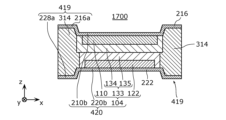
次に、実施の形態1の変形例7について、図12を用いて説明する。図12は、実施の形態1の変形例7における電池1700の概略構成を示す断面図である。
<Modification 7>
Next, Modification 7 of
図12に示されるように、電池1700は、変形例5における電池1500と比較して、対極集電体220の代わりに対極集電体222を備える。また、電池1700は、第1積層部分416の代わりに第1積層部分419を有する。
As shown in FIG. 12 ,
対極集電体222は、変形例5における対極集電体220と比較して、第1板部226aの代わりに第1板部228aを有する。第1板部228aは、厚みが均一の平板部である。第1板部228aは、対極集電体222の一部であって、平面視において封止部材314と重複する部分である。第1板部228aは、電池1700の第1積層部分419に含まれる。
The counter electrode
第1板部228aと第2板部220bとは、電池1700の厚み方向において異なる位置に位置している。具体的には、第1板部228aは、厚み方向において第2板部220bよりも電極集電体216から離れた位置に位置している。第1板部228aと第2板部220bとの接続部分は、第1板部228aおよび第2板部220bの各々に直交していてもよく、斜めに交差していてもよい。
第1積層部分419は、図12に示されるように、封止部材314と、電極集電体216の第1板部216aと、対極集電体222の第1板部228aとを含んでいる。第1積層部分419は、第2積層部分420よりも電池1700の厚み方向において両側に突出している。第1積層部分419のz軸の正方向への突出量と、z軸の負方向への突出量とは同じであってもよく、異なっていてもよい。
The first
以上の構成によれば、電気回路において電池1700と他の部品との接続を確実にするために電池1700に対して外力を加えた際に、外力は、主に第1積層部分419で受け止められる。したがって、発電要素104への応力を十分に軽減することができ、発電要素104の層間剥離および破損などをより効果的に抑制することができる。
According to the above configuration, when an external force is applied to
<変形例8>
次に、実施の形態1の変形例8について、図13を用いて説明する。図13は、実施の形態1の変形例8における電池1800の概略構成を示す断面図である。
<Modification 8>
Next, Modification 8 of
図13に示されるように、電池1800は、変形例7における電池1700と比較して、封止部材314の代わりに封止部材317を備える。封止部材317は、第1封止部材318と、第2封止部材319とを有する。第1封止部材318は、電極集電体216に近い側に位置し、第1材料を含む。第2封止部材319は、第1封止部材318よりも対極集電体222に近い側に位置し、第2材料を含む。第2材料は、第1材料とは異なる材料である。第2材料は、例えば、絶縁性であり、かつ、イオン伝導性を有さない材料である。第2材料は、例えば封止剤などの樹脂を含んでもよい。
As shown in FIG. 13 ,
第2材料は、例えば、第1材料として利用可能な複数の材料から選択された、第1封止部材318に含まれる材料とは異なる材料であってもよい。例えば、第2材料は、エポキシ樹脂とアクリル樹脂とポリイミド樹脂とシルセスキオキサンとのうち、第1封止部材318に含まれない材料であってもよい。第2材料は、粒子状の金属酸化物材料を含んでもよい。
The second material may be a different material than the material contained in the
以上の構成によれば、反応性または機械特性などの観点から、正極側の封止部材の材料として最も適した材料及び負極側の封止部材の材料として最も適した材料を、それぞれ選ぶことができる。これにより、電池1800の信頼性をさらに向上することができる。
According to the above configuration, it is possible to select the most suitable material for the positive electrode side sealing member and the most suitable material for the negative electrode side sealing member from the viewpoint of reactivity or mechanical properties. can. Thereby, the reliability of the
[電池の製造方法]
続いて、実施の形態1および各変形例における電池の製造方法の一例を説明する。以下では、図14を用いて、上述した変形例5における電池1500の製造方法を説明する。他の電池1000、1100、1200、1300、1400、1600、1700および1800についても同様である。
[Battery manufacturing method]
Next, an example of a method for manufacturing a battery according to
図14は、電池1500の製造方法の一例を示す図である。
14A and 14B are diagrams showing an example of a method for manufacturing the
まず、対極材料を溶媒と共に練り込んだペースト状の塗料を準備する。この塗料を対極集電体220上に塗工する。すなわち、対極層122を形成する。さらに、塗工された塗料を覆うように、固体電解質材料を対極集電体220上に塗工し、乾燥する。すなわち、対極側電解質層135を形成する。これにより、図14の(a)に示されるような、対極板が作製される。なお、対極材料(および、後述する電極材料)と固体電解質材料とは、溶剤を含まない材料で準備されてもよい。
First, a paste-like paint is prepared by kneading a counter electrode material together with a solvent. This paint is applied onto the counter electrode
次に、図14の(b)に示されるように、対極板の周辺部に封止材料を塗布する。すなわち、封止部材314を形成する。このとき、図14の(b)に示されるように、封止部材314の厚みが、対極層122と対極側電解質層135と電極層110と電極側電解質層134との厚みの合計よりも、厚く塗布されてもよい。
Next, as shown in FIG. 14(b), a sealing material is applied to the periphery of the counter electrode plate. That is, the sealing
さらに、封止材料を塗布した後に、熱処理または紫外線照射などを行う。これにより、塗料の流動性を残したまま増粘させて、塗料を仮硬化することができる。増粘硬化を用いることで、封止部材314の変形を制御できる。
Furthermore, after applying the sealing material, heat treatment or ultraviolet irradiation is performed. As a result, the paint can be temporarily cured by increasing the viscosity while maintaining the fluidity of the paint. By using thickening and curing, the deformation of the sealing
次に、電極材料を溶媒と共に練り込んだペースト状の塗料を準備する。この塗料を電極集電体216上に塗工する。すなわち、電極層110を形成する。さらに、塗工された塗料を覆うように、固体電解質材料を電極集電体216上に塗工し、乾燥する。すなわち、電極側電解質層134を形成する。これにより、図14の(c)に示されるような、電極板が作製される。なお、塗料の塗布するときの電極集電体216は、図14の(c)に示されるように、平板であってもよい。つまり、第1板部216aと第2板部210bとの厚み方向における段差は設けられていない。
Next, a paste-like paint is prepared by kneading the electrode material together with a solvent. This paint is applied onto the electrode
次に、図14の(c)に示されるように、上冶具510と下冶具520とを備える加圧冶具500を用いて、電極板と対極板とを圧着する。具体的には、封止部材314を形成した対極板に対向するように、電極板を配置し、上冶具510と下冶具520とで電極板と対極板とを挟み込んで圧着する。
Next, as shown in (c) of FIG. 14 , the electrode plate and the counter electrode plate are crimped using a
このとき、第1積層部分416の形状、配置および突出高さ(具体的には、電極集電体216の形状)は、例えば上冶具510に設けた突起512の形状、位置および高さによって制御することができる。例えば、図14の(c)に示される場合は、上冶具510と下冶具520との対向面において、上冶具510には発電要素104にほぼ対向する四角錐台状の突起512が設けられている。これにより、図14の(d)に示されるように、加圧後の電池1500には、突起512の高さで近似される高低差を有する第1積層部分416が発電要素104の外側に形成される。
At this time, the shape, arrangement and projection height of the first laminated portion 416 (specifically, the shape of the electrode current collector 216) are controlled by the shape, position and height of the
なお、例えば、熱処理またはUV照射などにより、封止部材314を本硬化させてもよい。これにより、封止状態をより強固にすることができる。
Note that, for example, the sealing
また、電極板と対極板との両方に封止材料をそれぞれ塗布してもよい。電極板と対極板との各々に封止部材314の一部を形成してから、電極板と対極板とを貼り合わせてもよい。これにより、一度に形成する封止部材314の量が減るので、封止部材314をより高速に形成することができる。また、接合面積が増えることで、封止部材314と電極板の接合をより強固にすることができる。また、封止部材314の突起が低くなるので、工程途中の電極板または対極板を容易に巻き取ることができる。また、電極板と対極板とにそれぞれ、最適な異なる封止材料を選択することもできる。
Alternatively, the sealing material may be applied to both the electrode plate and the counter electrode plate. A part of the sealing
以上のように、図14に示される電池1500の製造方法では、電極板と対極板とが貼り合わされる前に、封止部材314を事前に形成する工程を包含する。これにより、電極集電体216と対極集電体220との少なくとも一方の外側に、封止部材314が形成される。これにより、電極集電体216と対極集電体220とが直接接触することに起因する、電極層110と対極層122との短絡のリスクを、大幅に小さくすることができる。
As described above, the method for manufacturing
ここで、封止部材314の厚み制御は、電池1500の信頼性の向上に、大きく寄与する要素となる。また、封止部材314の厚みは、塗布厚みの調整により、制御される。このとき、封止部材314が、電極集電体216と対極集電体220との端部の大半を被覆しないように、つまり、各集電体の端部から外側に漏れないように調整されてもよい。
Here, controlling the thickness of the sealing
なお、封止部材314を形成する位置、電極層110と対極層122と電解質層133との各々の形成範囲、電極集電体216と対極集電体220との大きさなどが調整されてもよい。これにより、実施の形態1および各変形例において示された電池のそれぞれが、作製されうる。また、複数の電池の積層を行うことで、後述する実施の形態2において示す積層電池が作製されうる。
In addition, even if the position where the sealing
また、本実施の形態における電池の製造方法においては、電極板と対極板との貼り合わせ時、または、複数の電池の積層時に、加圧が行われてもよい。電極板または対極板を個別に加圧してから封止部材314を形成してもよい。
In addition, in the method for manufacturing a battery according to the present embodiment, pressure may be applied when bonding the electrode plate and the counter electrode plate together or when stacking a plurality of batteries. The sealing
(実施の形態2)
以下では、実施の形態2について説明する。なお、以下の説明において、上述の実施の形態1および各変形例との相違点を中心に説明し、共通点の説明を適宜、省略または簡略化する。
(Embodiment 2)
Embodiment 2 will be described below. In the following description, the points of difference from the above-described first embodiment and each modified example will be mainly described, and descriptions of common points will be omitted or simplified as appropriate.
図15は、実施の形態2における積層電池2000の概略構成を示す断面図である。実施の形態2における積層電池2000は、上述の実施の形態1または各変形例における電池を複数積層し、かつ、直列で接続してなる積層電池である。
FIG. 15 is a cross-sectional view showing a schematic configuration of a
図15に示される例では、積層電池2000は、3つの電池2002、2004および2006をこの順で積層した構成を有する。電池2002、2004および2006はそれぞれ、互いに同じ構成を有する。電池2002、2004および2006の1つが第1電池の一例であり、電池2002、2004および2006の他の1つが第2電池の一例である。
In the example shown in FIG. 15, a
例えば、電池2002、2004および2006はそれぞれ、実施の形態1の変形例5における電池1500とほぼ同じ構成を有する。なお、電池2002、2004および2006の少なくとも1つは、実施の形態1における電池1000であってもよく、変形例1から変形例8における電池1100から電池1800の少なくとも1つであってもよい。
For example,
積層電池2000においては、所定の電池(例えば、単電池)の電極集電体と、別の電池(例えば、単電池)の対極集電体とを接合することで、複数の電池が積層されている。具体的には、図15に示されるように、電池2002の電極集電体216と電池2004の対極集電体220とが接合されている。電池2004の電極集電体216と電池2006の対極集電体220とが接合されている。電極集電体216と対極集電体220との接合は、直接接合されてもよく、導電性接着剤または溶接法などにより接合されてもよい。電池2002、2004および2006は、直列に接続されている。
In the
図15に示されるように、積層電池2000は、さらに、電気絶縁部材2010を備える。電気絶縁部材2010は、電池2002、2004および2006の各々の側面を覆っている。これにより、積層電池2000における複数の電池の積層状態を、より強固に維持することができる。電気絶縁部材2010は、電気的に絶縁性を有する樹脂材料を用いて形成されている。電気絶縁部材2010は、例えば、封止部材314と同じ材料を用いて形成されていてもよい。
As shown in FIG. 15, the
なお、積層電池2000が備える電池の数は、3以上であってもよく、2つのみであってもよい。積層される電池の数を調整することで、所望の電池特性を得ることができる。
Note that the number of batteries included in the stacked
また、積層電池を構成する際に、必要な特性に応じて、複数の電池を並列接続してもよい。また、並列接続された2以上の電池と直列接続された2以上の電池とが混在してもよい。これにより、僅かな体積で高容量の積層電池を実現できる。 Moreover, when configuring a laminated battery, a plurality of batteries may be connected in parallel depending on the required characteristics. Also, two or more batteries connected in parallel and two or more batteries connected in series may be mixed. As a result, a laminated battery with a small volume and a high capacity can be realized.
以上の構成によれば、複数の単電池を直列に積層することにより、高電圧を得ることができる。したがって、直列型であり、かつ、短絡リスクが小さく、電気的接続の信頼性が高い積層電池を実現できる。すなわち、集電体同士の接触による短絡リスクが小さく、かつ、発電要素104に加わる外力を小さくしつつ、電気的接続の信頼性が高い直列積層のバイポーラ構造を形成できる。
According to the above configuration, a high voltage can be obtained by stacking a plurality of single cells in series. Therefore, it is possible to realize a stacked battery that is a series type, has a low risk of short circuit, and has a highly reliable electrical connection. That is, it is possible to form a series-laminated bipolar structure with a low risk of short-circuiting due to contact between current collectors, a low external force applied to the
図16は、実施の形態2における積層電池2000の使用例を模式的に示す図である。積層電池2000は、図16に示されるように、例えば電極押さえ2020と対極押さえ2030との間に挟み込まれて加圧されている。電極押さえ2020には、電極取り出し線2022が設けられている。対極押さえ2030には、対極取り出し線2032が設けられている。電極押さえ2020、対極押さえ2030、電極取り出し線2022および対極取り出し線2032はそれぞれ、導電性を有する金属材料などで形成されている。これにより、電極取り出し線2022および対極取り出し線2032を介して、積層電池2000から電流を取り出すことができる。
FIG. 16 is a diagram schematically showing a usage example of the
電極押さえ2020と対極押さえ2030との間に電池または積層電池を挟み込んで加圧しても、第1積層部分410が加圧を受けることにより、電気的接続の良化と発電要素100の破損の抑制という効果を両立することができる。
Even if the battery or laminated battery is sandwiched between the
なお、積層電池2000は、封止ケースに内包されてもよい。封止ケースとしては、例えば、ラミネート袋、金属缶、樹脂ケースなどの封止ケースが用いられうる。封止ケースを用いることで、発電要素が水分によって劣化することを抑制することができる。
Note that the
[変形例]
以下では、実施の形態2の複数の変形例について説明する。なお、以下の複数の変形例の説明において、実施の形態2との相違点を中心に説明し、共通点の説明を省略または簡略化する。
[Modification]
A plurality of modifications of the second embodiment will be described below. In addition, in the following description of a plurality of modified examples, differences from Embodiment 2 will be mainly described, and descriptions of common points will be omitted or simplified.
<変形例1>
まず、実施の形態2の変形例1について、図17を用いて説明する。図17は、実施の形態2の変形例1における積層電池2100の概略構成を示す図である。具体的には、図17の(a)および(b)はそれぞれ、積層電池2100の厚み方向に平行な2つの断面であって、互いに直交する2つの断面(xz断面とyz断面)を表している。
<
First,
変形例1における積層電池2100では、第1積層部分418の位置が電池毎に調整されている。具体的には、積層電池2100は、3つの電池2002、2004および2006が積層された構造を有する。変形例1において、3つの電池2002、2004および2006は、図10に示されたように、発電要素104の平面視形状が矩形であり、かつ、2つの第1積層部分418が矩形の対辺に沿って設けられている電池である。
In the
積層電池2100では、図10に示される電池の方向を揃えて積層されている。具体的には、図17の(a)に示されるように、3つの電池2002、2004および2006の各々の第1積層部分418が厚み方向において並んでいる。より具体的には、電池2002の第1積層部分418と電池2004の第1積層部分418とは、接している。電池2004の第1積層部分418と電池2006の第1積層部分418とは接している。
In the stacked
これにより、外力を加えた際にも発電要素104への応力を軽減することができ、積層電池2100内の発電要素104の層間剥離および破損などを抑制することができる。つまり、外力に対する積層電池2100内の発電要素104の機械的強度を高めることができる。
As a result, even when an external force is applied, the stress on the
一方で、図17の(b)に示されるように、3つの電池2002、2004および2006の各々の第3積層部分430も厚み方向において並んでいる。このとき、電池2002の第3積層部分430と電池2004の第3積層部分430とは、接しておらず、空間2110が介在している。電池2004の第3積層部分430と電池2006の第3積層部分430とは、接しておらず、空間2120が介在している。
On the other hand, as shown in FIG. 17(b), the third
つまり、積層電池2100は、積層された第1電池と第2電池との間に、空間を有する。具体的には、図17の(b)に示されるように、電池2002と電池2004との間には、空間2110が設けられている。電池2004と電池2006との間には、空間2120が設けられている。
That is, the stacked
空間2110および2120は、放熱空間として機能する。放熱空間の向きが揃っているので、例えば冷却ファンなどを用いたときの風の通りが良く、効率良く冷却することができる。また、電池の充放電に伴う体積膨張を、空間2110および2120によって吸収することができる。空間2110および2120は、電気配線または光通信などの経路として用いることもできる。
<変形例2>
次に、実施の形態2の変形例2について、図18を用いて説明する。図18は、実施の形態2の変形例2における積層電池2200の概略構成を示す図である。具体的には、図18の(a)および(b)はそれぞれ、積層電池2200の厚み方向に平行な2つの断面であって、互いに直交する2つの断面(xz断面とyz断面)を表している。
<Modification 2>
Next, Modification 2 of Embodiment 2 will be described with reference to FIG. FIG. 18 is a diagram showing a schematic configuration of a
図18に示される積層電池2200では、第1電池の第1積層部分は、第2電池における第1積層部分ではない部分に接している。具体的には、積層電池2200では、変形例1における積層電池2100と比較して、電池2004の配置の向きが異なっている。具体的には、図18に示される電池2004は、図17に示される電池2004と比べて、平面視において90°回転させて積層されている。つまり、本変形例における積層電池2200では、電池の積層毎に、電池が90°ずつ回転させて積層されている。
In the
このため、図18の(a)に示されるように、電池2002の第1積層部分418と、電池2004の第3積層部分430と、電池2006の第1積層部分418とが、厚み方向に並んでいる。電池2002の第1積層部分418と、電池2004の第3積層部分430とは接している。電池2004の第3積層部分430と電池2006の第1積層部分418とは、接しておらず、空間2120が介在している。
Therefore, as shown in FIG. 18A, the first
また、図18の(b)に示されるように、電池2002の第3積層部分430と、電池2004の第1積層部分418と、電池2006の第3積層部分430とが、厚み方向に並んでいる。電池2002の第3積層部分430と電池2004の第1積層部分418とは、接しておらず、空間2110が介在している。電池2004の第1積層部分418と電池2006の第3積層部分430とは接している。
Further, as shown in FIG. 18B, the third
このように、図18に示される積層電池2200では、各電池の第1積層部分418が井桁状に積み重なっているので、積層電池2200の機械的強度が更に向上する。つまり、外力に対する積層電池2200内の発電要素104の機械的強度を一層高めることができる。さらに、変形例1と同様に、積層電池2200では、空間2110および2120が放熱空間として機能するので、放熱性を高めることができる。
In this way, in the
(他の実施の形態)
以上、1つまたは複数の態様における電池および積層電池について、実施の形態に基づいて説明したが、本開示は、これらの実施の形態に限定されるものではない。本開示の主旨を逸脱しない限り、当業者が思いつく各種変形を本実施の形態に施したもの、および、異なる実施の形態における構成要素を組み合わせて構築される形態も、本開示の範囲内に含まれる。
(Other embodiments)
Although the battery and stacked battery in one or more aspects have been described above based on the embodiments, the present disclosure is not limited to these embodiments. As long as they do not deviate from the gist of the present disclosure, modifications that can be made by those skilled in the art to the present embodiment, and forms constructed by combining the components of different embodiments are also included within the scope of the present disclosure. be
例えば、上記の実施の形態では、封止部材310、312、314、316または317は、電極集電体210、212、214、216または218に接していなくてもよい。例えば、電極層110が電極集電体210、212、214、216または218の全面に形成されていてもよく、封止部材310、312、314、316または317は、電極層110と対極集電体220または222との間に位置し、電極層110に接していてもよい。
For example, in the embodiments described above, sealing
同様に、封止部材310、312、314、316または317は、対極集電体220または222に接していなくてもよい。例えば、対極層120または122が対極集電体220または222の全面に形成されていてもよく、封止部材310、312、314、316または317は、対極層120または122と電極集電体210、212、214、216または218との間に位置し、対極層120または122に接していてもよい。
Similarly, sealing
また、例えば、封止部材310、312、314、316または317は、発電要素100、102、104または106に接していなくてもよい。
Also, for example, the sealing
また、例えば、電解質層130は、固体電解質層でなくてもよく、電解液であってもよい。
Also, for example, the
また、例えば、上記の各実施の形態および各変形例では、封止部材310、312、314、316または317の厚みを発電要素100、102または104の厚みと異ならせることにより、各第1積層部分の厚みT1と各第2積層部分の厚みT2とを異ならせる例について説明したが、これに限らない。例えば、各電極集電体および各対極集電体の少なくとも一方の厚みが異なっていてもよい。
Further, for example, in each of the above-described embodiments and modifications, by making the thickness of the sealing
具体的には、第1積層部分410、412、414、416、418または419において、封止部材310、312、314、316または317の厚みは、発電要素100、102または104の厚みと同じであってもよく、発電要素100、102または104の厚みより小さくてもよい。電極集電体210、212、214、216または218、および、対極集電体220または222の少なくとも一方の厚みが、第1積層部分410、412、414、416、418または419において第2積層部分420よりも大きくてもよい。例えば、各電極集電体の第1板部210a、212a、214a、216aまたは218aの厚みは、各電極集電体の第2板部210bの厚みより大きくてもよい。あるいは、各対極集電体の第1板部220a、222a、224a、226aまたは228aの厚みは、各対極集電体の第2板部220bの厚みより大きくてもよい。
Specifically, in the first
また、上記の各実施の形態は、特許請求の範囲またはその均等の範囲において種々の変更、置き換え、付加、省略などを行うことができる。 In addition, various changes, replacements, additions, and omissions can be made to each of the above-described embodiments within the scope of claims or equivalents thereof.
本開示の電池および積層電池は、電子機器、電気器具装置、電気車両などの電池として、利用されうる。 The batteries and laminated batteries of the present disclosure can be utilized as batteries for electronic devices, appliance devices, electric vehicles, and the like.
100、102、104 発電要素
110 電極層
120、122 対極層
130、132、133 電解質層
134 電極側電解質層
135 対極側電解質層
210、212、214、216、218 電極集電体
210a、212a、214a、216a、218a、220a、222a、224a、226a、228a 第1板部
210b、220b 第2板部
218c、220c 第3板部
220、222 対極集電体
230、232、234 第1領域
240 第2領域
310、312、314、316、317 封止部材
316a 第1封止部分
316b 第2封止部分
318 第1封止部材
319 第2封止部材
250 対向領域
410、412、414、416、418、418a、418b、419 第1積層部分
420 第2積層部分
430 第3積層部分
500 加圧冶具
510 上冶具
512 突起
520 下冶具
1000、1100、1200、1300、1400、1500、1600、1700、1800、2002、2004、2006 電池
2000、2100、2200 積層電池
2010 電気絶縁部材
2020 電極押さえ
2022 電極取り出し線
2030 対極押さえ
2032 対極取り出し線
2110、2120 空間
100, 102, 104
Claims (23)
電極層、前記電極層に対向する対極層、及び前記電極層と前記対極層との間に配置される固体電解質層を含み、全固体電池である単電池と、
前記電極層に接する電極集電体と、
前記対極層に接する対極集電体と、
前記電極集電体と前記対極集電体との間に配置される封止部材と、
を備え、
前記単電池は、前記電極集電体と前記対極集電体との間に配置され、
前記電池を厚み方向に見た場合において、
前記電極集電体は、前記電極層と重ならない第1領域を含み、前記第1領域は、前記電極集電体の外周の少なくとも一部を含み、
前記対極集電体は、前記対極層と重ならない第2領域を含み、前記第2領域は、前記対極集電体の外周の少なくとも一部を含み、
前記封止部材は、前記第1領域及び前記第2領域と重なっており、
前記封止部材の少なくとも一部である第1封止部分と、前記電極集電体の一部であって、前記電池を厚み方向に見た場合において前記第1封止部分に重なる部分と、前記対極集電体の一部であって、前記電池を厚み方向に見た場合において前記第1封止部分に重なる部分と、を含む部分を第1積層部分とし、
前記単電池と、前記電極集電体の一部であって、前記電池を厚み方向に見た場合において前記単電池に重なる部分と、前記対極集電体の一部であって、前記電池を厚み方向に見た場合において前記単電池に重なる部分と、を含む部分を第2積層部分とすると、
前記第1積層部分の厚みは、前記第2積層部分の厚みより大きい、
電池。 a battery,
a single cell, which is an all-solid battery, comprising an electrode layer, a counter electrode layer facing the electrode layer, and a solid electrolyte layer disposed between the electrode layer and the counter electrode layer;
an electrode current collector in contact with the electrode layer;
a counter electrode current collector in contact with the counter electrode layer;
a sealing member disposed between the electrode current collector and the counter electrode current collector;
with
The unit cell is arranged between the electrode current collector and the counter electrode current collector,
When the battery is viewed in the thickness direction,
The electrode current collector includes a first region that does not overlap with the electrode layer, the first region includes at least part of the outer periphery of the electrode current collector,
The counter electrode current collector includes a second region that does not overlap with the counter electrode layer, the second region includes at least part of the outer circumference of the counter electrode current collector,
The sealing member overlaps the first region and the second region,
a first sealing portion that is at least part of the sealing member; a portion that is a part of the electrode current collector and overlaps the first sealing portion when the battery is viewed in the thickness direction; A first laminated portion is a portion that is a part of the counter electrode current collector and includes a portion that overlaps with the first sealing portion when the battery is viewed in the thickness direction,
The unit cell, a portion of the electrode current collector that overlaps the unit cell when the battery is viewed in the thickness direction, and a portion of the counter electrode current collector that is a part of the battery. If a portion including a portion overlapping with the unit cell when viewed in the thickness direction is defined as a second laminated portion,
The thickness of the first laminated portion is greater than the thickness of the second laminated portion,
battery.
請求項1に記載の電池。 The sealing member surrounds the cell,
A battery according to claim 1 .
請求項1または2に記載の電池。 When the battery is viewed in the thickness direction, the first stacked portion includes a plurality of island-shaped portions spaced apart from each other and positioned outside the unit cell,
The battery according to claim 1 or 2.
請求項1から3のいずれかに記載の電池。 When the battery is viewed in the thickness direction, the first laminated portion has an elongated shape arranged outside the unit cell along the outer periphery of the unit cell.
The battery according to any one of claims 1 to 3.
前記第1積層部分は、前記矩形の2つの対辺のそれぞれに沿って位置する、2つの部分を含む、
請求項1から4のいずれかに記載の電池。 The shape of the cell is a rectangle when the battery is viewed in the thickness direction,
the first laminated portion includes two portions located along each of two opposite sides of the rectangle;
The battery according to any one of claims 1 to 4.
請求項1に記載の電池。 The first laminated portion is arranged continuously along the entire circumference of the cell when the battery is viewed in the thickness direction,
A battery according to claim 1 .
請求項1から6のいずれかに記載の電池。 The first laminated portion protrudes to both sides in the thickness direction of the battery more than the second laminated portion,
The battery according to any one of claims 1 to 6.
請求項1から7のいずれかに記載の電池。 the sealing member is in contact with the cell,
The battery according to any one of claims 1 to 7.
前記第1封止部材は、前記第2封止部材よりも前記電極集電体の近くに位置し、
前記第2封止部材は、前記第1封止部材よりも前記対極集電体の近くに位置する、
請求項1から8のいずれかに記載の電池。 The sealing member includes a first sealing member containing a first material and a second sealing member containing a second material different from the first material,
The first sealing member is positioned closer to the electrode current collector than the second sealing member,
The second sealing member is located closer to the counter electrode current collector than the first sealing member,
The battery according to any one of claims 1 to 8.
前記第1材料は、絶縁性であり、かつ、イオン伝導性を有さない材料である、
請求項1から8のいずれかに記載の電池。 the sealing member comprises a first material;
The first material is a material that is insulative and does not have ionic conductivity.
The battery according to any one of claims 1 to 8.
請求項9または10に記載の電池。 The first material includes resin,
The battery according to claim 9 or 10.
請求項9から11のいずれかに記載の電池。 The first material is at least one selected from the group consisting of epoxy resins, acrylic resins, polyimide resins, and silsesquioxanes.
The battery according to any one of claims 9-11.
請求項1から12のいずれかに記載の電池。 wherein the sealing member comprises a particulate metal oxide material;
A battery according to any one of claims 1 to 12.
前記第2封止部分と、前記電極集電体の一部であって、前記電池を厚み方向に見た場合において前記第2封止部分に重なる部分と、前記対極集電体の一部であって、前記電池を厚み方向に見た場合において前記第2封止部分に重なる部分と、を含む部分を第3積層部分とすると、
前記第3積層部分の厚みは、前記第2積層部分の厚みと等しい、
請求項1から13のいずれかに記載の電池。 The sealing member further includes a second sealing portion different from the first sealing portion,
The second sealing portion, a portion of the electrode current collector which overlaps with the second sealing portion when the battery is viewed in the thickness direction, and a portion of the counter electrode current collector. If a portion including a portion overlapping with the second sealing portion when the battery is viewed in the thickness direction is defined as a third laminated portion,
The thickness of the third laminated portion is equal to the thickness of the second laminated portion,
14. The battery according to any one of claims 1-13.
前記第1電池と積層される第2電池と、を備え、
前記第1電池及び前記第2電池の各々は、
電極層、前記電極層に対向する対極層、及び前記電極層と前記対極層との間に配置される固体電解質層を含み、全固体電池である単電池と、
前記電極層に接する電極集電体と、
前記対極層に接する対極集電体と、
前記電極集電体と前記対極集電体との間に配置される封止部材と、
を含み、
前記単電池は、前記電極集電体と前記対極集電体との間に配置され、
前記第1電池及び前記第2電池の各々を厚み方向に見た場合において、
前記電極集電体は、前記電極層と重ならない第1領域を含み、前記第1領域は、前記電極集電体の外周の少なくとも一部を含み、
前記対極集電体は、前記対極層と重ならない第2領域を含み、前記第2領域は、前記対極集電体の外周の少なくとも一部を含み、
前記封止部材は、前記第1領域及び前記第2領域と重なっており、
前記封止部材の少なくとも一部である第1封止部分と、前記電極集電体の一部であって、前記第1電池及び前記第2電池の各々を厚み方向に見た場合において前記第1封止部分に重なる部分と、前記対極集電体の一部であって、前記第1電池及び前記第2電池の各
々を厚み方向に見た場合において前記第1封止部分に重なる部分と、を含む部分を第1積層部分とし、
前記単電池と、前記電極集電体の一部であって、前記第1電池及び前記第2電池の各々を厚み方向に見た場合において前記単電池に重なる部分と、前記対極集電体の一部であって、前記第1電池及び前記第2電池の各々を厚み方向に見た場合において前記単電池に重なる部分と、を含む部分を第2積層部分とすると、
前記第1積層部分の厚みは、前記第2積層部分の厚みより大きい、
積層電池。 a first battery;
a second battery stacked with the first battery,
each of the first battery and the second battery,
a single cell, which is an all-solid battery, comprising an electrode layer, a counter electrode layer facing the electrode layer, and a solid electrolyte layer disposed between the electrode layer and the counter electrode layer;
an electrode current collector in contact with the electrode layer;
a counter electrode current collector in contact with the counter electrode layer;
a sealing member disposed between the electrode current collector and the counter electrode current collector;
including
The unit cell is arranged between the electrode current collector and the counter electrode current collector,
When each of the first battery and the second battery is viewed in the thickness direction,
The electrode current collector includes a first region that does not overlap with the electrode layer, the first region includes at least part of the outer periphery of the electrode current collector,
The counter electrode current collector includes a second region that does not overlap with the counter electrode layer, the second region includes at least part of the outer circumference of the counter electrode current collector,
The sealing member overlaps the first region and the second region,
A first sealing portion that is at least a part of the sealing member, and a part of the electrode current collector that is the first battery when each of the first battery and the second battery is viewed in the thickness direction. and a portion that is a part of the counter electrode current collector and overlaps with the first sealing portion when each of the first battery and the second battery is viewed in the thickness direction. , is defined as the first laminated portion,
the unit cell, a portion of the electrode current collector that overlaps the unit cell when each of the first battery and the second battery is viewed in the thickness direction, and the counter electrode current collector When a portion that is part and includes a portion that overlaps with the unit cell when each of the first battery and the second battery is viewed in the thickness direction is defined as a second stacked portion,
The thickness of the first laminated portion is greater than the thickness of the second laminated portion,
laminated battery.
請求項15に記載の積層電池。 Having a space between the first battery and the second battery,
The laminated battery according to claim 15.
請求項15または16に記載の積層電池。 wherein the first stacked portion of the first battery is in contact with a portion of the second battery that is not the first stacked portion;
The laminated battery according to claim 15 or 16.
電極層、前記電極層に対向する対極層、及び前記電極層と前記対極層との間に配置される固体電解質層を含む単電池と、 a unit cell comprising an electrode layer, a counter electrode layer facing the electrode layer, and a solid electrolyte layer disposed between the electrode layer and the counter electrode layer;
前記電極層に接する電極集電体と、 an electrode current collector in contact with the electrode layer;
前記対極層に接する対極集電体と、 a counter electrode current collector in contact with the counter electrode layer;
前記電極集電体と前記対極集電体との間に配置される封止部材と、 a sealing member disposed between the electrode current collector and the counter electrode current collector;
を備え、with
前記単電池は、前記電極集電体と前記対極集電体との間に配置され、 The unit cell is arranged between the electrode current collector and the counter electrode current collector,
前記電池を厚み方向に見た場合において、 When the battery is viewed in the thickness direction,
前記電極集電体は、前記電極層と重ならない第1領域を含み、前記第1領域は、前記電極集電体の外周の少なくとも一部を含み、 The electrode current collector includes a first region that does not overlap with the electrode layer, the first region includes at least part of the outer periphery of the electrode current collector,
前記対極集電体は、前記対極層と重ならない第2領域を含み、前記第2領域は、前記対極集電体の外周の少なくとも一部を含み、 The counter electrode current collector includes a second region that does not overlap with the counter electrode layer, the second region includes at least part of the outer circumference of the counter electrode current collector,
前記封止部材は、前記第1領域及び前記第2領域と重なっており、 The sealing member overlaps the first region and the second region,
前記封止部材の少なくとも一部である第1封止部分と、前記電極集電体の一部であって、前記電池を厚み方向に見た場合において前記第1封止部分に重なる部分と、前記対極集電体の一部であって、前記電池を厚み方向に見た場合において前記第1封止部分に重なる部分と、を含む部分を第1積層部分とし、 a first sealing portion that is at least part of the sealing member; a portion that is a part of the electrode current collector and overlaps the first sealing portion when the battery is viewed in the thickness direction; A first laminated portion is a portion that is a part of the counter electrode current collector and includes a portion that overlaps with the first sealing portion when the battery is viewed in the thickness direction,
前記単電池と、前記電極集電体の一部であって、前記電池を厚み方向に見た場合において前記単電池に重なる部分と、前記対極集電体の一部であって、前記電池を厚み方向に見た場合において前記単電池に重なる部分と、を含む部分を第2積層部分とすると、 The unit cell, a portion of the electrode current collector that overlaps the unit cell when the battery is viewed in the thickness direction, and a portion of the counter electrode current collector that is a part of the battery. If a portion including a portion overlapping with the unit cell when viewed in the thickness direction is defined as a second laminated portion,
前記第1積層部分の厚みは、前記第2積層部分の厚みより大きく、 The thickness of the first laminated portion is greater than the thickness of the second laminated portion,
前記電池を厚み方向に見た場合において、前記第1積層部分は、互いに離間し、前記単電池の外側に位置する、複数の島状部分を含む、 When the battery is viewed in the thickness direction, the first stacked portion includes a plurality of island-shaped portions spaced apart from each other and positioned outside the unit cell,
電池。 battery.
電極層、前記電極層に対向する対極層、及び前記電極層と前記対極層との間に配置される固体電解質層を含む単電池と、 a unit cell comprising an electrode layer, a counter electrode layer facing the electrode layer, and a solid electrolyte layer disposed between the electrode layer and the counter electrode layer;
前記電極層に接する電極集電体と、 an electrode current collector in contact with the electrode layer;
前記対極層に接する対極集電体と、 a counter electrode current collector in contact with the counter electrode layer;
前記電極集電体と前記対極集電体との間に配置される封止部材と、 a sealing member disposed between the electrode current collector and the counter electrode current collector;
を備え、with
前記単電池は、前記電極集電体と前記対極集電体との間に配置され、 The unit cell is arranged between the electrode current collector and the counter electrode current collector,
前記電池を厚み方向に見た場合において、 When the battery is viewed in the thickness direction,
前記電極集電体は、前記電極層と重ならない第1領域を含み、前記第1領域は、前記電極集電体の外周の少なくとも一部を含み、 The electrode current collector includes a first region that does not overlap with the electrode layer, the first region includes at least part of the outer periphery of the electrode current collector,
前記対極集電体は、前記対極層と重ならない第2領域を含み、前記第2領域は、前記対極集電体の外周の少なくとも一部を含み、 The counter electrode current collector includes a second region that does not overlap with the counter electrode layer, the second region includes at least part of the outer circumference of the counter electrode current collector,
前記封止部材は、前記第1領域及び前記第2領域と重なっており、 The sealing member overlaps the first region and the second region,
前記封止部材の少なくとも一部である第1封止部分と、前記電極集電体の一部であって、前記電池を厚み方向に見た場合において前記第1封止部分に重なる部分と、前記対極集電体の一部であって、前記電池を厚み方向に見た場合において前記第1封止部分に重なる部分と、を含む部分を第1積層部分とし、 a first sealing portion that is at least part of the sealing member; a portion that is a part of the electrode current collector and overlaps the first sealing portion when the battery is viewed in the thickness direction; A first laminated portion is a portion that is a part of the counter electrode current collector and includes a portion that overlaps with the first sealing portion when the battery is viewed in the thickness direction,
前記単電池と、前記電極集電体の一部であって、前記電池を厚み方向に見た場合において前記単電池に重なる部分と、前記対極集電体の一部であって、前記電池を厚み方向に見た場合において前記単電池に重なる部分と、を含む部分を第2積層部分とすると、 The unit cell, a portion of the electrode current collector that overlaps the unit cell when the battery is viewed in the thickness direction, and a portion of the counter electrode current collector that is a part of the battery. If a portion including a portion overlapping with the unit cell when viewed in the thickness direction is defined as a second laminated portion,
前記第1積層部分の厚みは、前記第2積層部分の厚みより大きく、 The thickness of the first laminated portion is greater than the thickness of the second laminated portion,
前記封止部材は、前記単電池に接する、 the sealing member is in contact with the cell,
電池。 battery.
電極層、前記電極層に対向する対極層、及び前記電極層と前記対極層との間に配置される固体電解質層を含む単電池と、 a unit cell comprising an electrode layer, a counter electrode layer facing the electrode layer, and a solid electrolyte layer disposed between the electrode layer and the counter electrode layer;
前記電極層に接する電極集電体と、 an electrode current collector in contact with the electrode layer;
前記対極層に接する対極集電体と、 a counter electrode current collector in contact with the counter electrode layer;
前記電極集電体と前記対極集電体との間に配置される封止部材と、 a sealing member disposed between the electrode current collector and the counter electrode current collector;
を備え、with
前記単電池は、前記電極集電体と前記対極集電体との間に配置され、 The unit cell is arranged between the electrode current collector and the counter electrode current collector,
前記電池を厚み方向に見た場合において、 When the battery is viewed in the thickness direction,
前記電極集電体は、前記電極層と重ならない第1領域を含み、前記第1領域は、前記電極集電体の外周の少なくとも一部を含み、 The electrode current collector includes a first region that does not overlap with the electrode layer, the first region includes at least part of the outer periphery of the electrode current collector,
前記対極集電体は、前記対極層と重ならない第2領域を含み、前記第2領域は、前記対極集電体の外周の少なくとも一部を含み、 The counter electrode current collector includes a second region that does not overlap with the counter electrode layer, the second region includes at least part of the outer circumference of the counter electrode current collector,
前記封止部材は、前記第1領域及び前記第2領域と重なっており、 The sealing member overlaps the first region and the second region,
前記封止部材の少なくとも一部である第1封止部分と、前記電極集電体の一部であって、前記電池を厚み方向に見た場合において前記第1封止部分に重なる部分と、前記対極集電体の一部であって、前記電池を厚み方向に見た場合において前記第1封止部分に重なる部分と、を含む部分を第1積層部分とし、 a first sealing portion that is at least part of the sealing member; a portion that is a part of the electrode current collector and overlaps the first sealing portion when the battery is viewed in the thickness direction; A first laminated portion is a portion that is a part of the counter electrode current collector and includes a portion that overlaps with the first sealing portion when the battery is viewed in the thickness direction,
前記単電池と、前記電極集電体の一部であって、前記電池を厚み方向に見た場合において前記単電池に重なる部分と、前記対極集電体の一部であって、前記電池を厚み方向に見た場合において前記単電池に重なる部分と、を含む部分を第2積層部分とすると、 The unit cell, a portion of the electrode current collector that overlaps the unit cell when the battery is viewed in the thickness direction, and a portion of the counter electrode current collector that is a part of the battery. If a portion including a portion overlapping with the unit cell when viewed in the thickness direction is defined as a second laminated portion,
前記第1積層部分の厚みは、前記第2積層部分の厚みより大きく、 The thickness of the first laminated portion is greater than the thickness of the second laminated portion,
前記封止部材は、第1材料を含む第1封止部材と、前記第1材料と異なる第2材料を含む第2封止部材とを含み、 The sealing member includes a first sealing member containing a first material and a second sealing member containing a second material different from the first material,
前記第1封止部材は、前記第2封止部材よりも前記電極集電体の近くに位置し、 The first sealing member is positioned closer to the electrode current collector than the second sealing member,
前記第2封止部材は、前記第1封止部材よりも前記対極集電体の近くに位置する、 The second sealing member is located closer to the counter electrode current collector than the first sealing member,
電池。 battery.
電極層、前記電極層に対向する対極層、及び前記電極層と前記対極層との間に配置される固体電解質層を含む単電池と、 a unit cell comprising an electrode layer, a counter electrode layer facing the electrode layer, and a solid electrolyte layer disposed between the electrode layer and the counter electrode layer;
前記電極層に接する電極集電体と、 an electrode current collector in contact with the electrode layer;
前記対極層に接する対極集電体と、 a counter electrode current collector in contact with the counter electrode layer;
前記電極集電体と前記対極集電体との間に配置される封止部材と、 a sealing member disposed between the electrode current collector and the counter electrode current collector;
を備え、with
前記単電池は、前記電極集電体と前記対極集電体との間に配置され、 The unit cell is arranged between the electrode current collector and the counter electrode current collector,
前記電池を厚み方向に見た場合において、 When the battery is viewed in the thickness direction,
前記電極集電体は、前記電極層と重ならない第1領域を含み、前記第1領域は、前記電極集電体の外周の少なくとも一部を含み、 The electrode current collector includes a first region that does not overlap with the electrode layer, the first region includes at least part of the outer periphery of the electrode current collector,
前記対極集電体は、前記対極層と重ならない第2領域を含み、前記第2領域は、前記対極集電体の外周の少なくとも一部を含み、 The counter electrode current collector includes a second region that does not overlap with the counter electrode layer, the second region includes at least part of the outer circumference of the counter electrode current collector,
前記封止部材は、前記第1領域及び前記第2領域と重なっており、 The sealing member overlaps the first region and the second region,
前記封止部材の少なくとも一部である第1封止部分と、前記電極集電体の一部であって、前記電池を厚み方向に見た場合において前記第1封止部分に重なる部分と、前記対極集電体の一部であって、前記電池を厚み方向に見た場合において前記第1封止部分に重なる部分と、を含む部分を第1積層部分とし、 a first sealing portion that is at least part of the sealing member; a portion that is a part of the electrode current collector and overlaps the first sealing portion when the battery is viewed in the thickness direction; A first laminated portion is a portion that is a part of the counter electrode current collector and includes a portion that overlaps with the first sealing portion when the battery is viewed in the thickness direction,
前記単電池と、前記電極集電体の一部であって、前記電池を厚み方向に見た場合において前記単電池に重なる部分と、前記対極集電体の一部であって、前記電池を厚み方向に見た場合において前記単電池に重なる部分と、を含む部分を第2積層部分とすると、 The unit cell, a portion of the electrode current collector that overlaps the unit cell when the battery is viewed in the thickness direction, and a portion of the counter electrode current collector that is a part of the battery. If a portion including a portion overlapping with the unit cell when viewed in the thickness direction is defined as a second laminated portion,
前記第1積層部分の厚みは、前記第2積層部分の厚みより大きく、 The thickness of the first laminated portion is greater than the thickness of the second laminated portion,
前記封止部材は、前記第1封止部分とは異なる第2封止部分をさらに含み、 The sealing member further includes a second sealing portion different from the first sealing portion,
前記第2封止部分と、前記電極集電体の一部であって、前記電池を厚み方向に見た場合において前記第2封止部分に重なる部分と、前記対極集電体の一部であって、前記電池を厚み方向に見た場合において前記第2封止部分に重なる部分と、を含む部分を第3積層部分とすると、 The second sealing portion, a portion of the electrode current collector which overlaps with the second sealing portion when the battery is viewed in the thickness direction, and a portion of the counter electrode current collector. If a portion including a portion overlapping with the second sealing portion when the battery is viewed in the thickness direction is defined as a third laminated portion,
前記第3積層部分の厚みは、前記第2積層部分の厚みと等しい、 The thickness of the third laminated portion is equal to the thickness of the second laminated portion,
電池。 battery.
前記第1電池と積層される第2電池と、を備え、 a second battery stacked with the first battery,
前記第1電池及び前記第2電池の各々は、 each of the first battery and the second battery,
電極層、前記電極層に対向する対極層、及び前記電極層と前記対極層との間に配置される固体電解質層を含む単電池と、 a unit cell comprising an electrode layer, a counter electrode layer facing the electrode layer, and a solid electrolyte layer disposed between the electrode layer and the counter electrode layer;
前記電極層に接する電極集電体と、 an electrode current collector in contact with the electrode layer;
前記対極層に接する対極集電体と、 a counter electrode current collector in contact with the counter electrode layer;
前記電極集電体と前記対極集電体との間に配置される封止部材と、 a sealing member disposed between the electrode current collector and the counter electrode current collector;
を含み、including
前記単電池は、前記電極集電体と前記対極集電体との間に配置され、 The unit cell is arranged between the electrode current collector and the counter electrode current collector,
前記第1電池及び前記第2電池の各々を厚み方向に見た場合において、 When each of the first battery and the second battery is viewed in the thickness direction,
前記電極集電体は、前記電極層と重ならない第1領域を含み、前記第1領域は、前記電極集電体の外周の少なくとも一部を含み、 The electrode current collector includes a first region that does not overlap with the electrode layer, the first region includes at least part of the outer periphery of the electrode current collector,
前記対極集電体は、前記対極層と重ならない第2領域を含み、前記第2領域は、前記対極集電体の外周の少なくとも一部を含み、 The counter electrode current collector includes a second region that does not overlap with the counter electrode layer, the second region includes at least part of the outer circumference of the counter electrode current collector,
前記封止部材は、前記第1領域及び前記第2領域と重なっており、 The sealing member overlaps the first region and the second region,
前記封止部材の少なくとも一部である第1封止部分と、前記電極集電体の一部であって、前記第1電池及び前記第2電池の各々を厚み方向に見た場合において前記第1封止部分に重なる部分と、前記対極集電体の一部であって、前記第1電池及び前記第2電池の各 A first sealing portion that is at least a part of the sealing member, and a part of the electrode current collector that is the first battery when each of the first battery and the second battery is viewed in the thickness direction. 1 A part overlapping the sealing part and a part of the counter electrode current collector, each of the first battery and the second battery
々を厚み方向に見た場合において前記第1封止部分に重なる部分と、を含む部分を第1積層部分とし、A portion overlapping the first sealing portion when viewed in the thickness direction, and a portion including the first laminated portion,
前記単電池と、前記電極集電体の一部であって、前記第1電池及び前記第2電池の各々を厚み方向に見た場合において前記単電池に重なる部分と、前記対極集電体の一部であって、前記第1電池及び前記第2電池の各々を厚み方向に見た場合において前記単電池に重なる部分と、を含む部分を第2積層部分とすると、 the unit cell, a portion of the electrode current collector that overlaps the unit cell when each of the first battery and the second battery is viewed in the thickness direction, and the counter electrode current collector When a portion that is part and includes a portion that overlaps with the unit cell when each of the first battery and the second battery is viewed in the thickness direction is defined as a second stacked portion,
前記第1積層部分の厚みは、前記第2積層部分の厚みより大きく、 The thickness of the first laminated portion is greater than the thickness of the second laminated portion,
前記第1電池と前記第2電池との間に、空間を有する、 Having a space between the first battery and the second battery,
積層電池。 laminated battery.
前記第1電池と積層される第2電池と、を備え、 a second battery stacked with the first battery,
前記第1電池及び前記第2電池の各々は、 each of the first battery and the second battery,
電極層、前記電極層に対向する対極層、及び前記電極層と前記対極層との間に配置される固体電解質層を含む単電池と、 a unit cell comprising an electrode layer, a counter electrode layer facing the electrode layer, and a solid electrolyte layer disposed between the electrode layer and the counter electrode layer;
前記電極層に接する電極集電体と、 an electrode current collector in contact with the electrode layer;
前記対極層に接する対極集電体と、 a counter electrode current collector in contact with the counter electrode layer;
前記電極集電体と前記対極集電体との間に配置される封止部材と、 a sealing member disposed between the electrode current collector and the counter electrode current collector;
を含み、including
前記単電池は、前記電極集電体と前記対極集電体との間に配置され、 The unit cell is arranged between the electrode current collector and the counter electrode current collector,
前記第1電池及び前記第2電池の各々を厚み方向に見た場合において、 When each of the first battery and the second battery is viewed in the thickness direction,
前記電極集電体は、前記電極層と重ならない第1領域を含み、前記第1領域は、前記電極集電体の外周の少なくとも一部を含み、 The electrode current collector includes a first region that does not overlap with the electrode layer, the first region includes at least part of the outer periphery of the electrode current collector,
前記対極集電体は、前記対極層と重ならない第2領域を含み、前記第2領域は、前記対極集電体の外周の少なくとも一部を含み、 The counter electrode current collector includes a second region that does not overlap with the counter electrode layer, the second region includes at least part of the outer circumference of the counter electrode current collector,
前記封止部材は、前記第1領域及び前記第2領域と重なっており、 The sealing member overlaps the first region and the second region,
前記封止部材の少なくとも一部である第1封止部分と、前記電極集電体の一部であって、前記第1電池及び前記第2電池の各々を厚み方向に見た場合において前記第1封止部分に重なる部分と、前記対極集電体の一部であって、前記第1電池及び前記第2電池の各 A first sealing portion that is at least a part of the sealing member, and a part of the electrode current collector that is the first battery when each of the first battery and the second battery is viewed in the thickness direction. 1 A part overlapping the sealing part and a part of the counter electrode current collector, each of the first battery and the second battery
々を厚み方向に見た場合において前記第1封止部分に重なる部分と、を含む部分を第1積層部分とし、A portion overlapping the first sealing portion when viewed in the thickness direction, and a portion including the first laminated portion,
前記単電池と、前記電極集電体の一部であって、前記第1電池及び前記第2電池の各々を厚み方向に見た場合において前記単電池に重なる部分と、前記対極集電体の一部であって、前記第1電池及び前記第2電池の各々を厚み方向に見た場合において前記単電池に重なる部分と、を含む部分を第2積層部分とすると、 the unit cell, a portion of the electrode current collector that overlaps the unit cell when each of the first battery and the second battery is viewed in the thickness direction, and the counter electrode current collector When a portion that is part and includes a portion that overlaps with the unit cell when each of the first battery and the second battery is viewed in the thickness direction is defined as a second stacked portion,
前記第1積層部分の厚みは、前記第2積層部分の厚みより大きく、 The thickness of the first laminated portion is greater than the thickness of the second laminated portion,
前記第1電池の前記第1積層部分は、前記第2電池の前記第1積層部分ではない部分に接する、 wherein the first stacked portion of the first battery is in contact with a portion of the second battery that is not the first stacked portion;
積層電池。 laminated battery.
Applications Claiming Priority (2)
| Application Number | Priority Date | Filing Date | Title |
|---|---|---|---|
| JP2018098821 | 2018-05-23 | ||
| JP2018098821 | 2018-05-23 |
Publications (2)
| Publication Number | Publication Date |
|---|---|
| JP2019207872A JP2019207872A (en) | 2019-12-05 |
| JP7262018B2 true JP7262018B2 (en) | 2023-04-21 |
Family
ID=68613540
Family Applications (1)
| Application Number | Title | Priority Date | Filing Date |
|---|---|---|---|
| JP2019089971A Active JP7262018B2 (en) | 2018-05-23 | 2019-05-10 | Batteries and laminated batteries |
Country Status (3)
| Country | Link |
|---|---|
| US (1) | US11031601B2 (en) |
| JP (1) | JP7262018B2 (en) |
| CN (1) | CN110534790A (en) |
Families Citing this family (4)
| Publication number | Priority date | Publication date | Assignee | Title |
|---|---|---|---|---|
| WO2020202698A1 (en) * | 2019-03-29 | 2020-10-08 | パナソニックIpマネジメント株式会社 | Battery |
| US11335916B2 (en) * | 2019-11-11 | 2022-05-17 | Omnitek Partners Llc | Liquid reserve batteries for low temperature activation and performance in munitions |
| JP7310626B2 (en) | 2020-01-30 | 2023-07-19 | トヨタ自動車株式会社 | assembled battery |
| CN116888803A (en) * | 2021-02-19 | 2023-10-13 | 松下知识产权经营株式会社 | Battery cell |
Citations (3)
| Publication number | Priority date | Publication date | Assignee | Title |
|---|---|---|---|---|
| JP2006269288A (en) | 2005-03-24 | 2006-10-05 | Ngk Spark Plug Co Ltd | Thin battery |
| JP2016033880A (en) | 2014-07-31 | 2016-03-10 | 日本碍子株式会社 | All-solid lithium battery |
| WO2018016166A1 (en) | 2016-07-19 | 2018-01-25 | 日本碍子株式会社 | Battery |
Family Cites Families (13)
| Publication number | Priority date | Publication date | Assignee | Title |
|---|---|---|---|---|
| JPH04106866A (en) * | 1990-08-27 | 1992-04-08 | Yuasa Corp | Thin battery |
| JP2002270200A (en) | 2001-03-07 | 2002-09-20 | Mitsui Eng & Shipbuild Co Ltd | Gas separator for solid electrolyte type fuel cell, members thereof, and stack unit using the same, and solid electrolyte type fuel cell stack |
| JP2007273350A (en) * | 2006-03-31 | 2007-10-18 | Toyota Motor Corp | Stacked battery and manufacturing method therefor |
| DE112007000072B4 (en) * | 2006-06-26 | 2013-03-28 | Panasonic Corporation | The solid polymer electrolyte fuel cell |
| JP2008010240A (en) | 2006-06-28 | 2008-01-17 | Ngk Insulators Ltd | Solid oxide fuel cell and its manufacturing method |
| PL2082619T3 (en) | 2006-11-06 | 2023-03-13 | Agency For Science, Technology And Research | Nanoparticulate encapsulation barrier stack |
| JP4420960B2 (en) | 2008-05-13 | 2010-02-24 | シャープ株式会社 | Fuel cell and fuel cell layer |
| JP5346086B2 (en) * | 2008-09-05 | 2013-11-20 | レナタ・アーゲー | Thin film battery |
| KR101501329B1 (en) | 2010-01-12 | 2015-03-10 | 도요타지도샤가부시키가이샤 | Liquid hydrophobic phase transition substance, and battery comprising same |
| WO2012124108A1 (en) * | 2011-03-17 | 2012-09-20 | トヨタ自動車株式会社 | Solid-state battery and solid-state battery manufacturing method |
| CN105009239B (en) | 2013-08-22 | 2019-04-05 | 积水化学工业株式会社 | The manufacturing method of photo-electric conversion element and photo-electric conversion element |
| JP6676399B2 (en) | 2015-10-05 | 2020-04-08 | 古河機械金属株式会社 | Bipolar lithium-ion battery and method of manufacturing bipolar lithium-ion battery |
| EP3185335B1 (en) * | 2015-12-21 | 2020-02-05 | The Swatch Group Research and Development Ltd. | Battery |
-
2019
- 2019-05-10 JP JP2019089971A patent/JP7262018B2/en active Active
- 2019-05-14 US US16/412,386 patent/US11031601B2/en active Active
- 2019-05-17 CN CN201910409563.9A patent/CN110534790A/en active Pending
Patent Citations (3)
| Publication number | Priority date | Publication date | Assignee | Title |
|---|---|---|---|---|
| JP2006269288A (en) | 2005-03-24 | 2006-10-05 | Ngk Spark Plug Co Ltd | Thin battery |
| JP2016033880A (en) | 2014-07-31 | 2016-03-10 | 日本碍子株式会社 | All-solid lithium battery |
| WO2018016166A1 (en) | 2016-07-19 | 2018-01-25 | 日本碍子株式会社 | Battery |
Also Published As
| Publication number | Publication date |
|---|---|
| US11031601B2 (en) | 2021-06-08 |
| JP2019207872A (en) | 2019-12-05 |
| US20190363364A1 (en) | 2019-11-28 |
| CN110534790A (en) | 2019-12-03 |
Similar Documents
| Publication | Publication Date | Title |
|---|---|---|
| JP7262018B2 (en) | Batteries and laminated batteries | |
| JP7199033B2 (en) | battery | |
| JP2023060068A (en) | battery | |
| JP7437710B2 (en) | laminated battery | |
| US20230387473A1 (en) | Battery and method for manufacturing battery | |
| JP7357275B2 (en) | Batteries and laminated batteries | |
| US20210391617A1 (en) | Laminated battery | |
| US20240072381A1 (en) | Battery and method of manufacturing battery | |
| JP7378093B2 (en) | Batteries and laminated batteries | |
| WO2023074066A1 (en) | Battery and method for manufacturing battery | |
| WO2022239528A1 (en) | Battery and method for producing battery | |
| JP7336751B2 (en) | battery | |
| JP2021174621A (en) | Battery and production method thereof | |
| WO2023145223A1 (en) | Battery and production method for battery | |
| US20240021959A1 (en) | Battery and method for manufacturing battery | |
| WO2022270142A1 (en) | Battery | |
| WO2022239527A1 (en) | Battery and method for manufacturing battery | |
| WO2023053640A1 (en) | Battery and method for manufacturing battery | |
| US20240128620A1 (en) | Battery | |
| WO2024062777A1 (en) | Battery and method for producing same | |
| WO2023058294A1 (en) | Battery and method for manufacturing battery | |
| WO2024062778A1 (en) | Battery and production method therefor | |
| US20240106004A1 (en) | Battery and method for manufacturing battery | |
| JP2023013190A (en) | battery |
Legal Events
| Date | Code | Title | Description |
|---|---|---|---|
| A621 | Written request for application examination |
Free format text: JAPANESE INTERMEDIATE CODE: A621 Effective date: 20211206 |
|
| A977 | Report on retrieval |
Free format text: JAPANESE INTERMEDIATE CODE: A971007 Effective date: 20220921 |
|
| A131 | Notification of reasons for refusal |
Free format text: JAPANESE INTERMEDIATE CODE: A131 Effective date: 20221011 |
|
| A521 | Request for written amendment filed |
Free format text: JAPANESE INTERMEDIATE CODE: A523 Effective date: 20221202 |
|
| TRDD | Decision of grant or rejection written | ||
| A01 | Written decision to grant a patent or to grant a registration (utility model) |
Free format text: JAPANESE INTERMEDIATE CODE: A01 Effective date: 20230314 |
|
| A61 | First payment of annual fees (during grant procedure) |
Free format text: JAPANESE INTERMEDIATE CODE: A61 Effective date: 20230329 |
|
| R151 | Written notification of patent or utility model registration |
Ref document number: 7262018 Country of ref document: JP Free format text: JAPANESE INTERMEDIATE CODE: R151 |