JP7261172B2 - breath condensate analyzer - Google Patents
breath condensate analyzer Download PDFInfo
- Publication number
- JP7261172B2 JP7261172B2 JP2019552495A JP2019552495A JP7261172B2 JP 7261172 B2 JP7261172 B2 JP 7261172B2 JP 2019552495 A JP2019552495 A JP 2019552495A JP 2019552495 A JP2019552495 A JP 2019552495A JP 7261172 B2 JP7261172 B2 JP 7261172B2
- Authority
- JP
- Japan
- Prior art keywords
- analyzer
- housing
- cartridge
- cartridge device
- zone
- Prior art date
- Legal status (The legal status is an assumption and is not a legal conclusion. Google has not performed a legal analysis and makes no representation as to the accuracy of the status listed.)
- Active
Links
Images


Classifications
-
- G—PHYSICS
- G01—MEASURING; TESTING
- G01N—INVESTIGATING OR ANALYSING MATERIALS BY DETERMINING THEIR CHEMICAL OR PHYSICAL PROPERTIES
- G01N33/00—Investigating or analysing materials by specific methods not covered by groups G01N1/00 - G01N31/00
- G01N33/48—Biological material, e.g. blood, urine; Haemocytometers
- G01N33/483—Physical analysis of biological material
- G01N33/497—Physical analysis of biological material of gaseous biological material, e.g. breath
-
- A—HUMAN NECESSITIES
- A61—MEDICAL OR VETERINARY SCIENCE; HYGIENE
- A61B—DIAGNOSIS; SURGERY; IDENTIFICATION
- A61B10/00—Other methods or instruments for diagnosis, e.g. instruments for taking a cell sample, for biopsy, for vaccination diagnosis; Sex determination; Ovulation-period determination; Throat striking implements
-
- A—HUMAN NECESSITIES
- A61—MEDICAL OR VETERINARY SCIENCE; HYGIENE
- A61B—DIAGNOSIS; SURGERY; IDENTIFICATION
- A61B5/00—Measuring for diagnostic purposes; Identification of persons
- A61B5/0002—Remote monitoring of patients using telemetry, e.g. transmission of vital signals via a communication network
-
- A—HUMAN NECESSITIES
- A61—MEDICAL OR VETERINARY SCIENCE; HYGIENE
- A61B—DIAGNOSIS; SURGERY; IDENTIFICATION
- A61B5/00—Measuring for diagnostic purposes; Identification of persons
- A61B5/01—Measuring temperature of body parts ; Diagnostic temperature sensing, e.g. for malignant or inflamed tissue
-
- A—HUMAN NECESSITIES
- A61—MEDICAL OR VETERINARY SCIENCE; HYGIENE
- A61B—DIAGNOSIS; SURGERY; IDENTIFICATION
- A61B5/00—Measuring for diagnostic purposes; Identification of persons
- A61B5/08—Detecting, measuring or recording devices for evaluating the respiratory organs
- A61B5/082—Evaluation by breath analysis, e.g. determination of the chemical composition of exhaled breath
-
- A—HUMAN NECESSITIES
- A61—MEDICAL OR VETERINARY SCIENCE; HYGIENE
- A61B—DIAGNOSIS; SURGERY; IDENTIFICATION
- A61B5/00—Measuring for diagnostic purposes; Identification of persons
- A61B5/08—Detecting, measuring or recording devices for evaluating the respiratory organs
- A61B5/087—Measuring breath flow
-
- A—HUMAN NECESSITIES
- A61—MEDICAL OR VETERINARY SCIENCE; HYGIENE
- A61B—DIAGNOSIS; SURGERY; IDENTIFICATION
- A61B5/00—Measuring for diagnostic purposes; Identification of persons
- A61B5/08—Detecting, measuring or recording devices for evaluating the respiratory organs
- A61B5/097—Devices for facilitating collection of breath or for directing breath into or through measuring devices
-
- A—HUMAN NECESSITIES
- A61—MEDICAL OR VETERINARY SCIENCE; HYGIENE
- A61B—DIAGNOSIS; SURGERY; IDENTIFICATION
- A61B10/00—Other methods or instruments for diagnosis, e.g. instruments for taking a cell sample, for biopsy, for vaccination diagnosis; Sex determination; Ovulation-period determination; Throat striking implements
- A61B2010/0083—Other methods or instruments for diagnosis, e.g. instruments for taking a cell sample, for biopsy, for vaccination diagnosis; Sex determination; Ovulation-period determination; Throat striking implements for taking gas samples
- A61B2010/0087—Breath samples
-
- G—PHYSICS
- G01—MEASURING; TESTING
- G01N—INVESTIGATING OR ANALYSING MATERIALS BY DETERMINING THEIR CHEMICAL OR PHYSICAL PROPERTIES
- G01N1/00—Sampling; Preparing specimens for investigation
- G01N1/28—Preparing specimens for investigation including physical details of (bio-)chemical methods covered elsewhere, e.g. G01N33/50, C12Q
- G01N1/40—Concentrating samples
- G01N1/4022—Concentrating samples by thermal techniques; Phase changes
- G01N2001/4033—Concentrating samples by thermal techniques; Phase changes sample concentrated on a cold spot, e.g. condensation or distillation
-
- G—PHYSICS
- G01—MEASURING; TESTING
- G01N—INVESTIGATING OR ANALYSING MATERIALS BY DETERMINING THEIR CHEMICAL OR PHYSICAL PROPERTIES
- G01N2291/00—Indexing codes associated with group G01N29/00
- G01N2291/02—Indexing codes associated with the analysed material
- G01N2291/025—Change of phase or condition
- G01N2291/0253—Condensation
-
- G—PHYSICS
- G01—MEASURING; TESTING
- G01N—INVESTIGATING OR ANALYSING MATERIALS BY DETERMINING THEIR CHEMICAL OR PHYSICAL PROPERTIES
- G01N25/00—Investigating or analyzing materials by the use of thermal means
- G01N25/14—Investigating or analyzing materials by the use of thermal means by using distillation, extraction, sublimation, condensation, freezing, or crystallisation
- G01N25/142—Investigating or analyzing materials by the use of thermal means by using distillation, extraction, sublimation, condensation, freezing, or crystallisation by condensation
Description
本発明は、哺乳類(特に人間ではあるが、馬、犬等の動物も含む)の呼気の分析に用いられるデバイスに関する。このデバイスは特に、肺胞気の分析に用いられる。 The present invention relates to a device used for analyzing exhaled breath of mammals (especially humans, but also animals such as horses, dogs, etc.). This device is used in particular for the analysis of alveolar air.
本出願人に譲渡された過去の出願(特許文献1)においては、呼気の効率的な収集、特に、後続の分析にエラーを引き起こす揮発性成分の損失を最小限に抑えた収集を可能にするデバイスが記載されている。凝縮した呼吸サンプルは、分析に利用可能となる。ただし、分析は、デバイスから分離して行う必要があり、これは、その間にサンプル成分が変化して、得られる結果に影響を及ぼし得ることを意味する。 In a prior application assigned to the applicant (US Pat. No. 5,330,001), it allows efficient collection of exhaled breath, in particular with minimal loss of volatile components that cause errors in subsequent analysis. device is listed. A condensed breath sample is made available for analysis. However, the analysis must be done separately from the device, which means that the sample components can change during that time and affect the results obtained.
従来技術文献である特許文献2は、所定体積のサンプルが得られるまで呼気を凝縮させる方法を記載している。このようにして得られたサンプルは、保管ゾーンから検出ゾーンまで移動する。ただし、この方法には、収集と検出との間の遅延が含まれるため、サンプルの任意固有の不安定性が、最終的に決定される濃度に影響を及ぼすことになる。たとえば、サンプルには乾燥のための十分な時間があり、短寿命種が分解する可能性があるため、外部源による汚染のリスクが存在する。 The prior art document US Pat. No. 5,200,003 describes a method of condensing exhaled breath until a sample volume of predetermined volume is obtained. The sample thus obtained moves from the storage zone to the detection zone. However, since this method involves a delay between collection and detection, any inherent instability of the sample will affect the final determined concentration. For example, there is a risk of contamination from external sources as the samples have sufficient time to dry and short-lived species can decompose.
特許文献3は、呼気凝縮物を測定する閉鎖カセットの提供によって部分的に、上記問題に対処する。デバイス内には、緩衝溶液および/またはセンサキャリブレーション溶液が含まれる。ただし、使用される液体試薬の一部は、保存可能期間が限られている。さらに、オペレータは、複数の手動ステップの実行を求められるが、前記液体試薬を使うことが多く、遅延および潜在的なエラーにつながる可能性がある。 US Pat. No. 6,200,003 addresses the above problem, in part, by providing a closed cassette for measuring exhaled breath condensate. Included within the device is a buffer solution and/or a sensor calibration solution. However, some of the liquid reagents used have a limited shelf life. Furthermore, the operator is required to perform multiple manual steps, often using the liquid reagents, which can lead to delays and potential errors.
第1の広範で独立した態様においては、呼気凝縮物を収集して分析する分析装置であって、ハウジングを備え、当該ハウジングが、冷却手段を有するとともに、対象者からの呼気を凝縮させる凝縮ゾーンを備えたカートリッジデバイスを保持し、冷却手段が、凝縮ゾーンと冷却関係にあり、デバイスが、被分析物の検出および被分析物の測定を行う1つまたは複数の別の離散領域を含み、カートリッジデバイスが、凝縮ゾーンを1つまたは複数の離散領域に接続する流体経路をさらに備え、ハウジングが、ユーザが内部に息を吹き込める入口ポートを有するマウスピースを含み、当該マウスピースが、進入する呼吸を凝縮ゾーンに案内する1つまたは複数の流体通路を備えた、分析装置が提供される。 In a first broad independent aspect, an analyzer for collecting and analyzing exhaled breath condensate, comprising a housing having cooling means and a condensation zone for condensing exhaled breath from a subject. wherein the cooling means is in cooling relationship with the condensation zone, the device includes one or more separate discrete regions for analyte detection and analyte measurement, the cartridge The device further comprises a fluid pathway connecting the condensation zone to the one or more discrete regions, the housing including a mouthpiece having an inlet port into which a user can breathe, the mouthpiece allowing incoming breathing. An analytical device is provided that includes one or more fluid passages that guide the to the condensation zone.
この構成は、分析装置の統合性によって、オペレータの介入を最小限に抑えられるため、実施される分析の精度および信頼性が向上するとともに、必要となる呼気凝縮物が1つだけであることから、特に都合が良い。また、この構成によれば、如何なる2次汚染またはサンプル喪失の発生リスクも最小限に抑えられる。ある領域を別の領域から空間的に分離することによって、領域を異なる温度および状態に保持することができ、また、離散領域のチャネルおよび検知ゾーンへの自然流路が凝縮物に与えられていることから、オペレータの干渉の必要がないため、最も大きな誤り原因のうちの1つ(手動作業実行時のユーザエラー)が取り除かれる。 This configuration improves the accuracy and reliability of the analysis performed by minimizing operator intervention due to the integrity of the analyzer and because only one exhaled breath condensate is required. , is particularly convenient. This configuration also minimizes the risk of any cross-contamination or sample loss occurring. By spatially separating one region from another, the regions can be maintained at different temperatures and conditions, and the condensate is provided with a natural flow path to the channels and sensing zones of the discrete regions. As such, one of the most significant sources of error (user error when performing manual tasks) is eliminated because there is no need for operator intervention.
カートリッジデバイスは、ハウジングに対して取り外し可能に取り付け可能であって、使用済みのカートリッジデバイスを交換できるのが好都合である。 Advantageously, the cartridge device is removably attachable to the housing to allow replacement of used cartridge devices.
ハウジングは、それ自体がカートリッジの一部を構成する反応ゾーンを加熱する加熱手段を備えるのが好ましい。加熱手段は、ハウジング中に配置されるか、または、カートリッジの一部として配置されるのがさらに好ましい。任意選択として、ハウジングとカートリッジとの間に電気的接続が存在する。加熱手段は、抵抗ヒータであってもよい。 The housing preferably comprises heating means for heating the reaction zone which itself forms part of the cartridge. More preferably, the heating means are arranged in the housing or as part of the cartridge. Optionally there is an electrical connection between the housing and the cartridge. The heating means may be a resistance heater.
加熱・冷却手段は、呼気凝縮物膜としての凝縮およびその後の膜に対する酵素アッセイの実行の両者を可能にする。さらに、センサが加熱されるようになっていてもよい。センサの能動的な加熱によって、10~15℃未満の環境におけるカートリッジの動作が可能となる。 The heating and cooling means allow both condensation as a breath condensate film and subsequent enzymatic assays to be performed on the film. Furthermore, the sensor may be heated. Active heating of the sensor allows operation of the cartridge in environments below 10-15°C.
ハウジングは、実質的に蒸気のみがカートリッジに達するように、唾液エアロゾルを蒸気サンプルから除去する一連のバッフルを備えるのが好ましい。この代替または追加として、1つまたは複数のバッフルが任意選択としてカートリッジに設けられている。さらに別の代替案として、単一のバッフルがハウジングおよびカートリッジのそれぞれに設けられていてもよい。 The housing preferably includes a series of baffles to remove saliva aerosol from the vapor sample such that substantially only vapor reaches the cartridge. Alternatively or additionally, one or more baffles are optionally provided on the cartridge. As yet another alternative, a single baffle may be provided on each of the housing and cartridge.
ハウジングは、複雑なデバイスを通る少なくとも2つの流路を提供する弁機構を備えるのが好ましい。このため、呼気が第1の流路を通って案内され、吸気が第2の流路を通って案内されるようになっていてもよい。 The housing preferably includes a valve mechanism that provides at least two flow paths through the complex device. To this end, exhaled air may be guided through the first flow path and inhaled air through the second flow path.
ハウジングおよび/またはカートリッジ(好ましくは、カートリッジ)は、呼吸流量を測定する流量センサを備えるのがさらに好ましい。 More preferably, the housing and/or cartridge (preferably the cartridge) comprises a flow sensor for measuring respiratory flow.
ハウジングおよび/またはカートリッジ(好ましくは、カートリッジ)は、呼吸の二酸化炭素濃度を測定する二酸化炭素センサを備えるのがさらに好ましい。 More preferably, the housing and/or cartridge (preferably the cartridge) comprises a carbon dioxide sensor for measuring respiratory carbon dioxide concentration.
ハウジングおよび/またはカートリッジ(好ましくは、カートリッジ)は、1つまたは複数の湿度センサを備えるのがさらに好ましい。たとえば、呼吸または周囲空気の湿度を検知する2つ以上の湿度センサが存在していてもよい。 More preferably, the housing and/or the cartridge (preferably the cartridge) comprise one or more humidity sensors. For example, there may be more than one humidity sensor sensing breathing or ambient air humidity.
ハウジングおよび/またはカートリッジ(好ましくは、カートリッジ)は、呼吸温度を測定する温度センサを備えるのがさらに好ましい。 Further preferably, the housing and/or the cartridge (preferably the cartridge) are provided with a temperature sensor for measuring breath temperature.
ハウジングおよび/またはカートリッジ(好ましくは、カートリッジ)は、呼気または吸気時の呼吸圧を測定する圧力センサを備えるのがさらに好ましい。 More preferably, the housing and/or cartridge (preferably the cartridge) comprises a pressure sensor for measuring respiratory pressure during exhalation or inhalation.
このため、ハウジングおよび/またはカートリッジは任意選択として、呼気数、呼気の含水量、呼気の温度、呼気の二酸化炭素レベル、呼吸圧等、患者の呼吸の物理的および化学的パラメータを測定する。 As such, the housing and/or cartridge optionally measure physical and chemical parameters of the patient's breathing, such as breath rate, breath water content, breath temperature, breath carbon dioxide level, breath pressure, and the like.
この分析装置は、これらさまざまなセンサをモニタリングし、これらを利用して実時間でユーザにフィードバックを与えることができるため、ユーザは、それぞれの呼吸プロファイルを変調可能である。このフィードバックは、視覚または聴覚等、複数の形態で与え得る。 The analyzer can monitor these various sensors and utilize them to provide real-time feedback to the user so that the user can modulate their breathing profile. This feedback can be given in multiple forms, such as visual or auditory.
ハウジングは、1つもしくは複数のセンサからの情報の外部装置への提供ならびに/または外部源からの電気エネルギーの受電を行う電子インターフェースをさらに備えるのが好都合である。電子インターフェースは、アナログまたはデジタル形式の情報を提供するようにしてもよい。 Conveniently, the housing further comprises an electronic interface for providing information from one or more sensors to an external device and/or receiving electrical energy from an external source. Electronic interfaces may provide information in analog or digital form.
ハウジングは、データ処理ユニットをさらに備えるのが好ましい。データ処理ユニットは、アナログ-デジタル変換器を備えていてもよい。ハウジングは、情報またはデータを外部装置に送信する送達手段をさらに備えていてもよい。また、データ格納手段を備え得る。ハウジングは、取り外し可能なデータ格納手段に対する電子インターフェースを備えていてもよい。 Preferably, the housing further comprises a data processing unit. The data processing unit may comprise an analog-to-digital converter. The housing may further comprise delivery means for transmitting information or data to an external device. It may also comprise data storage means. The housing may include an electronic interface to removable data storage means.
ハウジングは、ユーザが呼吸パラメータ(圧力または流量等)を所望の範囲内に保つのを補助するフィードバックおよび/または命令をユーザに与える音声出力をさらに備えるのが好ましい。 The housing preferably further comprises an audio output that provides the user with feedback and/or instructions to help the user maintain respiratory parameters (such as pressure or flow) within desired ranges.
ハウジングは、ディスプレイをさらに備えるのが好ましい。ディスプレイは、呼吸サイクルに関する情報を実時間または近実時間でユーザに提供するようにしてもよい。ディスプレイは、ユーザが呼吸パラメータ(圧力または流量等)を所望の範囲内に保つのを補助するフィードバックおよび/または命令をユーザに与えるようにしてもよい。 Preferably, the housing further comprises a display. The display may provide real-time or near-real-time information to the user regarding the respiratory cycle. The display may provide the user with feedback and/or instructions to help the user keep respiratory parameters (such as pressure or flow) within desired ranges.
凝縮ゾーンは、当該凝縮ゾーンを少なくとも部分的に覆う蓋を有するのが好ましい。この構成は、部分的な蓋が凝縮物を分析装置内に保持する助けとなり、呼気凝縮物をチャネルおよび検知ゾーンへと導くため、特に都合が良い。 The condensation zone preferably has a lid that at least partially covers the condensation zone. This configuration is particularly advantageous because the partial lid helps retain condensate within the analyzer and directs exhaled breath condensate to the channel and detection zone.
この分析装置は、凝縮物の有無を検出する分析開始手段を備えるのが好ましい。 The analyzer preferably comprises analysis initiation means for detecting the presence or absence of condensate.
この構成は、凝縮物サンプルの移動と関連付けられた如何なる遅延およびエラーの可能性をも低減する単一の統合デバイスにおいて実行される呼気凝縮物の分析の機能を有効にするため、特に都合が良い。したがって、オペレータの関与の必要なく分析を実施するため、別レベルのシステム制御が提供される。 This configuration is particularly advantageous as it enables the ability of breath condensate analysis to be performed in a single integrated device which reduces any potential delays and errors associated with moving the condensate sample. . Therefore, another level of system control is provided to perform the analysis without the need for operator involvement.
1つまたは複数の離散領域が特定の容積を有し、これらの容積に基づいて、測定結果が計算され得るのが好ましい。 Preferably, one or more discrete regions have specific volumes, based on which measurements can be calculated.
特定の容積は、最大約4μlであってもよい。 A specific volume may be up to about 4 μl.
1つまたは複数の離散領域は、1回の呼気の凝縮物の体積よりも容積が小さい被分析物検出ゾーンが存在するように、特定の容積を有するのが好ましい。これにより、呼気凝縮物の決定体積の測定が可能となる。 The discrete region or regions preferably have a specific volume such that there is an analyte detection zone with a volume less than the volume of the condensate of a single exhalation. This allows determination of the determined volume of exhaled breath condensate.
離散領域の表面には、凝縮物を取り込んで組成を決定する試薬を含む表面被膜を含むのが好ましい。 The surface of the discrete regions preferably includes a surface coating containing reagents that take up and determine the composition of the condensate.
この構成は、液体試薬をサンプルに添加する必要がなく、希釈エラーが最小限に抑えられ、保存可能期間が長くて製造も容易なデバイスが提供されることを意味するため、特に都合が良い。 This configuration is particularly advantageous as it means that no liquid reagents need to be added to the sample, dilution errors are minimized, and a device is provided that has a long shelf life and is easy to manufacture.
表面被膜は、1μm~15μmの範囲の厚さを有するのが好ましい。 The surface coating preferably has a thickness in the range 1 μm to 15 μm.
離散領域は、凝縮ゾーンと動作可能に接続され、異なる電位に保持された一対の電極を含むのが好ましい。一対の電極間の電位は、可変であるのがさらに好ましい。電極の使用によって、被分析物の正確な決定が可能となり、さらに、長持ちする分析手段が提供されるため、精度の低下なく、デバイスを長期間にわたって保管可能となる。 The discrete regions preferably include a pair of electrodes held at different potentials in operable connection with the condensation zone. More preferably, the potential between the pair of electrodes is variable. The use of electrodes allows for accurate determination of analytes and also provides a long-lasting means of analysis, allowing the device to be stored for extended periods of time without loss of accuracy.
任意選択として、前記凝縮物には、さらに離散した準備領域において試薬が添加される。 Optionally, reagents are added to the condensate in further discrete preparation areas.
これにより、製造および保管中の相互作用、反応、および/または劣化を防止するための適切な物理的分離を除いて、一体的な配合またはデバイス内の準備のための密接触状態での格納がなされる場合に、本質的に配合禁忌となる薬剤および試薬を使用可能となる。 This precludes close contact storage for integral formulation or preparation within a device, except for appropriate physical separation to prevent interaction, reaction, and/or degradation during manufacture and storage. Drugs and reagents that would otherwise be inherently contraindicated can be used.
1つまたは複数の領域の温度が制御されるのが好ましい。 Preferably, the temperature of one or more zones is controlled.
この構成は、分析装置の異なる機能が最もよく作用するには異なる温度が必要であることから、ゾーンを同じ温度または異なる温度に保持可能であり、デバイスの動作中に温度を変更可能であり、また、周囲温度に対してゾーン内の温度を制御可能であるため、特に都合が良い。 This configuration can keep the zones at the same or different temperatures since different functions of the analyzer require different temperatures to work best, and can change the temperature during operation of the device; It is also particularly convenient because the temperature within the zone can be controlled with respect to the ambient temperature.
凝縮物の分析用の試薬は、凝縮物サンプルが凝縮ゾーンから検出ゾーンまで通過する間、凝縮物サンプルに装填されるのが好ましい。これにより、凝縮物内の被分析物の検出および分析が補助される。 Reagents for analysis of the condensate are preferably loaded into the condensate sample during its passage from the condensation zone to the detection zone. This aids in the detection and analysis of analytes within the condensate.
離散領域は、2~10mmの範囲の外周、特に5mmの外周を有するのが好ましい。 Preferably, the discrete regions have a perimeter in the range of 2-10 mm, in particular a perimeter of 5 mm.
離散領域は、約75~750μmの高さ、特に100μmの高さを有するのが好ましい。 Preferably, the discrete regions have a height of about 75-750 μm, especially 100 μm.
離散領域は、5つの面が囲まれ、流体の進入および置換空気の退出のために第6の面が開放されたチャンバを備えていてもよい。 The discrete region may comprise a chamber enclosed on five sides and open on a sixth side for fluid ingress and displacement air egress.
凝縮物は、液滴ではなく膜を形成するのが好ましい。領域の上記特徴は、膜の形成の助けとなる。膜は流れを制御し、空気がチャンバ内に捕捉されないようにする。これは任意選択として、呼気凝縮物との適当な接触角(好ましくは、およそ20°)を有する凝縮ゾーンの表面材料の選択により実現される。 The condensate preferably forms a film rather than droplets. The above characteristics of the regions aid in the formation of the membrane. The membrane controls flow and prevents air from getting trapped in the chamber. This is optionally achieved by selection of a surface material for the condensation zone that has a suitable contact angle (preferably around 20°) with exhaled air condensate.
より効率的なデバイスの提供のため、複数の呼気凝縮物が同時に収集・分析され得るのが好ましい。 Preferably, multiple breath condensates can be collected and analyzed simultaneously to provide a more efficient device.
任意選択として、デバイスは、分析に関する情報を送信して処理・表示することにより、ユーザが結果を精査できるようにするケーブル、Wi-Fi接続等の送信手段を備える。これにより、オペレータの介入がさらに最小化されて、手動作業実行時のユーザエラーによる最も大きな誤り原因のうちの1つが取り除かれる。 Optionally, the device comprises transmission means, such as a cable, Wi-Fi connection, etc., for transmitting, processing and displaying information relating to the analysis to allow the user to review the results. This further minimizes operator intervention and eliminates one of the largest sources of error due to user error when performing manual tasks.
決定値に対する任意の干渉が測定され、最終信号において考慮されるのが好ましい。 Any interference to the decision value is preferably measured and taken into account in the final signal.
この構成は、信号のキャリブレーションによって、少ないエラーで正確な結果を得られるため、特に都合が良い。 This configuration is particularly advantageous because signal calibration yields accurate results with few errors.
呼気の流量または呼気の凝縮率および呼気の総収集体積を計算できるように、凝縮ゾーンへの電力が決定されるのが好都合である。これには、許容範囲のパラメータを維持するようにデバイスの効率を決定可能であることから、多くの利点がある。また、この体積の使用により、ユーザの呼吸効率を決定することができる。 Conveniently, the power to the condensation zone is determined so that the exhaled air flow rate or exhaled air condensation rate and the total exhaled collection volume can be calculated. This has many advantages as the efficiency of the device can be determined to maintain acceptable parameters. This volume can also be used to determine the user's breathing efficiency.
この分析装置は、空気がカートリッジデバイスから退出し得る孔またはチャネルであり、離散領域を大気と接続することによって、呼気凝縮物が流入した際に空気がデバイスから離れ得るとともに、空気がデバイス内に捕捉されないようにする、孔またはチャネルをさらに備えるのが好ましい。 The analyzer is a hole or channel through which air can exit the cartridge device, and by connecting discrete regions with the atmosphere , air can leave the device when exhaled condensate enters and air can enter the device. Preferably, it further comprises holes or channels to prevent entrapment.
カートリッジは、周囲空気による凝縮の汚染を可能な限り回避するため、周囲空気との直接接触から保護されていてもよい。 The cartridge may be protected from direct contact with ambient air in order to avoid condensate contamination by ambient air as much as possible.
カートリッジは、呼吸サンプル中に存在し得る任意の光活性種の破壊を可能な限り回避するため、周囲光から保護されていてもよい。 The cartridge may be protected from ambient light to avoid possible destruction of any photoactive species that may be present in the respiratory sample.
カートリッジデバイスは、十分な凝縮物が収集されたものと判定した場合、カートリッジの電気的な起動および呼気凝縮物の測定によって、呼気凝縮物内の被分析物の濃度を決定できるように構成されていてもよい。 The cartridge device is configured such that upon determining that sufficient condensate has been collected, electrical activation of the cartridge and measurement of the exhaled breath condensate can determine the concentration of the analyte in the exhaled breath condensate. may
任意選択として、アッセイは、液体サンプルによる2つの電極の電気的短絡等、カートリッジ充填条件が満たされた場合に自動的に開始となる。 Optionally, the assay starts automatically when cartridge filling conditions are met, such as electrical shorting of two electrodes by a liquid sample.
被分析物は任意選択として、酵素反応により電気化学的に活性な分子へと変換され、電気化学的分析により検出される。酵素配合物は、凝縮物サンプルに溶ける溶解性の配合物であり、反応は均一相中で進行する。電圧の印加によって電気化学反応が開始となり、後続の電流は、関心被分析物に比例する。 The analyte is optionally converted into an electrochemically active molecule by an enzymatic reaction and detected by electrochemical analysis. The enzyme formulation is a soluble formulation that dissolves in the condensate sample and the reaction proceeds in a homogeneous phase. Application of a voltage initiates an electrochemical reaction and subsequent current is proportional to the analyte of interest.
カートリッジのハウジングへの電気的接続は、アッセイ検出、温度モニタリング、温度制御、自動アッセイ開始、または電気化学的検出に割り当てられた複数の接点を通じて行われる。 Electrical connections to the housing of the cartridge are made through multiple contacts assigned to assay detection, temperature monitoring, temperature control, automatic assay initiation, or electrochemical detection.
デバイスは、周囲大気から保護されることによって、さもなければ分析を複雑化させる周囲湿気の共凝縮を最小限に抑える。 The device is shielded from the ambient atmosphere to minimize co-condensation of ambient moisture that would otherwise complicate analysis.
デバイスは、キャリブレーションの詳細およびデバイスの製造時期に関する情報を保持する一意の識別子を有する。このデータは、リーダ装置により読み出して、デバイス全体の精度の向上に使用可能である。 A device has a unique identifier that holds information about calibration details and when the device was manufactured. This data can be read by a reader device and used to improve the accuracy of the entire device.
チャンバの充填完了が近づくと、呼吸膜凝縮物は、銀/塩化銀基準電極における電位の固定および比較的低いインピーダンスのサンプルの提供の両者に必要な塩のパッチを溶解させる。 As the chamber nears completion of filling, respiratory membrane condensate dissolves the salt patch necessary to both fix the potential at the silver/silver chloride reference electrode and provide a relatively low impedance sample.
この設計は、サンプルの手動取り扱いがなく、サンプルが偶然の汚染から保護され、サンプルの移動に必要な可動部品が存在し、空気の封入なくサンプルがチャンバにガイドされ得ることを意味する。凝縮されたサンプルは、移送および分析を通じてカートリッジと接触する。 This design means that there is no manual handling of the sample, the sample is protected from accidental contamination, there are moving parts required for sample movement, and the sample can be guided into the chamber without air entrapment. The condensed sample contacts the cartridge throughout transport and analysis.
任意選択として、試薬の凝縮物への添加は、表面上のサンプルの通過または機能化膜へのサンプルの吸収時における薬剤の呼気凝縮物への最後から2番目の溶解によって実現される。 Optionally, addition of the reagent to the condensate is accomplished by penultimate dissolution of the drug into the exhaled breath condensate upon passage of the sample over the surface or absorption of the sample onto the functionalized membrane.
呼気は、呼吸膜の凝縮の効率を最大化させるように機能化が最適化された機能化表面上で凝縮される。この表面は、液滴形成を最小限に抑える代わりに、表面全体に膜を形成するように系統的に最適化・特性化されている。捕捉空気の排出用の通気口を持たない最終分析チャンバにマイクロ流体チャンバが組み込まれた従来のデバイスとは異なり、本概念においては、液体が進入すると空気が同じルートで離れる。液体は最初にチャンバの底部へとガイドされることから、チャンバが下から上へと充填されるため、気泡は捕捉されない。 Exhaled air is condensed on a functionalized surface whose functionalization is optimized to maximize the efficiency of condensation of the respiratory membrane. This surface has been systematically optimized and characterized to form a film over the entire surface instead of minimizing droplet formation. Unlike conventional devices that incorporate a microfluidic chamber into the final analysis chamber that has no vent for the evacuation of trapped air, in the present concept air leaves by the same route as liquid enters. Since the liquid is guided to the bottom of the chamber first, no air bubbles are trapped as the chamber fills from the bottom up.
デバイスは、凝縮物に対する複数の化学的および生化学的ステップを並列または連続的に実行可能となるようにレイアウトされる。 The device is laid out so that multiple chemical and biochemical steps on the condensate can be performed in parallel or in series.
緩衝剤、塩、および酵素等、異なる試薬パッチがデバイス内にレイアウトされる。 Different reagent patches are laid out in the device, such as buffers, salts, and enzymes.
呼吸膜凝縮物は、固定容積検知チャンバにガイドされる。溶液は、チャンバに進入すると、連続して酵素および塩に達する。両パッチの溶解は、時間的に異なる可能性もあるし、重なる可能性もある。 Respirable membrane condensate is guided to a fixed volume sensing chamber. As the solution enters the chamber, it reaches the enzyme and salt in succession. The dissolution of both patches may be temporally different or may overlap.
最終検知チャンバにおいては、分子、巨大分子、イオン等の使用によって、測定用の特定の関心被分析物を検出可能であり、抗原、抗体、RNA、DNA、タンパク質、酵素、イオノフォア等が挙げられるが、これらに限定されない。これらの生化学反応は、関心被分析物に比例する信号を与えるように設計されている。 In the final sensing chamber, molecules, macromolecules, ions, etc. can be used to detect specific analytes of interest for measurement, including antigens, antibodies, RNA, DNA, proteins, enzymes, ionophores, etc. , but not limited to. These biochemical reactions are designed to give a signal proportional to the analyte of interest.
呼気凝縮物を収集するとともに凝縮物内の物質を決定する本発明に係るデバイスは、少なくとも1つの凝縮ゾーンおよび少なくとも1つの検知ゾーンを含む。これらのゾーンは、任意の必要な浄化またはサンプル強化を受けつつ、凝縮物の検知ゾーンへの移送を促進するように一体化する。膜が大きな面積に集められ、徐々に小さな面積へと狭まることで膜を最終検知ゾーンに集中させるテーパ状の流体レイアウトが存在する。 A device according to the invention for collecting exhaled breath condensate and determining substances in the condensate comprises at least one condensation zone and at least one sensing zone. These zones are integrated to facilitate transport of condensate to the sensing zone while undergoing any necessary cleaning or sample enrichment. There is a tapered fluid layout where the membrane is collected in a large area and narrowed down to smaller and smaller areas to concentrate the membrane to the final sensing zone.
短期間の後、適切なサンプルが検知ゾーンに達したら、当該サンプルに対するアッセイまたは測定が起こり得る。アッセイの開始は、開始条件によって自動化可能であるが、このような条件としては、2つの電極間の電圧の印加によって生じる電気信号が可能である。 After a short period of time, when a suitable sample reaches the sensing zone, assays or measurements on that sample can occur. Initiation of the assay can be automated by an initiation condition, which can be an electrical signal produced by application of a voltage between two electrodes.
別の実施形態においては、凝縮ゾーンの温度を周囲温度に対して設定可能であり、温度の維持に必要な電力は、呼気速度ならびにガス、蒸気、およびエアロゾル相から液体凝縮物相への相変化に必要な電力の両者を示す。多くの生化学、分子生物学、および化学反応が温度の影響を受けやすいため、反応ゾーンは、好ましくは後側に、周囲温度および凝縮ゾーン温度を上回る温度に昇温させる統合ヒータを有する。 In another embodiment, the temperature of the condensation zone can be set relative to the ambient temperature, and the power required to maintain the temperature depends on the expiratory rate and the phase change from gas, vapor, and aerosol phases to the liquid condensate phase. shows both the power required for Since many biochemistry, molecular biology, and chemical reactions are temperature sensitive, the reaction zone preferably has an integrated heater on the rear side that raises the temperature above ambient and condensation zone temperatures.
温度ゾーンの能動的な加熱によって、温度が10~15℃を下回り得る馬小屋等の低温環境においてもアッセイを実行可能となる。 Active heating of the temperature zone allows the assay to be performed in cold environments such as stables where temperatures can be below 10-15°C.
この分析装置は、動作に必要なオペレータの介入が最小限に抑えられ、手動作業実行時のユーザエラーによる最も大きな誤り原因のうちの1つが取り除かれた分析装置を提供するように注意深く設計されている。また、この分析装置は、可動部品なしに設計されている。代わりに、サンプルの冷却、ガイド、および準備には、複雑なポンプ方式を伴わない良好な設計および材料科学の組み合わせが用いられる。呼気凝縮物膜は、最終チャンバへとテーパ状の流体レイアウトによってガイドされる。呼気凝縮物膜を流す駆動力は、重力、毛細管力、およびテーパ状チャネルの組み合わせによってもたらされる。また、この分析装置は、複数の試薬をサンプルに導入可能であるが、これらはすべて、乾燥状態でデバイス上に堆積ならびに/または圧縮および保管されるため、保存可能期間の安定性が最適化される。カートリッジデバイスを含む分析装置全体は、凝縮から最終検出までサンプルがデバイスから離れず、サンプル汚染またはサンプル喪失のリスクが取り除かれるように統合されている。同様に、すべての湿潤部品が各アッセイ後に処分可能であることから、サンプル間の2次汚染に関する懸念も取り除かれる。 The analyzer has been carefully designed to provide an analyzer that requires minimal operator intervention to operate, eliminating one of the greatest sources of error due to user error when performing manual tasks. there is Also, the analyzer is designed without moving parts. Instead, sample cooling, guiding, and preparation use a combination of good design and materials science without complex pumping schemes. The exhaled breath condensate film is guided by a tapered fluid layout into the final chamber. The driving force for shedding the exhaled condensate film is provided by a combination of gravity, capillary forces, and tapered channels. The analyzer also allows multiple reagents to be introduced to the sample, all of which are deposited and/or compressed and stored dry on the device, optimizing shelf-life stability. be. The entire analyzer, including the cartridge device, is integrated such that the sample does not leave the device from condensation to final detection, eliminating the risk of sample contamination or sample loss. Similarly, concerns about cross-contamination between samples are eliminated as all wetted parts are disposable after each assay.
この分析装置は任意選択として、マウスピースを備え、当該マウスピースが、入口ポートおよび出口弁を備え、複数のチャンバが間に介在して、入口ポートから出口弁まで流体流を案内し、チャンバが、流体流の方向を90°変化させるように構成されている。さらに、任意選択として、少なくとも2つのチャンバが一方向弁によって分離されている。 The analytical device optionally comprises a mouthpiece, the mouthpiece comprising an inlet port and an outlet valve, a plurality of chambers interposed to guide fluid flow from the inlet port to the outlet valve, the chambers , configured to change the direction of fluid flow by 90°. Further optionally, the at least two chambers are separated by a one-way valve.
動作時、カートリッジデバイスは、壁および弁の背後の周囲湿気から保護される。これにより、周囲湿気の共凝縮が抑えられるが、さもなければ呼気凝縮物膜が希釈および汚染されることになる。 In operation, the cartridge device is protected from ambient moisture behind the walls and valves. This prevents co-condensation of ambient moisture, which would otherwise dilute and contaminate the breath condensate film.
また、マウスピース本体を備え、入口ポートおよび出口弁を有し、複数のチャンバが間に介在して、入口ポートから出口弁まで流体流を案内し、チャンバが、流体流の方向を90°変化させるように構成された、マウスピースが開示される。任意選択として、少なくとも2つのチャンバが一方向弁によって分離されている。 Also comprising a mouthpiece body having an inlet port and an outlet valve, a plurality of chambers interposed to guide fluid flow from the inlet port to the outlet valve, the chambers changing the direction of the fluid flow by 90°. A mouthpiece is disclosed that is configured to allow Optionally, at least two chambers are separated by a one-way valve.
関心被分析物または測定から直接集められた信号は、検知ゾーン温度、サンプル導電性、周囲温度、呼吸流プロファイル、呼吸凝縮プロファイル、呼吸二酸化炭素プロファイル等、多くの他の信号に対してキャリブレーション可能である。 Signals collected directly from analytes of interest or measurements can be calibrated against many other signals such as detection zone temperature, sample conductivity, ambient temperature, respiratory flow profile, respiratory condensation profile, respiratory carbon dioxide profile, etc. is.
多くの検知ベースのシステムにおいて、最終信号の大きさならびに関心被分析物もしくは測定に対する信号の感度は、同じ製造バッチのセンサ間および異なる製造バッチのセンサに対して変数となり得る。現行システムにおいて、バッチ内およびバッチ間のセンサ多様性によるエラーは、使用時点のデバイスの特性化およびデバイスの製造時に決定されるキャリブレーション係数によっても取り除かれる。最後に、経年劣化に起因するデバイスの感度の如何なる変化も、入力がデバイスの年齢であるキャリブレーション係数によって、キャリブレーション可能である。 In many sensing-based systems, the magnitude of the final signal and the sensitivity of the signal to the analyte or measurement of interest can be variable between sensors of the same production batch and for sensors of different production batches. In current systems, errors due to intra-batch and inter-batch sensor variability are also removed by point-of-use device characterization and calibration factors determined during device manufacture. Finally, any change in device sensitivity due to aging can be calibrated by a calibration factor whose input is the age of the device.
以下、呼気凝縮物収集・分析デバイスの実施形態を一例としてのみ示す添付の図面に関して、本発明を説明する。 The invention will now be described with reference to the accompanying drawings, which show, by way of example only, an embodiment of a breath condensate collection and analysis device.
長年にわたって、人間または動物における生理学的機能障害を決定する呼気の分析が知られている。呼吸の成分の有無は、肺機能または細胞機能等、身体の不備を示し得る。このため、より揮発性の成分を含み、さもなければ捕捉されずに分析から漏れてしまう呼気の収集を目的としたデバイスが開発された。多くのデバイスにおいては、呼吸がまずは凝縮されて液体または固体の形態となった後、分析される。 For many years the analysis of exhaled breath to determine physiological dysfunction in humans or animals has been known. The presence or absence of respiratory components can indicate deficiencies in the body, such as lung function or cell function. For this reason, devices have been developed aimed at collecting exhaled breath, which contains more volatile components and which otherwise escapes analysis without being captured. In many devices, breath is first condensed into liquid or solid form and then analyzed.
ただし、分析結果を取得する上で克服する必要がある問題が存在する。多くのデバイスでは、分析を実行する問題がユーザに残されている。凝縮サンプルは、分析が実行された場所から離れた場所への移送が必要となることが多い。ただし、過酸化水素等、特性化が必要な呼吸成分の一部は、本質的に不安定なため、任意の分析の実行前にある程度まで分解することになる。遷移中のサンプルの冷却の他、サンプル取得以降の時間に基づく推定値への後方外挿等、この問題を軽減するステップを講じることも可能であるが、これらのステップは実行が難しく、任意特定の結果に対するエラーの限界が上昇する可能性がある。 However, there are problems that need to be overcome in obtaining analytical results. Many devices leave the user with the problem of performing analytics. Condensed samples often require transport to a location remote from where the analysis was performed. However, some of the respiratory components that need to be characterized, such as hydrogen peroxide, are inherently unstable and will be resolved to some extent before any analysis is performed. Steps can be taken to mitigate this problem, such as cooling the sample during the transition, or backward extrapolation to estimates based on time since sample acquisition, but these steps are difficult to implement and arbitrary. The bounds of error on the results of
サンプルが取得された現場で直接分析を実行することにより、上記問題の大部分を克服可能であるが、特に動物に関する場合は、任意の建物から少し離れている可能性があるため、分析の問題を伴う。また、キャリブレーションされた試薬を分析者が手元に有することが求められる。 While most of the above problems can be overcome by performing the analysis directly at the site where the sample was taken, especially when it comes to animals, it can be some distance from any given building, thus the analysis problem. Accompanied by It also requires the analyst to have calibrated reagents on hand.
本発明は、呼気の収集および分析の両者を行う手持ちのデバイスを提供することによって、上記不都合を軽減しようとする。 The present invention seeks to alleviate the above disadvantages by providing a handheld device that both collects and analyzes exhaled breath.
これを実現するため、広範な一態様において、本発明は、ユーザが息を吹き込める分析装置(理想的には手持ち)であって、マウスピースにおいて最初に呼吸を各成分へと分離し、肺から分析装置ハウジングに保持されたカートリッジデバイスへと肺胞気を案内する、分析装置を提供する。カートリッジデバイスは、凝縮ゾーンに衝突した呼吸を凝縮させる凝縮ゾーンすなわち収集器を有し、その後、凝縮ゾーンに流体接続された分析装置に対して凝縮物のサンプルを移送することにより、分析装置において、固体分析要素を用いた分析が実行される。固体要素の使用によって、液体試薬のキャリブレーションの必要性および希釈エラーのリスクが取り除かれる。また、このような分析装置は、従来のデバイスよりも長い保存可能期間を提供するとともに、製造もより容易である。分析装置内の可動部品の数を減らして信頼性を高めるため、凝縮物は、毛細管現象によってカートリッジデバイス中を移動するのが好ましく、また、任意選択として、機能化表面を使用することにより領域間の流れを増大させる。理想的には、サンプルの凝縮と分析との間が30秒以下であるものとする。一実施形態において、分析装置は、交換可能なマウスピースおよびカートリッジデバイスを受容するハウジングを具備する。 To accomplish this, in one broad aspect, the present invention is a user-breathable analyzer (ideally hand-held) that first separates the breath into its components at the mouthpiece, pulmonary to a cartridge device held in an analyzer housing. The cartridge device has a condensation zone or collector that condenses breath impinging on the condensation zone and then transfers a sample of the condensate to an analytical instrument fluidly connected to the condensation zone, thereby in the analytical instrument: An analysis using a solid analytical element is performed. The use of solid components eliminates the need for liquid reagent calibration and the risk of dilution errors. Such analyzers also offer longer shelf life than conventional devices and are easier to manufacture. In order to reduce the number of moving parts in the analyzer and increase reliability, the condensate preferably moves through the cartridge device by capillary action, and optionally through the use of functionalized surfaces, between regions. increase the flow of Ideally, there should be 30 seconds or less between sample condensation and analysis. In one embodiment, the analyzer comprises a housing that receives a replaceable mouthpiece and cartridge device.
より詳細には、通常、呼吸成分の分離を補助するバッフルを組み込んだマウスピースにユーザが息を吹き込むと、呼吸がマウスピースから出て、呼気が表面上で凝縮されるが、これは任意選択として、任意の機能化の最適化により、凝縮の効率を最大化するとともに、重力下の流れあるいは凝縮ゾーンから提供された統合流体チャネルまでの凝縮物相の流れを最大化するように機能化されている。カートリッジデバイスは、凝縮物に対する複数の化学的および生化学的ステップを並列または連続的に実行可能となるようにレイアウトされる。提供されるチャネルレイアウトは、分析時に薬剤および試薬が利用される場合、そのために提供された一連の薬剤および試薬ゾーン上をサンプルが流れる場合に、薬剤および試薬が連続してサンプルに添加され得ることを意味する。この構成により、他の試薬の存在下で不安定なものを含めて、不安定な試薬を相互にごく近接して準備または保管可能となるが、相互作用の防止のため、空間的には依然として分離される。デバイス内においては、試薬およびサンプル調節用添加剤を複数の異なる時点で添加することができる。 More specifically, when a user blows into a mouthpiece that typically incorporates baffles to help separate the breath components, the breath exits the mouthpiece and exhaled air condenses on the surface, although this is optional. As such, optimization of any functionalization maximizes the efficiency of condensation as well as the flow under gravity or condensate phase flow from the condensation zone to the integrated fluid channels provided. ing. The cartridge device is laid out so that multiple chemical and biochemical steps on the condensate can be performed in parallel or in series. The channel layout provided is such that if drugs and reagents are utilized during analysis, drugs and reagents can be added to the sample in sequence as the sample flows over a series of drug and reagent zones provided for that purpose. means This configuration allows labile reagents, including those labile in the presence of other reagents, to be prepared or stored in close proximity to each other, but still spatially separated to prevent interaction. separated. Reagents and sample conditioning additives can be added at multiple different times within the device.
最後に、凝縮物は、それぞれが固定容積を有する1つまたは複数の検知チャンバに進入する。ここで、分析に必要なタンパク質、酵素、巨大分子、界面活性剤、イオン等を含み得るその他任意の試薬は、最終分析点にごく近接または中間近接した乾燥可動性または固定化配合物として存在し得る。このような試薬(抗原、抗体、RNA、DNA、タンパク質、酵素等をさらに含み得る)を用いることにより、最終検知チャンバにおいては、特定の関心被分析物を検出可能である。検出対象の被分析物としては、グルコース、乳酸塩、ケトン、過酸化水素、および酸化窒素が挙げられるが、これらに限定されず、また、直接的に検出されるようになっていてもよいし、間接的に検出されるようになっていてもよい。 Finally, the condensate enters one or more sensing chambers each having a fixed volume. Here, any other reagents, which may include proteins, enzymes, macromolecules, surfactants, ions, etc., required for analysis are present as dry mobile or immobilized formulations in close or intermediate proximity to the final point of analysis. obtain. Using such reagents (which may further include antigens, antibodies, RNA, DNA, proteins, enzymes, etc.) specific analytes of interest can be detected in the final sensing chamber. Analytes to be detected include, but are not limited to, glucose, lactate, ketones, hydrogen peroxide, and nitric oxide, and may be directly detected. , may be indirectly detected.
検出は、電気化学的な実行によって、結果の精度および再現性を向上させるのが好ましい。一実施形態においては、2つの平行電極が設けられ、使用しない時には互いに電気的に隔離される。電極間に液体が存在する状態では、ソフト短絡が発生して、被分析物のレベルの決定に使用し得る測定可能な電気信号が生じる。また、このような信号は、カートリッジへの凝縮物の到達を決定して、さらなる分析ステップを開始するのにも使用可能である。 Detection is preferably performed electrochemically to improve the accuracy and reproducibility of results. In one embodiment, two parallel electrodes are provided and electrically isolated from each other when not in use. In the presence of liquid between the electrodes, a soft short occurs and produces a measurable electrical signal that can be used to determine analyte levels. Such a signal can also be used to determine the arrival of condensate on the cartridge and initiate further analysis steps.
使用される試薬は、関心被分析物の濃度に対して既知の関係(比例等)を有する信号を与えるように設計されている。試薬は、適所に乾燥定着した形態、凍結乾燥ビーズの形態、膜の形態、またはその他任意の好適な形態で存在していてもよい。乾燥試薬を使用する利点として、このような試薬は、保管がより安定する傾向にあり、それぞれの濃度がより正確に把握される可能性が高い。試薬は、生物学的に適合したポリマー、巨大生体分子、またはメディエータを含むポリマーブレンド等の膜であってもよい。また、生物学的に適合したポリマー等の他の試薬(たとえば、ポリウレタン、西洋ワサビペルオキシダーゼ、またはドデシル硫酸ナトリウム等の界面活性剤)が存在していてもよい。メディエータの例として、特に過酸化水素の分析用にフェロシアン化および/またはフェリシアン化カリウムを使用可能である。 The reagents used are designed to give a signal with a known relationship (eg proportionality) to the concentration of the analyte of interest. The reagents may be present in dry-fixed-in-place form, in the form of lyophilized beads, in the form of membranes, or in any other suitable form. An advantage of using dry reagents is that such reagents tend to be more stable in storage and their concentrations are likely to be more accurately known. Reagents may be membranes such as biocompatible polymers, macrobiomolecules, or polymer blends containing mediators. Other reagents such as biocompatible polymers (eg, polyurethanes, horseradish peroxidase, or surfactants such as sodium dodecyl sulfate) may also be present. As an example mediator, ferrocyanide and/or potassium ferricyanide can be used, especially for the analysis of hydrogen peroxide.
図6に示す一例として、西洋ワサビペルオキシダーゼ(HRP)の使用により、過酸化水素を間接的に検出可能である。HRPの還元型が最初に過酸化水素と反応して酸化型を生成する。酸化型はその後、ヘキサシアノ鉄酸カリウム(II)(フェロシアン化カリウム)と反応してヘキサシアノ鉄酸カリウム(III)(フェリシアン化カリウム)を生成する。そして、電流が電極から流れるアンペロメトリ等の電気化学的方法によって、フェリシアン化カリウムが検出される。流れる電流は、生成されるフェリシアン化カリウムの濃度に比例するため、最終的な電流は、サンプル中の最初の過酸化水素濃度と間接的につながっている。フェリシアン化物種の検出に際しては、これが還元されて、フェロシアン化物に戻る。 As an example shown in Figure 6, hydrogen peroxide can be detected indirectly through the use of horseradish peroxidase (HRP). The reduced form of HRP reacts first with hydrogen peroxide to produce the oxidized form. The oxidized form then reacts with potassium(II) hexacyanoferrate (potassium ferrocyanide) to produce potassium(III) hexacyanoferrate (potassium ferricyanide). Potassium ferricyanide is then detected by an electrochemical method such as amperometry in which an electric current is passed through the electrodes. Since the flowing current is proportional to the concentration of potassium ferricyanide produced, the final current is indirectly linked to the initial hydrogen peroxide concentration in the sample. Upon detection of the ferricyanide species, it is reduced back to ferrocyanide.
凝縮ゾーンの温度は、周囲温度に対して設定可能である。温度差の維持に必要な電力の利用により、呼気の生成速度を決定することができる。これを実現するため、温度の維持に必要な電力がモニタリングされる。これは、呼気相の液体凝縮物相への変化により生成される熱エネルギーの関数であるため、このエネルギーの測定結果を生成凝縮物の体積に変換することができる。 The temperature of the condensation zone can be set relative to ambient temperature. The power utilization required to maintain the temperature differential can determine the rate of exhaled breath production. To accomplish this, the power required to maintain temperature is monitored. Since it is a function of the thermal energy produced by the change of the exhaled gas phase to the liquid condensate phase, a measurement of this energy can be converted to the volume of condensate produced.
好適な一実施形態においては、凝縮ゾーンの冷却にペルチェ素子が用いられるようになっていてもよい。冷却ゾーン自体の面上の温度は、静的であってもよいし、動的であってもよい。好適な一実施形態において、温度は、10℃前後となるものの、当然のことながら、周囲条件を含むさまざまなパラメータに応じて変化し得る。デバイスの特定の任意選択的な実施形態のように、大気が除外される場合は、5℃前後の低温を使用可能である。 In one preferred embodiment, a Peltier element may be used to cool the condensation zone. The temperature on the surface of the cooling zone itself can be static or dynamic. In one preferred embodiment, the temperature will be around 10° C., but can of course vary depending on various parameters, including ambient conditions. Low temperatures around 5° C. can be used if the atmosphere is excluded, as in certain optional embodiments of the device.
製造される分析装置の統合性によれば、動作に必要なオペレータの介入が最小限に抑えられた分析装置を提供可能であるため、結果から誤り原因が取り除かれる。また、サンプルの準備および分析に可動部品が関わらないことから、得られる結果が改善されるとともに、デバイスの寿命が長くなる。さらに、分析装置は、複数の試薬をサンプルに導入可能であるが、これらすべての試薬が乾燥状態でカートリッジデバイス内に保管されるため、試薬の保存可能期間が長くなる。最後に、分析中のサンプルは、凝縮の時間と最終検出との間に分析装置から離れないため、サンプルの汚染または喪失のリスクが最小限に抑えられる。さらに、分析の一部として用いられる要素を使用後に処分可能であることからも、2次汚染のリスクが低減される。さらに、分析装置の分析要素は、カートリッジデバイス等の取り外し可能な部分に組み込み可能であるため、分析装置のその他の要素の洗浄あるいは使用準備がなされた場合は、新たなカートリッジを挿入して別途使用の準備をすることができる。これにより、異なる対象者の別個の測定を迅速に行うことができ、以前の対象者からの結果が取得されている間に、対象者の分析を行うことができる。あるいは、同じ対象者に対する異なる呼気の測定を互いに比較的近い時間で行うことができる。 The integrity of the manufactured analyzer can provide an analyzer that requires minimal operator intervention to operate, thereby removing a source of error from the results. Also, no moving parts are involved in sample preparation and analysis, resulting in improved results and longer device lifetime. In addition, the analyzer can introduce multiple reagents into the sample, all of which are stored in the cartridge device in a dry state, thereby increasing the shelf life of the reagents. Finally, the sample under analysis does not leave the analyzer between the time of condensation and final detection, thus minimizing the risk of sample contamination or loss. Furthermore, the risk of cross-contamination is reduced because the elements used as part of the analysis can be disposed of after use. Furthermore, the analytical elements of the analyzer can be incorporated into removable parts such as cartridge devices, so that when the other elements of the analyzer are cleaned or prepared for use, a new cartridge can be inserted and used separately. can prepare for This allows separate measurements of different subjects to be made quickly, and subject analysis to be performed while results from previous subjects are being obtained. Alternatively, different breath measurements for the same subject can be taken relatively close in time to each other.
カートリッジ内の使用可能な液体の体積は、5~40μl、好ましくは10~30μlと見込まれる。 The volume of liquid available in the cartridge is expected to be 5-40 μl, preferably 10-30 μl.
分析に際して、関心被分析物または測定から生成された信号は、検知ゾーン温度、サンプル導電性、周囲温度等、多くの他の信号に対してキャリブレーション可能である。したがって、この場合も、バッチ内およびバッチ間のセンサ多様性によるエラーは、使用時点の分析装置の特性化および分析装置の製造時に決定される係数によって取り除かれる。 Upon analysis, the analyte of interest or the signal generated from the measurement can be calibrated against many other signals such as sensing zone temperature, sample conductivity, ambient temperature, and the like. Thus, again, errors due to intra-batch and inter-batch sensor variability are removed by the characterization of the analyzer at the point of use and factors determined at the time of manufacture of the analyzer.
電極を用いて実行される分析の結果の変動は、サンプル中の塩化物イオンの異なる濃度に起因するが、これを取り除くため、標準的な電極塩化物濃度(通常、飽和溶液)をサンプルにより構成可能である。これは、塩化ナトリウム等の塩化物が外面または内部に添加された表面上を凝縮物が通過することにより実現され得る。これは、たとえば塩化物イオンが容易に拡散し得るゲル層内に存在し得る。したがって、電極から取得される信号は、塩による電極応答をフィルタリング可能であることから、関心被分析物に起因し得る。 To eliminate variations in the results of analyzes performed with the electrode due to different concentrations of chloride ions in the sample, a standard electrode chloride concentration (usually a saturated solution) is made up with the sample. It is possible. This can be accomplished by passing the condensate over a surface that has been externally or internally loaded with chloride, such as sodium chloride. This can be, for example, in a gel layer through which chloride ions can readily diffuse. Thus, the signal acquired from the electrodes can be attributed to the analyte of interest due to the ability to filter the electrode response due to salt.
分析および凝縮ゾーンに適用された冷却の電力使用による信号は、分析装置または外部に取り付けられたプロセッサに供給可能であり、当該プロセッサがその後、ユーザが要求するデータを生成する。また、収集された凝縮物および検知チャンバに進入する凝縮物に関する質量平衡計算の実行によって、分析装置は、当該分析装置全体のサンプルの分布を計算するとともに、カートリッジが漏洩または遮断したかを判定可能であり、分析装置に品質確認を組み入れることができる。 Signals due to the power usage of the cooling applied to the analysis and condensation zones can be supplied to an analyzer or an externally mounted processor, which then produces the data requested by the user. Also, by performing mass balance calculations on collected condensate and condensate entering the sensing chamber, the analyzer can calculate the distribution of the sample throughout the analyzer and determine if a cartridge has leaked or blocked. , and quality assurance can be incorporated into the analyzer.
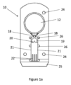
ここで図1を参照するが、この図は、統合収集・分析カートリッジデバイスすなわち分析装置の一部として用いられるデバイスの第1の実施形態を示している。デバイス(概して、10で参照)は、凝縮ゾーン12を有する呼吸収集部11上に呼気を案内するマウスピース(ここでは図示せず)に対して動作可能につながっている。凝縮ゾーン12は、収集された凝縮呼吸流体の分析を行い得る検知ゾーン13と流体接続されている。当然のことながら、凝縮ゾーン12が最上位となるようにデバイス10が実際に保持されている場合は、検知ゾーン13への流体の流れが重力によって促進される。図1には示していないものの、凝縮ゾーン12および検知ゾーン13は、1つまたは複数のチャネルによる流体接続によって、制御された流体流を提供する。チャネルの寸法は、デバイス10全体の寸法よりも1桁小さいが、チャネルの機能に応じて変動し得る。さらに、チャネルの寸法は、チャネルの長さに沿って変動し得る。図示しない別の実施形態において、凝縮ゾーンから検知ゾーンまでの流体の流れは、最初に凝縮流体を1つの領域に収集・保持した後、規定の分割量で収集流体の一部を検知ゾーンに流し込むことにより制御される。
Reference is now made to FIG. 1, which shows a first embodiment of a device used as part of an integrated collection and analysis cartridge device or analysis apparatus. The device (generally referenced 10 ) is operably connected to a mouthpiece (not shown here) that guides exhaled breath over a
好適な一実施形態において、デバイス10の全体寸法は、図4および図5に示すように、66mm×30mm×5mmである。好適な実施形態において、凝縮ゾーン12および検知ゾーン13はそれぞれ、略円形であるが、多角形状も有し得る。サイズは、使用に適するように変更可能である。凝縮ゾーン12は、デバイス10全体の寸法オーダの大きさの寸法であるのが好ましい。検知ゾーン13は、約2~10mmで、約5mmの外周を有し得る。高さとしては、約75~750μm、特に100μmが可能である。
In one preferred embodiment, the overall dimensions of
図1aは、デバイス10の特徴をさらに詳しく示している。呼吸は凝縮ゾーン12上で凝縮され、その表面上に膜を形成する。凝縮流体は、当該流体をセンサ要素19に導くチャネル18を介して、毛細管現象により凝縮ゾーン12から出る。図示のセンサ要素19は、カウンタおよび基準電極を組み合わせたものであるが、別個の実施形態においては、別々に位置付け可能である。作用電極20は、セラミックセンサ21の一部として収容されている。セラミックセンサ21の遠位端の電気接点パッド22によって、使用時にデバイス10が嵌合する装置ハウジング上の対応する要素との電気的接続が可能となる。カバー23が設けられている(図1b)が、これは、当該カバー23の直下にマイクロ流体チャンバを規定する。
FIG. 1a shows features of
ハウジング内のデバイス10の正しい位置合わせを補助するため、ハウジングの対応する突起と係合する鍵穴24が設けられている。また、デバイス10のハウジングへの挿入を補助するため、デバイス10の遠位端25は、くさび形状を有する。センサ要素19、セラミックセンサ21、およびカバー23は、エポキシ樹脂固定具26によりデバイス本体に対して適所に保持されるが、機械的手段を含む他の固定手段も利用可能である。
To aid in proper alignment of the
別の好適な実施形態において、1つまたは複数のチャネル(図示せず)は、たとえばサンプルがチャネルに流れ込んだ場合に空気をデバイス10から離れさせる手段を有する。この手段の一例は、空気が退出し得る別のチャネルまたは開口部であってもよい。これにより、空気が離れ得るルートを有することから、流体が流れ込んだ際に空気がデバイス10内に捕捉されなくなる。本実施形態の一例を図4および図5に示す。
In another preferred embodiment, one or more channels (not shown) have means for forcing air away from the
別の実施形態において、デバイスは、図4に示すように、空気退出チャネル60を具備していてもよい。
In another embodiment, the device may include
ガスおよび蒸気の混合物を含む呼気をある体積へと凝縮させるため、凝縮ゾーン12には、冷却手段が設けられている。また、検知ゾーン13の構成要素にも、必要に応じて冷却または加熱手段を設けることにより、呼気凝縮物の分析を補助する。たとえば、酵素的に触媒された反応をアッセイが含む場合、通例は、正常な体温前後で反応を実行するのが好都合である。反応温度の昇温に使用可能なヒータの一例は、スクリーン印刷して検知ゾーンに隣接するセンサの背面に固定可能な導電性ストリップである。たとえば電流をストリップに流して抵抗加熱を利用する場合は、ヒータ両端のパルス電圧によって温度を制御可能である。
Cooling means are provided in the
上記の追加または代替として、熱電対センサも具備可能であり、センサに印刷されて当該センサとの密接触を実現するとともに、センサ温度の正確な値を与えるのが好ましい。ただし、外部の温度センサも使用可能である。 Additionally or alternatively, a thermocouple sensor may also be provided and preferably printed on the sensor to provide intimate contact with the sensor and provide an accurate reading of the sensor temperature. However, an external temperature sensor can also be used.
凝縮ゾーン12のある領域における凝縮物の収集を促進するため、凝縮ゾーン12は、凝縮呼吸を任意選択として当該凝縮ゾーン12の特定領域へと案内する被覆面を有することができ、また、この特定領域は、凝縮ゾーン12の他の領域よりも低温に維持することができる。表面被膜は、疎水性であるのが好ましいが、必要に応じて親水性も可能である。また、油および水の両者が表面から容易に離れるように、疎水性かつ疎油性の被膜を設けることもできる。このような被膜としては、たとえばテフロン(登録商標、RTM)という商標で販売されているペルフルオロポリマー等、当技術分野において既知のものが可能である。被膜の厚さとしては、乾燥させた場合、1μm~15μmの範囲が可能である。被膜は、サンプルと接触した場合に膨張して厚さが増大するようになっていてもよい。図7は、円形エリアの膜によって、被膜の一例を示している。本実施形態において、膜状被膜が覆う円形エリアの高さは、5μmである。
To facilitate the collection of condensate in an area of the
凝縮ゾーン12または検知ゾーン13(図2参照)の一方または両方はそれぞれ、蓋14または15によって少なくとも部分的に覆うことができる。図2においては、凝縮ゾーン12の外周の周りに位置付けられた蓋14を示すが、この蓋14は、凝縮ゾーン12内に凝縮物を保持するように作用する。また、凝縮ゾーン12を部分的に覆う蓋14は、収集部11からの呼吸の流出を最小限に抑えるとともに、凝縮ゾーン12との接触で直ぐには凝縮しない呼吸の喪失を制限するように作用する。外周領域間の開放エリアは、凝縮ゾーン12の表面に呼気が達し得るようにする。
One or both of the
検知ゾーン13の検知チャンバおよびチャネル上に位置付けられた蓋15は、1つまたは複数のチャネル中およびチャネルに沿ったサンプルのウィッキングも促しつつ、体積の制御およびサンプルの保持を可能にする。サンプルの体積は、蓋の使用により小さく保たれて分析を補助する。また、蓋は、乱流および混合を取り除く。
A
図3は、最初の試薬または他の修飾剤をサンプルに添加して検知ゾーン32における分析を促進する別のサンプル準備ゾーン31を有するカートリッジデバイス30を示している。また、サンプルの純度は、サンプルが検知ゾーン32を通過して分析領域33に入る前に決定可能である。
FIG. 3 shows
検知チャンバは任意選択として、サンプルが存在するかを判定するサンプルセンサに対して動作可能に接続されている。また、検知チャンバ内のサンプルのレベルも決定可能である。予め設定されたレベルに達したら、オペレータからの入力なしでアッセイが自動的に開始となるように、レベルセンサが信号を送信する。これにより、分析が始まる時間が短くなる。 The sensing chamber is optionally operably connected to a sample sensor that determines if sample is present. Also, the level of sample in the sensing chamber can be determined. When a preset level is reached, a level sensor signals the assay to start automatically without operator input. This shortens the time at which the analysis begins.
図8および図9は、凝縮ゾーン41、51の下方において相互並列(図8)または直列(図9)に、検知ゾーン42、52をデバイス40、50内にレイアウト可能な別の実施形態を示している。
Figures 8 and 9 show another embodiment in which the
図10および図11は、既知および未知の種々源による干渉が生成信号をどの程度歪ませ得るかを示している。好適な実施形態においては、リーダによって、生の信号内のスパイクが最初に識別され、被分析物の濃度の計算の前に、スパイクの寄与が生の信号から取り除かれる。 Figures 10 and 11 show how interference from various known and unknown sources can distort the generated signal. In a preferred embodiment, the reader first identifies spikes in the raw signal and removes the spike contribution from the raw signal prior to calculation of the analyte concentration.
デバイスの別の実施形態(図示せず)において、デバイスは、凝縮ゾーンから検知ゾーンまでの凝縮流体の通過を管理する制御手段を具備する。これにより、既知の制御された状態で、凝縮呼吸を分析へと移動可能である。 In another embodiment of the device (not shown), the device comprises control means governing the passage of condensed fluid from the condensation zone to the detection zone. This allows condensed breaths to be moved to analysis in a known and controlled manner.
一例としては、凝縮ゾーン、特に凝縮ゾーンと検知ゾーンとの流体接続が非垂直で、おそらくは水平に配向することにより、流体が比較的ゆっくりと、おそらくは不均一に流れるように配向したデバイスで呼吸を収集可能である。そして、カートリッジを手動、任意選択として機械的に回転することにより、垂直配向を与えることができる。このプロセスは、サンプルの有無を判定するカートリッジデバイスまたはハウジング上に位置付けられたセンサによって、信号がカートリッジに送られ、回転手段が所要配向へと駆動される点において、自動的に行われ得る。センサがプロセッサを介してアルコール水準器等につながることにより、カートリッジの現在の配向および流体接続を把握することができる。 One example is breathing in a device oriented such that the fluid flows relatively slowly, possibly unevenly, by non-vertical and possibly horizontal orientation of the fluid connection between the condensation zone, particularly the condensation zone and the sensing zone. Collectable. Vertical orientation can then be imparted by rotating the cartridge manually, optionally mechanically. This process can be done automatically, in that a signal is sent to the cartridge by a sensor located on the cartridge device or housing that determines the presence or absence of the sample, and the rotating means is driven to the required orientation. A sensor can be connected through the processor to a spirit level or the like to keep track of the current orientation and fluid connections of the cartridge.
上記の追加または代替として、凝縮ゾーンの振動により凝縮ゾーンにおいて流体を移動させる振動手段を具備可能である。 Additionally or alternatively to the above, vibration means may be provided for moving fluid in the condensation zone by vibration of the condensation zone.
さらに別の実施形態においては、対象者の唾液が凝縮ゾーンに達して呼吸サンプルを汚染することを防止する手段が含まれる。唾液は、肺からの空気に存在する量の10~100倍の過酸化水素を含有することが知られている。このような防止手段は、対象者の正常な呼吸と干渉しないようにする必要があり、Tidal Breathing法と称することが多い。防止手段の一選択肢には、回旋状経路と、任意選択として1つまたは複数の弁とを含む。防止手段は、当該防止手段から出た呼吸が凝縮ゾーン12へと案内されるように、デバイス10とともに共通のハウジング上に載置可能である。通例、患者が息を吹き込むマウスピースとして形成された防止手段は、分析装置の衛生および精度の向上のため、使用後に交換可能であるのが好ましい。
In yet another embodiment, means are included to prevent the subject's saliva from reaching the condensation zone and contaminating the respiratory sample. Saliva is known to contain 10-100 times more hydrogen peroxide than is present in air from the lungs. Such preventive measures should not interfere with the subject's normal breathing and are often referred to as Tidal Breathing techniques. One option for preventing means includes a convoluted path and optionally one or more valves. The prevention means can be mounted on a common housing with the
さらに別の実施形態においては、周囲空気からの湿気が凝縮ゾーンで凝縮するとともに、主として希釈、場合により浮遊汚染物質の導入によってサンプルを汚染することを防止する手段も具備可能である。これを図12に示す。 In yet another embodiment, means can also be provided to prevent moisture from the ambient air from condensing in the condensation zone and contaminating the sample, primarily by dilution and possibly introduction of airborne contaminants. This is shown in FIG.
呼気凝縮物の潜在的な汚染源の1つとして、周囲空気からの湿気の偶発的な凝縮があり、これは、過酸化水素の濃度が制御されない無制御プロセスとなる。図12a~図12fに示す弁機構により、周囲空気が容易にペルチェ冷却器へと流れてカートリッジ内で凝縮することが防止される。また、マウスピース120によれば、唾液トラップ、フィルタ、流量制限器、および鼻クリップ等、必要に応じて用いられる付属品の有効利用が可能となる。したがって、付属品の使用の有無または使用される付属品に応じて、複数の動作モードで分析装置を使用可能である。 One potential source of breath condensate contamination is the accidental condensation of moisture from the ambient air, which is an uncontrolled process in which the concentration of hydrogen peroxide is not controlled. The valve mechanism shown in Figures 12a-12f prevents ambient air from readily flowing to the Peltier cooler and condensing within the cartridge. Mouthpiece 120 also allows for the efficient use of optional accessories such as saliva traps, filters, flow restrictors, and nose clips. Thus, the analyzer can be used in multiple modes of operation, depending on whether or not accessories are used and which accessories are used.
弁およびバッフルの使用により、呼気の大部分は、カートリッジの冷却された凝縮ゾーンの近傍内の通過を強制されるため、呼気蒸気の凝縮の効率が良好となる。弁付きマウスピースは、直接接続または弁を介した接続がなされた1つまたは複数のチャンバを内部に有し得る。開示の実施形態においては、3つのチャンバが存在し、第1のチャンバ121と第2のチャンバ122との間に弁が存在する一方、第2のチャンバ122および第3のチャンバ123は直接接触している。図示の実施形態において、マウスピース120は使用時に、外部つまみ128によってハウジングに固定されることを意図している。
The use of valves and baffles forces most of the exhaled air to pass within the vicinity of the cooled condensing zone of the cartridge, resulting in efficient condensation of exhaled vapor. A valved mouthpiece may have one or more chambers therein that are directly connected or connected via a valve. In the disclosed embodiment, there are three chambers, with a valve between the
弁のロジックとしては、分析装置が動作していない場合に、すべての弁が常閉となる。吸気に際しては、第3の弁126が開く一方、第1の弁124および第2の弁125は閉じたままである。呼気に際しては、第3の弁126が閉じ、第2の弁125および第1の弁124が開く。分析装置は、呼気凝縮物被分析物の即時分析を可能とするが、この場合、1つまたは複数の常閉弁の背後で周囲空気がカートリッジから締め出される。空気を肺に案内するとともに肺からカートリッジに案内するデバイスは、直列または並列にレイアウトされた1つまたは複数のチャンバを有し得る。
The valve logic is that all valves are normally closed when the analyzer is not running. During inspiration, the third valve 126 opens while the
したがって、使用時にユーザは、好適な固定手段によって、マウスピース120をハウジングに固定する。マウスピース120を適所に固定するとともに、第1の弁124を凝縮ゾーン12と流体接続させるような手段が設けられる。分析装置が起動すると、ユーザは、入口ポート127の周りに口を当てて、通常の呼吸を開始する。呼気は、チャンバ121、122、123をそれぞれ通過する。第2の弁125から進入し、第1の弁124を介してマウスピースから離れる呼吸の方向を90°前後変化させることにより、ユーザから吐き出された不要な物質またはユーザの口から離れた不要な物質がカートリッジデバイス10に達することはない。
Therefore, in use, the user secures the mouthpiece 120 to the housing by suitable securing means. Means are provided to secure the mouthpiece 120 in place and to fluidly connect the
本発明に適した弁の一例として、ダイヤフラム弁を挙げることができる。ダイヤフラム弁は、ユーザの吸気時に、一方の弁が開いて空気の流入を可能とする一方、他方の弁が閉じるように使用される。呼気に際しては、弁状態が逆転する。 A diaphragm valve can be mentioned as an example of a valve suitable for the present invention. Diaphragm valves are used such that when a user inhales, one valve is open to allow the inflow of air while the other valve is closed. During expiration, the valve states are reversed.
分析装置は、カートリッジの凝縮ゾーンの表面全体に呼気を案内することによって、呼吸による蒸気の効率的な凝縮を保証するように設計されている。チャンバは、相互の直接接続または弁を介した接続が可能である。呼吸サイクルにおいては、空気が肺に流入し得る一方、カートリッジが周囲空気に曝露されないように空気の流れが制御される。その後の呼気に際しては、周囲への排出前に低温ゾーン上を呼吸が通過する経路に沿って、呼気が導かれる。弁を慎重に使用することは、表1に示す弁のロジックによって、分析装置の動作または非動作時に周囲空気がカートリッジに直接達しないことを意味する。また、分析装置は、ユーザ、周囲空気、ならびに分析装置およびデバイス内の空気間の空気/ガス交換を可能にする1つまたは複数のポートを有する。これらのポートは、唾液トラップ、流量制限器、およびフィルタ等の付属品との併用により、複数の作用モードが可能となる。最後に、分析装置は、空気が口のみを通過する呼吸モードを強制するようにユーザの鼻腔を通る空気の流れを防止する手段と併用可能である。 The analyzer is designed to ensure efficient condensation of the vapor by breathing by guiding the exhaled air over the entire surface of the condensation zone of the cartridge. The chambers can be directly connected to each other or connected via valves. During the respiratory cycle, air flow is controlled so that air can flow into the lungs while the cartridge is not exposed to ambient air. On subsequent exhalations, the exhaled air is directed along a path through which it passes over the cold zone before being exhaled to the surroundings. Careful use of valves means that the valve logic shown in Table 1 prevents ambient air from reaching the cartridge directly when the analyzer is on or off. The analyzer also has one or more ports that allow air/gas exchange between the user, the ambient air, and the air within the analyzer and device. These ports allow multiple modes of action in conjunction with accessories such as saliva traps, flow restrictors, and filters. Finally, the analyzer can be used with means to prevent airflow through the user's nasal passages to force a breathing mode in which air only passes through the mouth.

分析装置のさらに別の実施形態においては、呼気の流量をモニタリングすることにより、ユーザまたは管理者が流量を制御したりガイダンスを発したりすることができる。したがって、デバイス内には、流量のセンサ手段が具備されていてもよい。これにより、センサは、視覚的または聴覚的フィードバックを与え得る実時間データを送信するため、許容範囲の境界に納まるように呼吸速度を調整可能である。また、呼吸速度は、診断決定の一部として利用可能である。 In yet another embodiment of the analyzer, the exhaled breath flow rate is monitored to allow the user or administrator to control the flow rate or provide guidance. Accordingly, sensor means for flow rate may be provided within the device. This allows the sensor to transmit real-time data that can provide visual or auditory feedback so that respiration rate can be adjusted to stay within tolerance boundaries. Respiration rate can also be used as part of a diagnostic decision.
例示的な分析装置は、以下の3つの動作モードを有していてもよい。 An exemplary analyzer may have the following three modes of operation.
モード1:呼気二酸化炭素レベル、呼吸流量、呼吸含水量、呼吸圧、呼吸温度等の1つまたは複数の実時間信号から、対象者の状態を分析する。これら信号のうちの1つまたは複数を用いて、ユーザの状態および/またはそれぞれの肺機能を決定する。 Mode 1: Analyze the subject's condition from one or more real-time signals such as exhaled carbon dioxide level, respiratory flow, respiratory water content, respiratory pressure, and respiratory temperature. One or more of these signals are used to determine the user's condition and/or respective lung function.
モード2:収集された呼気凝縮物から、対象者の状態を分析する。この測定は、呼気プロファイル、呼吸含水量、呼吸二酸化炭素レベル等のパラメータに対して補正可能である。たとえば、二酸化炭素信号の使用により、被分析物の測定濃度から、被分析物の分割濃度を計算することができる。 Mode 2: Analyze the subject's condition from the collected breath condensate. This measurement can be corrected for parameters such as exhalation profile, respiratory water content, and respiratory carbon dioxide level. For example, using the carbon dioxide signal, the split concentration of the analyte can be calculated from the measured concentration of the analyte.
モード3:呼気プロファイルおよび呼吸ガス分析全体の背景において呼気凝縮物が報告され得るように、上述の2つのモードを組み合わせることにより、対象者の状態を分析する。 Mode 3: Analyze the subject's condition by combining the above two modes so that breath condensate can be reported in the context of the overall breath profile and breath gas analysis.
別の例示的な実施形態において、マウスピースは、バッフルの配列を採用して、口からのエアロゾルが凝縮ゾーンに達する機会を最小限に抑える。一構成において、マウスピースに入った空気は、90°前後だけ空気の速度を変化させる第1のバッフルと会合する。その後、第2のバッフルが方向を約180°変化させる。このように、口からの大きな液滴が空気流から滴り落ちて、肺からの蒸気を通過させる。 In another exemplary embodiment, the mouthpiece employs an arrangement of baffles to minimize the chances of aerosol from the mouth reaching the condensation zone. In one configuration, air entering the mouthpiece meets a first baffle that changes the air velocity by about 90°. A second baffle then changes direction by approximately 180°. Thus, large droplets from the mouth drip out of the airflow and pass vapor from the lungs.
カートリッジデバイスは通常、ハウジング内に交換可能に保持されて分析装置を構成するが、このハウジングは、カートリッジデバイスと協調して使用可能な冷却、加熱、処理手段等の特徴を含む。カートリッジデバイスがハウジング内に正しく設置されたことを示す検出手段が存在し得る。ハウジングは、凝縮に適した温度までカートリッジを冷却するペルチェプレート等の冷却手段を備えていてもよい。あるいは、冷却手段は、カートリッジの一部であってもよい。さらに、分析装置は、カートリッジが適所に正しく配置され、冷却が適正に実現されるまで、起動停止に保持可能である。 Cartridge devices are typically exchangeably held within a housing to form an analytical instrument, which housing includes features such as cooling, heating and processing means that can be used in conjunction with the cartridge device. There may be detection means to indicate that the cartridge device has been properly installed within the housing. The housing may include cooling means such as a Peltier plate to cool the cartridge to a temperature suitable for condensation. Alternatively, the cooling means may be part of the cartridge. Additionally, the analyzer can be held off-load until the cartridge is properly placed in place and proper cooling is achieved.
分析装置は、任意数の信号を組み合わせて、患者の状態の決定または信号のキャリブレーションを行うことができる。また、分析装置は、規定条件の満足に応答して、弁を開閉することができる(たとえば、二酸化炭素レベル基準が満たされた場合の弁のトリガーによる分割呼吸の収集)。 The analyzer can combine any number of signals to determine patient status or calibrate the signals. The analyzer may also open and close valves in response to satisfaction of prescribed conditions (eg, collection of split breaths by triggering valves when carbon dioxide level criteria are met).
提供される分析装置は、軽量かつ携行可能であるため、持ち上げて口の前に置くことができ、また、電源または第三者デバイスへの物理的な接続なく動作可能である。ユーザの補助のため、分析装置が使える状態であることを示すディスプレイを設けることができる。商用電源から遠隔での使用を可能にするため、ハウジング中の一体的もしくは取り外し可能な取り付け、または任意選択もしくは追加として、カートリッジデバイスの一部として電源函を具備し得る。 The analyzers provided are lightweight and portable, so they can be picked up and placed in front of the mouth, and can operate without physical connection to a power source or third party device. To assist the user, a display can be provided to indicate that the analyzer is ready for use. A power box may be provided, either integrally or removably mounted in the housing, or optionally or additionally as part of the cartridge device to allow remote use from mains power.
分析装置は、強制的な空気操作を必要とする従来のデバイスに対して、患者の受け入れをより大きくするTidal Breathingと併用されるように設計されている。 The analyzer is designed to be used with Tidal Breathing, which provides greater patient acceptance versus conventional devices requiring forced air manipulation.
分析装置は、手動干渉またはユーザもしくは臨床医による介入なく呼気凝縮物を収集して分析するワークフローに含まれる必要なすべての機能を実行することを目的とする。分析装置は、呼吸および呼吸と関連付けられた物理的パラメータの実時間検知および分析の両者を有していてもよい。任意選択として、分析装置は、患者に関するデータを共有可能であるとともに、患者の能力の如何なる変化をも直接的に決定する比較器を具備し得る。 The analyzer is intended to perform all necessary functions involved in the workflow of collecting and analyzing exhaled breath condensate without manual intervention or intervention by the user or clinician. The analyzer may have both real-time sensing and analysis of respiration and physical parameters associated with respiration. Optionally, the analyzer can share data about the patient and can include a comparator that directly determines any changes in the patient's performance.
好適な一実施形態において、呼気凝縮物膜は、対象者の口から蛇行経路を通じて完全一体型の分析装置(すなわち、ハウジングおよびカートリッジ)へと直ちに案内され、呼吸の凝縮によって、冷却ゾーン上に呼吸膜凝縮物が生じる。得られた凝縮物膜は、毛細管力および重力の組み合わせにより、分割面を横切ってチャンバへと直ちにガイドされる。膜は、チャンバの側面に下方へと追従し、底部から上方にチャンバを充填することによって、チャンバに進入する。最後に、凝縮物は、複数の塩のパッチを溶解させる。呼吸膜凝縮物への塩の溶解は、電気的/電気化学的にモニタリングされ、オンボードアッセイ品質管理の一部として、正しい溶解プロファイルが確認される。正しくないプロファイルを使用すると、カートリッジが拒絶される。 In one preferred embodiment, the exhaled breath condensate film is immediately guided from the subject's mouth through a tortuous path to a fully integrated analyzer (i.e., housing and cartridge) where breath condensation causes respiration onto a cooling zone. A film condensate forms. The resulting condensate film is immediately guided across the dividing surface into the chamber by a combination of capillary forces and gravity. The membrane enters the chamber by following down the sides of the chamber and filling the chamber from the bottom up. Finally, the condensate dissolves the salt patches. Salt dissolution into respiratory membrane condensate is monitored electrically/electrochemically to confirm the correct dissolution profile as part of the on-board assay quality control. Using an incorrect profile will cause the cartridge to be rejected.
本発明に係る一概念は、呼吸を膜として凝縮させ、呼気凝縮物膜内の被分析物を分析する単一の統合カートリッジデバイスに関する。デバイスは、手動干渉または臨床医等のユーザによる介入なく呼気凝縮物を収集して分析するワークフローに含まれる必要なすべての機能を実行する。デバイスは、凝縮物を測定する少なくとも1つの検知ゾーンと一体化された呼吸凝縮用の少なくとも1つの温度ゾーンを含む。 One concept according to the present invention relates to a single integrated cartridge device that condenses breath as a membrane and analyzes analytes within the breath condensate membrane. The device performs all the necessary functions involved in the workflow of collecting and analyzing exhaled breath condensate without manual intervention or intervention by a user, such as a clinician. The device includes at least one temperature zone for respiratory condensation integrated with at least one sensing zone for measuring condensate.
別の実施形態(図示せず)において、凝縮ゾーンは、カートリッジデバイスではなくハウジングに組み込まれている。本実施形態において、カートリッジデバイスは、ハウジングに対して取り外し可能に取り付けられており、取り付けられた場合は、凝縮ゾーンと流体的につながるため、凝縮された呼吸がカートリッジデバイスに流れ込んで、上述のように分析可能となる。 In another embodiment (not shown), the condensation zone is built into the housing rather than the cartridge device. In this embodiment, the cartridge device is removably attached to the housing and, when attached, is in fluid communication with the condensation zone so that condensed breath can flow into the cartridge device and analysis becomes possible.
装置の好適な実施形態において、凝縮ゾーンは、短い蛇行流路により患者の口に接続され、口等からのエアロゾルを除外しつつ、肺、特に肺の肺胞部からの蒸気が通過し得るように設計されている。呼気の凝縮の後、膜は、重力および毛細管力の影響下で、5つの面が閉じたチャンバに流れ込む。膜は、チャンバの側面を下方に流れ、底部から上方へとチャンバを効果的に充填する。 In a preferred embodiment of the device, the condensation zone is connected to the patient's mouth by a short tortuous channel to allow passage of vapors from the lungs, particularly the alveolar portion of the lungs, while excluding aerosols from the mouth and the like. is designed to After condensation of exhaled breath, the membrane flows into a five-sided closed chamber under the influence of gravity and capillary forces. The membrane flows down the sides of the chamber, effectively filling the chamber from the bottom up.
チャンバの充填完了が近づくと、呼吸膜凝縮物は、銀/塩化銀基準電極における電位の固定および比較的低いインピーダンスのサンプルの提供の両者に必要な塩のパッチを溶解させる。 As the chamber nears completion of filling, respiratory membrane condensate dissolves the salt patch necessary to both fix the potential at the silver/silver chloride reference electrode and provide a relatively low impedance sample.
Claims (22)
マウスピースを備え、該マウスピースが、入口ポートおよび出口弁を備え、複数のチャンバが間に介在して、前記入口ポートから前記出口弁まで流体流を案内し、前記チャンバが、流体流の方向を90°変化させるように構成された、分析装置。 1. An analyzer for collecting and analyzing exhaled breath condensate, comprising a housing having cooling means and holding a cartridge device with a condensation zone for condensing exhaled breath from a subject, said cooling Means are in cooling relationship with the condensation zone, the device includes one or more separate discrete regions for analyte detection and analyte measurement, and the cartridge device circulates the condensation zone. Further comprising a fluid pathway connecting said one or more discrete regions, said housing including a mouthpiece having an inlet port into which a user may exhale, said mouthpiece directing incoming breath to said condensation zone. comprising one or more fluid passages leading to
a mouthpiece comprising an inlet port and an outlet valve, a plurality of chambers interposed to guide fluid flow from the inlet port to the outlet valve, the chambers directing fluid flow; 90° .
Applications Claiming Priority (3)
| Application Number | Priority Date | Filing Date | Title |
|---|---|---|---|
| GB1704367.0 | 2017-03-20 | ||
| GBGB1704367.0A GB201704367D0 (en) | 2017-03-20 | 2017-03-20 | A breath condensate analyser |
| PCT/GB2018/050720 WO2018172760A1 (en) | 2017-03-20 | 2018-03-20 | A breath-condensate analyser |
Publications (3)
| Publication Number | Publication Date |
|---|---|
| JP2020514767A JP2020514767A (en) | 2020-05-21 |
| JP2020514767A5 JP2020514767A5 (en) | 2021-04-15 |
| JP7261172B2 true JP7261172B2 (en) | 2023-04-19 |
Family
ID=58688399
Family Applications (2)
| Application Number | Title | Priority Date | Filing Date |
|---|---|---|---|
| JP2019552630A Pending JP2020511667A (en) | 2017-03-20 | 2018-03-20 | Respiratory condensate device |
| JP2019552495A Active JP7261172B2 (en) | 2017-03-20 | 2018-03-20 | breath condensate analyzer |
Family Applications Before (1)
| Application Number | Title | Priority Date | Filing Date |
|---|---|---|---|
| JP2019552630A Pending JP2020511667A (en) | 2017-03-20 | 2018-03-20 | Respiratory condensate device |
Country Status (12)
| Country | Link |
|---|---|
| US (2) | US11885794B2 (en) |
| EP (2) | EP3602043A1 (en) |
| JP (2) | JP2020511667A (en) |
| KR (2) | KR20190128693A (en) |
| CN (2) | CN110431419B (en) |
| AU (2) | AU2018238863A1 (en) |
| CA (2) | CA3056858A1 (en) |
| DK (1) | DK3602042T3 (en) |
| ES (1) | ES2940098T3 (en) |
| FI (1) | FI3602042T3 (en) |
| GB (1) | GB201704367D0 (en) |
| WO (2) | WO2018172760A1 (en) |
Families Citing this family (11)
| Publication number | Priority date | Publication date | Assignee | Title |
|---|---|---|---|---|
| CN108459044A (en) * | 2018-05-23 | 2018-08-28 | 无锡森威尔化工装备科技有限公司 | A kind of black wooden test equipment |
| GB201908784D0 (en) * | 2019-06-19 | 2019-07-31 | Exhalation Tech Limited | A collection device for exhaled breath |
| CN110368039B (en) * | 2019-08-12 | 2024-02-20 | 北京大学第一医院 | Expired air condensate collector |
| GB201916214D0 (en) * | 2019-11-07 | 2019-12-25 | Chen Yu Chih | Exhaled breath collection device |
| WO2021211821A2 (en) * | 2020-04-15 | 2021-10-21 | The Regents Of The University Of California | Sample collection methods and apparatus for viral load level diagnosis |
| US20210325381A1 (en) * | 2020-04-19 | 2021-10-21 | John J. Daniels | Using Exhaled Breath Condensate for Testing for a Biomarker of COVID-19 |
| GB202011756D0 (en) * | 2020-07-29 | 2020-09-09 | Exhalation Tech Limited | A modular mouthpiece |
| CN112932459A (en) * | 2021-01-29 | 2021-06-11 | 西安交通大学第二附属医院 | Noninvasive analysis device and noninvasive analysis system for respiratory disease detection |
| WO2022248936A2 (en) * | 2021-05-28 | 2022-12-01 | Exhalation Technology Ltd | Device and method for detecting a component of exhaled breath condensate |
| PL438534A1 (en) * | 2021-07-20 | 2023-01-23 | Gdański Uniwersytet Medyczny | Apparatus for collecting exhaled air condensate and a method of diagnosing the patient's condition |
| WO2023153958A2 (en) * | 2022-02-08 | 2023-08-17 | Федеральное Государственное Бюджетное Учреждение Науки Институт Синтетических Полимерных Материалов Имени Н.С. Ениколопова Российской Академии Наук (Испм Ран) | Method of early non-invasive detection of covid-19 by analysis of exhaled air |
Citations (9)
| Publication number | Priority date | Publication date | Assignee | Title |
|---|---|---|---|---|
| JP2001108673A (en) | 1999-10-07 | 2001-04-20 | Univ Nihon | Cirrhosis examining method and device to use scentometer |
| JP2004361160A (en) | 2003-06-03 | 2004-12-24 | Terametsukusu Kk | Expiration condensate collection apparatus |
| US20070173731A1 (en) | 2006-01-26 | 2007-07-26 | Neil R. Euliano | Breath and Breath Condensate Analysis System and Associated Methods |
| US20120004571A1 (en) | 2008-12-23 | 2012-01-05 | Ku David N | Lung aerosol collection device |
| JP2012524267A (en) | 2009-04-15 | 2012-10-11 | ナノミックス・インコーポレーテッド | Portable unit for sampling and detecting exhalation and method for detecting an analyte in exhalation |
| JP2013519896A (en) | 2010-02-17 | 2013-05-30 | コーニンクレッカ フィリップス エレクトロニクス エヌ ヴィ | Nitric oxide measuring method and apparatus |
| WO2016078972A1 (en) | 2014-11-19 | 2016-05-26 | Koninklijke Philips N.V. | Method and device for determining the health of a subject |
| JP2016532117A (en) | 2013-08-30 | 2016-10-13 | キャプニア, インク.Capnia, Inc. | Universal breath analysis sampling device |
| JP2016534829A (en) | 2013-08-30 | 2016-11-10 | キャプニア, インク.Capnia, Inc. | Columnar flow gas sampling and measurement system |
Family Cites Families (19)
| Publication number | Priority date | Publication date | Assignee | Title |
|---|---|---|---|---|
| US6033368A (en) | 1996-03-28 | 2000-03-07 | Nitromed, Inc. | Condensate colorimetric nitrogen oxide analyzer |
| DE19951204C2 (en) | 1999-10-15 | 2002-08-08 | Filt Forschungsgesellschaft Fu | Procedure for analyzing the ingredients in exhaled air |
| DE10137565B4 (en) | 2001-07-30 | 2004-07-15 | Filt Lungen- Und Thoraxdiagnostik Gmbh | Method for determining parameters of a breath condensate |
| US7948041B2 (en) * | 2005-05-19 | 2011-05-24 | Nanomix, Inc. | Sensor having a thin-film inhibition layer |
| US20050130226A1 (en) | 2003-09-26 | 2005-06-16 | The University Of Cincinnati | Fully integrated protein lab-on-a-chip with smart microfluidics for spot array generation |
| WO2007001342A2 (en) | 2004-08-20 | 2007-01-04 | University Of Virginia Patent Foundation | Exhaled breath condensate collection and assay system and method |
| DE102005020102B3 (en) * | 2005-04-25 | 2006-11-30 | Universität Potsdam | Method and device for obtaining and analyzing respiratory condensates |
| US7914460B2 (en) | 2006-08-15 | 2011-03-29 | University Of Florida Research Foundation, Inc. | Condensate glucose analyzer |
| WO2008022183A1 (en) | 2006-08-15 | 2008-02-21 | University Of Florida Research Foundation, Inc. | Condensate glucose analyzer |
| GB2441781B (en) * | 2006-09-13 | 2010-05-19 | Autoliv Dev | Breath analyser |
| GB2451249A (en) | 2007-07-24 | 2009-01-28 | Equine Healthcare Ltd | A breath condensate collector |
| CN101238980A (en) * | 2008-03-14 | 2008-08-13 | 吉林大学 | Collecting device of exhaled breath condensate (EBC) |
| US8394030B2 (en) | 2009-03-18 | 2013-03-12 | Carefusion 207, Inc. | Exhaled breath condensate biometric marker measurement apparatus and method |
| WO2011029888A1 (en) * | 2009-09-09 | 2011-03-17 | Sensa Bues Ab | Surface-enhanced raman scattering for drug detection in exhaled breath |
| CN104939831B (en) * | 2010-09-09 | 2018-11-09 | 森撒部伊斯公司 | The system and method and application thereof of sample are collected from the expiratory air of subject |
| EP2518499B1 (en) * | 2011-03-09 | 2015-06-10 | Sensa Bues AB | A portable sampling device and method for drug detection from exhaled breath |
| GB201313817D0 (en) | 2013-08-01 | 2013-09-18 | Maddison Product Design Ltd | Exhaled breath condensate collector |
| DE102015203719A1 (en) | 2015-03-03 | 2016-09-08 | Robert Bosch Gmbh | Apparatus and method for respiratory gas analysis and respiratory gas analyzer |
| CN104958073A (en) * | 2015-07-03 | 2015-10-07 | 深圳市共进电子股份有限公司 | Humidity sensor, electronic device and respiration detection system and method |
-
2017
- 2017-03-20 GB GBGB1704367.0A patent/GB201704367D0/en not_active Ceased
-
2018
- 2018-03-20 AU AU2018238863A patent/AU2018238863A1/en active Pending
- 2018-03-20 CN CN201880019387.1A patent/CN110431419B/en active Active
- 2018-03-20 WO PCT/GB2018/050720 patent/WO2018172760A1/en unknown
- 2018-03-20 KR KR1020197030596A patent/KR20190128693A/en not_active IP Right Cessation
- 2018-03-20 KR KR1020197029934A patent/KR102490939B1/en active IP Right Grant
- 2018-03-20 CA CA3056858A patent/CA3056858A1/en active Pending
- 2018-03-20 CN CN201880019388.6A patent/CN110431420A/en active Pending
- 2018-03-20 DK DK18722134.6T patent/DK3602042T3/en active
- 2018-03-20 JP JP2019552630A patent/JP2020511667A/en active Pending
- 2018-03-20 ES ES18722134T patent/ES2940098T3/en active Active
- 2018-03-20 AU AU2018238862A patent/AU2018238862A1/en active Pending
- 2018-03-20 WO PCT/GB2018/050721 patent/WO2018172761A1/en unknown
- 2018-03-20 EP EP18722135.3A patent/EP3602043A1/en active Pending
- 2018-03-20 JP JP2019552495A patent/JP7261172B2/en active Active
- 2018-03-20 CA CA3056855A patent/CA3056855A1/en active Pending
- 2018-03-20 US US16/494,981 patent/US11885794B2/en active Active
- 2018-03-20 EP EP18722134.6A patent/EP3602042B1/en active Active
- 2018-03-20 US US16/494,979 patent/US11733231B2/en active Active
- 2018-03-20 FI FIEP18722134.6T patent/FI3602042T3/en active
Patent Citations (9)
| Publication number | Priority date | Publication date | Assignee | Title |
|---|---|---|---|---|
| JP2001108673A (en) | 1999-10-07 | 2001-04-20 | Univ Nihon | Cirrhosis examining method and device to use scentometer |
| JP2004361160A (en) | 2003-06-03 | 2004-12-24 | Terametsukusu Kk | Expiration condensate collection apparatus |
| US20070173731A1 (en) | 2006-01-26 | 2007-07-26 | Neil R. Euliano | Breath and Breath Condensate Analysis System and Associated Methods |
| US20120004571A1 (en) | 2008-12-23 | 2012-01-05 | Ku David N | Lung aerosol collection device |
| JP2012524267A (en) | 2009-04-15 | 2012-10-11 | ナノミックス・インコーポレーテッド | Portable unit for sampling and detecting exhalation and method for detecting an analyte in exhalation |
| JP2013519896A (en) | 2010-02-17 | 2013-05-30 | コーニンクレッカ フィリップス エレクトロニクス エヌ ヴィ | Nitric oxide measuring method and apparatus |
| JP2016532117A (en) | 2013-08-30 | 2016-10-13 | キャプニア, インク.Capnia, Inc. | Universal breath analysis sampling device |
| JP2016534829A (en) | 2013-08-30 | 2016-11-10 | キャプニア, インク.Capnia, Inc. | Columnar flow gas sampling and measurement system |
| WO2016078972A1 (en) | 2014-11-19 | 2016-05-26 | Koninklijke Philips N.V. | Method and device for determining the health of a subject |
Also Published As
| Publication number | Publication date |
|---|---|
| JP2020514767A (en) | 2020-05-21 |
| US11733231B2 (en) | 2023-08-22 |
| FI3602042T3 (en) | 2023-03-20 |
| CN110431419A (en) | 2019-11-08 |
| AU2018238863A1 (en) | 2019-10-31 |
| AU2018238862A1 (en) | 2019-10-31 |
| CA3056858A1 (en) | 2018-09-27 |
| US11885794B2 (en) | 2024-01-30 |
| CN110431419B (en) | 2021-10-26 |
| KR102490939B1 (en) | 2023-01-25 |
| US20200033323A1 (en) | 2020-01-30 |
| ES2940098T3 (en) | 2023-05-03 |
| GB201704367D0 (en) | 2017-05-03 |
| WO2018172760A1 (en) | 2018-09-27 |
| US20200041485A1 (en) | 2020-02-06 |
| JP2020511667A (en) | 2020-04-16 |
| WO2018172761A1 (en) | 2018-09-27 |
| KR20190128682A (en) | 2019-11-18 |
| EP3602042A1 (en) | 2020-02-05 |
| EP3602043A1 (en) | 2020-02-05 |
| CA3056855A1 (en) | 2018-09-27 |
| KR20190128693A (en) | 2019-11-18 |
| EP3602042B1 (en) | 2022-12-14 |
| CN110431420A (en) | 2019-11-08 |
| DK3602042T3 (en) | 2023-03-06 |
Similar Documents
| Publication | Publication Date | Title |
|---|---|---|
| JP7261172B2 (en) | breath condensate analyzer | |
| US8002712B2 (en) | Breath and breath condensate analysis system and associated methods | |
| JP4839367B2 (en) | Apparatus and method for collecting and analyzing exhaled breath condensate | |
| Schon et al. | Versatile breath sampler for online gas sensor analysis | |
| EP3665479B1 (en) | Apparatus for accurate sensing of physiological substance in blood | |
| US20110046497A1 (en) | Sensor platform for respiratory gas analysis | |
| US9821307B2 (en) | Sample volume metering system for point-of-care testing | |
| JP7427668B2 (en) | Device that measures exhaled breath humidity | |
| US20220322962A1 (en) | A collection device for exhaled breath | |
| US20140021065A1 (en) | Device and method for measuring biomarkers | |
| JP7477606B2 (en) | Portable breath gas and volatile substance analyzer |
Legal Events
| Date | Code | Title | Description |
|---|---|---|---|
| A521 | Request for written amendment filed |
Free format text: JAPANESE INTERMEDIATE CODE: A523 Effective date: 20210302 |
|
| A621 | Written request for application examination |
Free format text: JAPANESE INTERMEDIATE CODE: A621 Effective date: 20210302 |
|
| A977 | Report on retrieval |
Free format text: JAPANESE INTERMEDIATE CODE: A971007 Effective date: 20220118 |
|
| A131 | Notification of reasons for refusal |
Free format text: JAPANESE INTERMEDIATE CODE: A131 Effective date: 20220208 |
|
| A521 | Request for written amendment filed |
Free format text: JAPANESE INTERMEDIATE CODE: A523 Effective date: 20220506 |
|
| A131 | Notification of reasons for refusal |
Free format text: JAPANESE INTERMEDIATE CODE: A131 Effective date: 20220906 |
|
| TRDD | Decision of grant or rejection written | ||
| A01 | Written decision to grant a patent or to grant a registration (utility model) |
Free format text: JAPANESE INTERMEDIATE CODE: A01 Effective date: 20230314 |
|
| A61 | First payment of annual fees (during grant procedure) |
Free format text: JAPANESE INTERMEDIATE CODE: A61 Effective date: 20230407 |
|
| R150 | Certificate of patent or registration of utility model |
Ref document number: 7261172 Country of ref document: JP Free format text: JAPANESE INTERMEDIATE CODE: R150 |