JP7258677B2 - Operation control method and operation control device - Google Patents
Operation control method and operation control device Download PDFInfo
- Publication number
- JP7258677B2 JP7258677B2 JP2019125756A JP2019125756A JP7258677B2 JP 7258677 B2 JP7258677 B2 JP 7258677B2 JP 2019125756 A JP2019125756 A JP 2019125756A JP 2019125756 A JP2019125756 A JP 2019125756A JP 7258677 B2 JP7258677 B2 JP 7258677B2
- Authority
- JP
- Japan
- Prior art keywords
- vehicle
- obstacle
- avoidance
- control
- processor
- Prior art date
- Legal status (The legal status is an assumption and is not a legal conclusion. Google has not performed a legal analysis and makes no representation as to the accuracy of the status listed.)
- Active
Links
Images


Description
本発明は、運転制御方法及び運転制御装置に関する。 The present invention relates to an operation control method and an operation control device.
自車両の両側にリスクがある場面を想定し、自車両の左に存在する第1危険度と自車両の右に存在する第2危険度を算出し、第1危険度に基づいて自車両の左に第1制御閾値を設定し、第2危険度に基づいて自車両の右に第2制御閾値を設定し、第1危険度と第2危険度に基づいて、第1制御閾値又は第2制御閾値を変更する技術が知られている(特許文献1)。 Assuming a situation where there are risks on both sides of the own vehicle, the first degree of danger existing on the left of the own vehicle and the second degree of danger existing on the right of the own vehicle are calculated, and based on the first degree of danger, the degree of danger of the own vehicle A first control threshold is set to the left, a second control threshold is set to the right of the vehicle based on the second degree of risk, and the first control threshold or the second control threshold is set based on the first degree of risk and the second degree of risk. A technique for changing the control threshold is known (Patent Document 1).
従来の技術では、障害物を回避するために十分な余裕領域が確保できない状況において、検出結果に基づいて回避軌跡を補正すると、補正後の回避軌跡の変化量が大きくなるという不都合がある。 In the conventional technology, if the avoidance trajectory is corrected based on the detection results in a situation where a sufficient margin area for avoiding the obstacle cannot be secured, there is an inconvenience that the amount of change in the avoidance trajectory after correction becomes large.
本発明が解決しようとする課題は、障害物を回避するために十分な余裕領域が確保できない状況であっても、緩やかな回避軌跡で障害物を回避することができる運転制御方法及び運転制御装置を提供することである。 The problem to be solved by the present invention is an operation control method and an operation control device that can avoid an obstacle with a gentle avoidance trajectory even in a situation where a sufficient margin area for avoiding the obstacle cannot be secured. is to provide
本発明は、操舵制御による横位置の移動が開始可能な、自車両の前方の基準位置に横位置変更開始位置を設定し、所定の回避条件に従い、障害物の回避制御が完了する完了位置を算出し、算出された完了位置が障害物に対して定義された所定の目標位置に属さないと判断された場合には、操舵制御が開始される前に、自車両の目標速度を減速させる減速制御を実行することにより、上記課題を解決する。 According to the present invention, a lateral position change start position is set to a reference position in front of the host vehicle at which lateral position movement by steering control can be started, and a completion position for completing obstacle avoidance control is determined according to a predetermined avoidance condition. If it is determined that the calculated completion position does not belong to the predetermined target position defined for the obstacle, a deceleration is performed to reduce the target speed of the own vehicle before steering control is started. By executing the control, the above problems are solved.
本発明によれば、算出された回避制御の完了位置が目標位置に属さないと判断された場合には、操舵制御の開始前に自車両を減速させることにより、回避制御の完了位置を算出できるので、十分な余裕領域が確保できない状況であっても、緩やかな動きで自車両に障害物を回避させることができる。 According to the present invention, when it is determined that the calculated avoidance control completion position does not belong to the target position, the avoidance control completion position can be calculated by decelerating the own vehicle before starting the steering control. Therefore, even in a situation in which a sufficient margin area cannot be secured, the own vehicle can be made to avoid the obstacle by gentle movement.
以下、本発明の実施形態を図面に基づいて説明する。本実施形態では、本発明の実施形態に係る車両の運転制御装置を、車両に搭載された運転制御システムに適用した場合を例にして説明する。本実施形態の運転制御装置の実施の形態は限定されず、車両コントローラと情報の授受が可能な携帯端末装置に適用することもできる。運転制御装置、運転制御システム及び携帯端末装置は、いずれも演算処理を実行する運転制御用のコンピュータである。 BEST MODE FOR CARRYING OUT THE INVENTION An embodiment of the present invention will be described below with reference to the drawings. In the present embodiment, a case where a vehicle driving control device according to an embodiment of the present invention is applied to a driving control system mounted on a vehicle will be described as an example. The embodiment of the operation control device of this embodiment is not limited, and it can also be applied to a mobile terminal device capable of exchanging information with a vehicle controller. The operation control device, the operation control system, and the portable terminal device are all computers for operation control that execute arithmetic processing.
図1は、運転制御システム1000のブロック構成を示す図である。本実施形態の運転制御システム1000は、運転制御装置100と車両コントローラ200とを備える。本実施形態の運転制御装置100は通信装置111を有し、車両コントローラ200も図外の通信装置を有し、両装置は有線通信又は無線通信により互いに情報の授受を行う。 FIG. 1 is a diagram showing a block configuration of an operation control system 1000. As shown in FIG. A driving control system 1000 of this embodiment includes a driving control device 100 and a vehicle controller 200 . The operation control device 100 of this embodiment has a communication device 111, and the vehicle controller 200 also has a communication device (not shown), and both devices exchange information with each other by wired communication or wireless communication.
運転制御システム1000は、センサ1と、ナビゲーション装置2と、読み込み可能な記録媒体に記録された地図情報3と、自車情報検出装置4と、環境認識装置5と、物体認識装置6と、運転制御装置100と、車両コントローラ200とを備える。各装置は、相互に情報の授受を行うためにCAN(Controller Area Network)その他の車載LANによって接続されている。
The driving control system 1000 includes a
センサ1は、自車両の周囲(前方、側方、後方の全周囲)の障害物の存在を含む走行環境に関する情報を検知する。センサ1は、カメラを含む。本実施形態のカメラは、例えばCCD等の撮像素子を備えるカメラである。本実施形態のカメラは自車両に設置され、自車両の周囲を撮像し、自車両の周囲に存在する対象車両を含む画像データを取得する。カメラは、自車両周囲の環境情報を認識するための装置であり、イメージセンサのみならず、超音波カメラ、赤外線カメラなどを含む。センサ1は、測距センサを含む。測距センサは、自車両と対象物との相対距離および相対速度を演算する。測距センサにより検出された対象物の情報は、プロセッサ10に向けて出力される。測距センサとしては、レーザーレーダー、ミリ波レーダーなど(LRF等)、LiDAR(light detection and ranging)ユニット、超音波レーダーなどの出願時に知られた方式のものを用いることができる。センサ1は、一又は複数のカメラ、測距センサを採用することができる。本実施形態のセンサ1は、カメラの検知情報と測距センサの検知情報など複数の異なるセンサ情報を統合し、もしくは合成することにより補完し、自車両周囲の環境情報とするセンサフュージョン機能を備える。このセンサフュージョン機能は、環境認識装置5や物体認識装置6やその他のコントローラやロジックに組み込まれるようにしてもよい。
The
対象物は、車線境界線、センターライン、路面標識、中央分離帯、ガードレール、縁石、高速道路の側壁、道路標識、信号機、横断歩道、工事現場、事故現場、交通制限を含む。対象物は、自車両以外の自動車(他車両)、オートバイ、自転車、歩行者を含む。対象物は、障害物を含む。障害物は、自車両の走行に影響を与える対象物である。センサ1は、少なくとも障害物に関する情報を検知する。
Objects include lane boundaries, centerlines, road markings, medians, guardrails, curbs, highway sidewalls, road signs, traffic lights, pedestrian crossings, construction sites, accident sites, and traffic restrictions. Objects include automobiles other than the host vehicle (other vehicles), motorcycles, bicycles, and pedestrians. Objects include obstacles. Obstacles are objects that affect the travel of the host vehicle. The
ナビゲーション装置2は、地図情報3を参照し、自車情報検出装置4により検出された現在位置から目的地までの走行レーン/経路を算出する。
The navigation device 2 refers to the
地図情報3は、運転制御装置100、車載装置、又はサーバ装置に設けられた記録媒体に読み込み可能な状態で記録される。地図情報3は、経路算出及び/又は運転制御に用いられる。地図情報3は、道路情報、施設情報、それらの属性情報を含む。道路情報及び道路の属性情報には、道路幅、曲率半径、路肩構造物、道路交通法規(制限速度、車線変更の可否)、道路の合流地点、分岐地点、車線数の増加・減少位置等の情報が含まれている。本実施形態の地図情報3は、いわゆる高精細地図情報である。高精細地図情報によれば、レーンごとの移動の軌跡(走行経路)を把握できる。高精細地図情報は、各地図座標における二次元位置情報及び/又は三次元位置情報、各地図座標における道路・レーンの境界情報、道路属性情報、レーンの上り・下り情報、レーン識別情報、接続先レーン情報を含む。
The
自車情報検出装置4は、自車両の状態に関する検知情報を取得する。自車両の状態とは、自車両の現在位置、速度、加速度、姿勢、車両性能を含む。これらは、自車両の車両コントローラ200から取得してもよいし、自車両の各センサから取得してもよい。自車情報検出装置4は、自車両のGPS(Global Positioning System)ユニット、ジャイロセンサ、オドメトリから取得した情報に基づいて自車両の現在位置を取得する。自車情報検出装置4は、自車両の車速センサから自車両の速度・加速度を取得する。自車情報検出装置4は、自車両の慣性計測ユニット(IMU:Inertial Measurement Unit)から自車両の姿勢データを取得する。 The own vehicle information detection device 4 acquires detection information regarding the state of the own vehicle. The state of the own vehicle includes the current position, speed, acceleration, posture, and vehicle performance of the own vehicle. These may be acquired from the vehicle controller 200 of the own vehicle, or may be acquired from each sensor of the own vehicle. The own vehicle information detection device 4 acquires the current position of the own vehicle based on information acquired from the own vehicle's GPS (Global Positioning System) unit, gyro sensor, and odometry. The host vehicle information detection device 4 acquires the speed/acceleration of the host vehicle from the vehicle speed sensor of the host vehicle. The own vehicle information detection device 4 acquires posture data of the own vehicle from an inertial measurement unit (IMU) of the own vehicle.
環境認識装置5は、センサ1が取得した位置情報、自車両周囲の画像情報及び測距情報から得られた物体認識情報、及び地図情報に基づいて構築された環境に関する情報を認識する。環境認識装置5は、複数の情報を統合することにより、自車両の周囲の環境情報を生成する。物体認識装置6も、地図情報3を用いて、センサ1が取得した自車両周囲の画像情報及び測距情報を用いて、自車両周囲の物体の認識や動きを予測する。
The environment recognition device 5 recognizes the environment information constructed based on the position information acquired by the
車両コントローラ200は、電子コントロールユニット(ECU:Electronic Control Unit)などの車載コンピュータであり、車両の運転を律する駆動機構210を電子的に制御する。車両コントローラ200は、駆動機構に含まれる駆動装置、制動装置、および操舵装置を制御して、自車両を目標経路に従って走行させる。
駆動機構には、走行駆動源である電動モータ及び/又は内燃機関、これら走行駆動源からの出力を駆動輪に伝達するドライブシャフトや自動変速機を含む動力伝達装置、動力伝達装置を制御する駆動装置、及び車輪を制動する制動装置などが含まれる。車両コントローラ200は、アクセル操作及びブレーキ操作による入力信号、車両コントローラ200又は運転制御装置100から取得した制御信号に基づいてこれら駆動機構の各制御信号を生成し、車両の加減速を含む運転制御を実行させる。駆動機構210に制御情報を送出することにより、車両の加減速を含む運転制御を自律的に行うことができる。
The vehicle controller 200 is an in-vehicle computer such as an electronic control unit (ECU), and electronically controls a drive mechanism 210 that controls driving of the vehicle. The vehicle controller 200 controls the driving device, the braking device, and the steering device included in the driving mechanism to cause the host vehicle to travel along the target route.
The drive mechanism includes an electric motor and/or an internal combustion engine as a driving source, a drive shaft that transmits the output from these driving sources to the drive wheels, a power transmission device including an automatic transmission, and a drive that controls the power transmission device. devices, and braking devices for braking the wheels. The vehicle controller 200 generates control signals for these drive mechanisms based on input signals from accelerator operation and brake operation and control signals acquired from the vehicle controller 200 or the operation control device 100, and controls operation including acceleration and deceleration of the vehicle. let it run. By sending control information to the drive mechanism 210, driving control including acceleration and deceleration of the vehicle can be performed autonomously.
車両コントローラ200は、地図情報3が記憶するレーン情報、環境認識装置5が認識した情報、及び物体認識装置6で取得した情報の内の何れか一つ以上を用いて、自車両が走行経路(軌跡)に対して所定の横位置を維持しながら走行するように操舵装置の制御を行う。本明細書における走行経路は、自車両の走行する軌跡に対応する経路であり、道路、道路の上り/下り、道路の車線ごとに識別可能である。操舵装置は、ステアリングアクチュエータを備える。ステアリングアクチュエータは、ステアリングのコラムシャフトに取り付けられるモータ等を含む。操舵装置は、車両コントローラ200から取得した制御信号、又は運転者のステアリング操作により入力信号に基づいて車両の操舵制御を実行する。
The vehicle controller 200 uses any one or more of the lane information stored in the
以下、本実施形態の運転制御装置100について説明する。運転制御装置100は、自車両の運転を制御することにより、自車両の走行を支援する制御を実行する。 The operation control device 100 of this embodiment will be described below. The operation control device 100 executes control for supporting the running of the own vehicle by controlling the operation of the own vehicle.
図1に示すように、本実施形態の運転制御装置100は、プロセッサ10を備える。
プロセッサ10は、自車両の運転制御を実行させるプログラムが格納されたROM(Read Only Memory)12と、このROM12に格納されたプログラムを実行することで、運転制御装置100として機能する動作回路としてのCPU(Central Processing Unit)11と、アクセス可能な記録装置として機能するRAM(Random Access Memory)13と、を備えるコンピュータである。本実施形態のプロセッサ10は、上記機能を実現するためのソフトウェアと、上述したハードウェアの協働により各機能を実行する。プロセッサ10は、通信装置111を備える出力装置110を備え、各種の出力又は入力の指令、情報の読み込み許可又は情報提供の指令を車両コントローラ200、各構成2-6へ送出する。プロセッサ10は、センサ1、上述した各構成2-6、及び車両コントローラ200と相互に情報の授受を行う。
As shown in FIG. 1 , the operation control device 100 of this embodiment includes a processor 10 .
The processor 10 includes a ROM (Read Only Memory) 12 storing a program for executing driving control of the own vehicle, and an operation circuit functioning as the driving control device 100 by executing the program stored in the
プロセッサ10は、目的地設定機能120と、経路プランニング機能130と、運転計画機能140と、運転可能ゾーン算出機能150と、経路算出機能160と、運転行動制御機能170と備える。本実施形態のプロセッサ10は、上記各機能を実現する又は各処理を実行するためのソフトウェアと、上述したハードウェアとの協働により各機能を実行する。 The processor 10 includes a destination setting function 120 , a route planning function 130 , a driving planning function 140 , a drivable zone calculating function 150 , a route calculating function 160 and a driving behavior control function 170 . The processor 10 of the present embodiment executes each function in cooperation with software for realizing each function or executing each process and the hardware described above.
プロセッサ10の各機能の実現による制御手順の内容を図2に基づいて説明する。
図2のステップ1において、プロセッサ10の目的地設定機能120は、自車情報検出装置4の検出結果に基づいて自車両の現在位置を取得する処理を実行させ、ステップS2において、自車両の目的地を設定する処理を実行させる。目的地はユーザが入力したものであってもよいし、予測されたものであってもよい。ステップ3において、経路プランニング機能は地図情報3を含む各種検出情報を取得する。ステップS4において、経路プランニング機能130は、目的地設定機能120が設定した目的地に対する走行経路を設定する。経路プランニング機能130は地図情報3や自己位置情報に加え、環境認識装置5や物体認識装置6から得られた情報を用いて、走行経路を設定する。この経路プランニング機能130は走行する道路を設定するが、道路に限らず、道路内において自車両が走行する車線を設定する。ステップS5において、運転計画機能140は、経路上の各地点における自車両の運転行動を計画する処理を実行させる。運転計画は、各地点における進行(GO)、停止(No-GO)といった運転行動が規定される。例えば、交差点を右折する場合では、停止線の位置で停止するのか否かの判定や、対向車線の車両に対する進行判定を実行する。ステップ6において、ステップ5で計画した運転行動を実行するために、運転可能ゾーン算出機能150は、地図情報3や自己位置情報に加え、環境認識装置5や物体認識装置6から得られた情報を用いて、自車両の周囲で走行可能な領域を算出する処理を実行する。ステップ7において、運転行動制御機能170は、自車両が走行する走行軌跡を算出する処理を実行させる。それに加えて、運転行動制御機能170は、走行軌跡に沿って走行する時の目標速度/減速度、目標加減速度、それらのプロファイルを決定する。なお、決定した目標速度/減速度、目標加減速度を、走行軌跡の算出処理にフィードバックして、車両の挙動及び車両の乗員が感じる動き(挙動)を抑制するように、走行軌跡を生成するようにしてもよい。決定した走行軌跡を目標速度/減速度、目標加減速度を算出する処理にフィードバックして、車両の挙動及び車両の乗員が感じる動き(挙動)を抑制するように、目標速度/減速度、目標加減速度を算出するようにしてもよい。ステップ8において、算出された走行軌跡を自車両に走行させる運転計画を立案する処理を実行させる。そして、ステップ9において、プロセッサ10の出力装置110は、通信装置111を介して運転計画に基づく制御指令、制御指令値を車両コントローラ200に出力し、各種アクチュエータである駆動機構210を動作させる。
The contents of the control procedure for implementing each function of the processor 10 will be described with reference to FIG.
In
図3は、制御指令を取得した車両コントローラ200が実行する処理手順の概要を示す。本実施形態の運転制御システム1000は、自律走行制御を実行する自律走行モードと、自律走行制御を実行しないでドライバの運転操作による手動走行モードとが選択可能とされている。たとえば、自律走行モードを選択することで自律走行制御の実行が開始され、自律走行モードの終了を選択することで自律走行制御が終了して手動走行モードに遷移する。また、自律走行制御の実行中に、ハンドル操作、ブレーキ操作又はアクセル操作といったドライバによる操作介入がされると、こうした手動操作を自律走行制御に対して優先する。
そのため、車両コントローラ200には、自律運転階層からの指令値が入力される(ステップS11)とともに、ドライバのマニュアル操作に基づく指令値も、並行して入力される(ステップS12)。自律運転階層からの指令値としては、上述したプロセッサ10からの指令値である。車両コントローラ200は、プロセッサ10からの指令値と、手動操作に基づく指令値とを調整し(ステップS13)、縦力Fx及び横力Fyを入力する(ステップS14)。ステップS13の調整は、たとえば手動操作を自律走行制御に対して優先するといった内容が定義される。そして、縦力Fx及び横力Fyに基づいて、自車両が目標とする走行経路に追従して自律的に走行するように、車体の挙動が制御されるとともに(ステップS15)、車輪の挙動が制御される(ステップS16)。その結果、これらの制御に基づいて、車体の駆動機構210の駆動アクチュエータ、制動アクチュエータの少なくとも一方、必要に応じてステアリングアクチュエータが自律的に動作する(ステップS17)。
FIG. 3 shows an outline of a processing procedure executed by vehicle controller 200 that has acquired a control command. The driving control system 1000 of the present embodiment allows selection between an autonomous driving mode in which autonomous driving control is executed, and a manual driving mode in which the driver operates the vehicle without executing the autonomous driving control. For example, by selecting the autonomous driving mode, execution of the autonomous driving control is started, and by selecting the end of the autonomous driving mode, the autonomous driving control is terminated and the vehicle shifts to the manual driving mode. Further, when the driver performs an operation intervention such as a steering wheel operation, a brake operation, or an accelerator operation during the execution of the autonomous cruise control, such manual operation is prioritized over the autonomous cruise control.
Therefore, to the vehicle controller 200, a command value from the autonomous driving layer is input (step S11), and a command value based on the driver's manual operation is also input in parallel (step S12). The command value from the autonomous driving hierarchy is the command value from the processor 10 described above. Vehicle controller 200 adjusts the command value from processor 10 and the command value based on manual operation (step S13), and inputs longitudinal force Fx and lateral force Fy (step S14). The adjustment in step S13 is defined, for example, to give priority to manual operation over autonomous travel control. Then, based on the longitudinal force Fx and the lateral force Fy, the behavior of the vehicle body is controlled (step S15), and the behavior of the wheels is controlled so that the vehicle autonomously travels along the target travel route. controlled (step S16). As a result, based on these controls, at least one of the drive actuator and brake actuator of the vehicle body drive mechanism 210, and if necessary, the steering actuator autonomously operates (step S17).
本実施形態の運転制御装置100は、操舵制御による横位置の移動の開始が可能な位置であり、自車両V1の前方の基準位置に横位置変更開始位置を設定し、横位置変更開始位置から障害物VPを回避して、回避制御が完了する完了位置を算出する。
基準位置は、自車両V1の前端VS1から前方の距離D1に応じて設定される。本実施形態では、基準位置V01に横位置変更開始位置が設定される。特に限定されないが、自車両V1の前端VS1からの距離D1を前方注視点距離に対応させ、基準位置V01を前方注視点に対応させてもよい。また、横位置変更開始位置は、位置座標値によって定義される絶対位置として定義してもよいし、自車両V1を基準として設定された制御位置、例えば、自車両V1から所定距離だけ離隔した位置などの自車両V1の位置を基準として設定された相対的な位置として定義してもよい。この点については後述する。
The operation control device 100 of the present embodiment sets a lateral position change start position to a reference position in front of the host vehicle V1, which is a position at which lateral position movement can be started by steering control. Avoiding the obstacle VP, the completion position where the avoidance control is completed is calculated.
The reference position is set according to the forward distance D1 from the front end VS1 of the own vehicle V1. In this embodiment, the horizontal position change start position is set at the reference position V01. Although not particularly limited, the distance D1 from the front end VS1 of the host vehicle V1 may correspond to the forward gaze point distance, and the reference position V01 may correspond to the forward gaze point. The lateral position change start position may be defined as an absolute position defined by position coordinate values, or may be a control position set with the host vehicle V1 as a reference, for example, a position separated from the host vehicle V1 by a predetermined distance. It may be defined as a relative position set with the position of the host vehicle V1 as a reference. This point will be described later.
完了位置は、横位置変更開始位置よりも、自車両V1が走行する走行経路(以下、単に「走行経路」ともいう。)の進行方向の前方に位置する。算出された回避制御の完了位置が所定の目標位置に属さないと判断された場合には、操舵制御(横位置の移動又は変更)が開始される前に、自車両V1の目標速度を減速させる運転計画を算出する処理を行う。完了位置は、横位置変更開始位置から障害物VPを回避する回避軌跡を算出し、回避軌跡上に求めることができる。プロセッサ10は、算出した回避軌跡において、障害物VPの回避が完了したと判断できる位置を完了位置として求めることができる。障害物VPの回避が完了したか否かの判断は、障害物VPの占有領域よりも前方(図中+X方向)に自車両V1が存在する、又は車線変更などにより障害物VPの占有領域よりも側方(図中-Y方向)に自車両V1が存在するという判断を用いることができる。 The completion position is located ahead of the lateral position change start position in the traveling direction of the travel route (hereinafter also simply referred to as "travel route") along which the host vehicle V1 travels. If it is determined that the calculated avoidance control completion position does not belong to the predetermined target position, the target speed of the host vehicle V1 is decelerated before steering control (moving or changing the lateral position) is started. Processing for calculating the operation plan is performed. The completion position can be obtained on the avoidance trajectory by calculating an avoidance trajectory for avoiding the obstacle VP from the lateral position change start position. The processor 10 can obtain a position where it can be determined that the avoidance of the obstacle VP is completed in the calculated avoidance trajectory as the completed position. Whether or not the obstacle VP has been completely avoided is determined by the presence of the own vehicle V1 ahead of the occupied area of the obstacle VP (in the +X direction in the figure), or by changing lanes, etc. It is also possible to use the determination that the own vehicle V1 exists on the side of the driver (-Y direction in the drawing).
本実施形態の運転制御装置100のプロセッサ10は、センサ1から自車両V1の前方に存在する障害物に関する検知情報を取得し、その障害物を回避させるための回避制御を自車両V1に実行させる。本実施形態における回避制御においては、自車両V1に回避軌跡を走行させることで、障害物との間に所定のマージンを保持した状態(所定の距離だけ離隔した状態)で障害物を追い越して前進する。本実施形態における「前進」「前方」「前」は、自車両V1が走行する走行経路の進行方向を示す。回避軌跡は、運転制御における走行経路の一部を構成する。走行経路は、自車両V1の目的地に至る経路である。走行経路は、回避軌跡の前又は後に、これに連なる自車両V1を右左折させる転舵軌跡を含む経路であってもよいし、回避経路の後に、別の回避経路を含む経路であってもよい。
The processor 10 of the operation control device 100 of the present embodiment acquires detection information regarding an obstacle existing in front of the own vehicle V1 from the
図4は、プロセッサ10により実行される回避制御の制御手順を示すフローチャートである。本制御手順は、図2のステップS6に続けて実行される。プロセッサ10は、障害物VPの情報を取得する(ステップS101)。ここで取得する障害物VPの情報は、自車両V1の走行に影響を与える障害物VPの情報である。プロセッサ10は、自車両V1の進行方向の前方(図中X方向)に存在し、回避対象となる障害物VPを特定する(ステップS102)。プロセッサ10は、特定された障害物VPに関する検知情報を取得する。 FIG. 4 is a flowchart showing a control procedure of avoidance control executed by the processor 10. As shown in FIG. This control procedure is executed following step S6 in FIG. The processor 10 acquires information on the obstacle VP (step S101). The information on the obstacle VP acquired here is information on the obstacle VP that affects the traveling of the own vehicle V1. The processor 10 identifies an obstacle VP that exists in front of the host vehicle V1 in the traveling direction (the X direction in the figure) and that is to be avoided (step S102). The processor 10 acquires detection information regarding the identified obstacle VP.
プロセッサ10は、センサ1の検知情報に基づいて自車両V1が回避すべき障害物VPを検知した場合に、ステップS103以降の処理を行う。ステップS103において、プロセッサ10は、予め定義された自車両V1の前方の基準位置よりも自車両Vの進行方向に沿って下流側(図中X方向)に、横位置を変更することにより障害物VPを回避するための横位置変更(車線変更)に関する回避制御を開始する横位置変更開始位置を設定する。
When the processor 10 detects an obstacle VP to be avoided by the own vehicle V1 based on the detection information of the
図5(A)に基準位置、横位置変更開始位置、完了位置の設定手法の一例を示す。同図に示すように、プロセッサ10は、自車両V1の現在位置VS1よりも距離D1だけ前方の位置に基準位置V01を設定する。特に限定されないが、プロセッサ10は、自車両V1の車速に基づいて基準位置V01を算出する。プロセッサ10は、自車情報検出装置4から自車両V1の車速を取得し、自車両V1の車速に基づいて基準距離D1を算出し、自車両V1から進行方向の下流側に向かって、つまり、図中X方向に沿って基準距離D1の基準位置V01を設定する。基準位置V01は、図中X軸の値が共通する位置群である(X=V01)。基準位置V01は、自車両V1の位置から自車両V1のドライバが注視する位置(前方注視点)までの距離(いわゆる前方注視点距離)に対応する。また、基準位置V01は、自車両V1が緩やかな回避軌跡で障害物VPを回避できる自車両V1と障害物VPとの距離ともいえる。ここで、緩やかな回避軌跡とは、回避軌跡の曲線部分について、最大曲率半径が所定値以下、その平均値が所定値以下、曲率半径の変化率が所定値以上など、線形としての回避軌跡の変化量が大きいことを意味する。 FIG. 5A shows an example of a method for setting the reference position, horizontal position change start position, and completion position. As shown in the figure, the processor 10 sets the reference position V01 at a position ahead of the current position VS1 of the host vehicle V1 by a distance D1. Although not particularly limited, the processor 10 calculates the reference position V01 based on the vehicle speed of the host vehicle V1. The processor 10 acquires the vehicle speed of the own vehicle V1 from the own vehicle information detection device 4, calculates the reference distance D1 based on the vehicle speed of the own vehicle V1, and moves downstream from the own vehicle V1 in the traveling direction, that is, A reference position V01 with a reference distance D1 is set along the X direction in the figure. The reference position V01 is a position group having common values on the X-axis in the figure (X=V01). The reference position V01 corresponds to the distance (so-called forward gaze point distance) from the position of the own vehicle V1 to the position (forward gaze point) gazed at by the driver of the own vehicle V1. Also, the reference position V01 can be said to be the distance between the vehicle V1 and the obstacle VP at which the vehicle V1 can avoid the obstacle VP on a gentle avoidance trajectory. Here, the gradual avoidance trajectory refers to a linear avoidance trajectory in which the maximum curvature radius is a predetermined value or less, the average value is a predetermined value or less, the curvature radius change rate is a predetermined value or more, etc., for the curved portion of the avoidance trajectory. It means that the amount of change is large.
なお、基準位置V01は、車両制御の制御遅れや制御応答性を考慮して、自車両V1が将来のタイミングにおいて存在する位置(前進走行中は自車両の前方の位置)における制御量を設定するための制御目標位置である。この制御目標位置は、指令値を出力して実際に制御が実行され始める(制御が働き始める)までの時間に自車両V1が進む距離に依存するため、自車両V1の車速が高いほど、自車両V1に対する相対位置(相対距離)が大きくなり、自車両V1から離隔させた位置に設定される。例えば、予め決定された設定位置(絶対位置/座標定義位置)から制御を働かせるとした場合には、自車両V1の車速が高いほど、その決められた設定位置から手前に離隔させた位置から指令値を出力する必要があり、また車速が低いほど、決められた設定位置に近い位置で指令値を出力することができる。情報の伝達には時間を要するからである。一般的に、この基準位置V01は、車速により変化する前方注視点を用いるが、本実施形態に関する基準位置V01は必ずしも前方注視点に限られない。 For the reference position V01, a control amount is set at a position where the own vehicle V1 will exist at a future timing (a position ahead of the own vehicle when traveling forward) in consideration of control delay and control responsiveness of vehicle control. is the control target position for This control target position depends on the distance traveled by the own vehicle V1 in the time from when the command value is output until the control is actually started (the control starts to work). The relative position (relative distance) with respect to the vehicle V1 is increased, and the position is set apart from the own vehicle V1. For example, when the control is to be applied from a predetermined set position (absolute position/coordinate defined position), the higher the vehicle speed of the host vehicle V1, the more distant the vehicle V1 is from the predetermined set position. It is necessary to output a value, and the lower the vehicle speed, the closer the command value can be output to the determined set position. This is because it takes time to transmit information. Generally, this reference position V01 uses a forward gaze point that changes depending on the vehicle speed, but the reference position V01 related to this embodiment is not necessarily limited to the forward gaze point.
一般に、車速が高いほど乗員は遠くを注視し、車速が低いほど乗員は近くを注視するという傾向がある。乗員の視点/注意力に応じて、回避制御が行われることが好ましいという観点から、プロセッサ10は、自車両V1の車速が高いほど、長い基準距離D1(前方注視点距離)を設定し、自車両V1の車速が低いほど、短い基準距離D1(前方注視点距離)を設定する。
自車両V1から基準距離D1にある領域は、自車両V1の乗員にとって運転環境を認知しやすい領域である。特に限定されないが、基準距離D1は、自車両V1の車速(V[km/s])が高いほど高くなるように設定することができる。この関係は比例関係により定義されてもよいし、その他の増加関数により定義されてもよい。プロセッサ10のROM12は、車速Vと基準距離D1との関係を定義するマップを記録する。プロセッサ10は、自車情報検出装置4から車速Vの情報を取得し、マップを参照して車速Vに応じた基準距離D1を算出する。
In general, the higher the vehicle speed, the more distant the occupant looks, and the lower the vehicle speed, the closer the occupant tends to look. From the viewpoint that avoidance control is preferably performed according to the viewpoint/attentiveness of the occupant, the processor 10 sets a longer reference distance D1 (forward gazing point distance) as the vehicle speed of the own vehicle V1 increases. The lower the vehicle speed of the vehicle V1, the shorter the reference distance D1 (forward gaze point distance) is set.
The area at the reference distance D1 from the own vehicle V1 is an area where the driver of the own vehicle V1 can easily perceive the driving environment. Although not particularly limited, the reference distance D1 can be set to be higher as the vehicle speed (V [km/s]) of the own vehicle V1 is higher. This relationship may be defined by a proportional relationship, or by some other increasing function.
また、基準距離D1は、自車両V1の指令に対する応答必要時間を考慮して決定されることが好ましい。応答必要時間とは運転操作による指令の入力から動作までの時間である。例えば、反応必要時間は、操舵指令の入力から車両の横位置が変化するまでの時間である。反応必要時間は、駆動制御に要する時間、通信に要する時間、指令が実行されるまでの時間などを加算した時間である。これにより、車両性能を考慮した基準距離D1を設定することができる。
上述したように、自車両V1から基準距離D1にある領域は、自車両V1の乗員にとって運転環境を認知しやすい領域であるため、運転制御装置100は、基準距離D1だけ先の地点における運転の制御指令を、現時点で出力することがある。このように、離隔した位置における運転の制御指令を先んじて出力することにより、回避軌跡の変化量を低減することができる。
Moreover, it is preferable that the reference distance D1 is determined in consideration of the response time required for the command of the own vehicle V1. The required response time is the time from the input of a command by driving operation to the action. For example, the required reaction time is the time from the input of the steering command until the lateral position of the vehicle changes. The required reaction time is a time obtained by adding the time required for drive control, the time required for communication, the time until the command is executed, and the like. Thereby, the reference distance D1 can be set in consideration of the vehicle performance.
As described above, since the area at the reference distance D1 from the own vehicle V1 is an area where the occupant of the own vehicle V1 can easily perceive the driving environment, the operation control device 100 controls the driving at the point ahead by the reference distance D1. A control command may be output at this time. In this way, the amount of change in the avoidance trajectory can be reduced by outputting a control command for driving at a distant position in advance.
基準位置V01を決定した後、同ステップS103において、プロセッサ10は、基準位置V01よりも自車両V1の進行方向に沿って下流側(図中X方向)に、障害物VPを回避するための回避制御を開始する横位置変更開始位置StP1を設定する。回避軌跡RT11は、回避制御の実行が開始される、横位置変更開始位置StP1から、障害物VPを回避する経路(障害物VPの側方の経路)を辿り、完了位置EdP2に至る経路である。回避軌跡RT11は、自車両V1の目的地に至る走行経路RT1の一部を構成する。 After determining the reference position V01, in the same step S103, the processor 10 moves the obstacle VP to the downstream side (X direction in the drawing) along the traveling direction of the own vehicle V1 from the reference position V01. A lateral position change start position StP1 for starting control is set. The avoidance trajectory RT11 is a route from the lateral position change start position StP1 at which the execution of avoidance control is started, following a route for avoiding the obstacle VP (a route on the side of the obstacle VP), to the completion position EdP2. . The avoidance trajectory RT11 forms part of the travel route RT1 leading to the destination of the vehicle V1.
ステップS104において、プロセッサ10は、予め記録されている回避条件を取得する。回避条件は、予め定義され、少なくとも一時的に記録できる記録媒体に格納される。特に限定されないが、回避条件は、回避軌跡と障害物VPとの位置関係(マージン)、回避軌跡の最小曲率半径の下限/最大曲率の上限、目標速度、目標加速度、目標横移動速度、及び/又は目標横移動加速度などの目標とする移動速度又はその範囲、移動速度の制限値を含む。
上記回避条件における速度、加速度、横移動速度、横移動加速度は、自車両V1と障害物VPとの距離、道路の曲率、道路幅、現在の速度、運転制御の対象となる自車両V1の車種(運転性能)に応じて設定される。
In step S104, the processor 10 acquires a pre-recorded avoidance condition. The avoidance conditions are predefined and stored in at least temporarily recordable recording media. Although not particularly limited, the avoidance conditions include the positional relationship (margin) between the avoidance trajectory and the obstacle VP, the lower limit of the minimum radius of curvature/the upper limit of the maximum curvature of the avoidance trajectory, the target speed, the target acceleration, the target lateral movement speed, and/or Alternatively, it includes a target movement speed such as a target lateral movement acceleration or its range, and a limit value of the movement speed.
The speed, acceleration, lateral movement speed, and lateral movement acceleration under the avoidance conditions are the distance between the vehicle V1 and the obstacle VP, the curvature of the road, the width of the road, the current speed, and the vehicle type of the vehicle V1 to be controlled. (driving performance).
ステップS105において、プロセッサ10は、予め規定された回避条件に従い、回避制御における横位置変更開始位置StP1から、障害物VPを回避して完了位置に至る回避軌跡RT11を算出する。プロセッサ10は、横位置変更開始位置StP1から横位置の変更を開始して、回避条件において予め設定されている最小曲率半径(最小回転半径)、自車両V1に発生する許容横加速度の上限値に基づいて自車両V1が障害物VPの側方(隣接する車線)へ移動する回避軌跡の算出を試みる。回避軌跡は、自車両V1が走行中のレーンLN01の横位置変更開始位置StP1から、隣接するレーンLN02へ横位置を-Y方向に移動させることにより車線変更し、障害物VPの側方へ移動する軌跡である。回避軌跡の算出手法は特に限定されず、出願時において知られた車両の移動軌跡(運転軌道)の算出手法を適宜に用いることができる。 In step S105, the processor 10 calculates an avoidance trajectory RT11 from the lateral position change start position StP1 in avoidance control to the completion position while avoiding the obstacle VP according to a predetermined avoidance condition. The processor 10 starts changing the lateral position from the lateral position change start position StP1, and reaches the minimum radius of curvature (minimum turning radius) preset in the avoidance conditions and the upper limit of the allowable lateral acceleration generated in the vehicle V1. Based on this, an attempt is made to calculate an avoidance trajectory in which the own vehicle V1 moves to the side of the obstacle VP (adjacent lane). The avoidance trajectory is changed from the lateral position change start position StP1 of the lane LN01 on which the host vehicle V1 is traveling to the adjacent lane LN02 by changing the lateral position in the -Y direction, and moving to the side of the obstacle VP. It is the trajectory that A method of calculating the avoidance trajectory is not particularly limited, and a method of calculating a vehicle movement trajectory (driving trajectory) known at the time of filing can be used as appropriate.
ステップS106において、プロセッサ10は、回避軌跡における完了位置を算出する。完了位置は、自車両V1が障害物VPの回避が完了したと判断できる位置である。障害物VPの回避は、自車両V1の車幅方向/レーン幅方向の横位置が、障害物VPの存在する横位置と異なる状態を経て実現される。このため、完了位置は、自車両V1と障害物VPとの車幅方向/レーン幅方向(横方向:図中Y方向)の距離が所定値以上である位置と定義できる。自車両V1と障害物VPとの車幅方向の距離(横位置:図中Y方向の距離)が所定値以上であれば、自車両V1は障害物VPを回避した状態であると判断できる。 At step S106, the processor 10 calculates the completed position on the avoidance trajectory. The completion position is a position where it can be determined that the host vehicle V1 has completed avoidance of the obstacle VP. Avoidance of the obstacle VP is realized through a state in which the lateral position of the host vehicle V1 in the vehicle width direction/lane width direction is different from the lateral position where the obstacle VP exists. Therefore, the completion position can be defined as a position where the distance between the host vehicle V1 and the obstacle VP in the vehicle width direction/lane width direction (horizontal direction: Y direction in the figure) is equal to or greater than a predetermined value. If the distance in the vehicle width direction (horizontal position: distance in the Y direction in the figure) between the vehicle V1 and the obstacle VP is greater than or equal to a predetermined value, it can be determined that the vehicle V1 has avoided the obstacle VP.
ステップS107において、プロセッサ10は、完了位置を評価するための目標位置を設定する。目標位置は、一の座標点(X,Y)によって特定された地点であってもよいし、X方向における範囲(座標値域)が限定された領域であってもよいし、Y方向における範囲(座標値域)が限定された領域であってもよいし、X方向の領域及びY方向の領域が定義された領域であってもよい。 At step S107, the processor 10 sets a target position for evaluating the completed position. The target position may be a point specified by one coordinate point (X, Y), an area with a limited range (coordinate range) in the X direction, or a range in the Y direction ( It may be an area in which the coordinate value range) is limited, or an area in which an area in the X direction and an area in the Y direction are defined.
目標位置の設定手法は特に限定されないが、図5(A)に示すように、自車両V1が隣接するレーンを通過することにより、前方の障害物VPを回避する場合には、完了位置は障害物VPが存在するレーンLN01に隣接するレーンLN02との位置関係、例えば自車両V1の全部又は所定の部位がレーンLN02に属した状態であると判断してもよい。自車両V1の基準位置が隣接レーンLN02の略中央に属した場合として定義してもよい。自車両V1と障害物VPの存在するレーンLN01に隣接するレーンLN02に中央に移動していれば、自車両V1と障害物VPとの横位置は重複せず、自車両V1は障害物VPを回避した状態であると言える。図5(A)に示す例では、自車両V1は完了地点EdP1において障害物VPを回避した状態と判断できる。図5(B)に示す例では、自車両V1は完了地点EdP2において障害物VPを回避した状態と判断できる。 Although the method of setting the target position is not particularly limited, as shown in FIG. It may be determined that the positional relationship between the lane LN01 adjacent to the lane LN01 in which the object VP exists and the lane LN02, for example, all or a predetermined portion of the host vehicle V1 belongs to the lane LN02. It may be defined as a case where the reference position of the own vehicle V1 belongs to the approximate center of the adjacent lane LN02. If the vehicle V1 and the obstacle VP are moving toward the center on the lane LN02 adjacent to the lane LN01 where the obstacle VP exists, the vehicle V1 and the obstacle VP do not overlap in lateral position, and the vehicle V1 crosses the obstacle VP. It can be said that it is in a state of avoidance. In the example shown in FIG. 5A, it can be determined that the own vehicle V1 has avoided the obstacle VP at the completion point EdP1. In the example shown in FIG. 5B, it can be determined that the host vehicle V1 has avoided the obstacle VP at the completion point EdP2.
本実施形態のプロセッサ10は、完了位置の横位置(Y座標)のみではなく、完了位置の縦位置(X座標)の位置も取得する。完了位置の縦位置は、自車両V1の進行方向に沿う位置である。完了位置の横位置は、自車両V1が障害物VPを回避したか否かの判断において参照され、完了位置の縦位置は、自車両V1が障害物VPを回避したタイミングの判断において参照される。 The processor 10 of the present embodiment acquires not only the horizontal position (Y coordinate) of the completed position, but also the vertical position (X coordinate) of the completed position. The vertical position of the completion position is a position along the traveling direction of the own vehicle V1. The lateral position of the completion position is referred to in determining whether or not the vehicle V1 has avoided the obstacle VP, and the vertical position of the completion position is referred to in determining the timing at which the vehicle V1 has avoided the obstacle VP. .
本実施形態の目標位置の自車両V1の進行方向に沿う第1位置は、障害物VPの進行方向に沿う2つの位置(縦位置:図中X座標値)に基づいて特定される領域(範囲)である。目標位置の縦位置の領域(範囲)を障害物VPの縦位置に基づいて設定することにより、自車両V1が回避対象とする障害物VPの位置に応じて目標位置を設定し、この目標位置に応じて完了位置を設定できる。その結果、自車両V1が障害物VPの回避を完了するタイミングを適切に設定することができる。これにより、自車両V1に対する障害物VPの位置に応じた完了位置を有する回避軌跡を算出できる。 The first position along the traveling direction of the host vehicle V1 of the target position of the present embodiment is a region (range ). By setting the vertical position area (range) of the target position based on the vertical position of the obstacle VP, the target position is set according to the position of the obstacle VP to be avoided by the own vehicle V1, and the target position is set. You can set the completion position according to As a result, it is possible to appropriately set the timing at which the own vehicle V1 completes avoidance of the obstacle VP. As a result, an avoidance trajectory having a completion position corresponding to the position of the obstacle VP with respect to the host vehicle V1 can be calculated.
特に限定されないが、目標位置の第1位置は、進行方向に沿う障害物VPの位置よりも上流側であることが好ましい。プロセッサ10は、目標位置の第1位置を、進行方向に沿う障害物VPの位置よりも下流側に設定しないようにしてもよい。目標位置の第1位置を、進行方向に沿う障害物VPの位置よりも上流側に設定することにより、障害物VPの手前で自車両V1は横位置の変更(車線変更)を完了することができる。回避制御を早いタイミングで完了させることができる。また、回避制御を早めに実行することにより、緩やかな(曲率変化量の小さい)回避軌跡で障害物VPを回避することができる。目標位置の第1位置は、進行方向に沿う障害物VPの側方に設定されてもよい。 Although not particularly limited, it is preferable that the first position of the target position be upstream of the position of the obstacle VP along the traveling direction. The processor 10 may not set the first position of the target position downstream of the position of the obstacle VP along the traveling direction. By setting the first position of the target position upstream of the position of the obstacle VP along the traveling direction, the vehicle V1 can complete the lateral position change (lane change) before the obstacle VP. can. Avoidance control can be completed at an early timing. Also, by executing the avoidance control early, it is possible to avoid the obstacle VP with a gradual avoidance trajectory (with a small amount of change in curvature). The first position of the target position may be set to the side of the obstacle VP along the traveling direction.
領域として設定された目標位置Kの一例を図5(A)に示す。本実施形態のプロセッサ10は、目標位置Kの進行方向に沿う第1位置を、進行方向に沿って上流側に位置する障害物VPの後端部VPrを基準とし、そこから、進行方向の上流側(進行方向の逆側、自車両V1側)に第1閾値DX以下の距離にある位置(領域)として設定する。目標位置Kを障害物VPの後端部VPrから所定距離DXの範囲に設定することにより、自車両V1は、障害物VPよりも上流側で回避制御(横位置の変更)を完了させることができる。また、障害物VPよりも上流側で回避しつつ、自車両V1からの距離を最大に確保できるので、自車両V1は緩やかな(変化量の小さい)回避軌跡に従って移動できる。回避制御における自車両V1の車両姿勢の変化量も抑制できるので、安定した走行で障害物VPを回避できる。 An example of the target position K set as a region is shown in FIG. 5(A). The processor 10 of the present embodiment sets the first position of the target position K along the direction of travel to the rear end portion VPr of the obstacle VP located upstream along the direction of travel. A position (area) located at a distance equal to or less than the first threshold value DX is set on the side (opposite side of the traveling direction, the host vehicle V1 side). By setting the target position K within the range of the predetermined distance DX from the rear end portion VPr of the obstacle VP, the host vehicle V1 can complete avoidance control (change of lateral position) upstream of the obstacle VP. can. Further, since the maximum distance from the vehicle V1 can be ensured while avoiding the obstacle VP on the upstream side, the vehicle V1 can move along a gradual (small variation) avoidance trajectory. Since the amount of change in the attitude of the host vehicle V1 during avoidance control can also be suppressed, the obstacle VP can be avoided with stable running.
また、プロセッサ10は、自車両V1の横移動速度、自車両V1が走行するレーンの車線幅、及び障害物VPと自車両V1が走行する車線との距離のうちの何れか一つ以上の情報に基づいて第1位置を設定することができる。上述したように、障害物VPの上流側で横位置の変更処理(回避制御)を完了しておくことが好ましいものの、障害物VPに対して路幅が広く自車両V1の横移動速度が小さくて済む場合、自車両V1が走行するレーンの車線幅が広い場合、又は路肩に寄った状態で障害物VPが停止しているため障害物VPと自車両V1が走行する車線との距離が大きい場合などは、目標位置が障害物VPに接近しても問題が無い場合がある。このような場合は、図5(B)に示すように、自車両V1の進行方向に沿って下流側に拡大された目標位置K2を設定してもよい。図5(B)に示す例では、障害物VPの後端部VPrから下流側に距離DXdの長さを有し、後端部VPrから上流側に距離DXuの長さを有する目標位置Kを設定してもよい。この処理は、まず図5(A)に示す目標位置Kを設定してから、車両V1の横移動速度、自車両V1が走行するレーンの車線幅、及び障害物VPと自車両V1が走行する車線との距離のうちの何れか一つ以上の情報に基づいて目標位置K補正して、目標位置K2を算出してもよい。 In addition, the processor 10 stores information on any one or more of the lateral movement speed of the vehicle V1, the lane width of the lane in which the vehicle V1 is traveling, and the distance between the obstacle VP and the lane in which the vehicle V1 is traveling. The first position can be set based on. As described above, it is preferable to complete the lateral position change processing (avoidance control) upstream of the obstacle VP. the lane width of the lane in which the vehicle V1 is traveling is wide, or the distance between the obstacle VP and the lane in which the vehicle V1 is traveling is large because the obstacle VP is stopped while approaching the shoulder of the road. In some cases, there is no problem even if the target position approaches the obstacle VP. In such a case, as shown in FIG. 5B, a target position K2 expanded downstream along the traveling direction of the vehicle V1 may be set. In the example shown in FIG. 5B, a target position K having a distance DXd downstream from the rear end VPr of the obstacle VP and a distance DXu upstream from the rear end VPr is set. May be set. This process first sets the target position K shown in FIG. The target position K2 may be calculated by correcting the target position K based on information on any one or more of the distances to the lane.
図5(B)に示すように、横移動速度RXを考慮して、障害物VPから距離Thだけ離隔させた位置となるように目標位置K2を設定してもよい。これにより、自車両V1と障害物VPが干渉する可能性を低減させることができる。 As shown in FIG. 5(B), the target position K2 may be set so as to be a position separated by a distance Th from the obstacle VP in consideration of the lateral movement speed RX. As a result, the possibility of interference between the own vehicle V1 and the obstacle VP can be reduced.
このように、自車両V1の横移動速度、自車両V1が走行するレーンの車線幅、及び障害物VPと自車両V1が走行する車線との距離などの実際の交通状況において、回避軌跡の完了位置(目標位置)を進行方向の下流側にシフトすることが可能である場合には、完了位置(目標位置)を進行方向の下流側(進行方向側)にシフトさせることにより、回避軌跡の距離を確保することができる。これにより、自車両V1は緩やかな(変化量の小さい)回避軌跡に従って移動できる。回避制御における自車両V1の車両姿勢の変化量も抑制できるので、安定した走行で障害物VPを回避できる。 Thus, in real traffic conditions such as the lateral movement speed of the vehicle V1, the lane width of the lane in which the vehicle V1 is traveling, and the distance between the obstacle VP and the lane in which the vehicle V1 is traveling, the avoidance trajectory is completed. If the position (target position) can be shifted downstream in the direction of travel, by shifting the completion position (target position) downstream in the direction of travel (direction of travel), the distance of the avoidance trajectory can be reduced. can be ensured. As a result, the host vehicle V1 can move along a gradual (small change) avoidance trajectory. Since the amount of change in the attitude of the host vehicle V1 during avoidance control can also be suppressed, the obstacle VP can be avoided with stable running.
本実施形態の目標位置は、自車両V1の走行するレーンの路幅に沿う第2位置(横位置:図中Y座標値)によって定義される。上述したように、障害物VPの回避が完了したと判断するためには、自車両V1の横位置(横方向の占有領域)が障害物VPの横位置(横方向の占有領域)と重複しないことが必要である。つまり、共通するX座標において、自車両V1の横位置(横方向の占有領域)のY座標が、障害物VPの横位置(横方向の占有領域)のY座標と共通する値を持たないことが必要である。プロセッサ10は、自車両V1が走行する路幅に沿う目標位置の第2位置(横位置:図中Y座標値)を、回避軌跡側の障害物VPの側面から第2閾値以上離隔した第2範囲に存在する位置と定義する。障害物VPが他車両である場合には障害物VPの側面はサイドドアの位置となる。図5(A)(B)に示すように、目標位置K及び目標位置K2は、障害物VPの側方からY方向に沿ってDYだけ離隔している。
目標領域K及びK2を障害物VPから所定距離DYだけ離隔させることにより、自車両V1に障害物VPを回避させることができる。
The target position in this embodiment is defined by a second position (lateral position: Y coordinate value in the drawing) along the road width of the lane on which the vehicle V1 travels. As described above, in order to determine that the obstacle VP has been avoided, the lateral position (laterally occupied area) of the host vehicle V1 must not overlap with the lateral position (laterally occupied area) of the obstacle VP. It is necessary. That is, in common X coordinates, the Y coordinate of the lateral position (laterally occupied area) of the own vehicle V1 does not have a common value with the Y coordinate of the lateral position (laterally occupied area) of the obstacle VP. is necessary. The processor 10 sets the second position (lateral position: Y coordinate value in the figure) of the target position along the width of the road on which the host vehicle V1 travels to a second position separated from the side surface of the obstacle VP on the avoidance trajectory side by a second threshold value or more. Defined as a position that exists in the range. If the obstacle VP is another vehicle, the side of the obstacle VP will be the position of the side door. As shown in FIGS. 5A and 5B, the target position K and the target position K2 are separated from the side of the obstacle VP by DY along the Y direction.
By separating the target areas K and K2 from the obstacle VP by the predetermined distance DY, the own vehicle V1 can avoid the obstacle VP.
プロセッサ10は、障害物VPの外縁のうち回避軌跡と最も接近する位置と、回避軌跡を走行する自車両V1の位置との距離に基づいて第1位置及び/又は第2位置を設定する。プロセッサ10は、障害物VPの外縁(外形)のうち回避軌跡と最も接近する位置と、回避軌跡を走行する自車両V1の位置との距離に基づいて第1位置又は第2位置を定義する。完了位置に至る自車両V1と障害物VPとの干渉を防止する観点から、障害物VPのうち自車両V1と最も接近する部分(位置)に着目して第1位置又は第2位置を定義する。障害物VPが駐車車両である場合には、車両の後端のセンターライン側の位置(図5(A)(B)に示す例では車両の後端の右端部)が、最も自車両V1に接近する可能性がある。この点を基準として障害物VPに対して目標位置を定義する領域K、K2との離隔距離(マージン)を設定し、目標位置の第1位置を設定する。これにより、設定された目的位置K、K2に基づいて回避軌跡の完了位置をコントロールしつつも、完了位置に至る自車両V1と障害物VPとの干渉を防止することができる。この結果、障害物VPを確実に回避しつつ、回避を完了させるタイミングをコントロールすることができる。最も自車両V1に接近する点を基準として障害物VPに対して目標位置を定義する領域K、K2との離隔距離(マージン)を設定して、目標位置の第2位置を設定することにより、自車両V1と障害物VPとの干渉を防止するという上記効果を奏する。 The processor 10 sets the first position and/or the second position based on the distance between the position closest to the avoidance trajectory among the outer edges of the obstacle VP and the position of the own vehicle V1 traveling on the avoidance trajectory. The processor 10 defines the first position or the second position based on the distance between the position closest to the avoidance trajectory on the outer edge (outer shape) of the obstacle VP and the position of the host vehicle V1 traveling on the avoidance trajectory. From the viewpoint of preventing interference between the vehicle V1 and the obstacle VP leading to the completion position, the first position or the second position is defined by focusing on the part (position) of the obstacle VP that is closest to the vehicle V1. . When the obstacle VP is a parked vehicle, the position of the rear end of the vehicle on the center line side (in the example shown in FIGS. 5A and 5B, the right end of the rear end of the vehicle) is closest to the own vehicle V1. may approach. Using this point as a reference, a separation distance (margin) from areas K and K2 defining the target position with respect to the obstacle VP is set, and the first position of the target position is set. As a result, it is possible to prevent interference between the own vehicle V1 and the obstacle VP reaching the completion position while controlling the completion position of the avoidance trajectory based on the set target positions K and K2. As a result, it is possible to reliably avoid the obstacle VP and control the timing of completing the avoidance. By setting the separation distance (margin) between areas K and K2 defining the target position with respect to the obstacle VP with reference to the point closest to the own vehicle V1, and setting the second position of the target position, The above effect of preventing interference between own vehicle V1 and obstacle VP is achieved.
ステップS107において目標位置が設定されたら、ステップS108に進む。ステップS108において、回避軌跡の完了位置が、障害物VPの位置に基づいて定義された所定の目標位置に属するか否かを判断する。完了位置が目標位置に属するとは、完了位置が目標位置に一致する場合のみならず、目標位置として定義された範囲(値域)に含まれる場合をも含む。完了位置が面(領域)で定義される場合には、完了位置が目標位置に属する場合とは、完了位置が目標位置に含まれる場合、完了位置と目標位置に重複部分がある場合である。目標位置は、回避制御のタイミングを制御するために設定された位置であり、目標位置に回避軌跡の完了位置が属する場合には、適切なタイミングで回避制御が実行されることが期待できる。ステップS108において、完了位置が障害物PVの位置に基づいて定義された所定の目標位置Kに属すると判断された場合には、ステップS121へ進み、プロセッサ10は、ステップS105において算出された回避軌跡に従う運転計画を生成する。プロセッサ10は、完了位置が、障害物VPの位置に基づいて定義された所定の目標位置に属すると判断された場合には、操舵制御の開始前に自車両を減速させる減速制御を含まない運転計画を算出する。回避制御の完了位置が目標位置に属すると判断された場合においては、操舵制御の開始前に減速制御を行わずに、算出された回避軌跡に従い、車両位置及び車両姿勢の変化が小さく緩やかな動きで、自車両V1に障害物VPを回避させることができる。 After the target position is set in step S107, the process proceeds to step S108. In step S108, it is determined whether or not the completed position of the avoidance trajectory belongs to a predetermined target position defined based on the position of the obstacle VP. That the completed position belongs to the target position includes not only the case where the completed position matches the target position, but also the case where it is included in the range defined as the target position. When the completed position is defined by a plane (area), the completed position belongs to the target position when the completed position is included in the target position or when there is an overlap between the completed position and the target position. The target position is a position set to control the timing of avoidance control, and if the target position includes the completion position of the avoidance trajectory, it can be expected that avoidance control will be executed at appropriate timing. If it is determined in step S108 that the completed position belongs to the predetermined target position K defined based on the position of the obstacle PV, the process proceeds to step S121, where the processor 10 calculates the avoidance trajectory calculated in step S105. Generate a driving plan according to If it is determined that the completed position belongs to a predetermined target position defined based on the position of the obstacle VP, the processor 10 performs driving that does not include deceleration control for decelerating the host vehicle before starting steering control. Calculate the plan. When it is determined that the completion position of the avoidance control belongs to the target position, the calculated avoidance trajectory is followed without deceleration control before the start of the steering control, and the vehicle position and attitude move gently with little change. , the host vehicle V1 can avoid the obstacle VP.
他方、ステップS108において、完了位置が障害物PVの位置に基づいて定義された所定の目標位置Kに属さないと判断された場合には、ステップS109へ進む。ステップS109において、プロセッサ10は、自車両V1を減速させるための減速値を算出する。減速値を算出した後、ステップS121へ進み、プロセッサは、ステップS109において算出された減速値に基づく減速を伴う運転計画を生成してもよい。減速制御は、操舵制御(横位置の変更開始)の前に実行される。 On the other hand, if it is determined in step S108 that the completed position does not belong to the predetermined target position K defined based on the position of the obstacle PV, the process proceeds to step S109. In step S109, the processor 10 calculates a deceleration value for decelerating the host vehicle V1. After calculating the deceleration value, the processor may proceed to step S121 and generate a driving plan involving deceleration based on the deceleration value calculated in step S109. Deceleration control is executed before steering control (starting to change the lateral position).
ステップS109において減速値を算出した後、ステップS121又はステップS110に進むことができる。ステップS109からステップS121に進む処理例を先に説明する。ステップS121においては、ステップS109において算出された減速値に基づいて、回避軌跡を算出し、回避軌跡に従う運転計画を生成する。生成された運転計画において、プロセッサ10は、車両コントローラ200に自車両V1を減速させる制御を実行させる。 After calculating the deceleration value in step S109, the process can proceed to step S121 or step S110. An example of processing from step S109 to step S121 will be described first. In step S121, an avoidance trajectory is calculated based on the deceleration value calculated in step S109, and a driving plan that follows the avoidance trajectory is generated. In the generated driving plan, the processor 10 causes the vehicle controller 200 to decelerate the own vehicle V1.
ここで、減速制御について説明する。
図6(A)は、自車両V1の前方に障害物VPが検出され、自車両V1が回避軌跡RT11に沿って移動することにより、障害物VPを回避する場合を示す。プロセッサ10は、回避制御が実行される際に、自車両V1の現在位置の前方に基準位置V01に横位置変更開始位置StP1を設定する。プロセッサ10は、回避条件に従うことを条件に、横位置変更開始位置StP1から障害物VPを回避する(障害物VPから所定距離だけ離隔した位置を通る)回避軌跡RT11を算出する。回避軌跡RT11上の完了位置EdP1を算出する。本例の完了位置EdP1は、回避軌跡RT11上の点であって、隣接するレーンLN02の略中央に位置する。自車両V1の車幅方向の位置が障害物V1から所定距離以上となった位置であり、障害物V1が自車両V1の前方には存在しない状態である。図6(A)に示す回避経路RT1における完了位置EdP1は、設定された目標位置K(領域K)に属さない。このため、プロセッサ10は自車両V1の減速制御を行うため、減速値を算出する。減速値は、ある地点における目標速度であってもよいし、ある地点において停止させるための減速度であってもよいし、指定された一又は複数の所定の減速度であってもよい。
Here, deceleration control will be described.
FIG. 6A shows a case where an obstacle VP is detected in front of the host vehicle V1, and the host vehicle V1 avoids the obstacle VP by moving along an avoidance trajectory RT11. The processor 10 sets the lateral position change start position StP1 to the reference position V01 ahead of the current position of the host vehicle V1 when the avoidance control is executed. The processor 10 calculates an avoidance trajectory RT11 that avoids the obstacle VP from the lateral position change start position StP1 (passes through a position separated from the obstacle VP by a predetermined distance) on condition that the avoidance condition is met. A completion position EdP1 on the avoidance trajectory RT11 is calculated. The completion position EdP1 in this example is a point on the avoidance trajectory RT11 and is located substantially in the center of the adjacent lane LN02. The position of the vehicle V1 in the vehicle width direction is a position at a predetermined distance or more from the obstacle V1, and the obstacle V1 does not exist in front of the vehicle V1. A completion position EdP1 on the avoidance route RT1 shown in FIG. 6A does not belong to the set target position K (region K). Therefore, the processor 10 calculates a deceleration value in order to perform deceleration control of the host vehicle V1. The deceleration value may be a target speed at a certain point, a deceleration for stopping at a certain point, or one or more specified predetermined decelerations.
本実施形態において、減速するタイミング、つまり、減速指令を実行するタイミングは、少なくとも操舵制御の開始前である。操舵制御の開始前に一度でも減速制御が実行されればよい。操舵制御の開始前における減速制御は、自車両V1の現在位置から横位置変更開始位置StP1に至る区間の何れかの地点、自車両V1の現在位置VS1から所定距離の区間において減速してもよいし、自車両V1の現在位置から横位置変更開始位置StP1に至る区間に含まれる一又は複数の副区間のうちの何れか一つ以上の副区間(サブセクション)において行うことができる。 In this embodiment, the timing of deceleration, ie, the timing of executing the deceleration command, is at least before the start of steering control. Deceleration control may be executed even once before steering control is started. The deceleration control before the start of the steering control may be performed at any point in the section from the current position of the vehicle V1 to the lateral position change start position StP1, or in the section a predetermined distance from the current position VS1 of the vehicle V1. However, it can be performed in one or more subsections among one or a plurality of subsections included in the section from the current position of the host vehicle V1 to the lateral position change start position StP1.
もちろん、操舵制御の開始前における減速制御が実行された後、つまり、操舵制御の開始後に減速制御を実行してもよい。再度の減速制御は、横位置変更開始位置StP1から完了位置EdP1に至る区間の何れかの地点又は、回避軌跡RT11上の何れか一つ又は二つ以上の地点、回避軌跡RT11上の一の区間、又は回避軌跡RT11上の複数の区間、又は横位置変更開始位置StP1から所定距離の区間において減速してもよい。各区間は、距離によって定義してもよいし、位置によって定義してもよいし、タイミング(通過時刻)によって定義してもよい。 Of course, deceleration control may be executed after deceleration control before steering control is started, that is, after steering control is started. The second deceleration control is performed at any point in the section from the lateral position change start position StP1 to the end position EdP1, or any one or more points on the avoidance trajectory RT11, or one section on the avoidance trajectory RT11. Alternatively, the vehicle may be decelerated in a plurality of sections on the avoidance trajectory RT11, or in sections of a predetermined distance from the lateral position change start position StP1. Each section may be defined by distance, position, or timing (passage time).
「減速をする」という制御の内容/手法は限定されることなく、プロセッサ10は、各地点又は各区間における目標速度を低い値に変更する、又は各地点において設定した減速度に応じて自車両V1を減速させてもよい。プロセッサ10は、図6(B)に示す減速後の回避軌跡RT21に含まれる各地点における目標速度(又は走行速度)の積分値が、図6(A)に示す減速前の回避軌跡RT11における各地点における目標速度の積分値よりも低い値となるように、減速制御を行ってもよい。図6(B)に示す減速後の回避軌跡RT21の各区間(L1S,L1e)に含まれる各地点における目標速度(又は走行速度)の積分値が、図6(A)に示す減速前の回避軌跡RT11の各区間(L0S,L0e)における各地点における目標速度の積分値よりも低い値となるように、減速制御を行ってもよい。積分対象となる区間は任意に設定できる。
操舵制御が開始されるタイミングよりも前、横位置変更開始位置StP1よりも自車両V1の走行経路の進行方向側の位置において、減速制御が一度でも行われればよい。横位置変更開始位置StP1から自車両V1が完了位置EdP1に到達するまでの間に一回又は複数回の減速制御を行うことができる。減速制御は、所定周期で行ってもよいし、ランダムに行ってもよいし、連続して行ってもよいし、又は不連続に行ってもよい。
The content/method of control to "decelerate" is not limited. V1 may be decelerated. The processor 10 determines that the integrated value of the target speed (or running speed) at each point included in the avoidance trajectory RT21 after deceleration shown in FIG. Deceleration control may be performed so that the value becomes lower than the integrated value of the target speed at the point. The integrated value of the target speed (or running speed) at each point included in each section (L1S, L1e) of the avoidance trajectory RT21 after deceleration shown in FIG. Deceleration control may be performed so that the value becomes lower than the integrated value of the target speed at each point in each section (L0S, L0e) of the trajectory RT11. The interval to be integrated can be set arbitrarily.
Before the timing at which the steering control is started, deceleration control may be performed even once at a position on the traveling direction side of the travel route of the host vehicle V1 relative to the lateral position change start position StP1. During the period from the lateral position change start position StP1 until the host vehicle V1 reaches the completion position EdP1, deceleration control can be performed once or multiple times. The deceleration control may be performed in a predetermined cycle, randomly, continuously, or discontinuously.
減速制御には、一時的な停止、つまり速度がゼロの状態を含む。例えば、自車両が走行する走行経路の車線幅が狭く、減速の程度が大きく、速度がゼロに漸近する状態を含む。
プロセッサ10は、減速制御において、自車両V1が走行する車線と隣接する他の車線の存在する方向に向くように、自車両V1の姿勢を制御する姿勢制御を含む運転計画を算出する。
運転計画は、減速制御とともに姿勢制御を含む。姿勢制御は、操舵量により制御することができる。減速時において自車両V1が隣接する他の車線の方向に向く姿勢であることにより、減速から加速に転じた場合に、障害物VPの側方を走行する経路を早期に開始できる。
特に、減速制御における速度がゼロから所定値の低速又は一時停止(速度がゼロ)をする場合には、自車両V1の姿勢が、障害物VPを回避するために向かう隣接する他の車線の方向に向かせる姿勢制御を運転計画に含ませることが好ましい。
Deceleration control includes a temporary stop, ie, a zero speed condition. For example, the lane width of the travel route on which the host vehicle travels is narrow, the degree of deceleration is large, and the speed asymptotically approaches zero.
In the deceleration control, the processor 10 calculates a driving plan including attitude control for controlling the attitude of the vehicle V1 so that the vehicle V1 faces in the direction of another lane adjacent to the lane in which the vehicle V1 is traveling.
The operation plan includes attitude control as well as deceleration control. Attitude control can be controlled by the amount of steering. During deceleration, the self-vehicle V1 is oriented in the direction of another adjacent lane, so that when deceleration changes to acceleration, a route traveling along the side of the obstacle VP can be started early.
In particular, when the speed in deceleration control is reduced from zero to a predetermined value or paused (speed is zero), the attitude of the own vehicle V1 changes in the direction of the other adjacent lane toward avoiding the obstacle VP. It is preferable to include in the operation plan an attitude control that directs the .
減速の手法は特に限定されないが、プロセッサ10は、障害物VPよりも自車両V1に近い位置に仮想停止目標地点P1を設定し、仮想停止目標地点P1で自車両V1を停止させる場合の減速度で自車両V1を減速させる。仮想停止目標地点P1は、障害物VPの後端部VPrよりも上流側に設定されることが好ましい。これにより、障害物VPに接近する前に自車両V1の速度を低減させ、異なる回避軌跡RT11を算出することができる。 The deceleration method is not particularly limited, but the processor 10 sets the virtual stop target point P1 at a position closer to the own vehicle V1 than the obstacle VP, and determines the deceleration when stopping the own vehicle V1 at the virtual stop target point P1. to decelerate the host vehicle V1. The virtual stop target point P1 is preferably set upstream of the rear end VPr of the obstacle VP. As a result, the speed of the own vehicle V1 can be reduced before approaching the obstacle VP, and a different avoidance trajectory RT11 can be calculated.
プロセッサ10は、回避条件において定義された制動減速度以下の減速度により自車両V1を減速させることができる。上限値として定義された制動減速度は、回避条件としてプロセッサ10のROM12又はRAM13が記録してもよいし、自律運転用のプロファイルとともに車両コントローラ200に記録させてもよい。制動減速度以下の減速度により、自車両V1を減速させるので、車両挙動が大きく変動することを防止できる。
The processor 10 can decelerate the host vehicle V1 with a deceleration equal to or less than the braking deceleration defined in the avoidance condition. The braking deceleration defined as the upper limit value may be recorded in the
図6(A)に示すように、完了位置EdP1が目標位置Kに属さないと判断された場合において、自車両V1を減速させると、図6(A)に示す回避軌跡RT11は、図6(B)に示す回避軌跡RT2が算出される。
一例ではあるが、図6(A)に示すように、自車両V1の現在位置VS1から横位置変更開始位置StP1に至る区間LOSの目標車速はV0であり、区間LOSの通過所要時間がTαであり、横位置変更開始位置StP1から完了位置EdP1に至る区間LOeの目標車速がV0であり、区間LOeの通過所要時間がTβであったとする。目標速度V0をこれよりも低い目標速度V1に変更して回避軌跡の算出処理を再度行う。再度の算出処理により、図6(B)に示す回避軌跡RT21を得る。図6(B)に示すとおり、速度を減じて算出された回避軌跡RT21は、自車両V1の現在位置VS1から横位置変更開始位置StP2に至る区間L1Sの目標車速はV1となり、区間L1Sの通過所要時間はTα´となり、横位置変更開始位置StP2から完了位置EdP2に至る区間L1eの目標車速はV1となり、区間L1eの通過所要時間はTβ´となる。
As shown in FIG. 6(A), when it is determined that the completion position EdP1 does not belong to the target position K, if the own vehicle V1 is decelerated, the avoidance trajectory RT11 shown in FIG. An avoidance trajectory RT2 shown in B) is calculated.
As an example, as shown in FIG. 6A, the target vehicle speed of the section LOS from the current position VS1 of the host vehicle V1 to the lateral position change start position StP1 is V0, and the time required to pass the section LOS is Tα. , the target vehicle speed of the section LOe from the lateral position change start position StP1 to the end position EdP1 is V0, and the time required to pass the section LOe is Tβ. The target speed V0 is changed to a lower target speed V1, and the avoidance trajectory calculation process is performed again. By performing the calculation process again, an avoidance trajectory RT21 shown in FIG. 6B is obtained. As shown in FIG. 6B, in the avoidance trajectory RT21 calculated by reducing the speed, the target vehicle speed of the section L1S from the current position VS1 of the host vehicle V1 to the lateral position change start position StP2 is V1, and the target vehicle speed of the section L1S is V1. The required time is Tα', the target vehicle speed of the section L1e from the lateral position change start position StP2 to the end position EdP2 is V1, and the time required to pass the section L1e is Tβ'.
つまり、減速後の回避軌跡に関し、図6(B)に示された自車両V1の現在位置VS2から横位置変更開始位置StP2に至る区間の長さL1S、横位置変更開始位置StP2から完了位置EdP2に至る区間の長さL1e、これらを含む回避軌跡RT21の長さL1は、いずれにおいても、図6(A)に示す自車両V1の現在位置VS1から横位置変更開始位置StP1に至る区間の長さL0S、横位置変更開始位置StP1から完了位置EdP1に至る区間の長さL0e、これらを含む回避軌跡RT11の長さL0よりも短い。 That is, regarding the avoidance trajectory after deceleration, the length L1S of the section from the current position VS2 of the host vehicle V1 to the lateral position change start position StP2 shown in FIG. and the length L1 of the avoidance trajectory RT21 including these are the length of the section from the current position VS1 of the host vehicle V1 shown in FIG. 6A to the lateral position change start position StP1. L0S, the length L0e of the section from the lateral position change start position StP1 to the end position EdP1, and the length L0 of the avoidance trajectory RT11 including these.
図6(A)(B)に示すように、操舵制御の開始前に減速制御を実行することにより、現在位置VS2から横位置変更開始位置StP2に至る区間の長さL1S、横位置変更開始位置StP2から完了位置EdP2に至る区間の長さL1e、これらを含む回避軌跡RT21の進行方向に沿う長さL1のいずれも短縮することができる。 As shown in FIGS. 6A and 6B, by executing the deceleration control before starting the steering control, the length L1S of the section from the current position VS2 to the lateral position change start position StP2, the lateral position change start position Both the length L1e of the section from StP2 to the completion position EdP2 and the length L1 along the traveling direction of the avoidance trajectory RT21 including these can be shortened.
これにより、横位置の変更が完了する完了位置EdP2が、自車両V1の進行方向に沿う上流側に位置する回避軌跡を算出することができる。つまり、横位置の変更(車線変更)を伴う回避制御の完了タイミングを早めることができる。
また、横位置の変更を開始する横位置変更開始位置StP2が、自車両V1の進行方向に沿う上流側に位置する回避軌跡を算出することができる。つまり、回避制御において重要な横位置の変更(車線変更)の開始の完了タイミングを早めることができる。
As a result, it is possible to calculate an avoidance trajectory in which the completion position EdP2 at which the lateral position change is completed is located on the upstream side along the traveling direction of the host vehicle V1. In other words, the completion timing of the avoidance control involving the change of the lateral position (lane change) can be advanced.
Further, it is possible to calculate an avoidance trajectory in which the lateral position change start position StP2 at which lateral position change is started is located upstream along the traveling direction of the host vehicle V1. In other words, it is possible to advance the completion timing of the start of the lateral position change (lane change), which is important in avoidance control.
本実施形態のプロセッサ10は、回避軌跡を算出するにあたり、自車両V1を減速させた場合に算出される回避軌跡RT21の長さが、自車両V1を減速させる前に算出される回避軌跡RT11の長さよりも短くなるように回避軌跡RT11を補正し、補正後の相対的に距離が短い回避軌跡RT21を得る。これにより、回避軌跡RT21の長さを短縮することができ、上記効果を得られる。プロセッサ10は、算出された回避軌跡RT21に基づいて運転計画を算出する。 In calculating the avoidance trajectory, the processor 10 of the present embodiment determines that the length of the avoidance trajectory RT21 calculated when the host vehicle V1 is decelerated is the length of the avoidance trajectory RT11 calculated before decelerating the host vehicle V1. The avoidance trajectory RT11 is corrected so as to be shorter than the length, and an avoidance trajectory RT21 having a relatively short distance after correction is obtained. As a result, the length of the avoidance trajectory RT21 can be shortened, and the above effect can be obtained. The processor 10 calculates a driving plan based on the calculated avoidance trajectory RT21.
ところで、自車両V1が走行中のレーン前方に存在する障害物PVを回避して前進するためには、一度、横位置を変更して、障害物PVを回避する必要がある。障害物PVを基準とする距離やリスク領域の外側を走行する回避制御を行う際に、適用される車線変更の曲率の上限が低い、つまりカーブの緩やかな軌跡で障害物VPを回避することを前提とすることがある。実際の走行環境においては、カーブの緩やかな軌跡で障害物VPを回避できる余裕が無いことがある。このような場合に、回避軌跡が算出できなかったことをトリガとして、回避軌跡を再度求めるという処理が行われることがある。回避軌跡が算出できなかったという状況に遭遇してから回避軌跡を求める場合には、その回避軌跡のカーブの曲率は大きなものとなり、曲率の変化量も大きいものとなる。運転を許可する条件を充足しないことを理由として、結局は、停止制御をせざるを得ないという結果になることがある。この場合には、自車両V1は、障害物VPを回避するというタスクを実行することができず、その後に続く右左折の運転計画も一時的ではあるが断念せざるを得ない。 By the way, in order for the own vehicle V1 to move forward while avoiding the obstacle PV existing in front of the lane in which it is traveling, it is necessary to change its lateral position once to avoid the obstacle PV. When performing avoidance control for traveling outside the distance or risk area based on the obstacle PV, the upper limit of the curvature of the applied lane change is low, that is, avoiding the obstacle VP with a gentle curve trajectory. It may be assumed. In an actual driving environment, there may not be enough room to avoid an obstacle VP on a trajectory with a gentle curve. In such a case, the fact that the avoidance trajectory could not be calculated may be used as a trigger to perform a process of obtaining the avoidance trajectory again. If the avoidance trajectory is obtained after encountering a situation in which the avoidance trajectory cannot be calculated, the curvature of the curve of the avoidance trajectory will be large, and the amount of change in the curvature will also be large. As a result of not satisfying the conditions for permitting the operation, it may eventually result in a forced stop control. In this case, the own vehicle V1 cannot execute the task of avoiding the obstacle VP, and has to temporarily abandon the driving plan for the subsequent left and right turns.
自律運転の制御指令は、現在位置から所定距離だけ離隔した位置に対して出力される。このため、障害物VPを回避するための回避制御は、障害物VPの位置よりも上流側で出力される。自車両V1と障害物VPとの間に十分な距離がとれない状態において、現在位置から所定距離だけ離隔した位置(例えば、前方注視点)に対する指令値が出力されることを前提とすると、横位置の変化量の大きい(緩やかではない)回避軌跡が算出される。 A control command for autonomous operation is output to a position separated by a predetermined distance from the current position. Therefore, the avoidance control for avoiding the obstacle VP is output on the upstream side of the position of the obstacle VP. Assuming that a command value for a position (for example, forward gaze point) separated from the current position by a predetermined distance is output in a state in which a sufficient distance cannot be secured between the host vehicle V1 and the obstacle VP, the lateral An avoidance trajectory with a large (not gradual) change in position is calculated.
これに対し、本実施形態の運転制御装置100は、横位置の変更処理/車線変更処理を早めのタイミングで実行するために、基準位置よりも前方の横位置変更開始位置から回避条件を充足する回避軌跡を算出し、障害物VPの回避が完了した完了位置が目標位置であるか否かの評価に基づいて、操舵制御の開始前に自車両V1の速度を減じるので、早いタイミングで回避制御の可否を判断し、さらに、回避制御における横位置変更のタイミングを早めることができる。結果として、回避制御の完了のタイミングも早めることができる。現実の運転環境においては、他車両の動き、センサ1の検知環境などにより、障害物VPの検知情報を早期かつ正確に取得できないこともある。そのような場合であっても、回避制御の完了のタイミングも早めることができ、運転計画を着実に実行することができる。
また、自車両V1の速度を減じる(停止を含む)ので、十分な余裕領域が確保できない状況においても、緩やかな回避軌跡で障害物VPを回避できる。障害物VPとの間に十分な距離がとれない状態で、前方注視点(現在位置から所定距離だけ離隔した位置)に対する指令値が出力される場合であっても、横位置の変化量を大きくすることなく、緩やかな回避軌跡で障害物VPを回避できる。
In contrast, the operation control device 100 of the present embodiment satisfies the avoidance condition from the lateral position change start position ahead of the reference position in order to execute the lateral position change process/lane change process at an early timing. The avoidance trajectory is calculated, and based on the evaluation of whether or not the completion position where the avoidance of the obstacle VP is completed is the target position, the speed of the own vehicle V1 is reduced before the steering control is started, so the avoidance control can be performed at an early timing. In addition, it is possible to advance the timing of lateral position change in avoidance control. As a result, the timing of completion of avoidance control can also be advanced. In an actual driving environment, it may not be possible to quickly and accurately acquire the detection information of the obstacle VP due to the movement of other vehicles, the detection environment of the
In addition, since the speed of the own vehicle V1 is reduced (including stopping), the obstacle VP can be avoided with a gentle avoidance trajectory even in situations where a sufficient margin area cannot be secured. Even if a command value for a forward fixation point (a position separated by a predetermined distance from the current position) is output in a state where a sufficient distance cannot be obtained from the obstacle VP, the amount of change in the lateral position is increased. The obstacle VP can be avoided with a gentle avoidance trajectory.
ここで「横位置変更開始位置」に関する説明をする。
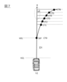
本実施形態では、自車両V1の現在位置を基準とする「基準位置V01」に「横位置変更開始位置」を設定する。図7は、自車両V1の前端V1Sから前方の距離D1に応じて設定される基準位置V01の一例を示す。図7に示す基準位置V01までの距離は距離D1である。前述したように、本例では、距離D1を前方注視点距離に対応させ、基準位置V01を前方注視点に対応させてもよい。
Here, the "horizontal position change start position" will be described.
In this embodiment, the "lateral position change start position" is set to the "reference position V01" based on the current position of the host vehicle V1. FIG. 7 shows an example of the reference position V01 set according to the distance D1 in front of the front end V1S of the own vehicle V1. The distance to the reference position V01 shown in FIG. 7 is the distance D1. As described above, in this example, the distance D1 may correspond to the forward gaze point distance, and the reference position V01 may correspond to the forward gaze point.
上述したように、障害物VPを回避するための横位置制御を開始する横位置変更開始位置は、位置座標値によって定義される絶対位置として定義されてもよいが、自車両V1を基準として設定された制御位置、例えば、自車両V1から所定距離だけ離隔した位置などの自車両V1の位置を基準として設定された相対的な位置として定義してもよい。
本実施形態では、障害物VPの回避制御を開始する横位置変更開始位置は、回避制御における制御指令値が設定される制御目標位置とすることができる。制御目標位置は、走行する自車両V1の制御上の時空間座標に基づいて設定できる。回避制御においては、自車両V1の走行位置を現在位置から実行される制御指令によって追跡することができる。つまり、ある制御目標位置における自車両V1の存在/通過タイミング及び存在位置が特定され、その制御目標位置において新たな制御指令が実行される。
As described above, the lateral position change start position for starting lateral position control for avoiding the obstacle VP may be defined as an absolute position defined by position coordinate values, but is set with the host vehicle V1 as a reference. For example, it may be defined as a relative position set with reference to the position of the vehicle V1, such as a position separated from the vehicle V1 by a predetermined distance.
In this embodiment, the lateral position change start position at which the avoidance control of the obstacle VP is started can be the control target position at which the control command value in the avoidance control is set. The control target position can be set based on the control spatio-temporal coordinates of the running own vehicle V1. In avoidance control, the running position of the own vehicle V1 can be tracked by a control command executed from the current position. That is, the existence/passage timing and the existence position of the host vehicle V1 at a certain control target position are specified, and a new control command is executed at the control target position.
図7には、基準位置V01に設定された横位置変更開始位置Strを示す。横位置変更開始位置Strは、車両制御の制御遅れや制御応答性を考慮して、自車両V1が将来のタイミングにおいて存在する位置(前進走行中又は自車両の前方の位置)における制御量を設定するための制御目標位置(の一つ)である。自車両V1の位置に対する制御目標位置は、指令値を出力して実際に制御が実行され始める(制御が働き始める)までに自車両V1が進む距離に依存するため、自車両V1の車速が高いほど、自車両V1に対する相対位置(相対距離)が大きくなり、自車両V1から離隔させた位置に設定される。例えば、予め決定された設定位置(絶対位置/座標定義位置)から制御を働かせるとした場合には、自車両V1の車速が高いほど、その決められた設定位置から手前に離隔させた位置から指令値を出力する必要があり、また車速が低いほど、決められた設定位置に近い位置で指令値を出力することができる。指令の伝達及び実行には時間を要するからである。一般的に、この第2位置P2は、車速により変化する前方注視点を用いるが、本実施形態に関する第2位置P2は必ずしも前方注視点に限らない。 FIG. 7 shows the lateral position change start position Str set at the reference position V01. The lateral position change start position Str is set to a control amount at a position where the host vehicle V1 will exist at a future timing (during forward travel or a position in front of the host vehicle), taking into account control delay and control responsiveness of vehicle control. It is (one of) the control target positions for The control target position with respect to the position of the own vehicle V1 depends on the distance traveled by the own vehicle V1 from the time the command value is output until the control is actually started (the control starts to work), so the vehicle speed of the own vehicle V1 is high. As the distance increases, the relative position (relative distance) with respect to the host vehicle V1 increases, and the position is set apart from the host vehicle V1. For example, when the control is to be applied from a predetermined set position (absolute position/coordinate defined position), the higher the vehicle speed of the host vehicle V1, the more distant the vehicle V1 is from the predetermined set position. It is necessary to output a value, and the lower the vehicle speed, the closer the command value can be output to the determined set position. This is because it takes time to transmit and execute commands. In general, the second position P2 uses a forward gaze point that changes depending on the vehicle speed, but the second position P2 related to this embodiment is not necessarily limited to the forward gaze point.
図7に示す例において、自車両V1の位置を基準として、制御位置としての制御目標位置CT0~CT6(n)を設定することができる。各制御目標位置CTnには、回避制御における制御指令値が対応づけて設定される。回避制御を一つの制御群とすれば、制御目標位置CTnのうち、横位置の制御が開始される制御目標位置CT0が横位置変更開始位置Stpである。
本実施形態のように、横位置変更開始位置Stpを、自車両V1の位置の変化に応じて相対的に決定される制御目標位置CTnとして設定することにより、運転制御指令の出力、受信、又は実行の遅れを抑制することができ、運転制御指令の連続性を担保することができる。これにより、実行される回避制御を適時に開始し、滑らかな(適切に連続した)運転動作を実行することができる。
In the example shown in FIG. 7, control target positions CT0 to CT6(n) can be set as control positions with reference to the position of the own vehicle V1. A control command value for avoidance control is set in association with each control target position CTn. If the avoidance control is taken as one control group, the control target position CT0 at which lateral position control is started among the control target positions CTn is the lateral position change start position Stp.
As in the present embodiment, by setting the lateral position change start position Stp as the control target position CTn relatively determined according to the change in the position of the host vehicle V1, the operation control command can be output, received, or Delay in execution can be suppressed, and continuity of operation control commands can be ensured. As a result, the avoidance control to be executed can be started in a timely manner, and a smooth (appropriately continuous) driving action can be executed.
本実施形態の運転制御方法においては、基準位置V01を、回避制御における制御指令値が設定される制御目標位置CTnとすることができる。基準位置V01に設定される横位置変更開始位置Stpは、自車両V1の運転制御の観点から設定される。これにより、実際に回避制御を実行した場合に、制御が完了できる位置を正確に算出(予測)することができ、自車両V1が障害物VPを回避して回避制御が完了できるかどうかを正確に判断できる。 In the operation control method of this embodiment, the reference position V01 can be set as the control target position CTn to which the control command value in the avoidance control is set. The lateral position change start position Stp set at the reference position V01 is set from the viewpoint of driving control of the own vehicle V1. As a result, when the avoidance control is actually executed, it is possible to accurately calculate (predict) the position at which the control can be completed, and to accurately determine whether the vehicle V1 can avoid the obstacle VP and complete the avoidance control. can be judged.
また、本実施形態の運転制御方法において、制御目標位置CTnは、自車両V1の位置を基準として設定され、自車両V1の車速が高いほど、自車両V1の位置に対する相対距離が大きくなるように設定する。自車両V1の位置に対する制御目標位置は、指令値を出力して実際に制御が実行され始める(制御が働き始める)までに自車両V1が進む距離に依存する。そのため、自車両V1の車速が高いほど、自車両V1に対する相対位置の差(距離)を大きく設定し、自車両V1から離隔させた位置に制御目標位置を設定する。このため、自車両V1の車速を考慮したうえで、回避制御が完了できるか否かを正確に判断できる。 Further, in the operation control method of the present embodiment, the control target position CTn is set with the position of the vehicle V1 as a reference, and the higher the vehicle speed of the vehicle V1, the greater the relative distance to the position of the vehicle V1. set. The control target position with respect to the position of the own vehicle V1 depends on the distance traveled by the own vehicle V1 from the time the command value is output until the control is actually started (the control starts to work). Therefore, the higher the vehicle speed of the own vehicle V1, the larger the difference (distance) in the relative position to the own vehicle V1 is set, and the control target position is set at a position separated from the own vehicle V1. Therefore, it is possible to accurately determine whether or not the avoidance control can be completed in consideration of the vehicle speed of the own vehicle V1.
以上において、ステップS108からステップS121へ遷移する処理を説明した。以下において、ステップS109からステップS109以降へ遷移する処理を説明する。
本実施形態のプロセッサ10は、ステップS109において減速値を算出し、その減速値を用いて運転制御をすることも可能であるが、減速値が適切であるか否か、つまり、その減速値によって自車両V1を減速させることにより、回避軌跡の完了位置が目標位置に属するのか否かを確認し、確認された減速値を用いて運転制御を実行することもできる。
The process of transitioning from step S108 to step S121 has been described above. The process of transitioning from step S109 to step S109 and subsequent steps will be described below.
The processor 10 of this embodiment can calculate the deceleration value in step S109 and use the deceleration value to control the operation. By decelerating the own vehicle V1, it is possible to confirm whether or not the completion position of the avoidance trajectory belongs to the target position, and to execute driving control using the confirmed deceleration value.
本実施形態のプロセッサ10は、自車両V1の目標速度を第1目標速度に減速させた場合の第1補正回避軌跡を算出し、第1補正回避軌跡の完了位置が、目標位置に属すると判断された場合には、第1補正回避軌跡に従って自車両V1を走行させる運転計画を算出する。他方、第1補正回避軌跡の完了位置が、目標位置に属さないと判断された場合には、自車両V1を第1目標速度よりも低い第2の目標速度に減速させる運転計画を算出する。
本実施形態のプロセッサ10は、減速後の目標速度に基づいて補正された回避軌跡の完了位置が目標位置に属するまで適切な減速度を探求し、完了位置が目標位置に属する目標速度における回避軌跡が得られたとき、目標速度への減速度、新たな第2目標速度、回避軌跡を用いて運転計画を算出する。
The processor 10 of this embodiment calculates the first corrected avoidance trajectory when the target speed of the host vehicle V1 is reduced to the first target speed, and determines that the completed position of the first corrected avoidance trajectory belongs to the target position. If so, a driving plan is calculated for causing the own vehicle V1 to travel along the first corrected avoidance trajectory. On the other hand, when it is determined that the completion position of the first corrected avoidance trajectory does not belong to the target position, a driving plan for decelerating the host vehicle V1 to a second target speed lower than the first target speed is calculated.
The processor 10 of the present embodiment searches for an appropriate deceleration until the completion position of the avoidance trajectory corrected based on the target speed after deceleration belongs to the target position, is obtained, the operation plan is calculated using the deceleration to the target speed, the new second target speed, and the avoidance trajectory.
具体的に、ステップS110において、プロセッサ10は、ステップS109において算出された減速後の第1目標速度に応じた回避条件を取得する。ステップS111において、プロセッサ10は、取得した回避条件に従い、現在位置VS2の前方の横位置変更開始位置StP2から障害物VPを回避して完了位置EdP2に至る第1補正回避軌跡RT21を算出する。ステップS112において、第1補正回避軌跡RT21の完了位置EdP2が目標位置であるか否かを判断する。第1補正回避軌跡RT21の完了位置EdP2が目標位置に属すると判断された場合には、ステップS113に進み、第1目標速度への減速値に基づく減速指令を生成する。一方、ステップS112において、第1補正回避軌跡RT21の完了位置EdP2が目標位置に属さないと判断された場合には、ステップS109に戻り、第1目標速度よりも低い第2目標速度への減速値を算出する。そして、第2目標速度を前提に算出された回避軌跡の完了位置EdP2が目標位置に属するまで、ステップS109からS113を繰り返してもよい。 Specifically, in step S110, the processor 10 acquires an avoidance condition corresponding to the first target speed after deceleration calculated in step S109. In step S111, the processor 10 calculates a first corrected avoidance trajectory RT21 from the lateral position change start position StP2 in front of the current position VS2 to the completion position EdP2 while avoiding the obstacle VP, according to the acquired avoidance conditions. In step S112, it is determined whether or not the completion position EdP2 of the first corrected avoidance trajectory RT21 is the target position. When it is determined that the completion position EdP2 of the first corrected avoidance trajectory RT21 belongs to the target position, the process proceeds to step S113 to generate a deceleration command based on the deceleration value to the first target speed. On the other hand, if it is determined in step S112 that the completion position EdP2 of the first corrected avoidance trajectory RT21 does not belong to the target position, the process returns to step S109, and the deceleration value to the second target speed lower than the first target speed is calculated. Calculate Steps S109 to S113 may be repeated until the avoidance trajectory completion position EdP2 calculated on the premise of the second target speed belongs to the target position.
本処理によれば、回避制御における操舵制御の開始前に行われる減速制御により、完了位置EdP2が目標位置に属するように自車両V1に障害物VPを回避させることができる。操舵制御の開始前に行われる減速制御後の回避軌跡によれば、現在位置VS2から横位置変更開始位置StP2に至る区間の長さL1S、横位置変更開始位置StP2から完了位置EdP2に至る区間の長さL1e、これらを含む回避軌跡RT21の長さL2のいずれも短縮することができる。
これにより、横位置の変更が完了する完了位置EdP2が、自車両V1の進行方向に沿う上流側に位置する回避軌跡を算出することができる。つまり、横位置の変更(車線変更)を伴う回避制御の完了タイミングを早めることができる。
According to this processing, the vehicle V1 can avoid the obstacle VP so that the completion position EdP2 belongs to the target position by the deceleration control performed before the start of the steering control in the avoidance control. According to the avoidance trajectory after deceleration control performed before the start of steering control, the length L1S of the section from the current position VS2 to the lateral position change start position StP2, and the length of the section from the lateral position change start position StP2 to the completion position EdP2. Both the length L1e and the length L2 of the avoidance trajectory RT21 including these can be shortened.
As a result, it is possible to calculate an avoidance trajectory in which the completion position EdP2 at which the lateral position change is completed is located on the upstream side along the traveling direction of the host vehicle V1. In other words, the completion timing of the avoidance control involving the change of the lateral position (lane change) can be advanced.
回避軌跡の完了位置EdP2を目標位置、例えば障害物VPの後端部VPrよりも上流側に位置させることができるので、障害物VPを回避するときに回避のための余裕(マージン)が狭い状況においても、早いタイミングで横位置の変更制御が完了する回避制御を実行できる。回避のための余裕(マージン)が狭い状況においても、緩やかな(変化量の低い)回避軌跡に従って自車両V1を移動させることができ、車両の横Gの変化量を低減させ、安定した車両挙動を保った状態で回避制御を実行することができる。 Since the completion position EdP2 of the avoidance trajectory can be positioned upstream of the target position, for example, the rear end VPr of the obstacle VP, the margin for avoiding the obstacle VP is narrow. Also in , it is possible to execute avoidance control in which lateral position change control is completed at an early timing. Even in situations where the margin for avoidance is narrow, the own vehicle V1 can be moved along a gentle (low change amount) avoidance trajectory, reducing the change amount of the lateral G of the vehicle and stabilizing the vehicle behavior. Avoidance control can be executed while maintaining
本実施形態では、回避軌跡の完了位置を目標位置とさせる観点から、少なくとも操舵制御前において自車両を減速させるが、これに加えて、車両の横移動速度を加速し、目標横移動速度を高く変更することもできる。 In the present embodiment, the host vehicle is decelerated at least before steering control from the viewpoint of setting the completion position of the avoidance trajectory as the target position. You can change it.
ステップS114において、プロセッサは、横移動速度の加速値を算出する。加速値は、回避条件に含ませて記録してもよい。ステップS115において、加速後の横移動速度に応じた回避条件を取得する。ステップS116において、加速後の横移動速度が適用され補正回避軌跡を算出する。補正回避軌跡においては横方向の移動速度が速い、つまり操舵量の変化が速くなることが許容されるので、軌跡の曲率の変化量が高い回避軌跡が算出される。ステップS117において、算出された回避軌跡の完了位置が目標位置に属するか否かを判断する。回避軌跡の完了位置が目標位置に属すると判断された場合には、ステップS118に進み、横移動速度の加速指令を生成する。他方、回避軌跡の完了位置が目標位置に属さないと判断された場合には、ステップS119に進む。 In step S114, the processor calculates the acceleration value of the lateral movement speed. The acceleration value may be included in the avoidance condition and recorded. In step S115, an avoidance condition corresponding to the lateral movement speed after acceleration is obtained. In step S116, the lateral movement speed after acceleration is applied to calculate a corrected avoidance trajectory. In the corrected avoidance trajectory, the speed of movement in the lateral direction is high, that is, the change in steering amount is allowed to be fast, so an avoidance trajectory with a large amount of change in the curvature of the trajectory is calculated. In step S117, it is determined whether or not the calculated completion position of the avoidance trajectory belongs to the target position. If it is determined that the completion position of the avoidance trajectory belongs to the target position, the process proceeds to step S118 to generate an acceleration command for the lateral movement speed. On the other hand, when it is determined that the completion position of the avoidance trajectory does not belong to the target position, the process proceeds to step S119.
ステップS119において、自車両V1の減速及び横移動速度の加速によっても、完了位置が目標位置に属さず、しかも完了位置が障害物VPよりも下流側(走行経路の進行方向側)に位置する場合には、ステップS120に進み回避制御を中止する。ステップS119においては、完了位置が、障害物VPの後端部VPrより下流側(走行経路の進行方向とは逆方向側)であるか否かを判断してもよい。ステップS119において、自車両V1の減速及び横移動速度の加速によって、完了位置が目標位置に属さないものの、完了位置が障害物VPよりも上流側に位置する場合には、再度の速度調整を行うためにステップS109に戻る。ステップS119の処理を行うことなく、所定回数の判断を経てステップS117において完了位置が目標位置に属さないと判断された場合にステップS120へ進んで回避制御を中止することも可能である。 In step S119, when the completion position does not belong to the target position even by the deceleration of the own vehicle V1 and the acceleration of the lateral movement speed, and the completion position is located downstream of the obstacle VP (on the traveling direction side of the travel route). Otherwise, the process proceeds to step S120 to stop the avoidance control. In step S119, it may be determined whether or not the completion position is downstream of the rear end portion VPr of the obstacle VP (on the side opposite to the traveling direction of the travel route). In step S119, if the completion position does not belong to the target position due to the deceleration of the host vehicle V1 and the acceleration of the lateral movement speed, but the completion position is positioned upstream of the obstacle VP, the speed is adjusted again. Therefore, the process returns to step S109. If it is determined in step S117 that the completion position does not belong to the target position after a predetermined number of determinations, without performing the processing in step S119, it is possible to proceed to step S120 and stop the avoidance control.
自車両V1の横移動速度を加速することにより、回避軌跡の曲率の変化量が高くなるものの、完了位置が目標位置に属する回避軌跡を算出することができる。これにより、自車両V1が障害物VPに到達する前(障害物VPの上流側)の早いタイミングで回避制御を完了させることができる。 By accelerating the lateral movement speed of the host vehicle V1, it is possible to calculate an avoidance trajectory whose completion position belongs to the target position, although the amount of change in the curvature of the avoidance trajectory increases. As a result, the avoidance control can be completed at an early timing before the host vehicle V1 reaches the obstacle VP (on the upstream side of the obstacle VP).
ステップS114~ステップS116までの処理は、ステップS108及び/又はステップS112において完了位置が障害目標位置に属さないと判断された場合に実行される。自車両V1の減速制御と並行して行ってもよいし、自車両V1の減速制御の後に行ってもよい。 The processing from step S114 to step S116 is executed when it is determined in step S108 and/or step S112 that the completed position does not belong to the obstacle target position. It may be performed in parallel with the deceleration control of the own vehicle V1, or may be performed after the deceleration control of the own vehicle V1.
なお、障害物VPを回避するときに、交通量が少なくレーン幅が広い状態であれば回避のためのマージン(余裕領域)を十分にとることができ、理想的な回避軌跡を算出することができる。しかしながら、実際の交通において自律的な運転で障害物VPを回避しようとする場合に、常に十分なマージンが確保されているとは限らない。このような場合においても、本実施形態の運転制御方法によれば、障害物VPを基準に設定された目標位置に回避軌跡の完了位置が属するか否かという判断結果に基づいて自車両V1を減速させるという減速制御を含む運転計画を実行させることにより、自車両V1と障害物VPとの経時的な位置関係を変化させ、新たな関係の下で、適切な完了位置を算出することができる。これに伴い適切な完了位置に至る適切な回避軌跡を算出できる。本実施形態において補正される回避軌跡は、現在位置から横位置変更開始位置までの距離が短く、横位置変更開始位置から完了位置までの距離が短く、しかも、自車両V1が障害物VPを避ける移動の軌跡が緩やかである。 When avoiding the obstacle VP, if the traffic volume is low and the lane width is wide, a sufficient margin (margin area) for avoidance can be secured, and an ideal avoidance trajectory can be calculated. can. However, when attempting to avoid obstacles VP by autonomous driving in actual traffic, a sufficient margin is not always ensured. Even in such a case, according to the operation control method of the present embodiment, the own vehicle V1 is controlled based on the determination result as to whether or not the completion position of the avoidance trajectory belongs to the target position set with reference to the obstacle VP. By executing a driving plan including deceleration control to decelerate, the temporal positional relationship between the host vehicle V1 and the obstacle VP can be changed, and an appropriate completion position can be calculated under the new relationship. . Along with this, it is possible to calculate an appropriate avoidance trajectory leading to an appropriate completion position. The avoidance trajectory corrected in this embodiment has a short distance from the current position to the lateral position change start position, a short distance from the lateral position change start position to the completion position, and the vehicle V1 avoids the obstacle VP. The trajectory of movement is gentle.
本発明の実施形態の運転制御装置100は、以上のように構成され動作するので、以下の効果を奏する。 Since the operation control device 100 of the embodiment of the present invention is configured and operates as described above, it has the following effects.
[1]本実施形態の運転制御方法は、操舵制御による横位置の移動が開始可能である自車両V1の前方の基準位置に、障害物VPを回避するための回避制御を開始する横位置変更開始位置を設定し、所定の回避条件に従い、横位置変更開始位置から障害物VPを回避して、障害物VPの回避が完了する完了位置を算出し、完了位置が障害物VPに対して定義された所定の目標位置に属さないと判断された場合には、操舵制御の開始前に自車両V1の目標速度を減速させることを特徴とする。
本発明によれば、算出された完了位置が目標位置に属さないと判断された場合において、操舵制御の実行開始前に自車両V1を減速させることにより、回避制御の完了位置を変更することができるので、十分な余裕領域が確保できない状況においても、車両位置及び車両姿勢の変化が小さく緩やかな動きで自車両V1に障害物VPを回避させることができる。障害物VPとの間に十分な距離がとれない状態で、前方注視点(現在位置から所定距離だけ離隔した位置)に対する指令値が出力される場合であっても、横位置の変化量を大きくすることなく、緩やかな動きで障害物VPを回避できる。
自車両V1の減速制御を操舵制御の開始前に実行することにより、現在位置VS2から横位置変更開始位置StP2に至る区間の長さL1S、これを含む回避のための回避軌跡RT21の長さL2を短縮することができる。加えて、減速制御を操舵制御の開始後にも実行することができるが、これにより、横位置変更開始位置StP2から完了位置EdP2に至る区間の長さL1e、これを含む回避軌跡RT21の長さL2を短縮することができる。これにより、横位置の変更が完了する完了位置EdP2が、自車両V1の走行経路における進行方向の上流側(自車両側)に位置するように障害物VPの回避制御を実行することができる。つまり、回避制御の完了タイミングを早めることができる。
回避制御における完了位置EdP2を目標位置、例えば障害物VPの後端部VPrよりも自車両V1側(走行経路の進行方向に対して上流側)に位置させることができるので、障害物VPを回避するときに回避のための余裕(マージン)が狭い状況においても、早いタイミングで横位置の変更制御が完了する回避制御を実行できる。
回避のための余裕(マージン)が狭い状況においても、変化が相対的に少ない移動軌跡上を、緩やかな(車両位置及び車両姿勢の変化量が小さい)動きで自車両V1を移動させることができ、車両の横Gの変化量を低減させ、安定した車両挙動を保った状態で回避制御を実行することができる。
[1] The operation control method of the present embodiment is a lateral position change that starts avoidance control for avoiding an obstacle VP to a reference position in front of the own vehicle V1 at which lateral position movement can be started by steering control. A start position is set, the obstacle VP is avoided from the lateral position change start position according to a predetermined avoidance condition, the completion position at which the avoidance of the obstacle VP is completed is calculated, and the completion position is defined for the obstacle VP. If it is determined that the target position does not belong to the predetermined target position, the target speed of the host vehicle V1 is decelerated before the steering control is started.
According to the present invention, when it is determined that the calculated completion position does not belong to the target position, the completion position of the avoidance control can be changed by decelerating the own vehicle V1 before starting the execution of the steering control. Therefore, even in a situation in which a sufficient margin area cannot be secured, the vehicle V1 can avoid the obstacle VP with a gentle movement with little change in the vehicle position and attitude. Even if a command value for a forward fixation point (a position separated by a predetermined distance from the current position) is output in a state where a sufficient distance cannot be obtained from the obstacle VP, the amount of change in the lateral position is increased. The obstacle VP can be avoided by gentle movement without doing anything.
By executing the deceleration control of the own vehicle V1 before the start of the steering control, the length L1S of the section from the current position VS2 to the lateral position change start position StP2 and the length L2 of the avoidance trajectory RT21 for avoidance including this length L2 can be shortened. In addition, deceleration control can also be executed after the start of steering control. can be shortened. As a result, avoidance control of the obstacle VP can be executed so that the completion position EdP2 at which the lateral position change is completed is located on the upstream side (self-vehicle side) in the traveling direction of the travel route of the self-vehicle V1. That is, the completion timing of avoidance control can be advanced.
Since the completion position EdP2 in avoidance control can be positioned on the target position, for example, on the host vehicle V1 side (on the upstream side with respect to the traveling direction of the travel route) of the rear end portion VPr of the obstacle VP, the obstacle VP is avoided. Avoidance control that completes lateral position change control at an early timing can be executed even in a situation where there is a narrow margin for avoidance.
Even in a situation where the margin for avoidance is narrow, the own vehicle V1 can be moved in a gentle motion (the amount of change in the vehicle position and the vehicle attitude is small) on a movement trajectory that changes relatively little. , the amount of change in the lateral G of the vehicle can be reduced, and avoidance control can be executed while maintaining stable vehicle behavior.
[2]本実施形態の運転制御方法において、プロセッサ10は、完了位置が、障害物VPの位置に基づいて定義された所定の目標位置に属すると判断された場合には、操舵制御の開始前に自車両を減速させる減速制御を含まない運転計画を算出する。回避制御の完了位置が目標位置に属すると判断された場合においては、操舵制御の開始前には、減速制御を行わないようにするので、上述の項目[1]と同様に、車両位置及び車両姿勢の変化が小さく緩やかな動きで、自車両V1に障害物VPを回避させることができる。 [2] In the operation control method of the present embodiment, if the processor 10 determines that the completed position belongs to a predetermined target position defined based on the position of the obstacle VP, before starting the steering control A driving plan that does not include deceleration control for decelerating the own vehicle is calculated. When it is determined that the avoidance control completion position belongs to the target position, deceleration control is not performed before steering control is started. The vehicle V1 can be made to avoid the obstacle VP by a gentle movement with a small change in attitude.
[3]本実施形態の運転制御方法においては、基準位置を、回避制御における制御指令値が設定される制御目標位置とすることができる。基準位置に設定される横位置変更開始位置は、車両の運転制御の観点から設定される。これにより、実際に回避制御を実行した場合に、制御が完了できる位置を正確に算出(予測)することができ、自車両V1が障害物VPを回避して回避制御が完了できるかどうかを正確に判断できる。 [3] In the operation control method of the present embodiment, the reference position can be the control target position to which the control command value for avoidance control is set. The lateral position change start position set as the reference position is set from the viewpoint of driving control of the vehicle. As a result, when the avoidance control is actually executed, it is possible to accurately calculate (predict) the position at which the control can be completed, and to accurately determine whether the vehicle V1 can avoid the obstacle VP and complete the avoidance control. can be judged.
[4]本実施形態の運転制御方法において、制御目標位置は、自車両の位置を基準として設定され、自車両V1の車速が高いほど、自車両の位置に対する相対距離が大きくなるように設定する。自車両V1の位置に対する制御目標位置は、指令値を出力して実際に制御が実行され始める(制御が働き始める)までに自車両V1が進む距離に依存する。そのため、自車両V1の車速が高いほど、自車両V1に対する相対位置の差(距離)を大きく設定し、自車両V1から離隔させた位置に制御目標位置を設定する。このため、自車両V1の車速を考慮したうえで、回避制御が完了できるか否かを正確に判断できる。 [4] In the operation control method of the present embodiment, the control target position is set based on the position of the own vehicle, and is set such that the higher the vehicle speed of the own vehicle V1, the greater the relative distance to the position of the own vehicle. . The control target position with respect to the position of the own vehicle V1 depends on the distance traveled by the own vehicle V1 from the time the command value is output until the control is actually started (the control starts to work). Therefore, the higher the vehicle speed of the own vehicle V1, the larger the difference (distance) in the relative position to the own vehicle V1 is set, and the control target position is set at a position separated from the own vehicle V1. Therefore, it is possible to accurately determine whether or not the avoidance control can be completed in consideration of the vehicle speed of the own vehicle V1.
[5]本実施形態の運転制御方法において、障害物VPよりも自車両V1に近い位置に仮想停止目標地点P1を設定し、仮想停止目標地点P1で自車両V1を停止させる場合の減速度で自車両V1を減速させる。仮想停止目標地点P1は、障害物VPの後端部VPrよりも上流側に設定されることが好ましい。これにより、障害物VPに接近する前に自車両V1の速度を低減させることができる。 [5] In the operation control method of the present embodiment, the virtual stop target point P1 is set at a position closer to the own vehicle V1 than the obstacle VP, and the deceleration when stopping the own vehicle V1 at the virtual stop target point P1. The host vehicle V1 is decelerated. The virtual stop target point P1 is preferably set upstream of the rear end VPr of the obstacle VP. As a result, the speed of the host vehicle V1 can be reduced before approaching the obstacle VP.
[6]本実施形態の運転制御方法において、回避条件において定義された制動減速度以下の減速度により自車両V1を減速させる。回避条件において設定された制限減速度を上限として自車両V1を減速させるので、車両挙動が大きく変動することを防止できる。 [6] In the operation control method of the present embodiment, the own vehicle V1 is decelerated by deceleration equal to or less than the braking deceleration defined in the avoidance condition. Since the host vehicle V1 is decelerated with the deceleration limit set in the avoidance condition as the upper limit, it is possible to prevent the vehicle behavior from greatly fluctuating.
[7]本実施形態の運転制御方法において、完了位置が目標位置の属さないと判断された場合には、自車両V1の横移動速度を高く変更する運転計画を算出する。自車両V1の横移動速度を加速することにより、回避軌跡の曲率の変化量が高くなるものの、完了位置が目標位置に属する回避軌跡を算出することができる。これにより、自車両V1が障害物VPに到達する前(障害物VPの上流側)の早いタイミングで回避制御を完了させることができる。 [7] In the operation control method of the present embodiment, when it is determined that the completed position does not belong to the target position, a driving plan is calculated to increase the lateral movement speed of the vehicle V1. By accelerating the lateral movement speed of the host vehicle V1, it is possible to calculate an avoidance trajectory whose completion position belongs to the target position, although the amount of change in the curvature of the avoidance trajectory increases. As a result, the avoidance control can be completed at an early timing before the host vehicle V1 reaches the obstacle VP (on the upstream side of the obstacle VP).
[8]本実施形態の運転制御方法において、プロセッサ10は、予め規定された回避条件に従い、横位置変更開始位置からの所定の回避軌跡を算出することで完了位置を算出する。自車両V1が、横位置変更開始位置から障害物VPの回避が完了する完了位置に至る回避軌跡を算出することにより、障害物VPを回避し、回避制御が完了したと判断できる完了位置を求めることができる。 [8] In the operation control method of the present embodiment, the processor 10 calculates the completion position by calculating a predetermined avoidance trajectory from the lateral position change start position according to the avoidance condition defined in advance. By calculating the avoidance trajectory from the lateral position change start position to the completion position where the avoidance of the obstacle VP is completed, the own vehicle V1 avoids the obstacle VP and obtains the completion position where it can be determined that the avoidance control is completed. be able to.
[9]本実施形態の運転制御方法においては、自車両V1の目標速度を第1目標速度に減速させた場合の第1補正回避軌跡を算出し、第1補正回避軌跡の完了位置が目標位置に属すると判断された場合には、第1補正回避軌跡に従って自車両を走行させる運転計画を算出し、第1補正回避軌跡の完了位置が、目標位置に属さないと判断された場合には、自車両を第1目標速度よりも低い第2の目標速度に減速させる運転計画を算出する。
完了位置が目標位置に属するという条件を満たす回避軌跡を用いて運転計画を算出するので、横位置の変更(車線変更)を伴う回避制御の完了タイミングを確実に早めることができ、上記[1]に記載した効果を得ることができる。
[9] In the operation control method of the present embodiment, the first corrected avoidance trajectory is calculated when the target speed of the host vehicle V1 is reduced to the first target speed, and the completion position of the first corrected avoidance trajectory is the target position. When it is determined that the vehicle belongs to the first corrected avoidance trajectory, a driving plan for driving the own vehicle along the first corrected avoidance trajectory is calculated. A driving plan for decelerating the own vehicle to a second target speed lower than the first target speed is calculated.
Since the driving plan is calculated using the avoidance trajectory that satisfies the condition that the completion position belongs to the target position, the completion timing of the avoidance control that involves a lateral position change (lane change) can be reliably advanced. The effect described in can be obtained.
[10]本実施形態の運転制御方法において、自車両V1を減速させた場合に算出される回避軌跡の長さが、自車両V1を減速させる前に算出される回避軌跡の長さよりも短くなるように回避軌跡を補正し、補正された回避軌跡に基づいて運転計画を算出する。これにより、回避制御の開始から完了までの軌跡の長さを短縮することができ、上記効果を得られる。 [10] In the operation control method of the present embodiment, the length of the avoidance trajectory calculated when the host vehicle V1 is decelerated becomes shorter than the length of the avoidance trajectory calculated before decelerating the host vehicle V1. and calculate the driving plan based on the corrected avoidance trajectory. As a result, the length of the trajectory from the start to the end of the avoidance control can be shortened, and the above effects can be obtained.
[11]本実施形態の運転制御方法において、目標位置の自車両V1の進行方向に沿う第1位置(縦位置:図中X座標値)は、障害物VPの進行方向に沿う位置(縦位置:図中X座標値)に基づいて設定される。目標位置を障害物VPの縦位置に基づいて設定することにより、自車両V1が回避対象とする障害物VPの位置に応じて目標位置を設定し、この目標位置に応じて完了位置を設定できる。その結果、自車両V1が障害物VPの回避を完了するタイミングを適切に設定することができる。特に限定されないが、目標位置の第1位置は、進行方向に沿う障害物VPの位置よりも上流側であることが好ましいが、これにより、自車両V1に対する障害物VPの位置に応じた完了位置を有する回避軌跡を算出できる。 [11] In the operation control method of the present embodiment, the first position (vertical position: X coordinate value in the figure) of the target position along the traveling direction of the host vehicle V1 is the position along the traveling direction of the obstacle VP (vertical position : X coordinate value in the figure). By setting the target position based on the vertical position of the obstacle VP, the target position can be set according to the position of the obstacle VP to be avoided by the own vehicle V1, and the completion position can be set according to this target position. . As a result, it is possible to appropriately set the timing at which the own vehicle V1 completes avoidance of the obstacle VP. Although not particularly limited, the first position of the target position is preferably upstream of the position of the obstacle VP along the direction of travel. can be calculated.
[12]本実施形態の運転制御方法において、目標位置Kの進行方向に沿う第1位置を、進行方向に沿って上流側に位置する障害物VPの後端部VPrを基準とし、そこから第1閾値DX以下の距離にある位置(領域)として設定する。目標位置Kを障害物VPの後端部VPrから所定距離DXの範囲に設定することにより、自車両V1は、障害物VPよりも上流側で回避制御(横位置の変更)を完了することができる。また、障害物VPよりも上流側で回避しつつ、自車両V1からの距離を最大に確保できるので、自車両V1は緩やかな(変化量の低い)回避軌跡に従って移動できる。回避制御における自車両V1の車両姿勢の変化量も抑制できるので、安定した走行で障害物VPを回避できる。目標位置の第1位置を、進行方向に沿う障害物VPの位置よりも上流側に設定することにより、障害物VPの手前で自車両V1は横位置の変更(車線変更)を完了することができる。回避制御を早いタイミングで完了させることができる。また、回避制御を早めに実行することにより、緩やかな(曲率変化量の小さい)回避軌跡で障害物VPを回避することができる。 [12] In the operation control method of the present embodiment, the first position along the traveling direction of the target position K is based on the rear end portion VPr of the obstacle VP located on the upstream side along the traveling direction. A position (region) at a distance of one threshold value DX or less is set. By setting the target position K within the range of the predetermined distance DX from the rear end portion VPr of the obstacle VP, the own vehicle V1 can complete avoidance control (change of lateral position) on the upstream side of the obstacle VP. can. Further, since the maximum distance from the host vehicle V1 can be secured while avoiding the obstacle VP on the upstream side, the host vehicle V1 can move along a gradual (low variation) avoidance trajectory. Since the amount of change in the attitude of the host vehicle V1 during avoidance control can also be suppressed, the obstacle VP can be avoided with stable running. By setting the first position of the target position upstream of the position of the obstacle VP along the traveling direction, the vehicle V1 can complete the lateral position change (lane change) before the obstacle VP. can. Avoidance control can be completed at an early timing. Also, by executing the avoidance control early, it is possible to avoid the obstacle VP with a gradual avoidance trajectory (with a small amount of change in curvature).
[13]本実施形態の運転制御方法において、障害物VPの外縁のうち回避軌跡と最も接近する位置と、回避軌跡を走行する自車両V1の位置との距離に基づいて第1位置を設定する。
これにより、完了位置を設定された目的位置に基づいてコントロールしつつも、完了位置に至る自車両V1と障害物VPとの干渉を、自車両V1の性能、回避時における道路環境、障害物VPのレーン上の位置に応じて防止することができる。この結果、障害物VPを確実に回避しつつ、回避を完了させるタイミングをコントロールすることができる。
[13] In the operation control method of the present embodiment, the first position is set based on the distance between the position closest to the avoidance trajectory among the outer edges of the obstacle VP and the position of the own vehicle V1 traveling on the avoidance trajectory. .
As a result, while the completion position is controlled based on the set target position, interference between the own vehicle V1 and the obstacle VP reaching the completion position can be controlled by the performance of the own vehicle V1, the road environment at the time of avoidance, and the obstacle VP. can be prevented depending on its position on the lane. As a result, it is possible to reliably avoid the obstacle VP and control the timing of completing the avoidance.
[14]本実施形態の運転制御方法において、自車両V1の横移動速度、自車両V1が走行するレーンの車線幅、及び障害物VPと自車両V1が走行する車線との距離などの実際の交通状況において、回避軌跡の完了位置(目標位置)を進行方向の下流側にシフトすることが可能である場合には、完了位置(目標位置)を進行方向の下流側にシフトさせることにより、回避軌跡の距離を確保することができる。これにより、自車両V1は緩やかな(変化量の低い)回避軌跡に従って移動できる。回避制御における自車両V1の車両姿勢の変化量も抑制できるので、安定した走行で障害物VPを回避できる。完了位置を設定された目的位置に基づいてコントロールしつつも、完了位置に至る自車両V1と障害物VPとの干渉を防止することができる。この結果、障害物VPを確実に回避しつつ、回避を完了させるタイミングをコントロールすることができる。 [14] In the operation control method of the present embodiment, actual values such as the lateral movement speed of the vehicle V1, the lane width of the lane in which the vehicle V1 travels, and the distance between the obstacle VP and the lane in which the vehicle V1 travels are calculated. In traffic conditions, if the completion position (target position) of the avoidance trajectory can be shifted downstream in the direction of travel, the completion position (target position) of the avoidance trajectory is shifted downstream in the direction of travel to avoid It is possible to secure the distance of the trajectory. As a result, the own vehicle V1 can move along a gradual avoidance trajectory (with a small amount of change). Since the amount of change in the attitude of the host vehicle V1 during avoidance control can also be suppressed, the obstacle VP can be avoided with stable running. While controlling the completion position based on the set target position, interference between the own vehicle V1 reaching the completion position and the obstacle VP can be prevented. As a result, it is possible to reliably avoid the obstacle VP and control the timing of completing the avoidance.
[15]本実施形態の運転制御方法において、プロセッサ10は、自車両V1が走行する路幅に沿う目標位置の第2位置(横位置:図中Y座標値)を、回避軌跡側の障害物VPの側面から第2閾値以上離隔した第2範囲に存在する位置と定義する。目標領域K及びK2を障害物VPから所定距離DYだけ離隔させることにより、自車両V1に障害物VPを確実に回避させることができる。 [15] In the operation control method of the present embodiment, the processor 10 sets the second position (horizontal position: Y coordinate value in the figure) of the target position along the width of the road on which the vehicle V1 travels to the obstacle on the avoidance trajectory side. It is defined as a position existing in a second range separated from the side of the VP by a second threshold or more. By separating the target areas K and K2 from the obstacle VP by the predetermined distance DY, the own vehicle V1 can reliably avoid the obstacle VP.
[16]本実施形態の運転制御方法において、障害物VPの外縁のうち回避軌跡と最も接近する位置と、回避軌跡を走行する自車両V1の位置との距離に基づいて第2位置を設定する。
これにより、完了位置を設定された目的位置に基づいてコントロールしつつも、完了位置に至る自車両V1と障害物VPとの干渉を、自車両V1の性能、回避時における道路環境、障害物VPのレーン上の位置に応じて防止することができる。この結果、障害物VPを確実に回避しつつ、回避を完了させるタイミングをコントロールすることができる。
[16] In the operation control method of the present embodiment, the second position is set based on the distance between the position closest to the avoidance trajectory among the outer edges of the obstacle VP and the position of the own vehicle V1 traveling on the avoidance trajectory. .
As a result, while the completion position is controlled based on the set target position, interference between the own vehicle V1 and the obstacle VP reaching the completion position can be controlled by the performance of the own vehicle V1, the road environment at the time of avoidance, and the obstacle VP. can be prevented depending on its position on the lane. As a result, it is possible to reliably avoid the obstacle VP and control the timing of completing the avoidance.
[17]本実施形態の運転制御方法において、プロセッサ10は、自車両V1を減速させる減速制御を含む運転計画を算出する場合に、自車両V1が走行する車線の中に存在するときに減速するように運転計画を算出する。自車両V1が走行中の車線(走行経路)の中において減速を行うので、自車両が走行中の車線に隣接する他の車線(走行経路に隣接する他の走行経路)を走行する他車両の走行に影響を与えることを抑制し、隣接する他の車線における交通流を妨げることを抑制できる。 [17] In the driving control method of the present embodiment, when calculating a driving plan including deceleration control for decelerating the own vehicle V1, the processor 10 decelerates when the own vehicle V1 is in the lane. Calculate the operation plan as follows. Since the vehicle V1 decelerates in the lane (travel route) in which the vehicle V1 is traveling, other vehicles traveling in other lanes (other travel routes adjacent to the travel route) adjacent to the lane in which the vehicle V1 is traveling It is possible to suppress the influence on driving and to suppress the obstruction of traffic flow in other adjacent lanes.
[18]本実施形態の運転制御方法において、プロセッサ10は、自車両V1を減速させる減速制御を含む運転計画を算出する場合に、自車両V1が走行する車線と隣接する他の車線の存在する方向に、自車両V1が向く姿勢となるように運転計画を算出する。自車両V1が走行する車線と隣接する他の車線の存在する方向に、自車両V1が向くように自車両V1の姿勢を制御する運転計画を算出するので、減速制御の後に、車線変更をする運転がスムーズに実行させるようにすることができる。 [18] In the driving control method of the present embodiment, when the processor 10 calculates a driving plan including deceleration control for decelerating the own vehicle V1, the processor 10 determines whether there is another lane adjacent to the lane in which the own vehicle V1 is traveling. A driving plan is calculated so that the own vehicle V1 is oriented in the direction. Since the driving plan is calculated to control the attitude of the vehicle V1 so that the vehicle V1 faces in the direction in which other lanes adjacent to the lane in which the vehicle V1 travels exist, the lane is changed after deceleration control. Driving can be made to run smoothly.
[19]本実施形態の運転制御方法がプロセッサ10により実行されることにより、運転制御装置100は、上記運転制御方法と同様の作用を奏し、同様の効果を奏する。 [19] By executing the operation control method of the present embodiment by the processor 10, the operation control device 100 performs the same operation as the above operation control method, and has the same effect.
なお、以上説明した実施形態は、本発明の理解を容易にするために記載されたものであって、本発明を限定するために記載されたものではない。したがって、上記の実施形態に開示された各要素は、本発明の技術的範囲に属する全ての設計変更や均等物をも含む趣旨である。 It should be noted that the embodiments described above are described to facilitate understanding of the present invention, and are not described to limit the present invention. Therefore, each element disclosed in the above embodiments is meant to include all design changes and equivalents that fall within the technical scope of the present invention.
1000…運転制御システム
1…センサ
2…ナビゲーション装置
3…地図情報
4…自車情報検出装置
5…環境認識装置
6…物体認識装置
100…運転制御装置
10…プロセッサ
11…CPU
12…ROM
13…RAM
120…目的地設定機能
130…経路プランニング機能
140…運転計画機能
150…運転可能ゾーン算出機能
160…経路算出機能
170…運転行動制御機能
110…出力装置
111…通信装置
200…車両コントローラ
210…駆動機構
DESCRIPTION OF SYMBOLS 1000...
12 ROM
13 RAM
DESCRIPTION OF SYMBOLS 120... Destination setting function 130... Route planning function 140... Operation planning function 150... Drivable zone calculation function 160... Route calculation function 170... Driving behavior control function 110... Output device 111... Communication device 200... Vehicle controller 210... Drive mechanism
Claims (19)
前記プロセッサは、
前記センサの検知情報に基づいて前記自車両が回避すべき障害物を検知した場合には、
前記自車両の運転の制御において、操舵制御による横位置の移動を開始することが可能な、予め定義された前記自車両の前方の基準位置に、前記障害物を回避するための回避制御を開始する横位置変更開始位置を設定し、
予め規定された回避条件に従い、前記横位置変更開始位置から前記障害物を回避して前記回避制御が完了する完了位置を算出し、
前記完了位置が、前記障害物の位置に基づいて定義された所定の目標位置に属さないと判断された場合には、前記操舵制御の開始前に前記自車両を減速させる減速制御を含む運転計画を算出する運転制御方法。 A driving control method for controlling the driving of an own vehicle, which is used in a driving control device comprising a sensor and a processor,
The processor
When an obstacle to be avoided by the own vehicle is detected based on the detection information of the sensor,
In controlling the driving of the own vehicle, avoidance control for avoiding the obstacle is started at a predefined reference position in front of the own vehicle at which lateral movement by steering control can be started. set the horizontal position change start position to
calculating a completion position at which the avoidance control is completed by avoiding the obstacle from the lateral position change start position according to a predetermined avoidance condition;
If it is determined that the completed position does not belong to a predetermined target position defined based on the position of the obstacle, a driving plan including deceleration control for decelerating the own vehicle before starting the steering control. Operation control method for calculating
前記自車両の位置を基準として設定され、前記自車両の車速が高いほど、前記自車両の位置に対する相対距離が大きい位置に設定される請求項3に記載の運転制御方法。 The control target position is
4. The operation control method according to claim 3, wherein the position of the own vehicle is set as a reference, and the higher the vehicle speed of the own vehicle, the larger the relative distance to the position of the own vehicle is set.
前記障害物よりも前記自車両に近い位置に仮想停止目標地点を設定し、
前記仮想停止目標地点で前記自車両を停止させる場合の減速度で前記自車両を減速させる請求項1~4の何れか一項に記載の運転制御方法。 The processor
setting a virtual stop target point at a position closer to the own vehicle than the obstacle;
The operation control method according to any one of claims 1 to 4, wherein the own vehicle is decelerated at the deceleration for stopping the own vehicle at the virtual stop target point.
前記回避条件において定義された制動減速度以下の減速度により前記自車両を減速させる請求項1~5の何れか一項に記載の運転制御方法。 The processor
The operation control method according to any one of claims 1 to 5, wherein the own vehicle is decelerated by deceleration equal to or less than the braking deceleration defined in the avoidance condition.
前記完了位置が前記目標位置に属さないと判断された場合には、前記自車両の横移動速度を高く設定する運転計画を算出する請求項1~6の何れか一項に記載の運転制御方法。 The processor
The operation control method according to any one of claims 1 to 6, wherein when it is determined that the completed position does not belong to the target position, a driving plan for setting a high lateral movement speed of the own vehicle is calculated. .
前記予め規定された回避条件に従い、前記横位置変更開始位置からの所定の回避軌跡を算出し、前記回避軌跡に基づいて前記完了位置を算出する請求項1~7のいずれか一項に記載の運転制御方法。 The processor
8. The method according to any one of claims 1 to 7, wherein a predetermined avoidance trajectory from the lateral position change start position is calculated according to the predetermined avoidance condition, and the completion position is calculated based on the avoidance trajectory. Operation control method.
前記自車両の目標速度を第1目標速度に減速させた場合の第1補正回避軌跡を算出し、
前記第1補正回避軌跡の完了位置が、前記目標位置に属すると判断された場合には、前記第1補正回避軌跡に従って前記自車両を走行させる運転計画を算出し、
前記第1補正回避軌跡の完了位置が、前記目標位置に属さないと判断された場合には、前記自車両を前記第1目標速度よりも低い第2の目標速度に減速させる運転計画を算出する請求項8に記載の運転制御方法。 The processor
calculating a first corrected avoidance trajectory when the target speed of the own vehicle is decelerated to the first target speed;
when it is determined that the completion position of the first corrected avoidance trajectory belongs to the target position, calculating a driving plan for causing the own vehicle to travel according to the first corrected avoidance trajectory;
When it is determined that the completed position of the first corrected avoidance trajectory does not belong to the target position, a driving plan for decelerating the own vehicle to a second target speed lower than the first target speed is calculated. The operation control method according to claim 8.
前記自車両を減速させた場合に算出される前記回避軌跡の長さが、前記自車両を減速させる前に算出される前記回避軌跡の長さよりも短くなるように前記回避軌跡を補正し、
前記補正された前記回避軌跡に基づいて前記運転計画を算出する請求項8又は9に記載の運転制御方法。 The processor
correcting the avoidance trajectory so that the length of the avoidance trajectory calculated when the own vehicle is decelerated is shorter than the length of the avoidance trajectory calculated before decelerating the own vehicle;
The operation control method according to claim 8 or 9, wherein the operation plan is calculated based on the corrected avoidance trajectory.
前記自車両の走行経路の進行方向に沿う前記目標位置の第1位置を、前記走行経路の進行方向に沿う前記障害物の位置に基づいて設定する請求項1~10の何れか一項に記載の運転制御方法。 The processor
11. The method according to any one of claims 1 to 10, wherein the first position of the target position along the traveling direction of the travel route of the host vehicle is set based on the position of the obstacle along the traveling direction of the travel route. operation control method.
前記自車両が走行する走行経路の進行方向に沿う前記目標位置の第1位置を、
前記走行経路の進行方向に沿って上流側に位置する前記障害物の後端部から前記上流側に第1閾値以下の距離にある位置として設定する請求項1~10の何れか一項に記載の運転制御方法。 The processor
A first position of the target position along the traveling direction of the travel route on which the own vehicle travels,
11. The obstacle according to any one of claims 1 to 10, wherein the position is set at a distance equal to or less than a first threshold on the upstream side from the rear end portion of the obstacle located on the upstream side along the traveling direction of the travel route. operation control method.
前記予め規定された回避条件に従い、前記横位置変更開始位置からの所定の回避軌跡を算出し、
前記障害物の外縁のうち前記回避軌跡と最も接近する位置と、前記回避軌跡を走行する前記自車両の位置との距離に基づいて前記第1位置を設定する請求項11又は12に記載の運転制御方法。 The processor
calculating a predetermined avoidance trajectory from the lateral position change start position according to the predetermined avoidance condition;
13. The driving according to claim 11 or 12, wherein the first position is set based on a distance between a position of the outer edge of the obstacle closest to the avoidance trajectory and a position of the own vehicle traveling on the avoidance trajectory. control method.
前記自車両の横移動速度、前記自車両が走行するレーンの車線幅、及び前記障害物と前記自車両が走行する走行経路の車線との距離のうちの何れか一つ以上の情報に基づいて前記第1位置を設定する請求項11~13の何れか一項に記載の運転制御方法。 The processor
Based on information on any one or more of the lateral movement speed of the own vehicle, the lane width of the lane in which the own vehicle travels, and the distance between the obstacle and the lane of the travel route in which the own vehicle travels The operation control method according to any one of claims 11 to 13, wherein the first position is set.
前記予め規定された回避条件に従い、前記横位置変更開始位置からの所定の回避軌跡を算出し、
前記自車両が走行する走行経路の路幅に沿う前記目標位置の第2位置を、
前記回避軌跡の側の前記障害物の側面から第2閾値以上離隔した位置として設定する請求項1~14の何れか一項に記載の運転制御方法。 The processor
calculating a predetermined avoidance trajectory from the lateral position change start position according to the predetermined avoidance condition;
A second position of the target position along the road width of the travel route on which the own vehicle travels,
15. The operation control method according to any one of claims 1 to 14, wherein the position is set at a distance of a second threshold or more from the side of the obstacle on the side of the avoidance trajectory.
前記障害物の外縁のうち前記回避軌跡と最も接近する位置と、前記回避軌跡を走行する前記自車両の位置との距離に基づいて前記第2位置を設定する請求項15に記載の運転制御方法。 The processor
16. The operation control method according to claim 15, wherein the second position is set based on a distance between a position of the outer edge of the obstacle that is closest to the avoidance trajectory and a position of the own vehicle traveling on the avoidance trajectory. .
前記自車両を減速させる減速制御を含む運転計画を算出する場合に、前記自車両が走行する車線の中に存在するときに減速するように運転計画を算出する請求項1~16の何れか一項に記載の運転制御方法。 The processor
17. The method according to any one of claims 1 to 16, wherein when calculating a driving plan including deceleration control for decelerating the own vehicle, the driving plan is calculated so as to decelerate when the own vehicle is in a lane in which the own vehicle is traveling. The operation control method described in the paragraph.
前記減速制御において、前記自車両が走行する車線と隣接する他の車線の存在する方向に向くように前記自車両の姿勢を制御する姿勢制御を含む運転計画を算出する請求項1~17の何れか一項に記載の運転制御方法。 The processor
18. A driving plan according to any one of claims 1 to 17, wherein, in said deceleration control, a driving plan including posture control for controlling the posture of said vehicle so that it faces a direction in which there is another lane adjacent to said lane in which said vehicle is traveling is calculated. or the operation control method according to item 1.
前記自車両の運転を制御するプロセッサと、を備え、前記自車両の運転を制御する運転制御装置であって、
前記プロセッサは、
前記センサの検知情報に基づいて前記自車両が回避すべき障害物を検知した場合には、
前記自車両の運転の制御において、操舵制御による横位置の移動を開始することが可能な、予め定義された前記自車両の前方の基準位置に、前記障害物を回避するための回避制御を開始する横位置変更開始位置を設定し、
予め規定された回避条件に従い、前記横位置変更開始位置から前記障害物を回避して前記回避制御が完了する完了位置を算出し、
前記完了位置が、前記障害物の位置に基づいて定義された所定の目標位置に属さないと判断された場合には、前記操舵制御の開始前に前記自車両を減速させる減速制御を含む運転計画を算出する運転制御装置。 a sensor that detects information about obstacles around the vehicle;
A driving control device for controlling driving of the own vehicle, comprising a processor for controlling driving of the own vehicle,
The processor
When an obstacle to be avoided by the own vehicle is detected based on the detection information of the sensor,
In controlling the driving of the own vehicle, avoidance control for avoiding the obstacle is started at a predefined reference position in front of the own vehicle at which lateral movement by steering control can be started. set the horizontal position change start position to
calculating a completion position at which the avoidance control is completed by avoiding the obstacle from the lateral position change start position according to a predetermined avoidance condition;
If it is determined that the completed position does not belong to a predetermined target position defined based on the position of the obstacle, a driving plan including deceleration control for decelerating the own vehicle before starting the steering control. An operation control device that calculates
Priority Applications (1)
| Application Number | Priority Date | Filing Date | Title |
|---|---|---|---|
| JP2019125756A JP7258677B2 (en) | 2019-07-05 | 2019-07-05 | Operation control method and operation control device |
Applications Claiming Priority (1)
| Application Number | Priority Date | Filing Date | Title |
|---|---|---|---|
| JP2019125756A JP7258677B2 (en) | 2019-07-05 | 2019-07-05 | Operation control method and operation control device |
Publications (2)
| Publication Number | Publication Date |
|---|---|
| JP2021011168A JP2021011168A (en) | 2021-02-04 |
| JP7258677B2 true JP7258677B2 (en) | 2023-04-17 |
Family
ID=74227916
Family Applications (1)
| Application Number | Title | Priority Date | Filing Date |
|---|---|---|---|
| JP2019125756A Active JP7258677B2 (en) | 2019-07-05 | 2019-07-05 | Operation control method and operation control device |
Country Status (1)
| Country | Link |
|---|---|
| JP (1) | JP7258677B2 (en) |
Citations (10)
| Publication number | Priority date | Publication date | Assignee | Title |
|---|---|---|---|---|
| US20080208408A1 (en) | 2005-09-15 | 2008-08-28 | Continental Teves Ag & Co. Ohg | Method and device for performing a collision avoidance maneuver |
| JP2009051430A (en) | 2007-08-28 | 2009-03-12 | Fuji Heavy Ind Ltd | Running support system |
| JP2010036856A (en) | 2008-08-08 | 2010-02-18 | Nissan Motor Co Ltd | Driving support device for vehicle and driving support method for vehicle |
| US20160107682A1 (en) | 2014-10-15 | 2016-04-21 | Han-Shue Tan | System and method for vehicle steering control |
| JP2016071566A (en) | 2014-09-29 | 2016-05-09 | 日立建機株式会社 | Obstacle avoidance system |
| WO2017145555A1 (en) | 2016-02-26 | 2017-08-31 | 日立オートモティブシステムズ株式会社 | Cruise control apparatus and cruise control system |
| JP2018103645A (en) | 2016-12-22 | 2018-07-05 | トヨタ自動車株式会社 | Collision avoidance support device |
| JP2018203108A (en) | 2017-06-06 | 2018-12-27 | マツダ株式会社 | Vehicle control device |
| JP2019043344A (en) | 2017-09-01 | 2019-03-22 | 株式会社デンソー | Vehicle drive control device and method of controlling the same |
| JP2019119237A (en) | 2017-12-28 | 2019-07-22 | マツダ株式会社 | Vehicle controller |
Family Cites Families (1)
| Publication number | Priority date | Publication date | Assignee | Title |
|---|---|---|---|---|
| JPH079969A (en) * | 1993-06-22 | 1995-01-13 | Suzuki Motor Corp | Traveling controller for unmanned vehicle |
-
2019
- 2019-07-05 JP JP2019125756A patent/JP7258677B2/en active Active
Patent Citations (10)
| Publication number | Priority date | Publication date | Assignee | Title |
|---|---|---|---|---|
| US20080208408A1 (en) | 2005-09-15 | 2008-08-28 | Continental Teves Ag & Co. Ohg | Method and device for performing a collision avoidance maneuver |
| JP2009051430A (en) | 2007-08-28 | 2009-03-12 | Fuji Heavy Ind Ltd | Running support system |
| JP2010036856A (en) | 2008-08-08 | 2010-02-18 | Nissan Motor Co Ltd | Driving support device for vehicle and driving support method for vehicle |
| JP2016071566A (en) | 2014-09-29 | 2016-05-09 | 日立建機株式会社 | Obstacle avoidance system |
| US20160107682A1 (en) | 2014-10-15 | 2016-04-21 | Han-Shue Tan | System and method for vehicle steering control |
| WO2017145555A1 (en) | 2016-02-26 | 2017-08-31 | 日立オートモティブシステムズ株式会社 | Cruise control apparatus and cruise control system |
| JP2018103645A (en) | 2016-12-22 | 2018-07-05 | トヨタ自動車株式会社 | Collision avoidance support device |
| JP2018203108A (en) | 2017-06-06 | 2018-12-27 | マツダ株式会社 | Vehicle control device |
| JP2019043344A (en) | 2017-09-01 | 2019-03-22 | 株式会社デンソー | Vehicle drive control device and method of controlling the same |
| JP2019119237A (en) | 2017-12-28 | 2019-07-22 | マツダ株式会社 | Vehicle controller |
Also Published As
| Publication number | Publication date |
|---|---|
| JP2021011168A (en) | 2021-02-04 |
Similar Documents
| Publication | Publication Date | Title |
|---|---|---|
| JP6704890B2 (en) | Vehicle control device, vehicle control method, and program | |
| JP6916953B2 (en) | Vehicle control devices, vehicle control methods, and programs | |
| US11731665B2 (en) | Driving control method and driving control device | |
| EP3696788B1 (en) | Driving control method and driving control apparatus | |
| EP3696789B1 (en) | Driving control method and driving control apparatus | |
| US10854083B2 (en) | Vehicle control device, vehicle control method, and storage medium | |
| EP3842315B1 (en) | Autonomous driving vehicle three-point turn | |
| JP7379033B2 (en) | Driving support method and driving support device | |
| JP7035408B2 (en) | Vehicle driving control method and equipment | |
| JP7341806B2 (en) | Operation control method and operation control device | |
| RU2763445C1 (en) | Method for vehicle control and vehicle control device | |
| WO2021005392A1 (en) | Driving control method and driving control device | |
| US20220266870A1 (en) | Remote support system, remote support method, and non-transitory storage medium | |
| JP7435787B2 (en) | Route confirmation device and route confirmation method | |
| JP2020045038A (en) | Vehicle control method and vehicle control apparatus | |
| JP7350540B2 (en) | Operation control method and operation control device | |
| JP7258677B2 (en) | Operation control method and operation control device | |
| JP2019147437A (en) | Vehicle control device, vehicle control method and program | |
| US11780474B2 (en) | Vehicle travel control method and vehicle travel control device | |
| JP7118838B2 (en) | Operation control method and operation control device | |
| WO2021048583A1 (en) | Action deciding method of traveling support device, and traveling support device | |
| JP2021109576A (en) | Travel assistance method and travel assistance device for vehicle | |
| JP7471900B2 (en) | Vehicle driving support method and driving support device | |
| WO2023047148A1 (en) | Travel assistance method and travel assistance device | |
| WO2022123278A1 (en) | Travel assistance method and travel assistance device |
Legal Events
| Date | Code | Title | Description |
|---|---|---|---|
| A621 | Written request for application examination |
Free format text: JAPANESE INTERMEDIATE CODE: A621 Effective date: 20220510 |
|
| A977 | Report on retrieval |
Free format text: JAPANESE INTERMEDIATE CODE: A971007 Effective date: 20230224 |
|
| TRDD | Decision of grant or rejection written | ||
| A01 | Written decision to grant a patent or to grant a registration (utility model) |
Free format text: JAPANESE INTERMEDIATE CODE: A01 Effective date: 20230307 |
|
| A61 | First payment of annual fees (during grant procedure) |
Free format text: JAPANESE INTERMEDIATE CODE: A61 Effective date: 20230405 |
|
| R150 | Certificate of patent or registration of utility model |
Ref document number: 7258677 Country of ref document: JP Free format text: JAPANESE INTERMEDIATE CODE: R150 |