JP7257110B2 - Thermal non-contact voltage and non-contact current devices - Google Patents
Thermal non-contact voltage and non-contact current devices Download PDFInfo
- Publication number
- JP7257110B2 JP7257110B2 JP2018114549A JP2018114549A JP7257110B2 JP 7257110 B2 JP7257110 B2 JP 7257110B2 JP 2018114549 A JP2018114549 A JP 2018114549A JP 2018114549 A JP2018114549 A JP 2018114549A JP 7257110 B2 JP7257110 B2 JP 7257110B2
- Authority
- JP
- Japan
- Prior art keywords
- voltage
- current
- contact
- electrical circuit
- processor
- Prior art date
- Legal status (The legal status is an assumption and is not a legal conclusion. Google has not performed a legal analysis and makes no representation as to the accuracy of the status listed.)
- Active
Links
Images


Classifications
-
- G—PHYSICS
- G01—MEASURING; TESTING
- G01R—MEASURING ELECTRIC VARIABLES; MEASURING MAGNETIC VARIABLES
- G01R19/00—Arrangements for measuring currents or voltages or for indicating presence or sign thereof
-
- G—PHYSICS
- G01—MEASURING; TESTING
- G01R—MEASURING ELECTRIC VARIABLES; MEASURING MAGNETIC VARIABLES
- G01R31/00—Arrangements for testing electric properties; Arrangements for locating electric faults; Arrangements for electrical testing characterised by what is being tested not provided for elsewhere
- G01R31/28—Testing of electronic circuits, e.g. by signal tracer
- G01R31/302—Contactless testing
- G01R31/308—Contactless testing using non-ionising electromagnetic radiation, e.g. optical radiation
-
- G—PHYSICS
- G01—MEASURING; TESTING
- G01R—MEASURING ELECTRIC VARIABLES; MEASURING MAGNETIC VARIABLES
- G01R15/00—Details of measuring arrangements of the types provided for in groups G01R17/00 - G01R29/00, G01R33/00 - G01R33/26 or G01R35/00
- G01R15/14—Adaptations providing voltage or current isolation, e.g. for high-voltage or high-current networks
- G01R15/24—Adaptations providing voltage or current isolation, e.g. for high-voltage or high-current networks using light-modulating devices
-
- G—PHYSICS
- G01—MEASURING; TESTING
- G01R—MEASURING ELECTRIC VARIABLES; MEASURING MAGNETIC VARIABLES
- G01R21/00—Arrangements for measuring electric power or power factor
- G01R21/02—Arrangements for measuring electric power or power factor by thermal methods, e.g. calorimetric
-
- G—PHYSICS
- G01—MEASURING; TESTING
- G01R—MEASURING ELECTRIC VARIABLES; MEASURING MAGNETIC VARIABLES
- G01R23/00—Arrangements for measuring frequencies; Arrangements for analysing frequency spectra
- G01R23/02—Arrangements for measuring frequency, e.g. pulse repetition rate; Arrangements for measuring period of current or voltage
-
- G—PHYSICS
- G01—MEASURING; TESTING
- G01R—MEASURING ELECTRIC VARIABLES; MEASURING MAGNETIC VARIABLES
- G01R23/00—Arrangements for measuring frequencies; Arrangements for analysing frequency spectra
- G01R23/16—Spectrum analysis; Fourier analysis
-
- G—PHYSICS
- G01—MEASURING; TESTING
- G01R—MEASURING ELECTRIC VARIABLES; MEASURING MAGNETIC VARIABLES
- G01R25/00—Arrangements for measuring phase angle between a voltage and a current or between voltages or currents
-
- H—ELECTRICITY
- H02—GENERATION; CONVERSION OR DISTRIBUTION OF ELECTRIC POWER
- H02J—CIRCUIT ARRANGEMENTS OR SYSTEMS FOR SUPPLYING OR DISTRIBUTING ELECTRIC POWER; SYSTEMS FOR STORING ELECTRIC ENERGY
- H02J13/00—Circuit arrangements for providing remote indication of network conditions, e.g. an instantaneous record of the open or closed condition of each circuitbreaker in the network; Circuit arrangements for providing remote control of switching means in a power distribution network, e.g. switching in and out of current consumers by using a pulse code signal carried by the network
- H02J13/00002—Circuit arrangements for providing remote indication of network conditions, e.g. an instantaneous record of the open or closed condition of each circuitbreaker in the network; Circuit arrangements for providing remote control of switching means in a power distribution network, e.g. switching in and out of current consumers by using a pulse code signal carried by the network characterised by monitoring
-
- G—PHYSICS
- G01—MEASURING; TESTING
- G01R—MEASURING ELECTRIC VARIABLES; MEASURING MAGNETIC VARIABLES
- G01R15/00—Details of measuring arrangements of the types provided for in groups G01R17/00 - G01R29/00, G01R33/00 - G01R33/26 or G01R35/00
- G01R15/14—Adaptations providing voltage or current isolation, e.g. for high-voltage or high-current networks
- G01R15/18—Adaptations providing voltage or current isolation, e.g. for high-voltage or high-current networks using inductive devices, e.g. transformers
- G01R15/181—Adaptations providing voltage or current isolation, e.g. for high-voltage or high-current networks using inductive devices, e.g. transformers using coils without a magnetic core, e.g. Rogowski coils
-
- G—PHYSICS
- G01—MEASURING; TESTING
- G01R—MEASURING ELECTRIC VARIABLES; MEASURING MAGNETIC VARIABLES
- G01R15/00—Details of measuring arrangements of the types provided for in groups G01R17/00 - G01R29/00, G01R33/00 - G01R33/26 or G01R35/00
- G01R15/14—Adaptations providing voltage or current isolation, e.g. for high-voltage or high-current networks
- G01R15/20—Adaptations providing voltage or current isolation, e.g. for high-voltage or high-current networks using galvano-magnetic devices, e.g. Hall-effect devices, i.e. measuring a magnetic field via the interaction between a current and a magnetic field, e.g. magneto resistive or Hall effect devices
- G01R15/202—Adaptations providing voltage or current isolation, e.g. for high-voltage or high-current networks using galvano-magnetic devices, e.g. Hall-effect devices, i.e. measuring a magnetic field via the interaction between a current and a magnetic field, e.g. magneto resistive or Hall effect devices using Hall-effect devices
-
- G—PHYSICS
- G01—MEASURING; TESTING
- G01R—MEASURING ELECTRIC VARIABLES; MEASURING MAGNETIC VARIABLES
- G01R15/00—Details of measuring arrangements of the types provided for in groups G01R17/00 - G01R29/00, G01R33/00 - G01R33/26 or G01R35/00
- G01R15/14—Adaptations providing voltage or current isolation, e.g. for high-voltage or high-current networks
- G01R15/20—Adaptations providing voltage or current isolation, e.g. for high-voltage or high-current networks using galvano-magnetic devices, e.g. Hall-effect devices, i.e. measuring a magnetic field via the interaction between a current and a magnetic field, e.g. magneto resistive or Hall effect devices
- G01R15/205—Adaptations providing voltage or current isolation, e.g. for high-voltage or high-current networks using galvano-magnetic devices, e.g. Hall-effect devices, i.e. measuring a magnetic field via the interaction between a current and a magnetic field, e.g. magneto resistive or Hall effect devices using magneto-resistance devices, e.g. field plates
-
- G—PHYSICS
- G01—MEASURING; TESTING
- G01R—MEASURING ELECTRIC VARIABLES; MEASURING MAGNETIC VARIABLES
- G01R21/00—Arrangements for measuring electric power or power factor
- G01R21/06—Arrangements for measuring electric power or power factor by measuring current and voltage
-
- G—PHYSICS
- G01—MEASURING; TESTING
- G01R—MEASURING ELECTRIC VARIABLES; MEASURING MAGNETIC VARIABLES
- G01R21/00—Arrangements for measuring electric power or power factor
- G01R21/08—Arrangements for measuring electric power or power factor by using galvanomagnetic-effect devices, e.g. Hall-effect devices
-
- H—ELECTRICITY
- H02—GENERATION; CONVERSION OR DISTRIBUTION OF ELECTRIC POWER
- H02J—CIRCUIT ARRANGEMENTS OR SYSTEMS FOR SUPPLYING OR DISTRIBUTING ELECTRIC POWER; SYSTEMS FOR STORING ELECTRIC ENERGY
- H02J13/00—Circuit arrangements for providing remote indication of network conditions, e.g. an instantaneous record of the open or closed condition of each circuitbreaker in the network; Circuit arrangements for providing remote control of switching means in a power distribution network, e.g. switching in and out of current consumers by using a pulse code signal carried by the network
- H02J13/00001—Circuit arrangements for providing remote indication of network conditions, e.g. an instantaneous record of the open or closed condition of each circuitbreaker in the network; Circuit arrangements for providing remote control of switching means in a power distribution network, e.g. switching in and out of current consumers by using a pulse code signal carried by the network characterised by the display of information or by user interaction, e.g. supervisory control and data acquisition systems [SCADA] or graphical user interfaces [GUI]
-
- Y—GENERAL TAGGING OF NEW TECHNOLOGICAL DEVELOPMENTS; GENERAL TAGGING OF CROSS-SECTIONAL TECHNOLOGIES SPANNING OVER SEVERAL SECTIONS OF THE IPC; TECHNICAL SUBJECTS COVERED BY FORMER USPC CROSS-REFERENCE ART COLLECTIONS [XRACs] AND DIGESTS
- Y02—TECHNOLOGIES OR APPLICATIONS FOR MITIGATION OR ADAPTATION AGAINST CLIMATE CHANGE
- Y02E—REDUCTION OF GREENHOUSE GAS [GHG] EMISSIONS, RELATED TO ENERGY GENERATION, TRANSMISSION OR DISTRIBUTION
- Y02E60/00—Enabling technologies; Technologies with a potential or indirect contribution to GHG emissions mitigation
-
- Y—GENERAL TAGGING OF NEW TECHNOLOGICAL DEVELOPMENTS; GENERAL TAGGING OF CROSS-SECTIONAL TECHNOLOGIES SPANNING OVER SEVERAL SECTIONS OF THE IPC; TECHNICAL SUBJECTS COVERED BY FORMER USPC CROSS-REFERENCE ART COLLECTIONS [XRACs] AND DIGESTS
- Y04—INFORMATION OR COMMUNICATION TECHNOLOGIES HAVING AN IMPACT ON OTHER TECHNOLOGY AREAS
- Y04S—SYSTEMS INTEGRATING TECHNOLOGIES RELATED TO POWER NETWORK OPERATION, COMMUNICATION OR INFORMATION TECHNOLOGIES FOR IMPROVING THE ELECTRICAL POWER GENERATION, TRANSMISSION, DISTRIBUTION, MANAGEMENT OR USAGE, i.e. SMART GRIDS
- Y04S10/00—Systems supporting electrical power generation, transmission or distribution
- Y04S10/30—State monitoring, e.g. fault, temperature monitoring, insulator monitoring, corona discharge
-
- Y—GENERAL TAGGING OF NEW TECHNOLOGICAL DEVELOPMENTS; GENERAL TAGGING OF CROSS-SECTIONAL TECHNOLOGIES SPANNING OVER SEVERAL SECTIONS OF THE IPC; TECHNICAL SUBJECTS COVERED BY FORMER USPC CROSS-REFERENCE ART COLLECTIONS [XRACs] AND DIGESTS
- Y04—INFORMATION OR COMMUNICATION TECHNOLOGIES HAVING AN IMPACT ON OTHER TECHNOLOGY AREAS
- Y04S—SYSTEMS INTEGRATING TECHNOLOGIES RELATED TO POWER NETWORK OPERATION, COMMUNICATION OR INFORMATION TECHNOLOGIES FOR IMPROVING THE ELECTRICAL POWER GENERATION, TRANSMISSION, DISTRIBUTION, MANAGEMENT OR USAGE, i.e. SMART GRIDS
- Y04S10/00—Systems supporting electrical power generation, transmission or distribution
- Y04S10/40—Display of information, e.g. of data or controls
Description
本開示は、全般的には電気回路の様々な特性の非接触測定又は非接触検出に関する。 The present disclosure relates generally to contactless measurement or detection of various characteristics of electrical circuits.
高抵抗の電気接続は、電気回路における電力の損失をもたらす場合がある。このような接続は、通常、「抵抗性電力損失」、「銅損」、又は「I2R損失」と称される。この等式は、電流(I)と、電圧(V)と、電気抵抗(R)との間の関係を記述するV=IRであるオームの法則の置換である。関係式は、電力(P)が、電圧が乗算された電流に等しいことを示すP=VIである。上述の式から、電力損失は、式P=I2Rによって求めることができる。この式から、エネルギー又は電力損失は、導体を通る電流(I)の2乗を伴い、かつ導体の電気抵抗(R)に比例して増加することがわかる。 High resistance electrical connections can result in loss of power in electrical circuits. Such connections are commonly referred to as "resistive power losses", "copper losses", or " I2R losses". This equation is a substitution of Ohm's Law with V=IR describing the relationship between current (I), voltage (V) and electrical resistance (R). The relationship is P=VI which indicates that power (P) is equal to current multiplied by voltage. From the equations above, the power loss can be determined by the equation P=I 2 R. From this equation it can be seen that energy or power loss accompanies the square of the current (I) through the conductor and increases proportionally to the electrical resistance (R) of the conductor.
電気回路の抵抗性電力損失がある場合、電気エネルギーは、残念ながら、熱エネルギー(赤外線エネルギー)に変換されず、設計どおりの意図した目的を達成することができない。電力の伝送において、抵抗性電力損失が発生することとなる場合が多いが、より高い抵抗性接続により、そのような状況を、電気技師及びエンジニアが「排熱」が生じると表現するほどまでに電気損失が更に増大する。この特性の個別の問題は、電力損失自体の観点からは、典型的には、多額の費用がかかるとは言い切れないが、経時的に、又は特定の施設内において、これらの問題が増えれば増えるほどエネルギーコストが上昇する場合がある。 Unfortunately, if there are resistive power losses in the electrical circuit, the electrical energy will not be converted to thermal energy (infrared energy) and will not be able to achieve its intended purpose as designed. The transmission of electrical power often results in resistive power losses, but higher resistive connections can reduce such situations to the point where electricians and engineers describe such situations as producing "waste heat." Electrical losses are further increased. Individual problems of this nature are typically not very costly in terms of power loss per se, but over time or within a particular facility, if these problems increase Energy costs may rise as it increases.
赤外線撮像(例えば、サーモグラフィ、熱撮像)を使用すれば、特定の場所に高抵抗性接続が存在することを示すことができる熱のパターンを検出することができる。残念ながら、高抵抗の問題状況の場所及び発生源を発見ができることは、電気技師、エンジニア、及びその他の保守専門家にとって非常に貴重ではあるが、赤外線撮像のみでは、典型的には、エネルギー損失の量を実用的に定量化することはできない。 Infrared imaging (eg, thermography, thermal imaging) can be used to detect thermal patterns that can indicate the presence of highly resistive connections at particular locations. Unfortunately, while the ability to locate and source problem conditions of high resistance is invaluable to electrical engineers, engineers, and other maintenance professionals, infrared imaging alone typically results in energy loss cannot be practically quantified.
非接触測定システム又は装置は、ハウジングと、動作中、電気回路を含む対象シーンからの赤外放射を検出し、電気回路のためのサーモグラフ画像データを生成する、ハウジング内又はハウジング上に配置された熱撮像サブシステム又はツールと、動作中、電気回路の絶縁導体の電圧を、絶縁導体にガルバニック接触することなく、検知する非接触電圧測定ツール(NVMT)と、動作中、電気回路の絶縁導体の電流を、絶縁導体にガルバニック接触することなく、検知する非接触電流測定ツール(NCMT)と、表示サブシステムと、プロセッサ実行可能命令又はデータのうちの少なくとも一方を記憶する少なくとも1つの非一時的プロセッサ可読記憶媒体と、少なくとも1つの非一時的プロセッサ可読記憶媒体と、熱撮像ツールと、NVMTと、NCMTと、表示サブシステムとに通信可能に連結された少なくとも1つのプロセッサと、を備え、動作中、少なくとも1つのプロセッサは、熱撮像ツールからサーモグラフ画像データを受信することと、電気回路の異常発熱の場所の有無を示すサーモグラフ画像データを、表示サブシステムによって、提示することと、NVMT又はNCMTの少なくとも一方から測定データを受信することであって、測定データは、NVMTからの電圧センサ信号又はNCMTからの電流センサ信号のうちの少なくとも一方を含み、電圧センサ信号は、試験中の電気回路の絶縁導体の電圧を示し、電流センサ信号は、試験中の電気回路の絶縁導体の電流を示す、ことと、を行うとして要約され得る。ハウジングは、外部に露出した導電面を有していなくてもよい。NVMT、NCMT、又は表示サブシステムのうちの少なくとも1つは、ハウジング内又はハウジング上に配置されてもよい。NVMT及びNCMTはそれぞれ、ハウジング内又はハウジング上に配置されてもよい。NVMT又はNCMTのうちの少なくとも一方は、別のハウジング内に配置され、有線又は無線接続を介して少なくとも1つのプロセッサに通信可能に連結可能であってもよい。動作中、少なくとも1つのプロセッサは、受信した測定データに基づいて、少なくとも1つの電気パラメータを判定することができ、判定された少なくとも1つの電気パラメータは、電力を含む。 A non-contact measurement system or device is disposed in or on the housing and, in operation, detects infrared radiation from a scene of interest containing the electrical circuit and generates thermographic image data for the electrical circuit. a thermal imaging subsystem or tool, a non-contact voltage measurement tool (NVMT) that during operation senses the voltage across an insulated conductor of an electrical circuit without galvanically contacting the insulated conductor, and a non-contact voltage measurement tool (NVMT) that during operation senses the insulated conductor of the electrical circuit a non-contact current measurement tool (NCMT) that senses current without galvanically contacting an insulated conductor; a display subsystem; at least one processor communicatively coupled to a processor readable storage medium, at least one non-transitory processor readable storage medium, a thermal imaging tool, an NVMT, an NCMT, and a display subsystem; at least one processor receiving thermographic image data from a thermal imaging tool; presenting, by a display subsystem, the thermographic image data indicative of locations of abnormal heat generation in the electrical circuit; or receiving measurement data from at least one of the NCMTs, the measurement data including at least one of a voltage sensor signal from the NVMT or a current sensor signal from the NCMT, the voltage sensor signal Indicating the voltage in the insulated conductors of the circuit, the current sensor signal can be summarized as indicating the current in the insulated conductors of the electrical circuit under test. The housing need not have exposed conductive surfaces. At least one of the NVMT, NCMT, or display subsystem may be disposed in or on the housing. The NVMT and NCMT may each be located in or on the housing. At least one of the NVMT or NCMT may be located within another housing and communicatively coupled to the at least one processor via a wired or wireless connection. During operation, the at least one processor can determine at least one electrical parameter based on the received measurement data, the determined at least one electrical parameter including power.
動作中、少なくとも1つのプロセッサは、ある期間にわたる電気回路の絶縁導体における電力損失量を推定することと、表示サブシステムによって、推定電力損失量を提示することと、又は有線若しくは無線通信インタフェースを介して、推定電力損失量を外部装置に伝達することと、のうちの少なくとも一方を行い得る。ある期間は、日数、週数、月数、又は年数のうちの少なくとも1つを含んでもよい。動作中、少なくとも1つのプロセッサは、絶縁導体における電力損失量を、絶縁導体における予測電力損失量と比較して推定することができる。動作中、少なくとも1つのプロセッサは、推定電力損失量に関連付けられた推定コストを判定し、推定コストを表示サブシステムによって提示してもよい。NVMTは、電気回路の2つの異なる場所の同時測定を可能にする少なくとも2つの非接触電圧センサを含んでもよい。NCMTは、フラックス・ゲートセンサ、ホール効果センサ、ロゴウスキーコイル、変流器、又は巨大磁気抵抗(GMR)磁気センサのうちの少なくとも1つを含んでもよい。NVMTは、容量分圧器型電圧センサ、基準信号型電圧センサ、又はマルチコンデンサ型電圧センサのうちの少なくとも1つを含んでもよい。 During operation, the at least one processor estimates an amount of power loss in an insulated conductor of an electrical circuit over a period of time and presents the estimated amount of power loss via a display subsystem or via a wired or wireless communication interface. and/or communicating the estimated amount of power loss to an external device. A period of time may include at least one of days, weeks, months, or years. During operation, the at least one processor can estimate an amount of power lost in the insulated conductors compared to an expected amount of power lost in the insulated conductors. During operation, the at least one processor may determine an estimated cost associated with the estimated amount of power lost and present the estimated cost by the display subsystem. The NVMT may include at least two contactless voltage sensors that allow simultaneous measurement of two different locations in the electrical circuit. The NCMT may include at least one of a fluxgate sensor, a Hall effect sensor, a Rogowski coil, a current transformer, or a giant magnetoresistance (GMR) magnetic sensor. The NVMT may include at least one of a capacitive voltage divider voltage sensor, a reference signal voltage sensor, or a multi-capacitor voltage sensor.
動作中、少なくとも1つのプロセッサは、測定時間間隔中、NVMTによって取得されたNVMTからの電圧センサ信号を受信し、測定時間間隔中、NCMTによって取得されたNCMTからの電流センサ信号を受信し、少なくとも1つの交流(AC)電気パラメータを、受信された電圧センサ信号及び受信された電流センサ信号に基づいて判定してもよい。動作中、少なくとも1つのプロセッサは、表示サブシステムに、判定された少なくとも1つのAC電気パラメータを提示させてもよい。 In operation, the at least one processor receives a voltage sensor signal from the NVMT acquired by the NVMT during the measurement time interval, receives a current sensor signal from the NCMT acquired by the NCMT during the measurement time interval, and at least One alternating current (AC) electrical parameter may be determined based on the received voltage sensor signal and the received current sensor signal. During operation, the at least one processor may cause the display subsystem to present the determined at least one AC electrical parameter.
非接触測定装置は、少なくとも1つのプロセッサに動作可能に連結された有線又は無線通信インタフェースを更に備え、動作中、少なくとも1つのプロセッサは、通信インタフェースを介して、データを少なくとも1つの外部装置に送り、データは、サーモグラフ画像データ、電圧センサ信号、電流センサ信号、又は判定された少なくとも1つのAC電気パラメータのうちの少なくとも1つに関連付けられてもよい。通信インタフェースは、動作中、少なくとも1つの外部装置にデータを無線で送る無線通信インタフェースを含んでもよい。 The contactless measurement device further comprises a wired or wireless communication interface operably coupled to the at least one processor, wherein during operation the at least one processor transmits data to the at least one external device via the communication interface. , the data may be associated with at least one of the thermographic image data, the voltage sensor signal, the current sensor signal, or the determined at least one AC electrical parameter. The communication interface may include a wireless communication interface that wirelessly transmits data to at least one external device during operation.
非接触測定装置を動作させる方法は、非接触測定装置のハウジング内又はハウジング上に配置された熱撮像ツールによって、電気回路を含む対象シーンからの赤外放射を検出することと、熱撮像ツールによって、電気回路のためのサーモグラフ画像データを生成することと、少なくとも1つのプロセッサが、熱撮像ツールからサーモグラフ画像データを受信することと、表示サブシステムによって、電気回路における異常発熱の場所の有無を示すサーモグラフ画像データを提示することと、非接触電圧測定ツール(NVMT)によって、電気回路の絶縁導体の電圧を、絶縁導体にガルバニック接触することなく検知することと、又は非接触電流測定ツール(NCMT)によって、電気回路の絶縁導体の電流を、絶縁導体にガルバニック接触することなく検知することと、のうちの少なくとも一方と、少なくとも1つのプロセッサが、NVMT又はNCMTのうちの少なくとも一方から測定データを受信することであって、測定データは、NVMTからの電圧センサ信号又はNCMTからの電流センサ信号のうちの少なくとも一方を含み、電圧センサ信号は、試験中の電気回路の絶縁導体の電圧を示し、電流センサ信号は、試験中の電気回路の絶縁導体の電流を示す、ことと、少なくとも1つのプロセッサが、受信測定データに基づいて、少なくとも1つの交流(AC)電気パラメータを判定することと、を含むとして要約され得る。方法は、非接触電圧測定ツール(NVMT)によって、電気回路の絶縁導体の電圧を、絶縁導体にガルバニック接触することなく検知することと、非接触電流測定ツール(NCMT)によって、電気回路の絶縁導体の電流を、絶縁導体にガルバニック接触することなく検知することと、を含み、少なくとも1つのAC電気パラメータを判定することは、AC電力を判定することを含んでもよい。 A method of operating a non-contact measurement device includes detecting infrared radiation from a scene of interest containing electrical circuits with a thermal imaging tool located in or on the housing of the non-contact measurement device; generating thermographic image data for the electrical circuit; at least one processor receiving the thermographic image data from the thermal imaging tool; and sensing the voltage of an insulated conductor of an electrical circuit without galvanic contact to the insulated conductor by a non-contact voltage measurement tool (NVMT), or a non-contact current measurement tool sensing current in an insulated conductor of an electrical circuit without galvanic contact with the insulated conductor by (NCMT), and at least one processor measures from at least one of NVMT or NCMT; Receiving data, the measured data including at least one of a voltage sensor signal from the NVMT or a current sensor signal from the NCMT, the voltage sensor signal representing a voltage on an insulated conductor of the electrical circuit under test. wherein the current sensor signal is indicative of current in an insulated conductor of the electrical circuit under test; and at least one processor determines at least one alternating current (AC) electrical parameter based on the received measurement data. , which can be summarized as including The method includes sensing the voltage of an insulated conductor of an electrical circuit by a non-contact voltage measurement tool (NVMT) without making galvanic contact with the insulated conductor and by a non-contact current measurement tool (NCMT) by and sensing the current of without galvanically contacting the insulated conductor, and determining the at least one AC electrical parameter may include determining the AC power.
方法は、少なくとも1つのプロセッサが、ある期間にわたる電気回路の絶縁導体における電力損失量を推定することと、表示サブシステムによって、推定電力損失量を提示することと、又は有線若しくは無線通信インタフェースを介して、推定電力損失量を外部装置に伝達することと、のうちの少なくとも一方を更に含んでもよい。 The method includes: at least one processor estimating an amount of power lost in an insulated conductor of an electrical circuit over a period of time; presenting the estimated amount of power lost by a display subsystem; and communicating the estimated amount of power loss to an external device.
方法は、少なくとも1つのプロセッサが、推定電力損失量に関連付けられた推定コストを判定することと、推定コストを表示サブシステムによって提示することと、を更に含んでもよい。電気回路の絶縁導体内の電圧を、絶縁導体にガルバニック接触することなく、検知することは、電気回路の2つの異なる場所を2つの非接触電圧センサで同時に検知して、電気回路の2つの異なる場所の間の電圧降下を取得することを含んでもよい。 The method may further include at least one processor determining an estimated cost associated with the estimated amount of power lost and presenting the estimated cost by a display subsystem. Sensing the voltage in an insulated conductor of an electrical circuit without galvanic contact with the insulated conductor can be achieved by simultaneously sensing two different locations in the electrical circuit with two non-contact voltage sensors to detect two different voltages in the electrical circuit. It may include obtaining the voltage drop between locations.
非接触測定装置は、動作中、電気回路を含む対象シーンからの赤外放射を検出し、電気回路のためのサーモグラフ画像データを生成する、熱撮像ツールと、動作中、電気回路の絶縁導体の電圧を、絶縁導体にガルバニック接触することなく、検知する非接触電圧測定ツール(NVMT)と、動作中、電気回路の絶縁導体の電流を、絶縁導体にガルバニック接触することなく、検知する非接触電流測定ツール(NCMT)と、プロセッサ実行可能命令又はデータのうちの少なくとも一方を記憶する少なくとも1つの非一時的プロセッサ可読記憶媒体と、少なくとも1つの非一時的プロセッサ可読記憶媒体と、熱撮像ツールと、NVMTと、NCMTと、に通信可能に連結された少なくとも1つのプロセッサと、を備え、動作中、少なくとも1つのプロセッサは、熱撮像ツールからサーモグラフ画像データを受信することと、受信したサーモグラフ画像データに少なくとも部分的に基づいて、電気回路の異常発熱の場所の有無を示すことと、NVMT又はNCMTのうちの少なくとも一方から測定データを受信することであって、測定データは、NVMTからの電圧センサ信号又はNCMTからの電流センサ信号のうちの少なくとも一方を含み、電圧センサ信号は、試験中の電気回路の絶縁導体の電圧を示し、電流センサ信号は、試験中の電気回路の絶縁導体の電流を示す、ことと、受信したサーモグラフ画像データに少なくとも部分的に基づいて示すことに関連して、表示サブシステムによって、測定データの少なくとも一部を提示することと、行うとして要約され得る。 Non-contact measurement devices include thermal imaging tools that, in operation, detect infrared radiation from a scene of interest containing an electrical circuit and generate thermographic image data for the electrical circuit, and insulated conductors of the electrical circuit, in operation. non-contact voltage measurement tools (NVMT) that sense the voltage of insulated conductors without galvanic contact, and non-contact voltage measurement tools that sense the current in insulated conductors of electrical circuits during operation without galvanic contact with the insulated conductors. a current measurement tool (NCMT), at least one non-transitory processor-readable storage medium storing at least one of processor-executable instructions or data, at least one non-transitory processor-readable storage medium, and a thermal imaging tool. , NVMT, and NCMT, wherein in operation the at least one processor receives thermographic image data from the thermal imaging tool; indicating the presence or absence of locations of abnormal heating in the electrical circuit based at least in part on the image data; and receiving measurement data from at least one of the NVMT or the NCMT, wherein the measurement data is from the NVMT. including at least one of a voltage sensor signal or a current sensor signal from the NCMT, the voltage sensor signal indicative of the voltage of the insulated conductors of the electrical circuit under test, and the current sensor signal indicative of the voltage of the insulated conductors of the electrical circuit under test. Presenting at least a portion of the measured data by the display subsystem in connection with indicating the current and indicating based at least in part on the received thermographic image data may be summarized as performing.
図面において、同一の参照番号によって同様の要素又は行為が識別される。図面中の部品のサイズ及び相対位置は、必ずしも尺度どおりに描かれていない。例えば、様々な要素及び角度の形状は、必ずしも縮尺通りに描かれているわけではなく、これらの要素の一部は、図面が見やすくなるように任意に拡大して位置付けられている場合がある。更に、図示のような要素の特定の形状は、必ずしも特定の要素の実際の形状に関する任意の情報を伝えることが意図されているわけではなく、単に図面中で認識しやすいように選択されている場合がある。
本開示の1つ以上の実施形態は、電気回路における異常状態を検出又は測定するための熱撮像及び非接触電圧又は電流測定センサを提供するシステム及び方法を提供する。このようなシステム及び方法は、単一の試験装置、又は有線の組み合わせ、又は複数の試験装置及び/若しくは付属部品との無線通信実装、又は携帯電話、タブレットコンピュータ、パーソナルコンピュータ(PC)、クラウド型サーバなどの1つ以上の付加的な装置と組み合わせて実施することができる。 One or more embodiments of the present disclosure provide systems and methods for providing thermal imaging and non-contact voltage or current measurement sensors for detecting or measuring abnormal conditions in electrical circuits. Such systems and methods may include a single test device, or a wired combination, or a wireless communication implementation with multiple test devices and/or accessories, or mobile phones, tablet computers, personal computers (PCs), cloud-based It can be implemented in combination with one or more additional devices, such as servers.
少なくともいくつかの実施形態では、赤外線センサを含む測定装置の熱撮像サブシステム又はツールは、電気回路などの物体内の1つ以上の熱的異常を最初に発見し撮像することができる。その後、ユーザ又は測定装置のいずれか一方は、局所的な高抵抗の電気接続又は誤った導体若しくは部品のサイズ決めに起因する高抵抗のいずれか一方を示すことができる検出されたヒートパターンを分析することができる。例えば、絶縁電線は、電線が搬送する電流量に対して小さ過ぎる直径を有する場合がある。別の例として、コネクタは、損傷している場合があり、あるいは不適切に設置されている場合があり、これにより、意図した場合よりも高いインピーダンスを発生させる場合がある。測定装置の非接触電流センサツールを使用して、熱的異常の直近領域における電流負荷を測定することができる。同様に、測定装置の非接触電圧センサツールは、熱的異常の直近領域の電圧を測定することができる。適切に同期している場合、測定装置、又は測定データが転送される外部装置は、その後、測定された電流データ及び電圧データを用いて、測定された場所における電力損失を求めることができる。測定された電力損失を、回路における意図された理論的な電力損失と比較するように使用することにより、回路の領域における異常抵抗性電力損失の推定値を求めることができる。 In at least some embodiments, a thermal imaging subsystem or tool of the measurement device, including an infrared sensor, can initially locate and image one or more thermal anomalies within an object, such as an electrical circuit. Either the user or the measurement device then analyzes the detected heat pattern, which can indicate either high resistance localized electrical connections or high resistance due to incorrect conductor or component sizing. can do. For example, an insulated wire may have a diameter that is too small for the amount of current that the wire carries. As another example, a connector may be damaged or improperly installed, causing a higher impedance than intended. A non-contact current sensor tool of the measurement device can be used to measure the current load in the immediate area of the thermal anomaly. Similarly, a non-contact voltage sensor tool of the measurement device can measure the voltage in the immediate area of the thermal anomaly. If properly synchronized, the measuring device, or the external device to which the measured data is transferred, can then use the measured current and voltage data to determine the power loss at the measured location. By using the measured power loss to compare with the intended theoretical power loss in the circuit, an estimate of the anomalous resistive power loss in the area of the circuit can be obtained.
更に、少なくともいくつかの実施形態では、測定装置は、電力コスト情報を利用して、経時的な(例えば、日、週、月、年の)電力損失のコストの推定値を算出することができる。例えば、電力コスト情報(例えば、キロワット時あたりの価格)は、ユーザによって手動で入力されてもよく、あるいは測定装置によってアクセス可能なローカル若しくはリモートの記憶装置又は測定装置に通信可能に連結された装置に記憶されてもよい。求められた電力損失と共に、コスト情報を使用して、経時的な電力損失のコストを推定することができる。その後、決定者は、この電力コストの推定値を使用して、経済的に健全な修復を決定することができ、あるいはこれらの問題が存在し、ツールが使用される施設におけるエネルギー効率の監査及び算出に必要な推定に使用することができる。 Further, in at least some embodiments, the measurement device can utilize the power cost information to calculate an estimate of the cost of power loss over time (eg, days, weeks, months, years). . For example, power cost information (e.g., price per kilowatt-hour) may be manually entered by a user, or stored in a local or remote storage device accessible by the measurement device or device communicatively coupled to the measurement device. may be stored. Along with the determined power loss, the cost information can be used to estimate the cost of power loss over time. Decision makers can then use this power cost estimate to determine economically sound remediation, or an energy efficiency audit and It can be used for any extrapolation needed for calculations.
少なくともいくつかの実施形態では、測定装置は、工業施設及び商業施設に関するオペレーションの問題の不測のコストを発生させる場合が多い複数のタイプの電気負荷又は電気機器の存在による無効電力損失の発見、文書化、及び定量化に使用することができる。本開示の様々な実施形態は、図面を参照して以下により詳細に検討される。 In at least some embodiments, the measurement devices detect, document, and document reactive power losses due to the presence of multiple types of electrical loads or electrical equipment that often create unforeseen costs of operation problems for industrial and commercial facilities. can be used for identification and quantification. Various embodiments of the present disclosure are discussed in more detail below with reference to the drawings.
以下の説明において、様々な開示の実施形態の完全な理解が得られるように、ある具体的な詳細について述べる。しかしながら、実施形態が、これらの具体的な詳細のうちの1つ以上を伴わないか、又は他の方法、部品、材料などを伴って、実施され得ることを当業者は理解するであろう。他の例では、コンピュータシステム、サーバコンピュータ及び/又は通信ネットワークに関連付けられる周知の構造体は、実施形態の説明を必要以上に不明瞭にすることを避けるために、詳細には示されていないか又は記載されていない。 In the following description, certain specific details are set forth in order to provide a thorough understanding of the various disclosed embodiments. One skilled in the art will understand, however, that the embodiments can be practiced without one or more of these specific details, or with other methods, components, materials, and so on. In other instances, well-known structures associated with computer systems, server computers and/or communication networks have not been shown in detail to avoid unnecessarily obscuring the description of the embodiments. or not listed.
コンテキスト上、別段に必要とされない限り、以下の明細書及び特許請求の範囲を通して、「備える(comprising)」という語は、「含む(including)」という語と同義であり、包括的であり、つまり、限定的ではない(即ち、更なる、記載されていない要素又は方法の行為を除外しない)。 Unless the context requires otherwise, throughout the following specification and claims, the word "comprising" is synonymous with, and inclusive of, the word "including," that is, , is not limiting (ie, does not exclude additional, undescribed elements or method acts).
本明細書全体の「一実施形態」又は「実施形態」を参照することは、実施形態に関して記述された特定の特徴、構造又は特性が少なくとも1つの実施形態に含まれることを意味する。このため、本明細書全体の様々な場所での語句「一実施形態では」又は「実施形態では」は、必ずしも全て同じ実施形態について言及するものではない。更に、特定の特徴、構造又は特性は、1つ以上の実施形態において任意の好適な方法で組み合わせられてもよい。 References to "one embodiment" or "an embodiment" throughout this specification mean that at least one embodiment includes the particular feature, structure or property described with respect to the embodiment. Thus, the appearances of the phrases "in one embodiment" or "in an embodiment" in various places throughout this specification are not necessarily all referring to the same embodiment. Moreover, the specific features, structures or characteristics may be combined in any suitable manner in one or more embodiments.
本明細書及び添付の特許請求の範囲において使用するときに、単数形「a」、「an」、及び「the」は、その内容について別段の明確な指示がない限り、複数の指示対象を含む。用語「又は」は、コンテキスト上、別段の明確な指示がない限り、その意味において「及び/又は」を含んで概ね用いられることもまた注意されたい。 As used in this specification and the appended claims, the singular forms "a," "an," and "the" include plural referents unless the content clearly dictates otherwise. . Note also that the term "or" is generally used in its sense including "and/or" unless the context clearly dictates otherwise.
本明細書で提供される見出し及び要約書は、便宜のためだけであり、実施形態の範囲又は意味を説明するものではない。 The headings and abstract provided herein are for convenience only and do not interpret the scope or meaning of the embodiments.
図1は、本開示の1つ以上の実施形態による、ハンドヘルド型の熱非接触電圧及び非接触電流測定装置100(「測定装置」)の概略的なブロック図を示す。測定装置100は、非接触電流又は電圧測定から得られるか、あるいは非接触電圧又は電流測定から導出された1つ以上のAC電気パラメータ(例えば、電圧、電流、電力、エネルギー、周波数、高調波)を判定するように動作可能である。測定装置100は、測定を行いながらユーザの手に保持されるように概ね構成された「ハンドヘルド型装置」又はシステムであってよい。しかしながら、測定装置100は、ユーザの手に常時保持される必要はなく、例えば、支持体又は機械からシステム又は装置を固定又は吊り下げることによって、ユーザが保持しないように位置付けることができることを理解されたい。他の実施形態では、測定装置100は、1つ以上の電気回路をモニタ及び測定するために、特定の位置に取り外し可能に又は恒久的に位置付けられるように設計されてもよい。
FIG. 1 illustrates a schematic block diagram of a handheld thermal non-contact voltage and current measurement device 100 (“measurement device”), according to one or more embodiments of the present disclosure.
測定装置100は、プロセッサ102と、非一時的プロセッサ可読記憶媒体又はメモリ104と、非接触電圧測定ツール(NVMT)106と、非接触電流測定ツール(NCMT)108と、撮像ツール110と、通信サブシステム又はインタフェース112と、I/Oインタフェース114と、を備える。少なくともいくつかの実施形態では、測定装置100は、上記部品のそれぞれを含まなくてもよく、図1に図示されていない追加の部品を含んでもよい。測定装置100の様々な部品は、少なくとも1つの着脱可能な又は非着脱可能なバッテリによって、電気的主要部によって、誘導電力システムによって、熱エネルギー変換システムなどによって電力供給され得る。更に、測定装置100の様々な部品は、単一のハウジング内又は単一のハウジング上に配置されてもよく、有線及び/又は無線通信チャネルを介して通信可能に共に連結されている複数の物理的装置又はツールに亘って分散されてもよい。少なくともいくつかの実施形態では、測定装置100は、露出した導電性部品を有さず、その結果、測定装置100が電気回路にガルバニック接触する可能性が排除される。
The
プロセッサ102は、命令の実行をサポートすることにより、測定装置100の演算センタとして機能し得る。プロセッサ102は、光学データを処理するためのイメージプロセッサを含んでもよい。プロセッサ102は、1つ以上の中央処理装置(CPU)、マイクロプロセッサ、デジタル信号プロセッサ(DSP)、特定用途向け集積回路(ASIC)、フィールド・プログラマブル・ゲート・アレイ(FPGA)などの1つ以上の論理処理ユニットを含んでもよい。メモリ104は、プロセッサ102などの1つ以上の装置の部品によってアクセス可能なプログラム又はデータを記憶するために好適である現在入手可能であるか、又は後に開発される記憶媒体が挙げられる非一時的プロセッサ可読記憶媒体の1つ以上の形態を含んでもよい。メモリ104は、着脱可能又は非着脱可能であってもよく、揮発性又は不揮発性であってもよい。メモリの非限定的な例としては、ハードドライブ、光学ドライブ、RAM、ROM、EEPROM、及びフラッシュタイプのメモリが挙げられる。
通信サブシステム112は、1つ以上の有線又は無線通信ネットワーク118(例えば、インターネット)を介して、外部装置116と通信するための1つ以上の部品を含むことができる。外部装置116は、携帯電話、タブレットコンピュータ、パーソナルコンピュータ(PC)、クラウド型サーバなどであってもよい。無線通信インタフェース112の非限定的な例としては、WiFi(登録商標)、Bluetooth(登録商標)、Bluetooth Low Energy、Zigbee(登録商標)、6LoWPAN(登録商標)、Optical IR、wireless HARTなどを挙げることができる。有線通信インタフェース112の非限定的な例としては、USB(登録商標)、イーサネット、PLC、HART、MODBUS、FireWire(登録商標)、Thunderbolt(登録商標)などを挙げることができる。更に、外部装置116にデータを送信することに加えて、少なくともいくつかの実施形態では、測定装置100は、外部装置116からのデータ又は命令(例えば、制御命令)のうちの少なくとも一方を、有線又は無線通信インタフェース112を介して受信することができる。
Communications subsystem 112 may include one or more components for communicating with
I/Oインタフェース114は、例えば、1つ以上の入力装置と、表示サブシステムと、を含むことができる。一般的には、I/Oインタフェース114としては、ユーザ又は外部システムがプロセッサ102と対話することを可能にする任意のデバイス、及びプロセッサ102が画像などの情報を表示することを可能にする任意のデバイスを挙げることができる。少なくとも1つの実施形態では、I/Oインタフェース114は、ユーザが、特定の測定を実行し、又は測定装置100から特定のデータを要求するように、測定装置100を制御又は構成することができる。以下により詳細に検討されるように、携帯型測定装置100の特定の構成に関する情報は、メモリ104に記憶されてもよい。I/Oインタフェース114の表示サブシステムとしては、例えば、液晶ディスプレイ(LCD)デバイス、発光ダイオード(LED)ディスプレイなどを挙げることができる。少なくともいくつかの実施形態では、表示サブシステムは、カラー画像を表示することが可能であり得る。少なくともいくつかの実施形態では、I/Oインタフェース114の表示サブシステムは、ユーザ入力を可能にするタッチスクリーンを含んでもよい。表示サブシステムは、I/Oインタフェース114に対するユーザの入力に応答して、特定の測定に関連付けられた情報又はデータを表示してもよい。以下に更に詳細に検討されるように、I/Oインタフェース114の表示サブシステムは、撮像ツール110によって受信された光学データに対応する1つ以上の画像を表示してもよい。
I/
I/Oインタフェース114は、測定装置100のプロセッサ102に対する入力を伝達するように構成された単一の入力装置、又は入力装置の組合せを含んでもよい。入力装置の非限定的な例としては、ボタン、キーパッド、タッチパッド、スイッチ、セレクタ、ロータリースイッチ、あるいはその他の既知の入力装置又は後に開発される入力装置が挙げられる。以上のように、I/Oインタフェース114は、タッチスクリーンとして表示サブシステムに組み込まれている入力装置を含んでもよい。少なくともいくつかの実施形態では、測定装置100は、I/Oインタフェース114の入力装置に対する入力であるユーザの入力又は選択に応答して、特定のタイプの測定を実行するように動作する。特定の測定構成は、例えば、測定設定データを変更することによって構成可能であってもよい。少なくともいくつかの実施形態では、設定データは、特定の測定データに関連付けられ、メモリ104に記憶されてもよい。一例では、ユーザがI/Oインタフェース114の入力装置の特定のボタンを押すと、測定装置100により実行される測定のタイプが構成されてもよい。別の例として、特定のボタンが押されると、熱撮像ツール110は、検査中の対象物122(例えば、電気回路)を含む対象シーン120内の光学データを検知することによって応答してもよい。
I/
NVMT 106及び/又はNCMT 108は、それぞれ、任意の好適な「非接触」電圧センサツール及び電流センサツールであってもよく、試験中の導体と試験電極又はプローブとのガルバニック接続を必要としながら、測定値を取得することができる。これにより、用語「非接触」が物理的な接触よりもガルバニック接触を意味することを理解されたい。NCMTのタイプの非限定的な例としては、フラックス・ゲートセンサ、ホール効果センサ、ロゴウスキーコイル、変流器、巨大磁気抵抗(GMR)磁気センサなどを挙げることができる。NVMTのタイプの非限定的な例としては、「容量分圧器」型電圧センサ、「基準信号」型電圧センサ、「マルチキャパシタ」型電圧センサなどを挙げることができる。
一般的には、容量分圧器型電圧センサツール又はシステムは、導体と試験電極又はプローブとの間のガルバニック接続を必要とすることなく、絶縁導体(例えば、絶縁電線)のAC電圧を測定する。容量分圧器型電圧センサツールは、試験中の絶縁導体と接地又は他の基準との間に可変容量性電圧を生成するように動作する可変容量ツールを含んでもよい。測定中、非接触電圧測定装置は、可変容量ツールの容量を変更し、試験中の絶縁導体と接地との間の容量分圧器回路のインピーダンスを変える。2回(又は3回)の測定を可変容量ツール全体にわたって順次に行うことによって、絶縁導体のAC電圧を、絶縁導体とのガルバニック接続を必要とすることなく測定することができる。 Generally, a capacitive voltage divider voltage sensor tool or system measures AC voltage on an insulated conductor (eg, an insulated wire) without requiring a galvanic connection between the conductor and a test electrode or probe. A capacitive voltage divider voltage sensor tool may include a variable capacitance tool that operates to generate a variable capacitive voltage between an insulated conductor under test and ground or other reference. During measurement, the non-contact voltage measurement device changes the capacitance of the variable capacitance tool, changing the impedance of the capacitive voltage divider circuit between the insulated conductor under test and ground. By taking two (or three) measurements sequentially across the variable capacitance tool, the AC voltage on the insulated conductor can be measured without requiring a galvanic connection to the insulated conductor.
一般的には、「基準信号」型電圧センサツールは、導電センサ、内部接地ガード、及び基準シールドを含む非接触電圧センサツールであってよい。同相基準電圧源は、内部接地ガードと基準シールドとの間に電気的に連結され、基準電流を導電センサに通過させるAC基準電圧を生成することができる。少なくとも1つのプロセッサは、AC基準電圧及び絶縁導体のAC電圧によって、導電センサを通って流れる電流を示す信号を受信することができ、受信した信号の少なくとも一部に基づいて、絶縁導体のAC電圧を判定する。 Generally, a "reference signal" type voltage sensor tool may be a non-contact voltage sensor tool that includes a conductivity sensor, an internal ground guard, and a reference shield. A common mode reference voltage source may be electrically coupled between the internal ground guard and the reference shield to generate an AC reference voltage that passes a reference current to the conductivity sensor. The at least one processor can receive a signal indicative of current flowing through the conductivity sensor according to the AC reference voltage and the AC voltage on the insulated conductor, and based at least in part on the received signal, determine the AC voltage on the insulated conductor. judge.
一般的には、「マルチキャパシタ」型電圧センサツールは、絶縁導体と容量結合する複数の導電センサを含んでもよい。複数のセンサのそれぞれは、容量結合に影響を与える少なくとも1つの特性に関して、導電センサのうちの他のセンサと異なっていてもよい。少なくとも1つのプロセッサは、絶縁導体のAC電圧によって導電センサでの電圧を示す信号を受信し、受信した信号の少なくとも一部に基づいて絶縁導体のAC電圧を判定する。 In general, a "multi-capacitor" type voltage sensor tool may include multiple conductivity sensors capacitively coupled with an insulated conductor. Each of the plurality of sensors may differ from other ones of the conductivity sensors with respect to at least one characteristic that affects capacitive coupling. At least one processor receives a signal indicative of the voltage at the conductivity sensor due to the AC voltage on the insulated conductor and determines the AC voltage on the insulated conductor based at least in part on the received signal.
このような非接触センサツールの様々な非限定的な例は、2016年11月11日に出願された米国特許仮出願第62/421,124号、2016年11月7日に出願された米国特許出願公開第15/345,256号、2017年1月23日に出願された米国特許出願公開第15/413,025号、2017年1月23日に出願された米国特許出願公開第15/412,891号、2017年5月24日に出願された米国特許出願公開第15/604,320号、及び2017年6月16日に出願された米国特許出願公開第15/625,745号に開示され、これらの内容は、参照によりその全体が本明細書に援用されている。 Various non-limiting examples of such non-contact sensor tools are described in U.S. Provisional Patent Application No. 62/421,124, filed November 11, 2016; U.S. Patent Application Publication No. 15/345,256, U.S. Patent Application Publication No. 15/413,025, filed January 23, 2017, U.S. Patent Application Publication No. 15/2017, filed January 23, 2017 412,891, U.S. Patent Application Publication No. 15/604,320 filed May 24, 2017, and U.S. Patent Application Publication No. 15/625,745 filed June 16, 2017 Disclosed, the contents of which are hereby incorporated by reference in their entireties.
撮像ツール110は、少なくとも赤外線(IR)熱撮像装置又はツールを含み、任意に可視光(VL)撮像ツールを含む。少なくともいくつかの実施形態では、撮像ツール110は、可視光(VL)、近赤外線(NIR)、短波長赤外線(SWIR)、長波長赤外線(LWIR)、テラヘルツ(THz)、紫外線(UV)、X線、又は他の波長の任意の組み合わせを検出することができる。撮像ツール110がVL撮像ツールを含む実施形態において、測定装置100は、VL画像と、熱画像又は他の非VL波長で検出された画像との組み合わせ(例えば、オーバーレイ)である画像をユーザに提示してもよい。
動作中、測定装置100は、撮像ツール110の視野120又は対象シーンにおける対象物122(例えば、電気回路又はその一部分)の画像を撮像するように撮像ツール110が向けられるようにユーザによって操作され得る。撮像ツール110は、測定装置100のI/Oインタフェース114の表示サブシステム上に表示することができる1つ以上の熱画像及び任意に1つ以上の可視光画像を撮像することができる。ユーザは、画像を利用して、検査中の対象物122における異常な発熱の場所を検出することができる。あるいは、測定装置100は、対象物122における異常な発熱の1つ以上の場所を自動的に検出するための画像解析を実行してもよい。このように、潜在的な問題場所を迅速に識別できることは、潜在的な異常な発熱問題に対して手動での検査が必要であると考えられる多数の(例えば、10箇所、100箇所、1000箇所)の場所を有する電気回路のような対象物に関して有利である。
In operation, the
次いで、ユーザは、NVMT 106又はNCMT 108のうちの少なくとも一方を利用して、熱撮像ツール110を介して異常な発熱を有すると識別された1つ以上の場所で、電圧又は電流測定値をそれぞれ取得することができる。例えば、熱画像データは、領域からの距離が大きくなるにつれて、導体又は部品に沿って減少勾配に従って発熱パターンが消滅する、高い放熱性を有する領域を示す導体接続点に近接するヒートパターンを示し得る(例えば、図7参照)。NVMT 106又はNCMT 108を使用して、最も高い抵抗点における又はこの近くにおける1つ以上の読み取り値を取得することができ、最も高い抵抗点は、熱撮像ツール110からの赤外線画像により示めされ、過度の加熱を示している。一例として、NVMT 106を使用して、導体の加熱領域の両側の電圧測定値を取得して、その領域に亘る電圧降下を取得することができる。NCMT 108を追加的に又は代替的に使用して、導体の加熱領域の電流測定値を取得することができる。このような情報を使用して、測定装置は、I2R損失又は「銅損」による加熱領域における電力損失量を判定することができる。少なくともいくつかの実施形態では、NVMT 106、NCMT 108、及び撮像ツール110のうちの少なくとも2つは、互いに同時に測定値を取得することができるため、より正確な測定が可能である。
The user then utilizes at least one of
動作中、プロセッサ102は、NVMT 106及びNCMT 108から信号を受信して、電圧及び電流測定値をそれぞれ取得する。プロセッサ102は、そのような電圧及び電流測定値を利用して、測定値の組み合わせに基づいて、付加的なAC電気パラメータを導出することができる。そのようなパラメータとして、例えば、電力(例えば、真の電力、皮相電力など)、位相(例えば、三相)、周波数、高調波、エネルギーなどを挙げることができる。
During operation,
少なくともいくつかの実施形態では、電圧センサ信号及び電流センサ信号は、共通の、つまり、重なり合う測定時間間隔内にそれぞれNVMT 106及びNCMT 108によって取得することができ、この測定時間間隔は、持続時間が比較的短くてもよい(例えば、10ミリ秒(ms)、100ms、1秒、10秒、30秒)。例えば、NVMT 106及びNCMT 108は、少なくとも部分的に互いに並行して測定値を取得することができる。別の例として、NVMT 106及びNCMT 108のうちの一方は、NVMT及びNCMTのうちの他方が測定値を取得した実質的に直後に測定値を取得することができ、測定値は、ほぼ同時に取得されるようになっている。一部の実施形態において、NVMT 106及びNCMT 108は、測定値を指定の間隔にて(例えば、10ms毎に、100ms毎に、1秒毎に、10秒毎に)同時に又は連続して繰り返し得るように動作することができる。一般的には、少なくともいくつかの実施形態では、NVMT 106及びNCMT 108は、いずれも測定時間間隔内にそれぞれの測定値を取得し、測定時間間隔は、電圧測定値及び電流測定値の対が互いに対応するように十分に短く、これによって、取得された電流測定値及び電圧測定値を使用した1つ以上のAC電気パラメータ(例えば、電力、段階)の正確な導出又は判定が可能である。
In at least some embodiments, the voltage sensor signal and the current sensor signal can be acquired by
プロセッサ102は、I/Oインタフェース114の表示サブシステムに、測定又は導出されたパラメータのうちの1つ以上を提示させてもよく、1つ以上の特性をグラフィック表示してもよい。このようなグラフィック表示としては、波形、高調波の棒グラフなどが挙げられる。I/Oインタフェース114の表示サブシステムによって提示することができる例示的な信号特性としては、電圧、電流、周波数、電力パラメータ(例えば、ワット、KVA)、位相、エネルギー、高調波、位相シーケンスの検出などを挙げることができる。その後、ユーザは、情報を利用して、異常な発熱を有する接続又は導体を交換するなど、必要であれば、適切なアクションを取ることができる。
少なくともいくつかの実施形態では、NVMT 106及びNCMT 108のうちの一方又は両方は、それぞれ、複数のセンサツール(例えば、2つのセンサツール、3つのセンサツール、6つのセンサツール)を含んでもよく、その結果、改善された測定を可能にし、あるいは電圧の場合には、特定の部品(例えば、コネクタ)全体に亘る電圧降下を容易に測定することを可能にする。少なくともいくつかの実施形態では、取得された測定値を使用して、測定装置100は、測定された条件を検査中の対象物に対する理論的条件又は期待条件と比較することによって、電力損失を算出することができる。少なくともいくつかの実施形態では、測定された電力損失は、検査中の特定対象物又は検査中の対象物と同様又は同一である対象物について予め取得されたベースラインの電力損失測定値と比較することができる。
In at least some embodiments, one or both of
少なくともいくつかの実施形態では、測定装置100は、電力使用コスト情報(例えば、キロワット時あたりの価格)でプログラムされてもよく、その結果、測定装置100又は測定装置に通信可能に連結された装置は、未処置の場合の個々の高抵抗位置の経時的な総コストを推定できるようになる。少なくともいくつかの実施形態では、測定装置100は、条件が経時的により悪化した水準に低下した場合、追加のコストを更に推定することができる。このような特徴は、部品を修理するか否かに関して、意思決定者を支援し、またコスト及び/又は状況を悪化させる潜在性に基づいて、発見された複数の問題の修理に関する優先順位を付ける方法を提供する。
In at least some embodiments, the
少なくともいくつかの実施形態では、測定装置100のI/Oインタフェース114は、撮像ツール110、NVMT 106、及びNCMT 108のうちの1つ以上によってある判定基準が観察された場合、警告信号(例えば、可聴信号、視覚的信号)を発生してもよい。
In at least some embodiments, the I/
図2A~図6は、熱撮像、非接触電圧測定、及び/又は非接触電流測定を利用して、電気回路の異常状態を検出する測定装置の様々な例示的な実施形態を示す。以下に検討される測定装置のそれぞれは、上述した測定装置100の部品及び特徴の一部又は全部を含んでもよい。
2A-6 illustrate various exemplary embodiments of measurement devices that utilize thermal imaging, non-contact voltage measurement, and/or non-contact current measurement to detect abnormal conditions in electrical circuits. Each of the measurement devices discussed below may include some or all of the components and features of
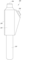
図2A及び図2Bは、例示的な測定装置200を示す。測定装置200は、上述の図1の測定装置100の部品及び特徴の一部又は全部を含んでもよい。測定装置200は、ハウジング202と、入力インタフェース203と、表示サブシステム204と、ユーザによって把持され得るハンドル部分205と、を備える。入力インタフェース203は、1つ以上のボタン、ダイヤル、タッチパッドなどを含んでもよい。入力インタフェース203はまた、例えば、タッチスクリーンとして表示サブシステム204と一体化されていてもよい。測定装置200のハウジング202は、電圧及び電流のうちの少なくとも一方を測定するために使用することができる少なくとも1つの非接触センサツールを含む前端部分206を含む。例えば、前端部分206は、非接触電圧センサツール、非接触電流センサツール、電流及び電圧の両方を測定することができる単一の非接触センサツール、又はこれらの任意の組み合わせを含んでもよい。
2A and 2B show an
測定装置200のハウジング202はまた、電気回路などの対象物の熱画像を撮像するように動作する熱撮像ツール208(図2B)を含む。動作中、測定装置200の撮像ツール208は、ディスプレイ204上に視覚画像(例えば、赤外線画像、VL画像)を提供してもよく、任意でレーザ誘導されてもよい。次いで、ユーザは、異常な発熱があると判定された電気回路の場所の近位に前端部分206を位置付けることができる。前端部分206が位置付けられると、測定装置200は、電力損失並びにそのような電力損失の経時的なコストを判定するために使用することができる電流測定値及び電圧測定値のうちの少なくとも一方を取得することができる。少なくともいくつかの実施形態では、測定装置200は、有線及び/又は無線通信インタフェース(例えば、USB、スパイラルケーブル、Bluetooth Low Energy(登録商標)、WiFi(登録商標))を介して、外部のプロセッサベースの装置(例えば、スマートフォン、タブレットコンピュータ、サーバ、別の測定器具)に通信可能に連結可能である。
The
図3は、1つの図示した実施形態による測定装置300の別の例を示す。測定装置300は、ケーブル306又は他の有線接続によって共に連結された第1のハウジング302及び第2のハウジング304を備える。この例では、第1のハウジング302は、表示サブシステム308と、ユーザインタフェース310と、(破線で示す)熱撮像ツール312と、を含む。第2のハウジング304は、電圧又は電流のうちの少なくとも一方を測定するための少なくとも1つの非接触センサ316を含む前端部分314を含むハンドヘルド型装置である。例えば、少なくとも1つの非接触センサ316は、少なくとも1つの非接触電圧センサのみを含んでもよく、少なくとも1つの非接触電流センサのみを含んでもよく、少なくとも1つの非接触電圧センサ及び少なくとも1つの非接触電流センサを含んでもよく、あるいは電圧及び電流の両方を検知できる少なくとも1つの非接触センサを含んでもよい。
FIG. 3 shows another example of a
動作中、ユーザは、第1のハウジング302内又は第1のハウジング302上の撮像ツール312を検査される対象物に向けることができる。撮像ツール312は、熱画像データを表示サブシステム308に表示でき、それによって、ユーザは、異常に高い発熱を潜在的に有する場所を特定することができる。追加的に又は代替的に、測定装置300は、画像データを分析して、異常に高い熱量を生成している1つ以上の場所を自動的に特定することができる。ユーザは、第2のハウジング304の前端部分314を、過剰な熱を有すると判定された(複数の)場所の近位に同時に又は後で位置付けることができ、その結果、検査中の導体とセンサ316との間のガルバニック接続なしに、その場所の電圧及び電流のうちの少なくとも一方を測定することができる。上述のように、測定装置300は、このような測定値を利用して、絶対電力損失、予測又は理論電力損失と比較した相対電力損失、電力損失の推定コストなどを判定することができる。測定装置300は、その後、判定されたパラメータのうちの1つ以上を、表示サブシステム308を介してユーザに提示することができる。
In operation, a user can aim the
図4は、1つの図示した実施形態による測定装置400の別の例を示す。測定装置400は、図3の測定装置300と多数の点で同様である。この実施形態では、ケーブル306(図3)を介して通信するのではなく、無線信号402で示されるように、第1のハウジング302の部品は、無線インタフェース(例えば、Bluetooth(登録商標)、Bluetooth Low Energy(登録商標)、WiFi(登録商標))を介して、第2のハウジング304の部品と通信する。
FIG. 4 shows another example of a
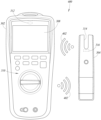
図5は、1つの図示した実施形態による測定装置500の別の実施形態を示す。測定装置500は、携帯装置502と、非接触電圧測定ツール504と、非接触電流測定ツール506と、熱撮像ツール508と、を備える。携帯装置502は、携帯電話、タブレットコンピュータ、パーソナルコンピュータ、測定機器(例えば、DMM)などを含むが、これらに限定されない多様なタイプの携帯装置のいずれかであってもよい。この実施形態では、非接触電圧測定ツール504、非接触電流測定ツール506、熱撮像ツール508のそれぞれは、携帯装置502と無線で通信するように構成されている。このような通信は、命令又はデータ(例えば、測定データ)の通信を含むことができる。いくつかの実施形態では、非接触電圧測定装置ツール、非接触電流測定ツール506、熱撮像装置ツールのうちの少なくとも2つは、単一のハウジング内に組み合わされてもよい。
FIG. 5 shows another embodiment of a
動作中、携帯装置502は、撮像データを受信及び表示し、電圧及び電流測定データを受信及び表示し、測定装置500のユーザに提示するための様々なパラメータ(例えば、電圧、電流、電力損失、電力損失のコスト)を判定又は推定することができる。携帯装置502はまた、外部システム510にデータ又は命令を送信してもよく、1つ以上の有線又は無線通信ネットワーク512を介して、外部システムからデータ又は命令を受信してもよい。外部システム510としては、パーソナルコンピュータ、サーバ、クラウド型サーバなどの任意のタイプのシステムを挙げることができる。
In operation,
いくつかの実施形態では、携帯装置502又は他の装置は、非接触電圧測定装置ツール、非接触電流測定ツール506、熱撮像ツール508、及び外部システム510の間のゲートウェイ装置として機能してもよい。この場合、携帯装置502は、任意の演算を行わなくてもよく、画像データを表示しなくてもよく、代わりに、外部システム510とセンサツール504、506、及び508との間で命令又はデータを通信してもよい。いくつかの実施形態では、センサツール504、506、及び508は、ゲートウェイ装置を要さずに、1つ以上の有線又は無線ネットワークを介して、外部システム510(例えば、クラウド型サーバ)と直接通信するように動作してもよい。
In some embodiments, the
図6は、1つの図示した実施形態による測定装置600の絵図である。測定装置600は、表示サブシステム604及び撮像ツール606を備えるマスター装置602を含む。測定装置600はまた、複数(図では3つ)の無線非接触センサツール608(「スレーブツール」)を備える。無線非接触センサツール608は、非接触電圧、非接触電流、又はその両方を測定するように動作し得る。無線非接触センサツール608は、好適な無線通信プロトコル(例えば、WiFi(登録商標)、Bluetooth(登録商標)、Bluetooth Low Energy(登録商標)、Zigbee(登録商標)、6LoWPAN(登録商標)、Optical IR、wireless HART)を介してマスター装置602と無線通信することができる。他の実施形態では、測定ツール608のうちの少なくとも1つは、ケーブル又は他の有線通信チャネル(例えば、USB(登録商標)、Ethernet、PLC、HART、MODBUS、FireWire(登録商標)、Thunderbolt(登録商標))を介して、マスター装置602と通信してもよい。
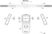
FIG. 6 is a pictorial diagram of a
マスター装置602は、直接又はゲートウェイ装置612を介して、携帯装置610と無線通信するように動作してもよい。一方、携帯装置610又はゲートウェイ装置612は、1つ以上のネットワーク614を介して、遠隔に位置する外部システム616(例えば、PC、サーバ)と無線通信するように動作してもよい。いくつかの実施形態では、マスター装置は、携帯装置610又はゲートウェイ装置612との通信を要さずに、1つ以上のネットワーク614を介して、外部システム616と通信することができてもよい。一般的には、本開示は、マスター装置602、センサツール608、携帯装置610、ゲートウェイ装置612、及び外部システム616の間の接続性の種々の組み合わせが想到されることを理解されたい。
図7は、図6の測定装置600の例示的な動作を示す。この例では、マスター装置602の熱撮像ツールを使用して、第1の電気導体702を第2の電気導体704に接続する電気回路の電気コネクタ700を撮像する。マスター装置602のディスプレイ604は、電気コネクタ700及び導体702、704の熱プロファイルを示し、熱プロファイルは、電気コネクタが電気抵抗の高い領域であることを示す。図7では、熱プロファイルを示すために影が使用され、より放熱性の高い領域を示す影は薄く、より放熱性の低い領域を示す影は濃くなっている。少なくともいくつかの実施形態では、ディスプレイ604は、電気回路のヒートパターンを描画するために様々な色を利用してもよい。
FIG. 7 illustrates exemplary operation of the
ユーザ及び/又はマスター装置602が電気コネクタ700を過剰な発熱の潜在的な領域として認識すると、ユーザは、電気コネクタに対する様々な電流測定値及び電圧測定値を取得してもよい。例えば、ユーザは、コネクタ700の片側の第1の導体702の第1の場所706の近位に非接触センサツール608のうちの1つを位置付けてもよく、コネクタ700の反対側の第2の導体704の第2の場所708の近位に非接触センサツール608のうちの他のツールを位置付けてもよい。非接触センサツール608のそれぞれは、上記のように、導体702、704とのガルバニック接触を要さずに、電圧及び/又は電流を測定するように動作することができる。一例として、2つのセンサツール608は、場所706及び708に位置付けられて、電気コネクタ700全体に亘る電圧降下を測定することができる。少なくともいくつかの実施形態では、2つ以上のセンサ(例えば、非接触電圧センサ)を使用して、電気回路の2つ以上の異なる場所を同時に測定することができる。例えば、コネクタの両側の2つのセンサを使用して、コネクタの両側の電圧を同時に測定して、コネクタ全体に亘る電圧降下を正確に測定することができる。
Once the user and/or
センサ608は、取得された測定データを、処理及びディスプレイ604上に提示するためにマスター装置602に送信してもよい。上記のように、マスター装置602は、コネクタ700全体に亘る電圧降下、コネクタを流れる電流、コネクタにおける電力損失、コネクタにおける電力損失の経時的なコストなどを判定することができる。そのような情報は、ディスプレイ604上に、ユーザに対して提示されてもよく、かつ/又は上記のように有線及び/若しくは無線通信チャネルを介して、1つ以上の遠隔装置に対して送信されてもよい。
前出の詳細な説明では、ブロック図、概略図及び実施例を使用して、装置及び/又はプロセスの様々な実施形態を説明してきた。そのようなブロック図、系統図及び実施例が1つ以上の機能及び/又は動作を含む限り、そのようなブロック図、フロー図又は実施例内のそれぞれの機能及び/又は動作は、広範囲にわたるハードウェア、ソフトウェア、ファームウェア又はこれらの実質的に任意の組み合わせによって個別にかつ/又は集合的に実行することができることが、当業者により理解されるであろう。1つの実施形態において、本主題を特定用途向け集積回路(ASIC)を介して実行することができる。しかしながら、当業者は、本明細書で開示する実施形態は、全部、一部を問わず、1つ以上のコンピュータ上で実行される1つ以上のコンピュータプログラムとして(例えば、1つ以上のコンピュータシステム上で実行される1つ以上のプログラムとして)、1つ以上の制御装置(例えば、マイクロコントローラ)上で実行される1つ以上のプログラムとして、1つ以上のプロセッサ(例えば、マイクロプロセッサ)上で実行される1つ以上のプログラムとして、ファームウェアとして、又はこれらの実質的に任意の組み合わせとして標準的な集積回路内で同等に実行することができ、ソフトウェア及び/又はファームウェアについての回路設計及び/又はコード書き込みであれば、十分に、本開示に照らして当該技術分野における当業者の知識の範囲内になることを認識するであろう。 The foregoing detailed description uses block diagrams, schematic diagrams, and examples to describe various embodiments of apparatus and/or processes. To the extent such block diagrams, system diagrams and examples include one or more functions and/or actions, each function and/or action within such block diagrams, flow diagrams or examples may be implemented using extensive hardware. It will be understood by those skilled in the art that they can be implemented individually and/or collectively by hardware, software, firmware or substantially any combination thereof. In one embodiment, the present subject matter can be implemented via an application specific integrated circuit (ASIC). However, one skilled in the art will appreciate that the embodiments disclosed herein can be implemented in whole or in part as one or more computer programs running on one or more computers (e.g., one or more computer systems). as one or more programs running on a computer), as one or more programs running on one or more controllers (e.g., microcontrollers), on one or more processors (e.g., microprocessors) Equivalently implemented in standard integrated circuits as one or more programs executed, as firmware, or substantially any combination thereof, circuit design and/or for software and/or firmware It will be appreciated that writing code is well within the knowledge of those skilled in the art in light of this disclosure.
当業者は、本明細書に記載する方法又はアルゴリズムの多くは、付加的な行為を採用することができ、一部の行為を省略することができ、かつ/又は行為を指定された順番と異なる順番で実行することができることを認識するであろう。 It will be appreciated by those skilled in the art that many of the methods or algorithms described herein may employ additional acts, may omit some acts, and/or perform acts out of the order specified. It will be appreciated that they can be executed in order.
更に、当業者は、本明細書で教示する機構は、様々な形態でプログラム製品として流通可能であり、例示的な実施形態は、流通を実際に実行するために使用される特定の形式の信号担持媒体に関係なく等しく適用されることを認識するであろう。信号担持媒体の例としては、以下、即ち、フロッピーディスク、ハードディスクドライブ、CD-ROM、デジタルテープ及びコンピュータメモリなどの記録可能な形式の媒体が挙げられるがこれらに限定されない。 Moreover, those skilled in the art will appreciate that the mechanisms taught herein can be distributed as program products in a variety of forms, and the exemplary embodiment is the specific form of signal used to actually effect the distribution. It will be recognized that it applies equally regardless of the carrier medium. Examples of signal-bearing media include, but are not limited to, recordable forms of media such as floppy disks, hard disk drives, CD-ROMs, digital tapes, and computer memory.
上述した様々な実施形態を組み合わせて、更なる実施形態を提供することができる。これらの実施形態が本明細書に記載の教示及び定義と矛盾しない程度に、2014年10月24日に出願された米国特許仮出願第62/068,392号、2015年10月23日に出願された米国特許出願公開第14/921,128号、2014年9月17日に出願された米国特許仮出願第62/051,930号、2014年11月6日に出願された米国特許仮出願第62/076,088号、2015年9月16日に出願された米国特許出願公開第14/856,046号、2012年8月3日に出願された米国特許出願公開第13/566,947号、及び2011年8月3日に出願された米国特許仮出願第61/514,842号を含む、本明細書に引用される米国特許、米国特許出願公報、米国特許出願、外国特許、外国特許出願、及び非特許公報の全ては、参照によりその全体が本明細書に援用されている。実施形態の態様は、様々な特許、出願及び公報のシステム、回路、及び概念を用いて、尚更なる実施形態を提供するように必要に応じて修正することができる。 The various embodiments described above can be combined to provide further embodiments. To the extent these embodiments are consistent with the teachings and definitions set forth herein, U.S. Provisional Patent Application No. 62/068,392, filed October 24, 2014, filed October 23, 2015. U.S. Patent Application Publication No. 14/921,128, filed September 17, 2014; U.S. Provisional Application No. 62/051,930, filed November 6, 2014; 62/076,088, U.S. Patent Application Publication No. 14/856,046 filed September 16, 2015, U.S. Patent Application Publication No. 13/566,947 filed August 3, 2012 and U.S. Provisional Patent Application No. 61/514,842 filed Aug. 3, 2011, U.S. patents, U.S. patent application publications, U.S. patent applications, foreign patents, foreign All patent applications and non-patent publications are hereby incorporated by reference in their entirety. Aspects of the embodiments can be modified, if necessary, using systems, circuits, and concepts of the various patents, applications, and publications to provide still further embodiments.
上記の説明を考慮すれば、実施形態へのこれらの変更及び他の変更を行うことができる。概して、以下の請求項において、使用する用語は、明細書及び請求項に開示された特定の実施形態に対する請求項を限定するものと解釈すべきではないが、こうした請求項に権利を与えた等価物の全範囲と共に全ての考えられる実施形態を含むものと解釈すべきである。したがって、請求項は、開示によって制限されるものではない。 These and other changes to the embodiments can be made in light of the above description. In general, the language used in the following claims should not be construed as limiting the claims to the particular embodiments disclosed in the specification and claims, but rather equivalents entitled to such claims. It should be interpreted as including all possible embodiments as well as the full scope of the product. Accordingly, the claims are not limited by the disclosure.
Claims (15)
動作中、電気回路を含む対象シーンからの赤外放射を検出し、前記電気回路のためのサーモグラフ画像データを生成する、前記ハウジング内又は前記ハウジング上に配置された熱撮像ツールと、
動作中、前記電気回路の絶縁導体の電圧を、前記絶縁導体にガルバニック接触することなく、検知する非接触電圧測定ツール(NVMT)と、
動作中、前記電気回路の絶縁導体の電流を、前記絶縁導体にガルバニック接触することなく、検知する非接触電流測定ツール(NCMT)と、
表示サブシステムと、
プロセッサ実行可能命令又はデータのうちの少なくとも一方を記憶する少なくとも1つの非一時的プロセッサ可読記憶媒体と、
前記少なくとも1つの非一時的プロセッサ可読記憶媒体と、前記熱撮像ツールと、前記NVMTと、前記NCMTと、前記表示サブシステムとに通信可能に連結された少なくとも1つのプロセッサと、を備える、非接触測定装置であって、動作中、前記少なくとも1つのプロセッサは、
前記熱撮像ツールからサーモグラフ画像データを受信することと、
前記熱撮像ツールから受信した前記サーモグラフ画像データの解析に基づいて、前記電気回路内の高抵抗の電気接続を特定することと、
前記NVMTに前記高抵抗の電気接続からの電圧を測定させること又は前記NCMTに前記高抵抗の電気接続からの電流を測定させることのうちの少なくとも一方と、を行う、非接触測定装置。 a housing;
a thermal imaging tool disposed in or on the housing that, in operation, detects infrared radiation from a target scene containing an electrical circuit and generates thermographic image data for the electrical circuit;
a non-contact voltage measurement tool (NVMT) for sensing, during operation, the voltage of an insulated conductor of the electrical circuit without galvanically contacting the insulated conductor;
a non-contact current measurement tool (NCMT) for sensing current in insulated conductors of the electrical circuit during operation without galvanic contact with the insulated conductors;
a display subsystem;
at least one non-transitory processor-readable storage medium storing at least one of processor-executable instructions or data;
at least one processor communicatively coupled to the at least one non-transitory processor-readable storage medium, the thermal imaging tool, the NVMT, the NCMT, and the display subsystem. A measurement device, wherein in operation the at least one processor:
receiving thermographic image data from the thermal imaging tool;
identifying high resistance electrical connections in the electrical circuit based on analysis of the thermographic image data received from the thermal imaging tool;
and/or causing the NVMT to measure voltage from the high resistance electrical connection and/or the NCMT to measure current from the high resistance electrical connection.
前記電気回路の異常発熱の場所の有無を示す前記サーモグラフ画像データを、前記表示サブシステムによって、提示することと、presenting, by the display subsystem, the thermograph image data indicating the presence or absence of locations of abnormal heat generation in the electric circuit;
前記NVMT又は前記NCMTのうちの少なくとも一方から測定データを受信することであって、前記測定データは、前記NVMTからの電圧センサ信号又は前記NCMTからの電流センサ信号のうちの少なくとも一方を含み、前記電圧センサ信号は、前記電気回路の絶縁導体の電圧を示し、前記電流センサ信号は、前記電気回路の絶縁導体の電流を示す、ことと、を行う、請求項1に記載の非接触測定装置。receiving measurement data from at least one of the NVMT or the NCMT, the measurement data including at least one of a voltage sensor signal from the NVMT or a current sensor signal from the NCMT; 2. The non-contact measurement device of claim 1, wherein the voltage sensor signal is indicative of the voltage of the insulated conductors of the electrical circuit and the current sensor signal is indicative of the current of the insulated conductors of the electrical circuit.
ある期間にわたる前記電気回路の絶縁導体における電力損失量を推定することと、更に、
前記表示サブシステムによって、前記電力損失量を提示することと、又は
有線若しくは無線通信インタフェースを介して、前記電力損失量を外部装置に伝達することのうちの少なくとも一方を行う、請求項1から3のいずれか一項に記載の非接触測定装置。 During operation, the at least one processor:
estimating the amount of power lost in insulated conductors of the electrical circuit over time;
4. The display subsystem at least one of presenting the power loss measure and/or communicating the power loss measure to an external device via a wired or wireless communication interface. The non-contact measurement device according to any one of .
前記電力損失量に関連付けられた推定コストを判定することと、
前記推定コストを前記表示サブシステムによって提示することと、を行う、請求項4又は5に記載の非接触測定装置。 During operation, the at least one processor:
determining an estimated cost associated with the amount of power lost;
Presenting the estimated cost by the display subsystem.
測定時間間隔中、前記NVMTによって取得された前記NVMTからの電圧センサ信号を受信することと、
前記測定時間間隔中、前記NCMTによって取得された前記NCMTからの電流センサ信号を受信することと、
少なくとも1つの交流(AC)電気パラメータを、前記電圧センサ信号及び前記電流センサ信号に基づいて判定することと、を行う、請求項1から7のいずれか一項に記載の非接触測定装置。 During operation, the at least one processor:
receiving a voltage sensor signal from the NVMT acquired by the NVMT during a measurement time interval;
receiving a current sensor signal from the NCMT acquired by the NCMT during the measurement time interval;
8. A non-contact measurement device according to any preceding claim, wherein at least one alternating current (AC) electrical parameter is determined based on the voltage sensor signal and the current sensor signal.
前記非接触測定装置のハウジング内又はハウジング上に配置された熱撮像ツールによって、電気回路を含む対象シーンからの赤外放射を検出することと、
前記熱撮像ツールによって、前記電気回路のためのサーモグラフ画像データを生成することと、
少なくとも1つのプロセッサが、前記熱撮像ツールから前記サーモグラフ画像データを受信することと、
前記熱撮像ツールから受信した前記サーモグラフ画像データの解析に基づいて、前記電気回路内の高抵抗の電気接続を特定することと、
非接触電圧測定ツール(NVMT)に前記高抵抗の電気接続からの電圧を測定させること又は非接触電流測定ツール(NCMT)に前記高抵抗の電気接続からの電流を測定させることのうちの少なくとも一方と、を含む、方法。 A method of operating a non-contact measurement device, the method comprising:
detecting infrared radiation from a target scene containing electrical circuits with a thermal imaging tool positioned in or on the housing of the non-contact measurement device;
generating thermographic image data for the electrical circuit with the thermal imaging tool;
at least one processor receiving the thermographic image data from the thermal imaging tool;
identifying high resistance electrical connections in the electrical circuit based on analysis of the thermographic image data received from the thermal imaging tool;
At least one of having a non-contact voltage measurement tool (NVMT) measure voltage from the high resistance electrical connection or have a non-contact current measurement tool (NCMT) measure current from the high resistance electrical connection. and, including, methods.
前記NVMTによって、前記電気回路の絶縁導体の電圧を、前記絶縁導体にガルバニック接触することなく検知することと、又は、前記NCMTによって、前記電気回路の絶縁導体の電流を、前記絶縁導体にガルバニック接触することなく検知することと、のうちの少なくとも一方と、The NVMT senses voltage in an insulated conductor of the electrical circuit without galvanic contact to the insulated conductor; or the NCMT senses a current in an insulated conductor of the electrical circuit without galvanic contact to the insulated conductor. at least one of detecting without
前記少なくとも1つのプロセッサが、前記NVMT又は前記NCMTのうちの少なくとも一方から測定データを受信することであって、前記測定データは、前記NVMTからの電圧センサ信号又は前記NCMTからの電流センサ信号のうちの少なくとも一方を含み、前記電圧センサ信号は、前記電気回路の絶縁導体の電圧を示し、前記電流センサ信号は、前記電気回路の絶縁導体の電流を示す、ことと、The at least one processor receives measurement data from at least one of the NVMT or the NCMT, the measurement data being either a voltage sensor signal from the NVMT or a current sensor signal from the NCMT. wherein the voltage sensor signal is indicative of a voltage in an insulated conductor of the electrical circuit and the current sensor signal is indicative of a current in an insulated conductor of the electrical circuit;
前記少なくとも1つのプロセッサが、前記測定データに基づいて、少なくとも1つの交流(AC)電気パラメータを判定することと、を更に含む請求項9に記載の方法。10. The method of claim 9, further comprising determining at least one alternating current (AC) electrical parameter based on the measured data.
表示サブシステムによって、前記電力損失量を提示することと、又は
有線若しくは無線通信インタフェースを介して、前記電力損失量を外部装置に伝達することと、のうちの少なくとも一方を更に含む、請求項9又は10に記載の方法。 the at least one processor estimating an amount of power lost in an insulated conductor of the electrical circuit over time;
12. The claim further comprising at least one of: presenting the power loss measure by a display subsystem; or communicating the power loss measure to an external device via a wired or wireless communication interface. 11. The method according to 9 or 10 .
前記推定コストを前記表示サブシステムによって提示することと、を更に含む、請求項11に記載の方法。 the at least one processor determining an estimated cost associated with the amount of power lost;
12. The method of claim 11 , further comprising presenting the estimated cost by the display subsystem.
動作中、前記電気回路の絶縁導体の電圧を、前記絶縁導体にガルバニック接触することなく、検知する非接触電圧測定ツール(NVMT)と、
動作中、前記電気回路の絶縁導体の電流を、前記絶縁導体にガルバニック接触することなく、検知する非接触電流測定ツール(NCMT)と、
プロセッサ実行可能命令又はデータのうちの少なくとも一方を記憶する少なくとも1つの非一時的プロセッサ可読記憶媒体と、
前記少なくとも1つの非一時的プロセッサ可読記憶媒体と、前記熱撮像ツールと、前記NVMTと、前記NCMTと、に通信可能に連結された少なくとも1つのプロセッサと、を備える、非接触測定装置であって、動作中、前記少なくとも1つのプロセッサは、
前記熱撮像ツールからサーモグラフ画像データを受信することと、
前記熱撮像ツールから受信した前記サーモグラフ画像データの解析に基づいて、前記電気回路内の高抵抗の電気接続を特定することと、
前記電気回路内の前記高抵抗の電気接続を表示することと、
前記NVMTに前記高抵抗の電気接続からの電圧を測定させること又は前記NCMTに前記高抵抗の電気接続からの電流を測定させることのうちの少なくとも一方と、を行う、非接触測定装置。 a thermal imaging tool that, in operation, detects infrared radiation from a scene of interest containing an electrical circuit and generates thermographic image data for the electrical circuit;
a non-contact voltage measurement tool (NVMT) for sensing, during operation, the voltage of an insulated conductor of the electrical circuit without galvanically contacting the insulated conductor;
a non-contact current measurement tool (NCMT) for sensing current in insulated conductors of the electrical circuit during operation without galvanic contact with the insulated conductors;
at least one non-transitory processor-readable storage medium storing at least one of processor-executable instructions or data;
A non-contact measurement device comprising: said at least one non-transitory processor-readable storage medium; and at least one processor communicatively coupled to said thermal imaging tool, said NVMT, and said NCMT; , in operation, the at least one processor comprising:
receiving thermographic image data from the thermal imaging tool;
identifying high resistance electrical connections in the electrical circuit based on analysis of the thermographic image data received from the thermal imaging tool;
displaying the high resistance electrical connection in the electrical circuit ;
and/or causing the NVMT to measure voltage from the high resistance electrical connection and/or the NCMT to measure current from the high resistance electrical connection.
該サーモグラフ画像データの少なくとも一部に基づいて、前記電気回路の異常発熱の場所の有無を表示することと、displaying the presence or absence of a location of abnormal heat generation in the electric circuit based on at least part of the thermograph image data;
前記NVMT又は前記NCMTのうちの少なくとも一方から測定データを受信することであって、前記測定データは、前記NVMTからの電圧センサ信号又は前記NCMTからの電流センサ信号のうちの少なくとも一方を含み、前記電圧センサ信号は、前記電気回路の絶縁導体の電圧を示し、前記電流センサ信号は、前記電気回路の絶縁導体の電流を示す、ことと、receiving measurement data from at least one of the NVMT or the NCMT, the measurement data including at least one of a voltage sensor signal from the NVMT or a current sensor signal from the NCMT; the voltage sensor signal is indicative of the voltage of the insulated conductors of the electrical circuit and the current sensor signal is indicative of the current of the insulated conductors of the electrical circuit;
前記サーモグラフ画像データの少なくとも一部に基づいた前記電気回路の異常発熱の場所の有無の表示に関連して、表示サブシステムによって、前記測定データの少なくとも一部を提示することと、を行う、請求項14に記載の非接触測定装置。presenting at least a portion of the measurement data by a display subsystem in connection with displaying the presence or absence of locations of abnormal heat generation in the electrical circuit based at least in part on the thermographic image data; 15. The non-contact measuring device according to claim 14.
Applications Claiming Priority (2)
| Application Number | Priority Date | Filing Date | Title |
|---|---|---|---|
| US15/625,812 US10120021B1 (en) | 2017-06-16 | 2017-06-16 | Thermal non-contact voltage and non-contact current devices |
| US15/625,812 | 2017-06-16 |
Publications (3)
| Publication Number | Publication Date |
|---|---|
| JP2019023623A JP2019023623A (en) | 2019-02-14 |
| JP2019023623A5 JP2019023623A5 (en) | 2021-07-29 |
| JP7257110B2 true JP7257110B2 (en) | 2023-04-13 |
Family
ID=62684626
Family Applications (1)
| Application Number | Title | Priority Date | Filing Date |
|---|---|---|---|
| JP2018114549A Active JP7257110B2 (en) | 2017-06-16 | 2018-06-15 | Thermal non-contact voltage and non-contact current devices |
Country Status (5)
| Country | Link |
|---|---|
| US (1) | US10120021B1 (en) |
| EP (1) | EP3415930A1 (en) |
| JP (1) | JP7257110B2 (en) |
| CN (1) | CN109142842A (en) |
| TW (1) | TWI799424B (en) |
Families Citing this family (9)
| Publication number | Priority date | Publication date | Assignee | Title |
|---|---|---|---|---|
| EP2974266A4 (en) * | 2013-03-15 | 2016-11-02 | Fluke Corp | Visible audiovisual annotation of infrared images using a separate wireless mobile device |
| US10375325B2 (en) * | 2016-06-23 | 2019-08-06 | Fluke Corporation | Thermal anomaly detection |
| US11175314B2 (en) * | 2018-04-06 | 2021-11-16 | STB Electrical Test Equipment, Inc. | Multimeter with a meter probe module and phasing probe module capable of wireless communication and taking measurements proximally |
| CN112816769A (en) * | 2019-11-15 | 2021-05-18 | 许继集团有限公司 | Current and voltage combined data acquisition device |
| CN111948452A (en) * | 2020-08-13 | 2020-11-17 | 南方电网科学研究院有限责任公司 | Harmonic detection device and method of non-invasive micro sensor and terminal equipment |
| CN112615347B (en) * | 2020-10-29 | 2021-12-10 | 深圳市中创电测技术有限公司 | Line safety management system and method |
| CN113447698B (en) * | 2021-06-11 | 2022-03-08 | 南方电网数字电网研究院有限公司 | Voltage measurement circuit, method and apparatus |
| CN113744197B (en) * | 2021-08-09 | 2024-01-02 | 福建工程学院 | Cable fault detection method based on infrared and ultraviolet composite imaging |
| CN114019226A (en) * | 2021-10-27 | 2022-02-08 | 北京大学 | Non-contact electric quantity measuring and recording device |
Citations (5)
| Publication number | Priority date | Publication date | Assignee | Title |
|---|---|---|---|---|
| JP2001509903A (en) | 1998-08-01 | 2001-07-24 | ビーエーイー・システムズ・パブリック・リミテッド・カンパニー | Thermographic wiring inspection |
| JP2002298726A (en) | 2001-03-29 | 2002-10-11 | Hitachi Ltd | Measuring device |
| JP2005164463A (en) | 2003-12-04 | 2005-06-23 | Meidensha Corp | Voltage/current measuring device for distribution equipment |
| US20160119592A1 (en) | 2014-10-24 | 2016-04-28 | Fluke Corporation | Imaging system employing fixed, modular mobile, and portable infrared cameras with ability to receive, communicate, and display data and images with proximity detection |
| JP2017032287A (en) | 2015-07-29 | 2017-02-09 | 日置電機株式会社 | Clamp type sensor and measuring device |
Family Cites Families (60)
| Publication number | Priority date | Publication date | Assignee | Title |
|---|---|---|---|---|
| DE2363933C3 (en) | 1973-12-20 | 1980-09-04 | Siemens Ag, 1000 Berlin Und 8000 Muenchen | Combined current and voltage measuring device |
| US4173970A (en) * | 1977-08-03 | 1979-11-13 | Jaymin Research Corporation | Thermographic diagnostic method and system |
| US4689752A (en) | 1983-04-13 | 1987-08-25 | Niagara Mohawk Power Corporation | System and apparatus for monitoring and control of a bulk electric power delivery system |
| US4584523A (en) * | 1983-10-03 | 1986-04-22 | Rca Corporation | Measurement of the current flow in an electric power transmission line by detection of infrared radiation therefrom |
| JP2581605Y2 (en) | 1992-09-01 | 1998-09-24 | 株式会社アドバンテスト | Non-contact AC voltmeter |
| JPH06222087A (en) | 1993-01-27 | 1994-08-12 | Hamamatsu Photonics Kk | Voltage detector |
| US5973501A (en) | 1993-10-18 | 1999-10-26 | Metropolitan Industries, Inc. | Current and voltage probe for measuring harmonic distortion |
| US6043640A (en) | 1997-10-29 | 2000-03-28 | Fluke Corporation | Multimeter with current sensor |
| US6118270A (en) | 1998-02-17 | 2000-09-12 | Singer; Jerome R. | Apparatus for fast measurements of current and power with scaleable wand-like sensor |
| GB2340224B (en) * | 1998-08-01 | 2001-06-06 | British Aerospace | Thermographic wiring inspection |
| US6177800B1 (en) | 1998-11-10 | 2001-01-23 | Xerox Corporation | Method and apparatus for using shuttered windows in a micro-electro-mechanical system |
| IL127699A0 (en) | 1998-12-23 | 1999-10-28 | Bar Dov Aharon | Method and device for non contact detection of external electric or magnetic fields |
| US6812685B2 (en) | 2001-03-22 | 2004-11-02 | Actuant Corporation | Auto-selecting, auto-ranging contact/noncontact voltage and continuity tester |
| JP3761470B2 (en) | 2001-04-04 | 2006-03-29 | 北斗電子工業株式会社 | Non-contact voltage measurement method and apparatus, and detection probe |
| US7256588B2 (en) | 2004-04-16 | 2007-08-14 | General Electric Company | Capacitive sensor and method for non-contacting gap and dielectric medium measurement |
| JP4611774B2 (en) | 2005-03-04 | 2011-01-12 | 東日本電信電話株式会社 | Non-contact voltage detection method and non-contact voltage detection device |
| US7466145B2 (en) | 2005-10-12 | 2008-12-16 | Hioki Denki Kabushiki Kaisha | Voltage measuring apparatus and power measuring apparatus |
| JP4607753B2 (en) | 2005-12-16 | 2011-01-05 | 日置電機株式会社 | Voltage measuring device and power measuring device |
| JP4607752B2 (en) | 2005-12-16 | 2011-01-05 | 日置電機株式会社 | Variable capacitance circuit, voltage measuring device and power measuring device |
| JP4713358B2 (en) | 2006-02-08 | 2011-06-29 | 日置電機株式会社 | Voltage detector |
| JP4648228B2 (en) | 2006-03-24 | 2011-03-09 | 日置電機株式会社 | Voltage detection apparatus and initialization method |
| JP5106798B2 (en) | 2006-06-22 | 2012-12-26 | 日置電機株式会社 | Voltage measuring device |
| JP4726722B2 (en) | 2006-07-03 | 2011-07-20 | 日置電機株式会社 | Voltage measuring device |
| JP4726721B2 (en) | 2006-07-03 | 2011-07-20 | 日置電機株式会社 | Voltage measuring device |
| JP4629625B2 (en) | 2006-07-12 | 2011-02-09 | 日置電機株式会社 | Voltage measuring device |
| GB0614261D0 (en) | 2006-07-18 | 2006-08-30 | Univ Sussex The | Electric Potential Sensor |
| JP2008215900A (en) | 2007-03-01 | 2008-09-18 | Hitachi Mobile Co Ltd | Noncontact current meter and measurement auxiliary tool of the same |
| JP5106909B2 (en) | 2007-04-10 | 2012-12-26 | 日置電機株式会社 | Line voltage measuring device |
| JP4927632B2 (en) | 2007-04-13 | 2012-05-09 | 日置電機株式会社 | Voltage measuring device |
| JP5144110B2 (en) | 2007-04-13 | 2013-02-13 | 日置電機株式会社 | Voltage measuring device |
| JP5160248B2 (en) | 2008-01-18 | 2013-03-13 | 日置電機株式会社 | Voltage detector |
| US20100090682A1 (en) | 2008-02-14 | 2010-04-15 | Armstrong Eric A | Multi-Meter Test Lead Probe For Hands-Free Electrical Measurement of Control Panel Industrial Terminal Blocks |
| US8222886B2 (en) | 2008-06-18 | 2012-07-17 | Hioki Denki Kabushiki Kaisha | Voltage detecting apparatus and line voltage detecting apparatus having a detection electrode disposed facing a detected object |
| JP5389389B2 (en) | 2008-07-22 | 2014-01-15 | 日置電機株式会社 | Line voltage measuring apparatus and program |
| CN101881791B (en) | 2009-04-30 | 2015-08-05 | 日置电机株式会社 | Voltage check device |
| JP5340817B2 (en) | 2009-06-11 | 2013-11-13 | 日置電機株式会社 | Voltage detector |
| JP5420387B2 (en) | 2009-12-09 | 2014-02-19 | 日置電機株式会社 | Voltage detector |
| JP5474707B2 (en) | 2010-08-30 | 2014-04-16 | 日置電機株式会社 | Detection circuit and voltage detection device for voltage detection device |
| US8466687B2 (en) * | 2010-09-20 | 2013-06-18 | The Aerospace Corporation | System and method for detecting defects |
| US9063184B2 (en) | 2011-02-09 | 2015-06-23 | International Business Machines Corporation | Non-contact current-sensing and voltage-sensing clamp |
| US8680845B2 (en) | 2011-02-09 | 2014-03-25 | International Business Machines Corporation | Non-contact current and voltage sensor |
| JP5737750B2 (en) | 2011-02-25 | 2015-06-17 | 株式会社日立パワーソリューションズ | AC power measuring device |
| JP5834663B2 (en) * | 2011-04-06 | 2015-12-24 | 富士通株式会社 | AC power measuring device |
| WO2013020110A2 (en) * | 2011-08-03 | 2013-02-07 | Fluke Corporation | Maintenance management systems and methods |
| JP4995993B2 (en) | 2012-03-05 | 2012-08-08 | 日置電機株式会社 | Clamp sensor |
| US20140035607A1 (en) | 2012-08-03 | 2014-02-06 | Fluke Corporation | Handheld Devices, Systems, and Methods for Measuring Parameters |
| JP5981270B2 (en) | 2012-08-28 | 2016-08-31 | 日置電機株式会社 | Voltage measuring sensor and voltage measuring device |
| JP5981271B2 (en) | 2012-08-28 | 2016-08-31 | 日置電機株式会社 | Voltage measuring sensor and voltage measuring device |
| KR101961097B1 (en) * | 2012-09-06 | 2019-03-25 | 삼성전자 주식회사 | Test apparatus for semiconductor packages |
| CN204649311U (en) * | 2012-09-14 | 2015-09-16 | 菲力尔系统公司 | Measurement mechanism |
| JP6104578B2 (en) | 2012-11-30 | 2017-03-29 | 日置電機株式会社 | Inspection apparatus and inspection method |
| JP2015111087A (en) | 2013-12-06 | 2015-06-18 | オムロン株式会社 | Non-contact voltage measurement device and non-contact voltage measurement method |
| JP6459188B2 (en) * | 2014-03-13 | 2019-01-30 | オムロン株式会社 | Non-contact voltage measuring device |
| JP6343984B2 (en) * | 2014-03-13 | 2018-06-20 | オムロン株式会社 | Non-contact voltage measuring device |
| JP6210938B2 (en) | 2014-06-18 | 2017-10-11 | 日置電機株式会社 | Non-contact voltage detector |
| TWI531800B (en) * | 2014-09-16 | 2016-05-01 | 財團法人工業技術研究院 | Non-contact type voltage sensor for dual-wire power cable and method for compensating installtion position variation thereof |
| US10602082B2 (en) * | 2014-09-17 | 2020-03-24 | Fluke Corporation | Triggered operation and/or recording of test and measurement or imaging tools |
| US20160080666A1 (en) | 2014-09-17 | 2016-03-17 | Fluke Corporation | Test and measurement system with removable imaging tool |
| TWI649568B (en) | 2014-10-17 | 2019-02-01 | 日商日置電機股份有限公司 | Voltage detecting device |
| WO2016146150A1 (en) * | 2015-03-13 | 2016-09-22 | Stefan Keckeisen Akkumulatoren E.K. | Voltage measuring device |
-
2017
- 2017-06-16 US US15/625,812 patent/US10120021B1/en active Active
-
2018
- 2018-06-14 EP EP18177845.7A patent/EP3415930A1/en not_active Withdrawn
- 2018-06-15 TW TW107120684A patent/TWI799424B/en active
- 2018-06-15 CN CN201810619943.0A patent/CN109142842A/en active Pending
- 2018-06-15 JP JP2018114549A patent/JP7257110B2/en active Active
Patent Citations (5)
| Publication number | Priority date | Publication date | Assignee | Title |
|---|---|---|---|---|
| JP2001509903A (en) | 1998-08-01 | 2001-07-24 | ビーエーイー・システムズ・パブリック・リミテッド・カンパニー | Thermographic wiring inspection |
| JP2002298726A (en) | 2001-03-29 | 2002-10-11 | Hitachi Ltd | Measuring device |
| JP2005164463A (en) | 2003-12-04 | 2005-06-23 | Meidensha Corp | Voltage/current measuring device for distribution equipment |
| US20160119592A1 (en) | 2014-10-24 | 2016-04-28 | Fluke Corporation | Imaging system employing fixed, modular mobile, and portable infrared cameras with ability to receive, communicate, and display data and images with proximity detection |
| JP2017032287A (en) | 2015-07-29 | 2017-02-09 | 日置電機株式会社 | Clamp type sensor and measuring device |
Also Published As
| Publication number | Publication date |
|---|---|
| CN109142842A (en) | 2019-01-04 |
| US10120021B1 (en) | 2018-11-06 |
| TW201905425A (en) | 2019-02-01 |
| TWI799424B (en) | 2023-04-21 |
| EP3415930A1 (en) | 2018-12-19 |
| JP2019023623A (en) | 2019-02-14 |
Similar Documents
| Publication | Publication Date | Title |
|---|---|---|
| JP7257110B2 (en) | Thermal non-contact voltage and non-contact current devices | |
| EP3321696B1 (en) | Non-contact electrical parameter measurement systems | |
| EP3069424B1 (en) | System and method of tracking the thermal age of a heating cable | |
| TWI785078B (en) | Multiple phase measurement device | |
| JP7159106B2 (en) | Clamp probe for non-contact electrical parameter measurement | |
| US20150331024A1 (en) | Power meter with current and phase sensor | |
| CN107655940B (en) | Transformer winding material detection equipment and system | |
| WO2013126612A3 (en) | Electrical test device and method | |
| BRPI0716882A2 (en) | SENSOR, METHOD AND SYSTEM FOR MONITORING TRANSMISSION LINES | |
| US20210041483A1 (en) | Non-contact electrical parameter measurement device with clamp jaw assembly | |
| JP2019023623A5 (en) | ||
| CN109917157A (en) | A kind of Auto-Test System of wireless charging system | |
| JP2019215329A5 (en) | ||
| CN105509893B (en) | Thermal imaging temperature measurement on-line method | |
| US20150198734A1 (en) | Apparatus and method for detecting location of buried pipe | |
| TW201516418A (en) | Voltage detection method and voltage detection device using the same | |
| CN112285404B (en) | Measurement device for power interference indication and method of operation thereof | |
| KR20140003427U (en) | corded metal identification apparatus | |
| KR101338756B1 (en) | Apparatus for Temperature Detection Using Resistance Temperature Detector | |
| CN112345831B (en) | Direct-current resistance measuring device of ultra-high voltage transformer | |
| TWI522626B (en) | Portable power information detector | |
| Khalid et al. | Energy Meter (E-MON) With IoT Monitoring (Web & Apps) | |
| PL402223A1 (en) | Method and system for measuring the choke's own and mutual thermal resistance | |
| TWM472194U (en) | Voltage detection device capable of measuring high voltage | |
| MX2016017168A (en) | System and method for the measurement of magnetic susceptibility and the constant of magnetic anisotropy of superparamagnetic nanoparticles. |
Legal Events
| Date | Code | Title | Description |
|---|---|---|---|
| A521 | Request for written amendment filed |
Free format text: JAPANESE INTERMEDIATE CODE: A523 Effective date: 20210615 |
|
| A621 | Written request for application examination |
Free format text: JAPANESE INTERMEDIATE CODE: A621 Effective date: 20210615 |
|
| A521 | Request for written amendment filed |
Free format text: JAPANESE INTERMEDIATE CODE: A821 Effective date: 20220414 |
|
| RD02 | Notification of acceptance of power of attorney |
Free format text: JAPANESE INTERMEDIATE CODE: A7422 Effective date: 20220414 |
|
| A977 | Report on retrieval |
Free format text: JAPANESE INTERMEDIATE CODE: A971007 Effective date: 20220622 |
|
| A131 | Notification of reasons for refusal |
Free format text: JAPANESE INTERMEDIATE CODE: A131 Effective date: 20220726 |
|
| A601 | Written request for extension of time |
Free format text: JAPANESE INTERMEDIATE CODE: A601 Effective date: 20221025 |
|
| A601 | Written request for extension of time |
Free format text: JAPANESE INTERMEDIATE CODE: A601 Effective date: 20221223 |
|
| A521 | Request for written amendment filed |
Free format text: JAPANESE INTERMEDIATE CODE: A523 Effective date: 20230124 |
|
| TRDD | Decision of grant or rejection written | ||
| A01 | Written decision to grant a patent or to grant a registration (utility model) |
Free format text: JAPANESE INTERMEDIATE CODE: A01 Effective date: 20230307 |
|
| A61 | First payment of annual fees (during grant procedure) |
Free format text: JAPANESE INTERMEDIATE CODE: A61 Effective date: 20230403 |
|
| R150 | Certificate of patent or registration of utility model |
Ref document number: 7257110 Country of ref document: JP Free format text: JAPANESE INTERMEDIATE CODE: R150 |