JP7256016B2 - Predictive model generation device, prediction model generation method by prediction model generation device, and prediction device - Google Patents
Predictive model generation device, prediction model generation method by prediction model generation device, and prediction device Download PDFInfo
- Publication number
- JP7256016B2 JP7256016B2 JP2019011714A JP2019011714A JP7256016B2 JP 7256016 B2 JP7256016 B2 JP 7256016B2 JP 2019011714 A JP2019011714 A JP 2019011714A JP 2019011714 A JP2019011714 A JP 2019011714A JP 7256016 B2 JP7256016 B2 JP 7256016B2
- Authority
- JP
- Japan
- Prior art keywords
- image
- images
- unit
- amount
- prediction
- Prior art date
- Legal status (The legal status is an assumption and is not a legal conclusion. Google has not performed a legal analysis and makes no representation as to the accuracy of the status listed.)
- Active
Links
Images


Description
本発明は、予測モデル生成装置等に関する。 The present invention relates to a prediction model generation device and the like.
従来から、焼却炉等の加熱炉内を撮像した画像データに基づき、加熱炉に対する制御プロセス値(制御量)を決定する技術が開発されている。このような技術の一例が、特許文献1及び2に開示されている。
2. Description of the Related Art Conventionally, techniques have been developed for determining a control process value (control amount) for a heating furnace based on image data obtained by imaging the inside of a heating furnace such as an incinerator. Examples of such techniques are disclosed in
特許文献1には、ストーカ式焼却炉の燃焼制御方法の一例が開示されている。当該燃焼制御方法では、赤外線カメラで撮像された画像に基づき、可燃物層(ごみの燃焼層)の表面における低温領域の面積を算出する。そして、算出した低温領域の面積と、検出器により検出された、排ガス熱を回収するボイラの発生蒸気量とに基づき、ストーカ式焼却炉にごみを投入するためのフィーダの作動速度、及びストーカ式焼却炉へ送り込む空気量等の調整を行う。 Patent Literature 1 discloses an example of a combustion control method for a stoker-type incinerator. In the combustion control method, the area of the low-temperature region on the surface of the combustible layer (the combustible layer of garbage) is calculated based on the image captured by the infrared camera. Then, based on the calculated area of the low temperature region and the amount of steam generated by the boiler that recovers the exhaust gas heat detected by the detector, the operating speed of the feeder for putting garbage into the stoker type incinerator and the stoker type Adjust the amount of air sent to the incinerator, etc.
特許文献2には、ビジュアルフィードバック制御装置の一例が開示されている。当該制御装置では、記憶された画像データ、操作量データ及び未来の操作量を、制御対象の未来の画像を予測する予測モデルに与えて未来の予測画像を取得する。そして、この予測画像と、目標画像に対する差分及び制約条件とに基づき操作量を求め、当該操作量を適宜予測モデルにフィードバックする。
特許文献1の技術は、現状の燃焼状態に基づき上記作動速度及び空気量等を調整するものであって、特許文献1には、画像から制御プロセス値を予測する旨の開示はない。一方、特許文献2には、予測画像を用いて制御プロセス値を予測することが開示されているが、開示される予測画像の取得方法および予測では、現在求められている精度の高い制御プロセス値の予測には不十分であることが見込まれる。
The technique of Patent Document 1 adjusts the operating speed, the amount of air, etc. based on the current combustion state, and Patent Document 1 does not disclose that the control process value is predicted from the image. On the other hand,
本発明の一態様は、高い精度で制御プロセス値の予測を行うことが可能な学習済モデルを生成できる予測モデル生成装置等を実現することを目的とする。 An object of one aspect of the present invention is to realize a prediction model generation device or the like capable of generating a learned model capable of predicting a control process value with high accuracy.
上記の課題を解決するために、本発明の一態様に係る予測モデル生成装置は、プラントによる処理対象が撮像された過去の複数の画像から、時系列に沿って複数の画像を取得する画像抽出部と、前記画像抽出部が取得した画像のうち、前の画像に対する前記処理対象の領域の移動量が所定範囲内にある画像を複数含む画像群を、学習対象画像群として特定する画像特定部と、前記画像特定部が特定した学習対象画像群と、当該学習対象画像群に含まれる任意の画像を撮像したときから所定時間経過後の、前記プラントにおける制御プロセス値の変化傾向を示す傾向情報と、を対応付けた教師データを用いて機械学習を行うことにより、前記変化傾向を予測可能な学習済モデルを生成するモデル生成部と、を備える。 In order to solve the above problems, a predictive model generation device according to an aspect of the present invention provides image extraction for acquiring a plurality of images in time series from a plurality of past images of an object to be processed by a plant. and an image specifying unit that specifies, as a learning target image group, an image group including a plurality of images, among the images acquired by the image extracting unit, in which the amount of movement of the region to be processed with respect to the previous image is within a predetermined range. and trend information indicating the trend of change in the control process value in the plant after a predetermined time has passed since the learning target image group specified by the image specifying unit and any image included in the learning target image group were captured. and a model generation unit that generates a learned model capable of predicting the change tendency by performing machine learning using teacher data that associates .
さらに、上記の課題を解決するために、本発明の一態様に係る予測モデル生成装置による予測モデル生成方法は、プラントによる処理対象が撮像された過去の複数の画像から、時系列に沿って複数の画像を取得する画像抽出ステップと、前記画像抽出ステップにて取得した画像のうち、前の画像に対する前記処理対象の領域の移動量が所定範囲内にある画像を複数含む画像群を、学習対象画像群として特定する画像特定ステップと、前記画像特定ステップにて特定した学習対象画像群と、当該学習対象画像群に含まれる任意の画像を撮像したときから所定時間経過後の、前記プラントにおける制御プロセス値の変化傾向を示す傾向情報と、を対応付けた教師データを用いて機械学習を行うことにより、前記変化傾向を予測可能な学習済モデルを生成するモデル生成ステップと、を含む。 Furthermore, in order to solve the above problems, a predictive model generation method by a predictive model generation device according to one aspect of the present invention provides a plurality of past images of a plant to be processed, which are captured in time series. an image extraction step of acquiring an image of the image extraction step, and an image group including a plurality of images in which the amount of movement of the region to be processed with respect to the previous image is within a predetermined range, among the images acquired in the image extraction step, is an image group to be learned a step of specifying an image to be specified as a group of images; a group of learning target images specified in the image specifying step; a model generation step of generating a trained model capable of predicting the change trend by performing machine learning using teacher data associated with trend information indicating the change trend of the process value.
本発明の一態様に係る予測モデル生成装置及び予測モデル生成方法によれば、高い精度で制御プロセス値を予測可能な学習済モデルを生成できる。 According to the predictive model generating device and the predictive model generating method according to one aspect of the present invention, it is possible to generate a learned model capable of predicting control process values with high accuracy.
〔ごみ焼却発電プラント〕
まず、図1を用いて、本実施形態のごみ焼却発電プラント1の制御システムの一例について説明する。図1は、ごみ焼却発電プラント1の制御システムの一例を示すブロック図である。
[Waste incineration power plant]
First, with reference to FIG. 1, an example of a control system for a waste incineration power plant 1 of this embodiment will be described. FIG. 1 is a block diagram showing an example of a control system for a waste incineration power plant 1. As shown in FIG.
上記制御システムは、主として、ごみ焼却発電プラント1、予測モデル生成装置2、及び予測装置3を備える。
The control system mainly includes a waste incineration power plant 1 , a prediction
ごみ焼却発電プラント1は、処理対象としてのごみを焼却すると共に、焼却時に発生した蒸気を用いて発電を行うプラントである。ごみ焼却発電プラント1は、主として、燃焼制御装置10、ごみピット11、ストーカ式焼却炉12(焼却炉)、ストーカ制御装置13、空気量調整装置14、ボイラ15、蒸気タービン発電機16、及び蒸気量検出装置17を備える。
The waste incineration power plant 1 is a plant that incinerates waste to be treated and generates power using the steam generated during the incineration. The waste incineration power plant 1 mainly includes a
ごみピット11は、ごみ収集車等により収集されたごみが投入され、集積される場所である。ごみピット11に集積されたごみは、ごみクレーン(不図示)によりストーカ式焼却炉12に搬送される。
The garbage pit 11 is a place where garbage collected by a garbage truck or the like is thrown and accumulated. The garbage accumulated in the garbage pit 11 is conveyed to the stoker-
ストーカ式焼却炉12は、ごみを移動させながら燃焼可能とするストーカ121を備える。ストーカ121には、複数の火格子が階段状に設置されている。各火格子が並設された方向(前後方向)に移動することにより、ごみは、上段の火格子から下段の火格子へと移動しながら焼却される。
The stoker-
また、ストーカ式焼却炉12は、撮像装置122を備える。撮像装置122は、ストーカ式焼却炉12の炉内で燃焼されるごみを撮像する。本実施形態では、撮像装置122は、ストーカ121の下段側の上方に設けられている。撮像装置122は、撮像した画像(画像データ)を、予測モデル生成装置2又は予測装置3に送信する。
The stoker-
撮像装置122としては、例えば赤外線カメラが適用される。赤外線カメラは、撮像波長を適切に選択することにより、炎の影響を除いた画像を撮像できるため、予測モデル生成装置2及び予測装置3の処理で用いる、ごみの像を含む画像を取得することが可能となる。
For example, an infrared camera is applied as the
なお本実施形態では、撮像装置122は動画像を撮像するが、複数の静止画像を撮像するものであっても構わない。
In this embodiment, the
ストーカ制御装置13は、ストーカ121の動作を制御する。例えば、ストーカ制御装置13は、各火格子の移動速度(ごみの送り速度)を制御する。また、空気量調整装置14は、ストーカ式焼却炉12に送り込む空気の量を調整する。
The
ボイラ15は、蒸気タービン発電機16に送るための蒸気を発生させる。ボイラ15は、ストーカ式焼却炉12と接続されており、ストーカ式焼却炉12においてごみの燃焼により発生したガスを受け取る。ボイラ15は、受け取ったガスの熱を利用して蒸気を発生させる。
Boiler 15 generates steam for delivery to
蒸気タービン発電機16は、ボイラ15と接続されており、ボイラ15が発生した蒸気を受けて発電する。
The
蒸気量検出装置17は、ボイラ15の内部に設けられ、ボイラ15が発生させた蒸気量を検出するセンサである。蒸気量検出装置17は、検出した蒸気量(蒸気量データ)を予測モデル生成装置2に送信する。
The steam
予測モデル生成装置2は、撮像装置122から取得した画像(学習済モデル(予測モデル)生成のために撮像された画像)と、蒸気量検出装置17から取得した蒸気量とに基づき、所定時間経過後の蒸気量の変化傾向を予測するための学習済モデルを生成する。予測モデル生成装置2は、生成した学習済モデルを予測装置3に記憶させる。
The predictive
予測装置3は、ごみを撮像した画像に基づいて蒸気量の変化傾向を予測する。具体的には、予測装置3は、撮像装置122が撮像した画像(変化傾向を予測するために撮像した画像)を、予測モデル生成装置2が生成した学習済モデルに入力する。これにより、予測装置3は、撮像装置122が当該画像を撮像したときから所定時間経過後の蒸気量の変化傾向を予測する。また、予測装置3は、この予測結果を燃焼制御装置10に送信する。
The
燃焼制御装置10は、ストーカ制御装置13及び空気量調整装置14を制御することで、ボイラ15が発生する蒸気量が一定量に維持されるように、火格子の移動速度、及び炉内に送り込む空気量を調整する。これは、蒸気タービン発電機16が安定して発電を行うためには、ボイラ15により発生させる蒸気量が一定量に維持されることが望まれるためである。燃焼制御装置10は、予測装置3の予測結果に応じて、当該移動速度及び空気量の値(調整値)をそれぞれ決定し、当該調整値をストーカ制御装置13及び空気量調整装置14にそれぞれ送信する。
The
なお、ごみの燃焼により発生する蒸気量は、ごみ焼却発電プラント1の制御プロセス値の一例である。制御プロセス値は、プラントにおいて処理対象に対する処理が効率良く行われるために制御されるべき値である。ごみ焼却発電プラント1においては、ごみの燃焼、及び当該燃焼に伴う発電が効率良く行われるために制御されるべき、ボイラ15が発生させる蒸気量、炉内の温度、炉内の圧力、及び炉内に存在する所定気体の濃度等の値が制御プロセス値として挙げられる。また所定気体の例としては、酸素、一酸化炭素等が挙げられる。
Note that the amount of steam generated by burning waste is an example of the control process value of the waste incineration power plant 1 . The control process value is a value that should be controlled in order to efficiently treat the object to be treated in the plant. In the waste incineration power plant 1, the amount of steam generated by the
以上述べたように、ボイラ15が発生させる蒸気量を一定量に維持することは、蒸気タービン発電機16による発電量を安定させるために必要である。そのため、予測モデル生成装置2で蒸気量の変化傾向を学習させ、その学習結果を用いて予測装置3が当該変化傾向の予測を行うことにより、蒸気量を一定量に維持するように火格子の移動速度等を制御することが可能となる。従って、蒸気量の変化傾向の予測により発電量の安定化を図ることが可能となる。
As described above, it is necessary to keep the amount of steam generated by the
続いて、予測モデル生成装置2及び予測装置3の詳細について説明する。
Next, details of the prediction
〔予測モデル生成装置〕
次に、図2~図4を用いて、予測モデル生成装置2の構成例について説明する。図2は、予測モデル生成装置2の構成例を示すブロック図である。図3の(a)及び(b)は、撮像装置122が撮像した画像の一例を示す図である。図4の(a)~(d)は、画像特定部213による処理の概要を説明するための図である。
[Prediction model generation device]
Next, a configuration example of the predictive
図2に示すように、予測モデル生成装置2は、主として、制御部21及び記憶部22を備える。制御部21は、予測モデル生成装置2を統括的に制御するものである。記憶部22は、制御部21が実行する各種のプログラム、及び当該プログラムによって使用されるデータを記憶する。当該データとしては、例えば、撮像装置122が撮像した画像、及び蒸気量検出装置17が検出した蒸気量が挙げられる。記憶部22には、過去にごみを燃焼したときのごみを撮像した複数の画像(動画像)が記憶される。
As shown in FIG. 2 , the prediction
制御部21は、主として、画像抽出部211、暗転画像除外部212(画像除外部)、画像特定部213、教師データ生成部214、及びモデル生成部215を備える。
The
画像抽出部211は、ごみが撮像された過去(例えば3ヶ月前)の複数の画像から、時系列に沿って一定期間の動画像(複数のフレーム画像)を取得し、さらに、この一定期間の動画像から所定間隔で複数の画像を抽出する。この抽出された複数の画像が暗転画像除外部212の処理対象となる。なお、撮像された複数の静止画像が記憶部22に記憶されている場合、画像抽出部211は、それら複数の静止画像を、撮像された順に、記憶部22から取得しても構わない。
The
この一定期間および所定間隔は、後述の画像特定部213で特定される画像が必要な数取得できると推定される期間および間隔に設定される。例えば、一定期間を60分、所定間隔を10フレーム毎と設定してもよい。なお、所定間隔を10フレーム毎とするとは、動画像の画像データの10フレームのうちの1フレームを採用することであり、これにより処理するデータ量を減少させている。
The fixed period and the predetermined interval are set to a period and interval that are estimated to acquire the required number of images specified by the
暗転画像除外部212は、画像抽出部211が抽出した画像から、輝度値が所定値以下である画像を除外することにより、画像特定部213の処理対象となる輝度値が所定値よりも大きな画像を抽出する。すなわち、暗転画像除外部212は、画像抽出部211が抽出した複数の画像のうち、輝度値が所定値よりも大きいものを画像特定部213への入力対象とする。なお、所定値(所定の輝度値)は、画像特定部213の処理で必要とされる輝度値である。
The darkened
図3の(a)は輝度値が高く、暗転画像でないと識別される画像の一例であり、図3の(b)は輝度値が低く、暗転画像と識別される画像の一例である。なお、画像において、上側がストーカ121の上段側、下側がストーカ121の下段側となっている。
FIG. 3A is an example of an image with a high luminance value and identified as not a darkened image, and FIG. 3B is an example of an image with a low luminance value and identified as a darkened image. In the image, the upper side is the upper side of the
なお、このような輝度値が低い画像(つまり暗い画像)が取得される原因の一例として、灰が挙げられる。ストーカ121の下段には、燃焼済のごみの灰を受け入れる灰収集ピット(不図示)が設けられている。この灰収集ピットに灰が落下したときに、撮像装置122とストーカ121との間に灰が舞い上がる。このときに撮像された画像には灰が映り込むためである。
As an example of a cause of acquiring such an image with a low luminance value (that is, a dark image), ash can be cited. At the bottom of the
暗転画像除外部212は、例えば、画像抽出部211が抽出した画像を構成する画素毎の輝度値を用いて、当該画像の輝度値の平均値及び標準偏差を算出する。暗転画像除外部212は、算出した平均値及び標準偏差をそれぞれ閾値と比較し、平均値及び標準偏差の何れか一方が閾値以下であると判定した場合に、抽出した画像を暗転画像であると判定する。
The darkened
なお、暗転画像除外部212では、ごみ領域の移動量を算出するのに不適な画像が暗転画像として特定されればよい。そのため、上記閾値は、実験等を経て、画像においてごみ領域を抽出できる程度に設定されていればよい。また、平均値及び標準偏差の両方が閾値以下となった場合に、抽出した画像が暗転画像であると判定されても構わないし、更に、平均値及び標準偏差以外の判定指標が用いられても構わない。
Note that the darkened
画像特定部213は、暗転画像除外部212が処理した複数の画像から、教師データ生成部214が教師データとして用いる画像を複数特定する。具体的には、画像特定部213は、前後関係のある2枚の画像におけるごみ領域を構成する画素の移動量を算出し、移動量が所定範囲内となる画像を教師データとして用いるための学習対象画像として特定する。このようにして、前の画像に対するごみ領域の移動量が所定範囲内にある画像を複数含む画像群を、学習対象画像群として特定することを実現する。
The
2枚の画像から移動量を算出する手段として、例えば公知の技術であるオプティカルフローが適用できる。焼却炉の燃焼状態を撮像した画像では、移動体として撮像されるものはごみだけであるため、2枚の画像に対してオプティカルフローを適用することによりごみの移動量が算出される。なお、オプティカルフローを用いた移動量の算出の例については、後ほど説明を行う。 As means for calculating the amount of movement from two images, for example, optical flow, which is a well-known technique, can be applied. In the images obtained by imaging the combustion state of the incinerator, only garbage is captured as a moving object, so the amount of movement of the garbage is calculated by applying the optical flow to the two images. An example of calculating the movement amount using optical flow will be described later.
以下、画像特定部213について、より詳細な説明を行う。画像特定部213は、暗転画像除外部212から入力された複数の画像のうち、最後に撮像された画像を基準画像として選択する。なお、最後に撮像された画像とは、画像抽出部211において抽出された一定期間の動画像のうち、最も新しい画像を指す。なお、厳密に最後の画像である必要はなく、最後の画像に近い画像を基準画像として選択してもよい。
The
次に、暗転画像除外部212から受け取った複数の画像のうち、この基準画像よりも1つ前の時間に撮像された画像を対象画像として選択し、基準画像とこの対象画像との間におけるごみ領域の移動量を算出する。
Next, among the plurality of images received from the darkened
算出した移動量が所定範囲に達しない場合は、対象画像よりも1つ前の時間に撮像された画像を新たな対象画像として選択し、基準画像と新たな対象画像とを用いて移動量を計算する。これを基準画像に対して移動量が所定範囲に達する画像が対象画像として選択されるまで繰り返す。 If the calculated movement amount does not reach the predetermined range, an image captured one time before the target image is selected as a new target image, and the movement amount is calculated using the reference image and the new target image. calculate. This is repeated until an image whose movement amount reaches a predetermined range with respect to the reference image is selected as the target image.
移動量が所定範囲に達する対象画像と基準画像との組が見つかった場合、基準画像を教師データ生成部214に渡す第1の学習対象画像として特定する。そして、この時の対象画像を第2の学習対象画像として特定すると共に、新たな基準画像として設定する。
When a pair of the target image and the reference image whose movement amount reaches the predetermined range is found, the reference image is specified as the first learning target image to be passed to the teacher
続いて、この新たな基準画像に対して、先の基準画像に対して行った処理と同様の処理を行う。そして、この新たな基準画像との移動量が所定範囲に達する対象画像が見つかった場合には、この時の対象画像を第3の学習対象画像として特定すると共に、新たな基準画像として設定する。 Subsequently, the same processing as that performed on the previous reference image is performed on this new reference image. Then, when a target image whose amount of movement from the new reference image reaches a predetermined range is found, the target image at this time is specified as a third learning target image and set as a new reference image.
これを、学習対象画像が少なくとも所定数に達するまで繰り返す。なお、学習対象画像の所定数、及び所定範囲として用いる移動量は、所定時間経過後の蒸気量の変化傾向を精度良く予測できるように設定されればよい。例えば、実験によって得られた蒸気量の変化傾向と一致する、又はそれに近い変化傾向を示す傾向情報を出力できるように設定されればよい。例えば上記所定数(予め定められた枚数)は10枚と設定してもよい。 This is repeated until the number of learning target images reaches at least a predetermined number. It should be noted that the predetermined number of learning target images and the amount of movement used as the predetermined range may be set so that the trend of change in the amount of steam after a predetermined period of time can be predicted with high accuracy. For example, it may be set so as to be able to output trend information indicating a trend of change that matches or is close to the trend of change in the amount of steam obtained by experiment. For example, the predetermined number (predetermined number of sheets) may be set to 10 sheets.
なお、学習の精度を維持するため、画像抽出部211で画像を抽出する一定期間は、予め定められた枚数が確実に確保できるように設定することが望ましい。他の手段として、画像特定部213が受け取った画像について全ての移動量を算出した状態になっても必要な数の学習対象画像が収集できない場合には、画像抽出部211が取得した一定期間の画像に連続し、この一定期間よりも前の期間の連続する画像を新たに取得し、この新たに取得した複数の画像から不足する画像を特定するようにしてもよい。
In addition, in order to maintain the accuracy of learning, it is desirable to set the predetermined number of images for a certain period of time during which the
また、所定範囲として用いる移動量としては、例えばごみの実際の移動距離として500cm以上600cm以下としてもよく、例えば画素の移動量として500pixel以上600pixel以下としてもよい。本実施形態では、所定範囲として下限のみを確認するようにしているが、これは火格子の動きが撮像装置122のフレームレートに対して十分に遅く、所定範囲の上限を超える可能が極めて低いという事情によるものである。このため、必要に応じて上限を超えていないかという確認を行ってよいことはいうまでもない。
As for the movement amount used as the predetermined range, for example, the actual movement distance of the dust may be 500 cm or more and 600 cm or less, or the pixel movement amount may be 500 pixels or more and 600 pixels or less. In this embodiment, only the lower limit of the predetermined range is checked, but this is because the motion of the grate is sufficiently slow relative to the frame rate of the
なお、上述の制御部21の各機能ブロックに関して例示した数値は、この予め定められた枚数が10枚以上とする場合に対応するもので、その際の焼却炉のパラメータとして、火格子の移動速度(すなわちごみの移動速度)は6m/h~16m/h、動画の撮像フレームレートは10fpsとしている。
The numerical values exemplified for each functional block of the
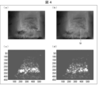
ここで、図4を用いて、連続する2つの画像からオプティカルフローを用いた移動量の算出の例を示す。図4の(a)は、連続する2つの画像のうち、移動量算出の基準となる元画像の一例を示すものである。図4の(b)は、画像特定部213が算出した、オプティカルフローによる移動量の算出結果の一例を描画したものである。図4の(b)の例では、移動量が、ごみ領域を構成する各画素の動きベクトルVrとして描画されることにより、元画像が変化した状態を示している。
Here, an example of calculating the amount of movement using optical flow from two consecutive images will be shown with reference to FIG. (a) of FIG. 4 shows an example of an original image, which is used as a reference for calculating the amount of movement, among two consecutive images. (b) of FIG. 4 depicts an example of the calculation result of the movement amount by the optical flow calculated by the
なお、移動量算出に際し、算出した動きベクトルのx成分及びy成分を抽出しても構わない。この場合、画像特定部213は、画素毎のx成分の移動量(動きベクトルのx成分の大きさ)と、画素毎のy成分の移動量(動きベクトルのy成分の大きさ)とを算出する。図4の(c)は、画素毎のx成分の移動量の大きさの分布を表現したものであり、図4の(d)は、画素毎のy成分の移動量の大きさの分布を表現したものである。図4の(d)では、白く表現されている部分ほど、移動量が大きいことを示している。
Note that, when calculating the movement amount, the x component and the y component of the calculated motion vector may be extracted. In this case, the
また、移動量の算出に関し、ごみ領域を構成する画素毎に画素の移動量を算出するようにした場合には、画像特定部213は、例えば、画素毎に算出した移動量の総和を算出し、当該総和が閾値以上である場合に、移動量が所定範囲内にあると判定しても構わない。さらに、画像特定部213は、例えば、画素毎に算出した移動量のうち、最大値をとる移動量が閾値以上である場合に、移動量が所定範囲内にあると判定しても構わない。
Regarding the calculation of the amount of movement, when the amount of movement of pixels is calculated for each pixel forming the dust area, the
さらに、動きベクトルのx成分及びy成分が算出されている場合には、画像特定部213は、例えば、x成分及びy成分の何れもが閾値以上であると判定した場合に、移動量が所定範囲内にあると判定しても構わない。
Further, when the x component and the y component of the motion vector are calculated, the
教師データ生成部214は、画像特定部213が特定した学習対象画像群と、当該学習対象画像群に含まれる任意の画像を撮像したときから所定時間経過後の蒸気量の変化傾向を示す傾向情報と、を対応付けて教師データを生成する。
The training
具体的には、教師データ生成部214は、画像特定部213が特定した学習対象画像群と、例えば、当該学習対象画像群の最後の画像を撮像したときから所定時間経過後の蒸気量の変化傾向を示す傾向情報と、を対応付けて1つの教師データを生成する。このようにして生成された教師データは、モデル生成部215へ送られる。
Specifically, the teacher
この傾向情報は、例えば、最後の画像を取得したとき、及び所定時間経過後において実際に蒸気量検出装置17によって取得された蒸気量の実測値を用いて算出される。もちろん、最後の画像を取得したときから所定時間経過後に至る途中の蒸気量の実測値も用いてもよい。
This trend information is calculated using, for example, actual measurement values of the amount of steam actually obtained by the steam
教師データ生成部214は、例えば、最後の画像を撮像した時点から変化傾向を予測したい時点の間の複数の実測値に基づく近似式を算出すると共に、当該近似式の傾きを算出する。教師データ生成部214は、算出した傾きが負である場合、蒸気量が減少するというパターンに該当すると判定する。また、当該傾きが正である場合、蒸気量が増加するというパターンに該当すると判定する。また、教師データ生成部214は、当該傾きが0または略0である場合には、蒸気量は維持されるというパターンに該当すると判定する。
The teacher
なお、上記の例では、傾向情報として特定されるパターンとして、蒸気量の減少、増加及び維持の3段階が設定されているが、これに限られない。上記パターンとして、例えば、減少量:大、減少量:小、維持、増加量:小、増加量:大の5段階が設定されていても構わない。また、教師データ生成部214は、傾向情報として、例えば最後の画像を撮像したときから所定時間経過後の蒸気量そのものの値(予測値)を算出しても構わない。
Note that, in the above example, three stages of decrease, increase, and maintenance of the amount of steam are set as the pattern specified as the trend information, but the pattern is not limited to this. As the pattern, for example, five levels of decrease amount: large, decrease amount: small, maintenance, increase amount: small, and increase amount: large may be set. Further, the teacher
また、所定時間としては、本実施形態では、例えば、リアルタイムに画像を撮像してから5分後~10分後を想定している。つまり、5分後~10分後の変化傾向の予測を想定している。上記所定時間経過後の変化傾向の予測を実現するために、1つの学習対象画像群に含まれる画像の数が設定されてもよく、例えば10枚に設定される。なお、所定時間は、実験等を経て、燃焼完了時間(例:約2時間)を上限として適宜設定されてもよいが、所定時間が長くなるほど予測の難易度は増加すると見込まれる。 Further, in this embodiment, the predetermined time is assumed to be, for example, 5 to 10 minutes after the image is captured in real time. In other words, it is assumed that the trend of change will be predicted after 5 to 10 minutes. In order to predict the change tendency after the predetermined time has passed, the number of images included in one learning target image group may be set, for example, 10 images. The predetermined time may be appropriately set through experiments, etc., with the combustion completion time (eg, about 2 hours) as the upper limit, but it is expected that the longer the predetermined time, the more difficult the prediction will be.
教師データ生成部214は、画像特定部213により生成された複数の学習対象画像群のそれぞれについて傾向情報を特定する。そして、教師データ生成部214は、複数の学習対象画像群のそれぞれと、特定した上記傾向情報とを対応付けた教師データを複数生成し、当該教師データをモデル生成部215に入力する。
The teacher
なお、上記説明では、学習対象画像群に含まれる画像のうちの最後の画像を撮像したときから所定時間経過後の蒸気量の実測値を、学習対象画像群に対応付けたが、最後の画像に限らず、任意の画像を撮像したときから所定時間経過後の蒸気量の実測値を、学習対象画像群に対応付けてもよい。この場合、予測対象となる所定時間を最後の画像を撮像する場合から適宜調整すればよい。 Note that in the above description, the actually measured value of the steam amount after a predetermined time has passed since the last image among the images included in the learning target image group was captured is associated with the learning target image group. Alternatively, the actually measured value of the amount of steam after a predetermined time has passed since an arbitrary image was captured may be associated with the learning target image group. In this case, the predetermined time to be predicted may be appropriately adjusted from the case where the last image is captured.
モデル生成部215は、教師データ生成部214が生成した教師データを用いて機械学習を行うことにより、蒸気量の変化傾向を予測可能な学習済モデルを生成する。精度の高い学習モデルを構築するため、モデル生成部215で用いられる教師データの数は1万個以上あると好ましい。このため、画像抽出部211は、過去1万個以上の一定期間の画像データを取得することが望まれる。また、ごみ焼却炉は年間スケジュールを立てて運用することが一般的であるため、これらの画像データは季節の偏りなく取得された画像データであることが好ましい。
The
モデル生成部215は、具体的には、適用可能なアルゴリズムは特に限定されないが、ニューラルネットワーク等の機械学習アルゴリズムを利用することが好ましく、特に深層学習したニューラルネットワーク(例えば3次元畳み込みニューラルネットワーク(3D CNN)等)に教師データを入力しながら、当該3D CNNのパラメータを調整することで、学習済モデルを構築する。
Specifically, the applicable algorithm for the
なお本実施形態では、モデル生成部215は、学習モデル(適用可能な機械学習アルゴリズム)として、3次元畳み込みニューラルネットワーク(3D CNN)を用いているが、変化傾向を予測可能な学習済モデルを生成できるのであれば、これに限らず、2次元CNN、又はその他の機械学習アルゴリズムを用いても構わない。
Note that in the present embodiment, the
<処理の流れ>
図5及び図6の(a)を用いて、予測モデル生成装置2における処理(予測モデル生成装置2による予測モデル生成方法)の流れについて説明する。図5の(a)~(c)は、画像抽出部211が抽出した画像の中から、画像特定部213が学習対象画像群を特定するまでの処理の概要を説明するための図である。図6の(a)は、予測モデル生成装置2における処理の流れの一例を示すフローチャートである。
<Process flow>
The flow of processing (prediction model generation method by the prediction model generation device 2) in the prediction
画像抽出部211は、ごみが撮像された過去の複数の画像から、時系列に沿って一定期間の動画像を取得する(ステップS1)。図5の(a)は、取得された一定期間の動画像のうちの一部を示すものである。
The
さらに、画像抽出部211は、この一定期間の動画像から所定間隔で複数の画像を抽出する(ステップS2)。図5では、ステップS2は、図5の(a)に示す動画像から図5の(b)に示す画像を抽出することに相当する。
Further, the
暗転画像除外部212は、画像の輝度値が所定値以下のものを除外し(ステップS3)、所定値よりも輝度値が大きなものを画像特定部213に入力する。図5ではこの説明を省略する。
The darkened
画像特定部213は、暗転画像除外部212から入力された複数の画像のうち、最後に撮像された画像を基準画像(B_IMG1)として選択する(ステップS4)。次に、この基準画像よりも1つ前の時間に撮像された画像を対象画像(T_IMG1)として選択し(ステップS5)、基準画像とこの対象画像との間におけるごみ領域の移動量を算出する。そして、この移動量が所定範囲内であるか否かを判定する(ステップS6)。
The
この移動量が所定範囲に達していない場合は(ステップS6でNo)、対象画像よりも1つ前の時間に撮像された画像を新たな対象画像(T_IMG2)とし、基準画像と新たな対象画像とを用いて移動量を算出する。これを基準画像に対して移動量が所定範囲に達する画像が対象画像として選択されるまで繰り返す(ステップS5およびS6)。 If this movement amount does not reach the predetermined range (No in step S6), the image captured one time earlier than the target image is set as a new target image (T_IMG2), and the reference image and the new target image are set. and to calculate the amount of movement. This is repeated until an image whose movement amount reaches a predetermined range with respect to the reference image is selected as the target image (steps S5 and S6).
基準画像と対象画像との間におけるごみ領域の移動量が所定範囲に達していた場合(ステップS6でYes)、基準画像(B_IMG1)及びこの時の対象画像(T_IMG3)をそれぞれ、教師データ生成部214で用いる第1の学習対象画像(S_IMG1)及び第2の学習対象画像(S_IMG2)として特定する(ステップS7)。 If the amount of movement of the dust area between the reference image and the target image has reached a predetermined range (Yes in step S6), the reference image (B_IMG1) and the target image (T_IMG3) at this time are generated by the teacher data generation unit. 214 as the first learning target image (S_IMG1) and the second learning target image (S_IMG2) used in 214 (step S7).
画像特定部213は、特定された学習対象画像の枚数をカウントしており、学習対象画像が所定数となったか否かを判定する(ステップS8)。所定数に達していない場合は(ステップS8でNo)、移動量が所定範囲内となった対象画像(T_IMG3)を新たな基準画像(B_IMG2)として選択し(ステップS9)、学習対象画像が所定枚数となるまでステップS5~ステップS9を繰り返す。図5の(c)では、複数の学習対象画像(S_IMG1~S_IMG4)が特定されている。
The
画像特定部213は、学習対象画像が所定数となった場合(ステップS8でYes)、画像の特定を終了する。このとき、所定数の学習対象画像(S_IMG)群が特定される。
When the number of learning target images reaches a predetermined number (Yes in step S8), the
教師データ生成部214は、学習対象画像(S_IMG)群とこの学習対象画像群に対応する傾向情報とを、正解データ(ラベル)として紐づけて教師データとする(ステップS10)。モデル生成部215は、教師データ生成部214が生成した教師データを用いて学習済モデルを生成する(ステップS11)。
The training
以上のように構成することにより、次のような効果が期待される。 The following effects can be expected from the configuration as described above.
<主な効果>
通常、ごみの移動量、すなわちごみの移動速度はごみの燃焼状態等に応じて様々に変化する。例えば、一定の時間間隔で画像を抽出し、所定時間経過後の蒸気量の変化傾向を示す傾向情報と対応付けて教師データを作成する場合、その移動速度毎に応じた教師データを準備する必要が生じる。一方、本実施形態では、ごみの移動量が所定範囲内となる画像と所定時間経過後の蒸気量の変化傾向を示す傾向情報と対応付けて教師データを作成しているため、ごみの移動速度毎に応じた教師データを準備する必要がない。すなわち、ごみの移動速度が変動した場合であっても、その変動が教師データに与える影響を抑制できることになる。
<Main effects>
Normally, the amount of movement of the garbage, that is, the movement speed of the garbage varies depending on the combustion state of the garbage. For example, when images are extracted at regular time intervals and the teacher data is created by associating them with trend information indicating the trend of change in the amount of steam after the elapse of a predetermined time, it is necessary to prepare teacher data corresponding to each moving speed. occurs. On the other hand, in the present embodiment, the teaching data is created by associating the image in which the amount of dust movement is within a predetermined range with the trend information indicating the trend of change in the amount of steam after the passage of a predetermined period of time. There is no need to prepare training data for each case. That is, even if the moving speed of dust fluctuates, the influence of the fluctuation on the teacher data can be suppressed.
また、ごみの移動速度毎に応じた教師データを準備する必要がないため、ごみの移動速度が異なるものも教師データとして利用することができ、教師データとして利用できる画像と傾向情報との組み合わせの数を大幅に増加させることが可能となる。すなわち、同じ変化傾向に含まれる画像群の総数を増加させることができる。このため、予測の精度を大幅に向上させることが期待できる。 In addition, since it is not necessary to prepare training data for each speed of movement of dust, it is possible to use data with different speeds of movement of dust as training data. It is possible to increase the number significantly. That is, the total number of image groups included in the same trend of change can be increased. Therefore, it can be expected that the accuracy of prediction can be significantly improved.
〔予測装置〕
次に、図7を用いて、予測装置3の構成例について説明する。図7は、予測装置3の構成例を示すブロック図である。予測装置3は、主として、制御部31及び記憶部32を備える。制御部31は、予測装置3を統括的に制御するものである。記憶部32は、制御部31が実行する各種のプログラム、及び当該プログラムによって使用されるデータを記憶する。当該データとしては、例えば、撮像装置122が撮像した画像、及び予測モデル生成装置2が生成した学習済モデルが挙げられる。記憶部32には、燃焼しているごみをリアルタイムに撮像した複数の画像(動画像又は複数の静止画像)が記憶される。
[Prediction device]
Next, a configuration example of the
制御部31は、主として、画像抽出部311、暗転画像除外部312、画像特定部313、変化傾向予測部314、及び予測結果出力部315を備える。
The
画像抽出部311は、画像抽出部211と同様の機能を有する。但し、ごみが撮像された複数の画像(ごみ焼却中に撮像された複数の画像であって、現時点で撮像された画像を含む)において、現時点から過去に遡って所定期間の複数の画像を取得する点で、画像抽出部211と異なる。なお、現時点とは、おおよそ現時点とみなすことができることができる時点であり、厳密な現時点のみに限定されるものではない。暗転画像除外部312は、暗転画像除外部212と同様の機能を有する。画像特定部313は、暗転画像除外部312が処理した複数の画像から、変化傾向予測部314が用いる、予測モデル生成装置2が生成した学習済モデルへの入力対象画像を複数特定する。
The
なお、画像特定部313が特定する、1つの入力対象画像群に含まれる画像の数は、画像特定部213が特定した、1つの学習対象画像群に含まれる画像の数と同一である。また、予測モデル生成装置2で生成された学習済モデルに入力することで、所定時間経過後の蒸気量の変化傾向を予測できるため、画像特定部313が特定する入力対象画像群は1つでよい。
Note that the number of images included in one input target image group specified by the
変化傾向予測部314は、画像特定部313が特定した入力対象画像群を、予測モデル生成装置2が生成した学習済モデルに入力する。これにより、変化傾向予測部314は、入力対象画像群に含まれる任意の画像を撮像したときから所定時間経過後の変化傾向を予測する。具体的には、変化傾向予測部314は、入力対象画像群と相関度が高い学習対象画像群に対応する傾向情報(例えば、減少量:大、減少量:小、維持、増加量:小、増加量:大の何れか)を出力する。予測結果出力部315は、変化傾向予測部314が予測した変化傾向を示す傾向情報を、燃焼制御装置10に出力する。
The change
燃焼制御装置10では、傾向情報と調整値(火格子の移動速度、及びストーカ式焼却炉12の炉内に送り込む空気量)とが対応付けて記憶されている。燃焼制御装置10は、変化傾向予測部314が予測した傾向情報に応じた調整値を用いて、当該移動速度及び空気量を調整する。これにより、ボイラ15が発生させる蒸気量を一定量に維持できる。
In the
<処理の流れ>
次に、図6の(b)を用いて、予測装置3における処理(予測方法)の流れについて説明する。図6の(b)は、予測装置3における処理の流れの一例を示すフローチャートである。
<Process flow>
Next, the flow of processing (prediction method) in the
図6の(b)に示すように、画像抽出部311は、ごみが撮像された複数の画像(現時点で撮像された画像を含む)において、現時点から過去に遡って所定期間の動画像を取得する(ステップS21)。その後、ステップS22~ステップS29の処理は、ステップS2~ステップS9の処理と同様である。但し、ステップS27及びS28では、ステップS7及びステップS8の学習対象画像を入力対象画像とする。
As shown in (b) of FIG. 6, the
画像特定部313は、入力対象画像が所定数となった場合(ステップS28でYes)、画像の特定を終了する。変化傾向予測部314は、画像特定部313が特定した入力対象画像群を、予測モデル生成装置2が生成した学習済モデルに入力する。これにより、変化傾向予測部314は、予測モデル生成装置2による学習結果を反映した傾向情報を出力する(ステップS30)。
When the number of input target images reaches a predetermined number (Yes in step S28), the
予測結果出力部315は、変化傾向予測部314が予測した変化傾向を示す傾向情報を燃焼制御装置10に出力する(ステップS31)。これにより、燃焼制御装置10は、傾向情報が維持以外の値を示している場合に、将来に亘り蒸気量が一定量に維持されるように、火格子の移動速度等を調整できる。
The prediction
このように、燃焼制御装置10は、予測装置3の予測結果を受けて、火格子の移動速度等を調整する。これにより、燃焼制御装置10は、蒸気量の変動が生じる前に、その変動が生じないように火格子の移動速度等を調整できる。従って、蒸気量を一定量に維持する(蒸気の発生を安定化させる)ための人による監視が不要となり、当該監視を無人化できる。
In this manner, the
<主な効果>
本実施形態では、画像抽出部311は、現在を基点として過去に遡って画像を抽出する。画像特定部313は、画像抽出部311が抽出した画像のうち、ごみ領域の移動量が所定範囲内にある画像を特定し、予測装置3で蒸気量の変化傾向を予測するときに用いる入力対象画像群とする。この入力対象画像群を予測モデル生成装置2が生成した学習済モデルに入力する。これにより、入力対象画像群に含まれる任意の画像を撮像したときから所定時間経過後の蒸気量の変化傾向を精度良く予測できる。所定時間経過後の蒸気量の予測により、火格子の送り速度又は二次空気量の変更などを行うことが可能となり、蒸気量を一定量に維持できる。その結果、蒸気量の変動が生じる前に燃焼制御を行うことが可能となり、安定した燃焼制御を実現できる。
<Main effects>
In the present embodiment, the
〔補足事項〕
本実施形態では、ストーカ式焼却炉12に投入されたごみを処理対象とするごみ焼却発電プラント1の制御について説明した。つまり、ごみ焼却発電プラント1を制御するために、予測モデル生成装置2で生成した学習済モデルを用いて、予測装置3で蒸気量の変化傾向を予測し、燃焼制御装置10がこの予測結果に基づき火格子の移動速度等を制御する制御システムについて説明した。
[Supplementary information]
In the present embodiment, the control of the waste incineration power plant 1 that treats waste thrown into the
しかしながら、制御システムの制御対象は、ごみ焼却発電プラント1に限られない。当該制御対象は、処理対象の処理状況に応じて処理環境が変化するプラントであって、当該処理環境を所定の環境に維持するために制御プロセス値を制御するプラントであれば、どのようなプラントであっても構わない。 However, the control target of the control system is not limited to the waste incineration power plant 1 . If the target of control is a plant whose treatment environment changes according to the treatment status of the treatment target and controls the control process values to maintain the treatment environment at a predetermined environment, what kind of plant It doesn't matter if it is.
また、本実施形態の制御システムでは、制御プロセス値としての蒸気量の変化傾向を学習させることで当該変化傾向の予測を行っているが、これに限られない。制御プロセス値としての、炉内の温度、炉内の圧力、及び炉内に存在する所定気体の濃度等の値を学習させることで、これらの値の予測を行っても構わない。この場合も、予測結果と、火格子の移動速度、及び炉内に送り込む空気量との対応関係を示すデータに従って、予測結果に応じた移動速度及び空気量に制御されることで、制御プロセス値を所望の値に維持できる。 In addition, in the control system of the present embodiment, the trend of change in the amount of steam as a control process value is learned to predict the trend of change, but the present invention is not limited to this. These values may be predicted by learning values such as the temperature in the furnace, the pressure in the furnace, and the concentration of a predetermined gas existing in the furnace as control process values. Also in this case, according to the data indicating the correspondence between the prediction result, the moving speed of the grate, and the amount of air sent into the furnace, the moving speed and the amount of air are controlled according to the prediction result, so that the control process value can be maintained at a desired value.
また、本実施形態では、予測モデル生成装置2は暗転画像除外部212を備えているが、必ずしも備えている必要は無い。制御システムの制御対象がごみ焼却発電プラント1とは異なる種類のプラントである場合、撮像した画像に、舞い上がった灰が映り込んでしまうことは無い。つまり、灰が舞い上がることが無いプラントにおいて予測モデル生成装置を用いる場合には、暗転画像除外部212を備える必要は無い。換言すれば、ごみ焼却発電プラント1においては、移動量算出に不要となる暗転画像が発生するために、予測モデル生成装置2が暗転画像除外部212を備えることは有益である。この点については、暗転画像除外部312についても同様のことがいえる。
Further, in the present embodiment, the prediction
〔ソフトウェアによる実現例〕
予測モデル生成装置2の制御ブロック(特に制御部21の各部)、及び予測装置3の制御ブロック(特に制御部31の各部)は、集積回路(ICチップ)等に形成された論理回路(ハードウェア)によって実現してもよいし、ソフトウェアによって実現してもよい。
[Example of realization by software]
Control blocks of the prediction model generation device 2 (especially each part of the control unit 21) and control blocks of the prediction device 3 (especially each part of the control unit 31) are logic circuits (hardware ) or by software.
後者の場合、予測モデル生成装置2及び予測装置3は、各機能を実現するソフトウェアであるプログラムの命令を実行するコンピュータを備えている。このコンピュータは、例えば少なくとも1つのプロセッサ(制御装置)を備えていると共に、上記プログラムを記憶したコンピュータ読み取り可能な少なくとも1つの記録媒体を備えている。そして、上記コンピュータにおいて、上記プロセッサが上記プログラムを上記記録媒体から読み取って実行することにより、本発明の目的が達成される。上記プロセッサとしては、例えばCPU(Central Processing Unit)を用いることができる。上記記録媒体としては、「一時的でない有形の媒体」、例えば、ROM(Read Only Memory)等の他、テープ、ディスク、カード、半導体メモリ、プログラマブルな論理回路などを用いることができる。また、上記プログラムを展開するRAM(Random Access Memory)などをさらに備えていてもよい。また、上記プログラムは、該プログラムを伝送可能な任意の伝送媒体(通信ネットワークや放送波等)を介して上記コンピュータに供給されてもよい。なお、本発明の一態様は、上記プログラムが電子的な伝送によって具現化された、搬送波に埋め込まれたデータ信号の形態でも実現され得る。
In the latter case, the prediction
〔付記事項〕
本発明の態様1に係る予測モデル生成装置は、プラントによる処理対象が撮像された過去の複数の画像から、時系列に沿って複数の画像を取得する画像抽出部と、前記画像抽出部が取得した画像のうち、前の画像に対する前記処理対象の領域の移動量が所定範囲内にある画像を複数含む画像群を、学習対象画像群として特定する画像特定部と、前記画像特定部が特定した学習対象画像群と、当該学習対象画像群に含まれる任意の画像を撮像したときから所定時間経過後の、前記プラントにおける制御プロセス値の変化傾向を示す傾向情報と、を対応付けた教師データを用いて機械学習を行うことにより、前記変化傾向を予測可能な学習済モデルを生成するモデル生成部と、を備える。
[Additional notes]
A prediction model generation device according to aspect 1 of the present invention includes an image extraction unit that acquires a plurality of images in time series from a plurality of past images in which an object to be processed by a plant was captured, and the image extraction unit acquires an image specifying unit that specifies, as a learning target image group, an image group including a plurality of images in which the amount of movement of the region to be processed with respect to the previous image is within a predetermined range, from among the images that have been processed, and the image specifying unit specifies teaching data in which a learning target image group and trend information indicating a change trend of a control process value in the plant after a predetermined time has passed since an arbitrary image included in the learning target image group was captured are associated with each other; and a model generation unit that generates a learned model capable of predicting the change tendency by performing machine learning using the model generation unit.
さらに、本発明の態様2に係る予測モデル生成装置では、態様1において、前記画像抽出部が取得した画像から、輝度値が所定値以下である画像を除外することにより、前記画像特定部への入力対象とする画像を抽出する画像除外部を備えても構わない。
Further, in the predictive model generation device according to
さらに、本発明の態様3に係る予測モデル生成装置は、態様1又は2において、前記画像特定部は、前記画像抽出部が取得した画像のうちの2つの画像における前記処理対象の領域を構成する画素の移動量を、前記領域の移動量として算出しても構わない。
Further, in the prediction model generation device according to
さらに、本発明の態様4に係る予測モデル生成装置は、態様1から3の何れかにおいて、前記処理対象は、ごみ焼却発電プラントの焼却炉に投入されたごみであり、前記制御プロセス値は、前記ごみの燃焼により発生する蒸気量であっても構わない。
Further, in the predictive model generation device according to
さらに、本発明の態様5に係る予測モデル生成装置による予測モデル生成方法は、プラントによる処理対象が撮像された過去の複数の画像から、時系列に沿って複数の画像を取得する画像抽出ステップと、前記画像抽出ステップにて取得した画像のうち、前の画像に対する前記処理対象の領域の移動量が所定範囲内にある画像を複数含む画像群を、学習対象画像群として特定する画像特定ステップと、前記画像特定ステップにて特定した学習対象画像群と、当該学習対象画像群に含まれる任意の画像を撮像したときから所定時間経過後の、前記プラントにおける制御プロセス値の変化傾向を示す傾向情報と、を対応付けた教師データを用いて機械学習を行うことにより、前記変化傾向を予測可能な学習済モデルを生成するモデル生成ステップと、を含む。 Furthermore, a prediction model generation method by a prediction model generation device according to aspect 5 of the present invention includes an image extraction step of acquiring a plurality of images in time series from a plurality of past images of an object to be processed by the plant. and an image specifying step of specifying, as a group of images to be learned, an image group including a plurality of images, among the images acquired in the image extracting step, in which the amount of movement of the region to be processed with respect to the previous image is within a predetermined range. , trend information indicating a change tendency of the control process value in the plant after a predetermined time has passed since the learning target image group specified in the image specifying step and an arbitrary image included in the learning target image group were captured. and a model generation step of generating a learned model capable of predicting the change tendency by performing machine learning using teacher data in which and are associated with each other.
さらに、本発明の態様6に係る予測装置は、前記処理対象を撮像した画像に基づいて、前記変化傾向を予測する予測装置であって、前記処理対象を撮像した複数の画像において、現時点から過去に遡って所定期間の複数の画像を取得する画像抽出部と、前記画像抽出部が取得した画像のうち、前の画像に対する前記処理対象の領域の移動量が所定範囲内にある画像を複数含む画像群を、入力対象画像群として特定する画像特定部と、前記画像特定部が特定した入力対象画像群を、態様1から4の何れかに記載の予測モデル生成装置が生成した前記学習済モデルに入力することにより、前記入力対象画像群に含まれる任意の画像を撮像したときから所定時間経過後の、前記プラントにおける制御プロセス値の変化傾向を予測する変化傾向予測部と、を備える。 Further, a prediction device according to aspect 6 of the present invention is a prediction device that predicts the change tendency based on an image of the processing target, wherein in a plurality of images of the processing target, from the present to the past and a plurality of images, among the images acquired by the image extraction unit, for which the movement amount of the region to be processed with respect to the previous image is within a predetermined range. An image specifying unit that specifies a group of images as an input target image group; and a change trend prediction unit that predicts a change trend of the control process value in the plant after a predetermined time has passed since an arbitrary image included in the input target image group was captured by inputting to the input target image group.
なお、本発明の各態様に係る予測モデル生成装置は、コンピュータによって実現してもよく、この場合には、コンピュータを上記予測モデル生成装置が備える各部(ソフトウェア要素)として動作させることにより上記予測モデル生成装置をコンピュータにて実現させる予測モデル生成装置の制御プログラム、およびそれを記録したコンピュータ読み取り可能な記録媒体も、本発明の範疇に入る。 The predictive model generating device according to each aspect of the present invention may be realized by a computer. In this case, the predictive model generating device can A control program for a predictive model generation device that implements the generation device on a computer, and a computer-readable recording medium recording it are also included in the scope of the present invention.
最後に、本発明は上述した各実施形態に限定されるものではなく、請求項に示した範囲で種々の変更が可能であり、異なる実施形態にそれぞれ開示された技術的手段を適宜組み合わせて得られる実施形態についても本発明の技術的範囲に含まれる。さらに、各実施形態にそれぞれ開示された技術的手段を組み合わせることにより、新しい技術的特徴を形成することができる。 Finally, the present invention is not limited to the above-described embodiments, and can be modified in various ways within the scope of the claims, and can be obtained by appropriately combining technical means disclosed in different embodiments. Any embodiment is also included in the technical scope of the present invention. Furthermore, new technical features can be formed by combining the technical means disclosed in each embodiment.
1 ごみ焼却発電プラント(プラント)
2 予測モデル生成装置
3 予測装置
12 ストーカ式焼却炉(焼却炉)
211 画像抽出部
212 暗転画像除外部(画像除外部)
213 画像特定部
215 モデル生成部
311 画像抽出部
313 画像特定部
314 変化傾向予測部
1 Waste to Energy Plant (Plant)
2 prediction
211
213
Claims (6)
前記画像抽出部が取得した画像のうち、前の画像に対する前記処理対象の領域の移動量が所定範囲内にある画像を複数含む画像群を、学習対象画像群として特定する画像特定部と、
前記画像特定部が特定した学習対象画像群と、当該学習対象画像群に含まれる任意の画像を撮像したときから所定時間経過後の、前記プラントにおける制御プロセス値の変化傾向を示す傾向情報と、を対応付けた教師データを用いて機械学習を行うことにより、前記変化傾向を予測可能な学習済モデルを生成するモデル生成部と、を備える、予測モデル生成装置。 an image extracting unit that acquires a plurality of images in chronological order from a plurality of past images of an object to be processed by the plant;
an image identification unit that identifies, as a learning target image group, an image group including a plurality of images in which the movement amount of the region to be processed with respect to the previous image is within a predetermined range, among the images acquired by the image extraction unit;
A learning target image group specified by the image specifying unit, trend information indicating a change tendency of the control process value in the plant after a predetermined time has elapsed since an arbitrary image included in the learning target image group was captured, and and a model generating unit that generates a learned model capable of predicting the change tendency by performing machine learning using teacher data associated with.
前記制御プロセス値は、前記ごみの燃焼により発生する蒸気量である、請求項1から3の何れか1項に記載の予測モデル生成装置。 The object to be treated is waste put into an incinerator of a waste incineration power plant,
The predictive model generation device according to any one of claims 1 to 3, wherein the control process value is the amount of steam generated by burning the waste.
前記画像抽出ステップにて取得した画像のうち、前の画像に対する前記処理対象の領域の移動量が所定範囲内にある画像を複数含む画像群を、学習対象画像群として特定する画像特定ステップと、
前記画像特定ステップにて特定した学習対象画像群と、当該学習対象画像群に含まれる任意の画像を撮像したときから所定時間経過後の、前記プラントにおける制御プロセス値の変化傾向を示す傾向情報と、を対応付けた教師データを用いて機械学習を行うことにより、前記変化傾向を予測可能な学習済モデルを生成するモデル生成ステップと、を含む、予測モデル生成方法。 an image extraction step of acquiring a plurality of images in chronological order from a plurality of past images in which the object to be processed by the plant was captured;
an image specifying step of specifying, as a learning target image group, an image group including a plurality of images in which the movement amount of the region to be processed with respect to the previous image is within a predetermined range, among the images acquired in the image extracting step;
The learning target image group identified in the image identification step, and trend information indicating the change tendency of the control process value in the plant after a predetermined time has elapsed since an arbitrary image included in the learning target image group was captured. and a model generation step of generating a learned model capable of predicting the change tendency by performing machine learning using teacher data associated with .
前記処理対象を撮像した複数の画像において、現時点から過去に遡って所定期間の複数の画像を取得する画像抽出部と、
前記画像抽出部が取得した画像のうち、前の画像に対する前記処理対象の領域の移動量が所定範囲内にある画像を複数含む画像群を、入力対象画像群として特定する画像特定部と、
前記画像特定部が特定した入力対象画像群を、請求項1から4の何れか1項に記載の予測モデル生成装置が生成した前記学習済モデルに入力することにより、前記入力対象画像群に含まれる任意の画像を撮像したときから所定時間経過後の、前記プラントにおける制御プロセス値の変化傾向を予測する変化傾向予測部と、を備える、予測装置。 A prediction device that predicts the change tendency based on an image of the processing target,
an image extracting unit that acquires a plurality of images of a predetermined period of time from the current time to the past, among the plurality of images obtained by imaging the processing target;
an image specifying unit that specifies, as an input target image group, an image group including a plurality of images in which the movement amount of the region to be processed with respect to the previous image is within a predetermined range, among the images acquired by the image extracting unit;
By inputting the input target image group specified by the image specifying unit to the trained model generated by the prediction model generation device according to any one of claims 1 to 4, the input target image group includes a change trend prediction unit that predicts a change trend of the control process value in the plant after a predetermined time has passed since an arbitrary image was captured.
Priority Applications (1)
| Application Number | Priority Date | Filing Date | Title |
|---|---|---|---|
| JP2019011714A JP7256016B2 (en) | 2019-01-25 | 2019-01-25 | Predictive model generation device, prediction model generation method by prediction model generation device, and prediction device |
Applications Claiming Priority (1)
| Application Number | Priority Date | Filing Date | Title |
|---|---|---|---|
| JP2019011714A JP7256016B2 (en) | 2019-01-25 | 2019-01-25 | Predictive model generation device, prediction model generation method by prediction model generation device, and prediction device |
Publications (2)
| Publication Number | Publication Date |
|---|---|
| JP2020119407A JP2020119407A (en) | 2020-08-06 |
| JP7256016B2 true JP7256016B2 (en) | 2023-04-11 |
Family
ID=71890978
Family Applications (1)
| Application Number | Title | Priority Date | Filing Date |
|---|---|---|---|
| JP2019011714A Active JP7256016B2 (en) | 2019-01-25 | 2019-01-25 | Predictive model generation device, prediction model generation method by prediction model generation device, and prediction device |
Country Status (1)
| Country | Link |
|---|---|
| JP (1) | JP7256016B2 (en) |
Families Citing this family (2)
| Publication number | Priority date | Publication date | Assignee | Title |
|---|---|---|---|---|
| JP2022165456A (en) * | 2021-04-20 | 2022-11-01 | 日立造船株式会社 | Detection device, detection method, detection program, and detection system |
| CN117437609B (en) * | 2023-12-20 | 2024-03-15 | 博大视野(厦门)科技有限公司 | Method, system, equipment and storage medium for correcting driving deviation of tire crane |
Citations (3)
| Publication number | Priority date | Publication date | Assignee | Title |
|---|---|---|---|---|
| JP2000179820A (en) | 1998-12-15 | 2000-06-27 | Kawasaki Heavy Ind Ltd | Method and apparatus for detecting burnout point of refuse incienrator |
| JP2001082719A (en) | 1999-09-16 | 2001-03-30 | Ebara Corp | Combustion control for refuse incinerating plant |
| JP2018021686A (en) | 2016-08-01 | 2018-02-08 | 株式会社タクマ | Combustion control device including garbage moving speed detection function |
Family Cites Families (2)
| Publication number | Priority date | Publication date | Assignee | Title |
|---|---|---|---|---|
| JP2797056B2 (en) * | 1993-08-09 | 1998-09-17 | 住友重機械工業株式会社 | Combustion control method and device for refuse incinerator |
| DE19735139C1 (en) * | 1997-08-13 | 1999-02-25 | Martin Umwelt & Energietech | Method for determining the average radiation from a combustion bed in incineration plants and controlling the combustion process |
-
2019
- 2019-01-25 JP JP2019011714A patent/JP7256016B2/en active Active
Patent Citations (3)
| Publication number | Priority date | Publication date | Assignee | Title |
|---|---|---|---|---|
| JP2000179820A (en) | 1998-12-15 | 2000-06-27 | Kawasaki Heavy Ind Ltd | Method and apparatus for detecting burnout point of refuse incienrator |
| JP2001082719A (en) | 1999-09-16 | 2001-03-30 | Ebara Corp | Combustion control for refuse incinerating plant |
| JP2018021686A (en) | 2016-08-01 | 2018-02-08 | 株式会社タクマ | Combustion control device including garbage moving speed detection function |
Also Published As
| Publication number | Publication date |
|---|---|
| JP2020119407A (en) | 2020-08-06 |
Similar Documents
| Publication | Publication Date | Title |
|---|---|---|
| JP6723864B2 (en) | Combustion control device equipped with a garbage moving speed detection function | |
| CN111065859B (en) | Apparatus, system, program and method for estimating composition of waste | |
| JP7256016B2 (en) | Predictive model generation device, prediction model generation method by prediction model generation device, and prediction device | |
| JP7443683B2 (en) | Automatic combustion control method and monitoring center | |
| US8019446B2 (en) | Control loop for regulating a combustion process | |
| WO2020232220A1 (en) | Autonomous burner | |
| JP4188859B2 (en) | Operation control method and operation control apparatus for waste treatment plant equipment | |
| KR102276894B1 (en) | Calorific value estimation method, calorific value estimation device and waste storage facility | |
| WO2023063107A1 (en) | Control apparatus | |
| JP7085039B1 (en) | Predictive model creation device, exhaust gas concentration control system, predictive model creation method, and exhaust gas concentration control method | |
| WO2023037742A1 (en) | Control device for incinerator equipment | |
| CN114729746A (en) | Control device for combustion facility, control method for combustion facility, and program | |
| KR102470121B1 (en) | Garbage incinerator and its control method | |
| JP7354930B2 (en) | Information processing device, information processing method, combustion control device, and combustion control method | |
| JP7354924B2 (en) | Information processing device, information processing method, waste supply rate measuring device and measuring method, burn-out point position measuring device and measuring method, combustion control device and combustion control method | |
| JP2024001991A (en) | Information processing device, information processing method, and program | |
| JP2022161090A (en) | Waste information prediction device, combustion control device of incinerator, waste information prediction method, learning method for waste information prediction model, and waste information predication model program | |
| JP2022168717A (en) | Prediction device, prediction method, prediction program, facility controller, facility control method, and control program | |
| JP2022028463A (en) | Information processing device, information processing method, combustion control device and combustion control method | |
| JP2020091631A (en) | Information processing apparatus, information processing method and program for waste disposal plant | |
| JP2004245519A (en) | Combustion controller for incinerator | |
| JP2021173495A (en) | Waste supply abnormality detection method, waste supply control method, waste supply abnormality detection device and waste supply control device | |
| JP2020165626A (en) | Method for operating combustion equipment | |
| CN114659120A (en) | Control method for circulating fluidized bed garbage incinerator roller feeder | |
| JP2005337556A (en) | Waste material combustion installation |
Legal Events
| Date | Code | Title | Description |
|---|---|---|---|
| A621 | Written request for application examination |
Free format text: JAPANESE INTERMEDIATE CODE: A621 Effective date: 20220107 |
|
| A131 | Notification of reasons for refusal |
Free format text: JAPANESE INTERMEDIATE CODE: A131 Effective date: 20221129 |
|
| A977 | Report on retrieval |
Free format text: JAPANESE INTERMEDIATE CODE: A971007 Effective date: 20221130 |
|
| TRDD | Decision of grant or rejection written | ||
| A01 | Written decision to grant a patent or to grant a registration (utility model) |
Free format text: JAPANESE INTERMEDIATE CODE: A01 Effective date: 20230322 |
|
| A61 | First payment of annual fees (during grant procedure) |
Free format text: JAPANESE INTERMEDIATE CODE: A61 Effective date: 20230330 |
|
| R150 | Certificate of patent or registration of utility model |
Ref document number: 7256016 Country of ref document: JP Free format text: JAPANESE INTERMEDIATE CODE: R150 |