JP7253233B2 - Filter device, filter program, filter design program, reference signal generation device, and reference signal generation program - Google Patents
Filter device, filter program, filter design program, reference signal generation device, and reference signal generation program Download PDFInfo
- Publication number
- JP7253233B2 JP7253233B2 JP2019039430A JP2019039430A JP7253233B2 JP 7253233 B2 JP7253233 B2 JP 7253233B2 JP 2019039430 A JP2019039430 A JP 2019039430A JP 2019039430 A JP2019039430 A JP 2019039430A JP 7253233 B2 JP7253233 B2 JP 7253233B2
- Authority
- JP
- Japan
- Prior art keywords
- transfer function
- reference signal
- controller
- output signal
- input
- Prior art date
- Legal status (The legal status is an assumption and is not a legal conclusion. Google has not performed a legal analysis and makes no representation as to the accuracy of the status listed.)
- Active
Links
Images


Landscapes
- Feedback Control In General (AREA)
Description
本発明は、フィルタ装置、フィルタプログラム、フィルタ設計プログラム、参照信号生成装置及び参照信号生成プログラムに関する。 The present invention relates to a filter device, a filter program, a filter design program, a reference signal generation device, and a reference signal generation program.
近年、工場等において制御器を使用してモータ等の制御対象を制御する技術が多用されている。ところが、制御対象に入力される入力信号が変化していなくても経年変化等により制御対象から出力される出力信号が変化してしまうことがある。このような場合でも制御対象に所望の出力信号を出力させるための手段として、制御器の変更、例えば、制御器自体の交換、制御器のパラメータの更新が挙げられる。特許文献1には、制御出力と目標値との偏差に基づき、可変パラメータを有する伝達関数に従う制御入力を算出し、この制御入力に基づき制御対象を制御する制御装置における可変パラメータの設定値を更新するパラメータ更新装置が開示されている。
2. Description of the Related Art In recent years, a technique of controlling a controlled object such as a motor using a controller has been widely used in a factory or the like. However, even if the input signal input to the controlled object does not change, the output signal output from the controlled object may change due to aging or the like. Means for outputting a desired output signal to the controlled object even in such a case include changing the controller, for example, replacing the controller itself and updating the parameters of the controller. In
しかし、上述したパラメータ更新装置は、最適なパラメータに更新することができず、制御器及び制御対象を含むシステムを不安定化させてしまうことがある。 However, the above-described parameter update device cannot update the parameters to optimum parameters, which may destabilize the system including the controller and the controlled object.
そこで、本発明は、制御器を変更すること無く、制御対象に所望の出力信号を出力させることができるフィルタ装置、フィルタプログラム、フィルタ設計プログラム、参照信号生成装置及び参照信号生成プログラムを提供することを課題とする。 Accordingly, the present invention provides a filter device, a filter program, a filter design program, a reference signal generation device, and a reference signal generation program that can cause a controlled object to output a desired output signal without changing the controller. is the subject.
本発明の一態様は、制御対象に入力される入力信号を取得し、前記入力信号の入力に応じて前記制御対象から出力される出力信号を取得する入出力信号取得部と、前記制御対象を制御している実装済制御器の伝達関数のパラメータを前記入力信号及び前記出力信号に基づくデータ駆動制御により更新して仮想制御器の伝達関数を演算する伝達関数演算部と、前記制御対象の伝達関数、前記実装済制御器の伝達関数及び前記仮想制御器の伝達関数を使用して前記制御対象及び前記実装済制御器を含む閉ループ系に入力される更新前参照信号を前記制御対象に目標出力信号又は前記出力信号よりも前記目標出力信号に近似している近似目標出力信号を出力させる更新後参照信号に変換する参照信号変換部と、を備えるフィルタ装置である。 According to one aspect of the present invention, an input/output signal acquisition unit acquires an input signal input to a controlled object and acquires an output signal output from the controlled object in response to the input of the input signal; a transfer function calculation unit for calculating a transfer function of a virtual controller by updating parameters of a transfer function of the mounted controller being controlled by data-driven control based on the input signal and the output signal; and transfer of the controlled object. A target output to the controlled object of a pre-update reference signal input to a closed loop system including the controlled object and the implemented controller using a function, a transfer function of the implemented controller, and a transfer function of the virtual controller a reference signal conversion unit that converts the reference signal into an updated reference signal for outputting an approximate target output signal that is closer to the target output signal than the output signal.
また、本発明の一態様は、上記のフィルタ装置において、前記伝達関数演算部が、次の式(1)及び式(2)で表される評価関数を使用して前記実装済制御器の伝達関数のパラメータを更新することにより前記仮想制御器の伝達関数を演算する。 Further, according to one aspect of the present invention, in the filter device described above, the transfer function calculation unit uses evaluation functions represented by the following formulas (1) and (2) to transfer Compute the transfer function of the virtual controller by updating the parameters of the function.


u0 :入力信号
y0 :出力信号
Td :閉ループ系の目標伝達関数
ρ :パラメータ
C(ρ):制御器の伝達関数
u 0 : input signal y 0 : output signal T d : target transfer function of closed loop system ρ : parameter C(ρ): transfer function of controller
また、本発明の一態様は、上記のフィルタ装置において、前記参照信号変換部が、前記更新前参照信号を次の式(3)及び式(4)で表される前記更新後参照信号に変換する。 Further, according to one aspect of the present invention, in the filter device described above, the reference signal conversion unit converts the pre-update reference signal into the post-update reference signal represented by the following equations (3) and (4): do.


ρ0 :更新前のパラメータ
C(ρ0):実装済制御器の伝達関数
ρ* :更新後のパラメータ
C(ρ*):仮想制御器の伝達関数
G :制御対象の伝達関数
r* :更新後参照信号
r * : Post-update reference signal
本発明の一態様は、コンピュータに、制御対象に入力される入力信号を取得し、前記入力信号の入力に応じて前記制御対象から出力される出力信号を取得する入出力信号取得機能と、前記制御対象を制御している実装済制御器の伝達関数のパラメータを前記入力信号及び前記出力信号に基づくデータ駆動制御により更新して仮想制御器の伝達関数を演算する伝達関数演算機能と、前記制御対象の伝達関数、前記実装済制御器の伝達関数及び前記仮想制御器の伝達関数を使用して前記制御対象及び前記実装済制御器を含む閉ループ系に入力される更新前参照信号を前記制御対象に目標出力信号又は前記出力信号よりも前記目標出力信号に近似している近似目標出力信号を出力させる更新後参照信号に変換する参照信号変換機能と、を実現させるためのフィルタプログラムである。 According to one aspect of the present invention, a computer includes an input/output signal acquisition function of acquiring an input signal input to a controlled object and acquiring an output signal output from the controlled object in response to the input of the input signal; a transfer function calculation function for calculating a transfer function of a virtual controller by updating parameters of a transfer function of a mounted controller controlling a controlled object by data-driven control based on the input signal and the output signal; A pre-update reference signal input to a closed loop system including the controlled object and the implemented controller using the transfer function of the object, the transfer function of the implemented controller, and the transfer function of the virtual controller is transferred to the controlled object and a reference signal conversion function for converting to an updated reference signal that outputs a target output signal or an approximate target output signal that is closer to the target output signal than the output signal.
また、本発明の一態様は、上記のフィルタプログラムにおいて、伝達関数演算機能が、次の式(5)及び式(6)で表される評価関数を使用して前記実装済制御器の伝達関数のパラメータを更新して前記仮想制御器の伝達関数を演算する機能である。 Further, according to one aspect of the present invention, in the above filter program, the transfer function calculation function uses evaluation functions represented by the following equations (5) and (6) to calculate the transfer function of the implemented controller: is a function of updating the parameters of and calculating the transfer function of the virtual controller.


u0 :入力信号
y0 :出力信号
Td :閉ループ系の目標伝達関数
ρ :パラメータ
C(ρ):制御器の伝達関数
u 0 : input signal y 0 : output signal T d : target transfer function of closed loop system ρ : parameter C(ρ): transfer function of controller
また、本発明の一態様は、上記のフィルタプログラムにおいて、前記参照信号変換機能が、前記更新前参照信号を次の式(7)及び式(8)で表される前記更新後参照信号に変換する機能である。 Further, according to one aspect of the present invention, in the filter program described above, the reference signal conversion function converts the pre-update reference signal into the post-update reference signal represented by the following equations (7) and (8): It is a function to
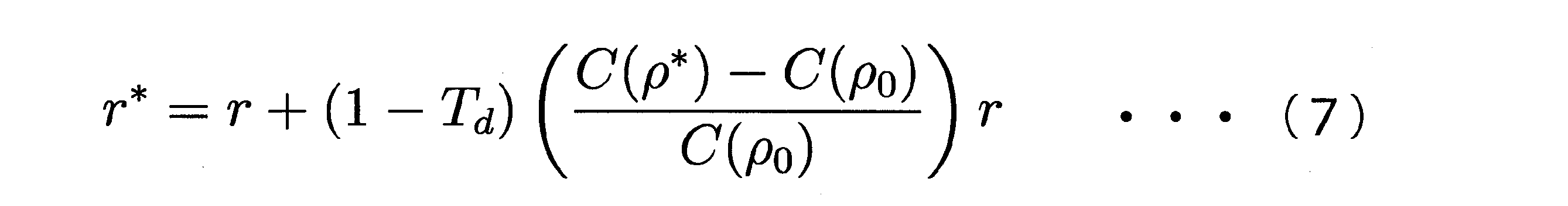

ρ0 :更新前のパラメータ
C(ρ0):実装済制御器の伝達関数
ρ* :更新後のパラメータ
C(ρ*):仮想制御器の伝達関数
G :制御対象の伝達関数
r* :更新後参照信号
r * : Post-update reference signal
本発明の一態様は、コンピュータに、制御対象に入力される入力信号を取得し、前記入力信号の入力に応じて前記制御対象から出力される出力信号を取得する入出力信号取得機能と、前記制御対象を制御している実装済制御器の伝達関数のパラメータを前記入力信号及び前記出力信号に基づくデータ駆動制御により更新して仮想制御器の伝達関数を演算する伝達関数演算機能と、前記制御対象の伝達関数、前記実装済制御器の伝達関数及び前記仮想制御器の伝達関数を使用して前記制御対象及び前記実装済制御器を含む閉ループ系に入力される更新前参照信号を前記制御対象に目標出力信号又は前記出力信号よりも前記目標出力信号に近似している近似目標出力信号を出力させる更新後参照信号に変換するフィルタを設計するフィルタ設計機能と、を実現させるためのフィルタ設計プログラムである。 According to one aspect of the present invention, a computer includes an input/output signal acquisition function of acquiring an input signal input to a controlled object and acquiring an output signal output from the controlled object in response to the input of the input signal; a transfer function calculation function for calculating a transfer function of a virtual controller by updating parameters of a transfer function of a mounted controller controlling a controlled object by data-driven control based on the input signal and the output signal; A pre-update reference signal input to a closed loop system including the controlled object and the implemented controller using the transfer function of the object, the transfer function of the implemented controller, and the transfer function of the virtual controller is transferred to the controlled object a filter design function for designing a filter for converting into an updated reference signal that outputs a target output signal or an approximate target output signal that is closer to the target output signal than the output signal, and a filter design program for realizing is.
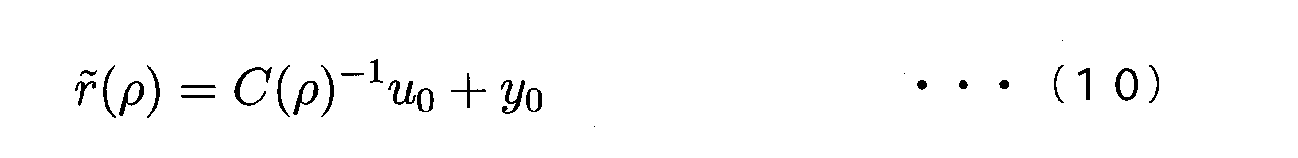
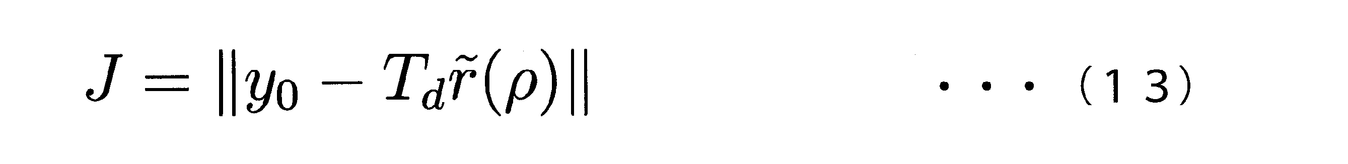
また、本発明の一態様は、上記のフィルタ設計プログラムにおいて、前記伝達関数演算機能が、次の式(9)及び式(10)で表される評価関数を使用して前記実装済制御器の伝達関数のパラメータを更新することにより前記仮想制御器の伝達関数を演算する機能である。 Further, according to one aspect of the present invention, in the above-described filter design program, the transfer function calculation function uses evaluation functions represented by the following equations (9) and (10) to determine the implemented controller: It is a function of calculating the transfer function of the virtual controller by updating the parameters of the transfer function.

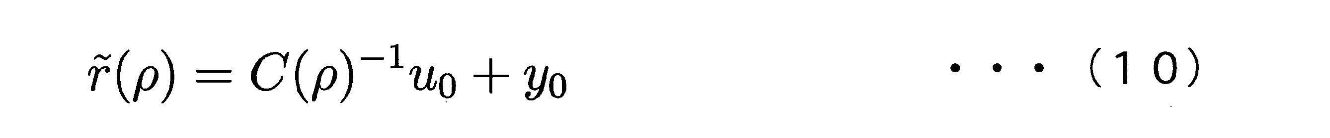
u0 :入力信号
y0 :出力信号
Td :閉ループ系の目標伝達関数
ρ :パラメータ
C(ρ):制御器の伝達関数
u 0 : input signal y 0 : output signal T d : target transfer function of closed loop system ρ : parameter C(ρ): transfer function of controller
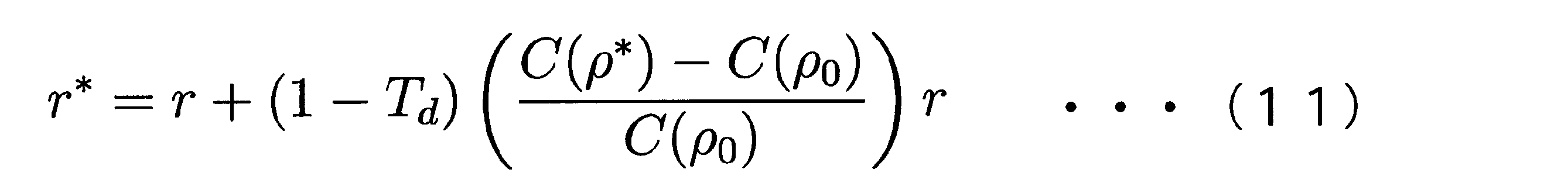
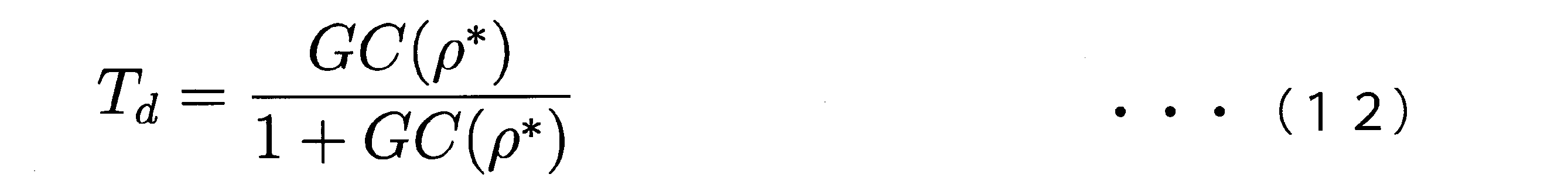
また、本発明の一態様は、上記のフィルタ設計プログラムにおいて、前記フィルタ設計機能が、前記更新前参照信号を次の式(11)及び式(12)で表される前記更新後参照信号に変換するフィルタを設計する機能である。 Further, according to one aspect of the present invention, in the filter design program described above, the filter design function converts the pre-update reference signal into the post-update reference signal represented by the following equations (11) and (12): It is a function to design a filter that
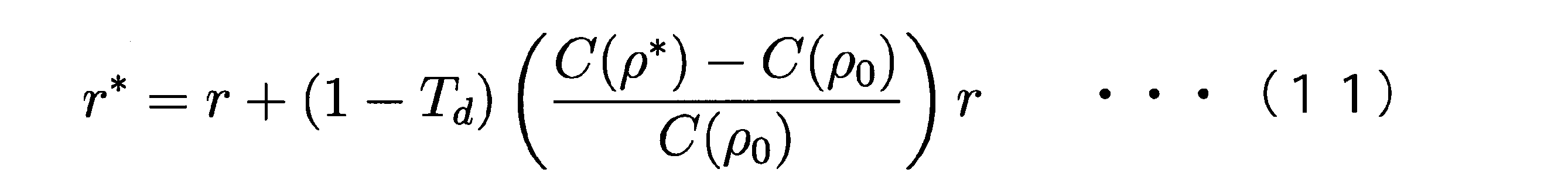

ρ0 :更新前のパラメータ
C(ρ0):実装済制御器の伝達関数
ρ* :更新後のパラメータ
C(ρ*):仮想制御器の伝達関数
G :制御対象の伝達関数
r* :更新後参照信号
r * : Post-update reference signal
本発明の一態様は、制御対象に入力される入力信号を取得し、前記入力信号の入力に応じて前記制御対象から出力される出力信号を取得する入出力信号取得部と、前記制御対象を制御している実装済制御器の伝達関数のパラメータを前記入力信号及び前記出力信号に基づくデータ駆動制御により更新して仮想制御器の伝達関数を演算する伝達関数演算部と、前記制御対象の伝達関数、前記実装済制御器の伝達関数及び前記仮想制御器の伝達関数を使用して前記制御対象及び前記実装済制御器を含む閉ループ系に入力される更新前参照信号から前記制御対象に目標出力信号又は前記出力信号よりも前記目標出力信号に近似している近似目標出力信号を出力させる更新後参照信号を生成する参照信号生成部と、を備える参照信号生成装置である。 According to one aspect of the present invention, an input/output signal acquisition unit acquires an input signal input to a controlled object and acquires an output signal output from the controlled object in response to the input of the input signal; a transfer function calculation unit for calculating a transfer function of a virtual controller by updating parameters of a transfer function of the mounted controller being controlled by data-driven control based on the input signal and the output signal; and transfer of the controlled object. A target output to the controlled object from a pre-update reference signal input to a closed loop system including the controlled object and the implemented controller using a function, a transfer function of the implemented controller, and a transfer function of the virtual controller a reference signal generation unit that generates an updated reference signal for outputting an approximate target output signal that is closer to the target output signal than the output signal.
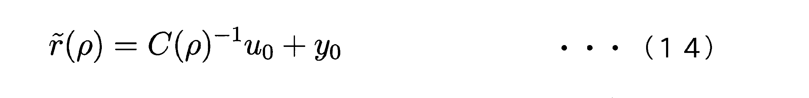
また、本発明の一態様は、上記の参照信号生成装置において、前記伝達関数演算部が、次の式(13)及び式(14)で表される評価関数を使用して前記実装済制御器の伝達関数のパラメータを更新することにより前記仮想制御器の伝達関数を演算する。 Further, according to one aspect of the present invention, in the reference signal generation device described above, the transfer function calculation unit uses evaluation functions represented by the following equations (13) and (14) to The transfer function of the virtual controller is calculated by updating the parameters of the transfer function of .

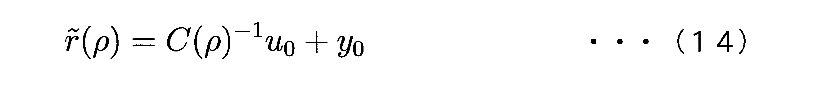
u0 :入力信号
y0 :出力信号
Td :閉ループ系の目標伝達関数
ρ :パラメータ
C(ρ):制御器の伝達関数
u 0 : input signal y 0 : output signal T d : target transfer function of closed loop system ρ : parameter C(ρ): transfer function of controller
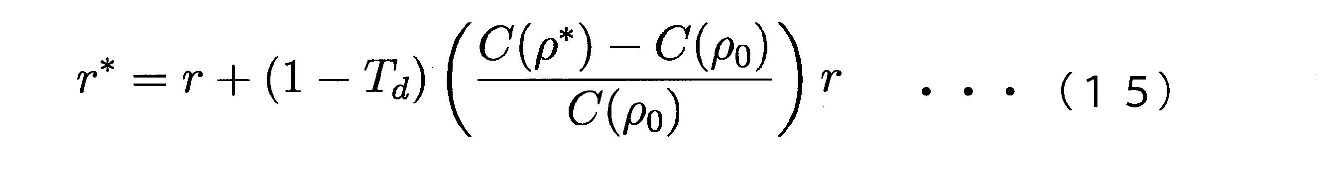
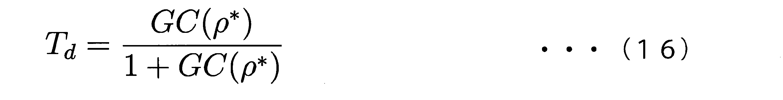
また、本発明の一態様は、上記の参照信号生成装置において、前記参照信号生成部が、前記更新前参照信号から次の式(15)及び式(16)で表される前記更新後参照信号を生成する。 Further, according to one aspect of the present invention, in the reference signal generation device described above, the reference signal generation unit converts the pre-update reference signal to the post-update reference signal represented by the following equations (15) and (16): to generate
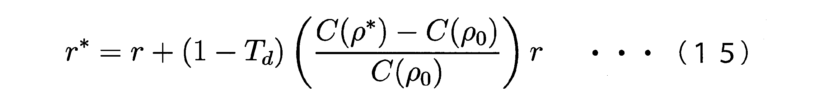
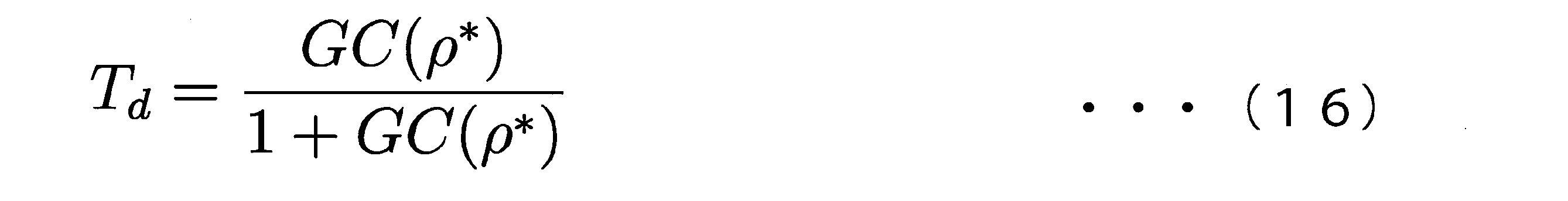
ρ0 :更新前のパラメータ
C(ρ0):実装済制御器の伝達関数
ρ* :更新後のパラメータ
C(ρ*):仮想制御器の伝達関数
G :制御対象の伝達関数
r* :更新後参照信号
r * : Post-update reference signal
本発明の一態様は、コンピュータに、制御対象に入力される入力信号を取得し、前記入力信号の入力に応じて前記制御対象から出力される出力信号を取得する入出力信号取得機能と、前記制御対象を制御している実装済制御器の伝達関数のパラメータを前記入力信号及び前記出力信号に基づくデータ駆動制御により更新して仮想制御器の伝達関数を演算する伝達関数演算機能と、前記制御対象の伝達関数、前記実装済制御器の伝達関数及び前記仮想制御器の伝達関数を使用して前記制御対象及び前記実装済制御器を含む閉ループ系に入力される更新前参照信号から前記制御対象に目標出力信号又は前記出力信号よりも前記目標出力信号に近似している近似目標出力信号を出力させる更新後参照信号を生成する参照信号生成機能と、を実現させるための参照信号生成プログラムである。 According to one aspect of the present invention, a computer includes an input/output signal acquisition function of acquiring an input signal input to a controlled object and acquiring an output signal output from the controlled object in response to the input of the input signal; a transfer function calculation function for calculating a transfer function of a virtual controller by updating parameters of a transfer function of a mounted controller controlling a controlled object by data-driven control based on the input signal and the output signal; From a pre-update reference signal input to a closed-loop system including the controlled object and the implemented controller using a transfer function of the target, a transfer function of the implemented controller, and a transfer function of the virtual controller, the controlled object and a reference signal generation function for generating an updated reference signal for outputting a target output signal or an approximate target output signal that is closer to the target output signal than the output signal. .
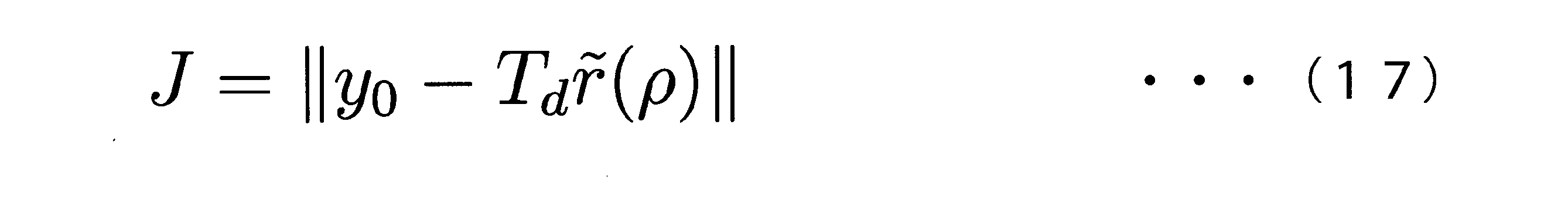
また、本発明の一態様は、上記の参照信号生成プログラムにおいて、前記伝達関数演算機能が、次の式(17)及び式(18)で表される評価関数を使用して前記実装済制御器の伝達関数のパラメータを更新することにより前記仮想制御器の伝達関数を演算する機能である。 Further, according to one aspect of the present invention, in the reference signal generating program described above, the transfer function calculation function uses evaluation functions represented by the following equations (17) and (18) to It is a function of calculating the transfer function of the virtual controller by updating the parameters of the transfer function of .


u0 :入力信号
y0 :出力信号
Td :閉ループ系の目標伝達関数
ρ :パラメータ
C(ρ):制御器の伝達関数
u 0 : input signal y 0 : output signal T d : target transfer function of closed loop system ρ : parameter C(ρ): transfer function of controller
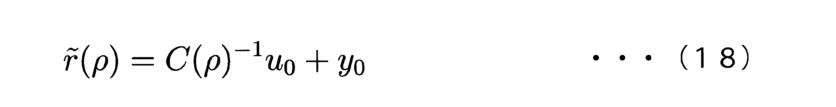
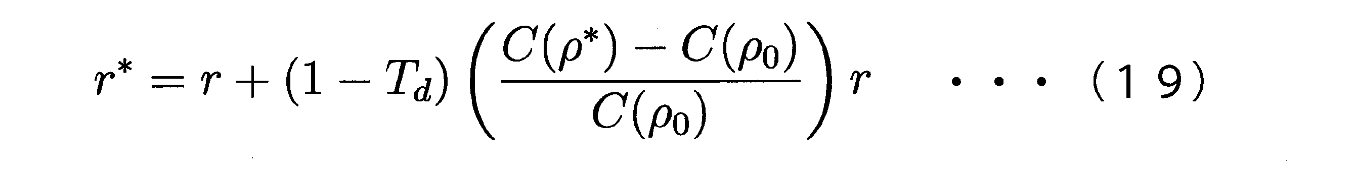
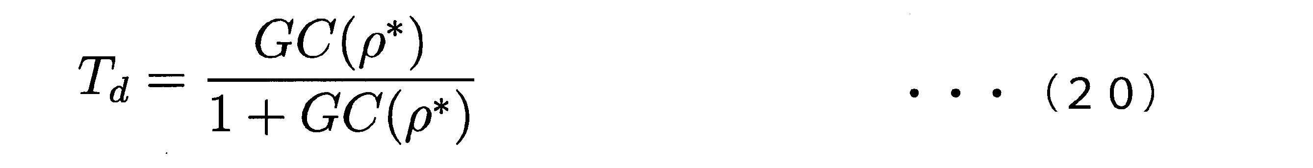
また、本発明の一態様は、上記の参照信号生成プログラムにおいて、前記参照信号生成機能が、前記更新前参照信号から次の式(19)及び式(20)で表される前記更新後参照信号を生成する機能である。 Further, according to one aspect of the present invention, in the above reference signal generation program, the reference signal generation function converts the pre-update reference signal to the post-update reference signal represented by the following equations (19) and (20): is a function that generates
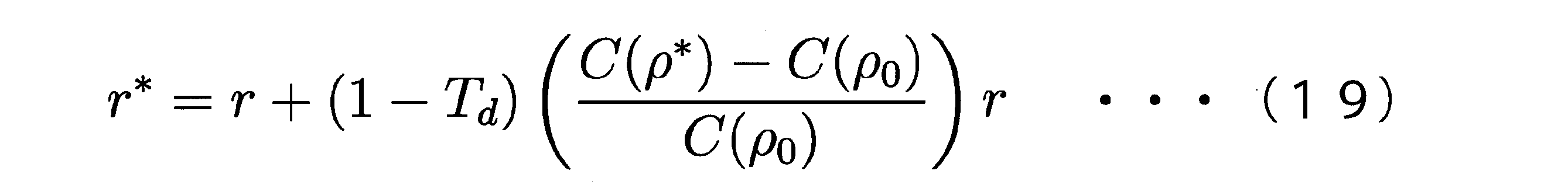

ρ0 :更新前のパラメータ
C(ρ0):実装済制御器の伝達関数
ρ* :更新後のパラメータ
C(ρ*):仮想制御器の伝達関数
G :制御対象の伝達関数
r* :更新後参照信号
r * : Post-update reference signal
本発明によれば、制御器を変更すること無く、制御対象に所望の出力信号を出力させることができる。 ADVANTAGE OF THE INVENTION According to this invention, a controlled object can be made to output a desired output signal, without changing a controller.
図1から図4を参照しながら、実施形態に係る制御器更新装置の構成の一例を説明する。 An example of the configuration of the controller update device according to the embodiment will be described with reference to FIGS. 1 to 4. FIG.
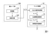
図1は、本発明の実施形態に係る閉ループ系及びフィルタ装置の機能的な構成の一例を示す図である。図1に示すように、フィルタ装置10は、入出力信号取得部11と、伝達関数演算部12と、参照信号変換部13とを備える。フィルタ装置10は、閉ループ系100に含まれる制御器110を変更せず、閉ループ系100に入力される更新前参照信号rを更新後参照信号r*に変換することにより、閉ループ系100に含まれる制御対象120に所望の出力信号である目標出力信号y*又は近似目標出力信号を出力させる。以下、フィルタ装置10について更に具体的に説明する。
FIG. 1 is a diagram showing an example of functional configurations of a closed loop system and a filter device according to an embodiment of the present invention. As shown in FIG. 1 , the
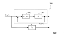
図2は、本発明の実施形態に係る閉ループ系のブロック線図の一例を示す図である。図2に示すように、閉ループ系100は、制御器110と、制御対象120とを備える。制御器110は、制御対象120を制御する機器、例えば、PID制御器である。また、制御器110は、原点極を持つことが許されており、閉ループ系100により出力される出力信号を安定化させる制御器である。制御対象120は、例えば、モータである。また、制御対象120は、一入力一出力であり、伝達関数の構造が未知である。
FIG. 2 is a diagram showing an example of a block diagram of a closed loop system according to an embodiment of the present invention. As shown in FIG. 2 , the
入出力信号取得部11は、図1及び図2に示した入力信号u0及び出力信号y0を取得する。入力信号u0は、閉ループ系100に更新前参照信号rが入力されている場合に制御器110が制御対象120に入力する信号である。出力信号y0は、入力信号u0の入力に応じて制御対象120から出力される信号である。
The input/output
伝達関数演算部12は、制御対象120を制御している実装済制御器の伝達関数のパラメータを入力信号u0及び出力信号y0に基づくデータ駆動制御により更新して仮想制御器の伝達関数を演算する。データ駆動制御は、制御対象120の動作に関するデータを直接活用して制御器110の設計や更新を行う手法である。また、データ駆動制御としては、例えば、FRIT(Fictitious Reference Iterative Tuning)、ERIT(Estimated Response Iterative Tuning)、VRFT(Virtual Reference Feedback Tuning)、VIMT(Virtual Internal Model Tuning)、IFT(Iterative Feedback Tuning)、CbT(Correlation based Tuning)が挙げられる。以下の説明では、データ駆動制御がFRITである場合を例に挙げる。
The
実装済制御器は、閉ループ系100に更新前参照信号rが入力されている場合に制御対象120を制御している制御器110であり、パラメータが更新前のパラメータρ0となっている。仮想制御器は、閉ループ系100が目標出力信号y*を出力すると仮定した場合に制御対象120を制御している制御器110であり、パラメータが更新後のパラメータρ*となっている。
The implemented controller is the
図3は、本発明の実施形態に係る閉ループ系における目標伝達関数と、制御器の伝達関数と、制御対象の伝達関数との関係を説明するための図である。 FIG. 3 is a diagram for explaining the relationship among the target transfer function, the transfer function of the controller, and the transfer function of the controlled object in the closed loop system according to the embodiment of the present invention.
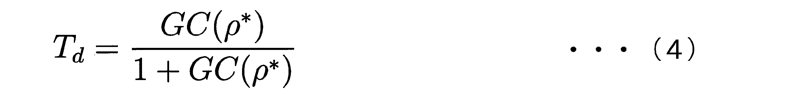
伝達関数演算部12は、閉ループ系100の目標伝達関数Tdを含む式(21)及び制御器110の伝達関数C(ρ)を含む式(22)で表される評価関数Jを使用して実装済制御器の伝達関数C(ρ0)のパラメータρ0を更新することにより仮想制御器の伝達関数C(ρ*)を演算する。パラメータρ0は、更新前参照信号rが入力されている場合における制御器110のパラメータρである。パラメータρ*は、閉ループ系100が目標出力信号y*を出力している場合における制御器110のパラメータρである。
The
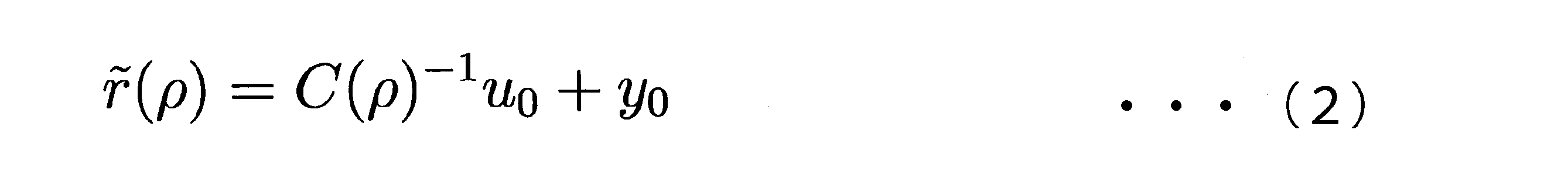
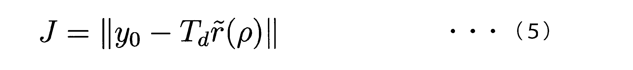
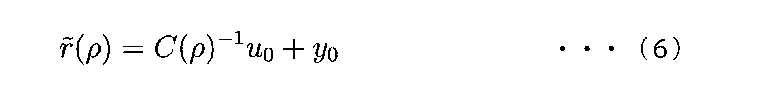
具体的には、伝達関数演算部12は、式(21)及び式(22)を使用して、出力信号y0と、擬似的に式(22)で算出した擬似参照信号r(~)を目標伝達関数Tdに印加した信号との差分が最小となるようなパラメータρ*を探索する。なお、本明細書中に示す「r(~)」の「(~)」は、本来は、図3並びに式(21)及び式(22)に示すように「~」が「r」の上に付加されるものであるが、本明細書では記載上の制約から「r(~)」と記載する。
図3の上下のブロックの出力が等しくなるように、
y0=T(ρ*)r(~)(ρ*)=Tdr(~)(ρ*)
とし、T(ρ*)≒Tdとみなすと、T(ρ*)は、制御対象Gと制御器C(ρ*)からなる閉ループ系であるから、C(ρ*)を実装し、本来の参照信号rを印加することで、
y(ρ*)=GC(ρ*)/(1+GC(ρ*))r≒Tdr
となり、ρ*を用いた閉ループ系の応答y(ρ*)が所望の応答Tdrとなる。
よって、仮想制御器の伝達関数C(ρ*)は、パラメータρ*により与えられる。また、目標伝達関数Tdと、仮想制御器の伝達関数C(ρ*)と、制御対象120の伝達関数Gとの関係は、図3に示すような関係となり、数式で表現すると、後述する式(24)のような関係となる。
Specifically, the
So that the outputs of the upper and lower blocks in FIG. 3 are equal,
y0 =T(ρ * )r( ~ )(ρ * )= Tdr ( ~ )(ρ * )
Assuming that T(ρ * ) ≈ Td , T(ρ * ) is a closed loop system consisting of the controlled object G and the controller C(ρ * ). By applying a reference signal r of
y(ρ * )=GC(ρ * )/(1+GC(ρ * )) r≈Tdr
Thus, the response y(ρ * ) of the closed loop system using ρ * is the desired response T dr .
Hence, the transfer function C(ρ * ) of the virtual controller is given by the parameter ρ * . The relationship between the target transfer function Td , the transfer function C(ρ * ) of the virtual controller, and the transfer function G of the controlled


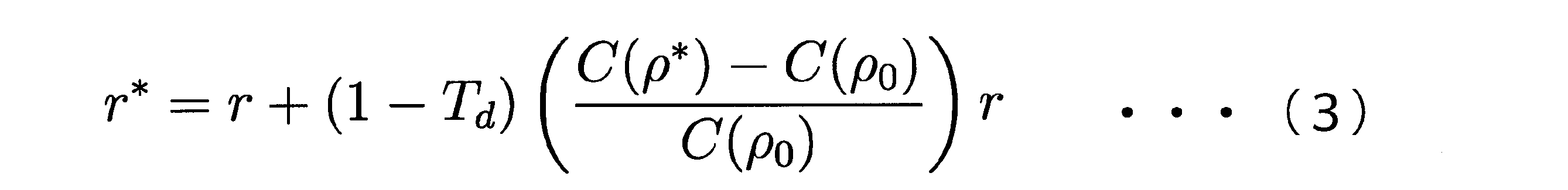
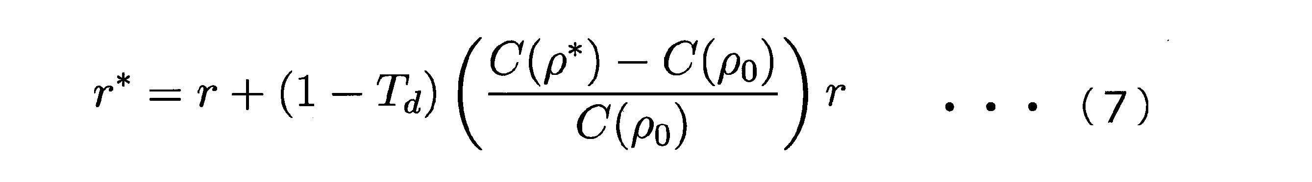
参照信号変換部13は、制御対象120の伝達関数G、実装済制御器の伝達関数C(ρ0)及び仮想制御器の伝達関数C(ρ*)を使用して更新前参照信号rを更新後参照信号r*に変換する。更新前参照信号rは、制御対象120及び実装済制御器を含む閉ループ系100に入力される参照信号である。更新後参照信号r*は、制御対象120に目標出力信号y*又は出力信号よりも目標出力信号y*に近似している近似目標出力信号を出力させる参照信号である。
The reference
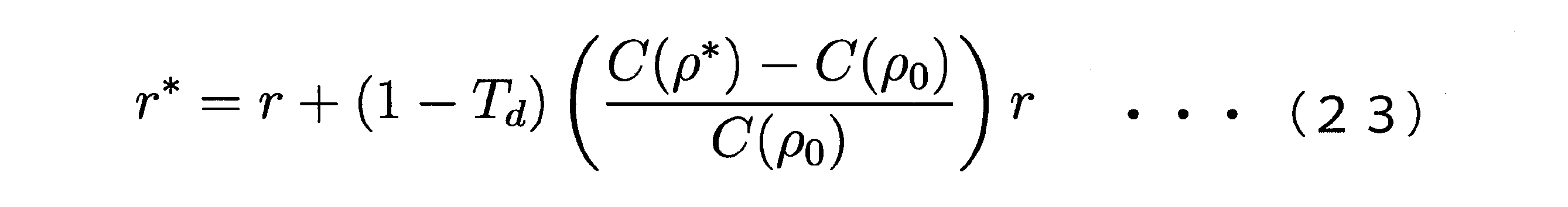
例えば、参照信号変換部13は、更新前参照信号rを次の式(23)で表される更新後参照信号r*に変換する。次に式(23)を導出する手順を説明する。
For example, the reference
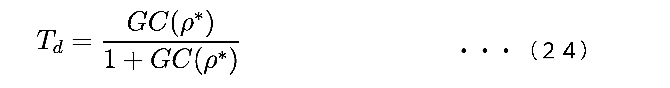
閉ループ系100の目標伝達関数Tdは、次の式(24)で表される。式(24)は、式(21)で表される評価関数Jが最小となる場合に成立する。また、この場合、パラメータρは、パラメータρ*に等しい。
A target transfer function Td of the
また、目標出力信号y*は、閉ループ系100の目標伝達関数Td及び更新前参照信号rを使用して次の式(25)で表される。
Also, the target output signal y * is expressed by the following equation (25) using the target transfer function Td of the

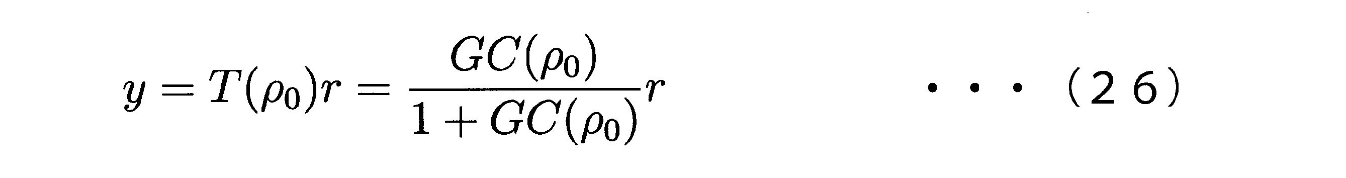
さらに、更新前参照信号r、閉ループ系100が出力する出力信号y及びこの場合における閉ループ系100の伝達関数T(ρ0)の間には、次の式(26)が成立する。
Furthermore, the following equation (26) holds between the pre-update reference signal r, the output signal y output from the
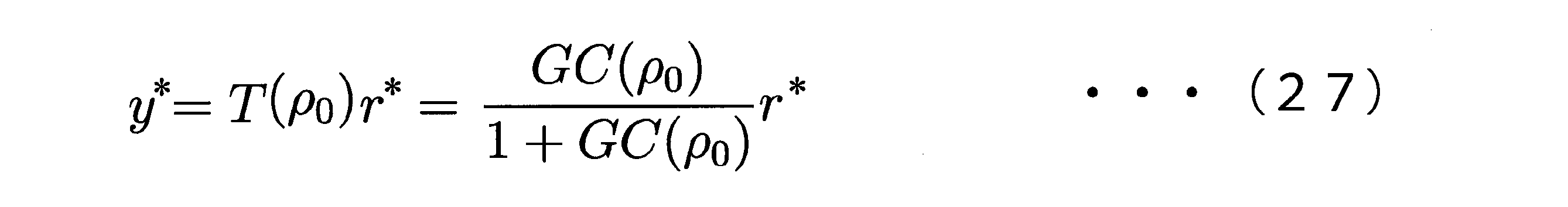
また、目標出力信号y*は、上述した閉ループ系100の伝達関数T(ρ0)及び更新後参照信号r*を使用して次の式(27)で表される。
Also, the target output signal y * is expressed by the following equation (27) using the transfer function T(ρ 0 ) of the
式(25)と式(26)との左辺同士及び右辺同士の差分を取ると次の式(28)のようになる。 Taking the difference between the left sides and the right sides of the equations (25) and (26) yields the following equation (28).
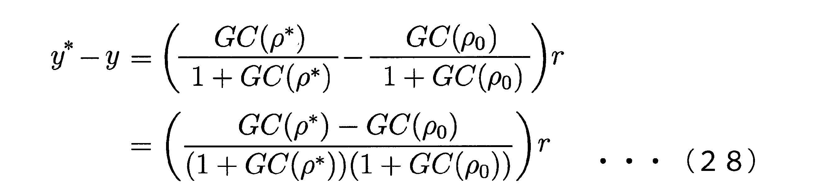
ここで、式(25)、式(26)及び式(27)の関係を使用すると、式(28)は、次の式(29)のように変形することができる。 Here, using the relationships of equations (25), (26) and (27), equation (28) can be transformed into equation (29) below.
この式(29)の左辺の更新前参照信号rを右辺に移項し、上述した式(24)を使用すると、上述した式(23)が導出される。 By transposing the pre-update reference signal r on the left side of Equation (29) to the right side and using Equation (24) above, Equation (23) above is derived.
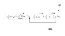
図4は、本発明の実施形態に係る閉ループ系及びこれに付加されたフィルタのブロック線図の一例を示す図である。図4に示すように、フィルタ装置10は、閉ループ系100の前段に設けられ、式(23)を使用して更新前参照信号rを更新後参照信号r*に変換し、閉ループ系100に更新後参照信号r*を入力する。
FIG. 4 is a diagram showing an example of a block diagram of a closed loop system and a filter added thereto according to an embodiment of the present invention. As shown in FIG. 4 , the
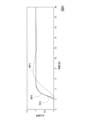
次に、図5及び図6を参照しながら、フィルタ装置10の数値シミュレーションについて説明する。図5は、本発明の実施形態に係る数値シミュレーションにおける更新前参照信号及び更新後参照信号の一例を示す図である。図6は、本発明の実施形態に係る数値シミュレーションにおける出力信号、目標出力信号及び近似目標出力信号の一例を示す図である。
Next, a numerical simulation of the
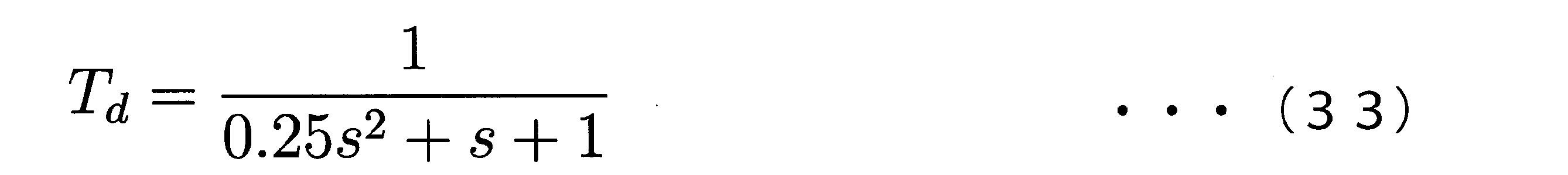
当該数値シミュレーションでは、制御対象120の伝達関数G、制御器110の伝達関数C(ρ0)、制御器110の更新前ゲイン及び閉ループ系100の目標伝達関数Tdがそれぞれ次の式(30)、式(31)、式(32)及び式(33)で表される。これら四つの式は、いずれもラプラス演算子sを含んでいる。また、当該数値シミュレーションでは、制御器110がPID制御器である場合を仮定している。
In the numerical simulation, the transfer function G of the controlled
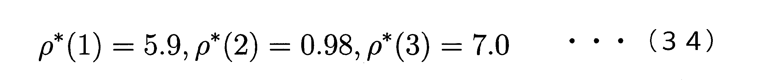
閉ループ系100は、図5に示された単位ステップ信号である更新前参照信号BR1が入力された場合、図6に示された出力信号BP1を出力する。一方、閉ループ系100は、図5に示された更新後参照信号AR1が入力された場合、図6に示された近似目標出力信号AP1を出力する。図6に示すように、近似目標出力信号AP1は、出力信号BP1よりも目標出力信号TP1に近い振る舞いを示している。また、この場合における制御器110の更新後ゲインは、次の式(34)で表される。
The
なお、閉ループ系100は、図5に示された更新後参照信号AR1が入力された場合、近似目標出力信号AP1の代わりに目標出力信号TP1を出力してもよい。
Note that, when the updated reference signal AR1 shown in FIG. 5 is input, the
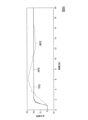
次に、図7、図8及び図9を参照しながら、フィルタ装置10の実機検証について説明する。図7は、本発明の実施形態に係る実機検証における更新前参照信号及び更新後参照信号の一例を示す図である。図8は、本発明の実施形態に係る実機検証における出力信号、目標出力信号及び近似目標出力信号の一例を示す図である。図9は、本発明の実施形態に係る目標出力信号、近似目標出力信号及びパラメータが更新された制御器により出力された出力信号の一例を示す図である。
Next, actual machine verification of the
当該実機検証では、制御対象120がモータで駆動される台車であり、制御器110が当該台車の直線上における移動距離を制御する。また、閉ループ系100が出力する信号をサンプリングする周期が0.016秒としている。さらに、当該実機検証における制御対象120の伝達関数G、制御器110の更新前ゲイン及び更新前の評価関数の値は、それぞれ次の式(35)、式(36)及び式(37)で表される。式(35)は、ラプラス演算子sを含んでいる。
In the actual machine verification, the controlled


閉ループ系100は、図7に示された立ち上がり幅0.2のステップ信号である更新前参照信号BR2が入力された場合、図8に示された出力信号BP2を出力する。一方、閉ループ系100は、図7に示された更新後参照信号AR2が入力された場合、図8に示された近似目標出力信号AP2を出力する。図8に示すように近似目標出力信号AP2は、出力信号BP2よりも目標出力信号TP2に近い振る舞いを示している。また、当該実機検証における制御器110の更新後ゲイン及び更新後の評価関数の値は、それぞれ次の式(38)及び式(39)で表される。
The


また、図9に示すように、近似目標出力信号AP2は、制御器110のパラメータが更新された場合における出力信号Uと同程度に目標出力信号TP2に追従している。
Further, as shown in FIG. 9, the approximate target output signal AP2 follows the target output signal TP2 to the same extent as the output signal U when the parameter of the
なお、閉ループ系100は、図7に示された更新後参照信号AR2が入力された場合、近似目標出力信号AP2の代わりに目標出力信号TP2を出力してもよい。
Note that, when the updated reference signal AR2 shown in FIG. 7 is input, the
以上、実施形態に係るフィルタ装置10について説明した。フィルタ装置10は、制御対象120を制御している実装済制御器の伝達関数のパラメータを入力信号及び出力信号に基づくデータ駆動制御、例えば、FRITにより更新して仮想制御器の伝達関数を演算する。そして、フィルタ装置10は、制御対象120の伝達関数、実装済制御器の伝達関数及び仮想制御器の伝達関数を使用して制御対象120及び実装済制御器を含む閉ループ系に入力される更新前参照信号を制御対象120に目標出力信号又は出力信号よりも目標出力信号に近似している近似目標出力信号を出力させる更新後参照信号に変換する。
The
したがって、フィルタ装置10は、制御器110の変更、例えば、制御器110自体の交換、制御器110のパラメータの更新を避けつつ、制御対象120に所望の出力信号である目標出力信号又は近似目標出力信号を出力させることができる。また、これにより、フィルタ装置10は、制御器110の変更が適切に実行されなかった場合に制御器110及び制御器110を含む閉ループ系100を不安定化させてしまうことを回避することができる。
Therefore, the
なお、上述した実施形態では、閉ループ系100の前段にフィルタ装置10が設けられる場合を例に挙げて説明したが、これに限定されない。
In the above-described embodiment, the case where the
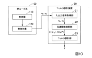
例えば、図10に示したフィルタ設計装置20が設計したフィルタFが閉ループ系100の前段に設けられてもよい。図10は、本発明の実施形態に係る閉ループ系及びフィルタ設計装置の機能的な構成の一例を示す図である。図10に示すように、フィルタ設計装置20は、入出力信号取得部21と、伝達関数演算部22と、フィルタ設計部23とを備える。入出力信号取得部21及び伝達関数演算部22は、それぞれ上述した入出力信号取得部11及び伝達関数演算部12と同様である。
For example, the filter F designed by the
フィルタ設計部23は、上述した制御対象120の伝達関数G、実装済制御器の伝達関数C(ρ0)及び仮想制御器の伝達関数C(ρ*)を使用して更新前参照信号rを更新後参照信号r*に変換するフィルタFを設計する。フィルタFは、上述した式(23)により更新前参照信号rを更新後参照信号r*に変換するフィルタである。
The
フィルタ設計装置20は、上述したフィルタ装置10と同様の効果を奏するフィルタFを複数の閉ループ系に提供することができる。
The
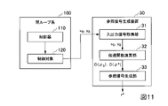
或いは、閉ループ系100の前段に上述したフィルタ装置10又はフィルタFを設ける代わりに、図11に示した参照信号生成装置30が上述した更新後参照信号r*を生成し、当該更新後参照信号r*が閉ループ系100に入力されてもよい。図11に示すように、参照信号生成装置30は、当該更新後参照信号r*を生成する装置であり、閉ループ系100から独立している。参照信号生成装置30は、入出力信号取得部31と、伝達関数演算部32と、参照信号生成部33とを備える。入出力信号取得部31及び伝達関数演算部32は、それぞれ上述した入出力信号取得部11及び伝達関数演算部12と同様である。
Alternatively, instead of providing the above-described
参照信号生成部33は、上述した制御対象120の伝達関数G、実装済制御器の伝達関数C(ρ0)及び仮想制御器の伝達関数C(ρ*)を使用して更新前参照信号rから更新後参照信号r*を生成する。参照信号生成部33が更新後参照信号r*を生成する手順は、上述したフィルタ装置10が更新前参照信号rを更新後参照信号r*に変換する手順と同様である。
The reference signal generator 33 generates the pre-update reference signal r to generate the updated reference signal r * . The procedure for the
参照信号生成装置30は、閉ループ系100から独立した装置であるため、上述したフィルタ装置10と同様の効果に加え、閉ループ系100のハードウェア設計の自由度を高めることができる。
Since the reference
なお、上述したフィルタ装置10、フィルタ設計装置20及び参照信号生成装置30の各機能を実現するためのプログラムをコンピュータ読み取り可能な記録媒体に記録させ、この記録媒体に記録されたプログラムをコンピュータシステムに読み込ませて実行することにより、上述した処理の少なくとも一部を実行してもよい。
A program for realizing each function of the
ここで言うコンピュータシステムとは、オペレーティング・システム(Operating System:OS)及び周辺機器等のハードウェアの少なくとも一つを含む。また、コンピュータ読み取り可能な記録媒体とは、例えば、フロッピーディスク、光磁気ディスク、ROM(Read Only Memory)、フラッシュメモリ等の書き込み可能な不揮発性メモリ、DVD(Digital Versatile Disc)等の可搬媒体、コンピュータシステムに内蔵されるハードディスク等の記憶装置、ネットワーク又は通信回線を介してプログラムが送信される場合におけるサーバ又はクライアントとなるコンピュータシステム内部の揮発性メモリのように一定時間プログラムを保持しているものも含む。 The computer system referred to here includes at least one of an operating system (OS) and hardware such as peripheral devices. Further, the computer-readable recording medium includes, for example, a floppy disk, a magneto-optical disk, a ROM (Read Only Memory), a writable non-volatile memory such as a flash memory, a portable medium such as a DVD (Digital Versatile Disc), A storage device such as a hard disk built into a computer system, or a device that retains a program for a certain period of time, such as a volatile memory inside a computer system that acts as a server or client when the program is transmitted via a network or communication line. Also includes
また、上述したプログラムは、このプログラムを記憶装置等に格納したコンピュータシステムから、伝送媒体を介して、又は、伝送媒体中の伝送波により他のコンピュータシステムに伝送されてもよい。ここで、プログラムを伝送する伝送媒体とは、インターネット等のネットワーク又は電話回線等の通信回線のように情報を伝送する機能を有する媒体のことをいう。 Further, the program described above may be transmitted from a computer system storing this program in a storage device or the like to another computer system via a transmission medium or by a transmission wave in a transmission medium. Here, the transmission medium for transmitting the program means a medium having a function of transmitting information such as a network such as the Internet or a communication line such as a telephone line.
また、上述したプログラムは、上述した機能の一部を実現するためのものであってもよく、上述した機能をコンピュータシステムに既に記録されているプログラムとの組み合わせで実現できるもの、いわゆる差分プログラムであってもよい。上述したプログラムは、例えば、コンピュータが備えるCPU(Central Processing Unit)等のプロセッサにより読み出されて実行される。 Further, the above-mentioned program may be for realizing part of the above-mentioned functions, and is a so-called difference program that can realize the above-mentioned functions in combination with a program already recorded in the computer system. There may be. The above-described program is read and executed by a processor such as a CPU (Central Processing Unit) provided in a computer, for example.
以上、本発明の実施形態について図面を参照して詳述したが、具体的な構成はこの実施形態に限られるものではなく、本発明の要旨を逸脱しない範囲内において種々の変形、置換及び設計変更の少なくとも一つを加えることができる。上述した各実施形態に記載の構成を組み合わせてもよい。 As described above, the embodiment of the present invention has been described in detail with reference to the drawings. At least one of the changes can be added. You may combine the structure as described in each embodiment mentioned above.
10…フィルタ装置、11…入出力信号取得部、12…伝達関数演算部、13…参照信号変換部、14…フィルタ、20…フィルタ設計装置、21…入出力信号取得部、22…伝達関数演算部、23…フィルタ設計部、30…参照信号生成装置、31…入出力信号取得部、32…伝達関数演算部、33…参照信号生成部、100…閉ループ系、110…制御器、120…制御対象、AP1,AP2…近似目標出力信号、BP1,BP2…出力信号、AR1,AR2…更新後参照信号、BR1,BR2…更新前参照信号、TP1,TP2…目標出力信号
DESCRIPTION OF
Claims (15)
前記制御対象を制御している実装済制御器の伝達関数のパラメータを前記入力信号及び前記出力信号に基づくデータ駆動制御により更新して仮想制御器の伝達関数を演算する伝達関数演算部と、
前記制御対象の伝達関数、前記実装済制御器の伝達関数及び前記仮想制御器の伝達関数を使用して前記制御対象及び前記実装済制御器を含む閉ループ系に入力される更新前参照信号を前記制御対象に目標出力信号又は前記出力信号よりも前記目標出力信号に近似している近似目標出力信号を出力させる更新後参照信号に変換する参照信号変換部と、
を備えるフィルタ装置。 an input/output signal acquisition unit that acquires an input signal input to a controlled object and acquires an output signal that is output from the controlled object in response to the input of the input signal;
a transfer function calculation unit for calculating a transfer function of a virtual controller by updating parameters of a transfer function of a mounted controller that controls the controlled object by data-driven control based on the input signal and the output signal;
The pre-update reference signal input to a closed loop system including the controlled object and the implemented controller using the transfer function of the controlled object, the transfer function of the implemented controller, and the transfer function of the virtual controller; a reference signal conversion unit that converts to an updated reference signal that causes a controlled object to output a target output signal or an approximate target output signal that is closer to the target output signal than the output signal;
A filter device comprising:
請求項1に記載のフィルタ装置。

u0 :入力信号
y0 :出力信号
Td :閉ループ系の目標伝達関数
ρ :パラメータ
C(ρ):制御器の伝達関数 The transfer function calculation unit updates the parameters of the transfer function of the implemented controller using the evaluation functions represented by the following equations (1) and (2), whereby the transfer function of the virtual controller to compute
A filter device according to claim 1 .
u 0 : input signal y 0 : output signal T d : target transfer function of closed loop system ρ : parameter C(ρ): transfer function of controller
請求項1又は請求項2に記載のフィルタ装置。
ρ0 :更新前のパラメータ
C(ρ0):実装済制御器の伝達関数
ρ* :更新後のパラメータ
C(ρ*):仮想制御器の伝達関数
G :制御対象の伝達関数
r* :更新後参照信号 The reference signal conversion unit converts the pre-update reference signal into the post-update reference signal represented by the following equations (3) and (4).
The filter device according to claim 1 or 2.
r * : Post-update reference signal
制御対象に入力される入力信号を取得し、前記入力信号の入力に応じて前記制御対象から出力される出力信号を取得する入出力信号取得機能と、
前記制御対象を制御している実装済制御器の伝達関数のパラメータを前記入力信号及び前記出力信号に基づくデータ駆動制御により更新して仮想制御器の伝達関数を演算する伝達関数演算機能と、
前記制御対象の伝達関数、前記実装済制御器の伝達関数及び前記仮想制御器の伝達関数を使用して前記制御対象及び前記実装済制御器を含む閉ループ系に入力される更新前参照信号を前記制御対象に目標出力信号又は前記出力信号よりも前記目標出力信号に近似している近似目標出力信号を出力させる更新後参照信号に変換する参照信号変換機能と、
を実現させるためのフィルタプログラム。 to the computer,
an input/output signal acquisition function for acquiring an input signal input to a controlled object and acquiring an output signal output from the controlled object in response to the input of the input signal;
a transfer function calculation function for calculating a transfer function of a virtual controller by updating parameters of a transfer function of a mounted controller that controls the controlled object by data-driven control based on the input signal and the output signal;
The pre-update reference signal input to a closed loop system including the controlled object and the implemented controller using the transfer function of the controlled object, the transfer function of the implemented controller, and the transfer function of the virtual controller; a reference signal conversion function for converting to an updated reference signal that causes a controlled object to output a target output signal or an approximate target output signal that is closer to the target output signal than the output signal;
A filter program to realize
請求項4に記載のフィルタプログラム。
u0 :入力信号
y0 :出力信号
Td :閉ループ系の目標伝達関数
ρ :パラメータ
C(ρ):制御器の伝達関数 The transfer function calculation function updates parameters of the transfer function of the implemented controller using evaluation functions represented by the following equations (5) and (6) to obtain the transfer function of the virtual controller. is a function that computes
5. A filter program according to claim 4.
u 0 : input signal y 0 : output signal T d : target transfer function of closed loop system ρ : parameter C(ρ): transfer function of controller
請求項4又は請求項5に記載のフィルタプログラム。

ρ0 :更新前のパラメータ
C(ρ0):実装済制御器の伝達関数
ρ* :更新後のパラメータ
C(ρ*):仮想制御器の伝達関数
G :制御対象の伝達関数
r* :更新後参照信号 The reference signal conversion function is a function of converting the pre-update reference signal into the post-update reference signal represented by the following equations (7) and (8).
6. A filter program according to claim 4 or 5.
r * : Post-update reference signal
制御対象に入力される入力信号を取得し、前記入力信号の入力に応じて前記制御対象から出力される出力信号を取得する入出力信号取得機能と、
前記制御対象を制御している実装済制御器の伝達関数のパラメータを前記入力信号及び前記出力信号に基づくデータ駆動制御により更新して仮想制御器の伝達関数を演算する伝達関数演算機能と、
前記制御対象の伝達関数、前記実装済制御器の伝達関数及び前記仮想制御器の伝達関数を使用して前記制御対象及び前記実装済制御器を含む閉ループ系に入力される更新前参照信号を前記制御対象に目標出力信号又は前記出力信号よりも前記目標出力信号に近似している近似目標出力信号を出力させる更新後参照信号に変換するフィルタを設計するフィルタ設計機能と、
を実現させるためのフィルタ設計プログラム。 to the computer,
an input/output signal acquisition function for acquiring an input signal input to a controlled object and acquiring an output signal output from the controlled object in response to the input of the input signal;
a transfer function calculation function for calculating a transfer function of a virtual controller by updating parameters of a transfer function of a mounted controller that controls the controlled object by data-driven control based on the input signal and the output signal;
The pre-update reference signal input to a closed loop system including the controlled object and the implemented controller using the transfer function of the controlled object, the transfer function of the implemented controller, and the transfer function of the virtual controller; a filter design function for designing a filter for conversion to an updated reference signal that causes a controlled object to output a target output signal or an approximate target output signal that is closer to the target output signal than the output signal;
A filter design program to realize
請求項7に記載のフィルタ設計プログラム。

u0 :入力信号
y0 :出力信号
Td :閉ループ系の目標伝達関数
ρ :パラメータ
C(ρ):制御器の伝達関数 The transfer function calculation function updates the parameters of the transfer function of the implemented controller using the evaluation functions represented by the following equations (9) and (10), whereby the transfer function of the virtual controller is a function that computes
The filter design program according to claim 7.
u 0 : input signal y 0 : output signal T d : target transfer function of closed loop system ρ : parameter C(ρ): transfer function of controller
請求項7又は請求項8に記載のフィルタ設計プログラム。
ρ0 :更新前のパラメータ
C(ρ0):実装済制御器の伝達関数
ρ* :更新後のパラメータ
C(ρ*):仮想制御器の伝達関数
G :制御対象の伝達関数
r* :更新後参照信号 The filter design function is a function of designing a filter that converts the pre-update reference signal into the post-update reference signal represented by the following equations (11) and (12).
The filter design program according to claim 7 or 8.
r * : Post-update reference signal
前記制御対象を制御している実装済制御器の伝達関数のパラメータを前記入力信号及び前記出力信号に基づくデータ駆動制御により更新して仮想制御器の伝達関数を演算する伝達関数演算部と、
前記制御対象の伝達関数、前記実装済制御器の伝達関数及び前記仮想制御器の伝達関数を使用して前記制御対象及び前記実装済制御器を含む閉ループ系に入力される更新前参照信号から前記制御対象に目標出力信号又は前記出力信号よりも前記目標出力信号に近似している近似目標出力信号を出力させる更新後参照信号を生成する参照信号生成部と、
を備える参照信号生成装置。 an input/output signal acquisition unit that acquires an input signal input to a controlled object and acquires an output signal that is output from the controlled object in response to the input of the input signal;
a transfer function calculation unit for calculating a transfer function of a virtual controller by updating parameters of a transfer function of a mounted controller that controls the controlled object by data-driven control based on the input signal and the output signal;
From the pre-update reference signal input to a closed loop system including the controlled object and the implemented controller using the transfer function of the controlled object, the transfer function of the implemented controller, and the transfer function of the virtual controller a reference signal generator that generates an updated reference signal that causes a controlled object to output a target output signal or an approximate target output signal that is closer to the target output signal than the output signal;
A reference signal generation device comprising:
請求項10に記載の参照信号生成装置。
u0 :入力信号
y0 :出力信号
Td :閉ループ系の目標伝達関数
ρ :パラメータ
C(ρ):制御器の伝達関数 The transfer function calculation unit updates the parameters of the transfer function of the implemented controller using evaluation functions represented by the following equations (13) and (14), whereby the transfer function of the virtual controller to compute
The reference signal generation device according to claim 10.
u 0 : input signal y 0 : output signal T d : target transfer function of closed loop system ρ : parameter C(ρ): transfer function of controller
請求項10又は請求項11に記載の参照信号生成装置。
ρ0 :更新前のパラメータ
C(ρ0):実装済制御器の伝達関数
ρ* :更新後のパラメータ
C(ρ*):仮想制御器の伝達関数
G :制御対象の伝達関数
r* :更新後参照信号 The reference signal generation unit generates the post-update reference signal represented by the following equations (15) and (16) from the pre-update reference signal.
The reference signal generation device according to claim 10 or 11.
r * : Post-update reference signal
制御対象に入力される入力信号を取得し、前記入力信号の入力に応じて前記制御対象から出力される出力信号を取得する入出力信号取得機能と、
前記制御対象を制御している実装済制御器の伝達関数のパラメータを前記入力信号及び前記出力信号に基づくデータ駆動制御により更新して仮想制御器の伝達関数を演算する伝達関数演算機能と、
前記制御対象の伝達関数、前記実装済制御器の伝達関数及び前記仮想制御器の伝達関数を使用して前記制御対象及び前記実装済制御器を含む閉ループ系に入力される更新前参照信号から前記制御対象に目標出力信号又は前記出力信号よりも前記目標出力信号に近似している近似目標出力信号を出力させる更新後参照信号を生成する参照信号生成機能と、
を実現させるための参照信号生成プログラム。 to the computer,
an input/output signal acquisition function for acquiring an input signal input to a controlled object and acquiring an output signal output from the controlled object in response to the input of the input signal;
a transfer function calculation function for calculating a transfer function of a virtual controller by updating parameters of a transfer function of a mounted controller that controls the controlled object by data-driven control based on the input signal and the output signal;
From the pre-update reference signal input to a closed loop system including the controlled object and the implemented controller using the transfer function of the controlled object, the transfer function of the implemented controller, and the transfer function of the virtual controller a reference signal generation function that generates an updated reference signal that causes a controlled object to output a target output signal or an approximate target output signal that is closer to the target output signal than the output signal;
A reference signal generator for realizing
請求項13に記載の参照信号生成プログラム。
u0 :入力信号
y0 :出力信号
Td :閉ループ系の目標伝達関数
ρ :パラメータ
C(ρ):制御器の伝達関数 The transfer function calculation function updates the parameters of the transfer function of the implemented controller using the evaluation functions represented by the following equations (17) and (18), whereby the transfer function of the virtual controller is a function that computes
14. The reference signal generation program according to claim 13.
u 0 : input signal y 0 : output signal T d : target transfer function of closed loop system ρ : parameter C(ρ): transfer function of controller
請求項13又は請求項14に記載の参照信号生成プログラム。
ρ0 :更新前のパラメータ
C(ρ0):実装済制御器の伝達関数
ρ* :更新後のパラメータ
C(ρ*):仮想制御器の伝達関数
G :制御対象の伝達関数
r* :更新後参照信号 The reference signal generation function is a function of generating the post-update reference signal represented by the following equations (19) and (20) from the pre-update reference signal.
15. The reference signal generating program according to claim 13 or 14.
r * : Post-update reference signal
Priority Applications (1)
| Application Number | Priority Date | Filing Date | Title |
|---|---|---|---|
| JP2019039430A JP7253233B2 (en) | 2019-03-05 | 2019-03-05 | Filter device, filter program, filter design program, reference signal generation device, and reference signal generation program |
Applications Claiming Priority (1)
| Application Number | Priority Date | Filing Date | Title |
|---|---|---|---|
| JP2019039430A JP7253233B2 (en) | 2019-03-05 | 2019-03-05 | Filter device, filter program, filter design program, reference signal generation device, and reference signal generation program |
Publications (2)
| Publication Number | Publication Date |
|---|---|
| JP2020144506A JP2020144506A (en) | 2020-09-10 |
| JP7253233B2 true JP7253233B2 (en) | 2023-04-06 |
Family
ID=72354157
Family Applications (1)
| Application Number | Title | Priority Date | Filing Date |
|---|---|---|---|
| JP2019039430A Active JP7253233B2 (en) | 2019-03-05 | 2019-03-05 | Filter device, filter program, filter design program, reference signal generation device, and reference signal generation program |
Country Status (1)
| Country | Link |
|---|---|
| JP (1) | JP7253233B2 (en) |
Citations (2)
| Publication number | Priority date | Publication date | Assignee | Title |
|---|---|---|---|---|
| JP2009237916A (en) | 2008-03-27 | 2009-10-15 | Yaskawa Electric Corp | Servo control device |
| WO2016092872A1 (en) | 2014-12-11 | 2016-06-16 | 富士電機株式会社 | Control device, program therefor, and plant control method |
Family Cites Families (1)
| Publication number | Priority date | Publication date | Assignee | Title |
|---|---|---|---|---|
| JP5430535B2 (en) * | 2010-10-25 | 2014-03-05 | 本田技研工業株式会社 | Plant control equipment |
-
2019
- 2019-03-05 JP JP2019039430A patent/JP7253233B2/en active Active
Patent Citations (2)
| Publication number | Priority date | Publication date | Assignee | Title |
|---|---|---|---|---|
| JP2009237916A (en) | 2008-03-27 | 2009-10-15 | Yaskawa Electric Corp | Servo control device |
| WO2016092872A1 (en) | 2014-12-11 | 2016-06-16 | 富士電機株式会社 | Control device, program therefor, and plant control method |
Also Published As
| Publication number | Publication date |
|---|---|
| JP2020144506A (en) | 2020-09-10 |
Similar Documents
| Publication | Publication Date | Title |
|---|---|---|
| JP4223894B2 (en) | PID parameter adjustment device | |
| US10120396B2 (en) | Control device for machine apparatus and gain determination method for friction compensation | |
| US10935939B2 (en) | Machine learning device, servo control apparatus, servo control system, and machine learning method | |
| JP6740279B2 (en) | Adjusting device and adjusting method | |
| Günay et al. | Enhancement of real‐time hybrid simulation on a shaking table configuration with implementation of an advanced control method | |
| EP3304817B1 (en) | Interaction of devices in a networked environment | |
| JP2020064439A (en) | Control model identification method, control model identification apparatus and program | |
| JP2021081786A (en) | Inference system, inference device, inference method, and inference program | |
| JP6779035B2 (en) | Controls, underwater vehicles, control methods and programs | |
| JP7253233B2 (en) | Filter device, filter program, filter design program, reference signal generation device, and reference signal generation program | |
| JP2016164697A (en) | Position control system | |
| Ordóñez et al. | Adaptive control for a class of nonlinear systems with a time-varying structure | |
| KR20210022696A (en) | Feedback control method, and feedback control device | |
| Kirange et al. | Optimising SMIB system stability: FOPID controller tuning via Harris hawks optimisation | |
| JP2020038656A (en) | Controller update device and controller update program | |
| JPH09136698A (en) | Servo control system for aircraft control surface | |
| JP2017182179A (en) | Control system | |
| Grimble | Reduced‐order non‐linear generalised minimum variance control for quasi‐linear parameter varying systems | |
| JP2025095227A (en) | CONTROL SYSTEM, SYSTEM DESIGN TOOL, CONTROL METHOD, AND COMPUTER PROGRAM | |
| CN116075782B (en) | Parameter adjusting device and parameter adjusting method | |
| KR20220074388A (en) | Apparatus and method for controlling line of sight stabilization | |
| JP2012226551A (en) | Pid gain adjustment device and pid gain adjustment method | |
| CN118090102B (en) | Real-time hybrid test loading device time lag compensation method based on fuzzy neural network | |
| JP7000868B2 (en) | Control system | |
| Teixeira et al. | Stability analysis of indirect binary model reference adaptive controller for plants with relative degree one |
Legal Events
| Date | Code | Title | Description |
|---|---|---|---|
| A621 | Written request for application examination |
Free format text: JAPANESE INTERMEDIATE CODE: A621 Effective date: 20220301 |
|
| A977 | Report on retrieval |
Free format text: JAPANESE INTERMEDIATE CODE: A971007 Effective date: 20230220 |
|
| TRDD | Decision of grant or rejection written | ||
| A01 | Written decision to grant a patent or to grant a registration (utility model) |
Free format text: JAPANESE INTERMEDIATE CODE: A01 Effective date: 20230307 |
|
| A61 | First payment of annual fees (during grant procedure) |
Free format text: JAPANESE INTERMEDIATE CODE: A61 Effective date: 20230317 |
|
| R150 | Certificate of patent or registration of utility model |
Ref document number: 7253233 Country of ref document: JP Free format text: JAPANESE INTERMEDIATE CODE: R150 |