JP7246721B2 - game machine - Google Patents
game machine Download PDFInfo
- Publication number
- JP7246721B2 JP7246721B2 JP2019159601A JP2019159601A JP7246721B2 JP 7246721 B2 JP7246721 B2 JP 7246721B2 JP 2019159601 A JP2019159601 A JP 2019159601A JP 2019159601 A JP2019159601 A JP 2019159601A JP 7246721 B2 JP7246721 B2 JP 7246721B2
- Authority
- JP
- Japan
- Prior art keywords
- game
- setting
- jackpot
- special symbol
- probability
- Prior art date
- Legal status (The legal status is an assumption and is not a legal conclusion. Google has not performed a legal analysis and makes no representation as to the accuracy of the status listed.)
- Active
Links
Images


Landscapes
- Pinball Game Machines (AREA)
- Display Devices Of Pinball Game Machines (AREA)
Description
本発明は、特別遊技を実行するか否かを判定し、その判定結果に基づいて演出を実行する遊技機に関する。 TECHNICAL FIELD The present invention relates to a gaming machine that determines whether or not to execute a special game, and executes an effect based on the determination result.
パチンコ遊技機では、所定の始動口に遊技球が入賞すると、遊技者に有利な特別遊技を実行するか否かが判定される。そして、この判定の結果を報知する特別図柄の変動表示中において、画像表示手段等を用いた各種の演出が行われる(例えば特許文献1参照)。
In the pachinko game machine, when a game ball enters a predetermined starting hole, it is determined whether or not to execute a special game advantageous to the player. Various effects are performed using an image display means or the like during the variable display of the special symbols for informing the result of this determination (see
ところで、特別遊技を実行すると判定される判定確率を操作によって変更可能な構成を採用した場合に、この構成に応じた適切な演出制御を行う必要がある。 By the way, when adopting a configuration that can change the determination probability determined to execute a special game by an operation, it is necessary to perform appropriate effect control according to this configuration.
それ故に、本発明の目的は、適切な演出制御を行うことが可能な遊技機を提供することである。 SUMMARY OF THE INVENTION Therefore, an object of the present invention is to provide a gaming machine capable of performing appropriate effect control.
本発明は、上記の課題を解決するために以下の構成を採用した。
本発明に係る遊技機は、遊技を制御する遊技制御部と、演出を制御する演出制御部とを具備する遊技機であって、前記遊技制御部は、遊技者に有利な特別遊技を実行するか否かを判定する判定手段と、操作手段を用いる所定の操作に応じて、前記判定手段によって前記特別遊技を実行すると判定される判定確率が複数の確率のいずれかの確率となることを示す設定値を設定する設定手段と、前記設定手段によって設定された前記設定値を、少なくとも前記設定手段による前記設定が完了したときに送信する設定値送信手段と、前記判定手段の判定結果を送信可能な判定結果送信手段と、を備え、前記演出制御部は、前記設定値送信手段によって送信された前記設定値と、前記判定結果送信手段によって送信された前記判定手段の判定結果と、を受信可能であり、前記判定手段によって前記特別遊技を実行すると判定されたことを示す前記判定結果が受信された場合に、前記設定手段によって設定される設定値によらず、前記判定手段の判定結果に応じた一の演出を所定の実行確率で実行し、前記設定手段によって設定される設定値によって、前記一の演出に関して前記特別遊技が実行されるときの出現率と前記特別遊技が実行されないときの出現率との合算出現率を異ならせる。
The present invention employs the following configurations in order to solve the above problems.
A gaming machine according to the present invention is a gaming machine comprising a game control unit for controlling a game and an effect control unit for controlling an effect, wherein the game control unit executes a special game advantageous to a player. Determination means for determining whether or not, and a determination probability that the determination means determines that the special game will be executed according to a predetermined operation using the operation means is one of a plurality of probabilities. setting means for setting a setting value; setting value transmission means for transmitting the setting value set by the setting means at least when the setting by the setting means is completed; and a determination result of the determination means can be transmitted. and a determination result transmission means, and the effect control unit can receive the set value transmitted by the set value transmission means and the determination result of the determination means transmitted by the determination result transmission means. and when the determination result indicating that the determination means has determined to execute the special game is received, regardless of the setting value set by the setting means, the determination result of the determination means One effect corresponding to the effect is executed with a predetermined execution probability, and an appearance rate when the special game is executed with respect to the one effect and an appearance rate when the special game is not executed are set according to the setting value set by the setting means. Differentiate the total appearance rate from the appearance rate .
この発明によれば、適切な演出制御を行うことが可能である。 According to this invention, it is possible to perform appropriate effect control.
以下、適宜図面を参照しつつ、本発明の遊技機の一実施形態に係る遊技機1について説明する。
Hereinafter, a
[遊技機1の概略構成例]
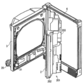
まず、図1を参照しつつ、遊技機1の概略構成について説明する。ここで、図1は、遊技機1の概略正面図である。図1に例示されるように、遊技機1は、入賞や判定に関する役物等が設けられた遊技盤2と、遊技盤2を囲む内枠3とを備えている。内枠3は、遊技盤2と所定の間隔を隔てて平行配置された透明なガラス板を支持しており、このガラス板と遊技盤2とによって、遊技球が流下可能な遊技領域10が形成されている。
[Example of schematic configuration of gaming machine 1]
First, a schematic configuration of the
遊技者がハンドル20を握ってレバー21を時計方向に回転させると、上皿28に溜められた遊技球が不図示の発射装置へと案内され、ハンドル20の回転角度に応じた打球力で遊技領域10へと発射される。この遊技領域10には、不図示の遊技クギや風車等が設けられており、発射された遊技球は、遊技領域10における上部位置へと案内され、遊技クギや風車等に接触することでその移動方向を変化させながら遊技盤2に沿って遊技領域10を落下する。なお、遊技球の発射は、遊技者が停止ボタン22を操作することによって一時的に停止される。
When the player grips the
上皿28は、発射装置へ供給される遊技球及び賞球を溜めるものである。この上皿28の下方には、賞球を溜める下皿29が設けられている。この下皿29と近接配置された取り出しボタン23を遊技者が操作すると、下皿29の下面の一部が開口されて、下皿29に溜まった遊技球が下皿29の下方に配置された不図示の箱に落下する。なお、上皿28及び下皿29は、1つの皿で構成されてもよい。
The
遊技者がハンドル20を小さい回転角で回転させた状態を維持するいわゆる「左打ち」を行うと、遊技球が相対的に弱い打球力で打ち出される。この場合、遊技球は、矢印35に例示されるように遊技領域10における左側領域を流下する。一方、遊技者がハンドル20を大きい回転角で回転させた状態を維持するいわゆる「右打ち」を行うと、遊技球が相対的に強い打球力で打ち出される。この場合、遊技球は、矢印36に例示されるように遊技領域10における右側領域を流下する。
When the player performs so-called "left-handed hitting", in which the player rotates the
左打ちされた遊技球の通過経路には、入賞や判定に関する役物として、第1始動口11、第2始動口12、2つの普通入賞口14、及び電動チューリップ17が設けられている。また、右打ちされた遊技球の通過経路には、入賞や判定に関する役物として、上記第2始動口12、大入賞口13、2つの普通入賞口14、ゲート16、及び上記電動チューリップ17が設けられている。
A
遊技領域10に打ち出された遊技球は、遊技盤2に沿って流下する過程で、第1始動口11、第2始動口12、大入賞口13、及び普通入賞口14のいずれかに入球して入賞する場合がある。この場合、入賞した箇所に応じた所定数の賞球が上皿28又は下皿29に払い出される。例えば、第1始動口11に遊技球が入賞すると4個の賞球が払い出され、第2始動口12に遊技球が入賞すると2個の賞球が払い出され、大入賞口13に遊技球が入賞すると14個の賞球が払い出され、普通入賞口14に遊技球が入賞すると3個の賞球が払い出される。なお、入賞しなかった遊技球は、排出口18を介して遊技領域10から排出される。
The game ball launched into the
第1始動口11は、常時開放されている始動領域であり、第2始動口12は、普通電動役物としての電動チューリップ17が作動しているときだけ開放される始動領域である。遊技機1では、遊技球が第1始動口11を通過して入賞した場合、又は遊技球が第2始動口12を通過して入賞した場合、遊技者にとって有利な大当たり遊技(特別遊技)を実行するか否かが判定され、その判定結果を示す図柄が後述する表示器4の第1特別図柄表示器41または第2特別図柄表示器42に表示される。そして、大当たりを示す図柄が停止表示された場合、大入賞口13を開放する大当たり遊技が実行される。
The
なお、以下の説明では、第1始動口11への遊技球の入賞を条件として実行される判定を「第1特別図柄判定」と呼び、第2始動口12への遊技球の入賞を条件として実行される判定を「第2特別図柄判定」と呼び、これらの判定を総称して「特別図柄判定」と呼ぶものとする。
In the following description, the judgment executed on the condition that the game ball enters the
大入賞口13は、特別図柄判定の結果に応じて開放される特別入賞領域である。この大入賞口13の開口部には、大入賞口13を開閉するプレートが設けられている。大入賞口13は、通常はこのプレートによって閉塞されている。これに対して、特別図柄判定の判定結果が「大当たり」であることを示す所定の大当たり図柄が表示器4に停止表示された場合、上記プレートを作動させて大入賞口13を開放する大当たり遊技が実行される。大当たり遊技中は、所定条件(本実施形態では、大入賞口13への9個の遊技球の入賞、又は大入賞口13が開放されてから29.5秒の経過)を満たすまで大入賞口13が開放状態に維持されてから閉塞される長開放ラウンド遊技が所定の時間間隔で所定回数(本実施形態では5回または10回:図14(B)及び(C)参照)実行される。
The big winning
このように、大当たり遊技中には大入賞口13が長開放されるため、遊技者は、大当たり遊技中に右打ちを行うことで、大当たり遊技が行われていないときに比べてより多くの賞球を獲得可能である。
In this way, since the big winning
電動チューリップ17は、第2始動口12に近接配置されており、一対の羽根部材を有している。この電動チューリップ17は、一対の羽根部材が第2始動口12を閉塞する閉姿勢(図1の実線を参照)と、第2始動口12を開放する開姿勢(図1の破線を参照)とに姿勢変化可能に構成されている。
The
第2始動口12は、図1に例示されるように、通常は電動チューリップ17によって閉塞されている。これに対して、遊技球がゲート16を通過すると、賞球の払い出しは行われないものの、第2始動口12を開放するか否かが判定される。ここで、第2始動口12を開放すると判定された場合、電動チューリップ17の一対の羽根部材が規定時間開姿勢を維持した後に閉姿勢に戻る動作が規定回数行われる。このように、第2始動口12は、電動チューリップ17が作動していないときには遊技球が通過し難い状態であるのに対して、電動チューリップ17が作動することによって遊技球が通過し易い状態となる。
The
なお、以下の説明では、ゲート16に対する遊技球の通過を条件として実行される判定を「普通図柄判定」と呼ぶものとする。
Incidentally, in the following description, the determination executed on the condition that the game ball passes through the
普通入賞口14は、第1始動口11と同様に常時開放されており、遊技球の入賞によって所定個数(本実施形態では3個)の賞球が払い出される入賞口である。なお、第1始動口11等とは異なり、普通入賞口14に遊技球が入賞しても判定が行われることはない。
The
[遊技機1の演出手段の構成例]
図1に例示されるように、遊技盤2又は内枠3には、各種の演出を行うものとして、液晶表示装置5、スピーカ24、演出役物7、盤ランプ25等が設けられている。また、内枠3には、図1には示されていない枠ランプ37(図8参照)が内蔵されている。
[Configuration example of effect means of gaming machine 1]
As exemplified in FIG. 1, the
液晶表示装置5は、演出画像を表示する画像表示装置であり、液晶表示装置5の表示画面(以下「液晶画面5」とも言う。)は、遊技者によって視認され易い位置に設けられている。この液晶画面5には、例えば、特別図柄判定の判定結果を報知する装飾図柄、大当たり信頼度を示唆する予告演出などを行うキャラクタやアイテム、特別図柄判定が保留されている数だけ表示される保留アイコン、特別図柄の変動表示中であることを示唆する当該アイコン等の各種表示オブジェクトを含む演出画像が表示される。なお、画像表示装置は、EL表示装置等の他の画像表示装置によって構成されてもよい。
The liquid
スピーカ24は、液晶画面5で行われる表示演出と同期するように、或いは非同期に、楽曲や音声、効果音等を出力して音による演出を行う。なお、スピーカ24は、不正遊技に対する警告、エラー報知等にも使用される。
The
演出役物7は、液晶画面5の前方且つ側方に配置されている。演出役物7には、発光素子(例えばLED)が内蔵されている。演出役物7は、役物自体の動きと光との両方或いは一方によって所定の演出を行う。演出役物7は、本実施形態では、星を模した形状に構成されており、遊技機1の奥行き方向を軸方向として回転可能に構成されている。
The
盤ランプ25および枠ランプ37は、点灯又は点滅のパターンの変更、発光色の変更等の光による各種の演出を行う。
The
[遊技機1の入力手段の構成例]
図1に例示されるように、内枠3には、遊技者が入力を行うための入力手段として、演出ボタン26および演出キー27が設けられている。演出ボタン26は、遊技者が押下することによって操作情報を入力するための押ボタンである。演出キー27は、遊技者が選択操作やカーソル移動を行うためのいわゆる十字キーであり、上キー、下キー、左キー、及び右キーを有して構成されている。遊技機1では、演出ボタン26と演出キー27の操作に応じた演出が行われる場合がある。
[Configuration example of input means of gaming machine 1]
As illustrated in FIG. 1, the
[表示器4の構成例]
図2は、図1における表示器4の拡大図である。表示器4は、図2に例示されるように、第1特別図柄表示器41、第2特別図柄表示器42、第1特別図柄保留表示器43、第2特別図柄保留表示器44、普通図柄表示器45、普通図柄保留表示器46、遊技状態表示器47、ラウンド表示器48等を有して構成されている。
[Configuration example of display 4]
FIG. 2 is an enlarged view of the
第1特別図柄表示器41は、第1特別図柄判定が行われると、図柄を変動表示してから第1特別図柄判定の判定結果を示す図柄を停止表示することによって第1特別図柄判定の判定結果を報知する。第2特別図柄表示器42は、第2特別図柄判定が行われると、図柄を変動表示してから第2特別図柄判定の判定結果を示す図柄を停止表示することによって第2特別図柄判定の判定結果を報知する。第1特別図柄表示器41と第2特別図柄表示器42には、判定結果を示す図柄として、「大当たり」であることを示す大当たり図柄、又は「ハズレ」であることを示すハズレ図柄が停止表示される。
When the first special symbol determination is performed, the first special
第1特別図柄保留表示器43は、第1特別図柄判定の保留数を表示する。第2特別図柄保留表示器44は、第2特別図柄判定の保留数を表示する。
The first special
普通図柄表示器45は、普通図柄判定が行われると、図柄を変動表示してから普通図柄判定の判定結果を示す図柄を停止表示することによって普通図柄判定の判定結果を報知する。普通図柄保留表示器46は、普通図柄判定の保留数を表示する。遊技状態表示器47は、遊技機1の電源投入時点における遊技状態を表示する。ラウンド表示器48は、第1特別図柄表示器41または第2特別図柄表示器42に大当たり図柄が停止表示されると、大当たり遊技中の大入賞口13の開放パターンを表示する。
When the normal symbol determination is performed, the
なお、以下の説明では、第1特別図柄表示器41または第2特別図柄表示器42に表示される図柄を「特別図柄」と呼び、普通図柄表示器45に表示される図柄を「普通図柄」と呼ぶものとする。また、第1特別図柄表示器41に表示される特別図柄を「第1特別図柄」と呼び、第2特別図柄表示器42に表示される特別図柄を「第2特別図柄」と呼んで両者を区別する場合がある。
In the following description, the symbol displayed on the first
[遊技機1の内部構成例]
図3は、外枠6に対して内枠3および遊技盤ユニット201が開いた状態を示す遊技機1の斜視図である。図4は、裏面側から見た遊技盤ユニット201の一部を示す正面図である。
[Example of internal configuration of gaming machine 1]
FIG. 3 is a perspective view of the
図3に例示されるように、遊技機1は、外枠6と、遊技盤ユニット201と、内枠3とを備えている。外枠10は、遊技場(いわゆる「ホール」)に設けられた島に固定されている。遊技盤ユニット201および内枠3は、遊技機1の上下方向を軸方向として、外枠6に対して回動可能に構成されている。
As illustrated in FIG. 3, the
内枠3は、その表面側に上述したハンドル20等が設けられている一方で、裏面側には、外枠6に対して内枠3が開放されているか否かを検知する扉開放スイッチ31(図3参照)が設けられている。
扉開放スイッチ31は、内枠3の開放を検知していない場合には、内枠3が開放されていないことを示す信号を遊技制御基板100に出力し、内枠3の開放を検知した場合には、内枠3が開放されていることを示す信号を遊技制御基板100に出力する。
The
When the
遊技盤ユニット201は、遊技盤ユニット201を構成するベース枠体202が外枠6に対して回動可能に支持されていることによって、外枠6に対して回動可能である。なお、ベース枠体202の表面側には、上述した遊技盤2、この遊技盤2に設けられた開口部を通して遊技者が視認可能な液晶表示装置5等が組み付けられている一方で、ベース枠体202の裏面側には、液晶表示装置5の背面側を覆う背面カバー203、後述する遊技制御基板100が封入された基板ケース210等が組み付けられている(図4参照)。
The
[遊技制御基板100の構成例]
次に、図5を参照しつつ、遊技の進行を制御する遊技制御基板100の構成例について説明する。ここで、図5は、遊技制御基板100に実装された性能表示器215について説明するための説明図である。図5(A)に例示されるように、遊技制御基板100には、遊技機1の性能を表示する性能表示器215、メインRAM103の一部の記憶領域を初期化するためのRAMクリアスイッチ216、設定キーを挿入する鍵穴を形成する設定キー挿入部218(及び設定キースイッチ217:図8参照)等が実装されている。
[Configuration example of game control board 100]
Next, a configuration example of the
[基板ケース210の構成例]
基板ケース210は、これらの部材が実装された遊技制御基板100を封入する箱型形状の部材であり、例えば遊技制御基板100のROM(本実施形態ではメインROM102:図8参照)を交換するといった不正改造の有無を目視で確認できるように、透明な樹脂部材で形成されている。このように、基板ケース210が透明な樹脂部材で形成されているため、基板ケース210を通して、性能表示器215に表示されている情報を視認することが可能である(図4参照)。なお、図4では、説明の便宜上、性能表示器215を除いて、遊技制御基板100に実装されている部材の図示が省略されている。
また、詳細な説明は省略するが、基板ケース210は、基板ケース210を構成するケース部材同士を分離させた場合に、これらの部材の結合部が破壊されて、基板ケース210を開けた痕跡が残るように構成されている。
[Configuration Example of Board Case 210]
The
Further, although the detailed description is omitted, when the case members constituting the
図4に示されるように、この基板ケース210には、リセットカバー211および設定カバー213が設けられている。
As shown in FIG. 4, the
<RAMクリア処理に係るハードウェア構成>
遊技制御基板100には、遊技制御基板100が備えるメインRAM103の一部の記憶領域を初期化するためのスイッチであるRAMクリアスイッチ216が実装されている(図5(A)及び図8参照)。本実施形態では、RAMクリアスイッチ216および電源スイッチ32(図4参照)を用いた所定の操作を行うことによって、遊技機1にRAMクリア処理を行わせることが可能である。
<Hardware Configuration for RAM Clear Processing>
The
図には表れていないが、RAMクリアスイッチ216(図5参照)は、遊技制御基板100と共に基板ケース210に封入されている。また、基板ケース210には、RAMクリアスイッチ216と対応する位置に、RAMクリアスイッチ216を操作するためのリセットピン212(例えば図6(A)参照)を挿通する挿通口が形成されている。このリセットピン212は、その一端がRAMクリアスイッチ216に当接すると共に、その他端部が基板ケース210の外側に露出している。このため、ホール店員がリセットピン212を押下することによって、RAMクリアスイッチ216を操作(押下)することができる。
Although not shown, the RAM clear switch 216 (see FIG. 5) is enclosed in the
ところで、RAMクリアスイッチ216は、メインRAM103の一部の記憶領域を初期化するためのスイッチであることから、簡単に操作できるのは好ましくない。
By the way, since the RAM
このため、基板ケース210には、基板ケース210の外側に露出しているリセットピン212の他端部を覆うリセットカバー211(図4及び図6(A)参照)が配置されている。このリセットカバー211は、遊技機1の奥行き方向を軸方向として回動可能に構成されており、通常は、リセットカバー211の自重により、リセットピン212の他端部を覆った姿勢となっている(図4参照)。これに対して、ホール店員は、リセットカバー211を指で押さえながら図4の矢印で示される方向に回動させることによって、リセットカバー211がリセットピン212の他端部を開放する姿勢となる(図6(A)参照)。その結果、リセットピン212の操作が可能になる。
For this reason, the
<性能表示器215>
性能表示器215は、遊技機1の性能を表示するものであり、遊技制御基板100に実装されている(図5(A)及び図8参照)。本実施形態における性能表示器215は、横一列に並べて配置された4つの7セグメントディスプレイ215A,215B,215C,215Dを有して構成され(図5(B)参照)、図5(A)に例示されるように、遊技制御基板100を平面視した場合に、遊技制御基板100の右上端部に設けられている。
<
The
なお、後に詳述するが、性能表示器215には、遊技機1の低ベース状態におけるベース値Bや、大当たり確率に係る設定値といった重要度が高い情報が表示される。本実施形態の遊技機1では、各7セグメントディスプレイ215A,215B,215C,215Dの縦幅αが9mm、横幅βが5mmに設定されており、各7セグメントディスプレイ215A,215B,215C,215Dの表示面の面積が45mm2(=9×5)に設定されている。このため、ホール店員は、性能表示器215に表示されている情報を容易に視認することができる。
As will be described in detail later, the
図5(C)は、図5(A)に示される矢印220の方向から見た遊技制御基板100の一部を示す図である。図5(C)に示されるように、各7セグメントディスプレイ215A,215B,215C,215Dの各表示部の裏面には、5本のピンからなるピン部が設けられており、各表示面は、ピン部によって、遊技制御基板100に固定されると共に、遊技制御基板100と電気的に接続されている。
FIG. 5(C) is a view showing part of the
ところで、従来から、比較的面積が広い電子部品が遊技制御基板100に実装される場合、遊技制御基板100の表面と当該電子部品との間(当該電子部品の下側)に不正な電子部品を実装する不正行為が知られている。上述した通り、性能表示器215に表示される各情報の視認性を向上させるため、本実施形態の性能表示器215の表示面の面積は、予め定められた閾値(36mm2)以上(本実施形態では、45mm2)である。したがって、上述した不正行為が容易になる不都合が想定される。
By the way, conventionally, when an electronic component with a relatively large area is mounted on the
以上の事情を考慮して、本実施形態では、性能表示器215(各7セグメントディスプレイ215A,215B,215C,215D)と遊技制御基板100の表面との間に他の電子部品が実装困難(実質的に不可能)に構成した。具体的には、図5(C)から理解される通り、性能表示器215は、遊技制御基板100の表面に近接するように(大きな隙間が生じないように)実装される構成とした。例えば、性能表示器215の表示部の裏面と遊技制御基板100の表面との距離が3mm以下の構成が好適である。以上の構成によれば、上述した不都合が抑制される。
In consideration of the above circumstances, in this embodiment, it is difficult to mount other electronic components between the performance indicator 215 (each 7-
また、上述した図5(A)に示す通り、上側縁部UEから性能表示器215が設けられる領域までの遊技制御基板100の表面には電子部品は実装されない。したがって、上側縁部UE側から見た場合、図5(C)に示す通り、性能表示器215が他の電子部品と重ならない。したがって、遊技制御基板100の上側縁部UE側から見た場合、他の電子部品で性能表示器215が隠れないため、性能表示器215と遊技制御基板100との間に不正な電子部品が実装されているか否かを確認し易いという利点がある。
Further, as shown in FIG. 5A described above, no electronic components are mounted on the surface of the
なお、電子部品が実装されない領域は、上側縁部UEから性能表示器215が設けられる領域までに限られず、性能表示器215の実装位置に応じて、左側縁部、右側縁部RE、下側縁部のいずれか一縁部から性能表示器215が設けられる領域でありさえすれば、上記利点を有することに変わりはない。本実施形態の遊技機1では、上側縁部UEから性能表示器215が設けられる領域までの領域と、右側縁部REから性能表示器215が設けられる領域までの領域の2つの領域が、電子部品が実装されない領域とされている。このため、電子部品が実装されない領域が1つである場合に比べて、性能表示器215と遊技制御基板100との間に不正な電子部品が実装されているか否かの確認がより容易であるという利点がある。
Note that the area where electronic components are not mounted is not limited to the area from the upper edge UE to the area where the
この性能表示器215は、低ベース状態におけるベース値を表示する機能と、遊技機1の大当たり確率に係る設定値を表示する機能とを併せ持っているが、これらの機能については、後に詳述する。本実施形態では、ベース値を表示する性能表示器215(本実施形態では、右端の7セグメントディスプレイ215D)を、設定値を表示する設定表示器として兼用する場合について説明するが、他の実施形態では、設定値を表示する設定表示器を性能表示器215とは別に設けるようにしてもよい。また、性能表示器215を構成する7セグメントディスプレイの数は4つに限らず、3つ以下や5つ以上であってもよい。
This
<設定変更処理に係る本実施形態のハードウェア構成>
図6は、遊技制御基板100の基板ケース210の一部を示す正面図であり、図6(A)は、設定変更処理に係る本実施形態におけるハードウェア構成を例示する図であり、図6(B)は、設定変更処理に係る他の実施形態におけるハードウェア構成を例示する図である。
<Hardware configuration of the present embodiment related to setting change processing>
FIG. 6 is a front view showing part of the
設定キー挿入部218は、遊技制御基板100に固定された挿入部本体と、この挿入部本体に対して回動する回動部材とを有して構成されており、回動部材には、ホール店員が設定キーを挿し込むための鍵穴が形成されている。
The setting
後に詳述するが、本実施形態の遊技機1では、設定キー(不図示)を所持するホール店員が、設定キー挿入部218(図6(A)参照)を介して操作される設定キースイッチ217(図8参照)やリセットピン212(図6(A)参照)、電源スイッチ32(図4参照)を用いた所定の操作を行うことによって、特別図柄判定において大当たりと判定される大当たり確率を変更することができる。すなわち、本実施形態では、設定キースイッチ217、リセットピン212、及び電源スイッチ32を用いた所定の操作を行うことによって、大当たり確率に係る設定変更処理を遊技機1に行わせることが可能である。
また、設定キースイッチ217を用いた所定の操作を行うことによって、大当たり確率がどの確率に設定されているかを示す設定値を性能表示器215(本実施形態では、右端の7セグメントディスプレイ215D)に点灯表示させて確認することが可能である。
As will be described in detail later, in the
Also, by performing a predetermined operation using the setting
このように、設定キースイッチ217を用いて、大当たり確率の設定を変更したり、或いは、大当たり確率の設定を確認したりするために、基板ケース210には、設定キーが挿し込まれる設定キー挿入部218(図6(A)参照)が設けられている。この設定キー挿入部218は、遊技制御基板100に実装されており、基板ケース210における設定キー挿入部218と対応する位置に形成された開口部を通して、その鍵穴が基板ケース210の外側に露出されている(図6(A)参照)。図には表れていないが、この設定キー挿入部218には、設定キー挿入部218の回動部材が時計回りに所定角度(例えば90度)回動されたことを検知する設定キースイッチ217(図8参照)が近接配置されており、設定キースイッチ217は、上記回動部材が所定角度回動されたこと(ON姿勢になったこと)を検知した場合に、その旨を示す検知信号を遊技制御基板100に出力する。
In this way, in order to change the setting of the jackpot probability using the setting
ところで、設定キーを用いて設定キー挿入部218の回動部材を回動させる操作によって、大当たり確率を変更して遊技機1の性能を変化させたり、或いは、現在の大当たり確率に係る設定値を確認したりすることが可能であることから、不正防止の観点から、設定キーを用いた上記の操作が簡単に行えるのは好ましくないと言える。
Incidentally, by operating the setting key to rotate the rotating member of the setting
このため、基板ケース210には、設定キー挿入部218(回動部材の鍵穴)を覆う設定カバー213(図4、図6(A)参照)が設けられている。この設定カバー213は、遊技機1の奥行き方向を軸方向として回動可能に構成されており、通常は、設定カバー213の自重により、設定キー挿入部218を覆った姿勢となっている(図4参照)。これに対して、ホール店員は、設定カバー213を図4の矢印で示される方向に回動させることによって、設定カバー213が設定キー挿入部218の鍵穴を開放した姿勢となる(図6(A)参照)。これにより、設定キー挿入部218の鍵穴に設定キーを挿し込むことが可能となる。なお、図6(A)には、設定キー挿入部218の回動部材が回動していない状態が例示され、図6(B)には、設定キー挿入部218の回動部材が回動した状態が例示されている。
For this reason, the
<電源スイッチ32>
図4に例示されるように、ベース枠体202における基板ケース210の右下方の位置には、電源スイッチ32が設けられている。図には示されていないが、遊技機1は、島に設けられた島電源ラインを介して島電源供給装置と電気的に接続されており、電源スイッチ32を「ON」することで、遊技機1の制御装置の全体に、島電源供給装置からの電力供給が開始される。
<
As illustrated in FIG. 4 , a
なお、本実施形態では、電源スイッチ32は、RAMクリア処理や設定変更処理を遊技機1に行わせるための操作手段の1つとなっており、不正防止の観点から、設定キー挿入部218を用いる操作と電源スイッチ32に対する操作とを片手で同時に行ったり、リセットピン212に対する操作と電源スイッチ32に対する操作とを片手で同時に行ったりすることが容易でないことが好ましい。
In this embodiment, the
このため、本実施形態の遊技機1では、右手で操作を行うことを想定した場合に、例えば、親指でリセットカバー211を回動させてリセットピン212を押しながら小指で電源スイッチ32を操作するといったことが行えない程度に、電源スイッチ32がリセットピン212から離れた位置に配置されている。
また、右手で操作を行うことを想定した場合に、例えば、親指と人差し指で設定キーを設定キー挿入部218の鍵穴に挿し込んで回動部材を回動させつつ、小指で電源スイッチ32を操作するといったことが行えない程度に、電源スイッチ32が設定キー挿入部218から離れた位置に配置されている。
Therefore, in the
Assuming that the right hand is operated, for example, the
このように、本実施形態おける遊技機1では、リセットピン212を覆うリセットカバー211を設け、設定キー挿入部218の鍵穴を覆う設定カバー213を設け、更に、電源スイッチ32をリセットピン212や設定キー挿入部218の鍵穴からある程度離れた位置に設けることによって、RAMクリア処理に係る操作や設定変更処理に係る操作が片手で容易に行えない構成が採用されている。
Thus, in the
<設定変更処理に係るハードウェア構成の第1の変形例>
本実施形態では、大当たり確率に係る設定を変更する際に、大当たり確率を切り替えるためにリセットピン212を使用する場合について説明するが、他の実施形態では、図6(B)に示されるように、例えば、基板ケース210における設定キー挿入部218と近接する位置に(設定値を切り替えるための)切替ボタン222を設けて、設定キー挿入部218、切替ボタン222、及び電源スイッチ32を用いて設定変更操作を行う構成を採用してもよい。
<First Modification of Hardware Configuration for Setting Change Processing>
In the present embodiment, the
この場合、例えば、設定キーを設定キー挿入部218の鍵穴に挿し込んで回動部材を所定の角度だけ回動させた状態(ON姿勢の状態)で電源スイッチ32を「ON」にすると、現在の設定値が性能表示器215のいずれかの7セグメントディスプレイ(例えば、7セグメントディスプレイ215D)に表示され、切替ボタン222を押下する毎に、表示される設定値が切り替わり、設定キーを操作して回動部材を元の姿勢(OFF姿勢)に戻すと、現在の設定値が、回動部材を元の姿勢に戻す直前に性能表示器215に表示されていた設定値に更新されるといった流れで操作や処理を行うことが考えられる。また、この場合、設定キーを操作して回動部材を元の姿勢に戻した後、電源スイッチ32を「OFF」にしてから「ON」にする操作が行われたことを条件として、設定値の変更を確定させる構成としてもよい。
In this case, for example, when the setting key is inserted into the keyhole of the setting
<設定変更処理に係るハードウェア構成の第2の変形例>
図7は、遊技制御基板100の基板ケース210の一部を示す正面図である。他の実施形態では、大当たり確率に係る設定を切り替えるための設定切替ボタン(不図示)を遊技制御基板100に実装し、設定キー挿入部218に代えて、図7に例示されるように、設定切替ボタンを操作するための設定変更ピン219を基板ケース210に設けるといった構成を採用してもよい。
<Second Modification of Hardware Configuration for Setting Change Processing>
FIG. 7 is a front view showing part of the
この場合、以下のような操作とそれに応じた処理とを行うことが考えられる。例えば、設定変更ピン219を押しながら電源スイッチ32を「ON」にすると、設定値を変更可能な状態となる。この状態で、ホール店員が設定変更ピン219を操作する毎に、性能表示器215のいずれかの7セグメントディスプレイ(例えば、7セグメントディスプレイ215D)に表示されている設定値の表示を切り替え、電源スイッチ32を「OFF」にしてから「ON」にする操作を行うと、電源スイッチ32を「OFF」にする直前に表示されていた設定値となるように設定値を更新する処理を行う。
In this case, it is conceivable to perform the following operations and corresponding processing. For example, when the
[遊技機1の制御装置の構成]
図8は、遊技機1が備える制御装置の構成例を示すブロック図である。
遊技盤2の裏面側(遊技盤ユニット201:図3参照)には、上皿28又は下皿29へと送り出される遊技球を溜めておく球タンクの他に、遊技機1の動作を制御する制御装置が設けられている。図4に例示されるように、遊技機1の制御装置は、各種判定やコマンドの送信といった遊技の進行を制御する遊技制御基板100(遊技制御部の一例)、遊技制御基板100から受信したコマンドに基づいて演出を統括的に制御する演出制御基板130(演出制御部の一例)、画像や音による演出を制御する画像音響制御基板140、各種のランプや可動体による演出を制御するランプ制御基板150等から構成されている。
なお、制御装置の構成はこれに限定されるものではなく、例えば演出制御基板130、画像音響制御基板140、及びランプ制御基板150が1つの制御基板で構成されていてもよい。
[Configuration of control device of gaming machine 1]
FIG. 8 is a block diagram showing a configuration example of a control device provided in the
On the back side of the game board 2 (game board unit 201: see FIG. 3), in addition to a ball tank for storing game balls sent out to the
The configuration of the control device is not limited to this. For example, the
[遊技制御基板100の構成例]
遊技制御基板100は、メインCPU101、メインROM102、及びメインRAM103を備えている。メインCPU101は、メインROM102に記憶されたプログラム等に基づいて、判定や払い出し賞球数に関連する各種の演算処理を行う。メインROM102には、後述する低ベース状態におけるベース値Bを算出するためのベース計算プログラム等が記憶されている。メインRAM103は、メインCPU101が上記プログラムを実行する際に用いる各種データを一時的に記憶する記憶領域又はデータ処理などの作業領域として使用される。
[Configuration example of game control board 100]
The
遊技制御基板100には、カウントスイッチ110、第1始動口スイッチ111、第2始動口スイッチ112、電動チューリップ制御部113、ゲートスイッチ114、大入賞口スイッチ115、大入賞口制御部116、普通入賞口スイッチ117、扉開放スイッチ31、性能表示器215、RAMクリアスイッチ216、設定キースイッチ217、及び表示器4を構成する各表示器41~48が接続されている。なお、本実施形態における遊技機1は4つの普通入賞口14を有しているため、4つの普通入賞口スイッチ117を備えているが、図4においては、普通入賞口スイッチ117を1つだけ表記している。
The
カウントスイッチ110は、遊技領域10に打ち出された遊技球の数をカウントするためのものであり、遊技領域10に打ち出された遊技球を検知して、その検知信号を遊技制御基板100に出力する。メインCPU101は、このカウントスイッチ110から出力される検知信号に基づいて、遊技領域10に打ち出された遊技球の数をカウントする。
The
第1始動口スイッチ111は、第1始動口11に遊技球が入賞したことを検知して、その検知信号を遊技制御基板100に出力する。第2始動口スイッチ112は、第2始動口12に遊技球が入賞したことを検知して、その検知信号を遊技制御基板100に出力する。電動チューリップ制御部113は、遊技制御基板100からの制御信号に応じて、電動チューリップ17の一対の羽根部材に駆動伝達可能に連結された電動ソレノイドを作動させることによって、第2始動口12を開閉する。ゲートスイッチ114は、遊技球がゲート16を通過したことを検知して、その検知信号を遊技制御基板100に出力する。
The first
大入賞口スイッチ115は、大入賞口13に遊技球が入賞したことを検知して、その検知信号を遊技制御基板100に出力する。大入賞口制御部116は、遊技制御基板100からの制御信号に基づいて、大入賞口13を閉塞するプレートに駆動伝達可能に連結された電動ソレノイドを作動させることによって、大入賞口13を開閉する。普通入賞口スイッチ117は、遊技球が普通入賞口14に入賞したことを検知して、その検知信号を遊技制御基板100に出力する。
The big winning
扉開放スイッチ31は、内枠3が開放されていることを検知して、その検知信号を遊技制御基板100に出力する。設定キースイッチ217は、設定キー挿入部218の回動部材が時計回りに所定角度回動されたこと(ON姿勢になったこと)を検知して、その検知信号を遊技制御基板100に出力する。
The door
性能表示器215は、遊技機1の性能を表示するものであり、低ベース状態におけるベース値Bを点滅表示する機能と、図10に基づいて後述する設定変更モードや設定確認モードにおいて、遊技機1の大当たり確率に係る設定値を点灯表示する機能とを併せ持っている。なお、ベース値Bの点滅表示と設定値の点灯表示については、後に詳述する。
The
RAMクリアスイッチ216は、メインRAM103における一部の領域に記憶されている情報の消去を指示するためのスイッチであり、遊技制御基板100上に実装されている。リセットピン212が押下された状態で電源スイッチ32が「ON」になると、このRAMクリアスイッチ216は、遊技制御基板100に対してRAMクリア信号を出力する。これを受けて、メインCPU101は、メインRAM103の一部領域に関してRAMクリア処理(後述する第1RAMクリア処理:図10参照)を実行する。
The RAM
遊技制御基板100のメインCPU101は、第1始動口スイッチ111、第2始動口スイッチ112、大入賞口スイッチ115、又は普通入賞口スイッチ117からの検知信号が入力されると、遊技球が入賞した場所に応じた所定数の賞球の払い出しを払出制御基板(不図示)に指示し、払出制御基板からの情報に基づいて、払い出す賞球の個数を管理する。詳細な説明は省略するが、払出制御基板は、球タンクから遊技球を送り出す駆動モータを制御することによって、上皿28又は下皿29に遊技球を供給する。
When the
メインCPU101は、第1始動口スイッチ111からの検知信号が入力されたタイミングで取得情報としての各種乱数を取得し、取得した乱数を用いて第1特別図柄判定を実行する。また、第2始動口スイッチ112からの検知信号が入力されたタイミングで取得情報としての各種乱数を取得し、取得した乱数を用いて第2特別図柄判定を実行する。
The
なお、第1始動口スイッチ111または第2始動口スイッチ112によって遊技球が検知されて、その検知信号が入力されると、メインCPU101は、大当たり乱数、図柄乱数、リーチ乱数、変動パターン乱数を取得する。
When the game ball is detected by the
ここで、大当たり乱数は、大当たり又はハズレを決定するための乱数である。図柄乱数は、大当たりであると判定された場合に、大当たりの種類を決定するための乱数である。リーチ乱数は、ハズレであると判定された場合に、リーチ有りの演出を行うか或いはリーチ無しの演出を行うかの決定に用いられる乱数である。変動パターン乱数は、特別図柄が変動表示される際の変動パターンを決定するための乱数である。 Here, the jackpot random number is a random number for determining a jackpot or a loss. The symbol random number is a random number for determining the type of jackpot when it is determined to be a jackpot. The ready-to-win random number is a random number used for determining whether to perform a ready-to-win effect or to perform a no-reach effect when it is determined that the winning game is lost. The variation pattern random number is a random number for determining the variation pattern when the special symbols are variably displayed.
メインCPU101は、これらの乱数を取得すると、先ずは、取得した大当たり乱数が、メインROM102に記憶されている所定の乱数値と一致するか否かに基づいて、大当たり遊技を実行するか否かを判定する。ここで、大当たり遊技を実行すると判定した場合には、取得した図柄乱数が、メインROM102に記憶されている所定の乱数値のどの乱数値と一致するかに基づいて、大当たりの種類を決定する。ここで、大当たりの種類としては、例えば、大当たり遊技が終了した後に「確変遊技状態」で遊技が制御されることになる「確変大当たり」や、大当たり遊技が終了した後に「時短遊技状態」で遊技が制御されることになる「通常大当たり」が例として挙げられる。
When the
<遊技状態について>
後述する図12に示されるように、本実施形態の遊技機1は、「通常遊技状態」、「確変遊技状態」、及び「時短遊技状態」のいずれかの遊技状態で遊技が制御される。
<About game status>
As shown in FIG. 12, which will be described later, the
「通常遊技状態」は、特別図柄判定によって大当たり遊技を実行すると判定される確率が相対的に低い低確率状態で特別図柄判定が行われると共に、電チューサポート機能が付与されない通常の遊技状態である。すなわち、通常遊技状態では、大当たり遊技を実行すると判定される大当たり確率が相対的に低い確率に設定される。また、普通図柄判定によって第2始動口12を開放すると判定される確率が相対的に低い確率(例えば1/12)に設定され、普通図柄の変動時間が相対的に長い時間(例えば25秒)に設定され、且つ第2始動口12を開放すると判定された場合の第2始動口12の開放時間が相対的に短い時間(例えば0.1秒×1回)に設定される。
"Normal game state" is a normal game state in which special symbol determination is performed in a low probability state in which the probability of executing a jackpot game by special symbol determination is relatively low, and the electric chew support function is not provided. . That is, in the normal game state, the big win probability determined to execute the big win game is set to a relatively low probability. In addition, the probability that the
「確変遊技状態」は、大当たり遊技を実行すると判定される確率が相対的に高い高確率状態で特別図柄判定が行われると共に、電チューサポート機能が付与される遊技状態である。すなわち、確変遊技状態では、特別図柄判定によって大当たり遊技を実行すると判定される大当たり確率が相対的に高い確率に設定される。また、普通図柄判定によって第2始動口12を開放すると判定される確率が相対的に高い確率(例えば12/12)に設定され、普通図柄の変動時間が相対的に短い時間(例えば2秒)に設定され、且つ第2始動口12を開放すると判定された場合の第2始動口12の開放時間が相対的に長い時間(例えば1.6秒×3回)に設定される。
"Probability variation gaming state" is a gaming state in which special symbol determination is performed in a high probability state with a relatively high probability of being determined to execute a jackpot game, and an electric chew support function is provided. That is, in the variable probability gaming state, the big hit probability determined to execute the big hit game by the special symbol determination is set to a relatively high probability. In addition, the probability that the
「時短遊技状態」は、上記低確率状態で特別図柄判定が行われると共に、電チューサポート機能が付与される遊技状態である。すなわち、時短遊技状態では、特別図柄判定によって大当たり遊技を実行すると判定される大当たり確率が相対的に低い確率に設定される。また、普通図柄判定によって第2始動口12を開放すると判定される確率が相対的に高い確率(例えば12/12)に設定され、普通図柄の変動時間が相対的に短い時間(例えば2秒)に設定され、且つ第2始動口12を開放すると判定された場合の第2始動口12の開放時間が相対的に長い時間(例えば1.6秒×3回)に設定される。
"Time-saving game state" is a game state in which special symbol determination is performed in the low probability state and an electric chew support function is provided. That is, in the time-saving gaming state, the jackpot probability determined to execute the jackpot game by the special symbol determination is set to a relatively low probability. In addition, the probability that the
特別図柄の変動パターンに関して各遊技状態を比較すると、「通常遊技状態」では、特別図柄の変動時間が相対的に長い変動パターンが設定され易く、「確変遊技状態」や「時短遊技状態」では、特別図柄の変動時間が相対的に短い変動パターンが設定され易い。 Comparing each game state with respect to the variation pattern of the special symbol, in the "normal game state", it is easy to set a variation pattern with a relatively long variation time of the special symbol, A variation pattern in which the variation time of the special symbol is relatively short is likely to be set.
なお、以下の説明では、電チューサポート機能が付与されていることによって第2始動口12への遊技球の入賞が容易な状態を「高ベース状態」(本実施形態では、「確変遊技状態」と「時短遊技状態」がこれに該当する)と呼び、電チューサポート機能が付与されていないために第2始動口12への遊技球の入賞が容易ではない状態を「低ベース状態」(本実施形態では、「通常遊技状態」がこれに該当する)と呼ぶものとする。
In addition, in the following description, the state in which it is easy to win the game ball to the
メインCPU101は、大当たり乱数に基づく判定で、大当たり遊技を実行しないと判定した場合、取得したリーチ乱数が、メインROM102に記憶されている所定の乱数値と一致するか否かに基づいて、リーチ有り演出を行うか、或いはリーチ無し演出を行うかを決定する。また、メインCPU101は、大当たり遊技を行うか否かに関わらず、特別図柄を変動表示する際の特別図柄の変動パターンを決定する。これにより、特別図柄の変動時間が決定されることになる。
When the
メインCPU101は、大当たり遊技を実行すると判定して、大当たりの種類を決定した場合、大入賞口制御部116を介して大入賞口13の開閉を制御することによって、大当たりの種類に応じた大当たり遊技を実行する。
When the
また、メインCPU101は、ゲートスイッチ114からの検知信号が入力されたタイミングで乱数を取得し、取得した乱数を用いて普通図柄判定を実行する。そして、第2始動口12を開放すると判定した場合、電動チューリップ制御部113を介して電動チューリップ17を作動させることによって、第2始動口12を一時的に開放する。
Further, the
また、メインCPU101は、表示器4を構成する各表示器41~48に図2に基づいて上述した処理を実行させる。
Further, the
また、メインCPU101は、内枠3が開放されていることを示す扉開放スイッチ31からの検知信号が入力されると、「扉が開いています」といったエラーメッセージをスピーカ24から出力させるためのエラー報知処理を実行する。また、メインCPU101は、大当たり確率に係る設定変更処理の実行を指示する所定の操作が行われた場合、内枠3が開放されていることを示す扉開放スイッチ31からの検知信号が入力されたことを条件として、設定変更処理を実行する。一方、大当たり確率に係る設定変更処理の実行を指示する所定の操作が行われた場合、内枠3が開放されていることを示す扉開放スイッチ31からの検知信号が入力されなければ、設定変更処理を実行せずにエラー処理を実行する。なお、設定変更処理については、図10に基づいて後に詳述する。
Further, when the
<ベース値Bの計算と表示について>
また、メインCPU101は、メインROM102に記憶されているベース計算プログラムに基づいて、低ベース状態におけるベース値Bを算出して、算出したベース値Bを性能表示器215に表示させる。このベース値Bは、低ベース状態のとき(遊技者が左打ちを行っているとき)に遊技領域10に打ち出された遊技球の合計数をG、低ベース状態のときに第1始動口11に遊技球が入賞したことに応じて払い出された賞球の合計賞球数をH、低ベース状態のときに(遊技領域10における左側領域に設けられている2つの)普通入賞口14に遊技球が入賞したことに応じて払い出された賞球の合計賞球数をFとした場合に、以下の計算式に基づいて算出することができる。
B%=(H+F)/G×100
<Calculation and display of base value B>
Further, the
B % = (H + F) /
図には示されていないが、メインRAM103には、合計数Gが記憶されており、メインCPU101は、低ベース状態においてカウントスイッチ110から検知信号が出力される毎に、記憶されている合計数Gを「1」加算した値に更新する第1の更新処理を行う。
Although not shown in the figure, the
また、メインRAM103には、合計賞球数Hが記憶されており、本実施形態では、遊技球が第1始動口11に入賞する毎に4個の賞球が払い出される。このため、メインCPU101は、低ベース状態において第1始動口スイッチ111からの検知信号が出力される毎に、記憶されている合計賞球数Hを「4」加算した値に更新する第2の更新処理を行う。
Also, the
また、メインRAM103には、合計賞球数Fが記憶されており、本実施形態では、遊技球が普通入賞口12に入賞する毎に3個の賞球が払い出される。このため、メインCPU101は、低ベース状態において普通入賞口スイッチ117からの検知信号が出力される毎に、記憶されている合計賞球数Fを「3」加算した値に更新する第3の更新処理を行う。
Further, the
メインCPU101は、上述した第1の更新処理、第2の更新処理、及び第3の更新処理のいずれかを行った際に、上記の計算式に基づく再計算を行う。例えば、遊技領域10に100個の遊技球が打ち出されて合計数Gが「100」となり、第1始動口11に9個の遊技球が入賞して合計賞球数Hが「36」(=4×9個)となり、普通入賞口12に8個の遊技球が入賞して合計賞球数Fが「24」(=3×8個)となっている場合、(36+24)/100×100%=60%というベース値Bを算出することができる。
この場合、性能表示器215には、例えば「B060」というベース値Bが点滅表示される(図10参照)。具体的には、左端の7セグメントディスプレイ215Aでは「B」が点滅表示され、左から2番目の7セグメントディスプレイ215Bでは「0」が点滅表示され、左から3番目の7セグメントディスプレイ215C「6」が点滅表示され、右端の7セグメントディスプレイ215Dでは「0」が点滅表示される。なお、これら4つの左端の7セグメントディスプレイの点滅表示は同期するため、全体として、「B060」というベース値が点滅して見える。また、この「B060」というベース値Bの点滅表示は、合計数G、合計賞球数H、及び合計賞球数をFのいずれかの値が更新されるまで継続され、いずれかの値が更新されると、更新後の値に基づいて再計算されたベース値Bの点滅表示が開始される。
The
In this case, the
なお、本実施形態の遊技機1では、図10に基づいて後述する設定変更モードと設定確認モードのときを除き、遊技機1に対して外部から電力が供給されているときは常に、性能表示器215にベース値Bが点滅表示される。
このため、ホール店員は、上記2つのモード中であるときを除けば、遊技機1の電源が入っているときであればいつでも、内枠3および遊技盤201を回動させて性能表示器215を露出させることによって、現在のベース値Bを確認することが可能である。
In addition, in the
Therefore, the hall clerk rotates the
また、大当たり遊技が行われているときや、大当たり遊技が行われたことを契機として高ベース状態(本実施形態では、「確変遊技状態」又は「時短遊技状態」)となっているときには、第1の更新処理、第2の更新処理、及び第3の更新処理がいずれも中断される。このため、性能表示器215に表示されているベース値Bが更新されることはない。
また、高ベース状態から低ベース状態に復帰して遊技者が「左打ち」を再開すると、第1の更新処理、第2の更新処理、及び第3の更新処理が再開され、上記の計算式に基づいて算出したベース値Bを表すように性能表示器215の点滅表示を適宜更新する処理が行われる。
Also, when the jackpot game is performed, or when the high base state triggered by the jackpot game (in the present embodiment, "probability variable game state" or "time-saving game state"), the second The first update process, the second update process, and the third update process are all interrupted. Therefore, the base value B displayed on the
Further, when the player returns from the high base state to the low base state and resumes "left-handed", the first update process, the second update process, and the third update process are resumed, and the above calculation formula A process is performed to appropriately update the blinking display of the
なお、本実施形態では、低ベース状態において、第1始動口11に遊技球が入賞したことに応じて払い出された賞球の合計賞球数Hと、2つの普通入賞口14に遊技球が入賞したことに応じて払い出された賞球の合計賞球数Fとに基づいて、ベース値Bを算出する場合について説明する。
これに対して、他の実施形態では、遊技球が通過すると普通図柄判定が行われるゲート16と同様のゲートが遊技領域10の左側領域にも設けられており、合計賞球数Hおよび合計賞球数Fに加えて、低ベース状態のときに遊技者が左打ちした遊技球が第2始動口12に入賞する場合には、その入賞に応じた合計賞球数Dに基づいてベース値Bを算出するようにしてもよい。この場合のベース値Bを算出するための計算式は以下の通りである。
B%=(H+F+D)/G×100
In addition, in this embodiment, in the low base state, the total number of prize balls paid out in response to the game balls entering the
On the other hand, in another embodiment, a gate similar to the
B % = (H + F + D) /
また、遊技機1では、外部(不図示の島電源供給装置)からの電力が供給されているときには必ず、ベース値Bまたは大当たり確率に係る設定値が性能表示器215に表示される。その一方で、遊技機1に対して外部から電力が供給されていないときには、性能表示器215にベース値Bや設定値が表示されることはない。
Also, in the
[演出制御基板130の構成例]
演出制御基板130は、サブCPU131、サブROM132、サブRAM133、及びRTC(リアルタイムクロック)134を備えている。サブCPU131は、サブROM132に記憶されたプログラムに基づいて、演出を制御する際の演算処理を行う。サブRAM133は、サブCPU131が上記プログラムを実行する際に用いる各種データを一時的に記憶する記憶領域又はデータ処理などの作業領域として使用される。RTC134は、現時点の日時(日付及び時刻)を計測する。
[Configuration example of production control board 130]
The
サブCPU131は、遊技制御基板100から送信される特別図柄判定や普通図柄判定、大当たり遊技等に関する遊技情報に基づいて演出内容を設定する。その際、演出ボタン26又は演出キー27からの操作情報の入力を受け付けて、その操作情報に応じた演出内容を設定する場合もある。サブCPU131は、設定した演出内容の演出の実行を指示するコマンドを画像音響制御基板140及びランプ制御基板150に送信する。
The
[画像音響制御基板140の構成例]
画像音響制御基板140は、統括CPU141、制御用ROM142、制御用RAM143、VDP(Video Display Processor)144、音響DSP(Digital Signal Processor)145等を有して構成されている。統括CPU141は、制御用ROM142に記憶されたプログラムに基づいて、演出制御基板130において演出内容が設定された演出を表現する画像や音を制御する際の演算処理を行う。制御用RAM143は、統括CPU141が上記プログラムを実行する際に用いる各種データを一時的に記憶する記憶領域又はデータ処理などの作業領域として使用される。
[Configuration example of image sound control board 140]
The image
VDP144は、液晶画面5に表示される画像を生成する。音響DSP145は、スピーカ24から出力される音響データを生成する。統括CPU141は、演出制御基板130からのコマンド及び制御用ROM142に記憶されているプログラムに基づいて制御信号を生成してVDP144および音響DSP145に出力して、VDP144および音響DSP145の動作を制御する。
The
図には示されていないが、VDP144は、画像の生成に必要な素材データを記憶する画像用ROM、画像の描画処理を実行する描画エンジン、及び描画エンジンによって描画された画像を液晶表示装置5に出力する出力回路を有している。画像用ROMには、素材データとして、画素情報の集まりからなるスプライトデータ(1枚の画像データ)、複数の画像データの集まりからなるムービーデータ等が圧縮された状態で記憶されており、描画エンジンは、統括CPU141からの制御信号に基づいて、画像用ROMに記憶されている素材データを用いて、フレームバッファに対する描画処理を行う。出力回路は、このフレームバッファに描画された画像を所定のタイミングで液晶表示装置5に出力する。
Although not shown in the figure, the
また、図には示されていないが、音響DSP145には、楽曲や音声、効果音等の演出音に関する各種音響データを記憶する音響用ROMと、音響DSP145によるデータ処理等の作業領域として使用されるSDRAMが接続されている。音響DSP145は、統括CPU141からの制御信号に対応する音響データを音響用ROMからSDRAMに読み出してデータ処理を実行し、データ処理後の音響データをスピーカ24へ出力する。
Also, although not shown in the figure, the
[ランプ制御基板150の構成例]
ランプ制御基板150は、ランプCPU151、ランプROM152、及びランプRAM153を備えている。ランプCPU151は、ランプROM152に記憶されたプログラムに基づいて、演出役物7、盤ランプ25、枠ランプ37等を制御する際の演算処理を行う。ランプRAM153は、ランプCPU151が上記プログラムを実行する際に用いる各種データを一時的に記憶する記憶領域又はデータ処理などの作業領域として使用される。
[Configuration example of lamp control board 150]
The
ランプROM152には、発光パターンデータ及び動作パターンデータが記憶されている。ここで、発光パターンデータは、演出役物7が備える発光素子、盤ランプ25、枠ランプ37等のそれぞれの発光パターンを示すデータである。動作パターンデータは、演出役物7等の動作パターンを示すデータである。
The
ランプCPU151は、ランプROM152に記憶された発光パターンデータの中から、演出制御基板130から受信したコマンドに対応する発光パターンデータをランプRAM153に読み出して、演出役物7が備える発光素子、盤ランプ25、枠ランプ37の発光を制御する。また、ランプCPU151は、ランプROM152に記憶された動作パターンデータの中から、演出制御基板130から受信したコマンドに対応する動作パターンデータをランプRAM153に読み出して、演出役物7を動作させるモータの駆動を制御する。
The
また、ランプCPU151は、遊技者によって演出ボタン26または演出キー27が操作された場合に、その旨を通知する操作コマンドを演出制御基板130に送信する。
Further, when the player operates the
[メインRAM103の構成例]
<判定用記憶領域1030、保留記憶領域1031~1038>
図9は、メインRAM103の各種記憶領域と記憶される情報について説明するための説明図である。図9(A)に例示されるように、メインRAM103には、第1始動口11又は第2始動口12に遊技球が入賞した際に取得された取得情報等を記憶する記憶領域として、判定用記憶領域1030、第1保留記憶領域1031、第2保留記憶領域1032、第3保留記憶領域1033、第4保留記憶領域1034、第1保留記憶領域1035、第2保留記憶領域1036、第3保留記憶領域1037、及び第4保留記憶領域1038が設けられている。
[Configuration example of main RAM 103]
<Determination Storage Area 1030,
FIG. 9 is an explanatory diagram for explaining various storage areas of the
判定用記憶領域1030は、特別図柄判定が実際に実行されるときにその特別図柄判定に使用される各種情報が記憶される記憶領域である。第1保留記憶領域1031~第4保留記憶領域1034は、第1特別図柄判定に係る各種情報が記憶される記憶領域であり、第1保留記憶領域1035~第4保留記憶領域1038は、第2特別図柄判定に係る各種情報が記憶される記憶領域である。また、第1特別図柄判定に係る権利と第2特別図柄判定に係る権利とが保留されている状態で特別図柄判定の実行が可能になった場合、第1特別図柄判定よりも第2特別図柄判定が優先消化される。このため、判定用記憶領域1030には、特別図柄判定の実行に際して、第2特別図柄判定が保留されている場合には第1保留記憶領域1035に記憶されている各種情報がシフトされ、第1特別図柄判定のみが保留されている場合には第1保留記憶領域1031に記憶されている各種情報がシフトされる。
The determination storage area 1030 is a storage area for storing various information used for the special symbol determination when the special symbol determination is actually executed. The first
図9(B)に例示されるように、保留記憶領域1031~1038は、それぞれ、メインCPU101によって取得された、大当たり乱数を記憶する領域、図柄乱数を記憶する領域、リーチ乱数を記憶する領域、変動パターン乱数を記憶する領域、事前判定結果を示す情報である事前判定情報を記憶する領域等を含んでいる。大当たり乱数、図柄乱数、リーチ乱数、及び変動パターン乱数は、上述した通りである。
As illustrated in FIG. 9B, the reserved
事前判定情報は、大当たり乱数、図柄乱数、リーチ乱数、及び変動パターン乱数に基づいて、後述する事前判定処理(図25参照)によって得られる情報である。事前判定情報は、具体的には、入賞始動口情報、特別図柄判定の判定結果が大当たりであるか否かを示す情報、大当たりである場合にはその大当たりの種類が何であるかを示す情報、特別図柄の変動パターンを示す情報、遊技機1の遊技状態を示す情報等を含んでいる。ここで、入賞始動口情報は、同じ保留記憶領域内に格納される大当たり乱数、図柄乱数、リーチ乱数、及び変動パターン乱数が、遊技球が第1始動口11に入賞したことを契機として取得されたのか、或いは遊技球が第2始動口12に入賞したことを契機として取得されたのかを示す情報である。これらの情報を含む事前判定情報は、事前判定処理に使用された大当たり乱数、図柄乱数、リーチ乱数、及び変動パターン乱数と同じ保留記憶領域内に格納される。
The pre-determination information is information obtained by a pre-determination process (see FIG. 25), which will be described later, based on a jackpot random number, a symbol random number, a reach random number, and a fluctuation pattern random number. Preliminary judgment information is specifically, winning start information, information indicating whether the judgment result of special symbol judgment is a jackpot, information indicating what kind of jackpot if it is a jackpot, Information indicating the variation pattern of the special symbol, information indicating the game state of the
図9(B)に基づいて説明した5つの情報は、第1始動口11に遊技球が入賞する毎に第1保留記憶領域1031から順に第1保留記憶領域1031~第4保留記憶領域1034のいずれかに格納され、第2始動口12に遊技球が入賞する毎に第1保留記憶領域1035から順に第1保留記憶領域1035~第4保留記憶領域1038のいずれかに格納される。
The five pieces of information explained based on FIG. 9(B) are stored in the first
例えば第1保留記憶領域1031~第4保留記憶領域1034のいずれにも情報が記憶されていない状態で第1特別図柄判定に係る5つの情報が新たに取得された場合、この5つの情報は、第1保留記憶領域1031に格納される。また、例えば第1保留記憶領域1031及び第2保留記憶領域1032のそれぞれに5つの情報が記憶された状態で第1特別図柄判定に係る5つの情報が新たに取得された場合、この5つの情報は、第3保留記憶領域1033に格納される。
For example, when the information is not stored in any of the first
また、第1特別図柄判定の実行に際して第1保留記憶領域1031に記憶されている情報が判定用記憶領域1030にシフトされると、第2保留記憶領域1032以降の保留記憶領域に記憶されている情報が第1保留記憶領域1031側にシフトされる。例えば第1保留記憶領域1031~第3保留記憶領域1033のそれぞれに情報が記憶された状態で第1保留記憶領域1031に記憶されている情報が判定用記憶領域1030にシフトされると、第2保留記憶領域1032に記憶されている情報が第1保留記憶領域1031にシフトされると共に、第3保留記憶領域1033に記憶されている情報が第2保留記憶領域1032にシフトされる。
In addition, when the information stored in the first
このような情報のシフト処理は、第2特別図柄判定に係る情報が記憶される第1保留記憶領域1035~第4保留記憶領域1038においても同様に行われる。なお、本実施形態における遊技機1では、第1特別図柄判定及び第2特別図柄判定の両方が保留されている場合、すなわち第1保留記憶領域1031及び第1保留記憶領域1035の両方に情報が記憶されている場合、第1保留記憶領域1031~第4保留記憶領域1034におけるシフト処理に先立って、第1保留記憶領域1035~第4保留記憶領域1038におけるシフト処理が優先して行われる。
Such shift processing of information is similarly performed in the first
ところで、特別図柄が変動表示されているときや大当たり遊技中に第1始動口11又は第2始動口12に遊技球が入賞して各種乱数が取得されたとしても、特別図柄判定や特別図柄の変動表示を直ちに行うことはできない。
By the way, even if the game ball enters the
このため、メインCPU101は、このような状況下で各種乱数が取得された場合には、上述したように、取得された各種乱数等を、特別図柄判定の権利を保留する情報として保留記憶領域1031~1038のいずれかの領域に格納することとしている。その一方で、特別図柄が変動表示されておらず、特別図柄判定が保留されておらず、また、大当たり遊技中でもない場合には、メインCPU101は、始動口入賞を契機として取得した各種乱数等を判定用記憶領域1030に直接格納することとしている。
Therefore, when various random numbers are acquired under such circumstances, the
<遊技状態記憶領域1039>
また、図9(A)に例示されるように、メインRAM133には、現在の遊技状態がどの遊技状態であるかを示す情報が記憶される遊技状態記憶領域1039が設けられている。本実施形態では、現在の遊技状態が「確変遊技状態」であることを示す情報、現在の遊技状態が「時短遊技状態」であることを示す情報、現在の遊技状態が「通常遊技状態」、又は現在の遊技状態が大当たり遊技の実行中である「大当たり遊技状態」であることを示す情報が遊技状態記憶領域1039に記憶される。
<Game state storage area 1039>
Further, as illustrated in FIG. 9A, the
<設定値仮記憶領域1040>
また、図9(A)に例示されるように、メインRAM103には、設定値仮記憶領域1040が設けられている。この設定値仮記憶領域1040には、後述する設定変更処理の途中で、大当たり遊技を実行すると判定される大当たり確率に係る設定値が一時的に記憶される記憶領域である。
なお、この設定値仮記憶領域1040に記憶された設定値は、設定変更処理が完了する際に設定値仮記憶領域1040から消去される。
<Setting value temporary storage area 1040>
Further, as illustrated in FIG. 9A, the
The setting values stored in the setting value temporary storage area 1040 are deleted from the setting value temporary storage area 1040 when the setting change process is completed.
<設定値本記憶領域1041>
また、図9(A)に例示されるように、メインRAM103には、設定値本記憶領域1041が設けられている。この設定情報本記憶領域1041には、後述する設定変更処理によって確定した設定値を記憶する記憶領域である。
後述するが、設定変更処理では、設定を確定させる確定操作が行われた場合に、設定値仮記憶領域1040に記憶されている設定値と同じ設定値が設定情報本記憶領域1041に格納される。
<Set value main storage area 1041>
Further, as illustrated in FIG. 9A, the
As will be described later, in the setting change process, when a confirmation operation for confirming the setting is performed, the same setting value as the setting value stored in the setting value temporary storage area 1040 is stored in the setting information main storage area 1041. .
なお、本実施形態の遊技機1では、メインRAM103に記憶されている情報を初期化するRAMクリア処理として、後述する第1RAMクリア処理および第2RAMクリア処理という2種類のRAMクリア処理が用意されている。
これに対して、設定値仮記憶領域1040は、第1RAMクリア処理が行われたとしても記憶されている設定値が消去されないものの、第2RAMクリア処理が行われると記憶されている設定値が消去される。
一方、設定値本記憶領域1041は、第1RAMクリア処理および第2RAMクリア処理のいずれのRAMクリア処理が行われたとしても、記憶されている設定値が消去されることはない。
In addition, in the
On the other hand, in the setting value temporary storage area 1040, although the setting values stored in the setting value temporary storage area 1040 are not erased even if the first RAM clear processing is performed, the stored setting values are erased when the second RAM clear processing is performed. be done.
On the other hand, the set values stored in the main set value storage area 1041 are not erased regardless of whether the first RAM clear processing or the second RAM clear processing is performed.
<性能表示用記憶領域1042>
また、図9(A)に例示されるように、メインRAM103には、性能表示用記憶領域1042が設けられている。この性能表示用記憶領域1042には、上述した低ベース状態のときに遊技領域10に打ち出された遊技球の合計数G、低ベース状態のときに第1始動口11に遊技球が入賞したことに応じて払い出された賞球の合計賞球数をH、低ベース状態のときに遊技領域10の左側領域に設けられている2つの普通入賞口14に遊技球が入賞したことに応じて払い出された賞球の合計賞球数F、これらの変数に基づいて算出された低ベース状態におけるベース値Bが記憶される。
<Performance Display Storage Area 1042>
Further, as illustrated in FIG. 9A, the
(情報の保持について)
なお、遊技機1は、外部(不図示の島電源供給装置)から遊技機1が備える電源基板へと電力が供給されることによって起動する。そして、このように外部から電力が供給されているときには、電源基板から供給される電力によって、メインRAM103に記憶されている各情報が保持される。
一方、島電源供給装置から電源基板に電力が供給されていないときには、不図示のバックアップ電源から供給される電力によって、メインRAM103に記憶されている各情報が保持される。
(Regarding retention of information)
The
On the other hand, when power is not supplied from the island power supply device to the power supply board, each information stored in the
これに対して、図9(A)に示されるように、設定値本記憶領域1041および性能表示用記憶領域1042は、第1RAMクリア処理や第2RAMクリア処理の対象とならないRAMクリア処理非対象領域となっている。
このため、外部から遊技機1に電力が供給されているか否かに関わらず、設定値本記憶領域1041に記憶されている設定値、及び性能表示用記憶領域1042に記憶されている各情報が消去されることなく保持される。
On the other hand, as shown in FIG. 9A, the main setting value storage area 1041 and the performance display storage area 1042 are RAM clear processing non-target regions that are not subjected to the first RAM clear processing or the second RAM clear processing. It has become.
Therefore, regardless of whether or not power is supplied to the
したがって、大当たり確率が設定されているにも関わらずその設定値が設定値本記憶領域1041から消去されてしまい、結果として大当たり遊技を実行するか否かの特別図柄判定が適切に行えなくなるといった問題が生じることはない。また、性能表示用記憶領域1042に記憶されている各情報が長期に亘って保持されるため、ある1日において電力供給が開始されてから終了するまでに限らず、1週間、1ヶ月、3ヶ月といった長期に亘ってベース値Bを累積計算して、算出したベース値Bを性能表示器215に点滅表示させることができる。
Therefore, the set value is erased from the main set value storage area 1041 in spite of the fact that the jackpot probability is set, and as a result, there is a problem that the special symbol determination as to whether or not to execute the jackpot game cannot be properly performed. does not occur. In addition, since each information stored in the performance display storage area 1042 is retained over a long period of time, it is not limited to the period from when power supply is started to when it is finished in one day. By cumulatively calculating the base value B over a long period of time such as a month, the calculated base value B can be blinked on the
[電源投入時の5モードについて]
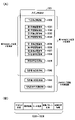
図10は、設定変更モード、設定確認モード、第1RAMクリアモード、第2RAMクリアモード、及び電源復旧モードについて説明するための説明図である。本実施形態の遊技機1は、電源投入時(電源スイッチ32が「ON」になるとき)の設定キースイッチ217およびRAMクリアスイッチ216の状態に応じて、設定変更モード、設定確認モード、第1RAMクリアモード、及び電源復旧モードのいずれかのモードに移行する。
[About the 5 modes when the power is turned on]
FIG. 10 is an explanatory diagram for explaining the setting change mode, setting confirmation mode, first RAM clear mode, second RAM clear mode, and power restoration mode. The
なお、図10中の「電源ON」は、遊技機1に対して外部からの電力供給を開始させるための電源スイッチ32のON操作が行われたことを意味する。また、図10中の「設定キーON」は、ホール店員による設定キーを用いた操作によって、設定キー挿入部218の回動部材がON姿勢となっていることを意味する。また、図10中の(「電源ON」と併記されている)「設定キーOFF」は、設定キー挿入部218の回動部材がOFF姿勢となっていることを意味する。すなわち、設定キー挿入部218の鍵穴に設定キーが挿し込まれていないか、或いは、設定キー挿入部218の鍵穴に設定キーが挿し込まれていても、回動部材がON姿勢へと姿勢変化していない状態を意味する。なお、図10中の2つの下向き矢印に併記されている「設定キーOFF」は、設定キー挿入部218の回動部材をON姿勢からOFF姿勢へと姿勢変化させるための設定キーを用いた操作が行われることを意味する。
"Power ON" in FIG. 10 means that the
また、図10中の「RAMクリアスイッチOFF」は、RAMクリアスイッチ216が操作されていない状態(すなわちリセットピン212が押下されていない状態)であることを意味し、図10中の「RAMクリアスイッチON」は、RAMクリアスイッチ216が操作されている状態(すなわちリセットピン212が押下されている状態)であることを意味する。
"RAM clear switch OFF" in FIG. 10 means that the RAM
ここで、電源復旧モードは、電源遮断前の遊技状態に復旧するための電源復旧処理が行われるモードである。第1RAMクリアモードは、図9(A)に例示される第1RAMクリア処理対象領域内の各記憶領域に対するRAMクリア処理が行われるモードである。設定変更モードは、設定値本記憶領域1041に記憶されている設定値を変更する設定変更処理が行われるモードである。設定確認モードは、設定値本記憶領域1041に記憶されている設定値を性能表示器215に点灯表示させる設定確認処理が行われるモードである。
Here, the power restoration mode is a mode in which power restoration processing is performed to restore the gaming state before the power shutdown. The first RAM clear mode is a mode in which RAM clear processing is performed on each storage area within the first RAM clear processing target area illustrated in FIG. 9A. The setting change mode is a mode in which setting change processing for changing the setting values stored in the main setting value storage area 1041 is performed. The setting confirmation mode is a mode in which a setting confirmation process is performed to display the setting values stored in the main setting value storage area 1041 on the
本実施形態では、図6(A)に基づいて上述したように、基板ケース210に、遊技制御基板100に実装されたRAMクリアスイッチ216を押下するためのリセットピン212と、設定キー挿入部218とが設けられている。 In this embodiment, as described above with reference to FIG. and are provided.
<電源復旧モード>
本実施形態の遊技機1では、設定キー挿入部218がOFF姿勢となっている状態で、RAMクリアスイッチ216(リセットピン212)を押下せずに電源スイッチ32を「ON」にする操作が行われると、遊技機1が起動した直後に電源復旧モードに移行する(図10参照)。
<Power recovery mode>
In the
この電源復旧モードに移行すると、メインCPU101は、メインRAM103に記憶されているバックアップデータをメインRAM103の作業領域(例えば遊技状態記憶領域1039)に格納し、後述するタイマ割込み処理(図21参照)を実行可能な状態にする電源復旧処理を行う。この電源復旧処理が行われることによって、遊技状態が、外部からの電力供給が遮断される前の状態に復旧することになる。
When the power restoration mode is entered, the
この電源復旧モードのときには、例えば、黒一色の背景画像に「電源復旧中」という文字を重畳表示した電源復旧画面が液晶画面5に表示され、「電源復旧中です」という音声がスピーカ24から繰り返し出力される。
In this power recovery mode, for example, a power recovery screen is displayed on the
また、この電源復旧モードのときには、メインCPU101は、性能表示用記憶領域1042に記憶されているベース値Bを性能表示器215に点滅表示させる(図10参照)。なお、本実施形態では、他のモードにおいて、性能表示器215に設定値が表示される。このため、ホール店員がベース値Bと設定値とを混同するといった問題が生じるのをより効果的に抑制すべく、(設定変更モードや設定確認モードにおいて)設定値を性能表示器215に点灯表示させる一方で、ベース値Bを性能表示器215に点滅表示されることとしている。このことは、第1RAMクリアモードのときと、第2RAMクリアモードのときについても同様である。
Further, in this power restoration mode, the
なお、図10に例示されるように、第1RAMクリアモードにおける第1RAMクリア処理、又は第2RAMクリアモードにおける第2RAMクリア処理が行われると、上記バックアップデータが破棄されるため、電源復旧モードでは、遊技状態が初期状態(通常遊技状態)に復旧することになる。 As illustrated in FIG. 10, when the first RAM clearing process in the first RAM clearing mode or the second RAM clearing process in the second RAM clearing mode is performed, the backup data is discarded. The game state is restored to the initial state (normal game state).
<第1RAMクリアモード>
本実施形態では、設定キー挿入部218の回動部材がOFF姿勢になっている状態で、RAMクリアスイッチ216(リセットピン212)を押下しながら電源スイッチ32を「ON」にする操作が行われると、遊技機1が起動した直後に第1RAMクリアモードに移行する(図10参照)。
<First RAM clear mode>
In the present embodiment, the
この第1RAMクリアモードに移行すると、メインCPU101は、第1RAMクリア対象領域内の各記憶領域を初期化する第1RAMクリア処理を行う。具体的には、例えば、判定用記憶領域1030や第1保留記憶領域1031に大当たり乱数等の情報が記憶されている場合には、これらの情報を消去する処理を行う。また、現在の遊技状態が「確変遊技状態」であることを示す情報が遊技状態記憶領域1039に記憶されている場合は、この情報を現在の遊技状態が「通常遊技状態」であることを示す情報に更新する処理を行う。なお、上記バックアップデータがメインRAM103に記憶されている場合には、そのバックアップデータを破棄する処理が併せて行われる。
After shifting to the first RAM clear mode, the
この第1RAMクリアモードのときには、例えば、黒一色の背景画像に「RAMクリア中」という文字を重畳表示したRAMクリア画面が液晶画面5に表示され、「RAMがクリアされました」という音声がスピーカ24から繰り返し出力される。この第1RAMクリアモードのときには、メインCPU101は、性能表示用記憶領域1042に記憶されているベース値Bを性能表示器215に表示させる(図10参照)。そして、第1RAMクリア処理が完了すると、自動的に電源復旧モードへと移行する。
In this first RAM clearing mode, for example, a RAM clearing screen is displayed on the
<設定変更モード>
本実施形態では、設定キー挿入部218をON姿勢にした状態(設定キー33を設定キー挿入部218に挿し込んで時計回りに90度回転させた状態)で、RAMクリアスイッチ216(リセットピン212)を押しながら電源スイッチ32を「ON」にする操作が行われると、メインCPU101は、内枠3が開放されていることを示す検知信号が扉開放スイッチ31から入力されているか否かを判定する。ここで、内枠3が開放されていることを示す検知信号が入力されていないと判定した場合、すなわち、内枠3が閉じられたままの状態であると判定した場合、所定のエラー音をスピーカ24から繰り返し出力させる処理を含むエラー処理を行う。このエラー処理が行われた場合、所定のエラー解除操作が行われるまでの間、設定変更モードへの移行が禁止される。
一方、内枠3が開放されていることを示す検知信号が入力されていると判定された場合は、遊技機1が起動した直後に設定変更モードに移行する(図10参照)。
<Setting change mode>
In this embodiment, the RAM clear switch 216 (the
On the other hand, when it is determined that the detection signal indicating that the
この設定変更モードに移行すると、メインCPU101は、以下のような処理を行う。具体的には、まず、設定値本記憶領域1041に記憶されているのと同じ設定値を設定値仮記憶領域1040に格納する。そして、格納した設定値を、性能表示器215の一番右側の7セグメントディスプレイ215Dに点灯表示させる。なお、設定値が表示されているときには、性能表示器215の残り3つの7セグメントディスプレイ215A~215Cは非表示の状態となる。
After shifting to this setting change mode, the
後に詳述するが、本実施形態の遊技機1は、大当たり確率に係る設定値として、大当たり確率が最も低い「1」と、大当たり確率が次に高い「2」と、大当たり確率が最も高い「3」とが用意されている。設定変更モードに移行すると、メインCPU101は、ホール店員がRAMクリアスイッチ216(リセットピン212)を操作する毎に、設定値仮記憶領域1040に記憶されている設定値を「1」、「2」、「3」、「1」、「2」・・・の順で更新すると共に、更新後の設定値を性能表示器215に点灯表示させる。その際、リセットピン212を操作する毎に、例えば、「1です」、「2です」といった7セグメントディスプレイ215Dに新たに点灯表示された設定値を報知する音声がスピーカ24から出力される。
なお、図10には、リセットピン212の操作によって、設定値仮記憶領域1040に設定値「1」が記憶されていることを示すように、一番右側の7セグメントディスプレイ215Dに「1」が表示されている状態が例示されている。
As will be described in detail later, the
In FIG. 10, by operating the
なお、この設定変更モードのときには、例えば、黒一色の背景画像に「設定変更中」という文字を重畳表示した設定変更画面が液晶画面5に表示され、「設定変更中です」という音声がスピーカ24から繰り返し出力される。そして、リセットピン212を用いて設定値の切り替えが行われているときには、リセットピン212が操作される毎に、上記のように「1です」、「2です」といった音声がスピーカ24から出力される。
In this setting change mode, for example, a setting change screen is displayed on the
ホール店員は、性能表示器215に任意の設定値が表示された状態で、この設定値の選択を確定させるための第1の操作として、設定キー挿入部218の回動部材をON姿勢からOFF姿勢に戻す操作を行う。具体的には、水平になっている設定キー挿入部218の回動部材が垂直となるように、設定キー挿入部218の鍵穴に挿し込まれている設定キーを反時計回りに90度回転させる。メインCPU101は、設定変更モードにおいて、設定キースイッチ217からの検知信号に基づいて、設定キー挿入部218の回動部材がON姿勢からOFF姿勢に戻されたか否かを判定する。ここで、回動部材がOFF姿勢に戻されたと判定されると、遊技機1の状態が設定変更モードから第2RAMクリアモードに移行する(図10参照)。
The hall clerk turns the turning member of the setting
本実施形態では、設定変更モードにおいて、リセットピン212を操作する毎に、「1です」、「2です」といった新たに点灯表示された設定値を報知する音声をスピーカ24から出力する場合について説明するが、設定値の漏洩を抑制する効果を高めるために、他の実施形態では、設定値を報知する上記の音声を出力しないようにしてもよい。
In the present embodiment, in the setting change mode, each time the
<第2RAMクリアモード>
この第2RAMクリアモードに移行すると、メインCPU101は、第2RAMクリア処理対象領域内の各記憶領域を初期化する第2RAMクリア処理を行う。この第2RAMクリア処理対象領域は、上述した第1RAMクリア処理対象領域を含んでおり、この第1RAMクリア処理対象領域に対するRAMクリア処理は、上記第1RAMクリアモード中に行われる第1RAMクリア処理と同じである。一方、メインCPU101は、第1RAMクリア処理にはない第2RAMクリア処理に特有のRAMクリア処理として、設定値仮記憶領域1040に記憶されている設定値を消去する処理を行う。なお、この第2RAMクリアモードでは、第1RAMクリアモードと同様、上記バックアップデータがメインRAM103に記憶されている場合には、そのバックアップデータを破棄する処理が併せて行われる。
<Second RAM clear mode>
After shifting to the second RAM clear mode, the
この第2RAMクリアモードのときには、例えば、黒一色の背景画像に「RAMクリア中」という文字を重畳表示したRAMクリア画面が液晶画面5に表示される。そして、「RAMがクリアされました」という音声がスピーカ24から出力させる。そして、この段階では、設定値の選択が確定しておらず、設定値の選択を確定させるための第2の操作として、電源を入れ直すための電源スイッチ32の操作が必要であることから、「設定を確定させるために電源を入れ直して下さい」という音声がスピーカ24から繰り返し出力される。なお、この後者の音声出力は、電源スイッチ32をOFF状態にする操作が行われるまで断続して出力される。
In the second RAM clearing mode, for example, a RAM clearing screen is displayed on the
これを受けてホール店員が電源スイッチ32をOFF状態に戻す際に、メインCPU101は、第2RAMクリア処理によって設定値仮記憶領域1040に記憶されていた設定値を示すバックアップデータをメインRAM103の所定領域に格納する。そして、ホール店員が電源スイッチ32を再びON状態にする操作を行うと、上述した電源復旧モードに移行する。
In response to this, when the hall clerk returns the
なお、メインCPU101は、電源復旧モードに移行した場合、設定値を示すバックアップデータがメインRAM103の所定領域に記憶されているか否かを判定する。ここで、設定値を示すバックアップデータが記憶されていないと判定した場合、通常の起動操作が行われたと判断して、上記電源復旧モードにおける処理を行う。一方、設定値を示すバックアップデータが記憶されていると判定した場合、第2RAMクリアモードから電源復旧モードに移行したと判断して、上記電源復旧モードにおける処理に加えて以下の処理を行う。
すなわち、バックアップデータが示す設定値と同じ設定値となるように、設定値本記憶領域1041に記憶されている設定値を更新する(上書きする)。なお、バックアップデータは、設定値本記憶領域1041の設定値が更新されると不要になるため、メインRAM103から消去される。
Note that when the
That is, the setting values stored in the main setting value storage area 1041 are updated (overwritten) so that they become the same setting values as those indicated by the backup data. The backup data is deleted from the
また、図10には示されていないが、第2RAMクリアモードから電断復旧を挟んで電源復旧モードに移行した場合、電源復旧モードにおいて、「設定が確定されました」という音声がスピーカ24から出力される。
Also, although not shown in FIG. 10, when the second RAM clear mode is switched to the power restoration mode after the power failure is restored, the
このように、メインCPU101は、電源スイッチ32、設定キースイッチ217、RAMクリアスイッチ216を用いる所定の操作に応じて、設定値本記憶領域1041に記憶されている設定値を更新することによって、大当たり遊技を実行すると判定される大当たり確率を、複数の確率のいずれかの確率に設定する。なお、設定値毎の大当たり確率については、図13等に基づいて後に詳述する。
In this way, the
なお、本実施形態では、設定変更モードにおいて設定キーを用いて設定キー挿入部218の回動部材をOFF姿勢に戻した後に電源スイッチ32を操作して電源を入れ直さなければ設定値の選択が確定しない場合について説明する。これに対して、他の実施形態では、例えば、設定キー挿入部218の回動部材をOFF姿勢に戻したことを条件として設定値の選択が確定するといった構成を採用してもよい。
In this embodiment, the setting value cannot be selected unless the
また、本実施形態では、設定変更モードから第2RAMクリアモードに移行してから、第2RAMクリア処理対象領域に対する第2RAMクリア処理を行う場合について説明する。これに対して、他の実施形態では、設定変更モードに移行した直後に第2RAMクリア処理対象領域に対する1回目の第2RAMクリア処理を行い、設定変更モードから第2RAMクリアモードに移行してから、第2RAMクリア処理対象領域に対する2回目の第2RAMクリア処理を行うようにしてもよい。このように、第2RAMクリア処理対象領域に対する2回のRAMクリア処理を行うことで、エラー等に起因して、第2RAMクリア処理対象領域内の一部の記憶領域に記憶されている情報が初期化されないといった問題が生じるのを効果的に抑制することが可能である。 Also, in this embodiment, a case will be described in which the second RAM clear processing is performed on the second RAM clear processing target area after the setting change mode is shifted to the second RAM clear mode. On the other hand, in another embodiment, immediately after shifting to the setting change mode, the first second RAM clear processing is performed on the second RAM clear processing target area, and after shifting from the setting change mode to the second RAM clear mode, The second RAM clear processing may be performed for the second RAM clear processing target area. In this way, by performing the RAM clear process twice for the area targeted for the second RAM clear process, information stored in a part of the storage area within the area targeted for the second RAM clear process may be initialized due to an error or the like. It is possible to effectively suppress the occurrence of the problem that the
<設定確認モード>
本実施形態では、設定キー挿入部218の回動部材をON姿勢にした状態(設定キー33を鍵穴に挿し込んで設定キー挿入部218の回動部材を時計回りに90度回転させた状態)で、RAMクリアスイッチ216を押さずに電源スイッチ32を「ON」にする操作が行われると、遊技機1が起動した直後に設定確認モードに移行する(図10参照)。この設定確認モードでは、大当たり確率の設定変更はできないものの、設定値本記憶領域1041に記憶されている設定値が性能表示器215に点灯表示され、ホール店員は、性能表示器215を見て現在の設定値を確認することができる。
<Setting confirmation mode>
In this embodiment, the turning member of the setting
設定確認モードに移行すると、メインCPU101は、設定値本記憶領域1041に記憶されている設定値を、性能表示器215の一番右側の7セグメントディスプレイ215Dに点灯表示させる。なお、図10には、現在の設定値が「3」であることを示す3の数値が一番右側の7セグメントディスプレイに点灯表示されている状態が例示されている。
When shifting to the setting confirmation mode, the
なお、この設定確認モードのときには、例えば、黒一色の背景画像に「設定確認中」という文字を重畳表示した設定確認画面が液晶画面5に表示され、「設定確認中です」という音声がスピーカ24から繰り返し出力される。
In this setting confirmation mode, for example, a setting confirmation screen is displayed on the
ホール店員は、設定の確認が完了した後、設定キー33を反時計回りに90度回転させて設定キー挿入部218の回動部材をOFF姿勢に戻す操作を行う。これに対して、メインCPU101は、設定確認モードを終了させて、上記電源復旧モードへと移行させる。これに伴い、性能表示器215が大当たり確率に係る設定値を点灯表示していた状態から、性能表示器215が低ベース状態におけるベース値Bを点滅表示する状態へと、性能表示器215の表示が切り替えられる。
After confirming the setting, the hall clerk rotates the setting key 33 counterclockwise by 90 degrees to return the rotating member of the setting
なお、本実施形態では、電源が投入された直後に、現在の設定値を確認可能な設定確認モードに移行する場合について説明するが、他の実施形態では、遊技が進行していない非遊技状態(例えば客待ち状態)のときに、設定キーを設定キー挿入部218の鍵穴に挿し込んで回動部材をOFF姿勢からON姿勢へと姿勢変化させることによって設定確認モードに移行するといった構成を採用してもよい。
In this embodiment, immediately after the power is turned on, a case will be described in which the current setting value can be confirmed, but in other embodiments, a non-game state where the game is not progressing will be described. A setting confirmation mode is entered by inserting the setting key into the keyhole of the setting
[各モードの特徴]
図11は、図10に例示される各モードの特徴を示す説明図である。図10に基づいて上述した5つのモードには、以下のような特徴がある。
[Features of each mode]
FIG. 11 is an explanatory diagram showing features of each mode illustrated in FIG. The five modes described above with reference to FIG. 10 have the following characteristics.
<電源復旧モードの特徴>
電源復旧モードには、設定キー挿入部218をOFF姿勢にした状態でRAMクリアスイッチ216(リセットピン212)を押さずに電源スイッチ32を「ON」にすることで移行するという特徴がある。
また、電源復旧モードには、図10に基づいて上述した第1RAMクリアモード、第2RAMクリアモード、設定確認モードからも移行するという特徴がある。
<Characteristics of Power Recovery Mode>
The power recovery mode is characterized in that it is shifted to the power recovery mode by turning the
Further, the power recovery mode is characterized in that it also shifts from the first RAM clear mode, the second RAM clear mode, and the setting confirmation mode described above with reference to FIG.
また、電源復旧モードでは、上述した電源復旧処理が行われ、「電源復旧中」の文字を含む電源復旧画面を液晶画面5に表示すると共に「電源復旧中です」といった音声をスピーカ24から出力することによって、電源復旧中であることが報知されるという特徴がある。
In the power recovery mode, the above-described power recovery processing is performed, and a power recovery screen including the characters "power recovery in progress" is displayed on the
また、電源復旧モードでは、大当たり確率に係る設定値を表示する必要がないことから、電源復旧モード中は、設定値は表示されず、低ベース状態におけるベース値Bが点滅表示されるという特徴がある(図10参照)。 Also, in the power restoration mode, since it is not necessary to display the set value related to the probability of a big hit, the set value is not displayed during the power restoration mode, and the base value B in the low base state is blinking. (see FIG. 10).
なお、本実施形態では、ホール店員がきちんと電源が入ったことを確認できるように、図10に例示されるように、第1RAMクリアモード(又は第2RAMクリアモード)から電源復旧モードに移行させて、「電力供給」が復旧したことを報知することとしている。一方、第1RAMクリアモードや第2RAMクリアモードに移行した場合には、メインRAM103に記憶されているバックアップデータが破棄されているため、「データ復旧」という意味では、電力供給が遮断される前の状態に復旧することはない。このため、RAMクリア処理が行われていないとホール店員が誤認しないように、他の実施形態では、第1RAMクリアモード(又は第2RAMクリアモード)から電源復旧モードに移行させないようにしてもよい。
In this embodiment, the first RAM clear mode (or the second RAM clear mode) is shifted to the power recovery mode so that the hall clerk can confirm that the power has been properly turned on, as illustrated in FIG. , to notify that the "power supply" has been restored. On the other hand, when the mode is shifted to the first RAM clear mode or the second RAM clear mode, the backup data stored in the
<第1RAMクリアモードの特徴>
第1RAMクリアモードには、設定キー挿入部218の回動部材がOFF姿勢になっている状態でRAMクリアスイッチ216(リセットピン212)を押しながら電源スイッチ32を「ON」にすることで移行するという特徴がある。
<Characteristics of the first RAM clear mode>
The first RAM clear mode is entered by turning the
また、第1RAMクリアモードでは、上述した第1RAMクリア処理対象領域を対象として第1RAMクリア処理が実行され、「RAMクリア中」の文字を含むRAMクリア画面を液晶画面5に表示すると共に「RAMがクリアされました」という音声をスピーカ24から出力することによって、第1RAMクリア処理対象領域がクリアされたことが報知されるという特徴がある。
In the first RAM clearing mode, the first RAM clearing process is executed for the above-described first RAM clearing process target area, and a RAM clearing screen including characters "RAM is being cleared" is displayed on the
また、第1RAMクリアモードでは、大当たり確率に係る設定値を表示する必要がないことから、第1RAMクリアモード中は、設定値は表示されず、低ベース状態におけるベース値Bが性能表示器215に点滅表示されるという特徴がある(図10参照)。
Also, in the first RAM clear mode, since it is not necessary to display the setting value related to the jackpot probability, the setting value is not displayed during the first RAM clear mode, and the base value B in the low base state is displayed on the
<設定変更モードの特徴>
設定変更モードには、設定キー挿入部218の回動部材がON姿勢になっている状態でRAMクリアスイッチ216(リセットピン212)を押しながら電源スイッチ32を「ON」にすることで移行するという特徴がある。
<Characteristics of setting change mode>
The setting change mode is entered by turning the
また、設定変更モードでは、リセットピン212を操作することで設定値を変更可能であり、「設定変更中」の文字を含む設定変更画面を液晶画面5に表示すると共に「設定変更中です」という音声をスピーカ24から出力することによって、設定変更中であることが報知されるという特徴がある。
Also, in the setting change mode, the setting value can be changed by operating the
また、設定変更モード中は、低ベース状態におけるベース値Bの表示が非表示となり、リセットピン212を用いて選択した設定値が性能表示器215の右端の7セグメントディスプレイに点灯表示される。
Also, during the setting change mode, the display of the base value B in the low base state is hidden, and the set value selected using the
設定変更モード中は、遊技が行われない非遊技状態であり、また、性能表示器215にベース値Bが点滅表示されないことから、遊技球の入賞の検知、及び入賞に応じた賞球の払い出しの両方が無効になる。
Since the setting change mode is a non-playing state in which no game is played and the base value B is not flashed on the
具体的には、本実施形態の遊技機1では、設定変更モードから(第2RAMクリアモードおよび電源復旧モードを介して)通常モードに移行しなければ、遊技領域10に遊技球が打ち出されたとしても遊技球が打ち出されたとは判定せず、第1始動口11や普通入賞口14に対する遊技球の入賞を検知して、その検知結果に基づいて賞球を払い出す処理を含むタイマ割込み処理の実行を許可しないという構成が採用されている。このため、メインCPU101は、設定変更モード中は、カウントスイッチ110からの検知信号が出力されたとしても、遊技領域10に遊技球が打ち出されたとは判定しない。また、設定変更モード中は、第1始動口11(又は普通入賞口14)を遊技球が通過したことに応じて第1始動口スイッチ111(又は普通入賞口スイッチ118)からの検知信号が出力されたとしても、入賞があったとメインCPU101が判定することはなく、当然、メインCPU101が払出制御基板に対して賞球の払い出しを指示することもない。
Specifically, in the
また、設定変更モード中は、メインROM102に記憶されているベース計算プログラムが起動しないように構成されている。このため、メインCPU101は、設定変更モード中は、低ベース状態においてカウントスイッチ110から検知信号が出力されたとしても、メインRAM103に記憶されている合計数Gを更新する上記第1の更新処理を行わない。また、メインCPU101は、設定変更モード中は、低ベース状態において第1始動口スイッチ111からの検知信号が出力されたとしても、メインRAM103に記憶されている合計賞球数Hを更新する上記第2の更新処理を行わない。また、メインCPU101は、設定変更モード中は、低ベース状態において普通入賞口スイッチ117からの検知信号が出力されたとしても、メインRAM103に記憶されている合計賞球数Fを更新する上記第3の更新処理を行わない。そして、これら3つの更新処理をいずれも実行しないことから、上記の計算式に基づいてベース値Bを算出する再計算が行われることもない。
Also, during the setting change mode, the base calculation program stored in the
また、設定変更モード中は、第1始動口11を遊技球が通過したとしても第1始動口11に遊技球が入賞したと判定されないことから、第1特別図柄判定が実行されたり、或いは、第1特別図柄判定の権利が保留されたりすることはなく、また、メインCPU101が払出制御基板に対して賞球の払い出しを指示することもない。
Also, during the setting change mode, even if the game ball passes through the
このように、第1始動口11や普通入賞口14に対する遊技球の入賞が無効になり、これらの入賞に応じた賞球の払い出しも無効になるのは、後述する設定確認モードについても同様である。
In this way, the winning of game balls to the
なお、他の実施形態では、以下の構成を採用してもよい。
すなわち、設定変更モード中も図21のタイマ割込み処理の実行を許可し、メインCPU101は、第1始動口スイッチ111(又は普通入賞口スイッチ118)からの検知信号が出力された場合に、第1始動口11(又は普通入賞口14)に遊技球が入賞したと判定する一方で、ステップS7(図21参照)の賞球処理では払出制御基板に対して賞球の払い出しを指示しないという構成を採用してもよい。この場合、遊技球の入賞自体は有効であることから、メインRAM103に記憶されている合計数G、合計賞球数H、及び合計賞球数Fを適宜更新する構成としてもよいが、設定変更モード中は、非遊技中であることから、本実施形態と同様にベース計算プログラムが起動しない構成を採用して、上記の各変数を更新しないことが好ましい。
Note that the following configuration may be employed in other embodiments.
That is, the execution of the timer interrupt process of FIG. 21 is permitted even during the setting change mode, and the
図10に説明を戻すと、設定変更モード中に設定キーを操作して設定キー挿入部218の回動部材をON姿勢からOFF姿勢に戻すと、第2RAMクリアモードに移行する。
Returning to FIG. 10, when the setting key is operated in the setting change mode to return the turning member of the setting
<第2RAMクリアモードの特徴>
第2RAMクリアモードでは、上述した第2RAMクリア処理対象領域を対象として、設定変更モードでの設定変更処理に伴う第2RAMクリア処理が実行される。この第2RAMクリアモード中は、「RAMクリア中」の文字を含むRAMクリア画面を液晶画面5に表示すると共に「RAMがクリアされました」という音声をスピーカ24から出力することによって、第2RAMクリア処理対象領域がクリアされたことが報知されるという特徴がある。
<Characteristics of the second RAM clear mode>
In the second RAM clear mode, the second RAM clear process accompanying the setting change process in the setting change mode is executed for the above-described second RAM clear process target area. During this second RAM clearing mode, the second RAM is cleared by displaying a RAM clearing screen including the characters "RAM clearing" on the
また、ホール店員が選択した設定値を確定させるための設定確定操作として、電源を入れ直す(電源スイッチ32を「OFF」にしてから再度「ON」にする)ことをホール店員に促すために、「設定を確定させるために電源を入れ直してください」といった音声がスピーカ24から出力される。
In order to prompt the hall clerk to turn the power back on (turn the
また、第2RAMクリアモードでは、大当たり確率に係る設定値を表示する必要がないことから、第2RAMクリアモード中は、設定値は表示されず、低ベース状態におけるベース値Bが性能表示器215に点滅表示されるという特徴がある(図10参照)。
Also, in the second RAM clear mode, since it is not necessary to display the setting value related to the jackpot probability, the setting value is not displayed during the second RAM clear mode, and the base value B in the low base state is displayed on the
<設定確認モードの特徴>
設定確認モードには、設定キー挿入部218の回動部材をON姿勢にした状態でRAMクリアスイッチ216(リセットピン212)を押さずに電源スイッチ32を「ON」にすることで移行するという特徴がある。
この設定確認モードは、現在の設定値を確認可能なモードであり、現在のベース値Bに代えて、設定値本記憶領域1041に記憶されている現在の設定値が性能表示器215に点灯表示される。
<Features of setting confirmation mode>
The setting confirmation mode is entered by turning the
This setting confirmation mode is a mode in which the current set value can be confirmed. be done.
なお、設定確認モード中に設定キーを操作して設定キー挿入部218の回動部材をOFF姿勢に戻すと、電源復旧モードに移行する。
If the setting key is operated in the setting confirmation mode to return the rotating member of the setting
また、図には示されていないが、メインCPU101が図21に例示されるタイマ割込み処理を繰り返し実行することに応じて遊技が進行する遊技中である通常モードにおいては、設定キーを用いた操作や、RAMクリアスイッチ216(リセットピン212)に対する操作が無効であり、これらの操作に応じた処理が行われることはない。言い換えれば、これらの操作は、通常モードを除く図10に基づいて上述した5つのモードにおいてのみ有効である。
Also, although not shown in the figure, in the normal mode during the game in which the game progresses as the
[遊技の流れについて]
図12は、遊技の流れについて説明するための説明図である。図12に例示されるように、本実施形態の遊技機1は、上述した「通常遊技状態」、「確変遊技状態」、及び「時短遊技状態」のいずれかの遊技状態で遊技が制御される。
[About the game flow]
FIG. 12 is an explanatory diagram for explaining the flow of the game. As illustrated in FIG. 12, the
遊技者が右打ちした遊技球は、第1始動口11には入賞せず、第2始動口12に入賞し得る。しかしながら、低ベース状態のときには、第2始動口12が開放され難く、開放されたとしてもその開放時間は短い。このため、低ベース状態(本実施形態では「通常遊技状態」がこれに該当)で遊技が制御されているときには、遊技者は、第1始動口11を狙った左打ちにより遊技を行うことになる。
A game ball hit to the right by the player does not enter the
通常遊技状態のときに左打ちされた遊技球が第1始動口11に入賞すると、第1特別図柄判定が実行される。ここで、大当たり遊技を実行すると判定された場合、第1特別図柄表示器41において、第1特別図柄が変動表示されてから、第1特別図柄として大当たり図柄が停止表示される。
When the game ball struck left in the normal game state wins the
ここで、確変大当たりであることを示す大当たり図柄が停止表示された場合(図12(A)参照)、大当たり遊技が実行され、大当たり遊技終了後は、実質的に次回の大当たりまで確変遊技状態で遊技が制御されることになる(図12(B)参照)。一方、通常大当たりであることを示す大当たり図柄が停止表示された場合(図12(C)参照)、大当たり遊技が実行され、大当たり遊技終了後は、途中で大当たりと判定されることがなければ、第2特別図柄判定(又は第1特別図柄判定)が例えば80回行われるまで「通常遊技状態」で遊技が制御されることになる(図12(D)参照)。なお、本実施形態の遊技機1では、第1特別図柄判定の判定結果が大当たりとなった場合に、確変大当たりであることを示す大当たり図柄が停止表示される割合が60%、通常大当たりであることを示す大当たり図柄が停止表示される割合が40%に設定されている。
Here, when the jackpot pattern indicating that the probability variable jackpot is stopped and displayed (see FIG. 12 (A)), the jackpot game is executed, and after the jackpot game ends, the probability variable game state is substantially until the next jackpot. The game is controlled (see FIG. 12(B)). On the other hand, when the jackpot pattern indicating the normal jackpot is stopped and displayed (see FIG. 12(C)), the jackpot game is executed, and after the jackpot game ends, if it is not determined to be a jackpot midway through, The game is controlled in the "normal game state" until the second special symbol determination (or first special symbol determination) is performed, for example, 80 times (see FIG. 12(D)). In addition, in the
図12に例示されるように、「確変遊技状態」又は「時短遊技状態」に移行した場合、第2始動口12の方が第1始動口11よりも遊技球が入賞し易い高ベース状態となる。この高ベース状態で遊技が制御されているときには、遊技者は、第2始動口12を狙った右打ちにより遊技を行うことになる。また、本実施形態では、第1特別図柄判定よりも第2特別図柄判定の方が優先消化される。このため、「確変遊技状態」や「時短遊技状態」では、基本的には第2特別図柄判定が行われることになる。
As exemplified in FIG. 12, when shifting to the "probability variable gaming state" or the "time-saving gaming state", the
「確変遊技状態」のときに遊技球がゲート16を通過すると、普通図柄判定が行われる。上述したように、「確変遊技状態」における普通図柄判定では、12/12の割合で第2始動口12を開放すると判定され、その上、第2始動口12の開放時間が相対的に長い(本実施形態では1.6秒×3回)。このため、右打ちにより遊技領域10の右側領域に打ち出された遊技球が第2始動口12に容易に入賞して、高確率状態で第2特別図柄判定が行われることになる。したがって、「確変遊技状態」においては、「通常遊技状態」のときに比べて、遊技者が大当たりを引き当て易い。
When the game ball passes through the
右打ちされた遊技球が第2始動口12に入賞すると、第2特別図柄判定が行われ、第2特別図柄が変動表示された後にその第2特別図柄判定の判定結果を示す第2特別図柄が停止表示される。ここで、第2特別図柄判定によって大当たり遊技を実行しないと判定された場合には、第2特別図柄として「ハズレ図柄」が停止表示される。一方、大当たり遊技を実行すると判定された場合には、第2特別図柄として「大当たり図柄」停止表示される。その際、本実施形態の遊技機1では、60%の割合で確変大当たりであることを示す大当たり図柄が停止表示されて、大当たり遊技終了後に再び「確変遊技状態」に移行し(図12(E)及び(B)参照)、40%の割合で通常大当たりであることを示す大当たり図柄が停止表示されて、大当たり遊技終了後に「時短遊技状態」に移行する(図12(F)及び(G)参照)。
When the right-handed game ball wins the
一方、大当たり遊技終了後に「時短遊技状態」に移行した場合、「通常遊技状態」と同じ低確率状態で第2特別図柄判定が行われることになる。ここで、「時短遊技状態」において80回目の第2特別図柄判定が行われるまでの間に大当たり遊技を実行すると判定された場合、第2特別図柄として「大当たり図柄」停止表示される。その際、60%の割合で確変大当たりであることを示す大当たり図柄が停止表示されて、大当たり遊技終了後に「確変遊技状態」に移行し(図12(I)及び(B)参照)、40%の割合で通常大当たりであることを示す大当たり図柄が停止表示されて、大当たり遊技終了後に再び「時短遊技状態」に移行する(図12(H)及び(G)参照)。 On the other hand, when the game shifts to the "time saving game state" after the jackpot game ends, the second special symbol determination is performed in the same low probability state as the "normal game state". Here, when it is determined that the big winning game is to be executed until the 80th second special symbol determination is performed in the "time saving game state", the "big winning symbol" is stopped and displayed as the second special symbol. At that time, the jackpot pattern indicating that it is a probability variable jackpot is displayed at a rate of 60%, and after the jackpot game ends, it shifts to the "variable probability game state" (see FIGS. 12 (I) and (B)), 40% The jackpot symbols indicating the normal jackpot are stopped and displayed at a rate of , and after the jackpot game ends, the state shifts to the "time-saving game state" again (see FIGS. 12(H) and (G)).
なお、80回の特別図柄判定(基本的には第2特別図柄判定)が行われても1度も大当たり遊技を実行すると判定されなかった場合、80回目の特別図柄判定の判定結果を示す特別図柄が停止表示された後に、遊技状態が「時短遊技状態」から「通常遊技状態」に移行することになる(図12(J)参照)。 In addition, if it is not determined to execute a big hit game even once 80 times of special symbol determination (basically the second special symbol determination) is performed, a special indicating the determination result of the 80th special symbol determination After the symbols are stopped and displayed, the game state shifts from the "time-saving game state" to the "normal game state" (see FIG. 12(J)).
[設定値と大当たり確率との関係]
次に、図13を参照しつつ、設定値本記憶領域1041に記憶されている設定値と大当たり確率との関係について説明する。ここで、図13は、大当たり確率に係る設定について説明するための説明図である。
[Relationship between set value and jackpot probability]
Next, referring to FIG. 13, the relationship between the set values stored in the main set value storage area 1041 and the jackpot probability will be described. Here, FIG. 13 is an explanatory diagram for explaining the setting related to the jackpot probability.
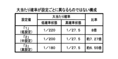
本実施形態の遊技機1は、設定値本記憶領域1041に記憶されている設定値によって、大当たり遊技を実行すると判定される確率が変化する。具体的には、大当たり遊技を実行すると判定される大当たり確率が相対的に低い低確率状態(本実施形態では、「通常遊技状態」と「時短遊技状態」がこれに該当する)のときには、設定値本記憶領域1041に記憶されている設定値が「1」(低設定)である場合には、大当たり確率が1/220に設定され、設定値本記憶領域1041に記憶されている設定値が「2」(中設定)である場合には、大当たり確率が1/200に設定され、設定値本記憶領域1041に記憶されている設定値が「3」(高設定)である場合には、大当たり確率が1/180に設定される。
In the
なお、本実施形態の遊技機1では、大当たり遊技を実行すると判定される大当たり確率が相対的に高い高確率状態(本実施形態では、「確変遊技状態」がこれに該当する)における大当たり確率の低確率状態における大当たり確率の割合が、設定値によらず8倍に固定されている。
このため、高確率状態のときには、設定値本記憶領域1041に記憶されている設定値が「1」(低設定)である場合には、大当たり確率が1/27.5(=1/220×8倍)に設定され、設定値本記憶領域1041に記憶されている設定値が「2」(中設定)である場合には、大当たり確率が1/25(=1/200×8倍)に設定され、設定値本記憶領域1041に記憶されている設定値が「3」(高設定)である場合には、大当たり確率が1/22.5(=1/180×8倍)に設定される。
In addition, in the
Therefore, in the high-probability state, if the setting value stored in the main setting value storage area 1041 is "1" (low setting), the jackpot probability is 1/27.5 (=1/220× 8 times), and when the setting value stored in the setting value main storage area 1041 is "2" (medium setting), the jackpot probability is 1/25 (= 1/200 x 8 times). When the setting value set and stored in the main setting value storage area 1041 is "3" (high setting), the jackpot probability is set to 1/22.5 (=1/180×8 times). be.
このように、本実施形態では、高確率状態における大当たり確率と低確率状態における大当たり確率との比率が、設定値によらず固定されているため、低確率状態から高確率状態へと移行した場合に、設定毎の大当たり確率の大小関係が大きく崩れてしまうといった問題が生じるのを容易且つ効果的に抑制することが可能である。 Thus, in the present embodiment, since the ratio of the jackpot probability in the high probability state and the jackpot probability in the low probability state is fixed regardless of the set value, when transitioning from the low probability state to the high probability state In addition, it is possible to easily and effectively suppress the problem that the magnitude relationship of the jackpot probability for each setting is greatly disrupted.
ところで、低確率状態における大当たり確率に関して、例えば、設定値が最高設定である「3」に設定されている場合の大当たり確率が、設定値が最低設定である「1」に設定されている場合の大当たり確率の2倍に設定されるというように、最低設定と最高設定との間での大当たり確率の違いが大きすぎると、設定によって遊技機1の性能が必要以上に大きく変化してしまうといった問題が生じる可能性がある。
By the way, regarding the jackpot probability in the low probability state, for example, the jackpot probability when the setting value is set to the highest setting "3" is changed to the jackpot probability when the setting value is set to the lowest setting "1". If the difference in the jackpot probability between the lowest setting and the highest setting is too large, such as when the jackpot probability is set to twice the jackpot probability, the performance of the
このため、設定値が最低設定である「1」に設定されている場合の低確率状態における大当たり確率は、低確率状態における全設定の大当たり確率の平均値である平均大当たり確率に対して、例えば-10%以上の値に設定されるのが好ましい。また、設定値が最高設定である「3」に設定されている場合の低確率状態における大当たり確率は、上記平均大当たり確率に対して、例えば+10%以下の値に設定されるのが好ましい。このことは、設定の段階数が3以外である場合についても同様である。 For this reason, the jackpot probability in the low probability state when the setting value is set to the lowest setting "1" is compared to the average jackpot probability, which is the average value of all the set jackpot probabilities in the low probability state, for example It is preferably set to a value of -10% or higher. Also, the jackpot probability in the low-probability state when the set value is set to the maximum setting of "3" is preferably set to a value of, for example, +10% or less with respect to the average jackpot probability. This also applies to cases where the number of setting steps is other than three.
[設定と大当たり確率に関する変形例]
なお、他の実施形態では、以下のような構成を採用してもよい。
すなわち、本実施形態では、「1」(低設定)、「2」(中設定)、「3」(高設定)という連続する自然数によって大当たり確率に関する設定が表される場合について説明する。これに対して、他の実施形態では、「1」(低設定)、「3」(中設定)、「5」(高設定)といった不連続な自然数によって大当たり確率に関する設定が表されてもよい。また、大当たり確率に関する設定を表す情報は自然数に限らず、例えば、「L」(低設定)、「M」(中設定)、「H」(高設定)といった固有名称であってもよい。
[Modified example regarding setting and jackpot probability]
In addition, in another embodiment, the following configuration may be adopted.
That is, in the present embodiment, a case will be described in which the setting regarding the jackpot probability is represented by consecutive natural numbers such as "1" (low setting), "2" (middle setting), and "3" (high setting). On the other hand, in other embodiments, the setting regarding the jackpot probability may be represented by discrete natural numbers such as "1" (low setting), "3" (medium setting), and "5" (high setting). . Also, the information representing the setting regarding the jackpot probability is not limited to a natural number, and may be, for example, a unique name such as "L" (low setting), "M" (middle setting), or "H" (high setting).
また、本実施形態では、大当たり確率に関して3段階の設定が設けられている場合を例に説明するが、設定の段階数はこれに限定されるものではなく、例えば、2段階であってもよいし、4段階以上であってもよい。
ただし、設定の段階数が多くなり過ぎると、例えばホール店員による設定値の設定操作が煩雑になるといった問題が生じることが予想されることから、設定の段階数は、例えば「6」以下であることが好ましい。
In addition, in the present embodiment, a case in which three stages of settings are provided for the probability of a big win will be described as an example, but the number of stages of settings is not limited to this, and may be, for example, two stages. However, the number may be four or more.
However, if the number of setting steps becomes too large, it is expected that the setting operation of the setting value by the hall clerk becomes complicated, so the number of setting steps is, for example, "6" or less. is preferred.
また、本実施形態では、低確率状態における大当たり確率に関して、3段階の設定を設ける場合について説明するが、他の実施形態では、低確率状態における大当たり確率に関して設定を設けないようにしてもよい。すなわち、例えば、低確率状態における大当たり確率には設定が無く(大当たり確率が固定であり)、高確率状態における大当たり確率に関して設定差があるような構成を採用してもよい。この場合、例えば、設定値「1」(低設定)に対応する大当たり確率と、設定値「2」(中設定)に対応する大当たり確率と、設定値「3」(高設定)に対応する大当たり確率とが全て同じ確率となるように構成することが一例として挙げられる。 In addition, in the present embodiment, three levels of settings are provided for the jackpot probability in the low-probability state, but in other embodiments, the jackpot probability in the low-probability state may not be set. That is, for example, there is no setting for the jackpot probability in the low-probability state (the jackpot probability is fixed), and a configuration may be adopted in which there is a setting difference regarding the jackpot probability in the high-probability state. In this case, for example, the jackpot probability corresponding to the setting value "1" (low setting), the jackpot probability corresponding to the setting value "2" (medium setting), and the jackpot corresponding to the setting value "3" (high setting) As an example, it is configured such that the probabilities are all the same.
また、本実施形態では、高確率状態における大当たり確率と低確率状態における大当たり確率との比率が8倍に設定されている場合について説明するが、この比率は、10倍を超えるものでなければ、他の値であってもよい。すなわち、当該比率は、例えば、8倍よりも小さい3倍であってもよいし、8倍よりも大きい9倍であってもよい。 Also, in this embodiment, the case where the ratio of the jackpot probability in the high-probability state and the jackpot probability in the low-probability state is set to 8 times will be described. Other values are possible. That is, the ratio may be, for example, 3 times, which is less than 8 times, or 9 times, which is greater than 8 times.
また、本実施形態では、設定値が「1」(低設定)に設定されている場合と、設定値が「2」(中設定)に設定されている場合と、設定値が「3」(高設定)に設定されている場合とで、高確率状態における大当たり確率と低確率状態における大当たり確率との比率が完全に一致する場合について説明する。
これに対して、当該比率を完全に一致させることができない場合には、設定毎の比率を近似させるようにしてもよい。
In this embodiment, the setting value is set to "1" (low setting), the setting value is set to "2" (medium setting), and the setting value is set to "3" (medium setting). High setting) and the case where the ratio of the jackpot probability in the high probability state and the jackpot probability in the low probability state are completely the same will be described.
On the other hand, if the ratios cannot be perfectly matched, the ratios for each setting may be approximated.
例えば、大当たり乱数が例えば「0」~「19799」の19800個の乱数値を取り得る場合には、低確率状態における当選値として設定値「3」(高設定)に対して110個の乱数値を用意しておくことで、大当たり確率を1/180(=110/19800)に設定することが可能である。そして、高確率状態における当選値として設定値「3」(高設定)に対して1100個の乱数値を用意しておくことで、高確率状態における大当たり確率を低確率状態における大当たり確率のちょうど10倍である1/18(=(110×10)/19800)に設定することができる。 For example, if the jackpot random number can take 19800 random numbers from "0" to "19799", 110 random numbers for the set value "3" (high setting) as the winning value in the low probability state is prepared, it is possible to set the jackpot probability to 1/180 (=110/19800). By preparing 1100 random numbers for the set value "3" (high setting) as winning values in the high-probability state, the jackpot probability in the high-probability state is exactly 10 times the jackpot probability in the low-probability state. It can be set to double 1/18 (=(110*10)/19800).
これに対して、大当たり乱数の取り得る値の個数等の関係で、低確率状態のときの当選値の10倍の当選値を用意してしまうと、高確率状態における大当たり確率と低確率状態における大当たり確率との比率が10倍を僅かに超えてしまうような場合には、高確率状態における当選値を10倍の個数から僅かに減らして、当該比率が10倍を超えず、且つ、当該比率が10倍に近似するようにすればよい 。 On the other hand, due to the number of values that can be taken by the jackpot random number, if a winning value that is 10 times the winning value in the low probability state is prepared, the jackpot probability in the high probability state and the low probability state If the ratio with the jackpot probability slightly exceeds 10 times, the winning value in the high probability state is slightly reduced from the number of 10 times, and the ratio does not exceed 10 times and the ratio should be approximated by a factor of 10.
[乱数を用いた特別図柄判定について]
<大当たり乱数に基づく処理について>
次に、図14を参照しつつ、大当たり乱数、図柄乱数、及びリーチ乱数を用いた特別図柄判定について説明する。ここで、図14は、各種乱数について説明するための説明図である。
[Regarding special symbol judgment using random numbers]
<About processing based on jackpot random numbers>
Next, with reference to FIG. 14, the special symbol determination using the jackpot random number, the symbol random number, and the reach random number will be described. Here, FIG. 14 is an explanatory diagram for explaining various random numbers.
図14(A)に例示される大当たり乱数は、大当たり遊技を実行するか否かの大当たり判定処理(図26のステップS309)に使用される乱数であり、大当たり遊技を実行すると判定される確率が相対的に低い低確率状態と、大当たり遊技を実行すると判定される確率が相対的に高い高確率状態のそれぞれについて、個別に設定されている。また、本実施形態では、低確率状態と高確率状態のそれぞれについて、設定値によって異なる数の当選値が用意されている(図14(A)参照)。 The jackpot random numbers exemplified in FIG. 14(A) are random numbers used in the jackpot determination process (step S309 in FIG. 26) to determine whether or not to execute the jackpot game, and the probability that the jackpot game will be executed is A relatively low low-probability state and a high-probability state with a relatively high probability of being determined to execute a jackpot game are individually set. In addition, in the present embodiment, different numbers of winning values are prepared depending on the set value for each of the low-probability state and the high-probability state (see FIG. 14A).
図14(A)に例示されるように、メインROM102には、低確率状態における設定値「1」(低設定)関して、大当たり乱数の当選値として90個の当選値が記憶され、低確率状態における設定値「2」(中設定)関して、大当たり乱数の当選値として99個の当選値が記憶され、低確率状態における設定値「3」(高設定)関して、大当たり乱数の当選値として110個の当選値が記憶されている。
As illustrated in FIG. 14A, the
メインCPU101は、低確率状態で遊技が制御されているときに大当たり乱数を取得すると、設定値本記憶領域1041に記憶されている設定値が「1」である場合には、取得した大当たり乱数が設定値「1」に対応する上記90個の当選値のいずれかと一致するか否かに基づいて、大当たり遊技を実行するか否かを判定する。また、設定値本記憶領域1041に記憶されている設定値が「2」である場合には、取得した大当たり乱数が設定値「2」に対応する上記99個の当選値のいずれかと一致するか否かに基づいて、大当たり遊技を実行するか否かを判定する。また、設定値本記憶領域1041に記憶されている設定値が「3」である場合には、取得した大当たり乱数が設定値「3」に対応する上記110個の当選値のいずれかと一致するか否かに基づいて、大当たり遊技を実行するか否かを判定する。
When the
なお、本実施形態では、大当たり乱数の取り得る範囲は、低確率状態と高確率状態のいずれの状態であっても、「0」~「19799」の19800個である。このため、低確率状態であり且つ設定値「1」が設定されている場合の大当たり確率は1/220(=90/19800)であり、低確率状態であり且つ設定値「2」が設定されている場合の大当たり確率は1/200(=99/19800)であり、低確率状態であり且つ設定値「3」が設定されている場合の大当たり確率は1/180(=110/19800)である(図13および図14(A)参照)。 In the present embodiment, the possible range of the jackpot random numbers is 19800 from "0" to "19799" in both the low-probability state and the high-probability state. Therefore, the jackpot probability is 1/220 (=90/19800) when the low probability state and the setting value "1" are set, and when the low probability state and the setting value "2" are set. The jackpot probability is 1/200 (=99/19800) when the (See FIGS. 13 and 14(A)).
また、図14(A)に例示されるように、メインROM102には、高確率状態における設定値「1」(低設定)関して、大当たり乱数の当選値として720個の当選値が記憶され、高確率状態における設定値「2」(中設定)関して、大当たり乱数の当選値として792個の当選値が記憶され、高確率状態における設定値「3」(高設定)関して、大当たり乱数の当選値として880個の当選値が記憶されている。
Further, as illustrated in FIG. 14A, the
このため、高確率状態であり且つ設定値「1」が設定されている場合の大当たり確率は1/27.5(=720/19800)であり、高確率状態であり且つ設定値「2」が設定されている場合の大当たり確率は1/25(=792/19800)であり、高確率状態であり且つ設定値「3」が設定されている場合の大当たり確率は1/22.5(=880/19800)である(図13および図14(A)参照)。 Therefore, the jackpot probability when the high probability state and the set value "1" is set is 1/27.5 (=720/19800), and the high probability state and the set value "2" is The jackpot probability when set is 1/25 (=792/19800), and the jackpot probability when it is in a high probability state and the set value "3" is set is 1/22.5 (=880). /19800) (see FIGS. 13 and 14(A)).
<図柄乱数に基づく処理について>
メインCPU101は、大当たり遊技を実行すると判定した場合、その判定に用いた大当たり乱数と一緒に取得した図柄乱数が、大当たりの種類毎に予め設定された乱数値のうちのどの乱数値と一致するかに基づいて、大当たりの種類を決定する。
<Regarding processing based on pattern random numbers>
When the
(第1特別図柄判定に係る大当たりの種類)
図14(B)に例示されるように、本実施形態では、第1始動口入賞による大当たりの種類として、「10R確変大当たり」、「5R確変大当たり」、及び「5R通常大当たり」の3種類が用意されている。ここで、「10R確変大当たり」(10R確変)は、10回の長開放ラウンド遊技を行う大当たり遊技が実行された後に、次回大当たりまで「確変遊技状態」で遊技が制御される大当たりである。「5R確変大当たり」(5R確変)は、5回の長開放ラウンド遊技を行う大当たり遊技が実行された後に、次回大当たりまで「確変遊技状態」で遊技が制御される大当たりである。「5R通常大当たり」(5R通常)は、5回の長開放ラウンド遊技を行う大当たり遊技が実行された後に、80回の特別図柄判定が行われるまで「時短遊技状態」で遊技が制御される大当たりである。
(Types of jackpots related to the first special symbol determination)
As illustrated in FIG. 14(B), in this embodiment, there are three types of "10R probability variable jackpot", "5R probability variable jackpot", and "5R normal jackpot" as the types of jackpots by winning the first starting gate. prepared. Here, the ``10R probability variable jackpot'' (10R probability variable) is a jackpot in which the game is controlled in the ``variable probability game state'' until the next jackpot after the jackpot game of 10 long open round games is executed. The "5R probability variable jackpot" (5R probability variable) is a jackpot in which the game is controlled in the "variable probability game state" until the next jackpot after the jackpot game of five long open round games is executed. "5R normal jackpot" (5R normal) is a jackpot in which the game is controlled in a "time-saving game state" until 80 special symbol determinations are performed after a jackpot game that performs 5 long open round games is executed. is.
図14(B)に例示されるように、本実施形態では、低ベース状態(本実施形態では「通常遊技状態」)のときに第1始動口11に遊技球が入賞したことに応じて取得された大当たり乱数が当選値と一致して大当たりとなった場合に、その第1始動口入賞に応じた大当たりの種類を決定するための乱数値がメインROM102に記憶されている。具体的には、10R確変であることを示す大当たり図柄X1に対して40個の乱数値が記憶され、5R確変であることを示す大当たり図柄X2に対して200個の乱数値が記憶され、5R通常であることを示す大当たり図柄X3に対して160個の乱数値が記憶されている。
As illustrated in FIG. 14(B), in this embodiment, when the low base state ("normal game state" in this embodiment), the game ball is acquired in response to winning the first start port 11 A
なお、本実施形態では、低ベース状態であるか高ベース状態であるかに関わらず、図柄乱数の取り得る範囲が「0」~「399」に設定されている。このため、メインCPU101が、第1始動口入賞に応じて大当たりと判定した場合、その大当たりの種類を10R確変大当たりに決定する割合は10%(=40/400×100)であり、5R確変大当たりに決定する割合は50%(=200/400×100)であり、5R通常大当たりに決定する割合は40%(=160/400×100)である。
In this embodiment, the possible range of the symbol random number is set to "0" to "399" regardless of whether the base state is the low base state or the high base state. Therefore, when the
言い換えれば、第1特別図柄判定の判定結果が「大当たり」となった場合、第1特別図柄表示器41において、第1特別図柄として10%の割合で大当たり図柄X1が停止表示され、50%の割合で大当たり図柄X2が停止表示され、40%の割合で大当たり図柄X3が停止表示される。
In other words, when the determination result of the first special symbol determination is "big win", the first
(第2特別図柄判定に係る大当たりの種類)
図14(C)に例示されるように、本実施形態では、第2始動口入賞による大当たりの種類として、第1始動口入賞による大当たりの種類と同様に、「10R確変大当たり」、「5R確変大当たり」、及び「5R通常大当たり」の3種類が用意されている。
(Types of jackpots related to second special symbol determination)
As illustrated in FIG. 14 (C), in the present embodiment, as the types of jackpots by the second starting gate winning, similar to the types of jackpots by the first starting gate winning, "10R probability variable jackpot", "5R probability variable There are three types of jackpots, ie, 5R normal jackpots.
図14(C)に例示されるように、本実施形態では、高ベース状態(本実施形態では「確変遊技状態」又は「時短遊技状態」)のときに第2始動口12に遊技球が入賞したことに応じて取得された大当たり乱数が当選値と一致して大当たりとなった場合に、その第2始動口入賞に応じた大当たりの種類を決定するための乱数値がメインROM102に記憶されている。具体的には、10R確変であることを示す大当たり図柄Y1に対して200個の乱数値が記憶され、5R確変であることを示す大当たり図柄Y2に対して40個の乱数値が記憶され、5R通常であることを示す大当たり図柄Y3に対して160個の乱数値が記憶されている。
As illustrated in FIG. 14 (C), in this embodiment, the game ball wins the
このため、メインCPU101が、第2始動口入賞に応じて大当たりと判定した場合、その大当たりの種類を10R確変大当たりに決定する割合は50%(=200/400×100)であり、5R確変大当たりに決定する割合は10%(=40/400×100)であり、5R通常大当たりに決定する割合は40%(=160/400×100)である。
Therefore, when the
言い換えれば、第2特別図柄判定の判定結果が「大当たり」となった場合、第2特別図柄表示器42において、第2特別図柄として50%の割合で大当たり図柄Y1が停止表示され、10%の割合で大当たり図柄Y2が停止表示され、40%の割合で大当たり図柄Y3が停止表示される。
In other words, when the determination result of the second special symbol determination is "big win", the second special
<リーチ乱数に基づく処理について>
メインCPU101は、大当たり遊技を実行しないと判定した場合、その判定に用いた大当たり乱数や図柄乱数と一緒に取得したリーチ乱数が、リーチ有り演出に対応する乱数値と、リーチ無し演出に対応する乱数値のどちらの乱数値と一致するかに基づいて、リーチ有り演出を行うか、或いはリーチ無し演出を行うかを決定する。
<Processing based on reach random numbers>
When the
図14(D)に例示されるように、本実施形態では、特別図柄判定の判定結果が「ハズレ」となった場合に、リーチ有り演出を行うか否かを決定するための乱数値がメインROM102に記憶されている。具体的には、リーチ乱数と比較される乱数値として、リーチ有り演出に対して40個の乱数値が記憶され、リーチ無し演出に対して360個の乱数値が記憶されている。
As exemplified in FIG. 14(D), in the present embodiment, when the determination result of the special symbol determination is "losing", the main random value is for determining whether or not to perform the reach presence effect. It is stored in
本実施形態では、第1始動口11又は第2始動口12に遊技球が入賞したことに応じて取得されるリーチ乱数の取り得る範囲が「0」~「399」に設定されている。このため、リーチ有り演出を行うと決定される割合は、10%(=40/400×100)であり、リーチ無し演出を行うと決定される割合は、90%(=360/400×100)である。
In this embodiment, the possible range of the reach random number acquired in response to the winning of the game ball in the
メインCPU101は、リーチ乱数に基づいてリーチ有り演出を行うと決定した場合は、特別図柄の変動パターンとして、リーチ演出が行われる装飾図柄の変動演出パターンが演出制御基板130において選択されることになる変動パターンを選択する。逆に、リーチ乱数に基づいてリーチ無し演出を行うと決定した場合は、特別図柄の変動パターンとして、リーチ演出が行われない装飾図柄の変動演出パターンが演出制御基板130において選択されることになる変動パターンを選択する。
When the
なお、ここまで説明した図14の表記から以下のことが言える。
すなわち、設定値本記憶領域1041に記憶されている設定値によって、低確率状態および高確率状態における大当たり確率が変化する一方で、大当たり遊技が終了した後に「確変遊技状態」で遊技が制御される割合である確変割合は、設定値本記憶領域1041に記憶されている設定値によって変化することがないということが言える。
In addition, the following can be said from the notation of FIG. 14 explained so far.
That is, while the jackpot probability in the low-probability state and the high-probability state changes according to the set value stored in the set value main storage area 1041, the game is controlled in the "probability variable gaming state" after the jackpot game ends. It can be said that the probability variable ratio, which is a ratio, does not change depending on the setting value stored in the main setting value storage area 1041 .
また、同様に、設定値本記憶領域1041に記憶されている設定値によって、低確率状態および高確率状態における大当たり確率が変化する一方で、大当たり図柄X1~X3、大当たり図柄Y1~Y3がそれぞれ選択される割合は、設定値本記憶領域1041に記憶されている設定値によって変化することがないということが言える。 Similarly, while the jackpot probability in the low-probability state and the high-probability state changes according to the set value stored in the set value main storage area 1041, the jackpot patterns X1 to X3 and the jackpot patterns Y1 to Y3 are selected respectively. It can be said that the ratio to be set does not change depending on the setting value stored in the main setting value storage area 1041 .
また、同様に、5R通常大当たりであることを示す大当たり図柄X3(図14(B)参照)が選択される割合や、同じく5R通常大当たりであることを示す大当たり図柄Y3(図14(C)参照)が選択される割合が、設定値本記憶領域1041に記憶されている設定値によって変化することがないことから、大当たり遊技が終了した後の時短回数(本実施形態では80回:図12参照)が、設定によって変化することがないということが言える。 Similarly, the ratio of selecting the jackpot pattern X3 (see FIG. 14(B)) indicating the 5R normal jackpot, and the jackpot pattern Y3 (see FIG. 14(C)) indicating the 5R normal jackpot ) is selected does not change depending on the set value stored in the set value main storage area 1041, so the number of time reductions after the jackpot game is completed (80 times in this embodiment: see FIG. 12 ) does not change depending on the setting.
これらのことは、図14(B)及び(C)に示されるように、設定値本記憶領域1041に記憶されている設定値によって、図柄乱数と比較される乱数値の個数が変化しないことから明らかである。 This is because, as shown in FIGS. 14B and 14C, the set values stored in the set value main storage area 1041 do not change the number of random numbers to be compared with the symbol random numbers. it is obvious.
[特別図柄の変動パターンの説明]
次に、図15を参照しつつ、特別図柄の変動パターンについて説明する。ここで、図15は、変動パターンの選択に使用される変動パターンテーブルについて説明するための説明図である。
[Description of special pattern variation pattern]
Next, with reference to FIG. 15, a variation pattern of special symbols will be described. Here, FIG. 15 is an explanatory diagram for explaining the variation pattern table used for selecting the variation pattern.
第1始動口11(又は第2始動口12)に遊技球が入賞すると、上述した大当たり乱数、図柄乱数、及びリーチ乱数と共に、変動パターン乱数が取得される。この変動パターン乱数は、特別図柄の変動パターンを選択する変動パターン選択処理に使用される乱数である。 When a game ball wins in the first starting port 11 (or the second starting port 12), a fluctuation pattern random number is acquired together with the above-described jackpot random number, symbol random number, and reach random number. This variation pattern random number is a random number used in the variation pattern selection process for selecting the variation pattern of the special symbol.
(大当たり時の変動パターンの選択について)
メインCPU101は、大当たり乱数に基づいて大当たりであると判定した場合、メインROM102に記憶されている大当たり用変動パターンテーブル(図15(A)参照)を参照して特別図柄の変動パターンを選択する。
(Regarding selection of variation pattern at the time of jackpot)
When the
図15(A)に例示されるように、大当たり用変動パターンテーブルでは、変動パターン乱数と特別図柄の変動パターンとが対応付けられている。取得される変動パターン乱数の取り得る範囲は、本実施形態では「0」~「399」に設定されている。大当たり用変動パターンテーブルでは、変動時間が互いに異なる第1変動パターン~第6変動パターンの6つの変動パターンのそれぞれに対して、互いに異なる乱数値が対応付けられている。 As illustrated in FIG. 15A, in the big hit variation pattern table, variation pattern random numbers and special symbol variation patterns are associated with each other. The possible range of the acquired variation pattern random numbers is set to "0" to "399" in this embodiment. In the jackpot variation pattern table, different random numbers are associated with six variation patterns, ie, first to sixth variation patterns with different variation times.
メインCPU101は、大当たりであると判定した場合に、大当たり乱数等と一緒に取得した変動パターン乱数が、大当たり用変動パターンテーブルにおいて第1変動パターン~第6変動パターンのそれぞれに対応付けられているどの乱数値と一致するかに基づいて、いずれか1つの変動パターンを選択する。例えば、取得した変動パターン乱数が第1変動パターンに対応する乱数値と一致した場合には、第1変動パターンを選択し、取得した変動パターン乱数が第4変動パターンに対応する乱数値と一致した場合には、第4変動パターンを選択する。
When the
図15(A)に例示されるように、本実施形態における大当たり用変動パターンテーブルでは、第1変動パターンに対して8個の乱数値が対応付けられ、第2変動パターンに対して32個の乱数値が対応付けられ、第3変動パターンに対して60個の乱数値が対応付けられ、第4変動パターンに対して80個の乱数値が対応付けられ、第5変動パターンに対して100個の乱数値が対応付けられ、第6変動パターンに対して120個の乱数値が対応付けられている。 As illustrated in FIG. 15(A), in the jackpot variation pattern table in this embodiment, 8 random numbers are associated with the first variation pattern, and 32 with respect to the second variation pattern. Random values are associated, 60 random values are associated with the third variation pattern, 80 random values are associated with the fourth variation pattern, and 100 are associated with the fifth variation pattern. , and 120 random numbers are associated with the sixth variation pattern.
このため、特別図柄判定の判定結果が大当たりとなった場合、変動時間が30秒である第1変動パターンが2%(=8/400×100)の割合で選択され、変動時間が45秒である第2変動パターンが8%(=32/400×100)の割合で選択され、変動時間が60秒である第3変動パターンが15%(=60/400×100)の割合で選択され、変動時間が70秒である第4変動パターンが20%(=80/400×100)の割合で選択され、変動時間が90秒である第5変動パターンが25%(=100/400×100)の割合で選択され、変動時間が120秒である第6変動パターンが30%(=120/400×100)の割合で選択される。 Therefore, when the determination result of the special symbol determination is a big hit, the first variation pattern with a variation time of 30 seconds is selected at a rate of 2% (= 8/400 x 100), and the variation time is 45 seconds. A certain second variation pattern is selected at a rate of 8% (= 32/400 x 100), and a third variation pattern with a variation time of 60 seconds is selected at a rate of 15% (= 60/400 x 100), The fourth variation pattern with a variation time of 70 seconds is selected at a rate of 20% (= 80/400 x 100), and the fifth variation pattern with a variation time of 90 seconds is selected at 25% (= 100/400 x 100). , and the sixth variation pattern whose variation time is 120 seconds is selected at a rate of 30% (=120/400×100).
(ハズレ時にリーチ有り演出を行う場合の変動パターンの選択について)
メインCPU101は、大当たり乱数に基づいてハズレであると判定し、且つ、その大当たり乱数と一緒に取得したリーチ乱数に基づいてリーチ有り演出を行うと判定した場合、メインROM102に記憶されているリーチ用変動パターンテーブル(図15(B)参照)を参照して特別図柄の変動パターンを選択する。
(Regarding the selection of the variation pattern when performing a reach effect at the time of loss)
When the
図15(B)に例示されるように、リーチ用変動パターンテーブルでは、変動時間が互いに異なる第7変動パターン~第12変動パターンの6つの変動パターンのそれぞれに対して、互いに異なる乱数値が対応付けられている。 As illustrated in FIG. 15(B), in the reach variation pattern table, different random numbers correspond to each of the six variation patterns of the seventh variation pattern to the twelfth variation pattern with different variation times. attached.
メインCPU101は、取得した大当たり乱数に基づいてハズレであると判定し、且つ取得したリーチ乱数に基づいてリーチ有り演出を行うと判定した場合、これらの乱数と一緒に取得した変動パターン乱数が、リーチ用変動パターンテーブルにおいて第7変動パターン~第12変動パターンのそれぞれに対応付けられているどの乱数値と一致するかに基づいて、いずれか1つの変動パターンを選択する。例えば、取得した変動パターン乱数が第8変動パターンに対応する乱数値と一致した場合には、第8変動パターンを選択し、取得した変動パターン乱数が第11変動パターンに対応する乱数値と一致した場合には、第11変動パターンを選択する。
When the
図15(B)に例示されるように、本実施形態におけるハズレ用変動パターンテーブルでは、第7変動パターンに対して140個の乱数値が対応付けられ、第8変動パターンに対して100個の乱数値が対応付けられ、第9変動パターンに対して80個の乱数値が対応付けられ、第10変動パターンに対して40個の乱数値が対応付けられ、第11変動パターンに対して28個の乱数値が対応付けられ、第12変動パターンに対して12個の乱数値が対応付けられている。 As illustrated in FIG. 15 (B), in the losing variation pattern table in this embodiment, 140 random numbers are associated with the seventh variation pattern, and 100 with respect to the eighth variation pattern. Random values are associated, 80 random values are associated with the 9th variation pattern, 40 random values are associated with the 10th variation pattern, and 28 with respect to the 11th variation pattern. , and 12 random numbers are associated with the 12th variation pattern.
このため、特別図柄判定の判定結果がハズレとなり、且つリーチ有り演出を行うと判定された場合には、変動時間が30秒である第7変動パターンが35%(=140/400×100)の割合で選択され、変動時間が45秒である第8変動パターンが25%(=100/400×100)の割合で選択され、変動時間が60秒である第9変動パターンが20%(=80/400×100)の割合で選択され、変動時間が70秒である第10変動パターンが10%(=40/400×100)の割合で選択され、変動時間が90秒である第11変動パターンが7%(=28/400×100)の割合で選択され、変動時間が120秒である第12変動パターンが3%(=12/400×100)の割合で選択される。 Therefore, when it is determined that the determination result of the special symbol determination is a loss, and it is determined that the reach presence effect is performed, the seventh variation pattern with a variation time of 30 seconds is 35% (= 140/400 x 100). The eighth variation pattern with a variation time of 45 seconds is selected at a rate of 25% (=100/400×100), and the ninth variation pattern with a variation time of 60 seconds is selected at a rate of 20% (=80 / 400 × 100), the 10th variation pattern with a variation time of 70 seconds is selected at a rate of 10% (= 40/400 x 100), and the 11th variation pattern with a variation time of 90 seconds is selected at a rate of 7% (=28/400×100), and the twelfth variation pattern whose variation time is 120 seconds is selected at a rate of 3% (=12/400×100).
(ハズレ時にリーチ無し演出を行う場合の変動パターンの選択について)
メインCPU101は、大当たり乱数に基づいてハズレであると判定し、且つ、その大当たり乱数と一緒に取得したリーチ乱数に基づいてリーチ無し演出を行うと判定した場合、メインROM102に記憶されているハズレ用変動パターンテーブル(図15(C)参照)を参照して特別図柄の変動パターンを選択する。
(Regarding the selection of the variation pattern when performing a no-reach effect at the time of loss)
When the
ハズレ用変動パターンテーブル(図15(C)参照)では、低ベース状態であるか或いは高ベース状態であるかと、今回の特別図柄の変動表示が開始される際の特別図柄判定の保留数と、特別図柄の変動パターンとが対応付けられている。 In the change pattern table for losing (see FIG. 15(C)), whether it is in a low base state or a high base state, the number of pending special symbol determinations when the variable display of this special symbol is started, It is associated with the variation pattern of the special symbol.
現在の状態が低ベース状態である場合、メインCPU101は、特別図柄(基本的には第1特別図柄)の変動表示を開始させるに際して、特別図柄判定(基本的には第1特別図柄判定)の保留数が「0」または「1」である場合には、特別図柄の変動時間が13秒である第13変動パターンを選択し、保留数が「2」である場合には変動時間が8秒である第14変動パターンを選択し、保留数が「3」である場合には変動時間が4秒である第15変動パターンを選択する。
When the current state is the low base state, the
一方、現在の状態が高ベース状態である場合、メインCPU101は、特別図柄(基本的には第2特別図柄)の変動表示を開始させるに際して、特別図柄判定(基本的には第2特別図柄判定)の保留数が「0」または「1」である場合には、特別図柄の変動時間が6秒である第16変動パターンを選択し、保留数が「2」である場合には変動時間が4秒である第17変動パターンを選択し、保留数が「3」である場合には変動時間が2秒である第18変動パターンを選択する。
On the other hand, when the current state is the high base state, the
図15(A)~(C)に基づくここまでの説明から、以下のことが言える。
すなわち、本実施形態の遊技機1では、特別図柄判定の判定結果がハズレであり、且つリーチ無し演出を行うと判定された場合には、特別図柄の変動パターンとして、リーチ演出が行われることがない変動時間が短い変動パターンが選択される(図15(C)参照)。一方、特別図柄判定の判定結果が大当たりである場合には、変動時間が相対的に短い特別図柄の変動パターンが選択され難く、逆に、変動時間が相対的に長い特別図柄の変動パターンが選択され易い(図15(A)参照)。また、特別図柄判定の判定結果がハズレであり且つリーチ有り演出を行うと判定された場合には、変動時間が相対的に短い特別図柄の変動パターンが選択され易く、逆に、変動時間が相対的に長い特別図柄の変動パターンが選択され難い(図15(B)参照)。
これらのことから、特別図柄の変動時間が長ければ長いほど、大当たり信頼度(大当たり遊技が実行される可能性)が高くなるということが言える。
From the description so far based on FIGS. 15A to 15C, the following can be said.
That is, in the
From these things, it can be said that the longer the fluctuation time of the special symbols, the higher the reliability of the big win (the possibility of executing the big win game).
また、図15の表記から明らかなように、本実施形態の遊技機1では、各変動パターンに対応付けられている乱数値の数が、設定値本記憶領域1041に記憶されている設定値によって変化することがないことから、各変動パターンの選択割合が大当たり確率に係る設定によって変化することはないという特徴があると言える。
15, in the
なお、他の実施形態では、大当たり用変動パターンテーブルとリーチ用変動パターンテーブルとを、変動パターン乱数と特別図柄の変動パターンとに加えて、変動開始時の特別図柄判定の保留数が更に対応付けられた変動パターンテーブルを用いてもよい。 In another embodiment, in addition to the variation pattern random number and the special symbol variation pattern, the big hit variation pattern table and the reach variation pattern table are further associated with the number of pending special symbol determination at the start of the variation. You may use the fluctuation pattern table provided.
また、本実施形態では、第1始動口11への遊技球の入賞に応じて各種乱数を取得した場合と、第2始動口12への遊技球の入賞に応じて各種乱数を取得した場合とで、同じ変動パターンテーブル(大当たり用変動パターンテーブルとリーチ用変動パターンテーブル)を使用する場合について説明するが、他の実施形態では、入賞始動口によって、使用する変動パターンテーブルを異ならせるようにしてもよい。
In addition, in this embodiment, when various random numbers are acquired according to the winning of the game ball to the
[通常遊技状態における液晶画面5の画面構成例]
図16は、通常遊技状態における液晶画面5の画面構成を例示する画面図である。通常遊技状態で遊技が制御されているときの液晶画面5には、図16に例示されるように、装飾図柄表示領域50、保留アイコン表示領域51、及び当該領域52が形成される。
[Screen configuration example of
FIG. 16 is a screen diagram illustrating the screen configuration of the
なお、特別図柄の変動表示中において、装飾図柄表示領域50などに表示される装飾図柄が、完全には静止せずにその場で揺れるように微動し続ける場合がある。一方、特別図柄が停止表示されているときには、装飾図柄が完全に静止した状態となる。このため、以下の説明では、装飾図柄が完全に静止した状態を「本停止」と呼び、装飾図柄が完全には静止せずにその場で微動し続けることを「擬似停止」と呼んで、両者を明確に区別するものとする。
During the variable display of the special symbols, the decorative symbols displayed in the decorative
<装飾図柄表示領域50と装飾図柄について>
装飾図柄表示領域50は、特別図柄判定の判定結果を報知する装飾図柄が表示される表示領域である。特別図柄が停止している状態では、装飾図柄表示領域50には、例えば、1~9の数字が下から上へ縦方向に連続して記された数列からなる装飾図柄の図柄列の一部が横方向に3つ並ぶように本停止している。この状態で、例えば、第1始動口11に遊技球が入賞すると第1特別図柄判定が実行され、これに応じて、第1特別図柄の変動表示および装飾図柄の変動表示が開始される。そして、第1特別図柄の変動表示の終盤になると、第1特別図柄判定の判定結果を示す態様で3つの装飾図柄が擬似停止し、第1特別図柄判定の判定結果を報知する第1特別図柄が停止表示されるのに伴い、上記3つの装飾図柄が本停止する。
<Decorative
The decorative
<保留アイコン表示領域51>
保留アイコン表示領域51は、第1特別図柄判定が保留されていることを示す保留アイコンが表示される領域である。遊技機1では、特別図柄の変動表示中や大当たり遊技中といった、特別図柄判定および特別図柄の変動表示を直ちに開始できない状況で第1始動口11に遊技球が入賞した場合には、第1特別図柄判定の権利が所定数(本実施形態では4つ)を上限として保留される。
<Holding icon display area 51>
The pending icon display area 51 is an area where a pending icon indicating that the first special symbol determination is pending is displayed. In the
このように、第1特別図柄判定の権利が保留された場合、第1保留領域51には、第1特別図柄保留表示器43が示す第1特別図柄判定の保留数と同数の保留アイコンが表示される。図16には、第1特別図柄判定の保留数が最大の「4」であることを示唆するために、保留アイコン表示領域51に4つの保留アイコンが表示された状態が例示されている。なお、図16では、保留アイコンが表示される順番を分かり易く表現するために、各保留アイコンに数字が付されているが、実際には、数字を含まない保留アイコンが表示される。
Thus, when the right of the first special symbol determination is reserved, in the first reservation area 51, the same number of reservation icons as the number of reservations of the first special symbol determination indicated by the first special
なお、通常遊技状態で遊技が制御されているときには、基本的に第2始動口12に遊技球が入賞することがなく、このため、第2特別図柄判定の権利が保留されることがない。このため、液晶画面5に第2特別図柄判定に係る保留アイコンが表示されたり、この保留アイコンを表示するための表示領域が形成されたりすることはない。
When the game is controlled in the normal game state, basically no game balls enter the
(アイコン変化演出について)
本実施形態の遊技機1では、保留アイコンは、通常は白色の保留アイコンとして表示される。これに対して、保留アイコンが保留アイコン表示領域51に表示されているときにその保留アイコンの色が変化するアイコン変化演出が行われる場合がある。このアイコン変化演出が行われた場合、白色の保留アイコンが、青色、緑色、赤色、金色、虹色といった大当たり信頼度を示唆する色の保留アイコンに変化する。ここで例示した白色以外の色は、大当たり信頼度が低いものから順に並んでいる。虹色は、「大当たり」となる場合にのみ選択され得る。金色や赤色は、大当たりの場合に選択され易い一方でハズレの場合には選択され難く、また、特別図柄の変動時間が相対的に長い時間に設定される場合に選択され易い。緑色は、「大当たり」となる場合や「ハズレ」となるものの特別図柄の変動時間が中程度の時間に設定される場合に選択され易い。青色は、「ハズレ」である場合や「ハズレ」であって且つ特別図柄の変動時間が相対的に短い時間に設定される場合に選択され易い。
(About icon change effect)
In the
なお、ここでは、1回のアイコン変化演出が行われる場合を例に説明したが、例えば、白色の保留アイコンが青色の保留アイコンに変化し、この青色の保留アイコンが後に赤色の保留アイコンに変化するというように、1つの保留アイコンを対象として複数回のアイコン変化演出が行われる場合もある。
また、ここでは、保留アイコンの表示が開始されたときには白色であった保留アイコンの色が他の表示色に変化する場合について説明したが、新たに表示された保留アイコンの表示色が初めから他の表示色である場合もあり、この保留アイコンを対象としてアイコン変化演出が行われる場合もある。
Here, the case where the icon change effect is performed once has been described as an example. In some cases, the icon change effect is performed a plurality of times for one reserved icon.
Also, here, the case where the color of the pending icon that was white when the display of the pending icon was started changed to another display color was explained, but the display color of the newly displayed pending icon was changed from the beginning. , and an icon change effect may be performed for this reserved icon.
ここまで、保留アイコン表示領域51に表示された保留アイコンを対象として行われるアイコン変化演出について説明したが、このアイコン変化演出は、後述する当該領域52に表示された当該アイコンを対象として行われる場合もある。また、保留アイコン表示領域51に表示された保留アイコンを対象としたアイコン変化演出が行われた後に、その保留アイコンが当該領域52に移動して当該アイコンとして表示されているときに、その当該アイコンを対象としたアイコン変化演出が行われる場合もある。
Up to this point, the icon change effect performed for the suspended icon displayed in the suspended icon display area 51 has been described. There is also Further, after the icon change effect is performed for the suspended icon displayed in the suspended icon display area 51, when the suspended icon is moved to the
(モード移行演出について)
本実施形態の遊技機1では、通常遊技状態で遊技が制御されているときに、後述する事前判定の結果に基づいて演出モードを移行させるモード移行演出が行われる場合がある。本実施形態では、通常遊技状態における演出モードとして、通常モード、チャンスモード、激熱ゾーンといった複数種類の演出モードが用意されている。これらの演出モードを比較した場合、以下のことが言える。すなわち、通常モードと、チャンスモードと、激熱ゾーンとを比較した場合、液晶画面5に表示される背景画像の種類や、装飾図柄の表示態様、スピーカ24から出力される演出音の種類等が互いに異なっている。また、チャンスモードの方が通常モードよりも大当たり信頼度が高く、激熱ゾーンの方がチャンスモードに比べて大当たり信頼度が高くなっている。
(About mode transition effect)
In the
図16には、演出モードがチャンスモードに移行していることを報知するために、液晶画面5の画面左上に「チャンスモード」の文字が表示された様子が例示されている。
FIG. 16 illustrates a state in which characters "chance mode" are displayed on the upper left of the
本実施形態の遊技機1では、大当たり遊技を実行するか否かの第1特別図柄判定が実行されると、第1特別図柄の変動表示および装飾図柄の変動表示が開始されるが、これらの変動表示(以下「当該変動」という)に先立って、上記第1特別図柄判定に使用されるのと同じ乱数値を用いて、大当たり遊技を実行するか否かを判定する事前判定処理が行われる。そして、この事前判定処理の結果に基づいて、モード移行演出を実行するか否か、モード移行演出を実行する場合にはどのような移行パターンで演出モードを移行させるかが決定される。このモード移行演出が行われる場合、当該変動の開始前に演出モードが移行したり、当該変動の途中で演出モードが移行したり、或いは、当該変動の開始前と当該変動の途中の両方で演出モードが移行したりする。
In the
モード移行演出の移行パターンには、例えば以下のようなものがある。
例えば、当該変動が開始される前に、演出モードが通常モードからチャンスモードへと移行するモード移行演出が行われ、当該変動中にチャンスモードでの演出が行われる場合がある。また、例えば、当該変動が開始される前に、演出モードが通常モードから激熱ゾーンへと移行するモード移行演出が行われ、当該変動中に激熱ゾーンでの演出が行われる場合がある。
また、例えば、当該変動が開始される前に、演出モードが通常モードからチャンスモードへと移行し、当該変動開始時に(或いは当該変動の途中で)チャンスモードから激熱ゾーンへと移行するモード移行演出が行われ、当該変動中に激熱ゾーンでの演出が行われる場合がある。
The transition patterns of the mode transition effect include, for example, the following.
For example, before the change is started, there is a case where a mode transition effect in which the effect mode shifts from the normal mode to the chance mode is performed, and the effect in the chance mode is performed during the change. Also, for example, before the change starts, there is a case where a mode transition effect is performed in which the effect mode shifts from the normal mode to the intense heat zone, and during the change, the effect in the intense heat zone is performed.
Also, for example, before the change starts, the production mode shifts from the normal mode to the chance mode, and at the start of the change (or in the middle of the change), the mode shifts from the chance mode to the intense heat zone. A production is performed, and a production in the intense heat zone may be performed during the change.
(事前判定について)
本実施形態の遊技機1では、第1特別図柄判定の権利が保留された場合、メインCPU101は、その第1特別図柄判定を行う前に、大当たり遊技を実行するか否かの事前判定を行う。具体的には、上記の第1始動口11への遊技球の入賞に応じて取得した大当たり乱数に基づいて、第1特別図柄判定を行った場合に「大当たり」と判定されることになるか否かを事前判定する。また、上記の大当たり乱数と一緒に取得された変動パターン乱数に基づいて、第1特別図柄判定の実行に応じて変動表示される第1特別図柄の変動パターンとしてどの変動パターンが選択されることになるか等も併せて事前判定する。上記のアイコン変化演出は、この事前判定の結果に基づいて行われる。
(Regarding advance judgment)
In the
一方、確変遊技状態や時短遊技状態で遊技が制御されているときには、第2始動口12に遊技球が入賞し易く、第2特別図柄判定の権利が保留され易い。このため、これらの遊技状態で遊技が制御されているときには、保留アイコン表示領域51とは別の保留アイコン表示領域が形成され、その保留アイコン表示領域に第2特別図柄判定に係る保留アイコンが表示される。なお、詳細な説明は省略するが、この第2特別図柄判定に係る保留アイコンについても、保留アイコン表示領域51に表示される第1特別図柄判定に係る保留アイコンとの同様に、アイコン変化演出を行うことが可能である。この場合、第2特別図柄判定の保留に係る事前判定結果に基づいて、アイコン変化演出を行うか否かや、アイコン変化演出を行う場合にはどのような演出パターンで行うか等が決定されることになる。
On the other hand, when the game is controlled in the probability variable game state or the time-saving game state, the game ball is likely to enter the
<当該領域52について>
当該領域52は、特別図柄が変動表示されていることを示唆する変動示唆画像としての当該アイコンを表示する領域である。第1特別図柄判定が実行された場合、当該アイコンは、第1特別図柄の変動表示の開始に伴って当該領域52に表示され、例えば、第1特別図柄が停止表示されるタイミングで当該領域52から消去される。なお、当該アイコンの消去タイミングはこれに限らず、第1特別図柄の変動表示中に当該アイコンを消去してもよい。
<Regarding the
The
なお、保留アイコン表示領域51に表示されている最先の保留アイコン(当該領域52に最も近い「1」の番号を含む保留アイコン:図16参照)に対応する第1特別図柄判定が実行されると、第1特別図柄の変動表示に開始に伴って、その保留アイコンが当該領域52にシフトして、当該アイコンとして表示されることになる。その際、保留アイコン表示領域51に他の保留アイコンが表示されている場合には、それらの保留アイコンは、保留アイコン表示領域51内において、当該領域52に近づく方向にシフトする。
In addition, the first special symbol determination corresponding to the earliest pending icon displayed in the pending icon display area 51 (the pending icon including the number "1" closest to the area 52: see FIG. 16) is executed. Then, with the start of the variable display of the first special symbol, the pending icon shifts to the
[第1特別図柄の変動表示に伴う演出の流れ]
図17は、リーチ演出の流れを例示する説明図である。第1特別図柄判定が実行されると、第1特別図柄が変動表示されてから第1特別図柄判定の判定結果を示す態様で停止表示される。これに対して、液晶画面5では、第1特別図柄の変動表示に伴い、装飾図柄表示領域50(図16参照)における装飾図柄の変動表示が開始される。この装飾図柄の変動表示の開始については、図16に基づいて上述した通りである。
[Flow of production accompanying the variable display of the first special symbol]
FIG. 17 is an explanatory diagram illustrating the flow of the ready-to-win effect. When the first special symbol determination is executed, the first special symbol is variably displayed and then stop-displayed in a mode showing the determination result of the first special symbol determination. On the other hand, on the
第1特別図柄判定の判定結果が「ハズレ」である場合、第1特別図柄の変動表示中にリーチが成立することなく、装飾図柄表示領域50にハズレを示す3つの装飾図柄(例えば「368」といったバラケ目)を擬似停止させてから、ハズレを示す第1特別図柄の停止表示に伴って、これら3つの装飾図柄を本停止させる当落報知演出(ここではハズレ報知演出)が行われることがある(図17(B)参照)。
When the determination result of the first special symbol determination is "losing", three decorative symbols (e.g., "368") that indicate losing are displayed in the decorative
一方、第1特別図柄判定の判定結果が「大当たり」である場合と、第1特別図柄判定の判定結果が「ハズレ」であるものの(リーチ乱数に基づいて)リーチ演出を行うことが決定されている場合、第1特別図柄の変動表示中に、有効ライン上に同一の左図柄および右図柄が擬似停止してリーチが成立する。そして、このようにしてリーチが成立すると、リーチ図柄(左図柄および右図柄)と同じ装飾図柄が中図柄として有効ライン上に停止して図柄揃いとなることに対する遊技者の期待感を高める所定のリーチ演出が行われる。 On the other hand, when the determination result of the first special symbol determination is "big win", and when the determination result of the first special symbol determination is "losing", it is decided to perform the reach effect (based on the reach random number). If so, during the variable display of the first special symbol, the same left symbol and right symbol stop on the active line in a simulated manner to establish a reach. When ready-to-win is established in this way, the same decorative pattern as the ready-to-win pattern (left and right patterns) stops as a middle pattern on the effective line, and the player's expectations for matching patterns are increased. A reach performance is performed.
本実施形態では、第1特別図柄の変動表示に伴って実行され得るリーチ演出として、ノーマルリーチ、SPリーチ、SPSPリーチ、及びストーリーリーチの4種類のリーチ演出が用意されている(図17参照)。 In this embodiment, four kinds of ready-to-win effects of normal reach, SP ready-to-win, SPSP ready-to-win, and story ready-to-win are prepared as ready-to-win effects that can be executed with the variable display of the first special symbol (see FIG. 17).
ノーマルリーチ(図17(D)参照)は、大当たり信頼度が相対的に低いリーチ演出(例えば、大当たり信頼度:約2%)である。リーチ成立からノーマルリーチに発展すると、2つのリーチ図柄(左図柄および右図柄)の間において高速でスクロール表示されていた中列の図柄列のスクロール速度が徐々に低下して行く。 Normal reach (see FIG. 17(D)) is a reach effect with relatively low jackpot reliability (for example, jackpot reliability: about 2%). When the ready-to-win state develops to the normal ready-to-win state, the scroll speed of the middle pattern row, which has been scrolled at high speed between the two ready-to-win patterns (left and right patterns), gradually decreases.
ここで、第1特別図柄判定の判定結果が「ハズレ」であり、例えば、第1特別図柄の変動表示の開始時に変動時間が30秒である第7変動パターン(図15(B)参照)が選択されている場合、中図柄としてリーチ図柄と異なる装飾図柄を有効ライン上に擬似停止させ、その後に有効ライン上の3つの装飾図柄(例えば「434」などのリーチハズレ目)を本停止させる当落報知演出(ここではハズレ報知演出:図17(B)参照)が行われる。 Here, the determination result of the first special symbol determination is "losing", for example, the seventh variation pattern (see FIG. 15 (B)) having a variation time of 30 seconds at the start of the variation display of the first special symbol If it is selected, a decorative pattern different from the ready-to-win pattern as a middle pattern is pseudo-stopped on the effective line, and then three decorative patterns (for example, reach-losing numbers such as "434") on the effective line are actually stopped. An effect (here, a loss notification effect: see FIG. 17(B)) is performed.
一方、第1特別図柄判定の判定結果が「大当たり」であり、例えば、第1特別図柄の変動表示の開始時に変動時間が30秒である第1変動パターン(図15(A)参照)が選択されている場合、中図柄としてリーチ図柄と同じ装飾図柄を有効ライン上に擬似停止させ、その後に有効ライン上の3つの装飾図柄(例えば「444」などのゾロ目)を本停止させる当落報知演出(ここでは当たり報知演出:図17(B)参照)が行われる。 On the other hand, the determination result of the first special symbol determination is "jackpot", for example, the first variation pattern (see FIG. 15 (A)) whose variation time is 30 seconds at the start of the variation display of the first special symbol is selected. If it is, the same decorative pattern as the ready-to-win pattern is pseudo-stopped on the active line as a medium pattern, and then three decorative patterns (for example, doubles such as "444") on the active line are stopped. (Here, a hit notification effect: see FIG. 17(B)) is performed.
一方、第1特別図柄の変動時間が相対的に長い変動パターンが選択されている場合、ノーマルリーチにおいて上記当たり報知演出やハズレ報知演出が行われることなく、リーチ図柄と同じ装飾図柄が有効ライン上を通過した後も中列の図柄列のスクロール表示が継続されて、SPリーチ、SPSPリーチ、又はストーリーリーチに発展する。 On the other hand, when a variation pattern with a relatively long variation time of the first special symbol is selected, the same decorative symbol as the ready-to-win pattern is displayed on the effective line without performing the above-mentioned hit notification effect or loss notification effect in normal reach. The scrolling display of the middle pattern row continues even after passing, and develops into SP reach, SPSP reach, or story reach.
なお、SPリーチとSPSPリーチは、例えば、自キャラが敵キャラと闘うバトル演出として構成されており、SPリーチがバトルの前半、SPSPリーチがバトルの後半という位置付けになっており、バトル前半とバトル後半とでは、闘う敵キャラが共通している。すなわち、例えば、バトル前半のSPリーチで敵キャラAとのバトルが展開された場合、バトル後半のSPSPリーチでも同じ敵キャラAとのバトルが展開されることになる。 SP Reach and SPSP Reach are configured, for example, as a battle production in which one's own character fights an enemy character. In the second half, the fighting enemy characters are common. That is, for example, when a battle with enemy character A is developed in SP reach in the first half of the battle, a battle with the same enemy character A is developed in SP reach in the latter half of the battle.
SPリーチとSPSPリーチとを比較した場合、SPSPリーチの方がSPリーチよりも大当たり信頼度が高く、SPリーチの終盤で当落が報知される場合に比べて、SPSPリーチの終盤で当落が報知される場合の方が、大当たりが報知され易い。 When SP reach and SP reach are compared, SP SP reach has higher hit reliability than SP reach, and hit and lose are reported at the end of SP reach compared to the case where hit and lose are reported at the end of SP reach. In the case where the player wins, it is easier to be notified of the jackpot.
本実施形態の遊技機1では、ノーマルリーチ(図17(D)参照)からバトル前半のSPリーチ(図17(E)参照)へと発展して、このSPリーチにて図17(B)の当落報知演出(当たり報知演出またはハズレ報知演出)が行われる場合がある。
In the
また、ノーマルリーチからSPリーチを経由してSPSPリーチへと発展する場合と、ノーマルリーチからSPリーチを経由せずにSPSPリーチへと直接発展する場合とがあり、これらの場合、このSPSPリーチにて図17(B)の当落報知演出(当たり報知演出またはハズレ報知演出)が行われることになる。 In addition, there are cases where normal reach develops into SPSP reach via SP reach, and cases where normal reach develops directly into SPSP reach without going through SP reach. 17(B) win/lose notification effect (hit notification effect or loss notification effect) is performed.
一方、ストーリーリーチ(図17(G)参照)は、特定のストーリーが液晶画面5上で展開されて、そのストーリーの結末が所定の結末となるか否かによって大当たりか否かを報知する演出として構成されている。本実施形態では、4種類あるリーチ演出を比較した場合に、ストーリーリーチの大当たり信頼度が最も高く、ノーマルリーチからストーリーリーチに直接発展する。
On the other hand, story reach (see FIG. 17(G)) is an effect in which a specific story is developed on the
なお、図17に例示されるリーチ演出の種類、リーチ演出の発展の仕方は単なる一例であって、リーチ演出の種類や発展の仕方は、他のものであってもよい。 The type of ready-to-win effect and the way of developing the ready-to-win effect illustrated in FIG. 17 are merely examples, and other types of ready-to-win effect and the way of developing the ready-to-win effect may be used.
[ゼブラ演出について]
図18は、ゼブラ演出について説明するための画面図である。本実施形態の遊技機1では、液晶画面5において装飾図柄を用いた変動演出が行われているときに、大当たり信頼度を示唆する各種の予告演出が行われ、この予告演出の1つとしてゼブラ演出(図18参照)が実行される場合がある。このゼブラ演出は、ゼブラ柄を含む所定のゼブラ演出画像55を液晶画面5に表示することによって、大当たり信頼度が相対的に高いことを示唆する予告演出である。
[About the zebra effect]
FIG. 18 is a screen diagram for explaining the zebra effect. In the
[低確率状態におけるゼブラ演出に関する制御]
以下、図19(A)、図20(A)及び(B)を参照しつつ、低確率状態におけるゼブラ演出に関する制御について説明する。ここで、図19(A)は、低確率状態におけるゼブラ演出の実行割合(実行確率)、出現率、及び信頼度について説明するための説明図である。図20(A)及び(B)は、低確率状態においてゼブラ演出を実行するか否かを決定するためのゼブラ演出決定テーブルについて説明するための説明図である。
[Control Regarding Zebra Effect in Low Probability State]
Hereinafter, control regarding the zebra effect in the low probability state will be described with reference to FIGS. 19A, 20A and 20B. Here, FIG. 19A is an explanatory diagram for explaining the execution ratio (execution probability), appearance rate, and reliability of the zebra effect in the low-probability state. FIGS. 20A and 20B are explanatory diagrams for explaining a zebra effect determination table for determining whether or not to execute a zebra effect in a low probability state.
本実施形態の遊技機1では、低確率状態において、設定値が「1」(低設定)に設定されている場合の大当たり確率は1/220であり、設定値が「2」(中設定)に設定されている場合の大当たり確率は1/200であり、設定値が「3」(高設定)に設定されている場合の大当たり確率は1/180である。これについては、図13及び図14(A)に基づいて上述した通りである。
In the
(低確率状態におけるメインCPU101の処理)
遊技制御基板100のメインCPU101は、低確率状態(例えば通常遊技状態)のときに第1始動口11に遊技球が入賞したことに基づいて、第1特別図柄判定を実行する。そして、メインCPU101は、大当たり遊技を実行するか否かを判定する大当たり判定処理の判定結果を示す図柄の設定情報を含み、且つ設定値本記憶領域1041(図9参照)に記憶されている設定値を含まない第1特別図柄判定に係る変動開始コマンドを演出制御基板130に送信する。
(Processing of
The
メインCPU101は、低確率状態(本実施形態では、「通常遊技状態」又は「時短遊技状態」)で遊技が制御されているときには、大当たり遊技を実行するか否かの判定結果を示す図柄の設定情報を送信する一方で、設定値本記憶領域1041に記憶されている設定値(現在の大当たり確率を特定可能な情報)を送信しない。
When the game is controlled in the low probability state (in this embodiment, the “normal game state” or the “time-saving game state”), the
(低確率状態におけるサブCPU131の処理)
これに対して、演出制御基板130のサブCPU131は、遊技制御基板100から第1特別図柄判定に係る変動開始コマンドを受信した場合に、受信した変動開始コマンドに含まれている図柄の設定情報に基づいて、ゼブラ演出を実行するか否かを決定する。なお、サブCPU131は、遊技機1が起動している間、所定の周期で乱数更新処理を繰り返し実行しており、この乱数更新処理によって適宜更新されるゼブラ演出乱数について、遊技制御基板100から変動開始コマンドを受信した時点の値を取得する。そして、受信した変動開始コマンドが、大当たり図柄X1~X3(図14(B)参照)のいずれかの大当たり図柄を示す設定情報を含んでいる場合は、サブROM132に記憶されている低確率状態・大当たり用ゼブラ演出決定テーブル(図20(A)参照)を参照して、ゼブラ演出を実行するか否かを決定する。
(Processing of
On the other hand, the sub CPU131 of the
低確率状態・大当たり用ゼブラ演出決定テーブル(図20(A)参照)では、ゼブラ演出無しとゼブラ演出有りのそれぞれに対して、互いに異なる乱数値が対応付けられている。サブCPU131は、低確率状態・大当たり用ゼブラ演出決定テーブルを参照し、取得したゼブラ演出乱数が、ゼブラ演出有りに対応付けられている乱数値のいずれかと一致するか否かに基づいて、ゼブラ演出を実行するか否かを決定する。
In the low-probability state/big win zebra effect determination table (see FIG. 20A), different random numbers are associated with each of non-zebra effect and with zebra effect. The
(低確率状態における大当たり時のゼブラ演出実行割合)
本実施形態では、サブCPU131によって取得されるゼブラ演出乱数の取り得る範囲が「0」~「99999」に設定されている(図20(A)参照)。そして、低確率状態・大当たり用ゼブラ演出決定テーブルでは、ゼブラ演出無しとゼブラ演出有りのそれぞれに対して、いずれも50000個の乱数値が対応付けられている。このため、ゼブラ演出無しが選択される割合と、ゼブラ演出有りが選択される割合は、いずれも50%(=50000/100000×100)である。
(Zebra effect execution ratio at the time of jackpot in low probability state)
In this embodiment, the possible range of the zebra effect random number acquired by the
このように、本実施形態の遊技機1では、低確率状態のときに第1特別図柄判定の判定結果が大当たりとなった場合に、遊技制御基板100の設定値本記憶領域1041(図9参照)に記憶されている設定値に関わらず、ゼブラ演出の実行割合が50%に予め設定されている(図19(A)参照)。
Thus, in the
これに対して、低確率状態のときに第1特別図柄判定の判定結果が大当たりとなった場合の、各設定におけるゼブラ演出の出現率は以下の通りである。なお、以下の説明では、1変動当たりの大当たりを伴うゼブラ演出が出現する期待値を「大当たり時のゼブラ演出出現率」と呼び、1変動当たりのハズレを伴うゼブラ演出が出現する期待値を「ハズレ時のゼブラ演出出現率」と呼び、大当たりか否かに関わらず1変動当たりのゼブラ演出が出現する期待値を「総合出現率」と呼ぶものとする。 On the other hand, when the determination result of the first special symbol determination is a big hit in the low probability state, the appearance rate of the zebra effect in each setting is as follows. In the following explanation, the expected value for the appearance of a zebra effect that accompanies a big win per variation is called the "appearance rate of a zebra effect at the time of a big win", and the expected value for the appearance of a zebra effect that accompanies a loss per variation is called " The expected value for the appearance of the zebra effect per variation regardless of whether it is a big win or not is called the "total appearance rate".
(低確率状態における大当たり時のゼブラ演出出現率)
すなわち、図19(A)に例示されるように、設定値が「1」(低設定)に設定されている場合、低確率状態における大当たり確率が1/220であり、大当たり時のゼブラ演出の実行割合が50%であることから、設定値が「1」に設定されている場合の大当たり時のゼブラ演出出現率は、約0.227%(≒1/220×0.5×100)である。
また、図19(A)に例示されるように、設定値が「2」(中設定)に設定されている場合、低確率状態における大当たり確率が1/200であり、大当たり時のゼブラ演出の実行割合が50%であることから、設定値が「2」に設定されている場合の大当たり時のゼブラ演出出現率は、約0.250%(=1/200×0.5×100)である。
また、図19(A)に例示されるように、設定値が「3」(高設定)に設定されている場合、低確率状態における大当たり確率が1/180であり、大当たり時のゼブラ演出の実行割合が50%であることから、設定値が「3」に設定されている場合の大当たり時のゼブラ演出出現率は、約0.278%(≒1/180×0.5×100)である。
(Zebra effect appearance rate at the time of jackpot in low probability state)
That is, as exemplified in FIG. 19A, when the setting value is set to “1” (low setting), the jackpot probability in the low probability state is 1/220, and the zebra effect at the jackpot Since the execution ratio is 50%, the zebra effect appearance rate at the time of the big win when the setting value is set to "1" is about 0.227% (≈ 1/220 x 0.5 x 100). be.
Further, as illustrated in FIG. 19A, when the set value is set to "2" (middle setting), the probability of a big win in the low probability state is 1/200, and the zebra effect at the time of a big win. Since the execution ratio is 50%, the zebra effect appearance rate at the time of the big win when the setting value is set to "2" is about 0.250% (= 1/200 x 0.5 x 100). be.
In addition, as illustrated in FIG. 19A, when the set value is set to "3" (high setting), the probability of a big win in the low probability state is 1/180, and the zebra effect at the time of a big win. Since the execution ratio is 50%, the zebra effect appearance rate at the time of the big win when the setting value is set to "3" is about 0.278% (≈ 1/180 x 0.5 x 100). be.
一方、低確率状態のときに設定値が「1」(低設定)に設定されている場合、大当たり確率が1/220であることから、ハズレ確率は219/220(=1-1/220)である。
また、低確率状態のときに設定値が「2」(中設定)に設定されている場合、大当たり確率が1/200であることから、ハズレ確率は199/200(=1-1/200)である。
また、低確率状態のときに設定値が「3」(高設定)に設定されている場合、大当たり確率が1/180であることから、ハズレ確率は179/180(=1-1/180)である。
On the other hand, when the setting value is set to "1" (low setting) in the low probability state, the probability of winning is 219/220 (=1-1/220) because the probability of big hit is 1/220. is.
In addition, when the setting value is set to "2" (medium setting) in the low probability state, the probability of winning is 1/200, so the probability of losing is 199/200 (= 1-1/200). is.
Also, if the set value is set to "3" (high setting) in the low probability state, the probability of winning is 1/180, so the probability of losing is 179/180 (= 1-1/180). is.
サブCPU131は、遊技制御基板100から受信した変動開始コマンドが、ハズレ図柄を示す設定情報を含んでいる場合、サブROM132に記憶されている低確率状態・ハズレ用ゼブラ演出決定テーブル(図20(B)参照)を参照して、ゼブラ演出を実行するか否かを決定する。
When the variation start command received from the
低確率状態・ハズレ用ゼブラ演出決定テーブル(図20(B)参照)では、ゼブラ演出無しとゼブラ演出有りのそれぞれに対して、互いに異なる乱数値が対応付けられている。サブCPU131は、低確率状態・ハズレ用ゼブラ演出決定テーブルを参照し、取得したゼブラ演出乱数が、ゼブラ演出有りに対応付けられている乱数値のいずれかと一致するか否かに基づいて、ゼブラ演出を実行するか否かを決定する。
In the low-probability state/losing zebra effect determination table (see FIG. 20B), different random numbers are associated with the no zebra effect and the with the zebra effect. The
(低確率状態におけるハズレ時のゼブラ演出実行割合)
上記の通り、サブCPU131によって取得されるゼブラ演出乱数の取り得る範囲は、「0」~「99999」である。これに対して、低確率状態・ハズレ用ゼブラ演出決定テーブルでは、ゼブラ演出無しに対して99773個の乱数値が対応付けられ、ゼブラ演出有りに対して227個の乱数値が対応付けられている。このため、ゼブラ演出有りが選択される割合は、0.227%(=227/100000×100)である。
(Zebra effect execution ratio when losing in low probability state)
As described above, the possible range of the zebra effect random number acquired by the
このように、本実施形態の遊技機1では、低確率状態のときに第1特別図柄判定の判定結果がハズレとなった場合に、遊技制御基板100の設定値本記憶領域1041(図9参照)に記憶されている設定値に関わらず、ゼブラ演出の実行割合が0.227%に予め設定されている(図19(A)参照)。
なお、低確率状態のときに第1特別図柄判定の判定結果がハズレとなった場合の、各設定におけるゼブラ演出の出現率は以下の通りである。
Thus, in the
In addition, when the determination result of the first special symbol determination is lost in the low probability state, the appearance rate of the zebra effect in each setting is as follows.
(低確率状態におけるハズレ時のゼブラ演出出現率)
すなわち、図19(A)に例示されるように、設定値が「1」(低設定)に設定されている場合、低確率状態におけるハズレ確率が219/220であり、ハズレ時のゼブラ演出の実行割合が0.227%であることから、設定値が「1」に設定されている場合のハズレ時のゼブラ演出出現率は、約0.226%(≒219/220×0.227%)である。
また、図19(A)に例示されるように、設定値が「2」(中設定)に設定されている場合、低確率状態におけるハズレ確率が199/200であり、ハズレ時のゼブラ演出の実行割合が0.227%であることから、設定値が「2」に設定されている場合のハズレ時のゼブラ演出出現率は、約0.226%(≒199/200×0.227%)である。
また、図19(A)に例示されるように、設定値が「3」(高設定)に設定されている場合、低確率状態におけるハズレ確率が179/180であり、ハズレ時のゼブラ演出の実行割合が0.227%であることから、設定値が「3」に設定されている場合のハズレ時のゼブラ演出出現率は、約0.226%(≒179/180×0.227%)である。
(Zebra effect appearance rate when losing in low probability state)
That is, as illustrated in FIG. 19A, when the setting value is set to "1" (low setting), the probability of losing in the low probability state is 219/220, and the zebra effect at the time of losing Since the execution ratio is 0.227%, the appearance rate of the zebra effect when the set value is set to "1" is approximately 0.226% (≈ 219/220 x 0.227%). is.
Also, as illustrated in FIG. 19A, when the setting value is set to "2" (medium setting), the probability of losing in the low probability state is 199/200, and the zebra effect at the time of losing Since the execution ratio is 0.227%, the appearance rate of the zebra effect when the set value is set to "2" is approximately 0.226% (≈199/200 x 0.227%). is.
Further, as illustrated in FIG. 19A, when the setting value is set to "3" (high setting), the probability of losing in the low probability state is 179/180, and the zebra effect at the time of losing Since the execution ratio is 0.227%, the appearance rate of the zebra effect when the set value is set to "3" is approximately 0.226% (≒179/180*0.227%). is.
(低確率状態におけるゼブラ演出の総合出現率と大当たり信頼度)
低確率状態にける設定毎のゼブラ演出の総合出現率(大当たり時の出現率とハズレ時の出現率を合算した出現率)と大当たり信頼度は以下の通りである。すなわち、図19(A)に例示されるように、低確率状態において設定値が「1」(低設定)に設定されている場合、大当たり時のゼブラ演出出現率が0.227%であり、ハズレ時のゼブラ演出出現率が0.226%である。このため、低確率状態において設定値が「1」(低設定)に設定されている場合のゼブラ演出の総合出現率は、約0.453%(=0.227+0.226)である。このため、低確率状態において設定値が「1」に設定されている場合におけるゼブラ演出の大当たり信頼度は、約50.11%(≒0.227/0.453×100)である。
(Comprehensive appearance rate and jackpot reliability of zebra production in low probability state)
The overall appearance rate of the zebra effect for each setting in the low probability state (appearance rate that sums the appearance rate at the time of the big hit and the appearance rate at the time of the loss) and the reliability of the big hit are as follows. That is, as illustrated in FIG. 19A, when the setting value is set to "1" (low setting) in the low probability state, the zebra effect appearance rate at the time of the big win is 0.227%. The zebra effect appearance rate at the time of losing is 0.226%. Therefore, the total appearance rate of the zebra effect when the set value is set to "1" (low setting) in the low probability state is approximately 0.453% (=0.227+0.226). Therefore, the reliability of the big win of the zebra effect when the set value is set to "1" in the low probability state is approximately 50.11% (≈0.227/0.453×100).
また、図19(A)に例示されるように、低確率状態において設定値が「2」(中設定)に設定されている場合、大当たり時のゼブラ演出出現率が0.250%であり、ハズレ時のゼブラ演出出現率が0.226%である。このため、低確率状態において設定値が「2」(中設定)に設定されている場合のゼブラ演出の総合出現率は、約0.476%(=0.250+0.226)である。このため、低確率状態において設定値が「2」に設定されている場合におけるゼブラ演出の大当たり信頼度は、約52.52%(≒0.250/0.476×100)である。 Further, as illustrated in FIG. 19A, when the setting value is set to "2" (middle setting) in the low probability state, the zebra effect appearance rate at the time of the big win is 0.250%. The zebra effect appearance rate at the time of losing is 0.226%. Therefore, the total appearance rate of the zebra effect when the set value is set to "2" (medium setting) in the low probability state is about 0.476% (=0.250+0.226). Therefore, the reliability of the big hit of the zebra effect when the set value is set to "2" in the low probability state is approximately 52.52% (≈0.250/0.476×100).
また、図19(A)に例示されるように、低確率状態において設定値が「3」(高設定)に設定されている場合、大当たり時のゼブラ演出出現率が0.278%であり、ハズレ時のゼブラ演出出現率が0.226%である。このため、低確率状態において設定値が「3」(高設定)に設定されている場合のゼブラ演出の総合出現率は、約0.504%(=0.278+0.226)である。このため、低確率状態において設定値が「3」に設定されている場合におけるゼブラ演出の大当たり信頼度は、約55.16%(≒0.278/0.504×100)である。 Further, as illustrated in FIG. 19A, when the setting value is set to "3" (high setting) in the low probability state, the zebra effect appearance rate at the time of the big win is 0.278%. The zebra effect appearance rate at the time of losing is 0.226%. Therefore, the total appearance rate of the zebra effect when the set value is set to "3" (high setting) in the low probability state is approximately 0.504% (=0.278+0.226). Therefore, the reliability of the big win of the zebra effect when the set value is set to "3" in the low probability state is approximately 55.16% (≈0.278/0.504×100).
(低確率状態におけるゼブラ演出の特徴)
低確率状態におけるゼブラ演出には、以下のような特徴がある。
本実施形態では、サブCPU131は、低確率状態で遊技が制御されているときに、大当たり図柄を示す図柄の設定情報(大当たり遊技を実行すると判定されたことを示す情報)を含む変動開始コマンドを受信した場合に、設定値本記憶領域1041に記憶されている設定値が「1」~「3」のいずれであるかに関わらず、50%の実行割合でゼブラ演出を実行させる(図19(A)参照)。すなわち、低確率状態で遊技が制御されているときには、大当たり確率の設定によらず、大当たり時のゼブラ演出の実行割合が50%に固定されているという特徴がある。
(Features of zebra effect in low probability state)
The zebra effect in the low probability state has the following features.
In this embodiment, the
また、サブCPU131は、低確率状態で遊技が制御されているときに、ハズレ図柄を示す図柄の設定情報(大当たり遊技を実行しないと判定されたことを示す情報)を含む変動開始コマンドを受信した場合に、設定値本記憶領域1041に記憶されている設定値が「1」~「3」のいずれであるかに関わらず、0.227%の実行割合でゼブラ演出を実行させる(図19(A)参照)。すなわち、低確率状態で遊技が制御されているときには、大当たり確率の設定によらず、ハズレ時のゼブラ演出の実行割合が0.227%に固定されているという特徴がある。
Further, the
このように、本実施形態では、低確率状態で遊技が制御されているときに、メインCPU101は、設定値本記憶領域1041に記憶されている設定値を演出制御基板130に送信せず、サブCPU131は、設定値本記憶領域1041に記憶されている設定値に基づかずに、大当たり時とハズレ時の両方で、固定の実行割合でゼブラ演出を実行させるようにしている。
Thus, in this embodiment, when the game is controlled in the low-probability state, the
[設定値を送信することによる問題点]
ところで、仮に、遊技制御基板100から演出制御基板130に設定値を送信するという構成を安易に採用してしまうと、演出制御基板130において、設定値に基づいてゼブラ演出の実行を制御することが可能になり、その結果、あからさまな設定示唆演出が組み込まれてしまうおそれがある。
[Problems caused by sending setting values]
By the way, if the configuration of transmitting the set values from the
この問題点を極端な例を挙げて説明すると、例えば、低確率状態における設定値「1」(低設定)と設定値「2」(中設定)に対しては、大当たり時のゼブラ演出実行割合を例えば0%に設定すると共に、低確率状態における設定値「3」(高設定)に対しては、大当たり時のゼブラ演出実行割合を50%に設定しておけば、低確率状態のときに大当たりとなった場合、設定値が「3」でなければゼブラ演出が実行されないことから、このゼブラ演出が、高設定であることを明確に示唆する設定示唆演出として機能するおそれがある。
そして、このようなあからさまな設定示唆演出は、遊技者の射幸心を過度に煽り、結果として、遊技者の遊技に対するのめり込みを助長してしまうことに繋がりかねない。
To explain this problem with an extreme example, for example, for the set value “1” (low setting) and the set value “2” (medium setting) in the low probability state, the zebra effect execution ratio at the time of the big win is set to 0%, for example, and for the set value "3" (high setting) in the low probability state, if the zebra effect execution ratio at the time of the big win is set to 50%, in the low probability state In the case of a big win, since the zebra effect is not executed unless the set value is "3", there is a possibility that this zebra effect functions as a setting suggestion effect that clearly suggests the high setting.
Then, such an overt setting-suggesting effect may excessively arouse the gambling spirit of the player, and as a result, may lead to the encouragement of the player's immersion in the game.
これに対して、本実施形態の遊技機1では、低確率状態のときに遊技制御基板100から演出制御基板130に対して設定値を送信しないという構成が採用されている。このため、図20(A)及び(B)の表記から明らかなように、ゼブラ演出決定テーブルを設定毎に用意する必要もなければ、設定に基づいてゼブラ演出決定テーブルを切り替えてゼブラ演出を実行するか否かを決定することもできない。本実施形態の遊技機1では、低確率状態において、設定によらず、大当たり時のゼブラ演出出現率およびハズレ時のゼブラ演出出現率が固定されている。このため、図19(A)に例示されるように、低確率状態における大当たり確率に設定差があることに起因してゼブラ演出の大当たり信頼度に僅かな設定差が生じるものの、遊技機1の製造社があからさまな設定示唆演出を故意に盛り込むことが完全に防止され、結果として、遊技者の射幸心を煽ることによって遊技者の遊技に対するのめり込みを助長してしまうといった問題が生じるのを容易且つ効果的に抑制することが可能である。
On the other hand, in the
[演出制御基板130に設定値を送信しないことによる問題点]
ところで、本実施形態のように、低確率状態における大当たり確率が設定によって異なる場合、ゼブラ演出によって設定が示唆されないように、上述したように、大当たり時(若しくはハズレ時)のゼブラ演出の実行割合を一定にすることが好ましい(図18(A)参照)。この構成であれば、上記の通り、遊技制御基板100から演出制御基板130に設定値を送る必要がなく、ゼブラ演出等の演出によってあからさまな設定示唆演出が実行されるのを抑制することができる。
このため、遊技機1を、過度に遊技にのめり込ませる性能を持たない遊技機として構成することができ、遊技者の遊技に対するのめり込みを効果的に抑制することが可能である。
[Problems caused by not transmitting set values to the production control board 130]
By the way, when the jackpot probability in the low-probability state differs depending on the setting as in the present embodiment, the execution ratio of the zebra effect at the time of the big win (or at the time of losing) is set as described above so that the setting is not suggested by the zebra effect. It is preferable to keep it constant (see FIG. 18(A)). With this configuration, as described above, there is no need to send the setting value from the
Therefore, the
しかしながら、低確率状態における大当たり確率が設定によって異なることから、いくらゼブラ演出の選択率を固定したとしても、大当たり信頼度に若干の設定差が生じてしまうという課題に直面することになる。 However, since the jackpot probability in the low-probability state differs depending on the setting, even if the selection rate of the zebra effect is fixed, there is a problem that the jackpot reliability will vary slightly.
[問題点の解決策]
この大当たり信頼度の設定差を是正するためには、全ての設定値に対して低確率状態における大当たり確率を同じにして、低確率状態における大当たり確率に設定差を無くす他に、設定値に基づいてゼブラ演出の実行割合を変化させて、ゼブラ演出の出現率を固定することが考えられる。
[Problem Solution]
In order to correct the setting difference of this jackpot reliability, make the jackpot probability in the low probability state the same for all setting values, and eliminate the setting difference in the jackpot probability in the low probability state. It is conceivable to fix the appearance rate of the zebra effect by changing the execution ratio of the zebra effect.
そこで、本実施形態の遊技機1では、低確率状態のときには、メインCPU101が演出制御基板130へ設定値を送信しない一方で、高確率状態のときには、メインCPU101が演出制御基板130へ設定値を送信し、サブCPU131は、高確率状態のときには設定値に基づいてゼブラ演出の(大当たり時とハズレ時の両方の)実行割合を変化させてゼブラ演出の出現率を固定し、結果として、高確率状態においてゼブラ演出の大当たり信頼度に設定差が出ないか、或いは、大当たり信頼度の設定差が微差となるようにしている。
Therefore, in the
このように、低確率状態および高確率状態のうちの高確率状態においてのみ、遊技制御基板100から演出制御基板130へ設定値を送る構成が採用されている。これにより、低確率状態および高確率状態の両方で設定値を送る場合に比べて、ゼブラ演出による設定示唆の可能性を適度に抑制することが可能である。低確率状態および高確率状態の両方で遊技制御基板100から演出制御基板130へ設定値を送らない場合と比べた場合にも、同様のことが言える。
In this way, only in the high probability state of the low probability state and the high probability state, a configuration is adopted in which the set value is sent from the
[高確率状態におけるゼブラ演出に関する制御]
以下、図19(B)、図20(C)及び(D)を参照しつつ、高確率状態におけるゼブラ演出に関する制御について説明する。ここで、図19(B)は、高確率状態におけるゼブラ演出の実行割合、出現率、及び信頼度について説明するための説明図である。図20(C)及び(D)は、高確率状態においてゼブラ演出を実行するか否かを決定するためのゼブラ演出決定テーブルについて説明するための説明図である。
[Control Regarding Zebra Effect in High Probability State]
Hereinafter, with reference to FIGS. 19B, 20C and 20D, the control regarding the zebra effect in the high-probability state will be described. Here, FIG. 19B is an explanatory diagram for explaining the execution ratio, appearance rate, and reliability of the zebra effect in the high-probability state. FIGS. 20C and 20D are explanatory diagrams for explaining a zebra effect determination table for determining whether or not to execute a zebra effect in a high probability state.
本実施形態の遊技機1では、高確率状態において、設定値が「1」(低設定)に設定されている場合の大当たり確率は1/27.5であり、設定値が「2」(中設定)に設定されている場合の大当たり確率は1/25であり、設定値が「3」(高設定)に設定されている場合の大当たり確率は1/22.5である。これについては、図13及び図14(A)に基づいて上述した通りである。
In the
(高確率状態におけるメインCPU101の処理)
遊技制御基板100のメインCPU101は、高確率状態(本実施形態では「確変遊技状態」がこれに該当)のときに第2始動口12に遊技球が入賞したことに基づいて、第2特別図柄判定を実行する。そして、メインCPU101は、大当たり遊技を実行するか否かを判定する大当たり判定処理の判定結果を示す図柄の設定情報と、設定値本記憶領域1041(図9参照)に記憶されている設定値とを含む第2特別図柄判定に係る変動開始コマンドを演出制御基板130に送信する。
(Processing of
The
なお、本実施形態では、高確率状態において、図柄の設定情報と設定値の両方を変動開始コマンドに含めることによって、大当たり判定処理の判定結果を示す情報と、設定されている大当たり確率を特定可能な設定値とを一緒に送信する場合について説明する。その一方で、例えば、低確率状態から高確率状態へと移行した際に演出制御基板130へ設定値を送信しておき、大当たり判定処理の判定結果を示す情報を含み且つ設定値を含まない第2特別図柄判定に係る変動開始コマンドを送信することによって、大当たり判定処理の判定結果を示す情報と設定値とを別々に送信するようにしてもよい。
In addition, in the present embodiment, in the high probability state, by including both the setting information and the setting value of the pattern in the variation start command, the information indicating the judgment result of the jackpot judgment process and the set jackpot probability can be specified. The following describes the case of transmitting together with a setting value that is On the other hand, for example, a set value is transmitted to the
このように、メインCPU101は、高確率状態で遊技が制御されているときには、大当たり遊技を実行するか否かの判定結果を示す図柄の設定情報を送信し、設定値本記憶領域1041に記憶されている設定値を送信する。
In this way, when the game is controlled in the high probability state, the
(高確率状態におけるサブCPU131の処理)
これに対して、演出制御基板130のサブCPU131は、大当たり判定処理の判定結果を示す情報および設定値を含む第2特別図柄判定に係る変動開始コマンドを遊技制御基板100から受信する。そして、受信した変動開始コマンドに含まれている図柄の設定情報に基づいて、ゼブラ演出を実行するか否かを決定する。
サブCPU131は、低確率状態のときと同様に、遊技制御基板100から変動開始コマンドを受信した時点のゼブラ演出乱数を取得する。そして、受信した変動開始コマンドが、大当たり図柄Y1~Y3(図14(C)参照)のいずれかの大当たり図柄を示す設定情報を含んでいる場合は、サブROM132に記憶されている高確率状態・大当たり用ゼブラ演出決定テーブル(図20(C)参照)を参照して、ゼブラ演出を実行するか否かを決定する。
(Processing of
On the other hand, the
The
高確率状態・大当たり用ゼブラ演出決定テーブル(図20(C)参照)では、設定値毎に、ゼブラ演出無しとゼブラ演出有りのそれぞれに対して、互いに異なる乱数値が対応付けられている。サブCPU131は、高確率状態・大当たり用ゼブラ演出決定テーブルを参照し、取得したゼブラ演出乱数が、現在の設定値(遊技制御基板100から受信した設定値)のゼブラ演出有りに対応付けられている乱数値のいずれかと一致するか否かに基づいて、ゼブラ演出を実行するか否かを決定する。
In the high-probability state/big win zebra effect determination table (see FIG. 20C), different random numbers are associated with each set value without zebra effect and with zebra effect. The
(高確率状態における大当たり時のゼブラ演出実行割合)
サブCPU131によって取得されるゼブラ演出乱数の取り得る範囲は、高確率状態においても、上記の通り「0」~「99999」である。高確率状態・大当たり用ゼブラ演出決定テーブル(図20(C)参照)では、設定値と、ゼブラ演出の有無と、ゼブラ演出乱数と比較される乱数値とが対応付けられている。図20(C)に例示されるように、設定値「1」に関しては、ゼブラ演出無しとゼブラ演出有りのそれぞれに対して、いずれも50000個の乱数値が対応付けられている。このため、設定値「1」を含む変動開始コマンドを受信した場合には、50%(=50000/100000×100)の割合でゼブラ演出有りが選択されることになる(図20(C)及び図19(B)参照)。
(Zebra effect execution ratio at the time of jackpot in high probability state)
The possible range of the zebra effect random number acquired by the
また、設定値「2」に関しては、ゼブラ演出無しに対して54550個の乱数値が対応付けられ、ゼブラ演出有りに対して45450個の乱数値が対応付けられている。このため、設定値「2」を含む変動開始コマンドを受信した場合には、45.45%(=45450/100000×100)の割合でゼブラ演出有りが選択されることになる(図20(C)及び図19(B)参照)。 As for the set value "2", 54550 random numbers are associated with no zebra effect, and 45450 random numbers are associated with the zebra effect. Therefore, when a variation start command including the set value “2” is received, the zebra effect is selected at a rate of 45.45% (=45450/100000×100) (Fig. 20 (C ) and FIG. 19(B)).
また、設定値「3」に関しては、ゼブラ演出無しに対して59090個の乱数値が対応付けられ、ゼブラ演出有りに対して40910個の乱数値が対応付けられている。このため、設定値「3」を含む変動開始コマンドを受信した場合には、40.91%(=40910/100000×100)の割合でゼブラ演出有りが選択されることになる(図20(C)及び図19(B)参照)。 As for the set value "3", 59090 random numbers are associated with no zebra effect, and 40910 random numbers are associated with the zebra effect. Therefore, when a variation start command including the set value "3" is received, the zebra effect is selected at a rate of 40.91% (=40910/100000×100) (FIG. 20 (C ) and FIG. 19(B)).
このように、本実施形態の遊技機1では、高確率状態のときに第2特別図柄判定の判定結果が大当たりとなった場合に、遊技制御基板100の設定値本記憶領域1041(図9参照)に記憶されている設定値に応じて、ゼブラ演出の実行割合を異ならせている。
なお、高確率状態のときに第2特別図柄判定の判定結果が大当たりとなった場合の、各設定におけるゼブラ演出の出現率は以下の通りである。
Thus, in the
In addition, when the determination result of the second special symbol determination is a big hit in the high probability state, the appearance rate of the zebra effect in each setting is as follows.
(高確率状態における大当たり時のゼブラ演出出現率)
すなわち、図19(B)に例示されるように、設定値が「1」(低設定)に設定されている場合、高確率状態における大当たり確率が1/27.5であり、大当たり時のゼブラ演出の実行割合が50%であることから、設定値が「1」に設定されている場合の大当たり時のゼブラ演出出現率は、約1.818%(≒1/27.5×0.5×100)である。
また、図19(B)に例示されるように、設定値が「2」(中設定)に設定されている場合、高確率状態における大当たり確率が1/25であり、大当たり時のゼブラ演出の実行割合が45.45%であることから、設定値が「2」に設定されている場合の大当たり時のゼブラ演出出現率は、1.818%(=1/25×0.4545×100)である。
また、図19(B)に例示されるように、設定値が「3」(高設定)に設定されている場合、高確率状態における大当たり確率が1/22.5であり、大当たり時のゼブラ演出の実行割合が40.91%であることから、設定値が「3」に設定されている場合の大当たり時のゼブラ演出出現率は、約1.818%(≒1/22.5×0.4091×100)である。
(Zebra effect appearance rate at the time of jackpot in high probability state)
That is, as illustrated in FIG. 19B, when the setting value is set to "1" (low setting), the probability of a big hit in the high probability state is 1/27.5, and the zebra Since the performance execution ratio is 50%, the zebra effect appearance rate at the time of the big win when the set value is set to "1" is about 1.818% (≈ 1/27.5 x 0.5 × 100).
Further, as illustrated in FIG. 19B, when the set value is set to "2" (medium setting), the probability of a big win in the high probability state is 1/25, and the zebra effect at the time of a big win. Since the execution ratio is 45.45%, the zebra effect appearance rate at the time of the big win when the set value is set to "2" is 1.818% (= 1/25 x 0.4545 x 100). is.
Further, as illustrated in FIG. 19B, when the set value is set to "3" (high setting), the probability of a big win in the high probability state is 1/22.5, and the zebra Since the performance execution ratio is 40.91%, the zebra effect appearance rate at the time of the big win when the set value is set to "3" is about 1.818% (≈ 1/22.5 x 0 .4091×100).
このように、高確率状態の大当たり時において、設定値に応じてゼブラ演出の実行割合を変化させることによって、設定値によらず、大当たり時のゼブラ演出の出現率を約1.818%に固定することができる。 In this way, by changing the execution ratio of the zebra effect according to the set value at the time of the big win in the high probability state, the appearance rate of the zebra effect at the time of the big win is fixed to about 1.818% regardless of the set value. can do.
一方、高確率状態のときに設定値が「1」(低設定)に設定されている場合、大当たり確率が1/27.5であることから、ハズレ確率は26.5/27.5(=1-1/27.5)である。
また、高確率状態のときに設定値が「2」(中設定)に設定されている場合、大当たり確率が1/25であることから、ハズレ確率は24/25(=1-1/25)である。
また、高確率状態のときに設定値が「3」(高設定)に設定されている場合、大当たり確率が1/22.5であることから、ハズレ確率は21.5/22.5(=1-1/22.5)である。
On the other hand, if the setting value is set to "1" (low setting) in the high probability state, the probability of winning is 1/27.5, so the probability of losing is 26.5/27.5 (= 1-1/27.5).
Also, if the setting value is set to "2" (medium setting) in the high probability state, the probability of winning is 1/25, so the probability of losing is 24/25 (=1-1/25). is.
Also, when the setting value is set to "3" (high setting) in the high probability state, the probability of winning is 1/22.5, so the probability of losing is 21.5/22.5 (= 1-1/22.5).
サブCPU131は、遊技制御基板100から受信した変動開始コマンドが、ハズレ図柄を示す設定情報と設定値を含んでいる場合、サブROM132に記憶されている高確率状態・ハズレ用ゼブラ演出決定テーブル(図20(D)参照)を参照して、ゼブラ演出を実行するか否かを決定する。
When the variation start command received from the
高確率状態・ハズレ用ゼブラ演出決定テーブル(図20(D)参照)では、設定値毎に、ゼブラ演出無しとゼブラ演出有りのそれぞれに対して、互いに異なる乱数値が対応付けられている。サブCPU131は、高確率状態・ハズレ用ゼブラ演出決定テーブルを参照し、取得したゼブラ演出乱数が、現在の設定値(遊技制御基板100から受信した設定値)のゼブラ演出有りに対応付けられている乱数値のいずれかと一致するか否かに基づいて、ゼブラ演出を実行するか否かを決定する。
In the high-probability state/losing zebra effect determination table (see FIG. 20(D)), different random numbers are associated with each of the setting values without the zebra effect and with the zebra effect. The
(高確率状態におけるハズレ時のゼブラ演出実行割合)
高確率状態・ハズレ用ゼブラ演出決定テーブル(図20(D)参照)では、設定値と、ゼブラ演出の有無と、ゼブラ演出乱数と比較される乱数値とが対応付けられている。図20(D)に例示されるように、設定値「1」に関しては、ゼブラ演出無しに対して98182個の乱数値が対応付けられ、ゼブラ演出有りに対して1818個の乱数値が対応付けられている。このため、設定値「1」を含む変動開始コマンドを受信した場合には、1.818%(=1818/100000×100)の割合でゼブラ演出有りが選択されることになる(図20(D)及び図19(B)参照)。
(Percentage of execution of zebra effect when losing in high probability state)
In the high-probability state/losing zebra effect determination table (see FIG. 20(D)), set values, presence/absence of zebra effects, and random numbers to be compared with zebra effect random numbers are associated with each other. As exemplified in FIG. 20(D), with respect to the set value “1”, 98182 random numbers are associated with no zebra effect, and 1818 random numbers are associated with zebra effect. It is Therefore, when a variation start command including the set value "1" is received, the zebra effect is selected at a rate of 1.818% (=1818/100000×100) (Fig. 20 (D ) and FIG. 19(B)).
また、設定値「2」に関しては、ゼブラ演出無しに対して98175個の乱数値が対応付けられ、ゼブラ演出有りに対して1825個の乱数値が対応付けられている。このため、設定値「2」を含む変動開始コマンドを受信した場合には、1.825%(=1825/100000×100)の割合でゼブラ演出有りが選択されることになる(図20(C)及び図19(B)参照)。 As for the set value “2”, 98175 random numbers are associated with no zebra effect, and 1825 random numbers are associated with zebra effect. Therefore, when a variable start command including the set value "2" is received, the zebra effect is selected at a rate of 1.825% (=1825/100000*100) (Fig. 20 (C ) and FIG. 19(B)).
また、設定値「3」に関しては、ゼブラ演出無しに対して98167個の乱数値が対応付けられ、ゼブラ演出有りに対して1833個の乱数値が対応付けられている。このため、設定値「3」を含む変動開始コマンドを受信した場合には、1.833%(=1833/100000×100)の割合でゼブラ演出有りが選択されることになる(図20(C)及び図19(B)参照)。 As for the set value “3”, 98167 random numbers are associated with no zebra effect, and 1833 random numbers are associated with zebra effect. Therefore, when a variable start command including the set value "3" is received, the zebra effect is selected at a rate of 1.833% (=1833/100000*100) (Fig. 20 (C ) and FIG. 19(B)).
このように、本実施形態の遊技機1では、高確率状態のときに第2特別図柄判定の判定結果がハズレとなった場合に、遊技制御基板100の設定値本記憶領域1041(図9参照)に記憶されている設定値に応じて、ゼブラ演出の実行割合を異ならせている。
なお、高確率状態のときに第2特別図柄判定の判定結果がハズレとなった場合の、各設定におけるゼブラ演出の出現率は以下の通りである。
Thus, in the
In addition, when the determination result of the second special symbol determination is lost in the high probability state, the appearance rate of the zebra effect in each setting is as follows.
(高確率状態におけるハズレ時のゼブラ演出出現率)
すなわち、図19(B)に例示されるように、設定値が「1」(低設定)に設定されている場合、高確率状態におけるハズレ確率が26.5/27.5であり、ハズレ時のゼブラ演出の実行割合が1.818%であることから、設定値が「1」に設定されている場合のハズレ時のゼブラ演出出現率は、約1.752%(≒26.5/27.5×0.01818×100)である。
また、図19(B)に例示されるように、設定値が「2」(中設定)に設定されている場合、高確率状態におけるハズレ確率が24/25であり、ハズレ時のゼブラ演出の実行割合が1.825%であることから、設定値が「2」に設定されている場合のハズレ時のゼブラ演出出現率は、1.752%(=24/25×0.01825×100)である。
また、図19(B)に例示されるように、設定値が「3」(高設定)に設定されている場合、高確率状態におけるハズレ確率が21.5/22.5であり、ハズレ時のゼブラ演出の実行割合が1.833%であることから、設定値が「3」に設定されている場合のハズレ時のゼブラ演出出現率は、約1.752%(≒21.5/22.5×0.01833×100)である。
(Zebra effect appearance rate when losing in high probability state)
That is, as illustrated in FIG. 19B, when the setting value is set to "1" (low setting), the probability of losing in the high probability state is 26.5/27.5, and when losing is 1.818%, the zebra effect appearance rate when the set value is set to "1" is about 1.752% (≈ 26.5/27 .5×0.01818×100).
Also, as illustrated in FIG. 19B, when the setting value is set to "2" (medium setting), the probability of losing in the high probability state is 24/25, and the zebra effect at the time of losing Since the execution ratio is 1.825%, the appearance rate of the zebra effect when the set value is set to "2" is 1.752% (=24/25*0.01825*100). is.
Further, as illustrated in FIG. 19B, when the setting value is set to "3" (high setting), the probability of losing in the high probability state is 21.5/22.5, and when losing Since the execution ratio of the zebra effect is 1.833%, the zebra effect appearance rate at the time of failure when the setting value is set to "3" is about 1.752% (≒ 21.5/22 .5×0.01833×100).
このように、高確率状態のハズレ時において、設定値に応じてゼブラ演出の実行割合を変化させることによって、設定値によらず、ハズレ時のゼブラ演出の出現率を約1.818%に固定することができる。 In this way, by changing the execution ratio of the zebra effect according to the set value in the event of a failure in a high-probability state, the appearance rate of the zebra effect at the time of failure is fixed at about 1.818% regardless of the set value. can do.
(高確率状態におけるゼブラ演出の総合出現率と大当たり信頼度)
高確率状態にける設定毎のゼブラ演出の総合出現率と大当たり信頼度は以下の通りである。すなわち、図19(B)に例示されるように、高確率状態において設定値が「1」(低設定)に設定されている場合、大当たり時のゼブラ演出出現率が1.818%であり、ハズレ時のゼブラ演出出現率が1.752%である。このため、高確率状態において設定値が「1」(低設定)に設定されている場合のゼブラ演出の総合出現率は、3.57%(=1.818+1.752)である。このため、高確率状態において設定値が「1」に設定されている場合におけるゼブラ演出の大当たり信頼度は、約50.92%(≒1.818/3.57×100)である。
(Comprehensive appearance rate and jackpot reliability of zebra effects in high probability state)
The overall appearance rate and jackpot reliability of the zebra effect for each setting in the high probability state are as follows. That is, as illustrated in FIG. 19B, when the setting value is set to "1" (low setting) in the high probability state, the zebra effect appearance rate at the time of the big win is 1.818%. The zebra effect appearance rate at the time of losing is 1.752%. Therefore, the total appearance rate of the zebra effect when the setting value is set to "1" (low setting) in the high probability state is 3.57% (=1.818+1.752). Therefore, the reliability of the big win of the zebra effect when the set value is set to "1" in the high probability state is approximately 50.92% (≈1.818/3.57×100).
また、図19(B)に例示されるように、高確率状態において設定値が「2」(中設定)に設定されている場合、大当たり時のゼブラ演出出現率が1.818%であり、ハズレ時のゼブラ演出出現率が1.752%である。このため、高確率状態において設定値が「2」(中設定)に設定されている場合のゼブラ演出の総合出現率は、3.57%(=1.818+1.752)である。このため、高確率状態において設定値が「2」に設定されている場合におけるゼブラ演出の大当たり信頼度は、約50.92%(≒1.818/3.57×100)である。 Further, as illustrated in FIG. 19B, when the set value is set to "2" (medium setting) in the high probability state, the zebra effect appearance rate at the time of the big win is 1.818%. The zebra effect appearance rate at the time of losing is 1.752%. Therefore, the total appearance rate of the zebra effect when the set value is set to "2" (medium setting) in the high probability state is 3.57% (=1.818+1.752). Therefore, the reliability of the big win of the zebra effect when the setting value is set to "2" in the high probability state is approximately 50.92% (≈1.818/3.57×100).
また、図19(B)に例示されるように、高確率状態において設定値が「3」(高設定)に設定されている場合、大当たり時のゼブラ演出出現率が1.818%であり、ハズレ時のゼブラ演出出現率が1.752%である。このため、高確率状態において設定値が「3」(高設定)に設定されている場合のゼブラ演出の総合出現率は、3.57%(=1.818+1.752)である。このため、高確率状態において設定値が「3」に設定されている場合におけるゼブラ演出の大当たり信頼度は、約50.92%(≒1.818/3.57×100)である。 Further, as illustrated in FIG. 19B, when the set value is set to "3" (high setting) in the high probability state, the zebra effect appearance rate at the time of the big win is 1.818%. The zebra effect appearance rate at the time of losing is 1.752%. Therefore, the total appearance rate of the zebra effect when the set value is set to "3" (high setting) in the high probability state is 3.57% (=1.818+1.752). Therefore, the reliability of the big win of the zebra effect when the set value is set to "3" in the high probability state is approximately 50.92% (≈1.818/3.57×100).
(高確率状態におけるゼブラ演出の特徴)
高確率状態におけるゼブラ演出には、以下のような特徴がある。
本実施形態では、サブCPU131は、高確率状態で遊技が制御されているときに、大当たり図柄を示す図柄の設定情報(大当たり遊技を実行すると判定されたことを示す情報)を含む変動開始コマンドを受信した場合に、設定値本記憶領域1041に記憶されている設定値から特定される大当たり確率に応じた実行割合でゼブラ演出を実行させる。具体的には、図19(B)に示されるように、設定値「1」が記憶されている場合には50%の実行割合でゼブラ演出を実行させ、設定値「2」が記憶されている場合には45.45%の実行割合でゼブラ演出を実行させ、設定値「3」が記憶されている場合には40.91%の実行割合でゼブラ演出を実行させる。
これにより、大当たり確率によらず、大当たり時のゼブラ演出の出現率が1.818%に固定されるという特徴がある。
(Features of zebra effect in high probability state)
The zebra effect in the high-probability state has the following features.
In this embodiment, the
As a result, the appearance rate of the zebra effect at the time of the big win is fixed to 1.818% regardless of the probability of the big win.
また、サブCPU131は、高確率状態で遊技が制御されているときに、ハズレ図柄を示す図柄の設定情報(大当たり遊技を実行しないと判定されたことを示す情報)を含む変動開始コマンドを受信した場合に、設定値本記憶領域1041に記憶されている設定値から特定される大当たり確率に応じた実行割合でゼブラ演出を実行させる。具体的には、図19(B)に示されるように、設定値「1」が記憶されている場合には1.818%の実行割合でゼブラ演出を実行させ、設定値「2」が記憶されている場合には1.825%の実行割合でゼブラ演出を実行させ、設定値「3」が記憶されている場合には1.833%の実行割合でゼブラ演出を実行させる。
これにより、大当たり確率によらず、ハズレ時のゼブラ演出の出現率が1.752%に固定されるという特徴がある。
Further, the
As a result, the appearance rate of the zebra effect at the time of losing is fixed at 1.752% regardless of the probability of a big win.
このように、本実施形態では、高確率状態で遊技が制御されているときに、メインCPU101は、設定値本記憶領域1041に記憶されている設定値を演出制御基板130に送信し、サブCPU131は、大当たり時とハズレ時の両方で、設定値本記憶領域1041に記憶されている設定値に応じた実行割合でゼブラ演出を実行させるようにしている。
Thus, in this embodiment, when the game is controlled in the high probability state, the
また、本実施形態では、高確率状態で遊技が制御されているときに、設定によらず、ゼブラ演出の総合出現率が3.57%に固定されている。そして、大当たり時のゼブラ演出の出現率が設定によらず固定されているため、大当たり確率によらず、ゼブラ演出の大当たり信頼度が50.92%に固定されている。 Further, in this embodiment, when the game is controlled in the high probability state, the total appearance rate of the zebra effect is fixed at 3.57% regardless of the setting. Since the appearance rate of the zebra effect at the time of the big win is fixed regardless of the setting, the reliability of the big win of the zebra effect is fixed at 50.92% regardless of the probability of the big win.
このように、本実施形態の遊技機1では、高確率状態における大当たり時のゼブラ演出出現率、ハズレ時のゼブラ演出出現率、ゼブラ演出の大当たり信頼度が設定によらず固定されているので、高確率状態で遊技が制御されているときに行われるゼブラ演出が、あからさまな設定示唆演出として機能してしまうのを容易に抑制することが可能である。
As described above, in the
[通常モードについて]
本実施形態の遊技機1では、図10に基づいて上述した電源復旧モードでの電源復旧処理が完了すると、禁止されていた割込み処理が許可され、図21に例示されるタイマ割込み処理の実行が可能となる。
[Regarding normal mode]
In the
[遊技制御基板100によるタイマ割込み処理]
図21は、遊技制御基板100において実行されるタイマ割込み処理の一例を示すフローチャートである。遊技制御基板100は、第1RAMクリアモード中、設定変更モード中、第2RAMクリアモード中、設定確認モード中、電源復旧モード中、電源断時等の特殊な場合を除く通常の動作時において、図21に例示されている一連の処理を一定時間(例えば4ミリ秒)毎に繰り返し実行する。なお、図21以降のフローチャートに基づいて説明する遊技制御基板100の処理は、メインROM102に記憶されているプログラムに基づいてメインCPU101が発行する命令に従って行われる。
[Timer interrupt processing by game control board 100]
FIG. 21 is a flow chart showing an example of timer interrupt processing executed in the
まず、メインCPU101は、大当たり乱数、図柄乱数、リーチ乱数、変動パターン乱数、及び普通図柄乱数の各種乱数を更新する乱数更新処理を実行する(ステップS1)。
First, the
大当たり乱数、図柄乱数、リーチ乱数、及び変動パターン乱数は上述した通りである。普通図柄乱数は、第2始動口12を開放するか否かを決定するための乱数である。大当たり乱数、図柄乱数、リーチ乱数、変動パターン乱数、及び普通図柄乱数は、このステップS1の処理が行われる毎に「1」加算される。なお、このステップS1の処理を行うカウンタとしては、例えばループカウンタが使用されており、各乱数は、予め設定された最大値に達した後は「0」に戻されて更新される。
The jackpot random numbers, pattern random numbers, reach random numbers, and variation pattern random numbers are as described above. The normal symbol random number is a random number for determining whether or not to open the
ステップS1の処理に続いて、メインCPU101は、各スイッチからの検知信号が入力されたことに応じて各種の乱数を取得する処理を含むスイッチ処理を実行する(ステップS2)。このスイッチ処理については、図22に基づいて後に詳述する。
Following the processing of step S1, the
ステップS2の処理に続いて、メインCPU101は、特別図柄判定を実行して、第1特別図柄表示器41又は第2特別図柄表示器42に特別図柄を変動表示させてから特別図柄判定の判定結果を示す特別図柄を停止表示させる処理等を含む特別図柄処理を実行する(ステップS3)。この特別図柄処理については、図26に基づいて後に詳述する。
Following the processing of step S2, the
ステップS3の処理に続いて、メインCPU101は、普通図柄判定を実行し、普通図柄表示器45に普通図柄を変動表示させてから普通図柄判定の結果を示す普通図柄を停止表示させる処理等を含む普通図柄処理を実行する(ステップS4)。
Following the process of step S3, the
ステップS4の処理に続いて、メインCPU101は、普通図柄判定を行った結果、第2始動口12を開放すると判定した場合に、電動チューリップ制御部113を介して電動チューリップ17を動作させる電動チューリップ処理を実行する(ステップS5)。
Following the processing of step S4, the
ステップS5の処理に続いて、メインCPU101は、ステップS3の処理で大当たりであると判定した場合に、大入賞口制御部116を制御して大入賞口13を開放する大入賞口開放制御処理を実行する(ステップS6)。この大入賞口開放制御処理が実行されることによって、5回の長開放ラウンド遊技を含む大当たり遊技、又は10回の長開放ラウンド遊技を含む大当たり遊技が行われることになる。
Following the processing of step S5, the
ステップS6の処理に続いて、メインCPU101は、遊技球の入賞に応じた賞球の払い出しを制御する賞球処理を実行する(ステップS7)。具体的には、第1始動口スイッチ111、第2始動口スイッチ112、大入賞口スイッチ115、又は普通入賞口スイッチ117からの検知信号が入力されると、遊技球が入賞した場所に応じた所定数の賞球の払い出しを払出制御基板に指示し、払出制御基板からの情報に基づいて、払い出す賞球の個数を管理する。
Following the processing of step S6, the
なお、メインCPU101は、このステップS7において、以下の処理も併せて実行する。具体的には、低ベース状態においてカウントスイッチ110から検知信号が入力される毎に、メインRAM103に記憶されている(遊技領域10に打ち出された遊技球の合計数を示す)合計数Gを「1」加算した値に更新する第1の更新処理を実行する。
また、低ベース状態において第1始動口スイッチ111からの検知信号が入力される毎に、メインRAM103に記憶されている合計賞球数Hを「4」加算した値に更新する第2の更新処理を実行する。
また、低ベース状態において普通入賞口スイッチ117からの検知信号が入力される毎に、記憶されている合計賞球数Fを「3」加算した値に更新する第3の更新処理を実行する。
また、これら第1~第3の更新処理のいずれかの更新処理を行った場合に、上述したベース値Bを再計算して、算出したベース値Bを性能表示器215に点滅表示させる処理を実行する。
It should be noted that the
In addition, every time a detection signal is input from the first
In addition, every time a detection signal is input from the normal
Further, when any one of the first to third update processes is performed, the above-described base value B is recalculated, and the calculated base value B is displayed blinking on the
ステップS7の処理に続いて、メインCPU101は、ステップS7以前の処理ステップにおいてメインRAM103にセット(格納)された各種コマンドや演出内容を決定するために必要な情報を演出制御基板130に送信する送信処理を実行する(ステップS8)。
Following the processing of step S7, the
[遊技制御基板100によるスイッチ処理]
図22は、図21のステップS2におけるスイッチ処理の詳細フローチャートである。ステップS1の処理に続いて、メインCPU101は、図22に例示されるように、第1始動口スイッチ111からの検知信号の入力の有無を監視して、ステップS1の処理によって適宜更新される各種乱数(大当たり乱数、図柄乱数、リーチ乱数、及び変動パターン乱数)について、第1始動口スイッチ111からの検知信号が入力された時点の値を取得する処理等を含む第1始動口スイッチ処理を実行する(ステップS21)。この第1始動口スイッチ処理については、図23に基づいて後に詳述する。
[Switch processing by game control board 100]
FIG. 22 is a detailed flowchart of the switch processing in step S2 of FIG. Following the processing of step S1, the
次に、メインCPU101は、第2始動口スイッチ112からの検知信号の入力の有無を監視して、ステップS1の処理によって適宜更新される各種乱数について、第2始動口スイッチ112からの検知信号が入力された時点の値を取得する処理等を含む第2始動口スイッチ処理を実行する(ステップS22)。この第2始動口スイッチ処理については、図24に基づいて後に詳述する。
Next, the
そして、メインCPU101は、ゲートスイッチ114からの検知信号の入力の有無を監視して、ステップS1の処理によって適宜更新される普通図柄乱数について、ゲートスイッチ114からの検知信号が入力された時点の値を取得するゲートスイッチ処理を実行する(ステップS23)。
Then, the
[遊技制御基板100による第1始動口スイッチ処理]
図23は、図22のステップS21における第1始動口スイッチ処理の詳細フローチャートである。図23に例示されるように、メインCPU101は、ステップS1の乱数更新処理に続いて、第1始動口スイッチ111からの検知信号(具体的には第1始動口スイッチ111が「ON」になったことを示すON信号)が入力されたか否かに基づいて、第1始動口スイッチ111が「ON」になったか否かを判定する(ステップS210)。ここで、第1始動口スイッチ111が「ON」になったと判定した場合(ステップS210:YES)、メインRAM103に記憶されている第1特別図柄判定の保留数U1が、メインROM102に記憶されている第1特別図柄判定の最大保留数Umax1(本実施形態では「4」)未満であるか否かを判定する(ステップS211)。
[First start opening switch processing by game control board 100]
FIG. 23 is a detailed flowchart of the first start opening switch process in step S21 of FIG. As exemplified in FIG. 23, the
メインCPU101は、保留数U1が最大保留数Umax1未満であると判定した場合(ステップS211:YES)、保留数U1の値を「1」加算した値に更新し(ステップS212)、第1特別図柄判定に使用する取得情報として、大当たり乱数、図柄乱数、リーチ乱数、及び変動パターン乱数を取得して、これらの乱数を対応付けてメインRAM103に格納する(ステップS213~ステップS216)。
When the
このように、保留数U1が最大保留数Umax1未満の状態で第1始動口スイッチ111が「ON」になるという取得条件の成立に応じて、大当たり乱数等の各種の取得情報が取得される。
なお、第1特別図柄判定および第1特別図柄の変動表示を直ちに実行可能な状況で各種乱数が取得された場合には、これらの乱数は判定用記憶領域1030(図9(A)参照)に直接格納され、直ちに実行できない状況で各種乱数が取得された場合には、これらの乱数は第1保留記憶領域1031~第4保留記憶領域1034(図9(A)参照)のいずれかの領域に格納される。
In this way, various acquisition information such as a jackpot random number is acquired in accordance with the establishment of the acquisition condition that the first
In addition, when various random numbers are acquired in a situation where the first special symbol determination and the variable display of the first special symbol can be executed immediately, these random numbers are stored in the determination storage area 1030 (see FIG. 9 (A)). When various random numbers are obtained in a situation where they are directly stored and cannot be executed immediately, these random numbers are stored in any of the first
ステップS216の処理に続いて、メインCPU101は、現在の状態が高ベース状態であるか否かを判断する(ステップS217)。メインRAM103には、時短遊技フラグが記憶されている。この時短遊技フラグは、第2始動口12に遊技球が入賞し難い状態に電動チューリップ17を制御する場合に「OFF」に設定され、逆に、第2始動口12に遊技球が入賞し易い状態に電動チューリップ17を制御する場合に「ON」に設定されるフラグである。メインCPU101は、ステップS217において、メインRAM103に記憶されている時短遊技フラグが「ON」に設定されているか否かに基づいて、現在の状態が高ベース状態であるか否かを判断する。
Following the processing of step S216, the
メインCPU101は、現在の状態が高ベース状態ではないと判断した場合(ステップS217:NO)、すなわち時短遊技フラグが「OFF」に設定されている場合、事前判定処理を実行する(ステップS218)。具体的には、後述する大当たり判定処理(図27参照)や変動パターン選択処理(図28参照)に先立って、ステップS213~S216の処理によって取得された取得情報に基づいて、大当たりとなるか否かを事前判定すると共に、第1特別図柄判定が実行される際に実際に選択される特別図柄の変動パターンを事前判定する事前判定を実行する。この事前判定処理については、図25に基づいて後に詳述する。
When the
メインCPU101は、ステップS218の処理を実行した場合、又は高ベース状態である(時短遊技フラグが「ON」に設定されている)と判断した場合(ステップS217:YES)、第1特別図柄判定に係る保留コマンドをメインRAM103にセットする(ステップS219)。この保留コマンドは、第1特別図柄判定が保留されたことを通知するコマンドであって、ステップS8の送信処理によって演出制御基板130に送信される。
When the
なお、ステップS218の処理に続いてステップS219の処理が実行された場合には、ステップS218の処理で得られた事前判定情報を含む保留コマンドが演出制御基板130に送信される。
In addition, when the process of step S219 is performed following the process of step S218, the pending|holding command containing the prior determination information obtained by the process of step S218 is transmitted to the production|
[遊技制御基板100による第2始動口スイッチ処理]
図24は、図22のステップS22における第2始動口スイッチ処理の詳細フローチャートである。図24に例示されるように、メインCPU101は、ステップS21の第1始動口スイッチ処理に続いて、第2始動口スイッチ112からの検知信号(具体的には第2始動口スイッチ112が「ON」になったことを示すON信号)が入力されたか否かに基づいて、第2始動口スイッチ112が「ON」になったか否かを判定する(ステップS220)。
[Second start opening switch processing by game control board 100]
FIG. 24 is a detailed flowchart of the second start opening switch process in step S22 of FIG. As illustrated in FIG. 24, following the first starter switch process in step S21, the
メインCPU101は、第2始動口スイッチ112が「ON」になったと判定した場合(ステップS220:YES)、メインRAM103に記憶されている第2特別図柄判定の保留数U2が、メインROM102に記憶されている第2特別図柄判定の最大保留数Umax2(本実施形態では「4」)未満であるか否かを判定する(ステップS221)。
When the
メインCPU101は、保留数U2が最大保留数Umax2未満であると判定した場合(ステップS221:YES)、保留数U2の値を「1」加算した値に更新し(ステップS222)、第2特別図柄判定に使用する取得情報として、大当たり乱数、図柄乱数、リーチ乱数、及び変動パターン乱数を取得して、これらの乱数を対応付けてメインRAM103に格納する(ステップS223~ステップS226)。
When the
なお、第2特別図柄判定および第2特別図柄の変動表示を直ちに実行可能な状況で各種乱数が取得された場合には、これらの乱数は判定用記憶領域1030(図9(A)参照)に直接格納され、直ちに実行できない状況で各種乱数が取得された場合には、これらの乱数は第1保留記憶領域1035~第4保留記憶領域1038(図9(A)参照)のいずれかの領域に格納される。
In addition, when various random numbers are acquired in a situation where the second special symbol determination and the variable display of the second special symbol can be executed immediately, these random numbers are stored in the determination storage area 1030 (see FIG. 9 (A)). When various random numbers are obtained in a situation where they are directly stored and cannot be executed immediately, these random numbers are stored in one of the first
ステップS226の処理に続いて、メインCPU101は、ステップS217の処理と同様に、現在の状態が高ベース状態であるか否かを判断する(ステップS227)。ここで、現在の状態が高ベース状態であると判断した場合(ステップS227:YES)、すなわち時短遊技フラグが「ON」に設定されている場合、事前判定処理を実行する(ステップS228)。この事前判定処理については、図25に基づいて後に詳述する。
Following the process of step S226, the
メインCPU101は、ステップS228の処理を実行した場合、又は高ベース状態ではない(時短遊技フラグが「OFF」に設定されている)と判断した場合(ステップS227:NO)、第2特別図柄判定に係る保留コマンドをメインRAM103にセットする(ステップS229)。この保留コマンドは、第2特別図柄判定が保留されたことを通知するコマンドであって、ステップS8の送信処理によって演出制御基板130に送信される。
When the
なお、ステップS228の処理に続いてステップS229の処理が実行された場合には、ステップS228の処理で得られた事前判定情報を含む保留コマンドが演出制御基板130に送信される。
In addition, when the process of step S229 is performed following the process of step S228, the pending|holding command containing the prior determination information obtained by the process of step S228 is transmitted to the production|
[遊技制御基板100による事前判定処理]
以下、図25を参照しつつ、遊技制御基板100によって実行される事前判定処理について説明する。ここで、図25は、図23,24のステップS218,S228における事前判定処理の詳細フローチャートである。
[Preliminary determination processing by the game control board 100]
Hereinafter, the prior determination processing executed by the
メインCPU101は、図23のステップS217の処理で高ベース状態ではないと判断した場合、又は図24のステップS227の処理で高ベース状態であると判断した場合、現在の設定値を特定する(ステップS2180)。具体的には、設定値本記憶領域1041に記憶されている設定値に基づいて、現在の設定値が「1」~「3」のいずれに設定されているかを特定する。
If the
メインCPU101は、ステップS2180の処理に続いて、大当たり判定処理を実行する(ステップS2181)。具体的には、低確率状態(本実施形態では通常遊技状態または時短遊技状態)である場合には、低確率時用大当たり乱数テーブル(図14(A)参照)をメインROM102から読み出してメインRAM103にセットする。一方、高確率状態(本実施形態では確変遊技状態)である場合には、高確率時用大当たり乱数テーブル(図14(A)参照)をメインROM102から読み出してメインRAM103にセットする。そして、図23のステップS213の処理(又は図24のステップS223の処理)で取得した大当たり乱数が、メインRAM103にセットした大当たり乱数テーブルに格納されている当選値のいずれかと一致するか否かに基づいて、当該変動開始時に大当たりと判定されることになるか否かを判定する。
After the process of step S2180, the
メインCPU101は、低確率時用大当たり乱数テーブル(図14(A)参照)をセットした場合、取得した大当たり乱数が、現在の設定値に対応付けられている当選値のいずれかと一致するか否かに基づいて、当該変動開始時に大当たりと判定されることになるか否かを判定する。低確率時用大当たり乱数テーブルでは、図14(A)に例示されるように、設定値「1」に対して90個の当選値が対応付けられており、ステップS2180の処理で特定した設定値が「1」である場合、取得した大当たり乱数が上記90個の当選値のいずれかと一致するか否かに基づいて、当該変動開始時に大当たりと判定されることになるか否かを判定する。
When the
また、設定値「2」に対しては99個の当選値が対応付けられており(図14(A)参照)、ステップS2180の処理で特定した設定値が「2」である場合、取得した大当たり乱数が上記99個の当選値のいずれかと一致するか否かに基づいて、当該変動開始時に大当たりと判定されることになるか否かを判定する。また、設定値「3」に対しては110個の当選値が対応付けられており(図14(A)参照)、ステップS2180の処理で特定した設定値が「3」である場合、取得した大当たり乱数が上記110個の当選値のいずれかと一致するか否かに基づいて、当該変動開始時に大当たりと判定されることになるか否かを判定する。 Also, 99 winning values are associated with the setting value "2" (see FIG. 14A), and if the setting value specified in step S2180 is "2", the acquired Based on whether or not the jackpot random number coincides with any one of the 99 winning values, it is determined whether or not it will be determined as a jackpot at the start of the variation. Also, 110 winning values are associated with the setting value "3" (see FIG. 14A), and if the setting value specified in step S2180 is "3", the acquired Based on whether or not the jackpot random number coincides with any one of the above 110 winning values, it is determined whether or not it will be determined as a jackpot at the start of the variation.
一方、メインCPU101は、高確率時用大当たり乱数テーブル(図14(A)参照)をセットした場合、取得した大当たり乱数が、現在の設定値に対応付けられている当選値のいずれかと一致するか否かに基づいて、当該変動開始時に大当たりと判定されることになるか否かを判定する。高確率時用大当たり乱数テーブルでは、図14(A)に例示されるように、設定値「1」に対して720個の当選値が対応付けられており、ステップS2180の処理で特定した設定値が「1」である場合、取得した大当たり乱数が上記720個の当選値のいずれかと一致するか否かに基づいて、当該変動開始時に大当たりと判定されることになるか否かを判定する。
On the other hand, when the
また、設定値「2」に対しては792個の当選値が対応付けられており(図14(A)参照)、ステップS2180の処理で特定した設定値が「2」である場合、取得した大当たり乱数が上記792個の当選値のいずれかと一致するか否かに基づいて、当該変動開始時に大当たりと判定されることになるか否かを判定する。また、設定値「3」に対しては880個の当選値が対応付けられており(図14(A)参照)、ステップS2180の処理で特定した設定値が「3」である場合、取得した大当たり乱数が上記880個の当選値のいずれかと一致するか否かに基づいて、当該変動開始時に大当たりと判定されることになるか否かを判定する。 Also, 792 winning values are associated with the setting value "2" (see FIG. 14A), and if the setting value specified in step S2180 is "2", the acquired Based on whether or not the jackpot random number coincides with any one of the 792 winning values, it is determined whether or not it will be determined as a jackpot at the start of the variation. Also, 880 winning values are associated with the set value "3" (see FIG. 14A), and if the set value specified in step S2180 is "3", the acquired Based on whether or not the jackpot random number coincides with any one of the above 880 winning values, it is determined whether or not it will be determined as a jackpot at the start of the variation.
次に、メインCPU101は、ステップS2181の判定結果に基づいて、当該変動開始時に大当たりであると判定されるか否かを判断する(ステップS2182)。ここで、当該変動開始時に大当たりであると判定されると判断した場合(ステップS2182:YES)、大当たり用変動パターンテーブル(図15(A)参照)をメインROM102から読み出してメインRAM103にセットする(ステップS2183)。
Next, the
一方、メインCPU101は、当該変動開始時に大当たりではないと判定されると判断した場合(ステップS2182:NO)、当該変動中にリーチ演出が行われるか否かを判定する(ステップS2184)。具体的には、ステップS2181の大当たり判定処理に使用された大当たり乱数と一緒に取得されたリーチ乱数が、メインROM102に記憶されているリーチ乱数の当選値(図14(D)参照)と一致するか否かに基づいて、当該変動中にリーチ演出が行われるか否かを判定する。
On the other hand, when the
メインCPU101は、リーチ演出が行われると判定した場合(ステップS2184:YES)、リーチ用変動パターンテーブル(図15(B)参照)をメインROM102から読み出してメインRAM103にセットする(ステップS2185)。
When the
ところで、例えば、特別図柄判定の判定結果が「ハズレ」であり、且つ当該変動中にリーチ演出が行われない場合、当該変動開始時における特別図柄判定の保留数に基づいて特別図柄の変動パターンが決定される。そして、保留されている特別図柄判定が消化される前と後とでは特別図柄判定の保留数が相異なる場合がある。このため、特別図柄判定が消化される前に取得した特別図柄の変動パターンが、その特別図柄判定が実際に消化される際に選択される特別図柄の変動パターンとは異なる場合がある。すなわち、当該変動中にリーチ演出が行われない特別図柄判定の権利に対しては、その特別図柄判定に先立って正確な特別図柄の変動パターンを取得できない場合がある。 By the way, for example, if the determination result of the special symbol determination is "losing" and the reach effect is not performed during the variation, the special symbol variation pattern is based on the number of suspensions of the special symbol determination at the start of the variation. It is determined. Then, the number of pending special symbol determinations may differ between before and after the suspended special symbol determination is digested. Therefore, the special symbol variation pattern acquired before the special symbol determination is digested may differ from the special symbol variation pattern selected when the special symbol determination is actually digested. That is, there is a case where an accurate special symbol variation pattern cannot be acquired prior to the special symbol determination for the right of the special symbol determination in which the ready-to-win effect is not performed during the variation.
このため、リーチ演出が行われないと判定された場合には(ステップS2184:NO)、後述するステップS2186の変動パターン乱数判定処理が行われることなくステップS2187に処理が進められる。 Therefore, when it is determined that the ready-to-win effect is not performed (step S2184: NO), the process proceeds to step S2187 without performing the fluctuation pattern random number determination process of step S2186 described later.
メインCPU101は、大当たり用変動パターンテーブル又はリーチ用変動パターンテーブルをセットすると、変動パターン乱数判定処理を実行する(ステップS2186)。具体的には、ステップS2181の処理で使用された大当たり乱数と一緒に始動口入賞時に取得された変動パターン乱数が、メインRAM103にセットされている変動パターンテーブルに規定されている乱数値のうちのどの乱数値と一致するかに基づいて、当該変動開始時に行われる特別図柄判定で選択されることになる特別図柄の変動パターンを特定する。
When the
メインCPU101は、ステップS2186の処理を実行した場合、又はリーチ演出が行われないと判定した場合(ステップS2184:NO)、事前判定情報を生成してメインRAM103に格納する(ステップS2187)。なお、この事前判定情報が格納される領域については、図9に基づいて上述した通りである。
When the
[遊技制御基板100による特別図柄処理]
次に、図26を参照しつつ、遊技制御基板100によって実行される特別図柄処理の詳細について説明する。ここで、図26は、図21のステップS3における特別図柄処理の詳細フローチャートである。
[Special symbol processing by game control board 100]
Next, details of the special symbol processing executed by the
図26に例示されるように、メインCPU101は、メインRAM103に記憶されている大当たり遊技フラグが「ON」に設定されているか否かに基づいて、大当たり遊技中であるか否かを判定する(ステップS301)。この大当たり遊技フラグは、大当たり遊技の実行中であるか否かを示すフラグであり、大当たり遊技の開始時に「ON」に設定され、大当たり遊技の終了時に「OFF」に設定される。ここで、大当たり遊技中であると判定された場合(ステップS301:YES)、ステップS4の普通図柄処理に処理が進められる。
As illustrated in FIG. 26, the
メインCPU101は、大当たり遊技中ではないと判定した場合(ステップS301:NO)、特別図柄の変動表示中であるか否かを判定する(ステップS302)。ここで、特別図柄の変動表示中ではないと判定した場合(ステップS302:NO)、メインRAM103に記憶されている第2特別図柄判定の保留数U2が「1」以上であるか否かを判定する(ステップS303)。ここで、保留数U2が「1」以上であると判定した場合(ステップS303:YES)、保留数U2を「1」減算した値に更新する(ステップS304)。
When the
メインCPU101は、保留数U2が「1」以上ではないと判定した場合(ステップS303:NO)、メインRAM103に記憶されている第1特別図柄判定の保留数U1が「1」以上であるか否かを判定する(ステップS305)。ここで、保留数U1が「1」以上であると判定した場合(ステップS305:YES)、保留数U1を「1」減算した値に更新する(ステップS306)。
When the
ステップS304の処理又はステップS306の処理に続いて、メインCPU101は、メインRAM103の保留記憶領域に対するシフト処理を実行する(ステップS308)。具体的には、メインCPU101は、ステップS304の処理に続いてシフト処理を実行する場合には、第2特別図柄判定用の保留記憶領域1035~1038(図9(A)参照)に記憶されている最先の取得情報を判定用記憶領域1030にシフトさせると共に、残りの取得情報を判定用記憶領域1030側にシフトさせる。また、ステップS306の処理に続いてシフト処理を実行する場合には、第1特別図柄判定用の保留記憶領域1031~1034(図9(A)参照)に記憶されている最先の取得情報を判定用記憶領域1030にシフトさせると共に、残りの取得情報を判定用記憶領域1030側にシフトさせる。
Following the processing of step S304 or the processing of step S306, the
ステップS308の処理に続いて、メインCPU101は、判定用記憶領域1030に記憶されている乱数に基づいて、大当たり判定処理を実行する(ステップS309)。この大当たり判定処理が実行されることによって、大当たりか否かが判定されると共に、大当たりであると判定された場合には大当たりの種類が決定される。そして、これらの処理の結果を示す特別図柄の設定情報がメインRAM103にセットされる。この大当たり判定処理については、図27に基づいて後に詳述する。
Following the process of step S308, the
ステップS309の処理に続いて、メインCPU101は、特別図柄の変動パターンを選択する変動パターン選択処理を実行する(ステップS310)。この変動パターン選択処理については、図28に基づいて後に詳述する。
Following the process of step S309, the
ステップS310の処理に続いて、メインCPU101は、メインRAM103に記憶されている確変遊技フラグが「ON」に設定されているか否かに基づいて、現在の状態が高確率状態であるか否かを判定する(ステップS311)。ここで、確変遊技フラグは、特別図柄判定において大当たりであると判定される確率が相対的に高い高確率状態であるか否かを示すフラグであり、確変遊技状態で遊技を制御する場合に「ON」に設定され、通常遊技状態または時短遊技状態で遊技を制御する場合に「OFF」に設定される。
Following the process of step S310, the
メインCPU101は、現在の状態が高確率状態ではないと判定した場合(ステップS311:NO)、すなわち現在の状態が低確率状態である場合、図19(A)に基づいて上述したように、設定値本記憶領域1041に記憶されている設定値を送信しないようにするために、設定値を含まない変動開始コマンドをメインRAM103にセットする(ステップS312)。
When the
一方、メインCPU101は、現在の状態が高確率状態であると判定した場合(ステップS311:YES)、図19(B)に基づいて上述したように、設定値本記憶領域1041に記憶されている設定値を送信するために、設定値を含む変動開始コマンドをメインRAM103にセットする(ステップS313)。
On the other hand, when the
なお、ステップS312の処理と、ステップS313の処理のいずれの処理が実行される場合であっても、ステップS309の処理で設定した特別図柄の設定情報、この特別図柄の設定情報が第1特別図柄判定に係るものであるか或いは第2特別図柄判定に係るものであるかを示す情報、ステップS310の処理で設定した変動パターンの設定情報、遊技機1の遊技状態に関する情報等を含む変動開始コマンドがメインRAM103にセットされる。
In addition, even if the processing of step S312 or the processing of step S313 is executed, the setting information of the special symbol set in the processing of step S309, the setting information of this special symbol is the first special symbol. Information indicating whether it is related to the determination or the second special symbol determination, setting information of the variation pattern set in the process of step S310, variation start command including information on the game state of the
この変動開始コマンドは、特別図柄の変動表示に伴う演出の開始を指示するコマンドであって、ステップS8の送信処理によって演出制御基板130に送信される。これにより、液晶画面5における装飾図柄の変動表示等が開始されることになる。
This variation start command is a command for instructing the start of an effect associated with the variable display of the special symbol, and is transmitted to the
ステップS312又はステップS313の処理に続いて、メインCPU101は、ステップS312又はステップS313の処理でセットした変動開始コマンドに含まれている変動パターンの設定情報に基づいて、特別図柄の変動表示を開始する(ステップS314)。その際、判定用記憶領域1030に第1特別図柄判定に係る取得情報(乱数)が記憶された状態でステップS309以降の処理が行われた場合には、第1特別図柄表示器41において第1特別図柄の変動表示を開始する。一方、第2特別図柄判定に係る取得情報(乱数)が記憶された状態でステップS309以降の処理が行われた場合には、第2特別図柄表示器42において第2特別図柄の変動表示を開始する。
Following the processing of step S312 or step S313, the
次に、メインCPU101は、ステップS314における変動表示を開始してからの経過時間である変動時間の計測を開始する(ステップS315)。
Next, the
メインCPU101は、ステップS315の処理を実行した場合、又は特別図柄の変動表示中であると判定した場合(ステップS302:YES)、ステップS315における変動時間の計測開始から、ステップS310の処理によって選択された変動パターンに対応する変動時間が経過したか否かを判定する(ステップS316)。ここで、変動時間が経過していないと判定された場合(ステップS316:NO)、ステップS4の普通図柄処理に処理が進められる。
When the
メインCPU101は、変動時間が経過したと判定した場合(ステップS316:YES)、第1特別図柄表示器41又は第2特別図柄表示器42に特別図柄判定の判定結果を示す特別図柄が停止表示されることを通知する図柄確定コマンドをメインRAM103にセットする(ステップS317)。この図柄確定コマンドは、ステップS8の送信処理によって演出制御基板130に送信される。これにより、液晶画面5に変動表示されていた装飾図柄を特別図柄判定の判定結果を示す態様で停止表示させる処理等が行われることになる。
When the
ステップS317の処理に続いて、メインCPU101は、ステップS314の処理で開始した特別図柄の変動表示を終了させる(ステップS318)。具体的には、ステップS309の処理で設定した特別図柄(大当たり図柄又はハズレ図柄)を、特別図柄を変動表示していた特別図柄表示器に停止表示させる。なお、この特別図柄の停止表示は、少なくとも所定の図柄確定時間(例えば1秒)が経過するまで継続される。
Following the process of step S317, the
このように、メインCPU101は、第1特別図柄表示器41又は第2特別図柄表示器42に特別図柄を変動表示させてから大当たり判定処理の判定結果を示す特別図柄を第1特別図柄表示器41又は第2特別図柄表示器42に停止表示させる。
In this way, the
ステップS318の処理に続いて、メインCPU101は、上記ステップS315の処理で計測を開始した変動時間をリセットし(ステップS319)、大当たりである場合に大当たり遊技を開始させる処理等を含む停止中処理を実行する(ステップS320)。この停止中処理については、図29に基づいて後に詳述する。
Following the process of step S318, the
[遊技制御基板100による大当たり判定処理]
図27は、図26のステップS309における大当たり判定処理の詳細フローチャートである。メインCPU101は、ステップS308のシフト処理に続いて、まず、図25のステップS2180の処理と同様に、現在の設定値を特定する(ステップS3090)。次に、判定用記憶領域1030(図9(A)参照)に記憶された大当たり乱数に基づいて大当たり判定を実行する(ステップS3091)。具体的には、低確率状態である場合には、低確率時用大当たり乱数テーブル(図14(A)参照)をメインROM102から読み出してメインRAM103にセットし、高確率状態である場合には、高確率時用大当たり乱数テーブル(図14(A)参照)をメインROM102から読み出してメインRAM103にセットする。そして、判定用記憶領域1030に記憶された大当たり乱数が、メインRAM103にセットした大当たり乱数テーブルに格納されている当選値のいずれかと一致するか否かに基づいて、当該変動開始時に大当たりと判定されることになるか否かを判定する。
[Big hit determination processing by game control board 100]
FIG. 27 is a detailed flowchart of the big hit determination process in step S309 of FIG. Following the shift process in step S308,
メインCPU101は、低確率時用大当たり乱数テーブル(図14(A)参照)をセットした場合、判定用記憶領域1030に記憶された大当たり乱数が、ステップS3090の処理で特定した現在の設定値に対応付けられている当選値のいずれかと一致するか否かに基づいて、当該変動開始時に大当たりと判定されることになるか否かを判定する。特定した現在の設定値が「1」である場合、判定用記憶領域1030に記憶された大当たり乱数が、設定値「1」に対応付けられている90個の当選値(図14(A)参照)のいずれかと一致するか否かに基づいて、大当たりか否かを判定する。また、特定した現在の設定値が「2」である場合、判定用記憶領域1030に記憶された大当たり乱数が、設定値「2」に対応付けられている99個の当選値(図14(A)参照)のいずれかと一致するか否かに基づいて、大当たりか否かを判定する。また、特定した現在の設定値が「3」である場合、判定用記憶領域1030に記憶された大当たり乱数が、設定値「3」に対応付けられている110個の当選値(図14(A)参照)のいずれかと一致するか否かに基づいて、大当たりか否かを判定する。
When the
一方、メインCPU101は、高確率時用大当たり乱数テーブル(図14(A)参照)をセットした場合も同様に、判定用記憶領域1030に記憶された大当たり乱数が、ステップS3090の処理で特定した現在の設定値に対応付けられている当選値のいずれかと一致するか否かに基づいて、当該変動開始時に大当たりと判定されることになるか否かを判定する。特定した現在の設定値が「1」である場合、判定用記憶領域1030に記憶された大当たり乱数が、設定値「1」に対応付けられている720個の当選値(図14(A)参照)のいずれかと一致するか否かに基づいて、大当たりか否かを判定する。また、特定した現在の設定値が「2」である場合、判定用記憶領域1030に記憶された大当たり乱数が、設定値「2」に対応付けられている792個の当選値(図14(A)参照)のいずれかと一致するか否かに基づいて、大当たりか否かを判定する。また、特定した現在の設定値が「3」である場合、判定用記憶領域1030に記憶された大当たり乱数が、設定値「3」に対応付けられている880個の当選値(図14(A)参照)のいずれかと一致するか否かに基づいて、大当たりか否かを判定する。
On the other hand, when the high-probability jackpot random number table (see FIG. 14A) is set, the
このように、メインCPU101は、第1始動口11又は第2始動口12に遊技球が入賞したことを契機として取得された大当たり乱数等の取得情報が判定用記憶領域1030に記憶されるといった始動条件が成立すると、その大当たり乱数や現在の設定値に基づいて、遊技者にとって有利な大当たり遊技を実行するか否かを判定する。
In this way, the
ステップS3091の処理に続いて、メインCPU101は、大当たり判定の判定結果が大当たりであるか否かを判断する(ステップS3092)。ここで、大当たりであると判断した場合(ステップS3092:YES)、メインROM102に記憶されている大当たり時の図柄決定テーブルを参照して大当たりの種類を決定する(ステップS3093)。
Following the processing of step S3091, the
具体的には、ステップS3091の大当たり判定に使用された大当たり乱数と一緒に判定用記憶領域1030に記憶されている図柄乱数が第1特別図柄判定に係るものである場合には、その図柄乱数が、第1始動口入賞用の図柄決定テーブル(図14(B)参照)に規定されているどの乱数値と一致するかに基づいて、大当たりの種類を決定する。例えば、判定用記憶領域1030に記憶されている第1特別図柄判定に係る図柄乱数が、大当たり図柄X1に対応付けられている40個の乱数値のいずれかと一致する場合には、大当たりの種類を「10R確変」に決定する。一方、第2特別図柄判定に係るものである場合には、その図柄乱数が、第2始動口入賞用の図柄決定テーブル(図14(C)参照)に規定されているどの乱数値と一致するかに基づいて、大当たりの種類を決定する。例えば、判定用記憶領域1030に記憶されている第2特別図柄判定に係る図柄乱数が、大当たり図柄Y3に対応付けられている160個の乱数値のいずれかと一致する場合には、大当たりの種類を「5R通常」に決定する。 Specifically, when the symbol random number stored in the determination storage area 1030 together with the jackpot random number used for the jackpot determination in step S3091 relates to the first special symbol determination, the symbol random number is , the type of jackpot is determined based on which random number values stipulated in the symbol determination table (see FIG. 14(B)) for the first start opening prize match. For example, when the symbol random number related to the first special symbol determination stored in the determination storage area 1030 matches any one of the 40 random numbers associated with the jackpot symbol X1, the type of jackpot is determined. Decide on "10R probability change". On the other hand, if it relates to the second special symbol determination, the symbol random number matches with any random number defined in the symbol determination table for the second starting opening winning (see FIG. 14(C)). determines the type of jackpot. For example, when the symbol random number related to the second special symbol determination stored in the determination storage area 1030 matches one of the 160 random numbers associated with the jackpot symbol Y3, the type of jackpot is determined. Decide on "5R normal".
そして、メインCPU101は、決定した大当たりの種類に応じた大当たり図柄の設定情報をメインRAM103にセットする(ステップS3094)。例えば、第1特別図柄判定に係る大当たりの種類が「10R確変」である場合、大当たり図柄X1の設定情報をメインRAM103にセットする。また、例えば、第2特別図柄判定に係る大当たりの種類が「5R通常」である場合、大当たり図柄Y3の設定情報をメインRAM103にセットする。これにより、上記ステップS318の処理の際にここでセットされた大当たり図柄が第1特別図柄表示器41又は第2特別図柄表示器42に停止表示されて、その特別図柄に応じた大当たり遊技が行われることになる。
Then, the
一方、メインCPU101は、大当たりではないと判断した場合(ステップS3092:NO)、ハズレ図柄の設定情報をメインRAM103にセットする(ステップS3095)。これにより、上記ステップS318の処理の際にここでセットされたハズレ図柄が第1特別図柄表示器41又は第2特別図柄表示器42に停止表示される。この場合、大当たり遊技は行われない。
On the other hand, when the
[遊技制御基板100による変動パターン選択処理]
図28は、図26のステップS310における変動パターン選択処理の詳細フローチャートである。メインCPU101は、図26のステップS309における大当たり判定処理を実行した後、ステップS3091の判定結果が大当たりであるか否かを判断する(ステップS3101)。ここで、大当たりであると判断した場合(ステップS3101:YES)、大当たり用変動パターンテーブル(図15(A)参照)をメインROM102から読み出してメインRAM103にセットする(ステップS3102)。
[Variation pattern selection processing by game control board 100]
FIG. 28 is a detailed flowchart of the variation pattern selection process in step S310 of FIG. After executing the big win determination process in step S309 of FIG. 26, the
一方、メインCPU101は、大当たりではないと判断した場合(ステップS3101:NO)、判定用記憶領域1030に記憶されているリーチ乱数がメインROM102に記憶されているリーチ乱数の当選値(図14(D)参照)のいずれかと一致するか否かに基づいて、遊技者に対して大当たりを期待させるリーチ演出を行うか否かを判定する(ステップS3103)。ここで、リーチ演出を行うと判定した場合(ステップS3103:YES)、リーチ用変動パターンテーブル(図15(B)参照)をメインROM102から読み出してメインRAM103にセットする(ステップS3104)。逆に、リーチ演出を行わないと判定した場合(ステップS3103:NO)、ハズレ用変動パターンテーブル(図15(C)参照)をメインROM102から読み出してメインRAM103にセットする(ステップS3105)。
On the other hand, when the
続いて、メインCPU101は、ステップS3102の処理、ステップS3104の処理、又はステップS3105の処理によってメインRAM103にセットされた変動パターンテーブルを参照して変動パターン乱数判定処理を実行する(ステップS3106)。具体的には、大当たり用変動パターンテーブル又はリーチ用変動パターンテーブルがメインRAM103にセットされた場合、判定用記憶領域1030に記憶されている変動パターン乱数に対応する変動パターンを、セットされている変動パターンテーブルから読み出すことによって1の変動パターンを選択する。
Subsequently, the
また、ハズレ用変動パターンテーブルがメインRAM103にセットされた場合、ステップS308のシフト処理が行われる直前に各種情報が記憶されていた保留記憶領域の数に基づいて特別図柄判定の保留数を特定し、特定した保留数と現在の時短の有無とに対応する変動パターンをハズレ用変動パターンテーブルから読み出すことによって変動パターンを選択する。
Also, when the fluctuation pattern table for losing is set in the
このようにして特別図柄の変動パターンが選択されることによって、特別図柄の変動時間が必然的に決定されることになる。 By selecting the special symbol variation pattern in this manner, the special symbol variation time is inevitably determined.
メインCPU101は、変動パターンを選択すると、選択した変動パターンの設定情報をメインRAM103にセットする(ステップS3107)。この変動パターンの設定情報は、上述したステップS309の大当たり判定処理によってメインRAM103にセットされた図柄の設定情報と共に変動開始コマンドに含まれて演出制御基板130に送信される。
When the variation pattern is selected, the
[遊技制御基板100による停止中処理]
図29は、図26のステップS320における停止中処理の詳細フローチャートである。メインCPU101は、上記ステップS319の処理によって変動時間をリセットした後、図29に例示されるように、大当たりであるか否かを判断する(ステップS3201)。ここで、大当たりであると判断した場合(ステップS3201:YES)、メインRAM103に記憶されている大当たり遊技フラグを「ON」に設定し(ステップS3202)、同じくメインRAM103に記憶されている時短遊技フラグおよび確変遊技フラグを「OFF」に設定する(ステップS3203)。
[Stopping process by game control board 100]
FIG. 29 is a detailed flowchart of the stop processing in step S320 of FIG. After resetting the variation time by the process of step S319, the
なお、本実施形態の遊技機1では、時短遊技フラグおよび確変遊技フラグの設定により遊技状態が制御される。すなわち、遊技状態を「確変遊技状態」に制御する場合には確変遊技フラグおよび時短遊技フラグの両方が「ON」に設定され、遊技状態を「時短遊技状態」に制御する場合には確変遊技フラグが「OFF」に設定されると共に時短遊技フラグが「ON」に設定され、遊技状態を「通常遊技状態」に制御する場合には確変遊技フラグおよび時短遊技フラグの両方が「OFF」に設定される。
In addition, in the
ステップS3203の処理に続いて、メインCPU101は、大当たり遊技が開始されることを通知するためのオープニングコマンドをメインRAM103にセットする(ステップS3204)。このオープニングコマンドは、大当たりの種類、大当たり遊技中の大入賞口13の開放パターン等の情報を含み、ステップS8の送信処理によって演出制御基板130に送信される。
Following the processing of step S3203, the
一方、メインCPU101は、大当たりではないと判断した場合(ステップS3201:NO)、時短遊技フラグが「ON」に設定されているか否かを判定する(ステップS3206)。ここで、時短遊技フラグが「ON」に設定されていると判定した場合(ステップS3206:YES)、メインRAM103に記憶されている時短遊技残余回数Jを「1」減算した値に更新する(ステップS3207)。この時短遊技残余回数Jは、時短状態(高ベース状態)で特別図柄判定が実行される残り回数を示すものである。
On the other hand, when the
ステップS3207の処理に続いて、メインCPU101は、時短遊技残余回数Jが「0」であるか否かを判定する(ステップS3208)。ここで、時短遊技残余回数Jが「0」であると判定した場合(ステップS3208:YES)、時短遊技フラグを「OFF」に設定する(ステップS3209)。これにより、電チューサポート機能が付与されなくなる。
Following the process of step S3207, the
メインCPU101は、ステップS3209の処理を実行した場合、時短遊技フラグが「ON」ではないと判定した場合(ステップS3206:NO)、又は時短遊技残余回数Jが「0」ではないと判定した場合(ステップS3208:NO)、確変遊技フラグが「ON」に設定されているか否かを判定する(ステップS3211)。
When the
メインCPU101は、確変遊技フラグが「ON」に設定されていると判定した場合(ステップS3211:YES)、メインRAM103に記憶されている高確率遊技残余回数Kを「1」減算した値に更新する(ステップS3212)。この高確率遊技残余回数Kは、高確率状態で特別図柄判定が実行される残り回数を示すものである。
When the
ステップS3212の処理に続いて、メインCPU101は、高確率遊技残余回数Kが「0」であるか否かを判定する(ステップS3213)。ここで、高確率遊技残余回数Kが「0」であると判定した場合(ステップS3213:YES)、確変遊技フラグを「OFF」に設定する(ステップS3214)。これにより、特別図柄判定が低確率状態で行われるようになる。
Following the process of step S3212, the
このステップS3214の処理が行われた場合、確変遊技フラグが「ON」ではないと判定された場合(ステップS3211:NO)、高確率遊技残余回数Kが「0」ではないと判定された場合(ステップS3213:NO)、又はステップS3214の処理が行われた場合、ステップS4の普通図柄処理に処理が進められる。 When the processing of this step S3214 is performed, if it is determined that the probability variation gaming flag is not "ON" (step S3211: NO), if it is determined that the high probability game residual number K is not "0" ( Step S3213: NO), or when the processing of step S3214 is performed, the processing proceeds to the normal design processing of step S4.
[遊技制御基板100による遊技状態設定処理]
次に、図30を参照しつつ、大当たり遊技の終了時に実行される遊技状態設定処理について説明する。ここで、図30は、大当たり遊技の終了時に行われる遊技状態設定処理の詳細フローチャートである。メインCPU101は、大当たり遊技が終了する際に、メインRAM103に記憶されている図柄の設定情報に基づいて、今回の大当たり遊技の契機となった大当たりが確変大当たり(本実施形態では「10R確変」又は「5R確変」:図14(C)及び(D)参照)であるか否かを判定する(ステップS601)。ここで、確変大当たりではないと判定された場合(ステップS601:NO)、後述するステップS606に処理が進められる。
[Game state setting processing by game control board 100]
Next, with reference to FIG. 30, the game state setting process executed at the end of the jackpot game will be described. Here, FIG. 30 is a detailed flowchart of the game state setting process performed at the end of the jackpot game. When the jackpot game ends, the
メインCPU101は、確変大当たりであると判定した場合(ステップS601:YES)、確変遊技フラグを「ON」に設定し(ステップS602)、高確率遊技残余回数Kを例えば「10000」に設定し(ステップS603)、時短遊技フラグを「ON」に設定し(ステップS604)、時短遊技残余回数Jを「10000」に設定する(ステップS605)。これらステップS602~ステップS605の処理が行われることによって、大当たり遊技が終了してから10000回の特別図柄判定が行われるまで確変遊技状態が継続することになる。すなわち、実質的に、次回大当たりまで確変遊技状態が継続することになる。
When the
一方、メインCPU101は、確変大当たりではないと判定した場合(ステップS601:NO)、時短遊技フラグを「ON」に設定し(ステップS606)、時短遊技残余回数Jを「80」に設定する(ステップS607)。このようにしてステップS606~ステップS607の処理が行われることによって、大当たり遊技が終了してから途中で大当たりが発生しなければ80回の特別図柄判定が行われるまで時短遊技状態が継続することになる。
On the other hand, when the
[演出制御基板130によるタイマ割込み処理]
遊技機1が起動しているときに、演出制御基板130のサブCPU131は、後述するタイマ割込み処理を行う周期であるCTC周期を設定する。そして、サブCPU131は、演出内容を決定するために用いられる演出乱数等を更新する乱数更新処理をCTC周期よりも短い所定周期で繰り返す。すなわち、サブCPU131は、遊技機1が起動している間、所定周期で乱数更新処理を繰り返しつつ、CTC周期でタイマ割込み処理を繰り返す。
[Timer interrupt processing by production control board 130]
When the
以下、図31を参照しつつ、演出制御基板130において実行されるタイマ割込み処理について説明する。ここで、図31は、演出制御基板130において実行されるタイマ割込み処理の一例を示すフローチャートである。サブCPU131は、遊技制御基板100で行われるタイマ割込み処理と同様に、図31に例示されている一連の処理を一定時間(例えば4ミリ秒)毎に繰り返し実行する。なお、図31以降のフローチャートに基づいて説明する演出制御基板130で行われる処理は、サブROM132に記憶されているプログラムに基づいてサブCPU131が発行する命令に従って行われる。
Hereinafter, timer interrupt processing executed in the
サブCPU131は、まず、遊技制御基板100からコマンドを受信した場合にそのコマンドに応じた処理を行う処理等を含むコマンド受信処理を実行する(ステップS50)。このコマンド受信処理については、図32に基づいて後に詳述する。
The
ステップS50の処理に続いて、サブCPU131は、コマンド送信処理を実行する(ステップS70)。具体的には、ステップS50の処理によってサブRAM133にセットされたコマンドを画像音響制御基板140(及びランプ制御基板150)に送信する。このコマンド送信処理が実行されることによって、画像表示や音声出力等による演出の実行が画像音響制御基板140に対して指示され、各種ランプの点灯等による演出の実行がランプ制御基板150に対して指示される。
Following the processing of step S50, the
そして、サブCPU131は、データ転送処理を実行する(ステップS90)。具体的には、画像音響制御に関するデータが画像音響制御部140から送信されるので、そのデータをランプ制御部150に転送する。これにより、液晶画面5およびスピーカ24で行われている演出と同期するように、盤ランプ25、枠ランプ37、演出役物7等の演出媒体による演出がランプ制御部150によって制御される。
Then, the
[演出制御部130によるコマンド受信処理]
図32は、図31のステップS50におけるコマンド受信処理の詳細フローチャートである。図32に例示されるように、サブCPU131は、まず、遊技制御基板100から送信されたコマンドを受信したか否かを判定する(ステップS51)。ここで、コマンドを受信していないと判定された場合(ステップS51:NO)、上記ステップS70に処理が進められる。
[Command reception processing by effect control unit 130]
FIG. 32 is a detailed flowchart of command reception processing in step S50 of FIG. As illustrated in FIG. 32, the
サブCPU131は、遊技制御基板100からのコマンドを受信したと判定した場合(ステップS51:YES)、そのコマンドがステップS219(図23参照)又はステップS229(図24参照)の処理に応じて遊技制御基板100から送信された保留コマンドであるか否かを判定する(ステップS52)。
When the
サブCPU131は、受信したコマンドが保留コマンドであると判定した場合(ステップS52:YES)、保留コマンド受信処理を実行する(ステップS53)。この保留コマンド受信処理については、図33に基づいて後に詳述する。
When the
一方、サブCPU131は、受信したコマンドが保留コマンドではないと判定した場合(ステップS52:NO)、受信したコマンドが図26に示されるステップS312の処理またはステップS313の処理に応じて遊技制御基板100から送信された変動開始コマンドであるか否かを判定する(ステップS55)。ここで、受信したコマンドが変動開始コマンドであると判定した場合(ステップS55:YES)、変動開始コマンド受信処理を実行する(ステップS56)。この変動開始コマンド受信処理については、図34に基づいて後に詳述する。
On the other hand, when the
サブCPU131は、受信したコマンドが変動開始コマンドではないと判定した場合(ステップS55:NO)、受信したコマンドがステップS317(図26参照)の処理に応じて遊技制御基板100から送信された図柄確定コマンドであるか否かを判定する(ステップS58)。サブCPU131は、図柄確定コマンドであると判定した場合(ステップS58:YES)、装飾図柄の変動表示を終了して図柄変動開始時に実行された特別図柄判定の判定結果を示す装飾図柄を停止表示する処理の実行を指示する変動演出終了コマンドをサブRAM133にセットする(ステップS59)。
When the
この変動演出終了コマンドがステップS70の処理によって画像音響制御部140およびランプ制御部150に送信されることによって、第1特別図柄判定(又は第2特別図柄判定)の判定結果を示す特別図柄が第1特別図柄表示器41(又は第2特別図柄表示器42)に停止表示されるのに伴い、第1特別図柄判定(又は第2特別図柄判定)の判定結果を示す装飾図柄が液晶画面5に停止表示(本停止)されることになる。
By transmitting this fluctuation effect end command to the image
サブCPU131は、受信したコマンドが図柄確定コマンドではないと判定した場合(ステップS58:NO)、受信したコマンドがステップS3204(図29参照)の処理に応じて遊技制御基板100から送信されたオープニングコマンドであるか否かを判定する(ステップS60)。サブCPU131は、オープニングコマンドであると判定した場合(ステップS60:YES)、大当たり遊技のオープニング期間中に行われるオープニング演出の実行を指示するオープニング演出開始コマンドをサブRAM133にセットする(ステップS61)。
When the
このオープニング演出開始コマンドがステップS70の処理によって画像音響制御部140およびランプ制御部150に送信されることによって、オープニング演出が開始されることになる。
The opening effect is started by transmitting this opening effect start command to the image
一方、受信したコマンドがオープニングコマンドではないと判定された場合(ステップS60:NO)、他のコマンドに応じた処理を実行する(ステップS62)。例えば、受信したコマンドが、ランプ制御基板150から送信された操作コマンドである場合、その操作コマンドに基づいて、操作されたのが演出ボタン26であるか演出キー27であるか、演出キー27が操作された場合にはどのキーが操作されたかを特定し、それを通知する操作通知コマンドをサブRAM133にセットする。
On the other hand, if it is determined that the received command is not the opening command (step S60: NO), processing according to another command is executed (step S62). For example, if the received command is an operation command transmitted from the
[演出制御基板130による保留コマンド受信処理]
図33は、図32のステップS53における保留コマンド受信処理の詳細フローチャートである。サブCPU131は、受信したコマンドが保留コマンドであると判定した場合(ステップS52:YES)、図33に例示されるように、サブRAM133に記憶されている特別図柄判定の保留数を「1」加算した値に更新する(ステップS531)。具体的には、第1特別図柄判定に係る保留コマンドを受信した場合には第1特別図柄判定の保留数を「1」加算した値に更新し、第2特別図柄判定に係る保留コマンドを受信した場合には第2特別図柄判定の保留数を「1」加算した値に更新する。
[Pending command reception processing by production control board 130]
FIG. 33 is a detailed flowchart of the pending command reception process in step S53 of FIG. When the
次に、サブCPU131は、受信した保留コマンドに事前判定情報が含まれているか否かを判定し(ステップS532)、事前判定情報が含まれていないと判定した場合には(ステップS532:NO)、アイコン表示コマンドをセットする(ステップS533)。
Next, the
このアイコン表示コマンドは、特別図柄判定が保留されたことを示す保留アイコンの表示を指示するコマンドであり、ステップS70のコマンド送信処理によって画像音響制御基板140及びランプ制御基板150に送信される。このアイコン表示コマンドには入賞始動口情報が含まれており、画像音響制御基板140の統括CPU141は、第1特別図柄判定と第2特別図柄判定とのどちらの特別図柄判定が保留されたかを例えば入賞始動口情報に基づいて特定して、対応する表示領域(第1特別図柄判定の保留であれば保留アイコン表示領域51:図16参照)に保留アイコンを表示させる。
This icon display command is a command to display a pending icon indicating that the special symbol determination has been suspended, and is transmitted to the image
なお、受信した保留コマンドに事前判定情報が含まれていない場合、上述したアイコン変化演出等の事前判定結果に基づく先読み演出を行うことはできない。このため、ステップS533の処理が行われた場合には、通常の表示態様の保留アイコン(本実施形態では白色の保留アイコン)が表示され、アイコン変化演出が行われることはない。 It should be noted that if the received pending command does not contain the pre-determination information, it is not possible to perform the pre-reading effect based on the result of the pre-determination such as the above-described icon change effect. Therefore, when the processing of step S533 is performed, the suspension icon in the normal display mode (white suspension icon in this embodiment) is displayed, and the icon change effect is not performed.
一方、サブCPU131は、受信した保留コマンドに事前判定情報が含まれていると判定した場合(ステップS532:YES)、その事前判定情報をサブRAM133の所定領域に格納する(ステップS534)。
On the other hand, if the
次に、サブCPU131は、アイコン変化演出抽選を実行する(ステップS535)。具体的には、まず、アイコン変化演出乱数を取得してサブRAM133に格納する。このアイコン変化演出乱数は、上述した乱数更新処理が行われる毎に「1」加算され、サブCPU131は、保留コマンドを受信した時点のカウント値をアイコン変化演出乱数として取得し、その変化演出乱数が予めサブROM132に記憶されているアイコン変化演出乱数に関する乱数値のいずれかと一致するか否かに基づいて、アイコン変化演出を実行するか否かを決定する。
Next, the
なお、本実施形態では、大当たりとなることを示す事前判定情報を含む保留コマンドを受信した場合の方が、ハズレとなることを示す事前判定情報を含む保留コマンドを受信する場合に比べて、アイコン変化演出を実行すると決定され易くなっている。また、事前判定情報に基づいて特定される特別図柄の変動パターンの変動時間が相対的に長い方が、相対的に短い場合に比べて、アイコン変化演出を実行すると決定され易くなっている。 It should be noted that, in the present embodiment, when receiving a hold command containing advance determination information indicating that it will be a big hit, the icon It is easy to decide to execute the change production. Also, when the variation time of the variation pattern of the special symbols specified based on the advance determination information is relatively long, it is easier to decide to execute the icon change effect than when it is relatively short.
サブCPU131は、ステップS535の抽選結果に基づいて、アイコン変化演出を実行するか否かを判定し(ステップS536)、アイコン変化演出を実行すると判定した場合(ステップS536:YES)、例えば乱数を用いた演出抽選を行って、複数あるアイコン変化演出の演出パターンの中からいずれか1つの演出パターンを選択し、選択したアイコン変化演出パターンをサブRAM133にセットする(ステップS537)。
The
なお、ここでは、アイコン変化演出を実行するか否かを決定する抽選と、アイコン変化演出の演出パターンを選択する抽選とが別抽選である場合を例に説明したが、アイコン変化演出を実行するか否かと、実行する場合にはアイコン変化演出をどのような演出パターンで実行するかを、1回の抽選で決定するようにしてもよい。 It should be noted that here, the case where the lottery for determining whether or not to execute the icon change effect and the lottery for selecting the effect pattern of the icon change effect are separate lotteries has been described as an example, but the icon change effect is executed. It may be determined by one lottery whether or not the icon change effect is to be executed and, if executed, in what effect pattern the icon change effect is to be executed.
サブCPU131は、ステップS537の処理を実行した場合、又はアイコン変化演出を実行しないと判定した場合(ステップS536:NO)、受信した保留コマンドに含まれている情報に基づいて、受信した保留コマンドが第1特別図柄判定の保留に係るものであるか否かを判定する(ステップS539)。ここで、第1特別図柄判定の保留に係るものではないと判定された場合(ステップS539:NO)、後述するステップS543に処理が進められる。
When the
サブCPU131は、受信した保留コマンドが第1特別図柄判定の保留に係るものであると判定した場合(ステップS539:YES)、モード移行演出抽選を実行する(ステップS540)。具体的には、ステップS534の処理でサブRAM133に格納した事前判定情報に基づいて、その事前判定情報が大当たりを示す事前判定情報であるか否かを判断する。ここで、大当たりを示す事前判定情報であると判断した場合には、サブROM132に記憶されている大当たり用モード移行パターン選択テーブル(不図示)を読み出してサブRAM133にセットする。一方、大当たりを示す事前判定情報ではない(ハズレを示す事前判定情報である)と判断した場合には、サブROM132に記憶されているハズレ用モード移行パターン選択テーブル(不図示)を読み出してサブRAM133にセットする。
When the
なお、これらのモード移行パターン選択テーブルは、モード移行演出を実行するか否か、モード移行演出を実行する場合にはどのような移行パターンで演出モードを移行させるかを決定するためのテーブルである。なお、詳細な説明は省略するが、前者のモード移行パターンテーブルを参照した方が、後者のモード移行パターンテーブルを参照する場合に比べて、モード移行演出が実行され易いという特徴がある。また、モード移行演出を実行する場合の比較において、前者のモード移行パターンテーブルを参照した方が、後者のモード移行パターンテーブルを参照する場合に比べて、最終的により上位の演出モード(例えば激熱モード)に移行し易いという特徴がある。 It should be noted that these mode transition pattern selection tables are tables for determining whether or not to execute the mode transition effect, and in what transition pattern the effect mode is to be shifted in the case of executing the mode transition effect. . Although detailed description is omitted, the former mode transition pattern table is characterized in that the mode transition effect is more likely to be executed than the latter mode transition pattern table. Also, in the comparison when executing the mode transition effect, the former mode transition pattern table is compared to the latter mode transition pattern table. mode).
サブCPU131は、上述した乱数更新処理が行われる毎に「1」加算されるモード移行演出乱数に関して、例えば保留コマンドを受信した時点のカウント値をモード移行演出乱数として取得しておく。そして、ステップS540において、このモード移行演出乱数に対応するモード移行パターンをサブRAM133にセットしたモード移行パターン選択テーブルから読み出すことによって、1のモード移行パターンを選択する。なお、モード移行パターン選択テーブルでは、モード移行演出無しに対しても複数の乱数値が対応付けられており、モード移行演出乱数がこれらの乱数値のいずれかと一致した場合には、モード移行演出を実行しないと決定される。
The
サブCPU131は、ステップS540の抽選結果に基づいて、モード移行演出を実行するか否かを判断する(ステップS541)。ここで、モード移行演出を実行すると判断した場合(ステップS541:YES)、ステップS540のモード移行演出抽選によって選択したモード移行パターンを、モード移行演出の設定情報としてサブRAM133の所定領域にセットする(ステップS542)。
The
サブCPU131は、ステップS542の処理を実行した場合、又はモード移行演出を実行しないと判断した場合(ステップS541:NO)、アイコン表示コマンドをサブRAM133にセットする(ステップS543)。
When the
なお、ステップS537の処理が実行されている場合は、このステップS543において、アイコン変化演出パターンを含むアイコン表示コマンドがセットされ、このアイコン表示コマンドがステップS70のコマンド送信処理によって画像音響制御基板140及びランプ制御基板150に送信されることによって、アイコン変化演出が行われる。
When the process of step S537 is executed, an icon display command including an icon change effect pattern is set in step S543, and this icon display command is transmitted to the image
まあ、ステップS542の処理が実行されている場合は、ステップS543において、モード移行パターンを含むアイコン表示コマンドがセットされ、このアイコン表示コマンドがステップS70のコマンド送信処理によって画像音響制御基板140及びランプ制御基板150に送信されることによって、モード移行演出が行われる。
Well, if the process of step S542 has been executed, an icon display command including a mode transition pattern is set in step S543, and this icon display command is transmitted by the command transmission process of step S70 to the image
[演出制御基板130による変動開始コマンド受信処理]
図34は、図32のステップS56における変動開始コマンド受信処理の詳細フローチャートである。サブCPU131は、遊技制御基板100から受信したコマンドが変動開始コマンドであると判定した場合(ステップS55:YES)、図34に例示される一連の処理を実行する。
[Variation start command reception processing by production control board 130]
FIG. 34 is a detailed flowchart of the fluctuation start command reception process in step S56 of FIG. When the
すなわち、サブCPU131は、上述した乱数更新処理によって適宜更新される演出乱数に関して、遊技制御基板100から変動開始コマンドを受信した時点の値を取得してサブRAM133に格納する(ステップS561)。次に、受信した変動開始コマンドに設定値が含まれているか否かを判断し(ステップS562)、設定値が含まれていると判断した場合(ステップS562:YES)、その設定値をサブRAM133の所定領域に格納する(ステップS563)。
That is, the
本実施形態の遊技機1では、図26のステップS312の処理でセットされた設定値を含まない変動開始コマンドが遊技制御基板100から送信される場合と、図26のステップS313の処理でセットされた設定値を含む変動開始コマンドが遊技制御基板100から送信される場合とがあり、後者の変動開始コマンドが送信された場合には上記ステップS563の処理が実行され、前者の変動開始コマンドが送信された場合には、上記ステップS563の処理が実行されずに後述するステップS564に処理が進められる。
In the
ところで、大当たり確率に係る設定値を「1」~「3」のいずれかに設定するための設定変更操作は、例えば、遊技機1が設置されたホールが開店する前に行い、ホールが開店してから閉店するまでの間は、この設定変更操作を行わないようにすることが好ましい。このように、ホールの開店中に設定変更操作を行わないようにすることで、ある遊技者に対して不利な遊技が行われ、別の遊技者に対しては有利な遊技が行われてしまうといった問題が生じるのを抑制することができる。
By the way, the setting change operation for setting the set value related to the jackpot probability to any one of "1" to "3" is performed, for example, before the opening of the hall in which the
これに対して、例えば、ホール開店前の上記設定変更操作によって設定値が「1」に設定されているにも関わらず、不正遊技者が何らかの装置を使って設定値本記憶領域1041の設定値を「3」に書き換えるといった不正行為を行った場合に、不正遊技者が不当に利益を得てしまう可能性がある。 On the other hand, for example, although the set value is set to "1" by the setting change operation before opening the hall, an illegal player uses some device to change the set value in the set value main storage area 1041. is changed to "3", there is a possibility that the illegal player will gain an unfair advantage.
そこで、このような問題が生じるのを防止するために、例えば以下のような構成や処理を採用することが考えられる。具体的には、遊技制御基板100において、メインCPU101が、第2RAMクリアモード(図10参照)において電源を入れ直すためのスイッチ32の操作が行われた後に電源復旧モードに移行した直後に、設定値本記憶領域1041に記憶された設定値を含む設定変更終了コマンドを演出制御基板130に送信する。これに対して、サブCPU131は、設定変更終了コマンドを受信した場合に、この設定変更終了コマンドに含まれている設定値を、正規の設定値としてサブRAM133の所定領域に格納する。
Therefore, in order to prevent such problems from occurring, it is conceivable to employ the following configuration and processing, for example. Specifically, in the
そして、サブCPU131は、受信した変動開始コマンドに設定値が含まれていると判断した場合(ステップS562:YES)、その設定値が、サブRAM133に予め記憶されている正規の設定値と一致するか否かを判定する。ここで、正規の設定値と一致すると判定した場合は、上述したステップS563の処理を実行して、変動開始コマンドに含まれていた設定値をサブRAM133の所定領域に格納する。一方、正規の設定値と一致しないと判定した場合は、ステップS563の処理を実行せず、不正が行われた可能性があることを報知するためのエラー報知処理を実行する。具体的には、例えば、「設定エラーが発生しました」というエラーメッセージを液晶画面5に表示すると共に、所定のエラー音をスピーカ24から出力する処理の実行を指示するエラーコマンドをサブRAM133にセットし、このエラーコマンドをステップS70のコマンド送信処理によって画像音響制御基板140(及びランプ制御基板150)に送信する。
When the
このように、設定変更処理が完了した際に、遊技制御基板100から演出制御基板130へと設定値(正規の設定値)を送り、サブCPU131が、設定値を含む変動開始コマンドを受信する毎に、その設定値が正規の設定値と一致するか否かを判定してその判定結果に応じたエラー報知処理を実行することで、不正な設定変更操作が行われた可能性があることをホール店員が容易に把握することが可能である。
Thus, when the setting change process is completed, the set value (regular set value) is sent from the
なお、本実施形態では、高確率状態において、変動開始コマンドに含まれている設定値に基づいてサブCPU131がゼブラ演出に関する演出制御を行う場合を例に説明する。これに対して、他の実施形態では、メインCPU101が、設定変更操作が完了した際に、設定値本記憶領域1041に記憶された設定値を含む設定変更終了コマンドを送信する一方で、高確率状態であっても、設定値を含まない変動開始コマンドを送信し、サブCPU131が、設定変更終了コマンドに含まれていた設定値をサブRAM133に保持しておいて、その保持されている設定値に基づいて、高確率状態におけるゼブラ演出の演出制御を実行するようにしてもよい。
In the present embodiment, an example will be described in which the
図34の説明に戻り、サブCPU131は、ステップS563の処理を実行した場合、又は変動開始コマンドに設定値が含まれていないと判断した場合(ステップS562:NO)、受信した変動開始コマンドを解析する(ステップS564)。
Returning to the description of FIG. 34, when the
この変動開始コマンドには、上述したように、大当たり判定処理の判定結果を示す図柄の設定情報、この図柄の設定情報が第1特別図柄判定に係るものであるか或いは第2特別図柄判定に係るものであるかを示す入賞始動口情報、特別図柄の変動パターンの設定情報、遊技機1の遊技状態を示す情報等が含まれている。したがって、変動開始コマンドを解析することによって、特別図柄判定の種類と結果を特定することができる。すなわち、大当たりであるか或いはハズレであるか、大当たりである場合にはその大当たりの種類が何であるかを特定することができる。また、変動パターンの設定情報に基づいて変動パターンがハズレ用の変動パターンであるか否かを特定することにより、リーチ有り演出とリーチ無し演出のどちらを行う必要があるのかを判断することができる。また、同じく変動パターンの設定情報に基づいて、特別図柄の変動時間を特定することができる。また、遊技状態を示す情報に基づいて、遊技機1の現在の遊技状態を特定することができる。
In this variation start command, as described above, the symbol setting information indicating the determination result of the big hit determination process, and whether the symbol setting information relates to the first special symbol determination or the second special symbol determination Winning start opening information indicating whether or not it is a thing, setting information of the variation pattern of the special symbol, information indicating the game state of the
変動開始コマンドを解析すると、サブCPU131は、その解析結果に基づいて、特別図柄の変動表示に伴う変動演出の変動演出パターンを設定する変動演出パターン設定処理を実行する(ステップS565)。この変動演出パターン選択設定が実行されることによって、装飾図柄の変動態様、リーチ演出の有無、擬似連演出の有無、リーチ図柄を構成する装飾図柄の種類、リーチ演出の種類や内容、擬似連演出の内容、停止表示される装飾図柄の種類等が決定される。この変動演出パターン設定処理については、図35に基づいて後に詳述する。
After analyzing the fluctuation start command, the
続いて、サブCPU131は、ステップS565の処理で設定した変動演出パターンで装飾図柄が変動表示されているときに実行する各種予告演出に関する設定を行う予告演出パターン設定処理を実行する(ステップS566)。このステップS566の処理が実行されることにより、ゼブラ演出等の予告演出に関して、予告演出を実行するか否か、予告演出を実行する場合にはどのような演出パターンで実行するか等が決定される。この予告演出パターン設定処理については、図36に基づいて後に詳述する。
Subsequently, the
次に、サブCPU131は、ステップS565の処理で設定した変動演出パターンでの変動演出の開始、及びステップS566の処理で設定した予告演出パターンでの予告演出の開始を指示する変動演出開始コマンドをサブRAM133にセットする(ステップS567)。
Next, the
この変動演出開始コマンドは、ステップS565の処理によって設定された変動演出パターンを示す情報と、ステップS566の処理によって設定された予告演出パターンを示す情報とを含むものであり、ステップS70のコマンド送信処理によって画像音響制御基板140及びランプ制御基板150に送信される。これにより、演出制御基板130において演出パターンが決定された変動演出および予告演出が、画像音響制御基板140およびランプ制御基板150によって実現されることになる。
This variable effect start command includes information indicating the variable effect pattern set by the process of step S565 and information indicating the notice effect pattern set by the process of step S566, and command transmission process of step S70. is sent to the image
ステップS567の処理に続いて、サブCPU131は、サブRAM133に記憶されている保留数を「1」減算する(ステップS568)。具体的には、遊技制御基板100から受信した変動開始コマンドが第1特別図柄判定に係る図柄変動の開始を通知するものである場合には、第1特別図柄判定の保留数を「1」減算した値に更新する。一方、受信した変動開始コマンドが第2特別図柄判定に係る図柄変動の開始を通知するものである場合には、第2特別図柄判定の保留数を「1」減算した値に更新する。
Following the process of step S567, the
[演出制御基板130による変動演出パターン選択処理]
図35は、図34のステップS565における変動演出パターン設定処理の詳細フローチャートである。サブCPU131は、ステップS564の処理に続いて、第1特別図柄(又は第2特別図柄)の停止表示に伴って液晶画面5に最終的に停止表示(本停止)させる装飾図柄を設定する(ステップS5651)。具体的には、遊技制御基板100から受信した変動開始コマンドに含まれている図柄の設定情報に基づいて、図柄変動の終了時に大当たりを示す特別図柄が停止表示されるのか、或いはハズレを示す特別図柄が停止表示されるのかを特定する。そして、大当たりを示す特別図柄が停止表示されることを特定した場合には、本停止させる装飾図柄として大当たりを報知するための装飾図柄(例えばゾロ目を示す装飾図柄)を設定し、ハズレを示す特別図柄が停止表示されることを特定した場合には、ハズレを報知するための装飾図柄を設定する。なお、ハズレを報知するための装飾図柄を設定する際に、リーチ演出を行ってからハズレを報知する場合には、ハズレを報知するための装飾図柄として、リーチハズレ目を設定し、リーチ演出を行うことなくハズレを報知する場合には、ハズレを報知するための装飾図柄として、バラケ目を設定する。
[Variation production pattern selection processing by production control board 130]
FIG. 35 is a detailed flowchart of the variable effect pattern setting process in step S565 of FIG. Following the process of step S564, the
次に、サブCPU131は、受信した変動開始コマンドに含まれている特別図柄の変動パターンの設定情報に基づいて、今回の特別図柄の変動表示に伴ってリーチ有り演出を行う必要があるか否かを判断する(ステップS5652)。ここで、リーチ有り演出を行う必要が無いと判断した場合(ステップS5652:NO)、リーチ無し演出の変動演出パターンを設定する(ステップS5653)。例えば、特別図柄の変動パターン毎に複数種類のリーチ無し演出の変動演出パターンが対応付けられたリーチ無し用変動演出パターン選択テーブルから、ステップS561の処理で取得した演出乱数に対応するいずれか1つの変動演出パターンを読み出して、その変動演出パターンを示す情報をサブRAM133にセットする。
Next, the
一方、サブCPU131は、リーチ有り演出を行う必要があると判断した場合(ステップS5652:YES)、リーチ有り演出の変動演出パターンを設定する(ステップS5654)。例えば、特別図柄判定の判定結果と特別図柄の変動パターンとの組み合わせのそれぞれに対して複数種類のリーチ有り演出の変動演出パターンが対応付けられたリーチ有り用変動演出パターン選択テーブルから、ステップS561の処理で取得した演出乱数に対応するいずれか1つの変動演出パターンを読み出して、その変動演出パターンを示す情報をサブRAM133にセットする。
On the other hand, when the
このステップS5653又はステップS5654の処理が行われることによって、装飾図柄をどのような変動パターンで変動表示するか、リーチ演出を行う場合にどのリーチ演出を行うか、リーチ演出を発展させる場合にはどのような流れでリーチ演出を発展させるか等が決定されることになる。 By performing the processing of this step S5653 or step S5654, it is possible to determine with what kind of variation pattern the decorative symbols are variably displayed, which reach performance is performed when the reach performance is performed, and which reach performance is developed when the reach performance is developed. Whether or not to develop the ready-to-win effect in such a flow is determined.
サブCPU131は、ステップS541(図33参照)の処理が行われた結果として、サブRAM133にモード移行パターンがセットされているか否かを判定する(ステップS5655)。ここで、モード移行パターンがセットされていないと判定した場合(ステップS5655:NO)、一連の変動演出パターン選択処理が終了して、ステップS566の予告演出パターン選択処理に処理が進められる。この場合、モード移行演出が行われないため、今回の変動では通常モードで変動演出が行われることになる。
The
一方、サブCPU131は、モード移行パターンがセットされていると判定した場合(ステップS5655:YES)、モード移行演出に関する設定情報をセットする(ステップS5656)。例えば、通常モードから激熱ゾーンに移行することを示すモード移行パターンがセットされている場合、背景画像を通常モードの背景画像から激熱ゾーンの背景画像に変更したり、変動演出に伴ってスピーカ24から出力される変動演出音を通常モードに対応する変動演出音から激熱ゾーンに対応する変動演出音に変更したりするために必要な設定情報を生成して、その設定情報をサブRAM133にセットする。
On the other hand, when the
[演出制御基板130による変動演出パターン選択処理]
図36は、図34のステップS566における予告演出パターン設定処理の詳細フローチャートである。サブCPU131は、ステップS565の変動演出パターン設定処理に続いて、以下のような処理を実行する。すなわち、サブCPU131は、上述した乱数更新処理によって適宜更新されるゼブラ演出乱数に関して、遊技制御基板100から変動開始コマンドを受信した時点の値を取得してサブRAM133に格納する(ステップS5661)。次に、サブCPU131は、現在の状態が高確率状態であるか否かを判定する(ステップS5662)。具体的には、例えば、遊技制御基板100から受信した遊技状態を示す情報に基づいて、現在の状態が高確率状態であるか否かを判定する(ステップS5662)。
[Variation production pattern selection processing by production control board 130]
FIG. 36 is a detailed flowchart of the advance notice effect pattern setting process in step S566 of FIG. The
ところで、本実施形態の遊技機1では、高確率状態で遊技が制御されている場合には、設定値を含む変動開始コマンドが遊技制御基板100から送信される一方で、低確率状態で遊技が制御されている場合は、設定値を含まない変動開始コマンドが遊技制御基板100から送信される(図26参照)。
By the way, in the
このため、サブCPU131は、現在の状態が高確率状態ではないと判定した場合(ステップS5662:NO)、すなわち、低確率状態で遊技が制御されていると判断した場合、遊技制御基板100から受信した変動開始コマンドに設定値が含まれていないことから、設定値本記憶領域1041に記憶されている現在の設定値を特定できない状態にある。このように、低確率状態において設定値を特定できていない状態では、以下のような処理が行われる。
Therefore, when the
すなわち、サブCPU131は、現在の状態が高確率状態ではないと判定した場合(ステップS5662:NO)、受信した変動開始コマンドに含まれている図柄の設定情報に基づいて、今回の特別図柄判定(ここでは第1特別図柄判定)の判定結果が「大当たり」であるか否かを判断する(ステップS5663)。ここで、今回の特別図柄判定の判定結果が「大当たり」であると判断した場合(ステップS5663:YES)、サブROM132から低確率状態・大当たり用ゼブラ演出決定テーブル(図20(A)参照)を読み出してサブRAM133にセットする(ステップS5664)。逆に、今回の特別図柄判定の判定結果が「大当たり」ではないと判断した場合(ステップS5663:NO)、すなわち「ハズレ」である場合、サブROM132から低確率状態・ハズレ用ゼブラ演出決定テーブル(図20(B)参照)を読み出してサブRAM133にセットする(ステップS5665)。
That is, when the
一方、現在の状態が高確率状態であると判定された場合(ステップS5662:YES)、すなわち、高確率状態で遊技が制御されている場合、遊技制御基板100から設定値を含む変動開始コマンドが送信されたことに応じて、この設定値をサブRAM133に格納するステップS563(図34参照)の処理が既に行われている。この場合、サブCPU131は以下のような処理を行う。
On the other hand, if it is determined that the current state is a high probability state (step S5662: YES), that is, if the game is controlled in a high probability state, the variation start command including the set value from the
すなわち、サブCPU131は、現在の状態が高確率状態であると判定した場合(ステップS5662:YES)、ステップS5663の処理と同様に、今回の特別図柄判定(ここでは第1特別図柄判定)の判定結果が「大当たり」であるか否かを判断する(ステップS5667)。ここで、今回の特別図柄判定の判定結果が「大当たり」であると判断した場合(ステップS5667:YES)、サブROM132から高確率状態・大当たり用ゼブラ演出決定テーブル(図20(C)参照)を読み出してサブRAM133にセットする(ステップS5668)。逆に、今回の特別図柄判定の判定結果が「大当たり」ではないと判断した場合(ステップS5667:NO)、すなわち「ハズレ」である場合、サブROM132から高確率状態・ハズレ用ゼブラ演出決定テーブル(図20(D)参照)を読み出してサブRAM133にセットする(ステップS5669)。
In other words, when the
このように、サブCPU131は、4種類のゼブラ演出決定テーブルのいずれかをサブRAM133にセットした場合、ゼブラ演出を実行するか否かを判定する(ステップS5671)。ここで、低確率状態・大当たり用ゼブラ演出決定テーブル(図20(A)参照)または低確率状態・ハズレ用ゼブラ演出決定テーブル(図20(B)参照)がセットされている場合、サブCPU131は、ステップS5661の処理で取得・格納したゼブラ演出乱数が、セットされているゼブラ演出決定テーブルにおいてゼブラ演出有りに対応付けられている乱数値のいずれかと一致するか否かに基づいて、ゼブラ演出を実行するか否かを判定する。この判定処理については、図20(A)及び(B)等に基づいて上述した通りである。
Thus, when one of the four types of zebra effect determination tables is set in the
一方、高確率状態・大当たり用ゼブラ演出決定テーブル(図20(C)参照)または高確率状態・ハズレ用ゼブラ演出決定テーブル(図20(D)参照)がセットされている場合、サブCPU131は、ステップS5661の処理で取得・格納したゼブラ演出乱数が、現在の設定値のゼブラ演出有りに対応付けられている乱数値のいずれかと一致するか否かに基づいて、ゼブラ演出を実行するか否かを判定する。この判定処理については、図20(C)及び(D)等に基づいて上述した通りである。
On the other hand, when the high probability state/jackpot zebra effect determination table (see FIG. 20(C)) or the high probability state/losing zebra effect determination table (see FIG. 20(D)) is set, the
そして、サブCPU131は、ゼブラ演出を実行すると判定した場合(ステップS5671:YES)、ゼブラ演出を実行するための設定情報をサブRAM133にセットする(ステップS5672)。
Then, when determining to execute the zebra effect (step S5671: YES), the
サブCPU131は、ステップS5672の処理を実行した場合、ゼブラ演出を実行しないと判定した場合(ステップS5671:NO)、例えば、ステップアップ演出やセリフ予告演出といった他の予告演出の演出パターンを設定する演出パターン設定処理を実行する(ステップS5673)。
When the
[画像音響制御基板140によるタイマ割込み処理]
次に、図37を参照しつつ、画像音響制御基板140において実行されるタイマ割込み処理について説明する。ここで、図37は、画像音響制御基板140において実行されるタイマ割込み処理の一例を示すフローチャートである。画像音響制御基板140は、電源投入時や電源断時等の特殊な場合を除く通常の動作時において、図37に例示される一連の処理を一定時間(例えば33ミリ秒)毎に繰り返し実行する。
[Timer Interrupt Processing by Image Sound Control Board 140]
Next, timer interrupt processing executed in the image
まず、統括CPU141は、演出制御基板130から受信したコマンドに基づいて液晶画面5における画像表示を制御する画像出力制御処理を実行する(ステップS41)。この画像出力制御処理については、図38に基づいて後に詳述する。
First, the
ステップS41の処理に続いて、統括CPU141は、液晶画面5で行われる画面表示と同期するように或いは非同期に、スピーカ24から各種の音を出力させるための音出力制御処理を実行する(ステップS42)。
Following the processing of step S41, the
ステップS42の処理に続いて、統括CPU141は、データ送信制御処理を実行する(ステップS43)。具体的には、画像音響制御基板140において行われる画像音響制御に関するデータを演出制御基板130に送信する。これに対して、演出制御基板130は、画像音響制御基板140から受信したデータをランプ制御基板150に転送する。これにより、液晶画面5およびスピーカ24によって実行される演出と同期するように、枠ランプ25や盤ランプ37、演出役物7等が制御される。
Following the processing of step S42, the
[画像音響制御基板140による画像出力制御処理]
図38は、図37のステップS41における画像出力制御処理の詳細フローチャートである。統括CPU141は、まず、演出制御基板130から送信されたコマンドを受信したか否かを判定する(ステップS411)。ここで、コマンドを受信していないと判定された場合(ステップS411:NO)、上記ステップS42に処理が進められる。
[Image Output Control Processing by Image Sound Control Board 140]
FIG. 38 is a detailed flowchart of image output control processing in step S41 of FIG. The
一方、統括CPU141は、演出制御基板130からのコマンドを受信したと判定した場合(ステップS411:YES)、そのコマンドに含まれている設定情報を制御用RAM143にセットする(ステップS412)。次に、統括CPU141は、セットした設定情報に基づいて、液晶画面5に各種の演出画像をどのように表示すべきかを判断し、VDP144の描画処理を制御するためのディスプレイリストを作成して制御用RAM143に格納し(ステップS413)、そのディスプレイリストをディスプレイリスト記憶領域にセットする(ステップS414)。
On the other hand, when the
ここで、ディスプレイリストは、フレーム単位で描画の実行を指示するためのコマンド群で構成されており、描画する画像の種類、画像を描画する位置(座標)、表示の優先順位、表示倍率、回転角、透過率等の各種パラメータを含むものである。ディスプレイリスト記憶領域は、画像データを高速に書き込んだり読み出したりすることができるSRAMを有するVRAMに設けられており、VDP144は、ディスプレイリスト記憶領域にセットされたディスプレイリストに基づいて、液晶画面5に表示される画像の描画処理を実行する。 Here, the display list consists of a group of commands for instructing the execution of drawing in units of frames. It includes various parameters such as angle and transmittance. The display list storage area is provided in a VRAM having an SRAM capable of writing and reading image data at high speed. Executes the drawing process of the displayed image.
[遊技の他の流れについて]
本実施形態では、遊技機1がいわゆる確変ループタイプと呼ばれる遊技機である場合を例に説明するが、遊技機1はこれに限定されるものではなく、規定の回転数まで高確率状態(ST:スペシャルタイム)が継続するいわゆるST機であってもよい。遊技機1をST機として構成した場合、以下のような流れで遊技を制御することが考えられる。
[About other game flows]
In the present embodiment, a case where the
図39は、遊技の他の流れについて説明するための説明図である。通常遊技状態のときに左打ちされた遊技球が第1始動口11に入賞すると、第1特別図柄判定が実行される。ここで、大当たり遊技を実行すると判定された場合、第1特別図柄表示器41において、第1特別図柄が変動表示されてから、第1特別図柄として大当たり図柄が停止表示される。この大当たり図柄として、確変大当たりであることを示す確変図柄を用意しておく一方で、通常大当たりであることを示す通常図柄を用意しないようにすることで、第1特別図柄判定に係る大当たりが全て確変大当たりとなり(図39(A)参照)、この確変大当たりに応じた大当たり遊技が終了した後は必ず、例えば25回の特別図柄判定が実行されるまで確変遊技状態で遊技が制御される(図39(B)参照)。
FIG. 39 is an explanatory diagram for explaining another flow of the game. When the game ball struck left in the normal game state wins the
この確変遊技状態に移行すると、遊技者は、ゲート16および第2始動口12を狙った「右打ち」を行う。この確変遊技状態は、第2始動口12に遊技球が入賞し易い高ベース状態であることから、確変遊技状態で遊技が制御されているときには、基本的には、第2特別図柄判定が実行されることになる。
When shifting to this variable probability game state, the player makes a "right shot" aiming at the
この確変遊技状態のときに、遊技者が25回転以内に第2特別図柄判定に係る大当たりを引き当てた場合は、第2特別図柄表示器42に大当たり図柄としての確変図柄が停止表示されて、大当たり遊技終了後は、再び確変遊技状態で遊技が制御されることになる(図39(C)及び(B)参照)。
In this variable probability game state, when the player wins the big hit related to the second special symbol determination within 25 rotations, the variable probability symbol as the big winning symbol is stopped and displayed on the second special
一方、確変遊技状態のときに遊技者が25回転以内に大当たりを引き当てることができなければ、確変遊技状態から時短遊技状態へと移行する(図39(D)参照)。このように、時短遊技状態に移行した場合、遊技者が55回転以内に大当たり(全て確変大当たり)を引き当てることができれば、大当たり遊技終了後に再び確変遊技状態に移行する(図39(E)及び(B)参照)。 On the other hand, if the player can not hit the jackpot within 25 rotations in the variable probability game state, the state changes from the variable probability game state to the time-saving game state (see FIG. 39(D)). In this way, when shifting to the time-saving gaming state, if the player can draw a jackpot (all probability variable jackpots) within 55 rotations, after the jackpot game ends, the state shifts to the probability variable gaming state again (Fig. 39 (E) and ( B)).
一方、時短遊技状態において遊技者が55回転以内に大当たりを引き当てることができなければ、遊技状態が時短遊技状態から通常遊技状態に移行することとなる(図39(F)参照)。 On the other hand, if the player cannot hit the jackpot within 55 spins in the time-saving game state, the game state shifts from the time-saving game state to the normal game state (see FIG. 39(F)).
なお、ここでは、確変遊技状態のときに25回転以内に大当たりを引き当てられなければ確変遊技状態に移行する場合を例に説明したが、25回転以内に大当たりを引き当てられなければ、確変遊技状態から通常遊技状態へと遊技状態を移行させるようにしてもよい。 It should be noted that, here, was described as an example of the case of shifting to the probability variation gaming state if the jackpot is not drawn within 25 rotations during the probability variation gaming state, but if the jackpot is not drawn within 25 rotations, from the probability variation gaming state The game state may be shifted to the normal game state.
[ST機として構成した場合の問題点]
ところで、本実施形態の遊技機1を上記のようなST機として構成した場合、以下のような問題が生じると考えられる。すなわち、図13に示されるように、高確率状態における大当たり確率と低確率状態における大当たり確率との比率を設定によらず固定した場合、高確率状態における大当たり確率が設定によって異なることとなる。例えば、図13に示される例では、高確率状態において、設定値「1」(低設定)に対する大当たり確率が1/27.5であり、設定値「2」(中設定)に対する大当たり確率が1/25であり、設定値「3」(高設定)に対する大当たり確率が1/22.5である。
[Problems when configured as an ST machine]
By the way, when the
ST機における確変継続率は、高確率状態における大当たり確率と、高確率状態が継続する変動回数であるST回数に基づいて算出することができるが、上記のように高確率状態における大当たり確率に設定差がある構成では、確変継続率が設定毎に異なってしまうという不具合が起きる可能性がある。 The probability variable continuation rate in the ST machine can be calculated based on the jackpot probability in the high probability state and the ST number, which is the number of fluctuations in which the high probability state continues, as described above Set the jackpot probability in the high probability state In a configuration with a difference, there is a possibility that the probability variable continuation rate will differ for each setting.
[上記問題点の解決策]
そこで、ST機として構成した場合の上記問題点を解決するために、高確率状態における大当たり確率と低確率状態における大当たり確率との比率を設定に応じて異ならせることで、設定によらず高確率状態における大当たり確率が固定されるようにしてもよい(図40参照)。
[Solutions for the above problems]
Therefore, in order to solve the above problem when configured as a ST machine, the ratio of the jackpot probability in the high probability state and the jackpot probability in the low probability state is changed according to the setting, so that the probability is high regardless of the setting The jackpot probability in a state may be fixed (see FIG. 40).
図40は、大当たり確率に係る他の設定について説明するための説明図である。図40に例示されるように、設定値「1」(低設定)に対する低確率状態における大当たり確率が1/220である場合、比率を8倍とすることで、設定値「1」に対する高確率状態における大当たり確率を1/27.5(=1/220×8)とする。また、設定値「2」(中設定)に対する低確率状態における大当たり確率が1/200である場合、比率を約7.25倍とすることで、設定値「2」に対する高確率状態における大当たり確率を約1/27.5(≒1/200×7.25)とする。設定値「3」(高設定)に対する低確率状態における大当たり確率が1/180である場合、比率を約6.55倍とすることで、設定値「3」に対する高確率状態における大当たり確率を約1/27.5(≒1/180×6.55)とする。 FIG. 40 is an explanatory diagram for explaining another setting related to the probability of a big win. As illustrated in FIG. 40, when the jackpot probability in the low probability state for the set value "1" (low setting) is 1/220, by setting the ratio to 8 times, the high probability for the set value "1" Assume that the jackpot probability in the state is 1/27.5 (=1/220×8). Also, if the jackpot probability in the low probability state for the set value "2" (medium setting) is 1/200, by setting the ratio to about 7.25 times, the jackpot probability in the high probability state for the set value "2" is about 1/27.5 (≈1/200×7.25). If the jackpot probability in the low probability state for the set value “3” (high setting) is 1/180, by setting the ratio to about 6.55 times, the jackpot probability in the high probability state for the set value “3” is about 1/27.5 (≈1/180×6.55).
このように、設定によって上記比率を異ならせることによって、高確率状態における大当たり確率の設定差をほぼ無くすことができる。なお、図40には、大当たり乱数の取り得る範囲の都合上、高確率状態における大当たり確率に僅かながら設定差がある例が示されているが、大当たり乱数の取り得る範囲、設定毎の低確率状態における大当たり確率、設定毎の比率を工夫することによって、各設定の高確率状態における大当たり確率を完全に一致させるようにしてもよい。 In this way, by varying the ratio depending on the setting, it is possible to substantially eliminate the setting difference of the big win probability in the high probability state. In addition, FIG. 40 shows an example in which there is a slight setting difference in the jackpot probability in the high probability state for the convenience of the range that the jackpot random number can take, but the range that the jackpot random number can take and the low probability for each setting By devising the jackpot probability in each state and the ratio for each setting, the jackpot probability in the high-probability state of each setting may be completely matched.
[改変例]
なお、図19(B)には、高確率状態における大当たり確率が設定によって異なるという構成(第1の構成)と、ゼブラ演出の実行割合を設定によって異ならせるという構成(第2の構成)とを組み合わせた場合のゼブラ演出の出現率や信頼度が例示されている。
これに対して、上記第1の構成を、図40に基づいて上述したように、高確率状態における大当たり確率が設定によらず固定するといった構成(第3の構成)に変更した遊技機1を実現することも可能となる。
[Modification example]
Note that FIG. 19B shows a configuration (first configuration) in which the jackpot probability in the high-probability state differs depending on the setting, and a configuration (second configuration) in which the execution ratio of the zebra effect varies depending on the setting. The appearance rate and reliability of the zebra effect when combined are illustrated.
On the other hand, the
以下、図41を参照しつつ、上記第2の構成と第3の構成とを組み合わせた遊技機1におけるゼブラ演出の演出制御について説明する。ここで、図41は、ゼブラ演出の他の実行割合、出現率、及び信頼度について説明するための説明図である。
Hereinafter, the effect control of the zebra effect in the
図40,41に例示されるように、上記構成3を適用した場合、設定値「1」(低設定)に対する高確率状態における大当たり確率と、設定値「2」(中設定)に対する高確率状態における大当たり確率と、設定値「3」(高設定)に対する高確率状態における大当たり確率とが、いずれも1/27.5となる。
As illustrated in FIGS. 40 and 41, when the
ここで、設定値本記憶領域1041に設定値「1」が記憶されており、サブCPU131が、高確率状態のときに受信した変動開始コマンドに含まれている設定値「1」に基づいて、大当たり時に例えば40%の実行割合でゼブラ演出を実行することとした場合、大当たり時のゼブラ演出出現率は、約1.455%(≒1/27.5×0.4×100)となる(図41参照)。
また、設定値本記憶領域1041に設定値「2」が記憶されており、サブCPU131が、高確率状態のときに受信した変動開始コマンドに含まれている設定値「2」に基づいて、大当たり時に例えば50%の実行割合でゼブラ演出を実行することとした場合、大当たり時のゼブラ演出出現率は、約1.818%(≒1/27.5×0.5×100)となる(図41参照)。
また、設定値本記憶領域1041に設定値「3」が記憶されており、サブCPU131が、高確率状態のときに受信した変動開始コマンドに含まれている設定値「3」に基づいて、大当たり時に例えば60%の実行割合でゼブラ演出を実行することとした場合、大当たり時のゼブラ演出出現率は、約2.182%(≒1/27.5×0.6×100)となる(図41参照)。
Here, the set value "1" is stored in the set value main storage area 1041, and the
In addition, the set value "2" is stored in the set value main storage area 1041, and the
In addition, the set value "3" is stored in the set value main storage area 1041, and the
一方、設定値がどの値であっても大当たり確率が1/27.5である場合、高確率状態におけるハズレ確率は、設定によらず、26.5/27.5(=1-1/27.5)である。 On the other hand, if the jackpot probability is 1/27.5 regardless of the setting value, the probability of losing in the high probability state is 26.5/27.5 (=1-1/27 .5).
ここで、設定値本記憶領域1041に設定値「1」が記憶されており、サブCPU131が、高確率状態のときに受信した変動開始コマンドに含まれている設定値「1」に基づいて、ハズレ時に例えば1.90%の実行割合でゼブラ演出を実行することとした場合、ハズレ時のゼブラ演出出現率は、約1.831%(≒26.5/27.5×0.019×100)となる(図41参照)。
また、設定値本記憶領域1041に設定値「2」が記憶されており、サブCPU131が、高確率状態のときに受信した変動開始コマンドに含まれている設定値「2」に基づいて、ハズレ時に例えば1.80%の実行割合でゼブラ演出を実行することとした場合、ハズレ時のゼブラ演出出現率は、約1.735%(≒26.5/27.5×0.018×100)となる(図41参照)。
また、設定値本記憶領域1041に設定値「3」が記憶されており、サブCPU131が、高確率状態のときに受信した変動開始コマンドに含まれている設定値「3」に基づいて、ハズレ時に例えば1.70%の実行割合でゼブラ演出を実行することとした場合、ハズレ時のゼブラ演出出現率は、約1.638%(≒26.5/27.5×0.017×100)となる(図41参照)。
Here, the set value "1" is stored in the set value main storage area 1041, and the
In addition, the set value "2" is stored in the set value main storage area 1041, and the
In addition, the set value "3" is stored in the set value main storage area 1041, and the
このように、高確率状態のときに設定値が「1」に設定されている場合、大当たり時のゼブラ演出出現率が1.455%であり、ハズレ時のゼブラ演出出現率が1.831%であることから、ゼブラ演出の総合出現率は3.286%(=1.455+1.831)であり、この場合、ゼブラ演出の大当たり信頼度は約44.28%(≒1.455/3.286×100)である。
また、高確率状態のときに設定値が「2」に設定されている場合、大当たり時のゼブラ演出出現率が1.818%であり、ハズレ時のゼブラ演出出現率が1.735%であることから、ゼブラ演出の総合出現率は3.553%(=1.818+1.735)であり、この場合、ゼブラ演出の大当たり信頼度は約51.17%(≒1.818/3.553×100)である。
また、高確率状態のときに設定値が「3」に設定されている場合、大当たり時のゼブラ演出出現率が2.182%であり、ハズレ時のゼブラ演出出現率が1.638%であることから、ゼブラ演出の総合出現率は3.820%(=2.182+1.638)であり、この場合、ゼブラ演出の大当たり信頼度は約57.12%(≒2.182/3.820×100)である。
In this way, when the set value is set to "1" in the high probability state, the zebra effect appearance rate at the time of the big win is 1.455%, and the zebra effect appearance rate at the time of losing is 1.831%. Therefore, the total appearance rate of the zebra effect is 3.286% (=1.455+1.831), and in this case, the reliability of the big win of the zebra effect is about 44.28% (≈1.455/3. 286×100).
Also, when the setting value is set to "2" in the high probability state, the zebra effect appearance rate at the time of the big win is 1.818%, and the zebra effect appearance rate at the time of the loss is 1.735%. Therefore, the overall appearance rate of the zebra effect is 3.553% (= 1.818 + 1.735), and in this case, the reliability of the big hit of the zebra effect is about 51.17% (≈ 1.818/3.553 x 100).
Also, when the set value is set to "3" in the high probability state, the zebra effect appearance rate at the time of the big win is 2.182%, and the zebra effect appearance rate at the time of the loss is 1.638%. Therefore, the overall appearance rate of the zebra effect is 3.820% (=2.182+1.638), and in this case, the reliability of the zebra effect is about 57.12% (≈2.182/3.820× 100).
ここまで説明したように、高確率状態における大当たり確率を設定によらず固定し、高設定であるほど大当たり時のゼブラ演出の実行割合が高くなるように制御し、高設定であるほどハズレ時のゼブラ演出の実行割合が低くなるように制御することで、高設定であるほどゼブラ演出の信頼度が高くなるといった構成としてもよい(図41参照)。 As explained so far, the jackpot probability in the high-probability state is fixed regardless of the setting. By controlling the execution ratio of the zebra effect to be low, the higher the setting is, the higher the reliability of the zebra effect may be (see FIG. 41).
[演出制御の対象となる演出について]
なお、本実施形態では、大当たり判定確率に係る設定に基づかない演出制御(図20(A)参照)や大当たり判定確率に係る設定に基づく演出制御(図20(B)、図41参照)の対象となる演出がゼブラ演出である場合を例に説明したが、これらの演出制御の対象となる演出はゼブラ演出に限定されるものではなく、例えば、ステップアップ演出やセリフ予告とった他の予告演出であってもよい。また、これらの演出制御の対象となる演出は、予告演出に限定されるものではなく、例えば、アイコン変化演出やモード移行演出といった事前判定情報に基づく先読み演出や、SPリーチやSPSPリーチ等のリーチ演出であってもよい。
[Regarding productions targeted for production control]
In addition, in the present embodiment, production control (see FIG. 20 (A)) not based on the setting related to the jackpot determination probability and production control (see FIG. 20 (B) and FIG. 41) based on the setting related to the jackpot determination probability Target Although the case where the effect is a zebra effect has been described as an example, the effect that is the target of these effect control is not limited to the zebra effect, for example, a step-up effect or other advance notice effects such as dialogue notice may be In addition, the effects that are the targets of these effects control are not limited to the advance notice effects. It can be a performance.
[本実施形態の作用効果]
このように、本実施形態の遊技機1によれば、図19(A)に例示されるように、低確率状態においては、遊技制御基板100から演出制御基板130へ大当たり確率に係る設定値が送信されず、大当たり時のゼブラ演出の実行割合とハズレ時のゼブラ演出の実行割合とが、設定によらず固定されている。このため、上述したように、ゼブラ演出があからさまな設定示唆演出として機能して、遊技者の射幸心を過度に煽ってしまうのを抑制することができ、結果として、遊技に対するのめり込みを効果的に抑制することが可能である。
[Action and effect of the present embodiment]
Thus, according to the
また、本実施形態の遊技機1では、高確率状態においては、遊技制御基板100から演出制御基板130へ大当たり確率に係る設定値が送信され、大当たり時のゼブラ演出の実行割合と、ハズレ時のゼブラ演出の実行割合とが、大当たり確率の設定によって異なっている(図19(B)、図41参照)。
In addition, in the
このように、ゼブラ演出の実行割合を設定によって異ならせる場合、図19(B)に例示されるように、例えば、大当たり確率に係る設定が高設定であるほど大当たり時のゼブラ演出の実行割合を低くすると共に、ハズレ時のゼブラ演出の実行割合を高くすることによって、ゼブラ演出の総合出現率と信頼度に設定差を無くすことができ、結果として、ゼブラ演出が大当たり確率に係る設定の示唆に繋がるのを効果的に抑制することが可能である。 In this way, when the execution ratio of the zebra effect is changed depending on the setting, for example, as shown in FIG. In addition to lowering it, by increasing the execution ratio of the zebra effect at the time of losing, it is possible to eliminate the setting difference in the overall appearance rate and reliability of the zebra effect, and as a result, the zebra effect can suggest settings related to the probability of a big win. It is possible to effectively suppress the connection.
また、ゼブラ演出の実行割合を設定によって異ならせる場合、図41に例示されるように、例えば、大当たり確率に係る設定が高設定であるほど大当たり時のゼブラ演出の実行割合を高くすると共に、ハズレ時のゼブラ演出の実行割合を低くすることによって、ゼブラ演出の総合出現率と信頼度に設定差を生じさせて、結果として、ゼブラ演出の興趣性を効果的に向上させることも可能である。 Further, when the execution ratio of the zebra effect is changed depending on the setting, as shown in FIG. By lowering the execution ratio of the zebra effect at time, it is possible to create a setting difference in the overall appearance rate and reliability of the zebra effect, and as a result, to effectively improve the interest of the zebra effect.
[変形例]
なお、本発明は上記実施形態に限定されるものではなく、例えば以下の形態であってもよい。すなわち、上記実施形態では、特別図柄判定の判定結果が「大当たり」又は「ハズレ」となる場合について説明したが、特別図柄判定の判定結果が「大当たり」、「小当たり」、又は「ハズレ」となるような構成であってもよい。なお、小当たりは、長開放ラウンド遊技に比べて短い時間だけ大入賞口13を短開放する短開放ラウンド遊技が行われる当たりであってもよいし、V領域を内包する大入賞口を開放して、遊技球がV領域を通過したことを条件としていわゆる2種当たりを生起させる当たりであってもよい。
このように、特別図柄判定の判定結果の一部が「小当たり」となる場合には、設定によって大当たり確率を変化させる一方で、設定が変わっても小当たり確率は変化しないといった構成を採用するのが好ましい。
[Modification]
In addition, the present invention is not limited to the above-described embodiments, and may be, for example, in the following forms. That is, in the above embodiment, the case where the determination result of the special symbol determination is "big hit" or "losing" has been described, but the determination result of the special symbol determination is "big hit", "small hit", or "losing". It may be configured as follows. Incidentally, the small win may be a win in which a short opening round game is performed in which the big winning
In this way, when a part of the determination result of the special symbol determination is "small win", while changing the big win probability according to the setting, the configuration is adopted such that the small win probability does not change even if the setting changes. is preferred.
また、上記実施形態では、本発明をいわゆる1種タイプのパチンコ遊技機に適用した場合について説明したが、本発明を、1種2種混合タイプのパチンコ遊技機等の他の遊技機に適用してもよい。
Further, in the above embodiment, the case where the present invention is applied to a so-called
また、上記実施形態において説明した遊技機1の構成や各部材の動作態様は単なる一例に過ぎず、他の構成や動作態様であっても本発明を実現できることは言うまでもない。また、上述したフローチャートにおける処理の順序、設定値、判定に用いられる閾値等は単なる一例に過ぎず、本発明の範囲を逸脱しなければ他の順序や値であっても、本発明を実現できることは言うまでもない。上記実施形態で例示した画面図等も単なる一例であって、他の態様であってもよい。
Further, the configuration of the
1 遊技機
3 内枠
4 表示器
5 液晶表示装置(液晶画面)
6 外枠
10 遊技領域
11 第1始動口
12 第2始動口
13 大入賞口
14 普通入賞口
24 スピーカ
31 扉開放スイッチ
32 電源スイッチ
55 ゼブラ演出画像
100 遊技制御基板
101 メインCPU
102 メインROM
103 メインRAM
110 カウントスイッチ
111 第1始動口スイッチ
112 第2始動口スイッチ
113 電動チューリップ制御部
114 ゲートスイッチ
115 大入賞口スイッチ
116 大入賞口制御部
117 普通入賞口スイッチ
130 演出制御基板
131 サブCPU
132 サブROM
133 サブRAM
134 RTC
140 画像音響制御基板
141 統括CPU
142 制御用ROM
143 制御用RAM
144 VDP
145 音響DSP
210 基板ケース
211 リセットカバー
212 リセットピン
213 設定カバー
215 性能表示器
216 RAMクリアスイッチ
217 設定キースイッチ
218 設定キー挿入部
219 設定変更ピン
222 切替ボタン
1039 遊技状態記憶領域
1040 設定値仮記憶領域
1041 設定値本記憶領域
1042 性能表示用記憶領域
1
6
102 Main ROM
103 Main RAM
110
132 sub ROMs
133 sub-RAM
134 RTCs
140 image
142 control ROM
143 control RAM
144 VDP
145 Acoustic DSP
210
Claims (1)
前記遊技制御部は、
遊技者に有利な特別遊技を実行するか否かを判定する判定手段と、
操作手段を用いる所定の操作に応じて、前記判定手段によって前記特別遊技を実行すると判定される判定確率が複数の確率のいずれかの確率となることを示す設定値を設定する設定手段と、
前記設定手段によって設定された前記設定値を、少なくとも前記設定手段による前記設定が完了したときに送信する設定値送信手段と、
前記判定手段の判定結果を送信可能な判定結果送信手段と、を備え、
前記演出制御部は、
前記設定値送信手段によって送信された前記設定値と、前記判定結果送信手段によって送信された前記判定手段の判定結果と、を受信可能であり、
前記判定手段によって前記特別遊技を実行すると判定されたことを示す前記判定結果が受信された場合に、前記設定手段によって設定される設定値によらず、前記判定手段の判定結果に応じた一の演出を所定の実行確率で実行し、
前記設定手段によって設定される設定値によって、前記一の演出に関して前記特別遊技が実行されるときの出現率と前記特別遊技が実行されないときの出現率との合算出現率を異ならせることを特徴とする遊技機。 A gaming machine comprising a game control unit for controlling a game and an effect control unit for controlling an effect,
The game control unit is
Determination means for determining whether or not to execute a special game advantageous to the player;
A setting means for setting a set value indicating that the determination probability that the special game is to be executed by the determination means is one of a plurality of probabilities in response to a predetermined operation using the operation means;
setting value transmission means for transmitting the setting value set by the setting means at least when the setting by the setting means is completed;
a judgment result transmission means capable of transmitting the judgment result of the judgment means,
The production control unit is
capable of receiving the setting value transmitted by the setting value transmitting means and the determination result of the determining means transmitted by the determination result transmitting means ;
When the determination result indicating that the special game is determined to be executed by the determination means is received, a set value according to the determination result of the determination means is received regardless of the setting value set by the setting means. is executed with a predetermined execution probability,
According to the set value set by the setting means, a total appearance rate of the appearance rate when the special game is performed and the appearance rate when the special game is not performed in relation to the one effect is different. game machine.
Priority Applications (1)
| Application Number | Priority Date | Filing Date | Title |
|---|---|---|---|
| JP2019159601A JP7246721B2 (en) | 2019-09-02 | 2019-09-02 | game machine |
Applications Claiming Priority (1)
| Application Number | Priority Date | Filing Date | Title |
|---|---|---|---|
| JP2019159601A JP7246721B2 (en) | 2019-09-02 | 2019-09-02 | game machine |
Related Parent Applications (1)
| Application Number | Title | Priority Date | Filing Date |
|---|---|---|---|
| JP2017196309A Division JP6582032B2 (en) | 2017-10-06 | 2017-10-06 | Game machine |
Publications (3)
| Publication Number | Publication Date |
|---|---|
| JP2019198761A JP2019198761A (en) | 2019-11-21 |
| JP2019198761A5 JP2019198761A5 (en) | 2020-11-12 |
| JP7246721B2 true JP7246721B2 (en) | 2023-03-28 |
Family
ID=68611417
Family Applications (1)
| Application Number | Title | Priority Date | Filing Date |
|---|---|---|---|
| JP2019159601A Active JP7246721B2 (en) | 2019-09-02 | 2019-09-02 | game machine |
Country Status (1)
| Country | Link |
|---|---|
| JP (1) | JP7246721B2 (en) |
Citations (2)
| Publication number | Priority date | Publication date | Assignee | Title |
|---|---|---|---|---|
| JP2017164035A (en) | 2016-03-14 | 2017-09-21 | 株式会社三共 | Game machine |
| JP2017164622A (en) | 2017-07-03 | 2017-09-21 | 株式会社ユニバーサルエンターテインメント | Game machine |
-
2019
- 2019-09-02 JP JP2019159601A patent/JP7246721B2/en active Active
Patent Citations (2)
| Publication number | Priority date | Publication date | Assignee | Title |
|---|---|---|---|---|
| JP2017164035A (en) | 2016-03-14 | 2017-09-21 | 株式会社三共 | Game machine |
| JP2017164622A (en) | 2017-07-03 | 2017-09-21 | 株式会社ユニバーサルエンターテインメント | Game machine |
Also Published As
| Publication number | Publication date |
|---|---|
| JP2019198761A (en) | 2019-11-21 |
Similar Documents
| Publication | Publication Date | Title |
|---|---|---|
| JP6582030B2 (en) | Game machine | |
| JP7126264B2 (en) | game machine | |
| JP7134515B2 (en) | game machine | |
| JP7207731B2 (en) | game machine | |
| JP2023053156A (en) | game machine | |
| JP2023053158A (en) | game machine | |
| JP6654175B2 (en) | Gaming machine | |
| JP7246721B2 (en) | game machine | |
| JP7246722B2 (en) | game machine | |
| JP7246720B2 (en) | game machine | |
| JP7142924B2 (en) | game machine | |
| JP7221535B2 (en) | game machine | |
| JP7126266B2 (en) | game machine | |
| JP7126265B2 (en) | game machine | |
| JP2019068944A (en) | Game machine | |
| JP6654178B2 (en) | Gaming machine | |
| JP6654177B2 (en) | Gaming machine | |
| JP6654176B2 (en) | Gaming machine | |
| JP6582032B2 (en) | Game machine | |
| JP6582031B2 (en) | Game machine | |
| JP6582033B2 (en) | Game machine | |
| JP7290352B2 (en) | game machine | |
| JP7290353B2 (en) | game machine | |
| JP7283800B2 (en) | game machine | |
| JP7319711B2 (en) | game machine |
Legal Events
| Date | Code | Title | Description |
|---|---|---|---|
| A521 | Request for written amendment filed |
Free format text: JAPANESE INTERMEDIATE CODE: A523 Effective date: 20200925 |
|
| A621 | Written request for application examination |
Free format text: JAPANESE INTERMEDIATE CODE: A621 Effective date: 20200925 |
|
| A977 | Report on retrieval |
Free format text: JAPANESE INTERMEDIATE CODE: A971007 Effective date: 20210707 |
|
| A131 | Notification of reasons for refusal |
Free format text: JAPANESE INTERMEDIATE CODE: A131 Effective date: 20210716 |
|
| A521 | Request for written amendment filed |
Free format text: JAPANESE INTERMEDIATE CODE: A523 Effective date: 20210913 |
|
| A131 | Notification of reasons for refusal |
Free format text: JAPANESE INTERMEDIATE CODE: A131 Effective date: 20220302 |
|
| A521 | Request for written amendment filed |
Free format text: JAPANESE INTERMEDIATE CODE: A523 Effective date: 20220428 |
|
| A02 | Decision of refusal |
Free format text: JAPANESE INTERMEDIATE CODE: A02 Effective date: 20220901 |
|
| A521 | Request for written amendment filed |
Free format text: JAPANESE INTERMEDIATE CODE: A523 Effective date: 20221128 |
|
| C60 | Trial request (containing other claim documents, opposition documents) |
Free format text: JAPANESE INTERMEDIATE CODE: C60 Effective date: 20221128 |
|
| A911 | Transfer to examiner for re-examination before appeal (zenchi) |
Free format text: JAPANESE INTERMEDIATE CODE: A911 Effective date: 20221206 |
|
| C21 | Notice of transfer of a case for reconsideration by examiners before appeal proceedings |
Free format text: JAPANESE INTERMEDIATE CODE: C21 Effective date: 20221207 |
|
| TRDD | Decision of grant or rejection written | ||
| A01 | Written decision to grant a patent or to grant a registration (utility model) |
Free format text: JAPANESE INTERMEDIATE CODE: A01 Effective date: 20230228 |
|
| A61 | First payment of annual fees (during grant procedure) |
Free format text: JAPANESE INTERMEDIATE CODE: A61 Effective date: 20230308 |
|
| R150 | Certificate of patent or registration of utility model |
Ref document number: 7246721 Country of ref document: JP Free format text: JAPANESE INTERMEDIATE CODE: R150 |