JP7242582B2 - butterfly valve - Google Patents
butterfly valve Download PDFInfo
- Publication number
- JP7242582B2 JP7242582B2 JP2020009768A JP2020009768A JP7242582B2 JP 7242582 B2 JP7242582 B2 JP 7242582B2 JP 2020009768 A JP2020009768 A JP 2020009768A JP 2020009768 A JP2020009768 A JP 2020009768A JP 7242582 B2 JP7242582 B2 JP 7242582B2
- Authority
- JP
- Japan
- Prior art keywords
- butterfly valve
- rod
- flow path
- peripheral surface
- insertion hole
- Prior art date
- Legal status (The legal status is an assumption and is not a legal conclusion. Google has not performed a legal analysis and makes no representation as to the accuracy of the status listed.)
- Active
Links
Images


Classifications
-
- F—MECHANICAL ENGINEERING; LIGHTING; HEATING; WEAPONS; BLASTING
- F16—ENGINEERING ELEMENTS AND UNITS; GENERAL MEASURES FOR PRODUCING AND MAINTAINING EFFECTIVE FUNCTIONING OF MACHINES OR INSTALLATIONS; THERMAL INSULATION IN GENERAL
- F16K—VALVES; TAPS; COCKS; ACTUATING-FLOATS; DEVICES FOR VENTING OR AERATING
- F16K1/00—Lift valves or globe valves, i.e. cut-off apparatus with closure members having at least a component of their opening and closing motion perpendicular to the closing faces
- F16K1/16—Lift valves or globe valves, i.e. cut-off apparatus with closure members having at least a component of their opening and closing motion perpendicular to the closing faces with pivoted closure-members
- F16K1/18—Lift valves or globe valves, i.e. cut-off apparatus with closure members having at least a component of their opening and closing motion perpendicular to the closing faces with pivoted closure-members with pivoted discs or flaps
- F16K1/22—Lift valves or globe valves, i.e. cut-off apparatus with closure members having at least a component of their opening and closing motion perpendicular to the closing faces with pivoted closure-members with pivoted discs or flaps with axis of rotation crossing the valve member, e.g. butterfly valves
- F16K1/226—Shaping or arrangements of the sealing
- F16K1/2263—Shaping or arrangements of the sealing the sealing being arranged on the valve seat
- F16K1/2265—Shaping or arrangements of the sealing the sealing being arranged on the valve seat with a channel- or U-shaped seal covering a central body portion
-
- F—MECHANICAL ENGINEERING; LIGHTING; HEATING; WEAPONS; BLASTING
- F16—ENGINEERING ELEMENTS AND UNITS; GENERAL MEASURES FOR PRODUCING AND MAINTAINING EFFECTIVE FUNCTIONING OF MACHINES OR INSTALLATIONS; THERMAL INSULATION IN GENERAL
- F16K—VALVES; TAPS; COCKS; ACTUATING-FLOATS; DEVICES FOR VENTING OR AERATING
- F16K1/00—Lift valves or globe valves, i.e. cut-off apparatus with closure members having at least a component of their opening and closing motion perpendicular to the closing faces
- F16K1/16—Lift valves or globe valves, i.e. cut-off apparatus with closure members having at least a component of their opening and closing motion perpendicular to the closing faces with pivoted closure-members
- F16K1/18—Lift valves or globe valves, i.e. cut-off apparatus with closure members having at least a component of their opening and closing motion perpendicular to the closing faces with pivoted closure-members with pivoted discs or flaps
- F16K1/22—Lift valves or globe valves, i.e. cut-off apparatus with closure members having at least a component of their opening and closing motion perpendicular to the closing faces with pivoted closure-members with pivoted discs or flaps with axis of rotation crossing the valve member, e.g. butterfly valves
- F16K1/226—Shaping or arrangements of the sealing
- F16K1/2268—Sealing means for the axis of rotation
-
- F—MECHANICAL ENGINEERING; LIGHTING; HEATING; WEAPONS; BLASTING
- F16—ENGINEERING ELEMENTS AND UNITS; GENERAL MEASURES FOR PRODUCING AND MAINTAINING EFFECTIVE FUNCTIONING OF MACHINES OR INSTALLATIONS; THERMAL INSULATION IN GENERAL
- F16K—VALVES; TAPS; COCKS; ACTUATING-FLOATS; DEVICES FOR VENTING OR AERATING
- F16K1/00—Lift valves or globe valves, i.e. cut-off apparatus with closure members having at least a component of their opening and closing motion perpendicular to the closing faces
- F16K1/16—Lift valves or globe valves, i.e. cut-off apparatus with closure members having at least a component of their opening and closing motion perpendicular to the closing faces with pivoted closure-members
- F16K1/18—Lift valves or globe valves, i.e. cut-off apparatus with closure members having at least a component of their opening and closing motion perpendicular to the closing faces with pivoted closure-members with pivoted discs or flaps
- F16K1/22—Lift valves or globe valves, i.e. cut-off apparatus with closure members having at least a component of their opening and closing motion perpendicular to the closing faces with pivoted closure-members with pivoted discs or flaps with axis of rotation crossing the valve member, e.g. butterfly valves
- F16K1/221—Lift valves or globe valves, i.e. cut-off apparatus with closure members having at least a component of their opening and closing motion perpendicular to the closing faces with pivoted closure-members with pivoted discs or flaps with axis of rotation crossing the valve member, e.g. butterfly valves specially adapted operating means therefor
-
- F—MECHANICAL ENGINEERING; LIGHTING; HEATING; WEAPONS; BLASTING
- F16—ENGINEERING ELEMENTS AND UNITS; GENERAL MEASURES FOR PRODUCING AND MAINTAINING EFFECTIVE FUNCTIONING OF MACHINES OR INSTALLATIONS; THERMAL INSULATION IN GENERAL
- F16K—VALVES; TAPS; COCKS; ACTUATING-FLOATS; DEVICES FOR VENTING OR AERATING
- F16K1/00—Lift valves or globe valves, i.e. cut-off apparatus with closure members having at least a component of their opening and closing motion perpendicular to the closing faces
- F16K1/16—Lift valves or globe valves, i.e. cut-off apparatus with closure members having at least a component of their opening and closing motion perpendicular to the closing faces with pivoted closure-members
- F16K1/18—Lift valves or globe valves, i.e. cut-off apparatus with closure members having at least a component of their opening and closing motion perpendicular to the closing faces with pivoted closure-members with pivoted discs or flaps
- F16K1/22—Lift valves or globe valves, i.e. cut-off apparatus with closure members having at least a component of their opening and closing motion perpendicular to the closing faces with pivoted closure-members with pivoted discs or flaps with axis of rotation crossing the valve member, e.g. butterfly valves
- F16K1/226—Shaping or arrangements of the sealing
-
- F—MECHANICAL ENGINEERING; LIGHTING; HEATING; WEAPONS; BLASTING
- F16—ENGINEERING ELEMENTS AND UNITS; GENERAL MEASURES FOR PRODUCING AND MAINTAINING EFFECTIVE FUNCTIONING OF MACHINES OR INSTALLATIONS; THERMAL INSULATION IN GENERAL
- F16K—VALVES; TAPS; COCKS; ACTUATING-FLOATS; DEVICES FOR VENTING OR AERATING
- F16K1/00—Lift valves or globe valves, i.e. cut-off apparatus with closure members having at least a component of their opening and closing motion perpendicular to the closing faces
- F16K1/32—Details
- F16K1/34—Cutting-off parts, e.g. valve members, seats
- F16K1/36—Valve members
-
- F—MECHANICAL ENGINEERING; LIGHTING; HEATING; WEAPONS; BLASTING
- F16—ENGINEERING ELEMENTS AND UNITS; GENERAL MEASURES FOR PRODUCING AND MAINTAINING EFFECTIVE FUNCTIONING OF MACHINES OR INSTALLATIONS; THERMAL INSULATION IN GENERAL
- F16K—VALVES; TAPS; COCKS; ACTUATING-FLOATS; DEVICES FOR VENTING OR AERATING
- F16K27/00—Construction of housing; Use of materials therefor
- F16K27/02—Construction of housing; Use of materials therefor of lift valves
- F16K27/0209—Check valves or pivoted valves
- F16K27/0218—Butterfly valves
-
- F—MECHANICAL ENGINEERING; LIGHTING; HEATING; WEAPONS; BLASTING
- F16—ENGINEERING ELEMENTS AND UNITS; GENERAL MEASURES FOR PRODUCING AND MAINTAINING EFFECTIVE FUNCTIONING OF MACHINES OR INSTALLATIONS; THERMAL INSULATION IN GENERAL
- F16K—VALVES; TAPS; COCKS; ACTUATING-FLOATS; DEVICES FOR VENTING OR AERATING
- F16K31/00—Actuating devices; Operating means; Releasing devices
- F16K31/02—Actuating devices; Operating means; Releasing devices electric; magnetic
- F16K31/04—Actuating devices; Operating means; Releasing devices electric; magnetic using a motor
- F16K31/041—Actuating devices; Operating means; Releasing devices electric; magnetic using a motor for rotating valves
-
- F—MECHANICAL ENGINEERING; LIGHTING; HEATING; WEAPONS; BLASTING
- F16—ENGINEERING ELEMENTS AND UNITS; GENERAL MEASURES FOR PRODUCING AND MAINTAINING EFFECTIVE FUNCTIONING OF MACHINES OR INSTALLATIONS; THERMAL INSULATION IN GENERAL
- F16K—VALVES; TAPS; COCKS; ACTUATING-FLOATS; DEVICES FOR VENTING OR AERATING
- F16K31/00—Actuating devices; Operating means; Releasing devices
- F16K31/02—Actuating devices; Operating means; Releasing devices electric; magnetic
- F16K31/06—Actuating devices; Operating means; Releasing devices electric; magnetic using a magnet, e.g. diaphragm valves, cutting off by means of a liquid
- F16K31/0644—One-way valve
- F16K31/0655—Lift valves
-
- F—MECHANICAL ENGINEERING; LIGHTING; HEATING; WEAPONS; BLASTING
- F16—ENGINEERING ELEMENTS AND UNITS; GENERAL MEASURES FOR PRODUCING AND MAINTAINING EFFECTIVE FUNCTIONING OF MACHINES OR INSTALLATIONS; THERMAL INSULATION IN GENERAL
- F16K—VALVES; TAPS; COCKS; ACTUATING-FLOATS; DEVICES FOR VENTING OR AERATING
- F16K49/00—Means in or on valves for heating or cooling
- F16K49/002—Electric heating means
-
- F—MECHANICAL ENGINEERING; LIGHTING; HEATING; WEAPONS; BLASTING
- F16—ENGINEERING ELEMENTS AND UNITS; GENERAL MEASURES FOR PRODUCING AND MAINTAINING EFFECTIVE FUNCTIONING OF MACHINES OR INSTALLATIONS; THERMAL INSULATION IN GENERAL
- F16K—VALVES; TAPS; COCKS; ACTUATING-FLOATS; DEVICES FOR VENTING OR AERATING
- F16K51/00—Other details not peculiar to particular types of valves or cut-off apparatus
- F16K51/02—Other details not peculiar to particular types of valves or cut-off apparatus specially adapted for high-vacuum installations
Landscapes
- Engineering & Computer Science (AREA)
- General Engineering & Computer Science (AREA)
- Mechanical Engineering (AREA)
- Lift Valve (AREA)
- Details Of Valves (AREA)
Description
本発明は、真空チャンバと真空ポンプとを接続する配管上に配設され、真空チャンバの真空圧力制御を行うバタフライバルブであって、モータを備える駆動部と、内部に流路およびバタフライ弁体を備える弁部と、が結合されてなり、モータに接続されたロッドが、駆動部から延伸し、弁部の備える挿通孔から流路に挿入され、バタフライ弁体に結合されているバタフライバルブに関するものである。 The present invention is a butterfly valve arranged on a pipe connecting a vacuum chamber and a vacuum pump to control the vacuum pressure of the vacuum chamber, comprising a drive unit equipped with a motor, a flow path and a butterfly valve element inside. A butterfly valve comprising: a valve portion; and a rod connected to a motor. is.
従来、半導体製造工程では、真空チャンバと真空ポンプとの間に、真空圧力制御装置として、流路のコンダクタンスが大きいバタフライバルブを配置し、真空チャンバの真空圧力を制御することが多い。例えば、特許文献1に開示されるような、モータを備える駆動部と、内部に流路およびバタフライ弁体を備える弁部と、が結合されてなり、モータに接続されたロッドが、駆動部から延伸し、弁部の備える挿通孔から流路に挿入され、バタフライ弁体に結合されているバタフライバルブが用いられる。
2. Description of the Related Art Conventionally, in semiconductor manufacturing processes, a butterfly valve having a large conductance of a flow path is often arranged as a vacuum pressure control device between a vacuum chamber and a vacuum pump to control the vacuum pressure of the vacuum chamber. For example, as disclosed in
しかしながら、上記従来技術には次のような問題があった。
近年、原子層堆積法(ALD法)などにより、半導体の製造サイクルが高速化されていることに伴い、バタフライバルブのロッドの回転回数として、数千万回の高耐久性が求められる。従来のバタフライバルブにおいては、制御流体(プロセスガス)が流路からロッドを挿通する挿通孔を通ってバタフライバルブの外部へ流出しないよう、ロッド外周面にOリングを配設し、挿通孔のシールを行っているが、Oリングは数千万回の回転に耐えられるような十分な耐久性を有していない。Oリングの耐久性が十分でないために、短期間で、ロッドの回転に対するシールが不完全となり、プロセスガスがバタフライバルブの外部へ流出し、外気が汚染されるおそれがあった。また、短期間でシールが不完全となると、短期間でバタフライバルブを新しいものに交換しなければならず、半導体製造効率を低下させるおそれがあった。
However, the above prior art has the following problems.
In recent years, the atomic layer deposition (ALD) method and the like have speeded up the manufacturing cycle of semiconductors, and as the number of rotations of the rod of the butterfly valve, there is a demand for high durability of tens of millions of rotations. In conventional butterfly valves, an O-ring is provided on the outer peripheral surface of the rod so that the control fluid (process gas) does not flow out of the butterfly valve through the insertion hole through which the rod is inserted from the flow path, and the insertion hole is sealed. However, O-rings do not have sufficient durability to withstand tens of millions of rotations. Since the durability of the O-ring is not sufficient, the seal against rotation of the rod becomes incomplete in a short period of time, and the process gas may flow out of the butterfly valve, contaminating the outside air. In addition, if the seal becomes incomplete in a short period of time, the butterfly valve must be replaced with a new one in a short period of time, which may reduce the efficiency of semiconductor manufacturing.
本発明は、上記問題点を解決するためのものであり、ロッドの回転に対するシールの耐久性を高めることで、プロセスガスの外部漏れによる外気汚染を防止するとともに高寿命なバタフライバルブを提供することを目的とする。 SUMMARY OF THE INVENTION It is an object of the present invention to solve the above-mentioned problems, and to provide a butterfly valve with a long life while preventing contamination of the outside air due to external leakage of process gas by increasing the durability of the seal against the rotation of the rod. With the goal.
上記課題を解決するために、本発明のバタフライバルブは、次のような構成を有している。
(1)真空チャンバと真空ポンプとを接続する配管上に配設され、真空チャンバの真空圧力制御を行うバタフライバルブであって、モータを備える駆動部と、内部に流路およびバタフライ弁体を備える弁部と、が結合されてなり、モータに接続されたロッドが、駆動部から延伸し、弁部の備える挿通孔から流路に挿入され、バタフライ弁体に結合されているバタフライバルブにおいて、駆動部は、モータと弁部が結合されている側の端部との間に、ロッドが挿通される中空部を備えること、中空部において、ロッドと同軸に、ロッドの外周面を覆う円筒状の磁性部材が配置され、磁性部材の外周面と中空部の内周面との間の空隙に、磁性流体が充填されていること、ロッドは非磁性の耐食性合金からなること、弁部は、パージガスを入力するための入力ポートと、入力ポートと挿通孔とを連通するパージガス流路と、を備え、入力ポートと流路とが、パージガス流路と挿通孔とにより連通されていること、バタフライバルブは、バタフライ弁体が全閉位置にあるとき、バタフライ弁体の外周面と流路の内壁との間に隙間を有し、真空チャンバは、絶えず排気されている状態にあること、を特徴とする。
In order to solve the above problems, the butterfly valve of the present invention has the following configuration.
(1) A butterfly valve arranged on a pipe connecting a vacuum chamber and a vacuum pump to control the vacuum pressure of the vacuum chamber, comprising a drive unit having a motor, and a flow path and a butterfly valve element inside. A butterfly valve, wherein a rod connected to a motor extends from a driving part, is inserted into a flow path through an insertion hole provided in the valve part, and is connected to a butterfly valve element, wherein The part is provided with a hollow part through which the rod is inserted between the end on the side where the motor and the valve part are coupled, and in the hollow part, a cylindrical A magnetic member is arranged, and a magnetic fluid is filled in the gap between the outer peripheral surface of the magnetic member and the inner peripheral surface of the hollow portion. The rod is made of a non-magnetic corrosion-resistant alloy. and a purge gas flow path communicating between the input port and the insertion hole, wherein the input port and the flow path are communicated by the purge gas flow path and the insertion hole, a butterfly valve characterized in that, when the butterfly valve body is in the fully closed position, there is a gap between the outer peripheral surface of the butterfly valve body and the inner wall of the flow path, and the vacuum chamber is constantly being evacuated. do.
(1)に記載のバタフライバルブによれば、駆動部は、モータと弁部が結合されている側の端部との間に、ロッドが挿通される中空部を備え、中空部において、ロッドと同軸に、ロッドの外周面を覆う円筒状の磁性部材が配置され、磁性部材の外周面と中空部の内周面との間の空隙に、磁性流体が充填されているため、中空部において、磁性流体が磁性部材の磁力により保持され、いわゆる磁性流体シールが形成されている。磁性流体シールは、ロッドが数千万回の回転を行っても劣化しにくく、Oリングに比べてロッドの回転に対するシールの耐久性が高い。また、流路から挿通孔を通ってバタフライバルブの外部へ流出しようとするプロセスガスは、磁性流体シールによって流出を阻まれる。よって、シールの耐久性を高めつつ、プロセスガスがバタフライバルブの外部へ流出し、外気が汚染されることを防止することができ、バタフライバルブの寿命の低下、ひいては半導体製造効率の低下を防止することができる。 According to the butterfly valve described in (1), the drive unit has a hollow portion through which the rod is inserted between the motor and the end on the side where the valve unit is coupled, and the rod and the A cylindrical magnetic member is coaxially arranged to cover the outer peripheral surface of the rod, and the gap between the outer peripheral surface of the magnetic member and the inner peripheral surface of the hollow portion is filled with a magnetic fluid. The magnetic fluid is held by the magnetic force of the magnetic member, forming a so-called magnetic fluid seal. The magnetic fluid seal is less likely to deteriorate even if the rod rotates tens of millions of times, and the durability of the seal against rotation of the rod is higher than that of the O-ring. In addition, the process gas that attempts to flow out of the butterfly valve from the flow path through the insertion hole is blocked by the magnetic fluid seal. Therefore, it is possible to prevent the process gas from flowing out of the butterfly valve and contamination of the outside air while increasing the durability of the seal, thereby preventing the life of the butterfly valve from being shortened and the semiconductor manufacturing efficiency from being lowered. be able to.
磁性流体を用いることで、次のような新たな課題が生じる。磁性流体をロッドの外周に保持するためには、例えば、ロッドに磁性体のステンレス鋼を用いることが考えられる。しかし、磁性体のステンレス鋼は、非磁性体のステンレス鋼に比べて耐食性が劣る。ロッドは、流路に挿入され、プロセスガスに接する接ガス部材であるため、ロッドが磁性体のステンレス鋼からなる場合、ロッドがプロセスガスにより腐食するおそれがある。 Using a magnetic fluid raises the following new issues. In order to retain the magnetic fluid on the outer circumference of the rod, it is conceivable to use magnetic stainless steel for the rod, for example. However, magnetic stainless steel is inferior in corrosion resistance to non-magnetic stainless steel. Since the rod is inserted into the flow path and is a gas-contacting member that comes into contact with the process gas, if the rod is made of magnetic stainless steel, the rod may be corroded by the process gas.
そこで、本発明においては、ロッドは非磁性の耐食性合金からなるものとし、ロッドの腐食を防いでいる。そして、磁性流体の保持には、ロッドの外周面を覆う円筒状の磁性部材を用いることとした。 Therefore, in the present invention, the rod is made of a non-magnetic corrosion-resistant alloy to prevent corrosion of the rod. A cylindrical magnetic member that covers the outer peripheral surface of the rod is used to hold the magnetic fluid.
また、(1)に記載のバタフライバルブによれば、パージガスを入力するための入力ポートと弁部の流路とが、パージガス流路と挿通孔とにより連通されているため、入力ポートから入力されるパージガスが、パージガス流路と挿通孔を通り、流路に出力される。挿通孔から流路に向かってパージガスが流れることにより、流路から挿通孔を通って、磁性流体シール部への侵入や、バタフライバルブの外部へ流出をしようとするプロセスガスは流路へ押し戻される。よって、プロセスガスが、磁性流体シール部に侵入することや、バタフライバルブの外部に流出することを防止することができ、外気の汚染や、バタフライバルブの寿命の低下、ひいては半導体製造効率の低下を防止することができる。 Further, according to the butterfly valve described in (1) , since the input port for inputting the purge gas and the passage of the valve portion communicate with each other through the purge gas passage and the insertion hole, the input from the input port The purge gas passing through the purge gas channel and the insertion hole is output to the channel. As the purge gas flows from the insertion hole toward the flow path, the process gas that attempts to enter the magnetic fluid seal or flow out of the butterfly valve through the insertion hole from the flow path is pushed back into the flow path. . Therefore, it is possible to prevent the process gas from entering the magnetic fluid seal portion and from flowing out of the butterfly valve, thereby preventing contamination of the outside air, shortening of the life of the butterfly valve, and further deterioration of semiconductor manufacturing efficiency. can be prevented.
(3)(1)に記載のバタフライバルブにおいて、弁部は、弁部を加熱するヒータを備
えること、パージガス流路は、ヒータの近傍に形成されたものであるとともに、熱交換器
を備えること、ヒータに熱せられた熱交換器によって、パージガスは所定の温度に温めら
れること、を特徴とする。
(3) In the butterfly valve described in ( 1 ), the valve portion includes a heater for heating the valve portion, and the purge gas flow path is formed near the heater and includes a heat exchanger. and the purge gas is heated to a predetermined temperature by a heat exchanger heated by a heater.
(3)に記載のバタフライバルブによれば、プロセスガスの成分の固形化によるパーティクルの発生を防止することができる。 According to the butterfly valve described in (3), it is possible to prevent generation of particles due to solidification of components of the process gas.
半導体製造工程に用いられるプロセスガスは、常温では固体または液体であるものがあり、高温に熱せられたガス状態で用いられる(例えば200度程度に熱せられている)。したがって、入力ポートから入力されるパージガスは、流路に出力される前に熱しておく必要がある。これは、温度が低い状態で流路に出力されたパージガスがプロセスガスと接触してしまうと、プロセスガスの温度が低下することでプロセスガスが固体化または液化し、流路や配管に固形化したプロセスガス等の生成物が堆積するおそれがあるためである。これを防ぐためには、パージガスをバタフライバルブの外部で熱した後にバタフライバルブに供給することも考えられるが、バタフライバルブを用いる半導体製造装置に、加熱のための装置が別途に必要となるため好ましくない。そこで、本発明のように、弁部がヒータを備え、パージガス流路がヒータの近傍に形成されたものであるとともに、熱交換器を備えたものとすれば、ヒータの熱を利用して、パージガス流路を通るパージガスを所定の温度に熱することができるため、半導体製造装置に別途加熱のための装置を要することなく、プロセスガスの固形化または液化を防止することができ、流路や配管に固形化したプロセスガス等の生成物が堆積することを防止することができる。 Some of the process gases used in the semiconductor manufacturing process are solid or liquid at room temperature, and are used in a gaseous state heated to a high temperature (for example, heated to about 200 degrees). Therefore, the purge gas input from the input port must be heated before being output to the flow path. This is because if the purge gas that is output to the flow path at a low temperature comes into contact with the process gas, the temperature of the process gas will drop, causing the process gas to solidify or liquefy. This is because there is a possibility that a product such as a process gas generated from the gas may be deposited. In order to prevent this, it is conceivable to supply the purge gas to the butterfly valve after heating it outside the butterfly valve. . Therefore, as in the present invention, if the valve portion is provided with a heater, the purge gas flow path is formed in the vicinity of the heater, and a heat exchanger is provided, the heat of the heater can be used to Since the purge gas passing through the purge gas passage can be heated to a predetermined temperature, the process gas can be prevented from solidifying or liquefying without requiring a separate heating device in the semiconductor manufacturing apparatus. It is possible to prevent products such as solidified process gas from accumulating on the piping.
(4)(1)乃至(3)のいずれか1つに記載のバタフライバルブにおいて、ロッドは、挿通孔の内周面に対向する外周面に、ロッドの軸方向に並ぶ複数の凹部を備えること、挿通孔の内周面と、複数の凹部と、によりラビリンスシールが形成されること、を特徴とする。 (4) In the butterfly valve according to any one of (1) to (3), the rod has a plurality of recesses arranged in the axial direction of the rod on the outer peripheral surface facing the inner peripheral surface of the insertion hole. A labyrinth seal is formed by the inner peripheral surface of the insertion hole and the plurality of recesses.
(4)に記載のバタフライバルブによれば、真空チャンバの急激な圧力変動による磁性流体シールの破壊を防止することができる。 According to the butterfly valve described in (4), it is possible to prevent breakage of the magnetic fluid seal due to sudden pressure fluctuations in the vacuum chamber.
例えば、作業者が操作を誤り、真空チャンバの圧力が急激に低下した場合、流路に急激な負圧が発生する。流路に生じる急激な負圧によって駆動部内の気体が流路へ急激に吸い出され、駆動部内の圧力が急激に低下する。磁性流体は磁性部材の磁力により保持されているが、駆動部内の圧力が急激に低下すると、磁性流体に過大な圧力衝撃が加わり、磁性流体シールが破壊され、機能しなくなるおそれがある。磁性流体シールが破壊されてしまうと、駆動部へのプロセスガスの侵入を防ぐことができなくなる。そこで、本発明のように、ロッドが挿通孔の内周面に対向する外周面に、ロッドの軸方向に並ぶ複数の凹部を備え、挿通孔の内周面と複数の凹部とによりラビリンスシールを形成することで、流路に急激な負圧が発生したとしても、ラビリンスシールが駆動部内から流路へ吸い出される気体の量を絞るため、駆動部内の圧力が急激に低下することがなく、磁性流体に加わる圧力衝撃が緩和される。これにより、磁性流体シールの破壊を防止することができる。 For example, if an operator makes an operation error and the pressure in the vacuum chamber suddenly drops, a sudden negative pressure is generated in the channel. Due to the sudden negative pressure generated in the flow path, the gas in the driving section is rapidly sucked into the flow path, and the pressure in the driving section rapidly drops. The magnetic fluid is held by the magnetic force of the magnetic member, but if the pressure in the drive section suddenly drops, the magnetic fluid will be subjected to excessive pressure shocks, and the magnetic fluid seal may break and stop functioning. If the magnetic fluid seal is destroyed, it will no longer be possible to prevent process gas from entering the drive unit. Therefore, as in the present invention, the outer peripheral surface of the rod facing the inner peripheral surface of the insertion hole is provided with a plurality of recesses arranged in the axial direction of the rod, and the inner peripheral surface of the insertion hole and the plurality of recesses form a labyrinth seal. By forming the labyrinth seal, even if a sudden negative pressure is generated in the flow path, the labyrinth seal restricts the amount of gas sucked from the inside of the drive section to the flow path. The pressure impact applied to the magnetic fluid is mitigated. Thereby, destruction of the magnetic fluid seal can be prevented.
(5)(4)に記載のバタフライバルブにおいて、磁性流体とラビリンスシールとの間に、バッファ容積を有すること、を特徴とする (5) The butterfly valve according to (4), characterized by having a buffer volume between the magnetic fluid and the labyrinth seal.
(5)に記載のバタフライバルブによれば、磁性流体とラビリンスシールとの間に、バッファ容積を有しているため、流路において急激な圧力低下が発生した際に駆動部から吸い出される気体の量が、バッファ容積を有しない場合に比べて増加し、より確実に磁性流体に加わる圧力衝撃を緩和すること、ひいては磁性流体シールの破壊を防止することができる。 According to the butterfly valve described in (5), since there is a buffer volume between the magnetic fluid and the labyrinth seal, gas is sucked out from the driving part when a sudden pressure drop occurs in the flow path. increases compared to the case where there is no buffer volume, and it is possible to more reliably mitigate the pressure shock applied to the magnetic fluid and thus prevent the destruction of the magnetic fluid seal.
本発明のバタフライバルブは、上記構成を有することにより、ロッドの回転に対するシールの耐久性を高めることで、プロセスガスの外部漏れによる外気汚染を防止するとともに高寿命なバタフライバルブとすることができる。 The butterfly valve of the present invention having the above structure can prevent contamination of the outside air due to external leakage of process gas and can be a long-life butterfly valve by increasing the durability of the seal against the rotation of the rod.
本発明のバタフライバルブの実施形態について、図面を参照しながら詳細に説明する。 An embodiment of the butterfly valve of the present invention will be described in detail with reference to the drawings.
本実施形態のバタフライバルブ1は、図1に示すように、半導体製造工程において、真空チャンバ32と真空ポンプ33を接続する配管34上に配設され、ガス供給源37からガスが供給されている真空チャンバ32の圧力を制御する真空圧力制御装置として使用される。
As shown in FIG. 1, the
図2は、本発明の実施形態に係るバタフライバルブ1の、回転軸11aの軸線RAに平行かつ流路30に平行な方向に切断した断面図である。また、図2は、本発明の実施形態に係るバタフライバルブ1の、回転軸11aの軸線RAに平行かつ流路30に直交する方向に切断した断面図である。なお、図2、図3ともに閉弁状態を表している。
FIG. 2 is a cross-sectional view of the
図2および図3に示すように、バタフライバルブ1は、駆動部2と弁部3とからなる。駆動部2は、耐久性に優れたダイレクトドライブモータ(モータの一例。以下DDモータ)11を有しており、図1に示すように、DDモータ11は、モータドライバ12と、エンコーダ14に接続されている。また、モータドライバ12は、制御基板13に接続されている。DDモータ11は減速機等の中間機構を要さないため、駆動部2の小型化、騒音の低減の他、応答性能、速度安定性能、位置決め精度が向上される。よって、バタフライバルブ1による真空圧力制御の精度が高まる。また、DDモータ11は、図2および図3に示すように、回転軸11aを有しており、回転軸11aの回転中心を軸線RAとする。
As shown in FIGS. 2 and 3, the
制御基板13には、図1に示すように、モータドライバ12と、真空チャンバ32の圧力を検出する圧力計35が接続されている。制御基板13は、記憶手段131を有しており、記憶手段131には、例えば、バタフライ弁体9の全閉位置および全開位置や、真空チャンバ32の任意の目標圧力等に対応する回転軸11aの回転角度(即ち、後述するロッド10の回転角度)が記憶されている。そして、記憶手段131から読み出される回転角度に基づき、モータドライバ12がDDモータ11の回転を制御する。
As shown in FIG. 1, the
回転軸11aには、図2および図3に示すように、金属板ばね式のカップリング17を介してロッド10の一端が接続されている。カップリング17により、ロッド10が後述する流路30を流れるプロセスガス(例えば、200度程度のガス)によって熱せられても、その熱がDDモータ11に伝わりにくくなっている。
As shown in FIGS. 2 and 3, one end of a
また、駆動部2は、弁部3に、ハウジング16と、断熱部材7と、ヒートシンク15とDDモータ11が積みあがるようにして結合されている。駆動部2は、DDモータ11と弁部3との間に、ヒートシンク15と断熱部材7を有するため、プロセスガスや、後述するヒータ27により熱せられた弁部3の熱が、DDモータ11に伝達されることを防ぐことができる。
Further, the
ハウジング16は、中空の円筒状に形成されている。これにより、駆動部2は、DDモータ11と駆動部2の弁部3が結合されている側の端部との間に、中空部16aを備えている。中空部16aには、ロッド10が挿通されており、ロッド10と同軸に、ロッド10の外周面を覆う円筒状の磁性部材18が配置されている。さらに、磁性部材18の外周面と中空部16aの内周面との間の空隙には、磁性流体19が充填されている。磁性流体19は、磁性部材18の磁力により保持されるため、いわゆる磁性流体シールが形成される。
The
ハウジング16と弁部3との間には、Oリング31が配設されており、Oリング31によって、後述する流路30およびバッファ容積51の気密を保っている。
An O-
磁性部材18および磁性流体19のDDモータ11側には、ロッド10の軸方向に隣接して並ぶ2つのボールベアリング21A,21Bが配設されており、ボールベアリング21A,21Bは、ロッド10を回転可能に軸支している。ボールベアリング21A,21Bは、軸受け押さえ24と、磁性部材18とによって、上下方向から挟まれることで固定されている。
Two
また、ハウジング16は、弁部3側の端部に、ロッド10の外形よりも大きい内径を有する貫通孔16bを有しており、中空部16aに挿通されたロッド10は、貫通孔16bを通り、弁部3へ挿入される。
Further, the
駆動部2と連結している弁部3は、バルブボディ8と、バタフライ弁体9とを有している。バルブボディ8は、耐腐食性や耐熱性を有するステンレス鋼からなる。
The
バルブボディ8は、図2中の左端部に継手5を、図2中の右端部に継手6を備えており、継手5の内壁には入力側流路8bが形成され、継手6の内壁には出力側流路8cが形成されている。そして、入力側流路8bと出力側流路8cとの間には、断面円弧状の内壁からなる弁孔8aが形成されている。入力側流路8bと弁孔8aと出力側流路8cは、同軸上に設けられるとともに連通し、一連の流路30を構成する。そして、継手5は真空チャンバ32に、継手6は真空ポンプ33に、それぞれ配管34を介して接続され、流路30によって真空チャンバ32の排気を行う。
The
また、バルブボディ8は、図3に示すように、バルブボディ8の温度を計測する温度センサとしての熱電対28を備えている。さらに、バルブボディ8は、流路30を流れる流体の温度を保つため、弁孔8aを挟むように、一対のヒータ27A,27Bを備えている。ヒータ27A,27Bは、カートリッジヒータであり、バタフライバルブ1の外部の制御装置(図示せず)と接続されている。そして、ヒータ27A,27Bは、制御装置によって熱電対28の計測値に基づいたONまたはOFFの制御がされ、バルブボディ8の温度を調整する。また、バルブボディ8は、サーモスタット29を備えている。サーモスタット29は、ヒータ27A,27Bが暴走して、バルブボディ8が過剰に加熱された場合に作動する。サーモスタット29が作動すると、制御装置は、ヒータ27を停止させる。
The
さらに、バルブボディ8は、図2および図3に示すように、駆動部2側の端面(上端面)と弁孔8aとを貫通する挿通孔8dを有しており、挿通孔8dにはロッド10が挿通されている。挿通孔8dに挿通されたロッド10は、弁孔8aに、流路30に対して直交する方向に架設されている。なお、挿通孔8dは、ブッシュ20を備えており、ブッシュ20の内周面20aが挿通孔8dの内周面の一部を形成している。ブッシュ20は耐食性が高く、摺動性の良い樹脂からなっているため、ロッド10のスムーズな回転が確保されている。
Further, as shown in FIGS. 2 and 3, the
挿通孔8dの上端部は、ブッシュ20を備える部分に比べて拡径されており、図4に示すように、ロッド10の外周面との間に第1空間511が形成されている。さらに、ハウジング16の貫通孔16bの内周面とロッド10の外周面との間に第2空間512が形成されており、第1空間511と第2空間512とによりバッファ容積51が形成されている。
The upper end portion of the
ロッド10は、非磁性の耐腐食性合金であるステンレス鋼(例えばSUS316L)を削り出して、円柱状に形成されたものである。ロッド10の挿通孔8dに挿通されている部分の外周面には、図5に示すように、ロッド10の軸方向に並ぶ複数の凹部10a~10eが設けられており、挿通孔8dの内周面(ブッシュ20の内周面20a)と複数の凹部10a~10eとによりラビリンスシール50が形成されている。
The
また、ロッド10は、図2および図3に示すように、流路30に挿通されている側の一端が、ブッシュ22によって回転可能に軸支されている。ブッシュ22は耐食性が高く、摺動性の良い樹脂からなる。上記した通り、ロッド10は、ボールベアリング21A,21Bによっても軸支されているため、ロッド10は、ボールベアリング21A,21Bとブッシュ22とによって、両持ち状態に軸支されていることになる。ロッド10は、両持ち状態に軸支されることで、回転中心軸が安定し、ぶれにくくなっている。
2 and 3, one end of the
ロッド10の流路30に挿入されている部分は、弁体取付部10fを備えており、バタフライ弁体9が結合されている。バタフライ弁体9は、耐腐食性や耐熱性を有するステンレス鋼を削り出して円板状に形成したものである。外径は、弁孔8aの内径とほぼ同一であり、バタフライ弁体9の外周と、弁孔8aの内壁との隙間は極小となっている。
A portion of the
バタフライ弁体9は、図2に示すように、ねじ25A,25B,25Cおよび座金26A,26B,26Cによりロッド10に結合されている。なお、ねじ25A,25B,25Cは3つとも全て同一種類のねじであり、座金26A,26B,26Cも3つとも全て同一種類の座金である。
バタフライ弁体9がロッド10に結合されているため、DDモータ11の回転軸11aが軸線RAを中心に正方向Kに回転すると、回転軸11aとカップリング17を介して接続されたロッド10が正方向Kに回転され、弁孔8aを塞いでいたバタフライ弁体9が同方向に回転される。回転角度が90度になると、バタフライ弁体9は、流路30が開放される全開位置となるため、真空チャンバ32から大量の排気が可能となる。
Since the
一方、バタフライ弁体9が全開位置となった状態で、DDモータ11の回転軸11aが軸線RAを中心に、開弁時とは逆方向である負方向-Kに90度回転すると、ロッド10が-K方向に回転し、バタフライ弁体9が弁孔8aを塞ぐ全閉位置となる。バタフライ弁体9が全閉位置となったとき、バタフライ弁体9の外周面と弁孔8aの内壁との間には、極小の隙間が設けられているため、完全にシールされている状態ではなく、バタフライ弁体9は、いわば絞りの役割を果たしている。したがって、真空チャンバ32は、排気が停止されることなく、絶えず排気されている状態にある。これは、ALDでは真空チャンバ32の圧力が制御できていれば良く、完全に流路30をシールする必要がないためである。
On the other hand, when the
バルブボディ8には、図3に示すように、パージガスを入力するための入力ポート41が、パージガス管42を介して接続されている。パージガス管42の内部には、流路42aが設けられている。
An
さらに、バルブボディ8には、後述する熱交換器43を挿入するための挿入孔8fが、バルブボディ8の上端面からヒータ27A付近まで、軸線RAに対して角度を持って穿設されている。この挿入孔8fは、連通孔8gにより、パージガス管42の流路42aに連通されるとともに、連通孔8h,8iにより、挿通孔8dにも連通している。
Further, the
挿入孔8fには、挿入孔8fの内径よりもやや小さい外径を有するとともに、内部に中空部43aを有する円筒状の熱交換器43が挿入されている。熱交換器43が挿入孔8fの内径よりもやや小さい外径を有するため、熱交換器43の外周面と挿入孔8fとの間に空間81が形成される。そして、熱交換器43の、バルブボディ8の上端面側の端部にはOリング45が取り付けられており、挿入孔8fにより圧縮されるOリング45が、空間81を密閉している。
A
上記に説明した流路42aと、連通孔8gと、熱交換器43の中空部43aと、連通孔8h,8iとにより、パージガス流路44が形成され、パージガス流路44は、入力ポート41と挿通孔8dとを連通している。つまり、パージガス流路44と挿通孔8dとにより、入力ポート41とプロセスガスを流す流路30とが連通するため、入力ポート41から入力されるパージガスが、流路30に出力される。
A purge
詳しく説明すると、パージガスは、流路42a、連通孔8gを通った後、挿入孔8fに達する。このとき、Oリング45はパージガスがバルブボディ8の上端面側へ流れること防ぐため、パージガスは空間81をヒータ27Aの側へ向かって流れていく。そして、挿入孔8fの最下端に達したパージガスは、熱交換器43の中空部43aを通り、バルブボディ8の上端面側へ向かって流れていく。熱交換器43は、ヒータ27Aにより、200度程度まで熱せられているため、パージガスは、空間81と中空部43aとを通る際に熱せられる。そして、中空部43aを通り、バルブボディ8の上端面に達したパージガスは、さらに連通孔8h,8iを通り、挿通孔8dまで流れる。挿通孔8dの上方は、磁性流体シールが形成されているため、パージガスがDDモータ11側へ流入することはなく、挿通孔8dに達したパージガスは、流路30へ出力される。
Specifically, the purge gas reaches the
次に、バタフライバルブ1を用いた真空圧力制御の概要を説明する。
バタフライ弁体9は、全閉位置にある場合でも、弁孔8aの内周面に対して極小の隙間を持っているため、絞りの役割を果たすものである。したがって、バタフライバルブ1は、真空ポンプ33の動作による真空チャンバ32の排気を、常に行っている。そして、バタフライ弁体9は、真空チャンバ32が目標の圧力となるように、全閉位置(回転角度0°)から、全開位置(回転角度90°)までの間で、任意の回転角度をもって回転し、流路30の流路面積を調整する。
Next, an outline of vacuum pressure control using the
Even when the
例えば、全閉位置の状態、または、任意の回転角度で回転された位置から、より大量に排気を行い、真空チャンバ32の圧力を低下させる場合、バタフライバルブ1の制御基板13は、記憶手段131から目標とする圧力に対応する回転角度を読み出す。そして、読み出された回転角度に基づき、モータドライバ12が、エンコーダ14を用いてDDモータ11を駆動する。ロッド10は、DDモータ11により、読み出された回転角度まで正方向Kに回転する。ロッド10に結合されたバタフライ弁体9は、ロッド10と一体的に正方向Kに回転し、絞られていた流路面積を拡大させていく。
For example, when the pressure of the
一方で、全開位置の状態、または任意の回転角度で回転された位置から、排気する量を絞り、真空チャンバ32の圧力を上昇させる場合は、バタフライバルブ1の制御基板13は、記憶手段131から目標とする圧力に対応する回転角度を読み出す。そして、読み出された回転角度に基づき、モータドライバ12が、エンコーダ14を用いてDDモータ11を駆動する。そして、ロッド10は、真空チャンバ32の圧力を低下させる場合とは逆方向である-Kに回転する。ロッド10に結合されたバタフライ弁体9は、ロッド10と一体的に-Kの方向に回転し、拡大されていた流路面積を絞っていく。
On the other hand, when the pressure of the
以上のように、バタフライ弁体9により流路面積を調整される流路30を、真空ポンプ33に吸引されたプロセスガスが流れることとなる。流路30を流れるプロセスガスは、挿通孔8dから駆動部2へ侵入しようとするが、駆動部2を構成するハウジング16の中空部16aには、磁性部材18の磁力により保持された磁性流体19が、磁性流体シールを形成しているため、プロセスガスは、磁性流体シールからDDモータ11側には侵入することができないようになっている。これにより、パージガスがバタフライバルブ1の外部へ流出し、外気が汚染されることや、バタフライバルブ1の寿命の低下、ひいては半導体製造効率の低下を防止することができる。また、磁性流体シールはロッド10が数千万回の回転を行ったとしてもシール性が劣化しにくく、回転回数の増大に対する耐久性が非常に高い。
As described above, the process gas sucked by the
さらに、入力ポート41から入力されるパージガスが、パージガス流路44と挿通孔8dを通って流路30に出力されているため、流路30から挿通孔8dを通って、バタフライバルブ1の外部へ流出しようとするプロセスガスは流路30に押し戻される。よって、より確実にパージガスがバタフライバルブ1の外部へ流出し、外気が汚染されることや、バタフライバルブ1の寿命の低下、ひいては半導体製造効率の低下を防止することができる。
Furthermore, since the purge gas input from the
また、パージガスは、流路30に流出することでプロセスガスと接触する。
プロセスガスは、常温では固体または液体であるため、例えば200度程度まで熱せられて用いられる。このため、パージガスの温度が低いと、プロセスガスが固形化または液化し、流路30や配管34に固形化したプロセスガス等の生成物が堆積するおそれがある。しかし、本実施形態においては、パージガスがパージガス流路44を流れる際に、熱交換器43により、例えば160度程度まで熱せられているため、パージガスがプロセスガスに接触しても、プロセスガスを固形化または液化させるおそれがない。
Also, the purge gas comes into contact with the process gas by flowing out into the
Since the process gas is solid or liquid at room temperature, it is used after being heated to, for example, about 200 degrees. Therefore, if the temperature of the purge gas is low, the process gas may be solidified or liquefied, and products such as the solidified process gas may be deposited on the
ここで、磁性流体19は、磁性部材18の磁力により保持されているものの、真空チャンバ32の急激な圧力変動により過大な圧力衝撃が加わると、磁性部材18の保持力が、圧力衝撃に耐えることができず、磁性流体シールが破壊されるおそれがある。例えば、作業者が真空ポンプ33の操作を誤り、真空チャンバ32の圧力が急激に低下した場合、流路30に急激な負圧が発生する。駆動部2には、入力ポート41からパージガスが入力されているが、流路30に急激な負圧が生じると、パージガスの供給量が追い付かず、駆動部2内の気体が流路30へ急激に吸い出され、駆動部2内の圧力が急激に低下する。駆動部2内の圧力が急激に低下すると、磁性流体19に過大な圧力衝撃が加わり、磁性流体シールが破壊され、機能しなくなるおそれがある。磁性流体シールが破壊されると、駆動部2へのプロセスガスの侵入を防ぐことができなくなるおそれがある。
Here, although the
しかし、バタフライバルブ1は、挿通孔8dの内周面(ブッシュ20の内周面20a)と、ロッド10に設けられた複数の凹部10a~10eとによりラビリンスシール50が形成されているため、流路30に急激な負圧が発生したとしても、ラビリンスシール50が、駆動部2内から流路30へ吸い出される気体の量を絞るため、駆動部2内の圧力が急激に低下することがなく、磁性流体19に加わる圧力衝撃が緩和される。よって、磁性流体シールの破壊を防止することができる。
However, in the
さらに、バタフライバルブ1は、磁性流体19とラビリンスシール50との間に、バッファ容積51を有するため、流路30において急激な圧力低下が発生したとしても、駆動部2から吸い出される気体の量が、バッファ容積51を有しない場合に比べて増加するため、より確実に磁性流体19に加わる圧力衝撃を緩和すること、ひいては磁性流体シールの破壊を防止することができる。
Furthermore, since the
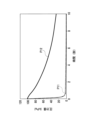
図6は真空チャンバ32の圧力値P11と、磁性流体19に負荷される圧力値P12の関係を表したグラフである。縦軸が圧力値(kPa)であり、横軸が時間(秒)である。
FIG. 6 is a graph showing the relationship between the pressure value P11 of the
真空チャンバ32の圧力値P11は、0秒の時点から急激に低下している。これは、例えば、作業者が操作を誤るなどして、真空チャンバ32の圧力が急激に低下した状態を表している。真空チャンバ32の圧力が急激に低下していることは、真空チャンバ32と連通している流路30において急激に負圧が発生していることを意味する。このような急激な圧力変動が生じているにも関わらず、磁性流体19に負荷される圧力値P12は、0秒の時点から緩やかに低下していることが図6のグラフから分かる。圧力値P12が緩やかに低下していることは、磁性流体19に加わる圧力衝撃が緩和されていることを意味している。これは、上記の通り、ラビリンスシール50が、流路30に発生する急激な負圧により駆動部2内から流路30へ吸い出される気体の量を絞るとともに、バッファ容積51が吸い出される気体の量を増加させていることによる。
The pressure value P11 of the
以上説明したように、本実施形態のバタフライバルブ1によれば、
(1)真空チャンバ32と真空ポンプ33とを接続する配管34上に配設され、真空チャンバ32の真空圧力制御を行うバタフライバルブ1であって、DDモータ11を備える駆動部2と、内部に流路30およびバタフライ弁体9を備える弁部3と、が結合されてなり、DDモータ11に接続されたロッド10が、駆動部2から延伸し、弁部3の備える挿通孔8dから流路30に挿入され、バタフライ弁体9に結合されているバタフライバルブ1において、駆動部2は、DDモータ11と弁部3が結合されている側の端部との間に、ロッド10が挿通される中空部16aを備えること、中空部16aにおいて、ロッド10と同軸に、ロッド10の外周面を覆う円筒状の磁性部材18が配置され、磁性部材18の外周面と中空部16aの内周面との間の空隙に、磁性流体19が充填されていること、ロッド10は非磁性の耐食性合金からなること、を特徴とするので、中空部16aにおいて、磁性流体19が磁性部材18の磁力により保持され、いわゆる磁性流体シールが形成されている。磁性流体シールは、ロッド10が数千万回の回転を行っても劣化しにくく、Oリングに比べてロッド10の回転に対するシールの耐久性が高い。また、流路30から挿通孔8dを通ってバタフライバルブ1の外部へ流出しようとするプロセスガスは、磁性流体シールによって流出を阻まれる。よって、シールの耐久性を高めつつ、プロセスガスがバタフライバルブ1の外部へ流出し、外気が汚染されることを防止することができ、バタフライバルブ1の寿命の低下、ひいては半導体製造効率の低下を防止することができる。
As described above, according to the
(1) A
磁性流体19を用いることで、次のような新たな課題が生じる。磁性流体19を、ロッド10の外周に保持するためには、例えば、ロッド10に磁性体のステンレス鋼を用いることが考えられる。しかし、磁性体のステンレス鋼は、非磁性体のステンレス鋼に比べ、耐食性が劣る。ロッド10は、流路30に挿入され、プロセスガスに接する接ガス部材であるため、ロッド10が磁性体のステンレス鋼からなる場合、ロッド10がプロセスガスにより腐食するおそれがある。
Using the
そこで、本発明においては、ロッド10は非磁性の耐食性合金(例えばSUS316L)からなるものとし、ロッド10の腐食を防いでいる。そして、磁性流体19の保持には、ロッド10の外周面を覆う円筒状の磁性部材18を用いることとした。
Therefore, in the present invention, the
(2)(1)に記載のバタフライバルブ1において、弁部3は、パージガスを入力するための入力ポート41と、入力ポート41と挿通孔8dとを連通するパージガス流路44と、を備え、入力ポート41と流路30とが、パージガス流路44と挿通孔8dとにより連通されていること、を特徴とするので、入力ポート41から入力されるパージガスが、パージガス流路44と挿通孔8dを通り、流路30に出力される。挿通孔8dから流路30に向かってパージガスが流れることにより、流路30から挿通孔8dを通って、磁性体シール部への侵入や、バタフライバルブ1の外部へ流出をしようとするプロセスガスは流路30へ押し戻される。よって、プロセスガスが、磁性体シール部に侵入することや、バタフライバルブ1の外部に流出することを防止することができ、外気の汚染や、バタフライバルブ1の寿命の低下、ひいては半導体製造効率の低下を防止することができる。
(2) In the
(3)(2)に記載のバタフライバルブ1において、弁部3は、弁部3を加熱するヒータ27A,27Bを備えること、パージガス流路44は、ヒータ27Aの近傍に形成されたものであるとともに、熱交換器43を備えること、ヒータ27Aに熱せられた熱交換器43によって、パージガスは所定の温度に温められること、を特徴とするので、プロセスガスの成分の固形化によるパーティクルの発生を防止することができる。
(3) In the
半導体製造工程に用いられるプロセスガスは、常温では固体または液体であるものがあり、高温に熱せられたガス状態で用いられる(例えば200度程度に熱せられている)。したがって、入力ポート41から入力されるパージガスは、流路30に出力される前に熱しておく必要がある。これは、温度が低い状態で流路30に出力されたパージガスがプロセスガスと接触してしまうと、プロセスガスの温度が低下することでプロセスガスが固体化または液化し、流路30や配管34に固形化したプロセスガス等の生成物が堆積するおそれがあるためである。これを防ぐためには、パージガスをバタフライバルブ1の外部で熱した後にバタフライバルブ1に供給することも考えられるが、バタフライバルブ1を用いる半導体製造装置に、加熱のための装置が別途に必要となるため好ましくない。そこで、本発明のように、弁部3がヒータ27A,27Bを備え、パージガス流路44がヒータ27Aの近傍に形成されたものであるとともに、熱交換器43を備えたものとすれば、ヒータ27Aの熱を利用して、パージガス流路44を通るパージガスを所定の温度に熱することができるため、プロセスガスの固形化または液化を防止することができ、流路30や配管34に固形化したプロセスガス等の生成物が堆積することを防止することができる。
Some of the process gases used in the semiconductor manufacturing process are solid or liquid at room temperature, and are used in a gaseous state heated to a high temperature (for example, heated to about 200 degrees). Therefore, the purge gas input from the
(4)(1)乃至(3)のいずれか1つに記載のバタフライバルブ1において、ロッド10は、挿通孔8dの内周面(ブッシュ20の内周面20a)に対向する外周面に、ロッド10の軸方向に並ぶ複数の凹部10a~10eを備えること、挿通孔8dの内周面(ブッシュ20の内周面20a)と、複数の凹部10a~10eと、によりラビリンスシール50が形成されること、を特徴とするので、真空チャンバ32の急激な圧力変動による磁性流体シールの破壊を防止することができる。
(4) In the
例えば、作業者が真空ポンプ33の操作を誤り、真空チャンバ32の圧力が急激に低下した場合、流路30に急激な負圧が発生する。流路30に生じる急激な負圧によって駆動部2内の気体が流路30へ急激に吸い出され、駆動部2内の圧力が急激に低下する。磁性流体19は磁性部材18の磁力により保持されているが、駆動部2内の圧力が急激に低下すると、磁性流体19に過大な圧力衝撃が加わり、磁性流体シールが破壊され、機能しなくなるおそれがある。磁性流体シールが破壊されてしまうと、駆動部2へのプロセスガスの侵入を防ぐことができなくなる。そこで、本発明のように、ロッド10が挿通孔8dの内周面(ブッシュ20の内周面20a)に対向する外周面に、ロッド10の軸方向に並ぶ複数の凹部10a~10eを備え、挿通孔8dの内周面(ブッシュ20の内周面20a)と複数の凹部10a~10eとによりラビリンスシール50を形成することで、流路30に急激な負圧が発生したとしても、ラビリンスシール50が駆動部2内から流路30へ吸い出される気体の量を絞るため、駆動部2内の圧力が急激に低下することもなく、磁性流体19に加わる圧力衝撃が緩和される。これにより、磁性流体シールの破壊を防止することができる。
For example, when an operator erroneously operates the
(5)(4)に記載のバタフライバルブ1において、磁性流体19とラビリンスシール50との間に、バッファ容積51を有すること、を特徴とするので、流路30において急激な圧力低下が発生した際に駆動部2から吸い出される気体の量が、バッファ容積51を有しない場合に比べて増加するため、より確実に磁性流体19に加わる圧力衝撃を緩和すること、ひいては磁性流体シールの破壊を防止することができる。
(5) Since the
なお、本実施形態は単なる例示にすぎず、本発明を何ら限定するものではない。したがって本発明は当然に、その要旨を逸脱しない範囲内で様々な改良、変形が可能である。例えば、本実施形態においては、バタフライ弁体9が全閉位置にあっても、流路30を完全にシールするものとなっていないが、弁孔8aに弁座を設け、弁座にバタフライ弁体9を当接させることで、完全にシールできるものとしても良い。
It should be noted that this embodiment is merely an example, and does not limit the present invention in any way. Therefore, the present invention can naturally be improved and modified in various ways without departing from the scope of the invention. For example, in this embodiment, even if the
1 バタフライバルブ
2 駆動部
3 弁部
8d 挿通孔
9 バタフライ弁体
10 ロッド
11 DDモータ(モータの一例)
16a 中空部
18 磁性部材
19 磁性流体
30 流路
32 真空チャンバ
33 真空ポンプ
34 配管
Claims (4)
前記駆動部は、前記モータと前記弁部が結合されている側の端部との間に、前記ロッドが挿通される中空部を備えること、
前記中空部において、前記ロッドと同軸に、前記ロッドの外周面を覆う円筒状の磁性部材が配置され、
前記磁性部材の外周面と前記中空部の内周面との間の空隙に、磁性流体が充填されていること、
前記ロッドは非磁性の耐食性合金からなること、
前記弁部は、パージガスを入力するための入力ポートと、前記入力ポートと前記挿通孔とを連通するパージガス流路と、を備え、
前記入力ポートと前記流路とが、前記パージガス流路と前記挿通孔とにより連通されていること、
前記バタフライバルブは、前記バタフライ弁体が全閉位置にあるとき、前記バタフライ弁体の外周面と前記流路の内壁との間に隙間を有し、前記真空チャンバは、絶えず排気されている状態にあること、
を特徴とするバタフライバルブ。 A butterfly valve arranged on a pipe connecting a vacuum chamber and a vacuum pump to control the vacuum pressure of the vacuum chamber, comprising a drive unit having a motor, and a valve unit having a flow path and a butterfly valve body therein. and a rod connected to the motor extends from the driving portion, is inserted into the flow path through an insertion hole provided in the valve portion, and is connected to the butterfly valve body. in
The drive unit includes a hollow portion through which the rod is inserted between the motor and the end on the side where the valve unit is coupled;
A cylindrical magnetic member covering the outer peripheral surface of the rod is arranged coaxially with the rod in the hollow portion,
A gap between the outer peripheral surface of the magnetic member and the inner peripheral surface of the hollow portion is filled with a magnetic fluid;
the rod is made of a non-magnetic, corrosion-resistant alloy;
The valve section includes an input port for inputting a purge gas, and a purge gas flow path communicating between the input port and the insertion hole,
the input port and the flow path are communicated by the purge gas flow path and the insertion hole;
The butterfly valve has a gap between the outer peripheral surface of the butterfly valve body and the inner wall of the flow path when the butterfly valve body is in the fully closed position, and the vacuum chamber is continuously evacuated. to be in
A butterfly valve characterized by
前記弁部は、前記弁部を加熱するヒータを備えること、
前記パージガス流路は、前記ヒータの近傍に形成されたものであるとともに、熱交換器を備えること、
前記ヒータに熱せられた前記熱交換器によって、前記パージガスは所定の温度に温められること、
を特徴とするバタフライバルブ。 A butterfly valve according to claim 1 ,
The valve section includes a heater that heats the valve section;
the purge gas flow path is formed in the vicinity of the heater and includes a heat exchanger;
The purge gas is warmed to a predetermined temperature by the heat exchanger heated by the heater;
A butterfly valve characterized by
前記ロッドは、前記挿通孔の内周面に対向する外周面に、前記ロッドの軸方向に並ぶ複数の凹部を備えること、
前記挿通孔の内周面と、前記複数の凹部と、によりラビリンスシールが形成されること、
を特徴とするバタフライバルブ。 A butterfly valve according to claim 1 or 2 ,
the rod has a plurality of recesses arranged in the axial direction of the rod on the outer peripheral surface facing the inner peripheral surface of the insertion hole;
A labyrinth seal is formed by the inner peripheral surface of the insertion hole and the plurality of recesses;
A butterfly valve characterized by
前記磁性流体と前記ラビリンスシールとの間に、バッファ容積を有すること、
を特徴とするバタフライバルブ。 A butterfly valve according to claim 3 ,
having a buffer volume between the magnetic fluid and the labyrinth seal;
A butterfly valve characterized by
Priority Applications (5)
| Application Number | Priority Date | Filing Date | Title |
|---|---|---|---|
| JP2020009768A JP7242582B2 (en) | 2020-01-24 | 2020-01-24 | butterfly valve |
| CN202110019863.3A CN113175536B (en) | 2020-01-24 | 2021-01-07 | butterfly valve |
| US17/144,334 US11339876B2 (en) | 2020-01-24 | 2021-01-08 | Butterfly valve |
| TW110100940A TWI782392B (en) | 2020-01-24 | 2021-01-11 | Butterfly valve |
| KR1020210005906A KR102546033B1 (en) | 2020-01-24 | 2021-01-15 | Butterfly valve |
Applications Claiming Priority (1)
| Application Number | Priority Date | Filing Date | Title |
|---|---|---|---|
| JP2020009768A JP7242582B2 (en) | 2020-01-24 | 2020-01-24 | butterfly valve |
Publications (2)
| Publication Number | Publication Date |
|---|---|
| JP2021116846A JP2021116846A (en) | 2021-08-10 |
| JP7242582B2 true JP7242582B2 (en) | 2023-03-20 |
Family
ID=76921643
Family Applications (1)
| Application Number | Title | Priority Date | Filing Date |
|---|---|---|---|
| JP2020009768A Active JP7242582B2 (en) | 2020-01-24 | 2020-01-24 | butterfly valve |
Country Status (5)
| Country | Link |
|---|---|
| US (1) | US11339876B2 (en) |
| JP (1) | JP7242582B2 (en) |
| KR (1) | KR102546033B1 (en) |
| CN (1) | CN113175536B (en) |
| TW (1) | TWI782392B (en) |
Families Citing this family (6)
| Publication number | Priority date | Publication date | Assignee | Title |
|---|---|---|---|---|
| CN115167574B (en) * | 2022-09-08 | 2023-02-28 | 拓荆科技(上海)有限公司 | Valve temperature control device and vapor deposition equipment |
| KR102533164B1 (en) * | 2022-11-02 | 2023-05-17 | (주)하나프리 | Device including magnetic fluid seals that can be supplemented with magnetic fluid |
| US12196336B2 (en) * | 2023-01-12 | 2025-01-14 | Magdrive Technologies, Inc. | Electromagnetically activated rising stem valve |
| US11976742B1 (en) * | 2023-01-12 | 2024-05-07 | Magdrive Technologies, Inc. | Electromagnetically activated pipe valve |
| US12392419B2 (en) | 2023-01-12 | 2025-08-19 | Magdrive Technologies, Inc. | Electromagnetically activated pipe valve |
| DE102023003612A1 (en) * | 2023-09-05 | 2025-03-06 | Vat Holding Ag | GAS INLET VALVE WITH BELLOWS ACTUATOR |
Citations (9)
| Publication number | Priority date | Publication date | Assignee | Title |
|---|---|---|---|---|
| JP2003172261A (en) | 2001-12-03 | 2003-06-20 | Teijin Seiki Co Ltd | Rotary shaft seal mechanism |
| JP2009002253A (en) | 2007-06-22 | 2009-01-08 | Nabtesco Corp | Screw vacuum pump and control method thereof |
| JP2010056124A (en) | 2008-08-26 | 2010-03-11 | Hitachi Kokusai Electric Inc | Substrate processing device and method for manufacturing semiconductor device |
| US20100096574A1 (en) | 2006-11-09 | 2010-04-22 | Gyu-Tae Son | Throttle valve having magnetic fluid seal structure |
| JP2010116627A (en) | 2009-12-25 | 2010-05-27 | Hitachi Kokusai Electric Inc | Semiconductor manufacturing equipment, valve device, cvd treatment method using the semiconductor manufacturing equipment, and method of manufacturing semiconductor |
| JP2011237022A (en) | 2010-05-13 | 2011-11-24 | Ckd Corp | Vacuum valve |
| WO2018190148A1 (en) | 2017-04-10 | 2018-10-18 | イーグル工業株式会社 | Butterfly valve |
| WO2019044013A1 (en) | 2017-08-30 | 2019-03-07 | 株式会社Kokusai Electric | Protection plate, substrate treatment device, and method for manufacturing semiconductor device |
| JP2019086093A (en) | 2017-11-07 | 2019-06-06 | 東京エレクトロン株式会社 | Relief valve and substrate processing device |
Family Cites Families (10)
| Publication number | Priority date | Publication date | Assignee | Title |
|---|---|---|---|---|
| US4335885A (en) * | 1980-08-19 | 1982-06-22 | Mechanical Technology Incorporated | Plural fluid magnetic/centrifugal seal |
| JPS59118852U (en) * | 1983-01-31 | 1984-08-10 | 三菱電機株式会社 | Magnetic fluid seal device |
| JP2606154Y2 (en) * | 1993-01-27 | 2000-09-25 | ボッシュ ブレーキ システム株式会社 | Butterfly valve |
| JPH0771620A (en) * | 1993-06-11 | 1995-03-17 | Nippon Seiko Kk | Magnetic fluid sealing device |
| NL9301162A (en) * | 1993-07-02 | 1995-02-01 | Keystone Int | Seal for valve shaft. |
| US5462080A (en) * | 1993-08-31 | 1995-10-31 | Applied Materials, Inc. | Heated removable throttle valve |
| JPH08114282A (en) * | 1994-10-17 | 1996-05-07 | Smc Corp | High vacuum pressure valve |
| JP3509443B2 (en) * | 1997-01-13 | 2004-03-22 | 株式会社クボタ | Butterfly valve |
| JP5505605B2 (en) * | 2009-09-07 | 2014-05-28 | 旭有機材工業株式会社 | Butterfly valve |
| JP7013152B2 (en) * | 2017-07-13 | 2022-01-31 | Ckd株式会社 | Butterfly valve and vacuum pressure controller |
-
2020
- 2020-01-24 JP JP2020009768A patent/JP7242582B2/en active Active
-
2021
- 2021-01-07 CN CN202110019863.3A patent/CN113175536B/en active Active
- 2021-01-08 US US17/144,334 patent/US11339876B2/en active Active
- 2021-01-11 TW TW110100940A patent/TWI782392B/en active
- 2021-01-15 KR KR1020210005906A patent/KR102546033B1/en active Active
Patent Citations (9)
| Publication number | Priority date | Publication date | Assignee | Title |
|---|---|---|---|---|
| JP2003172261A (en) | 2001-12-03 | 2003-06-20 | Teijin Seiki Co Ltd | Rotary shaft seal mechanism |
| US20100096574A1 (en) | 2006-11-09 | 2010-04-22 | Gyu-Tae Son | Throttle valve having magnetic fluid seal structure |
| JP2009002253A (en) | 2007-06-22 | 2009-01-08 | Nabtesco Corp | Screw vacuum pump and control method thereof |
| JP2010056124A (en) | 2008-08-26 | 2010-03-11 | Hitachi Kokusai Electric Inc | Substrate processing device and method for manufacturing semiconductor device |
| JP2010116627A (en) | 2009-12-25 | 2010-05-27 | Hitachi Kokusai Electric Inc | Semiconductor manufacturing equipment, valve device, cvd treatment method using the semiconductor manufacturing equipment, and method of manufacturing semiconductor |
| JP2011237022A (en) | 2010-05-13 | 2011-11-24 | Ckd Corp | Vacuum valve |
| WO2018190148A1 (en) | 2017-04-10 | 2018-10-18 | イーグル工業株式会社 | Butterfly valve |
| WO2019044013A1 (en) | 2017-08-30 | 2019-03-07 | 株式会社Kokusai Electric | Protection plate, substrate treatment device, and method for manufacturing semiconductor device |
| JP2019086093A (en) | 2017-11-07 | 2019-06-06 | 東京エレクトロン株式会社 | Relief valve and substrate processing device |
Also Published As
| Publication number | Publication date |
|---|---|
| US20210231220A1 (en) | 2021-07-29 |
| CN113175536A (en) | 2021-07-27 |
| US11339876B2 (en) | 2022-05-24 |
| CN113175536B (en) | 2023-08-08 |
| TWI782392B (en) | 2022-11-01 |
| JP2021116846A (en) | 2021-08-10 |
| TW202134556A (en) | 2021-09-16 |
| KR102546033B1 (en) | 2023-06-21 |
| KR20210095801A (en) | 2021-08-03 |
Similar Documents
| Publication | Publication Date | Title |
|---|---|---|
| JP7242582B2 (en) | butterfly valve | |
| JP7141418B2 (en) | Non-hermetic butterfly valve and manufacturing method thereof | |
| KR100898943B1 (en) | Valve flapper with dynamic circumferential seal | |
| JP6101365B2 (en) | Flow control valve | |
| KR20040054576A (en) | Cryogenic valve device | |
| CN110617337A (en) | Electric valve and refrigeration cycle system | |
| KR102836988B1 (en) | Butterfly valve | |
| EP1781946B1 (en) | An integrated high vacuum pumping system | |
| KR101493934B1 (en) | Vacuum valve | |
| CN113614427B (en) | butterfly valve | |
| JP2007536471A (en) | Valve that shuts off steam from leaking between two process units connected to each other | |
| KR20060133413A (en) | Throttle Valve for Pressure Control of Semiconductor Manufacturing Equipment |
Legal Events
| Date | Code | Title | Description |
|---|---|---|---|
| A621 | Written request for application examination |
Free format text: JAPANESE INTERMEDIATE CODE: A621 Effective date: 20210930 |
|
| A977 | Report on retrieval |
Free format text: JAPANESE INTERMEDIATE CODE: A971007 Effective date: 20220922 |
|
| A131 | Notification of reasons for refusal |
Free format text: JAPANESE INTERMEDIATE CODE: A131 Effective date: 20220927 |
|
| A521 | Request for written amendment filed |
Free format text: JAPANESE INTERMEDIATE CODE: A523 Effective date: 20221019 |
|
| TRDD | Decision of grant or rejection written | ||
| A01 | Written decision to grant a patent or to grant a registration (utility model) |
Free format text: JAPANESE INTERMEDIATE CODE: A01 Effective date: 20230228 |
|
| A61 | First payment of annual fees (during grant procedure) |
Free format text: JAPANESE INTERMEDIATE CODE: A61 Effective date: 20230308 |
|
| R150 | Certificate of patent or registration of utility model |
Ref document number: 7242582 Country of ref document: JP Free format text: JAPANESE INTERMEDIATE CODE: R150 |