JP7241021B2 - ATR spectrometer and method for analyzing the chemical composition of a sample - Google Patents
ATR spectrometer and method for analyzing the chemical composition of a sample Download PDFInfo
- Publication number
- JP7241021B2 JP7241021B2 JP2019548903A JP2019548903A JP7241021B2 JP 7241021 B2 JP7241021 B2 JP 7241021B2 JP 2019548903 A JP2019548903 A JP 2019548903A JP 2019548903 A JP2019548903 A JP 2019548903A JP 7241021 B2 JP7241021 B2 JP 7241021B2
- Authority
- JP
- Japan
- Prior art keywords
- infrared
- atr
- detectors
- infrared detectors
- wavelength
- Prior art date
- Legal status (The legal status is an assumption and is not a legal conclusion. Google has not performed a legal analysis and makes no representation as to the accuracy of the status listed.)
- Active
Links
- 238000000034 method Methods 0.000 title claims description 18
- 239000000126 substance Substances 0.000 title claims description 12
- 238000001228 spectrum Methods 0.000 claims description 52
- 230000001419 dependent effect Effects 0.000 claims description 35
- 239000013078 crystal Substances 0.000 claims description 30
- 238000010521 absorption reaction Methods 0.000 claims description 18
- 238000000862 absorption spectrum Methods 0.000 claims description 18
- 230000003595 spectral effect Effects 0.000 claims description 17
- 230000005855 radiation Effects 0.000 claims description 9
- 238000012986 modification Methods 0.000 claims description 7
- 230000004048 modification Effects 0.000 claims description 7
- 238000005033 Fourier transform infrared spectroscopy Methods 0.000 claims description 5
- FGUUSXIOTUKUDN-IBGZPJMESA-N C1(=CC=CC=C1)N1C2=C(NC([C@H](C1)NC=1OC(=NN=1)C1=CC=CC=C1)=O)C=CC=C2 Chemical compound C1(=CC=CC=C1)N1C2=C(NC([C@H](C1)NC=1OC(=NN=1)C1=CC=CC=C1)=O)C=CC=C2 FGUUSXIOTUKUDN-IBGZPJMESA-N 0.000 claims description 3
- 239000000523 sample Substances 0.000 description 38
- 238000012937 correction Methods 0.000 description 11
- LFQSCWFLJHTTHZ-UHFFFAOYSA-N Ethanol Chemical compound CCO LFQSCWFLJHTTHZ-UHFFFAOYSA-N 0.000 description 8
- 230000008033 biological extinction Effects 0.000 description 5
- 230000003993 interaction Effects 0.000 description 5
- XLYOFNOQVPJJNP-UHFFFAOYSA-N water Substances O XLYOFNOQVPJJNP-UHFFFAOYSA-N 0.000 description 5
- 238000004566 IR spectroscopy Methods 0.000 description 4
- 238000012569 chemometric method Methods 0.000 description 4
- 238000002835 absorbance Methods 0.000 description 3
- 239000013074 reference sample Substances 0.000 description 3
- 230000000694 effects Effects 0.000 description 2
- 238000005259 measurement Methods 0.000 description 2
- 238000012545 processing Methods 0.000 description 2
- 230000008901 benefit Effects 0.000 description 1
- 230000005540 biological transmission Effects 0.000 description 1
- 230000008859 change Effects 0.000 description 1
- 230000000593 degrading effect Effects 0.000 description 1
- 238000013461 design Methods 0.000 description 1
- 230000002708 enhancing effect Effects 0.000 description 1
- 230000003287 optical effect Effects 0.000 description 1
- 238000010238 partial least squares regression Methods 0.000 description 1
- 230000002123 temporal effect Effects 0.000 description 1
Images


Classifications
-
- G—PHYSICS
- G01—MEASURING; TESTING
- G01J—MEASUREMENT OF INTENSITY, VELOCITY, SPECTRAL CONTENT, POLARISATION, PHASE OR PULSE CHARACTERISTICS OF INFRARED, VISIBLE OR ULTRAVIOLET LIGHT; COLORIMETRY; RADIATION PYROMETRY
- G01J3/00—Spectrometry; Spectrophotometry; Monochromators; Measuring colours
- G01J3/28—Investigating the spectrum
- G01J3/2803—Investigating the spectrum using photoelectric array detector
-
- G—PHYSICS
- G01—MEASURING; TESTING
- G01J—MEASUREMENT OF INTENSITY, VELOCITY, SPECTRAL CONTENT, POLARISATION, PHASE OR PULSE CHARACTERISTICS OF INFRARED, VISIBLE OR ULTRAVIOLET LIGHT; COLORIMETRY; RADIATION PYROMETRY
- G01J3/00—Spectrometry; Spectrophotometry; Monochromators; Measuring colours
- G01J3/28—Investigating the spectrum
- G01J3/30—Measuring the intensity of spectral lines directly on the spectrum itself
- G01J3/36—Investigating two or more bands of a spectrum by separate detectors
-
- G—PHYSICS
- G01—MEASURING; TESTING
- G01J—MEASUREMENT OF INTENSITY, VELOCITY, SPECTRAL CONTENT, POLARISATION, PHASE OR PULSE CHARACTERISTICS OF INFRARED, VISIBLE OR ULTRAVIOLET LIGHT; COLORIMETRY; RADIATION PYROMETRY
- G01J3/00—Spectrometry; Spectrophotometry; Monochromators; Measuring colours
- G01J3/28—Investigating the spectrum
- G01J3/42—Absorption spectrometry; Double beam spectrometry; Flicker spectrometry; Reflection spectrometry
-
- G—PHYSICS
- G01—MEASURING; TESTING
- G01N—INVESTIGATING OR ANALYSING MATERIALS BY DETERMINING THEIR CHEMICAL OR PHYSICAL PROPERTIES
- G01N21/00—Investigating or analysing materials by the use of optical means, i.e. using sub-millimetre waves, infrared, visible or ultraviolet light
- G01N21/17—Systems in which incident light is modified in accordance with the properties of the material investigated
- G01N21/25—Colour; Spectral properties, i.e. comparison of effect of material on the light at two or more different wavelengths or wavelength bands
- G01N21/27—Colour; Spectral properties, i.e. comparison of effect of material on the light at two or more different wavelengths or wavelength bands using photo-electric detection ; circuits for computing concentration
- G01N21/274—Calibration, base line adjustment, drift correction
-
- G—PHYSICS
- G01—MEASURING; TESTING
- G01N—INVESTIGATING OR ANALYSING MATERIALS BY DETERMINING THEIR CHEMICAL OR PHYSICAL PROPERTIES
- G01N21/00—Investigating or analysing materials by the use of optical means, i.e. using sub-millimetre waves, infrared, visible or ultraviolet light
- G01N21/17—Systems in which incident light is modified in accordance with the properties of the material investigated
- G01N21/25—Colour; Spectral properties, i.e. comparison of effect of material on the light at two or more different wavelengths or wavelength bands
- G01N21/31—Investigating relative effect of material at wavelengths characteristic of specific elements or molecules, e.g. atomic absorption spectrometry
- G01N21/35—Investigating relative effect of material at wavelengths characteristic of specific elements or molecules, e.g. atomic absorption spectrometry using infrared light
-
- G—PHYSICS
- G01—MEASURING; TESTING
- G01N—INVESTIGATING OR ANALYSING MATERIALS BY DETERMINING THEIR CHEMICAL OR PHYSICAL PROPERTIES
- G01N21/00—Investigating or analysing materials by the use of optical means, i.e. using sub-millimetre waves, infrared, visible or ultraviolet light
- G01N21/17—Systems in which incident light is modified in accordance with the properties of the material investigated
- G01N21/55—Specular reflectivity
- G01N21/552—Attenuated total reflection
-
- G—PHYSICS
- G01—MEASURING; TESTING
- G01J—MEASUREMENT OF INTENSITY, VELOCITY, SPECTRAL CONTENT, POLARISATION, PHASE OR PULSE CHARACTERISTICS OF INFRARED, VISIBLE OR ULTRAVIOLET LIGHT; COLORIMETRY; RADIATION PYROMETRY
- G01J3/00—Spectrometry; Spectrophotometry; Monochromators; Measuring colours
- G01J3/28—Investigating the spectrum
- G01J2003/2866—Markers; Calibrating of scan
- G01J2003/2869—Background correcting
-
- G—PHYSICS
- G01—MEASURING; TESTING
- G01J—MEASUREMENT OF INTENSITY, VELOCITY, SPECTRAL CONTENT, POLARISATION, PHASE OR PULSE CHARACTERISTICS OF INFRARED, VISIBLE OR ULTRAVIOLET LIGHT; COLORIMETRY; RADIATION PYROMETRY
- G01J3/00—Spectrometry; Spectrophotometry; Monochromators; Measuring colours
- G01J3/02—Details
- G01J3/0205—Optical elements not provided otherwise, e.g. optical manifolds, diffusers, windows
-
- G—PHYSICS
- G01—MEASURING; TESTING
- G01N—INVESTIGATING OR ANALYSING MATERIALS BY DETERMINING THEIR CHEMICAL OR PHYSICAL PROPERTIES
- G01N21/00—Investigating or analysing materials by the use of optical means, i.e. using sub-millimetre waves, infrared, visible or ultraviolet light
- G01N21/17—Systems in which incident light is modified in accordance with the properties of the material investigated
- G01N21/25—Colour; Spectral properties, i.e. comparison of effect of material on the light at two or more different wavelengths or wavelength bands
- G01N21/31—Investigating relative effect of material at wavelengths characteristic of specific elements or molecules, e.g. atomic absorption spectrometry
- G01N21/35—Investigating relative effect of material at wavelengths characteristic of specific elements or molecules, e.g. atomic absorption spectrometry using infrared light
- G01N21/3563—Investigating relative effect of material at wavelengths characteristic of specific elements or molecules, e.g. atomic absorption spectrometry using infrared light for analysing solids; Preparation of samples therefor
-
- G—PHYSICS
- G01—MEASURING; TESTING
- G01N—INVESTIGATING OR ANALYSING MATERIALS BY DETERMINING THEIR CHEMICAL OR PHYSICAL PROPERTIES
- G01N21/00—Investigating or analysing materials by the use of optical means, i.e. using sub-millimetre waves, infrared, visible or ultraviolet light
- G01N21/17—Systems in which incident light is modified in accordance with the properties of the material investigated
- G01N21/25—Colour; Spectral properties, i.e. comparison of effect of material on the light at two or more different wavelengths or wavelength bands
- G01N21/31—Investigating relative effect of material at wavelengths characteristic of specific elements or molecules, e.g. atomic absorption spectrometry
- G01N21/35—Investigating relative effect of material at wavelengths characteristic of specific elements or molecules, e.g. atomic absorption spectrometry using infrared light
- G01N21/3577—Investigating relative effect of material at wavelengths characteristic of specific elements or molecules, e.g. atomic absorption spectrometry using infrared light for analysing liquids, e.g. polluted water
Landscapes
- Physics & Mathematics (AREA)
- Spectroscopy & Molecular Physics (AREA)
- General Physics & Mathematics (AREA)
- Biochemistry (AREA)
- Chemical & Material Sciences (AREA)
- Analytical Chemistry (AREA)
- Life Sciences & Earth Sciences (AREA)
- General Health & Medical Sciences (AREA)
- Health & Medical Sciences (AREA)
- Immunology (AREA)
- Pathology (AREA)
- Engineering & Computer Science (AREA)
- Mathematical Physics (AREA)
- Theoretical Computer Science (AREA)
- Investigating Or Analysing Materials By Optical Means (AREA)
Description
本発明は、サンプルの化学組成を分析するためのATR分光計、及びATR分光計によってサンプルの化学組成を分析する方法に関する。 The present invention relates to an ATR spectrometer for analyzing the chemical composition of a sample and a method of analyzing the chemical composition of a sample with an ATR spectrometer.
サンプルの化学組成は、赤外分光法によって分析できる。赤外分光法は、赤外線光源から放射される広帯域赤外光をサンプルに照射し、赤外光がサンプルを通過した後にサンプルの吸光度スペクトルを測定する吸光分光計によって行われる。又は、ATR分光計を使用して赤外線分光法を行うことができる。該赤外線分光法では、ATR分光計のATR結晶と接触するサンプルで生成された赤外線のエバネッセント波が該サンプルと相互作用し、相互作用後のATRスペクトルが測定される。吸光度スペクトルとATRスペクトルの両方は、サンプルの吸光の波長依存測定、つまりサンプルとの相互作用後の光の減衰の測定を含む。吸光は、吸収成分と散乱成分で構成される。つまり、波長をλ、吸光度スペクトルをextinction(λ)、吸光度スペクトルの吸収成分をabsorption(λ)、吸光度スペクトルの散乱成分をscattering(λ)として、extinction(λ)=absorption(λ)+scattering(λ)となる。サンプルの化学組成を分析するために、通常、吸収のみが考慮される。サンプルに水が含まれている場合、水に関するピークはATRスペクトル中では吸光度スペクトルより目立たないため、ATR分光計は吸光分光計より有利である。これにより、水に関するピークは、吸光度スペクトル中よりATRスペクトル中の他のピークをカバーしない。 The chemical composition of the sample can be analyzed by infrared spectroscopy. Infrared spectroscopy is performed by an absorption spectrometer that illuminates a sample with broadband infrared light emitted from an infrared light source and measures the absorbance spectrum of the sample after the infrared light has passed through the sample. Alternatively, infrared spectroscopy can be performed using an ATR spectrometer. In the infrared spectroscopy, infrared evanescent waves generated in a sample in contact with an ATR crystal of an ATR spectrometer interact with the sample and the ATR spectrum after interaction is measured. Both absorbance and ATR spectra involve wavelength-dependent measurements of the absorbance of a sample, ie, the attenuation of light after interaction with the sample. Absorption is composed of an absorption component and a scattering component. In other words, where λ is the wavelength, extinction (λ) is the absorbance spectrum, absorption (λ) is the absorption component of the absorbance spectrum , and scattering (λ) is the scattering component of the absorbance spectrum, extinction (λ) = absorption (λ) + scattering (λ) becomes. For analyzing the chemical composition of a sample, usually only absorption is considered. If the sample contains water, the ATR spectrometer has an advantage over the absorbance spectrometer because the peaks associated with water are less prominent in the ATR spectrum than the absorbance spectrum. Thus, the peak for water does not cover other peaks in the ATR spectrum than in the absorbance spectrum.
しかし、赤外線光源から放射される赤外光の強度が時間的に変動すれば、ATRスペクトルの強度も変動して、品質が低下する。さらに、ATR結晶と、消光スペクトルを測定するための赤外光の異なる部分を通過する線形可変フィルタは、ATR分光計の検出器を配置するためのスペースが限られるため、限られた寸法となっている。検出器のスペースが限られているので、ATRスペクトルのスペクトル分解能が低下し、又はATRスペクトルの測定可能範囲が狭くなる。このため、ATRスペクトルの品質が低下する。 However, if the intensity of the infrared light emitted from the infrared light source fluctuates over time, the intensity of the ATR spectrum will also fluctuate, degrading the quality. Furthermore, the ATR crystal and the linearly variable filter that passes different portions of the infrared light for measuring the extinction spectrum are of limited dimensions due to the limited space for placing the detector of the ATR spectrometer. ing. The limited space of the detector reduces the spectral resolution of the ATR spectrum or narrows the measurable range of the ATR spectrum. This reduces the quality of the ATR spectrum.
従って、本発明の目的は、ATRスペクトルを高品質で測定できるATR分光計及びATR分光計の動作方法を提供することである。 SUMMARY OF THE INVENTION It is therefore an object of the present invention to provide an ATR spectrometer and a method of operating an ATR spectrometer capable of measuring ATR spectra with high quality.
本発明による、サンプルの化学組成を分析するためのATR分光計は、ATR結晶の入口端の直近に配置される入射面と、入口端の反対側に配置され、ATR結晶の出口端の直近に配置される出射面とを有するATR結晶と、入射面に配置される少なくとも一つの赤外線光源と、出射面に配置され、赤外光検出器が線状に並べられたラインアレイと、出射面に配置され、少なくとも一つの単一の赤外光検出器とを備える。少なくとも一つの赤外光源は、入射面を介してATR結晶に入射し、ATR結晶にすぐ隣りに配置されるサンプルとの相互作用及び内部全反射の下で赤外光検出器に導かれる赤外光を放射するように構成される。波長分散素子は、出射面からラインアレイまでの赤外光の経路に配置されており、ラインアレイは、赤外光のスペクトルを測定するように構成され、波長フィルタは、出射面から単一の赤外光検出器までの赤外光の経路に配置される。赤外光検出器は、それぞれの赤外光検出器に入射する赤外光の量を示す電気信号を出力するように構成される。少なくとも一つの赤外光検出器は、信号修正用に選択された赤外光検出器として選択される。ATR分光計は、前記選択された赤外線検出器の電気信号を使用して、他の全ての前記赤外線検出器の電気信号を修正するように構成される。 An ATR spectrometer for analyzing the chemical composition of a sample, according to the present invention, has an entrance plane located immediately adjacent to the entrance end of the ATR crystal, and an entrance surface located opposite the entrance edge and located immediately adjacent the exit end of the ATR crystal. at least one infrared light source disposed on the entrance surface; a line array in which infrared photodetectors are linearly arranged and disposed on the exit surface; and at least one single infrared photodetector. At least one infrared light source is incident on the ATR crystal through the plane of incidence and directs infrared light to an infrared photodetector under interaction and total internal reflection with a sample located immediately adjacent to the ATR crystal. configured to emit light; A wavelength dispersive element is placed in the path of the infrared light from the exit face to the line array, the line array is configured to measure the spectrum of the infrared light, and the wavelength filter is a single wavelength filter from the exit face. It is placed in the path of the infrared light to the infrared photodetector. The infrared photodetectors are configured to output electrical signals indicative of the amount of infrared light incident on each infrared photodetector. At least one infrared photodetector is selected as the infrared photodetector selected for signal modification. An ATR spectrometer is configured to use the electrical signal of the selected infrared detector to modify the electrical signals of all other infrared detectors.
選択された赤外線検出器による他の全ての赤外線検出器の修正により、少なくとも一つの赤外線光源の変動を修正でき、そのためATRスペクトルの高品質な測定が有利に達成される。ラインアレイと少なくとも一つの赤外線検出器を使用するため、波長分散素子、ラインアレイの赤外光検出器、及び/又は少なくとも一つの単一の赤外光検出器の波長フィルタの波長特性の選択により、ATRスペクトルを測定する波長領域の選択と選択された赤外線検出器の波長領域の選択が極めて柔軟になる。赤外線検出器を配置するための利用可能なスペースが限られているにもかかわらず、この大きな柔軟性が得られる。この波長領域の選択による大きな柔軟性によって、これらの波長領域をサンプルの光学特性に適合させ、ATRスペクトルの品質をさらに高めることができる。 Modification of all other infrared detectors by the selected infrared detector can correct for variations in at least one infrared light source, thus advantageously achieving high quality measurements of the ATR spectrum. for using a line array and at least one infrared detector, by selecting wavelength characteristics of a wavelength dispersive element, a line array infrared photodetector, and/or a wavelength filter of at least one single infrared photodetector; , the selection of the wavelength region for measuring the ATR spectrum and the selection of the wavelength region of the selected infrared detector becomes very flexible. This great flexibility is obtained despite the limited space available for placing the infrared detectors. Great flexibility in the selection of this wavelength range allows these wavelength ranges to be adapted to the optical properties of the sample, further enhancing the quality of the ATR spectrum.
好ましくは、赤外光は、赤外光検出器へ進行方向を変えることなく出射面から導かれる。これにより、ATR分光計のシンプルな設計が可能となる。 Preferably, the infrared light is guided from the exit surface without changing its traveling direction to the infrared photodetector. This allows for a simple design of the ATR spectrometer.
好ましくは、サンプルはATR結晶のすぐ隣に配置され、選択された赤外線検出器は、サンプルが実質的に吸収を有さない波長領域になるように、対応する検出可能な波長範囲が選択される。このようにして、少なくとも一つの赤外線光源の強度の時間的変動を特に十分に補償でき、それにより、ATRスペクトルの品質をさらに高めることができる。 Preferably, the sample is placed immediately next to the ATR crystal and the infrared detector selected is selected with a corresponding detectable wavelength range such that the sample is in the wavelength region where it has substantially no absorption. . In this way, temporal fluctuations in the intensity of the at least one infrared light source can be particularly well compensated, whereby the quality of the ATR spectrum can be further enhanced.
好ましくは、単一の赤外線検出器のそれぞれが、ラインアレイの赤外線検出器のそれぞれより大きな光活性表面を有する。従って、単一の赤外線検出器は、ラインアレイの赤外線検出器より高い信号対雑音比を有する。単一の赤外線検出器の一つを使用してATRスペクトルの一部を測定する場合、この部分は高い信号対雑音比で有利に測定できる。また、ATRスペクトルの特定の成分を定量的に測定できる。単一の赤外線検出器の一つが信号修正用に選択された赤外線検出器の一つである場合、高い信号対雑音比のために高精度で信号を修正できる。どちらの場合も、単一の赤外線検出器の大きな光活性表面によって、ATRスペクトルの品質が向上する。 Preferably, each single infrared detector has a larger photoactive surface than each of the line array infrared detectors. Thus, a single infrared detector has a higher signal-to-noise ratio than a line array infrared detector. If a portion of the ATR spectrum is measured using one of the single infrared detectors, this portion can be advantageously measured with a high signal-to-noise ratio. Also, a specific component of the ATR spectrum can be quantitatively measured. If one of the single infrared detectors is one of the infrared detectors selected for signal correction, the signal can be corrected with high accuracy due to the high signal-to-noise ratio. In both cases, the large photoactive surface of a single infrared detector improves the quality of ATR spectra.
好ましくは、出射面から単一の赤外光検出器までの赤外光の経路に配置される波長フィルタは帯域通過フィルタである。好ましくは、少なくとも一つの単一の赤外線検出器のスペクトル分解能は、ラインアレイの全ての赤外線検出器のスペクトル分解能より高い。この単一の赤外線検出器がATRスペクトルの一部の測定に使用される場合、ATRスペクトルのピークが解消する可能性があるが、ラインアレイのスペクトル分解能が低いために、ATRスペクトルのピークをラインアレイで検出できない。この単一の赤外線検出器が信号修正のために選択された赤外線検出器の一つである場合、信号の修正は、スペクトル分解能が低いため、ラインアレイの赤外線検出器の一つを使用した場合よりも高い精度で実行できる。どちらの場合も、単一の赤外線検出器の非常に高いスペクトル分解能により、ATRスペクトルの品質が向上する。 Preferably, the wavelength filters placed in the path of the infrared light from the exit surface to the single infrared photodetector are bandpass filters. Preferably, the spectral resolution of at least one single infrared detector is higher than the spectral resolution of all infrared detectors of the line array. If this single infrared detector is used to measure a portion of the ATR spectrum, the peaks of the ATR spectrum may disappear, but due to the low spectral resolution of the line array, the peaks of the ATR spectrum can be separated into lines. Not detectable by array. If this single infrared detector is one of the infrared detectors selected for signal correction, the signal correction can be reduced by using one of the line array infrared detectors due to the lower spectral resolution. can be performed with greater accuracy. In both cases, the very high spectral resolution of a single infrared detector improves the quality of ATR spectra.
好ましくは、ATR分光計の動作中に、他の全ての赤外線検出器によって出力される電気信号から選択された赤外線検出器によって出力される電気信号が減算されるように、選択された赤外線検出器は他の全ての赤外線検出器と接続される。このようにして、ATR分光計は、電気信号が増幅及び/又はデジタル化される前に電気信号を修正するように構成される。また、電気信号の修正は、ソフトウェアではなく、データ処理を高速化するハードウェアによって実行される。データ処理の高速化により、ATRスペクトルをより高い繰り返し数で測定できる。繰り返し数が高いほど、ATRスペクトルを平均化でき、ATRスペクトルの品質が向上する。 Preferably, the selected infrared detector is subtracted from the electrical signals output by all other infrared detectors during operation of the ATR spectrometer. is connected to all other infrared detectors. In this way, the ATR spectrometer is configured to modify the electrical signal before it is amplified and/or digitized. Also, the modification of the electrical signal is performed by hardware rather than software , which speeds up data processing . The faster data processing allows ATR spectra to be measured at higher repetition rates. The higher the repetition number, the more the ATR spectrum can be averaged and the better the quality of the ATR spectrum.
修正は、例えば、選択された赤外線検出器によって出力された信号値を、他の全ての赤外線検出器の信号値から減算する。あるいは、修正は、選択された赤外線検出器によって出力される信号値の逆数を、他の全ての赤外線検出器の信号値の逆数から減算する。好ましくは、両方の選択肢について、ATR分光計は、複数の選択された赤外線光検出器の電気信号を使用して波長依存関数を生成し、波長依存関数を使用して他の全ての赤外線光検出器の電気信号を修正するように構成される。信号値が減算される場合、波長依存関数は、選択された赤外線検出器によって出力される信号値に波長依存関数を適合させることによって生成され、波長依存関数は他の全ての赤外光検出器によって出力される信号値から減算される。信号値の逆数が減算される場合、波長依存関数は、選択された赤外線検出器によって出力される信号値の逆数に波長依存関数を適合させることにより生成され、波長依存関数は、他のすべての赤外線検出器によって出力される信号値の逆数から減算される。これにより、赤外線光源の強度の変動だけでなく、赤外線光源のスペクトルドリフトも修正できる。これにより、ATRスペクトルの品質がさらに向上する。 The correction is, for example, subtracting the signal value output by the selected infrared detector from the signal values of all other infrared detectors. Alternatively, the correction subtracts the reciprocal of the signal value output by the selected infrared detector from the reciprocals of the signal values of all other infrared detectors. Preferably, for both options, the ATR spectrometer uses the electrical signals of a plurality of selected infrared photodetectors to generate a wavelength dependent function, and uses the wavelength dependent function to detect all other infrared photodetectors. configured to modify the electrical signal of the device. If the signal values are subtracted, the wavelength dependent function is generated by fitting the wavelength dependent function to the signal values output by the selected infrared detector, and the wavelength dependent function is applied to all other infrared photodetectors. is subtracted from the signal value output by If the reciprocal of the signal value is subtracted, the wavelength dependent function is generated by fitting the wavelength dependent function to the reciprocal of the signal value output by the selected infrared detector, and the wavelength dependent function is reduced to all other It is subtracted from the reciprocal of the signal value output by the infrared detector. This not only corrects for variations in the intensity of the infrared light source, but also for spectral drift of the infrared light source. This further improves the quality of the ATR spectrum.
好ましくは、少なくとも一つの選択された赤外線検出器はラインアレイの赤外線検出器の一つであり、少なくとも一つの選択された赤外線検出器は単一の赤外線検出器の一つである。少なくとも一つの選択された赤外線検出器に対応する波長フィルタは、ラインアレイで測定できるスペクトル外の波長領域の透過性を有する。このようにして、選択された赤外線検出器で広いスペクトル範囲がカバーされるため、ほとんど波長に依存せずにスペクトルシフトを特に高精度で修正できる。選択された赤外線検出器に対応する検出可能な波長範囲が、サンプルが実質的に吸収しない波長領域にある場合、散乱の波長依存性が小さいため、サンプルの散乱の影響を特によく修正できる。 Preferably, the at least one selected infrared detector is one of the line array infrared detectors and the at least one selected infrared detector is one of the single infrared detectors. A wavelength filter associated with at least one selected infrared detector has transparency for wavelength regions outside the spectrum measurable by the line array. In this way, a wide spectral range is covered by the selected infrared detector, so that spectral shifts can be corrected with particularly high accuracy almost independently of wavelength. If the detectable wavelength range corresponding to the selected infrared detector is in a wavelength region where the sample does not substantially absorb, the scattering effects of the sample can be corrected particularly well due to the small wavelength dependence of scattering.
本発明によるサンプルの化学組成を分析するための方法は、以下のステップを含む。
a)ATR結晶の入口端の直近に配置される入射面と、ATR結晶の入口端の反対側に配置される出口端の直近に配置される出射面とを有するATR結晶と、入射面に配置される少なくとも一つの赤外線光源と、出射面に配置され、赤外光検出器が線状に並べられたラインアレイと、出射面に配置され、少なくとも一つの赤外線検出器とを有し、少なくとも一つの赤外線光源は、入射面を通じてATR結晶に入射し、全反射及びATR結晶のすぐ隣に配置されるサンプルとの相互作用及び内部全反射の下で赤外光検出器に導かれる赤外光を放射するように構成され、出射面からラインアレイへの赤外光の経路に波長分散素子が配置され、ラインアレイが赤外光のスペクトルを測定するように構成されており、出射面から単一の赤外光検出器への赤外光の経路に波長フィルタが配置されるATR分光計を提供する。b)少なくとも一つの赤外光検出器を選択された赤外光検出器として選択し、該選択された赤外線検出器に対応する検出可能な波長範囲は、サンプルが実質的に吸収がない波長領域になるようにする。c)ATR結晶のすぐ隣にサンプルを配置する。つまり、サンプルをATR結晶の表面に接触させる。d)少なくとも一つの赤外線光源によって赤外線を放射する。e)赤外光検出器のそれぞれに入射する赤外光の量を示す電気信号を赤外光検出器のそれぞれから出力する。f)選択された赤外線検出器の電気信号で、他の全ての赤外線検出器の電気信号を修正する。
A method for analyzing the chemical composition of a sample according to the invention includes the following steps.
a) an ATR crystal having an entrance surface located immediately adjacent to the entrance end of the ATR crystal and an exit surface located immediately adjacent to the exit end located opposite the entrance end of the ATR crystal; a line array in which infrared photodetectors are arranged linearly arranged on the exit surface; and at least one infrared detector arranged on the exit surface, and at least one Two infrared light sources enter the ATR crystal through the plane of incidence and direct the infrared light to an infrared photodetector under total internal reflection and interaction with a sample located immediately adjacent to the ATR crystal. a wavelength dispersive element positioned in the path of the infrared light from the exit surface to the line array, the line array configured to measure the spectrum of the infrared light and a single An ATR spectrometer is provided in which a wavelength filter is placed in the path of the infrared light to the infrared photodetector. b) selecting at least one infrared photodetector as a selected infrared photodetector, wherein the detectable wavelength range corresponding to said selected infrared photodetector is a wavelength region where the sample has substantially no absorption; to be c) Place the sample immediately next to the ATR crystal. That is, the sample is brought into contact with the surface of the ATR crystal. d) emit infrared radiation by at least one infrared light source; e) outputting an electrical signal from each of the infrared photodetectors indicating the amount of infrared light incident on each of the infrared photodetectors; f) modifying the electrical signals of all other infrared detectors with the electrical signal of the selected infrared detector;
ステップf)で、選択された赤外線検出器から出力される信号値を、他の全ての赤外線検出器の信号値から減算できる。あるいは、選択された赤外線検出器によって出力される信号値の逆数を、他の全ての赤外線検出器の信号値の逆数から減算できる。ステップb)で、好ましくは、赤外光検出器の一つのみが選択される。このようにして、好ましくは、少なくとも一つの赤外線光源によって放射される赤外光の強度の変動を効果的に補償できる。これにより、好ましくは、複数の赤外線光源が設けられ、選択された赤外光検出器が全ての赤外線光源の赤外光による影響を受ける。このようにして、選択された赤外線検出器の一つだけで、多数の赤外線光源から放射される赤外線の強度の変動を補償できる。 In step f), the signal value output from the selected infrared detector can be subtracted from the signal values of all other infrared detectors. Alternatively, the reciprocal of the signal value output by the selected infrared detector can be subtracted from the reciprocals of the signal values of all other infrared detectors. In step b) preferably only one of the infrared photodetectors is selected. In this way, preferably, variations in the intensity of the infrared light emitted by the at least one infrared light source can be effectively compensated. Thereby, preferably a plurality of infrared light sources are provided and a selected infrared photodetector is affected by the infrared light of all the infrared light sources. In this way, only one selected infrared detector can compensate for variations in the intensity of infrared radiation emitted from multiple infrared light sources.
両方の選択肢、すなわち信号値の減算又は信号値の逆数の減算の場合、好ましくは、ステップb)で複数の赤外線検出器が選択され、方法は以下のステップを含む。el)選択された複数の赤外線検出器の電気信号を使用して波長依存関数を生成する。ステップf)で、波長依存関数を使用して、他の全ての赤外線検出器の電気信号が修正される。信号値が減算される場合、波長依存関数は、選択された赤外線検出器によって出力される信号値に波長依存関数を適合させることによって生成され、波長依存関数は他の全ての赤外線光検出器によって出力される信号値から減算される。信号値の逆数が減算される場合、波長依存関数は、選択された赤外線検出器によって出力された信号値の逆数に波長依存関数を適合させることにより生成され、波長依存関数は他の全ての赤外線検出器によって出力される信号値の逆数から減算される。従って、有利なことに、赤外線光源によって放射される赤外光のスペクトルシフトの補償を達成できる。 For both options, ie subtraction of the signal value or subtraction of the reciprocal of the signal value, preferably a plurality of infrared detectors are selected in step b) and the method comprises the following steps. el) generating a wavelength dependent function using the electrical signals of a plurality of selected infrared detectors; In step f), the wavelength dependent function is used to modify the electrical signals of all other infrared detectors. If the signal values are subtracted, a wavelength dependent function is generated by fitting the wavelength dependent function to the signal values output by the selected infrared detector, and the wavelength dependent functions are generated by all other infrared photodetectors. Subtracted from the output signal value. If the reciprocal of the signal value is subtracted, the wavelength dependent function is generated by fitting the wavelength dependent function to the reciprocal of the signal value output by the selected infrared detector, and the wavelength dependent function is the sum of all other infrared Subtracted from the reciprocal of the signal value output by the detector. Advantageously, therefore, a compensation for the spectral shift of the infrared light emitted by the infrared light source can be achieved.
これにより、好ましくは、少なくとも一つの選択された赤外線検出器がラインアレイの赤外線検出器の一つであり、少なくとも一つの選択された赤外線検出器が単一の赤外線検出器の一つである。少なくとも一つの選択された赤外光検出器に対応する波長フィルタは、ラインアレイで測定できるスペクトル外の波長領域で透過性を有する。それにより、散乱の影響を特に高精度で修正できる。 Thereby, preferably the at least one selected infrared detector is one of the infrared detectors of the line array and the at least one selected infrared detector is one of the single infrared detectors. A wavelength filter associated with at least one selected infrared photodetector is transmissive in wavelength regions outside the spectrum measurable by the line array. Scattering effects can thereby be corrected with particularly high precision.
ステップb)で、特にFTIR分光計を使用して、異なる濃度のサンプル又はサンプルに類似する参照サンプルの吸光度スペクトルを測定し、サンプルが実質的に吸収を有さない波長領域は、隣接する部分より濃度依存性が小さい吸光度スペクトルの一部として識別される。例えば、サンプルがエタノールと水を含み、サンプル内のエタノール濃度を決定しようとする場合、エタノールと水を含む参照サンプルを測定するだけで十分である。なぜなら、エタノール濃度が異なると、吸光度スペクトルの絶対強度は異なるが、スペクトルは変化しないからである。 In step b), the absorbance spectra of samples of different concentrations or of reference samples similar to the samples are measured, especially using an FTIR spectrometer, and wavelength regions in which the samples have substantially no absorption are more concentrated than adjacent portions. It is identified as the part of the absorbance spectrum that is less concentration dependent. For example, if the sample contains ethanol and water and one wishes to determine the concentration of ethanol in the sample, it is sufficient to measure a reference sample containing ethanol and water. This is because when the ethanol concentration is different, the absolute intensity of the absorbance spectrum is different, but the spectrum does not change.
濃度依存度が隣接部分より小さい吸光度スペクトルの部分を識別するために、例えば、濃度に関して吸光度スペクトルの導関数を形成し、このように形成されたスペクトルの局所的最小値を識別することが考えられる。 In order to identify portions of the absorbance spectrum that are less concentration dependent than neighboring portions, it is possible, for example, to form the derivative of the absorbance spectrum with respect to concentration and to identify local minima in the spectrum thus formed. .
あるいは、計量化学法(ケモメトリックス法)を使用することも考えられる。計量化学法では、ガウス型のウィンドウなどの吸光度スペクトルのウィンドウが、吸光度スペクトルの一方の端から吸光度スペクトルの他方の端まで選択され、これらのウィンドウは濃度の反復で減じられる。これらの修正されたスペクトルは、部分最小二乗(PLS)回帰を介して、標準誤差の二乗平均平方根(RMSE)と測定濃度と予測濃度のR2が取得される。最良のR2、つまり最も1に近いもの及び対応するウィンドウは、サンプルが実質的に吸収を有さない波長領域に対して選択される。 Alternatively, it is also conceivable to use chemometric methods (chemometric methods). In chemometric methods, windows of the absorbance spectrum, such as Gaussian windows, are selected from one end of the absorbance spectrum to the other end of the absorbance spectrum, and these windows are reduced with concentration iterations. These corrected spectra are obtained via partial least squares (PLS) regression to obtain the root mean square (RMSE) of the standard errors and the R2 of the measured and predicted concentrations. The best R 2 , ie the one closest to 1, and the corresponding window are chosen for wavelength regions where the sample has substantially no absorption.
好ましくは、FTIR分光計は、少なくとも5cm-1、特に少なくとも1cm-1のスペクトル分解能を有する。この高いスペクトル分解能によって、サンプルが実質的に吸収を有さない消光スペクトルの波長領域を簡単に特定できる。さらに、好ましくは、消光スペクトルは2μmから20μmのスペクトル範囲をカバーする。FTIR分光計は、赤外光がサンプル又は参照サンプルを確実に透過する強力な赤外線光源を有しているため、さらに有利である。 Preferably, the FTIR spectrometer has a spectral resolution of at least 5 cm -1 , especially at least 1 cm -1 . This high spectral resolution makes it easy to identify wavelength regions of the extinction spectrum where the sample has substantially no absorption. Further, preferably the extinction spectrum covers the spectral range from 2 μm to 20 μm. FTIR spectrometers are further advantageous as they have a strong infrared light source which ensures that the infrared light is transmitted through the sample or reference sample.
好ましくは、ステップa)において、本発明又は好ましいATR分光計の一つが提供される。 Preferably, in step a) an inventive or one of the preferred ATR spectrometers is provided.
以下において、本発明は概略図に基づいて説明される。 In the following, the invention is explained on the basis of schematic drawings.
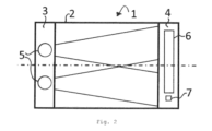
図1から図3に示すように、サンプルの化学組成を分析するためのATR分光計1は、ATR結晶2、少なくとも一つの赤外光源5、赤外光検出器が線状に並べられたラインアレイ6、及び少なくとも一つの単一の赤外光検出器7を含む。図1及び図2は、少なくとも一つの単一の赤外線検出器7及びラインアレイ6が互いに離れて配置され、ラインアレイ6と単一の赤外線検出器7との間に空間が配置されることを示す。複数の単一の赤外光検出器7が設けられる場合、隣接する単一の赤外光検出器7の間にさらなる空間を設けることができる。ATR結晶2は、ATR結晶2の入口端の直近に配置される入射面3を有する。出射面4は、ATR結晶2の出口端の直近に配置され、出口端は入口端の反対側に配置される。少なくとも一つの赤外線光源5は、入射面3に配置される。赤外光検出器のラインアレイ6及び単一の赤外光検出器7は、出射面4に配置される。
As shown in FIGS. 1 to 3, an
サンプルの化学組成を分析するために、サンプルはATR結晶2のすぐ近くに配置され、このため、サンプルがATR結晶2の表面に接触し、入射面3及び出射面4に面していないが、入射面3及び出射面4に平行に配置される(図3参照)。
In order to analyze the chemical composition of the sample, the sample is placed in close proximity to the
少なくとも一つの赤外線光源5は、入射面3を通じてATR結晶2に入り、出射面4を通じてATR結晶2を出て、赤外光検出器に、すなわち全反射及びサンプルとの相互作用下で、ラインアレイ6及び少なくとも一つの単一の赤外線検出器7に導かれる赤外光を発するように構成される。赤外光は、方向転換することなく、すなわち、赤外光が進行方向を変えることなく、出口表面4から赤外光検出器に導かれる。図3は、波長分散素子8が出射面4からラインアレイ6への赤外光の経路に配置され、ラインアレイ6が赤外光のスペクトルを測定するようになっていることを示している。波長分散素子は、例えば、プリズム、格子、及び/又は線形可変フィルタでよい。波長フィルタ9は、出射面4から単一の赤外光検出器7までの赤外光の経路に配置される。複数の単一赤外光検出器7が設けられる場合、それぞれの波長フィルタ9がそれぞれの単一の赤外光検出器7に設けられる。波長フィルタ9のそれぞれは、異なる波長依存透過性を有する。
At least one infrared
赤外光検出器は、それぞれの赤外光検出器に当たる赤外光の量を示す電気信号を出力するように構成される。電気信号は、例えば、電流又は電圧でよい。電気信号は、通常、それぞれの赤外光検出器に当たる光の量が増えると高くなる。少なくとも一つの赤外線検出器が、信号修正用に選択された赤外線検出器として選択される。ATR分光計1は、選択された赤外線検出器の電気信号を使用して、他の全ての赤外線検出器の電気信号を修正するように構成されている。
The infrared photodetectors are configured to output electrical signals indicative of the amount of infrared light striking each infrared photodetector. The electrical signal may be, for example, current or voltage. The electrical signal is typically higher as the amount of light impinging on each infrared photodetector increases. At least one infrared detector is selected as the selected infrared detector for signal modification.
図1は、ATR分光計1の第1の実施形態を示す。第1の実施形態では、ラインアレイ6の全体を照明し、単一の赤外光検出器7の全体を照明するために十分に大きい指向角を有する唯一の赤外線光源5が設けられる。図2は、ATR分光計1の第2の実施形態を示す。第2の実施形態では、二つの赤外線光源5が設けられ、各赤外光検出器は二つの赤外線光源5の少なくとも一つによって照射される。一つだけの選択された赤外線検出器が提供される場合、この選択された赤外線検出器は、両方の赤外線光源5によって照射される場所に配置される。
FIG. 1 shows a first embodiment of an
図4及び図5は、選択した赤外線光検出器の電気信号を使用して、他の全ての赤外線光検出器の電気信号を修正する方法を示す。図4は修正前のATRスペクトル10を示し、図5は修正後のATRスペクトル11を示す。修正前のATRスペクトル10を決定するために、全ての電気信号の逆数が使用され、図4の場合、周波数vに対してプロットされる。図4及び図5は、ラインアレイ6によって測定可能なスペクトルの波長範囲12も示す。
4 and 5 illustrate how the electrical signal of a selected infrared photodetector is used to modify the electrical signals of all other infrared photodetectors. FIG. 4 shows the
ATR分光計1は、選択された複数の赤外線検出器の電気信号を使用して波長依存関数16を生成し、波長依存関数16を使用して他の全ての赤外線検出器の電気信号を修正するように構成される。
The
少なくとも一つの選択された赤外線検出器は、ラインアレイ6の赤外線検出器の一つである。図4及び図5の場合、二つの選択された赤外線検出器がラインアレイ6から選択される。選択された赤外線検出器の少なくとも一つは、一つの単一の赤外線検出器7である。図4及び図5の場合、単一の赤外線検出器の一つだけが、選択された赤外線検出器の一つである。その結果、図4及び図5によれば、ATR分光計1は、三つの選択された赤外線検出器を備える。一つの選択された赤外光検出器、つまり単一の赤外光検出器7に対応する波長フィルタ9は、バンドパスフィルタであり、ラインアレイ6で測定できるスペクトル外の波長領域に透過性を有する(図4及び図5参照)。
At least one selected infrared detector is one of the infrared detectors of
選択された赤外光検出器は、それらの対応する検出可能な波長範囲が、サンプルが実質的に吸収を有さない波長領域にあるように選択される。ATR分光計1は三つの選択された赤外光検出器を有するため、ATR分光計1は実質的に吸収がないATRスペクトルの三つの異なる波長領域を測定するように構成されている。図4及び図5から分かるように、第1の波長領域13はラインアレイ6の二つの選択された赤外線検出器の一つに対応し、第2の波長領域14はラインアレイ6の二つの選択された赤外線検出器の他の一つに対応し、第3の波長領域15は単一の赤外光検出器7に対応する。
Selected infrared photodetectors are selected such that their corresponding detectable wavelength ranges are in wavelength regions where the sample has substantially no absorption. Since the
波長領域を選択するために、FTIR分光計を使用して、サンプル又はサンプルに類似する参照サンプルの吸光度スペクトルを測定することが考えられる。実質的に吸収がない波長領域は、吸光度スペクトルから決定できる。 To select the wavelength region, an FTIR spectrometer may be used to measure the absorbance spectrum of the sample or a reference sample similar to the sample. A wavelength region with substantially no absorption can be determined from the absorbance spectrum.
ATR分光計1は、選択された赤外光検出器によって出力される信号値の逆数に波長依存関数16を適合させるように構成される。図3による波長依存関数16は、y(v)=a+b×exp(c×v)という形式を有し、a、b、及びcは波長依存関数16のパラメータである。波長依存関数16の三つの点は、三つの選択された赤外線検出器によって決定されるため、関数yは明確に決定される。しかし、波長依存関数16の他の形態も考えられる。波長依存関数16が導出された後、波長依存関数が図4のATRスペクトル10から減じられる。減算の結果、図5のATRスペクトル11が得られる。このようにして、少なくとも一つの赤外光源5のスペクトルドリフトを補償でき、同時に散乱の寄与をATRスペクトル10から除去できる。
サンプルの化学組成は、修正後のスペクトル11の少なくとも一部へのランベルト・ベールの法則の適用によって、及び/又は修正後のスペクトル11への計量化学法の適用によって分析できる。
The chemical composition of the sample can be analyzed by applying the Beer-Lambert law to at least a portion of the corrected
1 ATR分光計
2 ATR結晶
3 入射面
4 出射面
5 赤外線光源
6 ラインアレイ
7 単一赤外線検出器
8 波長分散素子
9 波長フィルタ
10 修正前のATRスペクトル
11 修正後のATRスペクトル
12 ラインアレイの波長範囲
13 第1の波長領域
14 第2の波長領域
15 第3の波長領域
16 波長依存関数
1
Claims (15)
前記ATR分光計(1)は、
ATR結晶(2)の入口端の直近に配置される入射面(3)と、前記入口端の反対側に配置され、ATR結晶(2)の出口端の直近に配置される出射面(4)とを有するATR結晶(2)と、
前記入射面(3)に配置される少なくとも一つの赤外線光源(5)と、
前記出射面(4)に配置される赤外線検出器のラインアレイ(6)と、
前記出射面(4)に配置され、前記ラインアレイ(6)から分離した少なくとも一つの追加の赤外線検出器(7)とを備え、
前記少なくとも一つの赤外線光源(5)は、前記入射面(3)を通じて前記ATR結晶(2)に入射し、前記ATR結晶(2)の表面に接触して配置される前記サンプルとの相互作用及び内部全反射の下で前記ラインアレイ(6)の前記赤外線検出器及び前記少なくとも一つの追加の赤外線検出器(7)に導かれる赤外線を放射するように構成され、
前記ATR分光計(1)は、前記ラインアレイ(6)が前記赤外線のスペクトルを測定するために適合するように、前記出射面(4)から前記ラインアレイ(6)への前記赤外線の経路に配置された波長分散素子(8)と、
前記出射面(4)から前記少なくとも一つの追加の赤外線検出器(7)への前記赤外線の経路に配置された波長フィルタ(9)とを更に含み、
前記ラインアレイ(6)の前記赤外線検出器及び前記少なくとも一つの追加の赤外線検出器(7)はそれぞれ、それぞれの前記赤外線検出器に入射する前記赤外線の量を示す電気信号を出力するように構成され、
前記ラインアレイ(6)の前記赤外線検出器及び前記少なくとも一つの追加の赤外線検出器(7)からなる赤外線検出器のグループにおける少なくとも一つの赤外線検出器は、信号の修正用に選択された赤外線検出器であるように選択され、前記ATR分光計(1)は、少なくとも一つの選択された赤外線検出器の前記電気信号を使用して、前記赤外線検出器のグループにおける他の全ての前記赤外線検出器の前記電気信号を修正するように構成される、ATR分光計。 An ATR spectrometer for analyzing the chemical composition of a sample, comprising:
The ATR spectrometer (1) comprises
an entrance face (3) located immediately adjacent to the entrance end of the ATR crystal (2) and an exit surface (4) located opposite said entrance end and located immediately adjacent the exit end of the ATR crystal (2). an ATR crystal (2) having
at least one infrared light source (5) positioned on the entrance surface (3);
a line array (6) of infrared detectors arranged on the exit surface (4);
at least one additional infrared detector (7) located on said exit face (4) and separate from said line array (6) ;
The at least one infrared light source (5) enters the ATR crystal (2) through the entrance surface (3) and interacts with the sample placed in contact with the surface of the ATR crystal (2) and configured to emit infrared radiation which is directed to the infrared detectors of the line array (6) and the at least one additional infrared detector (7) under total internal reflection;
The ATR spectrometer (1) directs the infrared radiation from the exit surface (4) to the line array (6) such that the line array (6) is adapted to measure the spectrum of the infrared radiation . a wavelength dispersive element (8) arranged in the path ;
a wavelength filter (9) positioned in the path of the infrared radiation from the exit surface (4) to the at least one additional infrared detector (7);
The infrared detectors of the line array (6) and the at least one additional infrared detector (7) each have electrical signals indicative of the amount of the infrared radiation incident on the respective infrared detector. is configured to output
At least one infrared detector in a group of infrared detectors consisting of said infrared detectors of said line array (6) and said at least one additional infrared detector (7) is selected for signal modification. and said ATR spectrometer (1) uses said electrical signal of at least one selected infrared detector to detect all others in said group of said infrared detectors. ATR spectrometer configured to modify the electrical signal of the infrared detector of the ATR spectrometer.
前記サンプルは前記ATR結晶の表面に接触して配置され、
選択された赤外線検出器のそれぞれは、前記サンプルが吸収を有さない波長領域になるように、その対応する検出可能な波長範囲が選択される、ATR分光計。 The ATR spectrometer of claim 1, comprising
the sample is placed in contact with the surface of the ATR crystal;
An ATR spectrometer, wherein each of the selected infrared detectors has its corresponding detectable wavelength range selected to be a wavelength region in which said sample has no absorption .
前記追加の赤外線検出器(7)のそれぞれが、前記ラインアレイ(6)の赤外線検出器のそれぞれより大きな光活性表面を有する、ATR分光計。 An ATR spectrometer according to claim 1 or 2,
An ATR spectrometer , wherein each of said additional infrared detectors (7) has a larger photoactive surface than each of said infrared detectors of said line array (6).
前記波長フィルタ(9)は帯域通過フィルタである、ATR分光計。 An ATR spectrometer according to any one of claims 1 to 3,
An ATR spectrometer , wherein said wavelength filter (9) is a bandpass filter.
前記少なくとも一つの追加の赤外線検出器(7)の少なくとも一つに関するスペクトル分解能は、前記ラインアレイ(6)の全ての赤外線検出器のスペクトル分解能より高い、ATR分光計。 An ATR spectrometer according to claim 4, wherein
An ATR spectrometer, wherein the spectral resolution for at least one of said at least one additional infrared detector (7) is higher than the spectral resolution of all infrared detectors of said line array (6).
選択された赤外光検出器のそれぞれは、前記ATR分光計(1)の動作中に、前記赤外線検出器のグループにおける他の全ての前記赤外線検出器によって出力される前記電気信号から選択された赤外線検出器のそれぞれによって出力される前記電気信号が減算されるように、前記赤外線検出器のグループの他の全ての前記赤外線検出器と接続される、ATR分光計。 An ATR spectrometer according to any one of claims 1 to 5,
Each selected infrared photodetector selects from said electrical signals output by all other said infrared detectors in said group of infrared detectors during operation of said ATR spectrometer (1). an ATR spectrometer connected with all other infrared detectors of the group of infrared detectors such that the electrical signal output by each of the selected infrared detectors is subtracted .
前記赤外線検出器のグループにおける複数の赤外線検出器が、信号の修正用に選択された赤外線検出器であるように選択され、
前記ATR分光計(1)は、
前記複数の選択された赤外線検出器の前記電気信号を使用して波長依存関数(16)を生成し、前記波長依存関数(16)を使用して、前記赤外線検出器のグループの他の全ての前記赤外線検出器の前記電気信号を修正するように構成される、ATR分光計。 An ATR spectrometer according to any one of claims 1 to 6,
wherein a plurality of infrared detectors in the group of infrared detectors are selected to be infrared detectors selected for signal modification;
The ATR spectrometer (1) comprises
generating a wavelength dependent function (16) using said electrical signals of said plurality of selected infrared detectors, and using said wavelength dependent function (16) for all other groups of said infrared detectors; An ATR spectrometer configured to modify the electrical signal of the infrared detector.
前記選択された赤外線検出器の少なくとも一つは、前記ラインアレイ(6)の前記赤外線検出器の一つであり、且つ
前記選択された赤外線検出器の少なくとも一つは、前記少なくとも一つの追加の赤外線検出器(7)の一つであり、
前記少なくとも一つの追加の赤外線検出器(7)における前記選択された赤外線検出器に対応する前記波長フィルタ(9)は、前記ラインアレイ(6)で測定できるスペクトル外の波長領域の透過性を有する、ATR分光計。 An ATR spectrometer according to claim 7, comprising
at least one of the selected infrared detectors is one of the infrared detectors of the line array (6); and
at least one of said selected infrared detectors is one of said at least one additional infrared detector (7);
The wavelength filter (9) corresponding to the selected infrared detector in the at least one additional infrared detector (7) has transparency for wavelength regions outside the spectrum measurable by the line array (6). , ATR spectrometer.
a)請求項1から7のいずれか一つに記載のATR分光計(1)を準備するステップと、
b)前記ラインアレイ(6)の前記赤外線検出器及び前記少なくとも一つの追加の赤外線検出器(7)からなる赤外線検出器のグループにおける少なくとも一つの赤外光検出器を選択された赤外光検出器として選択するステップであって、選択された赤外線検出器のそれぞれの対応する検出可能な波長範囲は、前記サンプルが吸収がない波長領域になるようにする、ステップと、
c)前記ATR結晶(2)の表面に接触して前記サンプルを配置するステップと、
d)前記少なくとも一つの赤外線光源(5)によって前記赤外線を放射するステップと、
e)前記赤外線検出器のグループにおける前記赤外線検出器のそれぞれによって、電気信号を出力するステップであって、電気信号のそれぞれは、前記赤外線検出器のそれぞれに入射する前記赤外線の量を示す、ステップと、
f)選択された赤外線検出器のそれぞれの前記電気信号で、前記赤外線検出器のグループの他の全ての前記赤外線検出器の前記電気信号を修正するステップとを含む、方法。 A method of analyzing the chemical composition of a sample , comprising:
a) providing an ATR spectrometer (1) according to any one of claims 1 to 7 ;
b) infrared light selected at least one infrared photodetector in a group of infrared detectors consisting of said infrared detectors of said line array (6) and said at least one additional infrared detector (7); selecting as detectors, each corresponding detectable wavelength range of the infrared detector selected is such that the sample is in the absorption -free wavelength range;
c) placing the sample in contact with the surface of the ATR crystal (2);
d) emitting said infrared radiation by said at least one infrared light source (5);
e) outputting an electrical signal by each of said infrared detectors in said group of infrared detectors , each electrical signal corresponding to the intensity of said infrared radiation incident on each of said infrared detectors ; indicating a step ;
f ) modifying, with the electrical signal of each of the selected infrared detectors, the electrical signals of all other infrared detectors of the group of infrared detectors .
ステップb)において、一つの赤外線検出器のみが選択される、方法。 10. The method of claim 9, wherein
The method, wherein in step b) only one infrared detector is selected .
複数の前記赤外線光源(5)が設けられ、前記選択された赤外光検出器には、全ての前記赤外線光源(5)の前記赤外線が入射する、方法。 11. The method of claim 10, wherein
A method according to claim 1, wherein a plurality of said infrared light sources (5) are provided and said infrared light of all said infrared light sources (5) is incident on said selected infrared photodetector.
ステップb)において、二つ以上の赤外線検出器が選択され、
el)二つ以上の選択された複数の赤外線検出器の前記電気信号を使用して波長依存関数(16)を生成するステップを更に含み、
ステップf)において、前記波長依存関数(16)を使用して、前記赤外線検出器のグループの他の全ての前記赤外線検出器の前記電気信号を修正する、方法。 10. The method of claim 9, wherein
In step b) two or more infrared detectors are selected,
el) using said electrical signals of two or more selected infrared detectors to generate a wavelength dependent function (16);
The method in step f) using the wavelength dependent function (16) to modify the electrical signals of all other infrared detectors of the group of infrared detectors .
前記選択された赤外光検出器の少なくとも一つは、前記ラインアレイ(6)の前記赤外線検出器の一つであり、且つ前記選択された赤外光検出器の少なくとも一つは、前記少なくとも一つの追加の赤外線検出器(7)の一つであり、
前記選択された赤外光検出器に対応する前記波長フィルタ(9)は、前記ラインアレイ(6)で測定できるスペクトル外の波長領域で透過性を有する、方法。 13. The method of claim 12, wherein
at least one of said selected infrared photodetectors is one of said infrared detectors of said line array (6), and at least one of said selected infrared photodetectors is one of said at least one additional infrared detector (7);
A method according to claim 1 , wherein said wavelength filter (9) corresponding to said selected infrared photodetector is transparent in wavelength regions outside the spectrum measurable by said line array (6).
ステップb)において、FTIR分光計を使用して、異なる濃度の前記サンプル又は前記サンプルに類似する参照サンプルの吸光度スペクトルを測定し、
前記サンプルが吸収を有さない前記波長領域は、隣接する部分より濃度依存性が小さい前記吸光度スペクトルの一部として識別される、方法。 14. A method according to any one of claims 9 to 13,
In step b) measuring absorbance spectra of said samples at different concentrations or reference samples similar to said samples using an FTIR spectrometer;
A method , wherein the wavelength regions in which the sample has no absorption are identified as those portions of the absorbance spectrum that are less concentration dependent than adjacent portions.
前記少なくとも一つの追加の赤外線検出器(7)のそれぞれが、前記ラインアレイ(6)の赤外線検出器のそれぞれより大きな光活性表面を有する、方法。 15. A method according to any one of claims 9 to 14,
A method according to claim 1, wherein each of said at least one additional infrared detector (7) has a larger photoactive surface than each of said infrared detectors of said line array (6).
Applications Claiming Priority (3)
| Application Number | Priority Date | Filing Date | Title |
|---|---|---|---|
| DE102017104872.3 | 2017-03-08 | ||
| DE102017104872.3A DE102017104872A1 (en) | 2017-03-08 | 2017-03-08 | ATR spectrometer and method for analyzing the chemical composition of a sample |
| PCT/EP2018/055319 WO2018162398A1 (en) | 2017-03-08 | 2018-03-05 | Atr spectrometer and method for analysing the chemical composition of a sample |
Publications (3)
| Publication Number | Publication Date |
|---|---|
| JP2020513216A JP2020513216A (en) | 2020-05-07 |
| JPWO2018162398A5 JPWO2018162398A5 (en) | 2022-05-27 |
| JP7241021B2 true JP7241021B2 (en) | 2023-03-16 |
Family
ID=61691925
Family Applications (1)
| Application Number | Title | Priority Date | Filing Date |
|---|---|---|---|
| JP2019548903A Active JP7241021B2 (en) | 2017-03-08 | 2018-03-05 | ATR spectrometer and method for analyzing the chemical composition of a sample |
Country Status (5)
| Country | Link |
|---|---|
| US (1) | US11248958B2 (en) |
| EP (1) | EP3593118A1 (en) |
| JP (1) | JP7241021B2 (en) |
| DE (1) | DE102017104872A1 (en) |
| WO (1) | WO2018162398A1 (en) |
Families Citing this family (2)
| Publication number | Priority date | Publication date | Assignee | Title |
|---|---|---|---|---|
| TWI809530B (en) * | 2021-10-15 | 2023-07-21 | 譜鉅科技股份有限公司 | Drug scanning and identification system and using method thereof |
| CN115993342A (en) | 2021-10-15 | 2023-04-21 | 谱钜科技股份有限公司 | Drug scanning and identifying system and using method thereof |
Citations (5)
| Publication number | Priority date | Publication date | Assignee | Title |
|---|---|---|---|---|
| US5460973A (en) | 1994-12-20 | 1995-10-24 | Ceramoptec Industries Inc. | Method for continuous determination of volatile impurities in contaminated medium |
| JP2005156243A (en) | 2003-11-21 | 2005-06-16 | Konica Minolta Sensing Inc | Spectral intensity measuring device, calibration method therefor, spectral reflection characteristic measuring device, and calibration method therefor |
| JP2008197043A (en) | 2007-02-15 | 2008-08-28 | Yokogawa Electric Corp | Optical signal measuring device |
| JP2011513725A (en) | 2008-02-27 | 2011-04-28 | ゼーエスエムヘルスケア株式会社 | Urinal component analyzer for toilet and real-time urine component analysis method using the same |
| JP2012507017A (en) | 2008-10-31 | 2012-03-22 | カール ツァイス マイクロイメージング ゲーエムベーハー | Spectroscopic structure and method for determining temperature values for a detector of a spectrometer |
Family Cites Families (12)
| Publication number | Priority date | Publication date | Assignee | Title |
|---|---|---|---|---|
| JPS59171837A (en) * | 1983-03-19 | 1984-09-28 | Japan Spectroscopic Co | Data correction for transmissivity measurement with infrared spectroscope |
| US5731581A (en) | 1995-03-13 | 1998-03-24 | Ohmeda Inc. | Apparatus for automatic identification of gas samples |
| US20030176775A1 (en) | 1998-10-13 | 2003-09-18 | Medoptix, Inc. | Cleaning kit for an infrared glucose measurement system |
| DE102009027134A1 (en) * | 2009-06-24 | 2010-12-30 | Robert Bosch Gmbh | Spectroscopic gas sensor for detecting concentration of e.g. ethanol in liquid mixtures, has infrared radiation source for discharging infrared radiation, and evaluating device receiving measurement signal to correct another signal |
| AT512291B1 (en) | 2012-02-20 | 2013-07-15 | Anton Paar Gmbh | METHOD AND DEVICE FOR DETERMINING THE CO2 LEVEL IN A LIQUID |
| DE102013005372B4 (en) | 2013-03-28 | 2015-03-12 | Spectrolytic GmbH | Device for spectroscopic measured value acquisition of physical and / or chemical parameters of a measurement object |
| WO2015050791A1 (en) | 2013-10-04 | 2015-04-09 | The Research Foundation For The State University Of New York | Spectroscopy for gunshot residue analysis |
| DE102013114244B3 (en) | 2013-12-17 | 2015-01-22 | Pyreos Ltd. | ATR infrared spectrometer |
| US9182280B1 (en) | 2014-08-08 | 2015-11-10 | Thermo Scientific Portable Analytical Instruments Inc. | Method for reducing frequency of taking background/reference spectra in FTIR or FTIR-ATR spectroscopy and handheld measurement device embodying same |
| GB2530098B (en) * | 2014-09-15 | 2017-02-22 | Schlumberger Holdings | Mid-infrared acid sensor |
| DE102014115502A1 (en) * | 2014-10-24 | 2016-04-28 | Pyreos Ltd. | Skin gauge and wristwatch |
| US10066990B2 (en) * | 2015-07-09 | 2018-09-04 | Verifood, Ltd. | Spatially variable filter systems and methods |
-
2017
- 2017-03-08 DE DE102017104872.3A patent/DE102017104872A1/en not_active Withdrawn
-
2018
- 2018-03-05 WO PCT/EP2018/055319 patent/WO2018162398A1/en unknown
- 2018-03-05 US US16/491,068 patent/US11248958B2/en active Active
- 2018-03-05 EP EP18712092.8A patent/EP3593118A1/en active Pending
- 2018-03-05 JP JP2019548903A patent/JP7241021B2/en active Active
Patent Citations (5)
| Publication number | Priority date | Publication date | Assignee | Title |
|---|---|---|---|---|
| US5460973A (en) | 1994-12-20 | 1995-10-24 | Ceramoptec Industries Inc. | Method for continuous determination of volatile impurities in contaminated medium |
| JP2005156243A (en) | 2003-11-21 | 2005-06-16 | Konica Minolta Sensing Inc | Spectral intensity measuring device, calibration method therefor, spectral reflection characteristic measuring device, and calibration method therefor |
| JP2008197043A (en) | 2007-02-15 | 2008-08-28 | Yokogawa Electric Corp | Optical signal measuring device |
| JP2011513725A (en) | 2008-02-27 | 2011-04-28 | ゼーエスエムヘルスケア株式会社 | Urinal component analyzer for toilet and real-time urine component analysis method using the same |
| JP2012507017A (en) | 2008-10-31 | 2012-03-22 | カール ツァイス マイクロイメージング ゲーエムベーハー | Spectroscopic structure and method for determining temperature values for a detector of a spectrometer |
Also Published As
| Publication number | Publication date |
|---|---|
| DE102017104872A1 (en) | 2018-09-13 |
| US20200011735A1 (en) | 2020-01-09 |
| EP3593118A1 (en) | 2020-01-15 |
| JP2020513216A (en) | 2020-05-07 |
| WO2018162398A1 (en) | 2018-09-13 |
| US11248958B2 (en) | 2022-02-15 |
Similar Documents
| Publication | Publication Date | Title |
|---|---|---|
| EP3344971B1 (en) | Reference switch architectures for noncontact sensing of substances | |
| JP6490700B2 (en) | Optical filter and spectrometer | |
| US7903252B2 (en) | Noise cancellation in fourier transform spectrophotometry | |
| US10151633B2 (en) | High accuracy absorbance spectrophotometers | |
| US20100128256A1 (en) | Optical cell | |
| US20130222789A1 (en) | Spectrophotometer | |
| WO2005074525A2 (en) | Entangled-photon fourier transform spectroscopy | |
| CN104655279A (en) | Optical absorption spectrometry system including dichroic beam combiner and splitter | |
| US7796261B2 (en) | Spectrophotometer | |
| US20180238735A1 (en) | Spatially variable light source and spatially variable detector systems and methods | |
| US10036702B2 (en) | Method, device and sensor for determining an absorption behavior of a medium | |
| JP7241021B2 (en) | ATR spectrometer and method for analyzing the chemical composition of a sample | |
| WO2016129033A1 (en) | Multi-channel spectrophotometer and data processing method for multi-channel spectrophotometer | |
| KR20160099620A (en) | ATR infrared spectrometer | |
| US20100253942A1 (en) | Method and device for characterizing silicon layer on translucent substrate | |
| KR101381618B1 (en) | Multi-gas analysis device using non dispersion ultraviolet absorption spectrophotometer | |
| US10690591B2 (en) | Measurement time distribution in referencing schemes | |
| US20120307240A1 (en) | Spectrophotometer and method for determining performance thereof | |
| WO2022059379A1 (en) | Spectrometry method, spectrometry device, product inspection method, product inspection device, and product selection device | |
| US8873040B2 (en) | Raman apparatus and method for real time calibration thereof | |
| JPWO2018162398A5 (en) | ||
| US9030666B2 (en) | Non-dispersive gas analyzer | |
| WO2018003045A1 (en) | Beam splitter with aperture function, and detector provided with said beam splitter | |
| JPH10115583A (en) | Spectrochemical analyzer | |
| KR102556283B1 (en) | Ndir . |
Legal Events
| Date | Code | Title | Description |
|---|---|---|---|
| A621 | Written request for application examination |
Free format text: JAPANESE INTERMEDIATE CODE: A621 Effective date: 20210224 |
|
| A977 | Report on retrieval |
Free format text: JAPANESE INTERMEDIATE CODE: A971007 Effective date: 20211130 |
|
| A131 | Notification of reasons for refusal |
Free format text: JAPANESE INTERMEDIATE CODE: A131 Effective date: 20211207 |
|
| A601 | Written request for extension of time |
Free format text: JAPANESE INTERMEDIATE CODE: A601 Effective date: 20220304 |
|
| RD03 | Notification of appointment of power of attorney |
Free format text: JAPANESE INTERMEDIATE CODE: A7423 Effective date: 20220426 |
|
| A524 | Written submission of copy of amendment under article 19 pct |
Free format text: JAPANESE INTERMEDIATE CODE: A524 Effective date: 20220428 |
|
| A521 | Request for written amendment filed |
Free format text: JAPANESE INTERMEDIATE CODE: A821 Effective date: 20220426 |
|
| A711 | Notification of change in applicant |
Free format text: JAPANESE INTERMEDIATE CODE: A711 Effective date: 20220524 |
|
| A521 | Request for written amendment filed |
Free format text: JAPANESE INTERMEDIATE CODE: A821 Effective date: 20220524 |
|
| A131 | Notification of reasons for refusal |
Free format text: JAPANESE INTERMEDIATE CODE: A131 Effective date: 20220823 |
|
| TRDD | Decision of grant or rejection written | ||
| A01 | Written decision to grant a patent or to grant a registration (utility model) |
Free format text: JAPANESE INTERMEDIATE CODE: A01 Effective date: 20230207 |
|
| A61 | First payment of annual fees (during grant procedure) |
Free format text: JAPANESE INTERMEDIATE CODE: A61 Effective date: 20230306 |
|
| R150 | Certificate of patent or registration of utility model |
Ref document number: 7241021 Country of ref document: JP Free format text: JAPANESE INTERMEDIATE CODE: R150 |