JP7236272B2 - Steam valve and power generation system - Google Patents
Steam valve and power generation system Download PDFInfo
- Publication number
- JP7236272B2 JP7236272B2 JP2018247066A JP2018247066A JP7236272B2 JP 7236272 B2 JP7236272 B2 JP 7236272B2 JP 2018247066 A JP2018247066 A JP 2018247066A JP 2018247066 A JP2018247066 A JP 2018247066A JP 7236272 B2 JP7236272 B2 JP 7236272B2
- Authority
- JP
- Japan
- Prior art keywords
- valve
- steam
- inclined surface
- parent
- child
- Prior art date
- Legal status (The legal status is an assumption and is not a legal conclusion. Google has not performed a legal analysis and makes no representation as to the accuracy of the status listed.)
- Active
Links
Images


Classifications
-
- F—MECHANICAL ENGINEERING; LIGHTING; HEATING; WEAPONS; BLASTING
- F16—ENGINEERING ELEMENTS AND UNITS; GENERAL MEASURES FOR PRODUCING AND MAINTAINING EFFECTIVE FUNCTIONING OF MACHINES OR INSTALLATIONS; THERMAL INSULATION IN GENERAL
- F16K—VALVES; TAPS; COCKS; ACTUATING-FLOATS; DEVICES FOR VENTING OR AERATING
- F16K39/00—Devices for relieving the pressure on the sealing faces
- F16K39/02—Devices for relieving the pressure on the sealing faces for lift valves
- F16K39/024—Devices for relieving the pressure on the sealing faces for lift valves using an auxiliary valve on the main valve
-
- F—MECHANICAL ENGINEERING; LIGHTING; HEATING; WEAPONS; BLASTING
- F16—ENGINEERING ELEMENTS AND UNITS; GENERAL MEASURES FOR PRODUCING AND MAINTAINING EFFECTIVE FUNCTIONING OF MACHINES OR INSTALLATIONS; THERMAL INSULATION IN GENERAL
- F16K—VALVES; TAPS; COCKS; ACTUATING-FLOATS; DEVICES FOR VENTING OR AERATING
- F16K1/00—Lift valves or globe valves, i.e. cut-off apparatus with closure members having at least a component of their opening and closing motion perpendicular to the closing faces
- F16K1/32—Details
- F16K1/34—Cutting-off parts, e.g. valve members, seats
- F16K1/44—Details of seats or valve members of double-seat valves
-
- F—MECHANICAL ENGINEERING; LIGHTING; HEATING; WEAPONS; BLASTING
- F01—MACHINES OR ENGINES IN GENERAL; ENGINE PLANTS IN GENERAL; STEAM ENGINES
- F01D—NON-POSITIVE DISPLACEMENT MACHINES OR ENGINES, e.g. STEAM TURBINES
- F01D17/00—Regulating or controlling by varying flow
- F01D17/10—Final actuators
- F01D17/12—Final actuators arranged in stator parts
- F01D17/14—Final actuators arranged in stator parts varying effective cross-sectional area of nozzles or guide conduits
- F01D17/141—Final actuators arranged in stator parts varying effective cross-sectional area of nozzles or guide conduits by means of shiftable members or valves obturating part of the flow path
- F01D17/145—Final actuators arranged in stator parts varying effective cross-sectional area of nozzles or guide conduits by means of shiftable members or valves obturating part of the flow path by means of valves, e.g. for steam turbines
-
- F—MECHANICAL ENGINEERING; LIGHTING; HEATING; WEAPONS; BLASTING
- F01—MACHINES OR ENGINES IN GENERAL; ENGINE PLANTS IN GENERAL; STEAM ENGINES
- F01D—NON-POSITIVE DISPLACEMENT MACHINES OR ENGINES, e.g. STEAM TURBINES
- F01D25/00—Component parts, details, or accessories, not provided for in, or of interest apart from, other groups
- F01D25/04—Antivibration arrangements
-
- F—MECHANICAL ENGINEERING; LIGHTING; HEATING; WEAPONS; BLASTING
- F16—ENGINEERING ELEMENTS AND UNITS; GENERAL MEASURES FOR PRODUCING AND MAINTAINING EFFECTIVE FUNCTIONING OF MACHINES OR INSTALLATIONS; THERMAL INSULATION IN GENERAL
- F16K—VALVES; TAPS; COCKS; ACTUATING-FLOATS; DEVICES FOR VENTING OR AERATING
- F16K1/00—Lift valves or globe valves, i.e. cut-off apparatus with closure members having at least a component of their opening and closing motion perpendicular to the closing faces
- F16K1/32—Details
- F16K1/34—Cutting-off parts, e.g. valve members, seats
- F16K1/44—Details of seats or valve members of double-seat valves
- F16K1/443—Details of seats or valve members of double-seat valves the seats being in series
-
- F—MECHANICAL ENGINEERING; LIGHTING; HEATING; WEAPONS; BLASTING
- F16—ENGINEERING ELEMENTS AND UNITS; GENERAL MEASURES FOR PRODUCING AND MAINTAINING EFFECTIVE FUNCTIONING OF MACHINES OR INSTALLATIONS; THERMAL INSULATION IN GENERAL
- F16K—VALVES; TAPS; COCKS; ACTUATING-FLOATS; DEVICES FOR VENTING OR AERATING
- F16K1/00—Lift valves or globe valves, i.e. cut-off apparatus with closure members having at least a component of their opening and closing motion perpendicular to the closing faces
- F16K1/32—Details
- F16K1/52—Means for additional adjustment of the rate of flow
Description
本発明は、蒸気弁、及び発電システムに関する。 The present invention relates to steam valves and power generation systems.
発電システムは、蒸気タービンと、負荷変化に応じて蒸気量を調節したり、異常時に蒸気の供給を遮断したりするための蒸気弁と、を備える。
蒸気弁は、開口部を有する弁座と、弁座の開口部に対向して設けられた弁体を弁座に接離する方向に移動させる弁棒と、弁棒を摺動自在に支持する円筒状の支持部材と、を有する。このような構成とされた蒸気弁では、蒸気による弁体の回転やガタツキ等による摩耗を抑制することが重要となる。
A power generation system includes a steam turbine and steam valves for adjusting the amount of steam according to load changes and for shutting off the supply of steam in the event of an abnormality.
A steam valve slidably supports a valve seat having an opening, a valve stem for moving a valve element facing the opening of the valve seat toward and away from the valve seat, and the valve stem. a cylindrical support member. In the steam valve configured as described above, it is important to suppress wear due to rotation, rattling, and the like of the valve body due to steam.
特許文献1には、弁体と弁棒の嵌合部において、弁体の平面(弁棒の軸線方向に対して平行な面)と弁棒の平面(弁棒の軸線方向に対して平行な面)とが面接触させた蒸気タービン用蒸気弁(主蒸気止め弁)が開示されている。 In Patent Document 1, a plane of the valve disc (a plane parallel to the axial direction of the valve stem) and a plane of the valve stem (parallel to the axial direction of the valve stem) are disclosed in the fitting portion of the valve disc and the valve stem. A steam valve for a steam turbine (main steam stop valve) is disclosed in which the surfaces are in surface contact with each other.
ところで、蒸気弁を構成する止め弁には、弁棒と、弁棒の先端に配置された子弁と、子弁が開いた際に蒸気が流れる貫通孔が形成された親弁(特許文献1に開示された弁体に対応する構成)と、を備えたものがある。
このような蒸気弁では、アクチュエータとともに、親弁よりも先に子弁が開くことで、貫通孔に導かれる蒸気の力を利用して親弁を開く構成とされている。
By the way, the stop valve that constitutes the steam valve includes a valve stem, a child valve arranged at the tip of the valve stem, and a parent valve formed with a through hole through which steam flows when the child valve is opened (Patent Document 1 A configuration corresponding to the valve body disclosed in).
In such a steam valve, the main valve is opened using the power of the steam guided to the through-hole by opening the child valve earlier than the main valve together with the actuator.
上記構成とされた蒸気弁では、止め弁の摩耗を抑制する観点から、子弁及び親弁が開いた状態において、弁棒に対して親弁が回転したり、ガタついたりしないように親弁を支持することが重要となる。 In the steam valve configured as described above, from the viewpoint of suppressing wear of the stop valve, when the child valve and the parent valve are open, the parent valve is designed so that the parent valve does not rotate or rattle with respect to the valve stem. It is important to support
しかしながら、特許文献1に開示された技術では、弁棒と弁体との嵌合部において、互いの平面が接触するように係合させた構成であるため、子弁及び親弁が全開の状態において、弁棒に対して親弁が回転したり、ガタついたりしないように親弁を支持することが困難であった。
つまり、特許文献1に開示された技術では、子弁及び親弁が全開状態において、止め弁の摩耗を抑制することが困難であった。
However, in the technique disclosed in Patent Document 1, the mating portion of the valve stem and the valve body are engaged so that their flat surfaces are in contact with each other. , it was difficult to support the main valve so that the main valve would not rotate or rattle with respect to the valve stem.
In other words, with the technique disclosed in Patent Document 1, it is difficult to suppress the wear of the stop valve when the child valve and the parent valve are fully open.
そこで、本発明は、子弁及び親弁が全開状態において、止め弁の摩耗を抑制することの可能な蒸気弁、及び発電システムを提供することを目的とする。 SUMMARY OF THE INVENTION Accordingly, an object of the present invention is to provide a steam valve and a power generation system capable of suppressing wear of a stop valve when a child valve and a parent valve are fully open.
本発明の一態様に係る蒸気弁は、蒸気が流れる蒸気流路、及び前記蒸気流路の途中に設けられ、開口部を有する弁座を有する弁本体と、 軸線が延びる軸線方向に延び、前記軸線方向に進退可能な弁棒、前記弁棒の先端部のうち、前記弁棒の先端に設けられた子弁、及び前記弁棒の先端部のうち、前記先端よりも前記弁棒の基端側に位置する部分が挿入される貫通部を含み、前記弁座に当接されることで前記蒸気流路を閉じ、前記子弁が開いた際に前記蒸気が流入する貫通孔が形成された親弁を有する止め弁と、 を備え、 前記親弁は、前記子弁の弁座として機能するとともに、前記弁棒に固定されておらず、前記軸線方向に進退可能な構成とされており、 前記弁棒の前記先端部には、前記弁棒の先端側から基端側に向かうにつれて前記弁棒の外径を拡径させる第1の傾斜面が形成されており、 前記親弁のうち、前記弁棒の基端側に位置する部分の内側には、前記第1の傾斜面と同じ傾斜角度で傾斜する第2の傾斜面が形成されており、 前記子弁及び前記親弁が閉じた状態において、前記第1の傾斜面と前記第2の傾斜面とが離れ、 前記子弁及び前記親弁が全開状態のときに、前記第1の傾斜面と前記第2の傾斜面とが当接され、前記第1の傾斜面は、前記軸線を挟んで配置された一対の第1の傾斜平面部を少なくとも1つ有し、 前記第2の傾斜面は、前記子弁及び前記親弁が全開状態のときに、前記一対の第1の傾斜平面部に当接される一対の第2の傾斜平面部を有する。 A steam valve according to an aspect of the present invention includes: a steam flow path through which steam flows; a valve body having a valve seat provided in the middle of the steam flow path and having an opening; A valve stem that can advance and retract in the axial direction, a child valve provided at the tip of the valve stem in the tip of the valve stem, and a proximal end of the valve stem in the tip of the valve stem rather than the tip a through-hole into which the side portion is inserted, which closes the steam flow path by abutting against the valve seat and into which the steam flows when the child valve is opened is formed. a stop valve having a parent valve, wherein the parent valve functions as a valve seat of the child valve, is not fixed to the valve stem, and is configured to advance and retract in the axial direction; The distal end portion of the valve stem is formed with a first inclined surface that increases the outer diameter of the valve stem from the distal end side toward the proximal end side of the valve stem, A second inclined surface inclined at the same inclination angle as the first inclined surface is formed inside the portion located on the proximal side of the valve stem, and the child valve and the parent valve are closed. state, the first inclined surface and the second inclined surface are separated from each other, and the first inclined surface and the second inclined surface contact each other when the child valve and the parent valve are in the fully open state. The first inclined surface has at least one pair of first inclined plane portions arranged across the axis, and the second inclined surface is formed by the child valve and the parent valve It has a pair of second inclined plane portions that abut on the pair of first inclined plane portions in the fully open state.
このように、軸線を挟んで配置された一対の第1の傾斜平面部を少なくとも1つ有するとともに、子弁及び親弁が全開状態のときに、一対の第1の傾斜平面部と第2の傾斜平面部とが当接される構成とすることで、弁棒に対する親弁の軸線方向における摺動が抑制可能になるとともに、弁棒に対して親弁が回転することを抑制可能となる。これにより、止め弁の摩耗をさらに抑制できる。 In this way, at least one pair of first inclined plane portions is arranged with the axis interposed therebetween, and when the child valve and the parent valve are in the fully open state, the pair of first inclined plane portions and the second inclined plane portions are arranged. By adopting a configuration in which the inclined plane portions abut against each other, it is possible to suppress the sliding of the main valve in the axial direction with respect to the valve stem, and it is possible to suppress the rotation of the main valve with respect to the valve stem. Thereby, wear of the stop valve can be further suppressed.
本発明の一態様に係る蒸気弁は、蒸気が流れる蒸気流路、及び前記蒸気流路の途中に設けられ、開口部を有する弁座を有する弁本体と、 軸線が延びる軸線方向に延び、前記軸線方向に進退可能な弁棒、前記弁棒の先端部のうち、前記弁棒の先端に設けられた子弁、及び前記弁棒の先端部のうち、前記先端よりも前記弁棒の基端側に位置する部分が挿入される貫通部を含み、前記弁座に当接されることで前記蒸気流路を閉じ、前記子弁が開いた際に前記蒸気が流入する貫通孔が形成された親弁を有する止め弁と、 を備え、 前記親弁は、前記子弁の弁座として機能するとともに、前記弁棒に固定されておらず、前記軸線方向に進退可能な構成とされており、 前記弁棒の前記先端部には、前記弁棒の先端側から基端側に向かうにつれて前記弁棒の外径を拡径させる第1の傾斜面が形成されており、 前記親弁のうち、前記弁棒の基端側に位置する部分の内側には、前記第1の傾斜面と同じ傾斜角度で傾斜する第2の傾斜面が形成されており、 前記子弁及び前記親弁が閉じた状態において、前記第1の傾斜面と前記第2の傾斜面とが離れ、 前記子弁及び前記親弁が全開状態のときに、前記第1の傾斜面と前記第2の傾斜面とが当接され、前記親弁は、前記弁座に当接される親弁本体と、前記親弁本体の内側に配置された筒状のブッシュと、を有し、 前記第2の傾斜面は、前記ブッシュに形成されている。 A steam valve according to an aspect of the present invention includes: a steam flow path through which steam flows; a valve body having a valve seat provided in the middle of the steam flow path and having an opening; A valve stem that can advance and retract in the axial direction, a child valve provided at the tip of the valve stem in the tip of the valve stem, and a proximal end of the valve stem in the tip of the valve stem rather than the tip a through-hole into which the side portion is inserted, which closes the steam flow path by abutting against the valve seat and into which the steam flows when the child valve is opened is formed. a stop valve having a parent valve, wherein the parent valve functions as a valve seat of the child valve, is not fixed to the valve stem, and is configured to advance and retract in the axial direction; The distal end portion of the valve stem is formed with a first inclined surface that increases the outer diameter of the valve stem from the distal end side toward the proximal end side of the valve stem, A second inclined surface inclined at the same inclination angle as the first inclined surface is formed inside the portion located on the proximal side of the valve stem, and the child valve and the parent valve are closed. state, the first inclined surface and the second inclined surface are separated from each other, and the first inclined surface and the second inclined surface contact each other when the child valve and the parent valve are in the fully open state. the parent valve has a parent valve main body that abuts against the valve seat; and a cylindrical bush that is arranged inside the main valve main body, and the second inclined surface Formed in a bush .
このように、親弁本体の内側に配置された筒状のブッシュに第2の傾斜面を形成してもよい。 In this manner, the second inclined surface may be formed on the cylindrical bushing disposed inside the parent valve body.
本発明の一態様に係る蒸気弁は、蒸気が流れる蒸気流路、及び前記蒸気流路の途中に設けられ、開口部を有する弁座を有する弁本体と、 軸線が延びる軸線方向に延び、前記軸線方向に進退可能な弁棒、前記弁棒の先端部のうち、前記弁棒の先端に設けられた子弁、及び前記弁棒の先端部のうち、前記先端よりも前記弁棒の基端側に位置する部分が挿入される貫通部を含み、前記弁座に当接されることで前記蒸気流路を閉じ、前記子弁が開いた際に前記蒸気が流入する貫通孔が形成された親弁を有する止め弁と、 を備え、 前記親弁は、前記子弁の弁座として機能するとともに、前記弁棒に固定されておらず、前記軸線方向に進退可能な構成とされており、 前記弁棒の前記先端部には、前記弁棒の先端側から基端側に向かうにつれて前記弁棒の外径を拡径させる第1の傾斜面が形成されており、 前記親弁のうち、前記弁棒の基端側に位置する部分の内側には、前記第1の傾斜面と同じ傾斜角度で傾斜する第2の傾斜面が形成されており、 前記子弁及び前記親弁が閉じた状態において、前記第1の傾斜面と前記第2の傾斜面とが離れ、 前記子弁及び前記親弁が全開状態のときに、前記第1の傾斜面と前記第2の傾斜面とが当接され、前記軸線方向において、前記子弁と前記親弁との間に設けられた圧縮コイルばねを備え、 前記圧縮コイルばねは、前記軸線方向一方側の端が前記子弁と接続され、前記軸線方向他方側の端が前記親弁と接続される。また、上記本発明の一態様に係る蒸気弁において、前記軸線方向において、前記子弁と前記親弁との間に設けられた圧縮コイルばねを備え、前記圧縮コイルばねは、前記軸線方向一方側の端が前記子弁と接続され、前記軸線方向他方側の端が前記親弁と接続されていてもよい。
A steam valve according to an aspect of the present invention includes: a steam flow path through which steam flows; a valve body having a valve seat provided in the middle of the steam flow path and having an opening; A valve stem that can advance and retract in the axial direction, a child valve provided at the tip of the valve stem in the tip of the valve stem, and a proximal end of the valve stem in the tip of the valve stem rather than the tip a through-hole into which the side portion is inserted, which closes the steam flow path by abutting against the valve seat and into which the steam flows when the child valve is opened is formed. a stop valve having a parent valve, wherein the parent valve functions as a valve seat of the child valve, is not fixed to the valve stem, and is configured to advance and retract in the axial direction; The distal end portion of the valve stem is formed with a first inclined surface that increases the outer diameter of the valve stem from the distal end side toward the proximal end side of the valve stem, A second inclined surface inclined at the same inclination angle as the first inclined surface is formed inside the portion located on the proximal side of the valve stem, and the child valve and the parent valve are closed. state, the first inclined surface and the second inclined surface are separated from each other, and the first inclined surface and the second inclined surface contact each other when the child valve and the parent valve are in the fully open state. a compression coil spring provided between the child valve and the parent valve in the axial direction, the compression coil spring being connected to the child valve at one end in the axial direction; The other end in the axial direction is connected to the parent valve . Further, in the steam valve according to the aspect of the present invention, a compression coil spring is provided between the child valve and the parent valve in the axial direction, and the compression coil spring is arranged on one side in the axial direction. may be connected to the child valve, and the other end in the axial direction may be connected to the parent valve.
このような構成とされた圧縮コイルばねを有することで、子弁から親弁が離れる方向(子弁から親弁に向かう方向)に力を加え続けることが可能となる。
これにより、子弁及び親弁が全開のときに、弁棒の軸線と開口部の軸線とを一致させた状態で、第1の傾斜面と第2の傾斜面とをしっかりと当接させることが可能となるので、止め弁の摩耗抑制効果を高めることができる。
By having the compression coil spring with such a configuration, it is possible to continuously apply force in the direction in which the parent valve separates from the child valve (the direction from the child valve toward the parent valve).
As a result, when the child valve and the parent valve are fully open, the first inclined surface and the second inclined surface are brought into firm contact with the axis of the valve stem aligned with the axis of the opening. is possible, the effect of suppressing wear of the stop valve can be enhanced.
また、上記本発明の一態様に係る蒸気弁において、前記親弁は、前記弁座に当接される親弁本体と、前記親弁本体の内側に配置された筒状のブッシュと、を有し、前記第2の傾斜面は、前記ブッシュに形成されており、前記圧縮コイルばねの前記軸線方向他方側の端は、前記ブッシュと接続されていてもよい。 Further, in the steam valve according to the aspect of the present invention, the parent valve has a parent valve body that abuts against the valve seat, and a cylindrical bush that is arranged inside the parent valve body. The second inclined surface may be formed on the bush, and the other end of the compression coil spring in the axial direction may be connected to the bush.
このように、子弁とブッシュとの間に、圧縮コイルばねを配置させ、圧縮コイルばねの軸線方向他方側の端をブッシュと接続させてもよい。 In this manner, a compression coil spring may be arranged between the child valve and the bush, and the other end of the compression coil spring in the axial direction may be connected to the bush.
また、上記本発明の一態様に係る蒸気弁において、前記子弁は、前記弁棒の前記第1の部分に固定されていてもよい。 Moreover, in the steam valve according to the aspect of the present invention, the child valve may be fixed to the first portion of the valve stem.
このように、弁棒の第1の部分に子弁を固定することで、弁棒に対して子弁がガタついたり、回転したりすることを抑制可能となる。これにより、子弁と弁棒との間における摩耗(止め弁の摩耗)を抑制することができる。 By fixing the child valve to the first portion of the valve stem in this way, it is possible to suppress rattling and rotation of the child valve with respect to the valve stem. As a result, wear (wear of the stop valve) between the child valve and the valve stem can be suppressed.
また、上記本発明の一態様に係る蒸気弁において、前記軸線方向において、前記止め弁と対向配置され、前記親弁が当接される前記弁座の位置よりも外側の位置で前記弁座に当接可能な加減弁を有してもよい。 Further, in the steam valve according to the aspect of the present invention, in the axial direction, the stop valve is arranged opposite to the valve seat at a position outside the position of the valve seat with which the parent valve abuts. It may have an abuttable control valve.
このように、加減弁が止め弁の外側に配置された蒸気弁に、上述した止め弁を適用してもよい。 Thus, the stop valve described above may be applied to a steam valve in which the control valve is arranged outside the stop valve.
上記課題を解決するため、本発明の一態様に係る発電システムは、蒸気弁と、蒸気を生成するボイラと、前記蒸気によって駆動される蒸気タービンと、前記ボイラと前記蒸気タービンとを接続し、前記蒸気タービンに前記蒸気を供給する蒸気供給配管と、を備え、前記蒸気弁は、前記蒸気供給配管に設けられている。 In order to solve the above problems, a power generation system according to an aspect of the present invention connects a steam valve, a boiler that generates steam, a steam turbine driven by the steam, the boiler and the steam turbine, and a steam supply pipe for supplying the steam to the steam turbine, wherein the steam valve is provided in the steam supply pipe.
本発明によれば、発電システムが止め弁の摩耗を抑制可能な蒸気弁を備えることで、蒸気弁のメンテナンス頻度を低減することが可能となるため、発電システムの可動効率を向上させることができる。 According to the present invention, since the power generation system includes a steam valve capable of suppressing wear of the stop valve, it is possible to reduce the maintenance frequency of the steam valve, so that the operating efficiency of the power generation system can be improved. .
本発明によれば、子弁及び親弁が全開時において、止め弁の摩耗を抑制できる。 According to the present invention, wear of the stop valve can be suppressed when the child valve and the parent valve are fully open.
以下、図面を参照して本発明を適用した実施形態について詳細に説明する。 Embodiments to which the present invention is applied will be described in detail below with reference to the drawings.
(第1の実施形態)
図1を参照して、本発明の第1の実施形態に係る蒸気弁14が適用された発電システム1について説明する。
発電システム1は、蒸気タービン10と、ボイラ11と、第1の蒸気供給配管12(蒸気供給配管)と、加減弁43及び止め弁45を含む蒸気弁14と、第2の蒸気供給配管16と、再熱器18と、止め弁21と、加減弁22と、第3の蒸気供給配管25と、発電機26と、を有する。
(First embodiment)
A power generation system 1 to which a
The power generation system 1 includes a
蒸気タービン10は、高圧蒸気タービン31と、中圧蒸気タービン32と、低圧蒸気タービン33と、を有する。中圧蒸気タービン32は、高圧蒸気タービン31と低圧蒸気タービン33との間に配置されている。
The
高圧蒸気タービン31、中圧蒸気タービン32、及び低圧蒸気タービン33は、一方向に延びる回転軸35を有する。回転軸35は、回転軸本体と、複数の動翼(図示せず)と、が形成されている。
高圧蒸気タービン31、中圧蒸気タービン32、及び低圧蒸気タービン33に供給された蒸気により、回転軸35が回転させられることで発電される。
The high-
Steam supplied to the high-
ボイラ11は、第1の蒸気供給配管12の一端と接続されている。ボイラ11は、高圧の蒸気(以下、「高圧蒸気」という)を生成する。ボイラ11で生成された高圧蒸気は、第1の蒸気供給配管12内に供給される。
The
第1の蒸気供給配管12は、他端が高圧蒸気タービン31の入口と接続されている。第1の蒸気供給配管12は、ボイラ11が生成した高圧蒸気を高圧蒸気タービン31に導くための配管である。
The other end of the first
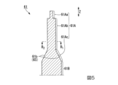
次に、図2~図7を参照して、蒸気弁14について説明する。図2において、Aは領域(以下、「領域A」という)、O1は止め弁45を構成する弁棒61の軸線(以下、「軸線O1」という)、O2は加減弁43を構成する弁棒55の軸線(以下、「軸線O2」という)、Zは軸線O1,O2が延びる方向(以下、「軸線方向Z」という)をそれぞれ示している。
図3において、θ1は軸線O1に対する第1の傾斜面61bの傾斜角度(以下、「傾斜角度θ1」という)、θ2は軸線O1に対する第2の傾斜面76dの傾斜角度(以下、「傾斜角度θ2」という)をそれぞれ示している。
図1~図7において、同一構成部分には、同一符号を付す。
Next, the
3, θ 1 is the inclination angle of the first
In FIGS. 1 to 7, the same components are denoted by the same reference numerals.
蒸気弁14は、第1の蒸気供給配管12に設けられている。蒸気弁14は、弁本体41と、加減弁43と、止め弁45と、アクチュエータ46A,46Bと、を有する。
A
弁本体41は、流路区画部47と、弁座48と、を有する。
流路区画部47は、蒸気流路52を区画するとともに、加減弁43の一部(先端側)、及び止め弁45の一部(先端側)を収容している。
蒸気流路52は、入口52Aと、出口52Bと、を有する。蒸気流路52の入口52Aは、第1の蒸気供給配管12の一方側を介して、ボイラ11と接続されている。蒸気流路52の入口52Aには、ボイラ11で生成された高圧蒸気が導入される。
The
The
蒸気流路52の出口52Bは、第1の蒸気供給配管12の他方側を介して、高圧蒸気タービン31と接続されている。
止め弁45が開いた状態において、高圧蒸気タービン31には、加減弁43により流量が調節された高圧蒸気が供給される。
An
With the
流路区画部47は、第1のガイド部材47Aと、第2のガイド部材47Bと、を含む。
第1のガイド部材47Aは、加減弁43を構成する弁棒55のうち、蒸気流路52に露出されていない部分の外周面を覆うように設けられている。第1のガイド部材47Aは、弁棒55を軸線方向Zに案内するガイドとして機能する。
The flow
47 A of 1st guide members are provided so that the outer peripheral surface of the part which is not exposed to the
第2のガイド部材47Bは、止め弁45を構成する棒状部61Bの外周面を覆うように設けられている。第2のガイド部材47Bは、弁棒61を軸線方向Zに案内するガイドとして機能する。
The
弁座48は、蒸気流路52の途中に位置する流路区画部47に設けられている。弁座48の形状は、軸線O1を中心とするリング形状とされている。弁座48の軸線は、軸線O1と一致している。
弁座48は、蒸気流路52に露出された弁座面48aを有する。弁座面48aは、湾曲した面である。弁座面48aには、止め弁45を構成する親弁64、及び加減弁43を構成する加減弁本体56の先端56Aが当接される。
The
The
加減弁43は、蒸気の流れ方向において、止め弁45が配置された位置よりも上流側に配置されている。加減弁43は、弁棒55と、加減弁本体56と、を有する。
弁棒55は、軸線方向Zに延びており、先端側が蒸気流路52に配置されている。弁棒55の軸線O1は、止め弁45の弁棒55の軸線O2と一致している。弁棒55は、軸線方向Zに移動可能な構成とされている。
The
The valve stem 55 extends in the axial direction Z, and the tip side thereof is arranged in the
加減弁本体56は、弁棒55の先端部に設けられている。加減弁本体56のうち、弁座48側に位置する部分は、筒状とされている。加減弁本体56は、弁座48の弁座面48aに当接される先端56Aを有する。
上記構成とされた加減弁43は、蒸気タービン10の負荷に応じて、高圧蒸気タービン31に供給する高圧蒸気の流量を制御する。
The control valve
The
止め弁45は、加減弁43の内側に配置されている。止め弁45は、弁棒61と、子弁62と、親弁64と、を有する。
The
弁棒61は、軸線方向Zに延びており、先端部61Aと、棒状部61Bと、を有する。先端部61A及び棒状部61Bの先端側は、蒸気流路52に配置されている。
先端部61Aは、先端面61aを含む第1の弁棒部61Aaと、第2の弁棒部61Abと、第3の弁棒部61Acと、を有する。
The valve stem 61 extends in the axial direction Z and has a
The
第1の弁棒部61Aaは、円柱形状とされており、第2の部分よりも外径が小さくなるように構成されている。第1の弁棒部61Aaは、軸線方向Zにおいて外径が一定の大きさとされている。 The first valve stem portion 61Aa has a columnar shape and is configured to have an outer diameter smaller than that of the second portion. The first valve rod portion 61Aa has a constant outer diameter in the axial direction Z. As shown in FIG.
第2の弁棒部61Abは、軸線方向Zにおいて第1の弁棒部61Aaと第3の弁棒部61Acとの間に配置されている。第2の弁棒部61Abは、第1及び第3の弁棒部61Aa,61Acと一体に構成されている。
第2の弁棒部61Abの外形は、円柱形状とされている。第2の弁棒部61Abの外径は、軸線方向Zにおいて一定の大きさとされている。
The second valve stem portion 61Ab is arranged in the axial direction Z between the first valve stem portion 61Aa and the third valve stem portion 61Ac. The second valve stem portion 61Ab is configured integrally with the first and third valve stem portions 61Aa and 61Ac.
The outer shape of the second valve rod portion 61Ab is cylindrical. The outer diameter of the second valve rod portion 61Ab is constant in the axial direction Z. As shown in FIG.
第3の弁棒部61Acは、軸線方向Zにおいて第2の弁棒部61Abと棒状部61Bとの間に配置されている。第3の弁棒部61Acは、第2の弁棒部61Ab及び棒状部61Bと一体に構成されている。
The third valve stem portion 61Ac is arranged in the axial direction Z between the second valve stem portion 61Ab and the rod-shaped
第3の弁棒部61Acの外形は、円錐台形状とされている。第3の弁棒部61Acは、弁棒61の先端側から基端側に向かうにつれて、第3の弁棒部61Acの外径を拡径させる第1の傾斜面61bを有する。
第1の傾斜面61bは、弁棒61の周方向に対して連続して形成された1つのテーパ面65である。第1の傾斜面61bは、軸線O1に対する角度が傾斜角度θ1となるように傾斜している。
The external shape of the third valve stem portion 61Ac is a truncated cone. The third valve stem portion 61Ac has a first
The first
棒状部61Bは、軸線方向Zに延びており、基端部を含む。棒状部61Bの基端側は、アクチュエータ46Bと接続されている。
上記構成とされた弁棒61は、軸線方向Zに進退可能な構成とされている。
The bar-shaped
The valve stem 61 configured as described above is configured to be able to advance and retract in the axial direction Z. As shown in FIG.
子弁62は、凹部62Aと、当接部62Bと、を有する。
凹部62Aは、第1の弁棒部61Aaを嵌合可能な形状とされている。子弁62は、凹部62Aと第1の弁棒部61Aaとを嵌合させることで、弁棒61の第1の弁棒部61Aa(弁棒61の先端)に固定されている。
The
The
このように、弁棒61の第1の弁棒部61Aaを子弁62に形成された凹部62Aに嵌合させることで、弁棒61に子弁62が固定されるため、弁棒61に対して子弁62がガタついたり、回転したりすることを抑制可能となる。これにより、子弁62と弁棒61との間における摩耗(止め弁45の摩耗)を抑制することができる。
Since the
当接部62Bは、子弁62の外周部を構成している。当接部62Bは、斜め下方に延びている。当接部62Bは、リング状とされている。
子弁62が閉じた状態(図2及び図3に示す状態)において、当接部62Bは、親弁64を構成する親弁本体71の弁座面71aのうち、貫通孔71Bの外側に位置する面に当接される。
この状態では、高圧蒸気が流れる蒸気流路52から貫通孔71Bの入口71Baが隔離された状態となるため、貫通孔71Bには、高圧蒸気が流れない。
The
When the
In this state, the inlet 71Ba of the through-
一方、図4に示すように、子弁62が開いた状態(子弁62の当接部62Bが弁座面71aから離れた状態)では、子弁62と親弁64との間に隙間が形成されるため、貫通孔71Bの入口71Baに高圧蒸気が流入する。貫通孔71Bの入口71Baに流入した高圧蒸気は、貫通孔71Bの出口71Bbから蒸気流路52に導出される。
On the other hand, as shown in FIG. 4, when the
親弁64は、弁棒61に挿入された状態で、子弁62と棒状部61Bとの間に配置されている。親弁64は、親弁本体71と、ブッシュ72と、を有する。
親弁本体71は、縦断面視した状態においてV字形状とされている。親弁本体71は、貫通部71Aと、弁座面71aと、当接面71bと、内周面71cと、複数の貫通孔71Bと、を有する。
The
The parent valve
貫通部71Aは、親弁本体71の中央部を軸線方向Zに貫通するように形成されている。貫通部71Aは、円柱状の穴であり、内周面71cにより区画されている。
貫通部71Aには、第2の弁棒部61Ab及びブッシュ72が配置されている。貫通部71Aの内径は、第2の弁棒部61Ab及びブッシュ72が配置可能な大きさとされている。
The through
A second valve stem portion 61Ab and a
弁座面71aは、子弁62側(弁棒61の先端側)に配置された曲面である。弁座面71aのうち、複数の貫通孔71Bの入口71Baよりも外側に位置する面には、子弁62の当接部62Bが当接される。
The
当接面71bは、弁棒61の基端側に配置された曲面である。親弁64が全閉された状態において、当接面71bの外周部は、弁座48の弁座面48aに当接される。この状態では、弁座48の下流側には高圧蒸気が流れない。
親弁64が開状態では、当接面71bと弁座面48aとが離間して、当接面71bと弁座面48aとの間に隙間が形成されるため、弁座48の下流側に高圧蒸気が流れる。
The
When the
複数の貫通孔71Bは、弁座面71aから当接面71bに到達するように、親弁本体71を貫通して形成されている。複数の貫通孔71Bは、親弁本体71の周方向に配置されている。
貫通孔71Bは、入口71Baと、出口71Bbと、を有する。入口71Baは、当接部62Bと弁座面71aとの当接位置よりも内側に位置する弁座面71aに形成されている。子弁62が開いて、子弁62と親弁64との間に隙間が形成されると、入口71Baを介して、貫通孔71Bに高圧蒸気が流入する。
A plurality of through
The through
出口71Bbは、入口71Baの形成位置より軸線O1の径方向外側に位置する当接面71bに形成されている。出口71Bbは、弁座48の下流側に位置する蒸気流路52と連通している。
上記構成とされた貫通孔71Bは、入口71Baから出口71Bbに向かう方向に傾斜している。
The outlet 71Bb is formed on the
The through
ブッシュ72は、第1のブッシュ部75と、第2のブッシュ部76と、を有する。
第1のブッシュ部75は、親弁本体71の内側に配置されている。第1のブッシュ部75は、第2の弁棒部61Abの外周面を囲む筒状とされている。第1のブッシュ部75の内周面75aは、第1のブッシュ部75が軸線方向Zに移動可能な状態で、第2の弁棒部61Abの外周面と接触している。
第1のブッシュ部75は、軸線Oの径方向において、親弁本体71から離れた状態で、親弁本体71と対向している。これにより、第1のブッシュ部75と親弁本体71との間には、リング状の空間78が形成されている。
The
The
The
第2のブッシュ部76は、親弁本体71の内側に配置されている。第2のブッシュ部76は、第1のブッシュ部75よりも第3の弁棒部61Ac側に位置する第2の弁棒部61Abの外周面を囲む筒状とされている。
第2のブッシュ部76は、第1のブッシュ部75の端のうち、第1の傾斜面61b側に位置する端に設けられている。第2のブッシュ部76は、第1のブッシュ部75と一体に構成されている。
The
The
第2のブッシュ部76は、内周面76aと、外周面76bと、端面76c,76eと、第2の傾斜面76dと、を有する。
内周面76aは、第2のブッシュ部76が軸線方向Zに移動可能な状態で、第2の弁棒部61Abの外周面と接触している。
第2のブッシュ部76は、外周面76bと親弁本体71の内周面76aとが接触した状態で、親弁本体71に固定されている。軸線方向Zにおける外周面76bの長さは、内周面76aの長さよりも短い。
The
The inner
The
端面76cは、第3の弁棒部61Ac側に配置されている。端面76cは、軸線方向Zに対して直交する面である。端面76cは、外周面76bと接続されている。
The
第2の傾斜面76dは、内周面76aと端面76cとを接続するように、弁棒61側に配置されている。第2の傾斜面76dは、第1のブッシュ部75から第3の弁棒部61Acに向かうにつれて、第2のブッシュ部76の径方向の厚さが薄くなるように傾斜している。第2の傾斜面76dは、第2のブッシュ部76のうち、弁棒61の基端側に位置する部分の内側に形成されている。
76 d of 2nd inclined surfaces are arrange|positioned at the
第2の傾斜面76dは、親弁64の周方向に対して連続して形成された1つのテーパ面80である。第2の傾斜面76dは、第1の傾斜面61bと同じ方向に傾斜している。
軸線O1に対する第2の傾斜面76dの傾斜角度θ2は、第1の傾斜面61bの傾斜角度θ1と等しくなるように構成されている。
The second
The inclination angle θ 2 of the second
子弁62及び親弁64が閉じた状態において、第2の傾斜面76dは、第1の傾斜面61bから離れた位置にある。一方、子弁62及び親弁64が全開状態のときには、弁棒61が加減弁43側に移動することで、第2の傾斜面76dと第1の傾斜面61bとが当接され、親弁64が第1の傾斜面61bにより支持される。
When the
端面76eは、第1のブッシュ部75側に配置されている。端面76eは、軸線O1に対して直交する面である。端面76eは、外周面76bと接続されている
端面76eは、空間78に露出された面である。端面76eは、軸線方向Zにおいて、空間78を介して子弁62と対向している。
The
第2の蒸気供給配管16は、一端が高圧蒸気タービン31の出口と接続されており、他端が中圧蒸気タービン32の入口と接続されている。第2の蒸気供給配管16には、高圧蒸気タービン31内で使用された蒸気が導出される。
第2の蒸気供給配管16は、高圧蒸気タービン31内で使用された蒸気を中圧蒸気タービン32に供給するための配管である。
The second
The second
再熱器18は、第2の蒸気供給配管16に設けられている。再熱器18は、高圧蒸気タービン31から排出された蒸気を加熱することで、中圧の蒸気(以下、「中圧蒸気」という)を生成する。生成された中圧蒸気は、再熱器18の下流側に供給される。
A
止め弁21は、第2の蒸気供給配管16のうち、再熱器18の下流側に位置する部分に設けられている。止め弁21は、先に説明した止め弁45と同様な機能を有する。
加減弁22は、第2の蒸気供給配管16のうち、止め弁21の下流側に位置する部分に設けられている。加減弁22は、先に説明した加減弁43と同様な機能を有する。
The stop valve 21 is provided in a portion of the second
The
第3の蒸気供給配管25は、一端が中圧蒸気タービン32の出口と接続されており、他端が低圧蒸気タービン33の入口と接続されている。第3の蒸気供給配管25には、中圧蒸気タービン32内で使用されることで低圧とされた蒸気(以下、「低圧蒸気」という)が導出される。
第3の蒸気供給配管25に導出された低圧蒸気は、低圧蒸気タービン33内に供給される。
The third
The low-pressure steam led out to the third
発電機26は、回転軸35の一方の端部と接続されている。発電機26は、回転軸35を介して伝えられる蒸気タービン10の回転駆動力により駆動される。
The
第1の実施形態の蒸気弁14によれば、第2の弁棒部61Abの外周面に形成され、弁棒61の先端側から基端側に向かうにつれて弁棒61の外径を拡径させる第1の傾斜面61bであるテーパ面65と、弁棒61の基端側に位置する親弁64の内側に形成され、第1の傾斜面61bの傾斜角度θ1と同じ大きさとされた傾斜角度θ2で傾斜する第2の傾斜面76dであるテーパ面80と、を有するとともに、子弁62及び親弁64が閉じた状態において、テーパ面65とテーパ面80とが離れ、子弁62及び親弁64が全開状態のときに、テーパ面65とテーパ面80とが当接される構成とすることで、子弁及び親弁が全開のときに、弁棒61の軸線O1と貫通部71Aの軸線とを一致させた状態で、テーパ面65により親弁64を支持することが可能となる。
これにより、弁棒61に対する親弁64の軸線方向Zにおける摺動を抑制することが可能となるので、止め弁45の摩耗を抑制することができる。
According to the
As a result, it is possible to suppress the sliding of the
また、第1の実施形態の発電システム1によれば、止め弁45の摩耗を抑制可能な蒸気弁14を備えることで、蒸気弁14のメンテナンス頻度を低減することが可能となるため、発電システム1の可動効率を向上させることができる。
Further, according to the power generation system 1 of the first embodiment, by including the
(第2の実施形態)
図8~図11を参照して、本発明の第2の実施形態に係る蒸気弁85について説明する。
図10において、X方向はZ方向に対して直交するとともに、2つの第1の傾斜平面部93が配置される方向を示しており、Y方向はX方向及びZ方向に対して直交するとともに、残りの2つの第1の傾斜平面部93が配置される方向を示している。また、図10に示すF1-F2線の断面位置は、図8に示す断面に対応している。
図11において、X方向はZ方向に対して直交するとともに、2つの第2の傾斜平面部94が配置される方向を示しており、Y方向はX方向及びZ方向に対して直交するとともに、残りの2つの第2の傾斜平面部94が配置される方向を示している。
図8において、図2~図4に示す構造体と同一構成部分には、同一符号を付す。図8~図11において、同一構成部分には、同一符号を付す。
(Second embodiment)
A
In FIG. 10 , the X direction is perpendicular to the Z direction and indicates the direction in which the two first
In FIG. 11, the X direction is orthogonal to the Z direction and indicates the direction in which the two second
In FIG. 8, the same components as those of the structure shown in FIGS. 2 to 4 are denoted by the same reference numerals. 8 to 11, the same components are denoted by the same reference numerals.
蒸気弁85は、第1の実施形態の蒸気弁14を構成する止め弁45に替えて、止め弁86を有すること以外は、蒸気弁85と同様に構成されている。
The
止め弁86は、第1の実施形態で説明した止め弁45を構成する弁棒61及び親弁64に替えて、弁棒88及び親弁89を有すること以外は、止め弁45と同様に構成されている。
The
弁棒88は、第1の実施形態で説明した弁棒61を構成する第1の傾斜面61b(テーパ面65)に替えて、二対の第1の傾斜平面部93を含む第1の傾斜面88a、及び4つの曲面88bを有すること以外は、弁棒61と同様に構成されている。
Instead of the first
二対の第1の傾斜平面部93は、合計で4つの第1の傾斜平面部93で構成されている。
4つの第1の傾斜平面部93は、第3の弁棒部61Acの外周部に形成されている。
4つの第1の傾斜平面部93のうち、2つの第1の傾斜平面部93は、X方向に配置されており、残りの2つの第1の傾斜平面部93は、Y方向に配置されている。
弁棒88の周方向において、互いに隣り合う第1の傾斜平面部93の間には、曲面88bが配置されている。
The two pairs of first
The four first
Of the four first
A
4つの第1の傾斜平面部93は、弁棒88の先端側から基端側に向かうにつれて、第3の弁棒部61Acの外径を拡径させる方向に傾斜している。
軸線O1に対する第1の傾斜平面部93の傾斜角度θ3は、例えば、先に説明した傾斜角度θ1と同じ大きさにすることが可能である。
The four first
The inclination angle θ 3 of the first
親弁89は、第1の実施形態で説明した親弁64を構成するブッシュ72に替えてブッシュ91を有すること以外は、親弁64と同様に構成されている。
ブッシュ91は、ブッシュ72に形成された第2の傾斜面76d(テーパ面65)に替えて、4つの第2の傾斜平面部94を含む第2の傾斜面91aを有すること以外は、ブッシュ72と同様に構成されている。
The
The
4つの第2の傾斜平面部94は、4つの第2の傾斜平面部94のうち、2つの第2の傾斜平面部94は、軸線O1を挟んでX方向に配置されており、残りの2つの第2の傾斜平面部94は、軸線O1を挟んでY方向に配置されている。
各第2の傾斜平面部94は、軸線O1方向に配置された1つの第1の傾斜平面部93と対向している。
4つの第2の傾斜平面部94は、軸線O1に対する傾斜角度θ4が傾斜角度θ3と等しくなるように傾斜している。
弁棒88の周方向において、互いに隣り合う第1の傾斜平面部93の間には、曲面88bが配置されている。
Of the four second
Each second
The four second
A
子弁62及び親弁89が閉じた状態(図7に示す状態)において、第2の傾斜平面部94は、第1の傾斜平面部93から離れた位置にある。
一方、子弁62及び親弁89が全開状態(図8に示す状態)のときには、弁棒88が加減弁側に移動することで、第2の傾斜平面部94と第1の傾斜平面部93とが当接され、親弁89が第1の傾斜平面部93により支持される。
When the
On the other hand, when the
第2の実施形態の蒸気弁85によれば、弁棒88に形成され、軸線O1を挟んでX方向及びY方向に形成された4つの第1の傾斜平面部93と、ブッシュ91に形成され、軸線O1を挟んでX方向及びY方向に形成された4つの第2の傾斜平面部94と、を有するとともに、子弁62及び親弁64が全開状態のときに、第1の傾斜平面部と第2の傾斜平面部とが当接される構成とすることにより、弁棒88に対する親弁89の軸線方向Zにおける摺動が抑制可能になるとともに、弁棒88に対して親弁89が回転することを抑制可能となる。これにより、止め弁86の摩耗をさらに抑制することができる。
According to the
なお、第2の実施形態では、一例として、二対の第1及び第2の傾斜平面部93,94を形成した場合を例に挙げて説明したが、第1及び第2の傾斜平面部93,94は、それぞれ一対以上設けられていればよく、二対に限定されない。
In addition, in the second embodiment, as an example, the case where the two pairs of first and second
(第3の実施形態)
図12~図13を参照して、本発明の第3の実施形態に係る蒸気弁100について説明する。図12において、図2~図4に示す構造体と同一構成部分には、同一符号を付す。また、図13において、図12に示す構造体と同一構成部分には、同一符号を付す。
(Third embodiment)
A
蒸気弁100は、第1の実施形態の蒸気弁14を構成する止め弁45に替えて、止め弁101を有すること以外は、止め弁45と同様に構成されている。
The
止め弁101は、止め弁45の構成に、さらに圧縮コイルばね103を有すること以外は、止め弁45と同様に構成されている。
The
圧縮コイルばね103は、子弁62と第2のブッシュ部76との間に配置されている。圧縮コイルばね103は、軸線方向Z一方側の端が子弁62に固定されており、軸線方向Z他方側の端が第2のブッシュ部76の端面76eに固定されている。圧縮コイルばね103の一部は、リング状の空間78に配置されている。
上記構成とされた圧縮コイルばね103は、子弁62から親弁64が離れる方向(子弁62から親弁64に向かう方向)に力を加え続けるためのばねである。
A
The
第3の実施形態の蒸気弁100によれば、子弁62から親弁64が離れる方向(子弁62から親弁64に向かう方向)に力を加え続ける圧縮コイルばね103を有することで、子弁62及び親弁64が全開のときに、弁棒61の軸線O1と貫通部71Aの軸線とを一致させた状態で、第1の傾斜面61b(テーパ面65)と第2の傾斜面76d(テーパ面80)とをしっかりと当接させることが可能となるので、止め弁101の摩耗抑制効果をさらに高めることができる。
According to the
なお、第3の実施形態で説明した圧縮コイルばね103は、第2の実施形態で説明した蒸気弁85に適用してもよい。この場合、第3の実施形態の蒸気弁100と同様な効果を得ることができる。
The
以上、本発明の好ましい実施形態について詳述したが、本発明はかかる特定の実施形態に限定されるものではなく、特許請求の範囲内に記載された本発明の要旨の範囲内において、種々の変形・変更が可能である。 Although the preferred embodiments of the present invention have been described in detail above, the present invention is not limited to such specific embodiments, and various modifications can be made within the scope of the invention described in the scope of the claims. Transformation and change are possible.
1…発電システム
10…蒸気タービン
11…ボイラ
12…第1の蒸気供給配管
14,85,100…蒸気弁
16…第2の蒸気供給配管
18…再熱器
21,45,86,101…止め弁
22,43…加減弁
25…第3の蒸気供給配管
26…発電機
31…高圧蒸気タービン
32…中圧蒸気タービン
33…低圧蒸気タービン
35…回転軸
41…弁本体
46A,46B…アクチュエータ
47…流路区画部
47A…第1のガイド部材
47B…第2のガイド部材
48…弁座
48a,71a…弁座面
52…蒸気流路
52A,71Ba…入口
52B,71Bb…出口
55,61,88…弁棒
56…加減弁本体
56A…先端
61a…先端面
61A…先端部
61Aa…第1の弁棒部
61Ab…第2の弁棒部
61Ac…第3の弁棒部
61b,88a…第1の傾斜面
61B…棒状部
62…子弁
62A…凹部
62B…当接部
64,89…親弁
65,80…テーパ面
71…親弁本体
71A…貫通部
71b…当接面
71B…貫通孔
71c,75a,76a…内周面
72,91…ブッシュ
75…第1のブッシュ部
76…第2のブッシュ部
76a…内周面
76b…外周面
76c,76e…端面
76d,91a…第2の傾斜面
78…空間
88b,91b…曲面
93…第1の傾斜平面部
94…第2の傾斜平面部
103…圧縮コイルばね
A…領域
θ1~θ4…傾斜角度
O1,O2…軸線
Z…軸線方向
Reference Signs List 1
Claims (8)
軸線が延びる軸線方向に延び、前記軸線方向に進退可能な弁棒、前記弁棒の先端部のうち、前記弁棒の先端に設けられた子弁、及び前記弁棒の先端部のうち、前記先端よりも前記弁棒の基端側に位置する部分が挿入される貫通部を含み、前記弁座に当接されることで前記蒸気流路を閉じ、前記子弁が開いた際に前記蒸気が流入する貫通孔が形成された親弁を有する止め弁と、
を備え、
前記親弁は、前記子弁の弁座として機能するとともに、前記弁棒に固定されておらず、前記軸線方向に進退可能な構成とされており、
前記弁棒の前記先端部には、前記弁棒の先端側から基端側に向かうにつれて前記弁棒の外径を拡径させる第1の傾斜面が形成されており、
前記親弁のうち、前記弁棒の基端側に位置する部分の内側には、前記第1の傾斜面と同じ傾斜角度で傾斜する第2の傾斜面が形成されており、
前記子弁及び前記親弁が閉じた状態において、前記第1の傾斜面と前記第2の傾斜面とが離れ、
前記子弁及び前記親弁が全開状態のときに、前記第1の傾斜面と前記第2の傾斜面とが当接され、
前記第1の傾斜面は、前記軸線を挟んで配置された一対の第1の傾斜平面部を少なくとも1つ有し、
前記第2の傾斜面は、前記子弁及び前記親弁が全開状態のときに、前記一対の第1の傾斜平面部に当接される一対の第2の傾斜平面部を有する蒸気弁。 a valve body having a steam flow path through which steam flows and a valve seat provided in the middle of the steam flow path and having an opening;
The valve stem extending in the axial direction of the axis and capable of advancing and retracting in the axial direction; It includes a penetrating portion into which a portion positioned closer to the base end of the valve stem than the tip is inserted, and closes the steam flow path by contacting the valve seat, and when the child valve is opened, the steam. a stop valve having a parent valve formed with a through hole into which the
with
The parent valve functions as a valve seat for the child valve, is not fixed to the valve stem, and is configured to move forward and backward in the axial direction,
A first inclined surface is formed on the distal end portion of the valve stem so that the outer diameter of the valve stem increases from the distal end side to the proximal end side of the valve stem,
A second inclined surface inclined at the same inclination angle as the first inclined surface is formed inside a portion of the parent valve located on the proximal end side of the valve stem,
When the child valve and the parent valve are closed, the first inclined surface and the second inclined surface are separated,
When the child valve and the parent valve are in a fully open state, the first inclined surface and the second inclined surface are in contact,
The first inclined surface has at least one pair of first inclined plane portions arranged across the axis,
The steam valve, wherein the second inclined surface has a pair of second inclined plane portions that abut on the pair of first inclined plane portions when the child valve and the parent valve are in a fully open state.
軸線が延びる軸線方向に延び、前記軸線方向に進退可能な弁棒、前記弁棒の先端部のうち、前記弁棒の先端に設けられた子弁、及び前記弁棒の先端部のうち、前記先端よりも前記弁棒の基端側に位置する部分が挿入される貫通部を含み、前記弁座に当接されることで前記蒸気流路を閉じ、前記子弁が開いた際に前記蒸気が流入する貫通孔が形成された親弁を有する止め弁と、
を備え、
前記親弁は、前記子弁の弁座として機能するとともに、前記弁棒に固定されておらず、前記軸線方向に進退可能な構成とされており、
前記弁棒の前記先端部には、前記弁棒の先端側から基端側に向かうにつれて前記弁棒の外径を拡径させる第1の傾斜面が形成されており、
前記親弁のうち、前記弁棒の基端側に位置する部分の内側には、前記第1の傾斜面と同じ傾斜角度で傾斜する第2の傾斜面が形成されており、
前記子弁及び前記親弁が閉じた状態において、前記第1の傾斜面と前記第2の傾斜面とが離れ、
前記子弁及び前記親弁が全開状態のときに、前記第1の傾斜面と前記第2の傾斜面とが当接され、
前記親弁は、前記弁座に当接される親弁本体と、前記親弁本体の内側に配置された筒状のブッシュと、を有し、
前記第2の傾斜面は、前記ブッシュに形成されている蒸気弁。 a valve body having a steam flow path through which steam flows and a valve seat provided in the middle of the steam flow path and having an opening;
The valve stem extending in the axial direction of the axis and capable of advancing and retracting in the axial direction; It includes a penetrating portion into which a portion positioned closer to the base end of the valve stem than the tip is inserted, and closes the steam flow path by contacting the valve seat, and when the child valve is opened, the steam. a stop valve having a parent valve formed with a through hole into which the
with
The parent valve functions as a valve seat for the child valve, is not fixed to the valve stem, and is configured to move forward and backward in the axial direction,
A first inclined surface is formed on the distal end portion of the valve stem so that the outer diameter of the valve stem increases from the distal end side to the proximal end side of the valve stem,
A second inclined surface inclined at the same inclination angle as the first inclined surface is formed inside a portion of the parent valve located on the proximal end side of the valve stem,
When the child valve and the parent valve are closed, the first inclined surface and the second inclined surface are separated,
When the child valve and the parent valve are in a fully open state, the first inclined surface and the second inclined surface are in contact,
The parent valve has a parent valve body that abuts against the valve seat, and a cylindrical bush that is arranged inside the parent valve body,
The steam valve, wherein the second inclined surface is formed on the bush.
軸線が延びる軸線方向に延び、前記軸線方向に進退可能な弁棒、前記弁棒の先端部のうち、前記弁棒の先端に設けられた子弁、及び前記弁棒の先端部のうち、前記先端よりも前記弁棒の基端側に位置する部分が挿入される貫通部を含み、前記弁座に当接されることで前記蒸気流路を閉じ、前記子弁が開いた際に前記蒸気が流入する貫通孔が形成された親弁を有する止め弁と、
を備え、
前記親弁は、前記子弁の弁座として機能するとともに、前記弁棒に固定されておらず、前記軸線方向に進退可能な構成とされており、
前記弁棒の前記先端部には、前記弁棒の先端側から基端側に向かうにつれて前記弁棒の外径を拡径させる第1の傾斜面が形成されており、
前記親弁のうち、前記弁棒の基端側に位置する部分の内側には、前記第1の傾斜面と同じ傾斜角度で傾斜する第2の傾斜面が形成されており、
前記子弁及び前記親弁が閉じた状態において、前記第1の傾斜面と前記第2の傾斜面とが離れ、
前記子弁及び前記親弁が全開状態のときに、前記第1の傾斜面と前記第2の傾斜面とが当接され、
前記軸線方向において、前記子弁と前記親弁との間に設けられた圧縮コイルばねを備え、
前記圧縮コイルばねは、前記軸線方向一方側の端が前記子弁と接続され、前記軸線方向他方側の端が前記親弁と接続される蒸気弁。 a valve body having a steam flow path through which steam flows and a valve seat provided in the middle of the steam flow path and having an opening;
The valve stem extending in the axial direction of the axis and capable of advancing and retracting in the axial direction; It includes a penetrating portion into which a portion positioned closer to the base end of the valve stem than the tip is inserted, and closes the steam flow path by contacting the valve seat, and when the child valve is opened, the steam. a stop valve having a parent valve formed with a through hole into which the
with
The parent valve functions as a valve seat for the child valve, is not fixed to the valve stem, and is configured to move forward and backward in the axial direction,
A first inclined surface is formed on the distal end portion of the valve stem so that the outer diameter of the valve stem increases from the distal end side to the proximal end side of the valve stem,
A second inclined surface inclined at the same inclination angle as the first inclined surface is formed inside a portion of the parent valve located on the proximal end side of the valve stem,
When the child valve and the parent valve are closed, the first inclined surface and the second inclined surface are separated,
When the child valve and the parent valve are in a fully open state, the first inclined surface and the second inclined surface are in contact,
a compression coil spring provided between the child valve and the parent valve in the axial direction;
The compression coil spring is a steam valve in which one end in the axial direction is connected to the child valve and the other end in the axial direction is connected to the main valve.
前記第2の傾斜面は、前記ブッシュに形成されており、
前記圧縮コイルばねの前記軸線方向他方側の端は、前記ブッシュと接続されている請求項3記載の蒸気弁。 The parent valve has a parent valve body that abuts against the valve seat, and a cylindrical bush that is arranged inside the parent valve body,
The second inclined surface is formed on the bush,
4. The steam valve according to claim 3 , wherein the other end of the compression coil spring in the axial direction is connected to the bush.
前記第2の傾斜面は、前記親弁の周方向に対して連続して形成された1つのテーパ面である請求項1から4のいずれか一項に記載の蒸気弁。 The first inclined surface is one tapered surface formed continuously in the circumferential direction of the valve stem,
5. The steam valve according to any one of claims 1 to 4 , wherein the second inclined surface is one tapered surface formed continuously in the circumferential direction of the parent valve.
蒸気を生成するボイラと、
前記蒸気によって駆動される蒸気タービンと、
前記ボイラと前記蒸気タービンとを接続し、前記蒸気タービンに前記蒸気を供給する蒸気供給配管と、
を備え、
前記蒸気弁は、前記蒸気供給配管に設けられている発電システム。 a steam valve according to any one of claims 1 to 7 ;
a boiler for producing steam;
a steam turbine driven by the steam;
a steam supply pipe connecting the boiler and the steam turbine and supplying the steam to the steam turbine;
with
The power generation system, wherein the steam valve is provided in the steam supply pipe.
Priority Applications (4)
| Application Number | Priority Date | Filing Date | Title |
|---|---|---|---|
| JP2018247066A JP7236272B2 (en) | 2018-12-28 | 2018-12-28 | Steam valve and power generation system |
| PCT/JP2019/051165 WO2020138307A1 (en) | 2018-12-28 | 2019-12-26 | Steam valve and power generation system |
| CN201980084303.7A CN113227542B (en) | 2018-12-28 | 2019-12-26 | Steam valve and power generation system |
| US17/414,438 US11879553B2 (en) | 2018-12-28 | 2019-12-26 | Steam valve and power generation system |
Applications Claiming Priority (1)
| Application Number | Priority Date | Filing Date | Title |
|---|---|---|---|
| JP2018247066A JP7236272B2 (en) | 2018-12-28 | 2018-12-28 | Steam valve and power generation system |
Publications (2)
| Publication Number | Publication Date |
|---|---|
| JP2020106120A JP2020106120A (en) | 2020-07-09 |
| JP7236272B2 true JP7236272B2 (en) | 2023-03-09 |
Family
ID=71128778
Family Applications (1)
| Application Number | Title | Priority Date | Filing Date |
|---|---|---|---|
| JP2018247066A Active JP7236272B2 (en) | 2018-12-28 | 2018-12-28 | Steam valve and power generation system |
Country Status (4)
| Country | Link |
|---|---|
| US (1) | US11879553B2 (en) |
| JP (1) | JP7236272B2 (en) |
| CN (1) | CN113227542B (en) |
| WO (1) | WO2020138307A1 (en) |
Families Citing this family (2)
| Publication number | Priority date | Publication date | Assignee | Title |
|---|---|---|---|---|
| DE112022002448T5 (en) | 2022-02-01 | 2024-04-18 | Mitsubishi Heavy Industries, Ltd. | MEASURING METHOD FOR STEAM VALVE AND MEASURING DEVICE FOR STEAM VALVE |
| WO2024034368A1 (en) * | 2022-08-12 | 2024-02-15 | 三菱重工業株式会社 | Steam valve and power generation system |
Citations (3)
| Publication number | Priority date | Publication date | Assignee | Title |
|---|---|---|---|---|
| US20130015387A1 (en) | 2011-07-15 | 2013-01-17 | General Electric Company | Valve system with circumferentially oriented flow |
| JP2015081568A (en) | 2013-10-23 | 2015-04-27 | 株式会社東芝 | Steam valve device |
| JP2016056748A (en) | 2014-09-10 | 2016-04-21 | 株式会社東芝 | Combination steam valve and steam turbine system |
Family Cites Families (13)
| Publication number | Priority date | Publication date | Assignee | Title |
|---|---|---|---|---|
| US2333455A (en) * | 1942-04-04 | 1943-11-02 | Gen Electric | Valve arrangement |
| JPS5485422A (en) * | 1977-12-21 | 1979-07-07 | Tokyo Shibaura Electric Co | Valve |
| JPS6042321B2 (en) * | 1978-02-20 | 1985-09-21 | 株式会社日立製作所 | Main steam stop valve with bypass valve |
| DE3071051D1 (en) * | 1980-03-10 | 1985-10-10 | Bbc Brown Boveri & Cie | Excluding device for gaseous media comprising an equipment for damping of selfexciting acoustic vibrations in cavities |
| AU537607B2 (en) * | 1980-12-02 | 1984-07-05 | Hitachi Limited | Combined valve for use in a reheating steam turbine |
| JPS60195906U (en) * | 1984-06-07 | 1985-12-27 | 株式会社東芝 | combination reheat steam valve |
| JPH07111125B2 (en) * | 1989-03-06 | 1995-11-29 | 株式会社日立製作所 | Steam control valve |
| US4986309A (en) * | 1989-08-31 | 1991-01-22 | Dayton Power And Light Company | Main steam by-pass valve |
| JPH06173611A (en) * | 1992-12-04 | 1994-06-21 | Toshiba Corp | Steam valve |
| DE102007031464A1 (en) | 2006-07-17 | 2008-01-24 | Alstom Technology Ltd. | Steam inlet valve of a steam turbine |
| JP2014070513A (en) | 2012-09-28 | 2014-04-21 | Hitachi Ltd | Steam valve for steam turbine |
| JP6606407B2 (en) * | 2015-11-12 | 2019-11-13 | 三菱日立パワーシステムズ株式会社 | Steam valve and steam turbine system |
| JP6718306B2 (en) * | 2016-05-20 | 2020-07-08 | 三菱日立パワーシステムズ株式会社 | Valve and steam turbine equipment |
-
2018
- 2018-12-28 JP JP2018247066A patent/JP7236272B2/en active Active
-
2019
- 2019-12-26 CN CN201980084303.7A patent/CN113227542B/en active Active
- 2019-12-26 WO PCT/JP2019/051165 patent/WO2020138307A1/en active Application Filing
- 2019-12-26 US US17/414,438 patent/US11879553B2/en active Active
Patent Citations (3)
| Publication number | Priority date | Publication date | Assignee | Title |
|---|---|---|---|---|
| US20130015387A1 (en) | 2011-07-15 | 2013-01-17 | General Electric Company | Valve system with circumferentially oriented flow |
| JP2015081568A (en) | 2013-10-23 | 2015-04-27 | 株式会社東芝 | Steam valve device |
| JP2016056748A (en) | 2014-09-10 | 2016-04-21 | 株式会社東芝 | Combination steam valve and steam turbine system |
Also Published As
| Publication number | Publication date |
|---|---|
| US20220082169A1 (en) | 2022-03-17 |
| WO2020138307A1 (en) | 2020-07-02 |
| US11879553B2 (en) | 2024-01-23 |
| CN113227542B (en) | 2023-03-21 |
| CN113227542A (en) | 2021-08-06 |
| JP2020106120A (en) | 2020-07-09 |
Similar Documents
| Publication | Publication Date | Title |
|---|---|---|
| JP7236272B2 (en) | Steam valve and power generation system | |
| US9593690B2 (en) | Turbocharger with an annular rotary bypass valve | |
| US9121510B2 (en) | Pressure independent control valve | |
| WO2015155986A1 (en) | Steam valve | |
| EP3045677B1 (en) | Turbocharger with an annular rotary bypass valve | |
| JP6606407B2 (en) | Steam valve and steam turbine system | |
| EP2270369A1 (en) | Valve device and a steam turbine system incorporating said valve device | |
| EP2270370A1 (en) | Actuator assembly for a valve device and a steam turbine system incorporating said valve device | |
| EP3212976B1 (en) | Clamped bonnet assembly for an axial flow valve and axial flow valve comprising same | |
| JP6541205B2 (en) | Stop valve and steam turbine | |
| JP6951081B2 (en) | Steam valve and steam turbine equipment | |
| JP2018506676A (en) | System for controlling variable pitch vanes of a turbine engine | |
| WO2024034368A1 (en) | Steam valve and power generation system | |
| RU2699154C1 (en) | Gas flow regulator | |
| KR20230154321A (en) | Steam valves, and power generation systems | |
| JP6385867B2 (en) | Steam valve device, steam flow control system, and steam turbine power plant | |
| JP7232043B2 (en) | Steam valve and power generation system | |
| JP7458168B2 (en) | Steam valve, steam turbine equipment, and steam valve assembly method | |
| JP6320252B2 (en) | Steam turbine system | |
| US20180128217A1 (en) | Blow-off valve | |
| JP7335619B2 (en) | Valve device and pressure reducing valve using the same | |
| JP2023087843A (en) | Steam valve and steam turbine plant | |
| JP5611005B2 (en) | Adjustable and combined steam valves for steam turbines | |
| CN108026830A (en) | Ring spring valve seat and the butterfly valve with ring spring valve seat | |
| JP3889809B2 (en) | Steam turbine component with throttle mechanism for adjusting steam flow and method for adjusting steam flow in a steam turbine |
Legal Events
| Date | Code | Title | Description |
|---|---|---|---|
| A625 | Written request for application examination (by other person) |
Free format text: JAPANESE INTERMEDIATE CODE: A625 Effective date: 20210524 |
|
| A711 | Notification of change in applicant |
Free format text: JAPANESE INTERMEDIATE CODE: A712 Effective date: 20220124 |
|
| A131 | Notification of reasons for refusal |
Free format text: JAPANESE INTERMEDIATE CODE: A131 Effective date: 20220412 |
|
| A521 | Request for written amendment filed |
Free format text: JAPANESE INTERMEDIATE CODE: A523 Effective date: 20220613 |
|
| A02 | Decision of refusal |
Free format text: JAPANESE INTERMEDIATE CODE: A02 Effective date: 20221018 |
|
| A521 | Request for written amendment filed |
Free format text: JAPANESE INTERMEDIATE CODE: A523 Effective date: 20230118 |
|
| C60 | Trial request (containing other claim documents, opposition documents) |
Free format text: JAPANESE INTERMEDIATE CODE: C60 Effective date: 20230118 |
|
| A911 | Transfer to examiner for re-examination before appeal (zenchi) |
Free format text: JAPANESE INTERMEDIATE CODE: A911 Effective date: 20230125 |
|
| C21 | Notice of transfer of a case for reconsideration by examiners before appeal proceedings |
Free format text: JAPANESE INTERMEDIATE CODE: C21 Effective date: 20230131 |
|
| TRDD | Decision of grant or rejection written | ||
| A01 | Written decision to grant a patent or to grant a registration (utility model) |
Free format text: JAPANESE INTERMEDIATE CODE: A01 Effective date: 20230221 |
|
| A61 | First payment of annual fees (during grant procedure) |
Free format text: JAPANESE INTERMEDIATE CODE: A61 Effective date: 20230227 |
|
| R150 | Certificate of patent or registration of utility model |
Ref document number: 7236272 Country of ref document: JP Free format text: JAPANESE INTERMEDIATE CODE: R150 |