JP7229852B2 - Method for processing silicon carbide wafers and silicon carbide semiconductor devices - Google Patents
Method for processing silicon carbide wafers and silicon carbide semiconductor devices Download PDFInfo
- Publication number
- JP7229852B2 JP7229852B2 JP2019099046A JP2019099046A JP7229852B2 JP 7229852 B2 JP7229852 B2 JP 7229852B2 JP 2019099046 A JP2019099046 A JP 2019099046A JP 2019099046 A JP2019099046 A JP 2019099046A JP 7229852 B2 JP7229852 B2 JP 7229852B2
- Authority
- JP
- Japan
- Prior art keywords
- silicon carbide
- layer
- wafer
- ions
- carbide wafer
- Prior art date
- Legal status (The legal status is an assumption and is not a legal conclusion. Google has not performed a legal analysis and makes no representation as to the accuracy of the status listed.)
- Active
Links
- HBMJWWWQQXIZIP-UHFFFAOYSA-N silicon carbide Chemical compound [Si+]#[C-] HBMJWWWQQXIZIP-UHFFFAOYSA-N 0.000 title claims description 599
- 229910010271 silicon carbide Inorganic materials 0.000 title claims description 520
- 238000000034 method Methods 0.000 title claims description 124
- 238000012545 processing Methods 0.000 title claims description 23
- 235000012431 wafers Nutrition 0.000 title description 380
- 239000004065 semiconductor Substances 0.000 title description 91
- 239000010410 layer Substances 0.000 claims description 446
- 239000007943 implant Substances 0.000 claims description 137
- 150000002500 ions Chemical class 0.000 claims description 121
- 239000006096 absorbing agent Substances 0.000 claims description 115
- 229910021426 porous silicon Inorganic materials 0.000 claims description 73
- 238000010521 absorption reaction Methods 0.000 claims description 65
- 230000007547 defect Effects 0.000 claims description 64
- 239000000463 material Substances 0.000 claims description 54
- 239000013078 crystal Substances 0.000 claims description 50
- 239000002344 surface layer Substances 0.000 claims description 31
- 238000000137 annealing Methods 0.000 claims description 29
- -1 nitrogen ions Chemical class 0.000 claims description 24
- IJGRMHOSHXDMSA-UHFFFAOYSA-N nitrogen Substances N#N IJGRMHOSHXDMSA-UHFFFAOYSA-N 0.000 claims description 15
- 229910052757 nitrogen Inorganic materials 0.000 claims description 13
- 238000005468 ion implantation Methods 0.000 claims description 11
- 229910052710 silicon Inorganic materials 0.000 claims description 10
- XUIMIQQOPSSXEZ-UHFFFAOYSA-N Silicon Chemical compound [Si] XUIMIQQOPSSXEZ-UHFFFAOYSA-N 0.000 claims description 9
- 230000001678 irradiating effect Effects 0.000 claims description 9
- 239000010703 silicon Substances 0.000 claims description 9
- 239000010936 titanium Substances 0.000 claims description 8
- 238000005530 etching Methods 0.000 claims description 7
- 238000001556 precipitation Methods 0.000 claims description 6
- XKRFYHLGVUSROY-UHFFFAOYSA-N argon Substances [Ar] XKRFYHLGVUSROY-UHFFFAOYSA-N 0.000 claims description 5
- 229910052796 boron Inorganic materials 0.000 claims description 5
- 238000010438 heat treatment Methods 0.000 claims description 5
- 229910052719 titanium Inorganic materials 0.000 claims description 5
- 229910052786 argon Inorganic materials 0.000 claims description 4
- 229910052799 carbon Inorganic materials 0.000 claims description 4
- 238000000151 deposition Methods 0.000 claims description 4
- 229910052782 aluminium Inorganic materials 0.000 claims description 3
- 238000005229 chemical vapour deposition Methods 0.000 claims description 3
- 229910052750 molybdenum Inorganic materials 0.000 claims description 3
- 239000011733 molybdenum Substances 0.000 claims description 3
- 229910052698 phosphorus Inorganic materials 0.000 claims description 3
- ZOKXTWBITQBERF-UHFFFAOYSA-N Molybdenum Chemical compound [Mo] ZOKXTWBITQBERF-UHFFFAOYSA-N 0.000 claims description 2
- VEQPNABPJHWNSG-UHFFFAOYSA-N Nickel(2+) Chemical compound [Ni+2] VEQPNABPJHWNSG-UHFFFAOYSA-N 0.000 claims description 2
- 229910001453 nickel ion Inorganic materials 0.000 claims description 2
- 239000011574 phosphorus Substances 0.000 claims description 2
- 229910052715 tantalum Inorganic materials 0.000 claims description 2
- GUVRBAGPIYLISA-UHFFFAOYSA-N tantalum atom Chemical compound [Ta] GUVRBAGPIYLISA-UHFFFAOYSA-N 0.000 claims description 2
- 229910052721 tungsten Inorganic materials 0.000 claims description 2
- 239000010937 tungsten Substances 0.000 claims description 2
- 238000003763 carbonization Methods 0.000 claims 1
- 229910052733 gallium Inorganic materials 0.000 claims 1
- 229910001456 vanadium ion Inorganic materials 0.000 claims 1
- 230000008569 process Effects 0.000 description 45
- 238000002513 implantation Methods 0.000 description 41
- 239000000758 substrate Substances 0.000 description 34
- 238000001465 metallisation Methods 0.000 description 18
- 230000006378 damage Effects 0.000 description 16
- 230000005540 biological transmission Effects 0.000 description 12
- 230000006870 function Effects 0.000 description 11
- 230000015572 biosynthetic process Effects 0.000 description 10
- PXHVJJICTQNCMI-UHFFFAOYSA-N Nickel Chemical compound [Ni] PXHVJJICTQNCMI-UHFFFAOYSA-N 0.000 description 8
- 239000011148 porous material Substances 0.000 description 8
- 238000005498 polishing Methods 0.000 description 7
- 230000003746 surface roughness Effects 0.000 description 7
- KRHYYFGTRYWZRS-UHFFFAOYSA-N Fluorane Chemical compound F KRHYYFGTRYWZRS-UHFFFAOYSA-N 0.000 description 6
- 230000002745 absorbent Effects 0.000 description 6
- 239000002250 absorbent Substances 0.000 description 6
- 239000011521 glass Substances 0.000 description 6
- 238000002048 anodisation reaction Methods 0.000 description 5
- 230000015556 catabolic process Effects 0.000 description 5
- 238000010586 diagram Methods 0.000 description 5
- 238000000407 epitaxy Methods 0.000 description 5
- 238000004519 manufacturing process Methods 0.000 description 5
- 229910052751 metal Inorganic materials 0.000 description 5
- 239000002184 metal Substances 0.000 description 5
- 230000001419 dependent effect Effects 0.000 description 4
- 230000005669 field effect Effects 0.000 description 4
- 238000005224 laser annealing Methods 0.000 description 4
- 230000000930 thermomechanical effect Effects 0.000 description 4
- 230000009471 action Effects 0.000 description 3
- 239000010949 copper Substances 0.000 description 3
- 238000000354 decomposition reaction Methods 0.000 description 3
- 238000009826 distribution Methods 0.000 description 3
- 230000000694 effects Effects 0.000 description 3
- 239000001257 hydrogen Substances 0.000 description 3
- 229910052739 hydrogen Inorganic materials 0.000 description 3
- 238000002347 injection Methods 0.000 description 3
- 239000007924 injection Substances 0.000 description 3
- 229910021421 monocrystalline silicon Inorganic materials 0.000 description 3
- 229910052759 nickel Inorganic materials 0.000 description 3
- 125000004433 nitrogen atom Chemical group N* 0.000 description 3
- 238000001953 recrystallisation Methods 0.000 description 3
- 238000000926 separation method Methods 0.000 description 3
- ZOXJGFHDIHLPTG-UHFFFAOYSA-N Boron Chemical compound [B] ZOXJGFHDIHLPTG-UHFFFAOYSA-N 0.000 description 2
- OKTJSMMVPCPJKN-UHFFFAOYSA-N Carbon Chemical compound [C] OKTJSMMVPCPJKN-UHFFFAOYSA-N 0.000 description 2
- LFQSCWFLJHTTHZ-UHFFFAOYSA-N Ethanol Chemical compound CCO LFQSCWFLJHTTHZ-UHFFFAOYSA-N 0.000 description 2
- UFHFLCQGNIYNRP-UHFFFAOYSA-N Hydrogen Chemical compound [H][H] UFHFLCQGNIYNRP-UHFFFAOYSA-N 0.000 description 2
- RTAQQCXQSZGOHL-UHFFFAOYSA-N Titanium Chemical compound [Ti] RTAQQCXQSZGOHL-UHFFFAOYSA-N 0.000 description 2
- 230000004913 activation Effects 0.000 description 2
- 238000007792 addition Methods 0.000 description 2
- CAVCGVPGBKGDTG-UHFFFAOYSA-N alumanylidynemethyl(alumanylidynemethylalumanylidenemethylidene)alumane Chemical compound [Al]#C[Al]=C=[Al]C#[Al] CAVCGVPGBKGDTG-UHFFFAOYSA-N 0.000 description 2
- 125000004429 atom Chemical group 0.000 description 2
- 210000000746 body region Anatomy 0.000 description 2
- 239000002800 charge carrier Substances 0.000 description 2
- 238000002144 chemical decomposition reaction Methods 0.000 description 2
- 229910052802 copper Inorganic materials 0.000 description 2
- 230000008021 deposition Effects 0.000 description 2
- 238000009792 diffusion process Methods 0.000 description 2
- 239000003792 electrolyte Substances 0.000 description 2
- 238000005286 illumination Methods 0.000 description 2
- 238000000608 laser ablation Methods 0.000 description 2
- 238000012986 modification Methods 0.000 description 2
- 230000004048 modification Effects 0.000 description 2
- QPJSUIGXIBEQAC-UHFFFAOYSA-N n-(2,4-dichloro-5-propan-2-yloxyphenyl)acetamide Chemical compound CC(C)OC1=CC(NC(C)=O)=C(Cl)C=C1Cl QPJSUIGXIBEQAC-UHFFFAOYSA-N 0.000 description 2
- 125000004437 phosphorous atom Chemical group 0.000 description 2
- 238000011084 recovery Methods 0.000 description 2
- 238000002310 reflectometry Methods 0.000 description 2
- 238000005245 sintering Methods 0.000 description 2
- 238000000527 sonication Methods 0.000 description 2
- 238000005496 tempering Methods 0.000 description 2
- JBRZTFJDHDCESZ-UHFFFAOYSA-N AsGa Chemical compound [As]#[Ga] JBRZTFJDHDCESZ-UHFFFAOYSA-N 0.000 description 1
- RYGMFSIKBFXOCR-UHFFFAOYSA-N Copper Chemical compound [Cu] RYGMFSIKBFXOCR-UHFFFAOYSA-N 0.000 description 1
- 239000004593 Epoxy Substances 0.000 description 1
- PXGOKWXKJXAPGV-UHFFFAOYSA-N Fluorine Chemical compound FF PXGOKWXKJXAPGV-UHFFFAOYSA-N 0.000 description 1
- JMASRVWKEDWRBT-UHFFFAOYSA-N Gallium nitride Chemical compound [Ga]#N JMASRVWKEDWRBT-UHFFFAOYSA-N 0.000 description 1
- 229910005487 Ni2Si Inorganic materials 0.000 description 1
- OAICVXFJPJFONN-UHFFFAOYSA-N Phosphorus Chemical compound [P] OAICVXFJPJFONN-UHFFFAOYSA-N 0.000 description 1
- 239000000370 acceptor Substances 0.000 description 1
- 238000004026 adhesive bonding Methods 0.000 description 1
- 230000002411 adverse Effects 0.000 description 1
- XAGFODPZIPBFFR-UHFFFAOYSA-N aluminium Chemical compound [Al] XAGFODPZIPBFFR-UHFFFAOYSA-N 0.000 description 1
- 238000005280 amorphization Methods 0.000 description 1
- 230000004888 barrier function Effects 0.000 description 1
- 230000009286 beneficial effect Effects 0.000 description 1
- 230000000903 blocking effect Effects 0.000 description 1
- 238000006731 degradation reaction Methods 0.000 description 1
- 230000032798 delamination Effects 0.000 description 1
- 230000001066 destructive effect Effects 0.000 description 1
- 239000002019 doping agent Substances 0.000 description 1
- 238000001035 drying Methods 0.000 description 1
- 230000005670 electromagnetic radiation Effects 0.000 description 1
- 238000002474 experimental method Methods 0.000 description 1
- 239000011737 fluorine Substances 0.000 description 1
- 229910052731 fluorine Inorganic materials 0.000 description 1
- 239000007789 gas Substances 0.000 description 1
- BHEPBYXIRTUNPN-UHFFFAOYSA-N hydridophosphorus(.) (triplet) Chemical compound [PH] BHEPBYXIRTUNPN-UHFFFAOYSA-N 0.000 description 1
- 150000002431 hydrogen Chemical class 0.000 description 1
- 238000010348 incorporation Methods 0.000 description 1
- 230000006698 induction Effects 0.000 description 1
- 238000007689 inspection Methods 0.000 description 1
- 230000003993 interaction Effects 0.000 description 1
- 238000002955 isolation Methods 0.000 description 1
- 230000031700 light absorption Effects 0.000 description 1
- 230000007774 longterm Effects 0.000 description 1
- 239000003550 marker Substances 0.000 description 1
- 238000005259 measurement Methods 0.000 description 1
- 238000002844 melting Methods 0.000 description 1
- 230000008018 melting Effects 0.000 description 1
- 229910044991 metal oxide Inorganic materials 0.000 description 1
- 150000004706 metal oxides Chemical class 0.000 description 1
- 150000004767 nitrides Chemical class 0.000 description 1
- 238000005457 optimization Methods 0.000 description 1
- 230000035515 penetration Effects 0.000 description 1
- 238000007517 polishing process Methods 0.000 description 1
- 230000009024 positive feedback mechanism Effects 0.000 description 1
- 239000002244 precipitate Substances 0.000 description 1
- 238000007639 printing Methods 0.000 description 1
- 230000005855 radiation Effects 0.000 description 1
- 230000008707 rearrangement Effects 0.000 description 1
- 230000009467 reduction Effects 0.000 description 1
- 230000002787 reinforcement Effects 0.000 description 1
- 238000007650 screen-printing Methods 0.000 description 1
- 229910052709 silver Inorganic materials 0.000 description 1
- 238000004088 simulation Methods 0.000 description 1
- 230000003595 spectral effect Effects 0.000 description 1
- 238000001228 spectrum Methods 0.000 description 1
- 229910001460 tantalum ion Inorganic materials 0.000 description 1
- 238000012546 transfer Methods 0.000 description 1
- 238000002834 transmittance Methods 0.000 description 1
- 238000002525 ultrasonication Methods 0.000 description 1
- 229910052720 vanadium Inorganic materials 0.000 description 1
Images


Classifications
-
- H—ELECTRICITY
- H01—ELECTRIC ELEMENTS
- H01L—SEMICONDUCTOR DEVICES NOT COVERED BY CLASS H10
- H01L21/00—Processes or apparatus adapted for the manufacture or treatment of semiconductor or solid state devices or of parts thereof
- H01L21/02—Manufacture or treatment of semiconductor devices or of parts thereof
- H01L21/04—Manufacture or treatment of semiconductor devices or of parts thereof the devices having at least one potential-jump barrier or surface barrier, e.g. PN junction, depletion layer or carrier concentration layer
- H01L21/0445—Manufacture or treatment of semiconductor devices or of parts thereof the devices having at least one potential-jump barrier or surface barrier, e.g. PN junction, depletion layer or carrier concentration layer the devices having semiconductor bodies comprising crystalline silicon carbide
-
- H—ELECTRICITY
- H01—ELECTRIC ELEMENTS
- H01L—SEMICONDUCTOR DEVICES NOT COVERED BY CLASS H10
- H01L21/00—Processes or apparatus adapted for the manufacture or treatment of semiconductor or solid state devices or of parts thereof
- H01L21/70—Manufacture or treatment of devices consisting of a plurality of solid state components formed in or on a common substrate or of parts thereof; Manufacture of integrated circuit devices or of parts thereof
- H01L21/77—Manufacture or treatment of devices consisting of a plurality of solid state components or integrated circuits formed in, or on, a common substrate
- H01L21/78—Manufacture or treatment of devices consisting of a plurality of solid state components or integrated circuits formed in, or on, a common substrate with subsequent division of the substrate into plural individual devices
- H01L21/7806—Manufacture or treatment of devices consisting of a plurality of solid state components or integrated circuits formed in, or on, a common substrate with subsequent division of the substrate into plural individual devices involving the separation of the active layers from a substrate
-
- H—ELECTRICITY
- H01—ELECTRIC ELEMENTS
- H01L—SEMICONDUCTOR DEVICES NOT COVERED BY CLASS H10
- H01L21/00—Processes or apparatus adapted for the manufacture or treatment of semiconductor or solid state devices or of parts thereof
- H01L21/02—Manufacture or treatment of semiconductor devices or of parts thereof
- H01L21/02104—Forming layers
- H01L21/02365—Forming inorganic semiconducting materials on a substrate
- H01L21/02367—Substrates
- H01L21/0237—Materials
- H01L21/02373—Group 14 semiconducting materials
- H01L21/02378—Silicon carbide
-
- H—ELECTRICITY
- H01—ELECTRIC ELEMENTS
- H01L—SEMICONDUCTOR DEVICES NOT COVERED BY CLASS H10
- H01L21/00—Processes or apparatus adapted for the manufacture or treatment of semiconductor or solid state devices or of parts thereof
- H01L21/02—Manufacture or treatment of semiconductor devices or of parts thereof
- H01L21/02104—Forming layers
- H01L21/02365—Forming inorganic semiconducting materials on a substrate
- H01L21/02518—Deposited layers
- H01L21/02521—Materials
- H01L21/02524—Group 14 semiconducting materials
- H01L21/02529—Silicon carbide
-
- H—ELECTRICITY
- H01—ELECTRIC ELEMENTS
- H01L—SEMICONDUCTOR DEVICES NOT COVERED BY CLASS H10
- H01L21/00—Processes or apparatus adapted for the manufacture or treatment of semiconductor or solid state devices or of parts thereof
- H01L21/02—Manufacture or treatment of semiconductor devices or of parts thereof
- H01L21/02104—Forming layers
- H01L21/02365—Forming inorganic semiconducting materials on a substrate
- H01L21/02612—Formation types
- H01L21/02617—Deposition types
- H01L21/0262—Reduction or decomposition of gaseous compounds, e.g. CVD
-
- H—ELECTRICITY
- H01—ELECTRIC ELEMENTS
- H01L—SEMICONDUCTOR DEVICES NOT COVERED BY CLASS H10
- H01L21/00—Processes or apparatus adapted for the manufacture or treatment of semiconductor or solid state devices or of parts thereof
- H01L21/02—Manufacture or treatment of semiconductor devices or of parts thereof
- H01L21/04—Manufacture or treatment of semiconductor devices or of parts thereof the devices having at least one potential-jump barrier or surface barrier, e.g. PN junction, depletion layer or carrier concentration layer
- H01L21/18—Manufacture or treatment of semiconductor devices or of parts thereof the devices having at least one potential-jump barrier or surface barrier, e.g. PN junction, depletion layer or carrier concentration layer the devices having semiconductor bodies comprising elements of Group IV of the Periodic System or AIIIBV compounds with or without impurities, e.g. doping materials
- H01L21/26—Bombardment with radiation
- H01L21/263—Bombardment with radiation with high-energy radiation
- H01L21/265—Bombardment with radiation with high-energy radiation producing ion implantation
- H01L21/26506—Bombardment with radiation with high-energy radiation producing ion implantation in group IV semiconductors
-
- H—ELECTRICITY
- H01—ELECTRIC ELEMENTS
- H01L—SEMICONDUCTOR DEVICES NOT COVERED BY CLASS H10
- H01L21/00—Processes or apparatus adapted for the manufacture or treatment of semiconductor or solid state devices or of parts thereof
- H01L21/02—Manufacture or treatment of semiconductor devices or of parts thereof
- H01L21/04—Manufacture or treatment of semiconductor devices or of parts thereof the devices having at least one potential-jump barrier or surface barrier, e.g. PN junction, depletion layer or carrier concentration layer
- H01L21/18—Manufacture or treatment of semiconductor devices or of parts thereof the devices having at least one potential-jump barrier or surface barrier, e.g. PN junction, depletion layer or carrier concentration layer the devices having semiconductor bodies comprising elements of Group IV of the Periodic System or AIIIBV compounds with or without impurities, e.g. doping materials
- H01L21/30—Treatment of semiconductor bodies using processes or apparatus not provided for in groups H01L21/20 - H01L21/26
- H01L21/324—Thermal treatment for modifying the properties of semiconductor bodies, e.g. annealing, sintering
-
- H—ELECTRICITY
- H01—ELECTRIC ELEMENTS
- H01L—SEMICONDUCTOR DEVICES NOT COVERED BY CLASS H10
- H01L21/00—Processes or apparatus adapted for the manufacture or treatment of semiconductor or solid state devices or of parts thereof
- H01L21/70—Manufacture or treatment of devices consisting of a plurality of solid state components formed in or on a common substrate or of parts thereof; Manufacture of integrated circuit devices or of parts thereof
- H01L21/77—Manufacture or treatment of devices consisting of a plurality of solid state components or integrated circuits formed in, or on, a common substrate
- H01L21/78—Manufacture or treatment of devices consisting of a plurality of solid state components or integrated circuits formed in, or on, a common substrate with subsequent division of the substrate into plural individual devices
-
- H—ELECTRICITY
- H01—ELECTRIC ELEMENTS
- H01L—SEMICONDUCTOR DEVICES NOT COVERED BY CLASS H10
- H01L29/00—Semiconductor devices adapted for rectifying, amplifying, oscillating or switching, or capacitors or resistors with at least one potential-jump barrier or surface barrier, e.g. PN junction depletion layer or carrier concentration layer; Details of semiconductor bodies or of electrodes thereof ; Multistep manufacturing processes therefor
- H01L29/02—Semiconductor bodies ; Multistep manufacturing processes therefor
- H01L29/12—Semiconductor bodies ; Multistep manufacturing processes therefor characterised by the materials of which they are formed
- H01L29/16—Semiconductor bodies ; Multistep manufacturing processes therefor characterised by the materials of which they are formed including, apart from doping materials or other impurities, only elements of Group IV of the Periodic System
- H01L29/1608—Silicon carbide
-
- H—ELECTRICITY
- H01—ELECTRIC ELEMENTS
- H01L—SEMICONDUCTOR DEVICES NOT COVERED BY CLASS H10
- H01L21/00—Processes or apparatus adapted for the manufacture or treatment of semiconductor or solid state devices or of parts thereof
- H01L21/70—Manufacture or treatment of devices consisting of a plurality of solid state components formed in or on a common substrate or of parts thereof; Manufacture of integrated circuit devices or of parts thereof
- H01L21/71—Manufacture of specific parts of devices defined in group H01L21/70
- H01L21/76—Making of isolation regions between components
- H01L21/762—Dielectric regions, e.g. EPIC dielectric isolation, LOCOS; Trench refilling techniques, SOI technology, use of channel stoppers
- H01L21/7624—Dielectric regions, e.g. EPIC dielectric isolation, LOCOS; Trench refilling techniques, SOI technology, use of channel stoppers using semiconductor on insulator [SOI] technology
- H01L21/76251—Dielectric regions, e.g. EPIC dielectric isolation, LOCOS; Trench refilling techniques, SOI technology, use of channel stoppers using semiconductor on insulator [SOI] technology using bonding techniques
- H01L21/76254—Dielectric regions, e.g. EPIC dielectric isolation, LOCOS; Trench refilling techniques, SOI technology, use of channel stoppers using semiconductor on insulator [SOI] technology using bonding techniques with separation/delamination along an ion implanted layer, e.g. Smart-cut, Unibond
Landscapes
- Engineering & Computer Science (AREA)
- Physics & Mathematics (AREA)
- Microelectronics & Electronic Packaging (AREA)
- Power Engineering (AREA)
- Condensed Matter Physics & Semiconductors (AREA)
- General Physics & Mathematics (AREA)
- Computer Hardware Design (AREA)
- Manufacturing & Machinery (AREA)
- High Energy & Nuclear Physics (AREA)
- Chemical & Material Sciences (AREA)
- Health & Medical Sciences (AREA)
- Toxicology (AREA)
- Ceramic Engineering (AREA)
- Materials Engineering (AREA)
- Crystallography & Structural Chemistry (AREA)
- Recrystallisation Techniques (AREA)
- Crystals, And After-Treatments Of Crystals (AREA)
Description
本願における例は、炭化ケイ素ウェハを処理するための方法および炭化ケイ素半導体デバイスに関する。 Examples herein relate to methods for processing silicon carbide wafers and silicon carbide semiconductor devices.
炭化ケイ素半導体デバイスを形成するための方法は、炭化ケイ素ウェハを研磨し、例えば炭化ケイ素半導体デバイスの電気抵抗を低減することを含むことがある。研磨は、時間がかかることがあり、炭化ケイ素材料の高い消費量を含み、その結果、炭化ケイ素デバイスのコストが高くなることがある。例えば、炭化ケイ素ウェハを使用してさらなる炭化ケイ素半導体デバイスを形成するための再使用の概念が、この場合には可能ではない。 A method for forming a silicon carbide semiconductor device may include polishing a silicon carbide wafer to, for example, reduce the electrical resistance of the silicon carbide semiconductor device. Polishing can be time consuming and involves a high consumption of silicon carbide material, which can result in high cost silicon carbide devices. For example, the concept of reuse to form additional silicon carbide semiconductor devices using silicon carbide wafers is not possible in this case.
再使用の概念を実現することができるように、炭化ケイ素ウェハを分割することができる。しかし、炭化ケイ素ウェハの分割は、炭化ケイ素半導体デバイスを形成するのに必要ないくつかの半導体プロセスを制限することがあり、または炭化ケイ素ウェハの分割されるウェハ部分の厚さが不正確になることがある。例えば、分割されるウェハ部分の所要の厚さは、いくつかの分割概念を使用しても実現可能でないことがある。炭化ケイ素ウェハを処理するための概念を改良することが望まれる。 Silicon carbide wafers can be divided so that the concept of reuse can be realized. However, splitting a silicon carbide wafer can limit some semiconductor processes required to form silicon carbide semiconductor devices, or the thickness of the split wafer portion of the silicon carbide wafer can be inaccurate. Sometimes. For example, the required thickness of the wafer portion to be split may not be achievable using some splitting concepts. It would be desirable to improve concepts for processing silicon carbide wafers.
一例は、炭化ケイ素ウェハを処理するための方法に関する。本例によれば、炭化ケイ素ウェハにイオンが注入されて、炭化ケイ素ウェハ内に吸収層を形成する。目標波長の光に関して、吸収層の吸収係数は、吸収層外の炭化ケイ素ウェハの炭化ケイ素材料の吸収係数の少なくとも100倍である。さらに、この例による方法は、少なくとも目標波長の光を炭化ケイ素ウェハに照射することによって炭化ケイ素ウェハを吸収層に沿って分割して、炭化ケイ素デバイスウェハおよび残りの炭化ケイ素ウェハを得ることを含む。 One example relates to a method for processing silicon carbide wafers. According to this example, a silicon carbide wafer is implanted with ions to form an absorber layer within the silicon carbide wafer. For light of the target wavelength, the absorption coefficient of the absorbing layer is at least 100 times the absorption coefficient of the silicon carbide material of the silicon carbide wafer outside the absorbing layer. Further, the method according to this example includes splitting the silicon carbide wafer along the absorbing layer by irradiating the silicon carbide wafer with light of at least the target wavelength to obtain a silicon carbide device wafer and a remaining silicon carbide wafer. .
別の例は、炭化ケイ素半導体デバイスに関する。炭化ケイ素半導体デバイスは、4H結晶構造を有する炭化ケイ素半導体基板と、炭化ケイ素半導体基板の表側にある金属化構造とを備える。さらに、炭化ケイ素半導体デバイスは、炭化ケイ素半導体基板の裏側表面に位置する裏側層を備える。この裏側層は、少なくとも50nmの厚さを有し、少なくとも部分的に3C結晶構造を有する。 Another example relates to silicon carbide semiconductor devices. A silicon carbide semiconductor device comprises a silicon carbide semiconductor substrate having a 4H crystal structure and a metallization structure on the front side of the silicon carbide semiconductor substrate. Additionally, the silicon carbide semiconductor device comprises a backside layer located on the backside surface of the silicon carbide semiconductor substrate. This backside layer has a thickness of at least 50 nm and at least partially has a 3C crystal structure.
以下、装置および/または方法のいくつかの例を、単に例示として、添付図面を参照して述べる。 Some examples of apparatus and/or methods are described below, by way of example only, with reference to the accompanying drawings.
ここで、いくつかの例を図示する添付図面を参照して、様々な例をより詳細に述べる。これらの図では、わかりやすくするために、線の太さ、層の厚さ、および/または領域の厚さが誇張されていることがある。 Various examples will now be described in more detail with reference to the accompanying drawings that illustrate some examples. In these figures, the thickness of lines, layer thicknesses, and/or region thicknesses may be exaggerated for clarity.
したがって、さらなる例は、様々な修正形態および代替形態が可能であるが、図では、それらのうちのいくつかの特定の例を図示し、詳細に後述する。しかし、この「発明を実施するための形態」の項は、後述する特定の形態にさらなる例を限定するものではない。さらなる例は、本開示の範囲内のすべての修正形態、均等形態、および代替形態を対象とし得る。図の記述全体を通して、同一または類似の参照符号は、類似または同様の要素を意味し、これらの要素は、互いに比較したとき、同一に実施されることも、修正された形態で実施されることもあるが、同一または同様の機能性を提供する。 Accordingly, while the further examples are susceptible to various modifications and alternative forms, specific examples of some of them are shown in the figures and described in detail below. However, this Detailed Description section is not intended to limit further examples to the specific forms described below. Further examples may cover all modifications, equivalents, and alternatives within the scope of this disclosure. Throughout the description of the figures, identical or similar reference characters denote similar or similar elements, which may be implemented identically or in modified form when compared to each other. but provide the same or similar functionality.
ある要素が別の要素に「接続」または「結合」されているものとして言及されるとき、それらの要素は、直接接続または結合されていても、1つまたは複数の中間要素を介していてもよいことを理解されたい。2つの要素AおよびBが「または」を使用してつながれている場合、明示的または暗示的に定義されていない限り、これは、すべての可能な組合せ、すなわち、Aのみ、Bのみ、ならびにAおよびBを開示しているものと理解されたい。この同じ組合せに対する代替的な言い回しは、「AおよびBの少なくとも1つ」または「Aおよび/またはB」である。同じことは、必要な変更を加えて3つ以上の要素の組合せにも当てはまる。 When an element is referred to as being "connected" or "coupled" to another element, whether those elements are directly connected or coupled or through one or more intermediate elements. Please understand that it is good. When two elements A and B are joined using "or", unless explicitly or implicitly defined, this means all possible combinations, i.e. A only, B only, and A and B. are disclosed. An alternative phrase for this same combination is "at least one of A and B" or "A and/or B." The same applies mutatis mutandis to combinations of three or more elements.
特定の例を記述する目的で本明細書において使用する用語は、さらなる例に関して限定を意図するものではない。単数形(「a」、「an」、および「the」など)が使用されており、要素を1つだけ使用することが必須であるという定義が明示的にも暗黙的にも成されていない場合には、さらなる例は、同じ機能を実施するために複数の要素を使用してもよい。同様に、ある機能が、複数の要素を使用して実施されるものとして後述されるとき、さらなる例は、同じ機能を単一の要素または処理エンティティを使用して実施してもよい。「備える」、「備えている」、「含む」、および/または「含んでいる」という用語が使用されるとき、それらの用語は、示された特徴、整数、ステップ、操作、処理、作用、要素、および/または構成要素の存在を指定するものであり、1つまたは複数の他の特徴、整数、ステップ、操作、処理、作用、要素、構成要素、および/またはそれらの任意の群の存在または追加を排除するものではないことをさらに理解されたい。 Terms used herein for the purpose of describing particular examples are not intended to be limiting with respect to further examples. Singular forms (such as "a", "an", and "the") are used and there is no explicit or implicit definition that the use of only one element is required In some cases, further examples may use multiple elements to perform the same function. Similarly, when certain functions are described below as being implemented using multiple elements, further examples may implement the same functions using a single element or processing entity. When the terms “comprise,” “comprise,” “include,” and/or “include” are used, they refer to the indicated feature, integer, step, operation, process, action, specifies the presence of an element and/or component and the presence of one or more other features, integers, steps, operations, processes, actions, elements, components, and/or any group thereof or addition is not excluded.
別段の定義がない限り、本明細書において、すべての用語(技術用語および科学用語を含む)は、各例が属している分野におけるそれらの通常の意味で使用される。 Unless otherwise defined, all terms (including technical and scientific terms) are used herein with their ordinary meaning in the field to which each example belongs.
図1は、一実施形態による炭化ケイ素ウェハを処理するための方法100の流れ図を示す。炭化ケイ素ウェハは、ドープされた炭化ケイ素結晶(例えば、少なくとも2・1017cm-3および最大で1・1019cm-3、例えば少なくとも5・1017cm-3および最大で1・1019cm-3のドーピング濃度を有する)でよく、または公称でドープされていない炭化ケイ素結晶(例えば、最大で1・1017cm-3または最大で1・1015cm-3のドーピング濃度を有する;いわゆる「意図せずにドープされた炭化ケイ素」)でよい。方法100は、炭化ケイ素ウェハにイオンを注入110して、炭化ケイ素ウェハ内に吸収層を形成することを含むことがある。イオンは、炭化ケイ素ウェハにわたって横方向に延在する領域内にある炭化ケイ素ウェハの炭化ケイ素材料に注入110されることがある。さらに、注入されたイオンを含む炭化ケイ素ウェハは、例えば、アニーリングされて、吸収層を形成することがある。吸収層は、横方向吸収層および/または埋込み吸収層でよい。吸収層は、炭化ケイ素ウェハ全体にわたって、またはウェハ面積の少なくとも95%にわたって延在していてよい。例えば、イオンは、炭化ケイ素ウェハの表側表面を通して注入されてよい。例えば、炭化ケイ素ウェハの表面に対する吸収層の注入深さまたは距離は、選択される注入エネルギーに依存する。
FIG. 1 shows a flow diagram of a
横方向吸収層は、垂直寸法よりも大幅に大きい横方向寸法を有していてよい。例えば、横方向吸収層の最大横方向寸法は、横方向吸収層の最大垂直寸法の少なくとも5倍(または少なくとも10倍、または少なくとも20倍、または少なくとも100倍、または少なくとも1000倍、または少なくとも10000倍、または少なくとも50000倍)でよい。横方向吸収層は、炭化ケイ素ウェハの表面に位置していても、炭化ケイ素ウェハ内に埋め込まれていてもよい。垂直寸法は、炭化ケイ素ウェハの表側表面と直交に測定することができ、横方向寸法は、炭化ケイ素ウェハの表側表面と平行に測定することができる。 The lateral absorbent layer may have a lateral dimension that is significantly greater than the vertical dimension. For example, the maximum lateral dimension of the lateral absorbent layer is at least 5 times (or at least 10 times, or at least 20 times, or at least 100 times, or at least 1000 times, or at least 10000 times the maximum vertical dimension of the lateral absorbent layer) , or at least 50,000 times). The lateral absorber layer may be located on the surface of the silicon carbide wafer or embedded within the silicon carbide wafer. The vertical dimension can be measured perpendicular to the front side surface of the silicon carbide wafer and the lateral dimension can be measured parallel to the front side surface of the silicon carbide wafer.
例えば、埋込み吸収層は、炭化ケイ素ウェハの表面から離して位置されるように炭化ケイ素ウェハ内に形成されてよい。言い換えると、埋込み吸収層は、炭化ケイ素ウェハ内に埋め込まれてよい。例えば、炭化ケイ素ウェハの第1の部分は、炭化ケイ素ウェハの表側表面と埋込み吸収層との間に位置し、炭化ケイ素ウェハの第2の部分は、炭化ケイ素ウェハの裏側表面と埋込み吸収層との間に位置する。 For example, a buried absorber layer may be formed within a silicon carbide wafer so as to be spaced apart from the surface of the silicon carbide wafer. In other words, the buried absorber layer may be embedded within the silicon carbide wafer. For example, a first portion of the silicon carbide wafer is located between the front surface of the silicon carbide wafer and the buried absorber layer, and a second portion of the silicon carbide wafer is between the back surface of the silicon carbide wafer and the buried absorber layer. located between
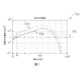
例えば、吸収層の吸収係数は、少なくとも目標波長の光に関して、吸収層外の炭化ケイ素ウェハの炭化ケイ素材料の吸収係数よりも高いことがある。すなわち、吸収層は、少なくとも目標波長に関して、炭化ケイ素材料よりも高い屈折率(例えば、より高い虚部)を有することがある。本明細書では以後、層および/または材料の吸収係数は、それぞれ上記層および/または上記材料の平均吸収係数でよく、平均吸収係数から2標準偏差を超えて逸脱する吸収係数を有する層および/または材料の領域は、平均を取る際に考慮に入れられないことがある。 For example, the absorption coefficient of the absorbing layer may be higher than the absorption coefficient of the silicon carbide material of the silicon carbide wafer outside the absorbing layer, at least for light of the target wavelength. That is, the absorbing layer may have a higher refractive index (eg, higher imaginary part) than the silicon carbide material, at least for target wavelengths. Hereinafter, the absorption coefficient of a layer and/or material may be the average absorption coefficient of said layer and/or said material, respectively, and layers and/or materials having absorption coefficients that deviate from the average absorption coefficient by more than two standard deviations. Or areas of material may not be taken into account when taking the average.
吸収層外の炭化ケイ素ウェハの炭化ケイ素材料は、少なくとも垂直方向で吸収層を取り囲んでいることがある。吸収層の吸収係数は、吸収層外の炭化ケイ素ウェハの炭化ケイ素材料の吸収係数の少なくとも5倍(もしくは少なくとも10倍、少なくとも20倍、少なくとも30倍、もしくは少なくとも50倍)でよく、または吸収層の吸収係数は、目標波長の光に関して、吸収層外の炭化ケイ素ウェハの炭化ケイ素材料の吸収係数の少なくとも100倍(もしくは少なくとも200倍、少なくとも500倍、少なくとも850倍、もしくは少なくとも1000倍)でよい。以下に提案する概念を使用することによって、例えば半導体デバイスを形成するために使用される炭化ケイ素ウェハ内で、吸収層外の炭化ケイ素ウェハの炭化ケイ素材料の吸収係数よりも例えば100倍高い吸収層の吸収係数を実現することが可能であり得る。 The silicon carbide material of the silicon carbide wafer outside the absorber layer may surround the absorber layer at least vertically. The absorption coefficient of the absorbing layer may be at least 5 times (or at least 10 times, at least 20 times, at least 30 times, or at least 50 times) the absorption coefficient of the silicon carbide material of the silicon carbide wafer outside the absorbing layer, or may be at least 100 times (or at least 200 times, at least 500 times, at least 850 times, or at least 1000 times) the absorption coefficient of the silicon carbide material of the silicon carbide wafer outside the absorbing layer for light of the target wavelength . By using the concepts proposed below, for example in a silicon carbide wafer used to form a semiconductor device, an absorption layer that is e.g. 100 times higher than the absorption coefficient of the silicon carbide material of the silicon carbide wafer outside the absorber layer It may be possible to achieve an absorption coefficient of
目標波長は、炭化ケイ素(SiC)ウェハを分割120するために使用される光の特性波長(例えば、レーザの波長またはスペクトル中で最大の波長)でよい。例えば、「目標波長の光」という用語は、目標波長における極大値、特に最大値を有する波長分布を有する光を表すことがある。さらにまたはあるいは、「目標波長の光」という用語は、目標波長に対応する周波数から最大で1GHz(または最大で0.5GHz、または最大で100MHz)だけ異なる極大値、特に最大値を有する周波数分布を有する光を表すことがある。しかし、例えば、目標波長の光のエネルギーが、吸収層の化学的な分解に必要なエネルギーを超える場合には、周波数分布の極大値または最大値のより高い周波数偏差が可能であり得る。本明細書では以後、「光」という用語は、可視波長だけを含むものと解釈されるべきではなく、例えば可視光、紫外光、および赤外光などの電磁放射を表す。 The target wavelength may be a characteristic wavelength of the light used to split 120 the silicon carbide (SiC) wafer (eg, the wavelength of the laser or the wavelength at the maximum in the spectrum). For example, the term "light of a target wavelength" may refer to light having a wavelength distribution with a local maximum, particularly a maximum, at the target wavelength. Additionally or alternatively, the term "light of a target wavelength" refers to a frequency distribution having a maximum, especially a maximum, that differs by up to 1 GHz (or up to 0.5 GHz, or up to 100 MHz) from the frequency corresponding to the target wavelength. It may represent the light that has However, higher frequency deviations of the maxima or maxima of the frequency distribution may be possible, for example if the energy of the light of the target wavelength exceeds the energy required for chemical decomposition of the absorbing layer. Hereafter the term "light" should not be construed as including only visible wavelengths, but represents electromagnetic radiation such as visible light, ultraviolet light, and infrared light.
炭化ケイ素材料に注入110されたイオンは、イオンが注入されていない炭化ケイ素材料に比べ、吸収層内の吸収係数を増加させることができる。例えば、注入ドーズ量を調整することができ、および/または注入されるイオンの種をウェハ材料に応じて選択することができ、より高い吸収係数を実現する、および/または吸収層の吸収係数の値を制御することができる。 The ions implanted 110 into the silicon carbide material can increase the absorption coefficient in the absorber layer compared to silicon carbide material not implanted with ions. For example, the implant dose can be adjusted and/or the species of implanted ions can be selected depending on the wafer material to achieve a higher absorption coefficient and/or reduce the absorption coefficient of the absorbing layer. You can control the value.
方法100は、炭化ケイ素ウェハを吸収層に沿って分割120することをさらに含むことがある。例えば、吸収層は、炭化ケイ素ウェハの画定された分割領域を提供するように形成されてよい。分割120は、少なくとも炭化ケイ素ウェハに目標波長の光を照射することによって実現することができる。例えば、単に炭化ケイ素ウェハに照射するだけで炭化ケイ素ウェハを分割することができ、または追加のプロセス(例えば、加熱、機械的な応力および/または力の印加、および/または超音波処理)を実施してSiC(炭化ケイ素)ウェハを分割することができる。
The
炭化ケイ素ウェハの分割120のために、例えば、目標波長の光のエネルギーは、SiCウェハを分割するのに必要なエネルギーに基づいて、吸収層の吸収係数に基づいて、炭化ケイ素ウェハの厚さに基づいて、吸収層の厚さに基づいて、および/または(例えば、炭化ケイ素ウェハによる追加の吸収を考慮に入れるために)炭化ケイ素ウェハ内の吸収層の位置に基づいて選択することができる。目標波長の光は、炭化ケイ素ウェハの表側および/または裏側に照射されてよい。吸収層の吸収係数がより高いことにより、目標波長の光は、吸収層内で、吸収層外のSiCウェハのSiC材料内よりも多く吸収され得る。例えば、吸収層内で吸収される目標波長の光は、吸収層の少なくとも一部、例えば横方向に接続された領域の分解または破壊を引き起こすことがあり、それにより、炭化ケイ素ウェハを吸収層に沿って分割120することができる。吸収層内で吸収された目標波長の光の放出エネルギーが、炭化ケイ素ウェハの分割120を引き起こすことができる。 For splitting 120 of a silicon carbide wafer, for example, the energy of the light at the target wavelength is scaled to the thickness of the silicon carbide wafer, based on the absorption coefficient of the absorbing layer, based on the energy required to split the SiC wafer. can be selected based on the thickness of the absorber layer and/or based on the position of the absorber layer within the silicon carbide wafer (eg, to account for additional absorption by the silicon carbide wafer). A target wavelength of light may be applied to the front side and/or the back side of the silicon carbide wafer. Due to the higher absorption coefficient of the absorption layer, more light of the target wavelength can be absorbed in the absorption layer than in the SiC material of the SiC wafer outside the absorption layer. For example, light of a target wavelength that is absorbed in an absorbing layer can cause decomposition or destruction of at least a portion of the absorbing layer, such as a laterally connected region, thereby turning the silicon carbide wafer into the absorbing layer. can be divided 120 along. The emitted energy of the target wavelength light absorbed in the absorbing layer can cause splitting 120 of the silicon carbide wafer.
例えば、炭化ケイ素ウェハを分割120することによって、炭化ケイ素デバイスウェハおよび残りの炭化ケイ素ウェハを得ることができる。残りの炭化ケイ素ウェハと炭化ケイ素デバイスウェハとはどちらも、主材料として吸収層外の炭化ケイ素ウェハの炭化ケイ素材料を含んでいてよく、または上記炭化ケイ素材料からなっていてよい。吸収層を照射することによって炭化ケイ素ウェハを吸収層に沿って分割120することによって、例えば他の分割法に比べて、正確に、および/または炭化ケイ素デバイスウェハの横方向延在部に沿ったばらつきを低減して、および/または炭化ケイ素デバイスウェハの横方向延在部に沿って均質に、炭化ケイ素デバイスウェハの厚さを画定することを可能にすることができる。例えば、方法100は、炭化ケイ素デバイスウェハの厚さに対する制御を改良することができる。吸収層の厚さは、他の分割領域の厚さに比べて薄くすることができ、したがって炭化ケイ素デバイスウェハの厚さのばらつきを低減することができる。また、例えば、吸収層を使用しない他の概念によって特に必要とされることがあるより厚い分割領域の使用に比べて薄くした吸収層を提供することによって、分割120のための炭化ケイ素ウェハの材料消費量を減少させることができる。
For example, a silicon carbide device wafer and a residual silicon carbide wafer can be obtained by dividing 120 a silicon carbide wafer. Both the remaining silicon carbide wafer and the silicon carbide device wafer may contain as the main material the silicon carbide material of the silicon carbide wafer outside the absorber layer or consist of the silicon carbide material described above. Separating 120 the silicon carbide wafer along the absorber layer by irradiating the absorber layer, for example, more accurately and/or along the lateral extension of the silicon carbide device wafer than other separation methods. It may allow the thickness of the silicon carbide device wafer to be defined with reduced variability and/or uniformity along the lateral extension of the silicon carbide device wafer. For example, the
いくつかの例は、吸収層外の炭化ケイ素ウェハの炭化ケイ素材料の吸収係数に比べて5倍高い、さらには100倍高い吸収係数を有する吸収層の形成を可能にすることができる態様に関する。吸収層の吸収係数を増加させるために、注入ドーズ量を増加してイオンを注入110することが必要になることがある。しかし、イオンが炭化ケイ素ウェハの第1の表面を通して注入110されるとき、第1の表面および/または第1の表面に近い領域で、空格子点などの欠陥が生じることがある。注入ドーズ量が増加すると共に、欠陥密度が増加し得る。例えば、臨界欠陥密度を超えるそのような欠陥は、例えば第1の表面上で成長するエピタキシャル層の品質を制限することがある。 Some examples relate to aspects that can enable formation of an absorber layer having an absorption coefficient that is 5 times higher, or even 100 times higher than the absorption coefficient of the silicon carbide material of the silicon carbide wafer outside the absorber layer. It may be necessary to implant 110 ions at an increased implant dose to increase the absorption coefficient of the absorber layer. However, when ions are implanted 110 through the first surface of the silicon carbide wafer, defects such as vacancies may occur at the first surface and/or regions near the first surface. As the implant dose increases, the defect density can increase. For example, such defects exceeding a critical defect density may limit the quality of epitaxial layers grown on, for example, the first surface.
例えば、臨界注入ドーズ量(例えば、イオンを注入110して吸収層を形成するために使用される)を超えると、注入後に表面の不規則性(例えば、空格子点および/または空格子点クラスタなどの欠陥)が生じることがあり、この不規則性は、例えば、表面上での適切なエピタキシャル成長(例えば、4H結晶構造、すなわち4H-SiC層を有するエピタキシャル炭化ケイ素層の成長)を妨げることがある。例えば、高品質のエピタキシャル層が必要になることがあり、いくつかの例によれば、導入される層(例えば、吸収層)の最大吸収力(例えば、吸収係数の上限)が制限されることがある。これは、表面欠陥の発生により、イオンを注入110するための最大注入ドーズ量が制限されることがあるからである。例えば、注入後の第1の表面付近の領域または第1の表面に直接接触する領域での例えば3・1022cm-3の空格子点濃度は、(例えば、注入110される種またはイオンのタイプによらず)適切なエピタキシャル成長に関する上限となり得る。以下では、ある表面付近の領域またはその表面に直接接触する領域内の空格子点濃度は、上記特定の表面「の」空格子点濃度とも呼ぶ。 For example, exceeding a critical implant dose (e.g., used to implant 110 ions to form an absorbing layer) can result in surface irregularities (e.g., vacancies and/or clusters of vacancies) after implantation. defects such as ), and this irregularity can, for example, prevent proper epitaxial growth on the surface (e.g. growth of epitaxial silicon carbide layers with a 4H crystalline structure, ie 4H—SiC layers). be. For example, high quality epitaxial layers may be required, and according to some examples, the maximum absorption power (e.g. upper limit of absorption coefficient) of the introduced layer (e.g. absorption layer) may be limited. There is This is because the occurrence of surface defects may limit the maximum implant dose for implanting 110 ions. For example, a vacancy concentration of, for example, 3·10 22 cm −3 in a region near the first surface after implantation or in a region directly contacting the first surface may be (eg, of the implanted 110 species or ions can be an upper limit for suitable epitaxial growth (regardless of type). In the following, the vacancy concentration in a region near or in direct contact with a surface is also referred to as the vacancy concentration “of” said particular surface.
限度未満の炭化ケイ素ウェハ表面の欠陥濃度、例えば最大空格子点濃度を保ちながら、より高い吸収係数を有する吸収層を形成するために注入ドーズ量の増加を可能にする方法を提供することが必要であり得る。以下では、高い吸収係数を有する吸収層の形成を可能にすることができると共に、イオンが注入110される炭化ケイ素ウェハ表面の良好な表面品質を提供する例を提案する。 There is a need to provide a method that allows increasing the implant dose to form an absorber layer with a higher absorption coefficient while keeping the defect concentration, e.g., the maximum vacancy concentration, of the silicon carbide wafer surface below limits. can be In the following, an example is proposed that can allow the formation of an absorption layer with a high absorption coefficient while providing good surface quality of the silicon carbide wafer surface into which the ions are implanted 110 .
例えば、イオンの注入110中の炭化ケイ素ウェハの温度は、少なくとも250℃(もしくは少なくとも300℃、少なくとも350℃、少なくとも400℃、少なくとも450℃、少なくとも500℃、少なくとも600℃、少なくとも700℃、もしくは少なくとも800℃)および/または最大で1000℃(もしくは最大で800℃、最大で700℃、もしくは最大で600℃)でよい。例えば、炭化ケイ素ウェハ内にイオンを注入110して吸収層を形成する前に、炭化ケイ素ウェハは、少なくとも300℃の温度まで加熱されてよく、イオンの注入110中、炭化ケイ素ウェハの温度は300℃超の温度で保たれてよい。 For example, the temperature of the silicon carbide wafer during ion implantation 110 is at least 250° C. (or at least 300° C., at least 350° C., at least 400° C., at least 450° C., at least 500° C., at least 600° C., at least 700° C., or at least 800° C.) and/or up to 1000° C. (or up to 800° C., up to 700° C., or up to 600° C.). For example, prior to implanting 110 ions into the silicon carbide wafer to form an absorber layer, the silicon carbide wafer may be heated to a temperature of at least 300° C., and the temperature of the silicon carbide wafer is 300° C. during the implantation of ions 110 . It may be kept at a temperature above °C.
注入中に炭化ケイ素ウェハの表面を通して高温でイオンを注入するとき、表面(例えば、V、V2、Z1,2、および/または他の欠陥など、表面付近の結晶損傷)の欠陥またはこの表面に近い欠陥を制限することができる。例えば、300℃以上の炭化ケイ素ウェハの温度でイオンを注入110するとき、高ドーズ量注入後に(例えばエピタキシャル層の)良好な結晶品質を実現することができる。例えば、(例えば吸収層内の)安定したエンドオブレンジ欠陥は、高温の影響をほとんど受けないことがある。使用すべき温度範囲は、300℃と最大注入温度、例えば700℃との間でよい。例えば、炭化ケイ素ウェハの表面において、4H-SiC構成は、300℃以上の注入温度で保つことができる。例えばわずか200℃のウェハ温度での(および、例えば、注入後に例えば3分間1800℃のアニーリングを伴う)高ドーズ量注入を行う他のプロセスでは、3C-SiCのエピタキシャル層が表面上で成長し得る。吸収層を形成するためには高注入ドーズ量が必要となることがあるので、室温から高温(例えば300℃超)までウェハ温度を上昇させるのに必要な追加の時間によって、わずかだけプロセスのコストまたは時間が増すことがある。 When implanting ions at high temperatures through the surface of a silicon carbide wafer during implantation, defects in the surface (e.g., crystalline damage near the surface, such as V, V2, Z1,2 , and/or other defects) or in this surface. Close defects can be restricted. For example, when implanting 110 ions at a silicon carbide wafer temperature of 300° C. or higher, good crystalline quality (eg, of an epitaxial layer) can be achieved after a high dose implant. For example, stable end-of-range defects (eg, in an absorber layer) may be largely unaffected by high temperatures. The temperature range to be used may be between 300°C and the maximum injection temperature, eg 700°C. For example, on the surface of a silicon carbide wafer, a 4H—SiC structure can be maintained at implant temperatures of 300° C. or higher. In other processes with high dose implants at wafer temperatures of, for example, only 200° C. (and with, for example, annealing at 1800° C. for, for example, 3 minutes after implantation), an epitaxial layer of 3C—SiC can grow on the surface. . Since high implant doses may be required to form the absorber layer, the additional time required to raise the wafer temperature from room temperature to elevated temperatures (e.g., greater than 300° C.) adds only a small cost to the process. or time may increase.
例えば、イオンの注入110は、2つ以上の注入プロセスと、それらの合間の例えばアニーリングまたは層成長などの中間プロセスとによって行われてよい。それに従って、イオンが第1の注入ドーズ量で注入されることがある。第1の注入ドーズ量でイオンを注入した後、別個のプロセスが行われて、例えば、表面付近での結晶欠陥が低減されたまたはより少ない(例えば、より低い欠陥密度の)ウェハ表面を得ることができる。その後、イオンの注入110は、表面付近の結晶欠陥が低減されたウェハ表面を得た後、第2の注入ドーズ量でイオンを注入することを含むことがある。これらのイオンは、欠陥密度が低減されたまたはより低い表面を通して第2の注入ドーズ量で注入されてよい。 For example, ion implantation 110 may be performed by two or more implantation processes with intermediate processes in between, such as annealing or layer growth. Accordingly, ions may be implanted at a first implant dose. After implanting ions at the first implant dose, a separate process is performed, e.g., to obtain a wafer surface with reduced or fewer (e.g., lower defect density) crystal defects near the surface. can be done. Implanting 110 ions may then include implanting ions at a second implant dose after obtaining a wafer surface with reduced near-surface crystal defects. These ions may be implanted at a second implant dose through the surface with reduced or lower defect density.
例えば、第1の注入ドーズ量を注入した後に表面での欠陥密度が低減される場合、第1の注入ドーズ量は、臨界ドーズ量を超えていることがある。例えば、表面付近の結晶欠陥を低減させて、表面付近の結晶欠陥が低減されたウェハ表面を得る前には、臨界ドーズ量を超える注入ドーズ量でイオンを注入したときに表面上で低品質エピタキシャル層しか成長しないことがあるのに対し、表面付近の結晶欠陥を低減した後では、表面上で高品質エピタキシャル層が成長することができる。例えば、第1および/または第2の注入ドーズ量は、最大で3.0・1016cm-2(または最大で2.00・1016cm-2、最大で1.35・1016cm-2、最大で1.2・1016cm-2、最大で1.0・1016cm-2、最大で1.8・1015cm-2、最大で4.0・1014cm-2、または最大で2.0・1014cm-2)でよい。例えば、第1および/または第2の注入ドーズ量は、窒素原子の注入では最大で1.35・1016cm-2、リンイオンの注入では最大で1.8・1015cm-2でよい。例えば、第1および/または第2の注入ドーズ量は、臨界ドーズ量でよい。 For example, the first implant dose may exceed the critical dose if the defect density at the surface is reduced after implanting the first implant dose. For example, prior to reducing near-surface crystalline defects to obtain a wafer surface with reduced near-surface crystalline defects, low-quality epitaxial growth was observed on the surface when ions were implanted at an implant dose above the critical dose. After reducing crystal defects near the surface, a high quality epitaxial layer can be grown on the surface, whereas only a layer may grow. For example, the first and/or second implant dose may be up to 3.0·10 16 cm −2 (or up to 2.00·10 16 cm −2 , up to 1.35·10 16 cm −2 ). 2 , 1.2·10 16 cm −2 at maximum, 1.0·10 16 cm −2 at maximum, 1.8·10 15 cm −2 at maximum, 4.0·10 14 cm −2 at maximum, or at most 2.0·10 14 cm −2 ). For example, the first and/or second implant dose may be up to 1.35·10 16 cm −2 for nitrogen atom implants and up to 1.8·10 15 cm −2 for phosphorous ion implants. For example, the first and/or second implant doses can be critical doses.
例えば、第2の注入ドーズ量でイオンを注入した後、例えばさらなるプロセスによって、表面付近の結晶欠陥が低減されたウェハ表面を再度得ることができ、その後、第3の注入ドーズ量でイオンを注入することによって第3の注入ステップを行うことができる。同様に、その後、さらなる注入ドーズ量を注入することができる。2つ、3つ、4つ、または5つの後続の注入ステップ中に吸収層を形成することが可能になり得る。例えば、注入ステップの1つまたは複数の後(例えば、各ステップの後)に、炭化ケイ素ウェハの表面の表面欠陥を低減することができる。 For example, after implanting ions with a second implant dose, a wafer surface with reduced crystal defects near the surface can be obtained again, for example by further processing, and then implanting ions with a third implant dose. A third implant step can be performed by Further implant doses can be implanted thereafter as well. It may be possible to form the absorber layer during 2, 3, 4 or 5 subsequent implantation steps. For example, surface defects on the surface of the silicon carbide wafer can be reduced after one or more of the implant steps (eg, after each step).
例えば、第1の注入ドーズ量でのイオンを、炭化ケイ素ウェハの第1の表面を通して注入することができ、第1の注入ドーズ量でイオンを注入した後、第1の表面の結晶欠陥を低減するためのプロセスステップを行うことができる。表面付近の結晶欠陥が低減されたまたは結晶品質が向上されたウェハ表面を得るために、様々な方法またはプロセスを使用することができる。 For example, ions at a first implantation dose can be implanted through a first surface of a silicon carbide wafer to reduce crystalline defects at the first surface after implanting ions at the first implantation dose. A process step can be performed to Various methods or processes can be used to obtain a wafer surface with reduced near-surface crystal defects or improved crystal quality.
例えば、第1の注入ドーズ量でイオンを注入した後、炭化ケイ素ウェハ(例えば、少なくとも炭化ケイ素ウェハの第1の表面)をアニーリングして、表面付近の結晶欠陥が低減されたウェハ表面を得ることができる。炭化ケイ素ウェハをアニーリングするためのアニーリング温度は、少なくとも1600℃(もしくは少なくとも1650℃、少なくとも1700℃、少なくとも1750℃、もしくは少なくとも1800℃)および/または最大で1850℃(もしくは最大で1800℃、最大で1750℃、もしくは最大で1700℃)でよい。例えば、第1の注入ドーズ量でのイオン注入と第2の注入ドーズ量でのイオン注入との合間に第1の表面をアニーリングすることができる。アニーリング時間、例えばウェハ表面をアニーリング温度に晒す時間は、1分超(もしくは2分超、3分超、もしくは5分超)および/もしくは7分未満(もしくは5分未満、もしくは4分未満)でよく、例えばアニーリング時間は3分でよい。アニーリング後、欠陥密度は、アニーリング前よりも低くなることがあり、例えば、高品質エピタキシャル層を成長させることができる臨界欠陥密度よりも低くなることがある。 For example, after implanting ions at a first implant dose, annealing a silicon carbide wafer (e.g., at least a first surface of the silicon carbide wafer) to obtain a wafer surface with reduced near-surface crystal defects. can be done. The annealing temperature for annealing the silicon carbide wafer is at least 1600° C. (or at least 1650° C., at least 1700° C., at least 1750° C., or at least 1800° C.) and/or up to 1850° C. (or up to 1800° C., up to 1750°C, or up to 1700°C). For example, the first surface can be annealed between implants with a first implant dose and implants with a second implant dose. The annealing time, e.g., the time the wafer surface is exposed to the annealing temperature, is greater than 1 minute (or greater than 2 minutes, or greater than 3 minutes, or greater than 5 minutes) and/or less than 7 minutes (or less than 5 minutes, or less than 4 minutes). Well, for example the annealing time can be 3 minutes. After annealing, the defect density may be lower than before annealing, eg, below the critical defect density at which high quality epitaxial layers can be grown.
例えば、表面付近の結晶欠陥が低減されたウェハ表面を得るための炭化ケイ素ウェハのアニーリングは、アニーリングチャンバ内で行われてよい。例えば、炭化ケイ素ウェハは、レーザアニーリングによってアニーリングされてよい。レーザアニーリングは、例えば、より短いアニーリング時間を可能にすることができる。例えば、表面付近の注入損傷層のアニーリングは、非溶融式レーザアニーリングによって行うことができる。 For example, annealing a silicon carbide wafer to obtain a wafer surface with reduced crystal defects near the surface may be performed in an annealing chamber. For example, silicon carbide wafers may be annealed by laser annealing. Laser annealing, for example, can allow shorter annealing times. For example, annealing of near-surface implant damage layers can be performed by non-melting laser annealing.
一例によれば、第1の注入ドーズ量でのイオンは、第1の注入エネルギーで注入されてよく、第2の注入ドーズ量でのイオンは、第2の注入エネルギーで注入されてよい。第2の注入エネルギーは、第1の注入エネルギーの少なくとも5%(もしくは少なくとも7%、少なくとも9%、少なくとも15%、もしくは少なくとも20%)だけ、および/もしくは最大で40%(もしくは最大で30%、最大で20%、もしくは最大で10%)だけ第1の注入エネルギーと異なることがある。異なる注入エネルギーでイオンを注入することによって、より厚い吸収層の形成を可能にすることができる。異なる注入ステップにおいて注入エネルギーを変えることによって、例えば、生成される損傷(例えば注入による表面欠陥)を、(例えば表面付近の結晶欠陥が低減されたウェハ表面を得るためのプロセスステップにおいて)より効率的に低減することができる。 According to one example, ions at a first implantation dose may be implanted at a first implantation energy and ions at a second implantation dose may be implanted at a second implantation energy. The second implant energy is at least 5% (or at least 7%, at least 9%, at least 15%, or at least 20%) of the first implant energy, and/or up to 40% (or up to 30%) , up to 20%, or up to 10%) from the first implant energy. Implanting ions with different implantation energies can allow the formation of a thicker absorber layer. By varying the implant energy in different implant steps, for example, the damage produced (e.g. surface defects due to implantation) can be made more efficient (e.g. in process steps to obtain a wafer surface with reduced crystal defects near the surface). can be reduced to
2つ以上の注入ステップおよび少なくとも1つの中間ステップでイオンを注入110することによって吸収層を形成することにより、イオンを注入し、炭化ケイ素ウェハを連続してアニーリングすることを可能にすることができる。例えば、各ステップ中に、(例えば吸収層の所定の吸収係数を得るための)所要のドーズ量の一部だけを注入し、続いてアニーリング(例えば、ファーネスアニーリング手順)を行って、表面付近の損傷または表面付近の欠陥を回復させることができ、その一方で、例えば、吸収層内に(例えば高吸収係数を得るために必要な)安定した結晶欠陥中心が残ることがある。 Forming an absorber layer by implanting 110 ions in two or more implant steps and at least one intermediate step may allow ion implantation and continuous annealing of the silicon carbide wafer. . For example, during each step, only a fraction of the required dose (e.g., to obtain a predetermined absorption coefficient of the absorbing layer) is implanted, followed by annealing (e.g., a furnace annealing procedure) to reduce near-surface Damage or near-surface defects can be healed, while, for example, stable crystal defect centers (necessary for obtaining high absorption coefficients) may remain in the absorbing layer.
あるいはまたはさらに、表面付近の結晶欠陥が低減された、または低い欠陥密度を有するウェハ表面を得ることは、炭化ケイ素ウェハの第1の側(例えば、炭化ケイ素ウェハの表側にある第1の表面)に、第1の側から(例えば第1の表面を通して)第1の注入ドーズ量でイオンを注入した後に炭化ケイ素層を形成することを含むことがある。例えば、炭化ケイ素層を形成する前に、炭化ケイ素ウェハの第1の表面の欠陥密度は、高品質炭化ケイ素層を形成するための臨界限度でよい。炭化ケイ素層を形成した後、炭化ケイ素層の表面が、炭化ケイ素ウェハの表面を成す。この炭化ケイ素層は、この炭化ケイ素層を有さない炭化ケイ素ウェハの表面にある層(例えば、ある厚さの炭化ケイ素層を有する)よりも低い欠陥密度を有することができるため、炭化ケイ素ウェハの表面または表面にある層は、炭化ケイ素層を形成した後、欠陥密度がより低くなり得るまたは低減され得る。第2の注入ドーズ量でイオンを注入するとき、注入により、欠陥密度が低減された表面に新たな欠陥が生じる場合がある。しかし、例えば表面上にさらなる炭化ケイ素層(例えば、エピタキシャル層)を形成することがそれでも可能であり得る。例えば、後続のイオン注入およびエピタキシャル成長を行うプロセス手順では、例えば高品質エピタキシャル成長にやはり適している表面上に形成される炭化ケイ素層によって表面損傷の低減を実現することができる。 Alternatively or additionally, obtaining a wafer surface with reduced crystal defects near the surface or with a low defect density includes: may include forming a silicon carbide layer after implanting ions at a first implant dose from the first side (eg, through the first surface). For example, prior to forming the silicon carbide layer, the defect density of the first surface of the silicon carbide wafer may be a critical limit for forming a high quality silicon carbide layer. After forming the silicon carbide layer, the surface of the silicon carbide layer forms the surface of the silicon carbide wafer. Since the silicon carbide layer can have a lower defect density than a layer (e.g., having a thickness of silicon carbide layer) on the surface of a silicon carbide wafer without the silicon carbide layer, the silicon carbide wafer The surface or layer at the surface of may have a lower or reduced defect density after forming the silicon carbide layer. When implanting ions at the second implant dose, the implant may create new defects in the surface with reduced defect density. However, it may still be possible, for example, to form a further silicon carbide layer (eg an epitaxial layer) on the surface. For example, in subsequent ion implantation and epitaxial growth process steps, reduced surface damage can be achieved, for example, by a silicon carbide layer formed on a surface that is also suitable for high quality epitaxial growth.
第1の側(例えば第1の表面)に炭化ケイ素層を形成し、その後、第2の注入エネルギーでイオンを注入するとき、例えば炭化ケイ素ウェハの同じ領域、例えば吸収層内にイオンを注入するために、第1の注入ドーズ量のイオンよりも高い注入エネルギーで第2の注入ドーズ量のイオンを注入する必要があり得る。したがって、例えば、形成される炭化ケイ素層を考慮に入れた新たな目標注入深さに達するように、注入エネルギーを適合させることができる。例えば、第1の注入エネルギーに対する第2の注入エネルギーの増加は、形成される炭化ケイ素層の厚さに依存することがある。あるいは、例えば、より厚い吸収層を形成するために、第1および第2の注入エネルギーは、少なくとも実質的に等しくてよい。例えば、表面は変わることなく、吸収層は、炭化ケイ素ウェハ内のより大きい垂直範囲にわたって広がっていてよい。 forming a silicon carbide layer on a first side (e.g. a first surface) and then implanting ions at a second implantation energy, e.g. implanting ions into the same region of the silicon carbide wafer, e.g. For this reason, it may be necessary to implant the second implant dose of ions at a higher implant energy than the first implant dose of ions. Thus, for example, the implantation energy can be adapted to reach a new target implantation depth that takes into account the silicon carbide layer to be formed. For example, the increase in second implant energy relative to the first implant energy may depend on the thickness of the silicon carbide layer being formed. Alternatively, the first and second implant energies may be at least substantially equal, eg, to form a thicker absorber layer. For example, the absorber layer may extend over a greater vertical extent within the silicon carbide wafer while the surface remains unchanged.
例えば、炭化ケイ素層を形成することは、第1の側の表面上に炭化ケイ素層をエピタキシャル成長させること、または第1の側の表面上に化学気相成長法によって炭化ケイ素層を堆積することを含む。化学気相成長法を使用して炭化ケイ素層を形成することによって、炭化ケイ素層の低コストで迅速な形成を可能にすることができる。 For example, forming a silicon carbide layer may refer to epitaxially growing a silicon carbide layer on the surface of the first side or depositing a layer of silicon carbide on the surface of the first side by chemical vapor deposition. include. Using chemical vapor deposition to form the silicon carbide layer can allow for low cost and rapid formation of the silicon carbide layer.
例えば、形成される炭化ケイ素層は、少なくとも20nm(もしくは少なくとも50nm、少なくとも100nm、少なくとも200nm、少なくとも300nm、もしくは少なくとも500nm)および/または最大で700nm(もしくは最大で500nm、最大で300nm、最大で200nm、もしくは最大で150nm)の厚さを有していてよい。 For example, the silicon carbide layer formed has a thickness of at least 20 nm (or at least 50 nm, at least 100 nm, at least 200 nm, at least 300 nm, or at least 500 nm) and/or up to 700 nm (or up to 500 nm, up to 300 nm, up to 200 nm, Alternatively, it may have a thickness of up to 150 nm).
例えば、イオンを注入110して吸収層を形成するために、2つ以上(例えば3つ)の注入プロセスと、表面付近の結晶欠陥が低減されたウェハ表面を得るための2つ以上の中間プロセスとが使用される場合、少なくとも2つの中間プロセスのうちの第1のプロセスは、アニーリングでよく、少なくとも2つの中間プロセスのうちの第2のプロセスは、層成長でよい。例えば、アニーリングと層成長とはどちらも、第1の注入プロセスとそれに続く第2の注入プロセスとの間に行われてよい。 For example, two or more (e.g., three) implantation processes to implant 110 ions to form an absorber layer and two or more intermediate processes to obtain a wafer surface with reduced near-surface crystal defects. is used, the first of the at least two intermediate processes may be annealing and the second of the at least two intermediate processes may be layer growth. For example, both annealing and layer growth may occur between a first implant process and a subsequent second implant process.
例えば、炭化ケイ素ウェハの処理は、炭化ケイ素ウェハの第1の側(例えば表側)に多孔質炭化ケイ素層を形成することを含むことがある。多孔質炭化ケイ素層は、例えば、炭化ケイ素ウェハ内または炭化ケイ素ウェハの表面上に形成されてよい。多孔質炭化ケイ素層を形成することによって、吸収層の吸収係数を増加させること、および/または炭化ケイ素ウェハの表面に臨界限度以下の欠陥密度を提供することを可能にすることができ、この欠陥密度により、例えば、多孔質炭化ケイ素層を形成した後、第1の側の表面に高品質エピタキシャル層を成長させることが可能になり得る。 For example, processing a silicon carbide wafer may include forming a porous silicon carbide layer on a first side (eg, front side) of the silicon carbide wafer. A porous silicon carbide layer may be formed, for example, in a silicon carbide wafer or on the surface of a silicon carbide wafer. By forming a porous silicon carbide layer, it may be possible to increase the absorption coefficient of the absorbing layer and/or provide a sub-critical defect density on the surface of the silicon carbide wafer, which defects The density may allow, for example, to grow a high quality epitaxial layer on the surface of the first side after forming the porous silicon carbide layer.
多孔質炭化ケイ素層は、例えばフッ素を含む電解質中での陽極酸化などによって、炭化ケイ素ウェハ内に形成することができる。電解質は、フッ化水素酸(HF)および/またはエタノールを含むことがある。陽極酸化は、ある程度、多孔質炭化ケイ素層の領域内の炭化ケイ素結晶を電気化学的に分解する。シリコン結晶を均一に分解するのではなく、電気化学的な分解により、炭化ケイ素結晶格子からケイ素原子を局所的に除去し、炭化ケイ素結晶内に小孔または細孔を形成することができる。例えば、多孔質炭化ケイ素層外の炭化ケイ素ウェハの結晶構造は、陽極酸化による影響を受けずにそのままであり得る。 A porous silicon carbide layer can be formed in a silicon carbide wafer by, for example, anodization in an electrolyte containing fluorine. The electrolyte may include hydrofluoric acid (HF) and/or ethanol. To some extent, anodization electrochemically decomposes the silicon carbide crystals within the region of the porous silicon carbide layer. Rather than uniformly decomposing the silicon crystal, electrochemical decomposition can locally remove silicon atoms from the silicon carbide crystal lattice and form small holes or pores within the silicon carbide crystal. For example, the crystalline structure of the silicon carbide wafer outside the porous silicon carbide layer may remain unaffected by the anodization.
多孔質炭化ケイ素層は、第1の側の表面(例えば表側表面)と、陽極酸化による影響を受けないことがある炭化ケイ素ウェハの(例えば裏側にある)基部領域との間の陽極酸化によって形成されてよい。多孔質炭化ケイ素層は、炭化ケイ素ウェハの表面の少なくとも一部の陽極エッチング、例えばフッ化水素酸(HF)中での陽極エッチングによって形成されてよい。多孔質炭化ケイ素層は、半導体基板の電気化学エッチングまたは光電気化学エッチングによって形成されてもよい。 A porous silicon carbide layer is formed by anodization between a first side surface (e.g., front side surface) and a base region (e.g., on the back side) of the silicon carbide wafer, which may not be affected by the anodization. may be The porous silicon carbide layer may be formed by anodic etching of at least a portion of the surface of the silicon carbide wafer, such as anodic etching in hydrofluoric acid (HF). The porous silicon carbide layer may be formed by electrochemical etching or photoelectrochemical etching of the semiconductor substrate.
多孔質炭化ケイ素層の多孔率は、多孔質炭化ケイ素層の全体積(炭化ケイ素ウェハの体積および多孔質炭化ケイ素層内の細孔容積を含む)に対する多孔質炭化ケイ素層内の実効細孔容積(例えば細孔の容積)の比として測定することができる。例えば、より高い多孔率の値は、多孔質炭化ケイ素層内のより高い細孔密度またはより大きい細孔容積を示すことがあり、一方、より低い多孔率の値は、多孔質炭化ケイ素層内のより低い細孔密度またはより小さい細孔容積を示すことがある。例えば、多孔質炭化ケイ素層は、例えば5%~95%(または10%~80%、または25%~60%)の多孔率を有していてよい。例えば、炭化ケイ素層は、多孔質炭化ケイ素層を取り囲む炭化ケイ素ウェハの炭化ケイ素材料の約90%、80%、または70%の密度(重量/体積)を有していてよい。 The porosity of the porous silicon carbide layer is the effective pore volume in the porous silicon carbide layer relative to the total volume of the porous silicon carbide layer (including the volume of the silicon carbide wafer and the pore volume in the porous silicon carbide layer). (eg, pore volume). For example, higher porosity values may indicate higher pore density or greater pore volume within the porous silicon carbide layer, while lower porosity values indicate may exhibit lower pore densities or smaller pore volumes. For example, a porous silicon carbide layer may have a porosity of, for example, 5% to 95% (or 10% to 80%, or 25% to 60%). For example, the silicon carbide layer may have a density (weight/volume) of about 90%, 80%, or 70% of the silicon carbide material of the silicon carbide wafer surrounding the porous silicon carbide layer.
例えば、多孔質炭化ケイ素層の少なくとも一部(例えば垂直部分)を通してイオンを注入110することができる。例えば、多孔質炭化ケイ素層が形成された後に、イオンを注入110して吸収層を形成することができる。多孔質炭化ケイ素層内に吸収層を形成することができ(例えば、多孔質炭化ケイ素層内に吸収層を完全に形成することができ)、多孔質炭化ケイ素層の第1の垂直部分を通してイオンを注入することができる。例えば、少なくとも吸収層の第1の垂直部分が多孔質炭化ケイ素層の下に形成されてよく、例えば、多孔質炭化ケイ素層は、垂直方向で、イオンが注入される炭化ケイ素ウェハの表面と吸収層の第1の垂直部分との間に位置決めされてよい。 For example, ions can be implanted 110 through at least a portion (eg, vertical portion) of the porous silicon carbide layer. For example, after the porous silicon carbide layer is formed, ions can be implanted 110 to form an absorbing layer. An absorbing layer can be formed within the porous silicon carbide layer (e.g., the absorbing layer can be formed entirely within the porous silicon carbide layer), and ions are directed through the first vertical portion of the porous silicon carbide layer. can be injected. For example, at least a first vertical portion of the absorbing layer may be formed below the porous silicon carbide layer, for example, the porous silicon carbide layer is perpendicular to the surface of the silicon carbide wafer into which the ions are implanted and the absorbing layer. It may be positioned between the first vertical portion of the layer.
イオンを注入110して多孔質炭化ケイ素層を通る吸収層を形成することによって、注入の深さを増すことができ(例えば、炭化ケイ素ウェハの表面と吸収層との間の距離が広がる)、その一方で、表面損傷は、例えば、印加する注入ドーズ量に関するその固有値の近くで保つことができる。結果として、吸収層と、例えば炭化ケイ素ウェハの電気的に活性のデバイス層(例えば、吸収層を形成した後、炭化ケイ素ウェハを分割する前に形成される)との距離を広げることができ、例えば、(例えばレーザなどの光を照射することによる)分割中に生じるデバイスの活性部分との相互作用を小さくすることができる。 By implanting 110 ions to form an absorbing layer through the porous silicon carbide layer, the depth of implantation can be increased (e.g., increasing the distance between the surface of the silicon carbide wafer and the absorbing layer); On the other hand, the surface damage can be kept close to its characteristic value, eg for the applied implant dose. As a result, the distance between the absorber layer and, for example, an electrically active device layer of a silicon carbide wafer (e.g., formed after forming the absorber layer and before splitting the silicon carbide wafer) can be increased, For example, interaction with the active portion of the device that occurs during splitting (eg, by illumination with light such as a laser) can be reduced.
上述したように、吸収層または少なくとも吸収層の垂直部分は、多孔質炭化ケイ素層内に形成されてよい。吸収層を炭化ケイ素の多孔質層に注入することによって、この層の吸収力を高めることができ(例えば、より高い吸収係数を得ることができ)、例えば、機械的な活性光吸収中心と電気的/光学的な活性光吸収中心との組合せを可能にする。例えば、(例えばレーザなどの光照射による)分割は、より低い注入ドーズ量(例えば、吸収層を形成するための合計の注入ドーズ量)で可能になることがあり、その結果、より低い表面損傷、したがってエピタキシャル成長に適した表面品質が得られる。 As noted above, the absorber layer, or at least the vertical portion of the absorber layer, may be formed within the porous silicon carbide layer. By injecting an absorbing layer into a porous layer of silicon carbide, the absorbing power of this layer can be increased (e.g. higher absorption coefficients can be obtained), e.g. Allows combination with optically/optically active light absorbing centers. For example, splitting (e.g., by light irradiation such as a laser) may be possible with a lower implant dose (e.g., total implant dose to form the absorber layer), resulting in lower surface damage. , thus providing a suitable surface quality for epitaxial growth.
例えば、吸収層を形成した後に多孔質炭化ケイ素層を形成することができる。多孔質炭化ケイ素層は、少なくとも吸収層を含む炭化ケイ素ウェハの領域内で垂直方向に延在していてよい。例えば多孔質炭化ケイ素層が吸収層よりも後に形成されるとき、吸収層を形成するための注入ドーズ量は、臨界ドーズ量、例えば窒素原子を注入するときには最大で1.35・1016cm-2でよい。吸収層を形成するために使用される注入ドーズ量は、表面欠陥をもたらすことがあるが、これは、例えば表面上の高品質エピタキシャル成長をそれでも可能にする。吸収層の形成後に多孔質炭化ケイ素層を形成することによって、例えば表面にさらなる注入欠陥を生成することなく、吸収層の吸収係数をさらに増加させることができる。例えば、多孔質炭化ケイ素層の形成後、吸収層の吸収係数は、多孔質炭化ケイ素層の形成前よりも高くなり得る。 For example, a porous silicon carbide layer can be formed after forming the absorber layer. The porous silicon carbide layer may extend vertically within at least the region of the silicon carbide wafer that contains the absorber layer. For example, when the porous silicon carbide layer is formed after the absorber layer, the implant dose for forming the absorber layer is a critical dose, e.g. 2 is fine. Although the implant dose used to form the absorber layer may lead to surface defects, this still allows for example high quality epitaxial growth on the surface. By forming a porous silicon carbide layer after forming the absorber layer, the absorption coefficient of the absorber layer can be further increased, for example, without creating additional implant defects on the surface. For example, after forming the porous silicon carbide layer, the absorption coefficient of the absorbing layer may be higher than before forming the porous silicon carbide layer.
多孔質化プロセス(例えば多孔質炭化ケイ素層を形成する)前に炭化ケイ素ウェハ内にイオンを注入することによって、多孔質化強度(例えば多孔率)および/または多孔質炭化ケイ素層の深さプロファイルを適合することを可能にすることができる。これにより、吸収層内の吸収係数を増加させる(例えば、照射された光の吸収率をより高くする)ことができ、および/または吸収層内での十分に高い吸収係数で、エピタキシャル成長に関するより良好な表面品質を得ることができ、および/または炭化ケイ素ウェハのさらなる処理(例えば、エピタキシャル成長、活性化アニーリングなど)のサーマルバジェットによる多孔質層(例えば多孔質炭化ケイ素層)の変化の有益な効果を有することができる。 By implanting ions into the silicon carbide wafer prior to the porosification process (e.g., forming the porous silicon carbide layer), the porosization strength (e.g., porosity) and/or depth profile of the porous silicon carbide layer can be adapted. This can lead to an increased absorption coefficient (e.g., higher absorption of the irradiated light) in the absorption layer and/or a sufficiently high absorption coefficient in the absorption layer for better epitaxial growth. good surface quality and/or beneficial effect of changing the porous layer (e.g. porous silicon carbide layer) by the thermal budget of further processing of the silicon carbide wafer (e.g. epitaxial growth, activation annealing, etc.). can have
例えば、多孔質炭化ケイ素層上にエピタキシャル層を成長させる前に、多孔質炭化ケイ素層の表面層(例えば、薄い表面層)を非多孔質炭化ケイ素層(例えば、いわゆるスキン層または開始層)に変えるまたは変換することができる。さらにまたは代替として、非多孔質炭化ケイ素層が表面に残るように多孔質化を行うことができる。非多孔質炭化ケイ素層上で成長するエピタキシャル層の品質は、例えば、多孔質炭化ケイ素層上で成長するエピタキシャル層の品質よりも高くなり得る。 For example, prior to growing an epitaxial layer on the porous silicon carbide layer, the surface layer (e.g. thin surface layer) of the porous silicon carbide layer is applied to a non-porous silicon carbide layer (e.g. a so-called skin layer or starting layer). capable of being altered or transformed. Additionally or alternatively, porosification can be performed such that a non-porous silicon carbide layer remains on the surface. The quality of epitaxial layers grown on non-porous silicon carbide layers can be higher than, for example, epitaxial layers grown on porous silicon carbide layers.
例えば、多孔質炭化ケイ素層は、例えば互いに垂直に隣接する異なる多孔率を有する少なくとも2つの層で形成されてよい。上層(例えば炭化ケイ素ウェハの表面を成す)の多孔率は、例えば、炭化ケイ素ウェハの表面上にエピタキシャル層を成長させる前に、適切なスキン層を表面上に形成できるように選択することができる。例えば、吸収層の形成後、多孔質炭化ケイ素層の表面層を非多孔質炭化ケイ素層に変えることができる。例えば、非多孔質炭化ケイ素層に変えられた表面層は、スキン層でよく、例えばエピタキシャル層を成長させるための開始層として使用することができる。 For example, the porous silicon carbide layer may be formed, for example, of at least two layers having different porosities vertically adjacent to each other. The porosity of the overlying layer (e.g., forming the surface of the silicon carbide wafer) can be selected such that a suitable skin layer can be formed on the surface, e.g., prior to growing an epitaxial layer on the surface of the silicon carbide wafer. . For example, after formation of the absorbent layer, the surface layer of the porous silicon carbide layer can be changed to a non-porous silicon carbide layer. For example, the surface layer transformed into a non-porous silicon carbide layer can be a skin layer and can be used as a starting layer for growing an epitaxial layer, for example.
多孔質炭化ケイ素層の表面層を非多孔質結晶性開始層に変えるために、多孔質炭化ケイ素層の表面層を、例えば水素を含む還元雰囲気中で加熱することができる。この熱処理により、多孔質炭化ケイ素層の露出した表面に沿って薄層内で炭化ケイ素原子を再配列することができ、多孔質炭化ケイ素層の薄い表面層内の原子は、リフロープロセス中に配置し直され、例えば高い結晶品質を有する連続的な非多孔質結晶性開始層を形成することができる。あるいはまたはさらに、非多孔質結晶性開始層は、多孔質炭化ケイ素層上でのエピタキシャル成長によって、または多孔質炭化ケイ素層の表面上での原子の再配列を引き起こすレーザアニーリングによって形成することができる。 To transform the surface layer of the porous silicon carbide layer into a non-porous crystalline starting layer, the surface layer of the porous silicon carbide layer can be heated in a reducing atmosphere, eg containing hydrogen. This heat treatment allows the silicon carbide atoms to rearrange within the thin layer along the exposed surface of the porous silicon carbide layer, the atoms within the thin surface layer of the porous silicon carbide layer being arranged during the reflow process. It can be redone to form a continuous non-porous crystalline starting layer, eg with high crystalline quality. Alternatively or additionally, the non-porous crystalline starting layer can be formed by epitaxial growth on the porous silicon carbide layer or by laser annealing to induce atomic rearrangements on the surface of the porous silicon carbide layer.
非多孔質結晶性開始層は、エピタキシャル層を成長させるための基部として使用することができる。非多孔質結晶性開始層は、高い結晶品質を有することができるため、エピタキシャル層は、非多孔質結晶性開始層上に高い結晶品質で成長することができる。例えば、非多孔質結晶性開始層上で成長するエピタキシャル層は、従来の非多孔質単結晶炭化ケイ素ウェハ上に直接成長するエピタキシャル層と同等の結晶欠陥密度を有することができる。例えば、成長したエピタキシャル層を有する非多孔質結晶性開始層は、後述するように、半導体デバイスの構造を形成するための基板として使用することができる。 A non-porous crystalline starting layer can be used as a base for growing an epitaxial layer. The non-porous crystalline starting layer can have a high crystalline quality, so that the epitaxial layer can be grown on the non-porous crystalline starting layer with a high crystalline quality. For example, an epitaxial layer grown on a non-porous crystalline starting layer can have a crystal defect density comparable to an epitaxial layer grown directly on a conventional non-porous single crystal silicon carbide wafer. For example, a non-porous crystalline starting layer with a grown epitaxial layer can be used as a substrate for forming semiconductor device structures, as described below.
例えば、多孔質炭化ケイ素層は、少なくとも0.3μm(もしくは少なくとも0.5μm、少なくとも0.8μm、もしくは少なくとも1.2μm)および/または最大で3μm(もしくは最大で2μm、もしくは最大で1.5μm)の厚さを有していてよい。 For example, the porous silicon carbide layer is at least 0.3 μm (or at least 0.5 μm, at least 0.8 μm, or at least 1.2 μm) and/or at most 3 μm (or at most 2 μm, or at most 1.5 μm) may have a thickness of
例えば、多孔質炭化ケイ素層は、炭化ケイ素ウェハの基板(例えば、炭化ケイ素ウェハの裏側表面と多孔質炭化ケイ素層との間)から、(例えば、吸収層の形成後、炭化ケイ素ウェハの分割前に形成される)炭化ケイ素ウェハのデバイスのドリフト区域内への臨界欠陥の侵入を制限することができ、したがって、ドリフト区域における欠陥密度および/または有害なバイポーラ劣化の影響を少なくとも低減することができる。 For example, the porous silicon carbide layer can be removed from the substrate of the silicon carbide wafer (e.g., between the backside surface of the silicon carbide wafer and the porous silicon carbide layer) (e.g., after formation of the absorber layer, before splitting the silicon carbide wafer). can limit the penetration of critical defects into the drift zone of devices of silicon carbide wafers formed in the .
上で提案した、または以下に提案する概念の少なくとも1つを使用することにより、例えば、特にいわゆる冷間分割(cold split)を用いるウェハ分割用途に関して、注入により誘発された吸収層の効率を高めるための方法を提供することが可能であり得る。例えば、提案する方法は、例えば半導体ウェハ(例えば、SiCウェハ)の表面の表面層損傷を低減することを可能にして、例えば分割前に、良好な(例えば、適切な)エピタキシャル成長、例えばSiCエピタキシャル成長を可能にすることができる。例えば、いくつかのやり方で吸収効率を高め、例えば、それと同時に、未臨界欠陥密度を有する良質なエピタキシャル層を有する表面でのエピタキシャル成長をさらに可能にするための概念を提案する。例えば吸収層を形成するためのイオンの注入110中の結晶損傷生成を制限する概念を提案する。 By using at least one of the concepts proposed above or proposed below, the efficiency of the implant-induced absorber layer is increased, for example, especially for wafer splitting applications using so-called cold splits. It may be possible to provide a method for For example, the proposed method makes it possible, for example, to reduce superficial layer damage on the surface of a semiconductor wafer (for example, a SiC wafer), e.g. can be made possible. For example, we propose a concept to increase the absorption efficiency in several ways and at the same time, for example, to further enable epitaxial growth on surfaces with good quality epitaxial layers with subcritical defect densities. A concept is proposed to limit crystal damage generation during implantation 110 of ions, eg, to form an absorber layer.
提案する態様は、SiC表面層損傷を低減しつつ注入誘発吸収層の効率を改良するための方法に関する。例えば表側プロセスおよび/または分割プロセスの前に、SiC表面層損傷を低減して適切なSiCエピタキシャル成長を実現することが可能であり得る。 The proposed aspect relates to a method for improving the efficiency of implant-induced absorber layers while reducing SiC surface layer damage. For example, it may be possible to reduce SiC surface layer damage to achieve proper SiC epitaxial growth prior to frontside and/or splitting processes.
さらに、注入ドーズ量を増加して吸収層を形成することによって、ウェハの湾曲および/またはウェハの反りを制限することが可能であり得る。例えば、より高い注入ドーズ量でイオンを注入するとき、ウェハの湾曲および/またはウェハの反りを減少することが可能であり得る。例えば、3μm~-14μmのイオン注入前の初期中央湾曲を有する半導体ウェハにイオンを注入するとき、イオン注入後の最終中央湾曲は、使用される注入ドーズ量に応じて-180μm~-450μmでよい。一般に、注入ドーズ量が高いほど、より高い凸状の中央湾曲が生じることがある。具体的には、0.9・1016cm-2の注入ドーズ量で、注入後の中央湾曲は-427μmとなり得て、2.25・1016cm2の注入ドーズ量で、注入後の中央湾曲は-268μmとなり得て、および/または2.7・1016cm-2の注入ドーズ量で、注入後の中央湾曲は-205μmとなり得る(例えば、負の数が凸状の湾曲を示す)。例えば、イオン注入前の初期の全体的な反りが20μm~35μmである半導体ウェハにイオンを注入するとき、イオン注入後の最終的な全体的な反りは、使用される注入ドーズ量に応じて200μm~480μmとなり得る。具体的には、0.9・1016cm-2の注入ドーズ量で、注入後の全体的な反りは457μmとなり得て、2.25・1016cm2の注入ドーズ量で、注入後の全体的な反りは293μmとなり得て、および/または2.7・1016cm-2の注入ドーズ量で、注入後の全体的な反りは231μmとなり得る。 Additionally, by increasing the implant dose to form an absorber layer, it may be possible to limit wafer bow and/or wafer bow. For example, it may be possible to reduce wafer bow and/or wafer bow when implanting ions at a higher implant dose. For example, when implanting ions into a semiconductor wafer having an initial pre-implant central curvature of 3 μm to −14 μm, the final post-implant central curvature may be −180 μm to −450 μm depending on the implant dose used. . In general, higher implant doses may result in higher convex central curvature. Specifically, at an implant dose of 0.9·10 16 cm −2 , the post-implant central curvature can be −427 μm, and at an implant dose of 2.25·10 16 cm 2 , the post-implant central curvature can be −427 μm. The curvature can be −268 μm, and/or at an implant dose of 2.7·10 16 cm −2 , the post-implant central curvature can be −205 μm (eg, negative numbers indicate convex curvature). . For example, when implanting ions into a semiconductor wafer that has an initial total bow before ion implantation of 20 μm to 35 μm, the final total bow after ion implantation is 200 μm depending on the implant dose used. can be ~480 μm. Specifically, at an implant dose of 0.9·10 16 cm −2 , the total post-implant bow can be 457 μm, and at an implant dose of 2.25·10 16 cm 2 , the post-implant bow is The total bow can be 293 μm and/or with an implant dose of 2.7·10 16 cm −2 the total bow after implantation can be 231 μm.
注入後に中央湾曲および/または全体的な反りが増加することがあるので、手動ではない処理時にウェハ取扱いの問題が生じることがあり、そのようなプロセスを用いた大量生産の実施が困難になることがある。したがって、注入後の中央湾曲および/または全体的な反りを減少するための方法を提供することが必要となり得る。(例えば、エピタキシャル成長のための良好な表面品質を依然として実現しながら)注入ドーズ量を増加するための概念を提供することによって、より高い注入ドーズ量により、ウェハの湾曲および/または全体的な反りを減少することができ、例えば、自動のウェハ取扱いを可能にすることができる。例えば、(例えば第1および第2の注入ドーズ量を用いた2つの注入ステップ間の)中間アニーリングステップも、例えばSiCウェハのウェハ湾曲を減少することがある。 Central bow and/or overall warpage may increase after implantation, which may lead to wafer handling problems during non-manual processing, making it difficult to implement high volume production using such a process. There is Therefore, it may be necessary to provide a method for reducing central bowing and/or overall warping after implantation. By providing a concept for increasing the implant dose (e.g., while still achieving good surface quality for epitaxial growth), a higher implant dose may reduce wafer bowing and/or overall bowing. can be reduced, for example allowing automated wafer handling. For example, an intermediate annealing step (eg, between two implant steps using first and second implant doses) may also reduce wafer bow, eg, for SiC wafers.
いくつかの例によれば、炭化ケイ素ウェハの処理は、炭化ケイ素ウェハの表面層を炭化ケイ素ウェハの第1の側(例えば表側)から除去することをさらに含むことがある。表面層の厚さは、炭化ケイ素ウェハの第1の表面(例えば表側表面)から炭化ケイ素ウェハ内に延在していてよい。表面層は、第1の表面と直接接触していてよく、および/または第1の表面を含んでいてよい。表面層は、100nm未満(もしくは95nm未満、90nm未満、もしくは80nm未満)および/または50nm超の(もしくは70nm超、もしくは85nm超)厚さを有していてよい。第1の側からイオンを注入110することができ、イオンの注入110後、炭化ケイ素ウェハの分割120前に表面層を除去することができる。 According to some examples, processing the silicon carbide wafer can further include removing a surface layer of the silicon carbide wafer from a first side (eg, front side) of the silicon carbide wafer. A thickness of the surface layer may extend into the silicon carbide wafer from a first surface (eg, front surface) of the silicon carbide wafer. The surface layer may be in direct contact with and/or include the first surface. The surface layer may have a thickness of less than 100 nm (or less than 95 nm, less than 90 nm, or less than 80 nm) and/or greater than 50 nm (or greater than 70 nm, or greater than 85 nm). Ions may be implanted 110 from a first side, and after implanting 110 the ions, the surface layer may be removed before splitting 120 the silicon carbide wafer.
例えば、表面層は、炭化ケイ素ウェハの第1の側をエッチングすることによって第1の側から除去されてよい。例えば、表面層の除去後、例えば上述または後述するように、炭化ケイ素ウェハの第1の側の表面上でエピタキシャル層を成長させることができる。 For example, the surface layer may be removed from the first side by etching the first side of the silicon carbide wafer. For example, after removal of the surface layer, an epitaxial layer can be grown on the surface of the first side of the silicon carbide wafer, eg, as described above or below.
例えば、炭化ケイ素ウェハの第1の側から表面層を除去した後、炭化ケイ素ウェハの第1の側にある層内の最大空格子点濃度(例えば、表面空格子点濃度)は、最大で3・1022cm-3(または最大で2・1022cm-3、または最大で1・1022cm-3)でよい。この層は、5nm~20nm、例えば10nmの厚さを有していてよく、層の厚さは、炭化ケイ素ウェハの表面から炭化ケイ素ウェハ内へ延在する。この層の空格子点濃度は、例えば層の平均空格子点濃度でよい。この層は、除去した表面層に比べて高い欠陥密度を有する層であり得る。例えば、炭化ケイ素ウェハの表面付近の領域は、表面層の除去後、表面付近の比較的低い欠陥密度、例えば最大で3・1022cm-3の空格子点濃度を有する。表面付近の低い欠陥密度は、例えば、炭化ケイ素ウェハの表面上での高品質エピタキシャル層の成長を可能にすることができる。除去される表面層の欠陥濃度は、この層(例えば、厚さ10nmの層)の欠陥濃度よりも低いことがある。しかし、エピタキシャル成長プロセスでは、例えばエピタキシャル成長前のプレエッチングが必要となることがあり、表面層が除去されることがある(例えば、表面層は、90nmの厚さを有してよい)。したがって、臨界欠陥密度は、例えば、表面層を含む炭化ケイ素ウェハの約100nmの深さにおける欠陥密度とみなしてよい。 For example, after removing the surface layer from the first side of the silicon carbide wafer, the maximum vacancy concentration (eg, surface vacancy concentration) in the layer on the first side of the silicon carbide wafer is at most 3 • 10 22 cm -3 (or up to 2·10 22 cm -3 , or up to 1·10 22 cm -3 ). This layer may have a thickness of 5 nm to 20 nm, eg 10 nm, the thickness of the layer extending from the surface of the silicon carbide wafer into the silicon carbide wafer. The vacancy concentration of this layer may be, for example, the average vacancy concentration of the layer. This layer may be a layer with a higher defect density compared to the removed surface layer. For example, the near-surface region of a silicon carbide wafer has a relatively low near-surface defect density, eg, a vacancy concentration of up to 3·10 22 cm −3 after removal of the surface layer. Low defect densities near the surface, for example, can enable the growth of high quality epitaxial layers on the surface of silicon carbide wafers. The defect concentration of the surface layer to be removed may be lower than that of this layer (for example a 10 nm thick layer). However, the epitaxial growth process may require, for example, pre-etching prior to epitaxial growth, and the surface layer may be removed (eg, the surface layer may have a thickness of 90 nm). Therefore, the critical defect density may be taken as the defect density at a depth of about 100 nm in a silicon carbide wafer, including the surface layer, for example.
例えば、イオンは、吸収層の炭化ケイ素材料の非晶質化に必要な非晶質ドーズ量よりも高い注入ドーズ量で注入110することができる。例えば、後続の注入プロセス中に例えば第1および第2の注入ドーズ量でイオンが注入される場合、後続の注入プロセスそれぞれにおいて、注入ドーズ量は、非晶質ドーズ量よりも高くなり得る。例えば、注入されたイオンは、炭化ケイ素ウェハの炭化ケイ素材料内の結晶構造を乱すことができ、および/または炭化ケイ素ウェハ内に非晶質領域を生じることができる。ここで、炭化ケイ素ウェハの結晶構造は、炭化ケイ素の多形の1つに対応していてよい。 For example, ions can be implanted 110 at an implant dose higher than the amorphous dose required to amorphize the silicon carbide material of the absorber layer. For example, if ions are implanted at, for example, first and second implant doses during subsequent implant processes, the implant dose may be higher than the amorphous dose in each subsequent implant process. For example, implanted ions can disrupt the crystalline structure within the silicon carbide material of the silicon carbide wafer and/or can create amorphous regions within the silicon carbide wafer. Here, the crystal structure of the silicon carbide wafer may correspond to one of the polymorphs of silicon carbide.
さらに、イオンを注入110した後、炭化ケイ素ウェハをアニーリングすることができる。これは、非晶質領域の部分的または完全な再結晶化をもたらすことができ、この再結晶化により、吸収層外の炭化ケイ素ウェハの炭化ケイ素材料の結晶構造とは異なる結晶構造を得ることができる。例えば、異なる結晶構造は、吸収層と、吸収層外の炭化ケイ素ウェハの炭化ケイ素材料との異なるバンドギャップをもたらすことができ、したがって、吸収層と、吸収層外の炭化ケイ素材料との波長依存吸収係数は、バンドギャップに応じて異なる波長で最大値を有する。言い換えると、異なる結晶構造は、吸収層と、吸収層外の炭化ケイ素材料との異なる吸収帯をもたらすことができる。他の半導体材料、例えばシリコンでは、異なる結晶構造を提供することによって吸収係数を増加させることは可能でないことがある。さらに、例えばイオンを注入110して吸収層を形成した後、炭化ケイ素ウェハをアニーリングすることによって、イオンが注入された炭化ケイ素ウェハの表面の表面欠陥を低減することができる。 Additionally, after implanting 110 ions, the silicon carbide wafer may be annealed. This can result in partial or complete recrystallization of the amorphous regions, which recrystallization results in a crystal structure different from that of the silicon carbide material of the silicon carbide wafer outside the absorber layer. can be done. For example, different crystal structures can lead to different bandgaps between the absorbing layer and the silicon carbide material of the silicon carbide wafer outside the absorbing layer, thus the wavelength dependence of the absorbing layer and the silicon carbide material outside the absorbing layer. The absorption coefficient has a maximum at different wavelengths depending on the bandgap. In other words, different crystal structures can lead to different absorption bands in the absorber layer and the silicon carbide material outside the absorber layer. In other semiconductor materials, such as silicon, it may not be possible to increase the absorption coefficient by providing a different crystal structure. Further, surface defects on the surface of the ion-implanted silicon carbide wafer can be reduced by annealing the silicon carbide wafer after, for example, ion implantation 110 to form an absorber layer.
例えば、吸収層は、3C結晶構造を有していてよい。例えば、吸収層の炭化ケイ素材料は、3C結晶構造を有していてよい。吸収層を取り囲む炭化ケイ素ウェハの炭化ケイ素材料は、4H、6H、または15R結晶構造を有していてよい。 For example, the absorber layer may have a 3C crystal structure. For example, the silicon carbide material of the absorber layer may have a 3C crystal structure. The silicon carbide material of the silicon carbide wafer surrounding the absorber layer may have a 4H, 6H, or 15R crystal structure.
さらにまたはあるいは、イオンは、炭化ケイ素ウェハの炭化ケイ素材料の溶解度よりも高い注入ドーズ量で炭化ケイ素ウェハに注入110することができる。例えば、使用される注入ドーズ量は、吸収層内で沈殿(または析出)を生じることがある。析出または沈殿を生じさせるために、イオンを注入110した後に炭化ケイ素ウェハをアニーリングすることができる。例えば、炭化ケイ素ウェハをアニーリングすることにより、注入されるイオンは、互いに、および炭化ケイ素ウェハの炭化ケイ素材料のイオンと反応して、析出を生成することができる。注入されるイオンの析出によって、例えば、吸収層外の炭化ケイ素材料に比べて吸収層の吸収係数が高くなり得る。 Additionally or alternatively, ions may be implanted 110 into the silicon carbide wafer at an implant dose that is higher than the solubility of the silicon carbide material in the silicon carbide wafer. For example, the implant doses used may cause precipitation (or deposition) within the absorber layer. The silicon carbide wafer may be annealed after ion implantation 110 to induce deposition or precipitation. For example, annealing a silicon carbide wafer allows the implanted ions to react with each other and with ions of the silicon carbide material of the silicon carbide wafer to produce precipitates. Precipitation of the implanted ions can, for example, increase the absorption coefficient of the absorber layer relative to the silicon carbide material outside the absorber layer.
例えば、注入されるイオンは、窒素(N)イオン、バナジウム(V)イオン、ホウ素(B)イオン、アルゴン(Ar)イオン、炭素(C)イオン、ニッケル(Ni)イオン、ケイ素(Si)イオン、チタン(Ti)イオン、タンタル(Ta)イオン、モリブデンイオン、タングステンイオン、およびアルミニウム(Al)イオンの少なくとも1つでよい。注入されるイオンは、吸収層内で炭化ケイ素ウェハの炭化ケイ素材料の結晶格子内に取り込まれ、目標波長の光に関する吸収バリアを形成することができる。例えば、窒素(N)イオン、バナジウム(V)イオン、ホウ素(B)イオン、アルゴン(Ar)イオン、炭素(C)イオン、ニッケル(Ni)イオン、ケイ素(Si)イオン、および/またはチタン(Ti)イオンは、SiC結晶格子に取り込まれた後、強い吸収帯を形成し得る。例えば、アルミニウムイオン、タンタルイオン、ホウ素イオン、チタンイオン、および/またはニッケルイオンが炭化ケイ素ウェハに注入110されてよく、イオンを注入110した後に炭化ケイ素ウェハがアニーリングされてよい。例えば、イオン(例えばリンイオン)は、少なくとも2・1015cm-2(または少なくとも1・1016cm-2、または少なくとも5・1016cm-2)の注入ドーズ量で注入されてよい。例えば、窒素イオンを使用することができ、それにより、他のイオンに比べて注入表面での損傷を小さくすることができる。注入されるイオンがドナーまたはアクセプタである場合に関して、局所的に高められた最終的な電荷キャリア密度は、特に高注入ドーズ量が使用される場合に吸収プロセスをサポートすることができる。 For example, implanted ions include nitrogen (N) ions, vanadium (V) ions, boron (B) ions, argon (Ar) ions, carbon (C) ions, nickel (Ni) ions, silicon (Si) ions, It may be at least one of titanium (Ti) ions, tantalum (Ta) ions, molybdenum ions, tungsten ions, and aluminum (Al) ions. The implanted ions are captured within the absorbing layer into the crystal lattice of the silicon carbide material of the silicon carbide wafer and can form an absorbing barrier for light of the target wavelength. For example, nitrogen (N) ions, vanadium (V) ions, boron (B) ions, argon (Ar) ions, carbon (C) ions, nickel (Ni) ions, silicon (Si) ions, and/or titanium (Ti ) ions can form strong absorption bands after being incorporated into the SiC crystal lattice. For example, aluminum ions, tantalum ions, boron ions, titanium ions, and/or nickel ions may be implanted 110 into the silicon carbide wafer, and the silicon carbide wafer may be annealed after implanting 110 the ions. For example, ions (eg, phosphorous ions) may be implanted with an implant dose of at least 2·10 15 cm −2 (or at least 1·10 16 cm −2 , or at least 5·10 16 cm −2 ). For example, nitrogen ions can be used, which can cause less damage to the implanted surface than other ions. For the case where the implanted ions are donors or acceptors, the locally enhanced final charge carrier density can support the absorption process, especially when high implant doses are used.
例えば、吸収層の厚さは、少なくとも30nm(もしくは少なくとも50nm、少なくとも100nm、少なくとも200nm、もしくは少なくとも300nm)および/または最大で1500nm(もしくは最大で750nm、最大で500nm、もしくは最大で400nm)でよい。典型的な実施形態では、吸収層の厚さは、少なくとも100nm、および最大で500nmである。例えば、吸収層が薄いほど、炭化ケイ素デバイスウェハの厚さのばらつきをより小さくすることができる。例えば、炭化ケイ素デバイスウェハの表面の表面粗さは、炭化ケイ素ウェハを分割120した後、1μm未満(または500nm未満、または200nm未満)でよい。別の例では、炭化ケイ素デバイスウェハの表面の表面粗さは、20μm未満でよい。一般に、表面粗さは、吸収層の厚さよりも小さくすることができる。上記表面粗さを有する表面は、炭化ケイ素デバイスウェハの表側とは反対側でよく、例えば吸収層の残りの部分を含んでいてよい。上記表面粗さは、炭化ケイ素ウェハを分割120した直後に(例えば、後続の研磨を行わない状態で)生じ得る。表面粗さは、さらなる処理、例えば表面研磨によって低減することができる。 For example, the absorber layer may have a thickness of at least 30 nm (or at least 50 nm, at least 100 nm, at least 200 nm, or at least 300 nm) and/or up to 1500 nm (or up to 750 nm, up to 500 nm, or up to 400 nm). In typical embodiments, the absorber layer has a thickness of at least 100 nm and at most 500 nm. For example, thinner absorber layers allow for smaller thickness variations in silicon carbide device wafers. For example, the surface roughness of the silicon carbide device wafer surface may be less than 1 μm (or less than 500 nm, or less than 200 nm) after splitting 120 the silicon carbide wafer. In another example, the surface of the silicon carbide device wafer may have a surface roughness of less than 20 μm. Generally, the surface roughness can be less than the thickness of the absorbing layer. The surface having said surface roughness may be opposite the front side of the silicon carbide device wafer and may comprise, for example, the remainder of the absorber layer. The surface roughness described above can occur immediately after cleaving 120 the silicon carbide wafer (eg, without subsequent polishing). Surface roughness can be reduced by further processing, such as surface polishing.
例えば、吸収層は、炭化ケイ素ウェハの表面に対して、少なくとも300nm(もしくは少なくとも500nm、少なくとも1000nm、もしくは少なくとも2000nm)および/または最大で5μm(もしくは最大で4μm、もしくは最大で3μm)の距離、例えば垂直距離で炭化ケイ素ウェハ内に形成されてよい。この距離は、イオンを注入110する注入エネルギーを制御することによって実現することができる。炭化ケイ素デバイスウェハの厚さは、炭化ケイ素ウェハ表面と吸収層との間の選択された距離に基づいて制御されてよい。 For example, the absorber layer is at least 300 nm (or at least 500 nm, at least 1000 nm, or at least 2000 nm) and/or at most 5 μm (or at most 4 μm, or at most 3 μm) away from the surface of the silicon carbide wafer, e.g. It may be formed within the silicon carbide wafer at a vertical distance. This distance can be achieved by controlling the implant energy at which the ions are implanted 110 . The thickness of the silicon carbide device wafer may be controlled based on the selected distance between the silicon carbide wafer surface and the absorber layer.
例えば、目標波長は、少なくとも100nm(もしくは少なくとも200nm、少なくとも400nm、少なくとも500nm、少なくとも600nm、少なくとも700nm、少なくとも750nm、少なくとも1.0μm、もしくは少なくとも1.25μm、もしくは少なくとも1.5μm)および/または最大で3.5μm(もしくは最大で2μm、最大で1.6μm、最大で1.1μm、最大で750nm、最大で650nm、もしくは最大で550nm)でよい。典型的な実施形態では、目標波長は、少なくとも300nmおよび最大で600nmである。例えば、目標波長は、370nm~430nm(もしくは390nm~410nm、例えば、395nm、400nm、もしくは405nm)または620nm~720nmでよい。例えば、目標波長は、500nmよりも高く、例えば500nm~800nmである。目標波長は、例えば±1GHz内の吸収層の材料のバンドギャップに対応することが可能である。典型的な例では、目標波長は、吸収層内にエネルギーが確実に堆積されるように十分に低くすべきだが、吸収層外の材料中の高い透過率を可能にするように十分高くすべきでもある。例えば、吸収層が3C結晶構造を有する場合、バンドギャップは、少なくとも約350nmから最大で400nm、特に388nmの目標波長に対応する3.2eVでよい。 For example, the target wavelength is at least 100 nm (or at least 200 nm, at least 400 nm, at least 500 nm, at least 600 nm, at least 700 nm, at least 750 nm, at least 1.0 μm, or at least 1.25 μm, or at least 1.5 μm) and/or at most It may be 3.5 μm (or up to 2 μm, up to 1.6 μm, up to 1.1 μm, up to 750 nm, up to 650 nm, or up to 550 nm). In typical embodiments, the target wavelength is at least 300 nm and at most 600 nm. For example, the target wavelength may be 370 nm-430 nm (or 390 nm-410 nm, eg, 395 nm, 400 nm, or 405 nm) or 620 nm-720 nm. For example, the target wavelength is higher than 500 nm, eg between 500 nm and 800 nm. The target wavelength may correspond to the bandgap of the absorbing layer material within ±1 GHz, for example. Typically, the target wavelength should be low enough to ensure that the energy is deposited within the absorbing layer, but high enough to allow high transmission through the material outside the absorbing layer. But also. For example, if the absorbing layer has a 3C crystal structure, the bandgap may be 3.2 eV, corresponding to a target wavelength of at least about 350 nm and up to 400 nm, especially 388 nm.
分割120に使用される目標波長の光は、レーザ光でよい。目標波長の光のエネルギー密度は、少なくとも0.5J/cm2、例えば1J/cm2、および最大で100J/cm2、例えば最大で10J/cm2でよい。そのようなエネルギー密度は、吸収層の化学的な分解を可能にするのに十分に高くてよい。例えば、目標波長の光は、パルスレーザ光および/または非焦点レーザ光でよい。例えば焦点レーザ光を使用する他の分割概念に比べ、非焦点レーザ光の使用は、照射用の光源または光学系の複雑性を低減し、炭化ケイ素ウェハを分割120することを可能にすることができる。パルスレーザ光は、最大で100ns、例えば最大で10nsのパルス幅を有していてよい。 The target wavelength light used for splitting 120 may be laser light. The energy density of light at the target wavelength may be at least 0.5 J/cm 2 , such as 1 J/cm 2 , and up to 100 J/cm 2 , such as up to 10 J/cm 2 . Such energy densities may be high enough to allow chemical decomposition of the absorbing layer. For example, the target wavelength light may be pulsed laser light and/or unfocused laser light. Compared to other splitting concepts that use, for example, focused laser light, the use of non-focused laser light may reduce the complexity of the source or optics for illumination and allow splitting 120 of silicon carbide wafers. can. The pulsed laser light may have a pulse width of up to 100 ns, for example up to 10 ns.
例えば、吸収層外の炭化ケイ素ウェハの炭化ケイ素材料を通り抜ける、および/または吸収層に当射する目標波長の光の少なくとも5%(または少なくとも7%、少なくとも10%、または少なくとも15%)が、吸収層によって吸収されてよい。さらなる割合の目標波長の光が、吸収層外の材料によって吸収されてもよい。典型的な例では、吸収層に当射する目標波長の光の少なくとも20%が吸収される。吸収層内での高い吸収率(これは、吸収層の厚さと組み合わせた高吸収係数によって生み出されることがある)によって、吸収層外の炭化ケイ素ウェハの領域、例えば吸収層の裏にある領域に対する目標波長の光の影響の低減を可能にすることができる。 For example, at least 5% (or at least 7%, at least 10%, or at least 15%) of the light at the target wavelength that passes through the silicon carbide material of the silicon carbide wafer outside the absorbing layer and/or impinges on the absorbing layer is It may be absorbed by an absorbent layer. A further percentage of the target wavelength of light may be absorbed by materials outside the absorbing layer. Typically, at least 20% of the target wavelength light impinging on the absorbing layer is absorbed. Due to the high absorption within the absorber layer (which may be produced by the high absorption coefficient combined with the thickness of the absorber layer), the It can allow reduction of the influence of light of the target wavelength.
例えば、目標波長の光は、炭化ケイ素ウェハの第1の側(例えば裏側)から照射することができ、吸収層内、および吸収層と第1の側との間の炭化ケイ素ウェハの材料内でほぼ完全に吸収することができるため、目標波長の光は、吸収層と炭化ケイ素ウェハの第2の側(例えば表側)の表面との間に位置する炭化ケイ素ウェハの領域、および/または炭化ケイ素ウェハの第2の側に位置する構造(例えば金属化構造)を変えないことがある。 For example, light of a target wavelength can be illuminated from a first side (e.g., back side) of a silicon carbide wafer, within the absorbing layer and within the material of the silicon carbide wafer between the absorbing layer and the first side. Because it can be almost completely absorbed, light of the target wavelength is absorbed by the silicon carbide wafer in the regions located between the absorbing layer and the surface of the second side (e.g., front side) of the silicon carbide wafer, and/or the silicon carbide wafer. Structures (eg, metallization structures) located on the second side of the wafer may not be changed.
少なくとも1つの例によれば、方法100は、以下の追加の方法ステップ(i)~(iii)の少なくとも1つをさらに含むことがある。(i)炭化ケイ素ウェハを加熱するステップ、(ii)炭化ケイ素ウェハに機械的な応力および/または力を印加するステップ、ならびに(iii)炭化ケイ素ウェハを超音波処理するステップ。少なくとも1つの追加の方法ステップ(i)~(iii)は、炭化ケイ素ウェハへの目標波長の光の照射中および/または照射後に適用されてよい。少なくとも1つの追加の方法ステップ(i)~(iii)は、特に、炭化ケイ素ウェハを分割120するために適用されてよい。例えば、炭化ケイ素ウェハの加熱またはアニーリング(任意選択のステップ(i))は、例えば吸収層で熱機械的応力を導入して炭化ケイ素ウェハの分割120をサポートすることによって、炭化ケイ素ウェハの分割120を容易にすることができる。機械的な力および/または応力(任意選択のステップ(ii))は、例えば炭化ケイ素ウェハ上に追加の層を形成することによって印加されてよく、この追加の層は、炭化ケイ素ウェハに対して機械的にプレストレスを加えられる(例えば、ねじられるおよび/または引っ張られる)ことがある。さらにまたは代替として、任意選択のステップ(ii)において機械的な力および/または応力を印加することは、ウェハの側面に圧縮ガスまたは圧縮空気を加えることを含んでいてよい。超音波処理(任意選択のステップ(iii))は、炭化ケイ素ウェハに超音波放射を印加することを含んでいてよい。また、任意選択のステップ(i)と同様に、超音波処理も、炭化ケイ素ウェハを加熱することがある。
According to at least one example,
例えば、吸収層は、炭化ケイ素ウェハの裏側を通して照射されてよい。例えば、目標波長の光は、炭化ケイ素ウェハの裏側に照射されてよく、この裏側と吸収層との間の炭化ケイ素ウェハの領域を通って吸収層へ透過されてよい。目標波長の光を裏側から照射することによって、照射した光による炭化ケイ素ウェハの表側にある構造に対する影響を避けることができる。したがって、炭化ケイ素ウェハを分割120する前に、炭化ケイ素ウェハの表側において、構造、例えば炭化ケイ素半導体デバイスの金属化構造を形成することが可能であり得る。炭化ケイ素半導体デバイスの形成後の炭化ケイ素ウェハの分割120は、薄い炭化ケイ素半導体デバイスの形成を容易にすることができる。これは、炭化ケイ素半導体デバイスの構造を炭化ケイ素ウェハにすでに形成した状態でウェハを分割することで、より薄いデバイスウェハを得ることができるからである。
For example, the absorber layer may be illuminated through the backside of the silicon carbide wafer. For example, light of a target wavelength may be directed onto the backside of a silicon carbide wafer and transmitted to the absorber layer through the region of the silicon carbide wafer between the backside and the absorber layer. By irradiating the target wavelength from the back side, it is possible to avoid the influence of the irradiated light on the structures on the front side of the silicon carbide wafer. Thus, prior to splitting 120 the silicon carbide wafer, it may be possible to form structures, for example metallization structures of silicon carbide semiconductor devices, on the front side of the silicon carbide wafer.
例えば、炭化ケイ素ウェハを分割する前に、炭化ケイ素ウェハの表側にキャリア構造(例えば、キャリアウェハ)を設けることができる。キャリア構造を表側に配置するまたは取り付けることによって、例えば、炭化ケイ素デバイスウェハを扱い易くする、および/または炭化ケイ素デバイスウェハに対する機械的支持を提供することができる。 For example, a carrier structure (eg, carrier wafer) can be provided on the front side of the silicon carbide wafer prior to splitting the silicon carbide wafer. Positioning or attaching a carrier structure to the front side can, for example, facilitate handling of the silicon carbide device wafer and/or provide mechanical support to the silicon carbide device wafer.
一例によれば、方法100は、残りの炭化ケイ素ウェハ内にさらなる吸収層を形成することをさらに含むことがある。例えば、本明細書で述べる炭化ケイ素ウェハ内への吸収層の形成に従って、残りの炭化ケイ素ウェハ内にイオンを注入することによって、さらなる吸収層を形成することができる。方法100は、例えば本明細書で述べる炭化ケイ素ウェハの分割120と同様に、残りの炭化ケイ素ウェハをさらなる吸収層に沿って分割することをさらに含むことがある。さらなる分割によって、さらなる炭化ケイ素デバイスウェハを得ることができる。言い換えると、残りの炭化ケイ素ウェハの再使用を可能にすることができる。例えば、それぞれの炭化ケイ素デバイスウェハを分割するための炭化ケイ素材料の高い消費量を防止しながら、複数の炭化ケイ素デバイスウェハの形成を可能にすることができる。
According to one example,
例えば、炭化ケイ素ウェハの正味のドーピング濃度は、最大で2・1019cm-3(もしくは最大で5・1018cm-3、もしくは最大で1・1018cm-3)および/または少なくとも1・1017cm-3(もしくは少なくとも5・1017cm-3)でよい。ここで、使用されるドーピング原子は、窒素原子および/またはリン原子でよい。正味のドーピング濃度は、例えば、吸収層外の炭化ケイ素ウェハの炭化ケイ素材料の平均正味のドーピング濃度でよい。あるいは、炭化ケイ素ウェハの正味のドーピング濃度は、最大で1・1015cm-3(いわゆる公称でドープされていない炭化ケイ素)でよい。 For example, a silicon carbide wafer may have a net doping concentration of up to 2·10 19 cm −3 (or up to 5·10 18 cm −3 , or up to 1·10 18 cm −3 ) and/or at least 1· It may be 10 17 cm −3 (or at least 5·10 17 cm −3 ). The doping atoms used here may be nitrogen atoms and/or phosphorus atoms. The net doping concentration may be, for example, the average net doping concentration of the silicon carbide material of the silicon carbide wafer outside the absorber layer. Alternatively, the net doping concentration of the silicon carbide wafer can be up to 1·10 15 cm −3 (so-called nominally undoped silicon carbide).
例えば、方法100は、炭化ケイ素半導体デバイスを形成するために使用することができる。方法100は、炭化ケイ素ウェハの表側にエピタキシャル層を成長させることをさらに含むことがある。エピタキシャル層は、炭化ケイ素ウェハを分割する前に成長させるまたは堆積することができる。例えば、炭化ケイ素ウェハの表側表面に多孔質炭化ケイ素層が形成される場合、エピタキシャル層を表側に成長させる前に、非多孔質スキン層、例えば非多孔質結晶性開始層を多孔質炭化ケイ素層の表面に形成させることができ、非多孔質結晶性開始層上にエピタキシャル層を成長させることができる。例えば、エピタキシャル層は、炭化ケイ素ウェハの表側にある炭化ケイ素ウェハの半導体材料に対してホモエピタキシャルでよい。エピタキシャル層は、炭化ケイ素層でよい。例えば、エピタキシャル層は、少なくとも3μm(または少なくとも5μm、少なくとも10μm、または少なくとも20μm)および最大で300μm(または最大で200μm、または最大で100μm、または最大で50μm、または最大で30μm)の厚さを有していてよい。エピタキシャル層は、炭化ケイ素半導体デバイスのドレイン区域、バッファ区域、裏側エミッタ、およびドリフト区域の少なくとも1つを画定することができる。
For example,
例えば、方法100は、炭化ケイ素ウェハを分割する前に、炭化ケイ素ウェハの表側に金属化構造を形成することをさらに含むことがある。金属化構造は、例えば、エピタキシャル層上に形成されてよい。金属化構造(例えば、ソース金属化またはゲート配線構造)は、例えば、形成される炭化ケイ素半導体デバイスの金属化構造でよい。
For example, the
例えば、1つまたは複数の炭化ケイ素半導体デバイスを、炭化ケイ素ウェハ上に形成することができる。例えば、各炭化ケイ素半導体デバイスは、トランジスタを含むことがあり、またはトランジスタでよい。例えば分割120の前に、ゲートトレンチおよびトランジスタのゲート電極の少なくとも1つが形成されてよい。炭化ケイ素ウェハの表側に炭化ケイ素半導体デバイスの全構造を形成した後、炭化ケイ素ウェハを分割120することが可能であり得る。例えば、炭化ケイ素デバイスウェハを(例えばソーイングによって)ダイシングして、複数の炭化ケイ素デバイスを得ることができる。 For example, one or more silicon carbide semiconductor devices can be formed on a silicon carbide wafer. For example, each silicon carbide semiconductor device may include or be a transistor. For example, prior to splitting 120, at least one of a gate trench and a gate electrode of a transistor may be formed. After forming all of the silicon carbide semiconductor device structures on the front side of the silicon carbide wafer, it may be possible to divide 120 the silicon carbide wafer. For example, a silicon carbide device wafer can be diced (eg, by sawing) to obtain a plurality of silicon carbide devices.
トランジスタは、電界効果トランジスタ(例えば、金属酸化物半導体電界効果トランジスタ(MOSFET)もしくは絶縁ゲートバイポーラトランジスタ(IGBT))またはサイリスタでよい。トランジスタのゲートは、炭化ケイ素半導体デバイスの炭化ケイ素半導体基板内に延在するゲートトレンチに位置してよく、または炭化ケイ素半導体基板の横方向表面上に位置してよい。トランジスタは、1つまたは複数のトランジスタセルを備えていてよい。例えば、炭化ケイ素半導体基板は、トランジスタの1つまたは複数のソース領域、1つまたは複数のボディ領域、およびドリフト領域を備えていてよい。1つまたは複数のソース領域およびドリフト領域はそれぞれ、第1の導電型(例えば、nドープ)でよい。1つまたは複数のボディ領域は、第2の導電型(例えば、pドープ)でよい。 The transistors may be field effect transistors (eg, metal oxide semiconductor field effect transistors (MOSFETs) or insulated gate bipolar transistors (IGBTs)) or thyristors. The gate of the transistor may be located in a gate trench extending into the silicon carbide semiconductor substrate of the silicon carbide semiconductor device or may be located on the lateral surface of the silicon carbide semiconductor substrate. A transistor may comprise one or more transistor cells. For example, a silicon carbide semiconductor substrate may comprise one or more source regions, one or more body regions, and a drift region of a transistor. One or more of the source and drift regions may each be of a first conductivity type (eg, n-doped). One or more of the body regions may be of the second conductivity type (eg, p-doped).
トランジスタは、炭化ケイ素半導体基板の表側表面と炭化ケイ素半導体基板の裏側表面との間で電流を伝導する垂直トランジスタ構造でよい。例えば、炭化ケイ素半導体デバイスのトランジスタは、ソース配線構造に接続された複数のソースドーピング領域と、ゲート配線構造に接続された複数のゲート電極またはゲート電極グリッドと、裏側ドレインの金属化または裏側コレクタの金属化とを含んでいてよい。 The transistor may be a vertical transistor structure that conducts current between the front surface of the silicon carbide semiconductor substrate and the back surface of the silicon carbide semiconductor substrate. For example, a silicon carbide semiconductor device transistor may include multiple source doping regions connected to a source wiring structure, multiple gate electrodes or gate electrode grids connected to a gate wiring structure, and a backside drain metallization or backside collector. and metallization.
例えば、炭化ケイ素ウェハは、炭化ケイ素ベース基板、炭化ケイ素ベース基板上で成長する炭化ケイ素エピタキシャル層を有する炭化ケイ素ベース基板、または炭化ケイ素エピタキシャル層のいずれか1つでよい。炭化ケイ素ウェハは、単結晶炭化ケイ素ウェハでよく、または少なくとも単結晶炭化ケイ素層を含んでいてよい。 For example, a silicon carbide wafer can be any one of a silicon carbide base substrate, a silicon carbide base substrate with a silicon carbide epitaxial layer grown on the silicon carbide base substrate, or a silicon carbide epitaxial layer. The silicon carbide wafer may be a monocrystalline silicon carbide wafer or may include at least a monocrystalline silicon carbide layer.
炭化ケイ素ウェハの表側は、炭化ケイ素ウェハの裏側よりも洗練された複雑な構造(例えば、トランジスタのゲート)を実装するために使用される面でよい。裏側にある構造を形成するためのプロセスパラメータ(例えば温度)および取扱いは、表側に形成される構造が変わらないように制限することができる。 The front side of the silicon carbide wafer may be the side used to implement more sophisticated and complex structures (eg gates of transistors) than the back side of the silicon carbide wafer. Process parameters (eg, temperature) and handling for forming structures on the back side can be limited such that the structures formed on the front side are unchanged.
例えば、垂直寸法または垂直距離および層の厚さは、半導体基板の表側表面と直交に測定することができ、横方向および横方向寸法は、半導体基板の表側表面と平行に測定することができる。 For example, vertical dimensions or vertical distances and layer thicknesses can be measured orthogonal to the front-side surface of the semiconductor substrate, and lateral and lateral dimensions can be measured parallel to the front-side surface of the semiconductor substrate.
炭化ケイ素ウェハに形成すべき炭化ケイ素半導体デバイスは、パワー半導体デバイスであり得る。パワー半導体デバイスまたはこのパワー半導体デバイスの電気構造(例えば、炭化ケイ素デバイスのトランジスタまたはダイオード)は、例えば、100V超(例えば、200V、300V、400V、もしくは500Vの降伏電圧)、または500V超(例えば、600V、700V、800V、もしくは1000Vの降伏電圧)、または1000V超(例えば、1200V、1500V、1700V、2000V、3300V、もしくは6500Vの降伏電圧)の降伏電圧または阻止電圧を有していてよい。 Silicon carbide semiconductor devices to be formed on silicon carbide wafers may be power semiconductor devices. A power semiconductor device or an electrical structure of this power semiconductor device (e.g. a silicon carbide device transistor or diode) may, for example, have a breakdown voltage above 100 V (e.g. a breakdown voltage of 200 V, 300 V, 400 V or 500 V), or above 500 V (e.g. 600V, 700V, 800V, or 1000V), or a breakdown or blocking voltage greater than 1000V (eg, a breakdown voltage of 1200V, 1500V, 1700V, 2000V, 3300V, or 6500V).
上述および後述の例は、炭化ケイ素ウェハに関連して述べている。代替として、例えば炭化ケイ素とは異なるワイドバンドギャップ半導体材料を含むワイドバンドギャップ半導体ウェハを処理することもできる。ワイドバンドギャップ半導体ウェハは、シリコンのバンドギャップ(1.1eV)よりも広いバンドギャップを有していてよい。例えば、ワイドバンドギャップ半導体ウェハは、炭化ケイ素(SiC)ウェハ、またはガリウムヒ素(GaAs)ウェハ、または窒化ガリウム(GaN)ウェハでよい。 The examples above and below are described in relation to silicon carbide wafers. Alternatively, wide bandgap semiconductor wafers comprising wide bandgap semiconductor materials other than, for example, silicon carbide can be processed. A wide bandgap semiconductor wafer may have a bandgap wider than that of silicon (1.1 eV). For example, the wide bandgap semiconductor wafer may be a silicon carbide (SiC) wafer, or a gallium arsenide (GaAs) wafer, or a gallium nitride (GaN) wafer.
上述および後述の実施形態に関連して、さらなる詳細および態様に言及する。ワイドバンドギャップ半導体ウェハの処理は、上述および後述する提案する概念または1つもしくは複数の実施形態に関連して言及する1つまたは複数の態様に対応する1つまたは複数の任意選択の追加の特徴を含んでいてよい。図2は、例えば炭化ケイ素ウェハの多孔質層の少なくとも一部を通してイオンを注入することを含む、炭化ケイ素ウェハを処理するための方法100aの流れ図を示す。方法100aは、炭化ケイ素ウェハの表側にある炭化ケイ素ウェハの多孔質炭化ケイ素層の少なくとも一部を通して炭化ケイ素ウェハ内にイオンを注入110aして、炭化ケイ素ウェハ内に吸収層を形成することを含むことがある。方法110aは、少なくとも目標波長の光を炭化ケイ素ウェハに照射することによって、炭化ケイ素ウェハを吸収層に沿って分割120aして、炭化ケイ素デバイスウェハおよび残りの炭化ケイ素ウェハを得ることをさらに含むことがある。 Further details and aspects are referred to in connection with the embodiments described above and below. The processing of wide bandgap semiconductor wafers has one or more optional additional features corresponding to one or more aspects noted in connection with the proposed concepts or one or more embodiments described above and below. may contain FIG. 2 shows a flow diagram of a method 100a for processing a silicon carbide wafer that includes, for example, implanting ions through at least a portion of a porous layer of the silicon carbide wafer. The method 100a includes implanting 110a ions into the silicon carbide wafer through at least a portion of a porous silicon carbide layer of the silicon carbide wafer on the front side of the silicon carbide wafer to form an absorber layer within the silicon carbide wafer. Sometimes. The method 110a further includes splitting 120a the silicon carbide wafer along the absorbing layer to obtain a silicon carbide device wafer and a remaining silicon carbide wafer by irradiating the silicon carbide wafer with light of at least the target wavelength. There is
例えば、上述および後述する方法に従って炭化ケイ素ウェハの多孔質炭化ケイ素層を形成し、その後、イオンを注入110aすることができる。多孔質炭化ケイ素層を通してイオンを注入することによって、炭化ケイ素ウェハの表面(例えば表側表面)との距離がより大きい吸収層の形成を可能にすることができる。例えば、多孔質炭化ケイ素層を通してイオンを注入するとき、炭化ケイ素ウェハの表面で生じる欠陥を低減することができる。例えば、吸収層の少なくとも一部を多孔質炭化ケイ素層内に形成するとき、吸収層の吸収係数を増加させることができる。 For example, a porous silicon carbide layer of a silicon carbide wafer can be formed according to the methods described above and below, followed by ion implantation 110a. Implanting ions through a porous silicon carbide layer can allow the formation of an absorbing layer with greater distance to the surface (eg, front surface) of the silicon carbide wafer. For example, defects generated at the surface of a silicon carbide wafer can be reduced when implanting ions through a porous silicon carbide layer. For example, the absorption coefficient of the absorbing layer can be increased when at least a portion of the absorbing layer is formed within a porous silicon carbide layer.
上述および後述した実施形態に関連して、さらなる詳細および態様に言及する。図2に示す実施形態は、上述および後述する提案する概念または1つもしくは複数の実施形態(例えば、図1および図3~図7h)に関連して言及する1つまたは複数の態様に対応する1つまたは複数の任意選択の追加の特徴を含んでいてよい。 Further details and aspects are referred to in connection with the embodiments described above and below. The embodiment shown in FIG. 2 corresponds to one or more aspects noted in connection with the proposed concept or one or more embodiments (eg, FIGS. 1 and 3-7h) discussed above and below. It may include one or more optional additional features.
図3は、多孔質炭化ケイ素層230aを含むことがある炭化ケイ素半導体デバイス200aの概略断面図を示す。炭化ケイ素半導体デバイス200aは、例えば、4H結晶構造を有する炭化ケイ素半導体基板210aと、炭化ケイ素半導体基板210aの表側に位置する金属化構造220aとをさらに含んでいてよい。多孔質炭化ケイ素層230aは、炭化ケイ素半導体基板210aの表側と裏側表面245aとの間に位置していてよい。
FIG. 3 shows a schematic cross-sectional view of a silicon
炭化ケイ素半導体デバイス200aは、上述および後述する方法に従って形成することができる。例えば、多孔質炭化ケイ素層230aを設けることによって、炭化ケイ素半導体デバイス200aの製造の改良を可能にすることができる。
Silicon
例えば、炭化ケイ素半導体デバイス200aは、炭化ケイ素半導体デバイス200aの裏側に位置して裏側表面245aを提供する裏側層240aを含んでいてよい。裏側層は、例えば非多孔質層でよい。あるいは、多孔質炭化ケイ素層は、炭化ケイ素半導体基板の裏側表面245aに延在していてよい。言い換えると、裏側層240aが多孔質層であることが可能である。
For example, silicon
例えば、炭化ケイ素半導体基板200aの裏側炭化ケイ素層240aは、少なくとも50nmの厚さを有していてよく、および/または少なくとも部分的に3C結晶構造を有していてよい。例えば、裏側炭化ケイ素層240aの3C結晶構造は、炭化ケイ素半導体デバイス200aを炭化ケイ素ウェハから分割することによって形成することができる。
For example, the backside
上述および後述の実施形態に関連して、さらなる詳細および態様に言及する。図3に示す実施形態は、上述および後述する提案する概念または1つもしくは複数の実施形態(例えば、図1~図2および図4~図7h)に関連して言及する1つまたは複数の態様に対応する1つまたは複数の任意選択の追加の特徴を含んでいてよい。 Further details and aspects are referred to in connection with the embodiments described above and below. The embodiment shown in FIG. 3 is one or more aspects referred to in connection with the proposed concept or one or more embodiments (eg, FIGS. 1-2 and 4-7h) discussed above and below. may include one or more optional additional features corresponding to
図4は、炭化ケイ素半導体デバイス200の概略断面図を示す。炭化ケイ素半導体デバイス200は、例えば、4H結晶構造を有する炭化ケイ素半導体基板210を備えていてよい。炭化ケイ素半導体デバイス200は、炭化ケイ素半導体基板210の表側に位置する金属化構造220をさらに備えていてよい。
FIG. 4 shows a schematic cross-sectional view of a silicon
例えば、炭化ケイ素半導体デバイス200は、炭化ケイ素半導体基板210の裏側表面に位置する裏側炭化ケイ素層230を備えていてよい。例えば、裏側層は、少なくとも30nm(もしくは少なくとも50nm、少なくとも100nm、もしくは少なくとも150nm)および/または最大で300nm(もしくは最大で200nm、もしくは最大で150nm)の厚さを有してよい。裏側炭化ケイ素層230は、3C結晶構造を有していてよい。例えば、炭化ケイ素半導体基板220の厚さは、裏側炭化ケイ素層230よりも厚くてよい。
For example, silicon
例えば、炭化ケイ素半導体デバイス200は、方法100を使用することによって形成することができる。炭化ケイ素半導体デバイス200の厚さは、例えば、最大で300μm(または最大で200μm、または最大で100μm、または最大で50μm、または最大で20μm)でよい。裏側炭化ケイ素層230は、例えば、炭化ケイ素ウェハを分割した後に、残った炭化ケイ素ウェハの裏側に残る吸収層の残存部分でよい。例えば、4H結晶構造を有する炭化ケイ素半導体基板220の影響に比べ、3C結晶構造を有する薄い裏側炭化ケイ素層230は、炭化ケイ素半導体デバイス200のパラメータに大きな影響を与えないことがある。この層によって、例えばより低いバンドギャップおよびより高い欠陥/ドーピングレベルにより、裏側金属化に対する接触抵抗を減少することができる。
For example, silicon
上述および後述の実施形態に関連して、さらなる詳細および態様に言及する。図4に示す実施形態は、上述および後述する提案する概念または1つもしくは複数の実施形態(例えば、図1~図3および図5~図7h)に関連して言及する1つまたは複数の態様に対応する1つまたは複数の任意選択の追加の特徴を含んでいてよい。 Further details and aspects are referred to in connection with the embodiments described above and below. 4 illustrates one or more aspects referred to in connection with the proposed concept or one or more embodiments (eg, FIGS. 1-3 and 5-7h) discussed above and below. may include one or more optional additional features corresponding to
図5は、炭化ケイ素ウェハの深さ(例えば、炭化ケイ素ウェハ表面からの垂直距離)に応じた第1の空格子点濃度510および第2の空格子点濃度520を示す概略図500を示す。空格子点または欠陥は、イオンを注入して吸収層を形成することによって(例えば、最大空格子点濃度を含む炭化ケイ素ウェハの領域内で)生じ得る。
FIG. 5 shows a schematic diagram 500 showing a
臨界空格子点濃度505は、層上での高品質エピタキシャル成長を可能にする層の欠陥または空格子点の限度を示す。例えば、窒素イオンを第1の注入ドーズ量(例えば臨界ドーズ量)で注入して第1の空格子点濃度510を得て、第2の注入ドーズ量で注入して第2の空格子点濃度520を得ることができる。例えば、炭化ケイ素ウェハ表面(深さ0nm)において、空格子点濃度510と520はどちらも臨界空格子点濃度505よりも低い。
The
しかし、エピタキシャル成長の前に、厚さx、例えば90nmの表面層を除去して、炭化ケイ素ウェハ表面(例えば、新たな表面)での空格子点濃度、すなわち、グラフ500において深さxで示される空格子点濃度を増加させることができる。見てわかるように、第2の空格子点濃度520は、臨界限度よりも上にあり、したがって、場合によっては低品質のエピタキシャル成長が生じる。しかし、第1の注入ドーズ量に対応する第1の空格子点濃度510は臨界限度にあり、したがって例えば高品質エピタキシャル層を成長させることができる。第1の空格子点濃度510は、例えば、1.35・1016cm-2の(例えば、3つの後続の注入ステップにおける)合計の注入ドーズ量で窒素イオンを注入することによって実現することができる。
However, prior to epitaxial growth, a surface layer of thickness x, e.g. Vacancy concentration can be increased. As can be seen, the
上述または後述する提案する概念を使用することによって、第2の注入ドーズ量でイオンを注入するとき、例えば、深さ0nmから少なくとも深さx(例えば90nm)までの表面領域における空格子点濃度520を低減することが可能であり得る。例えば、第2の注入ドーズ量でのイオンの注入中、炭化ケイ素ウェハが加熱されてよく、および/または(第2の注入ドーズ量をもたらす組合せで)後続のステップ中にイオンが注入されてよく、後続のステップ間に表面欠陥密度を低減することができる。その結果、(例えば臨界ドーズ量よりも高い)第2の注入ドーズ量でイオンを注入したときにも、表面層を除去した後に、炭化ケイ素ウェハの表面上で高品質エピタキシャル層を成長させることができる。
By using the proposed concept described above or below, when implanting ions with the second implant dose, for example, the
例えば、第1の空格子点濃度510および第2の空格子点濃度520を得るために、炭化ケイ素ウェハには、例えば、1200keV、1000keV、および800keVのエネルギーを用いた3つの注入ステップで窒素イオンが注入されて、例えば、より広い損傷ピークを可能にする。適切なエピタキシャル品質は、1.35・1016cm-2の注入ドーズ量まで実現することができ、1.35・1016cm-2の注入ドーズ量を超えると、(例えば不良のエピタキシャル成長をもたらす)表面の不規則性が出現することがあり、例えば、1.80・1016cm-2のドーズ量で不規則性が生じることがある。リン(図示せず)および窒素が注入されたウェハの実験およびシミュレーションから、例えば、3・1022cm-2の表面空格子点濃度が、(例えば、注入される種に依存しない)適切なエピタキシャル成長に関する限度となり得ると推論することができる。
For example, to obtain a
例えば、リン原子が注入されて吸収層を形成するとき、エピタキシャル品質(例えば、表面上で成長するエピタキシャル層の品質)に重大な影響を及ぼさない最大注入ドーズ量は、1.8・1015cm-2でよく、窒素原子が注入されるとき、最大注入ドーズ量は、13.5・1015cm-2でよい。例えば、(例えばより高い注入ドーズ量による)窒素注入後に、吸収率に及ぼされるより強い影響(例えば、より高い吸収係数)が見られることがあるが、良好な表面形態を保つ。例えば、すでに顕著な吸収率のスペクトル領域内でのみ、吸収率をさらに増加させることができ、例えば、新たな吸収端(例えば、高い吸収係数を有する波長範囲)は生成され得ない。 For example, when phosphorus atoms are implanted to form an absorber layer, the maximum implant dose that does not significantly affect the epitaxial quality (e.g., the quality of the epitaxial layer grown on the surface) is 1.8·10 15 cm. −2 , and when nitrogen atoms are implanted, the maximum implant dose may be 13.5·10 15 cm −2 . For example, after nitrogen implantation (eg, due to higher implant dose), a stronger effect on absorptance (eg, higher absorption coefficient) may be seen, while preserving good surface morphology. For example, the absorptance can be further increased only in spectral regions of already significant absorptivity, e.g. new absorption edges (e.g. wavelength ranges with high absorption coefficients) cannot be created.
上述および後述の実施形態に関連して、さらなる詳細および態様に言及する。図5に示す実施形態は、上述および後述する提案する概念または1つもしくは複数の実施形態(例えば、図1~図4および図6~図7h)に関連して言及する1つまたは複数の態様に対応する1つまたは複数の任意選択の追加の特徴を含んでいてよい。 Further details and aspects are referred to in connection with the embodiments described above and below. 5 illustrates one or more aspects referred to in connection with the proposed concept or one or more embodiments (eg, FIGS. 1-4 and 6-7h) discussed above and below. may include one or more optional additional features corresponding to
図6は、目標波長に応じた炭化ケイ素ウェハの反射率および透過率を示す概略グラフ600を示す。炭化ケイ素ウェハ内での光の吸収率は、反射率および透過率が低い値であるときに高い。
FIG. 6 shows a
グラフ600は、炭化ケイ素ウェハを通る光の透過率の2つの例示的なプロットを示し、第1の透過率線610は、ドープされていない炭化ケイ素ウェハを通る光の透過率を示し、第2の透過率線620は、例えばリンPでドープされた吸収層を備える、ドープされた炭化ケイ素ウェハを通る光の透過率を示す。あるいは、炭化ケイ素ウェハは、例えば吸収層を形成するために窒素Nでドープされてもよい。図6を見てわかるように、例えば、約400nmの波長では、透過率線610の値と透過率線620の値との第1の差630aが大きく、したがって、この波長では、吸収層を有する炭化ケイ素ウェハに照射される光は、吸収層外の炭化ケイ素ウェハの(例えばドープされていない)炭化ケイ素材料を通って透過し、吸収層内で多量に吸収される。したがって、例えば、約400nmの波長が、炭化ケイ素ウェハを分割するのに適した目標波長である。さらに、第1の透過率線610と第2透過率線620との第2の差630bは、約500nmからの波長で増加し始めている。したがって、あるいはまたはさらに、少なくとも500nmの目標波長を、炭化ケイ素ウェハを分割するために使用することができる。
例えば、300nm以上の波長では、ドープされていない炭化ケイ素の吸収率は、ドープされている炭化ケイ素の吸収率よりも低いことがある(図6には図示せず)。その結果、これらの波長では、より多量の光を吸収層内で吸収することができ、したがって吸収層の分割が可能であり得る。 For example, at wavelengths above 300 nm, the absorption of undoped silicon carbide may be lower than that of doped silicon carbide (not shown in FIG. 6). As a result, at these wavelengths, more light can be absorbed within the absorbing layer, and thus splitting of the absorbing layer may be possible.
例えば、P注入とN注入のどちらに関しても、吸収層を有する炭化ケイ素ウェハの吸収率測定では、400nmの付近(および500nm超)で吸収率の増加が示される。例えば、N注入に関して、厚さ350μmのウェハ(例えば炭化ケイ素ウェハ)内の300nmの層(例えば吸収層の厚さ)により、吸収効果は約2倍に増加する。注入層(例えば吸収層)内の局所的な吸収率は、基板、例えば吸収層外の炭化ケイ素材料中よりも約1000倍大きいことがある。 For example, for both P and N implants, absorptivity measurements of silicon carbide wafers with absorbing layers show an increase in absorptance near 400 nm (and above 500 nm). For example, for N implantation, a 300 nm layer (eg, absorber layer thickness) in a 350 μm thick wafer (eg, a silicon carbide wafer) increases the absorption effect by about a factor of two. The local absorptance within the injection layer (eg, absorber layer) can be about 1000 times greater than in the silicon carbide material outside the substrate, eg, absorber layer.
上述および後述の実施形態に関連して、さらなる詳細および態様に言及する。図6に示す実施形態は、上述および後述する提案する概念または1つもしくは複数の実施形態(例えば、図1~図5および図7a~図7h)に関連して言及する1つまたは複数の態様に対応する1つまたは複数の任意選択の追加の特徴を含んでいてよい。 Further details and aspects are referred to in connection with the embodiments described above and below. The embodiment shown in FIG. 6 illustrates one or more aspects referred to in connection with the proposed concept or one or more embodiments (eg, FIGS. 1-5 and 7a-7h) discussed above and below. may include one or more optional additional features corresponding to
図7a~図7hは、レーザ照射によって半導体ウェハを注入層に沿って分割する方法の一例を示す。炭化ケイ素(SiC)ウェハ300が提供されることがある。炭化ケイ素ウェハ300は、エピタキシのために用意された表面を有する4H SiCウェハでよい。イオンを非常に高いドーズ量で炭化ケイ素ウェハ300に注入して、例えば、表面下領域312内で表面下の非晶質化/過飽和を発生させることができる。この注入は、以下の特徴のうちの1つまたは複数を用いて、例えば0.5~5μmの深さに高ドーズ量で行われてよい。深さピーク(例えば、エンドオブレンジ)領域内のドーズ量は、非晶質ドーズ量よりも大きくなり得る。例えば、後の焼戻し/アニーリングプロセスでは、非晶質SiCの再多結晶化が生じることがあり、この非晶質SiCは、例えば部分的に3C SiCを含む(例えば、3C SiCは、4H SiC(例えば、3.2eV)に比べて低いバンドギャップ(例えば2.4eV)を有することがある)。あるいはまたはさらに、イオンは、SiC中の溶解度よりも高い注入ドーズ量で注入されてよく、例えば、後の焼戻しプロセスにおいて、注入されたイオンの析出がSiC中で生じることがある(例えば、Al→炭化アルミニウム(AlC)、Ta→TaC、B→BC、Ti→TiC、Ni→Ni2Si)。あるいはまたはさらに、注入されたイオンは、SiC結晶格子(例えば、N、V、B、Ar、C、Ni、Si、Ti)内へのそれらの取込み後、強い吸収帯を形成することができる。
Figures 7a-7h show an example of how a semiconductor wafer may be split along an implanted layer by laser irradiation. A silicon carbide (SiC)
例えば、図7bに示すように、注入後、エピ(エピタキシャル)プロセスを実行することができる。エピタキシャル層320を成長させることができる。エピタキシャル層320は、炭化ケイ素半導体デバイス(例えばトランジスタまたはダイオードであり得る)のドレイン層、バッファ層、裏側エミッタ、およびドリフト層の少なくとも1つを含んでいてよい。特に、エピタキシャル層320は、炭化ケイ素ウェハが分割される前に成長させることができる。エピタキシャル層の厚さは、a)所望の電気阻止力と、b)分割層のための所要の機械的安定性とに関する2つの厚さの値のうち大きい方と少なくとも同様の厚さでよい。エピタキシ中、埋め込まれた注入領域を少なくとも部分的に回復することができ、吸収層310を形成することができる(例えば、吸収層310は、SiCウェハ300が実質的に透明または実質的に不透明である波長でよい)。例えばエピ成長は、非晶質領域の再結晶/沈殿/高ドーズ量ドーピングと共に実施されてよい。
For example, after implantation, an epi (epitaxial) process can be performed, as shown in FIG. 7b. An
あるいはまたはさらに、(例えば、図1または図2に関する記述における)上述および後述する概念を、吸収層310を形成するために使用することができる。例えば、SiCウェハ300が少なくとも300℃の温度を有した状態でイオンを注入することによって、吸収層を形成することができる。例えば、少なくとも2つの注入プロセスにおいて、少なくとも第1および第2の注入ドーズ量でイオンを注入することができる。例えば、第1の注入ドーズ量の注入と第2の注入ドーズ量の注入との間に、SiCウェハ300をアニーリングすることができ、および/またはイオンが注入されるSiCウェハ300の表面上で薄いエピタキシャル層を成長させることができる。例えば、多孔質層を形成することができ、および/または、吸収層310を形成するために、SiCウェハ300の多孔質層の少なくとも一部を通してイオンを注入することができる(多孔質層は、図7a~図7hには図示せず)。
Alternatively or additionally, the concepts described above and below (eg, in the discussion with respect to FIG. 1 or FIG. 2) can be used to form the
その後、図7cに示すように、SiCウェハの表側で、それぞれのSiCデバイスに必要なプロセス手順を実行することができる(例えば、ドーピング領域330、332の注入、トレンチ構造の製造、金属化334など)。例えば、注入ウェル、金属層、および/またはトレンチを形成することができる。
Thereafter, as shown in FIG. 7c, on the front side of the SiC wafer, the necessary process steps for the respective SiC device can be performed (e.g., implantation of
任意選択で、炭化ケイ素ウェハ300の表側に表側キャリア340を取り付けてもよい。例えばデバイス表側が完成した後、例えば吸収層内でSiCを分割するために、裏側からのレーザ照射を実施してよい(図7dに示されており、ここで、レーザ光は、光ビーム350、352によって概略的に図示されている)。ウェハは、例えばレーザを使用して裏側に当射され/裏側から照射されてよく、ウェハは、使用されるレーザ光波長に関してほぼ透明でよく、一方、吸収層は、使用されるレーザ光波長に関して透明でないことがある。吸収層では、レーザエネルギーの約10%および/または少なくとも10%、もしくは少なくとも30%、もしくは少なくとも50%、もしくは少なくとも70%、もしくは少なくとも90%が吸収され得て、結果として、ウェハ表側での金属構造の損傷が生じないことがある。
Optionally, a
吸収層内に放出されるレーザパワーにより、この領域内のSiCの分解が生じることがあり、これは、図7eに示す剥離をもたらすことがある。結果として、a)例えば、ドリフト区域、任意選択のバッファ区域、ドレイン区域(ダイオードまたはIGBTの場合には、エミッタ区域も)、および/または表側デバイス構造を含むことがあるシステムウェハまたは炭化ケイ素デバイスウェハ360と、b)回収プロセス(例えば、分割する厚さにほぼ対応する厚さを有するエピ層の成長など)に適した残留ウェハまたは残りの炭化ケイ素ウェハ362との2つの部分的なウェハを得ることができ、例えば、上述したように、さらなるプロセスサイクル用の基板として再び提供することができる。システムウェハ360は、回収ウェハ362から剥離されることがある。適用可能である場合、残留ウェハからのシステムウェハの分離プロセスは、例えば、レーザ照射中および/またはレーザ照射後の熱機械的な応力によってサポートされてもよい。
The laser power emitted into the absorbing layer can cause decomposition of the SiC in this region, which can lead to the delamination shown in FIG. 7e. As a result: a) a system wafer or silicon carbide device wafer which may include, for example, a drift zone, an optional buffer zone, a drain zone (and in the case of diodes or IGBTs, also an emitter zone), and/or front side device structures; Obtaining two partial wafers, 360 and b) a residual wafer or residual
システムウェハ360に、裏側接触部の金属化およびそれに続くチップのダイシングを施すことができる(図7f~図7hに示す)。例えば、裏側オーミック接触部370が形成されることがある。例えば、ガラスフレームへの接着および/またはスクリーン印刷を行うことができる。例えば、裏側パワー金属372を焼結させることができる。例えば、裏側の平坦化、表側ガラスキャリア340の除去、検査、ソーイングテープ374上への炭化ケイ素デバイスウェハ360の取付け、および/またはチップ分離を行うことが可能である。
The
上述および後述の実施形態に関連して、さらなる詳細および態様に言及する。図7a~図7hに示す実施形態は、上述および後述する提案する概念または1つもしくは複数の実施形態(例えば、図1~図6)に関連して言及する1つまたは複数の態様に対応する1つまたは複数の任意選択の追加の特徴を含んでいてよい。 Further details and aspects are referred to in connection with the embodiments described above and below. The embodiments shown in FIGS. 7a-7h correspond to one or more aspects noted in connection with the proposed concept or one or more embodiments (eg, FIGS. 1-6) described above and below. It may include one or more optional additional features.
いくつかの例は、エピタキシャル層を有する炭化ケイ素(SiC)ウェハをレーザ剥離によって分割すること、およびSiCウェハを分割するための吸収層を形成することに関する。例えば、ドリフト区域、バッファ区域、ドレイン区域のエピタキシャル成長前のイオン注入によって、SiCウェハの表面のすぐ下に層を生成し、この層が、例えば基本的にSiCからなり、例えば特定の波長帯においてSiCウェハ自体よりも少なくとも1桁高い吸収係数を有することを提案する。したがって、この分割プロセスのために、レーザの合焦はもはや必要ないことがあり、分割される層の厚さは、注入深さとエピタキシ厚さとの合計となり得る。この方法を適用するのに適したデバイスは、SiCベースのパワーMOSFET、ダイオード、J-FET(J-FET:ジャンクション電界効果トランジスタ)、IGBTなどでよい。 Some examples relate to splitting a silicon carbide (SiC) wafer with an epitaxial layer by laser ablation and forming an absorber layer for splitting the SiC wafer. For example, ion implantation prior to epitaxial growth of the drift zone, buffer zone and drain zone produces a layer immediately below the surface of the SiC wafer, which layer consists, for example, essentially of SiC and, for example, SiC in certain wavelength bands. It is proposed to have an absorption coefficient at least one order of magnitude higher than the wafer itself. Therefore, for this splitting process, laser focusing may no longer be required, and the thickness of the split layer may be the sum of the implant depth and the epitaxy thickness. Devices suitable for applying this method may be SiC-based power MOSFETs, diodes, J-FETs (J-FETs: Junction Field Effect Transistors), IGBTs, and the like.
例えば、薄いウェハの場合、(表側、例えばシステム側に実装された)キャリアウェハの使用が有利になることがある。例えば、分割および裏側金属化に必要な機械的強度をキャリアウェハ(例えばガラスキャリア)によって保証することができるので、システムウェハの厚さを最小(例えば、<100μm、<50μm、さらには<30μm)に保つことができる。 For example, for thin wafers it may be advantageous to use a carrier wafer (mounted on the front side, eg the system side). For example, a minimum system wafer thickness (e.g. <100 μm, <50 μm or even <30 μm), as the necessary mechanical strength for splitting and backside metallization can be ensured by a carrier wafer (e.g. glass carrier) can be kept in
さらに、分割前に、デバイスの境界/縁部(例えば、切断部)に深いトレンチをエッチングしてもよい。このトレンチは、吸収層に達していてよい(適用可能である場合、吸収層をエッチングストップおよび/またはマーカ層として使用してよい)。分割後、デバイスは、キャリア上の単一のチップとしてすでに利用可能であり得る。チップ間のギャップは、例えばエポキシまたはスピンオンシリコンなど、容易に分離できる媒体によって一時的に充填することができる。キャリアウェハを除去する前に、システムウェハを恒久的に導電性のキャリアに結合してよい。例えば、金属キャリア(例えば、モリブデン(Mo)、銅(Cu)など)にはんだ付け、拡散はんだ付け、または摩擦接合してよい。それにより、システムウェハは、半導体厚さが非常に薄くても機械的安定性を有することができる。導電性キャリアを(例えばレーザアブレーションによって)デバイスの境界に沿って分離してもよく、完了した状態でデバイスの一部を残してもよい。 Additionally, deep trenches may be etched at the boundaries/edges (eg, cuts) of the device prior to splitting. This trench may reach the absorber layer (where applicable the absorber layer may be used as an etch stop and/or marker layer). After division, the device may already be available as a single chip on the carrier. Gaps between chips can be temporarily filled with an easily separable medium, such as epoxy or spin-on silicon. The system wafer may be permanently bonded to the conductive carrier before removing the carrier wafer. For example, it may be soldered, diffusion soldered, or friction bonded to a metal carrier (eg, molybdenum (Mo), copper (Cu), etc.). Thereby, the system wafer can have mechanical stability even with very small semiconductor thicknesses. The conductive carrier may be separated (eg, by laser ablation) along the boundaries of the device, leaving portions of the device in a completed state.
十分に安定なガラスフレーム上へのシステムウェハの接合/接着も可能である。ガラスブリッジが切断部領域(ダイシング用の切断部領域)に沿ってフレームを安定させる場合に有利であり得る。この場合、例えば、裏側接触部の補強は、例えばドクターブレード(ドイツ語では「Rakel」)を含めたスクリーン印刷および/または輪転グラビア印刷によって可能であり得て、ガラスブリッジ間の領域は充填される(例えば、Cu、Ag、ペースト、後続の乾燥および焼結ステップ)。金属化領域の焼結後、ダイシング前に、平坦化ステップを含めてもよい。 Bonding/gluing of the system wafer onto a sufficiently stable glass frame is also possible. It may be advantageous if the glass bridge stabilizes the frame along the cut area (cut area for dicing). In this case, for example, the reinforcement of the back side contacts can be possible by screen printing and/or rotogravure printing, for example with a doctor blade (“Rakel” in German), the areas between the glass bridges being filled. (eg Cu, Ag, paste, subsequent drying and sintering steps). A planarization step may be included after sintering the metallized regions and before dicing.
提案する概念のうちの少なくとも1つを使用することにより、分割されるシステムウェハの厚さの良好な制御、および使用されるレーザ波長での吸収層の不透明性による表側金属化の保護を実現することができる。他の分割概念に比べ、表側の完了後に分割プロセスを実行することが可能であり得る。それにより、比較的コストおよび時間がかかる高温のキャリアを省くことができる。さらに、開始基板内に通常存在する欠陥が、デバイスの電気的な長期安定性に悪影響を及ぼさないことがある。なぜなら、デバイスの動作中のいわゆるバイポーラ劣化の過程において、例えば基板がすでに除去されている時点では、そのような影響の移動が生じ得るからである。SiCウェハの再使用を可能にすることができる。今日、ウェハのコストは、全チップコストの約50%になることがある。提案する概念は、シリコンパワー電界効果トランジスタと同様のSiCデバイスを用いた超薄ウェハプロセスを可能にすることができる(例えば、より良好な熱機械的特性、SiC基板の抵抗の寄与の低減)。 Use of at least one of the proposed concepts provides good control of the thickness of the system wafer to be cleaved and protection of the front side metallization due to the opacity of the absorbing layer at the laser wavelength used. be able to. Compared to other splitting concepts, it may be possible to perform the splitting process after the front side is completed. A relatively costly and time consuming hot carrier can thereby be dispensed with. Furthermore, defects normally present in the starting substrate may not adversely affect the long-term electrical stability of the device. This is because during the process of so-called bipolar degradation during operation of the device such a transfer of influence can occur, for example when the substrate has already been removed. Reuse of SiC wafers can be enabled. Today, the wafer cost can be about 50% of the total chip cost. The proposed concept can enable ultra-thin wafer processing with SiC devices similar to silicon power field effect transistors (e.g. better thermo-mechanical properties, reduced resistive contribution of the SiC substrate).
分割後、デバイスは、例えばチップ裏側に吸収層の残渣を有することがある。得られた裏側粗さが、改良された裏側接触部に利用される場合、表面粗さは、提案する概念のうちの少なくとも1つに従って形成されるデバイスに特有のものでよい。さらに、この層内のより高い欠陥密度は、提案する概念を使用するための明確な指標となり得る。例えば研磨だけによる非常に薄いSiCチップの生成は比較的コストおよび時間がかかることがあるので、チップ厚さは、任意の形態の提案する分割プロセス/キャリアの概念が使用されるという情報を提示し得る。 After dicing, the device may have residues of the absorber layer, for example on the back side of the chip. If the resulting backside roughness is utilized for improved backside contacts, the surface roughness may be specific to devices formed according to at least one of the proposed concepts. Moreover, the higher defect density within this layer can be a clear indicator for using the proposed concept. The chip thickness provides information that any form of the proposed splitting process/carrier concept is used, since the production of very thin SiC chips, e.g. by polishing alone, can be relatively costly and time consuming. obtain.
SiCウェハは、高価であることがあり、例えば、阻止が可能な活性ドリフト区域のエピタキシャル成長のための機械的支持およびシード基部としての機能のみを有することがある。電気的特性に関して、ウェハが望ましくない抵抗を加えることがあり、そのため、いくつかの概念に従って処理した後に、できるだけ大きいウェハの部分を表側から研磨することによって除去することができる(例えば、350μmのウェハ厚さを仮定して約110μmの目標厚さで)。SiCが硬質材料であり、摩滅される高価な単結晶SiCがさらなる処理のために失われるので、この研磨プロセスはコストおよび時間がかかることがある。(例えば研磨ではなく)非破壊法でSiCウェハの不要な部分を分離し、さらなる(再)使用のために開始ウェハと同じものを提供する方法を見出すことが一態様であり得る。したがって、全体的なプロセスにおいて再使用を繰り返す場合、例えば5回再使用する場合のウェハ消費率を約20%まで低減することができるので、SiC開始ウェハの相対的な基本材料コストを実質的に低減することができる。一定の厚さのウェハを高精度で分割することを可能にする必要があり得る。 SiC wafers can be expensive and, for example, may only serve as mechanical support and seed base for epitaxial growth of the active drift zone that can be blocked. With respect to electrical properties, wafers can add undesirable resistance, so after processing according to some concept, they can be removed by polishing from the front side as large a portion of the wafer as possible (e.g. 350 μm wafer with a target thickness of about 110 μm assuming thickness). This polishing process can be costly and time consuming because SiC is a hard material and expensive single crystal SiC that is worn away is lost to further processing. It may be an aspect to find a way to separate the unwanted portion of the SiC wafer in a non-destructive manner (eg, not by polishing) to provide the same as the starting wafer for further (re)use. Therefore, the relative base material cost of SiC starting wafers can be reduced substantially by reducing the wafer consumption rate for repeated reuses, e.g., 5 reuses, to about 20% in the overall process. can be reduced. It may be necessary to be able to divide wafers of constant thickness with high precision.
いくつかの参照分割概念は、水素注入およびアニーリングを使用することができる。例えば、注入深さ(注入エネルギー)に応じて薄層だけを分割することができる。20~40μm(例えば、後のSiCチップに関する厚さ)を分割するために、高イオン電流を同時に必要とする高注入エネルギーが必要となる。800℃~1200℃の範囲内のいくつかのプロセスにおける分割プロセスの熱誘導により、この高注入エネルギーは、SiCエピタキシ(例えば、約1600℃)、ドーパント活性アニーリング(例えば、約1800℃)、および場合によってはトレンチラウンディング(例えば、約1500℃)などの高温プロセスとは適合することができないことがある。これは、システムウェハの非常に早期の部分的な分割をもたらすことがあり、または例えばいくつかの概念によれば、水素拡散により分割プロセスが省かれることがある。したがって、いくつかの分割プロセスは、例えば、高温に適合可能なキャリアシステムと組み合わせてエピタキシの前にのみ使用することができる。 Some reference splitting concepts can use hydrogen implantation and annealing. For example, only thin layers can be divided according to the implantation depth (implantation energy). To split 20-40 μm (eg the thickness for later SiC chips), high implantation energies are required which simultaneously require high ion currents. Due to the thermal induction of splitting processes in several processes in the range of 800° C. to 1200° C., this high implantation energy is useful for SiC epitaxy (eg, about 1600° C.), dopant activation annealing (eg, about 1800° C.), and in some cases Some may not be compatible with high temperature processes such as trench rounding (eg, about 1500° C.). This may result in very early partial splitting of the system wafer, or for example according to some concepts hydrogen diffusion may skip the splitting process. Therefore, some splitting processes can only be used before epitaxy, for example in combination with high temperature compatible carrier systems.
いくつかの方法は、例えば、SiCの吸収ギャップ内の波長を有する集束レーザを使用する照射に基づいていてよい。高光子密度によって、焦点で電荷キャリアプラズマが生成されてよく、これは例えば吸収率を増加させることがある。結果として、正のフィードバックメカニズムが生じることがあり、これは、例えばSiCを局所的に分解し、それにより、熱機械的応力によるサポートと共に分割プロセスのために後で使用することができる分割レベルの生成を可能にすることができる。分割レベルは、光学系の品質によって影響を及ぼされることがあり、デバイスの活性区域に対して自動的に調節されないことがある。例えば、デバイスの処理(短時間の薄いウェハプロセス)がある程度完了したときに分割プロセスが実行されてよい。例えば、ウェハは、表側ですでに金属化されていてよい。ウェハ裏側がレーザによって照射され、レーザ光が焦点面に即座には完全に吸収されない場合、例えば表側まで通り抜けるレーザパワー照射が、そこで金属/半導体の界面を損傷することがある。 Some methods may, for example, be based on irradiation using a focused laser with a wavelength within the absorption gap of SiC. A high photon density may create a charge carrier plasma at the focal point, which may increase the absorption rate, for example. As a result, a positive feedback mechanism may occur, for example, by locally decomposing SiC, thereby reducing the splitting level, which can later be used for the splitting process with support from thermo-mechanical stress. can be generated. The splitting level may be affected by the quality of the optics and may not automatically adjust to the active area of the device. For example, the splitting process may be performed when device processing (short-time thin wafer processing) has been completed to some extent. For example, the wafer may already be metallized on the front side. If the backside of the wafer is illuminated by the laser and the laser light is not immediately and completely absorbed in the focal plane, for example laser power irradiation through to the frontside can damage the metal/semiconductor interface there.
機械的分離層の製造は、例えば、パターン形成した窒化物層に薄い単結晶SiC層を接合することによって、および/または後続のエピタキシャル成長で多孔質SiCを製造することによって可能にすることができる。提示する概念は、例えば、注入ドーズ量の最適化、とりわけ、ウェハを回収するための別の手段を提案する。 Fabrication of the mechanical isolation layer can be enabled, for example, by bonding a thin monocrystalline SiC layer to the patterned nitride layer and/or by subsequent epitaxial growth to produce porous SiC. The presented concept offers, for example, an optimization of the implant dose and, among other things, another means for recovering the wafer.
前に詳述した例および図の1つまたは複数と共に言及および記述した態様および特徴は、他の例の1つまたは複数と組み合わせて、他の例の同様の特徴の代わりとする、または他の例に追加として特徴を導入することができる。 Aspects and features referred to and described in conjunction with one or more of the previously detailed examples and figures may be combined with one or more of the other examples in place of similar features of the other examples or in other examples. Features can be introduced as additions to the examples.
本記述および図面は、本開示の原理を示すにすぎない。さらに、本明細書に記載したすべての例は、主として、本開示の原理、および本発明者らによる当技術分野の進歩に寄与する概念を読者が理解する助けとなるように、単に例示目的のものとして明示的に意図する。本開示の原理、態様、および例、ならびにそれらの具体例を引用する本明細書中のすべての記載は、本開示の均等物を包含することを意図する。 The description and drawings merely illustrate the principles of the disclosure. Moreover, all examples set forth herein are for illustrative purposes only, primarily to assist the reader in understanding the principles of the disclosure and the concepts that contribute to the advancement of the art by the inventors. expressly intended as All statements herein reciting principles, aspects, and examples of the disclosure, as well as specific examples thereof, are intended to encompass equivalents of the disclosure.
明細書または特許請求の範囲において開示される複数の作用、プロセス、操作、ステップ、または機能の開示は、例えば技術的な理由のために、明示的にも暗示的にも述べられていない限り、特定の順序があるとは解釈されないことがあることを理解されたい。したがって、複数の作用または機能の開示は、そのような作用または機能が技術的な理由のために交換可能でない限り、それらを特定の順序に制限しない。さらに、いくつかの例では、単一の作用、機能、プロセス、操作、またはステップは、それぞれ、複数の下位作用、下位機能、下位プロセス、下位操作、または下位ステップを含んでいてもよく、またはそれらに分解されてもよい。明示的に除外されていない限り、そのような下位作用は、この単一の作用の開示内に含まれ、その一部でよい。 Disclosure of multiple acts, processes, operations, steps, or functions disclosed in a specification or claim, unless explicitly or implicitly stated, for example for technical reasons, is It should be understood that no particular order may be construed. Accordingly, disclosure of multiple acts or functions does not limit them to a particular order unless such acts or functions are interchangeable for technical reasons. Further, in some examples, a single action, function, process, operation, or step may each include multiple sub-actions, sub-functions, sub-processes, sub-operations, or sub-steps, or may be decomposed into them. Unless expressly excluded, such sub-acts may be included within and a part of this disclosure of a single act.
さらに、添付の特許請求の範囲は、本明細書において詳細な説明に援用し、ここで、各請求項は、個別の例として単独で成立し得る。各請求項は、個別の例として単独で成立し得る(ただし、従属請求項は、特許請求の範囲内で1つまたは複数の他の請求項との特定の組合せに言及することがある)が、他の例は、従属請求項と、他の従属請求項または独立請求項それぞれの主題との組合せを含むこともあることに留意されたい。そのような組合せは、特定の組合せを意図していないと述べられていない限り、本明細書において明示的に提案する。さらに、ある請求項が任意の他の独立請求項に直接従属しない場合であっても、この請求項の特徴もその独立請求項に含まれることを意図する。 Moreover, the following claims are hereby incorporated into the Detailed Description, with each claim standing on its own as a separate example. Each claim can stand alone as a separate instance (although dependent claims may refer to a specific combination with one or more other claims within their scope) Note that other examples may include combinations of dependent claims with subject matter of other dependent or independent claims, respectively. Such combinations are expressly suggested herein unless stated that no particular combination is intended. Furthermore, even if a claim is not directly dependent on any other independent claim, the features of this claim are also intended to be included in that independent claim.
100 方法
110、110a 注入
120、120a 分割
200、200a 炭化ケイ素半導体デバイス
210、210a 炭化ケイ素半導体基板
220 炭化ケイ素半導体基板
220a 金属化構造
230、240a 裏側炭化ケイ素層
230a 多孔質炭化ケイ素層
245a 裏側表面
300 炭化ケイ素ウェハ
310 吸収層
320 エピタキシャル層
360 炭化ケイ素デバイスウェハ
362 炭化ケイ素ウェハ
100 methods 110, 110a
Claims (28)
前記炭化ケイ素ウェハにイオンを注入して、前記炭化ケイ素ウェハ内に吸収層を形成するステップであって、目標波長の光に関して、前記吸収層の吸収係数が、前記吸収層外の前記炭化ケイ素ウェハの炭化ケイ素材料の吸収係数の少なくとも100倍であるステップと、
前記吸収層を形成した後、前記炭化ケイ素ウェハの第1の側に多孔質炭化ケイ素層を形成するステップと、
前記多孔質炭化ケイ素層を形成した後、少なくとも前記目標波長の光を前記炭化ケイ素ウェハに照射することによって前記炭化ケイ素ウェハを前記吸収層に沿って分割して、炭化ケイ素デバイスウェハおよび残りの炭化ケイ素ウェハを得るステップと、
を含み、
前記多孔質炭化ケイ素層が、少なくとも前記吸収層を含む前記炭化ケイ素ウェハの領域内で垂直方向に延在し、
前記吸収層を形成するための注入ドーズ量が、最大で1.35・1016cm-2である、方法。 A method for processing a silicon carbide wafer, comprising:
Implanting ions into the silicon carbide wafer to form an absorbing layer in the silicon carbide wafer, wherein for light of a target wavelength, the absorption coefficient of the absorbing layer is greater than the absorption coefficient of the silicon carbide wafer outside the absorbing layer. is at least 100 times the absorption coefficient of the silicon carbide material of
forming a porous silicon carbide layer on a first side of the silicon carbide wafer after forming the absorber layer;
After forming the porous silicon carbide layer, the silicon carbide wafer is split along the absorber layer by irradiating the silicon carbide wafer with light of at least the target wavelength to form a silicon carbide device wafer and residual carbonization. obtaining a silicon wafer ;
including
said porous silicon carbide layer extends vertically within a region of said silicon carbide wafer that includes at least said absorber layer;
The method, wherein the implant dose for forming the absorber layer is at most 1.35·10 16 cm −2 .
第1の注入ドーズ量でイオンを注入すること、
表面付近の結晶欠陥が低減されたウェハ表面を得ること、および
表面付近の結晶欠陥が低減された前記ウェハ表面を得た後、第2の注入ドーズ量でイオンを注入すること
を含む、請求項1に記載の方法。 The step of implanting the ions comprises:
implanting ions at a first implant dose;
obtaining a wafer surface with reduced near-surface crystal defects; and after obtaining said wafer surface with reduced near-surface crystal defects, implanting ions at a second implant dose. 1. The method according to 1.
前記第1の注入ドーズ量で前記イオンを注入した後、前記炭化ケイ素ウェハをアニーリングすること
を含む、請求項3に記載の方法。 obtaining the wafer surface with reduced crystal defects near the surface;
4. The method of claim 3, comprising annealing the silicon carbide wafer after implanting the ions at the first implant dose.
前記炭化ケイ素ウェハの前記第1の側から前記第1の注入ドーズ量で前記イオンを注入した後、前記炭化ケイ素ウェハの前記第1の側に炭化ケイ素層を形成することを含む、請求項3に記載の方法。 obtaining the wafer surface with reduced crystal defects near the surface;
4. Forming a silicon carbide layer on said first side of said silicon carbide wafer after implanting said ions at said first implant dose from said first side of said silicon carbide wafer. The method described in .
前記炭化ケイ素ウェハの第1の側にある前記炭化ケイ素ウェハの多孔質炭化ケイ素層を通して前記炭化ケイ素ウェハ内にイオンを注入して、前記炭化ケイ素ウェハ内に吸収層を形成するステップと、
少なくとも目標波長の光を前記炭化ケイ素ウェハに照射することによって前記炭化ケイ素ウェハを前記吸収層に沿って分割して、炭化ケイ素デバイスウェハおよび残りの炭化ケイ素ウェハを得るステップと、
前記炭化ケイ素ウェハの表面層を前記炭化ケイ素ウェハの前記第1の側から除去するステップと
を含み、
前記表面層の厚さが、前記炭化ケイ素ウェハの第1の表面から前記炭化ケイ素ウェハ内に延在し、
前記表面層が100nm未満の厚さを有し、
前記イオンが前記第1の側から注入され、
前記表面層が、前記イオンの注入後、且つ前記炭化ケイ素ウェハの分割前に除去される、方法。 A method for processing a silicon carbide wafer, comprising:
implanting ions into the silicon carbide wafer through a porous silicon carbide layer of the silicon carbide wafer on a first side of the silicon carbide wafer to form an absorber layer within the silicon carbide wafer;
splitting the silicon carbide wafer along the absorbing layer by irradiating the silicon carbide wafer with light of at least a target wavelength to obtain a silicon carbide device wafer and a remaining silicon carbide wafer;
removing a surface layer of the silicon carbide wafer from the first side of the silicon carbide wafer;
the thickness of the surface layer extends into the silicon carbide wafer from a first surface of the silicon carbide wafer;
the surface layer has a thickness of less than 100 nm;
said ions being implanted from said first side;
The method, wherein the surface layer is removed after implanting the ions and before splitting the silicon carbide wafer.
前記炭化ケイ素ウェハを加熱するステップと、
前記炭化ケイ素ウェハに機械的な力および/または応力を印加するステップと、
前記炭化ケイ素ウェハの超音波処理を行うステップ
の少なくとも一つをさらに含む、請求項14に記載の方法。 During and/or after irradiating the silicon carbide wafer with light of the target wavelength,
heating the silicon carbide wafer;
applying a mechanical force and/or stress to the silicon carbide wafer;
15. The method of claim 14, further comprising at least one step of sonicating the silicon carbide wafer.
前記さらなる吸収層に沿って前記残りの炭化ケイ素ウェハを分割するステップ、
をさらに含む、請求項14に記載の方法。
forming an additional absorber layer within the remaining silicon carbide wafer; and dividing the remaining silicon carbide wafer along the additional absorber layer;
15. The method of claim 14, further comprising:
Applications Claiming Priority (4)
| Application Number | Priority Date | Filing Date | Title |
|---|---|---|---|
| DE102018112729 | 2018-05-28 | ||
| DE102018112729.4 | 2018-05-28 | ||
| DE102019111377.6 | 2019-05-02 | ||
| DE102019111377.6A DE102019111377A1 (en) | 2018-05-28 | 2019-05-02 | A method of processing a silicon carbide wafer and a silicon carbide semiconductor device |
Publications (3)
| Publication Number | Publication Date |
|---|---|
| JP2020010020A JP2020010020A (en) | 2020-01-16 |
| JP2020010020A5 JP2020010020A5 (en) | 2022-06-06 |
| JP7229852B2 true JP7229852B2 (en) | 2023-02-28 |
Family
ID=68499521
Family Applications (1)
| Application Number | Title | Priority Date | Filing Date |
|---|---|---|---|
| JP2019099046A Active JP7229852B2 (en) | 2018-05-28 | 2019-05-28 | Method for processing silicon carbide wafers and silicon carbide semiconductor devices |
Country Status (3)
| Country | Link |
|---|---|
| US (1) | US10903078B2 (en) |
| JP (1) | JP7229852B2 (en) |
| DE (1) | DE102019111377A1 (en) |
Families Citing this family (13)
| Publication number | Priority date | Publication date | Assignee | Title |
|---|---|---|---|---|
| CN109791880A (en) * | 2016-10-13 | 2019-05-21 | 三菱电机株式会社 | The manufacturing method of semiconductor device |
| JP7155759B2 (en) * | 2018-08-27 | 2022-10-19 | 富士電機株式会社 | Semiconductor device and method for manufacturing semiconductor device |
| JP7330771B2 (en) * | 2019-06-14 | 2023-08-22 | 株式会社ディスコ | Wafer production method and wafer production apparatus |
| US11081393B2 (en) | 2019-12-09 | 2021-08-03 | Infineon Technologies Ag | Method for splitting semiconductor wafers |
| CN113981528A (en) * | 2020-07-27 | 2022-01-28 | 环球晶圆股份有限公司 | Method for manufacturing silicon carbide wafer and semiconductor structure |
| DE102020119953A1 (en) | 2020-07-29 | 2022-02-03 | Infineon Technologies Ag | Method of forming a semiconductor device |
| DE102020210934A1 (en) | 2020-08-31 | 2022-03-03 | Robert Bosch Gesellschaft mit beschränkter Haftung | power semiconductor arrangement |
| US11848197B2 (en) | 2020-11-30 | 2023-12-19 | Thinsic Inc. | Integrated method for low-cost wide band gap semiconductor device manufacturing |
| DE102020215007A1 (en) | 2020-11-30 | 2022-06-02 | Robert Bosch Gesellschaft mit beschränkter Haftung | Process for manufacturing a vertical power semiconductor component |
| CN113178383A (en) * | 2021-03-10 | 2021-07-27 | 华为技术有限公司 | Silicon carbide substrate, silicon carbide device and substrate thinning method thereof |
| WO2022260941A1 (en) * | 2021-06-07 | 2022-12-15 | The Regents Of The University Of California | Iii-v, ii-vi in-situ compliant substrate formation |
| DE102021118315A1 (en) * | 2021-07-15 | 2023-01-19 | mi2-factory GmbH | Process for manufacturing an electronic semiconductor component |
| DE102021124636A1 (en) | 2021-09-23 | 2023-03-23 | Infineon Technologies Ag | METHOD OF FORMING A SEMICONDUCTOR DEVICE INCLUDING AN ABSORBING LAYER |
Citations (3)
| Publication number | Priority date | Publication date | Assignee | Title |
|---|---|---|---|---|
| JP2002033465A (en) | 2000-05-10 | 2002-01-31 | Ion Engineering Research Institute Corp | Method for forming semiconductor thin film |
| JP2014179605A (en) | 2013-03-08 | 2014-09-25 | Infineon Technologies Austria Ag | Semiconductor device and method for manufacturing the same |
| WO2016114382A1 (en) | 2015-01-16 | 2016-07-21 | 住友電気工業株式会社 | Method for manufacturing semiconductor substrate, semiconductor substrate, method for manufacturing composite semiconductor substrate, composite semiconductor substrate, and semiconductor bonding substrate |
Family Cites Families (23)
| Publication number | Priority date | Publication date | Assignee | Title |
|---|---|---|---|---|
| JP3975634B2 (en) * | 2000-01-25 | 2007-09-12 | 信越半導体株式会社 | Manufacturing method of semiconductor wafer |
| JP2003095798A (en) * | 2001-09-27 | 2003-04-03 | Hoya Corp | Method of producing single crystal substrate |
| JP5190451B2 (en) * | 2007-04-20 | 2013-04-24 | キヤノンアネルバ株式会社 | Annealing method of semiconductor device having silicon carbide substrate |
| US8207590B2 (en) * | 2008-07-03 | 2012-06-26 | Samsung Electronics Co., Ltd. | Image sensor, substrate for the same, image sensing device including the image sensor, and associated methods |
| JP2010258083A (en) * | 2009-04-22 | 2010-11-11 | Panasonic Corp | Soi wafer, method for producing the same, and method for manufacturing semiconductor device |
| CN102812537B (en) * | 2010-03-23 | 2016-03-16 | 住友电气工业株式会社 | Semiconductor device and manufacture method thereof |
| WO2013126927A2 (en) * | 2012-02-26 | 2013-08-29 | Solexel, Inc. | Systems and methods for laser splitting and device layer transfer |
| EP2924715A4 (en) * | 2012-11-22 | 2016-07-27 | Shinetsu Chemical Co | Composite substrate manufacturing method, and composite substrate |
| JP6068175B2 (en) * | 2013-02-12 | 2017-01-25 | 新光電気工業株式会社 | WIRING BOARD, LIGHT EMITTING DEVICE, WIRING BOARD MANUFACTURING METHOD, AND LIGHT EMITTING DEVICE MANUFACTURING METHOD |
| US11721547B2 (en) * | 2013-03-14 | 2023-08-08 | Infineon Technologies Ag | Method for manufacturing a silicon carbide substrate for an electrical silicon carbide device, a silicon carbide substrate and an electrical silicon carbide device |
| US9761493B2 (en) * | 2014-01-24 | 2017-09-12 | Rutgers, The State University Of New Jersey | Thin epitaxial silicon carbide wafer fabrication |
| US9881832B2 (en) * | 2015-03-17 | 2018-01-30 | Sunedison Semiconductor Limited (Uen201334164H) | Handle substrate for use in manufacture of semiconductor-on-insulator structure and method of manufacturing thereof |
| DE102015112649B4 (en) * | 2015-07-31 | 2021-02-04 | Infineon Technologies Ag | METHOD OF FORMING A SEMICONDUCTOR COMPONENT AND A SEMICONDUCTOR COMPONENT |
| JP6572694B2 (en) * | 2015-09-11 | 2019-09-11 | 信越化学工業株式会社 | Method for manufacturing SiC composite substrate and method for manufacturing semiconductor substrate |
| WO2017142849A1 (en) * | 2016-02-19 | 2017-08-24 | Sunedison Semiconductor Limited | Semiconductor on insulator structure comprising a buried high resistivity layer |
| DE102016105610B4 (en) * | 2016-03-24 | 2020-10-08 | Infineon Technologies Ag | Semiconductor component with a graphene layer and a method for its production |
| WO2017175799A1 (en) * | 2016-04-05 | 2017-10-12 | 株式会社サイコックス | POLYCRYSTALLINE SiC SUBSTRATE AND METHOD FOR MANUFACTURING SAME |
| DE102017127169B4 (en) * | 2017-11-17 | 2022-01-27 | Infineon Technologies Ag | PROCESS FOR MANUFACTURING A SEMICONDUCTOR DEVICE |
| DE102019106124A1 (en) * | 2018-03-22 | 2019-09-26 | Infineon Technologies Ag | Forming semiconductor devices in silicon carbide |
| DE102019110402A1 (en) * | 2018-05-25 | 2019-11-28 | Infineon Technologies Ag | A method of processing a semiconductor wafer, a semiconductor composite structure and a support structure for a semiconductor wafer |
| DE102018116051A1 (en) * | 2018-07-03 | 2020-01-09 | Infineon Technologies Ag | SEMICONDUCTOR DEVICE AND METHOD FOR PRODUCING A SEMICONDUCTOR DEVICE |
| DE102019119289B4 (en) * | 2018-08-24 | 2023-11-30 | Infineon Technologies Ag | SUPPORT, LAMINATE AND METHOD FOR PRODUCING SEMICONDUCTOR DEVICES |
| DE102018132447B4 (en) * | 2018-12-17 | 2022-10-13 | Infineon Technologies Ag | Semiconductor device and method of manufacturing a semiconductor device |
-
2019
- 2019-05-02 DE DE102019111377.6A patent/DE102019111377A1/en active Pending
- 2019-05-24 US US16/422,659 patent/US10903078B2/en active Active
- 2019-05-28 JP JP2019099046A patent/JP7229852B2/en active Active
Patent Citations (3)
| Publication number | Priority date | Publication date | Assignee | Title |
|---|---|---|---|---|
| JP2002033465A (en) | 2000-05-10 | 2002-01-31 | Ion Engineering Research Institute Corp | Method for forming semiconductor thin film |
| JP2014179605A (en) | 2013-03-08 | 2014-09-25 | Infineon Technologies Austria Ag | Semiconductor device and method for manufacturing the same |
| WO2016114382A1 (en) | 2015-01-16 | 2016-07-21 | 住友電気工業株式会社 | Method for manufacturing semiconductor substrate, semiconductor substrate, method for manufacturing composite semiconductor substrate, composite semiconductor substrate, and semiconductor bonding substrate |
Also Published As
| Publication number | Publication date |
|---|---|
| US20190362972A1 (en) | 2019-11-28 |
| US10903078B2 (en) | 2021-01-26 |
| JP2020010020A (en) | 2020-01-16 |
| DE102019111377A1 (en) | 2019-11-28 |
Similar Documents
| Publication | Publication Date | Title |
|---|---|---|
| JP7229852B2 (en) | Method for processing silicon carbide wafers and silicon carbide semiconductor devices | |
| EP2388804B1 (en) | Method for manufacturing semiconductor element | |
| US7910458B2 (en) | Method and structure using selected implant angles using a linear accelerator process for manufacture of free standing films of materials | |
| JP5594336B2 (en) | Semiconductor device and manufacturing method thereof | |
| US10784145B2 (en) | Wafer composite and method for producing a semiconductor component | |
| WO2016042954A1 (en) | Semiconductor device and method for manufacturing semiconductor device | |
| JP5554126B2 (en) | Method for manufacturing SiC semiconductor device | |
| EP2437282A1 (en) | Sos substrate having low defect density in the vicinity of interface | |
| JP2007158320A (en) | Semiconductor device and method of manufacturing the same | |
| JP2023126260A (en) | Silicon carbide component and method for manufacturing the same | |
| JP2014229843A (en) | Method for manufacturing silicon carbide semiconductor device and silicon carbide semiconductor device | |
| JP2004363326A (en) | Method of manufacturing silicon carbide semiconductor device | |
| WO2023067386A1 (en) | Manufacturing and reuse of semiconductor substrates | |
| US11557506B2 (en) | Methods for processing a semiconductor substrate | |
| JP2004335815A (en) | Manufacturing method of silicon carbide schottky barrier diode | |
| US11414782B2 (en) | Method of separating a film from a main body of a crystalline object | |
| JP5333241B2 (en) | Manufacturing method of semiconductor device | |
| US20130109200A1 (en) | Method for manufacturing semiconductor device | |
| JP5783298B2 (en) | SiC semiconductor device manufacturing method and SiC semiconductor device | |
| US20230127556A1 (en) | Manufacturing and reuse of semiconductor substrates | |
| US11417528B2 (en) | Method of manufacturing a semiconductor device and semiconductor wafer | |
| US20230395394A1 (en) | Methods for Forming a Semiconductor Device Having a Second Semiconductor Layer on a First Semiconductor Layer | |
| JP7451881B2 (en) | Silicon carbide epitaxial substrate, silicon carbide semiconductor chip and silicon carbide semiconductor module | |
| US20240055251A1 (en) | Method for producing a pretreated composite substrate, and pretreated composite substrate | |
| JP2023046389A (en) | Method of forming semiconductor layer including absorption layer |
Legal Events
| Date | Code | Title | Description |
|---|---|---|---|
| A521 | Request for written amendment filed |
Free format text: JAPANESE INTERMEDIATE CODE: A523 Effective date: 20220527 |
|
| A621 | Written request for application examination |
Free format text: JAPANESE INTERMEDIATE CODE: A621 Effective date: 20220527 |
|
| A871 | Explanation of circumstances concerning accelerated examination |
Free format text: JAPANESE INTERMEDIATE CODE: A871 Effective date: 20220527 |
|
| A131 | Notification of reasons for refusal |
Free format text: JAPANESE INTERMEDIATE CODE: A131 Effective date: 20220705 |
|
| A521 | Request for written amendment filed |
Free format text: JAPANESE INTERMEDIATE CODE: A523 Effective date: 20221004 |
|
| TRDD | Decision of grant or rejection written | ||
| A01 | Written decision to grant a patent or to grant a registration (utility model) |
Free format text: JAPANESE INTERMEDIATE CODE: A01 Effective date: 20230117 |
|
| A61 | First payment of annual fees (during grant procedure) |
Free format text: JAPANESE INTERMEDIATE CODE: A61 Effective date: 20230215 |
|
| R150 | Certificate of patent or registration of utility model |
Ref document number: 7229852 Country of ref document: JP Free format text: JAPANESE INTERMEDIATE CODE: R150 |