JP7229092B2 - Foreign matter inspection device and glass container manufacturing method using the same - Google Patents
Foreign matter inspection device and glass container manufacturing method using the same Download PDFInfo
- Publication number
- JP7229092B2 JP7229092B2 JP2019089324A JP2019089324A JP7229092B2 JP 7229092 B2 JP7229092 B2 JP 7229092B2 JP 2019089324 A JP2019089324 A JP 2019089324A JP 2019089324 A JP2019089324 A JP 2019089324A JP 7229092 B2 JP7229092 B2 JP 7229092B2
- Authority
- JP
- Japan
- Prior art keywords
- axis
- foreign matter
- glass container
- detection area
- area line
- Prior art date
- Legal status (The legal status is an assumption and is not a legal conclusion. Google has not performed a legal analysis and makes no representation as to the accuracy of the status listed.)
- Active
Links
Images


Description
本発明は、ガラス容器の裾底部に異物が混入しているか否かを検査するための異物検査装置及びそれを用いたガラス容器製造方法に関する。
BACKGROUND OF THE
従来用いられていたこの種の異物検査装置としては、例えば下記の特許文献1等に示されている構成を挙げることができる。すなわち、従来の異物検査装置では、ガラス容器を間に挟むように光源とカメラとを配置して、光源からガラス容器に光を照射している状態でガラス容器のヒール部をカメラで撮像している。そして、カメラにより撮像された画像内で、背景よりも暗く映る部分を異物として判定している。
Conventionally used foreign matter inspection apparatuses of this type include, for example, the configuration disclosed in
上記のような従来の異物検査装置では、或る程度の大きさ例えば直径0.8mmの異物であれば見つけることができるが、それ以下の微小異物を発見できず通過させてしまうということがある。ガラス容器の裾底部の内表面に微小異物が残ることにより、ガラス容器が破損してしまうということがある。微小異物を発見するためには、裾底部の内部を高倍率で撮像するとともに、裾底部の内部だけにピントを合わせた被写界深度が浅い画像を得る必要がある。高価な撮像レンズを用いればそのような画像を得ることができるかもしれないが、装置コストが増大してしまう。 In the conventional foreign matter inspection apparatus as described above, foreign matter of a certain size, for example, a diameter of 0.8 mm, can be found, but minute foreign matter smaller than that size cannot be found and may be passed through. . The glass container may be damaged due to minute foreign matter remaining on the inner surface of the skirt bottom portion of the glass container. In order to find minute foreign matter, it is necessary to image the inside of the skirt bottom at a high magnification and obtain an image with a shallow depth of field in which only the inside of the skirt bottom is focused. Although it may be possible to obtain such an image using an expensive imaging lens, the equipment cost increases.
本発明は、上記のような課題を解決するためになされたものであり、その目的の一つは、微小異物をより確実に発見できる異物検査装置及びそれを用いたガラス容器製造方法を提供することである。 SUMMARY OF THE INVENTION The present invention has been made to solve the above problems, and one of its objects is to provide a foreign matter inspection device and a glass container manufacturing method using the same, which can more reliably detect minute foreign matter. That is.
本発明に係る異物検査装置は、ガラス容器に光を照射する光源と、ガラス容器の裾底部を撮像するカメラと、カメラが撮像した画像に基づいて裾底部に異物が混入しているか否かを判定する判定装置とを備え、カメラは、カメラ本体と、カメラ本体に取り付けられたリバースリングと、リバースリングを介して表裏反転してカメラ本体に取り付けられた撮像レンズとを有する。 A contaminant inspection apparatus according to the present invention comprises a light source for irradiating a glass container with light, a camera for capturing an image of the hem and bottom of the glass container, and based on the image captured by the camera, it is determined whether or not foreign matter is mixed in the hem and bottom. The camera has a camera body, a reverse ring attached to the camera body, and an imaging lens attached to the camera body while being turned upside down via the reverse ring.
また、本発明に係る異物検査装置は、ガラス容器に光を照射する光源と、ガラス容器の裾底部を撮像するカメラと、カメラが撮像した画像に基づいて裾底部に異物が混入しているか否かを判定する判定装置とを備え、画像は、X軸及びY軸を有する2次元画素データを含んでおり、画像には、X軸の一端側に位置するとともにガラス容器の底部に対応する暗部と、X軸の他端側に位置するとともにガラス容器の裾部に対応する明部とが含まれており、画像において、異物は、ガラス容器の裾部に対応する明部の中に点状の暗部として現れ、判定装置は、X軸の他端側から一端側に向けて暗部を検出したときに暗部が初めて検出されるX軸座標をY軸方向に連ねて検知エリア線を画定する検知エリア線画定部と、Y軸に沿って検知エリア線のX軸座標のずれ量を算出するずれ量算出部と、Y軸の一端から他端に向けてX軸座標のずれ量をスキャンして、異物により検知エリア線が非連続となっている特異領域を検出する特異領域検出部と、特異領域が検出されるとき、スキャンの方向に係る特異領域の前又は後のY軸座標における検知エリア線のX軸座標を用いて検知エリア線を補正する検知エリア線補正部と、補正された検知エリア線とX軸の他端との間で、異物に対応する点状の暗部を検出する異物検出部とを有している。 Further, a foreign matter inspection apparatus according to the present invention comprises a light source for irradiating a glass container with light, a camera for imaging the bottom of the glass container, and whether foreign matter is mixed in the bottom based on the image captured by the camera. the image includes two-dimensional pixel data having an X-axis and a Y-axis, the image including a dark portion located at one end of the X-axis and corresponding to the bottom of the glass container. and a bright portion located on the other end side of the X-axis and corresponding to the skirt of the glass container. The determination device demarcates the detection area line by connecting the X-axis coordinates at which the dark portion is detected for the first time when the dark portion is detected from the other end side to the one end side of the X-axis in the Y-axis direction. an area line demarcation unit, a deviation amount calculation unit that calculates the amount of deviation of the X-axis coordinates of the detection area line along the Y-axis, and a scan of the deviation amount of the X-axis coordinates from one end of the Y-axis toward the other end. , a peculiar area detection unit that detects a peculiar area in which the detection area line is discontinuous due to foreign matter; A detection area line correction unit that corrects the detection area line using the X-axis coordinates of the line, and a foreign matter that detects a dot-like dark part corresponding to the foreign matter between the corrected detection area line and the other end of the X-axis. and a detection unit.
本発明に係るガラス容器製造方法は、上述の異物検査装置を用いてガラス容器の裾底部に異物が混入しているか否かを検査する工程を含む。 A method of manufacturing a glass container according to the present invention includes a step of inspecting whether or not foreign matter is mixed in the skirt bottom portion of the glass container using the foreign matter inspection apparatus described above.
本発明の異物検査装置及びそれを用いたガラス容器製造方法によれば、リバースリングを介して表裏反転してカメラ本体に撮像レンズが取り付けられているので、高価な撮像レンズを用いなくても微小異物の発見に適した画像を得ることができる。これにより、装置コストを抑えつつ、微小異物をより確実に発見できる。また、本発明の異物検査装置及びそれを用いたガラス容器製造方法は、特異領域が検出されるとき検知エリア線を補正した上で、異物に対応する点状の暗部を検出するので、微小異物をより確実に発見できる。 According to the foreign matter inspection apparatus of the present invention and the glass container manufacturing method using the same, since the imaging lens is attached to the camera body while being turned upside down through the reverse ring, even if an expensive imaging lens is not used, fine particles can be detected. It is possible to obtain an image suitable for finding a foreign object. As a result, minute foreign matter can be found more reliably while suppressing apparatus costs. Further, in the foreign matter inspection apparatus and the glass container manufacturing method using the foreign matter inspection apparatus of the present invention, the detection area line is corrected when the peculiar area is detected, and then the dot-like dark portion corresponding to the foreign matter is detected. can be found more reliably.
以下、本発明を実施するための形態について、図面を参照して説明する。本発明は各実施の形態に限定されるものではなく、その要旨を逸脱しない範囲で構成要素を変形して具体化できる。また、各実施形態に開示されている複数の構成要素の適宜な組み合わせにより、種々の発明を形成できる。例えば、実施の形態に示される全構成要素からいくつかの構成要素を削除してもよい。さらに、異なる実施形態の構成要素を適宜組み合わせてもよい。 EMBODIMENT OF THE INVENTION Hereinafter, the form for implementing this invention is demonstrated with reference to drawings. The present invention is not limited to each embodiment, and can be embodied by modifying the constituent elements without departing from the scope of the invention. Moreover, various inventions can be formed by appropriately combining a plurality of constituent elements disclosed in each embodiment. For example, some components may be deleted from all the components shown in the embodiments. Furthermore, components of different embodiments may be combined as appropriate.
図1は本発明の実施の形態による異物検査装置の検査対象であるガラス容器1を示す正面図であり、図2は図1の裾底部13の断面図である。ガラス容器1は、透明又は半透明なガラスで形成された容器である。ガラスは、無色の透明ガラスであってもよいが、色ガラスであってもよい。本実施の形態では、飲料が充填されるびんとしてガラス容器1を説明する。飲料は、炭酸飲料であり得る。
FIG. 1 is a front view showing a
図1に示すように、ガラス容器1には、口部10、肩部11、胴部12及び裾底部13が設けられている。
As shown in FIG. 1 , the
口部10は、ガラス容器1の内外を連通する開口を有する筒状の部分であり、ガラス容器1の上部に設けられている。肩部11は、口部10の下端と胴部12の上端とを接続する部分である。肩部11の内径は、口部10から胴部12に向けて徐々に拡大されている。本実施の形態の肩部11の外表面には、模様11aが設けられている。図1では網掛けにより模様11aの存在を示している。模様11aの具体的な形状は任意である。肩部11の外表面に模様11aが設けられていなくてもよい。胴部12は、肩部11の下端と裾底部13の上端とを接続する筒状の部分である。本実施の形態の胴部12の内径は、ガラス容器1の高さ方向に一様とされている。
The
裾底部13は、胴部12の下部に設けられた部分である。裾底部13は、胴部12の下端に接続された裾部130と、裾部130の下部に設けられた底部131とを含んでいる。裾部130は、胴部12と同様の筒状の部分である。底部131は、ガラス容器1の底を構成する部分である。本実施の形態の底部131の中央部は、ガラス容器1の内部に向かって隆起されている。底部131の外周表面は曲面とされている。ガラス容器1の内部における裾部130と底部131との接続部の表面は曲面とされている。底部131の下面にはナーリングが形成され得る。
The
本実施の形態の裾部130の外周面には、リングマーク132が形成されている。図2に現れているように、本実施の形態のリングマーク132は、一対の溝部132aと、それら溝部132aの間の山部132bとによって構成されている。各溝部132a及び山部132bの外表面は、曲率半径3mm程度の円弧面により構成され得る。上方の溝部132aの中心とガラス容器1の底面との離間距離は13mm程度であり得る。溝部132aの中心とは、溝部132aを構成する窪みの最も深い位置と理解することができる。各溝部132aの中心間距離は4mm程度であり得る。図示していないが、裾部130と底部131との間にはバッフルマークと呼ばれる微細な段差が形成されていることがある。
A
ガラス容器1の製造時に裾底部13の内部に異物2が混入することがある。異物2は、ガラス原料以外の物質又は気泡であり得る。異物2を構成する物質は、例えば石、陶器、磁器、金属又は耐熱ガラス等の微細な粒である場合がある。異物2を構成する物質は、裾底部13の壁面に埋まっているか又は裾底部13の壁面に付着している場合がある。異物2を構成する気泡は、裾底部13の壁面に埋まっているか又は壁面に窪みを形成している場合がある。異物2は、例えば0.8mm以下の微小異物であり得る。ガラス容器1を出荷するか又はガラス容器1に飲料を充填する前に、裾底部13に異物2が残留しているガラス容器1を発見する必要がある。
A
次に、図3は、本発明の実施の形態による異物検査装置3を示す構成図である。図3に示す異物検査装置3は、ガラス容器1の裾底部13に異物2が混入しているか否かを検査するための装置である。図3に示すように、本実施の形態の異物検査装置3には、基台30、回転駆動装置31、光源32、カメラ33及び判定装置34を有している。
Next, FIG. 3 is a configuration diagram showing the foreign
基台30は、ガラス容器1が載せられた台である。図3では、1つのガラス容器1のみを示しているが、複数のガラス容器1が基台30に載せられる場合がある。基台30に載せられた複数のガラス容器1は、カメラ33の前を順に通過するよう搬送される。検査対象たるガラス容器1がカメラ33の前に位置した際、ガラス容器1の搬送が一時的に停止される。
The
回転駆動装置31は、カメラ33の前でガラス容器1を回転させるための装置である。ガラス容器1は、ガラス容器1の中心軸1aを中心に回転される。本実施の形態の回転駆動装置31は、駆動軸310及び回転板311を有している。駆動軸310は、図示しないモータの動力により回転駆動される。回転板311は、駆動軸310の上部に取り付けられており、駆動軸310と一体に回転可能とされている。回転板311の外周面はガラス容器1の胴部12の外表面に接触されており、回転板311の回転に応じてガラス容器1が回転される。
The
光源32は、ガラス容器1に光を照射するための機器である。本実施の形態の光源32は、ガラス容器1の側方に配置されている。図示はしないが、光源32は、複数のLED発光素子と、複数のLED発光素子の前面に配置された拡散板とを有しており、LED発光素子からの光を拡散板で拡散した上で出射させることにより、面光源として機能することができる。光源32からの光の波長は、任意であるが、ガラス容器1が色ガラスにより形成されている場合には、そのガラス容器1に対する透過率が高い波長が好ましい。ガラス容器1が茶系の色ガラスにより形成されている場合、光源32からの光を赤色とすることができる。
The
光源32は、ガラス容器1が透明びん及び色びんであるとき、1700lx以上の照度でガラス容器1に光を照射する高輝度光源であることが好ましい。1700lx以上の照度でガラス容器1に光を照射することで、カメラ33によりガラス容器1の裾底部13を撮像した画像において、模様11a又はリングマーク132等の外乱要素の影をより確実に消すか又は薄くすることができる。外乱要素の影をより確実に消すか又は薄くすることで、その画像に基づく異物2の検出精度を向上させることができる。
The
なお、後述のライトコントロールフィルム320が光源32に取り付けられているとき、上述の光源32の照度は、ライトコントロールフィルム320から出射される光の照度を意味する。例えばライトコントロールフィルム320が光源32の光を1/5程度しか通過させない場合、光源32自体の照度は、ガラス容器1が透明びん及び色びんであるとき、8500(=1700×5)lx以上であることが好ましい。
When the
本実施の形態の光源32には、光源32からの光の拡散を制限するライトコントロールフィルム320が取り付けられている。ライトコントロールフィルム320は、互いに平行に延在された複数のルーバーが設けられたフィルムである。本実施の形態のライトコントロールフィルム320のルーバーは、鉛直方向に延在されている。ライトコントロールフィルム320は、カメラ33の前に位置するガラス容器1に向かうように光源32の光の向きを整える。ライトコントロールフィルム320は、ガラス容器1の周囲に光が照射されることを制限する。ライトコントロールフィルム320により光の拡散を制限することで、異物検査装置3の周囲に対する光の影響を抑えることができる。ライトコントロールフィルム320は、光源32として上述の高輝度光源を用いる際に特に有用である。
A
本実施の形態の光源32の高さは、ガラス容器1の高さよりも高くされており、光源32の上部からの光は斜め上方からガラス容器1に入射される。光源32は、カメラ33の光軸33aの仰角θ1に12°以上かつ22°以下の角度θ2を加えた角度だけ水平に対して傾斜した角度でリングマーク132に光を入射させることが好ましい。リングマーク132は光源32からの光を屈折しやすい。リングマーク132への光の入射角が小さいと、リングマーク132の影がカメラ33の画像に現れることがある。仰角θ1に12°以上の角度θ2を加えた角度だけ水平に対して傾斜した角度でリングマーク132に光を入射させることで、リングマーク132の影がカメラ33の画像に現れる虞を低減できる。22°を超える角度を仰角θ1に加えた角度でリングマーク132に光を入射させても、その光がリングマーク132の影を低減できる効果は小さくなる。
The height of the
カメラ33は、ガラス容器1の裾底部13を撮像するための機器である。本実施の形態のカメラ33は、カメラ本体330、リバースリング331及び撮像レンズ332を有している。
The
カメラ本体330は、例えばCCD等の撮像素子を有している。カメラ本体330は、撮像素子が直線状に配置されたラインセンサカメラとすることができる。回転駆動装置31によりカメラ33の前で回転されるガラス容器1をカメラ本体330が撮像し続けることにより、ガラス容器1の全周にわたって裾底部13の画像を得ることできる。
The camera
リバースリング331は、カメラ本体330と撮像レンズ332との間に介在された器具である。カメラ本体330と撮像レンズ332との間にリバースリング331が介在されることで、表裏反転して撮像レンズ332をカメラ本体330に取り付けることができる。すなわち、撮像レンズ332は、本来の前玉をカメラ本体330に向け、本来の後玉をガラス容器1に向けた状態で、前後逆にカメラ本体330に取り付けられている。
A
表裏反転して撮像レンズ332をカメラ本体330に取り付けることで、撮像レンズ332の本来の拡大率よりも大きな拡大率で撮像可能となる。これにより、微小な異物2を大きく撮像することができ、異物2の検出精度を向上させることができる。また、表裏反転して撮像レンズ332をカメラ本体330に取り付けることで、カメラ33の被写界深度を数mm程度まで極めて浅くすることができる。これにより、微小な異物2を鮮明に撮像しつつ、リングマーク132等の裾底部13の外表面の外乱要素をぼかして撮像することができ、異物2の検出精度を向上させることができる。
By attaching the
本実施の形態のカメラ33は、斜め下方から裾底部13を撮像するように配置されている。カメラ33の光軸33aの仰角θ1(水平に対する光軸33aの傾斜角度)は33°以上かつ43°以下であることが好ましい。仰角θ1が33°を下回ると、カメラ33の撮像面が鉛直に近づき、奥行方向に関して限られた領域しか鮮明な画像を得ることができなくなるため、底部131側の異物2を見逃す虞が増えてしまう。一方、仰角θ1が43°を上回ると、カメラ33の撮像面が水平に近づき、高さ方向に関して限られた領域しか鮮明な画像を得ることができなくなるため、裾部130側の異物2を見逃す虞が増えてしまう。仰角θ1が33°以上かつ43°以下であることで、底部131側及び裾部130側の異物2をバランス良く撮像することができ、異物2の検出精度を向上させることができる。仰角θ1は、35°以上かつ41°以下であることがより好ましく、38°であることがさらに好ましい。なお、カメラ33の光軸33aは、カメラ本体330の撮像素子に直交する直線であって、その撮像素子の中心を通る直線と理解することができる。カメラ本体330がラインセンサカメラであるとき、撮像素子の中心は、撮像素子の延在方向中央の位置と理解することができる。
The
カメラ33の被写界深度は1.5mm以上かつ5.0mm以下であることが好ましい。被写界深度が1.5mm未満であると、ピント合わせが困難になる虞がある。一方、被写界深度が5.0mmを超えると、異物2が存在する可能性がある裾底部13の内部のみならず、裾底部13の外表面まで鮮明に撮像し、リングマーク132等の外乱要素により異物2の検出精度が低下する虞がある。被写界深度が1.5mm以上かつ5.0mm以下であることで、ピント合わせの容易さを確保しつつ、外乱要素の影響を抑えて異物2の検出精度を向上できる。被写界深度が2.0mm以上かつ4.5mm以下であることがより好ましく、3.0mm以上かつ4.0mm以下であることがさらに好ましく、3.8mmであることがより一層好ましい。
The depth of field of the
なお、撮像レンズ332の焦点距離が短くなるほど、撮像倍率が大きくなり、被写界深度が浅くなる傾向にある。
Note that the shorter the focal length of the
カメラ本体330とリバースリング331との間か、又はリバースリング331と撮像レンズ332との間に1つ又は複数の接写リングを介在させることもできる。接写リングを介在させることで、撮像倍率を向上させることができる。接写リングを介在させた場合、被写界深度が浅くなる傾向にある。
One or more close-up rings may also be interposed between the
判定装置34は、例えばプログラムに基づいて演算処理を行うコンピューター又は専用回路等により構成されるものであり、カメラ33に接続されている。判定装置34は、カメラ33が撮像した画像に基づいて裾底部13に異物2が混入しているか否かを判定する。
The
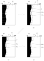
次に、図4は、図3のカメラ33が撮像した裾底部13の画像の一例を示す説明図である。図4に示すように、カメラ33が撮像した画像は、X軸及びY軸を有する2次元画素データを含んでいる。X軸はガラス容器1の高さ方向に相当し、Y軸はガラス容器1の周方向に相当する。画像には、暗部40及び明部41が含まれている。暗部40は、ガラス容器1の底部131に対応する部分であり、X軸の一端側(図中左側)に位置している。図4に示す一例としての暗部40の輪郭は、全体として連続的な曲線で構成されている。暗部40には、裾部130と底部131との間のバッフルマークに相当する一対のスパイク部40aも含まれている。スパイク部40aは、連続的な曲線から突出されたとげ状の部分であり、X軸及びY軸の両方に対して傾斜する直線状の輪郭を有している。明部41は、ガラス容器1の裾部130に対応する部分であり、X軸の他端側(図中右側)に位置している。異物2は、ガラス容器1の裾部130に対応する明部41の中に点状の暗部として現れている。
Next, FIG. 4 is an explanatory diagram showing an example of an image of the
次に、図5は図3の判定装置34の構成を示すブロック図であり、図6は図5の判定装置34による画像処理を示す説明図である。図5に示すように、本実施の形態の判定装置34は、明部輪郭線画定部340、オフセット部341、検知エリア線画定部342、ずれ量算出部343、特異領域検出部344、検知エリア線補正部345及び異物検出部346を有している。
Next, FIG. 5 is a block diagram showing the configuration of the
明部輪郭線画定部340は、画像のX軸の一端から他端側に向けて明部41を検出したときに明部41が初めて検出されるX軸座標をY軸に連ねて、図6(a)にて破線で示す明部輪郭線5を画定する。図6(a)の暗部40中に示す白抜きの矢印は、X軸の一端から他端側に向けて明部41を検出している様子を示している。
The bright-portion
オフセット部341は、図6(b)に示すように、明部輪郭線画定部340により確定された明部輪郭線5をX軸の他端側にオフセットする。明部輪郭線5のオフセット量は、スパイク部40aから明部輪郭線5が離れるように、X軸に係るスパイク部40aの幅より大きく設定される。
As shown in FIG. 6B, the offset
検知エリア線画定部342は、X軸の他端側から一端側に向けて暗部40を検出したときに暗部40が初めて検出されるX軸座標をY軸方向に連ねて検知エリア線6を画定する。スパイク部40a及び異物2がある位置では、検知エリア線6は、暗部40の連続的な曲線部分に一致されず、スパイク部40a及び異物2に沿って画定される。本実施の形態の検知エリア線画定部342は、X軸の他端から暗部40を検出せず、オフセット部341によってオフセットされた明部輪郭線5から一端側に向けて暗部40を検出する。オフセットされた明部輪郭線5から暗部40を検出することで、明部41にリングマーク132等の外乱要素の影が存在したとしても、外乱要素の影をガラス容器1の底部131に対応する暗部40と誤認する虞を低減できる。但し、明部輪郭線5をオフセットする代りに、スパイク部40aよりもX軸の他端側に基準線を設定し、その基準線から一端側に向けて暗部40を検出してもよい。基準線は、任意の線でよいが、例えばY軸と平行に延在する直線とすることができる。また、明部輪郭線画定部340及びオフセット部341が省略されて、検知エリア線画定部342がX軸の他端から暗部40を検出してもよい。
The detection area
ずれ量算出部343は、検知エリア線画定部342が検知エリア線6を画定した後に、Y軸に沿って検知エリア線6のX軸座標のずれ量を算出する。本実施の形態のずれ量算出部343は、2つの連続するY軸座標における検知エリア線6のX軸座標のずれ量を算出する。但し、連続していなくても例えば10画素(ピクセル)以内等の近接するY軸座標における検知エリア線6のX軸座標のずれ量を算出してもよい。なお、X軸の1画素は0.015mm程度であり得る。例えば異物2よりもY軸の一端側(上側)では、検知エリア線6が連続的であるためずれ量は小さい。一方、異物2の前後では大きなずれ量が算出されることになる。
After the detection area
特異領域検出部344は、Y軸の一端から他端に向けてX軸座標のずれ量をスキャンして、異物2により検知エリア線6が非連続となっている特異領域7を検出する。Y軸の所定座標範囲内で、検知エリア線6のX軸座標がX軸の一端側から他端側に所定量以上をずれるとともに、検知エリア線6のX軸座標がX軸の他端側から一端側に所定量以上をずれる領域を探すことで、特異領域7を検出することができる。検知エリア線6のX軸座標の変化を関連付けて見つけるY軸の座標範囲を適切に設定することで、異物2により検知エリア線6が非連続となっている特異領域7と、スパイク部40aにより検知エリア線6が非連続となっている領域とを区別することができる。例えば、Y軸に関して50画素以内で、検知エリア線6がX軸に関して15画素以上の幅を往復した領域を特異領域7として検出することができる。Y軸方向の分解能が0.06mm/画素であるときY軸の50画素は3mmであり、X軸方向の分解能が0.015mm/画素であるときX軸の15画素は0.225mmである。
The peculiar
検知エリア線補正部345は、特異領域7が検出されるとき、特異領域検出部344によるずれ量のスキャンの方向に係る特異領域7の前又は後のY軸座標における検知エリア線6のX軸座標を用いて検知エリア線6を補正する(図6(d)参照)。上述のように本実施の形態では、特異領域検出部344は、Y軸の一端から他端に向けてX軸座標のずれ量をスキャンする。特異領域7の前のY軸座標は、Y軸の一端側における特異領域7の直前のY軸座標であり得る。同様に、特異領域7の後のY軸座標は、Y軸の他端側における特異領域7の直後のY軸座標であり得る。但し、直前又は直後でなくても、例えば10画素以内等の近接する検知エリア線6のX軸座標を用いて検知エリア線6を補正してもよい。検知エリア線6の補正は、特異領域7中の検知エリア線6のX軸座標を特異領域7の前又は後のX軸座標に置き換えることで行うことができる。図6(d)では、特異領域7中の検知エリア線6のX軸座標を特異領域7の直前の検知エリア線6のX軸座標に置き換えた態様を示している。このため、補正された検知エリア線6では、特異領域7であった部分のX軸座標が一定値をとっている。特異領域7であった部分のX軸座標が特異領域7の前のX軸座標から特異領域7の後のX軸座標に連続的又は断続的に変化するように検知エリア線6を補正してもよい。
When the
異物検出部346は、補正された検知エリア線6とX軸の他端(明部41側)との間で、異物2に対応する点状の暗部を検出する。具体的には、検知エリア線6とX軸の他端(明部41側)との間で所定値以下の面積(又は所定範囲の面積)を有する暗部が存在する場合に、その暗部を異物2として検出する。例えば、異物2は、X軸方向に関して20画素(0.3[mm]/0.015[mm/画素])、Y軸方向に関して5画素(0.3[mm]/0.06[mm/画素])の暗部であり、その面積は100画素となる。面積100画素の暗部を異物2として検出できるように面積の閾値を設定することで、縦横0.3mmの四角形の異物2を発見することができる。
The
異物検出部346は、X軸の他端、補正された検知エリア線6をX軸の他端側にオフセットした線、又はY軸と平行に延在する直線をX軸の他端側の基準として、異物2に対応する点状の暗部を検出することができる。補正された検知エリア線6をX軸の他端側にオフセットした線、及びY軸と平行に延在する直線は、暗部40からX軸の他端側に400画素程度の位置等、X軸の他端よりもX軸の一端側に近い位置に配置される。これらのX軸の他端よりもX軸の一端側に近い位置の線を基準とすることで、異物2に対応する点状の暗部の検査範囲を限定でき、処理速度を向上できる。
The foreign
特異領域検出部344によって特異領域7が検出されず、検知エリア線補正部345によって検知エリア線6が補正されない場合、異物検出部346は、検知エリア線画定部342によって確定された検知エリア線6とX軸の他端(明部41側)との間で、異物2に対応する点状の暗部を検出することができる。
If the
次に、図7は、本発明の実施の形態によるガラス容器製造方法を示すフローチャートである。図7に示すように、本実施の形態によるガラス容器製造方法は、調合工程(ステップS1)、溶解工程(ステップS2)、成形工程(ステップS3)、徐冷工程(ステップS4)及び検査工程(ステップS5)を含んでいる。 Next, FIG. 7 is a flow chart showing a glass container manufacturing method according to an embodiment of the present invention. As shown in FIG. 7, the glass container manufacturing method according to the present embodiment includes a blending step (step S1), a melting step (step S2), a forming step (step S3), a slow cooling step (step S4), and an inspection step ( step S5).
調合工程(ステップS1)では、製造すべきガラス容器の性質に応じて所定比率で原料が混合される。ガラス容器の原料には、例えば珪砂、ソーダ灰、石灰及びカレット等の主原料と、例えば酸化剤、還元剤、清澄材、消色材及び着色剤等の副原料とが含まれる。 In the mixing step (step S1), raw materials are mixed at a predetermined ratio according to the properties of the glass container to be manufactured. Raw materials for the glass container include main raw materials such as silica sand, soda ash, lime and cullet, and auxiliary raw materials such as oxidizing agents, reducing agents, clarifying agents, decolorizing agents and coloring agents.
溶解工程(ステップS2)は、調合工程で調合された原料をガラス溶解窯にて加熱及び溶解することにより溶融ガラスを生成する工程である。 The melting step (step S2) is a step of heating and melting the raw materials blended in the blending step in a glass melting furnace to produce molten glass.
成形工程(ステップS3)は、溶融ガラスからガラス容器を成形する工程である。粗型にて溶融ガラスからパリソンと呼ばれる中間体を成形し、仕上型にてパリソンからガラス容器を成形することができる。 The forming step (step S3) is a step of forming a glass container from molten glass. An intermediate body called a parison can be formed from molten glass in a rough mold, and a glass container can be formed from the parison in a finishing mold.
徐冷工程(ステップS4)は、成形工程で成形されたガラス容器を徐冷窯に導入し、ガラス容器を徐冷する工程である。 The slow cooling step (step S4) is a step of introducing the glass container molded in the molding step into a slow cooling kiln and slowly cooling the glass container.
検査工程(ステップS5)は、本実施の形態の異物検査装置3を用いて、徐冷工程で徐冷されたガラス容器1の裾底部13に異物2が混入しているか否かを検査する工程である。検査工程で裾底部13に異物2が混入していないと判定されたガラス容器1は、例えば包装及び出荷等の次工程に搬送される。一方、裾底部13に異物2が混入していると判定されたガラス容器1は、次工程に搬送されずに、再検査のため貯められるか又は廃棄される。
The inspection step (step S5) is a step of inspecting, using the foreign
検査工程には、カメラ33により異物検査装置3の裾底部13を撮像する工程と、カメラ33が撮像した画像に基づいて裾底部13に異物2が混入しているか否かを判定装置34により判定する工程とが含まれている。
The inspection process includes a step of capturing an image of the
異物2が混入しているか否かを判定装置34により判定する工程には、画像のX軸の他端側から一端側に向けて暗部40を検出したときに暗部40が初めて検出されるX軸座標をY軸方向に連ねて検知エリア線6を画定する検知エリア線画定工程と、Y軸に沿って検知エリア線6のX軸座標のずれ量を算出するずれ量算出工程と、Y軸の一端から他端に向けてX軸座標のずれ量をスキャンして、異物2により検知エリア線6が非連続となっている特異領域7を検出する特異領域検出工程と、特異領域7が検出されるとき、スキャンの方向に係る特異領域7の前又は後のY軸座標における検知エリア線6のX軸座標を用いて検知エリア線6を補正する検知エリア線補正工程と、補正された検知エリア線6とX軸の他端との間で、異物2に対応する点状の暗部を検出する異物検出工程とが含まれる。
In the step of determining whether or not the
また、異物2が混入しているか否かを判定装置34により判定する工程には、画像のX軸の一端から他端側に向けて明部41を検出したときに明部41が初めて検出されるX軸座標をY軸に連ねて明部輪郭線5を画定する明部輪郭線画定工程と、明部輪郭線5をX軸の他端側にオフセットするオフセット工程とがさらに含まれていてもよい。この場合、検知エリア線画定工程にて、オフセットされた明部輪郭線5からX軸の一端側に向けて暗部40を検出して検知エリア線6を画定することができる。
In addition, in the step of determining whether or not the
このような異物検査装置及びそれを用いたガラス容器製造方法では、リバースリング331を介して表裏反転してカメラ本体330に撮像レンズ332が取り付けられているので、高価な撮像レンズ332を用いなくても微小異物の発見に適した画像を得ることができる。これにより、装置コストを抑えつつ、微小異物をより確実に発見できる。
In such a foreign matter inspection apparatus and a glass container manufacturing method using the same, since the
また、カメラ33は、斜め下方から裾底部13を撮像するように配置されており、カメラ33の光軸33aの仰角が33°以上かつ43°以下であるので、底部131側及び裾部130側の異物2をバランス良く撮像することができ、異物2の検出精度を向上させることができる。
Further, the
また、カメラ33の被写界深度が1.5mm以上かつ5.0mm以下であるので、ピント合わせの容易さを確保しつつ、外乱要素の影響を抑えて異物2の検出精度を向上できる。
In addition, since the depth of field of the
また、光源32が1700lx以上の照度でガラス容器1に光を照射するので、カメラ33によりガラス容器1の裾底部13を撮像した画像において、外乱要素の影をより確実に消すか又は薄くすることができ、その画像に基づく異物2の検出精度を向上させることができる。
In addition, since the
また、光源32には、光源32からの光の拡散を制限するライトコントロールフィルム320が取り付けられているので、異物検査装置3の周囲に対する光の影響を抑えることができる。ライトコントロールフィルム320は、光源32として高輝度光源を用いる際に特に有用である。
Moreover, since the
また、光源32は、カメラ33の光軸33aの仰角θ1に12°以上かつ22°以下の角度θ2を加えた角度だけ水平に対して傾斜した角度でリングマーク132に光を入射させるので、リングマーク132の影がカメラ33の画像に現れる虞を低減でき、異物2の検出精度を向上させることができる。
In addition, the
また、判定装置34は、特異領域7が検出されるとき検知エリア線6を補正した上で、異物2に対応する点状の暗部を検出するので、微小異物をより確実に発見できる。
Further, when the
また、検知エリア線画定部342は、オフセットされた明部輪郭線5からX軸の一端側に向けて暗部40を検出して検知エリア線6を画定するので、明部41にリングマーク132等の外乱要素の影が存在したとしても、外乱要素の影をガラス容器1の底部131に対応する暗部40と誤認する虞を低減できる。
Further, since the detection
なお、実施の形態では、リバースリング331を介して表裏反転して撮像レンズ332がカメラ本体330に取り付けられるように説明したが、表裏反転せずに撮像レンズ332がカメラ本体330に取り付けられた状態で撮像された画像に基づいて判定装置34が異物2の混入を判定してもよい。
In the embodiment, the
1 ガラス容器
13 裾底部
130 裾部
131 底部
132 リングマーク
2 異物
3 異物検査装置
32 光源
320 ライトコントロールフィルム
33 カメラ
33a 光軸
330 カメラ本体
331 リバースリング
332 撮像レンズ
34 判定装置
340 明部輪郭線画定部
341 オフセット部
342 検知エリア線画定部
343 ずれ量算出部
344 特異領域検出部
345 検知エリア線補正部
346 異物検出部
40 暗部
41 明部
5 明部輪郭線
6 検知エリア線
7 特異領域
Claims (10)
前記ガラス容器の裾底部を撮像するカメラと、
前記カメラが撮像した画像に基づいて前記裾底部に異物が混入しているか否かを判定する判定装置と
を備え、
前記カメラは、
カメラ本体と、
前記カメラ本体に取り付けられたリバースリングと、
前記リバースリングを介して表裏反転して前記カメラ本体に取り付けられた撮像レンズと
を有し、
前記画像は、X軸及びY軸を有する2次元画素データを含んでおり、
前記画像には、X軸の一端側に位置するとともに前記ガラス容器の底部に対応する暗部と、前記X軸の他端側に位置するとともに前記ガラス容器の裾部に対応する明部とが含まれており、
前記画像において、前記異物は、前記ガラス容器の裾部に対応する明部の中に点状の暗部として現れ、
前記判定装置は、
前記X軸の他端側から一端側に向けて前記暗部を検出したときに前記暗部が初めて検出されるX軸座標を前記Y軸方向に連ねて検知エリア線を画定する検知エリア線画定部と、
前記Y軸に沿って前記検知エリア線のX軸座標のずれ量を算出するずれ量算出部と、
前記Y軸の一端から他端に向けて前記X軸座標のずれ量をスキャンして、前記異物により前記検知エリア線が非連続となっている特異領域を検出する特異領域検出部と、
前記特異領域が検出されるとき、前記スキャンの方向に係る前記特異領域の前又は後のY軸座標における前記検知エリア線のX軸座標を用いて前記検知エリア線を補正する検知エリア線補正部と、
補正された前記検知エリア線と前記X軸の他端との間で、前記異物に対応する点状の暗部を検出する異物検出部と
を有している、
異物検査装置。 a light source that irradiates the glass container with light;
a camera for imaging the hem bottom of the glass container;
a determination device that determines whether or not foreign matter is mixed in the skirt bottom based on the image captured by the camera,
The camera is
camera body and
a reverse ring attached to the camera body;
an imaging lens attached to the camera body by being turned upside down via the reverse ring;
the image includes two-dimensional pixel data having an X-axis and a Y-axis;
The image includes a dark portion located on one end side of the X-axis and corresponding to the bottom of the glass container, and a bright portion located on the other end side of the X-axis and corresponding to the bottom portion of the glass container. and
In the image, the foreign matter appears as a dot-like dark portion in a bright portion corresponding to the bottom portion of the glass container,
The determination device is
a detection area line defining unit that defines a detection area line by connecting in the Y-axis direction the X-axis coordinates at which the dark portion is detected for the first time when the dark portion is detected from the other end side of the X-axis toward one end side; ,
a shift amount calculation unit that calculates a shift amount of the X-axis coordinate of the detection area line along the Y-axis;
a peculiar area detection unit that scans the deviation amount of the X-axis coordinates from one end of the Y-axis toward the other end to detect a peculiar area where the detection area line is discontinuous due to the foreign matter;
A detection area line correction unit for correcting the detection area line using the X-axis coordinate of the detection area line in the Y-axis coordinates before or after the specific area in the scanning direction when the specific area is detected. and,
a foreign object detection unit that detects a dotted dark part corresponding to the foreign object between the corrected detection area line and the other end of the X axis;
have,
Foreign object inspection device.
前記カメラの光軸の仰角が33°以上かつ43°以下である、
請求項1記載の異物検査装置。 The camera is arranged to capture an image of the hem bottom from obliquely below,
The elevation angle of the optical axis of the camera is 33° or more and 43° or less.
A foreign matter inspection apparatus according to claim 1.
請求項1又は請求項2に記載の異物検査装置。 The camera has a depth of field of 1.5 mm or more and 5.0 mm or less.
The foreign matter inspection device according to claim 1 or 2.
請求項1から請求項3までのいずれか一項に記載の異物検査装置。 The light source irradiates the glass container with an illuminance of 1700 lx or more.
The foreign matter inspection device according to any one of claims 1 to 3.
請求項1から請求項4までのいずれか一項に記載の異物検査装置。 The light source is fitted with a light control film that limits the diffusion of light from the light source.
The foreign matter inspection device according to any one of claims 1 to 4.
前記光源は、前記カメラの光軸の仰角に12°以上かつ22°以下の角度を加えた角度だけ水平に対して傾斜した角度で前記リングマークに光を入射させる、
請求項1から請求項5までのいずれか1項に記載の異物検査装置。 A ring mark is provided on the outer peripheral surface of the hem bottom,
The light source causes light to enter the ring mark at an angle inclined with respect to the horizontal by an angle equal to or greater than 12° and equal to or less than 22° to the elevation angle of the optical axis of the camera.
The foreign matter inspection device according to any one of claims 1 to 5.
前記X軸の一端から他端側に向けて前記明部を検出したときに前記明部が初めて検出されるX軸座標を前記Y軸に連ねて明部輪郭線を画定する明部輪郭線画定部と、
前記明部輪郭線を前記X軸の他端側にオフセットするオフセット部と
をさらに有しており、
前記検知エリア線画定部は、オフセットされた前記明部輪郭線から一端側に向けて前記暗部を検出して検知エリア線を画定する、
請求項1から請求項6までのいずれか1項に記載の異物検査装置。 The determination device is
Defining a bright portion outline by linking the X-axis coordinates at which the bright portion is detected for the first time when the bright portion is detected from one end of the X axis toward the other end to the Y axis to define a bright portion outline. Department and
and an offset portion that offsets the bright portion contour line to the other end side of the X axis,
The detection area line demarcation unit detects the dark part toward one end side from the offset bright part outline to demarcate the detection area line.
The foreign matter inspection device according to any one of claims 1 to 6 .
前記ガラス容器の裾底部を撮像するカメラと、
前記カメラが撮像した画像に基づいて前記裾底部に異物が混入しているか否かを判定する判定装置と
を備え、
前記画像は、X軸及びY軸を有する2次元画素データを含んでおり、
前記画像には、X軸の一端側に位置するとともに前記ガラス容器の底部に対応する暗部と、前記X軸の他端側に位置するとともに前記ガラス容器の裾部に対応する明部とが含まれており、
前記画像において、前記異物は、前記ガラス容器の裾部に対応する明部の中に点状の暗部として現れ、
前記判定装置は、
前記X軸の他端側から一端側に向けて前記暗部を検出したときに前記暗部が初めて検出されるX軸座標を前記Y軸方向に連ねて検知エリア線を画定する検知エリア線画定部と、
前記Y軸に沿って前記検知エリア線のX軸座標のずれ量を算出するずれ量算出部と、
前記Y軸の一端から他端に向けて前記X軸座標のずれ量をスキャンして、前記異物により前記検知エリア線が非連続となっている特異領域を検出する特異領域検出部と、
前記特異領域が検出されるとき、前記スキャンの方向に係る前記特異領域の前又は後のY軸座標における前記検知エリア線のX軸座標を用いて前記検知エリア線を補正する検知エリア線補正部と、
補正された前記検知エリア線と前記X軸の他端との間で、前記異物に対応する点状の暗部を検出する異物検出部と
を有している、
異物検査装置。 a light source that irradiates the glass container with light;
a camera for imaging the hem bottom of the glass container;
a determination device that determines whether or not foreign matter is mixed in the skirt bottom based on the image captured by the camera,
the image includes two-dimensional pixel data having an X-axis and a Y-axis;
The image includes a dark portion located on one end side of the X-axis and corresponding to the bottom of the glass container, and a bright portion located on the other end side of the X-axis and corresponding to the bottom portion of the glass container. and
In the image, the foreign matter appears as a dot-like dark portion in a bright portion corresponding to the bottom portion of the glass container,
The determination device is
a detection area line defining unit that defines a detection area line by connecting in the Y-axis direction the X-axis coordinates at which the dark portion is detected for the first time when the dark portion is detected from the other end side of the X-axis toward one end side; ,
a shift amount calculation unit that calculates a shift amount of the X-axis coordinate of the detection area line along the Y-axis;
a peculiar area detection unit that scans the deviation amount of the X-axis coordinates from one end of the Y-axis toward the other end to detect a peculiar area where the detection area line is discontinuous due to the foreign matter;
A detection area line correction unit for correcting the detection area line using the X-axis coordinate of the detection area line in the Y-axis coordinates before or after the specific area in the scanning direction when the specific area is detected. and,
a foreign object detection unit that detects a dot-like dark part corresponding to the foreign object between the corrected detection area line and the other end of the X-axis,
Foreign object inspection device.
前記X軸の一端から他端側に向けて前記明部を検出したときに前記明部が初めて検出されるX軸座標を前記Y軸に連ねて明部輪郭線を画定する明部輪郭線画定部と、
前記明部輪郭線を前記X軸の他端側にオフセットするオフセット部と
をさらに有しており、
前記検知エリア線画定部は、オフセットされた前記明部輪郭線から一端側に向けて前記暗部を検出して検知エリア線を画定する、
請求項8記載の異物検査装置。 The determination device is
Defining a bright portion outline by linking the X-axis coordinates at which the bright portion is detected for the first time when the bright portion is detected from one end of the X axis toward the other end to the Y axis to define a bright portion outline. Department and
and an offset portion that offsets the bright portion contour line to the other end side of the X axis,
The detection area line demarcation unit detects the dark part toward one end side from the offset bright part outline to demarcate the detection area line.
A foreign matter inspection apparatus according to claim 8 .
ガラス容器製造方法。 A step of inspecting whether foreign matter is mixed in the bottom of the glass container using the foreign matter inspection device according to any one of claims 1 to 9 ,
Glass container manufacturing method.
Priority Applications (1)
| Application Number | Priority Date | Filing Date | Title |
|---|---|---|---|
| JP2019089324A JP7229092B2 (en) | 2019-05-09 | 2019-05-09 | Foreign matter inspection device and glass container manufacturing method using the same |
Applications Claiming Priority (1)
| Application Number | Priority Date | Filing Date | Title |
|---|---|---|---|
| JP2019089324A JP7229092B2 (en) | 2019-05-09 | 2019-05-09 | Foreign matter inspection device and glass container manufacturing method using the same |
Publications (2)
| Publication Number | Publication Date |
|---|---|
| JP2020186919A JP2020186919A (en) | 2020-11-19 |
| JP7229092B2 true JP7229092B2 (en) | 2023-02-27 |
Family
ID=73222738
Family Applications (1)
| Application Number | Title | Priority Date | Filing Date |
|---|---|---|---|
| JP2019089324A Active JP7229092B2 (en) | 2019-05-09 | 2019-05-09 | Foreign matter inspection device and glass container manufacturing method using the same |
Country Status (1)
| Country | Link |
|---|---|
| JP (1) | JP7229092B2 (en) |
Citations (3)
| Publication number | Priority date | Publication date | Assignee | Title |
|---|---|---|---|---|
| JP2012122912A (en) | 2010-12-10 | 2012-06-28 | Kirin Techno-System Co Ltd | Determination method of inspection region and foreign matter inspection device |
| JP2014085525A (en) | 2012-10-24 | 2014-05-12 | Olympus Imaging Corp | Interchangeable lens and imaging device using the same |
| JP2015169442A (en) | 2014-03-04 | 2015-09-28 | 東洋ガラス機械株式会社 | Opening inspection device of glass bottle |
Family Cites Families (2)
| Publication number | Priority date | Publication date | Assignee | Title |
|---|---|---|---|---|
| JPH0785061B2 (en) * | 1993-04-12 | 1995-09-13 | 東洋ガラス株式会社 | Foreign substance inspection device at the bottom of the transparent glass container |
| JPH11166906A (en) * | 1997-12-05 | 1999-06-22 | Kirin Techno System:Kk | Bottle inspecting device |
-
2019
- 2019-05-09 JP JP2019089324A patent/JP7229092B2/en active Active
Patent Citations (3)
| Publication number | Priority date | Publication date | Assignee | Title |
|---|---|---|---|---|
| JP2012122912A (en) | 2010-12-10 | 2012-06-28 | Kirin Techno-System Co Ltd | Determination method of inspection region and foreign matter inspection device |
| JP2014085525A (en) | 2012-10-24 | 2014-05-12 | Olympus Imaging Corp | Interchangeable lens and imaging device using the same |
| JP2015169442A (en) | 2014-03-04 | 2015-09-28 | 東洋ガラス機械株式会社 | Opening inspection device of glass bottle |
Also Published As
| Publication number | Publication date |
|---|---|
| JP2020186919A (en) | 2020-11-19 |
Similar Documents
| Publication | Publication Date | Title |
|---|---|---|
| JP6778754B2 (en) | Burn inspection device for glass containers | |
| TWI426261B (en) | End inspection device | |
| US20080094618A1 (en) | Machine for inspecting glass containers | |
| US20100085426A1 (en) | Machine for Inspecting Glass Containers | |
| KR0145173B1 (en) | Apparatus for inspecting a bottom border portion of a transparent glass level | |
| JPH11108643A (en) | Method and device for inspecting sealing surface area of container | |
| JP2010107254A (en) | Device and method for inspecting led chip | |
| JP6134383B2 (en) | Optical method for inspecting transparent or translucent containers with visible patterns | |
| JP4493048B2 (en) | Inspection device | |
| JP7382519B2 (en) | Glass bottle inspection method, glass bottle manufacturing method, and glass bottle inspection device | |
| JP7229092B2 (en) | Foreign matter inspection device and glass container manufacturing method using the same | |
| JP2010091530A (en) | Method and apparatus for inspecting foreign substance | |
| KR102205582B1 (en) | Container inspection device and container inspection method | |
| JP5726628B2 (en) | Appearance inspection apparatus and appearance inspection method for transparent body bottle | |
| JP2012122912A (en) | Determination method of inspection region and foreign matter inspection device | |
| KR20140031392A (en) | Container mouth portion inspection method and device | |
| JPH0797087B2 (en) | Inspection of container split | |
| JP5959430B2 (en) | Bottle cap appearance inspection device and appearance inspection method | |
| KR102540808B1 (en) | Glass bottle inspection method and glass bottle manufacturing method | |
| US6621573B2 (en) | Glass container inspection machine | |
| JPH07104290B2 (en) | Bottle inspection equipment | |
| JPS62113050A (en) | Bottle mouth inspection system | |
| JP2009162728A (en) | Transparent body inspection apparatus, transparent body inspection method, and transparent body inspection system | |
| JP2005189196A (en) | Inspection device of foreign matter in liquid | |
| JP2019174195A (en) | Support ring inspection device and support ring inspection method of container with support ring |
Legal Events
| Date | Code | Title | Description |
|---|---|---|---|
| A621 | Written request for application examination |
Free format text: JAPANESE INTERMEDIATE CODE: A621 Effective date: 20211126 |
|
| A977 | Report on retrieval |
Free format text: JAPANESE INTERMEDIATE CODE: A971007 Effective date: 20220930 |
|
| A131 | Notification of reasons for refusal |
Free format text: JAPANESE INTERMEDIATE CODE: A131 Effective date: 20221004 |
|
| A521 | Request for written amendment filed |
Free format text: JAPANESE INTERMEDIATE CODE: A523 Effective date: 20221111 |
|
| TRDD | Decision of grant or rejection written | ||
| A01 | Written decision to grant a patent or to grant a registration (utility model) |
Free format text: JAPANESE INTERMEDIATE CODE: A01 Effective date: 20230131 |
|
| A61 | First payment of annual fees (during grant procedure) |
Free format text: JAPANESE INTERMEDIATE CODE: A61 Effective date: 20230214 |
|
| R150 | Certificate of patent or registration of utility model |
Ref document number: 7229092 Country of ref document: JP Free format text: JAPANESE INTERMEDIATE CODE: R150 |