JP2012122912A - Determination method of inspection region and foreign matter inspection device - Google Patents
Determination method of inspection region and foreign matter inspection device Download PDFInfo
- Publication number
- JP2012122912A JP2012122912A JP2010275228A JP2010275228A JP2012122912A JP 2012122912 A JP2012122912 A JP 2012122912A JP 2010275228 A JP2010275228 A JP 2010275228A JP 2010275228 A JP2010275228 A JP 2010275228A JP 2012122912 A JP2012122912 A JP 2012122912A
- Authority
- JP
- Japan
- Prior art keywords
- image
- inspection
- inspection area
- glass bottle
- foreign matter
- Prior art date
- Legal status (The legal status is an assumption and is not a legal conclusion. Google has not performed a legal analysis and makes no representation as to the accuracy of the status listed.)
- Pending
Links
Images


Abstract
Description
本発明は、ガラス壜を撮像してガラス壜の欠陥またはガラス壜内の異物を検出するための検査を行う際の検査領域の決定方法に関するものである。また、本発明はガラス壜を撮像してガラス壜の底部に異物があるか否かを検査する異物検査装置に関するものである。 The present invention relates to a method for determining an inspection area when performing an inspection to detect a defect in a glass bottle or a foreign substance in the glass bottle by imaging a glass bottle. The present invention also relates to a foreign substance inspection apparatus that images a glass bottle and inspects whether or not there is a foreign substance at the bottom of the glass bottle.
飲料等の液体が充填されたガラス壜にゴムパッキン片やガラス片等の異物が混入している場合がある。異物はガラス壜の底部に沈殿していることが多い。そのため、ガラス壜に飲料等の液体を充填した後に壜の底部又は底部付近に異物が沈殿しているか否かの検査を行っている。ガラス壜をコンベア等の搬送装置で搬送している間に、壜底部に沈殿した異物を自動検査するには、ガラス壜の斜め上方からカメラで壜底部を撮像し、得られた画像から壜底の位置と形状を特定して検査領域を作成する必要がある。
従来、自動検査のための検査領域は以下の手順で作成されている。まず、あらかじめ検査領域の固定された形状を設定し、検査のために壜を撮影した画像からあらかじめ設定した位置(固定位置)で壜の特定部位のエッジ等を検出する。これにより、壜のXY方向の位置を特定し、特定した壜のXY方向の位置に基づいてXY方向の位置ズレ量を検出し、この位置ズレ量に合わせて検査領域を移動することにより自動検査のための検査領域を作成している。
In some cases, foreign substances such as rubber packing pieces and glass pieces are mixed in a glass bottle filled with a liquid such as a beverage. Foreign objects often settle on the bottom of the glass bottle. Therefore, after filling a glass bottle with a liquid such as a beverage, an inspection is performed to determine whether or not foreign matter has precipitated at the bottom or near the bottom of the bottle. In order to automatically inspect foreign matter that has settled on the bottom of the glass bottle while the glass bottle is being transported by a conveyor or other transport device, the bottom of the glass bottle is imaged from the diagonally upper side of the glass bottle. Therefore, it is necessary to create an inspection region by specifying the position and shape.
Conventionally, an inspection area for automatic inspection is created by the following procedure. First, a fixed shape of an inspection area is set in advance, and an edge of a specific part of the eyelid is detected at a preset position (fixed position) from an image obtained by photographing the eyelid for inspection. As a result, the position of the eyelid in the XY direction is specified, the position shift amount in the XY direction is detected based on the specified position in the XY direction, and automatic inspection is performed by moving the inspection area according to the position shift amount. An inspection area is created for.
上述した従来の自動検査のための検査領域の作成方法には、以下のような問題点がある。
(1)検査領域が固定形状のため、検査対象のガラス壜がコンベア上で前後にずれて像の大きさが変化する場合にはあらかじめその変化量を見込んで検査領域の形状を設定しなければならない。そのため、設定に手間がかかるだけでなく、検査領域を小さく設定することになるため、検査に不利となる。
(2)検査対象のXY方向の位置ズレ量を検出する必要があり、検査毎に安定したXY方向の位置ズレ量を検出できるウィンドウをあらかじめ設定しなければならない。ウィンドウの設定が適正になされないと、検査画像と検査領域にズレが生じ誤検出の原因となる。また、前記位置ズレ量が検出できない場合には、あらかじめ位置ズレ量を予想し、位置ズレ量分だけ検査領域を小さく設定することになるため、検査に不利となる。
The above-described conventional method for creating an inspection area for automatic inspection has the following problems.
(1) Since the inspection area has a fixed shape, if the glass bottle to be inspected shifts back and forth on the conveyor and the image size changes, the inspection area shape must be set in anticipation of the amount of change. Don't be. For this reason, not only the setting takes time, but also the inspection area is set small, which is disadvantageous for inspection.
(2) It is necessary to detect the amount of positional deviation in the XY direction of the inspection target, and a window capable of detecting a stable positional deviation amount in the XY direction for each inspection must be set in advance. If the window is not set properly, the inspection image and the inspection area will be misaligned, causing erroneous detection. Further, when the positional deviation amount cannot be detected, the positional deviation amount is predicted in advance, and the inspection area is set to be small by the positional deviation amount, which is disadvantageous for inspection.
本発明は、上述の事情に鑑みなされたもので、検査対象の形状バラツキに対応でき、検査対象の位置ズレ量を検出する必要がなく、また、コンベア等の搬送装置上での検査対象の位置のバラツキによる微細な大きさ形状変化にも対応できる検査領域の決定方法および異物検査装置を提供することを目的とする。 The present invention has been made in view of the above-described circumstances, can cope with variations in the shape of an inspection target, does not need to detect the amount of positional displacement of the inspection target, and is the position of the inspection target on a transport device such as a conveyor. It is an object of the present invention to provide an inspection region determination method and a foreign matter inspection apparatus that can cope with a minute size and shape change due to variations in size.
上述の目的を達成するため、本発明者らは、自動検査のための検査領域の作成方法について鋭意研究を行い、以下のような知見を得た。
ガラス壜の壜底部において、壜底外形部分(壜外側部分)の形状は一定しているが、壜底下端部分(壜底内面)の形状は壜毎に変化し形状特定が困難である。また、茶色の壜など光を通し難い壜では、コンベア等の搬送装置上に壜の影ができるため壜底外形部分(壜外側部分)の検出が困難である。さらに、壜底頂上部分(壜底内面の中央部の盛り上がった部分)は形状が一定しないため、頂上部分を検出して壜底下端部分(壜底内面)を推定するのは困難であり、このため、壜の上下方向位置の特定は困難である。
In order to achieve the above-mentioned object, the present inventors conducted earnest research on a method for creating an inspection region for automatic inspection, and obtained the following knowledge.
At the bottom of the glass bottle, the shape of the bottom outer part (outer side part) is constant, but the shape of the bottom bottom part (the inner surface of the bottom) changes from one bowl to another, making it difficult to specify the shape. Moreover, in the case of a cocoon that is difficult to transmit light, such as a brown cocoon, a cocoon shadow is formed on a conveying device such as a conveyor, so that it is difficult to detect the heel bottom outer portion (the outer heel portion). Furthermore, since the shape of the top part of the bottom of the bottom (the raised part of the central part of the inner surface of the bottom) is not constant, it is difficult to detect the bottom part of the bottom (the inner surface of the bottom) by detecting the top part. Therefore, it is difficult to specify the vertical position of the bag.
本発明者らは、ガラス壜を成形する際に壜底下端部分にできるバッフルマーク(またはパーティングライン)が壜底下端部分(壜底内面)とほぼ一致した位置と形状をしていることに着目し、壜底下端内側形状(壜底内面形状)を特定するためにバッフルマークを検出して利用することを着想したものである。
すなわち、本発明の検査領域の決定方法は、ガラス壜を撮像してガラス壜の欠陥またはガラス壜内の異物を検出するための検査を行う際の検査領域の決定方法であって、ガラス壜の壜底部をカメラによって撮影して壜底部の画像を得、前記画像から、ガラス壜を成形する際に壜底下端部分にできるバッフルマークを検出し、検出したバッフルマークを利用して画像中に検査領域を決定することを特徴とする。
The inventors of the present invention have a baffle mark (or parting line) formed at the bottom bottom portion of the bottom of the glass bowl when forming the glass bowl, and has a position and a shape that substantially coincide with the bottom bottom part (bottom inner surface). Focusing on this, the idea is to detect and use baffle marks in order to identify the bottom bottom inner side shape (bottom bottom inner surface shape).
That is, the method for determining an inspection area of the present invention is a method for determining an inspection area when performing an inspection to detect defects in the glass bottle or foreign matter in the glass bottle by imaging the glass bottle. The bottom of the heel is photographed with a camera to obtain an image of the heel, and the baffle mark that can be formed at the bottom of the heel is detected from the image, and the image is inspected using the detected baffle mark. A region is determined.
本発明によれば、照明からの拡散光はガラス壜の照明側の壜側面部から入射し、壜底部で反射し、カメラ側の壜側面部からカメラに入射して撮影される。カメラで撮影された壜底部の画像は、画像処理され、壜底下端部分にあるバッフルマークが検出される。そして、検出したバッフルマークを利用して画像中に検査領域を決定する。このバッフルマークは壜底下端内側形状(壜底内面形状)に近い位置にあるため、検査領域を決定する基準として利用するものである。 According to the present invention, the diffused light from the illumination is incident from the illuminating side surface portion of the glass jar on the illuminating side, reflected from the heel bottom portion, and incident on the camera side from the heel side surface portion and photographed. The image of the heel bottom imaged by the camera is subjected to image processing, and a baffle mark at the bottom edge of the heel bottom is detected. Then, the inspection area is determined in the image using the detected baffle mark. Since this baffle mark is in a position close to the bottom bottom inner shape (the bottom inner surface shape), it is used as a reference for determining the inspection region.
本発明の好ましい態様によれば、前記検出したバッフルマークから前記検査領域の下端線を決定することを特徴とする。
本発明によれば、バッフルマークは壜底下端内側形状(壜底内面形状)に近い位置にあるため、検出したバッフルマークから検査領域の下端線を決定すれば、壜形状計測の手間が省け、壜毎の形状バラツキにも対応できる。また、コンベア等の搬送装置上での壜位置のバラツキによる微細な形状変化にも対応できる。
According to a preferred aspect of the present invention, a lower end line of the inspection area is determined from the detected baffle mark.
According to the present invention, since the baffle mark is close to the bottom bottom inner shape (bottom bottom inner shape), if the bottom line of the inspection area is determined from the detected baffle mark, the labor of the bowl shape measurement can be saved, It can also handle variations in the shape of each bowl. In addition, it is possible to cope with minute shape changes due to variations in the wrinkle position on a conveying device such as a conveyor.
本発明の好ましい態様によれば、前記画像にラプラスフィルタをかけて前記バッフルマークを顕在化することにより前記検査領域の下端線を決定することを特徴とする。
本発明の好ましい態様によれば、前記画像にガンマ補正を施し前記バッフルマークを顕在化することにより前記検査領域の下端線を決定することを特徴とする。
According to a preferred aspect of the present invention, a bottom line of the inspection area is determined by applying a Laplace filter to the image to reveal the baffle mark.
According to a preferred aspect of the present invention, gamma correction is performed on the image to reveal the baffle mark, thereby determining the lower end line of the inspection area.
本発明の好ましい態様によれば、前記検査領域の下端線は楕円方程式で表されることを特徴とする。
本発明によれば、検査領域の下端線を楕円方程式で表すことができるため、検査領域の下端線を画像上で明確に特定することができる。
According to a preferred aspect of the present invention, the lower end line of the inspection region is represented by an elliptic equation.
According to the present invention, since the lower end line of the inspection area can be expressed by an elliptic equation, the lower end line of the inspection area can be clearly identified on the image.
本発明の好ましい態様によれば、前記検査領域の下端線から画像の上方に向かってスキャンし、前記検査領域の上端を、一定以上の明るさの画素が連続して続く領域の開始点を検出することにより決定することを特徴とする。
本発明によれば、バッフルマークは壜底下端内側形状(壜底内面形状)の直下にあるため、検出されたバッフルマークから決定された検査領域の下端線から画像を上方にスキャンする。壜底下端内側形状(壜底内面形状)よりやや上方の部位は、画像中では明るい画像部分になっているために、検査領域の上端を、あらかじめ決定しておく必要がなく、検査領域の下端線から画像を上方に向かってスキャンし、一定以上の明るさの画素が連続して続く領域の開始点を検出することにより自動的に決定できる。
According to a preferred aspect of the present invention, scanning is performed from the lower end line of the inspection area toward the upper side of the image, and the upper end of the inspection area is detected as a start point of an area in which pixels having a certain brightness or higher continue. It is characterized by determining by doing.
According to the present invention, since the baffle mark is directly below the bottom bottom inner shape (bottom bottom inner surface shape), the image is scanned upward from the bottom line of the inspection area determined from the detected baffle mark. Since the part slightly above the inner bottom edge shape (inner bottom inner surface shape) is a bright image portion in the image, there is no need to determine the upper end of the inspection area in advance, and the lower end of the inspection area. The image can be automatically determined by scanning the image upward from the line and detecting the start point of a region in which pixels of a certain brightness or higher continue.
本発明の異物検査装置は、ガラス壜を所定の搬送経路に沿って搬送している間にガラス壜を撮像してガラス壜の底部に異物があるか否かを検査する装置において、前記搬送経路に沿って搬送されるガラス壜の側方に配置され、ガラス壜内を照明する照明と、ガラス壜を挟んで前記照明と対向して配置され、ガラス壜の壜底部を透過した透過光を撮影するカメラと、前記カメラで壜底部を撮影した画像を処理する画像処理装置とを備え、前記画像処理装置は、前記画像から、ガラス壜を成形する際に壜底下端部分にできるバッフルマークを検出し、検出したバッフルマークを利用して画像中に検査領域を決定することを特徴とする。 The foreign matter inspection apparatus according to the present invention is an apparatus that images a glass bottle while the glass bottle is being conveyed along a predetermined conveyance path and inspects whether or not there is a foreign substance at the bottom of the glass bottle. It is arranged on the side of the glass bottle that is transported along the side of the glass bottle, and illuminates the inside of the glass bottle, and is arranged opposite to the illumination with the glass bottle in between, and shoots the transmitted light that has passed through the bottom of the glass bottle. And an image processing device that processes an image obtained by photographing the bottom of the bottom with the camera. The image processing device detects, from the image, a baffle mark that can be formed at the bottom end of the bottom of the glass when forming a glass bottle. The inspection area is determined in the image using the detected baffle mark.
本発明によれば、照明からの拡散光はガラス壜の照明側の壜側面部から入射し、壜底部で反射し、カメラ側の壜側面部からカメラに入射して撮影される。カメラで撮影された壜底部の画像は、画像処理装置により画像処理され、壜底下端部分にあるバッフルマークが検出される。そして、検出したバッフルマークを利用して画像中に検査領域を決定する。このバッフルマークは壜底下端内側形状(壜底内面形状)に近い位置にあるため、検査領域を決定する基準として利用するものである。 According to the present invention, the diffused light from the illumination is incident from the illuminating side surface portion of the glass jar on the illuminating side, reflected from the heel bottom portion, and incident on the camera side from the heel side surface portion and photographed. The image of the heel bottom imaged by the camera is subjected to image processing by an image processing device, and a baffle mark at the bottom edge of the heel bottom is detected. Then, the inspection area is determined in the image using the detected baffle mark. Since this baffle mark is in a position close to the bottom bottom inner shape (the bottom inner surface shape), it is used as a reference for determining the inspection region.
本発明の好ましい態様によれば、前記ガラス壜はコンベアによって直線搬送経路に沿って搬送されることを特徴とする。
本発明によれば、コンベアの一側に照明を配置し、コンベアの他側にカメラを配置し、ガラス壜をコンベアによって直線搬送経路に沿って搬送している間にガラス壜の底部にある異物を検出することができる。
According to a preferred aspect of the present invention, the glass bottle is conveyed along a straight conveyance path by a conveyor.
According to the present invention, the illumination is arranged on one side of the conveyor, the camera is arranged on the other side of the conveyor, and the foreign object at the bottom of the glass bottle while the glass bottle is being conveyed along the straight conveyance path by the conveyor. Can be detected.
本発明の好ましい態様によれば、前記画像処理装置は、前記検出したバッフルマークから前記検査領域の下端線を決定することを特徴とする。
本発明によれば、バッフルマークは壜底下端内側形状(壜底内面形状)に近い位置にあるため、検出したバッフルマークから検査領域の下端線を決定すれば、壜形状計測の手間が省け、壜毎の形状バラツキにも対応できる。また、コンベア等の搬送装置上での壜位置のバラツキによる微細な形状変化にも対応できる。
According to a preferred aspect of the present invention, the image processing apparatus determines a lower end line of the inspection area from the detected baffle mark.
According to the present invention, since the baffle mark is close to the bottom bottom inner shape (bottom bottom inner shape), if the bottom line of the inspection area is determined from the detected baffle mark, the labor of the bowl shape measurement can be saved, It can also handle variations in the shape of each bowl. In addition, it is possible to cope with minute shape changes due to variations in the wrinkle position on a conveying device such as a conveyor.
本発明の好ましい態様によれば、前記検査領域の下端線は楕円方程式で表されることを特徴とする。
本発明によれば、検査領域の下端線を楕円方程式で表すことができるため、検査領域の下端線を画像上で明確に特定することができる。
According to a preferred aspect of the present invention, the lower end line of the inspection region is represented by an elliptic equation.
According to the present invention, since the lower end line of the inspection area can be expressed by an elliptic equation, the lower end line of the inspection area can be clearly identified on the image.
本発明の好ましい態様によれば、前記画像処理装置は、前記検査領域の下端線から画像の上方に向かってスキャン(走査)して、明暗のエッジを求めて異物を検出することを特徴とする。
本発明によれば、バッフルマークは壜底下端内側形状(壜底内面形状)の直下にあるため、検出されたバッフルマークから決定された検査領域の下端線から画像を上方にスキャンすれば、スキャンする範囲を必要最小限にすることができ、無駄にスキャンする領域がなく、検査領域の下端部の下方に存在する壜外側の異物を誤検知することもない。
According to a preferred aspect of the present invention, the image processing apparatus scans from the lower end line of the inspection area toward the upper side of the image to obtain a bright / dark edge and detect a foreign object. .
According to the present invention, since the baffle mark is directly below the bottom bottom inner shape (bottom bottom inner surface shape), if the image is scanned upward from the bottom line of the inspection area determined from the detected baffle mark, the scan is performed. The necessary range can be minimized, there is no useless scanning area, and no foreign matter is detected on the outer side of the lower side of the inspection area.
本発明の好ましい態様によれば、前記画像処理装置は、前記検査領域の上端を、一定以上の明るさの画素が連続して続く領域の開始点を検出することにより決定することを特徴とする。
本発明によれば、壜底下端内側形状(壜底内面形状)よりやや上方の部位は、画像中では明るい画像部分になっているために、検査領域の上端を、あらかじめ決定しておく必要がなく、検査領域の下端線から画像を上方に向かってスキャンし、一定以上の明るさの画素が連続して続く領域の開始点を検出することにより自動的に決定できる。
According to a preferred aspect of the present invention, the image processing apparatus determines the upper end of the inspection region by detecting a start point of a region in which pixels having a certain brightness or higher continue. .
According to the present invention, since the part slightly above the inner bottom bottom inner shape (the inner bottom shape) is a bright image portion in the image, the upper end of the inspection area needs to be determined in advance. Instead, it can be automatically determined by scanning the image upward from the lower end line of the inspection area and detecting the start point of the area in which pixels having a certain brightness or higher continue.
本発明は、以下に列挙する効果を奏する。
(1)壜底下端内側形状(壜底内面形状)を特定するため、それに最も近いと考えられるバッフルマークを検出して、検査領域を決定することにより、壜形状計測の手間が省け、壜毎の形状バラツキにも対応できる。また、コンベア等の搬送装置上での壜位置のバラツキによる微細な形状変化にも対応できる。
(2)バッフルマークを検出し、検査領域を決定することにより、壜毎の形状バラツキや、コンベア等の搬送装置上の位置のバラツキにも左右されずに、検査位置を特定できる。
The present invention has the following effects.
(1) In order to identify the bottom bottom inner shape (bottom inner surface shape), the baffle mark that is considered to be closest to it is detected and the inspection area is determined, so that the labor for measuring the hook shape can be saved. It can cope with the shape variation. In addition, it is possible to cope with minute shape changes due to variations in the wrinkle position on a conveying device such as a conveyor.
(2) By detecting the baffle mark and determining the inspection area, it is possible to specify the inspection position without being influenced by the shape variation of each basket or the position variation on the transfer device such as the conveyor.
以下、本発明に係る検査領域の決定方法および異物検査装置の実施形態を図1乃至図6を参照して説明する。図1乃至図6において、同一または相当する構成要素には、同一の符号を付して重複した説明を省略する。 Embodiments of a method for determining an inspection area and a foreign substance inspection apparatus according to the present invention will be described below with reference to FIGS. 1 to 6, the same or corresponding components are denoted by the same reference numerals, and redundant description is omitted.
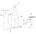
図1は、本発明に係る検査領域の決定方法を使用した異物検査装置の構成を示す模式的な立面図である。図1に示すように、コンベアCによって搬送されるガラス壜1の背面に照明2を配置し、ガラス壜1を挟んで照明2の反対側にカメラ3を配置している。ここでは壜底外周部が円形であるガラス壜1を検査対象とする。照明2は、赤色LEDを縦横に配列した赤色LED照明からなり、その前面の照明面2aはガラス壜1の壜胴部と平行になっている。照明2は、ガラス壜1の壜胴部および壜底部に拡散光を投光するようになっている。カメラ3はCCDカメラからなり、カメラ3の光軸3xは、ガラス壜1の軸心1xと壜下端部で交わるように、水平面に対して斜め下方に所定の角度(θ)=10°〜50°傾いて配置されている。図示例では、角度(θ)は20°である。カメラ3には画像処理装置5が接続されている。
FIG. 1 is a schematic elevation view showing the configuration of a foreign matter inspection apparatus using the inspection region determination method according to the present invention. As shown in FIG. 1, the
図1に示すように構成された異物検査装置において、照明2からの拡散光はガラス壜1の壜底部1aの外周面に入射する。ガラス壜1の壜底部1aに入射した光はガラス壜1の壜底部1aを透過し、透過光はカメラ3に入射して撮影される。
In the foreign matter inspection apparatus configured as shown in FIG. 1, the diffused light from the
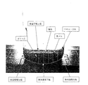
図2は、図1に示す異物検査装置のカメラ3によって茶色の一升壜を撮影した原画像である。カメラ3によって撮影された画像は画像処理装置5により画像処理される。この画像は以下の手順(ステップ1〜3)にて画像処理される。
ステップ1)
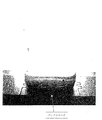
図2に示す原画像にラプラスフィルタをかけバッフルマークを顕在化した画像を得る。すなわち、ラプラスフィルタによって原画像中のエッジ成分を強調して領域の境界線を得る。図3はバッフルマークを顕在化させた画像である。図3に示すように、ガラス壜の壜底部の下端部に長軸より下半分の楕円形状のバッフルマークが顕在化する。
FIG. 2 is an original image obtained by photographing a brown glance with the
Step 1)
An Laplace filter is applied to the original image shown in FIG. 2 to obtain an image in which baffle marks are actualized. That is, an edge component in the original image is emphasized by a Laplace filter to obtain a region boundary line. FIG. 3 is an image in which baffle marks are made apparent. As shown in FIG. 3, an elliptical baffle mark that is a lower half of the long axis becomes apparent at the lower end of the bottom of the glass bottle.
ステップ2)
バッフルマーク上の点を求め、この点座標(Xi,Yi)をもとに最小二乗法により楕円近似を行い、楕円形状を求める。求めた楕円形状は、長半径をA、短半径をB、楕円の中心座標を(Xo,Yo)とすると、次の楕円方程式で表される。
(Xi−Xo)2/A2+(Yi−Yo)2/B2=1・・・(1)
したがって、検査領域下端線は上記の楕円方程式(1)で表される。図2の原画像に図3で示す顕在化した検査領域下端線を重ねて描画したものに、上記楕円方程式で表される楕円中心(Xo,Yo)、楕円上端(Yo+B)、楕円右端(Xo+A)、楕円左端(Xo−A)を示したものを図4で表す。
Step 2)
A point on the baffle mark is obtained, and elliptical approximation is performed by the least square method based on the point coordinates (Xi, Yi) to obtain an elliptical shape. The obtained elliptical shape is represented by the following elliptic equation, where A is the long radius, B is the short radius, and (Xo, Yo) is the center coordinate of the ellipse.
(Xi-Xo) 2 / A 2 + (Yi-Yo) 2 /
Therefore, the lower end line of the inspection area is expressed by the above elliptic equation (1). 2 is obtained by superimposing the actual examination region lower end line shown in FIG. 3 on the original image shown in FIG. 2, and the ellipse center (Xo, Yo), the upper end of the ellipse (Yo + B), and the right end of the ellipse (Xo + A). ), An ellipse left end (Xo-A) is shown in FIG.
ステップ3)
次に、図5に示すように、検出したバッフルマークから求めた検査領域下端線を検査領域の下端とし、検査領域下端線の左端を検査領域左端とし、検査領域下端線の右端を検査領域右端とする。検査領域下端線から画像の上方に向かってスキャン(走査)して、明暗のエッジを求めてガラス片や黒ゴムなどの異物を検出する。検査領域の上端は、一定以上の明るさの画素が連続して続く領域の開始点を検出することにより、自動的に求めることができる。異物が黒ゴムなどの遮光性異物の場合には、異物は画像中に所定の明るさの背景の中に暗い影として映るため、作成した検査領域内に暗い影があるか否かを画像処理装置5により判別することにより異物を検出する。また、異物がガラス片等の反射性の異物である場合には、異物は乱反射して明るく光るため、異物は画像中に所定の明るさの背景の中に明るい点(又は領域)として映るため、作成した検査領域内に明るい点(又は領域)があるか否かを画像処理装置5により判別することにより異物を検出する。図5にはガラス片や黒ゴムなどの異物を検出した画像が示されている。検出したガラス片は白、黒ゴムは黒で描画してある。
Step 3)
Next, as shown in FIG. 5, the lower end line of the inspection area obtained from the detected baffle mark is the lower end of the inspection area, the left end of the lower end line of the inspection area is the left end of the inspection area, and the right end of the lower end line of the inspection area is the right end of the inspection area. And Scanning is performed from the lower end line of the inspection area toward the upper side of the image, and a bright and dark edge is obtained to detect foreign matters such as glass pieces and black rubber. The upper end of the inspection area can be automatically obtained by detecting the start point of an area in which pixels having a certain brightness or higher continue. If the foreign object is a light-shielding foreign object such as black rubber, the foreign object appears as a dark shadow in the background of the specified brightness in the image, so image processing is performed to determine whether there is a dark shadow in the created inspection area. A foreign object is detected by the determination by the
上記ステップ1においては、図2に示す原画像にラプラスフィルタをかけてバッフルマークを顕在化したが、原画像にガンマ補正を施すことによりバッフルマークを顕在化することも可能である。図6は、図2に示す原画像にガンマ補正を施してバッフルマークを顕在化した画像である。この場合にも、図6から明らかなようにガラス壜の壜底部の下端部に長軸より下半分の楕円形状のバッフルマークが顕在化する。ガンマ補正を施した後、上記ステップ2およびステップ3と同様の手順により処理される。
In
これまで本発明の実施形態について説明したが、本発明は上述の実施形態に限定されず、その技術思想の範囲内において、種々の異なる形態で実施されてよいことは勿論である。 Although the embodiment of the present invention has been described so far, the present invention is not limited to the above-described embodiment, and it is needless to say that the present invention may be implemented in various different forms within the scope of the technical idea.
1 ガラス壜
1a 壜底部
1x 軸心
2 照明
2a 照明面
3 カメラ
3x 光軸
DESCRIPTION OF
Claims (12)
ガラス壜の壜底部をカメラによって撮影して壜底部の画像を得、
前記画像から、ガラス壜を成形する際に壜底下端部分にできるバッフルマークを検出し、
検出したバッフルマークを利用して画像中に検査領域を決定することを特徴とする検査領域の決定方法。 A method for determining an inspection area when performing an inspection to detect a defect in the glass bottle or a foreign substance in the glass bottle by imaging the glass bottle,
Take a picture of the bottom of the glass wall with a camera to get an image of the bottom of the glass wall,
From the image, when forming a glass bottle, a baffle mark that can be formed on the lower edge of the bottle bottom is detected,
A method for determining an inspection area, wherein an inspection area is determined in an image using a detected baffle mark.
前記搬送経路に沿って搬送されるガラス壜の側方に配置され、ガラス壜内を照明する照明と、
ガラス壜を挟んで前記照明と対向して配置され、ガラス壜の壜底部を透過した透過光を撮影するカメラと、
前記カメラで壜底部を撮影した画像を処理する画像処理装置とを備え、
前記画像処理装置は、前記画像から、ガラス壜を成形する際に壜底下端部分にできるバッフルマークを検出し、検出したバッフルマークを利用して画像中に検査領域を決定することを特徴とする異物検査装置。 In an apparatus for inspecting whether there is a foreign object at the bottom of the glass bottle by imaging the glass bottle while the glass bottle is being conveyed along a predetermined conveyance path,
Illuminated to illuminate the inside of the glass bottle, disposed on the side of the glass bottle conveyed along the conveyance path,
A camera that is arranged to face the illumination across the glass jar and that captures the transmitted light that has passed through the heel of the glass jar,
An image processing device for processing an image obtained by photographing the bottom of the heel with the camera,
The image processing device detects a baffle mark formed at a bottom lower end portion of the glass bottom when forming a glass bottle from the image, and determines an inspection region in the image using the detected baffle mark. Foreign matter inspection device.
Priority Applications (1)
| Application Number | Priority Date | Filing Date | Title |
|---|---|---|---|
| JP2010275228A JP2012122912A (en) | 2010-12-10 | 2010-12-10 | Determination method of inspection region and foreign matter inspection device |
Applications Claiming Priority (1)
| Application Number | Priority Date | Filing Date | Title |
|---|---|---|---|
| JP2010275228A JP2012122912A (en) | 2010-12-10 | 2010-12-10 | Determination method of inspection region and foreign matter inspection device |
Publications (1)
| Publication Number | Publication Date |
|---|---|
| JP2012122912A true JP2012122912A (en) | 2012-06-28 |
Family
ID=46504488
Family Applications (1)
| Application Number | Title | Priority Date | Filing Date |
|---|---|---|---|
| JP2010275228A Pending JP2012122912A (en) | 2010-12-10 | 2010-12-10 | Determination method of inspection region and foreign matter inspection device |
Country Status (1)
| Country | Link |
|---|---|
| JP (1) | JP2012122912A (en) |
Cited By (5)
| Publication number | Priority date | Publication date | Assignee | Title |
|---|---|---|---|---|
| JP2016527498A (en) * | 2013-07-19 | 2016-09-08 | ヴィルコ・アーゲー | Method and apparatus for in-line testing of device |
| JP2018146419A (en) * | 2017-03-07 | 2018-09-20 | アンリツインフィビス株式会社 | X-ray inspection device |
| KR20200054233A (en) * | 2017-09-19 | 2020-05-19 | 기린 테크노시스템 가부시끼가이샤 | Foreign body inspection device |
| JP2020186919A (en) * | 2019-05-09 | 2020-11-19 | 東洋ガラス株式会社 | Foreign matter inspection device and glass container manufacturing method using the same |
| DE102021115493A1 (en) | 2021-06-15 | 2022-12-15 | Heuft Systemtechnik Gmbh | Process and device for full container inspection |
-
2010
- 2010-12-10 JP JP2010275228A patent/JP2012122912A/en active Pending
Cited By (7)
| Publication number | Priority date | Publication date | Assignee | Title |
|---|---|---|---|---|
| JP2016527498A (en) * | 2013-07-19 | 2016-09-08 | ヴィルコ・アーゲー | Method and apparatus for in-line testing of device |
| JP2018146419A (en) * | 2017-03-07 | 2018-09-20 | アンリツインフィビス株式会社 | X-ray inspection device |
| KR20200054233A (en) * | 2017-09-19 | 2020-05-19 | 기린 테크노시스템 가부시끼가이샤 | Foreign body inspection device |
| KR102627123B1 (en) | 2017-09-19 | 2024-01-23 | 기린 테크노시스템 가부시끼가이샤 | foreign matter inspection device |
| JP2020186919A (en) * | 2019-05-09 | 2020-11-19 | 東洋ガラス株式会社 | Foreign matter inspection device and glass container manufacturing method using the same |
| JP7229092B2 (en) | 2019-05-09 | 2023-02-27 | 東洋ガラス株式会社 | Foreign matter inspection device and glass container manufacturing method using the same |
| DE102021115493A1 (en) | 2021-06-15 | 2022-12-15 | Heuft Systemtechnik Gmbh | Process and device for full container inspection |
Similar Documents
| Publication | Publication Date | Title |
|---|---|---|
| JP2012122912A (en) | Determination method of inspection region and foreign matter inspection device | |
| JP5294427B2 (en) | Glass bottle inspection equipment | |
| TW201629474A (en) | Inspection device | |
| JP5776467B2 (en) | Defect inspection equipment | |
| JP5726628B2 (en) | Appearance inspection apparatus and appearance inspection method for transparent body bottle | |
| JP5499289B1 (en) | Cap inspection device | |
| JP2012237632A (en) | Appearance inspection device and appearance inspection method of transparent body bottle | |
| JP5959430B2 (en) | Bottle cap appearance inspection device and appearance inspection method | |
| KR102540808B1 (en) | Glass bottle inspection method and glass bottle manufacturing method | |
| JP2008261696A (en) | Measuring method of liquid level | |
| JP2006038751A (en) | Inspection method and inspection device for container filling inlet edge and filling device | |
| JP2013257245A (en) | Inspection device for articles | |
| JP2006313070A (en) | Inspection method of container | |
| JP2005009981A (en) | Inspection method and inspection apparatus for superposed state of superposed object | |
| JP5991463B2 (en) | Inspection device | |
| JP2002267612A (en) | Device and system for inspecting foreign matter in liquid filled in transparent container or the like | |
| JP6194659B2 (en) | Resin container inspection equipment | |
| JP6860227B2 (en) | Cap inspection method and inspection equipment | |
| JP7189417B2 (en) | Article inspection device | |
| JP2012122877A (en) | Method for inspecting foreign substance in liquid | |
| JPS62113050A (en) | Bottle mouth inspection system | |
| JP5822126B2 (en) | Method and apparatus for inspecting liquid level of container | |
| JP2012137324A (en) | Method and apparatus for inspecting foreign substances floating on liquid surface | |
| JP2011127987A (en) | Liquid-level floating foreign substance inspection method and apparatus | |
| JP4253228B2 (en) | Lid displacement inspection device |