JP7228317B2 - packaging system - Google Patents
packaging system Download PDFInfo
- Publication number
- JP7228317B2 JP7228317B2 JP2018166472A JP2018166472A JP7228317B2 JP 7228317 B2 JP7228317 B2 JP 7228317B2 JP 2018166472 A JP2018166472 A JP 2018166472A JP 2018166472 A JP2018166472 A JP 2018166472A JP 7228317 B2 JP7228317 B2 JP 7228317B2
- Authority
- JP
- Japan
- Prior art keywords
- packaging
- information
- printing device
- phototube
- printed
- Prior art date
- Legal status (The legal status is an assumption and is not a legal conclusion. Google has not performed a legal analysis and makes no representation as to the accuracy of the status listed.)
- Active
Links
Images


Landscapes
- Containers And Plastic Fillers For Packaging (AREA)
- Auxiliary Devices For And Details Of Packaging Control (AREA)
Description
本発明は、包装システムに関する。 The present invention relates to packaging systems.
従来、包装システムに関し、特に、パンやおにぎりなどの食品、あるいは食品以外の物品を袋に密封する包装システムが知られている(たとえば、特許文献1~3参照)。 2. Description of the Related Art Conventionally, regarding packaging systems, packaging systems that seal foods such as bread and rice balls, or articles other than foods, in bags are known (for example, see Patent Documents 1 to 3).
上記特許文献1~3には、内容物、すなわち被包装物としてのおにぎりを包装するための長尺状の包装材と、この包装材を筒状に形成しておにぎりを収容する製袋器と、筒状に形成された包装材の3辺をシールすることにより連続した複数の包装体を得るシール手段と、複数の包装体を個々の包装体に切断するカッターと、おにぎりに関する情報(商品名、原材料名、製造地、賞味期限、価格等)が印字されたラベルを包装体に貼り付けるラベル貼付機とを備えた包装システムが開示されている。 The above Patent Documents 1 to 3 disclose a long packaging material for packaging a content, that is, a rice ball as an object to be packaged, and a bag making machine for forming the packaging material into a cylindrical shape to accommodate the rice ball. , sealing means for obtaining a plurality of continuous packages by sealing three sides of a cylindrically formed packaging material, a cutter for cutting the plurality of packages into individual packages, and information on rice balls (trade name , name of raw material, place of manufacture, expiration date, price, etc.) is attached to the package.
上記特許文献3には、おにぎりを包装するための包装材が予めロール状に巻回されており、おにぎりが製袋器に向かってコンベア上を移動するのに伴って、包装材がロールから引き出され、製袋器において包装材が筒状に形成されておにぎりが収容される点が開示されている。 In Patent Document 3, a packaging material for packaging rice balls is wound in a roll in advance, and the packaging material is pulled out from the roll as the rice balls move on a conveyor toward a bag making machine. In addition, it is disclosed that the packaging material is cylindrically formed in the bag making machine to accommodate the rice balls.
一般的な包装システムで使用される包装材には、おにぎりと筒状の包装材との位置を調整し、筒状の包装材を適切な位置でシールするとともに切断するための目印として、光電管マークが事前に印刷されている。この光電管マークは、包装される内容物の大きさに応じて、包装材の長手方向に対して等間隔で複数印刷されている。 Packaging materials used in general packaging systems have a phototube mark as a mark for adjusting the position of the rice ball and the tubular packaging material, sealing the tubular packaging material at the appropriate position, and cutting the packaging material. is pre-printed. A plurality of phototube marks are printed at equal intervals in the longitudinal direction of the packaging material according to the size of the contents to be packaged.
しかしながら、上記特許文献1~3に記載された包装システムでは、事前に包装材に光電管マークが印刷されているため、印刷された光電管マークに対応する1つの大きさの内容物のみの包装が可能である。そのため、複数の異なる大きさの内容物を包装する場合には、包装する内容物の大きさ毎に、内容物に対応する光電管マークが印刷された包装材を用意し、一度工程を止めて包装材を変更する必要がある。 However, in the packaging systems described in Patent Documents 1 to 3, since the phototube mark is printed on the packaging material in advance, it is possible to package only contents of one size corresponding to the printed phototube mark. is. Therefore, when packaging a plurality of contents of different sizes, a packaging material printed with a phototube mark corresponding to the contents is prepared for each size of the contents to be packaged, and the process is temporarily stopped before packaging. Material needs to be changed.
本発明は、上記問題点を解消すべくなされたものであって、包装する被包装物の大きさ毎に包装材を用意する必要や、包装材の変更をすることなく、複数の異なる大きさの被包装物を包装することが可能な包装システムを供給することを目的とする。 The present invention has been made to solve the above-mentioned problems, and the present invention eliminates the need to prepare a packaging material for each size of an object to be packaged, or to change the packaging material. The purpose is to provide a packaging system capable of packaging a number of objects to be packaged.
上記目的を達成するために、本発明は、次のように構成されている。 In order to achieve the above objects, the present invention is configured as follows.
(1)本発明の包装システムは、被包装物の大きさに関する情報が入力される制御部と、前記被包装物を包装するための長尺状の包装材の長手方向に複数の光電管マークを印字する工程を行う印字装置とを備え、前記制御部は、前記印字装置が前記情報に対応させて前記複数の光電管マークの間隔を異ならせて印字するように制御する包装システムであって、前記被包装材の移送方向において上流側から供給された前記包装材は、前記移送方向において下流側に位置する前記印字装置に供給されて印字の工程が行われ、前記印字装置による印字の工程の後、前記移送方向において前記印字装置よりさらに下流側で、前記包装材に前記被包装物を充填する工程が連続して行われる。 (1) The packaging system of the present invention comprises a control section to which information relating to the size of an item to be packaged is input, and a plurality of phototube marks in the longitudinal direction of a long packaging material for packaging the item to be packaged. a printing device that performs a printing step , wherein the control unit controls the printing device to print with different intervals between the plurality of phototube marks in correspondence with the information, wherein the The packaging material supplied from the upstream side in the transport direction of the material to be packaged is supplied to the printing device positioned downstream in the transport direction and undergoes a printing step, and after the printing step by the printing device. and a step of filling the packaging material with the article to be packaged is continuously performed further downstream than the printing device in the transport direction.
上記構成によると、異なる大きさの被包装物(内容物)を包装する際に、その被包装物の大きさ毎に包装材に光電管マークを印字するため、被包装物の大きさ毎の包装材の長さを長短可変とすることができる。このため、包装する被包装物の大きさ毎に包装材を用意する必要や、包装材の変更をすることなく、複数の異なる大きさの被包装物を包装することができる。 According to the above configuration, when packaging objects (contents) of different sizes, the phototube mark is printed on the packaging material for each size of the object to be packaged. The length of the material can be variable. Therefore, it is possible to package a plurality of different sizes of packaged objects without the need to prepare packaging materials for each size of the packaged objects or to change the packaging material.
(2)本発明の包装システムでは、前記被包装物の大きさに関する情報を検知するとともに、前記情報を前記制御部に出力する検知センサをさらに備える。これにより、検知センサにより自動的に被包装物の大きさに関する情報を取得することができるため、オペレーターが手動で被包装物の大きさに関する情報を包装システムに入力することが不要となる。そのため、包装システムに供給される被包装物の大きさが途中で変わったとしても、自動的に複数の光電管マークの間隔を異ならせて印字して複数の異なる大きさの被包装物を包装することができる。 (2) The packaging system of the present invention further includes a detection sensor that detects information about the size of the item to be packaged and that outputs the information to the control unit. As a result, the detection sensor can automatically acquire information about the size of the item to be packaged, eliminating the need for the operator to manually input information about the size of the item to the packaging system. Therefore, even if the size of the object to be packaged supplied to the packaging system changes during the process, the plurality of phototube marks are automatically printed with different intervals to package the objects of different sizes. be able to.
(3)本発明の包装システムでは、前記印字装置は、加熱により前記包装材を発色させて印字を行う感熱印字装置を含み、前記制御部は、前記感熱印字装置が前記複数の光電管マークの前記印字を行うことを制御する。たとえば、インクを用いて光電管マークが印刷された面を外側にしてヒートシールバーによりシールした場合には、インクの印字面にヒートシールバーが当接することに起因して、ヒートシールバーにインクが付着してしまう。その結果、インクが付着した状態のヒートシールバーで包装材の他の部分をシールした際に、ヒートシールバーに付着したインクが包装材の他の部分に付着してしまう。また、インクを用いて光電管マークが印刷された面を内側にしてヒートシールバーによりシールした場合には、インクによる印字面同士が当接することとなり、ヒートシール面同士が密着しないことに起因してヒートシール不良となる。これに対して、本発明では、感熱印字装置の加熱により包装材を発色させて光電管マークを印字するため、ヒートシールバーの汚れを軽減することができ、かつ、ヒートシール面同士を密着させて確実にヒートシールすることができる。 (3) In the packaging system of the present invention, the printing device includes a thermal printing device that prints by coloring the packaging material by heating, and the controller controls the thermal printing device to print the plurality of phototube marks. Controls printing. For example, when the surface on which the phototube mark is printed using ink is sealed by the heat seal bar with the surface printed with the phototube mark facing outward, the heat seal bar comes into contact with the printed surface of the ink, causing the ink to adhere to the heat seal bar. It sticks. As a result, when another portion of the packaging material is sealed with the heat-sealing bar to which ink is adhered, the ink attached to the heat-sealing bar adheres to the other portion of the packaging material. In addition, when the surface on which the phototube mark is printed using ink is sealed with a heat seal bar with the surface printed with the phototube mark inside, the surfaces printed with ink come into contact with each other, and the heat seal surfaces do not adhere to each other. Poor heat sealing. On the other hand, in the present invention, the phototube mark is printed by coloring the packaging material by heating the thermal printing device. It can be reliably heat-sealed.
(4)本発明の包装システムでは、前記包装材は、JIS P8149に準拠して測定された不透明度が25%以上である。これにより、バーコード等の読み取り特性に優れた包装材を提供することができる。 (4) In the packaging system of the present invention, the packaging material has an opacity of 25% or more as measured according to JIS P8149. As a result, it is possible to provide a packaging material having excellent readability for barcodes and the like.
(5)本発明の包装システムでは、前記包装材は、JIS-K7136:2000に準拠して測定されたヘイズ値が70%以上である。これにより、バーコード等の読み取り特性の低下を確実に抑制することができる。 (5) In the packaging system of the present invention, the packaging material has a haze value of 70% or more measured according to JIS-K7136:2000. As a result, it is possible to reliably suppress deterioration in reading characteristics of barcodes and the like.
(6)本発明の包装システムでは、前記制御部は、前記印字装置が前記被包装物に関する情報をさらに印字するように制御する。これにより、被包装物に関するより詳細な情報(商品名、原材料名、製造地、賞味期限、価格等)を印字して購入者に対して知らせることができる。 (6) In the packaging system of the present invention, the control section controls the printing device to further print information on the packaged item. As a result, more detailed information (product name, raw material name, place of manufacture, expiration date, price, etc.) on the packaged item can be printed and notified to the purchaser.
(7)本発明の包装システムでは、前記制御部は、前記印字装置が前記複数の光電管マークと前記被包装物に関する情報とを同時に印字するように制御する。これにより、光電管マークと被包装物に関する情報とが別個に印字される場合と比べて、印字工程を短縮することができる。 (7) In the packaging system of the present invention, the controller controls the printing device to simultaneously print the plurality of phototube marks and the information on the package. As a result, the printing process can be shortened compared to the case where the phototube mark and the information on the package are printed separately.
本発明の包装システムは、包装する内容物の大きさ毎に包装材を用意する必要や、包装材の変更をすることなく、複数の異なる大きさの内容物を包装することができる。 The packaging system of the present invention can package contents of a plurality of different sizes without the need to prepare a packaging material for each size of contents to be packaged and without changing the packaging material.
以下、本発明を適用した包装システムの実施の形態を、図1~図6を参照し、詳細に説明する。 An embodiment of a packaging system to which the present invention is applied will be described in detail below with reference to FIGS. 1 to 6. FIG.
図1は、本実施形態に係る包装システムの全体構成例を示す概略図である。図2および図3は、包装シートへの印字の様子を示す図である。図4は、包装シートの概略断面図である。図5および図6は、包装物を示す図である。なお、これらの図は模式図であって、必ずしも大きさを正確な比率で記したものではない。たとえば、図1~図6における包装シートの縦の長さおよび横の長さの比や被包装物としてのパンの大きさは現実における比率に対応している訳ではない。 FIG. 1 is a schematic diagram showing an example of the overall configuration of a packaging system according to this embodiment. 2 and 3 are diagrams showing how printing is performed on the packaging sheet. FIG. 4 is a schematic cross-sectional view of the packaging sheet. 5 and 6 are diagrams showing packages. It should be noted that these figures are schematic diagrams, and the sizes are not necessarily shown in exact proportions. For example, the ratio of the vertical length to the horizontal length of the packaging sheet in FIGS. 1 to 6 and the size of the bread as the packaged item do not correspond to the actual ratio.
(包装システム100)
図1に示すように、本実施形態の包装システム100は、包装装置200と、サーマルプリンタ300と、これらの装置を制御する制御盤400とを備えている。なお、サーマルプリンタ300は、本発明の「印字装置」および「感熱印字装置」の一例である。
(Packaging system 100)
As shown in FIG. 1, the
包装装置200は、長尺状の包装シート2が巻回されたロール1と、包装シート2により包装される被包装物(内容物)としてのパン500を上流側から下流側に移送する第1のベルトコンベア101と、筒状の包装シート2の幅方向の一方端部をシールする第1のヒートシーラー102、第1のヒートシーラー102によりシールされた部分を折り曲げる折り曲げローラー103、包装シート2の一部を内方に押し込む一対の押込片104、包装シート2の上流側および下流側の幅方向の端部をシールする第2のヒートシーラー105、および、包装シート2を所定の大きさ毎にカットするカッター106と、パン500の包装完了後の包装物600を移送する第2のベルトコンベア107とを備えている。なお、包装シート2は、本発明の「包装材」の一例である。
The
また、第1のヒートシーラー102の上流側における第1のベルトコンベア101の近傍には、第1の検知センサ108が設けられている。この第1の検知センサ108は、パン500の大きさに関する情報(長さ、幅、厚み等)を検知(取得)するとともに、その情報を後述する制御盤400の制御部401に出力する。
A
折り曲げローラー103と押込片104との間における第1のベルトコンベア101の近傍には、第2の検知センサ109が設けられている。この第2の検知センサ109は、包装物600のシール位置および切断位置を決定するために包装シート2に印字された後述する光電管マーク3aを検知する。
A
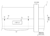
サーマルプリンタ300は、サーマルヘッドユニット301と、プラテンローラ302とを備えている。プラテンローラ302は、ステッピングモータ(図示せず)との間にベルト(図示せず)を介して接続されている。また、サーマルプリンタ300は、図2および図3に示すように、加熱により、包装シート2の幅方向の端部に移送方向(長手方向)に沿って所定の間隔を隔てて複数の光電管マーク3aを印字する。さらに、サーマルプリンタ300は、パン500に関する情報3bおよび3c(商品名、原材料名、製造地、賞味期限、価格、バーコード等)も印字する。これらの光電管マーク3aとパン500に関する情報3bおよび3cとは、同時に印字される。
A
制御盤400は、図1に示すように、制御部401と、液晶ディスプレイなどの表示部402と、キーボードなどの入力部403とを備えている。制御部401は、主として、表示部402、入力部403、第1の検知センサ108、第2の検知センサ109、および、サーマルプリンタ300と接続されており、一方向または双方向で情報の入出力が可能となっている。
As shown in FIG. 1, the control panel 400 includes a
制御部401は、オペレーター700により入力部403が操作されて入力されたパン500の大きさや個数に関する情報に対応させて、複数の光電管マーク3aの間隔を異ならせて包装シート2に印字するようにサーマルプリンタ300を制御する。また、パン500の大きさに関する情報を自動的に取得する場合には、制御部401は、第1の検知センサ108により検知されて出力されるパン500の大きさや個数に関する情報に対応させて、複数の光電管マーク3aの間隔を異ならせて包装シート2に印字するようにサーマルプリンタ300を制御する。この包装シート2への印字については、後述の「包装システム100を用いた包装方法」の説明において詳述する。
The
(包装シート2)
次に、図4を参照して、包装シート2の各層の構成を説明する。なお、図4は実施形態を説明するための概略図であって、正確なものではない。例えば、各層の厚みの比率は実際の各層の厚みと対応していない。
(Packaging sheet 2)
Next, the configuration of each layer of the
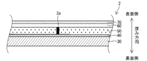
包装シート2は、図4に示すように、厚み方向において裏面側から表面側に対して順番に、加熱により密着可能なヒートシール性を有するとともに強度を担保する基材層30と、基材層30と発色層50との密着性を高めるアンダーコート層40と、加熱により発色する発色材料を含む感熱層50と、感熱層50を保護するための中間層60と、感熱層50や中間層60の表面側からの劣化から保護するための保護層70とを備えている。
As shown in FIG. 4, the
(基材層30)
基材層30としては、透明の合成樹脂フィルム、たとえば、ポリプロピレンフィルム、ポリエチレンテレフタレートフィルム、ポリスチレンフィルム、ポリカーボネートフィルムなどのフィルム全般を用いることができる。基材層30の厚さは特に限定されないが、たとえば、10μm~100μm程度が塗工性及び透明性に優れ、好ましい。このフィルム同士を互いに密着させた状態で加熱することにより、ヒートシールすることが可能となっている。
(Base material layer 30)
As the
(アンダーコート層40)
アンダーコート層40は、基材層30と感熱層50との密着性を高めるために設けられており、結着剤や充填剤を主成分として形成されている。
(Undercoat layer 40)
The
(感熱層50)
感熱層50は、任意のタイミングで加熱により発色させることにより、包装シート2にバーコードや文字等の情報を印字することができる。この感熱層50は、図2および図3に示すように、平面視において、幅方向に対して中央よりも一方側の領域に、移送方向に対して帯状に延びている。この感熱層50は、不透明度が高く設定されており、視覚的には白色を有している。感熱層50は、アクリル樹脂等の中空粒子を含み、光散乱効果により不透明性を付与することで、感熱層50に印字された文字やバーコード等の情報の視認性を向上させることが可能となっている。バーコード等の読み取り特性を向上させるためには、感熱層50は、JIS P8149に準拠して測定される不透明度が25%以上であることが好ましい。また、感熱層50は、JIS-K7136:2000に準拠して測定されたヘイズ値が70%以上であることが好ましい。
(Heat sensitive layer 50)
Information such as bar codes and characters can be printed on the
感熱層50を形成する材料としては、加熱により発色する発色剤、顕色剤、結着剤、および、滑剤などを分散媒に分散させ、積層する。ここで、分散媒として有機溶媒を用いても良い。発色剤としては、透明または淡色の染料(ロイコ染料)と、この染料を加熱により発色させることができる顕色剤とを組み合わせて使用する。かかる発色剤は、一般的な感熱記録紙などで広く用いられており、入手が容易で、汎用性が高い。
As materials for forming the heat-
(中間層60)
中間層60は、感熱層50等を表面側からの劣化から保護するとともに、包装シート2の透明性を向上させるために設けられている。かかる目的のため、アクリルアミド樹脂などのアクリル系樹脂を含むコアシェル型粒子を中間層に含んでいる。
(Intermediate layer 60)
The
(保護層70)
保護層70は、中間層60や感熱層50等を表面側からの劣化から保護するために設けられている。また、保護層70は、充填剤としてのコロイダルシリカおよび滑剤としてのステアリン酸亜鉛を結着剤としてのアクリル樹脂を用いて成膜させて形成することによって、表面の滑りを良くしサーマルヘッドユニット301に対する適性を向上させている。
(Protective layer 70)
The
(包装システム100を用いた包装方法)
次に、図1~図3、図5および図6を参照して、本実施形態による包装システム100を用いた包装方法について説明する。
(Packaging method using packaging system 100)
Next, a packaging method using the
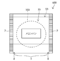
図1に示すように、本実施形態による包装システム100を用いた包装方法は、帯状の包装シート2に印字するための印字工程Aと、包装シート2を筒状に屈曲させる屈曲工程Bと、長手方向溶着部6(図5および図6参照)を形成する長手方向溶着部形成工程Cと、幅方向溶着部7(図5および図6参照)を形成して袋状の包装物600を形成するための幅方向溶着部形成工程Dとを含む。各工程は、横ピロー包装機によって連続的かつ一部は重畳的に行われる。以下、図面に従い各工程を詳説する。
As shown in FIG. 1, the packaging method using the
まず、ロール1から移送方向(下流側)に供給された帯状の包装シート2は、下流側に進み、サーマルプリンタ300に供給される。このとき、オペレーター700が制御盤400の入力部403を操作して、包装されるパン500の大きさや個数が入力される。このとき、オペレーター700により、予め制御盤400内に記録されているデータベースからパンの種類を選択する方法や、直接数値等を入力する方法などがある。そして、入力されたパン500の大きさや個数に関する情報は、制御盤400の制御部401に入力され、制御部401は、前記情報に対応する印字データをサーマルプリンタ300に出力する。
First, the band-shaped
また、上述のようにオペレーター700が手動でパン500に関する情報を入力するという方法以外の方法として、第1の検知センサ108によりパン500の大きさや個数に関する情報を自動的に検知させる方法がある。すなわち、第1のベルトコンベア101により上流側から下流側に移送されるパン500の大きさや個数に関する情報が第1の検知センサ108により検知されるとともに、検知(取得)された情報が第1の検知センサ108から制御盤400の制御部401に出力される。そして、制御部401は、前記情報に対応する印字データをサーマルプリンタ300に出力する。
As a method other than the method in which the
上述した第1の検知センサ108は、パン500の大きさを画像により認識する画像センサなどを用いて構成することにより、第1のベルトコンベア101により移送されるパン500を迅速かつ正確に認識することが可能となる。なお、オペレーター700により入力された情報、または、第1の検知センサ108により検知された情報は、制御盤400の表示部402に表示されてもよい。
The
サーマルプリンタ300は、図2および図3に示すように、制御盤400の制御部401から取得した情報に基づいて、サーマルヘッドユニット301の加熱により、包装シート2の幅方向に対して中央部近傍に長手方向に沿って所定の間隔を隔てて複数の光電管マーク3aと、パン500に関する情報3bおよび3c(商品名、原材料名、製造地、賞味期限、価格等)とを同時に印字する。また、光電管マーク3aは、カッター106により包装シート2aを各々の包装物の大きさにカットするための目印として印字される。
As shown in FIGS. 2 and 3, the
具体的には、図2に示すように、パン500の大きさが比較的小さい「メロンパン」の場合には、パン500を包装するのに包装シート2が適切な大きさでカットされるように、光電管マーク3aの間隔がL1となるように印字される。これに対して、図3に示すように、パン500の大きさが比較的大きい「バゲット」の場合には、光電管マーク3aの間隔がL1よりも大きいL2となるように印字される。
Specifically, as shown in FIG. 2, in the case of "melon bread" in which the size of the
このように、本実施形態では、パン500の移送途中でパン500の大きさが変更されたとしても、その大きさに対応させてサーマルプリンタ300により光電管マーク3aの間隔を異ならせて(変更して)印字が可能となっている。また、光電管マーク3aが印字されるのと同時に、各々のパン500に関する情報3bおよび3cも異ならせて(変更して)印字が可能となっている。
As described above, in this embodiment, even if the size of the
次に、屈曲工程Bにおいて、印字が完了した帯状の包装シート2は、さらに下流側に進むに従い筒状に屈曲されるとともに、包装シート2の幅方向の一方端部5(包装物600を商品棚に陳列する際に底面に対応する部分)(図5参照)が、基材層30のヒートシール面同士を接するように重ね合わされる。この屈曲工程Bにより、筒状部4が形成される。このとき、筒状部4の内部には、第1のベルトコンベア101の上面に所定の間隔で積載されたパン500が、順に挿入されてゆく。
Next, in the bending step B, the strip-shaped
次に、長手方向溶着部形成工程Cにおいて、包装シート2の幅方向の一方端部5に第1のヒートシーラー102が押し当てられることにより、包装シート2の一方端部5は移送方向において上流側から下流側に向かって連続的に熱溶着されることにより、長手方向溶着部6が下流側から上流側に連続的に形成される。形成された長手方向溶着部6は、折り曲げローラー103によって上面側から下面側に押しつけられることによって、筒状部4の底面に沿うように折り曲げられる。
Next, in the longitudinal welded portion forming step C, the
次に、幅方向溶着部形成工程Dにおいて、包装シート2の幅方向(移送方向に直交する方向)に延設された第2のヒートシーラー105が表面側および裏面側から筒状部4を挟み込む様に加熱することにより、筒状部4に幅方向に帯状に延びた幅方向溶着部7が形成される。この幅方向溶着部7は移送方向において一定の距離毎に、パン500が充填されている場所を避けて筒状部4に形成される。幅方向溶着部7が形成される際に、幅方向溶着部7の上流側および下流側の両端部に一対の押込片104の先端があてがわれることにより、包装シート2の一部が内方に押し込まれ、押込部8が形成される。
Next, in the width direction welded portion forming step D, the
上述のパン500が充填されている場所を避けて幅方向溶着部7を形成する工程は、光学センサなどからなる第2の検知センサ109により、包装シート2に印字された光電管マーク3aを検知するとともにパン500の有無をチェックしつつ、第2のヒートシーラー105を動作させることにより、正確に行うことができる。なお、包装シート2に幅方向溶着部7を形成するその他の方法としては、第1のベルトコンベア101と第2のヒートシーラー105とを同期させることによっても可能である。
In the step of forming the widthwise welded
第2のヒートシーラー105には、筒状部4を切断するカッター106が併設されている。従って、幅方向溶着部7の形成と同時に下流側の筒状部4は切り離され、パン500が封入され封口された包装物600が形成される。
The
上記説明した本実施形態によれば、以下の効果を得ることができる。 According to this embodiment described above, the following effects can be obtained.
(1)本発明の包装システム100では、制御部401が、サーマルプリンタ300が情報に対応させて複数の光電管マーク3aの間隔を異ならせて印字するように制御する。これにより、異なる大きさのパン500を包装する際に、そのパン500の大きさ毎に包装シート2に光電管マーク3aを印字するため、パン500の大きさ毎の包装シート2の長さを長短可変とすることができる。このため、包装するパン500の大きさ毎に包装シート2を用意する必要や、包装シート2が巻回されたロール1の変更をすることなく、複数の異なる大きさのパン500を包装することができる。
(1) In the
(2)本発明の包装システム100では、検知センサ108がパン500の大きさに関する情報を検知するとともに、情報を制御部401に出力することによって、検知センサ108により自動的にパン500の大きさに関する情報を取得することができるため、オペレーター700が手動でパン500の大きさに関する情報を入力部403を介して制御盤400に入力することが不要となる。そのため、包装システム100に供給されるパン500の大きさが途中で変わったとしても、自動的に複数の光電管マーク3aの間隔を異ならせて印字して複数の異なる大きさのパン500を包装することができる。
(2) In the
(3)本発明の包装システム100では、サーマルプリンタ300が複数の光電管マーク3aの印字を行うことを制御部401により制御することによって、たとえば、インクを用いて光電管マークが印刷された面を外側にしてヒートシールバーによりシールした場合には、インクの印字面にヒートシールバーが当接することに起因して、ヒートシールバーにインクが付着してしまう。その結果、インクが付着した状態のヒートシールバーで包装材の他の部分をシールした際に、ヒートシールバーに付着したインクが包装シートの他の部分に付着してしまう。また、インクを用いて光電管マークが印刷された面を内側にしてヒートシールバーによりシールした場合には、インクによる印字面同士が当接することとなり、ヒートシール面同士が密着しないことに起因してヒートシール不良となる。これに対して、本実施形態では、サーマルプリンタ300の加熱により包装シート2の感熱層50を発色させて光電管マーク3aを印字するため、ヒートシールバーの汚れを軽減することができ、かつ、ヒートシール面同士を密着させて確実にヒートシールすることができる。
(3) In the
(4)本発明の包装システム100では、包装シート2がJIS P8149に準拠して測定された不透明度が25%以上であることによって、バーコード等の読み取り特性に優れた包装シート2を提供することができる。
(4) In the
(5)本発明の包装システム100では、包装シート2がJIS-K7136:2000に準拠して測定されたヘイズ値が70%以上であることによって、バーコード等の読み取り特性の低下を確実に抑制することができる。
(5) In the
(6)本発明の包装システム100では、制御部401が、サーマルプリンタ300がパン500に関する情報をさらに印字するように制御する。これにより、パン500に関するより詳細な情報(商品名、原材料名、製造地、賞味期限、価格等)を印字して購入者に対して知らせることができる。
(6) In the
(7)本発明の包装システム100では、制御部401が、サーマルプリンタ300が複数の光電管マーク3aとパン500に関する情報とを同時に印字するように制御する。これにより、光電管マーク3aとパン500に関する情報とが別個に印字される場合と比べて、印字工程を短縮することができる。
(7) In the
上記実施形態は、以下のように変更した構成とすることもできる。 The above embodiment can also be modified as follows.
・上記実施形態では、被包装物(内容物)の一例としてパンを包装する例を示したが、本発明はこれに限られない。たとえば、本発明では、本包装システムで包装可能であれば、パン以外の食品や食品以外の物品でも適用可能である。 - Although the example which packages bread was shown as an example of a to-be-packaged item (contents) in the said embodiment, this invention is not limited to this. For example, the present invention can be applied to foods other than bread and articles other than foods as long as the packaging system can be used for packaging.
・上記実施形態では、印字装置の一例として、感熱式サーマルプリンタを用いて印字する例を示したが、本発明はこれに限られない。本発明では、被包装物(本実施形態ではパン)の大きさに関する情報に対応させて複数の光電管マークの間隔を異ならせて印字することが可能であれば、インクが塗布されたリボンに加熱した印字ヘッドを押し当てて印字を行う熱転写式サーマルプリンタを用いて印字することも可能である。 - In the above-described embodiment, an example of printing using a thermal printer is shown as an example of a printing device, but the present invention is not limited to this. In the present invention, if it is possible to print with different intervals between a plurality of phototube marks corresponding to information on the size of the item to be packaged (bread in this embodiment), the ribbon coated with the ink is heated. It is also possible to print using a thermal transfer type thermal printer that prints by pressing a printed print head.
・上記実施形態では、印字装置の一例として、サーマルプリンタを用いて印字する例を示したが、本発明はこれに限られない。本発明では、加熱により包装シートを発色させて印字することが可能であれば、レーザーマーカーのような印字装置でも適用可能である。このように構成すれば、包装シートと非接触で印字することができるとともに、ヒートシールバーと印字面との接触による汚れの付着を軽減することができる。 - In the above embodiment, an example of printing using a thermal printer was shown as an example of a printing device, but the present invention is not limited to this. In the present invention, a printing device such as a laser marker can also be applied as long as the packaging sheet can be colored and printed by heating. With this configuration, printing can be performed without contact with the packaging sheet, and adhesion of dirt due to contact between the heat seal bar and the printed surface can be reduced.
・上記実施形態では、印字装置の一例として、サーマルプリンタを用いて印字する例を示したが、本発明はこれに限られない。本発明では、インクを吹き付けて印字を行うインクジェットプリンタ、ドットに対応するピンをインクリボンに叩き付けて印字を行う感圧式印字装置、または、レーザーを利用して印字を行うレーザープリンターを用いて印字することも可能である。 - In the above embodiment, an example of printing using a thermal printer was shown as an example of a printing device, but the present invention is not limited to this. In the present invention, printing is performed using an inkjet printer that prints by spraying ink, a pressure-sensitive printing device that prints by striking a pin corresponding to a dot against an ink ribbon, or a laser printer that prints using a laser. is also possible.
・上記実施形態では、包装シート2の表面側にのみ印字する例を示したが、本発明はこれに限られない。たとえば、包装シート2の表面および裏面の両面に印字可能な印字装置を適用してもよい。
- Although the example which prints only on the surface side of the
・上記実施形態では、基材層としてヒートシール性を有するフィルムを用いて、これらのフィルム同士を互いに密着させた状態で加熱することにより、ヒートシールすることが可能な例を示したが、本発明はこれに限られない。たとえば、基材層の裏面側に別途ヒートシール層を設けて、これらを互いに密着させた状態で加熱してヒートシールしてもよい。 - In the above-described embodiment, an example was shown in which a film having heat-sealing properties was used as the base material layer, and heat-sealed by heating these films in a state in which these films were in close contact with each other. The invention is not limited to this. For example, a separate heat-sealing layer may be provided on the back side of the base material layer, and these layers may be heated and heat-sealed while they are in close contact with each other.
・上記実施形態では、長尺状の1枚の包装シートを用いて被包装物を包装する例を示したが、本発明はこれに限られない。たとえば、2枚またはそれ以上の長尺状の包装シートをヒートシールにより貼り合わせて被包装物を包装してもよい。 - Although the said embodiment showed the example which packages a to-be-packaged item using one long packaging sheet, this invention is not limited to this. For example, two or more long packaging sheets may be heat-sealed together to package an object.
・上記実施形態では、光電管マークの印字される位置が包装シートの幅方向に対して中央部近傍に長手方向に沿って印字される例を示したが、本発明はこれに限られない。たとえば、光電管マークが包装シートの幅方向に対して端部近傍に印字されていてもよい。この場合、光電管マークの印字された部分を折り曲げてシールすることにより、外側から見えないようにしてもよい。 - In the above-described embodiment, the phototube mark is printed along the longitudinal direction near the center of the packaging sheet in the width direction, but the present invention is not limited to this. For example, a phototube mark may be printed near the end in the width direction of the packaging sheet. In this case, the printed portion of the phototube mark may be folded and sealed so that it cannot be seen from the outside.
・上記実施形態では、感熱層の幅方向の端部に光電管マークを印字する例を示したが、本発明はこれに限られない。たとえば、包装シートが被包装物の大きさ毎に適切にカットされるように光電管マークを検知することが可能であれば、光電管マークの印字される位置は限定されるものではない。 - In the above-described embodiment, an example in which the phototube mark is printed on the end portion of the heat-sensitive layer in the width direction has been shown, but the present invention is not limited to this. For example, the position where the phototube mark is printed is not limited as long as the phototube mark can be detected so that the packaging sheet is appropriately cut according to the size of the item to be packaged.
・上記実施形態では、光電管マークの印字された位置をカッターによりカットするとともに、その周辺をヒートシールバーによりシールする例を示したが、本発明はこれに限られない。たとえば、ヒートシールする際に、ヒートシールバーの温度調整を行って、シール位置を発色させることにより、光電管マークが目立たないようにすることも可能である。 - In the above-described embodiment, the position where the phototube mark is printed is cut with a cutter, and the periphery thereof is sealed with a heat seal bar. However, the present invention is not limited to this. For example, it is possible to make the phototube mark inconspicuous by adjusting the temperature of the heat-sealing bar and coloring the sealing position during heat-sealing.
・上記実施形態は、いずれも本発明の適応の例示であり、特許請求の範囲に記載の範囲内におけるその他いかなる実施形態も、発明の技術的範囲に含まれることは当然のことである。 - All of the above-described embodiments are examples of adaptation of the present invention, and it is a matter of course that any other embodiments within the scope of the claims are also included in the technical scope of the invention.
2 …包装シート(包装材)
3a …光電管マーク
100 …包装システム
108 …第1の検知センサ(検知センサ)
200 …包装装置
300 …サーマルプリンタ(感熱印字装置)
401 …制御部
500 …パン(被包装物)
2 ... packaging sheet (packaging material)
3a ...
200 ...
401 ...
Claims (7)
前記被包装物を包装するための長尺状の包装材の長手方向に複数の光電管マークを印字する工程を行う印字装置と、を備え、
前記制御部は、前記印字装置が前記情報に対応させて前記複数の光電管マークの間隔を異ならせて印字するように制御する、包装システムであって、
前記被包装材の移送方向において上流側から供給された前記包装材は、前記移送方向において下流側に位置する前記印字装置に供給されて印字の工程が行われ、
前記印字装置による印字の工程の後、前記移送方向において前記印字装置よりさらに下流側で、前記包装材に前記被包装物を充填する工程が連続して行われる、包装システム。 a control unit to which information about the size of the package is input;
a printing device for printing a plurality of phototube marks in the longitudinal direction of a long packaging material for packaging the object to be packaged ;
The control unit controls the printing device to print with different intervals between the plurality of phototube marks corresponding to the information , wherein
The packaging material supplied from the upstream side in the direction of transport of the material to be packaged is supplied to the printing device positioned downstream in the direction of transport to perform a printing process,
A packaging system, wherein after a step of printing by the printing device, a step of filling the packaging material with the object to be packaged is continuously performed downstream of the printing device in the transport direction.
前記制御部は、前記感熱印字装置が前記複数の光電管マークの前記印字を行うことを制御する、請求項1または2に記載の包装システム。 The printing device includes a thermal printing device that prints by coloring the packaging material by heating,
3. The packaging system according to claim 1, wherein said controller controls said thermal printing device to print said plurality of phototube marks.
7. The packaging system according to claim 6, wherein said control unit controls said printing device to simultaneously print said plurality of phototube marks and said information on said package.
Priority Applications (1)
| Application Number | Priority Date | Filing Date | Title |
|---|---|---|---|
| JP2018166472A JP7228317B2 (en) | 2018-09-06 | 2018-09-06 | packaging system |
Applications Claiming Priority (1)
| Application Number | Priority Date | Filing Date | Title |
|---|---|---|---|
| JP2018166472A JP7228317B2 (en) | 2018-09-06 | 2018-09-06 | packaging system |
Publications (2)
| Publication Number | Publication Date |
|---|---|
| JP2020037444A JP2020037444A (en) | 2020-03-12 |
| JP7228317B2 true JP7228317B2 (en) | 2023-02-24 |
Family
ID=69737429
Family Applications (1)
| Application Number | Title | Priority Date | Filing Date |
|---|---|---|---|
| JP2018166472A Active JP7228317B2 (en) | 2018-09-06 | 2018-09-06 | packaging system |
Country Status (1)
| Country | Link |
|---|---|
| JP (1) | JP7228317B2 (en) |
Families Citing this family (4)
| Publication number | Priority date | Publication date | Assignee | Title |
|---|---|---|---|---|
| JP7482503B2 (en) * | 2020-04-30 | 2024-05-14 | 大森機械工業株式会社 | Packaging Systems |
| JP7526463B2 (en) * | 2020-05-07 | 2024-08-01 | 大森機械工業株式会社 | Packaging Machine |
| AU2022445995B2 (en) * | 2022-03-10 | 2026-04-09 | Osaka Sealing Printing Co., Ltd. | Heat-sealable heat-sensitive film and method for producing same |
| JP7793191B2 (en) * | 2022-03-11 | 2026-01-05 | 株式会社フジキカイ | Bag-filled package, horizontal bag-making and filling machine, and method of manufacturing bag-filled package |
Citations (4)
| Publication number | Priority date | Publication date | Assignee | Title |
|---|---|---|---|---|
| JP2011042396A (en) | 2009-08-24 | 2011-03-03 | Ishida Co Ltd | Bag-making and packaging device and bag-making and packaging method |
| JP2014234165A (en) | 2013-05-30 | 2014-12-15 | 株式会社川島製作所 | Bag-making, filling and packaging machine including filling cylinder having double cylinder structure and method for detaching inner cylinder of bag-making and filling double cylinder in the bag-making, filling and packaging machine |
| US20150174848A1 (en) | 2013-12-19 | 2015-06-25 | Pitney Bowes Inc. | System and method for ensuring cutting accuracy in a mailpiece wrapper |
| JP2018008744A (en) | 2016-06-29 | 2018-01-18 | 株式会社イシダ | Cooperative system |
-
2018
- 2018-09-06 JP JP2018166472A patent/JP7228317B2/en active Active
Patent Citations (4)
| Publication number | Priority date | Publication date | Assignee | Title |
|---|---|---|---|---|
| JP2011042396A (en) | 2009-08-24 | 2011-03-03 | Ishida Co Ltd | Bag-making and packaging device and bag-making and packaging method |
| JP2014234165A (en) | 2013-05-30 | 2014-12-15 | 株式会社川島製作所 | Bag-making, filling and packaging machine including filling cylinder having double cylinder structure and method for detaching inner cylinder of bag-making and filling double cylinder in the bag-making, filling and packaging machine |
| US20150174848A1 (en) | 2013-12-19 | 2015-06-25 | Pitney Bowes Inc. | System and method for ensuring cutting accuracy in a mailpiece wrapper |
| JP2018008744A (en) | 2016-06-29 | 2018-01-18 | 株式会社イシダ | Cooperative system |
Also Published As
| Publication number | Publication date |
|---|---|
| JP2020037444A (en) | 2020-03-12 |
Similar Documents
| Publication | Publication Date | Title |
|---|---|---|
| JP7228317B2 (en) | packaging system | |
| US20220402239A1 (en) | Thermal transfer of active ink with dynamic environmental data | |
| EP1947440A2 (en) | Package heat seal quality indicator | |
| EP3595977B1 (en) | Identification of shrink-wrapped objects | |
| US20080096748A1 (en) | Reusable package, apparatus, and method | |
| BRPI0315591B1 (en) | Packaging material and method of transferring information from a facility for producing packaging material to a filling machine | |
| US20120012490A1 (en) | Marking packages | |
| EP2565124A1 (en) | Apparatus and method for printing on a package | |
| JP5414166B2 (en) | Laser printing apparatus and laser printing method | |
| EP2565036A1 (en) | Packaging material and packages | |
| JPH06510261A (en) | Packaging bag, preferred packaging bag for hazardous material samples, and method for manufacturing the packaging bag | |
| JP5281274B2 (en) | Retransfer thermal printer and seal device using the same | |
| JP6371503B2 (en) | Label printing device | |
| JP2002283633A (en) | Product information printing device | |
| JP6121754B2 (en) | Label issuing and pasting device | |
| JP4472268B2 (en) | Bag packing machine | |
| JP2018076097A (en) | Packaging film and package | |
| JP3378777B2 (en) | Engraving method of polyethylene bag | |
| JP6045037B2 (en) | Method for detecting film joints of laminated film for filling and packaging machine | |
| JP5071066B2 (en) | Packaging equipment | |
| JP6382246B2 (en) | Packaged food for cooked rice and its packaging method | |
| JP5509928B2 (en) | Packaging film and packaging apparatus using the packaging film | |
| NL1003290C2 (en) | Meat products packaging method - involves foil, printed labels and glue application where labels show shop, packaging date, price, weight and bar code for scanning | |
| JP2820373B2 (en) | Manufacturing method of packaging bag | |
| JP7220003B2 (en) | Packaging material, packaging method and package |
Legal Events
| Date | Code | Title | Description |
|---|---|---|---|
| A621 | Written request for application examination |
Free format text: JAPANESE INTERMEDIATE CODE: A621 Effective date: 20210811 |
|
| A977 | Report on retrieval |
Free format text: JAPANESE INTERMEDIATE CODE: A971007 Effective date: 20220721 |
|
| A131 | Notification of reasons for refusal |
Free format text: JAPANESE INTERMEDIATE CODE: A131 Effective date: 20220802 |
|
| A521 | Request for written amendment filed |
Free format text: JAPANESE INTERMEDIATE CODE: A523 Effective date: 20220926 |
|
| TRDD | Decision of grant or rejection written | ||
| A01 | Written decision to grant a patent or to grant a registration (utility model) |
Free format text: JAPANESE INTERMEDIATE CODE: A01 Effective date: 20230207 |
|
| A61 | First payment of annual fees (during grant procedure) |
Free format text: JAPANESE INTERMEDIATE CODE: A61 Effective date: 20230209 |
|
| R150 | Certificate of patent or registration of utility model |
Ref document number: 7228317 Country of ref document: JP Free format text: JAPANESE INTERMEDIATE CODE: R150 |
|
| R250 | Receipt of annual fees |
Free format text: JAPANESE INTERMEDIATE CODE: R250 |