JP7226250B2 - Drive device, short circuit detection method and computer program - Google Patents
Drive device, short circuit detection method and computer program Download PDFInfo
- Publication number
- JP7226250B2 JP7226250B2 JP2019200125A JP2019200125A JP7226250B2 JP 7226250 B2 JP7226250 B2 JP 7226250B2 JP 2019200125 A JP2019200125 A JP 2019200125A JP 2019200125 A JP2019200125 A JP 2019200125A JP 7226250 B2 JP7226250 B2 JP 7226250B2
- Authority
- JP
- Japan
- Prior art keywords
- switch
- switches
- motor
- circuit
- input
- Prior art date
- Legal status (The legal status is an assumption and is not a legal conclusion. Google has not performed a legal analysis and makes no representation as to the accuracy of the status listed.)
- Active
Links
Images


Classifications
-
- H—ELECTRICITY
- H02—GENERATION; CONVERSION OR DISTRIBUTION OF ELECTRIC POWER
- H02H—EMERGENCY PROTECTIVE CIRCUIT ARRANGEMENTS
- H02H3/00—Emergency protective circuit arrangements for automatic disconnection directly responsive to an undesired change from normal electric working condition with or without subsequent reconnection ; integrated protection
- H02H3/08—Emergency protective circuit arrangements for automatic disconnection directly responsive to an undesired change from normal electric working condition with or without subsequent reconnection ; integrated protection responsive to excess current
-
- H—ELECTRICITY
- H02—GENERATION; CONVERSION OR DISTRIBUTION OF ELECTRIC POWER
- H02H—EMERGENCY PROTECTIVE CIRCUIT ARRANGEMENTS
- H02H7/00—Emergency protective circuit arrangements specially adapted for specific types of electric machines or apparatus or for sectionalised protection of cable or line systems, and effecting automatic switching in the event of an undesired change from normal working conditions
- H02H7/20—Emergency protective circuit arrangements specially adapted for specific types of electric machines or apparatus or for sectionalised protection of cable or line systems, and effecting automatic switching in the event of an undesired change from normal working conditions for electronic equipment
-
- H—ELECTRICITY
- H02—GENERATION; CONVERSION OR DISTRIBUTION OF ELECTRIC POWER
- H02P—CONTROL OR REGULATION OF ELECTRIC MOTORS, ELECTRIC GENERATORS OR DYNAMO-ELECTRIC CONVERTERS; CONTROLLING TRANSFORMERS, REACTORS OR CHOKE COILS
- H02P27/00—Arrangements or methods for the control of AC motors characterised by the kind of supply voltage
- H02P27/04—Arrangements or methods for the control of AC motors characterised by the kind of supply voltage using variable-frequency supply voltage, e.g. inverter or converter supply voltage
- H02P27/06—Arrangements or methods for the control of AC motors characterised by the kind of supply voltage using variable-frequency supply voltage, e.g. inverter or converter supply voltage using dc to ac converters or inverters
-
- H—ELECTRICITY
- H02—GENERATION; CONVERSION OR DISTRIBUTION OF ELECTRIC POWER
- H02P—CONTROL OR REGULATION OF ELECTRIC MOTORS, ELECTRIC GENERATORS OR DYNAMO-ELECTRIC CONVERTERS; CONTROLLING TRANSFORMERS, REACTORS OR CHOKE COILS
- H02P29/00—Arrangements for regulating or controlling electric motors, appropriate for both AC and DC motors
- H02P29/02—Providing protection against overload without automatic interruption of supply
- H02P29/024—Detecting a fault condition, e.g. short circuit, locked rotor, open circuit or loss of load
-
- H—ELECTRICITY
- H02—GENERATION; CONVERSION OR DISTRIBUTION OF ELECTRIC POWER
- H02P—CONTROL OR REGULATION OF ELECTRIC MOTORS, ELECTRIC GENERATORS OR DYNAMO-ELECTRIC CONVERTERS; CONTROLLING TRANSFORMERS, REACTORS OR CHOKE COILS
- H02P5/00—Arrangements specially adapted for regulating or controlling the speed or torque of two or more electric motors
- H02P5/68—Arrangements specially adapted for regulating or controlling the speed or torque of two or more electric motors controlling two or more dc dynamo-electric motors
-
- H—ELECTRICITY
- H02—GENERATION; CONVERSION OR DISTRIBUTION OF ELECTRIC POWER
- H02P—CONTROL OR REGULATION OF ELECTRIC MOTORS, ELECTRIC GENERATORS OR DYNAMO-ELECTRIC CONVERTERS; CONTROLLING TRANSFORMERS, REACTORS OR CHOKE COILS
- H02P7/00—Arrangements for regulating or controlling the speed or torque of electric DC motors
- H02P7/06—Arrangements for regulating or controlling the speed or torque of electric DC motors for regulating or controlling an individual dc dynamo-electric motor by varying field or armature current
- H02P7/18—Arrangements for regulating or controlling the speed or torque of electric DC motors for regulating or controlling an individual dc dynamo-electric motor by varying field or armature current by master control with auxiliary power
- H02P7/24—Arrangements for regulating or controlling the speed or torque of electric DC motors for regulating or controlling an individual dc dynamo-electric motor by varying field or armature current by master control with auxiliary power using discharge tubes or semiconductor devices
- H02P7/28—Arrangements for regulating or controlling the speed or torque of electric DC motors for regulating or controlling an individual dc dynamo-electric motor by varying field or armature current by master control with auxiliary power using discharge tubes or semiconductor devices using semiconductor devices
- H02P7/285—Arrangements for regulating or controlling the speed or torque of electric DC motors for regulating or controlling an individual dc dynamo-electric motor by varying field or armature current by master control with auxiliary power using discharge tubes or semiconductor devices using semiconductor devices controlling armature supply only
- H02P7/29—Arrangements for regulating or controlling the speed or torque of electric DC motors for regulating or controlling an individual dc dynamo-electric motor by varying field or armature current by master control with auxiliary power using discharge tubes or semiconductor devices using semiconductor devices controlling armature supply only using pulse modulation
Description
本開示は駆動装置、短絡検知方法及びコンピュータプログラムに関する。 TECHNICAL FIELD The present disclosure relates to a driving device, a short circuit detection method, and a computer program.
車両には、複数のモータを駆動する駆動装置(例えば、特許文献1を参照)が搭載されている。特許文献1に記載された駆動装置は第1モータ及び第2モータのロータを回転させる。第1モータ及び第2モータそれぞれのロータの回転方向は、自身を流れる電流の方向に応じて異なる。この駆動装置では、直流電源の正極及び負極間に第1回路、第2回路及び第3回路が各別に接続されている。第1回路、第2回路及び第3回路それぞれでは、2つのスイッチが直列に接続されている。
A vehicle is equipped with a driving device (see, for example, Patent Document 1) that drives a plurality of motors. The driving device described in
第1回路が有する2つのスイッチ間の接続ノードと、第3回路が有する2つのスイッチ間の接続ノードとの間に第1モータが接続されている。第2回路が有する2つのスイッチ間の接続ノードと、第3回路が有する2つのスイッチ間の接続ノードとの間に第2モータが接続されている。 A first motor is connected between a connection node between the two switches of the first circuit and a connection node between the two switches of the third circuit. A second motor is connected between a connection node between the two switches of the second circuit and a connection node between the two switches of the third circuit.
第1回路の正極側のスイッチ及び第3回路の負極側のスイッチがオンである場合、第1モータを第1方向の電流が流れ、第1モータが正方向に回転する。第1回路の負極側のスイッチ及び第3回路の正極側のスイッチがオンである場合、第1モータを第2方向の電流が流れ、第1モータが逆方向に回転する。同様に、第2回路の負極側のスイッチ及び第3回路の正極側のスイッチがオンである場合、第2モータを第1方向の電流が流れ、第2モータが正方向に回転する。第2回路の正極側のスイッチ及び第3回路の負極側のスイッチがオンである場合、第2モータを第2方向の電流が流れ、第2モータが逆方向に回転する。 When the switch on the positive side of the first circuit and the switch on the negative side of the third circuit are on, current flows in the first direction through the first motor, causing the first motor to rotate in the forward direction. When the negative switch of the first circuit and the positive switch of the third circuit are on, current flows in the second direction through the first motor and the first motor rotates in the opposite direction. Similarly, when the negative switch of the second circuit and the positive switch of the third circuit are on, current flows in the first direction through the second motor, causing the second motor to rotate in the positive direction. When the positive side switch of the second circuit and the negative side switch of the third circuit are on, current flows in the second direction through the second motor and the second motor rotates in the opposite direction.
特許文献1に記載されているように複数のスイッチが配置された従来の駆動装置では、第3回路が有する2つのスイッチは、第1モータ及び第2モータの両方が作動する場合、第1モータが単独で作動する場合、及び、第2モータが単独で作動する場合において、オン又はオフに切替えられる。このため、第3回路が有する2つのスイッチについて、切替えが行われる頻度が高く、第3回路が有する2つのスイッチそれぞれにおいて短絡が発生する可能性が高い。
In a conventional driving device in which a plurality of switches are arranged as described in
第3回路が有する2つのスイッチ中の一方の両端が短絡した場合、第1モータ及び第2モータそれぞれに流すことが可能な電流は、第1方向及び第2方向の電流の一方に限定される。このため、第3回路が有する2つのスイッチ中の一方の両端が短絡した場合、第1モータ及び第2モータは、正方向及び逆方向に回転することが可能なモータとして機能することはない。 When both ends of one of the two switches of the third circuit are short-circuited, the current that can flow in each of the first motor and the second motor is limited to one of the currents in the first direction and the second direction. . Therefore, when both ends of one of the two switches of the third circuit are short-circuited, the first motor and the second motor do not function as motors capable of rotating in forward and reverse directions.
本開示は斯かる事情に鑑みてなされたものであり、その目的とするところは、2つのモータに接続される複数のスイッチの直列回路において1つのスイッチの両端が短絡した場合であっても、少なくとも1つのモータを正方向及び逆方向に回転させることができる駆動装置と、駆動装置が備えるスイッチの短絡を検知する短絡検知方法及びコンピュータプログラムとを提供することにある。 The present disclosure has been made in view of such circumstances, and aims to An object of the present invention is to provide a driving device capable of rotating at least one motor in forward and reverse directions, and a short circuit detection method and computer program for detecting a short circuit of a switch provided in the driving device.
本開示の一態様に係る駆動装置は、回転方向が自身を流れる電流の方向に応じて異なる第1モータ及び第2モータを駆動する駆動装置であって、電流が入力される入力端、及び、電流が出力される出力端間に各別に接続される第1接続回路、第2接続回路及び第3接続回路を備え、前記第1接続回路では、2つの第1スイッチが直列に接続され、前記第2接続回路では、2つの第2スイッチが直列に接続され、前記第3接続回路では、3つの第3スイッチが直列に接続され、前記第1モータは、前記2つの第1スイッチ間の第1接続ノードと、前記出力端側の2つの第3スイッチ間の接続ノードとの間に接続され、前記第2モータは、前記2つの第2スイッチ間の第2接続ノードと、前記入力端側の2つの第3スイッチ間の接続ノードとの間に接続される。 A drive device according to an aspect of the present disclosure is a drive device that drives a first motor and a second motor that rotate in different directions depending on the direction of current flowing through the motor, the drive device comprising: an input end to which the current is input; A first connection circuit, a second connection circuit, and a third connection circuit are separately connected between output terminals to which current is output, wherein the first connection circuit includes two first switches connected in series, and the In the second connection circuit, two second switches are connected in series, in the third connection circuit, three third switches are connected in series, and the first motor is connected between the two first switches. 1 connection node and a connection node between two third switches on the output end side, and the second motor is connected between a second connection node between the two second switches on the input end side and the connection node between the two third switches on the output end side. and the connection node between the two third switches of .
本開示の一態様に係る短絡検知方法では、2つの第1スイッチと、2つの第2スイッチと、3つの第3スイッチと、第1抵抗、第2抵抗及び回路スイッチが直列に接続され、一定電圧が印加されている直列回路とを備え、回転方向が自身を流れる電流の方向に応じて異なる第1モータ及び第2モータを駆動する駆動装置の前記回路スイッチをオン又はオフに切替えるステップと、前記第1抵抗及び第2抵抗間の抵抗接続ノードのノード電圧を示す電圧情報を取得するステップと、取得した電圧情報に基づいて、前記2つの第1スイッチ、前記2つの第2スイッチ及び前記3つの第3スイッチ中の1つの短絡を検知するステップとをコンピュータが実行し、前記駆動装置は、電流が入力される入力端、及び、電流が出力される出力端間に各別に接続される第1接続回路、第2接続回路及び第3接続回路を更に備え、前記第1接続回路では、前記2つの第1スイッチが直列に接続され、前記第2接続回路では、前記2つの第2スイッチが直列に接続され、前記第3接続回路では、前記3つの第3スイッチが直列に接続され、前記第1モータは、前記2つの第1スイッチ間の第1接続ノードと、前記出力端側の2つの第3スイッチ間の接続ノードとの間に接続され、前記第2モータは、前記2つの第2スイッチ間の第2接続ノードと、前記入力端側の2つの第3スイッチ間の接続ノードとの間に接続され、前記抵抗接続ノードが前記第1接続ノードに接続される。 In a short circuit detection method according to an aspect of the present disclosure, two first switches, two second switches, three third switches, a first resistor, a second resistor, and a circuit switch are connected in series, and a constant switching on or off the circuit switch of a drive device for driving a first motor and a second motor, comprising a series circuit to which a voltage is applied, the direction of rotation of which differs depending on the direction of the current flowing through them; acquiring voltage information indicating a node voltage of a resistance connection node between the first resistor and the second resistor; and based on the acquired voltage information, the two first switches, the two second switches and the three a step of detecting a short circuit in one of the three third switches, wherein the driving device is separately connected between an input end to which current is input and an output end to which current is output; It further comprises a first connection circuit, a second connection circuit and a third connection circuit, wherein the first connection circuit connects the two first switches in series, and the second connection circuit connects the two second switches. are connected in series, and in the third connection circuit, the three third switches are connected in series, and the first motor is connected to a first connection node between the two first switches, a connection node between two third switches, and the second motor is connected between a second connection node between the two second switches and a connection node between the two third switches on the input end side. and the resistor connection node is connected to the first connection node.
本開示の一態様に係るコンピュータプログラムは、2つの第1スイッチと、2つの第2スイッチと、3つの第3スイッチと、第1抵抗、第2抵抗及び回路スイッチが直列に接続され、一定電圧が印加されている直列回路とを備え、回転方向が自身を流れる電流の方向に応じて異なる第1モータ及び第2モータを駆動する駆動装置の前記回路スイッチをオン又はオフに切替えるステップと、前記第1抵抗及び第2抵抗間の抵抗接続ノードのノード電圧を示す電圧情報を取得するステップと、取得した電圧情報に基づいて、前記2つの第1スイッチ、前記2つの第2スイッチ及び前記3つの第3スイッチ中の1つの短絡を検知するステップとをコンピュータに実行させるために用いられ、前記駆動装置は、電流が入力される入力端、及び、電流が出力される出力端間に各別に接続される第1接続回路、第2接続回路及び第3接続回路を更に備え、前記第1接続回路では、前記2つの第1スイッチが直列に接続され、前記第2接続回路では、前記2つの第2スイッチが直列に接続され、前記第3接続回路では、前記3つの第3スイッチが直列に接続され、前記第1モータは、前記2つの第1スイッチ間の第1接続ノードと、前記出力端側の2つの第3スイッチ間の接続ノードとの間に接続され、前記第2モータは、前記2つの第2スイッチ間の第2接続ノードと、前記入力端側の2つの第3スイッチ間の接続ノードとの間に接続され、前記抵抗接続ノードが前記第1接続ノードに接続される。 A computer program according to an aspect of the present disclosure includes two first switches, two second switches, three third switches, a first resistor, a second resistor, and a circuit switch connected in series, and a constant voltage switching on or off the circuit switch of a drive device for driving a first motor and a second motor, the direction of rotation of which differs depending on the direction of the current flowing through the motor, the circuit switch comprising a series circuit to which is applied the acquiring voltage information indicating a node voltage of a resistance connection node between a first resistor and a second resistor; and based on the acquired voltage information, the two first switches, the two second switches and the three detecting a short circuit in one of the third switches; The two first switches are connected in series in the first connection circuit, and the two first switches are connected in the second connection circuit. Two switches are connected in series, and in the third connection circuit, the three third switches are connected in series, and the first motor comprises a first connection node between the two first switches and the output terminal. and the second motor is connected between a second connection node between the two second switches on the input side and a connection node between the two third switches on the input side. connection node, and the resistance connection node is connected to the first connection node.
上記の態様に係る駆動装置によれば、第3接続回路において1つのスイッチの両端が短絡した場合であっても、少なくとも1つのモータを正方向及び逆方向に回転させることができる。
上記の態様に係る短絡検知方法及びコンピュータプログラムによれば、駆動装置が備えるスイッチの短絡を検知する。
According to the driving device according to the above aspect, even when both ends of one switch are short-circuited in the third connection circuit, at least one motor can be rotated in the forward direction and the reverse direction.
According to the short-circuit detection method and computer program according to the above aspects, a short-circuit of the switch provided in the driving device is detected.
[本開示の実施形態の説明]
最初に本開示の実施態様を列挙して説明する。以下に記載する実施形態の少なくとも一部を任意に組み合わせてもよい。
[Description of Embodiments of the Present Disclosure]
First, embodiments of the present disclosure are enumerated and described. At least some of the embodiments described below may be combined arbitrarily.
(1)本開示の一態様に係る駆動装置は、回転方向が自身を流れる電流の方向に応じて異なる第1モータ及び第2モータを駆動する駆動装置であって、電流が入力される入力端、及び、電流が出力される出力端間に各別に接続される第1接続回路、第2接続回路及び第3接続回路を備え、前記第1接続回路では、2つの第1スイッチが直列に接続され、前記第2接続回路では、2つの第2スイッチが直列に接続され、前記第3接続回路では、3つの第3スイッチが直列に接続され、前記第1モータは、前記2つの第1スイッチ間の第1接続ノードと、前記出力端側の2つの第3スイッチ間の接続ノードとの間に接続され、前記第2モータは、前記2つの第2スイッチ間の第2接続ノードと、前記入力端側の2つの第3スイッチ間の接続ノードとの間に接続される。 (1) A drive device according to an aspect of the present disclosure is a drive device that drives a first motor and a second motor whose rotation directions are different according to the direction of the current flowing through them, and includes an input terminal to which a current is input. , and a first connection circuit, a second connection circuit, and a third connection circuit, which are separately connected between the output terminals to which the current is output, wherein the first connection circuit includes two first switches connected in series. and the second connection circuit includes two second switches connected in series, the third connection circuit includes three third switches connected in series, and the first motor connects the two first switches and a connection node between the two third switches on the output end side, and the second motor is connected between the second connection node between the two second switches and the It is connected between the connection node between the two third switches on the input side.
(2)本開示の一態様に係る駆動装置は、第1抵抗、第2抵抗及び回路スイッチが直列に接続され、前記第1抵抗及び第2抵抗間の抵抗接続ノードが前記第1接続ノードに接続され、一定電圧が印加されている直列回路と、処理を実行する処理部とを備え、前記処理部は、前記回路スイッチをオン又はオフに切替え、前記抵抗接続ノードのノード電圧を示す電圧情報を取得し、取得した電圧情報に基づいて、前記2つの第1スイッチ、前記2つの第2スイッチ及び前記3つの第3スイッチ中の1つの短絡を検知する処理を実行する。 (2) A drive device according to an aspect of the present disclosure, in which a first resistor, a second resistor, and a circuit switch are connected in series, and a resistance connection node between the first resistor and the second resistor is connected to the first connection node. a series circuit connected to and to which a constant voltage is applied; and a processing unit for executing processing, wherein the processing unit switches on or off the circuit switch and outputs voltage information indicating the node voltage of the resistance connection node. is obtained, and based on the obtained voltage information, a process of detecting a short circuit in one of the two first switches, the two second switches, and the three third switches is executed.
(3)本開示の一態様に係る駆動装置では、前記抵抗接続ノードは前記回路スイッチの下流側の接続ノードであり、前記処理部は、前記2つの第1スイッチ、前記2つの第2スイッチ及び前記3つの第3スイッチのオフへの切替えを指示しており、かつ、前記回路スイッチがオフである場合における前記電圧情報を取得し、取得した前記電圧情報に基づいて、前記入力端側の第1スイッチの短絡を検知する処理を実行する。 (3) In the drive device according to an aspect of the present disclosure, the resistance connection node is a connection node on the downstream side of the circuit switch, and the processing unit includes the two first switches, the two second switches and obtaining the voltage information when the three third switches are instructed to be turned off and the circuit switch is off; A process for detecting a short circuit of one switch is executed.
(4)本開示の一態様に係る駆動装置では、前記抵抗接続ノードは前記回路スイッチの下流側の接続ノードであり、前記処理部は、前記2つの第1スイッチ、前記2つの第2スイッチ及び前記3つの第3スイッチのオフへの切替えを指示しており、かつ、前記回路スイッチがオンである場合における前記電圧情報を取得し、取得した前記電圧情報に基づいて、前記出力端側の第1スイッチ又は前記出力端側の第3スイッチの短絡を検知する処理を実行する。 (4) In the drive device according to an aspect of the present disclosure, the resistance connection node is a connection node on the downstream side of the circuit switch, and the processing unit includes the two first switches, the two second switches and Acquiring the voltage information when the three third switches are instructed to be turned off and the circuit switch is on; 1 switch or a process for detecting a short circuit of the third switch on the output terminal side.
(5)本開示の一態様に係る駆動装置では、前記抵抗接続ノードは前記回路スイッチの下流側の接続ノードであり、前記処理部は、前記2つの第1スイッチ、前記2つの第2スイッチ、前記入力端側の第3スイッチ及び前記出力端側の第3スイッチのオフへの切替えを指示しており、前記入力端側の第3スイッチ及び前記出力端側の第3スイッチ間に接続されている第3スイッチのオンへの切替えを指示しており、かつ、前記回路スイッチがオフである場合における前記電圧情報を取得し、取得した前記電圧情報に基づいて、前記入力端側の第2スイッチ又は前記入力端側の第3スイッチの短絡を検知する処理を実行する。 (5) In the drive device according to an aspect of the present disclosure, the resistance connection node is a connection node on the downstream side of the circuit switch, and the processing unit includes the two first switches, the two second switches, It instructs to turn off the third switch on the input side and the third switch on the output side, and is connected between the third switch on the input side and the third switch on the output side. acquires the voltage information when the circuit switch is off and instructs to switch on the third switch on the input terminal side, and based on the acquired voltage information, the second switch on the input terminal side Alternatively, a process of detecting a short circuit of the third switch on the input terminal side is executed.
(6)本開示の一態様に係る駆動装置では、前記抵抗接続ノードは前記回路スイッチの下流側の接続ノードであり、前記処理部は、前記2つの第1スイッチ、前記2つの第2スイッチ、前記入力端側の第3スイッチ及び前記出力端側の第3スイッチのオフへの切替えを指示しており、前記入力端側の第3スイッチ及び前記出力端側の第3スイッチ間に接続されている第3スイッチのオンへの切替えを指示しており、かつ、前記回路スイッチがオンである場合における前記電圧情報を取得し、取得した前記電圧情報に基づいて、前記出力端側の第2スイッチの短絡を検知する処理を実行する。 (6) In the drive device according to one aspect of the present disclosure, the resistance connection node is a connection node on the downstream side of the circuit switch, and the processing unit includes the two first switches, the two second switches, It instructs to turn off the third switch on the input side and the third switch on the output side, and is connected between the third switch on the input side and the third switch on the output side. acquires the voltage information when the circuit switch is on and instructs to switch on the third switch on the output terminal side, and based on the acquired voltage information, the second switch on the output end side short circuit is detected.
(7)本開示の一態様に係る駆動装置では、前記抵抗接続ノードは前記回路スイッチの下流側の接続ノードであり、前記処理部は、前記入力端側の第2スイッチ及び前記入力端側の第3スイッチの一方又は両方のオンへの切替えを指示しており、前記2つの第1スイッチ、前記2つの第2スイッチ及び前記3つの第3スイッチの中で残りのスイッチのオフへの切替えを指示しており、かつ、前記回路スイッチがオフである場合における前記電圧情報を取得し、取得した前記電圧情報に基づいて、前記入力端側の第3スイッチ及び前記出力端側の第3スイッチ間に接続されている第3スイッチの短絡を検知する処理を実行する。 (7) In the drive device according to an aspect of the present disclosure, the resistance connection node is a connection node on the downstream side of the circuit switch, and the processing unit includes a second switch on the input terminal side and a instructing to turn on one or both of the third switches, and to turn off the remaining switches among the two first switches, the two second switches and the three third switches; and acquiring the voltage information when the circuit switch is off, and based on the acquired voltage information, between the third switch on the input terminal side and the third switch on the output terminal side , a process for detecting a short circuit of the third switch connected to the .
(8)本開示の一態様に係る駆動装置では、前記処理部は、前記出力端側の第1スイッチ又は前記出力端側の第3スイッチの短絡を検知した場合、前記2つの第2スイッチ及び前記3つの第3スイッチのオン又はオフへの切替えを各別に指示することによって前記第2モータのみを駆動する処理を実行する。 (8) In the drive device according to the aspect of the present disclosure, when the processing unit detects a short circuit of the first switch on the output end side or the third switch on the output end side, the two second switches and A process of driving only the second motor is executed by individually instructing switching on or off of the three third switches.
(9)本開示の一態様に係る駆動装置では、前記処理部は、前記2つの第2スイッチ及び前記入力端側の第3スイッチ中の1つの短絡を検知した場合、前記2つの第1スイッチ及び前記3つの第3スイッチのオン又はオフへの切替えを各別に指示することによって前記第1モータのみを駆動する処理を実行する。 (9) In the driving device according to the aspect of the present disclosure, when the processing unit detects a short circuit in one of the two second switches and the third switch on the input terminal side, the two first switches and a process of driving only the first motor by individually instructing switching on or off of the three third switches.
(10)本開示の一態様に係る駆動装置では、前記処理部は、前記入力端側の第3スイッチ及び前記出力端側の第3スイッチ間に接続されている第3スイッチの短絡を検知した場合、前記第1モータを駆動するか否かを判定し、前記第1モータを駆動しないと判定した場合に前記第2モータを駆動する処理を実行する。 (10) In the drive device according to the aspect of the present disclosure, the processing unit detects a short circuit of a third switch connected between the third switch on the input terminal side and the third switch on the output terminal side. If so, it is determined whether or not to drive the first motor, and if it is determined not to drive the first motor, a process of driving the second motor is executed.
(11)本開示の一態様に係る駆動装置では、前記処理部は、前記入力端側の第3スイッチ及び前記出力端側の第3スイッチ間に接続されている第3スイッチの短絡を検知した場合、前記第2モータを駆動するか否かを判定し、前記第2モータを駆動しないと判定した場合に前記第1モータを駆動する処理を実行する。 (11) In the drive device according to the aspect of the present disclosure, the processing unit detects a short circuit of a third switch connected between the third switch on the input side and the third switch on the output side. If so, it is determined whether or not to drive the second motor, and if it is determined not to drive the second motor, a process of driving the first motor is executed.
(12)本開示の一態様に係る駆動装置では、前記第3接続回路の数は2以上であり、前記第1モータは、前記2つの第1スイッチ間の接続ノードと、複数の第3接続回路の1つに係る前記出力端側の2つの第3スイッチ間の出力側接続ノードとの間に接続され、前記第2モータは、前記2つの第2スイッチ間の接続ノードと、前記複数の第3接続回路の中で前記第1モータが接続されている第3接続回路とは異なる第3接続回路に係る前記入力端側の2つの第3スイッチ間の入力側接続ノードとの間に接続され、2つの第3接続回路の一方の入力側接続ノードと、前記2つの第3接続回路の他方の出力側接続ノード間に、回転方向が自身を流れる電流の方向に応じて異なる第3モータが接続され、各第3接続回路の入力側接続ノード及び出力側接続ノードそれぞれに接続されるモータの数は1である。 (12) In the drive device according to one aspect of the present disclosure, the number of the third connection circuits is two or more, and the first motor includes a connection node between the two first switches and a plurality of third connections. and an output side connection node between the two third switches on the output side of one of the circuits, and the second motor is connected between the connection node between the two second switches and the plurality of Connected between the input side connection node between the two third switches on the input side related to a third connection circuit different from the third connection circuit to which the first motor is connected in the third connection circuit. and a third motor whose rotation direction differs according to the direction of the current flowing through itself, between the input side connection node of one of the two third connection circuits and the output side connection node of the other of the two third connection circuits. are connected, and the number of motors connected to each of the input-side connection node and the output-side connection node of each third connection circuit is one.
(13)本開示の一態様に係る短絡検知方法では、2つの第1スイッチと、2つの第2スイッチと、3つの第3スイッチと、第1抵抗、第2抵抗及び回路スイッチが直列に接続され、一定電圧が印加されている直列回路とを備え、回転方向が自身を流れる電流の方向に応じて異なる第1モータ及び第2モータを駆動する駆動装置の前記回路スイッチをオン又はオフに切替えるステップと、前記第1抵抗及び第2抵抗間の抵抗接続ノードのノード電圧を示す電圧情報を取得するステップと、取得した電圧情報に基づいて、前記2つの第1スイッチ、前記2つの第2スイッチ及び前記3つの第3スイッチ中の1つの短絡を検知するステップとをコンピュータが実行し、前記駆動装置は、電流が入力される入力端、及び、電流が出力される出力端間に各別に接続される第1接続回路、第2接続回路及び第3接続回路を更に備え、前記第1接続回路では、前記2つの第1スイッチが直列に接続され、前記第2接続回路では、前記2つの第2スイッチが直列に接続され、前記第3接続回路では、前記3つの第3スイッチが直列に接続され、前記第1モータは、前記2つの第1スイッチ間の第1接続ノードと、前記出力端側の2つの第3スイッチ間の接続ノードとの間に接続され、前記第2モータは、前記2つの第2スイッチ間の第2接続ノードと、前記入力端側の2つの第3スイッチ間の接続ノードとの間に接続され、前記抵抗接続ノードが前記第1接続ノードに接続される。 (13) In a short circuit detection method according to an aspect of the present disclosure, two first switches, two second switches, three third switches, a first resistor, a second resistor, and a circuit switch are connected in series. and a series circuit to which a constant voltage is applied, for switching on or off said circuit switch of a driving device for driving a first motor and a second motor, the direction of rotation of which differs according to the direction of the current flowing through them. acquiring voltage information indicating a node voltage of a resistance connection node between the first resistor and the second resistor; and based on the acquired voltage information, the two first switches and the two second switches. and detecting a short circuit in one of the three third switches, wherein the driving device is separately connected between an input end to which current is input and an output end to which current is output. The two first switches are connected in series in the first connection circuit, and the two first switches are connected in the second connection circuit. Two switches are connected in series, and in the third connection circuit, the three third switches are connected in series, and the first motor comprises a first connection node between the two first switches and the output terminal. and the second motor is connected between a second connection node between the two second switches on the input side and a connection node between the two third switches on the input side. connection node, and the resistance connection node is connected to the first connection node.
(14)本開示の一態様に係るコンピュータプログラムは、2つの第1スイッチと、2つの第2スイッチと、3つの第3スイッチと、第1抵抗、第2抵抗及び回路スイッチが直列に接続され、一定電圧が印加されている直列回路とを備え、回転方向が自身を流れる電流の方向に応じて異なる第1モータ及び第2モータを駆動する駆動装置の前記回路スイッチをオン又はオフに切替えるステップと、前記第1抵抗及び第2抵抗間の抵抗接続ノードのノード電圧を示す電圧情報を取得するステップと、取得した電圧情報に基づいて、前記2つの第1スイッチ、前記2つの第2スイッチ及び前記3つの第3スイッチ中の1つの短絡を検知するステップとをコンピュータに実行させるために用いられ、前記駆動装置は、電流が入力される入力端、及び、電流が出力される出力端間に各別に接続される第1接続回路、第2接続回路及び第3接続回路を更に備え、前記第1接続回路では、前記2つの第1スイッチが直列に接続され、前記第2接続回路では、前記2つの第2スイッチが直列に接続され、前記第3接続回路では、前記3つの第3スイッチが直列に接続され、前記第1モータは、前記2つの第1スイッチ間の第1接続ノードと、前記出力端側の2つの第3スイッチ間の接続ノードとの間に接続され、前記第2モータは、前記2つの第2スイッチ間の第2接続ノードと、前記入力端側の2つの第3スイッチ間の接続ノードとの間に接続され、前記抵抗接続ノードが前記第1接続ノードに接続される。 (14) A computer program according to one aspect of the present disclosure includes two first switches, two second switches, three third switches, a first resistor, a second resistor, and a circuit switch connected in series. , a series circuit to which a constant voltage is applied, the circuit switches being switched on or off for driving a first motor and a second motor, the directions of rotation of which differ depending on the direction of the current flowing through them. and acquiring voltage information indicating a node voltage of a resistance connection node between the first resistor and the second resistor; based on the acquired voltage information, the two first switches, the two second switches and and detecting a short circuit in one of the three third switches, wherein the driving device connects between an input terminal to which current is input and an output terminal to which current is output. It further comprises a first connection circuit, a second connection circuit and a third connection circuit which are connected separately, wherein the first connection circuit connects the two first switches in series, and the second connection circuit connects the Two second switches are connected in series, and in the third connection circuit, the three third switches are connected in series, and the first motor is connected to a first connection node between the two first switches; The second motor is connected between a connection node between the two third switches on the output end side, and the second motor is connected between the second connection node between the two second switches on the input end side and the two third switches on the input end side. A connection node between switches, and the resistance connection node is connected to the first connection node.
上記の一態様に係る駆動装置にあっては、第1モータの一端は、2つの第1スイッチ間の第1接続ノードに接続されている。第2モータの一端は、2つの第2スイッチ間の接続ノードに接続されている。正常な2つのスイッチ間の接続ノードと、正常な他の2つのスイッチ間の接続ノード間に接続されているモータについては、正方向及び逆方向の回転の両方を実現することができる。3つの第3スイッチの1つの両端が短絡した場合であっても、第1モータ又は第2モータの他端は、残りの2つの第3スイッチ間の接続ノードに接続される。従って、第1モータ及び第2モータに接続されている第3接続回路が有する1つの第3スイッチの両端が短絡した場合であっても、第1モータ又は第2モータを正方向及び逆方向に回転させることができる。 In the driving device according to the above aspect, one end of the first motor is connected to the first connection node between the two first switches. One end of the second motor is connected to the connection node between the two second switches. For a motor connected between a connection node between two normal switches and a connection node between other two normal switches, both forward and reverse rotation can be achieved. Even if both ends of one of the three third switches are short-circuited, the other end of the first motor or the second motor is connected to the connection node between the remaining two third switches. Therefore, even if both ends of one third switch of the third connection circuit connected to the first motor and the second motor are short-circuited, the first motor or the second motor can be operated in the forward and reverse directions. can be rotated.
上記の一態様に係る駆動装置、短絡検知方法及びコンピュータプログラムにあっては、抵抗接続ノードは、例えば、回路スイッチの下流側の接続ノードである。2つの第1スイッチ、2つの第2スイッチ、入力端側の第3スイッチ及び出力端側の第3スイッチがオフである場合において、回路スイッチがオンであるとき、抵抗接続ノードのノード電圧は、第1抵抗及び第2抵抗が一定電圧を分圧することによって得られる分圧電圧である。同様の場合において、回路スイッチがオフであるとき、ノード電圧はゼロVである。ノード電圧が想定された電圧とは異なる場合、処理部は、2つの第1スイッチ、2つの第2スイッチ及び3つの第3スイッチ中の1つの短絡を検知する。 In the driving device, the short-circuit detection method, and the computer program according to the aspect described above, the resistance connection node is, for example, a connection node on the downstream side of the circuit switch. When the two first switches, the two second switches, the third switch on the input terminal side, and the third switch on the output terminal side are off, when the circuit switch is on, the node voltage of the resistance connection node is It is a divided voltage obtained by dividing a constant voltage by the first resistor and the second resistor. In a similar case, the node voltage is zero volts when the circuit switch is off. If the node voltages differ from the expected voltages, the processing unit detects a short circuit in one of the two first switches, the two second switches and the three third switches.
上記の一態様に係る駆動装置にあっては、例えば、入力端及び出力端に直流電圧が印加され、直流電圧は一定電圧以上であり、電圧閾値は、ゼロVを超えており、かつ、分圧電圧以下である。短絡するスイッチの数は1つであると仮定する。2つの第1スイッチ、2つの第2スイッチ及び3つの第3スイッチがオフである場合において、回路スイッチがオフであるとき、ノード電圧はゼロVであり、電圧閾値未満である。入力端側の第1スイッチの両端が短絡している場合、ノード電圧は直流電圧であり、電圧閾値以上である。従って、ノード電圧が電圧閾値以上である場合、入力端側の第1スイッチの短絡を検知する。 In the drive device according to the aspect described above, for example, a DC voltage is applied to the input end and the output end, the DC voltage is equal to or higher than a certain voltage, the voltage threshold exceeds zero V, and pressure voltage or less. Assume that the number of shorted switches is one. In the case where the two first switches, the two second switches and the three third switches are off, the node voltage is zero V and less than the voltage threshold when the circuit switches are off. When both ends of the first switch on the input side are short-circuited, the node voltage is a DC voltage and is above the voltage threshold. Therefore, when the node voltage is greater than or equal to the voltage threshold, a short circuit of the first switch on the input side is detected.
上記の一態様に係る駆動装置にあっては、例えば、前述したように、直流電圧が印加され、電圧閾値が設定されている。短絡するスイッチの数は1つであり、第1抵抗及び第2抵抗中の上流側の抵抗の抵抗値が第1モータの抵抗成分値よりも十分に大きいと仮定する。2つの第1スイッチ、2つの第2スイッチ及び3つの第3スイッチがオフである場合において、回路スイッチがオンであるとき、ノード電圧は分圧電圧であり、電圧閾値以上である。出力端側の第1スイッチ又は出力端側の第3スイッチの両端が短絡している場合、ノード電圧は実質的にゼロVであり、電圧閾値未満である。従って、ノード電圧が電圧閾値未満である場合、出力端側の第1スイッチ又は出力端側の第3スイッチの短絡を検知する。 In the driving device according to the above aspect, for example, as described above, a DC voltage is applied and a voltage threshold is set. It is assumed that the number of short-circuited switches is one, and the resistance value of the upstream resistor in the first resistor and the second resistor is sufficiently larger than the resistance component value of the first motor. In the case where the two first switches, the two second switches and the three third switches are off, when the circuit switches are on, the node voltage is the divided voltage and is greater than or equal to the voltage threshold. When both ends of the first switch on the output side or the third switch on the output side are shorted, the node voltage is substantially zero V, which is less than the voltage threshold. Therefore, if the node voltage is less than the voltage threshold, a short circuit of the first switch on the output side or the third switch on the output side is detected.
上記の一態様に係る駆動装置にあっては、例えば、前述したように、直流電圧が印加され、電圧閾値が設定されている。短絡するスイッチの数は1つであり、第1抵抗及び第2抵抗中の下流側の抵抗の抵抗値が第1モータ及び第2モータの抵抗成分値よりも十分に大きく、2つの第1スイッチ及び出力端側の第3スイッチにおいて短絡が発生していないと仮定する。これらの短絡は、例えば、前述した方法によって検知される。以下では、入力端側の第3スイッチ及び出力端側の第3スイッチ間に接続されている第3スイッチを第3中間スイッチと記載する。 In the driving device according to the above aspect, for example, as described above, a DC voltage is applied and a voltage threshold is set. The number of short-circuited switches is one, the resistance value of the downstream resistor in the first resistor and the second resistor is sufficiently larger than the resistance component value of the first motor and the second motor, and the two first switches and the third switch on the output side are not short-circuited. These shorts are detected, for example, by the methods previously described. Hereinafter, the third switch connected between the third switch on the input terminal side and the third switch on the output terminal side will be referred to as a third intermediate switch.
2つの第1スイッチ、2つの第2スイッチ、入力端側の第3スイッチ及び出力端側の第3スイッチがオフであり、かつ、第3中間スイッチがオンである場合において、回路スイッチがオフであるとき、ノード電圧は、ゼロVであり、電圧閾値未満である。入力端側の第2スイッチ又は入力端側の第3スイッチの両端が短絡している場合、ノード電圧は、実質的に直流電圧であり、電圧閾値以上である。従って、ノード電圧が電圧閾値以上である場合、入力端側の第2スイッチ又は入力端側の第3スイッチの短絡を検知する。 The circuit switch is off when the two first switches, the two second switches, the third switch on the input side and the third switch on the output side are off, and the third intermediate switch is on. At some point, the node voltage is zero V, below the voltage threshold. If both ends of the second switch on the input side or the third switch on the input side are short-circuited, the node voltage is substantially a DC voltage and is above the voltage threshold. Therefore, if the node voltage is greater than or equal to the voltage threshold, a short circuit of the second switch on the input side or the third switch on the input side is detected.
上記の一態様に係る駆動装置にあっては、例えば、前述したように直流電圧が印加され、電圧閾値が設定されている。短絡するスイッチの数は1つであり、第1抵抗及び第2抵抗中の上流側の抵抗の抵抗値が第1モータ及び第2モータの抵抗成分値よりも十分に大きく、2つの第1スイッチ、入力端側の第2スイッチ及び3つの第3スイッチにおいて短絡が発生していないと仮定する。これらの短絡は、例えば、前述した方法によって検知される。2つの第1スイッチ、2つの第2スイッチ、入力端側の第3スイッチ及び出力端側の第3スイッチがオフであり、かつ、第3中間スイッチがオンである場合において、回路スイッチがオンであるとき、ノード電圧は、分圧電圧であり、電圧閾値以上である。出力端側の第2スイッチの両端が短絡している場合、ノード電圧は、実質的にゼロVであり、電圧閾値未満である。従って、ノード電圧が電圧閾値未満である場合、出力端側の第2スイッチの短絡を検知する。 In the drive device according to the aspect described above, for example, a DC voltage is applied and a voltage threshold is set as described above. The number of short-circuited switches is one, the resistance value of the upstream resistor in the first resistor and the second resistor is sufficiently larger than the resistance component value of the first motor and the second motor, and the two first switches , that there is no short circuit in the second switch and the three third switches on the input side. These shorts are detected, for example, by the methods previously described. The circuit switch is on when the two first switches, the two second switches, the third switch on the input side and the third switch on the output side are off, and the third intermediate switch is on. At some point, the node voltage is the divided voltage and is greater than or equal to the voltage threshold. When the second switch on the output side is shorted across, the node voltage is substantially zero volts, below the voltage threshold. Therefore, if the node voltage is less than the voltage threshold, a short circuit of the second switch on the output side is detected.
上記の一態様に係る駆動装置にあっては、例えば、前述したように直流電圧が印加され、電圧閾値が設定されている。短絡するスイッチの数は1つであり、第1抵抗及び第2抵抗中の下流側の抵抗の抵抗値が第1モータ及び第2モータの抵抗成分値よりも十分に大きいと仮定する。更に、2つの第1スイッチ、2つの第2スイッチ、入力端側の第3スイッチ及び出力端側の第3スイッチにおいて短絡が発生していないと仮定する。これらの短絡は、例えば、前述した方法によって検知される。 In the drive device according to the aspect described above, for example, a DC voltage is applied and a voltage threshold is set as described above. It is assumed that the number of short-circuited switches is one, and the resistance values of the downstream resistors of the first and second resistors are sufficiently larger than the resistance component values of the first and second motors. Further assume that there is no short circuit in the two first switches, the two second switches, the third switch on the input side and the third switch on the output side. These shorts are detected, for example, by the methods previously described.
2つの第1スイッチ、2つの第2スイッチ及び3つの第3スイッチの中で、入力端側の第2スイッチ及び入力端側の第3スイッチの一方又は両方がオンであり、他のスイッチがオフである場合において、回路スイッチがオフであるとき、ノード電圧は、ゼロVであり、電圧閾値未満である。第3中間スイッチの両端が短絡している場合、ノード電圧は、実質的に直流電圧であり、電圧閾値以上である。従って、ノード電圧が電圧閾値以上である場合、第3中間スイッチの短絡を検知する。 Among the two first switches, the two second switches and the three third switches, one or both of the second switch on the input end side and the third switch on the input end side are on, and the other switches are off. , the node voltage is zero V and below the voltage threshold when the circuit switch is off. If both ends of the third intermediate switch are shorted, the node voltage is substantially a DC voltage and above the voltage threshold. Therefore, if the node voltage is greater than or equal to the voltage threshold, a short circuit of the third intermediate switch is detected.
上記の一態様に係る駆動装置にあっては、出力端側の第1スイッチ又は出力端側の第3スイッチの両端が短絡している場合、第1モータの回転方向は、正方向及び逆方向中の1つに限定されるので、第2モータのみを駆動する。 In the driving device according to the above aspect, when both ends of the first switch on the output end side or the third switch on the output end side are short-circuited, the rotation direction of the first motor is forward and reverse. Since it is limited to one of them, only the second motor is driven.
上記の一態様に係る駆動装置にあっては、2つの第2スイッチ及び入力端側の第3スイッチ中の1つの両端が短絡している場合、第2モータの回転方向は、正方向及び逆方向中の1つに限定されるので、第1モータのみを駆動する。 In the drive device according to the above aspect, when both ends of one of the two second switches and the third switch on the input end side are short-circuited, the rotation direction of the second motor is forward and reverse. Since it is limited to one of the directions, it drives only the first motor.
上記の一態様に係る駆動装置にあっては、第3中間スイッチの両端が短絡している場合においては、第1モータ及び第2モータ中の一方のモータが回転しているとき、他方のモータの回転方向は、正方向及び逆方向中の1つに限定される。第1モータを駆動する場合においては、第2モータを駆動しない。第1モータを駆動しない場合のみ、第2モータを駆動する。 In the driving device according to the above aspect, when both ends of the third intermediate switch are short-circuited, when one of the first motor and the second motor is rotating, the other motor is limited to one of forward and reverse directions. When driving the first motor, the second motor is not driven. The second motor is driven only when the first motor is not driven.
上記の一態様に係る駆動装置にあっては、第3中間スイッチの両端が短絡している場合においては、第1モータ及び第2モータ中の一方のモータが回転しているとき、他方のモータの回転方向は、正方向及び逆方向中の1つに限定される。第2モータを駆動する場合においては、第1モータを駆動しない。第2モータを駆動しない場合のみ、第1モータを駆動する。 In the driving device according to the above aspect, when both ends of the third intermediate switch are short-circuited, when one of the first motor and the second motor is rotating, the other motor is limited to one of forward and reverse directions. When driving the second motor, the first motor is not driven. The first motor is driven only when the second motor is not driven.
上記の一態様に係る駆動装置にあっては、第1モータの一端は、2つの第1スイッチ間の第1接続ノードに接続されている。第2モータの一端は、2つの第2スイッチ間の接続ノードに接続されている。1つの第3接続回路が有する1つの第3スイッチの両端が短絡した場合であっても、第1モータ又は第2モータの他端は、正常な2つの第3スイッチ間の接続ノードに接続される。第1モータ、第2モータ及び第3モータ中の2つのモータに接続されている第3接続回路が有する1つの第3スイッチの両端が短絡した場合であっても、第1モータ、第2モータ及び第3モータ中の少なくとも1つを正方向及び逆方向に回転させることができる。 In the driving device according to the above aspect, one end of the first motor is connected to the first connection node between the two first switches. One end of the second motor is connected to the connection node between the two second switches. Even if both ends of one third switch of one third connection circuit are short-circuited, the other end of the first motor or the second motor is connected to the connection node between the two normal third switches. be. Even if both ends of one third switch of the third connection circuit connected to two motors among the first motor, the second motor and the third motor are short-circuited, the first motor and the second motor and at least one of the third motor can rotate in forward and reverse directions.
[本開示の実施形態の詳細]
本開示の実施形態に係る電源システムの具体例を、以下に図面を参照しつつ説明する。なお、本発明はこれらの例示に限定されるものではなく、特許請求の範囲によって示され、特許請求の範囲と均等の意味および範囲内でのすべての変更が含まれることが意図される。
[Details of the embodiment of the present disclosure]
A specific example of a power supply system according to an embodiment of the present disclosure will be described below with reference to the drawings. The present invention is not limited to these exemplifications, but is indicated by the scope of the claims, and is intended to include all modifications within the scope and meaning equivalent to the scope of the claims.
(実施形態1)
<電源システムの構成>
図1は、実施形態1における電源システム1の要部構成を示すブロック図である。電源システム1は、好適に車両に搭載されており、駆動装置10、第1モータ11、第2モータ12及び直流電源Uを備える。直流電源Uは例えばバッテリである。駆動装置10は、第1モータ11の一端及び他端に接続されるとともに、第2モータ12の一端及び他端に接続されている。駆動装置10は、更に、直流電源Uの正極に接続されている。駆動装置10及び直流電源Uの負極は接地されている。
(Embodiment 1)
<Configuration of power supply system>
FIG. 1 is a block diagram showing the main configuration of a
第1モータ11及び第2モータ12それぞれは、車体の設置場所を起点としたドアミラーの回転、座席の背もたれの角度の調整又は窓の開閉等を行う。第1モータ11を電流が流れた場合、第1モータ11は回転する。第1モータ11の回転は、第1モータ11が有する棒状のロータが軸回りに回転することを意味する。第1モータ11を流れる電流の方向が、第1方向、具体的には、図1の下方向である場合、第1モータ11は、正方向に回転する。第1モータ11を流れる電流の方向が、第2方向、具体的には、図1の上方向である場合、第1モータ11は、逆方向に回転する。第1モータ11への電流の供給が停止した場合、第1モータ11は回転を停止する。
Each of the
第2モータ12は第1モータ11と同様に構成されている。従って、第2モータ12を流れる電流の方向が、第1方向である場合、第2モータ12は、正方向に回転する。第2モータ12を流れる電流の方向が、第2方向である場合、第2モータ12は、逆方向に回転する。第2モータ12への電流の供給が停止した場合、第2モータ12は回転を停止する。
The
第1モータ11及び第2モータ12それぞれについて、正方向は時計回り又は反時計回りである。正方向が時計回りである場合、逆方向は反時計回りである。正方向が反時計回りである場合、逆方向は時計回りである。第1モータ及び第2モータの正方向は同じであってもよいし、相互に異なっていてもよい。
The positive direction is clockwise or counterclockwise for each of the
駆動装置10は第1モータ11及び第2モータ12を駆動する。駆動装置10は、第1モータ11又は第2モータ12を正方向に回転させる場合、第1方向の電流を第1モータ11又は第2モータ12に供給する。駆動装置10は、第1モータ11又は第2モータ12を逆方向に回転させる場合、第2方向の電流を第1モータ11又は第2モータ12に供給する。第1モータ11及び第2モータ12に供給される電流は直流電源Uから出力される。駆動装置10は、第1モータ11又は第2モータ12の動作を停止する場合、直流電源Uから第1モータ11又は第2モータ12への電流の供給を停止する。
A driving
第1モータ11及び第2モータ12の一方又は両方の駆動を指示する駆動信号が駆動装置10に入力される。駆動信号は、第1モータ11及び第2モータ12の中で駆動する駆動モータと、駆動モータの回転方向とを示す。回転方向は正方向又は逆方向である。第1モータ11及び第2モータ12の動作の停止を示す停止信号が駆動装置10に入力される。
A drive signal instructing driving of one or both of the
駆動信号が駆動装置10に入力された場合、駆動装置10は、入力された駆動信号の内容に従って、第1モータ11及び第2モータ12の一方又は両方を駆動する。例えば、駆動装置10は、第1モータ11及び第2モータ12の正方向への回転を示す駆動信号が入力された場合、第1モータ11及び第2モータ12を正方向に回転させる。
停止信号が駆動装置10に入力された場合、駆動装置10は第1モータ11及び第2モータ12の動作を停止させる。
When the drive signal is input to the
When the stop signal is input to the driving
<駆動装置10の構成>
駆動装置10は、スイッチ回路20、マイクロコンピュータ(以下、マイコンという)21、直列回路22及び電圧検出回路23を有する。直列回路22は、回路スイッチ30、第1抵抗31及び第2抵抗32を有する。直列回路22では、回路スイッチ30、第1抵抗31及び第2抵抗32が直列に接続されている。回路スイッチ30の一端には、接地電位を基準とした一定電圧Vcが印加されている。回路スイッチ30の他端には、第1抵抗31の一端が接続されている。第1抵抗31の他端は第2抵抗32の一端に接続されている。第2抵抗32の他端は接地されている。
<Configuration of
The
以下では、接地電位を基準とした直流電源Uの正極の電圧を電源電圧と記載し、第1抵抗31及び第2抵抗32間の接続ノードを抵抗接続ノードと記載する。一定電圧Vcは、電源電圧未満であり、例えば、レギュレータが電源電圧を降圧することによって生成される。
Hereinafter, the voltage of the positive electrode of the DC power supply U with respect to the ground potential is referred to as the power supply voltage, and the connection node between the
スイッチ回路20は、直流電源Uの正極、第1モータ11の一端及び他端、並びに、第2モータ12の一端及び他端に接続されている。スイッチ回路20は、更に、マイコン21及び直列回路22の抵抗接続ノードに接続されている。抵抗接続ノードは、更に、電圧検出回路23に接続されている。電圧検出回路23は、更に、マイコン21に接続されている。
The
スイッチ回路20は複数のスイッチを有する。マイコン21は、複数のスイッチについて、オン又はオフの切替えを各別に指示する。複数のスイッチそれぞれは、マイコン21の指示に従って、オン又はオフに切替わる。これにより、スイッチ回路20は、第1モータ11及び第2モータ12それぞれに第1方向又は第2方向の電流を供給するとともに、第1モータ11及び第2モータ12それぞれへの電流の供給を停止する。
The
以下では、接地電位を基準とした抵抗接続ノードの電圧をノード電圧と記載する。電圧検出回路23はノード電圧を検出する。電圧検出回路23は、検出したノード電圧を示すアナログの電圧情報をマイコン21に出力する。アナログの電圧情報は、例えば、ノード電圧を分圧することによって得られる電圧である。
Hereinafter, the voltage of the resistance connection node with reference to the ground potential is referred to as node voltage.
マイコン21は回路スイッチ30をオン又はオフに切替える。マイコン21は、回路スイッチ30がオン又はオフである場合に入力された電圧情報に基づいて、スイッチ回路20が有するスイッチの短絡を検知する。スイッチの短絡は、スイッチがオンに固定され、かつ、スイッチのオフへの切替えが不可能であることを意味する。
The
<スイッチ回路20の構成>
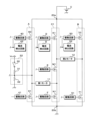
図2は、スイッチ回路20の構成を説明するための回路図である。スイッチ回路20は、入力端20a及び出力端20bを有する。入力端20aは直流電源Uの正極に接続されている。出力端20bは接地されている。電流は、直流電源Uの正極から入力端20aに入力される。電流は出力端20bから出力される。
<Structure of
FIG. 2 is a circuit diagram for explaining the configuration of the
スイッチ回路20は、入力端20a及び出力端20bに加えて、駆動回路40,41,50,51,D,E,F、電流検出回路42,52,G、第1接続回路A、第2接続回路B及び第3接続回路C1を有する。第1接続回路Aは、第1入力スイッチ60及び第1出力スイッチ61を有する。第2接続回路Bは、第2入力スイッチ70及び第2出力スイッチ71を有する。第3接続回路C1は、第3入力スイッチK1、第3中間スイッチM1及び第3出力スイッチN1を有する。第1入力スイッチ60、第1出力スイッチ61、第2入力スイッチ70、第2出力スイッチ71、第3入力スイッチK1、第3中間スイッチM1及び第3出力スイッチN1それぞれは、Nチャネル型のFET(Field Effect Transistor)である。
In addition to an
第1接続回路Aでは、第1入力スイッチ60及び第1出力スイッチ61が直列に接続されている。具体的には、第1入力スイッチ60のソースは、第1出力スイッチ61のドレインに接続されている。第1入力スイッチ60及び第1出力スイッチ61それぞれは第1スイッチとして機能する。第2接続回路Bでは、第2入力スイッチ70及び第2出力スイッチ71が直列に接続されている。具体的には、第2入力スイッチ70のソースは、第2出力スイッチ71のドレインに接続されている。第2入力スイッチ70及び第2出力スイッチ71それぞれは第2スイッチとして機能する。
以下では、第1入力スイッチ60及び第1出力スイッチ61間の接続ノードを第1接続ノードと記載する。更に、第2入力スイッチ70及び第2出力スイッチ71間の接続ノードを第2接続ノードと記載する。
In the first connection circuit A, the
A connection node between the
第3接続回路C1では、第3入力スイッチK1、第3中間スイッチM1及び第3出力スイッチN1が直列に接続されている。具体的には、第3入力スイッチK1のソースは第3中間スイッチM1のドレインに接続されている。第3中間スイッチM1のソースは第3出力スイッチのドレインに接続されている。第3入力スイッチK1、第3中間スイッチM1及び第3出力スイッチN1は第3スイッチとして機能する。 In the third connection circuit C1, the third input switch K1, the third intermediate switch M1 and the third output switch N1 are connected in series. Specifically, the source of the third input switch K1 is connected to the drain of the third intermediate switch M1. The source of the third intermediate switch M1 is connected to the drain of the third output switch. The third input switch K1, the third intermediate switch M1 and the third output switch N1 function as a third switch.
第1入力スイッチ60、第2入力スイッチ70及び第3入力スイッチK1のドレインは入力端20aに接続されている。第1出力スイッチ61、第2出力スイッチ71及び第3出力スイッチN1のソースは出力端20bに接続されている。従って、入力端20a及び出力端20b間に第1接続回路A、第2接続回路B及び第3接続回路C1が各別に接続されている。
The drains of the
第1モータ11は、第1接続ノードと、第3中間スイッチM1及び第3出力スイッチN1間の接続ノードとの間に接続されている。第2モータ12は、第2接続ノードと、第3入力スイッチK1及び第3中間スイッチM1間の接続ノードとの間に接続されている。第1接続ノードは、更に、直列回路22の抵抗接続ノードに接続されている。
The
第1入力スイッチ60、第1出力スイッチ61、第2入力スイッチ70、第2出力スイッチ71、第3入力スイッチK1、第3中間スイッチM1及び第3出力スイッチN1それぞれは、駆動回路40,41,50,51,D,E,Fに接続されている。駆動回路40,41,50,51,D,E,Fは、更に、マイコン21に接続されている。駆動回路40,50,Dそれぞれは、電流検出回路42,52,Gに接続されている。電流検出回路42,52,Gは、更に、マイコン21に接続されている。
The
第1入力スイッチ60において、ソースの電位を基準としたゲートの電圧が一定の基準電圧以上である場合、ドレイン及びソース間の抵抗値は十分に小さい。このとき、第1入力スイッチ60はオンであり、ドレイン及びソースを介して電流が流れることが可能である。第1入力スイッチ60において、ソースの電位を基準としたゲートの電圧が基準電圧未満である場合、ドレイン及びソース間の抵抗値は十分に大きい。このとき、第1入力スイッチ60はオフであり、ドレイン及びソースを介して電流が流れることはない。
In the
第1出力スイッチ61、第2入力スイッチ70、第2出力スイッチ71、第3入力スイッチK1、第3中間スイッチM1及び第3出力スイッチN1それぞれは、第1入力スイッチ60と同様に作用する。第1入力スイッチ60、第1出力スイッチ61、第2入力スイッチ70、第2出力スイッチ71、第3入力スイッチK1、第3中間スイッチM1及び第3出力スイッチN1それぞれの基準電圧は、他のスイッチの基準電圧と異なっていてもよい。
The
駆動回路40,41,50,51,D,E,Fそれぞれは、第1入力スイッチ60、第1出力スイッチ61、第2入力スイッチ70、第2出力スイッチ71、第3入力スイッチK1、第3中間スイッチM1及び第3出力スイッチN1をオン又はオフに切替える。駆動回路40は、第1入力スイッチ60をオンに切替える場合、接地電位を基準とした第1入力スイッチ60のゲートの電圧を上昇させる。これにより、第1入力スイッチ60において、ソースの電位を基準としたゲートの電圧が基準電圧以上となり、第1入力スイッチ60はオンに切替わる。駆動回路40は、第1入力スイッチ60をオフに切替える場合、接地電位を基準とした第1入力スイッチ60のゲートの電圧を低下させる。これにより、第1入力スイッチ60において、ソースの電位を基準としたゲートの電圧が基準電圧未満となり、第1入力スイッチ60はオフに切替わる。
Each of the
駆動回路41,50,51,D,E,Fそれぞれは、駆動回路40と同様に、第1出力スイッチ61、第2入力スイッチ70、第2出力スイッチ71、第3入力スイッチK1、第3中間スイッチM1及び第3出力スイッチN1をオン又はオフに切替える。
Each of the
電流検出回路42は、例えば、カレントミラー回路を用いて構成され、第1入力スイッチ60を介して流れる電流を検出する。電流検出回路42は、検出した電流を示すアナログの電流情報をマイコン21及び駆動回路40に出力する。電流情報は、例えば、第1入力スイッチ60を介して流れる電流に比例する電圧である。
The
電流検出回路52,Gそれぞれは、電流検出回路42と同様に、第2入力スイッチ70及び第3入力スイッチK1を介して流れる電流を検出する。電流検出回路52は、検出した電流を示すアナログの電流情報をマイコン21及び駆動回路50に出力する。電流検出回路Gは、検出した電流を示すアナログの電流情報をマイコン21及び駆動回路Dに出力する。
Like the
マイコン21から駆動回路40,41,50,51,D,E,Fそれぞれに、オンへの切替えを示すハイレベル電圧、又は、オフへの切替えを示すローレベル電圧が入力される。以下では、スイッチをオン又はオフに切替える駆動回路に入力される電圧を入力電圧と記載する。
A high-level voltage indicating ON switching or a low-level voltage indicating OFF switching is input from the
駆動回路40は、入力された電流情報が示す電流が電流閾値未満である場合において、入力電圧がハイレベル電圧に切替わったとき、第1入力スイッチ60をオンに切替える。駆動回路40は、同様の場合において、入力電圧がローレベル電圧に切替わったとき、第1入力スイッチ60をオフに切替える。駆動回路40は、入力された電流情報が示す電流が電流閾値以上となった場合、入力電圧に無関係に第1入力スイッチ60をオフに切替える。その後、駆動回路40は、入力された電流情報が示す電流に無関係に第1入力スイッチ60のオフを維持する。
駆動回路50,Dそれぞれは、駆動回路40と同様に、第2入力スイッチ70及び第3入力スイッチK1をオン又はオフに切替える。
When the current indicated by the input current information is less than the current threshold, the
Each of the
駆動回路41,51,E,Fそれぞれは、入力電圧がハイレベル電圧に切替わった場合、第1出力スイッチ61、第2出力スイッチ71、第3中間スイッチM1及び第3出力スイッチN1をオンに切替える。駆動回路41,51,E,Fそれぞれは、入力電圧がローレベル電圧に切替わった場合、第1出力スイッチ61、第2出力スイッチ71、第3中間スイッチM1及び第3出力スイッチN1をオフに切替える。
Each of the
マイコン21は、駆動回路40,41,50,51,D,E,Fの入力電圧をハイレベル電圧又はローレベル電圧に各別に切替える。これにより、マイコン21は、第1入力スイッチ60、第1出力スイッチ61、第2入力スイッチ70、第2出力スイッチ71、第3入力スイッチK1、第3中間スイッチM1及び第3出力スイッチN1を各別にオン又はオフに切替え、第1モータ11及び第2モータ12を駆動する。第1モータ11及び第2モータ12について、第1方向の電流は図2の右方向であり、第2方向の電流は図2の左方向である。
The
<第1モータ11及び第2モータ12の駆動方法>
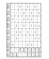
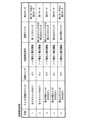
図3は第1モータ11及び第2モータ12の駆動方法を示す図表である。第1モータ11及び第2モータ12の欄に記載されている「-」は動作の停止を示す。第1入力スイッチ60、第1出力スイッチ61、第2入力スイッチ70、第2出力スイッチ71、第3入力スイッチK1、第3中間スイッチM1及び第3出力スイッチN1の欄に記載されている「-」はオフを示す。
<Method of
FIG. 3 is a chart showing how the
第1モータ11を正方向に回転させる場合、第1入力スイッチ60及び第3出力スイッチN1をオンに切替え、スイッチ回路20が有する残りのスイッチをオフに切替える。これにより、第1方向の電流が第1モータ11を流れる。第1モータ11を逆方向に回転させる場合、第1出力スイッチ61、第3入力スイッチK1及び第3中間スイッチM1をオンに切替え、スイッチ回路20が有する残りのスイッチをオフに切替える。これにより、第2方向の電流が第1モータ11を流れる。
When rotating the
第2モータ12を正方向に回転させる場合、第3入力スイッチK1及び第2出力スイッチ71をオンに切替え、スイッチ回路20が有する残りのスイッチをオフに切替える。これにより、第1方向の電流が第2モータ12を流れる。第2モータ12を逆方向に回転させる場合、第3中間スイッチM1、第3出力スイッチN1及び第2入力スイッチ70をオンに切替え、スイッチ回路20が有する残りのスイッチをオフに切替える。これにより、第2方向の電流が第2モータ12を流れる。
When rotating the
第1モータ11及び第2モータ12を正方向に回転させる場合、第1入力スイッチ60、第3入力スイッチK1、第3出力スイッチN1及び第2出力スイッチ71をオンに切替え、スイッチ回路20が有する残りのスイッチをオフに切替える。これにより、第1方向の電流が第1モータ11及び第2モータ12を流れる。
When rotating the
第1モータ11及び第2モータ12それぞれを正方向及び逆方向に回転させる場合、第1入力スイッチ60、第3中間スイッチM1、第3出力スイッチN1及び第2入力スイッチ70をオンに切替え、スイッチ回路20が有する残りのスイッチをオフに切替える。これにより、第1方向の電流が第1モータ11を流れ、第2方向の電流が第2モータ12を流れる。
When rotating the
第1モータ11及び第2モータ12それぞれを逆方向及び正方向に回転させる場合、第1出力スイッチ61、第3入力スイッチK1、第3中間スイッチM1及び第2出力スイッチ71をオンに切替え、スイッチ回路20が有する残りのスイッチをオフに切替える。これにより、第2方向の電流が第1モータ11を流れ、第1方向の電流が第2モータ12を流れる。
When rotating the
第1モータ11及び第2モータ12を逆方向に回転させる場合、第1出力スイッチ61、第3中間スイッチM1及び第2入力スイッチ70をオンに切替え、スイッチ回路20が有する残りのスイッチをオフに切替える。これにより、第2方向の電流が第1モータ11及び第2モータ12を流れる。
When rotating the
<第1モータ11及び第2モータ12の回転速度の調整>
第1モータ11及び第2モータ12それぞれの回転速度は、第1モータ11及び第2モータ12に供給される電流の平均値に比例する。このため、スイッチ回路20が有する少なくとも1つのスイッチについて、PWM(Pulse Width Modulation)制御を行うことによって、第1モータ11及び第2モータ12の回転速度を調整することができる。以下では、PWM制御の対象であるスイッチをPWMスイッチと記載する。
<Adjustment of rotation speed of
The rotation speed of each of the
PWM制御は、スイッチのオン及びオフへの切替えを交互に繰り返す制御である。スイッチのオン又はオフへの切替えが周期的に行われる。1周期の中でスイッチがオンである期間が占める割合、即ち、デューティを調整することによって、第1モータ11又は第2モータ12を流れる電流の平均値が調整される。デューティが大きい程、電流の平均値は大きい。
PWM control is control that alternately repeats switching on and off of a switch. Switching on or off of the switch occurs periodically. The average value of the current flowing through the
図4は第1モータ11用及び第2モータ12用のPWMスイッチを示す図表である。図4に示すように、第1モータ11を正方向に回転させる場合、第1入力スイッチ60又は第3出力スイッチN1についてPWM制御を行う。第1モータ11を逆方向に回転させる場合、第1出力スイッチ61、第3入力スイッチK1又は第3中間スイッチM1について、PWM制御を行う。
FIG. 4 is a chart showing PWM switches for the
第2モータ12を正方向に回転させる場合、第2出力スイッチ71又は第3入力スイッチK1についてPWM制御を行う。第2モータ12を逆方向に回転させる場合、第2入力スイッチ70、第3中間スイッチM1又は第3出力スイッチN1について、PWM制御を行う。
When rotating the
第1モータ11及び第2モータ12を正方向に回転させる場合、第1入力スイッチ60又は第3出力スイッチN1についてPWM制御を行うことによって、第1モータ11の回転速度を調整する。第2出力スイッチ71又は第3入力スイッチK1についてPWM制御を行うことによって、第2モータ12の回転速度を調整する。
When rotating the
第1モータ11及び第2モータ12それぞれを正方向及び逆方向に回転させる場合、第1入力スイッチ60又は第3出力スイッチN1についてPWM制御を行うことによって、第1モータ11の回転速度を調整する。第2入力スイッチ70、第3中間スイッチM1又は第3出力スイッチN1について、PWM制御を行うことによって、第2モータ12の回転速度を調整する。ここで、第3出力スイッチN1についてPWM制御を行った場合、第1モータ11及び第2モータ12に供給される電流が調整され、第1モータ11及び第2モータ12の回転速度が調整される。
When rotating the
第1モータ11及び第2モータ12それぞれを逆方向及び正方向に回転させる場合、第1出力スイッチ61、第3入力スイッチK1又は第3中間スイッチM1について、PWM制御を行うことによって、第1モータ11の回転速度を調整する。第2出力スイッチ71又は第3入力スイッチK1についてPWM制御を行うことによって、第2モータ12の回転速度を調整する。ここで、第3入力スイッチK1についてPWM制御を行った場合、第1モータ11及び第2モータ12に供給される電流が調整され、第1モータ11及び第2モータ12の回転速度が調整される。
When rotating the
第1モータ11及び第2モータ12を逆方向に回転させる場合、第1出力スイッチ61、第2入力スイッチ70又は第3中間スイッチM1についてPWM制御を行うことによって、第1モータ11及び第2モータ12の回転速度を調整する。
When rotating the
第1モータ11及び第2モータ12を逆方向に回転させる場合、第1出力スイッチ61、第2入力スイッチ70及び第3中間スイッチM1がオンに切替えられ、第1モータ11及び第2モータ12が直列に接続される。他の場合、第1モータ11及び第2モータ12それぞれについて、一端及び他端それぞれが入力端20a及び出力端20bに接続される。このため、第1モータ11及び第2モータ12を逆方向に回転させる場合において第1モータ11を流れる電流は、他の場合に第1モータ11を流れる電流よりも小さい。第1モータ11及び第2モータ12を逆方向に回転させる場合において第2モータ12を流れる電流は、他の場合に第2モータ12を流れる電流よりも小さい。
When rotating the
従って、第1モータ11及び第2モータ12を逆方向に回転させる場合におけるPWM制御のデューティを、第1モータ11のみ又は第2モータ12のみを回転させる場合におけるPWM制御のデューティよりも大きい値に設定されている。これにより、第1モータ11及び第2モータ12を逆方向に回転させる場合における第1モータ11及び第2モータ12それぞれの回転速度を他の場合における第1モータ11及び第2モータ12の回転速度と同じ速度に調整することができる。
Therefore, the duty of PWM control when rotating the
マイコン21は、PWMスイッチを駆動する駆動回路に、ハイレベル電圧及びローレベル電圧への切替えを交互に繰り返すPWM信号を出力する。これにより、PWM制御が行われる。PWM信号では、ハイレベル電圧又はローレベル電圧への切替えが周期的に行われる。1周期の中でハイレベル電圧の期間が占める割合がPWM制御のデューティに相当する。
The
通常、入力電圧及び電流情報に基づいてスイッチをオン又はオフに切替える駆動回路について、入力電圧がハイレベル電圧又はローレベル電圧に切替わってから、スイッチのオン又はオフへの切替えが行われるまでの期間は長い。このため、PWMスイッチは、入力電圧のみに基づいて駆動回路がオン又はオフに切替えるスイッチ、即ち、第1出力スイッチ61、第2出力スイッチ71、第3中間スイッチM1又は第3出力スイッチN1であることが好ましい。
Generally, for a driver circuit that switches a switch on or off based on input voltage and current information, the time from when the input voltage switches to a high level voltage or low level voltage to when the switch is switched on or off is The period is long. Thus, the PWM switch is a switch that the drive circuit switches on or off based only on the input voltage, i.e. the
<マイコン21の構成>
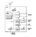
図5はマイコン21の要部構成を示すブロック図である。マイコン21は、出力部80、A/D変換部81,82、切替え部83、入力部84,85,86、記憶部87及び制御部88を有する。出力部80、A/D変換部81,82、切替え部83、入力部84、記憶部87及び制御部88は内部バス89に接続されている。出力部80は、更に、スイッチ回路20の駆動回路40,41,50,51,D,E,Fに各別に接続されている。
<Configuration of
FIG. 5 is a block diagram showing the essential configuration of the
A/D変換部81は、更に、入力部85に接続されている。入力部85は、更に、スイッチ回路20の電流検出回路42,52,Gに各別に接続されている。A/D変換部82は、更に、入力部86に接続されている。入力部86は、更に、電圧検出回路23に接続されている。
The A/
出力部80は、制御部88の指示に従って、駆動回路40,41,50,51,D,E,Fの入力電圧をハイレベル電圧又はローレベル電圧に切替える。更に、出力部80は、制御部88の指示に従って、駆動回路40,41,50,51,D,E,FにPWM信号を出力する。駆動回路40,41,50,51,D,E,Fに出力するPWM信号のデューティは各別に設定されている。制御部88がこれらのデューティを変更してもよい。
The
電流検出回路42,52,Gそれぞれは、アナログの電流情報を入力部85に出力する。入力部85は、電流検出回路42,52,Gからアナログの電流情報が入力された場合、入力されたアナログの電流情報をA/D変換部81に出力する。A/D変換部81は、入力部85から入力されたアナログの電流情報をデジタルの電流情報に変換する。
Each of the
制御部88は、A/D変換部81が変換したデジタルの電流情報を取得する。制御部88が電流検出回路42,52,Gの1つから出力された電流情報をA/D変換部81から取得した場合、取得した電流情報が示す電流は、取得時点において検出された電流と実質的に一致する。
The
切替え部83は、制御部88の指示に従って、直列回路22の回路スイッチ30をオン又はオフに切替える。
電圧検出回路23は、ノード電圧を示すアナログの電圧情報を入力部86に出力する。入力部86は、アナログの電圧情報が入力された場合、入力されたアナログの電流情報をA/D変換部82に出力する。A/D変換部82は、入力部86から入力されたアナログの電圧情報をデジタルの電圧情報に変換する。制御部88は、A/D変換部82からデジタルの電圧情報を取得する。制御部88が取得した電圧情報が示すノード電圧は、取得時点において電圧検出回路23が検出したノード電圧と実質的に一致する。
The switching
The
駆動信号及び停止信号は入力部84に入力される。入力部84は、駆動信号が入力された場合、入力された駆動信号の内容、即ち、駆動するモータと、駆動するモータの回転方向とを制御部88に通知する。入力部84は、停止信号が入力された場合、停止信号の入力を制御部88に通知する。
A drive signal and a stop signal are input to the
記憶部87は不揮発性メモリである。記憶部87には、コンピュータプログラムPが記憶されている。制御部88は、処理を実行する処理素子、例えば、CPU(Central Processing Unit)を有し、処理部として機能する。制御部88の処理素子は、コンピュータプログラムPを実行することによって、短絡検知処理、通常駆動処理、第1部分駆動処理、第2部分駆動処理及び第3部分駆動処理を実行する。
The
短絡検知処理は、スイッチ回路20が有するスイッチの短絡を検知する処理である。通常駆動処理は、第1モータ11及び第2モータ12の一方又は両方を駆動する処理であり、スイッチ回路20が有する全てのスイッチが正常である場合に実行される。第1部分駆動処理は、第1モータ11のみを駆動する処理であり、第1出力スイッチ61又は第3出力スイッチN1の両端が短絡している場合に実行される。第2部分駆動処理は、第2モータ12のみを駆動する処理であり、第2入力スイッチ70、第2出力スイッチ71又は第3入力スイッチK1の両端が短絡している場合に実行される。第3部分駆動処理は、第1モータ11又は第2モータ12を駆動する処理であり、第3中間スイッチM1の両端が短絡している場合に実行される。
The short circuit detection process is a process of detecting a short circuit of a switch included in the
なお、コンピュータプログラムPは、制御部88の処理素子が読み取り可能に、記憶媒体Hに記憶されていてもよい。この場合、図示しない読み出し装置によって記憶媒体Hから読み出されたコンピュータプログラムPが記憶部87に記憶される。記憶媒体Hは、光ディスク、フレキシブルディスク、磁気ディスク、磁気光ディスク又は半導体メモリ等である。光ディスクは、CD(Compact Disc)-ROM(Read Only Memory)、DVD(Digital Versatile Disc)-ROM、又は、BD(Blu-ray(登録商標) Disc)等である。磁気ディスクは、例えばハードディスクである。また、図示しない通信網に接続されている図示しない外部装置からコンピュータプログラムPをダウンロードし、ダウンロードしたコンピュータプログラムPを記憶部87に記憶してもよい。
The computer program P may be stored in the storage medium H so as to be readable by the processing element of the
制御部88が有する処理素子の数は2以上であってもよい。この場合、複数の処理素子が短絡検知処理、通常駆動処理、第1部分駆動処理、第2部分駆動処理及び第3部分駆動処理それぞれを並行して実行してもよい。
The number of processing elements that the
<短絡検知処理>
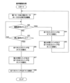
図6は短絡検知処理の手順を示す図表である。制御部88は、第1モータ11及び第2モータ12が動作を停止している場合に短絡検知処理を実行する。短絡検知条件は、短絡が発生したとみなす条件である。短絡スイッチは、両端が短絡したスイッチである。禁止モータは、駆動が禁止されているモータである。
<Short circuit detection processing>
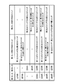
FIG. 6 is a chart showing the procedure of short-circuit detection processing. The
記憶部87には、一定の電圧閾値が予め記憶されている。電圧閾値は、ゼロVを超えており、かつ、第1抵抗31及び第2抵抗32が一定電圧Vcを分圧することによって得られる分圧電圧以下である。また、スイッチ回路20が有するスイッチ、即ち、第1入力スイッチ60、第1出力スイッチ61、第2入力スイッチ70、第2出力スイッチ71、第3入力スイッチK1、第3中間スイッチM1及び第3出力スイッチN1の中で、2つ以上のスイッチの両端が短絡することはないと仮定する。
A constant voltage threshold is stored in advance in the
第1抵抗31及び第2抵抗32それぞれの抵抗値は、第1モータ11の抵抗成分値よりも十分に大きく、第2モータ12の抵抗成分値よりも十分に大きい。また、制御部88は、出力部80に、スイッチ回路20が有するスイッチそれぞれについてオン又はオフへの切替えを指示する。出力部80は、制御部88の指示に従って、駆動回路40,41,50,51,D,E,Fに出力している電圧をハイレベル電圧又はローレベル電圧に切替える。前述したように、駆動回路40,41,50,51,D,E,Fそれぞれは、入力電圧に基づいて、第1入力スイッチ60、第1出力スイッチ61、第2入力スイッチ70、第2出力スイッチ71、第3入力スイッチK1、第3中間スイッチM1及び第3出力スイッチN1をオン又はオフに切替える。
The resistance values of the
制御部88は、まず、手順1を実行する。手順1では、制御部88は、出力部80に、スイッチ回路20が有する全てのスイッチのオフへの切替えを指示する。更に、制御部88は、切替え部83に指示して、直列回路22の回路スイッチ30をオフに切替えさせる。この状態で、制御部88は、A/D変換部82から抵抗接続ノードのノード電圧を示す電圧情報を取得する。
The
ここで、スイッチ回路20が有する全てのスイッチが正常である場合、ノード電圧はゼロVであり、電圧閾値未満である。第1入力スイッチ60の両端が短絡している場合、ノード電圧は直流電源Uの電源電圧に実質的に一致し、電圧閾値以上である。このため、制御部88は、取得した電圧情報が示すノード電圧が電圧閾値以上である場合、第1入力スイッチ60の短絡を検知する。制御部88は、第1入力スイッチ60の短絡を検知した場合、第1モータ11及び第2モータ12の駆動を禁止し、短絡検知処理を終了する。
Here, when all the switches included in the
第1入力スイッチ60の両端が短絡している場合、第1モータ11に第2方向(図2の左方向)の電流を流すことができない。また、第2モータ12に第2方向の電流を供給するために、第2入力スイッチ70、第3中間スイッチM1及び第3出力スイッチN1をオンに切替えた場合、第1モータ11に第1方向(図2の右方向)の電流が供給され、第1モータ11が正方向に回転する。このため、第1モータ11及び第2モータ12の駆動を禁止する。
When both ends of the
制御部88は、第1入力スイッチ60の短絡を検知しなかった場合、手順2を実行する。手順2では、制御部88は、出力部80にスイッチ回路20の全てのスイッチのオフへの切替えを指示している状態で、切替え部83に指示して回路スイッチ30をオンに切替えさせる。この状態で、制御部88は、A/D変換部82から電圧情報を取得する。
If the
ここで、スイッチ回路20が有する全てのスイッチが正常である場合、ノード電圧は分圧電圧であり、電圧閾値以上である。第1出力スイッチ61又は第3出力スイッチN1の両端が短絡している場合、ノード電圧は、実質的にゼロVであり、電圧閾値未満である。このため、制御部88は、取得した電圧情報が示すノード電圧が電圧閾値未満である場合、第1出力スイッチ61又は第3出力スイッチN1の短絡を検知する。制御部88は、第1出力スイッチ61又は第3出力スイッチN1の短絡を検知した場合、第1モータ11の駆動を禁止し、短絡検知処理を終了する。
第1出力スイッチ61又は第3出力スイッチN1の両端が短絡している場合、第1モータ11に第1方向又は第2方向の電流を供給することができないので、第1モータ11の駆動を禁止する。
Here, when all the switches included in the
When both ends of the
スイッチ回路20が有する全てのスイッチがオフである場合において、回路スイッチ30がオンであるとき、電流は回路スイッチ30、第1抵抗31及び第2抵抗32の順に流れる。従って、第1抵抗31及び第2抵抗32間の抵抗接続ノードは、回路スイッチ30の下流側の接続ノードである。
なお、回路スイッチ30は、第1抵抗31及び第2抵抗32間に接続されていてもよい。この場合、第1抵抗31の一端に一定電圧Vcが印加され、抵抗接続ノードは、回路スイッチ30及び第2抵抗32間の接続ノードである。
When all the switches of the
Note that the
制御部88は、手順2において、第1出力スイッチ61又は第3出力スイッチN1の短絡を検知しなかった場合、手順3を実行する。手順3では、制御部88は、出力部80に、スイッチ回路20が有するスイッチの中で第3中間スイッチM1のみのオンへの切替えを指示する。第3中間スイッチM1のみにオンへの切替えを指示しているので、スイッチ回路20が有するスイッチの中で第3中間スイッチM1以外のスイッチについてはオフへの切替えを指示している。更に、制御部88は、切替え部83に指示して、回路スイッチ30をオフに切替えさせる。この状態で、制御部88は、A/D変換部82から電圧情報を取得する。
If the
ここで、スイッチ回路20が有する全てのスイッチが正常である場合、ノード電圧はゼロVであり、電圧閾値未満である。第2入力スイッチ70又は第3入力スイッチK1の両端が短絡している場合、ノード電圧は、直流電源Uの電源電圧に実質的に一致し、電圧閾値以上である。このため、制御部88は、取得した電圧情報が示すノード電圧が電圧閾値以上である場合、第2入力スイッチ70又は第3入力スイッチK1の短絡を検知する。制御部88は、第2入力スイッチ70又は第3入力スイッチK1の短絡を検知した場合、第2モータ12の駆動を禁止し、短絡検知処理を終了する。
第2入力スイッチ70又は第3入力スイッチK1の両端が短絡している場合、第2方向又は第1方向の電流を第2モータ12に供給することができないので、第2モータ12の駆動を禁止する。
Here, when all the switches included in the
When both ends of the
制御部88は、第2入力スイッチ70又は第3入力スイッチK1の短絡を検知しなかった場合、手順4を実行する。手順4では、制御部88は、出力部80に、スイッチ回路20が有するスイッチの中で第3中間スイッチM1のみのオンへの切替えを指示している状態で切替え部83に指示して、回路スイッチ30をオンに切替えさせる。この状態で、制御部88は、A/D変換部82から電圧情報を取得する。
If the
ここで、スイッチ回路20が有する全てのスイッチが正常である場合、ノード電圧は分圧電圧であり、電圧閾値以上である。第2出力スイッチ71の両端が短絡している場合、ノード電圧は、実質的にゼロVであり、電圧閾値未満である。このため、制御部88は、取得した電圧情報が示すノード電圧が電圧閾値未満である場合、第2出力スイッチ71の短絡を検知する。制御部88は、第2出力スイッチ71の短絡を検知した場合、第2モータ12の駆動を禁止し、短絡検知処理を終了する。
第2出力スイッチ71の両端が短絡している場合、第2モータ12に第2方向の電流を供給することができないため、第2モータ12の駆動を禁止する。
Here, when all the switches included in the
When both ends of the
制御部88は、第2出力スイッチ71の短絡を検知しなかった場合、手順5を実行する。手順5では、制御部88は、出力部80に、第3入力スイッチK1のみのオンへの切替えを指示する。第3入力スイッチK1のみにオンへの切替えを指示しているので、スイッチ回路20が有するスイッチの中で第3入力スイッチK1以外のスイッチについてオフへの切替えを指示している。更に、制御部88は、切替え部83に指示して、回路スイッチ30をオフに切替えさせる。この状態で、制御部88は、A/D変換部82から電圧情報を取得する。
If the
ここで、スイッチ回路20が有する全てのスイッチが正常である場合、ノード電圧はゼロVであり、電圧閾値未満である。第3中間スイッチM1の両端が短絡している場合、ノード電圧は、直流電源Uの電源電圧に実質的に一致し、電圧閾値以上である。制御部88は、取得した電圧情報が示すノード電圧が電圧閾値以上である場合、第3中間スイッチM1の短絡を検知し、第1モータ11又は第2モータ12の駆動を禁止する。
Here, when all the switches included in the
第3中間スイッチM1の両端が短絡している場合、第1モータ11及び第2モータ12の両方に第1方向又は第2方向の電流を供給することができない。第1モータ11又は第2モータ12中の一方のモータが回転している場合、他方のモータの回転方向は、正方向及び逆方向中の1つに限定される。第1モータ11又は第2モータ12の駆動の禁止は、第1モータ11及び第2モータ12中の一方のモータを駆動している場合、他方のモータの駆動を禁止することを意味する。
If both ends of the third intermediate switch M1 are short-circuited, both the
制御部88は、手順5を実行した後、短絡検知処理を終了する。制御部88は、短絡検知処理を実行した後において、通常駆動処理、第1部分駆動処理、第2部分駆動処理又は第3部分駆動処理を実行する。
なお、手順5では、制御部88は、出力部80に第3入力スイッチK1のみのオンへの切替えを指示する代わりに、出力部80に第2入力スイッチ70のみのオンへの切替えを指示するか、又は、第3入力スイッチK1及び第2入力スイッチ70の両方のオンへの切替えを指示してもよい。
After executing
In
<通常駆動処理>
図7は通常駆動処理の手順を示すフローチャートである。制御部88は、スイッチ回路20が有する全てのスイッチが正常である場合において、入力部84に駆動信号が入力されたとき、通常駆動処理を実行する。通常駆動処理では、制御部88は、まず、入力部84に入力された駆動信号の内容に従って、第1モータ11及び第2モータ12の一方又は両方をスイッチ回路20に駆動させる(ステップS1)。
<Normal drive processing>
FIG. 7 is a flow chart showing the procedure of normal drive processing. When all the switches of the
具体的には、制御部88は、出力部80に指示して、スイッチ回路20が有するスイッチを各別にオン又はオフに切替えさせる。出力部80は、入力部84に入力された駆動信号の内容に応じて、スイッチ回路20が有するスイッチを各別にオン又はオフに切替える。出力部80は、PWMスイッチをオン又はオフに切替える駆動回路にPWM信号を出力し、PWMスイッチについてPWM制御を行う。
Specifically, the
入力部84に入力された駆動信号が、駆動モータとして第1モータ11を示し、第1モータ11の回転方向として正方向を示す場合、図3に示すように、出力部80は、第1入力スイッチ60及び第3出力スイッチN1をオンに切替え、他のスイッチをオフに切替える。これにより、第1モータ11に第1方向の電流が供給される。更に、出力部80は、駆動回路40,Fの一方にPWM信号を出力する。これにより、第1入力スイッチ60又は第3出力スイッチN1についてPWM制御が行われ、第1モータ11の回転速度が調整される。
When the drive signal input to the
制御部88は、ステップS1を実行した後、入力部84に駆動信号が入力されたか否かを判定する(ステップS2)。制御部88は、駆動信号が入力されていないと判定した場合(S2:NO)、入力部84に停止信号が入力されたか否かを判定する(ステップS3)。制御部88は、停止信号が入力されていないと判定した場合(S3:NO)、ステップS2を再び実行し、駆動信号又は停止信号が入力部84に入力されるまで待機する。
After executing step S1, the
制御部88は、駆動信号が入力されたと判定した場合(S2:YES)、出力部80に指示して、全ての入力スイッチ、即ち、第1入力スイッチ60、第2入力スイッチ70及び第3入力スイッチK1をオフに切替えさせる(ステップS4)。これにより、第1モータ11及び第2モータ12への電流の供給が停止し、第1モータ11及び第2モータ12は動作を停止する。
When the
制御部88は、ステップS4を実行した後、出力部80に指示して、第3中間スイッチM1及び全ての出力スイッチをオンに切替えさせる(ステップS5)。全ての出力スイッチは、第1出力スイッチ61、第2出力スイッチ71及び第3出力スイッチN1である。第1モータ11及び第2モータ12の一方又は両方を駆動している場合、第1モータ11又は第2モータ12に電流が供給され、第1モータ11又は第2モータ12のコイルにエネルギーが蓄えられる。第3中間スイッチM1及び全ての出力スイッチがオンである場合、第1モータ11又は第2モータ12のコイルは、電流を出力し、エネルギーを放出する。
After executing step S4, the
制御部88は、ステップS5を実行した後、ステップS1を実行し、入力部84に新たに入力された駆動信号の内容に従って、第1モータ11及び第2モータ12の一方又は両方をスイッチ回路20に駆動させる。
After executing step S5, the
制御部88は、停止信号が入力されたと判定した場合(S3:YES)、ステップS4と同様に、出力部80に指示して、全ての入力スイッチをオフに切替えさせる(ステップS6)。これにより、第1モータ11及び第2モータ12は動作を停止する。制御部88は、ステップS6を実行した後、ステップS5と同様に、出力部80に指示して、第3中間スイッチM1及び全ての出力スイッチをオンに切替えさせる(ステップS7)。これにより、第1モータ11又は第2モータ12のコイルはエネルギーを放出する。
制御部88は、ステップS7を実行した後、出力部80に指示して、スイッチ回路20が有する全てのスイッチをオフに切替えさせ(ステップS8)、通常駆動処理を終了する。
When determining that the stop signal has been input (S3: YES), the
After executing step S7, the
<第1部分駆動処理>
図8は第1部分駆動処理の手順を示すフローチャートである。制御部88は、禁止モータが第2モータ12である場合において、入力部84に駆動信号が入力されたとき、第1部分駆動処理を実行する。第1部分駆動処理では、制御部88は、まず、入力部84に入力された駆動信号に基づいて、第1モータ11を駆動するか否かを判定する(ステップS11)。ステップS11では、制御部88は、駆動信号が示す駆動モータに第1モータ11が含まれている場合、第1モータ11を駆動すると判定する。制御部88は、駆動信号が駆動モータとして第2モータ12のみが示されている場合、第1モータ11を駆動しないと判定する。
<First partial drive process>
FIG. 8 is a flow chart showing the procedure of the first partial drive process. When the prohibited motor is the
制御部88は、第1モータ11を駆動すると判定した場合(S11:YES)、入力部84に入力された駆動信号の内容に従って、第1モータ11を駆動する(ステップS12)。具体的には、制御部88は、出力部80に、第1入力スイッチ60、第1出力スイッチ61、第3入力スイッチK1、第3中間スイッチM1及び第3出力スイッチN1のオン又はオフへの切替えを各別に指示することによって第1モータ11を駆動する。制御部88は、出力部80に指示して、PWMスイッチをオン又はオフに切替える駆動回路にPWM信号を出力させる。これにより、PWMスイッチについてPWM制御が行われる。第2モータ12の駆動は禁止されているので、第1部分駆動処理において第2モータ12が駆動されることはない。
When determining to drive the first motor 11 (S11: YES), the
入力部84に入力された駆動信号が第1モータ11の回転方向として正方向を示す場合、図3に示すように、出力部80は、第1入力スイッチ60及び第3出力スイッチN1をオンに切替え、他のスイッチをオフに切替える。これにより、第1モータ11に第1方向の電流が供給される。更に、出力部80は、駆動回路40,Fの一方にPWM信号を出力する。これにより、第1入力スイッチ60又は第3出力スイッチN1についてPWM制御が行われ、第1モータ11の回転速度が調整される。PWMスイッチとして、短絡スイッチとは異なるスイッチが選択される。
When the drive signal input to the
制御部88は、ステップS12を実行した後、入力部84に駆動信号又は停止信号が入力されたか否かを判定する(ステップS13)。制御部88は、入力部84に駆動信号又は停止信号が入力されていないと判定した場合(S13:NO)、ステップS13を再び実行し、入力部84に駆動信号又は停止信号が入力されるまで待機する。
After executing step S12, the
制御部88は、駆動信号又は停止信号が入力したと判定した場合(S13:YES)、出力部80に指示して、第1入力スイッチ60、第3入力スイッチK1及び第3中間スイッチM1をオフに切替えさせる(ステップS14)。これにより、第1モータ11への電流の供給が停止し、第1モータ11は動作を停止する。ステップS14が実行された時点において、第3入力スイッチK1の両端が短絡している可能性がある。この場合、出力部80は第3入力スイッチK1をオフに切替えることができない。しかしながら、第3中間スイッチM1はオフに切替わるため、第1モータ11は動作を停止する。
When the
制御部88は、ステップS14を実行した後、出力部80に指示して、第1出力スイッチ61及び第3出力スイッチN1をオンに切替えさせる(ステップS15)。これにより、第1モータ11のコイルはエネルギーを放出する。制御部88は、ステップS15を実行した後、入力部84に入力された入力信号が駆動信号であるか否かを判定する(ステップS16)。制御部88は、入力信号が駆動信号であると判定した場合(S16:YES)、ステップS11を実行する。入力部84に新たに入力された駆動信号が示す駆動モータに第1モータ11が含まれている場合、新たに入力された駆動信号の内容に従って、第1モータ11をスイッチ回路20に駆動させる。
After executing step S14, the
制御部88は、第1モータ11を駆動しないと判定した場合(S11:NO)、又は、入力信号が駆動信号ではないと判定した場合(S16:NO)、出力部80に指示して、スイッチ回路20が有する全てのスイッチをオフに切替えさせ(ステップS17)、第1部分駆動処理を終了する。ステップS17が実行された場合、スイッチ回路20が有するスイッチの中で短絡スイッチを除く他のスイッチがオフに切替わる。
If the
<第2部分駆動処理>
図9は第2部分駆動処理の手順を示すフローチャートである。制御部88は、禁止モータが第1モータ11である場合において、入力部84に駆動信号が入力されたとき、第2部分駆動処理を実行する。第2部分駆動処理では、制御部88は、まず、入力部84に入力された駆動信号に基づいて、第2モータ12を駆動するか否かを判定する(ステップS21)。ステップS21では、制御部88は、駆動信号が示す駆動モータに第2モータ12が含まれている場合、第2モータ12を駆動すると判定する。制御部88は、駆動信号が駆動モータとして第1モータ11のみが示されている場合、第2モータ12を駆動しないと判定する。
<Second Partial Drive Processing>
FIG. 9 is a flow chart showing the procedure of the second partial drive process. When the prohibited motor is the
制御部88は、第2モータ12を駆動すると判定した場合(S21:YES)、入力部84に入力された駆動信号の内容に従って、第2モータ12を駆動する(ステップS22)。具体的には、制御部88は、出力部80に、第2入力スイッチ70、第2出力スイッチ71、第3入力スイッチK1、第3中間スイッチM1及び第3出力スイッチN1のオン又はオフへの切替えを各別に指示することによって第2モータ12を駆動する。制御部88は、出力部80に指示して、PWMスイッチをオン又はオフに切替える駆動回路にPWM信号を出力させる。これにより、PWMスイッチについてPWM制御が行われる。第1モータ11の駆動は禁止されているので、第2部分駆動処理において第1モータ11が駆動されることはない。
When determining to drive the second motor 12 (S21: YES), the
入力部84に入力された駆動信号が第2モータ12の回転方向として正方向を示す場合、図3に示すように、出力部80は、第3入力スイッチK1及び第2出力スイッチ71をオンに切替え、他のスイッチをオフに切替える。これにより、第2モータ12に第1方向の電流が供給される。更に、出力部80は、駆動回路D,51の一方にPWM信号を出力する。これにより、第3入力スイッチK1又は第2出力スイッチ71についてPWM制御が行われ、第2モータ12の回転速度が調整される。PWMスイッチとして、短絡スイッチとは異なるスイッチが選択される。
When the drive signal input to the
制御部88は、ステップS22を実行した後、入力部84に駆動信号又は停止信号が入力されたか否かを判定する(ステップS23)。制御部88は、入力部84に駆動信号又は停止信号が入力されていないと判定した場合(S23:NO)、ステップS23を再び実行し、入力部84に駆動信号又は停止信号が入力されるまで待機する。
After executing step S22, the
制御部88は、駆動信号又は停止信号が入力したと判定した場合(S23:YES)、出力部80に指示して、第2入力スイッチ70及び第3入力スイッチK1をオフに切替えさせる(ステップS24)。これにより、第2モータ12への電流の供給が停止し、第2モータ12は動作を停止する。
If the
制御部88は、ステップS24を実行した後、出力部80に指示して、第2出力スイッチ71、第3中間スイッチM1及び第3出力スイッチN1をオンに切替えさせる(ステップS25)。これにより、第2モータ12のコイルはエネルギーを放出する。ステップS25が実行された時点において、第3出力スイッチN1の両端が短絡している可能性がある。この場合であっても、第3出力スイッチN1は短絡しているので、第2モータ12のコイルはエネルギーを放出する。
After executing step S24, the
制御部88は、ステップS25を実行した後、入力部84に入力された入力信号が駆動信号であるか否かを判定する(ステップS26)。制御部88は、入力信号が駆動信号であると判定した場合(S26:YES)、ステップS21を実行する。入力部84に新たに入力された駆動信号が示す駆動モータに第2モータ12が含まれている場合、新たに入力された駆動信号の内容に従って、第2モータ12をスイッチ回路20に駆動させる。
After executing step S25, the
制御部88は、第2モータ12を駆動しないと判定した場合(S21:NO)、又は、入力信号が駆動信号ではないと判定した場合(S26:NO)、出力部80に指示して、スイッチ回路20が有する全てのスイッチをオフに切替えさせ(ステップS27)、第2部分駆動処理を終了する。ステップS27が実行された場合、スイッチ回路20が有するスイッチの中で短絡スイッチを除く他のスイッチがオフに切替わる。
If the
<第3部分駆動処理>
図10は第3部分駆動処理の手順を示すフローチャートである。制御部88は、禁止モータが第1モータ11又は第2モータ12である場合、即ち、第3中間スイッチM1の短絡を検知した場合において、入力部84に駆動信号が入力されたとき、第3部分駆動処理を実行する。第3部分駆動処理では、制御部88は、まず、第1部分駆動処理のステップS11と同様に、入力部84に入力された駆動信号に基づいて、第1モータ11を駆動するか否かを判定する(ステップS31)。
<Third Partial Drive Processing>
FIG. 10 is a flow chart showing the procedure of the third partial drive process. When the prohibited motor is the
制御部88は、第1モータ11を駆動すると判定した場合(S31:YES)、第1部分駆動処理のステップS12と同様に、入力部84に入力された駆動信号の内容に従って、第1モータ11を駆動する(ステップS32)。制御部88は、第1モータ11を駆動しないと判定した場合(S31:NO)、第2部分駆動処理のステップS22と同様に、入力部84に入力された駆動信号の内容に従って、第2モータ12を駆動する(ステップS33)。
When determining to drive the first motor 11 (S31: YES), the
制御部88は、ステップS32,S33の一方を実行した後、入力部84に駆動信号が入力されたか否かを判定する(ステップS34)。制御部88は、駆動信号が入力されていないと判定した場合(S34:NO)、入力部84に停止信号が入力されたか否かを判定する(ステップS35)。制御部88は、停止信号が入力されていないと判定した場合(S35:NO)、ステップS34を再び実行し、駆動信号又は停止信号が入力部84に入力されるまで待機する。
After executing one of steps S32 and S33, the
制御部88は、駆動信号が入力されたと判定した場合(S34:YES)、出力部80に指示して、全ての入力スイッチをオフに切替えさせる(ステップS36)。これにより、第1モータ11及び第2モータ12への電流の供給が停止し、第1モータ11及び第2モータ12は動作を停止する。
When determining that the drive signal has been input (S34: YES), the
制御部88は、ステップS36を実行した後、出力部80に指示して、全ての出力スイッチをオンに切替えさせる(ステップS37)。全ての出力スイッチがオンである場合、第3中間スイッチM1の両端は短絡しているので、第1モータ11又は第2モータ12のコイルは、電流を出力し、エネルギーを放出する。
After executing step S36, the
制御部88は、ステップS37を実行した後、ステップS31を再び実行し、入力部84に新たに入力された駆動信号の内容に従って、第1モータ11を駆動するか否かを判定する。その後、新たに入力された駆動信号の内容に従って、第1モータ11又は第2モータ12が駆動される。
After executing step S<b>37 , the
制御部88は、停止信号が入力されたと判定した場合(S35:YES)、ステップS36と同様に、出力部80に指示して、全ての入力スイッチをオフに切替えさせる(ステップS38)。これにより、第1モータ11及び第2モータ12は動作を停止する。制御部88は、ステップS38を実行した後、ステップS37と同様に、出力部80に指示して、全ての出力スイッチをオンに切替えさせる(ステップS39)。これにより、第1モータ11又は第2モータ12のコイルはエネルギーを放出する。
When determining that the stop signal has been input (S35: YES), the
制御部88は、ステップS39を実行した後、出力部80に指示して、スイッチ回路20が有する全てのスイッチをオフに切替えさせ(ステップS40)、第3部分駆動処理を終了する。ステップS39が実行された場合、スイッチ回路20が有するスイッチの中で短絡スイッチを除く他のスイッチがオフに切替わる。
After executing step S39, the
以上のように、第3中間スイッチM1の両端が短絡している場合において、制御部88は、第1モータ11を駆動する場合、第2モータ12を駆動しない。制御部88は、第1モータ11を駆動しない場合、第2モータ12を駆動する。制御部88は、第1モータ11の駆動を優先する。
As described above, when both ends of the third intermediate switch M1 are short-circuited, the
<駆動装置10の効果及びなお書き>
第1モータ11の一端及び他端それぞれが、正常な2つのスイッチ間の接続ノードに接続されている場合、駆動装置10は第1モータ11を正方向及び逆方向に回転させることができる。同様に、第2モータ12の一端及び他端それぞれが、正常な2つのスイッチ間の接続ノードに接続されている場合、駆動装置10は第2モータ12を正方向及び逆方向に回転させることができる。第3接続回路C1が有する3つのスイッチ中の1つの両端が短絡した場合であっても、第1モータ11又は第2モータ12の一端は、第3接続回路C1が有する残りの2つのスイッチ間の接続ノードに接続されている。このため、第3接続回路C1が有する1つのスイッチの両端が短絡した場合であっても、第1モータ11又は第2モータ12を正方向及び逆方向に回転させることができる。
制御部88は、第1モータ11又は第2モータ12を駆動している間、第1入力スイッチ60、第2入力スイッチ70及び第3入力スイッチK1を介して流れる電流に基づいて、スイッチ回路20の故障又は異常を検知してもよい。
<Effects of the driving
When one end and the other end of the
While driving the
(実施形態2)
実施形態1において、第3中間スイッチM1の両端が短絡している場合において、制御部88は第1モータ11の駆動を優先する。しかしながら、駆動が優先されるモータは第1モータ11に限定されない。
以下では、実施形態2について、実施形態1と異なる点を説明する。後述する構成を除く他の構成は、実施形態1と共通している。このため、実施形態1と共通する構成部には実施形態1と同一の参照符号を付してその説明を省略する。
(Embodiment 2)
In the first embodiment, the
Below, the points of the second embodiment that are different from the first embodiment will be described. Configurations other than those described later are common to the first embodiment. For this reason, the same reference numerals as those of the first embodiment are given to the components that are common to the first embodiment, and the description thereof is omitted.
<第3部分駆動処理>
図11は実施形態2における第3部分駆動処理の手順を示すフローチャートである。制御部88は、禁止モータが第1モータ11又は第2モータ12である場合、即ち、第3中間スイッチM1の短絡を検知した場合において、入力部84に駆動信号が入力されたとき、第3部分駆動処理を実行する。実施形態2における第3部分駆動処理の大部分は実施形態1における第3部分駆動処理と同様である。このため、実施形態2における第3部分駆動処理において、第3部分駆動処理と同様である部分、即ち、ステップS32~S40の詳細な説明を省略する。
<Third Partial Drive Processing>
FIG. 11 is a flow chart showing the procedure of the third partial drive process according to the second embodiment. When the prohibited motor is the
第3部分駆動処理では、制御部88は、まず、第2部分駆動処理のステップS21と同様に、入力部84に入力された駆動信号に基づいて、第2モータ12を駆動するか否かを判定する(ステップS51)。制御部88は、第2モータ12を駆動しないと判定した場合(S51:NO)、ステップS32を実行する。制御部88は、第2モータ12を駆動すると判定した場合(S51:YES)、ステップS33を実行する。制御部88は、ステップS37を実行した後、ステップS51を再び実行し、入力部84に新たに入力された駆動信号の内容に従って、第2モータ12を駆動するか否かを判定する。その後、新たに入力された駆動信号の内容に従って、第1モータ11又は第2モータ12が駆動される。
In the third partial drive process, the
以上のように、第3中間スイッチM1の両端が短絡している場合において、制御部88は、第2モータ12を駆動する場合、第1モータ11を駆動しない。制御部88は、第2モータ12を駆動しない場合、第1モータ11を駆動する。制御部88は、第2モータ12の駆動を優先する。
As described above, when both ends of the third intermediate switch M1 are short-circuited, the
<駆動装置10の効果>
実施形態2における駆動装置10は、実施形態1における駆動装置10が奏する効果の中で、第3部分駆動処理において第1モータ11の駆動を優先することによって得られる効果を除く他の効果を同様に奏する。
<Effects of
The
(実施形態3)
実施形態1では、駆動装置10が駆動するモータの数は2である。しかしながら、駆動装置10が駆動するモータの数は3以上であってもよい。
以下では、実施形態3について、実施形態1と異なる点を説明する。後述する構成を除く他の構成は、実施形態1と共通している。このため、実施形態1と共通する構成部には実施形態1と同一の参照符号を付してその説明を省略する。
(Embodiment 3)
In
In the following, the points of the third embodiment that are different from the first embodiment will be described. Configurations other than those described later are common to the first embodiment. For this reason, the same reference numerals as those of the first embodiment are given to the components that are common to the first embodiment, and the description thereof is omitted.
<スイッチ回路20の構成>
図12は、実施形態3におけるスイッチ回路20の構成を説明するための回路図である。実施形態3における電源システム1は、駆動装置10、第1モータ11、第2モータ12、第3モータ13及び直流電源Uを備える。実施形態3における駆動装置10は、第1モータ11、第2モータ12及び第3モータ13を駆動する。実施形態3におけるスイッチ回路20は、第1モータ11及び第2モータ12に加えて、第3モータ13の一端及び他端に接続されている。第3モータ13は第1モータ11又は第2モータ12と同様に構成されている。第3モータ13を第1方向(図12の右方向)の電流が流れた場合、第1モータ11又は第2モータ12と同様に、第3モータ13は正方向に回転する。第3モータ13を第2方向(図12の左方向)の電流が流れた場合、第1モータ11又は第2モータ12と同様に逆方向に回転する。第3モータ13への電流の供給が停止した場合、第3モータ13は回転を停止する。正方向は、時計回り及び反時計回りのいずれであってもよい。
<Structure of
FIG. 12 is a circuit diagram for explaining the configuration of the
実施形態3におけるスイッチ回路20は、実施形態1におけるスイッチ回路20が有する全ての構成部を有する。実施形態3におけるスイッチ回路20は、更に、第3接続回路C2を有する。入力端20a及び出力端20b間には、第1接続回路A、第2接続回路B、第3接続回路C1及び第3接続回路C2が各別に接続されている。
The
第3接続回路C2は、第3入力スイッチK2、第3中間スイッチM2及び第3出力スイッチN2を有する。これらは、Nチャネル型のFETである。第3接続回路C2では、第3入力スイッチK2、第3中間スイッチM2及び第3出力スイッチN2は直列に接続されている。具体的には、第3入力スイッチK2のソースは第3中間スイッチM2のドレインに接続されている。第3中間スイッチM2のソースは第3出力スイッチN2のドレインに接続されている。 The third connection circuit C2 has a third input switch K2, a third intermediate switch M2 and a third output switch N2. These are N-channel FETs. In the third connection circuit C2, the third input switch K2, the third intermediate switch M2 and the third output switch N2 are connected in series. Specifically, the source of the third input switch K2 is connected to the drain of the third intermediate switch M2. The source of the third intermediate switch M2 is connected to the drain of the third output switch N2.
第3入力スイッチK2のドレインは入力端20aに接続されている。第3出力スイッチN2のソースは出力端20bに接続されている。第1モータ11は実施形態1と同様に接続されている。第2モータ12は、第2接続回路Bの第2接続ノードと、第3入力スイッチK2及び第3中間スイッチM2間の接続ノードとの間に接続されている。第3モータ13は、第3入力スイッチK1及び第3中間スイッチM1間の接続ノードと、第3中間スイッチM2及び第3出力スイッチN2間の接続ノードとの間に接続されている。
The drain of the third input switch K2 is connected to the
第3入力スイッチK2、第3中間スイッチM2及び第3出力スイッチN2それぞれは、第1入力スイッチ60と同様に作用する。第1入力スイッチ60、第1出力スイッチ61、第2入力スイッチ70、第2出力スイッチ71、第3入力スイッチK1,K2、第3中間スイッチM1,M2及び第3出力スイッチN1,N2それぞれの基準電圧は、他のスイッチの基準電圧と異なっていてもよい。
Each of the third input switch K2, the third intermediate switch M2 and the third output switch N2 act similarly to the
実施形態3におけるスイッチ回路20は、更に、第3入力スイッチK2、第3中間スイッチM2及び第3出力スイッチN2のゲートに接続される3つの駆動回路と、第3入力スイッチK2を介して流れる電流を検出する電流検出回路とを備える。図12では、駆動回路及び電流検出回路の図示を省略している。
The
3つの駆動回路は、駆動回路D,E,Fと同様にマイコン21の出力部80に接続されている。第3入力スイッチK2に接続される駆動回路は、第3入力スイッチK2を介して流れる電流を検出する電流検出回路に接続されている。駆動回路及び電流検出回路間の接続ノードは、マイコン21の入力部85に接続されている。電流検出回路は、電流検出回路Gと同様に、検出した電流を示すアナログの電流情報を、第3入力スイッチK2に接続されている駆動回路とマイコン21の入力部85とに出力する。3つの駆動回路それぞれは、駆動回路D,E,Fと同様に第3入力スイッチK2、第3中間スイッチM2及び第3出力スイッチN2をオン又はオフに切替える。
The three drive circuits are connected to the
第3入力スイッチK2を介して流れる電流を検出する電流検出回路は、アナログの電流情報を入力部85に出力する。入力部85は、電流検出回路からアナログの電流情報が入力された場合、入力されたアナログの電流情報をA/D変換部81に出力する。A/D変換部81は、入力部85から入力されたアナログの電流情報をデジタルの電流情報に変換する。制御部88は、A/D変換部81が変換したデジタルの電流情報を取得する。制御部88が電流検出回路から出力された電流情報をA/D変換部81から取得した場合、取得した電流情報が示す電流は、取得時点において検出された電流と実質的に一致する。
A current detection circuit that detects current flowing through the third input switch K2 outputs analog current information to the
第1抵抗31及び第2抵抗32それぞれの抵抗値は、第3モータ13の抵抗成分値よりも十分に大きい。また、制御部88は、出力部80に、実施形態1と同様に、スイッチ回路20が有するスイッチそれぞれについてオン又はオフへの切替えを指示する。出力部80は、制御部88の指示に従って、第3入力スイッチK2、第3中間スイッチM2及び第3出力スイッチN2それぞれに接続されている3つの駆動回路に出力している電圧をハイレベル電圧又はローレベル電圧に切替える。3つの駆動回路それぞれは、入力電圧に基づいて、第3入力スイッチK2、第3中間スイッチM2及び第3出力スイッチN2をオン又はオフに切替える。
Each resistance value of the
<短絡検知処理>
図13は短絡検知処理の手順を示す図表である。制御部88は、第1モータ11、第2モータ12及び第3モータ13が動作を停止している場合に、実施形態1と同様に、短絡検知処理を実行する。
制御部88は、まず、手順1を実行する。手順1では、制御部88は、出力部80に、スイッチ回路20が有する全てのスイッチのオフへの切替えを指示しており、かつ、回路スイッチ30がオフである状態で抵抗接続ノードのノード電圧を示す電圧情報を取得する。制御部88は、取得した電圧情報が示すノード電圧が電圧閾値以上である場合、第1入力スイッチ60の短絡を検知する。制御部88は、第1入力スイッチ60の短絡を検知した場合、第1モータ11及び第3モータ13の駆動を禁止し、短絡検知処理を終了する。
<Short circuit detection processing>
FIG. 13 is a chart showing the procedure of short-circuit detection processing. The
The
制御部88は、第1入力スイッチ60の短絡を検知しなかった場合、手順2を実行する。手順2では、制御部88は、出力部80にスイッチ回路20の全てのスイッチのオフへの切替えを指示しており、かつ、回路スイッチ30がオンである状態で電圧情報を取得する。制御部88は、取得した電圧情報が示すノード電圧が電圧閾値未満である場合、第1出力スイッチ61又は第3出力スイッチN1の短絡を検知する。制御部88は、第1出力スイッチ61又は第3出力スイッチN1の短絡を検知した場合、第1モータ11の駆動を禁止し、短絡検知処理を終了する。
If the
制御部88は、第1出力スイッチ61又は第3出力スイッチN1の短絡を検知しなかった場合、手順3を実行する。手順3では、制御部88は、出力部80に、スイッチ回路20が有するスイッチの中で第3中間スイッチM1のみのオンへの切替えを指示しており、かつ、回路スイッチ30がオフである状態でA/D変換部82から電圧情報を取得する。制御部88は、取得した電圧情報が示すノード電圧が電圧閾値以上である場合、第3入力スイッチK1の短絡を検知する。制御部88は、第3入力スイッチK1の短絡を検知した場合、第2モータ12及び第3モータ13の駆動を禁止し、短絡検知処理を終了する。
If the
制御部88は、第3入力スイッチK1の短絡を検知しなかった場合、手順4を実行する。手順4では、制御部88は、出力部80に、スイッチ回路20が有するスイッチの中で第3中間スイッチM1のみのオンへの切替えを指示しており、かつ、回路スイッチ30がオンである状態で、A/D変換部82から電圧情報を取得する。制御部88は、取得した電圧情報が示すノード電圧が電圧閾値未満である場合、第3出力スイッチN2の短絡を検知する。制御部88は、第3出力スイッチN2の短絡を検知した場合、第3モータ13の駆動を禁止し、短絡検知処理を終了する。
If the
制御部88は、第3出力スイッチN2の短絡を検知しなかった場合、手順5を実行する。手順5では、制御部88は、出力部80に、第3入力スイッチK1のみのオンへの切替えを指示しており、かつ、回路スイッチ30がオフである状態で、A/D変換部82から電圧情報を取得する。制御部88は、取得した電圧情報が示すノード電圧が電圧閾値以上である場合、第3中間スイッチM1の短絡を検知し、第1モータ11又は第3モータ13の駆動を禁止する。
If the
なお、手順5では、制御部88は、出力部80に第3入力スイッチK1のみのオンへの切替えを指示する代わりに、出力部80に第3入力スイッチK2のみのオンへの切替えを指示するか、又は、第3入力スイッチK1,K2の両方のオンへの切替えを指示してもよい。
In
制御部88は、第3中間スイッチM1の短絡を検知しなかった場合、手順6を実行する。手順6では、制御部88は、出力部80に、スイッチ回路20が有するスイッチの中で第3中間スイッチM1,M2のみのオンへの切替えを指示しており、かつ、回路スイッチ30がオフである状態で、A/D変換部82から電圧情報を取得する。制御部88は、取得した電圧情報が示すノード電圧が電圧閾値以上である場合、第2入力スイッチ70又は第3入力スイッチK2の短絡を検知する。制御部88は、第2入力スイッチ70又は第3入力スイッチK2の短絡を検知した場合、第2モータ12の駆動を禁止し、短絡検知処理を終了する。
If the
制御部88は、第2入力スイッチ70又は第3入力スイッチK2の短絡を検知しなかった場合、手順7を実行する。手順7では、制御部88は、出力部80に、スイッチ回路20が有するスイッチの中で第3中間スイッチM1,M2のみのオンへの切替えを指示しており、かつ、回路スイッチ30がオンである状態で、A/D変換部82から電圧情報を取得する。制御部88は、取得した電圧情報が示すノード電圧が電圧閾値未満である場合、第2出力スイッチ71の短絡を検知する。制御部88は、第2出力スイッチ71の短絡を検知した場合、第2モータ12の駆動を禁止し、短絡検知処理を終了する。
The
制御部88は、第2出力スイッチ71の短絡を検知しなかった場合、手順8を実行する。手順8では、制御部88は、出力部80に、第3入力スイッチK2及び第3中間スイッチM1のみのオンへの切替えを指示しており、かつ、回路スイッチ30がオフである状態で、A/D変換部82から電圧情報を取得する。制御部88は、取得した電圧情報が示すノード電圧が電圧閾値以上である場合、第3中間スイッチM2の短絡を検知し、第2モータ12又は第3モータ13の駆動を禁止する。
If the
なお、手順8では、制御部88は、出力部80に第3入力スイッチK2のオンへの切替えを指示する代わりに、出力部80に第2入力スイッチ70のオンへの切替えを指示するか、又は、第2入力スイッチ70及び第3入力スイッチK2の両方のオンへの切替えを指示してもよい。
In
<駆動処理>
実施形態3においても、制御部88は、コンピュータプログラムPを実行することによって、種々の駆動処理を実行する。これらの駆動処理では、実施形態1又は実施形態2と同様に、制御部88は、禁止モータを駆動することなく、駆動信号が示す内容が可能な限り満たされるように、第1モータ11、第2モータ12及び第3モータ13中の少なくとも1つを駆動する。禁止モータが第1モータ11若しくは第3モータ13である場合、又は、禁止モータが第2モータ12若しくは第3モータ13である場合、実施形態1又は実施形態2の第3部分駆動処理と同様に一方のモータの駆動を優先させる。
<Drive processing>
Also in the third embodiment, the
第1モータ11、第2モータ12及び第3モータ13を逆方向に回転させる場合におけるPWM制御のデューティは、第1モータ11のみ、第2モータ12のみ又は第3モータ13のみを回転させる場合におけるPWM制御のデューティよりも大きい値に設定されている。
The PWM control duty when rotating the
<駆動装置10の効果>
第3接続回路C1,C2が有する6つのスイッチ中の1つの両端が短絡した場合であっても、第1モータ11又は第2モータ12の一端は、正常な2つのスイッチ間の接続ノードに接続されている。このため、第3接続回路C1,C2が有する6つのスイッチ中の1つの両端が短絡した場合であっても、第1モータ11又は第2モータ12を正方向及び逆方向に回転させることができる。実施形態3における駆動装置10は、実施形態1又は実施形態2における駆動装置10が奏する効果を同様に奏する。
<Effects of
Even if both ends of one of the six switches of the third connection circuits C1 and C2 are short-circuited, one end of the
(実施形態4)
実施形態3では、駆動装置10が駆動するモータの数は3である。しかしながら、駆動装置10が駆動するモータの数は4以上であってもよい。
以下では、実施形態4について、実施形態3と異なる点を説明する。後述する構成を除く他の構成は、実施形態3と共通している。このため、実施形態3と共通する構成部には実施形態3と同一の参照符号を付してその説明を省略する。
(Embodiment 4)
In
In the following, points of the fourth embodiment that differ from the third embodiment will be described. Configurations other than those described later are the same as those of the third embodiment. For this reason, the same reference numerals as those of the third embodiment are assigned to the components that are common to the third embodiment, and the description thereof will be omitted.
<スイッチ回路20の構成>
図14は、実施形態4におけるスイッチ回路20の構成を説明するための回路図である。実施形態4における電源システム1は、駆動装置10、第1モータ11、第2モータ12、複数の第3モータ13及び直流電源Uを備える。実施形態4における駆動装置10は、第1モータ11及び第2モータ12に加えて、複数の第3モータ13を駆動する。実施形態3におけるスイッチ回路20は、第1モータ11及び第2モータ12に加えて、複数の第3モータ13それぞれの一端及び他端に接続されている。
<Structure of
FIG. 14 is a circuit diagram for explaining the configuration of the
スイッチ回路20は、第1接続回路A、第2接続回路B及び複数の第3接続回路C1,C2,・・・,Ci(i:2以上の整数)を有する。第3接続回路Cj(j=1,2,・・・i)では、第3入力スイッチKj、第3中間スイッチMj及び第3出力スイッチNjが直列に接続されている。第3入力スイッチKj、第3中間スイッチMj及び第3出力スイッチNjそれぞれはNチャネル型のFETである。第1接続回路A及び第3接続回路C1間に第1モータ11が実施形態3と同様に接続されている。第2モータ12は、第2接続回路Bの第2接続ノードと、第3入力スイッチKi及び第3中間スイッチMi間の接続ノードとの間に接続されている。
The
第3接続回路Cx,Cx+1(x=1,2,・・・,i-1)間に第3モータ13が実施形態3と同様に接続されている。従って、複数の第3接続回路Cjそれぞれにおいて、第3入力スイッチKj及び第3中間スイッチMj間の接続ノードに接続されるモータの数は1であり、第3中間スイッチMj及び第3出力スイッチNj間の接続ノードに接続されるモータの数も1である。スイッチ回路20が有する各スイッチは、実施形態3と同様に、駆動回路によってオン又はオフに切替えられる。マイコン21は、実施形態3と同様に、スイッチ回路20が有する全てのスイッチを各別にオン又はオフに切替える。
A
<短絡検知処理>
以上のように構成された駆動装置10であっても、実施形態3と同様に、マイコン21の制御部88は、第3接続回路C1,C2,・・・,Ciの第3中間スイッチを順次オンに切替えることによって、スイッチ回路20が有する全てのスイッチの短絡を検知することができる。
<Short circuit detection processing>
Even in the
<駆動処理>
実施形態4においても、制御部88は、コンピュータプログラムPを実行することによって、種々の駆動処理を実行する。これらの駆動処理では、実施形態3と同様に、制御部88は、禁止モータを駆動することなく、駆動信号が示す内容が可能な限り満たされるように、第1モータ11、第2モータ12及び複数の第3モータ13中の少なくとも1つを駆動する。禁止モータが2つのモータの一方である場合、例えば、第1モータ11又は第3モータ13である場合、実施形態1又は実施形態2の第3部分駆動処理と同様に一方のモータの駆動を優先させる。
<Drive processing>
Also in the fourth embodiment, the
第1モータ11、第2モータ12及び全ての第3モータ13を逆方向に回転させる場合におけるPWM制御のデューティを、第1モータ11のみ、第2モータ12のみ又は1つの第3モータ13のみを回転させる場合におけるPWM制御のデューティよりも大きい値に設定されている。
The PWM control duty when rotating the
<駆動装置10の効果>
第3接続回路C1,C2,・・・,Ciが有するスイッチ中の1つの両端が短絡した場合であっても、第1モータ11又は第2モータ12の一端は、正常な2つのスイッチ間の接続ノードに接続されている。このため、第3接続回路C1,C2,・・・,Ciが有するスイッチの1つの両端が短絡した場合であっても、第1モータ11又は第2モータ12を正方向及び逆方向に回転させることができる。実施形態4における駆動装置10は、実施形態3における駆動装置10が奏する効果を同様に奏する。
<Effects of
Even if both ends of one of the switches of the third connection circuits C1, C2, . Connected to a connection node. Therefore, even if both ends of one of the switches of the third connection circuits C1, C2, . be able to. The driving
(実施形態5)
実施形態1では、直列回路22において抵抗接続ノードは回路スイッチ30の下流側に位置する。しかしながら、抵抗接続ノードは回路スイッチ30の上流側であってもよい。
以下では、実施形態5について、実施形態1と異なる点を説明する。後述する構成を除く他の構成は、実施形態1と共通している。このため、実施形態1と共通する構成部には実施形態1と同一の参照符号を付してその説明を省略する。
(Embodiment 5)
In the first embodiment, the resistor connection node is located downstream of the
Below, the points of the fifth embodiment that are different from the first embodiment will be described. Configurations other than those described later are common to the first embodiment. For this reason, the same reference numerals as those of the first embodiment are given to the components that are common to the first embodiment, and the description thereof is omitted.
<直列回路22の構成>
図15は実施形態5における直列回路22の回路図である。図15に示すように、第1抵抗31の一端に一定電圧Vcが印加されている。第1抵抗31の他端は第2抵抗32の一端に接続されている。第2抵抗32の他端は回路スイッチ30の一端に接続され、回路スイッチ30の他端は接地されている。
<Structure of
FIG. 15 is a circuit diagram of the
スイッチ回路20が有する全てのスイッチがオフである場合において、回路スイッチ30がオンであるとき、電流は、第1抵抗31、第2抵抗32及び回路スイッチ30の順に流れる。第1抵抗31及び第2抵抗32間の抵抗接続ノードは、回路スイッチ30の上流側に位置する。
なお、回路スイッチ30は第1抵抗31及び第2抵抗32間に接続されていてもよい。この場合、抵抗接続ノードは回路スイッチ30及び第1抵抗31間の接続ノードである。
When all the switches included in the
Note that the
<短絡検知処理>
図16は短絡検知処理の手順を示す図表である。マイコン21の制御部88は、実施形態1と同様に短絡検知処理を実行する。実施形態5においては、電圧閾値は、第1抵抗31及び第2抵抗32が一定電圧Vcを分圧することによって得られる分圧電圧を超えており、かつ、一定電圧Vc以下である。実施形態1の説明で述べたように、一定電圧Vcは直流電源Uの電源電圧未満である。
<Short circuit detection processing>
FIG. 16 is a chart showing the procedure of short-circuit detection processing. The
実施形態5における短絡検知処理を、図6に示す実施形態1における短絡検知処理と比較した場合、回路スイッチ30をオン又はオフに切替えるタイミングが異なる。実施形態5における制御部88は、手順1,3,5において、切替え部83に指示して、回路スイッチ30をオンに切替えさせ、手順2,4において、切替え部83に指示して、回路スイッチ30をオフに切替えさせる。
When the short-circuit detection process in the fifth embodiment is compared with the short-circuit detection process in the first embodiment shown in FIG. 6, the timing for turning on or off the
スイッチ回路20が有する全てのスイッチがオフであり、かつ、回路スイッチ30がオンである場合、ノード電圧は、分圧電圧であり、電圧閾値未満である。ここで、第1入力スイッチ60の両端が短絡している場合、ノード電圧は、電源電圧に実質的に一致し、電圧閾値以上である。このため、手順1では、制御部88は、ノード電圧が電圧閾値以上である場合に第1入力スイッチ60の短絡を検知する。手順3,5では、制御部88は、手順1と同様に短絡を検知する。
When
スイッチ回路20が有する全てのスイッチがオフであり、かつ、回路スイッチ30がオフである場合、ノード電圧は、一定電圧Vcであり、電圧閾値以上である。ここで、第1入力スイッチ60又は第3出力スイッチN1の両端が短絡している場合、ノード電圧は、ゼロVに実質的に一致し、電圧閾値未満である。このため、手順2では、制御部88は、ノード電圧が電圧閾値未満である場合に第1入力スイッチ60又は第3出力スイッチN1の短絡を検知する。手順4では、制御部88は、手順2と同様に短絡を検知する。
When all the switches included in the
<駆動装置10の効果及びなお書き>
実施形態5における駆動装置10は、実施形態1における駆動装置10が奏する効果を同様に奏する。
実施形態5において、制御部88は、実施形態2と同様に第3部分駆動処理を実行してもよい。実施形態3,4における直列回路22は、実施形態5における直列回路22と同様に構成されていてもよい。実施形態3,4における短絡検知処理は、実施形態5と同様に実行される。
<Effects of the driving
The driving
In the fifth embodiment, the
<変形例>
実施形態1~5において、第1モータ11、第2モータ12又は第3モータ13の抵抗成分値が第1抵抗31及び第2抵抗32の抵抗値よりも十分に小さくない場合、抵抗値が小さい抵抗を第1モータ11、第2モータ12又は第3モータ13に並列に接続してもよい。これにより、制御部88は、短絡検知処理を適切に実行することができる。
<Modification>
In
実施形態1~5において、短絡を検知する方法は、ノード電圧に基づく方法に限定されず、例えば、電流に基づく方法であってもよい。短絡検知処理の各手順において、オフへの切替えを指示しているスイッチを介して電流が流れている場合、このスイッチの故障を検知する。この構成では、全ての出力スイッチを介して流れる電流を各別に検出する必要がある。また、スイッチ回路20が有するスイッチは、Nチャネル型のFETに限定されず、Pチャネル型のFET、バイポーラトランジスタ又はリレー接点等であってもよい。
In Embodiments 1-5, the method of detecting a short circuit is not limited to the node voltage-based method, and may be, for example, a current-based method. In each procedure of the short-circuit detection process, if current flows through the switch instructing switching to OFF, failure of this switch is detected. In this configuration, it is necessary to separately detect the current flowing through all the output switches. Further, the switches included in the
開示された実施形態1~5はすべての点で例示であって、制限的なものではないと考えられるべきである。本発明の範囲は、上述した意味ではなく、特許請求の範囲によって示され、特許請求の範囲と均等の意味及び範囲内でのすべての変更が含まれることが意図される。
The disclosed
1 電源システム
10 駆動装置
11 第1モータ
12 第2モータ
13 第3モータ
20 スイッチ回路
20a 入力端
20b 出力端
21 マイコン
22 直列回路
23 電圧検出回路
30 回路スイッチ
31 第1抵抗
32 第2抵抗
40,41,50,51,D,E,F 駆動回路
42,52,G 電流検出回路
60 第1入力スイッチ(第1スイッチ)
61 第1出力スイッチ(第1スイッチ)
70 第2入力スイッチ(第2スイッチ)
71 第2出力スイッチ(第2スイッチ)
80 出力部
81,82 A/D変換部
83 切替え部
84,85,86 入力部
87 記憶部
88 制御部(処理部)
89 内部バス
A 第1接続回路
B 第2接続回路
C1,C2,・・・,Ci 第3接続回路
H 記憶媒体
K1,K2 第3入力スイッチ(第3スイッチ)
M1,M2 第3中間スイッチ(第3スイッチ)
N1,N2 第3出力スイッチ(第3スイッチ)
P コンピュータプログラム
U 直流電源
61 first output switch (first switch)
70 second input switch (second switch)
71 second output switch (second switch)
80
89 internal bus A first connection circuit B second connection circuit C1, C2, . . . , Ci third connection circuit H storage medium K1, K2 third input switch (third switch)
M1, M2 Third intermediate switch (third switch)
N1, N2 Third output switch (third switch)
P computer program U DC power supply
Claims (14)
電流が入力される入力端、及び、電流が出力される出力端間に各別に接続される第1接続回路、第2接続回路及び第3接続回路を備え、
前記第1接続回路では、2つの第1スイッチが直列に接続され、
前記第2接続回路では、2つの第2スイッチが直列に接続され、
前記第3接続回路では、3つの第3スイッチが直列に接続され、
前記第1モータは、前記2つの第1スイッチ間の第1接続ノードと、前記出力端側の2つの第3スイッチ間の接続ノードとの間に接続され、
前記第2モータは、前記2つの第2スイッチ間の第2接続ノードと、前記入力端側の2つの第3スイッチ間の接続ノードとの間に接続される
駆動装置。 A drive device for driving a first motor and a second motor whose rotation directions are different according to the direction of current flowing through them,
a first connection circuit, a second connection circuit, and a third connection circuit that are separately connected between an input terminal to which current is input and an output terminal to which current is output;
In the first connection circuit, two first switches are connected in series,
In the second connection circuit, two second switches are connected in series,
In the third connection circuit, three third switches are connected in series,
the first motor is connected between a first connection node between the two first switches and a connection node between the two third switches on the output end side;
The second motor is connected between a second connection node between the two second switches and a connection node between the two third switches on the input end side.
処理を実行する処理部と
を備え、
前記処理部は、
前記回路スイッチをオン又はオフに切替え、
前記抵抗接続ノードのノード電圧を示す電圧情報を取得し、
取得した電圧情報に基づいて、前記2つの第1スイッチ、前記2つの第2スイッチ及び前記3つの第3スイッチ中の1つの短絡を検知する
処理を実行する請求項1に記載の駆動装置。 a series circuit in which a first resistor, a second resistor and a circuit switch are connected in series, a resistor connection node between the first resistor and the second resistor is connected to the first connection node, and a constant voltage is applied;
a processing unit that executes processing;
The processing unit is
switching the circuit switch on or off;
obtaining voltage information indicating a node voltage of the resistor connection node;
2. The drive device according to claim 1, further comprising detecting a short circuit in one of said two first switches, said two second switches and said three third switches based on the acquired voltage information.
前記処理部は、
前記2つの第1スイッチ、前記2つの第2スイッチ及び前記3つの第3スイッチのオフへの切替えを指示しており、かつ、前記回路スイッチがオフである場合における前記電圧情報を取得し、
取得した前記電圧情報に基づいて、前記入力端側の第1スイッチの短絡を検知する
処理を実行する請求項2に記載の駆動装置。 the resistor connection node is a connection node on the downstream side of the circuit switch;
The processing unit is
instructing to turn off the two first switches, the two second switches, and the three third switches, and acquiring the voltage information when the circuit switches are off;
3. The driving device according to claim 2, which detects a short circuit of the first switch on the input terminal side based on the acquired voltage information.
前記処理部は、
前記2つの第1スイッチ、前記2つの第2スイッチ及び前記3つの第3スイッチのオフへの切替えを指示しており、かつ、前記回路スイッチがオンである場合における前記電圧情報を取得し、
取得した前記電圧情報に基づいて、前記出力端側の第1スイッチ又は前記出力端側の第3スイッチの短絡を検知する
処理を実行する請求項2又は請求項3のいずれか1つに記載の駆動装置。 the resistor connection node is a connection node on the downstream side of the circuit switch;
The processing unit is
obtaining the voltage information when the two first switches, the two second switches, and the three third switches are instructed to be turned off, and the circuit switches are on;
4. The method according to claim 2, further comprising detecting a short circuit of the first switch on the output terminal side or the third switch on the output terminal side based on the acquired voltage information. drive.
前記処理部は、
前記2つの第1スイッチ、前記2つの第2スイッチ、前記入力端側の第3スイッチ及び前記出力端側の第3スイッチのオフへの切替えを指示しており、前記入力端側の第3スイッチ及び前記出力端側の第3スイッチ間に接続されている第3スイッチのオンへの切替えを指示しており、かつ、前記回路スイッチがオフである場合における前記電圧情報を取得し、
取得した前記電圧情報に基づいて、前記入力端側の第2スイッチ又は前記入力端側の第3スイッチの短絡を検知する
処理を実行する請求項2から請求項4のいずれか1つに記載の駆動装置。 the resistor connection node is a connection node on the downstream side of the circuit switch;
The processing unit is
instructing to turn off the two first switches, the two second switches, the third switch on the input side, and the third switch on the output side, and the third switch on the input side; and a third switch connected between the third switch on the output end side is instructed to be turned on, and the voltage information is acquired when the circuit switch is off,
5. The method according to any one of claims 2 to 4, further comprising detecting a short circuit of the second switch on the input terminal side or the third switch on the input terminal side based on the acquired voltage information. drive.
前記処理部は、
前記2つの第1スイッチ、前記2つの第2スイッチ、前記入力端側の第3スイッチ及び前記出力端側の第3スイッチのオフへの切替えを指示しており、前記入力端側の第3スイッチ及び前記出力端側の第3スイッチ間に接続されている第3スイッチのオンへの切替えを指示しており、かつ、前記回路スイッチがオンである場合における前記電圧情報を取得し、
取得した前記電圧情報に基づいて、前記出力端側の第2スイッチの短絡を検知する
処理を実行する請求項2から請求項5のいずれか1つに記載の駆動装置。 the resistor connection node is a connection node on the downstream side of the circuit switch;
The processing unit is
instructing to turn off the two first switches, the two second switches, the third switch on the input side, and the third switch on the output side, and the third switch on the input side; and a third switch connected between the third switch on the output end side is instructed to be turned on, and the voltage information is acquired when the circuit switch is on;
The driving device according to any one of claims 2 to 5, further comprising detecting a short circuit of the second switch on the output end side based on the acquired voltage information.
前記処理部は、
前記入力端側の第2スイッチ及び前記入力端側の第3スイッチの一方又は両方のオンへの切替えを指示しており、前記2つの第1スイッチ、前記2つの第2スイッチ及び前記3つの第3スイッチの中で残りのスイッチのオフへの切替えを指示しており、かつ、前記回路スイッチがオフである場合における前記電圧情報を取得し、
取得した前記電圧情報に基づいて、前記入力端側の第3スイッチ及び前記出力端側の第3スイッチ間に接続されている第3スイッチの短絡を検知する
処理を実行する請求項2から請求項6のいずれか1つに記載の駆動装置。 the resistor connection node is a connection node on the downstream side of the circuit switch;
The processing unit is
One or both of the second switch on the input terminal side and the third switch on the input terminal side are instructed to be switched on, and the two first switches, the two second switches and the three third switches are instructed to be switched on. obtaining the voltage information when the remaining switch among the three switches is instructed to be turned off and the circuit switch is off;
3. Detecting a short circuit of a third switch connected between the third switch on the input terminal side and the third switch on the output terminal side based on the acquired voltage information. 7. The driving device according to any one of 6.
請求項2から請求項7のいずれか1つに記載の駆動装置。 The processing unit switches on or off the two second switches and the three third switches when detecting a short circuit of the first switch on the output side or the third switch on the output side. The driving device according to any one of claims 2 to 7, wherein a process of driving only the second motor is executed by giving separate instructions.
請求項2から請求項8のいずれか1つに記載の駆動装置。 The processing unit switches on or off the two first switches and the three third switches when detecting a short circuit in one of the two second switches and the third switch on the input end side. The driving device according to any one of claims 2 to 8, wherein the process of driving only the first motor is executed by instructing separately.
前記入力端側の第3スイッチ及び前記出力端側の第3スイッチ間に接続されている第3スイッチの短絡を検知した場合、前記第1モータを駆動するか否かを判定し、
前記第1モータを駆動しないと判定した場合に前記第2モータを駆動する
処理を実行する請求項2から請求項9のいずれか1つに記載の駆動装置。 The processing unit is
determining whether or not to drive the first motor when a short circuit of a third switch connected between the third switch on the input side and the third switch on the output side is detected;
The driving device according to any one of claims 2 to 9, which drives the second motor when it is determined not to drive the first motor.
前記入力端側の第3スイッチ及び前記出力端側の第3スイッチ間に接続されている第3スイッチの短絡を検知した場合、前記第2モータを駆動するか否かを判定し、
前記第2モータを駆動しないと判定した場合に前記第1モータを駆動する
処理を実行する請求項2から請求項9のいずれか1つに記載も駆動装置。 The processing unit is
determining whether or not to drive the second motor when a short circuit of a third switch connected between the third switch on the input side and the third switch on the output side is detected;
10. The driving device according to any one of claims 2 to 9, which drives the first motor when it is determined not to drive the second motor.
前記第1モータは、前記2つの第1スイッチ間の接続ノードと、複数の第3接続回路の1つに係る前記出力端側の2つの第3スイッチ間の出力側接続ノードとの間に接続され、
前記第2モータは、前記2つの第2スイッチ間の接続ノードと、前記複数の第3接続回路の中で前記第1モータが接続されている第3接続回路とは異なる第3接続回路に係る前記入力端側の2つの第3スイッチ間の入力側接続ノードとの間に接続され、
2つの第3接続回路の一方の入力側接続ノードと、前記2つの第3接続回路の他方の出力側接続ノード間に、回転方向が自身を流れる電流の方向に応じて異なる第3モータが接続され、
各第3接続回路の入力側接続ノード及び出力側接続ノードそれぞれに接続されるモータの数は1である
請求項1に記載の駆動装置。 The number of the third connection circuits is two or more,
The first motor is connected between a connection node between the two first switches and an output-side connection node between the two third switches on the output end side associated with one of the plurality of third connection circuits. is,
The second motor relates to a connection node between the two second switches and a third connection circuit different from the third connection circuit to which the first motor is connected among the plurality of third connection circuits. connected between an input side connection node between the two third switches on the input side;
A third motor is connected between one input-side connection node of two third connection circuits and the other output-side connection node of the two third connection circuits, the rotation direction of which differs depending on the direction of the current flowing through the motor. is,
The driving device according to claim 1, wherein the number of motors connected to each of the input-side connection node and the output-side connection node of each third connection circuit is one.
前記第1抵抗及び第2抵抗間の抵抗接続ノードのノード電圧を示す電圧情報を取得するステップと、
取得した電圧情報に基づいて、前記2つの第1スイッチ、前記2つの第2スイッチ及び前記3つの第3スイッチ中の1つの短絡を検知するステップと
をコンピュータが実行し、
前記駆動装置は、電流が入力される入力端、及び、電流が出力される出力端間に各別に接続される第1接続回路、第2接続回路及び第3接続回路を更に備え、
前記第1接続回路では、前記2つの第1スイッチが直列に接続され、
前記第2接続回路では、前記2つの第2スイッチが直列に接続され、
前記第3接続回路では、前記3つの第3スイッチが直列に接続され、
前記第1モータは、前記2つの第1スイッチ間の第1接続ノードと、前記出力端側の2つの第3スイッチ間の接続ノードとの間に接続され、
前記第2モータは、前記2つの第2スイッチ間の第2接続ノードと、前記入力端側の2つの第3スイッチ間の接続ノードとの間に接続され、
前記抵抗接続ノードが前記第1接続ノードに接続される
短絡検知方法。 A series circuit in which two first switches, two second switches, three third switches, a first resistor, a second resistor and a circuit switch are connected in series and a constant voltage is applied, switching on or off the circuit switch of a drive device for driving a first motor and a second motor whose direction of rotation differs depending on the direction of the current flowing through them;
obtaining voltage information indicating a node voltage of a resistance connection node between the first resistor and the second resistor;
a step of detecting a short circuit in one of the two first switches, the two second switches and the three third switches based on the obtained voltage information,
The driving device further comprises a first connection circuit, a second connection circuit, and a third connection circuit, which are separately connected between an input terminal to which current is input and an output terminal to which current is output,
In the first connection circuit, the two first switches are connected in series,
In the second connection circuit, the two second switches are connected in series,
In the third connection circuit, the three third switches are connected in series,
the first motor is connected between a first connection node between the two first switches and a connection node between the two third switches on the output end side;
the second motor is connected between a second connection node between the two second switches and a connection node between the two third switches on the input end side;
The short circuit detection method, wherein the resistive connection node is connected to the first connection node.
前記第1抵抗及び第2抵抗間の抵抗接続ノードのノード電圧を示す電圧情報を取得するステップと、
取得した電圧情報に基づいて、前記2つの第1スイッチ、前記2つの第2スイッチ及び前記3つの第3スイッチ中の1つの短絡を検知するステップと
をコンピュータに実行させるために用いられ、
前記駆動装置は、電流が入力される入力端、及び、電流が出力される出力端間に各別に接続される第1接続回路、第2接続回路及び第3接続回路を更に備え、
前記第1接続回路では、前記2つの第1スイッチが直列に接続され、
前記第2接続回路では、前記2つの第2スイッチが直列に接続され、
前記第3接続回路では、前記3つの第3スイッチが直列に接続され、
前記第1モータは、前記2つの第1スイッチ間の第1接続ノードと、前記出力端側の2つの第3スイッチ間の接続ノードとの間に接続され、
前記第2モータは、前記2つの第2スイッチ間の第2接続ノードと、前記入力端側の2つの第3スイッチ間の接続ノードとの間に接続され、
前記抵抗接続ノードが前記第1接続ノードに接続される
コンピュータプログラム。 A series circuit in which two first switches, two second switches, three third switches, a first resistor, a second resistor and a circuit switch are connected in series and a constant voltage is applied, switching on or off the circuit switch of a drive device for driving a first motor and a second motor whose direction of rotation differs depending on the direction of the current flowing through them;
obtaining voltage information indicating a node voltage of a resistance connection node between the first resistor and the second resistor;
and detecting a short circuit among the two first switches, the two second switches and the three third switches based on the obtained voltage information.
The driving device further comprises a first connection circuit, a second connection circuit, and a third connection circuit, which are separately connected between an input terminal to which current is input and an output terminal to which current is output,
In the first connection circuit, the two first switches are connected in series,
In the second connection circuit, the two second switches are connected in series,
In the third connection circuit, the three third switches are connected in series,
the first motor is connected between a first connection node between the two first switches and a connection node between the two third switches on the output end side;
the second motor is connected between a second connection node between the two second switches and a connection node between the two third switches on the input end side;
A computer program, wherein the resistive connection node is connected to the first connection node.
Priority Applications (5)
| Application Number | Priority Date | Filing Date | Title |
|---|---|---|---|
| JP2019200125A JP7226250B2 (en) | 2019-11-01 | 2019-11-01 | Drive device, short circuit detection method and computer program |
| DE112020005396.2T DE112020005396T5 (en) | 2019-11-01 | 2020-10-13 | Driver device, short circuit detection method and computer program |
| CN202080071271.XA CN114556769A (en) | 2019-11-01 | 2020-10-13 | Drive device, short circuit detection method, and computer program |
| US17/755,522 US11799402B2 (en) | 2019-11-01 | 2020-10-13 | Drive device, short circuit detection method, and computer program |
| PCT/JP2020/038613 WO2021085118A1 (en) | 2019-11-01 | 2020-10-13 | Drive device, short circuit detection method, and computer program |
Applications Claiming Priority (1)
| Application Number | Priority Date | Filing Date | Title |
|---|---|---|---|
| JP2019200125A JP7226250B2 (en) | 2019-11-01 | 2019-11-01 | Drive device, short circuit detection method and computer program |
Publications (3)
| Publication Number | Publication Date |
|---|---|
| JP2021072756A JP2021072756A (en) | 2021-05-06 |
| JP2021072756A5 JP2021072756A5 (en) | 2022-02-24 |
| JP7226250B2 true JP7226250B2 (en) | 2023-02-21 |
Family
ID=75713869
Family Applications (1)
| Application Number | Title | Priority Date | Filing Date |
|---|---|---|---|
| JP2019200125A Active JP7226250B2 (en) | 2019-11-01 | 2019-11-01 | Drive device, short circuit detection method and computer program |
Country Status (5)
| Country | Link |
|---|---|
| US (1) | US11799402B2 (en) |
| JP (1) | JP7226250B2 (en) |
| CN (1) | CN114556769A (en) |
| DE (1) | DE112020005396T5 (en) |
| WO (1) | WO2021085118A1 (en) |
Families Citing this family (1)
| Publication number | Priority date | Publication date | Assignee | Title |
|---|---|---|---|---|
| JP2023090440A (en) * | 2021-12-17 | 2023-06-29 | 株式会社オートネットワーク技術研究所 | Power feeding control device and failure detection method |
Citations (3)
| Publication number | Priority date | Publication date | Assignee | Title |
|---|---|---|---|---|
| JP2006506262A (en) | 2002-11-14 | 2006-02-23 | ローベルト ボツシユ ゲゼルシヤフト ミツト ベシユレンクテル ハフツング | Control device for dual motor wiper device |
| CN102801353A (en) | 2012-08-10 | 2012-11-28 | 北京海斯德电机技术有限公司 | Space vector-based switching power amplifier for purely-electromagnetic magnetic bearing system |
| JP2018518135A (en) | 2015-06-01 | 2018-07-05 | アロス、エレクトロニクス、アクチボラグAros Electronics Ab | Reducing DC bus ripple |
Family Cites Families (7)
| Publication number | Priority date | Publication date | Assignee | Title |
|---|---|---|---|---|
| JPH1014285A (en) * | 1996-06-25 | 1998-01-16 | Toshiba Corp | Dc motor driving circuit and its control system |
| JP2001061288A (en) * | 1999-08-19 | 2001-03-06 | Shibaura Densan Kk | Inverter device |
| JP3957177B2 (en) * | 2002-07-30 | 2007-08-15 | 本田技研工業株式会社 | Motor drive device |
| KR100774763B1 (en) * | 2006-07-24 | 2007-11-08 | 현대자동차주식회사 | Motor driver of agcs |
| JP2009033835A (en) * | 2007-07-25 | 2009-02-12 | Tokai Rika Co Ltd | Load drive control circuit |
| JP2015051718A (en) | 2013-09-06 | 2015-03-19 | 日立オートモティブシステムズ株式会社 | Motor controller |
| JP2019200125A (en) | 2018-05-16 | 2019-11-21 | 三菱電機株式会社 | Route guidance control device and route guidance control method |
-
2019
- 2019-11-01 JP JP2019200125A patent/JP7226250B2/en active Active
-
2020
- 2020-10-13 US US17/755,522 patent/US11799402B2/en active Active
- 2020-10-13 DE DE112020005396.2T patent/DE112020005396T5/en active Pending
- 2020-10-13 WO PCT/JP2020/038613 patent/WO2021085118A1/en active Application Filing
- 2020-10-13 CN CN202080071271.XA patent/CN114556769A/en active Pending
Patent Citations (3)
| Publication number | Priority date | Publication date | Assignee | Title |
|---|---|---|---|---|
| JP2006506262A (en) | 2002-11-14 | 2006-02-23 | ローベルト ボツシユ ゲゼルシヤフト ミツト ベシユレンクテル ハフツング | Control device for dual motor wiper device |
| CN102801353A (en) | 2012-08-10 | 2012-11-28 | 北京海斯德电机技术有限公司 | Space vector-based switching power amplifier for purely-electromagnetic magnetic bearing system |
| JP2018518135A (en) | 2015-06-01 | 2018-07-05 | アロス、エレクトロニクス、アクチボラグAros Electronics Ab | Reducing DC bus ripple |
Also Published As
| Publication number | Publication date |
|---|---|
| CN114556769A (en) | 2022-05-27 |
| WO2021085118A1 (en) | 2021-05-06 |
| US11799402B2 (en) | 2023-10-24 |
| DE112020005396T5 (en) | 2022-08-18 |
| US20220376637A1 (en) | 2022-11-24 |
| JP2021072756A (en) | 2021-05-06 |
Similar Documents
| Publication | Publication Date | Title |
|---|---|---|
| JP5537272B2 (en) | LOAD DRIVE CIRCUIT DEVICE AND ELECTRIC DEVICE USING THE SAME | |
| JP4688693B2 (en) | Power supply control device | |
| JP4229656B2 (en) | CURRENT LIMIT CIRCUIT AND OUTPUT CIRCUIT HAVING THE SAME | |
| US20080186603A1 (en) | Vehicle mirror device | |
| US11533016B2 (en) | Motor driving device and steering system | |
| JP3329541B2 (en) | Motor control device and motor control method | |
| JP7363955B2 (en) | Power supply control device, power supply control method and computer program | |
| JP7226250B2 (en) | Drive device, short circuit detection method and computer program | |
| JP5077030B2 (en) | Motor drive circuit and motor abnormality determination method | |
| JP6708003B2 (en) | Power supply control device | |
| JP7238703B2 (en) | drive | |
| JP6710188B2 (en) | Motor drive control device and motor drive control method | |
| JP7294127B2 (en) | Power supply controller | |
| JP2008118821A (en) | Dc motor drive control apparatus | |
| JP7310591B2 (en) | drive | |
| WO2023026684A1 (en) | Power supply control device, power supply control method, and computer program | |
| WO2021210319A1 (en) | Power feeding control device, test method, and computer program | |
| JP4352487B2 (en) | Electrical load energization control device | |
| JP7196826B2 (en) | SWITCH DEVICE, CURRENT DETERMINATION METHOD AND COMPUTER PROGRAM | |
| JP2018182798A (en) | Electronic control device | |
| WO2023112656A1 (en) | Power supply control device and failure detection method | |
| JP2006081363A (en) | Circuit for driving coil load and optical disk device equipped with the same | |
| JPH09233888A (en) | Electric motor control device for vehicle | |
| JP2010035275A (en) | Motor controller and motor drive device |
Legal Events
| Date | Code | Title | Description |
|---|---|---|---|
| A521 | Request for written amendment filed |
Free format text: JAPANESE INTERMEDIATE CODE: A523 Effective date: 20220214 |
|
| A621 | Written request for application examination |
Free format text: JAPANESE INTERMEDIATE CODE: A621 Effective date: 20220228 |
|
| TRDD | Decision of grant or rejection written | ||
| A01 | Written decision to grant a patent or to grant a registration (utility model) |
Free format text: JAPANESE INTERMEDIATE CODE: A01 Effective date: 20230110 |
|
| A61 | First payment of annual fees (during grant procedure) |
Free format text: JAPANESE INTERMEDIATE CODE: A61 Effective date: 20230123 |
|
| R150 | Certificate of patent or registration of utility model |
Ref document number: 7226250 Country of ref document: JP Free format text: JAPANESE INTERMEDIATE CODE: R150 |