JP7224725B2 - Conveyor system - Google Patents

Conveyor system Download PDF

Info

Publication number
JP7224725B2
JP7224725B2 JP2019057710A JP2019057710A JP7224725B2 JP 7224725 B2 JP7224725 B2 JP 7224725B2 JP 2019057710 A JP2019057710 A JP 2019057710A JP 2019057710 A JP2019057710 A JP 2019057710A JP 7224725 B2 JP7224725 B2 JP 7224725B2
Authority
JP
Japan
Prior art keywords
unit
workpiece
transport
blade
unmanned
Prior art date
Legal status (The legal status is an assumption and is not a legal conclusion. Google has not performed a legal analysis and makes no representation as to the accuracy of the status listed.)
Active
Application number
JP2019057710A
Other languages
Japanese (ja)
Other versions
JP2020161578A (en
Inventor
一馬 関家
Current Assignee (The listed assignees may be inaccurate. Google has not performed a legal analysis and makes no representation or warranty as to the accuracy of the list.)
Disco Corp
Original Assignee
Disco Corp
Priority date (The priority date is an assumption and is not a legal conclusion. Google has not performed a legal analysis and makes no representation as to the accuracy of the date listed.)
Filing date
Publication date
Application filed by Disco Corp filed Critical Disco Corp
Priority to JP2019057710A priority Critical patent/JP7224725B2/en
Priority to KR1020200019788A priority patent/KR20200115098A/en
Priority to US16/812,894 priority patent/US10964571B2/en
Priority to SG10202002162VA priority patent/SG10202002162VA/en
Priority to CN202010180219.XA priority patent/CN111755368A/en
Priority to TW109109921A priority patent/TW202036770A/en
Priority to DE102020203931.3A priority patent/DE102020203931B4/en
Publication of JP2020161578A publication Critical patent/JP2020161578A/en
Application granted granted Critical
Publication of JP7224725B2 publication Critical patent/JP7224725B2/en
Active legal-status Critical Current
Anticipated expiration legal-status Critical

Links

Images

Classifications

    • HELECTRICITY
    • H01ELECTRIC ELEMENTS
    • H01LSEMICONDUCTOR DEVICES NOT COVERED BY CLASS H10
    • H01L21/00Processes or apparatus adapted for the manufacture or treatment of semiconductor or solid state devices or of parts thereof
    • H01L21/67Apparatus specially adapted for handling semiconductor or electric solid state devices during manufacture or treatment thereof; Apparatus specially adapted for handling wafers during manufacture or treatment of semiconductor or electric solid state devices or components ; Apparatus not specifically provided for elsewhere
    • H01L21/677Apparatus specially adapted for handling semiconductor or electric solid state devices during manufacture or treatment thereof; Apparatus specially adapted for handling wafers during manufacture or treatment of semiconductor or electric solid state devices or components ; Apparatus not specifically provided for elsewhere for conveying, e.g. between different workstations
    • H01L21/67703Apparatus specially adapted for handling semiconductor or electric solid state devices during manufacture or treatment thereof; Apparatus specially adapted for handling wafers during manufacture or treatment of semiconductor or electric solid state devices or components ; Apparatus not specifically provided for elsewhere for conveying, e.g. between different workstations between different workstations
    • H01L21/67733Overhead conveying
    • BPERFORMING OPERATIONS; TRANSPORTING
    • B65CONVEYING; PACKING; STORING; HANDLING THIN OR FILAMENTARY MATERIAL
    • B65GTRANSPORT OR STORAGE DEVICES, e.g. CONVEYORS FOR LOADING OR TIPPING, SHOP CONVEYOR SYSTEMS OR PNEUMATIC TUBE CONVEYORS
    • B65G1/00Storing articles, individually or in orderly arrangement, in warehouses or magazines
    • B65G1/02Storage devices
    • B65G1/04Storage devices mechanical
    • B65G1/0492Storage devices mechanical with cars adapted to travel in storage aisles
    • HELECTRICITY
    • H01ELECTRIC ELEMENTS
    • H01LSEMICONDUCTOR DEVICES NOT COVERED BY CLASS H10
    • H01L21/00Processes or apparatus adapted for the manufacture or treatment of semiconductor or solid state devices or of parts thereof
    • H01L21/67Apparatus specially adapted for handling semiconductor or electric solid state devices during manufacture or treatment thereof; Apparatus specially adapted for handling wafers during manufacture or treatment of semiconductor or electric solid state devices or components ; Apparatus not specifically provided for elsewhere
    • H01L21/67005Apparatus not specifically provided for elsewhere
    • H01L21/67011Apparatus for manufacture or treatment
    • H01L21/67092Apparatus for mechanical treatment
    • HELECTRICITY
    • H01ELECTRIC ELEMENTS
    • H01LSEMICONDUCTOR DEVICES NOT COVERED BY CLASS H10
    • H01L21/00Processes or apparatus adapted for the manufacture or treatment of semiconductor or solid state devices or of parts thereof
    • H01L21/67Apparatus specially adapted for handling semiconductor or electric solid state devices during manufacture or treatment thereof; Apparatus specially adapted for handling wafers during manufacture or treatment of semiconductor or electric solid state devices or components ; Apparatus not specifically provided for elsewhere
    • H01L21/67005Apparatus not specifically provided for elsewhere
    • H01L21/67011Apparatus for manufacture or treatment
    • H01L21/67155Apparatus for manufacturing or treating in a plurality of work-stations
    • H01L21/6719Apparatus for manufacturing or treating in a plurality of work-stations characterized by the construction of the processing chambers, e.g. modular processing chambers
    • HELECTRICITY
    • H01ELECTRIC ELEMENTS
    • H01LSEMICONDUCTOR DEVICES NOT COVERED BY CLASS H10
    • H01L21/00Processes or apparatus adapted for the manufacture or treatment of semiconductor or solid state devices or of parts thereof
    • H01L21/67Apparatus specially adapted for handling semiconductor or electric solid state devices during manufacture or treatment thereof; Apparatus specially adapted for handling wafers during manufacture or treatment of semiconductor or electric solid state devices or components ; Apparatus not specifically provided for elsewhere
    • H01L21/677Apparatus specially adapted for handling semiconductor or electric solid state devices during manufacture or treatment thereof; Apparatus specially adapted for handling wafers during manufacture or treatment of semiconductor or electric solid state devices or components ; Apparatus not specifically provided for elsewhere for conveying, e.g. between different workstations
    • H01L21/67703Apparatus specially adapted for handling semiconductor or electric solid state devices during manufacture or treatment thereof; Apparatus specially adapted for handling wafers during manufacture or treatment of semiconductor or electric solid state devices or components ; Apparatus not specifically provided for elsewhere for conveying, e.g. between different workstations between different workstations
    • H01L21/67706Mechanical details, e.g. roller, belt
    • HELECTRICITY
    • H01ELECTRIC ELEMENTS
    • H01LSEMICONDUCTOR DEVICES NOT COVERED BY CLASS H10
    • H01L21/00Processes or apparatus adapted for the manufacture or treatment of semiconductor or solid state devices or of parts thereof
    • H01L21/67Apparatus specially adapted for handling semiconductor or electric solid state devices during manufacture or treatment thereof; Apparatus specially adapted for handling wafers during manufacture or treatment of semiconductor or electric solid state devices or components ; Apparatus not specifically provided for elsewhere
    • H01L21/677Apparatus specially adapted for handling semiconductor or electric solid state devices during manufacture or treatment thereof; Apparatus specially adapted for handling wafers during manufacture or treatment of semiconductor or electric solid state devices or components ; Apparatus not specifically provided for elsewhere for conveying, e.g. between different workstations
    • H01L21/67703Apparatus specially adapted for handling semiconductor or electric solid state devices during manufacture or treatment thereof; Apparatus specially adapted for handling wafers during manufacture or treatment of semiconductor or electric solid state devices or components ; Apparatus not specifically provided for elsewhere for conveying, e.g. between different workstations between different workstations
    • H01L21/67724Apparatus specially adapted for handling semiconductor or electric solid state devices during manufacture or treatment thereof; Apparatus specially adapted for handling wafers during manufacture or treatment of semiconductor or electric solid state devices or components ; Apparatus not specifically provided for elsewhere for conveying, e.g. between different workstations between different workstations by means of a cart or a vehicule
    • HELECTRICITY
    • H01ELECTRIC ELEMENTS
    • H01LSEMICONDUCTOR DEVICES NOT COVERED BY CLASS H10
    • H01L21/00Processes or apparatus adapted for the manufacture or treatment of semiconductor or solid state devices or of parts thereof
    • H01L21/67Apparatus specially adapted for handling semiconductor or electric solid state devices during manufacture or treatment thereof; Apparatus specially adapted for handling wafers during manufacture or treatment of semiconductor or electric solid state devices or components ; Apparatus not specifically provided for elsewhere
    • H01L21/677Apparatus specially adapted for handling semiconductor or electric solid state devices during manufacture or treatment thereof; Apparatus specially adapted for handling wafers during manufacture or treatment of semiconductor or electric solid state devices or components ; Apparatus not specifically provided for elsewhere for conveying, e.g. between different workstations
    • H01L21/67703Apparatus specially adapted for handling semiconductor or electric solid state devices during manufacture or treatment thereof; Apparatus specially adapted for handling wafers during manufacture or treatment of semiconductor or electric solid state devices or components ; Apparatus not specifically provided for elsewhere for conveying, e.g. between different workstations between different workstations
    • H01L21/6773Conveying cassettes, containers or carriers
    • HELECTRICITY
    • H01ELECTRIC ELEMENTS
    • H01LSEMICONDUCTOR DEVICES NOT COVERED BY CLASS H10
    • H01L21/00Processes or apparatus adapted for the manufacture or treatment of semiconductor or solid state devices or of parts thereof
    • H01L21/67Apparatus specially adapted for handling semiconductor or electric solid state devices during manufacture or treatment thereof; Apparatus specially adapted for handling wafers during manufacture or treatment of semiconductor or electric solid state devices or components ; Apparatus not specifically provided for elsewhere
    • H01L21/677Apparatus specially adapted for handling semiconductor or electric solid state devices during manufacture or treatment thereof; Apparatus specially adapted for handling wafers during manufacture or treatment of semiconductor or electric solid state devices or components ; Apparatus not specifically provided for elsewhere for conveying, e.g. between different workstations
    • H01L21/67703Apparatus specially adapted for handling semiconductor or electric solid state devices during manufacture or treatment thereof; Apparatus specially adapted for handling wafers during manufacture or treatment of semiconductor or electric solid state devices or components ; Apparatus not specifically provided for elsewhere for conveying, e.g. between different workstations between different workstations
    • H01L21/67736Loading to or unloading from a conveyor
    • HELECTRICITY
    • H01ELECTRIC ELEMENTS
    • H01LSEMICONDUCTOR DEVICES NOT COVERED BY CLASS H10
    • H01L21/00Processes or apparatus adapted for the manufacture or treatment of semiconductor or solid state devices or of parts thereof
    • H01L21/67Apparatus specially adapted for handling semiconductor or electric solid state devices during manufacture or treatment thereof; Apparatus specially adapted for handling wafers during manufacture or treatment of semiconductor or electric solid state devices or components ; Apparatus not specifically provided for elsewhere
    • H01L21/677Apparatus specially adapted for handling semiconductor or electric solid state devices during manufacture or treatment thereof; Apparatus specially adapted for handling wafers during manufacture or treatment of semiconductor or electric solid state devices or components ; Apparatus not specifically provided for elsewhere for conveying, e.g. between different workstations
    • H01L21/67739Apparatus specially adapted for handling semiconductor or electric solid state devices during manufacture or treatment thereof; Apparatus specially adapted for handling wafers during manufacture or treatment of semiconductor or electric solid state devices or components ; Apparatus not specifically provided for elsewhere for conveying, e.g. between different workstations into and out of processing chamber
    • H01L21/67751Apparatus specially adapted for handling semiconductor or electric solid state devices during manufacture or treatment thereof; Apparatus specially adapted for handling wafers during manufacture or treatment of semiconductor or electric solid state devices or components ; Apparatus not specifically provided for elsewhere for conveying, e.g. between different workstations into and out of processing chamber vertical transfer of a single workpiece
    • BPERFORMING OPERATIONS; TRANSPORTING
    • B65CONVEYING; PACKING; STORING; HANDLING THIN OR FILAMENTARY MATERIAL
    • B65GTRANSPORT OR STORAGE DEVICES, e.g. CONVEYORS FOR LOADING OR TIPPING, SHOP CONVEYOR SYSTEMS OR PNEUMATIC TUBE CONVEYORS
    • B65G2201/00Indexing codes relating to handling devices, e.g. conveyors, characterised by the type of product or load being conveyed or handled
    • B65G2201/02Articles
    • B65G2201/0297Wafer cassette

Description

本発明は、加工装置に対して被加工物を搬送する搬送システムに関する。 The present invention relates to a transport system for transporting a workpiece to a processing apparatus.

電子機器等に組み込まれるデバイスチップの製造工程では、半導体ウェーハや樹脂パッケージ基板に代表される板状の被加工物が様々な加工装置によって加工される。この加工装置に対して被加工物を搬送する際には、通常、複数の被加工物を収容できる搬送用のカセットが用いられる。 2. Description of the Related Art In the manufacturing process of device chips to be incorporated into electronic equipment and the like, plate-shaped workpieces typified by semiconductor wafers and resin package substrates are processed by various processing apparatuses. When transporting workpieces to this processing apparatus, a transport cassette capable of accommodating a plurality of workpieces is usually used.

ところで、カセットに複数の被加工物を収容して一度に加工装置へと搬送する上述の方法では、何らかの原因で加工装置が停止すると、カセットに収容されている未加工の被加工物を一律に待機させることになる。つまり、未加工の被加工物を他の加工装置で加工することもできなくなるので、加工の能率が大幅に低下する。 By the way, in the above-described method in which a plurality of workpieces are stored in a cassette and transported to the processing apparatus at once, if the processing apparatus stops for some reason, the unprocessed workpieces stored in the cassette are uniformly will have to wait. In other words, it becomes impossible to process an unprocessed workpiece with another processing apparatus, so that the efficiency of processing is greatly reduced.

この問題を解消するには、例えば、加工装置の稼働状況に合わせて被加工物を1枚ずつ加工装置へと搬送すれば良い。そこで、複数の加工装置を搬送用の経路で繋ぎ、各加工装置に対して任意のタイミングで被加工物を搬送できる搬送システムが提案されている(例えば、特許文献1参照)。 In order to solve this problem, for example, the workpieces may be conveyed one by one to the processing apparatus in accordance with the operating conditions of the processing apparatus. In view of this, a transport system has been proposed in which a plurality of processing apparatuses are connected by transport paths, and workpieces can be transported to the respective processing apparatuses at arbitrary timings (see, for example, Patent Document 1).

特開平6-177244号公報JP-A-6-177244

しかしながら、各加工装置の側面には、配管が接続される配管接続部やメンテナンス用の扉等が設けられており、上述した搬送システムを構築する際には、これらと干渉しないように搬送用の経路を設計する必要がある。そのため、搬送システムの構築は必ずしも容易でなく、また、搬送用の経路も長くなりがちであった。 However, on the side of each processing device, there are pipe connections to which pipes are connected, doors for maintenance, and the like. It is necessary to design a route. Therefore, construction of a transport system is not necessarily easy, and the path for transport tends to be long.

本発明はかかる問題点に鑑みてなされたものであり、その目的とするところは、複数の加工装置のそれぞれに対して被加工物を搬送でき、構築も容易な搬送システムを提供することである。 SUMMARY OF THE INVENTION The present invention has been made in view of such problems, and its object is to provide a transport system that can transport a workpiece to each of a plurality of processing apparatuses and that can be easily constructed. .

本発明の一態様によれば、複数の加工装置のそれぞれに対して被加工物を搬送する搬送システムであって、複数の該加工装置に渡って該加工装置の真上の空間に設置される搬送通路と、該被加工物を収容する被加工物収容部、該被加工物収容部に設けられた走行機構、及び制御信号を受信する受信機を備え、該搬送通路を走行する無人搬送車と、該被加工物が収容された被加工物ストッカーから該無人搬送車の該被加工物収容部に対して該被加工物を受け渡す際に該被加工物収容部を保持する収容部保持台、及び制御信号を受信する受信機を備えるストックユニットと、該搬送通路の該ストックユニットの上方に相当する領域と該ストックユニットの該収容部保持台との間、又は、該搬送通路の該加工装置の上方に相当する領域と該加工装置の内部との間で該被加工物収容部を搬送する収容部搬送ユニットと、該加工装置、該無人搬送車、及び該ストックユニットに制御信号を送信する送信機、該加工装置から送信される通知信号を受信する受信機、及び該送信機から送信される制御信号を生成する制御信号生成部を備える制御ユニットと、を含み、該制御ユニットの該制御信号生成部は、該制御ユニットの該受信機が受信した通知信号に基づき該制御ユニットの該送信機から送信される制御信号を生成し、該制御ユニットの該送信機は、該制御ユニットの該制御信号生成部で生成された制御信号を、該加工装置、該無人搬送車、及び該ストックユニットに送信し、該無人搬送車は、該受信機で受信した制御信号に基づき該搬送通路上で走行し、該無人搬送車の該被加工物収容部は、該被加工物収容部に収容される該被加工物とともに、該搬送通路の該加工装置の上方に相当する該領域から該加工装置の内部へと搬送される搬送システムが提供される。 According to one aspect of the present invention, there is provided a transport system that transports a workpiece to each of a plurality of processing apparatuses, and is installed in a space directly above the processing apparatuses over the plurality of processing apparatuses. An unmanned guided vehicle that includes a conveying passage, a workpiece housing section that houses the workpiece, a traveling mechanism provided in the workpiece housing section, and a receiver that receives a control signal, and that travels along the conveying passage. and a storage portion holding portion for holding the workpiece storage portion when the workpiece is transferred from the workpiece stocker storing the workpiece to the workpiece storage portion of the automatic guided vehicle. and a stock unit comprising a platform and a receiver for receiving control signals; A storage section transport unit that transports the workpiece storage section between an area corresponding to the upper side of the processing apparatus and the inside of the processing apparatus, and a control signal to the processing apparatus, the automatic guided vehicle, and the stock unit. A transmitter that transmits, a receiver that receives a notification signal transmitted from the processing device, and a control unit that includes a control signal generation unit that generates a control signal transmitted from the transmitter, and the control unit The control signal generator generates a control signal to be transmitted from the transmitter of the control unit based on the notification signal received by the receiver of the control unit, and the transmitter of the control unit is configured to The control signal generated by the control signal generation unit of is transmitted to the processing device, the automatic guided vehicle, and the stock unit, and the automatic guided vehicle controls the conveying path based on the control signal received by the receiver and the workpiece accommodation portion of the automatic guided vehicle, together with the workpiece accommodated in the workpiece accommodation portion, travels from the region of the transport passage corresponding to the upper side of the processing device. A transport system is provided for transporting into the interior of the processing apparatus.

この搬送システムにおいて、該搬送通路は、該加工装置の上面に設置されることが好ましい。 In this transport system, the transport passage is preferably installed on the upper surface of the processing device.

また、この搬送システムにおいて、該無人搬送車は、該収容部搬送ユニットを備えても良い。 Moreover, in this transport system, the automatic transport vehicle may include the storage section transport unit.

本発明の一態様に係る搬送システムは、複数の加工装置に渡って設置される搬送通路と、被加工物を収容する被加工物収容部、被加工物収容部に設けられた走行機構、及び制御信号を受信する受信機を備え、搬送通路を走行する無人搬送車と、被加工物が収容された被加工物ストッカーから無人搬送車の被加工物収容部に対して被加工物を受け渡す際に被加工物収容部を保持する収容部保持台、及び制御信号を受信する受信機を備えるストックユニットと、搬送通路のストックユニットの上方に相当する領域とストックユニットの収容部保持台との間、又は、搬送通路の加工装置の上方に相当する領域と加工装置の内部との間で被加工物収容部を搬送する収容部搬送ユニットと、を含んでいる。 A conveying system according to an aspect of the present invention includes a conveying passage installed across a plurality of processing apparatuses, a workpiece housing section for housing a workpiece, a traveling mechanism provided in the workpiece housing section, and An unmanned guided vehicle that is equipped with a receiver for receiving a control signal, and a workpiece stocker that stores the workpieces, transfer the workpieces to the workpiece storage unit of the unmanned guided vehicle. and a stock unit having a receiver for receiving a control signal; and a container transport unit for transporting the workpiece container between the space or between the area corresponding to the upper part of the processing device in the transport path and the inside of the processing device.

そのため、例えば、ストックユニットで被加工物ストッカーから被加工物を受け取った無人搬送車の被加工物収容部を、収容部搬送ユニットによって搬送通路へと搬送し、この無人搬送車を搬送通路上で走行させることにより、複数の加工装置のそれぞれに対して被加工物を搬送できる。なお、この無人搬送車の被加工物収容部は、例えば、無人搬送車を走行させた後に、収容部搬送ユニットによって加工装置の内部へと搬送される。 Therefore, for example, the stock unit receives the workpiece from the workpiece stocker, and the workpiece storage section of the automatic guided vehicle is transported to the transportation path by the storage section transport unit, and the automated guided vehicle is transported on the transportation path. By running, the workpiece can be conveyed to each of the plurality of processing apparatuses. For example, after the automatic guided vehicle is driven, the workpiece storage section of the automatic guided vehicle is transported into the processing apparatus by the storage section transport unit.

また、本発明の一態様に係る搬送システムでは、搬送通路が、加工装置の真上の空間に設置される。そのため、この搬送通路を設計する際に各加工装置の側面の構造を考慮する必要がない。すなわち、搬送システムの構築が容易になる。 Further, in the transport system according to one aspect of the present invention, the transport passage is installed in the space right above the processing device. Therefore, there is no need to consider the side structure of each processing device when designing this transport path. That is, it becomes easy to construct a transport system.

第1実施形態に係る搬送システムの構成例を示す平面図である。1 is a plan view showing a configuration example of a transport system according to a first embodiment; FIG. 第1実施形態に係る搬送システムの接続関係の例を示す機能ブロック図である。FIG. 3 is a functional block diagram showing an example of connection relationship of the transport system according to the first embodiment; 第1実施形態に係るストックユニットの構成例を模式的に示す側面図である。FIG. 2 is a side view schematically showing a configuration example of a stock unit according to the first embodiment; FIG. 図4(A)は、無人被加工物搬送車及び搬送ユニットの構成例を示す斜視図であり、図4(B)は、無人被加工物搬送車が搬送ユニットによって搬送される様子を示す斜視図である。FIG. 4A is a perspective view showing a configuration example of an unmanned workpiece carrier and a carrier unit, and FIG. 4B is a perspective view showing how the unmanned workpiece carrier is carried by the carrier unit. It is a diagram. 第1実施形態に係る切削装置や搬送通路等の外観を示す斜視図である。It is a perspective view which shows the external appearances, such as a cutting device and a conveyance path, which concern on 1st Embodiment. 切削装置の構成例を示す斜視図である。It is a perspective view which shows the structural example of a cutting device. 切削装置に搬送通路が設置される様子を示す斜視図である。FIG. 4 is a perspective view showing how a conveying passage is installed in the cutting device; 図8(A)、図8(B)、及び図8(C)は、通路モジュールの構成例を示す平面図である。8A, 8B, and 8C are plan views showing configuration examples of passage modules. 通路モジュールから搬送通路が形成される様子を示す斜視図である。FIG. 4 is a perspective view showing how a transport path is formed from the path modules; 図10(A)、及び図10(B)は、通路モジュールが連結される様子を示す断面図である。10(A) and 10(B) are cross-sectional views showing how passage modules are connected. 通路モジュールの構成例を示す底面図である。It is a bottom view which shows the structural example of a passage module. 図12(A)は、搬送ユニットをガイドレールに支持させる際の様子をY軸方向から見た一部断面側面図であり、図12(B)は、搬送ユニットでシャシを下降させる際の様子をY軸方向から見た一部断面側面図である。FIG. 12A is a partial cross-sectional side view of the transport unit being supported by the guide rails as seen from the Y-axis direction, and FIG. 12B is a state of lowering the chassis by the transport unit. is a partial cross-sectional side view as seen from the Y-axis direction. 図13(A)は、図12(A)に示す状態をX軸方向から見た一部断面側面図であり、図13(B)は、図12(B)に示す状態をX軸方向から見た一部断面側面図である。13A is a partial cross-sectional side view of the state shown in FIG. 12A viewed from the X-axis direction, and FIG. 13B is a side view of the state shown in FIG. 12B viewed from the X-axis direction. Fig. 3 is a partially sectioned side view as seen; 第1実施形態に係る搬送システムの制御方法の例を説明するための機能ブロック図である。FIG. 3 is a functional block diagram for explaining an example of a control method for the transport system according to the first embodiment; FIG. 図15(A)は、変形例に係る搬送ユニットをガイドレールに支持させる際の様子をX軸方向から見た一部断面側面図であり、図15(B)は、変形例に係る搬送ユニットでシャシを下降させる際の様子をX軸方向から見た一部断面側面図である。FIG. 15(A) is a partial cross-sectional side view showing a state in which the transport unit according to the modification is supported by the guide rails as seen from the X-axis direction, and FIG. 15(B) is a transport unit according to the modification. is a partial cross-sectional side view of the state when lowering the chassis with , as seen from the X-axis direction. 第2実施形態に係る搬送システムの接続関係の例を示す機能ブロック図である。FIG. 11 is a functional block diagram showing an example of the connection relationship of the transport system according to the second embodiment; 第2実施形態に係るストックユニットの構成例を示す側面図である。FIG. 11 is a side view showing a configuration example of a stock unit according to the second embodiment; 無人ブレード搬送車の構成例を示す斜視図である。It is a perspective view which shows the structural example of an unmanned blade conveyance vehicle. 第2実施形態に係る切削装置等の外観を示す斜視図である。It is a perspective view which shows the external appearances, such as a cutting device which concerns on 2nd Embodiment. ブレードチェンジャーの構成例を示す分解斜視図である。FIG. 3 is an exploded perspective view showing a configuration example of a blade changer; 第2実施形態に係る搬送システムの制御方法の例を説明するための機能ブロック図である。FIG. 11 is a functional block diagram for explaining an example of a method of controlling the transport system according to the second embodiment; 第3実施形態に係るストックユニットの構成例を模式的に示す側面図である。FIG. 11 is a side view schematically showing a configuration example of a stock unit according to a third embodiment; 第3実施形態に係るストックユニットの内部の構造を模式的に示す平面図である。FIG. 11 is a plan view schematically showing the internal structure of a stock unit according to a third embodiment; 第3実施形態に係るストックユニットの第1仮置き台と第2仮置き台とを第2方向に移動させて、第1仮置き台の位置と第2仮置き台の位置とを入れ替える様子を模式的に示す側面図である。Fig. 10 shows a state in which the first temporary placement table and the second temporary placement table of the stock unit according to the third embodiment are moved in the second direction, and the position of the first temporary placement table and the position of the second temporary placement table are exchanged; It is a side view shown typically. 図25(A)及び図25(B)は、第3実施形態に係るストックユニットの動作の例を示す模式的に示す平面図である。25A and 25B are plan views schematically showing an example of the operation of the stock unit according to the third embodiment. 図26(A)及び図26(B)は、第3実施形態に係るストックユニットの動作の例を示す模式的に示す平面図である。26A and 26B are plan views schematically showing an example of the operation of the stock unit according to the third embodiment.

添付図面を参照して、本発明の実施形態について説明する。なお、以下の各実施形態では、複数の切削装置に対して被加工物等を搬送する搬送システムについて説明するが、本発明の搬送システムは、複数の加工装置に対して被加工物等を搬送できるように構成されていれば良い。すなわち、被加工物等の搬送先は、切削装置以外の加工装置でも良い。 Embodiments of the present invention will be described with reference to the accompanying drawings. In each of the following embodiments, a conveying system that conveys workpieces and the like to a plurality of cutting devices will be described. It should be configured so that it can. In other words, a processing device other than a cutting device may be used as the destination of the workpiece or the like.

例えば、本発明の搬送システムは、複数のレーザー加工装置に対して被加工物を搬送できるように構成されることがある。また、本発明の搬送システムは、例えば、一連の加工に使用される複数の種類の加工装置に対して順に被加工物を搬送できるように構成されることもある。なお、本明細書では、被加工物を加工するための一連の工程で用いられ得る全ての装置を加工装置と表現する。つまり、本明細書の加工装置には、必ずしも被加工物の加工を目的としないテープ貼付装置、紫外線照射装置、洗浄装置等が含まれる。 For example, the transport system of the present invention may be configured to transport workpieces to multiple laser processing devices. Further, the transport system of the present invention may be configured, for example, so that workpieces can be sequentially transported to a plurality of types of processing apparatuses used for a series of processes. In this specification, all devices that can be used in a series of steps for processing a workpiece are expressed as processing devices. That is, the processing apparatus of the present specification includes a tape application apparatus, an ultraviolet irradiation apparatus, a cleaning apparatus, etc., which are not necessarily intended for processing a workpiece.

(実施形態1)
図1は、本実施形態に係る搬送システム2の構成例を示す平面図であり、図2は、搬送システム2の接続関係の例を示す機能ブロック図である。図1に示すように、本実施形態に係る搬送システム2は、切削装置(加工装置)4によって加工される板状の被加工物11(図4(B)等参照)を搬送するための搬送通路6を含んでいる。
(Embodiment 1)
FIG. 1 is a plan view showing a configuration example of a transport system 2 according to this embodiment, and FIG. 2 is a functional block diagram showing an example of the connection relationship of the transport system 2. As shown in FIG. As shown in FIG. 1, a transport system 2 according to the present embodiment is a transport system for transporting a plate-shaped workpiece 11 (see FIG. 4B, etc.) to be processed by a cutting device (processing device) 4. Aisle 6 is included.

被加工物11は、例えば、シリコン等の半導体材料でなる円盤状のウェーハである。この被加工物11の表面側は、互いに交差する複数の分割予定ライン(ストリート)によって複数の小領域に区画されており、各小領域には、IC(Integrated Circuit)、MEMS(Micro Electro Mechanical Systems)等のデバイスが形成されている。 The workpiece 11 is, for example, a disk-shaped wafer made of a semiconductor material such as silicon. The surface side of the workpiece 11 is partitioned into a plurality of small regions by a plurality of dividing lines (streets) that intersect each other, and each small region contains an IC (Integrated Circuit), a MEMS (Micro Electro Mechanical Systems) ) and other devices are formed.

被加工物11の裏面側には、被加工物11よりも径の大きいテープ(ダイシングテープ)13が貼付されている。テープ13の外周部分は、被加工物11を囲む環状のフレーム15に固定されている。被加工物11は、このテープ13を介してフレーム15に支持された状態で切削装置4へと搬送される。 A tape (dicing tape) 13 having a diameter larger than that of the workpiece 11 is attached to the back side of the workpiece 11 . A peripheral portion of the tape 13 is fixed to an annular frame 15 surrounding the workpiece 11 . The workpiece 11 is conveyed to the cutting device 4 while being supported by the frame 15 via the tape 13 .

なお、本実施形態では、シリコン等の半導体材料でなる円盤状のウェーハを被加工物11としているが、被加工物11の材質、形状、構造、大きさ等に制限はない。例えば、他の半導体、セラミックス、樹脂、金属等の材料でなる基板等を被加工物11として用いることもできる。 In this embodiment, a disk-shaped wafer made of a semiconductor material such as silicon is used as the workpiece 11, but the material, shape, structure, size, etc. of the workpiece 11 are not limited. For example, a substrate made of other materials such as semiconductors, ceramics, resins, and metals can be used as the workpiece 11 .

同様に、デバイスの種類、数量、形状、構造、大きさ、配置等にも制限はない。被加工物11には、デバイスが形成されていなくても良い。更に、本実施形態では、テープ13を介してフレーム15に支持された状態の被加工物11を搬送の対象としているが、テープ13が貼付されていない被加工物11や、フレーム15に支持されていない被加工物11等が搬送の対象となることもある。 Similarly, there are no restrictions on the type, quantity, shape, structure, size, arrangement, etc. of the device. Devices may not be formed on the workpiece 11 . Furthermore, in this embodiment, the workpiece 11 supported by the frame 15 via the tape 13 is to be conveyed. The work piece 11 or the like that is not in the state may be the object of transportation.

また、この被加工物11を加工する切削装置4は、被加工物11の搬送先として搬送システム2に接続されているが、必ずしも搬送システム2の構成要素ではない。よって、切削装置4は、上述のように、搬送システム2の使用の態様に合わせて変更、省略されても良い。 Also, the cutting device 4 for processing the workpiece 11 is connected to the transport system 2 as a transport destination of the workpiece 11 , but is not necessarily a component of the transport system 2 . Therefore, the cutting device 4 may be changed or omitted according to the mode of use of the transport system 2 as described above.

そして、図1では、説明の便宜上、1台の切削装置4aのみを示し、図2では、2台の切削装置4a,4bを示しているが、本実施形態では、被加工物11の搬送先として、2台以上の切削装置4が必要になる。すなわち、搬送システム2に接続される加工装置の台数は、2台以上である。 For convenience of explanation, FIG. 1 shows only one cutting device 4a, and FIG. 2 shows two cutting devices 4a and 4b. As such, two or more cutting devices 4 are required. That is, the number of processing apparatuses connected to the transport system 2 is two or more.

搬送通路6は、各切削装置4に対して被加工物11を搬送できるように、複数の切削装置4に渡って設置される。すなわち、複数の切削装置4は、搬送通路6を介して互いに連結されている。また、搬送通路6は、切削装置4の真上の空間に設けられている。そのため、各切削装置4の側面に接続される配管21等に対して搬送通路6が干渉することはない。 The conveying passage 6 is installed over a plurality of cutting devices 4 so that the workpiece 11 can be conveyed to each cutting device 4 . That is, the plurality of cutting devices 4 are connected to each other via the transport passage 6 . Further, the conveying passage 6 is provided in a space right above the cutting device 4 . Therefore, the conveying passage 6 does not interfere with the piping 21 connected to the side surface of each cutting device 4 .

搬送通路6の下方には、切削装置4の他に、複数の被加工物11を収容できるストックユニット8が設けられている。ストックユニット8に収容されている被加工物11は、任意のタイミングで無人被加工物搬送車(無人搬送車)10へと搬入される。無人被加工物搬送車10は、搬送通路6上を走行して被加工物11を各切削装置4へと搬送する。なお、図1では、3台の無人被加工物搬送車10a,10b,10cを示し、図2では、2台の無人被加工物搬送車10a,10bを示しているが、無人被加工物搬送車10の台数に制限はない。 A stock unit 8 capable of accommodating a plurality of workpieces 11 is provided below the conveying passage 6 in addition to the cutting device 4 . A workpiece 11 stored in the stock unit 8 is carried into an unmanned workpiece carrier (unmanned carrier) 10 at an arbitrary timing. An unmanned workpiece transport vehicle 10 travels on the transport path 6 to transport a workpiece 11 to each cutting device 4 . 1 shows three unmanned workpiece carriers 10a, 10b and 10c, and FIG. 2 shows two unmanned workpiece carriers 10a and 10b. The number of cars 10 is unlimited.

図1に示すように、無人被加工物搬送車10の上部には、搬送ユニット(収容部搬送ユニット)12が設けられている。この搬送ユニット12によって、搬送通路6の切削装置4の上方に相当する領域と切削装置4の内部との間、又は、搬送通路6のストックユニット8の上方に相当する領域とストックユニット8の内部との間で無人被加工物搬送車10が搬送される。 As shown in FIG. 1 , a transport unit (accommodating section transport unit) 12 is provided above the unmanned workpiece transport vehicle 10 . With this conveying unit 12, between the area corresponding to the upper part of the cutting device 4 in the conveying path 6 and the inside of the cutting apparatus 4, or the area corresponding to the upper part of the stock unit 8 in the conveying path 6 and the inside of the stock unit 8 The unmanned workpiece transport vehicle 10 is transported between .

なお、本実施形態では、この搬送ユニット12が無人被加工物搬送車10に設けられる例を説明するが、搬送ユニット12は、必ずしも無人被加工物搬送車10に設けられなくて良い。同様に、搬送ユニット12は、必ずしも無人被加工物搬送車10によって制御されなくて良い。例えば、切削装置4や搬送通路6、ストックユニット8等に搬送ユニット12を設け、これを切削装置4や搬送通路6、ストックユニット8等によって制御することもできる。もちろん、搬送ユニット12を他の構成要素から独立させても良い。 In this embodiment, an example in which the transfer unit 12 is provided on the unmanned workpiece carrier 10 will be described, but the transfer unit 12 does not necessarily have to be provided on the unmanned workpiece carrier 10 . Similarly, transport unit 12 need not necessarily be controlled by unmanned workpiece transport vehicle 10 . For example, the cutting device 4, the conveying passage 6, the stock unit 8, etc. may be provided with the conveying unit 12, which may be controlled by the cutting device 4, the conveying passage 6, the stock unit 8, etc. FIG. Of course, the transport unit 12 may be independent from other components.

図2に示すように、切削装置4、ストックユニット8、無人被加工物搬送車10(搬送ユニット12を含む)には、これらの動作を制御する制御ユニット14が無線で接続されている。ただし、制御ユニット14は、切削装置4、ストックユニット8、無人被加工物搬送車10(搬送ユニット12を含む)の動作を制御できるように構成されていれば良く、これらに対して有線で接続されることもある。 As shown in FIG. 2, the cutting device 4, the stock unit 8, and the unmanned workpiece carrier 10 (including the carrier unit 12) are wirelessly connected to a control unit 14 that controls these operations. However, the control unit 14 only needs to be configured to be able to control the operations of the cutting device 4, the stock unit 8, and the unmanned workpiece carrier 10 (including the carrier unit 12). Sometimes it is done.

図3は、ストックユニット8の構成例を模式的に示す側面図である。図3に示すように、ストックユニット8は、各種の構成要素を収容する筐体16を含む。なお、この図3では、説明の便宜上、筐体16の輪郭のみが示されている。 FIG. 3 is a side view schematically showing a configuration example of the stock unit 8. As shown in FIG. As shown in FIG. 3, the stock unit 8 includes a housing 16 that houses various components. 3, only the outline of the housing 16 is shown for convenience of explanation.

筐体16内には、例えば、ボールねじ式の第1昇降機構(不図示)によって昇降するカセット保持台18が設けられている。カセット保持台18の上面には、複数の被加工物11を収容できるカセット(被加工物ストッカー)20が載せられる。なお、このカセット20は、上述のように、テープ13を介してフレーム15に支持された状態の被加工物11を収容する。 A cassette holder 18 is provided in the housing 16 and is lifted and lowered by, for example, a ball screw type first elevating mechanism (not shown). A cassette (workpiece stocker) 20 capable of accommodating a plurality of workpieces 11 is placed on the upper surface of the cassette holder 18 . The cassette 20 accommodates the workpiece 11 supported by the frame 15 via the tape 13 as described above.

カセット保持台18の側方には、フレーム15を把持して移動できるプッシュプルアーム22が配置されている。例えば、カセット20に収容されているフレーム15の高さを第1昇降機構でプッシュプルアーム22の高さに合わせ、このプッシュプルアーム22によってカセット20内のフレーム15を把持すれば、フレーム15をカセット20の外部へと引き出せる。 A push-pull arm 22 capable of gripping and moving the frame 15 is arranged on the side of the cassette holder 18 . For example, if the height of the frame 15 housed in the cassette 20 is adjusted to the height of the push-pull arm 22 by the first elevating mechanism, and the push-pull arm 22 grips the frame 15 in the cassette 20, the frame 15 can be lifted. It can be pulled out to the outside of the cassette 20 .

プッシュプルアーム22を挟む位置には、互いに平行な状態を維持しながら接近、離隔される一対のガイドレール24が設けられている。各ガイドレール24は、フレーム15を下方から支持する支持面と、支持面に概ね垂直な側面とを備え、プッシュプルアーム22によってカセット20から引き出されたフレーム15を挟み込んで所定の位置に合わせる。 A pair of guide rails 24 are provided at positions sandwiching the push-pull arm 22 so as to approach and separate from each other while maintaining a parallel state. Each guide rail 24 has a support surface for supporting the frame 15 from below and a side surface substantially perpendicular to the support surface, and holds the frame 15 pulled out of the cassette 20 by the push-pull arm 22 to align it at a predetermined position.

プッシュプルアーム22及び一対のガイドレール24の更に側方には、例えば、ボールねじ式の第2昇降機構(不図示)によって昇降する搬送車保持台(収容部保持台)26が設けられている。この搬送車保持台26の上面には、被加工物11(フレーム15)を収容できる無人被加工物搬送車10が載せられる。 Further to the side of the push-pull arm 22 and the pair of guide rails 24, there is provided a carriage holding table (receiving portion holding table) 26 which is lifted and lowered by, for example, a ball screw type second elevating mechanism (not shown). . An unmanned workpiece carrier 10 capable of accommodating the workpiece 11 (frame 15) is placed on the upper surface of the carrier platform 26 .

一対のガイドレール24によって所定の位置に合わせられたフレーム15は、プッシュプルアーム22によって再び把持され、第2昇降機構によって高さが調整された搬送車保持台26上の無人被加工物搬送車10に側方から挿入される。なお、搬送車保持台26の上面には、無人被加工物搬送車10を固定する固定部(不図示)が設けられている。よって、被加工物11が収容されたカセット20から無人被加工物搬送車10に被加工物11を受け渡す際には、無人被加工物搬送車10は、搬送車保持台26上の固定部によって決まる所定の位置に位置付けられる。 The frame 15, which has been adjusted to a predetermined position by the pair of guide rails 24, is gripped again by the push-pull arms 22, and the unmanned workpiece carrier on the carrier carrier platform 26 whose height is adjusted by the second elevating mechanism. 10 is inserted laterally. A fixing portion (not shown) for fixing the unmanned workpiece carrier 10 is provided on the top surface of the carrier platform 26 . Therefore, when transferring the workpiece 11 from the cassette 20 containing the workpiece 11 to the unmanned workpiece carrier 10, the unmanned workpiece carrier 10 is mounted on the fixed portion on the carrier holder 26. is positioned at a predetermined position determined by

搬送車保持台26の直上の領域には、筐体16の天井16aを上下に貫通する開口16bが設けられている。この開口16bは、少なくとも、搬送車保持台26に載せられる無人被加工物搬送車10を通過できる形状、大きさに形成されている。無人被加工物搬送車10は、この開口16bを通じて筐体16の外部から内部へと搬送され、又は、この開口16bを通じて筐体16の内部から外部へと搬送される。 An opening 16 b that penetrates vertically through the ceiling 16 a of the housing 16 is provided in a region immediately above the carrier platform 26 . The opening 16b is formed to have a shape and a size that allow at least the unmanned workpiece transport vehicle 10 placed on the transport vehicle holding table 26 to pass through. The unmanned workpiece transport vehicle 10 is transported from the outside to the inside of the housing 16 through the opening 16b, or is transported from the inside to the outside of the housing 16 through the opening 16b.

ストックユニット8の筐体16の上方には、搬送通路6のストックユニット8の上方に相当する領域とストックユニット8の搬送車保持台26との間で無人被加工物搬送車10が搬送される際に、搬送ユニット12を支持する搬送ユニット支持構造28が設けられている。第1昇降機構、プッシュプルアーム22、一対のガイドレール24、第2昇降機構等の構成要素には、ストックユニット8の動作を制御するための制御装置32が接続されている。 Above the housing 16 of the stock unit 8, the unmanned workpiece carrier 10 is conveyed between the area corresponding to the upper part of the stock unit 8 in the conveying passage 6 and the carrier holder 26 of the stock unit 8. At this time, a transport unit support structure 28 is provided to support the transport unit 12 . A control device 32 for controlling the operation of the stock unit 8 is connected to components such as the first lifting mechanism, the push-pull arm 22, the pair of guide rails 24, and the second lifting mechanism.

制御装置32は、代表的には、CPU(Central Processing Unit)等の処理装置や、フラッシュメモリ等の記憶装置を含むコンピュータによって構成される。記憶装置に記憶されるソフトウェアに従い処理装置等を動作させることによって、制御装置32の機能が実現されている。 The control device 32 is typically configured by a computer including a processing device such as a CPU (Central Processing Unit) and a storage device such as a flash memory. The functions of the control device 32 are realized by operating the processing device and the like according to software stored in the storage device.

制御装置32には、更に、搬送システム2の制御ユニット14から送信される制御用の信号(制御信号)を受信する受信機34と、制御ユニット14に対して通知用の信号(通知信号)を送信する送信機36とが接続されている。制御装置32は、受信機34で受信した信号に基づきストックユニット8の動作を制御する。また、制御装置32は、送信機36を通じて必要な信号を制御ユニット14に送信する。 The controller 32 further includes a receiver 34 for receiving a control signal (control signal) transmitted from the control unit 14 of the transport system 2 and a notification signal (notification signal) for the control unit 14. A transmitter 36 for transmission is connected. The controller 32 controls the operation of the stock unit 8 based on signals received by the receiver 34 . Controller 32 also transmits the necessary signals to control unit 14 through transmitter 36 .

図4(A)は、無人被加工物搬送車10及び搬送ユニット12の構成例を示す斜視図であり、図4(B)は、無人被加工物搬送車10が搬送ユニット12によって搬送される様子を示す斜視図である。図4(A)に示すように、無人被加工物搬送車10は、例えば、1枚の被加工物11(及びフレーム15)を収容できるように構成された直方体状のシャシ(被加工物収容部)37を含む。 4A is a perspective view showing a configuration example of the unmanned workpiece carrier 10 and the carrier unit 12, and FIG. 4B shows the unmanned workpiece carrier 10 being carried by the carrier unit 12. It is a perspective view showing a state. As shown in FIG. 4A, the unmanned workpiece carrier 10 is, for example, a rectangular parallelepiped chassis (workpiece accommodation frame) configured to accommodate one workpiece 11 (and frame 15). part) 37.

シャシ37の内部には、被加工物11(及びフレーム15)を収容するための空間37aが形成されている。シャシ37の一対の側面には、被加工物11(及びフレーム15)を通過できる大きさの開口部37bが設けられており、シャシ37の空間37aは、この開口部37bを介して外部に接続されている。つまり、被加工物11(及びフレーム15)は、開口部37bを通じてシャシ37の空間37aに搬入され、また、開口部37bを通じてシャシ37の空間37aから搬出される。 A space 37a is formed inside the chassis 37 to accommodate the workpiece 11 (and the frame 15). A pair of side surfaces of the chassis 37 are provided with openings 37b large enough to pass the workpiece 11 (and the frame 15), and the space 37a of the chassis 37 is connected to the outside through the openings 37b. It is That is, the workpiece 11 (and the frame 15) is carried into the space 37a of the chassis 37 through the opening 37b, and is carried out of the space 37a of the chassis 37 through the opening 37b.

シャシ37の下面側には、複数(本実施形態では、4個)の車輪(走行機構)38が設けられている。各車輪38は、モータ等の回転駆動源に連結されており回転する。この車輪38を回転駆動源によって回転させることで、無人被加工物搬送車10は、搬送ユニット12とともに搬送通路6上を走行する。なお、車輪38としては、傾斜した樽状(筒状)の複数の回転体が搬送通路6と接触する外周面に取り付けられた、いわゆるメカナムホイール等を用いると良い。 A plurality of (four in this embodiment) wheels (running mechanisms) 38 are provided on the underside of the chassis 37 . Each wheel 38 is connected to a rotational drive source such as a motor and rotates. By rotating the wheel 38 by the rotation drive source, the unmanned workpiece transport vehicle 10 travels along the transport path 6 together with the transport unit 12 . As the wheels 38, a so-called mecanum wheel or the like having a plurality of tilted barrel-shaped (cylindrical) rotating bodies attached to the outer peripheral surface that contacts the conveying path 6 is preferably used.

シャシ37の上方には、搬送ユニット12を構成する上部筐体39が配置される。上部筐体39は、平面視でシャシ37と同程度の大きさに形成された平板状の基部39aを含む。基部39aの四隅に相当する領域の下面側には、複数(本実施形態では、4本)のワイヤ40が配置されている。無人被加工物搬送車10と搬送ユニット12とは、このワイヤ40を介して互いに連結されている。また、基部39aの内部には、ワイヤ40を巻き取るためのウインチ(不図示)が設けられている。 An upper housing 39 that constitutes the transport unit 12 is arranged above the chassis 37 . The upper housing 39 includes a flat plate-shaped base 39a formed to have approximately the same size as the chassis 37 in plan view. A plurality of (four in this embodiment) wires 40 are arranged on the lower surface side of regions corresponding to the four corners of the base portion 39a. The unmanned workpiece carrier 10 and the carrier unit 12 are connected to each other via this wire 40 . A winch (not shown) for winding the wire 40 is provided inside the base portion 39a.

例えば、無人被加工物搬送車10のシャシ37を浮かせるように搬送ユニット12の基部39aを支持した状態で、ワイヤ40を基部39aから引き出すようにウインチを動作させれば、図4(B)に示すように、シャシ37を下降させることができる。また、このワイヤ40を巻き取って基部39aに収納するようにウインチを動作させれば、シャシ37を上昇させることができる。 For example, when the base 39a of the transfer unit 12 is supported so as to float the chassis 37 of the unmanned workpiece transfer vehicle 10, if the winch is operated to pull out the wire 40 from the base 39a, FIG. As shown, chassis 37 can be lowered. Further, the chassis 37 can be lifted by operating the winch so as to wind the wire 40 and store it in the base portion 39a.

基部39aの上面側には、直方体状の突出部39bが配置されており、この突出部39bの側面には、複数(本実施形態では、4個)の車輪(走行機構)41が設けられている。各車輪41は、モータ等の回転駆動源に連結されており回転する。例えば、この車輪41を搬送ユニット支持構造28等の上に載せて回転させれば、無人被加工物搬送車10の車輪38が搬送通路6と接触していない状況でも、無人被加工物搬送車10及び搬送ユニット12を搬送ユニット支持構造28等に沿って移動させることができる。 A rectangular parallelepiped projecting portion 39b is arranged on the upper surface side of the base portion 39a, and a plurality of (in this embodiment, four) wheels (traveling mechanism) 41 are provided on the side surface of the projecting portion 39b. there is Each wheel 41 is connected to a rotational drive source such as a motor and rotates. For example, if the wheels 41 are placed on the transport unit support structure 28 or the like and rotated, the unmanned workpiece transport vehicle 10 can be rotated even when the wheels 38 of the unmanned workpiece transport vehicle 10 are not in contact with the transport passage 6 . 10 and transport unit 12 may be moved along a transport unit support structure 28 or the like.

また、基部39aの内部には、無人被加工物搬送車10及び搬送ユニット12の動作を制御する制御装置42が設けられている。制御装置42は、代表的には、CPU等の処理装置や、フラッシュメモリ等の記憶装置を含むコンピュータによって構成される。記憶装置に記憶されるソフトウェアに従い処理装置等を動作させることによって、制御装置42の機能が実現されている。 A control device 42 for controlling the operation of the unmanned workpiece carrier 10 and the carrier unit 12 is provided inside the base portion 39a. The control device 42 is typically configured by a computer including a processing device such as a CPU and a storage device such as a flash memory. The functions of the control device 42 are realized by operating the processing device and the like according to the software stored in the storage device.

この制御装置42には、搬送システム2の制御ユニット14から送信される制御用の信号(制御信号)を受信する受信機44と、制御ユニット14に対して通知用の信号(通知信号)を送信する送信機46とが接続されている。制御装置42は、受信機44で受信した信号に基づき無人被加工物搬送車10及び搬送ユニット12の動作を制御する。また、制御装置42は、送信機46を通じて必要な信号を制御ユニット14に送信する。 The controller 42 includes a receiver 44 that receives a control signal (control signal) transmitted from the control unit 14 of the transport system 2 and a notification signal (notification signal) that is transmitted to the control unit 14 . A transmitter 46 is connected. The controller 42 controls the operation of the unmanned workpiece carrier 10 and the carrier unit 12 based on the signals received by the receiver 44 . Controller 42 also transmits necessary signals to control unit 14 through transmitter 46 .

なお、本実施形態では、説明の便宜上、制御装置42、受信機44及び送信機46を、無人被加工物搬送車10の構成要素として扱うが、制御装置42、受信機44及び送信機46を、搬送ユニット12の構成要素として扱っても良い。もちろん、制御装置42、受信機44及び送信機46を、無人被加工物搬送車10と搬送ユニット12との共通の構成要素として扱うこともできる。 In this embodiment, for convenience of explanation, the control device 42, the receiver 44 and the transmitter 46 are treated as components of the unmanned workpiece carrier 10, but the control device 42, the receiver 44 and the transmitter 46 are , may be treated as components of the transport unit 12 . Of course, controller 42 , receiver 44 and transmitter 46 may be treated as common components of unmanned workpiece carrier 10 and transport unit 12 .

上述した回転駆動源、ウインチ、制御装置42、受信機44、送信機46等の構成要素には、例えば、二次電池が接続されており、この二次電池から供給される電力によって、無人被加工物搬送車10及び搬送ユニット12の各構成要素が動作する。二次電池への給電(充電)は、非接触(ワイヤレス、無接点)方式で行われることが望ましいが、接触方式で行われても良い。 A secondary battery, for example, is connected to the components such as the rotational drive source, winch, control device 42, receiver 44, and transmitter 46 described above. Each component of the workpiece carrier 10 and the transport unit 12 operates. Power supply (charging) to the secondary battery is desirably performed by a non-contact (wireless, non-contact) method, but may be performed by a contact method.

なお、突出部39bには、上述した搬送ユニット支持構造28等に接触できる電極39c(図12参照)が設けられており、無人被加工物搬送車10及び搬送ユニット12を構成する一部又は全部の構成要素には、この電極39cを通じて外部からも電力が供給され得る。そのため、例えば、大きな電力を消費しがちな搬送ユニット12の回転駆動源やウインチ等を外部から供給される電力によって動作させることで、二次電池の放電を抑制して、無人被加工物搬送車10等の長時間の稼働が可能になる。また、この電極39cを通じて供給される電力によって、二次電池を充電することもできる。 The projecting portion 39b is provided with an electrode 39c (see FIG. 12) that can come into contact with the transport unit support structure 28 and the like described above. can also be supplied with power from the outside through this electrode 39c. Therefore, for example, by operating the rotation drive source of the transfer unit 12, the winch, etc., which tend to consume a large amount of power, with the power supplied from the outside, the discharge of the secondary battery is suppressed, and the unmanned workpiece transfer vehicle is operated. Long-time operation of 10th grade becomes possible. Also, the secondary battery can be charged with the power supplied through this electrode 39c.

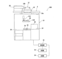
図5は、切削装置4や搬送通路6等の外観を示す斜視図であり、図6は、切削装置4の構成例を示す斜視図である。図5及び図6に示すように、切削装置4は、各構成要素を支持する基台48を備えている。基台48の角部には、開口48aが形成されており、この開口48aには、昇降機構(不図示)によって昇降する搬送車保持台(収容部保持台)50が設けられている。 FIG. 5 is a perspective view showing the appearance of the cutting device 4, the conveying path 6, etc. FIG. 6 is a perspective view showing a configuration example of the cutting device 4. As shown in FIG. As shown in FIGS. 5 and 6, the cutting device 4 includes a base 48 that supports each component. An opening 48a is formed at a corner of the base 48, and the opening 48a is provided with a transport vehicle holding table (accommodating section holding table) 50 which is lifted and lowered by an elevating mechanism (not shown).

この搬送車保持台50の上面には、上述した無人被加工物搬送車10のシャシ37が載せられる。なお、搬送車保持台50の上面には、無人被加工物搬送車10の車輪38を固定する車輪止め部50aが設けられており、搬送車保持台50上のシャシ37は、車輪止め部50aによって決まる所定の位置に位置付けられる。 The chassis 37 of the above-described unmanned workpiece carrier 10 is placed on the upper surface of the carrier platform 50 . In addition, a wheel stop portion 50a for fixing the wheel 38 of the unmanned workpiece transport vehicle 10 is provided on the upper surface of the transport vehicle holding base 50. is positioned at a predetermined position determined by

図6に示すように、開口48aの側方には、X軸方向(前後方向、加工送り方向)に長い開口48bが形成されている。開口48b内には、ボールねじ式のX軸移動機構(加工送りユニット)52と、X軸移動機構52の上部を覆う防塵防滴カバー54とが配置されている。X軸移動機構52は、X軸移動テーブル52aを備えており、このX軸移動テーブル52aをX軸方向に移動させる。 As shown in FIG. 6, an opening 48b elongated in the X-axis direction (front-rear direction, processing feed direction) is formed on the side of the opening 48a. A ball-screw type X-axis moving mechanism (processing feed unit) 52 and a dust-proof and drip-proof cover 54 covering the upper part of the X-axis moving mechanism 52 are arranged in the opening 48b. The X-axis moving mechanism 52 has an X-axis moving table 52a, and moves this X-axis moving table 52a in the X-axis direction.

X軸移動テーブル52a上には、被加工物11を吸引、保持するチャックテーブル(保持テーブル)56が設けられている。チャックテーブル56は、モータ等の回転駆動源(不図示)に連結されており、Z軸方向(鉛直方向、切り込み送り方向)に概ね平行な回転軸の周りに回転する。また、チャックテーブル56は、上述したX軸移動機構52によってX軸方向に移動する(加工送り)。 A chuck table (holding table) 56 for sucking and holding the workpiece 11 is provided on the X-axis moving table 52a. The chuck table 56 is connected to a rotation drive source (not shown) such as a motor, and rotates around a rotation axis substantially parallel to the Z-axis direction (vertical direction, cutting feed direction). Also, the chuck table 56 is moved in the X-axis direction by the X-axis moving mechanism 52 (processing feed).

チャックテーブル56の上面は、被加工物11を保持するための保持面56aになっている。保持面56aは、チャックテーブル56の内部に形成された吸引路(不図示)等を介して吸引源(不図示)に接続されている。また、チャックテーブル56の周囲には、被加工物11を支持するフレーム15を四方から固定するための4個のクランプ58が設けられている。 The upper surface of the chuck table 56 is a holding surface 56a for holding the workpiece 11. As shown in FIG. The holding surface 56 a is connected to a suction source (not shown) via a suction path (not shown) formed inside the chuck table 56 . Further, four clamps 58 are provided around the chuck table 56 for fixing the frame 15 supporting the workpiece 11 from all sides.

開口48bの上方には、Y軸方向(左右方向、割り出し送り方向)に平行な状態を維持しながら接近、離隔される一対のガイドレール(仮置き領域)60が設けられている。一対のガイドレール60は、それぞれ、フレーム15を下方から支持する支持面と、支持面に概ね垂直な側面とを備え、シャシ37から引き出されたフレーム15をX軸方向において挟み込んで所定の位置に合わせる。 Above the opening 48b, a pair of guide rails (temporary placement areas) 60 are provided that are kept parallel to the Y-axis direction (horizontal direction, index feed direction) and are moved toward and away from each other. Each of the pair of guide rails 60 has a support surface that supports the frame 15 from below and a side surface that is substantially perpendicular to the support surface. match.

基台48の上方には、門型の第1支持構造62が開口48bを跨ぐように配置されている。第1支持構造62の前面(ガイドレール60側の面)には、Y軸方向に沿う第1レール64が固定されており、この第1レール64には、第1移動機構66等を介して第1保持ユニット68が連結されている。 A gate-shaped first support structure 62 is arranged above the base 48 so as to straddle the opening 48b. A first rail 64 extending in the Y-axis direction is fixed to the front surface of the first support structure 62 (the surface on the side of the guide rail 60). A first holding unit 68 is connected.

第1保持ユニット68は、例えば、フレーム15の上面に接触してこのフレーム15を吸着、保持し、第1移動機構66によって昇降するとともに、第1レール64に沿ってY軸方向に移動する。第1保持ユニット68の開口48a側には、フレーム15を把持するための把持機構68aが設けられている。 The first holding unit 68 contacts, for example, the upper surface of the frame 15 to attract and hold the frame 15, moves up and down by the first moving mechanism 66, and moves along the first rails 64 in the Y-axis direction. A gripping mechanism 68a for gripping the frame 15 is provided on the opening 48a side of the first holding unit 68 .

例えば、把持機構68aでフレーム15を把持して第1保持ユニット68をY軸方向に移動させれば、シャシ37内のフレーム15を一対のガイドレール60に引き出し、又は、一対のガイドレール60上のフレーム15をシャシ37に挿入できる。なお、一対のガイドレール60でフレーム15の位置を合わせた後には、第1保持ユニット68でこのフレーム15(被加工物11)を吸着、保持してチャックテーブル56へと搬入する。 For example, if the frame 15 is gripped by the gripping mechanism 68a and the first holding unit 68 is moved in the Y-axis direction, the frame 15 in the chassis 37 can be pulled out onto the pair of guide rails 60, or can be moved onto the pair of guide rails 60. can be inserted into the chassis 37. After aligning the frame 15 with the pair of guide rails 60 , the frame 15 (work piece 11 ) is sucked and held by the first holding unit 68 and carried into the chuck table 56 .

また、第1支持構造62の前面には、Y軸方向に沿う第2レール70が第1レール64の上方に固定されている。この第2レール70には、第2移動機構72等を介して第2保持ユニット74が連結されている。第2保持ユニット74は、例えば、フレーム15の上面に接触してこのフレーム15を吸着、保持し、第2移動機構72によって昇降するとともに、第2レール70に沿ってY軸方向に移動する。 A second rail 70 extending in the Y-axis direction is fixed above the first rail 64 on the front surface of the first support structure 62 . A second holding unit 74 is connected to the second rail 70 via a second moving mechanism 72 and the like. The second holding unit 74 contacts, for example, the upper surface of the frame 15 to suck and hold the frame 15 , moves up and down by the second moving mechanism 72 , and moves along the second rail 70 in the Y-axis direction.

第1支持構造62の後方には、門型の第2支持構造76が配置されている。第2支持構造76の前面(第1支持構造62側の面)には、それぞれY軸Z軸移動機構(割り出し送りユニット、切り込み送りユニット)78を介して2組の切削ユニット(加工ユニット)80が設けられている。各切削ユニット80は、対応するY軸Z軸移動機構78によってY軸方向に移動する(割り出し送り)とともに、Z軸方向に移動する(切り込み送り)。 A gate-shaped second support structure 76 is arranged behind the first support structure 62 . Two sets of cutting units (processing units) 80 are provided on the front surface of the second support structure 76 (the surface on the side of the first support structure 62 ) via Y-axis and Z-axis movement mechanisms (index feed unit, cut feed unit) 78 . is provided. Each cutting unit 80 moves in the Y-axis direction (indexing feed) and moves in the Z-axis direction (cutting feed) by the corresponding Y-axis and Z-axis moving mechanisms 78 .

各切削ユニット80は、Y軸方向に概ね平行な回転軸となるスピンドル(不図示)を備えている。各スピンドルの一端側には、円環状の切削ブレード82が装着されている。各スピンドルの他端側には、モータ等の回転駆動源(不図示)が連結されている。また、切削ブレード82の傍には、被加工物11や切削ブレード82に純水等の切削液を供給するためのノズルが配置されている。 Each cutting unit 80 has a spindle (not shown) serving as a rotating shaft generally parallel to the Y-axis direction. An annular cutting blade 82 is attached to one end of each spindle. A rotary drive source (not shown) such as a motor is connected to the other end of each spindle. A nozzle for supplying a cutting fluid such as pure water to the workpiece 11 and the cutting blade 82 is arranged near the cutting blade 82 .

このノズルから切削液を供給しながら、回転させた切削ブレード82をチャックテーブル56に保持された被加工物11に切り込ませることで、被加工物11を切削できる。切削ユニット80に隣接する位置には、チャックテーブル56に保持された被加工物11等を撮像するための撮像ユニット(カメラ)84が設けられている。この撮像ユニット84も、Y軸Z軸移動機構78によってY軸方向に移動するとともに、Z軸方向に移動する。 The workpiece 11 held by the chuck table 56 can be cut by causing the rotating cutting blade 82 to cut into the workpiece 11 while supplying cutting fluid from this nozzle. At a position adjacent to the cutting unit 80, an imaging unit (camera) 84 for imaging the workpiece 11 held on the chuck table 56 and the like is provided. The imaging unit 84 is also moved in the Y-axis direction and in the Z-axis direction by the Y-axis and Z-axis moving mechanism 78 .

開口48bに対して開口48aと反対側の位置には、洗浄ユニット86が配置されている。洗浄ユニット86は、筒状の洗浄空間内で被加工物11を吸引、保持するスピンナテーブル88を備えている。スピンナテーブル88の下部には、スピンナテーブル88を所定の速さで回転させる回転駆動源(不図示)が連結されている。 A cleaning unit 86 is arranged at a position opposite to the opening 48a with respect to the opening 48b. The cleaning unit 86 has a spinner table 88 that sucks and holds the workpiece 11 in a cylindrical cleaning space. A rotary drive source (not shown) is connected to the lower portion of the spinner table 88 to rotate the spinner table 88 at a predetermined speed.

スピンナテーブル88の上方には、スピンナテーブル88により保持された被加工物11に向けて洗浄用の流体(代表的には、水とエアーとを混合した混合流体)を噴射する噴射ノズル90が配置されている。被加工物11を保持したスピンナテーブル88を回転させて、噴射ノズル90から洗浄用の流体を噴射することで、被加工物11を洗浄できる。 Above the spinner table 88, an injection nozzle 90 for injecting a cleaning fluid (typically a mixed fluid of water and air) toward the workpiece 11 held by the spinner table 88 is arranged. It is The workpiece 11 can be cleaned by rotating the spinner table 88 holding the workpiece 11 and ejecting the cleaning fluid from the ejection nozzle 90 .

切削ユニット80で被加工物11を切削した後には、例えば、第2保持ユニット74でフレーム15を吸着、保持して洗浄ユニット86へと搬入する。洗浄ユニット86で被加工物11を洗浄した後には、例えば、第1保持ユニット68でフレーム15を吸着、保持して一対のガイドレール60に載せ、その後、このフレーム15を把持機構68aで把持してシャシ37に収容する。 After cutting the workpiece 11 with the cutting unit 80 , for example, the second holding unit 74 sucks and holds the frame 15 and carries it into the cleaning unit 86 . After cleaning the workpiece 11 by the cleaning unit 86, for example, the first holding unit 68 sucks and holds the frame 15 and places it on the pair of guide rails 60, and then the frame 15 is held by the holding mechanism 68a. and housed in the chassis 37.

図5に示すように、基台48の上面側は、カバー92によって覆われており、上述した各構成要素は、カバー92の内側に収容される。開口48aの直上の領域には、カバー92の天井92aを上下に貫通する開口92bが設けられている。無人被加工物搬送車10のシャシ37は、この開口92bを通じてカバー92の外部から内部へと搬送され、又は、この開口92bを通じてカバー92の内部から外部へと搬送される。開口92bの形状や大きさに特段の制限はないが、この開口92bは、少なくともシャシ37を通過できるように構成される必要がある。 As shown in FIG. 5, the upper surface side of the base 48 is covered with a cover 92, and each component described above is accommodated inside the cover 92. As shown in FIG. An opening 92b penetrating vertically through the ceiling 92a of the cover 92 is provided in a region immediately above the opening 48a. The chassis 37 of the unmanned workpiece carrier 10 is transported from the outside to the inside of the cover 92 through the opening 92b, or is transported from the inside to the outside of the cover 92 through the opening 92b. There are no particular restrictions on the shape and size of the opening 92b, but the opening 92b must be configured to allow at least the chassis 37 to pass through.

切削装置4のカバー92の上方には、搬送ユニット支持構造28が設けられている。この搬送ユニット支持構造28は、例えば、下端部が搬送通路6(又は切削装置4)に固定された支持構造29を含む。支持構造29の上端部には、例えば、X軸方向及びY軸方向に沿う平板状の支持プレート30の一端部が固定されている。支持プレート30の下面の他端部側には、X軸方向に沿うガイドレール31が設けられている。ただし、搬送ユニット支持構造28の構成や配置等は、切削装置4の構成や搬送通路6の配置等に応じて任意に変更され得る。 A transport unit support structure 28 is provided above the cover 92 of the cutting device 4 . This transport unit support structure 28 includes, for example, a support structure 29 whose lower end is fixed to the transport passage 6 (or cutting device 4). One end of a flat support plate 30 along the X-axis direction and the Y-axis direction, for example, is fixed to the upper end of the support structure 29 . A guide rail 31 is provided along the X-axis direction on the other end side of the lower surface of the support plate 30 . However, the configuration and arrangement of the transport unit support structure 28 can be arbitrarily changed according to the configuration of the cutting device 4, the arrangement of the transport passage 6, and the like.

ガイドレール31の下端部には、Y軸方向に隙間を空けて配置された一対の平坦な支持部31a(図13(A)等参照)が設けられている。一対の支持部31aの隙間は、搬送ユニット12の車輪41の間隔(突出部39bの厚み)に応じて設定されている。そのため、例えば、この隙間に突出部39bが挿入されるように無人被加工物搬送車10及び搬送ユニット12をX軸方向に移動させれば、搬送ユニット12の車輪41は、一対の支持部31aの上面に載る。その結果、搬送ユニット12は、搬送ユニット支持構造28によって支持された状態となる。 A pair of flat support portions 31a (see FIG. 13A, etc.) arranged with a gap in the Y-axis direction is provided at the lower end portion of the guide rail 31 . The gap between the pair of support portions 31a is set according to the gap between the wheels 41 of the transport unit 12 (thickness of the projecting portion 39b). Therefore, for example, when the unmanned workpiece transport vehicle 10 and the transport unit 12 are moved in the X-axis direction so that the projecting portion 39b is inserted into this gap, the wheels 41 of the transport unit 12 move toward the pair of support portions 31a. be placed on top of the As a result, the transport unit 12 is in a state of being supported by the transport unit support structure 28 .

搬送ユニット支持構造28によって搬送ユニット12が支持された状態で車輪41を回転させると、搬送ユニット12は、ガイドレール31に沿って移動する。つまり、搬送ユニット12をこの搬送ユニット支持構造28と組み合わせて用いることで、無人被加工物搬送車10の車輪38が搬送通路6と接触していない状況でも、無人被加工物搬送車10及び搬送ユニット12をガイドレール31に沿って移動させることができるようになる。 When the wheels 41 are rotated while the transport unit 12 is supported by the transport unit support structure 28 , the transport unit 12 moves along the guide rails 31 . In other words, by using the transport unit 12 in combination with the transport unit support structure 28, even in a situation where the wheels 38 of the unmanned workpiece transport vehicle 10 are not in contact with the transport path 6, the unmanned workpiece transport vehicle 10 and the transport can be maintained. It becomes possible to move the unit 12 along the guide rail 31 .

そのため、例えば、搬送ユニット12で無人被加工物搬送車10のシャシ37を開口92bの直上に移動させた後に、ワイヤ40を基部39aから引き出してシャシ37を下降させれば、搬送車保持台50にシャシ37を載せることができる。また、ワイヤ40を基部39aに収納してシャシ37を搬送車保持台50から上昇させた後に、搬送ユニット12でシャシ37を移動させて車輪38を搬送通路6に接触させれば、無人被加工物搬送車10は、車輪38によって自走できるようになる。 Therefore, for example, after the chassis 37 of the unmanned workpiece carrier 10 is moved to the position directly above the opening 92b by the carrier unit 12, the wire 40 is pulled out from the base portion 39a and the chassis 37 is lowered. The chassis 37 can be placed on the After the wire 40 is housed in the base portion 39a and the chassis 37 is lifted from the transport vehicle holding table 50, the chassis 37 is moved by the transport unit 12 to bring the wheels 38 into contact with the transport passage 6. The object transport vehicle 10 is made self-propelled by the wheels 38 .

このように、搬送ユニット支持構造28は、搬送通路6の切削装置4の上方に相当する領域と切削装置4の搬送車保持台50との間で無人被加工物搬送車10のシャシ37が搬送される際に、搬送ユニット12を支持する。なお、ストックユニット8が備える搬送ユニット支持構造28の構成は、切削装置4が備える搬送ユニット支持構造28の構成と同じで良い。 In this way, the transport unit support structure 28 allows the chassis 37 of the unmanned workpiece transport vehicle 10 to be transported between the area of the transport passage 6 corresponding to the upper side of the cutting device 4 and the transport vehicle holding base 50 of the cutting device 4 . It supports the transport unit 12 when it is loaded. The configuration of the transport unit support structure 28 provided in the stock unit 8 may be the same as the configuration of the transport unit support structure 28 provided in the cutting device 4 .

上述した切削装置4の各構成要素は、制御装置96に接続されている(図5)。制御装置96は、代表的には、CPU等の処理装置や、フラッシュメモリ等の記憶装置を含むコンピュータによって構成される。記憶装置に記憶されるソフトウェアに従い処理装置等を動作させることによって、制御装置96の機能が実現されている。 Each component of the cutting device 4 described above is connected to a control device 96 (FIG. 5). The control device 96 is typically configured by a computer including a processing device such as a CPU and a storage device such as a flash memory. The functions of the control device 96 are realized by operating the processing device and the like according to software stored in the storage device.

制御装置96には、搬送システム2の制御ユニット14から送信される制御用の信号(制御信号)を受信する受信機98と、制御ユニット14に対して通知用の信号(通知信号)を送信する送信機100と、が更に接続されている。制御装置96は、例えば、受信機98で受信した信号等に基づき、上述した切削装置4の各構成要素を制御する。 The controller 96 includes a receiver 98 that receives a control signal (control signal) transmitted from the control unit 14 of the transport system 2 and a notification signal (notification signal) that is transmitted to the control unit 14. A transmitter 100 is further connected. The control device 96 controls each component of the above-described cutting device 4 based on, for example, signals received by the receiver 98 .

基台48の側壁には、各種の配管21を接続する配管接続部48c(図5)が設けられている。また、カバー92の側壁には、メンテナンス等の際に開閉される扉92c(図5)が設けられている。更に、カバー92の側壁には、操作パネル(不図示)やディスプレイ(不図示)等が設けられていても良い。 A side wall of the base 48 is provided with a pipe connection portion 48c (FIG. 5) for connecting various pipes 21. As shown in FIG. A side wall of the cover 92 is provided with a door 92c (FIG. 5) that is opened and closed during maintenance and the like. Furthermore, the side wall of the cover 92 may be provided with an operation panel (not shown), a display (not shown), and the like.

図7は、切削装置4に搬送システム2の搬送通路6が設置される様子を示す斜視図である。図7等に示すように、本実施形態に係る搬送システム2の搬送通路6は、切削装置4が備えるカバー92の天井92aの上面側に装着される。すなわち、搬送通路6は、切削装置4の真上の空間に設置される。 FIG. 7 is a perspective view showing how the conveying passage 6 of the conveying system 2 is installed in the cutting device 4. As shown in FIG. As shown in FIG. 7 and the like, the conveying passage 6 of the conveying system 2 according to the present embodiment is attached to the upper surface side of the ceiling 92a of the cover 92 of the cutting device 4. As shown in FIG. That is, the conveying passage 6 is installed in the space right above the cutting device 4 .

これにより、切削装置4の側面に設けられている配管接続部48cや扉92c等の構造に対して、搬送通路6が干渉することはなくなる。つまり、搬送通路6を設計する際に、切削装置4の側面の構造を考慮する必要がない。そのため、搬送システム2の構築が容易になる。 As a result, the transport path 6 does not interfere with structures such as the pipe connection portion 48c and the door 92c provided on the side surface of the cutting device 4. FIG. That is, there is no need to consider the side structure of the cutting device 4 when designing the conveying path 6 . Therefore, construction of the transport system 2 is facilitated.

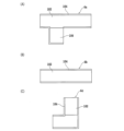
図8(A)は、搬送通路6に使用される通路モジュール6aの構成例を示す平面図であり、図8(B)は、通路モジュール6bの構成例を示す平面図であり、図8(C)は、通路モジュール6cの構成例を示す平面図である。搬送通路6は、例えば、図8(A)、図8(B)、及び図8(C)に示す複数の通路モジュール6a,6b,6cを組み合わせて構成される。 FIG. 8(A) is a plan view showing a configuration example of the passage module 6a used in the transport passage 6, and FIG. 8(B) is a plan view showing a configuration example of the passage module 6b. C) is a plan view showing a configuration example of the passage module 6c. The transport path 6 is configured by combining a plurality of path modules 6a, 6b, 6c shown in FIGS. 8A, 8B, and 8C, for example.

各通路モジュール6a,6b,6cは、それぞれ、無人被加工物搬送車10の走行に適した平坦性の高い上面を持つ通路部102と、通路部102の幅方向の端に設けられこの通路部102に沿うガイド部104と、を含む。ガイド部104の上端の通路部102からの高さは、例えば、無人被加工物搬送車10の車輪38の高さよりも高くなっている。これにより、通路部102を走行する無人被加工物搬送車10が通路部102から脱落するのを防止できる。 Each of the passage modules 6a, 6b, and 6c includes a passage portion 102 having a highly flat upper surface suitable for traveling of the unmanned workpiece carrier 10, and a passage portion provided at the end of the passage portion 102 in the width direction. and a guide portion 104 along . The height of the upper end of the guide portion 104 from the passage portion 102 is higher than the height of the wheels 38 of the unmanned workpiece carrier 10, for example. As a result, the unmanned workpiece carrier 10 traveling in the passage portion 102 can be prevented from falling out of the passage portion 102 .

図8(A)の通路モジュール6aは、無人被加工物搬送車10を待機させるための待機部106を更に有しており、例えば、切削装置4等の直上に設置される。なお、この待機部106等には、無人被加工物搬送車10の二次電池に給電する給電設備(充電器)を設けると良い。一方で、図8(B)の通路モジュール6bは、直線状に形成されており、図8(C)の通路モジュール6cは、曲がり角に適した直角状に形成されている。 The passage module 6a of FIG. 8A further has a waiting section 106 for waiting the unmanned workpiece carrier 10, which is installed directly above the cutting device 4, for example. In addition, it is preferable to provide a power supply facility (charger) for supplying power to the secondary battery of the unmanned workpiece carrier 10 in the standby section 106 and the like. On the other hand, the passage module 6b in FIG. 8(B) is formed in a straight line, and the passage module 6c in FIG. 8(C) is formed in a right angle suitable for turning.

通路モジュール6b,6cは、例えば、隣接する2つの通路モジュール6aの間を繋ぐために用いられる。ただし、搬送通路6を構成する通路モジュールの種類、数量、配置(接続の関係)等に制限はない。例えば、2つの通路モジュール6aの間を、更に別の通路モジュール6aで繋いでも良い。また、例えば、直角状の通路モジュール6cの代わりに、円弧状(曲線状)の通路モジュールを用いることもできる。 The passage modules 6b, 6c are used, for example, to connect between two adjacent passage modules 6a. However, there are no restrictions on the type, quantity, arrangement (connection relationship), etc. of the passage modules that constitute the conveying passage 6 . For example, two passage modules 6a may be connected by another passage module 6a. Also, for example, an arc-shaped (curved) passageway module can be used instead of the right-angled passageway module 6c.

図9は、通路モジュール6a及び通路モジュール6bから搬送通路6が形成される様子を示す斜視図である。図10(A)、及び図10(B)は、通路モジュール6a及び通路モジュール6bが連結される様子を示す断面図である。また、図11は、通路モジュール6bの構成例を示す底面図である。 FIG. 9 is a perspective view showing how the transport path 6 is formed from the path module 6a and the path module 6b. 10(A) and 10(B) are sectional views showing how the passage module 6a and the passage module 6b are connected. FIG. 11 is a bottom view showing a configuration example of the passage module 6b.

図9に示すように、通路部102の下面の長さ方向の端部(搬送通路6に沿う方向の端部)には、断面がL字状の一対のアングル(ブラケット)108が設けられている。各アングル108は、概ね水平な支持面108aと、支持面108aに対して概ね垂直な側面108bとを備え、各アングル108の長手方向が搬送通路6に沿うように通路部102の下面に固定される。 As shown in FIG. 9, a pair of angles (brackets) 108 having an L-shaped cross section are provided at the longitudinal ends of the lower surface of the passage portion 102 (the ends in the direction along the conveying passage 6). there is Each angle 108 has a substantially horizontal support surface 108a and a side surface 108b substantially perpendicular to the support surface 108a. be.

通路モジュール6aと通路モジュール6bとを連結する際には、まず、図10(A)に示すように、通路モジュール6aを構成する通路部102の長手方向の端部と、通路モジュール6bを構成する通路部102の長手方向の端部とを十分に近付ける。そして、図10(B)に示すように、通路モジュール6aを構成する通路部102に設けられているアングル108と、通路モジュール6bを構成する通路部102に設けられているアングル108と、に連結具110を挿入する。 When connecting the passage module 6a and the passage module 6b, first, as shown in FIG. 10(A), the longitudinal ends of the passage portions 102 constituting the passage module 6a and the passage module 6b are formed. The ends of the passage portion 102 in the longitudinal direction are brought sufficiently close to each other. Then, as shown in FIG. 10B, the angle 108 provided in the passage portion 102 forming the passage module 6a and the angle 108 provided in the passage portion 102 forming the passage module 6b are connected. Insert tool 110 .

連結具110は、例えば、通路モジュール6aのアングル108の長さと通路モジュール6bのアングル108の長さとを合わせた長さよりも長いロッド部110aと、ロッド部110aの両端に設けられ中央に開口を有するリング部110bと、を含んでいる。アングル108には、この連結具110のロッド部110aが挿入される。 The coupler 110 has, for example, a rod portion 110a longer than the sum of the length of the angle 108 of the passage module 6a and the length of the angle 108 of the passage module 6b, and an opening in the center provided at both ends of the rod portion 110a. and a ring portion 110b. A rod portion 110 a of the connector 110 is inserted into the angle 108 .

アングル108にロッド部110aを挿入した後には、リング部110bの開口を通じて通路部102の下面側のボルト孔(不図示)にボルト112を締め込む。これにより、連結具110を介して通路モジュール6aと通路モジュール6bとを連結できる。なお、通路モジュール6cも、同様の手順で他の通路モジュール(通路モジュール6aや通路モジュール6b等)に連結される。 After inserting the rod portion 110a into the angle 108, the bolt 112 is screwed into the bolt hole (not shown) on the lower surface side of the passage portion 102 through the opening of the ring portion 110b. Thereby, the passage module 6a and the passage module 6b can be connected via the connector 110. As shown in FIG. The passage module 6c is also connected to other passage modules (the passage module 6a, the passage module 6b, etc.) in the same procedure.

切削装置4に対する通路モジュール6a,6b,6cの装着は、例えば、図9、図11等に示す脚部材114を介して行われる。脚部材114は、板状の基部114aと、基部114aの一方側の面の中央付近から突出する柱状の柱部114bと、柱部114bの先端に装着された吸盤状の吸着部114c(図11)と、を含んでいる。 The passage modules 6a, 6b, 6c are attached to the cutting device 4, for example, via leg members 114 shown in FIGS. 9, 11, and the like. The leg member 114 includes a plate-shaped base portion 114a, a columnar column portion 114b protruding from the vicinity of the center of one side surface of the base portion 114a, and a suction cup-like suction portion 114c (FIG. 11) attached to the tip of the column portion 114b. ) and contains

基部114aの柱部114bと重ならない領域には、この基部114aを厚み方向に貫通する4個の開口114dが形成されている。また、通路モジュール6a,6b,6cを構成する通路部102の下面には、各開口114dに対応するボルト孔102a(図11)が形成されている。 Four openings 114d penetrating through the base portion 114a in the thickness direction are formed in a region of the base portion 114a that does not overlap with the column portion 114b. Bolt holes 102a (FIG. 11) corresponding to the respective openings 114d are formed in the lower surfaces of the passage portions 102 constituting the passage modules 6a, 6b, and 6c.

そのため、基部114aの他方側の面を通路部102の下面に接触させ、開口114dを通じてボルト孔102aにボルト116を締め込めば、通路モジュール6a,6b,6cに脚部材114を固定できる。なお、開口114d及びボルト孔102aの数量や配置等に制限はない。 Therefore, the leg member 114 can be fixed to the passage modules 6a, 6b, 6c by bringing the other surface of the base portion 114a into contact with the lower surface of the passage portion 102 and tightening the bolt 116 into the bolt hole 102a through the opening 114d. There are no restrictions on the number and arrangement of the openings 114d and the bolt holes 102a.

図11に示すように、本実施形態の通路モジュール6bには、通路部102の下面の複数の領域のそれぞれに基部114aの4個の開口114dに対応する4個のボルト孔102aが形成されており、任意の領域に脚部材114を装着できる。他の通路モジュール6a,6cについても同様である。 As shown in FIG. 11, in the passage module 6b of this embodiment, four bolt holes 102a corresponding to the four openings 114d of the base portion 114a are formed in a plurality of regions of the lower surface of the passage portion 102, respectively. , and the leg member 114 can be attached to any region. The same applies to the other passage modules 6a, 6c.

すなわち、脚部材114は、通路部102の下面の複数の領域から選択されたいずれかの領域に装着される。なお、各通路モジュール6a,6b,6cには、複数の脚部材114を装着することが望ましい。これにより、切削装置4に対する搬送通路6の位置が安定し易くなる。 That is, the leg member 114 is attached to one of the regions selected from the plurality of regions on the lower surface of the passage portion 102 . A plurality of leg members 114 are preferably attached to each of the passage modules 6a, 6b, 6c. This facilitates stabilizing the position of the conveying passage 6 with respect to the cutting device 4 .

切削装置4に対して通路モジュール6a,6b,6cを装着する際には、例えば、切削装置4のカバー92に対して通路モジュール6a,6b,6cの位置を合わせ、図7に示すように、脚部材114の吸着部114cをカバー92の天井92aの上面に押し当てる。これにより、カバー92の天井92aの上面に吸着部114cを吸着させて、任意の通路モジュール6a,6b,6cをカバー92に装着できる。つまり、任意の通路モジュール6a,6b,6cが、脚部材114を介して切削装置4のカバー92に装着される。 When attaching the passage modules 6a, 6b, 6c to the cutting device 4, for example, the positions of the passage modules 6a, 6b, 6c are aligned with the cover 92 of the cutting device 4, and as shown in FIG. The suction portion 114 c of the leg member 114 is pressed against the upper surface of the ceiling 92 a of the cover 92 . Thus, any passage modules 6a, 6b, and 6c can be attached to the cover 92 by causing the suction portion 114c to adhere to the upper surface of the ceiling 92a of the cover 92. FIG. That is, any passage module 6 a , 6 b , 6 c is attached to the cover 92 of the cutting device 4 via the leg member 114 .

なお、必ずしも全ての通路モジュール6a,6b,6cを切削装置4に対して装着しなくて良い。例えば、2台の切削装置4の間に位置する通路モジュールは、連結具110を介して隣接する通路モジュールのみに支持されることがある。また、切削装置4やストックユニット8等に対して装着される通路モジュールの通路部102には、図1に示すように、2次元コードに代表される識別コードや無線タグ等の情報提供部102bが設けられている。この情報提供部102bによって提供される情報は、例えば、無人被加工物搬送車10の位置の確認等に使用される。 It should be noted that not all the passage modules 6a, 6b, 6c need to be attached to the cutting device 4. For example, a passageway module located between two cutting devices 4 may be supported only by adjacent passageway modules via connectors 110 . In addition, as shown in FIG. 1, the passage portion 102 of the passage module attached to the cutting device 4, the stock unit 8, etc. has an information providing portion 102b such as an identification code typified by a two-dimensional code and a wireless tag. is provided. The information provided by the information providing unit 102b is used, for example, to confirm the position of the unmanned workpiece carrier 10, and the like.

次に、搬送通路6の切削装置4の上方に相当する領域と切削装置4の搬送車保持台50との間で無人被加工物搬送車10のシャシ37が搬送される際の動作について詳述する。図12(A)は、搬送ユニット12をガイドレール31に支持させる際の様子をY軸方向から見た一部断面側面図であり、図12(B)は、搬送ユニット12でシャシ37を下降させる際の様子をY軸方向から見た一部断面側面図である。 Next, the operation when the chassis 37 of the unmanned workpiece transport vehicle 10 is transported between the region of the transport passage 6 corresponding to the upper part of the cutting device 4 and the transport vehicle holding table 50 of the cutting device 4 will be described in detail. do. FIG. 12A is a partial cross-sectional side view of the transport unit 12 being supported by the guide rails 31 as seen from the Y-axis direction, and FIG. FIG. 10 is a partial cross-sectional side view of the state when the two are moved, as seen from the Y-axis direction.

また、図13(A)は、図12(A)に示す状態をX軸方向から見た一部断面側面図であり、図13(B)は、図12(B)に示す状態をX軸方向から見た一部断面側面図である。搬送通路6の切削装置4の上方に相当する領域から切削装置4の搬送車保持台50へとシャシ37を搬送する際には、図12(A)及び図13(A)に示すように、まず、ガイドレール31の延長線上の開始点に車輪41が位置付けられるように、無人被加工物搬送車10の位置を調整する。 13A is a partial cross-sectional side view of the state shown in FIG. 12A viewed from the X-axis direction, and FIG. 13B is a state shown in FIG. It is a partial cross section side view seen from the direction. When conveying the chassis 37 from the region of the conveying passage 6 corresponding to the upper part of the cutting device 4 to the carrier pedestal 50 of the cutting device 4, as shown in FIGS. 12A and 13A, First, the position of the unmanned workpiece carrier 10 is adjusted so that the wheel 41 is positioned at the starting point on the extension line of the guide rail 31 .

次に、車輪38を回転させて、無人被加工物搬送車10及び搬送ユニット12をガイドレール31に向けて移動させる。すなわち、無人被加工物搬送車10及び搬送ユニット12をX軸方向に移動させる。その結果、搬送ユニット12の突出部39bは、ガイドレール31の一対の支持部31aの隙間に挿入され、搬送ユニット12の車輪41が一対の支持部31aの上面に載る。 Next, the wheels 38 are rotated to move the unmanned workpiece carrier 10 and the carrier unit 12 toward the guide rails 31 . That is, the unmanned workpiece carrier 10 and the carrier unit 12 are moved in the X-axis direction. As a result, the projecting portion 39b of the transport unit 12 is inserted into the gap between the pair of support portions 31a of the guide rail 31, and the wheels 41 of the transport unit 12 are placed on the upper surfaces of the pair of support portions 31a.

なお、このタイミングで搬送ユニット12の電極39cがガイドレール31に接触し、搬送ユニット12等への給電が開始される。搬送ユニット12の車輪41が一対の支持部31aの上面に載せられた後には、この車輪41を回転させて、シャシ37を切削装置4の開口92bの直上に移動させる。 At this timing, the electrode 39c of the transport unit 12 comes into contact with the guide rail 31, and power supply to the transport unit 12 and the like is started. After the wheels 41 of the transport unit 12 are placed on the upper surfaces of the pair of support portions 31 a , the wheels 41 are rotated to move the chassis 37 directly above the opening 92 b of the cutting device 4 .

そして、図12(B)及び図13(B)に示すように、搬送ユニット12のウインチを動作させて、ワイヤ40を基部39aから引き出す。これにより、開口92bを通過するようにシャシ37を下降させて、搬送車保持台50にシャシ37を載せることができる。搬送車保持台50にシャシ37を載せた後には、被加工物11(フレーム15)がシャシ37から搬出される。また、被加工物11の切削が完了した後には、被加工物11(フレーム15)がシャシ37に搬入される。 Then, as shown in FIGS. 12B and 13B, the winch of the transport unit 12 is operated to pull out the wire 40 from the base portion 39a. As a result, the chassis 37 can be lowered so as to pass through the opening 92b and placed on the carriage holding table 50 . After the chassis 37 is placed on the carrier platform 50 , the workpiece 11 (frame 15 ) is unloaded from the chassis 37 . After the cutting of the workpiece 11 is completed, the workpiece 11 (frame 15 ) is carried into the chassis 37 .

切削装置4の搬送車保持台50から搬送通路6の切削装置4の上方に相当する領域へとシャシ37を搬送する際には、まず、搬送ユニット12のウインチを動作させて、ワイヤ40を巻き取り、基部39aに収納する。これにより、開口92bを通過するようにシャシ37を上昇させて、切削装置4のカバー92の外部にシャシ37を搬出できる。 When the chassis 37 is conveyed from the conveying vehicle holding table 50 of the cutting device 4 to the area corresponding to the upper part of the cutting device 4 in the conveying passage 6, first, the winch of the conveying unit 12 is operated to wind the wire 40. and stored in the base 39a. As a result, the chassis 37 can be lifted so as to pass through the opening 92 b and carried out to the outside of the cover 92 of the cutting device 4 .

次に、車輪41を回転させて、無人被加工物搬送車10及び搬送ユニット12を上述した開始点に向けて移動させる。すなわち、無人被加工物搬送車10及び搬送ユニット12をX軸方向に移動させる。その結果、搬送ユニット12の車輪41は一対の支持部31aから脱落する。 Next, the wheels 41 are rotated to move the unmanned workpiece transport vehicle 10 and transport unit 12 toward the starting point described above. That is, the unmanned workpiece carrier 10 and the carrier unit 12 are moved in the X-axis direction. As a result, the wheels 41 of the transport unit 12 drop off from the pair of support portions 31a.

なお、このタイミングで、搬送ユニット12の電極39cがガイドレール31から離れて、搬送ユニット12等への給電が終了する。また、無人被加工物搬送車10の車輪38が搬送通路6に接触し、無人被加工物搬送車10は、車輪38によって自走できるようになる。 At this timing, the electrodes 39c of the transport unit 12 are separated from the guide rails 31, and power supply to the transport unit 12 and the like is terminated. Further, the wheels 38 of the unmanned workpiece carrier 10 come into contact with the transport passage 6, and the unmanned workpiece carrier 10 can run on its own.

次に、本実施形態に係る搬送システム2の制御方法の例を説明する。図14は、搬送システム2の制御方法の例を説明するための機能ブロック図である。例えば、切削装置4の制御装置96は、新たな被加工物11(未加工の被加工物11)が必要な状況になると、その旨を通知するための通知信号(被加工物要求信号)を生成する。制御装置96で生成された通知信号(被加工物要求信号)は、送信機100から制御ユニット14へと送信される。 Next, an example of a control method for the transport system 2 according to this embodiment will be described. FIG. 14 is a functional block diagram for explaining an example of a control method for the transport system 2. As shown in FIG. For example, when a new workpiece 11 (unmachined workpiece 11) is required, the controller 96 of the cutting device 4 sends a notification signal (workpiece request signal) to notify that fact. Generate. A notification signal (workpiece request signal) generated by the controller 96 is transmitted from the transmitter 100 to the control unit 14 .

図14に示すように、制御ユニット14は、各種の制御を行うための制御信号を生成する制御部(制御信号生成部)132を備えている。この制御部132は、代表的には、CPU等の処理装置や、フラッシュメモリ等の記憶装置を含むコンピュータによって構成される。記憶装置に記憶されるソフトウェアに従い処理装置等を動作させることによって、制御部132の機能が実現されている。 As shown in FIG. 14, the control unit 14 includes a control section (control signal generation section) 132 that generates control signals for performing various controls. The control unit 132 is typically configured by a computer including a processing device such as a CPU and a storage device such as a flash memory. The functions of the control unit 132 are realized by operating the processing device and the like according to software stored in the storage device.

この制御部132には、切削装置4、ストックユニット8、無人被加工物搬送車10等から送信される通知信号を受信する受信機134と、切削装置4、ストックユニット8、無人被加工物搬送車10(搬送ユニット12を含む)等に対して制御信号を送信する送信機136とが接続されている。 The controller 132 includes a receiver 134 for receiving notification signals transmitted from the cutting device 4, the stock unit 8, the unmanned workpiece carrier 10, etc. A transmitter 136 that transmits a control signal to the vehicle 10 (including the transport unit 12) or the like is connected.

制御ユニット14の受信機134は、切削装置4の送信機100から送信された通知信号(被加工物要求信号)を受信すると、これを制御部132へと送る。制御部132は、切削装置4からの通知信号(被加工物要求信号)を確認すると、無人被加工物搬送車10(及び搬送ユニット12)に対して、ストックユニット8の傍に移動し、シャシ37をストックユニット8の搬送車保持台26へと搬送するように指示を出す。具体的には、制御部132は、この指示に相当する制御信号(第1搬送指示信号)を生成し、送信機136から無人被加工物搬送車10へと送信する。 The receiver 134 of the control unit 14 , upon receiving the notification signal (workpiece request signal) transmitted from the transmitter 100 of the cutting device 4 , sends this to the control section 132 . Upon confirming the notification signal (workpiece request signal) from the cutting device 4, the control unit 132 moves the unmanned workpiece carrier 10 (and the carrier unit 12) to the side of the stock unit 8, 37 to the carriage holding table 26 of the stock unit 8. Specifically, the control unit 132 generates a control signal (first transport instruction signal) corresponding to this instruction, and transmits it from the transmitter 136 to the unmanned workpiece transport vehicle 10 .

無人被加工物搬送車10の受信機44は、制御ユニット14からの制御信号(第1搬送指示信号)を受信すると、これを制御装置42へと送る。制御装置42は、この制御信号(第1搬送指示信号)に基づき車輪(走行機構)38等の動作を制御し、無人被加工物搬送車10を搬送通路6に沿って走行させる。 The receiver 44 of the unmanned workpiece transport vehicle 10 , upon receiving the control signal (first transport instruction signal) from the control unit 14 , sends it to the control device 42 . The control device 42 controls the operation of the wheels (traveling mechanism) 38 and the like based on this control signal (first transfer instruction signal) to cause the unmanned workpiece transfer vehicle 10 to travel along the transfer path 6 .

なお、図14に示すように、無人被加工物搬送車10の制御装置42には、搬送通路6に設けられている情報提供部102bの情報を読み取るための読み取り機138が接続されている。そのため、読み取り機138によって情報提供部102bの情報を読み取ることで、制御装置42は、自身(無人被加工物搬送車10)の位置を確認できる。 As shown in FIG. 14, the controller 42 of the unmanned workpiece carrier 10 is connected to a reader 138 for reading information from the information providing section 102b provided in the carrier passage 6. As shown in FIG. Therefore, by reading the information of the information providing unit 102b with the reader 138, the control device 42 can confirm the position of itself (the unmanned workpiece carrier 10).

制御装置42は、自身(無人被加工物搬送車10)がストックユニット8の傍に移動したことを確認すると、上述のように、搬送ユニット12の突出部39bが、ストックユニット8の上方に配置されたガイドレール31の一対の支持部31aの隙間に挿入されるように、無人被加工物搬送車10及び搬送ユニット12を移動させる。その結果、搬送ユニット12の車輪41は、一対の支持部31aの上面に載せられる。 When the control device 42 confirms that it (the unmanned workpiece carrier 10) has moved to the side of the stock unit 8, the protruding portion 39b of the carrier unit 12 is arranged above the stock unit 8 as described above. The unmanned workpiece carrier 10 and the carrier unit 12 are moved so as to be inserted into the gaps between the pair of support portions 31a of the guide rails 31 that are aligned. As a result, the wheels 41 of the transport unit 12 are placed on the upper surfaces of the pair of support portions 31a.

搬送ユニット12の車輪41が一対の支持部31aの上面に載せられた後には、制御装置42は、この車輪41を回転させて、シャシ37をストックユニット8の開口16bの直上に移動させる。そして、開口16bを通過するようにシャシ37を下降させて、ストックユニット8の内部にある搬送車保持台26にシャシ37を載せる。 After the wheels 41 of the transport unit 12 are placed on the upper surfaces of the pair of support portions 31 a , the controller 42 rotates the wheels 41 to move the chassis 37 directly above the opening 16 b of the stock unit 8 . Then, the chassis 37 is lowered so as to pass through the opening 16 b and is placed on the transport vehicle holding base 26 inside the stock unit 8 .

搬送車保持台26にシャシ37を載せた後には、制御装置42は、ストックユニット8へのシャシ37の搬送が完了した旨を通知するための通知信号(第1搬送完了信号)を生成する。制御装置42で生成された通知信号(第1搬送完了信号)は、送信機46から制御ユニット14へと送信される。 After the chassis 37 is placed on the transport vehicle holding table 26, the control device 42 generates a notification signal (first transport completion signal) for notifying that transport of the chassis 37 to the stock unit 8 is completed. A notification signal (first transport completion signal) generated by the control device 42 is transmitted from the transmitter 46 to the control unit 14 .

制御ユニット14の受信機134は、無人被加工物搬送車10の送信機46から送信された通知信号(第1搬送完了信号)を受信すると、これを制御部132へと送る。制御部132は、無人被加工物搬送車10からの通知信号(第1搬送完了信号)を確認すると、ストックユニット8に対して、搬送車保持台26上のシャシ37に新たな被加工物11を搬入するように指示を出す。具体的には、制御部132は、この指示に相当する制御信号(第1搬入指示信号)を生成し、送信機136からストックユニット8へと送信する。 The receiver 134 of the control unit 14 , upon receiving the notification signal (first transport completion signal) transmitted from the transmitter 46 of the unmanned workpiece transport vehicle 10 , sends this to the control section 132 . When the control unit 132 confirms the notification signal (first transfer completion signal) from the unmanned workpiece carrier 10 , the controller 132 transfers the new workpiece 11 to the chassis 37 on the carrier platform 26 to the stock unit 8 . give instructions to bring in the Specifically, the control unit 132 generates a control signal (first carry-in instruction signal) corresponding to this instruction, and transmits it from the transmitter 136 to the stock unit 8 .

ストックユニット8の受信機34は、制御ユニット14からの制御信号(第1搬入指示信号)を受信すると、これを制御装置32へと送る。制御装置32は、この制御信号(第1搬入指示信号)に基づき第1昇降機構、プッシュプルアーム22、一対のガイドレール24、第2昇降機構等の動作を制御して、新たな被加工物11をシャシ37に搬入する。 The receiver 34 of the stock unit 8 receives the control signal (first carry-in instruction signal) from the control unit 14 and sends it to the control device 32 . The control device 32 controls the operations of the first lifting mechanism, the push-pull arm 22, the pair of guide rails 24, the second lifting mechanism, etc., based on this control signal (first carry-in instruction signal), so that a new work piece can be picked up. 11 is loaded into the chassis 37 .

新たな被加工物11がシャシ37に搬入されると、制御装置32は、シャシ37への被加工物11の搬入が完了した旨を通知するための通知信号(第1搬入完了信号)を生成する。制御装置32で生成された通知信号(第1搬入完了信号)は、送信機36から制御ユニット14へと送信される。 When the new workpiece 11 is loaded into the chassis 37, the control device 32 generates a notification signal (first loading completion signal) for notifying that loading of the workpiece 11 into the chassis 37 is completed. do. A notification signal (first carry-in completion signal) generated by the control device 32 is transmitted from the transmitter 36 to the control unit 14 .

制御ユニット14の受信機134は、ストックユニット8の送信機36から送信された通知信号(第1搬入完了信号)を受信すると、これを制御部132へと送る。制御部132は、ストックユニット8からの通知信号(第1搬入完了信号)を確認すると、無人被加工物搬送車10(及び搬送ユニット12)に対して、切削装置4の傍に移動し、シャシ37を切削装置4の搬送車保持台50へと搬送するように指示を出す。具体的には、制御部132は、この指示に相当する制御信号(第2搬送指示信号)を生成し、送信機136から無人被加工物搬送車10へと送信する。 The receiver 134 of the control unit 14 , upon receiving the notification signal (first carry-in completion signal) transmitted from the transmitter 36 of the stock unit 8 , sends this to the control section 132 . When the control unit 132 confirms the notification signal (first carry-in completion signal) from the stock unit 8, the unmanned workpiece carrier 10 (and the carrier unit 12) moves to the side of the cutting device 4, and moves to the side of the cutting device 4. 37 to the carriage holding base 50 of the cutting device 4. Specifically, the control unit 132 generates a control signal (second transport instruction signal) corresponding to this instruction, and transmits it from the transmitter 136 to the unmanned workpiece transport vehicle 10 .

無人被加工物搬送車10の受信機44は、制御ユニット14からの制御信号(第2搬送指示信号)を受信すると、これを制御装置42へと送る。制御装置42は、この制御信号(第2搬送指示信号)に基づきシャシ37を上昇させて、ストックユニット8の外部にシャシ37を搬送する。その後、車輪41等の動作を制御して、シャシ37を搬送通路6の上方に移動させる。そして、車輪38等の動作を制御して、無人被加工物搬送車10を搬送通路6に沿って走行させる。 The receiver 44 of the unmanned workpiece transport vehicle 10 , upon receiving the control signal (second transport instruction signal) from the control unit 14 , sends it to the control device 42 . The control device 42 lifts the chassis 37 based on this control signal (second transport instruction signal) and transports the chassis 37 to the outside of the stock unit 8 . After that, the operation of the wheels 41 and the like is controlled to move the chassis 37 above the transport passage 6 . Then, the operation of the wheels 38 and the like is controlled to cause the unmanned workpiece transport vehicle 10 to travel along the transport path 6 .

制御装置42は、自身(無人被加工物搬送車10)が切削装置4の傍に移動したことを確認すると、上述のように、搬送ユニット12の突出部39bが、切削装置4の上方に配置されたガイドレール31の一対の支持部31aの隙間に挿入されるように、無人被加工物搬送車10及び搬送ユニット12を移動させる。その結果、一対の支持部31aの上面には、搬送ユニット12の車輪41が載せられる。 When the controller 42 confirms that it (the unmanned workpiece carrier 10) has moved to the side of the cutting device 4, the projecting portion 39b of the carrier unit 12 is positioned above the cutting device 4 as described above. The unmanned workpiece carrier 10 and the carrier unit 12 are moved so as to be inserted into the gaps between the pair of support portions 31a of the guide rails 31 that are aligned. As a result, the wheels 41 of the transport unit 12 are placed on the upper surfaces of the pair of support portions 31a.

搬送ユニット12の車輪41が一対の支持部31aの上面に載せられた後には、制御装置42は、この車輪41を回転させて、シャシ37を切削装置4の開口92bの直上に移動させる。そして、開口92bを通過するようにシャシ37を下降させて、切削装置4の内部にある搬送車保持台50にシャシ37を載せる。 After the wheels 41 of the transport unit 12 are placed on the upper surfaces of the pair of support portions 31 a , the controller 42 rotates the wheels 41 to move the chassis 37 directly above the opening 92 b of the cutting device 4 . Then, the chassis 37 is lowered so as to pass through the opening 92b, and is placed on the carriage holding table 50 inside the cutting device 4. As shown in FIG.

搬送車保持台50にシャシ37を載せた後には、制御装置42は、切削装置4へのシャシ37の搬送が完了した旨を通知するための通知信号(第2搬送完了信号)を生成する。制御装置42で生成された通知信号(第2搬送完了信号)は、送信機46から制御ユニット14へと送信される。 After placing the chassis 37 on the transport vehicle holding table 50, the control device 42 generates a notification signal (second transport completion signal) for notifying that transport of the chassis 37 to the cutting device 4 is completed. A notification signal (second transportation completion signal) generated by the control device 42 is transmitted from the transmitter 46 to the control unit 14 .

制御ユニット14の受信機134は、無人被加工物搬送車10の送信機46から送信された通知信号(第2搬送完了信号)を受信すると、これを制御部132へと送る。制御部132は、無人被加工物搬送車10からの通知信号(第2搬送完了信号)を確認すると、切削装置4に対して、搬送車保持台50上のシャシ37から新たな被加工物11を搬出するように指示を出す。具体的には、制御部132は、この指示に相当する制御信号(第1搬出指示信号)を生成し、送信機136から切削装置4へと送信する。 The receiver 134 of the control unit 14 , upon receiving the notification signal (second transfer completion signal) transmitted from the transmitter 46 of the unmanned workpiece transfer vehicle 10 , sends this to the control section 132 . When the control unit 132 confirms the notification signal (second transfer completion signal) from the unmanned workpiece carrier 10 , the controller 132 sends a new workpiece 11 from the chassis 37 on the carrier platform 50 to the cutting device 4 . give instructions to remove the Specifically, the control unit 132 generates a control signal (first unloading instruction signal) corresponding to this instruction, and transmits it from the transmitter 136 to the cutting device 4 .

切削装置4の受信機98は、制御ユニット14からの制御信号(第1搬出指示信号)を受信すると、これを制御装置96へと送る。制御装置96は、この制御信号(第1搬出指示信号)に基づき各構成要素の動作を制御して、新たな被加工物11をシャシ37から搬出する。 When the receiver 98 of the cutting device 4 receives the control signal (first unloading instruction signal) from the control unit 14 , it sends it to the control device 96 . The control device 96 controls the operation of each component based on this control signal (first unloading instruction signal) to unload the new workpiece 11 from the chassis 37 .

新たな被加工物11がシャシ37から搬出されると、例えば、制御装置96は、シャシ37からの被加工物11の搬出が完了した旨を通知するための通知信号(第1搬出完了信号)を生成する。制御装置96で生成された通知信号(第1搬出完了信号)は、送信機100から制御ユニット14へと送信される。 When the new workpiece 11 is unloaded from the chassis 37, for example, the control device 96 outputs a notification signal (first unloading completion signal) for notifying that the unloading of the workpiece 11 from the chassis 37 is completed. to generate A notification signal (first unloading completion signal) generated by the control device 96 is transmitted from the transmitter 100 to the control unit 14 .

このような手順により、ストックユニット8に収容されている被加工物11を任意の切削装置4に対して搬送できる。なお、ここでは、ストックユニット8から切削装置4に対して被加工物11を搬送する際の手順について主に説明したが、切削装置4からストックユニット8に対して被加工物11を搬送する際の手順等も同様である。 Through such procedures, the workpiece 11 stored in the stock unit 8 can be transported to any cutting device 4 . Here, the procedure for conveying the workpiece 11 from the stock unit 8 to the cutting device 4 has been mainly described, but the procedure for conveying the workpiece 11 from the cutting device 4 to the stock unit 8 The procedure of , etc. is the same.

具体的には、例えば、切削装置4の制御装置96は、被加工物11の加工が完了すると、その旨を通知するための通知信号(加工完了信号)を生成する。制御装置96で生成された通知信号(加工完了信号)は、送信機100から制御ユニット14へと送信される。制御ユニット14の受信機134は、切削装置4の送信機100から送信された通知信号(加工完了信号)を受信すると、これを制御部132へと送る。 Specifically, for example, when the machining of the workpiece 11 is completed, the control device 96 of the cutting device 4 generates a notification signal (machining completion signal) for notifying that effect. A notification signal (processing completion signal) generated by the control device 96 is transmitted from the transmitter 100 to the control unit 14 . The receiver 134 of the control unit 14 , upon receiving the notification signal (machining completion signal) transmitted from the transmitter 100 of the cutting device 4 , sends this to the control section 132 .

制御部132は、切削装置4からの通知信号(加工完了信号)を確認すると、無人被加工物搬送車10(及び搬送ユニット12)に対して、切削装置4の傍に移動し、シャシ37を切削装置4の搬送車保持台50へと搬送するように指示を出す。具体的には、制御部132は、この指示に相当する制御信号(第3搬送指示信号)を生成し、送信機136から無人被加工物搬送車10へと送信する。 When the control unit 132 confirms the notification signal (processing completion signal) from the cutting device 4, the unmanned workpiece transport vehicle 10 (and the transport unit 12) moves to the side of the cutting device 4 and moves the chassis 37. An instruction is given to convey to the conveying vehicle holding base 50 of the cutting device 4 . Specifically, the control unit 132 generates a control signal (third transport instruction signal) corresponding to this instruction, and transmits it from the transmitter 136 to the unmanned workpiece transport vehicle 10 .

無人被加工物搬送車10の受信機44は、制御ユニット14からの制御信号(第3搬送指示信号)を受信すると、これを制御装置42へと送る。制御装置42は、この制御信号(第3搬送指示信号)に基づき車輪(走行機構)38等の動作を制御し、無人被加工物搬送車10を搬送通路6に沿って走行させる。 The receiver 44 of the unmanned workpiece transport vehicle 10 , upon receiving the control signal (third transport instruction signal) from the control unit 14 , sends this to the control device 42 . The control device 42 controls the operation of the wheels (running mechanism) 38 and the like based on this control signal (third transport instruction signal) to cause the unmanned workpiece transport vehicle 10 to run along the transport path 6 .

制御装置42は、自身(無人被加工物搬送車10)が切削装置4の傍に移動したことを確認すると、上述のように、搬送ユニット12の突出部39bが、切削装置4の上方に配置されたガイドレール31の一対の支持部31aの隙間に挿入されるように、無人被加工物搬送車10及び搬送ユニット12を移動させる。その結果、一対の支持部31aの上面には、搬送ユニット12の車輪41が載せられる。 When the controller 42 confirms that it (the unmanned workpiece carrier 10) has moved to the side of the cutting device 4, the projecting portion 39b of the carrier unit 12 is positioned above the cutting device 4 as described above. The unmanned workpiece carrier 10 and the carrier unit 12 are moved so as to be inserted into the gaps between the pair of support portions 31a of the guide rails 31 that are aligned. As a result, the wheels 41 of the transport unit 12 are placed on the upper surfaces of the pair of support portions 31a.

搬送ユニット12の車輪41が一対の支持部31aの上面に載せられた後には、制御装置42は、この車輪41を回転させて、シャシ37を切削装置4の開口92bの直上に移動させる。そして、開口92bを通過するようにシャシ37を下降させて、切削装置4の内部にある搬送車保持台50にシャシ37を載せる。 After the wheels 41 of the transport unit 12 are placed on the upper surfaces of the pair of support portions 31 a , the controller 42 rotates the wheels 41 to move the chassis 37 directly above the opening 92 b of the cutting device 4 . Then, the chassis 37 is lowered so as to pass through the opening 92b, and is placed on the carriage holding table 50 inside the cutting device 4. As shown in FIG.

搬送車保持台50にシャシ37を載せた後には、制御装置42は、切削装置4へのシャシ37の搬送が完了した旨を通知するための通知信号(第3搬送完了信号)を生成する。制御装置42で生成された通知信号(第3搬送完了信号)は、送信機46から制御ユニット14へと送信される。 After placing the chassis 37 on the transport vehicle holding base 50, the control device 42 generates a notification signal (third transport completion signal) for notifying that transport of the chassis 37 to the cutting device 4 is completed. A notification signal (third transportation completion signal) generated by the control device 42 is transmitted from the transmitter 46 to the control unit 14 .

制御ユニット14の受信機134は、無人被加工物搬送車10の送信機46から送信された通知信号(第3搬送完了信号)を受信すると、これを制御部132へと送る。制御部132は、無人被加工物搬送車10からの通知信号(第3搬送完了信号)を確認すると、切削装置4に対して、搬送車保持台50上のシャシ37に加工後の被加工物11を搬入するように指示を出す。具体的には、制御部132は、この指示に相当する制御信号(第2搬入指示信号)を生成し、送信機136から切削装置4へと送信する。 The receiver 134 of the control unit 14 , upon receiving the notification signal (third transfer completion signal) transmitted from the transmitter 46 of the unmanned workpiece transfer vehicle 10 , sends this to the control section 132 . When the controller 132 confirms the notification signal (third transfer completion signal) from the unmanned workpiece carrier 10 , the controller 132 sends the workpiece after machining to the chassis 37 on the carrier platform 50 to the cutting device 4 . Give instructions to bring in 11. Specifically, the control unit 132 generates a control signal (second carry-in instruction signal) corresponding to this instruction, and transmits it from the transmitter 136 to the cutting device 4 .

切削装置4の受信機98は、制御ユニット14からの制御信号(第2搬入指示信号)を受信すると、これを制御装置96へと送る。制御装置96は、この制御信号(第2搬入指示信号)に基づき各構成要素の動作を制御して、加工後の被加工物11をシャシ37に搬入する。 When the receiver 98 of the cutting device 4 receives the control signal (second carry-in instruction signal) from the control unit 14 , it sends it to the control device 96 . The control device 96 controls the operation of each component based on this control signal (second loading instruction signal), and loads the workpiece 11 after machining into the chassis 37 .

加工後の被加工物11がシャシ37に搬入されると、制御装置96は、シャシ37への被加工物11の搬入が完了した旨を通知するための通知信号(第2搬入完了信号)を生成する。制御装置96で生成された通知信号(第2搬入完了信号)は、送信機100から制御ユニット14へと送信される。 When the processed workpiece 11 is loaded into the chassis 37, the control device 96 outputs a notification signal (second loading completion signal) for notifying that loading of the workpiece 11 into the chassis 37 is completed. Generate. A notification signal (second carry-in completion signal) generated by the control device 96 is transmitted from the transmitter 100 to the control unit 14 .

制御ユニット14の受信機134は、切削装置4の送信機100から送信された通知信号(第2搬入完了信号)を受信すると、これを制御部132へと送る。制御部132は、切削装置4からの通知信号(第2搬入完了信号)を確認すると、無人被加工物搬送車10(及び搬送ユニット12)に対して、ストックユニット8の傍に移動した上で、シャシ37をストックユニット8の搬送車保持台26へと搬送するように指示を出す。具体的には、制御部132は、この指示に相当する制御信号(第4搬送指示信号)を生成し、送信機136から無人被加工物搬送車10へと送信する。 The receiver 134 of the control unit 14 , upon receiving the notification signal (second carry-in completion signal) transmitted from the transmitter 100 of the cutting device 4 , sends this to the control section 132 . Upon confirming the notification signal (second carry-in completion signal) from the cutting device 4, the control unit 132 moves the unmanned workpiece carrier 10 (and the carrier unit 12) to the side of the stock unit 8, and , to convey the chassis 37 to the carriage holding table 26 of the stock unit 8 . Specifically, the control unit 132 generates a control signal (fourth transport instruction signal) corresponding to this instruction, and transmits it from the transmitter 136 to the unmanned workpiece transport vehicle 10 .

無人被加工物搬送車10の受信機44は、制御ユニット14からの制御信号(第4搬送指示信号)を受信すると、これを制御装置42へと送る。制御装置42は、この制御信号(第4搬送指示信号)に基づきシャシ37を上昇させて、切削装置4の外部にシャシ37を搬送する。その後、車輪41等の動作を制御して、シャシ37を搬送通路6の上方に移動させる。そして、車輪38等の動作を制御して、無人被加工物搬送車10を搬送通路6に沿って走行させる。 The receiver 44 of the unmanned workpiece transport vehicle 10 , upon receiving the control signal (fourth transport instruction signal) from the control unit 14 , sends it to the control device 42 . The control device 42 raises the chassis 37 based on this control signal (fourth transport instruction signal) and transports the chassis 37 to the outside of the cutting device 4 . After that, the operation of the wheels 41 and the like is controlled to move the chassis 37 above the transport passage 6 . Then, the operation of the wheels 38 and the like is controlled to cause the unmanned workpiece transport vehicle 10 to travel along the transport path 6 .

制御装置42は、自身(無人被加工物搬送車10)がストックユニット8の傍に移動したことを確認すると、上述のように、搬送ユニット12の突出部39bが、ストックユニット8の上方に配置されたガイドレール31の一対の支持部31aの隙間に挿入されるように、無人被加工物搬送車10及び搬送ユニット12を移動させる。その結果、一対の支持部31aの上面には、搬送ユニット12の車輪41が載せられる。 When the control device 42 confirms that it (the unmanned workpiece carrier 10) has moved to the side of the stock unit 8, the protruding portion 39b of the carrier unit 12 is arranged above the stock unit 8 as described above. The unmanned workpiece carrier 10 and the carrier unit 12 are moved so as to be inserted into the gaps between the pair of support portions 31a of the guide rails 31 that are aligned. As a result, the wheels 41 of the transport unit 12 are placed on the upper surfaces of the pair of support portions 31a.

搬送ユニット12の車輪41が一対の支持部31aの上面に載せられた後には、制御装置42は、この車輪41を回転させて、シャシ37をストックユニット8の開口16bの直上に移動させる。そして、開口16bを通過するようにシャシ37を下降させて、ストックユニット8の内部にある搬送車保持台26にシャシ37を載せる。 After the wheels 41 of the transport unit 12 are placed on the upper surfaces of the pair of support portions 31 a , the controller 42 rotates the wheels 41 to move the chassis 37 directly above the opening 16 b of the stock unit 8 . Then, the chassis 37 is lowered so as to pass through the opening 16 b and is placed on the transport vehicle holding base 26 inside the stock unit 8 .

搬送車保持台26にシャシ37を載せた後には、制御装置42は、ストックユニット8へのシャシ37の搬送が完了した旨を通知するための通知信号(第4搬送完了信号)を生成する。制御装置42で生成された通知信号(第4搬送完了信号)は、送信機46から制御ユニット14へと送信される。 After placing the chassis 37 on the transport vehicle holding table 26, the control device 42 generates a notification signal (fourth transport completion signal) for notifying that transport of the chassis 37 to the stock unit 8 is completed. A notification signal (fourth transport completion signal) generated by the control device 42 is transmitted from the transmitter 46 to the control unit 14 .

制御ユニット14の受信機134は、無人被加工物搬送車10の送信機46から送信された通知信号(第4搬送完了信号)を受信すると、これを制御部132へと送る。制御部132は、無人被加工物搬送車10からの通知信号(第4搬送完了信号)を確認すると、ストックユニット8に対して、搬送車保持台26上のシャシ37から加工後の被加工物11を搬出するように指示を出す。具体的には、制御部132は、この指示に相当する制御信号(第2搬出指示信号)を生成し、送信機136からストックユニット8へと送信する。 The receiver 134 of the control unit 14 , upon receiving the notification signal (fourth transfer completion signal) transmitted from the transmitter 46 of the unmanned workpiece transfer vehicle 10 , sends this to the control section 132 . When the controller 132 confirms the notification signal (fourth transfer completion signal) from the unmanned workpiece carrier 10 , the controller 132 transfers the processed workpiece from the chassis 37 on the carrier platform 26 to the stock unit 8 . Give instructions to carry out 11. Specifically, the control section 132 generates a control signal (second carry-out instruction signal) corresponding to this instruction, and transmits it from the transmitter 136 to the stock unit 8 .

ストックユニット8の受信機34は、制御ユニット14からの制御信号(第2搬出指示信号)を受信すると、これを制御装置32へと送る。制御装置32は、この制御信号(第2搬出指示信号)に基づき第1昇降機構、プッシュプルアーム22、一対のガイドレール24、第2昇降機構等の動作を制御して、加工後の被加工物11をシャシ37から搬出する。 When the receiver 34 of the stock unit 8 receives the control signal (second unloading instruction signal) from the control unit 14 , it sends it to the control device 32 . The control device 32 controls the operations of the first elevating mechanism, the push-pull arm 22, the pair of guide rails 24, the second elevating mechanism, etc., based on this control signal (second carry-out instruction signal), and moves the workpiece after machining. The object 11 is unloaded from the chassis 37 .

加工後の被加工物11がシャシ37から搬出されると、例えば、制御装置32は、シャシ37からの被加工物11の搬出が完了した旨を通知するための通知信号(第2搬出完了信号)を生成する。制御装置32で生成された通知信号(第2搬出完了信号)は、送信機36から制御ユニット14へと送信される。このような手順により、切削装置4で加工された後の被加工物11をストックユニット8に対して搬送できる。 When the machined workpiece 11 is unloaded from the chassis 37, for example, the control device 32 outputs a notification signal (second unloading completion signal) for notifying that the unloading of the workpiece 11 from the chassis 37 is completed. ). A notification signal (second unloading completion signal) generated by the control device 32 is transmitted from the transmitter 36 to the control unit 14 . Through such procedures, the workpiece 11 that has been machined by the cutting device 4 can be transported to the stock unit 8 .

また、上述した手順は、被加工物11を適切に搬送できる範囲内で任意に変更できる。例えば、上述した手順に含まれている複数のステップを同時に行っても良いし、被加工物11の搬送に支障が出ない範囲内でステップの順序を入れ替えても良い。同様に、被加工物11の搬送に支障が出ない範囲内で任意のステップを追加、変更、省略して良い。 Moreover, the above-described procedure can be arbitrarily changed within a range in which the workpiece 11 can be conveyed appropriately. For example, a plurality of steps included in the procedure described above may be performed at the same time, or the order of the steps may be changed within a range that does not hinder the conveyance of the workpiece 11 . Similarly, arbitrary steps may be added, changed, or omitted within a range that does not hinder the transportation of the workpiece 11 .

以上のように、本実施形態に係る搬送システム2は、複数の切削装置(加工装置)4に渡って設置される搬送通路6と、被加工物11を収容するシャシ(被加工物収容部)37、シャシ37に設けられた車輪(走行機構)38、及び制御信号を受信する受信機44を備え、搬送通路6を走行する無人被加工物搬送車(無人搬送車)10と、被加工物が収容されたカセット(被加工物ストッカー)20から無人被加工物搬送車10のシャシ37に対して被加工物11を受け渡す際にシャシ37を保持する搬送車保持台(収容部保持台)26、及び制御信号を受信する受信機34を備えるストックユニット8と、搬送通路6のストックユニット8の上方に相当する領域とストックユニット8の搬送車保持台26との間、又は、搬送通路6の切削装置4の上方に相当する領域と切削装置4の内部との間でシャシ37を搬送する搬送ユニット(収容部搬送ユニット)12と、を含んでいる。 As described above, the transport system 2 according to the present embodiment includes a transport passage 6 installed over a plurality of cutting devices (processing devices) 4 and a chassis (workpiece storage section) that accommodates the workpiece 11. 37, wheels (running mechanism) 38 provided on the chassis 37, and a receiver 44 for receiving a control signal, an unmanned workpiece carrier (automated guided vehicle) 10 traveling on the carrier passage 6, and a workpiece A carrier holding stand (accommodating part holding stand) for holding the chassis 37 when the workpiece 11 is transferred from the cassette (workpiece stocker) 20 containing the to the chassis 37 of the unmanned workpiece carrier 10 26 and a receiver 34 for receiving the control signal, and between the area corresponding to the upper side of the stock unit 8 in the transport path 6 and the carrier platform 26 of the stock unit 8, or the transport path 6 and a carrier unit (container carrier unit) 12 that carries the chassis 37 between an area corresponding to the upper portion of the cutting device 4 and the inside of the cutting device 4 .

そのため、例えば、ストックユニット8でカセット20から被加工物11を受け取った無人被加工物搬送車10のシャシ37を、搬送ユニット12によって搬送通路6へと搬送し、この無人被加工物搬送車10を搬送通路6上で走行させることにより、複数の切削装置4のそれぞれに対して被加工物11を搬送できる。なお、この無人被加工物搬送車10のシャシ37は、例えば、無人被加工物搬送車10を走行させた後に、搬送ユニット12によって切削装置4の内部へと搬送される。 Therefore, for example, the chassis 37 of the unmanned workpiece transport vehicle 10 that has received the workpiece 11 from the cassette 20 in the stock unit 8 is transported to the transport passage 6 by the transport unit 12, and the unmanned workpiece transport vehicle 10 on the conveying path 6 , the workpiece 11 can be conveyed to each of the plurality of cutting devices 4 . The chassis 37 of the unmanned workpiece carrier 10 is transported into the cutting device 4 by the transport unit 12 after the unmanned workpiece carrier 10 is driven, for example.

また、本実施形態に係る搬送システム2では、搬送通路6が、切削装置4の真上の空間に設置される。そのため、この搬送通路6を設計する際に各切削装置4の側面の構造を考慮する必要がない。すなわち、搬送システムの構築が容易になる。 Further, in the transport system 2 according to this embodiment, the transport passage 6 is installed in the space right above the cutting device 4 . Therefore, there is no need to consider the side structure of each cutting device 4 when designing the conveying passage 6 . That is, it becomes easy to construct a transport system.

なお、上述した実施形態では、所定の隙間を有する一対の支持部31aに対応した搬送ユニット(収容部搬送ユニット)12を示したが、本発明の搬送ユニット及び搬送ユニット支持構造に特段の制限はない。図15(A)は、変形例に係る搬送ユニット140及び搬送ユニット支持構造142をX軸方向から見た一部断面側面図であり、図15(B)は、変形例に係る搬送ユニット140でシャシ37を下降させる際の様子をX軸方向から見た一部断面側面図である。 In the above-described embodiment, the transport unit (container transport unit) 12 corresponding to a pair of support parts 31a having a predetermined gap is shown, but there is no particular limitation to the transport unit and transport unit support structure of the present invention. do not have. FIG. 15A is a partial cross-sectional side view of the transport unit 140 and the transport unit support structure 142 according to the modification as seen from the X-axis direction, and FIG. 15B is the transport unit 140 according to the modification. FIG. 11 is a partial cross-sectional side view of the state when the chassis 37 is lowered, as seen from the X-axis direction;

なお、この変形例に係る搬送ユニット140の基本的な構成は、上述した実施形態に係る搬送ユニット12の基本的な構成と同じである。よって、ここでは、主に相違点についてのみ説明する。図15(A)及び図15(B)に示すように、変形例に係る搬送ユニット140は、上部筐体144を備えている。 The basic configuration of the transport unit 140 according to this modified example is the same as the basic configuration of the transport unit 12 according to the embodiment described above. Therefore, only the differences will be mainly described here. As shown in FIGS. 15A and 15B, the transport unit 140 according to the modification includes an upper housing 144. As shown in FIGS.

この上部筐体144は、平面視でシャシ37と同程度の大きさに形成された平板状の基部144aを含んでいる。基部144aの四隅に相当する領域の下面側には、複数のワイヤ40が配置されている。また、基部144aの内部には、ワイヤ40を巻き取るためのウインチ(不図示)が設けられている。 The upper housing 144 includes a flat plate-shaped base 144a formed to have approximately the same size as the chassis 37 in plan view. A plurality of wires 40 are arranged on the lower surface side of regions corresponding to the four corners of the base portion 144a. A winch (not shown) for winding the wire 40 is provided inside the base portion 144a.

基部144aの上面側には、直方体状の突出部144bが配置されており、この突出部144bの側面には、複数の車輪(走行機構)41が設けられている。各車輪41は、モータ等の回転駆動源に連結されており回転する。なお、本変形例の搬送ユニット140では、突出部144bのY軸方向の一方側にのみ車輪(走行機構)41が設けられている。 A rectangular parallelepiped projecting portion 144b is arranged on the upper surface side of the base portion 144a, and a plurality of wheels (running mechanism) 41 are provided on the side surface of the projecting portion 144b. Each wheel 41 is connected to a rotational drive source such as a motor and rotates. In addition, in the transport unit 140 of this modified example, wheels (running mechanism) 41 are provided only on one side of the projecting portion 144b in the Y-axis direction.

切削装置4のカバー92の上方には、搬送ユニット支持構造142が設けられている。この搬送ユニット支持構造142は、例えば、下端部が搬送通路6(又は切削装置4)に固定された支持構造146を含む。支持構造146の上端部には、例えば、X軸方向及びY軸方向に沿う平板状の支持プレート148の一端部が固定されている。支持プレート148の下面の他端部側には、X軸方向に沿う中空のガイドレール150が設けられている。ただし、搬送ユニット支持構造142の構成や配置等は、切削装置4の構成や搬送通路6の配置等に応じて任意に変更され得る。 A transport unit support structure 142 is provided above the cover 92 of the cutting device 4 . This transport unit support structure 142 includes, for example, a support structure 146 whose lower end is fixed to the transport passage 6 (or cutting device 4). One end of a flat support plate 148 along the X-axis direction and the Y-axis direction, for example, is fixed to the upper end of the support structure 146 . A hollow guide rail 150 is provided along the X-axis direction on the other end side of the lower surface of the support plate 148 . However, the configuration, arrangement, etc. of the transport unit support structure 142 can be arbitrarily changed according to the configuration of the cutting device 4, the arrangement of the transport passage 6, and the like.

ガイドレール150の側方には、このガイドレール150の内部に車輪41を挿入できるように所定の開口が形成されている。例えば、無人被加工物搬送車10及び搬送ユニット140をX軸方向に移動させてガイドレール150の内部に車輪41を挿入すれば、搬送ユニット12は、搬送ユニット支持構造140によって支持された状態となる。そのため、この変形例に係る搬送ユニット140及び搬送ユニット支持構造142を用いる場合にも、無人被加工物搬送車10及び搬送ユニット140をガイドレール150に沿って移動させることができる。 A predetermined opening is formed on the side of the guide rail 150 so that the wheel 41 can be inserted inside the guide rail 150 . For example, when the unmanned workpiece carrier 10 and the carrier unit 140 are moved in the X-axis direction and the wheels 41 are inserted into the guide rails 150 , the carrier unit 12 is supported by the carrier unit support structure 140 . Become. Therefore, even when the transport unit 140 and the transport unit support structure 142 according to this modified example are used, the unmanned workpiece transport vehicle 10 and the transport unit 140 can be moved along the guide rails 150 .

(実施形態2)
本実施形態では、被加工物11とともに切削ブレード82等を搬送の対象とする搬送システムについて説明する。なお、本実施形態に係る搬送システムの基本的な構成は、実施形態1に係る搬送システム2の基本的な構成と同じである。よって、実施形態1の搬送システム2と共通する構成要素には同じ符号を付して詳細な説明を省略する。
(Embodiment 2)
In this embodiment, a conveying system for conveying the cutting blade 82 and the like together with the workpiece 11 will be described. The basic configuration of the transport system according to this embodiment is the same as the basic configuration of the transport system 2 according to the first embodiment. Therefore, the same reference numerals are assigned to the components common to the transport system 2 of the first embodiment, and detailed description thereof is omitted.

図16は、本実施形態に係る搬送システム202の接続関係の例を示す機能ブロック図である。図16に示すように、本実施形態に係る搬送システム202の制御ユニット14には、無人被加工物搬送車(無人搬送車)10、切削装置204、無人ブレード搬送車206、ストックユニット208が無線で接続されている。 FIG. 16 is a functional block diagram showing an example of the connection relationship of the transport system 202 according to this embodiment. As shown in FIG. 16, the control unit 14 of the transfer system 202 according to the present embodiment includes an unmanned workpiece carrier (automatic carrier) 10, a cutting device 204, an unmanned blade carrier 206, and a stock unit 208 wirelessly. connected with

無人ブレード搬送車206は、無人被加工物搬送車10と同様に搬送通路6(図16等参照)を走行し、各切削装置204に対して切削ブレード82を搬送する。ストックユニット208は、複数の被加工物11に加えて、各切削装置204に供給される切削ブレード82を収容できるように構成されている。 The unmanned blade transport vehicle 206 travels along the transport passage 6 (see FIG. 16 and the like) in the same manner as the unmanned workpiece transport vehicle 10 and transports the cutting blades 82 to the respective cutting devices 204 . The stock unit 208 is configured to accommodate a plurality of workpieces 11 as well as cutting blades 82 supplied to each cutting device 204 .

なお、図16では、説明の便宜上、2台の無人被加工物搬送車10a,10b、2台の切削装置204a,204b、及び2台の無人ブレード搬送車206a,206bを示しているが、それぞれの台数に制限はない。また、制御ユニット14は、無人被加工物搬送車10、切削装置204、無人ブレード搬送車206、ストックユニット208等に対して有線で接続されても良い。 For convenience of explanation, FIG. 16 shows two unmanned workpiece carriers 10a and 10b, two cutting devices 204a and 204b, and two unmanned blade carriers 206a and 206b. There is no limit to the number of Also, the control unit 14 may be wired to the unmanned workpiece carrier 10, the cutting device 204, the unmanned blade carrier 206, the stock unit 208, and the like.

図17は、第2実施形態に係るストックユニット208の構成例を示す側面図である。図17に示すように、ストックユニット208の基本的な構成は、実施形態1に係るストックユニット8の基本的な構成と同じである。ただし、本実施形態に係るストックユニット208には、複数の切削ブレード82を収容するためのブレードストッカー210が配置されている。 FIG. 17 is a side view showing a configuration example of the stock unit 208 according to the second embodiment. As shown in FIG. 17, the basic configuration of the stock unit 208 is the same as the basic configuration of the stock unit 8 according to the first embodiment. However, the stock unit 208 according to the present embodiment is provided with a blade stocker 210 for storing a plurality of cutting blades 82 .

ブレードストッカー210は、例えば、上面側が複数の領域に区画されたトレー状に構成されている。各領域には、切削ブレード82が収容される。また、このブレードストッカー210の傍には、ブレードストッカー210と無人ブレード搬送車206との間で切削ブレード82を搬送するブレード搬送アーム(ブレード搬送部)212が設けられている。 The blade stocker 210 is configured, for example, in the shape of a tray whose upper surface side is partitioned into a plurality of areas. Each region accommodates a cutting blade 82 . A blade transfer arm (blade transfer section) 212 for transferring the cutting blade 82 between the blade stocker 210 and the unmanned blade transfer vehicle 206 is provided near the blade stocker 210 .

図18は、無人ブレード搬送車206の構成例を示す斜視図である。図18に示すように、無人ブレード搬送車206は、トレー状のシャシ(ブレード保持部)214を含む。シャシ214の上面側には、切削ブレード82の大きさに対応する複数の凹部214aが形成されており、各凹部214aには、切削ブレード82を収容できるブレードケース216が配置されている。 FIG. 18 is a perspective view showing a configuration example of the unmanned blade carrier 206. As shown in FIG. As shown in FIG. 18 , the unmanned blade carrier 206 includes a tray-shaped chassis (blade holder) 214 . A plurality of recesses 214a corresponding to the size of the cutting blade 82 are formed on the upper surface side of the chassis 214, and a blade case 216 capable of accommodating the cutting blade 82 is arranged in each recess 214a.

ブレード搬送アーム212で搬送された切削ブレード82は、このシャシ214の凹部214aに配置されたブレードケース216に載せられる。なお、シャシ214の各ブレードケース216(凹部214a)に対応する位置には、無線タグや識別コード等の情報提供部214bが設けられている。よって、情報提供部214bにより提供される情報に基づいて、各ブレードケース216に収容される切削ブレード82を容易に特定できる。 The cutting blade 82 conveyed by the blade conveying arm 212 is placed on the blade case 216 arranged in the recess 214 a of the chassis 214 . At positions corresponding to the blade cases 216 (recesses 214a) of the chassis 214, information providing units 214b such as wireless tags and identification codes are provided. Therefore, the cutting blades 82 housed in each blade case 216 can be easily identified based on the information provided by the information providing section 214b.

シャシ214の下面側には、複数(本実施形態では、4個)の車輪(走行機構)218が設けられている。各車輪218は、モータ等の回転駆動源に連結されており回転する。この車輪218を回転駆動源によって回転させることで、無人ブレード搬送車206は、搬送通路6上を走行する。なお、車輪218としては、傾斜した樽状(筒状)の複数の回転体が搬送通路6と接触する外周面に取り付けられた、いわゆるメカナムホイール等を用いると良い。 A plurality of (four in this embodiment) wheels (running mechanisms) 218 are provided on the underside of the chassis 214 . Each wheel 218 is connected to a rotational drive source such as a motor and rotates. The unmanned blade carrier 206 travels on the carrier passage 6 by rotating the wheel 218 with the rotary drive source. As the wheels 218, a so-called mecanum wheel or the like having a plurality of inclined barrel-shaped (cylindrical) rotating bodies attached to the outer peripheral surface of the conveying passage 6 in contact with each other is preferably used.

シャシ214の内部には、無人ブレード搬送車206の動作を制御する制御装置220が設けられている。制御装置220は、代表的には、CPU等の処理装置や、フラッシュメモリ等の記憶装置を含むコンピュータによって構成される。記憶装置に記憶されるソフトウェアに従い処理装置等を動作させることによって、制御装置220の機能が実現されている。 A controller 220 is provided inside the chassis 214 to control the operation of the unmanned blade carrier 206 . The control device 220 is typically configured by a computer including a processing device such as a CPU and a storage device such as a flash memory. The functions of the control device 220 are realized by operating the processing device and the like according to software stored in the storage device.

この制御装置220には、制御ユニット14から送信される制御用の信号(制御信号)を受信する受信機222と、制御ユニット14に対して通知用の信号(通知信号)を送信する送信機224とが接続されている。制御装置220は、受信機222で受信した信号に基づき無人ブレード搬送車206の動作(走行)を制御する。また、制御装置220は、送信機224を通じて必要な信号を制御ユニット14に送信する。 The control device 220 includes a receiver 222 for receiving a control signal (control signal) transmitted from the control unit 14, and a transmitter 224 for transmitting a notification signal (notification signal) to the control unit 14. is connected. The controller 220 controls the operation (running) of the unmanned blade carrier 206 based on the signal received by the receiver 222 . Controller 220 also transmits necessary signals to control unit 14 through transmitter 224 .

図19は、切削装置204等の外観を示す斜視図である。図19に示すように、切削装置204の基本的な構成は、実施形態1に係る切削装置4の基本的な構成と同じである。また、切削装置204の周辺の構成も、実施形態1に係る切削装置4の周辺の基本的な構成と同じである。例えば、図19では省略されているが、切削装置204の上方には、搬送ユニット支持構造28等が設けられている。 FIG. 19 is a perspective view showing the appearance of the cutting device 204 and the like. As shown in FIG. 19, the basic configuration of the cutting device 204 is the same as the basic configuration of the cutting device 4 according to the first embodiment. The configuration around the cutting device 204 is also the same as the basic configuration around the cutting device 4 according to the first embodiment. For example, although omitted in FIG. 19, above the cutting device 204, a transport unit support structure 28 and the like are provided.

この切削装置204には、カバー92の天井92aを上下に貫通する2つの開口92dが更に設けられている。各開口92dは、切削ブレード82を通過できる大きさに形成されている。また、各開口92dには、切削ブレード82を昇降させるためのブレード昇降機構226が配置されている。 The cutting device 204 is further provided with two openings 92d penetrating the ceiling 92a of the cover 92 vertically. Each opening 92d is sized to allow the cutting blade 82 to pass therethrough. A blade elevating mechanism 226 for elevating the cutting blade 82 is arranged in each opening 92d.

ブレード昇降機構226は、切削ブレード82を保持するブレード保持部228を備え、このブレード保持部228を昇降させる。そのため、ブレード保持部228に切削ブレード82を保持させた上でこのブレード保持部228を昇降させれば、切削ブレード82をカバー92の外部から内部へと搬送し、又はカバー92の内部から外部へと搬送できる。 The blade elevating mechanism 226 includes a blade holding portion 228 that holds the cutting blade 82 and raises and lowers the blade holding portion 228 . Therefore, if the cutting blade 82 is held by the blade holding portion 228 and the blade holding portion 228 is moved up and down, the cutting blade 82 can be conveyed from the outside to the inside of the cover 92, or from the inside to the outside of the cover 92. and can be transported.

カバー92の天井92aには、ブレード昇降機構226が備えるブレード保持部228と、ブレード昇降機構226の傍で待機する無人ブレード搬送車206と、の間で切削ブレード82を搬送するブレード搬送アーム230が設けられている。ブレード搬送アーム230は、切削ブレード82を保持するブレード把持部230aを備え、このブレード把持部230aを回転、昇降させることにより、無人ブレード搬送車206とブレード保持部228との間で切削ブレード82を搬送する。 On the ceiling 92a of the cover 92, there is a blade transfer arm 230 that transfers the cutting blade 82 between the blade holder 228 provided in the blade lifting mechanism 226 and the unmanned blade transfer vehicle 206 that stands by by the blade lifting mechanism 226. is provided. The blade transfer arm 230 includes a blade gripping portion 230a that holds the cutting blade 82. By rotating and raising and lowering the blade gripping portion 230a, the cutting blade 82 is moved between the unmanned blade transfer vehicle 206 and the blade holding portion 228. transport.

切削装置204のカバー92の内部には、切削ユニット80の切削ブレード82を自動制御で交換するブレードチェンジャー232が更に設けられている。ブレードチェンジャー232は、ブレード昇降機構226やブレード搬送アーム230とともに、制御装置96に接続されている。 A blade changer 232 is further provided inside the cover 92 of the cutting device 204 for automatically changing the cutting blade 82 of the cutting unit 80 . The blade changer 232 is connected to the control device 96 together with the blade lifting mechanism 226 and the blade transfer arm 230 .

図20は、ブレードチェンジャー232の構成例を示す分解斜視図である。このブレードチェンジャー232は、例えば、基台48やカバー92等に対して位置が固定される固定プレート234を備えている。固定プレート234の下面側には、X軸方向に長い一対のガイドレール236が設けられている。ガイドレール236には、移動プレート238がX軸方向に沿ってスライドできる態様で支持される。 FIG. 20 is an exploded perspective view showing a configuration example of the blade changer 232. As shown in FIG. The blade changer 232 includes, for example, a fixed plate 234 whose position is fixed with respect to the base 48, the cover 92, and the like. A pair of guide rails 236 elongated in the X-axis direction are provided on the lower surface side of the fixed plate 234 . A moving plate 238 is supported by the guide rail 236 so as to be slidable along the X-axis direction.

移動プレート238のY軸方向の端部には、ガイドレール236の形状に対応するブラケット240が設けられており、このブラケット240を介して移動プレート238がガイドレール236に支持される。移動プレート238の上面には、ナット部242が固定されている。ナット部242のねじ孔242aには、X軸方向に概ね平行なボールねじ244が回転できる態様で挿入される。 A bracket 240 corresponding to the shape of the guide rail 236 is provided at the end of the moving plate 238 in the Y-axis direction. A nut portion 242 is fixed to the upper surface of the moving plate 238 . A ball screw 244 substantially parallel to the X-axis direction is rotatably inserted into the screw hole 242a of the nut portion 242 .

ボールねじ244の一端には、パルスモータ246が連結されている。このパルスモータ246でボールねじ244を回転させれば、移動プレート238は、ガイドレール236に沿ってX軸方向に移動する。移動プレート238の下面側には、チェンジャー支持構造248が固定されている。 A pulse motor 246 is connected to one end of the ball screw 244 . By rotating the ball screw 244 with the pulse motor 246, the moving plate 238 moves along the guide rail 236 in the X-axis direction. A changer support structure 248 is fixed to the lower surface of the moving plate 238 .

チェンジャー支持構造248には、切削ユニット80に対して切削ブレード82を固定する固定ナット(不図示)を着脱するための一対のナット着脱機構250が支持されている。各ナット着脱機構250は、Y軸方向に沿って移動できるとともに、Y軸方向に平行な回転軸の周りに回転できるように構成される。このナット着脱機構250によって固定ナットを把持して回転させることで、切削ユニット80に固定ナットを取り付け、又は切削ユニット80から固定ナットを取り外すことができる。 The changer support structure 248 supports a pair of nut attaching/detaching mechanisms 250 for attaching/detaching fixing nuts (not shown) that fix the cutting blade 82 to the cutting unit 80 . Each nut attaching/detaching mechanism 250 is configured to be movable along the Y-axis direction and to be rotatable around a rotation axis parallel to the Y-axis direction. By gripping and rotating the fixed nut by the nut attachment/detachment mechanism 250 , the fixed nut can be attached to the cutting unit 80 or removed from the cutting unit 80 .

また、チェンジャー支持構造248には、切削ブレード82を交換するための一対のブレード交換機構252が支持されている。各ブレード交換機構252は、それぞれ切削ブレード82を保持可能な第1ブレード保持部252a及び第2ブレード保持部252bを含む。このブレード交換機構252は、Y軸方向に沿って移動できるとともに、X軸方向において第1ブレード保持部252aと第2ブレード保持部252bとの位置を入れ替えることができるように構成される。 The changer support structure 248 also supports a pair of blade replacement mechanisms 252 for replacing the cutting blades 82 . Each blade exchange mechanism 252 includes a first blade holding portion 252a and a second blade holding portion 252b capable of holding the cutting blade 82, respectively. The blade exchange mechanism 252 is configured to be able to move along the Y-axis direction and to exchange the positions of the first blade holding portion 252a and the second blade holding portion 252b in the X-axis direction.

ブレードチェンジャー232で切削ブレード82を交換する際には、例えば、ブレード昇降機構226のブレード保持部228によって保持された交換用の切削ブレード82を第1ブレード保持部252aで受け取る。そして、ナット着脱機構250で切削ユニット80から固定ナットを取り外す。また、切削ユニット80に装着されている切削ブレード82を第2ブレード保持部252bで切削ユニット80から取り外す。 When exchanging the cutting blade 82 with the blade changer 232, for example, the replacement cutting blade 82 held by the blade holding portion 228 of the blade lifting mechanism 226 is received by the first blade holding portion 252a. Then, the fixing nut is removed from the cutting unit 80 by the nut attaching/detaching mechanism 250 . Also, the cutting blade 82 attached to the cutting unit 80 is removed from the cutting unit 80 by the second blade holding portion 252b.

その後、第1ブレード保持部252aと第2ブレード保持部252bとの位置を入れ替え、第1ブレード保持部252aで交換用の切削ブレード82を切削ユニット80に取り付ける。そして、最後に、ナット着脱機構250で切削ユニット80に固定ナットを取り付ける。なお、切削ユニット80に装着されていた切削ブレード82は、例えば、第2ブレード保持部252bからブレード昇降機構226のブレード保持部228に受け渡される。 After that, the positions of the first blade holding portion 252a and the second blade holding portion 252b are exchanged, and the replacement cutting blade 82 is attached to the cutting unit 80 by the first blade holding portion 252a. Finally, the fixing nut is attached to the cutting unit 80 by the nut attachment/detachment mechanism 250 . The cutting blade 82 attached to the cutting unit 80 is transferred from the second blade holding portion 252b to the blade holding portion 228 of the blade lifting mechanism 226, for example.

次に、本実施形態に係る搬送システム202の制御方法の例を説明する。図21は、搬送システム202の制御方法の例を説明するための機能ブロック図である。なお、被加工物11の搬送に係る制御は実施形態1と同様であるから、本実施形態では、主に切削ブレード82の搬送に係る制御の例を説明する。 Next, an example of a control method for the transport system 202 according to this embodiment will be described. FIG. 21 is a functional block diagram for explaining an example of a control method for the transport system 202. As shown in FIG. Since the control for conveying the workpiece 11 is the same as in the first embodiment, an example of the control for conveying the cutting blade 82 will be mainly described in this embodiment.

例えば、切削装置204の制御装置96は、切削ブレード82の交換が必要な状況になると、その旨を通知するための通知信号(ブレード要求信号)を生成する。制御装置96で生成された通知信号(ブレード要求信号)は、送信機100から制御ユニット14へと送信される。 For example, when the cutting blade 82 needs to be replaced, the control device 96 of the cutting device 204 generates a notification signal (blade request signal) for notifying it. A notification signal (blade request signal) generated by the controller 96 is transmitted from the transmitter 100 to the control unit 14 .

制御ユニット14の受信機134は、切削装置204の送信機100から送信された通知信号(ブレード要求信号)を受信すると、これを制御部132へと送る。制御部132は、切削装置204からの通知信号(ブレード要求信号)を確認すると、無人ブレード搬送車206に対して、ストックユニット208の傍(切削ブレード82を受け渡せる位置)で待機するように指示を出す。具体的には、制御部132は、この指示に相当する制御信号(第1待機指示信号)を生成し、送信機136から無人ブレード搬送車206へと送信する。 The receiver 134 of the control unit 14 , upon receiving the notification signal (blade request signal) transmitted from the transmitter 100 of the cutting device 204 , sends this to the control section 132 . Upon confirming the notification signal (blade request signal) from the cutting device 204, the control unit 132 instructs the unmanned blade carrier 206 to wait by the stock unit 208 (position where the cutting blade 82 can be delivered). out. Specifically, the control unit 132 generates a control signal (first standby instruction signal) corresponding to this instruction, and transmits it from the transmitter 136 to the unmanned blade carrier 206 .

無人ブレード搬送車206の受信機222は、制御ユニット14からの制御信号(第1待機指示信号)を受信すると、これを制御装置220へと送る。制御装置220は、この制御信号(第1待機指示信号)に基づき車輪(走行機構)218等の動作を制御し、無人ブレード搬送車206を搬送通路6に沿って走行させる。 The receiver 222 of the unmanned blade carrier 206 , upon receiving the control signal (first standby instruction signal) from the control unit 14 , sends it to the control device 220 . The control device 220 controls the operation of the wheels (running mechanism) 218 and the like based on this control signal (first standby instruction signal) to run the unmanned blade transport vehicle 206 along the transport path 6 .

なお、図21に示すように、無人ブレード搬送車206の制御装置220には、搬送通路6に設けられている情報提供部102bの情報を読み取るための読み取り機254が接続されている。そのため、読み取り機254によって情報提供部102bの情報を読み取ることで、制御装置220は、自身(無人ブレード搬送車206)の位置を確認できる。 As shown in FIG. 21, the controller 220 of the unmanned blade carrier 206 is connected to a reader 254 for reading information from the information providing section 102b provided in the carrier passage 6. As shown in FIG. Therefore, by reading the information of the information providing unit 102b with the reader 254, the control device 220 can confirm the position of itself (the unmanned blade carrier 206).

制御装置220は、自身(無人ブレード搬送車206)がストックユニット208の傍に移動したことを確認すると、車輪218等を停止させる。また、制御装置220は、無人ブレード搬送車206がストックユニット208の傍で待機中である旨を通知するための通知信号(第1待機中信号)を生成する。制御装置220で生成された通知信号(第1待機中信号)は、送信機224から制御ユニット14へと送信される。 When the controller 220 confirms that it (the unmanned blade carrier 206) has moved to the side of the stock unit 208, it stops the wheels 218 and the like. The control device 220 also generates a notification signal (first waiting signal) for notifying that the unmanned blade carrier 206 is waiting by the stock unit 208 . A notification signal (first waiting signal) generated by the control device 220 is transmitted from the transmitter 224 to the control unit 14 .

制御ユニット14の受信機134は、無人ブレード搬送車206の送信機224から送信された通知信号(第1待機中信号)を受信すると、これを制御部132へと送る。制御部132は、無人ブレード搬送車206からの通知信号(第1待機中信号)を確認すると、ストックユニット208に対して、切削ブレード82を無人ブレード搬送車206へと搬送するように指示を出す。具体的には、制御部132は、この指示に相当する制御信号(第1搬送指示信号)を生成し、送信機136からストックユニット208へと送信する。 The receiver 134 of the control unit 14 , upon receiving the notification signal (first standby signal) transmitted from the transmitter 224 of the unmanned blade carrier 206 , sends it to the control section 132 . Upon confirming the notification signal (first waiting signal) from the unmanned blade carrier 206, the control unit 132 instructs the stock unit 208 to carry the cutting blade 82 to the unmanned blade carrier 206. . Specifically, the control section 132 generates a control signal (first transport instruction signal) corresponding to this instruction, and transmits it from the transmitter 136 to the stock unit 208 .

ストックユニット208の受信機34は、制御ユニット14からの制御信号(第1搬送指示信号)を受信すると、これを制御装置32へと送る。制御装置32は、この制御信号(第1搬送指示信号)に基づきブレード搬送アーム212等の動作を制御して、切削ブレード82をブレードストッカー210から搬出し、無人ブレード搬送車206のシャシ214に載せる。具体的には、例えば、制御信号(第1搬送指示信号)を通じて制御ユニット14から指示されたブレードケース216に切削ブレード82を載せる。 Receiver 34 of stock unit 208 , upon receiving a control signal (first transport instruction signal) from control unit 14 , sends this to controller 32 . The control device 32 controls the operation of the blade transfer arm 212 and the like based on this control signal (first transfer instruction signal), carries out the cutting blade 82 from the blade stocker 210, and places it on the chassis 214 of the unmanned blade transfer vehicle 206. . Specifically, for example, the cutting blade 82 is placed on the blade case 216 instructed by the control unit 14 through a control signal (first transport instruction signal).

無人ブレード搬送車206に切削ブレード82が搬送されると、制御装置32は、無人ブレード搬送車206への切削ブレード82の搬送が完了した旨を通知するための通知信号(第1搬送完了信号)を生成する。制御装置32で生成された通知信号(第1搬送完了信号)は、送信機36から制御ユニット14へと送信される。 When the cutting blade 82 is transported to the unmanned blade transport vehicle 206, the control device 32 outputs a notification signal (first transport completion signal) for notifying that transport of the cutting blade 82 to the unmanned blade transport vehicle 206 is completed. to generate A notification signal (first transport completion signal) generated by the control device 32 is transmitted from the transmitter 36 to the control unit 14 .

制御ユニット14の受信機134は、ストックユニット208の送信機36から送信された通知信号(第1搬送完了信号)を受信すると、これを制御部132へと送る。制御部132は、ストックユニット208からの通知信号(第1搬送完了信号)を確認すると、無人ブレード搬送車206に対して、切削装置204の傍(切削ブレード82を受け渡せる位置)に移動して待機するように指示を出す。具体的には、制御部132は、この指示に相当する制御信号(第2待機指示信号)を生成し、送信機136から無人ブレード搬送車206へと送信する。 The receiver 134 of the control unit 14 , upon receiving the notification signal (first transport completion signal) transmitted from the transmitter 36 of the stock unit 208 , sends this to the control section 132 . When the control unit 132 confirms the notification signal (first transfer completion signal) from the stock unit 208, the unmanned blade transfer vehicle 206 moves to the side of the cutting device 204 (position where the cutting blade 82 can be transferred). Instruct to wait. Specifically, the control unit 132 generates a control signal (second standby instruction signal) corresponding to this instruction, and transmits it from the transmitter 136 to the unmanned blade carrier 206 .

無人ブレード搬送車206の受信機222は、制御ユニット14からの制御信号(第2待機指示信号)を受信すると、これを制御装置220へと送る。制御装置220は、この制御信号(第2待機指示信号)に基づき車輪218等の動作を制御して、無人ブレード搬送車206を搬送通路6に沿って走行させる。 The receiver 222 of the unmanned blade carrier 206 , upon receiving the control signal (second standby instruction signal) from the control unit 14 , sends it to the control device 220 . The control device 220 controls the operation of the wheels 218 and the like based on this control signal (second standby instruction signal) to cause the unmanned blade carrier 206 to travel along the carrier passage 6 .

制御装置220は、無人ブレード搬送車206が切削装置204の傍に移動したことを確認すると、車輪218等を停止させる。また、制御装置220は、無人ブレード搬送車206が切削装置204の傍で待機中である旨を通知するための通知信号(第2待機中信号)を生成する。制御装置220で生成された通知信号(第2待機中信号)は、送信機224から制御ユニット14へと送信される。 When the controller 220 confirms that the unmanned blade carrier 206 has moved to the side of the cutting device 204, it stops the wheels 218 and the like. The control device 220 also generates a notification signal (second waiting signal) for notifying that the unmanned blade carrier 206 is waiting by the cutting device 204 . A notification signal (second waiting signal) generated by the control device 220 is transmitted from the transmitter 224 to the control unit 14 .

制御ユニット14の受信機134は、無人ブレード搬送車206の送信機224から送信された通知信号(第2待機中信号)を受信すると、これを制御部132へと送る。制御部132は、無人ブレード搬送車206からの通知信号(第2待機中信号)を確認すると、切削装置204に対して、切削ブレード82を無人ブレード搬送車206から搬送するように指示を出す。具体的には、制御部132は、この指示に相当する制御信号(第2搬送指示信号)を生成し、送信機136から切削装置204へと送信する。 The receiver 134 of the control unit 14 , upon receiving the notification signal (second waiting signal) transmitted from the transmitter 224 of the unmanned blade carrier 206 , sends it to the control section 132 . Upon confirming the notification signal (second waiting signal) from the unmanned blade carrier 206 , the control unit 132 instructs the cutting device 204 to carry the cutting blade 82 from the unmanned blade carrier 206 . Specifically, the control unit 132 generates a control signal (second transport instruction signal) corresponding to this instruction, and transmits it from the transmitter 136 to the cutting device 204 .

切削装置204の受信機98は、制御ユニット14からの制御信号(第2搬送指示信号)を受信すると、これを制御装置96へと送る。制御装置96は、この制御信号(第2搬送指示信号)に基づきブレード搬送アーム230等の動作を制御して、切削ブレード82を無人ブレード搬送車206のシャシ214から搬出し、ブレード保持部228に受け渡す。具体的には、制御信号(第2搬送指示信号)を通じて制御ユニット14から指示されるブレードケース216内の切削ブレード82が搬出され、ブレード保持部228へと受け渡される。 The receiver 98 of the cutting device 204 , upon receiving the control signal (second transport instruction signal) from the control unit 14 , sends it to the control device 96 . The control device 96 controls the operation of the blade transfer arm 230 and the like based on this control signal (second transfer instruction signal), carries out the cutting blade 82 from the chassis 214 of the unmanned blade transfer vehicle 206, and transfers it to the blade holding portion 228. hand over. Specifically, the cutting blade 82 in the blade case 216 instructed by the control unit 14 through the control signal (second transfer instruction signal) is carried out and transferred to the blade holding section 228 .

切削装置204に切削ブレード82が受け渡されると、例えば、制御装置96は、切削装置204への切削ブレード82の搬送が完了した旨を通知するための通知信号(第2搬送完了信号)を生成する。制御装置96で生成された通知信号(第2搬送完了信号)は、送信機100から制御ユニット14へと送信される。このような手順により、ストックユニット208に収容されている切削ブレード82を必要に応じて切削装置204に搬送できる。 When the cutting blade 82 is transferred to the cutting device 204, for example, the control device 96 generates a notification signal (second transfer completion signal) for notifying that the transfer of the cutting blade 82 to the cutting device 204 is completed. do. A notification signal (second transportation completion signal) generated by the control device 96 is transmitted from the transmitter 100 to the control unit 14 . Through such procedures, the cutting blades 82 housed in the stock unit 208 can be transported to the cutting device 204 as needed.

その後、切削装置204は、例えば、上述したブレード保持部228からブレードチェンジャー232へと切削ブレード82を受け渡す。そして、このブレードチェンジャー232によって、ブレード保持部228から受け取った切削ブレード82と、切削ユニット80に既に装着されている使用済みの切削ブレード82とが交換される。 The cutting device 204 then passes the cutting blade 82 from, for example, the blade holder 228 described above to the blade changer 232 . The blade changer 232 exchanges the cutting blade 82 received from the blade holder 228 with the used cutting blade 82 already attached to the cutting unit 80 .

切削ユニット80から取り外された使用済みの切削ブレード82は、ブレード保持部228へと受け渡される。ブレード搬送アーム230は、ブレード保持部228に保持されている使用済みの切削ブレード82を、待機中の無人ブレード搬送車206のシャシ214に載せる。この時、使用済みの切削ブレード82は、例えば、制御装置96によって指定されたブレードケース216へと載せられる。 The used cutting blade 82 removed from the cutting unit 80 is transferred to the blade holder 228 . The blade transfer arm 230 loads the used cutting blade 82 held by the blade holder 228 onto the chassis 214 of the unmanned blade transfer vehicle 206 on standby. At this time, the used cutting blade 82 is loaded onto the blade case 216 designated by the controller 96, for example.

無人ブレード搬送車206に使用済みの切削ブレード82が搬送されると、制御装置96は、無人ブレード搬送車206への使用済みの切削ブレード82の搬送が完了した旨を通知するための通知信号(第3搬送完了信号)を生成する。制御装置96で生成された通知信号(第3搬送完了信号)は、送信機100から制御ユニット14へと送信される。なお、この通知信号(第3搬送完了信号)には、使用済みの切削ブレード82が載せられたブレードケース216の情報(ブレードケース216に対応する情報提供部214bの情報)が含まれる。 When the used cutting blade 82 is transported to the unmanned blade transport vehicle 206, the control device 96 outputs a notification signal ( 3rd transport complete signal). A notification signal (third transportation completion signal) generated by the control device 96 is transmitted from the transmitter 100 to the control unit 14 . This notification signal (third transfer completion signal) includes information on the blade case 216 on which the used cutting blade 82 is placed (information on the information providing unit 214b corresponding to the blade case 216).

制御ユニット14の受信機134は、切削装置204の送信機100から送信された通知信号(第3搬送完了信号)を受信すると、これを制御部132へと送る。制御部132は、切削装置204からの通知信号(第3搬送完了信号)を確認すると、無人ブレード搬送車206に対して、ストックユニット208の傍に移動して待機するように指示を出す。具体的には、制御部132は、この指示に相当する制御信号(第3待機指示信号)を生成し、送信機136から無人ブレード搬送車206へと送信する。 The receiver 134 of the control unit 14 , upon receiving the notification signal (third transfer completion signal) transmitted from the transmitter 100 of the cutting device 204 , sends this to the control section 132 . When the control unit 132 confirms the notification signal (third transfer completion signal) from the cutting device 204, it instructs the unmanned blade transfer vehicle 206 to move to the side of the stock unit 208 and wait. Specifically, the control unit 132 generates a control signal (third standby instruction signal) corresponding to this instruction, and transmits it from the transmitter 136 to the unmanned blade carrier 206 .

無人ブレード搬送車206の受信機222は、制御ユニット14からの制御信号(第3待機指示信号)を受信すると、これを制御装置220へと送る。制御装置220は、この制御信号(第3待機指示信号)に基づき車輪218等の動作を制御して、無人ブレード搬送車206を搬送通路6に沿って走行させる。 The receiver 222 of the unmanned blade carrier 206 , upon receiving the control signal (third standby instruction signal) from the control unit 14 , sends it to the control device 220 . The control device 220 controls the operation of the wheels 218 and the like based on this control signal (third standby instruction signal) to cause the unmanned blade carrier 206 to travel along the carrier passage 6 .

制御装置220は、無人ブレード搬送車206がストックユニット208の傍に移動したことを確認すると、車輪218等を停止させる。また、制御装置220は、無人ブレード搬送車206がストックユニット208の傍で待機中である旨を通知するための通知信号(第3待機中信号)を生成する。制御装置220で生成された通知信号(第3待機中信号)は、送信機224から制御ユニット14へと送信される。 When the controller 220 confirms that the unmanned blade carrier 206 has moved to the side of the stock unit 208, it stops the wheels 218 and the like. The control device 220 also generates a notification signal (third waiting signal) for notifying that the unmanned blade carrier 206 is waiting by the stock unit 208 . A notification signal (third waiting signal) generated by the control device 220 is transmitted from the transmitter 224 to the control unit 14 .

制御ユニット14の受信機134は、無人ブレード搬送車206の送信機224から送信された通知信号(第3待機中信号)を受信すると、これを制御部132へと送る。制御部132は、無人ブレード搬送車206からの通知信号(第3待機中信号)を確認すると、ストックユニット208に対して、使用済みの切削ブレード82を無人ブレード搬送車206から搬出するように指示を出す。具体的には、制御部132は、この指示に相当する制御信号(第3搬送指示信号)を生成し、送信機136からストックユニット208へと送信する。 The receiver 134 of the control unit 14 , upon receiving the notification signal (third waiting signal) transmitted from the transmitter 224 of the unmanned blade carrier 206 , sends this to the control section 132 . When the controller 132 confirms the notification signal (third waiting signal) from the unmanned blade carrier 206, it instructs the stock unit 208 to carry out the used cutting blade 82 from the unmanned blade carrier 206. out. Specifically, the control section 132 generates a control signal (third transport instruction signal) corresponding to this instruction, and transmits it from the transmitter 136 to the stock unit 208 .

ストックユニット208の受信機34は、制御ユニット14からの制御信号(第3搬送指示信号)を受信すると、これを制御装置32へと送る。制御装置32は、この制御信号(第3搬送指示信号)に基づきブレード搬送アーム212等の動作を制御して、使用済みの切削ブレード82を無人ブレード搬送車206のシャシ214から搬出し、ブレードストッカー210に収容する。具体的には、制御信号(第3搬送指示信号)を通じて制御ユニット14から指示されるブレードケース216内の切削ブレード82が搬出され、ブレードストッカー210へと受け渡される。 Receiver 34 of stock unit 208 , upon receiving a control signal (third transport instruction signal) from control unit 14 , sends this to controller 32 . The control device 32 controls the operation of the blade transfer arm 212 and the like based on this control signal (third transfer instruction signal), carries out the used cutting blade 82 from the chassis 214 of the unmanned blade transfer vehicle 206, and stores it in the blade stocker. Housed in 210. Specifically, the cutting blade 82 in the blade case 216 instructed by the control unit 14 through the control signal (third transfer instruction signal) is carried out and transferred to the blade stocker 210 .

このような手順により、ストックユニット208に収容されている切削ブレード82を必要に応じて切削装置204に搬送し、また、切削装置204の切削ユニット80から取り外された使用済みの切削ブレード82を回収できる。なお、ここでは、切削ブレード82を交換する作業の間に無人ブレード搬送車206をその場で待機させているが、例えば、この切削ブレード82を交換する作業の間に、他の切削装置204に対して切削ブレード82を搬送しても良い。 By such procedures, the cutting blades 82 stored in the stock unit 208 are transported to the cutting device 204 as necessary, and the used cutting blades 82 removed from the cutting unit 80 of the cutting device 204 are collected. can. Here, the unmanned blade carrier 206 is kept on standby during the work of replacing the cutting blade 82. For example, during the work of replacing the cutting blade 82, another cutting device 204 Alternatively, the cutting blade 82 may be transported.

また、上述した手順は、切削ブレード82を適切に搬送できる範囲内で変更できる。例えば、上述した手順に含まれている複数のステップを同時に行っても良いし、切削ブレード82の搬送に支障が出ない範囲内でステップの順序を入れ替えても良い。同様に、切削ブレード82の搬送に支障が出ない範囲内で任意のステップを追加、変更、省略して良い。 Also, the above-described procedure can be changed within the range that the cutting blade 82 can be conveyed appropriately. For example, a plurality of steps included in the procedure described above may be performed at the same time, or the order of the steps may be changed within a range that does not interfere with the transportation of the cutting blade 82 . Similarly, any step may be added, changed, or omitted within a range that does not hinder the transportation of the cutting blade 82 .

以上のように、本実施形態に係る搬送システム202は、複数の切削装置(加工装置)204に渡って設置される搬送通路6と、シャシ(ブレード保持部)214、車輪(走行機構)218、及び受信機222を備える無人ブレード搬送車206と、ブレード搬送アーム(ブレード搬送部)212、及び受信機34を備えるストックユニット208と、を含んでいる。 As described above, the transport system 202 according to the present embodiment includes a transport passage 6 installed across a plurality of cutting devices (processing devices) 204, a chassis (blade holding portion) 214, wheels (running mechanism) 218, and an unmanned blade carrier 206 with a receiver 222 , and a stock unit 208 with a blade transfer arm (blade carrier) 212 and a receiver 34 .

そのため、ブレードストッカー210に収容されている切削ブレード82をブレード搬送アーム212で無人ブレード搬送車206のシャシ214へと搬送し、この無人ブレード搬送車206を搬送通路6上で走行させることにより、複数の切削装置204のそれぞれに対して切削ブレード82を搬送できる。また、本実施形態に係る搬送システム202では、搬送通路6が、切削装置204の真上の空間に設置される。そのため、この搬送通路6を設計する際に各切削装置204の側面の構造を考慮する必要がない。すなわち、搬送システム202の構築が容易になる。 Therefore, the cutting blade 82 stored in the blade stocker 210 is transported to the chassis 214 of the unmanned blade transport vehicle 206 by the blade transport arm 212, and the unmanned blade transport vehicle 206 is run on the transport passage 6, whereby a plurality of cutting devices 204, a cutting blade 82 can be transported. Further, in the transport system 202 according to this embodiment, the transport passage 6 is installed in the space right above the cutting device 204 . Therefore, it is not necessary to consider the side structure of each cutting device 204 when designing the conveying passage 6 . That is, construction of the transport system 202 is facilitated.

(実施形態3)
本実施形態では、ストックユニット8及びストックユニット208とは異なる構造のストックユニットについて説明する。なお、本実施形態のストックユニットが組み込まれる搬送システム等の基本的な構成は、実施形態1及び実施形態2に係る搬送システム等と同じである。よって、共通する構成要素には同じ符号を付して詳細な説明を省略する。
(Embodiment 3)
In this embodiment, a stock unit having a structure different from that of the stock unit 8 and the stock unit 208 will be described. The basic configuration of the transport system and the like in which the stock unit of the present embodiment is incorporated is the same as that of the transport system and the like according to the first and second embodiments. Therefore, common components are given the same reference numerals and detailed descriptions thereof are omitted.

図22は、本実施形態に係るストックユニット308の構成例を模式的に示す側面図であり、図23は、ストックユニット308の内部の構造を模式的に示す平面図である。図22に示すように、ストックユニット308は、各種の構成要素を収容する筐体316を含む。なお、図22では、説明の便宜上、筐体316の輪郭のみが示されている。 22 is a side view schematically showing a configuration example of the stock unit 308 according to this embodiment, and FIG. 23 is a plan view schematically showing the internal structure of the stock unit 308. As shown in FIG. As shown in Figure 22, the stock unit 308 includes a housing 316 that houses various components. In addition, in FIG. 22, only the outline of the housing 316 is shown for convenience of explanation.

筐体316内には、例えば、ボールねじ式の第1昇降機構(不図示)によって昇降するカセット保持台318が設けられている。カセット保持台318の上面には、複数の被加工物11を収容できるカセット(被加工物ストッカー)20が載せられる。なお、このカセット20は、例えば、上述のように、テープ13を介してフレーム15に支持された状態の被加工物11を収容する。 A cassette holder 318 is provided in the housing 316 and is raised and lowered by, for example, a ball screw type first elevator mechanism (not shown). A cassette (workpiece stocker) 20 capable of accommodating a plurality of workpieces 11 is placed on the upper surface of the cassette holder 318 . The cassette 20 accommodates the workpiece 11 supported by the frame 15 via the tape 13, for example, as described above.

図23に示すように、カセット保持台318(カセット20)に対面する第1位置には、フレーム15を把持して移動させる第1被加工物移動ユニット320が配置されている。第1被加工物移動ユニット320は、フレーム15を上下に把持する把持部322と、把持部322を概ね水平な方向に移動させる駆動部324とを含む。 As shown in FIG. 23, a first workpiece moving unit 320 that grips and moves the frame 15 is arranged at a first position facing the cassette holder 318 (cassette 20). The first workpiece moving unit 320 includes a gripper 322 that vertically grips the frame 15 and a drive 324 that moves the gripper 322 in a substantially horizontal direction.

駆動部324の上面には、カセット保持台318に向かって概ね水平に伸びるスリット状の開口324aが形成されており、駆動部324は、この開口324aに沿う第1方向に把持部322を移動させる。つまり、把持部322は、カセット保持台318に対して接近し、又はカセット保持台318から離隔するように移動する。 A slit-shaped opening 324a extending generally horizontally toward the cassette holder 318 is formed on the upper surface of the driving portion 324, and the driving portion 324 moves the gripping portion 322 in a first direction along the opening 324a. . In other words, the gripper 322 moves closer to or away from the cassette holder 318 .

そのため、例えば、カセット20に収容されているフレーム15の高さを第1昇降機構によって把持部322の高さに合わせ、把持部322をカセット保持台318に接近させれば、把持部322によってカセット20内のフレーム15を把持できる。また、把持部322によってカセット20内のフレーム15を把持した後に、把持部322をカセット保持台318から離隔させれば、フレーム15をカセット20の外部に引き出せる。 Therefore, for example, if the height of the frame 15 accommodated in the cassette 20 is adjusted to the height of the gripping portion 322 by the first elevating mechanism, and the gripping portion 322 is brought closer to the cassette holder 318, the gripping portion 322 lifts the cassette. Frame 15 in 20 can be gripped. Also, after the frame 15 in the cassette 20 is gripped by the gripping portion 322 , the gripping portion 322 is moved away from the cassette holder 318 so that the frame 15 can be pulled out of the cassette 20 .

第1被加工物移動ユニット320の周囲には、カセット20から搬出されたフレーム15が仮置きされる第1仮置き台326が配置されている。第1仮置き台326は、それぞれ第1方向に長い一対のガイド部326aと、第1方向に垂直かつ水平な第2方向に長い基部326bと、を含む。一対のガイド部326aは、互いの長手方向が平行になるように基部326bを介して連結されている。第1被加工物移動ユニット320でカセット20から引き出されたフレーム15は、一対のガイド部326aに載せられる。 A first temporary placement table 326 on which the frame 15 unloaded from the cassette 20 is temporarily placed is arranged around the first workpiece moving unit 320 . The first temporary placement table 326 includes a pair of guide portions 326a each elongated in the first direction, and a base portion 326b elongated in a second direction perpendicular to the first direction and horizontal. The pair of guide portions 326a are connected via a base portion 326b such that their longitudinal directions are parallel to each other. The frame 15 pulled out from the cassette 20 by the first workpiece moving unit 320 is placed on the pair of guide portions 326a.

第1仮置き台326は、この第1仮置き台326を第2方向に移動させる第1仮置き台移動部328によって支持されている。第1仮置き台移動部328は、第2方向に長いガイドレール330を備えている。ガイドレール330には、移動部材332がスライド可能に取り付けられている。 The first temporary placement table 326 is supported by a first temporary placement table moving section 328 that moves the first temporary placement table 326 in the second direction. The first temporary placement table moving portion 328 includes a guide rail 330 elongated in the second direction. A moving member 332 is slidably attached to the guide rail 330 .

移動部材332には、ナット部(不図示)が設けられており、このナット部には、ガイドレール330に概ね平行なボールねじ(不図示)が螺合されている。ボールねじの一端には、パルスモータ334が連結されている。パルスモータ334でボールねじを回転させると、移動部材332は、ガイドレール330に沿って第2方向に移動する。 A nut portion (not shown) is provided on the moving member 332 , and a ball screw (not shown) substantially parallel to the guide rail 330 is screwed into the nut portion. A pulse motor 334 is connected to one end of the ball screw. When the pulse motor 334 rotates the ball screw, the moving member 332 moves along the guide rail 330 in the second direction.

移動部材332の上部には、第1仮置き台326の基部326bが固定されている。そのため、第1仮置き台326は、移動部材332とともに第2方向に移動する。なお、第1仮置き台移動部328は、第1位置と、この第1位置の隣の第2位置との間で第1仮置き台326を移動させることができるように構成されている。 A base portion 326 b of the first temporary placement table 326 is fixed to the upper portion of the moving member 332 . Therefore, the first temporary placement table 326 moves in the second direction together with the moving member 332 . The first temporary placement table moving section 328 is configured to be able to move the first temporary placement table 326 between a first position and a second position adjacent to the first position.

第2位置には、フレーム15を把持して移動させる第2被加工物移動ユニット336が配置されている。つまり、第2被加工物移動ユニット336は、第1被加工物移動ユニット320の隣に配置されている。第2被加工物移動ユニット336の構造は、第1被加工物移動ユニット320の構造と同様である。 A second workpiece moving unit 336 is arranged at the second position to grip and move the frame 15 . That is, the second workpiece movement unit 336 is arranged next to the first workpiece movement unit 320 . The structure of the second workpiece moving unit 336 is similar to that of the first workpiece moving unit 320 .

具体的には、第2被加工物移動ユニット336は、フレーム15を上下に把持する把持部338と、把持部338を概ね水平な方向に移動させる駆動部340とを含む。駆動部340の上面には、第1方向に長いスリット状の開口340aが形成されており、駆動部340は、この開口340aに沿って把持部338を移動させる。 Specifically, the second workpiece moving unit 336 includes a gripper 338 that vertically grips the frame 15 and a drive 340 that moves the gripper 338 in a substantially horizontal direction. A slit-shaped opening 340a elongated in the first direction is formed in the upper surface of the driving portion 340, and the driving portion 340 moves the gripping portion 338 along this opening 340a.

第2被加工物移動ユニット336の周囲には、第1仮置き台326と同様の構造を持つ第2仮置き台342が配置されている。つまり、第2仮置き台342は、それぞれ第1方向に長い一対のガイド部342aと、第1方向に垂直かつ水平な第2方向に長い基部342bとを含む。一対のガイド部342aは、互いの長手方向が平行になるように基部342bを介して連結されている。 A second temporary placement table 342 having the same structure as the first temporary placement table 326 is arranged around the second workpiece moving unit 336 . That is, the second temporary placement table 342 includes a pair of guide portions 342a each elongated in the first direction, and a base portion 342b elongated in a second direction perpendicular to and horizontal to the first direction. The pair of guide portions 342a are connected via a base portion 342b such that their longitudinal directions are parallel to each other.

第2仮置き台342は、この第2仮置き台342を第2方向及び鉛直方向に移動させる第2仮置き台移動部344によって支持されている。第2仮置き台移動部344は、第2方向に長いガイドレール346を備えている。ガイドレール346には、移動部材348がスライド可能に取り付けられている。 The second temporary placement table 342 is supported by a second temporary placement table moving section 344 that moves the second temporary placement table 342 in the second direction and the vertical direction. The second temporary placement table moving section 344 includes a guide rail 346 elongated in the second direction. A moving member 348 is slidably attached to the guide rail 346 .

移動部材348には、ナット部(不図示)が設けられており、このナット部には、ガイドレール346に概ね平行なボールねじ(不図示)が螺合されている。ボールねじの一端には、パルスモータ350が連結されている。パルスモータ350でボールねじを回転させると、移動部材348は、ガイドレール346に沿って第2方向に移動する。 A nut portion (not shown) is provided on the moving member 348, and a ball screw (not shown) substantially parallel to the guide rail 346 is screwed into the nut portion. A pulse motor 350 is connected to one end of the ball screw. When the pulse motor 350 rotates the ball screw, the moving member 348 moves along the guide rail 346 in the second direction.

移動部材348の上部には、エアシリンダ等で構成される昇降機構352を介して第2仮置き台342の基部342bが固定されている。そのため、第2仮置き台342は、移動部材348及び昇降機構352とともに第2方向に移動し、昇降機構352によって昇降する。なお、第2仮置き台移動部344は、第2位置と、この第2位置の隣の第1位置との間で第2仮置き台342を移動させることができるように構成されている。 A base portion 342b of the second temporary placement table 342 is fixed to the upper portion of the moving member 348 via an elevating mechanism 352 composed of an air cylinder or the like. Therefore, the second temporary placement table 342 moves in the second direction together with the moving member 348 and the elevating mechanism 352 and is elevated by the elevating mechanism 352 . The second temporary placement table moving section 344 is configured to be able to move the second temporary placement table 342 between the second position and the first position adjacent to the second position.

図24は、第1仮置き台326と第2仮置き台342とを第2方向に移動させて、第1仮置き台326の位置と第2仮置き台342の位置とを入れ替える様子を模式的に示す側面図である。第1仮置き台326の位置と第2仮置き台342の位置とを入れ替える際には、まず、第2仮置き台342を昇降機構352によって上昇させる。具体的には、第2仮置き台342の下端の高さが第1仮置き台326の上端の高さよりも高くなる上昇位置に第2仮置き台342を位置付ける。 FIG. 24 schematically shows how the first temporary placement table 326 and the second temporary placement table 342 are moved in the second direction and the position of the first temporary placement table 326 and the position of the second temporary placement table 342 are exchanged. 1 is a schematic side view. FIG. When exchanging the position of the first temporary placement table 326 and the position of the second temporary placement table 342 , first, the second temporary placement table 342 is raised by the elevating mechanism 352 . Specifically, the second temporary placement table 342 is positioned at a raised position where the height of the lower end of the second temporary placement table 342 is higher than the height of the upper end of the first temporary placement table 326 .

その後、第2仮置き台342を上昇位置に位置付けた状態で、第2仮置き台342を第2仮置き台移動部344によって第1位置側に移動させる。また、同様のタイミングで、第1仮置き台326を第1仮置き台移動部328によって第2位置側に移動させる。なお、図24では、第1仮置き台326を第1位置から第2位置まで移動させ、第2仮置き台342を第2位置から第1位置まで移動させる様子を示している。 After that, the second temporary placement table 342 is moved to the first position side by the second temporary placement table moving unit 344 while the second temporary placement table 342 is positioned at the raised position. Also, at the same timing, the first temporary placement table moving section 328 moves the first temporary placement table 326 to the second position side. 24 shows how the first temporary placement table 326 is moved from the first position to the second position, and the second temporary placement table 342 is moved from the second position to the first position.

第1仮置き台326及び第2仮置き台342の移動が完了した後には、第2仮置き台342を昇降機構352によって下降させ、第2仮置き台342の下端の高さが第1仮置き台326の下端の高さと概ね等しくなる基準位置に第2仮置き台342を位置付ける。このように、ストックユニット308では、第1仮置き台移動部328と第2仮置き台移動部344とによって、第1位置と第2位置との間で第1仮置き台326と第2仮置き台342とを入れ替えるように移動させることができる。 After the movement of the first temporary placement table 326 and the second temporary placement table 342 is completed, the second temporary placement table 342 is lowered by the elevating mechanism 352 so that the height of the lower end of the second temporary placement table 342 is the first temporary placement table. The second temporary placement table 342 is positioned at a reference position substantially equal to the height of the lower end of the placement table 326 . In this manner, in the stock unit 308, the first temporary placement table moving section 328 and the second temporary placement table moving section 344 move the first temporary placement table 326 and the second temporary placement table moving section 344 between the first position and the second position. It can be moved so as to replace the placing stand 342 .

第2被加工物移動ユニット336が配置されている第2位置と対面する位置には、ボールねじ式の第2昇降機構(不図示)によって昇降する搬送車保持台(収容部保持台)354が設けられている。この搬送車保持台354の上面には、無人被加工物搬送車10のシャシ37が載せられる。図22に示すように、搬送車保持台354の直上の領域には、筐体316の天井316aを上下に貫通する開口316bが設けられている。この開口316bは、搬送車保持台354に載せられるシャシ37を通過できる形状、大きさに形成されている。 At a position facing the second position where the second workpiece moving unit 336 is arranged, there is a carriage holding table (accommodating section holding table) 354 which is lifted and lowered by a ball screw type second elevating mechanism (not shown). is provided. The chassis 37 of the unmanned workpiece carrier 10 is placed on the upper surface of the carrier platform 354 . As shown in FIG. 22 , an opening 316 b vertically penetrating through a ceiling 316 a of the housing 316 is provided in a region immediately above the carriage holding table 354 . The opening 316b is formed to have a shape and size that allow the chassis 37 placed on the carriage holding table 354 to pass therethrough.

カセット保持台318を昇降する第1昇降機構、第1被加工物移動ユニット320、第1仮置き台移動部328、第2被加工物移動ユニット336、第2仮置き台移動部344、昇降機構352、搬送車保持台354を昇降する第2昇降機構等の構成要素には、ストックユニット308の動作を制御するための制御装置362が接続されている。制御装置362は、代表的には、CPU等の処理装置や、フラッシュメモリ等の記憶装置を含むコンピュータによって構成され、記憶装置に記憶されるソフトウェアに従い処理装置等を動作させることによって、制御装置362の機能が実現される。 A first elevating mechanism for elevating the cassette holding table 318, a first workpiece moving unit 320, a first temporary placement table moving section 328, a second workpiece moving unit 336, a second temporary placing table moving section 344, an elevator mechanism A control device 362 for controlling the operation of the stock unit 308 is connected to components such as a second lifting mechanism 352 and a second lifting mechanism for lifting and lowering the carriage holding table 354 . The control device 362 is typically composed of a computer including a processing device such as a CPU and a storage device such as a flash memory. function is realized.

制御装置362には、更に、搬送システムの制御ユニット14から送信される制御用の信号(制御信号)を受信する受信機364と、制御ユニット14に対して通知用の信号(通知信号)を送信する送信機366とが接続されている。制御装置362は、受信機364で受信した信号に基づきストックユニット308の動作を制御する。また、制御装置362は、送信機366を通じて必要な信号を制御ユニット14に送信する。 The control device 362 further includes a receiver 364 for receiving a control signal (control signal) transmitted from the control unit 14 of the transport system, and a notification signal (notification signal) for the control unit 14. A transmitter 366 is connected. Controller 362 controls the operation of stock unit 308 based on signals received by receiver 364 . Controller 362 also transmits necessary signals to control unit 14 through transmitter 366 .

次に、本実施形態に係るストックユニット308の動作を説明する。図25(A)、図25(B)、図26(A)、及び図26(B)は、ストックユニット308の動作の例を模式的に示す平面図である。なお、本実施形態では、第1仮置き台326が第1位置に位置付けられ、第2仮置き台342が第2位置に位置付けられている場合の動作について説明するが、第1仮置き台326が第2位置に位置付けられ、第2仮置き台342が第1位置に位置付けられている場合の動作も同様である。 Next, the operation of the stock unit 308 according to this embodiment will be described. 25A, 25B, 26A, and 26B are plan views schematically showing an example of the operation of the stock unit 308. FIG. Note that in this embodiment, the operation when the first temporary placement table 326 is positioned at the first position and the second temporary placement table 342 is positioned at the second position will be described. is positioned at the second position and the second temporary placement table 342 is positioned at the first position.

例えば、搬送ユニット12は、加工後の被加工物11が収容されている無人被加工物搬送車10のシャシ37を、搬送車保持台354に載せる。なお、カセット保持台318には、加工前の被加工物11(フレーム15)が収容されているカセット20を予め載せておく。 For example, the transport unit 12 places the chassis 37 of the unmanned workpiece transport vehicle 10 containing the processed workpiece 11 on the transport vehicle holding table 354 . Note that the cassette 20 containing the unprocessed workpiece 11 (frame 15 ) is placed in advance on the cassette holder 318 .

その後、図25(A)に示すように、カセット保持台318上のカセット20に対して把持部322を接近させ、カセット20に収容されているフレーム15を把持部322で把持する。同様のタイミングで、搬送車保持台354上のシャシ37に対して把持部338を接近させ、シャシ37に収容されているフレーム15を把持部338で把持する。 Thereafter, as shown in FIG. 25A, the gripping portion 322 is brought closer to the cassette 20 on the cassette holder 318, and the frame 15 accommodated in the cassette 20 is gripped by the gripping portion 322. As shown in FIG. At the same timing, the gripping portion 338 is brought closer to the chassis 37 on the carriage holding base 354 to grip the frame 15 accommodated in the chassis 37 .

カセット20内のフレーム15を把持部322で把持した後には、図25(B)に示すように、把持部322をカセット保持台318から離隔させる。同様に、シャシ37内のフレーム15を把持部338で把持した後には、図25(B)に示すように、把持部338を搬送車保持台354から離隔させる。これにより、加工前の被加工物11がカセット20から第1仮置き台326に引き出され、加工後の被加工物11がシャシ37から第2仮置き台342に引き出される。 After the frame 15 in the cassette 20 is gripped by the gripping portion 322, the gripping portion 322 is separated from the cassette holder 318 as shown in FIG. 25(B). Similarly, after the frame 15 in the chassis 37 is gripped by the gripping portion 338, the gripping portion 338 is separated from the carriage holding table 354 as shown in FIG. 25(B). As a result, the workpiece 11 before machining is pulled out from the cassette 20 onto the first temporary placement table 326 , and the workpiece 11 after machining is pulled out from the chassis 37 onto the second temporary placement table 342 .

次に、図26(A)に示すように、第1位置と第2位置との間で第1仮置き台326と第2仮置き台342とを入れ替えるように移動させる。すなわち、第2仮置き台342を昇降機構352によって上昇させ、上昇位置に位置付ける。そして、第2仮置き台342を第2方向に沿って第1位置側に移動させる。 Next, as shown in FIG. 26A, the first temporary placement table 326 and the second temporary placement table 342 are moved so as to be interchanged between the first position and the second position. That is, the second temporary placement table 342 is raised by the elevating mechanism 352 and positioned at the raised position. Then, the second temporary placement table 342 is moved toward the first position along the second direction.

また、同様のタイミングで、第1仮置き台326を第2方向に沿って第2位置側に移動させる。第1仮置き台326及び第2仮置き台342の移動が完了した後には、第2仮置き台342を昇降機構352によって下降させ、基準位置に位置付ける。その結果、第1仮置き台326が搬送車保持台354と対面する第2位置に位置付けられ、第2仮置き台342がカセット保持台318と対面する第1位置に位置付けられる。 Also, at the same timing, the first temporary placement table 326 is moved to the second position along the second direction. After the movement of the first temporary placement table 326 and the second temporary placement table 342 is completed, the second temporary placement table 342 is lowered by the lifting mechanism 352 and positioned at the reference position. As a result, the first temporary placement table 326 is positioned at the second position facing the carriage holding table 354 , and the second temporary placing table 342 is positioned at the first position facing the cassette holding table 318 .

その後、図26(B)に示すように、第1仮置き台326上のフレーム15を把持部338で把持し、搬送車保持台354上のシャシ37に対して把持部338を接近させる。これにより、加工前の被加工物11を支持する第1仮置き台326上のフレーム15が搬送車保持台354上のシャシ37に収容される。 After that, as shown in FIG. 26B, the frame 15 on the first temporary placement table 326 is gripped by the gripping portion 338 and the gripping portion 338 is brought closer to the chassis 37 on the carriage holding table 354 . As a result, the frame 15 on the first temporary placement table 326 that supports the workpiece 11 before machining is housed in the chassis 37 on the carriage holding table 354 .

同様のタイミングで、第2仮置き台342上のフレーム15を把持部322で把持し、カセット保持台318上のカセット20に対して把持部338を接近させる。これにより、加工後の被加工物11を支持する第2仮置き台342上のフレーム15がカセット保持台318上のカセット20に収容される。 At the same timing, the gripping portion 322 grips the frame 15 on the second temporary placement table 342 and moves the gripping portion 338 closer to the cassette 20 on the cassette holding table 318 . As a result, the frame 15 on the second temporary placement table 342 supporting the workpiece 11 after machining is housed in the cassette 20 on the cassette holding table 318 .

搬送ユニット12は、第1仮置き台326上のフレーム15が搬送車保持台354上のシャシ37に収容された後に、このシャシ37を搬送車保持台354から搬送する。以上により、無人被加工物搬送車10からストックユニット308に加工後の被加工物11を搬送し、ストックユニット308から無人被加工物搬送車10に加工前の被加工物11を搬送できる。 After the frame 15 on the first temporary placement table 326 is accommodated in the chassis 37 on the carrier table 354 , the carrier unit 12 carries the chassis 37 from the carrier table 354 . As described above, the processed workpiece 11 can be transported from the unmanned workpiece carrier 10 to the stock unit 308 , and the unmanned workpiece 11 can be transported from the stock unit 308 to the unmanned workpiece carrier 10 .

なお、第1仮置き台326と第2仮置き台342とは同じ機能を備えており、カセット20から搬出されるフレーム15は、第1仮置き台326と第2仮置き台342とのいずれに対しても仮置きされ得る。例えば、第2仮置き台342が第1位置に位置付けられている場合には、カセット20から搬出されるフレーム15は、第2仮置き台342に仮置きされることになる。 Note that the first temporary placement table 326 and the second temporary placement table 342 have the same function, and the frame 15 carried out from the cassette 20 can be either the first temporary placement table 326 or the second temporary placement table 342. can be provisionally placed for For example, when the second temporary placement table 342 is positioned at the first position, the frame 15 unloaded from the cassette 20 is temporarily placed on the second temporary placement table 342 .

また、上述した第1被加工物移動ユニット320は、第1位置に位置付けられた第1仮置き台326又は第2仮置き台342と、カセット保持台318(カセット20)との間で被加工物11を移動させる。同様に、第2被加工物移動ユニット336は、第2位置に位置付けられた第2仮置き台342又は第1仮置き台326と、搬送車保持台354(シャシ37)との間で被加工物11を移動させる。 Further, the above-described first workpiece moving unit 320 moves the workpiece between the first temporary placement table 326 or the second temporary placement table 342 positioned at the first position and the cassette holding table 318 (cassette 20). Move object 11. Similarly, the second workpiece moving unit 336 moves the workpiece between the second temporary placement table 342 or the first temporary placement table 326 positioned at the second position and the carriage holding table 354 (chassis 37). Move object 11.

なお、本発明は、上述した実施形態の記載に制限されず種々変更して実施可能である。例えば、上述した実施形態の切削装置204には、切削ブレード82を昇降させるためのブレード昇降機構226を設けているが、搬送通路6や無人ブレード搬送車206に対してブレード昇降機構を取り付けても良い。この場合には、切削装置にブレード昇降機構を設ける場合等に比べて搬送システムの汎用性が高くなる。 It should be noted that the present invention is not limited to the description of the above-described embodiment and can be implemented with various modifications. For example, the cutting device 204 of the above-described embodiment is provided with a blade elevating mechanism 226 for elevating the cutting blade 82, but the blade elevating mechanism may be attached to the conveying passage 6 or the unmanned blade carrier 206. good. In this case, the versatility of the conveying system is increased compared to the case where the cutting device is provided with a blade lifting mechanism.

また、搬送通路6は、2台の無人被加工物搬送車10等が行き違うためのスペース(待機領域)を有していても良い。更に、搬送通路6は、無人被加工物搬送車10等の一方向への走行のみを許容する、いわゆる一方通行に設定されても良い。この場合には、切削装置(加工装置)の上に、往路用の搬送通路6と、復路用の搬送通路6とを設けても良い。 Further, the transport passage 6 may have a space (waiting area) for two unmanned workpiece transport vehicles 10 and the like to pass each other. Furthermore, the transport passage 6 may be set to a so-called one-way passage, which allows the unmanned workpiece transport vehicle 10 or the like to travel in only one direction. In this case, a forward conveying path 6 and a returning conveying path 6 may be provided above the cutting device (processing device).

また、上述した実施形態では、識別コードや無線タグ等の情報提供部102bを通路部102に設けているが、情報提供部をガイド部104に対して取り付けることもできる。この場合には、例えば、ガイド部104の内側の壁面や上端部等に情報提供部を取り付けると良い。 Further, in the above-described embodiment, the information providing section 102b such as an identification code and a wireless tag is provided in the passage section 102, but the information providing section can be attached to the guide section 104 as well. In this case, for example, the information providing section may be attached to the inner wall surface or upper end of the guide section 104 .

また、ストックユニット308に対して、ストックユニット208のブレードストッカー210やブレード搬送アーム(ブレード搬送部)212等を組み込むこともできる。 Also, the stock unit 308 can incorporate the blade stocker 210 and the blade transfer arm (blade transfer section) 212 of the stock unit 208 .

その他、上述した実施形態や変形例等に係る構造、方法等は、本発明の目的の範囲を逸脱しない限りにおいて適宜変更して実施できる。 In addition, the structures, methods, and the like according to the above-described embodiments and modifications can be modified as appropriate without departing from the scope of the present invention.

2 :搬送システム
4 :切削装置(加工装置)
4a :切削装置(加工装置)
4b :切削装置(加工装置)
6 :搬送通路
6a :通路モジュール
6b :通路モジュール
6c :通路モジュール
8 :ストックユニット
10 :無人被加工物搬送車(無人搬送車)
10a :無人被加工物搬送車(無人搬送車)
10b :無人被加工物搬送車(無人搬送車)
10c :無人被加工物搬送車(無人搬送車)
12 :搬送ユニット(収容部搬送ユニット)
14 :制御ユニット
16 :筐体
16a :天井
16b :開口
18 :カセット保持台
20 :カセット(被加工物ストッカー)
22 :プッシュプルアーム
24 :ガイドレール
26 :搬送車保持台(収容部保持台)
28 :搬送ユニット支持構造
29 :支持構造
30 :支持プレート
31 :ガイドレール
31a :支持部
32 :制御装置
34 :受信機
36 :送信機
37 :シャシ(被加工物収容部)
37a :空間
37b :開口部
38 :車輪(走行機構)
39 :上部筐体
39a :基部
39b :突出部
39c :電極
40 :ワイヤ
41 :車輪(走行機構)
42 :制御装置
44 :受信機
46 :送信機
50 :搬送車保持台(収容部保持台)
50a :車輪止め部
92 :カバー
92a :天井
92b :開口
92c :扉
92d :開口
96 :制御装置
98 :受信機
100 :送信機
132 :制御部
134 :受信機
136 :送信機
138 :読み取り機
11 :被加工物
13 :テープ
15 :フレーム
21 :配管
2: Conveyance system 4: Cutting device (processing device)
4a: cutting device (processing device)
4b: cutting device (processing device)
6: Conveyance passage 6a: Passage module 6b: Passage module 6c: Passage module 8: Stock unit 10: Automated workpiece carrier (unmanned carrier)
10a: unmanned workpiece carrier (unmanned carrier)
10b: unmanned workpiece carrier (unmanned carrier)
10c: unmanned workpiece carrier (unmanned carrier)
12: Conveying unit (container conveying unit)
14: Control unit 16: Housing 16a: Ceiling 16b: Opening 18: Cassette holder 20: Cassette (workpiece stocker)
22 : Push-pull arm 24 : Guide rail 26 : Carrying vehicle holding base (accommodating part holding base)
28: Transport unit support structure 29: Support structure 30: Support plate 31: Guide rail 31a: Support part 32: Control device 34: Receiver 36: Transmitter 37: Chassis (workpiece storage part)
37a: space 37b: opening 38: wheel (running mechanism)
39: Upper housing 39a: Base 39b: Projection 39c: Electrode 40: Wire 41: Wheel (running mechanism)
42: Control device 44: Receiver 46: Transmitter 50: Carrier holding base (accommodating section holding base)
50a: Wheel stopper 92: Cover 92a: Ceiling 92b: Opening 92c: Door 92d: Opening 96: Control device 98: Receiver 100: Transmitter 132: Control unit 134: Receiver 136: Transmitter 138: Reader 11: Workpiece 13: Tape 15: Frame 21: Piping

Claims (3)

複数の加工装置のそれぞれに対して被加工物を搬送する搬送システムであって、
複数の該加工装置に渡って該加工装置の真上の空間に設置される搬送通路と、
該被加工物を収容する収容部、該収容部に設けられた走行機構、及び制御信号を受信する受信機を備え、該搬送通路を走行する無人搬送車と、
該被加工物が収容された被加工物ストッカーから該無人搬送車の該収容部に対して該被加工物を受け渡す際に該収容部を保持する収容部保持台、及び制御信号を受信する受信機を備えるストックユニットと、
該搬送通路の該ストックユニットの上方に相当する領域と該ストックユニットの該収容部保持台との間、又は、該搬送通路の該加工装置の上方に相当する領域と該加工装置の内部との間で該収容部を搬送する収容部搬送ユニットと、
該加工装置、該無人搬送車、及び該ストックユニットに制御信号を送信する送信機、該加工装置から送信される通知信号を受信する受信機、及び該送信機から送信される制御信号を生成する制御信号生成部を備える制御ユニットと、を含み、
該制御ユニットの該制御信号生成部は、該制御ユニットの該受信機が受信した通知信号に基づき該制御ユニットの該送信機から送信される制御信号を生成し、
該制御ユニットの該送信機は、該制御ユニットの該制御信号生成部で生成された制御信号を、該加工装置、該無人搬送車、及び該ストックユニットに送信し、
該無人搬送車は、該受信機で受信した制御信号に基づき該搬送通路上で走行し、
該無人搬送車の該収容部は、該収容部に収容される該被加工物とともに、該搬送通路の該加工装置の上方に相当する該領域から該加工装置の内部へと搬送されることを特徴とする搬送システム。
A transport system for transporting a workpiece to each of a plurality of processing apparatuses,
a conveying passage installed in a space directly above the processing devices over the plurality of processing devices;
an automatic guided vehicle that travels along the transport passage, comprising a storage section that stores the workpiece, a traveling mechanism provided in the storage section, and a receiver that receives a control signal;
receiving a storage section holding base for holding the storage section when the workpiece is transferred from a workpiece stocker storing the workpiece to the storage section of the automatic guided vehicle, and a control signal; a stock unit comprising a receiver;
Between the area of the conveying passage corresponding to the upper part of the stock unit and the holding base of the stock unit, or between the area of the conveying passage corresponding to the upper part of the processing device and the inside of the processing device. a container transport unit for transporting the container between;
A transmitter that transmits control signals to the processing device, the automatic guided vehicle, and the stock unit, a receiver that receives a notification signal transmitted from the processing device, and a control signal that is transmitted from the transmitter. a control unit comprising a control signal generator,
The control signal generator of the control unit generates a control signal to be transmitted from the transmitter of the control unit based on the notification signal received by the receiver of the control unit;
the transmitter of the control unit transmits the control signal generated by the control signal generator of the control unit to the processing device, the automatic guided vehicle, and the stock unit;
The automatic guided vehicle travels on the conveying path based on the control signal received by the receiver,
The accommodating portion of the automatic guided vehicle is transported together with the workpiece accommodated in the accommodating portion from the area corresponding to the upper portion of the processing apparatus in the transportation passage into the interior of the processing apparatus. A transport system characterized by:
該搬送通路は、該加工装置の上面に設置されることを特徴とする請求項1に記載の搬送システム。 2. The conveying system according to claim 1, wherein the conveying passage is installed on the upper surface of the processing device. 該無人搬送車は、該収容部搬送ユニットを備えることを特徴とする請求項1又は請求項2に記載の搬送システム。 3. The transfer system according to claim 1, wherein the automatic guided vehicle is provided with the storage section transfer unit.
JP2019057710A 2019-03-26 2019-03-26 Conveyor system Active JP7224725B2 (en)

Priority Applications (7)

Application Number Priority Date Filing Date Title
JP2019057710A JP7224725B2 (en) 2019-03-26 2019-03-26 Conveyor system
KR1020200019788A KR20200115098A (en) 2019-03-26 2020-02-18 Transfer system
US16/812,894 US10964571B2 (en) 2019-03-26 2020-03-09 Conveyance system
SG10202002162VA SG10202002162VA (en) 2019-03-26 2020-03-10 Conveyance system
CN202010180219.XA CN111755368A (en) 2019-03-26 2020-03-16 Conveying system
TW109109921A TW202036770A (en) 2019-03-26 2020-03-25 Conveyance system
DE102020203931.3A DE102020203931B4 (en) 2019-03-26 2020-03-26 TRANSPORT SYSTEM FOR TRANSPORTING A WORKPIECE TO EACH OF SEVERAL PROCESSING DEVICES

Applications Claiming Priority (1)

Application Number Priority Date Filing Date Title
JP2019057710A JP7224725B2 (en) 2019-03-26 2019-03-26 Conveyor system

Publications (2)

Publication Number Publication Date
JP2020161578A JP2020161578A (en) 2020-10-01
JP7224725B2 true JP7224725B2 (en) 2023-02-20

Family

ID=72604769

Family Applications (1)

Application Number Title Priority Date Filing Date
JP2019057710A Active JP7224725B2 (en) 2019-03-26 2019-03-26 Conveyor system

Country Status (7)

Country Link
US (1) US10964571B2 (en)
JP (1) JP7224725B2 (en)
KR (1) KR20200115098A (en)
CN (1) CN111755368A (en)
DE (1) DE102020203931B4 (en)
SG (1) SG10202002162VA (en)
TW (1) TW202036770A (en)

Families Citing this family (3)

* Cited by examiner, † Cited by third party
Publication number Priority date Publication date Assignee Title
JP7109863B2 (en) * 2018-11-30 2022-08-01 株式会社ディスコ Conveyor system
JP7229644B2 (en) * 2019-07-26 2023-02-28 株式会社ディスコ Conveyor system
CN117324967B (en) * 2023-12-01 2024-03-12 宁波肆典零科技有限公司 Heavy-duty production line

Citations (6)

* Cited by examiner, † Cited by third party
Publication number Priority date Publication date Assignee Title
US20030156928A1 (en) 2002-02-19 2003-08-21 Sackett James G. Local store for a wafer processing station
JP2006051886A (en) 2004-08-12 2006-02-23 Murata Mach Ltd Ceiling traveling vehicle system
JP2012144334A (en) 2011-01-12 2012-08-02 Daifuku Co Ltd Article carrying device
JP2015222738A (en) 2014-05-22 2015-12-10 株式会社ダイフク Carrier device
JP2016149437A (en) 2015-02-12 2016-08-18 株式会社ディスコ Wafer processing system
JP2018113410A (en) 2017-01-13 2018-07-19 株式会社ディスコ Frame unit transport system

Family Cites Families (9)

* Cited by examiner, † Cited by third party
Publication number Priority date Publication date Assignee Title
JPH06177244A (en) 1992-12-01 1994-06-24 Disco Abrasive Syst Ltd Dicing system
JPH07244504A (en) * 1994-03-04 1995-09-19 Hitachi Ltd Production equipment managing device
JPH1187204A (en) * 1997-09-05 1999-03-30 Texas Instr Japan Ltd Clean room system for semiconductor wafer treatment device
JP4048409B2 (en) * 2001-10-22 2008-02-20 株式会社ダイフク Transport equipment
US20050079041A1 (en) * 2003-10-13 2005-04-14 International Business Machines Corporation Hoisting device for use with overhead traveling carriage system
JP4378656B2 (en) * 2007-03-07 2009-12-09 株式会社ダイフク Goods transport equipment
US20090067957A1 (en) * 2007-09-06 2009-03-12 Mitsuhiro Ando Transport system with buffering
WO2014104895A1 (en) * 2012-12-31 2014-07-03 Asm Ip Holding B.V. Semiconductor processing assembly and facility
US10325797B2 (en) * 2014-09-25 2019-06-18 Murata Machinery, Ltd. Purging device and purging method

Patent Citations (6)

* Cited by examiner, † Cited by third party
Publication number Priority date Publication date Assignee Title
US20030156928A1 (en) 2002-02-19 2003-08-21 Sackett James G. Local store for a wafer processing station
JP2006051886A (en) 2004-08-12 2006-02-23 Murata Mach Ltd Ceiling traveling vehicle system
JP2012144334A (en) 2011-01-12 2012-08-02 Daifuku Co Ltd Article carrying device
JP2015222738A (en) 2014-05-22 2015-12-10 株式会社ダイフク Carrier device
JP2016149437A (en) 2015-02-12 2016-08-18 株式会社ディスコ Wafer processing system
JP2018113410A (en) 2017-01-13 2018-07-19 株式会社ディスコ Frame unit transport system

Also Published As

Publication number Publication date
CN111755368A (en) 2020-10-09
SG10202002162VA (en) 2020-10-29
US10964571B2 (en) 2021-03-30
JP2020161578A (en) 2020-10-01
KR20200115098A (en) 2020-10-07
US20200312688A1 (en) 2020-10-01
TW202036770A (en) 2020-10-01
DE102020203931B4 (en) 2024-02-22
DE102020203931A1 (en) 2020-10-01

Similar Documents

Publication Publication Date Title
JP7184453B2 (en) Conveyor system
JP7224725B2 (en) Conveyor system
JP7305258B2 (en) Conveyor system
CN101278384A (en) Method and apparatus for transferring and receiving article on overhead hoist transport carrier
JP7224728B2 (en) Conveyor system
JP7229644B2 (en) Conveyor system
JP7109863B2 (en) Conveyor system
JP7224726B2 (en) Transport system and management method
JP7162982B2 (en) Conveyor system
KR102637694B1 (en) driving car system
JP2001287141A (en) Grinding device

Legal Events

Date Code Title Description
A621 Written request for application examination

Free format text: JAPANESE INTERMEDIATE CODE: A621

Effective date: 20220121

A977 Report on retrieval

Free format text: JAPANESE INTERMEDIATE CODE: A971007

Effective date: 20230116

TRDD Decision of grant or rejection written
A01 Written decision to grant a patent or to grant a registration (utility model)

Free format text: JAPANESE INTERMEDIATE CODE: A01

Effective date: 20230207

A61 First payment of annual fees (during grant procedure)

Free format text: JAPANESE INTERMEDIATE CODE: A61

Effective date: 20230207

R150 Certificate of patent or registration of utility model

Ref document number: 7224725

Country of ref document: JP

Free format text: JAPANESE INTERMEDIATE CODE: R150