JP7223552B2 - Display device and automatic driving system - Google Patents
Display device and automatic driving system Download PDFInfo
- Publication number
- JP7223552B2 JP7223552B2 JP2018204159A JP2018204159A JP7223552B2 JP 7223552 B2 JP7223552 B2 JP 7223552B2 JP 2018204159 A JP2018204159 A JP 2018204159A JP 2018204159 A JP2018204159 A JP 2018204159A JP 7223552 B2 JP7223552 B2 JP 7223552B2
- Authority
- JP
- Japan
- Prior art keywords
- work
- display
- position information
- work vehicle
- working
- Prior art date
- Legal status (The legal status is an assumption and is not a legal conclusion. Google has not performed a legal analysis and makes no representation as to the accuracy of the status listed.)
- Active
Links
Images


Landscapes
- Guiding Agricultural Machines (AREA)
- Traffic Control Systems (AREA)
Description
本発明は、目標走行経路に沿って作業車両を自動走行させる自動走行システムに用いられる表示装置、及び、自動走行システムに関する。 The present invention relates to a display device used in an automatic traveling system for automatically traveling a work vehicle along a target traveling route, and to an automatic traveling system.
上記の自動走行システムは、衛星測位システム等を用いて取得される作業車両の測位情報に基づいて、予め生成した目標走行経路に沿って作業車両を自動走行させるようにしている(例えば、特許文献1参照。)。 The automatic traveling system described above automatically travels the work vehicle along a target travel route generated in advance based on positioning information of the work vehicle acquired using a satellite positioning system or the like. 1).
特許文献1に記載のシステムでは、自動運転による作業車両の作業走行中における各種の情報を表示する表示部を有する表示装置(端末装置)が備えられている。表示部には、作業車両の作業走行中において、目標走行経路と作業車両の現在位置とを表示エリアに重畳表示させており、ユーザ等が作業車両の走行状況を確認できるようにしている。
The system described in
特許文献1に記載の表示装置では、目標走行経路と作業車両の現在位置とを表示エリアに重畳表示させるに当たり、表示エリアの左右方向の中央部等の作業車両の現在位置を表示させる等、作業車両の現在位置を基準として表示させている。
In the display device described in
しかしながら、作業車両に装着される作業装置は、その作業位置が作業車両の左右方向において作業車両の走行位置と同一又略同一となるものばかりではなく、作業装置の作業位置と作業車両の走行位置とが作業車両の左右方向で離れた位置となっているものがある。例えば、オフセットモアやフレームモア等の作業装置では、作業車両の走行位置から左右方向で離れた位置に作業装置を配置させて、草刈等の作業を行っている。また、例えば、リバーシブルプラウ等の作業装置では、作業車両の前後方向における作業装置の長さが長くなる。よって、作業車両の前後方向でも、作業装置の作業位置と作業車両の走行位置とが離れた位置となる場合がある。 However, the working position of the working device mounted on the working vehicle is not only the same or substantially the same as the traveling position of the working vehicle in the lateral direction of the working vehicle, but also the working position of the working device and the traveling position of the working vehicle. and are separated from each other in the lateral direction of the work vehicle. For example, in a working device such as an offset mower or a frame mower, the working device is arranged at a position separated in the left-right direction from the traveling position of the work vehicle to perform work such as mowing grass. Further, for example, in a working device such as a reversible plow, the length of the working device in the front-to-rear direction of the work vehicle is increased. Therefore, even in the longitudinal direction of the work vehicle, the working position of the work device and the traveling position of the work vehicle may be separated from each other.
このように、作業車両の走行位置と作業装置の作業位置とが離れた位置にある場合に、特許文献1に記載の表示装置の如く、表示エリアにおいて、作業車両の現在位置である作業装置の走行位置を基準に表示させると、作業装置の作業位置が表示エリアの端部側に表示されたり、場合によっては、作業装置の作業位置が表示エリアから外れてしまう場合がある。よって、ユーザ等が、作業装置の作業位置がどの位置であるのかを認識し難く、作業装置による作業状況を把握し難いものとなる。
As described above, when the traveling position of the work vehicle and the working position of the work device are separated from each other, the display area of the work device, which is the current position of the work vehicle, can be displayed in the display area like the display device described in
この実情に鑑み、本発明の主たる課題は、作業装置の作業位置を容易に認識することができ、作業装置による作業状況を把握することができる表示装置、及び、その表示装置を用いた自動走行システムを提供する点にある。 In view of this situation, the main object of the present invention is to provide a display device that enables easy recognition of the working position of the work device and grasps the work status of the work device, and an automatic traveling system using the display device. The point is to provide a system.
本発明の第1特徴構成は、衛星測位システムにより取得される作業車両の測位情報に基づいて、目標走行経路に沿って自動走行させる作業車両の位置情報を取得する作業車両位置情報取得部と、
作業車両に装着されて所定の作業を行う作業装置の作業位置情報を取得する作業位置情報取得部と、
前記作業車両位置情報取得部にて取得する作業車両の位置情報、及び、前記作業位置情報取得部にて取得する作業位置情報に基づいて、作業装置の作業位置を基準として作業車両と作業装置との位置関係を表示させる作業位置基準表示形態にて表示部の表示エリアに表示させる表示制御部とが備えられている点にある。
A first characteristic configuration of the present invention is a work vehicle position information acquisition unit that acquires position information of a work vehicle that is automatically driven along a target travel route based on positioning information of the work vehicle that is acquired by a satellite positioning system;
a work position information acquisition unit that acquires work position information of a work device that is mounted on a work vehicle and performs a predetermined work;
Based on the position information of the work vehicle acquired by the work vehicle position information acquisition unit and the work position information acquired by the work position information acquisition unit, the work vehicle and the work device are positioned relative to the work position of the work device. and a display control unit for displaying in the display area of the display unit in a working position reference display form for displaying the positional relationship between the two.
本構成によれば、表示制御部は、作業装置の作業位置を基準として作業車両と作業装置との位置関係を表示させる作業位置基準表示形態にて表示部の表示エリアに表示させるので、ユーザ等は、表示エリアにおいて、作業装置の作業位置がどのような位置に位置しているのかを容易に把握することができる。これにより、ユーザ等は、作業装置の作業位置を容易に認識することができ、作業装置による作業状況を把握することができる有用な表示装置となる。 According to this configuration, the display control unit causes the display area of the display unit to display the positional relationship between the work vehicle and the work device based on the work position of the work device. can easily grasp what kind of position the working position of the working device is located in the display area. As a result, a user or the like can easily recognize the working position of the working device, and the display device is useful for grasping the working status of the working device.
本発明の第2特徴構成は、衛星測位システムにより取得される作業車両の測位情報に基づいて、目標走行経路に沿って自動走行させる作業車両の位置情報を取得する作業車両位置情報取得部と、
作業車両に装着されて所定の作業を行う作業装置の作業位置情報を取得する作業位置情報取得部と、
前記作業車両位置情報取得部にて取得する作業車両の位置情報、及び、前記作業位置情報取得部にて取得する作業位置情報に基づいて、作業装置の作業位置を基準として作業車両と作業装置との位置関係を表示させる作業位置基準表示形態にて表示部の表示エリアに表示させる表示制御部とが備えられている点にある。
A second characteristic configuration of the present invention is a work vehicle position information acquisition unit that acquires position information of a work vehicle that is automatically driven along a target travel route based on positioning information of the work vehicle that is acquired by a satellite positioning system;
a work position information acquisition unit that acquires work position information of a work device that is mounted on a work vehicle and performs a predetermined work;
Based on the position information of the work vehicle acquired by the work vehicle position information acquisition unit and the work position information acquired by the work position information acquisition unit, the work vehicle and the work device are positioned relative to the work position of the work device. and a display control unit for displaying in the display area of the display unit in a working position reference display form for displaying the positional relationship between the two.
本構成によれば、第1特徴構成と同様に、表示制御部は、作業装置の作業位置を基準として作業車両と作業装置との位置関係を表示させる作業位置基準表示形態にて表示部の表示エリアに表示させるので、ユーザ等は、表示エリアにおいて、作業装置の作業位置がどのような位置に位置しているのかを容易に把握することができる。これにより、ユーザ等は、作業装置の作業位置を容易に認識することができ、作業装置による作業状況を把握することができる有用な自動走行システムとなる。 According to this configuration, similarly to the first characteristic configuration, the display control unit displays the display on the display unit in the working position reference display mode for displaying the positional relationship between the working vehicle and the working device with reference to the working position of the working device. Since it is displayed in the area, a user or the like can easily grasp what kind of position the working position of the working device is located in the display area. As a result, a user or the like can easily recognize the working position of the working device, and the automatic traveling system can be useful in that the working status of the working device can be grasped.
本発明の第3特徴構成は、前記作業位置基準表示形態では、前記表示制御部が、前記表示エリアにおいて左右方向及び上下方向の少なくとも一方側の方向で作業装置の作業位置を中央部又は略中央部に位置させる形態で、作業車両と作業装置との位置関係を表示させる点にある。 According to a third characteristic configuration of the present invention, in the working position reference display mode, the display control unit changes the working position of the working device in at least one of the horizontal direction and the vertical direction in the display area to the center or substantially the center. The point is that the positional relationship between the work vehicle and the work device is displayed in the form of being positioned in the part.
本構成によれば、作業位置基準表示形態では、表示エリアにおいて左右方向及び上下方向の少なくとも一方側の方向で作業装置の作業位置を中央部又は略中央部に位置させるので、作業装置の作業位置が、表示エリアの端部側に位置したり、表示エリアから外れることがなく、ユーザ等が、作業装置の作業位置を適切に且つ簡易に把握することができ、作業装置による作業状況を適切に把握することができる。 According to this configuration, in the working position reference display mode, the working position of the working device is positioned at the center or approximately the center in at least one of the horizontal direction and the vertical direction in the display area. However, it is not located on the end side of the display area or deviates from the display area, and the user can appropriately and easily grasp the working position of the work device, and the work status of the work device can be properly understood. can grasp.
本発明の第4特徴構成は、前記表示制御部は、前記作業車両位置情報取得部にて取得する作業車両の位置情報、及び、前記作業位置情報取得部にて取得する作業位置情報に基づいて、作業車両の走行位置を基準として目標走行経路と作業車両と作業装置との位置関係を表示させる走行位置基準表示形態にて前記表示エリアに表示可能であり、且つ、前記表示エリアにおける表示形態を、前記作業位置基準表示形態と前記走行位置基準表示形態とに切替自在に構成されている点にある。 According to a fourth characteristic configuration of the present invention, the display control unit, based on the work vehicle position information acquired by the work vehicle position information acquisition unit and the work position information acquired by the work position information acquisition unit, the display area can be displayed in a travel position-based display mode for displaying the positional relationship between the target travel route and the work vehicle and the work device with reference to the travel position of the work vehicle, and the display mode in the display area is , the working position-based display form and the traveling position-based display form can be switched freely.
本構成によれば、表示制御部は、作業車両の走行位置を基準として目標走行経路と作業車両と作業装置との位置関係を表示させる走行位置基準表示形態にて表示エリアに表示させるので、ユーザ等は、目標走行経路に対して作業車両の走行位置がどのような位置に位置しているのかを容易に把握することができ、作業車両の走行状況を把握することができる。 According to this configuration, the display control unit causes the display area to display the target travel route and the positional relationship between the work vehicle and the work device based on the travel position of the work vehicle in the travel position reference display mode. etc., it is possible to easily grasp what position the work vehicle travels in with respect to the target travel route, and to grasp the travel situation of the work vehicle.
作業車両を自動走行させて作業を行う際に、ユーザ等の要望として、作業装置の作業位置を把握したい場合と作業車両の走行位置を把握したい場合とがある。そこで、本構成によれば、表示制御部は、表示エリアにおける表示形態を、作業位置基準表示形態と走行位置基準表示形態とに切替自在に構成されているので、作業装置の作業位置を把握したい場合には、表示制御部が作業位置基準表示形態に切り替え、作業車両の走行位置を把握したい場合には、表示制御部が走行位置基準表示形態に切り替えることができる。これにより、ユーザ等の要望に柔軟に対応しながら、作業装置による作業状況だけでなく、作業車両の走行状況も適切に把握することができる。 2. Description of the Related Art When a work vehicle is caused to automatically travel to perform work, there are cases where users want to know the working position of the work device and there are cases where they want to know the traveling position of the work vehicle. Therefore, according to this configuration, the display control unit is configured to be able to switch the display mode in the display area between the working position-based display mode and the traveling position-based display mode. In this case, the display control unit can switch to the working position-based display form, and can switch to the traveling position-based display form when it is desired to grasp the traveling position of the work vehicle. As a result, it is possible to appropriately grasp not only the work status of the work device but also the running status of the work vehicle while flexibly responding to requests from users and the like.
本発明に係る表示装置を用いた自動走行システムの実施形態を図面に基づいて説明する。
この自動走行システムは、図1に示すように、作業車両としてトラクタ1を適用しているが、トラクタ以外の、乗用田植機、コンバイン、乗用草刈機、ホイールローダ、除雪車等の乗用作業車両、及び、無人草刈機等の無人作業車両に適用することができる。
An embodiment of an automatic driving system using a display device according to the present invention will be described based on the drawings.
As shown in FIG. 1, this automatic driving system employs a
この自動走行システムは、図1及び図2に示すように、トラクタ1に搭載された自動走行ユニット2、及び、自動走行ユニット2と通信可能に通信設定された携帯通信端末3(表示装置に相当する)を備えている。携帯通信端末3には、タッチ操作可能なタッチパネル式の表示部51(例えば、液晶パネル)等を有するタブレット型のパーソナルコンピュータやスマートフォン等を採用することができる。
As shown in FIGS. 1 and 2, this automatic traveling system includes an
トラクタ1は、駆動可能な操舵輪として機能する左右の前輪5、及び、駆動可能な左右の後輪6を有する走行機体7が備えられている。走行機体7の前方側には、ボンネット8が配置され、ボンネット8内には、コモンレールシステムを備えた電子制御式のディーゼルエンジン(以下、エンジンと称する)9が備えられている。走行機体7のボンネット8よりも後方側には、搭乗式の運転部を形成するキャビン10が備えられている。
The
走行機体7の後部には、3点リンク機構11を介して、作業装置12の一例であるロータリ耕耘装置を昇降可能かつローリング可能に連結することができる。トラクタ1の後部には、ロータリ耕耘装置に代えて、モア、プラウ、播種装置、散布装置等の各種の作業装置12を連結することができる。
A rotary plowing device, which is an example of a
トラクタ1には、図2に示すように、エンジン9からの動力を変速する電子制御式の変速装置13、左右の前輪5を操舵する全油圧式のパワーステアリング機構14、左右の後輪6を制動する左右のサイドブレーキ(図示せず)、左右のサイドブレーキの油圧操作を可能にする電子制御式のブレーキ操作機構15、ロータリ耕耘装置等の作業装置12への伝動を断続する作業クラッチ(図示せず)、作業クラッチの油圧操作を可能にする電子制御式のクラッチ操作機構16、ロータリ耕耘装置等の作業装置12を昇降駆動する電子油圧制御式の昇降駆動機構17、トラクタ1の自動走行等に関する各種の制御プログラム等を有する車載電子制御ユニット18、トラクタ1の車速を検出する車速センサ19、前輪5の操舵角を検出する舵角センサ20、及び、トラクタ1の現在位置及び現在方位を測定する測位ユニット21等が備えられている。
As shown in FIG. 2, the
なお、エンジン9には、電子ガバナを備えた電子制御式のガソリンエンジンを採用してもよい。変速装置13には、油圧機械式無段変速装置(HMT)、静油圧式無段変速装置(HST)、又は、ベルト式無段変速装置等を採用することができる。パワーステアリング機構14には、電動モータを備えた電動式のパワーステアリング機構14等を採用してもよい。
The
キャビン10の内部には、図1に示すように、パワーステアリング機構14(図2参照)を介した左右の前輪5の手動操舵を可能にするステアリングホイール38、搭乗者用の運転席39、タッチパネル式の表示部、及び、各種の操作具等が備えられている。
Inside the
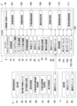
図2に示すように、車載電子制御ユニット18は、変速装置13の作動を制御する変速制御部181、左右のサイドブレーキの作動を制御する制動制御部182、ロータリ耕耘装置等の作業装置12の作動を制御する作業装置制御部183、自動走行時に左右の前輪5の目標操舵角を設定してパワーステアリング機構14に出力する操舵角設定部184、及び、予め生成された自動走行用の目標走行経路P(例えば、図3参照)等を記憶する不揮発性の車載記憶部185等を有している。
As shown in FIG. 2, the in-vehicle
図2に示すように、測位ユニット21には、衛星測位システム(NSS:Navigation Satellite System)の一例であるGPS(Global Positioning System)を利用してトラクタ1の現在位置と現在方位とを測定する衛星航法装置22、及び、3軸のジャイロスコープ及び3方向の加速度センサ等を有してトラクタ1の姿勢や方位等を測定する慣性計測装置(IMU:Inertial Measurement Unit)23等が備えられている。GPSを利用した測位方法には、DGPS(Differential GPS:相対測位方式)やRTK-GPS(Real Time Kinematic GPS:干渉測位方式)等がある。本実施形態においては、移動体の測位に適したRTK-GPSが採用されている。そのため、圃場周辺の既知位置には、図1及び図2に示すように、RTK-GPSによる測位を可能にする基準局4が設置されている。
As shown in FIG. 2, the
トラクタ1と基準局4との夫々には、図2に示すように、測位衛星71(図1参照)から送信された電波を受信する測位アンテナ24,61、及び、トラクタ1と基準局4との間における測位情報を含む各種情報の無線通信を可能にする通信モジュール25,62等が備えられている。これにより、衛星航法装置22は、トラクタ側の測位アンテナ24が測位衛星71からの電波を受信して得た測位情報と、基地局側の測位アンテナ61が測位衛星71からの電波を受信して得た測位情報とに基づいて、トラクタ1の現在位置及び現在方位を高い精度で測定することができる。また、測位ユニット21は、衛星航法装置22と慣性計測装置23とを備えることにより、トラクタ1の現在位置、現在方位、姿勢角(ヨー角、ロール角、ピッチ角)を高精度に測定することができる。
As shown in FIG. 2, the
トラクタ1に備えられる測位アンテナ24、通信モジュール25、及び、慣性計測装置23は、図1に示すように、アンテナユニット80に収納されている。アンテナユニット80は、キャビン10の前面側の上部位置に配置されている。
The
図2に示すように、携帯通信端末3には、表示部51等の作動を制御する各種の制御プログラム等を有する端末電子制御ユニット52、及び、トラクタ側の通信モジュール25との間における測位情報を含む各種情報の無線通信を可能にする通信モジュール53等が備えられている。端末電子制御ユニット52は、トラクタ1を自動走行させるための目標走行経路P(例えば、図3参照)を生成する走行経路生成部54、及び、ユーザが入力した各種の入力情報や走行経路生成部54が生成した目標走行経路P等を記憶する不揮発性の端末記憶部55等を有している。
As shown in FIG. 2, the
走行経路生成部54が目標走行経路Pを生成するに当たり、携帯通信端末3の表示部51に表示された目標走行経路設定用の入力案内に従って、運転者や管理者等のユーザ等が作業車両や作業装置12の種類や機種等の車体情報を入力しており、入力された車体情報が端末記憶部55に記憶されている。目標走行経路Pの生成対象となる作業領域S(図3参照)を圃場としており、携帯通信端末3の端末電子制御ユニット52は、圃場の形状や位置を含む圃場情報を取得して端末記憶部55に記憶している。
When the travel
圃場情報の取得について説明すると、ユーザ等が運転してトラクタ1を実際に走行させることで、端末電子制御ユニット52は、測位ユニット21にて取得するトラクタ1の現在位置等から圃場の形状や位置等を特定するための位置情報を取得することができる。端末電子制御ユニット52は、取得した位置情報から圃場の形状及び位置を特定し、その特定した圃場の形状及び位置から特定した作業領域Sを含む圃場情報を取得している。図3では、矩形状の作業領域Sが特定された例を示している。
When the user or the like drives the
特定された圃場の形状や位置等を含む圃場情報が端末記憶部55に記憶されると、走行経路生成部54は、端末記憶部55に記憶されている圃場情報や車体情報を用いて、目標走行経路Pを生成する。
When the field information including the shape, position, etc. of the specified field is stored in the
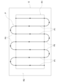
図3に示すように、走行経路生成部54は、作業領域S内を中央領域R1と外周領域R2とに区分け設定している。中央領域R1は、作業領域Sの中央部に設定されており、トラクタ1を往復方向に自動走行させて所定の作業(例えば、耕耘等の作業)を行う往復作業領域となっている。外周領域R2は、中央領域R1の周囲に設定されている。走行経路生成部54は、例えば、車体情報に含まれる旋回半径やトラクタ1の前後幅及び左右幅等から、トラクタ1を圃場の畔際で旋回走行させるために必要となる旋回走行用のスペース等を求めている。走行経路生成部54は、中央領域R1の外周に求めたスペース等を確保するように、作業領域S内を中央領域R1と外周領域R2とに区分けしている。
As shown in FIG. 3, the
走行経路生成部54は、図3に示すように、車体情報や圃場情報等を用いて、目標走行経路Pを生成している。例えば、目標走行経路Pは、中央領域R1において同じ直進距離を有して作業幅に対応する一定距離をあけて平行に配置設定された直線状の複数の作業経路P1とを有している。複数の作業経路P1は、トラクタ1を直進走行させながら、所定の作業を行うための経路である。連結経路P2は、所定の作業を行わずに、トラクタ1の走行方向を180度転換させるためのUターン経路であり、作業経路P1の終端と隣接する次の作業経路P1の始端とを連結している。
As shown in FIG. 3, the travel
ちなみに、図3に示す目標走行経路Pは、あくまで一例であり、どのような目標走行経路を設定するかは適宜変更が可能である。例えば、走行経路生成部54は、連結経路P2を生成せずに、作業経路P1のみを生成することもできる。例えば、走行経路生成部54は、ユーザ等が運転してトラクタ1を実際に走行させたときの移動軌跡に基づいて直線状の初期直線経路を生成し、その初期直線経路に平行な複数の平行経路を生成することで、初期直線経路及び複数の平行経路を作業経路P1とすることができる。この場合には、初期直線経路を適宜延長することができ、延長した初期直線経路に対して平行な複数の平行経路を生成することもできる。
Incidentally, the target travel route P shown in FIG. 3 is merely an example, and the type of target travel route to be set can be changed as appropriate. For example, the
走行経路生成部54にて生成された目標走行経路Pは、表示部51に表示可能であり、車体情報及び圃場情報等と関連付けた経路情報として端末記憶部55に記憶されている。経路情報には、目標走行経路Pの方位角、及び、目標走行経路Pでのトラクタ1の走行形態等に応じて設定された設定エンジン回転速度や目標走行速度等が含まれている。
The target travel route P generated by the travel
このようにして、走行経路生成部54が目標走行経路Pを生成すると、端末電子制御ユニット52が、携帯通信端末3からトラクタ1に経路情報を転送することで、トラクタ1の車載電子制御ユニット18が、経路情報を取得することができる。車載電子制御ユニット18は、取得した経路情報に基づいて、測位ユニット21にて自己の現在位置(トラクタ1の現在位置)を取得しながら、目標走行経路Pに沿ってトラクタ1を自動走行させることができる。測位ユニット21にて取得するトラクタ1の現在位置については、リアルタイム(例えば、数ミリ秒周期)でトラクタ1から携帯通信端末3に送信されており、携帯通信端末3にてトラクタ1の現在位置を把握している。
In this way, when the travel
経路情報の転送に関しては、トラクタ1が自動走行を開始する前の段階において、経路情報の全体を端末電子制御ユニット52から車載電子制御ユニット18に一挙に転送することができる。また、例えば、目標走行経路Pを含む経路情報を、情報量の少ない所定距離ごとの複数の経路部分に分割することもできる。この場合には、トラクタ1が自動走行を開始する前の段階においては、経路情報の初期経路部分のみが端末電子制御ユニット52から車載電子制御ユニット18に転送される。自動走行の開始後は、トラクタ1が情報量等に応じて設定された経路取得地点に達するごとに、その地点に対応する以後の経路部分のみの経路情報が端末電子制御ユニット52から車載電子制御ユニット18に転送するようにしてもよい。
Regarding the transfer of the route information, the entire route information can be transferred from the terminal
トラクタ1の自動走行を開始する場合には、例えば、ユーザ等がスタート地点にトラクタ1を移動させて、各種の自動走行開始条件が満たされると、携帯通信端末3にて、ユーザが表示部51を操作して自動走行の開始を指示することで、携帯通信端末3は、自動走行の開始指示をトラクタ1に送信する。これにより、トラクタ1では、車載電子制御ユニット18が、自動走行の開始指示を受けることで、測位ユニット21にて自己の現在位置(トラクタ1の現在位置)を取得しながら、目標走行経路Pに沿ってトラクタ1を自動走行させる自動走行制御を開始する。車載電子制御ユニット18が、衛星測位システムを用いて測位ユニット21により取得されるトラクタ1の測位情報に基づいて、作業領域S内の目標走行経路Pに沿ってトラクタ1を自動走行させる自動走行制御を行う自動走行制御部として構成されている。
When the automatic traveling of the
自動走行制御には、変速装置13の作動を自動制御する自動変速制御、ブレーキ操作機構15の作動を自動制御する自動制動制御、左右の前輪5を自動操舵する自動操舵制御、及び、ロータリ耕耘装置等の作業装置12の作動を自動制御する作業用自動制御、等が含まれている。
The automatic travel control includes automatic transmission control for automatically controlling the operation of the
自動変速制御においては、変速制御部181が、目標走行速度を含む目標走行経路Pの経路情報と測位ユニット21の出力と車速センサ19の出力とに基づいて、目標走行経路Pでのトラクタ1の走行形態等に応じて設定された目標走行速度がトラクタ1の車速として得られるように変速装置13の作動を自動制御する。
In the automatic shift control, the
自動制動制御においては、制動制御部182が、目標走行経路Pと測位ユニット21の出力とに基づいて、目標走行経路Pの経路情報に含まれている制動領域において左右のサイドブレーキが左右の後輪6を適正に制動するようにブレーキ操作機構15の作動を自動制御する。
In the automatic braking control, the
自動操舵制御においては、トラクタ1が目標走行経路Pを自動走行するように、操舵角設定部184が、目標走行経路Pの経路情報と測位ユニット21の出力とに基づいて左右の前輪5の目標操舵角を求めて設定し、設定した目標操舵角をパワーステアリング機構14に出力する。パワーステアリング機構14が、目標操舵角と舵角センサ20の出力とに基づいて、目標操舵角が左右の前輪5の操舵角として得られるように左右の前輪5を自動操舵する。
In the automatic steering control, the steering
作業用自動制御においては、作業装置制御部183が、目標走行経路Pの経路情報と測位ユニット21の出力とに基づいて、トラクタ1が作業経路P1(例えば、図3参照)の始端等の作業開始地点に達するのに伴って作業装置12による所定の作業(例えば耕耘作業)が開始され、かつ、トラクタ1が作業経路P1(例えば、図3参照)の終端等の作業終了地点に達するのに伴って作業装置12による所定の作業が停止されるように、クラッチ操作機構16及び昇降駆動機構17の作動を自動制御する。
In the automatic work control, the work
このようにして、トラクタ1においては、変速装置13、パワーステアリング機構14、ブレーキ操作機構15、クラッチ操作機構16、昇降駆動機構17、車載電子制御ユニット18、車速センサ19、舵角センサ20、測位ユニット21、及び、通信モジュール25、等によって自動走行ユニット2が構成されている。
Thus, in the
この実施形態では、キャビン10にユーザ等が搭乗せずにトラクタ1を自動走行させるだけでなく、キャビン10にユーザ等が搭乗した状態でトラクタ1を自動走行させることも可能となっている。よって、キャビン10にユーザ等が搭乗せずに、車載電子制御ユニット18による自動走行制御により、トラクタ1を目標走行経路Pに沿って自動走行させることができるだけでなく、キャビン10にユーザ等が搭乗している場合でも、車載電子制御ユニット18による自動走行制御により、トラクタ1を目標走行経路Pに沿って自動走行させることができる。
In this embodiment, not only can the
キャビン10にユーザ等が搭乗している場合には、車載電子制御ユニット18にてトラクタ1を自動走行させる自動走行状態と、ユーザ等の運転に基づいてトラクタ1を走行させる手動走行状態とに切り替えることができる。よって、自動走行状態にて目標走行経路Pを自動走行している途中に、自動走行状態から手動走行状態に切り替えることができ、逆に、手動走行状態にて走行している途中に、手動走行状態から自動走行状態に切り替えることができる。手動走行状態と自動走行状態との切り替えについては、例えば、運転席39の近傍に、自動走行状態と手動走行状態とに切り替えるための切替操作部を備えることができるとともに、その切替操作部を携帯通信端末3の表示部51に表示させることもできる。また、車載電子制御ユニット18による自動走行制御中に、ユーザがステアリングホイール38を操作すると、自動走行状態から手動走行状態に切り替えることができる。
When a user or the like is in the
トラクタ1には、図1及び図2に示すように、トラクタ1(走行機体7)の周囲における障害物を検知して、障害物との衝突を回避するための障害物検知システム100が備えられている。障害物検知システム100は、レーザを用いて測定対象物までの距離を3次元で測定可能な複数のライダーセンサ101,102と、超音波を用いて測定対象物までの距離を測定可能な複数のソナーを有するソナーユニット103,104と、障害物検知部110と、衝突回避制御部111とが備えられている。
As shown in FIGS. 1 and 2, the
ライダーセンサ101,102及びソナーユニット103,104にて測定する測定対象物は、物体や人等としている。ライダーセンサ101,102は、トラクタ1の前方側を測定対象とする前ライダーセンサ101と、トラクタ1の後方側を測定対象とする後ライダーセンサ102とが備えられている。ソナーユニット103,104は、トラクタ1の右側を測定対象とする右側のソナーユニット103と、トラクタ1の左側を測定対象とする左側のソナーユニット104とが備えられている。
The objects to be measured by the
障害物検知部110は、ライダーセンサ101,102及びソナーユニット103,104の測定情報に基づいて、所定距離内の物体や人等の測定対象物を障害物として検知する障害物検知処理を行うように構成されている。衝突回避制御部111は、障害物検知部110にて障害物を検知すると、トラクタ1を減速させる又はトラクタ1を走行停止させる衝突回避制御を行うように構成されている。衝突回避制御部111は、衝突回避制御において、トラクタ1を減速させる又はトラクタ1を走行停止させるだけでなく、報知ブザーや報知ランプ等の報知装置26を作動させて、障害物が存在することを報知している。衝突回避制御部111は、衝突回避制御において、通信モジュール25,53を用いて、トラクタ1から携帯通信端末3に通信して表示部51に障害物の存在を表示させることで、障害物が存在することを報知可能としている。
Based on the measurement information from the
障害物検知部110は、ライダーセンサ101,102及びソナーユニット103,104の測定情報に基づく障害物検知処理をリアルタイムで繰り返し行い、物体や人等の障害物を適切に検知している。衝突回避制御部111は、リアルタイムで検知される障害物との衝突を回避するための衝突回避制御を行うようにしている。
The
障害物検知部110及び衝突回避制御部111は、車載電子制御ユニット18に備えられている。車載電子制御ユニット18は、コモンレールシステムに含まれたエンジン用の電子制御ユニット、ライダーセンサ101,102、及び、ソナーユニット103,104等にCAN(Controller Area Network)を介して通信可能に接続されている。
The
携帯通信端末3では、トラクタ1を自動走行させる際等に、図4~図8に示すように、トラクタ1と作業装置12との位置関係を表示部51に表示させている。これにより、トラクタ1の自動走行中に、ユーザ等が、トラクタ1の走行状況や作業装置12による作業状況を把握することができる。以下、図4~図8に基づいて、携帯通信端末3の表示部51においてどのような表示を行うかについて説明する。
In the
携帯通信端末3には、図2に示すように、トラクタ1の位置情報を取得する作業車両位置情報取得部56と、トラクタ1に装着される作業装置12の作業位置情報を取得する作業位置情報取得部57と、表示部51における表示形態を制御する表示制御部58とが備えられている。
As shown in FIG. 2 , the
トラクタ1の測位ユニット21は、衛星測位システムを用いてトラクタ1の位置情報を取得しているので、作業車両位置情報取得部56は、トラクタ1側の通信モジュール25と携帯通信端末3側の通信モジュール53との間での無線通信を介して、トラクタ1の位置情報を取得している。
Since the
上述の如く、走行経路生成部54が目標走行経路Pを生成する際に、ユーザ等によりトラクタ1や作業装置12の種類や機種等の車体情報を携帯通信端末3に対して入力して、その入力された車体情報を端末記憶部55に記憶させている。これにより、トラクタ1を自動走行中において、端末記憶部55に記憶された車体情報に基づいて、トラクタ1の走行位置(トラクタ1の現在位置)に対して作業装置12がどのような位置関係に配置されるかを把握することができる。そこで、作業位置情報取得部57は、作業車両位置情報取得部56にて取得されるトラクタ1の位置情報からトラクタ1の走行位置(トラクタ1の現在位置)を取得し、そのトラクタ1の走行位置及び端末記憶部55に記憶された車体情報に基づいて、作業装置12の作業位置情報を取得している。
As described above, when the travel
ちなみに、作業装置12によっては、作業装置12自体に、測位衛星71(図1参照)から送信された電波を受信する測位アンテナが備えられているものがある。測位アンテナが備えられた作業装置12であれば、作業位置情報取得部57は、測位アンテナの受信情報から作業装置12の作業位置情報を取得することができる。
Incidentally, depending on the working
表示制御部58は、作業車両位置情報取得部56にて取得するトラクタ1の位置情報に基づいてトラクタ1の走行位置(トラクタ1の現在位置)を特定し、作業位置情報取得部57にて取得する作業位置情報に基づいて作業装置12の作業位置を特定している。表示制御部58は、図4~図8に示すように、地図上において、少なくとも特定したトラクタ1の走行位置と作業装置12の作業位置との位置関係を表示させる表示形態にて表示部51に表示させている。表示部51には、複数の表示エリアが備えられており、図4~図8に示すように、表示制御部58が、地図用の表示エリア51a(図4~図8において、右下側の表示エリア)に、少なくともトラクタ1の走行位置と作業装置12の作業位置との位置関係を表示させている。表示エリア51aにおける表示形態としては、2つの表示形態があるので、以下、それぞれの表示形態について説明する。
The
図4、図5、及び、図8では、図1とは異なり、作業装置12として、トラクタ1の左右方向でトラクタ1から離れた位置に作業装置12を配置させて、芝刈り等の作業を行うオフセットモアをトラクタ1に装着した場合を示している。図6、及び、図7では、作業装置13として、耕起等の作業を行うプラウであり、トラクタ1の前後方向での作業装置12の長さが長いリバーシブルプラウをトラクタ1に装着した場合を示している。
In FIGS. 4, 5, and 8, unlike FIG. 1, the working
携帯通信端末3の端末電子制御ユニット52は、目標走行経路Pのうち、作業済みの作業経路P1や作業済み箇所を登録して端末記憶部55に記憶させている。表示制御部58は、記憶された作業済みの作業経路P1や作業済み箇所に色(図4~図8では、グレー)等を付けることで、未作業の作業経路P1や未作業箇所と作業済みの作業経路P1や作業済み箇所とを識別可能としている。
The terminal
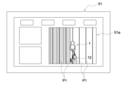
1つ目の表示形態は、図4及び図6に示すように、地図上において、トラクタ1の走行位置を基準として目標走行経路Pにおける作業経路P1とトラクタ1と作業装置12との位置関係を表示させる走行位置基準表示形態である。図4に示すものでは、表示制御部58が、走行位置基準表示形態として、表示エリア51aの左右方向でトラクタ1の走行位置を中央部又は略中央部に位置させる形態で、作業経路P1とトラクタ1と作業装置12とを表示エリア51aに重畳表示させている。図6に示すものでは、表示制御部58が、走行位置基準表示形態として、表示エリア51aの上下方向でトラクタ1の走行位置を中央部又は略中央部に位置させる形態で、作業経路P1とトラクタ1と作業装置12とを表示エリア51aに重畳表示させている。
As shown in FIGS. 4 and 6, the first display form shows the positional relationship between the work route P1, the
走行位置基準表示形態においてトラクタ1の走行位置を基準とするに当たり、トラクタ1の走行位置について、表示エリア51aの左右方向で中央部又は略中央部に位置させる形態(図4参照)とするか、表示エリア51aの上下方向で中央部又は略中央部に位置させる形態(図6参照)とするかは、どちらでもよく、ユーザの要望等、各種の条件に応じて適宜設定しておくことができる。また、図示は省略するが、走行位置基準表示形態として、表示制御部58が、表示エリア51aの左右方向及び上下方向の両方向でトラクタ1の走行位置を中央部又は略中央部に位置させる形態で、作業経路P1とトラクタ1と作業装置12との位置関係を表示エリア51aに表示させるように設定しておくこともできる。
When the traveling position of the
このように、走行位置基準表示形態では、図4及び図6に示すように、トラクタ1の走行位置を中央部に位置させてトラクタ1の走行位置を基準として、作業経路P1とトラクタ1と作業装置12とを重畳表示させているので、作業経路P1に対してトラクタ1の走行位置がずれているか否かを容易に把握することができ、トラクタ1の走行状況を把握し易いものとなっている。これにより、トラクタ1の自動走行中だけでなく、例えば、自動走行のスタート地点を作業経路P1上としてトラクタ1の自動走行を開始させる場合にも、トラクタ1の走行位置と作業経路P1との位置関係を容易に把握することができ、トラクタ1の走行位置を作業経路P1上に移動させる調整作業をスムーズに行うことができ、トラクタ1の自動走行をスムーズに開始することができる。
As described above, in the traveling position reference display mode, as shown in FIGS. 4 and 6, the traveling position of the
しかしながら、走行位置基準表示形態では、トラクタ1の走行位置を中央部に位置させてトラクタ1の走行位置を基準として表示させるので、図4に示すように、作業装置12として、トラクタ1の走行位置に対して左右方向でずれた位置で作業を行うオフセットモアを適用した場合には、作業装置12の作業位置とトラクタ1の走行位置とがトラクタ1の左右方向で離れた位置となっている。よって、作業装置12の作業位置が表示エリア51aの左右方向の端部側に表示され、作業装置12の作業位置がどの位置であるのかを認識し難く、作業装置12による作業状況を把握し難くなる。また、図6に示すように、作業装置12として、トラクタ1の走行方向で後方側に長いリバーシブルプラウを適用した場合には、作業装置12の作業位置とトラクタ1の走行位置とがトラクタ1の前後方向で離れた位置となっている。よって、作業装置12の作業位置が表示エリア51aの上下方向の端部側に表示され、作業装置12の作業位置がどの位置であるのかを認識し難く、作業装置12による作業状況を把握し難くなる。
However, in the traveling position reference display mode, the traveling position of the
そこで、2つ目の表示形態として、表示制御部58は、図5及び図7に示すように、地図上において、作業装置12の作業位置を基準として作業装置12とトラクタ1との位置関係を表示させる作業位置基準表示形態にて表示エリア51aに表示させている。図5に示すものでは、表示制御部58が、作業位置基準表示形態として、表示エリア51aの左右方向で作業装置12の作業位置を中央部又は略中央部に位置させる形態で、トラクタ1と作業装置12とを表示エリア51aに重畳表示させている。図7に示すものでは、表示制御部58が、作業位置基準表示形態として、表示エリア51aの上下方向で作業装置12の作業位置を中央部又は略中央部に位置させる形態で、トラクタ1と作業装置12とを表示エリア51aに重畳表示させている。
Therefore, as a second display form, the
図5に示すように、表示制御部58は、作業位置基準表示形態において、トラクタ1と作業装置12に加えて、表示エリア51aの左右方向において作業装置12の作業位置の中央部を示す直線状の作業位置ラインLを重畳表示させている。表示制御部58は、作業位置ラインLの重畳表示に代えて、図5の点線にて示すように、トラクタ1と作業装置12に加えて、作業経路P1を重畳表示させることもできる。また、表示制御部58は、作業位置ラインLと作業経路P1の両方を重畳表示させることもでき、作業位置ラインL及び作業経路P1について重畳表示させるか否かは適宜変更が可能である。
As shown in FIG. 5, in the working position reference display mode, the
このように、作業位置基準表示形態では、図5に示すように、作業装置12の作業位置を表示エリア51aの左右方向の中央部に位置させて作業装置12の作業位置を基準として、トラクタ1と作業装置12とに加えて、作業位置ラインL又は作業経路P1を重畳表示させているので、トラクタ1の左右方向において作業装置12の作業位置がどのような位置となっているかを容易に把握することができ、作業装置12による作業状況を把握し易いものとなっている。
As described above, in the working position reference display mode, as shown in FIG. 5, the working position of the working
自動走行システムには、目標走行経路Pにおける作業経路P1をその走行方向に直交する方向にオフセットさせてトラクタ1を自動走行させるオフセット機能が備えられている。このオフセット機能によりトラクタ1を自動走行させる場合に、図5に示す作業位置基準表示形態にて、トラクタ1と作業装置12とに加えて、作業位置ラインL又は作業経路P1を表示エリア51aに重畳表示させることで、ユーザ等は、トラクタ1の左右方向において作業装置12の作業位置がどのような位置となっているかを容易に認識することができ、作業経路P1に対するトラクタ1のオフセット量の調整を簡易に行うことができる。例えば、ユーザ等は、表示エリア51aの左右方向において作業装置12の作業位置が所望位置となるように、オフセット量を調整すればよいだけである。
The automatic traveling system has an offset function for automatically traveling the
図7に示すように、表示制御部58は、作業位置基準表示形態として、表示エリア51aの上下方向で作業装置12の作業位置を中央部に位置させて、作業装置12の作業位置を基準に表示させているので、リバーシブルプラウ等の作業装置12を装着させた場合でも、作業装置12の作業位置が認識し易い位置にあり、トラクタ1の前後方向において、作業装置12の作業位置がどのような位置となっているかを容易に把握することができ、作業装置12による作業状態を把握し易いものとなっている。
As shown in FIG. 7, the
また、図7に示すものでは、表示制御部58は、作業位置基準表示形態として、トラクタ1と作業装置12に加えて、作業経路P1を重畳表示させている。この場合には、表示エリア51aの上下方向で作業装置12の作業位置を中央部に位置させるので、表示エリア51aの左右方向でのトラクタ1と作業装置12の位置は、図6に示す走行位置基準表示形態と同一となる。そこで、表示制御部58は、作業位置基準表示形態において、トラクタ1と作業装置12に加えて、作業経路P1を重畳表示させることで、トラクタ1の左右方向において作業装置12の作業位置がどのような位置となっているかを容易に把握することができ、作業装置12による作業状況を把握し易いものとなっている。
In addition to the
作業位置基準表示形態において作業装置12の作業位置を基準とするに当たり、作業装置12の作業位置について、表示エリア51aの左右方向で中央部又は略中央部に位置させる形態(図5参照)とするか、表示エリア51aの上下方向で中央部又は略中央部に位置させる形態(図7参照)とするかは、どちらでもよく、ユーザの要望等、各種の条件に応じて適宜設定しておくことができる。また、図8に示すように、作業位置基準表示形態として、表示制御部58が、表示エリア51aの左右方向及び上下方向の両方向で作業装置12の作業位置を中央部又は略中央部に位置させる形態で、トラクタ1と作業装置12とに加えて、作業位置ラインL又は作業経路P1を重畳表示させるように設定しておくこともできる。
When the working position of the working
上述の如く、表示部51の表示エリア51aにおける表示形態として、走行位置基準表示形態と作業位置基準表示形態との2つがあり、図9に示すように、走行位置基準表示形態にて表示させるか、又は、作業位置基準表示形態にて表示させるかを選択することができる。
As described above, there are two display forms in the
図9は、表示部51に表示される表示形態を選択するための選択画面である。この図9に示す選択画面において、ユーザ等が選択操作を行うことで、走行位置基準表示形態にて表示させるか、又は、作業位置基準表示形態にて表示させるかを選択することができる。図9において、走行位置基準表示形態にて表示させる場合には、上側の「自車(アンテナ)中心位置」を選択操作し、作業位置基準表示形態にて表示させる場合には、下側の「作業中心位置」を選択操作する。図9では、上側の「自車(アンテナ)中心位置」を選択操作された場合を示している。
FIG. 9 shows a selection screen for selecting a display mode displayed on the
表示制御部58の動作について、図10のフローチャートに基づいて説明すると、表示制御部58が、図9において、「自車(アンテナ)中心位置」が選択操作されているか、又は、「作業中心位置」が選択操作されているかを確認する(ステップ#1)。「自車(アンテナ)中心位置」が選択操作されている場合には、表示制御部58が、走行位置基準表示形態(図4又は図6参照)にて表示エリア51aにトラクタ1と作業装置12等を重畳表示させる(ステップ#1のNoの場合、ステップ#2)。逆に、「作業中心位置」が選択操作されている場合には、表示制御部58が、作業位置基準表示形態(図5、図7又は図8参照)にて表示エリア51aにトラクタ1と作業装置12等を重畳表示させる(ステップ#1のYesの場合、ステップ#3)。
The operation of the
〔別実施形態〕
本発明の他の実施形態について説明する。
尚、以下に説明する各実施形態の構成は、夫々単独で適用することに限らず、他の実施形態の構成と組み合わせて適用することも可能である。
[Another embodiment]
Another embodiment of the present invention will be described.
It should be noted that the configuration of each embodiment described below is not limited to being applied alone, and can also be applied in combination with the configuration of other embodiments.
(1)作業車両の構成は種々の変更が可能である。
例えば、作業車両は、エンジン9と走行用の電動モータとを備えるハイブリット仕様に構成されていてもよく、また、エンジン9に代えて走行用の電動モータを備える電動仕様に構成されていてもよい。
例えば、作業車両は、走行部として、左右の後輪6に代えて左右のクローラを備えるセミクローラ仕様に構成されていてもよい。
例えば、作業車両は、左右の後輪6が操舵輪として機能する後輪ステアリング仕様に構成されていてもよい。
(1) The configuration of the work vehicle can be modified in various ways.
For example, the work vehicle may be configured as a hybrid specification including the
For example, the work vehicle may be configured as a semi-crawler specification that includes left and right crawlers instead of the left and right
For example, the work vehicle may be configured with a rear wheel steering specification in which the left and right
(2)上記実施形態では、作業位置基準表示形態において、作業装置12の作業位置について、表示エリア51aの左右方向で中央部又は略中央部に位置させる形態(図5参照)、表示エリア51aの上下方向で中央部又は略中央部に位置させる形態(図7参照)、表示エリア51aの左右方向及び上下方向の両方向で中央部又は略中央部に位置させる形態(図8参照)のいずれかの形態としているが、これらの形態に限るものではなく、他の形態にて表示させることもできる。
例えば、表示エリア51aにおいて作業装置12の作業位置を位置させる箇所をユーザが指定することができる。この場合には、表示制御部58が、表示エリア51aにおいてユーザが指定した箇所に作業装置12の作業位置を位置させる形態で、トラクタ1と作業装置12とに加えて、作業位置ラインL又は作業経路P1を重畳表示させることができる。
(2) In the above-described embodiment, in the working position reference display form, the working position of the working
For example, the user can designate a location where the working position of the working
(3)上記実施形態では、走行位置基準表示形態において、トラクタ1の走行位置について、表示エリア51aの左右方向で中央部又は略中央部に位置させる形態(図4参照)、表示エリア51aの上下方向で中央部又は略中央部に位置させる形態(図6参照)、表示エリア51aの左右方向及び上下方向の両方向で中央部又は略中央部に位置させる形態(図示省略)のいずれかの形態としているが、これらの形態に限るものではなく、他の形態にて表示させることもできる。
例えば、表示エリア51aにおいてトラクタ1の走行位置を位置させる箇所をユーザが指定することができる。この場合には、表示制御部58が、表示エリア51aにおいてユーザが指定した箇所にトラクタ1の走行位置を位置させる形態で、作業経路P1とトラクタ1と作業装置12とを重畳表示させることができる。
(3) In the above embodiment, in the traveling position reference display mode, the traveling position of the
For example, the user can designate a place where the traveling position of the
1 トラクタ(作業車両)
12 作業装置
51 表示部
51a 表示エリア
56 作業車両位置情報取得部
57 作業位置情報取得部
58 表示制御部
P 目標走行経路
1 tractor (work vehicle)
12
Claims (4)
作業車両に装着されて所定の作業を行う作業装置の作業位置情報を取得する作業位置情報取得部と、
前記作業車両位置情報取得部にて取得する作業車両の位置情報、及び、前記作業位置情報取得部にて取得する作業位置情報に基づいて、前記目標走行経路に直交するオフセット方向において互いに離れた位置である作業車両の位置と作業装置の作業位置との位置関係を、作業装置の作業位置を基準とする作業位置基準表示形態にて表示部の表示エリアに表示させる表示制御部とが備えられており、
前記作業位置基準表示形態では、前記表示制御部が、前記表示エリアにおいて前記オフセット方向で作業装置の作業位置を中央部又は略中央部に位置させる形態で、作業車両と作業装置との位置関係を表示させる、
表示装置。 a work vehicle position information acquisition unit that acquires position information of a work vehicle that is automatically driven along a target travel route;
a work position information acquisition unit that acquires work position information of a work device that is mounted on a work vehicle and performs a predetermined work;
Positions separated from each other in the offset direction orthogonal to the target travel route based on the position information of the work vehicle acquired by the work vehicle position information acquisition unit and the work position information acquired by the work position information acquisition unit a display control unit for displaying the positional relationship between the position of the work vehicle and the work position of the work device in the display area of the display unit in a work position reference display format based on the work position of the work device. cage,
In the working position reference display mode, the display control unit positions the working position of the working device in the center or substantially the center of the display area in the offset direction , thereby adjusting the positional relationship between the work vehicle and the working device. to display
display device.
作業車両に装着されて所定の作業を行う作業装置の作業位置情報を取得する作業位置情報取得部と、
前記作業車両位置情報取得部にて取得する作業車両の位置情報、及び、前記作業位置情報取得部にて取得する作業位置情報に基づいて、作業装置の作業位置を基準として作業車両と作業装置との位置関係を表示させる作業位置基準表示形態にて表示部の表示エリアに表示させる表示制御部とが備えられており、
前記表示制御部は、前記作業車両位置情報取得部にて取得する作業車両の位置情報、及び、前記作業位置情報取得部にて取得する作業位置情報に基づいて、作業車両の走行位置を基準として目標走行経路と作業車両と作業装置との位置関係を表示させる走行位置基準表示形態にて前記表示エリアに表示可能であり、且つ、前記表示エリアにおける表示形態を、前記作業位置基準表示形態と前記走行位置基準表示形態とに切替自在に構成されている、
表示装置。 a work vehicle position information acquisition unit that acquires position information of the work vehicle that is automatically driven along the target travel route;
a work position information acquisition unit that acquires work position information of a work device that is mounted on a work vehicle and performs a predetermined work;
Based on the position information of the work vehicle acquired by the work vehicle position information acquisition unit and the work position information acquired by the work position information acquisition unit, the work vehicle and the work equipment are determined based on the work position of the work device. a display control unit for displaying in the display area of the display unit in a working position reference display form for displaying the positional relationship with the position ,
Based on the position information of the work vehicle acquired by the work vehicle position information acquisition unit and the work position information acquired by the work position information acquisition unit, the display control unit uses the travel position of the work vehicle as a reference. It is possible to display in the display area in a traveling position-based display form that displays the positional relationship between the target traveling route, the work vehicle, and the work device, and the display form in the display area can be combined with the work position-based display form and the work position reference display form. It is configured to be switchable between the display mode based on the running position,
display device.
作業車両に装着されて所定の作業を行う作業装置の作業位置情報を取得する作業位置情報取得部と、
前記作業車両位置情報取得部にて取得する作業車両の位置情報、及び、前記作業位置情報取得部にて取得する作業位置情報に基づいて、前記目標走行経路に直交するオフセット方向において互いに離れた位置である作業車両の位置と作業装置の作業位置との位置関係を、作業装置の作業位置を基準とする作業位置基準表示形態にて表示部の表示エリアに表示させる表示制御部とが備えられており、
前記作業位置基準表示形態では、前記表示制御部が、前記表示エリアにおいて前記オフセット方向で作業装置の作業位置を中央部又は略中央部に位置させる形態で、作業車両と作業装置との位置関係を表示させる、
自動走行システム。 a work vehicle position information acquisition unit that acquires position information of the work vehicle that is automatically driven along the target travel route;
a work position information acquisition unit that acquires work position information of a work device that is mounted on a work vehicle and performs a predetermined work;
Positions separated from each other in the offset direction orthogonal to the target travel route based on the position information of the work vehicle acquired by the work vehicle position information acquisition unit and the work position information acquired by the work position information acquisition unit a display control unit for displaying the positional relationship between the position of the work vehicle and the work position of the work device in the display area of the display unit in a work position reference display form based on the work position of the work device. cage,
In the working position reference display mode, the display control unit positions the working position of the working device in the center or substantially the center of the display area in the offset direction , thereby adjusting the positional relationship between the work vehicle and the working device. to display
automatic driving system.
作業車両に装着されて所定の作業を行う作業装置の作業位置情報を取得する作業位置情報取得部と、
前記作業車両位置情報取得部にて取得する作業車両の位置情報、及び、前記作業位置情報取得部にて取得する作業位置情報に基づいて、作業装置の作業位置を基準として作業車両と作業装置との位置関係を表示させる作業位置基準表示形態にて表示部の表示エリアに表示させる表示制御部とが備えられており、
前記表示制御部は、前記作業車両位置情報取得部にて取得する作業車両の位置情報、及び、前記作業位置情報取得部にて取得する作業位置情報に基づいて、作業車両の走行位置を基準として目標走行経路と作業車両と作業装置との位置関係を表示させる走行位置基準表示形態にて前記表示エリアに表示可能であり、且つ、前記表示エリアにおける表示形態を、前記作業位置基準表示形態と前記走行位置基準表示形態とに切替自在に構成されている、
自動走行システム。 a work vehicle position information acquisition unit that acquires position information of a work vehicle that is automatically driven along a target travel route;
a work position information acquisition unit that acquires work position information of a work device that is mounted on a work vehicle and performs a predetermined work;
Based on the position information of the work vehicle acquired by the work vehicle position information acquisition unit and the work position information acquired by the work position information acquisition unit, the work vehicle and the work device are positioned relative to the work position of the work device. a display control unit for displaying in the display area of the display unit in the working position reference display form for displaying the positional relationship of
Based on the position information of the work vehicle acquired by the work vehicle position information acquisition unit and the work position information acquired by the work position information acquisition unit, the display control unit uses the traveling position of the work vehicle as a reference. It is possible to display in the display area in a travel position-based display form that displays the positional relationship between the target travel route, the work vehicle, and the work device, and the display form in the display area can be combined with the work position-based display form and the It is configured to be switchable between the display mode based on the running position ,
automatic driving system.
Priority Applications (1)
| Application Number | Priority Date | Filing Date | Title |
|---|---|---|---|
| JP2018204159A JP7223552B2 (en) | 2018-10-30 | 2018-10-30 | Display device and automatic driving system |
Applications Claiming Priority (1)
| Application Number | Priority Date | Filing Date | Title |
|---|---|---|---|
| JP2018204159A JP7223552B2 (en) | 2018-10-30 | 2018-10-30 | Display device and automatic driving system |
Publications (2)
| Publication Number | Publication Date |
|---|---|
| JP2020068693A JP2020068693A (en) | 2020-05-07 |
| JP7223552B2 true JP7223552B2 (en) | 2023-02-16 |
Family
ID=70546867
Family Applications (1)
| Application Number | Title | Priority Date | Filing Date |
|---|---|---|---|
| JP2018204159A Active JP7223552B2 (en) | 2018-10-30 | 2018-10-30 | Display device and automatic driving system |
Country Status (1)
| Country | Link |
|---|---|
| JP (1) | JP7223552B2 (en) |
Families Citing this family (3)
| Publication number | Priority date | Publication date | Assignee | Title |
|---|---|---|---|---|
| JP7496732B2 (en) * | 2020-08-06 | 2024-06-07 | 三菱マヒンドラ農機株式会社 | Work vehicles |
| JP7388339B2 (en) * | 2020-11-05 | 2023-11-29 | 井関農機株式会社 | work vehicle |
| JP2024062176A (en) * | 2022-10-24 | 2024-05-09 | 株式会社クボタ | Remote operation assistance system for work machine and remote apparatus |
Citations (4)
| Publication number | Priority date | Publication date | Assignee | Title |
|---|---|---|---|---|
| JP2015112056A (en) | 2013-12-11 | 2015-06-22 | 井関農機株式会社 | Agricultural work vehicle |
| JP2017139982A (en) | 2016-02-09 | 2017-08-17 | 株式会社クボタ | Work vehicle |
| JP2017211733A (en) | 2016-05-24 | 2017-11-30 | ヤンマー株式会社 | Autonomous travel path generation system |
| WO2018055921A1 (en) | 2016-09-26 | 2018-03-29 | ヤンマー株式会社 | Path creation system |
Family Cites Families (2)
| Publication number | Priority date | Publication date | Assignee | Title |
|---|---|---|---|---|
| US5991694A (en) * | 1995-11-13 | 1999-11-23 | Caterpillar Inc. | Method and apparatus for determining the location of seedlings during agricultural production |
| EP2158799B9 (en) * | 2008-08-27 | 2012-12-26 | CLAAS Tractor S.A.S. | Self-propelled agricultural working machine |
-
2018
- 2018-10-30 JP JP2018204159A patent/JP7223552B2/en active Active
Patent Citations (4)
| Publication number | Priority date | Publication date | Assignee | Title |
|---|---|---|---|---|
| JP2015112056A (en) | 2013-12-11 | 2015-06-22 | 井関農機株式会社 | Agricultural work vehicle |
| JP2017139982A (en) | 2016-02-09 | 2017-08-17 | 株式会社クボタ | Work vehicle |
| JP2017211733A (en) | 2016-05-24 | 2017-11-30 | ヤンマー株式会社 | Autonomous travel path generation system |
| WO2018055921A1 (en) | 2016-09-26 | 2018-03-29 | ヤンマー株式会社 | Path creation system |
Also Published As
| Publication number | Publication date |
|---|---|
| JP2020068693A (en) | 2020-05-07 |
Similar Documents
| Publication | Publication Date | Title |
|---|---|---|
| JP7356829B2 (en) | automatic driving system | |
| JP7044664B2 (en) | Autonomous driving system | |
| JP2021078440A (en) | Automatic travel system for work vehicle | |
| JP7223552B2 (en) | Display device and automatic driving system | |
| JP2023090789A (en) | Automatic travel system and automatic travel method | |
| JP7036707B2 (en) | Travel route generator | |
| JP2024053067A (en) | Automatic travel system and automatic travel method | |
| JP7100539B2 (en) | Autonomous driving system | |
| JP7146675B2 (en) | automatic driving system | |
| JP7246918B2 (en) | RUNNING STATE DISPLAY DEVICE AND AUTOMATIC RUNNING SYSTEM | |
| JP7094832B2 (en) | Collaborative work system | |
| JP7329645B2 (en) | Work support system | |
| JP7094833B2 (en) | Travel route display device | |
| JP7229119B2 (en) | automatic driving system | |
| JP7068969B2 (en) | Autonomous driving system | |
| JP2023126466A (en) | Automatic traveling method and automatic traveling system |
Legal Events
| Date | Code | Title | Description |
|---|---|---|---|
| RD03 | Notification of appointment of power of attorney |
Free format text: JAPANESE INTERMEDIATE CODE: A7423 Effective date: 20200814 |
|
| A621 | Written request for application examination |
Free format text: JAPANESE INTERMEDIATE CODE: A621 Effective date: 20210112 |
|
| A977 | Report on retrieval |
Free format text: JAPANESE INTERMEDIATE CODE: A971007 Effective date: 20211213 |
|
| A131 | Notification of reasons for refusal |
Free format text: JAPANESE INTERMEDIATE CODE: A131 Effective date: 20220111 |
|
| A521 | Request for written amendment filed |
Free format text: JAPANESE INTERMEDIATE CODE: A523 Effective date: 20220302 |
|
| A131 | Notification of reasons for refusal |
Free format text: JAPANESE INTERMEDIATE CODE: A131 Effective date: 20220614 |
|
| A521 | Request for written amendment filed |
Free format text: JAPANESE INTERMEDIATE CODE: A523 Effective date: 20220808 |
|
| A131 | Notification of reasons for refusal |
Free format text: JAPANESE INTERMEDIATE CODE: A131 Effective date: 20221108 |
|
| A521 | Request for written amendment filed |
Free format text: JAPANESE INTERMEDIATE CODE: A523 Effective date: 20221222 |
|
| TRDD | Decision of grant or rejection written | ||
| A01 | Written decision to grant a patent or to grant a registration (utility model) |
Free format text: JAPANESE INTERMEDIATE CODE: A01 Effective date: 20230124 |
|
| A61 | First payment of annual fees (during grant procedure) |
Free format text: JAPANESE INTERMEDIATE CODE: A61 Effective date: 20230206 |
|
| R150 | Certificate of patent or registration of utility model |
Ref document number: 7223552 Country of ref document: JP Free format text: JAPANESE INTERMEDIATE CODE: R150 |