JP7222430B2 - FRP product manufacturing method - Google Patents
FRP product manufacturing method Download PDFInfo
- Publication number
- JP7222430B2 JP7222430B2 JP2021540979A JP2021540979A JP7222430B2 JP 7222430 B2 JP7222430 B2 JP 7222430B2 JP 2021540979 A JP2021540979 A JP 2021540979A JP 2021540979 A JP2021540979 A JP 2021540979A JP 7222430 B2 JP7222430 B2 JP 7222430B2
- Authority
- JP
- Japan
- Prior art keywords
- prepreg
- anisotropic
- preforming
- degree
- manufacturing
- Prior art date
- Legal status (The legal status is an assumption and is not a legal conclusion. Google has not performed a legal analysis and makes no representation as to the accuracy of the status listed.)
- Active
Links
Images


Classifications
-
- B—PERFORMING OPERATIONS; TRANSPORTING
- B29—WORKING OF PLASTICS; WORKING OF SUBSTANCES IN A PLASTIC STATE IN GENERAL
- B29C—SHAPING OR JOINING OF PLASTICS; SHAPING OF MATERIAL IN A PLASTIC STATE, NOT OTHERWISE PROVIDED FOR; AFTER-TREATMENT OF THE SHAPED PRODUCTS, e.g. REPAIRING
- B29C70/00—Shaping composites, i.e. plastics material comprising reinforcements, fillers or preformed parts, e.g. inserts
- B29C70/04—Shaping composites, i.e. plastics material comprising reinforcements, fillers or preformed parts, e.g. inserts comprising reinforcements only, e.g. self-reinforcing plastics
- B29C70/06—Fibrous reinforcements only
- B29C70/08—Fibrous reinforcements only comprising combinations of different forms of fibrous reinforcements incorporated in matrix material, forming one or more layers, and with or without non-reinforced layers
- B29C70/081—Combinations of fibres of continuous or substantial length and short fibres
-
- B—PERFORMING OPERATIONS; TRANSPORTING
- B29—WORKING OF PLASTICS; WORKING OF SUBSTANCES IN A PLASTIC STATE IN GENERAL
- B29C—SHAPING OR JOINING OF PLASTICS; SHAPING OF MATERIAL IN A PLASTIC STATE, NOT OTHERWISE PROVIDED FOR; AFTER-TREATMENT OF THE SHAPED PRODUCTS, e.g. REPAIRING
- B29C43/00—Compression moulding, i.e. applying external pressure to flow the moulding material; Apparatus therefor
- B29C43/003—Compression moulding, i.e. applying external pressure to flow the moulding material; Apparatus therefor characterised by the choice of material
-
- B—PERFORMING OPERATIONS; TRANSPORTING
- B29—WORKING OF PLASTICS; WORKING OF SUBSTANCES IN A PLASTIC STATE IN GENERAL
- B29C—SHAPING OR JOINING OF PLASTICS; SHAPING OF MATERIAL IN A PLASTIC STATE, NOT OTHERWISE PROVIDED FOR; AFTER-TREATMENT OF THE SHAPED PRODUCTS, e.g. REPAIRING
- B29C43/00—Compression moulding, i.e. applying external pressure to flow the moulding material; Apparatus therefor
- B29C43/02—Compression moulding, i.e. applying external pressure to flow the moulding material; Apparatus therefor of articles of definite length, i.e. discrete articles
- B29C43/20—Making multilayered or multicoloured articles
- B29C43/203—Making multilayered articles
-
- B—PERFORMING OPERATIONS; TRANSPORTING
- B29—WORKING OF PLASTICS; WORKING OF SUBSTANCES IN A PLASTIC STATE IN GENERAL
- B29C—SHAPING OR JOINING OF PLASTICS; SHAPING OF MATERIAL IN A PLASTIC STATE, NOT OTHERWISE PROVIDED FOR; AFTER-TREATMENT OF THE SHAPED PRODUCTS, e.g. REPAIRING
- B29C70/00—Shaping composites, i.e. plastics material comprising reinforcements, fillers or preformed parts, e.g. inserts
- B29C70/04—Shaping composites, i.e. plastics material comprising reinforcements, fillers or preformed parts, e.g. inserts comprising reinforcements only, e.g. self-reinforcing plastics
- B29C70/06—Fibrous reinforcements only
- B29C70/08—Fibrous reinforcements only comprising combinations of different forms of fibrous reinforcements incorporated in matrix material, forming one or more layers, and with or without non-reinforced layers
-
- B—PERFORMING OPERATIONS; TRANSPORTING
- B29—WORKING OF PLASTICS; WORKING OF SUBSTANCES IN A PLASTIC STATE IN GENERAL
- B29C—SHAPING OR JOINING OF PLASTICS; SHAPING OF MATERIAL IN A PLASTIC STATE, NOT OTHERWISE PROVIDED FOR; AFTER-TREATMENT OF THE SHAPED PRODUCTS, e.g. REPAIRING
- B29C70/00—Shaping composites, i.e. plastics material comprising reinforcements, fillers or preformed parts, e.g. inserts
- B29C70/04—Shaping composites, i.e. plastics material comprising reinforcements, fillers or preformed parts, e.g. inserts comprising reinforcements only, e.g. self-reinforcing plastics
- B29C70/06—Fibrous reinforcements only
- B29C70/10—Fibrous reinforcements only characterised by the structure of fibrous reinforcements, e.g. hollow fibres
- B29C70/12—Fibrous reinforcements only characterised by the structure of fibrous reinforcements, e.g. hollow fibres using fibres of short length, e.g. in the form of a mat
- B29C70/14—Fibrous reinforcements only characterised by the structure of fibrous reinforcements, e.g. hollow fibres using fibres of short length, e.g. in the form of a mat oriented
-
- B—PERFORMING OPERATIONS; TRANSPORTING
- B29—WORKING OF PLASTICS; WORKING OF SUBSTANCES IN A PLASTIC STATE IN GENERAL
- B29C—SHAPING OR JOINING OF PLASTICS; SHAPING OF MATERIAL IN A PLASTIC STATE, NOT OTHERWISE PROVIDED FOR; AFTER-TREATMENT OF THE SHAPED PRODUCTS, e.g. REPAIRING
- B29C70/00—Shaping composites, i.e. plastics material comprising reinforcements, fillers or preformed parts, e.g. inserts
- B29C70/04—Shaping composites, i.e. plastics material comprising reinforcements, fillers or preformed parts, e.g. inserts comprising reinforcements only, e.g. self-reinforcing plastics
- B29C70/28—Shaping operations therefor
- B29C70/40—Shaping or impregnating by compression not applied
- B29C70/42—Shaping or impregnating by compression not applied for producing articles of definite length, i.e. discrete articles
- B29C70/46—Shaping or impregnating by compression not applied for producing articles of definite length, i.e. discrete articles using matched moulds, e.g. for deforming sheet moulding compounds [SMC] or prepregs
-
- B—PERFORMING OPERATIONS; TRANSPORTING
- B29—WORKING OF PLASTICS; WORKING OF SUBSTANCES IN A PLASTIC STATE IN GENERAL
- B29C—SHAPING OR JOINING OF PLASTICS; SHAPING OF MATERIAL IN A PLASTIC STATE, NOT OTHERWISE PROVIDED FOR; AFTER-TREATMENT OF THE SHAPED PRODUCTS, e.g. REPAIRING
- B29C70/00—Shaping composites, i.e. plastics material comprising reinforcements, fillers or preformed parts, e.g. inserts
- B29C70/68—Shaping composites, i.e. plastics material comprising reinforcements, fillers or preformed parts, e.g. inserts by incorporating or moulding on preformed parts, e.g. inserts or layers, e.g. foam blocks
-
- C—CHEMISTRY; METALLURGY
- C08—ORGANIC MACROMOLECULAR COMPOUNDS; THEIR PREPARATION OR CHEMICAL WORKING-UP; COMPOSITIONS BASED THEREON
- C08J—WORKING-UP; GENERAL PROCESSES OF COMPOUNDING; AFTER-TREATMENT NOT COVERED BY SUBCLASSES C08B, C08C, C08F, C08G or C08H
- C08J5/00—Manufacture of articles or shaped materials containing macromolecular substances
- C08J5/04—Reinforcing macromolecular compounds with loose or coherent fibrous material
- C08J5/0405—Reinforcing macromolecular compounds with loose or coherent fibrous material with inorganic fibres
- C08J5/042—Reinforcing macromolecular compounds with loose or coherent fibrous material with inorganic fibres with carbon fibres
-
- C—CHEMISTRY; METALLURGY
- C08—ORGANIC MACROMOLECULAR COMPOUNDS; THEIR PREPARATION OR CHEMICAL WORKING-UP; COMPOSITIONS BASED THEREON
- C08J—WORKING-UP; GENERAL PROCESSES OF COMPOUNDING; AFTER-TREATMENT NOT COVERED BY SUBCLASSES C08B, C08C, C08F, C08G or C08H
- C08J5/00—Manufacture of articles or shaped materials containing macromolecular substances
- C08J5/24—Impregnating materials with prepolymers which can be polymerised in situ, e.g. manufacture of prepregs
- C08J5/241—Impregnating materials with prepolymers which can be polymerised in situ, e.g. manufacture of prepregs using inorganic fibres
- C08J5/243—Impregnating materials with prepolymers which can be polymerised in situ, e.g. manufacture of prepregs using inorganic fibres using carbon fibres
-
- C—CHEMISTRY; METALLURGY
- C08—ORGANIC MACROMOLECULAR COMPOUNDS; THEIR PREPARATION OR CHEMICAL WORKING-UP; COMPOSITIONS BASED THEREON
- C08J—WORKING-UP; GENERAL PROCESSES OF COMPOUNDING; AFTER-TREATMENT NOT COVERED BY SUBCLASSES C08B, C08C, C08F, C08G or C08H
- C08J5/00—Manufacture of articles or shaped materials containing macromolecular substances
- C08J5/24—Impregnating materials with prepolymers which can be polymerised in situ, e.g. manufacture of prepregs
- C08J5/248—Impregnating materials with prepolymers which can be polymerised in situ, e.g. manufacture of prepregs using pre-treated fibres
-
- C—CHEMISTRY; METALLURGY
- C08—ORGANIC MACROMOLECULAR COMPOUNDS; THEIR PREPARATION OR CHEMICAL WORKING-UP; COMPOSITIONS BASED THEREON
- C08J—WORKING-UP; GENERAL PROCESSES OF COMPOUNDING; AFTER-TREATMENT NOT COVERED BY SUBCLASSES C08B, C08C, C08F, C08G or C08H
- C08J2363/00—Characterised by the use of epoxy resins; Derivatives of epoxy resins
Landscapes
- Chemical & Material Sciences (AREA)
- Engineering & Computer Science (AREA)
- Mechanical Engineering (AREA)
- Materials Engineering (AREA)
- Composite Materials (AREA)
- Chemical Kinetics & Catalysis (AREA)
- Health & Medical Sciences (AREA)
- Medicinal Chemistry (AREA)
- Polymers & Plastics (AREA)
- Organic Chemistry (AREA)
- Manufacturing & Machinery (AREA)
- Inorganic Chemistry (AREA)
- Textile Engineering (AREA)
- Reinforced Plastic Materials (AREA)
- Casting Or Compression Moulding Of Plastics Or The Like (AREA)
Description
本発明は、FRP製品の製造方法に関する。
本願は、2019年8月22日に日本に出願された特願2019-151942号及び2020年3月6日に日本に出願された特願2020-039300号に基づき優先権を主張し、その内容をここに援用する。The present invention relates to a method for manufacturing FRP products.
This application claims priority based on Japanese Patent Application No. 2019-151942 filed in Japan on August 22, 2019 and Japanese Patent Application No. 2020-039300 filed in Japan on March 6, 2020, and the content thereof is incorporated herein.
FRP(繊維強化プラスチック)製品の用途は広範で、スポーツ用品やレジャー用品から、輸送機器や産業機器の部品にまで及んでいる。
FRP製品の製造では、しばしば、中間材料としてプリプレグが使用される。プリプレグは、繊維とマトリックス樹脂組成物とからなる複合材料であり、一方向プリプレグ、クロスプリプレグ、トウプリプレグのように、繊維が特定の方向に並んでいるものもあれば、シートモールディングコンパウンド(SMC)のように、短くチョップされた繊維トウが面内で様々な方向を向いているものもある。
繊維が特定の方向に並んだプリプレグを用いて製造されるFPR製品では、繊維配列が乱れると強度が大きく低下することが知られている。
一方向プリプレグやクロスプリプレグをSMCと一体的に硬化させることにより、強度の優れたFRP製品を製造し得ることが知られている(例えば、特許文献1参照)。FRP (fiber reinforced plastic) products are used in a wide range of applications, ranging from sports and leisure goods to parts for transportation and industrial equipment.
Prepreg is often used as an intermediate material in the manufacture of FRP products. A prepreg is a composite material consisting of fibers and a matrix resin composition. There are unidirectional prepregs, cross prepregs, and tow prepregs in which fibers are aligned in a specific direction, and sheet molding compounds (SMC). , with short chopped fiber tows oriented in various directions in the plane.
It is known that an FPR product manufactured using a prepreg in which fibers are arranged in a specific direction is greatly reduced in strength when the fiber arrangement is disturbed.
It is known that by integrally curing unidirectional prepreg or cross prepreg with SMC, FRP products with excellent strength can be manufactured (see, for example, Patent Document 1).
本発明は、一方向プリプレグ、クロスプリプレグ、トウプリプレグのように繊維が特定方向に配列した異方性プリプレグを、シートモールディングコンパウンドのようなチョップド繊維プリプレグと一体的に硬化させて得られるFRP製品において、前者のプリプレグが硬化した部分における繊維配列の乱れを抑制して、期待通りの強度を発現させるための製造方法を提供すること目的とする。 The present invention relates to an FRP product obtained by integrally curing an anisotropic prepreg in which fibers are arranged in a specific direction, such as a unidirectional prepreg, a cross prepreg, and a tow prepreg, with a chopped fiber prepreg such as a sheet molding compound. An object of the present invention is to provide a manufacturing method for suppressing the disorder of the fiber arrangement in the portion where the former prepreg is cured, and for exhibiting the strength as expected.
本発明の実施形態は、以下を含む。
[1](i)異方性プリプレグをプリフォームするプリフォーム工程と、
(ii)前記プリフォーム工程でプリフォームされた異方性プリプレグをプレス金型内でチョップド繊維プリプレグと一体的に硬化させ、前記異方性プリプレグに由来する整列繊維強化部と前記チョップド繊維プリプレグに由来するチョップド繊維強化部との境界を有する成形品を得る圧縮成形工程と、を含み、
前記圧縮成形工程の前に前記異方性プリプレグが予備硬化されることにより、前記圧縮成形工程で得られる前記成形品の前記整列繊維強化部において繊維配列の乱れが抑制される、FRP製品の製造方法。
[2]前記プリフォーム工程の開始直前を0%としたときの前記異方性プリプレグの硬化度が、前記圧縮成形工程の開始直前において6%以上である、[1]に記載の製造方法。
[3](i)異方性プリプレグをプリフォームするプリフォーム工程と、
(ii)前記プリフォーム工程でプリフォームされた異方性プリプレグをプレス金型内でチョップド繊維プリプレグと一体的に硬化させ、前記異方性プリプレグに由来する整列繊維強化部と前記チョップド繊維プリプレグに由来するチョップド繊維強化部との境界を有する成形品を得る圧縮成形工程と、を含み、
前記プリフォーム工程の開始直前を0%としたときの前記異方性プリプレグの硬化度が、前記圧縮成形工程の開始直前において6%以上である、FRP製品の製造方法。
[4]前記プリフォーム工程の開始直前を0%としたときの前記異方性プリプレグの硬化度が、前記圧縮成形工程の開始直前において18%以上であり、36%以上であってもよい、[1]~[3]のいずれかに記載の製造方法。
[5]前記プリフォーム工程の開始直前を0%としたときの前記異方性プリプレグの硬化度が、前記圧縮成形工程の開始直前において94%以下であり、60%以下、50%以下または40%以下であってもよい、[1]~[4]のいずれかに記載の製造方法。
[6]前記プリフォーム工程の開始直前を0%としたときの前記異方性プリプレグの硬化度が、前記圧縮成形工程の開始直前において60%以下であり、50%以下、40%以下、30%以下、20%以下または10%以下であってもよい、[1]~[5]のいずれかに記載の製造方法。
[7]前記プリフォーム工程は、前記異方性プリプレグを切断することを含む、[1]~[6]のいずれかに記載の製造方法。
[8]前記プリフォーム工程は、前記異方性プリプレグを矯正することを含む、[1]~[7]のいずれかに記載の製造方法。
[9]前記プリフォーム工程は、前記異方性プリプレグから三次元形状のプリフォームを形成することを含む、[1]~[8]のいずれかに記載の製造方法。
[10]前記プリフォーム工程では、前記異方性プリプレグが賦形型または賦形ジグに多重に巻き付けられる、[9]に記載の製造方法。
[11]前記プリフォーム工程では、前記異方性プリプレグが他の異方性プリプレグと一体化される、[1]~[10]のいずれかに記載の製造方法。
[12]前記プリフォーム工程で前記異方性プリプレグの予備硬化が少なくとも部分的に行われる、[1]~[11]のいずれかに記載の製造方法。
[13]前記プリフォーム工程の開始直前を0%としたときの、前記異方性プリプレグの硬化度が、前記プリフォーム工程の終了時において6%以上である、[12]に記載の製造方法。
[14]前記異方性プリプレグが一軸プリプレグである、[1]~[13]のいずれかに記載の製造方法。
[15]前記異方性プリプレグが多軸プリプレグである、[1]~[13]のいずれかに記載の製造方法。
[16]前記異方性プリプレグが炭素繊維を含有する、[1]~[15]のいずれかに記載の製造方法。
[17]前記チョップド繊維プリプレグが炭素繊維を含有する、[1]~[16]のいずれかに記載の製造方法。
[18]前記異方性プリプレグがエポキシ樹脂を含有する、[1]~[17]のいずれかに記載の製造方法。
[19]前記チョップド繊維プリプレグがビニルエステル樹脂および不飽和ポリエステル樹脂から選ばれる一種以上を含有する、[1]~[18]のいずれかに記載の製造方法。
[20]前記チョップド繊維プリプレグがエポキシ樹脂を含有する、[1]~[18]のいずれかに記載の製造方法。
[21]前記チョップド繊維プリプレグがシートモールディングコンパウンドである、[1]~[20]のいずれかに記載の製造方法。
[22]前記圧縮成形工程で得られる前記成形品の表面の一部に、前記整列繊維強化部に含まれる繊維が前記成形品の表面と平行となるように、前記整列繊維強化部が配置される、[1]~[21]のいずれかに記載の製造方法。
[23]前記圧縮成形工程で得られる前記成形品が表面に稜線を有し、繊維が一方向に配向した前記整列繊維強化部が、繊維が一方向に配向した前記整列繊維強化部の繊維の方向を前記稜線と平行にして、前記稜線の全部または一部に沿って配置される、[1]~[22]のいずれかに記載の製造方法。
Embodiments of the invention include the following.
[1] (i) a preforming step of preforming an anisotropic prepreg;
(ii) The anisotropic prepreg preformed in the preforming step is integrally cured with the chopped fiber prepreg in a press mold, and the aligned fiber reinforced portion derived from the anisotropic prepreg and the chopped fiber prepreg a compression molding step to obtain a molded article bounded by the chopped fiber reinforcement from which it originates;
Manufacture of an FRP product in which the anisotropic prepreg is precured before the compression molding step, thereby suppressing the disorder of the fiber arrangement in the aligned fiber reinforced portion of the molded product obtained in the compression molding step. Method.
[2] The manufacturing method according to [1], wherein the degree of hardening of the anisotropic prepreg is 6% or more immediately before the start of the compression molding process when the degree of hardening of the anisotropic prepreg is 0% immediately before the start of the preforming process.
[3] (i) a preforming step of preforming an anisotropic prepreg;
(ii) The anisotropic prepreg preformed in the preforming step is integrally cured with the chopped fiber prepreg in a press mold, and the aligned fiber reinforced portion derived from the anisotropic prepreg and the chopped fiber prepreg a compression molding step to obtain a molded article bounded by the chopped fiber reinforcement from which it originates;
A method for manufacturing an FRP product, wherein the degree of hardening of the anisotropic prepreg is 6% or more immediately before the compression molding process when the hardening degree immediately before the start of the preforming process is set to 0%.
[4] The degree of hardening of the anisotropic prepreg is 18% or more immediately before the start of the compression molding process, and may be 36% or more when the degree of hardening of the anisotropic prepreg is 0% immediately before the start of the preforming process. The manufacturing method according to any one of [1] to [3].
[5] The degree of hardening of the anisotropic prepreg is 94% or less, 60% or less, 50% or less, or 40% immediately before the compression molding step when the degree of hardening immediately before the start of the preforming step is set to 0%. % or less, the production method according to any one of [1] to [4].
[6] The degree of hardening of the anisotropic prepreg is 60% or less, 50% or less, 40% or less, or 30% immediately before the compression molding step when the hardness immediately before the start of the preforming step is set to 0%. % or less, 20% or less, or 10% or less, the production method according to any one of [1] to [5].
[7] The manufacturing method according to any one of [1] to [6], wherein the preforming step includes cutting the anisotropic prepreg.
[8] The manufacturing method according to any one of [1] to [7], wherein the preforming step includes straightening the anisotropic prepreg.
[9] The manufacturing method according to any one of [1] to [8], wherein the preforming step includes forming a three-dimensional preform from the anisotropic prepreg.
[10] The manufacturing method according to [9], wherein in the preforming step, the anisotropic prepreg is multiple-wound around a shaping mold or shaping jig.
[11] The manufacturing method according to any one of [1] to [10], wherein in the preforming step, the anisotropic prepreg is integrated with another anisotropic prepreg.
[12] The manufacturing method according to any one of [1] to [11], wherein the anisotropic prepreg is at least partially precured in the preforming step.
[13] The production according to [12], wherein the degree of hardening of the anisotropic prepreg is 6 % or more at the end of the preforming process, relative to 0% immediately before the start of the preforming process. Method.
[14] The manufacturing method according to any one of [1] to [13], wherein the anisotropic prepreg is a uniaxial prepreg.
[15] The manufacturing method according to any one of [1] to [13], wherein the anisotropic prepreg is a multiaxial prepreg.
[16] The manufacturing method according to any one of [1] to [15], wherein the anisotropic prepreg contains carbon fibers.
[17] The production method according to any one of [1] to [16], wherein the chopped fiber prepreg contains carbon fibers.
[18] The manufacturing method according to any one of [1] to [17], wherein the anisotropic prepreg contains an epoxy resin.
[19] The production method according to any one of [1] to [18], wherein the chopped fiber prepreg contains one or more selected from vinyl ester resins and unsaturated polyester resins.
[20] The production method according to any one of [1] to [18], wherein the chopped fiber prepreg contains an epoxy resin.
[21] The production method according to any one of [1] to [20], wherein the chopped fiber prepreg is a sheet molding compound.
[22] The aligned fiber reinforced portion is arranged on a part of the surface of the molded product obtained in the compression molding step so that the fibers contained in the aligned fiber reinforced portion are parallel to the surface of the molded product. The production method according to any one of [1] to [21].
[23] The molded product obtained in the compression molding step has ridges on the surface, and the aligned fiber reinforced portion in which the fibers are oriented in one direction is the fiber of the aligned fiber reinforced portion in which the fibers are oriented in one direction. The manufacturing method according to any one of [1] to [22], wherein the direction is parallel to the ridgeline and is arranged along all or part of the ridgeline.
本発明によれば、一方向プリプレグ、クロスプリプレグ、トウプリプレグのように繊維が特定方向に配列した異方性プリプレグを、シートモールディングコンパウンドのようなチョップド繊維プリプレグと一体的に硬化させて得られるFRP製品において、前者のプリプレグが硬化した部分における繊維配列の乱れを抑制して、期待通りの強度を発現させるための製造方法が提供される。 According to the present invention, an FRP obtained by integrally curing an anisotropic prepreg in which fibers are arranged in a specific direction, such as a unidirectional prepreg, a cross prepreg, and a tow prepreg, with a chopped fiber prepreg such as a sheet molding compound. A manufacturing method is provided for suppressing disorder of the fiber arrangement in the portion where the former prepreg is cured in the product to develop the expected strength.
以下、本発明の実施の形態について詳細に説明する。 BEST MODE FOR CARRYING OUT THE INVENTION Hereinafter, embodiments of the present invention will be described in detail.
実施形態に係るFRP製品の製造方法ではプリプレグが使用される。
プリプレグが含有する繊維としては、例えば、炭素繊維、ガラス繊維、アラミド繊維、ボロン繊維、炭化珪素繊維、高強度ポリエチレン、ポリパラフェニレンベンゾビスオキサゾール(PBO)繊維、ナイロン繊維、ステンレススチール繊維が挙げられる。これらのなかでも、好ましくは、低比重にも拘わらず高強度を有する炭素繊維である。A prepreg is used in the FRP product manufacturing method according to the embodiment.
Examples of fibers contained in prepreg include carbon fiber, glass fiber, aramid fiber, boron fiber, silicon carbide fiber, high-strength polyethylene, polyparaphenylenebenzobisoxazole (PBO) fiber, nylon fiber, and stainless steel fiber. . Among these, carbon fibers having high strength despite low specific gravity are preferred.
プリプレグが含有するマトリックス樹脂組成物は、エポキシ樹脂、ビニルエステル樹脂、不飽和ポリエステル樹脂、ポリイミド樹脂、マレイミド樹脂、フェノール樹脂等の熱硬化性樹脂を主要成分として含有する。特に炭素繊維との接着性に優れる熱硬化性樹脂は、エポキシ樹脂とビニルエステル樹脂である。マトリックス樹脂組成物は二種以上の熱硬化性樹脂を含有し得る。 The matrix resin composition contained in the prepreg contains thermosetting resins such as epoxy resins, vinyl ester resins, unsaturated polyester resins, polyimide resins, maleimide resins and phenol resins as main components. Thermosetting resins that are particularly excellent in adhesion to carbon fibers are epoxy resins and vinyl ester resins. The matrix resin composition may contain two or more thermosetting resins.
マトリックス樹脂組成物には、必要に応じて、低収縮剤、充填剤、難燃剤など各種の添加剤が配合される。
マトリックス樹脂組成物には、熱可塑性樹脂が配合されてもよい。熱可塑性樹脂の好ましい配合量は、マトリックス樹脂組成物全体の1質量%~30質量%であり、15質量%以下であってもよい。マトリックス樹脂組成物が含有し得る熱可塑性樹脂としては、例えば、ポリエチレン、ポリプロピレン等のポリオレフィン、ナイロン6、ナイロン66等のポリアミド、ポリエチレンテレフタレート、ポリブチレンテレフタレート等のポリエステルの他、ポリエーテルケトン、ポリエーテルスルフォン、芳香族ポリアミドが挙げられる。Various additives such as a low-shrinkage agent, a filler, and a flame retardant are blended with the matrix resin composition, if necessary.
A thermoplastic resin may be blended in the matrix resin composition. A preferable blending amount of the thermoplastic resin is 1% by mass to 30% by mass of the entire matrix resin composition, and may be 15% by mass or less. Examples of thermoplastic resins that may be contained in the matrix resin composition include polyolefins such as polyethylene and polypropylene; polyamides such as nylon 6 and nylon 66; polyesters such as polyethylene terephthalate and polybutylene terephthalate; Sulfones and aromatic polyamides can be mentioned.
[1.FRP製品の製造方法]
実施形態に係るFRP製品の製造方法は、(i)プリフォーム工程と、(ii)圧縮成形工程とを少なくとも有する。[1. FRP product manufacturing method]
A method for manufacturing an FRP product according to an embodiment has at least (i) a preform step and (ii) a compression molding step.
実施形態に係るFRP製品の製造方法では、圧縮成形工程で得られる成形品の整列繊維強化部において繊維配列の乱れが抑制されるように、圧縮成形工程の前に、異方性プリプレグが予備硬化される。 In the FRP product manufacturing method according to the embodiment, the anisotropic prepreg is precured before the compression molding process so that the disorder of the fiber arrangement is suppressed in the aligned fiber reinforced portion of the molded product obtained in the compression molding process. be done.
本発明者等が実験を通して得た知見によれば、プリフォーム工程の開始直前を0%としたときの異方性プリプレグの硬化度が、圧縮成形工程の開始直前において6%以上となるよう、異方性プリプレグを予備硬化させたとき、圧縮成形工程で得られる成形品の整列繊維強化部において繊維配列の乱れが抑制された。 According to the findings obtained through experiments by the present inventors, the hardening degree of the anisotropic prepreg when the hardening degree immediately before the start of the preforming process is set to 0% is 6% or more immediately before the start of the compression molding process. When the anisotropic prepreg was precured, the disorder of the fiber arrangement was suppressed in the aligned fiber reinforced part of the molded product obtained by the compression molding process.
以下、実施形態に係るFRP製品の製造方法におけるプリフォーム工程、圧縮成形工程および予備硬化について詳述する。 The preforming step, compression molding step, and pre-curing in the FRP product manufacturing method according to the embodiment will be described in detail below.
[1.1.プリフォーム工程]
プリフォーム工程は、異方性プリプレグをプリフォームする工程である。
異方性プリプレグは、一軸プリプレグ(uniaxial prepreg)と多軸プリプレグ(multiaxial prepreg)の総称である。[1.1. Preform process]
The preforming step is a step of preforming an anisotropic prepreg.
Anisotropic prepreg is a general term for uniaxial prepreg and multiaxial prepreg.
一軸プリプレグでは、繊維トウが単一方向に配向している。一軸プリプレグとしては、例えば、一方向に引き揃えられるとともに単一面内に並べられた複数の繊維トウをマトリックス樹脂組成物で含浸させた一方向プリプレグシート、一方向プリプレグシートを繊維方向に沿って切断してなる一方向プリプレグテープ、単一の繊維トウをマトリックス樹脂組成物で含浸させてなるトウプリプレグ(pre-impregnated towともいう)が挙げられる。
一方向に引き揃えられた繊維トウをステッチで接合させた一軸ノンクリンプファブリックをマトリックス樹脂組成物で含浸させたプリプレグも、一軸プリプレグの一種である。In uniaxial prepreg, the fiber tows are oriented in a single direction. The uniaxial prepreg includes, for example, a unidirectional prepreg sheet obtained by impregnating a plurality of fiber tows aligned in one direction and arranged in a single plane with a matrix resin composition, and a unidirectional prepreg sheet cut along the fiber direction. and a tow prepreg (also referred to as pre-impregnated tow) formed by impregnating a single fiber tow with a matrix resin composition.
A prepreg obtained by impregnating a uniaxial non-crimp fabric in which fiber tows aligned in one direction are joined by stitches with a matrix resin composition is also a kind of uniaxial prepreg.
多軸プリプレグの典型例は、繊維トウからなる経糸と緯糸で構成された織物をマトリックス樹脂組成物で含浸させたクロスプリプレグである。かかるクロスプリプレグでは、繊維が互いに直交する2方向に配向している。
繊維トウで織った三軸織物を用いたクロスプリプレグは、繊維が3方向に配向した多軸プリプレグである。
軸方向をずらして重ねた複数の一軸ノンクリンプファブリックからなる積層物をマトリックス樹脂組成物で含浸させたプリプレグは、多軸プリプレグの一種である。A typical example of a multiaxial prepreg is a cross prepreg in which a fabric composed of warp and weft yarns made of fiber tows is impregnated with a matrix resin composition. In such a cross prepreg, fibers are oriented in two directions perpendicular to each other.
A cross prepreg using a triaxial fabric woven with fiber tows is a multiaxial prepreg in which fibers are oriented in three directions.
A prepreg obtained by impregnating a laminate of a plurality of uniaxial non-crimped fabrics stacked with a misalignment in the axial direction with a matrix resin composition is a type of multiaxial prepreg.
本明細書および本発明においては、異方性プリプレグの切断加工を、プリフォーム操作の一種とみなす。プリフォーム工程に供される段階において、異方性プリプレグは、金属製の刃を備える小型のハサミやナイフを用いて切断できる程度の柔らかさを有し得る。
シートの形状をした異方性プリプレグ(異方性プリプレグシート)にプリフォーム工程で行われる切断加工の一例は、異方性プリプレグシートの平面形状とサイズを、目的に応じたものとするためのトリミングである。For the purposes of this specification and the present invention, cutting anisotropic prepregs is considered a type of preform operation. When subjected to the preforming process, the anisotropic prepreg may be soft enough to be cut using small scissors or knives with metal blades.
An example of the cutting process performed in the preform process on an anisotropic prepreg in the form of a sheet (anisotropic prepreg sheet) is the cutting process for making the planar shape and size of the anisotropic prepreg sheet suitable for the purpose. Trimming.
プリフォーム工程では、異方性プリプレグシートにスリットが形成され得る。スリットの形成には、ナイフを用いうる。スリットの形成は繊維トウの一部を切断することを伴ってもよく、その目的は、例えば、異方性プリプレグシートから三次元形状のプリフォームを形成するときに、繊維配向が乱れないようにすることである。
プリフォーム工程で異方性プリプレグシートに対して行われるプリフォームには、矯正すること、すなわちカールを除去して平坦化することが含まれ得る。異方性プリプレグシートの矯正は、異方性プリプレグシートを2枚の平坦なプレートで挟むことにより行い得る。In the preforming process, slits may be formed in the anisotropic prepreg sheet. A knife may be used to form the slit. Forming the slits may involve cutting a portion of the fiber tows, the purpose being, for example, to keep the fiber orientation undisturbed when forming a three-dimensional shaped preform from an anisotropic prepreg sheet. It is to be.
Preforming performed on the anisotropic prepreg sheet in the preforming process can include straightening, ie decurling and flattening. The anisotropic prepreg sheet can be straightened by sandwiching the anisotropic prepreg sheet between two flat plates.
プリフォーム工程で異方性プリプレグシートに対して行われるプリフォームには、異方性プリプレグシートを変形させて三次元形状のプリフォームを形成することが含まれ得る。
三次元形状のプリフォームを形成するとき、異方性プリプレグシートは賦形型に押し付けることにより変形させることが好ましい。異方性プリプレグシートを様々な形状の賦形型に巻き付けることによりプリフォームを形成することもできる。巻き付けは多重に行ってもよい。Preforming performed on an anisotropic prepreg sheet in a preforming process can include deforming the anisotropic prepreg sheet to form a three-dimensional shaped preform.
When forming a three-dimensional preform, the anisotropic prepreg sheet is preferably deformed by being pressed against a shaping die. Preforms can also be formed by winding anisotropic prepreg sheets around shaping dies of various shapes. Multiple windings may be performed.
プリプレグテープまたはトウプリプレグのような細長い異方性プリプレグに対してプリフォーム工程で行われるプリフォームには、矯正すること、すなわちカールを除去して真っ直ぐにすることが含まれ得る。細長い異方性プリプレグの矯正は、細長い異方性プリプレグに張力を加えることにより行い得る。 Preforming performed in the preforming process for elongated anisotropic prepregs such as prepreg tapes or tow prepregs can include straightening, ie, decurling and straightening. Straightening of the elongated anisotropic prepreg may be accomplished by applying tension to the elongated anisotropic prepreg.
プリプレグテープまたはトウプリプレグのような細長い異方性プリプレグに対してプリフォーム工程で行われるプリフォームには、このような異方性プリプレグを賦形型に巻き付けて三次元形状のプリフォームを形成することが含まれ得る。 For preforming in a preforming process for an elongated anisotropic prepreg such as a prepreg tape or tow prepreg, such an anisotropic prepreg is wound around a shaping mold to form a three-dimensional preform. can be included.
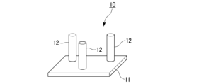
細長い異方性プリプレグにプリフォーム工程で行われるプリフォームには、相対的な配置が固定された複数のピンを有する賦形ジグにこのようなプリプレグを巻き付けて三次元形状のプリフォームを形成することが含まれ得る。図1に示す賦形ジグ10はその一例であり、プレート11と、その一方の面上に立設した3本のピン12とを有する。例えば、図2に示すように、プリプレグテープ(またはトウプリプレグ)20を、賦形ジグ10の3本のピン12の周りに張力を加えて巻き付けることにより、図3に示すプリフォーム30を形成することができる。
Preforms made in the preforming process on elongated anisotropic prepregs are formed by winding such prepregs around a shaping jig having a plurality of pins whose relative positions are fixed to form a three-dimensional preform. can be included. A shaping
図1に示す賦形ジグ10のピン12の本数と配置を変更することや、プリプレグテープ(またはトウプリプレグ)20の巻き付け方を変更することにより、様々な形状のプリフォームを形成することができる。
賦形型や賦形ジグに細長い異方性プリプレグを巻き付けるときは、多重に巻き付けてもよい。Preforms of various shapes can be formed by changing the number and arrangement of
When the elongated anisotropic prepreg is wound around the shaping mold or shaping jig, it may be wound multiple times.
カールした異方性プリプレグから三次元形状のプリフォームを形成するときは、三次元形状に変形させる前に異方性プリプレグを矯正してもよい。
プリフォーム工程では、異方性プリプレグの矯正をするとき、あるいは、異方性プリプレグから三次元形状のプリフォームを形成するときに、異方性プリプレグを他の異方性プリプレグと一体化させてもよい。
When forming a three-dimensional shaped preform from a curled anisotropic prepreg, the anisotropic prepreg may be straightened before being deformed into a three-dimensional shape.
In the preforming process, the anisotropic prepreg is integrated with other anisotropic prepregs when correcting the anisotropic prepreg or when forming a three-dimensional preform from the anisotropic prepreg . good too.
プリフォーム工程では、異方性プリプレグが容易に塑性変形するように、必要に応じて異方性プリプレグを加熱してもよい。異方性プリプレグの加熱は直接的であっても間接的であってもよく、方法は特に限定されない。すなわち、熱風や赤外線で異方性プリプレグを直接加熱してもよいし、賦形型や賦形ジグを加熱することにより異方性プリプレグを間接的に加熱してもよい。 In the preforming process, the anisotropic prepreg may be heated as necessary so that the anisotropic prepreg is easily plastically deformed. The anisotropic prepreg may be heated directly or indirectly, and the method is not particularly limited. That is, the anisotropic prepreg may be directly heated with hot air or infrared rays, or may be indirectly heated by heating a shaping mold or shaping jig.
[1.2.圧縮成形工程]
圧縮成形工程は、プリフォーム工程でプリフォームされた異方性プリプレグを、プレス金型内で、チョップド繊維プリプレグと一体的に硬化させ、異方性プリプレグに由来する整列繊維強化部とチョップド繊維プリプレグに由来するチョップド繊維強化部との境界を有する成形品を得る工程である。[1.2. Compression molding process]
In the compression molding process, the anisotropic prepreg preformed in the preforming process is integrally cured with the chopped fiber prepreg in a press mold, and the aligned fiber reinforced portion derived from the anisotropic prepreg and the chopped fiber prepreg are formed. It is a step of obtaining a molded product having a boundary with a chopped fiber reinforced portion derived from.
チョップド繊維プリプレグは、繊維トウを通常100mm以下、典型的には約50mm(約2インチ)や約25mm(約1インチ)の長さにチョップすることで得られるチョップド繊維トウ(チョップド繊維バンドルともいう)をマトリックス樹脂組成物で含浸させてなるプリプレグである。チョップド繊維プリプレグの典型例は、シートモールディングコンパウンド(SMC)とバルクモールディングコンパウンド(BMC)である。
チョップド繊維プリプレグは、異方性プリプレグに比べて、成形時の流動性に優れている。Chopped fiber prepregs are chopped fiber tows (also known as chopped fiber bundles) obtained by chopping fiber tows to a length of usually 100 mm or less, typically about 50 mm (about 2 inches) or about 25 mm (about 1 inch). ) is impregnated with a matrix resin composition. Typical examples of chopped fiber prepregs are sheet molding compound (SMC) and bulk molding compound (BMC).
Chopped fiber prepreg is superior to anisotropic prepreg in fluidity during molding.
圧縮成形工程では、例えば、図4に示す手順が実行され得る。
図4(a)はプレス金型の下金型41を示す断面図である。
図4(b)は、その下金型41内にチョップド繊維プリプレグ(SMC)51を配置したところを示す。
図4(c)は、下金型41内に更に異方性プリプレグ52を配置して、チョップド繊維プリプレグ(SMC)51の一部上に重ねたところを示す。
図4(d)は、上金型42を下ろして、チョップド繊維プリプレグ(SMC)51と異方性プリプレグ52を加熱および圧縮するところを示す。In the compression molding process, for example, the procedure shown in FIG. 4 can be performed.
FIG. 4(a) is a sectional view showing the
FIG. 4(b) shows the chopped fiber prepreg (SMC) 51 placed in the
FIG. 4( c ) shows an
FIG. 4(d) shows that the
他の一例において、圧縮成形工程では、図5および図6に示す手順が実行され得る。
図5(a)は賦形型(または賦形ジグ)61の断面図である。
図5(b)は、その賦形型(または賦形ジグ)61に異方性プリプレグ71を巻き付けてプリフォームするところを示す。プリフォームされた異方性プリプレグ71に存在するプリプレグ末端同士の境界72では、限定するものではないが、プリプレグ末端同士が重なっていてもよい。
図5(c)は、プリフォームされた異方性プリプレグ71が賦形型(または賦形ジグ)61から分離されたところである。
図6(a)は、圧縮成形工程で用いるコア81の断面図である。
図6(b)は、コア81にチョップド繊維プリプレグ(SMC)91を巻き付けてプリフォームするところを示す。プリフォームされたチョップド繊維プリプレグ(SMC)91に存在するプリプレグ末端同士の境界92では、限定するものではないが、プリプレグ末端同士が互いに付き合わされていてもよい。
図6(c)は、プリフォームされたチョップド繊維プリプレグ(SMC)91に、プリフォームされた異方性プリプレグ71を嵌合して、二次プリフォーム95を形成したところを示す。圧縮成形工程では、二次プリフォーム95をコア81ごとプレス金型の中に入れて、加熱および圧縮する。In another example, the compression molding process can perform the steps shown in FIGS.
FIG. 5(a) is a sectional view of a shaping die (or shaping jig) 61. FIG.
FIG. 5(b) shows a preform by winding an
5(c) shows the preformed
FIG. 6(a) is a cross-sectional view of a core 81 used in the compression molding process.
FIG. 6(b) shows the core 81 being preformed by winding a chopped fiber prepreg (SMC) 91 around it. Pre-preg end-to-
FIG. 6( c ) shows a preformed chopped fiber prepreg (SMC) 91 fitted with a preformed
圧縮成形の条件は、FRP製品の圧縮成形で従来から使用されている条件を参照することができ、限定するものではないが、成形温度は、例えば、100℃~200℃、成形圧力は、例えば、1MPa~10MPa、成形時間は、例えば、1分間~20分間である。 The compression molding conditions can refer to the conditions conventionally used in compression molding of FRP products, and are not limited, but the molding temperature is, for example, 100° C. to 200° C., and the molding pressure is, for example, , 1 MPa to 10 MPa, and the molding time is, for example, 1 minute to 20 minutes.
[1.3.異方性プリプレグの予備硬化]
圧縮成形工程の前に異方性プリプレグを予備硬化する目的は、事前に硬化反応(ゲル化)を進めておくことで圧縮成形工程における異方性プリプレグの流動を抑制し、それによって、得られる圧縮成形品の整列繊維強化部における繊維配列の乱れを抑制することにある。異方性プリプレグの予備硬化がされていなければ、プレス金型内に異方性プリプレグと共に装填されたチョップド繊維プリプレグが流動するときに、一緒になって異方性プリプレグが流動し、異方性プリプレグを構成する繊維の配向が乱れることになる。[1.3. Pre-curing of anisotropic prepreg]
The purpose of pre-curing the anisotropic prepreg before the compression molding process is to advance the curing reaction (gelation) in advance to suppress the flow of the anisotropic prepreg in the compression molding process, thereby obtaining An object of the present invention is to suppress disorder of fiber arrangement in an aligned fiber reinforced portion of a compression-molded product. If the anisotropic prepreg is not precured, when the chopped fiber prepreg loaded with the anisotropic prepreg in the press die flows, the anisotropic prepreg will flow together and the anisotropic The orientation of the fibers constituting the prepreg is disturbed.
予備硬化は異方性プリプレグを加熱することにより行われる。
予備硬化の条件を設定するにあたり指標として有用なのが、下記式(1)で定義される硬化度である。Precuring is performed by heating the anisotropic prepreg.
The degree of cure defined by the following formula (1) is useful as an index for setting the pre-curing conditions.

上記式(1)において、総発熱量および残余発熱量は、それぞれ、示差走査熱量測定(DSC)において試料を窒素雰囲気下、室温(25℃)から300℃まで10℃/minで昇温したときの発熱量である。
総発熱量は、プリフォーム工程の開始直前において異方性プリプレグが示す発熱量である。これは、プリフォーム工程の開始直前段階にある異方性プリプレグが、完全に硬化するまでの間に放出する熱量に相当する。
残余発熱量は、プリフォーム工程開始後のある時点において異方性プリプレグが示す発熱量であり、その時点から完全に硬化するまでの間に異方性プリプレグが放出する熱量に相当する。
要するに、本明細書にいう硬化度は、プリフォーム工程の開始直前の状態を0%、完全硬化した状態を100%としたときに、異方性プリプレグの硬化がどの程度まで進んでいるかを表している。In the above formula (1), the total calorific value and the residual calorific value are each measured by differential scanning calorimetry (DSC) when the sample is heated from room temperature (25°C) to 300°C at a rate of 10°C/min under a nitrogen atmosphere. is the calorific value of
The gross calorific value is the calorific value exhibited by the anisotropic prepreg immediately before the start of the preforming process. This corresponds to the amount of heat released by the anisotropic prepreg in the stage just before the start of the preforming process until it is completely cured.
The residual calorific value is the calorific value exhibited by the anisotropic prepreg at a certain point after the start of the preforming process, and corresponds to the calorific value emitted by the anisotropic prepreg from that point until it is completely cured.
In short, the degree of curing referred to in this specification represents how far the curing of the anisotropic prepreg progresses when the state immediately before the start of the preforming process is 0% and the completely cured state is 100%. ing.
後述する実験結果が示すように、圧縮成形工程の前に加熱処理で硬化度を6%とした異方性プリプレグを、チョップド繊維プリプレグとプレス金型内で一体的に硬化させたところ、得られた圧縮成形品において、整列繊維強化部における繊維配列乱れの抑制が認められた。
この実験で異方性プリプレグの硬化度を6%まで進めるには、80℃で2.5時間の加熱が必要だったことからすると、従来技術において異方性プリプレグをプリフォームするときに、Bステージにあるマトリックス樹脂を軟化させることを目的として行われる加温には、予備硬化としての働きは無いといってよい。かかる加温では、通常、表面温度が80℃を超えないように、加熱時間が1分以下とされるので、それによって異方性プリプレグの硬化度は実質的に変化しない。As shown by the experimental results to be described later, when the anisotropic prepreg whose degree of cure was 6% by heat treatment before the compression molding process was integrally cured with the chopped fiber prepreg in the press mold, In the compression-molded product, suppression of fiber arrangement disorder in the aligned fiber reinforced part was observed.
Considering that heating at 80° C. for 2.5 hours was required to advance the degree of curing of the anisotropic prepreg to 6% in this experiment, B It can be said that the heating performed for the purpose of softening the matrix resin in the stage does not function as pre-curing. In such heating, the heating time is generally set to 1 minute or less so that the surface temperature does not exceed 80° C., so that the hardening degree of the anisotropic prepreg does not substantially change.
プリフォーム工程で行われ得る切断加工は、通常、異方性プリプレグの硬化度に実質的な影響を与えない。従って、例えば、プリフォーム工程で異方性プリプレグに行われる最初の加工が切断加工のときには、切断加工の直後に測定した異方性プリプレグの発熱量を、総発熱量として取り扱ってもよい。 Cutting operations that may occur in the preform process typically do not substantially affect the degree of hardening of the anisotropic prepreg . Therefore, for example, when the first processing performed on the anisotropic prepreg in the preforming process is the cutting processing, the calorific value of the anisotropic prepreg measured immediately after the cutting processing may be treated as the total calorific value.
予備硬化としての加熱処理は、圧縮成形工程の直前における異方性プリプレグの硬化度が6%以上となるように行うことが好ましい。
マトリックス樹脂の組成が異なれば、同じ加熱処理により到達する異方性プリプレグの硬化度は異なり得るが、傾向として、加熱処理の温度が高い程、また、時間が長い程、プリプレグの硬化度は高くなる。従って、加熱処理の条件を変えた試作を何回か行い、結果をフィードバックすることで、異方性プリプレグが望ましい硬化度となる予備硬化の条件を容易に設定することができる。The heat treatment as pre-curing is preferably performed so that the degree of curing of the anisotropic prepreg immediately before the compression molding process is 6% or more.
If the composition of the matrix resin is different, the degree of curing of the anisotropic prepreg achieved by the same heat treatment may differ. However, the tendency is that the higher the temperature and the longer the time of the heat treatment, the higher the degree of curing of the prepreg. Become. Therefore, it is possible to easily set the pre-curing conditions that provide the desired degree of curing of the anisotropic prepreg by performing trial production several times with different heat treatment conditions and feeding back the results.
本発明者等が行った実験によれば、圧縮成形工程の開始直前における異方性プリプレグの硬化度は、より好ましくは18%以上、更に好ましくは36%以上である。異方性プリプレグの予備硬化が、圧縮成形品における整列繊維強化部とチョップド繊維強化部との接合強度に与える影響は大きいものではない。後述する実験結果が示すように、圧縮成形工程の開始直前における異方性プリプレグの硬化度が94%のときに、異方性プリプレグとチョップド繊維プリプレグとは好ましく一体成形することが可能だった。 According to experiments conducted by the present inventors, the hardening degree of the anisotropic prepreg immediately before the start of the compression molding process is more preferably 18% or more, and still more preferably 36% or more. The pre-curing of the anisotropic prepreg does not have a large effect on the bonding strength between the aligned-fiber-reinforced portion and the chopped-fiber-reinforced portion in the compression-molded product. As shown by the experimental results described later, it was possible to preferably integrally mold the anisotropic prepreg and the chopped fiber prepreg when the hardening degree of the anisotropic prepreg was 94% immediately before the start of the compression molding process.
予備硬化は、例えば、プリフォーム工程において異方性プリプレグを矯正するとき、または、プリフォーム工程において異方性プリプレグから三次元形状のプリフォームを形成するときに、同時に行うことができる。
例えば、カールした異方性プリプレグシートを2枚のプレートで挟んだ状態に保持して矯正するときの、プレートの温度と保持時間を適宜設定することで、矯正後の異方性プリプレグシートの硬化度を6%以上の任意の値とすることができる。
あるいは、カールした一方向プリプレグテープまたはトウプリプレグを矯正するために、張力を加えた状態で熱風または赤外線による加熱処理をすることができるが、そのときの温度と時間を適宜設定することで、矯正後の一方向プリプレグテープまたはトウプリプレグの硬化度を6%以上の任意の値とすることができる。Precuring can be performed simultaneously, for example, when straightening the anisotropic prepreg in the preforming process, or when forming a three-dimensional shaped preform from the anisotropic prepreg in the preforming process.
For example, when a curled anisotropic prepreg sheet is sandwiched between two plates and straightened, by appropriately setting the plate temperature and holding time, the anisotropic prepreg sheet after straightening can be hardened. degree can be any value of 6% or more.
Alternatively, in order to straighten the curled unidirectional prepreg tape or tow prepreg, heat treatment with hot air or infrared rays can be performed under tension. The degree of cure of the subsequent unidirectional prepreg tape or tow prepreg can be any value above 6%.
他の例では、異方性プリプレグを賦形型に押し付けて保持すること、または、賦形型または賦形ジグに巻き付けて保持することによって変形させ、3次元形状のプリフォームを形成するときに、賦形型または賦形ジグごと異方性プリプレグを熱風オーブンに入れ、保持温度と保持時間を適宜設定することにより、異方性プリプレグの硬化度を6%以上の任意の値とすることができる。 In other examples, when deforming an anisotropic prepreg by pressing and holding it against a shaping die or by wrapping and holding it around a shaping die or shaping jig to form a three-dimensional shaped preform, By placing the anisotropic prepreg together with the shaping mold or shaping jig in a hot air oven and appropriately setting the holding temperature and holding time, it is possible to set the degree of hardening of the anisotropic prepreg to an arbitrary value of 6% or more. can.
予備硬化のための加熱処理は、プリフォーム工程の終了後に行われてもよい。例えば、カールの矯正が行われた後、矯正に用いられたジグから取り外された異方性プリプレグに予備硬化のための加熱処理をしてもよい。あるいは、賦形型または賦形ジグを用いて3次元形状のプリフォームが形成された後、プリフォームをジグから取り外して、予備硬化のための加熱処理をしてもよい。
プリフォーム工程で異方性プリプレグに対しなされる加工が、切断加工のみであってもよいことは勿論である。
予備硬化のための加熱処理は、複数回に分けて行ってもよい。例えば、プリフォーム工程において加熱処理をした異方性プリプレグに対する追加の加熱処理を、プリフォーム工程の終了後に行ってもよい。A heat treatment for pre-curing may be performed after the preforming process is completed. For example, after the curl is straightened, the anisotropic prepreg removed from the jig used for straightening may be heat-treated for pre-curing. Alternatively, after a three-dimensional preform is formed using a shaping mold or shaping jig, the preform may be removed from the jig and subjected to heat treatment for pre-curing.
It goes without saying that the processing performed on the anisotropic prepreg in the preforming process may be only cutting.
The heat treatment for pre-curing may be performed in multiple steps. For example, the anisotropic prepreg heat-treated in the preforming process may be additionally heat-treated after the preforming process.
本発明者等による実験によれば、異方性プリプレグの予備硬化に基づく、成形品の整列繊維強化部における繊維配列の乱れ抑制効果は、圧縮成形工程の開始直前における異方性プリプレグの硬化度が36%程度を超えると飽和に向かう傾向が見られた。加えて、異方性プリプレグを加熱処理したときの硬化度の経時変化を調べると、硬化度は最初緩やかに増加した後、5~6%に達すると急激に立ち上がり、60%を超えると再度緩やかな増加に転じる傾向があることが判った。
従って、生産効率の観点からは、圧縮成形工程の開始直前における異方性プリプレグの硬化度は、好ましくは60%以下であり、製造しようとする成形品において必要十分な結果が得られるならば、50%以下、更には40%以下、更には30%以下、更には20%以下、更には10%以下であってもよい。According to experiments by the present inventors, the effect of suppressing the disturbance of the fiber arrangement in the aligned fiber reinforced part of the molded product based on the pre-curing of the anisotropic prepreg is the degree of curing of the anisotropic prepreg immediately before the start of the compression molding process. A tendency towards saturation was observed when the .sup.2 exceeds about 36%. In addition, when the anisotropic prepreg was heat-treated, the change in the degree of hardening over time was examined. The degree of hardening gradually increased at first, then rose sharply when it reached 5 to 6%, and slowed down again when it exceeded 60%. It was found that there was a trend toward a sharp increase.
Therefore, from the viewpoint of production efficiency, the degree of cure of the anisotropic prepreg immediately before the start of the compression molding process is preferably 60% or less. It may be 50% or less, further 40% or less, further 30% or less, further 20% or less, furthermore 10% or less.
前述した圧縮成形工程の開始直前における異方性プリプレグの硬化度の下限値と上限値は任意に組み合わせることができる。例えば、圧縮成形工程の開始直前における異方性プリプレグの硬化度は6~94%であり、6~60%、6~50%、6~40%、6~30%、6~20%、6~10%であってもよく、18~94%、18~60%、18~50%、18~40%、18~30%、18~20%であってもよく、36~94%、36~60%、36~50%、36~40%であってもよい。 The lower limit and upper limit of the hardening degree of the anisotropic prepreg immediately before the start of the compression molding process described above can be arbitrarily combined. For example, the degree of cure of the anisotropic prepreg just before the start of the compression molding process is 6-94%, 6-60%, 6-50%, 6-40%, 6-30%, 6-20%, 6-20%, ~10%, 18-94%, 18-60%, 18-50%, 18-40%, 18-30%, 18-20%, 36-94%, 36 It may be ~60%, 36-50%, 36-40%.
[2.FRP製品の形状]
実施形態に係るFRP製品の製造方法は、三次元形状を有するFRP製品の製造に好ましく用いることができる。
実施形態に係るFRP製品の製造方法で製造されるFRP製品の好ましい一例において、整列繊維強化部は、製品の表面の一部に、整列繊維強化部に含まれる繊維が製品の表面と平行となるように配置される。特に、表面に稜線を有するFRP製品においては、繊維が一方向に配向した整列繊維強化部が、繊維の配向方向を稜線と平行にして、稜線の全部または一部に沿って配置されることが好ましい。
図7は、実施形態に係るFRP製品の製造方法で製造されるFRP製品の一例を示す斜視図である。図7に示すFRP製品100は、直方体であり、直方体の各面(六面)を構成するチョップド繊維強化部101と、直方体の稜線に沿って配置された整列繊維強化部102とを有する。整列繊維強化部102において、繊維の方向は稜線に平行である。[2. Shape of FRP product]
The FRP product manufacturing method according to the embodiment can be preferably used for manufacturing an FRP product having a three-dimensional shape.
In a preferred example of the FRP product manufactured by the FRP product manufacturing method according to the embodiment, the aligned fiber reinforced portion is part of the surface of the product, and the fibers contained in the aligned fiber reinforced portion are parallel to the surface of the product. are arranged as follows. In particular, in FRP products having ridgelines on the surface, aligned fiber reinforcements in which fibers are oriented in one direction may be arranged along all or part of the ridgelines with the orientation direction of the fibers parallel to the ridgelines. preferable.
FIG. 7 is a perspective view showing an example of an FRP product manufactured by the FRP product manufacturing method according to the embodiment. The
[3.実験結果]
本発明者等が行った実験の結果を以下に記す。
実験で使用したプリプレグは下記表1に記す通りである。[3. Experimental result]
The results of experiments conducted by the inventors are described below.
The prepregs used in the experiment are as shown in Table 1 below.

トウプリプレグは、フィラメント数50000の炭素繊維トウ(三菱ケミカル社製パイロフィル(登録商標)TRW40 50L)をスプレッド(開繊)したうえ、メルト法によりエポキシ樹脂で含浸させる方法で作製した。作製したトウプリプレグは、幅が12.7mm、最大厚が0.3mmで、樹脂含有量は38%であった。
いずれの実験でも、異方性プリプレグの硬化度を求めるための発熱量測定には、TAインスツルメント社製の示差走査型熱量分析(DSC)装置Q-1000を用いた。
DSCでは、5mg~10mgの試料を、窒素雰囲気下で室温(25℃)から300℃まで10℃/分で昇温させた。
DSCの試料は、プリプレグテープまたはトウプリプレグの一方端に近い3つの箇所で採取し、各試料で測定した発熱量を平均した値を、そのプリプレグテープまたはトウプリプレグの発熱量とした。The tow prepreg was prepared by spreading (opening) a carbon fiber tow (Pyrofil (registered trademark) TRW40 50L manufactured by Mitsubishi Chemical Corporation) having a filament number of 50,000 and then impregnating the spread with an epoxy resin by a melt method. The tow prepreg produced had a width of 12.7 mm, a maximum thickness of 0.3 mm and a resin content of 38%.
In all experiments, a differential scanning calorimeter (DSC) Q-1000 manufactured by TA Instruments was used to measure the amount of heat generated to determine the degree of curing of the anisotropic prepreg.
In the DSC, a 5-10 mg sample was heated from room temperature (25° C.) to 300° C. at 10° C./min under a nitrogen atmosphere.
DSC samples were taken at three points near one end of the prepreg tape or tow prepreg, and the average value of the calorific value measured for each sample was taken as the calorific value of the prepreg tape or tow prepreg.
[実験1]
樹脂含有量30%の一方向プリプレグシート(三菱ケミカル社製パイロフィル(登録商標)TR361E250S)から、繊維方向を長手方向とする長さ285mm、幅25mm、厚さ0.2mmのプリプレグテープを切り出し、熱風オーブンに入れて80℃で4時間保持した。熱処理後のプリプレグテープの硬化度は19%であった。
熱処理したプリプレグテープを、295mm角に裁断した厚さ2mmのSMCとともに、プレス金型(下型)のキャビティ内に装填した。
図8(a)(平面図)および(b)(断面図)に示すように、SMC201はプレス金型300のキャビティ301の底面上に平置きし、プリプレグテープ202はSMC201の上面に、長手方向がSMC201の対向する2辺と平行となるように配置した。
プレス金型300のキャビティ底面は300mm角であったので、SMCの面積をキャビティの底面積で除算したSMCチャージ率は93%であった。[Experiment 1]
A prepreg tape with a length of 285 mm, a width of 25 mm, and a thickness of 0.2 mm was cut out from a unidirectional prepreg sheet (Pyrofil (registered trademark) TR361E250S manufactured by Mitsubishi Chemical Corporation) with a resin content of 30%, and the fiber direction was the longitudinal direction. It was placed in an oven and held at 80° C. for 4 hours. The degree of cure of the prepreg tape after heat treatment was 19%.
The heat-treated prepreg tape was loaded into the cavity of a press mold (lower mold) together with 2 mm thick SMC cut into 295 mm squares.
As shown in FIGS. 8(a) (plan view) and (b) (cross-sectional view), the
Since the bottom surface of the cavity of the press die 300 was 300 mm square, the SMC charge rate obtained by dividing the area of the SMC by the bottom area of the cavity was 93%.
SMC201とプリプレグテープ202を、圧力4MPa、温度140℃、硬化時間5分の条件で一体的に硬化させて、図9(a)(平面図)および(b)(断面図)に示す、チョップド繊維強化部401の表面と整列繊維強化部402の表面が同一面上にある、300mm角、厚さ2mmの板である圧縮成形品400を得た。
The
得られた圧縮成形品400において、整列繊維強化部402の一方端における幅方向の中点(図9(a)に示す点P)と他方端における幅方向の中点(図9(a)に示す点Q)とを結ぶ線分PQの方向を基準方向としたとき、整列繊維強化部402には繊維の方向が基準方向からずれている部分が視認できた。かかる部分における繊維のずれ角(繊維が基準方向となす角度)は、整列繊維強化部402内において最大6°であった。
In the obtained compression-molded
[実験2]
プリプレグテープの熱処理における加熱時間(80℃保持時間)を5時間としたこと以外は実験1と同様にして、圧縮成形品を作製した。熱処理後のプリプレグテープの硬化度は48%だった。
圧縮成形品の整列繊維強化部には、繊維の方向が基準方向からずれている部分が認められなかった。すなわち、整列繊維強化部内において、繊維のずれ角は、0°であった。[Experiment 2]
A compression-molded product was produced in the same manner as in Experiment 1, except that the heating time (holding time at 80° C.) in the heat treatment of the prepreg tape was set to 5 hours. The degree of cure of the prepreg tape after heat treatment was 48%.
In the aligned fiber reinforced portion of the compression molded product, no portion where the direction of the fibers deviated from the reference direction was observed. That is, the deviation angle of the fibers was 0° in the aligned fiber reinforced portion.
[実験3]
プリプレグテープに代えて、長さ285mmに切断したトウプリプレグを用いたことと、トウプリプレグの熱処理における加熱時間(80℃保持時間)を2.5時間としたこと以外は、実験1と同様にして圧縮成形品を作製した。熱処理後のトウプリプレグの硬化度は6%だった。
圧縮成形品の整列繊維強化部には、繊維の方向が基準方向からずれている部分が認められた。整列繊維強化部内において、繊維のずれ角の最大値は6°であった。[Experiment 3]
Experiment 1 was conducted in the same manner as in Experiment 1, except that tow prepreg cut to a length of 285 mm was used instead of the prepreg tape, and the heating time (holding time at 80°C) in the heat treatment of the tow prepreg was set to 2.5 hours. A compression molded product was produced. The degree of hardening of the tow prepreg after heat treatment was 6%.
In the aligned fiber reinforced part of the compression molded product, a portion where the direction of the fibers deviated from the reference direction was observed. The maximum deviation angle of the fibers within the aligned fiber reinforcement was 6°.
[実験4]
一方向プリプレグシートから切り出したプリプレグテープに代えて、長さ285mmに切断したトウプリプレグを用いたことと、トウプリプレグの熱処理における加熱時間(80℃保持時間)を3時間としたこと以外は、実験1と同様にして圧縮成形品を作製した。熱処理後のトウプリプレグの硬化度は18%だった。
圧縮成形品の整列繊維強化部には、繊維の方向が基準方向からずれている部分が認められた。整列繊維強化部内において、繊維のずれ角の最大値は5°であった。[Experiment 4]
Except for using a tow prepreg cut to a length of 285 mm instead of the prepreg tape cut out from the unidirectional prepreg sheet and setting the heating time (holding time at 80 ° C.) in the heat treatment of the tow prepreg to 3 hours, the experiment A compression-molded product was produced in the same manner as in 1. The degree of cure of the tow prepreg after heat treatment was 18%.
In the aligned fiber reinforced part of the compression molded product, a portion where the direction of the fibers deviated from the reference direction was observed. The maximum deviation angle of the fibers within the aligned fiber reinforcement was 5°.
[実験5]
トウプリプレグの熱処理における加熱時間(80℃保持時間)を3.5時間としたこと以外は、実験3と同様にして圧縮成形品を作製した。熱処理後のトウプリプレグの硬化度は36%だった。
圧縮成形品の整列繊維強化部には、繊維の方向が基準方向からずれている部分が認められなかった。すなわち、整列繊維強化部内において、繊維のずれ角は、0°であった。[Experiment 5]
A compression-molded product was produced in the same manner as in Experiment 3, except that the heating time (holding time at 80° C.) in the heat treatment of the tow prepreg was set to 3.5 hours. The degree of cure of the tow prepreg after heat treatment was 36%.
In the aligned fiber reinforced portion of the compression molded product, no portion where the direction of the fibers deviated from the reference direction was observed. That is, the deviation angle of the fibers was 0° in the aligned fiber reinforced portion.
[比較実験1]
プリプレグテープの熱処理を行わなかったこと以外は、実験1と同様にして圧縮成形品を作製した。
圧縮成形品の整列繊維強化部には、繊維の方向が基準方向からずれている部分が認められた。整列繊維強化部内において、繊維のずれ角の最大値は12°であった。[Comparative experiment 1]
A compression-molded product was produced in the same manner as in Experiment 1, except that the prepreg tape was not heat-treated.
In the aligned fiber reinforced part of the compression molded product, a portion where the direction of the fibers deviated from the reference direction was observed. The maximum deviation angle of the fibers in the aligned fiber reinforcement was 12°.
[比較実験2]
トウプリプレグを熱処理しなかったこと以外は、実験3と同様にして圧縮成形品を作製した。
圧縮成形品の整列繊維強化部には、繊維の方向が基準方向からずれている部分が認められた。整列繊維強化部内において、繊維のずれ角の最大値は9°であった。[Comparative experiment 2]
A compression molded article was made in the same manner as in Experiment 3, except that the tow prepreg was not heat treated.
In the aligned fiber reinforced part of the compression molded product, a portion where the direction of the fibers deviated from the reference direction was observed. The maximum deviation angle of the fibers in the aligned fiber reinforcement was 9°.
実験1~実験5並びに比較実験1および比較実験2の結果を、表2および表3に示す。 The results of Experiments 1 to 5 and Comparative Experiments 1 and 2 are shown in Tables 2 and 3.


[実験6]
予備硬化した異方性プリプレグをチョップド繊維プリプレグと一体的に硬化させた圧縮成形品における、整列繊維強化部とチョップド繊維強化部の界面の接合強度を評価するための実験を行った。
まず、プリプレグシートから切り出した、繊維方向を長手方向とする長さ75mm、幅25mm、厚さ0.2mmのストリップを10枚重ね、真空デバルクにより互いに密着させて積層体とした。この積層体を、熱風オーブンに入れて80℃で8時間保持することで、上記10枚のストリップが一体化してなる厚いストリップを得た。この厚いストリップの硬化度は94%であった。
次いで、図10(a)に断面図を示すように、厚いストリップ501の一部に耐熱テープ502を巻き付けて、厚いストリップ501の一方の端部501Aのみを所定の面積だけ露出させた。[Experiment 6]
An experiment was conducted to evaluate the bonding strength at the interface between the aligned fiber reinforced portion and the chopped fiber reinforced portion in a compression molded product obtained by integrally curing a precured anisotropic prepreg and a chopped fiber prepreg.
First, 10 strips each having a length of 75 mm, a width of 25 mm, and a thickness of 0.2 mm, which were cut out from the prepreg sheet and whose longitudinal direction is the fiber direction, were stacked and adhered to each other by vacuum debulking to form a laminate. This laminate was placed in a hot air oven and held at 80° C. for 8 hours to obtain a thick strip formed by integrating the 10 strips. The degree of cure of this thick strip was 94%.
Then, as shown in the cross-sectional view of FIG. 10(a), a part of the
更に、図10(b)に断面図を示すように、厚いストリップ501の該一方の端部501A側を、それぞれが2mm厚で長さ70mm、幅28mmにカットされた2枚のSMC503で挟んだ後、140℃~150℃、5分間の条件でプレス成形することにより、図10(c)に示す、整列繊維強化部601とチョップド繊維強化部603とを有する試験片600を作製した。
整列繊維強化部601は厚いストリップ501が硬化してなる部位であり、チョップド繊維強化部603はSMC503が硬化してなる部位である。Furthermore, as shown in the cross-sectional view of FIG. 10(b), the one
Aligned fiber reinforced
インストロン社製の万能試験機4482型を用いて引張試験を行うことにより、試験片600における整列繊維強化部601とチョップド繊維強化部603の界面の強度を評価した。引張試験には、荷重容量100kNのロードセルを使用し、引張速度は0.5mm/minとした。試験片の破壊は、整列繊維強化部601とチョップド繊維強化部603の界面で生じた。破壊時の荷重と、整列繊維強化部とチョップド繊維強化部との接触面積から求めた界面のシェア強度は17(N/mm2)であった。The strength of the interface between the aligned fiber reinforced
[比較実験3]
熱処理したプリプレグからなる厚いストリップに代えて、熱処理していないプリプレグテープをSUS304製金属ストリップに巻き付けたものを用いたこと以外は、実験6で作製した試験片と同様にして、比較用試験片を作製した。
プリプレグテープは、プリプレグシートから繊維方向が長手方向となるように切り出したもので、幅25mmであった。金属ストリップは、長さ75mm、幅28mm、厚さ2mmであった。
プリプレグテープを巻き付けるときは、その繊維方向が金属ストリップの長手方向と平行となるようにした。
耐熱テープを巻き付けるときは、比較試験片における整列繊維強化部とチョップド繊維強化部との界面の面積が、実験6の試験片のそれと同じとなるようにした。
実験6と同様にして引張試験を行った結果、比較試験片においても整列繊維強化部とチョップド繊維強化部の界面で破壊が生じた。破壊時の荷重と、整列繊維強化部とチョップド繊維強化部との接触面積から求めた界面のシェア強度は16.7(N/mm2)で、実験6の試験片と略同等であった。
この結果は、予備硬化により異方性プリプレグの硬化度を94%まで高めたときであっても、異方性プリプレグとチョップド繊維プリプレグを一体的に硬化させて得られる圧縮成形品において、整列繊維強化部とチョップド繊維強化部の界面の強度は十分に確保されることを示している。
[Comparative experiment 3]
A comparative test piece was prepared in the same manner as the test piece prepared in Experiment 6, except that instead of using a thick strip made of heat-treated prepreg, an unheat-treated prepreg tape was wrapped around a SUS304 metal strip. made.
The prepreg tape was cut from a prepreg sheet so that the fiber direction was the longitudinal direction, and had a width of 25 mm. The metal strip was 75 mm long, 28 mm wide and 2 mm thick.
When the prepreg tape was wound, its fiber direction was parallel to the longitudinal direction of the metal strip.
When the heat-resistant tape was wound, the area of the interface between the aligned fiber reinforced portion and the chopped fiber reinforced portion in the comparative test piece was made the same as that of the test piece in Experiment 6.
A tensile test was performed in the same manner as in Experiment 6. As a result, even in the comparative test piece, fracture occurred at the interface between the aligned-fiber-reinforced portion and the chopped-fiber-reinforced portion. The interface shear strength obtained from the load at break and the contact area between the aligned fiber reinforced portion and the chopped fiber reinforced portion was 16.7 (N/mm 2 ), which was substantially the same as the test piece of Experiment 6.
This result shows that even when the degree of hardening of the anisotropic prepreg is increased to 94% by pre-curing, the alignment fibers in the compression-molded product obtained by integrally curing the anisotropic prepreg and the chopped fiber prepreg are This indicates that sufficient strength is ensured at the interface between the reinforced portion and the chopped fiber reinforced portion.
本発明に係るFRP製品の製造方法は、輸送機器や産業機器に用いられるFRP部品の製造に用いることができる他、FRP製のスポーツ用品やレジャー用品の製造にも使用できる。本発明に係るFRP製品の製造方法は、特に、FRP製自動車部品の製造に適している。 The method for manufacturing an FRP product according to the present invention can be used for manufacturing FRP parts used in transportation equipment and industrial equipment, and can also be used for manufacturing FRP sporting goods and leisure goods. The FRP product manufacturing method according to the present invention is particularly suitable for manufacturing FRP automotive parts.
10 賦形ジグ
11 プレート
12 ピン
20 プリプレグテープ(またはトウプリプレグ)
30 プリフォーム
41 下金型
42 上金型
51 チョップド繊維プリプレグ
52 異方性プリプレグ
61 賦形ジグ
71 異方性プリプレグ
81 コア
91 チョップド繊維プリプレグ
95 二次プリフォーム
100 FRP製品
101 チョップド繊維強化部
102 整列繊維強化部
201 SMC
202 プリプレグテープ
300 プレス金型(下型)
301 キャビティ
400 圧縮成形品
401 チョップド繊維強化部
402 整列繊維強化部
501 厚いストリップ
502 耐熱テープ
503 SMC
600 試験片
601 整列繊維強化部
603 チョップド繊維強化部10 shaping
30
202
301
600
Claims (16)
(ii)前記プリフォーム工程でプリフォームされた異方性プリプレグをプレス金型内でチョップド繊維プリプレグと一体的に硬化させ、前記異方性プリプレグに由来する整列繊維強化部と前記チョップド繊維プリプレグに由来するチョップド繊維強化部との境界を有する成形品を得る圧縮成形工程と、を含み、
前記プリフォーム工程の開始以後、前記圧縮成形工程の前に前記異方性プリプレグが予備硬化されることにより、前記圧縮成形工程で得られる前記成形品の前記整列繊維強化部において繊維配列の乱れが抑制される、FRP製品の製造方法。 (i) a step of preforming an anisotropic prepreg that is a uniaxial prepreg containing an epoxy resin , wherein the anisotropic prepreg is straightened, and a three-dimensional preform is formed from the anisotropic prepreg; a preforming step including at least one of forming ;
(ii) The anisotropic prepreg preformed in the preforming step is integrally cured with the chopped fiber prepreg in a press mold, and the aligned fiber reinforced portion derived from the anisotropic prepreg and the chopped fiber prepreg a compression molding step to obtain a molded article bounded by the chopped fiber reinforcement from which it originates;
After the preforming step is started, the anisotropic prepreg is precured before the compression molding step, so that the fiber arrangement is not disturbed in the aligned fiber reinforced portion of the molded product obtained in the compression molding step. A method for manufacturing a restrained FRP product.
ただし、前記硬化度は下記式(1)で定義される硬化度である。

However, the said hardening degree is a hardening degree defined by following formula (1).
(ii)前記プリフォーム工程でプリフォームされた異方性プリプレグをプレス金型内でチョップド繊維プリプレグと一体的に硬化させ、前記異方性プリプレグに由来する整列繊維強化部と前記チョップド繊維プリプレグに由来するチョップド繊維強化部との境界を有する成形品を得る圧縮成形工程と、を含み、
前記プリフォーム工程の開始直前を0%としたときの前記異方性プリプレグの硬化度が、前記圧縮成形工程の開始直前において6%以上である、FRP製品の製造方法。
ただし、前記硬化度は下記式(1)で定義される硬化度である。

(ii) The anisotropic prepreg preformed in the preforming step is integrally cured with the chopped fiber prepreg in a press mold, and the aligned fiber reinforced portion derived from the anisotropic prepreg and the chopped fiber prepreg a compression molding step to obtain a molded article bounded by the chopped fiber reinforcement from which it originates;
A method for manufacturing an FRP product, wherein the degree of hardening of the anisotropic prepreg is 6% or more immediately before the compression molding process when the hardening degree immediately before the start of the preforming process is set to 0%.
However, the said hardening degree is a hardening degree defined by following formula (1).
Applications Claiming Priority (5)
| Application Number | Priority Date | Filing Date | Title |
|---|---|---|---|
| JP2019151942 | 2019-08-22 | ||
| JP2019151942 | 2019-08-22 | ||
| JP2020039300 | 2020-03-06 | ||
| JP2020039300 | 2020-03-06 | ||
| PCT/JP2020/031393 WO2021033740A1 (en) | 2019-08-22 | 2020-08-20 | Frp product manufacturing method |
Publications (3)
| Publication Number | Publication Date |
|---|---|
| JPWO2021033740A1 JPWO2021033740A1 (en) | 2021-02-25 |
| JPWO2021033740A5 JPWO2021033740A5 (en) | 2022-03-17 |
| JP7222430B2 true JP7222430B2 (en) | 2023-02-15 |
Family
ID=74661152
Family Applications (1)
| Application Number | Title | Priority Date | Filing Date |
|---|---|---|---|
| JP2021540979A Active JP7222430B2 (en) | 2019-08-22 | 2020-08-20 | FRP product manufacturing method |
Country Status (5)
| Country | Link |
|---|---|
| US (1) | US20220168974A1 (en) |
| EP (1) | EP4019223A4 (en) |
| JP (1) | JP7222430B2 (en) |
| CN (1) | CN114269547A (en) |
| WO (1) | WO2021033740A1 (en) |
Families Citing this family (1)
| Publication number | Priority date | Publication date | Assignee | Title |
|---|---|---|---|---|
| JP7468804B2 (en) | 2021-12-23 | 2024-04-16 | Dic株式会社 | Sheet molding compound and its manufacturing method |
Citations (4)
| Publication number | Priority date | Publication date | Assignee | Title |
|---|---|---|---|---|
| JP2009083441A (en) | 2007-10-03 | 2009-04-23 | Mitsubishi Rayon Co Ltd | Manufacturing method of fiber-reinforced resin structure |
| JP2014108612A (en) | 2012-12-04 | 2014-06-12 | Ehime Univ | Analysis method in molding carbon fiber reinforced plastic, and analyzer |
| WO2017073460A1 (en) | 2015-10-27 | 2017-05-04 | 東レ株式会社 | Nicked prepreg, cross-ply laminate, and nicked prepreg production method |
| WO2018147324A1 (en) | 2017-02-09 | 2018-08-16 | 東レ株式会社 | Preform element, preform using same, and method for producing same |
Family Cites Families (13)
| Publication number | Priority date | Publication date | Assignee | Title |
|---|---|---|---|---|
| JPS6482920A (en) * | 1987-09-24 | 1989-03-28 | Mazda Motor | Manufacture of arm member of frp |
| JPH09109167A (en) * | 1995-10-16 | 1997-04-28 | Hitachi Chem Co Ltd | Manufacture of fiber reinforced plastic molded product |
| US6893733B2 (en) * | 2000-07-07 | 2005-05-17 | Delphi Technologies, Inc. | Modified contoured crushable structural members and methods for making the same |
| JP2004338270A (en) * | 2003-05-16 | 2004-12-02 | Mitsubishi Rayon Co Ltd | Method for producing fiber-reinforced resin composite material and fiber-reinforced resin composite material |
| US8263205B2 (en) * | 2009-09-17 | 2012-09-11 | Hexcel Corporation | Method of molding complex composite parts using pre-plied multi-directional continuous fiber laminate |
| JP4973745B2 (en) * | 2010-02-01 | 2012-07-11 | トヨタ自動車株式会社 | Method for forming continuous fiber prepreg |
| US9505177B2 (en) * | 2010-12-02 | 2016-11-29 | Toray Industries, Inc. | Method for producing a metal composite |
| JP6369178B2 (en) * | 2014-07-07 | 2018-08-08 | 三菱ケミカル株式会社 | Preform manufacturing method, fiber-reinforced thermosetting resin molded product manufacturing method, and preform |
| DE102014215964A1 (en) * | 2014-08-12 | 2016-02-18 | Bayerische Motoren Werke Aktiengesellschaft | Method for producing an SMC component provided with a unidirectional fiber layer |
| WO2017089495A1 (en) * | 2015-11-25 | 2017-06-01 | Hexcel Holding Gmbh | Improvements in or relating to fibre reinforced composites |
| JP6648768B2 (en) | 2016-11-29 | 2020-02-14 | 三菱ケミカル株式会社 | Fiber reinforced resin molded product and method for producing fiber reinforced resin molded product |
| JP7124252B2 (en) | 2018-03-01 | 2022-08-24 | グンゼ株式会社 | lower body clothing |
| JP7220865B2 (en) | 2018-09-11 | 2023-02-13 | 国立研究開発法人物質・材料研究機構 | Nucleic acid molecule with redox activity |
-
2020
- 2020-08-20 CN CN202080057639.7A patent/CN114269547A/en active Pending
- 2020-08-20 EP EP20853670.6A patent/EP4019223A4/en active Pending
- 2020-08-20 JP JP2021540979A patent/JP7222430B2/en active Active
- 2020-08-20 WO PCT/JP2020/031393 patent/WO2021033740A1/en unknown
-
2022
- 2022-02-16 US US17/673,685 patent/US20220168974A1/en active Pending
Patent Citations (4)
| Publication number | Priority date | Publication date | Assignee | Title |
|---|---|---|---|---|
| JP2009083441A (en) | 2007-10-03 | 2009-04-23 | Mitsubishi Rayon Co Ltd | Manufacturing method of fiber-reinforced resin structure |
| JP2014108612A (en) | 2012-12-04 | 2014-06-12 | Ehime Univ | Analysis method in molding carbon fiber reinforced plastic, and analyzer |
| WO2017073460A1 (en) | 2015-10-27 | 2017-05-04 | 東レ株式会社 | Nicked prepreg, cross-ply laminate, and nicked prepreg production method |
| WO2018147324A1 (en) | 2017-02-09 | 2018-08-16 | 東レ株式会社 | Preform element, preform using same, and method for producing same |
Also Published As
| Publication number | Publication date |
|---|---|
| CN114269547A (en) | 2022-04-01 |
| JPWO2021033740A1 (en) | 2021-02-25 |
| US20220168974A1 (en) | 2022-06-02 |
| EP4019223A4 (en) | 2022-10-12 |
| EP4019223A1 (en) | 2022-06-29 |
| WO2021033740A1 (en) | 2021-02-25 |
Similar Documents
| Publication | Publication Date | Title |
|---|---|---|
| JP4789940B2 (en) | Isotropic fiber reinforced thermoplastic resin sheet, method for producing the same and molded plate | |
| US11421089B2 (en) | Prepreg sheet, method for manufacturing same, unit layer with a covering material, method for manufacturing fiber-reinforced composite, and fiber-reinforced composite | |
| US4407885A (en) | Composite article | |
| US4410385A (en) | Method of making a composite article | |
| JP5780968B2 (en) | Spun yarn and intermediate for fiber reinforced resin, and fiber reinforced resin molded product using the same | |
| US9469740B2 (en) | Carbon-fiber-reinforced plastic and process for producing same | |
| CN109715385B (en) | Laminated substrate and method for producing same | |
| EP2674447A1 (en) | Molded object with thickness gradient and process for producing same | |
| CN110997769B (en) | Prepreg laminate, method for producing fiber-reinforced plastic using prepreg laminate, and fiber-reinforced plastic | |
| KR20010006656A (en) | Molding material containing reinforcing fibers, method for producing molded articles using same and safety shoe toe cap | |
| JPH05147146A (en) | Molding sheet material and safety shoe toe core | |
| US4908494A (en) | Method for stabilized cutting of fibrous composite preforms | |
| US11926719B2 (en) | Materials comprising shape memory alloy wires and methods of making these materials | |
| JP5952510B2 (en) | Method for producing molded body having opening | |
| JPH085079B2 (en) | Method for producing fiber-reinforced thermoplastics | |
| JP7222430B2 (en) | FRP product manufacturing method | |
| KR20190107681A (en) | Fiber reinforced resin sheet | |
| WO2020218233A1 (en) | Manufacturing method of fiber reinforced resin fastener and fiber reinforced resin fastener | |
| US20040226191A1 (en) | Toecap made from woven layers of continuous strands aligned in layer-specific orientation | |
| TWM622947U (en) | Thermoplastic carbon fiber composite material structure | |
| CN112533753A (en) | Reinforcing fiber tape material, method for producing same, reinforcing fiber laminate using reinforcing fiber tape material, and fiber-reinforced resin molded article | |
| JP4019822B2 (en) | Manufacturing method of fiber reinforced composite material | |
| JPWO2021033740A5 (en) | ||
| JP3915614B2 (en) | Fiber structure and composite material having deformed portion | |
| WO2016128505A1 (en) | Consolidation cycle |
Legal Events
| Date | Code | Title | Description |
|---|---|---|---|
| A621 | Written request for application examination |
Free format text: JAPANESE INTERMEDIATE CODE: A621 Effective date: 20211119 |
|
| A521 | Request for written amendment filed |
Free format text: JAPANESE INTERMEDIATE CODE: A523 Effective date: 20220309 |
|
| A131 | Notification of reasons for refusal |
Free format text: JAPANESE INTERMEDIATE CODE: A131 Effective date: 20220712 |
|
| A601 | Written request for extension of time |
Free format text: JAPANESE INTERMEDIATE CODE: A601 Effective date: 20220905 |
|
| A521 | Request for written amendment filed |
Free format text: JAPANESE INTERMEDIATE CODE: A523 Effective date: 20221101 |
|
| TRDD | Decision of grant or rejection written | ||
| A01 | Written decision to grant a patent or to grant a registration (utility model) |
Free format text: JAPANESE INTERMEDIATE CODE: A01 Effective date: 20230104 |
|
| A61 | First payment of annual fees (during grant procedure) |
Free format text: JAPANESE INTERMEDIATE CODE: A61 Effective date: 20230117 |
|
| R151 | Written notification of patent or utility model registration |
Ref document number: 7222430 Country of ref document: JP Free format text: JAPANESE INTERMEDIATE CODE: R151 |