JP7222011B2 - Coil mounting device and coil mounting method - Google Patents

Coil mounting device and coil mounting method Download PDF

Info

Publication number
JP7222011B2
JP7222011B2 JP2021044810A JP2021044810A JP7222011B2 JP 7222011 B2 JP7222011 B2 JP 7222011B2 JP 2021044810 A JP2021044810 A JP 2021044810A JP 2021044810 A JP2021044810 A JP 2021044810A JP 7222011 B2 JP7222011 B2 JP 7222011B2
Authority
JP
Japan
Prior art keywords
coil
stator core
cuff
groove
guide
Prior art date
Legal status (The legal status is an assumption and is not a legal conclusion. Google has not performed a legal analysis and makes no representation as to the accuracy of the status listed.)
Active
Application number
JP2021044810A
Other languages
Japanese (ja)
Other versions
JP2022143986A (en
Inventor
泰斗 大橋
紀彦 引間
匠馬 大久保
Current Assignee (The listed assignees may be inaccurate. Google has not performed a legal analysis and makes no representation or warranty as to the accuracy of the list.)
Honda Motor Co Ltd
Original Assignee
Honda Motor Co Ltd
Priority date (The priority date is an assumption and is not a legal conclusion. Google has not performed a legal analysis and makes no representation as to the accuracy of the date listed.)
Filing date
Publication date
Application filed by Honda Motor Co Ltd filed Critical Honda Motor Co Ltd
Priority to JP2021044810A priority Critical patent/JP7222011B2/en
Priority to US17/676,244 priority patent/US20220302806A1/en
Priority to CN202210178902.9A priority patent/CN115118103A/en
Publication of JP2022143986A publication Critical patent/JP2022143986A/en
Application granted granted Critical
Publication of JP7222011B2 publication Critical patent/JP7222011B2/en
Active legal-status Critical Current
Anticipated expiration legal-status Critical

Links

Images

Classifications

    • HELECTRICITY
    • H02GENERATION; CONVERSION OR DISTRIBUTION OF ELECTRIC POWER
    • H02KDYNAMO-ELECTRIC MACHINES
    • H02K15/00Methods or apparatus specially adapted for manufacturing, assembling, maintaining or repairing of dynamo-electric machines
    • H02K15/06Embedding prefabricated windings in machines
    • H02K15/062Windings in slots; salient pole windings
    • H02K15/065Windings consisting of complete sections, e.g. coils, waves
    • H02K15/066Windings consisting of complete sections, e.g. coils, waves inserted perpendicularly to the axis of the slots or inter-polar channels
    • HELECTRICITY
    • H02GENERATION; CONVERSION OR DISTRIBUTION OF ELECTRIC POWER
    • H02KDYNAMO-ELECTRIC MACHINES
    • H02K3/00Details of windings
    • H02K3/04Windings characterised by the conductor shape, form or construction, e.g. with bar conductors
    • H02K3/12Windings characterised by the conductor shape, form or construction, e.g. with bar conductors arranged in slots
    • HELECTRICITY
    • H02GENERATION; CONVERSION OR DISTRIBUTION OF ELECTRIC POWER
    • H02KDYNAMO-ELECTRIC MACHINES
    • H02K3/00Details of windings
    • H02K3/32Windings characterised by the shape, form or construction of the insulation
    • H02K3/34Windings characterised by the shape, form or construction of the insulation between conductors or between conductor and core, e.g. slot insulation
    • H02K3/345Windings characterised by the shape, form or construction of the insulation between conductors or between conductor and core, e.g. slot insulation between conductor and core, e.g. slot insulation
    • YGENERAL TAGGING OF NEW TECHNOLOGICAL DEVELOPMENTS; GENERAL TAGGING OF CROSS-SECTIONAL TECHNOLOGIES SPANNING OVER SEVERAL SECTIONS OF THE IPC; TECHNICAL SUBJECTS COVERED BY FORMER USPC CROSS-REFERENCE ART COLLECTIONS [XRACs] AND DIGESTS
    • Y02TECHNOLOGIES OR APPLICATIONS FOR MITIGATION OR ADAPTATION AGAINST CLIMATE CHANGE
    • Y02TCLIMATE CHANGE MITIGATION TECHNOLOGIES RELATED TO TRANSPORTATION
    • Y02T10/00Road transport of goods or passengers
    • Y02T10/60Other road transportation technologies with climate change mitigation effect
    • Y02T10/64Electric machine technologies in electromobility

Landscapes

  • Engineering & Computer Science (AREA)
  • Power Engineering (AREA)
  • Manufacturing & Machinery (AREA)
  • Manufacture Of Motors, Generators (AREA)

Description

本発明は、コイル装着装置及びコイル装着方法に関する。 The present invention relates to a coil mounting device and a coil mounting method.

従来、円環状に巻かれたコイルをステータコアの内側に挿入し、コイルのスロット収容部をステータコアのスロットに対して内方から外方に向かって移動させることによって、ステータコアのスロットに装着する方法が知られている(例えば、特許文献1参照)。 Conventionally, there has been a method of mounting an annularly wound coil in a stator core slot by inserting the coil inside the stator core and moving the slot accommodating portion of the coil from the inside to the outside with respect to the stator core slot. known (see, for example, Patent Document 1).

上記従来技術は、外周に溝を有する円筒状の挿入治具にコイルを巻き付け、ステータコアの内側に挿入した後、挿入治具に巻き付けられたコイルを拡張治具によって拡径させるようにしている。 In the prior art described above, a coil is wound around a cylindrical insertion jig having a groove on its outer periphery, inserted inside a stator core, and then the diameter of the coil wound around the insertion jig is expanded by an expansion jig.

特許第3982446号公報Japanese Patent No. 3982446

ステータコアのスロット内には、コイルとステータコアとの絶縁を図るために、絶縁紙がそれぞれ装着される。そのため、ステータコアの内側に挿入された円環状のコイルを拡径させてスロット内に挿入する際に、絶縁紙が、コイルとスロットの内壁面との間で噛み込まれることによって損傷するおそれがある。 Insulating paper is mounted in the slots of the stator core to insulate the coils from the stator core. Therefore, when the annular coil inserted inside the stator core is expanded in diameter and inserted into the slot, the insulating paper may be caught between the coil and the inner wall surface of the slot, resulting in damage. .

しかしながら、上記従来技術では、スロット内のコイルと絶縁紙との噛み込みを防止するための具体的な装置及び方法は開示されていない。 However, the above prior art does not disclose a specific device and method for preventing the coil and the insulating paper from getting caught in the slot.

本発明は、円環状に巻き取られた帯状コイルの直状部をステータコアの内側からスロット内に挿入する際に、直状部がスロット内の絶縁紙を噛み込むおそれのないコイル装着装置及びコイル装着方法を提供することを目的とする。 The present invention provides a coil mounting device and a coil in which, when the straight portion of a belt-shaped coil wound in an annular shape is inserted into the slot from the inside of the stator core, the straight portion does not bite the insulating paper in the slot. It aims at providing the mounting method.

(1) 本発明に係るコイル装着装置は、円環状に巻回された帯状コイル(例えば、後述の帯状コイル100)の直状部(例えば、後述の直状部102)を、ステータコア(例えば、後述のステータコア2)の内方から、絶縁紙(例えば、後述の絶縁紙24)を有するスロット(例えば、後述のスロット22)内に挿入することによって、前記帯状コイルを前記ステータコアの周方向に沿って装着するコイル装着装置(例えば、後述のコイル装着装置1)であって、前記絶縁紙は、前記ステータコアの軸方向の端面(例えば、後述の端面2a)からはみ出したカフス部(例えば、後述のカフス部24a)を有し、前記ステータコアを、所定の位置及び姿勢に固定するステータコア固定治具(例えば、後述のステータコア固定治具3)と、前記ステータコア固定治具に固定される前記ステータコアの内側に配置され、外周に放射状に配列される櫛歯状溝(例えば、後述の櫛歯状溝43)に前記帯状コイルの前記直状部を挿入することによって、前記帯状コイルを円環状に巻き取ったコイル巻取治具(例えば、後述のコイル巻取治具4)と、前記ステータコア固定治具に設けられ、前記カフス部を支持するガイド溝(例えば、後述のガイド溝331)を有するカフスガイド(例えば、後述のカフスガイド33)と、を備え、前記ガイド溝は、前記カフス部を前記ステータコアの周方向から挟むように支持するカフス部支持溝部(例えば、後述のカフス部支持溝部331a)と、前記カフス部支持溝部よりも前記ステータコアの前記端面から遠い側に、前記カフス部支持溝部の溝幅(例えば、後述の溝幅W1)よりも狭い溝幅(例えば、後述の溝幅W2)を有するコイル案内溝部(例えば、後述のコイル案内溝部331b)と、を有する。 (1) The coil mounting device according to the present invention is configured such that a straight portion (for example, a straight portion 102 described later) of an annularly wound strip-shaped coil (eg, a strip-shaped coil 100 described later) is attached to a stator core (eg, a stator core (eg, a straight portion 102 described later)). By inserting an insulating paper (for example, an insulating paper 24 to be described later) from the inside of the stator core 2 (to be described later) into a slot (for example, a slot 22 to be described later), the strip-shaped coil is extended along the circumferential direction of the stator core. a coil mounting device (for example, a coil mounting device 1 described later), wherein the insulating paper is a cuff part (for example, a A stator core fixing jig (for example, a stator core fixing jig 3 described later) that has a cuff portion 24a) and fixes the stator core in a predetermined position and posture, and the inside of the stator core fixed to the stator core fixing jig By inserting the straight portion of the strip-shaped coil into comb-shaped grooves (for example, comb-shaped grooves 43 described later) radially arranged on the outer periphery, the strip-shaped coil is wound into an annular shape. a coil winding jig (for example, a coil winding jig 4 to be described later); and a cuff guide provided in the stator core fixing jig and having a guide groove (for example, a guide groove 331 to be described later) for supporting the cuff portion. (for example, a cuff guide 33 described later), and the guide groove supports the cuff so as to sandwich the cuff from the stator core in the circumferential direction (for example, a cuff support groove 331a described later). , a groove width (for example, a groove width W2 described later) narrower than a groove width (for example, a groove width W1 described later) of the cuff portion support groove portion is formed on a side farther from the end surface of the stator core than the cuff portion support groove portion. and a coil guide groove portion (for example, a coil guide groove portion 331b to be described later).

(2) 上記(1)に記載のコイル装着装置において、前記コイル巻取治具の前記櫛歯状溝は、外径側に、溝幅(例えば、後述の溝幅W3)が前記ガイド溝の前記コイル案内溝部の溝幅よりも狭い縮幅部(例えば、後述の縮幅部43a)を有してもよい。 (2) In the coil mounting device described in (1) above, the comb tooth-shaped groove of the coil winding jig has a groove width (for example, a groove width W3 to be described later) of the guide groove on the outer diameter side. A reduced-width portion (for example, a reduced-width portion 43a described later) that is narrower than the groove width of the coil guide groove portion may be provided.

(3) 本発明に係るコイル装着方法は、円環状に巻回された帯状コイル(例えば、後述の帯状コイル100)の直状部(例えば、後述の直状部102)を、ステータコア(例えば、後述のステータコア2)の内方から、絶縁紙(例えば、後述の絶縁紙24)を有するスロット(例えば、後述のスロット22)内に挿入することによって、前記帯状コイルを前記ステータコアの周方向に沿って装着するコイル装着方法であって、前記絶縁紙は、前記ステータコアの軸方向の端面(例えば、後述の端面2a)からはみ出したカフス部(例えば、後述のカフス部24a)を有し、前記カフス部を前記ステータコアの周方向から挟むように支持するカフス部支持溝部(例えば、後述のカフス部支持溝部331a)と、前記カフス部支持溝部よりも前記ステータコアの前記端面から遠い側に、前記カフス部支持溝部の溝幅(例えば、後述の溝幅W1)よりも狭い溝幅(例えば、後述の溝幅W2)を有するコイル案内溝部(例えば、後述のコイル案内溝部331b)と、を有するガイド溝(例えば、後述のガイド溝331)を備えるカフスガイド(例えば、後述のカフスガイド33)の前記カフス部支持溝部によって、前記カフス部を支持し、前記カフス部を前記カフス部支持溝部によって支持した状態で、円環状の前記帯状コイルを拡径させ、前記直状部を前記スロット内に挿入するとともに、前記コイル案内溝部によって前記直状部の移動を案内する。 (3) In the coil mounting method according to the present invention, a straight portion (for example, a straight portion 102 described later) of an annularly wound strip-shaped coil (eg, a strip-shaped coil 100 described later) is attached to a stator core (eg, a stator core (eg, a straight portion 102 described later). By inserting an insulating paper (for example, an insulating paper 24 to be described later) from the inside of the stator core 2 (to be described later) into a slot (for example, a slot 22 to be described later), the strip-shaped coil is extended along the circumferential direction of the stator core. In the coil mounting method, the insulating paper has a cuff portion (for example, a cuff portion 24a to be described later) protruding from an end surface (for example, an end surface 2a to be described later) of the stator core in the axial direction, and the cuff A cuff support groove (for example, a cuff support groove 331a to be described later) that supports a portion so as to sandwich the portion from the circumferential direction of the stator core; a guide groove (for example, a coil guide groove portion 331b to be described later) having a groove width (for example, a groove width W2 to be described later) narrower than the groove width (for example, a groove width W1 to be described later) of the support groove portion ( For example, the cuff part is supported by the cuff part support groove part of the cuff part guide (for example, the cuff part guide 33 to be described later) provided with a guide groove 331 described later, and the cuff part is supported by the cuff part support groove part. and expanding the diameter of the ring-shaped band-shaped coil, inserting the straight portion into the slot, and guiding the movement of the straight portion by the coil guide groove.

上記(1)によれば、スロット内の絶縁紙のカフス部が、カフスガイドのガイド溝のカフス部支持溝部によって、ステータコアの周方向から挟むように支持されるため、カフス部がスロットに対して位置決めされるとともに、直状部が、ガイド溝のコイル案内溝部に当接することによって、カフス部を噛み込むことなくスロット内に案内される。そのため、円環状に巻き取られた帯状コイルの直状部をステータコアの内側からスロット内に挿入する際に、直状部がスロット内の絶縁紙を噛み込むおそれのないコイル装着装置を提供することができる。 According to the above (1), the cuff part of the insulating paper in the slot is supported by the cuff part support groove part of the guide groove of the cuff guide so as to be sandwiched from the circumferential direction of the stator core. While being positioned, the straight portion abuts against the coil guide groove portion of the guide groove, so that it is guided into the slot without catching the cuff portion. Therefore, it is desirable to provide a coil mounting device that eliminates the possibility that the straight portion of a belt-shaped coil wound into an annular shape will bite into the insulating paper in the slot when the straight portion is inserted into the slot from the inside of the stator core. can be done.

上記(2)によれば、コイル巻取治具の櫛歯状溝内の直状部がステータコアのスロット内に挿入される直前で、直状部の位置が縮幅部によって補正される。そのため、櫛歯状溝内の直状部をスロット内の絶縁紙の内側に円滑に挿入することができる。 According to the above (2), the position of the straight portion in the comb-shaped groove of the coil winding jig is corrected by the reduced width portion immediately before the straight portion is inserted into the slot of the stator core. Therefore, the straight portion in the comb-shaped groove can be smoothly inserted inside the insulating paper in the slot.

上記(3)によれば、スロット内の絶縁紙のカフス部を、カフスガイドのガイド溝のカフス部支持溝部によって、ステータコアの周方向から挟むように支持するため、カフス部をスロットに対して位置決めすることができるとともに、直状部を、ガイド溝のコイル案内溝部に当接させることによって、カフス部を噛み込むことなくスロット内に案内することができる。そのため、円環状に巻き取られた帯状コイルの直状部をステータコアの内側からスロット内に挿入する際に、直状部がスロット内の絶縁紙を噛み込むおそれのないコイル装着方法を提供することができる。 According to the above (3), the cuff part of the insulating paper in the slot is supported by the cuff part support groove part of the guide groove of the cuff guide so as to be sandwiched from the circumferential direction of the stator core, so that the cuff part is positioned with respect to the slot. In addition, by bringing the straight portion into contact with the coil guide groove portion of the guide groove, the cuff portion can be guided into the slot without being caught. Therefore, it is desirable to provide a coil mounting method that eliminates the possibility that the straight portion of a belt-shaped coil wound into an annular shape will bite into the insulating paper in the slot when the straight portion is inserted into the slot from the inside of the stator core. can be done.

本発明の一実施形態に係るコイル装着装置を示す斜視図である。1 is a perspective view showing a coil mounting device according to one embodiment of the present invention; FIG. コイル装着装置におけるステータコアが固定されたステータコア固定治具とコイル巻取治具とを分解して示す斜視図である。FIG. 3 is an exploded perspective view showing a stator core fixing jig to which a stator core is fixed and a coil winding jig in the coil mounting device; ステータコア固定治具におけるステータコアの固定部位を示す部分拡大図である。FIG. 4 is a partially enlarged view showing a fixing portion of the stator core in the stator core fixing jig; ステータコアのスロット内に装着された絶縁紙を示す斜視図である。FIG. 4 is a perspective view showing insulating paper mounted in slots of a stator core; ステータコアのスロットとコイル巻取治具の櫛歯状溝とが位相合せされた状態を示す部分拡大図である。FIG. 4 is a partially enlarged view showing a state in which the slots of the stator core and the comb-shaped grooves of the coil winding jig are phase-matched; カフスガイドを示す側面図である。FIG. 4 is a side view showing a cuff guide; カフスガイドを図6中のA方向から見た図である。FIG. 7 is a view of the cuff guide viewed from direction A in FIG. 6; コイル巻取治具を示す斜視図である。It is a perspective view showing a coil winding jig. 帯状コイルを示す正面図である。It is a front view which shows a strip|belt-shaped coil. コイル巻取治具に帯状コイルを巻き取る様子を示す平面図である。FIG. 4 is a plan view showing how a belt-shaped coil is wound around a coil winding jig; 帯状コイルを巻き取ったコイル巻取治具を示す斜視図である。FIG. 4 is a perspective view showing a coil winding jig that winds a strip-shaped coil; ステータコアの内側に挿入されたコイル巻取治具に対してコイル拡張機構部を装着する様子を断面で示す側面図である。FIG. 5 is a side view showing a cross section of how the coil expansion mechanism is attached to the coil winding jig inserted inside the stator core. ステータコアの内側に挿入されたコイル巻取治具とコイル拡張機構部の保持部とを示す斜視図である。FIG. 4 is a perspective view showing the coil winding jig inserted inside the stator core and the holding portion of the coil expansion mechanism; 縮径状態のコイル拡張機構部を示す斜視図である。FIG. 4 is a perspective view showing the coil expansion mechanism in a diameter-reduced state; 縮径状態のコイル拡張機構部のコイル拡張部を示す側面図である。FIG. 11 is a side view showing the coil expansion part of the coil expansion mechanism in a diameter-reduced state; 縮径状態のコイル拡張機構部のコイル拡張部を示す正面図である。FIG. 10 is a front view showing the coil expansion part of the coil expansion mechanism in a diameter-reduced state; 拡径状態のコイル拡張機構部を示す斜視図である。FIG. 10 is a perspective view showing the coil expansion mechanism in a diameter-expanded state; 拡径状態のコイル拡張機構部のコイル拡張部を示す側面図である。FIG. 10 is a side view showing the coil expansion part of the coil expansion mechanism in a diameter-expanded state; 拡径状態のコイル拡張機構部のコイル拡張部を示す正面図である。FIG. 10 is a front view showing the coil expansion part of the coil expansion mechanism in a diameter-expanded state; ステータコアのスロット内の絶縁紙がカフスガイドによって支持される状態を示す斜視図である。FIG. 4 is a perspective view showing a state in which insulating paper in slots of a stator core is supported by cuff guides; ステータコアのスロット内の絶縁紙がカフスガイドによって支持された状態を示す部分拡大図である。FIG. 4 is a partially enlarged view showing a state in which insulating paper in slots of a stator core is supported by cuff guides; ステータコアを図21中のB-B線に沿って見た状態を示す図である。FIG. 22 is a diagram showing a state of the stator core viewed along line BB in FIG. 21; ステータコア固定治具に固定されたコイル巻取治具の帯状コイルをコイル拡張機構部によって拡張させる様子を断面で示す側面図である。FIG. 5 is a cross-sectional side view showing how the strip-shaped coil of the coil winding jig fixed to the stator core fixing jig is expanded by the coil expansion mechanism. コイル拡張機構部によって押圧された帯状コイルがステータコアのスロット内に挿入された状態を部分拡大図である。FIG. 4 is a partially enlarged view of a state in which strip-shaped coils pressed by a coil expansion mechanism are inserted into slots of a stator core; コイル巻取治具の櫛歯状溝とカフスガイドのガイド溝とを示す図である。FIG. 4 is a diagram showing comb-shaped grooves of a coil winding jig and guide grooves of a cuff guide; 帯状コイルの直状部がカフスガイドのガイド溝によって案内される様子を示す図6中のP1の位置の断面図である。FIG. 7 is a cross-sectional view of position P1 in FIG. 6 showing how the straight portion of the strip-shaped coil is guided by the guide groove of the cuff guide. 帯状コイルの直状部がカフスガイドのガイド溝によって案内される様子を示す図6中のP2の位置の断面図である。FIG. 7 is a cross-sectional view of position P2 in FIG. 6 showing how the straight portion of the strip-shaped coil is guided by the guide groove of the cuff guide. スロット内に帯状コイルが挿入された後にカフスガイドが後退した状態を示す部分拡大図である。FIG. 11 is a partially enlarged view showing a state in which the cuff guide is retracted after the strip-shaped coil is inserted into the slot; 帯状コイルがスロット内に周方向に沿って装着されたステータを示す斜視図である。FIG. 4 is a perspective view showing a stator in which belt-like coils are mounted in slots along the circumferential direction;

以下、本発明の実施形態について図面を参照して詳細に説明する。図1に示すように、コイル装着装置1は、ステータコア2と、ステータコア2を固定するステータコア固定治具3と、ステータコア2の内側に挿入され、帯状コイル100を円環状に巻き取ったコイル巻取治具4と、コイル巻取治具4に巻き取られた帯状コイル100を拡張させるコイル拡張機構部5と、を備える。 BEST MODE FOR CARRYING OUT THE INVENTION Hereinafter, embodiments of the present invention will be described in detail with reference to the drawings. As shown in FIG. 1, the coil mounting device 1 includes a stator core 2, a stator core fixing jig 3 for fixing the stator core 2, and a coil winder which is inserted inside the stator core 2 and winds a belt-like coil 100 in an annular shape. A jig 4 and a coil expansion mechanism 5 for expanding the belt-shaped coil 100 wound on the coil winding jig 4 are provided.

ステータコア2は、図2及び図3に示すように、例えば、薄肉のコアプレートが複数積層された積層体からなる円環部21を有する。円環部21の中心には、軸方向に貫通する貫通孔20を有する。ステータコア2は、ステータコア2の軸方向に貫通する複数のスロット22を有する。スロット22は、円環部21の周方向に沿って一定の間隔で放射状に配列され、円環部21の径方向の内方の貫通孔20に向けて開口する開口部22aを有する。本実施形態のステータコア2は、72個のスロット22を有する。ステータコア2の円環部21の外周には、一定の間隔で突出する6つの耳部23を有する。なお、ステータコア2及びステータコア固定治具3において、図2及び図3に示すように、スロット22が配列されるX方向が周方向であり、貫通孔20の中心から放射方向に沿うY方向が径方向であり、図2に示すZ方向(図3の紙面に対する垂直方向)が軸方向である。 As shown in FIGS. 2 and 3, the stator core 2 has, for example, an annular portion 21 formed by laminating a plurality of thin core plates. At the center of the annular portion 21, there is a through hole 20 penetrating in the axial direction. The stator core 2 has a plurality of slots 22 penetrating through the stator core 2 in the axial direction. The slots 22 are radially arranged at regular intervals along the circumferential direction of the annular portion 21 and have openings 22 a that open toward the through holes 20 radially inward of the annular portion 21 . The stator core 2 of this embodiment has 72 slots 22 . The outer periphery of the annular portion 21 of the stator core 2 has six ear portions 23 protruding at regular intervals. In the stator core 2 and the stator core fixing jig 3, as shown in FIGS. 2 and 3, the X direction in which the slots 22 are arranged is the circumferential direction, and the Y direction along the radial direction from the center of the through hole 20 is the radial direction. The Z direction shown in FIG. 2 (perpendicular to the plane of FIG. 3) is the axial direction.

ステータコア固定治具3は、図1、図2及び図3に示すように、ステータコア2の軸方向の寸法に略等しい軸方向の寸法を有する六角柱形状を有し、ステータコア2を挿入して配置可能なステータコア挿入孔31を中央に有する。本実施形態のコイル装着装置1において、ステータコア固定治具3は、ステータコア挿入孔31内に固定されたステータコア2の軸方向が水平方向になるように、コイル装着装置1の基台11の中央部に固定される。 As shown in FIGS. 1, 2 and 3, the stator core fixing jig 3 has a hexagonal prism shape with an axial dimension substantially equal to that of the stator core 2, and is arranged by inserting the stator core 2. It has a possible stator core insertion hole 31 in the center. In the coil mounting device 1 of the present embodiment, the stator core fixing jig 3 is arranged in the central portion of the base 11 of the coil mounting device 1 so that the axial direction of the stator core 2 fixed in the stator core insertion hole 31 is horizontal. fixed to

ステータコア固定治具3は、ステータコア挿入孔31内のステータコア2を所定の位置及び姿勢に固定する。詳しくは、ステータコア固定治具3は、図2及び図3に示すように、ステータコア2の6つの耳部23の位置に対応して、ステータコア挿入孔31内に対して突出及び後退するように移動可能な6つのコア押さえブロック32を有する。ステータコア固定治具3は、ステータコア挿入孔31内にステータコア2が挿入された後、コア押さえブロック32を、図示しないシリンダ等のアクチュエータの駆動によって、それぞれステータコア挿入孔31内に向けて突出させる。これによって、コア押さえブロック32は、図2に示すように、それぞれステータコア2の耳部23を把持し、ステータコア挿入孔31内のステータコア2を所定の位置及び姿勢に固定する。 The stator core fixing jig 3 fixes the stator core 2 in the stator core insertion hole 31 at a predetermined position and posture. Specifically, the stator core fixing jig 3 moves so as to protrude and retreat with respect to the stator core insertion hole 31 in accordance with the positions of the six ears 23 of the stator core 2, as shown in FIGS. There are six core hold-down blocks 32 possible. After the stator core 2 is inserted into the stator core insertion hole 31, the stator core fixing jig 3 protrudes the core pressing blocks 32 into the stator core insertion hole 31 by driving an actuator such as a cylinder (not shown). As a result, the core pressing blocks 32 grip the ears 23 of the stator core 2, respectively, as shown in FIG. 2, and fix the stator core 2 in the stator core insertion hole 31 at a predetermined position and posture.

ステータコア2のスロット22には、図3及び図4に示すように、それぞれ絶縁紙24が予め装着されている。絶縁紙24は、ステータコア2を軸方向から見たときのスロット22の略コ字状の内面形状に倣うように、略コ字状に折り曲げられて形成される。すなわち、絶縁紙24は、ステータコア2の径方向に延びるスロット22の内壁面に沿う一対の径方向部241,241と、径方向部241,241の径方向外側の端部同士をステータコア2の周方向に沿って連結する周方向部242と、を有する。 As shown in FIGS. 3 and 4, each slot 22 of the stator core 2 is pre-attached with an insulating paper 24 . The insulating paper 24 is formed by being folded into a substantially U-shape so as to follow the substantially U-shaped inner surface shape of the slot 22 when the stator core 2 is viewed from the axial direction. That is, the insulating paper 24 is arranged around the stator core 2 by connecting a pair of radial portions 241 , 241 along the inner wall surface of the slot 22 extending in the radial direction of the stator core 2 and radially outer ends of the radial portions 241 , 241 . and a circumferential portion 242 connecting along the direction.

図4に示すようにスロット22内に装着された絶縁紙24は、カフス部24aを有する。カフス部24aは、絶縁紙24の径方向部241,241及び周方向部242がステータコア2の軸方向に延長されてスロット22からはみ出し、ステータコア2の軸方向の端面2aから外側に突出する部位である。図4は、ステータコア2の一方の端面2aからはみ出した絶縁紙24の一方のカフス部24aのみを示すが、カフス部24aは、ステータコア2の軸方向の両方の端面2a,2aからそれぞれはみ出している。 As shown in FIG. 4, the insulating paper 24 mounted in the slot 22 has cuffs 24a. The cuff portion 24a is a portion where the radial portions 241, 241 and the circumferential portion 242 of the insulating paper 24 are extended in the axial direction of the stator core 2 to protrude from the slots 22 and protrude outward from the axial end face 2a of the stator core 2. be. FIG. 4 shows only one cuff portion 24a of the insulating paper 24 protruding from one end surface 2a of the stator core 2, but the cuff portion 24a protrudes from both axial end surfaces 2a, 2a of the stator core 2. .

図1及び図2に示すように、予めステータコア2が固定されたステータコア固定治具3の軸方向の両端面3a,3aには、それぞれ複数のカフスガイド33が周方向に沿って一定の間隔で放射状に配列するように取り付けられる。カフスガイド33は、それぞれ図示しないシリンダ等のアクチュエータの駆動によって、ステータコア2の径方向に沿って進退移動可能に設けられる。なお、図3では、コア押さえブロック32の説明の理解を容易にするため、カフスガイド33は図示を省略している。 As shown in FIGS. 1 and 2, a plurality of cuff guides 33 are provided at regular intervals along the circumferential direction on both axial end surfaces 3a, 3a of the stator core fixing jig 3 to which the stator core 2 is fixed in advance. Mounted in a radial array. The cuff guides 33 are provided so as to move forward and backward along the radial direction of the stator core 2 by driving actuators such as cylinders (not shown). Note that the cuff guide 33 is omitted in FIG. 3 to facilitate understanding of the description of the core pressing block 32 .

カフスガイド33は、ステータコア2の径方向に沿って長尺な薄板状に形成される。図5に示すように、カフスガイド33の内端33a側には、絶縁紙24のカフス部24aをステータコア2の周方向の両側から挟むように支持するガイド溝331を有する。ガイド溝331は、カフスガイド33の内端33a側に、カフスガイド33の長さ方向に沿ってコ字状に切り欠かれ、ステータコア固定治具3の内方に向けて開口している。カフスガイド33のガイド溝331よりも外端33b側には、カフスガイド33の径方向の移動範囲を規制する長孔332が設けられる。 The cuff guide 33 is formed in the shape of an elongated thin plate along the radial direction of the stator core 2 . As shown in FIG. 5, the inner end 33a side of the cuff guide 33 has a guide groove 331 that supports the cuff portion 24a of the insulating paper 24 from both sides in the circumferential direction of the stator core 2. As shown in FIG. The guide groove 331 is cut out in a U-shape along the length direction of the cuff guide 33 on the inner end 33 a side of the cuff guide 33 and opens toward the inside of the stator core fixing jig 3 . An elongated hole 332 is provided on the outer end 33b side of the cuff guide 33 relative to the guide groove 331 to regulate the range of movement of the cuff guide 33 in the radial direction.

図6及び図7に示すように、カフスガイド33は、長孔332よりも内端33aに向かうに従って、板厚が徐々に薄くなるテーパ面33cを有する。テーパ面33cは、ステータコア固定治具3の端面3aに対向する底面33dとは反対側の面に設けられる。ガイド溝331は、カフスガイド33においてテーパ面33c設けられる領域に亘って設けられている。ステータコア2の径方向に沿うガイド溝331の溝深さDは、ステータコア2の径方向に沿うスロット22の深さ以上である。 As shown in FIGS. 6 and 7, the cuff guide 33 has a tapered surface 33c whose thickness gradually decreases from the long hole 332 toward the inner end 33a. The tapered surface 33 c is provided on the surface opposite to the bottom surface 33 d facing the end surface 3 a of the stator core fixing jig 3 . The guide groove 331 is provided over a region of the cuff guide 33 where the tapered surface 33c is provided. A groove depth D of the guide grooves 331 along the radial direction of the stator core 2 is greater than or equal to the depth of the slots 22 along the radial direction of the stator core 2 .

図7に示すように、ガイド溝331は、ステータコア2の周方向に沿う溝幅が相対的に広いカフス部支持溝部331aと、ステータコア2の周方向に沿う溝幅が相対的に狭いコイル案内溝部331bと、によって形成される。カフス部支持溝部331aとコイル案内溝部331bとは、カフスガイド33の板厚方向(図6及び図7の上下方向)に連続して形成される。カフス部支持溝部331aは、ステータコア固定治具3に固定されたステータコア2の端面2aに近い側に配置され、コイル案内溝部331bは、ステータコア固定治具3に固定されたステータコア2の端面2aから遠い側に配置される。 As shown in FIG. 7, the guide groove 331 includes a cuff support groove portion 331a having a relatively wide groove width along the circumferential direction of the stator core 2 and a coil guide groove portion having a relatively narrow groove width along the circumferential direction of the stator core 2. 331b and . The cuff support groove 331a and the coil guide groove 331b are formed continuously in the plate thickness direction of the cuff guide 33 (vertical direction in FIGS. 6 and 7). The cuff support groove portion 331a is arranged near the end surface 2a of the stator core 2 fixed to the stator core fixing jig 3, and the coil guide groove portion 331b is far from the end surface 2a of the stator core 2 fixed to the stator core fixing jig 3. placed on the side.

カフス部支持溝部331aは、カフスガイド33の板厚方向におけるステータコア固定治具3の端面3aに対向する底面33dの側に配置される。ステータコア2の周方向に沿うカフス部支持溝部331aの溝幅W1は、ステータコア2の周方向に沿うスロット22の幅に略等しい。ステータコア2の軸方向に沿うカフス部支持溝部331aの高さH1は、ステータコア2の端面2aからはみ出すカフス部24aの突出高さ以上の高さを有する。この高さH1は、ガイド溝331の長さ方向に沿って一定である。カフス部支持溝部331aは、カフスガイド33がステータコア2のスロット22に向けて前進した際に、カフス部24aにおける一対の径方向部241,241の部位をステータコア2の周方向の両側から挟むように支持する(図22参照)。 The cuff support groove 331a is arranged on the side of the bottom surface 33d facing the end surface 3a of the stator core fixing jig 3 in the thickness direction of the cuff guide 33 . A groove width W1 of the cuff support groove portion 331a along the circumferential direction of the stator core 2 is substantially equal to the width of the slot 22 along the circumferential direction of the stator core 2 . The height H1 of the cuff support groove 331a along the axial direction of the stator core 2 is equal to or greater than the protruding height of the cuff 24a protruding from the end face 2a of the stator core 2 . This height H1 is constant along the length direction of the guide groove 331 . The cuff support groove 331a is formed so as to sandwich the pair of radial portions 241, 241 of the cuff 24a from both sides in the circumferential direction of the stator core 2 when the cuff guide 33 advances toward the slot 22 of the stator core 2. Support (see Figure 22).

コイル案内溝部331bは、カフスガイド33の板厚方向におけるテーパ面33cの側に配置され、カフス部支持溝部331aとテーパ面22cとの間の全体に亘って設けられる。ステータコア2の周方向に沿うコイル案内溝部331bの溝幅W2は、ステータコア2の周方向に沿うスロット22の開口幅よりも狭い。したがって、コイル案内溝部331bは、スロット22内に装着された絶縁紙24よりもスロット22の内部に向けて僅かに突出するように配置される。しかし、コイル案内溝部331bの溝幅W2は、スロット22内に挿入される後述の帯状コイル100の直状部102の幅Wc以上である(図25参照)。そのため、コイル案内溝部331bは、直状部102のスロット22内への挿入を阻害することはない。 The coil guide groove portion 331b is arranged on the side of the tapered surface 33c in the plate thickness direction of the cuff guide 33, and is provided over the entire area between the cuff portion support groove portion 331a and the tapered surface 22c. A groove width W2 of the coil guide groove portion 331b along the circumferential direction of the stator core 2 is narrower than the opening width of the slot 22 along the circumferential direction of the stator core 2 . Therefore, the coil guide groove portion 331b is arranged so as to protrude slightly toward the inside of the slot 22 from the insulating paper 24 mounted inside the slot 22 . However, the groove width W2 of the coil guide groove portion 331b is greater than or equal to the width Wc of the straight portion 102 of the belt-like coil 100 (described later) inserted into the slot 22 (see FIG. 25). Therefore, the coil guide groove portion 331b does not hinder the insertion of the straight portion 102 into the slot 22. As shown in FIG.

なお、本実施形態のステータコア固定治具3は、1つの端面3a当たり、ステータコア2の1つおきのスロット22に対応する36個のカフスガイド33を有する。カフスガイド33は、ステータコア固定治具3の径方向内側に移動してガイド位置に位置決めされた際に、隣り合うカフスガイド33,33間の内端33a側の周方向の離隔距離が、ガイド溝331のコイル案内溝部331bの溝幅W2に一致するように配置される。 The stator core fixing jig 3 of this embodiment has 36 cuff guides 33 corresponding to every other slot 22 of the stator core 2 per one end surface 3a. When the cuff guide 33 is moved radially inward of the stator core fixing jig 3 and positioned at the guide position, the circumferential separation distance on the inner end 33a side between the adjacent cuff guides 33, 33 is equal to the guide groove. 331 so as to match the groove width W2 of the coil guide groove portion 331b.

図6及び図7に示すように、カフスガイド33の内端33a側の両側面には、カフスガイド33の長さ方向に沿って、底面33d側のカフスガイド33の全体の幅を狭くする切り欠き部333a,333aを有する。この切り欠き部333aは、カフス部支持溝部331aと同じ一定の高さH1を有する。これによって、全てのカフスガイド33が径方向内側に移動して、対応する絶縁紙24のカフス部24aを挟むように支持した際(図21参照)、周方向に隣り合うカフスガイド33,33の切り欠き部333a,333aは、カフス部支持溝部331aと同様に、カフスガイド33,33の間に配置されるスロット22の絶縁紙24のカフス部24aをステータコア2の周方向の両側から挟むように支持するカフス部支持溝部を形成する。さらに、カフスガイド33の切り欠き部333aよりもテーパ面33c側の外側面には、切り欠き部333aよりも側方に張り出した張出部333bが形成される。これによって、隣り合うカフスガイド33,33の張出部333b,333bとの間には、コイル案内溝部331bと同様のコイル案内溝部が形成される。 As shown in FIGS. 6 and 7, on both side surfaces of the cuff guide 33 on the inner end 33a side, cuts are formed along the length of the cuff guide 33 to narrow the overall width of the cuff guide 33 on the bottom surface 33d side. It has notches 333a, 333a. The notch 333a has the same constant height H1 as the cuff support groove 331a. As a result, when all the cuff guides 33 move radially inward and support the cuff portions 24a of the corresponding insulating paper 24 so as to sandwich them (see FIG. 21), the cuff guides 33, 33 adjacent in the circumferential direction The cutouts 333a, 333a are formed so as to sandwich the cuff 24a of the insulating paper 24 of the slot 22 arranged between the cuff guides 33, 33 from both sides in the circumferential direction of the stator core 2, similarly to the cuff support groove 331a. A supporting cuff support groove is formed. Further, a projecting portion 333b projecting laterally beyond the notch portion 333a is formed on the outer surface of the cuff guide 33 closer to the tapered surface 33c than the notch portion 333a. As a result, a coil guide groove similar to the coil guide groove 331b is formed between the extensions 333b, 333b of the adjacent cuff guides 33, 33. As shown in FIG.

ステータコア固定治具3の両端面3a,3aには、図5に示すように、カフスガイド33にそれぞれ対応して一対ずつ設けられる内径側規制ピン34a及び外径側規制ピン34bを有する。カフスガイド33の長孔332は、一対の内径側規制ピン34a及び外径側規制ピン34bを内側に係合させて、ステータコア固定治具3の両端面3a,3aに取り付けられる。 As shown in FIG. 5, both end surfaces 3a, 3a of the stator core fixing jig 3 have inner diameter side regulation pins 34a and outer diameter side regulation pins 34b provided in pairs corresponding to the cuff guides 33, respectively. The long hole 332 of the cuff guide 33 is attached to both end surfaces 3a, 3a of the stator core fixing jig 3 by engaging a pair of inner diameter side regulation pin 34a and outer diameter side regulation pin 34b inside.

内径側規制ピン34aは、カフスガイド33がステータコア固定治具3の径方向外側に向けて移動した際に、長孔332の内端部332aに当接することによって、図2に示すように、カフスガイド33を最も径方向外側の非ガイド位置に位置決めする。非ガイド位置では、カフスガイド33の内端33aは、ステータコア挿入孔31よりも径方向の外側に配置される。 When the cuff guide 33 moves radially outward of the stator core fixing jig 3, the inner diameter regulating pin 34a abuts against the inner end 332a of the elongated hole 332, and thereby the cuff is positioned as shown in FIG. The guide 33 is positioned at the radially outermost non-guiding position. At the non-guiding position, the inner end 33 a of the cuff guide 33 is arranged radially outside the stator core insertion hole 31 .

外径側規制ピン34bは、カフスガイド33がステータコア固定治具3の径方向内側に向けて移動した際に、長孔332の外端部332bに当接することによって、カフスガイド33を最も径方向内側のガイド位置に位置決めする。このとき、カフスガイド33の内端33aは、コイル巻取治具4よりも径方向外側に配置される(図20及び図21参照)。 When the cuff guide 33 moves radially inward of the stator core fixing jig 3, the radially outer restricting pin 34b abuts against the outer end portion 332b of the long hole 332 to move the cuff guide 33 to the maximum radial direction. Position it in the inner guide position. At this time, the inner end 33a of the cuff guide 33 is arranged radially outside the coil winding jig 4 (see FIGS. 20 and 21).

なお、ステータコア2は、ステータコア固定治具3のステータコア挿入孔31に、軸方向のいずれか一方側から挿入されるため、ステータコア2の挿入側と反対側に配置されるカフスガイド33は、図5に示すように、外径側規制ピン34bが長孔332の内端部332aに当接した状態で、内端33a側がステータコア2の円環部21に干渉するように配置されていてもよい。しかし、内径側規制ピン34a及び外径側規制ピン34bは、ステータコア固定治具3の内部に設けたシリンダ等のアクチュエータを有する図示しない進退機構によって、ステータコア固定治具3の表面に対する突出及び陥没を選択可能に構成してもよい。これによって、図5に示すようにカフスガイド33が配置される場合、必要に応じて、内径側規制ピン34a及び外径側規制ピン34bをステータコア固定治具3の表面に対して陥没させることによって、カフスガイド33をさらに径方向外側に移動させ、図2に示すように、カフスガイド33をステータコア2の円環部21から完全に退避させた状態にすることができる。 Since the stator core 2 is inserted into the stator core insertion hole 31 of the stator core fixing jig 3 from either one side in the axial direction, the cuff guide 33 arranged on the side opposite to the insertion side of the stator core 2 is shown in FIG. 2, the inner end 33a side may be arranged to interfere with the annular portion 21 of the stator core 2 while the outer diameter side regulating pin 34b is in contact with the inner end portion 332a of the elongated hole 332. As shown in FIG. However, the radially inner regulating pin 34 a and the radially outer regulating pin 34 b are prevented from protruding and recessing with respect to the surface of the stator core fixing jig 3 by an advancing/retreating mechanism (not shown) having an actuator such as a cylinder provided inside the stator core fixing jig 3 . It may be configured to be selectable. As a result, when the cuff guide 33 is arranged as shown in FIG. , the cuff guide 33 can be further moved radially outward, and as shown in FIG.

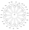
コイル巻取治具4は、図8に示すように、略円筒状の治具本体41と、治具本体41の外周に放射状に突出する複数の櫛歯部42と、周方向に隣り合う櫛歯部42の間によって形成される複数の櫛歯状溝43と、治具本体41の中心に開口する軸孔44と、を有する。 As shown in FIG. 8, the coil winding jig 4 includes a substantially cylindrical jig body 41, a plurality of comb tooth portions 42 radially projecting from the outer periphery of the jig body 41, and adjacent combs in the circumferential direction. It has a plurality of comb-like grooves 43 formed between the teeth 42 and a shaft hole 44 opening at the center of the jig body 41 .

櫛歯部42及び櫛歯状溝43は、治具本体41の軸方向の両端部にそれぞれ設けられる。治具本体41の両端部の櫛歯部42及び櫛歯状溝43のそれぞれの位相は軸方向に揃えられている。治具本体41の周方向に配列される櫛歯状溝43の数は、ステータコア2に設けられるスロット22の数に一致している。したがって、本実施形態のコイル巻取治具4は、72個の櫛歯状溝43を有する。コイル巻取治具4は、ステータコア2の円環部21の内側に挿入可能となるように、櫛歯部42の先端の位置によって規定されるコイル巻取治具4の外径が、ステータコア2の内径よりも小径になるように形成されている。 The comb tooth portions 42 and the comb tooth grooves 43 are provided at both ends of the jig body 41 in the axial direction. The phases of the comb tooth portions 42 and the comb tooth grooves 43 at both ends of the jig body 41 are aligned in the axial direction. The number of comb-shaped grooves 43 arranged in the circumferential direction of jig body 41 matches the number of slots 22 provided in stator core 2 . Therefore, the coil winding jig 4 of this embodiment has 72 comb-like grooves 43 . The outer diameter of the coil winding jig 4 defined by the positions of the tips of the comb tooth portions 42 is equal to the outer diameter of the stator core 2 so that the coil winding jig 4 can be inserted inside the annular portion 21 of the stator core 2 . It is formed to have a smaller diameter than the inner diameter of the

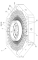
コイル巻取治具4には、ステータコア2に装着するための帯状コイル100が円環状に巻き取られる。図9に示すように、帯状コイル100は、断面形状が略矩形状の平角導線101によって形成される長尺帯状のコイルである。平角導線101は、例えば、銅、アルミニウム等の導電性の高い金属によって形成される。 A belt-like coil 100 to be mounted on the stator core 2 is wound around the coil winding jig 4 in an annular shape. As shown in FIG. 9, the strip-shaped coil 100 is a long strip-shaped coil formed by a flat conductor wire 101 having a substantially rectangular cross-sectional shape. The rectangular conducting wire 101 is made of, for example, highly conductive metal such as copper or aluminum.

帯状コイル100は、複数の直状部102と複数のコイルエンド部103とを有する。直状部102は、ステータコア2のスロット22内に挿入される部位であり、それぞれ略直線状に延びて一定の間隔で平行に配置される。コイルエンド部103は、直状部102よりも帯状コイル100の側端寄りの位置にそれぞれ配置され、隣り合う直状部102の一方端部同士と他方端部同士とを略三角形の山型状に交互に連結する。コイルエンド部103は、帯状コイル100がステータコア2のスロット22に装着された際に、スロット22からステータコア2の軸方向にそれぞれ突出するように配置される部位である。本実施形態の帯状コイル100は、複数の直状部102と複数のコイルエンド部103とがそれぞれ折り曲げ形成された6本の平角導線101を、直状部102が一定の間隔で平行に並列するように束ねることによって、長尺帯状に形成される。 The strip-shaped coil 100 has a plurality of straight portions 102 and a plurality of coil end portions 103 . The straight portions 102 are portions to be inserted into the slots 22 of the stator core 2, and extend substantially linearly and are arranged in parallel at regular intervals. The coil end portions 103 are arranged at positions closer to the side ends of the strip-shaped coil 100 than the straight portions 102, and one end portion and the other end portion of the adjacent straight portions 102 are formed in a substantially triangular mountain shape. Alternately connect to The coil end portions 103 are portions arranged so as to protrude from the slots 22 in the axial direction of the stator core 2 when the strip-shaped coil 100 is mounted in the slots 22 of the stator core 2 . A belt-shaped coil 100 of this embodiment includes six flat conductor wires 101 each formed by bending a plurality of straight portions 102 and a plurality of coil end portions 103, and the straight portions 102 are arranged in parallel at regular intervals. It is formed into a long belt shape by bundling it like this.

コイル巻取治具4は、図10に示すように、ステータコア2の内側に挿入される前に、帯状コイル100の直状部102を櫛歯状溝43の外方からそれぞれ順次挿入することによって、帯状コイル100を多重に巻き取っている。これによって、図11に示すように、帯状コイル100が円環状に巻き取られたコイル巻取治具4が構成される(コイル巻取工程)。 As shown in FIG. 10 , the coil winding jig 4 is formed by sequentially inserting the straight portions 102 of the belt-shaped coil 100 from the outside of the comb tooth-shaped grooves 43 before being inserted inside the stator core 2 . , the strip-shaped coil 100 is wound in multiple layers. As a result, as shown in FIG. 11, the coil winding jig 4 in which the belt-shaped coil 100 is wound in an annular shape is constructed (coil winding step).

治具本体41の軸方向の櫛歯部42間の距離は、帯状コイル100の直状部102の長さに対応している。そのため、コイル巻取治具4に巻き取られた帯状コイル100の直状部102は、治具本体41の両端部の同位相の櫛歯状溝43,43に亘って収容される。多重に巻き取られた帯状コイル100のコイルエンド部103は、櫛歯状溝43から治具本体41の軸方向にそれぞれ円筒状に突出する。このようにして帯状コイル100が円環状に巻き取られたコイル巻取治具4は、図1、図2及び図3に示すように、ステータコア固定治具3に固定されたステータコア2の貫通孔20の内側に、例えば、図示しないロボットの動作によって挿入される。なお、図1では、コイル巻取治具4の帯状コイル100は図示を省略している。 The distance between the comb tooth portions 42 in the axial direction of the jig body 41 corresponds to the length of the straight portion 102 of the belt-like coil 100 . Therefore, the straight portion 102 of the belt-like coil 100 wound on the coil winding jig 4 is accommodated across the comb-like grooves 43 , 43 of the same phase at both ends of the jig body 41 . The coil end portions 103 of the strip-shaped coil 100 wound in multiples protrude from the comb-shaped grooves 43 in the axial direction of the jig main body 41 in a cylindrical shape. As shown in FIGS. 1, 2, and 3, the coil winding jig 4 in which the strip-shaped coil 100 is wound in an annular shape is provided in the through hole of the stator core 2 fixed to the stator core fixing jig 3. 20, for example, by the action of a robot (not shown). In addition, in FIG. 1, illustration of the belt-shaped coil 100 of the coil winding jig 4 is omitted.

ステータコア2の内側の貫通孔20に挿入されたコイル巻取治具4は、ステータコア固定治具3を間に挟んでその両側にそれぞれ配置されるコイル拡張機構部5によって、所定の位置及び姿勢に保持される。本実施形態のコイル拡張機構部5は、図1に示すように、略円柱状の外観形状を有し、ステータコア2の内側に挿入されたコイル巻取治具4に対して軸方向から対向している。 The coil winding jig 4 inserted into the through hole 20 inside the stator core 2 is held in a predetermined position and posture by the coil expansion mechanisms 5 arranged on both sides of the stator core fixing jig 3. retained. As shown in FIG. 1, the coil expansion mechanism 5 of the present embodiment has a substantially cylindrical external shape, and faces the coil winding jig 4 inserted inside the stator core 2 in the axial direction. ing.

図1及び12に示すように、コイル拡張機構部5には、ステータコア固定治具3を固定する基台11上に、ステータコア固定治具3を挟んで対面するように、一対の支持基板12,12が立設される。コイル拡張機構部5は、支持基板12からステータコア2の内側に挿入されるコイル巻取治具4に向けてそれぞれ水平方向に突出している。コイル拡張機構部5は、支持基板12が図示しないモータ等の駆動によって基台11上を直線的に移動することによって、コイル巻取治具4に対して当接する方向及び離隔する方向にそれぞれ移動可能に設けられる。 As shown in FIGS. 1 and 12 , the coil expansion mechanism 5 includes a pair of support substrates 12 and 12 on a base 11 for fixing the stator core fixing jig 3 so as to face each other with the stator core fixing jig 3 interposed therebetween. 12 are erected. The coil expansion mechanism portions 5 horizontally protrude from the support substrate 12 toward the coil winding jig 4 inserted inside the stator core 2 . The coil extension mechanism 5 moves in a direction to contact and separate from the coil winding jig 4 by linearly moving the support substrate 12 on the base 11 by driving a motor or the like (not shown). possible.

コイル拡張機構部5は、図12及び図13に示すように、支持基板12からステータコア2の内側に挿入されたコイル巻取治具4に向けて延びる主軸部51を中心に有する。主軸部51の先端には、ステータコア2の内側においてコイル巻取治具4を所定の位置及び姿勢に保持する保持部52が設けられる。保持部52は、主軸部51の先端に配置される円形状の端板部521の中心から突出する軸突部522と、軸突部522の径方向外側の端板部521から軸突部522と同一方向に突出する1つの位置決め突部523と、を有する。軸突部522は、コイル巻取治具4の軸孔44に嵌合する。位置決め突部523は、コイル巻取治具4の軸孔44の径方向外側に設けられる1つの位置決め孔45に嵌合する。 As shown in FIGS. 12 and 13 , the coil expansion mechanism 5 has a main shaft 51 extending from the support substrate 12 toward the coil winding jig 4 inserted inside the stator core 2 . A holding portion 52 that holds the coil winding jig 4 at a predetermined position and orientation inside the stator core 2 is provided at the tip of the main shaft portion 51 . The holding portion 52 includes a shaft projection 522 projecting from the center of a circular end plate portion 521 arranged at the tip of the main shaft portion 51 and a shaft projection 522 extending from the end plate portion 521 radially outside the shaft projection 522 . and one positioning protrusion 523 protruding in the same direction as the . The shaft projection 522 fits into the shaft hole 44 of the coil winding jig 4 . The positioning protrusion 523 fits into one positioning hole 45 provided radially outside the shaft hole 44 of the coil winding jig 4 .

コイル巻取治具4の位置決め孔45及び保持部52の位置決め突部523は、互いに嵌合した際に、ステータコア固定治具3に固定されるステータコア2のスロット22の位相と、ステータコア2の内側に挿入されたコイル巻取治具4の櫛歯状溝43の位相とが一致するように、予め位置決めされて設けられている。したがって、コイル拡張機構部5がステータコア固定治具3に向けて移動し、コイル巻取治具4の軸孔44及び位置決め孔45と保持部52の軸突部522及び位置決め突部523とが嵌合すると、図5に示すように、コイル巻取治具4は、ステータコア2のスロット22に対して櫛歯状溝43の位相を合わせた状態で保持される。これによって、ステータコア2のスロット22の内部とコイル巻取治具4の櫛歯状溝43の内部とが、径方向に連通する。 When the positioning hole 45 of the coil winding jig 4 and the positioning projection 523 of the holding portion 52 are fitted to each other, the phase of the slot 22 of the stator core 2 fixed to the stator core fixing jig 3 and the phase of the stator core 2 are aligned. It is positioned in advance so as to match the phase of the comb-shaped grooves 43 of the coil winding jig 4 inserted in the coil winding jig 4 . Therefore, the coil expansion mechanism 5 moves toward the stator core fixing jig 3, and the shaft hole 44 and the positioning hole 45 of the coil winding jig 4 are fitted with the shaft projection 522 and the positioning projection 523 of the holding portion 52. Then, as shown in FIG. 5, the coil winding jig 4 is held in a state in which the phases of the comb-shaped grooves 43 are aligned with the slots 22 of the stator core 2 . As a result, the inside of the slots 22 of the stator core 2 and the inside of the comb-like grooves 43 of the coil winding jig 4 communicate with each other in the radial direction.

コイル拡張機構部5は、主軸部51の外周側にコイル拡張部53を有する。コイル拡張部53は、主軸部51の外周側に嵌合する可動筒部531と、可動筒部531のさらに外周側に配置される複数の可動腕部532と、可動腕部532の先端にそれぞれ設けられる複数の駒部材533と、を有する。 The coil extension mechanism section 5 has a coil extension section 53 on the outer peripheral side of the main shaft section 51 . The coil extension portion 53 includes a movable cylindrical portion 531 fitted to the outer peripheral side of the main shaft portion 51 , a plurality of movable arm portions 532 arranged further on the outer peripheral side of the movable cylindrical portion 531 , and a plurality of movable arm portions 532 at the tips of the movable arm portions 532 . and a plurality of piece members 533 provided.

可動筒部531は、主軸部51の長さよりも短い長さを有し、支持基板12の後方に配置されるシリンダ等のアクチュエータ54の駆動によって、主軸部51の軸方向に沿って摺動可能に設けられる。 The movable cylindrical portion 531 has a length shorter than the length of the main shaft portion 51 and is slidable along the axial direction of the main shaft portion 51 by being driven by an actuator 54 such as a cylinder arranged behind the support substrate 12 . provided in

可動腕部532は、主軸部51の軸方向に沿って延び、可動筒部531の外周側において周方向に一定の間隔をおいて複数配置される。本実施形態のコイル拡張部53は、主軸部51の周方向に沿って配列される12本の可動腕部532を有する。支持基板12の表面には、主軸部51を中心にして径方向外側に向けて放射状に配列される12本のガイドレール121が設けられる。可動腕部532の後端532bは、それぞれガイドレール121に沿って移動可能に取り付けられる。可動腕部532は、ガイドレールから可動筒部531の軸方向に沿って屈曲して保持部52の外周近傍まで延びている。可動腕部532の先端532aは、それぞれ回動可能に取り付けられる2つずつのリンク部534を介して、可動筒部531の先端側の外周面に連結される。 The movable arm portions 532 extend along the axial direction of the main shaft portion 51 and are arranged in plurality at regular intervals in the circumferential direction on the outer peripheral side of the movable cylindrical portion 531 . The coil extension portion 53 of this embodiment has twelve movable arm portions 532 arranged along the circumferential direction of the main shaft portion 51 . On the surface of the support substrate 12, twelve guide rails 121 are arranged radially outward in the radial direction around the main shaft portion 51. As shown in FIG. Rear ends 532b of the movable arms 532 are attached so as to be movable along the guide rails 121, respectively. The movable arm portion 532 is bent from the guide rail along the axial direction of the movable cylindrical portion 531 and extends to the vicinity of the outer circumference of the holding portion 52 . The distal end 532a of the movable arm portion 532 is connected to the outer peripheral surface of the distal end side of the movable cylindrical portion 531 via two rotatably attached link portions 534 each.

駒部材533は、略扇形状を有し、可動腕部532の先端にそれぞれ1つずつ設けられる。したがって、本実施形態のコイル拡張部53は、12個の駒部材533を有する。図15及び図16に示すように、駒部材533は、周方向の一方端部に一対の係合突片533aをそれぞれ有し、周方向の他方端部に、一対の係合突片533aと係合する一対の係合溝533bをそれぞれ有する。一対の係合突片533aは、コイル拡張部53の軸方向に平行に配置され、それぞれコイル拡張部53の周方向に向けて平行に突出している。12個の駒部材533は、周方向に隣り合う駒部材533,533の一対の係合突片533aと一対の係合溝533bとが互いに係合し合うことによって、保持部52の外周側に円環状に配列される。 The piece members 533 have a substantially sector shape, and are provided one each at the tip of the movable arm portion 532 . Therefore, the coil extension part 53 of this embodiment has twelve piece members 533 . As shown in FIGS. 15 and 16, the piece member 533 has a pair of engaging protrusions 533a at one end in the circumferential direction, and a pair of engaging protrusions 533a at the other end in the circumferential direction. Each has a pair of engaging grooves 533b for engagement. The pair of engaging protrusions 533 a are arranged in parallel with the axial direction of the coil extension portion 53 and protrude in parallel in the circumferential direction of the coil extension portion 53 . The twelve piece members 533 are arranged on the outer peripheral side of the holding portion 52 by engaging the pair of engaging protrusions 533a and the pair of engaging grooves 533b of the piece members 533, 533 adjacent in the circumferential direction. Arranged in a ring.

図12、図13及び図14に示すコイル拡張機構部5のコイル拡張部53は、可動筒部531が主軸部51の後端側(支持基板12側)に後退した状態を示す。このとき、可動腕部532は、それぞれ放射状のガイドレール121の内方端側に移動し、可動筒部531の外周面に最も近接するように配置される。これによって、コイル拡張部53は、図15及び図16に示すように、12個の駒部材533を互いに密接させるように最も縮径する。コイル拡張部53が最も縮径したときの外径は、帯状コイル100が巻き取られたコイル巻取治具4から軸方向に円筒状に突出するコイルエンド部103の内径よりも僅かに小さい。コイル拡張機構部5は、コイル拡張部53が縮径した状態で、コイル巻取治具4の軸方向に円筒状に突出するコイルエンド部103に挿入され、保持部52によってコイル巻取治具4を保持する。 12, 13, and 14 show the coil extension portion 53 of the coil extension mechanism portion 5 in a state in which the movable cylinder portion 531 is retracted to the rear end side of the main shaft portion 51 (the support substrate 12 side). At this time, the movable arm portions 532 move toward the inner ends of the radial guide rails 121 and are positioned closest to the outer peripheral surface of the movable cylindrical portion 531 . 15 and 16, the coil extension part 53 is most contracted so that the twelve piece members 533 are brought into close contact with each other. The outer diameter of the coil extension portion 53 when it is most contracted is slightly smaller than the inner diameter of the coil end portion 103 that axially protrudes cylindrically from the coil winding jig 4 around which the strip-shaped coil 100 is wound. The coil expansion mechanism part 5 is inserted into the coil end part 103 projecting cylindrically in the axial direction of the coil winding jig 4 in a state where the diameter of the coil expansion part 53 is reduced. Hold 4.

次に、可動筒部531が、アクチュエータ54の駆動によって、主軸部51に沿ってコイル巻取治具4に向けて前進すると、可動筒部531に連結されるリンク部534が、それぞれ可動筒部531の径方向外側に向けて張り出すように回動し、可動腕部532をガイドレールに沿ってそれぞれ外側に平行移動させる。これによって、12本の可動腕部532は、可動筒部531から径方向外側に離隔する。このとき、コイル拡張部53は、図17、図18及び図19に示すように、隣り合う駒部材533間の距離を互いに広げるように移動させて拡径する。最も拡径したコイル拡張部53の外径は、コイル巻取治具4の外径よりもやや大きい。 Next, when the movable cylinder portion 531 advances toward the coil winding jig 4 along the main shaft portion 51 by driving the actuator 54, the link portion 534 connected to the movable cylinder portion 531 moves toward the movable cylinder portion. 531 is rotated so as to protrude radially outward, and the movable arm portions 532 are translated outward along the guide rails. As a result, the twelve movable arm portions 532 are spaced radially outward from the movable cylindrical portion 531 . At this time, as shown in FIGS. 17, 18, and 19, the coil extension part 53 is moved so as to increase the distance between the adjacent piece members 533 to increase the diameter. The outer diameter of the coil extension portion 53 having the largest diameter is slightly larger than the outer diameter of the coil winding jig 4 .

なお、図18及び図19に示すように、コイル拡張部53が最も拡径した際、隣り合う駒部材533,533同士は離隔するが、駒部材533,533間には係合溝533bから離れた一対の係合突片533aが周方向に張り出している。そのため、コイル拡張部53を周方向に見た場合、隣り合う駒部材533,533の間は一対の係合突片533aによって連続し、コイル拡張部53を径方向に貫通するような溝部は形成されない。 As shown in FIGS. 18 and 19, when the coil extension portion 53 expands to the maximum diameter, the adjacent piece members 533, 533 are separated from each other. A pair of engaging protrusions 533a protrude in the circumferential direction. Therefore, when the coil extension portion 53 is viewed in the circumferential direction, the adjacent piece members 533, 533 are connected by a pair of engaging projecting pieces 533a, and a groove portion is formed that penetrates the coil extension portion 53 in the radial direction. not.

次に、コイル装着装置1において、コイル巻取治具4に巻き取られた帯状コイル100を、ステータコア固定治具3に固定されたステータコア2の内側からスロット22に挿入する方法について説明する。 Next, a method of inserting the strip-shaped coil 100 wound on the coil winding jig 4 into the slot 22 from the inside of the stator core 2 fixed on the stator core fixing jig 3 in the coil mounting device 1 will be described.

コイル巻取治具4には、ステータコア2の内側に挿入される前に、上記のように、コイル巻取工程において、帯状コイル100が円環状に巻き取られる。帯状コイル100が円環状に巻き取られたコイル巻取治具4がステータコア固定治具3に固定されたステータコア2の内側に挿入された後は、図20に示すように、カフスガイド33が、図示しないアクチュエータの駆動によって径方向内側に向けて移動する。 Before the coil winding jig 4 is inserted inside the stator core 2 , the belt-like coil 100 is wound into an annular shape in the coil winding process as described above. After the coil winding jig 4 around which the strip-shaped coil 100 is wound in an annular shape is inserted inside the stator core 2 fixed to the stator core fixing jig 3, the cuff guide 33 is closed as shown in FIG. It moves radially inward by driving an actuator (not shown).

カフスガイド33が径方向内側に向けて移動すると、図21に示すように、カフスガイド33のガイド溝331が、対応するスロット22内の絶縁紙24のカフス部24aを周方向の両側から挟み込むように支持する。詳しくは、図22に示すように、ガイド溝331のカフス部支持溝部331aは、カフス部24aの一対の径方向部241,241の部位を挟むように支持する。カフス部24aよりもステータコア2の軸方向外側(図22における紙面上方)には、ガイド溝331のコイル案内溝部331bが、カフス部24aを覆い隠すように配置される。 When the cuff guides 33 move radially inward, as shown in FIG. 21, the guide grooves 331 of the cuff guides 33 sandwich the cuff portions 24a of the insulating paper 24 in the corresponding slots 22 from both sides in the circumferential direction. to support. Specifically, as shown in FIG. 22, the cuff support groove 331a of the guide groove 331 supports the pair of radial portions 241, 241 of the cuff 24a so as to sandwich them. A coil guide groove portion 331b of the guide groove 331 is arranged outside the cuff portion 24a in the axial direction of the stator core 2 (upper side of the paper in FIG. 22) so as to cover the cuff portion 24a.

このとき、周方向に隣り合うカフスガイド33,33の間にも、カフスガイド33の切り欠き部333aによって形成されるカフス部支持溝部によって、カフスガイド33,33間のスロット22の絶縁紙24のカフス部24aが、周方向の両側から挟み込まれるように支持される。さらに、そのカフス部24aを覆い隠すように、カフスガイド33,33の張出部333b,333bが配置される。このように、スロット22内の全ての絶縁紙24のカフス部24aが、カフスガイド33のカフス部支持溝部331a及び切り欠き部333aによって支持されることにより、全ての絶縁紙24は、スロット22内の所定の位置に位置決めされる。 At this time, the insulating paper 24 in the slot 22 between the cuff guides 33, 33 is also supported between the cuff guides 33, 33 adjacent in the circumferential direction by the cuff support grooves formed by the cutouts 333a of the cuff guide 33. The cuff part 24a is supported so as to be sandwiched from both sides in the circumferential direction. Furthermore, projecting portions 333b, 333b of the cuff guides 33, 33 are arranged so as to cover the cuff portion 24a. In this way, the cuff portions 24a of all the insulating papers 24 inside the slots 22 are supported by the cuff portion support grooves 331a and the notch portions 333a of the cuff guides 33, so that all the insulating papers 24 are placed inside the slots 22. is positioned at a predetermined position.

なお、図20では、コイル巻取治具4を保持するコイル拡張機構部5は図示されていないが、カフスガイド33によるカフス部24aの支持動作は、ステータコア固定治具3にステータコア2が固定された後で、後述するコイル拡張部53の動作によって帯状コイル100がステータコア2のスロット22内に挿入される前までの適宜のタイミングで行われる。 Although FIG. 20 does not show the coil expansion mechanism 5 that holds the coil winding jig 4 , the cuff guide 33 supports the cuff 24 a when the stator core 2 is fixed to the stator core fixing jig 3 . After that, it is performed at an appropriate timing before the belt-like coil 100 is inserted into the slot 22 of the stator core 2 by the operation of the coil extension portion 53 which will be described later.

ステータコア2の内側に挿入されたコイル巻取治具4は、コイル拡張部53を縮径させた状態のコイル拡張機構部5がコイル巻取治具4に向けてそれぞれ移動することによって、コイル拡張機構部5の保持部52によって保持される(コイル巻取治具保持工程)。 The coil winding jig 4 inserted inside the stator core 2 expands the coil by moving the coil expanding mechanism portion 5 with the coil expanding portion 53 diameter-reduced toward the coil winding jig 4 . It is held by the holding portion 52 of the mechanism portion 5 (coil winding jig holding step).

さらに、カフスガイド33のガイド溝331のカフス部支持溝部331aによってスロット22内の絶縁紙24のカフス部24aが位置決めされた後、図23及び図24に示すように、コイル拡張機構部5のコイル拡張部53がそれぞれアクチュエータ54の駆動によって拡径する。これによって、コイル拡張部53は、コイル巻取治具4に巻き取られた帯状コイル100のコイルエンド部103を、帯状コイル100の内方から外方に向けて拡張させるように押圧する。コイル拡張部53によって押圧された帯状コイル100は徐々に拡張する。これに伴い、直状部102は、櫛歯状溝43にガイドされながら、櫛歯状溝43と連通するステータコア2のスロット22に向けて移動する。これによって、帯状コイル100の直状部102は、ステータコア2のスロット22に干渉することなく、スロット22の開口部22aからスロット22内に挿入される(コイル拡張工程)。 Further, after the cuff portion 24a of the insulating paper 24 in the slot 22 is positioned by the cuff portion supporting groove portion 331a of the guide groove 331 of the cuff guide 33, the coil of the coil extending mechanism portion 5 is expanded as shown in FIGS. The diameters of the expansion portions 53 are expanded by driving the actuators 54 respectively. As a result, the coil expanding portion 53 presses the coil end portion 103 of the strip-shaped coil 100 wound on the coil winding jig 4 so as to expand the strip-shaped coil 100 from the inside to the outside. The belt-like coil 100 pressed by the coil expanding portion 53 expands gradually. Accordingly, the straight portion 102 moves toward the slots 22 of the stator core 2 communicating with the comb-shaped grooves 43 while being guided by the comb-shaped grooves 43 . As a result, the straight portion 102 of the belt-shaped coil 100 is inserted into the slot 22 from the opening 22a of the slot 22 without interfering with the slot 22 of the stator core 2 (coil expansion step).

ここで、図25に示すように、コイル巻取治具4の櫛歯状溝43は、外径側に縮幅部43aを有する。コイル巻取治具4の周方向に沿う縮幅部43aの溝幅W3は、カフスガイド33のガイド溝331のコイル案内溝部331bの溝幅W2よりも狭い。しかし、この縮幅部43aの溝幅W3は、帯状コイル100の直状部102の幅Wcに略等しい。これによって、スロット22に向けて移動する櫛歯状溝43内の直状部102が縮幅部43aを通過する際に、直状部102の位置が、スロット22内に挿入される直前で、スロット22の開口部22aの中央を通るスロット中心線22bに沿うように位置補正される。そのため、櫛歯状溝43内の直状部102は、スロット22の開口部22aを通って絶縁紙24の内側に円滑に挿入される。 Here, as shown in FIG. 25, the comb tooth-shaped groove 43 of the coil winding jig 4 has a reduced width portion 43a on the outer diameter side. A groove width W3 of the reduced width portion 43a along the circumferential direction of the coil winding jig 4 is narrower than a groove width W2 of the coil guide groove portion 331b of the guide groove 331 of the cuff guide 33. As shown in FIG. However, the groove width W3 of the reduced width portion 43a is substantially equal to the width Wc of the straight portion 102 of the belt-like coil 100. As shown in FIG. As a result, when the straight portion 102 in the comb tooth-shaped groove 43 moving toward the slot 22 passes through the reduced-width portion 43a, the position of the straight portion 102 is changed immediately before being inserted into the slot 22. The position is corrected along the slot center line 22b passing through the center of the opening 22a of the slot 22. FIG. Therefore, the straight portion 102 in the comb tooth-shaped groove 43 is smoothly inserted inside the insulating paper 24 through the opening 22 a of the slot 22 .

スロット22の開口部22aを通過する直状部102は、図26に示すように、カフスガイド33のガイド溝331のコイル案内溝部331b及び張出部333bに当接しながらスロット22内を移動することによって、コイル案内溝部331b及び張出部333bに沿って案内される。コイル案内溝部331bは、カフス部支持溝部331aよりも幅狭であるため、カフス部支持溝部331aによって支持されるカフス部24aが直状部102と接触することはない。したがって、スロット22内に挿入される直状部102が、スロット22との間で絶縁紙24のカフス部24aを噛み込むことは防止される。 As shown in FIG. 26, the straight portion 102 passing through the opening 22a of the slot 22 moves in the slot 22 while contacting the coil guide groove 331b and the projecting portion 333b of the guide groove 331 of the cuff guide 33. are guided along the coil guide groove portion 331b and the projecting portion 333b. Since the coil guide groove portion 331b is narrower than the cuff support groove portion 331a, the cuff portion 24a supported by the cuff support groove portion 331a does not come into contact with the straight portion . Therefore, the straight portion 102 inserted into the slot 22 is prevented from biting the cuff portion 24a of the insulating paper 24 between the slot 22 and the straight portion 102 .

直状部102がスロット22内に挿入された帯状コイル100のコイルエンド部103は、図26に示すように、カフスガイド33のガイド溝331及び隣り合うカフスガイド33,33の間から外側に屈曲して延びるとともに、ガイド溝331のコイル案内溝部331bとテーパ面33cとの間の角部331c及び張出部333bとテーパ面33cとの間の角部333cに当接する(図6におけるP1位置)。帯状コイル100は、直状部102がスロット22内に奥深く挿入されるに従って徐々に拡径し、周方向に隣り合う直状部102,102同士の間隔が広がるため、コイルエンド部103と直状部102とが成す内側の角度θが次第に大きくなるように変形する。このとき、スロット22内の直状部102には、ステータコア2の周方向に湾曲しようとする応力が作用する。直状部102がスロット22内で湾曲すると、スロット22内の絶縁紙24の径方向部241と接触して絶縁紙24を損傷させるおそれがある。しかし、本実施形態のカフスガイド33の角部331c,333cは、テーパ面33cに沿って形成されるため、直状部102がスロット22内に奥深く挿入されるのに伴って、直状部102の両端のコイルエンド部103,103は、図27において矢印で示すように、角部331c,333cを支点にして、直状部102に対してステータコア2の軸方向(図27の上下方向)に沿う張力Fを付与する(図6におけるP2位置)。これによって、スロット22内の直状部102は真っ直ぐに延ばされ、スロット22内を移動する際に、直状部102が湾曲して絶縁紙24を損傷させることは抑制される。 As shown in FIG. 26, the coil end portion 103 of the belt-shaped coil 100 having the straight portion 102 inserted into the slot 22 is bent outward from between the guide groove 331 of the cuff guide 33 and the adjacent cuff guides 33, 33. and abuts on a corner portion 331c between the coil guide groove portion 331b and the tapered surface 33c of the guide groove 331 and a corner portion 333c between the projecting portion 333b and the tapered surface 33c (position P1 in FIG. 6). . The strip-like coil 100 gradually expands in diameter as the straight portion 102 is inserted deeper into the slot 22 , and the space between the straight portions 102 , 102 adjacent in the circumferential direction widens. The deformation is such that the inner angle θ formed with the portion 102 gradually increases. At this time, the straight portion 102 in the slot 22 is subjected to a stress that causes the stator core 2 to bend in the circumferential direction. If the straight portion 102 bends inside the slot 22 , it may come into contact with the radial portion 241 of the insulating paper 24 inside the slot 22 and damage the insulating paper 24 . However, since the corners 331c and 333c of the cuff guide 33 of the present embodiment are formed along the tapered surface 33c, the straight portion 102 is bent as the straight portion 102 is deeply inserted into the slot 22. 27, the coil end portions 103, 103 at both ends of the coil end portions 103, 103 extend in the axial direction of the stator core 2 (the vertical direction in FIG. 27) with respect to the straight portion 102 with the corner portions 331c, 333c as fulcrums. A tension F is applied along (P2 position in FIG. 6). As a result, the straight portion 102 in the slot 22 is straightened, and the bending of the straight portion 102 and damage to the insulating paper 24 during movement in the slot 22 are suppressed.

ガイド溝331のコイル案内溝部331bの角部331c,333cは、それぞれ丸みを有するR形状に形成されている。そのため、コイルエンド部103が角部331cと接触しても、帯状コイル100の表面に形成されている保護被膜の損傷は抑制される。コイル案内溝部331b及び張出部333bの全体が、丸みを有する円弧形状に形成されてもよい。 Corner portions 331c and 333c of a coil guide groove portion 331b of the guide groove 331 are each formed in a rounded R shape. Therefore, even if coil end portion 103 contacts corner portion 331c, damage to the protective coating formed on the surface of strip-shaped coil 100 is suppressed. The entire coil guide groove portion 331b and the projecting portion 333b may be formed in a rounded arc shape.

2つのコイル拡張機構部5のコイル拡張部53がそれぞれ最も拡径すると、コイル巻取治具4の帯状コイル100の直状部102は、図28に示すように、ステータコア2のスロット22内にそれぞれ完全に挿入され、帯状コイル100はステータコア2のスロット22内に装着される。2つのコイル拡張機構部5のコイル拡張部53は、同時に拡径するように動作してもよいし、直状部102がスロット22の開口部22aに対して径方向に斜めに挿入されるように、時間差を設けて順次拡径するように動作してもよい。 When the coil extension portions 53 of the two coil extension mechanism portions 5 are respectively expanded most, the straight portion 102 of the belt-shaped coil 100 of the coil winding jig 4 is inserted into the slot 22 of the stator core 2 as shown in FIG. Each fully inserted, strip-shaped coil 100 is mounted in slot 22 of stator core 2 . The coil expansion portions 53 of the two coil expansion mechanism portions 5 may be operated so as to expand the diameter at the same time, or the straight portion 102 may be inserted diagonally in the radial direction into the opening 22 a of the slot 22 . Alternatively, the diameter may be expanded sequentially with a time lag.

その後、カフスガイド33が径方向外側に移動してステータコア2の端面2aから完全に退避するとともに、コイル拡張部53がそれぞれ縮径し、コイル拡張機構部5はそれぞれコイル巻取治具4から離隔する。これによって、図29に示すように、ステータコア2のスロット22内に帯状コイル100が装着されたステータ200が得られる。 After that, the cuff guide 33 moves radially outward and completely retracts from the end face 2 a of the stator core 2 , the diameter of the coil extension part 53 is reduced, and the coil extension mechanism part 5 is separated from the coil winding jig 4 . do. As a result, a stator 200 having strip-like coils 100 mounted in slots 22 of stator core 2 is obtained, as shown in FIG.

以上のように、本実施形態のコイル装着装置1は、円環状に巻回された帯状コイル100の直状部102を、ステータコア2の内方から、絶縁紙24を有するスロット22内に挿入することによって、帯状コイル100をステータコア2の周方向に沿って装着する。絶縁紙24は、ステータコア2の軸方向の端面2aからはみ出したカフス部24aを有する。コイル装着装置1は、ステータコア2を、所定の位置及び姿勢に固定するステータコア固定治具3と、ステータコア固定治具3に固定されるステータコア2の内側に配置され、外周に放射状に配列される櫛歯状溝43に帯状コイル100の直状部102を挿入することによって、帯状コイル100を円環状に巻き取ったコイル巻取治具4と、ステータコア固定治具3に設けられ、カフス部24aを支持するガイド溝311を有するカフスガイド33と、を備える。ガイド溝331は、カフス部24aをステータコア2の周方向から挟むように支持するカフス部支持溝部331aと、カフス部支持溝部331aよりもステータコア2の端面2aから遠い側に、カフス部支持溝部331aの溝幅W1よりも狭い溝幅W2を有するコイル案内溝部311bと、を有する。これによれば、スロット22内の絶縁紙24のカフス部24aが、カフスガイド33のガイド溝331のカフス部支持溝部331aによって、ステータコア2の周方向から挟まれるように支持されるため、カフス部24aがスロット22に対して位置決めされるとともに、直状部102が、ガイド溝331のコイル案内溝部331bに当接することによって、カフス部24aを噛み込むことなくスロット22内に案内される。そのため、円環状に巻き取られた帯状コイル100の直状部102をステータコア2の内側からスロット22内に挿入する際に、直状部102がスロット22内の絶縁紙24を噛み込むおそれのないコイル装着装置1を提供することができる。 As described above, the coil mounting device 1 of the present embodiment inserts the straight portion 102 of the annularly wound belt-shaped coil 100 into the slot 22 having the insulating paper 24 from the inside of the stator core 2. Thus, the belt-shaped coil 100 is mounted along the circumferential direction of the stator core 2 . The insulating paper 24 has a cuff portion 24a protruding from the axial end surface 2a of the stator core 2 . The coil mounting device 1 includes a stator core fixing jig 3 for fixing the stator core 2 in a predetermined position and orientation, and combs disposed inside the stator core 2 fixed to the stator core fixing jig 3 and radially arranged on the outer circumference. By inserting the straight portion 102 of the belt-shaped coil 100 into the tooth-shaped groove 43, the coil winding jig 4 that winds the belt-shaped coil 100 in an annular shape and the stator core fixing jig 3 are provided with the cuff portion 24a. a cuff guide 33 having a guide groove 311 for support. The guide groove 331 includes a cuff support groove portion 331a that supports the cuff portion 24a so as to sandwich the cuff portion 24a from the circumferential direction of the stator core 2, and a cuff support groove portion 331a that is located farther from the end face 2a of the stator core 2 than the cuff support groove portion 331a. and a coil guide groove portion 311b having a groove width W2 narrower than the groove width W1. According to this, the cuff part 24a of the insulating paper 24 in the slot 22 is supported by the cuff part support groove part 331a of the guide groove 331 of the cuff guide 33 so as to be sandwiched from the circumferential direction of the stator core 2, so that the cuff part 24a is positioned with respect to the slot 22, and the straight portion 102 is guided into the slot 22 by contacting the coil guide groove portion 331b of the guide groove 331 without catching the cuff portion 24a. Therefore, when the straight portion 102 of the belt-shaped coil 100 wound in an annular shape is inserted into the slot 22 from the inside of the stator core 2, the straight portion 102 does not bite the insulating paper 24 in the slot 22. A coil mounting device 1 can be provided.

本実施形態のコイル巻取治具4の櫛歯状溝43は、外径側に、溝幅W3がガイド溝311のコイル案内溝部311bの溝幅W2よりも狭い縮幅部43aを有する。これによれば、コイル巻取治具の櫛歯状溝内の直状部がステータコアのスロット内に挿入される直前で、直状部の位置が縮幅部によって補正される。そのため、櫛歯状溝内の直状部をスロット内の絶縁紙の内側に円滑に挿入することができる。 The comb tooth-shaped groove 43 of the coil winding jig 4 of this embodiment has a reduced width portion 43a having a groove width W3 narrower than the groove width W2 of the coil guide groove portion 311b of the guide groove 311 on the outer diameter side. According to this, the position of the straight portion in the comb tooth-shaped groove of the coil winding jig is corrected by the reduced width portion immediately before the straight portion is inserted into the slot of the stator core. Therefore, the straight portion in the comb-shaped groove can be smoothly inserted inside the insulating paper in the slot.

本実施形態のコイル装着方法は、円環状に巻回された帯状コイル100の直状部102を、ステータコア2の内方から、絶縁紙24を有するスロット22内に挿入することによって、帯状コイル100をステータコア2の周方向に沿って装着する。絶縁紙24は、ステータコア2の軸方向の端面2aからはみ出したカフス部24aを有し、カフス部24aをステータコア2の周方向から挟むように支持するカフス部支持溝部331aと、カフス部支持溝部331aよりもステータコア2の端面2aから遠い側に、カフス部支持溝部331aの溝幅W1よりも狭い溝幅W2を有するコイル案内溝部331bと、を有するガイド溝331を備えるカフスガイド33のカフス部支持溝部331aによって、カフス部24aを支持し、カフス部24aをカフス部支持溝部331aによって支持した状態で、円環状の帯状コイル100を拡径させ、直状部102をスロット22内に挿入するとともに、コイル案内溝部331bによって直状部102の移動を案内する。これによれば、スロット22内の絶縁紙24のカフス部24aを、カフスガイド33のガイド溝331のカフス部支持溝部331aによって、ステータコア2の周方向から挟むように支持するため、カフス部24aをスロット22に対して位置決めすることができるとともに、直状部102を、ガイド溝331のコイル案内溝部331bに当接させることによって、カフス部24aを噛み込むことなくスロット22内に案内することができる。そのため、円環状に巻き取られた帯状コイル100の直状部102をステータコア2の内側からスロット22内に挿入する際に、直状部102がスロット22内の絶縁紙24を噛み込むおそれのないコイル装着方法を提供することができる。 In the coil mounting method of the present embodiment, the straight portion 102 of the annularly wound strip coil 100 is inserted from the inside of the stator core 2 into the slot 22 having the insulating paper 24 . are mounted along the circumferential direction of the stator core 2 . The insulating paper 24 has a cuff portion 24a protruding from the axial end surface 2a of the stator core 2, and a cuff portion support groove portion 331a that supports the cuff portion 24a so as to sandwich the cuff portion 24a from the circumferential direction of the stator core 2, and a cuff portion support groove portion 331a. The cuff support groove of the cuff guide 33 is provided with a guide groove 331 having a coil guide groove 331b having a groove width W2 narrower than the groove width W1 of the cuff support groove 331a on the far side from the end surface 2a of the stator core 2. The cuff part 24a is supported by the cuff part 331a, and in a state where the cuff part 24a is supported by the cuff part support groove part 331a, the diameter of the ring-shaped band-shaped coil 100 is expanded, the straight part 102 is inserted into the slot 22, and the coil The movement of the straight portion 102 is guided by the guide groove portion 331b. According to this, since the cuff part 24a of the insulating paper 24 in the slot 22 is supported by the cuff part support groove part 331a of the guide groove 331 of the cuff guide 33 so as to be sandwiched from the circumferential direction of the stator core 2, the cuff part 24a is supported. It can be positioned with respect to the slot 22, and by bringing the straight portion 102 into contact with the coil guide groove portion 331b of the guide groove 331, the cuff portion 24a can be guided into the slot 22 without being caught. . Therefore, when the straight portion 102 of the belt-shaped coil 100 wound in an annular shape is inserted into the slot 22 from the inside of the stator core 2, the straight portion 102 does not bite the insulating paper 24 in the slot 22. A coil mounting method can be provided.

以上説明した実施形態のコイル装着装置1は、ステータコア2及びコイル巻取治具4の軸方向が水平方向に配置されるように構成されるが、ステータコア2及びコイル巻取治具4の軸方向が垂直方向等の水平方向以外の方向に配置されるように構成されてもよい。 The coil mounting device 1 of the embodiment described above is configured such that the axial directions of the stator core 2 and the coil winding jig 4 are arranged in the horizontal direction. may be arranged in a direction other than horizontal, such as vertically.

帯状コイル100が円環状に巻き取られたコイル巻取治具4は、いずれか一方のコイル拡張機構部5の保持部52に取り付けられて保持された状態で、ステータコア固定治具3に固定されたステータコア2の内側に挿入されてもよい。 The coil winding jig 4 around which the belt-shaped coil 100 is wound in an annular shape is fixed to the stator core fixing jig 3 while being attached to and held by the holding portion 52 of one of the coil expansion mechanism portions 5 . may be inserted inside the stator core 2 .

ステータコア固定治具3の両端面3a,3aには、それぞれステータコア2のスロット22に対応する数のカフスガイド33が設けられてもよい。 The number of cuff guides 33 corresponding to the slots 22 of the stator core 2 may be provided on both end faces 3a, 3a of the stator core fixing jig 3, respectively.

1 コイル装着装置
2 ステータコア
2a 端面
22 スロット
24 絶縁紙
24a カフス部
3 ステータコア固定治具
33 カフスガイド
331 ガイド溝
331a カフス部支持溝部
331b コイル案内溝部
4 コイル巻取治具
43 櫛歯状溝
43a 縮幅部
100 帯状コイル
102 直状部
REFERENCE SIGNS LIST 1 coil mounting device 2 stator core 2a end face 22 slot 24 insulating paper 24a cuff 3 stator core fixing jig 33 cuff guide 331 guide groove 331a cuff support groove 331b coil guide groove 4 coil winding jig 43 comb tooth groove 43a reduced width Part 100 Belt-shaped coil 102 Straight part

Claims (3)

円環状に巻回された帯状コイルの直状部を、ステータコアの内方から、絶縁紙を有するスロット内に挿入することによって、前記帯状コイルを前記ステータコアの周方向に沿って装着するコイル装着装置であって、
前記絶縁紙は、前記ステータコアの軸方向の端面からはみ出したカフス部を有し、
前記ステータコアを、所定の位置及び姿勢に固定するステータコア固定治具と、
前記ステータコア固定治具に固定される前記ステータコアの内側に配置され、外周に放射状に配列される櫛歯状溝に前記帯状コイルの前記直状部を挿入することによって、前記帯状コイルを円環状に巻き取ったコイル巻取治具と、
前記ステータコア固定治具に設けられ、前記カフス部を支持するガイド溝を有するカフスガイドと、を備え、
前記ガイド溝は、前記カフス部を前記ステータコアの周方向から挟むように支持するカフス部支持溝部と、前記カフス部支持溝部よりも前記ステータコアの前記端面から遠い側に、前記カフス部支持溝部の溝幅よりも狭い溝幅を有するコイル案内溝部と、を有する、コイル装着装置。
A coil mounting device for mounting the belt-shaped coil along the circumferential direction of the stator core by inserting the straight portion of the belt-shaped coil wound in an annular shape into a slot having insulating paper from the inside of the stator core. and
The insulating paper has a cuff part protruding from the axial end face of the stator core,
a stator core fixing jig for fixing the stator core at a predetermined position and orientation;
The straight portions of the strip-shaped coil are arranged inside the stator core fixed to the stator core fixing jig, and are arranged radially on the outer circumference by inserting the straight portions of the strip-shaped coil into the comb-shaped grooves. a wound coil winding jig;
a cuff guide provided in the stator core fixing jig and having a guide groove for supporting the cuff portion,
The guide grooves include a cuff support groove portion that supports the cuff portion so as to sandwich the cuff portion from the circumferential direction of the stator core, and a groove of the cuff support groove portion on a side farther from the end surface of the stator core than the cuff support groove portion. and a coil guide groove portion having a groove width narrower than the width.
前記コイル巻取治具の前記櫛歯状溝は、外径側に、溝幅が前記ガイド溝の前記コイル案内溝部の溝幅よりも狭い縮幅部を有する、請求項1に記載のコイル装着装置。 2. The coil mounting according to claim 1, wherein said comb tooth-shaped groove of said coil winding jig has, on an outer diameter side, a reduced width portion whose groove width is narrower than the groove width of said coil guide groove portion of said guide groove. Device. 円環状に巻回された帯状コイルの直状部を、ステータコアの内方から、絶縁紙を有するスロット内に挿入することによって、前記帯状コイルを前記ステータコアの周方向に沿って装着するコイル装着方法であって、
前記絶縁紙は、前記ステータコアの軸方向の端面からはみ出したカフス部を有し、
前記カフス部を前記ステータコアの周方向から挟むように支持するカフス部支持溝部と、前記カフス部支持溝部よりも前記ステータコアの前記端面から遠い側に、前記カフス部支持溝部の溝幅よりも狭い溝幅を有するコイル案内溝部と、を有するガイド溝を備えるカフスガイドの前記カフス部支持溝部によって、前記カフス部を支持し、
前記カフス部を前記カフス部支持溝部によって支持した状態で、円環状の前記帯状コイルを拡径させ、前記直状部を前記スロット内に挿入するとともに、前記コイル案内溝部によって前記直状部の移動を案内する、コイル装着方法。
A coil mounting method for mounting the strip-shaped coil along the circumferential direction of the stator core by inserting the straight portion of the strip-shaped coil wound in an annular shape into a slot having insulating paper from the inside of the stator core. and
The insulating paper has a cuff part protruding from the axial end face of the stator core,
a cuff support groove for supporting the cuff so as to sandwich the cuff from the stator core in a circumferential direction; The cuff part is supported by the cuff part support groove part of the cuff guide provided with a coil guide groove part having a width and a guide groove having a
While the cuff part is supported by the cuff part support groove part, the diameter of the annular band-shaped coil is expanded, the straight part is inserted into the slot, and the straight part is moved by the coil guide groove part. How to install the coil.
JP2021044810A 2021-03-18 2021-03-18 Coil mounting device and coil mounting method Active JP7222011B2 (en)

Priority Applications (3)

Application Number Priority Date Filing Date Title
JP2021044810A JP7222011B2 (en) 2021-03-18 2021-03-18 Coil mounting device and coil mounting method
US17/676,244 US20220302806A1 (en) 2021-03-18 2022-02-21 Coil mounting apparatus and coil mounting method
CN202210178902.9A CN115118103A (en) 2021-03-18 2022-02-25 Coil mounting device and coil mounting method

Applications Claiming Priority (1)

Application Number Priority Date Filing Date Title
JP2021044810A JP7222011B2 (en) 2021-03-18 2021-03-18 Coil mounting device and coil mounting method

Publications (2)

Publication Number Publication Date
JP2022143986A JP2022143986A (en) 2022-10-03
JP7222011B2 true JP7222011B2 (en) 2023-02-14

Family

ID=83286077

Family Applications (1)

Application Number Title Priority Date Filing Date
JP2021044810A Active JP7222011B2 (en) 2021-03-18 2021-03-18 Coil mounting device and coil mounting method

Country Status (3)

Country Link
US (1) US20220302806A1 (en)
JP (1) JP7222011B2 (en)
CN (1) CN115118103A (en)

Families Citing this family (17)

* Cited by examiner, † Cited by third party
Publication number Priority date Publication date Assignee Title
JP2021087832A (en) * 2021-03-01 2021-06-10 株式会社三洋物産 Game machine
JP2021079227A (en) * 2021-03-01 2021-05-27 株式会社三洋物産 Game machine
JP2021087831A (en) * 2021-03-01 2021-06-10 株式会社三洋物産 Game machine
JP2021087830A (en) * 2021-03-01 2021-06-10 株式会社三洋物産 Game machine
JP2021087836A (en) * 2021-03-01 2021-06-10 株式会社三洋物産 Game machine
JP2021079229A (en) * 2021-03-01 2021-05-27 株式会社三洋物産 Game machine
JP2021079230A (en) * 2021-03-01 2021-05-27 株式会社三洋物産 Game machine
JP2021087834A (en) * 2021-03-01 2021-06-10 株式会社三洋物産 Game machine
JP2021079225A (en) * 2021-03-01 2021-05-27 株式会社三洋物産 Game machine
JP2021087837A (en) * 2021-03-01 2021-06-10 株式会社三洋物産 Game machine
JP2021090830A (en) * 2021-03-01 2021-06-17 株式会社三洋物産 Game machine
JP2021087833A (en) * 2021-03-01 2021-06-10 株式会社三洋物産 Game machine
JP2021079226A (en) * 2021-03-01 2021-05-27 株式会社三洋物産 Game machine
JP2021087835A (en) * 2021-03-01 2021-06-10 株式会社三洋物産 Game machine
JP2021079228A (en) * 2021-03-01 2021-05-27 株式会社三洋物産 Game machine
JP2021090876A (en) * 2021-03-19 2021-06-17 株式会社三洋物産 Game machine
JP2021090877A (en) * 2021-03-19 2021-06-17 株式会社三洋物産 Game machine

Citations (4)

* Cited by examiner, † Cited by third party
Publication number Priority date Publication date Assignee Title
JP2015061390A (en) 2013-09-18 2015-03-30 本田技研工業株式会社 Arrangement device and arrangement method
JP2020039208A (en) 2018-09-04 2020-03-12 本田技研工業株式会社 Method and apparatus for positioning and fixing stator core
JP2020145864A (en) 2019-03-07 2020-09-10 本田技研工業株式会社 Insertion device of electric conductor
JP2020162340A (en) 2019-03-27 2020-10-01 本田技研工業株式会社 Coil unit insertion method and device

Patent Citations (4)

* Cited by examiner, † Cited by third party
Publication number Priority date Publication date Assignee Title
JP2015061390A (en) 2013-09-18 2015-03-30 本田技研工業株式会社 Arrangement device and arrangement method
JP2020039208A (en) 2018-09-04 2020-03-12 本田技研工業株式会社 Method and apparatus for positioning and fixing stator core
JP2020145864A (en) 2019-03-07 2020-09-10 本田技研工業株式会社 Insertion device of electric conductor
JP2020162340A (en) 2019-03-27 2020-10-01 本田技研工業株式会社 Coil unit insertion method and device

Also Published As

Publication number Publication date
US20220302806A1 (en) 2022-09-22
JP2022143986A (en) 2022-10-03
CN115118103A (en) 2022-09-27

Similar Documents

Publication Publication Date Title
JP7222011B2 (en) Coil mounting device and coil mounting method
US10910928B2 (en) Stator assembly method and stator assembly apparatus
WO2014010642A1 (en) Electrical conductor aligning device and aligning method
US20200220438A1 (en) Stator assembly method and stator assembly apparatus
JP7222013B2 (en) Coil insertion guide device and coil insertion guide method
JP5177512B2 (en) Assembly method of split core type stator of inner rotor type rotating electrical machine
JP7282119B2 (en) Coil insertion device and coil insertion method
US10778072B2 (en) Electrical conductor bending method and apparatus
CN110932503A (en) Method for manufacturing stator
JP7203874B2 (en) Coil mounting device and coil mounting method
JP7456187B2 (en) Stator assembly equipment and stator assembly method
JP7303278B2 (en) Stator assembly device and stator assembly method
JP7205624B2 (en) Stator assembly method and stator assembly device
JP7320579B2 (en) Coil insertion guide device
JP2023074364A (en) Coil insertion device and coil insertion method
JP7473579B2 (en) Coil insertion device and coil insertion method
JP7382376B2 (en) Stator assembly equipment and stator assembly method
JP7351869B2 (en) Stator manufacturing method
JP7172704B2 (en) Stator assembly method and stator assembly device
CN116805830A (en) Stator assembling device and stator assembling method
JP2023050766A (en) Coil insertion device
JPH09191616A (en) Manufacture of motor stator and apparatus for manufacturing the motor

Legal Events

Date Code Title Description
A621 Written request for application examination

Free format text: JAPANESE INTERMEDIATE CODE: A621

Effective date: 20211129

TRDD Decision of grant or rejection written
A01 Written decision to grant a patent or to grant a registration (utility model)

Free format text: JAPANESE INTERMEDIATE CODE: A01

Effective date: 20230124

A61 First payment of annual fees (during grant procedure)

Free format text: JAPANESE INTERMEDIATE CODE: A61

Effective date: 20230202

R150 Certificate of patent or registration of utility model

Ref document number: 7222011

Country of ref document: JP

Free format text: JAPANESE INTERMEDIATE CODE: R150