JP7221237B2 - Method for manufacturing secondary battery - Google Patents
Method for manufacturing secondary battery Download PDFInfo
- Publication number
- JP7221237B2 JP7221237B2 JP2020077992A JP2020077992A JP7221237B2 JP 7221237 B2 JP7221237 B2 JP 7221237B2 JP 2020077992 A JP2020077992 A JP 2020077992A JP 2020077992 A JP2020077992 A JP 2020077992A JP 7221237 B2 JP7221237 B2 JP 7221237B2
- Authority
- JP
- Japan
- Prior art keywords
- charging rate
- charging
- secondary battery
- memory effect
- discharging
- Prior art date
- Legal status (The legal status is an assumption and is not a legal conclusion. Google has not performed a legal analysis and makes no representation as to the accuracy of the status listed.)
- Active
Links
Images


Classifications
-
- H—ELECTRICITY
- H01—ELECTRIC ELEMENTS
- H01M—PROCESSES OR MEANS, e.g. BATTERIES, FOR THE DIRECT CONVERSION OF CHEMICAL ENERGY INTO ELECTRICAL ENERGY
- H01M10/00—Secondary cells; Manufacture thereof
- H01M10/24—Alkaline accumulators
- H01M10/28—Construction or manufacture
-
- Y—GENERAL TAGGING OF NEW TECHNOLOGICAL DEVELOPMENTS; GENERAL TAGGING OF CROSS-SECTIONAL TECHNOLOGIES SPANNING OVER SEVERAL SECTIONS OF THE IPC; TECHNICAL SUBJECTS COVERED BY FORMER USPC CROSS-REFERENCE ART COLLECTIONS [XRACs] AND DIGESTS
- Y02—TECHNOLOGIES OR APPLICATIONS FOR MITIGATION OR ADAPTATION AGAINST CLIMATE CHANGE
- Y02E—REDUCTION OF GREENHOUSE GAS [GHG] EMISSIONS, RELATED TO ENERGY GENERATION, TRANSMISSION OR DISTRIBUTION
- Y02E60/00—Enabling technologies; Technologies with a potential or indirect contribution to GHG emissions mitigation
- Y02E60/10—Energy storage using batteries
-
- Y—GENERAL TAGGING OF NEW TECHNOLOGICAL DEVELOPMENTS; GENERAL TAGGING OF CROSS-SECTIONAL TECHNOLOGIES SPANNING OVER SEVERAL SECTIONS OF THE IPC; TECHNICAL SUBJECTS COVERED BY FORMER USPC CROSS-REFERENCE ART COLLECTIONS [XRACs] AND DIGESTS
- Y02—TECHNOLOGIES OR APPLICATIONS FOR MITIGATION OR ADAPTATION AGAINST CLIMATE CHANGE
- Y02P—CLIMATE CHANGE MITIGATION TECHNOLOGIES IN THE PRODUCTION OR PROCESSING OF GOODS
- Y02P70/00—Climate change mitigation technologies in the production process for final industrial or consumer products
- Y02P70/50—Manufacturing or production processes characterised by the final manufactured product
Landscapes
- Engineering & Computer Science (AREA)
- Manufacturing & Machinery (AREA)
- Chemical & Material Sciences (AREA)
- Chemical Kinetics & Catalysis (AREA)
- Electrochemistry (AREA)
- General Chemical & Material Sciences (AREA)
- Secondary Cells (AREA)
- Battery Electrode And Active Subsutance (AREA)
Description
本発明は、例えば、ニッケル水素蓄電池により構成される二次電池に関する。 TECHNICAL FIELD The present invention relates to a secondary battery composed of, for example, a nickel-metal hydride storage battery.
ニッケル水素蓄電池は、リチウムイオン蓄電池に比べて充電率変化に対する出力電圧の変動が平坦であるため、充電率の検出誤差が大きくなるという問題がある。充電率の検出誤差が大きくなると二次電池が過充電状態や過放電状態になり電池性能の維持が困難になるおそれがある。そこで、特許文献1にニッケル水素蓄電池が所定の充電率となる位置にメモリ効果を付与して充電率の検出精度を向上させる技術が開示されている。
Nickel-metal hydride storage batteries have a flatter variation in output voltage with respect to changes in the charging rate than lithium-ion storage batteries, so there is a problem that the detection error of the charging rate increases. If the charging rate detection error increases, the secondary battery may enter an overcharged or overdischarged state, making it difficult to maintain battery performance. Therefore,
特許文献1に記載の技術は、車両を走行させる走行用のモータと、モータに電力を供給するニッケル水素電池からなる走行用バッテリと、走行用バッテリを充電する発電機と、走行用バッテリの充放電を電池の電圧を検出してコントロールする制御回路とを備えるハイブリッドカーに、走行用バッテリ1を搭載する方法である。この搭載方法は、ハイブリッドカーに搭載する走行用バッテリを、メモリ効果によって実質容量を定格容量の70%以下に減少させた状態でハイブリッドカーに搭載する。
The technology described in
しかしながら、特許文献1では、メモリ効果を付与する条件、及び、方法が明確に記載されていない。ニッケル水素蓄電池の特性上、メモリ効果を付与する方法によっては、メモリ効果が付与される位置が意図した位置から乖離する。従って、特許文献1を参照したのみでは、メモリ効果を付与する充電率の設定精度が低く、メモリ効果を付与する充電率の狙い値とズレが大きくなる問題があった。
However,
本発明は、上記事情に鑑みてなされたものであり、メモリ効果を付与する充電率の精度を高めることを目的とするものである。 SUMMARY OF THE INVENTION The present invention has been made in view of the above circumstances, and an object of the present invention is to improve the accuracy of the charging rate that imparts the memory effect.
本発明の二次電池の製造方法の一態様は、電極体がケースに密閉された電池構造体に対して、前記電極体の正極活物質に導電ネットワークを形成する正極導電ネットワーク形成処理と、前記正極導電ネットワーク形成処理が成された前記電極体に対して充放電とエージングとを行い、負極活物質を活性化する負極活性化処理と、前記負極活性化処理後に、所定の充電率状態の前記電極体にメモリ効果を付与する充電率調整処理と、を有する二次電池の製造方法であって、前記充電率調整処理において、前記メモリ効果を付与する充電率に相当する充電停止充電率に達するまで前記充電率が単調増加するように充電処理を行った後に、前記充電停止充電率よりも低い充電率の放電停止充電率に達するまで前記充電率が単調減少するように放電処理を行う充放電処理を1サイクルで停止し、前記充電率調整処理後の前記二次電池を出荷する。 In one aspect of the method for manufacturing a secondary battery of the present invention, a positive electrode conductive network forming process for forming a conductive network in the positive electrode active material of the electrode body on a battery structure in which the electrode body is sealed in a case; A negative electrode activation process for activating the negative electrode active material by charging/discharging and aging the electrode body on which the positive electrode conductive network forming process has been performed; a charging rate adjustment process for imparting a memory effect to an electrode body, wherein in the charging rate adjustment process, a charge stop charging rate corresponding to the charging rate imparting the memory effect is reached. After performing charging processing so that the charging rate monotonically increases up to, discharging processing is performed so that the charging rate monotonically decreases until reaching a discharge stop charging rate that is a charging rate lower than the charging stop charging rate. The process is stopped after one cycle, and the secondary battery after the charging rate adjustment process is shipped.
本発明の二次電池の製造方法では、1度の充放電処理により二次電池にメモリ効果を付与する。 In the secondary battery manufacturing method of the present invention, a memory effect is imparted to the secondary battery by one charge/discharge treatment.
本発明の二次電池の製造方法によれば、メモリ効果を付与する二次電池の充電率の設定精度を向上させることができる。 According to the secondary battery manufacturing method of the present invention, it is possible to improve the setting accuracy of the charging rate of the secondary battery that imparts the memory effect.
実施の形態1
以下、図面を参照して本発明の実施の形態について説明する。説明の明確化のため、以下の記載及び図面は、適宜、省略、及び簡略化がなされている。各図面において、同一の要素には同一の符号が付されており、必要に応じて重複説明は省略されている。
BEST MODE FOR CARRYING OUT THE INVENTION Hereinafter, embodiments of the present invention will be described with reference to the drawings. For clarity of explanation, the following descriptions and drawings are omitted and simplified as appropriate. In each drawing, the same elements are denoted by the same reference numerals, and redundant description is omitted as necessary.
実施の形態1にかかる二次電池の製造方法では、二次電池の所定の充電率にメモリ効果を付与することで、二次電池の充電率に対する出力電圧の変化を大きくすることで、充電率の検出精度を向上させる。そこで、以下の説明では、実施の形態1にかかる二次電池の製造方法におけるメモリ効果の付与方法を説明する。また、以下の説明では、二次電池として、ニッケル水素蓄電池を適用した例について説明する。 In the method for manufacturing a secondary battery according to the first embodiment, by imparting a memory effect to a predetermined charging rate of the secondary battery, the change in the output voltage with respect to the charging rate of the secondary battery is increased. improve the detection accuracy of Therefore, in the following description, a method of imparting a memory effect in the method of manufacturing the secondary battery according to the first embodiment will be described. Also, in the following description, an example in which a nickel-metal hydride storage battery is applied as a secondary battery will be described.
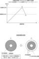
まず、図1を参照して、実施の形態1にかかる二次電池の製造方法を適用しない場合(以下、参考例と称す)におけるメモリ効果の付与位置のズレについて説明する。図1に、二次電池におけるメモリ効果付与充電率のズレが生じる原理を説明する図を示す。ニッケル水素蓄電池では、同じ充電率となる位置で充放電を繰り返すことでメモリ効果が生じることが知られている。そこで、メモリ効果の付与方法としては、メモリ効果を付与したい充電量の付近で複数回の充放電を行うことが考えられる。 First, with reference to FIG. 1, misalignment of the position where the memory effect is applied in the case where the secondary battery manufacturing method according to the first embodiment is not applied (hereinafter referred to as a reference example) will be described. FIG. 1 shows a diagram for explaining the principle of the deviation of the charging rate to which the memory effect is applied in the secondary battery. It is known that in a nickel-metal hydride storage battery, a memory effect occurs when charging and discharging are repeated at positions where the charging rate is the same. Therefore, as a method of imparting the memory effect, it is conceivable to perform charging and discharging a plurality of times in the vicinity of the amount of charge to be imparted with the memory effect.
そこで、参考例にかかるメモリ効果付与方法では、充放電を以下で説明する実施の形態にかかる二次電池の製造方法よりも低い電流値で行う低レート充放電を繰り返し行うことでメモリ効果を二次電池に付与する。図1では、上図に参考例にかかるメモリ効果付与方法における充放電サイクルを説明するタイミングチャートを示し、下図に参考例にかかるメモリ効果付与方法において正極活物質に生じる変化を説明する図を示した。 Therefore, in the memory effect imparting method according to the reference example, the memory effect is doubled by repeatedly performing low-rate charging and discharging at a current value lower than that of the secondary battery manufacturing method according to the embodiment described below. Give to the next battery. In FIG. 1, the upper diagram shows a timing chart for explaining the charge/discharge cycle in the memory effect imparting method according to the reference example, and the lower diagram shows a diagram explaining the change that occurs in the positive electrode active material in the memory effect imparting method according to the reference example. rice field.
図1に示すように、参考例にかかるメモリ効果付与方法では、低い電流値の充放電電流で充放電を行う低レート充放電による充放電サイクルを繰り返す。このとき比較例にかかるメモリ効果付与方法では、メモリ効果を付与する充電率で充電を止めるとともに、予め設定された充電率となる時点で放電を止める充放電を1サイクルの処理として充放電を繰り返す。図1に示す例では、メモリ効果が付与される充電率のズレを強調するために実際のズレよりも見た目のズレが大きくなるようにタイミングチャートを作成した。 As shown in FIG. 1, in the memory effect imparting method according to the reference example, charge/discharge cycles are repeated by low rate charge/discharge in which charge/discharge is performed at a low charge/discharge current value. At this time, in the memory effect imparting method according to the comparative example, charging and discharging are repeated as one cycle of charging and discharging, in which charging is stopped at the charging rate that imparts the memory effect and discharging is stopped when the preset charging rate is reached. . In the example shown in FIG. 1, the timing chart is created so that the apparent deviation is larger than the actual deviation in order to emphasize the deviation of the charging rate to which the memory effect is imparted.
図1の上図に示すように、メモリ効果は、充電を停止した充電率に付与される。しかし、低レート充放電を繰り返すと、充放電の繰り返しが進むと同一の出力電圧として検出されたときの充電率が低下する。これにより、比較例にかかるメモリ効果付与方法では、メモリ効果が付与される実際の充電率が目標値からズレる現象が生じる。 As shown in the upper diagram of FIG. 1, the memory effect is given to the charging rate at which charging is stopped. However, if the low-rate charge/discharge is repeated, the charge rate when the same output voltage is detected decreases as the charge/discharge repeats. As a result, in the memory effect imparting method according to the comparative example, a phenomenon occurs in which the actual charging rate at which the memory effect is imparted deviates from the target value.
このようなズレが発生する原理を図1の下図を参照して説明する。図1の下図に示すように、二次電池では、充電が進むと正極活物質を構成する粒子の表面から内部に向かって絶縁性のβ-水酸化ニッケル(β-Ni(OH)2)が導電性のオキシ水酸化ニッケル(β-NiOOH)に変化する。ここで、β-NiOOHの一部は、導電性のγ-オキシ水酸化ニッケル(γ-NiOOH)に変化する。そして、放電が進むと、正極活物質は、β-NiOOHからβ-Ni(OH)2に変化する(図1下図のP11の状態)が、γ-NiOOHが残る。γ-NiOOHは、β-NiOOHよりも抵抗が高いという特徴がある。そして、このγ-NiOOHの高い抵抗に起因してメモリ効果が生じる。 The principle of occurrence of such deviation will be described with reference to the lower diagram of FIG. As shown in the lower diagram of FIG. 1, in a secondary battery, as charging progresses, insulating β-nickel hydroxide (β-Ni(OH) 2 ) is generated from the surface of the particles constituting the positive electrode active material toward the inside. It changes to conductive nickel oxyhydroxide (β-NiOOH). Here, part of β-NiOOH changes to conductive γ-nickel oxyhydroxide (γ-NiOOH). As the discharge progresses, the positive electrode active material changes from β-NiOOH to β-Ni(OH) 2 (state P11 in the lower diagram of FIG. 1), but γ-NiOOH remains. γ-NiOOH is characterized by higher resistance than β-NiOOH. A memory effect occurs due to the high resistance of this γ-NiOOH.
しかし、図1に示す参考例にかかるメモリ効果付与方法では、低レート充放電でメモリ効果を付与するため、メモリ効果を強固にするため、充放電を繰り返す必要がある。このとき、低レート充放電では、二次電池の自己放電の影響が無視できず、充放電の繰り返しにより自己放電の影響が蓄積して、γ-NiOOHが想定よりも多くなる(図1下図の最も右側に示すP12の状態)。つまり、参考例にかかるメモリ効果付与方法では、充放電の手順に起因して自己放電の影響が蓄積し、メモリ効果の付与位置にズレが生じる。 However, in the memory effect imparting method according to the reference example shown in FIG. 1, since the memory effect is imparted by charging and discharging at a low rate, it is necessary to repeat charging and discharging in order to strengthen the memory effect. At this time, in low-rate charge/discharge, the effect of self-discharge of the secondary battery cannot be ignored, and the effect of self-discharge accumulates due to repeated charge/discharge, and γ-NiOOH becomes larger than expected (lower diagram in FIG. 1). state of P12 shown on the far right). In other words, in the memory effect imparting method according to the reference example, the effect of self-discharge is accumulated due to the procedure of charging and discharging, and the memory effect imparting position is shifted.
実施の形態1にかかるメモリ効果付与方法は、上記したメモリ効果の付与位置のズレを解消することが特徴の1つである。また、実施の形態1にかかるメモリ効果付与方法は、二次電池の製造処理のうち出荷前の充電率調整処理にて行われる。 One of the features of the memory effect imparting method according to the first embodiment is to eliminate the deviation of the above-described memory effect imparting position. Further, the memory effect imparting method according to the first embodiment is performed in the charging rate adjustment process before shipping in the manufacturing process of the secondary battery.
そこで、実施の形態1にかかる二次電池の製造方法について説明する。図2に実施の形態1にかかる二次電池の製造処理を説明するフローチャートを示す。図2に示すように、実施の形態1にかかる二次電池の製造方法では、電極体がケースに密閉された電池構造体に対して行われる出荷前充放電処理にて電極体への充放電を行った後に二次電池を出荷する。この出荷前充放電処理では、まず、電極体の正極活物質に導電ネットワークを形成する正極導電ネットワーク形成処理を行う(ステップS1)。この正極導電ネットワーク形成処理は、電極体に対する初めての通電処理であり、電極体のうち正極に塗布された正極活物質に通電を行うことで正極活物質に電気化学的変化を起こして、導電ネットワークを形成する。 Therefore, a method for manufacturing the secondary battery according to the first embodiment will be described. FIG. 2 shows a flowchart for explaining the manufacturing process of the secondary battery according to the first embodiment. As shown in FIG. 2, in the manufacturing method of the secondary battery according to the first embodiment, the electrode body is charged and discharged in the pre-shipment charging and discharging process performed on the battery structure in which the electrode body is sealed in the case. After performing the above, the secondary battery is shipped. In this pre-shipment charging/discharging process, first, a positive electrode conductive network forming process for forming a conductive network in the positive electrode active material of the electrode body is performed (step S1). This positive electrode conductive network formation treatment is the first energization treatment for the electrode body, and by energizing the positive electrode active material applied to the positive electrode of the electrode body, the positive electrode active material undergoes an electrochemical change, and the conductive network to form
続いて、実施の形態1にかかる二次電池の製造方法では、負極活性化処理を行う(ステップS2)。この負極活性化処理では、初充電処理が成された電極体に対して充放電とエージングとを行い、負極活物質を活性化する。ここで、エージング処理では、例えば、40℃から80℃程度のエージング温度と、予め設定されたエージング温度と、の所定の条件で放電を行う。 Subsequently, in the method for manufacturing a secondary battery according to the first embodiment, negative electrode activation processing is performed (step S2). In this negative electrode activation process, charging/discharging and aging are performed on the electrode body that has been subjected to the initial charging process to activate the negative electrode active material. Here, in the aging process, discharge is performed under predetermined conditions, for example, an aging temperature of about 40° C. to 80° C. and a preset aging temperature.
続いて、実施の形態1にかかる二次電池の製造方法では、充電率調整処理を行う(ステップS3)。この充電率調整処理では、負極活性化処理後に、所定の充電率状態の電極体にメモリ効果を付与する。また、充電率調整処理では、出荷時点での二次電池を予め設定された充電率となるように充電率を調整する。実施の形態1にかかる二次電池の製造方法では、充電率調整処理において、メモリ効果を付与する充電率に相当する充電停止充電率に達するまで充電率が単調増加するように充電処理を行った後に、充電停止充電率よりも低い充電率の放電停止充電率に達するまで充電率が単調減少するように放電処理を行う充放電処理を1サイクルで停止する。つまり、実施の形態1にかかる充電率調整処理では、二次電池に対する充放電サイクルを繰り返し実施しない。そして、充電率調整処理後の二次電池を出荷する。つまり、放電停止充電率は、出荷時点での二次電池の充電率に相当する。また、充電率調整処理後は、二次電池に対して一定期間、充電及び放電を行わない。 Subsequently, in the method for manufacturing a secondary battery according to the first embodiment, a charging rate adjustment process is performed (step S3). In this charging rate adjustment process, a memory effect is imparted to the electrode body in a predetermined charging rate state after the negative electrode activation process. In addition, in the charging rate adjustment process, the charging rate is adjusted so that the secondary battery at the time of shipment reaches a charging rate set in advance. In the manufacturing method of the secondary battery according to the first embodiment, in the charging rate adjustment process, the charging process is performed so that the charging rate monotonically increases until reaching the charging stop charging rate corresponding to the charging rate that imparts the memory effect. After that, the charging/discharging process that performs the discharging process so that the charging rate monotonously decreases until reaching the discharging stop charging rate that is lower than the charging stop charging rate is stopped after one cycle. In other words, in the state of charge adjustment process according to the first embodiment, the secondary battery is not repeatedly subjected to charge/discharge cycles. Then, the secondary battery after the charging rate adjustment process is shipped. That is, the discharge stop charging rate corresponds to the charging rate of the secondary battery at the time of shipment. After the charging rate adjustment process, the secondary battery is not charged or discharged for a certain period of time.
ここで、実施の形態1にかかる充電率調整処理について、より詳細に説明する。そこで、図3に実施の形態1にかかる二次電池の充電率調整処理を説明する図を示す。図3では、上図に充電率調整処理にて行う充放電処理のタイミングチャートを示し、下図に実施の形態1にかかる充電率調整処理にて生じる正極活物質の状態変化を説明する正極活物質の模式図を示した。 Here, the charging rate adjustment process according to the first embodiment will be described in more detail. FIG. 3 shows a diagram for explaining the charging rate adjustment processing of the secondary battery according to the first embodiment. In FIG. 3 , the upper diagram shows a timing chart of the charging and discharging process performed in the charging rate adjustment process, and the lower diagram shows the state change of the positive electrode active material that occurs in the charging rate adjustment process according to the first embodiment. A schematic diagram of
図3の上図に示すように、充電処理と放電処理を1サイクルのみ実施する。まず、充電処理では、メモリ効果を付与する充電率に相当する充電率を充電停止充電率(図3中の充電停止SOC(State Of Charge))まで充電率が単調増加するように充電を行う。そして、放電処理では、充電停止充電率まで充電率が達した後に放電停止充電率(図3中の放電停止SOC(State Of Charge))まで充電率が単調減少するように放電を行う。 As shown in the upper diagram of FIG. 3, only one cycle of the charging process and the discharging process is performed. First, in the charging process, charging is performed so that the charging rate corresponding to the charging rate that provides the memory effect monotonically increases to the charging stop charging rate (charging stop SOC (State Of Charge) in FIG. 3). In the discharging process, after the charging rate reaches the charging stop charging rate, the battery is discharged so that the charging rate monotonically decreases to the discharging stopping charging rate (discharging stopping SOC (State Of Charge) in FIG. 3).
ここで、充電停止充電率は、0%と100%を除く充電率であり10%~95%の値に設定することが好ましい。また、放電停止充電率は、充電停止充電率の1/2以上の充電率に設定することが好ましい。この充電率は、後述するβ-水酸化ニッケルをγ-水酸化ニッケルに変化させるために好ましい条件である。 Here, the charge stop charging rate is a charging rate other than 0% and 100%, and is preferably set to a value between 10% and 95%. Moreover, it is preferable to set the discharge stop charging rate to a charging rate equal to or more than 1/2 of the charge stopping charging rate. This charge rate is a preferable condition for converting β-nickel hydroxide to γ-nickel hydroxide, which will be described later.
また、充電処理と放電処理における電流値について説明する。二次電池の満充電としたときの電池容量を1時間で放電可能な電流量を1Cとした場合、充電処理では、3C~15Cの範囲の充電電流で充電を行う。また、放電処理では、3C~15Cの範囲の放電電流で放電を行う。このような通常使用状態に比べて大きな充放電電流を用いた充放電を高レート充放電と称す。高レート充放電を行うことで後述するγ-水酸化ニッケルを正極活物質の内部に多く生成することができる。 Also, current values in the charging process and the discharging process will be described. Assuming that the amount of current that can be discharged in one hour when the secondary battery is fully charged is 1C, charging is performed with a charging current in the range of 3C to 15C in the charging process. Also, in the discharge treatment, discharge is performed with a discharge current in the range of 3C to 15C. Such charging/discharging using a larger charging/discharging current than in normal use is referred to as high-rate charging/discharging. By performing high-rate charging and discharging, a large amount of γ-nickel hydroxide, which will be described later, can be generated inside the positive electrode active material.
続いて、図3の下図を参照して、充電率調整処理において正極活物質に生じる変化について説明する。図3下図では、正極活物質の粒子を模式的に示した。図3下図に示すように、充電処理により充電率が充電停止充電率となるタイミングP1では、正極活物質の粒子の両面から内部に向かって、絶縁性のβ-水酸化ニッケル(β-Ni(OH)2)が導電性のβ-オキシ水酸化ニッケル(β-NiOOH)に変化する。このタイミングP1では、β-NiOOHの一部がγ-オキシ水酸化ニッケル(γ-NiOOH)に変化する。そして、放電が進むと、正極活物質は、β-NiOOHからβ-Ni(OH)2変化する(図3下図のP2の状態)が、γ-NiOOHが残る。ここで、γ-NiOOHは、β-NiOOHよりも抵抗が高いという特徴がある。そして、このγ-NiOOHの高い抵抗に起因してメモリ効果が生じる。 Next, changes that occur in the positive electrode active material in the state of charge adjustment process will be described with reference to the lower diagram of FIG. The lower diagram of FIG. 3 schematically shows the particles of the positive electrode active material. As shown in the lower diagram of FIG. 3, at timing P1 when the charging rate becomes the charging stop charging rate due to the charging process, insulating β-nickel hydroxide (β-Ni( OH) 2 ) transforms into conductive β-nickel oxyhydroxide (β-NiOOH). At this timing P1, part of β-NiOOH changes to γ-nickel oxyhydroxide (γ-NiOOH). Then, as the discharge progresses, the positive electrode active material changes from β-NiOOH to β-Ni(OH) 2 (state P2 in the lower diagram of FIG. 3), but γ-NiOOH remains. Here, γ-NiOOH is characterized by higher resistance than β-NiOOH. A memory effect occurs due to the high resistance of this γ-NiOOH.
上記した正極活物質の変化を生じさせる際に、実施の形態1にかかる二次電池の製造方法では、高レート充放電を行う。まず、充電処理において高レート充電を行うと以下のような現象が生じる。高レート充電により短時間に充電を進めると、正極活物質の粒子の再表面化から内部に向かって充電される反応(β-Ni(OH)2→β-NiOOH)が進む中で、表面側が内部よりも多く充電される。その結果、表面側からβ-NiOOHからγ-NiOOHに変化する反応が起きる。このとき、γ-NiOOHは、抵抗が高いため、抵抗が低い正極活物質の粒子中央において、β-Ni(OH)2がβ-NiOOHに変化する充電反応が加速する。そして、このような反応により、正極活物質の内部にもγ-NiOOHを生成することが可能になる。 In the manufacturing method of the secondary battery according to the first embodiment, high-rate charge/discharge is performed when the positive electrode active material is changed as described above. First, when high-rate charging is performed in the charging process, the following phenomenon occurs. When charging proceeds for a short period of time by high-rate charging, the reaction (β-Ni(OH) 2 →β-NiOOH) in which the particles of the positive electrode active material resurface and charge toward the inside progresses, and the surface side becomes the inside. charged more than As a result, a reaction occurs from the surface side to change from β-NiOOH to γ-NiOOH. At this time, since γ-NiOOH has a high resistance, the charging reaction in which β-Ni(OH) 2 changes to β-NiOOH is accelerated at the center of the particles of the positive electrode active material with low resistance. Such a reaction makes it possible to generate γ-NiOOH also inside the positive electrode active material.
また、放電処理において高レート放電を行うと以下のような現象が生じる。高レート放電を行うことで、高充電率で充電状態が維持される時間が短縮されるため、自己放電を抑制することができる。これにより、メモリ効果の付与位置の精度を高めることができる。 Further, when high-rate discharge is performed in the discharge process, the following phenomenon occurs. By performing high-rate discharging, the time during which the charged state is maintained at a high charging rate is shortened, so self-discharge can be suppressed. Thereby, the accuracy of the position to which the memory effect is applied can be improved.
また、実施の形態1にかかる二次電池の製造方法では、放電停止充電率を、充電停止充電率の1/2以上に設定する。このような充電率に放電停止充電率を設定することで以下のような現象が生じる。 Further, in the method for manufacturing a secondary battery according to the first embodiment, the discharge stop charging rate is set to 1/2 or more of the charge stopping charging rate. Setting the discharge stop charging rate to such a charging rate causes the following phenomenon.
高レート放電の時間が短い(放電容量が少ない)と、正極活物質の再表面の微少な凹凸形状に依存して、粒子の再表面から内部へ放電する際に再表面側で放電した部分と放電できなかった部分ができる反応ムラが生じる。その結果、再表面で放電できなかった部分にγ-NiOOHが残るとともに、放電できた部分はβ-Ni(OH)2に戻る。このとき、抵抗の関係は、β-Ni(OH)2>γ-NiOOHである。そのため、この状態で二次電池を出荷すると正極活物質粒子の再表面に残った抵抗の低いγ-NiOOHから優先的に放電されてしまい、粒子内部のγ-NiOOHまで放電されるためメモリ効果が解消される現象が生じる。 If the high-rate discharge time is short (the discharge capacity is small), depending on the fine irregularities on the resurface of the positive electrode active material, when discharging from the resurface to the inside of the particle, the discharged portion on the resurface side and the inside. Reaction unevenness occurs where discharge is not possible. As a result, γ-NiOOH remains on the portion of the resurface that could not be discharged, and the portion that could be discharged returns to β-Ni(OH) 2 . At this time, the resistance relationship is β-Ni(OH) 2 >γ-NiOOH. Therefore, if the secondary battery is shipped in this state, the γ-NiOOH with low resistance remaining on the surface of the positive electrode active material particles is discharged preferentially, and the γ-NiOOH inside the particles is also discharged, resulting in a memory effect. A phenomenon that is resolved occurs.
さらに、放電停止充電率を0%付近の値に設定した場合(放電時間が長い)、全てのγ-NiOOHがβ-OOHに戻ってしまうためメモリ効果が解消されてしまうことになる。 Furthermore, when the discharge stop charging rate is set to a value near 0% (long discharge time), all of the γ-NiOOH returns to β-OOH, which eliminates the memory effect.
このようなメモリ効果の解消を防止するため、放電停止充電率と充電停止充電率との差は、充電停止充電率の1/2以上の充電率以上の値に設定することが好ましい。 In order to prevent such a memory effect from being eliminated, the difference between the discharge stop charging rate and the charge stop charging rate is preferably set to a value equal to or higher than 1/2 of the charge stopping charging rate.
続いて、実施の形態1にかかる充電率調整処理の具体例について説明する。そこで、図4に実施の形態1にかかる二次電池の充電率調整処理の具体例を説明する図を示す。図4では、上図に充電率が90%となる位置にメモリ効果を付与したい場合の充電率調整処理のタイミングチャートを示し、下図に充電率が20%となる位置にメモリ効果を付与したい場合の充電率調整処理のタイミングチャートを示した。 Next, a specific example of the charging rate adjustment process according to the first embodiment will be explained. FIG. 4 shows a diagram for explaining a specific example of the secondary battery charging rate adjustment process according to the first embodiment. In FIG. 4, the upper diagram shows the timing chart of the charging rate adjustment process when the memory effect is to be applied to the position where the charging rate is 90%, and the lower diagram is the timing chart when the memory effect is to be applied to the position where the charging rate is 20%. is a timing chart of the charging rate adjustment process.
図4に示すように、実施の形態1にかかる充電率調整処理では、充電停止充電率を10%~95%とし、放電停止充電率を充電停止充電率の1/2以上に設定する。図4に示す例では、充電停止充電率を90%とし、放電停止充電率を50%とした例を上図に示し、充電停止充電率を20%とし、放電停止充電率を8%とした例を下図に示した。そして、図4に示すように、実施の形態1にかかる充電率調整処理では、1回の充電処理と1回の放電処理とを1サイクルとする充放電サイクルを1サイクルだけ実施する。 As shown in FIG. 4, in the charging rate adjustment process according to the first embodiment, the charging stop charging rate is set to 10% to 95%, and the discharging stopping charging rate is set to 1/2 or more of the charging stopping charging rate. In the example shown in FIG. 4, the upper figure shows an example in which the charge-stop charging rate is 90% and the discharge-stop charging rate is 50%, the charge-stop charging rate is 20%, and the discharge-stop charging rate is 8%. An example is shown below. Then, as shown in FIG. 4, in the charging rate adjusting process according to the first embodiment, only one charging/discharging cycle, in which one charging process and one discharging process are set as one cycle, is performed.
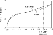
続いて、実施の形態1にかかる二次電池の製造方法を用いてメモリ効果を付与した二次電池の特性について説明する。そこで、図5に実施の形態1にかかる二次電池において充電率が90%となる位置にメモリ効果を付与したときの容量と出力電圧の関係を示すグラフを示す。 Next, the characteristics of the secondary battery to which the memory effect is imparted using the secondary battery manufacturing method according to the first embodiment will be described. FIG. 5 shows a graph showing the relationship between the capacity and the output voltage when the memory effect is applied to the secondary battery according to the first embodiment at the position where the charging rate is 90%.
図5では、実施の形態1にかかる二次電池の製造方法に対する比較例としてメモリ効果を付与しない場合の二次電池の容量と出力電圧のグラフを比較例として示した。図5に示すように、実施の形態1にかかる二次電池の製造方法により製造された二次電池は、容量に対する出力電圧がメモリを付与した充電率90%付近で比較例に対して高くなる変化が生じている。 FIG. 5 shows a graph of the capacity and output voltage of a secondary battery in which the memory effect is not imparted as a comparative example for the method of manufacturing the secondary battery according to the first embodiment. As shown in FIG. 5, in the secondary battery manufactured by the secondary battery manufacturing method according to the first embodiment, the output voltage with respect to the capacity is higher than that of the comparative example at a charging rate of around 90% with memory added. Change is happening.
上記説明より、実施の形態1にかかる二次電池の製造方法では、メモリ効果を付与する充電率調整処理において、1回の充電処理と1回の放電処理とからなる充放電サイクルを1サイクルで停止する。これにより、実施の形態1にかかる二次電池の製造方法では、メモリ効果を付与する充電率のズレを防ぐことができる。 As described above, in the method for manufacturing a secondary battery according to the first embodiment, in the charging rate adjustment process for imparting the memory effect, one charging/discharging cycle including one charging process and one discharging process is performed in one cycle. Stop. As a result, in the method for manufacturing a secondary battery according to the first embodiment, it is possible to prevent deviation in the charging rate that imparts the memory effect.
また、実施の形態1にかかる二次電池の製造方法では、充電率調整処理にける充放電を高レート充放電にて行う。これにより、二次電池の正極活物質の粒子の内部までメモリ効果の原因となるγ-NiOOHを生成することができる。つまり、実施の形態1にかかる二次電池の製造方法により製造される二次電池には、強固なメモリ効果を付与することができる。 In addition, in the method for manufacturing a secondary battery according to the first embodiment, charging and discharging in the charging rate adjustment process are performed at a high rate charging and discharging. As a result, γ-NiOOH, which causes a memory effect, can be generated even inside the particles of the positive electrode active material of the secondary battery. That is, a strong memory effect can be imparted to the secondary battery manufactured by the secondary battery manufacturing method according to the first embodiment.
二次電池では、メモリ効果が発生することは電池性能の劣化と捉えられており、実施の形態1にかかる二次電池の製造方法のようにメモリ効果を付与することは行われないことが一般的である。しかしながら、上述したようにメモリ効果を付与することで充電率の検出精度を高めることができ、電池の過放電状態及び過充電状態を防ぐことが可能になるため、二次電池の実使用条件では結果的に電池寿命を長くすることができる。さらに、メモリ効果の付与による充電率の検出精度の向上は電池の不具合の誤検出を防ぐ効果を奏する。 In a secondary battery, the occurrence of a memory effect is regarded as deterioration of battery performance, and it is generally not performed to impart a memory effect as in the secondary battery manufacturing method according to the first embodiment. target. However, by providing the memory effect as described above, it is possible to improve the detection accuracy of the state of charge and prevent the over-discharged state and over-charged state of the battery. As a result, battery life can be lengthened. Furthermore, the improvement in the detection accuracy of the state of charge due to the addition of the memory effect has the effect of preventing erroneous detection of battery defects.
さらに、実施の形態1にかかる二次電池の製造方法では、充電停止充電率を10%~95%、放電停止充電率を充電停止充電率の1/2以上に設定する。これにより、実施の形態1にかかる二次電池の製造方法では、充放電に起因する活物質の反応ムラを防止して、メモリ効果が解消されてしまうことを防止することができる。 Furthermore, in the secondary battery manufacturing method according to the first embodiment, the charge stop charging rate is set to 10% to 95%, and the discharge stop charging rate is set to 1/2 or more of the charge stop charging rate. As a result, in the method for manufacturing a secondary battery according to the first embodiment, uneven reaction of the active material due to charge/discharge can be prevented, and the memory effect can be prevented from disappearing.
なお、本発明は上記実施の形態に限られたものではなく、趣旨を逸脱しない範囲で適宜変更することが可能である。 It should be noted that the present invention is not limited to the above embodiments, and can be modified as appropriate without departing from the scope of the invention.
Claims (4)
前記充電率調整処理において、
前記メモリ効果を付与する充電率に相当する充電停止充電率に達するまで前記充電率が単調増加するように充電処理を行った後に、前記充電停止充電率よりも低い充電率の放電停止充電率に達するまで前記充電率が単調減少するように放電処理を行う充放電処理を1サイクルで停止し、
前記充電率調整処理後の前記二次電池を出荷し、
前記二次電池を満充電としたときの電池容量を1時間で放電可能な電流量を1Cとした場合、前記充電処理では、3C~15Cの範囲の充電電流で充電を行い、前記放電処理では、3C~15Cの範囲の放電電流で放電を行う二次電池の製造方法。 A charging rate adjustment process for imparting a memory effect to the electrode body for a battery structure in which the electrode body is sealed in a case, wherein
In the charging rate adjustment process,
After the charging process is performed so that the charging rate monotonically increases until reaching the charging stop charging rate corresponding to the charging rate that imparts the memory effect, the discharge stopping charging rate is changed to a charging rate lower than the charging stopping charging rate. Stopping the charging and discharging process in which the discharging process is performed so that the charging rate monotonically decreases until reaching the
shipping the secondary battery after the charging rate adjustment process;
When the battery capacity when the secondary battery is fully charged and the amount of current that can be discharged in one hour is 1 C, in the charging process, charging is performed with a charging current in the range of 3 C to 15 C, and in the discharging process , a method for manufacturing a secondary battery that discharges at a discharge current in the range of 3C to 15C .
前記放電停止充電率は、前記充電停止充電率の1/2以上の充電率が設定される請求項1に記載の二次電池の製造方法。 The charge stop charging rate is set to any value of 10 to 95% charging rate in the secondary battery,
2. The method of manufacturing a secondary battery according to claim 1 , wherein the discharge stop charging rate is set to a charging rate equal to or higher than 1/2 of the charge stopping charging rate.
前記電極体の正極活物質に導電ネットワークを形成する正極導電ネットワーク形成処理と、
前記正極導電ネットワーク形成処理が成された前記電極体に対して充放電とエージングとを行い、負極活物質を活性化する負極活性化処理と、
を行った後に行われる請求項1乃至3のいずれか1項に記載の二次電池の製造方法。 The charging rate adjustment process includes:
A positive electrode conductive network forming process for forming a conductive network in the positive electrode active material of the electrode body;
a negative electrode activation process for activating a negative electrode active material by charging/discharging and aging the electrode body on which the positive electrode conductive network forming process has been performed;
4. The method of manufacturing a secondary battery according to any one of claims 1 to 3 , wherein the method is performed after performing the step.
Priority Applications (2)
| Application Number | Priority Date | Filing Date | Title |
|---|---|---|---|
| JP2020077992A JP7221237B2 (en) | 2020-04-27 | 2020-04-27 | Method for manufacturing secondary battery |
| CN202110396760.9A CN114094204B (en) | 2020-04-27 | 2021-04-13 | Method for manufacturing secondary battery |
Applications Claiming Priority (1)
| Application Number | Priority Date | Filing Date | Title |
|---|---|---|---|
| JP2020077992A JP7221237B2 (en) | 2020-04-27 | 2020-04-27 | Method for manufacturing secondary battery |
Publications (2)
| Publication Number | Publication Date |
|---|---|
| JP2021174680A JP2021174680A (en) | 2021-11-01 |
| JP7221237B2 true JP7221237B2 (en) | 2023-02-13 |
Family
ID=78279807
Family Applications (1)
| Application Number | Title | Priority Date | Filing Date |
|---|---|---|---|
| JP2020077992A Active JP7221237B2 (en) | 2020-04-27 | 2020-04-27 | Method for manufacturing secondary battery |
Country Status (2)
| Country | Link |
|---|---|
| JP (1) | JP7221237B2 (en) |
| CN (1) | CN114094204B (en) |
Citations (2)
| Publication number | Priority date | Publication date | Assignee | Title |
|---|---|---|---|---|
| JP2004361313A (en) | 2003-06-06 | 2004-12-24 | Panasonic Ev Energy Co Ltd | Remaining capacity arithmetic unit and remaining capacity computing method of secondary battery |
| JP2012029455A (en) | 2010-07-23 | 2012-02-09 | Toyota Motor Corp | Device and method of controlling vehicle |
Family Cites Families (11)
| Publication number | Priority date | Publication date | Assignee | Title |
|---|---|---|---|---|
| JPH05236666A (en) * | 1992-02-24 | 1993-09-10 | Matsushita Electric Ind Co Ltd | Battery charger |
| JP4380856B2 (en) * | 1999-10-28 | 2009-12-09 | 三洋電機株式会社 | Secondary battery capacity calculation method |
| JP4589550B2 (en) * | 2001-03-05 | 2010-12-01 | パナソニック株式会社 | Manufacturing method of nickel metal hydride storage battery |
| EP1367666A4 (en) * | 2001-03-05 | 2006-04-05 | Yuasa Battery Co Ltd | METHOD FOR PRODUCING A NICKEL HYDROGEN BATTERY |
| US6946818B2 (en) * | 2003-10-14 | 2005-09-20 | General Motors Corporation | Method of determining battery power limits for an energy storage system of a hybrid electric vehicle |
| JP5078525B2 (en) * | 2007-09-28 | 2012-11-21 | 三洋電機株式会社 | How to install a running battery in a hybrid car |
| JP5308806B2 (en) * | 2008-12-25 | 2013-10-09 | プライムアースEvエナジー株式会社 | Manufacturing method of nickel metal hydride storage battery |
| JP5536122B2 (en) * | 2012-02-20 | 2014-07-02 | Necアクセステクニカ株式会社 | Charging apparatus and charging method |
| KR101651991B1 (en) * | 2014-10-30 | 2016-08-30 | 주식회사 엘지화학 | Method and apparatus for fast charging of battery |
| JP6229698B2 (en) * | 2015-08-21 | 2017-11-15 | トヨタ自動車株式会社 | Nickel metal hydride battery |
| KR20180049590A (en) * | 2016-11-03 | 2018-05-11 | 한국전기연구원 | Apparatus and Method of collecting and Modeling a SOC-OCV data of the secondary battery |
-
2020
- 2020-04-27 JP JP2020077992A patent/JP7221237B2/en active Active
-
2021
- 2021-04-13 CN CN202110396760.9A patent/CN114094204B/en active Active
Patent Citations (2)
| Publication number | Priority date | Publication date | Assignee | Title |
|---|---|---|---|---|
| JP2004361313A (en) | 2003-06-06 | 2004-12-24 | Panasonic Ev Energy Co Ltd | Remaining capacity arithmetic unit and remaining capacity computing method of secondary battery |
| JP2012029455A (en) | 2010-07-23 | 2012-02-09 | Toyota Motor Corp | Device and method of controlling vehicle |
Also Published As
| Publication number | Publication date |
|---|---|
| JP2021174680A (en) | 2021-11-01 |
| CN114094204A (en) | 2022-02-25 |
| CN114094204B (en) | 2024-05-28 |
Similar Documents
| Publication | Publication Date | Title |
|---|---|---|
| JP6455497B2 (en) | Vehicle battery system and control method thereof | |
| CN100395559C (en) | Secondary battery replacement method | |
| KR101886639B1 (en) | Method and device for charging rechargeable cells | |
| JP4118035B2 (en) | Battery control device | |
| US9368995B2 (en) | Lithium ion battery charging method and battery-equipped device | |
| US6646421B2 (en) | Method and apparatus for controlling residual battery capacity of secondary battery | |
| KR101475913B1 (en) | Apparatus and method for battery charging | |
| JP6797438B2 (en) | Battery charging method and battery charging device | |
| CN110729520B (en) | A fast charging method for ternary batteries | |
| JP2000133321A (en) | Lithium-ion battery charge control method | |
| CN1217832A (en) | Power supply device | |
| US9815376B2 (en) | Power supply apparatus | |
| JP5305653B2 (en) | Method for charging a lithium ion storage battery having a negative electrode | |
| JP2002142379A (en) | Charging method for battery | |
| KR102086631B1 (en) | Charging Method of Secondary Battery and Charging Apparatus of the Same | |
| CN113346152A (en) | Battery system and control method thereof | |
| JP2002313412A (en) | Activation method of secondary battery | |
| JP7221237B2 (en) | Method for manufacturing secondary battery | |
| CN118871318A (en) | Method for operating a traction battery of a motor vehicle, electronic computing device and motor vehicle having a traction battery | |
| KR20220051237A (en) | Methods and systems for improved performance of silicon anode containing cells through formation process | |
| JP6760241B2 (en) | Rechargeable battery system | |
| US7353894B2 (en) | Sealed nickel-metal hydride storage cells and hybrid electric having the storage cells | |
| WO2014104280A1 (en) | Control method and control device for secondary battery | |
| CN119275982A (en) | Intelligent photovoltaic power supply system and control method thereof | |
| JP2021141656A (en) | Battery system |
Legal Events
| Date | Code | Title | Description |
|---|---|---|---|
| A621 | Written request for application examination |
Free format text: JAPANESE INTERMEDIATE CODE: A621 Effective date: 20220222 |
|
| A977 | Report on retrieval |
Free format text: JAPANESE INTERMEDIATE CODE: A971007 Effective date: 20221026 |
|
| A131 | Notification of reasons for refusal |
Free format text: JAPANESE INTERMEDIATE CODE: A131 Effective date: 20221129 |
|
| A521 | Request for written amendment filed |
Free format text: JAPANESE INTERMEDIATE CODE: A523 Effective date: 20221223 |
|
| TRDD | Decision of grant or rejection written | ||
| A01 | Written decision to grant a patent or to grant a registration (utility model) |
Free format text: JAPANESE INTERMEDIATE CODE: A01 Effective date: 20230131 |
|
| A61 | First payment of annual fees (during grant procedure) |
Free format text: JAPANESE INTERMEDIATE CODE: A61 Effective date: 20230201 |
|
| R150 | Certificate of patent or registration of utility model |
Ref document number: 7221237 Country of ref document: JP Free format text: JAPANESE INTERMEDIATE CODE: R150 |
|
| R250 | Receipt of annual fees |
Free format text: JAPANESE INTERMEDIATE CODE: R250 |