JP7219967B2 - Mounting structure of corrugated metal roofing material - Google Patents
Mounting structure of corrugated metal roofing material Download PDFInfo
- Publication number
- JP7219967B2 JP7219967B2 JP2019088436A JP2019088436A JP7219967B2 JP 7219967 B2 JP7219967 B2 JP 7219967B2 JP 2019088436 A JP2019088436 A JP 2019088436A JP 2019088436 A JP2019088436 A JP 2019088436A JP 7219967 B2 JP7219967 B2 JP 7219967B2
- Authority
- JP
- Japan
- Prior art keywords
- roof
- corrugated
- corrugated metal
- fixture
- metal roofing
- Prior art date
- Legal status (The legal status is an assumption and is not a legal conclusion. Google has not performed a legal analysis and makes no representation as to the accuracy of the status listed.)
- Active
Links
Images


Description
本願は、屋根改修等において、波形スレート屋根に孔をあけることなく波形金属屋根材を取り付けることができ、様々な寸法の波形金属屋根材を取り付けることができる取付構造を提供することを目的とする。 It is an object of the present application to provide a mounting structure capable of mounting a corrugated metal roofing material without drilling holes in a corrugated slate roof, and mounting corrugated metal roofing materials of various sizes in roof repair or the like. .
従来技術について、図10で説明する。 A conventional technique will be described with reference to FIG.
図10は、特開2010-65506号公報にて公開されているスレート葺屋根における新設屋根材取付方法及び取付け作業器に関する技術である。この技術は、既設スレート葺屋根1における母屋材位置に当たる凸面部上に基板部と吊枠板5部から成る台金具を配置し、この台金具の基板の長手方向中央部に弯形部6を形成するとともにこの弯形部の一端部中央に開口部につづく長孔を設け、前記既設屋根の母屋材に下端部を掛止めるフックボルト20の上端部を前記台金具の長孔に螺着し、左右対称に成るレール材の前後両端部を各脚台上に設置し、一方の脚台の支板と立板との間に先端に係止部を有する固定具を設け、他方の脚台のレール材端部上に設けた支台の上端部間に作業杆の基端部を枢着し、この作業杆の適所に設けたガイド板の当接板を前記固定具との間に配置した前記台金具に抑止し、台金具の固定状態下において新設の屋根板26の適所に螺子25を内側の吊枠板の凸状上面部に取付けるものである。
FIG. 10 shows a technique relating to a new roofing material mounting method and mounting tool for a slate roof disclosed in Japanese Patent Application Laid-Open No. 2010-65506. In this technique, a metal base consisting of a base plate and a hanging frame plate 5 is placed on a convex surface corresponding to the position of the purlin of the existing
図10に示した先行技術では、既設屋根上のフックボルトの位置で、新設屋根が固定される必要がある。そのため、既設屋根の取付寸法に応じた新設屋根を用意する必要があった。たとえば、屋根の桁行方向で隣り合うフックボルト同士の間隔と、新設屋根の寸法が合わない場合、フックボルトのない山部においては既設屋根に穿孔する必要があった。また、屋根の桁行方向において、既設屋根上のフックボルト同士の離隔距離が大きい場合、新設屋根の沈みこみが発生する恐れがあった。 The prior art shown in FIG. 10 requires that the new roof be fixed at the hook bolt positions on the existing roof. Therefore, it was necessary to prepare a new roof according to the mounting dimensions of the existing roof. For example, if the spacing between adjacent hook bolts in the girder direction of the roof does not match the dimensions of the new roof, it has been necessary to drill holes in the existing roof at peaks where there are no hook bolts. In addition, if the separation distance between the hook bolts on the existing roof is large in the girder direction of the roof, there is a possibility that the new roof will sink.
本願は、波形スレート屋根上に波形金属屋根材が取り付けられた構造である。固定具は、波形スレート屋根を固定しているフックボルトに取り付けられる。補助固定具は、上面と、上面の両端から外側下方にのびる支持脚を有する。この補助固定具は、波形スレート屋根の山部上に上面が配置され、波形スレート屋根の谷部に支持脚下端が載置されている。そして、固定具上および補助固定具上に波形金属屋根材が止着具で固定されている。 The present application is a structure in which a corrugated metal roofing material is mounted on a corrugated slate roof. Fixtures are attached to the hook bolts that secure the corrugated slate roof. The secondary fixture has a top surface and support legs extending outwardly and downwardly from opposite ends of the top surface. The upper surface of the auxiliary fixture is placed on the peaks of the corrugated slate roof, and the lower ends of the support legs are placed on the valleys of the corrugated slate roof. A corrugated metal roofing material is fixed on the fixtures and on the auxiliary fixtures with fasteners.
本願は、波形金属屋根材が波形スレート屋根上のフックボルトの位置で固定具に固定されるのに加え、フックボルトのない位置でも補助固定具に固定される。そのため、たとえば、屋根の桁行方向で隣り合うフックボルト同士の間隔と、波形金属屋根材の寸法が合わない場合であっても、フックボルトのない山部においては補助固定具を載置して用いるだけでよく、波形スレート屋根に穿孔する必要がない。また、屋根の桁行方向において、波形スレート屋根上のフックボルト同士の離隔距離が大きい場合でも、波形金属屋根材が補助固定具で支持されるので、沈みこみが発生しにくい。 In addition to the corrugated metal roofing being secured to the fixtures at the hook bolt locations on the corrugated slate roof, the present application also secures the corrugated metal roofing to secondary fixtures at the hook bolt free locations. Therefore, for example, even if the spacing between adjacent hook bolts in the girder direction of the roof does not match the dimensions of the corrugated metal roof material, auxiliary fixtures are placed and used on peaks where there are no hook bolts. No need to drill holes in the corrugated slate roof. In addition, even if the separation distance between the hook bolts on the corrugated slate roof is large in the girder direction of the roof, the corrugated metal roof material is supported by the auxiliary fixtures, so sinking is less likely to occur.
本願の波形金属屋根材の取付構造について、図1から図9までにより説明する。図1は、本願の波形金属屋根材の取付構造における固定具の実施例を示す斜視図である。図2は、本願の波形金属屋根材の取付構造における固定具の実施例を示す正面図である。図3は、本願の波形金属屋根材の取付構造における上部材(固定具)の実施例を示す斜視図である。図4は、本願の波形金属屋根材の取付構造における下部材(固定具)の実施例を示す斜視図である。図5は、本願の波形金属屋根材の取付構造における補助固定具の実施例を示す斜視図である。図6は、本願の波形金属屋根材の取付構造における補助固定具の実施例を示す正面図である。図7から図9までは、本願の波形金属屋根材の取付構造の実施例を示す説明図(正面図)である。 The mounting structure of the corrugated metal roofing material of the present application will be described with reference to FIGS. 1 to 9. FIG. FIG. 1 is a perspective view showing an embodiment of a fixture in a corrugated metal roofing mounting structure of the present application. FIG. 2 is a front view showing an embodiment of a fixture in the corrugated metal roofing mounting structure of the present application. FIG. 3 is a perspective view showing an embodiment of the upper member (fixture) in the mounting structure of the corrugated metal roofing material of the present application. FIG. 4 is a perspective view showing an embodiment of a lower member (fixture) in the corrugated metal roofing mounting structure of the present application. FIG. 5 is a perspective view showing an embodiment of an auxiliary fixture in the corrugated metal roofing mounting structure of the present application. FIG. 6 is a front view showing an embodiment of an auxiliary fixture in the corrugated metal roofing mounting structure of the present application. 7 to 9 are explanatory views (front views) showing an embodiment of the mounting structure of the corrugated metal roofing material of the present application.
本実施例の波形スレート屋根Sは、山部S1および谷部S2が形成されている屋根材が、フックボルトFを用いて屋根下地に固定されている。このフックボルトFは、波形スレート屋根Sの山部S1より表面側に突出されている。このフックボルトFは、波形スレート屋根Sのすべての山部S1から突出されているわけではない。したがって、フックボルトFが突出されていない山部S1もある。 In the corrugated slate roof S of this embodiment, a roof material having peaks S1 and valleys S2 is fixed to the roof base using hook bolts F. As shown in FIG. The hook bolt F protrudes from the crest S1 of the corrugated slate roof S toward the surface side. The hook bolts F do not protrude from all peaks S1 of the corrugated slate roof S. Therefore, there is also a mountain portion S1 where the hook bolt F does not protrude.
本実施例の波形金属屋根材Nは、山部N1および谷部N2が形成されている屋根材で、山部N1の表面側から止着具Bを打ち込んで、屋根に固定される。本実施例の波形金属屋根材Nの山部N1および谷部N2の形成ピッチは、波形スレート屋根Sの山部S1および谷部S2の形成ピッチと同じであることが望ましい。 The corrugated metal roofing material N of this embodiment is a roofing material in which peaks N1 and valleys N2 are formed. The formation pitch of the peaks N1 and valleys N2 of the corrugated metal roof material N of this embodiment is preferably the same as the pitch of formation of the peaks S1 and valleys S2 of the corrugated slate roof S.
本実施例の固定具Kには、山部N1と谷部N2が形成された波形金属屋根材Nが取り付けられる。本実施例の固定具Kは、波形スレート屋根S上のフックボルトFに複数のものが固定され、その上に波形金属屋根材Nがかぶせられ、波形金属屋根材Nの表面側から固定具Kにビスなどの止着具Bが打ち込まれて固定される。 A corrugated metal roofing material N having peaks N1 and valleys N2 is attached to the fixture K of this embodiment. A plurality of fasteners K are fixed to the hook bolts F on the corrugated slate roof S, and the corrugated metal roofing material N is placed thereon. A fastening tool B such as a screw is driven into and fixed.
本実施例の固定具Kは、上方に凸となる湾曲に形成された上面に複数条の溝線K111が形成された波形金属屋根材取付部K11を有する。上面の湾曲頂部は、本実施例の固定具Kが波形スレート屋根SのフックボルトFに取り付けられたときに、屋根の流れ方向と略平行となるように形成されている。また、複数条の溝線K111も、本実施例の固定具Kが波形スレート屋根S上のフックボルトFに取り付けられたときに、屋根の流れ方向と略平行になる方向に形成されている。 The fixture K of this embodiment has a corrugated metal roof material mounting portion K11 having a curved upper surface with a plurality of groove lines K111 formed in an upwardly convex shape. The curved top of the upper surface is formed so as to be substantially parallel to the running direction of the roof when the fixture K of this embodiment is attached to the hook bolt F of the corrugated slate roof S. The plurality of groove lines K111 are also formed in a direction substantially parallel to the direction of flow of the roof when the fixture K of this embodiment is attached to the hook bolt F on the corrugated slate roof S.
波形スレート屋根S上においてフックボルトFが垂直でない場合、本実施例の固定具Kも傾いた状態で取り付けられる。しかし、本実施例の固定具Kは、上方に凸となる湾曲に形成された上面になっている。そこが波形金属屋根材N裏面に対して当接される構造になっているので、波形金属屋根材Nに金具痕が出てしまうことがない。なお、上方に凸となる湾曲は、波形スレート屋根Sの山部S1の半径に本実施例の固定具Kの高さ寸法を加算した半径で形成されているのが望ましい。 If the hook bolt F is not vertical on the corrugated slate roof S, the fixture K of this embodiment is also installed in an inclined state. However, the fixture K of this embodiment has a curved upper surface that is convex upward. Since it has a structure in which it is abutted against the back surface of the corrugated metal roof material N, metal fitting marks do not appear on the corrugated metal roof material N. - 特許庁The upwardly convex curve is preferably formed with a radius obtained by adding the height dimension of the fixture K of this embodiment to the radius of the ridges S1 of the corrugated slate roof S.
また、波形金属屋根材Nの表面側から固定具Kにビスなどの止着具Bが打ち込まれる際、止着具Bの先端が溝線K111に引っかかる構造になっており、固定具K上を滑って刺しにくくなることがない。なお、溝線K111の条数、溝線K111・K111同士の間隔は問わないが、止着具Bが打ち込まれる際、その先端が当たりうる範囲にわたって、波形金属屋根材取付部K11上を滑らない程度の間隔で溝線K111が形成されていることが望ましい。 Further, when the fastener B such as a screw is driven into the fixture K from the surface side of the corrugated metal roof material N, the tip of the fastener B is caught in the groove line K111. It does not slip and become difficult to pierce. Although the number of groove lines K111 and the interval between groove lines K111 and K111 are not specified, when the fastening tool B is driven in, it does not slide on the corrugated metal roof material mounting portion K11 over the range where the tip thereof can hit. It is desirable that the groove lines K111 are formed at regular intervals.
本実施例の固定具Kは、上部材K1と下部材K2で構成されている。そのため、上部材K1、下部材K2のどちらかを変えるだけで、波形金属屋根材Nの取付高さを調整できる。そのため、上部材K1と下部材K2、どちらかを取付高さを問わない共通部材とすることができる。さらに、上部材K1と下部材K2、どちらで取付高さを調整してもよいので、設計の自由度が高い。 The fixture K of this embodiment is composed of an upper member K1 and a lower member K2. Therefore, the mounting height of the corrugated metal roof material N can be adjusted simply by changing either the upper member K1 or the lower member K2. Therefore, either the upper member K1 or the lower member K2 can be used as a common member regardless of the mounting height. Furthermore, since the mounting height can be adjusted with either the upper member K1 or the lower member K2, the degree of freedom in design is high.
本実施例の上部材K1は、上方に凸となる湾曲に形成された上面に複数条の溝線K111が形成された波形金属屋根材取付部K11が形成されている。また、本実施例の上部材K1は、波形金属屋根材取付部K11の一対の両端縁から下方にのびる脚部K12・K12と、脚部K12・K12の下端にスライド部K13・K13を有している。この一対の両端縁は、溝線K111と平行な直線状になっている側の端縁である。波形金属屋根材取付部K11の一対の両端縁は、本実施例の波形金属屋根材取付部K11が波形スレート屋根S上のフックボルトFに取り付けられたときに、屋根の妻側に対面する向きに配置される。 The upper member K1 of this embodiment is formed with a corrugated metal roof material mounting portion K11 formed with a plurality of groove lines K111 on the upper surface which is curved upwardly. Further, the upper member K1 of this embodiment has legs K12 and K12 extending downward from a pair of both end edges of the corrugated metal roof material mounting portion K11, and slide portions K13 and K13 at the lower ends of the legs K12 and K12. ing. This pair of both end edges is the edge on the side of the straight line parallel to the groove line K111. A pair of both edges of the corrugated metal roof material mounting portion K11 are oriented to face the gable side of the roof when the corrugated metal roof material mounting portion K11 of this embodiment is attached to the hook bolt F on the corrugated slate roof S. placed in
本実施例において、脚部K12・K12は、波形金属屋根材取付部K11の一対の両端縁から下方、すなわち、波形金属屋根材取付部K11の一対の両端縁から波形スレート屋根S側に向けて形成されている。この脚部K12の高さ寸法によって、すなわち、本実施例の上部材K1によって、波形金属屋根材Nの取付高さを調整できる。 In this embodiment, the legs K12 and K12 extend downward from the pair of both edges of the corrugated metal roof material mounting portion K11, that is, from the pair of both edges of the corrugated metal roof material mounting portion K11 toward the corrugated slate roof S side. formed. The mounting height of the corrugated metal roof material N can be adjusted by the height dimension of the legs K12, that is, by the upper member K1 of this embodiment.
本実施例の上部材K1は、脚部K12・K12の下端にスライド部K13・K13を有している。本実施例の上部材K1は、脚部K12・K12の下端に内側当接部、外側当接部が形成されており、下部材K2の被スライド部K23を外側から抱持するような形状になっている。そのため、スライド部K13と被スライド部K23を係合させると、上部材が取り付けられる上下位置及び桁行位置が固定され、屋根の流れ方向のみにスライドされる構造になる。また、本実施例は、下部材K2の被スライド部K23を外側から抱持するような形状になっているので、外側にするどい端縁が突出することがなく、波形金属屋根材Nの裏面を傷つけにくい構造になっている。 The upper member K1 of this embodiment has slide portions K13 and K13 at the lower ends of the legs K12 and K12. The upper member K1 of this embodiment has an inner contact portion and an outer contact portion formed at the lower ends of the legs K12 and K12, and is shaped to hold the slide portion K23 of the lower member K2 from the outside. It's becoming Therefore, when the sliding portion K13 and the slidable portion K23 are engaged with each other, the vertical position and the girder position where the upper member is attached are fixed, and the structure is such that the upper member is slid only in the running direction of the roof. Further, in this embodiment, since the portion to be slid K23 of the lower member K2 is held from the outside, the sharp edge does not protrude outward, and the back surface of the corrugated metal roof material N is prevented from protruding outward. It has a structure that is hard to damage.
なお、本実施例のスライド部K13及び被スライド部K23の形状及び構造は一例であり、スライド部K13と被スライド部K23が係合されたときに、上部材K1が取り付けられる上下位置及び桁行方向における位置が固定され、屋根の流れ方向のみにスライドされる構造であればよい。 Note that the shape and structure of the sliding portion K13 and the slidable portion K23 in this embodiment are examples, and when the sliding portion K13 and the slidable portion K23 are engaged, the vertical position and the girder direction at which the upper member K1 is attached It is sufficient that the position of the roof is fixed and the structure is slid only in the direction of flow of the roof.
本実施例の下部材K2は、フックボルト固定部K211を有する底面K21を有する。波形スレート屋根Sの山部S1の形状にあわせて、本実施例において、底面K21は上方に凸となる湾曲に形成されている。 The lower member K2 of this embodiment has a bottom surface K21 having a hook bolt fixing portion K211. According to the shape of the ridges S1 of the corrugated slate roof S, in this embodiment, the bottom surface K21 is formed in a curved shape that protrudes upward.
また、本実施例の下部材K2が波形スレート屋根S上のフックボルトFに取り付けられる際、水下側になる端部から底辺略中央部にかけて、切り込みによってフックボルト固定部K211が形成されている。このフックボルト固定部K211は、波形スレート屋根S上のフックボルトFに係合され、下部材K2を波形スレート屋根S上のフックボルトFに固定するために用いられる。そのため、波形スレート屋根Sに孔をあけることなく、波形金属屋根材Nを取り付けることができる。 Further, when the lower member K2 of this embodiment is attached to the hook bolt F on the corrugated slate roof S, a hook bolt fixing portion K211 is formed by cutting from the end portion on the underwater side to the approximate center portion of the bottom side. . This hook bolt fixing portion K211 is engaged with the hook bolt F on the corrugated slate roof S and is used to fix the lower member K2 to the hook bolt F on the corrugated slate roof S. Therefore, the corrugated metal roof material N can be attached without making holes in the corrugated slate roof S.
本実施例において、下部材K2の水上側端部は、上方に折り曲げられ、打撃受部K24が形成されている。下部材K2は、フックボルト固定部K211が波形スレート屋根S上のフックボルトFに係合され、打撃受部K24がハンマー等によって打擲されることによって、波形スレート屋根S上のフックボルトFに固定される。 In this embodiment, the water side end portion of the lower member K2 is bent upward to form the impact receiving portion K24. The lower member K2 is fixed to the hook bolt F on the corrugated slate roof S by engaging the hook bolt fixing portion K211 with the hook bolt F on the corrugated slate roof S and hitting the impact receiving portion K24 with a hammer or the like. be done.
本実施例の下部材K2は、底面K21の一対の両端縁から上方にのびる支承部K22が形成されている。底面K21の一対の両端縁は、本実施例の波形金属屋根材取付部K11が波形スレート屋根S上のフックボルトFに取り付けられたときに、屋根の妻側に対面する向きに配置される。本実施例において、支承部K22は、底面K21の一対の端縁から上方、すなわち、底面K21の一対の両端縁から波形金属屋根材N側に向けて形成されている。この支承部K22の高さ寸法によって、すなわち、本実施例の下部材K2によって、波形金属屋根材Nの取付高さを調整できる。 The lower member K2 of this embodiment is formed with support portions K22 extending upward from a pair of both edges of the bottom surface K21. A pair of both edges of the bottom surface K21 are arranged to face the gable side of the roof when the corrugated metal roof material mounting portion K11 of this embodiment is attached to the hook bolts F on the corrugated slate roof S. In this embodiment, the support portions K22 are formed upward from a pair of edges of the bottom surface K21, that is, from a pair of both edges of the bottom surface K21 toward the corrugated metal roof material N side. The mounting height of the corrugated metal roof material N can be adjusted by the height dimension of the support portion K22, that is, by the lower member K2 of this embodiment.
本実施例の下部材K2は、支承部K22の上端に被スライド部K23を有する。本実施例において、被スライド部K23は、支承部K22の上端が外側に折り曲げられるとともに、折り曲げられた部分に切り欠きが形成され、外側及び内側双方に端縁が突出している構造になっている。本実施例では、被スライド部K23の外側端縁及び内側端縁が、スライド部K13の外側当接部及び内側当接部に強く当接される構造になっている。その構造によって、スライド部K13と被スライド部K23を一旦係合されると抜けにくい状態に、上部材K1と下部材K2が一体化される。この一体化に当たっては、鋲子などの追加部材も必要なく、コストを低く抑えることができる。 The lower member K2 of this embodiment has a slidable portion K23 at the upper end of the support portion K22. In this embodiment, the slidable portion K23 has a structure in which the upper end of the support portion K22 is bent outward, a notch is formed in the bent portion, and the edges protrude both outward and inward. . In this embodiment, the outer edge and inner edge of the slide portion K23 are strongly abutted against the outer contact portion and inner contact portion of the slide portion K13. Due to this structure, the upper member K1 and the lower member K2 are integrated so that once the sliding portion K13 and the slidable portion K23 are engaged with each other, they are difficult to come off. In this integration, additional members such as rivets are not required, and the cost can be kept low.
本実施例の下部材K2は、被スライド部K23の一端に止め部K231が形成されている。この止め部K231に、スライド部K13の水下側端縁が当接する位置が、上部材K1と下部材K2の適正な組合せ位置となる。また、スライド部K13と被スライド部K23の係合がゆるい場合でも、この止め部K231によって、上部材K1が下部材K2の水下側に滑落するのを防ぐことができる。 The lower member K2 of this embodiment has a stop portion K231 formed at one end of the portion to be slid K23. The position where the underwater side edge of the slide portion K13 abuts against the stopping portion K231 is the proper combination position of the upper member K1 and the lower member K2. Further, even when the sliding portion K13 and the slidable portion K23 are loosely engaged with each other, the stopping portion K231 can prevent the upper member K1 from sliding down to the underwater side of the lower member K2.
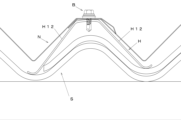
本実施例の補助固定具Hは、上面H1と、上面H1の両端から外側下方にのびる支持脚H12を有する。本実施例の補助固定具Hの上面H1には、複数条の溝線H111が形成された波形金属屋根材取付部H11が形成されている。この複数条の溝線H111は、本実施例の補助固定具Hが波形スレート屋根S上に設置されたときに、屋根の流れ方向と略平行になる方向に形成されている。 The auxiliary fixture H of this embodiment has a top surface H1 and support legs H12 extending outward and downward from both ends of the top surface H1. The upper surface H1 of the auxiliary fixture H of the present embodiment is formed with a corrugated metal roof material mounting portion H11 having a plurality of groove lines H111 formed therein. The plurality of groove lines H111 are formed in a direction substantially parallel to the flow direction of the roof when the auxiliary fixture H of this embodiment is installed on the corrugated slate roof S.
波形金属屋根材Nの山部N1および谷部N2の形成ピッチと、波形スレート屋根Sの山部N1および谷部N2の形成ピッチとが同じである場合、本実施例の補助固定具Hは、波形金属屋根材N・N同士の重なり部が波形スレート屋根SのフックボルトFのない山部S1上に当たる場合に設置される。もし、波形スレート屋根Sと波形金属屋根材Nの桁行寸法も同じであれば、波形金属屋根材N・N同士の重なり部は、必ず波形スレート屋根SのフックボルトFのある山部S1上に当たる。しかし、波形スレート屋根Sと波形金属屋根材Nの桁行寸法が異なる場合、波形金属屋根材N・N同士の重なり部は、必ずしも波形スレート屋根SのフックボルトFのある山部S1上に当たるとは限らない。したがって、本実施例の補助固定具Hは、隣り合う波形金属屋根材N・N同士の重なり部を固定するために用いられる。 When the formation pitch of the ridges N1 and the troughs N2 of the corrugated metal roofing material N and the formation pitch of the ridges N1 and the troughs N2 of the corrugated slate roof S are the same, the auxiliary fixture H of this embodiment is It is installed when the overlapping portion of the corrugated metal roof materials N and N hits the crest portion S1 of the corrugated slate roof S where there is no hook bolt F. If the girder dimensions of the corrugated slate roof S and the corrugated metal roof material N are the same, the overlapped portion of the corrugated metal roof materials N and N always hits the crest S1 of the corrugated slate roof S where the hook bolt F is located. . However, if the girder dimensions of the corrugated slate roof S and the corrugated metal roof material N are different, the overlapping portion of the corrugated metal roof materials N and N does not necessarily hit the crest S1 of the corrugated slate roof S where the hook bolt F is located. Not exclusively. Therefore, the auxiliary fixture H of this embodiment is used to fix overlapping portions of adjacent corrugated metal roof materials N and N. As shown in FIG.
本実施例の補助固定具Hは、波形金属屋根材Nの表面側から補助固定具Hの上面H11にビスなどの止着具Bが打ち込まれる際、止着具Bの先端が溝線H111に引っかかる構造になっており、補助固定具H上を滑って刺しにくくなることがない。なお、溝線H111の条数、溝線H111・H111同士の間隔は問わないが、止着具Bが打ち込まれる際、その先端が当たりうる範囲にわたって、波形金属屋根材取付部H11上を滑らない程度の間隔で溝線H111が形成されていることが望ましい。 In the auxiliary fixture H of this embodiment, when the fastener B such as a screw is driven into the upper surface H11 of the auxiliary fixture H from the surface side of the corrugated metal roofing material N, the tip of the fastener B is aligned with the groove line H111. It has a catch structure, and slipping on the auxiliary fixture H does not make it difficult to pierce. Although the number of groove lines H111 and the interval between the groove lines H111 and H111 do not matter, when the fastening tool B is driven, it does not slide on the corrugated metal roof material mounting portion H11 over the range where the tip thereof can hit. It is desirable that the groove lines H111 are formed at regular intervals.
本実施例の補助固定具Hの上面H1は、上方に凸となる湾曲に形成されていることが望ましい。たとえば、支持脚H12の一方が波形スレート屋根S・S同士の重なり部上に配置され、補助固定具Hが傾いた状態で設置される場合がある。その場合、本実施例の補助固定具Hの場合は、上面H1が上方に凸となる湾曲に形成されているので、そこが波形金属屋根材N裏面に対して当接される構造になっている。そのため、波形金属屋根材Nに金具痕が出てしまうことがない。なお、上方に凸となる湾曲は、波形スレート屋根Sの山部S1の半径に本実施例の補助固定具Hの高さ寸法を加算した半径で形成されているのが望ましい。 It is desirable that the upper surface H1 of the auxiliary fixture H of the present embodiment is curved to be convex upward. For example, one of the support legs H12 may be placed on the overlapping portion of the corrugated slate roofs S and S, and the auxiliary fixture H may be installed in an inclined state. In this case, in the case of the auxiliary fixture H of the present embodiment, the upper surface H1 is formed in a curved shape that protrudes upward, so that the upper surface H1 abuts against the back surface of the corrugated metal roofing material N. there is Therefore, metal fitting marks do not appear on the corrugated metal roof material N. - 特許庁The upwardly convex curve is preferably formed with a radius obtained by adding the height dimension of the auxiliary fixture H of this embodiment to the radius of the ridges S1 of the corrugated slate roof S.
本実施例の補助固定具Hは、波形スレート屋根Sの山部S1上に上面H1が配置され、波形スレート屋根Sの谷部S2に支持脚H12・H12下端が載置される。このとき、波形スレート屋根Sの山部S1と、補助固定具Hの間に空間が形成されている。この空間により、波形金属屋根材Nを固定する止着具Bが、波形スレート屋根Sに届かない構造になっている。 In the auxiliary fixture H of this embodiment, the upper surface H1 is arranged on the peak S1 of the corrugated slate roof S, and the lower ends of the support legs H12 and H12 are placed on the valley S2 of the corrugated slate roof S. At this time, a space is formed between the ridges S1 of the corrugated slate roof S and the auxiliary fixtures H. As shown in FIG. Due to this space, the fastener B for fixing the corrugated metal roof material N does not reach the corrugated slate roof S.
本実施例の支持脚H12下端は、下方に凸状の湾曲面となっている。このような形状になっていることによって、波形スレート屋根Sを傷つけにくくなるうえ、支持脚H12下端が波形スレート屋根Sの谷部S2にフィットし、本実施例の補助固定具Hが安定した状態に載置された状態になる。また、支持脚H12の一方が波形スレート屋根S・S同士の重なり部上に配置され、補助固定具Hが傾いた状態で設置される場合でも同様に、支持脚H12下端が波形スレート屋根Sの谷部S2にフィットし、本実施例の補助固定具Hが安定した状態に載置された状態になる。さらに、本実施例の支持脚H12下端表面に数条の溝線が形成されていてもよい。数条の溝線が形成されていることによって、波形スレート屋根S上において滑りにくくなる。 The lower end of the support leg H12 of this embodiment forms a downwardly convex curved surface. With such a shape, the corrugated slate roof S is less likely to be damaged, and the lower ends of the support legs H12 fit into the troughs S2 of the corrugated slate roof S, thereby stabilizing the auxiliary fixture H of the present embodiment. is placed on the Further, even when one of the supporting legs H12 is arranged on the overlapped portion of the corrugated slate roofs S and S, and the auxiliary fixture H is installed in a tilted state, the lower end of the supporting leg H12 is positioned on the corrugated slate roof S in the same manner. It fits into the trough S2, and the auxiliary fixture H of this embodiment is placed in a stable state. Furthermore, several groove lines may be formed on the lower end surface of the support leg H12 of this embodiment. Due to the formation of several groove lines, the corrugated slate roof S becomes less slippery.
本実施例の補助固定具Hには、山部N1と谷部N2が形成された波形金属屋根材Nが取り付けられる。波形スレート屋根S上のフックボルトFに固定された固定具Kに加え、本実施例の補助固定具Hが、波形スレート屋根Sの山部S1上に上面H1が配置され、波形スレート屋根Sの谷部S2に支持脚H12・H12下端が載置される。そして、これらの固定具Kおよび補助固定具H上に、波形金属屋根材Nがかぶせられ、波形金属屋根材Nの表面側からビスなどの止着具Bが、固定具Kおよび補助固定具Hに打ち込まれて固定される。 A corrugated metal roofing material N having peaks N1 and valleys N2 is attached to the auxiliary fixture H of this embodiment. In addition to the fixtures K fixed to the hook bolts F on the corrugated slate roof S, the auxiliary fixtures H of the present embodiment are placed on the ridges S1 of the corrugated slate roof S with the upper surface H1 arranged thereon. The lower ends of the support legs H12 and H12 are placed on the trough S2. Then, a corrugated metal roofing material N is put on the fixing device K and the auxiliary fixing device H, and fastening devices B such as screws are attached to the fixing device K and the auxiliary fixing device H from the surface side of the corrugated metal roofing member N. is driven into and fixed.
このとき、1枚の波形金属屋根材Nが、固定具Kによって、2山以上で固定されている場合、補助固定具Hは必ずしも波形スレート屋根Sに固定されていなくともよい。それは、1枚の波形金属屋根材Nが2山以上で固定されていることで通常の取付構造と同等な設計強度が確保されており、隣り合う波形金属屋根材N・Nの端部同士が固定具K上又は補助固定具H上で止着具Bによって結合されているので、風等でめくれ上がる恐れもないからである。 At this time, when one sheet of corrugated metal roof material N is fixed with two or more ridges by the fixtures K, the auxiliary fixtures H do not necessarily need to be fixed to the corrugated slate roof S. One sheet of corrugated metal roofing material N is fixed by two or more crests, ensuring the same design strength as a normal mounting structure, and the ends of adjacent corrugated metal roofing materials N and N This is because there is no possibility that the fixing device K or the auxiliary fixing member H will be turned up by the wind or the like because it is connected by the fastening device B. FIG.
このように、補助固定具Hが波形スレート屋根Sに固定されない構造にすることで、波形スレート屋根Sに孔をあけることなく、波形金属屋根材Nを取り付けることができる。 In this way, by adopting a structure in which the auxiliary fixture H is not fixed to the corrugated slate roof S, the corrugated metal roof material N can be attached without drilling holes in the corrugated slate roof S.
次に、本願の波形金属屋根材の取付構造について説明する。本実施例の固定具Kが、波形スレート屋根S上のフックボルトFに固定される。さらに、本実施例の補助固定具Hが、波形スレート屋根Sの山部S1上に上面H1が配置され、波形スレート屋根Sの谷部S2に支持脚H12下端が載置される。本実施例の固定具Kおよび補助固定具Hの湾曲に形成された上面H1に、波形金属屋根材Nの山部N1が取り付けられている。このとき、波形金属屋根材Nが当接している部分は、本実施例の固定具Kの湾曲に形成された上面、および補助固定具Hの湾曲に形成された上面H1の中央部とは限らない。本実施例の固定具Kの湾曲に形成された上面および補助固定具Hの湾曲に形成された上面H1の一部と、波形金属屋根材Nが当接していればよい。すなわち、当接されている位置は、本実施例の固定具Kの上面および補助固定具Hの上面H1であれば、任意である。 Next, the mounting structure of the corrugated metal roofing material of the present application will be described. A fixture K in this embodiment is secured to a hook bolt F on a corrugated slate roof S. Further, the auxiliary fixture H of this embodiment has the upper surface H1 arranged on the crest S1 of the corrugated slate roof S, and the lower end of the support leg H12 placed on the valley S2 of the corrugated slate roof S. A ridge portion N1 of a corrugated metal roofing material N is attached to the curved upper surface H1 of the fixture K and the auxiliary fixture H of this embodiment. At this time, the portion with which the corrugated metal roofing material N abuts is not limited to the central portion of the curved upper surface of the fixture K and the curved upper surface H1 of the auxiliary fixture H in this embodiment. do not have. It is sufficient that the corrugated metal roofing material N is in contact with a portion of the curved upper surface of the fixture K and the curved upper surface H1 of the auxiliary fixture H of this embodiment. That is, the abutting position is arbitrary as long as it is the upper surface of the fixture K and the upper surface H1 of the auxiliary fixture H in this embodiment.
本願の波形金属屋根材の取付構造は、複数の固定具Kが波形スレート屋根S上のフックボルトFに固定される。そして、複数の補助固定具Hが波形スレート屋根Sの山部S1上に上面H1が配置され、波形スレート屋根Sの谷部S2に支持脚H12下端が載置される。それらの上に波形金属屋根材Nがかぶせられ、波形金属屋根材Nの表面側から固定具Kおよび補助固定具Hに向けてビスなどの止着具Bが打ち込まれて固定される。このとき、波形スレート屋根Sには、止着具Bが届かない構造になっているので、孔があけられることがない。 In the corrugated metal roofing mounting structure of the present application, a plurality of fasteners K are fixed to hook bolts F on a corrugated slate roof S. Upper surfaces H1 of a plurality of auxiliary fixtures H are arranged on peaks S1 of the corrugated slate roof S, and lower ends of supporting legs H12 are placed on valleys S2 of the corrugated slate roof S. A corrugated metal roofing material N is put on them, and a fastener B such as a screw is driven from the surface side of the corrugated metal roofing material N toward the fixture K and the auxiliary fixture H to fix them. At this time, the corrugated slate roof S is structured so that the fasteners B do not reach it, so that holes are not made.
K 固定具
K1 上部材
K11 波形金属屋根材取付部
K111 溝線
K12 脚部
K13 スライド部
K2 下部材
K21 底面
K211 フックボルト固定部
K22 支承部
K23 被スライド部
K231 止め部
K24 打撃受部
H 補助固定具
H1 上面
H11 波形金属屋根材取付部
H111 溝線
H12 支持脚
S 波形スレート屋根
S1 山部
S2 谷部
F フックボルト
N 波形金属屋根材
N1 山部
N2 谷部
B 止着具
K fixture K1 upper member K11 corrugated metal roof material mounting part K111 groove line K12 leg K13 sliding part K2 lower member K21 bottom surface K211 hook bolt fixing part K22 bearing part K23 slidable part K231 stop part K24 impact receiving part H auxiliary fixing tool H1 Upper surface H11 Corrugated metal roof material attachment part H111 Groove line H12 Support leg S Corrugated slate roof S1 Peak S2 Valley F Hook bolt N Wave metal roof material N1 Peak N2 Valley B Fastener
Claims (1)
Priority Applications (1)
| Application Number | Priority Date | Filing Date | Title |
|---|---|---|---|
| JP2019088436A JP7219967B2 (en) | 2019-05-08 | 2019-05-08 | Mounting structure of corrugated metal roofing material |
Applications Claiming Priority (1)
| Application Number | Priority Date | Filing Date | Title |
|---|---|---|---|
| JP2019088436A JP7219967B2 (en) | 2019-05-08 | 2019-05-08 | Mounting structure of corrugated metal roofing material |
Publications (3)
| Publication Number | Publication Date |
|---|---|
| JP2020183665A JP2020183665A (en) | 2020-11-12 |
| JP2020183665A5 JP2020183665A5 (en) | 2021-11-11 |
| JP7219967B2 true JP7219967B2 (en) | 2023-02-09 |
Family
ID=73045102
Family Applications (1)
| Application Number | Title | Priority Date | Filing Date |
|---|---|---|---|
| JP2019088436A Active JP7219967B2 (en) | 2019-05-08 | 2019-05-08 | Mounting structure of corrugated metal roofing material |
Country Status (1)
| Country | Link |
|---|---|
| JP (1) | JP7219967B2 (en) |
Families Citing this family (1)
| Publication number | Priority date | Publication date | Assignee | Title |
|---|---|---|---|---|
| JP7278630B2 (en) * | 2021-04-07 | 2023-05-22 | 株式会社カナメ | Refurbishment structure of fittings and corrugated slate cladding |
Citations (4)
| Publication number | Priority date | Publication date | Assignee | Title |
|---|---|---|---|---|
| JP2001140411A (en) | 1999-11-16 | 2001-05-22 | Daido Steel Sheet Corp | Rerroofing frame for roof and reroofing construction |
| JP2003129614A (en) | 2001-10-23 | 2003-05-08 | A & A Material Corp | Roof material fixing device for overlapping roofing and method therefor |
| JP2013091890A (en) | 2011-10-24 | 2013-05-16 | Watahan Koki Kk | Roof repair method |
| JP6923948B2 (en) | 2019-02-01 | 2021-08-25 | 株式会社カナメ | New roof mounting fixtures and new roof mounting structure |
Family Cites Families (1)
| Publication number | Priority date | Publication date | Assignee | Title |
|---|---|---|---|---|
| JP2566069Y2 (en) * | 1992-07-06 | 1998-03-25 | 日本鐵板株式會社 | Eaves front door of renovated roof |
-
2019
- 2019-05-08 JP JP2019088436A patent/JP7219967B2/en active Active
Patent Citations (4)
| Publication number | Priority date | Publication date | Assignee | Title |
|---|---|---|---|---|
| JP2001140411A (en) | 1999-11-16 | 2001-05-22 | Daido Steel Sheet Corp | Rerroofing frame for roof and reroofing construction |
| JP2003129614A (en) | 2001-10-23 | 2003-05-08 | A & A Material Corp | Roof material fixing device for overlapping roofing and method therefor |
| JP2013091890A (en) | 2011-10-24 | 2013-05-16 | Watahan Koki Kk | Roof repair method |
| JP6923948B2 (en) | 2019-02-01 | 2021-08-25 | 株式会社カナメ | New roof mounting fixtures and new roof mounting structure |
Also Published As
| Publication number | Publication date |
|---|---|
| JP2020183665A (en) | 2020-11-12 |
Similar Documents
| Publication | Publication Date | Title |
|---|---|---|
| US9745754B1 (en) | Snow guard structure | |
| US8453407B2 (en) | Seismic clip | |
| US9670685B2 (en) | Removable anchoring device for pitched roofing | |
| US9809974B1 (en) | Adjustable deck tension tie | |
| CN104040879A (en) | System and method for establishing a self-aligning mounting system for mounting photovoltaic modules | |
| US20150284961A1 (en) | Locking adjustable gutter hanger | |
| JP7219967B2 (en) | Mounting structure of corrugated metal roofing material | |
| JPWO2018061645A1 (en) | Solar power generator | |
| JP6923948B2 (en) | New roof mounting fixtures and new roof mounting structure | |
| US11136824B2 (en) | Roof edge ladder guard | |
| JP6140089B2 (en) | Snow stop structure | |
| JP6661320B2 (en) | Solar cell module installation structure, installation method, and solar power generation system using the installation structure | |
| JP4686020B2 (en) | Roof repair method | |
| US20060016129A1 (en) | Downspout extension retaining device | |
| JP5517075B2 (en) | Exterior structure and construction method | |
| US20240133181A1 (en) | Hanger and strap assembly for rain gutters | |
| JP2018031114A (en) | Fitting structure for object installed on roof | |
| JP4287439B2 (en) | Stacking fixture and refurbishment structure using this fixture | |
| JP6248323B2 (en) | Valley snow cover and folded plate roof structure | |
| JP6714638B2 (en) | Support member and support structure for external material | |
| JP6714639B2 (en) | Support member and support structure for external material | |
| JP3617943B2 (en) | Roof replacement frame and replacement structure | |
| JP6561087B2 (en) | Roof safety equipment mounting bracket | |
| JPH09228532A (en) | Holding structure of roof panel | |
| JP3157921U (en) | Ladder fixture |
Legal Events
| Date | Code | Title | Description |
|---|---|---|---|
| A521 | Request for written amendment filed |
Free format text: JAPANESE INTERMEDIATE CODE: A523 Effective date: 20210929 |
|
| A621 | Written request for application examination |
Free format text: JAPANESE INTERMEDIATE CODE: A621 Effective date: 20210929 |
|
| A977 | Report on retrieval |
Free format text: JAPANESE INTERMEDIATE CODE: A971007 Effective date: 20220727 |
|
| A131 | Notification of reasons for refusal |
Free format text: JAPANESE INTERMEDIATE CODE: A131 Effective date: 20220802 |
|
| A521 | Request for written amendment filed |
Free format text: JAPANESE INTERMEDIATE CODE: A523 Effective date: 20220929 |
|
| TRDD | Decision of grant or rejection written | ||
| A01 | Written decision to grant a patent or to grant a registration (utility model) |
Free format text: JAPANESE INTERMEDIATE CODE: A01 Effective date: 20230110 |
|
| A61 | First payment of annual fees (during grant procedure) |
Free format text: JAPANESE INTERMEDIATE CODE: A61 Effective date: 20230123 |
|
| R150 | Certificate of patent or registration of utility model |
Ref document number: 7219967 Country of ref document: JP Free format text: JAPANESE INTERMEDIATE CODE: R150 |