JP6140089B2 - Snow stop structure - Google Patents
Snow stop structure Download PDFInfo
- Publication number
- JP6140089B2 JP6140089B2 JP2014042960A JP2014042960A JP6140089B2 JP 6140089 B2 JP6140089 B2 JP 6140089B2 JP 2014042960 A JP2014042960 A JP 2014042960A JP 2014042960 A JP2014042960 A JP 2014042960A JP 6140089 B2 JP6140089 B2 JP 6140089B2
- Authority
- JP
- Japan
- Prior art keywords
- frame
- snow
- frame body
- snow stopper
- side wall
- Prior art date
- Legal status (The legal status is an assumption and is not a legal conclusion. Google has not performed a legal analysis and makes no representation as to the accuracy of the status listed.)
- Expired - Fee Related
Links
Images


Classifications
-
- Y—GENERAL TAGGING OF NEW TECHNOLOGICAL DEVELOPMENTS; GENERAL TAGGING OF CROSS-SECTIONAL TECHNOLOGIES SPANNING OVER SEVERAL SECTIONS OF THE IPC; TECHNICAL SUBJECTS COVERED BY FORMER USPC CROSS-REFERENCE ART COLLECTIONS [XRACs] AND DIGESTS
- Y02—TECHNOLOGIES OR APPLICATIONS FOR MITIGATION OR ADAPTATION AGAINST CLIMATE CHANGE
- Y02B—CLIMATE CHANGE MITIGATION TECHNOLOGIES RELATED TO BUILDINGS, e.g. HOUSING, HOUSE APPLIANCES OR RELATED END-USER APPLICATIONS
- Y02B10/00—Integration of renewable energy sources in buildings
- Y02B10/10—Photovoltaic [PV]
-
- Y—GENERAL TAGGING OF NEW TECHNOLOGICAL DEVELOPMENTS; GENERAL TAGGING OF CROSS-SECTIONAL TECHNOLOGIES SPANNING OVER SEVERAL SECTIONS OF THE IPC; TECHNICAL SUBJECTS COVERED BY FORMER USPC CROSS-REFERENCE ART COLLECTIONS [XRACs] AND DIGESTS
- Y02—TECHNOLOGIES OR APPLICATIONS FOR MITIGATION OR ADAPTATION AGAINST CLIMATE CHANGE
- Y02E—REDUCTION OF GREENHOUSE GAS [GHG] EMISSIONS, RELATED TO ENERGY GENERATION, TRANSMISSION OR DISTRIBUTION
- Y02E10/00—Energy generation through renewable energy sources
- Y02E10/50—Photovoltaic [PV] energy
Description
本発明は、太陽電池パネルが設置された屋根の雪止め構造に関するものである。 The present invention relates to snow stop structure of the roof solar panels have been installed.
屋根上に積もった雪が屋根面を滑り落ち、軒先から落下することを抑止するために、降雪のある地方では傾斜した屋根に雪止めのための構造を設けるのが一般的である。太陽電池パネルが設置された屋根においてもその要請があり、太陽電池パネルの外周縁を保持する枠体に、雪止めを一体に形成したものが存在する。しかしながら、枠体に雪止めが一体に形成されていると、雪止めが破損したときに枠体全体を取り換える必要がある。また、雪止めを有する枠体と、雪止めの必要がない屋根に設置される太陽電池パネル用の枠体とを、別個に製造する必要がある。 In order to prevent the snow accumulated on the roof from sliding down the roof surface and falling from the eaves, it is common to provide a snow stop structure on the sloped roof in regions with snowfall. There is also a demand for the roof on which the solar cell panel is installed, and there is a frame body that holds the outer peripheral edge of the solar cell panel in which a snow stopper is integrally formed. However, if the snow stopper is formed integrally with the frame, it is necessary to replace the entire frame when the snow stopper is damaged. Moreover, it is necessary to manufacture separately the frame which has a snow stopper, and the frame for solar cell panels installed in the roof which does not need a snow stopper.
一方、太陽電池パネルを屋根に固定するための部材を介して、雪止めを設けることが提案されている(特許文献1参照)。特許文献1の技術では、屋根上に間隔をあけて平行に並設された長尺の桟材(レール)に、隣接して配される太陽電池パネルの枠体を載置し、二つの枠体間に配した支持部材によって枠体を桟材に固定している。そして、支持部材には、枠体間で支持部材を被覆するカバーが取り付けられており、このカバーと一体に雪止めが設けられている。これにより、雪止めの必要のない屋根に太陽電池パネルを設置する場合と、共通の枠体を使用できる利点がある。
On the other hand, it has been proposed to provide a snow stopper via a member for fixing the solar cell panel to the roof (see Patent Document 1). In the technique of
しかしながら、特許文献1の技術では、雪止めが支持部材を介して桟材に取り付けられているため、雪止めの設置位置が桟材上に限定されてしまう上に、雪止めの数も桟材の数に制限されてしまう。雪の滑落のしやすさは、積雪量、屋根の傾斜の大きさ、屋根の流れ方向の長さ、屋根が向いている方向など、種々の条件によって相違する。また、隣家の敷地や公共の道路に面した屋根など、雪の滑落を防止する重要度の高い屋根と、それほどではない屋根とがある。そのため、太陽電池パネルが設置される屋根に雪止めを設けることができ、且つ、雪止めの設置位置や設置個数の自由度が高い技術が要請されていた。
However, in the technique of
そこで、本発明は、上記の実情に鑑み、太陽電池パネルが設置される屋根に設置位置や設置個数の自由度高く雪止め具を設けることができる雪止め構造の提供を、課題とするものである。 The present invention has been made in view of the above circumstances, to provide a snow stop structure can be provided a high degree of freedom Yukitome tool roof installation position and installation number of solar panels are installed, which is an object It is.
上記の課題を解決するため、本発明にかかる雪止め構造は、「太陽電池パネルが設置された屋根上に雪止め具が取り付けられている雪止め構造であって、屋根上に隣接して配されている太陽電池パネルの内、軒側に配されている太陽電池パネルの棟側の端辺を保持している第一枠体、及び、棟側に配されている太陽電池パネルの軒側の端辺を保持している第二枠体が、それぞれの底面部より下方に空隙が形成されるように屋根面に固定されており、前記雪止め具は、前記第一枠体の上面部に当接し前記第一枠体に係止されている第一枠係止部と、該第一枠係止部から下方に延出し前記第一枠体の側面部に当接している第一側壁部と、該第一側壁部の下端から前記第二枠体に向かって延出している基部と、該基部の端部に接続され、前記第二枠体の側面部に沿って延出している第二側壁部と、該第二側壁部の下端から前記第二枠体の底面部に沿って延出している下端部と、前記第一枠係止部から上方に延出している雪止め部とが、一体成形されたものであり、前記雪止め具における寸法設定が、前記第一側壁部と前記基部との境界線である基線と前記第二側壁部の上端との長さが、前記第一枠体と前記第二枠体との間隙の距離より短い設定であると共に、前記第一枠体と前記第二枠体との間隙の上方に前記雪止め具を位置させた状態から、前記下端部の先端が前記第二枠体の側面部と干渉しない角度まで前記雪止め具を傾け、前記基線を前記第一枠体の側面部に沿わせて前記雪止め具を下降させたとき、前記第二枠体との干渉により前記雪止め具をこれ以上傾けることができない状態では、前記下端部の先端が前記第二枠体の底面部より低く位置する設定であることにより、前記第一枠体及び前記第二枠体の間隙に前記雪止め具を上方から挿入して取り付けることが可能である」ものである。 In order to solve the above problems, the snow stop structure according to the present invention is “a snow stop structure in which a snow stop is attached on the roof on which the solar panel is installed, and is arranged adjacent to the roof. The first frame body that holds the ridge side edge of the solar cell panel that is arranged on the eave side, and the eave side of the solar panel that is arranged on the ridge side Are fixed to the roof surface so that a gap is formed below each bottom surface portion, and the snow stopper is an upper surface portion of the first frame body. A first frame locking portion that is in contact with the first frame body and extends downward from the first frame locking portion and is in contact with a side surface portion of the first frame body A base, a base extending from the lower end of the first side wall toward the second frame, and an end of the base connected to the second frame A second side wall portion extending along the side surface portion, a lower end portion extending from the lower end of the second side wall portion along the bottom surface portion of the second frame body, and the first frame locking portion. The snow stopper part extending upward from the base is integrally formed, and the dimension setting in the snow stopper is a boundary line between the first side wall part and the base part, and the second side wall. The length of the upper end of the part is shorter than the distance of the gap between the first frame and the second frame, and above the gap between the first frame and the second frame. From the state in which the snow stopper is located, the snow stopper is tilted to an angle at which the tip of the lower end does not interfere with the side surface of the second frame, and the base line is aligned with the side surface of the first frame. When the snow stopper is lowered, the snow stopper cannot be tilted any further due to interference with the second frame. Is configured such that the tip of the lower end is positioned lower than the bottom surface of the second frame, so that the snow stopper is inserted into the gap between the first frame and the second frame from above. It can be attached ".
「雪止め部」としては、第一枠係止部において第一側壁部との境界となる端部から上方に延出している構成、その反対側の第一枠係止部の端部から上方に延出している構成、第一枠係止部において両端部の間から上方に延出している構成、を例示することができる。 As the “snow stopper”, the first frame locking portion is configured to extend upward from the end that becomes the boundary with the first side wall portion, and upward from the opposite end of the first frame locking portion. And a configuration in which the first frame locking portion extends upward from between both end portions.
「基部の端部に接続されている第二側壁部」としては、基部の端部から上下方向に延出している第二側壁部、基部の端部から下方のみに延出している第二側壁部、基部の端部から上方のみに延出している第二側壁部、を例示することができる。 The “second side wall connected to the end of the base” includes a second side wall extending in the vertical direction from the end of the base, and a second side wall extending only downward from the end of the base. And the second side wall portion extending only upward from the end portion of the base portion.
本構成の雪止め構造では、雪止め具は、第一枠係止部が第一枠体の上面部に当接し第一枠に係止されていることにより、重力による落下が防止されている。ただし、第一枠係止部から下方に延びている第一側壁部からは、第一枠係止部とは反対側に向けて基部が延びており、更にその先には第二側壁部と下端部を有しているため、この部分に作用する重力によって、雪止め具には上部が第二枠体側に傾くように力が作用する。この方向に作用する力に対しては、第二枠体の側面部に沿って延出している第二側壁部が、第二枠体の側面部に当接することによって抗する。従って、本構成における雪止め具は、ビスや釘等で留め付けることを要することなく、第一枠体及び第二枠体によって保持される。 In the snow stopper structure of this configuration, the snow stopper is prevented from dropping due to gravity because the first frame locking portion is in contact with the upper surface portion of the first frame body and locked to the first frame. . However, the base portion extends from the first side wall portion extending downward from the first frame locking portion toward the side opposite to the first frame locking portion, and further to the second side wall portion. Since the lower end portion is provided, the force acting on the snow stopper is such that the upper portion is inclined toward the second frame body due to the gravity acting on this portion. The force acting in this direction is countered by the second side wall portion extending along the side surface portion of the second frame body coming into contact with the side surface portion of the second frame body. Therefore, the snow stopper in this configuration is held by the first frame and the second frame without having to be fastened with screws or nails.
そして、第一枠体及び第二枠体によって保持された雪止め具においては、第一枠体の上面部に当接している第一枠係止部から上方に雪止め部が延出しているため、雪止め部は当然に第一枠体及び第二枠体の上面部よりも高く延出している。従って、このような構成の雪止め部によって、太陽電池パネル上の積雪の滑落が抑止される。 And in the snow stopper held | maintained by the 1st frame and the 2nd frame, the snow stopper extends upwards from the 1st frame latching | locking part contact | abutted to the upper surface part of the 1st frame. For this reason, the snow stoppers naturally extend higher than the upper surface portions of the first frame body and the second frame body. Therefore, the snow stopper portion having such a configuration prevents snow from falling on the solar cell panel.
また、積雪時には雪止め部の第二枠体側の面が積雪を受け止めるため、雪止め具には上部が第一枠体側に傾くように力が作用する。この方向に作用する力に対しては、第一枠体の側面部に当接している第一側壁部が抗すると共に、第二枠体の底面部に沿って延出している下端部が、第二枠体の底面部に当接することによって抗する。従って、雪止め具に積雪の荷重が加わっても、第一枠体及び第二枠体に保持されている雪止め具の姿勢が、安定的に維持される。 Further, since the surface on the second frame side of the snow stopper receives the snow during snow accumulation, a force acts on the snow stopper so that the upper part is inclined toward the first frame. For the force acting in this direction, the first side wall portion that is in contact with the side surface portion of the first frame body resists, and the lower end portion that extends along the bottom surface portion of the second frame body, It resists by coming into contact with the bottom surface of the second frame. Therefore, even if a snow load is applied to the snow stopper, the posture of the snow stopper held by the first frame and the second frame is stably maintained.
上記のように、本構成の雪止め構造によれば、雪止め具が第一枠体及び第二枠体によって保持されているため、太陽電池パネルを屋根上に設置するために第一枠体及び第二枠体を屋根面に固定するための部材とは無関係に、雪止め具を設置することできる。これにより、太陽電池パネルが設置される地域の降雪量、屋根の傾斜、屋根の長さ、屋根が向いている方向、雪の滑落を防止する重要度など、種々の条件に応じて、高い自由度で雪止め具の設置位置や設置個数を設定することができる。 As described above, according to the snow stop structure of this configuration, since the snow stop is held by the first frame and the second frame, the first frame is used to install the solar cell panel on the roof. And a snow stopper can be installed irrespective of the member for fixing a 2nd frame to a roof surface. As a result, the amount of snowfall in the area where the solar panels are installed, the slope of the roof, the length of the roof, the direction in which the roof is facing, the importance of preventing snow from falling, etc. The installation position and number of snow stoppers can be set according to the degree.
本発明にかかる雪止め構造は、上記構成において、「前記雪止め具の前記基部の端部は、前記第二側壁部の下端より上方で前記第二側壁部に接続されている」ものとすることができる。 In the snow stop structure according to the present invention, in the above configuration, “the end portion of the base portion of the snow stop device is connected to the second side wall portion above the lower end of the second side wall portion”. be able to.
上部が第二枠体側に傾くように雪止め具に外力が作用したとき、上述のように雪止め具の第二側壁部が第二枠体の側面部に当接してこれに抗する。換言すれば、基部を介して第二側壁部に伝達された力を、第二枠体の側面部が受け止める。本構成では、基部の端部が第二側壁部の下端より上方で第二側壁部に接続されているため、基部を介して第二側壁部の全体に力が伝達され易い。これにより、雪止め具に作用し第二側壁部に伝達された力を第二枠体の側面部が受け止め易く、雪止め具をより安定的に保持することができる。 When an external force is applied to the snow stopper so that the upper portion is inclined toward the second frame body, the second side wall portion of the snow stopper contacts the side surface portion of the second frame body as described above and resists this. In other words, the side part of the second frame body receives the force transmitted to the second side wall part via the base part. In this structure, since the edge part of a base is connected to the 2nd side wall part above the lower end of a 2nd side wall part, force is easy to be transmitted to the whole 2nd side wall part via a base part. Thereby, the side part of the second frame body can easily receive the force acting on the snow stopper and transmitted to the second side wall portion, and the snow stopper can be held more stably.
次に、本発明にかかる雪止め構造に使用される雪止め具は、「底面が平面となった第一枠係止部と、該第一枠係止部の一端から下方に延出しており、前記第一枠係止部側が平面となった第一側壁部と、該第一側壁部の下端から前記第一枠係止部とは反対の方向に延出している基部と、該基部の端部に接続されており、前記第一側壁部と平行に延出していると共に前記第一側壁部とは反対側が平面となった第二側壁部と、該第二側壁部の下端から前記基部とは反対の方向に延出しており、上面が平面となった下端部と、前記第一枠係止部から上方に延出している雪止め部とを具備する」ものである。 Next, the snow stop used for the snow stop structure according to the present invention is “a first frame locking portion having a flat bottom surface, and extending downward from one end of the first frame locking portion. A first side wall portion having a flat surface on the first frame locking portion side, a base portion extending from the lower end of the first side wall portion in a direction opposite to the first frame locking portion, and A second side wall connected to the end, extending in parallel with the first side wall and having a flat side opposite to the first side wall; and the base from the lower end of the second side wall It extends in the opposite direction, and has a lower end portion whose upper surface is a flat surface and a snow stop portion extending upward from the first frame locking portion.
これは、上記の雪止め構造に使用される雪止め具である。すなわち、第一枠係止部において平面となった底面が第一枠体の上面部に当接して第一枠体に係止され、第一側壁部における平面が第一枠体の側面部に当接する。そして、第二側壁部における平面が、上部が第二枠体側に傾くように雪止め具に外力が作用したときに第二枠体の側面部に当接し、下端部において平面となった上面が、上部が第一枠体側に傾くように雪止め具に外力が作用したときに第二枠体の底面部に当接する。 This is a snow stop used for the snow stop structure described above. That is, the bottom surface that is a flat surface in the first frame locking portion comes into contact with the top surface portion of the first frame body and is locked to the first frame body, and the flat surface in the first side wall portion is on the side surface portion of the first frame body. Abut. And when the external force is applied to the snow stop so that the upper surface of the second side wall portion is inclined to the second frame body side, the upper surface is in contact with the side surface portion of the second frame body and is flat at the lower end portion. When the external force is applied to the snow stopper so that the upper part is inclined toward the first frame body, it comes into contact with the bottom surface of the second frame body.
これにより、本構成の雪止め具は第一枠体及び第二枠体によって保持されるため、太陽電池パネルを屋根上に設置するために第一枠体及び第二枠体を屋根面に固定するための部材とは無関係に、太陽電池パネルが設置された屋根上に設置することできる。従って、雪止め具の設置位置や設置個数を、高い自由度で設定することができる。 Thereby, since the snow stopper of this structure is hold | maintained by the 1st frame and the 2nd frame, in order to install a solar cell panel on a roof, the 1st frame and the 2nd frame are fixed to a roof surface Regardless of the member to do, it can be installed on the roof where the solar cell panel is installed. Therefore, the installation position and the number of installation of the snow stoppers can be set with a high degree of freedom.
本発明にかかる雪止め構造に使用される雪止め具は、上記構成に加えて、「前記雪止め部の上端から前記雪止め部に対して屈曲して延出しているつまみ部を、更に具備する」ものとすることができる。 In addition to the above-described structure, the snow stopper used in the snow stopper structure according to the present invention further includes “a knob portion that bends and extends from the upper end of the snow stopper portion with respect to the snow stopper portion. Can be.
「つまみ部」の形状としては、雪止め部に対して直角に屈曲している形状、雪止め部に対して直角とは異なる角度で屈曲している形状、を例示することができる。また、つまみ部が屈曲している方向は、基部側であっても、その反対側であっても良い。 Examples of the shape of the “knob portion” include a shape bent at a right angle with respect to the snow stopper, and a shape bent at an angle different from the right angle with respect to the snow stopper. Further, the direction in which the knob portion is bent may be on the base side or on the opposite side.
本構成の雪止め具におけるつまみ部は、雪止め部の上端から屈曲させたのみの簡易な構成である。そして、雪止め具がつまみ部を有していることにより、雪止め具を第一枠体及び第二枠体に取り付ける際に雪止め具を指先でつかみ易く、取り付け作業が行い易い。特に、雪止め部の上端に設けられたつまみ部は、雪止め具の全体においても上端に位置している。詳細は後述するように、雪止め具の各部の長さを、第一枠体及び第二枠体の高さや両者間の間隔に応じた設定とすることにより、第一枠体と第二枠体との間隙に上方から雪止め具を挿入して、第一枠体及び第二枠体に雪止め具を取り付けることが可能である。従って、第一枠体と第二枠体との間隙に雪止め具を挿入する操作を、雪止め具における上端に位置するつまみ部を持って行うことができるため、その操作がし易く、効率良く雪止め具を取り付けることができる。 The knob part in the snow stopper of this structure is a simple structure only bent from the upper end of the snow stopper. And since a snow stopper has a knob part, when attaching a snow stopper to a 1st frame and a 2nd frame, it is easy to grasp a snow stopper with a fingertip, and it is easy to perform attachment work. In particular, the knob provided at the upper end of the snow stopper is located at the upper end of the entire snow stopper. As will be described in detail later, by setting the length of each part of the snow stopper according to the height of the first frame and the second frame and the interval between them, the first frame and the second frame It is possible to insert the snow stopper from above into the gap with the body and attach the snow stopper to the first frame and the second frame. Therefore, since the operation of inserting the snow stopper into the gap between the first frame body and the second frame body can be performed with the knob portion located at the upper end of the snow stopper, the operation is easy and efficient. A snow stop can be attached well.
以上のように、本発明の効果として、太陽電池パネルが設置される屋根に設置位置や設置個数の自由度高く雪止め具を設けることができる雪止め構造を、提供することができる。 As described above, as an effect of the present invention, the snow retaining structure can be provided a high degree of freedom Yukitome tool roof installation position and installation number of solar panels are installed, it is possible to provide.
以下、雪止め具1を使用した本発明の第一実施形態の雪止め構造について、図1乃至図3を用いて説明する。
Hereinafter, the snow stopper structure of the first embodiment of the present invention using the
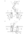
雪止め具1は、底面が平面となった第一枠係止部10と、第一枠係止部10の一端から下方に延出しており、第一枠係止部10側が平面となった第一側壁部11と、第一側壁部11の下端から第一枠係止部10とは反対の方向に延出している基部12と、基部12の端部に接続されており、第一側壁部11と平行に延出していると共に第一側壁部11とは反対側が平面となった第二側壁部13と、第二側壁部13の下端から基部12とは反対の方向に延出しており、上面が平面となった下端部14と、第一枠係止部10から上方に延出している雪止め部15とを、具備している。また、雪止め具1は、雪止め部15の上端から雪止め部15に対して屈曲して延出しているつまみ部16を、更に具備している。
The
より詳細に説明すると、第一枠係止部10は細長い平板状で、長辺の一方から下方に向かって直角に、平板状の第一側壁部11が延出している。第一側壁部11の下端からは、第一枠係止部10とは反対の方向に向かって直角に、平板状の基部12が延出している。基部12の端部は、第一側壁部11と平行に延びている平板状の第二側壁部13に、その高さ方向の中途の位置で接続されている。また、第二側壁部13の下端からは、基部12とは反対側の方向に直角に、平板状の下端部14が延出している。更に、第一枠係止部10において第一側壁部11との境界となる端部から上方に向かって、すなわち第一側壁部11を延長した面上に平板状の雪止め部15が延出している。雪止め部15の上端からは、第一枠係止部10とは反対の方向に直角に、平板状のつまみ部16が延出している。
If it demonstrates in detail, the 1st frame latching | locking
なお、第一枠係止部10の幅(第一側壁部11側の端部から、その反対側の端部までの距離)は、第一枠体20aの幅より僅かに長く設定されており、第一枠係止部10において第一側壁部11側とは反対側の端部には、下方に向かって突出した突起部17が形成されている。
In addition, the width | variety (distance from the edge part of the 1st
また、図3(b)に示すように、第一側壁部11の長さL1と、第二側壁部13において基部12との接続線より下方の長さN1との和L1+N1は、第一枠体20a及び第二枠体20bの高さ(側面部22の上端と下端との距離)より長く設定され、具体的には僅かに長く(例えば、+0.5mm〜+2mm)設定されている。加えて、第一側壁部11と基部12との境界線(以下、「基線P」と称する)と第二側壁部13の上端との長さR1は、第一枠体20aと第二枠体20bとの間の距離(互いの側面部22間の距離)より短く設定され、具体的には僅かに短く(例えば、−0.5mm〜−2mm)設定されている。
Further, as shown in FIG. 3B, the sum L1 + N1 of the length L1 of the first
なお、上記構成の雪止め具1は、金属により一体成形されている。このような雪止め具1は、例えば、押出成形によって形成された、軸方向に直交する断面が単一形状の長尺材を、所望の長さに切断することにより製造することができる。
In addition, the
次に、雪止め具1を第一枠体20a及び第二枠体20bに取り付けることにより、本実施形態の雪止め構造を構築する方法について、主に図2及び図3を用いて説明する。
Next, a method for constructing the snow stop structure of the present embodiment by attaching the
ここで、雪止め具1が取り付けられる第一枠体20a及び第二枠体20bは、同一の構成であり、雪止め具1との位置関係においてのみ区別されるものである。より具体的には、第一枠体20a及び第二枠体20bはそれぞれ、上下に延びている平板状の側面部22と、側面部22の上端から直角に延出している上面部21と、側面部22の下端から上面部21と同一の方向に延出している底面部23と、上面部21より下方で上面部21と同一の方向に側面部22から延出しており、上面部21との間で太陽電池パネルpの端辺を保持する下保持部24と、側面部22と平行に延び下保持部24と底面部23とを連結している連結部25とを備えている。なお、第一枠体20a及び第二枠体20bはそれぞれ、軸方向に直交する断面が単一形状の長尺材であり、例えば、金属の押出成形によって形成することができる。
Here, the
雪止め構造の構築に際しては、まず、それぞれ上面部21と下保持部24との間に太陽電池パネルpを保持した第一枠体20a及び第二枠体20bを、底面部23の下方に空隙が形成される状態で屋根面に固定する。
In constructing the snow stop structure, first, the
次に、雪止め具1を取り付ける。まず、第一枠係止部10を第一枠体20a側に向け、下端部14を下方に向けた状態で、雪止め具1を第一枠体20aと第二枠体20bとの間隙の上方に位置させる。そして、基線Pが第一枠体20aの側面部22の延長面上にほぼ位置する状態で、基線Pを回転中心として雪止め具1を回転させ、下端部14の先端が第一枠体20aの側面部22の延長面と干渉しない角度以上に雪止め具1を傾ける(図2(a)における実線または一点鎖線を参照)。上記のように、基線Pと第二側壁部13の上端との長さR1は、第一枠体20aと第二枠体20bとの間の距離より短いため、基線Pを回転中心として雪止め具1を回転させて下端部14の先端と第二枠体20bの側面部22との干渉を回避したときに、第二側壁部13の上端についても第一枠体20aの側面部22との干渉が回避される。
Next, the
この状態の雪止め具1を下降させて、第一枠体20aと第二枠体20bとの間隙に挿入する(図2(b)の一点鎖線を参照)。そして、基線Pが、第一枠体20aの側面部22の上端から距離L1だけ下方の位置に達した時点で、基線Pを回転中心として雪止め具1を上部が第一枠体20aに近づく方向に回転させ(図2(b)の実線を参照)、第一枠係止部10を第一枠体20aの上面部21に当接させると共に、第一側壁部11を第一枠体20aの側面部22に当接させる。これにより、第一枠係止部10が第一枠体20aに係止される。
The
これと同時に、基部12を介して第一側壁部11に接続されて第一側壁部11と平行に延びている第二側壁部13が、第一枠体20aの側面部22に沿った状態となると共に、第二側壁部13の下端から基部12とは反対側の方向に直角に延出している下端部14が、第一枠体20aの底面に沿った状態となる。本実施形態では、基線Pと第二側壁部13の上端との長さR1は、第一枠体20aと第二枠体20bとの間の距離より僅かに短い設定であるため、第二側壁部13は第一枠体20aの側面部22にごく近接して、側面部22に沿った状態となる。また、L1+N1の長さが第一枠体20a及び第二枠体20bの高さより僅かに長い設定であるため、下端部14は第一枠体20aの底面部23にごく近接して、底面部23に沿った状態となる(図3(a)参照)。
At the same time, the second
なお、上記の方法とは異なり、雪止め具1の下端部14の先端を第二枠体20bの底面部23より低い位置まで下降させたら(図2(b)の一点鎖線を参照)、それ以降は、基線Pを回転中心として雪止め具1を上部が第一枠体20aに近づく方向に回転させながら、第一枠体20aの側面部22に沿って基線Pを下方にスライドさせることによっても、第一枠係止部10を第一枠体20aの上面部21に当接させると共に、第一側壁部11を第一枠体20aの側面部22に当接させることができる。このようにすることにより、下端部14が図1乃至図3に例示した長さより長い場合、第一枠体20a及び第二枠体20bの高さが両者間の間隔に対して例示した長さより長い場合、第一枠体20a及び第二枠体20bの高さに対する第一側壁部の長さの割合が例示した長さより長い場合等であっても、第一枠体20a及び第二枠体20bの間隙に上方から挿入して、雪止め具1を取り付けることができる。
Unlike the above-described method, when the tip of the
換言すれば、下端部14の先端が第二枠体20bの側面部22と干渉しない角度まで雪止め具1を傾け、基線Pを第一枠体20aの側面部22に沿わせて雪止め具1を下降させたとき、雪止め具1をこれ以上傾けることができない状態、すなわち、第一側壁部11または雪止め部15が第二枠体20bの側壁部22の上端に接した状態で、下端部14の先端が第二枠体20bの底面部23より低く位置するような長さの設定であり、基線Pと第二側壁部13の上端との長さR1が第一枠体20aと第二枠体20bとの間の距離より短い設定であれば、第一枠体20a及び第二枠体20bの間隙に上方から挿入して、雪止め具1を取り付けることができる。
In other words, the
上記のように雪止め具1を第一枠体20a及び第二枠体20bに保持させることにより、図3(a)に示すように、本実施形態の雪止め構造が構築される。すなわち、太陽電池パネルが設置された屋根上に雪止め具1が取り付けられている雪止め構造であって、屋根上に隣接して配されている太陽電池パネルの内、軒側に配されている太陽電池パネルの棟側の端辺を保持している第一枠体20a、及び、棟側に配されている太陽電池パネルの軒側の端辺を保持している第二枠体20bが、それぞれの底面部23より下方に空隙が形成されるように屋根面に固定されており、雪止め具1は、第一枠体20aの上面部21に当接し第一枠体20aに係止されている第一枠係止部10と、第一枠係止部10から下方に延出し第一枠体20aの側面部22に当接している第一側壁部11と、第一側壁部11の下端から第二枠体20bに向かって延出している基部12と、基部12の端部に接続され、第二枠体20bの側面部22に沿って延出している第二側壁部13と、第二側壁部13の下端から第二枠体20bの底面部23に沿って延出している下端部14と、第一枠係止部10から上方に延出している雪止め部15とを具備する、雪止め構造である。
By holding the
そして、上記の雪止め構造において、雪止め具1の第二側壁部13には、その高さ方向の中途の位置で基部12の端部が接続されており、第二側壁部13は基部12の端部から上下方向に向かって第一枠体20aの側面部22に沿って延出している。
And in said snow stop structure, the edge part of the
ここで、第一枠体20a及び第二枠体20bを、それぞれ底面部23の下方に空隙が形成されるように屋根面に固定するには、例えば、屋根面に屋根の流れ方向に平行に長尺の桟材40を並設し、図6に示すように、固定部材30を介して第一枠体20a及び第二枠体20bを桟材40に取り付ける。
Here, in order to fix the
固定部材30について、具体的に説明する。固定部材30は、スペーサ部材31と押圧部材32とを具備している。スペーサ部材31は、桟材40の上面に載置される一対の脚板部31aと、一対の脚板部31aの上端を連結している天板部31bとを有している。押圧部材32は、第一枠体20a及び第二枠体20bの上面部21にそれぞれ当接する細長い平板状の一対の押圧部32aと、一対の押圧部32aそれぞれの内側の端部から下方へ直角に延出している一対の立板部32bと、一対の立板部32bを連結している平板状の基板部32cとを有している。また、スペーサ部材31における天板部31bと、押圧部材32における基板部32cの中心には、ボルト34が貫通する貫通孔31c,32dがそれぞれ設けられている。
The fixing
このような構成の固定部材30で第一枠体20a及び第二枠体20bを固定する桟材としては、角形の鋼管で、軸方向に延びるスリット40sが上面に設けられている桟材40を使用することができる。そして、スリット40sの幅よりも大径の頭部34aと、スリット40sの幅よりも小径の雄ネジ部34bを有するボルト34を倒立させて、スリット40sの端部から挿入し、頭部34aがスリット40sの内部に位置し、雄ネジ部34bが桟材40の上面から上方に延び出している状態とする。この状態のボルト34を、第一枠体20a及び第二枠体20bを固定部材30で固定する所望の位置まで、スリット40sに沿ってスライドさせる。
As a crosspiece for fixing the
次に、スペーサ部材31を一対の脚板部31aが下方を向いた状態として、天板部31bの貫通孔31cにボルト34の雄ネジ部34bを下方から挿通し、一対の脚板部31aが離隔する方向を桟材40の軸方向に一致させて、桟材40の上面に載置する。天板部31bより上方に延び出している雄ネジ部34bにナット35aを留め付け、スペーサ部材31を桟材40に固定する。この状態において、ボルト34の雄ネジ部34bはナット35aより更に上方まで延び出している。
Next, with the
桟材40に固定されたスペーサ部材31の一対の脚板部31aのうち、軒側に位置する脚板部31aの外側に第一枠体20aの側面部22を当接させながら、太陽電池パネルpを保持している第一枠体20aを桟材40の上面に載置する。また、棟側に位置する脚板部31aの外側に、第二枠体20bの側面部22を当接させながら、太陽電池パネルpを保持している第二枠体20bを桟材40の上面に載置する。次に、基板部32cを下方に向けた押圧部材32の貫通孔32dに、ナット35aより上方に延び出している雄ネジ部34bを下方から挿通する。そして、押圧部材32の一対の押圧部32aの一方を第一枠体20aの上面部21に当接させ、一対の立板部32bの一方を第一枠体20aの側面部22に当接させると共に、押圧部32aの他方を第二枠体20bの上面部21に当接させ、立板部32bの他方を第二枠体20bの側面部22に当接させる。
Of the pair of
この状態で、基板部32cより上方に延び出している雄ネジ部34bにナット35bを留め付ける。これにより、第一枠体20a及び第二枠体20bは押圧部材32によって上方から押圧されるように桟材40に固定され、桟材40と桟材40の間では、第一枠体20a及び第二枠体20bの底面部23は桟材40の高さ分だけ、屋根面より高く位置し、下方に空隙が形成される。
In this state, the
なお、押圧部材32の一対の立板部32bの間隙を上方から被覆するカバー部材33を取り付けることにより、貫通孔31c,32dを介した雨水の浸入を抑制することができる。なお、予めナット35a,35bを雄ネジ部34bに螺合させ、ボルト34でスペーサ部材31と押圧部材32とを仮留めした状態で、ボルト34を桟材40のスリット40sに挿入しても良い。
In addition, by attaching the
以上のように、第一実施形態の雪止め具1及びこれを使用した雪止め構造では、雪止め具1が第一枠体20a及び第二枠体20bによって保持されているため、太陽電池パネルを屋根上に設置するために第一枠体20a及び第二枠体20bを屋根面に固定するための部材とは無関係に、雪止め具1を屋根上に設置することできる。従って、雪止め具1の設置位置や設置個数を、高い自由度で設定することができる。
As described above, in the
雪止め具1からは、第一枠体20a及び第二枠体20bの上面より上方まで雪止め部15が延出しているため、この雪止め部15によって太陽電池パネルp上の積雪の滑落を抑止することができる。
Since the
そして、雪止め具1では第一枠係止部10が第一枠体20aに係止されているが、第一枠係止部10から下方に延出した第一側壁部11から、第二枠体20b側に向かって基部12が延出しており、更にその先に第二側壁部13及び下端部14を有しているため、この部分に作用する重力によって、上部が第二枠体20b側に傾くように雪止め具1に力が作用するところ、第二枠体20bの側面部22に沿って延出している第二側壁部13が第二枠体20bの側面部22に当接することによって、それ以上の傾きが阻止される。本実施形態の雪止め構造では、第二側壁部13は第二枠体20bの側面部22にごく近接して、側面部22に沿って延びているため、第二側壁部13が第二枠体20bの側面部22に当接するまでに雪止め具1は殆ど傾かない。
And in the
また、雪止め具1では、基部12の端部から第二側壁部13が上下に延出しているため、上部が第二枠体20b側に傾くように雪止め具1に作用した力を、基部12及び第二側壁部13を介して第二枠体20bの側面部22が受け止め易く、雪止め具1の姿勢をより安定的に維持することができる。
Moreover, in the
加えて、本実施形態の雪止め具1は、第一枠係止部10の端部に突起部17を有しているため、上部が第二枠体20b側に傾くように雪止め具1が傾いたとき、突起部17が第一枠体20aの上面部21の端部に引掛かり、これによっても雪止め具1が傾くことが抑止される。従って、雪止め具1は、ビスや釘等で留め付けることを要することなく、第一枠体20a及び第二枠体20bによって安定的に保持される。
In addition, since the
一方、雪止め部15に積雪の荷重がかかった状態では、雪止め具1には上部が第一枠体20a側に傾くように力が作用する。この方向に作用する力に対しては、第一枠体20aの側面部22に当接している第一側壁部11が抗すると共に、第二枠体20bの底面部23に沿って延出している下端部14が底面部23に当接することによって抗するため、第一枠体20a及び第二枠体20bに保持されている雪止め具1の姿勢が、安定的に維持される。
On the other hand, in a state where a snow load is applied to the
更に、雪止め具1は、第一枠体20a及び第二枠体20bの間隙に上方から挿入して取り付けることができるため、第一枠体20a及び第二枠体20bが既に屋根上に固定された後であっても、第一枠体20a及び第二枠体20bに保持させることができる。また、第一枠体20a及び第二枠体20bが上記に例示した固定部材30のような固定部材を介して屋根上に固定されている場合に、固定部材と固定部材との間の位置であっても、第一枠体20a及び第二枠体20bの間隙に上方から挿入することにより、雪止め具1を取り付けることができる。
Further, since the
また、雪止め具1は上端につまみ部16を有しているため、第一枠体20a及び第二枠体20bの間隙に上方から挿入したり、基線Pを回転中心として雪止め具1を回転させたりする操作が容易であり、効率良く雪止め具1を取り付けることができる。
Moreover, since the
次に、雪止め具2を使用した第二実施形態の雪止め構造について、図4を用いて説明する。雪止め具2と雪止め具1とでは、基部の端部に第二側壁部が接続されている態様において相違している。
Next, the snow stopper structure of the second embodiment using the
具体的には、雪止め具2の基部12bの端部は、第二側壁部13bの上端に接続されている。そして、図4(b)に示すように、第一側壁部11の長さL2と第二側壁部13bの長さN2との和L2+N2は、第一枠体20a及び第二枠体20bの高さより長く設定され、具体的には僅かに長く(例えば、+0.5mm〜+2mm)設定されている。加えて、基線Pと第二側壁部13bの上端との長さR2、すなわち基部12bの長さは、第一枠体20aと第二枠体20bとの間の距離より短く設定され、具体的には僅かに短く(例えば、−0.5mm〜−2mm)設定されている。
Specifically, the end of the base 12b of the
このような構成の雪止め具2も、第一実施形態の雪止め具1と同様に第一枠体20a及び第二枠体20bに取り付けることができ、上記と同様の雪止め構造が構築されるが、その雪止め構造において、雪止め具2の基部12の端部は第二側壁部13bの上端に接続されており、第二側壁部13bは基部12bの端部から下方に向かって第二枠体20bの側面部22に沿って延出している(図4(a)参照)。
Similarly to the
第二実施形態の雪止め具2、及び、これを使用した雪止め構造も、第一実施形態の雪止め具1、及び、これを使用した雪止め構造と同様の作用効果を奏する。なお、雪止め具2では、基線Pと第二側壁部13bの上端との長さR2は基部12bの長さであるため、第二側壁部13と第二枠体20bの側面部22との間に不可避的に間隙が生じる雪止め具1に比べ、更に第二側壁部13bを第二枠体20bの側面部22に近付けることが可能であり、第二側壁部13bが第二枠体20bの側面部22にほぼ当接する設定とすることも可能である。
The
次に、雪止め具3を使用した第三実施形態の雪止め構造について、図5を用いて説明する。雪止め具3と雪止め具1及び雪止め具2とでは、基部の端部に第二側壁部が接続されている態様において相違している。
Next, the snow stopper structure of the third embodiment using the
具体的には、雪止め具3の基部12cの端部は、第二側壁部13cの下端に接続されている。換言すれば、基部12cと下端部14とは同一面上にある。そして、図5(c)に示すように、第一側壁部11の長さL3は、第一枠体20a及び第二枠体20bの高さより長く設定され、具体的には僅かに長く(例えば、+0.5mm〜+2mm)設定されている。加えて、基線Pと第二側壁部13cの上端との長さR3は、第一枠体20aと第二枠体20bとの間の距離より短く設定され、具体的には僅かに短く(例えば、−0.5mm〜−2mm)設定されている。
Specifically, the end portion of the
このような構成の雪止め具3も、第一実施形態の雪止め具1及び第二実施形態の雪止め具2と同様に第一枠体20a及び第二枠体20bに取り付けることができ、上記と同様の雪止め構造が構築されるが、その雪止め構造において、雪止め具3の基部12cの端部は第二側壁部13cの下端に接続されており、第二側壁部13cは基部12cの端部から上方に向かって第二枠体20bの側面部22に沿って延出している(図5(a)参照)。
Similarly to the
ここで、雪止め具3は、雪止め具1,2に比べて第一側壁部11が長いため、下端部14が特に長くなくても、取り付け作業の途中で、第一枠体20aの側面部22において上端から距離L3の位置に基線Pが達する前に、第一側壁部11が第二枠体20bの側面部22の上端に接してしまい、その角度のままでは雪止め具3を下降させることができないことが生じ易い(図5(b)の実線を参照)。その場合は、雪止め具1の取り付け方法の説明において、付記した方法と同様に、基線Pを回転中心として上部が第一枠体20aに近づく方向に雪止め具3を回転させながら、第一枠体20aの側面部22に沿って基線Pを下方にスライドさせることによって、雪止め具3を第一枠体20a及び第二枠体20bに取り付けることができる(図5(b)の一点鎖線を参照)。
Here, since the
第三実施形態の雪止め具3、及び、これを使用した雪止め構造も、第一実施形態及び第二実施形態の雪止め具1,2、及び、これらをそれぞれ使用した雪止め構造と同様の作用効果を奏する。なお、雪止め具3では、雪止め具1,2に比べて第一側壁部11が長いため、第一枠体20aの側面部22との接触面積が大きく、雪止め具3の上部を第一枠体20a側に傾ける方向に作用する外力に対して、第一側壁部11が第一枠体20aの側面部22に当接によって抗する作用が大きい。
The
以上、本発明について好適な実施形態を挙げて説明したが、本発明は上記の実施形態に限定されるものではなく、以下に示すように、本発明の要旨を逸脱しない範囲において、種々の改良及び設計の変更が可能である。 The present invention has been described with reference to the preferred embodiments. However, the present invention is not limited to the above-described embodiments, and various improvements can be made without departing from the scope of the present invention as described below. And design changes are possible.
例えば、上記では、既に屋根上に固定されている第一枠体20a及び第二枠体20bに対して、雪止め具1,2,3を第一枠体20aと第二枠体20との間隙に上方から挿入することにより取り付ける方法を例示したが、これに限定されず、第一枠体及び第二枠体の一方を屋根上に固定した後、雪止め具を配し、この雪止め具を挟み込むように第一枠体及び第二枠体の他方を屋根上に固定することもできる。この場合、取り付け作業中に、雪止め具の第一側壁部及び第二側壁部は側方に開放しているため、ここにビスや釘を打ち込むことにより、雪止め具を枠体に取り付けることも可能である。その場合、ビスや釘を案内する溝や窪みを、第一側壁部及び第二側壁部の一方または双方に設けておいても良い。図1では、ビスや釘の案内に用いることが可能な構成として、第一側壁部11に設けられた断面V字形の長溝18を例示している。
For example, in the above, with respect to the
1,2,3 雪止め具
10 第一枠係止部
11 第一側壁部
12,12b,12c 基部
13,13b,13c 第二側壁部
14 下端部
15 雪止め部
16 つまみ部
20a 第一枠体
20b 第二枠体
21 上面部
22 側面部
23 底面部
p 太陽電池パネル
1, 2, 3
p solar panel
Claims (3)
屋根上に隣接して配されている太陽電池パネルの内、軒側に配されている太陽電池パネルの棟側の端辺を保持している第一枠体、及び、棟側に配されている太陽電池パネルの軒側の端辺を保持している第二枠体が、それぞれの底面部より下方に空隙が形成されるように屋根面に固定されており、
前記雪止め具は、
前記第一枠体の上面部に当接し前記第一枠体に係止されている第一枠係止部と、
該第一枠係止部から下方に延出し前記第一枠体の側面部に当接している第一側壁部と、
該第一側壁部の下端から前記第二枠体に向かって延出している基部と、
該基部の端部に接続され、前記第二枠体の側面部に沿って延出している第二側壁部と、
該第二側壁部の下端から前記第二枠体の底面部に沿って延出している下端部と、
前記第一枠係止部から上方に延出している雪止め部とが、一体成形されたものであり、
前記雪止め具における寸法設定が、前記第一側壁部と前記基部との境界線である基線と前記第二側壁部の上端との長さが、前記第一枠体と前記第二枠体との間隙の距離より短い設定であると共に、前記第一枠体と前記第二枠体との間隙の上方に前記雪止め具を位置させた状態から、前記下端部の先端が前記第二枠体の側面部と干渉しない角度まで前記雪止め具を傾け、前記基線を前記第一枠体の側面部に沿わせて前記雪止め具を下降させたとき、前記第二枠体との干渉により前記雪止め具をこれ以上傾けることができない状態では、前記下端部の先端が前記第二枠体の底面部より低く位置する設定であることにより、前記第一枠体及び前記第二枠体の間隙に前記雪止め具を上方から挿入して取り付けることが可能である
ことを特徴とする雪止め構造。 A snow stop structure in which a snow stop is mounted on a roof on which a solar panel is installed,
Among the solar cell panels that are arranged adjacent to the roof, the first frame body that holds the edge of the solar cell panel that is arranged on the eaves side, and that is arranged on the building side The second frame holding the eaves side edge of the solar panel is fixed to the roof surface so that a gap is formed below the bottom surface of each,
The snow stopper is
A first frame locking portion that is in contact with an upper surface portion of the first frame body and locked to the first frame body;
A first side wall portion extending downward from the first frame locking portion and in contact with a side surface portion of the first frame body;
A base portion extending from the lower end of the first side wall portion toward the second frame,
A second side wall connected to the end of the base and extending along the side of the second frame;
A lower end extending from the lower end of the second side wall along the bottom surface of the second frame,
The snow stopper portion extending upward from the first frame locking portion is integrally formed,
The length setting of the base line which is a boundary line of the first side wall part and the base part and the upper end of the second side wall part is set in the snow stopper, the first frame body and the second frame body. The tip of the lower end portion is set to be shorter than the distance between the first frame body and the second frame body when the snow stopper is positioned above the gap between the first frame body and the second frame body. The snow stopper is tilted to an angle that does not interfere with the side surface of the first frame, and when the snow stopper is lowered along the side surface of the first frame, the interference with the second frame causes the In a state where the snow stopper cannot be tilted any further, the gap between the first frame and the second frame is obtained by setting the tip of the lower end to be lower than the bottom surface of the second frame. wherein the snow stop can be attached by inserting from above <br/> thing Stop structure.
ことを特徴とする請求項1に記載の雪止め構造。 The snow stopper structure according to claim 1, wherein an end portion of the base portion of the snow stopper is connected to the second sidewall portion above a lower end of the second sidewall portion.
ことを特徴とする請求項1または請求項2に記載の雪止め構造。 The snow stop, the knob portion from the upper end of the snow stop portion extends bent with respect to the snow retaining part, claim 1 or claim, characterized in <br/> further comprising 2 Snow stop structure described in 1 .
Priority Applications (1)
| Application Number | Priority Date | Filing Date | Title |
|---|---|---|---|
| JP2014042960A JP6140089B2 (en) | 2014-03-05 | 2014-03-05 | Snow stop structure |
Applications Claiming Priority (1)
| Application Number | Priority Date | Filing Date | Title |
|---|---|---|---|
| JP2014042960A JP6140089B2 (en) | 2014-03-05 | 2014-03-05 | Snow stop structure |
Publications (3)
| Publication Number | Publication Date |
|---|---|
| JP2015168941A JP2015168941A (en) | 2015-09-28 |
| JP2015168941A5 JP2015168941A5 (en) | 2015-12-03 |
| JP6140089B2 true JP6140089B2 (en) | 2017-05-31 |
Family
ID=54201941
Family Applications (1)
| Application Number | Title | Priority Date | Filing Date |
|---|---|---|---|
| JP2014042960A Expired - Fee Related JP6140089B2 (en) | 2014-03-05 | 2014-03-05 | Snow stop structure |
Country Status (1)
| Country | Link |
|---|---|
| JP (1) | JP6140089B2 (en) |
Families Citing this family (3)
| Publication number | Priority date | Publication date | Assignee | Title |
|---|---|---|---|---|
| JP5998192B2 (en) * | 2014-07-29 | 2016-09-28 | 高島株式会社 | Snow slip prevention tool |
| JP7019299B2 (en) * | 2017-02-15 | 2022-02-15 | ソーラーフロンティア株式会社 | Construction method of snow stopper member, snow stopper mechanism, panel array structure and panel array structure. |
| CH717750B1 (en) | 2020-10-19 | 2022-02-28 | Apak Yavuz | Snow hook for solar panels. |
Family Cites Families (3)
| Publication number | Priority date | Publication date | Assignee | Title |
|---|---|---|---|---|
| JP5725960B2 (en) * | 2011-04-26 | 2015-05-27 | 高島株式会社 | Snowfall prevention bracket and solar cell module fixing structure |
| JP6456012B2 (en) * | 2012-05-09 | 2019-01-23 | 元旦ビューティ工業株式会社 | Snow stop structure using solar cells |
| US9175478B2 (en) * | 2012-05-29 | 2015-11-03 | Vermont Slate & Copper Services, Inc. | Snow fence for a solar panel |
-
2014
- 2014-03-05 JP JP2014042960A patent/JP6140089B2/en not_active Expired - Fee Related
Also Published As
| Publication number | Publication date |
|---|---|
| JP2015168941A (en) | 2015-09-28 |
Similar Documents
| Publication | Publication Date | Title |
|---|---|---|
| US9800200B2 (en) | Solar cell apparatus | |
| JP2006291506A (en) | Mounting structure of solar cell module | |
| US9745754B1 (en) | Snow guard structure | |
| KR101421965B1 (en) | Terracotta panel fixing device | |
| JP6140089B2 (en) | Snow stop structure | |
| JP6470673B2 (en) | Support bracket for solar panel | |
| JP6181596B2 (en) | Snowfall prevention structure and snowfall prevention fittings | |
| US20180062570A1 (en) | Mounting structure for solar cell module and mounting tool | |
| JP2006057357A (en) | Functional panel installation method | |
| US10742162B2 (en) | Fixing structure of solar cell module | |
| JP2019078095A (en) | Metal fitting and solar cell system | |
| JP6088912B2 (en) | Roof installation fixture | |
| JP6131150B2 (en) | Snow stopper structure and snow stopper | |
| JP6181598B2 (en) | Snow stopper structure and snow stopper | |
| US10436479B2 (en) | Fixture for solar cell module | |
| JP5648995B2 (en) | Mounting structure of support frame and exterior structure | |
| JP5534454B2 (en) | Panel holder and exterior structure using the same | |
| JP5709079B2 (en) | Exterior structure and construction method | |
| JP5517075B2 (en) | Exterior structure and construction method | |
| JP5686771B2 (en) | Solar cell module fixing structure and solar cell module fixing method | |
| JP5158685B2 (en) | Mounting member mounting structure and simple structure | |
| JP2020183665A (en) | Fitting structure of wavy metal roof material | |
| JP6693719B2 (en) | Gutter support structure, building, gutter installation method | |
| JP7115704B2 (en) | handrail | |
| JP2000008529A (en) | Roof for simplified structure |
Legal Events
| Date | Code | Title | Description |
|---|---|---|---|
| A521 | Request for written amendment filed |
Free format text: JAPANESE INTERMEDIATE CODE: A523 Effective date: 20151015 Free format text: JAPANESE INTERMEDIATE CODE: A821 Effective date: 20151015 |
|
| A621 | Written request for application examination |
Free format text: JAPANESE INTERMEDIATE CODE: A621 Effective date: 20151202 |
|
| A977 | Report on retrieval |
Free format text: JAPANESE INTERMEDIATE CODE: A971007 Effective date: 20160902 |
|
| A131 | Notification of reasons for refusal |
Free format text: JAPANESE INTERMEDIATE CODE: A131 Effective date: 20160913 |
|
| A521 | Request for written amendment filed |
Free format text: JAPANESE INTERMEDIATE CODE: A821 Effective date: 20161109 Free format text: JAPANESE INTERMEDIATE CODE: A523 Effective date: 20161109 |
|
| TRDD | Decision of grant or rejection written | ||
| A01 | Written decision to grant a patent or to grant a registration (utility model) |
Free format text: JAPANESE INTERMEDIATE CODE: A01 Effective date: 20170418 |
|
| A61 | First payment of annual fees (during grant procedure) |
Free format text: JAPANESE INTERMEDIATE CODE: A61 Effective date: 20170428 |
|
| R150 | Certificate of patent or registration of utility model |
Ref document number: 6140089 Country of ref document: JP Free format text: JAPANESE INTERMEDIATE CODE: R150 |
|
| LAPS | Cancellation because of no payment of annual fees |