JP7219086B2 - Sphygmomanometer, blood pressure measurement method, and program - Google Patents
Sphygmomanometer, blood pressure measurement method, and program Download PDFInfo
- Publication number
- JP7219086B2 JP7219086B2 JP2018245724A JP2018245724A JP7219086B2 JP 7219086 B2 JP7219086 B2 JP 7219086B2 JP 2018245724 A JP2018245724 A JP 2018245724A JP 2018245724 A JP2018245724 A JP 2018245724A JP 7219086 B2 JP7219086 B2 JP 7219086B2
- Authority
- JP
- Japan
- Prior art keywords
- pressure
- cuff
- sensing cuff
- fluid
- sensing
- Prior art date
- Legal status (The legal status is an assumption and is not a legal conclusion. Google has not performed a legal analysis and makes no representation as to the accuracy of the status listed.)
- Active
Links
Images


Classifications
-
- A—HUMAN NECESSITIES
- A61—MEDICAL OR VETERINARY SCIENCE; HYGIENE
- A61B—DIAGNOSIS; SURGERY; IDENTIFICATION
- A61B5/00—Measuring for diagnostic purposes; Identification of persons
- A61B5/02—Detecting, measuring or recording for evaluating the cardiovascular system, e.g. pulse, heart rate, blood pressure or blood flow
- A61B5/021—Measuring pressure in heart or blood vessels
- A61B5/022—Measuring pressure in heart or blood vessels by applying pressure to close blood vessels, e.g. against the skin; Ophthalmodynamometers
- A61B5/02233—Occluders specially adapted therefor
-
- A—HUMAN NECESSITIES
- A61—MEDICAL OR VETERINARY SCIENCE; HYGIENE
- A61B—DIAGNOSIS; SURGERY; IDENTIFICATION
- A61B5/00—Measuring for diagnostic purposes; Identification of persons
- A61B5/02—Detecting, measuring or recording for evaluating the cardiovascular system, e.g. pulse, heart rate, blood pressure or blood flow
- A61B5/021—Measuring pressure in heart or blood vessels
- A61B5/022—Measuring pressure in heart or blood vessels by applying pressure to close blood vessels, e.g. against the skin; Ophthalmodynamometers
- A61B5/02225—Measuring pressure in heart or blood vessels by applying pressure to close blood vessels, e.g. against the skin; Ophthalmodynamometers using the oscillometric method
-
- A—HUMAN NECESSITIES
- A61—MEDICAL OR VETERINARY SCIENCE; HYGIENE
- A61B—DIAGNOSIS; SURGERY; IDENTIFICATION
- A61B5/00—Measuring for diagnostic purposes; Identification of persons
- A61B5/02—Detecting, measuring or recording for evaluating the cardiovascular system, e.g. pulse, heart rate, blood pressure or blood flow
- A61B5/021—Measuring pressure in heart or blood vessels
- A61B5/02141—Details of apparatus construction, e.g. pump units or housings therefor, cuff pressurising systems, arrangements of fluid conduits or circuits
-
- A—HUMAN NECESSITIES
- A61—MEDICAL OR VETERINARY SCIENCE; HYGIENE
- A61B—DIAGNOSIS; SURGERY; IDENTIFICATION
- A61B5/00—Measuring for diagnostic purposes; Identification of persons
- A61B5/02—Detecting, measuring or recording for evaluating the cardiovascular system, e.g. pulse, heart rate, blood pressure or blood flow
- A61B5/021—Measuring pressure in heart or blood vessels
- A61B5/022—Measuring pressure in heart or blood vessels by applying pressure to close blood vessels, e.g. against the skin; Ophthalmodynamometers
- A61B5/0225—Measuring pressure in heart or blood vessels by applying pressure to close blood vessels, e.g. against the skin; Ophthalmodynamometers the pressure being controlled by electric signals, e.g. derived from Korotkoff sounds
-
- A—HUMAN NECESSITIES
- A61—MEDICAL OR VETERINARY SCIENCE; HYGIENE
- A61B—DIAGNOSIS; SURGERY; IDENTIFICATION
- A61B2562/00—Details of sensors; Constructional details of sensor housings or probes; Accessories for sensors
- A61B2562/02—Details of sensors specially adapted for in-vivo measurements
- A61B2562/0247—Pressure sensors
Landscapes
- Health & Medical Sciences (AREA)
- Life Sciences & Earth Sciences (AREA)
- Cardiology (AREA)
- Vascular Medicine (AREA)
- Biomedical Technology (AREA)
- Molecular Biology (AREA)
- Physiology (AREA)
- Biophysics (AREA)
- Pathology (AREA)
- Engineering & Computer Science (AREA)
- Veterinary Medicine (AREA)
- Heart & Thoracic Surgery (AREA)
- Medical Informatics (AREA)
- Physics & Mathematics (AREA)
- Surgery (AREA)
- Animal Behavior & Ethology (AREA)
- General Health & Medical Sciences (AREA)
- Public Health (AREA)
- Ophthalmology & Optometry (AREA)
- Dentistry (AREA)
- Measuring Pulse, Heart Rate, Blood Pressure Or Blood Flow (AREA)
Description
この発明は、血圧計、血圧測定方法、およびプログラムに関し、より詳しくは、被測定部位を周方向に取り巻いて装着される血圧計、当該血圧計を用いた血圧測定方法、およびプログラムに関する。 TECHNICAL FIELD The present invention relates to a sphygmomanometer, a blood pressure measuring method, and a program, and more particularly to a sphygmomanometer that is worn circumferentially around a site to be measured, a blood pressure measuring method using the sphygmomanometer, and a program.
従来、この種の血圧計としては、例えば特許文献1(特開2018-102867号公報)に開示されているものが存在している。当該血圧計は、手首に巻き付けられるカフと、このカフに一体に設けられた本体とを有する。当該血圧計は、帯状のベルトの内側に、動脈を圧迫する袋状のセンシングカフと、このセンシングカフの外側に設けた介在部材と、この介在部材の外側に設けられた袋状の押圧カフとを備える。上記血圧計の本体は、ポンプと、このポンプに搭載され、このポンプのオンオフに応じて閉じられ又は開かれる排気弁と、圧力センサと、上記ポンプと上記押圧カフとを流体流通可能に接続する第1の流路と、上記ポンプまたは第1の流路と上記センシングカフとを流体流通可能に接続し、かつ、開閉弁が介挿された第2の流路とを備えている。上記血圧計を用いて血圧測定を行うに際して、まず、上記排気弁と上記開閉弁とが開かれて上記押圧カフと上記センシングカフとの両方が大気圧に開放される。次に、上記排気弁が閉じられ、かつ上記開閉弁が開かれ状態で、上記ポンプから上記押圧カフと上記センシングカフに空気供給が開始される。上記センシングカフに空気が所定量だけ供給されると、上記開閉弁が閉じられて上記センシングカフが封じられる。この後、上記ポンプから上記押圧カフへ空気供給が継続されて、上記押圧カフによって上記センシングカフによって手首が圧迫される。そして、上記センシングカフに収容された空気の圧力(上記圧力センサによって測定される)に基づいて、オシロメトリック法により血圧が算出される。 Conventionally, this type of sphygmomanometer is disclosed in, for example, Patent Document 1 (Japanese Unexamined Patent Application Publication No. 2018-102867). The sphygmomanometer has a cuff that is wrapped around the wrist and a main body that is integrally provided with the cuff. The sphygmomanometer includes a bag-shaped sensing cuff that presses an artery inside a band-shaped belt, an intervening member provided outside the sensing cuff, and a bag-shaped pressure cuff provided outside the intervening member. Prepare. The main body of the sphygmomanometer connects a pump, an exhaust valve mounted on the pump that is closed or opened depending on whether the pump is turned on or off, a pressure sensor, the pump, and the pressure cuff so as to allow fluid flow. A first flow path and a second flow path connecting the pump or the first flow path and the sensing cuff in a fluid-communicable manner and having an on-off valve inserted therein are provided. When measuring blood pressure using the sphygmomanometer, first, the exhaust valve and the on-off valve are opened to release both the pressure cuff and the sensing cuff to atmospheric pressure. Next, with the exhaust valve closed and the on-off valve opened, the pump starts supplying air to the pressure cuff and the sensing cuff. When a predetermined amount of air is supplied to the sensing cuff, the on-off valve is closed to seal the sensing cuff. Thereafter, the pump continues to supply air to the pressure cuff, and the pressure cuff presses the wrist with the sensing cuff. Then, blood pressure is calculated by an oscillometric method based on the pressure of the air accommodated in the sensing cuff (measured by the pressure sensor).
ところで、上記血圧計による血圧測定後、次に血圧測定を行う前に、上記押圧カフと上記センシングカフとの両方が大気圧に開放されるとき、センシングカフ内には空気が残存している。そして、センシングカフ内の空気の残存量は、上記ベルトの巻き付け状態(緩い、きつい)によって毎回異なる可能性がある。この空気の残存量の相違が、血圧測定の精度に悪影響を及ぼすことを、発明者らは見出した。 By the way, when both the pressure cuff and the sensing cuff are released to the atmospheric pressure after the blood pressure measurement by the sphygmomanometer and before the next blood pressure measurement, air remains in the sensing cuff. The amount of air remaining in the sensing cuff may vary each time depending on the winding state of the belt (loose or tight). The inventors have found that this difference in the remaining amount of air adversely affects the accuracy of blood pressure measurement.
そこで、この発明の課題は、血圧測定前に、精度のよい血圧測定の状態を作り出すことができる、血圧計、血圧測定方法、およびプログラムを提供することにある。 Accordingly, an object of the present invention is to provide a sphygmomanometer, a blood pressure measurement method, and a program capable of creating a state of accurate blood pressure measurement before blood pressure measurement.
上記課題を解決するため、この開示の血圧計は、
ポンプを搭載した本体と、
上記本体から延在し、被測定部位を取り巻いて装着されるベルトと、
上記ベルトの内周側のうち、上記ベルトが上記被測定部位に装着された装着状態で、上記被測定部位の動脈通過部分を横切る部分に配設され、圧力伝達用の流体を収容可能に袋状に構成されたセンシングカフと、
上記センシングカフを上記被測定部位へ向かって押圧して、上記センシングカフに上記被測定部位を圧迫させる押圧部材と、
上記ポンプから上記センシングカフへ圧力伝達用の流体を供給するための供給モードと、上記センシングカフから流体を大気へ排出させるための排出モードと、上記センシングカフへの流体供給および上記センシングカフからの流体排出を遮断する遮断モードとを切り替えて構成可能な流体回路と、
制御部とを備え、
上記制御部は、上記装着状態において、
上記流体回路を上記排出モードに切り替えた状態で、上記押圧部材を動作させて上記センシングカフを上記被測定部位へ向かって押圧して、上記センシングカフに残存している流体を、上記流体回路を通して大気へ排出させる第1準備処理部と、
上記第1準備処理部の動作の後、上記流体回路を供給モードに切り替えた状態で、上記ポンプから上記流体回路を通して上記センシングカフに予め定められた量の圧力伝達用の流体を収容させる第2準備処理部と、
上記第2準備処理部の動作の後、上記流体回路を遮断モードに切り替えた状態で、上記押圧部材を動作させて上記センシングカフを上記被測定部位へ向かって押圧して、上記センシングカフに上記被測定部位を圧迫させながら、上記センシングカフに収容された上記圧力伝達用の流体の圧力に基づいてオシロメトリック法により上記被測定部位の血圧を算出する測定処理部とを含む、
ことを特徴とする。
In order to solve the above problems, the blood pressure monitor of this disclosure includes:
A body with a pump,
a belt extending from the main body and worn around a site to be measured;
A bag that is disposed on the inner peripheral side of the belt and that crosses the artery passage portion of the measurement site in the state where the belt is attached to the measurement site, and is capable of containing a fluid for pressure transmission. a sensing cuff configured in a shape;
a pressing member that presses the sensing cuff toward the measurement site and causes the sensing cuff to press the measurement site;
A supply mode for supplying a fluid for pressure transmission from the pump to the sensing cuff, a discharge mode for discharging the fluid from the sensing cuff to the atmosphere, a fluid supply to the sensing cuff and a discharge from the sensing cuff. a fluid circuit that can be configured by switching between a shutoff mode for shutting off fluid discharge;
and a control unit,
The control unit, in the wearing state,
With the fluid circuit switched to the discharge mode, the pressing member is operated to press the sensing cuff toward the measurement site, and the fluid remaining in the sensing cuff is discharged through the fluid circuit. a first preparatory processing unit for discharging to the atmosphere;
After the operation of the first preparatory processing unit, a second pressure transmission fluid is stored in the sensing cuff from the pump through the fluid circuit in a state where the fluid circuit is switched to the supply mode. a preparation processing unit;
After the operation of the second preparatory processing section, the pressing member is operated to press the sensing cuff toward the measurement site in a state in which the fluid circuit is switched to the interruption mode, and the sensing cuff is pressed against the measurement site. a measurement processing unit that calculates the blood pressure of the measurement site by an oscillometric method based on the pressure of the pressure-transmitting fluid contained in the sensing cuff while pressing the measurement site;
It is characterized by
「流体」は、典型的には空気であるが、他の気体、または液体であっても良い。 A "fluid" is typically air, but may be other gases or liquids.
ベルトの「内周側」とは、被測定部位を取り巻いた装着状態で被測定部位に面する側を指す。 The "inner peripheral side" of the belt refers to the side facing the site to be measured when the belt is worn and surrounds the site to be measured.
この開示の血圧計では、ベルトが被測定部位に装着された装着状態で、制御部が所定の制御を行う。すなわち、制御部に含まれた第1準備処理部は、流体回路を排出モードに切り替えた状態で、押圧部材を動作させてセンシングカフを押圧して、センシングカフに残存している流体を、流体回路を通して大気へ排出させる。これにより、たとえ上記血圧計による血圧測定後、次に血圧測定を行う前に、上記センシングカフに流体が残存していたとしても、その流体は上記センシングカフから排出される。次に、上記第1準備処理部の動作の後、第2準備処理部は、流体回路を供給モードに切り替えた状態で、ポンプから流体回路を通してセンシングカフに予め定められた量の圧力伝達用の流体を収容させる。これにより、上記センシングカフに上記圧力伝達用の流体が収容される。ここで、上記第1準備処理部の動作によって、上記センシングカフから残存流体が排出されているので、上記センシングカフに収容された上記圧力伝達用の流体の量が一定になる。次に、上記第2準備処理部の動作の後、測定処理部は、流体回路を遮断モードに切り替えた状態で、押圧部材を動作させてセンシングカフを押圧して、センシングカフに被測定部位を圧迫させながら、センシングカフに収容された圧力伝達用の流体の圧力に基づいてオシロメトリック法により被測定部位の血圧を算出する。これにより、例えば、特開2018-102868号公報、特開2018-102867号公報に開示されているように、上記ベルトと上記押圧部材と上記センシングカフ(適宜、これらを併せて「カフ」と総称する。)の幅方向寸法を小さく(例えば25mm程度に)設定した結果、加圧時に上記押圧部材の圧迫ロスが発生した場合であっても、被測定部位の血圧が精度良く算出される。特に、上述のように、上記第2準備処理部の動作後に上記センシングカフに収容された上記圧力伝達用の流体の量が一定になっているので、血圧が精度良く算出される。 In the sphygmomanometer disclosed in this disclosure, the control unit performs predetermined control while the belt is attached to the site to be measured. That is, the first preparation processing unit included in the control unit operates the pressing member to press the sensing cuff in a state where the fluid circuit is switched to the discharge mode, and removes the fluid remaining in the sensing cuff. Vent to atmosphere through circuit. Accordingly, even if fluid remains in the sensing cuff after the blood pressure measurement by the sphygmomanometer and before the next blood pressure measurement, the fluid is discharged from the sensing cuff. Next, after the operation of the first preparatory processing section, the second preparatory processing section transfers a predetermined amount of pressure from the pump through the fluid circuit to the sensing cuff while switching the fluid circuit to the supply mode. contain the fluid. Thereby, the fluid for pressure transmission is contained in the sensing cuff. Here, since the remaining fluid is discharged from the sensing cuff by the operation of the first preparatory processing section, the amount of the pressure-transmitting fluid received in the sensing cuff becomes constant. Next, after the operation of the second preparation processing section, the measurement processing section operates the pressing member to press the sensing cuff while the fluid circuit is switched to the blocking mode, and the part to be measured is applied to the sensing cuff. While applying pressure, the blood pressure of the measurement site is calculated by an oscillometric method based on the pressure of the fluid for pressure transmission contained in the sensing cuff. As a result, for example, as disclosed in JP-A-2018-102868 and JP-A-2018-102867, the belt, the pressing member, and the sensing cuff (as appropriate, collectively referred to as "cuff") ) is set to be small (for example, about 25 mm), the blood pressure of the measurement site can be accurately calculated even if pressure loss occurs in the pressing member during pressurization. In particular, as described above, the amount of the fluid for pressure transmission housed in the sensing cuff after the operation of the second preparation processing section is constant, so the blood pressure can be calculated with high accuracy.
一実施形態の血圧計では、
上記押圧部材は、上記ベルトと上記センシングカフとの間に配置される袋状の押圧カフを含み、
上記流体回路は、上記制御部の制御により、上記押圧部材の動作時には、上記ポンプから上記押圧カフへ加圧用の流体を供給して上記押圧カフを膨張させ、上記センシングカフを上記被測定部位へ向かって押圧させる一方、上記押圧部材の非動作時には、上記押圧カフから上記加圧用の流体を大気へ排出させることを特徴とする。
In one embodiment of the sphygmomanometer,
The pressing member includes a bag-like pressing cuff arranged between the belt and the sensing cuff,
Under the control of the control unit, the fluid circuit supplies pressurizing fluid from the pump to the pressure cuff to inflate the pressure cuff when the pressure member is in operation, and pushes the sensing cuff toward the measurement site. It is characterized in that the pressurizing fluid is discharged to the atmosphere from the press cuff while the press member is not operated while the press member is pressed.
この一実施形態の血圧計では、上記押圧カフは、上記ポンプ、すなわち、上記センシングカフに上記圧力伝達用の流体を供給する手段と共通の手段によって駆動(膨張または収縮)され得る。したがって、例えば上記押圧部材を機械式アクチュエータなどによって構成する場合に比して、この血圧計の構成が簡素化される。 In the sphygmomanometer of this embodiment, the pressure cuff can be driven (inflated or deflated) by means common to the pump, that is, the means for supplying the fluid for pressure transmission to the sensing cuff. Therefore, the configuration of the sphygmomanometer is simplified as compared with, for example, the case where the pressing member is configured by a mechanical actuator or the like.
一実施形態の血圧計では、
上記押圧部材は、上記ベルトの内周側のうち、上記装着状態で上記センシングカフと反対側となる部分に配置される袋状の押圧カフを含み、
上記流体回路は、上記制御部の制御により、上記押圧部材の動作時には、上記ポンプから上記押圧カフへ加圧用の流体を供給して上記押圧カフを膨張させ、上記センシングカフを上記被測定部位へ向かって押圧させる一方、上記押圧部材の非動作時には、上記押圧カフから上記加圧用の流体を大気へ排出させることを特徴とする。
In one embodiment of the sphygmomanometer,
The pressing member includes a bag-shaped pressing cuff arranged on the inner peripheral side of the belt on the side opposite to the sensing cuff in the wearing state,
Under the control of the control unit, the fluid circuit supplies pressurizing fluid from the pump to the pressure cuff to inflate the pressure cuff when the pressure member is in operation, and pushes the sensing cuff toward the measurement site. It is characterized in that the pressurizing fluid is discharged to the atmosphere from the press cuff while the press member is not operated while the press member is pressed.
この一実施形態の血圧計では、上記押圧カフは、上記ポンプ、すなわち、上記センシングカフに上記圧力伝達用の流体を供給する手段と共通の手段によって駆動(膨張または収縮)され得る。したがって、例えば上記押圧部材を機械式アクチュエータなどによって構成する場合に比して、この血圧計の構成が簡素化される。また、上記押圧カフは、上記ベルトの内周側のうち、上記装着状態で上記センシングカフと反対側となる部分に配置されている。例えば上記被測定部位が手首であれば、上記装着状態で、上記押圧カフは、手首の背側面(手の甲側に相当する面)に配置され、膨張することにより上記ベルトの張力を高める。この結果、上記ベルトのうち上記センシングカフに対向する部分は、上記センシングカフを上記被測定部位へ向かって押圧するストローク量が少なくて済む。したがって、被測定部位に存する動脈が上記センシングカフによって押されて逃げる距離が少なくなる(例えば、特開2017-006488号公報参照。)。したがって、血圧がさらに精度良く算出される。 In the sphygmomanometer of this embodiment, the pressure cuff can be driven (inflated or deflated) by means common to the pump, that is, the means for supplying the fluid for pressure transmission to the sensing cuff. Therefore, the configuration of the sphygmomanometer is simplified as compared with, for example, the case where the pressing member is configured by a mechanical actuator or the like. Further, the pressing cuff is arranged on the inner peripheral side of the belt on the opposite side to the sensing cuff in the wearing state. For example, if the part to be measured is the wrist, the pressure cuff is placed on the dorsal surface of the wrist (the surface corresponding to the back of the hand) in the wearing state, and expands to increase the tension of the belt. As a result, the portion of the belt that faces the sensing cuff requires a small amount of stroke for pressing the sensing cuff toward the measurement site. Therefore, the distance that the artery existing in the measurement site is pushed by the sensing cuff and escapes is reduced (see, for example, Japanese Patent Application Laid-Open No. 2017-006488). Therefore, blood pressure is calculated with higher accuracy.
一実施形態の血圧計では、
上記制御部は、上記第2準備処理部の動作の後、上記測定処理部の動作の前に動作する第3準備処理部を含み、
上記第3準備処理部は、上記流体回路を遮断モードに切り替えた状態で、上記押圧部材を非動作にして、上記押圧カフから上記加圧用の流体を大気へ排出させることを特徴とする。
In one embodiment of the sphygmomanometer,
The control unit includes a third preparation processing unit that operates after the operation of the second preparation processing unit and before the operation of the measurement processing unit,
The third preparation processing unit is characterized in that, in a state in which the fluid circuit is switched to the interruption mode, the pressing member is deactivated, and the pressurizing fluid is discharged from the pressing cuff to the atmosphere.
この一実施形態の血圧計では、上記第2準備処理部の動作の後、上記測定処理部の動作の前に、上記第3準備処理部は、流体回路を遮断モードに切り替えた状態で、上記押圧部材を非動作にして、上記押圧カフから上記加圧用の流体を大気へ排出させる。これにより、上記押圧カフによって上記センシングカフに与えられていた上記押圧が取り除かれる。したがって、上記第2準備処理部によって上記センシングカフに収容された上記圧力伝達用の流体が、上記センシングカフの内部に行き渡ることができる。したがって、上記測定処理部による血圧測定の際に、上記センシングカフは上記被測定部位の動脈による圧力(脈波信号)を正しく検出でき、血圧の測定精度が高まる。 In the sphygmomanometer of this embodiment, after the operation of the second preparation processing unit and before the operation of the measurement processing unit, the third preparation processing unit switches the fluid circuit to the cutoff mode, The pressing member is deactivated to exhaust the pressurizing fluid from the pressing cuff to the atmosphere. Thereby, the pressure applied to the sensing cuff by the pressure cuff is removed. Therefore, the fluid for pressure transmission accommodated in the sensing cuff by the second preparation processing section can spread inside the sensing cuff. Therefore, when the blood pressure is measured by the measurement processing unit, the sensing cuff can correctly detect the pressure (pulse wave signal) due to the artery of the measurement target site, and the blood pressure measurement accuracy is enhanced.
一実施形態の血圧計では、
上記押圧カフの圧力を計測する、押圧カフ圧力センサを、さらに備えることを特徴とする。
In one embodiment of the sphygmomanometer,
It is characterized by further comprising a pressure cuff pressure sensor that measures the pressure of the pressure cuff.
この一実施形態の血圧計では、上記押圧カフ圧力センサによって上記押圧カフの圧力を計測できる。したがって、上記押圧カフ圧力センサの出力を用いて上記押圧カフの圧力を制御できる。このことは、特に、上記第1準備処理部によって、上記センシングカフに残存している流体を大気へ排出させる際、および、上記測定処理部による血圧測定の際に役立つ。 In the sphygmomanometer of this embodiment, the pressure of the pressure cuff can be measured by the pressure cuff pressure sensor. Therefore, the pressure of the pressure cuff can be controlled using the output of the pressure cuff pressure sensor. This is particularly useful when the first preparation processor drains fluid remaining in the sensing cuff to the atmosphere and when the measurement processor measures blood pressure.
一実施形態の血圧計では、
上記センシングカフの圧力を計測する、センシングカフ圧力センサを、さらに備えることを特徴とする。
In one embodiment of the sphygmomanometer,
It is characterized by further comprising a sensing cuff pressure sensor that measures the pressure of the sensing cuff.
この一実施形態の血圧計では、上記センシングカフ圧力センサによって上記センシングカフの圧力を計測できる。したがって、上記センシングカフ圧力センサの出力を用いて上記センシングカフの圧力を制御できる。このことは、特に、上記第2準備処理部によって、上記センシングカフに予め定められた量の圧力伝達用の流体を収容させる際に役立つ。 In the sphygmomanometer of this embodiment, the pressure of the sensing cuff can be measured by the sensing cuff pressure sensor. Therefore, the output of the sensing cuff pressure sensor can be used to control the pressure of the sensing cuff. This is particularly useful when the second priming section causes the sensing cuff to contain a predetermined amount of pressure-transmitting fluid.
一実施形態の血圧計では、
上記本体は、上記ベルトの周方向に関して、上記センシングカフと反対側となる部分に配置されていることを特徴とする。
In one embodiment of the sphygmomanometer,
The main body is arranged on the opposite side of the sensing cuff in the circumferential direction of the belt.
一実施形態の血圧計では、上記本体は、上記ベルトの周方向に関して、上記センシングカフと反対側となる部分に配置されている。したがって、例えば、この血圧計が手首式血圧計を構成する場合、上記装着状態で、上記本体は、手首の背側面(手の甲側に相当する面)に配置される。この結果、上記本体は、ユーザの日常生活の邪魔になりにくい。また、上記ベルトの内周側のうち上記センシングカフと反対側となる部分に上記押圧カフが配置される場合、上記ポンプから上記押圧カフまでの距離を、極力短くすることができ、血圧計のコンパクト化も測ることができる。 In one embodiment of the sphygmomanometer, the main body is arranged on the opposite side to the sensing cuff in the circumferential direction of the belt. Therefore, for example, when this sphygmomanometer constitutes a wrist-type sphygmomanometer, the main body is arranged on the dorsal surface of the wrist (the surface corresponding to the back side of the hand) in the wearing state. As a result, the main body hardly interferes with the user's daily life. Further, when the pressure cuff is arranged on the inner peripheral side of the belt on the opposite side to the sensing cuff, the distance from the pump to the pressure cuff can be shortened as much as possible. Compactness can also be measured.
別の局面では、この開示の血圧測定方法は、ポンプを搭載した本体と、上記本体から延在し、被測定部位を取り巻いて装着されるベルトと、上記ベルトの内周側のうち、上記ベルトが上記被測定部位に装着された装着状態で、上記被測定部位の動脈通過部分を横切る部分に配設され、圧力伝達用の流体を収容可能に袋状に構成されたセンシングカフと、上記センシングカフを上記被測定部位へ向かって押圧して、上記センシングカフに上記被測定部位を圧迫させる押圧部材と、上記ポンプから上記センシングカフへ圧力伝達用の流体を供給するための供給モードと、上記センシングカフから流体を大気へ排出させるための排出モードと、上記センシングカフへの流体供給および上記センシングカフからの流体排出を遮断する遮断モードとを切り替えて構成可能な流体回路とを備えた血圧計を用いた、血圧測定方法であって、
上記装着状態において、
上記流体回路を上記排出モードに切り替えた状態で、上記押圧部材を動作させて上記センシングカフを上記被測定部位へ向かって押圧して、上記センシングカフに残存している流体を、上記流体回路を通して大気へ排出させる第1準備処理を行い、
上記第1準備処理の後、上記流体回路を供給モードに切り替えた状態で、上記ポンプから上記流体回路を通して上記センシングカフに予め定められた量の圧力伝達用の流体を収容させる第2準備処理を行い、
上記第2準備処理の後、上記流体回路を遮断モードに切り替えた状態で、上記押圧部材を動作させて上記センシングカフを上記被測定部位へ向かって押圧して、上記センシングカフに上記被測定部位を圧迫させながら、上記センシングカフに収容された上記圧力伝達用の流体の圧力に基づいてオシロメトリック法により上記被測定部位の血圧を算出する測定処理を行う、
ことを特徴とする。
In another aspect, the blood pressure measurement method of the present disclosure includes a main body having a pump mounted thereon, a belt extending from the main body and worn around a site to be measured, and the belt on the inner peripheral side of the belt. a sensing cuff arranged in a portion crossing the arterial passing portion of the measurement site in a state in which the is attached to the measurement site, and configured in a bag shape to accommodate a fluid for pressure transmission; a pressing member that presses the cuff toward the measurement target site to cause the sensing cuff to press the measurement target site; a supply mode for supplying a fluid for transmitting pressure from the pump to the sensing cuff; A sphygmomanometer comprising a fluid circuit capable of switching between a discharge mode for discharging fluid from the sensing cuff to the atmosphere and a blocking mode for blocking the supply of fluid to the sensing cuff and the discharge of the fluid from the sensing cuff. A blood pressure measurement method using
In the above wearing state,
With the fluid circuit switched to the discharge mode, the pressing member is operated to press the sensing cuff toward the measurement site, and the fluid remaining in the sensing cuff is discharged through the fluid circuit. perform a first preparatory process for discharging to the atmosphere,
After the first preparation process, a second preparation process of causing the sensing cuff to receive a predetermined amount of fluid for pressure transmission from the pump through the fluid circuit while the fluid circuit is switched to the supply mode. do,
After the second preparation process, in a state in which the fluid circuit is switched to the blocking mode, the pressing member is operated to press the sensing cuff toward the measurement site, and the sensing cuff is pressed against the measurement site. Performing a measurement process of calculating the blood pressure of the measurement site by an oscillometric method based on the pressure of the pressure transmission fluid contained in the sensing cuff while pressing the site,
It is characterized by
この開示の血圧測定方法では、ベルトが被測定部位に装着された装着状態で、次の各処理を行う。すなわち、流体回路を排出モードに切り替えた状態で、押圧部材を動作させてセンシングカフを押圧して、センシングカフに残存している流体を、流体回路を通して大気へ排出させる(第1準備処理)。これにより、たとえ上記血圧計による血圧測定後、次に血圧測定を行う前に、上記センシングカフに流体が残存していたとしても、その流体は上記センシングカフから排出される。次に、上記第1準備処理の後、流体回路を供給モードに切り替えた状態で、ポンプから流体回路を通してセンシングカフに予め定められた量の圧力伝達用の流体を収容させる(第2準備処理)。これにより、上記センシングカフに上記圧力伝達用の流体が収容される。ここで、上記第1準備処理によって、上記センシングカフから残存流体が排出されているので、上記センシングカフに収容された上記圧力伝達用の流体の量が一定になる。次に、上記第2準備処理の後、流体回路を遮断モードに切り替えた状態で、押圧部材を動作させてセンシングカフを押圧して、センシングカフに被測定部位を圧迫させながら、センシングカフに収容された圧力伝達用の流体の圧力に基づいてオシロメトリック法により被測定部位の血圧を算出する(測定処理)。これにより、例えば、特開2018-102868号公報、特開2018-102867号公報に開示されているように、上記ベルトと上記押圧部材と上記センシングカフ(適宜、これらを併せて「カフ」と総称する。)の幅方向寸法を小さく(例えば25mm程度に)設定した結果、加圧時に上記押圧部材の圧迫ロスが発生した場合であっても、被測定部位の血圧が精度良く算出される。特に、上述のように、上記第2準備処理部の動作後に上記センシングカフに収容された上記圧力伝達用の流体の量が一定になっているので、血圧が精度良く算出される。 In the blood pressure measurement method disclosed in this disclosure, the following processes are performed with the belt attached to the part to be measured. That is, with the fluid circuit switched to the discharge mode, the pressing member is operated to press the sensing cuff, and the fluid remaining in the sensing cuff is discharged to the atmosphere through the fluid circuit (first preparation process). Accordingly, even if fluid remains in the sensing cuff after the blood pressure measurement by the sphygmomanometer and before the next blood pressure measurement, the fluid is discharged from the sensing cuff. Next, after the first preparation process, a predetermined amount of fluid for pressure transmission is accommodated in the sensing cuff from the pump through the fluid circuit while the fluid circuit is switched to the supply mode (second preparation process). . Thereby, the fluid for pressure transmission is contained in the sensing cuff. Here, since the remaining fluid is discharged from the sensing cuff by the first preparation process, the amount of the fluid for pressure transmission contained in the sensing cuff becomes constant. Next, after the second preparation process, the pressure member is operated to press the sensing cuff in a state where the fluid circuit is switched to the cutoff mode, and the sensing cuff is accommodated while pressing the part to be measured by the sensing cuff. Based on the pressure of the fluid for pressure transmission, the blood pressure of the measurement site is calculated by the oscillometric method (measurement processing). As a result, for example, as disclosed in JP-A-2018-102868 and JP-A-2018-102867, the belt, the pressing member, and the sensing cuff (as appropriate, collectively referred to as "cuff") ) is set to be small (for example, about 25 mm), the blood pressure of the measurement site can be accurately calculated even if pressure loss occurs in the pressing member during pressurization. In particular, as described above, the amount of the fluid for pressure transmission housed in the sensing cuff after the operation of the second preparation processing section is constant, so the blood pressure can be calculated with high accuracy.
さらに別の局面では、この開示のプログラムは、血圧測定方法を、コンピュータに実行させるためのプログラムである。 In still another aspect, a program disclosed in this disclosure is a program for causing a computer to execute a blood pressure measurement method.
この開示のプログラムをコンピュータに実行させることによって、上記血圧測定方法を実施することができる。 The blood pressure measurement method can be implemented by causing a computer to execute the program of this disclosure.
以上より明らかなように、この開示の、血圧計および血圧測定方法によれば、血圧測定前に、精度のよい血圧測定の状態を作り出すことができる。 As is clear from the above, according to the sphygmomanometer and the blood pressure measurement method of the present disclosure, it is possible to create a state of accurate blood pressure measurement before blood pressure measurement.
以下、この発明の実施の形態を、図面を参照しながら詳細に説明する。 BEST MODE FOR CARRYING OUT THE INVENTION Hereinafter, embodiments of the present invention will be described in detail with reference to the drawings.
<実施の形態1>
(実施の形態1に係る血圧計の構成)
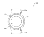
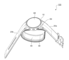
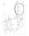
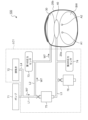
図1は、本実施の形態に係る血圧計100を正面から見た構成を示す。図2は、当該血圧計100を側面から見た構成を示す。また、図3は、当該血圧計100を、後述するベルトが開かれた状態で、斜め方向から見た構成を示す。図1~3を用いて、血圧計100の概略外観構成について説明する。
<
(Configuration of sphygmomanometer according to Embodiment 1)
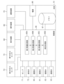
FIG. 1 shows a front configuration of a
血圧計100は、大別して、本体10、二つのベルト20a,20bを備え、また、図3中に示す押圧部材を構成する押圧カフ30、およびセンシングカフ40、を備える。
The
図1~3に示すように、本体10は、表示装置68および複数のボタンからなる操作装置69を、有する。また、本体10は、後述するポンプを搭載する。また、本体10には、一方のベルト20aと他方のベルト20bが取り付けられている。二つのベルト20a,20bは、本体10から延在し、被測定部位を取り巻いて装着される。なお、一方のベルト20aと他方のベルト20bとが締結されることにより、血圧計100が被測定部位に装着された状態(図4参照、これを「装着状態」と呼ぶ)が作り出される。
As shown in FIGS. 1-3, the
また、本実施の形態では、カフ30,40は積層構造を有するカフ構造体を構成している。血圧計100の上記装着状態において、ベルト20a,20bの締結部20T側から見みて、押圧カフ30と、センシングカフ40とが、当該順に配置される。押圧カフ30は、被測定部位に対する押圧力を発生する。そして、当該押圧力は、センシングカフ40を介して、被測定部位に印加される。特開2018-102867号公報に示されているように、カフ構造体は、上述した、押圧カフ30およびセンシングカフ40のほかに、カーラおよび背板等(図示せず)を含んでいてもよい。なお、ベルト20a,20b、カーラ、押圧カフ30、および背板等を含む部材が、被測定部位に対する押圧力を発生する押圧部材として機能する。押圧カフ30を含む押圧部材は、センシングカフ40を被測定部位へ向かって押圧して、センシングカフ40に被測定部位を圧迫(押圧)させる。
Moreover, in this embodiment, the
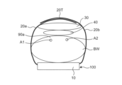
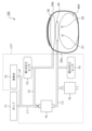
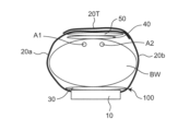
図4は、血圧計100が、被測定部位である手首BWに装着されている様子を、断面的に示している。図4に示すように、押圧部材を構成する押圧カフ30は、袋状であり、ベルト20a,20bとセンシングカフ40との間に配置される。上述したように、ベルト20a,20bが、手首BWを周方向に取り巻くことにより、血圧計100は手首BWに装着される。本実施の形態の装着状態では、図4に示すように、本体10から、ベルト20a,20bの締結部20Tに向かって、手首BW、センシングカフ40、および押圧カフ30が、当該順に配置される。図4の構成例では、本体10は、ベルト20a,20bの周方向に関して、センシングカフ40と反対側となる部分に配置されている。
FIG. 4 shows a cross-sectional view of the
上記装着状態では、袋状の押圧カフ30が、たとえば、手首BWの周方向に沿って延在する。また、袋状のセンシングカフ40が、押圧カフ30よりもベルト20a,20bの内周側に配置されて手首BWに(間接的または直接的に)接し、かつ、手首BWの動脈通過部分90aを横切るように周方向に延在する。なお、ベルト20a,20bの「内周側」とは、手首BWを取り巻いた装着状態で、手首BWに面する側を指す。
In the worn state, the bag-
図4中には、手首BWの、橈骨動脈A1および尺骨動脈A2が示されている。押圧部材を構成する押圧カフ30は、本実施の形態では、ベルト20a,20bとセンシングカフ40との間に配置される。当該押圧カフ30は、センシングカフ40を手首BWへ向かって押圧して、センシングカフ40に手首BWを圧迫させる。なお、血圧計100の具体例および当該血圧計100の装着例の詳細は、特開2018-102867号公報に記載されている。
Radial artery A1 and ulnar artery A2 of wrist BW are shown in FIG. A
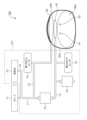
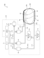
図5は、血圧計100の制御系に関する概略構成を示している。図5に示すように、血圧計100の本体10は、制御を担う制御部65と、制御部65に制御される複数の被制御構成要素66~76とを、備える。ここで、複数の被制御構成要素は、電源66、メモリ67、表示装置68、操作装置69、通信装置70、ポンプ71、排気弁72、第1の圧力センサ(押圧カフ圧力センサ)73、第2の圧力センサ(センシングカフ圧力センサ)74、および二つの開閉弁75,76を、含んでいる。
FIG. 5 shows a schematic configuration of the control system of
電源66は、この例では、充電可能な2次電池からなる。電源66は、本体10に搭載された要素、たとえば、プロセッサ65、メモリ67、表示装置68、通信装置70、ポンプ71、排気弁72、各圧力センサ73,74、および各開閉弁75,76へ、駆動のための電力を供給する。
The
メモリ67は、各種データを記憶する。たとえば、メモリ67は、血圧計100が計測した測定値、各圧力センサ73,74の計測結果等を、格納することができる。また、メモリ67は、制御部65で生成された各種データを格納することもできる。メモリ67は、RAM(Random Access Memory)およびROM(Read Only Memory)等を含む。たとえば、メモリ67には、各種プログラムが、変更可能に格納されている。
The
表示装置68は、一例として、LCD(Liquid Crystal Display)からなる。表示装置68は、制御部65からの制御信号に従って、血圧測定結果などの血圧測定に関する情報、その他の情報を表示する。なお、表示装置68は、タッチパネルとしての機能を有していてもよい。
The
操作装置69は、ユーザからの指示を受け付ける、複数のボタンから構成される。操作装置69が、ユーザからの指示を受け付けると、当該指示に従った操作・動作が、制御部65の制御の下、実施される。なお、操作装置69は、例えば感圧式(抵抗式)または近接式(静電容量式)のタッチパネル式スイッチなどであってもよい。また、図示しないマイクロフォンを備えて、ユーザの音声による指示を受け付ける構成を採用してもよい。
The
通信装置70は、各種データおよび各種信号を、通信ネットワークを介して外部の装置に送信したり、外部の装置からの情報を、通信ネットワークを介して受信したりする。当該ネットワークは、無線通信であっても、有線通信であってもよい。
ポンプ71は、この例では圧電ポンプからなり、制御部65から与えられる制御信号に基づいて、駆動する。ポンプ71は、加圧用の流体を、後述する各流路を通して、各カフ30,40に供給することができる。ここで、流体として、任意の液体または任意の気体を、採用できる。本実施の形態では、流体は、空気であるとする(以下、流体を空気として記載を進める)。なお、ポンプ71と他のエア部品72~76を含む流路系の構成については、後述する。
The
排気弁72は、ポンプ71の動作に応じて、制御される。つまり、排気弁72の開閉は、ポンプ71のオン/オフ(空気の供給/供給停止)に応じて、制御される。たとえば、排気弁72は、ポンプ71がオンされると、閉じる。他方、排気弁72は、ポンプ71がオフされると、開く。排気弁72が開状態である場合には、たとえばセンシングカフ40内の空気を、後述する流路を通して、大気中へ排出させることができる。なお、この排気弁72は、逆止弁の機能を有し、排出される空気が逆流することはない。
The
第1の圧力センサ73および第2の圧力センサ74は、たとえば、ピエゾ抵抗式圧力センサからなる。第1の圧力センサ73は、後述する流路を介して、押圧カフ30内の圧力を検出する。第2の圧力センサ74は、後述する流路を介して、センシングカフ40内の圧力を検出する。
The
開閉弁75,76は、後述する流路に、各々介挿される。開閉弁75,76は、制御部65から与えられる制御信号に基づいて開閉(開度)が制御される。開閉弁75,76が開状態にあるとき、当該開閉弁75,76内を、空気が流れる。他方、開閉弁75,76が閉状態にあるとき、当該開閉弁75,76内を、空気は流れない。
The on-off
制御部65は、この例では、CPU(Central Processing Unit)を含んでいる。たとえば、制御部65は、メモリ67に格納されている各プログラムおよび各データを読み込む。また、制御部65は、読み込んだプログラムに従い、各部67~76を制御し、所定の動作(機能)を実行させる。また、制御部65は、読み込んだプログラムに従い、当該制御部65内において、所定の演算、解析、処理等を実施する。なお、制御部65が実行する各機能の一部又は全部を、一つ或いは複数の集積回路等によりハードウェア的に構成してもよい。
The
図5に示すように、本実施の形態に係る制御部65は、第1準備処理部65A、第2準備処理部65B、第3準備処理部65C、および測定処理部65Dを、機能ブロックとして、備える。なお、各ブロック65A~65Dの動作は、後述する動作の説明において、詳述される。
As shown in FIG. 5, the
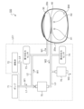
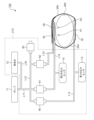
図6は、血圧計100の流路系に関する概略構成を示している。図6に示されている血圧計100は、ポンプ71、流体回路LC1、押圧カフ30、およびセンシングカフ40を、含む。なお、実際には、ポンプ71と流体回路LC1とは、本体10(図4参照)に搭載されている。しかしながら、図6では、理解の容易のため、流路系を展開して示している。
FIG. 6 shows a schematic configuration of the flow channel system of
流体回路LC1は、供給モードPM、排出モードDM、および遮断モードSMを、切り替えて構成可能である。ここで、供給モードPMは、ポンプ71からセンシングカフ40へ圧力伝達用の空気を供給するためのモードである。また、排出モードDMは、センシングカフ40から空気を大気へ排出させるためのモードである。また、遮断モードSMは、センシングカフ40への空気供給およびセンシングカフ40からの空気排出を遮断するモードである。また、流体回路LC1は、押圧部材をなす押圧カフ30を動作(膨張)させ、または、非動作(押圧カフ30から空気を排出)させるように、構成されている。
The fluid circuit LC1 can be configured by switching between a supply mode PM, a discharge mode DM, and a cutoff mode SM. Here, the supply mode PM is a mode for supplying air for pressure transmission from the
具体的には、本実施の形態に係る流体回路LC1は、排気弁72、各開閉弁75,76、各圧力センサ73,74、および各流路L1~L4を、含む。ここで、各流路L1~L4内において、空気が流通する。
Specifically, fluid circuit LC1 according to the present embodiment includes
図6に示すように、流路L1は、ポンプ71と開閉弁75とを接続する。流路L2は、流路L1と押圧カフ30とを接続する。流路L3は、開閉弁75とセンシングカフ40とを接続する。また、流路L4は、排気弁72と流路L1とを接続する。なお、開閉弁75は、流路L1と流路L3との間に介挿されている。第1の圧力センサ73は、流路L2に対して接続されている。第2の圧力センサ74は、流路L3に対して接続されている。また、開閉弁76は、流路L3と大気との間に介挿されている。
(実施の形態1に係る血圧計の動作)
As shown in FIG. 6, the flow path L1 connects the
(Operation of sphygmomanometer according to Embodiment 1)
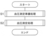
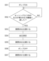
図7は、本実施の形態に係る血圧計100を用いた、血圧測定方法の流れを示す。血圧計100が手首BWに装着された後、図7に示すように、ステップS1において、血圧測定準備処理が実施され、当該ステップS1の後、血圧測定処理(ステップS2)が実施される。
FIG. 7 shows the flow of a blood pressure measurement method using blood pressure monitor 100 according to the present embodiment. After
(血圧測定準備処理の動作)
まず、ステップS1の血圧測定準備処理の詳細について、説明する。図8は、本実施の形態に係る血圧測定準備処理の具体的な流れを示している。
(Operation of blood pressure measurement preparation processing)
First, the details of the blood pressure measurement preparation process in step S1 will be described. FIG. 8 shows a specific flow of blood pressure measurement preparation processing according to the present embodiment.
(1) まず、血圧計100が手首BWに装着された状態において、制御部65の第1準備処理部65Aは、流体回路LC1を排出モードDMに切り替えた状態で、押圧カフ30を動作(膨張)させて、センシングカフ40を手首BWへ向かって押圧する。そして、当該押圧により、センシングカフ40に残存している空気を、流体回路LC1を通して大気へ排出させる。より具体的には、下記のとおりである。
(1) First, with the
まず、図8のステップS11において、第1準備処理部65Aは、開閉弁75を閉じる(図9の開閉弁75の「×」印参照)。さらに、ステップS12では、第1準備処理部65Aは、開閉弁76を開ける。第1準備処理部65Aは、開閉弁76を開状態にすることにより、当該第1準備処理部65Aは、流体回路LC1を、排出モードDMへと切り替える。
First, in step S11 in FIG. 8, the first
次に、ステップS13では、第1準備処理部65Aは、ポンプ71をON(オン)状態にする。これにより、図10中に矢印W1で示すように、ポンプ71は、流路L1,L2を介して、空気を、押圧カフ30に対して供給することができる。ステップS13における上記空気の供給により、押圧カフ30内に空気が充填され、当該押圧カフ30は膨張する(上記押圧カフ30の動作と把握できる)。そして、当該押圧カフ30の膨張により、センシングカフ40を手首BWへ向かって押圧する。そして、当該押圧により、センシングカフ40に残存している空気は、図10中に矢印W2で示すように、流路L3および開閉弁76を介して、大気へ排出される。このように、ステップS13では、押圧カフ30の膨張を利用して(押圧カフ30からの押圧力を利用して)、センシングカフ40内の空気量を、強制的に、当該センシングカフ40から大気へと放出し、センシングカフ40内の残留空気量を、ほぼゼロに近づける。
Next, in step S13, the first
次に、ステップS14では、第1準備処理部65Aは、第1の圧力センサ73の測定結果(押圧カフ30内の圧力)が、第1の圧力閾値Pth1に達したか否かを、判定する。ここで、第1の圧力閾値Pth1は、任意の値を採用することができる。ただし、当該第1の圧力閾値Pth1は、押圧カフ30の膨張により、センシングカフ40内の残留空気が、ほぼ押し出すことができる、という観点から選択されることが望ましい。たとえば一例として、第1の圧力閾値Pth1として、30mmHgが採用される。
Next, in step S14, the first
第1の圧力センサ73の測定結果が、第1の圧力閾値Pth1未満である場合(ステップS14でNO)には、ポンプ71から押圧カフ30への空気供給が継続され、一方で、ステップS14の判定処理も継続される。他方、第1の圧力センサ73の測定結果が、第1の圧力閾値Pth1に達した場合には(ステップS14でYES)、第1準備処理部65Aは、ポンプ71をOFF(オフ)状態にする(ステップS15)。これにより、ポンプ71から押圧カフ30への空気の供給は停止する。
When the measurement result of the
ところで、上述したように、排気弁72は、ポンプ71のON/OFFに連動して、開閉が制御される。具体的に、ポンプ71がON状態である場合、排気弁72は閉状態であり、ポンプ71がOFF状態である場合、排気弁72は開状態である。したがって、ステップS15により、ポンプ71はOFF状態となるので、排気弁72は開状態となる。よって、図11中に矢印W3で示すように、押圧カフ30内の空気は、流路L2,L1,L4および排気弁72を介して、大気中へ放出される。
By the way, as described above, the opening/closing of the
(2) 制御部65の第1準備処理部65Aの動作の後、制御部65の第2準備処理部65Bは、流体回路LC1を供給モードPMに切り替えた状態で、ポンプ71から流体回路LC1を通して、センシングカフ40に、予め定められた量(適量)の圧力伝達用の空気を、収容させる。より具体的には、下記のとおりである。
(2) After the operation of the first
まず、図8のステップS16において、第2準備処理部65Bは、開閉弁75を開状態にする。次に、ステップS17では、第2準備処理部65Bは、開閉弁76を閉じる(図12の開閉弁76の「×」印参照)。第2準備処理部65Bは、開閉弁75を開き、開閉弁76を閉じることにより、当該第2準備処理部65Bは、流体回路LC1を、供給モードPMへと切り替える。
First, in step S16 of FIG. 8, the second
次に、ステップS18では、第2準備処理部65Bは、ポンプ71をON状態にする。これにより、図12中に矢印W4で示すように、ポンプ71は、流路L1,L2を介して、空気を、押圧カフ30に対して供給することができ、さらに、矢印W5で示すように、流路L1、開閉弁75、および流路L3を介して、空気(上記適量の圧力伝達用の流体と把握できる)を、センシングカフ40へ供給することができる。ステップS18における上記空気の供給により、押圧カフ30内に空気が充填され、当該押圧カフ30は膨張する(図12参照)。さらに、当該ステップS18における上記空気の供給により、センシングカフ40に適量の圧力伝達用の流体を収容させる(図12参照)。ここで、「適量」がどの程度の量であるかについては、たとえば特開2018-102867号公報に記載されている。
Next, in step S18, the second
次に、ステップS19では、第2準備処理部65Bは、第2の圧力センサ74の測定結果(センシングカフ40内の圧力)が、第2の圧力閾値Pth2に達したか否かを、判定する。ここで、第2の圧力閾値Pth2は、任意の値を採用することができる。たとえば一例として、第2の圧力閾値Pth2として、40mmHg未満(好ましくは、30mmHg)が採用される。
Next, in step S19, the second
第2の圧力センサ74の測定結果が、第2の圧力閾値Pth2未満である場合(ステップS19でNO)には、ポンプ71から押圧カフ30およびセンシングカフ40への空気供給が継続され、一方で、ステップS19の判定処理も継続される。
When the measurement result of the
(3) 他方、第2の圧力センサ74の測定結果が、第2の圧力閾値Pth2に達した場合には(ステップS19でYES)、制御部65の第3準備処理部65Cは、第2準備処理部65Bの動作の後、血圧測定前に、次の制御を実施する。
(3) On the other hand, when the measurement result of the
具体的に、図8のステップS20において、第3準備処理部65Cは、開閉弁75を閉める(図13の開閉弁75の「×」印参照)。図13に示すように、ステップS13後において、開閉弁75,76が閉状態となっている(流体回路LC1の遮断モードSMへの切り替えと把握できる)。
Specifically, in step S20 of FIG. 8, the third preparation processing unit 65C closes the on-off valve 75 (see the "x" mark of the on-off
次に、ステップS21において、第3準備処理部65Cは、ポンプ71をOFF状態にする。これにより、ポンプ71から押圧カフ30への空気の供給は停止する(押圧カフ30の非動作と把握できる)。当該ステップS21により、図13中に矢印W6で示すように、遮断モードSMである流体回路LC1(流路L2,L1,L4および排気弁72)を介して、非動作である押圧カフ30内の空気を、大気へ放出させる。以上までが、制御部65の各準備処理部65A~65Cによる、血圧測定準備処理(図7のステップS1、図8)である。
Next, in step S21, the third preparation processing section 65C turns the
上述から分かるように、本実施の形態に係る流体回路LC1は、制御部65の制御により、押圧カフ30の動作時には、ポンプ71から当該押圧カフ30へ、加圧用の空気を供給し、当該押圧カフ30を膨張させる(図10)。これにより、押圧カフ30は、センシングカフ40を手首BWへ向かって押圧することができる。また、当該流体回路LC1は、制御部65の制御により、押圧カフ30の非動作時には、押圧カフ30から加圧用の空気を大気へ排出する(図11)。
As can be seen from the above description, the fluid circuit LC1 according to the present embodiment supplies air for pressurization from the
(血圧測定処理の動作)
図7のステップS1後(図8のフロー終了後)、制御部65の測定処理部65Dは、血圧測定処理を実施する(図7のステップS2)。具体的に、開閉弁75,76の閉状態(流体回路LC1の遮断モードSM)を維持したまま、測定処理部65Dは、ポンプ71をONにする。これにより、図14中に矢印W7で示すように、流路L1,L2を介して、押圧カフ30内に空気を送り込むことができる。したがって、押圧カフ30を動作(膨張)させることができる。当該膨張した押圧カフ30は、センシングカフ40を手首BWへ向かって押圧する。測定処理部65Dは、センシングカフ40に手首BWを圧迫させながら、センシングカフ40に収容された圧力伝達用の空気の圧力に基づいて、オシロメトリック法により手首BWの血圧を算出する。なお、当該血圧測定(血圧算出)処理の具体的な動作は、たとえば特開2018-102867号公報に記載されている。
(Operation of blood pressure measurement processing)
After step S1 in FIG. 7 (after the flow in FIG. 8 ends), the
測定処理部65Dによる血圧の算出が終了した後、測定処理部65Dは、開閉弁75,76を開状態にする。これにより、センシングカフ40内の空気は、図15中に矢印W8で示すように、流路L3および開閉弁76を介して、大気中へ放出され、押圧カフ30内の空気は、図15中に矢印W9で示すように、流路L2,L1,L4および排気弁72を介して、大気中へ放出される。したがって、押圧カフ30内の圧力およびセンシングカフ40内の圧力は、大気圧となり、血圧測定処理は終了する。
After the
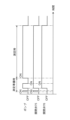
図16は、上記一連の処理を実行することが可能な、ポンプ71の動作タイミングおよび開閉弁75,76の動作タイミングを、時系列的に例示している。ここで、ポンプ71のONは、ポンプ71からの空気の供給を意味しており、ポンプ71のOFFは、当該ポンプ71による空気供給の停止を意味している。また、開閉弁75,76のONは、当該開閉弁75,76の閉状態を意味しており、開閉弁75,76のOFFは、当該開閉弁75,76の開状態を意味している。
FIG. 16 chronologically exemplifies the operation timing of the
(効果)
本実施の形態に係る血圧計100では、ベルト20a,20bが手首BWに装着された装着状態で、制御部65が所定の制御を行う。すなわち、制御部65に含まれた第1準備処理部65Aは、流体回路LC1を排出モードDMに切り替えた状態で、押圧カフ30を動作させてセンシングカフ40を押圧する。これにより、センシングカフ40に残存している空気は、流体回路LC1を通して大気へ排出される。これにより、たとえ上記血圧計100による血圧測定後、次に血圧測定を行う前に、センシングカフ40内に空気が残存していたとしても、その空気は、センシングカフ40から強制的に排出される。
(effect)
In
また、第1準備処理部65Aの動作の後、第2準備処理部65Bは、流体回路LC1を供給モードPMに切り替えた状態で、ポンプ71から流体回路LC1を通して、センシングカフ40内に、予め定められた量の圧力伝達用の空気を収容させる。これにより、センシングカフ40内に、上記圧力伝達用の空気が収容される。ここで、第1準備処理部65Aの動作によって、センシングカフ40から残存空気が排出されているので、センシングカフ40に収容された圧力伝達用の空気の量が一定になる。
Further, after the operation of the first
また、第2準備処理部65Bの動作の後、測定処理部65Dは、流体回路LC1を遮断モードSMに切り替えた状態で、押圧カフ30を動作させてセンシングカフ40を押圧する。そして、センシングカフ40に手首BWを圧迫させながら、センシングカフ40に収容された圧力伝達用の空気の圧力に基づいて、オシロメトリック法により、手首BWの血圧を算出する。これにより、例えば、特開2018-102868号公報、特開2018-102867号公報に開示されているように、ベルト20a,20bと押圧カフ30とセンシングカフ40の幅方向寸法を小さく(例えば25mm程度に)設定した結果、加圧時に押圧カフ30の圧迫ロスが発生した場合であっても、手首BWの血圧が精度良く算出される。特に、上述のように、第2準備処理部65Bの動作後に、センシングカフ40に収容された圧力伝達用の空気の量が一定になっているので、血圧を精度良く算出することができる。
After the operation of the second
また、本実施形態に係る血圧計100では、流体回路LC1は、制御部65の制御により、押圧カフ30の動作時には、ポンプ71から押圧カフ30へ加圧用の空気を供給して、当該押圧カフ30を膨張させ、センシングカフ40を手首BWへ向かって押圧させる。一方で、流体回路LC1は、制御部65の制御により、押圧カフ30の非動作時には、押圧カフ30から加圧用の空気を大気へ排出させる。
Further, in the
このように、本実施形態に係る血圧計100では、押圧カフ30は、ポンプ71、すなわち、センシングカフ40に圧力伝達用の空気を供給する手段と共通の手段によって、駆動(膨張または収縮)され得る。したがって、例えば押圧部材を機械式アクチュエータなどによって構成する場合に比して、血圧計100の構成を簡素化されることができる。
Thus, in the
また、本実施形態の血圧計100では、第2準備処理部65Bの動作の後、測定処理部65Dの動作の前に、第3準備処理部65Cは、流体回路LC1を遮断モードSMに切り替えた状態で、押圧カフ30を非動作にして、押圧カフ30から加圧用の空気を大気へ排出させる。これにより、押圧カフ30によって、センシングカフ40に与えられていた押圧が、取り除かれる。したがって、第2準備処理部65Bによって、センシングカフ40に収容された圧力伝達用の空気が、センシングカフ40の内部に行き渡ることができる。したがって、測定処理部65Dによる血圧測定の際に、センシングカフ40は、手首BWの動脈A1,A2による圧力(脈波信号)を正しく検出でき、血圧の測定精度が高まる。
Further, in the
また、本実施形態に係る血圧計100は、押圧カフ30の圧力を計測する、第1の圧力センサ(押圧カフ圧力センサ)73を、さらに備えている。したがって、第1の圧力センサ73によって、押圧カフ30内の圧力を計測できる。したがって、第1の圧力センサ73の出力を用いて、押圧カフ30の圧力を制御できる。このことは、特に、第1準備処理部65Aによって、センシングカフ40に残存している空気を大気へ排出させる際、および、測定処理部65Dによる血圧測定の際に、役立つ。
Moreover, the
本実施形態に係る血圧計100は、センシングカフ40内の圧力を計測する、第2の圧力センサ(センシングカフ圧力センサ)74を、さらに備えている。よって、第2の圧力センサ74を用いて、センシングカフ40内の圧力を計測できる。したがって、第2の圧力センサ74の出力を用いて、センシングカフ40の圧力を制御できる。このことは、特に、第2準備処理部65Bによって、センシングカフ40に、予め定められた量の圧力伝達用の空気を収容させる際に、役立つ。
The
また、本実施形態に係る血圧計100では、本体10は、ベルト20a,20bの周方向に関して、センシングカフ40と反対側となる部分に配置されている。したがって、例えば、当該血圧計100が手首BWに装着された状態において、本体10は、手首の背側面(手の甲側に相当する面)に配置される。この結果、本体10は、ユーザの日常生活の邪魔になりにくい。
Further, in the
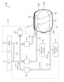
<実施の形態2>
(実施の形態2に係る血圧計の構成)
図17は、本実施の形態に係る血圧計100の概略構成を示す。図4と図17との比較から分かるように、押圧部材を構成する袋状の押圧カフ30の位置が、実施の形態1と実施の形態2との間で相違する。つまり、本実施の形態では、押圧カフ30は、ベルト20a,20bの内周側のうち、上記装着状態で、センシングカフ40と反対側となる部分に配置される。換言すれば、本実施の形態では、押圧カフ30は、本体10側に配置され、ベルト20a,20bの締結部20T側には、配置されない(図17参照)。
<
(Configuration of sphygmomanometer according to Embodiment 2)
FIG. 17 shows a schematic configuration of
また、本実施の形態では、図17に示すように、補助カフ50が追加されている。なお、図17の構成において、当該補助カフ50の省略は可能である。補助カフ50は、袋状であり、ベルト20a,20bとセンシングカフ40との間に配置される。本実施の形態の装着状態では、図17に示すように、本体10から、ベルト20a,20bの締結部20Tに向かって、押圧カフ30、手首BW、センシングカフ40、および補助カフ50が、当該順に配置される。図17の構成例では、本体10は、ベルト20a,20bの周方向に関して、センシングカフ40と反対側となる部分に配置されている。
Further, in this embodiment, as shown in FIG. 17, an
上記以外の構成は、実施の形態1と実施の形態2との間で同じである。よって、同じ構成については、説明を省略する。 Configurations other than the above are the same between the first embodiment and the second embodiment. Therefore, description of the same configuration is omitted.
図18は、本実施の形態に係る血圧計100の制御系に関する概略構成を示している。図5と図18との比較から分かるように、実施の形態1に係る血圧計100は、二つの開閉弁75,76を含んでいたが、本実施の形態に係る血圧計100は、四つの開閉弁80~83を含む。ここで、制御部65は、各開閉弁80~83の開閉を制御する。制御系の構成に関して、上記以外の構成は、実施の形態1と実施の形態2との間で同じである。よって、同じ構成については、説明を省略する。
FIG. 18 shows a schematic configuration of the control system of
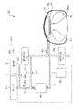
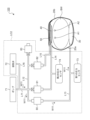
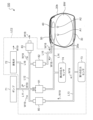
図19は、本実施の形態に係る血圧計100の流路系に関する概略構成を示している。図19に示されている血圧計100は、ポンプ71、流体回路LC2、押圧カフ30、センシングカフ40、および補助カフ50を、含む。なお、実際には、ポンプ71と流体回路LC2とは、本体10(図17参照)に搭載されている。しかしながら、図19では、図6におけるのと同様に、流路系を展開して示している。
FIG. 19 shows a schematic configuration of the flow path system of
流体回路LC2は、実施の形態1と同様に、供給モードPM、排出モードDM、および遮断モードSMを、切り替えて構成可能である。また、流体回路LC2は、押圧部材をなす押圧カフ30、補助カフ50を動作(膨張)させ、または、非動作とする(押圧カフ30、補助カフ50から空気を排出させる)ように構成されている。
As in the first embodiment, the fluid circuit LC2 can be configured by switching between the supply mode PM, the discharge mode DM, and the cutoff mode SM. In addition, the fluid circuit LC2 is configured to operate (inflate) the
具体的には、本実施の形態に係る流体回路LC2は、排気弁72、各開閉弁80~83、各圧力センサ73,74、および各流路L11~L16を、含む。ここで、各流路L11~L16内において、空気が流通する。
Specifically, the fluid circuit LC2 according to the present embodiment includes an
図19に示すように、流路L11は、ポンプ71と開閉弁81とを接続する。流路L12は、流路L11と合流しつつ、開閉弁80と開閉弁83とを接続する。流路L13は、開閉弁80と押圧カフ30とを接続する。流路L14は、開閉弁81とセンシングカフ40とを接続する。流路L15は、開閉弁82と補助カフ50とを接続する。また、流路L16は、排気弁72と流路L11とを接続する。なお、開閉弁80は、流路L12と流路L13との間に介挿され、開閉弁81は、流路L11と流路L14との間に介挿され、開閉弁82は、流路L12と流路L15との間に介挿されている。また、開閉弁83は、流路L12と大気との間に介挿されている。
As shown in FIG. 19, the flow path L11 connects the
第1の圧力センサ(押圧カフ圧力センサ)73は、流路L13に対して接続されている。また、第2の圧力センサ(センシングカフ圧力センサ)74は、流路L14に対して接続されている。 A first pressure sensor (pressing cuff pressure sensor) 73 is connected to the flow path L13. A second pressure sensor (sensing cuff pressure sensor) 74 is connected to the flow path L14.
(実施の形態2に係る血圧計の動作)
血圧計100が手首BWに装着された後、本実施の形態に係る血圧計100においても、図7で示した、血圧測定準備処理(ステップS1)および血圧測定処理(ステップS2)が実施される。
(Operation of sphygmomanometer according to Embodiment 2)
After
(血圧測定準備処理の動作)
まず、本実施の形態に係る血圧測定準備処理(ステップS1)の詳細について、説明する。図20は、本実施の形態に係る血圧測定準備処理の具体的な流れを示している。
(Operation of blood pressure measurement preparation processing)
First, the details of the blood pressure measurement preparation process (step S1) according to the present embodiment will be described. FIG. 20 shows a specific flow of blood pressure measurement preparation processing according to the present embodiment.
(1) 血圧計100が手首BWに装着された状態において、制御部65の第1準備処理部65Aは、流体回路LC2を排出モードDMに切り替えた状態で、押圧カフ30を動作(膨張)させて、センシングカフ40を手首BWへ向かって押圧する。そして、当該押圧により、センシングカフ40に残存している空気を、流体回路LC2を通して大気へ排出させる。より具体的には、下記のとおりである。
(1) With the
まず、図20のステップS31において、第1準備処理部65Aは、開閉弁81~83を閉じる(図21の開閉弁81~83の「×」印参照)。さらに、ステップS32では、第1準備処理部65Aは、開閉弁80を開ける。
First, in step S31 in FIG. 20, the first
次に、ステップS33では、第1準備処理部65Aは、ポンプ71をON状態にする。これにより、図21中に矢印W11で示すように、ポンプ71は、流路L11、開閉弁80、および流路L13を介して、空気を、押圧カフ30に対して供給することができる。ステップS33における上記空気の供給により、押圧カフ30内に空気が充填され、当該押圧カフ30は膨張する(上記押圧カフ30の動作と把握できる)。そして、当該押圧カフ30の膨張により、センシングカフ40に対する押圧力が発生する。
Next, in step S33, the first
次に、ステップS34では、第1準備処理部65Aは、第1の圧力センサ73の測定結果(押圧カフ30内の圧力)が、第1の圧力閾値Pth1に達したか否かを、判定する。上記実施の形態1におけるのと同様に、第1の圧力閾値Pth1は、任意に設定することができるが、たとえば一例として、30mmHgが採用してもよい。
Next, in step S34, the first
第1の圧力センサ73の測定結果が、第1の圧力閾値Pth1未満である場合(ステップS34でNO)には、ポンプ71から押圧カフ30への空気供給が継続され、一方で、ステップS34の判定処理も継続される。他方、第1の圧力センサ73の測定結果が、第1の圧力閾値Pth1に達した場合には(ステップS34でYES)、ステップS35において、第1準備処理部65Aは、開閉弁80を閉める(図22の開閉弁80の「×」印参照)。
When the measurement result of the
次に、ステップS36において、第1準備処理部65Aは、ポンプ71をOFF状態にする。これにより、ポンプ71から押圧カフ30への空気の供給は停止する。上述したように、排気弁72は、ポンプ71のON/OFFに連動して、開閉が制御され、ポンプ71がOFF状態である場合、排気弁72は開状態である。その後、ステップS37において、第1準備処理部65Aは、開閉弁81を開ける。ポンプ71の停止(排気弁72の開)および開閉弁81の開により、第1準備処理部65Aは、流体回路LC2を排出モードDMへと切り替える。
Next, in step S36, the first
流体回路LC2の上記排出モードDMにおいて、上述したように、押圧カフ30は動作(膨張)して、センシングカフ40を押圧する。そして、当該押圧により、センシングカフ40に残存している空気は、図22中に矢印W12で示すように、流路L14、開閉弁81、流路L11,L16、および排気弁72を介して、大気へ排出される。このように、押圧カフ30の膨張を利用して(押圧カフ30からの押圧力を利用して)、センシングカフ40内の空気量を、強制的に、当該センシングカフ40から大気へと放出し、センシングカフ40内の残留空気量を、ほぼゼロに近づける。
In the discharge mode DM of the fluid circuit LC2, the
(2) センシングカフ40内の残存空気がほぼ、大気へ放出された後(制御部65の第1準備処理部65Aの動作の後)、制御部65の第2準備処理部65Bは、流体回路LC2を供給モードPMに切り替えた状態で、ポンプ71から流体回路LC2を通して、センシングカフ40に予め定められた量(適量)の圧力伝達用の空気を収容させる。より具体的には、下記のとおりである。
(2) After almost all of the remaining air in the
まず、図20のステップS38において、第2準備処理部65Bは、ポンプ71をONする。ポンプ71のONおよび開閉弁81の開により、第2準備処理部65Bは、流体回路LC2を供給モードPMへと切り替える。当該供給モードPMにおいて、図23中に矢印W13で示すように、ポンプ71は、流路L11、開閉弁81、および流路L14を介して、空気(上記適量の圧力伝達用の流体と把握できる)を、センシングカフ40へ供給することができる。当該ステップS38における上記空気の供給により、センシングカフ40に適量の圧力伝達用の空気を収容させる(図23参照)。ここで、「適量」がどの程度の量であるかについては、たとえば、既述の特開2018-102867号公報に記載されている。
First, in step S38 of FIG. 20, the second
次に、ステップS39では、第2準備処理部65Bは、第2の圧力センサ74の測定結果(センシングカフ40内の圧力)が、第2の圧力閾値Pth2に達したか否かを、判定する。ここで、第2の圧力閾値Pth2は、任意の値を採用することができる。たとえば一例として、第2の圧力閾値Pth2として、40mmHg未満(好ましくは、30mmHg)が採用される。
Next, in step S39, the second
第2の圧力センサ74の測定結果が、第2の圧力閾値Pth2未満である場合(ステップS39でNO)には、ポンプ71からセンシングカフ40への空気供給が継続され、一方で、ステップS39の判定処理も継続される。
When the measurement result of the
(3) 他方、第2の圧力センサ74の測定結果が、第2の圧力閾値Pth2に達した場合には(ステップS39でYES)、制御部65の第3準備処理部65Cは、第2準備処理部65Bの動作の後、血圧測定前に、次の制御を実施する。
(3) On the other hand, when the measurement result of the
具体的に、図20のステップS40において、第3準備処理部65Cは、開閉弁81を閉める(図24の開閉弁81の「×」印参照)。当該開閉弁81の閉により、流体回路LC2は、遮断モードSMへ切り替る。
Specifically, in step S40 of FIG. 20, the third preparation processing unit 65C closes the on-off valve 81 (see the "x" mark of the on-off
次に、ステップS41において、第3準備処理部65Cは、ポンプ71をOFF状態にする。次に、ステップS42において、第3準備処理部65Cは、開閉弁80を開ける。これにより、図24中に矢印W14で示すように、遮断モードSMである流体回路LC2(流路L13、開閉弁80、流路L12,L11,L16、および排気弁72)を介して、非動作である押圧カフ30内の空気を、大気へ放出させることができる。以上までが、制御部65の各準備処理部65A~65Cによる、血圧測定準備処理(図7のステップS1、図20)である。
Next, in step S41, the third preparation processing section 65C turns the
上述から分かるように、本実施の形態に係る流体回路LC2は、制御部65の制御により、押圧カフ30の動作時には、ポンプ71から当該押圧カフ30へ、加圧用の空気を供給し、当該押圧カフ30を膨張させる(図21)。これにより、押圧カフ30は、センシングカフ40を手首BWへ向かって押圧することができる。また、当該流体回路LC2は、制御部65の制御により、押圧カフ30の非動作時には、押圧カフ30から加圧用の空気を大気へ排出する(図24)。
As can be seen from the above, the fluid circuit LC2 according to the present embodiment supplies air for pressurization from the
(血圧測定処理の動作)
図7のステップS1後(図20のフロー終了後)、制御部65の測定処理部65Dは、血圧測定処理を実施する(図7のステップS2)。図25は、本実施の形態に係る血圧測定処理の具体的な流れを示している。
(Operation of blood pressure measurement processing)
After step S1 in FIG. 7 (after the flow in FIG. 20 ends), the
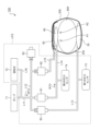
具体的に、図25のステップS51では、開閉弁81~83の閉状態(流体回路LC2の遮断モードSM)を維持したまま、測定処理部65Dは、ポンプ71をONにする。これにより、図26中に矢印W15で示すように、流路L11、開閉弁80、流路L13を介して、押圧カフ30内に空気を送り込むことができる。したがって、押圧カフ30を動作(膨張)させることができる。当該膨張した押圧カフ30は、ベルト20a,20bを介して、センシングカフ40を手首BWへ向かって押圧させる。
Specifically, in step S51 of FIG. 25, the
次に、ステップS52では、測定処理部65Dは、第2の圧力センサ74の測定結果(センシングカフ40内の圧力)が、第2の圧力閾値Pth2に達したか否かを、判定する。第2の圧力センサ74の測定結果が、第2の圧力閾値Pth2未満である場合(ステップS52でNO)には、ポンプ71から押圧カフ30への空気供給が継続され、一方で、ステップS52の判定処理も継続される。他方、第2の圧力センサ74の測定結果が、第2の圧力閾値Pth2に達した場合には(ステップS52でYES)、測定処理部65Dは、開閉弁82を開ける(ステップS53)。
Next, in step S52, the
これにより、図27中に矢印W16で示すように、ポンプ71から、流路L11,L12、開閉弁80、および流路L13を介して、押圧カフ30内に、空気が供給される。さらに、図27中に矢印W17で示すように、ポンプ71から、流路L11、開閉弁82、および流路L15を介して、補助カフ50内に、空気が供給される。このように、押圧カフ30および補助カフ50を徐々に加圧させながら(つまり、センシングカフ40に手首BWを圧迫させながら)、センシングカフ40に収容された圧力伝達用の空気の圧力に基づいて、オシロメトリック法により手首BWの血圧を算出する(ステップS54)。
As a result, air is supplied from the
測定処理部65Dによる血圧の算出が終了した後、ステップS55において、測定処理部65Dは、開閉弁83を開状態にする。次に、ステップS56において、測定処理部85Dは、ポンプ71をOFFにする。これにより、たとえば、補助カフ50内の空気は、図28中に矢印W18で示すように、流路L15、開閉弁82、流路L12、および開閉弁83を介して、大気中へ放出され、押圧カフ30内の空気は、図28中に矢印W19で示すように、流路L13、開閉弁80、流路L12、L11,L16、および排気弁72を介して、大気中へ放出される。よって、押圧カフ30内の圧力および補助カフ50内の圧力は、大気圧となる。
After the
次に、ステップS57において、測定処理部65Dは、開閉弁81を開状態にする。これにより、たとえば、センシングカフ40内の空気は、図29中に矢印W20で示すように、流路L14、開閉弁81、流路L11,L16、および排気弁72を介して、および/または、流路L14、開閉弁81、流路L12、および開閉弁83を介して、大気中へ放出される。よって、センシングカフ40内の圧力は、大気圧となり、血圧測定処理は終了する。
Next, in step S57, the
(効果)
本実施の形態に係る血圧計100は、実施の形態1で述べた効果に加えて、次の効果も有する。つまり、本実施形態に係る血圧計100では、押圧カフ30は、ベルト20a,20bの内周側のうち、装着状態でセンシングカフ40と反対側となる部分に配置される。そして、流体回路LC2は、制御部65の制御により、押圧カフ30の動作時には、ポンプ71から押圧カフ30へ加圧用の流体を供給して当該押圧カフ30を膨張させる。当該押圧カフ30の膨張により、センシングカフ40を手首BWへ向かって押圧させる。一方、流体回路LC2は、制御部65の制御により、押圧カフ30の非動作時には、押圧カフ30から加圧用の空気を、大気へ排出させる。
(effect)
これにより、押圧カフ30は、ポンプ71、すなわち、センシングカフ40に圧力伝達用の空気を供給する手段と共通の手段によって駆動(膨張または収縮)され得る。したがって、例えば押圧部材を機械式アクチュエータなどによって構成する場合に比して、血圧計100の簡素化を図ることができる。また、押圧カフ30は、ベルト20a,20bの内周側のうち、装着状態でセンシングカフ40と反対側となる部分に配置されている。例えば、装着状態で、押圧カフ30は、手首の背側面(手の甲側に相当する面)に配置され、膨張することにより、ベルト20a,20bの張力を高める。この結果、ベルト20a,20bのうちセンシングカフ40に対向する部分は、センシングカフ40を手首BWへ向かって押圧するストローク量が少なくて済む。したがって、手首BWに存する動脈A1,A2がセンシングカフ40によって押されて逃げる距離が、少なくなる(例えば、特開2017-006488号公報参照)。したがって、血圧を、さらに精度良く算出することができる。
Thereby, the
また、本実施形態に係る血圧計100においても、実施の形態1と同様に、本体10は、ベルト20a,20bの周方向に関して、センシングカフ40と反対側となる部分に配置されている。上記のように、ベルト20a,20bの内周側のうち、センシングカフ40と反対側となる部分に、押圧カフ30が配置される。したがって、本体10に搭載されたポンプ71から押圧カフ30までの距離を、極力短くすることができ、血圧計100のコンパクト化を図ることができる。
Further, in
なお、上記各実施の形態では、制御部65はCPUを含むものとしたが、これに限るものではない。制御部65は、PLD(Programmable Logic Device)、FPGA(Field Programmable Gate Array)などの、論理回路(集積回路)を含むものとしてもよい。
In addition, although the
以上の実施の形態は例示であり、この発明の範囲から離れることなく様々な変形が可能である。上述した複数の実施の形態は、それぞれ単独で成立し得るものであるが、実施の形態同士の組みあわせも可能である。また、異なる実施の形態の中の種々の特徴も、それぞれ単独で成立し得るものであるが、異なる実施の形態の中の特徴同士の組みあわせも可能である。 The above embodiments are examples, and various modifications are possible without departing from the scope of the present invention. Although each of the above-described multiple embodiments can be established independently, combinations of the embodiments are also possible. Also, various features in different embodiments can be established independently, but combinations of features in different embodiments are also possible.
10 本体
20a,20b ベルト
30 押圧カフ
40 センシングカフ
65 制御部
65A 第1準備処理部
65B 第2準備処理部
65C 第3準備処理部
65D 測定処理部
71 ポンプ
72 排気弁
75,76,80~83 開閉弁
73 第1の圧力センサ(押圧カフ圧力センサ)
74 第2の圧力センサ(センシングカフ圧力センサ)
100 血圧計
10
74 second pressure sensor (sensing cuff pressure sensor)
100 Sphygmomanometer
Claims (9)
前記本体から延在し、被測定部位を取り巻いて装着されるベルトと、
前記ベルトの内周側のうち、前記ベルトが前記被測定部位に装着された装着状態で、前記被測定部位の動脈通過部分を横切る部分に配設され、圧力伝達用の流体を収容可能に袋状に構成されたセンシングカフと、
前記センシングカフを前記被測定部位へ向かって押圧して、前記センシングカフに前記被測定部位を圧迫させる押圧部材と、
前記ポンプから前記センシングカフへ前記圧力伝達用の流体を供給するための供給モードと、前記センシングカフから流体を大気へ排出させるための排出モードと、前記センシングカフへの流体供給および前記センシングカフからの流体排出を遮断する遮断モードとを切り替えて構成可能な流体回路と、
制御部とを備え、
前記制御部は、前記装着状態において、
前記流体回路を前記排出モードに切り替えた状態で、前記押圧部材を動作させて前記センシングカフを前記被測定部位へ向かって押圧して、前記センシングカフに残存している流体を、前記流体回路を通して大気へ排出させる第1準備処理部と、
前記第1準備処理部の動作の後、前記流体回路を供給モードに切り替えた状態で、前記ポンプから前記流体回路を通して前記センシングカフに予め定められた量の前記圧力伝達用の流体を収容させる第2準備処理部と、
前記第2準備処理部の動作の後、前記流体回路を遮断モードに切り替えた状態で、前記押圧部材を動作させて前記センシングカフを前記被測定部位へ向かって押圧して、前記センシングカフに前記被測定部位を圧迫させながら、前記センシングカフに収容された前記圧力伝達用の流体の圧力に基づいてオシロメトリック法により前記被測定部位の血圧を算出する測定処理部とを含む、
血圧計。 A body with a pump,
a belt extending from the main body and worn around a site to be measured;
A bag that is disposed on the inner peripheral side of the belt and that crosses the artery passing portion of the measurement site in the state where the belt is attached to the measurement site, and is capable of containing a fluid for pressure transmission. a sensing cuff configured in a shape;
a pressing member that presses the sensing cuff toward the measurement site and causes the sensing cuff to press the measurement site;
A supply mode for supplying the fluid for pressure transmission from the pump to the sensing cuff, a discharge mode for discharging the fluid from the sensing cuff to the atmosphere, and a fluid supply to and from the sensing cuff. A fluid circuit that can be configured by switching between a shutoff mode that shuts off fluid discharge from the
and a control unit,
The control unit, in the wearing state,
With the fluid circuit switched to the discharge mode, the pressing member is operated to press the sensing cuff toward the measurement site, and the fluid remaining in the sensing cuff is discharged through the fluid circuit. a first preparatory processing unit for discharging to the atmosphere;
After the operation of the first preparatory processing unit, the sensing cuff receives a predetermined amount of the fluid for pressure transmission from the pump through the fluid circuit in a state where the fluid circuit is switched to the supply mode. 2 preparation processing unit;
After the operation of the second preparatory processing section, with the fluid circuit switched to the blocking mode, the pressing member is operated to press the sensing cuff toward the part to be measured, and the sensing cuff is pressed against the measurement site. a measurement processing unit that calculates the blood pressure of the measurement site by an oscillometric method based on the pressure of the pressure-transmitting fluid contained in the sensing cuff while pressing the measurement site;
Sphygmomanometer.
前記押圧部材は、前記ベルトと前記センシングカフとの間に配置される袋状の押圧カフを含み、
前記流体回路は、前記制御部の制御により、前記押圧部材の動作時には、前記ポンプから前記押圧カフへ加圧用の流体を供給して前記押圧カフを膨張させ、前記センシングカフを前記被測定部位へ向かって押圧させる一方、前記押圧部材の非動作時には、前記押圧カフから前記加圧用の流体を大気へ排出させる、
ことを特徴とする血圧計。 The sphygmomanometer according to claim 1,
The pressing member includes a bag-like pressing cuff arranged between the belt and the sensing cuff,
Under the control of the control unit, the fluid circuit supplies pressurizing fluid from the pump to the pressure cuff to inflate the pressure cuff when the pressure member is in operation, and pushes the sensing cuff toward the measurement site. While pressing toward the pressure member, when the pressing member is not in operation, discharging the pressurizing fluid from the pressure cuff to the atmosphere;
A sphygmomanometer characterized by:
前記押圧部材は、前記ベルトの内周側のうち、前記装着状態で前記センシングカフと反対側となる部分に配置される袋状の押圧カフを含み、
前記流体回路は、前記制御部の制御により、前記押圧部材の動作時には、前記ポンプから前記押圧カフへ加圧用の流体を供給して前記押圧カフを膨張させ、前記センシングカフを前記被測定部位へ向かって押圧させる一方、前記押圧部材の非動作時には、前記押圧カフから前記加圧用の流体を大気へ排出させる、
ことを特徴とする血圧計。 The sphygmomanometer according to claim 1,
The pressing member includes a bag-like pressing cuff arranged on the inner peripheral side of the belt on the side opposite to the sensing cuff in the worn state,
Under the control of the control unit, the fluid circuit supplies pressurizing fluid from the pump to the pressure cuff to inflate the pressure cuff when the pressure member is in operation, and pushes the sensing cuff toward the measurement site. While pressing toward the pressure member, when the pressing member is not in operation, discharging the pressurizing fluid from the pressure cuff to the atmosphere;
A sphygmomanometer characterized by:
前記制御部は、前記第2準備処理部の動作の後、前記測定処理部の動作の前に動作する第3準備処理部を含み、
前記第3準備処理部は、前記流体回路を遮断モードに切り替えた状態で、前記押圧部材を非動作にして、前記押圧カフから前記加圧用の流体を大気へ排出させる、
ことを特徴とする血圧計。 The sphygmomanometer according to claim 2 or 3,
The control unit includes a third preparation processing unit that operates after the operation of the second preparation processing unit and before the operation of the measurement processing unit,
The third preparation processing unit deactivates the pressing member in a state in which the fluid circuit is switched to a cutoff mode, and discharges the pressurizing fluid from the pressing cuff to the atmosphere.
A sphygmomanometer characterized by:
前記押圧カフの圧力を計測する、押圧カフ圧力センサを、さらに備える、
ことを特徴とする血圧計。 The sphygmomanometer according to claim 2 or 3,
further comprising a pressure cuff pressure sensor that measures the pressure of the pressure cuff;
A sphygmomanometer characterized by:
前記センシングカフの圧力を計測する、センシングカフ圧力センサを、さらに備える、
ことを特徴とする血圧計。 The sphygmomanometer according to any one of claims 1 to 5,
further comprising a sensing cuff pressure sensor that measures the pressure of the sensing cuff;
A sphygmomanometer characterized by:
前記本体は、前記ベルトの周方向に関して、前記センシングカフと反対側となる部分に配置されている、
ことを特徴とする血圧計。 The sphygmomanometer according to any one of claims 1 to 6,
The main body is arranged on the opposite side of the sensing cuff in the circumferential direction of the belt,
A sphygmomanometer characterized by:
前記装着状態において、
前記流体回路を前記排出モードに切り替えた状態で、前記押圧部材を動作させて前記センシングカフを前記被測定部位へ向かって押圧して、前記センシングカフに残存している流体を、前記流体回路を通して大気へ排出させる第1準備処理を行い、
前記第1準備処理の後、前記流体回路を供給モードに切り替えた状態で、前記ポンプから前記流体回路を通して前記センシングカフに予め定められた量の前記圧力伝達用の流体を収容させる第2準備処理を行い、
前記第2準備処理の後、前記流体回路を遮断モードに切り替えた状態で、前記押圧部材を動作させて前記センシングカフを前記被測定部位へ向かって押圧して、前記センシングカフに前記被測定部位を圧迫させながら、前記センシングカフに収容された前記圧力伝達用の流体の圧力に基づいてオシロメトリック法により前記被測定部位の血圧を算出する測定処理を行う、
血圧測定方法。 A main body having a pump mounted thereon, a belt extending from the main body and worn around a part to be measured, and an inner peripheral side of the belt, in a wearing state in which the belt is attached to the part to be measured, a sensing cuff arranged in a portion crossing the artery passing portion of the measurement site and having a bag-like structure capable of containing a fluid for pressure transmission; and pressing the sensing cuff toward the measurement site, a pressing member for causing the sensing cuff to press the site to be measured; a supply mode for supplying the fluid for transmitting the pressure from the pump to the sensing cuff; and a discharge for discharging the fluid from the sensing cuff to the atmosphere. A blood pressure measurement method using a sphygmomanometer equipped with a fluid circuit that can be configured by switching between a mode and a cutoff mode that cuts off the supply of fluid to the sensing cuff and the discharge of fluid from the sensing cuff,
In the wearing state,
With the fluid circuit switched to the discharge mode, the pressing member is operated to press the sensing cuff toward the measurement site, and the fluid remaining in the sensing cuff is discharged through the fluid circuit. perform a first preparatory process for discharging to the atmosphere,
After the first preparation process, a second preparation process of causing the sensing cuff to receive a predetermined amount of the fluid for pressure transmission from the pump through the fluid circuit while the fluid circuit is switched to the supply mode. and
After the second preparation process, in a state in which the fluid circuit is switched to the blocking mode, the pressing member is operated to press the sensing cuff toward the measurement site, and the sensing cuff presses the measurement target. performing a measurement process of calculating the blood pressure of the measurement site by an oscillometric method based on the pressure of the fluid for pressure transmission contained in the sensing cuff while pressing the site;
Blood pressure measurement method.
A program that causes a computer to execute the blood pressure measurement method according to claim 8 .
Priority Applications (5)
| Application Number | Priority Date | Filing Date | Title |
|---|---|---|---|
| JP2018245724A JP7219086B2 (en) | 2018-12-27 | 2018-12-27 | Sphygmomanometer, blood pressure measurement method, and program |
| PCT/JP2019/046973 WO2020137363A1 (en) | 2018-12-27 | 2019-12-02 | Sphygmomanometer, blood pressure measurement method, and program |
| DE112019006518.1T DE112019006518T5 (en) | 2018-12-27 | 2019-12-02 | SPHYGMOMANOMETER, BLOOD PRESSURE MEASUREMENT METHOD AND PROGRAM |
| CN201980085561.7A CN113226162B (en) | 2018-12-27 | 2019-12-02 | Blood pressure monitor, blood pressure measurement method and computer-readable storage medium |
| US17/413,438 US12161446B2 (en) | 2018-12-27 | 2021-06-11 | Sphygmomanometer, blood pressure measurement method, and computer-readable recording medium |
Applications Claiming Priority (1)
| Application Number | Priority Date | Filing Date | Title |
|---|---|---|---|
| JP2018245724A JP7219086B2 (en) | 2018-12-27 | 2018-12-27 | Sphygmomanometer, blood pressure measurement method, and program |
Publications (2)
| Publication Number | Publication Date |
|---|---|
| JP2020103613A JP2020103613A (en) | 2020-07-09 |
| JP7219086B2 true JP7219086B2 (en) | 2023-02-07 |
Family
ID=71127058
Family Applications (1)
| Application Number | Title | Priority Date | Filing Date |
|---|---|---|---|
| JP2018245724A Active JP7219086B2 (en) | 2018-12-27 | 2018-12-27 | Sphygmomanometer, blood pressure measurement method, and program |
Country Status (5)
| Country | Link |
|---|---|
| US (1) | US12161446B2 (en) |
| JP (1) | JP7219086B2 (en) |
| CN (1) | CN113226162B (en) |
| DE (1) | DE112019006518T5 (en) |
| WO (1) | WO2020137363A1 (en) |
Families Citing this family (2)
| Publication number | Priority date | Publication date | Assignee | Title |
|---|---|---|---|---|
| KR102561633B1 (en) * | 2021-06-07 | 2023-08-01 | (주)참케어 | Blood pressure measuring device |
| WO2024101834A1 (en) * | 2022-11-07 | 2024-05-16 | 이상진 | Band capable of measuring arterial blood |
Citations (1)
| Publication number | Priority date | Publication date | Assignee | Title |
|---|---|---|---|---|
| JP2018102867A (en) | 2016-12-28 | 2018-07-05 | オムロン株式会社 | Sphygmomanometer and method/apparatus for measuring blood pressure |
Family Cites Families (19)
| Publication number | Priority date | Publication date | Assignee | Title |
|---|---|---|---|---|
| JPS5892340A (en) * | 1981-11-28 | 1983-06-01 | 株式会社コパルタケダメディカル研究所 | Zero compensating apparatus of hemomanometer |
| JPS60132539A (en) * | 1983-12-20 | 1985-07-15 | 松下電工株式会社 | Hemomanometer |
| US4641496A (en) * | 1984-12-17 | 1987-02-10 | Ford Motor Company | Continuous rotary regeneration system for a particulate trap |
| JPH06117B2 (en) * | 1985-06-07 | 1994-01-05 | オムロン株式会社 | Electronic blood pressure monitor for fingers |
| JPH0453762Y2 (en) * | 1986-09-22 | 1992-12-17 | ||
| US4889132A (en) * | 1986-09-26 | 1989-12-26 | The University Of North Carolina At Chapel Hill | Portable automated blood pressure monitoring apparatus and method |
| US6336901B1 (en) * | 1998-04-27 | 2002-01-08 | Omron Corporation | Sphygmomanometer cuff achieving precise measurement of blood pressure |
| EP1256313B1 (en) * | 2001-05-07 | 2007-11-28 | Omron Healthcare Co., Ltd. | Cuff of wrist-mount blood pressure monitor |
| JP4943870B2 (en) * | 2007-01-24 | 2012-05-30 | テルモ株式会社 | Blood pressure measuring device and cuff |
| WO2008152894A1 (en) * | 2007-06-13 | 2008-12-18 | Terumo Kabushiki Kaisha | Sphygmomanometry apparatus |
| JP2011152307A (en) * | 2010-01-28 | 2011-08-11 | Omron Healthcare Co Ltd | Electronic blood-pressure meter and control method thereof |
| JP5493932B2 (en) * | 2010-02-02 | 2014-05-14 | オムロンヘルスケア株式会社 | Blood pressure information measuring device |
| JP5470126B2 (en) * | 2010-03-24 | 2014-04-16 | テルモ株式会社 | Electronic blood pressure monitor |
| JP5640527B2 (en) * | 2010-07-28 | 2014-12-17 | オムロンヘルスケア株式会社 | Blood pressure measuring device |
| JP2012040198A (en) * | 2010-08-19 | 2012-03-01 | Terumo Corp | Electronic sphygmomanometer |
| JP5821657B2 (en) * | 2012-01-25 | 2015-11-24 | オムロンヘルスケア株式会社 | Measuring apparatus and measuring method |
| JP5987547B2 (en) * | 2012-08-09 | 2016-09-07 | オムロンヘルスケア株式会社 | Blood pressure information measuring device |
| JP6172218B2 (en) | 2015-06-24 | 2017-08-02 | オムロンヘルスケア株式会社 | Fluid bag, blood pressure measurement cuff, blood pressure monitor, and blood pressure measurement method |
| JP6751666B2 (en) | 2016-12-28 | 2020-09-09 | オムロン株式会社 | Sphygmomanometer and blood pressure measurement method and equipment |
-
2018
- 2018-12-27 JP JP2018245724A patent/JP7219086B2/en active Active
-
2019
- 2019-12-02 WO PCT/JP2019/046973 patent/WO2020137363A1/en not_active Ceased
- 2019-12-02 CN CN201980085561.7A patent/CN113226162B/en active Active
- 2019-12-02 DE DE112019006518.1T patent/DE112019006518T5/en active Pending
-
2021
- 2021-06-11 US US17/413,438 patent/US12161446B2/en active Active
Patent Citations (1)
| Publication number | Priority date | Publication date | Assignee | Title |
|---|---|---|---|---|
| JP2018102867A (en) | 2016-12-28 | 2018-07-05 | オムロン株式会社 | Sphygmomanometer and method/apparatus for measuring blood pressure |
Also Published As
| Publication number | Publication date |
|---|---|
| WO2020137363A1 (en) | 2020-07-02 |
| CN113226162B (en) | 2024-03-12 |
| US12161446B2 (en) | 2024-12-10 |
| US20220218216A1 (en) | 2022-07-14 |
| DE112019006518T5 (en) | 2021-09-16 |
| JP2020103613A (en) | 2020-07-09 |
| CN113226162A (en) | 2021-08-06 |
Similar Documents
| Publication | Publication Date | Title |
|---|---|---|
| US6336901B1 (en) | Sphygmomanometer cuff achieving precise measurement of blood pressure | |
| US11918327B2 (en) | Sphygmomanometer, blood pressure measurement method, and device | |
| CN101861121B (en) | Arteriosclerosis degree judgment device capable of judging arteriosclerosis degree precisely | |
| US11534072B2 (en) | Sphygmomanometer, blood pressure measurement method, and device | |
| US11850031B2 (en) | Sphygmomanometer, blood pressure measurement method, and device | |
| EP1075846A2 (en) | Cuff for blood pressure manometer | |
| US11832922B2 (en) | Sphygmomanometer, and method and device for measuring blood pressure | |
| JP7219086B2 (en) | Sphygmomanometer, blood pressure measurement method, and program | |
| JP2009284967A (en) | Cuff for blood pressure data measuring instrument and blood pressure data measuring instrument equipped with it | |
| AU2016333151A1 (en) | Clamping device, system and method for controlling venous blood flow, improving venous dilation and effecting blood pressure measurement | |
| JP2004160231A (en) | Automatic non-invasive method and apparatus for monitoring blood pressure | |
| WO2017221627A1 (en) | Sphygmomanometer | |
| JP2009297222A (en) | Cuff structure in blood pressure information measuring apparatus and blood pressure information measuring apparatus | |
| JP2004254717A (en) | Cuff band of blood pressure meter and blood pressure meter using the same | |
| JP4689228B2 (en) | Air massage device abnormality detection system | |
| US11540733B2 (en) | Sphygmomanometer, and method and device for measuring blood pressure | |
| JP2010233655A (en) | Sphygmomanometer | |
| US20230210386A1 (en) | Sphygmomanometer | |
| US12070296B2 (en) | Cuff unit and sphygmomanometer | |
| JP5366704B2 (en) | Biological information measuring device | |
| JP2018130399A5 (en) | ||
| US20240192069A1 (en) | Blood-pressure gauge and method for measuring blood pressure | |
| WO2019003620A1 (en) | Biological information measuring device and sphygmomanometer | |
| JP2023114789A (en) | blood pressure cuff | |
| JP2023098261A5 (en) |
Legal Events
| Date | Code | Title | Description |
|---|---|---|---|
| A521 | Request for written amendment filed |
Free format text: JAPANESE INTERMEDIATE CODE: A523 Effective date: 20211216 |
|
| A621 | Written request for application examination |
Free format text: JAPANESE INTERMEDIATE CODE: A621 Effective date: 20211216 |
|
| A131 | Notification of reasons for refusal |
Free format text: JAPANESE INTERMEDIATE CODE: A131 Effective date: 20221011 |
|
| A521 | Request for written amendment filed |
Free format text: JAPANESE INTERMEDIATE CODE: A523 Effective date: 20221206 |
|
| TRDD | Decision of grant or rejection written | ||
| A01 | Written decision to grant a patent or to grant a registration (utility model) |
Free format text: JAPANESE INTERMEDIATE CODE: A01 Effective date: 20230117 |
|
| A61 | First payment of annual fees (during grant procedure) |
Free format text: JAPANESE INTERMEDIATE CODE: A61 Effective date: 20230126 |
|
| R150 | Certificate of patent or registration of utility model |
Ref document number: 7219086 Country of ref document: JP Free format text: JAPANESE INTERMEDIATE CODE: R150 |