JP7217230B2 - Devices, systems and methods for the treatment of heart failure by visceral nerve ablation - Google Patents
Devices, systems and methods for the treatment of heart failure by visceral nerve ablation Download PDFInfo
- Publication number
- JP7217230B2 JP7217230B2 JP2019526210A JP2019526210A JP7217230B2 JP 7217230 B2 JP7217230 B2 JP 7217230B2 JP 2019526210 A JP2019526210 A JP 2019526210A JP 2019526210 A JP2019526210 A JP 2019526210A JP 7217230 B2 JP7217230 B2 JP 7217230B2
- Authority
- JP
- Japan
- Prior art keywords
- ablation
- energy
- catheter
- vein
- nerve
- Prior art date
- Legal status (The legal status is an assumption and is not a legal conclusion. Google has not performed a legal analysis and makes no representation as to the accuracy of the status listed.)
- Active
Links
Images


Classifications
-
- A—HUMAN NECESSITIES
- A61—MEDICAL OR VETERINARY SCIENCE; HYGIENE
- A61B—DIAGNOSIS; SURGERY; IDENTIFICATION
- A61B18/00—Surgical instruments, devices or methods for transferring non-mechanical forms of energy to or from the body
- A61B18/04—Surgical instruments, devices or methods for transferring non-mechanical forms of energy to or from the body by heating
- A61B18/12—Surgical instruments, devices or methods for transferring non-mechanical forms of energy to or from the body by heating by passing a current through the tissue to be heated, e.g. high-frequency current
- A61B18/14—Probes or electrodes therefor
- A61B18/1492—Probes or electrodes therefor having a flexible, catheter-like structure, e.g. for heart ablation
-
- A—HUMAN NECESSITIES
- A61—MEDICAL OR VETERINARY SCIENCE; HYGIENE
- A61B—DIAGNOSIS; SURGERY; IDENTIFICATION
- A61B5/00—Measuring for diagnostic purposes; Identification of persons
- A61B5/02—Detecting, measuring or recording pulse, heart rate, blood pressure or blood flow; Combined pulse/heart-rate/blood pressure determination; Evaluating a cardiovascular condition not otherwise provided for, e.g. using combinations of techniques provided for in this group with electrocardiography or electroauscultation; Heart catheters for measuring blood pressure
- A61B5/021—Measuring pressure in heart or blood vessels
-
- A—HUMAN NECESSITIES
- A61—MEDICAL OR VETERINARY SCIENCE; HYGIENE
- A61N—ELECTROTHERAPY; MAGNETOTHERAPY; RADIATION THERAPY; ULTRASOUND THERAPY
- A61N1/00—Electrotherapy; Circuits therefor
- A61N1/02—Details
- A61N1/04—Electrodes
- A61N1/05—Electrodes for implantation or insertion into the body, e.g. heart electrode
- A61N1/0551—Spinal or peripheral nerve electrodes
-
- A—HUMAN NECESSITIES
- A61—MEDICAL OR VETERINARY SCIENCE; HYGIENE
- A61N—ELECTROTHERAPY; MAGNETOTHERAPY; RADIATION THERAPY; ULTRASOUND THERAPY
- A61N1/00—Electrotherapy; Circuits therefor
- A61N1/18—Applying electric currents by contact electrodes
-
- A—HUMAN NECESSITIES
- A61—MEDICAL OR VETERINARY SCIENCE; HYGIENE
- A61N—ELECTROTHERAPY; MAGNETOTHERAPY; RADIATION THERAPY; ULTRASOUND THERAPY
- A61N1/00—Electrotherapy; Circuits therefor
- A61N1/18—Applying electric currents by contact electrodes
- A61N1/32—Applying electric currents by contact electrodes alternating or intermittent currents
- A61N1/36—Applying electric currents by contact electrodes alternating or intermittent currents for stimulation
- A61N1/36014—External stimulators, e.g. with patch electrodes
- A61N1/36017—External stimulators, e.g. with patch electrodes with leads or electrodes penetrating the skin
-
- A—HUMAN NECESSITIES
- A61—MEDICAL OR VETERINARY SCIENCE; HYGIENE
- A61B—DIAGNOSIS; SURGERY; IDENTIFICATION
- A61B18/00—Surgical instruments, devices or methods for transferring non-mechanical forms of energy to or from the body
- A61B18/18—Surgical instruments, devices or methods for transferring non-mechanical forms of energy to or from the body by applying electromagnetic radiation, e.g. microwaves
-
- A—HUMAN NECESSITIES
- A61—MEDICAL OR VETERINARY SCIENCE; HYGIENE
- A61B—DIAGNOSIS; SURGERY; IDENTIFICATION
- A61B18/00—Surgical instruments, devices or methods for transferring non-mechanical forms of energy to or from the body
- A61B2018/00053—Mechanical features of the instrument of device
- A61B2018/00214—Expandable means emitting energy, e.g. by elements carried thereon
- A61B2018/0022—Balloons
-
- A—HUMAN NECESSITIES
- A61—MEDICAL OR VETERINARY SCIENCE; HYGIENE
- A61B—DIAGNOSIS; SURGERY; IDENTIFICATION
- A61B18/00—Surgical instruments, devices or methods for transferring non-mechanical forms of energy to or from the body
- A61B2018/00053—Mechanical features of the instrument of device
- A61B2018/00273—Anchoring means for temporary attachment of a device to tissue
- A61B2018/00279—Anchoring means for temporary attachment of a device to tissue deployable
- A61B2018/00285—Balloons
-
- A—HUMAN NECESSITIES
- A61—MEDICAL OR VETERINARY SCIENCE; HYGIENE
- A61B—DIAGNOSIS; SURGERY; IDENTIFICATION
- A61B18/00—Surgical instruments, devices or methods for transferring non-mechanical forms of energy to or from the body
- A61B2018/00315—Surgical instruments, devices or methods for transferring non-mechanical forms of energy to or from the body for treatment of particular body parts
- A61B2018/00434—Neural system
-
- A—HUMAN NECESSITIES
- A61—MEDICAL OR VETERINARY SCIENCE; HYGIENE
- A61B—DIAGNOSIS; SURGERY; IDENTIFICATION
- A61B18/00—Surgical instruments, devices or methods for transferring non-mechanical forms of energy to or from the body
- A61B2018/00571—Surgical instruments, devices or methods for transferring non-mechanical forms of energy to or from the body for achieving a particular surgical effect
- A61B2018/00577—Ablation
-
- A—HUMAN NECESSITIES
- A61—MEDICAL OR VETERINARY SCIENCE; HYGIENE
- A61B—DIAGNOSIS; SURGERY; IDENTIFICATION
- A61B18/00—Surgical instruments, devices or methods for transferring non-mechanical forms of energy to or from the body
- A61B2018/00636—Sensing and controlling the application of energy
- A61B2018/00642—Sensing and controlling the application of energy with feedback, i.e. closed loop control
- A61B2018/00648—Sensing and controlling the application of energy with feedback, i.e. closed loop control using more than one sensed parameter
-
- A—HUMAN NECESSITIES
- A61—MEDICAL OR VETERINARY SCIENCE; HYGIENE
- A61B—DIAGNOSIS; SURGERY; IDENTIFICATION
- A61B18/00—Surgical instruments, devices or methods for transferring non-mechanical forms of energy to or from the body
- A61B2018/00636—Sensing and controlling the application of energy
- A61B2018/00696—Controlled or regulated parameters
- A61B2018/00702—Power or energy
-
- A—HUMAN NECESSITIES
- A61—MEDICAL OR VETERINARY SCIENCE; HYGIENE
- A61B—DIAGNOSIS; SURGERY; IDENTIFICATION
- A61B18/00—Surgical instruments, devices or methods for transferring non-mechanical forms of energy to or from the body
- A61B2018/00636—Sensing and controlling the application of energy
- A61B2018/00773—Sensed parameters
- A61B2018/00791—Temperature
-
- A—HUMAN NECESSITIES
- A61—MEDICAL OR VETERINARY SCIENCE; HYGIENE
- A61B—DIAGNOSIS; SURGERY; IDENTIFICATION
- A61B18/00—Surgical instruments, devices or methods for transferring non-mechanical forms of energy to or from the body
- A61B2018/00636—Sensing and controlling the application of energy
- A61B2018/00773—Sensed parameters
- A61B2018/00875—Resistance or impedance
-
- A—HUMAN NECESSITIES
- A61—MEDICAL OR VETERINARY SCIENCE; HYGIENE
- A61B—DIAGNOSIS; SURGERY; IDENTIFICATION
- A61B18/00—Surgical instruments, devices or methods for transferring non-mechanical forms of energy to or from the body
- A61B18/04—Surgical instruments, devices or methods for transferring non-mechanical forms of energy to or from the body by heating
- A61B18/12—Surgical instruments, devices or methods for transferring non-mechanical forms of energy to or from the body by heating by passing a current through the tissue to be heated, e.g. high-frequency current
- A61B18/14—Probes or electrodes therefor
- A61B2018/1467—Probes or electrodes therefor using more than two electrodes on a single probe
-
- A—HUMAN NECESSITIES
- A61—MEDICAL OR VETERINARY SCIENCE; HYGIENE
- A61B—DIAGNOSIS; SURGERY; IDENTIFICATION
- A61B18/00—Surgical instruments, devices or methods for transferring non-mechanical forms of energy to or from the body
- A61B18/04—Surgical instruments, devices or methods for transferring non-mechanical forms of energy to or from the body by heating
- A61B18/12—Surgical instruments, devices or methods for transferring non-mechanical forms of energy to or from the body by heating by passing a current through the tissue to be heated, e.g. high-frequency current
- A61B18/14—Probes or electrodes therefor
- A61B2018/1475—Electrodes retractable in or deployable from a housing
-
- A—HUMAN NECESSITIES
- A61—MEDICAL OR VETERINARY SCIENCE; HYGIENE
- A61B—DIAGNOSIS; SURGERY; IDENTIFICATION
- A61B5/00—Measuring for diagnostic purposes; Identification of persons
- A61B5/02—Detecting, measuring or recording pulse, heart rate, blood pressure or blood flow; Combined pulse/heart-rate/blood pressure determination; Evaluating a cardiovascular condition not otherwise provided for, e.g. using combinations of techniques provided for in this group with electrocardiography or electroauscultation; Heart catheters for measuring blood pressure
- A61B5/024—Detecting, measuring or recording pulse rate or heart rate
-
- A—HUMAN NECESSITIES
- A61—MEDICAL OR VETERINARY SCIENCE; HYGIENE
- A61B—DIAGNOSIS; SURGERY; IDENTIFICATION
- A61B5/00—Measuring for diagnostic purposes; Identification of persons
- A61B5/08—Detecting, measuring or recording devices for evaluating the respiratory organs
Description
関連技術の相互参照
本出願は、それぞれが参照により全体が本明細書に組み込まれる、2016年7月29日に出願された米国仮特許出願第62/368,912号、2016年10月21日に出願された米国仮特許出願第62/411,492号、及び2017年4月5日に出願された米国仮特許出願第62/482,142号に基づく優先権を主張する。
CROSS-REFERENCE TO RELATED ART This application is the subject of U.S. Provisional Patent Application No. 62/368,912, filed July 29, 2016, October 21, 2016, each of which is hereby incorporated by reference in its entirety. No. 62/411,492, filed on April 5, 2017, and U.S. Provisional Patent Application No. 62/482,142, filed April 5, 2017.
参照による援用
本明細書で言及された全ての刊行物及び特許出願は、恰も、個々の刊行物又は特許出願がそれぞれ特定的且つ個別に、参照により組み込まれると示されたかの如く参照により本明細書に援用される。
本発明は、内臓神経アブレーションによる心不全の治療の為のデバイス、システム及び方法に関する。
INCORPORATION BY REFERENCE All publications and patent applications mentioned in this specification are herein incorporated by reference as if each individual publication or patent application was specifically and individually indicated to be incorporated by reference. Incorporated into
The present invention relates to devices, systems and methods for the treatment of heart failure by visceral nerve ablation.
心不全(HF)は、心臓が体内の臓器を維持する為に十分にポンプ動作できない場合に発生する病状である。心不全は重症であり、米国及び世界中の患者を侵している。 Heart failure (HF) is a medical condition that occurs when the heart is unable to pump adequately to keep the body's organs alive. Heart failure is serious and affects patients in the United States and around the world.
米国だけでも約510万人が心不全にかかっており、アメリカ疾病予防管理センター(the Center for Disease Control)によれば、この状況が国に、看護、治療、薬物治療及び生産性損失で300億ドル超の費用を課している。正常で健常な心臓は、平均的には拳より少し大きい筋肉ポンプである。心臓は、循環器系を通して絶えず血液を送り出し、酸素化された血液を体に供給する。心不全の症状下では、弱った心臓は体に十分な血液を供給できず、歩行などの日常的活動さえ困難にする、疲労及び息切れを特徴とする心筋症(心筋疾患)を招く。 Heart failure affects about 5.1 million people in the United States alone, and according to the Center for Disease Control, the situation costs the country $30 billion in nursing, care, medication and lost productivity. charges excessive costs. A normal, healthy heart is a muscular pump that is on average a little larger than a fist. The heart continually pumps blood through the circulatory system to supply the body with oxygenated blood. Under conditions of heart failure, a weakened heart cannot supply enough blood to the body, leading to cardiomyopathy (cardiomyopathy) characterized by fatigue and shortness of breath, making even daily activities such as walking difficult.
しばしば、この機能障害を補おうとして、心臓と身体は、身体を維持する為に心臓の不全を一時的にカバーする生理変化を経る。これらの変化は、心室の拡張、心筋組織増大、心拍数増加、血圧上昇、血行不良、四肢及び肺における体液の不均衡を含む。 Often, in an attempt to compensate for this dysfunction, the heart and body undergo physiological changes that temporarily cover the heart's insufficiency in order to sustain the body. These changes include ventricular dilatation, myocardial tissue enlargement, increased heart rate, increased blood pressure, poor circulation, and fluid imbalances in the extremities and lungs.
心臓の健康状態の1つの一般的指標は、左室駆出率(LVEF)又は駆出率である。定義では、収縮直前の心室内の血液量は、拡張終期容積(EDV)として知られる。同様に、収縮の終期に心室に残った血液の容積は、収縮末期容積(ESV)である。EDVとESVの差が一回拍出量(SV)である。SVは、各心拍ごとに右及び左心室から駆出される血液量を表す。駆出率(EF)は、各心拍ごとに駆出されるEDVの率であり、即ち、SVをEDVで割ったものである。心拍出量(CO)は、心臓の各心室によって毎分送り出される血液の量として定義される。COは、SVに心拍数(HR)を掛けたものに等しい。 One common indicator of heart health is the left ventricular ejection fraction (LVEF) or ejection fraction. By definition, the volume of blood in the ventricle just before contraction is known as the end-diastolic volume (EDV). Similarly, the volume of blood left in the ventricle at the end of systole is the end-systolic volume (ESV). The difference between EDV and ESV is the stroke volume (SV). SV represents the volume of blood ejected from the right and left ventricles with each heartbeat. Ejection fraction (EF) is the rate of EDV ejected with each beat, ie, SV divided by EDV. Cardiac output (CO) is defined as the amount of blood pumped each minute by each ventricle of the heart. CO is equal to SV multiplied by heart rate (HR).
心筋が弱る、伸びる、又はその他の構造的問題を呈する心筋症は更に、心室駆出率に基づいて、収縮性機能障害と拡張性機能障害に分類され得る。 Cardiomyopathies in which the myocardium weakens, stretches, or presents with other structural problems can be further divided into systolic and diastolic dysfunction based on ventricular ejection fraction.
収縮性機能障害は、心筋収縮性の減少を特徴とする。LVEFの減少は、心筋収縮性が左心室全体で減少したとき起こる。COは2つの方式で維持される:左室拡張は、より高いSVと、心臓を拡張したことによる機構的利点の増加の結果として収縮性の増加をもたらす。しかしながら、これらの代償機構は結局心臓の引き続いた衰弱とCOの減少に凌駕され、HFの生理的兆候につながる。心臓の左側は、大循環に十分な量の血液を押し出す為に十分な力でポンプ動作できない。これにより、液が肺に戻り、肺鬱血につながる。一般用語では、収縮性機能障害は、40%未満のLVEFとして定義され、これらの患者の心不全は、駆出率が減少した心不全(HFrEF)として広範に分類され得る。 Contractile dysfunction is characterized by decreased myocardial contractility. A decrease in LVEF occurs when myocardial contractility is decreased throughout the left ventricle. CO is maintained in two ways: left ventricular dilation leads to higher SV and increased contractility as a result of the increased mechanical advantage of dilating the heart. However, these compensatory mechanisms are eventually overwhelmed by continued weakening of the heart and depletion of CO, leading to physiologic manifestations of HF. The left side of the heart cannot pump with enough force to push a sufficient volume of blood into the general circulation. This causes fluid to return to the lungs, leading to pulmonary congestion. In general terms, contractile dysfunction is defined as an LVEF less than 40%, and heart failure in these patients can be broadly classified as heart failure with reduced ejection fraction (HFrEF).
拡張性機能障害は、左室充満が異常であり、充満圧上昇を伴う心臓の機能障害を指す。心臓拡張期では、心筋が弛緩しているとき、左心室の充満は、心筋又は心臓筋肉のコンプライアンス(圧力変化に対するキャパシタンス変化によって定義される)又は伸張性に依存する受動プロセスである。心室が弛緩できず充満できない場合、心筋は、貧弱なSVを補償しようとして強化され得る。この、引き続いた筋肉肥大はより一層不適切な充満につながる。拡張性機能障害は、特に足、足首及び脚への浮腫又は水分貯留につながり得る。更に、肺での液体の増大の結果、肺鬱血を患う患者もあり得る。HF患者であるが収縮性機能障害はない患者の場合、拡張性機能障害が推定される原因である。拡張性機能障害は、心筋の肥厚を特徴とする肥大型心筋症(HCM)ばかりでなく、受動充満に適応する為に伸縮できない剛直な心筋を特徴とする拘束型心筋症(RCM)に特有のものである。一般的に、拡張性機能障害は、40%超のLVEFとして定義され、これらの患者のHFは、駆出率が保たれた心不全(HFpEF)として広範に分類され得る。 Diastolic dysfunction refers to cardiac dysfunction with abnormal left ventricular filling and elevated filling pressure. In diastole, left ventricular filling is a passive process that depends on the myocardium or its compliance (defined by capacitance change to pressure change) or tonicity when the myocardium is relaxed. If the ventricle fails to relax and fill, the myocardium may strengthen in an attempt to compensate for the poor SV. This subsequent muscle hypertrophy leads to even more inappropriate filling. Diastolic dysfunction can lead to edema or water retention, especially in the feet, ankles and legs. Additionally, some patients may suffer from pulmonary congestion as a result of fluid build-up in the lungs. For patients with HF but without contractile dysfunction, diastolic dysfunction is the probable cause. Diastolic dysfunction is characteristic of restrictive cardiomyopathy (RCM), characterized by rigid myocardium that cannot stretch to accommodate passive filling, as well as hypertrophic cardiomyopathy (HCM), which is characterized by thickening of the myocardium. It is. Generally, diastolic dysfunction is defined as an LVEF greater than 40%, and HF in these patients can be broadly classified as heart failure with preserved ejection fraction (HFpEF).
幾つかの薬物療法は収縮性機能障害及びHFrEFを有効にターゲットにしているが、拡張性機能障害及びHFpEFを患う大集団の患者に対して、見込みのある療法は未だ特定されていない。HFrEFとHFpEFを両方患っている患者の為の臨床経過は、呼吸困難、運動耐容能低下、末梢浮腫などの症状を伴う急性非代償性心不全(ADHF)の再現性発現には重要である。ADHFでの再入院は現在のヘルスケアリソースの大きな部分を利用し、莫大なコストを生じさせ続ける可能性がある。 Although several pharmacotherapies have effectively targeted contractile dysfunction and HFrEF, no promising therapy has yet been identified for the large population of patients with diastolic dysfunction and HFpEF. The clinical course for patients with both HFrEF and HFpEF is important for the reproducible manifestation of acute decompensated heart failure (ADHF) with symptoms such as dyspnea, exercise intolerance, and peripheral edema. Readmissions for ADHF utilize a large portion of current healthcare resources and can continue to incur enormous costs.
HFの病態生理に関してはますます理解が深まりつつあるが、現代の医薬は、これまで、HF又は再発性ADHFのエピソードの慢性管理の為の新たな療法の開発には成功していない。過去数十年にわたり、ADHF管理及び防止の戦略は、塩分と水分の保持が血管内の液体膨張及び心臓の代償不全の原因であるとする伝統的なパラダイムに傾注してきており、今後も傾注し続ける。 Although there is an increasing understanding of the pathophysiology of HF, modern medicine has so far failed to develop new therapies for the chronic management of episodes of HF or recurrent ADHF. Over the past several decades, ADHF management and prevention strategies have focused and will continue to focus on the traditional paradigm that salt and water retention are responsible for intravascular fluid expansion and cardiac decompensation. continue.
従って、安全且つ有効な、心不全患者の為の改良された療法、及びこれらの療法を実行するように適合されたデバイスとシステムに対する必要が依然としてある。 Accordingly, there remains a need for improved therapies for heart failure patients that are safe and effective, and devices and systems adapted to carry out these therapies.
上記に鑑み、駆出率が保たれた心不全(HFpEF)と、循環血液量拡張耐性が妨げられている患者、運動制限及び労作時呼吸困難を含むHFの治療の為の神経体液活性化に影響を与える装置及び方法を提供することが望ましいであろう。 In view of the above, neurohumoral activation for the treatment of heart failure with preserved ejection fraction (HFpEF) and HF, including patients with impaired volume expansion tolerance, exercise limitation and dyspnea on exertion. It would be desirable to provide an apparatus and method that provides
本開示は、HFを患う患者の為の改良された治療オプションを、大内臓神経、小内臓神経及び最下内臓神経と、交感神経鎖から出て、腹部コンパートメントの臓器と脈管系及び特に大内臓神経(GSN)を神経刺激する胸内臓神経のうち少なくとも1つを形成する、内臓神経の寄与する神経の一部分を含む胸内臓神経(TSN)を融除することによって提供する方法、デバイス及びシステムを含む。GSN、小内臓神経及び最下内臓神経は、交感神経幹から、腹腔神経節にリレーする根又は支流として出現する節前線維から形成される為、交感神経幹と腹腔神経節の間の胸内臓神経を形成する全ての節前線維は、簡略化の為胸内臓神経と呼ばれる。特定の神経を選択的に融除することによって、本開示は、循環血液量、圧力、血流及び総合的な心臓及び循環器系機能に影響を及ぼし得る新規の方法及びデバイスを提供する。こうして、本開示は、HFに関する最新の理論に基づいた、HF及び特にHFpEFを治療する為の新規の解決策を導入することを支援する。 The present disclosure provides improved treatment options for patients with HF, including the greater, lesser and inferior splanchnic nerves, and the organs and vasculature of the abdominal compartment and especially the large splanchnic nerves, exiting the sympathetic chain. Methods, devices and systems provided by ablating a thoracic splanchnic nerve (TSN) comprising a portion of the contributing nerve of the splanchnic nerve forming at least one of the thoracic splanchnic nerves that innervate the splanchnic nerve (GSN). including. The GSN, the lesser and inferior splanchnic nerves, are formed from preganglionic fibers that emerge from the sympathetic trunk as roots or tributaries that relay to the celiac ganglion, thus the thoracic viscera between the sympathetic trunk and the celiac ganglion. All nerve-forming preganglionic fibers are called thoracic splanchnic nerves for simplicity. By selectively ablating specific nerves, the present disclosure provides novel methods and devices that can affect circulating blood volume, pressure, blood flow, and overall heart and circulatory system function. Thus, the present disclosure helps introduce novel solutions for treating HF, and particularly HFpEF, based on the latest theories regarding HF.
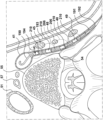
カテーテルナビゲーションのツールは、肋間腔及び/又は椎骨などの血管外ランドマークの使用を含む。内部走査又は検出方法は、放射線ランドマーク、CT走査、MRI及び/又は超音波の蛍光透視検出を含んでよい。これらの走査は、直接神経可視化、又は、隣接する血管(例えば、奇(azygos))及び非血管構造(横隔膜、椎骨、肋骨)の直接神経可視化の為に用いられる。放射線造影剤とガイドワイヤの使用は、デバイスのアブレーション要素の配置を支援できる。 Tools for catheter navigation include the use of extravascular landmarks such as intercostal spaces and/or vertebrae. Internal scanning or detection methods may include fluoroscopic detection of radiographic landmarks, CT scanning, MRI and/or ultrasound. These scans are used for direct neurovisualization, or of adjacent vessels (eg, azygos) and non-vascular structures (diaphragm, vertebrae, ribs). The use of radiocontrast agents and guidewires can assist in positioning the ablation elements of the device.
標的部位において、標的神経を特定的に融除する為の標的調節の幾つかの提案される方法は、極低温又は高温ベースのアブレーション、局所的ドラッグデリバリー(例えば、神経破壊剤、交感神経遮断薬、神経毒による局所注射及び浸潤)、局所麻酔、又は、高周波(RF)アブレーション、超音波エネルギー配給を含み得るエネルギー配給、又は機械的圧縮を含む。 Several proposed methods of targeted modulation to specifically ablate target nerves at target sites include cryogenic or high temperature-based ablation, local drug delivery (e.g., neurolytic agents, sympatholytic agents). , local injection and infiltration with a neurotoxin), local anesthesia, or energy delivery that may include radiofrequency (RF) ablation, ultrasonic energy delivery, or mechanical compression.
本開示は、左半身又は右半身等の片側のみで、又は両側部で両側で大内臓神経などの内臓神経を融除して、有効血流(有効血液量(stressed volume))から血液を動員して、それを内臓臓器又は脈管系及び内臓血管床(静脈血貯留器)に移動させて、心臓前負荷を減少させ正規化する為に静脈コンプライアンスを増加させ、静脈鬱血を減少させ、肺鬱血を緩和し、肺血圧を下げ、従って特に運動に反応した呼吸困難感を減少させ、一回拍出量を増加又は比較的維持し、血液循環を増強し、起立姿勢変化に対する十分に正常な反応を維持しながら全体的心臓機能を改善する、心臓カテーテル室で使用される治療を提供できる。その為、開示される療法、デバイス及びシステムは、心臓疾患を患う患者がより質の高い生活に戻ることを許し、ADHFでの入院を防止し得る。 The present disclosure ablates splanchnic nerves, such as the greater splanchnic nerve, on one side only, such as the left or right side of the body, or bilaterally on both sides to mobilize blood from the effective blood flow (stressed volume). and move it to the visceral organs or vascular system and splanchnic vascular bed (venous reservoir) to increase venous compliance to reduce and normalize cardiac preload, decrease venous congestion, and pulmonary Relieves congestion, lowers pulmonary blood pressure and thus reduces dyspnea, especially in response to exercise, increases or relatively maintains stroke volume, enhances blood circulation, and provides adequate normalization to postural changes. Treatments used in cardiac catheterization laboratories can be provided that improve overall cardiac function while maintaining response. As such, the disclosed therapies, devices and systems may allow patients with heart disease to return to a higher quality of life and prevent hospitalization for ADHF.
更に、本開示は、急性並びに慢性HF代償不全の療法に使用され得る。急性HF代償不全は、有効血液量(stressed volume)を減少させて、HFにおける腎機能障害の主構成要素である静脈鬱血を緩和することによって防止されるか、又はその進行が止められる。開示される療法のデバイス及び方法は、心臓の代償不全を阻止するか、又は進行を遅らせることができる為、利尿薬のような伝統的薬物療法の補助に用いられ得る。有効血液量の除荷と静脈鬱血の緩和は、患者の利尿薬用量効果反応を増加させると期待され得る。 Further, the present disclosure can be used for therapy of acute as well as chronic HF decompensation. Acute HF decompensation is prevented or halted by reducing the stressed volume to alleviate venous congestion, a major component of renal dysfunction in HF. The disclosed therapeutic devices and methods can prevent or slow the progression of cardiac decompensation and thus can be used as an adjunct to traditional medications such as diuretics. Unloading the effective blood volume and relieving venous congestion can be expected to increase the patient's diuretic dose-effect response.
慢性CHF状態において、開示される療法のデバイス及び方法は、体液分布を改良し、静脈コンプライアンス及びキャパシタンスを増加させ、静脈鬱血を緩和し、運動中の肺動脈及び左心房圧力を降下させ、心室の弛緩を改善して、それにより息切れ等の鬱血の症状を改善して、運動耐容能を改善する為に使用され得る。 In chronic CHF conditions, the disclosed therapeutic devices and methods improve fluid distribution, increase venous compliance and capacitance, relieve venous congestion, lower pulmonary and left atrial pressures during exercise, and induce ventricular relaxation. and thereby ameliorate symptoms of congestion such as shortness of breath and improve exercise tolerance.
従来の神経アブレーションの方法に比べて、開示される療法のデバイス及び方法は、過去の外科処置で観測された、痛み、起立性及び胃に関する副作用、胃の機能への深刻な長期損傷、肺及び胸膜に対する損傷、又はその他の、意図的でない非標的神経損傷などの副作用を引き起こさない、又は引き起こしても最小限である安全な方式で選択的TSNアブレーションを狙うことを目指している。 Compared to conventional methods of nerve ablation, the disclosed therapeutic devices and methods reduce the pain, orthostatic and gastric side effects, severe long-term damage to gastric function, pulmonary and We aim to target selective TSN ablation in a safe manner that causes no or minimal side effects such as damage to the pleura or other unintentional, non-targeted nerve damage.
更に、開示される治療のデバイス及び方法は、特に拡張性又はHFpEFの患者のHFの治療、特に、肺動脈血圧を降下させ、運動に反応した、また、場合によっては安静時での呼吸困難(息切れ)を緩和する必要のある患者の為のHFの治療を提供するという、長年の念願である必要を満たす。結果として得られる、健康における測定可能な改善は、労作に反応した肺毛細血管楔入圧と肺動脈圧の増加を減少させることによって運動耐容能を上げることを含んでよい。 In addition, the disclosed treatment devices and methods are particularly useful for treating HF in patients with diastolic or HFpEF, in particular lowering pulmonary artery blood pressure, dyspnea (shortness of breath) in response to exercise and, in some cases, at rest. ) to provide treatment for HF for patients in need of relief. The resulting measurable improvement in health may include increasing exercise tolerance by reducing the increase in pulmonary capillary wedge pressure and pulmonary artery pressure in response to exertion.
付加的な実施形態の要約
1.神経アブレーション用のデバイス、特に、神経アブレーションによる心不全の治療用のデバイスであって、
a.少なくとも1つのアブレーション要素を有する血管内カテーテルと、
b.エネルギーをアブレーション要素に伝達できるエネルギー源と、
c.エネルギー源に作用し、エネルギー源を制御して、アブレーション要素を付勢することを含むコマンド手順を実行するように構成されたコントローラと、
を備えたデバイス。
SUMMARY OF
a. an intravascular catheter having at least one ablation element;
b. an energy source capable of transmitting energy to the ablation element;
c. a controller configured to act on the energy source and control the energy source to execute a command sequence including energizing the ablation element;
device with
2.血管内カテーテルが、
i.近位領域と、
ii.可撓性シャフトと、
iii.遠位領域と、を備え、
可撓性シャフトは近位領域と遠位領域を接続し、患者の脈管系にアクセスするように構成され、
近位領域は、患者に対して外部である状態を保つように構成され、
遠位領域は、患者の脈管系を通って進められるように構成され、少なくとも1つのアブレーション要素を備えている、実施形態1に記載のデバイス。
2. an intravascular catheter
i. a proximal region;
ii. a flexible shaft;
iii. a distal region;
a flexible shaft connecting the proximal region and the distal region and configured to access the patient's vascular system;
the proximal region is configured to remain external to the patient;
2. The device of
3.カテーテルは少なくとも1つの刺激要素及び/又は少なくとも1つの検出要素を備えている、実施形態1又は2のいずれかに記載のデバイス。
3. 3. A device according to any of
4.カテーテルの遠位領域は少なくとも1つのアブレーション要素と、少なくとも1つの刺激要素と、少なくとも1つの検出要素を備えている、実施形態3に記載のデバイス。 4. 4. The device of embodiment 3, wherein the distal region of the catheter comprises at least one ablation element, at least one stimulation element, and at least one detection element.
5.エネルギー源は、アブレーション要素に、刺激要素に、及び/又は検出要素にエネルギーを伝達することが可能である、先行実施形態3又は4のいずれかに記載のデバイス。
5. 5. A device according to any
6.コントローラはエネルギー源に作用し、エネルギー源を、以下のステップ、
a.アブレーション要素を付勢する、
b.刺激要素を付勢する、及び
c.検出要素を付勢する、
のうち少なくとも2つのステップを含むコマンド手順を実行させるように制御するように構成されている、先行実施形態3又は4又は5のいずれかに記載のデバイス。
6. The controller acts on the energy source and converts the energy source into the following steps,
a. energizing the ablation element;
b. energizing the stimulation element; and c. energizing the sensing element;
6. A device as in any
7.コントローラはエネルギー源に作用し、エネルギー源を、以下のステップ、
a.アブレーション要素を付勢する、
b.刺激要素を付勢する、及び
c.検出要素を付勢する、
を含むコマンド手順を実行させるように制御するように構成されている、先行実施形態3又は4又は5又は6のいずれかに記載のデバイス。
7. The controller acts on the energy source and converts the energy source into the following steps,
a. energizing the ablation element;
b. energizing the stimulation element; and c. energizing the sensing element;
7. A device as in any
8.エネルギー源はカテーテル近位領域の一部である実施形態1乃至7のいずれかに記載のデバイス。 8. 8. A device according to any preceding embodiment, wherein the energy source is part of the catheter proximal region.
9.コントローラは、デジタル制御ユニットと、デジタル制御ユニットによって実行された場合に、制御手順を実行させるようにコントローラを構成する組込み型ソフトウェアプログラム、又は、制御手順を実行するように構成されたアナログ回路を備えている、実施形態1乃至8のいずれかに記載のデバイス。 9. The controller comprises a digital control unit and an embedded software program that, when executed by the digital control unit, configures the controller to perform the control procedure, or an analog circuit configured to perform the control procedure. 9. The device of any of embodiments 1-8, wherein the device is
10.コントローラに通信可能に結合されて、ユーザからの入力を受け取り、前記入力をコントローラに伝送するように構成された、任意選択的にカテーテル近位領域の一部であるユーザインターフェースを更に備えている、実施形態1乃至9いずれかに記載のデバイス。 10. further comprising a user interface, optionally part of the catheter proximal region, communicatively coupled to the controller and configured to receive input from a user and transmit said input to the controller; 10. The device of any of embodiments 1-9.
11.複数のアブレーション要素を備え、各アブレーション要素は少なくとも1つの刺激要素と関連付けられている、実施形態1乃至10のいずれかに記載のデバイス。 11. 11. A device according to any preceding embodiment, comprising a plurality of ablation elements, each ablation element associated with at least one stimulation element.
12.アブレーション要素は、電極、クライオコンソール、薬物配給デバイス、神経遮断剤の注射器、超音波デバイス、高周波デバイス、サーマルアブレーションデバイス、レーザーエミッタ及びそれらの任意の組み合わせからなるリストから選択された1つである、及び/又は、刺激要素は、電極、クライオコンソール、薬物配給デバイス、神経遮断剤の注射器、超音波デバイス、高周波デバイス、サーマルアブレーションデバイス、レーザーエミッタ及びそれらの任意の組み合わせからなるリストから選択された1つである、実施形態1乃至11のいずれかに記載のデバイス。
12. The ablation element is one selected from the list consisting of electrodes, cryoconsoles, drug delivery devices, neuroleptic syringes, ultrasound devices, radio frequency devices, thermal ablation devices, laser emitters and any combination thereof. and/or the stimulation element is selected from the list consisting of electrodes, cryoconsoles, drug delivery devices, neuroleptic syringes, ultrasound devices, radiofrequency devices, thermal ablation devices, laser emitters and any
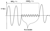
13.刺激要素が少なくとも1つの電極又は1つの電極対又は複数の電極対を備え、任意選択的に、コントローラは、エネルギー源に、10~500Hzの間に含まれる電圧波形を有する電流を刺激要素に供給するように命令するように構成されている、先行実施形態3乃至12のいずれかに記載のデバイス。波形は、TSNの刺激に反応してTSNを最適化し、痛覚器の反応を最小化する為に調整されてよい。例えば、高速スルーレートと低振幅を用いて、TSNから血圧又は心拍数の増加などの生理反応をもたらしながらも、患者に痛みを引き起こさないようにしてもよい。一実施形態において、TSNを刺激する為の電流は、対応するクロナキシー程度の範囲の短い持続時間を有することとなり、12.3V/mに等しい最小強度の電界を生じさせる。そのような電界を生じさせる為に、単極又は双極刺激構成に構成された電極を担持した3Fから8Fのカテーテルが用いられてよい。電極は0.5~4mmの長さを有してよい。双極刺激向けに構成されている場合、電極は0.5~20mmの距離だけ離隔していてよい。200~1000Ωの一般的な刺激インピーダンスに関して、結果として得られる刺激電流は0.1~5mA範囲、又は、0.05~5V範囲の刺激電圧にあってよい。患者に痛みを引き起こさずにTSNをキャプチャする為には、0.12msのパルス持続時間で、30~500V/mの範囲の電界強度が安全に用いられ得る。 13. The stimulation element comprises at least one electrode or one electrode pair or a plurality of electrode pairs, and optionally the controller supplies the energy source with a current having a voltage waveform comprised between 10 and 500 Hz to the stimulation element. 13. A device as in any preceding embodiment 3-12, wherein the device is configured to instruct to do so. The waveform may be adjusted to optimize the TSN and minimize nociceptor response in response to stimulation of the TSN. For example, a fast slew rate and low amplitude may be used to induce a physiological response from TSN, such as an increase in blood pressure or heart rate, while not causing pain to the patient. In one embodiment, the current for stimulating the TSN will have a short duration in the corresponding Chronaxie range, producing a minimum strength electric field equal to 12.3 V/m. A 3F to 8F catheter carrying electrodes configured in a monopolar or bipolar stimulation configuration may be used to generate such electric fields. The electrodes may have a length of 0.5-4 mm. When configured for bipolar stimulation, the electrodes may be separated by a distance of 0.5-20 mm. For typical stimulation impedances of 200-1000Ω, the resulting stimulation current may be in the 0.1-5mA range, or stimulation voltages in the 0.05-5V range. Field strengths in the range of 30-500 V/m with pulse durations of 0.12 ms can be safely used to capture TSN without causing pain to the patient.
14.アブレーション要素が高周波デバイスを備え、高周波デバイスは、300kHz~3MHzの範囲の周波数と5~50Wの範囲の電力を有する電流を出力するように構成されている、実施形態1乃至13のいずれかに記載のデバイス。 14. 14. Any of embodiments 1-13, wherein the ablation element comprises a radio frequency device, the radio frequency device configured to output a current having a frequency in the range of 300 kHz to 3 MHz and a power in the range of 5 to 50 W. device.
15.検出器が以下の、
a.全身静脈圧トランスデューサ、
b.肺静脈圧トランスデューサ、
c.肺動脈圧トランスデューサ、
d.少なくとも1つの心拍出量検出器、
e.少なくとも1つの血流モニタ、
f.又はそれらの組み合わせ
からなる群から選択される、先行実施形態3乃至14のいずれかに記載のデバイス。
15. If the detector is
a. systemic venous pressure transducer,
b. pulmonary vein pressure transducer,
c. pulmonary artery pressure transducer,
d. at least one cardiac output detector;
e. at least one blood flow monitor;
f. or combinations thereof.
16.遠位領域が更に、患者脈管系の対応する異なる部分にそれぞれが配置されるように構成された2つの別個の検出要素を備えている、先行実施形態3乃至15のいずれかに記載のデバイス。 16. 16. The device of any preceding embodiment 3-15, wherein the distal region further comprises two separate sensing elements each configured to be positioned in corresponding different portions of the patient's vasculature. .
17.検出要素が1つ以上の血圧トランスデューサを備えている、先行実施形態3乃至16のいずれかに記載のデバイス。 17. 17. The device of any preceding embodiment 3-16, wherein the sensing element comprises one or more blood pressure transducers.
18.検出要素が1つ以上の組織温度センサを備えている、先行実施形態3乃至17のいずれかに記載のデバイス。 18. 18. The device of any preceding embodiment 3-17, wherein the sensing element comprises one or more tissue temperature sensors.
19.検出要素が1つ以上の血行動態センサを備えている、先行実施形態3乃至18のいずれかに記載のデバイス。 19. 19. The device of any preceding embodiment 3-18, wherein the sensing element comprises one or more hemodynamic sensors.
20.検出要素が1つ以上の環境温度センサを備えている、先行実施形態3乃至19のいずれかに記載のデバイス。 20. 20. A device as in any preceding embodiment 3-19, wherein the sensing element comprises one or more environmental temperature sensors.
21.検出要素が1つ以上の組織インピーダンスセンサを備えている、先行実施形態3乃至20のいずれかに記載のデバイス。 21. 21. The device of any preceding embodiment 3-20, wherein the sensing element comprises one or more tissue impedance sensors.
22.遠位領域が、バルーン、ケージ、バスケット、予成形形状、投げ縄とループ(lasso and loop)及びそれらの任意の組み合わせからなるリストから選択された展開可能な構造を備えている、実施形態1乃至21のいずれかに記載のデバイス。 22. Embodiments 1-, wherein the distal region comprises an expandable structure selected from the list consisting of balloons, cages, baskets, preformed shapes, lasso and loops, and any combination thereof. 22. The device according to any of 21.
23.患者の脈管系を通ってカテーテルを進めることを促進する為に、任意選択的に非外傷性先端が備わったガイドワイヤを備えた、実施形態1乃至22のいずれかに記載のデバイス。 23. 23. The device of any of embodiments 1-22, comprising a guidewire, optionally with an atraumatic tip, to facilitate advancement of the catheter through the patient's vasculature.
24.カテーテルが、ガイドワイヤ越しのカテーテルの配給の為のガイドワイヤルーメンを備えている、実施形態23に記載のデバイス。
24. 24. The device of
25.アブレーション要素と刺激要素は、刺激要素によって刺激信号が配給される領域が、アブレーション要素によって供給されるアブレーションエネルギーが神経組織の不可逆的アブレーションを引き起こすのに十分であるアブレーションゾーンと相関するようにカテーテル上で相対的に配置されている、実施形態3乃至24のいずれかに記載のデバイス。 25. The ablation element and the stimulation element are positioned on the catheter such that the area to which the stimulation signal is delivered by the stimulation element correlates with the ablation zone where the ablation energy delivered by the ablation element is sufficient to cause irreversible ablation of nerve tissue. 25. The device of any of embodiments 3-24, positioned relative to each other at .
26.カテーテルは、無菌、長形、可撓性、灌流(irrigated)、シース付き、偏向可能、放射蛍光、放射不透過のうち1つ以上、又はそれらの任意の組み合わせである、実施形態1乃至25のいずれかに記載のデバイス。 26. of embodiments 1-25, wherein the catheter is one or more of sterile, elongated, flexible, irrigated, sheathed, deflectable, radiofluorescent, radiopaque, or any combination thereof Any of the devices described.
27.コントローラが実行するように構成されたコマンド手順は、アブレーション要素及び刺激要素のうち一方又は両方の患者脈管系への正しい位置決めを特定する為にマッピングアルゴリズムを実行することを含む、実施形態1乃至26のいずれかに記載のデバイス。 27. Embodiments 1-1, wherein the command sequence the controller is configured to execute includes executing a mapping algorithm to identify correct positioning of one or both of the ablation and stimulation elements into the patient's vasculature. 27. The device according to any of 26.
28.コントローラは、エネルギー源に、アブレーション要素と刺激要素のうち一方又は両方を付勢するように命令する前に、前記マッピングアルゴリズムを実行するように構成される、実施形態27に記載のデバイス。 28. 28. The device of embodiment 27, wherein the controller is configured to execute the mapping algorithm prior to instructing the energy source to energize one or both of the ablation and stimulation elements.
29.マッピングアルゴリズムが、
a)少なくとも1つのアブレーション要素又は少なくとも1つの刺激要素を付勢して静脈の内壁を介して刺激を与えて隣接する神経を刺激するように、エネルギー源に命令し、
b)患者の血行動態又は生理的パラメータにおける変化を検出し、
c)少なくとも1つのアブレーション要素が、又は少なくとも1つの刺激要素が、正しい位置にあることを、検出された変化に基づいて決定する、
ことを含む、実施形態27又は28に記載のデバイス。
30.少なくとも1つのアブレーション要素が、又は少なくとも1つの刺激要素が、正しい位置にあることを、検出された変化に基づいて決定することは、以下の、
1.患者の血行動態又は生理的パラメータにおける検出された変化を、所定の許容値又は許容値の組と比較し、
2.患者の血行動態又は生理的パラメータにおける検出された変化が、許容値又は許容値の組に適合している場合に、少なくとも1つのアブレーション要素が、又は少なくとも1つの刺激要素が、正しい位置にあることを確定する、
サブステップを含む、実施形態29に記載のデバイス。
29. the mapping algorithm
a) directing the energy source to energize at least one ablation element or at least one stimulation element to provide stimulation through the inner wall of the vein to stimulate adjacent nerves;
b) detecting changes in the patient's hemodynamic or physiological parameters;
c) determining that at least one ablation element or at least one stimulation element is in the correct position based on the detected change;
29. The device according to embodiment 27 or 28, comprising:
30. Determining that at least one ablation element or at least one stimulation element is in the correct position based on the detected change comprises:
1. comparing the detected change in the patient's hemodynamic or physiological parameter to a predetermined tolerance or set of tolerances;
2. at least one ablation element or at least one stimulation element being in the correct position if the detected change in the patient's hemodynamic or physiological parameter conforms to the tolerance or set of tolerances; confirm the
30. A device according to embodiment 29, comprising substeps.
31.マッピングアルゴリズムが、前記決定ステップc)の後で、患者の血行動態又は生理的パラメータにおける検出された変化が許容値又は許容値の組に適合すると結論づけられた場合に、少なくとも1つのアブレーション要素の、又は少なくとも1つの刺激要素の、正しい配置を示す信号を生成するステップd)を含む、実施形態29又は30に記載のデバイス。
31. of at least one ablation element if the mapping algorithm concludes, after said decision step c), that the detected change in the patient's hemodynamic or physiological parameter conforms to an acceptable value or set of acceptable values; 31. A device according to
32.前記信号を生成することは、コントローラに関連付けられたユーザインターフェースに第1の可聴及び/又は可視情報を発するように命令することを含む、実施形態31に記載のデバイス。 32. 32. The device of embodiment 31, wherein generating the signal comprises instructing a user interface associated with a controller to emit first audible and/or visual information.
33.マッピングアルゴリズムが、前記決定ステップc)の後で、検出された変化が前記許容値又は許容値の組に適合しないと結論づけられた場合に、少なくとも1つのアブレーション要素の、又は少なくとも1つの刺激要素の、誤配置を示す更なる信号を生成するステップe)を含む、実施形態29乃至32のいずれかに記載のデバイス。 33. of at least one ablation element or of at least one stimulation element if the mapping algorithm concludes after said decision step c) that the detected change does not comply with said tolerance or set of tolerances. 33. A device according to any of embodiments 29-32, comprising step e) of generating a further signal indicative of the misalignment.
34.前記更なる信号を生成することは、コントローラに関連付けられたユーザインターフェースに、第1の可聴及び/又は可視情報とは異なる第2の可聴及び/又は可視情報を発するように命令することを含む、実施形態33に記載のデバイス。
34. generating the further signal comprises instructing a user interface associated with the controller to emit second audible and/or visual information different from the first audible and/or visual information; 34. The device of
35.マッピングアルゴリズムは、カテーテルの遠位領域の再配置を検出して、決定ステップの後で、患者の血行動態又は生理的パラメータにおける検出された変化が前記許容値又は許容値の組に適合すると結論づけられるまで、ステップa)~c)又はa)~d)又はa)~e)を反復することを含む、実施形態29乃至34のいずれかに記載のデバイス。 35. The mapping algorithm detects repositioning of the distal region of the catheter and concludes, after the determining step, that the detected change in the patient's hemodynamic or physiological parameter conforms to said tolerance or set of tolerances. 35. The device of any of embodiments 29-34, comprising repeating steps a)-c) or a)-d) or a)-e) until the time of the step.
36.アブレーション要素は、1つ以上のアブレーション電極又は電極対を備える、及び/又は刺激要素は1つ以上の刺激電極又は電極対を備える、先行実施形態25乃至35のいずれかに記載のデバイス。 36. 36. The device according to any of the preceding embodiments 25-35, wherein the ablation element comprises one or more ablation electrodes or electrode pairs and/or the stimulation element comprises one or more stimulation electrodes or electrode pairs.
37.少なくとも1つのアブレーション要素又は少なくとも1つの刺激要素を付勢するようにエネルギー源に命令するステップは、少なくとも1つのアブレーション電極又は少なくとも1つの刺激電極に電気エネルギーを印加するようにエネルギー源に命令することを含む、実施形態36に記載のデバイス。 37. Directing the energy source to energize the at least one ablation element or the at least one stimulation element comprises directing the energy source to apply electrical energy to the at least one ablation electrode or the at least one stimulation electrode. 37. The device of embodiment 36, comprising:
38.少なくとも1つのアブレーション要素が、又は少なくとも1つの刺激要素が、正しい位置にあることを決定するステップは、アブレーション電極又は刺激電極がそれぞれ電気エネルギーを印加している間に、患者の少なくとも1つの選択された血行動態パラメータ又は生理的パラメータにおける変化を検出することによって、患者の標的神経にアブレーション電極又は刺激電極が近接している場合を判断することを含む、実施形態36又は37に記載のデバイス。 38. Determining that the at least one ablation element or the at least one stimulation element is in place includes moving at least one selected portion of the patient while the ablation electrode or stimulation electrode, respectively, is applying electrical energy. 38. A device according to embodiment 36 or 37, comprising determining when the patient's target nerve is in proximity of the ablation or stimulation electrode by detecting a change in a hemodynamic or physiological parameter.
39.カテーテルは、任意選択的にカテーテルの遠位領域に配置された複数のアブレーション電極を備え、アブレーション電極に電気エネルギーを印加するようにエネルギー源に命令することは、エネルギー源に、
1.アブレーション電極それぞれから電気エネルギーを逐次印加し、
2.電気エネルギーを印加したときに、少なくとも1つの選択された血行動態パラメータ又は生理的パラメータに変化を引き起こすアブレーション電極のうち少なくとも1つを選択する、
ように命令することを含む、実施形態36又は37又は38に記載のデバイス。
39. The catheter optionally comprises a plurality of ablation electrodes positioned in a distal region of the catheter, and commanding the energy source to apply electrical energy to the ablation electrodes comprises:
1. Sequentially applying electrical energy from each ablation electrode,
2. selecting at least one of the ablation electrodes that causes a change in at least one selected hemodynamic or physiological parameter when electrical energy is applied;
39. The device of
40.カテーテルは、任意選択的にカテーテルの遠位領域に配置された複数の刺激電極を備え、刺激電極に電気エネルギーを印加するようにエネルギー源に命令することは、エネルギー源に、
1.刺激電極それぞれから電気エネルギーを逐次印加し、
2.電気エネルギーを印加したときに、少なくとも1つの選択された血行動態パラ
メータ又は生理的パラメータに変化を引き起こす刺激電極のうち少なくとも1つを選択する、
ように命令することを含む、実施形態36又は37又は38又は39に記載のデバイス。
40. The catheter optionally comprises a plurality of stimulation electrodes positioned at a distal region of the catheter, and commanding the energy source to apply electrical energy to the stimulation electrodes comprises:
1. Sequentially apply electrical energy from each stimulation electrode,
2. selecting at least one of the stimulation electrodes that causes a change in at least one selected hemodynamic or physiological parameter when the electrical energy is applied;
40. The device of
41.刺激電極に電気エネルギーを印加するようにエネルギー源に命令することは、少なくとも1つの刺激パルスを刺激電極それぞれに逐次供給するようにエネルギー源に命令することを含み、更に、マッピングアルゴリズムが、
1.刺激電極が電気エネルギーを静脈に印加しない間に選択された血行動態又は生理的パラメータのベースラインを記録し、
2.各刺激パルスに反応した選択された血行動態又は生理的パラメータの値を記録する、
ことを含む、実施形態36乃至40のうちいずれかに記載のデバイス。
41. commanding the energy source to apply electrical energy to the stimulation electrodes includes commanding the energy source to sequentially deliver at least one stimulation pulse to each of the stimulation electrodes;
1. recording a baseline of a selected hemodynamic or physiological parameter while the stimulation electrodes do not apply electrical energy to the vein;
2. recording values of selected hemodynamic or physiological parameters in response to each stimulation pulse;
41. The device according to any one of embodiments 36-40, comprising:
42.アブレーション電極に電気エネルギーを印加するようにエネルギー源に命令することは、少なくとも1つの刺激パルスをアブレーション電極それぞれに逐次供給するようにエネルギー源に命令することを含み、更に、マッピングアルゴリズムが、
1.アブレーション電極が電気エネルギーを静脈に印加しない間に選択された血行動態又は生理的パラメータのベースラインを記録し、
2.各刺激パルスに反応した選択された血行動態又は生理的パラメータの値を記録する、
ことを含む、実施形態36乃至41のうちいずれかに記載のデバイス。
42. commanding the energy source to apply electrical energy to the ablation electrodes includes commanding the energy source to sequentially deliver at least one stimulation pulse to each of the ablation electrodes;
1. recording a baseline of a selected hemodynamic or physiological parameter while the ablation electrodes do not apply electrical energy to the vein;
2. recording values of selected hemodynamic or physiological parameters in response to each stimulation pulse;
42. The device of any of embodiments 36-41, comprising:
43.マッピングアルゴリズムが、記録された値をアブレーション電極又は刺激電極に相関し、値が記録されている間に電気エネルギーを印加するステップを含む、実施形態41又は42に記載のデバイス。
43. 43. The device of
44.刺激パルスが0から10mAの電流(I)、100~1000usのパルス幅(pw)、20~40ヘルツの周波数(F)及び20~60秒のデューティサイクル(D)を有する、実施形態41又は42又は43に記載のデバイス。
44.
45.各逐次印加に関して、更に、
1.選択された血行動態又は生理的パラメータの値が、ベースラインから閾値超大きいかどうか、任意選択的に、ベースラインから>20%であるかどうかを判断し、
2.選択された血行動態又は生理的パラメータをベースラインに、又はベースライン付近に戻させ、少なくとも3回の測定を反復し、少なくとも3回の刺激の平均測定を記録し、
3.標準誤差が+/-10%以内であれば、選択されたパラメータへの変更を確認する、
ことを含む、実施形態41又は42又は43又は44に記載のデバイス。
45. For each sequential application, further:
1. determining whether the value of the selected hemodynamic or physiological parameter is greater than a threshold from baseline, optionally >20% from baseline;
2. allowing the selected hemodynamic or physiological parameter to return to or near baseline, repeating at least three measurements, and recording the average measurement of at least three stimulations;
3. Confirm changes to selected parameters if the standard error is within +/- 10%;
45. The device of
46.血行動態又は生理的パラメータは、瞳孔拡張、発汗増加、心拍数増加、血圧上昇、平均動脈圧増加からなる反応群又はそれらの任意の組み合わせから選択される、実施形態29乃至45のいずれかに記載のデバイス。 46. 46. According to any of embodiments 29-45, wherein the hemodynamic or physiological parameter is selected from the response group consisting of dilated pupils, increased sweating, increased heart rate, increased blood pressure, increased mean arterial pressure, or any combination thereof. device.
47.カテーテルは、大内臓神経又は大内臓神経根又は交感神経鎖幹のアブレーション向けに構成されている、実施形態1乃至46のいずれかに記載のデバイス。 47. 47. The device of any of embodiments 1-46, wherein the catheter is configured for ablation of greater splanchnic nerves or greater splanchnic nerve roots or sympathetic chain trunks.
48.アブレーション要素は、カテーテルの遠位領域に配置された少なくとも2つのRF電極を備えている、実施形態36乃至47のいずれかに記載のデバイス。 48. 48. The device according to any of embodiments 36-47, wherein the ablation element comprises at least two RF electrodes positioned in the distal region of the catheter.
49.コントローラに通信可能に接続されたイメージングデバイスを備えた実施形態1乃至48のいずれかに記載のデバイス。 49. 49. A device as in any preceding embodiment, comprising an imaging device communicatively connected to the controller.
50.イメージングデバイスは、X線イメージングデバイス、コンピュータ制御トモグラフィ(CT)イメージングデバイス、核磁気共鳴画像法(MRI)デバイス、超音波イメージングトランスデューサのうち1つを含む、実施形態1乃至49のいずれかに記載のデバイス。 50. 50. A method according to any preceding embodiment, wherein the imaging device comprises one of an X-ray imaging device, a computer controlled tomography (CT) imaging device, a magnetic resonance imaging (MRI) device, an ultrasound imaging transducer. device.
51.マッピングアルゴリズムが、イメージングデバイスから画像を受け取り、前記画像に基づいてアブレーション要素の正しい位置取りを決定することを含む、実施形態49又は実施形態50と組み合わせた先行実施形態27乃至48のいずれかに記載のデバイス。
51. 49. Any preceding embodiment 27-48 in combination with
52.マッピングアルゴリズムが更に、エネルギー源に、遠位領域が挿入される脈管系を包囲する組織、例えば肋間静脈を5mmの半径内で融除する為の融除エネルギーをアブレーション要素に供給させることを含む、実施形態51に記載のデバイス。
52. The mapping algorithm further includes having the energy source supply the ablation element with ablation energy to ablate the tissue surrounding the vasculature into which the distal region is inserted, such as an intercostal vein, within a radius of 5 mm. 52. The device according to
53.コントローラは、アブレーション要素の正しい位置取りが決まった場合にのみエネルギー源に、融除エネルギーをアブレーション要素に供給させるように構成される、実施形態51又は52のいずれかに記載のデバイス。
53. 53. The device according to any of
54.アブレーション要素は少なくとも2つのRF電極を備え、アブレーション要素の正しい位置取りを決定することは、前記画像に基づいて少なくとも2つのRF電極の正しい位置決めを決定することを含む、実施形態51又は52又は53のいずれかに記載のデバイス。
54.
55.エネルギー源に、融除エネルギーをアブレーション要素に供給させることは、エネルギー源に、少なくとも2つのRF電極にRFエネルギーを供給させ、遠位領域が挿入される脈管系を包囲する組織、例えば肋間静脈を5mmの半径内で熱融除させることを含む実施形態54に記載のデバイス。
55. Having the energy source supply ablative energy to the ablation element causes the energy source to supply RF energy to at least two RF electrodes and to tissue surrounding the vasculature into which the distal region is inserted, such as intercostal veins. 55. The device of
56.カテーテル‐特にカテーテルの遠位領域‐は、患者の肋間静脈に挿入されるように構成され、アブレーション要素又は刺激要素を肋間静脈に配置するように構成され、そこから一定距離で、特に、開口部(ostium)から5cm以内(例えば3cm以内、2cm以内、1cm以内)で奇静脈に分岐する、実施形態1乃至55に記載のデバイス。カテーテル‐特にカテーテルの遠位領域‐は、最遠位アブレーション又は刺激要素、任意選択的にRF電極が、肋間静脈内に、及び肋椎関節の5mm以内に配置されるようにアブレーション要素又は刺激要素を配置するように構成される、実施形態56に記載のデバイス。
56. The catheter--particularly the distal region of the catheter--is configured to be inserted into the patient's intercostal vein and configured to position the ablation or stimulation element in the intercostal vein at a distance therefrom, in particular the opening. 56. The device of embodiments 1-55, which branches into the azygos vein within 5 cm (eg, within 3 cm, within 2 cm, within 1 cm) of (ostium). The catheter--especially the distal region of the catheter--is a distal-most ablation or stimulation element, optionally an ablation or stimulation element such that the RF electrode is positioned within the intercostal vein and within 5 mm of the costovertebral joint. 57. The device of
57.カテーテル‐特にカテーテルの遠位領域‐は、少なくとも2つのRF電極を備え、前記2つのRF電極はアブレーション要素又は刺激要素のいずれかであり、カテーテル‐特に前記カテーテルの遠位領域‐は、最遠位の電極が肋間静脈内及び肋椎関節の5mm以内に配置されるように構成され、少なくとも2つのRF電極は、肋椎関節と、奇静脈を合流させる肋間静脈の開口部との間に配置されるようにカテーテル上に構成されている、先行実施形態55及び56に記載のデバイス。
57. The catheter-particularly the distal region of the catheter-is provided with at least two RF electrodes, said two RF electrodes being either ablation or stimulation elements, the catheter-particularly the distal region of said catheter- being the farthest and at least two RF electrodes are positioned between the costovertebral joint and the opening of the intercostal vein that joins the azygos vein. 57. The device according to
58.カテーテルは、血管への、特に肋間静脈への挿入長を識別する為にカテーテル遠位領域に位置決めされた1つ以上のマーカを備えている、先行実施形態55及び56及び57に記載のデバイス。
58. 58. The device according to preceding
59.前記マーカは、カテーテル遠位領域に位置決めされてイメージングデバイスによって識別可能である、放射不透過マーカ又は機械式マーカ、任意選択的に、放射不透過バンド又は環状凸部又は環状凹部を含む、実施形態59に記載のデバイス。 59. An embodiment wherein said marker comprises a radiopaque or mechanical marker, optionally a radiopaque band or annular ridge or annular recess, positioned in the catheter distal region and identifiable by an imaging device. 59. The device according to 59.
60.カテーテル遠位領域が肋間静脈に挿入された状態で、イメージングデバイスは、カテーテル遠位領域を受け入れる前記肋間静脈に相対した患者の肺の位置に関する画像を生成するように構成され、コントローラは、
1.生成された画像を受信し、
2.生成された画像から、前記肋間静脈に相対した患者の肺の位置が所定距離内にあるかどうかを判断し、
3.患者の肺の位置が前記所定距離を超えている場合にのみ、エネルギー源が融除エネルギーを配給することを可能にする、
ように構成されている、先行実施形態49乃至59のいずれかに記載のデバイス。
60. With the catheter distal region inserted into the intercostal vein, the imaging device is configured to generate an image of the position of the patient's lungs relative to said intercostal vein receiving the catheter distal region, the controller comprising:
1. receive the generated image,
2. determining from the generated image whether the position of the patient's lungs relative to the intercostal veins is within a predetermined distance;
3. enabling the energy source to deliver ablative energy only when the location of the patient's lungs exceeds the predetermined distance;
60. The device of any of the preceding embodiments 49-59, configured to:
61.イメージングデバイスは、通信可能にコントローラに接続され、カテーテルの遠位領域に位置決めされた超音波イメージングトランスデューサを備えている、先行実施形態49乃至60のいずれかに記載のデバイス。 61. 61. A device according to any preceding embodiment 49-60, wherein the imaging device comprises an ultrasound imaging transducer communicatively connected to the controller and positioned at the distal region of the catheter.
62.超音波イメージングトランスデューサは、肋間静脈に相対した患者の肺の位置をイメージングする為のソノグラムを生成するように構成され、コントローラは、
1.生成されたソノグラムを受信し、
2.生成されたソノグラムから、肋間静脈に相対した患者の肺の位置が所定距離内にあるかどうかを判断し、
3.患者の肺の位置が前記所定距離を超えている場合にのみ、エネルギー源が融除エネルギーを配給することを可能にする、
ように構成される実施形態1乃至61のいずれかに記載のデバイス。
62. The ultrasound imaging transducer is configured to generate a sonogram for imaging the position of the patient's lungs relative to the intercostal veins, the controller comprising:
1. receive the generated sonogram,
2. determining from the generated sonogram whether the position of the patient's lungs relative to the intercostal veins is within a predetermined distance;
3. enabling the energy source to deliver ablative energy only when the location of the patient's lungs exceeds the predetermined distance;
62. The device of any of embodiments 1-61, configured to:
63.所定距離は少なくとも6mmであり、コントローラは、患者の肺の位置が前記肋間静脈の壁から少なくとも6mm離れている場合にエネルギー源に融除エネルギーを配給させ、患者の肺の位置が前記肋間静脈の壁の6mm以内である場合にエネルギー源に融除エネルギーを配給させないように構成される、実施形態60又は61又は62に記載のデバイス。
63. The predetermined distance is at least 6 mm, the controller causes the energy source to deliver ablative energy when the patient's lung position is at least 6 mm away from the wall of the intercostal vein, and the patient lung position is at least 6 mm from the intercostal vein wall. 63. The device of
64.コントローラは、エネルギー源に、アブレーション要素の5mm以内の組織の熱損傷を生じさせるのに適した融除エネルギーを配給させるが、アブレーション要素から5mm以上離れた組織を融除しないように構成される、実施形態1乃至63のいずれかに記載のデバイス。 64. a controller configured to cause the energy source to deliver ablation energy suitable to cause thermal damage to tissue within 5 mm of the ablation element, but not to ablate tissue more than 5 mm from the ablation element; 64. The device of any of embodiments 1-63.
65.コントローラは、以下の更なるステップ:
アブレーション要素に近接したアブレーションゾーンに存在する組織の物理的パラメータの少なくとも1つの測定値を受信又は決定する、
測定された物理的パラメータの前記値を少なくとも1つの基準値と比較する、
前記比較に基づいて、アブレーションゾーン内の肺組織の存在を検出する、
を含む肺の存在の検出手順を実行するように構成される実施形態1乃至64のいずれかに記載のデバイス。
65. The controller will do the following further steps:
receiving or determining at least one measurement of a physical parameter of tissue present in the ablation zone proximate the ablation element;
comparing said value of the measured physical parameter to at least one reference value;
detecting the presence of lung tissue within the ablation zone based on the comparison;
65. A device as in any preceding embodiment, configured to perform a lung presence detection procedure comprising:
66.物理的パラメータは組織の電気的パラメータである、実施形態65に記載のデバイス。
66. 66. The device of
67.物理的パラメータは組織の電気的インピーダンスである、実施形態66に記載のデバイス。
67. 67. A device according to
68.コントローラは、カテーテル電極と分散電極の間、又は2つのカテーテル電極の間に存在する組織の物理的パラメータの測定値を受信するように構成される、実施形態65又は66に記載のデバイス。
68. 67. The device according to
69.通信可能にコントローラに接続された電気的パラメータセンサを備え、コントローラが、
-エネルギー源に、エネルギー源に接続されたカテーテル電極とエネルギー源に接続された分散電極との間、又はエネルギー源に接続された2つのカテーテル電極の間に電流を流させるように命令し、
-電気的パラメータセンサから物理的パラメータの少なくとも1つの測定値を受信する、
ように構成される実施形態65又は66又は67又は68に記載のデバイス。
69. an electrical parameter sensor communicatively connected to the controller, the controller
- instructing the energy source to cause a current to flow between a catheter electrode connected to the energy source and a dispersive electrode connected to the energy source, or between two catheter electrodes connected to the energy source;
- receiving at least one measurement of a physical parameter from an electrical parameter sensor;
69. The device according to
70.物理的パラメータは組織の音響パラメータである実施形態65に記載のデバイス。
70. 66. A device according to
71.物理的パラメータは組織の音響コンダクタンスである実施形態66に記載のデバイス。
71. 67. The device of
72.コントローラは、カテーテル音響エミッタと、カテーテルから分離した音響受信機との間、又はカテーテル音響エミッタとカテーテル音響受信機との間に存在する組織の物理的パラメータの測定値を受信するように構成され、前記音響送信機と音響受信機は通信可能にコントローラと接続されている、実施形態70又は71に記載のデバイス。
72. The controller is configured to receive measurements of a physical parameter of tissue present between the catheter acoustic emitter and an acoustic receiver separate from the catheter or between the catheter acoustic emitter and the catheter acoustic receiver; 72. The device of
73.コントローラは、
‐エネルギー源に、前記音響エミッタからの発出音響信号を発出させるように命令し、
‐発出音響信号の結果として、音響受信機によって検出された音響信号に関する検出信号を、音響受信機から受信し、
‐前記発出信号と前記検出信号に基づいて物理的パラメータの値を決定する、
ように構成される実施形態72に記載のデバイス。
73. The controller is
- commanding an energy source to emit an emitted acoustic signal from said acoustic emitter;
- receiving from the acoustic receiver a detection signal relating to the acoustic signal detected by the acoustic receiver as a result of the emitted acoustic signal;
- determining a value of a physical parameter based on said emitted signal and said detected signal;
73. The device of embodiment 72, wherein the device is configured to:
74.組織インピーダンスを測定する為に使用される電気的周波数は5kHz~5MHzである、実施形態67又は68又は69に記載のデバイス。
74. 70. The device of
75.コントローラは、アブレーションゾーンにおける肺の存在が検出されない場合にのみエネルギー源に、アブレーションエネルギーを付勢させるように、任意に融除エネルギーを配給させるように構成される、実施形態65乃至74のいずれかに記載のデバイス。 75. 75. Any of embodiments 65-74, wherein the controller is configured to cause the energy source to optionally deliver ablation energy to activate ablation energy only if the presence of lungs in the ablation zone is not detected. devices described in .
76.コントローラは、エネルギー源に、肺の損傷を低減する損傷を形成する為に融除エネルギーを滴定するように命令するように構成される、実施形態1乃至75のいずれかに記載のデバイス。 76. 76. The device of any preceding embodiment, wherein the controller is configured to command the energy source to titrate the ablative energy to form a lesion that reduces lung damage.
77.アブレーション要素はアブレーション電極を備え、滴定は、エネルギーの大きさ、ランプ及び時間における変化を含む、実施形態1乃至76に記載のデバイス。 77. 77. The device of embodiments 1-76, wherein the ablation element comprises an ablation electrode and the titration includes changes in energy magnitude, ramp and time.
78.アブレーション要素は集束又は非集束の高周波数又は低周波数超音波向けに構成され、滴定は、エネルギーの大きさ、時間、焦点温度又は周波数における変化を含む、実施形態77に記載のデバイス。 78. 78. The device of embodiment 77, wherein the ablation element is configured for focused or unfocused high or low frequency ultrasound and the titration comprises change in energy magnitude, time, focal temperature or frequency.
79.コントローラは、エネルギー源に、アブレーションエネルギーを連続的又は間歇的に印加するように命令するように構成される、実施形態1乃至78のいずれかに記載のデバイス。 79. 79. The device of any preceding embodiment, wherein the controller is configured to command the energy source to apply ablative energy continuously or intermittently.
80.コントローラは、肺の存在の検出手順を連続的又は間隔を置いて反復するように構成される、先行実施形態65乃至79のいずれかに記載のデバイス。 80. 80. A device according to any preceding embodiment 65-79, wherein the controller is configured to repeat the lung presence detection procedure continuously or at intervals.
81.コントローラは、アブレーションゾーン内の肺の存在が検出されたときにエネルギー源がアブレーション要素を付勢することを防止するように構成され、更に、アブレーションゾーン内の肺の存在が検出されなくなるとすぐに、エネルギー源にアブレーション要素を付勢させるように構成される、実施形態80に記載のデバイス。
81. The controller is configured to prevent the energy source from energizing the ablation element when the presence of the lung within the ablation zone is detected, and as soon as the presence of the lung within the ablation zone is no longer detected. 81. The device of
82.カテーテルを脈管系から全面的又は部分的に退縮させるように構成されたカテーテル後退ユニットを備えた、先行実施形態1乃至81のいずれかに記載のデバイス。 82. 82. The device of any preceding embodiment 1-81, comprising a catheter retraction unit configured to fully or partially retract the catheter from the vascular system.
83.カテーテル後退ユニットは、通信可能にコントローラに接続され、カテーテルに作用する自動機構を備え、コントローラは、自動機構にカテーテルを脈管系から退縮させるように命令するように構成されている、実施形態82に記載のデバイス。 83. Embodiment 82, wherein the catheter retraction unit comprises an automated mechanism communicatively connected to the controller and acting on the catheter, the controller configured to command the automated mechanism to retract the catheter from the vasculature. devices described in .
84.自動機構は、リニアアクチュエータ、電動ユニット、ラチェットホイール、ラチェットラック、ねじ機構のうち1つを備える実施形態84に記載のデバイス。 84. 85. The device of embodiment 84, wherein the automatic mechanism comprises one of a linear actuator, an electric unit, a ratchet wheel, a ratchet rack, a screw mechanism.
85.コントローラは、自動機構に、脈管系からカテーテルを定速又は所定のフィードバック信号に依存した速度で退縮するように命令するように構成される、実施形態83又は84に記載のデバイス。 85. 85. The device according to embodiment 83 or 84, wherein the controller is configured to command the automatic mechanism to retract the catheter from the vascular system at a constant rate or a rate dependent on a predetermined feedback signal.
86.フィードバック信号は、前記組織温度変化又はインピーダンス変化のうち1つを含み、コントローラは、自動機構に作用する脈管系からのカテーテルの自動引き戻しを、前記フィードバック信号に基づいて誘起するように構成される、実施形態85に記載のデバイス。 86. A feedback signal includes one of the tissue temperature change or the impedance change, and the controller is configured to induce automatic withdrawal of the catheter from the vascular system acting on the automatic mechanism based on the feedback signal. 85. The device according to embodiment 85.
87.コントローラは、エネルギーがアブレーション電極に印加されている間、従って、脈管系の壁に沿って脈管系からカテーテルを退縮させるように自動機構に命令するように構成される、先行実施形態83乃至86のいずれかに記載のデバイス。 87. The controller is configured to command the automated mechanism to retract the catheter from the vasculature while energy is being applied to the ablation electrode, thus along the wall of the vasculature. 86. The device according to any of 86.
88.コントローラは、脈管系からカテーテルを螺旋パターンで退縮させるように自動機構に命令するように構成される、先行実施形態83乃至87のいずれかに記載のデバイス。 88. 88. The device according to any of the preceding embodiments 83-87, wherein the controller is configured to command the automated mechanism to retract the catheter from the vasculature in a helical pattern.
89.コントローラは、長形の損傷部を形成する為にアブレーションエネルギーを配給しながら脈管系からカテーテルを定速で、例えば毎秒約1mmで退縮させるように自動機構に命令するように構成される、先行実施形態83乃至88のいずれかに記載のデバイス。 89. The controller is configured to command the automated mechanism to retract the catheter from the vascular system at a constant rate, e.g., about 1 mm per second, while delivering ablation energy to form an elongated lesion. 89. The device of any of embodiments 83-88.
90.コントローラは、漸増するアブレーションエネルギーを配給することで多数の固定損傷部を形成、例えば、重複する多数の5mmの損傷部を形成しながら、脈管系からカテーテルを、定速で、例えば毎秒約1mmで退縮させるように自動機構に命令するように構成される、先行実施形態83乃至89のいずれかに記載のデバイス。 90. The controller draws the catheter from the vascular system at a constant rate, e.g., about 1 mm per second, while creating multiple fixed lesions, e.g. 89. A device according to any preceding embodiment 83-89, configured to command an automatic mechanism to retract at .
91.展開可能なスプラインと、展開可能なスプライン上に位置決めされたアブレーション要素を備えた、先行実施形態1乃至90のいずれかに記載のデバイス。 91. 91. The device of any preceding embodiment 1-90, comprising a deployable spline and an ablation element positioned on the deployable spline.
92.スプラインはニチノールなどのスーパープラスチック材料製であり、血管壁の輪郭に適合する能力を有する、実施形態91に記載のデバイス。 92. 92. A device according to embodiment 91, wherein the splines are made of a super plastic material such as Nitinol and have the ability to conform to the contours of the vessel wall.
93.シースに集束された場合に、より小型のデバイスにパッケージされる為に、異なる長さのスプラインを備えている、実施形態91又は92に記載のデバイス。 93. 93. A device according to embodiment 91 or 92, comprising splines of different lengths for packaging in a smaller device when focused in the sheath.
94.螺旋の形状の弾性ばね上に取り付けられた電極を備えた先行実施形態1乃至93のいずれかに記載のデバイス。 94. 94. A device according to any preceding embodiment 1-93, comprising an electrode mounted on an elastic spring in the form of a helix.
95.コマンド手順が、標的神経のアブレーションの成功を確認する為に生理反応を監視して、アブレーションエネルギーを配給する前の生理的状態と比較して生理反応に変化がない場合にアブレーションエネルギーの配給を繰り返すことを含む、実施形態1乃至94のいずれかに記載のデバイス。 95. A command procedure monitors the physiological response to confirm successful ablation of the target nerve and repeats the delivery of ablation energy if there is no change in the physiological response compared to the physiological state prior to delivery of the ablation energy. 95. The device of any of embodiments 1-94, comprising:
96.通信可能にコントローラに接続された呼吸モニタを備えた、実施形態1乃至95のいずれかに記載のデバイス。 96. 96. The device of any preceding embodiment, comprising a respiratory monitor communicatively connected to the controller.
97.呼吸モニタが、患者の換気に関連する電気的信号を生成するように構成された、任意選択的に呼吸ベルト(respiratory belt)、加速度計、酸素飽和度計、細胞インピーダンス計を含む1つ以上の呼吸センサを備えている、実施形態1乃至96に記載のデバイス。 97. The respiratory monitor optionally includes one or more respiratory belts, accelerometers, oximeters, cellular impedance meters configured to generate electrical signals related to patient ventilation. 97. The device of embodiments 1-96, comprising a respiration sensor.
98.コントローラが、
患者の換気に関連する信号を呼吸モニタから受信し、
呼吸モニタから来る前記信号から、以下の患者の換気パラメータのうち1つ以上を決定し、
・換気回数(時間単位ごとの呼吸)
・換気回数(時間単位ごとの総吸気量と総呼気量)
・各呼吸における排気開始時間
・各呼吸における吸気開始時間
・呼吸ごとの排気持続時間
・呼吸ごとの吸気持続時間
前記換気パラメータのうち1つ以上に基づいてアブレーションエネルギーを配給するように前記源を制御する、
ように構成されている実施形態97に記載のデバイス。
98. the controller
receiving a signal related to patient ventilation from a respiratory monitor;
determining one or more of the following patient ventilation parameters from the signals coming from the respiratory monitor;
・Ventilation rate (breaths per unit of time)
・Ventilation rate (total inspiratory volume and total expiratory volume per time unit)
Exhalation start time for each breath Inspiration start time for each breath Exhaust duration for each breath Inspiratory duration for each breath Controlling said source to deliver ablation energy based on one or more of said ventilation parameters. do,
98. The device of embodiment 97, configured to:
99.呼吸モニタが、患者の換気に関連する信号を生成するように構成され、前記信号から、以下の患者の換気パラメータ、
・換気回数(時間単位ごとの呼吸)
・換気回数(時間単位ごとの総吸気量と総呼気量)
・各呼吸における排気開始時間
・各呼吸における吸気開始時間
・呼吸ごとの排気持続時間
・呼吸ごとの吸気持続時間
のうち1つ以上を決定するように構成された自前のコンピューティングユニットを含み、
コントローラは前記換気パラメータのうち1つ以上を受信し、前記換気パラメータのうち1つ以上に基づいてアブレーションエネルギーを配給するように前記源を制御する、実施形態96又は97のいずれかに記載のデバイス。
99. A respiratory monitor configured to generate a signal related to patient ventilation, from which the following patient ventilation parameters:
・Ventilation rate (breaths per unit of time)
・Ventilation rate (total inspiratory volume and total expiratory volume per time unit)
including a home computing unit configured to determine one or more of an exhaust onset time for each breath, an inspiratory onset time for each breath, an exhaust duration for each breath, and an inspiratory duration for each breath;
98. The device according to any of embodiments 96 or 97, wherein a controller receives one or more of said ventilation parameters and controls said source to deliver ablation energy based on said one or more of said ventilation parameters. .
100.コントローラは、前記換気パラメータのうち1つへの同期化されたアブレーションエネルギーの配給向けに構成されている、実施形態98又は99のうちいずれかに記載のデバイス。 100. 99. The device according to any of embodiments 98 or 99, wherein the controller is configured for synchronized delivery of ablation energy to one of said ventilation parameters.
101.コントローラは、アブレーションエネルギーの配給が排気中にのみ発生するようにエネルギー源を制御するように構成される、先行実施形態96乃至100のうちいずれかに記載のデバイス。 101. 101. The device according to any of the preceding embodiments 96-100, wherein the controller is configured to control the energy source such that delivery of ablation energy occurs only during evacuation.
102.コントローラは、患者の呼吸吸気がいつ開始するかを検出して、結果的に、患者が吸気を始めたときにアブレーションエネルギーの配給を中断するようにエネルギー源に命令するように構成されている、実施形態96乃至101のいずれかに記載のデバイス。 102. The controller is configured to detect when a patient's respiratory inspiration begins and consequently command the energy source to discontinue delivery of ablation energy when the patient begins to inhale. 102. The device of any of embodiments 96-101.
103.コントローラは、患者の呼吸吸気がいつ行なわれているかを検出して、患者の呼吸吸気中にアブレーションエネルギーの配給を阻止するようにエネルギー源に命令するように構成されている、実施形態96乃至102のいずれかに記載のデバイス。 103. Embodiments 96-102, wherein the controller is configured to detect when patient respiratory inspiration is occurring and command the energy source to prevent delivery of ablation energy during patient respiratory inspiration, embodiments 96-102 A device as described in any of
104.コントローラは、患者の呼吸吸気がいつ終了するかを検出して、アブレーションエネルギーの配給を再開するようにエネルギー源に命令するように構成されている、実施形態96乃至103のいずれかに記載のデバイス。 104. 104. The device according to any of embodiments 96-103, wherein the controller is configured to detect when the patient's respiratory inspiration ends and command the energy source to resume delivery of ablative energy. .
105.コントローラは、アブレーションエネルギーの配給中又はその直前に、患者に最大深呼吸を実行するように指示する為にユーザインターフェースに信号を発出するように構成されている、実施形態1乃至104のいずれかに記載のデバイス。 105. 105. Any of embodiments 1-104, wherein the controller is configured to issue a signal to the user interface to instruct the patient to take a maximum deep breath during or just prior to delivery of ablative energy. device.
106.コントローラは、予め定めた時間間隔にわたり総アブレーションエネルギー配給を維持する為に、出力又はアブレーション時間を呼吸数に基づいて調整するように構成されている、実施形態1乃至105のいずれかに記載のデバイス。 106. 106. The device of any preceding embodiment, wherein the controller is configured to adjust power output or ablation time based on respiratory rate to maintain total ablation energy delivery over a predetermined time interval. .
107.コントローラは、患者の排気間隔中に熱損傷を生成することが可能な振幅でアブレーションエネルギーを配給するように前記エネルギー源を制御するように構成される、実施形態1乃至106のいずれかに記載のデバイス。 107. 107. Any of embodiments 1-106, wherein the controller is configured to control the energy source to deliver ablation energy at an amplitude capable of producing thermal damage during patient exhaust intervals. device.
108.心不全又は心不全に関連する症状を患っているヒトの患者の心臓機能を改善する方法であって、
近位領域、可撓性シャフト及び遠位領域を備えた血管内カテーテルを位置決めし、可撓性シャフトは近位領域と遠位領域を接続し、アクセス位置に相対した患者の腹部脈管系へのアクセスの為に十分な長さであり、近位領域は患者に対して外部である状態を保つように構成され、遠位領域は、患者の脈管系を通って進められるように構成され、血管の内壁と接触して腹部脈管系内で終端するような寸法であり、少なくとも1つのアブレーション要素、少なくとも1つの刺激要素及び少なくとも1つの検出要素を備え、
患者の脈管系を通って遠位領域を進め、
少なくとも1つのアブレーション要素を適用し、
患者から血管内カテーテルを除去する、ことを含む方法。
108. 1. A method of improving cardiac function in a human patient suffering from heart failure or a condition associated with heart failure, comprising:
Positioning an intravascular catheter having a proximal region, a flexible shaft and a distal region, the flexible shaft connecting the proximal region and the distal region into the patient's abdominal vasculature relative to the access location. with a proximal region configured to remain external to the patient and a distal region configured to be advanced through the patient's vasculature. , dimensioned to terminate in the abdominal vasculature in contact with the inner wall of a blood vessel and comprising at least one ablation element, at least one stimulation element and at least one detection element;
advancing the distal region through the patient's vasculature;
applying at least one ablation element;
A method comprising removing an intravascular catheter from a patient.
109.進めるステップは更に位置決めの成功を確認することを含む実施形態108に記載の方法。 109. 109. The method of embodiment 108, wherein advancing further comprises confirming successful positioning.
110.適用ステップは更に、神経のアブレーションの確認を含む、実施形態108に記載の方法。 110. 109. The method of embodiment 108, wherein the applying step further comprises confirmation of nerve ablation.
111.近位領域は、エネルギー源と、組込み型ロジック及びソフトウェアを備えたコントローラを備えている実施形態108に記載の方法。 111. 109. The method of embodiment 108, wherein the proximal region comprises an energy source and a controller with embedded logic and software.
112.近位領域は、エネルギー源と、組込み型ロジック及びソフトウェアを備えたコントローラを備え、更に、ユーザインターフェースを備えている実施形態108に記載の方法。 112. 109. The method of embodiment 108, wherein the proximal region comprises an energy source and a controller with embedded logic and software, and further comprising a user interface.
113.各アブレーション要素は少なくとも1つの刺激要素と関連付けられている実施形態108に記載の方法。 113. 109. The method of embodiment 108, wherein each ablation element is associated with at least one stimulation element.
114.遠位領域は更に、全身、肺動脈及び静脈圧トランスデューサ、少なくとも1つの心拍出量検出器、少なくとも1つの血流モニタ、又はそれらの組み合わせからなる群から選択された1つの検出要素を備えている実施形態108に記載の方法。 114. The distal region further comprises one sensing element selected from the group consisting of systemic, pulmonary artery and venous pressure transducers, at least one cardiac output detector, at least one blood flow monitor, or combinations thereof. 109. The method of embodiment 108.
115.遠位領域が更に、検出要素と、循環システムの異なる部分に位置決めされた少なくとも1つの他の検出要素を備えている実施形態108に記載の方法。 115. 109. The method of embodiment 108, wherein the distal region further comprises a sensing element and at least one other sensing element positioned in a different portion of the circulatory system.
116.アブレーション要素は、電極、クライオコンソール、薬物配給デバイス、神経遮断剤の注射、超音波デバイス、高周波デバイス、サーマルアブレーションデバイス、レーザーエミッタ及びそれらの任意の組み合わせからなるリストから選択される実施形態108に記載の方法。 116. 109. According to embodiment 108, the ablation element is selected from the list consisting of electrodes, cryoconsoles, drug delivery devices, neuroleptic injections, ultrasound devices, radio frequency devices, thermal ablation devices, laser emitters and any combination thereof. the method of.
117.高周波デバイスは350~500kHzの範囲の周波数と5~50Wの範囲の出力を有する電流を出力する実施形態116に記載の方法。 117. 117. The method of embodiment 116, wherein the high frequency device outputs a current having a frequency in the range of 350-500 kHz and a power in the range of 5-50W.
118.検出要素は血圧トランスデューサである実施形態108に記載の方法。 118. 109. The method of embodiment 108, wherein the sensing element is a blood pressure transducer.
119.検出要素は組織温度センサである実施形態108に記載の方法。 119. 109. The method of embodiment 108, wherein the sensing element is a tissue temperature sensor.
120.検出要素は血行動態センサである実施形態108に記載の方法。 120. 109. The method of embodiment 108, wherein the sensing element is a hemodynamic sensor.
121.検出要素は環境温度センサである実施形態108に記載の方法。 121. 109. The method of embodiment 108, wherein the sensing element is an ambient temperature sensor.
122.検出要素は組織インピーダンスセンサである実施形態108に記載の方法。 122. 109. The method of embodiment 108, wherein the sensing element is a tissue impedance sensor.
123.遠位領域が、バルーン、ケージ、バスケット、予成形形状、投げ縄とループ(lasso and loop)及びそれらの任意の組み合わせからなるリストから選択された展開可能な構造を備えている実施形態108に記載の方法。 123. 109. According to embodiment 108, the distal region comprises an expandable structure selected from the list consisting of balloons, cages, baskets, preformed shapes, lasso and loops and any combination thereof. the method of.
124.アクセス位置は橈骨静脈、上腕静脈、鎖骨下静脈、顎静脈又は大腿静脈である実施形態108に記載の方法。 124. 109. The method of embodiment 108, wherein the access location is the radial, brachial, subclavian, maxillary or femoral vein.
125.位置決めステップの前に、患者脈管系を通るカテーテルの前進を促進する為に、ガイドワイヤを導入し前進させる、実施形態108に記載の方法。 125. 109. The method of embodiment 108, wherein prior to the positioning step, a guidewire is introduced and advanced to facilitate advancement of the catheter through the patient's vasculature.
126.腹部脈管系は小静脈である実施形態108に記載の方法。 126. 109. The method of embodiment 108, wherein the abdominal vasculature is the venules.
127.腹部脈管系は小胸腔内静脈である実施形態108に記載の方法。 127. 109. The method of embodiment 108, wherein the abdominal vasculature is the minor intrathoracic vein.
128.腹部脈管系は奇静脈である実施形態108に記載の方法。 128. 109. The method of embodiment 108, wherein the abdominal vasculature is the azygos vein.
129.腹部脈管系は半奇静脈である実施形態108に記載の方法。 129. 109. The method of embodiment 108, wherein the abdominal vasculature is semi-azygous.
130.腹部脈管系は肋間静脈である実施形態108に記載の方法。 130. 109. The method of embodiment 108, wherein the abdominal vasculature is intercostal veins.
131.アブレーション要素と刺激要素は、刺激要素によって刺激信号が配給される領域が、アブレーション要素によって供給されるアブレーションエネルギーが神経組織の不可逆的アブレーションを引き起こすのに十分であるアブレーションゾーンと相関するようにカテーテル上で相対的に配置されている、実施形態108に記載の方法。 131. The ablation element and the stimulation element are positioned on the catheter such that the area to which the stimulation signal is delivered by the stimulation element correlates with the ablation zone where the ablation energy delivered by the ablation element is sufficient to cause irreversible ablation of nerve tissue. 109. The method of embodiment 108, wherein the method is positioned relative to .
132.カテーテルは、無菌、長形、可撓性、灌流、シース付き、偏向可能、放射蛍光、放射不透過、又はそれらの任意の組み合わせで構成される、実施形態108に記載の方法。 132. 109. The method of embodiment 108, wherein the catheter is constructed of sterile, elongated, flexible, perfused, sheathed, deflectable, radiofluorescent, radiopaque, or any combination thereof.
133.遠位領域位置決めの確認は、少なくとも1つの選択された血行動態又は生理的パラメータにおける変化を確認する為の自動化されたアルゴリズムプロセスによって実行される実施形態108に記載の方法。 133. 109. The method of embodiment 108, wherein confirming distal region positioning is performed by an automated algorithmic process for confirming changes in at least one selected hemodynamic or physiological parameter.
134.電極又は電極対を選択し、血行動態パラメータのベースラインを記録し、電流(I)、パルス幅(pw)、周波数(F)及びデューティサイクル(D)が約I=0~10mA、pw=100~1000us、F=20~40Hz、D=50%で、20~60sで脈動する刺激パルスを供給し、選択された血行動態パラメータを記録することを含む実施形態133の方法。 134. Select an electrode or electrode pair, record baseline hemodynamic parameters, current (I), pulse width (pw), frequency (F) and duty cycle (D) approximately I=0-10 mA, pw=100. 134. The method of embodiment 133 comprising delivering stimulation pulses pulsating from 20-60 s at ~1000 us, F=20-40 Hz, D=50%, and recording selected hemodynamic parameters.
135.選択された血行動態パラメータがベースラインから>20%であるかどうかを判断し、パラメータをベースラインに戻させ、少なくとも3回の測定を反復し、少なくとも3回の刺激の平均測定を記録し、標準誤差が+/-10%であれば、選択されたパラメータへの変更を確認することを更に含む実施形態134の方法。 135. determining if a selected hemodynamic parameter is >20% from baseline, allowing the parameter to return to baseline, repeating at least 3 measurements, recording the average measurement of at least 3 stimulations; 135. The method of embodiment 134, further comprising confirming the change to the selected parameter if the standard error is +/−10%.
136.血行動態又は生理的パラメータは、瞳孔拡張、発汗増加、心拍数増加、血圧上昇、平均動脈圧増加からなる反応群又はそれらの任意の組み合わせから選択される実施形態135の方法。 136. 136. The method of embodiment 135, wherein the hemodynamic or physiological parameter is selected from the response group consisting of dilated pupils, increased sweating, increased heart rate, increased blood pressure, increased mean arterial pressure, or any combination thereof.
137.心不全又は心不全に関連する症状を患っているヒトの患者の心臓機能を向上させる方法であって、
近位領域、可撓性シャフト及び遠位領域を備えた血管内カテーテルを位置決めし、可撓性シャフトは近位領域と遠位領域を接続し、アクセス位置に相対した患者の腹部脈管系へのアクセスの為に十分な長さであり、近位領域は患者に対して外部である状態を保つように構成され、遠位領域は、標的神経に隣接する患者の脈管系を通って進められるように構成され、血管の内壁と接触して腹部脈管系内で終端するような寸法であり、少なくとも1つのアブレーション要素、少なくとも1つの刺激要素及び少なくとも1つの検出要素を備え、
患者の脈管系を通って遠位領域を進め、静脈の内壁に、隣接する神経を刺激するのに十分な電気的刺激を印加し、少なくとも1つのアブレーション要素の位置決めが成功した適用を確認する為に生理変化を検出し、
隣接する神経を刺激する為に以前に十分であった電気的刺激を静脈の内壁に再印加して、標的神経の不可逆的アブレーションを確認し、
患者から血管内カテーテルを除去する、ことを含む方法。
137. 1. A method of improving cardiac function in a human patient suffering from heart failure or a condition associated with heart failure, comprising:
Positioning an intravascular catheter having a proximal region, a flexible shaft and a distal region, the flexible shaft connecting the proximal region and the distal region into the patient's abdominal vasculature relative to the access location. with the proximal region configured to remain external to the patient and the distal region advanced through the patient's vasculature adjacent to the target nerve. and dimensioned to contact the inner wall of a blood vessel and terminate in the abdominal vasculature, comprising at least one ablation element, at least one stimulation element and at least one detection element;
Advancing the distal region through the patient's vasculature, applying electrical stimulation to the inner wall of the vein sufficient to stimulate the adjacent nerves, and confirming successful application of positioning of at least one ablation element detect physiological changes for
reapplying electrical stimulation to the inner wall of the vein that was previously sufficient to stimulate the adjacent nerve to confirm irreversible ablation of the target nerve;
A method comprising removing an intravascular catheter from a patient.
138.遠位領域を再位置決めし、位置決めが確認されるまで電気的刺激を繰り返すことを更に含む実施形態137に記載の方法。 138. 138. The method of embodiment 137, further comprising repositioning the distal region and repeating electrical stimulation until positioning is confirmed.
139.生きている哺乳類患者の肋間静脈内のカテーテル上の電極が患者内の標的神経に近接しているかを、電極が肋間静脈に電気エネルギーを印加している間の患者の少なくとも1つの血行動態パラメータ又は生理的パラメータにおける変化を検出することによって判断することを含む方法。 139. at least one hemodynamic parameter of the patient while the electrodes are applying electrical energy to the intercostal vein; A method comprising determining by detecting a change in a physiological parameter.
140.電極がカテーテル上の複数の電極のうち1つであり、方法が更に、各電極から肋間静脈に電気エネルギーを逐次印加し、電気エネルギー印加時に、少なくとも1つの選択された血行動態パラメータ又は生理的パラメータに変化を引き起こす電極のうち少なくとも1つを選択することを含む実施形態139に記載の方法。 140. The electrode is one of a plurality of electrodes on the catheter, and the method further comprises sequentially applying electrical energy from each electrode to the intercostal vein, and at least one selected hemodynamic or physiological parameter upon application of the electrical energy. 140. The method of embodiment 139, comprising selecting at least one of the electrodes that causes a change in .
141.更に、電極が電気エネルギーを静脈に印加しない間に、選択された血行動態又は生理的パラメータのベースラインを記録し、各電極に少なくとも1つの刺激パルスを逐次供給し、刺激パルスは、0~10mAの電流(I)、100~1000usのパルス幅(pw)、20~40ヘルツの周波数(F)及び20~60秒のデューティサイクル(D)を有し、各刺激パルスに反応した選択された血行動態又は生理的パラメータの値を記録し、値が記録された間に、記録された値を、電気エネルギーを印加する電極に相関することを含む実施形態140に記載の方法。
141. Further, baseline recording of selected hemodynamic or physiological parameters is performed while the electrodes are not applying electrical energy to the vein, and at least one stimulation pulse is sequentially delivered to each electrode, the stimulation pulse being 0-10 mA. of current (I), pulse width (pw) of 100-1000 us, frequency (F) of 20-40 Hz and duty cycle (D) of 20-60 s, in response to each stimulation pulse. 141. A method according to
142.更に、各逐次印加につき、選択された血行動態又は生理的パラメータの値がベースラインからの閾値を上回るかを判断し、選択された血行動態又は生理的パラメータを、ベースライン自体又はベースライン付近に戻させ、少なくとも3回の測定を反復し、少なくとも3回の刺激の平均測定を記録し、標準誤差が+/-10%以内であれば、選択されたパラメータへの変更を確認する、ことを含む実施形態141に記載の方法。
142. Further, for each sequential application, it is determined whether the value of the selected hemodynamic or physiological parameter is above a threshold from baseline, and the selected hemodynamic or physiological parameter is reduced to or near baseline. Repeat at least three measurements, record the average measurement of at least three stimulations, and confirm changes to the selected parameters if the standard error is within +/- 10%. 142. The method of
143.血行動態又は生理的パラメータは、瞳孔拡張、発汗増加、心拍数増加、血圧上昇、平均動脈圧増加からなる反応群及びそれらの任意の組み合わせから選択される、実施形態139に記載の方法。 143. 140. The method of embodiment 139, wherein the hemodynamic or physiological parameter is selected from the response group consisting of dilated pupils, increased sweating, increased heart rate, increased blood pressure, increased mean arterial pressure, and any combination thereof.
144.カテーテルの遠位領域に位置決めされた少なくとも2つのRF電極と、ガイドワイヤ越しの配給の為であり、多数の重複する損傷部を形成するように構成されたルーメンを備えた、大内臓神経又は大内臓神経根のアブレーション向けに構成されたカテーテル。 144. At least two RF electrodes positioned in the distal region of the catheter and a lumen for over-guidewire delivery and configured to create multiple overlapping lesions. Catheter configured for visceral nerve root ablation.
145.実施形態144のカテーテルの使用方法であって、a)患者の静脈系を通って肋間静脈へとカテーテルの遠位領域を配給し、最遠位RF電極は、肋間静脈内且つ肋椎関節の5mm以内に配置され、少なくとも2つのRF電極は、肋椎関節と、奇静脈を合流させる肋間静脈の開口部との間に位置決めされるようにカテーテル上に構成される、ステップと、b)少なくとも2つのRF電極の所望の配置を確認する為に医療イメージングモダリティを用いて肋間静脈内のカテーテルの遠位領域をイメージングするステップと、c)肋間静脈を包囲する組織を、5mmの半径以内で熱融除する為に融除RFエネルギーを少なくとも2つのRF電極に配給するステップと、d)患者からカテーテルを除去するステップと、を含む方法。 145. A method of using the catheter of embodiment 144 comprising: a) delivering a distal region of the catheter through the patient's venous system into an intercostal vein, the most distal RF electrode being within the intercostal vein and 5 mm of the costovertebral joint; and the at least two RF electrodes are configured on the catheter to be positioned between the costovertebral joint and the opening of the intercostal vein that joins the azygos vein; b) at least two imaging the distal region of the catheter within the intercostal vein using a medical imaging modality to confirm the desired placement of the two RF electrodes; d) removing the catheter from the patient.
146.標的神経のアブレーションの成功を確認する為に生理反応を監視して、アブレーションエネルギーを配給する前の生理的状態と比較して生理反応に変化がない場合にアブレーションエネルギーの配給を繰り返すことを含む、実施形態145に記載の方法。 146. monitoring the physiological response to confirm successful ablation of the target nerve; 146. The method of embodiment 145.
147.大内臓神経又は大内臓神経根の血管内アブレーション向けに構成されたアブレーションカテーテルと、呼吸モニタと、コンピュータ制御コントローラと、アブレーションエネルギーコンソールを備え、呼吸モニタからの信号は、コンピュータ制御コントローラによって、患者の排気中及び、患者の吸気と一致する休止期間中に熱損傷を生成することが可能な振幅にアブレーションエネルギーの配給を制御する為に用いられる、大内臓神経又は大内臓神経根の血管内アブレーションの為のシステム。 147. an ablation catheter configured for endovascular ablation of the greater splanchnic nerve or greater splanchnic nerve root; a respiratory monitor; a computer-controlled controller; Intravascular ablation of large splanchnic nerves or large splanchnic nerve roots used to control the delivery of ablation energy to an amplitude capable of producing thermal injury during exhaustion and during periods of rest coinciding with patient inspiration. system for.
148.カテーテルの遠位領域に位置決めされたアブレーションエネルギー要素及び超音波イメージングトランスデューサと、ガイドワイヤルーメンを備えた、大内臓神経又は大内臓神経根の血管内アブレーション向けに構成されたカテーテル。 148. A catheter configured for endovascular ablation of a greater splanchnic nerve or greater splanchnic nerve root with an ablation energy element and an ultrasound imaging transducer positioned in a distal region of the catheter and a guidewire lumen.
149.肋間静脈に相対した患者の肺の位置をイメージングする為のソノグラムを生成し、患者の肺の位置が肋間静脈の壁から少なくとも6mm離れている場合に融除エネルギーを配給し、患者の肺の位置が肋間静脈の壁の6mm以内である場合には融除エネルギーを配給しないことを含み、融除エネルギーは、アブレーション要素の5mm以内の組織の熱損傷を生じさせるが、アブレーション要素から5mmを超えた組織は融除しないように構成されている、実施形態148のカテーテルの使用方法。 149. Generating a sonogram for imaging the position of the patient's lungs relative to the intercostal veins, delivering ablation energy when the patient's lung position is at least 6 mm from the walls of the intercostal veins, and positioning the patient's lungs. is within 6 mm of the wall of the intercostal vein; 149. The method of use of embodiment 148, wherein tissue is configured not to ablate.
150.胸内臓神経の少なくとも一部を融除して少なくとも1つの胸内臓神経に沿った神経信号を遮断し、それによって、神経信号を遮断すると内臓貯留器の血管コンプライアンスを増加させる、患者の心臓機能又は心不全に関連する症状を改善する方法。 150. ablating at least a portion of a thoracic splanchnic nerve to block neural signals along at least one thoracic splanchnic nerve, whereby blocking the neural signal increases vascular compliance of the visceral reservoir; or A method of ameliorating symptoms associated with heart failure.
151.アブレーションカテーテルによって担持されるアブレーション要素を患者の肋間静脈内に進めることを更に含み、融除ステップが、アブレーション要素からの融除エネルギーを胸内臓神経の少なくとも一部に配給することを含む、実施形態150に記載の方法。 151. An embodiment further comprising advancing an ablation element carried by an ablation catheter into an intercostal vein of the patient, wherein the ablation step comprises delivering ablation energy from the ablation element to at least a portion of a thoracic splanchnic nerve. 150. The method according to 150.
152.方法が更に、奇静脈、半奇静脈又は副半奇静脈から肋間静脈にアブレーションカテーテルを進めることを含む実施形態151に記載の方法。
152. 152. The method of
153.肋間静脈にアブレーションカテーテルを進めることは、アブレーションカテーテルを、T5‐T11肋間静脈に進めること、及び任意選択的にT8‐T11肋間静脈に進めることを含む実施形態152に記載の方法。 153. 153. The method of embodiment 152, wherein advancing an ablation catheter to an intercostal vein comprises advancing an ablation catheter to a T5-T11 intercostal vein, and optionally advancing a T8-T11 intercostal vein.
154.肋間静脈にアブレーションカテーテルを進めることは、アブレーションカテーテルを、被験者の横隔膜より三段階上位のレベル内のレベルに進めることを含む実施形態152に記載の方法。 154. 153. The method of embodiment 152, wherein advancing the ablation catheter into the intercostal vein comprises advancing the ablation catheter to a level within three levels above the subject's diaphragm.
155.融除エネルギーを配給することは、肋間静脈が奇静脈から分岐する開口部から0~50mmの間にアブレーション要素が位置決めされている場合に融除エネルギーを配給することを含む、実施形態151に記載の方法。
155. 152. Described in
156.アブレーション要素から、内臓神経、内臓神経根及び交感神経鎖幹のうち少なくとも1つに融除エネルギーを配給することは、アブレーション要素から約5mm以内の半径方向外側に延在するアブレーションゾーンを生成することを含む、実施形態151に記載の方法。
156. delivering ablative energy from the ablation element to at least one of the splanchnic nerve, the splanchnic nerve root, and the sympathetic chain to create an ablation zone extending radially outward within about 5 mm from the ablation element; 152. The method of
157.融除ステップは、アブレーション要素からの融除エネルギーを配給しながらアブレーション要素を肋間静脈内で退縮させて、軸方向に延在する、任意選択的に軸方向に延在し且つ非線形である(例えば螺旋状)アブレーションゾーンを生成することを含む、151に記載の方法。 157. The ablation step is axially extending, optionally axially extending and non-linear (e.g., 152. The method according to 151, comprising creating a spiral) ablation zone.
158.融除エネルギーを配給することは、融除RFエネルギーを配給することを含む、実施形態151に記載の方法。
158. 152. The method of
159.融除エネルギーを配給することは、融除超音波エネルギーを配給することを含む、実施形態151に記載の方法。
159. 152. The method of
160.アブレーション要素が超音波トランスデューサを備え、更に、バルーンを液体で充満し、超音波トランスデューサがバルーン内に配置されている、実施形態159に記載の方法。
160. 160. The method of
161.更に、肋間静脈内でのアブレーション要素の望ましい位置を確認することを含む実施形態151に記載の方法。
161. 152. The method of
162.アブレーションカテーテルは更に一時変調要素を担持し、アブレーション要素を患者の肋間静脈に進めると、一時変調要素も肋間静脈に進めることになる、実施形態161に記載の方法。 162. 162. The method of embodiment 161, wherein the ablation catheter further carries a temporary modulating element, and advancing the ablation element into the intercostal vein of the patient also advances the temporary modulating element into the intercostal vein.
163.更に、一時変調要素からアブレーション信号以外の一時変調信号を供給し、任意選択的に反応抑制又は刺激を行ない、一時変調信号に対する生理反応を測定し(例えば、血行動態変化)、アブレーション要素が内臓神経、内臓神経根及び交感神経鎖幹のうち少なくとも1つを融除する為の融除エネルギーを配給する為に望ましい位置にあるということをその反応が示唆しているかどうかを判断することを含む実施形態162に記載の方法。 163. Further, a temporal modulation signal other than an ablation signal is provided from the temporal modulation element, response suppression or stimulation is optionally performed, a physiological response to the temporal modulation signal is measured (e.g., hemodynamic change), and the ablation element is a splanchnic nerve. , determining whether the response indicates a desired location for delivering ablative energy to ablate at least one of the splanchnic nerve roots and the sympathetic chain trunk. 163. The method of aspect 162.
164.生理反応を測定することは、血圧と心拍数のうち少なくとも1つを測定することを含む実施形態163に記載の方法。 164. 164. The method of embodiment 163, wherein measuring the physiological response comprises measuring at least one of blood pressure and heart rate.
165.判断ステップは、少なくとも1つの非標的神経が、融除ステップの結果として生成されたアブレーションゾーンにないかどうかを判断することを含む実施形態163に記載の方法。 165. 164. The method of embodiment 163, wherein the determining step comprises determining whether at least one non-targeted nerve is absent from the ablation zone created as a result of the ablating step.
166.方法は、被験者の運動許容力における測定可能な改善をもたらす、実施形態150に記載の方法。
166. 151. The method of
167.ルーメンが中を通る第1のシャフトに取り付けられた展開可能なバルーンと、第1のシャフトのルーメン内にスライド可能に係合された第2のシャフト上に位置決めされたエネルギー配給要素を備えた経血管アブレーションカテーテル。 167. A tube comprising a deployable balloon attached to a first shaft having a lumen therethrough and an energy delivery element positioned on a second shaft slidably engaged within the lumen of the first shaft. Vascular Ablation Catheter.
168.エネルギー配給要素がルーメンより大きい直径を有し、展開可能なバルーンに対して遠位に位置決めされている、実施形態167のカテーテル。
168. 168. The catheter of
169.エネルギー配給要素が、展開可能なバルーンに対して0~3cm遠位の範囲内でスライドすることを可能にするように構成された実施形態167又は168のカテーテル。
169. 169. The catheter of
170.第2のシャフトを通るガイドワイヤルーメンを更に備えた実施形態167乃至169のカテーテル。 170. 170. The catheter of embodiments 167-169, further comprising a guidewire lumen through the second shaft.
171.エネルギー配給要素に対して遠位に位置決めされた第2の展開可能なバルーンを更に備え、カテーテルが、第1のバルーンと第2のバルーンの間の範囲内でエネルギー配給要素がスライドすることを可能にするように構成されている、実施形態167乃至170のカテーテル。 171. Further comprising a second deployable balloon positioned distally to the energy delivery element, the catheter allowing the energy delivery element to slide within a range between the first balloon and the second balloon. The catheter of embodiments 167-170, wherein the catheter is configured to:
172.被験者の肺の少なくとも1つの特性を感知し、内臓神経、内臓神経根及び交感神経鎖幹のうち少なくとも1つに沿って神経信号を遮断する為に、内臓神経、内臓神経根及び交感神経鎖幹のうち少なくとも1つを融除する為の融除エネルギーを配給することを含み、それにより、神経信号を遮断することは内臓貯留器の血管コンプライアンスを増加させ、融除エネルギーの少なくとも1つの配給パラメータは、被験者の肺の少なくとも1つの特性に基づいている、被験者の肺への損傷のリスクを低減しながら心臓機能を改善する方法。 172. splanchnic nerves, splanchnic nerve roots and sympathetic chain trunks for sensing at least one characteristic of the subject's lungs and blocking nerve signals along at least one of the splanchnic nerves, splanchnic nerve roots and sympathetic chain trunks; wherein blocking the neural signal increases vascular compliance of the visceral reservoir and at least one delivery parameter of the ablation energy. is a method of improving cardiac function while reducing the risk of injury to the lungs of a subject based on at least one characteristic of the lungs of the subject.
173.被験者の肺の少なくとも1つの特性を感知することは、患者の換気サイクルの少なくとも1つの様相を感知することを含む、実施形態172に記載の方法。
173. 173. The method of
174.被験者の肺の少なくとも1つの特性を感知することは、患者が吸気している場合と患者が排気している場合を感知することを含み、融除エネルギーの少なくとも1つの配給パラメータは、患者が排気中及び患者が吸気中に患者に対して融除エネルギーが配給される時間である、実施形態172に記載の方法。
174. Sensing at least one characteristic of the subject's lungs includes sensing when the patient is inhaling and when the patient is exhaling, and the at least one delivery parameter of the ablation energy is determined by 173. The method of
175.融除エネルギーの配給は吸気中には発生しない、実施形態174に記載の方法。 175. 175. The method of embodiment 174, wherein delivery of ablation energy does not occur during inspiration.
176.融除エネルギーの配給は、患者が呼気の後で息を止めている間に発生する実施形態175に記載の方法。 176. 176. The method of embodiment 175, wherein the delivery of ablative energy occurs while the patient is holding their breath after exhalation.
177.方法は更に、患者に、呼気の後で息を止めるように指示することを含む実施形態176に記載の方法。 177. 177. The method according to embodiment 176, wherein the method further comprises instructing the patient to hold their breath after exhaling.
178.融除エネルギーの配給は、少なくとも部分的に呼気中に発生する実施形態175に記載の方法。 178. 176. The method of embodiment 175, wherein delivery of the ablation energy occurs at least partially during exhalation.
179.肺がアブレーションゾーン内にあると判断されたときに融除エネルギーの配給を中断し、肺がアブレーションゾーン外にあると判断されたときに融除エネルギーの配給を再開することを更に含む実施形態173に記載の方法。
179.
180.患者が換気サイクルの第1部分に入ったときに融除エネルギーの配給を中断し、被験者が、換気サイクルの第1部分とは異なる第2部分に入ったと判断されたときに融除エネルギーの配給を再開することを更に含む実施形態173に記載の方法。
180. Interrupting the delivery of ablation energy when the patient enters the first portion of the ventilation cycle and delivering the ablation energy when it is determined that the subject has entered the second portion of the ventilation cycle different from the first portion. 174. The method of
181.患者の肺の少なくとも1つの特性を感知することは、標的神経付近の組織インピーダンス又はコンダクタンスを感知して、アブレーション要素又はアブレーションゾーンに相対した肺の位置を推定することを含む実施形態172に記載の方法。
181. 173. According to
182.融除エネルギーを配給することは、肺の位置が、記憶された距離より遠いと判断した後で融除エネルギーを配給することを含む実施形態181に記載の方法。
182. 182. The method of
183.標的神経付近の組織インピーダンス又はコンダクタンスを感知することは、換気サイクル中にインピーダンス又はコンダクタンスを感知し、患者の換気サイクル中の標的神経付近の組織インピーダンス又はコンダクタンスにおける変化をマッピングすることを含む実施形態181に記載の方法。
183.
184.融除エネルギーを配給することは、肺の位置が、記憶された距離より遠いと判断した後で融除エネルギーを配給することを含む実施形態183に記載の方法。
184. 184. The method of
185.標的神経付近の組織インピーダンス又はコンダクタンスを感知することは、換気サイクルにインピーダンス又はコンダクタンスを感知し、患者の換気サイクル中の標的神経付近の組織インピーダンス又はコンダクタンスにおける変化をマッピングすることを含む実施形態183に記載の方法。 185. Sensing tissue impedance or conductance near the target nerve includes sensing impedance or conductance during a ventilation cycle and mapping changes in tissue impedance or conductance near the target nerve during a ventilation cycle of the patient. described method.
186.感知されたインピーダンス又はコンダクタンスに基づいて、患者が呼気相の終盤にあるときを判断することを更に含む実施形態185に記載の方法。
186. 186. The method of
187.アブレーション要素又はアブレーションゾーンに相対した肺の位置を推定することは、患者が呼気中か、又は呼気相の終盤にあるときに発生する、実施形態184に記載の方法。
187. 185. The method of
188.患者の換気サイクルを監視し、その換気サイクルを、換気サイクル中に感知されたインピーダンス又はコンダクタンスに関連させることを更に含む実施形態183に記載の方法。
188. 184. The method of
189.アブレーション要素に相対した肺の位置を推定することは、肺組織と、アブレーション要素又はアブレーションゾーンとの間の距離を推定することを含む、実施形態181に記載の方法。
189. 182. The method of
190.肺組織と、アブレーション要素又はアブレーションゾーンとの間の距離を推定することは、患者が呼気中又は呼気相の終盤にあるときの、肺組織と、アブレーション要素又はアブレーションゾーンとの間の距離を推定することを含む、実施形態189に記載の方法。 190. Estimating the distance between the lung tissue and the ablation element or zone includes estimating the distance between the lung tissue and the ablation element or zone when the patient is exhaling or at the end of the exhalation phase. 190. The method of embodiment 189, comprising:
191.融除エネルギーを配給することは、肺がアブレーション要素又はアブレーションゾーンから十分に遠く離れていることを判断した後で発生する、実施形態189に記載の方法。 191. 190. The method of embodiment 189, wherein delivering ablative energy occurs after determining that the lung is sufficiently far from the ablation element or ablation zone.
192.組織インピーダンス又はコンダクタンスを感知することは、肋間静脈内に位置決めされた感知デバイスを用いて組織インピーダンス又はコンダクタンスを感知することを含む、実施形態181に記載の方法。
192. 182. The method of
193.患者の肺の少なくとも1つの特性を感知することは、イメージング要素が配置されている血管内から組織をイメージングして血管から肺組織までの距離を判断することを含む実施形態172に記載の方法。
193. 173. The method of
194.血管から肺組織までの距離を決定することは、内臓神経、内臓神経根及び交感神経鎖幹のうち少なくとも1つを安全に融除する為に、肺組織が血管又はアブレーションゾーンから十分に遠く離れているときを決定することを含み、融除エネルギーの配給は、肺が血管又はアブレーションゾーンから十分に遠く離れているときに発生する、実施形態193に記載の方法。
194. Determining the distance from the blood vessel to the lung tissue is sufficient to ensure that the lung tissue is far enough away from the blood vessel or ablation zone to safely ablate at least one of the splanchnic nerves, splanchnic nerve roots and sympathetic chain trunks. 194. The method of
195.更に、融除エネルギーを標的神経組織の方向に向け、非標的組織から逸らすことを含む実施形態172に記載の方法。
195. 173. The method of
196.更に、アブレーションカテーテルの遠位領域を、任意選択的に奇静脈を介して肋間静脈内に位置決めすることを含む実施形態172に記載の方法。
196. 173. The method of
197.肋間静脈はT5‐T11肋間静脈であり、任意選択的にT8‐T11肋間静脈である実施形態196に記載の方法。 197. 197. The method of embodiment 196, wherein the intercostal veins are T5-T11 intercostal veins, optionally T8-T11 intercostal veins.
198.肋間静脈は患者の横隔膜より三段階上位のレベル内の肋間静脈である実施形態196に記載の方法。 198. 197. The method of embodiment 196, wherein the intercostal vein is an intercostal vein within three levels above the patient's diaphragm.
199.融除エネルギーを配給することは、肺において洞(recess)が形成され肺組織は含まない位置に融除エネルギーを配給することを含む、実施形態172に記載の方法。
199. 173. The method of
200.更に、患者に、呼気と、呼気後に息を止めることのうち少なくとも1つを実行するように指示し、融除エネルギーの配給は吸気中には発生しないが、患者が、呼気中及び呼気後に息を止めている場合のうち少なくとも1つの場合に発生する、実施形態172に記載の方法。
200. Further, the patient is instructed to perform at least one of exhalation and post-expiration breath-holding, and the delivery of ablation energy does not occur during inspiration, but the patient is instructed to exhale during and after exhalation. 173. The method of
201.方法は、被験者の運動許容力における測定可能な改善をもたらす、実施形態172に記載の方法。
201. 173. The method of
202.被験者の運動許容力における改善は、労作に反応した肺毛細血管楔入圧(PCWP)及び肺動脈圧(PAP)の増加を低減することを含む実施形態201に記載の方法。
202. 202. The method of
203.方法は、血管コンプライアンス(dP/dVの率)における測定可能な改善をもたらす、実施形態172に記載の方法。
203. 173. The method of
204.方法は、肺血管圧力と、肺動脈圧(LVEDP)の率であるPCWPを減少させる実施形態172に記載の方法。
204. 173. The method of
205.心不全又は心不全に関連する症状を患っているヒトの患者の心臓機能を向上させる方法であって、胸内臓神経に隣接した血管にアブレーションカテーテルを配給し、アブレーションカテーテルは、アブレーション要素と、アブレーション要素から軸方向に間隔を空けた肺監視要素を含み、肺監視要素を作動させ、患者の肺が、アブレーション要素と関連付けられたアブレーションゾーンの外部にあるかどうかを判断し、患者の肺がアブレーションゾーンの外部にあると判断された場合にのみアブレーション要素を作動させて融除エネルギーを内臓神経のほうに供給し、それによって胸内臓神経に沿って神経信号を遮断することを含む方法。 205. A method of improving cardiac function in a human patient suffering from heart failure or heart failure-related conditions comprising delivering an ablation catheter to a blood vessel adjacent to a thoracic splanchnic nerve, the ablation catheter comprising an ablation element and an ablation element from the ablation element. including axially spaced lung monitoring elements, activating the lung monitoring elements, determining whether the patient's lungs are outside an ablation zone associated with the ablation element, and determining whether the patient's lungs are outside the ablation zone; A method comprising activating an ablation element to deliver ablative energy toward the splanchnic nerve only when determined to be external, thereby blocking nerve signals along the thoracic splanchnic nerve.
206.心不全又は心不全に関連する症状を患っているヒトの患者の心臓機能を向上させる方法であって、アブレーションカテーテルを血管内で配給し、アブレーションカテーテルは、アブレーション要素と、アブレーション要素から軸方向に間隔を空けた肺監視要素を含み、肺監視電極を作動させ、肺監視電極に隣接する感度ゾーン内で生体インピーダンスを監視し、患者の肺が、アブレーション要素と関連付けられたアブレーションゾーンから安全な距離にあるかどうかを判断し、患者の肺が、アブレーションから安全な距離にあると判断された場合にのみアブレーション要素を作動させて融除エネルギーを大内臓神経のほうに供給して、それによって胸内臓神経に沿って神経信号を遮断することを含む方法。 206. A method of improving cardiac function in a human patient suffering from heart failure or a condition associated with heart failure, comprising intravascularly delivering an ablation catheter, the ablation catheter comprising an ablation element and an ablation element axially spaced from the ablation element. Including an open lung monitoring element, activating the lung monitoring electrode, monitoring bioimpedance within a sensitivity zone adjacent to the lung monitoring electrode, and the patient's lungs are a safe distance from the ablation zone associated with the ablation element. and only when the patient's lungs are determined to be at a safe distance from ablation, the ablation element is activated to deliver ablative energy to the greater splanchnic nerves, thereby thoracic splanchnic nerves. A method comprising blocking nerve signals along a.
207.心不全又は心不全に関連する症状を患っているヒトの患者の心臓機能を向上させる方法であって、胸内臓神経に隣接した血管にアブレーションカテーテルを配給し、アブレーションカテーテルは、アブレーション要素を含み、重大な損傷を避ける為に、患者の肺が、アブレーション要素と関連付けられたアブレーションゾーンの外部にあるかどうか、又は、アブレーション要素から十分遠くにあるかどうかを判断し、患者の肺がアブレーションゾーンの外部にある、又は十分に遠いと判断された場合にのみアブレーション要素を作動させて融除エネルギーを内臓神経のほうに供給し、それによって胸内臓神経に沿って神経信号を遮断することを含む方法。 207. A method of improving cardiac function in a human patient suffering from heart failure or a heart failure-related condition comprising delivering an ablation catheter to a blood vessel adjacent to a thoracic splanchnic nerve, the ablation catheter including an ablation element, determining whether the patient's lungs are outside an ablation zone associated with the ablation element or sufficiently far from the ablation element to avoid injury; A method comprising activating an ablation element to deliver ablation energy toward the splanchnic nerve only when determined to be present or far enough, thereby blocking nerve signals along the thoracic splanchnic nerve.
208.患者の脈管系を通って、奇静脈、半奇静脈、副半奇静脈又は後肋間静脈に配給されるように構成された遠位領域を備えたカテーテルを備えた、胸内臓神経の血管内アブレーションの為のシステムであって、遠位領域が、アブレーションゾーン内の組織を融除するように構成されたアブレーションエネルギー配給要素と、生体インピーダンス感度ゾーン内の組織生体インピーダンスを測定するように構成されたインピーダンス測定電極と、アブレーションエネルギー配給要素及びインピーダンス測定電極と通信するコントローラを備え、コントローラは、測定された組織インピーダンスが、生体インピーダンス感度ゾーン内に肺組織が不在であることを示す場合にアブレーションエネルギーの配給を増加させ、測定された組織インピーダンスが、生体インピーダンス感度ゾーン内に肺組織が存在することを示す場合にアブレーションエネルギーの配給を減少させるように構成されているシステム。 208. Intravascularly of the thoracic splanchnic nerve with a catheter having a distal region configured to be delivered through the patient's vasculature to the azygos, semi-azygos, parasemi-azygos or posterior intercostal veins. A system for ablation, wherein the distal region comprises an ablation energy delivery element configured to ablate tissue within the ablation zone and a bioimpedance sensitivity zone configured to measure tissue bioimpedance. and a controller in communication with the ablation energy delivery element and the impedance measuring electrode, the controller providing ablation energy when the measured tissue impedance indicates absence of lung tissue within the bioimpedance sensitivity zone. and decrease the delivery of ablation energy when the measured tissue impedance indicates the presence of lung tissue within the bioimpedance sensitivity zone.
209.生体インピーダンス測定電極はアブレーションエネルギー配給要素の30mm以内である実施形態208に記載のシステム。
209. 209. The system of
210.生体インピーダンス測定電極はアブレーションエネルギー配給要素から少なくとも10mmのところに位置決めされている実施形態208又は209に記載のシステム。
210. 210. The system according to
211.生体インピーダンス感度ゾーンにおける肺組織の存在を示す測定された組織インピーダンスは、500~2000オームの範囲のインピーダンスを含み、生体インピーダンス感度ゾーンにおける肺組織の不在を示す測定された組織インピーダンスは、100~500オームの範囲のインピーダンスであることを含む、実施形態208に記載のシステム。
211. Measured tissue impedances indicative of the presence of lung tissue in the bioimpedance sensitivity zone include impedances in the range of 500-2000 ohms, and measured tissue impedances indicative of the absence of lung tissue in the bioimpedance sensitivity zone are 100-500 ohms. 209. The system of
212.アブレーションエネルギー配給要素の表面から5mm以下の半径を有するアブレーションゾーンを形成するように構成され、アブレーションゾーンの半径より大きく、インピーダンス測定電極から20mm以下の半径を有する生体インピーダンス感度ゾーンを形成するように構成された実施形態209に記載のシステム。
212. configured to form an ablation zone having a radius of 5 mm or less from the surface of the ablation energy delivery element, and configured to form a bioimpedance sensitivity zone having a radius greater than the ablation zone radius and 20 mm or less from the impedance measurement electrode. 209. The system according to
213.インピーダンス基準回路を更に含む実施形態208に記載のシステム。
213. 209. The system of
214.第1のインピーダンス測定電極に対して近位のカテーテル上に位置決めされた第2のインピーダンス測定電極を更に備えた実施形態208に記載のシステム。
214. 209. The system of
215.カテーテルは、第1のインピーダンス測定電極を第1の肋間静脈に位置決めするように構成され、第2のインピーダンス測定電極は、奇静脈、第2の肋間静脈、半奇静脈又は副半奇静脈のうち1つに配置される、実施形態214に記載のシステム。 215. The catheter is configured to position the first impedance-measuring electrode in the first intercostal vein, and the second impedance-measuring electrode is positioned in the azygos vein, the second intercostal vein, the semi-azygous vein, or the accessory semi-azygos vein. 215. The system of embodiment 214, arranged in one.
216.カテーテルは、第1のインピーダンス電極と第2のインピーダンス電極を、第1のインピーダンス電極と第2のインピーダンス電極の間の電流経路が、呼吸に伴って肺組織が出入りする患者の領域を通るように位置決めするように構成される実施形態214に記載のシステム。 216. The catheter connects the first impedance electrode and the second impedance electrode such that the current path between the first impedance electrode and the second impedance electrode is through the region of the patient through which lung tissue enters and exits with respiration. 215. The system of embodiment 214 configured to position.
217.少なくとも1つのアブレーションエネルギー配給要素は、拡散型接地パッドと電気的に連通するRF電極である実施形態208に記載のシステム。
217. 209. The system of
218.少なくとも1つのアブレーションエネルギー配給要素は、カテーテルの遠位領域上に位置決めされた双極構成の2つのRF電極である実施形態100に記載のシステム。
218. 101. The system of
219.2つのRF電極を、胸内臓神経が奇静脈の開口部と隣接する肋椎関節との間の肋間静脈に交差すると予測される範囲において肋間静脈内に位置決めすることを含む実施形態218のカテーテルを使用する方法。 219. The method of embodiment 218 comprising positioning two RF electrodes within the intercostal vein in an area where the thoracic splanchnic nerve is expected to cross the intercostal vein between the opening of the azygos vein and the adjacent costovertebral joint. How to use a catheter.
220.アブレーション要素を担持する長形シャフトを、標的神経近傍の血管内に進め、血管はルーメンを有し、血管に沿った位置でルーメンのサイズを減少させ、減少ステップの後で、アブレーション要素から標的神経のほうにアブレーションエネルギーを配給し、標的神経の少なくとも一部分をアブレーションエネルギーで融除することを含む、神経の経血管アブレーション方法。 220. An elongated shaft carrying an ablation element is advanced into a blood vessel proximate to the target nerve, the vessel having a lumen, reducing the size of the lumen at locations along the vessel, and removing the ablation element from the target nerve after the reduction step. A method of transvascular nerve ablation comprising delivering ablation energy toward and ablating at least a portion of a target nerve with the ablation energy.
221.アブレーション要素を担持する長形シャフトを、標的神経近傍の血管内に進め、血管はルーメンを有し、血管に沿った位置で血流量を減少させ、減少ステップの後で、アブレーション要素から標的神経のほうにアブレーションエネルギーを配給し、標的神経の少なくとも一部分をアブレーションエネルギーで融除することを含む、神経の経血管アブレーション方法。 221. An elongated shaft carrying an ablation element is advanced into a blood vessel proximate to the target nerve, the vessel having a lumen to reduce blood flow at locations along the blood vessel, and after the reduction step, the ablation element to the target nerve. A method of transvascular ablation of nerves comprising delivering ablation energy toward a nerve and ablating at least a portion of a target nerve with the ablation energy.
222.血管ルーメンに挿入されるように構成された長形シャフトに接続するように構成された配給デバイスを備えた、標的神経の経血管アブレーションの為の装置であって、配給デバイスが、血管に沿った位置でのルーメンのサイズか、又は、血管に沿った位置での血流のうち少なくとも1つを減少させ、前記標的神経のアブレーション向けに構成されたアブレーションエネルギーを配給するように構成されている装置。 222. An apparatus for transvascular ablation of a target nerve, comprising a delivery device configured to connect to an elongated shaft configured to be inserted into a blood vessel lumen, the delivery device extending along the blood vessel. A device configured to reduce at least one of lumen size at a location or blood flow at a location along a vessel to deliver ablation energy configured for ablation of the target nerve. .
223.配給デバイスは少なくともルーメン縮小エネルギーモードとアブレーションエネルギーモードで動作するように構成され、ルーメン縮小エネルギーモードでは、配給デバイスは、第1のエネルギーをエネルギー配給要素から生成させて配給させるように適合されており、アブレーションエネルギーモードでは、配給デバイスは、第1のエネルギーとは異なる第2のエネルギーを前記又は別のエネルギー配給要素から生成させて配給させるように適合されている、実施形態223に記載の装置。
223. The delivery device is configured to operate at least in a lumen reduction energy mode and an ablation energy mode, wherein in the lumen reduction energy mode the delivery device is adapted to generate and deliver the first energy from the energy delivery element. 224. The apparatus according to
224.長形シャフトが、長形シャフトの一部分によって担持される幾つかの電極を備え、配給デバイスが、前記幾つかの電極にエネルギーを配給するように構成された電源と、電源に接続されたコントローラを備え、コントローラは、以下のコントローラステップを実行するように構成される:配給デバイスがルーメン縮小エネルギーモードである場合、電源を、前記幾つかの電極のうち1つに、血管ルーメンのサイズの縮小を引き起こすように構成された第1のエネルギーを配給するように制御し、配給デバイスがアブレーションエネルギーモードである場合、電源を、前記幾つかの電極のうち1つ以上に、前記標的神経のアブレーションを引き起こすように構成された第2のエネルギーを配給するように制御する、実施形態224に記載の装置。
224. The elongated shaft comprises a number of electrodes carried by a portion of the elongated shaft, the delivery device comprising a power supply configured to deliver energy to said number of electrodes, and a controller connected to the power supply. and the controller is configured to perform the following controller steps: if the delivery device is in lumen reduction energy mode, apply a power supply to one of said several electrodes to reduce the size of the vessel lumen; controlling to deliver a first energy configured to cause a power supply to one or more of the plurality of electrodes to cause ablation of the target nerve when the delivery device is in an ablation energy mode; 225. The apparatus of
225.長形シャフトが、長形シャフトの一部分によって担持される幾つかの電極と、別の長形シャフトの一部分によって担持される別の幾つかの電極を備えた別の長形シャフトを備え、配給デバイスが、前記幾つかの電極に、及び前記別の幾つかの電極にエネルギーを配給するように構成された電源と、電源に接続されたコントローラを備え、コントローラは、以下のコントローラステップを実行するように構成される:配給デバイスがルーメン縮小エネルギーモードである場合、電源を、前記幾つかの電極のうち1つに、血管ルーメンのサイズの縮小を引き起こすように構成された第1のエネルギーを配給するように制御し、配給デバイスがアブレーションエネルギーモードである場合、電源を、前記別の幾つかの電極のうち1つ以上に、前記標的神経のアブレーションを引き起こすように構成された第2のエネルギーを配給するように制御する、実施形態224に記載の装置。
225. The delivery device, wherein the elongated shaft comprises a number of electrodes carried by a portion of the elongated shaft and another number of electrodes carried by a portion of the further elongated shaft, the delivery device comprises a power supply configured to deliver energy to said number of electrodes and to said further number of electrodes; and a controller connected to said power supply, said controller adapted to perform the following controller steps: When the delivery device is in lumen reduction energy mode, the power supply delivers to one of said several electrodes a first energy configured to cause a reduction in the size of the vessel lumen. and, when the delivery device is in the ablation energy mode, deliver a power supply to one or more of the additional electrodes a second energy configured to cause ablation of the target nerve. 225. The apparatus of
226.電源を、前記幾つかの電極のうち1つに、血管ルーメンのサイズの縮小を引き起こすように構成された第1のエネルギーを配給するように制御することは、電極表面を所定温度に加熱することと、電極から、血管の収縮を引き起こす刺激信号を発出させることのうち1つ以上を引き起こさせる電気的信号を前記幾つかの電極に配給することを含む、実施形態225又は226に記載の装置。
226. Controlling a power source to deliver a first energy to one of the plurality of electrodes configured to cause a reduction in size of the vessel lumen heats the electrode surface to a predetermined temperature. 227. An apparatus according to
227.電源を、前記幾つかの電極のうち1つに、血管ルーメンのサイズの縮小を引き起こすように構成された第1のエネルギーを配給するように制御することは、高周波電流を配給することを含む、実施形態225、226又は227に記載の装置。
227. controlling a power source to deliver to one of the plurality of electrodes a first energy configured to cause a reduction in size of a vessel lumen comprises delivering a high frequency current; 228. The apparatus according to
228.電源を、前記幾つかの電極のうち1つ以上に、前記標的神経のアブレーションを引き起こすように構成された第2のエネルギーを配給するように制御することは、融除高周波電流を配給することを含む、実施形態227乃至228のうちいずれかと組み合わせた、実施形態225に記載の装置。
228. Controlling a power source to deliver a second energy configured to cause ablation of the target nerve to one or more of the plurality of electrodes comprises delivering an ablative radio frequency current. 225. The apparatus of
229.電源を、前記別の幾つかの電極のうち1つ以上に、前記標的神経のアブレーションを引き起こすように構成された第2のエネルギーを配給するように制御することは、融除高周波電流を配給することを含む、実施形態227乃至228のうちいずれかと組み合わせた、実施形態226に記載の装置。
229. Controlling a power supply to deliver a second energy configured to cause ablation of the target nerve to one or more of the additional electrodes delivers an ablative radio frequency current. 226. The apparatus of
230.第2のエネルギーの融除高周波電流は、第1のエネルギーの高周波電流よりも低出力でより長い持続時間にわたり配給される、実施形態229又は230に記載の装置。
230. 231. The apparatus according to embodiment 229 or
231.第1のエネルギーは、5~15秒の範囲の持続時間にわたる、10~20Wの範囲の出力でのRFエネルギーであり、第2のエネルギーは、1~2分の範囲の持続時間にわたる、2~10Wの範囲の出力でのRFエネルギーである、実施形態231に記載の装置。
231. The first energy is RF energy at a power in the range 10-20 W for a duration ranging from 5-15 seconds and the second energy is 2-20 for a duration ranging from 1-2 minutes. 232. The apparatus of
232.電源は、同じ電極に第1のエネルギーと第2のエネルギーを逐次供給するように構成される、又は、幾つかの電極は、少なくとも1つの血管制限要素と少なくとも1つのアブレーション要素を備え、更に、電源は、第1のエネルギーを血管制限要素に、第2のエネルギーをアブレーション要素に供給するように構成されている、実施形態225と組み合わせた場合の、実施形態227乃至231、231、232のいずれかに記載の装置。
232. the power source is configured to sequentially supply the first energy and the second energy to the same electrode, or some electrodes comprise at least one vascular restriction element and at least one ablation element; Any of embodiments 227-231, 231, 232 when combined with
233.長形シャフトと別の長形シャフトが互いに結合され、別の長形シャフトによって担持される更なる幾つかの電極が、長形シャフトによって担持される幾つかの電極から距離を置いて位置決めされ得るように、長形シャフトは別の長形シャフトに対してスライド可能であり、任意選択的に長形シャフトは別の長形シャフトの内部でスライド可能である、実施形態226と組み合わせた場合の、実施形態227乃至231、231、232のいずれかに記載の装置。
233. An elongated shaft and another elongated shaft are coupled together, and a further number of electrodes carried by another elongated shaft may be positioned at a distance from some electrodes carried by the elongated shaft. When combined with
234.前記コントローラは、先ず前記血管ルーメンの閉塞又は部分閉塞を引き起こし、次に前記標的神経のアブレーションを引き起こす為に、前記第1のエネルギーを、次に第2のエネルギーを逐次供給するように構成される、実施形態225乃至234のいずれかに記載の装置。 234. The controller is configured to sequentially deliver the first energy and then the second energy to first cause occlusion or partial occlusion of the vessel lumen and then cause ablation of the target nerve. 235. The apparatus of any of embodiments 225-234.
235.長形シャフトが、長形シャフトの一部分によって担持される幾つかの電極を備え、その結果、長形シャフトが血管ルーメンに挿入された状態で、幾つかの電極が標的神経近傍に位置決めされることができ、配給デバイスが、前記幾つかの電極にエネルギーを配給するように構成された電源と、真空源又は血管収縮剤源又はバルーン膨張流体の源のうち少なくとも1つを含む源に流体接続可能な通路を備え、通路は、幾つかの電極の近傍に配置された開口を有する、又は、通路は、幾つかの電極近傍に配置されたバルーンを供給し、更に、電源に接続され、源に接続可能なコントローラを備え、前記コントローラは、以下のコントローラステップを実行するように構成されている:配給デバイスがルーメン縮小エネルギーモードである場合、源を制御して以下のうち1つをそれぞれ実行させる:血管ルーメンのサイズを縮小させる為の前記開口を通した流体の吸引、又は血管ルーメンのサイズを縮小させる為の前記開口を介した前記血管収縮剤の配給、又はバルーンを膨張させ血管ルーメンを閉塞する為にバルーン膨張流体を供給し、また、配給デバイスがアブレーションエネルギーモードである場合、前記幾つかの電極のうち1つ以上に、前記標的神経のアブレーションを行なわせるように構成されたエネルギーを配給するように電源を制御する、実施形態224に記載の装置。
235. The elongated shaft comprises several electrodes carried by a portion of the elongated shaft so that with the elongated shaft inserted into the vessel lumen, several electrodes are positioned near the target nerve. and a delivery device is fluidly connectable to a power source configured to deliver energy to the plurality of electrodes and a source including at least one of a vacuum source or a vasoconstrictor source or a balloon inflation fluid source. The passageway has an opening positioned near some electrodes, or the passageway feeds a balloon positioned near some electrodes and is further connected to a power source and connected to the source. A connectable controller is provided, said controller being configured to perform the following controller steps: when the delivery device is in lumen reduced energy mode, control the source to perform one of each of the following: : aspiration of fluid through the opening to reduce the size of the vessel lumen, or delivery of the vasoconstrictor through the opening to reduce the size of the vessel lumen, or inflation of the balloon to occlude the vessel lumen. and delivering energy configured to cause ablation of the target nerve to one or more of the plurality of electrodes when the delivery device is in an ablation energy mode. 225. The apparatus of
236.前記コントローラは、前記源と、次に電源を逐次制御して、先ず前記流体の吸引又は前記血管収縮剤の供給又はバルーン膨張流体の供給のうち1つを行なわせ、次に、前記エネルギーを幾つかの電極に供給し、それによって先ず前記血管ルーメンの閉塞又は部分閉塞を引き起こし、次に、前記標的神経のアブレーションを決定する、実施形態236に記載の装置。
236. The controller sequentially controls the source and then the power supply to first cause one of the aspiration of the fluid or the delivery of the vasoconstrictor or the delivery of the balloon inflation fluid, and then the amount of the energy. 237. The apparatus of
237.前記幾つかの電極のうち1つ以上に、前記標的神経のアブレーションを行なわせるように構成されたエネルギーを配給するように電源を制御することは、融除高周波電流を配給することを含む、実施形態236又は237に記載の装置。
237. wherein controlling a power source to deliver energy configured to cause ablation of the target nerve to one or more of the plurality of electrodes comprises delivering an ablative radio frequency current; 238. Apparatus according to
238.長形シャフトは、使用時に血管ルーメン内に位置決めされる遠位端を呈し、幾つかの電極は、電源に接続可能な少なくとも1つのアブレーション要素を備え、装置が、前記開口が真空源を用いて流体の吸引を可能にするか、又は、血管収縮剤源を用いて前記血管収縮剤の供給を可能にするか、のいずれかを呈し、開口は、アブレーション要素よりも長形シャフトの遠位端に近い長形シャフトの部位に配置されるか又はそこに位置決め可能である、又は、前記バルーンは、アブレーション要素よりも、長形シャフトの遠位端に近い長形シャフトの部位に配置されるか又は位置決め可能である、実施形態236乃至238のいずれかに記載の装置。 238. The elongated shaft presents a distal end that is positioned within the vessel lumen in use, several electrodes comprise at least one ablation element connectable to a power source, and the device is operable with a vacuum source such that the opening is energized using a vacuum source. The opening is located at the distal end of the elongated shaft relative to the ablation element to either allow fluid aspiration or to allow delivery of said vasoconstrictor using a vasoconstrictor source. or the balloon is located at a portion of the elongate shaft closer to the distal end of the elongate shaft than the ablation element or positionable, according to any of embodiments 236-238.
239.通路は、バルーン膨張流体の前記源と流体的に接続可能であり、幾つかの電極近傍に配置されたバルーンを供給し、更に、通路は、前記バルーンを遠位に運搬し、長形シャフトが前記通路をスライド可能に収容するか、又は長形シャフトと通路の両方が共通のガイドシース内にスライド可能に収容され、その結果、バルーンは、長形シャフトによって担持される前記幾つかの電極から距離を置いて位置決め可能であり、また、任意選択的に、バルーンは、前記幾つかの電極と比べてより遠位に位置決め可能である、実施形態236乃至239のいずれかに記載の装置。 239. A passageway is fluidly connectable with the source of balloon inflation fluid and feeds a balloon positioned proximate to several electrodes, the passageway carries the balloon distally and the elongated shaft is Either the passageway is slidably housed, or both the elongated shaft and the passageway are slidably housed within a common guide sheath, so that the balloon can be displaced from the several electrodes carried by the elongated shaft. 240. The apparatus according to any of embodiments 236-239, which can be positioned at a distance and, optionally, the balloon can be positioned more distally than the number of electrodes.
240.コントローラは更に、以下のコントローラステップを実行するように構成されている:前記幾つかの電極のうち1つ、又は前記別の幾つかの電極に、胸内臓神経に向けて神経刺激信号を供給するように電源を制御し、刺激信号に対する生理反応の尺度を受け取り、刺激信号に対する生理反応の尺度は、装置の専用センサによる幾つかの電極のうち1つ又は前記別の幾つかの電極のうち1つによって検出可能である、実施形態225乃至240のいずれかに記載の装置。 240. The controller is further configured to perform the following controller steps: providing a nerve stimulation signal to one of said number of electrodes or said other number of electrodes towards thoracic splanchnic nerves; and receive a measure of the physiological response to the stimulation signal, the measure of the physiological response to the stimulation signal being measured by a dedicated sensor of the device to one of several electrodes or one of the other several electrodes. 241. The apparatus according to any of embodiments 225-240, detectable by one.
241.コントローラは更に、前記電源を、前記幾つかの電極のうち1つに、前記標的神経のアブレーションを引き起こすように構成された前記エネルギーを分離した時間間隔で複数回配給するように制御するコントローラステップを実行するように構成されている、実施形態225乃至241のいずれかに記載の装置。 241. The controller further controls the power source to deliver to one of the plurality of electrodes multiple times at discrete time intervals the energy configured to cause ablation of the target nerve. 242. The apparatus according to any of embodiments 225-241, configured to perform:
242.前記幾つかの電極に近接した位置で長形シャフトに関連する、又は前記別の幾つかの電極に近接した位置で別の長形シャフトに関連する温度センサを備え、温度センサはコントローラに接続され、コントローラは、以下のコントローラステップを実行するように構成されている:温度センサから温度検出信号を受信し、前記温度信号から、温度センサに接触している、又は温度センサ近傍にある組織の実温度を判断し、実温度を目標温度と比較し、配給デバイスがアブレーションエネルギーモードである場合、電源を、実温度が目標温度に達するまで、エネルギーを、特に、5~15Wの範囲の出力でのRFアブレーションエネルギーを、幾つかの電極又は別の幾つかの電極に配給するように制御する、実施形態225乃至242のいずれかに記載の装置。 242. a temperature sensor associated with the elongated shaft proximate to the number of electrodes or associated with another elongated shaft proximate to the other number of electrodes, the temperature sensor being connected to a controller , the controller is configured to perform the following controller steps: receive a temperature detection signal from the temperature sensor; Determine the temperature, compare the actual temperature to the target temperature, and if the delivery device is in the ablation energy mode, reduce the power supply until the actual temperature reaches the target temperature, especially at an output in the range of 5-15W. 243. The apparatus according to any of embodiments 225-242, wherein RF ablation energy is controlled to be delivered to some electrodes or some other electrodes.
243.長形シャフトが、前記幾つかの電極に近接した位置で長形シャフトに関連する、又は前記別の幾つかの電極に近接した位置で別の長形シャフトに関連するインピーダンスセンサを備え、インピーダンスセンサは前記コントローラに接続可能であり、コントローラは、以下のコントローラステップを実行するように構成されている:インピーダンスセンサからインピーダンス検出信号を受信し、前記インピーダンス検出信号から、インピーダンスセンサに接触している、又はインピーダンスセンサ近傍にある組織の実インピーダンスを判断し、実インピーダンスを目標インピーダンスと比較し、組織内の実インピーダンスの、目標インピーダンスを超えた上昇に応答して、ルーメン縮小モードを中断するように電源又は源を制御し、目標インピーダンスは任意選択的に250~300オームの範囲である、実施形態225乃至243のいずれかに記載の装置。 243. the elongated shaft comprises an impedance sensor associated with the elongated shaft at a position proximate to the some electrodes or with another elongated shaft at a position proximate to the another of the electrodes; is connectable to the controller, the controller being configured to perform the following controller steps: receiving an impedance detection signal from an impedance sensor; from the impedance detection signal, contacting the impedance sensor; or determining the actual impedance of tissue proximate to the impedance sensor, comparing the actual impedance to a target impedance, and responsive to a rise in the actual impedance in the tissue above the target impedance, to interrupt the lumen reduction mode. 244. The apparatus according to any of embodiments 225-243, or controlling a source, wherein the target impedance is optionally in the range of 250-300 ohms.
244.前記長形シャフト部位は、5mm以下、好ましくは3mm以下の最大半径方向サイズを有する断面を呈する、実施形態223乃至244のいずれかに記載の装置。 244. 245. The apparatus of any of embodiments 223-244, wherein the elongated shaft portion presents a cross-section with a maximum radial size of 5 mm or less, preferably 3 mm or less.
245.長形シャフトは配給シース内にスライド可能に案内される、実施形態223乃至245のいずれかに記載の装置。 245. 246. The apparatus of any of embodiments 223-245, wherein the elongated shaft is slidably guided within the delivery sheath.
246.長形シャフトはガイドワイヤ越しに案内される実施形態223乃至246のいずれかに記載の装置。 246. Embodiments 223-246, wherein the elongated shaft is guided over a guidewire.
247.コントローラは、制御ユニットに接続されたメモリに記憶された実行可能なコンピュータプログラムを実行することが可能であるデジタル制御ユニットである、実施形態223乃至247のいずれかに記載の装置。 247. 248. The apparatus according to any of embodiments 223-247, wherein the controller is a digital control unit capable of executing an executable computer program stored in a memory coupled to the control unit.
248.前記長形シャフトを備えた実施形態223乃至248のいずれかに記載の装置。 248. 249. The apparatus of any of embodiments 223-248, comprising said elongated shaft.
249.前記源を備えた実施形態223乃至249のいずれかに記載の装置。 249. 250. The apparatus according to any of embodiments 223-249, comprising said source.
250.メモリに記憶されたコンピュータ実行可能プログラムであって、コンピュータ実行可能プログラムは、実施形態246の装置のコントローラによって実行された場合に、前記コントローラを、実施形態223乃至250のいずれかのコントローラステップを実行するように構成する、コンピュータ実行可能プログラム。
250. 250. A computer-executable program stored in memory which, when executed by the controller of the apparatus of
251.血管からの神経の経血管アブレーションの為のコンピュータ実行可能方法であって、メモリに記憶されプロセッサによって実行可能なコンピュータ実行可能方法を含み、コンピュータ実行可能方法はルーメン縮小エネルギーモードとアブレーションエネルギーモードを含み、ルーメン縮小エネルギーモードは、開始されると、医療デバイスのエネルギー配給要素から第1のタイプのエネルギーを生成させて配給させるように適合され、アブレーションエネルギーモードは、開始されると、医療デバイスの第2のエネルギー配給要素から第2のタイプのエネルギーを生成させて配給させるように適合され、第2のタイプは第1のタイプとは異なり、エネルギー配給要素と第2のエネルギー配給要素は同じ要素であっても、又は医療デバイス上の異なる要素であってもよい。 251. A computer-executable method for transvascular ablation of a nerve from a blood vessel, comprising a computer-executable method stored in memory and executable by a processor, the computer-executable method comprising a lumen reduction energy mode and an ablation energy mode. , the lumen reduction energy mode, when initiated, is adapted to generate and deliver a first type of energy from an energy delivery element of the medical device; and the ablation energy mode, when initiated, is adapted to cause the medical device to adapted to generate and distribute a second type of energy from two energy distribution elements, the second type being different from the first type, the energy distribution element and the second energy distribution element being the same element; or a different element on the medical device.
252.メモリを含むコンソールを更に備えた実施形態252に記載の方法。 252. 253. The method of embodiment 252, further comprising the console including memory.
253.エネルギー配給要素を担持する医療デバイスを更に備え、コンピュータ実行可能方法は、エネルギー配給要素へのエネルギー配給をもたらすように適合されている、実施形態253に記載の方法。 253. 254. The method of embodiment 253, further comprising a medical device carrying an energy delivery element, and wherein the computer-executable method is adapted to effect energy delivery to the energy delivery element.
254.アブレーションエネルギーモードは、ルーメン縮小エネルギーモードより低い出力のエネルギーを含み、より長時間にわたる、実施形態252に記載の方法。 254. 253. The method of embodiment 252, wherein the ablation energy mode comprises a lower output energy and is for a longer duration than the lumen reduction energy mode.
255.ルーメン縮小モードは10~20Wの範囲の出力でのRFエネルギーを5~15秒の範囲の持続時間にわたり配給し、アブレーションエネルギーモードは2~10Wの範囲の出力でのRFエネルギーを1~2分の範囲の持続時間にわたり配給する、実施形態255に記載の方法。
255. The lumen reduction mode delivers RF energy at powers ranging from 10-20 W for durations ranging from 5-15 seconds, and the ablation energy mode delivers RF energy at powers ranging from 2-10 W for 1-2 minutes. 256. The method of
256.アブレーションエネルギーモードは更に、目標温度に達するまで、5~15Wの範囲の出力でのRFエネルギーの初期配給を更に含む、実施形態255に記載の方法。
256. 256. The method of
257.ルーメン縮小エネルギーモードは任意選択的に約150オームから250~300オームへの組織インピーダンスの上昇に応答してエネルギー配給を停止するか、又は停止を開始するように適合されている、実施形態252に記載の方法。 257. According to embodiment 252, wherein the lumen reduction energy mode is optionally adapted to stop or initiate a stop of energy delivery in response to a rise in tissue impedance from about 150 ohms to 250-300 ohms. described method.
258.コンピュータ実行可能方法は、入力を受け取ると、アブレーションエネルギーモードを開始するように適合されている、実施形態252に記載の方法。 258. 253. The method of embodiment 252, wherein the computer-executable method is adapted to initiate an ablation energy mode upon receiving input.
259.コンピュータ実行可能方法は更に、入力を受け取ると、ルーメン縮小エネルギーモードを停止し、任意選択的に、アブレーションエネルギーモードを自動開始するように適合されている、実施形態252に記載の方法。 259. 253. The method of embodiment 252, wherein the computer-executable method is further adapted to terminate the lumen reduction energy mode and, optionally, automatically initiate the ablation energy mode upon receiving input.
260.少なくとも1つの電極を担持するアブレーションカテーテルと、少なくとも1つの電極に作動的に結合するように構成されたアブレーションエネルギーコンソールと、患者の呼吸サイクルを感知する第1の組の出力信号を出力する生理的モニタと、第1の組の信号を入力として受信して、第2の組の信号を生成するように構成されたコンピュータ制御コントローラを備え、第2の組の信号は、アブレーションエネルギーコンソールによるアブレーションエネルギーの配給をアブレーションカテーテル電極に同期化することを含む、胸内臓神経又は胸内臓神経根の血管内アブレーションの為のシステム。 260. an ablation catheter carrying at least one electrode; an ablation energy console configured to operatively couple to the at least one electrode; a monitor and a computer-controlled controller configured to receive as inputs the first set of signals and generate a second set of signals, the second set of signals being output from ablation energy by the ablation energy console; to an ablation catheter electrode.
261.胸内臓神経又は胸内臓神経根に近接して血管内に導入されるアブレーションカテーテルによって担持される電極に作動的に結合するように構成されたアブレーションエネルギーコンソールと、患者の呼吸サイクルを感知する第1の組の信号を出力する生理的モニタと、第1の組の信号を入力として受信して、第2の組の信号を生成するように構成されたコンピュータ制御コントローラを備え、第2の組の信号はアブレーションエネルギーコンソールによるアブレーションエネルギーの配給をアブレーションカテーテル電極に同期化する、ことを含む胸内臓神経又は胸内臓神経根の血管内アブレーションの為のシステム。 261. an ablation energy console configured to be operatively coupled to electrodes carried by an ablation catheter introduced intravascularly proximate to a thoracic splanchnic nerve or thoracic splanchnic nerve root; a computer controlled controller configured to receive as inputs the first set of signals and generate a second set of signals; A system for endovascular ablation of a thoracic splanchnic nerve or thoracic splanchnic nerve root, comprising: the signal synchronizing delivery of ablation energy by an ablation energy console to an ablation catheter electrode.
262.アブレーションカテーテルに接続可能な信号発生器を備えたアブレーションシステムであって、信号発生器が、信号発生器とアブレーションカテーテルの間の電気的連通を可能にするように構成されたアダプタと、コンピュータ実行可能方法を記憶するメモリと、メモリに接続可能なコントローラを備え、コントローラは、コンピュータ実行可能方法を実行するように構成され、コンピュータ実行可能方法は以下のステップを含む:信号発生器によって受信された、受信インピーダンス測定信号に応答して、受信したインピーダンス測定信号が、肺が感度ゾーンにはないことを示す、又は、カテーテルによって担持されるアブレーション要素から安全な距離にあることを示すかどうかを判断し、肺が感度ゾーンにはないこと、又は、肺がアブレーション要素から安全な距離にあることの判断に応答して、アブレーションレベルでのアブレーション信号を発生させ、判断ステップを繰り返し、肺が感度ゾーンに不在ではないこと、又は、肺がアブレーション要素から安全な距離にはないことの判断に反応して、アブレーションレベルでのアブレーション信号を中断し、中断ステップに引き続いたある時点で判断ステップを繰り返し、肺が感度ゾーンにはないこと、又は、肺がアブレーション要素から安全な距離にあることの判断に応答して、アブレーションレベルでのアブレーション信号を再発生させることを含むアブレーションシステム。 262. An ablation system comprising a signal generator connectable to an ablation catheter, the signal generator configured to enable electrical communication between the signal generator and the ablation catheter; a memory storing the method; and a controller connectable to the memory, the controller configured to execute the computer-executable method, the computer-executable method comprising the steps of: received by the signal generator; Determining, in response to the received impedance measurement signal, whether the received impedance measurement signal indicates that the lung is not in the sensitivity zone or is at a safe distance from the ablation element carried by the catheter. , in response to determining that the lung is not in the sensitivity zone or that the lung is at a safe distance from the ablation element, generating an ablation signal at the ablation level, repeating the determining step, and determining that the lung is in the sensitivity zone. Interrupting the ablation signal at the ablation level in response to determining that it is not absent or that the lung is not at a safe distance from the ablation element, and repeating the determining step at some point following the interrupting step, regenerating an ablation signal at the ablation level in response to determining that the lung is not in a sensitivity zone or that the lung is at a safe distance from the ablation element.
263.コントローラは、アブレーションカテーテルのアブレーション要素に接続された電源に作用し、前記アブレーション信号の生成又は中断は、電源に、対応するアブレーションエネルギーの、アブレーション要素へのそれぞれ送信及び送信中止を引き起こさせる、実施形態263のアブレーションシステム。 263. Embodiments wherein the controller acts on a power supply connected to an ablation element of an ablation catheter, wherein generation or interruption of said ablation signal causes the power supply to transmit and cease transmission, respectively, of corresponding ablation energy to the ablation element. 263 ablation system.
264.アブレーションカテーテルを更に備えた263乃至265のアブレーションシステム。 264. 263-265, the ablation system further comprising an ablation catheter.
本開示は、心臓疾患、機能障害及び心不全、特に、HFpEF又は、呼吸困難などの心臓疾患の測定可能な症状の治療を、静脈キャパシタンス増加及び肺鬱血の緩和及び利尿薬用量効果反応増加のメカニズムによって提供する医療デバイス、方法及びシステムに関する。この治療は、高血圧症、心腎症候群、門脈圧亢進及び三尖弁逆流などの血液量の再分配に関連する他の疾患、又は、難治性腹痛(例えば、癌患者の)又は利尿薬抵抗性などの胸内臓神経に関連する症状の治療にも有益であり得る。この治療は、心血管の健康の様々な因子に直接又は間接に関与する生理反応に影響する可能性がある、融除された神経又は複数の神経に沿った神経信号の通信を妨げるか又は停止する為に用いられる血管(例えば、奇静脈系、肋間静脈又は幾つかの選択された肋間静脈)に配給される医療デバイスでの、胸内臓神経(例えば、大内臓神経、小内臓神経、最下内臓神経、内臓神経根、内臓神経)を含む標的神経の少なくとも一部分のアブレーションによって提供される。 The present disclosure provides treatment of heart disease, dysfunction and heart failure, particularly HFpEF or measurable symptoms of heart disease such as dyspnea, by mechanisms of increased venous capacitance and relief of pulmonary congestion and increased diuretic dose-response. Medical devices, methods and systems provided. This treatment may be used for hypertension, cardio-renal syndrome, portal hypertension and other diseases associated with blood volume redistribution such as tricuspid regurgitation, or refractory abdominal pain (e.g. in cancer patients) or diuretic resistance. It may also be beneficial in treating conditions related to the thoracic visceral nerves, such as sex. This treatment prevents or stops the communication of nerve signals along the ablated nerve or nerves, which can affect physiological responses that are directly or indirectly involved in various factors of cardiovascular health. thoracic splanchnic nerves (e.g. greater splanchnic nerve, lesser splanchnic nerve, inferior provided by ablation of at least a portion of a target nerve, including a splanchnic nerve, splanchnic nerve root, splanchnic nerve).
一実施形態は、右又は左胸内臓神経の一部分を融除する為に奇静脈系の血管に、患者の血管系を介して配給されるカテーテル又は他の長形医療デバイスを備える。カテーテルは、アブレーション要素(例えば、RF電極、極低温アプリケーター、化学薬剤配給ニードル、超音波トランスデューサ、レーザーエミッタ)を備えてよく、胸内臓神経又はTSN根などの標的神経、又は非標的神経構造(例えば、電気的刺激電極、極低温アプリケーター、化学薬剤配給ニードル、X線不透過又はエコー源性マーカなどの視覚的エイド)への近接度を確認するようにも構成されてよい。カテーテルは、カテーテルの機能に貢献する他の構成要素を備えたシステムの一部として用いられてもよい。例えば、システムは、アブレーションエネルギー源(例えば、RF信号発生器、クライオコンソール、超音波信号発生器、化学薬剤源又はポンプ、レーザー発生器)、信号入力と増幅器と組込み型ソフトウェアロジックを備えたコントローラ、又はコンピュータ制御ユーザインターフェースを備えてよい。標的神経の一部を融除する為に、アブレーションエネルギー源は、標的神経に近接した患者の血管(例えば、奇静脈、肋間又は半奇静脈)内に位置決めされたアブレーション要素からアブレーションエネルギーを配給する。アブレーションエネルギーはアブレーション要素から標的神経に通過する。標的又は非標的神経構造に対する近接度を確認する為に、交感神経を活性化することが知られる電界又は薬剤などの刺激剤が、神経活動を一時的に活性化又は遮断する為に供給されてよく、生理反応が、神経刺激又は遮断に相関する為に観察又は監視されてよい。同様に、アブレーションの成功は、標的神経の電気的刺激と、アブレーション前と比べた生理反応の変化を含む生理反応を観察することによって、又はあって然るべき場合の生理反応の欠如によって確認されてよい。幾つかの実施形態では、肺などの、アブレーション対象ではない解剖学的構造の存在が、組織の電気的又は音響インピーダンスなどの信号を用いて任意選択的に自動で検出され得る。 One embodiment comprises a catheter or other elongated medical device delivered through a patient's vasculature to a vessel of the azygos system to ablate a portion of the right or left thoracic splanchnic nerve. Catheters may include ablation elements (e.g., RF electrodes, cryogenic applicators, chemical drug delivery needles, ultrasound transducers, laser emitters) to target nerves, such as thoracic splanchnic nerves or TSN roots, or non-targeted neural structures (e.g., , electrical stimulating electrodes, cryogenic applicators, chemical delivery needles, and visual aids such as radiopaque or echogenic markers). A catheter may be used as part of a system with other components that contribute to the function of the catheter. For example, the system includes an ablation energy source (e.g., RF signal generator, cryoconsole, ultrasonic signal generator, chemical agent source or pump, laser generator), a controller with signal inputs and amplifiers and embedded software logic, Or it may have a computer controlled user interface. To ablate a portion of the target nerve, the ablation energy source delivers ablation energy from an ablation element positioned within the patient's blood vessel (e.g., the azygos, intercostal, or semi-azygos vein) proximate to the target nerve. . Ablation energy passes from the ablation element to the target nerve. To ascertain proximity to target or non-target neural structures, stimulants such as electric fields or drugs known to activate sympathetic nerves are delivered to temporarily activate or block neural activity. Often physiological responses may be observed or monitored to correlate with neural stimulation or blockade. Similarly, successful ablation may be confirmed by electrical stimulation of the target nerve and observation of physiological response, including changes in physiological response compared to before ablation, or lack of physiological response where appropriate. . In some embodiments, the presence of non-ablated anatomical structures, such as lungs, can optionally be automatically detected using signals such as electrical or acoustic impedance of tissue.
解剖
図6A(矢状断面図)及び6B(2つ又は3つの脊椎レベル内の横隔膜より上のレベル、例えば、T10レベルでの横断図)は、幾つかの血管及び内臓神経の解剖学的関係の模式図である。奇静脈41は、胸脊柱(図7に、T1乃至T12と標示された胸椎骨55を含む)の側部を上り、上大静脈42及び下大静脈のほうに注ぐ。奇静脈系は、奇静脈41、半奇静脈43及び副半奇静脈44を含む(図7参照)。奇静脈の支流は後肋間静脈(本明細書では肋間静脈40とも呼ぶ)を含み、後肋間静脈は肋間腔に注ぐ。半奇静脈と副半奇静脈の支流は、左後肋間静脈(本明細書では肋間静脈40とも呼ぶ)を含む。これらの静脈、特に肋間静脈40は、内臓神経束の標的神経の少なくとも一部(例えば、大内臓神経45、小内臓神経46、最下内臓神経47、大内臓神経根48)を横断して非常に接近して通過する。GSN45は、腹腔神経節50につながるGSN根48として交感神経幹49から出現する節前線維から形成される為、交感神経幹49と腹腔神経節50の間でGSN45を形成するすべての節前線維を、簡略にする為、本明細書ではGSNと呼ぶ。同様に、交感神経幹49と腹腔神経節50の間の、大内臓神経、小内臓神経及び最下内臓神経を含む、胸内臓神経を形成するすべての節前線維を本明細書では胸内臓神経と呼ぶ。奇静脈41と肋椎関節54の間の肋間静脈40の図6Bに示した領域150は、GSN45及びGSN根48に近接している(例えば、一般的に、約1~5mmの距離194)。交感神経幹は肋椎関節54又は肋骨頚63付近である。図6Aには、大動脈51と横隔膜52も示されている。図6Bには、食道56、胸管57、迷走神経58、肋骨59、壁側胸膜60、胸膜61及び肺胸膜腔62及び肺65も示されている。
Anatomy Figures 6A (sagittal section) and 6B (transverse view at a supradiaphragmatic level within two or three vertebral levels, e.g. at the T10 level) show the anatomical relationship of some blood vessels and splanchnic nerves. It is a schematic diagram of. The
本開示の文脈において、TSNは、右又は左胸内臓神経及びそれらの寄与する神経を意味することがあり、経静脈アブレーション又は刺激は、右胸内臓神経にアクセスする為に奇静脈又は1つ以上の肋間静脈から実行されることができ、又は、左胸内臓神経にアクセスする為に奇静脈又は肋間静脈から実行されることができ、又はそれらの対応する支流から実行されることができ、又は、右胸内臓神経と左胸内臓神経両方にアクセスする為に、奇静脈及び半奇静脈両方及びそれらの支流から左右両側の治療が実行され得る。 In the context of this disclosure, TSN may refer to the right or left thoracic splanchnic nerves and their contributing nerves, and transvenous ablation or stimulation may refer to the azygos vein or one or more veins to access the right thoracic splanchnic nerves. or from the azygos or intercostal veins to access the left thoracic splanchnic nerve, or from their corresponding tributaries, or In order to access both the right and left thoracic splanchnic nerves, bilateral treatment can be performed from both the azygos and semi-azygos veins and their tributaries.
TSN(根を除く)並びに1つ以上のTSN根のアブレーションは、TSNのみ又はTSN根のみのアブレーションと比べてより大きな効能をもたらす。人は2乃至7のGSN根を有し得る。最も一般的には、最高位の根はT5又はT6椎骨のレベルであるが、希な事例ではT3まで高くてもよい。 Ablation of the TSN (excluding the root) as well as one or more TSN roots provides greater efficacy than ablation of the TSN alone or the TSN root alone. A person can have 2 to 7 GSN roots. Most commonly, the highest root is at the level of the T5 or T6 vertebrae, but may be as high as T3 in rare cases.
生理学
体内総水分の約5%は血液の形態で脈管系内にある。静脈系は総血液量の約70%を包含し、動脈系よりもおおよそ30倍コンプライアンスが高い。静脈コンプライアンスとは、内部圧力(例えば、dP/dV)の増加に応じて量を膨張増加させる中空臓器又は血管の能力の尺度である。量の調整には幾つかの機構が関与しており、最も重要なのは神経ホルモンである。動脈側では、流れ抵抗は抵抗血管によって調整される。交感神経系は、主に心肺及び動脈血圧反射機能の活性化及び不活性化によって、並びに循環ノルエピネフリンの変化によって全身血管抵抗(SVR)を決定するにあたり重要な役割を果たす。
Physiology About 5% of the total body water is in the form of blood within the vascular system. The venous system contains approximately 70% of the total blood volume and is approximately 30 times more compliant than the arterial system. Venous compliance is a measure of the ability of hollow organs or vessels to expand and increase in volume in response to increased internal pressure (eg, dP/dV). Several mechanisms are involved in volume regulation, the most important being neurohormones. On the arterial side, flow resistance is regulated by resistance vessels. The sympathetic nervous system plays an important role in determining systemic vascular resistance (SVR) primarily through activation and deactivation of cardiopulmonary and arterial blood pressure reflex functions and through changes in circulating norepinephrine.
キャパシタンスは静脈血管機能の決定因子であり、血管キャパシタンスが高いほど、対応する脈管系により多くの血液が保存されることを可能にする。自律神経系は血管キャパシタンスの主調節機構である。 Capacitance is a determinant of venous vascular function, with higher vascular capacitance allowing more blood to be stored in the corresponding vascular system. The autonomic nervous system is the master regulator of vascular capacitance.
循環血液は、生理的には2つに分かれているが解剖学的には分離していないコンパートメント、「静脈血貯留器」及び「有効循環血液量」に分配される。用語「静脈血貯留器」(又は「無効血液量(unstressed volume)」)は、主に内臓血管床にあり、有効循環量に寄与しない血液量を指す。「無効血液量」又は「血管キャパシタンス」とも呼ばれる静脈血貯留器は、交感神経系、薬剤又はホルモンの活性化等の幾つかの機構を介して採用され得る。 Circulating blood is divided into two physiologically separate but anatomically separate compartments, the "venous reservoir" and the "effective circulating blood volume." The term "venous reservoir" (or "unstressed volume") refers to the blood volume that resides primarily in the splanchnic vascular beds and does not contribute to effective circulating volume. Venous reservoirs, also called "ineffective blood volume" or "vascular capacitance," can be employed through several mechanisms such as sympathetic nervous system, drug or hormonal activation.
用語「有効循環血液量」(又は「有効血液量(stressed volume)」)は、主に動脈系及び非内臓静脈血管に存在し、心臓の前負荷の主決定因子の1つである血液を指す。有効血液量と全身血圧は、交感神経系がその一部である自律神経系によって調節される。 The term "effective circulating blood volume" (or "stressed volume") refers to the blood that resides primarily in the arterial system and non-visceral venous vessels and is one of the major determinants of cardiac preload. . Effective blood volume and systemic blood pressure are regulated by the autonomic nervous system, of which the sympathetic nervous system is a part.
血液の無効血液量はほぼ内臓貯留器又は「内臓血管床」に収容されている。内臓貯留器は、肝臓、脾臓、大腸及び小腸、胃並びに膵臓を含む内臓臓器の脈管系から成る。低血管抵抗と高キャパシタンスにより、内臓血管床はCOの約25%を受け取り、内臓静脈はいずれの場所でも総血液量の20%~50%を収容する。 Most of the dead blood volume of blood is contained in visceral reservoirs or "visceral vascular beds." The visceral reservoir consists of the vascular system of visceral organs including the liver, spleen, large and small intestine, stomach and pancreas. Due to low vascular resistance and high capacitance, splanchnic vascular beds receive approximately 25% of the CO and splanchnic veins contain anywhere from 20% to 50% of the total blood volume.
結果として内臓血管床は、循環血液量における変化の大きな部分として、能動的及び受動的に取り込みと放出が可能な主要血液貯留器として働く。 As a result, the splanchnic vascular bed acts as a major blood reservoir capable of active and passive uptake and release as a large part of changes in circulating blood volume.
ヒトのHF患者、死体及び動物での実験中に、著者らは、(a)GSNを選択的に融除又は刺激することによって静脈血貯留器を人工的に操作し変更する、(b)身体深部に潜在しているにしても、例えば、ヒト及び幾つかの動物の肋間静脈を含む奇静脈系である静脈系を介して表在静脈からGSNに非常に接近してアクセスすることができた。 During experiments in human HF patients, cadavers and animals, the authors (a) artificially manipulated and altered the venous reservoir by selectively ablating or stimulating the GSN, (b) Although deeply lurking, the GSN could be accessed very closely from superficial veins via the venous system, for example the azygos vein system, including intercostal veins in humans and some animals. .
内臓静脈は四肢の静脈よりもかなりコンプライアンスがある。動物とヒトの実験研究は、内臓貯留器が大量の血液を保存できないだけでなく、血液がそこから採用されて、心臓への血液の静脈還流の変動と、心臓前負荷の為の生理的必要性に応じて能動的又は受動的に大循環に向けられ得るということを実証している。能動的動員の主決定因子のうち1つは交感神経活動(SNA)であり、それはホルモン及び神経伝達物質エピネフリン及びノルエピネフリンを介して、静脈収縮を引き起こし、それによって内臓キャパシタンスを減少させ有効循環血液量を増加させる。これは、交感神経系への変化に感応する内臓脈管系内の多数のアドレナリン受容体によって説明され得る。動脈と比べて、内臓静脈はアドレナリン終端の密度の五(5)倍超を含む。結果として、他の血管領域と比べて、内臓系においてより顕著な静脈血管運動反応が得られる。 Visceral veins are considerably more compliant than limb veins. Experimental studies in animals and humans demonstrate that not only are visceral reservoirs incapable of storing large amounts of blood, but blood is taken from them, variability in the venous return of blood to the heart, and the physiological need for cardiac preload. demonstrating that it can be actively or passively directed into the general circulation depending on gender. One of the major determinants of active mobilization is sympathetic nerve activity (SNA), which, via the hormones and neurotransmitters epinephrine and norepinephrine, causes venous constriction, thereby reducing splanchnic capacitance and effective circulating blood volume. to increase This may be explained by the large number of adrenergic receptors within the visceral vasculature that respond to changes to the sympathetic nervous system. Compared to arteries, visceral veins contain more than five (5) times the density of adrenergic termini. As a result, a more pronounced venous vasomotor response is obtained in the visceral system compared to other vascular regions.
内臓血管床は、大量の血液を収容し保存し、また、血液を能動的循環に戻すように移動させて、自然に一時的血液量備蓄能力として働かせるのに非常に適している。高い血管キャパシタンスは、内臓血管床が心臓の前負荷を維持することを可能にし、結果として動脈血圧及びCOを、広範囲にわたる総身体容量変化に維持することを可能にする。内臓血管床の保存容量に達すると、総体液の増加は、生理的必要を超えた心臓前負荷の増加として自らを表し、次第に、血管外浮腫と、特に、HFでは通例の兆候である肺の液体貯留を表す。 The splanchnic vascular bed is well suited to contain and store large volumes of blood and to move blood back into active circulation, naturally acting as a temporary blood volume reserve capacity. A high vascular capacitance allows the splanchnic vascular bed to sustain the preload of the heart and consequently arterial blood pressure and CO over a wide range of gross body volume changes. Once the storage capacity of the splanchnic vascular bed is reached, the increase in total fluid manifests itself as an increase in cardiac preload in excess of physiological needs, which progressively leads to extravascular edema and, in particular, pulmonary edema, a common manifestation in HF. Represents liquid retention.
交感神経系(SNS)の活性化の増加と、体液及び塩分の増加を伴う神経ホルモン活性化は、HFの原因対効果として長いこと議論されてきた。HFにおいて、静脈コンプライアンス及びキャパシタンスの減少につながる、SNA増加によって駆動された内臓血管床への内臓貯留器の再分配が、総体内塩分及び水分の増加がない場合の心臓内充満圧力(前負荷)増加の原因であるということが従来指摘されている。HFはSNS及び神経ホルモン軸の慢性過活性を特徴とする。現在、SNA及び神経ホルモン活性化が血管緊張の増加をもたらし、結果として内臓血管床の血管キャパシタンスの減少をもたらすことが示唆されている。健全なコントロールと比べてHFpEFとHFrEFにおいては周辺血管キャパシタンスにはほぼ変化がないが、内臓血管の血管キャパシタンスは有意に減少する可能性がある。 Increased activation of the sympathetic nervous system (SNS) and neurohormonal activation with increased fluid and salt content have long been debated as the cause versus effect of HF. In HF, redistribution of splanchnic reservoirs to the splanchnic vascular bed driven by increased SNA, leading to decreased venous compliance and capacitance, increases intracardiac filling pressure (preload) in the absence of an increase in total body salt and water. It has been pointed out that this is the cause of the increase. HF is characterized by chronic overactivity of the SNS and neurohormonal axis. It is now suggested that SNA and neurohormonal activation result in increased vascular tone, resulting in decreased vascular capacitance of the splanchnic vascular bed. Although there is almost no change in peripheral vascular capacitance in HFpEF and HFrEF compared to healthy controls, splanchnic vascular capacitance may be significantly reduced.
所謂「急性HF」は、心臓及び血管の2つの経路の組み合わせで開始する。「心臓経路」は一般に低心臓収縮性予備能によって開始するのに対し、「血管経路」は、心臓収縮性予備能における軽度から中度の減少を表す急性HF(AHF)に通例的である。 So-called "acute HF" initiates in a combination of two pathways, cardiac and vascular. The "cardiac route" generally initiates with low cardiac contractile reserve, whereas the "vascular route" is typical of acute HF (AHF), which represents mild to moderate reduction in cardiac contractile reserve.
一般に、心臓疾患患者における息切れ(呼吸困難)、浮腫及び疲労の症状の悪化を特徴とする急性非代償性心不全(ADHF)において、心臓の充満圧は一般に投与の5日以上前に上昇し始める。これは、総流体量の増加の後の有効静脈鬱血の状態を反映し得るが、患者のほぼ50%は、投与一週間前の間は体重が少量しか(<1kg)増えなかった。これは、事例のうち約50%において、代謝不全HFが外部から加えられた流体によって引き起こされたわけではなく、鬱血の兆候は既存の血管内量の再分配によって全面的に説明され得るということを意味する。 In acute decompensated heart failure (ADHF), which is generally characterized by worsening symptoms of shortness of breath (dyspnea), edema and fatigue in patients with heart disease, cardiac filling pressures generally begin to rise 5 or more days before administration. Although this may reflect a state of effective venous congestion following an increase in total fluid volume, approximately 50% of patients gained only a small amount of weight (<1 kg) during the week prior to dosing. This suggests that in about 50% of cases the dysmetabolic HF was not caused by exogenously added fluids and that the signs of congestion could be entirely explained by pre-existing intravascular volume redistribution. means.
心臓虚血、不整脈、炎症活性及び心因性ストレスなどの既知の誘因及び他の未知の誘因による交感神経緊張の急性増加は、身体のバランスを乱して内臓静脈血貯留器から有効循環への流体移動につながり得る。これは最終的に前負荷と静脈鬱血の増加をもたらす。これは、ADHFにおいて、HFrEF及びHFpEF両方の前に、拡張性血圧の有意な増加があったという発見を説明するものである。 Acute increases in sympathetic tone, due to known and other unknown triggers such as cardiac ischemia, arrhythmias, inflammatory activity and psychogenic stress, disrupt the body's balance and divert blood from the splanchnic venous reservoirs to available circulation. can lead to fluid displacement. This ultimately results in increased preload and venous congestion. This explains the finding that in ADHF there was a significant increase in diastolic blood pressure before both HFrEF and HFpEF.
HFpEFを患う多くの患者において、拡張性圧力/前負荷における比較的小さな増加は、心室の正常に機能しない弛緩による代謝不全をもたらし得る。よって、HFpEFを患う患者は、内因性又は外因性流体移動に対してより感応性が高い。 In many patients with HFpEF, relatively small increases in diastolic pressure/preload can lead to metabolic dysfunction due to dysfunctional relaxation of the ventricles. Thus, patients with HFpEF are more sensitive to endogenous or exogenous fluid movement.
慢性CHFは長期にわたる静脈鬱血と、神経体液活性化増加を特徴とする。急性心不全の場合のように、内臓血管床はHF病態生理の主要原因と確認されている。血管コンプライアンスとキャパシタンスの慢性の減少は、人体を再発性急性代償不全を発症しやすくし、内臓コンパートメントの慢性鬱血の結果を有意にする。内臓血管コンパートメントは急性流体移動を収容するのに適しているが(例えば、姿勢及び起立効果の変化、運動及び水の食事摂取)、内臓血管床の調節は、総身体体積増加と内臓血管圧力増加に関連する慢性疾患状態に適応できなくなる。 Chronic CHF is characterized by prolonged venous congestion and increased neurohumoral activation. As in acute heart failure, the splanchnic vascular bed has been identified as a major cause of HF pathophysiology. Chronic reduction in vascular compliance and capacitance predisposes the human body to recurrent acute decompensation, a significant consequence of chronic congestion of the visceral compartment. Although the splanchnic vascular compartment is well suited to accommodate acute fluid movements (e.g., postural and orthostatic changes, exercise and dietary intake of water), modulation of the splanchnic vascular bed is associated with increased total body volume and increased splanchnic vascular pressure. inability to adapt to chronic disease states associated with
ニトログリセリン及びACE阻害薬のようなHF薬物療法の臨床的観察効果は、部分的に、内臓キャパシタンスを増加させて続いて血液を静脈血貯留器に移動させ、それによって左室拡張性圧力を低下させることによってHFの治療にプラスの効果を発揮した。左室拡張性圧力に言及する場合、それは左室端拡張性圧力(LVEDP)を意味してよく、LVEDPは測定し難い為、LVEDPの一般的臨床指標である肺毛細血管楔入圧(PCWP)を意味してもよいことが理解される。 Clinically observed effects of HF medications, such as nitroglycerin and ACE inhibitors, are in part to increase splanchnic capacitance and subsequently move blood to the venous reservoir, thereby lowering left ventricular diastolic pressure. had a positive effect on the treatment of HF. When referring to left ventricular diastolic pressure, it may mean left ventricular end diastolic pressure (LVEDP), and because LVEDP is difficult to measure, pulmonary capillary wedge pressure (PCWP), a common clinical index of LVEDP It is understood that it may mean
起立性ストレステスト(ティルト試験)又は簡単には「レッグアップ」試験は、通常血管キャパシタンスから低血管キャパシタンスを区別することを補助できる。起立性ストレスは、有効血液量から無効血液量への血液移動を引き起こす。四肢の静脈は内臓静脈よりもコンプライアンスが少なく、従って、それらの血液量貯留としての役割は比較的最小限である。身体が傾斜している又は立ち上がっているとき、血液は殆ど内臓コンパートメントに行き、それが右及び左心臓への前負荷を減少させることも余り知られていない。心房及び頚動脈圧受容器の刺激は、交感神経緊張を増加させて内臓血管収縮を引き起こす。この代償機構は、無効(unstressed)コンパートメトから有効循環量に急速に量を移動できる為重要である。慢性HFにおける傾斜への血行動態反応は、直立姿勢では有意な周辺貯留がない為非定的である。内臓コンパートメントにおけるキャパシタンスの減少は、内臓脈管系への交感神経緊張のマーカとして働くことが推測される。 An orthostatic stress test (tilt test) or simply a "leg-up" test can help distinguish low from normal vascular capacitance. Orthostatic stress causes blood movement from effective to ineffective blood volume. Extremity veins are less compliant than splanchnic veins and therefore their role as a volume reservoir is relatively minimal. It is also less known that when the body is leaning or standing, most of the blood goes to the visceral compartment, which reduces the preload on the right and left heart. Stimulation of atrial and carotid baroreceptors increases sympathetic tone and causes splanchnic vasoconstriction. This compensatory mechanism is important because it can rapidly shift volume from the unstressed compartment to the active circulating volume. The hemodynamic response to tilt in chronic HF is nonquantitative as there is no significant peripheral pooling in the upright position. Decreased capacitance in the visceral compartment is speculated to serve as a marker of sympathetic tone to the visceral vasculature.
急性経口又は静脈内輸液負荷は、内臓血管キャパシタンスの試験としても働く。血管キャパシタンスは、無効血液量貯留(静脈血貯留器)がどの程度「満杯」であるかを判断し、有効血流(有効血液量)の増加を緩衝する為にどの程度多くの流体を取り込めるかを決定する。輸液負荷は、心臓の充満圧での静脈内注入を介して与えられる補液の効果を測定することによってキャパシタンスを試験できる。 Acute oral or intravenous fluid challenge also serves as a test of splanchnic vascular capacitance. Vascular capacitance determines how "full" the ineffective blood volume reservoir (venous reservoir) is and how much fluid it can take in to buffer the increase in effective blood flow (effective blood volume). to decide. Fluid challenge can be tested for capacitance by measuring the effect of fluid replacement given via intravenous infusion at the filling pressure of the heart.
「満タン」(静脈血貯留器の低キャパシタンス)の患者は、静脈血貯留器の高キャパシタンスの患者と同様に補液の血行動態効果を緩衝できない。これは、同じ追加量でのより大きな血圧上昇を表す。従って、HF、HFpEFを患う患者、及びSNAが増加した患者は、輸液負荷に、心臓充満圧の釣り合わない上昇をもって反応する可能性が高い。これは、患者選択ツール並びに治療の成功の指標として働き得る。 Patients with a "full tank" (low venous reservoir capacitance) cannot buffer the hemodynamic effects of replacement fluids in the same way as patients with high venous reservoir capacitance. This represents a greater increase in blood pressure with the same added dose. Therefore, patients with HF, HFpEF, and those with increased SNA are likely to respond to fluid challenge with a disproportionate increase in cardiac filling pressure. This can serve as a patient selection tool as well as an indicator of treatment success.
同様に、HFpEFを患う患者は、ハンドグリップや定置した自転車でペダルを漕ぐなどの軽い運動に反応して、肺圧力やPWCPの異常に大規模な増加をみせる。この反応は、交感内臓神経によって媒介される無効血液量からの流体の、循環量への放出を補償できないことによって引き起こされる。運動への血行動態反応は、適切な患者を選択し、アブレーションの効果を試験する別の方式であり得る。 Similarly, patients with HFpEF show abnormally large increases in pulmonary pressure and PWCP in response to light exercise such as hand gripping or pedaling on a stationary bicycle. This response is caused by the inability to compensate for the sympathetic splanchnic nerve-mediated release of fluid from the ineffective blood volume into the circulating volume. Hemodynamic response to exercise may be another way to select appropriate patients and test the efficacy of ablation.
図1は、人体の臓器への交感神経線維の供給の解剖学的表現である。SNSは、副交感神経系も含む自律神経系の一部である。 FIG. 1 is an anatomical representation of the supply of sympathetic nerve fibers to organs of the human body. The SNS is part of the autonomic nervous system, which also includes the parasympathetic nervous system.
SNSは、しばしば闘争又は逃走反応と呼ばれる反応を活性化する。神経系の他の部分のように、交感神経系は一連の相互接続されたニューロンを通して動作する。交感ニューロンはしばしば周辺神経系の一部と見なされるが、中枢神経系内にある交感ニューロンも多い。 SNS activates a response often called the fight or flight response. Like other parts of the nervous system, the sympathetic nervous system operates through a series of interconnected neurons. Sympathetic neurons are often considered part of the peripheral nervous system, but there are also many sympathetic neurons within the central nervous system.
脊髄の交感ニューロン(CNSの一部である)は、一連の交感神経節を介して周辺交感ニューロンと通信する。神経節内で、脊髄交感ニューロンは、化学シナプシスを介して周辺交感ニューロンと結合する。従って脊髄交感ニューロンはシナプシス前(又は神経節前)ニューロンと呼ばれ、それに対して周辺交感ニューロンはシナプシス後(又は神経節後)ニューロンと呼ばれる。 Sympathetic neurons in the spinal cord (part of the CNS) communicate with peripheral sympathetic neurons through a series of sympathetic ganglia. Within the ganglion, spinal sympathetic neurons connect to peripheral sympathetic neurons via chemical synapses. Spinal sympathetic neurons are therefore called presynaptic (or preganglionic) neurons, whereas peripheral sympathetic neurons are called postsynaptic (or postganglionic) neurons.
交感神経節内のシナプシスで、神経節前交感ニューロンは、神経節後ニューロン上にニコチン性アセチルコリン受容体を結合して活性化する化学的メッセンジャーであるアセチルコリンを放出する。この刺激に反応して、神経節後ニューロンは主にノルアドレナリン(ノルエピネフリン)を放出する。活性化が長期化すると、副腎髄質からアドレナリンの放出を引き出すことができる。 At synapses within the sympathetic ganglion, preganglionic sympathetic neurons release acetylcholine, a chemical messenger that binds and activates nicotinic acetylcholine receptors on postganglionic neurons. Postganglionic neurons release primarily noradrenaline (norepinephrine) in response to this stimulus. Prolonged activation can elicit release of adrenaline from the adrenal medulla.
ひとたび放出されると、ノルアドレナリンとアドレナリンはアドレナリン受容体を周辺組織に結合する。アドレナリン受容体への結合は、闘争反応又は逃走反応中に見られる効果をもたらす。これらは、瞳孔拡張、発汗増加、心拍数増加及び血圧上昇を含む。 Once released, noradrenaline and adrenaline bind adrenergic receptors to surrounding tissue. Binding to adrenergic receptors produces effects seen during the fight or flight response. These include dilated pupils, increased sweating, increased heart rate and increased blood pressure.
交感神経は脊柱内部から生じ、第2又は第3腰髄節へと延出すると思われる脊髄の第1胸節で起始して、中間帯外側細胞柱(側角)内の脊髄の中心部に向かって延びる。その細胞が脊髄の胸部と腰部で起始する為、SNSは胸腰髄を有すると言われる。脊椎前神経節に連接する胸内臓神経(例えば、大、小又は最下内臓神経)はこの療法では特に関心の的である。 The sympathetic nerves originate from within the spinal column and may extend into the second or third lumbar segment, originating at the 1st thoracic segment of the spinal cord and centralizing the spinal cord within the medial zone lateral column (lateral horn). extending towards. The SNS is said to have a thoracolumbar spinal cord because its cells originate in the thoracic and lumbar regions of the spinal cord. The thoracic splanchnic nerves (eg, the greater, lesser, or lowest splanchnic nerves) that connect to the prevertebral ganglia are of particular interest in this therapy.
HFの患者では、流体ホメオスタシスと血管内の液分布の制御が妨げられるということを、エビデンスの増加が示唆している。この主要心血管調節構成要素の調節障害は、慢性HFばかりでなくADHFにおける所見も説明できなかった。結果として、人体内の液分布を変える為の自律神経系の遮断は、治療介入として用いられ得た。更に、HF病態生理の伝統的な理解は、乏しい前方への流れ(即ち、低CO)を強調し、結果として神経体液又は交感神経系(SNS)上方調節をもたらす。しかしながら、新規のビデンスは、HFの病態生理と疾病進行における後方不全(即ち、全身鬱血)の同時の役割を強調する。腎機能障害と利尿薬抵抗性の共存はしばしばHFの治療を複雑にし、心臓の充満圧が増加している患者により頻繁に発生する。慢性鬱血性心不全(CHF)は、長期にわたる静脈鬱血と、神経体液活性化の増加を特徴とする。血液貯留と心臓生理学に対する主要原因としての内臓血管床の特定は非常に重要であった。交感神経系遮断と内臓血管床を含むシステムの操作を包含する新規展開方法及びデバイスは、心臓疾患の治療に取り組む為の新規の道を開いた。特に、内臓静脈の壁内の平滑筋を刺激する交感神経の役割がより良く知られるようになってきた。これらの神経の過敏の場合、それらはCHFの治療における新規の目標となる。 A growing body of evidence suggests that fluid homeostasis and control of intravascular fluid distribution are impaired in patients with HF. Dysregulation of this key cardiovascular regulatory component could not explain the findings in ADHF as well as chronic HF. As a result, blockade of the autonomic nervous system to alter fluid distribution within the human body could be used as a therapeutic intervention. Furthermore, traditional understanding of HF pathophysiology emphasizes poor forward flow (ie, low CO), resulting in neurohumoral or sympathetic nervous system (SNS) upregulation. However, emerging evidence emphasizes the simultaneous role of posterior failure (ie, systemic congestion) in HF pathophysiology and disease progression. Coexistence of renal dysfunction and diuretic resistance often complicates the treatment of HF and occurs more frequently in patients with increased cardiac filling pressures. Chronic congestive heart failure (CHF) is characterized by prolonged venous congestion and increased neurohumoral activation. Identification of the splanchnic vascular bed as a major contributor to blood retention and cardiac physiology has been of great importance. Newly developed methods and devices involving sympathetic nervous system blockade and manipulation of systems including splanchnic vascular beds have opened new avenues for addressing the treatment of heart disease. In particular, the role of sympathetic nerves in stimulating smooth muscle in the walls of visceral veins has become better known. These neurosensitivities make them a novel target in the treatment of CHF.
図2は、非代償性心不全のメカニズムを示す流れ図である。図2は、代謝不全103につながる、静脈血貯留器101の、有効循環血液量102への動員における交感神経活性化100の役割を示す。大内臓神経のアブレーションによって、内臓神経の交感活性化を少なくとも部分的に逆転させることは、HF症状を緩和し、運動耐容能を向上させ、不全心臓への負荷を軽減することが期待される。
FIG. 2 is a flow chart showing the mechanism of decompensated heart failure. FIG. 2 shows the role of
体内の特段の関心領域は、内臓コンパートメント、内臓血管床、又は、肝臓、脾臓、大腸及び小腸、胃並びに膵臓を含む内臓臓器の脈管系を含む内臓貯留器である。内臓静脈血管床は主要な血液貯留器として働き、胸内臓神経、特に大内臓神経(GSN)の活性化(例えば、刺激)又は不活性化(例えば、遮断又はアブレーション)によって影響される可能性があり、静脈の弛緩、静脈血液と内臓血管床の間での、静脈血液のそれぞれ動員、放出又は取り込み及び循環血液量の重要な変化を引き起こす。 Of particular interest within the body are the visceral compartments, visceral vascular beds, or reservoirs comprising the vasculature of visceral organs including the liver, spleen, large and small intestine, stomach and pancreas. The splanchnic venous vascular bed serves as a major blood reservoir and can be affected by activation (eg, stimulation) or deactivation (eg, blockage or ablation) of thoracic splanchnic nerves, particularly the greater splanchnic nerve (GSN). There is, causing significant changes in venous relaxation, venous blood recruitment, release or uptake, respectively, and circulating blood volume between the venous and splanchnic vascular beds.
TSN、特にGSNは内臓静脈コンプライアンスとキャパシタンスを少なくとも部分的に制御してよい。キャパシタンスは、CHF患者及び特に、ある種の非常に難治性のHFpEF患者において、全体的に上昇した交感状態の一環として減少する。内臓静脈の収縮を制御する大内臓神経束における交感線維が、提案されるアブレーション療法の標的である。 TSNs, particularly GSNs, may at least partially control splanchnic venous compliance and capacitance. Capacitance decreases in CHF patients, and particularly in certain highly refractory HFpEF patients, as part of an overall elevated sympathetic state. The sympathetic fibers in the greater splanchnic bundle, which control the constriction of splanchnic veins, are the target of proposed ablation therapy.
内臓鬱血105と高静脈圧は腎機能に悪影響を与えると考えられ、肝腎症候群104によって示されるように、利尿薬抵抗性を引き起こすと考えられる。著者らは、提案されるアブレーションはこの現象を好転させ、腎機能を改善して利尿薬を効かせる(例えば、利尿薬用量効果反応を復活させる)ことができると信じるものである。
図3及び図4は、GSNの自然活性(例えば、発火率と、発火に従事する遠心性交感線維の数)と、内臓床への血液の保存とを含む交感神経系活性増加の間の幾つかの相互作用を示す。図3に示すように、中心SNA114の増加は、少なくとも部分的に、全タイプのHFにおけるGSNの活性上昇と、結果としてより低い内臓キャパシタンス及び潜在的に硬化してコンプライアンスの低い内臓床と、内臓臓器(例えば、肝臓、脾臓、膵臓、胃、腸)110に灌流し包囲する内臓静脈内に保存される血液量の減少と、中心(及び肺)静脈112における血液量の増加を明示し得る。内臓静脈又は内臓血管床111内の血液量は、「静脈血貯留器」又は「無効血液量」と記述することができ、有効循環量に寄与せず、従って循環には潜在している、又は血行動態的に潜在する血液量を指す。中心静脈113内の血液量は、「有効循環血液量」又は「有効血液量」と呼ばれることができ、非内臓静脈に主に存在し、心臓への前負荷の主決定因子の1つであり、CHFにおいて、静脈鬱血、高肺循環圧力及び呼吸困難感に寄与し得る、心臓とCHFへの前負荷の主決定因子の1つである血液量を指す。
Figures 3 and 4 show the difference between the GSN's natural activity (e.g., firing rate and number of efferent sympathetic fibers engaged in firing) and increased sympathetic nervous system activity, including blood storage in the visceral bed. show some interaction. As shown in FIG. 3, increased
逆に、図4に示すように、交感神経系活性の低下又はTSNアブレーション120で正常化された内臓床は、「硬直」又は収縮した状態であり、運動に反応した量の再分配に対してより反応性が低い状態から緩和又は正常化され得る、内臓床のコンプライアンスをもたらし得る。標的の内臓神経の融除は、内臓「静脈拡張」と呼ばれる、内臓血管床内の静脈の壁内の平滑筋に対する遠心性交感神経緊張の減少をもたらす可能性があり、内臓床122に保存された血液量の増加121と、中心静脈124内の血液量の減少123と、運動に反応した、又は交感神経系活性の全体的低下における無効血液量から大循環への血液の、放出動員の減少をもたらす。TSNアブレーションの他の効果は、左室拡張末期圧の指標である肺血管圧力と肺毛細血管楔入圧の低下を含み得て、HFの治療にかなり重要な改善をもたらす。これらの相互作用を理解し利用することは、本明細書で開示する幾つかの実施形態の主要な目的である。特に、内臓脈管系のコンプライアンスとキャパシタンスは、増加されることが望ましい。
Conversely, as shown in FIG. 4, a splanchnic bed normalized by reduction of sympathetic nervous system activity or
図5は、大内臓126神経の交感過敏がHFpEF患者における流体過負荷127と肺静脈鬱血の加速につながる潜在的臨床シナリオを示す。HF患者の予防的入院は、「労作時呼吸困難」を引き起こす、運動に反応した肺血圧の上昇によって誘発される。この感覚は、患者の、運動によって引き起こされ、肺循環と、心臓の左心房に伝達される静脈血液量と圧力の急激な増加に対する緩衝不能性によって部分的に説明され得る。
FIG. 5 illustrates a potential clinical scenario in which sympathetic hypersensitivity of the visceral 126 nerve leads to accelerated
血管内アブレーション
血管を通って配給されるカテーテル又は他の長形医療デバイスを用いた血管内神経アブレーション、又は神経構造のアブレーション、特に、血管付近(例えば、多くの場合、内部血管壁から約5mm未満であるが、10~20mm程度離れている)の深内臓神経のアブレーションは、外科切除又は外科アブレーションよりも有利であり得る。例えば、血管内アブレーションは、侵襲性がより低く、手順においてより高速であり、患者の回復がより速い。本明細書では、用語「アブレーション」又は「融除する」(又はそれらの他の派生語)は、不可逆的組織壊死を引き起こすものとして定義される。動脈よりも静脈への介入がより安全と考えられる為、アブレーションエネルギーを配給する為に患者の静脈系を使用することが有益であり得る。静脈は、天然血液フィルタとして働く肺で終端する為、静脈内の血圧は、より低く、また、アブレーションからの出血及びデブリ又は凝固の危険を抑える。静脈は弾性がより高く、標的神経に相対した融除デバイスのより良い固定と並置を達成する為に閉塞及び伸張され得るということも有利である。特に、奇静脈又は半奇静脈の場合、更に肋間静脈の場合はより一層、静脈系では大いに冗長性があり、これらの静脈の閉塞は患者に対して危険でない。これは幾つかの動脈と対照的であり、動脈では閉塞が患者に危険とリスクを与える為、可能な限り回避又は極減される。
Intravascular ablation Intravascular nerve ablation using a catheter or other elongated medical device delivered through a blood vessel, or ablation of nerve structures, particularly near blood vessels (e.g., often less than about 5 mm from the inner vessel wall) Ablation of deep splanchnic nerves (although as far as 10-20 mm apart) may be advantageous over surgical excision or ablation. For example, endovascular ablation is less invasive, faster in procedure, and provides faster patient recovery. As used herein, the terms "ablation" or "ablation" (or other derivatives thereof) are defined as causing irreversible tissue necrosis. Because venous interventions are considered safer than arterial interventions, it may be beneficial to use the patient's venous system to deliver ablation energy. Because the veins terminate in the lungs, which act as natural blood filters, blood pressure in the veins is lower and reduces the risk of bleeding and debris or clotting from ablation. It is also advantageous that veins are more elastic and can be occluded and stretched to achieve better fixation and apposition of the ablation device relative to the target nerve. Especially in the case of azygos or semi-azygos veins, and even more so in the case of intercostal veins, there is a great deal of redundancy in the venous system, and occlusion of these veins is not dangerous to the patient. This is in contrast to some arteries where occlusion presents danger and risk to the patient and is therefore avoided or minimized where possible.
血管壁を通して神経を融除する幾つかの受け入れられている方法があり、それらは例えば、抵抗加熱を用いるRFアブレーション、マイクロ波アブレーション、低温を用いるクライオアブレーション、超音波加熱アブレーション、光学又はレーザーベースのアブレーション、直接熱伝導及び、アルコール又は、グアネチジン、ボトックス(即ち、ボツリヌストキシンA)などのより特定的に作用する交感神経遮断薬が適用可能であり得る神経遮断剤(例えば、化学薬品の適用による神経の意図的な損傷を包含する神経ブロックの形式、その場合、手順は「神経剥離術」と呼ばれる)の注入である。以前に開示した経血管神経アブレーション方法及びデバイスの大部分は、標的の血管外膜内の、及び大量の血流(例えば、腎、肺、頚動脈、肝臓又は顎血管)で比較的大きい標的の血管内の神経構造を融除することに傾注している。本開示手順及び装置において、標的神経(複数可)は、標的の血管から0~5mmの距離に配置され、又は、ある種の患者の場合には約8mmまでの範囲の距離に配置されている。更に、標的の血管は、奇静脈系の静脈であってよい、又はより詳細には、比較的小さく非常に低血流を有する肋間静脈であってよい。この状況は、独自の装置又は手順特徴を要する。 There are several accepted methods of ablating nerves through the vessel wall, e.g., RF ablation using resistive heating, microwave ablation, cryoablation using low temperature, ultrasonic heating ablation, optical or laser-based ablation. Ablation, direct heat conduction, and neuroleptic agents (e.g., neuroleptics by chemical application) may be applicable, such as alcohol or more specifically acting sympatholytic agents such as guanethidine, Botox (i.e., botulinum toxin A). is a form of nerve block involving the intentional injury of the nerve, in which case the procedure is called "neuroablation"). Most of the previously disclosed transvascular nerve ablation methods and devices focus on relatively large target vessels within the target vessel adventitia and with high blood flow (e.g., renal, pulmonary, carotid, hepatic or maxillary vessels). It focuses on ablating the inner neural structures. In the disclosed procedures and devices, the target nerve(s) is placed at a distance of 0-5 mm from the target vessel, or in some patients at a distance ranging up to about 8 mm. . Further, the target vessel may be a vein of the azygos system, or more particularly an intercostal vein that is relatively small and has very low blood flow. This situation requires unique equipment or procedural features.
奇静脈又は肋間静脈に配置されたアブレーションカテーテルを用いて大内臓神経を融除する為の方法及びデバイスは、非標的神経及び構造を安全に回避するように構成及び/又は位置決めされてよい。例えば、腹腔神経節は大内臓神経付近にあってよい。横隔膜(例えば、T11又はT12椎体、又はその上)のところ、又はその若干上で、奇静脈又は肋間静脈に非常に接近しているTSNを恒久的に破壊する、例えば5mm直径の損傷を形成するアブレーション要素の配置は、腹腔神経節をアブレーションから保護する。腹腔神経節は、横隔膜のすぐ下の腹腔に配置されている。従って、標的を定めた神経の選択的アブレーションは、異なる群のHF患者の必要を満たすことができる。 Methods and devices for ablating large splanchnic nerves using ablation catheters placed in the azygos or intercostal veins may be configured and/or positioned to safely avoid non-target nerves and structures. For example, the celiac ganglion may be near the greater splanchnic nerve. Permanently destroying the TSN in close proximity to the azygos or intercostal veins at or slightly above the diaphragm (e.g., at or above the T11 or T12 vertebral body), e.g., creating a 5 mm diameter lesion The placement of the ablation elements to protect the celiac ganglia from ablation. The celiac ganglion is located in the abdominal cavity just below the diaphragm. Thus, targeted and selective ablation of nerves can meet the needs of different groups of HF patients.
図7は、左鎖骨下静脈130(又は、鎖骨下静脈につながる、図示しない左橈骨静脈)から、右TSN45アブレーションの為の奇静脈41における適切な位置へのカテーテル法手法の例を示す。図示のように、医療デバイスの作業端は奇静脈41に位置決めされている。図8は、左TSN53アブレーションに関して、奇静脈41から半奇静脈43に交差することによる、左鎖骨下静脈130から半奇静脈43の適切な位置へのカテーテル法手法の一例を示す。図示のように、医療デバイスの作業端は半奇静脈43に位置決めされている。図9は、左側TSNアブレーション用の、副半奇静脈から半奇静脈の間に連結静脈(connecting vein)を有する患者における、副半奇静脈44から半奇静脈43へのカテーテル法手法の一例を示す。図示のように、医療デバイスの作業端は半奇静脈43に位置決めされている。図10は、副半奇静脈44を介した奇静脈40へのカテーテル法手法の一例を示す。図示のように、医療デバイスの作業端は奇静脈41に位置決めされている。奇静脈系への血管内手法は、血管系、例えば、橈骨、上腕、鎖骨下、顎又は大腿静脈への導入を含み得る。
FIG. 7 shows an example of a catheterization procedure from the left subclavian vein 130 (or left radial vein, not shown, leading to the subclavian vein) to the appropriate location in the
ガイドワイヤは、入り組んだ血管経路を通るカテーテル10の前進を促進してよい。カテーテルは、ガイドワイヤ用などのルーメンを含む延長した管状部材又はシャフト、或いは薬物の注入又は放射線造影剤を含んでよい。左右両側又は片側TSNアブレーション(左右両側、又は左か右のいずれか)が可能であり、患者の解剖学、診断刺激又は療法への反応に基づいて望まれ得る。
The guidewire may facilitate advancement of
図7乃至11Bのカテーテル10又は132はそれぞれ、アブレーション療法を配給するように適合された少なくとも1つのアブレーション要素14又は22並びに、GSNなどの標的神経、又は非標的神経構造への近接度を確認する為の少なくとも1つの電気的刺激要素23又は32を備えてよい。図7乃至10Bのカテーテル10は、カテーテルの機能に貢献する他の構成要素を備えたシステムの一部として使用されてよい。システムは、アブレーションエネルギー源16(例えば、RF信号発生器、クライオコンソール、超音波信号発生器、化学薬剤源又はポンプ、レーザーエネルギー発生器、マイクロ波信号発生器)、電気的刺激エネルギー源18、組込み型ロジック及びソフトウェアを備えたコンピュータコントローラ15、肺又は肋膜の医原性損傷を回避する為にアブレーションを呼気と同期化するようコンピュータコンソールにリンクされた換気モニタ21、及び手動制御とディスプレイ19を備えたユーザインターフェース17を備えてよい。コンソール20は、アブレーションエネルギー源16、電気的刺激エネルギー源18、コンピュータコントローラ15、ユーザインターフェース17、任意選択的な肺検出システム又は換気モニタ21又はディスプレイを収容してよい。任意選択的な呼吸モニタ21は、アブレーションゾーン付近の肺の存在を検出するように適合された肺検出モニタであり得る。呼吸モニタ及び肺検出手順及びデバイスは、本明細書の実施形態いずれにおいても、特に明示されていなくても任意選択的である。
図11Aに示すような実施形態において、カテーテル10の遠位領域の、少なくとも1つのアブレーション要素22、及び任意選択的に少なくとも1つの刺激要素23又は任意選択的な換気監視若しくは肺検出要素25は、GSN45及び交感神経鎖49付近の肋間静脈40に位置決めされている。アブレーション要素22及び刺激要素23は、神経の刺激及びインピーダンスの測定に適した電極であってよい。この例で示すカテーテル法手法は、左鎖骨下静脈130又は左橈骨静脈(図示せず)に導入され、T9レベルで奇静脈41を介して後肋間静脈40に横断する。他の手法が、適切な静脈を介して可能である。右側又は左側及び他のレベル(例えば、横隔膜より上、又はレベルT9、T10、又はT11)上の他の後肋間静脈、又は多数の肋間静脈内の、同時又は連続したアブレーションが、提案される療法のカテーテル法に包含され得る。図11Bに示すような、鼠径部からの大腿静脈手法、及び、腕からの橈骨静脈手法は重要であり、利点を有するとともに、患者の快適さを増加させる。これらの手法において、カテーテルはガイドワイヤ131越しに配給されてよい(図11B参照)。カテーテルは、アブレーション療法を配給する為の少なくとも1つのアブレーション要素と、GSNなどの標的神経又は非標的神経構造への近接度を確認する為の少なくとも1つの電気的刺激要素と、肺検出要素(例えば、インピーダンス監視要素、超音波トランスデューサ)の任意の組み合わせを備えてよい。カテーテル10又は132は、カテーテルの機能に寄与するその他の構成要素を備えたシステムの一部として使用されてよい。システムは、メモリに記憶され、アブレーションエネルギー源16と通信するプロセッサによって実行可能なコンピュータ制御アルゴリズムを有するコンピュータ制御コントローラと、電気的刺激コントローラ18と、インピーダンス、温度などのセンサとのインターフェースと、生体組織の超音波センシングと、任意選択的な肺検出又は換気モニタ21と、ユーザインターフェース17を備えてよい。アブレーションシステムの性能と安全性を改善する為に、アブレーション部位における組織の温度及びインピーダンスの監視などの付加的な要素が追加されてもよい。
11A, at least one
一実施形態において、図12に示すように、カテーテル140上のアブレーション要素141は大内臓神経45付近の奇静脈41に位置決めされている。カテーテル140は、そのカテーテルの遠位領域に位置決めされた展開可能な構造143を備えてよい。展開可能な構造143は、展開可能な構造143が任意選択的に伸張して展開されたときに、図示のように奇静脈41と並置して、又は半奇静脈又は肋間静脈(図示せず)壁と並置して配置される少なくとも1つのアブレーション要素141(例えば、RF電極、マイクロ波アンテナ、超音波トランスデューサ、電熱素子、極低温素子、光学素子)を備える。展開可能な構造143は、例えば、限定はしないが、バルーン、ケージ若しくはケージ様デバイス、バスケット、2以上の拡張可能なスプライン、又は、投げ縄とループなどの予成形形状であってよい。展開可能な構造143は更に、少なくとも1つの刺激要素142(例えば、電気的刺激カソードと任意選択的なアノード)、可視化支援(例えば、X線不透過マーカ、造影剤配給ルーメン)及び肺検出モニタ(例えば、インピーダンスモニタ、超音波トランスデューサ)のうち少なくとも1つを備えてよい。奇静脈41又は半奇静脈を介した後肋間静脈への静脈内アクセスは、カテーテルが、胸内臓神経、特に大内臓神経(GSN)に近接した領域にアクセスすることを可能にする。
In one embodiment, an
動物及びヒトの死体での実験が著者らによって実行され、その実験において、GSNは、横隔膜のレベルで奇静脈に進められたカテーテルでうまくアクセスされ、電極は、大内臓神経を電気的に刺激して融除する為に十分接近して位置決めされた。動物実験では、GSNアクセスは右側に実行された。電気的パルスを奇静脈に印加して大内臓神経刺激の血行動態効果を観察することによって生理を確認した。著者らは、GSNが外科的にアクセスされ、視覚化され、刺激された後に、ビデオ下での胸腔鏡下手術(VATS)を用いて切除され融除される実験も実行した。治療の可能性と利点を示唆する、首尾一貫した同様な血行動態効果が観察された。 Experiments on animals and human cadavers were performed by the authors in which the GSN was successfully accessed with a catheter advanced into the azygos vein at the level of the diaphragm and electrodes electrically stimulated the greater splanchnic nerve. were positioned close enough to ablate. In animal studies, GSN access was performed on the right side. Physiology was confirmed by applying electrical pulses to the azygos vein and observing the hemodynamic effects of splanchnic nerve stimulation. The authors also performed experiments in which the GSN was surgically accessed, visualized and stimulated before being resected and ablated using video-assisted thoracoscopic surgery (VATS). Consistent and similar hemodynamic effects were observed suggesting therapeutic feasibility and benefit.
刺激確認実施形態
アブレーションのモダリティにかかわらず、デバイス、システム及び方法の実施形態は更に、アブレーションステップの前及び/又は後に安全性と効能の確認でアブレーション手順を支援するように構成されてよい。安全性の確認は、アブレーションエネルギー配給の範囲内の、非標的神経、器官若しくは解剖学的構造の検出又はそれらの不在の検出を含んでよい。技術的効能の確認は、アブレーションステップ前のアブレーションエネルギー配給の範囲内の標的神経の検出と、アブレーションステップ後の標的神経信号の不在の検出を含んでよい。手順効能の確認は、結果として得られる生理反応が、手順の望ましい臨床効果を表すものであるかを評価する為に、標的神経を一時的に遮断することを含み得る。
Stimulus Confirmation Embodiments Regardless of the modality of ablation, embodiments of the devices, systems and methods may be further configured to assist the ablation procedure with confirmation of safety and efficacy before and/or after the ablation step. Confirmation of safety may include detection of non-targeted nerves, organs or anatomical structures or their absence within the ablation energy delivery. Confirmation of technical efficacy may include detection of a target nerve within the range of ablation energy delivery prior to the ablation step and detection of absence of target nerve signal after the ablation step. Confirmation of procedure efficacy may involve transient blockage of target nerves to assess whether the resulting physiological response is representative of the desired clinical effect of the procedure.
技術的に有効な手順を促進する為に、実施形態は、アブレーション損傷が望ましい位置に形成されることを確認する、また、標的神経に、又は潜在的に非標的神経に不可逆的損傷を引き起こす為にアブレーションエネルギーが供給される前に、標的神経が、十分にアブレーションエネルギー配給の範囲内にあることを確認することを含んでよい。これは、少なくとも1つの、例えば刺激電極に電気的刺激信号を供給して、刺激電極に近接した神経を興奮させて、血行動態変化などの生理的効果又は、標的の胸内臓神経が刺激電極のアブレーションゾーン内にあることを示唆する、上腹部領域の感覚などの患者の感覚反応を観察することによって達成され得る。刺激電極は、アノードとカソードを構成する一対の電極、分散電極と通信する単一の単極電極、高周波又は電気的穿孔法などの電気的アブレーションエネルギーを配給する為に用いられるのと同じ構成要素、又はアブレーション要素に対して適切に位置決めされた(例えば、4mm以内)別個の電極又は一対の電極である。刺激電極は、アブレーションエネルギーを配給する為の素子を担持するデバイスとは異なるデバイス上に配置されてもよい。 To facilitate a technically effective procedure, embodiments confirm that the ablation lesion is formed at the desired location, and to cause irreversible damage to the target nerve, or potentially to non-target nerves. confirming that the target nerve is well within the ablation energy delivery before the ablation energy is delivered to. This is done by supplying an electrical stimulation signal to at least one, e.g., stimulation electrode, to excite nerves proximate to the stimulation electrode, resulting in physiological effects such as hemodynamic changes or targeted thoracic splanchnic nerves. This may be accomplished by observing the patient's sensory response, such as sensation in the epigastric region, which suggests being within the ablation zone. Stimulating electrodes may be a pair of electrodes comprising an anode and a cathode, a single unipolar electrode in communication with a dispersive electrode, the same components used to deliver electrical ablation energy such as radiofrequency or electroporation. , or a separate electrode or pair of electrodes appropriately positioned (eg, within 4 mm) relative to the ablation element. The stimulation electrodes may be placed on a different device than the device carrying the elements for delivering ablation energy.
図13は、著者らによって実行された動物実験において、横隔膜のすぐ上のレベルでのGSNの刺激146への応答を示す。上昇した大動脈及び左室圧力の認識可能な波形は、GSNの電気的刺激に対する生理反応を反映している。設備の整った任意の現代のカテーテル室で、熟練した心臓専門医によってリアルタイムで測定され監視され得る、中心静脈圧、右心房圧力及び肺動脈圧で同様の増加が観察された。
FIG. 13 shows the response of the GSN to
刺激電極又は電極対がアブレーション要素とは別個である一実施形態において、それらは、刺激ゾーン(例えば、刺激電極によって供給される刺激信号が神経内の活動電位を導き出すのに十分に強い領域)がアブレーションゾーン(例えば、アブレーション要素によって配給されるアブレーションエネルギーが、神経組織に不可逆的又は長続きする損傷を引き起こすのに十分である領域)と相関するように、相対的にカテーテル上に位置決めされてよい。 In one embodiment, where the stimulation electrode or electrode pair is separate from the ablation element, they are separated from each other by a stimulation zone (e.g., an area where the stimulation signal supplied by the stimulation electrode is strong enough to elicit an action potential in the nerve). It may be relatively positioned on the catheter to correlate with the ablation zone (e.g., the area where the ablation energy delivered by the ablation element is sufficient to cause irreversible or long-lasting damage to neural tissue).
刺激信号は、コンピュータ制御コンソール20(図7乃至10B参照)又は本明細書に記載される任意の他のコンソールによって制御されてよく、また、技術的に有効な位置決めの確認を促進する信号プロファイルを備えてよい。コンピュータ制御コンソール20は、コンソールに刺激信号を生成させる命令を記憶する非一時的メモリにアクセスするプロセッサを含んでよい。例えば、刺激ゾーン(印加される電流が標的神経を興奮させるゾーン)のサイズは、振幅及び信号プロファイルの関数であってよい。コンソールは、刺激の振幅(例えば、直線ランプ、階段状ランプ、交互レベル)又は周波数を変えることによって信号エネルギーを配給することによって、刺激ゾーンを達成してよい。所与の振幅に対応する観察された反応は、アブレーション要素への標的神経の距離を示唆するものであり得、アブレーションエネルギーの配給は、刺激ゾーンに対応する有効なアブレーションゾーンを形成する為に調節(例えば手動又は自動で)されてよい。
The stimulus signals may be controlled by a computer-controlled console 20 (see FIGS. 7-10B) or any other console described herein, and have a signal profile that facilitates confirmation of technically valid positioning. Be prepared. Computer controlled
例えば、異なるエネルギー配給電極が選択され得る、又は、カテーテルは再配置され得る。別の例では、信号プロファイルはオン期間とオフ期間(例えば、刺激振幅(複数可)と非刺激エネルギーレベル)を含み、誤った肯定的又は否定的評価を排除する為に、生理反応は信号プロファイルに従う。 For example, different energy delivery electrodes can be selected, or the catheter can be repositioned. In another example, the signal profile includes on and off periods (e.g., stimulus amplitude(s) and non-stimulus energy levels), and to eliminate false positive or negative evaluations, the physiological response is obey.
一実施形態において、神経への近接度が、例えば、限定はしないが、約5mm以内の目標距離にあるかどうかを試験する為に、0.5~15mAの電流、1~50Hzの周波数及び50~500マイクロ秒のパルス持続時間を配給する神経の電気的刺激の経静脈印加が適切であり得る。患者による痛覚を防止する為に鎮静が用いられてよい。生理反応が導き出されると、カソード電極は標的神経から1~5mmの距離にある可能性があり、例えば約5mmの標的サイズのアブレーションゾーンを形成するように構成された実施形態において、その領域におけるアブレーションは神経を恒久的に破壊する可能性があり、他方でアブレーションゾーン外の神経は破壊しないでおく。標的神経45に最も接近した領域33と、対応する電極34(図14参照)は、最低エネルギーでの反応を導き出すことが推定される(神経マッピングの例)。例えば、アブレーション要素(複数可)は、電気的回路を完結する為の患者の皮膚上の拡散型接地パッドを備えた単極構成でのRF電極(複数可)(例えば、約5~15mm2の露出表面積を有する)であってよい。
In one embodiment, a current of 0.5-15 mA, a frequency of 1-50 Hz and 50 Intravenous application of nerve electrical stimulation delivering pulse durations of ˜500 microseconds may be appropriate. Sedation may be used to prevent pain sensation by the patient. Once the physiological response is elicited, the cathodic electrode can be at a distance of 1-5 mm from the target nerve, and in embodiments configured to form an ablation zone with a target size of, for example, about 5 mm, ablation in that area can occur. can permanently destroy nerves, while leaving nerves outside the ablation zone intact. The
アブレーションエネルギーは、約200~3000kHzの範囲の周波数と、約1~100W(例えば、好ましくは5~50W以内)の範囲の高周波電流であってよい。 The ablation energy can be a frequency in the range of about 200-3000 kHz and a high frequency current in the range of about 1-100 W (eg, preferably within 5-50 W).
RFエネルギーの供給は、RF電極と関連する温度センサからの温度フィードバックを使用するコンピュータコンソール20(図10参照)と関連するエネルギー配給コンソール16によって制御されてよい。温度フィードバックは、各アブレーション要素と関連するT型熱電対、サーミスタ又は感温抵抗ブリッジなどの温度センサを備えてよい。センサは電極内部に封止されて、アブレーション回路から温度測定回路への電気的干渉を極減する為に、電気絶縁エポキシで被覆されてよい。代替的に、温度センサは、組織温度に近い値を読み取るように、外部媒体に露出されてもよい(例えば、溝又は開口部内に配置されて)。そのような場合、温度センサは、電極金属からの、又はその他の電極内部に配置された他の構成要素(例えば、操縦用ワイヤ)からの熱緩衝を極減する為に、断熱エポキシで封止されてよい。生理反応の観察は、パラメータの表示を提供する反応を測定する為の装置(例えば、血圧や心拍数などの血行動態パラメータを測定又は監視する為の、当技術分野で知られる装置、或いは、カテーテル又はシステムと関連するセンサで)。生理的監視装置は典型的にカテーテル室で利用可能であり、任意選択的に、コンピュータ制御コンソール20又は刺激エネルギー源18又はコンピュータ制御コントローラと通信してよい。代替的に、監視装置は、スペースを省き反応性と確実性を増加させる為にコントローラに一体化され得る。
The delivery of RF energy may be controlled by an
有効な位置決めの確認は、施術者によってパラメータ測定をリアルタイムで観察することによって手動で達成され得る。代替的に、確認は、生理的監視装置からの入力を受け取ってそれを刺激信号プロファイルと比較するコンピュータ制御システムコンソール20によって自動的に実行されてよい(自動化マッピング)。自動化されたマッピング又は確認アセスメントは更に、適切なアブレーションエネルギー配給プロファイルを選択するか、又は選択の支援を行なってよい。
Confirmation of valid positioning can be accomplished manually by the practitioner by observing the parameter measurements in real time. Alternatively, confirmation may be performed automatically by the
一実施形態において、カテーテル又は他の医療デバイスは、神経刺激への生理反応を監視するように構成されてよく、また、アブレーション要素及び刺激要素に加えて血管内に位置決めされ得る、カテーテル上の血圧トランスデューサを備えている。デバイス又はシステムは更に、異なる位置で測定された血圧を比較して、神経(例えば、内臓又は標的又は付近の非標的神経)刺激に対する反応の変化を評価する為に、循環システムの異なる部位(例えば、大腿又は橈骨動脈などの動脈系、肺動脈などの肺循環、大静脈などの中心静脈系、又は心臓の右心房又は内臓循環又は、肺動脈内などの肺循環システム)に位置決めされ得る第2の血圧トランスデューサを備えてよい。 In one embodiment, a catheter or other medical device may be configured to monitor physiological responses to nerve stimulation and may be positioned intravascularly in addition to the ablation and stimulation elements. It has a transducer. The device or system may also compare blood pressure measured at different locations to evaluate changes in response to nerve (e.g., visceral or targeted or nearby non-targeted nerve) stimulation at different sites in the circulatory system (e.g., the arterial system such as the femoral or radial artery; the pulmonary circulation such as the pulmonary artery; the central venous system such as the vena cava; or the right atrial or splanchnic circulation of the heart; Be prepared.
安全な手順を促進する為に、一実施形態は、アブレーションエネルギーが配給される前に、重要な非標的神経が、選択された療法モダリティである場合に、腹腔神経節などの重要な非標的神経に、アブレーション損傷が不可逆的損傷を行なわないように確認することを包含してよい。これは、隣接する神経を、同じ又は異なる電極で電気的に刺激し、生理的効果(例えば、心拍数又は血圧若しくは血流などの血行動態)を観察することによって達成され得る。一実施形態は、上記で説明したのと同じ原理及び構成要素を用いてよく、刺激ゾーンはアブレーションゾーンと相関されるが、観察される生理反応は、重要な非標的神経が刺激されたことを示唆し得る。標的神経を刺激した結果の生理反応の代わりに、又はそれと並んで、望ましくない反応が生起し得る。いずれの場合にも、重要な非標的神経からの反応は、その位置のままで融除するのは安全でないということを示唆し得る。例えば、中心静脈圧(CVP)又は肺動脈圧(PAP)の増加は、心拍数(HR)の減少と組み合わせた望ましい反応を示唆し得るが、HRの同時の増加は、重要な非標的神経が刺激ゾーン及び関連するアブレーションゾーン(例えば、副腎刺激神経)内にあり、アブレーション要素及び関連する刺激要素が再配置されて安全性と効能の確認が再適用され得ることを示唆し得る。標的神経と重要な非標的神経が両方とも同じ刺激信号によって刺激される場合、神経は互いに非常に接近している可能性があり、アブレーションエネルギーを配給することは安全でない可能性がある。非標的神経に傷害を与えるリスクを回避する為に、アブレーション要素と刺激要素は移動されて、安全と有効性が両方ともある位置が見つかるまで刺激が繰り返されてよい。例えば、カテーテルが進められてもよく、又は、カテーテル上で選択された異なる電極が、GSN及び交感神経鎖に沿う、交差、横断する奇静脈、半奇静脈又は肋間静脈に沿って配置されてよい(図14参照)。代替的に、カテーテルは、多数のアブレーション要素と、カテーテルの遠位区分の長さ(例えば、約1~5cm)に沿って位置決めされた対応する刺激要素を備えてよく、刺激療法は、最適な多数の位置から1つの位置を選択する為に供給されてよい。 To facilitate a safe procedure, one embodiment recommends that critical non-targeted nerves, such as the celiac ganglion, before the ablation energy is delivered, if the critical non-targeted nerve is the therapy modality of choice. may include ensuring that the ablation damage does not cause irreversible damage. This can be accomplished by electrically stimulating adjacent nerves with the same or different electrodes and observing physiological effects (eg heart rate or hemodynamics such as blood pressure or blood flow). One embodiment may use the same principles and components described above, where the stimulation zone is correlated with the ablation zone, but the physiological response observed indicates that important non-target nerves were stimulated. can suggest. Instead of, or in addition to, the physiological response resulting from stimulation of the target nerve, undesirable responses may occur. In either case, responses from significant non-targeted nerves may suggest that it is not safe to ablate in place. For example, an increase in central venous pressure (CVP) or pulmonary artery pressure (PAP) may suggest a desirable response in combination with a decrease in heart rate (HR), whereas a simultaneous increase in HR may indicate that important non-target nerves are stimulated. Within the zone and associated ablation zones (eg, adrenal stimulatory nerves), it may suggest that the ablation element and associated stimulation element may be repositioned and safety and efficacy checks reapplied. If both a target nerve and an important non-target nerve are stimulated by the same stimulation signal, the nerves may be very close to each other and delivering ablative energy may be unsafe. To avoid the risk of damaging non-target nerves, the ablation and stimulation elements may be moved and stimulation repeated until a position is found that is both safe and effective. For example, a catheter may be advanced or different electrodes selected on the catheter may be placed along the crossed, transverse azygos, semi-azygos or intercostal veins along the GSN and sympathetic chain. (See FIG. 14). Alternatively, the catheter may comprise multiple ablation elements and corresponding stimulation elements positioned along the length (eg, about 1-5 cm) of the distal section of the catheter, and the stimulation therapy is optimally It may be provided to select one location from multiple locations.
代替的に、刺激信号プロファイルは、標的神経を融除し非標的神経は融除しない適切なアブレーションセッティングを特定する為に刺激ゾーンを狭めてもよい。別の実施形態において、カテーテルは、アブレーションゾーンに空間的に対応する刺激ゾーンを有する1つの刺激要素(例えば、少なくとも1つの電極又は1つの電極対又は複数の電極対)を備えてよく、また付加的に、アブレーション要素(複数可)から十分離れた少なくとも1つの第2の刺激要素を有する第2の刺激ゾーンを有し、よってその第2の刺激ゾーンがアブレーションゾーンを越えた領域に対応する。この実施形態において、第2の刺激要素によって導き出されたものであり、アブレーション要素に関連する刺激要素によって導き出されたものではない生理反応は、安全な位置決めを示唆し得る。アブレーション要素がクライオアブレーション要素である一実施形態では、神経を恒久的に破壊せずに領域を冷却し、神経伝導を一時的に妨げる為にクライオマッピング技法が適用され得る。例えば、クライオマッピング技法は、クライオアブレーション要素から極低温エネルギーを配給するが、神経伝導を一時的にのみ妨げる持続時間又は温度で行なうことを含んでよい。一時的に妨げられた神経伝導への、標的神経又は非標的神経の生理反応は、刺激された神経とは異なり得る。一時的に妨げられた標的神経は、融除されたとしても短期間の融除である標的神経と類似した反応を有し得る。 Alternatively, the stimulation signal profile may narrow the stimulation zone to identify appropriate ablation settings that ablate target nerves and not ablate non-target nerves. In another embodiment, the catheter may comprise one stimulation element (eg, at least one electrode or one electrode pair or multiple electrode pairs) having a stimulation zone that spatially corresponds to the ablation zone; Specifically, it has a secondary stimulation zone with at least one secondary stimulation element sufficiently distant from the ablation element(s) so that the secondary stimulation zone corresponds to the area beyond the ablation zone. In this embodiment, physiological responses elicited by the second stimulation element and not by stimulation elements associated with the ablation element may indicate safe positioning. In one embodiment where the ablation element is a cryoablation element, cryomapping techniques may be applied to cool an area and temporarily block nerve conduction without permanently destroying the nerve. For example, cryomapping techniques may involve delivering cryogenic energy from a cryoablation element, but at a duration or temperature that only temporarily interferes with nerve conduction. The physiological response of target or non-target nerves to temporarily blocked nerve conduction may differ from stimulated nerves. A target nerve that is temporarily blocked may have a response similar to a target nerve that is ablated, if at all, of short duration.
図14は、カテーテル30の一部の長さに沿って軸方向に交互に離隔配置された多数のアブレーション要素151と複数の刺激要素32を含む血管内カテーテル30の模式図である。代替的に、刺激要素32は、RF電極などのアブレーション要素として機能してもよい。カテーテルは奇静脈41を介して肋間静脈40内に位置決めされる。カテーテルは大腿又は橈骨静脈から奇静脈41に入り、ガイドワイヤ越しに導入されてよい。アブレーション要素151と刺激要素32はカテーテルの表面上にあってよく、カテーテル30の遠位端の長さに沿って規則的な増分で位置決めされてよい。
FIG. 14 is a schematic illustration of an
カテーテル132の遠位区分は、図11Bによって示されるように、横隔膜のすぐ上の胸椎骨のレベル(T9、T10又はT11であり得る、横隔膜より2又は3レベル上のレベル内)で奇静脈及び肋間静脈空間へと通され得る。カテーテルの遠位領域132はGSN45と交感神経鎖49両方に非常に近接している。電極が配置されている部分のカテーテルの直径は、2~6mmであってよく、肋間静脈40をほぼ閉塞し、肋間静脈40を膨張させる可能性さえある。カテーテルは意図的に変形されてよく、又は、弾性要素に妥協して静脈壁への並置を達成する。標的神経は、選択された電極をカソード及びアノードとして使用し、生理反応を監視することによって、カテーテルの遠位領域に沿った神経の電気的刺激を使用することによって特定され得る。代替的に、肋間静脈又は静脈の標的区分に交差するあらゆる神経が融除されてもよい。
The distal section of the
図15A及び15Bは、動物での、交感神経鎖49及びGSN45の刺激中にそれぞれ観察された異なる生理反応のプロットである。動物実験では、肋間静脈内に位置決めされたカテーテルを介して左交感神経鎖が刺激された。図15Aに示すように、交感神経鎖49の刺激中に心拍数(HR)及び平均動脈圧(MAP)が上昇した。ボックス155は、60~90秒間の刺激エネルギーの印加の時間をX軸上に示している。刺激に反応して心臓の前負荷が増加することを、肺動脈圧(PAP)と右心房圧力(RAP)の変化が確認している。
Figures 15A and 15B are plots of different physiological responses observed during stimulation of
別の実験では、GSN45の胸区分に配置されたカフ電極を用いて右GSN45が選択的に刺激された。結果が図15Bに示されている。ボックス156として示されるGSN刺激中に、心拍数HRは減少しながら、大腿動脈で測定された平均収縮期圧(MSP)が増加した。HRの減少は、心臓拍出量の突然の上方調節が検出された場合の動脈圧反射の正常代償反応によって引き起こされた可能性がある。著者らは、下大静脈内の血流が増加しながら、心拍出量は比較的一定を保つことを確認した。図15BのPedの線(trace)は、静脈貯留からの液体の動員に応答した左室拡張終期圧(LVEDP)の増加を示す。
In another experiment, the right GSN45 was selectively stimulated using a cuff electrode placed on the chest compartment of GSN45. Results are shown in FIG. 15B. During GSN stimulation, shown as
臨床的に有効な手順を促進する為に、実施形態は、アブレーションエネルギーを配給する前に、患者がアブレーションの望ましい生理的効果を経験することを確認することを包含してよい。これは、神経を、電気的、薬理的又は極低温で一時的に遮断し、生理反応(例えば、血行動態効果)を観察することによって達成され得る。任意選択的に、血管神経マッピング又は、標的神経がアブレーションゾーン内にあることを示す為に、本明細書に記載されるような技術的に有効な位置決めの確認、又は、重要な非標的神経がアブレーションゾーン内にないことを示す為の安全な位置決めの確認が先ず実行されて、次に一時的神経ブロックが、潜在的臨床成功を評価する為に実行されてよい。潜在的臨床成功が、所望通りの生理反応を有するものとして評価された場合、次にアブレーションエネルギーが配給されて、一時的臨床効果と類似し得る、恒久的又はより長く続く臨床効果をもたらしてもよい。逆に、一時的遮断に対する生理反応が所望通りでなかった場合、医師は、アブレーションに進まないことを決定してもよい。異なる組の刺激とアブレーション要素を選択して確認ステップを適用してもよく、異なる位置が発見されても、又は、手順が中止されてもよい。 To facilitate a clinically effective procedure, embodiments may include confirming that the patient experiences the desired physiological effects of ablation prior to delivering ablation energy. This can be accomplished by temporarily blocking the nerve electrically, pharmacologically or cryogenically and observing the physiological response (eg, hemodynamic effects). Optionally, vascular nerve mapping or technically valid positioning confirmation as described herein to indicate that the target nerve is within the ablation zone, or non-target nerves of interest Confirmation of safe positioning to indicate not within the ablation zone is performed first, then a temporary nerve block may be performed to assess potential clinical success. If potential clinical success is assessed as having the desired physiological response, then ablative energy can be delivered to produce permanent or longer-lasting clinical effects that may resemble transient clinical effects. good. Conversely, if the physiological response to temporary blockade was not as desired, the physician may decide not to proceed with ablation. A different set of stimulation and ablation elements may be selected to apply the confirmation step, a different location may be found, or the procedure aborted.
技術的及び臨床的に有効な手順を促進する為に、一実施形態は、アブレーションが成功し、標的神経が、アブレーションエネルギーの配給後にもはや信号を伝導しないことを確認することを包含してもよい。これは、同じ又は異なる刺激要素で刺激信号を配給し、生理的(例えば、血行動態)効果を観察することによって達成され得る。 To facilitate a technically and clinically effective procedure, one embodiment may include confirming that the ablation was successful and the target nerve no longer conducts signals after delivery of the ablation energy. . This can be accomplished by delivering stimulation signals with the same or different stimulation elements and observing physiological (eg, hemodynamic) effects.
大内臓神経は多くの場合かなりの長さ(例えば、約3~5cmまで)にわたり奇静脈に沿って非常に近接して通る為、アブレーション部位に対して遠位の大内臓神経を刺激して、血行動態効果の欠如を観察することが可能であり得る。アブレーション部位に対して遠位部分を刺激するように構成されたデバイスは、アブレーションゾーンに関連する刺激ゾーンを有する刺激要素と、付加的に、アブレーションゾーンから離隔するように十分な距離でアブレーション要素に対して遠位に配置された刺激要素を備えてよい。 Stimulating the splanchnic nerve distal to the ablation site to It may be possible to observe a lack of hemodynamic effect. A device configured to stimulate a portion distal to an ablation site includes a stimulation element having a stimulation zone associated with the ablation zone and additionally having a stimulation element at a sufficient distance to separate the ablation zone from the ablation element. A stimulation element may be provided distally relative to.
アブレーションエネルギーを配給する前に、又は、適切なアブレーション要素と、デバイス上のアブレーション及び刺激要素の群からの対応する刺激要素とを選択する前に、標的神経(この場合、胸内臓神経)に対するアブレーション要素の相対位置が安全であり技術的に有効であることを確認する方法の一実施形態は、マッピングアルゴリズムの使用を含んでよい。 Ablation of the target nerve (in this case the thoracic visceral nerve) prior to delivery of the ablation energy or selection of the appropriate ablation element and corresponding stimulation element from the group of ablation and stimulation elements on the device. One embodiment of a method for ensuring that the relative positions of elements are safe and technically valid may involve the use of a mapping algorithm.
図16に示された1つの例示的マッピングアルゴリズムは以下のステップを含む。 One exemplary mapping algorithm shown in FIG. 16 includes the following steps.
(i)電極対(例えば、横隔膜より2又は3脊椎レベルだけ上、又はこれらのレベルでの選択された肋間静脈に沿い、奇静脈又は半奇静脈分岐から0~5cm以内、奇静脈又は半奇静脈分岐から0~3cm以内、肋骨脊柱関節と、奇静脈又は半奇静脈分岐の入口との間)を選択する。電極対は双極刺激及びアブレーションを指し、アブレーション又は刺激が単極である場合は、1つの電極が選択され得ることが理解される。 (i) electrode pairs (e.g., 2 or 3 vertebra levels above the diaphragm, or along selected intercostal veins at these levels, within 0-5 cm of the bifurcation of the azygos or semi-azygos veins; within 0-3 cm of the venous bifurcation, between the costovertebral joint and the entrance of the azygos or semi-azygos vein bifurcation). It is understood that electrode pair refers to bipolar stimulation and ablation, and one electrode may be selected if the ablation or stimulation is unipolar.
(ii)ベースラインを確立する為に、選択された血行動態パラメータ(例えば、MAP、CVP、PAP、RAP)を記録する。例えば、図17A乃至17Dの「GSNカット」前を参照。 (ii) recording selected hemodynamic parameters (eg, MAP, CVP, PAP, RAP) to establish a baseline; See, for example, Figures 17A-17D before "GSN cut".
(iii)電流(I)、パルス幅(pw)、周波数(F)及びデューティサイクル(D)が、約I=0~10mA、Pw=100~1000us、F=20~40Hz、D=50%で、刺激パルスを20~60sの間で配給する。オンと、少なくとも20~60sのオフ(図18参照)。 (iii) current (I), pulse width (pw), frequency (F) and duty cycle (D) are about I = 0-10mA, Pw = 100-1000us, F = 20-40Hz, D = 50% , delivering stimulation pulses for 20-60 s. ON and OFF for at least 20-60 s (see Figure 18).
(iv)図17A乃至17Dの「GSNカット」後に示すように、選択された血行動態パラメータ又は複数のパラメータ(例えば、HR、MAP、CVP、PAP、RAP)を記録する。 (iv) Record a selected hemodynamic parameter or parameters (eg, HR, MAP, CVP, PAP, RAP) as shown after "GSN cut" in Figures 17A-17D.
(v)選択された血行動態パラメータがベースラインから20%を超えて高ければ、ベースラインに戻させ、おそらくは反復する。 (v) If the selected hemodynamic parameter is greater than 20% above baseline, return to baseline and possibly repeat.
(vi)例えば3回の刺激の測定を平均し、標準誤差が+/-10%以内であれば、選択された血行動態パラメータにおける変化が関与していると考えられる。 (vi) Changes in the selected hemodynamic parameter are considered to be involved if the standard error is within +/- 10%, for example, averaging measurements of three stimulations.
アブレーションエネルギーを配給する前にアブレーション及び刺激要素の適切な位置を確認する別の方法は、特定の電流、周波数及びパルス幅が(例えば、コンピュータ制御アルゴリズムによって手動又は自動で)選択され、血管(例えば、静脈、奇静脈、半奇静脈)の壁に接触している電極対の間で実行される刺激試験を含む。電界がTSNを活性化するのに十分である場合、平均動脈圧(MAP)又はCVP又はPAPの急激な上昇及び他の血行動態変化が数秒のうちに起こり、グラフで記録され、アブレーション要素配置を評価する為に比較される。 Another method of confirming proper positioning of the ablation and stimulation elements prior to delivery of ablation energy is that specific currents, frequencies and pulse widths are selected (e.g., manually or automatically by a computer-controlled algorithm) and a vessel (e.g., , venous, azygous, semi-azygous) stimulation tests performed between pairs of electrodes in contact with the wall. When the electric field is sufficient to activate the TSN, a rapid rise in mean arterial pressure (MAP) or CVP or PAP and other hemodynamic changes occur within seconds and are recorded graphically, indicating ablation element placement. compared to evaluate.
アブレーションエネルギーの配給後に技術的成功を確認する方法、言い換えると、標的神経が成功裏に融除されたことを確認する方法は、アブレーション後に同じ刺激電極から同じ又は類似した電気的刺激パラメータが配給されることを含んでよい。代替的に又は付加的に、電気的刺激は、融除前に生理反応が導き出されたアブレーションの位置(脳又は交感神経鎖により近い)に近接して位置決めされた刺激電極から配給されてよい。反応の欠如又は反応の有意な減衰は、アブレーションの技術的成功を示唆することとなる。 A method of confirming technical success after delivery of ablation energy, in other words, successful ablation of the target nerve, is based on the same or similar electrical stimulation parameters being delivered from the same stimulation electrode after ablation. may include Alternatively or additionally, electrical stimulation may be delivered from stimulation electrodes positioned in proximity to the location of ablation (closer to the brain or sympathetic chain) from which the physiological response was elicited prior to ablation. Absence of response or significant attenuation of response would indicate technical success of the ablation.
この概念を確認する為に、図18は、大内臓神経刺激と、神経遮断剤の、局所注入されたリドカインでの遮断に対する血行動態反応が動物で試験された実験を示す。X軸上の時間は分である。Y軸は、平均動脈血圧をmmHgで表す。左からの第1の矢印157は、リドカイン注入の時間を示す。第2の矢印158は、神経の遮断された領域に対して近位の大内臓神経への電気的刺激の印加の時間を示す。本明細書で用いられる、神経上の相対位置を指す用語「近位」は、脳、脊髄、交感神経鎖又は体の中心線などの起点により近い位置を示し、用語「遠位」は、起点から更に離れており、内臓血管床、肝臓及び脾臓などの周辺臓器を刺激するのにより近い位置を示す為に使用される。神経ブロック157に対して近位の第1の刺激158の後に、動脈血圧、又は、簡略化の為このグラフでは省略された他の生理的パラメータに、生理反応は観察されないか、又は僅かしか観察されなかった。第3の矢印159は、リドカイン遮断領域に対して遠位に、30秒にわたり印加された大内臓神経の電気的刺激を示す。生理反応は、本明細書に記載のように平均動脈血圧及びその他の血行動態パラメータの増加によって現れる。外科手術を用いて実行されるこの実験は、適切なツールと先進的イメージングを使用して血管内アブレーションを用いて複製され得る。刺激電極を、奇静脈又は肋間静脈に沿って、例えば、アブレーション損傷に対して遠位又は近位の地点に移動させると、アブレーション有効性を確認できる。
To confirm this concept, FIG. 18 shows an experiment in which the hemodynamic response to large visceral nerve stimulation and blockade of the neuroleptic agent, with locally injected lidocaine, was tested in animals. Time on the X-axis is in minutes. The Y-axis represents mean arterial blood pressure in mmHg. The
カテーテルの長さに沿って離隔配置された多数の電極(例えば図14参照)間で交互に切り替えることが用いられてよい。異なる電極対を試験して反応を測定し、次にユーザインターフェース上でリポートを作成する為に単純なオートメーションデバイスが想定され得る。 Alternating between multiple electrodes (see, eg, FIG. 14) spaced along the length of the catheter may be used. A simple automation device can be envisioned to test different electrode pairs, measure the response, and then generate a report on a user interface.
代替的に、TSNの長さの異なる位置に沿って刺激する為に、肋間静脈(例えば、T9、T10及びT11)に多数のカテーテルが位置決めされてもよい。 Alternatively, multiple catheters may be positioned in intercostal veins (eg, T9, T10 and T11) to stimulate different locations along the length of the TSN.
椎骨、心臓、静脈及び横隔膜などの身体ランドマークを用いた蛍光透視イメージングが、カテーテルのアブレーション要素又は刺激要素の位置決めを促進する為に用いられてよい。神経が成功裏に融除されなかった場合、それは、アブレーションに対して近位の大内臓神経の刺激に応答した有効な血行動態変化によって示唆され得るが、その場合、遡及は、アブレーションをより高いエネルギーレベルで繰り返すこと、アブレーションを異なる位置で繰り返すこと又は改善された電極並置で繰り返すことを含んでよい。 Fluoroscopic imaging using body landmarks such as vertebrae, heart, veins and diaphragm may be used to facilitate positioning of the ablation or stimulation elements of the catheter. If the nerve was not successfully ablated, which may be indicated by significant hemodynamic changes in response to stimulation of the greater splanchnic nerve proximal to the ablation, then retroactivity would be more likely than ablation. It may involve repeating with energy levels, repeating the ablation at different locations, or repeating with improved electrode apposition.
上述のMAP監視は一例であり、血行動態監視は必ずしも侵襲的監視でなくともよく、例えば、病院で一般に使用される血行動態の連続監視の為のネックスフィン(Nexfin)又はクリアサイト(ClearSight)デバイス(エドワーズ(Edwards))を用いて、血圧の、より侵襲的でない監視で達成されてもよいことに留意されたい。クリアサイトシステムは、指の周りに膨張式カフを巻きつけることによって患者に素早く連結する。クリアサイトシステムは、SV、CO、SVR又は連続血圧(cBP)を含む、自動、最新の血行動態情報への非侵襲的アクセスを提供する。そのような監視デバイスは、生理反応をコンピュータに伝える為にコンピュータ制御コンソールにつながれてよく、コンピュータは生理反応に基づいて刺激又はアブレーションパラメータを決定してよい。 The MAP monitoring described above is an example, and the hemodynamic monitoring is not necessarily invasive monitoring, such as the Nexfin or ClearSight devices for continuous monitoring of hemodynamics commonly used in hospitals. (Edwards), less invasive monitoring of blood pressure may be achieved. The ClearSight system quickly connects to the patient by wrapping an inflatable cuff around the finger. The ClearSight system provides non-invasive access to automated, up-to-date hemodynamic information, including SV, CO, SVR or continuous blood pressure (cBP). Such monitoring devices may be linked to a computer control console to communicate physiological responses to a computer, and the computer may determine stimulation or ablation parameters based on the physiological responses.
システムの一実施形態は、少なくとも1つのアブレーション要素(例えば、RF電極)と、少なくとも1つの関連する刺激要素(例えば、刺激電極)と、刺激要素への刺激信号を生成しその配給を制御するように構成されたコンピュータ制御コンソールと、アブレーション信号(例えば、RF電流)を生成し、アブレーション要素へのその配給を制御するように構成されたコンピュータ制御コンソールを有するアブレーションカテーテルを備えてよい。刺激コンソールとアブレーションコンソールは別個の機械でも、又は1つの機械に一体化されていてもよく、互いに通信してもよい。システムは更に、アブレーションエネルギーのタイプをサポートする為に必要な構成要素を備えてもよく、例えば、アブレーションエネルギーがRF電流であれば、システムは更に、拡散型接地パッドを備えてよく、アブレーションエネルギーが化学薬剤であれば、システムは更に、手動操作式注射器又は自動制御ポンプなどのように、薬剤を注入するように構成されてよい。システムは更に、刺激コンソール又はアブレーションコンソールと通信して、刺激又はアブレーションに対する血行動態反応のフィードバックを提供する為の血行動態監視デバイスを備えてよい。コンピュータ制御コンソールは、メモリに記憶され、刺激及び血行動態反応の分析を促進するプロセッサによって実行可能な1つ以上のアルゴリズムを備えてよい。例えば、アルゴリズムは、刺激イベントへの血行動態反応が、反応の時間、反復性、ベースラインからの差に基づいて有意であるかを計算してよい。 One embodiment of the system includes at least one ablation element (e.g., RF electrode), at least one associated stimulation element (e.g., stimulation electrode), and a stimulator for generating and controlling the delivery of stimulation signals to the stimulation elements. and an ablation catheter having the computer-controlled console configured to generate an ablation signal (e.g., RF current) and control its delivery to the ablation elements. The stimulation console and ablation console may be separate machines or integrated into one machine and may communicate with each other. The system may further comprise the components necessary to support the type of ablation energy, e.g. if the ablation energy is RF current, the system may further comprise a diffused ground pad, If it is a chemical agent, the system may be further configured to inject the agent, such as a manually operated syringe or an automatically controlled pump. The system may further comprise a hemodynamic monitoring device for communicating with the stimulation console or ablation console to provide feedback of the hemodynamic response to stimulation or ablation. The computerized console may include one or more algorithms stored in memory and executable by the processor to facilitate analysis of stimulation and hemodynamic responses. For example, algorithms may calculate whether the hemodynamic response to a stimulus event is significant based on the time, repeatability, and difference from baseline of the response.
図14及び18を参照して、アブレーションカテーテルが多数のアブレーション要素及び関連する刺激要素を備えている実施形態では、アルゴリズムは、最適なアブレーション要素又は複数のアブレーション要素の選択を、刺激に対する最も強い、又は最も迅速な反応に基づいて促進して、次にアブレーションエネルギーを、選択された1つのアブレーション要素又は選択された複数のアブレーション要素に供給してもよい。コンソールは、ユーザが刺激反応の分析を理解することを補助する直感的なグラフィックス又はメッセージを提供するグラフィカルユーザインターフェースを備えてよい。 14 and 18, in embodiments in which the ablation catheter includes multiple ablation elements and associated stimulation elements, the algorithm selects the optimal ablation element or multiple ablation elements to Or, based on the most rapid response, ablation energy may then be delivered to a selected ablation element or a plurality of selected ablation elements. The console may include a graphical user interface that provides intuitive graphics or messages to assist the user in understanding the stimulus response analysis.
図19は、患者選択165から、TSNのアブレーションの実行166へ、更に、心不全を治療する為の成功した療法完了167までの患者フローの一例を示す。TSNアブレーションに適した患者の選択168は、内臓血管キャパシタンスの評価を含んでよい。起立性ストレステスト(傾斜テーブル検査)、輸液負荷、運動検査又は適切な薬物負荷が、低血管コンプライアンスの平常からの区別を補助できる。代替的試験は、自転車上又はトレッドミルでの運動、更には、単純なハンドグリップ運動さえも含む。起立性ストレスは、血液を有効血液量から無効血液量に移動させる。健常な患者では、この量移動を補償する為に、局所的交感神経緊張が増加し、結果として内臓血管収縮と、無効(unstressed)コンパートメントから有効循環への血液の急速な動員をもたらす。同様に、運動は、無効血液量からの循環への血液の放出を引き起こす。慢性CHFにおける、傾斜又は運動への血行動態反応は、減少した内臓血管キャパシタンスを示す直立姿勢では有意な周辺貯留がない為、非定型である。急性経口又は静脈内輸液負荷は、内臓血管キャパシタンスを評価する為の別の試験である。輸液負荷は、心臓の充満と肺圧力への補液の効果を測定することによってキャパシタンスを試験できる。内臓静脈血貯留器の低キャパシタンスを伴う患者は、補液の血行動態効果を補償できない。HF、HFPEFの患者及びSNAが増加した患者は、輸液負荷に、心充満圧及び他の関連する測定可能な生理的パラメータにおける不釣合いな上昇で反応しがちである。この反応は、患者がTSNアブレーション療法の候補者であるか、又は候補者でないかを示唆する(173)。アブレーション療法の候補者としての患者の認識後に、適切な標的神経の特定のプロセス169が、アブレーション手順の第1のステップとして実行される。標的神経並びに非標的神経、又は、融除エネルギーの範囲内の構造の正しい認識(マッピング)が、アブレーション手順の安全性と効能を確認する為に重要である。
FIG. 19 shows an example of a patient flow from
図15A及び15Bは、標的神経(例えば、GSN)又は異なる標的神経(例えば、交感神経鎖)又は付近の非標的神経を識別する為の電気的刺激への生理反応の差異の使用を示す。療法の選択は、マッピング情報及び患者の個々の反応及びニーズに基づいて医師によって選択可能になされる。例えば、高慢性HR又はBP(高血圧症)のHFpEF患者は、低血圧の患者とは異なる目標を要する可能性がある。神経標的の識別169及び選択の後で、手順効能の確認170の1つの任意選択的な例は、神経標的を一時的に遮断して、生理反応が、所望の臨床効果と一致するかどうかを評価することである。神経標的の識別が確認された後で、非標的神経又は他の構造はアブレーションエネルギーの範囲外であると見なされており、手順効能が確認され、アブレーション療法166が開始されてよい。
Figures 15A and 15B illustrate the use of differences in physiological responses to electrical stimulation to identify target nerves (eg, GSN) or different target nerves (eg, sympathetic nerve chains) or nearby non-target nerves. The choice of therapy is made selectable by the physician based on the mapping information and the patient's individual response and needs. For example, HFpEF patients with hyperchronic HR or BP (hypertension) may require different goals than patients with hypotension. After
アブレーション手順の技術的効能又は成功の確認170は、アブレーション前に生理反応が導き出されたアブレーションの位置の近位に電気的刺激を配給することによって達成されてよい。反応の欠如又は減衰は、アブレーション手順の技術的成功を示唆する(図18参照)。技術的効能の確認170の別の例は、内臓血管キャパシタンス(例えば、傾斜台及び/又は輸液負荷)を評価して、手順の前の結果と比較することであり得る。アブレーション手順が成功(171)であれば、それ以上のアクションは必要なく、アブレーション療法は完了する(167)。手順が成功しない場合、臨床医は同じ部位に付加的なアブレーション療法172を提供する、及び/又は付加的な標的神経160を識別する手順(例えば、左右両側のアブレーション)を繰り返して、以前に説明したアブレーション療法166を提供することを選択してもよい。
刺激波形は、痛覚器の反応を極減しながらTSN刺激に対する生理反応を最適化する為に調整されてよい。下記の表1は、通常は痛覚線維の挙動に類似するC線維の基電流(124V/m)と時定数(1ms)を示す。それと対照して、TSNの時定数は0.12ms範囲でAタイプ線維の時定数により近い。従って、TSNの基電流は痛覚線維の基電流よりも格段に低い。結果として、高速スルーレート及び低振幅の波形が、よりTSNを捕捉しやすいが、患者に疼痛を引き起こさない。 The stimulus waveform may be adjusted to optimize the physiological response to the TSN stimulus while minimizing the nociceptor response. Table 1 below shows the base current (124 V/m) and time constant (1 ms) of C-fibers, which normally mimic the behavior of pain fibers. In contrast, the time constant of TSN is closer to that of A-type fibers in the 0.12 ms range. Therefore, the rheobase of TSN is much lower than that of pain fibers. As a result, fast slew rate and low amplitude waveforms are more likely to capture TSN, but cause less pain to the patient.

強さ‐時間式により、神経を捕捉する為に十分強い、持続時間dの刺激パルスの振幅Iは、
![]()


![]()
アブレーションカテーテル実施形態
アブレーションに関する以下のいずれの方法、システム及びデバイスも、上記の刺激確認に関して述べたいずれの方法、システム及びデバイスにも組み込まれ得るる、又はそれらと併用され得る。
Ablation Catheter Embodiments Any of the following methods, systems and devices for ablation can be incorporated into or used in conjunction with any of the methods, systems and devices described above for stimulus confirmation.
図20Aは、血管(例えば、図20Aに示すような奇静脈41、又は図20Bに示すような肋間静脈40)から経静脈刺激及びRF神経のアブレーション(例えば、GSN45)が可能な複数の面電極182を備えた展開可能なバルーン181(又は他の展開可能な構造)を備えたカテーテル180の遠位端を模式的に示す。このデバイスは、大内臓神経を位置特定し、アブレーション電極182の適切に安全且つ鋼有効な配置を確認し、大内臓神経45を融除し、身体からデバイスを引き出して静脈穿刺を閉じる前にアブレーションの技術的成功を確認する為に、血行動態監視と併せて使用され得る。この実施形態において、カテーテルシャフト180は、バルーン181などの展開可能な構造に接続し、その配給を促進するものであり、バルーン181は、奇静脈41又は肋間静脈40内に配置されて示され、おそらく、静脈の壁を膨張させて、アブレーション電極182と刺激電極184を静脈の壁と並置させる。静脈が閉塞され膨張していれば、神経を融除する為に必要なエネルギーがより少なくなる。大内臓神経が、静脈の周縁沿いの何処に配置されているかを特定する為に、バルーンの周囲に位置決めされ、その内周の周りで静脈壁に接している刺激電極184からの、生理反応を観察しながらの刺激レベル電流(エネルギー)の系統的な印加が行なわれてよい。電極からの刺激電流によって生成された電界が、期待される血行動態効果を導き出した場合、損傷を形成する為にアブレーションレベルのエネルギーを印加する為に、半径方向に対応するアブレーション電極185が使用され得る。
FIG. 20A shows multiple surface electrodes capable of transvenous stimulation and RF nerve ablation (eg, GSN 45) from a vessel (eg,
アブレーションエネルギーの配給後に生理反応を観察しながらの電極184への刺激電流の印加が、技術的成功を確認する為に用いられてよく、アブレーション以前に観察された反応と比較した生理反応の欠如又は減少は、神経が成功裏に融除されたことを示唆し得る。
Application of stimulation current to
一実施形態において、カテーテルは、心血管系を介して経静脈的に、特に、大腿、橈骨又は内部顎静脈(IJV)アクセス経由で奇静脈又は肋間静脈に配給されてよい。アブレーション要素はガイドワイヤ183に補助されて、又は補助なしで位置決めされ得ることが想定される。望まれる場合、血管内に自然な流れのレベルを維持する為に、中空多極カテーテルが使用され得る。
In one embodiment, the catheter may be delivered transvenously through the cardiovascular system, particularly into the azygos or intercostal veins via femoral, radial or internal jaw vein (IJV) access. It is envisioned that the ablation element may be positioned with or without the aid of
アブレーション要素の位置の確認又は技術的若しくは臨床的成功の確認に用いられる刺激要素は、十分で最適又は状況に応じた量の電気信号を供給するように選択的に選ばれた、周方向又は長手方向に分散され間隔を空けて配置された、連なった、又は行列に配置された、1つ、2つ又はそれ以上の電極を含むと想定される。これらの実施形態において、刺激要素は、大内臓神経が、約1~5ミリメートルの距離で1~5cmの長さにわたって非常に近接して通る、又は静脈を横断する(例えば、静脈壁から約1~3ミリメートル)場所の、奇静脈、肋間静脈又は他の適切な静脈における適切な位置を、刺激に対する特定の血行動態反応を検出することによって最初にマッピングする為に用いられ得る。 Stimulation elements used to confirm the position of the ablation element or to confirm technical or clinical success may be circumferential or longitudinal, selectively chosen to provide a sufficient, optimal, or contextual amount of electrical signal. It is envisioned to include one, two or more electrodes distributed in a direction and spaced apart, arranged in series or in a matrix. In these embodiments, the stimulation element passes in close proximity to the greater splanchnic nerve over a length of 1-5 cm at a distance of about 1-5 millimeters, or traverses a vein (eg, about 1 mm from the vein wall). ~3 mm) location in the azygos, intercostal veins or other suitable veins can be used initially to map by detecting specific hemodynamic responses to stimulation.
例として、幾つかの実施形態において、カテーテル及びコンソールシステムは、患者の肋間静脈に配置されるように構成された(例えば図14に示すように)遠位端領域を有する可撓性シャフトに沿って空間を空けて配置された多数の電極を有するカテーテルを備えてよい。コンソールは、アブレーション信号(例えば、高エネルギーRF電気パルス)及び電気的刺激信号(例えば、低エネルギー低周波数電気パルス)を生成しその配給を制御するように構成されてよい。低エネルギー信号は、5~50Hzの範囲内の周波数を含んでよく、高エネルギー信号は、350~500kHzの範囲内の周波数を含む。低エネルギー信号は、有効電極に近接した神経を刺激する為に選択され、高エネルギー信号は、有効電極に近接した神経を融除するように構成される。信号は、カテーテルの遠位端領域の電極に印加される。コンソールは、全電極に低エネルギーパルスを逐次印加し、低エネルギー刺激信号と生理反応の導出によって識別された、標的神経(複数可)の融除距離内にあると判断された選択された電極に高エネルギーパルスを印加する等によって、各電極に、低レベルのエネルギーと高レベルのエネルギーを選択的に印加することができる。コンソールは、例えば、電極及び/又は一群の電極(単極及び/又は双極)を選択することによってそれら電極を活性化し、高エネルギー又は低エネルギーの配給を選択するように、1つ以上のアルゴリズムで構成された、例えばプログラムされたコントローラで構成されてよい。アブレーション電極(複数可)及び配給を選択する為の構成は、スイッチ又はプログラムロジックを含んでよい。コンソールは、コンソールと通信する生理的監視デバイス又は複数の生理的監視デバイスを含んでよく、生理的監視デバイスは、患者の脈管系内のいずれかの場所、及び/又は非侵襲的に、カテーテルデバイスに配置されたセンサを含んでよい。 By way of example, in some embodiments, the catheter and console system is configured along a flexible shaft having a distal end region (eg, as shown in FIG. 14) configured to be placed in a patient's intercostal vein. A catheter having multiple electrodes spaced apart may be provided. The console may be configured to generate and control the delivery of ablation signals (eg, high-energy RF electrical pulses) and electrical stimulation signals (eg, low-energy, low-frequency electrical pulses). The low energy signal may include frequencies within the range of 5-50 Hz and the high energy signal includes frequencies within the range of 350-500 kHz. A low energy signal is selected to stimulate nerves proximate to the effective electrode and a high energy signal is configured to ablate nerves proximate to the effective electrode. Signals are applied to electrodes in the distal end region of the catheter. The console sequentially applies low-energy pulses to all electrodes to selected electrodes determined to be within ablation distance of the target nerve(s), identified by derivation of low-energy stimulation signals and physiological responses. Low and high energy levels can be selectively applied to each electrode, such as by applying high energy pulses. The console activates electrodes by, for example, selecting an electrode and/or group of electrodes (unipolar and/or bipolar), selects high energy or low energy delivery, with one or more algorithms. It may consist of a configured, eg programmed controller. Configurations for selecting ablation electrode(s) and delivery may include switches or program logic. The console may include a physiological monitoring device or multiple physiological monitoring devices in communication with the console, the physiological monitoring devices located anywhere within the patient's vasculature and/or non-invasively through a catheter. It may include a sensor located on the device.
コンソール内のコンピュータコントローラは、コンソールと通信する患者監視デバイス又は複数の患者監視デバイスから記録された、例えば血行動態及び生理的値の分析を促進するアルゴリズムを含むソフトウェアとロジックを実行してよい。血行動態及び生理的パラメータの例は、瞳孔拡張、発汗増加、心拍数増加、血圧上昇、平均動脈圧増加及びそれらの任意の組み合わせである。 A computer controller within the console may execute software and logic including algorithms that facilitate analysis of, for example, hemodynamic and physiological values recorded from a patient monitoring device or multiple patient monitoring devices in communication with the console. Examples of hemodynamic and physiological parameters are dilated pupils, increased sweating, increased heart rate, increased blood pressure, increased mean arterial pressure and any combination thereof.
1つ以上のアルゴリズムは、刺激パルスによるカテーテル上の電極の活性化に応答して発生する、少なくとも1つの選択された血行動態又は生理的パラメータにおける変化を自動的に検出することによって、標的神経に対する、肋間静脈内のカテーテルに沿った電極の位置を確認してよい。アルゴリズムは最初に血行動態パラメータのベースライン値を記録することを含んでよい。その後、アルゴリズムは、カテーテル上の電極のうち1つ以上によって肋間静脈に刺激パルスを印加させる。刺激パルスは電流(I)、パルス幅(pw)、周波数(F)及びデューティサイクル(D)を有してよく、I=0~10mA、pw=100~1000us、F=20~40Hz及びD=50%で、20~60sで脈動する。各刺激パルスが印加されるにつれ、アルゴリズムは選択された血行動態又は生理的パラメータの値を記録する。刺激パルスの印加と、パルスから生じたパラメータ値の記録は、カテーテル上の電極各々に関して逐次進行されてよい。 The one or more algorithms automatically detect changes in at least one selected hemodynamic or physiological parameter that occur in response to activation of electrodes on the catheter by stimulation pulses, thereby providing stimulation to the target nerve. , may confirm the position of the electrodes along the catheter in the intercostal vein. The algorithm may initially include recording baseline values for hemodynamic parameters. The algorithm then causes stimulation pulses to be applied to the intercostal veins by one or more of the electrodes on the catheter. The stimulation pulse may have a current (I), pulse width (pw), frequency (F) and duty cycle (D) where I=0-10 mA, pw=100-1000 us, F=20-40 Hz and D= At 50%, it pulses for 20-60s. As each stimulation pulse is applied, the algorithm records the value of the selected hemodynamic or physiological parameter. Application of stimulation pulses and recording of parameter values resulting from the pulses may proceed sequentially for each electrode on the catheter.
記録されたパラメータ値は、アブレーションエネルギーパルスを受け取る電極を選択する為に使用される。選択は、ベースライン値からのパラメータ値の最大の変化に対応する電極(複数可)であってよい。更に、選択は、刺激パルスを印加しながら、パラメータ値に特定の閾値、例えばベースライン値から20パーセント(20%)の変化を超えさせた電極を特定する為であってよい。 The recorded parameter values are used to select electrodes to receive the ablation energy pulse. The selection may be the electrode(s) corresponding to the greatest change in parameter value from the baseline value. Additionally, the selection may be to identify electrodes whose parameter values have exceeded a particular threshold, eg, a twenty percent (20%) change from a baseline value, while applying stimulation pulses.
信頼性のあるパラメータ値を確実にする為に、刺激パルスは、電極それぞれによって数回、例えば3回等、印加されてよい。各刺激パルス中にパラメータ値が記録される。特定の電極に印加された刺激パルスそれぞれのパラメータ値の平均が、アブレーションパルス用の電極を選択する為のパラメータ値として用いられてよい。更に、パラメータ値が、例えば互いの10%以内などの特定の範囲内に従うように確認がなされてよい。いずれかの値が範囲外である場合、平均値を決定する為に追加刺激パルスが印加されるか、又は、医療提供者に与えられるコンソールによって警告が生成されてよい。 To ensure reliable parameter values, stimulation pulses may be applied several times, such as three times, by each electrode. Parameter values are recorded during each stimulation pulse. The average parameter value for each stimulation pulse applied to a particular electrode may be used as the parameter value for selecting electrodes for ablation pulses. Additionally, checks may be made to ensure that the parameter values are within a certain range, such as within 10% of each other. If any value is out of range, an additional stimulation pulse may be applied to determine the average value, or an alert may be generated by the console given to the healthcare provider.
コンピュータコントローラによって従われるアルゴリズムは、アブレーション療法の配給が自動化されたアルゴリズムプロセスによって実行される前に、患者が所望のアブレーションの生理的効果を経験することを確認する為に使用され得る。そのようなアルゴリズムは、標的神経を刺激信号で一時的に遮断し、神経が遮断されている間に生理反応を記録し、生理反応を評価して、患者が、神経付近の肋間静脈を融除することによって神経のアブレーションを蒙るべきであるかどうかを判断することを含む。臨床的有用性は、記録された反応を望ましい生理反応と比較することによって決定される。望ましい反応とは、圧力(例えば、MAP、PAP及びLVEDP)の漸減であり得る。標的神経は更に、薬理的又は極低温で、一時的に遮断されてよい。一時的な遮断が望ましい効果を達成できなかった場合、医師は、アブレーションを進めないことを決定してもよく、カテーテル上の異なる電極構成を選択して刺激信号を印加し、その後アブレーション信号を印加するか、又は肋間静脈内でカテーテルとその電極を回転方向又は横方向に移動させてもよい。 Algorithms followed by a computer controller can be used to confirm that the patient experiences the desired physiological effects of the ablation before delivery of the ablation therapy is performed by the automated algorithmic process. Such an algorithm temporarily blocks a target nerve with a stimulation signal, records the physiological response while the nerve is blocked, evaluates the physiological response, and allows the patient to ablate the intercostal vein near the nerve. determining whether to undergo nerve ablation by Clinical utility is determined by comparing the recorded response to the desired physiological response. A desired response may be a gradual decrease in pressure (eg, MAP, PAP and LVEDP). The target nerve may also be temporarily blocked pharmacologically or cryogenically. If the temporary blockade fails to achieve the desired effect, the physician may decide not to proceed with ablation, choosing a different electrode configuration on the catheter to apply the stimulation signal, followed by the ablation signal. Alternatively, the catheter and its electrodes may be moved rotationally or laterally within the intercostal vein.
コンピュータコントローラによって実行されるアルゴリズムは更に、アブレーション手順の技術的効能又は成功を確認してもよい。確認ステップは、肋間静脈を介した神経のアブレーションの後(ポスト)であり得る。コンフォメーションステップは、アブレーションの位置と同じ、又はその近位の肋間静脈の領域へのカテーテルによる電気的刺激を含む。電気的刺激に対する患者の反応(生理的又は血行動態)が記録され、アブレーション以前の反応と比較される。比較が、反応の減衰又は欠如を示唆する場合、アルゴリズムはアブレーション手順の技術的成功を示唆することとなる。 Algorithms executed by the computer controller may also verify the technical efficacy or success of the ablation procedure. The confirmation step can be post ablation of the nerve via the intercostal vein. The conformation step involves electrical stimulation with a catheter to the region of the intercostal vein at or proximal to the location of ablation. The patient's response (physiologic or hemodynamic) to the electrical stimulation is recorded and compared to the pre-ablation response. If the comparison suggests attenuation or lack of response, the algorithm will suggest a technical success of the ablation procedure.
比較が不成功なアブレーション手順を示唆する場合、医師又は他の医療提供者は、同じ部位でのアブレーション療法を繰り返してよい、及び/又は他の神経標的に療法手順を繰り返してよい。追加の神経標的は、追加肋間静脈又は左右両側のアブレーションを含み得る。 If the comparison suggests an unsuccessful ablation procedure, the physician or other health care provider may repeat the ablation therapy at the same site and/or repeat the therapy procedure on other neural targets. Additional neural targets may include additional intercostal veins or bilateral ablation.
コンソールは、低エネルギー及び/又は高エネルギーの配給後(例えば、5~60秒)に、生理的信号からの、生理反応である情報を提示するように構成されたグラフィカルユーザインターフェースと、適切な電極構成及び/又は適切なエネルギー配給の自動化された選択を提供する、メモリに記憶されたベースライン値からのデータと生理的信号を比較するアルゴリズムを含んでよい。 The console includes a graphical user interface configured to present information, which is the physiological response, from the physiological signals and the appropriate electrodes after low and/or high energy delivery (eg, 5-60 seconds). Algorithms may be included that compare physiological signals with data from baseline values stored in memory to provide automated selection of configurations and/or appropriate energy delivery.
特定の形態の電極、又は行列/一連の電極が本明細書で示され記載してきたが、記載され示された部分の特定の形態又は配置構成に限定されるものではない。 Although a particular form of electrode, or matrix/series of electrodes has been shown and described herein, it is not limited to the particular form or arrangement of parts described and shown.
図21は患者の肋間静脈40内のアブレーションカテーテル190の横断面図であり、図11Bと図14では正面から見た斜視図で示されている。この実施形態において、アブレーションカテーテル190は、ルーメンを通してカテーテル内に通されたガイドワイヤ191越しに導入される。ガイドワイヤ越しに配給されるように構成されたアブレーションカテーテルは、オーバ・ザ・ワイヤ(OTW)アブレーションカテーテルと呼ばれる。アブレーションカテーテルを配給する為のガイドワイヤの使用は周知であり、心臓専門医はそれらの使用に習熟している。適切な肋間静脈40は、造影剤有り又は無しで蛍光透視法を用いて奇静脈41から分岐する場所で発見され得るものであり、ガイドワイヤ191は、選択された肋間静脈40内に、カテーテル190の安全な操作の為に望ましいだけ深く挿通され得る。血管への損傷を避ける為に、ガイドワイヤには非外傷性先端192が装備されていてよい。
FIG. 21 is a cross-sectional view of an
従ってアブレーションカテーテル190は、肋間静脈40に交差する標的神経(例えば、GSN45)を位置特定して融除する為に所望の肋間静脈40内部でガイドワイヤ191に沿ってスライドすることができ、壁側胸膜193と肋間静脈40の間に狭く位置決めされる。静脈40と神経45が互いに交差する地点での静脈40と神経45の間の距離194は、略1~3mmであってよく、それは、RFアブレーションのように、約5mmの範囲内のアブレーションゾーンを生成するアブレーションモダリティを介したアブレーションには有利である。
The
図21は、選択された肋間静脈40内でのOTWアブレーションカテーテル190の位置決めを示す。選択された静脈は、横隔膜より上位且つ横隔膜に可能な限り接近していながらも、静脈造影及びガイドワイヤ191での可能な探査に基づいてカテーテルの挿入に適した静脈からのものである。著者らの、患者での経験に基づいて、T8~T10椎骨レベルの肋間静脈が、アブレーションカテーテルの配置の有力候補であるが、寄与する神経はT6程度高いことがわかる。標的神経はTSN又はTSNに寄与する神経(例えば、根)又は、選択された肋間静脈を妨害する場所の交感神経鎖幹であってよい。2つ以上の神経が標的とされて融除されてよい(例えば、GSN45、GSN根48、交感神経幹49)。
FIG. 21 illustrates positioning of
図20B及び21Bに示されるように、肋間静脈内から神経を融除する方法は、静脈を刺激しない神経内の神経組織を融除することを含んでよく、神経は一般に、肋間静脈ルーメンと平行でない関係で延在する。 As shown in FIGS. 20B and 21B, a method of ablating a nerve from within an intercostal vein may include ablating nerve tissue within the nerve that does not stimulate the vein, the nerve generally parallel to the intercostal vein lumen. Prolonged in relationships that are not.
標的神経(例えば、TSN、TSN根)を融除する方法の例示的実施形態及び本明細書に記載されるカテーテルの実施形態を用いた方法(例えば、図21に示されるように)は、以下のステップを含み得る:心不全を患う患者の静脈系にアクセスする(例えば、大腿静脈、橈骨静脈、上腕静脈、鎖骨下静脈、顎静脈を介して)、ガイドワイヤ191を下又は上大静脈42に進め、左無名静脈と右無名静脈の分岐点のすぐ下で奇静脈41に係合し、右側を治療している場合は、ガイドワイヤ191を、奇静脈41を下って、概ねT10~T11椎骨55のレベルである横隔膜52のレベルまで進めるか、又は、横隔膜に対して上位である、可能な限り体の後端まで、次に隣接する肋間静脈40まで進め、アブレーションエネルギーを配給する為に、アブレーションカテーテルを、ガイドワイヤ越しに肋間静脈へと進め、アブレーションカテーテルを正しい位置に進める為に、ガイドワイヤをリードとして用いて、隣接する肋間静脈に係合し、左側を治療している場合は、ガイドワイヤを用いて、概ねT8椎骨のレベルである半奇静脈43に係合し、また、ガイドワイヤを用いて、アブレーションの為に肋間静脈40を係合する。更に、TSNは脊椎に交差するときに半奇静脈に交差してよい。任意選択的に、この領域における半奇静脈に沿ったアブレーションを考慮してもよいが、胸管57を損傷しないように、又は、半奇静脈に同様に交差する下行大動脈51を損傷しないように注意を払わなければならない。手順ステップに関して、奇静脈及び半奇静脈解剖学における有意な変動性を考慮すべきである。右側治療よりも左側治療のほうにおいて、解剖学的変動性の考慮がより不可欠である。
Exemplary embodiments of methods of ablating target nerves (eg, TSN, TSN roots) and methods using catheter embodiments described herein (eg, as shown in FIG. 21) are as follows: accessing the venous system of a patient with heart failure (e.g., via the femoral, radial, brachial, subclavian, or maxillary veins), inserting the
本明細書に記載されるように、幾つかの実施形態において、肋間静脈と標的神経の交点の正確な位置が電流での刺激によってマッピングされてよい。代替的に、図22A及び22Bに示すように、肋間静脈40の部分150によって行路が形成された後で、長い損傷201が形成されてもよい。この損傷が3~5cmの長さであり、奇静脈41から分岐する地点での肋間静脈40の開口部64から遠位方向に延出する場合、そのような損傷は、RF電極であり得るカテーテルのエネルギー配給要素202によって肋間静脈40に沿って形成される行路によって遮られると予測され得る標的神経又は幾つかの標的神経(例えば、GSN45及びGSN根48)を含む可能性が非常に高い。この実施形態において、OTWアブレーションカテーテル203が、ガイドワイヤ204越しに遠位に進められてよく、次に、エネルギーが印加されて行路が融除される間にゆっくり後退されてよい。TSNは、腹腔神経節にリレーする交感神経幹から出現する節前線維を形成する為、長い損傷は、TSN又はTSN根を融除する為には交感神経幹のところまで遠位方向に延出するだけでよい。交感神経鎖49は脊椎と平行に通り、肋椎関節54又は結合部の、肋骨63頚にあり、肋骨頭の放射状靭帯に対してすぐ側方にある。この解剖学的ランドマークは遠位境界として使用され得るのに対し、奇静脈40から分岐する場所である肋間静脈40の開口部64は近位境界として使用されてよく、損傷は、遠位境界と近位境界の間に延在する。このランドマークの、X線、コンピュータ制御トモグラフィ(CT)又は核磁気共鳴画像法(MRI)によるイメージングは、例えば、蛍光透視法又は、空間内でのデバイスの位置を追跡する為の技法及びソフトウェア(例えば、EnSiteNavX、CARTO)と融合されてアブレーションをガイドしてもよい。
As described herein, in some embodiments, the exact location of the intersection of the intercostal vein and the target nerve may be mapped by stimulation with electrical current. Alternatively, as shown in FIGS. 22A and 22B, a
図22Aに示されるようにデバイス203が既知の又は所望の深さ150まで挿入された状態で(アブレーションエネルギーが配給される前)、標的神経を融除する為に組織に十分なエネルギーが印加されることを確実にする為に、電動ユニットで、定速又はデバイスからのフィードバックに依存した速度で、後退が自動的に行なわれ得る。所望の深さ150は、肋間静脈内で、開口部64で開始して奇静脈までの深さを含んでよく、また、肋椎関節54に整列する深さまで延在してよい。代替的に、所望の深さ150は、胸内臓神経が標的肋間静脈を通過する可能性のある範囲によって決まる所定の深さであってよい。例えば殆どのヒトの場合、胸内臓神経は、右側で約5cm以内、又は左側T6~T8レベルで約3cm、又はT9レベルで約2cm以内、又はT10レベルで1cm以内、又はT11レベルで約0.5mm以内にある。代替的に、ラチェット又はリードスクリュードライバーを用いてカテーテルを定速で後退する為に手動の機械式デバイスが使用され得る。制御システムは、アブレーション中に、温度センサ205によって測定された温度又は、電極202と、患者の皮膚上に位置決めされた分散電極(図示せず)との間で測定されたインピーダンス変化に基づくフィードバックを含んでよい。この情報は、アブレーションを加速又は減速する為に、またアブレーションを停止する為にも使用されてよい。アブレーションエネルギーを配給することは、図22Bに示すように静脈40を変形させる、例えば収縮、封止、凝固又は閉鎖させる可能性がある。静脈排出路は一般的に、肋間筋肉の灌流を維持する為に最終的に開く幾つかの重複経路と側副静脈を有する為、この変形は患者にとって大きなリスクではない。静脈収縮と相まって起こるインピーダンス及び温度の変化は、その特定のスポットでのアブレーションの成功を示唆し得る。そのようなフィードバック信号は、自動電動プルバックを誘起してもよく、又は、オペレータがアブレーション要素を新たな位置に移動させる指標として働き得る。
With the
アブレーションカテーテルの後退はオペレータによって手動で行なわれてもよい。例えば、オペレータはアブレーションカテーテルを物理的に引き戻すか進めて、連続的に融除してもよい。別の方式は、より良い融除範囲を確実にする為に固定距離でデバイスを後退するアブレーションカテーテルのハンドル上のアクチュエータを備えることであろう。例えば、後退ステップは、電極長さの50%であり得る。 Retraction of the ablation catheter may be performed manually by the operator. For example, the operator may physically pull back or advance the ablation catheter to continuously ablate. Another approach would be to have an actuator on the handle of the ablation catheter that retracts the device a fixed distance to ensure better ablation coverage. For example, the retraction step can be 50% of the electrode length.
別の実施形態では、アブレーション要素が標的範囲150内で(例えば、奇静脈の開口部と、奇静脈の開口部から肋椎関節の約0~5mm以内又は、肋間静脈への約1.5~5cm以内の間の肋間静脈内で)動かされて、アブレーションが繰り返されてよい。例えば、カテーテルが進められてもよく、又は、カテーテル上で選択された異なる電極が、標的神経(複数可)(例えば、GSN45、GSN根48、小内臓神経46又は交感神経鎖49)に交差又は横断する標的範囲150に沿って配置される。代替的に、カテーテルは、カテーテルの遠位区分の長さ(例えば、約1~5cm)に沿って位置決めされた多数のアブレーション要素210を備えてよく、アブレーションエネルギーがアブレーション要素それぞれに連続的又は同時に配給されて、図21に示すように標的範囲150にわたる長い損傷を形成してもよい。
In another embodiment, the ablation element is within the target area 150 (eg, the opening of the azygos vein and within about 0-5 mm of the costovertebral joint from the opening of the azygos vein or about 1.5-5 mm into the intercostal vein). within the intercostal vein within 5 cm) and the ablation may be repeated. For example, a catheter may be advanced or different electrodes selected on the catheter may cross or intersect the target nerve(s) (eg,
血流と、制御されていない静脈閉鎖による変動性を軽減する為のカテーテル実施形態
このセクションのいずれの方法、システム及びデバイスも、本明細書に記載のいずれの刺激確認及びアブレーション方法、デバイス及びシステムに組み込まれてよい。
Catheter embodiments for reducing blood flow and variability due to uncontrolled venous occlusion Any of the methods, systems and devices in this section can be any of the stimulus confirmation and ablation methods, devices and systems described herein. may be incorporated into
本明細書に記載されるように、胸内臓神経を融除する為の血管内手法は、カテーテル又は他の医療デバイス上の少なくとも1つのアブレーション要素を、患者の脈管系を通して血管内の配置領域に配給することを含んでよく、配置領域とは、アブレーションエネルギーが標的領域に配給される、適切な近接度内の、及び/又は、標的神経に対する配向の血管の領域と定義され得る。特に肋間静脈は比較的狭く(例えば、ほとんどの場合約2~3.5mmの内径を有する)、アブレーションエネルギーの配給中に加熱されると直径が収縮する可能性があり、それが、電気的及び熱特性の変動をもたらす可能性があり、それは次に、標的神経のほうに向いた損傷の厳密な形成を妨げ得るエネルギー配給制御システムの挙動の不安定さを引き起こす可能性があり、それは効能又は安全性を低下させ得る。更に、血管内の配置領域内の血流もアブレーションエネルギーの配給と相互作用する可能性があり、アブレーションエネルギー配給の持続時間中に電気的及び熱特性の変動をもたらし、それが、標的神経のほうに向いた損傷の厳密な形成を妨げ得る。血管(例えば、肋間静脈)内の配置領域を通る血流は、アブレーション要素、静脈壁及びおそらくは標的領域を含む壁を越えた幾つかの組織の対流冷却をもたらし得る。血流の体積流量に依存して、対流冷却のレベルは、標的神経を有効に融除には不十分に深くなり得る損傷をもたらし得る。 As described herein, an endovascular procedure for ablating a thoracic splanchnic nerve involves passing at least one ablation element on a catheter or other medical device through a patient's vasculature to an endovascular placement area. and a placement region may be defined as a region of blood vessels within suitable proximity and/or orientation to the target nerve where ablation energy is delivered to the target region. Intercostal veins in particular are relatively narrow (e.g., most often have an inner diameter of about 2-3.5 mm) and can shrink in diameter when heated during delivery of ablation energy, which can lead to electrical and It can lead to fluctuations in thermal properties, which in turn can lead to instability in the behavior of the energy delivery control system, which can prevent the precise formation of lesions towards the target nerve, which may affect efficacy or May reduce safety. In addition, blood flow within the intravascular placement region can also interact with the delivery of ablation energy, resulting in variations in electrical and thermal properties during the duration of ablation energy delivery, which in turn affect the target nerve. can prevent the precise formation of lesions directed toward the Blood flow through a placement area within a blood vessel (eg, an intercostal vein) can result in convective cooling of some tissue beyond the wall, including the ablation element, the vein wall, and possibly the target area. Depending on the volumetric flow rate of blood flow, the level of convective cooling may result in injury that may be deep enough to effectively ablate the target nerve.
エネルギー配給要素の周囲で閉じる静脈による変動する条件を考慮に入れ、インピーダンス及び温度などのパラメータに基づく1つ以上のフィードバックを有するエネルギー配給アルゴリズムを組み込んだシステムは、そのような正確でない損傷の形成を軽減する1つの例示的方法である。 A system incorporating an energy delivery algorithm with one or more feedbacks based on parameters such as impedance and temperature, taking into account the varying conditions due to the veins closing around the energy delivery element, could prevent such imprecise lesion formation. One exemplary method of mitigation.
この効果を軽減し、本明細書に記載される神経アブレーションの効能を改良する、デバイス及び使用方法の別の実施形態は、限定はしないが、アブレーションエネルギーが配給されている間に、血管内の配置領域を通る血流を減少又は除去することと、アブレーションエネルギーが配給されている間の血管内の配置領域内の制御された灌流と、エネルギー配給電極の制御された閉ループ灌流と、血流を閉塞して(例えば、血流を減少又は除去して)配給要素を配置領域内に位置決めする為に血管内の配置領域内で展開されるように構成された展開可能なバルーンカテーテルを含む。アブレーション要素を介して血流を減少又は除去することは、神経アブレーションの安全性を改善することにもなり得る。例えば、高周波電極などのアブレーション要素は、電極内又は電極の表面上の温度を測定する温度センサを備えてよい。血液で冷却される環境において、電極周辺のアブレーションゾーン内の組織の最も高温のスポットは、電極から離れた場所であり得、従って、電極に関連する温度センサは最高温スポットよりも低い温度を示し得る。逆に、血流又は灌流流体によって冷却されない環境では、電極に関連する温度センサはアブレーションゾーン内で最高温度又は最高温度の表示に少なくとも近い表示を示し得る。アブレーションエネルギーは、最高温度の正確な標示が、適切なサイズの損傷の形成を促進し得る温度制御モード又は温度制限モードで配給されてよい。最高温度が知られていない場合、肺実質又は胸膜などの付近の組織への望ましくない損傷を引き起こし得る大きすぎる損傷を形成するリスクがあり得る。 Another embodiment of the devices and methods of use that mitigates this effect and improves the efficacy of nerve ablation described herein includes, but is not limited to, intravascular reducing or eliminating blood flow through the deployment region; controlled perfusion within the deployment region within the vessel while ablation energy is being delivered; controlled closed-loop perfusion of the energy delivery electrodes; A deployable balloon catheter configured to be deployed within a deployment region within a vessel to occlude (eg, reduce or eliminate blood flow) and position a delivery element within the deployment region. Reducing or eliminating blood flow through the ablation element can also improve the safety of nerve ablation. For example, an ablation element, such as a radiofrequency electrode, may include a temperature sensor that measures the temperature within or on the surface of the electrode. In a blood-cooled environment, the hottest spot of tissue within the ablation zone around the electrode may be located further away from the electrode, thus the temperature sensor associated with the electrode will indicate a lower temperature than the hottest spot. obtain. Conversely, in an environment that is not cooled by blood flow or irrigation fluid, the temperature sensors associated with the electrodes may indicate the maximum temperature or at least an indication of the maximum temperature within the ablation zone. Ablation energy may be delivered in a temperature-controlled or temperature-limited mode in which accurate indication of maximum temperature may promote formation of appropriately sized lesions. If the maximum temperature is not known, there may be a risk of forming too large a lesion that could cause unwanted damage to nearby tissues such as the lung parenchyma or pleura.
血管の意図的な閉鎖と、その後のTSNアブレーション
血流と、血管(例えば、肋間静脈)の配置領域の収縮による電気的及び熱的変動性を低減する為の例示的方法は、標的神経を融除する為にアブレーションエネルギーを配給する前に静脈を意図的に閉じることである。冗長な静脈排出路経路により、患者を傷つけずに、幾つかの肋間静脈が閉塞又は閉鎖されてよく、閉塞又は閉鎖は恒久的であってもよい。血管の一部は、例えば、血管壁を加熱することによって、電気的信号若しくは、血管壁の平滑筋収縮を誘起する別の形態の刺激を印加することによって、又は血管内に真空を印加することによって、又は血管収縮剤を血管に配給することによって意図的に閉じられてよい。
Intentional Closure of Blood Vessels and Subsequent TSN Ablation An exemplary method for reducing blood flow and electrical and thermal variability due to constriction of the region of placement of blood vessels (e.g., intercostal veins) is fusing the target nerve. It is the intentional closure of the vein prior to delivery of the ablative energy to ablate. With redundant venous drainage pathways, several intercostal veins may be occluded or occluded, and the occluded or occluded may be permanent, without trauma to the patient. A portion of the blood vessel may be affected, for example, by heating the vessel wall, by applying an electrical signal or another form of stimulation that induces smooth muscle contraction of the vessel wall, or by applying a vacuum within the vessel. or by delivering a vasoconstrictor to the vessel.
本明細書の胸内臓神経の経血管アブレーションの方法は、肋間静脈の一部を意図的に閉じ、隣接する奇系統静脈の一部を任意選択的に閉塞し、次に融除エネルギーを標的神経(複数可)に配給することを含んでよい。例えば、肋間静脈の一部を閉鎖することは、肋間静脈の配置領域の上流の肋間静脈を閉鎖すること含んでよく、隣接する奇静脈の一部を任意選択的に閉塞することは、肋間静脈の配置領域に隣接した奇肋間静脈開口部を閉塞する、又は、静脈を開口部まで、又は開口部付近(例えば開口部から1~5mm)で閉塞する(例えば、肋間静脈を閉鎖するステップの後に)ことを含んでよく、標的神経にアブレーションエネルギーを配給することは、開口部を閉塞するステップの後で実行されてよい。これらの方法において、血流は、上流方向と下流方向の両方から肋間静脈の配置領域から遮断され、奇静脈を通る血流は、奇静脈に寄与する、又は奇静脈に流出する開口部を通って流れることを阻止される。ある種の患者では、標的内臓神経は、奇静脈内の血流が血管外組織を約5mm以内で冷却して、標的神経のサーマルアブレーションを妨げるように、開口部に十分接近していてよい。開口部ゾーンを介した血流を阻止することは、開口部に近接した標的神経のより有効なアブレーションを促進し得る。おそらくは開口部領域を含めて、肋間静脈の配置領域から血流が遮断された状態で、アブレーションエネルギーは、変動性がより少ない環境で配給され得る。任意選択的に、肋間静脈の配置領域は、アブレーション要素の周りで開存状態、灌流、又は閉じている可能性もある。任意選択的に、アブレーションエネルギーは高周波電流(例えば、単極構成、双極構成)を備えてよい。任意選択的に、アブレーションエネルギーは、比較的長めの持続時間で比較的低めの出力を備えてよい。 The method of transvascular ablation of the thoracic splanchnic nerves herein involves intentionally closing a portion of the intercostal vein, optionally occluding a portion of the adjacent paradoxical vein, and then applying ablation energy to the target nerve. may include distributing to(s). For example, occluding a portion of the intercostal vein may include occluding the intercostal vein upstream of the placement region of the intercostal vein, and optionally occluding a portion of the adjacent azygos vein may include occluding the intercostal vein. or occlude the vein up to or near the opening (e.g., 1-5 mm from the opening) (e.g., after closing the intercostal vein) ), and delivering ablation energy to the target nerve may be performed after occluding the opening. In these methods, blood flow is blocked from the placement area of the intercostal vein from both upstream and downstream directions, and blood flow through the azygos vein is either contributed to or drained from the azygos vein through the orifice. flow is blocked. In certain patients, the target splanchnic nerve may be sufficiently close to the opening that blood flow in the azygos vein cools the extravascular tissue to within about 5 mm to prevent thermal ablation of the target nerve. Blocking blood flow through the aperture zone may facilitate more effective ablation of target nerves proximal to the aperture. With blood flow cut off from the placement area of the intercostal vein, possibly including the orifice area, the ablation energy can be delivered in an environment with less variability. Optionally, the placement area of the intercostal vein may be open, perfused, or closed around the ablation element. Optionally, the ablation energy may comprise high frequency current (eg, monopolar configuration, bipolar configuration). Optionally, the ablation energy may comprise a relatively low power for a relatively long duration.
静脈閉鎖又は閉塞(完全に又は部分的に)に関連する以下の任意のデバイス及びシステムは、静脈閉鎖又は閉塞(完全に又は部分的に)に関連する、本明細書の任意の方法に従って使用されてもよい。 Any of the following devices and systems relating to venous occlusion or occlusion (fully or partially) may be used in accordance with any method herein relating to venous occlusion or occlusion (fully or partially). may
静脈のアブレーション領域に遠位の静脈を閉鎖するように構成されたTSNアブレーションカテーテル
限定はしないが、配置領域における血流を減少させる1つのモダリティは、静脈壁に十分な熱エネルギーを配給して、例えば静脈壁内のコラーゲン線維を変性させることによって、又は静脈壁の平滑筋収縮を刺激することによって静脈壁を閉鎖させることである。異なる目的に合わせて静脈を閉鎖する為に用いられ得るシステム及び方法は以前から開示されている。例えば、米国特許第3,301,258号は、静脈瘤を治療する為のシステムを記載している。開示されたシステムは、静脈内で展開されたプローブの2つの電極の間の静脈の区分に隣接した組織を介して電流を通し、電流は、静脈区分を閉鎖する為に静脈区分に十分な熱を生成する為のものである。しかしながら、このシステムは、神経の治療、組織の融除又は神経修飾療法を提供するように適合されたものとして意図されてはおらず、そのように記載されてはいない。実際、‘258号特許は、熱印加による付近の神経の機能の障害は一時的なものに過ぎないと教示しており、それは、本明細書に記載の使用方法及び療法とは特に反対であり、逆の教示をしている。従って、‘258号特許に記載される治療は、神経機能が治療後に回復することを可能にしている。
TSN Ablation Catheter Configured to Close the Vein Distal to the Ablation Region of the Vein Without limitation, one modality for reducing blood flow in the region of placement is to deliver sufficient thermal energy to the venous wall to For example, by denaturing collagen fibers within the vein wall or by stimulating smooth muscle contraction of the vein wall, the vein wall is closed. Systems and methods have previously been disclosed that can be used to close veins for different purposes. For example, US Pat. No. 3,301,258 describes a system for treating varicose veins. The disclosed system passes an electric current through the tissue adjacent to the venous segment between two electrodes of an intravenously deployed probe, the current applying sufficient heat to the venous segment to close the venous segment. is for generating However, the system is not intended or described as being adapted to provide nerve treatment, tissue ablation, or neuromodifying therapy. Indeed, the '258 patent teaches that the application of heat impairs nearby nerve function only temporarily, which is specifically contrary to the methods and therapies described herein. , teaches the opposite. Thus, the treatment described in the '258 patent allows neurological function to recover after treatment.
図38A乃至38Eは、単に例示的な方法及びデバイスを示す。図38A及び38Eにおいて、血管内カテーテル361はエネルギー配給要素362を含み、エネルギー配給要素は、アブレーション要素及び静脈閉鎖要素として機能してよく、また、アブレーション要素及び静脈閉鎖要素として使用されてよい。任意選択的に、エネルギー配給要素362は神経刺激要素として機能してもよい。任意選択的に、血管内カテーテルは別個の神経刺激要素を備えてよい。任意選択的に、エネルギー配給要素362は多数のアブレーション要素を備えてよく、例えば、エネルギー配給要素(複数可)362がカテーテルシャフトの表面上にあって、カテーテル遠位端領域の長さに沿って増分して(例えば、規則的増分、電極間で約4~6mmの間隔での増分で)位置決めされていてよい。
Figures 38A-38E merely show exemplary methods and devices. 38A and 38E, an
図38Gに示される別の実施形態では、エネルギー配給要素362は、例えばシースの遠位端上のポート384から出るシースのルーメンを通って、シース379を通って配給されるカテーテル365上で配給されてよい。
In another embodiment shown in FIG. 38G, the
図38A乃至38Eにおいて、カテーテル361の遠位領域は、図38Aで示されるように、奇静脈41と肋間静脈(例えば、胸椎骨T5~T11の肋間静脈)に誘導されることができ、カテーテルのエネルギー配給要素(複数可)は、標的神経(複数可)に有効にアブレーションエネルギーを配給する為に、標的神経に十分近接している。電極の直径は2~6mmであってよく、肋間静脈をほぼ閉塞し、肋間静脈を膨張させる可能性さえある。標的神経は、選択された電極をカソード及びアノードとして使用し、カテーテルに沿った神経の電気的刺激を使用して神経刺激に対する生理反応を監視することによって、特定され得る。アブレーションコンソール363は、コンピュータ制御高周波(RF)アブレーション発生器であってよい。任意選択的に、アブレーションコンソール363は神経刺激信号を配給するように機能してもよい。
38A-38E, the distal region of the
カテーテル361は、低流量環境のために構成される制御アルゴリズム(例えば、図42Bによって示されるエネルギー配給制御アルゴリズム)で融除エネルギーが配給された場合に、それを加熱してそのルーメンを閉じるか又は、その対応する血流を、標的神経の有効なアブレーションをサポートするレベルまで減少させる為に十分な直径に減少させる為に、アブレーション要素配置領域30に対して遠位(例えば、上流)の静脈壁に静脈閉鎖エネルギーを配給する。限定はしないが、カテーテル361によって配給される静脈閉鎖エネルギー又はアブレーションエネルギーは、高周波(RF)形式、マイクロ波、超音波、直接熱加熱、光学系(例えば、レーザー)、又は、例えば静脈壁を加熱することによって静脈閉鎖を推進する他の形式のエネルギーであってよい。図38A乃至38Eは、静脈閉鎖エネルギーが単極モダリティで配給されるRFエネルギーを備える実施形態を示しており、RF電気的回路は、RFアブレーションコンソール363からエネルギー配給要素362へ、更に患者の身体を通じて分散電極364へと形成される。カテーテル361上に担持されるエネルギー配給要素362は、2~10mmの長さと4~10フレンチサイズ(F)の直径を有してよい。代替的に、双極RFモダリティはこの目的に有効に使用され得る。代替的に、多電極カテーテル構造が有効に利用され得る。例えば、限定はしないが、可撓性本体(例えば、カテーテル、ガイドワイヤ、シース等)は、融除又は刺激エネルギーを配給するように構成された、1つ、2つ又はそれ以上の電極要素を担持してよい。電極要素は、可撓性本体の遠位領域に、間隔を空けた関係で配置され得る。可撓性本体は、限定はしないが、ポリウレタン又はPEBAX(登録商標)プラスチック材料などの電気的絶縁材料製であってよい。可撓性本体は、その長さに沿って分散された、異なる直径又は同じ直径の電極を担持してよい。そのような電極は、導電性材料製(例えば、Pt、PtIr、ステンレススチール、Au等)であってよい。代替的に、そのような電極は、導電性壁を有するバルーンタイプの材料製であってよい。可撓性本体は操作可能であってよく、又は、オーバ・ザ・ワイヤ展開を可能にするルーメンを有してよい。静脈壁の加熱は、血流を有効に減少させる為に数箇所で実行される必要があり得る。図38A乃至38Eは、加熱エネルギーが、アブレーションエネルギーが標的神経45のほうに配給される配置領域30に対して遠位の2つの位置で配給される段階的手法を示す。静脈ルーメンを閉鎖又は減少させる為に配給されるエネルギーは、所望の静脈閉鎖を迅速に達成する為に、より大量であるが持続時間はより短い。更に、静脈閉鎖エネルギーは、静脈の外面から1mmを超えたところの周囲の組織への熱の生成又は伝導を回避し、また、沸騰又は蒸気の発生を引き起こす血液内の過剰な熱を回避しながら、静脈壁に熱(例えば、63℃より上、約60℃~80℃の範囲、約63℃~75℃の範囲)を生成するように構成されてよい。代替的に、静脈閉鎖エネルギーは、肺実質又は胸膜などの、静脈の外部であり静脈に近接した組織への熱損傷を回避しながら、静脈ルーメンの一部を熱的に閉鎖又は縮小するように構成されてよい。
図38Aは、カテーテル361が奇静脈41(例えば、奇静脈、半奇静脈又は副半奇静脈などの肋間静脈に接続する奇脈系の静脈)に配給され、エネルギー配給要素362を備えたカテーテルのアブレーション部分365が、標的神経45に近接した配置領域30に対して遠位の肋間静脈40に配給される、全体的例示的方法の第1のステップを示す。例えば、アブレーション部分365は、任意選択的にガイドワイヤ366越しに配給されてよい。静脈を閉鎖する前に、血流367は肋間静脈40を通って奇静脈41のほうに通る。次に、静脈閉鎖エネルギーが、静脈ルーメンを閉鎖又は減少させる為にエネルギー配給要素362から血管に配給される。
FIG. 38A shows a
任意選択的に、静脈閉鎖エネルギーは、血流の十分な減少を促進し得る、配置領域に対して遠位の多数の位置の肋間静脈に配給されてよい。図38Bは、エネルギー配給要素362が、図38Aの電極配置から閉鎖された静脈368(図38B)の部位から近位に後退されているが、配置領域30に対しては依然として遠位である第2の任意選択的なステップを示す。静脈閉鎖エネルギーはこの位置から配給されて、付加的な静脈閉鎖を引き起こしてもよい。
Optionally, venous occlusion energy may be delivered to the intercostal veins at multiple locations distal to the placement area that may facilitate a significant reduction in blood flow. 38B shows the
任意選択的に、奇静脈を通る血流370も、標的神経のアブレーションの前に閉塞されてよい。奇静脈血流の軽減効果及びそれを行なう為の実施形態がより詳細に記載され、本明細書のいずれの方法にも組み込まれ得る。図38Cは、領域30に対して遠位に閉鎖される肋間静脈40の区分369及び368と、開口部64から離れる方向に分岐する奇静脈血流370を示す。エネルギー配給要素362は配置範囲30に後退されており、アブレーションエネルギーが、血管壁を通して、血管周囲(例えば、血管壁から約5mmまで)に、損傷371を形成する為に配給される。任意選択的に、アブレーションエネルギーを配給する前に、標的神経に対する近接度を確認する為に神経刺激信号が配給され、その例が本明細書に提供されている。
Optionally,
神経刺激マッピングが1つ以上の標的神経への近接を示している位置(複数可)に対応する範囲30の部分を融除することが望ましくあり得る。代替的に、神経刺激(神経マッピングとも呼ばれる)が実行されなかった場合に、恐らくは全ての標的神経を融除する可能性を増やす為に、全範囲30に沿った損傷を形成することが望ましくあり得る。多数のアブレーションが、この実施形態では逐次、電極を後退してアブレーションエネルギーを再び配給することによって形成され得る。図38Dは、第1の損傷371に対して近位の第2の損傷372の形成を示し、第2の損傷は、エネルギー配給要素362を、電極の長さ(例えば、約4mm)に略等しい量だけ後退することによって、例えば約20%分の第1の損傷に部分的に重複している。図38Eは全配置範囲30をカバーする多数の損傷371、372、373及び374を示す。範囲30をカバーする為に4より多い損傷が必要となり得、他の実施形態では、アブレーションエネルギーは範囲30の位置部分から配給されてよい。
It may be desirable to ablate portions of
図38Fは、奇血流が、標的神経の有効なアブレーションの能力に影響を与える為に、十分な対流冷却効果を有し得る、RFエネルギーの印加からの発熱を実証する有限要素モデルを示す。奇静脈と標的神経の間の距離が短く、0~5mmである場合に、これは特に関与する。有限要素モデルは、静脈のルーメン内に2mmのRF電極と、電極から5mm以内の奇静脈内に流れる血液によって体温まで冷却されるように想定された奇静脈と、静脈から組織に約4mmで延出する55℃等温線を備えている。このモデルは、組織が187Ωのインピーダンスを有していて、RFエネルギーが、単極構成で11.7Wの出力で120秒にわたり配給されるシナリオを表している。 FIG. 38F shows a finite element model demonstrating heat generation from the application of RF energy that paradoxical blood flow can have sufficient convective cooling effect to affect the ability of the target nerve to undergo effective ablation. This is particularly relevant when the distance between the azygos vein and the target nerve is short, 0-5 mm. The finite element model included a 2 mm RF electrode within the lumen of the vein, the azygos vein assumed to be cooled to body temperature by blood flowing into the azygos vein within 5 mm of the electrode, and an azygos vein extending approximately 4 mm from the vein into the tissue. 55° C. isotherm is provided. This model represents a scenario where tissue has an impedance of 187Ω and RF energy is delivered at a power of 11.7W for 120 seconds in a monopolar configuration.
任意選択的に、本明細書のいずれの方法でも、奇静脈41内の血流370は、肋間静脈40が奇静脈41に接続する開口部64から一時的に逸れる方向に分岐してもよい。開口部64から血流370を一時的に分岐させることは、例えば、標的の肋間静脈に対して遠位及び近位(例えば、上流及び下流の両方)、又はこれらの組み合わせで、標的の肋間静脈に対して遠位(例えば、上流)の奇静脈を閉塞することを含んでよい。又は、奇静脈内の血流370は、奇静脈を通じて流され得るが、開口部を介してでもなく、開口部65に対して約5mm近位又は遠位の奇静脈の領域内を通ってはならない。
Optionally, in any of the methods herein,
図43Aに、標的である肋間静脈40に対して遠位の奇静脈血流370を閉塞するように適合されたカテーテル446の一実施形態が示されており、バルーン445は血流370を少なくとも部分的に閉塞する為に奇静脈41内で展開されている。この目標を達成する為に、幾つかのバルーン、ステント、カテーテル又はガイドワイヤベースの概念が用いられてよい。例えば、限定はしないが、米国特許第6165172号は、静脈を通る血流を遮断又は閉塞する為に用いられ得るバルーン構造のような拡張可能な要素を記載している。そのような拡張可能な構造は、本発明の目標の部分的達成に使用されてよい。例えば、可撓性導入器デバイスが、上大静脈を通って、標的肋間静脈の開口部のすぐ遠位の奇静脈に展開されてよい。可撓性デバイスの遮断部材は次に、奇静脈を通る血流を遮断する為に拡張され得る。肋間静脈のルーメンの一部分を閉鎖又は減少させる為の、また、標的神経(複数可)を融除する為のエネルギーを供給するアブレーションカテーテルは次に、例えば図43A及び43Bに示すように別個に挿入されてよく、又は、本明細書に記載される他のアブレーションカテーテルのうちいずれかが挿入されてもよい。代替的に、アブレーションカテーテル及び閉塞部材は1つの単体デバイスに統合されてもよい。
FIG. 43A shows one embodiment of a
この特定の適用において、また、本明細書のいずれの方法においても、おそらくは開口部を含めて、例えば、開口部に対して遠位の血流を閉塞することに加えて、奇静脈を通る血流を、標的肋間静脈の開口部から近位の位置で遮断又は閉塞することが望ましくあり得る。遠位閉塞をしても、標的開口部(例えば、下流)に対して上位に配置された肋間静脈から逆流する血液は依然として神経アブレーションの有効性に影響を与える為に十分な対流冷却を提供できる可能性がある。標的開口部から近位及び遠位両方の血流を閉塞することは、図43Aに示した部材のようであるが更に長い、より長形の拡張可能部材で達成され得る。代替的に、二重バルーン構造のような、二重の拡張可能部材を担持する可撓性デバイスが有効に用いられてよい。 In this particular application, and in any of the methods herein, blood flow through the azygos vein, possibly including the opening, e.g., in addition to occluding blood flow distal to the opening, may It may be desirable to block or occlude flow at a location proximal to the opening of the target intercostal vein. Even with distal occlusion, retrograde blood from intercostal veins located superior to the target opening (e.g., downstream) can still provide sufficient convective cooling to affect the efficacy of nerve ablation. there is a possibility. Occlusion of both proximal and distal blood flow from the target opening can be accomplished with a longer elongated expandable member, such as the member shown in FIG. 43A but longer. Alternatively, a flexible device carrying dual expandable members may be effectively used, such as a dual balloon structure.
奇静脈血流を塞がずに開口部から逸れた方向に分岐させる為の方法及びカテーテルの例示的実施形態が図43A及び43B、及び38A乃至38Eに示されている。これらの方法及びカテーテルは、本明細書の任意の他の方法及びデバイスと共に用いられ得る。これらの実施形態において、カテーテル又は他の長形医療デバイスは、カテーテルへの弱い前方力で開口部64に結合され得る分岐点を備え、前方力はカテーテルシャフトの一部分を開口部に押し付ける。血液は奇静脈を通って流れ続けてよいが、開口部にわたっては流れない。開口部に上向きに押し付けられるカテーテルの部分は2~3.5mmの間の直径を有する開口部をカバーする為に十分大きくあってよいが、それでも、約9mmの直径を有する奇静脈を通って配給される為に十分なほど狭い。例えば、肋間静脈の開口部に上向きに押し付けられるカテーテルの部分は、約4mm~8mmの範囲の直径を有してよい。この実施形態は、流れを閉塞するか、又は開口部64の0~5mm以内に位置決めされた標的神経のサーマルアブレーションを可能にする為に十分に流れを減少させてよい。
Exemplary embodiments of methods and catheters for unobstructing and bifurcating azygos blood flow away from the orifice are shown in FIGS. 43A and 43B and 38A-38E. These methods and catheters can be used with any other methods and devices herein. In these embodiments, the catheter or other elongated medical device includes a bifurcation point that can be coupled to the
図39Aは、開口部64からの奇血流を閉塞する方法の別の実施形態と、開口部64からの奇血流を閉塞する方法での使用向けに構成された例示的デバイスを示す。配給シース379は、例えばガイドワイヤ越しに、患者の脈管系を通して奇静脈41に挿入されてよい。カテーテル360はシース379を介して配給されてよく、カテーテル360の長形管状構造体359に取り付けられる、又はそれによって担持される応従型バルーン377を備えてよい。膨張ポート378はバルーン377内の管状構造体359上に位置決めされてよく、カテーテルの近位領域上のルアーロックハブのような膨張ポートと流体連通していてよい。空気又は減菌水若しくは生理食塩水などの流体が、膨張ポート378を介してバルーンに注入されてバルーンを膨張させてもよい。管状構造体は、バルーンを通って延出するルーメン358を備えてよく、そのルーメン358を通ってシャフト356がスライド可能に係合してよい。エネルギー配給要素362は、シャフト365に接続されるかシャフト365によって担持され、神経刺激電極、静脈閉鎖電極及び図38A乃至38Eに関して本明細書に記載される経血管アブレーション電極のうち少なくとも1つとして機能する。バルーン377がその位置に留まるのに対し、エネルギー配給要素362は移動されてよい。例えば、エネルギー配給要素362は、静脈368及び369を閉鎖又は縮小する為にアブレーション領域30に対して遠位の区分に移動されてよく、次に、神経刺激信号を任意選択的に配給する為に、又は、神経(複数可)45を標的とする為に組織を融除する為に、領域30内で後退される。任意選択的に、シャフト365は、シャフト365の遠位端及びカテーテルの近位端と連通するルーメン376を備えてよい。ルーメン376は、ガイドワイヤ越しにデバイスを配給する為に、又は静脈がどの程度良く閉塞されているかを評価する為にX線不透過造影剤を注入する為に用いられてよい。カテーテル360を除去する為に、バルーン377は、注入ポート378及びカテーテル360を通って、バルーンから空気又は流体を除去することによって収縮されてよく、それに伴ってエネルギー配給要素(複数可)362は配給シース379を介して除去されてよい。
39A illustrates another embodiment of a method of occluding paradoxical blood flow from opening 64 and an exemplary device configured for use in the method of occluding paradoxical blood flow from opening 64. FIG. The
図39Bは、図39Aに示したのと類似した実施形態を示し、本明細書の任意の他の実施形態に組み込まれてよいが、静脈ルーメンを閉鎖又は縮小する為に静脈壁に熱エネルギーを印加することによって静脈40を閉塞する代わりに、シャフト412に取り付けられた閉塞バルーン411は、ルーメン376を介して配給されて静脈内で膨張される。バルーン411及びバルーン377がその位置に留まる一方で、エネルギー配給要素362は領域30内でスライドしてよい。閉塞411は、静脈40を少なくとも部分的に閉塞する為に、定位置で拡張した状態で示されている。
FIG. 39B shows an embodiment similar to that shown in FIG. 39A, which may be incorporated into any other embodiment herein, but applies thermal energy to the venous wall to close or constrict the venous lumen. Instead of occluding
別個の静脈閉鎖要素及びアブレーション要素を備えたTSNアブレーションカテーテル
図40は、1つ以上の静脈閉鎖電極と1つ以上の別個のアブレーション要素を含むカテーテルの例示的実施形態を示す。カテーテル404は、軸方向に間隔を空けた1つ以上の静脈閉鎖電極405と、1つ以上の別個の経血管アブレーション電極406を備えている。静脈閉鎖電極は、図示の、また領域30に対して遠位の肋間静脈40のような標的血管内に位置決めされてよい。エネルギー(例えば、RF)は静脈閉鎖電極405から、例えば図42Aに示すようなエネルギー配給プロファイルを用いて、図示のように静脈閉鎖電極405の周りにぴったり沿って血管ルーメンを閉鎖又は縮小する為に、血管壁内で熱エネルギーを生成する為に配給されてよい。電極405は、アブレーションが実行されている間に閉鎖した静脈内の定位置に留まってよく、それが血管の閉塞を補助し得る。アブレーション電極406は、標的神経(複数可)の位置を範囲30内でマッピングする為の神経刺激電極としても機能してよい。静脈閉鎖電極(複数可)はシャフト407に接続されるか、又はシャフト407によって担持され、アブレーション電極(複数可)406はシャフト408に接続されるか、又はシャフト408によって担持され、その結果、静脈閉鎖電極(複数可)がその位置に留まりながら、アブレーション電極(複数可)406は範囲30内でスライドできる。例えば、図示のように、シャフト407は、アブレーション電極406とシャフト408のルーメン内を通ってよい。アブレーション電極406は、シャフト408をカテーテルの近位端から押すか引くことによって動かされてよい。例えば、シャフト408は、アブレーション電極406の長さにほぼ等しい増分でシャフト408を動かし従って電極406を動かし得るハンドル(図示せず)上のアクチュエータに接続されてよく、それは、神経刺激マッピング又は多数のアブレーションの形成のステップ中の範囲30のカバレージを促進し得る。アブレーション後に、カテーテルは血管から除去されて、部分的に閉じられた静脈から静脈閉鎖電極を除去し、それは、静脈が部分的に閉じられていたとしても静脈を通って血液が流れることを可能にさせ得る。任意選択的に、カテーテル404はガイドワイヤルーメン411を備えてよく、ガイドワイヤ410越しに配給される。X線不透過造影剤は、静脈40が十分に閉塞されたことを確認する為に例えばガイドワイヤルーメン411を通して閉塞された区分に対して遠位(上流)の肋間静脈に注入されてよい。任意選択的に、カテーテル404は図示のように配給シース409を介して配給されてもよい。任意選択的に、奇静脈41内の血流は本明細書に記載されるように閉塞されてもよく、又は、開口部64から逸らされてもよい。任意選択的に、カテーテル404は、図43Aに示すようにカテーテル440のサイドポート441から配給されて、開口部64に結合され得るカテーテル分岐点を形成してもよい。
TSN Ablation Catheter with Separate Venous Occluder and Ablation Elements FIG. 40 illustrates an exemplary embodiment of a catheter that includes one or more venous occlusion electrodes and one or more separate ablation elements.
静脈のアブレーション領域内のエネルギー配給要素の周りの静脈を閉鎖するように構成されたTSNアブレーションカテーテル
図41A及び41Bに示された別の実施形態では、TSNアブレーション手順は、標的神経が交差する範囲30内にエネルギー配給要素417を位置決めし(図41A)、先ず静脈を閉鎖する為に範囲30内の静脈壁内で熱エネルギーを発生させる為に、エネルギー配給要素417を介してエネルギーを配給し、次に、エネルギー配給要素から、範囲30を取り囲む、又は範囲30に近接した組織にアブレーションエネルギーを配給して(図41B)、領域30の長さをカバーする為に多数の損傷418を形成して、標的神経45を融除することを含む。アブレーション範囲30内で静脈40を閉じることは、標的神経(複数可)45を融除する為に損傷の安全且つ有効な形成を促進する為に、電極(複数可)にわたる血流を減少又は除去できる。標的神経を融除する為のエネルギーを配給する前にアブレーション範囲内で静脈を閉鎖することは、エネルギー配給要素417と静脈壁の間の周方向並置も提供することとなり、それは、静脈周囲の首尾一貫した周方向アブレーションを促進し、それが効能を改善することにもなり得る。この方法向けに構成されたカテーテルは、ほぼ領域30の長さ(例えば、約3~4cm、約3cm、約1.5cm、約1~3cm)であるエネルギー配給要素を備えてよい。図示のように、エネルギー配給要素417は、シャフト419上に取り付けられシャフト419から軸方向に空間を空けて配置された多数のRF電極を備えている。多数の電極は単極モード又は双極モード向けに構成されてよい。図42A及び42Bに示されるように、単極モードでは、RFエネルギーは、静脈閉鎖の為のエネルギー配給プロファイルを用いて多数の電極から逐次配給されてよく、それに続いてアブレーションがある。RF電極は、アブレーション手順の技術的成功を評価する為の神経刺激電極としても機能してよい。エネルギー配給要素は、入り組んだ脈管系をうまく通る為に可撓性であってよい。代替的に、エネルギー配給要素は、金属コイル又はレーザーカット金属管などの単一の長形可撓性電極を備えてよい。代替的に、エネルギー配給要素は、直熱、マイクロ波又は光学的エネルギーなどの熱エネルギーを発生するその他のエネルギーモダリティを配給するように構成されてよい。
TSN Ablation Catheter Configured to Occlude the Vein Around the Energy Delivery Element within the Ablation Region of the Vein In another embodiment shown in FIGS. (FIG. 41A), first delivering energy through
静脈及び経血管神経アブレーションを閉鎖する為のRF配給プロファイル
隣接する奇静脈を介した肋間静脈開口部(任意選択的に)への、及び標的肋間静脈への血流が減少又は除去された状態で、手順は、標的静脈構造を融除するステップに進んでよい。図42A及び42Bは、肋間静脈の一部分を閉鎖する為の、感知された温度及びインピーダンスに基づくエネルギー配給の出力の制御の実施形態(図42A)と、経血管標的神経アブレーションの実施形態(図42B)を示す。例えば、図38A乃至38Eとともに図42Aに示すように、RFエネルギー出力380は、定出力(例えば、10~20Wの範囲)の形式で、肋間静脈40がアブレーション電極362周囲で閉じた(383)又は収縮した兆候として、対応するインピーダンス381が上昇する(例えば、約150Ωから、約250~300Ωの範囲のより高いインピーダンスに)まで印加される。それに対応して、アブレーションカテーテル361に任意選択的な温度センサ375が装備されていた場合、感知された温度382は、肋間静脈40を通る血流367によって提供される対流冷却が低減又は除去されるにつれ増加する(例えば、体温から、約70~85℃の範囲のより高い温度に)。上記で論じ図38A、38B及び38Cで示したように、このステップは、標的肋間静脈の十分に長い区分(例えば、開口部64から、肋間静脈内への約3cmの範囲30、開口部64から、隣接する肋椎関節に整列した肋間静脈への位置までの範囲30)が閉鎖又は収縮するまで繰り返されてよい。次に、標的神経のアブレーションが、図38A乃至38Eとともに図42Bに示すように、温度制御式モダリティでエネルギーを印加することによって達成され得る。アブレーションコンソール363は、目標温度386に達するまで、増加したレベルの出力387を配給してもよい(例えば、約5~15Wの範囲の出力)。しかしながら、感知された温度388が目標温度386に達するか又は近づくにつれ、出力は、時間イベント390によって示されるようにより低いレベル(例えば、約2~10W)に降下することがある。アブレーションは、損傷が拡張して、標的神経45の位置まで達することを可能にする為に、より長期間にわたり続いてよい。図42C及び42Dは、アブレーション持続時間の増加につれて損傷深さが成長し続けることを実証する有限要素解析(FEA)結果を示す。図42Cは60秒でのFEMであり、それに対し、図42Dは同じエネルギー配給パラメータであるが、120秒まで継続されたFEMであり、肋間静脈壁397を超えて電極396から延長する55℃等温線395を示している。
RF delivery profile for occluding venous and transvascular nerve ablation into intercostal vein openings (optionally) via adjacent azygos veins and with reduced or eliminated blood flow to target intercostal veins , the procedure may proceed to ablate the target venous structure. 42A and 42B illustrate an embodiment of control of energy delivery output based on sensed temperature and impedance (FIG. 42A) and a transvascular targeted nerve ablation embodiment (FIG. 42B) to occlude a portion of an intercostal vein. ). For example, as shown in FIG. 42A in conjunction with FIGS. 38A-38E, the
代替的に、定出力エネルギー配給モダリティ手法が用いられてよい。一実施形態において、エネルギー配給は温度感知によってガイドされる。代替的に、特定のアブレーション位置での熱力学条件がよく制御されていれば(例えば、血流が閉塞されている)、より長い持続時間(例えば、30~240秒)にわたる低出力レベル(例えば、2~20W)の印加も、所望の臨床効果を達成し得る。低出力で長持続時間のアブレーションエネルギーの配給は、標的TSNをジュール加熱によって十分に加熱して神経を融除するように構成されてよいが、それに対して肋間静脈又は肺組織などの、電極(複数可)に近接した他の組織は、代謝冷却により加熱性が低く、それは、標的神経又は神経を包囲する脂肪よりも多く灌流され、従って対側損傷が回避され得る為である。 Alternatively, a constant power energy delivery modality approach may be used. In one embodiment, energy delivery is guided by temperature sensing. Alternatively, if the thermodynamic conditions at a particular ablation location are well controlled (eg, blood flow is occluded), lower power levels (eg, , 2-20 W) may also achieve the desired clinical effect. Delivery of low-power, long-duration ablative energy may be configured to sufficiently heat the target TSN by Joule heating to ablate the nerve, whereas intercostal veins or pulmonary tissue, such as electrodes ( Other tissues in close proximity to the body(s) are less heatable due to metabolic cooling, as they may be perfused more than the target nerve or the fat surrounding the nerve, thus avoiding contralateral injury.
血管壁を冷却する為の灌流カテーテル
幾つかの例において、標的肋間静脈を通る、又は奇静脈を通る血流の十分な減少は達成可能でない、又は望まれない。例えば、後事の反復したアブレーション手順を可能にする為に、標的肋間静脈のルーメン直径が部分的にのみ、又は可逆的に閉鎖又は縮小されることが望ましい可能性がある。別の場合には、静脈は十分に大きい為、その完全な閉鎖は所望の目標ではない場合がある。そのような場合、血流によってもたらされる冷却を克服する為に、より高い出力レベルが用いられてよい。しかしながら、アブレーション電極への炭化又は凝塊の蓄積を回避する為に、灌流が用いられてよい。灌流は、0.9%生理食塩水などの生理的適合及び無菌流体を、開ループ又は閉ループ手法のいずれかで注入することを含む。開ループ手法では、灌流液はエネルギー配給要素を冷却し、次に患者の血液循環に注入される。閉ループ手法では、灌流剤はエネルギー配給要素内部で循環する。開ループ手法では、患者に注入される灌流剤の体積流量に注意を払う必要があり得る。患者の状態によっては、自身の循環器系への大量の追加流体を蒙ることができない患者もいる可能性がある。その為、2~10ml/分などの低流量での開ループ灌流アブレーションシステムを作動させることが好ましい。
Perfusion Catheters for Cooling Vessel Walls In some instances, sufficient reduction of blood flow through the target intercostal vein or through the azygos vein is not achievable or desired. For example, it may be desirable for the lumen diameter of the target intercostal vein to be only partially or reversibly occluded or reduced to allow for subsequent repeat ablation procedures. In other cases, the vein may be large enough that its complete closure is not the desired goal. In such cases, higher power levels may be used to overcome the cooling provided by blood flow. However, perfusion may be used to avoid charring or coagulum build-up on the ablation electrode. Perfusion involves infusing a physiologically compatible and sterile fluid, such as 0.9% saline, in either an open-loop or closed-loop manner. In an open loop approach, the perfusate cools the energy delivery element and is then injected into the patient's blood circulation. In a closed loop approach, the perfusate circulates inside the energy delivery element. An open-loop approach may require attention to the volumetric flow rate of the perfusate injected into the patient. Depending on the patient's condition, some patients may not be able to receive large amounts of additional fluid to their circulatory system. Therefore, it is preferable to operate the open-loop perfusion ablation system at low flow rates, such as 2-10 ml/min.
この概念を実証する為に、有限要素モデルが図42E及び42Fに示されている。図42Eは、肋間静脈に流れる血液が遮断される、左側に示したシナリオを、血流が電極まで流れて、電極及び周辺組織のうち幾つかにおける熱上昇を阻止する、右側に示したシナリオに比較する2つの有限要素モデルを示す。両方のシナリオにおいて、同じ出力(10.5W)、組織インピーダンス(167Ω)及び持続時間(120秒)が適用された。左シナリオで、電極から4mmのところに配置された標的TSNが、有効なアブレーションを示す55℃より高温に加熱された。右のシナリオでは、標的TSNはあまり加熱されず、有効性が低いアブレーションを示す可能性があった。図42Fは、肋間静脈内の血液が遮断される、左側に示したシナリオを、血流が電極まで流れ、また付加的に電極が、32℃の温度を有する生理食塩水などの流体で閉ループモードで灌流される、右側に示したシナリオに比較する2つの有限要素モデルを示す。例えば、灌流液は、室温に等しい初期温度を有してよく、液が患者の脈管系内のカテーテル内を移動するにつれ、少し温まる。従って、結果として得られるRF電極の温度は室温より若干高いが、体温より低く、約32℃の温度を妥当にしている。4~35℃の灌流液温度範囲が同等の効果をもたらし得る。両方のシナリオが同じ組織インピーダンス(167Ω)と持続時間(120秒)を適用するが、左シナリオは10.5Wの出力を適用するのに対し、右の灌流シナリオは16.3Wのより高い出力を適用する。灌流シナリオにおける標的TSNは、55℃より高温に加熱されてアブレーションを示す。付加的に、灌流電極と接触している静脈壁はより低い温度に維持され、それがアブレーションエネルギーの配給中に静脈閉鎖を防止する。 To demonstrate this concept, a finite element model is shown in Figures 42E and 42F. FIG. 42E depicts the scenario shown on the left, in which blood flow to the intercostal veins is blocked, to the scenario shown on the right, in which blood flows to the electrodes and prevents heat build-up in the electrodes and some of the surrounding tissue. Two finite element models are shown for comparison. The same power (10.5W), tissue impedance (167Ω) and duration (120s) were applied in both scenarios. In the left scenario, the target TSN placed 4 mm from the electrode was heated above 55°C indicating effective ablation. In the right scenario, the target TSN was less heated and could exhibit less effective ablation. FIG. 42F shows the scenario shown on the left, where blood in the intercostal veins is blocked, blood flow to the electrodes, and additionally the electrodes are in closed-loop mode with a fluid such as saline having a temperature of 32°C. 2 shows two finite element models comparing to the scenario shown on the right, perfused with . For example, the perfusate may have an initial temperature equal to room temperature and warm slightly as the fluid travels through the catheter in the patient's vascular system. Therefore, the temperature of the resulting RF electrode is slightly above room temperature, but below body temperature, making a temperature of about 32°C reasonable. A perfusate temperature range of 4-35° C. may have an equivalent effect. Both scenarios apply the same tissue impedance (167 Ω) and duration (120 s), but the left scenario applies a power of 10.5 W, whereas the right perfusion scenario applies a higher power of 16.3 W. Apply. A target TSN in a perfusion scenario is heated above 55° C. to exhibit ablation. Additionally, the vein wall in contact with the perfusion electrode is maintained at a cooler temperature, which prevents venous closure during delivery of ablation energy.
血管を開いた状態に保持し血流を閉塞する為のバルーンカテーテル
図43A乃至43Fに、TSNアブレーションカテーテルの別の実施形態が示されている。図43Bは、展開可能なバルーン448の表面上に取り付けられた多電極の形態のエネルギー配給要素(複数可)447を示す。バルーン448は肋間静脈40の標的領域30の内径にほぼ等しい直径を有してよく(例えば、2mm、2.5mm、3mm、3.5mm)、バルーンは、膨張されると、静脈を充満又は若干膨張させ、それで、血液がエネルギー配給要素(複数可)447にわたって流れることを防止し、エネルギー配給要素(複数可)を血管壁に確りと並置させて、血管の虚脱を防止し、エネルギー配給要素を標的神経に少し近づけて位置決めできる。これらの特徴は、エネルギー配給中の変動する熱及び電気的特性の効果を軽減することができ、それは、より正確、安全及び有効な神経アブレーション手順を促進し得る。更に、血管開存性を維持することにより、血液は、デバイスが除去された後で血管を流れることができ、後時に神経アブレーション手順を繰り返すことが必要な場合、デバイスが、開存した静脈に配給されてよい。図示のように、バルーン448は比較的長くて細型であり、エネルギー配給要素(複数可)447を、標的神経が交差し得る範囲30内に位置決めするように構成されている。例えば、バルーン448は、2.5~4cmの範囲(例えば、約3cm)の長さを有してよい。カテーテル用のバルーンを製造する為の材料と方法は当技術分野で知られている。バルーン448は、バルーン上に配置された膨張ポート450を有し、バルーンを膨張又は収縮させる為に空気又は生理食塩水などの流体を注入又は除去する為にカテーテルの近位領域へのルーメンと流体連通するシャフト449に取り付けられるかシャフト449によって担持されてよい。任意選択的に、シャフト449は、ガイワイヤを介して配給する為のルーメン451を備えてよい。ルーメン451は、バルーン448が静脈を十分に塞いでいるかを評価する為にX線不透過造影剤を肋間静脈40に注入する為にも用いられてもよい。図示のように、エネルギー配給要素(複数可)447は、バルーン448の表面上に実装された多数の電極(例えば、フレックス回路として製造された)を備えてよい。電極は、図43Bの線43C‐43Cに沿って採択した断面である、図43Cに図示した標的神経45に向く方向451(例えば、同じ方向、又は互いに対して0~45度の範囲の半径方向)にバルーン448が向くように、バルーン448の一側部に配向してよい。任意選択的に、エネルギー配給要素は双極又は多極又は多相系RF配給向けに構成された多数のエネルギー配給要素を備える。代替的に、エネルギー配給要素は、単一、長形、可撓性電極を備えてよい。代替的に、電極は、周縁方向のアブレーションを生成する為にバルーンの周囲に配向されてもよい。エネルギー配給要素(複数可)447は、カテーテルを通って、コンピュータ制御アブレーションコンソールに接続され得る場所であるカテーテルの近位領域に通る導体に電気的に接続されてもよく、コンピュータ制御アブレーションコンソールは、神経刺激信号をエネルギー配給要素(複数可)447に配給するようにも機能し得る。
Balloon Catheter for Holding Vessels Open and Occluding Blood Flow Another embodiment of a TSN ablation catheter is shown in FIGS. 43A-43F. FIG. 43B shows energy delivery element(s) 447 in the form of multiple electrodes mounted on the surface of
任意選択的に、バルーン448は、電極(複数可)447から熱を除去する循環流体で膨張されてもよく、また、静脈壁などの組織の小さな領域は、アブレーションゾーンの深さが増加するようにより大量の出力が配給されることを可能にし、それは、標的肋間静脈40と標的神経(複数可)45の間により大きい距離を有する患者では特に有利であり得る。
Optionally, the
バルーンカテーテルは、奇静脈系の静脈41内に位置決めされた配給シースを通って、また、任意選択的にガイドワイヤ越しに肋間静脈40に配給されてよい。
The balloon catheter may be delivered to the
代替的に、図43Bに示すように、バルーンカテーテルは、開口部64と結合するように構成された親カテーテル446から肋間静脈40に供給されてもよい。親カテーテル446は、電極447が親カテーテル446に対して常に同じ配向にある状態でバルーンカテーテルをサイドポート452から展開するように構成され、それは、電極を伴う構成が標的神経を向くことを可能にする。例えば、図43A、43B及び43Dにおいて、親カテーテル446は右に向いたサイドポート452を備え、バルーンカテーテル453は、図43Eに示すように、親カテーテルのシャフト456の相手側ルーメン455内に回転可能に拘束される正方形又は他の形状であるシャフト454の少なくとも一部を備える為、親カテーテル内で常に、その電極が正面を向いた状態(ページ外)に配向している。バルーンカテーテルがサイドポート452から進められると、電極447は正面を向いた(ページ外)配向を維持する。患者の右側肋間静脈40に位置決めされると、電極447は前方に向き、それは標的神経に向いている。エネルギー配給要素(複数可)が標的神経のみに配向している実施形態は、有効アブレーションをなす為により少ない出力を用いる可能性があり、より少ない側副損傷を引き起こす可能性があり(例えば、痛みが少ない、又はより早く治る)、アブレーションゾーン457を最小限にすることによってより安全であり得る。標的肋間静脈にアクセスする為の入り組んだ血管経路は、エネルギー配給要素を標的神経の方向に配向させる為に、カテーテルに沿って遠位領域に正確にトルクを伝えることを困難にする可能性がある。しかしながら、カテーテル446はより大きな直径(例えば、15~18Fr)を有し、奇静脈でより融通がきき、肋間静脈に適合するカテーテルと比べてねじれが少ない為、サイドポート452を肋間静脈40のほうに配向させる為にカテーテル446に沿って遠位領域458に正確にトルクを伝えることはより容易であり得る。
Alternatively, a balloon catheter may be fed into the
カテーテル446は更に、図43A、43C及び43Dに示すように、サイドポートを越えて(例えば、約1~2cmの長さ分)延出するシャフト459の部分を備えてよい。バルーンカテーテル453又は、別の実施形態のガイドワイヤ又は他のアブレーションカテーテルがサイドポート452から肋間静脈40へと展開されて、カテーテル446に弱い前方への力461が印加されると、シャフト459の部分及び側部延出カテーテル(例えば、図43Bの453又は図43Aのガイドワイヤ460)が分岐点を形成し、分岐点は開口部64(図43A)の下縁462に結合して下縁462に押し付けられる。この構成は、エネルギー配給中に固定位置を維持する為の固定力を提供する。更に、この構成はカテーテル446のシャフトを開口部64に押し付けて、奇静脈内の血流を開口部から逸らすように分岐させる。
任意選択的に、図43Aに示すように、カテーテル446は、標的肋間静脈40の上流の奇静脈41を閉塞する為にバルーンカテーテル445がその中を通って配給され得るルーメンを備えてよい。
Optionally,
異なるエネルギー配給モードの為のコンソールとコントローラ
本明細書の開示は、幾つかの実施形態において、アブレーションエネルギーを配給する前に静脈内の血流を減少させることができる方法及びデバイスを記載する。これらの実施形態いずれにおいても、患者の外部に配置され血管内のデバイスと通信するコンソール又は他の装置があってよい。コンソールは、メモリに記憶されてプロセッサによって実行可能なコンピュータ実行可能方法(例えば、アルゴリズム)を含んでよく、コンピュータ実行可能方法はルーメン縮小エネルギーモードとアブレーションエネルギーモードを含み、ルーメン縮小エネルギーモードは、開始されると、医療デバイスのエネルギー配給要素から第1のタイプのエネルギーを生成させて配給させるように適合され、アブレーションエネルギーモードは、開始されると、医療デバイスの第2のエネルギー配給要素から第2のタイプのエネルギーを生成させて配給させるように適合され、第2のタイプは第1のタイプとは異なり、エネルギー配給要素と第2のエネルギー配給要素は同じ要素であっても、又は医療デバイス上の異なる要素でもよい。異なるタイプのエネルギーはそれぞれ、ルーメン縮小ステップ及びアブレーションステップ用に適合され得る。
Consoles and Controllers for Different Energy Delivery Modes The present disclosure describes, in some embodiments, methods and devices that can reduce venous blood flow prior to delivering ablation energy. In any of these embodiments, there may be a console or other device located external to the patient and in communication with the intravascular device. The console may include computer-executable methods (e.g., algorithms) stored in memory and executable by the processor, the computer-executable methods including a lumen reduction energy mode and an ablation energy mode, the lumen reduction energy mode starting is adapted to generate and deliver a first type of energy from an energy delivery element of the medical device, and the ablation energy mode is initiated to a second energy delivery element from a second energy delivery element of the medical device; and the second type differs from the first type in that the energy-delivery element and the second energy-delivery element may be the same element or may be on a medical device. may be different elements of Different types of energy can be adapted for lumen reduction and ablation steps, respectively.
コンソールなどの外部デバイスは、血管内のデバイス(例えば、本明細書のいずれかのカテーテル)と通信状態にあるか、又は通信状態にされてよく、血管内のデバイスは1つ以上のエネルギー配給要素を担持し、コンピュータ実行可能方法は、1つ以上のエネルギー配給要素へのエネルギー配給を引き起こすように適合されている。 An external device, such as a console, may be in or placed in communication with an intravascular device (e.g., a catheter of any of the descriptions herein), the intravascular device comprising one or more energy delivery elements. and a computer-executable method adapted to cause energy delivery to one or more energy delivery elements.
アブレーションエネルギーモードは、より低い出力のエネルギーを備えてよく、ルーメン縮小エネルギーモードより長い持続時間向けであってよい。例えば、ルーメン縮小モードは、10~20Wの範囲の出力で5~15秒の範囲の持続時間にわたるRFエネルギーの配給を生じさせることができ、アブレーションエネルギーモードは、2~10Wの範囲の出力で1~2分の範囲の持続時間にわたるRFエネルギーの配給を生じさせることができる。アブレーションエネルギーモードは更に、目標温度に達するまで、5~15Wの範囲の出力でのRFエネルギーの初期配給を含み得る。 Ablation energy mode may comprise lower output energy and may be for longer duration than lumen reduction energy mode. For example, a lumen reduction mode can result in delivery of RF energy for durations ranging from 5-15 seconds at powers ranging from 10-20 W, and an ablation energy mode can result in delivery of RF energy at powers ranging from 2-10 W. Delivery of RF energy for durations ranging from ˜2 minutes can occur. The ablation energy mode may further include an initial delivery of RF energy at a power in the range of 5-15W until the target temperature is reached.
ルーメン縮小エネルギーモードは、任意選択的に約150オームから250~300オームへの組織インピーダンスの上昇に応答してエネルギー供給を停止、又は停止を始動するように適合されてよい。 The lumen reduction energy mode may optionally be adapted to terminate or initiate termination of energy delivery in response to a rise in tissue impedance from approximately 150 ohms to 250-300 ohms.
コンピュータ実行可能方法は、入力を受け取ると、アブレーションエネルギーモードを開始するように適合されてよい。コンピュータ実行可能方法は更に、入力を受け取ると、ルーメン縮小エネルギーモードを停止して、任意選択的に、アブレーションエネルギーモードを自動的に開始するように適合されてもよい。 The computer-executable method may be adapted to initiate an ablation energy mode upon receiving the input. The computer-executable method may be further adapted to terminate the lumen reduction energy mode and, optionally, automatically initiate the ablation energy mode upon receiving input.
一実施形態において、図44に示すように、システム470は、プロセッサ472と、コンピュータ実行可能方法を含むメモリデバイス473を備えたコンピュータ制御コンソール471を備えている。コンピュータ実行可能方法は、ルーメン縮小エネルギーモードとアブレーションエネルギーモードを含み、ルーメン縮小エネルギーモードは、開始されると、医療デバイス475のエネルギー配給要素474から第1のタイプのエネルギーを生成させて配給させるように適合され、アブレーションエネルギーモードは、開始されると、医療デバイスの第2のエネルギー配給要素476から第2のタイプのエネルギーを生成させて配給させるように適合され、第2のタイプは第1のタイプとは異なり、エネルギー配給要素と第2のエネルギー配給要素は同じ要素であっても、又は医療デバイス上の異なる要素でもよい。医療デバイスとコンソールは、例えば、コンソール上のコネクタ入力478と嵌合するコネクタ479を有する電気コネクタケーブル477と接続されるように適合される。医療デバイスとコンソールの間の接続は、ルーメン縮小エネルギーとアブレーションエネルギーの両方の伝達、並びに、温度又はインピーダンス及び任意選択的に神経刺激信号の配給などの、医療デバイス上のセンサからのフィードバック信号の伝達を提供してもよい。コンソールは更に、神経刺激又はRFエネルギー配給の為の電気的回路を完成させる為に使用される拡散型接地パッド480に接続するように適合されてよい。コンソールは更に、ルーメン縮小モード又はアブレーションモードいずれかにおいてエネルギー配給を推進する為に使用され得るボタン、ダイヤル、タッチスクリーン又はフットペダルなどのユーザ入力アクチュエータ481及び482を備えてよい。コンソールは更に、コンピュータ実行可能方法の状態、フィードバック信号、エラー又はメッセージなどの情報をユーザに表示するグラフィカルユーザインターフェース483を備えてよい。
In one embodiment, as shown in Figure 44, a
システム490の別の実施形態が図45に示されている。システムは、1つ以上の電極493及びコンソール又は配給デバイス492を有するカテーテル又は長形シャフト491などの医療デバイスを備えている。配給デバイスは、前記幾つかの電極にエネルギーを配給するように構成された電源494と、電源に接続されたコントローラ495を備えてよく、コントローラは、以下のコントローラステップを実行するように構成される:配給デバイスがルーメン縮小エネルギーモードである場合、電源を、前記幾つかの電極のうち1つに、血管ルーメンのサイズの縮小を引き起こすように構成された第1のエネルギーを配給するように制御し、配給デバイスがアブレーションエネルギーモードである場合、電源を、前記幾つかの電極のうち1つ以上に、前記標的神経のアブレーションを引き起こすように構成された第2のエネルギーを配給するように制御する。医療デバイス491は、別の長形シャフト496を備えてよく、その別の長形シャフトの一部によって更なる幾つかの電極497が担持され、配給デバイスは、前記幾つかの電極に、また前記別の幾つかの電極に、エネルギーを配給するように構成された電源と、電源に接続されたコントローラを備えてよく、コントローラは、以下のコントローラステップを実行するように構成される:配給デバイスがルーメン縮小エネルギーモードである場合、電源を、前記幾つかの電極のうち1つに、血管ルーメンのサイズの縮小を引き起こすように構成された第1のエネルギーを配給するように制御し、配給デバイスがアブレーションエネルギーモードである場合、電源を、前記別の幾つかの電極のうち1つ以上に、前記標的神経のアブレーションを引き起こすように構成された第2のエネルギーを配給するように制御する。血管ルーメンのサイズの縮小を引き起こすように構成された第1のエネルギーは、前記幾つかの電極に電気的信号を配給して、以下のうち1つ以上を引き起こすことを含んでよい:血管壁を所定温度に加熱し、それが、熱を電極表面(例えば、RFエネルギーである電気的信号)に伝導させて戻す可能性があり、また、電極から刺激信号を発出させて血管を収縮させる。前記標的神経のアブレーションを引き起こすように構成された第2のエネルギーは、アブレーションに適した高周波電流を配給することを含む。
Another embodiment of
任意選択的に又は代替的に、図46に示されるシステムは、標的血管を、薬物、吸引又は閉塞バルーンで収縮又は閉塞するように構成されてよい。医療デバイス又は長形シャフトは、真空源又は血管収縮剤源又はバルーン膨張流体の源の少なくとも1つを含む源507に流体接続可能な通路506を備えてよい。源は、コンソールの一部であるか、又はコンソールに接続可能であってよく、コンソールのコントローラは源を制御してよい。通路は、幾つかの電極に近接して配置された開口508を有してよい、又は、通路は幾つかの電極に近接して配置されたバルーン509を供給する。システム505は、電源511に接続され源に接続可能なコントローラ510を備えてよく、前記コントローラは、以下のコントローラステップを実行するように構成される:配給デバイスがルーメン縮小エネルギーモードである場合、電源を、前記開口から流体を吸引して血管ルーメンのサイズを縮小させる、前記開口から前記血管収縮剤を配給して血管ルーメンのサイズを縮小させる、又は、バルーン膨張流体を供給してバルーンを膨張させて血管ルーメンを閉塞する、のうち1つをそれぞれ引き起こすように制御し、配給デバイスがアブレーションエネルギーモードである場合、電源を、前記幾つかの電極のうち1つ以上に、前記標的神経のアブレーションを引き起こすように構成されたエネルギーを配給するように制御する。コントローラは、前記源を逐次制御し、次に、電源に先ず、前記流体の吸引か、前記血管収縮剤の配給か、又はバルーン膨張流体の供給のうち1つを引き起こさせ、次に、幾つかの電極への前記エネルギーの配給を行なわせて、それによって、先ず前記血管ルーメンの閉塞又は部分閉塞を引き起こし、次に前記標的神経のアブレーションを決定するように構成されてよい。融除エネルギーは、例えば高周波、超音波又はマイクロ波エネルギーであってよい。
Optionally or alternatively, the system shown in Figure 46 may be configured to deflate or occlude the target vessel with a drug, aspiration or occlusion balloon. The medical device or elongated shaft may comprise a
肺及び胸膜の保護
標的の静脈として、横隔膜に最も近い肋間静脈を選択する1つの理由は、融除エネルギー(例えば、熱エネルギー)からの肺への潜在的な損傷を極減することである。図6Bを参照すると、標的神経は幾つかの臓器及び組織によって包囲されている。脊椎骨、骨格筋、横隔膜及び壁側胸膜60などの、それらのうち幾つかは、高血流による熱から本質的に保護されているか、又は、健康又は生命へのリスクなしに瘢痕を維持できる。しかしながら。肺組織は比較的うまく灌流できず、熱を効率よく分散又は伝導することができない。肺は臓側胸膜61と呼ばれる薄い膜に封入されている。臓側胸膜がアブレーションによる熱によって損傷し穿孔されると、空気が胸膜腔62に逃げ込んで気胸が発生する可能性がある。臨床診療では、気胸は胸腔チューブの配置によって媒介されるが、気胸を全面的に回避するほうが好ましい。
Lung and Pleural Protection One reason for choosing the intercostal vein closest to the diaphragm as the target vein is to minimize potential damage to the lung from ablative energy (eg, thermal energy). Referring to FIG. 6B, the target nerve is surrounded by several organs and tissues. Some of them, such as the vertebrae, skeletal muscles, diaphragm and
一実施形態において、肺は、肺が後退されて胸膜洞が形成されるところで標的神経(例えば、TSN又はTSN根)を融除することによって偶発的損傷から保護されてよい。洞は、肺が吸気によって後退されて壁側胸膜60がそれ自体の上に畳み込まれる胸腔内の擬似空間又は潜在的空間である。
In one embodiment, the lung may be protected from accidental injury by ablating the target nerve (eg, TSN or TSN root) where the lung is retracted to form the pleural sinus. The sinuses are pseudo- or latent spaces within the thoracic cavity where the lungs are retracted by inspiration and the
胸膜腔62には4つの洞(recess)があり、肋骨縦隔洞と呼ばれる、胸骨と肋軟骨の背後の1つと、肋骨横隔洞と呼ばれる、横隔膜と胸壁の間の1つと、横隔縦隔洞と呼ばれる、横隔膜と縦隔の間の1つと、椎骨縦隔洞と呼ばれる、椎体と縦隔の間の1つである。後者の2つの洞は、標的神経(例えば、TSN又はTSN根)のアブレーション中に熱エネルギーによる偶発的アブレーションから肺を保護する為に使用され得る為、特に関心の的である。
The
図23に示すように、肋骨横隔洞(costophrenic recess)や肋骨横隔洞(phrenicocostal sinus)とも呼ばれる肋骨横隔洞(costodiaphragmatic recess)66は、肋骨横隔膜角にある、壁側胸膜の肋骨部67と壁側胸膜の横隔膜部68との接合部に配置された腔の最後端にある、胸膜腔62内の潜在的空間である。肋骨横隔洞は、縦方向に約5cmの長さがあり、中腋窩線に沿って第8肋骨208から第10肋骨210まで延在する。起立位の場合に肋骨横隔洞66に胸水が溜まる。
As shown in FIG. 23, the
深い吸気中に、肺は胸腔を充満するが、静かな換気中には肺はこれらの腔の部分を占有しない。肺が胸腔の部分を完全には占有しない場合、壁側胸膜の部分が胸膜洞に接触してくる。強制呼気中に、これらの洞は更に延長する。胸腔穿刺(thoracentesis)(胸腔穿刺(pleural tap))は、患者が最大呼気にあるときに多くの場合行なわれるが、それは、肺を穿刺して気胸を引き起こすリスクが少なくなるからである。同様に、アブレーションは、肺が、空気の呼気によって胸膜洞を拡大して邪魔にならない状態で実行され得る。 During deep inspiration, the lungs fill the thoracic cavity, but during quiet ventilation the lungs do not occupy part of these cavities. If the lungs do not completely occupy part of the thoracic cavity, part of the parietal pleura comes into contact with the pleural sinuses. During forced expiration, these sinuses elongate further. Thoracentesis (pleural tap) is often performed when the patient is at maximal exhalation because there is less risk of puncturing the lungs and causing a pneumothorax. Similarly, ablation may be performed with the lungs out of the way by enlarging the pleural sinuses with exhalation of air.
通常換気中の横隔膜転移は1~2cmであるが、患者が強く息を吐き出し息を止めた場合には5~8cmまで高くなり得る。これは、肺をT10のレベルまで押し上げる。アブレーション前又はアブレーション中に、患者に息を止めるように求めてもよい。この手法の有効さは、喘息又はCOPDの患者、また女性には制限される可能性がある。 Diaphragmatic displacement during normal ventilation is 1-2 cm, but can be as high as 5-8 cm if the patient exhales forcefully and holds his or her breath. This pushes the lungs up to the level of T10. The patient may be asked to hold their breath before or during ablation. The efficacy of this approach may be limited to patients with asthma or COPD, and women.
肋骨横隔洞66は、壁側胸膜の各側部の肋骨部67と横隔膜部68の間のスリット状の間隔である。肋骨横隔洞66は、吸気と呼気中に、肺が肋骨横隔洞に出入りするにつれて順に縮小し拡大する。肋骨縦隔洞は、胸膜の前縁に沿ってある潜在的空間である。ここで、壁側胸膜の肋骨部と横隔膜部が接触する。左洞は、心膜の前方の左肺内の、半円の欠損、心切痕の存在ゆえにより大きい。肋骨縦隔洞は第4又は第5肋間腔の前端にある。呼気と吸気中に、舌状突起と呼ばれる、左肺の薄い舌状の縁が、左肋骨縦隔洞にスライドして出入りする。
The
図23は更に、療法の一実施形態が、呼吸サイクル中に損傷から肺65と胸膜61を保護する為に如何に胸膜洞を利用できるかを示す。肺は呼気又は静かな呼吸によって、第8肋間腔211のレベルに後退されて示されている。第9肋骨209の隣の肋間静脈212からの神経のアブレーションは、このレベルでの肋骨横隔洞66が肺組織を含まない為安全である。第8肋骨208の隣の肋間静脈213は、肺65及び胸膜61に非常に近接しており、この肋間静脈213から標的神経を融除することは、気胸を引き起こす医原性損傷の付加的なリスクを保持し得る。肺組織がアブレーションゾーン内にあるか、又はアブレーションゾーンから安全に離れたところにあるかを検出するように構成されたTSNアブレーションカテーテル(例えば、本明細書で開示されるカテーテルなど)は、安全な位置のアセスメントを促進する為、又は安全性に則したアブレーションを制御する為に肺の運動を検出する為に、図23に示すように胸膜洞の隣の血管(例えば、肋間静脈)内に位置決めされてよい。
FIG. 23 further illustrates how one embodiment of therapy can utilize the pleural sinuses to protect the
図24Aは、TSNアブレーションの安全性を増加させる為に呼気中の肺の後退を利用するシステム220を示す模式図である。アブレーションカテーテル221は、患者の鼠径部内の切開によって大腿静脈69に挿入され、下大静脈を通って奇静脈に通され、更に、選出された肋間静脈に通された状態で示されている。カテーテルには、外部RF発生器223に接続された単極又は双極構成でのRFエネルギーの配給の為の電極であってよいエネルギー配給要素222が装備されている。例えば呼吸ベルト224である呼吸センサ、インピーダンスベース又は超音波ベースなどの加速度計226又はその他が、増幅器225と、コンピュータコントローラ227に接続され、コンピュータコントローラ227はリアルタイムで処理と分析を行なって、患者が息を吐くか、又は息を吸い始めたときを判断できる。エネルギーの配給は、呼気中又は呼気に相関した時間間隔にのみ発生するように同期化又はゲーティングされ得る。システムは、安全性を高める為に、アブレーション中に最大深呼吸を行なうように患者に指示してもよい。周波数が変動し得る、換気にゲーティングするにあたり、アブレーションシステムは総エネルギー配給を維持する為に出力又はアブレーション時間を調節してもよい。
FIG. 24A is a schematic diagram showing a
図24Bの模式図に示すように、システム230は、アブレーションカテーテル231(例えば、単極、双極として、又は、アブレーションカテーテル電極と外部要素の間で構成される)によって測定されたインピーダンスを検出することによって肺組織の近接度を識別するように構成されてよい。カテーテル電極232と分散電極233の間、又は第1の電極と第2の電極の間の、位相又は周波数特性などの電気的インピーダンス又はインピーダンス関連パラメータが、アブレーションゾーン内の肺の存在を予測する為に用いられてよい。
As shown in the schematic diagram of FIG. 24B,
インピーダンス(Z)は、交流電流(AC)回路内を流れる電流に対する総抵抗の尺度であり、その3つの個々の成分:抵抗(R)、インダクタンス(L)及びキャパシタンス(C)によって定義され、Z=R+j(ΩL-1/ΩC)の式で表される。電流の角周波数はΩによって表され、jは(-1)の平方根である。インピーダンスは、直流電流(DC)回路における抵抗(R)のAC相関として最高によく理解されることができ(R=V/I)、同様にオームで表される。 Impedance (Z) is a measure of the total resistance to current flowing in an alternating current (AC) circuit and is defined by its three individual components: resistance (R), inductance (L) and capacitance (C), Z =R+j(ΩL−1/ΩC). The angular frequency of the current is represented by Ω and j is the square root of (-1). Impedance can best be understood as the AC function of resistance (R) in a direct current (DC) circuit (R=V/I), also expressed in ohms.
インピーダンス測定又は「生体インピーダンス」は、交流電流の経路内の組織の抵抗とキャパシタンスを反映する複素変数である。それは、インピーダンスが測定された励磁周波数の関数である。幾つかの周波数又は周波数範囲にわたるインピーダンスの測定は、インピーダンススペクトル又はインピーダンス分光学と呼ばれる。抵抗は、材料特有抵抗の尺度であり、関連文献では頻繁に使用される。それは電極間の些細な物理的差異を補正する為に電極較正定数によって調節されてよい。 Impedance measurements or "bioimpedance" are complex variables that reflect the resistance and capacitance of tissue in the path of alternating current. It is a function of the excitation frequency at which the impedance was measured. Measurement of impedance over several frequencies or frequency ranges is called impedance spectrum or impedance spectroscopy. Resistance is a measure of material specific resistance and is frequently used in the relevant literature. It may be adjusted by an electrode calibration constant to compensate for small physical differences between electrodes.
個々のセルと生体組織は両方とも、細胞外抵抗(Re)、細胞内流体抵抗(Ri)及び細胞膜キャパシタンス(Cm)が表示される単純な等価回路で理想的にモデル化され得る。電流と電圧の個々のリアルタイム測定は、異なる周波数での抵抗とキャパシタンスの判定を可能にする。そのような回路及びアルゴリズムは文献で十分に説明されており、本明細書で用いる用語「インピーダンス」は、そのような測定を含む。 Both individual cells and biological tissues can be ideally modeled with simple equivalent circuits in which extracellular resistance (Re), intracellular fluid resistance (Ri) and cell membrane capacitance (Cm) are displayed. Separate real-time measurements of current and voltage allow determination of resistance and capacitance at different frequencies. Such circuits and algorithms are well explained in the literature and the term "impedance" as used herein includes such measurements.
組織及び生理流体は、特徴的な範囲のインピーダンス値を有する。この原理は、組織を区別してプローブ及びニードルの解剖学的位置決定を確認する為の適用を選択する為に使用されてきた。 Tissues and physiological fluids have a characteristic range of impedance values. This principle has been used for select applications to differentiate tissue and confirm anatomical localization of probes and needles.
従来技術において、多くのデバイスが、プローブ先端アプリケーターが所望のタイプの組織内にあるときに外科プローブの穿通を案内する為、又はプローブを活性化(例えば、融除熱を印加、又は薬物を注入)する為にインピーダンス検出を使用した。最も一般的な例は、多くの場合、周囲の肝臓、腎臓又は肺組織とは異なるインピーダンスを有する腫瘍に熱を印加することを含む。そのような適用において、ニードル又はプローブは、予測範囲のインピーダンスが監視されながら、所望の位置に漸次進められた。目標位置に達すると、プローブは固定されてアブレーションが実行される。 In the prior art, many devices have been used to guide the penetration of a surgical probe or to activate the probe (e.g., apply ablative heat or inject drugs) when the probe tip applicator is within a desired type of tissue. ) used impedance detection to The most common example involves applying heat to a tumor, which often has a different impedance than the surrounding liver, kidney or lung tissue. In such applications, the needle or probe was incrementally advanced to the desired position while the expected range of impedance was monitored. Once the target position is reached, the probe is fixed and ablation is performed.
組織インピーダンスの連続的監視は、RFエネルギーでの組織アブレーションをガイドする為に以前用いられた。例えば、1995年9月5日に発行された、「電極-組織接点、不整脈アブレーションに適切な位置及びアブレーション中の組織加熱を決定するために心内膜インピーダンスを用いる方法(Method of using endocardial impedance for determining electrode-tissue contact, appropriate site for arrhythmia ablation and tissue heating during ablation)」という米国特許5,447,529号は、組織のインピーダンスが加熱とともに減少するという事実を利用した。 Continuous monitoring of tissue impedance has previously been used to guide tissue ablation with RF energy. See, for example, "Method of using endocardial impedance for determining electrode-tissue junctions, appropriate positioning for arrhythmia ablation, and tissue heating during ablation," published September 5, 1995. US Pat. No. 5,447,529 entitled "determining electrode-tissue contact, appropriate site for arrhythmia ablation and tissue heating during ablation" took advantage of the fact that the impedance of tissue decreases with heating.
2003年5月27日に発行された、「電極-組織接点を決定するシステム及び方法(System and method for detecting electrode-tissue contact」」という米国特許第6,569,160号は、基準電極の使用を含めて、組織との電極接触を監視する為の閉回路インピーダンスを用いたシステムを開示している。電極‐組織接触を検出する為のシステムは、位置センサと遠位先端電極を有するカテーテルを備えている。カテーテルは、組織との接触から保護される基準電極を備えている。システムは更に、遠位先端と基準電極に試験信号を伝送する為の信号発生器を備えている。先端電極から戻り電極にわたる信号を、基準電極から戻り電極にわたる信号と比較することによって検出される。電極の、組織との接触が検出された場合、アブレーションエネルギーは、遠位先端電極に配給されてよい。 US Pat. No. 6,569,160, entitled "System and method for detecting electrode-tissue contact," issued May 27, 2003, describes the use of a reference electrode. A system using closed-circuit impedance for monitoring electrode contact with tissue is disclosed, comprising a catheter having a position sensor and a distal tip electrode. The catheter includes a reference electrode that is protected from contact with tissue, and the system further includes a signal generator for transmitting a test signal to the distal tip and the reference electrode. The signal across the return electrode is detected by comparing the signal across the return electrode from the reference electrode to the signal across the return electrode, and if contact of the electrode with tissue is detected, ablation energy may be delivered to the distal tip electrode.
組織アブレーションの自動停止は、インピーダンス変化に応答して提案されている。2008年5月6日の、フランシスチェッリ(Francischelli)らへの米国特許第7,367,972号「アブレーションシステム(Ablation system)」は、損傷を形成し、その完全性又は貫壁性を評価する為のシステムを開示している。損傷の貫壁性のアセスメントは、融除対象の組織のインピーダンスを監視することによって遂行される。所望の降下又は所望の増加インピーダンスを検出しようとするよりも、損傷の完全性は、所望の期間にわたり安定したレベルに留まる測定インピーダンス、インピーダンス平坦性と呼ばれるものに応答して検出される。 Automatic termination of tissue ablation has been proposed in response to impedance changes. US Pat. No. 7,367,972 to Francischelli et al., May 6, 2008, "Ablation system," forms a lesion and assesses its integrity or transmurality. A system for doing so is disclosed. Assessment of transmurality of injury is accomplished by monitoring the impedance of the tissue being ablated. Rather than attempting to detect a desired drop or desired increase in impedance, damage integrity is detected in response to a measured impedance that remains at a stable level over a desired period of time, called impedance flatness.
インピーダンス信号に基づく自動監視及び作動(出力変化)は、非標的の神経を保護しながら神経を経静脈的に安全に融除する為にも提案されている。例えば、2016年5月24日、バラクーラ(Ballakur)らの米国特許第9,345,530号、「ニューロモデュレーション治療を評価し、フィードバックする装置、システム、及び方法(Devices, systems and methods for evaluation and feedback of neuromodulation treatment)」、及び2016年5月24日、ウー(Wu)らの米国特許第9,345,900号「熱誘起腎性ニューロモデュレーションのための方法及びシステム(Methods and systems for thermally-induced renal neuromodulation)」である。 Automated monitoring and actuation (output change) based on impedance signals has also been proposed for safe transvenous ablation of nerves while protecting non-targeted nerves. For example, May 24, 2016, Ballakur et al., U.S. Patent No. 9,345,530, "Devices, systems and methods for evaluation of neuromodulation therapy. and feedback of neuromodulation treatment," and May 24, 2016, Wu et al., U.S. Patent No. 9,345,900, "Methods and systems for heat-induced renal neuromodulation." thermally-induced renal neuromodulation).
木村(Kimura)による、「肺腫瘍の診断のための電気インピーダンス分析の応用(Application of electrical impedance analysis for diagnosis of a pulmonary mass)」、Chest誌1994年6月号、105(6):1679‐82は、他の組織及び血液と比べた肺組織の差動測定又は抵抗及びキャパシタンスを記述している。10kHzの周波数で測定されて、健全な肺組織は、6,581オームのインピーダンスと893pFのキャパシタンスを有したが、筋肉は2,252オームの抵抗と2,366pFのキャパシタンスを有した。他の源は、肺の抵抗を、1,400オーム×cmで100kHzで測定し、筋肉の抵抗を225オーム×cmで測定した。TSNアブレーションの感度ゾーンは筋肉、膜(例えば、肋膜)、血管、脂肪及び肺実質を含み得る為、システムは、自然呼吸又は制御された呼吸中に収集されたデータを用いて患者に関して較正されてよい。 Kimura, "Application of electrical impedance analysis for diagnosis of a pulmonary mass," Chest June 1994, 105(6):1679-82. describe differential measurements or resistance and capacitance of lung tissue compared to other tissues and blood. Healthy lung tissue had an impedance of 6,581 ohms and a capacitance of 893 pF, while muscle had a resistance of 2,252 ohms and a capacitance of 2,366 pF, measured at a frequency of 10 kHz. Other sources measured lung resistance at 1,400 ohms x cm at 100 kHz and muscle resistance at 225 ohms x cm. Since TSN ablation sensitivity zones can include muscle, membranes (e.g., pleura), blood vessels, fat, and lung parenchyma, the system is calibrated on the patient using data collected during spontaneous or controlled breathing. good.
著者らは、経血管神経アブレーション手順中に、肺組織がアブレーションゾーン内にあるかを検出して、患者が呼吸するにつれてアブレーションゾーンに出入りする肺組織の副次的損傷を回避する為に、部分的に検出に基づいてアブレーションエネルギーの配給を制御する為の生体インピーダンス測定の新規の使用を提案する。図25Aに示す実施形態において、アブレーションカテーテルは、静脈系を通って(例えば、大腿静脈に導入されて、大静脈70を通って、上大静脈42に配給されて奇静脈41又は奇静脈系に至る)、アブレーション標的(例えば、GSN45)に近接した位置に進められ、前記位置は胸膜洞311の隣の後肋間静脈40にあってよい。アブレーションカテーテル310は、電極の周りに約5mm半径のアブレーションゾーン313を有する高周波電極などのアブレーション要素312を備えてよい。非標的の肺組織316又は肺組織の境界を定める胸膜は、アブレーションゾーン313内にあってよいし、又は、アブレーションゾーンに出入りしてもよい。カテーテル310は、インピーダンス監視電極314の周りの生体インピーダンス感度ゾーン315内の組織に感応するインピーダンス監視電極314を備えている。アブレーションエネルギーは、肺がアブレーションゾーン内に存在しない場合にのみ印加される。インピーダンス監視電極314は、カテーテルの遠位領域が、標的神経のアブレーションの為に血管内に位置決めされたときに、生体インピーダンス感度ゾーン315内の肺組織の検出が、アブレーションゾーン313内の肺組織316の正確な表示又は、肺組織316がアブレーションゾーン313から安全な距離にあるという表示を提供するように、アブレーション要素312に相対してカテーテル上に位置決めされてよい。例えば、生体インピーダンス感度ゾーン315は、アブレーションゾーンに重複して、又は、アブレーションゾーンに重複せずに、アブレーションゾーン313に隣接していてよい。図25Bに示すように、カテーテル310は、生体インピーダンス感度ゾーン315とアブレーションゾーン313が隣接しているが重複せず、また、肋間静脈内に位置決めされた場合に、肺317の運動は肋間静脈に対して幾分垂直となり、生体インピーダンス感度ゾーン314内に存在する肺組織が、アブレーションゾーン312の存在と協調するように、アブレーション要素312に対して遠位のインピーダンス監視電極314で構成されてよい。例えば、5mmのアブレーションゾーン半径と、約10mmの感度ゾーン半径を有するように構成されたカテーテルは、少なくとも15mm(例えば、約15~20mm)の、アブレーション電極とインピーダンス監視電極の間の距離を備えてよい。組織インピーダンスは加熱されると、又は乾燥すると変化する為、この構成は、アブレーションゾーン内で組織を加熱することによって影響されないインピーダンス測定を提供でき、それは、感度ゾーンにおける肺組織のより正確な検出を提供できる。この構成では、アブレーションゾーンと感度ゾーンは重複しないが、感度ゾーンにおける肺組織の検出は、肺の運動の方向に対して略垂直に通る肋間静脈内にカテーテルが配置された場合に、アブレーションエネルギーを配給することが安全でないということを暗示し得る。代替的に、生体インピーダンス感度ゾーンは、肺組織がアブレーションゾーン内に延在している可能性に関する情報が取得されるように、アブレーションゾーンを横断するベクトルに沿って測定されてよい。
The authors used a segmental neuroablation technique to detect whether lung tissue is within the ablation zone during a transvascular nerve ablation procedure to avoid collateral damage to lung tissue moving in and out of the ablation zone as the patient breathes. We propose a novel use of bioimpedance measurements to control the delivery of ablation energy based on detection. In the embodiment shown in FIG. 25A, the ablation catheter is introduced through the venous system (e.g., into the femoral vein, through the
呼吸が周期的であり、肺がアブレーションゾーンに出入りし得る為、エネルギーの印加は、重要な非標的組織(例えば、肺又は胸膜)が保護されながら標的神経が有効に融除されるまで繰り返されてよい。生体インピーダンス監視及びアブレーション制御の適用は、肺組織にほぼ空気が充満しており、肺組織は、線維組織、筋肉、間質液及び血液に比べて比較的高いインピーダンスを有している為、肺組織の近接度を検出するのに特に有利であり得る。 Because respiration is cyclical and the lungs can move in and out of the ablation zone, the application of energy is repeated until the target nerve is effectively ablated while protecting important non-target tissues (e.g., lung or pleura). you can The application of bioimpedance monitoring and ablation control is useful because lung tissue is nearly air-filled and has a relatively high impedance compared to fibrous tissue, muscle, interstitial fluid and blood. It may be particularly advantageous for detecting tissue proximity.
一般に、インピーダンス測定の容積感度は、所与の組織容積における電流密度の二乗の関数である。単極測定は1つの電極構成を有し、最高電流密度は、有効電極面に隣接した組織である。こうして、測定されたインピーダンスは有効電極近傍の組織によって、電極の面積と幾何形状に依存して支配される。インピーダンスデータは、支配的感度容量内の組織にわたる平均を反映することとなる。有効電極面積が小さくなるほど、得られる空間分解能は高くなる。例えば、均質な媒質の半球電極に関して、測定された抵抗の90%は、電極の半径の10倍の半径内の容積によるものと予測される。本明細書で開示される実施形態の単極構成(例えば、電気的回路が組織を通って患者の皮膚上の分散電極に至る)のインピーダンス監視電極は、1.5~2.5mmの範囲の直径を有してよい。この構成では、測定されたインピーダンスは主に、電極周囲の約10mmの半径内の組織のインピーダンスを反映することとなる。このゾーンを本明細書では「感度ゾーン」と呼ぶ。TSNのRFアブレーションの実施形態で、恒久的な組織損傷を生じさせるのに十分に高い温度がその内部にあるアブレーションゾーン又は半径は、アブレーション電極面の5mm以内と予測される。従って、感度ゾーンはアブレーションゾーンより大きく、インピーダンス監視は、肺組織がアブレーションゾーンに近づくにつれ感度ゾーン内の肺組織の存在を検出して、肺組織がアブレーションゾーンに入る前にアブレーションエネルギーの配給を停止できるべきである。 In general, the volumetric sensitivity of impedance measurements is a function of the square of the current density in a given tissue volume. Monopolar measurements have one electrode configuration and the highest current density is tissue adjacent to the active electrode surface. Thus, the measured impedance is dominated by the tissue in the vicinity of the effective electrode, depending on the area and geometry of the electrode. Impedance data will reflect an average over tissue within the dominant sensitive volume. The smaller the effective electrode area, the higher the spatial resolution obtained. For example, for a hemispherical electrode of homogeneous medium, 90% of the measured resistance is expected to be due to the volume within a radius of 10 times the radius of the electrode. The impedance monitoring electrodes of the embodiments disclosed herein in a unipolar configuration (e.g., an electrical circuit through tissue to a dispersive electrode on the patient's skin) have a range of 1.5-2.5 mm. diameter. In this configuration, the measured impedance will primarily reflect the impedance of tissue within a radius of about 10 mm around the electrode. This zone is referred to herein as the "sensitivity zone". In RF ablation embodiments of TSN, the ablation zone or radius within which temperatures are sufficiently high to cause permanent tissue damage is expected to be within 5 mm of the ablation electrode surface. Thus, the sensitivity zone is greater than the ablation zone, and impedance monitoring detects the presence of lung tissue within the sensitivity zone as it approaches the ablation zone and stops delivering ablation energy before the lung tissue enters the ablation zone. It should be possible.
図25A及び25Bに示されたカテーテルは、1つのアブレーション要素312を備えている。しかしながら、アブレーション要素は単極モードの1つのRF電極でも、双極モードの一対のRF電極でも、TSN位置313の範囲内に位置決めされた単極又は双極の多数のRF電極でも、生体インピーダンス測定電極314が定置位置に留まる一方でTSN位置の範囲内でカテーテルシャフトに沿ってスライドするスライド式RF電極でも、図34、35及び36に示されるように、スプライン、バルーン、螺旋又は支柱などの展開可能な構造上に位置決めされた1つ以上のRF電極でも、超音波トランスデューサ、極低温アプリケーター又は化学薬品注射針などの別の形態のアブレーション要素であってもよい。
The catheter shown in FIGS. 25A and 25B has one
図26は、肺が移動するにつれ肺組織への安全又は安全でない近接度を検出し、肺組織がアブレーションゾーンから安全な距離にあるときにアブレーションエネルギーを配給するように構成された経血管TSNアブレーションのシステムの一実施形態を示す。カテーテル325は、以前に説明した手順に従って肋間静脈40に供給される。カテーテル325は幾つかの電極:生体インピーダンス電極E1及びE2、生体インピーダンス基準チャネル電極E3及びE4及びアブレーション要素(例えば、患者の身体を通って分散電極334に至る回路を完成させるRFアブレーション電極EA)を担持する。肺関連生体インピーダンスフィードバックに基づいてアブレーションエネルギーを調整する概念を説明する為に、本節は単極アブレーション源を制御する双極インピーダンス測定サブシステムを提示する。当業者ならば、本発明の真髄から逸脱せずに、単極インピーダンスを測定する為に、又は双極インピーダンスエネルギー源又は構成を駆動する為に同等な概念を適用することによって、どのように本発明を適用するかがわかるであろう。更に、ここでは2電極インピーダンス測定技法を例証するが、3~4電極インピーダンス測定技法も用いられ得る。更に、アブレーション要素EAは代替的に、例えば、単極モードの1つのRF電極でも、双極モードの一対のRF電極でも、TSN位置313の範囲内に位置決めされた単極又は双極の多数のRF電極でも、生体インピーダンス測定電極314が定置位置に留まる一方でTSN位置の範囲内でカテーテルシャフトに沿ってスライドするスライド式RF電極でも、図34、35及び36に示されるように、スプライン、バルーン、螺旋又は支柱などの展開可能な構造上に位置決めされた1つ以上のRF電極でも、超音波トランスデューサ、極低温アプリケーター又は化学薬品注射針などの別の形態のアブレーション要素であってもよい。
FIG. 26 illustrates transvascular TSN ablation configured to detect safe or unsafe proximity to lung tissue as the lung moves and deliver ablation energy when the lung tissue is at a safe distance from the ablation zone. 1 shows an embodiment of the system of FIG.
電極E1及びE2は、電流源(+)とソース電流源(-)の間で移動する定電流によって駆動される。好ましくはこの電流源は少なくとも2つの異なる周波数f1及びf2の電流波形を印加する。例えば、f1とf2はそれぞれ、500~1000kHzの間及び10~100kHzの間であってよい。他の範囲も使用されてよい。例えば、本実施形態によって達成される結果と同等な結果が、5kHz~5MHzの範囲のf1及びf2で達成され得る。電流波形f1及びf2は逐次(例えば、周波数f1は周波数f2の波形に先行する)印加されても、又は同時に印加されてもよい。逐次印加される場合、図27に示されるように、f1からf2への波形遷移、及び再びf1に戻る遷移は零点交差で発生することを確実にすることが重要である。これは、短い時間間隔にわたる場合でも、全体的電流波形に関する零の平均値を保持することを補助する。次に、これは、波形遷移点における不用意な組織又は心臓の刺激の可能性を極減する。 Electrodes E1 and E2 are driven by a constant current moving between a current source (+) and a source current source (-). Preferably, this current source applies current waveforms of at least two different frequencies f1 and f2. For example, f1 and f2 may be between 500-1000 kHz and 10-100 kHz, respectively. Other ranges may also be used. For example, results comparable to those achieved by this embodiment can be achieved with f1 and f2 in the range of 5 kHz to 5 MHz. Current waveforms f1 and f2 may be applied sequentially (eg, frequency f1 precedes waveform at frequency f2) or may be applied simultaneously. When applied sequentially, it is important to ensure that the waveform transitions from f1 to f2 and back again to f1 occur at zero crossings, as shown in FIG. This helps maintain a zero mean value for the overall current waveform, even over short time intervals. This in turn minimizes the possibility of inadvertent tissue or heart stimulation at waveform transition points.
代替的に、個別の周波数の波形を印加するよりも、図26の電流源Isourceは、(図26の電流源-と電流源+)は、その動作周波数を、上記で説明したような値の範囲に掃引してもよい。患者の安全に適応する為に、印加電流量を、IEC60601-1などの国際医用安全規格に既定されるレベルに制限することが重要である。例えば、f1=1000kHzである場合、対応する電流量は10mAであってよい。F2=100kHzに関して、その対応する量は1mAであってよい。 Alternatively, rather than applying separate frequency waveforms, the current source Isource of FIG. A range may be swept. To accommodate patient safety, it is important to limit the amount of applied current to levels prescribed by international medical safety standards such as IEC60601-1. For example, if f1=1000 kHz, the corresponding current flow may be 10 mA. For F2=100 kHz, the corresponding amount may be 1 mA.
次に、E1とE2にわたる電圧(図26)が、検出モジュールVsenseで検出される(図26及び27参照)。Vsenseは、データ取得システム(DAQ)及びCPUに渡される、生体インピーダンス電極E1及びE2上で検出された電圧である。検出された電圧は増幅され、それに従って調整される。例えば、それぞれf1とf2にセンタリングされた2つの帯域を有するバンドパスフィルタが使用されてよい。フィルタは、Vsense増幅器の出力で接続するアナログフィルタとして実装されてもよい。代替的に、1つのみのより広帯域のアナログフィルタがVsense増幅器の出力に配置されて、f1とf2の両方が通過するが、より高い周波数とより低い周波数を除去することを可能にしてもよい。そのような場合、周波数f1及びf2によって伝播される情報を抽出する為に、デジタルフィルタが用いられてよい。フェーズロックループ、FFTベースのフィルタなどの他のフィルタリング技法が用いられてよい。勿論、いずれのそのようなデジタルフィルタリング要素も、調整されたVsenseをデジタル化する機能を担うデータ取得(DAQ)要素の後になるべきである。次にデータは制御ユニット(CPU)に渡され、CPUは情報を更に処理して、本明細書に記載されるいずれかの検出アルゴリズムを実行する。例えば、CPUは、電極E1とE2の間の複素インピーダンスの量Zmagと、位相φを抽出する。Zmagとφの変動は次にf1とf2で評価される。2つを超える周波数が使用されている場合、技法は、印加された周波数の全て又はサブセットに実行される。掃引周波数が使用された場合、Zmagとφは周波数掃引の範囲にわたり計算される。制御ユニットCPUは、図28に示すように、この情報を用いて、既知の検出閾値331と比較する。
The voltage across E1 and E2 (FIG. 26) is then sensed by the sense module Vsense (see FIGS. 26 and 27). Vsense is the voltage sensed on the bioimpedance electrodes E1 and E2 passed to the data acquisition system (DAQ) and CPU. The detected voltage is amplified and adjusted accordingly. For example, a bandpass filter with two bands centered at f1 and f2, respectively, may be used. The filter may be implemented as an analog filter that connects at the output of the Vsense amplifier. Alternatively, only one wider band analog filter may be placed at the output of the Vsense amplifier to allow both f1 and f2 to pass, but reject higher and lower frequencies. . In such cases, digital filters may be used to extract the information propagated by frequencies f1 and f2. Other filtering techniques such as phase-locked loops, FFT-based filters, etc. may be used. Of course, any such digital filtering elements should be preceded by a data acquisition (DAQ) element responsible for digitizing the adjusted Vsense. The data is then passed to a control unit (CPU), which further processes the information and implements any of the detection algorithms described herein. For example, the CPU extracts the complex impedance quantity Zmag between electrodes E1 and E2 and the phase φ. Variations in Zmag and φ are then evaluated at f1 and f2. If more than two frequencies are used, the technique is performed on all or a subset of the applied frequencies. If a swept frequency is used, Zmag and φ are calculated over the range of frequency sweeps. The control unit CPU uses this information to compare with a known
任意選択的に、同じインピーダンスで、測定モジュールは基準電極E3とE4の間のZref、複素インピーダンスを抽出する為に用いられてよい。同様に、複素インピーダンスZrefの大きさと位相が制御ユニットCPUによって処理されて計算される。電極E3とE4は、奇静脈又は、例えば別の肋間静脈などの別の隣接する静脈を通って流れる血流にほぼ曝されている。この手順中に、Zrefは、患者によって経験された流体摂取に相関する変化を表示し得る。付加的に、Zrefは、手順中に使用された麻酔によって影響され得る。Zrefの大きさと位相によって決定される相対変化が、それに従って検出閾値330を調節する為に使用されてよい(図28参照)。例えば、Zrefの大きさが注入流体摂取によって10%減少した場合、Zmagに対応する閾値は10%減らされてよい。
Optionally, with the same impedance, the measurement module may be used to extract Zref, the complex impedance between the reference electrodes E3 and E4. Similarly, the magnitude and phase of the complex impedance Zref are processed and calculated by the control unit CPU. Electrodes E3 and E4 are substantially exposed to blood flowing through the azygos vein or another adjacent vein, such as another intercostal vein. During this procedure, Zref may display changes correlated with fluid intake experienced by the patient. Additionally, Zref can be affected by the anesthesia used during the procedure. A relative change determined by the magnitude and phase of Zref may be used to adjust the
肺が縮小している状態(即ち空気が少ない)と、肺が膨張している状態(例えば、空気が多い)を差別化する為に、幾つかの閾値、又はそれらの組み合わせが用いられてよい。閾値328(図28)を決定する為に、カテーテルはTSNを狙う為に静脈内に位置決めされてよく(例えば、肋間静脈40の範囲150に)、換気中のインピーダンスの変化を判定して、インピーダンス測定を用いて、感度ゾーン内の肺組織の存在と肺組織の不在を見分ける為に、患者が深呼吸するように指示される間にインピーダンス測定が記録されてよい。任意選択的に、医用イメージングで、閾値値が肺近接度と協調していることを確認してもよい。例えば、X線不透過造影剤を、感度ゾーン又はアブレーションゾーンの領域内の胸膜腔に注入して(例えば、経皮的に挿入されるニードルを用いて、又はアブレーションカテーテルからの展開可能なニードルで)、肺の運動の蛍光透視イメージングが、アブレーションゾーンから安全に遠ざかる方向に肺が移動していることを確認すること、又は、感度ゾーン内の肺組織の存在又は欠如にインピーダンス測定が対応していることを確認することを可能にしてもよい。
Several thresholds, or a combination thereof, may be used to differentiate between collapsed lung conditions (i.e., less air) and expanded lung conditions (e.g., more air). . To determine threshold 328 (FIG. 28), a catheter may be positioned intravenously (e.g., in
肺検出閾値は、同じ又は等しくあってよいインピーダンス閾値Z_thr1及びZ_thr2、又は、インピーダンス位相閾値Zφ_thrを備えてよい。例えば、空気は生体組織よりも導電性が低い為、ZmagがZ_thr1を超えた場合、肺は吸気位相に入っているという判断がなされてよい。逆に、ZmagがZ_thr2を下回った場合、肺は呼気位相に入った可能性がある。Z_thr1はZ_thr2以上であってよい。Z_thr1とZ_thr2は、電極幾何形状、離隔距離及びf1とf2に用いられる値に依存し、500~2000Ω範囲内にあると予測される。代替的に、又は付加的に、Zφは対応する閾値に比較されてもよい。例えば、呼気中のZφは、吸気中のZφよりも負の状態であり絶対量が低いと予測される。例えば、肺内に空気が少ない場合(即ち、アブレーション安全状態)、Zφは-5~-25°範囲にあり得るのに対し、肺内に空気が多い場合(即ち、アブレーション安全でない状態)、Zφは-30~-50°範囲の間隔にあってよい。更に代替的に、又は付加的に、Zmagの周波数プロファイル(図29A及び29BにZfと標示され、実線として示されている)は、肺内に空気が少ない場合(即ち、アブレーション安全状態)に、図29Aに示すようにS字型曲線273を有する。プロファイルは、肺内に空気が多い場合(即ち、アブレーション安全でない状態)に、図29Bに示すようによりフラット(275)になる。図29Aに示すように、Zmagは、アブレーションエネルギーの配給前、配給中又は配給後のプロファイルを比較する為にアブレーション電極から生体インピーダンスが測定される実施形態において、又は生体インピーダンス感度ゾーンがアブレーションゾーンと重複する実施形態において、アブレーションの範囲と効果を評価する為に用いられてもよい。融除された組織のZmag周波数特性(破線274)対正常組織のZmag周波数特性(実線273)は、図29Bの線275によって示されるような空気が充満した肺の周波数ほどフラットではないにせよ、よりフラットであり得る。一般に融除された組織は、正常で健全な、又は融除されていない組織よりも低いZmag値を提示する。更に代替的に、又は付加的に、正常組織のインピーダンス位相の周波数プロファイルZφ(図29C及び29DにZφfと標示され、実線で示されている)は、肺内に空気が少ない場合(即ち、アブレーション安全)、図29Cに示すように曲線状(276)となる。プロファイルは、肺内に空気が多く存在する場合(即ち、アブレーション安全でない)、図29Dに示すようによりフラット(278)になる。図29Cに示すように、Zφはアブレーションの範囲と効果を評価する為にも用いられてよい。融除された組織のZφ周波数特性(破線277)対正常組織のZmag周波数特性(実線276)は、空気が充満した肺の周波数ほどフラットではないにせよ、よりフラットであり得る。融除された組織と融除されない組織の両方、又は正常組織は、細胞膜の容量的特性を与えられて、インピーダンス位相、Zφに関して依然として負の値を提示し得る。しかしながら、一般に、細胞セベルでアブレーションによって引き起こされた熱損傷の故に、融除された組織は、正常で健全又は融除されない組織よりも低い位相絶対値を提示する。これらの効果は、図29A及び29Cの破線で捕捉されている。
The lung detection thresholds may comprise impedance thresholds Z_thr1 and Z_thr2, which may be the same or equal, or an impedance phase threshold Zφ_thr. For example, air is less conductive than tissue, so if Zmag exceeds Z_thr1, a determination may be made that the lungs are in the inspiratory phase. Conversely, if Zmag drops below Z_thr2, the lungs may have entered the expiratory phase. Z_thr1 may be greater than or equal to Z_thr2. Z_thr1 and Z_thr2 are expected to be in the 500-2000Ω range, depending on electrode geometry, separation and the values used for f1 and f2. Alternatively or additionally, Zφ may be compared to corresponding thresholds. For example, Zφ during exhalation is expected to be more negative and less absolute than Zφ during inspiration. For example, when there is little air in the lungs (ie, an ablation safe condition), Zφ can be in the range of −5 to −25°, whereas when there is more air in the lungs (ie, an ablation unsafe condition), Zφ may be spaced in the range of -30 to -50°. Further alternatively or additionally, the frequency profile of Zmag (labeled Zf in FIGS. 29A and 29B and shown as a solid line) shows that when there is little air in the lungs (i.e., the ablation safe state), It has an S-shaped
使用された厳密な生体インピーダンス電極構成に依存して、Zmag及びΖφの周波数プロファイルは変動する可能性があるが、それらは、肺に空気が多い状態と肺に空気が少ない状態では大きく異なることが予測される。厳密なプロファイルは経験的又は実験的に決定されてよい。決定されると、厳密なプロファイルは制御ユニットCPUにプログラムされる。CPUは、上記で説明した検出基準のうち1つ以上、又はそれらの組み合わせを用いて、肺が、融除しても安全な状態333にあるか融除しては安全でない状態332にあるかを判断する(図28)。そのような判断に基づいて、CPUはアブレーション源を、アブレーション電極EAにそれぞれ融除エネルギーレベル又は非融除エネルギーレベルを配給するように駆動する。図30に示すように、不用意な組織又は心臓の刺激を極減する為に、アブレーション波形の1つの状態から次の状態への遷移を、その零点交差で行なうことが重要である。
Depending on the exact bioimpedance electrode configuration used, the frequency profiles of Zmag and Ζφ may vary, but they can be significantly different in air-rich and low-air lung conditions. is expected. The exact profile may be determined empirically or experimentally. Once determined, the exact profile is programmed into the control unit CPU. The CPU determines whether the lung is in an ablation-
図28は、肺組織の損傷を安全に回避しながら標的神経を融除する為に、アブレーションゾーン内の肺組織の検出とアブレーションエネルギーの制御の為に構成されたTSNのアブレーション向けのコンピュータ制御アルゴリズムのフローチャートである。CPUは、生体インピーダンス電極を介して配給される多数の周波数から複素インピーダンスのパラメータを計算することによって、本明細書に記載される肺検出閾値328又は状態を生成してよい。これは、患者が深呼吸をするように指示されながら、又はカテーテル325(図26)がTSNアブレーション向けに位置決めされて調節呼吸の状態で行なわれてよい。肺検出閾値又は状態328は、特に、他の組織又はエネルギー源からのアーティファクト又はノイズがある場合に安全を向上させ得る多数の決定因子を備えてよい。医師は、制御ユニットのユーザインターフェース上のボタンを押下することによってアブレーションプロセス329を開始してよい。コントローラは決定状態を連続的又は周期的に調べて、インピーダンス基準チャネル330からの情報に基づいて決定状態を変更してよい。基準チャネルはZref電極によって測定された血液インピーダンスを示して、手順中に変化があれば(例えば、注入流体負荷によって、又は麻酔効果によって)、検出閾値はそれに従って調節されてよい。生体インピーダンスパラメータが計算され、肺検出閾値又は状態331と比較される。安全でない状態が確定した場合、アブレーションエネルギーは、ゼロ振幅又は非常に小さい振幅であり得る非融除レベル332に設定されてよく、アルゴリズムは、安全な状態が確定するまでZrefと生体インピーダンスを監視し続けてよい。例えば、安全な状態中にアブレーションエネルギーが融除レベルで配給されており、アルゴリズムが、安全でない状態に入ったと判断した場合、アブレーションエネルギーを非融除レベルに設定すること(332)は、出力を下げるが出力を終了させないことを含んでよく、また、振幅の変化は、図30に示すように、零点交差遷移を含んでよい。安全な状態が確定した場合、アブレーションエネルギーは融除レベルに設定(333)されてよく、それは、融除エネルギーをオンにする、又は融除エネルギーの出力を非融除レベルから融除レベルに増加させることを含み得る。この文脈において、アブレーションエネルギーの非融除レベルは、アブレーションゾーン内にあって所定期間(例えば約3秒)の場合、肺組織又は胸膜に対する熱損傷を引き起こすことができないと定義され得る。任意選択的に又は代替的に、安全でない状態が所定期間(例えば約3秒)より長く続いていると検出された場合、アブレーションエネルギーは更に低減されるか、又はオフにされるか、又はユーザに警告する為にメッセージが表示されてよい。論じてきた非融除レベルから融除レベルへの遷移は、図30に示されるような零点交差遷移を含んでよい。アルゴリズムは、累積アブレーションドーズが標的神経を融除する為に十分であるか(334)を計算してもよく、それは、時間と温度と前期融除エネルギー配給の関数であり得る。アブレーションドーズが標的神経を融除する為に十分であった場合、アブレーションプロセスは335で終了してよい。アブレーションドーズが標的神経を融除する為に十分でなかった場合、アルゴリズムは、Zrefと生体インピーダンスを監視し続けて肺の存在を検出し、融除エネルギーを配給しても安全になった場合に、融除エネルギーを配給する。生体インピーダンスは、十分なアブレーション効果が達成されたかを評価する為に用いられてよい。例えば、肺内に空気が少ない場合に測定されたZmag及びΖφは、融除されない組織と融除された組織では異なる特性を示し得る。例えば、肺内に空気が少ない場合に、ZmagはZ_thr1を超える可能性があるが、アブレーションドーズが十分であった場合、ZmagはZ_thr3未満(Zmag<Z_thr3)となり得る。同様に、アブレーションドーズが十分であった場合、Ζφはよりフラットな周波数プロファイルを示し得るが、肺内の空気の欠如と一致する値の範囲内である。代替的に又は付加的に、十分なアブレーションドーズが達成されたことの決定は、カテーテルによって担持される温度センサによって測定された温度プロファイルに基づいてなされてよい。測定された温度が、十分に長い持続時間にわたり(10~60秒)治療的に有効な設定ポイント(例えば、55~75℃)に達した場合、アブレーション効果は十分であると見なされ、エネルギーの印加が停止される。
FIG. 28 is a computer-controlled algorithm for TSN ablation configured for detection of lung tissue within the ablation zone and control of ablation energy to ablate target nerves while safely avoiding lung tissue damage. is a flow chart. The CPU may generate the
代替的に、アルゴリズムは、肺が移動している、又は肺がアブレーションゾーン内に存在しない場合にのみ、アブレーションエネルギーを配給するアブレーションゾーンに対して肺が移動しているかどうかを検出するように構成されてよい。移動している肺組織へのアブレーションエネルギーの配給は、アブレーションエネルギーが大量の組織の上に十分に付与されており十分な時間が熱エネルギーの消散を可能にしていれば、肺への損傷を安全に回避させ得る。 Alternatively, the algorithm is configured to detect if the lung is moving relative to the ablation zone delivering ablation energy only if the lung is moving or is not within the ablation zone. may be Delivery of ablation energy to moving lung tissue is safe from injury to the lung if the ablation energy is sufficiently deposited over a large amount of tissue and sufficient time is allowed to allow the thermal energy to dissipate. can be avoided.
インピーダンス測定は、電極分極インピーダンス(EPI)によって影響され得る。このことは小型電極には特に該当する。EPIはインピーダンス測定の励磁周波数を増加させることによって低減され得る。例えば、10kHzを超える周波数、更に50kHzの周波数ならば、よりEPIの影響を受けにくい。 Impedance measurements can be influenced by electrode polarization impedance (EPI). This is especially true for small electrodes. EPI can be reduced by increasing the excitation frequency of the impedance measurement. For example, frequencies above 10 kHz and even 50 kHz are less susceptible to EPI.
インピーダンス測定電極構成の実施形態が図31A及び31Bに示されている。図31Aは、カテーテル340上に実装された小型アクティブインピーダンス測定電極342と、皮膚接着パッチ分散電極であり得る大型中性電極341を備えた2電極の単極インピーダンス測定構成を示す。別個のアブレーション電極343も示されている。そのような場合、電流が印加されて、検出された電圧は前記2つの電極342及び341を用いて測定される。ロジック要素は次に、印加された電流と測定された検出電圧に基づいてインピーダンスを計算する。特定の状況では、この技法は、EPIアーティファクトの影響をより受けやすい可能性がある。対照的に、図31Bは、3電極の単極インピーダンス測定構成の原理の模式図を示す。図31Aに示した構成と同様に、電流は依然としてアクティブインピーダンス測定電極352と分散電極354の間を流れる。しかしながら、この構成では、検出された電圧は電極353と電極354の間で測定される。そうすることによって、小型電極352に関連するEPI又は他のアーティファクトの影響が低減される。システムのインピーダンス監視チャネル355がボックスによって示されている。ブロック図は、信号源356と、能動演算増幅器357を示す。要素357は、353と354の間で検出された電圧を測定する。カテーテル電極353には電流が通らない為、EPI及び他のノイズが測定から除外されて、測定は結果として有効電極352及び有効電極352を取り囲む組織の特性によって支配される。経血管TSNアブレーション及び生体インピーダンス監視の為のシステムは任意選択的に、図31Aに示すような2電極の単極構成、又は図31Bに示すような3電極の単極構成を備えてよい。当業者に知られる他の構成が同様な結果で用いられてもよい。例えば、4電極インピーダンス測定が類似した方式で使用されてもよい。関与する電極は同じカテーテルにあっても異なるカテーテルにあってもよい。上記の構成の組み合わせが、同様な結果で用いられてよい。
An embodiment of an impedance measuring electrode configuration is shown in Figures 31A and 31B. FIG. 31A shows a two-electrode unipolar impedance measurement configuration with a small active
システムは、アブレーションの呼吸信号ゲーティングの為の種々のアルゴリズムを統合できるソフトウェアベースのロジックを有するコンピュータ制御コントローラを備えてよい。呼吸サイクルは、吸気、呼気及び呼吸休止期からなる。吸気中に、肺は洞(洞)を徐々に充満してアブレーションカテーテルのアブレーションゾーンに入る可能性があり、その場合、アブレーションエネルギーの配給は安全ではなくなり得る。呼気中に肺は後退されてアブレーションゾーンから移動してよく、するとアブレーションエネルギーを配給することが安全になり得る。本開示に適用され得る、リアルタイムで肺気量を測定する既知の方式があり、それらは、経胸インピーダンス、呼吸ベルト膨張、加速度計及び呼吸流量計その他などである。測定の最初の較正は、吸気、呼気及び息止めなどの呼吸行動を実行するように患者に指示することを含んでよい。 The system may include a computerized controller with software-based logic that can integrate various algorithms for respiratory signal gating of ablation. The respiratory cycle consists of inspiration, expiration and breath pauses. During inspiration, the lungs can gradually fill the sinus (sinus) and enter the ablation zone of the ablation catheter, in which case delivery of ablation energy can be unsafe. During expiration, the lungs may be retracted and moved away from the ablation zone, and it may be safe to deliver the ablation energy. There are known schemes for measuring lung volume in real time that can be applied to the present disclosure, such as transthoracic impedance, respiratory belt inflation, accelerometers and pneumotachographs, and others. Initial calibration of the measurements may include instructing the patient to perform respiratory actions such as inhalation, exhalation and breath-holding.
アブレーションエネルギーの配給を肺組織の運動にゲーティングするコンピュータ制御コントローラは更に、標的神経のアブレーションの為に有効な熱治療を計算するように構成されてよい。RFをアブレーションエネルギーとして用いる熱治療は、出力、出力増加率、出力配給の持続時間、肺への損傷を避ける為に出力が配給されなかったか、又は低下された休止持続時間の関数であり得る。例えば、組織温度及び持続時間の関数、又は安静時の体温より上の温度の温度時間プロットの積分である所定の加熱量を達成することが望まれ得る。加熱量は、生物組織への変動する熱印加の効果を理解する為の研究に用いられる概念である。この概念には、加熱中の条件及び加熱速度による制限がある。計算は、呼吸サイクルを反映する為に安静期を含むエネルギー配給プロファイルの範囲を複製するベンチモデル及び動物実験から導出され得る。例えば、エネルギーは、安静期での加熱の効果を理解する為のモデルで呼吸サイクルをシミュレートする為、また、如何にして組織壊死を達成し、変動する呼吸に対応するアブレーションエネルギーを配給しながら、コンピュータ制御コントローラが使用できる式を定式化するかをシミュレートする為に、0.5~10秒の休息期間を有する0.5~10秒の周期で配給されてよい。 A computer controlled controller that gates the delivery of ablation energy to lung tissue motion may be further configured to calculate the effective thermal therapy for ablation of the target nerve. Thermal therapy using RF as ablative energy can be a function of power, rate of power increase, duration of power delivery, duration of rest during which no power was delivered or was reduced to avoid damage to the lungs. For example, it may be desired to achieve a predetermined amount of heating that is a function of tissue temperature and duration, or the integral of a temperature-time plot of temperature above resting body temperature. Heat dose is a concept used in research to understand the effects of varying heat applications on biological tissue. This concept has limitations due to conditions during heating and heating rate. Calculations can be derived from bench models and animal experiments replicating a range of energy delivery profiles that include resting phases to reflect the respiratory cycle. For example, energy may be used to simulate the respiratory cycle in models to understand the effects of heating at rest, and how to achieve tissue necrosis while delivering ablation energy that corresponds to fluctuating respiration. , may be delivered in periods of 0.5-10 seconds with rest periods of 0.5-10 seconds to simulate how the computerized controller formulates formulas that can be used.
図22A及び22Bの実施形態は、組織インピーダンスを監視して、肺組織又は胸膜への近接度を評価し、任意選択的に、安全性に則してアブレーションエネルギーの配給を制御する為に用いられ得る。電極202は、融除RFエネルギーを配給し、また、組織インピーダンスを監視する為に用いられてよい。別の実施形態では、図32に示すように、TSNアブレーションカテーテル300は、双極モダリティで融除RFエネルギーを配給するように構成された一対のアブレーション電極301及び302と、双極RF電極のサーマルアブレーションゾーン304を超えた位置に位置決めされた別個のインピーダンス監視電極303を備え、組織インピーダンスはアブレーション中に組織が加熱又は脱水することによって変化する為、別個のインピーダンス監視電極303は、肺検出に適切な、より正確なインピーダンス測定を提供できる。インピーダンス監視電極303は、患者の皮膚上に配置された分散電極で電気的回路を完成させてよい。図示のように、カテーテル300は、ガイドワイヤ306越しに配給されるように構成されてよい。アブレーション電極301及び302とインピーダンス監視電極303の間の首尾一貫した並置を確実にする為に、電極は、肋間静脈40内にぴったりと嵌るサイズであってよい。例えば、電極は約3mmの直径を有してよい。代替的に、図30に示すように、電極は肋間静脈の内径よりも小さいサイズであってよく(例えば、1.5~2mm)、カテーテルの遠位領域300は偏向可能領域305を備えてよく、偏向可能領域305は、偏向されたときに、偏向可能領域に緩やかなカーブを付し、それが、電極301,302及び303を血管壁と並置させる。偏向可能領域305は長さ約3~5cmであってよく、最大偏向状態は、偏向可能領域の遠位端を約1cm偏向させる大きな曲率半径を有する緩やかな曲がりを備えてよい。血管(例えば、肋間静脈40)内に、ガイドワイヤ306によって拘束された場合、偏向は偏向可能領域305を方向307に移動させて、アブレーション及びインピーダンス電極301,302及び303と血管壁間に接触圧力を印加する。偏向は、カテーテルハンドルで体の外側から操作可能なプルワイヤを、カテーテルの内部ルーメンに一体化することによって実行され得る。
The embodiments of FIGS. 22A and 22B are used to monitor tissue impedance to assess proximity to lung tissue or pleura, and optionally to control delivery of ablation energy for safety reasons. obtain.
代替的に、遠位に位置決めされたインピーダンス監視電極を有するカテーテルが、図22Aに示すような1つのRF電極で、又は図20に示すような多数のRF電極での単極RFアブレーション向けに構成されてよい。 Alternatively, a catheter with distally positioned impedance monitoring electrodes is configured for unipolar RF ablation with one RF electrode as shown in FIG. 22A or with multiple RF electrodes as shown in FIG. may be
図33A及び33Bは、肋間静脈40から肺65までの距離241を決定する為に血管内イメージングの一形式が用いられる実施形態を示す。この実施形態においてアブレーションカテーテル242は、軟部組織を見る為に使用される一体型超音波イメージングトランスデューサ243又はトランスデューサのアレイを有する。肺の超音波画像は、空気が超音波エネルギーを吸収せず、標的神経(例えば、GSN45)の方向に静脈(例えば、肋間静脈40)に隣接して配置されている為、認識可能な暗色塊である。超音波イメージングトランスデューサ又はトランスデューサのアレイ243は、イメージング分析アルゴリズムが、肺又は胸膜がアブレーション要素245から安全な距離246にあるということを識別した場合に、アブレーションエネルギーの配給を自動的に制御する為にコンピュータ制御アブレーションコンソール251と一体化されていてよい、超音波イメージングコンピュータ制御コンソール及びディスプレイ250と電気的に連通していてよい(例えば、カテーテルシャフトを通る電気的導体を介して、又は電気ケーブルを介して)。代替的に、ユーザは、イメージングコンソールディスプレイ250を見て、図23で示すように胸膜洞に近接した適切な血管を識別してもよく、又は、肺近接度を評価して、アブレーションからの医原性損傷を回避する為に、肺又は胸膜が安全な距離246にある場合にのみアブレーションエネルギーを配給してもよい。カテーテルシャフトの周囲に位置決めされた超音波イメージングトランスデューサのアレイは、トランスデューサアレイ243の周りに半径方向距離(例えば、約1~3cm)で面244内に組織の画像を生成するように構成されてよく、それは、特定の側部を特定の方向に配向させる為にカテーテルにトルクを与える必要を取り除くことによってカテーテルの配置を促進し得る。任意選択的に、図24A又は24Bに示されたシステムは、インピーダンス測定と組み合わせてこのイメージング情報を用いて、肺近接度を検出するか、又は、肺を損傷させずに安全にアブレーションエネルギーを配給する為に、肺が融除要素(複数可)245から十分に離れているときを判断する為の換気分析及び予測を行なってよい。例えば、図33Aに示すように、トランスデューサアレイ243によって生成された結像面244は、胸膜61によって覆われた肺65の境界を示す可能性があり、肺65は、アブレーション要素(複数可)245のアブレーションゾーン247以内にある、トランスデューサアレイ243から第1の距離241にあり、アブレーションエネルギーを配給することが安全でないということを示している。胸膜248の破線の輪郭で示すように、肺65の境界がアブレーションゾーンから離れる方向に移動して(例えば、患者が息を吐き出す、息を止める、又は機械式呼吸器が肺から空気を引き出したとき)、胸膜が、トランスデューサアレイ243から、より遠い距離246であってそれがアブレーションゾーン247を超えた位置である場合、トランスデューサによって生成される画像は、アブレーションエネルギーを配給することが安全であることを示唆し得る。
33A and 33B show an embodiment in which a form of intravascular imaging is used to determine
別の実施形態において、システムは静脈と肺の間の距離65を測定して、肺への損傷を減少させる損傷を形成する融除エネルギーを滴定する。例えば、距離65又は246は、超音波トランスデューサから自動的に形成された画像を用いて画像処理又は画像のコンピュータ制御分析で測定されてよい。画像の縮尺は、例えば、カテーテルの既知の寸法を参照して決定されてよい。融除要素はRFであり、滴定は、大きさ又はエネルギー、ランプ及び時間の変化を包含する。融除要素は、収束された、又は収束されない高周波数又は低周波数超音波向けに構成され、滴定は、エネルギーの大きさ、時間、焦点深度又は周波数における変化を包含してもよい。別の実施形態において、システムは医師を、強制呼気行為を患者に指示するようにガイドしてもよい。アブレーションカテーテルに関連する超音波イメージングトランスデューサからの血管内のイメージングは、アブレーションエネルギーが、脊椎55、胸管57、食道56、大動脈51又は横隔膜52などの敏感な側副構造から逸らされることを確実にする為に用いられてよい。
In another embodiment, the system measures the
治療側の肺は、選択的に挿管されて収縮されてよく、それによって気胸のリスクを排除するが、これは、多くの訓練を包含する複雑な手順であり、患者の健康に別のリスクをもたらす。胸膜二酸化炭素送気は、肺実質の圧縮と胸膜下損傷の消滅を支援し、患者位置の変化と組み合わせた場合にリトラクタとして作用する為の、胸腔鏡手順で使用される既知の技法である。肺を保護する為に、伝統的な送気が、血管ベースのアブレーション療法と合わせて使用されてよいが、これは、手順に多くの複雑さをもたらし、患者への健康リスクを伴うことを再び述べておく。 The treating lung may be selectively intubated and deflated, thereby eliminating the risk of pneumothorax, but this is a complex procedure involving a lot of training and poses another risk to the patient's health. Bring. Pleural carbon dioxide insufflation is a known technique used in thoracoscopic procedures to assist in compression of the lung parenchyma and elimination of subpleural lesions and to act as a retractor when combined with changes in patient position. Traditional insufflation may be used in conjunction with vascular-based ablation therapy to protect the lungs, but again this introduces many complications to the procedure and entails health risks to the patient. I'll tell you.
図34は、厳密には不明であるが開口部64と肋椎関節54の間の範囲150内の位置で静脈の行路に交差する標的神経45及び48を融除する為に、おそらく静脈の加熱された部分を収縮又は封止しながら、アブレーションカテーテル257が配置されている肋間静脈40周りの組織の実質的な長さが融除される実施形態を示している。この例では、4つの電極256の電極システムがガイドカテーテルシース255から展開されて、肋間静脈へと3~10cm遠位に進められる。シース255は、前述のようにガイドワイヤ(図示せず)に挿入されるかガイドワイヤの上に位置決めされることができ、シースが所望の血管(例えば、肋間静脈40)内に位置決めされると、ガイドワイヤはアブレーションカテーテル257と交換されてよい。代替的に、カテーテル257は、ガイドワイヤ越しに、並びに配給シースを通して配給されるように構成されてよい。電極256はスプライン259上に実装され、スプライン259は電極を静脈40の壁に押し付けて、エネルギー配給の効率を更に上げ、標的神経までの距離を縮小する。エネルギーはパルスで連続的に印加されてよく、カテーテル電極システムは、エネルギーが静脈の壁に沿って印加されている間にゆっくりと後退される。任意選択的に、カテーテルは後退されるときに螺旋パターンでゆっくりと回転されてもよい。電極256は並列又は直列に接続された単極電極、又は単極電極よりも損傷の位置特定を目指した双極電極であってよい。アブレーション行路が作られると、行路に交差する標的神経(例えば、45及び48)が融除される。肋間静脈40は、熱によって閉鎖又は直径を縮小されて、プロセス中に封止されてよい。この設計及び他の類似する設計は、肺が行路に接近していないことを確実にする為に、イメージング及びインピーダンス監視と組み合わせられてよい。ラチェット及びモータ駆動リトラクタなどの機械式後退システムが、手動後退の不整合を取り除く為に用いられてもよい。シース255は定位置に留まり、その内面は、電極の連続的で首尾一貫した後退を促進する為に、滑らかで平坦である。例証として後退が示されているが、代替的に、電極システムは遠位に進められてもよく、後退は限定として解釈されるべきではないことを理解されたい。スプライン259上に4個の電極256が示されているが、1つの電極でも十分であり得る、又は2個、3個、又はそれ以上の電極などの他の組み合わせも使用され得ることを理解されたい。例えば、あるデバイスの実施形態は、図27に示すように、スプラインの先端にボール電極256がある4つのスプライン259を有してよい。電極は、壁を通して標的神経に融除エネルギーを配給する為に血管壁と接触する。デバイスのスプラインは、電極が、直径が3~6mmであり非常に膨張性である静脈の壁内に接触できるように十分な可撓性を有するように構成されている。シース255は、スプラインを崩壊させ、安全な除去又は再配置の為にスプラインをシース内に回収する為に個別に往復運動されてよく、それは、患者の静脈系を通る電極アセンブリシステムのナビゲーションを促進する為に重要である。
FIG. 34 illustrates the heating of the vein, presumably to ablate the
代替的に、電極は静脈の壁への良好な並置を確実にする為にバルーンの表面上に実装されてよく(例えば、図12に示すように)、バルーンは配置と後退を単純化する為にOTWタイプのカテーテルの遠位領域に実装されてよい。 Alternatively, the electrodes may be mounted on the surface of the balloon to ensure good apposition to the vein wall (e.g., as shown in Figure 12) and the balloon to simplify placement and retraction. may be implemented in the distal region of an OTW type catheter.
図34に示されたデバイスの使用方法の実施形態は、アブレーションカテーテル257を、シース255を通って、解剖学的ランドマーク(例えば、肋椎関節54)によって示されるアブレーション行路150の遠位境界付近の肋間静脈40に配給し、アブレーション電極256を備えたスプライン259を展開する為にシース255を後退させ、アブレーション電極と血管壁の接触を、インピーダンス測定で確認し、長形の損傷を形成する為にアブレーションエネルギーを配給しながら、例えば毎秒約1mmの定速で電極アセンブリをゆっくりと引き戻し、又は、短い増分でアブレーションエネルギーを配給することによって多数の定置損傷を形成して、例えば、重複する多数の5mmの損傷を形成することを含む。アブレーションエネルギーを配給する間、温度又はインピーダンスの変化は、損傷が完成し、ステップを後退させる時であることを示唆し得る。スプラインは、ニチノールなどの超弾性材料製であってよく、血管壁のコンターに適合する能力を有してよい。各電極は、電極表面に取り付けられた別個の温度センサを有してよい。システムは、展開され、後退され、移動され、異なる静脈に再展開されてもよい。代替的に、電極は、より小型のシースへのより良好な折り畳みを可能にする為に半球状であてもよい。スプラインは、シース内に回収されるときにより小型のデバイスに詰められるようにする為に長さが異なっていてよい。
A method of use embodiment of the device shown in FIG. The
図35は、血管(例えば、肋間静脈40)の異なる周縁区分に接触するように構成されたアブレーション電極266と、肺への近接度を検出する為に組織インピーダンスを測定する為に使用される別個の電極267を有するアブレーションカテーテル265の模式図を示す。図示のように、2つの電極266は、第1の長手方向位置と第2の長手方向位置において血管の内壁の対向する側部に接触するように構成されている。又は、2つを超える電極が血管の内壁の周縁の異なる区分に接触するように構成されてよい(例えば、2~4mm直径の血管の周縁の110°~130°に接触するように構成された3つの電極、周縁の80°~100°に接触するように構成された4つの電極)又は、1つの電極であっても、周縁の全て又は大部分(例えば、少なくとも60%)に接触するようなサイズであってよく、それが血管壁を膨張させさえする。アブレーション電極(複数可)から離れて(例えば、アブレーションゾーンを越えて、アブレーション電極から5mm以上超えて、アブレーション電極に約10mm遠位)位置決めされたインピーダンス監視電極267は、インピーダンスをより厳密に、又はアブレーションエネルギー(例えば、RF)の供給、若しくは組織を加熱することによって引き起こされたノイズが少なく、インピーダンスを監視できる可能性がある。これは、肺近接度を検出する為に使用される、より正確なインピーダンス測定値を提供できる。図28に示すように、アブレーション電極266は、カテーテルシャフトの側部から展開するように構成され、例えば、それらは、配給シース269によって拘束されていない場合に、カテーテルシャフトから半径方向外側に電極266を押すように形作られた予め形成されたニチノールワイヤなどの弾性部材268に接続されてよい。任意選択的に、カテーテル265はガイドワイヤ270越しに配給されてよい。
FIG. 35 illustrates an
図36は、電極281が螺旋の形状の弾性ばね282上に実装されているアブレーションカテーテル280の別の実施形態を示す。螺旋はガイドカテーテルシース又はスライド機構283に拡張され後退されることができ、カテーテル280のハンドル285内に配置された駆動機構284の使用によって肋間静脈40内で展開され得る。電流は、肋間静脈の長さを融除する為に、単極又は多極構成で多数の電極に同時に印加されても、又は、単極構成で逐次印加されてもよい。カテーテルは、必要に応じ、より深い損傷を形成する為に数回素早く再配置され得る。
FIG. 36 shows another embodiment of an
図37は、厳密な神経位置が不明である場合に、治療超音波アブレーション要素291を備えた、静脈内の標的アブレーション範囲150の長さ(例えば、約2.5~5cmの範囲、約3~5cmの範囲、約3~4cmの範囲、約3cm)にわたるアブレーションを可能にするアブレーションカテーテル290の実施形態を示す。カテーテルの遠位領域290はガイドワイヤ292越しに所望の血管(例えば、肋間静脈40)に配給され、血管内に遠位に進められてよい。次に、バルーン293が流体(例えば、減菌水、生理食塩水)で膨張される。流体を収容したバルーン293は、治療要素の動作温度を維持し、また、超音波アブレーション要素291から血管壁へ、また、血管壁の先の標的組織までの超音波エネルギーの伝送の為の固定媒体も提供する。高周波数、低周波数、平型、凹型又は凸型であってよい治療超音波トランスデューサ291は、独立したレール294上に載り、それにより、バルーン293の長さにわたって治療超音波トランスデューサ291が上下にスライドすることが可能となり、再位置決めの為にバルーンの収縮と膨張を要し得るカテーテル全体の移動を別段行なう必要なく、範囲150全体のより容易で迅速なアブレーションを可能にする。超音波トランスデューサは、医師によってハンドル内のアクチュエータを介して、又は、システム制御モータ式自動滑走具(sled)を介して自動的に後退され得る。任意選択的に、カテーテル291は、本明細書に記載されるように、肺組織への近接度をインピーダンスモニタ295で検出するように構成されてよい。
FIG. 37 illustrates the length of the intravenous target ablation area 150 (eg, about 2.5-5 cm, about 3-5 cm) with therapeutic
少なくとも1つの例示的実施形態が本明細書で開示されるが、当業者には、変形形態、置換形態及び代替形態が明らかであり、本開示の範囲から逸脱せずにそれらが行なわれ得ることを理解されたい。本開示は、例示的実施形態(複数可)のあらゆる改造形態又は変形形態を網羅することを意図している。更に、用語「備える(comprise又はcomprising)」は、他の要素又はステップを除外せず、用語「1つの(a又はone)」は複数を除外せず、用語「又は(or)」は、いずれか又は両方を意味する。更に、説明してきた特性又はステップは、本開示又は文脈が別の意味を示唆しない限り、他の特性又はステップと組み合わせて使用されてもよい。本開示は、利益又は優先権を主張する元となるあらゆる特許又は出願の完全な開示を参照により本明細書に援用する。
〔付記1〕
経血管標的神経のアブレーションの為の装置であって、
血管ルーメン内に挿入されるように構成された長形シャフトに接続するように構成された配給デバイスを備え、前記配給デバイスが、
血管に沿った位置でのルーメンのサイズ又は血管に沿った位置での血流のうち少なくとも1つを減少させ、
前記標的神経のアブレーション向けに構成されたアブレーションエネルギーを配給する、
ように構成されている装置。
〔付記2〕
前記配給デバイスは、少なくともルーメン縮小エネルギーモードとアブレーションエネルギーモードで動作するように構成され、
前記ルーメン縮小エネルギーモードでは、前記配給デバイスは、第1のエネルギーが生成されて、エネルギー配給要素から配給されるように適合され、
前記アブレーションエネルギーモードでは、前記配給デバイスは、前記第1のエネルギーとは異なる第2のエネルギーを生成させて、前記又は更なるエネルギー配給要素から配給させるように適合されている、付記1に記載の装置。
〔付記3〕
前記長形シャフトが、
前記長形シャフトの一部分によって担持される幾つかの電極を備え、
前記配給デバイスが、
前記幾つかの電極にエネルギーを配給するように構成された電源と、
電源に接続されたコントローラを備え、前記コントローラは、以下のコントローラステップを実行するように構成されている:
前記配給デバイスがルーメン縮小エネルギーモードである場合、前記電源を、前記幾つかの電極のうち1つに、血管ルーメンのサイズの縮小を引き起こすように構成された第1のエネルギーを配給させるように制御し、
配給デバイスがアブレーションエネルギーモードである場合、前記電源を、前記幾つかの電極のうち1つ以上に、前記標的神経のアブレーションを引き起こすように構成された第2のエネルギーを配給させるように制御する、ことを含む、付記2に記載の装置。
〔付記4〕
前記長形シャフトが、
前記長形シャフトの一部分によって担持される幾つかの電極と、
別の長形シャフトの一部分によって担持される更なる幾つかの電極を備えた別の長形シャフトと、を備え、
前記配給デバイスが、
前記幾つかの電極と、前記別の幾つかの電極にエネルギーを配給するように構成された電源と、
電源に接続されたコントローラを備え、前記コントローラは、以下のコントローラステップを実行するように構成される:
前記配給デバイスがルーメン縮小エネルギーモードである場合、前記電源を、前記幾つかの電極のうち1つに、血管ルーメンのサイズの縮小を引き起こすように構成された第1のエネルギーを配給させるように制御し、
配給デバイスがアブレーションエネルギーモードである場合、前記電源を、前記幾つかの電極のうち1つ以上に、前記標的神経のアブレーションを引き起こすように構成された第2のエネルギーを配給させるように制御する、ことを含む付記2に記載の装置。
〔付記5〕
前記電源を、前記幾つかの電極のうち1つに、血管ルーメンのサイズの縮小を引き起こすように構成された第1のエネルギーを配給させるように制御することは、
前記幾つかの電極に電気的信号を配給して、
電極表面を所定温度に加熱する、
電極から刺激信号の発出を引き起こして欠陥を収縮させる、
のうち1つ以上を引き起こすことを含む付記3又は4に記載の装置。
〔付記6〕
前記電源を、前記幾つかの電極のうち1つに、血管ルーメンのサイズの縮小を引き起こすように構成された第1のエネルギーを配給させるように制御することは、高周波電流を配給することを含む、付記3又は4又は5に記載の装置。
〔付記7〕
前記電源を、前記幾つかの電極のうち1つ以上に、前記標的神経のアブレーションを引き起こすように構成された第2のエネルギーを配給させるように制御することは、融除高周波電流を配給することを含む、付記5乃至6のいずれか一項と組み合わせた付記3に記載の装置。
〔付記8〕
前記電源を、前記更なる幾つかの電極のうち1つ以上に、前記標的神経のアブレーションを引き起こすように構成された第2のエネルギーを配給させるように制御することは、融除高周波電流を配給することを含む、付記5乃至6のいずれか一項と組み合わせた付記4に記載の装置。
〔付記9〕
前記第2のエネルギーの融除高周波電流は、前記第1のエネルギーの高周波電流よりも低出力且つより長い持続時間で配給される、付記7又は8に記載の装置。
〔付記10〕
前記第1のエネルギーは10~20Wの範囲の出力で5~15秒の範囲の持続時間にわたるRFエネルギーであり、前記第2のエネルギーは2~10Wの範囲の出力で1~2分の範囲の持続時間にわたるRFエネルギーである、付記9に記載の装置。
〔付記11〕
前記電源は、前記第1のエネルギーと第2のエネルギーを同じ電極に逐次配給するように構成され、又は、前記幾つかの電極は少なくとも1つの血管制限要素と少なくとも1つのアブレーション要素を備え、更に、前記電源は、前記第1のエネルギーを前記血管制限要素に配給し、前記第2のエネルギーを前記アブレーション要素に配給するように構成される、付記5乃至7、9、10のいずれか一項に記載の装置。
〔付記12〕
長形シャフトと別の長形シャフトが互いに結合され、長形シャフトは別の長形シャフトに対してスライド可能であり、任意選択的に長形シャフトは別の長形シャフトの内部でスライド可能であり、その為、前記別の長形シャフトによって担持される別の幾つかの電極が、前記長形シャフトによって担持される前記幾つかの電極から距離を置いて位置決め可能となる、付記5乃至7、9、10のいずれか一項に記載の装置。
〔付記13〕
前記コントローラは、前記第1のエネルギーを、次に前記第2のエネルギーを逐次配給して、先ず前記血管ルーメンの閉塞又は部分閉塞を引き起こし、次に前記標的神経のアブレーションを引き起こすように構成される、付記3乃至12のいずれか一項に記載の装置。
〔付記14〕
前記長形シャフトは、
長形シャフトの一部分によって担持される幾つかの電極を備え、その結果、前記長形シャフトが血管ルーメンに挿入された状態で、幾つかの電極が標的神経に近接して位置決めされることができ、
前記配給デバイスが、
前記幾つかの電極にエネルギーを配給するように構成された電源と、真空源又は血管収縮剤源又はバルーン膨張流体の源のうち少なくとも1つを含む源に接続可能な通路な通路を備え、前記通路が幾つかの電極に近接して配置された開口を有する、又は前記通路が幾つかの電極に近接して配置されたバルーンを供給し、
更に、前記電源に接続され、前記源に接続可能なコントローラを備え、前記コントローラは、以下のコントローラステップ:
前記配給デバイスがルーメン縮小エネルギーモードである場合、前記源を、それぞれ、前記血管ルーメンのサイズ縮小を引き起こす為の、前記開口を通じた流体の吸引、又は、前記血管ルーメンのサイズ縮小を引き起こす為の、前記開口を通じた前記血管収縮剤の配給、又は、前記バルーンを膨張させ、前記血管ルーメンを閉塞する為の、前記バルーン膨張流体の供給、のうち1つを行なわせるように制御し、
前記配給デバイスがアブレーションエネルギーモードである場合、前記電源を、前記幾つかの電極のうち1つ以上に、前記標的神経のアブレーションを引き起こさせるように構成されたエネルギーを配給するように制御する、
を実行するように構成された付記2に記載の装置。
〔付記15〕
前記コントローラは、前記源を、次に前記電源を逐次制御して、先ず、前記流体の吸引、又は、前記血管収縮剤の配給、又は、前記バルーン膨張流体の供給のうち1つを引き起こさせ、次に、前記幾つかの電極への前記エネルギーの配給を引き起こさせて、それによって先ず前記血管ルーメンの閉塞又は部分閉塞を引き起こし、次に前記標的神経のアブレーションを決定するように構成される、付記14に記載の装置。
〔付記16〕
前記電源を、前記幾つかの電極のうち1つ以上に、前記標的神経のアブレーションを引き起こすように構成されたエネルギーを配給するように制御することは、融除高周波電流を配給することを含む、付記14又は15に記載の装置。
〔付記17〕
前記長形シャフトは、使用時に前記血管ルーメン内に位置決め可能な遠位端を提示し、前記幾つかの電極は、前記電源に接続可能な少なくとも1つのアブレーション要素を備え、
前記装置は、
前記開口が、前記真空源を用いた流体の吸引を可能にすること、又は前記血管収縮剤源を用いた前記血管収縮剤の配給を可能にし、前記開口は、前記アブレーション要素よりも前記長形シャフトの遠位端に接近した前記長形シャフトの一部分に配置されるか、又は位置決め可能であること、又は、
前記長形シャフトの一部分に配置される、又は位置決め可能な前記バルーンは、アブレーション要素よりも長形シャフトの遠位端に接近していること、
のうちいずれかを提示する、付記14乃至16のいずれか一項に記載の装置。
〔付記18〕
前記通路はバルーン膨張流体の前記源と流体接続可能であって、前記幾つかの電極に近接して配置されたバルーンを供給し、更に、前記通路は前記バルーンを遠位に担持し、前記長形シャフトは前記通路をスライド可能に収容する、又は前記長形シャフトと前記通路は両方とも、共通のガイドシース内にスライド可能に収容されて、その結果、前記バルーンが、前記長形シャフトによって担持される前記幾つかの電極から距離を置いて位置決めされ、任意選択的に、前記バルーンは、前記幾つかの電極と比べてより遠位に位置決め可能である、付記14乃至17のいずれか一項に記載の装置。
〔付記19〕
前記コントローラは、以下のコントローラステップ:
前記電源を、前記幾つかの電極のうち1つ又は前記別の幾つかの電極に、胸内臓神経に向けた神経刺激信号を配給するように制御する、
刺激信号に対する生理反応の尺度を受信する、を実行するように構成され、前記刺激信号に対する生理反応の尺度は、前記装置の専用センサによって、幾つかの電極のうち1つによって、又は前記別の幾つかの電極のうち1つによって検出可能である、付記3乃至18のいずれか一項に記載の装置。
〔付記20〕
前記コントローラは更に、前記電源を、前記幾つかの電極のうち1つに、分離した時間間隔で複数回供給するように制御するコントローラステップを実行するように構成され、前記エネルギーは、前記標的神経のアブレーションを引き起こすように構成されている、付記3乃至19のいずれか一項に記載の装置。
〔付記21〕
前記幾つかの電極に近接した位置で長形シャフトに関連する、又は前記別の幾つかの電極に近接した位置で別の長形シャフトに関連する温度センサを備え、
前記温度センサはコントローラに接続され、前記コントローラは、以下のコントローラステップ:
前記温度センサから温度検出信号を受信する、
前記温度信号から、温度センサに接触している、又は温度センサ近傍にある組織の実温度を判断する、
実温度を目標温度と比較する、
前記電源を、配給デバイスがアブレーションエネルギーモードである場合に、実温度が目標温度に達するまで、前記幾つかの電極又は前記別の幾つかの電極に、特に5W~15Wの範囲の出力でのRFアブレーションエネルギーを配給するように制御する、
を実行するように構成される、付記3乃至20のいずれか一項に記載の装置。
〔付記22〕
前記長形シャフトは、前記幾つかの電極に近接した位置で前記長形シャフトに関連する、又は前記別の幾つかの電極に近接した位置で前記別の長形シャフトに関連するインピーダンスセンサを備え、
前記インピーダンスセンサは前記コントローラに接続可能であり、前記コントローラは、以下のコントローラステップ:
前記インピーダンスセンサからインピーダンス検出信号を受信し、
前記インピーダンス検出信号から、前記インピーダンスセンサに接触している、又は近接している組織の実インピーダンスを決定し、
前記実インピーダンスを目標インピーダンスと比較し、
前記組織内の実インピーダンスの、目標インピーダンスを超えた上昇に応答して、ルーメン縮小モードを中断するように電源又は源を制御し、前記目標インピーダンスは任意選択的に250~300オームの範囲である、
を実行するように構成される、付記3乃至21のいずれか一項に記載の装置。
〔付記23〕
前記長形シャフト部分が、5mm以下、好ましくは3mm以下の最大半径方向寸法を有する断面を呈する、付記1乃至21のいずれか一項に記載の装置。
〔付記24〕
前記長形シャフトは配給シース内にスライド可能に案内される、付記1乃至22のいずれか一項に記載の装置。
〔付記25〕
前記長形シャフトはガイドワイヤ越しに案内される、付記1乃至23のいずれか一項に記載の装置。
〔付記26〕
前記コントローラは、制御ユニットに接続されたメモリに記憶された実行可能なコンピュータプログラムを実行することができるデジタル制御ユニットである、付記3乃至24のいずれか一項に記載の装置。
〔付記27〕
前記長形シャフトを備えた付記1乃至25のいずれか一項に記載の装置。
〔付記28〕
前記源を備えた付記14乃至26のいずれか一項に記載の装置。
〔付記29〕
メモリに記憶されたコンピュータ実行可能プログラムであって、前記コンピュータ実行可能プログラムは、付記23の装置のコントローラによって実行された場合に、前記コントローラに、付記1乃至27に記載のいずれかのコントローラステップを実行させるように構成されているコンピュータ実行可能プログラム。
〔付記30〕
少なくとも心不全又は心不全の症状を治療する為の胸内臓神経の経血管アブレーションの方法であって、
アブレーション要素を担持する長形シャフトを、胸内臓神経に近接した肋間静脈へと進め、前記肋間静脈はルーメンを有し、
前記肋間静脈に沿った位置で前記ルーメンのサイズを縮小し、
前記縮小ステップの後で、前記アブレーション要素から胸内臓神経のほうにアブレーションエネルギーを配給し、
胸内臓神経の少なくとも一部分を前記アブレーションエネルギーで融除して少なくとも高血圧症を治療する、ことを含む方法。
〔付記31〕
前記ルーメンのサイズを縮小することは、前記位置で前記ルーメンを完全に閉塞することを含む付記29に記載の方法。
〔付記32〕
前記ルーメンのサイズを縮小することは、肋間静脈にエネルギーを配給することを含む付記29に記載の方法。
〔付記33〕
肋間静脈にエネルギーを配給することは、肋間静脈の少なくとも一部分を加熱することと、肋間静脈の少なくとも一部分に電気的信号を印加することのうち少なくとも1つを含む付記31に記載の方法。
〔付記34〕
前記ルーメンのサイズを縮小することは、肋間静脈の少なくとも一部分を機械的に刺激することと、肋間静脈の少なくとも少なくとも一部分に真空を印加することと、血管収縮薬を肋間静脈の少なくとも一部分に配給することとの少なくとも1つを含む付記29に記載の方法。
〔付記35〕
前記ルーメンのサイズを縮小することは、肋間静脈の平滑筋を収縮させることを含む付記29に記載の方法。
〔付記36〕
前記ルーメンのサイズを縮小することは、肋間静脈壁内のコラーゲン線維を変性させることを含む付記29に記載の方法。
〔付記37〕
更に、アブレーションエネルギーの配給を開始する前に、隣接する奇静脈から血流を逸らせるか、又は隣接する奇静脈系の一部分を少なくとも部分的に閉塞することを含む付記29に記載の方法。
〔付記38〕
隣接する奇静脈から血流を逸らせるか、又は隣接する奇静脈系の一部分を少なくとも部分的に閉塞することは、肋間静脈が奇静脈系に合流する開口部を閉塞することを含む付記36に記載の方法。
〔付記39〕
前記位置は、前記アブレーション要素から胸内臓神経のほうにアブレーションエネルギーを配給するときに肋間静脈内に前記アブレーション要素が位置決めされる位置に対して上流である付記29に記載の方法。
〔付記40〕
前記位置は、前記アブレーション要素から胸内臓神経のほうにアブレーションエネルギーを配給するときに肋間静脈内に前記アブレーション要素が位置決めされる位置と少なくとも部分的に重複する付記29に記載の方法。
〔付記41〕
前記アブレーションエネルギーを配給することは、融除高周波電流を配給することを含む付記29に記載の方法。
〔付記42〕
前記ルーメンのサイズを縮小することは、高周波電流を肋間静脈に配給することを含み、前記融除高周波電流は、前記ルーメンのサイズを縮小するときに配給される高周波電流よりも低い出力で、より長い持続時間にわたり配給される、付記40に記載の方法。
〔付記43〕
ルーメンのサイズを縮小することは、前記アブレーション要素からエネルギーを配給することを含む、付記29に記載の方法。
〔付記44〕
更に、胸内臓神経のほうに神経刺激信号を配給し、前記刺激信号に対する生理反応を測定することによって胸内臓神経への近接度を決定することを含む付記29に記載の方法。
〔付記45〕
痛覚線維を電気的に刺激せずに標的の胸内臓神経を電気的に刺激するように構成された付記43に記載の方法。
〔付記46〕
前記エネルギー配給電極は、前記標的胸内臓神経から0~5mm以内である肋間静脈内に位置決めされ、前記刺激信号は、0.05V~5Vで0.12ms~0.9msの範囲内のパルス持続時間の電圧を含む付記44に記載の方法。
〔付記47〕
前記刺激要素は3~8フレンチの外径と0.5mm~4mmの長さを有し、前記波形は、0.12msのパルス持続時間で30~500V/mの範囲の電界強度を生成するように構成される付記44に記載の方法。
〔付記48〕
アブレーションエネルギーを配給した後で、前記アブレーション要素を肋間静脈内で異なる位置に移動させ、前記アブレーション要素から胸内臓神経のほうにアブレーションエネルギーを再び配給することを更に含む付記29に記載の方法。
〔付記49〕
前記ルーメンのサイズを複数の位置で縮小することを更に含む付記29に記載の方法。
〔付記50〕
第2の長形シャフトを奇静脈内に位置決めすることを更に含み、アブレーション要素を担持する長形シャフトを肋間静脈内に進めることは、前記長形シャフトを前記第2の長形シャフトから遠ざかる方向に、肋間静脈内に延出させることを含む付記29に記載の方法。
〔付記51〕
血液を、肋間静脈が奇静脈系に合流する開口部から逸れる方向に分岐させることを更に含む付記29に記載の方法。
〔付記52〕
血管からの神経の、経血管アブレーションの為のコンピュータ実行可能方法であって、メモリに記憶されプロセッサによって実行可能なコンピュータ実行可能方法を含み、前記コンピュータ実行可能方法はルーメン縮小エネルギーモードとアブレーションエネルギーモードを含み、前記ルーメン縮小エネルギーモードは、開始されると、医療デバイスのエネルギー配給要素から第1のタイプのエネルギーを生成させて配給させるように適合され、前記アブレーションエネルギーモードは、開始されると、医療デバイスの第2のエネルギー配給要素から第2のタイプのエネルギーを生成させて配給させるように適合され、第2のタイプは第1のタイプとは異なり、前記エネルギー配給要素と前記第2のエネルギー配給要素は同じ要素であっても、又は医療デバイス上の異なる要素であってもよい方法。
〔付記53〕
メモリを含むコンソールを更に備えた付記51に記載の方法。
〔付記54〕
エネルギー配給要素を担持する医療デバイスを更に備え、コンピュータ実行可能方法は、前記エネルギー配給要素へのエネルギー配給をもたらすように適合されている、付記52に記載の方法。
〔付記55〕
前記アブレーションエネルギーモードは、前記ルーメン縮小エネルギーモードより低い出力のエネルギーを含み、より長時間にわたる、付記51に記載の方法。
〔付記56〕
前記ルーメン縮小モードは10~20Wの範囲の出力でのRFエネルギーを5~15秒の範囲の持続時間にわたり配給し、前記アブレーションエネルギーモードは2~10Wの範囲の出力でのRFエネルギーを1~2分の範囲の持続時間にわたり配給する、付記54に記載の方法。
〔付記57〕
前記アブレーションエネルギーモードは更に、目標温度に達するまで、5~15Wの範囲の出力でのRFエネルギーの初期配給を含む、付記54に記載の方法。
〔付記58〕
前記ルーメン縮小エネルギーモードは任意選択的に約150オームから250~300オームまでの組織インピーダンスの上昇に応答してエネルギー配給を停止するか、又は停止を開始するように適合されている、付記51に記載の方法。
〔付記59〕
コンピュータ実行可能方法は、入力を受け取ると、前記アブレーションエネルギーモードを開始するように適合されている、付記51に記載の方法。
〔付記60〕
前記コンピュータ実行可能方法は更に、入力を受け取ると、前記ルーメン縮小エネルギーモードを停止し、任意選択的に、前記アブレーションエネルギーモードを自動開始するように適合されている、付記51に記載の方法。
〔付記61〕
肋間静脈内から胸内臓神経を融除する方法であって、
ガイドワイヤ越しに配給シャフトを奇静脈内に血管内で位置決めし、前記配給シャフトは内部にサイドポートを有し、
前記配給シャフトを回転させて前記サイドポートを、奇静脈が肋間静脈に合流する開口部のほうに配向させ、
長形部材を、前記サイドポートから出して肋間静脈へと進め、前記長形部材はアブレーションエネルギー要素を担持し、
肋間静脈内の血流量を減少させ、
前記アブレーション要素から胸内臓神経のほうにアブレーションエネルギーを配給し、
胸内臓神経の少なくとも一部を融除する、ことを含む方法。
〔付記62〕
ガイドワイヤを、前記長形部材のルーメンを通って及び肋間静脈へと配給することを更に含む付記60に記載の方法。
〔付記63〕
長形部材を、前記サイドポートから出して肋間静脈へと進めることは、膨張可能なバルーンを担持する長形部材を進めることを含み、血流量を減少させることは、バルーンを膨張させることを含む、付記60に記載の方法。
〔付記64〕
前記バルーンを膨張させることは、前記アブレーションエネルギー要素を肋間静脈壁に接触させる、付記62に記載の方法。
〔付記65〕
前記バルーンを膨張させることは、前記バルーンを通して流体を循環させることを含む付記62に記載の方法。
〔付記66〕
前記配給シャフトを遠位に移動させて、肋間静脈と奇静脈の分岐点を係合することを更に含む付記60に記載の方法。
〔付記67〕
更に、前記長形部材のルーメンを通って、肋間静脈へと造影剤を配給して、肋間静脈が十分に閉塞されたかを判断することを含む付記60に記載の方法。
〔付記68〕
前記アブレーションエネルギーを配給することは、2~20Wの範囲の出力レベルのRFエネルギーを、30~240秒にわたり配給することを含む、付記60に記載の方法。
〔付記69〕
少なくとも1つの電極を担持するアブレーションカテーテルと、
少なくとも1つの電極に作動的に結合するように構成されたアブレーションエネルギーコンソールと、
患者の呼吸サイクルを感知する第1の組の出力信号を出力する生理的モニタと、
第1の組の信号を入力として受信して、第2の組の信号を生成するように構成されたコンピュータ制御コントローラを備え、
前記第2の組の信号は、アブレーションエネルギーコンソールによるアブレーションエネルギーの配給をアブレーションカテーテル電極に同期化する、ことを含む、胸内臓神経又は胸内臓神経根の血管内アブレーションの為のシステム。
〔付記70〕
胸内臓神経又は胸内臓神経根に近接して血管内に導入されるアブレーションカテーテルによって担持される電極に作動的に結合するように構成されたアブレーションエネルギーコンソールと、
患者の呼吸サイクルを感知する第1の組の信号を出力する生理的モニタと、
前記第1の組の信号を入力として受信して、第2の組の信号を生成するように構成されたコンピュータ制御コントローラを備え、
前記第2の組の信号は前記アブレーションエネルギーコンソールによるアブレーションエネルギーの配給を前記アブレーションカテーテル電極に同期化する、ことを含む胸内臓神経又は胸内臓神経根の血管内アブレーションの為のシステム。
〔付記71〕
アブレーションカテーテルを、胸内臓神経又は胸内臓神経根に近接して血管内に導入し、
前記アブレーションカテーテルを、アブレーションコンソールへの作動接続向けに構成し、
患者の呼吸サイクルに相関した生理的状態を監視し、
前記生理的状態に相関する第1の組の信号をコンピュータ制御コントローラに出力し、
前記コンピュータ制御コントローラによって第2の組の信号を生成し、
前記第2の組の信号を用いて、アブレーションエネルギーコンソールによるエネルギーの配給を同期化する、ことを含む胸内臓神経又は胸内臓神経根の融除方法。
〔付記72〕
アブレーションシステムであって、
アブレーションカテーテルに接続可能な信号発生器を含み、前記信号発生器が、
前記信号発生器と前記アブレーションカテーテルの間の電気的連通を可能にするように構成されたアダプタと、
コンピュータ実行可能方法を記憶するメモリと、
メモリに接続可能なコントローラを備え、前記コントローラは、コンピュータ実行可能方法を実行するように構成され、前記コンピュータ実行可能方法が、以下の、
信号発生器によって受信された、受信インピーダンス測定信号に応答して、受信したインピーダンス測定信号が、肺が感度ゾーンにはないことを示す、又は、カテーテルによって担持されるアブレーション要素から安全な距離にあることを示すかどうかを判断するステップと、
肺が感度ゾーンにはないこと、又は、肺がアブレーション要素から安全な距離にあることの判断に応答して、アブレーションレベルでのアブレーション信号を発生させるステップと、
判断ステップを繰り返すステップと、
肺が感度ゾーンに不在ではないこと、又は、肺が前記アブレーション要素から安全な距離にないことの判断に反応して、アブレーションレベルでのアブレーション信号を中断するステップと、
判断ステップを繰り返すステップと、
前記中断ステップに引き続いた時点で、肺が感度ゾーンにはないこと、又は、肺が前記アブレーション要素から安全な距離にあることの判断に応答して、アブレーションレベルでのアブレーション信号を再発生させるステップと、
を含む、アブレーションシステム。
〔付記73〕
前記コントローラはアブレーションカテーテルのアブレーション要素に接続された電源に作用し、前記アブレーション信号の生成又は中断は、前記電源をそれぞれ、前記アブレーション要素に、対応する前記アブレーションエネルギーを送信させる、又は送信を停止させる、付記71に記載のアブレーションシステム。
〔付記74〕
更にアブレーションカテーテルを備えた付記71乃至72に記載のアブレーションシステム。
〔付記75〕
高血圧症及び心不全のうち少なくとも1つを治療する為に胸内臓神経又は胸内臓神経根を融除する方法であって、
長形医療デバイスを肋間静脈へと進め、前記長形医療デバイスはアブレーションエネルギー要素を担持し、
前記アブレーションエネルギー要素を、胸内臓神経又は胸内臓神経根に近接する位置に位置決めし、
前記アブレーションエネルギー要素から、胸内臓神経及び胸内臓神経根のうち少なくとも1つにアブレーションエネルギーを配給し、
胸内臓神経及び胸内臓神経根のうち少なくとも1つの少なくとも一部分を融除して、胸内臓神経及び胸内臓神経根のうち少なくとも1つの伝導を不可逆的に減少させる、ことを含む方法。
〔付記76〕
肋間静脈は脊髄周囲領域内のレベル8、9、10又は11肋間静脈である、付記74に記載の方法。
〔付記77〕
肋間静脈は患者の右側にある、付記74に記載の方法。
〔付記78〕
前記アブレーションエネルギーを配給することは、前記アブレーション要素から、肋間静脈が奇静脈から分岐する開口部から5cm以内にエネルギーを配給することを含む、付記74に記載の方法。
〔付記79〕
前記アブレーションエネルギーを配給することは、RF、マイクロ波、超音波、極低温、化学及びレーザーのエネルギータイプから少なくとも1つを配給することを含む、付記74に記載の方法。
〔付記80〕
肋間静脈内に位置決めされた第2のアブレーションエネルギー要素からアブレーションエネルギーを配給することを更に含む付記74に記載の方法。
〔付記81〕
前記アブレーションエネルギーを配給することは、肋間静脈が奇静脈から分岐する開口部と、肋間静脈が肋骨関節に交差する位置との間の領域において、前記アブレーション要素からエネルギーを配給することを含む、付記74に記載の方法。
〔付記82〕
電気的刺激、極低温一時刺激(stunning)、化学薬剤配給及び視覚X線不透過又はエコー源性マーカのイメージングステップのうち少なくとも1つを用いて、胸内臓神経及び胸内臓神経根のうち少なくとも1つに相対したアブレーションエネルギー要素の位置を確認することを更に含む付記74の方法。
〔付記83〕
痛覚線維を電気的に刺激せずに標的胸内臓神経を電気的に刺激するように構成された付記81に記載の方法。
〔付記84〕
エネルギー配給電極は、前記標的胸内臓神経から0~5mm以内である肋間静脈内に位置決めされ、刺激信号がエネルギー配給電極から配給され、刺激信号は、0.05V~5Vの範囲の電圧と、0.12msから0.9msの範囲のパルス持続時間を備えている付記82に記載の方法。
〔付記85〕
前記刺激要素は3~8フレンチの外径と0.5mm~4mmの長さを有し、前記波形は、0.12msのパルス持続時間で30~500V/mの範囲の電界強度を生成するように構成されることを含む付記82に記載の方法。
Although at least one exemplary embodiment is disclosed herein, variations, permutations, and alterations will be apparent to those skilled in the art and may be made without departing from the scope of the present disclosure. Please understand. This disclosure is intended to cover any adaptations or variations of the example embodiment(s). Further, the term “comprise” or “comprising” does not exclude other elements or steps, the term “a or one” does not exclude a plurality, and the term “or” does not exclude any or both. Further, any described feature or step may be used in combination with other features or steps unless the disclosure or the context suggests otherwise. This disclosure incorporates by reference the complete disclosures of any patents or applications from which benefit or priority is claimed.
[Appendix 1]
A device for transvascular target nerve ablation comprising:
a delivery device configured to connect to an elongated shaft configured to be inserted into a vessel lumen, said delivery device comprising:
reducing at least one of lumen size at a location along the vessel or blood flow at a location along the vessel;
delivering ablation energy configured for ablation of the target nerve;
A device configured to
[Appendix 2]
the delivery device is configured to operate at least in a lumen reduction energy mode and an ablation energy mode;
in said lumen reduced energy mode said delivery device is adapted such that a first energy is generated and delivered from an energy delivery element;
2. The
[Appendix 3]
The elongated shaft is
a number of electrodes carried by a portion of said elongated shaft;
the distribution device comprising:
a power source configured to deliver energy to the number of electrodes;
A controller connected to a power supply, said controller configured to perform the following controller steps:
When the delivery device is in lumen reduction energy mode, controlling the power supply to cause one of the several electrodes to deliver a first energy configured to cause a reduction in vessel lumen size. death,
when the delivery device is in an ablation energy mode, controlling the power supply to cause one or more of the number of electrodes to deliver a second energy configured to cause ablation of the target nerve; The apparatus of
[Appendix 4]
The elongated shaft is
a number of electrodes carried by a portion of said elongated shaft;
another elongated shaft with a further number of electrodes carried by a portion of another elongated shaft;
the distribution device comprising:
a power source configured to deliver energy to the number of electrodes; and a power source configured to deliver energy to the number of other electrodes;
comprising a controller connected to a power supply, said controller being configured to perform the following controller steps:
When the delivery device is in lumen reduction energy mode, controlling the power supply to cause one of the several electrodes to deliver a first energy configured to cause a reduction in vessel lumen size. death,
when the delivery device is in an ablation energy mode, controlling the power supply to cause one or more of the number of electrodes to deliver a second energy configured to cause ablation of the target nerve; 2. The apparatus of
[Appendix 5]
controlling the power source to cause one of the plurality of electrodes to deliver a first energy configured to cause a reduction in size of a vessel lumen;
distributing an electrical signal to the number of electrodes;
heating the electrode surface to a predetermined temperature;
causing the emission of stimulation signals from the electrodes to contract the defect;
5. The apparatus of
[Appendix 6]
Controlling the power source to cause one of the several electrodes to deliver a first energy configured to cause a reduction in size of a vessel lumen includes delivering a high frequency current. ,
[Appendix 7]
Controlling the power source to cause one or more of the plurality of electrodes to deliver a second energy configured to cause ablation of the target nerve delivers an ablative radio frequency current. The apparatus of clause 3 in combination with any one of clauses 5-6, comprising:
[Appendix 8]
Controlling the power source to cause one or more of the additional electrodes to deliver a second energy configured to cause ablation of the target nerve delivers an ablative radio frequency current. The apparatus of
[Appendix 9]
9. Apparatus according to
[Appendix 10]
The first energy is RF energy at a power in the range of 10-20 W for a duration in the range of 5-15 seconds and the second energy is RF energy in the range of 2-10 W for a duration in the range of 1-2 minutes. 10. The device of Clause 9, which is RF energy for a duration.
[Appendix 11]
the power source is configured to sequentially deliver the first energy and the second energy to the same electrode, or the several electrodes comprise at least one vessel restriction element and at least one ablation element; and 11. Clause 5-7, 9, 10, wherein said power source is configured to deliver said first energy to said vessel restriction element and said second energy to said ablation element. The apparatus described in .
[Appendix 12]
An elongated shaft and another elongated shaft are coupled together, the elongated shaft being slidable relative to the other elongated shaft, optionally the elongated shaft being slidable within the other elongated shaft. Yes, so that another number of electrodes carried by said further elongated shaft can be positioned at a distance from said several electrodes carried by said elongated shaft; , 9 or 10.
[Appendix 13]
The controller is configured to sequentially deliver the first energy and then the second energy to first cause occlusion or partial occlusion of the vessel lumen and then cause ablation of the target nerve. 13. Apparatus according to any one of clauses 3-12.
[Appendix 14]
The elongated shaft is
A number of electrodes carried by a portion of the elongated shaft so that with said elongated shaft inserted into the vessel lumen, several electrodes can be positioned in close proximity to the target nerve. ,
the distribution device comprising:
a power source configured to deliver energy to the plurality of electrodes and a passageway connectable to a source including at least one of a vacuum source or a vasoconstrictor source or a balloon inflation fluid source; providing a balloon in which the passageway has openings located in close proximity to several electrodes or in which the passageway is located in close proximity to several electrodes;
Further comprising a controller connected to said power source and connectable to said source, said controller performing the following controller steps:
when the delivery device is in a lumen reduction energy mode, the source to cause a size reduction of the vessel lumen, aspiration of fluid through the opening, or a size reduction of the vessel lumen, respectively; controlling one of the delivery of the vasoconstrictor through the opening or the delivery of the balloon inflation fluid to inflate the balloon and occlude the vessel lumen;
when the delivery device is in an ablation energy mode, controlling the power source to deliver energy to one or more of the number of electrodes configured to cause ablation of the target nerve;
Apparatus according to
[Appendix 15]
the controller sequentially controls the source and then the power source to cause first one of aspiration of the fluid or delivery of the vasoconstrictor or delivery of the balloon inflation fluid; and then causing delivery of said energy to said several electrodes, thereby first causing occlusion or partial occlusion of said vessel lumen and then determining ablation of said target nerve. 15. The device according to 14.
[Appendix 16]
controlling the power source to deliver energy configured to cause ablation of the target nerve to one or more of the number of electrodes includes delivering an ablative radio frequency current; 16. Apparatus according to
[Appendix 17]
the elongated shaft presents a distal end positionable within the vessel lumen in use, the number of electrodes comprising at least one ablation element connectable to the power source;
The device comprises:
wherein the opening permits aspiration of fluid using the vacuum source or permits delivery of the vasoconstrictor using the vasoconstrictor source, wherein the opening is longer than the ablation element; disposed or positionable on a portion of the elongated shaft proximate the distal end of the shaft; or
the balloon disposed or positionable on a portion of the elongated shaft is closer to the distal end of the elongated shaft than the ablation element;
17. A device according to any one of clauses 14-16, which presents any of
[Appendix 18]
The passageway is fluidly connectable with the source of balloon inflation fluid to supply a balloon positioned proximate the several electrodes, the passageway carrying the balloon distally and the length of the A shaped shaft slidably houses the passageway, or both the elongated shaft and the passageway are slidably housed within a common guide sheath so that the balloon is carried by the elongated shaft. 18. Any one of
[Appendix 19]
The controller performs the following controller steps:
controlling the power supply to deliver a neural stimulation signal directed to the thoracic splanchnic nerve to one of the electrodes or the other electrode;
receiving a measure of a physiological response to a stimulation signal, the measure of the physiological response to a stimulation signal being measured by a dedicated sensor of the device, by one of several electrodes, or by the separate 19. A device according to any one of clauses 3-18, detectable by one of several electrodes.
[Appendix 20]
The controller is further configured to perform the controller step of controlling to supply the power source to one of the number of electrodes multiple times at discrete time intervals, wherein the energy is applied to the target nerve. 20. The device of any one of Clauses 3-19, wherein the device is configured to cause ablation of
[Appendix 21]
a temperature sensor associated with an elongated shaft proximate to said number of electrodes or associated with another elongated shaft proximate to said another number of electrodes;
The temperature sensor is connected to a controller, the controller performing the following controller steps:
receiving a temperature detection signal from the temperature sensor;
determining from the temperature signal the actual temperature of tissue in contact with or in proximity to the temperature sensor;
compare the actual temperature to the target temperature,
the power supply, especially RF at a power in the range of 5 W to 15 W, to the several electrodes or the further several electrodes until the actual temperature reaches the target temperature when the delivery device is in the ablation energy mode; controlling the delivery of ablation energy;
21. Apparatus according to any one of clauses 3 to 20, adapted to perform
[Appendix 22]
The elongated shaft comprises an impedance sensor associated with the elongated shaft at a location proximate to the number of electrodes or associated with the another elongated shaft at a location proximate to the other number of electrodes. ,
The impedance sensor is connectable to the controller, the controller performing the following controller steps:
receiving an impedance detection signal from the impedance sensor;
determining from the impedance detection signal the actual impedance of tissue in contact with or in proximity to the impedance sensor;
comparing the actual impedance to a target impedance;
Controlling a power source or source to discontinue lumen reduction mode in response to a rise in real impedance in said tissue above a target impedance, said target impedance optionally in the range of 250-300 ohms. ,
22. Apparatus according to any one of clauses 3 to 21, adapted to perform
[Appendix 23]
22. A device according to any one of the preceding claims, wherein said elongated shaft portion presents a cross-section with a maximum radial dimension of 5mm or less, preferably 3mm or less.
[Appendix 24]
23. The device of any one of the preceding clauses 1-22, wherein the elongated shaft is slidably guided within a delivery sheath.
[Appendix 25]
24. Apparatus according to any one of the clauses 1-23, wherein the elongated shaft is guided over a guidewire.
[Appendix 26]
25. Apparatus according to any one of clauses 3 to 24, wherein the controller is a digital control unit capable of executing an executable computer program stored in a memory connected to the control unit.
[Appendix 27]
26. Apparatus according to any one of
[Appendix 28]
27. Apparatus according to any one of clauses 14-26, comprising said source.
[Appendix 29]
A computer-executable program stored in memory, said computer-executable program, when executed by the controller of the apparatus of
[Appendix 30]
1. A method of transvascular ablation of the thoracic splanchnic nerve for treating at least heart failure or a symptom of heart failure, comprising:
advancing an elongated shaft carrying an ablation element into an intercostal vein proximal to the thoracic splanchnic nerve, said intercostal vein having a lumen;
reducing the size of the lumen along the intercostal vein;
delivering ablation energy from the ablation element toward the thoracic splanchnic nerve after the reduction step;
ablating at least a portion of a thoracic splanchnic nerve with said ablation energy to treat at least hypertension.
[Appendix 31]
30. The method of Clause 29, wherein reducing the size of the lumen includes completely occluding the lumen at the location.
[Appendix 32]
30. The method of Clause 29, wherein reducing the size of the lumen comprises delivering energy to an intercostal vein.
[Appendix 33]
32. The method of Clause 31, wherein delivering energy to the intercostal vein comprises at least one of heating at least a portion of the intercostal vein and applying an electrical signal to at least a portion of the intercostal vein.
[Appendix 34]
Reducing the size of the lumen includes mechanically stimulating at least a portion of the intercostal vein, applying a vacuum to at least a portion of the intercostal vein, and delivering a vasoconstrictor to at least a portion of the intercostal vein. 30. The method of clause 29, comprising at least one of:
[Appendix 35]
30. The method of Clause 29, wherein reducing the size of the lumen comprises contracting smooth muscle of intercostal veins.
[Appendix 36]
30. The method of paragraph 29, wherein reducing the size of the lumen comprises degenerating collagen fibers within the intercostal vein wall.
[Appendix 37]
30. The method of Clause 29, further comprising diverting blood flow from the adjacent azygos vein or at least partially occluding a portion of the adjacent azygos vein system prior to initiating delivery of the ablative energy.
[Appendix 38]
Diverting blood flow from the adjacent azygos vein or at least partially occluding a portion of the adjacent azygos system includes occluding the opening where the intercostal vein joins the azygos system. described method.
[Appendix 39]
30. The method of Clause 29, wherein the location is upstream relative to a location where the ablation element is positioned within an intercostal vein when delivering ablation energy from the ablation element toward the thoracic splanchnic nerve.
[Appendix 40]
[Appendix 41]
30. The method of Clause 29, wherein delivering ablative energy comprises delivering an ablative radio frequency current.
[Appendix 42]
Reducing the size of the lumen includes delivering a radio frequency current to an intercostal vein, the ablative radio frequency current being less powerful and more efficient than the radio frequency current delivered when reducing the size of the lumen. 41. The method of
[Appendix 43]
30. The method of Clause 29, wherein reducing lumen size comprises delivering energy from the ablation element.
[Appendix 44]
30. The method of Claim 29, further comprising determining proximity to the thoracic splanchnic nerve by delivering a nerve stimulation signal to the thoracic splanchnic nerve and measuring a physiological response to said stimulation signal.
[Appendix 45]
44. The method of
[Appendix 46]
The energy delivery electrode is positioned within an intercostal vein that is within 0-5 mm of the target thoracic splanchnic nerve, and the stimulation signal is 0.05 V-5 V with a pulse duration in the range of 0.12 ms-0.9 ms. 45. The method of
[Appendix 47]
The stimulation element has an outer diameter of 3-8 French and a length of 0.5 mm-4 mm, and the waveform is designed to produce a field strength in the range of 30-500 V/m with a pulse duration of 0.12 ms. 45. The method of
[Appendix 48]
30. The method of Claim 29, further comprising after delivering ablation energy, moving the ablation element to a different location within the intercostal vein and re-delivering ablation energy from the ablation element towards the thoracic splanchnic nerve.
[Appendix 49]
30. The method of Clause 29, further comprising reducing the lumen size at multiple locations.
[Appendix 50]
positioning a second elongated shaft within the azygos vein, wherein advancing an elongated shaft carrying an ablation element into the intercostal vein moves said elongated shaft away from said second elongated shaft; 30. The method of paragraph 29, comprising extending into an intercostal vein.
[Appendix 51]
30. The method of paragraph 29, further comprising bifurcating the blood away from the opening where the intercostal vein joins the azygos vein system.
[Appendix 52]
1. A computer-executable method for transvascular ablation of a nerve from a blood vessel, comprising a computer-executable method stored in memory and executable by a processor, said computer-executable method comprising a lumen reduction energy mode and an ablation energy mode. wherein the lumen reduction energy mode, when initiated, is adapted to generate and deliver a first type of energy from an energy delivery element of a medical device, the ablation energy mode, when initiated, comprising: adapted to generate and deliver a second type of energy from a second energy delivery element of a medical device, the second type differing from the first type by combining said energy delivery element and said second energy; The method wherein the delivery elements may be the same element or different elements on the medical device.
[Appendix 53]
52. The method of
[Appendix 54]
53. The method of
[Appendix 55]
[Appendix 56]
The lumen reduction mode delivers RF energy at a power in the range of 10-20 W for a duration in the range of 5-15 seconds, and the ablation energy mode delivers RF energy at a power in the range of 2-10 W from 1-2. 55. The method of
[Appendix 57]
55. The method of
[Appendix 58]
51, wherein said lumen reduction energy mode is optionally adapted to stop or initiate a stop of energy delivery in response to a rise in tissue impedance from about 150 ohms to 250-300 ohms; described method.
[Appendix 59]
52. The method of
[Appendix 60]
52. The method of
[Appendix 61]
A method of ablating a thoracic splanchnic nerve from within an intercostal vein, comprising:
intravascularly positioning a delivery shaft over the guidewire into the azygos vein, said delivery shaft having a side port therein;
rotating the delivery shaft to orient the side port toward the opening where the azygos vein joins the intercostal vein;
advancing an elongated member out of the side port and into the intercostal vein, the elongated member carrying an ablation energy element;
reduce blood flow in the intercostal veins,
delivering ablation energy from the ablation element towards the thoracic splanchnic nerve;
A method comprising ablating at least a portion of a thoracic splanchnic nerve.
[Appendix 62]
[Appendix 63]
Advancing an elongated member out of the side port and into the intercostal vein includes advancing an elongated member carrying an inflatable balloon, and reducing blood flow includes inflating the balloon. ,
[Appendix 64]
[Appendix 65]
63. The method of
[Appendix 66]
61. The method of
[Appendix 67]
61. The method of
[Appendix 68]
61. The method of
[Appendix 69]
an ablation catheter carrying at least one electrode;
an ablation energy console configured to operatively couple to at least one electrode;
a physiological monitor outputting a first set of output signals sensing the patient's respiratory cycle;
a computer controlled controller configured to receive as inputs the first set of signals and generate a second set of signals;
A system for endovascular ablation of a thoracic splanchnic nerve or thoracic splanchnic nerve root, wherein the second set of signals synchronizes delivery of ablation energy by an ablation energy console to an ablation catheter electrode.
[Appendix 70]
an ablation energy console configured to operatively couple to electrodes carried by an ablation catheter introduced intravascularly proximate to a thoracic splanchnic nerve or thoracic splanchnic nerve root;
a physiological monitor outputting a first set of signals sensing the patient's respiratory cycle;
a computer controlled controller configured to receive as inputs the first set of signals and generate a second set of signals;
A system for endovascular ablation of a thoracic splanchnic nerve or thoracic splanchnic nerve root, wherein said second set of signals synchronizes delivery of ablation energy by said ablation energy console to said ablation catheter electrodes.
[Appendix 71]
introducing an ablation catheter intravascularly adjacent to a thoracic splanchnic nerve or thoracic splanchnic nerve root;
configuring the ablation catheter for operative connection to an ablation console;
monitoring physiological conditions correlated to the patient's respiratory cycle;
outputting a first set of signals correlating to the physiological state to a computerized controller;
generating a second set of signals by the computer controlled controller;
A method of ablating a thoracic splanchnic nerve or splanchnic nerve root comprising synchronizing delivery of energy by an ablation energy console using the second set of signals.
[Appendix 72]
an ablation system,
a signal generator connectable to the ablation catheter, the signal generator comprising:
an adapter configured to enable electrical communication between the signal generator and the ablation catheter;
a memory storing a computer-executable method;
a controller connectable to the memory, said controller configured to execute a computer-executable method, said computer-executable method comprising:
In response to the received impedance measurement signal received by the signal generator, the received impedance measurement signal indicates that the lung is not in the sensitivity zone or is at a safe distance from the ablation element carried by the catheter. determining whether to indicate that
generating an ablation signal at the ablation level in response to determining that the lung is not in the sensitivity zone or that the lung is at a safe distance from the ablation element;
repeating the determining step;
discontinuing the ablation signal at the ablation level in response to determining that the lung is not absent from the sensitivity zone or at a safe distance from the ablation element;
repeating the determining step;
regenerating an ablation signal at an ablation level in response to determining that the lungs are not in the sensitivity zone or that the lungs are at a safe distance from the ablation element at a time subsequent to the interrupting step; and,
an ablation system, including;
[Appendix 73]
The controller acts on a power supply connected to an ablation element of an ablation catheter such that generation or interruption of the ablation signal causes the power supply to transmit or cease transmission of the corresponding ablation energy to the ablation element, respectively. , Supplementary Note 71.
[Appendix 74]
73. The ablation system of clauses 71-72, further comprising an ablation catheter.
[Appendix 75]
1. A method of ablating a thoracic splanchnic nerve or thoracic splanchnic nerve root to treat at least one of hypertension and heart failure, comprising:
advancing an elongated medical device into the intercostal vein, said elongated medical device carrying an ablation energy element;
positioning the ablation energy element in proximity to a thoracic splanchnic nerve or thoracic splanchnic nerve root;
delivering ablation energy from the ablation energy element to at least one of a thoracic splanchnic nerve and a thoracic splanchnic nerve root;
A method comprising ablating at least a portion of at least one of a thoracic splanchnic nerve and a thoracic splanchnic nerve root to irreversibly reduce conduction of at least one of the thoracic splanchnic nerve and thoracic splanchnic nerve root.
[Appendix 76]
75. The method of paragraph 74, wherein the intercostal vein is a
[Appendix 77]
75. The method of paragraph 74, wherein the intercostal vein is on the patient's right side.
[Appendix 78]
75. The method of Clause 74, wherein delivering the ablation energy comprises delivering energy from the ablation element within 5 cm of an opening where the intercostal vein branches from the azygos vein.
[Appendix 79]
75. The method of Clause 74, wherein delivering ablative energy comprises delivering at least one of RF, microwave, ultrasonic, cryogenic, chemical, and laser energy types.
[Appendix 80]
75. The method of Clause 74, further comprising delivering ablation energy from a second ablation energy element positioned within an intercostal vein.
[Appendix 81]
delivering the ablation energy includes delivering energy from the ablation element in a region between an opening where the intercostal vein branches from the azygos vein and a location where the intercostal vein intersects the costal joint; 74. The method according to 74.
[Appendix 82]
at least one of the thoracic splanchnic nerves and thoracic splanchnic nerve roots using at least one of electrical stimulation, cryogenic stunning, chemical drug delivery and imaging of visual radiopaque or echogenic markers; 75. The method of Clause 74, further comprising confirming the position of the ablation energy element relative to the two.
[Appendix 83]
82. The method of paragraph 81, configured to electrically stimulate the target thoracic visceral nerve without electrically stimulating pain fibers.
[Appendix 84]
An energy-delivery electrode is positioned within an intercostal vein that is within 0-5 mm of the target thoracic splanchnic nerve, and a stimulation signal is delivered from the energy-delivery electrode, the stimulation signal having a voltage ranging from 0.05V to 5V, 83. The method of clause 82, comprising a pulse duration ranging from 0.12 ms to 0.9 ms.
[Appendix 85]
The stimulation element has an outer diameter of 3-8 French and a length of 0.5 mm-4 mm, and the waveform is designed to produce a field strength in the range of 30-500 V/m with a pulse duration of 0.12 ms. 83. The method of clause 82, comprising:
10,132 カテーテル
14,22 アブレーション要素
15 コンピュータコントローラ
16 アブレーションエネルギー源
17 ユーザインターフェース
18 電気的刺激エネルギー源
19 ディスプレイ
20 コンソール
21 換気モニタ
23,32 電気的刺激要素
25 肺検出要素
40 肋間静脈
41 奇静脈
42 大動脈
43 半奇静脈
45 GSN
49 交感神経幹
50 腹腔神経節
52 横隔膜
54 肋椎関節
55 胸椎骨
130 左鎖骨下静脈
131 ガイドワイヤ
140 カテーテル
141 アブレーション要素
143 展開可能な構造
146 刺激
150 アブレーション行路、領域
202 電極
255 シース
256 アブレーション電極
257 アブレーションカテーテル
291 超音波アブレーション要素
293 バルーン
294 レール
295 インピーダンスモニタ
300 TSNアブレーションカテーテル
301,302 電極
303 インピーダンス監視電極
305 偏向可能領域
306 ガイドワイヤ
307 方向
10,132
49
Claims (1)
血管の内側の空洞である血管ルーメン内に挿入されるように構成された長形シャフトに接続するように構成された配給デバイスを備え、前記配給デバイスが、
第1のエネルギーをエネルギー配給要素から生成させて配給させるためのルーメン縮小エネルギーモードでは、前記血管に沿った位置での前記血管ルーメンのサイズを減少させ、
前記第1のエネルギーとは異なる第2のエネルギーを前記エネルギー配給要素又は別のエネルギー配給要素から生成させて配給させるためのアブレーションエネルギーモードでは、前記血管に沿った位置での前記血管ルーメンの前記サイズが減少している間に、前記標的神経のアブレーション向けに構成されたアブレーションエネルギーを配給する、
ように構成されている装置。 A device for transvascular target nerve ablation comprising:
a delivery device configured to connect to an elongated shaft configured to be inserted into a vessel lumen, which is a cavity inside a blood vessel, the delivery device comprising:
reducing the size of the vessel lumen at locations along the vessel in a lumen reduction energy mode for generating and delivering a first energy from the energy delivery element ;
In an ablation energy mode for generating and delivering a second energy different from the first energy from the energy delivery element or another energy delivery element, the size of the vessel lumen at locations along the vessel delivering ablative energy configured for ablation of said target nerve while is decreasing;
A device configured to
Priority Applications (1)
| Application Number | Priority Date | Filing Date | Title |
|---|---|---|---|
| JP2023007759A JP2023040300A (en) | 2016-07-29 | 2023-01-23 | Devices, systems, and methods for treatment of heart failure by splanchnic nerve ablation |
Applications Claiming Priority (7)
| Application Number | Priority Date | Filing Date | Title |
|---|---|---|---|
| US201662368912P | 2016-07-29 | 2016-07-29 | |
| US62/368,912 | 2016-07-29 | ||
| US201662411492P | 2016-10-21 | 2016-10-21 | |
| US62/411,492 | 2016-10-21 | ||
| US201762482142P | 2017-04-05 | 2017-04-05 | |
| US62/482,142 | 2017-04-05 | ||
| PCT/US2017/044747 WO2018023132A1 (en) | 2016-07-29 | 2017-07-31 | Devices, systems, and methods for treatment of heart failure by splanchnic nerve ablation |
Related Child Applications (1)
| Application Number | Title | Priority Date | Filing Date |
|---|---|---|---|
| JP2023007759A Division JP2023040300A (en) | 2016-07-29 | 2023-01-23 | Devices, systems, and methods for treatment of heart failure by splanchnic nerve ablation |
Publications (3)
| Publication Number | Publication Date |
|---|---|
| JP2019527121A JP2019527121A (en) | 2019-09-26 |
| JP2019527121A5 JP2019527121A5 (en) | 2020-09-10 |
| JP7217230B2 true JP7217230B2 (en) | 2023-02-02 |
Family
ID=61017627
Family Applications (2)
| Application Number | Title | Priority Date | Filing Date |
|---|---|---|---|
| JP2019526210A Active JP7217230B2 (en) | 2016-07-29 | 2017-07-31 | Devices, systems and methods for the treatment of heart failure by visceral nerve ablation |
| JP2023007759A Pending JP2023040300A (en) | 2016-07-29 | 2023-01-23 | Devices, systems, and methods for treatment of heart failure by splanchnic nerve ablation |
Family Applications After (1)
| Application Number | Title | Priority Date | Filing Date |
|---|---|---|---|
| JP2023007759A Pending JP2023040300A (en) | 2016-07-29 | 2023-01-23 | Devices, systems, and methods for treatment of heart failure by splanchnic nerve ablation |
Country Status (7)
| Country | Link |
|---|---|
| US (2) | US11154354B2 (en) |
| EP (1) | EP3490442A4 (en) |
| JP (2) | JP7217230B2 (en) |
| CN (2) | CN109843160B (en) |
| AU (2) | AU2017301911B2 (en) |
| CA (1) | CA3031766A1 (en) |
| WO (1) | WO2018023132A1 (en) |
Families Citing this family (33)
| Publication number | Priority date | Publication date | Assignee | Title |
|---|---|---|---|---|
| US11389232B2 (en) | 2006-06-28 | 2022-07-19 | Kardium Inc. | Apparatus and method for intra-cardiac mapping and ablation |
| US9119633B2 (en) | 2006-06-28 | 2015-09-01 | Kardium Inc. | Apparatus and method for intra-cardiac mapping and ablation |
| US8906011B2 (en) | 2007-11-16 | 2014-12-09 | Kardium Inc. | Medical device for use in bodily lumens, for example an atrium |
| US10827977B2 (en) | 2012-05-21 | 2020-11-10 | Kardium Inc. | Systems and methods for activating transducers |
| US9017320B2 (en) | 2012-05-21 | 2015-04-28 | Kardium, Inc. | Systems and methods for activating transducers |
| US9198592B2 (en) | 2012-05-21 | 2015-12-01 | Kardium Inc. | Systems and methods for activating transducers |
| US10722184B2 (en) | 2014-11-17 | 2020-07-28 | Kardium Inc. | Systems and methods for selecting, activating, or selecting and activating transducers |
| US10368936B2 (en) | 2014-11-17 | 2019-08-06 | Kardium Inc. | Systems and methods for selecting, activating, or selecting and activating transducers |
| US10376308B2 (en) | 2015-02-05 | 2019-08-13 | Axon Therapies, Inc. | Devices and methods for treatment of heart failure by splanchnic nerve ablation |
| US10207110B1 (en) | 2015-10-13 | 2019-02-19 | Axon Therapies, Inc. | Devices and methods for treatment of heart failure via electrical modulation of a splanchnic nerve |
| JP7217230B2 (en) | 2016-07-29 | 2023-02-02 | アクソン セラピーズ,インク. | Devices, systems and methods for the treatment of heart failure by visceral nerve ablation |
| US10561461B2 (en) | 2017-12-17 | 2020-02-18 | Axon Therapies, Inc. | Methods and devices for endovascular ablation of a splanchnic nerve |
| AU2019210741A1 (en) | 2018-01-26 | 2020-08-06 | Axon Therapies, Inc. | Methods and devices for endovascular ablation of a splanchnic nerve |
| EP3590428B1 (en) * | 2018-07-06 | 2022-10-19 | Siemens Healthcare GmbH | Method and imaging apparatus for generating a road map image |
| JP7374135B2 (en) * | 2018-07-19 | 2023-11-06 | ザ・ユニバーシティ・オブ・シドニー | Ablation cauterization nest formation device |
| EP3897364A1 (en) * | 2018-12-21 | 2021-10-27 | Medtronic, Inc. | Acute heart failure monitoring and treatment |
| EP3685772A1 (en) * | 2019-01-24 | 2020-07-29 | Aorticlab Sarl | Device for the treatment of tissue calcification |
| EP3917426B1 (en) * | 2019-06-20 | 2023-09-06 | Axon Therapies, Inc. | Devices for endovascular ablation of a splanchnic nerve |
| US20210138239A1 (en) | 2019-09-25 | 2021-05-13 | Swift Sync, Llc | Transvenous Intracardiac Pacing Catheter |
| US11923078B2 (en) | 2019-11-01 | 2024-03-05 | Terumo Cardiovascular Systems Corporation | Semi-autonomous medical systems and methods |
| JP2023510597A (en) | 2020-01-17 | 2023-03-14 | アクソン セラピーズ,インク. | Method and device for endovascular ablation of visceral nerves |
| EP3909640A1 (en) * | 2020-05-12 | 2021-11-17 | Surgicen SLU | Medical device for spinal cord stimulation |
| CN111790041A (en) * | 2020-05-25 | 2020-10-20 | 襄阳市中心医院 | Method for indwelling PICC catheter through internal jugular vein by double-tunnel technology |
| CN111653363A (en) * | 2020-06-23 | 2020-09-11 | 南京诺源医疗器械有限公司 | Curative effect evaluation method in microwave ablation based on simulated temperature field |
| CN111772773B (en) * | 2020-06-23 | 2021-11-30 | 广州启骏生物科技有限公司 | Ablation catheter for pulmonary artery stimulation |
| US20220061913A1 (en) | 2020-08-28 | 2022-03-03 | Biosense Webster (Israel) Ltd. | Proximal Electrode Cooling |
| WO2022045530A1 (en) * | 2020-08-28 | 2022-03-03 | 재단법인 오송첨단의료산업진흥재단 | High-frequency surgical apparatus and system for nerve blocking |
| US20220313981A1 (en) * | 2021-04-06 | 2022-10-06 | Phagenesis Limited | Pharyngeal electrical stimulation devices, systems, and methods |
| EP4108197A1 (en) | 2021-06-24 | 2022-12-28 | Gradient Denervation Technologies | Systems for treating tissue |
| US20230200637A1 (en) * | 2021-12-29 | 2023-06-29 | Dorna Hakimimehr | Devices and methods for endoscopic neuroablation in the tympanic cavity |
| US11672595B1 (en) * | 2022-06-15 | 2023-06-13 | Corveus Medical, Inc. | Systems and methods for interrupting nerve activity to treat a medical condition |
| CN115105759A (en) * | 2022-07-12 | 2022-09-27 | 四川大学华西医院 | Catheter for treating rapid arrhythmia caused by myocardial pathological tissues by utilizing radioactive source |
| CN117426857A (en) * | 2022-07-14 | 2024-01-23 | 波士顿科学医疗器械有限公司 | Ablation catheter with expandable element and bipolar electrode for treating varicose veins |
Citations (4)
| Publication number | Priority date | Publication date | Assignee | Title |
|---|---|---|---|---|
| JP2008510530A (en) | 2004-08-25 | 2008-04-10 | バイリス メディカル カンパニー インコーポレイテッド | Medical probe assembly and energy transmission system |
| JP2009500052A (en) | 2005-06-20 | 2009-01-08 | アブレーション フロンティアズ,インコーポレーテッド | Ablation catheter |
| US20120265198A1 (en) | 2010-11-19 | 2012-10-18 | Crow Loren M | Renal nerve detection and ablation apparatus and method |
| US20120289369A1 (en) | 2011-05-14 | 2012-11-15 | Fogarty Shaun P | Launchable flying device |
Family Cites Families (262)
| Publication number | Priority date | Publication date | Assignee | Title |
|---|---|---|---|---|
| US3301258A (en) | 1963-10-03 | 1967-01-31 | Medtronic Inc | Method and apparatus for treating varicose veins |
| US4403985A (en) | 1981-05-12 | 1983-09-13 | The United States Of America As Represented By The Department Of Health And Human Services | Jet controlled catheter |
| US4862891A (en) | 1988-03-14 | 1989-09-05 | Canyon Medical Products | Device for sequential percutaneous dilation |
| US5649974A (en) | 1992-07-27 | 1997-07-22 | Angeion Corporation | Low profile defibrillation catheter |
| US5860974A (en) | 1993-07-01 | 1999-01-19 | Boston Scientific Corporation | Heart ablation catheter with expandable electrode and method of coupling energy to an electrode on a catheter shaft |
| US5797903A (en) | 1996-04-12 | 1998-08-25 | Ep Technologies, Inc. | Tissue heating and ablation systems and methods using porous electrode structures with electrically conductive surfaces |
| US5840076A (en) | 1996-04-12 | 1998-11-24 | Ep Technologies, Inc. | Tissue heating and ablation systems and methods using electrode structures with distally oriented porous regions |
| US5928229A (en) | 1993-11-08 | 1999-07-27 | Rita Medical Systems, Inc. | Tumor ablation apparatus |
| US5458626A (en) | 1993-12-27 | 1995-10-17 | Krause; Horst E. | Method of electrical nerve stimulation for acceleration of tissue healing |
| US5658282A (en) * | 1994-01-18 | 1997-08-19 | Endovascular, Inc. | Apparatus for in situ saphenous vein bypass and less-invasive varicose vein treatment |
| US5447529A (en) | 1994-01-28 | 1995-09-05 | Philadelphia Heart Institute | Method of using endocardial impedance for determining electrode-tissue contact, appropriate sites for arrhythmia ablation and tissue heating during ablation |
| US5462545A (en) | 1994-01-31 | 1995-10-31 | New England Medical Center Hospitals, Inc. | Catheter electrodes |
| US5454840A (en) | 1994-04-05 | 1995-10-03 | Krakovsky; Alexander A. | Potency package |
| US6044846A (en) | 1994-06-24 | 2000-04-04 | Edwards; Stuart D. | Method to treat esophageal sphincters |
| US5740808A (en) | 1996-10-28 | 1998-04-21 | Ep Technologies, Inc | Systems and methods for guilding diagnostic or therapeutic devices in interior tissue regions |
| US5569198A (en) | 1995-01-23 | 1996-10-29 | Cortrak Medical Inc. | Microporous catheter |
| US6409722B1 (en) | 1998-07-07 | 2002-06-25 | Medtronic, Inc. | Apparatus and method for creating, maintaining, and controlling a virtual electrode used for the ablation of tissue |
| US5800484A (en) | 1995-08-15 | 1998-09-01 | Rita Medical Systems, Inc. | Multiple antenna ablation apparatus with expanded electrodes |
| US5891136A (en) | 1996-01-19 | 1999-04-06 | Ep Technologies, Inc. | Expandable-collapsible mesh electrode structures |
| US6071278A (en) | 1996-02-28 | 2000-06-06 | Ep Technologies, Inc. | Tissue heating and ablation systems and methods using porous electrode structures with specified electrical resistivities |
| US5871483A (en) | 1996-01-19 | 1999-02-16 | Ep Technologies, Inc. | Folding electrode structures |
| US5846239A (en) | 1996-04-12 | 1998-12-08 | Ep Technologies, Inc. | Tissue heating and ablation systems and methods using segmented porous electrode structures |
| US5961513A (en) | 1996-01-19 | 1999-10-05 | Ep Technologies, Inc. | Tissue heating and ablation systems and methods using porous electrode structures |
| US5836874A (en) | 1996-04-08 | 1998-11-17 | Ep Technologies, Inc. | Multi-function electrode structures for electrically analyzing and heating body tissue |
| US5925038A (en) | 1996-01-19 | 1999-07-20 | Ep Technologies, Inc. | Expandable-collapsible electrode structures for capacitive coupling to tissue |
| US6475213B1 (en) | 1996-01-19 | 2002-11-05 | Ep Technologies, Inc. | Method of ablating body tissue |
| US5830213A (en) | 1996-04-12 | 1998-11-03 | Ep Technologies, Inc. | Systems for heating and ablating tissue using multifunctional electrode structures |
| WO1997025918A1 (en) | 1996-01-19 | 1997-07-24 | Ep Technologies, Inc. | Electrode structures formed from flexible, porous, or woven materials |
| US5868736A (en) | 1996-04-12 | 1999-02-09 | Ep Technologies, Inc. | Systems and methods to control tissue heating or ablation with porous electrode structures |
| GB9610765D0 (en) * | 1996-05-23 | 1996-07-31 | Axon Anthony T R | Improvements in or relating to endoscopes |
| US6743197B1 (en) | 1996-07-10 | 2004-06-01 | Novasys Medical, Inc. | Treatment of discrete tissues in respiratory, urinary, circulatory, reproductive and digestive systems |
| US5704908A (en) | 1996-10-10 | 1998-01-06 | Genetronics, Inc. | Electroporation and iontophoresis catheter with porous balloon |
| US5722403A (en) | 1996-10-28 | 1998-03-03 | Ep Technologies, Inc. | Systems and methods using a porous electrode for ablating and visualizing interior tissue regions |
| US5904651A (en) | 1996-10-28 | 1999-05-18 | Ep Technologies, Inc. | Systems and methods for visualizing tissue during diagnostic or therapeutic procedures |
| RU2127075C1 (en) | 1996-12-11 | 1999-03-10 | Корженевский Александр Владимирович | Method for producing tomographic image of body and electrical-impedance tomographic scanner |
| US6076012A (en) | 1996-12-19 | 2000-06-13 | Ep Technologies, Inc. | Structures for supporting porous electrode elements |
| US5938660A (en) | 1997-06-27 | 1999-08-17 | Daig Corporation | Process and device for the treatment of atrial arrhythmia |
| ATE433306T1 (en) | 1997-07-08 | 2009-06-15 | Univ California | DEVICE FOR CIRCUMFERENTIAL ABLATION |
| US6500174B1 (en) | 1997-07-08 | 2002-12-31 | Atrionix, Inc. | Circumferential ablation device assembly and methods of use and manufacture providing an ablative circumferential band along an expandable member |
| US6401719B1 (en) * | 1997-09-11 | 2002-06-11 | Vnus Medical Technologies, Inc. | Method of ligating hollow anatomical structures |
| US6200312B1 (en) | 1997-09-11 | 2001-03-13 | Vnus Medical Technologies, Inc. | Expandable vein ligator catheter having multiple electrode leads |
| US6911028B2 (en) * | 1998-10-28 | 2005-06-28 | John H. Shadduck | Medical instrument working end and method for endoluminal treatments |
| US6685732B2 (en) | 1998-03-31 | 2004-02-03 | Innercool Therapies, Inc. | Method and device for performing cooling- or cryo-therapies for, e.g., angioplasty with reduced restenosis or pulmonary vein cell necrosis to inhibit atrial fibrillation employing microporous balloon |
| US6058331A (en) | 1998-04-27 | 2000-05-02 | Medtronic, Inc. | Apparatus and method for treating peripheral vascular disease and organ ischemia by electrical stimulation with closed loop feedback control |
| US7599736B2 (en) | 2001-07-23 | 2009-10-06 | Dilorenzo Biomedical, Llc | Method and apparatus for neuromodulation and physiologic modulation for the treatment of metabolic and neuropsychiatric disease |
| US6123718A (en) | 1998-11-02 | 2000-09-26 | Polymerex Medical Corp. | Balloon catheter |
| US6425877B1 (en) | 1999-04-02 | 2002-07-30 | Novasys Medical, Inc. | Treatment of tissue in the digestive circulatory respiratory urinary and reproductive systems |
| US20050010095A1 (en) | 1999-04-05 | 2005-01-13 | Medtronic, Inc. | Multi-purpose catheter apparatus and method of use |
| US6890332B2 (en) | 1999-05-24 | 2005-05-10 | Csaba Truckai | Electrical discharge devices and techniques for medical procedures |
| US6885888B2 (en) | 2000-01-20 | 2005-04-26 | The Cleveland Clinic Foundation | Electrical stimulation of the sympathetic nerve chain |
| WO2001066177A1 (en) | 2000-03-08 | 2001-09-13 | Dr. Japan Co., Ltd. | Diagnosis or therapy puncture needle |
| US6569151B1 (en) | 2000-03-10 | 2003-05-27 | Kensey Nash Corporation | Device for connecting a catheter or other tubular member onto a guide-wire without access to the ends of the guide-wire |
| US6454766B1 (en) | 2000-05-05 | 2002-09-24 | Scimed Life Systems, Inc. | Microporous electrode structure and method of making the same |
| US6395325B1 (en) | 2000-05-16 | 2002-05-28 | Scimed Life Systems, Inc. | Porous membranes |
| AU2001263239A1 (en) | 2000-05-18 | 2001-11-26 | Nuvasive, Inc. | Tissue discrimination and applications in medical procedures |
| US6890315B1 (en) | 2000-05-23 | 2005-05-10 | Chf Solutions, Inc. | Method and apparatus for vein fluid removal in heart failure |
| US6569160B1 (en) | 2000-07-07 | 2003-05-27 | Biosense, Inc. | System and method for detecting electrode-tissue contact |
| US6656174B1 (en) | 2000-07-20 | 2003-12-02 | Scimed Life Systems, Inc. | Devices and methods for creating lesions in blood vessels without obstructing blood flow |
| US7054689B1 (en) | 2000-08-18 | 2006-05-30 | Advanced Bionics Corporation | Fully implantable neurostimulator for autonomic nerve fiber stimulation as a therapy for urinary and bowel dysfunction |
| US8086314B1 (en) | 2000-09-27 | 2011-12-27 | Cvrx, Inc. | Devices and methods for cardiovascular reflex control |
| US6638275B1 (en) | 2000-10-05 | 2003-10-28 | Medironic, Inc. | Bipolar ablation apparatus and method |
| US7285199B2 (en) | 2000-10-31 | 2007-10-23 | Hitachi Chemical Research Center, Inc. | Apparatus and method for electrophoretic microspot concentration |
| US6832114B1 (en) | 2000-11-21 | 2004-12-14 | Advanced Bionics Corporation | Systems and methods for modulation of pancreatic endocrine secretion and treatment of diabetes |
| US20020087152A1 (en) | 2001-01-04 | 2002-07-04 | Endocare, Inc. | Systems and methods for delivering a probe into tissue |
| JP4234994B2 (en) | 2001-02-06 | 2009-03-04 | メドトロニック バスキュラー インコーポレイテッド | Guided transluminal intervention using vessel wall penetration catheters and other devices |
| US6648883B2 (en) | 2001-04-26 | 2003-11-18 | Medtronic, Inc. | Ablation system and method of use |
| US6972016B2 (en) | 2001-05-01 | 2005-12-06 | Cardima, Inc. | Helically shaped electrophysiology catheter |
| US20020198520A1 (en) | 2001-06-20 | 2002-12-26 | Scimed Life Systems, Inc. | Irrigation sheath |
| US7778703B2 (en) | 2001-08-31 | 2010-08-17 | Bio Control Medical (B.C.M.) Ltd. | Selective nerve fiber stimulation for treating heart conditions |
| GB0121117D0 (en) | 2001-08-31 | 2001-10-24 | Smiths Group Plc | Fluid gauging |
| JP4229621B2 (en) | 2002-03-05 | 2009-02-25 | 修 加藤 | Chemical injection catheter |
| US7689277B2 (en) | 2002-03-22 | 2010-03-30 | Leptos Biomedical, Inc. | Neural stimulation for treatment of metabolic syndrome and type 2 diabetes |
| US7239912B2 (en) | 2002-03-22 | 2007-07-03 | Leptos Biomedical, Inc. | Electric modulation of sympathetic nervous system |
| US7236822B2 (en) | 2002-03-22 | 2007-06-26 | Leptos Biomedical, Inc. | Wireless electric modulation of sympathetic nervous system |
| US7551964B2 (en) | 2002-03-22 | 2009-06-23 | Leptos Biomedical, Inc. | Splanchnic nerve stimulation for treatment of obesity |
| US7937145B2 (en) | 2002-03-22 | 2011-05-03 | Advanced Neuromodulation Systems, Inc. | Dynamic nerve stimulation employing frequency modulation |
| US7689276B2 (en) | 2002-09-13 | 2010-03-30 | Leptos Biomedical, Inc. | Dynamic nerve stimulation for treatment of disorders |
| US7702386B2 (en) | 2002-03-22 | 2010-04-20 | Leptos Biomedical, Inc. | Nerve stimulation for treatment of obesity, metabolic syndrome, and Type 2 diabetes |
| US7653438B2 (en) | 2002-04-08 | 2010-01-26 | Ardian, Inc. | Methods and apparatus for renal neuromodulation |
| US7162303B2 (en) * | 2002-04-08 | 2007-01-09 | Ardian, Inc. | Renal nerve stimulation method and apparatus for treatment of patients |
| US8347891B2 (en) | 2002-04-08 | 2013-01-08 | Medtronic Ardian Luxembourg S.A.R.L. | Methods and apparatus for performing a non-continuous circumferential treatment of a body lumen |
| US7860570B2 (en) | 2002-06-20 | 2010-12-28 | Boston Scientific Neuromodulation Corporation | Implantable microstimulators and methods for unidirectional propagation of action potentials |
| US7427280B2 (en) | 2002-09-06 | 2008-09-23 | Medtronic, Inc. | Method, system and device for treating disorders of the pelvic floor by delivering drugs to various nerves or tissues |
| IL152574A (en) | 2002-10-31 | 2009-09-22 | Transpharma Medical Ltd | Transdermal delivery system for dried particulate or lyophilized medications |
| US7112219B2 (en) | 2002-11-12 | 2006-09-26 | Myocor, Inc. | Devices and methods for heart valve treatment |
| US8814793B2 (en) | 2002-12-03 | 2014-08-26 | Neorad As | Respiration monitor |
| US7273479B2 (en) | 2003-01-15 | 2007-09-25 | Cryodynamics, Llc | Methods and systems for cryogenic cooling |
| US6984232B2 (en) | 2003-01-17 | 2006-01-10 | St. Jude Medical, Daig Division, Inc. | Ablation catheter assembly having a virtual electrode comprising portholes |
| US6960207B2 (en) | 2003-01-21 | 2005-11-01 | St Jude Medical, Daig Division, Inc. | Ablation catheter having a virtual electrode comprising portholes and a porous conductor |
| US7166088B2 (en) | 2003-01-27 | 2007-01-23 | Heuser Richard R | Catheter introducer system |
| US20050015132A1 (en) * | 2003-04-16 | 2005-01-20 | Itzhak Kronzon | Combined transesophageal echocardiography and transesophageal cardioversion probe |
| US7569626B2 (en) | 2003-06-05 | 2009-08-04 | Dfine, Inc. | Polymer composites for biomedical applications and methods of making |
| US7149574B2 (en) | 2003-06-09 | 2006-12-12 | Palo Alto Investors | Treatment of conditions through electrical modulation of the autonomic nervous system |
| US20150011834A1 (en) | 2003-07-31 | 2015-01-08 | Cook Medical Technologies Llc | System and method for introducing multiple medical devices |
| US7104989B2 (en) | 2003-09-05 | 2006-09-12 | Medtronic, Inc. | RF ablation catheter including a virtual electrode assembly |
| US7736362B2 (en) | 2003-09-15 | 2010-06-15 | Boston Scientific Scimed, Inc. | Catheter balloons |
| US7418292B2 (en) | 2003-10-01 | 2008-08-26 | Medtronic, Inc. | Device and method for attenuating an immune response |
| US20050075702A1 (en) | 2003-10-01 | 2005-04-07 | Medtronic, Inc. | Device and method for inhibiting release of pro-inflammatory mediator |
| US7970475B2 (en) | 2003-10-15 | 2011-06-28 | Rmx, Llc | Device and method for biasing lung volume |
| US7282050B2 (en) | 2003-10-31 | 2007-10-16 | Medtronic, Inc. | Ablation of exterior of stomach to treat obesity |
| US7282051B2 (en) | 2004-02-04 | 2007-10-16 | Boston Scientific Scimed, Inc. | Ablation probe for delivering fluid through porous structure |
| US20050245923A1 (en) | 2004-04-29 | 2005-11-03 | Medtronic, Inc. | Biopolar virtual electrode for transurethral needle ablation |
| WO2006007048A2 (en) | 2004-05-04 | 2006-01-19 | The Cleveland Clinic Foundation | Methods of treating medical conditions by neuromodulation of the sympathetic nervous system |
| US7330762B2 (en) | 2004-06-07 | 2008-02-12 | Neuro And Cardiac Technologies, Llc | Method and system for providing pulsed electrical stimulation to provide therapy for erectile/sexual dysfunction, prostatitis, prostatitis pain, and chronic pelvic pain |
| US7226447B2 (en) | 2004-06-23 | 2007-06-05 | Smith & Nephew, Inc. | Electrosurgical generator |
| US9387313B2 (en) | 2004-08-03 | 2016-07-12 | Interventional Spine, Inc. | Telescopic percutaneous tissue dilation systems and related methods |
| US7623924B2 (en) | 2004-08-31 | 2009-11-24 | Leptos Biomedical, Inc. | Devices and methods for gynecologic hormone modulation in mammals |
| US7532938B2 (en) | 2004-09-10 | 2009-05-12 | The Cleveland Clinic Foundation | Intraluminal electrode assembly |
| EP1804905B1 (en) * | 2004-10-05 | 2016-02-17 | Medtronic Ardian Luxembourg S.à.r.l. | Apparatus for renal neuromodulation |
| US8676326B1 (en) | 2004-10-21 | 2014-03-18 | Pacesetter, Inc | Implantable device with responsive vascular and cardiac controllers |
| US8066702B2 (en) | 2005-01-11 | 2011-11-29 | Rittman Iii William J | Combination electrical stimulating and infusion medical device and method |
| US7918795B2 (en) | 2005-02-02 | 2011-04-05 | Gynesonics, Inc. | Method and device for uterine fibroid treatment |
| US20060200121A1 (en) | 2005-03-03 | 2006-09-07 | Mowery Thomas M | Navigable, multi-positional and variable tissue ablation apparatus and methods |
| US20060224118A1 (en) | 2005-03-31 | 2006-10-05 | Morris Mary M | Medical fluid delivery system |
| WO2006116198A2 (en) | 2005-04-21 | 2006-11-02 | Asthmatx, Inc. | Control methods and devices for energy delivery |
| EP1906858B1 (en) | 2005-07-01 | 2016-11-16 | Hansen Medical, Inc. | Robotic catheter system |
| TW200800223A (en) | 2005-12-21 | 2008-01-01 | Shire Pharmaceuticals Inc | Transdermal delivery of meptazinol |
| WO2007075091A2 (en) | 2005-12-29 | 2007-07-05 | Rikshospitalet - Radiumhospitalet Hf | Method and apparatus for determining local tissue impedance for positioning of a needle |
| WO2007082216A1 (en) | 2006-01-09 | 2007-07-19 | Windcrest Llc | Vascular guidewire control apparatus |
| US7711430B2 (en) | 2006-02-10 | 2010-05-04 | Electrocore Llc | Methods and apparatus for treating anaphylaxis using electrical modulation |
| AU2007233135B2 (en) | 2006-03-29 | 2012-02-02 | Catholic Healthcare West | Synchronization of vagus nerve stimulation with the cardiac cycle of a patient |
| US8007496B2 (en) | 2006-05-26 | 2011-08-30 | Boston Scientific Scimed, Inc. | Method of therapeutically treating tissue while preventing perfusion/ventilation of the tissue |
| US8114071B2 (en) | 2006-05-30 | 2012-02-14 | Arthrocare Corporation | Hard tissue ablation system |
| US8295926B2 (en) | 2006-06-02 | 2012-10-23 | Advanced Neuromodulation Systems, Inc. | Dynamic nerve stimulation in combination with other eating disorder treatment modalities |
| ATE494040T1 (en) | 2006-06-28 | 2011-01-15 | Ardian Inc | SYSTEMS FOR HEAT-INDUCED RENAL NEUROMODULATION |
| US8556888B2 (en) * | 2006-08-04 | 2013-10-15 | INTIO, Inc. | Methods and apparatuses for performing and monitoring thermal ablation |
| US20080114335A1 (en) | 2006-08-23 | 2008-05-15 | William Flickinger | Medical Device Guide |
| BRPI0717008A2 (en) | 2006-09-01 | 2014-01-21 | Usv Ltd | PROCESS FOR PREPARING SEVELAMER CHLORIDE AND FORMULATING IT |
| US8636715B2 (en) | 2006-09-25 | 2014-01-28 | Medtronic Vascular, Inc. | High torque, low profile catheters and methods for transluminal interventions |
| EP2954868A1 (en) * | 2006-10-18 | 2015-12-16 | Vessix Vascular, Inc. | Tuned rf energy and electrical tissue characterization for selective treatment of target tissues |
| EP2094352A4 (en) | 2006-12-06 | 2010-05-19 | Cleveland Clinic Foundation | Method and system for treating acute heart failure by neuromodulation |
| US8979837B2 (en) | 2007-04-04 | 2015-03-17 | St. Jude Medical, Atrial Fibrillation Division, Inc. | Flexible tip catheter with extended fluid lumen |
| US10220187B2 (en) | 2010-06-16 | 2019-03-05 | St. Jude Medical, Llc | Ablation catheter having flexible tip with multiple flexible electrode segments |
| US11395694B2 (en) | 2009-05-07 | 2022-07-26 | St. Jude Medical, Llc | Irrigated ablation catheter with multiple segmented ablation electrodes |
| US8676362B2 (en) | 2007-09-11 | 2014-03-18 | Intel Corporation | Encapsulation of high definition audio data over an input/output interconnect |
| US8831716B2 (en) | 2007-09-11 | 2014-09-09 | Cardiac Pacemakers, Inc. | Histogram-based thoracic impedance monitoring |
| US8155744B2 (en) * | 2007-12-13 | 2012-04-10 | The Cleveland Clinic Foundation | Neuromodulatory methods for treating pulmonary disorders |
| EP2222374B1 (en) | 2007-12-21 | 2012-06-20 | Elekta AB (PUBL) | Apparatus for respiration state gated brachytherapy |
| US9199075B1 (en) | 2008-02-07 | 2015-12-01 | Respicardia, Inc. | Transvascular medical lead |
| US9245182B2 (en) | 2008-03-28 | 2016-01-26 | International Business Machines Corporation | Enhancing data in a screenshot |
| WO2009137819A1 (en) * | 2008-05-09 | 2009-11-12 | Innovative Pulmonary Solutions, Inc. | Systems, assemblies, and methods for treating a bronchial tree |
| US8414508B2 (en) | 2008-10-30 | 2013-04-09 | Vytronus, Inc. | System and method for delivery of energy to tissue while compensating for collateral tissue |
| US20150105659A1 (en) | 2008-11-11 | 2015-04-16 | Covidien Lp | Energy delivery device and methods of use |
| US8611496B2 (en) | 2008-11-12 | 2013-12-17 | University Of Tsukuba | Radiation treatment system |
| WO2010056745A1 (en) | 2008-11-17 | 2010-05-20 | Minnow Medical, Inc. | Selective accumulation of energy with or without knowledge of tissue topography |
| US20100168820A1 (en) | 2008-12-02 | 2010-07-01 | Leptos Biomedical Inc. | Automatic threshold assesment utilizing patient feedback |
| US8241273B2 (en) | 2009-01-09 | 2012-08-14 | Ncontact Surgical, Inc. | Method and devices for coagulation of tissue |
| WO2010085456A1 (en) | 2009-01-20 | 2010-07-29 | Guided Delivery Systems Inc. | Anchor deployment devices and related methods |
| US8994536B2 (en) | 2009-02-25 | 2015-03-31 | Xanthia Global Limited | Wireless physiology monitor |
| US20100241113A1 (en) | 2009-03-20 | 2010-09-23 | Boston Scientific Scimed, Inc. | Protecting the phrenic nerve while ablating cardiac tissue |
| US20100249702A1 (en) | 2009-03-24 | 2010-09-30 | Abbott Cardiovascular Systems Inc. | Porous catheter balloon and method of making same |
| US9002427B2 (en) | 2009-03-30 | 2015-04-07 | Lifewave Biomedical, Inc. | Apparatus and method for continuous noninvasive measurement of respiratory function and events |
| US8321030B2 (en) | 2009-04-20 | 2012-11-27 | Advanced Neuromodulation Systems, Inc. | Esophageal activity modulated obesity therapy |
| AU2010238744B2 (en) | 2009-04-22 | 2015-11-26 | Mercator Medsystems, Inc. | Use of guanethidine for treating hypertension by local vascular delivery |
| US8340772B2 (en) | 2009-05-08 | 2012-12-25 | Advanced Neuromodulation Systems, Inc. | Brown adipose tissue utilization through neuromodulation |
| EP2437848A4 (en) | 2009-06-01 | 2012-12-05 | Autonomic Technologies Inc | Methods and devices for adrenal stimulation |
| US8483821B2 (en) | 2009-07-27 | 2013-07-09 | Cardiac Pacemakers, Inc. | Blood volume redistribution therapy for heart failure |
| US20110028962A1 (en) | 2009-07-31 | 2011-02-03 | Randell Werneth | Adjustable pulmonary vein ablation catheter |
| US8617228B2 (en) | 2009-10-23 | 2013-12-31 | Medtronic Cryocath Lp | Method and system for preventing nerve injury during a medical procedure |
| WO2011056684A2 (en) | 2009-10-27 | 2011-05-12 | Innovative Pulmonary Solutions, Inc. | Delivery devices with coolable energy emitting assemblies |
| KR101673574B1 (en) | 2009-10-30 | 2016-11-07 | 레코 메디컬, 인코포레이티드 | Method and apparatus for treatment of hypertension through percutaneous ultrasound renal denervation |
| CN106618731B (en) | 2009-11-11 | 2020-08-07 | 努瓦拉公司 | Systems, devices, and methods for treating tissue and controlling stenosis |
| US8911439B2 (en) | 2009-11-11 | 2014-12-16 | Holaira, Inc. | Non-invasive and minimally invasive denervation methods and systems for performing the same |
| US8920415B2 (en) | 2009-12-16 | 2014-12-30 | Biosense Webster (Israel) Ltd. | Catheter with helical electrode |
| US9162075B2 (en) | 2009-12-23 | 2015-10-20 | Hitops Gmbh | Use of pulsed radio frequency |
| US8818508B2 (en) | 2010-03-12 | 2014-08-26 | Medtronic, Inc. | Dosing vagal nerve stimulation therapy in synchronization with transient effects |
| US9402560B2 (en) | 2010-07-21 | 2016-08-02 | Diros Technology Inc. | Advanced multi-purpose catheter probes for diagnostic and therapeutic procedures |
| US9408661B2 (en) * | 2010-07-30 | 2016-08-09 | Patrick A. Haverkost | RF electrodes on multiple flexible wires for renal nerve ablation |
| JP2012030010A (en) | 2010-08-03 | 2012-02-16 | Terumo Corp | Puncture needle, and method for manufacturing the same |
| CA2807277C (en) | 2010-08-05 | 2020-05-12 | Medtronic Ardian Luxembourg S.A.R.L. | Cryoablation apparatuses, systems, and methods for renal neuromodulation |
| US20120065554A1 (en) | 2010-09-09 | 2012-03-15 | Michael Pikus | Dual Balloon Ablation Catheter with Vessel Deformation Arrangement for Renal Nerve Ablation |
| US20120065506A1 (en) * | 2010-09-10 | 2012-03-15 | Scott Smith | Mechanical, Electromechanical, and/or Elastographic Assessment for Renal Nerve Ablation |
| US9084610B2 (en) | 2010-10-21 | 2015-07-21 | Medtronic Ardian Luxembourg S.A.R.L. | Catheter apparatuses, systems, and methods for renal neuromodulation |
| EP2632373B1 (en) * | 2010-10-25 | 2018-07-18 | Medtronic Ardian Luxembourg S.à.r.l. | System for evaluation and feedback of neuromodulation treatment |
| MX2013004437A (en) | 2010-10-25 | 2013-07-17 | Medtronic Ardian Luxembourg | Catheter apparatuses having multi-electrode arrays for renal neuromodulation and associated systems and methods. |
| US20120116354A1 (en) | 2010-11-08 | 2012-05-10 | Heuser Richard R | Devices and methods for small vessel access |
| US8473051B1 (en) | 2010-12-29 | 2013-06-25 | Cardialen, Inc. | Low-energy atrial cardioversion therapy with controllable pulse-shaped waveforms |
| US20130226201A1 (en) * | 2011-01-11 | 2013-08-29 | Amsel Medical Corporation | Method and apparatus for occluding a blood vessel |
| WO2012120495A2 (en) | 2011-03-04 | 2012-09-13 | Rainbow Medical Ltd. | Tissue treatment and monitoring by application of energy |
| US20140012251A1 (en) | 2011-03-07 | 2014-01-09 | Tidal Wave Technology, Inc. | Ablation devices and methods |
| CN102670264B (en) | 2011-03-15 | 2015-05-13 | 迈克尔·格特纳 | Nervous capacity regulation |
| US9271678B2 (en) | 2011-04-08 | 2016-03-01 | Siemens Aktiengesellschaft | Constrained registration for motion compensation in atrial fibrillation ablation procedures |
| US8909316B2 (en) * | 2011-05-18 | 2014-12-09 | St. Jude Medical, Cardiology Division, Inc. | Apparatus and method of assessing transvascular denervation |
| US20130035682A1 (en) | 2011-08-02 | 2013-02-07 | Sirius Medicine, Llc | Noninvasive Nerve Ablation |
| JP2014524305A (en) | 2011-08-18 | 2014-09-22 | スペクトラ メディカル デバイスィズ,インク. | Introducer for high frequency needles |
| US9278196B2 (en) | 2011-08-24 | 2016-03-08 | Ablative Solutions, Inc. | Expandable catheter system for vessel wall injection and muscle and nerve fiber ablation |
| US8702619B2 (en) | 2011-08-26 | 2014-04-22 | Symap Holding Limited | Mapping sympathetic nerve distribution for renal ablation and catheters for same |
| CN102949176B (en) * | 2011-08-26 | 2014-11-12 | 苏州信迈医疗器械有限公司 | Catheter having renal nerve mapping function |
| CN103796604B (en) | 2011-08-26 | 2017-03-01 | 苏州信迈医疗器械有限公司 | For the conduit of functional nerve, system and method in mapping arterial wall |
| US9125668B2 (en) | 2011-09-14 | 2015-09-08 | Boston Scientific Scimed Inc. | Ablation device with multiple ablation modes |
| EP2755588B1 (en) | 2011-09-14 | 2016-05-18 | Boston Scientific Scimed, Inc. | Ablation device with ionically conductive balloon |
| CN103857353B (en) * | 2011-10-11 | 2017-03-01 | 波士顿科学西美德公司 | There is the ablation catheter of dielectric tip |
| US20130096550A1 (en) * | 2011-10-18 | 2013-04-18 | Boston Scientific Scimed, Inc. | Ablative catheter with electrode cooling and related methods of use |
| WO2013059737A2 (en) | 2011-10-19 | 2013-04-25 | Nitinol Devices And Components, Inc. | Tissue treatment device and related methods |
| JP6441679B2 (en) | 2011-12-09 | 2018-12-19 | メタベンション インコーポレイテッド | Therapeutic neuromodulation of the liver system |
| WO2013090848A1 (en) | 2011-12-15 | 2013-06-20 | The Board Of Trustees Of The Leland Stanford Junior University | Apparatus and methods for treating pulmonary hypertension |
| WO2013096920A1 (en) | 2011-12-23 | 2013-06-27 | Vessix Vascular, Inc. | Methods and apparatuses for remodeling tissue of or adjacent to a body passage |
| WO2013119547A1 (en) | 2012-02-09 | 2013-08-15 | Therix Medical Development, Ltd. | Occlusion access system |
| CN104349815B (en) | 2012-03-07 | 2017-07-28 | 安特罗麦迪克斯公司 | Device for adjusting blood pressure and heart rate |
| US9439598B2 (en) | 2012-04-12 | 2016-09-13 | NeuroMedic, Inc. | Mapping and ablation of nerves within arteries and tissues |
| US9113929B2 (en) | 2012-04-19 | 2015-08-25 | St. Jude Medical, Cardiology Division, Inc. | Non-electric field renal denervation electrode |
| US9393070B2 (en) | 2012-04-24 | 2016-07-19 | Cibiem, Inc. | Endovascular catheters and methods for carotid body ablation |
| US20130289369A1 (en) * | 2012-04-27 | 2013-10-31 | Volcano Corporation | Methods and Apparatus for Renal Neuromodulation |
| US20130331813A1 (en) | 2012-05-02 | 2013-12-12 | Enigma Medical, Inc. | System and method of trans-abdominal pre-aortic ganglion ablation |
| US20130296836A1 (en) | 2012-05-02 | 2013-11-07 | Enigma Medical, Inc. | System and method of pre-aortic ganglion ablation |
| US9439722B2 (en) * | 2012-05-09 | 2016-09-13 | Biosense Webster (Israel) Ltd. | Ablation targeting nerves in or near the inferior vena cava and/or abdominal aorta for treatment of hypertension |
| US9283033B2 (en) | 2012-06-30 | 2016-03-15 | Cibiem, Inc. | Carotid body ablation via directed energy |
| US20140025069A1 (en) | 2012-07-17 | 2014-01-23 | Boston Scientific Scimed, Inc. | Renal nerve modulation catheter design |
| US20140067003A1 (en) | 2012-07-31 | 2014-03-06 | Abhi Vase | System and method for autonomic blood pressure regulation |
| US10321946B2 (en) | 2012-08-24 | 2019-06-18 | Boston Scientific Scimed, Inc. | Renal nerve modulation devices with weeping RF ablation balloons |
| WO2014052489A2 (en) | 2012-09-26 | 2014-04-03 | Boston Scientific Scimed, Inc. | Catheter having rib and spine structure supporting multiple electrodes for renal nerve ablation |
| WO2014052199A1 (en) | 2012-09-26 | 2014-04-03 | Boston Scientific Scimed, Inc. | Systems and methods for controlling energy application |
| US8740849B1 (en) | 2012-10-29 | 2014-06-03 | Ablative Solutions, Inc. | Peri-vascular tissue ablation catheter with support structures |
| US9301795B2 (en) | 2012-10-29 | 2016-04-05 | Ablative Solutions, Inc. | Transvascular catheter for extravascular delivery |
| CN107334525B (en) | 2012-11-05 | 2019-10-08 | 毕达哥拉斯医疗有限公司 | Controlled tissue ablation |
| AU2013365634A1 (en) | 2012-12-20 | 2015-05-21 | Renal Dynamics Ltd. | Multi point treatment probes and methods of using thereof |
| US9615878B2 (en) * | 2012-12-21 | 2017-04-11 | Volcano Corporation | Device, system, and method for imaging and tissue characterization of ablated tissue |
| US9050010B2 (en) | 2012-12-31 | 2015-06-09 | Biosense Webster (Israel) Ltd. | Double loop lasso with single puller wire for bi-directional actuation |
| EP2948216A1 (en) | 2013-01-28 | 2015-12-02 | Enteromedics Inc. | Energy efficient neuromodulation |
| CN205215353U (en) * | 2013-02-07 | 2016-05-11 | 上海魅丽纬叶医疗科技有限公司 | Radio frequency melts system and radio frequency melts equipment thereof |
| US20140303617A1 (en) | 2013-03-05 | 2014-10-09 | Neuro Ablation, Inc. | Intravascular nerve ablation devices & methods |
| US9693821B2 (en) * | 2013-03-11 | 2017-07-04 | Boston Scientific Scimed, Inc. | Medical devices for modulating nerves |
| US9179974B2 (en) | 2013-03-15 | 2015-11-10 | Medtronic Ardian Luxembourg S.A.R.L. | Helical push wire electrode |
| WO2014150887A1 (en) | 2013-03-15 | 2014-09-25 | Cibiem, Inc. | Endovascular catheters for carotid body ablation utilizing an ionic liquid stream |
| CN105142553A (en) | 2013-03-15 | 2015-12-09 | 美敦力阿迪安卢森堡有限公司 | Direct heat ablation catheter |
| US9179973B2 (en) | 2013-03-15 | 2015-11-10 | St. Jude Medical, Cardiology Division, Inc. | Feedback systems and methods for renal denervation utilizing balloon catheter |
| AU2014268737A1 (en) | 2013-05-20 | 2015-12-03 | Mayo Foundation For Medical Education And Research | Devices and methods for ablation of tissue |
| AU2014274903B2 (en) * | 2013-06-05 | 2019-03-07 | Medtronic Ireland Manufacturing Unlimited Company | Modulation of targeted nerve fibers |
| US9895539B1 (en) | 2013-06-10 | 2018-02-20 | Nevro Corp. | Methods and systems for disease treatment using electrical stimulation |
| JP2015002920A (en) | 2013-06-21 | 2015-01-08 | 株式会社パイオラックスメディカルデバイス | Guide wire insertion device |
| WO2015022668A2 (en) | 2013-08-14 | 2015-02-19 | La Vita Technologies Ltd. | Methods and apparatuses for treating auto-immune diseases by ablative neuromodulation |
| WO2015038886A1 (en) | 2013-09-12 | 2015-03-19 | Holaira, Inc. | Systems, devices, and methods for treating a pulmonary disease with ultrasound energy |
| US9931046B2 (en) | 2013-10-25 | 2018-04-03 | Ablative Solutions, Inc. | Intravascular catheter with peri-vascular nerve activity sensors |
| EP3071134A1 (en) | 2013-11-19 | 2016-09-28 | Ethicon, Inc. | Thoracoscopic methods for treatment of bronchial disease |
| WO2015079448A1 (en) | 2013-12-01 | 2015-06-04 | Cardiologic Innovations Ltd | A patient monitoring system |
| JP2015119830A (en) | 2013-12-24 | 2015-07-02 | テルモ株式会社 | Guiding catheter and ablation catheter |
| US20150223877A1 (en) | 2014-02-12 | 2015-08-13 | Perseus-Biomed Inc. | Methods and systems for treating nerve structures |
| EP2946727A1 (en) | 2014-05-20 | 2015-11-25 | SLE Limited | Electrode array |
| EP4233700A3 (en) | 2014-08-10 | 2024-02-14 | Autonomix Medical, Inc. | Methods and systems for assessing neural activity in an eye |
| CN104257426B (en) * | 2014-09-02 | 2017-09-05 | 远见企业有限公司 | A kind of arteria renalis with sealing valve removes sympathetic nerve cool brine radio frequency ablation catheter |
| US10383683B2 (en) | 2014-10-20 | 2019-08-20 | Asahi Medical Technologies, Inc. | Redirecting delivery catheter and methods of use thereof |
| US20180326227A1 (en) | 2014-11-26 | 2018-11-15 | Sonievie Ltd. | Devices and methods for pulmonary hypertension treatment |
| US20190069949A1 (en) * | 2014-12-03 | 2019-03-07 | Metavention, Inc. | Systems and methods for modulatng nerves or other tissue |
| DE102014018107B4 (en) | 2014-12-09 | 2022-03-10 | Drägerwerk AG & Co. KGaA | Device for processing tomographic data to display a course of therapy |
| US10376308B2 (en) | 2015-02-05 | 2019-08-13 | Axon Therapies, Inc. | Devices and methods for treatment of heart failure by splanchnic nerve ablation |
| WO2016132340A1 (en) | 2015-02-22 | 2016-08-25 | Renal Dynamics Ltd. | Flexible treatment catheter |
| US9855317B2 (en) | 2015-04-27 | 2018-01-02 | Reflex Medical, Inc. | Systems and methods for sympathetic cardiopulmonary neuromodulation |
| US20170035990A1 (en) | 2015-08-04 | 2017-02-09 | Kevin Swift | Endoluminal fluid delivery device and method |
| US20170049989A1 (en) | 2015-08-18 | 2017-02-23 | Leonardo Kapural | Methods and kits for treating dysmotility |
| US10207110B1 (en) | 2015-10-13 | 2019-02-19 | Axon Therapies, Inc. | Devices and methods for treatment of heart failure via electrical modulation of a splanchnic nerve |
| US20180360531A1 (en) | 2015-10-27 | 2018-12-20 | Mayo Foundation For Medical Education And Research | Devices and methods for ablation of tissue |
| EP3383471A4 (en) | 2015-12-03 | 2019-07-17 | University of Pittsburgh- Of the Commonwealth System of Higher Education | Device and method for nerve block by local cooling to room temperature |
| US20170202614A1 (en) | 2016-01-20 | 2017-07-20 | Rainbow Medical Ltd. | Catheter guidance and procedure planning |
| WO2017136552A1 (en) | 2016-02-02 | 2017-08-10 | Enteromedics Inc. | High-frequency low duty cycle patterns for neural regulation |
| US20170252101A1 (en) | 2016-03-04 | 2017-09-07 | St. Jude Medical, Cardiology Division, Inc. | Systems and methods for intraprocedural evaluation of renal denervation |
| JP7217230B2 (en) | 2016-07-29 | 2023-02-02 | アクソン セラピーズ,インク. | Devices, systems and methods for the treatment of heart failure by visceral nerve ablation |
| US9743984B1 (en) | 2016-08-11 | 2017-08-29 | Thermedical, Inc. | Devices and methods for delivering fluid to tissue during ablation therapy |
| US10751543B2 (en) | 2016-12-22 | 2020-08-25 | Cardiac Pacemakers, Inc. | Azygos, internal thoracic, and/or intercostal vein implantation and use of medical devices |
| US20190343579A1 (en) | 2016-12-28 | 2019-11-14 | Coridea LLC | Apparatus to treat cardiopulmonary disease |
| US10561461B2 (en) | 2017-12-17 | 2020-02-18 | Axon Therapies, Inc. | Methods and devices for endovascular ablation of a splanchnic nerve |
| AU2019210741A1 (en) | 2018-01-26 | 2020-08-06 | Axon Therapies, Inc. | Methods and devices for endovascular ablation of a splanchnic nerve |
| JP2023510597A (en) | 2020-01-17 | 2023-03-14 | アクソン セラピーズ,インク. | Method and device for endovascular ablation of visceral nerves |
-
2017
- 2017-07-31 JP JP2019526210A patent/JP7217230B2/en active Active
- 2017-07-31 WO PCT/US2017/044747 patent/WO2018023132A1/en unknown
- 2017-07-31 EP EP17835432.0A patent/EP3490442A4/en active Pending
- 2017-07-31 US US16/318,447 patent/US11154354B2/en active Active
- 2017-07-31 CA CA3031766A patent/CA3031766A1/en active Pending
- 2017-07-31 CN CN201780059625.7A patent/CN109843160B/en active Active
- 2017-07-31 AU AU2017301911A patent/AU2017301911B2/en active Active
- 2017-07-31 CN CN202210441796.9A patent/CN114711957A/en active Pending
-
2021
- 2021-10-26 US US17/452,305 patent/US11801092B2/en active Active
-
2022
- 2022-10-27 AU AU2022259789A patent/AU2022259789A1/en active Pending
-
2023
- 2023-01-23 JP JP2023007759A patent/JP2023040300A/en active Pending
Patent Citations (4)
| Publication number | Priority date | Publication date | Assignee | Title |
|---|---|---|---|---|
| JP2008510530A (en) | 2004-08-25 | 2008-04-10 | バイリス メディカル カンパニー インコーポレイテッド | Medical probe assembly and energy transmission system |
| JP2009500052A (en) | 2005-06-20 | 2009-01-08 | アブレーション フロンティアズ,インコーポレーテッド | Ablation catheter |
| US20120265198A1 (en) | 2010-11-19 | 2012-10-18 | Crow Loren M | Renal nerve detection and ablation apparatus and method |
| US20120289369A1 (en) | 2011-05-14 | 2012-11-15 | Fogarty Shaun P | Launchable flying device |
Also Published As
| Publication number | Publication date |
|---|---|
| AU2022259789A1 (en) | 2022-12-15 |
| WO2018023132A8 (en) | 2018-09-13 |
| AU2017301911B2 (en) | 2022-07-28 |
| EP3490442A1 (en) | 2019-06-05 |
| EP3490442A4 (en) | 2020-03-25 |
| US11154354B2 (en) | 2021-10-26 |
| US20200179045A1 (en) | 2020-06-11 |
| US11801092B2 (en) | 2023-10-31 |
| CA3031766A1 (en) | 2018-02-01 |
| AU2017301911A1 (en) | 2019-02-07 |
| US20220257315A1 (en) | 2022-08-18 |
| CN114711957A (en) | 2022-07-08 |
| JP2023040300A (en) | 2023-03-22 |
| CN109843160B (en) | 2022-04-15 |
| WO2018023132A1 (en) | 2018-02-01 |
| CN109843160A (en) | 2019-06-04 |
| JP2019527121A (en) | 2019-09-26 |
Similar Documents
| Publication | Publication Date | Title |
|---|---|---|
| JP7217230B2 (en) | Devices, systems and methods for the treatment of heart failure by visceral nerve ablation | |
| US11844569B1 (en) | Methods and devices for endovascular ablation of a splanchnic nerve | |
| US11864826B2 (en) | Devices and methods for treatment of heart failure by splanchnic nerve ablation | |
| US20140018788A1 (en) | Devices and Systems for Carotid Body Ablation | |
| EP3902494B1 (en) | Devices for endovascular ablation of a splanchnic nerve | |
| EP2840993A1 (en) | Endovascular catheters and methods for carotid body ablation | |
| US20220323142A1 (en) | Methods, systems and devices for endovascular electroporation of a greater splanchnic nerve | |
| CA3162954A1 (en) | Methods and devices for endovascular ablation of a splanchnic nerve |
Legal Events
| Date | Code | Title | Description |
|---|---|---|---|
| A521 | Request for written amendment filed |
Free format text: JAPANESE INTERMEDIATE CODE: A523 Effective date: 20200731 |
|
| A621 | Written request for application examination |
Free format text: JAPANESE INTERMEDIATE CODE: A621 Effective date: 20200731 |
|
| A131 | Notification of reasons for refusal |
Free format text: JAPANESE INTERMEDIATE CODE: A131 Effective date: 20210622 |
|
| A601 | Written request for extension of time |
Free format text: JAPANESE INTERMEDIATE CODE: A601 Effective date: 20210915 |
|
| A601 | Written request for extension of time |
Free format text: JAPANESE INTERMEDIATE CODE: A601 Effective date: 20211116 |
|
| A521 | Request for written amendment filed |
Free format text: JAPANESE INTERMEDIATE CODE: A523 Effective date: 20211213 |
|
| A131 | Notification of reasons for refusal |
Free format text: JAPANESE INTERMEDIATE CODE: A131 Effective date: 20220426 |
|
| A601 | Written request for extension of time |
Free format text: JAPANESE INTERMEDIATE CODE: A601 Effective date: 20220721 |
|
| A601 | Written request for extension of time |
Free format text: JAPANESE INTERMEDIATE CODE: A601 Effective date: 20220920 |
|
| A521 | Request for written amendment filed |
Free format text: JAPANESE INTERMEDIATE CODE: A523 Effective date: 20221019 |
|
| TRDD | Decision of grant or rejection written | ||
| A01 | Written decision to grant a patent or to grant a registration (utility model) |
Free format text: JAPANESE INTERMEDIATE CODE: A01 Effective date: 20221227 |
|
| A61 | First payment of annual fees (during grant procedure) |
Free format text: JAPANESE INTERMEDIATE CODE: A61 Effective date: 20230123 |
|
| R150 | Certificate of patent or registration of utility model |
Ref document number: 7217230 Country of ref document: JP Free format text: JAPANESE INTERMEDIATE CODE: R150 |