JP7216562B2 - ophthalmic equipment - Google Patents

ophthalmic equipment Download PDF

Info

Publication number
JP7216562B2
JP7216562B2 JP2019021003A JP2019021003A JP7216562B2 JP 7216562 B2 JP7216562 B2 JP 7216562B2 JP 2019021003 A JP2019021003 A JP 2019021003A JP 2019021003 A JP2019021003 A JP 2019021003A JP 7216562 B2 JP7216562 B2 JP 7216562B2
Authority
JP
Japan
Prior art keywords
eye
unit
examined
image
line
Prior art date
Legal status (The legal status is an assumption and is not a legal conclusion. Google has not performed a legal analysis and makes no representation as to the accuracy of the status listed.)
Active
Application number
JP2019021003A
Other languages
Japanese (ja)
Other versions
JP2020127587A (en
Inventor
隆史 行森
滋 沖川
Current Assignee (The listed assignees may be inaccurate. Google has not performed a legal analysis and makes no representation or warranty as to the accuracy of the list.)
Topcon Corp
Original Assignee
Topcon Corp
Priority date (The priority date is an assumption and is not a legal conclusion. Google has not performed a legal analysis and makes no representation as to the accuracy of the date listed.)
Filing date
Publication date
Application filed by Topcon Corp filed Critical Topcon Corp
Priority to JP2019021003A priority Critical patent/JP7216562B2/en
Publication of JP2020127587A publication Critical patent/JP2020127587A/en
Application granted granted Critical
Publication of JP7216562B2 publication Critical patent/JP7216562B2/en
Active legal-status Critical Current
Anticipated expiration legal-status Critical

Links

Images

Landscapes

  • Eye Examination Apparatus (AREA)

Description

本開示は、眼科装置に関する。 The present disclosure relates to ophthalmic devices.

眼科装置は、眼情報取得部を用いて、眼特性等の被検眼の情報を求めるものがある(例えば、特許文献1参照)。 2. Description of the Related Art Some ophthalmologic apparatuses use an eye information acquisition unit to obtain information about an eye to be examined, such as eye characteristics (see, for example, Patent Document 1).

この眼科装置は、眼情報取得部が、被検眼の眼底に測定光束を投影し、眼底で反射された測定光束(反射光束)を測定パターン像として取得し、その測定パターン像(その画像データ)を解析し、その解析し結果に基づいて被検眼の眼特性としての屈折特性を求める。 In this ophthalmologic apparatus, an eye information acquisition unit projects a measurement light flux onto the fundus of an eye to be inspected, acquires the measurement light flux reflected by the fundus (reflected light flux) as a measurement pattern image, and obtains the measurement pattern image (its image data). is analyzed, and the refraction characteristic as the ocular characteristic of the subject's eye is obtained based on the analysis result.

特開2007-89715号Japanese Patent Application Laid-Open No. 2007-89715

ここで、上記した眼科装置は、良好な眼特性が得られていないとき、それが正確な被検眼の眼特性である場合もあるが、被検眼の視線が適切な方向を向いていないことが原因の場合もある。このため、眼科装置は、被検眼の視線の方向を正確に把握できることが望ましい。 Here, with the above-described ophthalmologic apparatus, when good eye characteristics are not obtained, it may be the correct eye characteristics of the eye to be inspected, but it is also possible that the line of sight of the eye to be inspected is not directed in an appropriate direction. It may be the cause. Therefore, it is desirable that the ophthalmologic apparatus can accurately grasp the direction of the line of sight of the subject's eye.

本開示は、上記の事情に鑑みて為されたもので、被検眼の視線の方向を正確に取得できる眼科装置を提供することを目的とする。 The present disclosure has been made in view of the above circumstances, and an object thereof is to provide an ophthalmologic apparatus capable of accurately acquiring the direction of the line of sight of the subject's eye.

上記した課題を解決するために、本開示の眼科装置は、被検眼の情報を取得する眼情報取得部と、前記被検眼の前眼部を異なる方向から撮影する2つ以上の撮影部と、基準位置を形成するための光を前記前眼部に投光する基準投光部と、2つ以上の前記撮影部により撮影された被検眼画像における瞳孔中心位置を求める中心算出部と、前記基準投光部により形成された前記基準位置を求める基準算出部と、前記瞳孔中心位置と前記基準位置とから視線方向を求める視線算出部と、を備える。 In order to solve the above-described problems, the ophthalmologic apparatus of the present disclosure includes an eye information acquisition unit that acquires information on an eye to be inspected, two or more imaging units that capture images of the anterior segment of the eye to be inspected from different directions, a reference projection unit that projects light for forming a reference position onto the anterior segment of the eye; a center calculation unit that obtains a pupil center position in images of the subject's eye captured by the two or more imaging units; A reference calculation unit for calculating the reference position formed by the light projecting unit, and a line-of-sight calculation unit for calculating a line-of-sight direction from the pupil center position and the reference position.

本開示の眼科装置によれば、被検眼の視線の方向を正確に取得できる。 According to the ophthalmologic apparatus of the present disclosure, it is possible to accurately acquire the direction of the line of sight of the subject's eye.

本開示に係る眼科装置の一例としての実施例1の眼科装置の全体構成を示す説明図である。1 is an explanatory diagram showing the overall configuration of an ophthalmologic apparatus according to a first embodiment as an example of an ophthalmologic apparatus according to the present disclosure; FIG. 眼科装置において駆動機構を介して一対の測定ヘッドが移動可能とされた構成を模式的に示す説明図である。FIG. 4 is an explanatory view schematically showing a configuration in which a pair of measuring heads are movable via a drive mechanism in an ophthalmologic apparatus; 眼科装置の眼情報取得部の概略的な構成を示す説明図である。FIG. 3 is an explanatory diagram showing a schematic configuration of an eye information acquisition unit of an ophthalmologic apparatus; 眼科装置の制御系の構成を示すブロック図である。3 is a block diagram showing the configuration of the control system of the ophthalmologic apparatus; FIG. 眼情報取得部の光学系の構成を示す説明図である。FIG. 4 is an explanatory diagram showing the configuration of an optical system of an eye information acquisition unit; 一対のカメラで被検眼の特徴位置の3次元位置を求める様子を示す説明図である。FIG. 4 is an explanatory diagram showing how a pair of cameras obtains three-dimensional positions of characteristic positions of an eye to be examined; 瞳孔中心位置と基準位置と視線方向との関係を示す説明図である。FIG. 4 is an explanatory diagram showing the relationship between a pupil center position, a reference position, and a line-of-sight direction; 眼科装置の表示部に表示する視線方向画面の一例を示す図である。It is a figure which shows an example of the line-of-sight direction screen displayed on the display part of an ophthalmologic apparatus. 眼科装置の制御部で実行される眼情報取得処理(眼情報取得方法)を示すフローチャートである。4 is a flowchart showing eye information acquisition processing (eye information acquisition method) executed by the control unit of the ophthalmologic apparatus. 複数の前眼部投光部が設けられた例の測定ヘッドを示す説明図である。FIG. 10 is an explanatory diagram showing a measurement head in which a plurality of anterior eye segment light-projecting sections are provided; 4つの投影像が検出された一対の被検眼画像を示す説明図である。FIG. 10 is an explanatory diagram showing a pair of images of the subject's eye in which four projection images are detected;

以下に、本開示に係る眼科装置の一実施形態としての眼科装置10の実施例1について図1から図11を参照しつつ説明する。なお、図5、図6は、それぞれが示す構成や内容の理解を容易とするために、偏向部材26を省略して示している。 Example 1 of an ophthalmic device 10 as one embodiment of the ophthalmic device according to the present disclosure will be described below with reference to FIGS. 1 to 11 . 5 and 6, the deflecting member 26 is omitted in order to facilitate understanding of the configuration and contents shown therein.

本開示に係る眼科装置は、被検眼の情報を取得する眼情報取得部を備えるもので、被検眼の情報の取得として、被検眼(前眼部や眼底等)を撮影することや被検眼の眼特性を求めることの少なくとも一方が可能とされている。本開示に係る眼科装置は、被検眼の眼特性を求めることとして、任意の自覚検査および任意の他覚検査の少なくとも一方を行う。自覚検査は、被検者に視標等を提示し、この視標等に対する被検者の応答に基づいて検査結果を取得するものである。この自覚検査には、遠用検査、近用検査、コントラスト検査、グレア検査等の自覚屈折測定や、視野検査等がある。また、他覚検査は、被検眼に光を照射し、その戻り光の検出結果に基づいて被検眼に関する情報(特性)を測定するものである。この他覚検査には、被検眼の特性を取得するための測定と、被検眼の画像を取得するための撮影とが含まれる。さらに、他覚検査には、他覚屈折測定(レフ測定)、角膜形状測定(ケラト測定)、眼圧測定、眼底撮影、光コヒーレンストモグラフィ(Optical Coherence Tomography:以下、「OCT」という)を用いた断層像撮影(OCT撮影)、OCTを用いた計測等がある。 An ophthalmologic apparatus according to the present disclosure includes an eye information acquisition unit that acquires information about an eye to be examined. At least one of determining eye characteristics is enabled. An ophthalmologic apparatus according to the present disclosure performs at least one of arbitrary subjective examination and arbitrary objective examination to obtain ocular characteristics of an eye to be examined. A subjective test presents a target or the like to a subject, and acquires the test result based on the subject's response to the target or the like. The subjective examination includes subjective refraction measurement such as distance examination, near examination, contrast examination, glare examination, visual field examination, and the like. In the objective test, the subject's eye is irradiated with light, and information (characteristics) regarding the subject's eye is measured based on the detection result of the returned light. This objective examination includes measurement for acquiring characteristics of the eye to be inspected and photographing for acquiring an image of the eye to be inspected. Furthermore, objective refraction measurement (reflection measurement), corneal shape measurement (keratometric measurement), intraocular pressure measurement, fundus photography, and optical coherence tomography (hereinafter referred to as "OCT") are used for the objective examination. There are tomographic imaging (OCT imaging), measurement using OCT, and the like.

実施例1の眼科装置10は、被検者が左右の両眼を開放した状態で、被検眼Eの特性測定を両眼同時に実行可能な両眼開放タイプの眼科装置である。なお、眼科装置10は、片眼を遮蔽したり、固視標を消灯したりすることで、片眼ずつ検査等することも可能である。また、本開示に係る眼科装置は、両眼開放タイプに限定されるものではなく、片眼ずつ特性測定するタイプにも適用できる。 The ophthalmologic apparatus 10 of the first embodiment is a binocular open type ophthalmologic apparatus capable of simultaneously measuring the properties of the subject's eye E with both the left and right eyes of the subject open. It should be noted that the ophthalmologic apparatus 10 can also examine each eye one by one by shielding one eye or turning off the fixation target. In addition, the ophthalmologic apparatus according to the present disclosure is not limited to a binocular open type, and can also be applied to a type in which characteristics are measured for each eye.

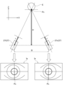
眼科装置10は、図1に示すように、床面に設置された基台11と、検眼用テーブル12と、支柱13と、支持部としてのアーム14と、駆動機構15と、一対の測定ヘッド16と、を備える。この眼科装置10は、検眼用テーブル12と正対する被検者が、両測定ヘッド16の間に設けられた額当部17に額を当てた状態で、被検者の被検眼E(図3等参照)の情報の取得を行う。以下では、被検者から見て、左右方向をX方向とし、上下方向(鉛直方向)をY方向とし、X方向およびY方向と直交する方向(測定ヘッド16の前後方向(被検者側を手前側とする))をZ方向とする。 As shown in FIG. 1, the ophthalmologic apparatus 10 includes a base 11 installed on the floor, an optometry table 12, a column 13, an arm 14 as a support, a drive mechanism 15, and a pair of measurement heads. 16 and. The ophthalmologic apparatus 10 is configured such that the subject facing the eye examination table 12 presses the forehead against the forehead support 17 provided between the measuring heads 16, and the subject's eye to be examined E (see FIG. 3). etc.). Hereinafter, when viewed from the subject, the left-right direction is defined as the X direction, the up-down direction (vertical direction) is defined as the Y direction, and the direction perpendicular to the X and Y directions (the front-rear direction of the measurement head 16 (on the subject side). The front side)) is the Z direction.

検眼用テーブル12は、後述する検者用コントローラ31や被検者用コントローラ32(図4参照)を置いたり検眼に用いるものを置いたりするための机であり、基台11により支持されている。検眼用テーブル12は、Y方向での位置(高さ位置)を調節可能に基台11に支持されていてもよい。 The optometry table 12 is a desk on which an examiner controller 31 and a subject controller 32 (see FIG. 4), which will be described later, are placed, and objects used for optometry are placed, and is supported by the base 11 . . The optometric table 12 may be supported by the base 11 so that its position in the Y direction (height position) can be adjusted.

支柱13は、検眼用テーブル12の後端部でY方向に伸びて基台11に支持されており、上部にアーム14が設けられる。アーム14は、検眼用テーブル12上で駆動機構15を介して一対の測定ヘッド16を吊り下げるもので、支柱13から手前側へとZ方向に伸びている。アーム14は、支柱13に対してY方向に移動可能とされ、後述するアーム駆動機構34(図4参照)によりY方向での位置(高さ位置)が調節される。なお、アーム14は、支柱13に対してX方向およびZ方向に移動可能とされていてもよい。このアーム14の先端には、駆動機構15により吊り下げられて両測定ヘッド16が支持されている。 The column 13 extends in the Y direction at the rear end of the optometry table 12 and is supported by the base 11, and an arm 14 is provided on the top. The arm 14 suspends a pair of measuring heads 16 on the optometry table 12 via a drive mechanism 15, and extends in the Z direction from the column 13 toward the near side. The arm 14 is movable in the Y direction with respect to the column 13, and its position (height position) in the Y direction is adjusted by an arm drive mechanism 34 (see FIG. 4), which will be described later. In addition, the arm 14 may be movable in the X direction and the Z direction with respect to the column 13 . Both measuring heads 16 are suspended from the tip of the arm 14 by a drive mechanism 15 and supported.

測定ヘッド16は、被検者の左右の被検眼Eに個別に対応すべく対を為して設けられ、以下では個別に述べる際には左眼用測定ヘッド16Lおよび右眼用測定ヘッド16Rとする。左眼用測定ヘッド16Lは、被験者の左側の被検眼Eの情報を取得し、右眼用測定ヘッド16Rは、被験者の右側の被検眼Eの情報を取得する。左眼用測定ヘッド16Lと右眼用測定ヘッド16Rとは、X方向で双方の中間に位置する鉛直面に関して面対称な構成とされている。 The measuring heads 16 are provided in pairs so as to individually correspond to the left and right eyes E of the subject to be examined. do. The left eye measurement head 16L acquires information on the left eye E of the subject, and the right eye measurement head 16R acquires information on the right eye E of the subject. The left-eye measurement head 16L and the right-eye measurement head 16R are configured to be symmetrical with respect to a vertical plane positioned between them in the X direction.

各測定ヘッド16には、被検眼Eの眼情報を取得する眼情報取得部21(個別に述べる際には右眼情報取得部21Rおよび左眼情報取得部21Lとする(図2参照))が収容されている。その眼情報は、被検眼Eの屈折力や、被検眼Eの画像や、被検眼Eの眼底Ef(図5参照)の画像や、被検眼Eの網膜の断層画像や、被検眼Eの角膜内皮画像や、被検眼Eの角膜形状や、被検眼Eの眼圧等が適宜組み合わされる。各眼情報取得部21は、屈折力を測定する屈折力測定機構(実施例1ではレフラクトメータ)、それと同じ光軸上で視標を呈示する視標呈示機構、呈示する視標を切り替えつつ視力検査を行う視力検査装置、矯正用レンズを切り換えて配置させて被検眼Eの適切な矯正屈折力を取得するフォロプタ、屈折力を測定する波面センサ、眼底の画像を撮影する眼底カメラ、網膜の断層画像を撮影する断層撮影装置(OCT)、角膜内皮画像を撮影するスペキュラマイクロスコープ、角膜形状を測定するケラトメータ、眼圧を測定するトノメータ等が適宜組み合わされて構成される。 Each measuring head 16 includes an eye information acquisition unit 21 (referred to as a right eye information acquisition unit 21R and a left eye information acquisition unit 21L (see FIG. 2) when describing separately) for acquiring eye information of the eye E to be examined. Contained. The eye information includes the refractive power of the eye to be examined E, the image of the eye to be examined E, the image of the fundus Ef of the eye to be examined E (see FIG. 5), the tomographic image of the retina of the eye to be examined E, and the cornea of the eye to be examined E. An endothelial image, the corneal shape of the eye to be examined E, the intraocular pressure of the eye to be examined E, and the like are appropriately combined. Each eye information acquisition unit 21 includes a refractive power measuring mechanism (a refractometer in the first embodiment) that measures refractive power, a target presenting mechanism that presents a target on the same optical axis as the refractive power measuring mechanism, and a target presenting mechanism that presents a target on the same optical axis. A visual acuity testing device for visual acuity testing, a phoropter for obtaining an appropriate corrective refractive power of an eye to be examined E by switching and arranging corrective lenses, a wavefront sensor for measuring refractive power, a fundus camera for capturing an image of the fundus, and a retina. A tomography apparatus (OCT) for capturing tomographic images, a specular microscope for capturing corneal endothelium images, a keratometer for measuring corneal shape, a tonometer for measuring intraocular pressure, etc. are combined appropriately.

両測定ヘッド16は、図2に示すように、アーム14の先端に設けられた取付ベース部18を介して駆動機構15により移動可能に吊り下げられている。取付ベース部18は、アーム14の先端に固定され、X方向に延びるともに、一方の端部に後述する左眼用駆動機構15Lが吊り下げられ、他方の端部に後述する右眼用駆動機構15Rが吊り下げられている。また、この取付ベース部18の中央部に、額当部17が設けられている。 Both measuring heads 16 are movably suspended by a drive mechanism 15 via a mounting base portion 18 provided at the tip of the arm 14, as shown in FIG. The mounting base portion 18 is fixed to the tip of the arm 14 and extends in the X direction. One end of the mounting base portion 18 suspends a left eye driving mechanism 15L described later, and the other end of the mounting base portion 18 supports a right eye driving mechanism 15L described later. 15R is suspended. A forehead support portion 17 is provided in the central portion of the mounting base portion 18 .

駆動機構15は、実施例1では、左眼用測定ヘッド16Lに対応する左眼用駆動機構15L(左鉛直駆動部22L、左水平駆動部23L、左Y軸回旋駆動部24L、左X軸回旋駆動部25L)と、右眼用測定ヘッド16Rに対応する右眼用駆動機構15R(右鉛直駆動部22R、右水平駆動部23R、右Y軸回旋駆動部24R、右X軸回旋駆動部25R)と、を有する。この左眼用駆動機構15Lと右眼用駆動機構15Rと(双方の各駆動部の構成)は、X方向で双方の中間に位置する鉛直面に関して面対称な構成とされており、個別に述べる時を除くと単に鉛直駆動部22と水平駆動部23とY軸回旋駆動部24とX軸回旋駆動部25と記す。駆動機構15は、アーム14側から鉛直駆動部22、水平駆動部23、Y軸回旋駆動部24、X軸回旋駆動部25の順に設けられている。 In the first embodiment, the drive mechanism 15 includes a left eye drive mechanism 15L (left vertical drive section 22L, left horizontal drive section 23L, left Y axis rotation drive section 24L, left X axis rotation drive section 24L) corresponding to the left eye measurement head 16L. drive unit 25L), and a right eye drive mechanism 15R corresponding to the right eye measurement head 16R (right vertical drive unit 22R, right horizontal drive unit 23R, right Y-axis rotation drive unit 24R, right X-axis rotation drive unit 25R). and have The drive mechanism 15L for the left eye and the drive mechanism 15R for the right eye (configurations of both drive units) are symmetrical with respect to a vertical plane positioned between them in the X direction, and will be described separately. Except for time, they are simply referred to as a vertical drive section 22, a horizontal drive section 23, a Y-axis rotation drive section 24, and an X-axis rotation drive section 25. The drive mechanism 15 is provided with a vertical drive section 22, a horizontal drive section 23, a Y-axis rotation drive section 24, and an X-axis rotation drive section 25 in this order from the arm 14 side.

鉛直駆動部22は、取付ベース部18と水平駆動部23との間に設けられ、取付ベース部18に対して水平駆動部23をY方向(鉛直方向)に移動させる。水平駆動部23は、鉛直駆動部22とY軸回旋駆動部24との間に設けられ、鉛直駆動部22に対してY軸回旋駆動部24をX方向およびZ方向(水平方向)に移動させる。この鉛直駆動部22および水平駆動部23は、例えばパルスモータのような駆動力を発生するアクチュエータと、例えば歯車の組み合わせやラック・アンド・ピニオン等のような駆動力を伝達する伝達機構と、を設けて構成する。水平駆動部23は、例えば、X方向とZ方向とで個別にアクチュエータおよび伝達機構の組み合わせを設けることで、容易に構成できるとともに水平方向の移動の制御を容易なものにできる。 The vertical driving portion 22 is provided between the mounting base portion 18 and the horizontal driving portion 23 and moves the horizontal driving portion 23 in the Y direction (vertical direction) with respect to the mounting base portion 18 . The horizontal drive unit 23 is provided between the vertical drive unit 22 and the Y-axis rotation drive unit 24, and moves the Y-axis rotation drive unit 24 in the X direction and the Z direction (horizontal direction) with respect to the vertical drive unit 22. . The vertical drive unit 22 and the horizontal drive unit 23 include an actuator such as a pulse motor that generates a driving force, and a transmission mechanism that transmits the driving force such as a combination of gears or a rack and pinion. set up and configured. The horizontal drive unit 23 can be easily configured and easily controlled for movement in the horizontal direction by providing separate combinations of actuators and transmission mechanisms for the X and Z directions, for example.

Y軸回旋駆動部24は、水平駆動部23とX軸回旋駆動部25との間に設けられ、水平駆動部23に対してX軸回旋駆動部25を、対応する被検眼Eの眼球回旋点Oを通りY方向に延びる眼球回旋Y軸を中心に回転させる。X軸回旋駆動部25は、Y軸回旋駆動部24と対応する測定ヘッド16との間に設けられ、Y軸回旋駆動部24に対して対応する測定ヘッド16を、対応する被検眼Eの眼球回旋点Oを通りX方向に延びる眼球回旋X軸を中心に回転させる。 The Y-axis rotation drive unit 24 is provided between the horizontal drive unit 23 and the X-axis rotation drive unit 25, and the X-axis rotation drive unit 25 is connected to the horizontal drive unit 23 at the corresponding eyeball rotation point of the eye E to be examined. Rotate around the Y axis of eye rotation extending through O in the Y direction. The X-axis rotation drive section 25 is provided between the Y-axis rotation drive section 24 and the corresponding measurement head 16, and rotates the corresponding measurement head 16 with respect to the Y-axis rotation drive section 24 to the eyeball of the eye E to be examined. The eye is rotated around the X-axis of eyeball rotation passing through the rotation point O and extending in the X-direction.

このY軸回旋駆動部24およびX軸回旋駆動部25は、例えば、鉛直駆動部22や水平駆動部23と同様にアクチュエータと伝達機構とを有するものとし、アクチュエータからの駆動力を受けた伝達機構が円弧状の案内溝に沿って移動する構成とする。Y軸回旋駆動部24は、案内溝の中心位置が眼球回旋Y軸と一致されることで、被検眼Eの眼球回旋Y軸を中心に測定ヘッド16を回転させることができる。また、X軸回旋駆動部25は、案内溝の中心位置が眼球回旋X軸と一致されることで、被検眼Eの眼球回旋X軸を中心に測定ヘッド16を回転させることができる。すなわち、測定ヘッド16は、Y軸回旋駆動部24およびX軸回旋駆動部25の各々の案内溝の中心位置が被検眼Eの眼球回旋点Oと一致されることで、眼球回旋点Oを中心に左右方向(Y方向を中心とする回転方向)および上下方向(X方向を中心とする回転方向)に回転可能とされている。 The Y-axis rotation driving section 24 and the X-axis rotation driving section 25, for example, have an actuator and a transmission mechanism like the vertical driving section 22 and the horizontal driving section 23, and the transmission mechanism receives the driving force from the actuator. moves along an arcuate guide groove. The Y-axis rotation drive unit 24 can rotate the measurement head 16 around the eyeball rotation Y-axis of the eye E to be examined by aligning the center position of the guide groove with the eyeball rotation Y-axis. Further, the X-axis rotation drive unit 25 can rotate the measurement head 16 about the X-axis of eyeball rotation of the eye E to be examined by aligning the center position of the guide groove with the X-axis of eyeball rotation. That is, the measurement head 16 is centered on the eyeball rotation point O by aligning the center positions of the guide grooves of the Y-axis rotation drive unit 24 and the X-axis rotation drive unit 25 with the eyeball rotation point O of the eye E to be examined. It is rotatable in the horizontal direction (rotating direction about the Y direction) and the vertical direction (rotating direction about the X direction).

なお、Y軸回旋駆動部24は、自らに設けたY軸回転軸線回りに回転可能に測定ヘッド16を支持するとともに水平駆動部23と協働してX軸回旋駆動部25を介して測定ヘッド16を支持する位置を変更しつつ回転させることで、被検眼Eの眼球回旋Y軸を中心に測定ヘッド16を回転させるものでもよい。また、X軸回旋駆動部25は、自らに設けたX軸回転軸線回りに回転可能に測定ヘッド16を支持するとともに鉛直駆動部22と協働して測定ヘッド16を支持する位置を変更しつつ回転させることで、被検眼Eの眼球回旋X軸を中心に測定ヘッド16を回転させるものでもよい。 The Y-axis rotation driving section 24 supports the measuring head 16 so as to be rotatable around its own Y-axis rotation axis, and cooperates with the horizontal driving section 23 to rotate the measuring head through the X-axis rotation driving section 25 . The measurement head 16 may be rotated around the eyeball rotation Y axis of the eye E to be inspected by rotating while changing the supporting position of the measurement head 16 . In addition, the X-axis rotation driving section 25 supports the measuring head 16 so as to be rotatable around the X-axis rotation axis provided therein, and cooperates with the vertical driving section 22 to change the position at which the measuring head 16 is supported. By rotating, the measurement head 16 may be rotated around the eyeball rotation X axis of the eye E to be examined.

以上の構成により、駆動機構15は、各測定ヘッド16を個別にまたは連動させて、X方向、Y方向およびZ方向に移動させることができるとともに、それぞれが対応する被検眼Eの眼球回旋点Oを中心に上下左右に回転させることができ、各測定ヘッド16を対応する被検眼Eの回旋に対応する位置(姿勢)に移動させることができる。駆動機構15は、各測定ヘッド16の位置を調整することで、対応する被検眼Eを開散(開散運動)させたり輻輳(輻輳運動)させたりすることができる。これにより、眼科装置10では、開散運動および輻輳運動のテストを行うことや、両眼視の状態で遠用検査や近用検査を行って両被検眼Eの各種特性を測定できる。 With the above configuration, the driving mechanism 15 can move the measuring heads 16 individually or in conjunction with each other in the X, Y, and Z directions, and move the corresponding eyeball rotation point O of the eye E to be examined. , and each measuring head 16 can be moved to a position (orientation) corresponding to the rotation of the eye E to be examined. By adjusting the position of each measuring head 16, the driving mechanism 15 can cause the corresponding subject's eye E to diverge (divergence movement) or converge (convergence movement). As a result, the ophthalmologic apparatus 10 can perform a divergence motion test and a convergence motion test, perform a distance test and a near test in a state of binocular vision, and measure various characteristics of both eyes E to be examined.

各測定ヘッド16では、偏向部材26が設けられ、偏向部材26を通じて眼情報取得部21により対応する被検眼Eの情報が取得される。眼科装置10は、図3に示すように、各偏向部材26が被験者の左右の被検眼Eにそれぞれ対応する位置となるように各測定ヘッド16の位置を調整することで、被検者が左右の両眼を開放した状態(両眼視の状態)で、被検眼Eの情報を両眼同時に取得できる。また、眼科装置10は、X軸回旋駆動部25により眼球回旋X軸を中心に各測定ヘッド16の回転姿勢を変化させることで、対応する被検眼Eを下方視や上方視させた状態で被検眼Eの情報を取得できる。そして、眼科装置10は、Y軸回旋駆動部24により眼球回旋Y軸を中心に各測定ヘッド16の回転姿勢を変化させることで、対応する被検眼Eを左右視させた状態で被検眼Eの情報を取得できる。 Each measuring head 16 is provided with a deflecting member 26 , and information on the corresponding subject's eye E is acquired by the eye information acquisition unit 21 through the deflecting member 26 . As shown in FIG. 3, the ophthalmologic apparatus 10 adjusts the positions of the measurement heads 16 so that the deflecting members 26 are positioned corresponding to the left and right eyes E of the subject. With both eyes open (binocular vision state), information on the subject's eye E can be obtained simultaneously with both eyes. In addition, the ophthalmologic apparatus 10 changes the rotational posture of each measuring head 16 about the X-axis of eyeball rotation by the X-axis rotation drive unit 25, so that the corresponding subject eye E is viewed downward or upward. Information on eye examination E can be acquired. Then, the ophthalmologic apparatus 10 changes the rotational posture of each measuring head 16 about the Y-axis of eyeball rotation by the Y-axis rotation drive unit 24, and the corresponding eye to be inspected E is viewed horizontally. information can be obtained.

各測定ヘッド16は、偏向部材26に近接して、各被検眼Eに対して異なる方向から撮影する2つ以上の撮影部としての複数のカメラ27を有する。カメラ27は、実施例1では、各被検眼Eに対して眼情報取得部21の光軸Lを前後(Z方向)に挟んで2台設けられており、ステレオカメラを構成している。各カメラ27は、対応する被検眼Eからの光が偏向部材26を介して進行方向が屈曲されて入射されて、それぞれが異なる方向であって斜め(正面(後述する観察系41の光軸L)に対して傾斜する位置)から被検眼Eを見た画像となる被検眼画像Ie(図6等参照)を取得する。このため、各カメラ27は、対応する被検眼Eに対して前後(Z方向)で対を為しているが、偏向部材26を介することで実質的に被検眼Eに対して左右(X方向)の斜めから被検眼画像Ieを取得している。これにより、各カメラ27は、一方が被験者の外側(被検眼Eに対して鼻とは反対側)から被検眼画像Ieを取得する外側カメラ27oとなり、他方が被験者の内側から被検眼画像Ieを取得する内側カメラ27iとなる。 Each measuring head 16 has a plurality of cameras 27 as two or more photographing units that photograph each eye E from different directions in the vicinity of the deflecting member 26 . In Example 1, two cameras 27 are provided with respect to each eye E to be inspected, with the optical axis L of the eye information acquisition unit 21 sandwiched in front and behind (in the Z direction), and constitute a stereo camera. Each camera 27 receives the light from the corresponding eye to be inspected E with its traveling direction bent through the deflecting member 26, and each camera 27 is directed in a different direction and obliquely (front (optical axis L of an observation system 41 described later)). ) to acquire an eye image Ie (see FIG. 6, etc.), which is an image of the eye E viewed from a position inclined with respect to ). For this reason, each camera 27 is paired in front and behind (in the Z direction) with respect to the corresponding eye E to be examined. ), the image Ie of the subject's eye is acquired obliquely. As a result, one of the cameras 27 becomes an outer camera 27o that acquires the subject's eye image Ie from the outside of the subject (the side opposite to the nose with respect to the subject's eye E), and the other acquires the subject's eye image Ie from the inside of the subject. It becomes the inner camera 27i to acquire.

ここで、2つのカメラ27は、被検眼Eに対して実質的に、上下(Y方向)で対を為して設けてもよいが、瞼が少し閉じられると上下の斜めからの被検眼画像Ieでは被検眼Eに対して瞼に隠される領域が大きくなるので、同じ状況でも影響の少ない左右(X方向)から被検眼画像Ieを取得する構成とすることが望ましい。加えて、年配の被検者は、瞼が下がる傾向があるので、左右(X方向)の斜め下方から被検眼画像Ieを取得する位置関係で両カメラ27を設けることが望ましい。 Here, the two cameras 27 may be provided in a pair substantially vertically (in the Y direction) with respect to the subject's eye E. In Ie, since the area hidden by the eyelid with respect to the subject's eye E becomes large, it is desirable to acquire the subject's eye image Ie from the left and right (X direction), which have less influence even in the same situation. In addition, since elderly subjects tend to droop their eyelids, it is desirable to provide both cameras 27 in such a positional relationship that the subject's eye images Ie are acquired obliquely downward in the left and right (X direction).

両カメラ27は、実質的に同時に被検眼Eを撮影することで、同時点での2つの異なる被検眼画像Ieを取得する。ここで、実質的に同時とは、両カメラ27による撮影において、眼球運動を無視できる程度の撮影タイミングのズレを許容することを意味する。両カメラ27は、被検眼Eを異なる方向から実質的に同時に撮影することで、被検眼Eが同じ位置(向き)にあるときの2以上の被検眼画像Ieを取得することが可能になる。これにより、両カメラ27は、後述するように被検眼Eの3次元位置の算出に用いることができる。 Both cameras 27 acquire two different images Ie of the eye to be inspected at the same point in time by photographing the eye E to be inspected substantially at the same time. Here, "substantially at the same time" means that, in photographing by both cameras 27, a difference in photographing timing to the extent that eye movement can be ignored is allowed. Both cameras 27 capture images of the subject's eye E substantially simultaneously from different directions, thereby making it possible to obtain two or more subject's eye images Ie when the subject's eye E is in the same position (orientation). As a result, both cameras 27 can be used to calculate the three-dimensional position of the subject's eye E, as will be described later.

なお、実施例1では、各被検眼Eに対して2つのカメラ27(撮影部)を設けているが、各被検眼Eに対して2つ以上の撮影部を設ければよく、実施例1の構成に限定されない。しかしながら、後述の3次元位置を求める際の演算処理を考慮すると、異なる2方向から実質的に同時に被検眼E(その前眼部)を撮影可能な構成であれば十分である。また、実施例1では、眼情報取得部21(その後述する観察系41)とは別個に2つのカメラ27を設けているが、異なる2つ以上の方向から実質的に同時に被検眼Eを撮影可能であれば、一方のカメラ27に替えて観察系41を用いるものとしてもよく、実施例1の構成に限定されない。 In the first embodiment, two cameras 27 (photographing units) are provided for each eye E to be examined. is not limited to the configuration of However, considering the arithmetic processing for determining the three-dimensional position, which will be described later, it is sufficient if the configuration is such that the subject's eye E (the anterior segment thereof) can be photographed substantially simultaneously from two different directions. In addition, in Example 1, two cameras 27 are provided separately from the eye information acquisition unit 21 (observation system 41 described later), but the subject's eye E is photographed substantially simultaneously from two or more different directions. If possible, the observation system 41 may be used instead of the one camera 27, and the configuration is not limited to that of the first embodiment.

基台11には、眼科装置10の各部を統括的に制御する制御部28が、制御ボックスに収納されて設けられる(図1参照)。制御部28は、図4に示すように、上記した各眼情報取得部21、駆動機構15としての各鉛直駆動部22、各水平駆動部23、各Y軸回旋駆動部24、各X軸回旋駆動部25および各カメラ27(外側カメラ27o、内側カメラ27i)に加えて、検者用コントローラ31と被検者用コントローラ32と記憶部33とアーム駆動機構34と、が接続されている。眼科装置10は、ケーブル29(図1、図2参照)を介して商用電源から制御部28に電力が供給され、制御部28が駆動機構15および両測定ヘッド16(両眼情報取得部21)に電力を供給する。制御部28は、駆動機構15や両測定ヘッド16(両眼情報取得部21)と情報の遣り取りが可能とされ、それらの動作を制御するとともにそれらから適宜情報を取得する。 The base 11 is provided with a control unit 28 that is housed in a control box and controls each part of the ophthalmologic apparatus 10 (see FIG. 1). As shown in FIG. 4, the control unit 28 includes the above-described eye information acquisition unit 21, each vertical drive unit 22 as the drive mechanism 15, each horizontal drive unit 23, each Y-axis rotation drive unit 24, and each X-axis rotation drive unit. In addition to the driving unit 25 and each camera 27 (outer camera 27o, inner camera 27i), an examiner controller 31, a subject controller 32, a storage unit 33, and an arm drive mechanism 34 are connected. In the ophthalmologic apparatus 10, power is supplied from a commercial power source to the control unit 28 via a cable 29 (see FIGS. 1 and 2), and the control unit 28 controls the drive mechanism 15 and both measurement heads 16 (both eye information acquisition unit 21). to power the The control unit 28 can exchange information with the drive mechanism 15 and both measurement heads 16 (binocular information acquisition unit 21), controls their operations, and acquires information from them as appropriate.

検者用コントローラ31は、検者が眼科装置10を操作するために用いられ、制御部28と近距離無線通信によって、互いに通信可能に接続されている。なお、検者用コントローラ31は、制御部28と有線または無線の通信路を介して接続されていればよく、実施例1の構成に限定されない。実施例1の検者用コントローラ31は、タブレット端末、スマートフォンなどの携帯端末(情報処理装置)が用いられている。なお、検者用コントローラ31は、携帯端末に限定されることはなく、ノート型パーソナルコンピュータ、デスクトップ型パーソナルコンピュータ等でもよく、眼科装置10に固定されて構成されていてもよく、実施例1の構成に限定されない。 The examiner controller 31 is used by an examiner to operate the ophthalmologic apparatus 10, and is communicably connected to the control unit 28 by short-range wireless communication. Note that the examiner controller 31 is not limited to the configuration of the first embodiment as long as it is connected to the control unit 28 via a wired or wireless communication path. A portable terminal (information processing device) such as a tablet terminal or a smartphone is used as the examiner controller 31 of the first embodiment. Note that the controller for examiner 31 is not limited to a mobile terminal, and may be a notebook personal computer, a desktop personal computer, or the like, and may be configured by being fixed to the ophthalmologic apparatus 10. Not limited to configuration.

検者用コントローラ31は、液晶モニタからなる表示部35を備える。この表示部35は、画像等が表示される表示面35a(図1等参照)と、そこに重畳して配置されたタッチパネル式の入力部35bと、を有する。検者用コントローラ31は、制御部28の制御下で、後述する観察系41に設けられた撮像素子41gからの画像信号に基づく前眼部画像I(図5参照)や各カメラ27からの被検眼画像Ie(図6等参照)や後述する測定リング像Ri(図8参照)や眼底画像等を、適宜表示面35aに表示させる。また、検者用コントローラ31は、制御部28の制御下で入力部35bが表示され、そこに入力されたアライメントの指示や測定の指示等の操作情報を制御部28に出力する。 The examiner controller 31 includes a display section 35 consisting of a liquid crystal monitor. The display unit 35 has a display surface 35a (see FIG. 1, etc.) on which an image or the like is displayed, and a touch panel type input unit 35b superimposed thereon. Under the control of the controller 28, the examiner controller 31 receives an anterior ocular segment image I (see FIG. 5) based on an image signal from an imaging device 41g provided in the observation system 41, which will be described later, and an object from each camera 27. The eye examination image Ie (see FIG. 6, etc.), a measurement ring image Ri (see FIG. 8) described later, a fundus image, and the like are appropriately displayed on the display surface 35a. Further, the examiner controller 31 displays an input section 35 b under the control of the control section 28 and outputs operation information such as an alignment instruction and a measurement instruction input there to the control section 28 .

被検者用コントローラ32は、被検眼Eの各種の眼情報の取得の際に、被検者が応答するために用いられ、有線または無線の通信路を介して制御部28と接続されている。被検者用コントローラ32は、例えばキーボード、マウス、ジョイスティック等の入力装置とされる。 The examinee controller 32 is used by the examinee to respond when acquiring various eye information of the eye to be examined E, and is connected to the control unit 28 via a wired or wireless communication path. . The subject controller 32 is, for example, an input device such as a keyboard, mouse, or joystick.

制御部28は、接続された記憶部33または内蔵する内部メモリ28aに記憶したプログラムを例えばRAM(Random Access Memory)上に展開することにより、適宜検者用コントローラ31や被検者用コントローラ32に対する操作に応じて、眼科装置10の動作を統括的に制御する。実施例1では、内部メモリ28aは、RAM等で構成され、記憶部33は、ROM(Read Only Memory)やEEPROM(Electrically Erasable Programmable ROM)等で構成される。眼科装置10では、上記した構成の他に、測定完了信号や測定者からの指示に応じて測定結果を印字するプリンタや、測定結果を外部メモリやサーバーに出力する出力部が適宜設けられる。 The control unit 28 appropriately controls the controller 31 for the examinee and the controller 32 for the examinee by expanding the program stored in the connected storage unit 33 or the built-in internal memory 28a on, for example, a RAM (random access memory). The operation of the ophthalmologic apparatus 10 is centrally controlled according to the operation. In the first embodiment, the internal memory 28a is composed of a RAM or the like, and the storage unit 33 is composed of a ROM (Read Only Memory), an EEPROM (Electrically Erasable Programmable ROM), or the like. In addition to the configuration described above, the ophthalmologic apparatus 10 is appropriately provided with a printer that prints the measurement results in response to a measurement completion signal or an instruction from the measurer, and an output unit that outputs the measurement results to an external memory or server.

次に、眼情報取得部21の一例としての光学的な構成を、図5を用いて説明する。上述したように、右眼情報取得部21Rおよび左眼情報取得部21Lの構成は、基本的に同一であるので、単に眼情報取得部21として説明する。 Next, an optical configuration as an example of the eye information acquisition section 21 will be described with reference to FIG. As described above, the configurations of the right eye information acquisition section 21R and the left eye information acquisition section 21L are basically the same, and therefore the eye information acquisition section 21 will be simply described.

眼情報取得部21の光学系は、図5に示すように、観察系41と視標投影系42と眼屈折力測定系43とZアライメント系44とXYアライメント系45とケラト系46とを有する。観察系41は、被検眼Eの前眼部を観察し、視標投影系42は、被検眼Eに視標を呈示し、眼屈折力測定系43は、被検眼Eの眼屈折力(屈折特性)の測定を行う。Zアライメント系44およびXYアライメント系45は、被検眼Eに対する光学系の位置合わせ(アライメント)を行うために設けられている。Zアライメント系44は、観察系41の光軸Lに沿う前後方向(Z方向)のアライメント情報を生成し、XYアライメント系45は、光軸Lに直交する上下左右方向(Y方向、X方向)のアライメント情報を生成する。ケラト系46は、角膜形状の測定を行う。 As shown in FIG. 5, the optical system of the eye information acquisition unit 21 includes an observation system 41, a target projection system 42, an eye refractive power measurement system 43, a Z alignment system 44, an XY alignment system 45, and a keratometric system 46. . The observation system 41 observes the anterior segment of the eye E to be examined, the target projection system 42 presents a target to the eye E to be examined, and the eye refractive power measurement system 43 measures the refractive power (refractive power) of the eye E to be examined. characteristics) are measured. The Z alignment system 44 and the XY alignment system 45 are provided to align the optical system with the eye E to be inspected. The Z alignment system 44 generates alignment information in the front-rear direction (Z direction) along the optical axis L of the observation system 41, and the XY alignment system 45 generates alignment information in the vertical and horizontal directions (Y direction, X direction) orthogonal to the optical axis L. generates alignment information for The keratometric system 46 provides measurements of corneal topography.

観察系41は、対物レンズ41aとダイクロイックフィルタ41bとハーフミラー41cとリレーレンズ41dとダイクロイックフィルタ41eと結像レンズ41fと撮像素子41gとを有する。観察系41は、被検眼E(前眼部)で反射された光束を、対物レンズ41aを経て結像レンズ41fにより撮像素子41g(その受光面)上に結像する。このため、撮像素子41gは、後述するケラトリング光束やアライメント光源44aの光束やアライメント光源45aの光束(輝点像Br)が投光(投影)された前眼部画像Iを検出(受像)する。制御部28は、撮像素子41gから出力される画像信号に基づく前眼部画像I等を表示部35の表示面35aに表示させる。この対物レンズ41aの前方にケラト系46を設けている。 The observation system 41 has an objective lens 41a, a dichroic filter 41b, a half mirror 41c, a relay lens 41d, a dichroic filter 41e, an imaging lens 41f, and an imaging device 41g. The observation system 41 forms an image of the luminous flux reflected by the subject's eye E (anterior segment) via the objective lens 41a and the imaging lens 41f on the imaging element 41g (its light receiving surface). For this reason, the imaging device 41g detects (receives) an anterior ocular segment image I projected (projected) by a keratling luminous flux, a luminous flux of the alignment light source 44a, or a luminous flux of the alignment light source 45a (bright point image Br), which will be described later. . The control unit 28 causes the display surface 35a of the display unit 35 to display the anterior segment image I based on the image signal output from the imaging element 41g. A kerato system 46 is provided in front of the objective lens 41a.

ケラト系46は、ケラト板46aとケラトリング光源46bとを有する。ケラト板46aは、観察系41の光軸Lに関して同心状のスリットが設けられた板状とされ、対物レンズ41aの近傍に設けられる。ケラトリング光源46bは、ケラト板46aのスリットに合わせて設けられる。このケラト系46は、点灯したケラトリング光源46bからの光束がケラト板46aのスリットを経ることで、被検眼E(その角膜Ec)に角膜形状の測定のためのケラトリング光束(角膜曲率測定用リング状視標)を投光(投影)する。ケラトリング光束は、被検眼Eの角膜Ecで反射されることで、観察系41により撮像素子41g上に結像され、撮像素子41gがリング状のケラトリング光束の像(画像)を検出(受像)する。制御部28は、撮像素子41gからの画像信号に基づいて、その測定パターンの像を表示面35aに表示させるとともに、角膜形状(曲率半径)を周知の手法により測定するケラト測定を行う。なお、実施例1では、角膜形状を測定する角膜形状測定系として、リングスリットが1重から3重程度で角膜の中心付近の曲率測定を行うケラト板46aを用いる例(ケラト系46)を示しているが、多重のリングを有し角膜全面の形状を測定可能なプラチド板を用いるものでもよく、他の構成でもよく、実施例1の構成に限定されない。このケラト系46(ケラト板46a)の後方にZアライメント系44を設けている。 Kerato system 46 has a kerato plate 46a and a kerato ring light source 46b. The keratoplate 46a has a plate shape provided with a slit concentric with respect to the optical axis L of the observation system 41, and is provided in the vicinity of the objective lens 41a. The keratizing light source 46b is provided in alignment with the slit of the keratoplate 46a. In the kerato system 46, a light flux from a lighted keratizing light source 46b passes through a slit of a keratoplate 46a, and a keratolight flux (for corneal curvature measurement) for measuring the shape of the cornea is directed to the eye E (its cornea Ec). A ring-shaped optotype) is emitted (projected). The keratling luminous flux is reflected by the cornea Ec of the eye E to be examined, and an image is formed on the imaging device 41g by the observation system 41. )do. Based on the image signal from the imaging element 41g, the control unit 28 displays the image of the measurement pattern on the display surface 35a, and performs keratometry for measuring the corneal shape (curvature radius) by a well-known technique. In Example 1, an example (kerat system 46) using a keratoplate 46a for measuring the curvature near the center of the cornea with one to three ring slits is shown as a corneal topography measuring system for measuring the corneal topography. However, a placido plate having multiple rings and capable of measuring the shape of the entire cornea may be used, or other configurations may be used, and the configuration is not limited to that of the first embodiment. A Z alignment system 44 is provided behind this kerato system 46 (kerato plate 46a).

Zアライメント系44は、一対のアライメント光源44aと投影レンズ44bとを有し、各アライメント光源44aからの光束を各投影レンズ44bで平行光束とし、ケラト板46aに設けたアライメント用孔を通して被検眼Eの角膜Ecに当該平行光束を投光(投影)する。この平行光束は、角膜Ecに投影された輝点(輝点像)のアライメント情報として検出される。これにより、Z方向のアライメントのための視標が被検眼Eの角膜Ecに投影される。この視標は、角膜表面反射による虚像(プルキンエ像)として検出される。制御部28は、撮像素子41g上のアライメント光源44aによる2個の輝点像の間隔とケラトリング像の直径との比が所定範囲内となるように、水平駆動部23により測定ヘッド16を前後方向(Z方向)に移動させることで、眼情報取得部21の光学系の光軸Lに沿う前後方向(Z方向)のアライメントを行う。ここで、制御部28は、その比率からアライメントのずれ量を求めて、このアライメントのずれ量を表示面35aに表示させてもよい。なお、前後方向のアライメントは、後述するアライメント光源45aによる輝点像のピントが合うように右眼用測定ヘッド16Rの位置を調整することで行ってもよい。また、Zアライメント系44による視標を用いたアライメントは、X方向およびY方向へのアライメントを含んでもよい。さらに、前後方向のアライメントは、一対のカメラ27からの2つの被検眼画像Ieを用いて行ってもよい。 The Z alignment system 44 has a pair of an alignment light source 44a and a projection lens 44b. A light beam from each alignment light source 44a is made into a parallel light beam by each projection lens 44b, and is projected through an alignment hole provided in a kerat plate 46a. The parallel light flux is projected (projected) onto the cornea Ec of . This parallel luminous flux is detected as alignment information of a bright spot (a bright spot image) projected onto the cornea Ec. Thereby, a target for alignment in the Z direction is projected onto the cornea Ec of the eye E to be examined. This visual target is detected as a virtual image (Purkinje image) due to corneal surface reflection. The control unit 28 moves the measurement head 16 back and forth by the horizontal driving unit 23 so that the ratio of the distance between the two bright spot images by the alignment light source 44a on the imaging device 41g and the diameter of the keratling image is within a predetermined range. Alignment in the front-rear direction (Z direction) along the optical axis L of the optical system of the eye information acquisition unit 21 is performed by moving in the direction (Z direction). Here, the controller 28 may obtain the amount of misalignment from the ratio, and display the amount of misalignment on the display surface 35a. Note that the alignment in the front-rear direction may be performed by adjusting the position of the right-eye measurement head 16R so that a bright spot image is focused by an alignment light source 45a, which will be described later. Alignment using a target by the Z alignment system 44 may include alignment in the X direction and the Y direction. Furthermore, alignment in the front-back direction may be performed using two eye images Ie from a pair of cameras 27 .

観察系41には、XYアライメント系45が設けられている。XYアライメント系45は、アライメント光源45aと投影レンズ45bとを有し、ハーフミラー41c、ダイクロイックフィルタ41bおよび対物レンズ41aを観察系41と共用する。XYアライメント系45は、アライメント光源45aからの光束を、対物レンズ41aを経て平行光束として光軸L上で角膜Ecに投光する。この平行光束は、角膜表面反射による虚像(プルキンエ像)を描出し、この虚像である輝点像Brが観察系41(その撮像素子41g)により検出される。この輝点(輝点像Br)は、角膜頂点Etと、角膜Ecの曲率中心と、の略中間位置に形成される。制御部28は、輝点(輝点像Br)に基づき、鉛直駆動部22および水平駆動部23を駆動して、測定ヘッド16を左右方向(X方向)、上下方向(Y方向)に移動させることで、上下左右方向(光軸Lに直交する方向)のアライメントを行う。このとき、制御部28は、輝点像が形成された前眼部画像Iに加えて、アライメントの目安となるアライメントマークALを表示面35aに表示させる。また、制御部28は、アライメントが完了すると測定を開始するように制御する構成としてもよい。アライメント光源45aは、XYアライメント系45によるアライメント動作中に、このアライメント光源45aを被検者が視認することを抑止するために、赤外光(例えば940nm)を発光する発光ダイオードとしている。 An XY alignment system 45 is provided in the observation system 41 . The XY alignment system 45 has an alignment light source 45a and a projection lens 45b, and shares the half mirror 41c, the dichroic filter 41b and the objective lens 41a with the observation system 41. The XY alignment system 45 projects the light flux from the alignment light source 45a onto the cornea Ec on the optical axis L as a parallel light flux through the objective lens 41a. This parallel luminous flux draws a virtual image (Purkinje image) due to the corneal surface reflection, and the bright point image Br, which is this virtual image, is detected by the observation system 41 (its imaging device 41g). This luminescent spot (luminescent spot image Br) is formed at a substantially intermediate position between the corneal vertex Et and the center of curvature of the cornea Ec. The control unit 28 drives the vertical driving unit 22 and the horizontal driving unit 23 based on the luminescent spot (luminescent spot image Br) to move the measuring head 16 in the horizontal direction (X direction) and the vertical direction (Y direction). Thus, alignment is performed in the vertical and horizontal directions (directions perpendicular to the optical axis L). At this time, the control unit 28 causes the display surface 35a to display an alignment mark AL, which serves as a guide for alignment, in addition to the anterior segment image I in which the bright spot image is formed. Further, the control unit 28 may be configured to perform control so as to start measurement when alignment is completed. The alignment light source 45a is a light-emitting diode that emits infrared light (for example, 940 nm) in order to prevent the subject from visually recognizing the alignment light source 45a during the alignment operation of the XY alignment system 45.

視標投影系42は、被検眼Eを固視、雲霧させる為に視標を投影して、その視標を眼底Efに呈示する。視標投影系42は、ディスプレイ42aとロータリープリズム42b、42cと結像レンズ42dと移動レンズ42eとリレーレンズ42fとフィールドレンズ42gとミラー42hとダイクロイックフィルタ42iとを有し、ダイクロイックフィルタ41bおよび対物レンズ41aを観察系41と共用する。ディスプレイ42aは、被検眼Eの視線を固定する視標としての固視標や点状視標を呈示したり、被検眼Eの特性(視力値や矯正度数(遠用度数、近用度数)等)を自覚的に検査するための自覚検査視標を呈示したりする。ディスプレイ42aは、EL(エレクトロルミネッセンス)や液晶ディスプレイ(Liquid Crystal Display(LCD))を用いることができ、制御部28の制御下で任意の画像を表示する。ディスプレイ42aは、視標投影系42の光路上において被検眼Eの眼底Efと共役となる位置に光軸に沿って移動可能に設けられる。 The visual target projection system 42 projects a visual target in order to fixate and cloud the subject's eye E, and presents the visual target on the fundus oculi Ef. The visual target projection system 42 has a display 42a, rotary prisms 42b and 42c, an imaging lens 42d, a moving lens 42e, a relay lens 42f, a field lens 42g, a mirror 42h, and a dichroic filter 42i. 41 a is shared with the observation system 41 . The display 42a presents a fixation target or a point-like target as a target for fixing the line of sight of the eye E to be examined, or displays characteristics of the eye E to be examined (visual acuity value, correction power (distance power, near power), etc.). ) is presented as a subjective test optotype for subjectively testing. The display 42a can use an EL (electroluminescence) or a liquid crystal display (LCD), and displays an arbitrary image under the control of the control section 28. FIG. The display 42a is movably provided along the optical axis at a position conjugate with the fundus Ef of the subject's eye E on the optical path of the target projection system 42 .

ロータリープリズム42b、42cは、斜位検査においてプリズム度数およびプリズム基底方向を調整するために用いられ、パルスモータ等の駆動によってそれぞれ独立に回転される。ロータリープリズム42b、42cは、互いに逆方向に回転されるとプリズム度数が連続的に変更され、同じ方向に一体的に回転されるとプリズム基底方向が連続的に変更される。移動レンズ42eは、駆動モータにより光軸に沿って進退駆動される。視標投影系42は、移動レンズ42eを被検眼E側に移動させることで、屈折力をマイナス側に変位させることができるとともに、移動レンズ42eを被検眼Eから離反する方向に移動させることで、屈折力をプラス側に変位させることができる。これにより、視標投影系42は、移動レンズ42eの進退駆動により、ディスプレイ42aに表示された視標の呈示距離を変更可能、すなわち視標像の呈示位置を変更可能であるとともに、被検眼Eを固視、雲霧させることができる。このため、視標投影系42は、被検眼Eに対して、固視のための指標や自覚検査のための指標を、任意の呈示距離で呈示できる。 The rotary prisms 42b and 42c are used for adjusting the prism power and the prism base direction in the oblique examination, and are rotated independently by driving a pulse motor or the like. When the rotary prisms 42b and 42c are rotated in directions opposite to each other, the prism power is continuously changed, and when they are rotated integrally in the same direction, the prism base direction is continuously changed. The moving lens 42e is driven forward and backward along the optical axis by a drive motor. By moving the moving lens 42e toward the subject's eye E, the visual target projection system 42 can displace the refractive power to the minus side, and moving the moving lens 42e in the direction away from the subject's eye E, , the refractive power can be displaced to the positive side. As a result, the target projection system 42 can change the presentation distance of the target displayed on the display 42a by moving the moving lens 42e back and forth, that is, can change the presentation position of the target image. can be fixed and clouded. Therefore, the eye target projection system 42 can present an index for fixation and an index for subjective examination to the subject's eye E at an arbitrary presentation distance.

眼屈折力測定系43は、被検眼Eの眼底Efに測定光束を投影し、眼底Efで反射された測定光束(その反射光束)を後述する測定リング像Ri(図8参照)として取得することで、被検眼Eの眼屈折力の測定を可能とする。実施例1の眼屈折力測定系43は、被検眼Eの眼底Efにリング状の測定パターンを投影するリング状光束投影系43Aと、眼底Efからのリング状の測定パターンの反射光を検出(受像)するリング状光束受光系43Bと、を有する。なお、眼屈折力測定系43は、上記した構成としているが、被検眼Eの眼底Efに測定光束を投影し、眼底Efで反射された測定光束を測定リング像Riとして取得するものであれば、他の構成でもよく、実施例1の構成に限定されない。この他の構成の一例としては、測定光束として点状のスポット光を眼底Efに投影し、眼底Efで反射された測定光束(その反射光束)をリング状のスリットやレンズを通すことでリング状の光束として、測定リング像Riを取得するものがあげられる。 The eye refractive power measurement system 43 projects a measurement light beam onto the fundus oculi Ef of the eye to be examined E, and acquires the measurement light beam reflected by the fundus oculi Ef (its reflected light beam) as a measurement ring image Ri (see FIG. 8), which will be described later. , the ocular refractive power of the eye E to be examined can be measured. The eye refractive power measurement system 43 of Example 1 includes a ring-shaped light flux projection system 43A that projects a ring-shaped measurement pattern onto the fundus Ef of the eye to be examined E, and detects the reflected light of the ring-shaped measurement pattern from the fundus Ef ( and a ring-shaped light receiving system 43B for receiving an image. The eye refractive power measurement system 43 has the above-described configuration. , other configurations may be used, and the configuration of the first embodiment is not limited. As an example of another configuration, a point-like spot light is projected onto the fundus oculi Ef as a measurement light beam, and the measurement light beam reflected by the fundus oculi Ef (the reflected light beam) passes through a ring-shaped slit or a lens to form a ring-shaped light beam. , for acquiring the measurement ring image Ri.

リング状光束投影系43Aは、レフ光源ユニット部43aとリレーレンズ43bと瞳リング絞り43cとフィールドレンズ43dと穴開きプリズム43eとロータリープリズム43fとを有し、ダイクロイックフィルタ42iを視標投影系42と共用し、ダイクロイックフィルタ41bおよび対物レンズ41aを観察系41と共用する。レフ光源ユニット部43aは、例えばLEDを用いたレフ測定用のレフ測定光源43gとコリメータレンズ43hと円錐プリズム43iとリングパターン形成板43jとを有し、それらが制御部28の制御下で眼屈折力測定系43の光軸上を一体的に移動可能となっている。 The ring-shaped beam projection system 43A has a reflector light source unit 43a, a relay lens 43b, a pupil ring diaphragm 43c, a field lens 43d, a perforated prism 43e, and a rotary prism 43f. The observation system 41 shares the dichroic filter 41b and the objective lens 41a. The reflector light source unit 43a has, for example, a reflector measuring light source 43g for reflector measurement using an LED, a collimator lens 43h, a conical prism 43i, and a ring pattern forming plate 43j. It is integrally movable along the optical axis of the force measuring system 43 .

リング状光束受光系43Bは、穴開きプリズム43eの穴部43pとフィールドレンズ43qと反射ミラー43rとリレーレンズ43sと合焦レンズ43tと反射ミラー43uとを有し、対物レンズ41a、ダイクロイックフィルタ41b、ダイクロイックフィルタ41e、結像レンズ41fおよび撮像素子41gを観察系41と共用し、ダイクロイックフィルタ42iを視標投影系42と共用し、ロータリープリズム43fおよび穴開きプリズム43eをリング状光束投影系43Aと共用する。 The ring-shaped light receiving system 43B has a hole portion 43p of a holed prism 43e, a field lens 43q, a reflecting mirror 43r, a relay lens 43s, a focusing lens 43t, and a reflecting mirror 43u. The dichroic filter 41e, the imaging lens 41f, and the imaging element 41g are shared with the observation system 41, the dichroic filter 42i is shared with the target projection system 42, and the rotary prism 43f and perforated prism 43e are shared with the ring-shaped beam projection system 43A. do.

眼屈折力測定系43は、眼屈折力測定モードにおいて、制御部28の制御下で、次のように動作されて被検眼Eの眼屈折力を測定する。先ず、リング状光束投影系43Aのレフ測定光源43gが点灯され、かつリング状光束投影系43Aのレフ光源ユニット部43aとリング状光束受光系43Bの合焦レンズ43tとが光軸方向に移動される。リング状光束投影系43Aでは、レフ光源ユニット部43aがリング状の測定パターンを出射し、その測定パターンをリレーレンズ43b、瞳リング絞り43cおよびフィールドレンズ43dを経て穴開きプリズム43eに進行させ、その反射面43vで反射し、ロータリープリズム43fを経てダイクロイックフィルタ42iに導く。リング状光束投影系43Aでは、その測定パターンをダイクロイックフィルタ42iおよびダイクロイックフィルタ41bを経て対物レンズ41aに導くことで、被検眼Eの眼底Efにリング状の測定パターンを投影する。 The eye refractive power measurement system 43 measures the eye refractive power of the subject's eye E under the control of the control unit 28 in the eye refractive power measurement mode as follows. First, the reflector measurement light source 43g of the ring-shaped beam projection system 43A is turned on, and the reflector light source unit 43a of the ring-shaped beam projection system 43A and the focusing lens 43t of the ring-shaped beam receiving system 43B are moved in the optical axis direction. be. In the ring-shaped luminous flux projection system 43A, the reflector light source unit 43a emits a ring-shaped measurement pattern, and the measurement pattern advances to the perforated prism 43e through the relay lens 43b, the pupil ring diaphragm 43c, and the field lens 43d. The light is reflected by the reflecting surface 43v and led to the dichroic filter 42i through the rotary prism 43f. The ring-shaped light beam projection system 43A projects the ring-shaped measurement pattern onto the fundus Ef of the subject's eye E by guiding the measurement pattern to the objective lens 41a through the dichroic filters 42i and 41b.

リング状光束受光系43Bでは、眼底Efに形成されたリング状の測定パターンを対物レンズ41aで集光し、ダイクロイックフィルタ41b、ダイクロイックフィルタ42iおよびロータリープリズム43fを経て穴開きプリズム43eの穴部43pに進行させる。リング状光束受光系43Bでは、その測定パターンをフィールドレンズ43q、反射ミラー43r、リレーレンズ43s、合焦レンズ43t、反射ミラー43u、ダイクロイックフィルタ41eおよび結像レンズ41fを経ることで、撮像素子41gに結像させる。これにより、撮像素子41gがリング状の測定パターンの像(以下では測定リング像Riともいう)を検出し、その測定リング像Riが表示部35の表示面35aに適宜表示される(図8参照)。制御部28は、その測定リング像Ri(撮像素子41gからの画像信号)に基づいて、眼屈折力としての球面度数S、円柱度数C(乱視度数)、軸角度Ax(乱視軸角度)を周知の手法により算出する。制御部28は、算出した眼屈折力を適宜表示面35aに表示させる。 In the ring-shaped light receiving system 43B, the ring-shaped measurement pattern formed on the fundus oculi Ef is collected by the objective lens 41a, passed through the dichroic filter 41b, the dichroic filter 42i, and the rotary prism 43f to the hole 43p of the perforated prism 43e. proceed. In the ring-shaped light receiving system 43B, the measurement pattern passes through a field lens 43q, a reflecting mirror 43r, a relay lens 43s, a focusing lens 43t, a reflecting mirror 43u, a dichroic filter 41e, and an imaging lens 41f, and is transferred to an image sensor 41g. form an image. As a result, the imaging element 41g detects an image of the ring-shaped measurement pattern (hereinafter also referred to as a measurement ring image Ri), and the measurement ring image Ri is appropriately displayed on the display surface 35a of the display unit 35 (see FIG. 8). ). Based on the measurement ring image Ri (image signal from the imaging device 41g), the control unit 28 informs the spherical power S, the cylindrical power C (cylinder power), and the axis angle Ax (cylinder axis angle) as eye refractive power. Calculated by the method of The control unit 28 appropriately displays the calculated eye refractive power on the display surface 35a.

また、眼屈折力測定モードでは、制御部28は、視標投影系42においてディスプレイ42aに固定固視標を表示させる。ディスプレイ42aからの光束は、ロータリープリズム42b、42c、結像レンズ42d、移動レンズ42e、リレーレンズ42f、フィールドレンズ42g、ミラー42h、ダイクロイックフィルタ42i、ダイクロイックフィルタ41b、対物レンズ41aを経て、被検眼Eの眼底Efに投光(投影)する。検者または制御部28は、呈示した固定固視標を被検者に固視させた状態でアライメントを行い、眼屈折力(レフ)の仮測定の結果に基づいて被検眼Eの遠点に移動レンズ42eを移動させた後に、ピントが合わない位置に移動レンズ42eを移動させて雲霧状態とする。これにより、被検眼Eは、調節休止状態(水晶体の調整除去状態)となり、その調節休止状態で眼屈折力が測定される。 In the eye refractive power measurement mode, the control unit 28 causes the display 42a of the target projection system 42 to display a fixed fixation target. A luminous flux from the display 42a passes through rotary prisms 42b and 42c, an imaging lens 42d, a moving lens 42e, a relay lens 42f, a field lens 42g, a mirror 42h, a dichroic filter 42i, a dichroic filter 41b, and an objective lens 41a, and reaches the subject's eye E is projected onto the fundus Ef. The examiner or the control unit 28 performs alignment with the examinee fixating the presented fixed fixation target, and aligns the subject with the far point of the eye to be examined E based on the results of the provisional measurement of the eye refractive power (ref). After moving the moving lens 42e, the moving lens 42e is moved to an out-of-focus position to create a cloudy state. As a result, the subject's eye E enters an accommodation resting state (a state in which the crystalline lens is adjusted and removed), and the eye refractive power is measured in the accommodation resting state.

なお、眼屈折力測定系43、Zアライメント系44、XYアライメント系45およびケラト系46等の構成や、眼屈折力(レフ)、自覚検査および角膜形状(ケラト)の測定原理等は、公知であるので、詳細な説明は省略する。 The configurations of the eye refractive power measurement system 43, the Z alignment system 44, the XY alignment system 45, the keratometry system 46, and the like, and the principles of eye refractive power (ref), subjective examination, and corneal shape (kerat) measurement are known. Therefore, detailed description is omitted.

眼科装置10は、制御部28の制御下で、オートアライメント(自動による位置合わせ)を行いつつ眼情報取得部21を用いて被検眼Eの眼情報を取得する。詳細には、制御部28は、Zアライメント系44、XYアライメント系45からのアライメント情報に基づいて、眼情報取得部21(その光学系)の光軸Lを被検眼Eの軸に合わせつつ被検眼Eに対する眼情報取得部21の距離が所定の作動距離になる移動量(アライメント情報)を算出する。ここで、作動距離とは、ワーキングディスタンスとも呼ばれる既定値であり、眼情報取得部21を用いて特性を適切に測定するための眼情報取得部21と被検眼Eとの間の距離である。制御部28は、移動量に応じて駆動機構15を駆動して被検眼Eに対して眼情報取得部21を移動させることで、対応する被検眼Eに対する眼情報取得部21(測定ヘッド16)のXYZ方向のアライメントを行う。 Under the control of the control unit 28, the ophthalmologic apparatus 10 acquires the eye information of the subject's eye E using the eye information acquisition unit 21 while performing auto-alignment (automatic alignment). Specifically, based on the alignment information from the Z alignment system 44 and the XY alignment system 45, the control unit 28 aligns the optical axis L of the eye information acquisition unit 21 (its optical system) with the axis of the eye E to be examined. A moving amount (alignment information) is calculated so that the distance of the eye information acquisition unit 21 with respect to the eye examination E becomes a predetermined working distance. Here, the working distance is a default value also called a working distance, and is the distance between the eye information acquisition unit 21 and the subject's eye E for appropriately measuring characteristics using the eye information acquisition unit 21 . The control unit 28 drives the driving mechanism 15 according to the movement amount to move the eye information acquiring unit 21 with respect to the eye E to be inspected, thereby moving the eye information acquiring unit 21 (measuring head 16) for the corresponding eye E to be inspected. are aligned in the XYZ directions.

その後、制御部28は、適宜眼情報取得部21を駆動して、被検眼Eの各種の眼情報を取得させる。眼科装置10では、手動すなわち検者が検者用コントローラ31を操作することで、被検眼Eに対して眼情報取得部21をアライメントし、眼屈折力測定系43を駆動して被検眼Eの各種の眼情報を取得することもできる。眼科装置10では、被検眼Eの各種の眼情報を取得する際、被検者が被検者用コントローラ32を操作することで応答することができ、被検眼Eの各種の眼情報の取得を補助する。このXYZ方向のアライメントにより、各測定ヘッド16は、Y軸回旋駆動部24およびX軸回旋駆動部25の各々の案内溝の中心位置が被検眼Eの眼球回旋点Oと一致され、眼球回旋点Oを中心に左右方向(Y方向を中心とする回転方向)および上下方向(X方向を中心とする回転方向)に回転可能とされる。そして、制御部28は、XYZ方向のアライメントが行われた各測定ヘッド16の位置に基づいて、各被検眼Eの眼球回旋点Oの3次元位置を取得できる。 After that, the control unit 28 drives the eye information acquisition unit 21 appropriately to acquire various types of eye information of the eye E to be examined. In the ophthalmologic apparatus 10, the eye information acquiring unit 21 is aligned with the eye to be examined E, the eye refractive power measuring system 43 is driven, and the eye to be examined E is measured by operating the controller for the examiner 31 manually, that is, by the examiner. Various types of eye information can also be acquired. In the ophthalmologic apparatus 10, when acquiring various types of eye information about the eye E to be examined, the subject can respond by operating the controller 32 for subject. assist. By this alignment in the XYZ directions, each measuring head 16 is arranged so that the center position of the guide groove of each of the Y-axis rotation driving section 24 and the X-axis rotation driving section 25 coincides with the eyeball rotation point O of the eye E to be examined. It is rotatable about O in the horizontal direction (rotating direction about the Y direction) and the vertical direction (rotating direction about the X direction). Then, the control unit 28 can acquire the three-dimensional position of the eyeball rotation point O of each eye E to be examined based on the position of each measuring head 16 aligned in the XYZ directions.

眼科装置10は、眼情報取得部21のオートアライメントを、両カメラ27(そこからの被検眼画像Ie(そのデータ))を用いて行うことができる。このとき、制御部28は、先ず、対を為すカメラ27からの各被検眼画像Ieにおいて共通の特徴位置を検出する。制御部28は、例えば前眼部の瞳孔中心に相当する位置を特徴位置とすると、後述するように被検眼画像Ieにおける瞳孔中心の座標を求め、それらと既知である両カメラ27の位置や角度や光学的特性等を用いて公知の三角法を適用することにより、瞳孔中心すなわち被検眼Eの3次元位置を算出する。そして、制御部28は、算出した被検眼Eの3次元位置に基づいて、眼情報取得部21(その光学系)の光軸Lを被検眼Eの軸に合わせつつ被検眼Eに対する眼情報取得部21の距離が所定の作動距離になる移動量(アライメント情報)を算出し、その移動量に応じて駆動機構15を制御する。制御部28は、移動量に応じて駆動機構15を駆動して被検眼Eに対して眼情報取得部21を移動させることで、両カメラ27を用いて眼情報取得部21のオートアライメントを行うことができる。 The ophthalmologic apparatus 10 can perform auto-alignment of the eye information acquisition unit 21 using both cameras 27 (eye image Ie to be examined therefrom (data thereof)). At this time, the control unit 28 first detects a common feature position in each subject's eye image Ie from the paired cameras 27 . If, for example, the position corresponding to the center of the pupil of the anterior segment is taken as a characteristic position, the control unit 28 obtains the coordinates of the center of the pupil in the image of the subject's eye Ie as will be described later, and calculates the coordinates of the center of the pupil in the image Ie to be examined, and the known positions and angles of both cameras 27 . The center of the pupil, that is, the three-dimensional position of the subject's eye E is calculated by applying a known trigonometric method using , optical characteristics, and the like. Then, based on the calculated three-dimensional position of the eye to be examined E, the control unit 28 acquires eye information for the eye to be examined E while aligning the optical axis L of the eye information acquiring unit 21 (its optical system) with the axis of the eye to be examined E. A movement amount (alignment information) is calculated so that the distance of the portion 21 becomes a predetermined working distance, and the driving mechanism 15 is controlled according to the movement amount. The control unit 28 drives the drive mechanism 15 according to the amount of movement to move the eye information acquisition unit 21 with respect to the eye E to be examined, thereby performing auto-alignment of the eye information acquisition unit 21 using both cameras 27. be able to.

眼科装置10では、制御部28が中心算出部28bと基準算出部28cと視線算出部28dとを有する。中心算出部28bは、各被検眼Eに対して、対応する一対のカメラ27が取得した2つの被検眼画像Ieに基づいて、瞳孔中心位置Pc(図6等参照)の3次元位置を求める。基準算出部28cは、各被検眼Eに対して、対応する一対のカメラ27が取得した2つの被検眼画像Ieに基づいて、XYアライメント系45が描出した輝点としてのプルキンエ像の虚像である輝点像Brの3次元位置(基準位置Pb)を求める。視線算出部28dは、中心算出部28bで求めた瞳孔中心位置Pcと、基準算出部28cで求めた基準位置Pbと、に基づいて、各被検眼Eの視線の方向を示す視線方向Ed(図7参照)を求める。 In the ophthalmologic apparatus 10, the control unit 28 has a center calculation unit 28b, a reference calculation unit 28c, and a line-of-sight calculation unit 28d. The center calculator 28b obtains the three-dimensional position of the pupil center position Pc (see FIG. 6 etc.) for each eye E based on the two eye images Ie acquired by the corresponding pair of cameras 27 . The reference calculator 28c is a virtual image of a Purkinje image as a bright point drawn by the XY alignment system 45 based on the two eye images Ie acquired by the corresponding pair of cameras 27 for each eye E to be examined. A three-dimensional position (reference position Pb) of the bright spot image Br is obtained. Based on the pupil center position Pc obtained by the center calculation unit 28b and the reference position Pb obtained by the reference calculation unit 28c, the line-of-sight calculation unit 28d calculates the line-of-sight direction Ed (Fig. 7).

中心算出部28bは、先ず、各被検眼画像Ieにおける瞳孔中心位置Pcの位置(座標)を求める。この各被検眼画像Ieにおける瞳孔中心位置Pcの位置を求める手法は周知のものから適宜選定すればよい。一例として、中心算出部28bは、単一の被検眼Eを異なる2つの方向から撮影した2つの被検眼画像Ieにおいて、画素値(輝度値等)の分布に基づいて、被検眼Eの瞳孔に相当する画像領域(瞳孔領域)を求める。一般に瞳孔は、他の部位よりも低い輝度で描画されるので、低輝度の画像領域を探索することによって瞳孔領域を求めることができる。このとき、瞳孔の形状が略円形であることを考慮して、略円形で低輝度の画像領域を探索することにより、瞳孔領域を求めるものとしてもよい。 The center calculator 28b first obtains the position (coordinates) of the pupil center position Pc in each eye image Ie. A method for obtaining the position of the pupil center position Pc in each eye image Ie may be appropriately selected from well-known methods. As an example, the center calculation unit 28b calculates the pupil of the eye E to be examined based on the distribution of pixel values (such as luminance values) in two eye images Ie obtained by photographing a single eye E from two different directions. Find the corresponding image area (pupil area). Since the pupil is generally drawn with lower brightness than other parts, the pupil region can be obtained by searching for the low-luminance image region. At this time, considering that the shape of the pupil is substantially circular, the pupil region may be obtained by searching for a substantially circular low-luminance image region.

次に、中心算出部28bは、求めた瞳孔領域の中心位置を求める。中心算出部28bは、上記のように瞳孔は略円形であるので、瞳孔領域の境界座標を楕円近似して、瞳孔近似楕円の中心を算出する。まず、中心算出部28bは、瞳孔領域の境界座標から、最小自乗法により、次式(1)に示す楕円の一般式における係数a、b、c、dおよびhを求める。

Figure 0007216562000001
Next, the center calculator 28b finds the center position of the found pupillary region. Since the pupil is substantially circular as described above, the center calculator 28b approximates the boundary coordinates of the pupil region to an ellipse to calculate the center of the approximate pupil ellipse. First, the center calculator 28b obtains the coefficients a, b, c, d, and h in the general formula of the ellipse shown in the following formula (1) by the method of least squares from the boundary coordinates of the pupil region.
Figure 0007216562000001

そして、中心算出部28bは、楕円の一般式(1)における各係数から、瞳孔近似楕円の中心座標を次式(2)により求める。下記式(2)により求められた瞳孔近似楕円の中心座標が各被検眼画像Ieにおける瞳孔中心位置Pcの座標となる。

Figure 0007216562000002

なお、中心算出部28bは、瞳孔領域の重心を求め、この重心位置を各被検眼画像Ieにおける瞳孔中心位置Pcの座標としてもよい。 Then, the center calculator 28b obtains the center coordinates of the approximate pupil ellipse from the coefficients in the general formula (1) of the ellipse by the following formula (2). The central coordinates of the approximate pupil ellipse determined by the following formula (2) are the coordinates of the pupil central position Pc in each subject's eye image Ie.
Figure 0007216562000002

Note that the center calculator 28b may obtain the center of gravity of the pupil region and use this center of gravity as the coordinates of the pupil center position Pc in each eye image Ie.

その後、中心算出部28bは、2つの被検眼画像Ieを取得した一対のカメラ27の位置と、求めた2つの被検眼画像Ieにおける瞳孔中心位置Pcの座標と、に基づいて、被検眼Eの瞳孔中心位置Pcの3次元位置を算出する。この処理について図6を用いて説明する。 After that, the center calculation unit 28b calculates the position of the eye E to be examined based on the positions of the pair of cameras 27 that have acquired the two images Ie of the eye to be examined and the coordinates of the pupil center position Pc in the two images Ie of the eye to be examined. A three-dimensional position of the pupil center position Pc is calculated. This processing will be described with reference to FIG.

図6は、被検眼Eと外側カメラ27oと内側カメラ27iとの間の位置関係を示しているとともに、各カメラ27の下方にそれぞれが撮影した被検眼画像Ieを示している。なお、図6では、Y方向(鉛直方向)での被検眼Eと各カメラ27との位置関係を省略しているが、被検眼Eと各カメラ27とのY方向の位置は変位していても等しくてもよい。ここで、外側カメラ27oと内側カメラ27iとの間の距離を基線長Bとし、基線長Bと瞳孔中心位置Pcとの間の距離を撮影距離Hとする。また、各外側カメラ27oと内側カメラ27iとが互いに等しい構成であるものとし、それぞれにおけるレンズ中心と撮像素子(画面平面)との間の距離を画面距離f(焦点距離と略等しい)とする。 FIG. 6 shows the positional relationship between the subject's eye E, the outer camera 27o, and the inner camera 27i, and also illustrates the subject's eye image Ie taken by each camera 27 below. Although the positional relationship between the eye E and each camera 27 in the Y direction (vertical direction) is omitted in FIG. 6, the positions of the eye E and each camera 27 in the Y direction are displaced. may also be equal. Here, let the distance between the outer camera 27o and the inner camera 27i be the baseline length B, and let the distance between the baseline length B and the pupil center position Pc be the shooting distance H. It is also assumed that the outer cameras 27o and the inner cameras 27i have the same configuration, and the distance between the lens center and the imaging element (screen plane) of each is the screen distance f (substantially equal to the focal length).

すると、外側カメラ27oおよび内側カメラ27iによる被検眼画像Ieの分解能は次式で表すことができる。ここで、Δpは、両カメラ27における画素分解能とする。
xy方向の分解能(平面分解能):Δxy=H×Δp/f
z方向の分解能(奥行き分解能):Δz=H×H×Δp/(B×f)
このように、両カメラ27からの被検眼画像Ieでは、Z方向のズレを画素位置のズレとして検出することができるので、両カメラ27の画素分解能に応じてZ方向の位置を検出できる。
Then, the resolution of the subject's eye image Ie by the outer camera 27o and the inner camera 27i can be expressed by the following equation. Here, Δp is the pixel resolution of both cameras 27 .
Resolution in the xy direction (planar resolution): Δxy=H×Δp/f
Resolution in z direction (depth resolution): Δz=H×H×Δp/(B×f)
In this way, in the image of the subject's eye Ie from both cameras 27 , a shift in the Z direction can be detected as a shift in pixel position.

中心算出部28bは、2つの外側カメラ27o、内側カメラ27iの位置(既知である)と、2つの被検眼画像Ieにおける瞳孔中心位置Pcの座標とに対して、図6に示す配置関係を考慮した公知の三角法を適用することにより、瞳孔中心位置Pcの3次元位置を求める。 The center calculator 28b considers the arrangement relationship shown in FIG. 6 with respect to the positions of the two outer cameras 27o and the inner camera 27i (which are already known) and the coordinates of the pupil center position Pc in the two eye images Ie to be examined. The three-dimensional position of the pupil center position Pc is obtained by applying the known trigonometric method described above.

ここで、中心算出部28bは、算出した瞳孔中心位置Pcの3次元位置に対して、所定変位量だけ前後方向(Z方向)の手前側へと変位させて瞳孔中心位置Pcの3次元位置としてもよい。これは、瞳孔中心位置Pcすなわち瞳孔は、所定変位量だけ角膜Ecの内方に位置することによる。中心算出部28bは、求めた瞳孔中心位置Pcから所定変位量だけ手前側へと変位させることで、瞳孔中心位置Pcが形成された位置を上下左右方向に変化させることなく角膜Ec上に変位させることができる。この所定変位量は、適宜設定すればよく、例えば、平均的な値として3.6mmを用いることができる。 Here, the center calculation unit 28b displaces the calculated three-dimensional position of the pupil center position Pc to the front side in the front-rear direction (Z direction) by a predetermined amount of displacement, and obtains the three-dimensional position of the pupil center position Pc. good too. This is because the pupil center position Pc, ie, the pupil, is positioned inside the cornea Ec by a predetermined amount of displacement. The center calculation unit 28b displaces the obtained pupil center position Pc forward by a predetermined displacement amount, thereby displacing the position where the pupil center position Pc is formed on the cornea Ec without changing it in the vertical and horizontal directions. be able to. This predetermined amount of displacement may be set appropriately, and for example, 3.6 mm can be used as an average value.

基準算出部28cは、輝点像Brの3次元位置に基づいて基準位置Pbの3次元位置を求める。各被検眼Eでは、アライメント光源45aからの平行光束が入射すると、図7に示すように、角膜Ec内部の位置Q(角膜頂点Etから内方へと角膜の曲率半径rの半分(r/2)の位置)にスポット状の虚像(プルキンエ像)が描出される。このプルキンエ像は、両カメラ27による各被検眼画像Ieにおいて輝点像Brとして取得(撮影)される。ここで、実施例1では、アライメント光源45aを赤外光としているので、両カメラ27の出力信号から赤外光領域の信号のみを取り出すことで、アライメント光源45aからの反射光に基づく輝点像Brの位置を簡易にかつ正確に求めることができる。基準算出部28cは、中心算出部28bが瞳孔中心位置Pcを求めることと同様に、各被検眼画像Ieにおける輝点像Brの位置を求め、その両輝点像Brの位置および一対のカメラ27の位置に基づいて、輝点像Brの3次元位置を算出する。 The reference calculator 28c obtains the three-dimensional position of the reference position Pb based on the three-dimensional position of the bright spot image Br. In each eye to be examined E, when the parallel light flux from the alignment light source 45a is incident, as shown in FIG. A spot-like virtual image (Purkinje image) is drawn at the position of ). This Purkinje image is acquired (photographed) as a bright spot image Br in each eye image Ie captured by both cameras 27 . Here, in the first embodiment, since the alignment light source 45a uses infrared light, by extracting only the signal in the infrared region from the output signals of both cameras 27, a bright point image based on the reflected light from the alignment light source 45a can be obtained. The position of Br can be obtained easily and accurately. The reference calculation unit 28c obtains the position of the bright spot image Br in each eye image Ie to be examined in the same way that the center calculation unit 28b obtains the pupil center position Pc, and calculates the positions of both the bright spot images Br and the pair of cameras 27 , the three-dimensional position of the bright spot image Br is calculated.

そして、基準算出部28cは、算出した輝点像Brの3次元位置に対して、角膜の曲率半径rの半分(r/2)だけ前後方向(Z方向)の手前側へと変位させて基準位置Pbの3次元位置とする。これは、上記したように、プルキンエ像が角膜Ecの曲率半径rの半分の値だけ角膜Ecの内方に形成されるので、輝点像Brから半分の値だけ手前側へと変位させることで、輝点像Brが形成された位置を上下左右方向に変化させることなく角膜Ec上に変位させた位置を基準位置Pbとすることによる。このため、XYアライメント系45(アライメント光源45a)は、基準位置Pbを形成するための光を前眼部に投光する基準投光部として機能する。なお、角膜の曲率半径rは、ケラト測定により取得された角膜の曲率Rを用いて求めること(r=1/R)ができるとともに、平均的な値を用いることもできる。ここで、曲率半径rは、ケラト測定での測定結果を用いることで、実際の被検眼Eにより適切に対応したものとなるので、視線方向Edをより正確に取得できることとなる。 Then, the reference calculation unit 28c displaces the calculated three-dimensional position of the bright spot image Br by half (r/2) of the radius of curvature r of the cornea to the front side in the front-rear direction (Z direction). Let the three-dimensional position be the position Pb. As described above, the Purkinje image is formed inside the cornea Ec by half the value of the radius of curvature r of the cornea Ec. 2, the position where the bright point image Br is formed is shifted on the cornea Ec without being changed in the vertical and horizontal directions as the reference position Pb. Therefore, the XY alignment system 45 (alignment light source 45a) functions as a reference light projecting unit that projects light to the anterior segment to form the reference position Pb. The radius of curvature r of the cornea can be obtained using the curvature R of the cornea obtained by keratometry (r=1/R), and an average value can also be used. Here, since the radius of curvature r uses the measurement result of the keratometry, it more appropriately corresponds to the actual subject's eye E, so that the line-of-sight direction Ed can be obtained more accurately.

視線算出部28dは、視線方向Edとして、被検眼Eにおける基準点から瞳孔中心位置Pcへ向かう方向を求める。実施例1の視線算出部28dは、被検眼Eにおける基準点を眼球回旋点Oとする。ここで、輝点像Brは、被検眼Eに対して眼情報取得部21が適切にアライメントされた状態では、眼情報取得部21(視標投影系42)の光軸L上に形成されるとともに、その光軸L上に眼球回旋点Oも存在する。そして、輝点像Brは、上記したように角膜頂点Etから内方へと角膜の曲率半径rの半分の位置に形成される。視線算出部28dは、角膜頂点Etから眼球回旋点Oまでの距離Dlとして予め決められた値(例えば、平均的な値である13mm)を用いることで、眼球回旋点Oの3次元位置を求めることができる。なお、距離Dlは、別の機器による測定において、実距離が既知である場合にはこの値を用いてもよい。 The line-of-sight calculation unit 28d obtains a direction from the reference point of the eye E to the pupil center position Pc as the line-of-sight direction Ed. The line-of-sight calculation unit 28d of Example 1 sets the eyeball rotation point O as a reference point in the eye E to be examined. Here, the bright point image Br is formed on the optical axis L of the eye information acquisition unit 21 (target projection system 42) when the eye information acquisition unit 21 is properly aligned with the subject's eye E. At the same time, an eyeball rotation point O also exists on the optical axis L. As described above, the bright spot image Br is formed inwardly from the corneal vertex Et at a position half the curvature radius r of the cornea. The line-of-sight calculation unit 28d obtains the three-dimensional position of the eyeball rotation point O by using a predetermined value (for example, an average value of 13 mm) as the distance Dl from the corneal vertex Et to the eyeball rotation point O. be able to. For the distance Dl, this value may be used when the actual distance is known in the measurement by another device.

視線算出部28dは、例えば、眼球回旋点Oから基準位置Pb(輝点像Br)へ向かう方向(光軸Lの方向)を基準線Blとして、視線方向Ed(眼球回旋点Oから瞳孔中心位置Pcへ向かう方向)を報知することで、視線方向Edの把握を容易なものにできる。この方法としては、視線方向Edは、基準線Blに対して、水平方向(X方向)および上下方向(Y方向)で為す角度(回旋角度)や被検眼画像Ie上での距離等で表すことがあげられる。なお、光軸Lの方向(基準線Bl)は、両被検眼Eの間隔となる瞳孔間距離PDと、両被検眼Eから固視画像の呈示位置までの間隔となる呈示距離Dpと、から求めることができる。ここで、眼情報取得部21(視標投影系42)において、無限遠に固視画像Sfを表示する状態おける光軸Lの方向(被検眼Eから各偏向部材26に至るまでの光軸Lの方向)が互いに平行な状態を基準とした角度を回旋角αとする。すると、回旋角αは、tan-1(PD/2Dp)で求めることができ、この回旋角αが光軸Lの方向(基準線Bl)となる。その瞳孔間距離PDは、前眼部画像Iやアライメントの位置から求めてもよく、一般的な値を用いてもよい。 For example, the line-of-sight calculation unit 28d calculates the line-of-sight direction Ed (from the eyeball rotation point O to the pupil center position) using the direction from the eyeball rotation point O to the reference position Pb (bright point image Br) (the direction of the optical axis L) as the reference line Bl. Pc), it is possible to easily grasp the line-of-sight direction Ed. As this method, the line-of-sight direction Ed is represented by an angle (rotational angle) formed in the horizontal direction (X direction) and the vertical direction (Y direction) with respect to the reference line Bl, or by a distance on the eye image Ie to be examined. is given. Note that the direction of the optical axis L (reference line Bl) is defined by the interpupillary distance PD, which is the distance between both eyes E, and the presentation distance Dp, which is the distance from both eyes E to the presentation position of the fixation image. can ask. Here, in the eye information acquisition unit 21 (target projection system 42), the direction of the optical axis L (the optical axis L direction) are parallel to each other. Then, the rotation angle α can be obtained by tan-1 (PD/2Dp), and this rotation angle α is the direction of the optical axis L (reference line Bl). The interpupillary distance PD may be obtained from the anterior segment image I or the alignment position, or may be a general value.

ここで、基準位置Pb(輝点像Br)から光軸Lの方向に伸ばした線上に眼球回旋点Oが存在しない場合が考えられる。この場合、視線算出部28dは、輝点像Brが角膜頂点Etから内方へと角膜の曲率半径rの半分の位置に形成されることに基づいて、基準位置Pb(輝点像Br)から角膜の曲率中心の三次元位置を求め、曲率中心と瞳孔中心位置Pcとを結ぶ方向を求めることで、距離Dlを用いて眼球回旋点Oの3次元位置を求めることができる。そして、視線算出部28dは、瞳孔中心位置Pcと眼球回旋点O(曲率中心)とを結ぶ方向および光軸Lの方向から、視線方向Edを求めることができる。 Here, it is conceivable that the eyeball rotation point O does not exist on the line extending in the direction of the optical axis L from the reference position Pb (bright point image Br). In this case, the line-of-sight calculation unit 28d calculates the distance from the reference position Pb (the bright point image Br) based on the fact that the bright point image Br is formed inward from the corneal vertex Et at a position half the radius of curvature r of the cornea. By determining the three-dimensional position of the center of curvature of the cornea and determining the direction connecting the center of curvature and the pupil center position Pc, the three-dimensional position of the eyeball rotation point O can be determined using the distance Dl. Then, the line-of-sight calculation unit 28d can obtain the line-of-sight direction Ed from the direction connecting the pupil center position Pc and the eyeball rotation point O (curvature center) and the direction of the optical axis L.

また、制御部28は、適切な視線方向Edではない場合に、所定の警告情報を出力部に出力させるものとしてもよい。この出力部としては、表示部35や図示しない音声出力部などがある。表示部35を出力部として用いる場合、制御部28は、所定の文字列情報、画像情報、ポップアップウインドウ等からなる警告メッセージを表示部35(その表示面35a)に表示させる。音声出力部を出力部として用いる場合、制御部28は、所定の音声情報、警告音等を音声出力部に出力させる。 Further, the control unit 28 may cause the output unit to output predetermined warning information when the line-of-sight direction Ed is not appropriate. The output section includes the display section 35 and an audio output section (not shown). When the display unit 35 is used as an output unit, the control unit 28 causes the display unit 35 (its display surface 35a) to display a warning message including predetermined character string information, image information, pop-up window, and the like. When the audio output section is used as the output section, the control section 28 causes the audio output section to output predetermined audio information, warning sound, and the like.

実施例1の眼科装置10では、例えば、三角測量に基づいて瞳孔中心位置Pcや輝点像Brの3次元位置を求めるものとしている。しかしながら、瞳孔中心位置Pcと輝点像Brとの3次元位置を求めるものであればよく、この手法に限定されるものではない。 In the ophthalmologic apparatus 10 of the first embodiment, for example, the pupil center position Pc and the three-dimensional position of the bright spot image Br are obtained based on triangulation. However, the method is not limited to this method as long as the three-dimensional positions of the pupil center position Pc and the bright spot image Br are obtained.

図8は、一例として視線方向Edを表示面35aに表示させた様子を示す。図8の例では、表示面35aにおいて、右上に左眼の正面被検眼画像Ifを、左上に右眼の正面被検眼画像Ifを、表示させているとともに、右下に左眼の測定リング像Riを、左下に右眼の測定リング像Riを、表示させている。その正面被検眼画像Ifは、カメラ27が取得した被検眼画像Ieを、被検眼Eの正面に設定した仮想視点から見たものに変換したものである。制御部28は、周知の技術を用いて、一方のカメラ27から入力された被検眼画像Ieの各画素の座標値に当該カメラ27の角度等に基づく種々の係数を乗じて出力画素の全ての座標値を形成する変換処理を行うことで、仮想視点から見た正面被検眼画像Ifを生成する。 FIG. 8 shows, as an example, how the line-of-sight direction Ed is displayed on the display surface 35a. In the example of FIG. 8, on the display surface 35a, the left eye front image If is displayed on the upper right, the right eye front image If is displayed on the upper left, and the left eye measurement ring image is displayed on the lower right. Ri, and the measurement ring image Ri for the right eye is displayed at the lower left. The front image of the eye to be inspected If is obtained by converting the image of the eye to be inspected Ie acquired by the camera 27 into an image viewed from a virtual viewpoint set in front of the eye E to be inspected. Using a well-known technique, the control unit 28 multiplies the coordinate values of each pixel of the image of the eye to be inspected Ie input from one of the cameras 27 by various coefficients based on the angle of the camera 27 and the like to obtain all of the output pixels. A front eye image If viewed from the virtual viewpoint is generated by performing conversion processing for forming coordinate values.

そして、図8の例では、表示面35aにおいて、各正面被検眼画像Ifの下方に、視線方向Edを示す視線方向表示Idを表示させている。図8の例の視線方向表示Idは、水平方向(X方向)での回旋角度Id1と、上下方向(Y方向)での回旋角度Id2と、を表示させている。なお、この視線方向表示Idは、被検眼画像Ie上での基準位置Pbと瞳孔中心位置Pcとの距離で示してもよく、基準線Blと視線方向Edとを模式的に示す図であってもよく、実施例1の構成に限定されない。 In the example of FIG. 8, a line-of-sight direction indicator Id indicating the line-of-sight direction Ed is displayed below each front eye image If on the display surface 35a. The line-of-sight direction display Id in the example of FIG. 8 displays a rotation angle Id1 in the horizontal direction (X direction) and a rotation angle Id2 in the vertical direction (Y direction). The line-of-sight direction display Id may be indicated by the distance between the reference position Pb and the pupil center position Pc on the eye image Ie to be examined. Also, it is not limited to the configuration of the first embodiment.

両測定リング像Riは、上記したように、眼屈折力測定系43による被検眼Eの眼屈折力の測定の際に取得される。表示面35aでは、例えば、眼屈折力測定系43で被検眼Eの眼屈折力の測定を行っていて、両測定リング像Riを表示させている場合であっても、その測定には使用しないカメラ27からの被検眼画像Ieに基づく正面被検眼画像Ifを表示させることができる。また、表示面35aでは、眼屈折力測定系43での測定を行っている場合でも、両カメラ27からの2つの被検眼画像Ieに基づいて視線方向Ed(眼球回旋点Oから瞳孔中心位置Pcへの方向)を求めることができるので、視線方向Ed(それを示す視線方向表示Id)を併せて表示させることができる。このため、眼科装置10は、カメラ27を有効利用しつつ表示面35aを見るだけで測定リング像Riと正面被検眼画像Ifと視線方向表示Idとを視認可能とすることができ、測定リング像Riの状態とともに被検眼Eの状態や視線方向Edを容易に確認させることができる。 Both measurement ring images Ri are acquired when the eye refractive power of the subject's eye E is measured by the eye refractive power measurement system 43, as described above. On the display surface 35a, for example, even when the eye refractive power of the subject's eye E is being measured by the eye refractive power measurement system 43 and both measurement ring images Ri are displayed, they are not used for the measurement. A front eye image If based on the eye image Ie from the camera 27 can be displayed. In addition, even when the eye refractive power measurement system 43 is performing measurement on the display surface 35a, the line-of-sight direction Ed (from the eyeball rotation point O to the pupil center position Pc Since the line-of-sight direction Ed (the line-of-sight direction display Id indicating it) can be obtained, the line-of-sight direction Ed (the line-of-sight direction display Id indicating it) can also be displayed. Therefore, the ophthalmologic apparatus 10 can make the measurement ring image Ri, the front eye image If, and the line-of-sight direction display Id visible only by looking at the display surface 35a while effectively using the camera 27. The state of the subject's eye E and the line-of-sight direction Ed can be easily confirmed together with the state of Ri.

次に、眼科装置10を用いて、被検眼Eの情報を取得する際に視線方向Edを測定して表示する一例としての眼情報取得処理(眼情報取得方法)について、図9を用いて説明する。この眼情報取得処理は、記憶部33または内蔵する内部メモリ28aに記憶されたプログラムに基づいて、制御部28が実行する。以下では、この図9のフローチャートの各ステップ(各工程)について説明する。この図9のフローチャートは、眼科装置10が起動されて、検者用コントローラ31のブラウザまたはアプリが立ち上がって表示面35aが表示され、その入力部35bで眼情報取得が開始されることにより開始される。このとき、被検者は椅子等に座っており、額当部17に額が当てられている。なお、実施例1の図9のフローチャートは、各ステップ(各工程)が一対の測定ヘッド16(両眼情報取得部21)で同時に行われるものであり、両眼視の状態で同時に測定されるものとしている。加えて、実施例1の図9のフローチャートは、後述するように正面被検眼画像Ifの動画を表示面35aに表示させているが、静止画やコマ送りの画像でもよく、実施例1の構成に限定されない。実施例1の図9のフローチャートは、一例として、眼屈折力を被検眼Eの情報としており、眼屈折力測定系43による測定を行うものとしている。 Next, an eye information acquisition process (eye information acquisition method) as an example of measuring and displaying the line-of-sight direction Ed when acquiring information on the subject's eye E using the ophthalmologic apparatus 10 will be described with reference to FIG. do. This eye information acquisition processing is executed by the control unit 28 based on a program stored in the storage unit 33 or the built-in internal memory 28a. Each step (each process) of the flow chart of FIG. 9 will be described below. The flowchart of FIG. 9 is started when the ophthalmologic apparatus 10 is activated, the browser or application of the examiner's controller 31 is activated, the display screen 35a is displayed, and eye information acquisition is started by the input section 35b. be. At this time, the subject is sitting on a chair or the like, and the forehead is applied to the forehead support portion 17 . In the flowchart of FIG. 9 of the first embodiment, each step (each process) is performed simultaneously by a pair of measurement heads 16 (binocular information acquisition unit 21), and measurements are performed simultaneously in the state of binocular vision. I am assuming. In addition, in the flowchart of FIG. 9 of the first embodiment, a moving image of the front eye image If is displayed on the display surface 35a as will be described later. is not limited to As an example, the flowchart of FIG. 9 of Example 1 uses the eye refractive power as information of the subject's eye E, and assumes that the eye refractive power measurement system 43 performs measurement.

ステップS1では、被検眼Eの前眼部画像の表示部35の表示面35aでの表示を開始して、ステップS2へ進む。ステップS1では、前眼部画像として、一方のカメラ27からの正面被検眼画像Ifの動画を表示面35aに表示させる。なお、ステップS1では、観察系41で取得した前眼部画像I(動画)を表示面35aに表示させてもよい。 In step S1, the anterior segment image of the subject's eye E is started to be displayed on the display surface 35a of the display unit 35, and the process proceeds to step S2. In step S1, a moving image of the front eye image If from one camera 27 is displayed on the display surface 35a as an anterior segment image. In step S1, the anterior segment image I (moving image) acquired by the observation system 41 may be displayed on the display surface 35a.

ステップS2では、オートアライメントを実行して、ステップS3へ進む。ステップS2では、上述したように、両カメラ27(そこからの被検眼画像Ie(そのデータ))を用いて、眼情報取得部21のオートアライメントを行う。このとき、ステップS2では、両カメラ27を用いたオートアライメントに伴う被検眼Eの被検眼画像Ieの動画を表示面35aに表示させている。なお、ステップS2は、後述するステップS6とともに、Zアライメント系44およびXYアライメント系45を用いてオートアライメントを行ってもよい。 In step S2, auto-alignment is executed, and the process proceeds to step S3. In step S2, as described above, auto-alignment of the eye information acquisition unit 21 is performed using both cameras 27 (images of the eye to be examined Ie (data thereof) therefrom). At this time, in step S2, a moving image of the subject's eye image Ie of the subject's eye E associated with auto-alignment using both cameras 27 is displayed on the display surface 35a. In step S2, auto-alignment may be performed using the Z alignment system 44 and the XY alignment system 45 together with step S6, which will be described later.

ステップS3では、視線方向Edの測定を開始して、ステップS4へ進む。ステップS3では、上述したように、両カメラ27からの被検眼画像Ie(そのデータ)を用いて、視線方向Edの測定を開始する。このため、このステップS3以降は、リアルタイムで視線方向Edを検出することとなる。 In step S3, measurement of the line-of-sight direction Ed is started, and the process proceeds to step S4. In step S3, as described above, using the subject's eye image Ie (its data) from both cameras 27, measurement of the line-of-sight direction Ed is started. Therefore, after step S3, the line-of-sight direction Ed is detected in real time.

ステップS4では、視線方向Edの表示を開始して、ステップS5へ進む。ステップS4では、ステップS3で開始して測定した視線方向Edの表示を開始するもので、実施例1では表示面35aにおいて両被検眼Eの視線方向表示Idの表示を開始する。このため、このステップS4以降は、リアルタイムで視線方向Edを表示することとなる。 In step S4, display of the line-of-sight direction Ed is started, and the process proceeds to step S5. In step S4, the display of the line-of-sight direction Ed measured starting in step S3 is started. Therefore, after step S4, the line-of-sight direction Ed is displayed in real time.

ステップS5では、眼屈折力測定系43を用いてラフ測定を実行して、ステップS6へ進む。ラフ測定とは、視標投影系42の移動レンズ42eやリング状光束投影系43Aのレフ光源ユニット部43aやリング状光束受光系43Bの合焦レンズ43tの移動量を決定するために、予備的に被検眼Eの概略の眼屈折力を測定することをいう。ステップS5では、移動レンズ42e、レフ光源ユニット部43aおよび合焦レンズ43tを0D(ディオプタ)位置に配置し、視標投影系42で固視標を固視させて、眼屈折力測定系43を用いてリング状光束投影系43Aにより被検眼Eの眼底Efにリング状の測定パターンを投影する。そして、ステップS5では、リング状光束受光系43Bにより撮像素子41gでリング状の測定パターンの測定リング像Riを検出し、その測定リング像Riを表示部35の表示面35aに表示させつつ、測定リング像Riに基づき眼屈折力を測定する。また、ステップS5では、視線方向表示Idおよび測定リング像Riとともに、一方のカメラ27からの正面被検眼画像If(動画)を表示面35aに表示させる(図8参照)。 In step S5, rough measurement is performed using the eye refractive power measurement system 43, and the process proceeds to step S6. Rough measurement is a preliminary measurement for determining the amount of movement of the moving lens 42e of the optotype projection system 42, the reflector light source unit 43a of the ring-shaped beam projection system 43A, and the focusing lens 43t of the ring-shaped beam receiving system 43B. means to measure the approximate ocular refractive power of the eye E to be examined. In step S5, the moving lens 42e, the reflex light source unit 43a, and the focusing lens 43t are placed at the 0D (diopter) position, the fixation target is fixed by the target projection system 42, and the eye refractive power measurement system 43 is operated. A ring-shaped measurement pattern is projected onto the fundus Ef of the eye to be examined E by the ring-shaped beam projection system 43A. Then, in step S5, the measurement ring image Ri of the ring-shaped measurement pattern is detected by the imaging element 41g by the ring-shaped light receiving system 43B, and the measurement ring image Ri is displayed on the display surface 35a of the display unit 35. The eye refractive power is measured based on the ring image Ri. Also, in step S5, the front eye image If (moving image) from one camera 27 is displayed on the display surface 35a along with the line-of-sight direction display Id and the measurement ring image Ri (see FIG. 8).

ステップS6では、オートアライメント(再アライメント)を実行して、ステップS7へ進む。ステップS6では、ステップS2と同様にオートアライメントを実行する。 In step S6, auto-alignment (re-alignment) is executed, and the process proceeds to step S7. In step S6, auto-alignment is executed as in step S2.

ステップS7では、視標投影系42を用いて雲霧を行い、ステップS8へ進む。ステップS7では、視標投影系42を用いてステップS5でのラフ測定による眼屈折力に基づいて合焦レンズ43tを移動させた後に雲霧状態とし、被検眼Eを調節休止状態とする。このとき、ステップS7では、表示面35aには視線方向表示Idおよび正面被検眼画像Ifを表示させる。 In step S7, fogging is performed using the target projection system 42, and the process proceeds to step S8. In step S7, the target projection system 42 is used to move the focusing lens 43t based on the eye refractive power obtained by the rough measurement in step S5, and then the cloudy state is set, and the subject's eye E is set in an accommodation pause state. At this time, in step S7, the line-of-sight direction display Id and the front eye image If are displayed on the display surface 35a.

ステップS8では、眼屈折力測定系43を用いた被検眼Eの特性の測定を実行して、ステップS9へ進む。ステップS8では、ステップS5でのラフ測定による眼屈折力に基づいて眼屈折力測定系43のレフ光源ユニット部43aおよび合焦レンズ43tを移動させ、雲霧状態(調節休止の状態)の被検眼Eに対して、眼屈折力測定系43を用いて測定リング像Riを検出する。また、ステップS8では、眼屈折力測定系43が取得した測定リング像Riに基づいて、眼屈折力としての球面度数、円柱度数、軸角度を周知の手法により算出する。このとき、ステップS8では、ステップS5と同様に、表示面35aに、視線方向表示Idおよび正面被検眼画像Ifとともに測定リング像Riを表示させる。 In step S8, the characteristics of the subject's eye E are measured using the eye refractive power measurement system 43, and the process proceeds to step S9. In step S8, the reflective light source unit 43a and the focusing lens 43t of the eye refractive power measurement system 43 are moved based on the eye refractive power obtained by the rough measurement in step S5, and the subject's eye E in the cloudy state (accommodation pause state) is detected. , the eye refractive power measurement system 43 is used to detect the measurement ring image Ri. Further, in step S8, based on the measurement ring image Ri acquired by the eye refractive power measurement system 43, the spherical power, the cylindrical power, and the axial angle as the eye refractive power are calculated by a well-known method. At this time, in step S8, similarly to step S5, the measurement ring image Ri is displayed on the display surface 35a together with the line-of-sight direction display Id and the front eye image If.

ステップS9では、測定値を表示させて、ステップS10へ進む。このステップS9では、ステップS8で測定した両被検眼Eの眼屈折力(球面度数、円柱度数、軸角度)を、表示面35aに表示させる。 In step S9, the measured value is displayed, and the process proceeds to step S10. In step S9, the eye refractive powers (spherical power, cylindrical power, axis angle) of both eyes E measured in step S8 are displayed on the display surface 35a.

ステップS10では、視線方向Edの表示を終了して、この眼情報取得処理を終了する。このステップS10では、ステップS4で開始した視線方向Edの表示を終了する。また、ステップS10では、ステップS3で開始した視線方向Edの測定も併せて終了する。 In step S10, the display of the line-of-sight direction Ed ends, and the eye information acquisition process ends. In this step S10, the display of the line-of-sight direction Ed started in step S4 ends. In addition, in step S10, the measurement of the line-of-sight direction Ed started in step S3 also ends.

これにより、眼科装置10は、被検眼Eの眼屈折力を測定することができる。このとき、眼科装置10は、両眼視の状態で双方の被検眼Eの眼屈折力を測定しているので、より自然に近い状態の眼屈折力を得ることができるとともに、一方ずつ測定することと比較して短時間で両被検眼Eの眼屈折力を測定することができる。 Thereby, the ophthalmologic apparatus 10 can measure the eye refractive power of the eye E to be examined. At this time, since the ophthalmologic apparatus 10 measures the eye refractive powers of both eyes to be examined E in a state of binocular vision, it is possible to obtain eye refractive powers in a more natural state and measure one eye at a time. It is possible to measure the ocular refractive powers of both eyes E to be examined in a short period of time.

本開示の眼科装置10は、上記した眼情報取得処理により被検眼Eの情報を取得できる。このとき、眼科装置10は、眼情報取得部21とは別に設けた一対のカメラ27からの被検眼画像Ieに基づいて視線方向Ed(眼球回旋点Oから瞳孔中心位置Pcへの方向)を求めることができるので、視線方向表示Idを併せて表示させることができる。このため、検者は、視線方向Edをリアルタイムで把握しつつ被検眼Eの情報を取得できるので、取得した情報が良好ではない場合に、被検眼Eの視線が適切な方向を向いていないことが原因であるか否かの判断が容易となる。 The ophthalmologic apparatus 10 of the present disclosure can acquire information about the subject's eye E through the eye information acquisition process described above. At this time, the ophthalmologic apparatus 10 obtains the line-of-sight direction Ed (the direction from the eyeball rotation point O to the pupil center position Pc) based on the subject's eye image Ie from a pair of cameras 27 provided separately from the eye information acquisition unit 21. Therefore, the line-of-sight direction display Id can be displayed together. Therefore, the examiner can obtain the information of the subject's eye E while grasping the line-of-sight direction Ed in real time. It becomes easy to determine whether or not this is the cause.

ここで、眼科装置10は、一対のカメラ27から被検眼画像Ieに基づいて視線方向Edを求めているので、正確な視線方向Edを求めることができる。これは、眼科装置10が、一対のカメラ27からの被検眼画像Ieに基づいて瞳孔中心位置Pcや基準位置Pb(輝点像Br)の3次元位置を求めているので、Z方向(前後方向)での変位を被検眼画像IeにおけるX方向での変位とすることができ、両カメラ27における画素分解能でZ方向(前後方向)での変位を検出できることによる。ここで、ケラトリング像の直径との比を用いることで、瞳孔中心位置Pcや輝点像BrのZ方向の位置を求めることも考えられるが、両カメラ27の画素分解能で変位を検出することと比較すると、精度が低下してしまう。また、瞳孔中心位置Pcや輝点像Brのピント状態から瞳孔中心位置Pcや輝点像BrのZ方向の位置を求めることも考えられるが、両カメラ27の画素分解能で変位を検出することと比較すると、精度が大きく低下してしまう。このため、眼科装置10は、瞳孔中心位置Pcや基準位置Pb(輝点像Br)の3次元位置を極めて高い精度で求めることができるので、その3次元位置に基づいて求めた視線方向Edの精度を向上させることができ、視線方向Edを正確に取得できる。 Here, since the ophthalmologic apparatus 10 obtains the line-of-sight direction Ed from the pair of cameras 27 based on the image Ie of the eye to be examined, it is possible to obtain an accurate line-of-sight direction Ed. This is because the ophthalmologic apparatus 10 obtains the three-dimensional positions of the pupil center position Pc and the reference position Pb (bright spot image Br) based on the image Ie of the eye to be examined from the pair of cameras 27. ) can be regarded as the displacement in the X direction in the eye image Ie to be examined, and the pixel resolution of both cameras 27 can detect the displacement in the Z direction (back and forth direction). Here, it is conceivable to obtain the pupil center position Pc and the position of the bright spot image Br in the Z direction by using the ratio to the diameter of the keratling image. accuracy is reduced when compared to It is also conceivable to obtain the pupil center position Pc and the Z-direction position of the bright spot image Br from the pupil center position Pc and the focus state of the bright spot image Br. In comparison, the precision drops significantly. Therefore, the ophthalmologic apparatus 10 can obtain the three-dimensional positions of the pupil center position Pc and the reference position Pb (bright point image Br) with extremely high accuracy. Accuracy can be improved, and the line-of-sight direction Ed can be obtained accurately.

本開示に係る眼科装置の実施例1の眼科装置10は、以下の各作用効果を得ることができる。 The ophthalmic device 10 of the first embodiment of the ophthalmic device according to the present disclosure can obtain the following effects.

眼科装置10は、被検眼Eの情報を取得する眼情報取得部21と、被検眼Eの前眼部を異なる方向から撮影する2つ以上の撮影部としてのカメラ27と、基準位置Pbを形成するための光を前眼部に投光する基準投光部としてのXYアライメント系45と、を備える。そして、眼科装置10は、2つ以上のカメラ27により撮影された被検眼画像Ieにおける瞳孔中心位置Pcを求める中心算出部28bと、XYアライメント系45により形成された基準位置Pbを求める基準算出部28cと、瞳孔中心位置Pcと基準位置Pbとから視線方向Edを求める視線算出部28dと、を備える。このため、眼科装置10は、2つ以上のカメラ27からの被検眼画像Ieに基づいて瞳孔中心位置Pcや基準位置Pbの3次元位置を求めて、それらから視線方向Edを求めているので、正確な視線方向Edを求めることができる。 The ophthalmologic apparatus 10 forms a reference position Pb with an eye information acquisition unit 21 that acquires information on the eye E to be examined, cameras 27 as two or more imaging units that photograph the anterior segment of the eye E to be examined from different directions. and an XY alignment system 45 as a reference light projecting unit that projects light to the anterior segment of the eye. The ophthalmologic apparatus 10 includes a center calculation unit 28b that calculates the pupil center position Pc in the image of the eye to be examined Ie photographed by two or more cameras 27, and a reference calculation unit that calculates the reference position Pb formed by the XY alignment system 45. 28c, and a line-of-sight calculator 28d that obtains the line-of-sight direction Ed from the pupil center position Pc and the reference position Pb. Therefore, the ophthalmologic apparatus 10 obtains the three-dimensional positions of the pupil center position Pc and the reference position Pb based on the images Ie of the subject's eye from two or more cameras 27, and obtains the line-of-sight direction Ed from them. An accurate line-of-sight direction Ed can be obtained.

眼科装置10は、基準算出部28cは、2つ以上のカメラ27により撮影された被検眼画像Ieに基づいてXYアライメント系45により形成された輝点像Brの位置を求め、輝点像Brを被検眼Eの角膜Ec上に変位させることで基準位置Pbを求める。このため、眼科装置10は、XYアライメント系45からの光が描出させた角膜表面反射による虚像(プルキンエ像)を用いて、より正確に視線方向Edを求めることができる。また、眼科装置10は、輝点像Brが左右の被検眼Eの外観形状等の差異に拘わらず等しい条件下で形成されるので、その3次元位置を基準位置Pbとすることで、より適切な視線方向Edを求めることができる。 In the ophthalmologic apparatus 10, the reference calculator 28c obtains the positions of the bright spot images Br formed by the XY alignment system 45 based on the eye images Ie captured by two or more cameras 27, and calculates the bright spot images Br. The reference position Pb is obtained by displacing it on the cornea Ec of the eye E to be examined. Therefore, the ophthalmologic apparatus 10 can obtain the line-of-sight direction Ed more accurately using a virtual image (Purkinje image) resulting from corneal surface reflection rendered by the light from the XY alignment system 45 . In addition, since the ophthalmologic apparatus 10 forms the luminescent spot images Br under the same condition regardless of the difference in the external shapes of the left and right eyes E to be examined, etc., the three-dimensional position thereof can be set as the reference position Pb, thereby making it more appropriate. line-of-sight direction Ed can be obtained.

眼科装置10は、眼情報取得部21が被検眼Eの情報を取得する光軸L上とは異なる位置で、対を為してカメラ27を設けている。このため、眼科装置10は、眼情報取得部21が被検眼Eの情報の取得を行っている最中でも、正確な視線方向Edを求めることができる。 The ophthalmologic apparatus 10 is provided with a pair of cameras 27 at positions different from the optical axis L where the eye information acquisition unit 21 acquires information on the eye E to be examined. Therefore, the ophthalmologic apparatus 10 can obtain an accurate line-of-sight direction Ed even while the eye information acquisition unit 21 is acquiring information on the eye E to be examined.

眼科装置10は、眼情報取得部21が被検眼Eの情報を取得する光軸L上で、XYアライメント系45が被検眼Eの前眼部に投光して基準位置Pbを形成する。このため、眼科装置10は、XYアライメント系45の光が光軸L上に描出させた角膜表面反射による虚像(プルキンエ像)を用いて、より正確に視線方向Edを求めることができる。 In the ophthalmologic apparatus 10, the XY alignment system 45 projects light onto the anterior segment of the eye E to be inspected on the optical axis L along which the eye information acquisition unit 21 acquires information on the eye E to be inspected, thereby forming a reference position Pb. Therefore, the ophthalmologic apparatus 10 can more accurately obtain the line-of-sight direction Ed by using a virtual image (Purkinje image) due to corneal surface reflection rendered on the optical axis L by the light of the XY alignment system 45 .

したがって、本開示に係る眼科装置の一実施例としての眼科装置10では、被検眼Eの視線の方向(視線方向Ed)を正確に取得できる。 Therefore, in the ophthalmologic apparatus 10 as an embodiment of the ophthalmologic apparatus according to the present disclosure, the direction of the line of sight of the subject's eye E (direction of line of sight Ed) can be accurately obtained.

以上、本開示の眼科装置を実施例1に基づき説明してきたが、具体的な構成については実施例1に限られるものではなく、特許請求の範囲の各請求項に係る発明の要旨を逸脱しない限り、設計の変更や追加等は許容される。 The ophthalmologic apparatus of the present disclosure has been described above based on Example 1, but the specific configuration is not limited to Example 1, and does not depart from the gist of the invention according to each claim. Design changes, additions, etc. are permitted as long as

例えば、実施例1では、ケラト系46を用いることで、角膜形状を測定できるものとしている。しかしながら、他の構成を用いて角膜形状を測定できるものとしてもよい。この一例を図10、図11を用いて説明する。図10に示す例では、各測定ヘッド16の筐体表面に複数の前眼部投光部51を設けている。各前眼部投光部51は、被検眼Eの角膜曲率情報を取得するために、互いに異なる方向から前眼部に光を投光するもので、この例では発光ダイオード(LED)が用いられて非平行光(発散光、収束光等)を前眼部に投光する。前眼部投光部51は、2つ以上の任意の個数とされ、この例では各カメラ27の上方(+Y方向)および下方(-Y方向)となる位置で合計4つ設けられている。各前眼部投光部51は、非平行光を前眼部の角膜Ecに投光することで、角膜表面反射による虚像(プルキンエ像)を描出し、この虚像である投影像Bpが各カメラ27により被検眼画像Ieとして検出される(図11参照)。 For example, in Example 1, the corneal shape can be measured by using the kerato system 46 . However, other configurations may be used to measure corneal topography. An example of this will be described with reference to FIGS. 10 and 11. FIG. In the example shown in FIG. 10 , a plurality of anterior ocular segment light-projecting sections 51 are provided on the housing surface of each measuring head 16 . Each anterior segment light-projecting unit 51 projects light from mutually different directions to the anterior segment in order to obtain corneal curvature information of the subject's eye E. In this example, light emitting diodes (LEDs) are used. to project non-parallel light (divergent light, convergent light, etc.) to the anterior segment. The number of anterior eye projection units 51 is two or more. Each anterior segment light-projecting unit 51 projects non-parallel light onto the cornea Ec of the anterior segment to render a virtual image (Purkinje image) due to corneal surface reflection. 27 detects the eye image Ie to be examined (see FIG. 11).

また、この例では、制御部28に形状算出部28e(図5参照)が設けられている。この形状算出部28eは、各前眼部投光部51により描出される投影像Bp(図11参照)を用いて被検眼Eの角膜Ecの形状(角膜形状)を求める。図11において、被検眼画像Ie1は、被検眼Eの右側斜め方向のカメラ27が撮影したものであり、被検眼画像Ie2は、被検眼Eの左側斜め方向のカメラ27が撮影したものである。図11の両被検眼画像Ieでは、4つの投影像Bpに加えて、輝点像Brも合わせて検出されている。形状算出部28eは、先ず、両被検眼画像Ieを解析することで、周囲と比較して高輝度の画素を抽出する等により、それぞれにおける4つの投影像Bpを探索し、各投影像Bpがいずれの前眼部投光部51に対応するものであるかを特定するラベリング処理を、周知の方法を用いて行う。そして、形状算出部28eは、各被検眼画像Ieにおける各投影像Bpの描出位置と、両カメラ27の見込角および撮影倍率と、に基づいて、眼科装置10に対する各投影像Bpの相対位置(3次元位置)を求めることで、角膜曲率(角膜曲率半径)を求める。 Further, in this example, the controller 28 is provided with a shape calculator 28e (see FIG. 5). The shape calculator 28e obtains the shape (corneal shape) of the cornea Ec of the subject's eye E using the projected image Bp (see FIG. 11) rendered by each anterior segment light projector 51. FIG. In FIG. 11, an eye image Ie1 to be examined is taken by the camera 27 obliquely to the right of the eye E to be examined, and an eye image Ie2 to be examined is taken by the camera 27 obliquely to the left of the eye E to be examined. In the image Ie of both eyes to be examined in FIG. 11, a bright spot image Br is also detected in addition to the four projected images Bp. The shape calculation unit 28e first analyzes the images Ie of both eyes to be inspected, and extracts pixels having a higher luminance than the surroundings, thereby searching for four projection images Bp in each of them, and determining that each projection image Bp is A well-known method is used to carry out a labeling process for identifying which anterior eye segment light-projecting part 51 it corresponds to. Then, the shape calculator 28e calculates the relative position of each projected image Bp with respect to the ophthalmologic apparatus 10 ( By obtaining the three-dimensional position), the corneal curvature (corneal curvature radius) is obtained.

このような構成とすると、眼科装置10は、被検眼Eの情報を取得している最中、例えば、実施例1のように眼屈折力測定系43で眼屈折力を求めている最中であっても、角膜Ecの形状を求めることができ、視線方向Edをより正確に取得できる。また、この例の眼科装置10は、先にケラト系46による測定を行うことなく視線方向Edをより正確に取得できるので、使い勝手を向上させることができる。さらに、この例の眼科装置10は、ケラト系46が設けられていない場合であっても、被検眼Eの情報の取得する際に視線方向Edをより正確に取得して、それを報知することができる。 With such a configuration, the ophthalmologic apparatus 10 can perform Even if there is, the shape of the cornea Ec can be obtained, and the line-of-sight direction Ed can be acquired more accurately. In addition, since the ophthalmologic apparatus 10 of this example can more accurately acquire the line-of-sight direction Ed without first performing measurement using the keratometric system 46, it is possible to improve usability. Furthermore, the ophthalmologic apparatus 10 of this example can more accurately acquire the line-of-sight direction Ed when acquiring information on the subject's eye E and report it, even when the keratotic system 46 is not provided. can be done.

また、実施例1では、上記した構成の眼情報取得部21を用いている。しかしながら、本開示の眼情報取得部は、被検眼Eの情報を取得できるものであれば、適用することができ、実施例1の構成に限定されない。 In addition, in Example 1, the eye information acquisition unit 21 having the configuration described above is used. However, the eye information acquisition unit of the present disclosure can be applied as long as it can acquire information about the eye E to be examined, and is not limited to the configuration of the first embodiment.

さらに、実施例1では、測定ヘッド16(眼情報取得部21)が対を為して設けられて、両眼視の状態で被検眼Eの特性の測定を行うことができるものとされている。しかしながら、本開示の眼科装置は、片眼視の状態で被検眼Eの眼屈折力を測定する構成でもよく、実施例1の構成に限定されない。 Furthermore, in Example 1, the measurement heads 16 (eye information acquisition units 21) are provided in pairs so that the characteristics of the subject's eye E can be measured in a state of binocular vision. . However, the ophthalmologic apparatus of the present disclosure may be configured to measure the ocular refractive power of the subject's eye E in the state of monocular vision, and is not limited to the configuration of the first embodiment.

実施例1では、上記したように視線方向Edを求めている。しかしながら、視線方向Edは、被検眼Eがどこを見ているかを示す視軸と被検眼Eが向いている方向を示す瞳孔軸とが為す角度であるラムダ角(平均値は5度)を考慮して補正したものとしてもよく、実施例1の構成に限定されない。 In Example 1, the line-of-sight direction Ed is obtained as described above. However, the line-of-sight direction Ed takes into consideration the lambda angle (average value is 5 degrees), which is the angle between the visual axis indicating where the subject's eye E is looking and the pupillary axis indicating the direction in which the subject's eye E is facing. The configuration of the first embodiment is not limited to the configuration of the first embodiment.

10 眼科装置 21 眼情報取得部 27 (撮影部の一例としての)カメラ 28b 中心算出部 28c 基準算出部 28d 視線算出部 28e 形状算出部 35 表示部 45 (基準投光部の一例としての)XYアライメント系 51 前眼部投光部 Bp 投影像 Br 輝点像 E 被検眼 Ec 角膜 Ed 視線方向 Ie 被検眼画像 L 光軸 Pb 基準位置 Pc瞳孔中心位置 REFERENCE SIGNS LIST 10 ophthalmologic apparatus 21 eye information acquisition unit 27 camera (as an example of an imaging unit) 28b center calculation unit 28c reference calculation unit 28d line-of-sight calculation unit 28e shape calculation unit 35 display unit 45 XY alignment (as an example of a reference projection unit) System 51 Anterior eye projection unit Bp Projection image Br Bright point image E Eye to be examined Ec Cornea Ed Line of sight Ie Image of eye to be examined L Optical axis Pb Reference position Pc Pupil center position

Claims (6)

被検眼の情報を取得する眼情報取得部と、
前記被検眼の前眼部を異なる方向から撮影する2つ以上の撮影部と、
基準位置を形成するための光を前記前眼部に投光する基準投光部と、
2つ以上の前記撮影部により撮影された被検眼画像における瞳孔中心位置を求める中心算出部と、
前記基準投光部により形成された前記基準位置を求める基準算出部と、
前記瞳孔中心位置と前記基準位置とから視線方向を求める視線算出部と、を備え
前記基準算出部は、2つ以上の前記撮影部により撮影された前記被検眼画像に基づいて前記基準投光部により形成された輝点像の位置を求め、前記輝点像の位置を前記被検眼の角膜上に変位させることで前記基準位置を求めることを特徴とする眼科装置。
an eye information acquisition unit that acquires information about an eye to be examined;
two or more photographing units for photographing the anterior segment of the eye to be examined from different directions;
a reference light projecting unit that projects light for forming a reference position onto the anterior segment;
a center calculation unit that obtains a pupil center position in images of the eye to be examined photographed by two or more of the photographing units;
a reference calculation unit for obtaining the reference position formed by the reference light projection unit;
a line-of-sight calculation unit that obtains a line-of-sight direction from the pupil center position and the reference position ;
The reference calculation unit obtains the positions of the bright spot images formed by the reference light projecting unit based on the images of the eye to be examined photographed by the two or more photographing units, and determines the positions of the bright spot images to the subject. An ophthalmologic apparatus , wherein the reference position is obtained by displacing it on the cornea of eye examination .
請求項1に記載の眼科装置であって、
さらに、投影像を形成するための光を前記前眼部に投光する前眼部投光部と、
前記投影像に基づいて前記角膜の形状を求める形状算出部と、備え、
前記基準算出部は、前記形状算出部が求めた前記角膜の形状に基づいて、求めた前記輝点像の位置を前記被検眼の前記角膜上に変位させることを特徴とする眼科装置。
The ophthalmic device of claim 1, wherein
Furthermore, an anterior segment light projecting unit that projects light for forming a projected image onto the anterior segment;
a shape calculator that calculates the shape of the cornea based on the projected image;
The reference calculation unit displaces the position of the obtained bright spot image on the cornea of the eye to be examined based on the shape of the cornea obtained by the shape calculation unit. Device.
前記撮影部は、前記眼情報取得部の光軸上とは異なる位置で対を為して設けられていることを特徴とする請求項1または請求項2に記載の眼科装置。 3. The ophthalmologic apparatus according to claim 1 , wherein the photographing unit is provided in a pair at a position different from the optical axis of the eye information acquiring unit . 前記基準投光部は、前記眼情報取得部の光軸上で前記前眼部に投光して前記基準位置を形成することを特徴とする請求項1から請求項3までのいずれか1項に記載の眼科装置。 4. Any one of claims 1 to 3, wherein the reference light projecting unit projects light onto the anterior segment of the eye on the optical axis of the eye information acquisition unit to form the reference position. 10. An ophthalmic device according to claim 1. 被検眼の情報を取得する眼情報取得部と、
前記被検眼の前眼部を異なる方向から撮影する2つ以上の撮影部と、
基準位置を形成するための光を前記前眼部に投光する基準投光部と、
2つ以上の前記撮影部により撮影された被検眼画像における瞳孔中心位置を求める中心算出部と、
前記基準投光部により形成された前記基準位置を求める基準算出部と、
前記瞳孔中心位置と前記基準位置とから視線方向を求める視線算出部と、を備え、
前記撮影部は、前記眼情報取得部の光軸上とは異なる位置で対を為して設けられていることを特徴とする眼科装置。
an eye information acquisition unit that acquires information about an eye to be examined;
two or more photographing units for photographing the anterior segment of the eye to be examined from different directions;
a reference light projecting unit that projects light for forming a reference position onto the anterior segment;
a center calculation unit that obtains a pupil center position in images of the eye to be examined photographed by two or more of the photographing units;
a reference calculation unit for obtaining the reference position formed by the reference light projection unit;
a line-of-sight calculation unit that obtains a line-of-sight direction from the pupil center position and the reference position;
An ophthalmologic apparatus , wherein the photographing units are provided in a pair at a position different from the optical axis of the eye information acquiring unit.
被検眼の情報を取得する眼情報取得部と、
前記被検眼の前眼部を異なる方向から撮影する2つ以上の撮影部と、
基準位置を形成するための光を前記前眼部に投光する基準投光部と、
2つ以上の前記撮影部により撮影された被検眼画像における瞳孔中心位置を求める中心算出部と、
前記基準投光部により形成された前記基準位置を求める基準算出部と、
前記瞳孔中心位置と前記基準位置とから視線方向を求める視線算出部と、を備え、
前記基準投光部は、前記眼情報取得部の光軸上で前記前眼部に投光して前記基準位置を形成することを特徴とする眼科装置。
an eye information acquisition unit that acquires information about an eye to be examined;
two or more photographing units for photographing the anterior segment of the eye to be examined from different directions;
a reference light projecting unit that projects light for forming a reference position onto the anterior segment;
a center calculation unit that obtains a pupil center position in images of the eye to be examined photographed by two or more of the photographing units;
a reference calculation unit for obtaining the reference position formed by the reference light projection unit;
a line-of-sight calculation unit that obtains a line-of-sight direction from the pupil center position and the reference position;
The ophthalmologic apparatus , wherein the reference light projecting unit projects light onto the anterior segment of the eye on the optical axis of the eye information acquisition unit to form the reference position .
JP2019021003A 2019-02-07 2019-02-07 ophthalmic equipment Active JP7216562B2 (en)

Priority Applications (1)

Application Number Priority Date Filing Date Title
JP2019021003A JP7216562B2 (en) 2019-02-07 2019-02-07 ophthalmic equipment

Applications Claiming Priority (1)

Application Number Priority Date Filing Date Title
JP2019021003A JP7216562B2 (en) 2019-02-07 2019-02-07 ophthalmic equipment

Publications (2)

Publication Number Publication Date
JP2020127587A JP2020127587A (en) 2020-08-27
JP7216562B2 true JP7216562B2 (en) 2023-02-01

Family

ID=72175134

Family Applications (1)

Application Number Title Priority Date Filing Date
JP2019021003A Active JP7216562B2 (en) 2019-02-07 2019-02-07 ophthalmic equipment

Country Status (1)

Country Link
JP (1) JP7216562B2 (en)

Citations (3)

* Cited by examiner, † Cited by third party
Publication number Priority date Publication date Assignee Title
JP2016051317A (en) 2014-08-29 2016-04-11 アルプス電気株式会社 Visual line detection device
JP2016106668A (en) 2014-12-02 2016-06-20 ソニー株式会社 Information processing apparatus, information processing method and program
WO2017013913A1 (en) 2015-07-17 2017-01-26 ソニー株式会社 Gaze detection device, eyewear terminal, gaze detection method, and program

Patent Citations (3)

* Cited by examiner, † Cited by third party
Publication number Priority date Publication date Assignee Title
JP2016051317A (en) 2014-08-29 2016-04-11 アルプス電気株式会社 Visual line detection device
JP2016106668A (en) 2014-12-02 2016-06-20 ソニー株式会社 Information processing apparatus, information processing method and program
WO2017013913A1 (en) 2015-07-17 2017-01-26 ソニー株式会社 Gaze detection device, eyewear terminal, gaze detection method, and program

Also Published As

Publication number Publication date
JP2020127587A (en) 2020-08-27

Similar Documents

Publication Publication Date Title
JP7100503B2 (en) Ophthalmic equipment
JP7390793B2 (en) ophthalmology equipment
JP7320662B2 (en) ophthalmic equipment
JP6641730B2 (en) Ophthalmic apparatus and ophthalmic apparatus program
JP2018042760A (en) Ophthalmologic examination apparatus
JP7391178B2 (en) ophthalmology equipment
JP7227812B2 (en) ophthalmic equipment
JP2021146184A (en) Ophthalmologic apparatus and measurement method
JP2023001323A (en) Ophthalmologic apparatus
JP7406413B2 (en) ophthalmology equipment
JP7216562B2 (en) ophthalmic equipment
JP7186048B2 (en) ophthalmic equipment
JP6962765B2 (en) Ophthalmic equipment
JP7227811B2 (en) ophthalmic equipment
JP7199895B2 (en) ophthalmic equipment
JP7166080B2 (en) ophthalmic equipment
JP7556110B2 (en) Ophthalmic Equipment
JP7265903B2 (en) ophthalmic equipment
JP7484231B2 (en) Objective eye examination device
JP6909325B2 (en) Ophthalmic examination equipment
US20220369921A1 (en) Ophthalmologic apparatus and measurement method using the same
JP2024047535A (en) Ophthalmologic apparatus
CN117752294A (en) Ophthalmic device
JP2021035630A (en) Ophthalmologic examination apparatus
JP2019062938A (en) Ophthalmologic apparatus

Legal Events

Date Code Title Description
A621 Written request for application examination

Free format text: JAPANESE INTERMEDIATE CODE: A621

Effective date: 20220121

A131 Notification of reasons for refusal

Free format text: JAPANESE INTERMEDIATE CODE: A131

Effective date: 20221025

A521 Request for written amendment filed

Free format text: JAPANESE INTERMEDIATE CODE: A523

Effective date: 20221220

TRDD Decision of grant or rejection written
A01 Written decision to grant a patent or to grant a registration (utility model)

Free format text: JAPANESE INTERMEDIATE CODE: A01

Effective date: 20230117

A61 First payment of annual fees (during grant procedure)

Free format text: JAPANESE INTERMEDIATE CODE: A61

Effective date: 20230120

R150 Certificate of patent or registration of utility model

Ref document number: 7216562

Country of ref document: JP

Free format text: JAPANESE INTERMEDIATE CODE: R150