JP7216413B2 - game machine - Google Patents
game machine Download PDFInfo
- Publication number
- JP7216413B2 JP7216413B2 JP2019082151A JP2019082151A JP7216413B2 JP 7216413 B2 JP7216413 B2 JP 7216413B2 JP 2019082151 A JP2019082151 A JP 2019082151A JP 2019082151 A JP2019082151 A JP 2019082151A JP 7216413 B2 JP7216413 B2 JP 7216413B2
- Authority
- JP
- Japan
- Prior art keywords
- effect
- pattern
- special
- game
- opening
- Prior art date
- Legal status (The legal status is an assumption and is not a legal conclusion. Google has not performed a legal analysis and makes no representation as to the accuracy of the status listed.)
- Active
Links
Images


Description
本発明は、パチンコ遊技機などの遊技機に関する。 The present invention relates to a game machine such as a pachinko game machine.
従来、始動口への遊技球の入賞を契機に表示装置を用いた表示演出を実行可能な遊技機
が知られている(例えば、特許文献1参照)。
2. Description of the Related Art Conventionally, there has been known a gaming machine capable of executing a display effect using a display device when a game ball enters a starting hole (see, for example, Patent Document 1).
このような遊技機では、キャラクタ画像や図柄などを用いた表示演出をおこなうことが
できる。
In such a game machine, display effects using character images, patterns, and the like can be performed.
しかしながら、上記の遊技機によっても、遊技の興趣を向上させるための技術について
は、なお改善の余地があった。
However, even with the gaming machines described above, there is still room for improvement in terms of techniques for enhancing the interest in games.
本発明は、上述した課題を解決するためになされたものであり、遊技の興趣の向上を図
ることを目的とする。
SUMMARY OF THE INVENTION The present invention has been made to solve the above-described problems, and an object of the present invention is to improve the enjoyment of games.
本発明は、上述の課題の少なくとも一部を解決するためになされたものであり、以下の
適用例として実現することが可能である。なお、本欄における括弧内の参照符号や補足説
明等は、本発明の理解を助けるために、後述する実施形態との対応関係を示したものであ
って、本発明を何ら限定するものではない。
The present invention has been made to solve at least part of the above problems, and can be implemented as the following application examples. In addition, the reference numerals in parentheses and supplementary explanations in this column indicate the correspondence with the embodiments described later in order to help the understanding of the present invention, and do not limit the present invention in any way. .
[適用例1]
複数種類の表示演出を実行可能な表示手段と、図柄の変動表示を表示可能な図柄表示手段と、前記図柄表示手段による前記図柄の変動表示に応じて装飾図柄の変動表示を表示可能な装飾図柄表示手段と、を備える遊技機であって、前記表示手段は、前記複数の表示演出のうちの一つの演出として、前記図柄の変動表示がおこなわれているときに所定のメータ演出を実行可能であり、前記メータ演出は、第1画像と第2画像とを有し、前記図柄の変動表示に応じて前記第2画像が前記第1画像上を第1位置から第2位置まで移動することで、当該図柄の1回の変動を報知可能とし、前記装飾図柄表示手段は、疑似連演出を実行可能であり、前記第2画像は、前記疑似連演出における前記装飾図柄の擬似的な変動表示の回数に応じて移動し、前記装飾図柄の疑似的な1回の変動表示の実行時間の長さによって移動する速度が変化し、前記装飾図柄の擬似的な変動表示において、最後の変動表示が実行され、前記第2画像が前記第1画像の所定位置まで移動したら、前記最後の変動表示において必ずリーチ演出が実行され、最後の変動表示においてリーチ演出が実行されない場合がない、ことを特徴とする遊技機。
[Application example 1]
A display means capable of executing a plurality of types of display effects, a pattern display means capable of displaying the variable display of patterns, and a decorative pattern capable of displaying the variable display of the decorative patterns according to the variable display of the patterns by the pattern display means. and display means, wherein the display means is capable of executing a predetermined meter effect as one of the plurality of display effects when the symbols are displayed in a variable manner. The meter effect has a first image and a second image, and the second image moves from a first position to a second position on the first image in accordance with the variable display of the symbols. , the one-time variation of the symbol can be notified, the decorative symbol display means can execute a pseudo-continuous effect, and the second image is a pseudo-variable display of the decorative symbol in the pseudo-continuous effect. It moves according to the number of times , the speed of movement changes depending on the length of execution time of one pseudo- variation display of the decorative symbols, and the last variation display is executed in the pseudo-variation display of the decorative symbols. and when the second image moves to a predetermined position of the first image, the ready-to-win effect is always executed in the last variable display, and there is no case where the ready-to-win effect is not executed in the last variable display. game machine.
[適用例2]
複数種類の表示演出を実行可能な表示手段と、図柄の変動表示を表示可能な図柄表示手段と、前記図柄表示手段による前記図柄の変動表示に応じて装飾図柄の変動表示を表示可能な装飾図柄表示手段と、を備える遊技機であって、前記表示手段は、前記複数の表示演出のうちの一つの演出として、前記図柄の変動表示がおこなわれているときに所定のカウントダウン表示演出を実行可能であり、前記カウントダウン表示演出は、カウントダウン表示が第1の数値から所定数ずつ減算されて第2の数値になることで、当該図柄の1回の変動を報知可能とし、前記装飾図柄表示手段は、疑似連演出を実行可能であり、前記カウントダウン表示は、前記疑似連演出において前記装飾図柄の擬似的な変動表示がおこなわれる毎に減算され、前記装飾図柄の擬似的な変動表示において、最後の変動表示が実行されるとき、前記カウントダウン表示演出において前記カウントダウン表示が擬似連演出における最後の変動表示が実行されることを示唆する所定数値に必ずなり、前記最後の変動表示において必ずリーチ演出が実行され、最後の変動表示においてリーチ演出が実行されない場合がない、ことを特徴とする遊技機。
[Application example 2]
A display means capable of executing a plurality of types of display effects, a pattern display means capable of displaying the variable display of patterns, and a decorative pattern capable of displaying the variable display of the decorative patterns according to the variable display of the patterns by the pattern display means. and display means, wherein the display means is capable of executing a predetermined countdown display effect as one of the plurality of display effects when the variable display of the symbols is being performed. In the countdown display effect, the countdown display becomes the second numerical value by subtracting a predetermined number from the first numerical value, so that it is possible to notify the one-time change of the design, and the decorative design display means is , a pseudo-continuous effect can be executed, the countdown display is subtracted each time the pseudo-variable display of the decorative symbols is performed in the pseudo-continuous effect, and in the pseudo-variable display of the decorative symbols, the last When the variable display is executed, the countdown display in the countdown display performance always becomes a predetermined value indicating that the last variable display in the pseudo-continuous performance is executed, and the ready -to-win performance is always executed in the last variable display. The gaming machine is characterized in that the ready-to-win performance is never executed in the last variable display.
本発明によれば、遊技の興趣を向上させることができる。 According to the present invention, it is possible to improve the interest of the game.
<第1実施形態>
1.遊技機の構造
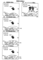
図1は、本発明の一実施形態としての遊技機1の正面図である。以下では、遊技機1の
左右方向を、遊技機1に対面する遊技者から見た左右方向に一致させて説明する。また、
遊技機1の前方向は、遊技機1から遊技者に向かう方向として説明し、遊技機1の後方向
は、遊技者から遊技機1に向かう方向として説明する。
<First Embodiment>
1. Structure of Gaming Machine FIG. 1 is a front view of a
The forward direction of the
遊技機1は、遊技者の発射操作に基づいて遊技球を発射させ、特定の入賞装置に遊技球
が入賞すると、その入賞に基づいて所定数の遊技球を遊技者に払い出すパチンコ遊技機で
ある。遊技機1は、遊技機枠50と、遊技盤2とを備え、遊技機枠50の内側に遊技盤2
が取り付けられている。遊技機枠50は、前枠(前枠部)53のほか、遊技機の外郭部を
形成する外枠(基枠部)と、外枠の内側において遊技盤2が取り付けられる内枠と、を備
えている。前枠(前枠部)53は、外枠および内枠の前方側に配置される縦長方形状のユ
ニットであり、ハンドル60と、打球供給皿(上皿)61と、余剰球受皿(下皿)62と
、演出ボタン63と、剣部材64と、剣ボタン65と、枠ランプ66と、スピーカ67と
、枠可動体600とを備えている。前枠53の中央には開口部が形成されており、開口部
を介して、遊技盤2の遊技領域3を視認することができる。
The
is installed. The
ハンドル60は、前枠53の右側の下端に配置され、回転角度に応じた発射強度で遊技
球を発射させる。打球供給皿(上皿)61は、前枠53の下方に設けられ、遊技球を貯留
する。余剰球受皿(下皿)62は、打球供給皿(上皿)61の下方に配置され、打球供給
皿61に収容しきれない遊技球を貯留する。演出ボタン63は、打球供給皿(上皿)61
の近傍に配置された操作部であり、遊技の進行に伴って実行される演出時などに遊技者に
よって操作(押圧)される。剣部材64は、剣の形を模した操作部であり、遊技の進行に
伴って実行される演出時等に遊技者が下方向に押し込むことができる。剣ボタン65は、
剣部材64の上端部分、すなわち、剣の柄の端部に設けられた操作部であり、遊技の進行
に伴って実行される演出時などに遊技者によって操作(押圧)される。剣部材64は、剣
部材64全体を下方に押し込む第1の操作と、先端の剣ボタン65を押圧する第2の操作
の異なる2つの操作を実行可能に構成されている。枠ランプ66は、前枠53の開口部周
辺に配置され、遊技中などに発光演出をおこなう。スピーカ67は、前枠53の左上方と
右上方に配置され、遊技中などに音演出をおこなう。枠可動体600は、前枠53の上部
に設けられた可動式のいわゆるギミックである。枠可動体600は、前枠53の内部に格
納されている格納状態から、前枠53の上方に突出する露出状態に変位可能に構成されて
いる。
The
, and is operated (pressed) by the player during effects that are executed as the game progresses. The
An operation unit provided at the upper end of the
遊技盤2は、遊技領域3と、レール部材4と、盤ランプ5と、画像表示装置7と、セン
ター装飾体10と、固定入賞装置(ヘソ)19と、普通可変入賞装置(電チュー)22と
、ゲート(スルーチャッカー)28と、第1大入賞装置(第1アタッカー)31と、第2
大入賞装置(第2アタッカー)36と、一般入賞口27(普通入賞口27)と、一般入賞
口29(普通入賞口29)、アウト口16と、表示器類40と、を備えている。
The
A big prize winning device (second attacker) 36, a general prize winning port 27 (ordinary prize winning port 27), a general prize winning port 29 (ordinary prize winning port 29), an
遊技領域3は、ハンドル60の操作によって発射された遊技球が流下する領域であり、
遊技球を誘導する複数の遊技釘が突設されている。レール部材4は、遊技領域3の左側端
部に配置され、ハンドル60の操作によって発射された遊技球を遊技領域3の上方に向け
て誘導する。盤ランプ5は、遊技領域3の背面側に配置され、遊技領域3の背面側から光
を照射する。
The
A plurality of game nails are protruded for guiding game balls. The
画像表示装置7は、遊技領域3の中央付近に設けられ、第1画像表示装置7Aと第2画
像表示装置7Bとを備えている。第1画像表示装置7Aは、表示画面7aを備えている。
第2画像表示装置7Bは、表示画面7bを備えている。画像表示装置7は、液晶表示装置
であってもよいし、有機EL表示装置、プラズマディスプレイ、プロジェクター、ドット
マトリクスなどの他の画像表示装置であってもよい。画像表示装置7の表示画面7a,7
bは、演出図柄(装飾図柄)8L、8C、8Rが可変表示(変動表示ともいう)される第
1演出図柄表示領域と、演出図柄(装飾図柄)8L、8C、8Rとは異なる他の装飾図柄
が変動表示される第2演出図柄表示領域と、保留画像9A、9Bが表示される保留画像表
示領域と、保留消化画像9Cが表示される保留消化画像表示領域と、を有している。保留
画像9A、9Bは、保留を表す画像であり、保留アイコン9A,9Bとも呼ぶ。保留消化
画像9Cは、当該保留を表す画像であり、当該保留画像9Cとも呼ぶ。第1保留アイコン
と第2保留アイコンとを総称して、単に保留アイコンとも呼ぶ。
The
The second image display device 7B has a display screen 7b. The
b is a first production pattern display area in which production patterns (decorative patterns) 8L, 8C, and 8R are variably displayed (also referred to as variable display), and other decorations different from the production patterns (decorative patterns) 8L, 8C, and 8R It has a second effect symbol display area in which symbols are variably displayed, a suspended image display area in which suspended
第1演出図柄表示領域は、「左」「中」「右」の3つの図柄表示エリアを含んでいる。
左の図柄表示エリアには左演出図柄(左装飾図柄)8Lが表示される。中の図柄表示エリ
アには中演出図柄(中装飾図柄)8Cが表示される。右の図柄表示エリアには右演出図柄
(右装飾図柄)8Rが表示される。演出図柄8L、8C、8Rは、例えば「1」~「9」
までの数字を表した複数の図柄によって構成されている。演出図柄8L、8C、8Rの変
動表示は、後述する第1特別図柄および第2特別図柄の変動表示と同期している。画像表
示装置7は、左、中、右の図柄表示エリアに表示する演出図柄の組み合わせによって、後
述の第1特別図柄表示器41aおよび第2特別図柄表示器41bによって表示される第1
特別図柄および第2特別図柄の可変表示の結果(大当たり抽選結果)を、遊技者にわかり
やすく表示することができる。
The first effect symbol display area includes three symbol display areas of "left", "middle" and "right".
A left effect pattern (left decorative pattern) 8L is displayed in the left pattern display area. A medium effect pattern (middle decorative pattern) 8C is displayed in the middle pattern display area. A right effect pattern (right decorative pattern) 8R is displayed in the right pattern display area.
It is composed of multiple patterns representing numbers up to. The variable display of the
The results of the variable display of the special symbols and the second special symbols (big hit lottery results) can be displayed in an easy-to-understand manner for the player.
例えば、大当たりに当選した場合には「777」などのゾロ目で演出図柄を停止表示す
る。はずれであった場合には「637」などのバラケ目で演出図柄を停止表示する。これ
により、遊技者による遊技の進行状況の把握が容易となる。遊技者は、大当たり抽選結果
を第1特別図柄表示器41aや第2特別図柄表示器41bのほか、画像表示装置7によっ
て把握することができる。なお、図柄表示エリアの位置は固定的でなくてもよい。また、
演出図柄の変動表示の態様としては、上下方向にスクロールする態様であってもよいしそ
れ以外の態様であってもよい。各抽選結果に応じてどのような演出図柄の組み合わせを停
止表示するかは上記に限定されず任意に設定することができる。以後、演出図柄8L、8
C、8Rを表示する演出を「演出図柄の変動演出」、「装飾図柄の変動演出」または、単
に「変動演出」とも呼ぶ。なお、この装飾図柄の変動演出は、特別図柄が変動開始してか
ら停止するまでの期間(特別図柄変動期間とも呼ぶ)における演出を1回の変動演出(1
サイクルの変動演出)としてカウントする。従って、特別図柄が変動開始してから停止す
るまでの期間に、装飾図柄を仮停止させる場合があったとしても、当該仮停止の演出は、
装飾図柄の変動演出に含まれる。
For example, when a jackpot is won, the production pattern is stopped and displayed with double numbers such as "777". In the case of a miss, the production pattern is stopped and displayed with a loose pattern such as "637". This makes it easier for the player to grasp the progress of the game. The player can grasp the jackpot lottery result by the
As a form of variable display of the production pattern, a form of scrolling in the vertical direction may be used, or another form may be used. It is not limited to the above, and can be arbitrarily set as to what combination of performance symbols to stop display according to each lottery result. After that,
The effect of displaying C and 8R is also called "variation effect of effect pattern", "variation effect of decorative symbol", or simply "variation effect". It should be noted that the variation effect of this decorative pattern is the effect in the period from the start of the special pattern to the stop (also called the special pattern fluctuation period).
count as a variable rendition of the cycle). Therefore, even if there is a case where the decorative design is temporarily stopped during the period from when the special design starts to change until it stops, the effect of the temporary stop is
Included in the variable production of decorative patterns.
また、第2演出図柄表示領域は、「左」「中」「右」の3つの図柄表示エリアを含んで
いる。左の図柄表示エリアには図示しない左演出図柄(左装飾図柄)が表示される。中の
図柄表示エリアには図示しない中演出図柄(中装飾図柄)が表示される。右の図柄表示エ
リアには図示しない右演出図柄(右装飾図柄)が表示される。第2演出図柄表示領域に表
示される演出図柄は、第1演出図柄表示領域に表示される演出図柄8L、8C、8Rと同
様の図柄となっており、装飾図柄8L、8C、8Rよりも小さく表示される。
Also, the second effect symbol display area includes three symbol display areas of "left", "middle" and "right". A left effect pattern (left decorative pattern) (not shown) is displayed in the left pattern display area. A medium effect pattern (middle decorative pattern) (not shown) is displayed in the middle pattern display area. A right performance pattern (right decorative pattern) (not shown) is displayed in the right pattern display area. The performance designs displayed in the second performance design display area are the same designs as the performance designs 8L, 8C and 8R displayed in the first performance design display area, and are smaller than the
画像表示装置7は、演出図柄変動演出のほか、大当たり遊技(特別遊技の一例)に並行
しておこなわれる大当たり演出や、客待ち用のデモ演出などを表示画面7a,7bに表示
することができる。演出図柄変動演出では、演出図柄のほか、背景画像やキャラクタ画像
などの演出画像も表示されてもよい。また、画像表示装置7は、演出図柄に加え、特別図
柄が変動中であることを示唆したり、特別図柄の抽選結果を示唆したりすることが可能な
識別表示(第四図柄、図示省略)を、表示画面7aに表示してもよい。なお、識別表示(
第四図柄)は、遊技領域3に設けられたLEDなどの発光器によって表示させてもよい。
The
The fourth symbol) may be displayed by a light emitting device such as an LED provided in the
保留画像表示領域は、後述の第1特図保留の記憶数に応じて保留画像9Aを表示する第
1保留表示エリアと、後述の第2特図保留の記憶数に応じて保留画像9Bを表示する第2
保留表示エリアとを含んでいる。保留画像9A、9Bの表示によって、後述の第1特図保
留表示器43aに表示される第1特図保留の記憶数と、第2特図保留表示器43bに表示
される第2特図保留の記憶数を、遊技者にわかりやすく表示することができる。保留消化
画像表示領域は、保留消化画像9Cを表示する保留消化表示エリアを含んでいる。保留消
化画像9Cは、表示画面7aまたは表示画面7bで現在変動中の演出図柄(演出図柄8L
、8C、8R)に対応しており、保留消化画像9Cの表示によって、第1特図保留または
第2特図保留が消化(後述の「特図保留の消化」)されることを、遊技者にわかりやすく
表示することができる。
The reserved image display area is a first reserved display area that displays a
and a reserved display area. By the display of the pending
, 8C, 8R), and the display of the pending
画像表示装置7の左右両側には、可動式のいわゆるギミックである第1盤可動体14(
第1可動役物14とも呼ぶ)が設けられている。第1可動役物14は、透過性を有する左
側板部材14Lと、透過性を有する右側板部材14Rを含んで構成されており。左側板部
材14Lと右側板部材14Rは、それぞれ左右に移動可能あり、後述するように、画像表
示装置7の全体を覆う閉状態と、画像表示装置7の中心部分を覆わない開状態とに遷移可
能に構成されている。
On both left and right sides of the
Also called a first movable accessory 14) is provided. The first
センター装飾体10は、遊技領域3の中央付近であって、画像表示装置7の前方に配置
されている。センター装飾体10には、可動式のいわゆるギミックである第2盤可動体1
5(第2可動役物15とも呼ぶ)が取り付けられている。センター装飾体10の下部には
、ステージ部11が形成されている。ステージ部11は、ステージ部11の上面を転動す
る遊技球を後述の第1始動口20へと誘導可能な形状を有している。センター装飾体10
の左下方には、ワープ部12が設けられている。ワープ部12は、遊技球が流入する入口
部と遊技球が流出する出口部とを備え、入口部から流入した遊技球を出口部からステージ
部11に流出させる。
The center
5 (also referred to as a second movable accessory 15) is attached. A
A
固定入賞装置(ヘソ)19は、遊技領域3における画像表示装置7の下方に配置され、
遊技球の入球し易さが常に変わらない第1始動口(第1始動入賞口、第1入球口、固定始
動口)20を備えている。第1始動口20への遊技球の入賞は、第1特別図柄の抽選(大
当たり抽選)の契機となっている。言い換えれば、第1始動口20への遊技球の入賞は、
大当たり乱数等の取得および大当たり判定等の契機となっている。
A fixed winning device (navel) 19 is arranged below the
A first start hole (first start winning hole, first ball entry hole, fixed start hole) 20 is provided so that the ease with which a game ball can enter is always the same. Winning of the game ball to the first starting port 20 triggers a first special symbol lottery (jackpot lottery). In other words, the winning of the game ball to the first start port 20,
It is a trigger for the acquisition of jackpot random numbers and the like and jackpot determination.
普通可変入賞装置(電チュー)22は、遊技領域3における第1始動口20の下方に配
置され、第2始動口(第2始動入賞口、第2入球口、可変始動口)21を備えている。第
2始動口21への遊技球の入賞は、第2特別図柄の抽選(大当たり抽選)の契機となって
いる。電チュー22は、第2始動口21の前方に可動部材23を備えており、可動部材2
3の作動によって第2始動口21を開閉する。可動部材23は、電チューソレノイド24
(図3)によって駆動される。第2始動口21は、可動部材23が開状態のとき遊技球が
入球可能である。なお、電チュー22は、可動部材23が開状態のときの方が閉状態のと
きよりも第2始動口21への入球が容易であればよく、閉状態のときに第2始動口21へ
の入球が可能であってもよい。
A normal variable winning device (electric chew) 22 is arranged below the first starting port 20 in the
3 opens and closes the
(FIG. 3). A game ball can enter the
ゲート(スルーチャッカー)28は、遊技領域3における第1大入賞装置(第1アタッ
カー)31の上方に配置されており、遊技球が通過可能に構成されている。ゲート28へ
の遊技球の通過は、電チュー22を開放するか否かを決定する普通図柄抽選の契機となっ
ている。言い換えれば、ゲート28への遊技球の通過は、普通図柄乱数(当たり乱数)の
取得および当たり判定等の契機となっている。
The gate (through chucker) 28 is arranged above the first big winning device (first attacker) 31 in the
ここで、「特別図柄の抽選」とは、第1始動口20または第2始動口21に遊技球が入
賞したときに、特別図柄判定用の乱数を取得し、この取得した乱数を予め定められた「大
当たり」に対応する値と比較することにより、大当たりか否かを判定する処理をいう。こ
の「大当たり」の抽選結果は即座に遊技者に報知されるわけではなく、後述の第1特別図
柄表示器41aまたは第2特別図柄表示器41bにおいて特別図柄の変動表示がおこなわ
れ、所定の変動時間を経過したところで、抽選結果に対応する特別図柄が停止表示(確定
表示)され、遊技者に抽選結果が報知される。画像表示装置7では、特別図柄の変動表示
と同期して演出図柄を変動表示する図柄合わせゲームが行われ、この図柄合わせゲームに
よって、より効果的に大当りの抽選結果が遊技者に報知される。
Here, the "lottery of special symbols" means that when a game ball wins in the first start port 20 or the
また、「普通図柄の抽選」とは、ゲート28を遊技球が通過したときに、普通図柄判定
用の乱数を取得し、この取得した乱数を予め定められた「当り」に対応する値と比較する
ことにより、当りか否かを判定する処理をいう。この普通図柄の抽選結果についても、ゲ
ート28を遊技球が通過して即座に抽選結果が報知されるわけではなく、後述の普通図柄
表示器42において普通図柄の変動表示がおこなわれ、所定の変動時間を経過したところ
で、抽選結果に対応する普通図柄が確定表示(点灯または消灯)され、遊技者に抽選結果
が報知される。
In addition, the "lottery of normal symbols" means that when a game ball passes through the
第1大入賞装置(第1アタッカー、第1特別可変入賞装置)31は、遊技領域3におけ
る第1始動口20の右上方に配置され、第1大入賞口(第1特別入賞口)30と、V領域
39と、非V領域70と、V開閉部材71とを備えている。第1大入賞口30は、スイン
グ式の開閉動作により遊技球の受け入れを許容または阻害する開閉部材(第1特別入賞口
開閉部材)32を備えている。開閉部材32は、第1大入賞口ソレノイド33(図3)に
よって駆動される。第1大入賞口30は、開閉部材32が開状態のとき遊技球が入球可能
となる。
The first big winning device (first attacker, first special variable winning device) 31 is arranged above the first starting port 20 in the
第1大入賞装置31は内部に、V領域(特定領域)39と、V領域センサ39a(図3
)と、非V領域(非特定領域)70と、非V領域センサ70a(図3)と、第1大入賞口
センサ30a(図3)と、V開閉部材71と、V開閉部材ソレノイド73(図3)と、を
備えている。V領域(特定領域)39および非V領域(非特定領域)70は、第1大入賞
装置31の内部において、第1大入賞口30を通過した遊技球が通過可能な領域として構
成されている。第1大入賞口センサ30aは、V領域39および非V領域70の上流に配
置され、第1大入賞口30への遊技球の入賞を検知する。V領域センサ39aは、V領域
39に配置され、V領域39への遊技球の通過を検知する。非V領域センサ70aは、非
V領域70に配置され、非V領域70への遊技球の通過を検知する。V開閉部材71は、
第1大入賞口30を通過した遊技球をV領域39または非V領域70のいずれかに振り分
ける。V開閉部材ソレノイド73は、V開閉部材71を駆動する。V開閉部材71は、回
転移動(遊技盤2に対して時計回りおよび反時計回り)するように構成され、V開閉部材
ソレノイド73の通電時には、原点位置から反時計回りに回転して遊技球をV領域39に
振り分ける第1の状態(回動状態)となり、V開閉部材ソレノイド73の非通電時には、
原点に位置して遊技球を非V領域70に振り分ける第2の状態(停止状態)となる。なお
、V開閉部材71は、回転移動に限らず、第1大入賞口30を通過した遊技球をV領域3
9または非V領域70のいずれかに振り分ける機能を有しておればよく、例えば、遊技盤
2に対して左右方向に移動するように構成してもよい。すなわち、V開閉部材ソレノイド
73の通電時には、遊技球をV領域39に振り分ける退避状態(第1の状態)となり、V
開閉部材ソレノイド73の非通電時には、遊技球を非V領域70に振り分ける進出状態(
第2の状態)となるように構成してもよい。なお、遊技機1では、V領域39への遊技球
の通過が後述の高確率状態への移行の契機となっている。つまり、V領域39は、確変作
動口となっている。一方、非V領域70は、確変作動口となっていない。本実施形態の第
1大入賞装置31は、さらに、第1大入賞装置31から排出される遊技球数を計数する第
1大入賞装置排出センサ(図示しない)を備えている。第1大入賞装置排出センサは、V
領域39と非V領域70が下流で合流した地点に設けられており、V領域センサ39aま
たは非V領域センサ70aを通過した遊技球数を計数する。
The first big
), a non-V area (non-specific area) 70, a non-V area sensor 70a (FIG. 3), a first prize winning opening sensor 30a (FIG. 3), a V opening/closing
The game balls passing through the first big winning
It becomes the second state (stop state) in which the game balls are distributed to the
9 or the
When the opening/closing
second state). In the
It is provided at a point where the
第2大入賞装置(第2アタッカー、第2特別可変入賞装置)36は、遊技領域3におけ
る第1大入賞口30の右上方に配置され、第2大入賞口(第2特別入賞口)35を備えて
いる。第2大入賞口35は、スイング式の開閉動作により遊技球の受け入れを阻害または
許容する開閉部材(第2特別入賞口開閉部材、可動部材)37を備えている。開閉部材3
7は、第2大入賞口ソレノイド38(図3)によって駆動される。第2大入賞口35は、
開閉部材37が開状態のとき遊技球が入球可能となる。
The second big winning device (second attacker, second special variable winning device) 36 is arranged above the first big winning
7 is driven by the second big winning opening solenoid 38 (Fig. 3). The second
A game ball can enter when the opening/closing
一般入賞口27は、遊技領域3の下部に設けられている。アウト口16は、遊技領域3
の下部に設けられており、いずれの入賞口にも入賞しなかった遊技球を遊技領域3の外へ
排出する。表示器類40は、遊技盤2の右側中央付近に配置されている。表示器類40の
詳細については後述する。
一般入賞口29は、遊技領域3の右下部であって、第1大入賞口30の右側に隣接して
配置されている。
The general winning
, and discharges out of the
The general winning opening 29 is arranged in the lower right part of the
遊技領域3には、左右方向の中央より左側の左遊技領域3Aと、右側の右遊技領域3B
とがある。左遊技領域3Aを遊技球が流下するように遊技球を発射する打ち方を「左打ち
」と呼ぶ。一方、右遊技領域3Bを遊技球が流下するように遊技球を発射する打ち方を「
右打ち」と呼ぶ。遊技機1では、左打ちにて第1始動口20への入賞を狙うことができる
。一方、右打ちにてゲート28への通過、第2始動口21、第1大入賞口30、および、
第2大入賞口35への入賞が狙うことができるように構成されている。
The
There is. A hitting method of shooting a game ball so that the game ball flows down the
It's called right-handed. In the
It is configured so that the player can aim to win a prize in the second
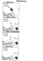
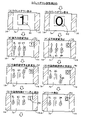
図2は、表示器類40の拡大図である。表示器類40は、第1特別図柄表示器41aと
、第2特別図柄表示器41bと、普通図柄表示器42と、第1特図保留表示器43aと、
第2特図保留表示器43bと、普図保留表示器44と、を含んでいる。第1特別図柄表示
器41aは、第1特別図柄を可変表示する。第2特別図柄表示器41bは、第2特別図柄
を可変表示する。普通図柄表示器42は、普通図柄を可変表示する。第1特図保留表示器
43aは、第1特別図柄表示器41aの作動保留(第1特図保留)の記憶数を表示する。
第2特図保留表示器43bは、第2特別図柄表示器41bの作動保留(第2特図保留)の
記憶数を表示する。普図保留表示器44は、普通図柄表示器42の作動保留(普図保留)
の記憶数を表示する。第1特別図柄の可変表示は、第1始動口20への遊技球の入賞を契
機としておこなわれる。第2特別図柄の可変表示は、第2始動口21への遊技球の入賞を
契機としておこなわれる。以下では、第1特別図柄および第2特別図柄を総称して「特別
図柄」とも呼ぶ。また、第1特別図柄表示器41aおよび第2特別図柄表示器41bを総
称して「特別図柄表示器41」とも呼ぶ。また、第1特図保留表示器43aおよび第2特
図保留表示器43bを総称して「特図保留表示器43」とも呼ぶ。
FIG. 2 is an enlarged view of the
The 2nd special
The 2nd special
display the number of memories of The variable display of the first special symbol is triggered by the winning of the game ball to the first starting port 20. - 特許庁The variable display of the second special symbol is performed with the winning of the game ball to the
特別図柄表示器41は、特別図柄(識別情報)を可変表示(変動表示)した後、停止表
示することによって第1始動口20または第2始動口21への入賞に基づく抽選(特別図
柄当たり抽選、大当たり抽選)の結果を報知する。停止表示される特別図柄(停止図柄、
可変表示の表示結果として導出表示される特別図柄)は、特別図柄抽選によって複数種類
の特別図柄の中から選択された一つの特別図柄である。停止図柄が予め定めた大当たり停
止態様の特別図柄(大当たり図柄)である場合には、停止表示された大当たり図柄の種類
(当選した大当たりの種類)に応じた開放パターンにて第1大入賞口30または第2大入
賞口35を開放させる特別遊技(大当たり遊技)がおこなわれる。なお、特別遊技におけ
る大入賞口(第1大入賞口30および第2大入賞口35)の開放パターンについては後述
する。
The special symbol display device 41 variably displays (variable display) the special symbol (identification information), and then displays it in a stopped state, so that a lottery (lottery per special symbol) based on winning the first start port 20 or the
The special symbol derived and displayed as a display result of variable display) is one special symbol selected from a plurality of types of special symbols by a special symbol lottery. When the stop pattern is a special pattern (jackpot pattern) of a predetermined jackpot stop mode, the first big
特別図柄表示器41は、横並びに配された8個のLEDから構成されており、その点灯
態様によって特別図柄当たり抽選の結果に応じた特別図柄を表示する。例えば、大当たり
(後述の複数種類の大当たりのうちの一つ)に当選した場合には、「○○●●○○●●」
(○:点灯、●:消灯)というように左から1,2,5,6番目にあるLEDが点灯した
大当たり図柄を表示する。ハズレである場合には、「●●●●●●●○」というように一
番右にあるLEDのみが点灯したハズレ図柄を表示する。ハズレ図柄として全てのLED
を消灯させる態様を採用してもよい。特別図柄が停止表示される前には、所定の変動時間
にわたって特別図柄の変動表示(可変表示)がなされる。変動表示の態様は、例えば、左
から右へ光が繰り返し流れるように各LEDが点灯してもよい。変動表示の態様は、各L
EDが停止表示(特定の態様での点灯表示)されていなければ、上記態様に限定されず、
任意の点灯態様とすることができる。例えば、変動表示の態様は、全LEDが一斉に点滅
してもよい。
The special symbol display device 41 is composed of eight LEDs arranged side by side, and displays a special symbol according to the result of the special symbol winning lottery according to the lighting mode thereof. For example, if you win a jackpot (one of the multiple types of jackpots described later), "○○●●○○●●"
(○: lights up, ●: lights out). If the game is lost, a lost pattern is displayed in which only the rightmost LED lights up, such as "●●●●●●●○". All LEDs as a missing pattern
may be turned off. Before the special symbols are stopped and displayed, the special symbols are variably displayed (variably displayed) for a predetermined variation time. As for the aspect of the variable display, for example, each LED may light so that the light repeatedly flows from left to right. The mode of variable display is each L
Unless the ED is stopped (lighting display in a specific mode), it is not limited to the above mode,
Any lighting mode can be used. For example, all LEDs may blink simultaneously in the variable display mode.
遊技機1では、第1始動口20または第2始動口21への遊技球の入賞(入球)がある
と、その入賞に対して取得した大当たり乱数等の各種乱数の値(数値情報)は、特図保留
記憶領域85(図5)に一旦記憶される。具体的には、第1始動口20への入賞であれば
、第1特図保留として第1特図保留記憶領域85a(図5)に記憶され、第2始動口21
への入賞であれば、第2特図保留として第2特図保留記憶領域85b(図5)に記憶され
る。各々の特図保留記憶領域85に記憶可能な特図保留の数には上限があり、本実施形態
における上限値は、第1特図保留記憶領域85a、第2特図保留記憶領域85bともにそ
れぞれ4個となっている。特図保留記憶領域85に記憶された特図保留は、その特図保留
に基づく特別図柄の可変表示が可能となったときに消化される。「特図保留の消化」とは
、その特図保留に対応する大当たり乱数等を判定して、その判定結果を示すための特別図
柄の可変表示を実行することをいう。従って、遊技機1では、第1始動口20または第2
始動口21への遊技球の入賞に基づく特別図柄の可変表示がその入賞後にすぐにおこなえ
ない場合、すなわち、特別図柄の可変表示の実行中や特別遊技の実行中に入賞があった場
合であっても、所定個数を上限として、その入賞に対する大当たり抽選の権利を留保する
ことができる。特図保留の数は、特図保留表示器43に表示される。第1特図保留表示器
43aと第2特図保留表示器43bは、例えばそれぞれ4個のLEDで構成されている。
各特図保留表示器43は、特図保留の数だけLEDを点灯させることによって特図保留の
数を表示する。
In the
If it is a winning prize, it is stored in the second special figure reservation storage area 85b (FIG. 5) as a second special figure reservation. There is an upper limit to the number of special figure reservations that can be stored in each special figure
When the variable display of the special symbols based on the winning of the game ball to the starting
Each special figure reservation indicator 43 displays the number of special figure reservations by turning on LEDs corresponding to the number of special figure reservations.
普通図柄の可変表示は、ゲート28への遊技球の通過を契機としておこなわれる。普通
図柄表示器42は、普通図柄を可変表示(変動表示)した後、停止表示することによって
ゲート28への遊技球の通過に基づく普通図柄抽選の結果を報知する。停止表示される普
通図柄(普図停止図柄、可変表示の表示結果として導出表示される普通図柄)は、普通図
柄抽選によって複数種類の普通図柄の中から選択された一つの普通図柄である。普図停止
図柄が予め定めた特定普通図柄(所定の停止態様の普通図柄すなわち普通当たり図柄)で
ある場合には、現在の遊技状態に応じた開放パターンに第2始動口21を開放させる補助
遊技が行われる。なお、第2始動口21の開放パターンについては後述する。
The variable display of normal symbols is performed when the game ball passes through the
普通図柄表示器42は、2個のLEDから構成されており、その点灯態様によって普通
図柄抽選の結果に応じた普通図柄を表示するものである。例えば、抽選結果が当たりであ
る場合には、「○○」(○:点灯、●:消灯)というように両LEDが点灯した普通当た
り図柄を表示する。抽選結果がハズレである場合には、「●○」というように右のLED
のみが点灯した普通ハズレ図柄を表示する。普通ハズレ図柄として全てのLEDを消灯さ
せる態様を採用してもよい。普通図柄が停止表示される前には、所定の変動時間にわたっ
て普通図柄の変動表示がなされる。変動表示の態様は、例えば、両LEDが交互に点灯し
てもよい。変動表示の態様は、各LEDが停止表示(特定の態様での点灯表示)されてい
なければ、上記態様に限定されず、任意の点灯態様とすることができる。例えば、変動表
示の態様は、全LEDが一斉に点滅してもよい。
The normal
Displays a normal losing pattern with only lit. A mode in which all the LEDs are extinguished may be employed as a normal losing pattern. Before the normal symbols are stop-displayed, the normal symbols are varied and displayed for a predetermined variation time. As for the aspect of the variable display, for example, both LEDs may alternately light up. The mode of the variable display is not limited to the above mode, and can be any lighting mode, as long as each LED is not stopped (lighting display in a specific mode). For example, all LEDs may blink simultaneously in the variable display mode.
遊技機1では、ゲート28への遊技球の通過があると、その通過に対して取得した普通
図柄乱数(当たり乱数)の値は、普図保留記憶領域86(図5)に普図保留として一旦記
憶される。普図保留記憶領域86に記憶可能な普図保留の数には上限があり、本形態にお
ける上限値は4個となっている。普図保留記憶領域86に記憶された普図保留は、その普
図保留に基づく普通図柄の可変表示が可能となったときに消化される。普図保留の消化と
は、その普図保留に対応する普通図柄乱数(当たり乱数)を判定して、その判定結果を示
すための普通図柄の可変表示を実行することをいう。従って、遊技機1では、ゲート28
への遊技球の通過に基づく普通図柄の可変表示がその通過後にすぐにおこなえない場合、
すなわち、普通図柄の可変表示の実行中や補助遊技の実行中に入賞があった場合であって
も、所定個数を上限として、その通過に対する普通図柄抽選の権利を留保することができ
る。普図保留の数は、普図保留表示器44に表示される。普図保留表示器44は、例えば
、4個のLEDで構成されており、普図保留の数だけLEDを点灯させることによって普
図保留の数を表示する。
In the
If the variable display of normal symbols based on the passage of the game ball into the game ball cannot be performed immediately after its passage,
That is, even if there is a prize during the execution of the variable display of the normal symbols or during the execution of the auxiliary game, it is possible to reserve the right of the normal symbol lottery for the passage, with a predetermined number as the upper limit. The number of normal map reservations is displayed on the normal
2.遊技機の電気的構成
図3、図4に基づいて、遊技機1の電気的構成について説明する。図3は、遊技機1の
主制御基板側の電気的な構成を示すブロック図である。図4は、遊技機1のサブ制御基板
側の電気的な構成を示すブロック図である。遊技機1は、主制御基板80(図3)と、サ
ブ制御基板90(図4)と、画像制御基板100(図4)と、ランプ制御基板107(図
4)と、音声制御基板106(図4)と、払出制御基板110(図3)と、を備えている
。主制御基板80は、大当たり抽選や遊技状態の移行などの遊技利益に関する制御をおこ
なう遊技制御基板であり、メイン制御部を構成する。サブ制御基板90は、遊技の進行に
伴って実行する演出に関する制御をおこなう演出制御基板であり、画像制御基板100、
ランプ制御基板107、音声制御基板106とともにサブ制御部を構成する。なお、サブ
制御部は、少なくともサブ制御基板90を備えていれば構成可能である。
2. Electrical Configuration of Gaming Machine The electrical configuration of the
Together with the
主制御基板80は、遊技制御用マイコン81と、入出力回路87と、を備えている。遊
技制御用マイコン81は、主制御基板80に実装されているワンチップマイコンであり、
プログラムに従って遊技機1の遊技の進行を制御する。遊技制御用マイコン81は、遊技
の進行を制御するためのプログラムなどを記憶するメインROM83と、ワークメモリと
して使用されるメインRAM84と、メインROM83に記憶されているプログラムを実
行するメインCPU82と、を含んでいる。メインROM83に記憶されているデータの
詳細、および、メインRAM84に設けられている記憶領域の詳細については後述する。
メインROM83は外付けROMとして構成されていてもよい。遊技制御用マイコン81
は、入出力回路(I/Oポート部)87を介して他の基板等とデータの送受信をおこなう
。入出力回路87は、遊技制御用マイコン81に内蔵されていてもよい。
The
The game progress of the
The
, transmits and receives data to and from other boards or the like via an input/output circuit (I/O port section) 87 . The input/
主制御基板80には、入出力回路87および中継基板88を介して各種センサやソレノ
イドが接続されている。主制御基板80は、各センサから出力された信号が入力するとと
もに、各ソレノイドに対して信号を出力する。中継基板88を介して接続されるセンサ類
としては、第1始動口センサ20a、第2始動口センサ21a、ゲートセンサ28a、第
1大入賞口センサ30a、第2大入賞口センサ35a、V領域センサ39a、非V領域セ
ンサ70a、および、普通入賞口センサ27a、29aが例示される。中継基板88を介
して接続されるソレノイド類としては、電チューソレノイド24、第1大入賞口ソレノイ
ド33、第2大入賞口ソレノイド38、および、V開閉部材ソレノイド73が例示される
。第1始動口センサ20aは、第1始動口20の内部に設けられ、第1始動口20に入賞
した遊技球を検出する。第2始動口センサ21aは、第2始動口21の内部に設けられ、
第2始動口21に入賞した遊技球を検出する。ゲートセンサ28aは、ゲート28の内部
に設けられ、ゲート28を通過した遊技球を検出する。第1大入賞口センサ30aは、第
1大入賞口30の内部に設けられ、第1大入賞口30に入賞した遊技球を検出する。第2
大入賞口センサ35aは、第2大入賞口35の内部に設けられ、第2大入賞口35に入賞
した遊技球を検出する。V領域センサ39aは、第1大入賞口30の内部のV領域39に
設けられ、V領域39を通過した遊技球を検出する。非V領域センサ70aは、第1大入
賞口30の内部の非V領域70に設けられ、非V領域70を通過した遊技球を検出する。
普通入賞口センサ27aは、普通入賞口27の内部に設けられ、普通入賞口27に入賞し
た遊技球を検出する。普通入賞口センサ29aは、普通入賞口29の内部に通過した遊技
球を検出する。電チューソレノイド24は、電チュー22の可動部材23を駆動する。第
1大入賞口ソレノイド33は、第1大入賞装置31の開閉部材32を駆動する。第2大入
賞口ソレノイド38は、第2大入賞装置36の開閉部材37を駆動する。V開閉部材ソレ
ノイド73は、第1大入賞装置31のV開閉部材71を駆動する。
Various sensors and solenoids are connected to the
A game ball that has entered the
The big winning hole sensor 35 a is provided inside the second big winning
The normal
主制御基板80には、入出力回路87を介して表示器類40が接続されている。遊技制
御用マイコン81は、第1特別図柄表示器41a、第2特別図柄表示器41b、普通図柄
表示器42、第1特図保留表示器43a、第2特図保留表示器43b、普図保留表示器4
4についての表示制御おこなう。
The
Display control for 4 is performed.
主制御基板80には、入出力回路87を介して払出制御基板110が接続されている。
主制御基板80は、払出制御基板110に各種コマンドを送信するとともに、払い出し監
視のために払出制御基板110から信号を受信する。払出制御基板110には、賞球払出
装置120と、貸球払出装置130と、カードユニット135と、が接続され、発射制御
回路111を介して発射装置112が接続されている。賞球払出装置120は、賞球の払
い出しをおこなう。払出制御基板110は、遊技制御用マイコン81からの信号に基づい
て、賞球払出装置120の賞球モータ121を駆動して賞球の払い出しをおこなう。払い
出される賞球は、計数のために賞球センサ122によって検知される。貸球払出装置13
0は、貸球の払い出しをおこなう。払出制御基板110は、遊技機1に接続されたカード
ユニット135からの信号に基づいて、貸球払出装置130の貸球モータ131を駆動し
て貸球の払い出しをおこなう。払い出される貸球は、計数のために貸球センサ132によ
って検知される。カードユニット135は、遊技機1に隣接して配置され、挿入されたプ
リペイドカードなどの情報に基づいて球貸に関する情報を出力する。発射装置112は、
ハンドル60(図1)と、発射モータ113と、タッチスイッチ114と、発射ボリュー
ム115と、を備えている。発射装置112は、遊技者によるハンドル60の操作があっ
た場合に、タッチスイッチ114によってハンドル60の接触を検知し、発射ボリューム
115によってハンドル60の回転量を検知する。そして、発射ボリューム115の検知
信号の大きさに応じた強さで遊技球が発射されるように発射モータ113を駆動する。
A
The
0 pays out the rental balls. The
It comprises a handle 60 (FIG. 1), a firing
主制御基板80には、入出力回路87を介してサブ制御基板90(図4)が接続されて
いる。主制御基板80は、サブ制御基板90に対して各種コマンドを送信する。主制御基
板80とサブ制御基板90との接続は、主制御基板80からサブ制御基板90への信号の
送信のみが可能な単方向通信接続となっている。すなわち、主制御基板80とサブ制御基
板90との間には、通信方向規制手段としての図示しない単方向性回路(例えばダイオー
ドを用いた回路)が介在している。
A sub control board 90 ( FIG. 4 ) is connected to the
サブ制御基板90は、演出制御用マイコン91と、入出力回路95と、を備えている。
演出制御用マイコン91は、サブ制御基板90に実装されているワンチップマイコンであ
り、プログラムに従って遊技機1の遊技の演出を制御する。演出制御用マイコン91は、
遊技の進行に伴って演出を制御するためのプログラム等を記憶するサブROM93と、ワ
ークメモリとして使用されるサブRAM94と、サブROM93に記憶されているプログ
ラムを実行するサブCPU92と、を含んでいる。サブROM93に記憶されているデー
タの詳細、および、サブRAM94に設けられている記憶領域の詳細については後述する
。サブROM93は外付けROMとして構成されていてもよい。演出制御用マイコン91
は、入出力回路(I/Oポート部)95を介して他の基板等とデータの送受信をおこなう
。入出力回路95は、演出制御用マイコン91に内蔵されていてもよい。サブ制御基板9
0には、入出力回路95を介して、画像制御基板100と、音声制御基板106と、ラン
プ制御基板107と、中継基板108と、が接続されている。
The
The
It includes a sub-ROM 93 that stores programs and the like for controlling effects as the game progresses, a sub-RAM 94 that is used as a work memory, and a sub-CPU 92 that executes the programs stored in the sub-ROM 93. . Details of the data stored in the sub-ROM 93 and details of the storage areas provided in the sub-RAM 94 will be described later. The
transmits/receives data to/from another board or the like via an input/output circuit (I/O port section) 95 . The input/
0 is connected to the
画像制御基板100は、画像制御用マイコン101と、入力回路105aと、出力回路
105bとを備えている。画像制御用マイコン101は、画像制御基板100に実装され
ているワンチップマイコンであり、プログラムに従って画像表示装置7(第1画像表示装
置7Aおよび第2画像表示装置7B)の表示制御をおこなう。画像制御用マイコン101
は、CPU102と、ROM103と、RAM104とを含んでいる。ROM103には
、表示制御をおこなうためのプログラムのほか、画像表示装置7に表示される静止画デー
タや動画データ、具体的には、キャラクタ、アイテム、図形、文字、数字および記号等(
演出図柄を含む)や背景画像等の画像データが格納されている。RAM104は、画像デ
ータを展開するためのメモリとして使用される。CPU102は、ROM103に記憶さ
れているプログラムを実行する。演出制御用マイコン91は、主制御基板80から受信し
たコマンドに基づいて、画像制御用マイコン101に画像表示装置7の表示制御をおこな
わせる。画像制御用マイコン101は、演出制御用マイコン91からの指令に基づいてR
OM103から画像データを読み出し、読み出した画像データに基づいて表示制御をおこ
なう。
The
includes a
(including effect patterns) and image data such as background images are stored. A
Image data is read from the
音声制御基板106には、スピーカ67が接続されており、演出制御用マイコン91は
、主制御基板80から受信したコマンドに基づいて、音声制御基板106を介してスピー
カ67から音声、楽曲、効果音等を出力させる。スピーカ67から出力する音声等の音響
データは、サブ制御基板90のサブROM93に格納されている。なお、音声制御基板1
06は、CPUを実装していてもよく、そのCPUにコマンドに基づく音声制御を実行さ
せてもよい。さらに、音声制御基板106は、ROMを実装してもよく、そのROMに音
響データを格納してもよい。また、スピーカ67を画像制御基板100に接続し、画像制
御基板100のCPU102に音声制御を実行させてもよい。さらに、画像制御基板10
0のROM103に音響データを格納してもよい。
A
06 may be implemented with a CPU, and may cause the CPU to execute voice control based on commands. Furthermore, the
The sound data may be stored in the
ランプ制御基板107には、枠ランプ66と、盤ランプ5と、第1可動役物14と、第
2可動役物15と、が接続されており、これらを制御する。演出制御用マイコン91は、
主制御基板80から受信したコマンドに基づいて、ランプ制御基板107を介して枠ラン
プ66や盤ランプ5等のランプの点灯制御をおこなう。つまり、演出制御用マイコン91
は、枠ランプ66や盤ランプ5等のランプの発光態様を決める発光パターンデータ(点灯
/消灯や発光色等を決めるデータ、ランプデータともいう)を作成し、発光パターンデー
タに従って枠ランプ66や盤ランプ5などのランプの発光を制御する。発光パターンデー
タの作成にはサブ制御基板90のサブROM93に格納されているデータが用いられる。
演出制御用マイコン91は、主制御基板80から受信したコマンドに基づいて、第1可動
役物14および第2可動役物15を動作させる。第1可動役物14は、画像表示装置7の
左右両側に設けられた可動式のいわゆるギミックである。第2可動役物15は、センター
装飾体10に設けられた可動式のいわゆるギミックである。演出制御用マイコン91は、
第1可動役物14および第2可動役物15のそれぞれの動作態様を決める動作パターンデ
ータ(駆動データ)を作成し、動作パターンデータに従って第1可動役物14および第2
可動役物15の動作を制御する。動作パターンデータの作成にはサブROM93に格納さ
れているデータを用いる。なお、ランプ制御基板107は、CPUを実装していてもよく
、そのCPUにコマンドに基づくランプの点灯制御や可動役物14、15の動作制御を実
行させてもよい。この場合、ランプ制御基板107はROMを実装してもよく、そのRO
Mに発光パターンや動作パターンに関するデータを格納してもよい。
The
Based on the command received from the
is light emission pattern data (lighting
(also called lamp data) is created, and the light emission of lamps such as the
The
Operation pattern data (driving data) that determine the respective operation modes of the first
It controls the operation of the
Data related to light emission patterns and operation patterns may be stored in M.
中継基板108には、演出ボタン検出スイッチ63aと、枠可動体600と、が接続さ
れている。演出ボタン検出スイッチ63aは、演出ボタン63(図1)が押下操作された
ことを検出する。演出ボタン63が押下されると、演出ボタン検出スイッチ63aから、
中継基板108を介してサブ制御基板90にスイッチ信号が出力される。演出制御用マイ
コン91は、主制御基板80から受信したコマンドに基づいて、枠可動体600を動作さ
せる。枠可動体600は、前枠53(図1)の上部に設けられた可動式のいわゆるギミッ
クである。演出制御用マイコン91は、枠可動体600の動作態様を決める動作パターン
データ(駆動データ)を作成し、動作パターンデータに従って枠可動体600の動作を制
御する。動作パターンデータの作成にはサブROM93に格納されているデータを用いる
。なお、中継基板108には、セレクトボタン68(図1)が押下操作されたことを検出
するセレクトボタン検出スイッチや、前枠53に設けられ、人体が接触すると検出信号を
出力するタッチセンサなどが接続されていてもよい。
An effect button detection switch 63 a and a frame
A switch signal is output to the
3.遊技機のデータ構成
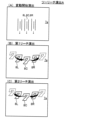
図5、図6に基づいて、遊技機1のデータ構成について説明する。図5(A)は、メイ
ンROM83に記憶されているテーブルを説明するための図である。図5(B)は、メイ
ンRAM84に設けられている記憶領域を説明するための図である。図6(A)は、サブ
ROM93に記憶されているテーブルを説明するための図である。図6(B)は、サブR
AM94に設けられている記憶領域を説明するための図である。
3. Data Configuration of Gaming Machine The data configuration of the
FIG. 10 is a diagram for explaining storage areas provided in the
メインROM83(図5(A))には、大当たり判定テーブルT1と、リーチ判定テー
ブルT2と、普通図柄当たり判定テーブルT3と、普通図柄変動パターン判定テーブルT
4と、大当たり種別判定テーブルT5と、変動パターン判定テーブルT6と、電チュー開
放パターン判定テーブルT7と、大入賞口開放パターン判定テーブルT8と、V開閉部材
開放パターン判定テーブルT9と、が格納されている。これらの判定テーブルは、遊技制
御用マイコン81が実行する主制御メイン処理(後述)において、遊技制御用マイコン8
1によって参照される。各判定テーブルの具体的な内容については後述する。
The main ROM 83 (FIG. 5(A)) contains a jackpot determination table T1, a ready-to-win determination table T2, a normal symbol hit determination table T3, and a normal symbol variation pattern determination table T.
4, a jackpot type determination table T5, a variation pattern determination table T6, an electric chew opening pattern determination table T7, a big winning opening pattern determination table T8, and a V opening/closing member opening pattern determination table T9 are stored. there is These determination tables are determined by the
referenced by 1. Specific contents of each determination table will be described later.
メインRAM84(図5(B))には、コマンドセット領域84aと、フラグセット領
域84bと、カウンタセット領域84cと、特別動作ステータスセット領域84dと、特
図保留記憶領域85と、普図保留記憶領域86とが設けられている。コマンドセット領域
84aは、主制御メイン処理(後述)において、メイン制御部側からサブ制御部側に出力
されるコマンドがセットされる領域(出力バッファ)であり、事前判定コマンド、保留球
数コマンド、変動開始コマンド、変動停止コマンド、オープニングコマンド、ラウンド指
定コマンド、エンディングコマンド、遊技状態指定コマンド、V通過コマンド、客待ち待
機コマンドなどがセットされる。フラグセット領域84bは、主制御メイン処理(後述)
において、遊技機の状態や遊技状態を示すフラグがセットされる領域であり、大当たりフ
ラグ、大当たり終了フラグ、第1入賞フラグ、第2入賞フラグ、Vフラグ、確変フラグ、
時短フラグなどがセットされる。カウンタセット領域84cは、主制御メイン処理(後述
)において使用されるカウンタがセットされる領域であり、乱数カウンタ、ラウンドカウ
ンタ、確変カウンタ、時短カウンタなどがセットされる。特別動作ステータスセット領域
84dは、後述する特別動作処理におけるステータスがセットされる領域である。特図保
留記憶領域85は、第1特図保留が記憶される第1特図保留記憶領域85aと、第2特図
保留が記憶される第2特図保留記憶領域85bとを含んでいる。第1特図保留記憶領域8
5aには、第1特図保留の1個目、2個目、3個目、4個目にそれぞれ対応する特別図柄
当たり乱数等の乱数値群(保留情報)を記憶するための第1記憶領域、第2記憶領域、第
3記憶領域、第4記憶領域が設けられている。第2特図保留記憶領域85bには、第2特
図保留の1個目、2個目、3個目、4個目にそれぞれ対応する乱数値群(保留情報)を記
憶するための第1記憶領域、第2記憶領域、第3記憶領域、第4記憶領域が設けられてい
る。普図保留記憶領域86は、普図保留の1個目、2個目、3個目、4個目にそれぞれ対
応する普通図柄乱数(あたり乱数)等の乱数値群(保留情報)を記憶するための第1記憶
領域、第2記憶領域、第3記憶領域、第4記憶領域が設けられている。なお、メインRA
M84には、上記の領域の他に、特図停止図柄データがセットされる当たり種別セットバ
ッファや、可動役物14、15や枠可動体600を駆動させるための駆動データがセット
される駆動データバッファ等が設けられている。
The main RAM 84 (FIG. 5(B)) includes a command set
, is an area where flags indicating the state of the gaming machine and the game state are set, and the jackpot flag, jackpot end flag, first prize flag, second prize flag, V flag, variable probability flag,
Time saving flag etc. are set. The counter set area 84c is an area where counters used in the main control main process (described later) are set, and a random number counter, a round counter, a variable probability counter, a time saving counter and the like are set. The special action status set area 84d is an area in which a status is set for special action processing, which will be described later. The special figure
In 5a, a first memory for storing random number groups (holding information) such as random numbers per special symbol corresponding to the first, second, third, and fourth of the first special figure reservation A second storage area, a third storage area, and a fourth storage area are provided. In the second special figure reservation storage area 85b, the first for storing the random number group (reservation information) corresponding to the first, second, third, and fourth of the second special figure reservation A storage area, a second storage area, a third storage area, and a fourth storage area are provided. The general pattern
In M84, in addition to the above areas, a hit type set buffer in which special figure stop pattern data is set, and drive data in which drive data for driving the
サブROM93(図6(A))には、先読み演出パターン決定テーブルT51と、基幹
演出パターン決定テーブルT52と、チャンスアップ演出パターン決定テーブルT53と
、停止図柄パターン決定テーブルT54と、が格納されている。これらの決定テーブルは
、演出制御用マイコン91が実行するサブ制御メイン処理(後述)において、演出制御用
マイコン91によって参照される。各決定テーブルの具体的な内容については後述する。
The sub-ROM 93 (FIG. 6A) stores a look-ahead effect pattern determination table T51, a basic effect pattern determination table T52, a chance up effect pattern determination table T53, and a stop symbol pattern determination table T54. . These determination tables are referred to by the
サブRAM94(図6(B))には、コマンド記憶領域94aと、演出コマンドセット
領域94bと、事前判定情報記憶領域94cと、カウンタセット領域94dと、が設けら
れている。コマンド記憶領域94aは、サブ制御メイン処理(後述)において、メイン制
御部側から入力されたコマンドが記憶される領域(入力バッファ)であり、事前判定コマ
ンド、保留球数コマンド、変動開始コマンド、変動停止コマンド、オープニングコマンド
、ラウンド指定コマンド、エンディングコマンド、遊技状態指定コマンド、V通過コマン
ド、客待ち待機コマンドなどが格納される。演出コマンドセット領域94bは、サブ制御
メイン処理(後述)において、サブ制御基板90から画像制御基板100、音声制御基板
106、ランプ制御基板107、中継基板108に出力されるコマンドがセットされる領
域(出力バッファ)であり、変動演出開始コマンド、変動終了前コマンド、変動演出終了
コマンド、オープニング演出開始コマンド、ラウンド演出開始コマンド、エンディング演
出開始コマンドなどがセットされる。事前判定情報記憶領域94cは、サブ制御メイン処
理(後述)において、事前判定情報が記憶される。カウンタセット領域94dは、サブ制
御メイン処理(後述)において使用されるカウンタがセットされる領域であり、乱数カウ
ンタ、第1特図保留演出カウンタ、第2特図保留演出カウンタ、普図保留演出カウンタ、
確変演出カウンタ、時短演出カウンタなどがセットされる。
The sub-RAM 94 (FIG. 6B) is provided with a
A probability variation production counter, a time saving production counter, etc. are set.
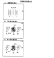
図7は、遊技機1において使用される各種の乱数を説明するための図である。図7(A
)は、メイン制御部側の遊技制御用マイコン81が取得する乱数を示しており、図7(B
)は、サブ制御部側の演出制御用マイコン91が取得する乱数を示している。遊技制御用
マイコン81は、「大当たり乱数」と、「大当たり種別乱数」と、「リーチ乱数」と、「
変動パターン乱数」と、「普通図柄乱数(当たり乱数)」とを後述するタイミングにおい
て取得するように構成されている。「大当たり乱数」は、大当たりか否かの抽選(大当た
り判定)に用いられる乱数であり、0~65535までの範囲の値をとる。「大当たり種
別乱数」は、当選した大当たりの種別の抽選(大当たり種別判定)に用いられる乱数であ
り、0~127までの範囲の値をとる。「リーチ乱数」は、大当たり判定がハズレである
場合に、その結果を示す演出図柄変動演出においてリーチを発生させるか否かを決定する
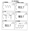
ために用いられる乱数であり、0~127までの範囲の値をとる。リーチとは、複数の演
出図柄(装飾図柄)のうち変動表示されている演出図柄が残り1つとなっている状態であ
って、変動表示されている演出図柄がどの図柄で停止表示されるか次第で大当たり当選を
示す演出図柄の組み合わせとなる状態(例えば、「7↓7」の状態)のことである。なお
、リーチ状態において停止表示されている演出図柄は、表示画面7a内で揺れているよう
に表示されてもよい。「変動パターン乱数」は、変動時間を含む変動パターンを決定する
ために用いられる乱数であり、0~127までの範囲の値をとる。「普通図柄乱数(当た
り乱数)」は、電チュー22を開放させる補助遊技をおこなうか否かの抽選(普通図柄抽
選)に用いられる。普通図柄乱数は、0~255までの範囲の値をとる。「大当たり乱数
」、「大当たり種別乱数」、「リーチ乱数」、「変動パターン乱数」は、始動口(第1始
動口20または第2始動口21)への入球に基づいて取得される。第1始動口20への入
球に基づいて取得された乱数値群は第1特図保留記憶領域85aに記憶され、第2始動口
21への入球に基づいて取得された乱数値群は第2特図保留記憶領域85bに記憶される
。「普通図柄乱数(当たり乱数)」は、ゲート28の通過に基づいて取得される。取得さ
れた普通図柄乱数値は、普図保留記憶領域86に記憶される。
FIG. 7 is a diagram for explaining various random numbers used in the
) indicates a random number acquired by the
) indicates a random number acquired by the
Fluctuation pattern random number" and "ordinary symbol random number (hit random number)" are configured to be acquired at the timing described later. The “jackpot random number” is a random number used for lottery (jackpot determination) to determine whether or not a jackpot will be won, and takes a value ranging from 0 to 65,535. The “jackpot type random number” is a random number used for the lottery (jackpot type determination) of the type of the winning jackpot, and takes a value in the range of 0-127. "Reach random number" is a random number used to determine whether or not to generate a reach in the effect symbol variation effect that indicates the result when the big hit determination is a loss, and is a value in the range of 0 to 127. take. Reach is a state in which only one of the plurality of production patterns (decorative patterns) that is displayed in a variable manner remains, and it depends on which design the variable display design is stopped and displayed. It is a state (for example, the state of "7↓7") that is a combination of performance symbols indicating a jackpot winning. In addition, the effect symbol that is stopped and displayed in the ready-to-win state may be displayed as if it is shaking within the
演出制御用マイコン91は、「先読み演出乱数」と、「チャンスアップ乱数」と、を後
述するタイミングにおいて取得するように構成されている。「先読み演出乱数」は、変動
演出時の先読み演出を決定するために用いられる乱数であり、0~127までの範囲の値
をとる。「チャンスアップ乱数」は、変動演出時のチャンスアップ演出を決定するために
用いられる乱数であり、0~127までの範囲の値をとる。「先読み演出乱数」は、メイ
ン制御部側からサブ制御部側に事前判定コマンドが出力されたことに基づいて取得される
。取得された乱数値群はサブRAM94に記憶される。「チャンスアップ乱数」は、メイ
ン制御部側からサブ制御部側に変動開始コマンドが出力されたことに基づいて取得される
。取得された乱数値はサブRAM94に記憶される。
The
図8は、判定テーブルT1~T4を説明するための図である。図8(A)には、大当た
り判定テーブルT1を説明するための図が示され、図8(B)には、リーチ判定テーブル
T2を説明するための図が示され、図8(C)には、普通図柄当たり判定テーブルT3を
説明するための図が示され、図8(D)には、普通図柄変動パターン判定テーブルT4を
説明するための図が示されている。
FIG. 8 is a diagram for explaining the determination tables T1 to T4. FIG. 8A shows a diagram for explaining the jackpot determination table T1, FIG. 8B shows a diagram for explaining the reach determination table T2, and FIG. shows a diagram for explaining the normal symbol hit determination table T3, and FIG. 8D shows a diagram for explaining the normal symbol variation pattern determination table T4.
大当たり判定テーブルT1は、遊技制御用マイコン81が主制御メイン処理(後述)に
おいて、取得した大当たり乱数値(0~65535のいずれか)が「大当たり」に該当す
るか「ハズレ」に該当するかを判定するために参照されるテーブルである。図8(A)で
は、「通常確率状態」において、大当たり乱数値が「0~164」の場合には、「大当た
り」と判定され、大当たり乱数値が「0~164以外の数値(165~65535)」の
場合には、「ハズレ」と判定されることが示されている。また、「高確率状態」において
、大当たり乱数値が「0~649」の場合には、「大当たり」と判定され、大当たり乱数
値が「0~649以外の数値(650~65535)」の場合には、「ハズレ」と判定さ
れることが示されている。「通常確率状態」および「高確率状態」の内容については後述
する。
The jackpot determination table T1 determines whether the jackpot random number value (one of 0 to 65535) acquired by the
リーチ判定テーブルT2は、遊技制御用マイコン81が主制御メイン処理(後述)にお
いて、取得したリーチ乱数値(0~127のいずれか)が「リーチ有り」に該当するか「
リーチ無し」に該当するかを判定するために参照されるテーブルである。図8(B)では
、「非時短状態」において、リーチ乱数値が「0~13」の場合には、「リーチ有り」と
判定され、リーチ乱数値が「0~13以外の数値(14~127)」の場合には、「リー
チ無し」と判定されることが示されている。また、「時短状態」において、リーチ乱数値
が「0~5」の場合には、「リーチ有り」と判定され、リーチ乱数値が「0~5以外の数
値(6~127)」の場合には、「リーチ無し」と判定されることが示されている。「時
短状態」および「非時短状態」の内容については後述する。リーチ判定テーブルT2では
、時短状態の方が非時短状態よりもハズレ時のリーチがかかりにくくなっている。これは
、時短状態において変動時間の短いリーチ無しハズレがより多く選択されることで、特図
保留の消化スピードを速めるためである。
The reach determination table T2 determines whether the reach random number (any of 0 to 127) acquired by the
It is a table referred to in order to determine whether it corresponds to "no reach". In FIG. 8 (B), in the "non-time saving state", if the reach random value is "0 to 13", it is determined to be "with reach", and the reach random value is a number other than "0 to 13 (14 to 127)” is determined to be “no reach”. Also, in the "time saving state", if the reach random number is "0 to 5", it is determined that there is reach, and if the reach random number is "a number other than 0 to 5 (6 to 127)" is determined to be "no reach". The contents of the "time saving state" and the "non-working time saving state" will be described later. In the reach determination table T2, the reach at the time of loss is less likely to be applied in the time saving state than in the non-working time saving state. This is to speed up the digestion speed of the special figure reservation by selecting more reach no loss with short fluctuation time in the time saving state.
普通図柄当たり判定テーブルT3は、遊技制御用マイコン81が主制御メイン処理(後
述)において、取得した普通図柄乱数値(0~255のいずれか)が「当たり」に該当す
るか「ハズレ」に該当するかを判定するために参照されるテーブルである。図8(C)で
は、「非時短状態」において、普通図柄乱数値が「0~2」の場合には、「当たり」と判
定され、普通図柄乱数値が「0~2以外の数値(3~255)」の場合には、「ハズレ」
と判定されることが示されている。また、「時短状態」において、普通図柄乱数値が「0
~254」の場合には、「当たり」と判定され、普通図柄乱数値が「0~254以外の数
値(255)」の場合には、「ハズレ」と判定されることが示されている。
In the normal symbol hit determination table T3, the normal symbol random number value (any one of 0 to 255) acquired by the
It is shown that it is determined that Also, in the "time saving state", the normal symbol random number is "0
~254", it is judged as "hit", and when the normal symbol random number is "a number other than 0 to 254 (255)", it is judged as "losing".
普通図柄変動パターン判定テーブルT4は、遊技制御用マイコン81が主制御メイン処
理(後述)において、遊技状態(非時短状態か時短状態か)に応じて、普通図柄の変動時
間が何秒かを判定するために参照されるテーブルである。図8(D)では、「非時短状態
」のとき、普通図柄の変動時間は「30秒」と判定され、「時短状態」のとき、普通図柄
の変動時間が「1秒」と判定されることが示されている。
In the normal symbol variation pattern determination table T4, the
図9は、大当たり種別判定テーブルT5を説明するための図である。大当たり種別判定
テーブルT5は、遊技制御用マイコン81が主制御メイン処理(後述)において、取得し
た大当たり種別乱数値(0~127のいずれか)に応じて、「大当たりの種別」と「特別
図柄の種類」を判定するために参照されるテーブルである。図9では、第1特別図柄(特
図1)の抽選において当選したとき、大当たり種別乱数値が「0~24」の場合には、大
当たり種別が「16RV通過予定大当たり」と判定され、特図1の停止図柄(特図停止図
柄)が「大当たり図柄1」と判定される。大当たり種別乱数値が「25~49」の場合に
は、大当たり種別が「16RV通過予定大当たり」と判定され、特図停止図柄が「大当た
り図柄2」と判定される。大当たり種別乱数値が「50~55」の場合には、大当たり種
別が「16R(実質15R)V通過予定大当たり」と判定され、特図停止図柄が「大当た
り図柄3」と判定される。大当たり種別乱数値が「56~67」の場合には、大当たり種
別が「16R(実質13R)V通過予定大当たり」と判定され、特図停止図柄が「大当た
り図柄4」と判定される。大当たり種別乱数値が「68~127」の場合には、大当たり
種別が「16R(実質13R)V非通過予定大当たり」と判定され、特図停止図柄が「大
当たり図柄5」と判定される。一方、第2特別図柄(特図2)の抽選において当選した場
合、大当たり種別乱数値によらず(0~127のいずれであっても)、大当たり種別が「
16RV通過予定大当たり」と判定され、特図2の停止図柄(特図停止図柄)が「大当た
り図柄1」と判定されることが示されている。なお、大当たり種別判定テーブルT5を参
照することによって、特図停止図柄に対応する「特図停止図柄データ」、特別遊技の「オ
ープニング(OP)コマンド」、「ラウンド指定コマンド」、「エンディング(ED)コ
マンド」も特定することができる。「16RV通過予定大当たり」、「16R(実質15
R)V通過予定大当たり」、「16R(実質13R)V通過予定大当たり」および「16
R(実質13R)V非通過予定大当たり」の具体的な内容については後述する。
FIG. 9 is a diagram for explaining the jackpot type determination table T5. The jackpot type determination table T5 is the
16RV passage scheduled jackpot", and the stop pattern of special figure 2 (special figure stop pattern) is determined to be "
R) V Pass Scheduled Jackpot”, “16R (actually 13R) V Pass Scheduled Jackpot” and “16
The specific contents of "R (substantially 13R) V non-passing scheduled jackpot" will be described later.
図10は、非時短状態時の変動パターン判定テーブルT6を説明するための図である。
図11は、時短状態時の変動パターン判定テーブルT6を説明するための図である。変動
パターン判定テーブルT6は、遊技制御用マイコン81が主制御メイン処理(後述)にお
いて、取得した変動パターン乱数値(0~127)に応じて、変動パターンを判定するた
めに参照されるテーブルである。図10では、例えば、非時短状態において第1始動口2
0に入賞し、大当たり判定テーブルT1において「ハズレ」と判定され、リーチ判定テー
ブルT2において「リーチ有り」と判定され、保留球数が「1~2」であり、変動パター
ン乱数値が「0~60」の場合には、変動パターンが「P7」と判定されることが示され
ている。図11では、例えば、時短状態において第2始動口21に入賞し、大当たり判定
テーブルT1において「大当たり」と判定され、大当たり種別判定テーブルT5において
「16RV通過予定大当たり」と判定され、変動パターン乱数値が「0~10」の場合に
は、変動パターンが「P61」と判定されることが示されている。図10,11に示され
るように、変動パターンが決定されれば、変動時間も決定される。また、リーチになる場
合に、そのリーチがノーマルリーチとなるのかスーパーリーチ(SPリーチ)となるのか
も決定される。スーパーリーチとは、ノーマルリーチよりもリーチ後の変動時間が長いリ
ーチ演出である。ここでは、変動時間の異なる3種類のスーパーリーチ(SP1、SP2
、SP3)が設定されている。変動時間の長さはSP3>SP2>SP1となっている。
SP1~3では、ノーマルリーチを経て発展的に実行される。SP1~3の違いは、例え
ば、疑似連の有無であってもよい。
FIG. 10 is a diagram for explaining the variation pattern determination table T6 during the non-time saving state.
FIG. 11 is a diagram for explaining the variation pattern determination table T6 during the time saving state. Variation pattern determination table T6 is a table referred to for determining a variation pattern according to the variation pattern random number value (0 to 127) acquired by the
0 won, it is determined to be "losing" in the jackpot determination table T1, it is determined to be "with reach" in the reach determination table T2, the number of pending balls is "1 to 2", and the variation pattern random value is "0 to 60", the variation pattern is determined to be "P7". In FIG. 11, for example, the
, SP3) are set. The length of the fluctuation time is SP3>SP2>SP1.
In SP1-3, it is executed progressively through normal reach. The difference between SP1-3 may be, for example, the presence or absence of pseudo-reams.
図12は、電チュー開放パターン判定テーブルT7を説明するための図である。電チュ
ー開放パターン判定テーブルT7は、遊技制御用マイコン81が主制御メイン処理(後述
)において、遊技状態(非時短状態か時短状態か)に応じて、電チュー22の開放パター
ンを判定するために参照されるテーブルである。図12(A)では、「非時短状態」のと
き、電チュー22の開放パターンは「開放パターン11」と判定され、「時短状態」のと
き、開放パターンは「開放パターン12」と判定されることが示されている。図12(B
)には、開放パターン11と開放パターン12の内容が示されている。開放パターン11
では、開放回数1回、開放時間0.2秒の電チュー22の開放をおこなう。開放パターン
12では、開放回数が3回、1回あたりの開放時間2.0秒、インターバル(開放間隔)
1.0秒の電チュー22の開放をおこなう。ただし、この電チュー22の開放は、予め定
められた数の遊技球の入賞(規定入賞数、最大10個)があった場合、開放時間が残って
いても閉鎖される。
FIG. 12 is a diagram for explaining the electric tube opening pattern determination table T7. The electric chew opening pattern determination table T7 is used by the
) shows the contents of the
Then, the
The
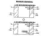
図13は、大入賞口開放パターン判定テーブルT8を説明するための図である。大入賞
口開放パターン判定テーブルT8は、遊技制御用マイコン81が主制御メイン処理(後述
)において、特図停止図柄データ(図9)に応じて、第1大入賞口30および第2大入賞
口35の開放パターンを判定するために参照されるテーブルである。図13(A)では、
特図停止図柄データが「11H」、「12H」、または、「21H」のとき、第1大入賞
口30および第2大入賞口35の開放パターンは「開放パターン21」と判定され、特図
停止図柄データが「14H」または「15H」のとき、開放パターンは「開放パターン2
2」と判定され、特図停止図柄データが「13H」のとき、開放パターンは「開放パター
ン23」と判定されることが示されている。図13(B)には、開放パターン21、開放
パターン22および開放パターン23の内容が示されている。開放パターン21では1~
13、15R目において、開放回数1回、開放時間29.5秒の第1大入賞口30の開放
(ロング開放)をおこない、14、16R目において、開放回数1回、開放時間29.5
秒の第2大入賞口35の開放(ロング開放)をおこなう。開放パターン22では1~13
R目において、開放回数1回、開放時間29.5秒の第1大入賞口30の開放(ロング開
放)をおこない、14、16R目において、開放回数1回、開放時間0.1秒の第2大入
賞口35の開放(ショート開放)をおこない、15R目において、開放回数1回、開放時
間0.1秒の第1大入賞口30の開放(ショート開放)をおこなう。開放パターン23で
は1~13、15R目において、開放回数1回、開放時間29.5秒の第1大入賞口30
の開放(ロング開放)をおこない、14R目において、開放回数1回、開放時間0.1秒
の第2大入賞口35の開放(ショート開放)をおこない、16R目において、開放回数1
回、開放時間29.5秒の第2大入賞口35の開放(ロング開放)をおこなう。ただし、
第1大入賞口30および第2大入賞口35の開放は、予め定められた数の遊技球の入賞(
規定入賞数、最大9個)があった場合、開放時間が残っていても閉鎖される。
FIG. 13 is a diagram for explaining the big winning opening opening pattern determination table T8. The
When the special figure stop symbol data is "11H", "12H" or "21H", the opening pattern of the first big winning
2", and when the special figure stop symbol data is "13H", the open pattern is determined to be "
In the 13th and 15th rounds, the first big prize-winning
The second big winning
In the R-th, the first big prize-winning
is opened (long opening), and in the 14th R, the second
Once, the opening (long opening) of the second big winning
The opening of the first big prize-winning
If there is a prescribed number of winnings (maximum 9), it will be closed even if the opening time remains.
図14は、V開閉部材開放パターン判定テーブルT9を説明するための図である。V開
閉部材開放パターン判定テーブルT9は、遊技制御用マイコン81が主制御メイン処理(
後述)において、特図停止図柄データ(図9)に応じて、V開閉部材71の開放パターン
を判定するために参照されるテーブルである。図14(A)では、特図停止図柄データが
「11H」、「12H」、または、「21H」のとき、V開閉部材71の開放パターンは
「開放パターン31」と判定され、特図停止図柄データが「13H」のとき、開放パター
ンは「開放パターン32」と判定され、特図停止図柄データが「14H」のとき、開放パ
ターンは「開放パターン33」と判定され、特図停止図柄データが「15H」のとき、開
放パターンは「開放パターン34」と判定されることが示されている。図14(B)には
、開放パターン31、開放パターン32、開放パターン33、および、開放パターン34
の内容が示されている。開放パターン31では2、4、6、8R目において、第1大入賞
口30に1個目の入賞があったとき開放時間0.1秒のV開閉部材71のショート開放を
おこなう。10、12R目において、第1大入賞口30に1個目の入賞があったとき開放
時間0.1秒のV開閉部材71のショート開放をおこない、2個目の入賞があったとき開
放時間最大31.5秒のV開閉部材71のロング開放をおこなう。開放パターン32では
2、4、6、12R目において、第1大入賞口30に1個目の入賞があったとき開放時間
0.1秒のV開閉部材71のショート開放をおこなう。8、10R目において、第1大入
賞口30に1個目の入賞があったとき開放時間0.1秒のV開閉部材71のショート開放
をおこない、2個目の入賞があったとき開放時間最大31.5秒のV開閉部材71のロン
グ開放をおこなう。開放パターン33では2、6R目において、第1大入賞口30に1個
目の入賞があったとき開放時間0.1秒のV開閉部材71のショート開放をおこない、2
個目の入賞があったとき開放時間最大31.5秒のV開閉部材71のロング開放をおこな
う。4、8、10、12R目において、第1大入賞口30に1個目の入賞があったとき開
放時間0.1秒のV開閉部材71のショート開放をおこなう。開放パターン34では2、
4、6、8、10、12R目において、第1大入賞口30に1個目の入賞があったとき開
放時間0.1秒のV開閉部材71のショート開放をおこなう。
FIG. 14 is a diagram for explaining the V opening/closing member opening pattern determination table T9. V opening and closing member opening pattern determination table T9,
later), it is a table referred to for determining the opening pattern of the V opening and closing
is shown. In the
Long opening of the V opening/closing
In the 4th, 6th, 8th, 10th, and 12th rounds, when the first prize is won in the first big
4.大当たり等の説明
遊技機1では、大当たり抽選(特別図柄抽選)の結果としての「大当たり」と「ハズレ
」がある。「大当たり」の場合には、特別図柄表示器41に「大当たり図柄」が停止表示
される。「ハズレ」のときには、特別図柄表示器41に「ハズレ図柄」が停止表示される
。大当たりに当選すると、停止表示された特別図柄の種類(大当たりの種類)に応じた開
放パターンにて、大入賞口(第1大入賞口30および第2大入賞口35)を開放させる「
大当たり遊技」が実行される。大当たり遊技は、特別遊技の一例である。大当たり遊技は
、複数回のラウンド遊技(単位開放遊技)と、初回のラウンド遊技が開始される前のオー
プニング(OP)と、最終回のラウンド遊技が終了した後のエンディング(ED)とを含
んでいる。各ラウンド遊技は、オープニングの終了、または、前のラウンド遊技の終了に
よって開始し、次のラウンド遊技の開始によって終了する。ラウンド遊技間の大入賞口の
閉鎖の時間(インターバル時間)は、その閉鎖前の開放ラウンド遊技に含まれる。
4. Explanation of Big Wins, etc. In the
A jackpot game" is executed. A jackpot game is an example of a special game. The jackpot game includes multiple round games (unit open games), an opening (OP) before the first round game starts, and an ending (ED) after the final round game ends. there is Each round begins with the end of the opening or the end of the previous round and ends with the beginning of the next round. The closing time (interval time) of the big winning opening between round games is included in the open round game before closing.
大当たりには複数の種別がある。大当たりの種別については、図9に示すとおりである
。ここでは、大当たりの種別としては、大きく分けて「V通過予定大当たり」と「V非通
過予定大当たり」の2つある。「V通過予定大当たり」は、その大当たり遊技中にV領域
39への遊技球の通過が可能な開放パターン(V通過予定開放パターン)で開閉部材32
、開閉部材37およびV開閉部材71を作動させる大当たりである。ここでは、特図停止
図柄データが11H~14H,21Hの大当たりが「V通過予定大当たり」に該当する。
図13に示す開閉部材32および開閉部材37の開放パターンと、図14に示すV開閉部
材71の開放パターンとの組み合わせが、(開放パターン21:開放パターン31)、(
開放パターン22:開放パターン33)、または(開放パターン23:開放パターン32
)のとき、その大当たり遊技中にV領域39への遊技球の通過が可能となる。「V非通過
予定大当たり」は、その大当たり遊技中にV領域39への遊技球の通過が不可能な開放パ
ターン(V非通過予定開放パターン)で開閉部材32、開閉部材37およびV開閉部材7
1を作動させる大当たりである。ここでは、特図停止図柄データが17Hの大当たりが「
V非通過予定大当たり」に該当する。図13に示す開閉部材32および開閉部材37の開
放パターンと、図14に示すV開閉部材71の開放パターンとの組み合わせが(開放パタ
ーン22:開放パターン34)のとき、その大当たり遊技中にV領域39への遊技球の通
過が不可能となる。上記のように、開閉部材32および開閉部材37の開放パターン22
は、V通過予定開放パターンとV非通過予定開放パターンとを兼ねている。
There are multiple types of jackpots. The types of jackpots are as shown in FIG. Here, the types of jackpots are roughly divided into two types, namely, "V-passing scheduled jackpot" and "V non-passing scheduled jackpot". The "V passage scheduled jackpot" is an opening pattern (V passage scheduled opening pattern) that allows the game ball to pass through the
, the opening/closing
The combination of the opening pattern of the opening/closing
Open pattern 22: Open pattern 33) or (Open pattern 23:
), it becomes possible for the game ball to pass through the
It is a jackpot that activates 1. Here, the special figure stop design data is 17H jackpot is "
V non-passing scheduled jackpot”. When the combination of the opening pattern of the opening/closing
serves as both a V-passing planned opening pattern and a V-non-passing planned opening pattern.
「V通過予定大当たり」は、「16RV通過予定大当たり」と、「16R(実質13R
)V通過予定大当たり」と、「16R(実質15R)V通過予定大当たり」と、を含んで
いる。「16RV通過予定大当たり」は、実質的な総ラウンド数が16Rである。1Rか
ら13Rまでと15Rは第1大入賞口30を1R当たり最大29.5秒にわたって開放す
る。14Rと16Rは第2大入賞口35を1R当たり最大29.5秒にわたって開放する
(図13:開放パターン21)。10Rおよび12Rでは、V開閉部材71がロング開放
され(図14:開放パターン31)、第1大入賞口30内のV領域39への通過が容易に
可能である。
"V passage scheduled jackpot" is divided into "16RV scheduled passage jackpot" and "16R (substantially 13R
) V Pass Scheduled Jackpot” and “16R (actually 15R) V Pass Scheduled Jackpot”. The "16RV scheduled jackpot" has a substantial total number of rounds of 16R. From 1R to 13R and 15R, the first
「16R(実質13R)V通過予定大当たり」は、総ラウンド数は16Rであるものの
、実質的な総ラウンド数は13Rである。つまり、1Rから13Rまでは第1大入賞口3
0を1R当たり最大29.5秒にわたって開放するが、15Rでは第1大入賞口30を1
R当たり0.1秒しか開放せず、また、14Rと16Rでも第2大入賞口35を1R当た
り0.1秒しか開放しない(図13:開放パターン22)。従って、この「16R(実質
13R)V通過予定大当たり」では14Rから16Rまでは、大入賞口の開放時間が極め
て短く、賞球の見込めないラウンドとなっている。つまり、「16R(実質13R)V通
過予定大当たり」は、実質13Rの大当たりとなっている。2Rおよび6Rでは、V開閉
部材71がロング開放され(図14:開放パターン33)、第1大入賞口30内のV領域
39への通過が容易に可能である。
"16R (substantially 13R) V expected passing jackpot" has a total number of rounds of 16R, but a substantial total number of rounds is 13R. In other words, from 1R to 13R is the first
0 is opened for a maximum of 29.5 seconds per 1R.
It opens only 0.1 seconds per R, and also opens the second big winning
「16R(実質15R)V通過予定大当たり」は、総ラウンド数は16Rであるものの
、実質的な総ラウンド数は15Rである。つまり、1Rから13Rまでと15Rは第1大
入賞口30を1R当たり最大29.5秒にわたって開放し、16Rでは第2大入賞口35
を1R当たり最大29.5秒にわたって開放するが、14Rでは第2大入賞口35を1R
当たり0.1秒しか開放しない(図13:開放パターン23)。従って、この「16R(
実質15R)V通過予定大当たり」では14Rは、大入賞口の開放時間が極めて短く、賞
球の見込めないラウンドとなっている。つまり、「16R(実質15R)V通過予定大当
たり」は、実質15Rの大当たりとなっている。8Rおよび10Rでは、V開閉部材71
がロング開放され(図14:開放パターン32)、第1大入賞口30内のV領域39への
通過が容易に可能である。
"16R (substantial 15R) V scheduled passing jackpot" has a total number of rounds of 16R, but a substantial total number of rounds is 15R. In other words, from 1R to 13R and 15R, the first big prize-winning
is opened for a maximum of 29.5 seconds per 1R, but in 14R the second
It opens only 0.1 seconds per time (Fig. 13: opening pattern 23). Therefore, this "16R (
Substantially 15R) V-passing scheduled jackpot", 14R is a round in which the opening time of the big prize opening is extremely short and no prize balls can be expected. In other words, the "16R (substantially 15R) V passage scheduled jackpot" is a substantially 15R jackpot. In 8R and 10R, the V opening/closing
is long open ( FIG. 14 : open pattern 32 ), and it is possible to easily pass through the
「V非通過予定大当たり」は、総ラウンド数は16Rであるものの、実質的な総ラウン
ド数は13となる開放パターン22の「16R(実質13R)V非通過予定大当たり」で
ある。つまり、1Rから13Rまでは第1大入賞口30を1R当たり最大29.5秒にわ
たって開放するが、15Rでは第1大入賞口30を1R当たり0.1秒しか開放せず、ま
た、14Rと16Rでも第2大入賞口35を1R当たり0.1秒しか開放しない(図13
:開放パターン22)。従って、この「16R(実質13R)V非通過予定大当たり」で
は14Rから16Rまでは、大入賞口の開放時間が極めて短く、賞球の見込めないラウン
ドとなっている。つまり、「16R(実質13R)V非通過予定大当たり」は実質13R
の大当たりとなっている。2R,4R,6R,8R,10Rおよび12Rでは、V開閉部
材71は開放されるもののその開放はショート開放であり(図14:開放パターン34)
、第1大入賞口30内のV領域39に遊技球が通過することはほぼ不可能となっている。
The "V non-passing scheduled jackpot" is a "16R (substantially 13R) V non-passing scheduled jackpot" of the
: open pattern 22). Therefore, in this "16R (substantially 13R) V non-passing scheduled jackpot", from 14R to 16R, the opening time of the big winning hole is extremely short, making it a round in which prize balls cannot be expected. In other words, "16R (substantially 13R) V non-passing scheduled jackpot" is substantially 13R
It is a big hit. In 2R, 4R, 6R, 8R, 10R and 12R, the V opening/closing
, it is almost impossible for the game ball to pass through the
上記の説明から明らかなように、「16R(実質13R)V非通過予定大当たり」と「
16R(実質13R)V通過予定大当たり」とは、第1大入賞口30と第2大入賞口35
(開閉部材32と開閉部材37)との開放パターンが同一(開放パターン22)であり、
V開閉部材71の開放パターンのみが異なっている(開放パターン34と開放パターン3
3)。すなわち、「16R(実質13R)V非通過予定大当たり」は、第1大入賞口30
内のV領域39に遊技球が通過することはほぼ不可能になっており、当該大当たり後の遊
技状態は低確時短状態(低確高ベース状態)となる。一方、「16R(実質13R)V通
過予定大当たり」は、第1大入賞口30内のV領域39への遊技球の通過が容易に可能に
なっており、当該大当たり後の遊技状態は高確時短状態(高確高ベース状態)となる。こ
のことから、遊技者は、「16R(実質13R)V非通過予定大当たり」と「16R(実
質13R)V通過予定大当たり」とを見分けることが困難になり、当該大当たり後の遊技
状態が低確時短状態(低確高ベース状態)になるか高確時短状態(高確高ベース状態)に
なるかが判別し難くなる。すなわち、「16R(実質13R)V通過予定大当たり」後の
遊技状態は、第1大入賞口30内のV領域39に遊技球が通過した場合には、高確時短状
態(高確高ベース状態)でありながら高確率になっていることが潜伏した状態(潜伏確変
状態)となる。
As is clear from the above description, "16R (real 13R) V non-passing scheduled jackpot" and "
16R (actually 13R) V passing scheduled jackpot" means the first
The opening patterns of (opening/closing
Only the opening pattern of the V opening/closing
3). That is, the "16R (substantially 13R) V non-passing scheduled jackpot"
It is almost impossible for the game ball to pass through the
また、図9に示すように、第1特別図柄(特図1)の抽選における大当たりの振分率は
、V通過予定大当たりが68/128(約53%)、V非通過予定大当たりが60/12
8(約47%)となっている。これに対して、第2特別図柄(特図2)の抽選において当
選した大当たりは、全てV通過予定大当たりとなっている。すなわち、後述の電サポ制御
の実行により入球可能となる第2始動口21への入賞に基づく抽選により大当たりに当選
した場合には、必ずV通過予定大当たりとなる。このように遊技機1では、第1始動口2
0に遊技球が入賞して行われる大当たり抽選(第1特別図柄の抽選)よりも、第2始動口
21に遊技球が入賞して行われる大当たり抽選(第2特別図柄の抽選)の方が、遊技者に
とって有利となるように設定されている。
In addition, as shown in FIG. 9, the distribution ratio of the jackpot in the lottery for the first special symbol (special figure 1) is 68/128 (about 53%) for the V-passing scheduled jackpot and 60/60 for the V non-passing scheduled jackpot. 12
8 (about 47%). On the other hand, the jackpots won in the lottery for the second special symbol (special pattern 2) are all V-passing schedule jackpots. That is, when a jackpot is won by a lottery based on winning a prize to the
The jackpot lottery (lottery of the second special pattern) performed by winning the game ball in the
5.遊技状態の説明
遊技機1の遊技状態について説明する。遊技制御用マイコン81は、特別図柄表示器4
1に表示する特別図柄および普通図柄表示器42に表示する普通図柄に対して、それぞれ
、「確率変動制御」と「変動時間短縮制御」とを実行可能である。ここでは、遊技制御用
マイコン81が特別図柄表示器41の特別図柄に対して確率変動制御している状態を「高
確率状態」と呼び、確率変動制御していない状態を単に「通常確率状態(非高確率状態、
低確率状態)」と呼ぶ。遊技制御用マイコン81は、特別図柄の確率変動制御として、大
当たりと判定される大当たり乱数値の数が通常確率状態よりも高確率状態の方が多い大当
たり判定テーブル(図8(A))を用いた大当たり判定をおこなうことにより、高確率状
態を実現する。従って、高確率状態は、通常確率状態よりも大当たりの確率が高くなる。
つまり、遊技制御用マイコン81が特別図柄表示器41の特別図柄に対して確率変動制御
を実行している場合には、確率変動制御を実行していない場合と比べて、特別図柄表示器
41による特別図柄の可変表示の表示結果(停止図柄)が大当たり図柄となる確率が高く
なる。
5. Explanation of Game State The game state of the
"Probability fluctuation control" and "variation time shortening control" can be executed for the special symbols displayed on 1 and the normal symbols displayed on the normal
low-probability state)”. The
That is, when the
また、遊技制御用マイコン81が特別図柄表示器41の特別図柄に対して変動時間短縮
制御している状態を「時短状態」といい、変動時間短縮制御していない状態を単に「非時
短状態」という。時短状態は、特別図柄の変動時間(変動表示開始時から表示結果の導出
表示時までの時間)が、非時短状態よりも短くなっている。遊技制御用マイコン81は、
時短状態のときに、変動時間の短い変動パターンが選択されることが非時短状態よりも多
くなるように定められた変動パターン判定テーブルT6(図10、図11)を用いた変動
パターンの判定をおこなう。つまり、遊技制御用マイコン81が特別図柄表示器41の特
別図柄に対して変動時間短縮制御を実行している場合には、変動時間短縮制御を実行して
いない場合と比べて、特別図柄の可変表示の変動時間として短い変動時間が選択されやす
くなる。その結果、時短状態では、特図保留の消化のペースが速くなり、始動口への有効
な入賞(特図保留として記憶され得る入賞)が発生しやすくなる。これにより、スムーズ
な遊技の進行のもとで大当たりを狙うことができる。なお、遊技制御用マイコン81は、
特別図柄表示器41の特別図柄に対して、確率変動制御と変動時間短縮制御とを同時に実
行することもあるし、片方のみ実行することもある。
In addition, the state in which the
Judgment of the variation pattern using the variation pattern determination table T6 (FIGS. 10 and 11) that is determined so that the variation pattern with a short variation time is selected more often than in the non-time saving state when in the time saving state Do. That is, when the
Probability variation control and variation time shortening control may be performed simultaneously with respect to the special symbols on the special symbol display 41, or only one of them may be performed.
遊技制御用マイコン81は、普通図柄表示器42の普通図柄に対する確率変動制御およ
び変動時間短縮制御を、特別図柄表示器41の特別図柄に対する変動時間短縮制御に同期
して実行する。すなわち、遊技制御用マイコン81は、普通図柄に対する確率変動制御お
よび変動時間短縮制御を、時短状態の場合は実行し、非時短状態の場合には実行しない。
遊技制御用マイコン81は、普通図柄の確率変動制御として、当たりと判定される普通図
柄乱数値(当たり乱数値)の数が非時短状態よりも時短状態の方が多い普通図柄当たり判
定テーブルT3(図8(C))を用いて、当たり判定(普通図柄の判定)をおこなう。従
って、時短状態では、普通図柄通常確率状態よりも当たり確率が高くなる。つまり、遊技
制御用マイコン81が普通図柄表示器42の普通図柄に対して確率変動制御を実行してい
る場合には、確率変動制御を実行していない場合と比べて、普通図柄表示器42による普
通図柄の可変表示の表示結果(停止図柄)が当たり図柄となる確率が高くなる。時短状態
では、普通図柄の変動時間が非時短状態よりも短くなっている。ここでは、普通図柄の変
動時間は非時短状態では30秒であるが、時短状態では1秒である(図8(D))。さら
に時短状態では、補助遊技における電チュー22の開放時間が、非時短状態よりも長くな
っている(図12)。すなわち、遊技制御用マイコン81は、電チュー22に対して開放
時間延長制御を実行している。加えて、時短状態では、補助遊技における電チュー22の
開放回数が非時短状態よりも多くなっている(図12)。すなわち、遊技制御用マイコン
81は、電チュー22に対して開放回数増加制御を実行している。遊技制御用マイコン8
1が、普通図柄表示器42の普通図柄に対する確率変動制御と変動時間短縮制御、および
、電チュー22に対する開放時間延長制御と開放回数増加制御とを実行している状況下で
は、これらの制御を実行していない場合と比べて、電チュー22が頻繁に開放され、第2
始動口21へ遊技球が頻繁に入賞することとなる。その結果、発射球数に対する賞球数の
割合であるベースが高くなる。従って、これらの制御が実行されている状態を「高ベース
状態」といい、実行されていない状態を「低ベース状態」という。高ベース状態では、手
持ちの遊技球を大きく減らすことなく大当たりを狙うことができる。なお、高ベース状態
とは、いわゆる電サポ制御(電チュー22により第2始動口21への入賞をサポートする
制御)が実行されている状態である。高ベース状態(電サポ制御状態)は、上記の全ての
制御を実行するものでなくてもよい。すなわち、普通図柄表示器42の普通図柄に対する
確率変動制御、普通図柄表示器42の普通図柄に対する変動時間短縮制御、電チュー22
に対する開放時間延長制御、および、電チュー22に対する開放回数増加制御のうち一つ
以上の制御を実行することによって、その制御が実行されていないときよりも電チュー2
2が開放され易くなっていればよい。また、高ベース状態(電サポ制御状態)は、時短状
態に付随せずに独立して制御されるようにしてもよい。
The
The
1, the probability variation control and variation time shortening control for the normal symbol of the
The game balls are frequently awarded to the starting port 21.例文帳に追加As a result, the base, which is the ratio of the number of balls awarded to the number of balls fired, increases. Therefore, the state in which these controls are executed is called the "high base state", and the state in which they are not executed is called the "low base state". In the high base state, you can aim for a big hit without greatly reducing the number of game balls you have. Note that the high base state is a state in which so-called electric support control (control for supporting winning to the
By executing one or more of the opening time extension control for the
2 should be easily opened. Further, the high base state (electrical support control state) may be independently controlled without accompanying the time saving state.
遊技機1では、V通過予定大当たりへの当選による大当たり遊技後の遊技状態は、その
大当たり遊技中にV領域39への通過がなされていれば、高確率状態かつ時短状態かつ高
ベース状態である。この遊技状態を特に、「高確高ベース状態」、または、「高確時短状
態」という。高確高ベース状態は、所定回数(ここでは160回)の特別図柄の可変表示
が実行されるか、または、大当たりに当選してその大当たり遊技が実行されることにより
終了する。また、V非通過予定大当たりへの当選による大当たり遊技後の遊技状態は、そ
の大当たり遊技中にV領域39の通過がなされていなければ(なされることはほぼない)
、通常確率状態(非高確率状態すなわち低確率の状態)かつ時短状態かつ高ベース状態で
ある。この遊技状態を特に、「低確高ベース状態」、「低確時短状態」という。低確高ベ
ース状態は、所定回数(ここでは100回)の特別図柄の可変表示が実行されるか、また
は、大当たりに当選してその大当たり遊技が実行されることにより終了する。遊技機1を
初めて遊技する場合において電源投入後の遊技状態は、通常確率状態かつ非時短状態かつ
低ベース状態(非電サポ制御状態)である。この遊技状態を特に、「低確低ベース状態」
という。低確低ベース状態を「通常遊技状態」、または、「低確非時短状態(単に、非時
短状態とも呼ぶ)」、と称することもある。また、特別遊技(大当たり遊技)の実行中の
状態を「特別遊技状態(大当たり遊技状態)」と称することとする。さらに、高確率状態
および高ベース状態のうち少なくとも一方の状態に制御されている状態を、「特定遊技状
態」という。
In the
, normal probability state (non-high probability state, ie, low probability state), time saving state and high base state. This game state is particularly referred to as "low probability high base state" and "low probability time saving state". The low-probability-high base state ends when the variable display of the special symbols is executed a predetermined number of times (here, 100 times), or when a big win is won and the big win game is executed. When the
It says. The low-probability low base state may be referred to as "normal game state" or "low-probability non-time-saving state (simply referred to as non-time-saving state)". Also, the state during execution of the special game (jackpot game) is referred to as "special game state (jackpot game state)". Furthermore, the state controlled to at least one of the high probability state and the high base state is referred to as a "specific game state".
高確高ベース状態や低確高ベース状態といった高ベース状態では、右打ちによって右遊
技領域3B(図1)へ遊技球を進入させた方が有利に遊技を進行させることができる。電
サポ制御によって、低ベース状態と比べて電チュー22が開放されやすくなっており、第
1始動口20への入賞よりも第2始動口21への入賞の方が容易となっているためである
。このことから、高ベース状態では、普通図柄抽選の契機となるゲート28へ遊技球を通
過させつつ、第2始動口21へ遊技球を入賞させるべく右打ちをおこなう。これにより左
打ちをするよりも、多数の始動入賞(始動口への入賞)を得ることができる。なお、遊技
機1では、大当たり遊技中も右打ちにて遊技をおこなう。一方、低ベース状態では、左打
ちによって左遊技領域3A(図1)へ遊技球を進入させた方が有利に遊技を進行させるこ
とができる。電サポ制御が実行されていないため、高ベース状態と比べて電チュー22が
開放されにくくなっており、第2始動口21への入賞よりも第1始動口20への入賞の方
が容易となっているためである。このことから、低ベース状態では、第1始動口20へ遊
技球を入賞させるべく左打ちをおこなう。これにより右打ちするよりも、多数の始動入賞
を得ることができる。
In high-base states such as high-probability-high base state and low-probability-high base state, it is possible to advance the game more advantageously by entering the game ball into the
6.遊技制御用マイコン81の動作
図15~図34に基づいて主制御基板80(図3)に設けられた遊技制御用マイコン8
1の動作について説明する。遊技制御用マイコン81の動作説明にて登場するカウンタ、
フラグ、ステータス、バッファ等はメインRAM84に設けられている。遊技制御用マイ
コン81は、当否判定手段(図23)、当否事前判定手段(図18、図19)に該当する
。
6. Operation of the
1 will be described. A counter that appears in the explanation of the operation of the
Flags, statuses, buffers, etc. are provided in the
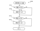
[主制御メイン処理]
図15は、主制御メイン処理のフローチャートである。遊技制御用マイコン81は、遊
技機1の電源がオンされると、メインROM83から主制御メイン処理を実行するための
プログラムを読み出す。主制御メイン処理では、遊技制御用マイコン81は、まず、初期
設定をおこなう(ステップS001)。初期設定では、例えば、メインCPU82の設定
、各種のフラグ、ステータスおよびカウンタなどのリセット等をおこなう。フラグの初期
値は「0」つまり「OFF」であり、ステータスの初期値は「1」であり、カウンタの初
期値は「0」である。なお、初期設定は、電源投入後に一度だけ実行され、それ以降は実
行されない。
[Main control main processing]
FIG. 15 is a flowchart of main control main processing. When the
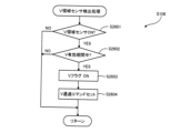
初期設定の後、遊技制御用マイコン81は、割り込み処理の割り込みを禁止し(ステッ
プS002)、普通図柄・特別図柄主要乱数更新処理(ステップS003)をおこなう。
この普通図柄・特別図柄主要乱数更新処理では、遊技制御用マイコン81は、図7(A)
で示した種々の乱数カウンタ値(大当たり乱数値、大当たり種別乱数値、リーチ乱数値、
変動パターン乱数値、普通図柄乱数値)を1加算して更新する。各乱数カウンタ値は設定
された上限値に達すると「0」に戻って再び加算される。なお、各乱数カウンタの初期値
は「0」以外の値であってもよく、ランダムに変更されるものであってもよい。また、各
乱数は、カウンタIC等からなる公知の乱数生成回路を利用して生成されるいわゆるハー
ドウェア乱数であってもよい。
After the initial setting, the
In this normal symbol/special symbol main random number update process, the
Various random number counter values shown in (jackpot random number, jackpot type random number, reach random number,
Fluctuation pattern random number, normal pattern random number) is updated by adding 1. When each random number counter value reaches the set upper limit value, it returns to "0" and is added again. The initial value of each random number counter may be a value other than "0", or may be changed randomly. Also, each random number may be a so-called hardware random number generated using a known random number generation circuit such as a counter IC.
普通図柄・特別図柄主要乱数更新処理の後、遊技制御用マイコン81は、割り込み処理
の割り込みを許可する(ステップS004)。割り込み許可中は、メイン側タイマ割り込
み処理(ステップS005)の実行が可能となる。メイン側タイマ割り込み処理は、所定
の周期(例えば、4msec周期)でメインCPU82に繰り返し入力される割り込みパルス
に基づいて実行される。すなわち、メイン側タイマ割り込み処理は、所定周期(例えば4
msec周期)ごとに実行される。そして、メイン側タイマ割り込み処理が終了してから、次
にメイン側タイマ割り込み処理が開始されるまでの間に、普通図柄・特別図柄主要乱数更
新処理による各種カウンタ値の更新処理が繰り返し実行される。なお、割り込み禁止状態
のときに、メインCPU82に割り込みパルスが入力された場合は、メイン側タイマ割り
込み処理はすぐには開始されず、割り込み許可がされてから開始される。
After the normal symbol/special symbol main random number update process, the
msec cycle). Then, after the main side timer interrupt processing is finished, until the next main side timer interrupt processing is started, the update processing of various counter values by the normal symbol/special symbol main random number update processing is repeatedly executed. . If an interrupt pulse is input to the
[メイン側タイマ割り込み処理]
図16は、メイン側タイマ割り込み処理(図15:ステップS005)のフローチャー
トである。メイン側タイマ割り込み処理では、遊技制御用マイコン81は、まず、乱数更
新処理をおこなう(ステップS101)。具体的には、遊技制御用マイコン81は、図7
(A)で示した種々の乱数カウンタ値を更新する。この乱数更新処理は、上述した主制御
メイン処理(図15)でおこなう普通図柄・特別図柄主要乱数更新処理と同じである。す
なわち、各種乱数カウンタ値の更新処理は、メイン側タイマ割り込み処理の実行期間と、
それ以外の期間(メイン側タイマ割り込み処理の終了後、次のメイン側タイマ割り込み処
理が開始されるまでの期間)との両方でおこなわれる。
[Main side timer interrupt processing]
FIG. 16 is a flowchart of main-side timer interrupt processing (FIG. 15: step S005). In the main timer interrupt process, the
Update the various random number counter values shown in (A). This random number update process is the same as the normal symbol/special symbol main random number update process performed in the main control main process (FIG. 15) described above. That is, the update processing of various random number counter values is performed during the execution period of the main side timer interrupt processing,
It is performed both during the other period (the period from the end of main-side timer interrupt processing to the start of the next main-side timer interrupt processing).
乱数更新処理の後、遊技制御用マイコン81は、入力処理をおこなう(ステップS10
2)。入力処理では、遊技制御用マイコン81は、遊技機1に取り付けられている各種セ
ンサが検出した検出信号を読み込み、入賞口の種類に応じた賞球を払い出すための払い出
しデータをメインRAM84の出力バッファにセットする。各種センサとは、例えば、第
1始動口センサ20a、第2始動口センサ21a、第1大入賞口センサ30a、第2大入
賞口センサ35a、普通入賞口センサ27a、普通入賞口センサ29a(図3)である。
After the random number update process, the
2). In the input process, the
入力処理の後、遊技制御用マイコン81は、始動口センサ検出処理(ステップS103
)、普通動作処理(ステップS104)、特別動作処理(ステップS105)、V領域セ
ンサ検出処理(ステップS106)、保留球数処理(ステップS107)を順に実行する
。これらの処理の詳細については後述する。保留球数処理の後、遊技制御用マイコン81
は、出力処理をおこなう(ステップS108)。出力処理では、遊技制御用マイコン81
は、上述の各処理においてメインRAM84のコマンドセット領域84aにセットしたコ
マンド等をサブ制御基板90に出力する。出力処理の後、遊技制御用マイコン81は、そ
の他の処理をおこなう(ステップS109)。その他の処理では、例えば、後述の特図2
保留球数に基づいて第2特図保留表示器43bをその数を示す表示態様に制御し、特図1
保留球数に基づいて第1特図保留表示器43aをその数を示す表示態様に制御する。
After the input process, the
), normal operation processing (step S104), special operation processing (step S105), V area sensor detection processing (step S106), and pending ball count processing (step S107) are executed in this order. Details of these processes will be described later. After processing the number of pending balls,
performs output processing (step S108). In the output process, the
outputs to the
Based on the number of reserved balls, the second special
Based on the number of reserved balls, the first special
[始動口センサ検出処理]
図17は、始動口センサ検出処理(図16:ステップS103)のフローチャートであ
る。遊技制御用マイコン81は、まず、ゲート28に遊技球が通過したか否かの判定をお
こなう(ステップS201)。この判定は、ゲートセンサ28aによって遊技球が検出さ
れたか否かによっておこなわれる。ゲート28に遊技球が通過していない場合(ステップ
S201:NO)、処理はステップS205にスキップする。ゲート28に遊技球が通過
した場合(ステップS201:YES)、遊技制御用マイコン81は、普通図柄保留球数
が「4(上限値)」であるか否かの判定をおこなう(ステップS202)。普通図柄保留
球数とは、普図保留の数であり、より具体的には、メインRAM84に設けられた普図保
留の数をカウントするカウンタの値である。普通図柄保留球数が「4」であれば(ステッ
プS202:YES)、処理はステップS205にスキップする。普通図柄保留球数が「
3」以下の場合(ステップS202:NO)、普通図柄保留球数に「1」を加算した後(
ステップS203)、普通図柄乱数取得処理をおこなう(ステップS204)。ここでは
、遊技制御用マイコン81は、普通図柄乱数カウンタの値(図7:ラベル-TRND-H
の値)を取得し、取得した乱数値をメインRAM84の普図保留記憶領域86の第1~第
4記憶領域うち、現在の普通図柄保留球数に応じた記憶領域に格納する。
[Starting port sensor detection process]
FIG. 17 is a flowchart of the starting opening sensor detection process (FIG. 16: step S103). The
3" or less (step S202: NO), after adding "1" to the number of normal design holding balls (
Step S203), normal design random number acquisition processing is done (step S204). Here, the
), and stores the acquired random value in the storage area corresponding to the current number of normal symbol reserved balls out of the first to fourth storage areas of the normal pattern reserved
ステップS205では、遊技制御用マイコン81は、第2始動口21に遊技球が入賞し
たか否かの判定をおこなう。この判定は、第2始動口センサ21aによって遊技球が検出
されたか否かによっておこなわれる。第2始動口21に遊技球が入賞していない場合(ス
テップS205:NO)、処理はステップS210にスキップする。遊技球が入賞した場
合(ステップS205:YES)、遊技制御用マイコン81は、特図2保留球数が「4(
上限値)」であるか否かの判定をおこなう(ステップS206)。特図2保留球数とは、
第2特図保留の数であり、より具体的には、メインRAM84に設けられた第2特図保留
の数をカウントするカウンタの値である。特図2保留球数が「4」であれば(ステップS
206:YES)、処理はステップS210にスキップする。特図2保留球数が「3」以
下の場合(ステップS206:NO)、特図2保留球数に「1」を加算した後(ステップ
S207)、特図2関係乱数取得処理をおこなう(ステップS208)。ここでは、大当
たり乱数カウンタの値(図7:ラベル-TRND-Aの値)、大当たり種別乱数カウンタ
の値(図7:ラベル-TRND-ASの値)、リーチ乱数カウンタの値(図7:ラベル-
TRND-RCの値)、変動パターン乱数カウンタの値(図7:ラベル-TRND-T1
の値)を取得する。遊技制御用マイコン81は、取得した乱数値群を第2特図保留記憶領
域85bの第1~第4記憶領域うち、現在の特図2保留球数に応じた記憶領域に格納する
。遊技制御用マイコン81は、後述の特図2事前判定処理(図18)のために、取得した
乱数値群を第2特図保留記憶領域85bとは異なるバッファ(事前判定用バッファ)にも
一時的に記憶(保持)させる。特図2関係乱数取得処理の後、遊技制御用マイコン81は
、特図2事前判定処理をおこなう(ステップS209)。特図2事前判定処理の詳細につ
いては後述する。
In step S205, the
upper limit)” (step S206). What is the number of reserved balls in special figure 2?
It is the number of second special figure reservations, more specifically, the value of the counter that counts the number of second special figure reservations provided in the
206: YES), the process skips to step S210. If the number of special figure 2 reserved balls is "3" or less (step S206: NO), after adding "1" to the number of special figure 2 reserved balls (step S207), special figure 2 related random number acquisition processing is performed (step S208). Here, the value of the jackpot random number counter (Figure 7: label-TRND-A value), the value of the jackpot type random number counter (Figure 7: label-TRND-AS value), the reach random number counter value (Figure 7: label -
TRND-RC value), fluctuation pattern random number counter value (Figure 7: Label-TRND-T1
value). The
ステップS210では、遊技制御用マイコン81は、第1始動口20に遊技球が入賞し
たか否かの判定をおこなう。この判定は、第1始動口センサ20aによって遊技球が検出
されたか否かによっておこなわれる。第1始動口20に遊技球が入賞していない場合(ス
テップS210:NO)、本処理を終了する。第1始動口20に遊技球が入賞した場合(
ステップS210:YES)、遊技制御用マイコン81は、特図1保留球数が「4(上限
値)」であるか否かの判定をおこなう(ステップS211)。特図1保留球数とは、第1
特図保留の数であり、より具体的には、メインRAM84に設けられた第1特図保留の数
をカウントするカウンタの値である。特図1保留球数が「4」であれば(ステップS21
1:YES)、本処理を終了する。特図1保留球数が「3」以下の場合(ステップS21
1:NO)、特図1保留球数に「1」を加算した後(ステップS212)、特図1関係乱
数取得処理をおこなう(ステップS213)。ここでは、上述の特図2関係乱数取得処理
(ステップS208)と同様に、大当たり乱数カウンタの値、大当たり種別乱数カウンタ
の値、リーチ乱数カウンタの値、変動パターン乱数カウンタの値を取得する。遊技制御用
マイコン81は、取得した乱数値群を第1特図保留記憶領域85aの第1~第4記憶領域
うち、現在の特図1保留球数に応じた記憶領域に格納する。遊技制御用マイコン81は、
後述の特図1事前判定処理(図19)のために、取得した乱数値群を第1特図保留記憶領
域85aとは異なるバッファ(事前判定用バッファ)にも一時的に記憶(保持)させる。
特図1関係乱数取得処理の後、遊技制御用マイコン81は、特図1事前判定処理をおこな
う(ステップS214)。特図1事前判定処理の詳細については後述する。
In step S210, the
Step S210: YES), the
It is the number of special figure reservations, more specifically, the value of the counter that counts the number of first special figure reservations provided in the
1: YES), this processing ends. If the number of special figure 1 pending balls is "3" or less (step S21
1: NO), after adding "1" to the number of special figure 1 pending balls (step S212), special figure 1 relation random number acquisition processing is performed (step S213). Here, the value of the jackpot random number counter, the value of the jackpot type random number counter, the value of the reach random number counter, and the value of the variation pattern random number counter are obtained in the same manner as the special figure 2 related random number acquisition process (step S208) described above. The
For the special figure 1 pre-determination process (FIG. 19) described later, the acquired random number group is temporarily stored (held) in a buffer (pre-determination buffer) different from the first special figure
After the special figure 1 related random number acquisition process, the
[特図2事前判定処理]
図18は、特図2事前判定処理(図17:ステップS209)のフローチャートである
。遊技制御用マイコン81は、まず、確変フラグがONであるか否かの判定をおこなう(
ステップS301)。確変フラグがOFFの場合(ステップS301:NO)、本処理を
終える。すなわち、確変フラグがOFFの場合には、事前判定はおこなわれない。一方、
確変フラグがONの場合、遊技制御用マイコン81は、大当たり判定テーブルT1(図8
)のうちの高確率状態用テーブルを参照して大当たり事前判定をおこなう(ステップS3
02)。具体的には、遊技制御用マイコン81は、まず、特図2関係乱数取得処理(図1
7:ステップS208)によって事前判定用バッファに一時的に記憶されている判定値と
しての大当たり乱数値を取得する。次に、遊技制御用マイコン81は、参照する大当たり
判定テーブルT1(図8)と大当たり乱数値とを用いて大当たりか否かの事前判定をおこ
なう。ここでは、高確率状態(確変フラグがON)であるため、遊技制御用マイコン81
は、大当たり判定テーブルT1のうち、高確率状態用のテーブル(大当たり判定値が「0
」~「649」)を参照して大当たりか否かを事前判定する。すなわち、大当たり乱数値
が「0」~「649」のとき「大当たり」と事前判定し、それ以外の値のとき「ハズレ」
と事前判定する。なお、本実施形態では、後述する大当たり判定処理(図23)で用いら
れる大当たり判定テーブルT1を用いて事前判定をおこなっているが、他の実施形態とし
て、大当たり判定テーブルT1とは異なる事前判定用の大当たり判定テーブルを用いて事
前判定をおこなってもよい。
[Special figure 2 pre-determination process]
FIG. 18 is a flowchart of the special figure 2 preliminary determination process (FIG. 17: step S209). The
step S301). If the probability variation flag is OFF (step S301: NO), this process ends. That is, when the probability variation flag is OFF, the prior determination is not performed. on the other hand,
When the probability variation flag is ON, the
), the high-probability state table is referred to and the jackpot prior determination is performed (step S3
02). Specifically, the
7: Acquire a jackpot random value as a determination value temporarily stored in the preliminary determination buffer in step S208). Next, the
is a table for high-probability states (where the jackpot determination value is "0
” to “649”) to determine in advance whether it is a big hit or not. That is, when the jackpot random value is "0" to "649", it is pre-determined as "jackpot", and when it is any other value, it is "losing".
determine in advance. In addition, in this embodiment, the prior determination is performed using the jackpot determination table T1 used in the jackpot determination process (FIG. 23) to be described later. Pre-determination may be performed using the jackpot determination table.
大当たり事前判定の結果が「ハズレ」の場合(ステップS304:NO)、処理はステ
ップS306にスキップする。一方、大当たり事前判定の結果が「大当たり」の場合(ス
テップS304:YES)、遊技制御用マイコン81は、大当たり種別事前判定をおこな
う(ステップS305)。大当たり種別事前判定では、遊技制御用マイコン81は、まず
、特図2関係乱数取得処理(図17:ステップS208)によって事前判定用バッファに
一時的に記憶されている判定値としての大当たり種別乱数値を取得する。次に、遊技制御
用マイコン81は、取得した大当たり種別乱数値と大当たり種別判定テーブルT5(図9
)に基づいて、大当たり種別の事前判定をおこなう。ここでは、大当たり種別乱数値が「
0」~「127」のいずれであっても「16RV通過予定大当たり」と事前判定する。な
お、本実施形態では、後述する大当たり判定処理(図23)で用いられる大当たり種別判
定テーブルT5を用いて事前判定をおこなっているが、他の実施形態として、大当たり種
別判定テーブルT5とは異なる事前判定用の大当たり種別判定テーブルを用いて事前判定
をおこなってもよい。
If the result of the jackpot preliminary determination is "losing" (step S304: NO), the process skips to step S306. On the other hand, if the result of the jackpot pre-determination is "jackpot" (step S304: YES), the
), the jackpot type is determined in advance. Here, the jackpot type random value is "
Any of 0" to "127" is pre-determined as "16RV passage scheduled jackpot". It should be noted that, in the present embodiment, the prior determination is performed using the jackpot type determination table T5 used in the jackpot determination process (FIG. 23) to be described later, but as another embodiment, different from the jackpot type determination table T5 Prior determination may be performed using a jackpot type determination table for determination.
ステップS306では、遊技制御用マイコン81は、変動パターン事前判定をおこなう
。具体的には、遊技制御用マイコン81は、まず、特図2関係乱数取得処理(図17:ス
テップS208)によって事前判定用バッファに一時的に記憶されている判定値としての
変動パターン乱数値、および、リーチ乱数値を取得する。次に、ここでは、時短状態(時
短フラグがON)であるため、遊技制御用マイコン81は、時短状態用の変動パターン判
定テーブルT6(図11)を参照し、ステップS304の大当たり事前判定結果、リーチ
乱数値から得られるリーチの有無事前判定結果、および、変動パターン乱数値から変動パ
ターンを特定する。なお、図11の変動パターン判定テーブルT6では、保留球数の違い
によって選択される変動パターンが異なる場合がある。ここでは、保留球数の違いによっ
て選択される可能性のあるすべての変動パターンが選択されるものとする。例えば、大当
たり事前判定結果、および、リーチ有無事前判定結果から、リーチ有りハズレが事前判定
され、変動パターン乱数値が「60」の場合、遊技制御用マイコン81は、保留球数が「
1~2」であれば選択される変動パターン「P64」と、保留球数が「3~4」であれば
選択される変動パターン「P68」の2つを選択する。なお、本実施形態では、後述する
変動パターン選択処理(図24、図25)で用いられる変動パターン判定テーブルT6を
用いて事前判定をおこなっているが、他の実施形態として、変動パターン判定テーブルT
6とは異なる事前判定用の変動パターン判定テーブルを用いて事前判定をおこなってもよ
い。
In step S306, the
Two of the variation pattern “P64” selected if the number of balls on hold is “1 to 2” and the variation pattern “P68” that is selected if the number of held balls is “3 to 4” are selected. In this embodiment, the variation pattern determination table T6 used in the variation pattern selection process (FIGS. 24 and 25), which will be described later, is used for preliminary determination, but as another embodiment, the variation pattern determination table T
Pre-determination may be performed using a variation pattern determination table for pre-determination different from 6.
ステップS307では、遊技制御用マイコン81は、事前判定コマンドの作成をおこな
う。事前判定コマンドには、大当たり事前判定結果、(当たりの場合には大当たり種別事
前判定結果)、および、変動パターン事前判定結果が含まれる。遊技制御用マイコン81
は、作成した事前判定コマンドをメインRAM84のコマンドセット領域84aにセット
して(ステップS308)、本処理を終える。
In step S307, the
sets the created pre-determined command in the command set
[特図1事前判定処理]
図19は、特図1事前判定処理(図17:ステップS214)のフローチャートである
。遊技制御用マイコン81は、まず、確変フラグがONであるか否かの判定をおこなう(
ステップS401)。上述の特図2事前判定処理とは反対に、確変フラグがONの場合(
ステップS401:YES)、本処理を終える。すなわち、確変フラグがONの場合には
、事前判定はおこなわれない。一方、確変フラグがOFFの場合(ステップS401:N
O)、遊技制御用マイコン81は、大当たり判定テーブルT1(図8)のうちの通常確率
状態用のテーブルを参照して大当たり事前判定をおこなう(ステップS402)。具体的
には、遊技制御用マイコン81は、まず、特図1関係乱数取得処理(図17:ステップS
213)によって事前判定用バッファに一時的に記憶されている判定値としての大当たり
乱数値を取得する。次に、ここでは、通常確率状態(確変フラグがOFF)であるため、
遊技制御用マイコン81は、大当たり判定テーブルT1のうち、通常確率状態用のテーブ
ル(大当たり判定値が「0」~「164」)に基づいて大当たりか否かを事前判定する。
すなわち、大当たり乱数値が「0」~「164」のとき「大当たり」と事前判定し、それ
以外の値のとき「ハズレ」と事前判定する。なお、大当たり事前判定は、大当たり判定テ
ーブルT1とは異なる事前判定用の大当たり判定テーブルを用いてもよい。以降、ステッ
プS404~S408の処理は、上述の特図2事前判定処理(図18)のステップS30
4~S308と同様であるため説明を省略する。
[Special figure 1 pre-determination process]
FIG. 19 is a flowchart of the special figure 1 preliminary determination process (FIG. 17: step S214). The
step S401). Contrary to the special figure 2 pre-determination process described above, if the probability variation flag is ON (
Step S401: YES), this processing ends. That is, when the probability variation flag is ON, prior determination is not performed. On the other hand, if the probability variation flag is OFF (step S401: N
O), the
213) acquires a jackpot random value as a determination value temporarily stored in the preliminary determination buffer. Next, here, since it is a normal probability state (variable probability flag is OFF),
The
That is, when the jackpot random number is "0" to "164", it is pre-determined as "big hit", and when it is any other value, it is pre-determined as "losing". Incidentally, for the jackpot preliminary determination, a jackpot determination table for preliminary determination that is different from the jackpot determination table T1 may be used. After that, the processing of steps S404 to S408 is the above-mentioned special figure 2 pre-determination processing (FIG. 18) step S30
4 to S308, the description is omitted.
[普通動作処理]
図20は、普通動作処理(図16:ステップS104)のフローチャートである。遊技
制御用マイコン81は、まず、電チュー22が作動中か否かの判定をおこなう(ステップ
S501)。電チュー22が作動中の場合(ステップS501:YES)、処理はステッ
プS520に移行する。電チュー22が作動中ではない場合(ステップS501:NO)
、遊技制御用マイコン81は、普通図柄の変動中か否かの判定をおこなう(ステップS5
02)。普通図柄の変動中の場合(ステップS502:YES)、処理はステップS50
8にスキップする。普通図柄の変動中ではない場合(ステップS502:NO)、遊技制
御用マイコン81は、普通図柄の保留球数が「0」か否かの判定をおこなう(ステップS
503)。保留球数が「0」の場合(ステップS503:YES)、本処理を終了する。
保留球数が1以上ある場合(ステップS503:NO)、普通図柄保留球数を1ディクリ
メントする(ステップS504)。従って、普通図柄の保留球数が「0」の状態でゲート
28を遊技球が通過した場合、始動口センサ検出処理(図17)のステップS203にお
いて、一旦、普通図柄の保留球数が「1」になり、その後、本ステップS504において
保留が消化され即座に普通図柄の保留球数が「0」になる。これは、特別図柄の保留球数
についても同様である。すなわち、始動口センサ検出処理(図17)のステップS207
およびステップS212において、一旦、特別図柄の保留数が「1」になり、その後、後
述の特別図柄待機処理(図22)におけるステップS1404およびステップS1410
において保留が消化され特別図柄の保留球数が「0」になる。次に、遊技制御用マイコン
81は、普通図柄当たり判定テーブルT3(図8(C))を参照して当たり判定をおこな
う(ステップS505)。具体的には、遊技制御用マイコン81は、まず、普図保留記憶
領域86の第1記憶領域(普図保留の1個目に対応)に記憶されている判定値としての普
通図柄乱数値(当たり乱数値)を読み出す。そして、普通図柄乱数値と、遊技状態(時短
状態か否か)と、普通図柄当たり判定テーブルT3とを用いて当たりか否かを判定する。
例えば、非時短状態において、普通図柄乱数値が「0」~「2」の場合には、「当たり」
と判定され、普通図柄乱数値がそれ以外の場合には、「ハズレ」と判定される(図8(C
)参照)。
[Normal operation processing]
FIG. 20 is a flowchart of normal operation processing (FIG. 16: step S104). The
, the
02). When the normal pattern is changing (step S502: YES), the process is step S50
Skip to 8. When the normal pattern is not fluctuating (step S502: NO), the
503). If the number of pending balls is "0" (step S503: YES), this process is terminated.
When the number of reserved balls is 1 or more (step S503: NO), the number of normal symbol reserved balls is decremented by 1 (step S504). Therefore, when the game ball passes through the
And in step S212, once the number of reserved special symbols becomes "1", then step S1404 and step S1410 in the special symbol standby process (FIG. 22) described later.
At , the reservation is digested and the number of reserved balls of the special symbol becomes "0". Next, the
For example, in a non-time-saving state, if the normal symbol random number is "0" to "2", "hit"
If the normal symbol random number value is other than that, it is determined as "losing" (Fig. 8 (C
)reference).
次に、遊技制御用マイコン81は、普通図柄変動パターン判定テーブルT4(図8(D
))を参照して変動パターンの選択をおこなう(ステップS506)。具体的には、遊技
制御用マイコン81は、まず、遊技状態(時短状態か否か)の判定をおこない、遊技状態
の判定結果と、普通図柄変動パターン判定テーブルT4とを用いて、普通図柄変動パター
ンとしての普通図柄の変動時間を選択する。ここでは、非時短状態のとき、普通図柄の変
動時間は「30秒」と判定され、時短状態のとき、普通図柄の変動時間が「1秒」と判定
される(図8(D)参照)。遊技制御用マイコン81は、選択した普通図柄変動パターン
をセットすることで、普通図柄の変動表示を開始させる(ステップS507)。
Next, the
)) to select a variation pattern (step S506). Specifically, the
ステップS508では、遊技制御用マイコン81は、普通図柄の変動時間が経過して終
了したか否かの判定をおこなう。普通図柄の変動時間とは、ステップS506で選択され
た変動時間である(図8(D)参照)。変動時間が終了していない場合(ステップS50
8:NO)、遊技制御用マイコン81は、本処理を終える。すなわち、普通図柄の変動表
示が継続される。一方、変動時間が終了している場合(ステップS508:YES)、遊
技制御用マイコン81は、変動表示を停止させ(ステップS509)、上述の当たり判定
(ステップS505)において「ハズレ」の場合には(ステップS510:NO)、本処
理を終える。一方、上述の当たり判定で「当たり」の場合には(ステップS510:YE
S)、遊技制御用マイコン81は、電チュー開放パターンのセットをおこなう(ステップ
S511)。電チュー22の開放パターンは、電チュー開放パターン判定テーブルT7(
図12(A))を参照して選択される。具体的には、遊技制御用マイコン81は、遊技状
態(時短状態か否か)の判定をおこない、遊技状態の判定結果と、電チュー開放パターン
判定テーブルT7とを用いて電チュー22の開放パターンを選択する。ここでは、非時短
状態のとき、「開放パターン11」が選択され、時短状態のとき、「開放パターン12」
が選択される。開放パターンの選択後、遊技制御用マイコン81は、選択した開放パター
ンに従うように電チュー作動を開始させ(ステップS512)、本処理を終える。
In step S508, the
8: NO), the
S), the
Selection is made with reference to FIG. Specifically, the
is selected. After selecting the opening pattern, the
上述のステップS501において、電チュー22が作動中の場合(ステップS501:
YES)、遊技制御用マイコン81は、電チュー22の閉鎖条件が成立しているか否かの
判定をおこなう(ステップS520)。ここでの閉鎖条件は、電チュー22への入賞個数
が規定の最大入賞個数(例えば6個)に達したこと、または、電チュー22の作動時間が
経過して電チュー22を閉鎖させる時間に至ったことのいずれかが満たされていることで
ある。電チュー22の作動時間とは、ステップS511で選択された開放パターンに対応
する作動時間である。電チュー22の閉鎖条件が成立していない場合(ステップS520
:NO)、遊技制御用マイコン81は、本処理を終える。一方、電チュー22の閉鎖条件
が成立している場合(ステップS520:YES)、遊技制御用マイコン81は、電チュ
ー22を閉鎖(閉塞)してその作動を停止し(ステップS521)、本処理を終える。
In the above-described step S501, if the
YES), the
: NO), the
[特別動作処理]
図21は、特別動作処理(図16:ステップS105)のフローチャートである。ここ
では、特別図柄表示器41および大入賞装置(第1大入賞装置31および第2大入賞装置
36)に関する処理を4つの段階に分け、各段階をそれぞれ「特別動作ステータス」の「
1」、「2」、「3」、「4」と呼ぶ。遊技制御用マイコン81は、「特別動作ステータ
ス」が「1」のとき(ステップS1301:YES)、特別図柄待機処理をおこなう(ス
テップS1302)。特別図柄待機処理では、大当たり判定や変動パターン選択等が実行
される。「特別動作ステータス」が「2」のときには(ステップS1301:NO、ステ
ップS1303:YES)、特別図柄変動中処理をおこなう(ステップS1304)。特
別図柄変動中処理では、変動時間経過後に変動停止コマンドの出力等が実行される。「特
別動作ステータス」が「3」のときには(ステップS1301、S1303:NO、ステ
ップS1305:YES)、特別図柄確定処理をおこなう(ステップS1306)。特別
図柄確定処理では、大当たり時にオープニングコマンドの出力等が実行される。「特別動
作ステータス」が「4」のときには(ステップS1301、S1303、S1305:N
O)、特別電動役物処理をおこなう(ステップS1308)。特別電動役物処理では、大
当たり遊技が実行される。上記の各処理の詳細については後述する。なお、特別動作ステ
ータスは、初期設定では「1」である。
[Special action processing]
FIG. 21 is a flowchart of special operation processing (FIG. 16: step S105). Here, the processing relating to the special symbol display device 41 and the big winning device (the first big winning
1", "2", "3", and "4". When the "special action status" is "1" (step S1301: YES), the
O), special electric accessories processing is performed (step S1308). In the special electric accessary product process, a jackpot game is executed. Details of each of the above processes will be described later. Note that the special operation status is "1" by default.
[特別図柄待機処理]
図22は、特別図柄待機処理(図21:ステップS1302)のフローチャートである
。特別図柄待機処理では、遊技制御用マイコン81は、まず、特図2保留球数が「0」で
あるか否かの判定をおこなう(ステップS1401)。特図2保留球数が「0」である場
合(ステップS1401:YES)、すなわち、第2特図保留記憶領域85bに、第2始
動口21への入賞に起因して取得した乱数値群の記憶がない場合には、処理はステップS
1407に移行する。特図2保留球数が「1」以上である場合(ステップS1401:N
O)、遊技制御用マイコン81は、大当たり判定処理(ステップS1402)、および、
変動パターン選択処理(ステップS1403)を実行する。これらの処理の詳細について
は後述する。変動パターン選択処理の後、特図2保留球数を1つディクリメントする(ス
テップS1404)。次に、遊技制御用マイコン81は、第2特図保留記憶領域85bの
第1~第4記憶領域に格納されている保留情報(各種乱数値)の格納場所を現在の位置か
ら読み出される側に1つシフトするとともに、第2特図保留記憶領域85bにおいて読み
出される側から最も遠い場所に格納されている保留情報をクリアする(ステップS140
5)。例えば、第1~第3記憶領域に保留情報が格納されている場合には、第3記憶領域
に格納されている保留情報をクリアし、第1~第4記憶領域に保留情報が格納されている
場合には、第4記憶領域に格納されている保留情報をクリアする。上記ステップによって
、第2特図保留が保留された順に消化される。この場合、画像表示装置7の表示画面7a
では、第2特図保留記憶領域85bの第1記憶領域に対応する保留画像9B(4つの保留
画像9Bのうち、一番左端の保留画像9B)が保留消化画像表示領域側にシフトし、保留
消化画像9Cとして表示される。また、第2特図保留記憶領域85bの第2~第4記憶領
域に対応する保留画像9B(4つの保留画像9Bのうち、左から2、3、4番目の保留画
像9B)がそれぞれ左側に1つシフトする(図1)。これにより、遊技者は、第2特図保
留が1つ消化されたことを認識することができる。次に、遊技制御用マイコン81は、特
図2変動開始処理をおこなう(ステップS1406)。特図2変動開始処理では、変動開
始コマンドをメインRAM84のコマンドセット領域84aにセットし、第2特別図柄の
変動表示を開始させるとともに、変動時間タイマのセットをおこなう。変動時間タイマに
は、変動パターン選択処理で選択された変動パターンに応じて決定される変動時間がセッ
トされる。また、遊技制御用マイコン81は、特別動作ステータスを「2」にセットする
。なお、特図2変動開始処理でセットされる変動開始コマンド(特図2変動開始コマンド
)には、大当たり判定処理(ステップS1402)でセットされた特図停止図柄データに
関する情報や変動パターン選択処理(ステップS1403)でセットされた変動パターン
に関する情報(変動時間に関する情報を含む)が含まれている。
[Special symbol standby process]
FIG. 22 is a flowchart of the special symbol standby process (FIG. 21: step S1302). In the special symbol standby process, the
1407. If the number of special figures 2 pending balls is "1" or more (step S1401: N
O), the
Variation pattern selection processing (step S1403) is executed. Details of these processes will be described later. After the variation pattern selection process, decrement the number of special figure 2 reserved balls by one (step S1404). Next, the
5). For example, when pending information is stored in the first to third storage areas, the pending information stored in the third storage area is cleared, and pending information is stored in the first to fourth storage areas. If so, clear the pending information stored in the fourth storage area. By the above steps, the second special figure reservation is digested in the order in which it was reserved. In this case, the
Then, the
ステップS1401において、特図2保留球数が「0」の場合(ステップS1401:
YES)、遊技制御用マイコン81は、特図1保留球数が「0」であるか否かの判定をお
こなう(ステップS1407)。特図1保留球数が「0」である場合(ステップS140
7:YES)、すなわち、第1特図保留記憶領域85aに、第1始動口20への入賞に起
因して取得した乱数値群の記憶がない場合には、処理はステップS1413に移行する。
特図1保留球数が「1」以上である場合(ステップS1407:NO)、遊技制御用マイ
コン81は、大当たり判定処理(ステップS1408)、および、変動パターン選択処理
(ステップS1409)を実行する。これらの処理の詳細については後述する。変動パタ
ーン選択処理の後、特図1保留球数を1つディクリメントする(ステップS1410)。
次に、遊技制御用マイコン81は、第1特図保留記憶領域85aの第1~第4記憶領域に
格納されている各種乱数値の格納場所を現在の位置から読み出される側に1つシフトする
とともに、第1特図保留記憶領域85aにおいて読み出される側から最も遠い場所に格納
されている保留情報をクリアする(ステップS1411)。上記ステップによって、第1
特図保留が保留された順に消化される。この場合、画像表示装置7の表示画面7aでは、
第1特図保留記憶領域85aの第1記憶領域に対応する保留画像9A(4つの保留画像9
Aのうち、一番右端の保留画像9A)が保留消化画像表示領域側にシフトし、保留消化画
像9Cとして表示される。また、第1特図保留記憶領域85aの第2~第4記憶領域に対
応する保留画像9A(4つの保留画像9Aのうち、左から2、3、4番目の保留画像9A
)がそれぞれ右側に1つシフトする(図1)。これにより、遊技者は、第1特図保留が1
つ消化されたことを認識することができる。次に、遊技制御用マイコン81は、特図1変
動開始処理をおこなう(ステップS1412)。特図1変動開始処理では、変動開始コマ
ンドをメインRAM84のコマンドセット領域84aにセットし、第1特別図柄の変動表
示を開始させるとともに、変動時間タイマのセットをおこなう。変動時間タイマには、変
動パターン選択処理で選択された変動パターンに応じて決定される変動時間がセットされ
る。また、遊技制御用マイコン81は、特別動作ステータスを「2」にセットする(ステ
ップS1406)。なお、特図1変動開始処理でセットされる変動開始コマンド(特図1
変動開始コマンド)には、大当たり判定処理(ステップS1408)でセットされた特図
停止図柄データに関する情報や変動パターン選択処理(ステップS1409)でセットさ
れた変動パターンに関する情報(変動時間に関する情報を含む)が含まれている。
In step S1401, if the number of special figure 2 pending balls is "0" (step S1401:
YES), the
7: YES), that is, when there is no memory of the random number group acquired due to the winning of the first starting port 20 in the first special figure
When the special figure 1 reserved ball number is "1" or more (step S1407: NO), the
Next, the
It will be digested in the order that the special figure hold was held. In this case, on the
Among A, the rightmost
) are shifted one to the right (Fig. 1). As a result, the player can set the first special figure reservation to 1
can recognize that it has been digested. Next, the
Variation start command) includes information on the special figure stop pattern data set in the jackpot determination process (step S1408) and information on the variation pattern set in the variation pattern selection process (step S1409) (including information on variation time) It is included.
ステップS1407において、特図1保留球数が「0」の場合(ステップS1407:
YES)、遊技制御用マイコン81は、画像表示装置7の表示画面7aが待機画面か否か
の判定をおこなう(ステップS1413)。待機画面とは、客待ち用のデモ画面のことで
ある。遊技制御用マイコン81は、例えば、客待ち用のデモ画面表示フラグのON/OF
Fによって判定してもよい。待機画面である場合(ステップS1413:YES)、本処
理を終了する。待機画面でない場合(ステップS1413:NO)、遊技制御用マイコン
81は、所定の待機時間の経過をまって、待機場面を表示させるための客待ち待機コマン
ドをメインRAM84のコマンドセット領域84aにセットし(ステップS1414)、
本処理を終える。上記のように、本実施形態の特別図柄待機処理によれば、第1特図保留
に基づく特別図柄の変動表示は、第2特図保留が「0」の場合に限って実行される。すな
わち、第2特図保留の消化は、第1特図保留の消化に優先して実行される。また、本実施
形態の大当たり種別判定テーブルT5によれば、第2特図保留に基づく抽選の方が、第1
特図保留に基づく抽選よりも遊技者にとって利益の大きい大当たり(V通過予定大当たり
)に当選しやすくなっている。
In step S1407, when the number of special figure 1 reserved balls is "0" (step S1407:
YES), the
You may judge by F. If the standby screen is displayed (step S1413: YES), the process ends. If it is not the standby screen (step S1413: NO), the
Finish this process. As described above, according to the special symbol waiting process of the present embodiment, the variable display of the special symbol based on the first special symbol reservation is executed only when the second special symbol reservation is "0". That is, digestion of the second special figure reservation is executed with priority over digestion of the first special figure reservation. Further, according to the jackpot type determination table T5 of the present embodiment, the lottery based on the second special figure reservation is the first
It is easier for the player to win the big win (V passing scheduled big win) than the lottery based on the special figure reservation.
[大当たり判定処理]
図23は、大当たり判定処理(図22:ステップS1402、S1408)のフローチ
ャートである。特図2の大当たり判定処理(ステップS1402)と特図1の大当たり判
定処理(ステップS1408)は処理の流れが同様であるため、まとめて説明する。大当
たり判定処理では、まず、遊技制御用マイコン81は、確変フラグがONであるか否かの
判定をおこなう(ステップS1501)。確変フラグがONの場合(ステップS1501
:YES)、大当たり判定テーブルT1(図8)のうちの高確率状態用テーブルを参照し
て大当たり判定をおこなう(ステップS1502)。具体的には、遊技制御用マイコン8
1は、まず、判定値としての大当たり乱数値の読み出しをおこなう。例えば、特図2の大
当たり判定処理では、第2特図保留記憶領域85bの第1記憶領域(第2特図保留の1個
目に対応)に記憶されている大当たり乱数値を読み出す。特図1の大当たり判定処理では
、第1特図保留記憶領域85aの第1記憶領域(第1特図保留の1個目に対応)に記憶さ
れている大当たり乱数値を読み出す。次に、遊技制御用マイコン81は、参照する大当た
り判定テーブルT1と大当たり乱数値とを用いて大当たりか否かを判定する。ここでは、
高確率状態(確変フラグがON)であるため、大当たり判定テーブルT1のうち、高確率
状態用のテーブル(大当たり判定値が「0」~「649」)に基づいて大当たりか否かを
判定する。
[Jackpot determination process]
FIG. 23 is a flowchart of the big hit determination process (FIG. 22: steps S1402 and S1408). Special Figure 2 big hit determination process (step S1402) and special figure 1 big hit determination process (step S1408) are similar in process flow, so they will be described collectively. In the jackpot determination process, first, the
: YES), the high-probability state table in the big-hit determination table T1 (FIG. 8) is referred to and the big-hit determination is performed (step S1502). Specifically, the
1, first, read out the big hit random number value as the judgment value. For example, in the special figure 2 jackpot determination process, the jackpot random value stored in the first storage area (corresponding to the first second special figure reservation) of the second special figure reservation storage area 85b is read. In the special figure 1 jackpot determination process, the jackpot random value stored in the first storage area (corresponding to the first first special figure reservation) of the first special figure
Since it is in a high probability state (probability variable flag is ON), it is determined whether or not it is a big hit based on the table for high probability state (jackpot determination value is "0" to "649") out of the big hit determination table T1.
ステップS1501において、確変フラグがOFFの場合(ステップS1501:NO
)、遊技制御用マイコン81は、大当たり判定テーブルT1(図8)のうちの通常確率状
態用のテーブルを参照して大当たり判定をおこなう(ステップS1504)。具体的には
、遊技制御用マイコン81は、まず、ステップS1502と同様の方法によって大当たり
乱数値の読み出しをおこなう。次に、ここでは、通常確率状態(確変フラグがOFF)で
あるため、大当たり判定テーブルT1のうち、通常確率状態用のテーブル(大当たり判定
値が「0」~「164」)に基づいて大当たりか否かを判定する。
In step S1501, if the probability variation flag is OFF (step S1501: NO
), the
大当たり判定の結果が「大当たり」の場合(ステップS1503、S1505:YES
)、遊技制御用マイコン81は、大当たりフラグをONにするとともに(ステップS15
06)、大当たり種別の判定をおこなう(ステップS1507)。具体的には、遊技制御
用マイコン81は、まず、判定値としての大当たり種別乱数値の読み出しをおこなう。例
えば、特図2の大当たり判定処理では、第2特図保留記憶領域85bの第1記憶領域に記
憶されている大当たり種別乱数値を読み出す。特図1の大当たり判定処理では、第1特図
保留記憶領域85aの第1記憶領域に記憶されている大当たり種別乱数値を読み出す。次
に、遊技制御用マイコン81は、読み出した大当たり種別乱数値と大当たり種別判定テー
ブルT5(図9)に基づいて、大当たり種別の判定をおこなう。大当たり種別の判定後、
特定された大当たり種別に応じた特図停止図柄データ(図9)をメインRAM84に設け
た大当たり種別バッファにセットして(ステップS1520)、本処理を終了する。一方
、ステップS1503またはステップS1505において、大当たり判定の結果が「ハズ
レ」の場合、ハズレ図柄に応じた特図停止図柄データ(01H)をメインRAM84に設
けた大当たり種別バッファにセットして(ステップS1520)、本処理を終了する。
If the result of the jackpot determination is "jackpot" (steps S1503, S1505: YES
), the
06), the jackpot type is determined (step S1507). Specifically, the
The special figure stop symbol data (FIG. 9) corresponding to the identified jackpot type is set in the jackpot type buffer provided in the main RAM 84 (step S1520), and this process is terminated. On the other hand, in step S1503 or step S1505, if the result of the big hit determination is "losing", the special figure stop design data (01H) corresponding to the losing design is set in the big hit type buffer provided in the main RAM 84 (step S1520). , the process ends.
[変動パターン選択処理]
図24および図25は、変動パターン選択処理(図22:ステップS1403、S14
09)のフローチャートである。特図2の変動パターン選択処理(ステップS1403)
と特図1の変動パターン選択処理(ステップS1409)は処理の流れが同様であるため
、まとめて説明する。変動パターン選択処理では、まず、遊技制御用マイコン81は、遊
技状態が時短状態であるか否かの判定をおこなう(ステップS1600)。時短状態であ
るか否かの判定は、時短フラグがONか否かによっておこなわれる。時短状態である場合
(ステップS1600:YES)、処理はステップS1612に移行する。時短状態でな
い場合(ステップS1600:NO)、遊技制御用マイコン81は、大当たりフラグがO
Nか否かの判定をおこなう(ステップS1602)。大当たりフラグがOFFの場合(ス
テップS1602:NO)、処理はステップS1607に移行する。大当たりフラグがO
Nの場合(ステップS1602:YES)、遊技制御用マイコン81は、大当たりが特図
2か否かの判定をおこなう(ステップS1603)。大当たりが特図2の場合(ステップ
S1603:YES)、大当たり種別が必ずV通過予定大当たりとなるため、処理はステ
ップS1605にスキップする。大当たりが特図1の場合(ステップS1603:NO)
、遊技制御用マイコン81は、大当たり種別がV通過予定大当たりか否かの判定をおこな
う(ステップS1604)、大当たり種別の判定は、メインRAM84にセットされてい
る特図停止図柄データに基づいておこなわれる。
[Variation pattern selection process]
24 and 25 show variation pattern selection processing (FIG. 22: steps S1403, S14
09). Variation pattern selection process of special figure 2 (step S1403)
And the variation pattern selection process (step S1409) of special figure 1 has the same process flow, so it will be described collectively. In the variation pattern selection process, first, the
It is determined whether or not it is N (step S1602). If the jackpot flag is OFF (step S1602: NO), the process proceeds to step S1607. Jackpot flag is O
In the case of N (step S1602: YES), the
, The
大当たり種別がV通過予定大当たりの場合(ステップS1604:YES)、遊技制御
用マイコン81は、変動パターン判定テーブルT6(図10)のうち、非時短状態V通過
予定大当たり用のテーブルを参照して変動パターンの選択をおこなう(ステップS160
5)。具体的には、遊技制御用マイコン81は、まず、判定値としての変動パターン乱数
値の読み出しをおこなう。例えば、特図2の変動パターン選択処理では、第2特図保留記
憶領域85bの第1記憶領域(第2特図保留の1個目に対応)に記憶されている変動パタ
ーン乱数値を読み出す。特図1の変動パターン選択処理では、第1特図保留記憶領域85
aの第1記憶領域(第1特図保留の1個目に対応)に記憶されている変動パターン乱数値
を読み出す。次に、遊技制御用マイコン81は、変動パターン判定テーブルT6と変動パ
ターン乱数値とを用いて変動パターンを選択する。ここでは、非時短状態V通過予定大当
たり用のテーブルとして、図10に示す非時短状態用の変動パターン判定テーブルT6の
うち、V通過予定大当たりに該当する部分(特図1では変動パターンが「P1」~「P3
」の部分、特図2では変動パターンが「P21」~「P23」の部分)が参照される(ア
ドレスがセットされる)。読み出した変動パターン乱数値から、特図1では変動パターン
として「P1」~「P3」のいずれか、特図2では「P21」~「P23」のいずれかが
選択される。
If the jackpot type is the V passage scheduled jackpot (step S1604: YES), the
5). Specifically, the
Read out the fluctuation pattern random value stored in the first storage area of a (corresponding to the first one of the first special figure reservation). Next, the
” part, in the special figure 2, the variation pattern is “P21” to “P23”) is referred to (address is set). From the read variation pattern random number, in special figure 1, either "P1" ~ "P3" as a variation pattern, in special figure 2, either "P21" ~ "P23" is selected.
大当たり種別がV非通過予定大当たりの場合(ステップS1604:NO)、遊技制御
用マイコン81は、変動パターン判定テーブルT6(図10)のうち、非時短状態V非通
過予定大当たり用のテーブルを参照して変動パターンの選択をおこなう(ステップS16
06)。ここでは、非時短状態V非通過予定大当たり用のテーブルとして、図10に示す
非時短状態用の変動パターン判定テーブルT6のうち、V非通過予定大当たりに該当する
部分(「P4」~「P6」の部分)が参照される。読み出した変動パターン乱数値から、
変動パターンとして「P4」~「P6」のいずれかが選択される。
If the jackpot type is the V non-passing scheduled jackpot (step S1604: NO), the
06). Here, as a table for the non-time-saving state V non-passing scheduled jackpot, the portion corresponding to the V non-passing scheduled jackpot ("P4" to "P6") of the variation pattern determination table T6 for the non-time-saving state shown in FIG. ) are referenced. From the read fluctuation pattern random value,
One of "P4" to "P6" is selected as the variation pattern.
ステップS1602において、大当たりフラグがOFFの場合(ステップS1602:
NO)、遊技制御用マイコン81は、リーチ乱数値がリーチ成立乱数値か否かの判定をお
こなう(ステップS1607)。具体的には、遊技制御用マイコン81は、まず、判定値
としてのリーチ乱数値の読み出しをおこなう。特図2の変動パターン選択処理では、第2
特図保留記憶領域85bの第1記憶領域(第2特図保留の1個目に対応)に記憶されてい
るリーチ乱数値を読み出す。特図1の変動パターン選択処理では、第1特図保留記憶領域
85aの第1記憶領域(第1特図保留の1個目に対応)に記憶されているリーチ乱数値を
読み出す。次に、遊技制御用マイコン81は、リーチ判定テーブルT2(図8(B))と
、リーチ乱数値とを用いてリーチの有無を判定する。ここでは、非時短状態であるため、
リーチ判定テーブルT2のうち、非時短状態用のテーブル(リーチ有り判定値(リーチ成
立乱数値)が「0」~「13」の部分)に基づいてリーチの有無を判定する。
In step S1602, if the jackpot flag is OFF (step S1602:
NO), the
The reach random number stored in the first storage area (corresponding to the first second special figure reservation) of the special figure reservation storage area 85b is read. In the variation pattern selection process of the special figure 1, the reach random number stored in the first storage area (corresponding to the first one of the first special figure reservation) of the first special figure
Of the reach determination table T2, the presence or absence of reach is determined based on the table for the non-time-saving state (the portion where the reach presence determination value (reach establishment random number) is "0" to "13").
リーチ乱数値がリーチ成立乱数値である場合(ステップS1607:YES)、すなわ
ち、リーチ有りハズレの場合には、遊技制御用マイコン81は、変動パターン判定テーブ
ルT6(図10)のうち、非時短状態リーチ有りハズレ用のテーブルを参照して変動パタ
ーンの選択をおこなう(ステップS1608)。ここでは、非時短状態リーチ有りハズレ
用のテーブルとして、図10に示す非時短状態用の変動パターン判定テーブルT6のうち
、リーチ有りハズレに該当する部分(特図1では変動パターンが「P7」~「P14」の
部分、特図2では変動パターンが「P24」~「P31」の部分)が参照される。特図1
では、読み出した変動パターン乱数値と、現在の特図1保留球数(1~4)から、変動パ
ターンとして「P7」~「P14」のいずれかが選択される。特図2では、読み出した変
動パターン乱数値と、現在の特図2保留球数(1~4)から、変動パターンとして「P2
4」~「P31」のいずれかが選択される。保留球数によって選択される変動パターンが
変わるため、保留球数に応じた短縮変動の機能が働くようになっている。すなわち、特図
1および特図2のいずれにおいても、保留球数が「3」~「4」であるときは、保留球数
が「1」~「2」であるときに比べて変動時間の短い変動パターンがより多く選択される
ようになっている。これにより、保留球数が多いときに特図保留の消化スピードを速める
ことができる。
When the reach random number is the reach establishment random number (step S1607: YES), that is, in the case of reach with loss, the
Then, the read variation pattern random value, from the current special figure 1 reserved ball number (1 to 4), one of the variation pattern "P7" ~ "P14" is selected. In special figure 2, from the read fluctuation pattern random number and the number of current special figure 2 pending balls (1 to 4), as a fluctuation pattern "P2
4” to “P31” is selected. Since the selected variation pattern changes depending on the number of held balls, the function of shortening variation according to the number of held balls works. That is, in both special figures 1 and 2, when the number of reserved balls is "3" to "4", the fluctuation time is longer than when the number of reserved balls is "1" to "2". Short fluctuation patterns are more likely to be selected. As a result, when the number of retained balls is large, the digestion speed of special figure retention can be increased.
リーチ乱数値がリーチ成立乱数値ではない場合(ステップS1607:NO)、すなわ
ち、リーチ無しハズレの場合には、遊技制御用マイコン81は、変動パターン判定テーブ
ルT6(図10)のうち、非時短状態リーチ無しハズレ用のテーブルを参照して変動パタ
ーンの選択をおこなう(ステップS1609)。ここでは、非時短状態リーチ無しハズレ
用のテーブルとして、図10に示す非時短状態用の変動パターン判定テーブルT6のうち
、リーチ無しハズレに該当する部分(特図1では変動パターンが「P15」~「P16」
の部分、特図2では変動パターンが「P32」~「P33」の部分)が参照される。特図
1では、読み出した変動パターン乱数値と、現在の特図1保留球数(1~4)から、変動
パターンとして「P15」、「P16」のいずれかが選択される。特図2では、読み出し
た変動パターン乱数値と、現在の特図2保留球数(1~4)から、変動パターンとして「
P32」、「P33」のいずれかが選択される。ここでも、保留球数によって選択される
変動パターンが変わるため、保留球数に応じた短縮変動の機能が働くようになっている。
When the reach random number is not the reach establishment random number (step S1607: NO), that is, in the case of no reach loss, the
part, in the special figure 2 the variation pattern is "P32" ~ "P33" part) is referred to. In the special figure 1, the fluctuation pattern random number value read out and the number of the current special figure 1 reserved balls (1 to 4) are selected as the variation pattern, either "P15" or "P16". In special figure 2, from the read fluctuation pattern random number and the current number of special figure 2 pending balls (1 to 4), as a fluctuation pattern "
Either "P32" or "P33" is selected. Also here, since the variation pattern to be selected changes depending on the number of held balls, the function of shortening variation according to the number of held balls works.
ステップS1600において、遊技状態が時短状態であると判定した場合には、遊技制
御用マイコン81は、大当たりフラグがONか否かの判定をおこなう(図25:ステップ
S1612)。以後、ステップS1613~S1619の処理は、以下の点を除いては上
述のステップS1603~S1609の処理と同様であるため説明を省略する。ステップ
S1613~S1619の処理とステップS1603~S1609の処理との違いは、ス
テップS1615、S1616、S1618、S1619において、参照される変動パタ
ーン判定テーブルT6の部分が既述のステップS1605、S1606、S1608、S
1609と異なる。具体的には、S1605、S1606、S1608、S1609では
、非時短状態用の変動パターン判定テーブルT6(図10)が参照されるのに対して、ス
テップS1615、S1616、S1618、S1619では、時短状態用の変動パター
ン判定テーブルT6(図11)が参照される。例えば、ステップS1615の場合、すな
わち、大当たり種別がV通過予定大当たりの場合、図11に示す時短状態用の変動パター
ン判定テーブルT6のうち、V通過予定大当たりに該当する部分(特図1では変動パター
ンが「P41」~「P43」の部分、特図2では変動パターンが「P61」~「P63」
の部分)が参照される。読み出した変動パターン乱数値から、特図1では変動パターンと
して「P41」~「P43」のいずれか、特図2では「P61」~「P63」のいずれか
が選択される。また、例えば、ステップS1616の場合、すなわち、大当たり種別がV
非通過予定大当たりの場合、図11に示す時短状態用の変動パターン判定テーブルT6の
うち、V非通過予定大当たりに該当する部分(「P44」~「P46」の部分)が参照さ
れる。読み出した変動パターン乱数値から、変動パターンとして「P44」~「P46」
のいずれかが選択される。
In step S1600, when it is determined that the game state is the time saving state, the
Different from 1609. Specifically, in S1605, S1606, S1608, and S1609, the variation pattern determination table T6 for non-time saving state (FIG. 10) is referred to, whereas in steps S1615, S1616, S1618, and S1619, for time saving state The variation pattern determination table T6 (FIG. 11) is referred to. For example, in the case of step S1615, that is, when the jackpot type is the V passing scheduled jackpot, the part corresponding to the V passing scheduled jackpot (in the special figure 1, the variation pattern determination table T6 for the time saving state shown in FIG. 11 is "P41" to "P43", and in special figure 2, the variation pattern is "P61" to "P63"
) are referenced. From the read variation pattern random number, either "P41" ~ "P43" as a variation pattern in the special figure 1, "P61" ~ "P63" in the special figure 2 is selected. Also, for example, in the case of step S1616, that is, the jackpot type is V
In the case of the scheduled non-passing jackpot, the part corresponding to the V non-passing schedule jackpot ("P44" to "P46") of the variation pattern determination table T6 for the time saving state shown in FIG. 11 is referred to. From the read fluctuation pattern random number, "P44" to "P46" as the fluctuation pattern
is selected.
上記のように変動パターンの選択をおこなった後、遊技制御用マイコン81は、選択し
た変動パターンをセットして(ステップS1630)本処理を終える。セットされた変動
パターンの情報は変動開始コマンドに含められて、出力処理(図16:ステップS108
)においてサブ制御基板90に送信される。これにより特別図柄の変動表示が開始される
。
After selecting the variation pattern as described above, the
) to the
[特別図柄変動中処理]
図26は、特別図柄変動中処理(図21:ステップS1304)のフローチャートであ
る。遊技制御用マイコン81は、まず、特別図柄の変動時間が経過して終了したか否かの
判定をおこなう(ステップS1701)。特別図柄の変動時間とは、上述の変動パターン
選択処理(図24、図25)で選択された変動パターンに応じて決定される変動時間であ
る。変動時間が終了していない場合(ステップS1701:NO)、本処理を終える。す
なわち、特別図柄待機処理(図22)のステップS1406またはS1412において開
始された特別図柄の変動表示が継続される。一方、変動時間が終了している場合(ステッ
プS1701:YES)、変動停止コマンドをセットし(ステップS1702)、特別動
作ステータスを「3」にセットする(ステップS1703)。また、遊技制御用マイコン
81は、変動停止にともなうその他の処理をおこなう(ステップS1704)。例えば、
遊技制御用マイコン81は、特別図柄の変動表示を、セットされている特図停止図柄デー
タに応じた図柄で停止させる処理等をおこなう。その後、遊技制御用マイコン81は、本
処理を終える。
[Processing during special symbol fluctuation]
FIG. 26 is a flow chart of the special symbol changing process (FIG. 21: step S1304). The
The
[特別図柄確定処理]
図27は、特別図柄確定処理(図21:ステップS1306)のフローチャートである
。遊技制御用マイコン81は、まず、遊技状態管理処理をおこなう(ステップS1801
)。遊技状態管理処理とは、ST回数や時短回数を管理するための処理であり内容につい
て後述する。遊技状態管理処理の後、大当たりフラグがONであるか否かの判定をおこな
う(ステップS1802)。大当たりフラグがOFFである場合(ステップS1802:
NO)、遊技制御用マイコン81は、特別動作ステータスを「1」にセットして(ステッ
プS1808)、本処理を終了する。これにより、大当たり遊技は開始されず、再度、特
別図柄待機処理(図22)に移行し、次の保留に対する大当たり判定等が実行される。
[Special symbol confirmation process]
FIG. 27 is a flowchart of the special symbol confirmation process (FIG. 21: step S1306). The
). The game state management process is a process for managing the number of times of ST and the number of time saving, and the contents thereof will be described later. After the game state management process, it is determined whether or not the jackpot flag is ON (step S1802). If the jackpot flag is OFF (step S1802:
NO), the
大当たりフラグがONの場合(ステップS1802:YES)、遊技制御用マイコン8
1は、当選した大当たりの種別に応じた大入賞口およびV開閉部材の開放パターンのセッ
トをおこなう(ステップS1803)。具体的には、遊技制御用マイコン81は、大入賞
口開放パターン判定テーブルT8(図13)を参照して、特図停止図柄データから大入賞
口の開放パターンを決定し、決定した開放パターンをセットする。例えば、特図停止図柄
データが「11H」の場合には、大入賞口の開放パターンとして「開放パターン21」が
セットされる。また、遊技制御用マイコン81は、V開閉部材開放パターン判定テーブル
T9(図14)を参照して、特図停止図柄データからV開閉部材71の開放パターンを決
定し、決定した開放パターンをセットする。例えば、特図停止図柄データが「11H」の
場合には、V開閉部材71の開放パターンとして「開放パターン31」がセットされる。
大入賞口およびV開閉部材の開放パターンのセットとあわせてラウンドカウンタの値を、
当選した大当たりの種類に応じたラウンド数にセットする。ラウンドカウンタとは、大当
たり遊技中に実行した単位開放遊技(ラウンド遊技)の回数をカウントするものである。
ここでは、ラウンドカウンタには「16」がセットされる(図13(B))。
If the jackpot flag is ON (step S1802: YES),
1 sets the opening pattern of the big winning opening and the V opening/closing member according to the type of the winning jackpot (step S1803). Specifically, the
The value of the round counter together with the set of the opening pattern of the large winning opening and the V opening and closing member,
Set the number of rounds according to the type of jackpot you won. The round counter counts the number of unit open games (round games) executed during the jackpot game.
Here, "16" is set in the round counter (FIG. 13(B)).
開放パターンのセット後、遊技制御用マイコン81は、遊技状態リセット処理をおこな
う(ステップS1804)。遊技状態リセット処理とは、確変フラグや時短フラグをリセ
ットする(OFFに戻す)ための処理であり内容について後述する。遊技状態リセット処
理の後、大当たり遊技を開始するために、大当たりのオープニングコマンドをセットし(
ステップS1805)、オープニングを開始する(ステップS1806)。その後、特別
動作ステータスを「4」にセットして(ステップS1807)、本処理を終える。
After setting the release pattern, the
Step S1805), and start opening (step S1806). After that, the special action status is set to "4" (step S1807), and this processing ends.
[遊技状態管理処理]
図28は、遊技状態管理処理(図27:ステップS1801)のフローチャートである
。遊技制御用マイコン81は、まず、確変フラグがONか否かの判定をおこなう(ステッ
プS2001)。確変フラグがOFFの場合(ステップS2001:NO)、処理はステ
ップS2005にスキップする。確変フラグがONの場合(ステップS2001:YES
)、確変カウンタの値を1ディクリメントする(ステップS2002)。確変カウンタと
は、高確率状態中に実行した特別図柄の変動回数をカウントするものである。ここでは、
高確率状態への移行時に確変カウンタに「160」がセットされる。遊技制御用マイコン
81は、確変カウンタを1ディクリメントした結果、カウンタの値が「0」になったか否
かの判定をおこなう(ステップS2003)。確変カウンタの値が「0」ではない場合(
ステップS2003:NO)、処理はステップS2005にスキップする。確変カウンタ
の値が「0」の場合(ステップS2003:YES)、確変フラグをOFFに切り替える
(ステップS2004)。
[Game State Management Processing]
FIG. 28 is a flowchart of the gaming state management process (FIG. 27: step S1801). The
), the value of the variable probability counter is decremented by 1 (step S2002). The probability variation counter counts the number of variations of the special symbols executed during the high probability state. here,
"160" is set to the variable probability counter at the time of transition to the high probability state. As a result of decrementing the variable probability counter by 1, the
Step S2003: NO), the process skips to step S2005. When the value of the variable probability counter is "0" (step S2003: YES), the variable probability flag is switched to OFF (step S2004).
ステップS2005では、遊技制御用マイコン81は、時短フラグがONか否かの判定
をおこなう。時短フラグがOFFの場合(ステップS2005:NO)、処理はステップ
S2009にスキップする。時短フラグがONの場合(ステップS2005:YES)、
時短カウンタの値を1ディクリメントする(ステップS2006)。時短カウンタとは、
時短状態中に実行した特別図柄の変動回数をカウントするものである。ここでは、時短状
態への移行時に、低確高ベース状態であれば時短カウンタに「100」がセットされ、高
確高ベース状態であれば時短カウンタに「160」がセットされる。遊技制御用マイコン
81は、時短カウンタを1ディクリメントした結果、カウンタの値が「0」になったか否
かの判定をおこなう(ステップS2007)。時短カウンタの値が「0」ではない場合(
ステップS2007:NO)、処理はステップS2009にスキップする。時短カウンタ
の値が「0」の場合(ステップS2007:YES)、時短フラグをOFFに切り替える
(ステップS2008)。
In step S2005, the
The value of the time saving counter is decremented by 1 (step S2006). What is a time saving counter?
It counts the number of variations of special symbols executed during the time saving state. Here, at the time of transition to the time saving state, "100" is set to the time saving counter if it is a low probability high base state, and "160" is set to the time saving counter if it is a high probability high base state. As a result of decrementing the time saving counter by 1, the
Step S2007: NO), the process skips to step S2009. When the value of the time saving counter is "0" (step S2007: YES), the time saving flag is switched to OFF (step S2008).
ステップS2009では、遊技制御用マイコン81は、遊技状態指定コマンドをメイン
RAM84のコマンドセット領域(出力バッファ)84aにセットして、本処理を終える
。遊技状態指定コマンドには、今設定した現在の遊技状態に関する情報(確変状態か否か
、確変カウンタ値、時短状態か否か、時短カウンタ値など)が含まれている。
In step S2009, the
[遊技状態リセット処理]
図29は、遊技状態リセット処理(図27:ステップS1804)のフローチャートで
ある。遊技制御用マイコン81は、まず、確変フラグがONか否かの判定をおこなう(ス
テップS2101)。確変フラグがOFFの場合(ステップS2101:NO)、処理は
ステップS2103にスキップする。確変フラグがONの場合(ステップS2101:Y
ES)、確変フラグをOFFに切り替える(ステップS2102)。ステップS2103
において、遊技制御用マイコン81は、時短フラグがONか否かの判定をおこなう。時短
フラグがOFFの場合(ステップS2103:NO)、本処理を終える。時短フラグがO
Nの場合(ステップS2103:YES)、時短フラグをOFFに切り替える(ステップ
S2104)。つまり、大当たり遊技の実行中は、非高確率状態かつ非時短状態となる。
遊技機1では、非時短状態時は常に低ベース状態となるため、大当たり遊技の実行中は低
ベース状態となる。
[Game state reset processing]
FIG. 29 is a flowchart of game state reset processing (FIG. 27: step S1804). The
ES), and switches the variable probability flag to OFF (step S2102). Step S2103
, the
In the case of N (step S2103: YES), the time saving flag is switched to OFF (step S2104). In other words, during execution of the jackpot game, it becomes a non-high probability state and a non-time saving state.
In the
[特別電動役物処理]
図30は、特別電動役物処理(図21:ステップS1308)のフローチャートである
。遊技制御用マイコン81は、まず、大当たり終了フラグがONか否かの判定をおこなう
(ステップS2200)。「大当たり終了フラグ」とは、実行中の大当たり遊技において
、開放パターンに基づく大入賞装置(第1大入賞装置31および第2大入賞装置36)の
開放がすべて終了したことを示すフラグである。大当たり終了フラグがONの場合(ステ
ップS2200:YES)、処理はステップS2230に移行する。大当たり終了フラグ
がOFFの場合(ステップS2200:NO)、V開閉部材71を作動させるためのV開
閉部材動作処理をおこなう(ステップS2201)。本実施形態のV開閉部材71は、第
1大入賞口30に所定個数の遊技球が入賞した時に作動するように構成されており、V開
閉部材動作処理では、V開閉部材開放パターンT9に応じて所定番目の遊技球の入賞時に
V開閉部材71を所定期間開放させる。V開閉部材動作処理の詳細については後述する。
V開閉部材動作処理の後、遊技制御用マイコン81は、大入賞口(第1大入賞口30およ
び第2大入賞口35)が開放中か否かの判定をおこなう(ステップS2202)。開放中
の場合(ステップS2202:YES)、処理はステップS2210に移行する。
[Special electric accessory processing]
FIG. 30 is a flowchart of the special electric accessory processing (FIG. 21: step S1308). The
After the V opening/closing member operation process, the
大入賞口が開放中ではない場合(ステップS2202:NO)、遊技制御用マイコン8
1は、大入賞口を開放する時間(タイミング)か否かの判定をおこなう(ステップS22
03)。大入賞口を開放する時間には、例えば、大当たりのオープニングの時間が経過し
て初回のラウンド遊技における開放開始の時期に至ったときや、開放後に一時的に閉鎖し
た大入賞口を再び開放させるまでのインターバル時間(閉鎖時間)が経過して、再度の開
放開始の時期に至ったときが含まれる。大入賞口を開放する時間ではない場合(ステップ
S2203:NO)、処理はステップS2220に移行する。
If the big winning opening is not open (step S2202: NO),
1 determines whether or not it is time (timing) to open the big winning opening (step S22
03). The time to open the big prize gate is, for example, when the opening time of the jackpot has passed and the time to start opening in the first round game, or when the big prize gate that was temporarily closed after opening is reopened. It includes the time when the interval time (closed time) has passed and it is time to start opening again. If it is not time to open the big winning slot (step S2203: NO), the process proceeds to step S2220.
大入賞口を開放する時間(タイミング)である場合(ステップS2203:YES)、
遊技制御用マイコン81は、大入賞口開放処理をおこなう(ステップS2207)。具体
的には、遊技制御用マイコン81は、大当たりの種類に応じた開放パターン(図13)に
従って大入賞口(第1大入賞口30または第2大入賞口35)を開放させる。大入賞口開
放処理の後、遊技制御用マイコン81は、ラウンド指定コマンドのセットをおこなう(ス
テップS2208)。ラウンド指定コマンドには、実行中の大当たり遊技のラウンド数に
関する情報が含まれており、遊技制御用マイコン81は、ラウンド指定コマンドをメイン
RAM84の出力バッファにセットする。なお、本実施形態では、1回のラウンド遊技中
に複数回の大入賞口の開放がなされることがない。しかし、他の実施形態として、1回の
ラウンド遊技中に複数回の大入賞口の開放がなされる場合には、遊技制御用マイコン81
は、大入賞口の開放が1回のラウンド中での初めての開放か否かを判定し、初めての開放
の場合のみ、ラウンド指定コマンドをセットするようにしてもよい。ラウンド指定コマン
ドをセットした後、本処理を終える。
If it is the time (timing) to open the big winning opening (step S2203: YES),
The
may determine whether or not the opening of the big winning opening is the first opening in one round, and set the round specifying command only in the case of opening for the first time. After setting the round designation command, this processing ends.
上述のステップS2202において、大入賞口の開放中の場合(ステップS2202:
YES)、遊技制御用マイコン81は、大入賞口の閉鎖条件が成立しているか否かの判定
をおこなう(ステップS2210)。ここでの閉鎖条件は、そのラウンド遊技における大
入賞口への入賞個数が規定の最大入賞個数(例えば、1ラウンドあたり9個)に達したこ
と、または、大入賞口を閉鎖させる時間に至ったこと(すなわち、大入賞口を開放してか
ら所定の開放時間(図13)が経過したこと)のいずれかが満たされていることである。
そして、大入賞口の閉鎖条件が成立していなければ(ステップS2210:NO)、遊技
制御用マイコン81は、本処理を終える。一方、大入賞口の閉鎖条件が成立している場合
には(ステップS2210:YES)、遊技制御用マイコン81は、大入賞口を閉鎖(閉
塞)する(ステップS2211)。
In the above-described step S2202, if the large winning opening is open (step S2202:
YES), the
Then, if the condition for closing the big winning opening is not satisfied (step S2210: NO), the
上述のステップS2203において、大入賞口を開放する時間(タイミング)ではない
場合、遊技制御用マイコン81は、当該ラウンド遊技が終了しているか否かの判定をおこ
なう(ステップS2220)。ここでは1回のラウンドは、大入賞口が閉鎖してから所定
の時間(ここでは2秒)経過後に終了する。上述のように、ラウンド遊技間の大入賞口の
閉鎖の時間(インターバル時間)は、その閉鎖前の開放ラウンド遊技に含まれるためであ
る。遊技制御用マイコン81は、大入賞口を閉鎖してから所定のインターバル時間が経過
したか否かによって、当該ラウンド遊技が終了しているか否かの判定をおこなう。当該ラ
ウンド遊技が終了していない場合(ステップS2220:NO)、遊技制御用マイコン8
1は本処理を終了する。
In step S2203 described above, if it is not time (timing) to open the big winning opening, the
1 terminates this process.
当該ラウンド遊技が終了している場合(ステップS2220:YES)、遊技制御用マ
イコン81は、ラウンドカウンタの値を1ディクリメンとし(ステップS2221)、ラ
ウンドカウンタの値が「0」であるか否かの判定をおこなう(ステップS2226)。ラ
ウンドカウンタの値が「0」でなはい場合(ステップS2226:NO)、すなわち、規
定のラウンド遊技回数をまだ消化していない場合、次のラウンド遊技を開始するために本
処理を終える。一方、ラウンドカウンタの値が「0」の場合、大当たり遊技を終了させる
大当たり終了処理として、大当たりのエンディングコマンドをセットするとともに(ステ
ップS2227)、大当たりのエンディングを開始する(ステップS2228)。本実施
形態では、「16R(実質13R)V通過予定大当たり」でV領域39への遊技球の通過
があった場合のエンディング時間(例えば18秒)は、「16R(実質13R)V非通過
予定大当たり」でV領域39への遊技球の通過が無かった場合のエンディング時間と同じ
長さになっている。これにより、遊技者に対して、「16R(実質13R)V通過予定大
当たり」でV領域39への遊技球の通過があった場合であっても、「16R(実質13R
)V非通過予定大当たり」でV領域39への遊技球の通過が無かったと認識させることが
できる。なお、「16R(実質13R)V通過予定大当たり」でV領域39への遊技球の
通過が無かった場合のエンディング時間もこれらと同じ長さになっている。大当たりのエ
ンディングの開始後、大当たり終了フラグをONにセットして(ステップS2229)、
本処理を終える。
If the round game has ended (step S2220: YES), the
) V non-passing scheduled jackpot" can be made to recognize that the game ball did not pass through the
Finish this process.
上述のステップS2200において、大当たり終了フラグがONの場合(ステップS2
200:YES)、最終ラウンドが終了しているので、遊技制御用マイコン81は、大当
たりのエンディングの時間が経過したか否かを判定する(ステップS2230)。エンデ
ィング時間が経過していない場合(ステップS2230:NO)、遊技制御用マイコン8
1は、本処理を終える。一方、エンディング時間が経過している場合(ステップS223
0:YES)、遊技制御用マイコン81は、大当たり終了フラグをOFFにするとともに
(ステップS2231)、大当たりフラグをOFFにし(ステップS2232)、特別動
作ステータスを「1」にセットする(ステップS2233)。これにより、次回の特別動
作処理において、再び特別図柄待機処理(ステップS1302)が実行される。その後、
後述の遊技状態設定処理(ステップS2234)を実行し本処理を終える。
In the above step S2200, if the jackpot end flag is ON (step S2
200: YES) Since the final round has ended, the
1 ends this processing. On the other hand, if the ending time has passed (step S223
0: YES), the
A game state setting process (step S2234), which will be described later, is executed, and this process ends.
[V開閉部材動作処理]
図31は、V開閉部材動作処理(図30:ステップS2201)のフローチャートであ
る。遊技制御用マイコン81は、まず、現在のラウンド遊技(当該ラウンド)がV開閉部
材71の開放ラウンドであるか否かの判定をおこなう(ステップS2501)。ここでは
、第2ラウンド,第4ラウンド,第6ラウンド,第8ラウンド,第10ラウンド,第12
ラウンドがV開閉部材71の開放ラウンドに該当する。遊技制御用マイコン81は、ラウ
ンドカウンタの値が「15」,「13」,「11」,「9」,「7」,「5」のとき、開
放ラウンドであると判定することができる。V開閉部材71の開放ラウンドではない場合
(ステップS2501:NO)、本処理を終える。当該ラウンドにおいてV開閉部材71
を作動させる必要がないためである。
[V opening/closing member operation processing]
FIG. 31 is a flowchart of the V opening/closing member operation processing (FIG. 30: step S2201). The
The round corresponds to the open round of the V opening/closing
This is because there is no need to activate the
V開閉部材71の開放ラウンドである場合(ステップS2501:YES)、遊技制御
用マイコン81は、第1入賞フラグがONか否かの判定をおこなう(ステップS2502
)。「第1入賞フラグ」とは、当該ラウンドにおいて、第1大入賞口30に1球目の入賞
があったことを示すフラグである。第1入賞フラグがONの場合(ステップS2502:
YES)、処理はステップS2520に移行する。第1入賞フラグがOFFの場合(ステ
ップS2502:NO)、1球目の入賞を検出したか否かの判定をおこなう(ステップS
2503)。1球目の入賞を検出していない場合(ステップS2503:NO)、本処理
を終える。当該ラウンドにおいて第1大入賞口30への入賞がまだなく、V開閉部材71
を作動させる必要がないためである。
If it is the open round of the V opening and closing member 71 (step S2501: YES), the
). The “first winning flag” is a flag indicating that the first ball has won the first big winning
YES), the process proceeds to step S2520. If the first winning flag is OFF (step S2502: NO), it is determined whether or not the winning of the first ball is detected (step S2502).
2503). If the winning of the first ball has not been detected (step S2503: NO), this processing ends. In the round concerned, there is no winning in the first
This is because there is no need to activate the
1球目の入賞を検出した場合(ステップS2503:YES)、遊技制御用マイコン8
1は、V開閉部材71をショート開放させるとともに、V有効期間設定処理をおこなう(
ステップS2504)。V開閉部材71をショート開放させるのは、V開閉部材71の開
放パターン(図14(B))では、「ショート開放」、「ロング開放」のいずれの場合で
あっても、1球目の入賞時にショート開放(ここでは0.1秒)を実行させるためである
。なお、V開閉部材71のショート開放では、V開閉部材71の開放時間が非常に短いた
め、第1大入賞口30に入賞した1球目の遊技球は、V領域39を通過せずに非V領域7
0を通過するように構成されている。V有効期間設定処理では、V開閉部材71の開放中
、および、V開閉部材71の閉鎖後の数秒間を、V領域センサ39aによる遊技球の検知
を有効とするV有効期間に設定する。ここでは、遊技制御用マイコン81は、V開閉部材
71の開放パターン(図14(B))に従って、V開閉部材71をショート開放(ここで
は0.1秒)させ、V開閉部材71の開放中および閉鎖後1秒間をV有効期間に設定する
。遊技制御用マイコン81は、V有効期間以外の期間(大当たり遊技を実行していないと
きも含む)を、V領域センサ39aによる遊技球の検知を無効と判定するV無効期間に設
定している。ここで「V領域センサ39aによる遊技球の検知を有効と判定する」とは、
V領域センサ39aによる遊技球の検知に基づいてVフラグをONにすることを意味する
(後述のV領域センサ検出処理(図33)参照)。また、「V領域センサ39aによる遊
技球の検知を無効と判定する」とは、V領域センサ39aによる遊技球の検知があっても
VフラグをONにしないことを意味する。なお、V有効期間にV開閉部材71の閉鎖後の
数秒間(球ハケ期間)を含めているのは、V開閉部材71とV領域センサ39aとの間に
は物理的な距離があるため、V開閉部材71の閉鎖直前にV領域39側に入球した遊技球
がV領域センサ39aによって検知されるまでの期間を考慮したものである。すなわち、
ここでは、V有効期間中のV通過(V領域39への遊技球の通過)の検知時のみVフラグ
をONし、V有効期間外(V無効期間)のV通過検知時にはVフラグをONしないことと
している。なお、VフラグがONである場合には、確変フラグがONされる、すなわち、
大当たり遊技後の遊技状態が高確率状態に設定される(後述の遊技状態設定処理(図32
)参照)。このようにすることで、不正行為によるV通過に基づいてVフラグがONされ
、高確率状態に設定されることのないようにしている。V開閉部材71のショート開放お
よびV有効期間設定処理の後、遊技制御用マイコン81は、第1入賞フラグをONに切り
替え(ステップS2505)、ステップS2540に移行する。
When the winning of the first ball is detected (step S2503: YES),
1 short-opens the V opening/closing
step S2504). The reason why the V opening/closing
configured to pass through 0. In the V effective period setting process, the V effective period during which the V opening/closing
This means that the V flag is turned ON based on the detection of the game ball by the V area sensor 39a (see V area sensor detection processing (FIG. 33) described later). Further, "determine that the game ball detection by the V area sensor 39a is invalid" means that the V flag is not turned ON even if the game ball is detected by the V area sensor 39a. The reason why the V effective period includes several seconds (ball brushing period) after the closing of the V opening/closing
Here, the V flag is turned ON only when V passage (passage of game ball to V area 39) is detected during the V effective period, and the V flag is not turned ON when V passage is detected outside the V effective period (V invalid period). I'm doing it. In addition, when the V flag is ON, the probability variation flag is turned ON, that is,
The game state after the jackpot game is set to the high probability state (the game state setting process described later (FIG. 32
)reference). By doing so, it is possible to prevent the V flag from being set to a high probability state by turning on the V flag based on passing through the V due to a fraudulent act. After the short opening of the V opening/closing
ステップS2502において、第1入賞フラグがONの場合、すなわち、既に1球目の
入賞があった場合(ステップS2502:YES)、遊技制御用マイコン81は、第2入
賞フラグがONか否かの判定をおこなう(ステップS2520)。「第2入賞フラグ」と
は、当該ラウンドのV開閉部材71の開放パターンがロング開放の場合には、第1大入賞
口30に2球目の入賞があったことを示すフラグである。第2入賞フラグがONの場合(
ステップS2520:YES)、処理はステップS2540に移行する。第2入賞フラグ
がOFFの場合(ステップS2520:NO)、遊技制御用マイコン81は、当該ラウン
ドにおけるV開閉部材71の開放パターンがロング開放か否かの判定をおこなう(ステッ
プS2521)。ロング開放ではない場合(ステップS2521:NO)、すなわち、シ
ョート開放である場合、処理はステップS2540に移行する。一方、ロング開放である
場合(ステップS2521:YES)、遊技制御用マイコン81は、2球目の入賞を検出
したか否かの判定をおこなう(ステップS2522)。2球目の入賞を検出していない場
合(ステップS2522:NO)、処理はステップS2540に移行する。
In step S2502, if the first winning flag is ON, that is, if the first ball has already won (step S2502: YES), the
Step S2520: YES), the process proceeds to step S2540. When the second winning flag is OFF (step S2520: NO), the
2球目の入賞を検出した場合(ステップS2522:YES)、遊技制御用マイコン8
1は、V開閉部材71をロング開放させるとともに、V有効期間設定処理をおこなう(ス
テップS2523)。V開閉部材71をロング開放させるのは、V開閉部材71の開放パ
ターン(図14(B))では、「ロング開放」の場合、2球目の入賞時にロング開放(こ
こでは最大31.5秒)を実行させるためである。なお、ここでは、1回のラウンド遊技
時間は最長で31.5秒(大入賞口最大開放時間29.5秒+インターバル閉鎖時間2秒
)となるため、一般的には、2球目の入賞時からラウンドの終了時までの時間は31.5
秒よりも短くなる。後述のように、V開閉部材71は、当該ラウンドの終了時に強制的に
閉鎖されるため、V開閉部材71のロング開放の開放時間は、31.5秒よりも短くなる
。しかし、V開閉部材71のロング開放は、V開閉部材71の開放時間が比較的長いため
、第1大入賞口30に入賞した2球目以降の遊技球の少なくとも一部は、V領域39を通
過するように構成されている。V有効期間設定処理では、遊技制御用マイコン81は、V
開閉部材71の開放中をV有効期間に設定し、当該ラウンドの終了時にV開閉部材71の
閉鎖とともにV無効期間を設定する。V開閉部材71のロング開放およびV有効期間設定
処理の後、遊技制御用マイコン81は、第2入賞フラグをONに切り替え(ステップS2
524)、ステップS2540に移行する。
When the winning of the second ball is detected (step S2522: YES),
In 1, the V open/
shorter than a second. As will be described later, the V opening/closing
The V valid period is set while the opening/closing
524) and proceeds to step S2540.
ステップS2540では、遊技制御用マイコン81は、V開閉部材71が開放中か否か
の判定をおこなう。V開閉部材71が開放中の場合(ステップS2540:YES)、遊
技制御用マイコン81は、当該ラウンド遊技が終了しているか否かの判定をおこなう(ス
テップS2550)。既述のように、遊技制御用マイコン81は、大入賞口を閉鎖してか
ら所定のインターバル時間(ここでは2秒)が経過したか否かによって、当該ラウンド遊
技が終了しているか否かの判定をおこなう。
In step S2540, the
当該ラウンド遊技が終了している場合(ステップS2550:YES)、遊技制御用マ
イコン81は、第1入賞フラグおよび第2入賞フラグをOFFに切り替え(ステップS2
551)、V開閉部材閉鎖処理およびV無効期間設定処理をおこなう(ステップS255
2)。ここでは、当該ラウンド遊技の終了時に遊技制御用マイコン81は、V開閉部材7
1を強制的に閉鎖させ、V開閉部材71の閉鎖後数秒間(ここでは1秒間)経過後から、
V無効期間に設定し、本処理を終える。
When the round game has ended (step S2550: YES), the
551), V opening/closing member closing processing and V invalid period setting processing are performed (step S255).
2). Here, at the end of the round game, the
1 is forcibly closed, and after several seconds (here, one second) after closing the V opening/closing
The V invalid period is set, and this processing ends.
当該ラウンド遊技が終了していない場合(ステップS2550:NO)、遊技制御用マ
イコン81は、V開閉部材71の閉鎖条件が成立しているか否かの判定をおこなう(ステ
ップS2560)。V開閉部材71の閉鎖条件とは、例えば、ショート開放であれば、V
開閉部材71の開放後に所定期間(例えば0.1秒)が経過していること等が例示できる
。閉鎖条件が成立している場合(ステップS2560:YES)、V開閉部材閉鎖処理お
よびV無効期間設定処理をおこない(ステップS2552)、本処理を終える。閉鎖条件
が成立していない場合(ステップS2560:NO)、V開閉部材71を開放状態、V有
効期間を継続したまま本処理を終える。
When the round game has not ended (step S2550: NO), the
For example, a predetermined period of time (for example, 0.1 second) has elapsed after the opening/closing
ステップS2540において、遊技制御用マイコン81は、V開閉部材71が閉鎖中と
判定した場合(ステップS2540:NO)、当該ラウンド遊技が終了しているか否かの
判定をおこなう(ステップS2571)。当該ラウンドが終了している場合(ステップS
2571:YES)、遊技制御用マイコン81は、第1入賞フラグおよび第2入賞フラグ
をOFFに切り替えて(ステップS2572)、本処理を終える。ラウンドが終了してい
ない場合には(ステップS2571:NO)、そのまま本処理を終える。
In step S2540, when the
2571: YES), the
[遊技状態設定処理]
図32は、遊技状態設定処理(図30:ステップS2234)のフローチャートである
。遊技制御用マイコン81は、まず、VフラグがONか否かの判定をおこなう(ステップ
S2301)。VフラグがOFFの場合(ステップS2301:NO)、時短フラグをO
Nにし(ステップS2302)、時短カウンタに「100」をセットする(ステップS2
303)。これにより、今回の大当たり遊技後の遊技状態が「非高確率状態」かつ「時短
状態」かつ「高ベース状態」(すなわち、低確高ベース)になる。この低確高ベース状態
は、特別図柄の可変表示が100回おこなわれること、または、次の大当たりに当選する
こと、のいずれかの条件の成立によって終了する。
[Game state setting process]
FIG. 32 is a flowchart of the game state setting process (FIG. 30: step S2234). The
Set to N (step S2302), and set "100" to the time saving counter (step S2
303). Thereby, the game state after the big hit game this time becomes "non-high probability state", "time saving state" and "high base state" (that is, low probability high base). This low-probability-high base state ends when either condition is satisfied, that is, the variable display of special symbols is performed 100 times, or the next jackpot is won.
一方、ステップS2301において、VフラグがONの場合(ステップS2301:Y
ES)、遊技制御用マイコン81は、確変フラグをONにし(ステップS2304)、確
変カウンタに「160」をセットし(ステップS2305)、VフラグをOFFにする(
ステップS2306)。また、遊技制御用マイコン81は、時短フラグをONにし(ステ
ップS2307)、時短カウンタに「160」をセットする(ステップS2308)。こ
れにより、今回の大当たり遊技後の遊技状態が「高確率状態」かつ「時短状態」かつ「高
ベース状態」(すなわち、高確高ベース)になる。この高確高ベース状態は、特別図柄の
可変表示が160回おこなわれること、または、次の大当たりに当選すること、のいずれ
かの条件の成立によって終了する。
On the other hand, if the V flag is ON in step S2301 (step S2301: Y
ES), the
step S2306). In addition, the
ステップS2309では、遊技制御用マイコン81は、遊技状態指定コマンドをメイン
RAM84のコマンドセット領域(出力バッファ)84aにセットして、本処理を終える
。遊技状態指定コマンドには、今設定した遊技状態に関する情報が含まれている。
In step S2309, the
[V領域センサ検出処理]
図33は、V領域センサ検出処理(図16:ステップS106)のフローチャートであ
る。遊技制御用マイコン81は、まず、V領域センサ39aによる遊技球の検知があった
か否かの判定をおこなう(ステップS2601)。V領域センサ39aによる遊技球の検
知がない場合には(ステップS2601:NO)、本処理を終える。一方、検知がある場
合には(ステップS2601:YES)、遊技制御用マイコン81は、V有効期間中か否
かの判定をおこなう(ステップS2602)。V有効期間は、V開閉部材動作処理(図3
1)のV有効期間設定処理(ステップS2504,S2523)によって設定される期間
である。V有効期間は、第2ラウンド,第4ラウンド,第6ラウンド,第8ラウンド,第
10ラウンド,第12ラウンド中のV開閉部材71の開放時や閉鎖後の数秒間(球ハケ期
間)に設定される。V有効期間中ではない場合には(ステップS2602:NO)、本処
理を終える。一方、V有効期間中である場合(ステップS2602:YES)、遊技制御
用マイコン81は、VフラグをONするとともに(ステップS2603)、V通過コマン
ドをセットして(ステップS2604)、本処理を終える。
[V area sensor detection processing]
FIG. 33 is a flowchart of the V area sensor detection process (FIG. 16: step S106). The
This is the period set by the V effective period setting process (steps S2504 and S2523) of 1). The V effective period is set to several seconds (ball brushing period) when the V opening/closing
[保留球数処理]
図34は、保留球数処理(図16:ステップS107)のフローチャートである。遊技
制御用マイコン81は、まず、メインRAM84に記憶されている特図1保留球数、特図
2保留球数、および、普通図柄保留球数の読み出しをおこなう(ステップS2701)。
次に、遊技制御用マイコン81は、保留球数コマンドをメインRAM84のコマンドセッ
ト領域(出力バッファ)84aにセットする(ステップS2702)。保留球数コマンド
は、保留球数をサブ制御基板90に通知するためのコマンドであり、特図1保留球数、特
図2保留球数、および、普通図柄保留球数に関する情報を含んでいる。保留球数コマンド
のセット後、遊技制御用マイコン81は、本処理を終了する。
[Processing of number of pending balls]
FIG. 34 is a flowchart of the pending ball number processing (FIG. 16: step S107). The
Next, the
7.演出制御用マイコン91の動作
図35~図45に基づいてサブ制御基板90(図4)に設けられた演出制御用マイコン
91の動作について説明する。演出制御用マイコン91の動作説明にて登場するカウンタ
、フラグ、ステータス、バッファ等はサブRAM94に設けられている。
7. Operation of
[サブ制御メイン処理]
図35は、サブ制御メイン処理を示すフローチャートである。演出制御用マイコン91
は、遊技機1の電源がオンされると、サブROM93からサブ制御メイン処理を実行する
ためのプログラムを読み出す。サブ制御メイン処理では、演出制御用マイコン91は、ま
ず、CPU初期化処理をおこなう(ステップS4000)。CPU初期化処理では、例え
ば、サブCPU92の設定、各種のフラグ、ステータスおよびカウンタなどのリセット等
をおこなう。フラグの初期値は「0」つまり「OFF」であり、ステータスの初期値は「
1」であり、カウンタの初期値は「0」である。なお、CPU初期化処理は、電源投入後
に一度だけ実行され、それ以降は実行されない。
[Sub-control main processing]
FIG. 35 is a flowchart showing sub-control main processing.
reads a program for executing a sub-control main process from the sub-ROM 93 when the
1", and the initial value of the counter is "0". Note that the CPU initialization process is executed only once after the power is turned on, and is not executed thereafter.
CPU初期化処理の後、演出制御用マイコン91は、割り込み処理の割り込みを禁止し
(ステップS4015)、乱数更新処理(ステップS4020)をおこなう。この乱数更
新処理では、演出制御用マイコン91は、図7(B)で示した乱数カウンタ値を1加算し
て更新する。各乱数カウンタ値は設定された上限値に達すると「0」に戻って再び加算さ
れる。なお、各乱数カウンタの初期値は「0」以外の値であってもよく、ランダムに変更
されるものであってもよい。また、乱数値は、1ずつ加算する以外に、2以上を加算する
ようにしてもよい。各乱数はいわゆるハードウェア乱数であってもよい。
After the CPU initialization processing, the
乱数更新処理の後、演出制御用マイコン91は、割り込み処理の割り込みを許可する(
ステップS4025)。割り込み許可中は、サブ側タイマ割り込み処理(ステップS40
35)の実行が可能となる。サブ側タイマ割り込み処理は、所定の周期でサブCPU92
に繰り返し入力される割り込みパルスに基づいて実行される。すなわち、サブ側タイマ割
り込み処理は、所定周期ごとに実行される。そして、サブ側タイマ割り込み処理が終了し
てから、次にサブ側タイマ割り込み処理が開始されるまでの間に、乱数更新処理が繰り返
し実行される。
After the random number update process, the
step S4025). While interrupts are enabled, sub-side timer interrupt processing (step S40
35) can be executed. The sub-side timer interrupt processing is executed by the
It is executed based on an interrupt pulse that is repeatedly input to That is, the sub-side timer interrupt process is executed at predetermined intervals. After the sub-side timer interrupt processing ends, the random number update processing is repeatedly executed until the next sub-side timer interrupt processing is started.
[サブ側タイマ割り込み処理]
図36は、サブ側タイマ割り込み処理(図35:ステップS4035)のフローチャー
トである。演出制御用マイコン91は、まず、受信コマンド解析処理をおこなう(ステッ
プS4300)。受信コマンド解析処理の詳細については後述する。受信コマンド解析処
理の後、演出制御用マイコン91は、変動演出中処理をおこなう(ステップS4305)
。変動演出中処理は、変動演出中に特定のタイミングで変動終了前コマンドをセットして
、表示画面7aに特定の表示演出を実行させるための処理であり、詳細については後述す
る。変動演出中処理の後、演出制御用マイコン91は、スイッチ処理をおこなう(ステッ
プS4310)。スイッチ処理では、演出制御用マイコン91は、演出ボタン検出スイッ
チ63aからの検知信号に基づいて出力されたスイッチデータ(エッジデータおよびレベ
ルデータ)に基づいて、表示画面7aの表示内容の設定等をおこなう。スイッチ処理の後
、演出制御用マイコン91は、コマンド送信処理をおこなう(ステップS4315)。コ
マンド送信処理では、演出制御用マイコン91は、受信コマンド解析処理等でサブRAM
94の演出コマンドセット領域94b(出力バッファ)にセットした各種コマンドを画像
制御基板100、音声制御基板106、ランプ制御基板107、中継基板108に送信す
る。各種コマンドを受信した画像制御基板100は、画像表示装置7を用いて、受信した
コマンドに応じた表示演出を実行する。また、各種コマンドを受信した音声制御基板10
6は、受信したコマンドに応じて、スピーカ67から音声を出力する音声演出を実行する
。各種コマンドを受信したランプ制御基板107は、受信したコマンドに応じて盤ランプ
5や枠ランプ66の発光制御を行うランプ演出を実行する。コマンド送信処理の後、演出
制御用マイコン91は、その他の処理をおこない(ステップS4320)、本処理を終え
る。その他の処理では、例えば、乱数更新処理等がおこなわれる。
[Sub-side timer interrupt processing]
FIG. 36 is a flowchart of sub-side timer interrupt processing (FIG. 35: step S4035). The
. The process during fluctuation production is a process for setting a pre-variation end command at a specific timing during the fluctuation production to cause the
Various commands set in the effect command set
6 executes a sound effect of outputting sound from the
[受信コマンド解析処理]
図37は、受信コマンド解析処理(図36:ステップS4300)のフローチャートで
ある。演出制御用マイコン91は、まず、主制御基板80から事前判定コマンドを受信し
たか否かの判定をおこなう(ステップS4415)。受信している場合(ステップS44
15:YES)、先読み演出決定処理をおこなう(ステップS4420)。「先読み演出
決定処理」は、先読み演出を実行するか否か、および実行する場合の先読み演出パターン
を決定する処理である。先読み演出決定処理の詳細については後述する。一方、受信して
いない場合(ステップS4415:NO)、上述の先読み演出決定処理をスキップする。
先読み演出とは、特図保留記憶領域85に新たに記憶された保留情報に大当たりが含まれ
ている可能性が高いことを示唆する演出であり、変動演出中に実行される。
[Receive command analysis processing]
FIG. 37 is a flow chart of the received command analysis process (FIG. 36: step S4300). The
15: YES), prefetch effect determination processing is performed (step S4420). "Prefetching effect determination processing" is a process of determining whether or not to execute a prefetching effect, and determining a prefetching effect pattern in the case of execution. The details of the look-ahead effect determination process will be described later. On the other hand, if it has not been received (step S4415: NO), the above-described look-ahead effect determination processing is skipped.
The look-ahead effect is a effect suggesting that there is a high possibility that the reservation information newly stored in the special figure
続いて、演出制御用マイコン91は、主制御基板80から保留球数コマンドを受信した
か否かの判定をおこなう(ステップS4445)。受信している場合(ステップS444
5:YES)、保留表示処理をおこなう(ステップS4450)。保留表示処理では、保
留球数コマンドに含まれている特図1保留球数、特図2保留球数、および、普通図柄保留
球数に関する情報に基づいて、サブRAM94のカウンタセット領域94dに設けられた
、第1特図保留演出カウンタ、第2特図保留演出カウンタ、および、普図保留演出カウン
タの値を更新する。これにより、主制御基板80側だけでなく、サブ制御基板90側でも
各保留球数の情報を保持することができる。また、演出制御用マイコン91は、第1特図
保留演出カウンタ、第2特図保留演出カウンタ、および、普図保留演出カウンタの値に基
づいて、表示画面7aに表示されている保留画像9A、9Bの更新をおこなう。一方、保
留球数コマンドを受信していない場合(ステップS4445:NO)、上述の保留表示処
理をスキップする。
Subsequently, the
5: YES), pending display processing is performed (step S4450). In the pending display process, based on the information on the special figure 1 reserved ball number, the special figure 2 reserved ball number, and the normal symbol reserved ball number included in the reserved ball number command, the counter set
続いて、演出制御用マイコン91は、主制御基板80から変動開始コマンドを受信した
か否かの判定をおこなう(ステップS4455)。受信している場合(ステップS445
5:YES)、変動演出開始処理をおこなう(ステップS4460)。「変動演出開始処
理」は、特別図柄変動中に実行する変動演出パターン(内容)を選択する処理である。変
動演出開始処理の詳細については後述する。一方、受信していない場合(ステップS44
55:NO)、上述の変動演出開始処理をスキップする。
Subsequently, the
5: YES), a variation effect start process is performed (step S4460). "Variation production start processing" is a process of selecting a variation production pattern (contents) to be executed during special symbol fluctuation. The details of the fluctuation effect start processing will be described later. On the other hand, if not received (step S44
55: NO), skip the above-described variable effect start processing.
続いて、演出制御用マイコン91は、主制御基板80から変動停止コマンドを受信した
か否かの判定をおこなう(ステップS4465)。受信している場合(ステップS446
5:YES)、変動演出終了処理をおこなう(ステップS4470)。「変動演出終了処
理」は、特別図柄変動中に実行される変動演出を停止させるための処理である。変動演出
終了処理では、演出制御用マイコン91は、変動停止コマンドの解析結果に基づいてカウ
ンタのセット等をおこなうとともに、変動演出を終了させるための変動演出終了コマンド
をセットする。これにより変動中の特図1または特図2に対応する装飾図柄が停止表示さ
れる。また、演出制御用マイコン91は、後述する事前判定情報シフト処理(図39)を
おこなう。なお、変動停止コマンドを受信していない場合(ステップS4465:NO)
、上述の変動演出終了処理をスキップする。
Subsequently, the
5: YES), end processing of fluctuation production is done (step S4470). "Variation effect end processing" is a process for stopping the variation effect that is executed during the special symbol variation. In the fluctuation production end processing, the
, Skip the above-mentioned fluctuation production end processing.
続いて、演出制御用マイコン91は、主制御基板80からオープニングコマンドを受信
したか否かの判定をおこなう(ステップS4475)。受信している場合(ステップS4
475:YES)、オープニング演出パターン決定処理をおこなう(ステップS4480
)。「オープニング演出パターン決定処理」は、特別遊技(大当たり遊技)開始時に実行
するオープニング演出パターン(内容)を選択する処理である。オープニング演出パター
ン決定処理では、演出制御用マイコン91は、まず、オープニングコマンドの解析をおこ
ない、オープニングコマンドに含まれる、大当たり当選判定時にセットされた特図停止図
柄データに関する情報をサブRAM94にセットする。そして、特図停止図柄データが示
す当たり種別に対応して予め設定されているオープニング演出の演出パターンを選択し、
選択したオープニング演出を開始するためのオープニング演出開始コマンドをサブRAM
94の演出コマンドセット領域94bにセットする。演出コマンドセット領域94bにセ
ットされたオープニング演出開始コマンドがコマンド送信処理(図36:ステップS43
15)において画像制御基板100に送信されると、画像制御基板100のCPU102
は、所定のオープニング演出画像をROM103から読み出して、画像表示装置7の表示
画面7aに表示させる。なお、ステップS4475において、オープニングコマンドを受
信していない場合(ステップS4475:NO)、上述のオープニング演出パターン決定
処理をスキップする。
Subsequently, the
475: YES), opening effect pattern determination processing is performed (step S4480)
). The "opening effect pattern determination process" is a process of selecting an opening effect pattern (contents) to be executed at the start of a special game (jackpot game). In the opening performance pattern determination processing, the
The sub-RAM stores an opening effect start command for starting the selected opening effect.
94 is set in the effect command set
15), when it is transmitted to the
reads a predetermined opening effect image from the
続いて、演出制御用マイコン91は、主制御基板80からラウンド指定コマンドを受信
したか否かの判定をおこなう(ステップS4485)。受信している場合(ステップS4
485:YES)、ラウンド演出パターン決定処理をおこなう(ステップS4490)。
「ラウンド演出パターン決定処理」は、特別遊技(大当たり遊技)において、大入賞口の
開放中や開放間のインターバル中に実行する開放遊技演出パターン(内容)を選択する処
理である。ラウンド演出パターン決定処理では、演出制御用マイコン91は、まず、ラウ
ンド指定コマンドの解析をおこない、ラウンド指定コマンドに含まれる、特図停止図柄デ
ータに関する情報、および、ラウンド数に関する情報をサブRAM94にセットする。そ
して、特図停止図柄データが示す当たり種別およびラウンド数に対応して予め設定されて
いるラウンド演出の演出パターンを選択し、選択したラウンド演出を開始するためのラウ
ンド演出開始コマンドをサブRAM94の演出コマンドセット領域94bにセットする。
演出コマンドセット領域94bにセットされたラウンド演出開始コマンドが画像制御基板
100に送信されると、CPU102は、所定のラウンド演出画像をROM103から読
み出して、表示画面7aに表示させる。なお、ステップS4485において、ラウンド指
定コマンドを受信していない場合(ステップS4485:NO)、上述のラウンド演出パ
ターン決定処理をスキップする。
Subsequently, the
485: YES), round effect pattern determination processing is performed (step S4490).
"Round effect pattern determination process" is a process of selecting an open game effect pattern (contents) to be executed during the opening of the big winning opening or during the interval between openings in a special game (jackpot game). In the round effect pattern determination process, the
When the round effect start command set in the effect command set
続いて、演出制御用マイコン91は、主制御基板80からエンディングコマンドを受信
したか否かの判定をおこなう(ステップS4495)。受信している場合(ステップS4
495:YES)、エンディング演出パターン決定処理をおこなう(ステップS4500
)。「エンディング演出パターン決定処理」は、特別遊技(大当たり遊技または小当たり
遊技)のエンディング中に実行するエンディング演出パターン(内容)を選択する処理で
ある。エンディング演出パターン決定処理では、演出制御用マイコン91は、まず、エン
ディングコマンドの解析をおこない、エンディングコマンドに含まれる特図停止図柄デー
タに関する情報をサブRAM94にセットする。そして、特図停止図柄データが示す当た
り種別に応じたエンディング演出パターンを選択し、選択したエンディング演出を開始す
るためのエンディング演出開始コマンドをサブRAM94の出力バッファにセットする。
演出コマンドセット領域94bにセットされたエンディング演出開始コマンドが画像制御
基板100に送信されると、CPU102は、所定のエンディング演出画像をROM10
3から読み出して、表示画面7aに表示させる。なお、エンディングコマンドを受信して
いない場合(ステップS4495:NO)、上述のエンディング演出パターン決定処理を
スキップする。
Subsequently, the
495: YES), ending effect pattern determination processing is performed (step S4500)
). "Ending effect pattern determination process" is a process of selecting an ending effect pattern (contents) to be executed during the ending of a special game (big hit game or small hit game). In the ending effect pattern determination process, the
When the ending effect start command set in the effect command set
3 and displayed on the
続いて、演出制御用マイコン91は、その他の処理をおこなう(ステップS4545)
。その他の処理では、例えば、演出制御用マイコン91は、遊技状態指定コマンドを受信
したときに、遊技状態指定コマンドに含まれる遊技状態に関する情報(高確率状態か否か
、時短状態か否か、確変カウンタ、時短カウンタの値など)をサブRAM94に保持させ
る。また、演出制御用マイコン91は、V通過コマンドを受信したときに、V通過した情
報をサブRAM94に保持させる。また、演出制御用マイコン91は、上記以外のコマン
ド(客待ち待機コマンド、RAMクリア報知コマンドなど)に基づく処理をおこなって、
本処理を終了する。
Subsequently, the
. In other processing, for example, when the
End this process.
[先読み演出決定処理]
図38は、先読み演出決定処理(図37:ステップS4420)のフローチャートであ
る。演出制御用マイコン91は、まず、事前判定情報書換処理をおこなう(ステップS4
601)。具体的には、演出制御用マイコン91は、主制御基板80から受信した事前判
定コマンドに含まれる、大当たり事前判定結果(大当たり判定情報)、大当たり種別事前
判定結果(大当たり種別情報)、および、変動パターン事前判定結果(変動パターン情報
)を事前判定情報記憶領域94cに記憶させる。
[Look-ahead effect determination processing]
FIG. 38 is a flowchart of the look-ahead effect determination process (FIG. 37: step S4420). The
601). Specifically, the
図39は、事前判定情報記憶領域94cの構成を説明するための図である。事前判定情
報記憶領域94cには、上述した、大当たり判定情報、大当たり種別情報、および、変動
パターン情報のほか、先読み演出パターン情報が記憶される。先読み演出パターン情報と
は、変動演出中に実行される先読み演出の内容を示す情報であり、後述するステップS4
604において選択される。図39(A)は、特図2保留の1個目~3個目にそれぞれ対
応する事前判定結果として、大当たり判定情報「ハズレ」と、変動パターン情報「P72
」「P73」が第1~3格納領域に記憶され、また、当該変動に対応する事前判定結果が
当該領域に記憶された状態が示されている。図39(B)は、図39(A)の状態から特
図2の入賞があり、主制御基板80から受信した事前判定コマンドに含まれる事前判定情
報を、特図2保留の4個目に対応する第4格納領域に記憶させた状態が示されている。こ
こでは、事前判定情報として、大当たり判定情報「大当たり」と、大当たり種別情報「2
1H」と、変動パターン情報「P61」が記憶されている。また、あわせて、特図2保留
の1個目~4個目に対応する第1~4格納領域と、当該変動に対応する当該領域とのぞれ
ぞれに先読み演出パターン情報として「パターンA」がセットされている。図39(C)
は、図39(B)の状態から当該変動が終了して事前判定情報シフト処理が実行された状
態が示されている。具体的には、第1格納領域に格納されていた事前判定情報が当該領域
にシフトし、第2~4格納領域に格納されていた事前判定情報が第1~3格納領域にシフ
トし、第4記憶領域の事前判定情報がクリアされる。事前判定情報シフト処理は、変動演
出終了処理(図37:ステップS4470)において実行される。
FIG. 39 is a diagram for explaining the configuration of the advance determination
Selected at 604 . FIG. 39 (A) shows, as a preliminary determination result corresponding to each of the first to third special figures 2 pending, the jackpot determination information “losing” and the variation pattern information “P72
' and 'P73' are stored in the first to third storage areas, and the preliminary determination result corresponding to the variation is stored in the area. FIG. 39(B) shows that there is a special figure 2 winning prize from the state of FIG. The state stored in the corresponding fourth storage area is shown. Here, as the prior determination information, the jackpot determination information "jackpot" and the jackpot type information "2
1H” and variation pattern information “P61” are stored. In addition, "Pattern A ” is set. Fig. 39(C)
39(B) shows a state in which the change has ended and the advance determination information shift processing has been executed. Specifically, the prior determination information stored in the first storage area is shifted to the relevant area, the prior determination information stored in the second to fourth storage areas is shifted to the first to third storage areas, and the 4, the pre-determination information in the storage area is cleared. The advance determination information shift process is executed in the fluctuation effect end process (FIG. 37: step S4470).
図38に戻り、続いて、演出制御用マイコン91は、事前判定情報記憶領域94cに先
読み演出パターン情報が記憶されているか否かの判定をおこなう(ステップS4602)
。具体的には、演出制御用マイコン91は、事前判定情報記憶領域94cの当該領域、第
1~4格納領域のいずれかに先読み演出パターン情報が記憶されていないか否かの判定を
おこなう。先読み演出パターン情報が記憶されている場合(ステップS4602:YES
)には、本処理を終了する。すなわち、事前判定情報記憶領域94cの当該領域、第1~
4格納領域のいずれかに先読み演出パターン情報が記憶されている場合には、新たに先読
み演出パターン情報を選択して記憶させない。一方、事前判定情報記憶領域94cに先読
み演出パターン情報が記憶されていない場合(ステップS4602:NO)には、演出制
御用マイコン91は、受信した事前判定コマンドに含まれる事前判定結果が「大当たり」
または「リーチ有りハズレ」か否かの判定をおこなう(ステップS4603)。「大当た
り」または「リーチ有りハズレ」か否かは、例えば、変動パターン事前判定結果(変動パ
ターン情報)によって判別することができる。演出制御用マイコン91は、受信した事前
判定コマンドに含まれる事前判定結果が「リーチ無しハズレ」の場合には(ステップS4
603:NO)、本処理を終了する。先読み演出をおこなう必要が無いためである。一方
、受信した事前判定コマンドに含まれる事前判定結果が「大当たり」または「リーチ有り
ハズレ」の場合(ステップS4603:YES)には、先読み演出を実行するか否かを判
定する先読み演出実行判定、および、先読み演出パターン選択をおこなう(ステップS4
604)。具体的には、演出制御用マイコン91は、先読み演出乱数乱数のカウンタの値
を取得し、取得した乱数値と、サブROM93に記憶されている先読み演出パターン決定
テーブルT51を参照して先読み演出をおこなうか否か、および、先読み演出をおこなう
場合の先読み演出パターンを決定する。
Returning to FIG. 38, subsequently, the
. Specifically, the
), the process ends. That is, the area of the advance determination
When pre-reading performance pattern information is stored in any of the 4 storage areas, pre-reading performance pattern information is newly selected and not stored. On the other hand, if the pre-read effect pattern information is not stored in the pre-determination
Alternatively, it is determined whether or not there is a "loss with reach" (step S4603). Whether or not it is a “big hit” or a “losing with reach” can be determined by, for example, a variation pattern preliminary determination result (variation pattern information). When the pre-determination result included in the received pre-determination command is "no reach", the effect control microcomputer 91 (step S4
603: NO), this processing ends. This is because there is no need to perform a look-ahead effect. On the other hand, if the pre-determination result included in the received pre-determination command is "jackpot" or "loss with reach" (step S4603: YES), pre-reading effect execution determination for determining whether to execute pre-reading effect, And, prefetch effect pattern selection is performed (step S4
604). Specifically, the
図40は、先読み演出パターン決定テーブルT51を説明するための図である。図40
では、事前判定結果が「大当たり」で、先読み演出乱数値が「0~55」の場合、先読み
演出は「無し」となり、先読み演出乱数値が「56~67」の場合、先読み演出として「
パターンA」が選択され、先読み演出乱数値が「68~127」の場合、先読み演出とし
て「パターンB」が選択される。また、事前判定結果が「リーチ有りハズレ」で、先読み
演出乱数値が「0~107」の場合、先読み演出は「無し」となり、先読み演出乱数値が
「108~114」の場合、先読み演出として「パターンA」が選択され、先読み演出乱
数値が「115~127」の場合、先読み演出として「パターンB」が選択される。なお
、先読み演出パターンの種類、内容、選択される乱数値の範囲は任意に設定することがで
きる。
FIG. 40 is a diagram for explaining the look-ahead effect pattern determination table T51. Figure 40
So, if the pre-judgment result is "big hit" and the pre-reading effect random value is "0-55", the pre-reading effect is "none", and if the pre-reading effect random value is "56-67", the pre-reading effect is "
When "Pattern A" is selected and the look-ahead effect random value is "68 to 127", "Pattern B" is selected as the look-ahead effect. Also, if the pre-judgment result is "losing with reach" and the pre-reading effect random value is "0 to 107", the pre-reading effect will be "none", and if the pre-reading effect random value is "108-114", as a pre-reading effect When "Pattern A" is selected and the look-ahead effect random number is "115 to 127", "Pattern B" is selected as the look-ahead effect. The type and content of the look-ahead effect pattern and the range of random numbers to be selected can be set arbitrarily.
図38に戻り、ステップS4604において、先読み演出が実行されることが決定した
場合(ステップS4605:YES)、選択された先読み演出パターンを事前判定情報記
憶領域94cに記憶する(ステップS4606)。ここでは、先読み演出パターンを事前
判定情報記憶領域94cに記憶するとき、第1~4格納領域のうち、受信した事前判定コ
マンドに対応する格納領域のみでなく、対応する格納領域よりも前の格納領域および当該
領域にも先読み演出パターンを格納する。具体的には、図39(B)に示すように、受信
した事前判定コマンドに対応する第4格納領域に「パターンA」をセットするだけでなく
、第1~3格納領域、および、当該領域にも「パターンA」をセットする。これにより、
第4格納領域に対応する変動演出が実行される前に実行される変動演出(当該領域および
第1~3格納領域に対応する変動演出)においても、先読み演出パターンAが実行される
。なお、当該領域に対応する変動演出で先読み演出が実行されるか否かは、当該変動演出
の進捗状況による。すなわち、当該変動演出において、先読み演出を実行するタイミング
をもう過ぎている場合には、先読み演出が実行されないが、先読み演出を実行するタイミ
ング前であれば、そのタイミングにおいて実行される。これについては後述する。ステッ
プS4604において、先読み演出が実行されないことが決定した場合(ステップS46
05:NO)、処理を終了する。
Returning to FIG. 38, when it is determined in step S4604 that the look-ahead effect is to be executed (step S4605: YES), the selected look-ahead effect pattern is stored in the preliminary determination
The look-ahead effect pattern A is also executed in the variable effect executed before the variable effect corresponding to the fourth storage area is executed (variable effects corresponding to this area and the first to third storage areas). Whether or not the look-ahead effect is executed in the variable effect corresponding to the area depends on the progress of the variable effect. That is, in the variable performance, if the timing for executing the look-ahead performance has already passed, the look-ahead performance is not executed, but if it is before the timing for executing the look-ahead performance, it is executed at that timing. This will be discussed later. In step S4604, if it is determined that the look-ahead effect is not executed (step S46
05: NO), the process ends.
[変動演出開始処理]
図41は、変動演出開始処理(図37:ステップS4460)のフローチャートである
。演出制御用マイコン91は、まず、変動開始コマンドの解析をおこなう(ステップS5
000)。ここでは、演出制御用マイコン91は、変動開始コマンドに含まれる特図停止
図柄データに関する情報、および、変動パターンに関する情報をサブRAM94にセット
する。セットされた情報には、現在の遊技状態を示す遊技状態情報や、特図1または特図
2の当たり判定処理の判定結果としての図柄を示す図柄情報等が含まれている。ここで取
得された遊技状態情報や図柄情報は、演出制御用マイコン91によって適宜参照され得る
。
[Variation production start processing]
FIG. 41 is a flow chart of the variable effect start process (FIG. 37: step S4460). The
000). Here, the
続いて、演出制御用マイコン91は、基幹演出パターン決定処理をおこなう(ステップ
S5010)。基幹演出パターン決定処理は、変動演出の基本的な構成(例えば、画像表
示装置7における背景画像の表示およびその切り換え、所定のキャラクタの表示およびそ
の動作、スピーカ67を用いたメロディや効果音の出力、ランプ類の点灯制御など)を決
定するための処理である。変動演出は、この基幹演出にチャンスアップ演出や先読み演出
などの付加的な演出が重畳されて完成する。演出制御用マイコン91は、サブROM93
に記憶されている基幹演出パターン決定テーブルT52を参照して基幹演出パターンを決
定する。
Subsequently, the
A basic performance pattern is determined by referring to a basic performance pattern determination table T52 stored in the table T52.
図42は、基幹演出パターン決定テーブルT52を説明するための図である。図42で
は、ノーマルリーチ演出をおこなう複数種類の基幹演出パターンと、SP1演出をおこな
う複数種類の基幹演出パターン、SP2演出をおこなう複数種類の基幹演出パターン、S
P3演出をおこなう複数種類の基幹演出パターンと、リーチ無しハズレ演出をおこなう複
数種類の基幹演出パターンが設定されている。基幹演出パターンの種類は任意に設定する
ことができる。ここでは、例えば、変動開始コマンドに含まれていた変動パターンが「P
1」の場合、SP1演出をおこなう基幹演出パターンが選択される。また、変動開始コマ
ンドに含まれていた変動パターンが「P72」の場合、リーチ無しハズレ演出をおこなう
基幹演出パターンが選択される。
FIG. 42 is a diagram for explaining the basic effect pattern determination table T52. In FIG. 42, there are multiple types of basic production patterns for normal reach production, multiple types of basic production patterns for SP1 production, multiple types of basic production patterns for SP2 production, S
A plurality of basic production patterns for P3 production and a plurality of basic production patterns for reachless loss production are set. The type of basic effect pattern can be set arbitrarily. Here, for example, the variation pattern included in the variation start command is "P
1”, the basic effect pattern for performing the SP1 effect is selected. In addition, when the variation pattern included in the variation start command is "P72", the basic effect pattern for performing the reach-less loss effect is selected.
図41に戻り、基幹演出パターンを決定した後、演出制御用マイコン91は、チャンス
アップ演出パターン決定処理をおこなう(ステップS5015)。チャンスアップ演出パ
ターン決定処理は、変動演出に重畳させる付加的な演出を決定するための処理である。演
出制御用マイコン91は、チャンスアップ乱数のカウンタの値を取得し、取得した乱数値
と、サブROM93に記憶されているチャンスアップ演出パターン決定テーブルT53を
参照してチャンスアップ演出パターンを決定する。
Returning to FIG. 41, after determining the basic effect pattern, the
図43は、チャンスアップ演出パターン決定テーブルT53を説明するための図である
。ここでは、チャンスアップ演出パターン決定テーブルT53のうち、非時短状態時にお
ける特図1の変動演出パターンを決定する部分のみを示している。すなわち、図43は、
変動開始コマンドに含まれていた変動パターンが「P1」~「P16」の場合において実
行されるチャンスアップ演出パターンを示している。なお、チャンスアップ演出パターン
決定テーブルT53は、変動パターンが「P21」~「P33」「P41」~「P56」
「61」~「73」の場合において実行されるチャンスアップ演出パターンを決定する部
分を備えていてもよいし備えていなくてもよい。
FIG. 43 is a diagram for explaining the chance-up effect pattern determination table T53. Here, of the chance-up production pattern determination table T53, only the portion for determining the variable production pattern of the special figure 1 in the non-time-saving state is shown. That is, FIG.
It shows the chance-up effect pattern executed when the variation pattern included in the variation start command is "P1" to "P16". The chance-up effect pattern determination table T53 has variation patterns of "P21" to "P33", "P41" to "P56".
It may or may not have a portion for determining the chance-up effect pattern to be executed in the cases of "61" to "73".
図43では、チャンスアップ演出パターンとして「2-NO」「2-SP1」「2-S
P2」「2-SP3」「3-NO」「3-SP1」「3-SP2」「3-SP3」「4-
NO」「4-SP1」「4-SP2」「4-SP3」「ANO」が設定されている。これ
らのチャンス演出パターンは、後述の種々のチャンスアップ演出に対応する。
In FIG. 43, "2-NO", "2-SP1", and "2-S" are used as the chance-up effect patterns.
P2""2-SP3""3-NO""3-SP1""3-SP2""3-SP3""4-
NO","4-SP1","4-SP2","4-SP3", and "ANO" are set. These chance effect patterns correspond to various chance-up effects, which will be described later.
図41に戻り、チャンスアップ演出パターンを決定した後、演出制御用マイコン91は
、さらに、乱数値と停止図柄パターン決定テーブルT54を参照して、停止表示する演出
図柄8L、8C、8Rの組み合わせなどを決定してもよい。これらにより、変動演出とし
てどのような演出をおこなうかが決定される。
Returning to FIG. 41, after determining the chance-up effect pattern, the
演出制御用マイコン91は、上記ステップS5010~S5015にて決定された変動
演出パターンに基づく変動演出が実現されるよう変動演出開始コマンドをサブRAM94
の演出コマンドセット領域94b(出力バッファ)にセットする(ステップS5020)
。サブRAM94の演出コマンドセット領域94bにセットされた変動演出開始コマンド
がコマンド送信処理(図36:ステップS4315)において画像制御基板100に送信
されると、画像制御基板100のCPU102は、変動演出画像をROM103から読み
出して、画像表示装置7の表示画面7aに表示させる。
The
is set in the effect command set
. When the variable effect start command set in the effect command set
続いて、演出制御用マイコン91は、変動演出タイマをセットして(ステップS503
0)、本処理を終了する。変動演出タイマには、変動開始コマンドに含まれる変動パター
ン変動パターンに応じた変動時間(図42)がセットされる。例えば、変動パターンが「
P1」のとき、変動演出タイマには「40秒」がセットされる。
Subsequently, the
0), the process ends. A variable time (FIG. 42) corresponding to the variation pattern variation pattern included in the variation start command is set in the variation effect timer. For example, if the variation pattern is
P1", "40 seconds" is set to the variable effect timer.
[変動演出中処理]
図44は、変動演出中処理(図36:ステップS4305)のフローチャートである。
演出制御用マイコン91は、変動演出中か否かの判定をおこなう(ステップS4701)
。変動演出中か否かは、例えば、変動演出タイマがゼロになっているか否かによって判定
することができる。変動演出中ではない場合(ステップSS4701:NO)、本処理を
終了する。一方、変動演出中の場合(ステップSS4701:YES)、演出制御用マイ
コン91は、変動終了前コマンドをサブRAM94の演出コマンドセット領域94bにセ
ットするタイミングか否かの判定をおこなう(ステップS4702)。変動終了前コマン
ドは、演出制御用マイコン91が画像制御基板100などに対して、変動演出中の特定の
タイミングであることを知らせるコマンドであり、画像制御基板100は、変動終了前コ
マンドを受信すると、変動終了前コマンドに含まれる情報にしたがって演出内容の切り替
えや、特定の画像の表示等をおこなう。
[Processing during fluctuation effect]
FIG. 44 is a flow chart of the processing during the fluctuation effect (FIG. 36: step S4305).
The
. Whether or not the variable effect is being performed can be determined by, for example, whether or not the variable effect timer is zero. If the variable effect is not in progress (step SS4701: NO), this process is terminated. On the other hand, if the variation effect is being performed (step SS4701: YES), the
変動終了前コマンドをセットするタイミングではない場合(ステップS4702:NO
)、本処理を終える。一方、変動終了前コマンドをセットするタイミングである場合(ス
テップS4702:YES)、事前判定情報記憶領域94cの当該領域に先読み演出パタ
ーン情報があるか否かの判定をおこなう(ステップS4703)。当該領域に先読み演出
パターン情報がある場合(ステップS4703:YES)、先読み演出パターン情報を含
んだ変動終了前コマンドをサブRAM94の演出コマンドセット領域94bにセットする
(ステップS4704)。一方、当該領域に先読み演出パターン情報が無い場合(ステッ
プS4703:NO)には、先読み演出パターン情報を含まない変動終了前コマンドをサ
ブRAM94の演出コマンドセット領域94bにセットする(ステップS4705)。こ
れにより、当該領域に先読み演出パターン情報がある場合には、当該変動演出の終了2秒
前に先読み演出パターン情報を含んだ変動終了前コマンドが画像制御基板100に送信さ
れる。そして、画像制御用マイコン101は、画像表示装置7の表示画面7aに先読み演
出画像を表示させる先読み演出を開始させる。一方、当該領域に先読み演出パターン情報
が無い場合にも当該変動の終了2秒前に変動終了前コマンドが画像制御基板100に送信
される。ここでは、画像制御用マイコン101は、画像表示装置7の表示画面7aに既に
予告画像が表示されている場合、その予告画像をフェードさせる予告フェード演出を開始
させる。
If it is not the timing to set the pre-variation end command (step S4702: NO
), the process ends. On the other hand, if it is time to set the pre-variation end command (step S4702: YES), it is determined whether or not there is prefetch effect pattern information in the area of the advance determination
8.画像制御用マイコン101の動作
図45に基づいて画像制御基板100(図4)に設けられた画像制御用マイコン101
の動作について説明する。画像制御用マイコン101の動作説明にて登場するバッファ等
はRAM104に設けられている。図45は、表示制御処理のフローチャートである。画
像制御用マイコン101は、遊技機1の電源がオンされると、ROM103からプログラ
ムを読み出し、CPU初期化処理の後、表示制御処理が繰り返し実行される。表示制御処
理では、まず、画像制御用マイコン101は、サブ制御基板90から変動演出開始コマン
ドを受信したか否かの判定をおこなう(ステップS5001)。受信している場合(ステ
ップS5001:YES)、画像制御用マイコン101は、変動演出表示を開始させる(
ステップS5002)。具体的には、画像制御用マイコン101は、受信した変動演出開
始コマンドを解析し、変動演出開始コマンドにおいて指示された所定の変動演出画像をR
OM103から読み出して、画像表示装置7の表示画面7aに表示させる。一方、受信し
ていない場合(ステップS5001:NO)、上述の処理をスキップする。
8. Operation of
operation will be described. A
step S5002). Specifically, the
It is read out from the
続いて、画像制御用マイコン101は、サブ制御基板90から変動終了前コマンドを受
信したか否かの判定をおこなう(ステップS5003)。受信している場合(ステップ5
003:YES)、画像制御用マイコン101は、先読み演出表示を開始させる(ステッ
プS5004)。具体的には、画像制御用マイコン101は、変動終了前コマンドを解析
し、変動終了前コマンドに先読み演出パターン情報が含まれている場合、所定の先読み演
出画像をROM103から読み出して、画像表示装置7の表示画面7aに表示させる。ま
た、変動終了前コマンドに先読み演出パターン情報が含まれていない場合であっても、画
像表示装置7の表示画面7aに予告画像が表示されていれば、その予告画像をフェードさ
せる予告フェード演出をおこなう。一方、受信していない場合(ステップS5003:N
O)、上述の処理をスキップする。
Subsequently, the
003: YES), the
O), skip the above process.
続いて、画像制御用マイコン101は、サブ制御基板90から変動演出終了コマンドを
受信したか否かの判定をおこなう(ステップS5005)。受信している場合(ステップ
5005:YES)、画像制御用マイコン101は、変動演出を停止表示させた画像をR
OM103から読み出して、画像表示装置7の表示画面7aに表示させる変動演出停止表
示をおこなう(ステップS5006)。一方、受信していない場合(ステップS5005
:NO)、上述の処理をスキップする。
Subsequently, the
It reads from the
: NO), skip the above process.
続いて、画像制御用マイコン101は、その他の処理をおこなう(ステップS4545
)。その他の処理では、例えば、画像制御用マイコン101は、オープニング演出開始コ
マンドを受信したときに、オープニング演出開始コマンドにおいて指示された所定のオー
プニング演出画像をROM103から読み出して、画像表示装置7の表示画面7aに表示
させる。また、ラウンド演出開始コマンドを受信したときに、ラウンド演出開始コマンド
において指示された所定のラウンド演出画像をROM103から読み出して、表示画面7
aに表示させる。また、エンディング演出開始コマンドを受信したときに、エンディング
演出開始コマンドにおいて指示された所定のエンディング演出画像をROM103から読
み出して、表示画面7aに表示させて、本処理を終了する。
Subsequently, the
). In other processing, for example, when the
display on a. Also, when the ending effect start command is received, a predetermined ending effect image instructed in the ending effect start command is read out from the
9.盤可動体(第1可動役物14および第2可動役物15)の動作
図46~図49を用いて、盤可動体(第1可動役物14および第2可動役物15)の動
作について説明する。図46は、第1可動役物14の第1態様を例示した説明図である。
図47は、第1可動役物14の第2態様を例示した説明図である。図48は、第2可動役
物15の第2態様を例示した説明図である。図49は、第1可動役物14と第2可動役物
15の組み合わせ演出を例示した説明図である。演出制御用マイコン91は、遊技演出(
表示演出)中や電源投入時の初期動作等において、第1可動役物14および第2可動役物
15を動作させる駆動制御をおこなう。
9. Operation of Movable Board (First
FIG. 47 is an explanatory diagram illustrating the second mode of the first
During the display effect) or in the initial operation when the power is turned on, drive control is performed to operate the first
第1可動役物14は、左側板部材14Lと、右側板部材14Rの2つの透過性を有する
板部材を含んでいる。ここで「透過性を有する板部材」とは、この板部材を介して板部材
の反対側に位置する画像等の少なくとも一部分が透けて視認可能となることを意味してお
り、反対側の画像等が完全に透ける必要はなく、ぼんやり透けてもよい。第1可動役物1
4は、図46に示すように、左側板部材14Lと右側板部材14Rによって、表示画面7
aの一部を覆う第1ポジションで静止することができる(第1態様)。このとき、左側板
部材14Lは、表示画面7aの左側部分の前方に位置し、表示画面7aの左側部分の一部
を覆う。また、右側板部材14Rは、表示画面7aの右側部分の前方に位置し、表示画面
7aの右側部分の一部を覆う。第1可動役物14は、図46の状態から、左側板部材14
Lがさらに右側に進出し、右側板部材14Rがさらに左側に進出することによって、図4
7に示す第2ポジションで静止することができる(第2態様)。この第2ポジションでは
、左側板部材14Lと右側板部材14Rが互いに接触し、左側板部材14Lと右側板部材
14Rが表示画面7aの前面に位置する。これにより、表示画面7aの全体が第1可動役
物14によって覆われる。一方、左側板部材14Lが左側に退避し、右側板部材14Rが
右側に退避することによって、図48に示す第3ポジション(ホームポジション)で静止
することができる(第3態様)。この第3ポジションでは、左側板部材14Lと右側板部
材14Rがそれぞれ遊技者から視認困難な状態になる。第1可動役物14は、第3態様、
第1態様、第2態様と順に遷移すると、表示画面7aを覆う面積が増加するように構成さ
れている。
The first
4, as shown in FIG. 46, the
It can rest in a first position covering part of a (first mode). At this time, the left
L further advances to the right side, and the right
It can rest in a second position shown at 7 (second aspect). In this second position, the
It is configured such that the area covering the
第2可動役物15は、顔が描かれた回転体を含んでいる。第2可動役物15は、図1や
図46に示すように、回転体がセンター装飾体10に格納される第1ポジション(ホーム
ポジション)で静止することができる(第1態様)。このとき、回転体の下側の一部が視
認可能な状態となる。第2可動役物15は、図1や図46の状態から、回転体が下方に進
出し、表示画面7aの前方において、図48に示すように回転演出をおこなうことができ
る(第2態様)。第1可動役物14が第2態様となっている状態で、第2可動役物15が
第2態様となると、図49に示すように、回転している第2可動役物15の回転体を、第
1可動役物14を介して視認可能となる。このように、第1可動役物14と第2可動役物
15は、互いの動作を組み合わせた組み合わせ演出をおこなうことができる。
The second
10.本実施形態の演出例、効果例、変形例、態様例
以下に、本実施形態の各演出例(表示演出例、役物可動演出例)を説明する。また、そ
の演出例に対する効果例、変形例、および、態様例も合わせて説明する。これから説明す
る演出は、上述したように、遊技制御用マイコン81から送信される種々の情報(大当た
り判定情報、大当たり種別情報、変動パターン情報、事前判定情報など)に基づき、演出
制御用マイコン91(画像制御用マイコン101)によって実現される演出である。なお
、以下の表示演出例は、画像表示装置7の表示画面7aで実行される。また、表示演出例
において保留表示(保留アイコン)が省略されている場合がある。
10. Effect Examples, Effect Examples, Modifications, and Aspect Examples of the Present Embodiment Below, each effect example (display effect example, character object movable effect example) of the present embodiment will be described. In addition, an effect example, a modification example, and a mode example for the effect example will also be described. The effect to be described from now on is based on various information (jackpot determination information, jackpot type information, variation pattern information, advance determination information, etc.) transmitted from the
以下に図50~図52を用いて保留画像透過視認演出A~Cについて説明する。この保
留画像透過視認演出は、装飾図柄の変動演出中やリーチ演出(スーパーリーチ演出)中な
どに実行され得る。すなわち、画像制御用マイコン101がサブ制御基板90から受信し
た変動演出開始コマンドを解析し、保留画像透過視認演出を実行する指示が含まれている
場合に、ROM103から対応する画像データや駆動データを読み出して表示画面7aに
画像を表示させるとともに、可動役物に所定の動作をさせる演出である。
50 to 52, the suspended image transparent viewing effects A to C will be described below. This pending image transparent visual recognition effect can be executed during a variation effect of decorative symbols or a ready-to-win effect (super reach effect). That is, the
[保留画像透過視認演出A]
図50は、保留画像透過視認演出Aを説明するための図である。保留画像透過視認演出
Aでは、まず、図50(A)に示すように、表示画面7aに保留画像(保留アイコン)9
Aと保留消化画像(当該保留画像)9Cとが表示される。このとき、第1可動役物14は
、ホームポジション(第3態様)で静止しており、遊技者から第1可動役物14が視認困
難な状態となっている。この状態から、図50(B)に示すように、第1可動役物14が
進出し、表示画面7aの一部を覆う第1ポジションで静止する(第1態様)。このとき、
第1可動役物14の左側板部材14Lが当該保留画像9Cの一部を覆い、第1可動役物1
4の右側板部材14Rが保留アイコン9Aの一部を覆う。これにより、当該保留画像9C
の一部分が左側板部材14Lを介して視認可能となり、保留アイコン9Aの一部分が右側
板部材14Rを介して視認可能になる。
[Retained image transmission visual effect A]
FIG. 50 is a diagram for explaining the pending image transparent visual recognition effect A. FIG. In the pending image transmissive viewing effect A, first, as shown in FIG.
A and a pending digested image (the pending image) 9C are displayed. At this time, the first
The left
4 covers a portion of the
becomes visible through the
次に、図50(C)に示す色対応演出が実行される。色対応演出では、表示画面7aに
保留画像(保留アイコン)9Aと保留消化画像(当該保留画像)9Cが表示された状態で
、表示画面7aに、さらに、特定画像IMGが表示される。特定画像IMGは、特定の対
象を表した画像であり、ここでは、矢印の形状を表している。なお、特定の対象とは、1
つの独立した対象として認識可能なすべてのものを意味しており、キャラクタや物などの
画像のほか、抽象的な図形や文字、記号、煙、線、残像、等も含まれる。特定画像IMG
の一部分は、表示画面7aのうち、第1可動役物14の右側板部材14Rに覆われた部分
に表示され、右側板部材14Rを介して視認可能となっている。
Next, the color correspondence effect shown in FIG. 50(C) is executed. In the color correspondence effect, a specific image IMG is further displayed on the
It means all things that can be recognized as one independent object, and includes images such as characters and objects, as well as abstract figures, characters, symbols, smoke, lines, afterimages, and the like. Specific image IMG
is displayed on the portion of the
特定画像IMGは、線状の画像であり、基端部側が表示画面7aからはみ出したように
表示される。特定画像IMGの色は、当該保留画像9Cの色と同じ色となっている。ここ
では、特定画像IMGと当該保留画像9Cは、ともに赤色となっている。なお、特定画像
IMGの色と当該保留画像9Cの色は、特定画像IMGが表示された時点から同じ色であ
る必要はなく、特定画像IMGと当該保留画像9Cの少なくとも一方の色が変化して互い
に同じ色になってもよい。
The specific image IMG is a linear image, and is displayed as if the base end side protrudes from the
次に、図50(D)に示す全体透過視認演出が実行される。具体的には、第1可動役物
14が第1態様からさらに進出し、表示画面7aの全体が第1可動役物14によって覆わ
れる第2ポジションで静止する(第2態様)。このとき、第1可動役物14の左側板部材
14Lが当該保留画像9Cの全部を覆い、第1可動役物14の右側板部材14Rが保留ア
イコン9Aの全部を覆う。また、左側板部材14Lと右側板部材14Rが、特定画像IM
Gの全体を覆う。これにより、当該保留画像9Cの全体が左側板部材14Lを介して視認
可能となり、保留アイコン9Aの全体が右側板部材14Rを介して視認可能になる。また
、特定画像IMGの全体が左側板部材14Lと右側板部材14Rを介して視認可能になる
。
Next, the overall see-through visual effect shown in FIG. 50(D) is executed. Specifically, the first
Covers the entire G. As a result, the entire
[保留画像透過視認演出B]
図51は、保留画像透過視認演出Bを説明するための図である。保留画像透過視認演出
Bは、図50の保留画像透過視認演出Aと比較して、装飾図柄8L、8C、8Rが表示さ
れている点と、特定画像IMGの位置と、第1可動役物14の動作内容が異なる。図51
(A)に示すように、表示画面7aに保留アイコン9Aと、当該保留画像9Cと、装飾図
柄8L、8C、8Rと、が表示される。このとき、装飾図柄8L、8C、8Rは変動表示
されている。第1可動役物14は、ホームポジション(第3態様)で静止しており、遊技
者から第1可動役物14が視認困難な状態となっている。この状態から、図51(B)に
示すように、第1可動役物14が進出し、表示画面7aの一部を覆う第1ポジションで静
止する(第1態様)。このとき、第1可動役物14の左側板部材14Lが当該保留画像9
Cの一部を覆い、第1可動役物14の右側板部材14Rが保留アイコン9Aの一部を覆う
。これにより、当該保留画像9Cの一部分が左側板部材14Lを介して視認可能となり、
保留アイコン9Aの一部分が右側板部材14Rを介して視認可能になる。装飾図柄8L、
8C、8Rは第1可動役物14によって覆われない。
[Retained image transparent viewing effect B]
FIG. 51 is a diagram for explaining the pending image transparent visual recognition effect B. FIG. The reserved image transparent visual effect B is different from the reserved image transparent visual effect A in FIG. are different. Figure 51
As shown in (A), a pending
C is partially covered, and the right
A portion of the
8C and 8R are not covered by the first
次に、図51(C)に示す色対応演出が実行される。ここでは、第1可動役物14がさ
らに進出し、表示画面7aを覆う面積が増大する。なお、進出後においても、第1可動役
物14は、表示画面7aの全部を覆わず一部分を覆う(第1態様)。表示画面7aには、
保留画像(保留アイコン)9Aと保留消化画像(当該保留画像)9Cが表示された状態で
、さらに、特定画像IMGが表示される。ここでは、特定画像IMGによって表される矢
印の向きが保留アイコン9Aを向いている。特定画像IMGの先端側の一部分は、右側板
部材14Rを介して視認可能となっており、特定画像IMGの基端側の一部分は、左側板
部材14Lを介して視認可能となっている。
Next, the color correspondence effect shown in FIG. 51(C) is executed. Here, the first
In a state in which the pending image (suspended icon) 9A and the pending digested image (the pending image) 9C are displayed, the specific image IMG is further displayed. Here, the direction of the arrow represented by the specific image IMG points to the pending
特定画像IMGは、線状の画像であり、基端部側が表示画面7aからはみ出したように
表示される。特定画像IMGの色は、保留アイコン9Aのうちの一つ色と同じ色となって
いる。なお、特定画像IMGの色と保留アイコン9Aうちの一つの色は、特定画像IMG
が表示された時点から同じ色である必要はなく、特定画像IMGと保留アイコン9Aの少
なくとも一方の色が変化して互いに同じ色になってもよい。装飾図柄8L、8C、8Rの
一部分は第1可動役物14によって覆われる。
The specific image IMG is a linear image, and is displayed as if the base end side protrudes from the
is not required to be the same color from the point of time when is displayed, and at least one of the specific image IMG and the
次に、図51(D)に示す全体透過視認演出が実行される。具体的には、第1可動役物
14が第1態様からさらに進出し、表示画面7aの全体が第1可動役物14によって覆わ
れる第2ポジションで静止する(第2態様)。このとき、第1可動役物14の左側板部材
14Lが当該保留画像9Cの全部を覆い、第1可動役物14の右側板部材14Rが保留ア
イコン9Aの全部を覆う。これにより、当該保留画像9Cの全体が左側板部材14Lを介
して視認可能となり、保留アイコン9Aの全体が右側板部材14Rを介して視認可能にな
る。特定画像IMGは表示されていない。
Next, the overall see-through visual effect shown in FIG. 51(D) is executed. Specifically, the first
[保留画像透過視認演出C]
図52は、保留画像透過視認演出Cを説明するための図である。保留画像透過視認演出
Cは、図50の保留画像透過視認演出Aと比較して、特定画像IMGの形状が異なる。図
52(A)に示すように、表示画面7aに保留アイコン9Aと、当該保留画像9Cと、が
表示される。このとき、第1可動役物14は、ホームポジション(第3態様)で静止して
おり、遊技者から第1可動役物14が視認困難な状態となっている。この状態から、図5
2(B)に示すように、第1可動役物14が進出し、表示画面7aの一部を覆う第1ポジ
ションで静止する(第1態様)。このとき、第1可動役物14の左側板部材14Lが当該
保留画像9Cの一部を覆い、第1可動役物14の右側板部材14Rが保留アイコン9Aの
一部を覆う。これにより、当該保留画像9Cの一部分が左側板部材14Lを介して視認可
能となり、保留アイコン9Aの一部分が右側板部材14Rを介して視認可能になる。表示
画面7aの右上に特定画像IMGが表示される。ここでは特定画像IMGは、星形の形状
を有している。特定画像IMGは、一部が表示画面7aからはみ出したように表示される
。特定画像IMGの色は、当該保留画像9Cの色と同じ色となっている。なお、特定画像
IMGの色と当該保留画像9Cの色は、特定画像IMGが表示された時点から同じ色であ
る必要はなく、特定画像IMGと当該保留画像9Cの少なくとも一方の色が変化して互い
に同じ色になってもよい。
[Retained image transparent visual effect C]
FIG. 52 is a diagram for explaining the reserved image transparent visual recognition effect C. FIG. The reserved image transparent visual effect C differs from the reserved image transparent visual effect A of FIG. 50 in the shape of the specific image IMG. As shown in FIG. 52(A), a pending
As shown in 2(B), the first
次に、図52(C)に示す特定画像移動演出が実行される。具体的には、表示画面7a
の右上から出現した特定画像IMGは、左下方向に移動する。そして、図52(D)に示
す全体透過視認演出が実行される。具体的には、第1可動役物14が第1態様からさらに
進出し、表示画面7aの全体が第1可動役物14によって覆われる第2ポジションで静止
する(第2態様)。このとき、第1可動役物14の左側板部材14Lが当該保留画像9C
の全部を覆い、第1可動役物14の右側板部材14Rが保留アイコン9Aの全部を覆う。
これにより、当該保留画像9Cの全体が左側板部材14Lを介して視認可能となり、保留
アイコン9Aの全体が右側板部材14Rを介して視認可能になる。また、特定画像IMG
の全体が左側板部材14Lを介して視認可能になる。
Next, the specific image moving effect shown in FIG. 52(C) is executed. Specifically, the
The specific image IMG that appears from the upper right of the moves to the lower left. Then, the overall see-through viewing effect shown in FIG. 52(D) is executed. Specifically, the first
, and the right
As a result, the entire
becomes visible through the left
[効果例]
以下に、保留画像透過視認演出の効果例を示す。
[効果1]
上記実施形態の遊技機1では、図50~図52に示すように、表示画面7aに当該保留
画像9Cが表示されているとき、当該保留画像9Cの一部分が第1可動役物14を介して
視認可能となる演出をおこなうことができる。また、表示画面7aに保留アイコン9Aが
表示されているとき、保留アイコン9Aの一部分が第1可動役物14を介して視認可能と
なる演出をおこなうことができる。この構成によれば、遊技者を視覚的に楽しませること
ができ、興趣の向上を図ることができる。
[効果2]
上記実施形態の遊技機1では、図50~図52に示すように、第1可動役物14は、第
1態様と第2態様とに遷移可能な可動役物であり、第1態様から第2態様に遷移すると、
表示画面7aの前面を覆う面積が増加するように構成されており、第1可動役物14が第
1態様のとき、当該保留画像9Cの一部分が第1可動役物14を介して視認可能となり、
第1可動役物14が第2態様のとき、当該保留画像9Cの全体が第1可動役物14を介し
て視認可能となる。また、第1可動役物14が第1態様のとき、保留アイコン9Aの一部
分が第1可動役物14を介して視認可能となり、第1可動役物14が第2態様のとき、保
留アイコン9Aの全体が第1可動役物14を介して視認可能となる。この構成によれば、
遊技者を視覚的に楽しませることができ、興趣の向上を図ることができる。
[効果3]
上記実施形態の遊技機1では、図50、図52に示すように、当該保留画像9Cの一部
分が第1可動役物14を介して視認可能となる演出をおこなうことができる。この構成に
よれば、遊技者を視覚的に楽しませることができ、興趣の向上を図ることができる。
[効果4]
上記実施形態の遊技機1では、図50~図52に示すように、表示画面7aに当該保留
画像9Cまたは保留アイコン9Aが表示された状態において、表示画面7aには、さらに
、特定画像IMGが表示され、特定画像IMGの少なくと一部分が第1可動役物14を介
して視認可能となる。この構成によれば、遊技者を視覚的に楽しませることができ、興趣
の向上を図ることができる。
[効果5]
上記実施形態の遊技機1では、図50~図52に示すように、特定画像IMGの色は、
当該保留画像9Cまたは保留アイコン9Aの色と対応する色となっている。この構成によ
れば、遊技者を視覚的に楽しませることができ、興趣の向上を図ることができる。
[効果6]
上記実施形態の遊技機1では、図50~図52に示すように、第1可動役物14は、そ
れぞれ、透過性を有し表示画面7aの前方に位置する、左側板部材14Lと、右側板部材
14Rとを備えており、当該保留画像9Cは、前左側板部材14Lを介して視認可能とな
り、特定画像IMGは、右側板部材14Rを介して視認可能となる。この構成によれば、
遊技者を視覚的に楽しませることができ、興趣の向上を図ることができる。
[Effect example]
An example of the effect of the pending image transparent viewing effect is shown below.
[Effect 1]
In the
[Effect 2]
In the
It is configured to increase the area covering the front surface of the
When the first
The player can be visually entertained, and the interest can be enhanced.
[Effect 3]
In the
[Effect 4]
In the
[Effect 5]
In the
The color corresponds to the color of the
[Effect 6]
In the
The player can be visually entertained, and the interest can be enhanced.
[変形例]
以下に、保留画像透過視認演出の変形例を示す。
[変形例1]
上記実施形態の遊技機1では、保留消化画像9Cおよび保留アイコン9Aが表示された
後に、第1可動役物14が移動して第3態様から第1態様となり、保留消化画像9Cおよ
び保留アイコン9Aの一部分が第1可動役物14を介して視認可能になるものとした。し
かし、第1可動役物14が第1態様となっている状態で、保留消化画像9Cおよび保留ア
イコン9Aが表示され、または、保留消化画像9Cおよび保留アイコン9Aが移動するこ
とによって、これらの一部分が第1可動役物14を介して視認可能になってもよい。
[Modification]
A modified example of the pending image transparent viewing effect will be shown below.
[Modification 1]
In the
[変形例2]
上記実施形態の遊技機1では、第1可動役物14が第1態様のとき、保留消化画像9C
および保留アイコン9Aの一部分が第1可動役物14を介して視認可能になるものとした
。しかし、第1可動役物14が第1態様のとき、保留消化画像9Cと保留アイコン9Aの
少なくとも一方について、その全体が第1可動役物14を介して視認可能になってもよい
。
[Modification 2]
In the
And part of the pending
[変形例3]
上記実施形態の遊技機1では、第1可動役物14が第1態様のとき、保留消化画像9C
と保留アイコン9Aの両方について、その一部分が第1可動役物14を介して視認可能に
なるものとした。しかし、第1可動役物14が第1態様のとき、保留消化画像9Cと保留
アイコン9Aの一方について、第1可動役物14を介して視認可能にならなくてもよい。
[Modification 3]
In the
, and the holding
[変形例4]
上記実施形態の遊技機1では、色対応演出の後に全体透過視認演出が実行されるものと
した。しかし、色対応演出の後に、全体視認演出が実行されなくてもよい。また、上記実
施形態の遊技機1では、特定画像IMGの色が当該保留画像9Cまたは保留アイコン9A
の色と対応するいろであるとした。しかし、当該保留画像9Cと保留アイコン9Aの少な
くとも一方の色が、特定画像IMGの色に対応するように変化してもよい。なお、当該保
留画像9Cと保留アイコン9Aの色は、特定画像IMGの色と対応していなくてもよい。
また、特定画像IMGは、表示されなくてもよい。
[Modification 4]
In the
is the color corresponding to the color of . However, the color of at least one of the
Also, the specific image IMG may not be displayed.
[態様例]
本実施形態の遊技機では、以下の態様を実現可能である。
◇[態様A1-1]
複数種類の画像を表示可能な表示手段と、
透過性を有する役物と、を備えた遊技機であって、
前記複数種類の画像のうちの一つは、保留画像であり、
前記表示手段に前記保留画像が表示されているとき、前記保留画像の少なくとも一部分
が前記役物を介して視認可能となる、
ことを特徴とする遊技機。
◇[態様A1-2]
態様A1-1に記載の遊技機であって、
前記役物は、第1の状態と第2の状態とに遷移可能な可動役物であり、前記第1の状態
から前記第2の状態に遷移すると、前記表示手段の前面を覆う面積が増加するように構成
されており、
前記役物が前記第1の状態のとき、前記保留画像の一部分が前記役物を介して視認可能
となり、
前記役物が前記第2の状態のとき、前記保留画像の全体が前記役物を介して視認可能と
なる、
ことを特徴とする遊技機。
◇[態様A1-3]
態様A1-1または態様A1-2に記載の遊技機であって、
前記保留画像は、当該保留に対応する当該保留画像である、
ことを特徴とする遊技機。
◇[態様A1-4]
態様A1-1から態様A1-3までのいずれか一項に記載の遊技機であって、
前記複数種類の画像のうちの一つは、特定の対象を表した特定画像であり、
前記表示手段に前記保留画像が表示された状態において、前記表示手段には、さらに、
前記特定画像が表示され、前記特定画像の少なくと一部分が前記役物を介して視認可能と
なる、
ことを特徴とする遊技機。
◇[態様A1-5]
態様A1-4に記載の遊技機であって、
前記特定画像の色は、前記保留画像の色と対応する色となっている、
ことを特徴とする遊技機。
◇[態様A1-6]
態様A1-4に記載の遊技機であって、
前記役物は、それぞれ、透過性を有し前記表示手段の前方に位置する、第1の板部材と
第2の板部材とを備えており、
前記保留画像は、前記第1の板部材を介して視認可能となり、
前記特定画像は、前記第2の板部材を介して視認可能となる、
ことを特徴とする遊技機。
[Mode example]
The gaming machine of this embodiment can implement the following aspects.
◇[Aspect A1-1]
a display means capable of displaying a plurality of types of images;
A gaming machine comprising a permeable accessory,
one of the plurality of types of images is a pending image;
When the reserved image is displayed on the display means, at least a portion of the reserved image is visible through the accessory,
A gaming machine characterized by:
◇ [Aspect A1-2]
The gaming machine according to aspect A1-1,
The accessory is a movable accessory that can transition between a first state and a second state, and when the transition from the first state to the second state occurs, the area covering the front surface of the display means increases. is configured to
When the role product is in the first state, a part of the reserved image becomes visible through the role product,
When the character is in the second state, the entire reserved image is visible through the character,
A gaming machine characterized by:
◇ [Aspect A1-3]
The gaming machine according to aspect A1-1 or aspect A1-2,
wherein the pending image is the pending image corresponding to the pending
A gaming machine characterized by:
◇ [Aspect A1-4]
The gaming machine according to any one of aspects A1-1 to A1-3,
one of the plurality of types of images is a specific image representing a specific target;
In a state in which the pending image is displayed on the display means, the display means further includes:
the specific image is displayed, and at least a portion of the specific image is visible through the accessory;
A gaming machine characterized by:
◇[Aspect A1-5]
The gaming machine according to aspect A1-4,
The color of the specific image is a color corresponding to the color of the reserved image,
A gaming machine characterized by:
◇ [Aspect A1-6]
The gaming machine according to aspect A1-4,
The accessory includes a first plate member and a second plate member, each of which has transparency and is positioned in front of the display means,
The reserved image becomes visible through the first plate member,
The specific image becomes visible through the second plate member,
A gaming machine characterized by:
以下に図53~図55を用いて役物透過視認演出A~Cについて説明する。この役物透
過視認演出は、装飾図柄の変動演出中やリーチ演出(スーパーリーチ演出)中などに実行
され得る。すなわち、画像制御用マイコン101がサブ制御基板90から受信した変動演
出開始コマンドを解析し、役物透過視認演出を実行する指示が含まれている場合に、RO
M103から対応する駆動データを読み出して可動役物に所定の動作をさせる演出である
。
53 to 55, the performances A to C of transparent visual recognition of character objects will be described below. This role object transparent visual recognition effect can be executed during the variation effect of the decorative pattern or the ready-to-win effect (super reach effect). That is, the
This is an effect in which the corresponding driving data is read out from M103 and the movable accessory is caused to perform a predetermined action.
[役物透過視認演出A]
図53は、役物透過視認演出Aを説明するための図である。役物透過視認演出Aでは、
まず、図53(A)に示すように、第1可動役物14と第2可動役物15の両方が第1態
様となっている。具体的には、第1可動役物14は、表示画面7aの一部を覆う第1ポジ
ションで静止しており、第2可動役物15は、回転体がセンター装飾体10に格納される
第1ポジション(ホームポジション)で静止している。表示画面7aには、特定画像IM
Gが表示されている。特定画像IMGは、特定の対象を表した画像であり、ここでは、星
の形状を表している。なお、特定の対象とは、1つの独立した対象として認識可能なすべ
てのものを意味しており、キャラクタや物などの画像のほか、抽象的な図形や文字、記号
、煙、線、残像、等も含まれる。特定画像IMGは、第1可動役物14に覆われていない
。
[Role object transparent visual effect A]
FIG. 53 is a diagram for explaining role object transparent visual recognition effect A. FIG. In role object transparent visual effect A,
First, as shown in FIG. 53(A), both the first
G is displayed. The specific image IMG is an image representing a specific object, and here it represents the shape of a star. In addition, a specific object means everything that can be recognized as an independent object, and in addition to images such as characters and objects, abstract figures, characters, symbols, smoke, lines, afterimages, etc. are also included. The specific image IMG is not covered with the first
次に、図53(B)に示すように、第1可動役物14が第2態様となる。具体的には、
第1可動役物14の左側板部材14Lと右側板部材14Rが互いに接触し、表示画面7a
の全体が第1可動役物14によって覆われる。これにより、第2可動役物15の一部分が
第1可動役物14を介して視認可能となり、特定画像IMGの全体が第1可動役物14を
介して視認可能となる。
Next, as shown in FIG. 53(B), the first
The left
is covered with the first
次に、図53(C)に示すように、第2可動役物15が第2態様となる。具体的には、
第2可動役物15の回転体が下方に進出する。これにより、第2可動役物15の全体が第
1可動役物14を介して視認可能となる。そして、図53(D)に示すように、表示画面
7aの前方の中央付近において、第2可動役物15の回転体による回転演出が実行される
。第2可動役物15の回転体の回転は、第1可動役物14を介して視認可能である。
Next, as shown in FIG. 53(C), the second
The rotating body of the second
[役物透過視認演出B]
図54は、役物透過視認演出Bを説明するための図である。役物透過視認演出Bは、図
53の役物透過視認演出Aと比較して、第1可動役物14と第2可動役物15のそれぞれ
が第2態様に遷移する順番が異なる。図54(A)に示すように、第1可動役物14と第
2可動役物15の両方が第1態様となっている。具体的には、第1可動役物14は、表示
画面7aの一部を覆う第1ポジションで静止しており、第2可動役物15は、回転体がセ
ンター装飾体10に格納される第1ポジション(ホームポジション)で静止している。表
示画面7aには、特定画像IMGが表示されている。特定画像IMGは、特定の対象を表
した画像であり、ここでは、星の形状を表している。なお、特定の対象とは、1つの独立
した対象として認識可能なすべてのものを意味しており、キャラクタや物などの画像のほ
か、抽象的な図形や文字、記号、煙、線、残像、等も含まれる。特定画像IMGは、第1
可動役物14に覆われていない。
[Role object transparent visual effect B]
FIG. 54 is a diagram for explaining role object transparent visual recognition effect B. FIG. The character transparent visual effect B differs from the character transparent visual effect A in FIG. 53 in the order in which the first
It is not covered with the
次に、図54(B)に示すように、第2可動役物15が第2態様となる。具体的には、
第2可動役物15の回転体が下方に進出する。次に、図54(C)に示すように、第1可
動役物14が第2態様となる。具体的には、第1可動役物14の左側板部材14Lと右側
板部材14Rが互いに接触し、表示画面7aの全体が第1可動役物14によって覆われる
。これにより、第2可動役物15の全体が第1可動役物14を介して視認可能となり、特
定画像IMGの全体が第1可動役物14を介して視認可能となる。そして、図54(D)
に示すように、表示画面7aの前方の中央付近において、第2可動役物15の回転体によ
る回転演出が実行される。第2可動役物15の回転体の回転は、第1可動役物14を介し
て視認可能である。
Next, as shown in FIG. 54(B), the second
The rotating body of the second
As shown in , in the vicinity of the center of the front of the
[役物透過視認演出C]
図55は、役物透過視認演出Cを説明するための図である。役物透過視認演出Cは、図
53の役物透過視認演出Aと比較して、第1可動役物14の第1態様の状態が異なる。図
55(A)に示すように、第1可動役物14と第2可動役物15の両方が第1態様となっ
ている。具体的には、第1可動役物14は、表示画面7aの一部を覆う第1ポジションで
静止しており、第2可動役物15は、回転体がセンター装飾体10に格納される第1ポジ
ション(ホームポジション)で静止している。このとき、第1可動役物14は、図53の
役物透過視認演出Aと比較して、表示画面7aの一部を覆う面積が大きく、第2可動役物
15の一部を覆っている。言い換えれば、ここでは、第2可動役物15の一部分は、第1
可動役物14を介して視認可能となっている。表示画面7aには、特定画像IMGが表示
されている。特定画像IMGは、特定の対象を表した画像であり、ここでは、星の形状を
表している。なお、特定の対象とは、1つの独立した対象として認識可能なすべてのもの
を意味しており、キャラクタや物などの画像のほか、抽象的な図形や文字、記号、煙、線
、残像、等も含まれる。第1可動役物14は、特定画像IMGの一部分を覆っている。言
い換えれば、特定画像IMGの一部分は、第1可動役物14を介して視認可能となってい
る。
[Role object transparent visual effect C]
FIG. 55 is a diagram for explaining the role object transparent visual recognition effect C. FIG. The character object transparent visual recognition effect C differs from the character object transparent visual recognition effect A in FIG. 53 in the state of the first mode of the first
It can be visually recognized through the
次に、図55(B)に示すように、第2可動役物15が第2態様となる。具体的には、
第2可動役物15の回転体が下方に進出する。表示画面7aの前方の中央付近においても
、第2可動役物15の一部分は、第1可動役物14を介して視認可能となっている。次に
、図55(C)に示すように、第1可動役物14が第2態様となる。具体的には、第1可
動役物14の左側板部材14Lと右側板部材14Rが互いに接触し、表示画面7aの全体
が第1可動役物14によって覆われる。これにより、第2可動役物15の全体が第1可動
役物14を介して視認可能となり、特定画像IMGの全体が第1可動役物14を介して視
認可能となる。そして、図55(D)に示すように、表示画面7aの前方の中央付近にお
いて、第2可動役物15の回転体による回転演出が実行される。第2可動役物15の回転
体の回転は、第1可動役物14を介して視認可能である。また、このとき、特定画像IM
Gは、位置や大きさ、色が変化する。この変化は第1可動役物14を介して視認可能であ
る。
Next, as shown in FIG. 55(B), the second
The rotating body of the second
G changes its position, size and color. This change can be visually recognized through the first
[効果例]
以下に、役物透過視認演出の効果例を示す。
[効果1]
上記実施形態の遊技機1では、図53~図55に示すように、透過性を有する第1可動
役物14と、第2可動役物15とを備えており、第2可動役物15の一部分が第1可動役
物14を介して視認可能となる第1の演出と、第2可動役物15の全体が第1可動役物1
4を介して視認可能となる第2の演出と、を実行可能に構成されている。この構成によれ
ば、遊技者を視覚的に楽しませることができ、興趣の向上を図ることができる。
[効果2]
上記実施形態の遊技機1では、図53~図55に示すように、第1可動役物14は、第
1態様と第2態様とに遷移可能であり、第1態様から第2の状態に遷移すると、第2可動
役物15の前面を覆う面積が増加するように構成されており、第1の演出では、第1可動
役物14が第1態様となっており、第2の演出では、第1可動役物14が第2態様となっ
ている。この構成によれば、遊技者を視覚的に楽しませることができ、興趣の向上を図る
ことができる。
[効果3]
上記実施形態の遊技機1では、図53~図55に示すように、第2可動役物15は、第
1の位置(第1態様)と第2の位置(第2態様)との間を移動可能であり、第1の演出で
は、第2可動役物15が第1の位置に位置しており、第2の演出では、第2可動役物15
が第2の位置に位置している。この構成によれば、遊技者を視覚的に楽しませることがで
き、興趣の向上を図ることができる。
[効果4]
上記実施形態の遊技機1では、図53~図55に示すように、第2可動役物15は、回
転可能に構成されており、第2の演出では、回転した状態の第2可動役物15が第1可動
役物14を介して視認可能となる。この構成によれば、遊技者を視覚的に楽しませること
ができ、興趣の向上を図ることができる。
[効果5]
上記実施形態の遊技機1では、図53~図55に示すように、複数種類の画像を表示可
能な表示画面7aを備え、表示画面7aに表示された特定画像IMGが第1可動役物14
を介して視認可能となる第3の演出を実行可能である。この構成によれば、遊技者を視覚
的に楽しませることができ、興趣の向上を図ることができる。
[Effect example]
Below, an example of the effect of the role object transparent visual recognition effect is shown.
[Effect 1]
As shown in FIGS. 53 to 55, the
A second effect that can be visually recognized via 4 is configured to be executable. According to this configuration, the player can be visually entertained, and the interest can be improved.
[Effect 2]
In the
[Effect 3]
In the
is located in the second position. According to this configuration, the player can be visually entertained, and the interest can be improved.
[Effect 4]
In the
[Effect 5]
As shown in FIGS. 53 to 55, the
It is possible to execute a third effect that becomes visible through. According to this configuration, the player can be visually entertained, and the interest can be improved.
[変形例]
以下に、役物透過視認演出の変形例を示す。
[変形例1]
上記実施形態の遊技機1では、第2可動役物15は、第1態様から第2態様に遷移する
ときに、回転体が回転せずに下方に移動し、表示画面7aの中央付近に位置した後に回転
を開始するものとした。しかし、第2可動役物15は、第1態様から第2態様に遷移する
ときに、回転体が回転しながら下方に移動し、表示画面7aの中央付近に位置した後にも
回転を継続するこうせいであってもよい。
[Modification]
Below, a modified example of the role object see-through visual effect is shown.
[Modification 1]
In the
[変形例2]
上記実施形態の遊技機1では、第1可動役物14は、左側板部材14Lと右側板部材1
4Rの2つの板部材によって構成されているものとした。しかし、第1可動役物14は、
3つ以上の板部材によって構成されていてもよい。
[Modification 2]
In the
It is assumed to be composed of two 4R plate members. However, the first
It may be composed of three or more plate members.
[変形例3]
上記実施形態の遊技機1では、特定画像IMGが表示されているものとした。しかし、
特定画像IMGは、表示されなくてもよいし、複数表示されてもよい。また、形状が変化
してもよい。
[Modification 3]
In the
The specific image IMG may not be displayed, or may be displayed in multiple numbers. Also, the shape may change.
[態様例]
本実施形態の遊技機では、以下の態様を実現可能である。
◇[態様A2-1]
透過性を有する第1の可動役物と、
第2の可動役物と、を備えた遊技機であって、
前記第2の可動役物の一部分が前記第1の可動役物を介して視認可能となる第1の演出
と、
前記第2の可動役物の全体が前記第1の可動役物を介して視認可能となる第2の演出と
、を実行可能な
ことを特徴とする遊技機。
◇[態様A2-2]
態様A2-1に記載の遊技機であって、
前記第1の可動役物は、第1の状態と第2の状態とに遷移可能であり、前記第1の状態
から前記第2の状態に遷移すると、前記第2の可動役物の前面を覆う面積が増加するよう
に構成されており、
前記第1の演出では、前記第1の可動役物が前記第1の状態となっており、
前記第2の演出では、前記第1の可動役物が前記第2の状態となっている、
ことを特徴とする遊技機。
◇[態様A2-3]
態様A2-1または態様A2-2に記載の遊技機であって、
前記第2の可動役物は、第1の位置と第2の位置との間を移動可能であり、
前記第1の演出では、前記第2の可動役物が前記第1の位置に位置しており、
前記第2の演出では、前記第2の可動役物が前記第2の位置に位置している、
ことを特徴とする遊技機。
。
◇[態様A2-4]
態様A2-1から態様A2-3までのいずれか一項に記載の遊技機であって、
前記第2の可動役物は、回転可能に構成されており、
前記第2の演出では、回転した状態の前記第2の可動役物が前記第1の可動役物を介し
て視認可能となる、
ことを特徴とする遊技機。
◇[態様A2-5]
態様A2-1から態様A2-4までのいずれか一項に記載の遊技機は、さらに、
複数種類の画像を表示可能な表示手段を備え、
前記複数種類の画像のうちの一つは、特定の対象を表した特定画像であり、
前記表示手段に表示された前記特定画像が前記第1の可動役物を介して視認可能となる
第3の演出を実行可能な、
ことを特徴とする遊技機。
[Mode example]
The gaming machine of this embodiment can implement the following aspects.
◇[Aspect A2-1]
a first movable role having transparency;
A gaming machine comprising a second movable accessory,
a first effect in which a portion of the second movable accessory is visible through the first movable accessory;
and a second effect in which the entire second movable accessory is visible through the first movable accessory.
◇[Aspect A2-2]
The gaming machine according to aspect A2-1,
The first movable role can transition between a first state and a second state, and when transitioning from the first state to the second state, the front surface of the second movable role It is configured to increase the area covered,
In the first production, the first movable accessory is in the first state,
In the second production, the first movable accessory is in the second state,
A gaming machine characterized by:
◇ [Aspect A2-3]
The gaming machine according to aspect A2-1 or aspect A2-2,
The second movable accessory is movable between a first position and a second position,
In the first production, the second movable accessory is positioned at the first position,
In the second production, the second movable accessory is positioned at the second position,
A gaming machine characterized by:
.
◇ [Aspect A2-4]
The gaming machine according to any one of aspects A2-1 to A2-3,
The second movable accessory is configured to be rotatable,
In the second effect, the second movable accessory in a rotated state becomes visible through the first movable accessory.
A gaming machine characterized by:
◇ [Aspect A2-5]
The gaming machine according to any one of aspects A2-1 to A2-4, further comprising:
Equipped with display means capable of displaying multiple types of images,
one of the plurality of types of images is a specific image representing a specific target;
capable of executing a third effect in which the specific image displayed on the display means is visible through the first movable accessory;
A gaming machine characterized by:
以下に図56~図58を用いて特定画像透過視認演出A~Cについて説明する。この特
定画像透過視認演出は、装飾図柄の変動演出中やリーチ演出(スーパーリーチ演出)中な
どに実行され得る。すなわち、画像制御用マイコン101がサブ制御基板90から受信し
た変動演出開始コマンドを解析し、特定画像透過視認演出を実行する指示が含まれている
場合に、ROM103から対応する画像データや駆動データを読み出して表示画面7aに
画像を表示させるとともに、可動役物に所定の動作をさせる演出である。
56 to 58, the specific image transparent visual effects A to C will be described below. This specific image transmission visually recognized effect can be executed during the variation effect of the decorative pattern or during the ready-to-win effect (super reach effect). That is, the
[特定画像透過視認演出A]
図56は、特定画像透過視認演出Aを説明するための図である。特定画像透過視認演出
Aでは、まず、図56(A)の第1特定画像出現演出が実行される。第1特定画像出現演
出では、表示画面7aに第1特定画像IC1と第1文字画像IW1と第2文字画像IW2
が表示される。第1特定画像IC1は、表示画面7aの中心付近の第1の位置に表示され
る。第1特定画像IC1は、特定の対象を表した画像であり、ここでは、顔の形状を表し
ている。なお、特定の対象とは、1つの独立した対象として認識可能なすべてのものを意
味しており、キャラクタや物などの画像のほか、抽象的な図形や文字、記号、煙、線、残
像、等も含まれる。文字画像IW1、IW2は、文字によって構成された画像であり、文
字の組み合わせについては任意の構成とすることができる。このとき、第1可動役物14
は、第1態様となっており、表示画面7aの一部を覆う第1ポジションで静止している。
第1特定画像IC1と、第1文字画像IW1は、第1可動役物14に覆われていないが、
第2文字画像IW2の一部分は、第1可動役物14(左側板部材14L)に覆われており
、第1可動役物14(左側板部材14L)を介して視認可能となっている。第1文字画像
IW1と第2文字画像IW2は、第1特定画像IC1と重なって表示されない。
[Specific Image Transmission Visibility Effect A]
FIG. 56 is a diagram for explaining the specific image transparent viewing effect A. FIG. In the specific image transmissive viewing effect A, first, the first specific image appearance effect shown in FIG. 56(A) is executed. In the first specific image appearance effect, a first specific image IC1, a first character image IW1, and a second character image IW2 are displayed on the
is displayed. The first specific image IC1 is displayed at a first position near the center of the
is in the first mode and rests at the first position covering part of the
Although the first specific image IC1 and the first character image IW1 are not covered with the first
A portion of the second character image IW2 is covered with the first movable accessory 14 (left
次に、図56(B)の第2特定画像出現演出が実行される。具体的には、表示画面7a
の第1の位置から第1特定画像IC1が消え、表示画面7aの第2の位置に第2特定画像
IC2が表示される。第2特定画像IC2は、特定の対象を表した画像であり、ここでは
、第1特定画像IC1よりも大きい顔の形状を表している。第2特定画像IC2の一部分
は、第1可動役物14(右側板部材14R)に覆われており、第1可動役物14(右側板
部材14R)を介して視認可能になっている。第1文字画像IW1と第2文字画像IW2
は、第2特定画像IC2と重なって表示されない。
Next, the second specific image appearance effect of FIG. 56(B) is executed. Specifically, the
The first specific image IC1 disappears from the first position of , and the second specific image IC2 is displayed at the second position of the
is not displayed overlapping the second specific image IC2.
次に、図56(C)の第3特定画像出現演出が実行される。具体的には、表示画面7a
の第2の位置から第2特定画像IC2が消え、表示画面7aの第3の位置に第3特定画像
IC3が表示される。第3特定画像IC3は、特定の対象を表した画像であり、ここでは
、第2特定画像IC2よりも大きい顔の形状を表している。第3特定画像IC3の一部分
は、第1可動役物14(左側板部材14L)に覆われており、第1可動役物14(左側板
部材14L)を介して視認可能になっている。第1文字画像IW1と第2文字画像IW2
は拡大表示される。第2文字画像IW2は、第3特定画像IC3と重なって表示される。
次に、図56(D)のカウントダウン演出が実行される。具体的には、表示画面7aにカ
ウントダウン画像ID1が表示される。カウントダウン画像ID1は、表示される数字が
順次ディクリメントされる。カウントダウン画像ID1の数字は、漢字やローマ字など任
意の態様とすることができる。
Next, the third specific image appearance effect of FIG. 56(C) is executed. Specifically, the
The second specific image IC2 disappears from the second position, and the third specific image IC3 is displayed at the third position on the
is enlarged. The second character image IW2 is displayed overlapping the third specific image IC3.
Next, the countdown effect of FIG. 56(D) is executed. Specifically, a countdown image ID1 is displayed on the
[特定画像透過視認演出B]
図57は、特定画像透過視認演出Bを説明するための図である。特定画像透過視認演出
Bは、図56の特定画像透過視認演出Aと比較して、第1特定画像IC1および第2特定
画像IC2の消えるタイミングが異なる。図57(A)の第1特定画像出現演出は、図5
6の特定画像透過視認演出Aと同様である。すなわち、表示画面7aの第1の位置に第1
特定画像IC1が表示され、ほかに、第1文字画像IW1と第2文字画像IW2が表示さ
れる。第2文字画像IW2の一部分は、第1可動役物14(左側板部材14L)を介して
視認可能となっている。
[Specific Image Transmission Visibility Effect B]
FIG. 57 is a diagram for explaining the specific image transparent visual recognition effect B. FIG. The specific image transparent visual effect B differs from the specific image transparent visual effect A of FIG. 56 in the disappearance timing of the first specific image IC1 and the second specific image IC2. The first specific image appearance effect of FIG. 57(A) is shown in FIG.
6 is the same as the specific image transparent visual effect A of No. 6. That is, at the first position of the
A specific image IC1 is displayed, and in addition, a first character image IW1 and a second character image IW2 are displayed. A part of the second character image IW2 is visible through the first movable accessory 14 (the left
次に、図57(B)の第2特定画像出現演出が実行される。具体的には、表示画面7a
に第1特定画像IC1が表示された状態で、表示画面7aの第2の位置に第2特定画像I
C2が表示される。第2特定画像IC2は、特定の対象を表した画像であり、第1特定画
像IC1よりも大きい。第2特定画像IC2の一部分は、第1可動役物14(右側板部材
14R)を介して視認可能になっている。
Next, the second specific image appearance effect of FIG. 57(B) is executed. Specifically, the
, the second specific image IC1 is displayed at the second position of the
C2 is displayed. The second specific image IC2 is an image representing a specific object and is larger than the first specific image IC1. A portion of the second specific image IC2 is visible through the first movable accessory 14 (right
次に、図57(C)の第3特定画像出現演出が実行される。具体的には、表示画面7a
に第1特定画像IC1および第2特定画像IC2が表示された状態で、表示画面7aの第
3の位置に第3特定画像IC3が表示される。第3特定画像IC3は、特定の対象を表し
た画像であり、第2特定画像IC2よりも大きい。第3特定画像IC3の一部分は、第1
可動役物14(左側板部材14L)を介して視認可能になっている。第1文字画像IW1
と第2文字画像IW2は拡大表示される。第2文字画像IW2は、第3特定画像IC3と
重なって表示される。次に、図57(D)のカウントダウン演出が実行される。具体的に
は、表示画面7aにカウントダウン画像ID1が表示される。カウントダウン画像ID1
は、表示される数字が順次ディクリメントされる。
Next, the third specific image appearance effect of FIG. 57(C) is executed. Specifically, the
In the state where the first specific image IC1 and the second specific image IC2 are displayed on the
It is visible through the movable accessory 14 (left
and the second character image IW2 are enlarged and displayed. The second character image IW2 is displayed overlapping the third specific image IC3. Next, the countdown effect of FIG. 57(D) is executed. Specifically, a countdown image ID1 is displayed on the
, the displayed number is decremented sequentially.
[特定画像透過視認演出C]
図58は、特定画像透過視認演出Cを説明するための図である。特定画像透過視認演出
Cは、図56の特定画像透過視認演出Aと比較して、特定画像の変化の態様が異なる。図
58(A)の特定画像出現演出では、表示画面7aの第1の位置に特定画像IC1が表示
され、ほかに、第1文字画像IW1と第2文字画像IW2が表示される。第2文字画像I
W2の一部分は、第1可動役物14(左側板部材14L)を介して視認可能となっている
。
[Specific Image Transmission Visibility Effect C]
FIG. 58 is a diagram for explaining the specific image transparent visual recognition effect C. FIG. The specific image transparently visually recognized effect C differs from the specific image transparently visually recognized effect A in FIG. In the specific image appearance rendering shown in FIG. 58A, the specific image IC1 is displayed at the first position on the
A part of W2 is visible through the first movable accessory 14 (left
次に、図58(B)の特定画像第1移動演出が実行される。具体的には、特定画像IC
1が第1の位置から第2の位置に移動する。移動後の特定画像IC1の一部分は、第1可
動役物14右側板部材14R)を介して視認可能になる。次に、図58(C)の特定画像
第2移動演出が実行される。具体的には、特定画像IC1が第2の位置から第3の位置に
移動する。移動後の特定画像IC1の一部分は、第1可動役物14(左側板部材14L)
を介して視認可能になる。第1文字画像IW1と第2文字画像IW2は拡大表示される。
次に、図58(D)のカウントダウン演出が実行される。具体的には、表示画面7aにカ
ウントダウン画像ID1が表示される。カウントダウン画像ID1は、表示される数字が
順次ディクリメントされる。
Next, the specific image first movement effect of FIG. 58(B) is executed. Specifically, the specific image IC
1 moves from the first position to the second position. A part of the specific image IC1 after the movement becomes visible through the right
becomes visible through The first character image IW1 and the second character image IW2 are enlarged and displayed.
Next, the countdown effect of FIG. 58(D) is executed. Specifically, a countdown image ID1 is displayed on the
[効果例]
以下に、特定画像透過視認演出の効果例を示す。
[効果1]
上記実施形態の遊技機1では、図56~図58に示すように、表示画面7aの第1の位
置に第1特定画像IC1が表示される第1の演出と、第1の演出の後に、表示画面7aの
第2の位置に第2特定画像IC2が表示される第2の演出と、を実行可能であり、第2の
演出では、第2特定画像IC2の少なくとも一部分が第1可動役物14を介して視認可能
となる。この構成によれば、遊技者を視覚的に楽しませることができ、興趣の向上を図る
ことができる。
[効果2]
上記実施形態の遊技機1では、図56~図58に示すように、第2の演出の後、表示画
面7aの第3の位置に第3特定画像IC3が表示される第3の演出を実行可能である。こ
の構成によれば、遊技者を視覚的に楽しませることができ、興趣の向上を図ることができ
る。
[効果3]
上記実施形態の遊技機1では、図56~図58に示すように、第3の演出では、第3特
定画像IC3の少なくとも一部分が第1可動役物14を介して視認可能となる。この構成
によれば、遊技者を視覚的に楽しませることができ、興趣の向上を図ることができる。
[効果4]
上記実施形態の遊技機1では、図56~図58に示すように、第1の演出と第2の演出
では、表示画面7aに同じ文字画像IW1、IW2が表示されており、第1特定画像IC
1および第2特定画像IC2は、文字画像IW1、IW2と重なって表示されない。
[効果5]
上記実施形態の遊技機1では、図56~図58に示すように、第3の演出では、表示画
面7aに第2文字画像IW2が表示されており、第3特定画像IW3は、第2文字画像I
W2と重なって表示される。この構成によれば、遊技者を視覚的に楽しませることができ
、興趣の向上を図ることができる。
[効果6]
上記実施形態の遊技機1では、図56~図58に示すように、第1可動役物14は、そ
れぞれ、透過性を有し表示画面7aの前方に位置する、右側板部材14Rと左側板部材1
4Lとを備えており、第2特定画像IC2の一部分は、右側板部材14Rを介して視認可
能となり、第3特定画像IC3の一部分は、左側板部材14Lを介して視認可能となる。
この構成によれば、遊技者を視覚的に楽しませることができ、興趣の向上を図ることがで
きる。
[Effect example]
An example of the effect of the specific image transparent viewing effect is shown below.
[Effect 1]
In the
[Effect 2]
In the
[Effect 3]
In the
[Effect 4]
In the
The first and second specific images IC2 are not displayed overlapping the character images IW1 and IW2.
[Effect 5]
In the
It is displayed overlapping with W2. According to this configuration, the player can be visually entertained, and the interest can be improved.
[Effect 6]
In the
4L, a portion of the second specific image IC2 is visible through the right
According to this configuration, the player can be visually entertained, and the interest can be improved.
[変形例]
以下に、特定画像透過視認演出の変形例を示す。
[変形例1]
図58の特定画像透過視認演出Cでは、同じ画像(特定画像IC1)が移動するものと
した。しかし、図58の特定画像透過視認演出Cは、第1特定画像IC1が移動した後に
第2特定画像IC2に変化し、第2特定画像IC2が移動して第3特定画像IC3に変化
してもよい。変化の態様は任意であってよい。例えば、大きさが変化してもよいし、色が
変化してもよい。また、第1特定画像IC1が移動中に一度消えることによって、第2特
定画像IC2が表示されてもよい。この場合、第1特定画像IC1と第2特定画像IC2
は、同じ態様の画像であってもよい。第3特定画像IC3についても同様である。
[Modification]
A modified example of the specific image transparent viewing effect will be described below.
[Modification 1]
In the specific image transparent visual effect C of FIG. 58, the same image (specific image IC1) is assumed to move. However, even if the specific image transparent visual effect C in FIG. 58 changes to the second specific image IC2 after the first specific image IC1 moves, and changes to the third specific image IC3 after the second specific image IC2 moves. good. The mode of change may be arbitrary. For example, the size may change, and the color may change. Alternatively, the second specific image IC2 may be displayed by disappearing once during the movement of the first specific image IC1. In this case, the first specific image IC1 and the second specific image IC2
may be images of the same aspect. The same applies to the third specific image IC3.
[変形例2]
上記実施形態の遊技機1では、第1可動役物14は、左側板部材14Lと右側板部材1
4Rの2つの板部材によって構成されているものとした。しかし、第1可動役物14は、
3つ以上の板部材によって構成されていてもよい。
[Modification 2]
In the
It is assumed to be composed of two 4R plate members. However, the first
It may be composed of three or more plate members.
[変形例3]
上記実施形態の遊技機1では、文字画像IW1、IW2が表示されるものとした。しか
し、文字画像IW1、IW2は表示されなくてもよいし、3カ所以上の箇所に表示されて
もよい。
[Modification 3]
Character images IW1 and IW2 are displayed in the
[態様例]
本実施形態の遊技機では、以下の態様を実現可能である。
◇[態様A3-1]
複数種類の画像を表示可能な表示手段と、
透過性を有する役物と、を備えた遊技機であって、
前記複数種類の画像のうちの一つは、特定の対象を表した特定画像であり、
前記表示手段の第1の位置に第1の前記特定画像が表示される第1の演出と、
前記第1の演出の後に、前記表示手段の第2の位置に第2の前記特定画像が表示される
第2の演出と、を実行可能であり、
前記第2の演出では、前記第2の特定画像の少なくとも一部分が前記役物を介して視認
可能となる、
ことを特徴とする遊技機。
◇[態様A3-2]
態様A3-1に記載の遊技機であって、
前記第2の演出の後、前記表示手段の第3の位置に第3の前記特定画像が表示される第
3の演出を実行可能であり、
ことを特徴とする遊技機。
◇[態様A3-3]
態様A3-2に記載の遊技機であって、
前記第3の演出では、前記第3の特定画像の少なくとも一部分が前記役物を介して視認
可能となる、
ことを特徴とする遊技機。
◇[態様A3-4]
態様A3-1から態様A3-3までのいずれか一項に記載の遊技機であって、
前記第1の演出と前記第2の演出では、前記表示手段に同じ文字画像が表示されており
、前記第1の特定画像および前記第2の特定画像は、前記文字画像と重なって表示されな
い、
ことを特徴とする遊技機。
◇[態様A3-5]
態様A3-2または態様A3-3に記載の遊技機であって、
前記第3の演出では、前記表示手段に文字画像が表示されており、前記第3の特定画像
は、前記文字画像と重なって表示される、
ことを特徴とする遊技機。
◇[態様A3-6]
態様A3-2または態様A3-3に記載の遊技機であって、
前記役物は、それぞれ、透過性を有し前記表示手段の前方に位置する、第1の板部材と
第2の板部材とを備えており、
前記第2の特定画像の一部分は、前記第1の板部材を介して視認可能となり、
前記第3の特定画像の一部分は、前記第2の板部材を介して視認可能となる、
ことを特徴とする遊技機。
[Mode example]
The gaming machine of this embodiment can implement the following aspects.
◇ [Aspect A3-1]
a display means capable of displaying a plurality of types of images;
A gaming machine comprising a permeable accessory,
one of the plurality of types of images is a specific image representing a specific target;
a first effect in which the first specific image is displayed at a first position of the display means;
a second effect in which the second specific image is displayed at a second position of the display means after the first effect, and
In the second effect, at least part of the second specific image becomes visible through the accessory,
A gaming machine characterized by:
◇ [Aspect A3-2]
The gaming machine according to aspect A3-1,
After the second effect, it is possible to execute a third effect in which the third specific image is displayed at a third position of the display means;
A gaming machine characterized by:
◇ [Aspect A3-3]
The gaming machine according to aspect A3-2,
In the third effect, at least part of the third specific image becomes visible through the accessory,
A gaming machine characterized by:
◇ [Aspect A3-4]
The gaming machine according to any one of aspects A3-1 to A3-3,
In the first effect and the second effect, the same character image is displayed on the display means, and the first specific image and the second specific image are not displayed overlapping the character image.
A gaming machine characterized by:
◇ [Aspect A3-5]
A gaming machine according to aspect A3-2 or aspect A3-3,
In the third effect, a character image is displayed on the display means, and the third specific image is displayed overlapping the character image.
A gaming machine characterized by:
◇[Aspect A3-6]
A gaming machine according to aspect A3-2 or aspect A3-3,
The accessory includes a first plate member and a second plate member, each having transparency and positioned in front of the display means,
A portion of the second specific image becomes visible through the first plate member,
A portion of the third specific image becomes visible through the second plate member,
A gaming machine characterized by:
以下に図59~図61を用いて示唆画像透過視認演出A~Cについて説明する。この示
唆画像透過視認演出は、装飾図柄の変動演出中やリーチ演出(スーパーリーチ演出)中な
どに実行され得る。すなわち、画像制御用マイコン101がサブ制御基板90から受信し
た変動演出開始コマンドを解析し、示唆画像透過視認演出を実行する指示が含まれている
場合に、ROM103から対応する画像データを読み出して表示画面7aに表示させる表
示演出である。
Suggestive image transparent viewing effects A to C will be described below with reference to FIGS. 59 to 61. FIG. This suggestive image transparent visual recognition effect can be executed during a variation effect of decorative patterns or during a ready-to-win effect (super reach effect). That is, the
[示唆画像透過視認演出A]
図59は、示唆画像透過視認演出Aを説明するための図である。示唆画像透過視認演出
Aでは、まず、図59(A)の示唆画像表示演出が実行される。示唆画像表示演出では、
表示画面7aに示唆画像IS1と、獲得球数画像BA1が表示される。示唆画像IS1は
、遊技者に右打ちを示唆する画像である。獲得球数画像BA1は、一連の当たり遊技にお
いて遊技者が獲得した球数を表す。示唆画像IS1は、「右打ち」と書かれた矩形形状の
部分と、右方向を示す三角形状の部分とを含んで構成されている。第1可動役物14は、
第1態様となっている。示唆画像IS1の一部分(三角形状の部分)は、第1可動役物1
4(右側板部材14R)に覆われており、第1可動役物14(右側板部材14R)を介し
て視認可能となっている。
[Suggestion image transmission visual effect A]
FIG. 59 is a diagram for explaining the suggestive image transparent visual recognition effect A. FIG. In the suggestive image transparent viewing effect A, first, the suggestive image display effect of FIG. 59(A) is executed. In the suggestive image display production,
A suggestive image IS1 and an acquired pitch image BA1 are displayed on the
It is the first mode. A part (triangular part) of the suggestive image IS1 is the first
4 (right
次に、図59(B)の示唆画像伸展演出が実行される。具体的には、示唆画像IS1の
一部分(三角形状の部分)の水平方向の長さが長くなるように変形する。これにより、示
唆画像IS1のうち、第1可動役物14(右側板部材14R)を介して視認可能となって
いる部分(領域)の面積が増大する。次に、図59(C)の示唆画像収縮演出が実行され
る。具体的には、示唆画像IS1の一部分(三角形状の部分)の水平方向の長さが短くな
るように変形する。これにより、示唆画像IS1のうち、第1可動役物14(右側板部材
14R)を介して視認可能となっている部分(領域)の面積が減少する。このように、示
唆画像IS1は、図59(B)の伸展と、図59(C)の収縮を繰り返すように形状が変
化する。これにより、示唆画像IS1のうち、第1可動役物14(右側板部材14R)を
介して視認可能となっている部分(領域)の面積の増減が複数回繰り返される。
Next, the suggestive image extension effect of FIG. 59B is executed. Specifically, the suggestive image IS1 is deformed such that a portion (triangular portion) of the suggestive image IS1 is elongated in the horizontal direction. As a result, the area of the portion (region) visible through the first movable accessory 14 (right
上述のように示唆画像IS1の伸縮が複数回繰り返された後、図59(D)の示唆画像
移動演出が実行される。具体的には、示唆画像IS1が縮小表示され、右上方向に移動す
る。このとき、示唆画像IS1は、第1可動役物14(右側板部材14R)に覆われない
。その後、図59(E)の示唆画像透過視認演出が実行される。具体的には、示唆画像I
S1の右上方向への移動によって示唆画像IS1の一部分が第1可動役物14(右側板部
材14R)に覆われ、第1可動役物14(右側板部材14R)を介して視認可能となる。
次に、図59(F)の示唆画像重畳演出が実行される。具体的には、示唆画像IS1の上
方への移動によって、示唆画像IS1と獲得球数画像BA1とが重畳表示される。言い換
えれば、示唆画像IS1の一部分が一時的に獲得球数画像BA1によって覆われ、視認困
難な状態になる。
After the expansion and contraction of the suggestive image IS1 is repeated a plurality of times as described above, the suggestive image movement effect of FIG. 59(D) is executed. Specifically, the suggestive image IS1 is displayed in a reduced size and moved to the upper right. At this time, the suggestive image IS1 is not covered with the first movable accessory 14 (right
A portion of the suggestive image IS1 is covered with the first movable accessory 14 (right
Next, the suggestive image superimposition effect of FIG. 59(F) is executed. Specifically, by moving the suggestive image IS1 upward, the suggestive image IS1 and the acquired ball number image BA1 are superimposed and displayed. In other words, part of the suggestive image IS1 is temporarily covered with the acquired ball count image BA1, making it difficult to see.
[示唆画像透過視認演出B]
図60は、示唆画像透過視認演出Bを説明するための図である。示唆画像透過視認演出
Bは、図59の示唆画像透過視認演出Aと比較して、示唆画像IS1の表示態様が異なる
。図60(A)の示唆画像表示演出では、表示画面7aに第1示唆画像IS1と、獲得球
数画像BA1のほか、第2示唆画像IS2が表示される。第1示唆画像IS1と第2示唆
画像IS2は、「右打ち」と書かれた矩形形状の部分と、右方向を示す三角形状の部分と
を含んで構成されている。この第1示唆画像IS1と第2示唆画像IS2は、図60(B
)、図60(C)に示すように、表示画面7aの左端から現れ、一定の距離を保ちつつ、
それぞれ右方向に移動する。そして、表示画面7aの右端から順にフレームアウトする。
これにより、第1示唆画像IS1のうち、第1可動役物14(右側板部材14R)を介し
て視認可能となっている部分(領域)の面積が増減する。また、第2示唆画像IS2のう
ち、第1可動役物14(右側板部材14R)を介して視認可能となっている部分(領域)
の面積が増減する。
[Suggestion image transparent visual effect B]
FIG. 60 is a diagram for explaining suggestive image transparent visual recognition effect B. FIG. The suggestive image transparent visual effect B differs from the suggestive image transparent visual effect A of FIG. 59 in the display mode of the suggestive image IS1. In the suggestive image display effect of FIG. 60(A), a second suggestive image IS2 is displayed in addition to the first suggestive image IS1 and the acquired pitch image BA1 on the
), as shown in FIG.
Each move to the right. Then, the frames are sequentially framed out from the right end of the
As a result, the area of the portion (region) visible through the first movable accessory 14 (right
area increases or decreases.
上述のように第1示唆画像IS1と第2示唆画像IS2の右移動が一定期間続くいた後
、図60(D)の示唆画像移動演出が実行される。具体的には、第2示唆画像IS2が縮
小表示され、右上方向に移動する。このとき、第2示唆画像IS2は、第1可動役物14
(右側板部材14R)に覆われない。その後、図60(E)の示唆画像透過視認演出が実
行される。具体的には、第2示唆画像IS2の右上方向への移動によって第2示唆画像I
S2の一部分が第1可動役物14(右側板部材14R)に覆われ、第1可動役物14(右
側板部材14R)を介して視認可能となる。次に、図60(F)の示唆画像重畳演出が実
行される。具体的には、第2示唆画像IS2の上方への移動によって、第2示唆画像IS
2と獲得球数画像BA1とが重畳表示される。言い換えれば、示唆画像IS1の一部分が
一時的に獲得球数画像BA1によって覆われ、視認困難な状態になる。
After the right movement of the first suggestive image IS1 and the second suggestive image IS2 continues for a certain period of time as described above, the suggestive image movement effect of FIG. 60(D) is executed. Specifically, the second suggestive image IS2 is displayed in a reduced size and moved to the upper right. At this time, the second suggestive image IS2 is the first
(Right
A part of S2 is covered with the first movable accessory 14 (right
2 and the acquired ball number image BA1 are superimposed and displayed. In other words, part of the suggestive image IS1 is temporarily covered with the acquired ball count image BA1, making it difficult to see.
[示唆画像透過視認演出C]
図61は、示唆画像透過視認演出Cを説明するための図である。示唆画像透過視認演出
Cは、図59の示唆画像透過視認演出Aと比較して、示唆画像IS1の表示態様が異なる
。図61(A)の示唆画像表示演出では、表示画面7aに示唆画像IS1と獲得球数画像
BA1がが表示される。示唆画像IS1は、「右打ち」と書かれた文字の部分と、右方向
を示す矢印の部分とを含んで構成されている。この示唆画像IS1うちの矢印部分は、図
61(B)の伸展と図61(C)の伸縮を繰り返す。これにより、に示すように、水平方
向に伸縮する。これにより、示唆画像IS1のうち、第1可動役物14(右側板部材14
R)を介して視認可能となっている部分(領域)の面積の増減が複数回繰り返される。
[Suggestion image transparent visual effect C]
FIG. 61 is a diagram for explaining the suggestive image transparent viewing effect C. As shown in FIG. The suggestive image transparent visual effect C differs from the suggestive image transparent visual effect A of FIG. 59 in the display mode of the suggestive image IS1. In the suggestive image display effect of FIG. 61(A), the suggestive image IS1 and the acquired pitch image BA1 are displayed on the
The increase and decrease in the area of the portion (region) visible through R) is repeated multiple times.
上述のように示唆画像IS1の伸縮が複数回繰り返された後、図61(D)の示唆画像
移動演出が実行される。具体的には、示唆画像IS1が縮小表示され、右上方向に移動す
る。このとき、示唆画像IS1は、第1可動役物14(右側板部材14R)に覆われない
。その後、図61(E)の示唆画像透過視認演出が実行される。具体的には、示唆画像I
S1の右上方向への移動によって示唆画像IS1の一部分が第1可動役物14(右側板部
材14R)に覆われ、第1可動役物14(右側板部材14R)を介して視認可能となる。
次に、図61(F)の示唆画像重畳演出が実行される。具体的には、示唆画像IS1の上
方への移動によって、示唆画像IS1と獲得球数画像BA1とが重畳表示される。言い換
えれば、示唆画像IS1の一部分が一時的に獲得球数画像BA1によって覆われ、視認困
難な状態になる。
After the expansion and contraction of the suggestive image IS1 is repeated a plurality of times as described above, the suggestive image movement effect of FIG. 61(D) is executed. Specifically, the suggestive image IS1 is displayed in a reduced size and moved to the upper right. At this time, the suggestive image IS1 is not covered with the first movable accessory 14 (right
A portion of the suggestive image IS1 is covered with the first movable accessory 14 (right
Next, the suggestive image superimposition effect of FIG. 61(F) is executed. Specifically, by moving the suggestive image IS1 upward, the suggestive image IS1 and the acquired ball number image BA1 are superimposed and displayed. In other words, part of the suggestive image IS1 is temporarily covered with the acquired ball count image BA1, making it difficult to see.
[効果例]
以下に、示唆画像透過視認演出の効果例を示す。
[効果1]
上記実施形態の遊技機1では、図59~図61に示すように、表示画面7aに、遊技球
を特定の方向に発射することを示唆する示唆画像IS1が表示されたとき、示唆画像IS
1の少なくとも一部分が第1可動役物14を介して視認可能となる第1の演出を実行可能
である。この構成によれば、遊技者を視覚的に楽しませることができ、興趣の向上を図る
ことができる。
[効果2]
上記実施形態の遊技機1では、図59~図61に示すように、第1の演出では、示唆画
像IS1の一部分が第1可動役物14を介して視認可能であり、示唆画像IS1のうち、
第1可動役物14を介して視認可能となる部分(領域)の面積が変化する。この構成によ
れば、遊技者を視覚的に楽しませることができ、興趣の向上を図ることができる。
[効果3]
上記実施形態の遊技機1では、図59、図61に示すように、第1の演出では、示唆画
像IS1の形状が変化することによって第1可動役物14を介して視認可能となる部分の
面積が変化する。この構成によれば、遊技者を視覚的に楽しませることができ、興趣の向
上を図ることができる。
[効果4]
上記実施形態の遊技機1では、図59~図61に示すように、第1の演出の後、示唆画
像IS1の画像面積が小さくなり、表示画面7a内において第1の方向に移動する第2の
演出を実行可能である。この構成によれば、遊技者を視覚的に楽しませることができ、興
趣の向上を図ることができる。
[効果5]
上記実施形態の遊技機1では、図59~図61に示すように、第2の演出では、示唆画
像IS1が第1の方向に移動しているときに、少なくとも一部分が第1可動役物14を介
して視認可能になる。この構成によれば、遊技者を視覚的に楽しませることができ、興趣
の向上を図ることができる。
[効果6]
上記実施形態の遊技機1では、図59~図61に示すように、第2の演出では、表示画
面7aに、当たり遊技において獲得された遊技球の数を表す獲得球数画像BA1が表示さ
れており、示唆画像IS1は第1の方向に移動しているときに、一部分が獲得球数画像B
A1に覆われる。この構成によれば、遊技者を視覚的に楽しませることができ、興趣の向
上を図ることができる。
[Effect example]
Below, an example of the effect of the suggestive image transparent viewing effect is shown.
[Effect 1]
In the
1 can be visually recognized through the first
[Effect 2]
In the
The area of the portion (region) that becomes visible through the first
[Effect 3]
In the
[Effect 4]
In the
[Effect 5]
In the
[Effect 6]
In the
Covered by A1. According to this configuration, the player can be visually entertained, and the interest can be improved.
[変形例]
以下に示唆画像透過視認演出の変形例を示す。
[変形例1]
上記実施形態の遊技機1では、示唆画像IS1は、その一部分が第1可動役物14を介
して視認可能となるように構成されていた。しかし、示唆画像IS1は、その全部が、第
1可動役物14を介して視認可能となってもよい。
[Modification]
A modified example of the suggestive image transparent viewing effect is shown below.
[Modification 1]
In the
[変形例2]
上記実施形態の遊技機1では、第1可動役物14は、左側板部材14Lと右側板部材
14Rの2つの板部材によって構成されているものとした。しかし、第1可動役物14は
、3つ以上の板部材によって構成されていてもよい。
[Modification 2]
In the
[変形例3]
上記実施形態の遊技機1では、獲得球数画像BA1が表示されるものとして説明した。
しかし、獲得球数画像BA1は捧持されなくてもよいし、複数表示されてもよい。
[Modification 3]
In the
However, the acquired ball number image BA1 may not be displayed, and a plurality of images may be displayed.
[態様例]
本実施形態の遊技機では、以下の態様を実現可能である。
◇[態様A4-1]
複数種類の画像を表示可能な表示手段と、
透過性を有する役物と、を備えた遊技機であって、
前記複数種類の画像のうちの一つは、遊技球を特定の方向に発射することを示唆する示
唆画像であり、
前記表示手段に前記示唆画像が表示されたとき、前記示唆画像の少なくとも一部分が前
記役物を介して視認可能となる第1の演出を実行可能な、
ことを特徴とする遊技機。
◇[態様A4-2]
態様A4-1に記載の遊技機であって、
前記第1の演出では、前記示唆画像の一部分が前記役物を介して視認可能であり、前記
示唆画像のうち、前記役物を介して視認可能となる部分の面積が変化する、
ことを特徴とする遊技機。
◇[態様A4-3]
態様A4-2に記載の遊技機であって、
前記第1の演出では、前記示唆画像の形状が変化することによって前記役物を介して視
認可能となる部分の面積が変化する、
ことを特徴とする遊技機。
◇[態様A4-4]
態様A4-1から態様A4-3までのいずれか一項に記載の遊技機であって、
前記第1の演出の後、前記示唆画像の画像面積が小さくなり、前記表示手段内において
第1の方向に移動する第2の演出を実行可能な、
ことを特徴とする遊技機。
◇[態様A4-5]
態様A4-4に記載の遊技機であって、
前記第2の演出では、前記示唆画像が前記第1の方向に移動しているときに、少なくと
も一部分が前記役物を介して視認可能になる、
ことを特徴とする遊技機。
◇[態様A4-6]
態様A4-4または態様A4-5に記載の遊技機であって、
前記複数種類の画像のうちの一つは、当たり遊技において獲得された遊技球の数を表す
獲得球数画像であり、
前記第2の演出では、前記表示手段に前記獲得球数画像が表示されており、前記示唆画
像は第1の方向に移動しているときに、一部分が前記獲得球数画像に覆われる、
ことを特徴とする遊技機。
[Mode example]
The gaming machine of this embodiment can implement the following aspects.
◇ [Aspect A4-1]
a display means capable of displaying a plurality of types of images;
A gaming machine comprising a permeable accessory,
one of the plurality of types of images is a suggestive image suggesting that a game ball is shot in a specific direction;
capable of executing a first effect in which, when the suggestive image is displayed on the display means, at least part of the suggestive image is visible through the accessory;
A gaming machine characterized by:
◇ [Aspect A4-2]
The gaming machine according to aspect A4-1,
In the first effect, a part of the suggestive image is visible through the role object, and the area of the part of the suggestive image that becomes visible through the role object changes.
A gaming machine characterized by:
◇ [Aspect A4-3]
The gaming machine according to aspect A4-2,
In the first effect, the area of the portion that becomes visible through the accessory changes as the shape of the suggestive image changes.
A gaming machine characterized by:
◇ [Aspect A4-4]
The gaming machine according to any one of aspects A4-1 to A4-3,
After the first effect, the image area of the suggestive image is reduced, and a second effect of moving in the first direction within the display means can be executed.
A gaming machine characterized by:
◇ [Aspect A4-5]
The gaming machine according to aspect A4-4,
In the second effect, when the suggestive image is moving in the first direction, at least part of it becomes visible through the accessory.
A gaming machine characterized by:
◇ [Aspect A4-6]
The gaming machine according to aspect A4-4 or aspect A4-5,
one of the plurality of types of images is an acquired ball number image representing the number of game balls acquired in a winning game;
In the second effect, the acquired ball number image is displayed on the display means, and a part of the suggested image is covered with the acquired ball number image when moving in the first direction.
A gaming machine characterized by:
以下に図62~図64を用いてその他の3つの透過視認演出について説明する。この3
つの透過視認演出は、装飾図柄の変動演出中やリーチ演出(スーパーリーチ演出)中など
に実行され得る。すなわち、画像制御用マイコン101がサブ制御基板90から受信した
変動演出開始コマンドを解析し、後述の透過視認演出を実行する指示が含まれている場合
に、ROM103から対応する画像データを読み出して表示画面7aに表示させる表示演
出である。
The other three transparent viewing effects will be described below with reference to FIGS. 62 to 64. FIG. This 3
The two see-through visual effects can be executed during variable effects of decorative patterns, reach effects (super reach effects), and the like. That is, the
[装飾図柄透過視認演出]
図62は、装飾図柄透過視認演出を説明するための図である。装飾図柄透過視認演出で
は、図62(A)の装飾図柄停止表示が実行される。装飾図柄停止表示では、表示画面7
aに、第1装飾図柄8L,8C,8Rと、第2装飾図柄8l,8c,8rと、示唆画像I
S1と、獲得球数画像BA1とが表示される。示唆画像IS1は、遊技者に右打ちを示唆
する画像である。獲得球数画像BA1は、一連の当たり遊技において遊技者が獲得した球
数を表す。第1可動役物14は、第1態様となっている。第1装飾図柄8L,8C,8R
の一部分は、第1可動役物14(右側板部材14R)を介して視認可能となっている。ま
た、獲得球数画像BA1の一部分は、第1可動役物14(右側板部材14R)を介して視
認可能となっている。一方、第2装飾図柄8l,8c,8rと示唆画像IS1は、第1可
動役物14に覆われていない。すなわち、第2装飾図柄8l,8c,8rと示唆画像IS
1は、表示画面7aにおいて、前面に第1可動役物14が位置していない部分(領域)に
表示される。
[Decorative pattern transparent visibility effect]
FIG. 62 is a diagram for explaining the decorative design see-through visual effect. In the decorative design see-through effect, the decorative design stop display of FIG. 62(A) is executed. In the decorative pattern stop display, the
a, first
S1 and the acquired ball number image BA1 are displayed. The suggestion image IS1 is an image that suggests the player to hit right. The acquired ball number image BA1 represents the number of balls acquired by the player in a series of winning games. The first
is visible through the first movable accessory 14 (right
1 is displayed in a portion (region) where the first
次に、図62(B)に示す装飾図柄変動表示が実行される。具体的には、第1装飾図柄
8L,8C,8Rと、第2装飾図柄8l,8c,8rと、それぞれが変動表示される。変
動表示中の第1装飾図柄8L,8C,8Rは、一部分が第1可動役物14(右側板部材1
4R)を介して視認可能となっている。次に、図62(C)に示すように、装飾図柄の停
止表示が開始される。具体的には、第1装飾図柄8L,8C,8Rの左装飾図柄8Lと、
右装飾図柄8Rが順に停止表示される。その後、図62(D)に示すように、装飾図柄が
停止表示される。具体的には、第1装飾図柄8L,8C,8Rでは、中装飾図柄8Cが停
止表示され、第2装飾図柄8l,8c,8rでは3つの装飾図柄のすべてが停止表示され
る。
Next, the decorative symbol variation display shown in FIG. 62(B) is executed. Specifically, the first
4R). Next, as shown in FIG. 62(C), the stop display of decorative symbols is started. Specifically, the left
The right
[演出内容表示透過視認演出]
図63は、演出内容表示透過視認演出を説明するための図である。演出内容表示透過視
認演出では、まず、図63(A)の演出内容示唆画像透過視認演出が実行される。ここで
は、まず、表示画面7aに、継続示唆画像WPと、演出内容示唆画像CGNと、が表示さ
れる。継続示唆画像WPは、遊技者にRUSHが継続することを示唆する画像である。演
出内容示唆画像CGNは、遊技者に今後開始される演出パターンの内容を示唆する画像で
ある。ここでは、天使モードという演出が開始されることが示唆されている。演出内容示
唆画像CGNは、キャラクタ画像と、吹き出し画像との組み合わせによって構成されてお
り、吹き出し部分に演出内容が表示される。第1可動役物14は、第1態様となっている
。演出内容示唆画像CGNの一部分(吹き出し画像の一部分)は、第1可動役物14(左
側板部材14L)を介して視認可能となっている。
[Production content display transparent visibility production]
FIG. 63 is a diagram for explaining the effect content display transmissive visual effect. In the effect content display transparent visual effect, first, the effect content suggestive image transparent visual effect shown in FIG. 63(A) is executed. Here, first, a continuation suggestive image WP and an effect content suggestive image CGN are displayed on the
次に、図63(B)に示す演出内容示唆画像移動演出が実行される。具体的には、演出
内容示唆画像CGNのうち、キャラクタ画像部分が消え、吹き出し部分が右上方向に移動
する。そして、図63(C)の演出内容示唆画像変形演出が実行される。具体的には、演
出内容示唆画像CGNの吹き出し部分が変化し、煙画像になる。このとき、この煙状態の
演出内容示唆画像CGNによって、継続示唆画像WPの一部分が覆われて視認困難な状態
になる。この煙状態の演出内容示唆画像CGNの一部分は、第1可動役物14(左側板部
材14L)を介して視認可能となっている。その後、図63(D)に示すように、演出内
容示唆画像CGNは、演出内容「天使モード」が明示される。このとき、演出内容示唆画
像CGNの一部分は、第1可動役物14(右側板部材14R)を介して視認可能となる。
Next, the effect content suggesting image moving effect shown in FIG. 63(B) is executed. Specifically, the character image portion disappears and the balloon portion moves in the upper right direction in the effect content suggestive image CGN. Then, the effect content suggestion image transformation effect of FIG. 63(C) is executed. Specifically, the speech bubble portion of the rendering content suggestive image CGN changes to become a smoke image. At this time, part of the continuation suggestion image WP is covered by the effect content suggestion image CGN in the smoke state, making it difficult to see. A part of the effect content suggestive image CGN of the smoke state is visible through the first movable accessory 14 (left
[獲得球数表示透過視認演出]
図64は、獲得球数表示透過視認演出を説明するための図である。獲得球数表示透過視
認演出では、まず、図64(A)の第1獲得球数画像透過視認演出が実行される。ここで
は、まず、表示画面7aに、第1獲得球数画像BA1と、示唆画像IS1と、が表示され
る。第1獲得球数画像BA1は、一連の当たり遊技において遊技者が獲得した球数を表す
。示唆画像IS1は、遊技者に右打ちを示唆する画像である。第1可動役物14は、第1
態様となっている。第1獲得球数画像BA1の一部分は、第1可動役物14(右側板部材
14R)を介して視認可能となっている。
[Acquired number of balls display transparent visual effect]
FIG. 64 is a diagram for explaining the number-of-gotten-balls display transparent viewing effect. In the acquired ball number display transparent visual effect, first, the first acquired ball number image transparent visual effect of FIG. 64(A) is executed. Here, first, the first acquired pitch image BA1 and the suggestive image IS1 are displayed on the
It has a form. A part of the first acquired ball number image BA1 is visible through the first movable accessory 14 (right
次に、図64(B)に示す第2獲得球数画像透過視認演出が実行される。具体的には、
表示画面7aに、さらに、第2獲得球数画像BA2が表示される。第2獲得球数画像BA
2は、一連の当たり遊技において遊技者が獲得した球数が所定の値となったことを表す。
第2獲得球数画像BA2は、第1獲得球数画像BA1よりも大きい。このとき、第1獲得
球数画像BA1の一部分と、第2獲得球数画像BA2の一部分とは、第1可動役物14(
右側板部材14R)を介して視認可能となっている。
Next, the second acquired ball number image transparent viewing effect shown in FIG. 64(B) is executed. in particular,
The
2 indicates that the number of balls won by the player in a series of winning games has reached a predetermined value.
The second acquired ball number image BA2 is larger than the first acquired ball number image BA1. At this time, a part of the first acquired ball number image BA1 and a part of the second acquired ball number image BA2 are the first movable accessory 14 (
It is visible through the right
[効果例]
以下に、上述の透過視認演出の効果例を示す。
[効果1]
上記実施形態の遊技機1では、図62に示すように、表示画面7aに第1装飾図柄8L
,8C,8Rが表示されたとき、第1装飾図柄8L,8C,8Rの少なくとも一部分が第
1可動役物14を介して視認可能となる第1の演出を実行可能である。この構成によれば
、第1装飾図柄8L,8C,8Rの少なくとも一部分が第1可動役物14を介して視認可
能となるため、遊技者を視覚的に楽しませることができ、興趣の向上を図ることができる
。
[効果2]
上記実施形態の遊技機1では、図62に示すように、第1の演出では、第1装飾図柄8
L,8C,8Rが変動表示され、変動表示中の第1装飾図柄8L,8C,8Rの少なくと
も一部分が第1可動役物14を介して視認可能となる。この構成によれば、変動表示中の
第1装飾図柄8L,8C,8Rの少なくとも一部分が第1可動役物14を介して視認可能
となるため、遊技者を視覚的に楽しませることができ、興趣の向上を図ることができる。
[効果3]
上記実施形態の遊技機1では、図62に示すように、第1の演出では、表示画面7aの
うち、前方に第1可動役物14が位置していない部分に第2装飾図柄8l,8c,8rが
表示される。この構成によれば、遊技者を視覚的に楽しませることができ、興趣の向上を
図ることができる。
[効果4]
上記実施形態の遊技機1では、図62に示すように、第1の演出では、表示画面7aに
獲得球数画像BA1が表示され、獲得球数画像BA1の少なくとも一部分が第1可動役物
14を介して視認可能となる。この構成によれば、遊技者を視覚的に楽しませることがで
き、興趣の向上を図ることができる。
[効果5]
上記実施形態の遊技機1では、図62に示すように、第1の演出では、表示画面7aの
うち、前方に第1可動役物14が位置していない部分に、遊技球を特定の方向に発射する
ことを示唆する示唆画像IS1が表示される。この構成によれば、遊技者を視覚的に楽し
ませることができ、興趣の向上を図ることができる。
[Effect example]
Below, an example of the effect of the transparent visual effect described above will be shown.
[Effect 1]
In the
, 8C, 8R are displayed, at least a part of the first
[Effect 2]
In the
L, 8C, and 8R are variably displayed, and at least a part of the variably displayed first
[Effect 3]
In the
[Effect 4]
In the
[Effect 5]
In the
[変形例]
以下に上述の透過視認演出の変形例を示す。
[変形例1]
図62の装飾図柄透過視認演出では、第1装飾図柄8L,8C,8Rのうちの一部分が
第1可動役物14を介して視認可能となっている。しかし、第1装飾図柄8L,8C,8
Rの全体が第1可動役物14を介して視認可能となっていてもよい。また、図62(B)
に示す変動表示中においても、変動表示中の第1装飾図柄8L,8C,8Rの全体が第1
可動役物14を介して視認可能となっていてもよい。また、上述した装飾図柄透過視認演
出では、獲得球数画像BA1の一部分が、第1可動役物14を介して視認可能となってい
る。しかし、獲得球数画像BA1の全体が第1可動役物14を介して視認可能となってい
てもよい。
[Modification]
A modified example of the above-described transmissive visual effect will be shown below.
[Modification 1]
62, a part of the first
The entire R may be visible through the first
, all of the first
It may be visible through the
[変形例2]
図63の演出内容表示透過視認演出では、図63(A)、図63(C)、図63(D)
に示す演出内容示唆画像CGNの一部分が、第1可動役物14を介して視認可能となって
いる。しかし、これらの少なくとも1以上において、演出内容示唆画像CGNの全体が第
1可動役物14を介して視認可能となっていてもよい。
[Modification 2]
FIG. 63(A), FIG. 63(C), and FIG. 63(D) are shown in FIG.
is visible through the first
[変形例3]
図64は、獲得球数表示透過視認演出では、図64(A)、図64(B)に示す第1獲
得球数画像BA1、および、図64(B)に示す第2獲得球数画像BA2は、それぞれ一
部分が第1可動役物14を介して視認可能となっている。しかし、第1獲得球数画像BA
1と第2獲得球数画像BA2の少なくとも一方は、その全体が第1可動役物14を介して
視認可能となっていてもよい。
[Modification 3]
FIG. 64 shows, in the acquired ball number display transparent visual effect, the first acquired ball number image BA1 shown in FIGS. 64(A) and 64(B), and the second acquired ball number image BA2 shown in FIG. 64(B). are partially visible through the first
At least one of 1 and the second number-of-balls-acquired image BA2 may be wholly visible through the first
[態様例]
本実施形態の遊技機では、以下の態様を実現可能である。
◇[態様A5-1]
複数種類の画像を表示可能な表示手段と、
透過性を有する役物と、を備えた遊技機であって、
前記複数種類の画像のうちの一つは、第1の装飾図柄であり、
前記表示手段に前記第1の装飾図柄が表示されたとき、前記第1の装飾図柄の少なくと
も一部分が前記役物を介して視認可能となる第1の演出を実行可能な、
ことを特徴とする遊技機。
◇[態様A5-2]
態様A5-1に記載の遊技機であって、
前記第1の演出では、前記第1の装飾図柄が変動表示され、変動表示中の前記第1の装
飾図柄の少なくとも一部分が前記役物を介して視認可能となる、
ことを特徴とする遊技機。
◇[態様A5-3]
態様A5-1または態様A5-2に記載の遊技機であって、
前記複数種類の画像のうちの一つは、第2の装飾図柄であり、
前記第1の演出では、前記表示手段のうち、前方に前記役物が位置していない部分に前
記第2の装飾図柄が表示される、
ことを特徴とする遊技機。
◇[態様A5-4]
態様A5-1から態様A5-3までのいずれか一項に記載の遊技機であって、
前記複数種類の画像のうちの一つは、当たり遊技において獲得された遊技球の数を表す
獲得球数画像であり、
前記第1の演出では、前記表示手段に前記獲得球数画像が表示され、前記獲得球数画像
の少なくとも一部分が前記役物を介して視認可能となる、
ことを特徴とする遊技機。
◇[態様A5-5]
態様A5-1から態様A5-4までのいずれか一項に記載の遊技機であって、
前記複数種類の画像のうちの一つは、遊技球を特定の方向に発射することを示唆する示
唆画像であり、
前記第1の演出では、前記表示手段のうち、前方に前記役物が位置していない部分に前
記示唆画像が表示される、
ことを特徴とする遊技機。
[Mode example]
The gaming machine of this embodiment can implement the following aspects.
◇[Aspect A5-1]
a display means capable of displaying a plurality of types of images;
A gaming machine comprising a permeable accessory,
one of the plurality of types of images is a first decorative design,
capable of executing a first effect in which, when the first decorative pattern is displayed on the display means, at least a portion of the first decorative pattern is visible through the accessory;
A gaming machine characterized by:
◇ [Aspect A5-2]
The gaming machine according to aspect A5-1,
In the first effect, the first decorative pattern is variably displayed, and at least a portion of the first decorative pattern being variably displayed becomes visible through the accessory.
A gaming machine characterized by:
◇[Aspect A5-3]
A gaming machine according to aspect A5-1 or aspect A5-2,
one of the plurality of types of images is a second decorative pattern,
In the first effect, the second decorative pattern is displayed in a portion of the display means where the accessory is not positioned in front.
A gaming machine characterized by:
◇[Aspect A5-4]
The gaming machine according to any one of aspects A5-1 to A5-3,
one of the plurality of types of images is an acquired ball number image representing the number of game balls acquired in a winning game;
In the first effect, the acquired ball number image is displayed on the display means, and at least a part of the acquired ball number image is visible through the accessory.
A gaming machine characterized by:
◇ [Aspect A5-5]
The gaming machine according to any one of aspects A5-1 to A5-4,
one of the plurality of types of images is a suggestive image suggesting that a game ball is shot in a specific direction;
In the first effect, the suggestive image is displayed in a portion of the display means where the character object is not positioned in front.
A gaming machine characterized by:
以下に図65~図67を用いて役物連携リーチ演出A~Cについて説明する。この役物
連携リーチ演出は、装飾図柄の変動演出中やリーチ演出(スーパーリーチ演出)中などに
実行され得る。すなわち、画像制御用マイコン101がサブ制御基板90から受信した変
動演出開始コマンドを解析し、役物連携リーチ演出を実行する指示が含まれている場合に
、ROM103から対応する画像データや駆動データを読み出して表示画面7aに画像を
表示させるとともに、可動役物に所定の動作をさせる演出である。
65 to 67 will be used to explain the character object cooperation ready-to-win effects A to C. FIG. This role-linked ready-to-win effect can be executed during variable effect of decorative patterns or during ready-to-win effect (super reach effect). That is, the
[役物連携リーチ演出A]
図65は、役物連携リーチ演出Aを説明するための図である。役物連携リーチ演出Aで
は、まず、図65(A)の装飾図柄リーチ演出が実行される。装飾図柄リーチ演出では、
表示画面7aに、装飾図柄8L,8C,8Rがリーチ状態で表示される。第1可動役物1
4は、第1態様となっている。すなわち、表示画面7aの前方に位置している。装飾図柄
8L,8C,8Rは、第1可動役物14に覆われていない。言い換えれば、装飾図柄8L
,8C,8Rは、表示画面7aのうち、前方に第1可動役物14が位置していない部分(
領域)に表示されている。
[Role cooperation reach production A]
FIG. 65 is a diagram for explaining the role product cooperation ready-to-win effect A. FIG. In the character cooperation ready-to-win production A, first, the decorative pattern ready-to-win production of FIG. 65(A) is executed. In the decorative design reach production,
4 is the first mode. That is, it is positioned in front of the
, 8C and 8R are the portions of the
area).
次に、図65(B)の装飾図柄移動演出が実行される。ここでは、装飾図柄8L,8C
,8Rのうちの左装飾図柄8Lと右装飾図柄8Rが表示画面7a内を移動する。具体的に
は、左装飾図柄8Lが左方向に移動し、右装飾図柄8Rが右方向に移動する。これにより
、図65(C)の装飾図柄透過視認演出が実行される。装飾図柄透過視認演出では、左装
飾図柄8Lの移動によって、左装飾図柄8Lの一部分が左側板部材14Lを介して視認可
能となり、右装飾図柄8Rの移動によって、右装飾図柄8Rの一部分が右側板部材14R
を介して視認可能となる。左側板部材14Lと右装飾図柄8Rの間には、第1特定画像I
C1が表示される。第1特定画像IC1は、特定の対象を表した画像であり、ここでは、
顔の形状を表している。なお、特定の対象とは、1つの独立した対象として認識可能なす
べてのものを意味しており、キャラクタや物などの画像のほか、抽象的な図形や文字、記
号、煙、線、残像、等も含まれる。
Next, the decorative symbol movement effect of FIG. 65(B) is executed. Here,
, 8R, the left
becomes visible through the A first specific image I
C1 is displayed. The first specific image IC1 is an image representing a specific object, and here,
represents the shape of the face. In addition, a specific object means everything that can be recognized as an independent object, and in addition to images such as characters and objects, abstract figures, characters, symbols, smoke, lines, afterimages, etc. are also included.
次に、図65(D)の全体透過視認演出が実行される。具体的には、図65(C)の装
飾図柄透過視認演出の後、第1可動役物14が第2態様に遷移する。すなわち、表示画面
7aの全体が第1可動役物14によって覆われる。また、左側板部材14Lと、右装飾図
柄8Rと、第1特定画像IC1が表示画面7aから消え、表示画面7aに第2特定画像I
C2が表示される。第1可動役物14の第2態様への遷移と、第2特定画像IC2の表示
は、遷移が先であってもよいし、表示が先であってもよい。これにより、第2特定画像I
C2は、第1可動役物14によって覆われた状態となり、第1可動役物14を介して視認
可能となる。
Next, the overall see-through visual effect shown in FIG. 65(D) is executed. Specifically, the first
C2 is displayed. The transition to the second mode of the first
C2 is covered with the first
[役物連携リーチ演出B]
図66は、役物連携リーチ演出Bを説明するための図である。役物連携リーチ演出Bは
、図65の役物連携リーチ演出Aと比較して、左装飾図柄8Lと右装飾図柄8Rの表示さ
れる位置が異なる。図66(A)の装飾図柄リーチ演出は、図65(A)と同様である。
すなわち、表示画面7aに、装飾図柄8L,8C,8Rがリーチ状態で表示される。第1
可動役物14は、第1態様となっている。すなわち、表示画面7aの前方に位置している
。装飾図柄8L,8C,8Rは、第1可動役物14に覆われていない。言い換えれば、装
飾図柄8L,8C,8Rは、表示画面7aのうち、前方に第1可動役物14が位置してい
ない部分(領域)に表示されている。
[Role cooperation reach production B]
FIG. 66 is a diagram for explaining the role-product cooperation ready-to-win effect B. FIG. In the role-linked ready-to-win production B, the position where the left
That is, the
The
次に、図66(B)の装飾図柄移動演出が実行される。ここでは、図65(B)と同様
に、左装飾図柄8Lが左方向に移動し、右装飾図柄8Rが右方向に移動する。一方、図6
5(B)よりも、それぞれの移動距離が長い。これにより、図66(C)の装飾図柄透過
視認演出が実行される。装飾図柄透過視認演出では、左装飾図柄8Lの全体が左側板部材
14Lを介して視認可能となり、右装飾図柄8Rの全体が右側板部材14Rを介して視認
可能となる。左側板部材14Lと右装飾図柄8Rの間には、第1特定画像IC1が表示さ
れる。第1特定画像IC1は、特定の対象を表した画像であり、ここでは、顔の形状を表
している。
Next, the decorative symbol movement effect of FIG. 66(B) is executed. Here, similarly to FIG. 65(B), the left
Each moving distance is longer than 5 (B). As a result, the decorative design see-through visual effect shown in FIG. 66(C) is executed. In the decorative pattern transparent visual effect, the entire left
次に、図66(D)の全体透過視認演出が実行される。具体的には、図66(C)の装
飾図柄透過視認演出の後、第1可動役物14が第2態様に遷移する。すなわち、表示画面
7aの全体が第1可動役物14によって覆われる。表示画面7aから第1特定画像IC1
が消え、左側板部材14Lと右装飾図柄8Rが残った状態で、さらに、表示画面7aに第
2特定画像IC2が表示される。第1可動役物14の第2態様への遷移と、第2特定画像
IC2の表示は、遷移が先であってもよいし、表示が先であってもよい。これにより、第
2特定画像IC2は、第1可動役物14によって覆われた状態となり、第1可動役物14
を介して視認可能となる。
Next, the overall see-through visual effect shown in FIG. 66(D) is executed. Specifically, the first
disappears, and the left
becomes visible through the
[役物連携リーチ演出C]
図67は、役物連携リーチ演出Cを説明するための図である。役物連携リーチ演出Cは
、図65の役物連携リーチ演出Aと比較して、左装飾図柄8Lと右装飾図柄8Rの一部が
第1可動役物14を介して視認可能な状態になるプロセスが異なる。役物連携リーチ演出
Cでは、左装飾図柄8Lと右装飾図柄8Rが移動するのではなく、第1可動役物14が移
動することによって、左装飾図柄8Lと右装飾図柄8Rの一部が第1可動役物14を介し
て視認可能な状態になる。図67(A)の装飾図柄リーチ演出は、図65(A)と同様で
ある。すなわち、表示画面7aに、装飾図柄8L,8C,8Rがリーチ状態で表示される
。第1可動役物14は、第1態様となっている。
[Role cooperation reach production C]
FIG. 67 is a diagram for explaining the role product cooperation ready-to-win effect C. FIG. In the role-linked ready-to-reach production C, a part of the left
次に、図67(B)の第1可動役物移動演出が実行される。ここでは、第1可動役物1
4がさらに進出し、表示画面7aを覆う面積が増大する。なお、進出後においても、第1
可動役物14は、表示画面7aの全部を覆わず一部分を覆う(第1態様)。これにより、
図67(C)の装飾図柄透過視認演出が実行される。具体的には、第1可動役物14の移
動によって、左装飾図柄8Lの一部が左側板部材14Lを介して視認可能となり、右装飾
図柄8Rの一部が右側板部材14Rを介して視認可能となる。左側板部材14Lと右装飾
図柄8Rの間には、第1特定画像IC1が表示される。第1特定画像IC1は、特定の対
象を表した画像であり、ここでは、星の形状を表している。
Next, the first movable role object movement effect of FIG. 67(B) is executed. Here, the first
4 advances further, and the area covering the
The
The decorative design see-through visual effect shown in FIG. 67(C) is executed. Specifically, by moving the first
次に、図67(D)の全体透過視認演出が実行される。具体的には、図67(C)の装
飾図柄透過視認演出の後、第1可動役物14が第2態様に遷移する。すなわち、表示画面
7aの全体が第1可動役物14によって覆われる。表示画面7aから第1特定画像IC1
が消え、左側板部材14Lと右装飾図柄8Rが残った状態で、さらに、表示画面7aに第
2特定画像IC2が表示される。第2特定画像IC2は顔画像の一部が表示画面7aから
はみ出た状態となるように表示される。第1可動役物14の第2態様への遷移と、第2特
定画像IC2の表示は、遷移が先であってもよいし、表示が先であってもよい。これによ
り、第2特定画像IC2は、第1可動役物14によって覆われた状態となり、第1可動役
物14を介して視認可能となる。
Next, the overall see-through visual effect shown in FIG. 67(D) is executed. Specifically, after the decorative pattern transparent visual effect shown in FIG. 67(C), the first
disappears, and the left
[効果例]
以下に、役物連携リーチ演出の効果例を示す。
[効果1]
上記実施形態の遊技機1では、図65~図67に示すように、第1可動役物14が第1
態様のときに、表示画面7aのうち、前方に第1可動役物14が位置していない部分に装
飾図柄8L,8C,8Rが表示される第1の演出と、第1可動役物14が第1態様のとき
に、表示画面7aのうち、前方に第1可動役物14が位置している部分に装飾図柄8L,
8C,8Rの少なくとも一部分が表示され、装飾図柄8L,8C,8Rの少なくとも一部
分が第1可動役物14を介して視認可能となる第2の演出と、第1の演出および第2の演
出の後に、第1可動役物14が第2態様に遷移する第3の演出と、を実行可能である。こ
の構成によれば、遊技者を視覚的に楽しませることができ、興趣の向上を図ることができ
る。
[効果2]
上記実施形態の遊技機1では、図65、図66に示すように、第1の演出の後、装飾図
柄8L,8C,8Rが表示画面7aを移動し、表示画面7aのうち、前方に第1可動役物
14が位置している部分に装飾図柄8L,8C,8Rの少なくとも一部分が表示されるこ
とによって第2の演出が実行される。この構成によれば、遊技者を視覚的に楽しませるこ
とができ、興趣の向上を図ることができる。
[効果3]
上記実施形態の遊技機1では、図65~図67に示すように、装飾図柄8L,8C,8
Rは、左装飾図柄8Lと右装飾図柄8Rを含んでおり、第1可動役物14は、それぞれ、
透過性を有し表示画面7aの前方に位置する、左側板部材14Lとと右側板部材14Rと
を備えており、第2の演出では、左装飾図柄8Lの少なくとも一部分が左側板部材14L
を介して視認可能となり、右装飾図柄8Rの少なくとも一部分が右側板部材14Rを介し
て視認可能となる。この構成によれば、遊技者を視覚的に楽しませることができ、興趣の
向上を図ることができる。
[効果4]
上記実施形態の遊技機1では、図65~図67に示すように、第2の演出では、左装飾
図柄8Lと右装飾図柄8Rとの間に第1特定画像IC1が表示される。この構成によれば
、遊技者を視覚的に楽しませることができ、興趣の向上を図ることができる。
[効果5]
上記実施形態の遊技機1では、図65~図67に示すように、第1可動役物14は、第
1態様から第2態様に遷移すると、表示画面7aの前面を覆う面積が増加するように構成
されており、第3の演出では、表示画面7aに表示される第2特定画像IC2が第1可動
役物14を介して視認可能となる。この構成によれば、遊技者を視覚的に楽しませること
ができ、興趣の向上を図ることができる。
[Effect example]
Below, an example of the effect of the character cooperation reach effect is shown.
[Effect 1]
In the
In the mode, a first effect in which
a second effect in which at least a portion of 8C, 8R is displayed and at least a portion of the
[Effect 2]
In the
[Effect 3]
In the
R includes a left
It has a left
, and at least a portion of the right
[Effect 4]
In the
[Effect 5]
In the
[変形例]
以下に、役物連携リーチ演出の変形例を示す。
[変形例1]
上記実施形態の遊技機1では、第1特定画像IC1が消えたあとに第2特定画像IC2
が表示されるものとした。しかし、第1特定画像IC1と第2特定画像IC2は両方が表
示されてもよい。また、第2特定画像ICが表示されず、第1特定画像IC1が継続して
表示されてもよい。この場合、全体透過視認演出では、第1特定画像IC1の全体が第1
可動役物14を介して視認可能になる。
[Modification]
Below, the modified example of the character cooperation ready-to-win production is shown.
[Modification 1]
In the
shall be displayed. However, both the first specific image IC1 and the second specific image IC2 may be displayed. Also, the second specific image IC may not be displayed, and the first specific image IC1 may be continuously displayed. In this case, in the overall see-through visual effect, the entire first specific image IC1 is the first
It becomes visible through the
[変形例2]
上記実施形態の遊技機1では、左装飾図柄8Lが左方向に移動し、右装飾図柄8Rが右
方向に移動するものとした。しかし、左装飾図柄8Lと右装飾図柄8Rは、これ以外の方
向に移動してもよい。例えば、左装飾図柄8Lが左上方に移動し、右装飾図柄8Rが右上
方に移動してもよい。この場合であっても、左装飾図柄8Lの一部または全体が左側板部
材14Lを介して視認可能となり、右装飾図柄8Rの一部または全体が右側板部材14R
を介して視認可能となる。
[Modification 2]
In the
becomes visible through the
[変形例3]
上記実施形態の遊技機1では、第1可動役物14は、左側板部材14Lと右側板部材1
4Rの2つの板部材によって構成されているものとした。しかし、第1可動役物14は、
3つ以上の板部材によって構成されていてもよい。
[Modification 3]
In the
It is assumed to be composed of two 4R plate members. However, the first
It may be composed of three or more plate members.
[変形例4]
上記実施形態の遊技機1では、第1特定画像IC1と第2特定画像IC2が表示される
ものとした。しかし、これらの少なくとも一方が表示されなくてもよい。また、第1可動
役物14が第1態様から第2態様に遷移するものとしたが、遷移しなくてもよい。
[Modification 4]
In the
[態様例]
本実施形態の遊技機では、以下の態様を実現可能である。
◇[態様A6-1]
複数種類の画像を表示可能な表示手段と、
第1の状態と第2の状態とに遷移可能な透過性を有する可動役物と、を備えた遊技機で
あって、
前記複数種類の画像のうちの一つは、装飾図柄であり、
前記可動役物が前記第1の状態のときに、前記表示手段のうち、前方に前記可動役物が
位置していない部分に前記装飾図柄が表示される第1の演出と、
前記可動役物が前記第1の状態のときに、前記表示手段のうち、前方に前記可動役物が
位置している部分に前記装飾図柄の少なくとも一部分が表示され、前記装飾図柄の少なく
とも一部分が前記可動役物を介して視認可能となる第2の演出と、
前記第1の演出および前記第2の演出の後に、前記可動役物が第2の状態に遷移する第
3の演出と、を実行可能な、
ことを特徴とする遊技機。
◇[態様A6-2]
態様A6-1に記載の遊技機であって、
前記第1の演出の後、前記装飾図柄が前記表示手段内を移動し、前記表示手段のうち、
前方に前記可動役物が位置している部分に前記装飾図柄の少なくとも一部分が表示される
ことによって前記第2の演出が実行される、
ことを特徴とする遊技機。
◇[態様A6-3]
態様A6-1または態様A6-2に記載の遊技機であって、
前記装飾図柄は、左装飾図柄と右装飾図柄を含んでおり、
前記可動役物は、それぞれ、透過性を有し前記表示手段の前方に位置する、第1の板部
材と第2の板部材とを備えており、
前記第2の演出では、前記左装飾図柄の少なくとも一部分が前記第1の板部材を介して
視認可能となり、前記右装飾図柄の少なくとも一部分が前記第2の板部材を介して視認可
能となる、
ことを特徴とする遊技機。
◇[態様A6-4]
態様A6-3に記載の遊技機であって、
前記複数種類の画像のうちの一つは、特定の対象を表した第1の特定画像であり、
前記第2の演出では、前記左装飾図柄と前記右装飾図柄との間に前記第1の特定画像が
表示される、
ことを特徴とする遊技機。
◇[態様A6-5]
態様A6-1から態様A6-4までのいずれか一項に記載の遊技機であって、
前記複数種類の画像のうちの一つは、特定の対象を表した第2の特定画像であり、
前記可動役物は、前記第1の状態から前記第2の状態に遷移すると、前記表示手段の前
面を覆う面積が増加するように構成されており、
前記第3の演出では、前記表示手段に表示される前記第2の特定画像が前記可動役物を
介して視認可能となる、
ことを特徴とする遊技機。
[Mode example]
The gaming machine of this embodiment can implement the following aspects.
◇ [Aspect A6-1]
a display means capable of displaying a plurality of types of images;
A gaming machine comprising a movable accessory having transparency capable of transitioning between a first state and a second state,
one of the plurality of types of images is a decorative pattern,
a first effect in which, when the movable accessory is in the first state, the decorative pattern is displayed in a portion of the display means where the movable accessory is not positioned in front;
When the movable accessory is in the first state, at least a portion of the decorative pattern is displayed in a portion of the display means where the movable accessory is positioned in front, and at least a portion of the decorative pattern is displayed. a second effect that can be visually recognized through the movable accessory;
a third effect in which the movable accessory transitions to a second state after the first effect and the second effect;
A gaming machine characterized by:
◇ [Aspect A6-2]
The gaming machine according to aspect A6-1,
After the first effect, the decorative pattern moves within the display means,
The second effect is executed by displaying at least part of the decorative pattern in the portion where the movable accessory is positioned in front.
A gaming machine characterized by:
◇ [Aspect A6-3]
A gaming machine according to aspect A6-1 or aspect A6-2,
The decorative pattern includes a left decorative pattern and a right decorative pattern,
The movable accessory comprises a first plate member and a second plate member, each of which has transparency and is positioned in front of the display means,
In the second effect, at least part of the left decorative pattern becomes visible through the first plate member, and at least part of the right decorative pattern becomes visible through the second plate member,
A gaming machine characterized by:
◇ [Aspect A6-4]
The gaming machine according to aspect A6-3,
one of the plurality of types of images is a first specific image representing a specific target;
In the second effect, the first specific image is displayed between the left decorative design and the right decorative design.
A gaming machine characterized by:
◇ [Aspect A6-5]
The gaming machine according to any one of aspects A6-1 to A6-4,
one of the plurality of types of images is a second specific image representing a specific target;
The movable accessory is configured such that when the first state transitions to the second state, the area covering the front surface of the display means increases,
In the third effect, the second specific image displayed on the display means becomes visible through the movable accessory.
A gaming machine characterized by:
以下に図68~図70を用いて特定画像被覆演出A~Cについて説明する。この特定画
像被覆演出は、装飾図柄の変動演出中やリーチ演出(スーパーリーチ演出)中などに実行
され得る。すなわち、画像制御用マイコン101がサブ制御基板90から受信した変動演
出開始コマンドを解析し、特定画像被覆演出を実行する指示が含まれている場合に、RO
M103から対応する画像データや駆動データを読み出して表示画面7aに画像を表示さ
せるとともに、可動役物に所定の動作をさせる演出である。
Specific image covering effects A to C will be described below with reference to FIGS. 68 to 70. FIG. This specific image covering effect can be executed during the variation effect of the decorative pattern or the ready-to-win effect (super ready-to-win effect). That is, the
This is an effect in which the corresponding image data and drive data are read out from M103 and an image is displayed on the
[特定画像被覆演出A]
図68は、特定画像被覆演出Aを説明するための図である。特定画像被覆演出Aでは、
まず、図68(A)の装飾図柄変動演出が実行される。装飾図柄変動演出では、表示画面
7aに、装飾図柄8L,8C,8Rが変動表示される。第1可動役物14は、第1態様と
なっている。すなわち、表示画面7aの前方に位置している。装飾図柄8L,8C,8R
は、第1可動役物14に覆われていない。言い換えれば、装飾図柄8L,8C,8Rは、
表示画面7aのうち、前方に第1可動役物14が位置していない部分(領域)に表示され
ている。
[Specific image covering effect A]
FIG. 68 is a diagram for explaining the specific image covering effect A. FIG. In the specific image covering effect A,
First, the decorative symbol variation effect of FIG. 68(A) is executed. In the decorative design variation effect, the
is not covered with the first
It is displayed in a portion (area) where the first
次に、図68(B)に示すように、第1可動役物14が第1態様から第2態様に遷移し
、表示画面7aの全体が第1可動役物14に覆われる。この状態で、表示画面7aに特定
演出開始示唆画像SI1が表示され、第1可動役物14を介して視認可能となる。特定演
出開始示唆画像SI1は、この後に開始される演出の内容を示唆する画像である。ここで
は「かくれんぼゾーン」という演出が開始されることが示唆されている。
Next, as shown in FIG. 68(B), the first
次に、図68(C)の特定画像表示演出が実行される。具体的には、表示画面7aに装
飾図柄8L,8C,8Rと、特定画像IC1と、が表示される。特定画像IC1は、特定
の対象を表した画像であり、ここでは、顔の形状を表している。なお、特定の対象とは、
1つの独立した対象として認識可能なすべてのものを意味しており、キャラクタや物など
の画像のほか、抽象的な図形や文字、記号、煙、線、残像、等も含まれる。装飾図柄8L
,8C,8Rと特定画像IC1は、第1可動役物14を介して視認可能となっている。こ
の後、装飾図柄8L,8C,8Rは、変動表示と仮停止表示を繰り返す疑似連演出が実行
される。
Next, the specific image display rendering shown in FIG. 68(C) is executed. Specifically,
It means everything that can be recognized as an independent object, and includes images such as characters and objects, as well as abstract figures, characters, symbols, smoke, lines, afterimages, and the like.
, 8C, 8R and the specific image IC1 are visible through the first
次に、図68(D)の特定画像被覆演出が開始される。具体的には、表示画面7aのう
ち、前方に第1可動役物14が配置されている部分(ここでは全部)に、単色の変色領域
VR1が出現する。この変色領域VR1は、表示画面7aの下方から出現し、上方に向か
って次第に表示面積が広がっていく。そのため、特定画像IC1や装飾図柄8L,8C,
8Rは次第に、変色領域VR1によって塗りつぶされる。言い換えれば、特定画像被覆演
出では、表示画面7aに表示される色が変色領域VR1の色に変化することによって、特
定画像IC1や装飾図柄8L,8C,8Rが次第に視認困難な状態になる。なお、特定画
像被覆演出では、表示画面7aの色が変化するのではなく、第1可動役物14の色が変化
してもよい。すなわち、透過性を有する第1可動役物14が部分的に透明度を低下させつ
つ特定の色に変化させることができる構成を備えていれば、第1可動役物14の下方側か
ら順に色を変化させることによって、図68(D)の状態とすることができる。第1可動
役物14が次第に特定の色に変化した場合であっても、特定画像IC1や装飾図柄8L,
8C,8Rが次第に視認困難な状態になる。
Next, the specific image covering effect of FIG. 68(D) is started. Specifically, a monochromatic discoloration area VR1 appears in the portion (here, the whole area) where the first
8R is gradually filled in by the discolored region VR1. In other words, in the specific image covering effect, the color displayed on the
8C and 8R gradually become difficult to see.
表示画面7aに表示される変色領域VR1が増加することによって、図68(E)に示
すように、特定画像IC1や装飾図柄8L,8C,8Rが視認困難になる特定画像視認困
難演出が実行される。なお、図68(D)の特定画像被覆演出において、表示画面7aの
色が変化するのではなく、第1可動役物14の色が変化している場合においても、第1可
動役物14において特定の色に変化している領域が増加することによって、特定画像IC
1や装飾図柄8L,8C,8Rが視認困難になる特定画像視認困難演出を実行することが
できる。
By increasing the color change area VR1 displayed on the
1 and the
その後、図68(F)に示すリーチ演出が実行される。具体的には、第1可動役物14
が第2態様から第1態様に遷移し、表示画面7aに、装飾図柄8L,8C,8Rがリーチ
状態で表示される。また、表示画面7aには、キャラクタ画像CRAや示唆画像CGNが
表示される。
After that, the ready-to-win effect shown in FIG. 68(F) is executed. Specifically, the first
is changed from the second mode to the first mode, and the
[特定画像被覆演出B]
図69は、特定画像被覆演出Bを説明するための図である。特定画像被覆演出Bは、図
68の特定画像被覆演出Aと比較して、変色領域VR1の表示態様が異なる。図69(A
)の装飾図柄変動演出、図69(B)の特定演出開始示唆、図69(C)の特定画像表示
演出は、図68の特定画像被覆演出Aの同様である。
[Specific image covering effect B]
FIG. 69 is a diagram for explaining the specific image covering effect B. FIG. The specific image covering effect B differs from the specific image covering effect A in FIG. 68 in the display mode of the color change region VR1. Figure 69 (A
), the specific effect start suggestion of FIG. 69(B), and the specific image display effect of FIG. 69(C) are the same as the specific image cover effect A of FIG.
次に、図69(D)の特定画像被覆演出が開始される。具体的には、表示画面7aのう
ち、前方に第1可動役物14が配置されている部分(ここでは全部)に、単色の変色領域
VR1が出現する。この変色領域VR1は、表示画面7aにおいて領域面積が次第に増加
するのではなく、あらかじめ、表示画面7aの全体が領域に設定されており、領域内の色
が次第に変化する。具体的には、領域内において特定の色が次第に濃くなっていき、特定
画像IC1や装飾図柄8L,8C,8Rは次第に、塗りつぶされる。これにより、特定画
像IC1や装飾図柄8L,8C,8Rが次第に視認困難な状態になる。なお、表示画面7
aの色が変化するのではなく、第1可動役物14の色が変化してもよい。すなわち、透過
性を有する第1可動役物14の全体が次第に透明度を低下させつつ特定の色に変化させる
ことができる構成を備えていれば、第1可動役物14の透明度を順に低下させることによ
って、図69(D)の状態とすることができる。第1可動役物14が次第に特定の色に変
化した場合であっても、特定画像IC1や装飾図柄8L,8C,8Rが次第に視認困難な
状態になる。
Next, the specific image covering effect of FIG. 69(D) is started. Specifically, a monochromatic discoloration area VR1 appears in the portion (here, the whole area) where the first
Instead of changing the color of a, the color of the first
変色領域VR1内の特定の色の濃度が増加することによって、図69(E)に示すよう
に、特定画像IC1や装飾図柄8L,8C,8Rが視認困難になる特定画像視認困難演出
が実行される。なお、図69(D)の特定画像被覆演出において、表示画面7aの色が変
化するのではなく、第1可動役物14の色が変化している場合においても、第1可動役物
14の全体の透明度が低下することによって、特定画像IC1や装飾図柄8L,8C,8
Rが視認困難になる特定画像視認困難演出を実行することができる。その後、図69(F
)に示すリーチ演出が実行される。図69(F)のリーチ演出は、図68の特定画像被覆
演出Aの同様である。
By increasing the density of the specific color in the discoloration region VR1, as shown in FIG. 69(E), the specific image making it difficult to see the specific image IC1 and the
It is possible to execute a specific image visibility difficulty presentation in which R becomes difficult to visually recognize. After that, FIG. 69 (F
) is executed. The ready-to-win effect of FIG. 69(F) is similar to the specific image covering effect A of FIG.
[特定画像被覆演出C]
図70は、特定画像被覆演出Cを説明するための図である。特定画像被覆演出Cは、図
68の特定画像被覆演出Aと比較して、変色領域VR1の表示態様と第1可動役物14の
動作態様が異なる。図70(A)の装飾図柄変動演出は、図68の特定画像被覆演出Aの
同様である。
[Specific image covering effect C]
FIG. 70 is a diagram for explaining the specific image covering effect C. FIG. The specific image covering effect C is different from the specific image covering effect A in FIG. 68 in the display mode of the color change region VR1 and the operation mode of the first
次に、図70(B)に示すように、第1可動役物14がさらに進出し、表示画面7aを
覆う面積が増大する。なお、進出後においても、第1可動役物14は、表示画面7aの全
部を覆わず一部分を覆う(第1態様)。この状態で、表示画面7aに特定演出開始示唆画
像SI1が表示され、特定演出開始示唆画像SI1の一部分が第1可動役物14を介して
視認可能となる。なお、特定演出開始示唆画像SI1の他の一部分は、第1可動役物14
に覆われておらず、直接視認可能となっている。
Next, as shown in FIG. 70(B), the first
It is not covered by
次に、図70(C)の特定画像表示演出が実行される。具体的には、表示画面7aに装
飾図柄8L,8C,8Rと、特定画像IC1と、が表示される。装飾図柄8L,8C,8
Rの全体は、第1可動役物14を介して視認可能となっている。特定画像IC1は、一部
が第1可動役物14を介して視認可能となっており、また、他の一部分は、第1可動役物
14に覆われておらず、直接視認可能となっている。
Next, the specific image display effect of FIG. 70(C) is executed. Specifically,
The entirety of R is visible through the first
次に、図70(D)の特定画像被覆演出が開始される。具体的には、表示画面7aのう
ち、前方に第1可動役物14が配置されている部分に、単色の変色領域VR1が出現する
。この変色領域VR1は、表示画面7aのうち、前方に第1可動役物14が配置されてい
る部分に設定されており、領域内の色が次第に変化する。具体的には、領域内において特
定の色が次第に濃くなっていき、特定画像IC1や装飾図柄8L,8C,8Rのうち、前
方に第1可動役物14が配置されている部分は次第に塗りつぶされる。これにより、特定
画像IC1の一部や装飾図柄8L,8C,8Rの全部が次第に視認困難な状態になる。な
お、表示画面7aの色が変化するのではなく、第1可動役物14の色が変化してもよい。
すなわち、透過性を有する第1可動役物14が次第に透明度を低下させつつ特定の色に変
化させることができる構成を備えていれば、第1可動役物14の透明度を順に低下させる
ことによって、図70(D)の状態とすることができる。第1可動役物14が次第に特定
の色に変化した場合であっても、特定画像IC1の一部や装飾図柄8L,8C,8Rの全
部が次第に視認困難な状態になる。
Next, the specific image covering effect of FIG. 70(D) is started. Specifically, a monochromatic discoloration region VR1 appears in the portion of the
That is, if the transparent first
変色領域VR1内の特定の色の濃度が増加することによって、図70(E)に示すよう
に、特定画像IC1の一部や装飾図柄8L,8C,8Rの全部が視認困難になる特定画像
視認困難演出が実行される。なお、図70(D)の特定画像被覆演出において、表示画面
7aの色が変化するのではなく、第1可動役物14の色が変化している場合においても、
第1可動役物14の全体の透明度が低下することによって、特定画像IC1の一部や装飾
図柄8L,8C,8Rの全部が視認困難になる特定画像視認困難演出を実行することがで
きる。その後、図70(F)に示すリーチ演出が実行される。図70(F)のリーチ演出
は、図68の特定画像被覆演出Aの同様である。
By increasing the density of the specific color in the discoloration region VR1, as shown in FIG. 70(E), part of the specific image IC1 and all of the
By lowering the transparency of the entire first
[効果例]
以下に、特定画像被覆演出の効果例を示す。
[効果1]
上記実施形態の遊技機1では、図68~図70に示すように、第1可動役物14は、第
1態様から第2態様に遷移すると、表示画面7aの前面を覆う面積が増加するように構成
されており、第1可動役物14が第2態様のときに、表示画面7aに表示された、特定画
像IC1が第1可動役物14を介して視認可能となる第1の演出と、第1の演出の後、表
示画面7aに表示される色、または、第1可動役物14の色が変化することによって、特
定画像IC1の少なくとも一部が視認困難な状態になる第2の演出と、を実行可能である
。この構成によれば、遊技者を視覚的に楽しませることができ、興趣の向上を図ることが
できる。
[効果2]
上記実施形態の遊技機1では、図68~図70に示すように、第2の演出では、表示画
面7aに表示される色、または、第1可動役物14の色が変化する部分の面積が順に大き
くなっていき、特定画像IC1の少なくとも一部が徐々に視認困難になる。この構成によ
れば、遊技者を視覚的に楽しませることができ、興趣の向上を図ることができる。
[効果3]
上記実施形態の遊技機1では、図68~図70に示すように、第2の演出の後、第1可
動役物14が第1態様に遷移する第3の演出を実行可能である。この構成によれば、遊技
者を視覚的に楽しませることができ、興趣の向上を図ることができる。
[効果4]
上記実施形態の遊技機1では、図68~図70に示すように、第1の演出は、装飾図柄
8L,8C,8Rによるリーチ演出の後に実行される。この構成によれば、遊技者を視覚
的に楽しませることができ、興趣の向上を図ることができる。
[効果5]
上記実施形態の遊技機1では、図68~図70に示すように、第2の演出では、装飾図
柄8L,8C,8Rによる疑似連演出が実行される。この構成によれば、遊技者を視覚的
に楽しませることができ、興趣の向上を図ることができる。
[Effect example]
An example of the effect of the specific image covering rendering will be shown below.
[Effect 1]
In the
[Effect 2]
In the
[Effect 3]
In the
[Effect 4]
In the
[Effect 5]
In the
[変形例]
以下に、特定画像被覆演出の変形例を示す。
[変形例1]
上記実施形態の遊技機1では、変色領域VR1は、単色とした。しかし、変色領域VR
1は、単色に限定されない。例えば、パターン画像であってもよいし、特定の模様や文字
・記号等を含んでいてもよい。
[Modification]
Modifications of the specific image covering effect are shown below.
[Modification 1]
In the
1 is not limited to a single color. For example, it may be a pattern image, or may include a specific pattern, characters, symbols, or the like.
[変形例2]
上記実施形態の遊技機1では、特定画像表示演出の前に特定演出開始示唆があるものと
した。しかし、特定画像表示演出の前に特定演出開始示唆がなくてもよい。
[Modification 2]
In the
[態様例]
本実施形態の遊技機では、以下の態様を実現可能である。
◇[態様A7-1]
複数種類の画像を表示可能な表示手段と、
第1の状態と第2の状態とに遷移可能な透過性を有する可動役物と、を備えた遊技機で
あって、
前記複数種類の画像のうちの一つは、特定の対象を表す特定画像であり、
前記可動役物は、前記第1の状態から前記第2の状態に遷移すると、前記表示手段の前
面を覆う面積が増加するように構成されており、
前記可動役物が前記第2の状態のときに、前記表示手段に表示された前記特定画像が前
記可動役物を介して視認可能となる第1の演出と、
前記第1の演出の後、前記表示手段に表示される色、または、前記可動役物の色が変化
することによって、前記特定画像の少なくとも一部が視認困難な状態になる第2の演出と
、を実行可能な、
ことを特徴とする遊技機。
◇[態様A7-2]
態様A7-1に記載の遊技機であって、
前記第2の演出では、前記表示手段に表示される色、または、前記可動役物の色が変化
する部分の面積が順に大きくなっていき、前記特定画像の少なくとも一部が徐々に視認困
難になる、
ことを特徴とする遊技機。
◇[態様A7-3]
態様A7-1または態様A7-2に記載の遊技機であって、
前記第2の演出の後、前記可動役物が前記第1の状態に遷移する第3の演出を実行可能
な、
ことを特徴とする遊技機。
◇[態様A7-4]
態様A7-1から態様A7-3までのいずれか一項に記載の遊技機であって、
前記複数種類の画像のうちの一つは、装飾図柄であり、
前記第1の演出は、前記装飾図柄によるリーチ演出の後に実行される、
ことを特徴とする遊技機。
◇[態様A7-5]
態様A7-4に記載の遊技機であって、
前記第2の演出では、前記装飾図柄による疑似連演出が実行される、
ことを特徴とする遊技機。
[Mode example]
The gaming machine of this embodiment can implement the following aspects.
◇ [Aspect A7-1]
a display means capable of displaying a plurality of types of images;
A gaming machine comprising a movable accessory having transparency capable of transitioning between a first state and a second state,
one of the plurality of types of images is a specific image representing a specific target;
The movable accessory is configured such that when the first state transitions to the second state, the area covering the front surface of the display means increases,
a first effect in which the specific image displayed on the display means is visible through the movable accessory when the movable accessory is in the second state;
a second effect in which, after the first effect, at least part of the specific image becomes difficult to see by changing the color displayed on the display means or the color of the movable accessory; , executable,
A gaming machine characterized by:
◇ [Aspect A7-2]
The gaming machine according to aspect A7-1,
In the second effect, the color displayed on the display means or the area of the portion where the color of the movable accessory changes gradually increases, and at least part of the specific image gradually becomes difficult to see. Become,
A gaming machine characterized by:
◇ [Aspect A7-3]
The gaming machine according to aspect A7-1 or aspect A7-2,
capable of executing a third effect in which the movable accessory transitions to the first state after the second effect;
A gaming machine characterized by:
◇ [Aspect A7-4]
The gaming machine according to any one of aspects A7-1 to A7-3,
one of the plurality of types of images is a decorative pattern,
The first production is executed after the reach production by the decorative pattern,
A gaming machine characterized by:
◇ [Aspect A7-5]
The gaming machine according to aspect A7-4,
In the second effect, a pseudo-continuous effect with the decorative pattern is executed.
A gaming machine characterized by:
以下に図71~図73を用いて残り時間示唆演出A~Cについて説明する。この残り時
間示唆演出は、装飾図柄の変動演出中やリーチ演出(スーパーリーチ演出)中などに実行
され得る。すなわち、画像制御用マイコン101がサブ制御基板90から受信した変動演
出開始コマンドを解析し、残り時間示唆演出を実行する指示が含まれている場合に、RO
M103から対応する画像データや駆動データを読み出して表示画面7aに画像を表示さ
せるとともに、可動役物に所定の動作をさせる演出である。
Remaining time indication effects A to C will be described below with reference to FIGS. 71 to 73. FIG. This remaining time suggesting effect can be executed during the variation effect of the decorative pattern or the ready-to-win effect (super reach effect). That is, the
This is an effect in which the corresponding image data and drive data are read out from M103 and an image is displayed on the
[残り時間示唆演出A]
図71は、残り時間示唆演出Aを説明するための図である。残り時間示唆演出Aでは、
まず、図71(A)に示すように、第1画像右移動演出が開始される。具体的には、まず
、表示画面7aに、第1画像IM1と、第2画像IM2と、第3画像IM3と、装飾図柄
8L,8C,8Rとが表示される。第1画像IM1は、特定の対象を表した画像であり、
ここでは、笑顔の形状を表している。なお、特定の対象とは、1つの独立した対象として
認識可能なすべてのものを意味しており、キャラクタや物などの画像のほか、抽象的な図
形や文字、記号、煙、線、残像、等も含まれる。第1画像IM1は、第2画像IM2上に
表示される。ここでは、第1画像IM1は、第2画像IM2上の左端に表示される。第2
画像IM2は、水平方向に長い略矩形形状の図形であり、表示画面7aの下方に表示され
る。第3画像IM3は、保留数を表す保留アイコン(保留画像)であり、第2画像IM2
上に表示される。ここでは保留数1が示唆されている。第1可動役物14は、第1態様と
なっている。すなわち、表示画面7aの前方に位置している。第1画像IM1と第2画像
IM2のそれぞれの一部分は、第1可動役物14に覆われ、第1可動役物14を介して視
認可能になっている。
[Remaining time indication A]
FIG. 71 is a diagram for explaining the remaining time suggestion effect A. FIG. In the remaining time suggestion production A,
First, as shown in FIG. 71(A), the first image right movement effect is started. Specifically, first, a first image IM1, a second image IM2, a third image IM3, and
Here, the shape of a smile is represented. In addition, a specific object means everything that can be recognized as an independent object, and in addition to images such as characters and objects, abstract figures, characters, symbols, smoke, lines, afterimages, etc. are also included. The first image IM1 is displayed over the second image IM2. Here, the first image IM1 is displayed on the left edge of the second image IM2. second
The image IM2 is a substantially rectangular figure elongated in the horizontal direction, and is displayed at the bottom of the
displayed above. A reservation number of 1 is suggested here. The first
次に、図71(B)に示す第1画像右移動演出が実行される。具体的には、第1画像I
M1が第2画像IM2上を右方向に移動する。第1画像IM1と第2画像IM2は、第2
画像IM2に対する第1画像IM1の位置によって、所定の期間が満了するまでの残り期
間を示唆する残り期間示唆画像として機能する。すなわち、第1画像IM1が第2画像I
M2の右端に位置したときに所定の期間が満了したことを示唆する。所定の期間とは、例
えば、1つの変動パターンの開始から終了までの期間である。そして、装飾図柄8L,8
C,8Rは、変動表示と仮停止表示を繰り返す疑似連演出が実行される。第2画像IM2
は、第1画像IM1の右側と左側とで表示内容が異なる。図71(B)では、第1画像I
M1は、第1可動役物14に覆われていない。すなわち、第1画像IM1は、表示画面7
aのうち、第1可動役物14に覆われていない部分(領域)に表示される。なお、図71
(B)では、第3画像IM3は、保留数2であることを示唆している。
Next, the first image right movement effect shown in FIG. 71(B) is executed. Specifically, the first image I
M1 moves rightward on the second image IM2. The first image IM1 and the second image IM2 are
The position of the first image IM1 with respect to the image IM2 functions as a remaining period suggesting image that suggests the remaining period until the predetermined period expires. That is, the first image IM1 becomes the second image I
It suggests that the predetermined time period has expired when located at the right end of M2. The predetermined period is, for example, the period from the start to the end of one fluctuation pattern. And
In C and 8R, a pseudo-continuous effect is executed in which the variable display and the temporary stop display are repeated. Second image IM2
, the display contents differ between the right side and the left side of the first image IM1. In FIG. 71(B), the first image I
M1 is not covered with the first
It is displayed in a portion (area) not covered by the first
In (B), the third image IM3 suggests a pending number of two.
第1画像IM1の右移動が継続することにより、図71(C)に示すように、第1画像
IM1と第3画像IM3とが重畳表示される。具体的には、第1画像IM1上に第3画像
IM3が表示され、第1画像IM1の一部が第3画像IM3によって視認困難になる。
As the first image IM1 continues to move to the right, the first image IM1 and the third image IM3 are superimposed and displayed as shown in FIG. 71(C). Specifically, the third image IM3 is displayed on the first image IM1, and a part of the first image IM1 becomes difficult to see due to the third image IM3.
所定のタイミングで図71(D)の第1画像左移動演出が実行される。具体的には、第
1画像IM1が第2画像IM2上を左方向に移動する。上述のように、第1画像IM1と
第2画像IM2は、第2画像IM2に対する第1画像IM1の位置によって、所定の期間
が満了するまでの残り期間を示唆する残り期間示唆画像として機能する。そのため、第1
画像IM1が左方向に移動することによって、所定の期間が満了するまでの期間が延長さ
れたことが示唆される。すなわち、図71(D)の第1画像左移動演出は、所定の期間が
満了するまでの期間が延長されたことを示唆する期間延長演出であるといえる。図71(
C)では、第3画像IM3は、保留数3であることを示唆している。
At a predetermined timing, the first image left movement effect of FIG. 71(D) is executed. Specifically, the first image IM1 moves leftward on the second image IM2. As described above, the first image IM1 and the second image IM2 function as remaining period suggesting images that suggest the remaining period until the predetermined period expires, depending on the position of the first image IM1 with respect to the second image IM2. Therefore, the first
The leftward movement of the image IM1 suggests that the period until the predetermined period expires has been extended. That is, it can be said that the first image leftward movement effect of FIG. 71(D) is a period extension effect suggesting that the period until the predetermined period expires is extended. Figure 71 (
In C), the third image IM3 suggests a pending number of three.
図71(D)の第1画像左移動演出後、所定のタイミングで図71(E)の第1画像右
再移動演出が実行される。具体的には、図71(B)と同様に、再び、第1画像IM1が
第2画像IM2上を右方向に移動する。その後、図71(F)に示すように、第1画像I
M1が第2画像IM2の右端に位置することによって、第1画像IM1の一部分が可動役
物14を介して視認可能になる第1画像透過視認演出が実行される。
After the effect of moving the first image to the left of FIG. 71(D), the effect of re-moving the first image to the right of FIG. 71(E) is executed at a predetermined timing. Specifically, similarly to FIG. 71B, the first image IM1 moves rightward again on the second image IM2. After that, as shown in FIG. 71(F), the first image I
By positioning M1 at the right end of the second image IM2, a first image transparent viewing effect is executed in which a portion of the first image IM1 becomes visible through the
[残り時間示唆演出B]
図72は、残り時間示唆演出Bを説明するための図である。残り時間示唆演出Bは、図
71の残り時間示唆演出Aと比較して、第1可動役物14の第1態様における位置が異な
る。図72(A)に示すように、第1画像右移動演出が開始される時点では、図71の残
り時間示唆演出Aと比較して、第1可動役物14がさらに進出しており、表示画面7aを
覆う面積が増大している。表示画面7aに表示される、第1画像IM1と、第2画像IM
2と、第3画像IM3と、装飾図柄8L,8C,8Rとは、図71の残り時間示唆演出A
と同様である。第1可動役物14がさらに進出しているため、第1画像IM1の全部と、
第2画像IM2の一部分が第1可動役物14に覆われ、第1可動役物14を介して視認可
能になっている。
[Remaining time indication B]
FIG. 72 is a diagram for explaining the remaining time suggestion effect B. FIG. The remaining time suggesting effect B differs from the remaining time suggesting effect A of FIG. 71 in the position of the first
2, the third image IM3, and the
is similar to Since the first
A part of the second image IM2 is covered with the first
次に、図72(B)に示す第1画像右移動演出は、第1可動役物14の位置以外は、図
71(B)と同様である。図72(C)では、第1画像IM1と第3画像IM3とが重畳
表示され、一部分が第1可動役物14を介して視認可能になっている。図72(D)と図
72(E)は、第3画像IM3の一部分が、第1可動役物14を介して視認可能になって
いる。図72(F)では、第1画像IM1の全体が第1可動役物14を介して視認可能に
なっている。
Next, the first image right movement effect shown in FIG. 72(B) is the same as that shown in FIG. 71(B) except for the position of the first
[残り時間示唆演出C]
図73は、残り時間示唆演出Cを説明するための図である。残り時間示唆演出Cは、図
71の残り時間示唆演出Aと比較して、演出内容が異なる。残り時間示唆演出Cでは、図
73(A)に示す特定画像落下演出が開始される。具体的には、表示画面7aに、第1画
像IM1と、第2画像IM2と、第3画像IM3と、第4画像IM4と、装飾図柄8L,
8C,8Rとが表示される。第1画像IM1と、第2画像IM2と、第3画像IM3と、
装飾図柄8L,8C,8Rは、図71の残り時間示唆演出Aと同様である。第4画像IM
4は、特定の対象を表した画像であり、ここでは、笑顔の形状を表している。なお、特定
の対象とは、1つの独立した対象として認識可能なすべてのものを意味しており、キャラ
クタや物などの画像のほか、抽象的な図形や文字、記号、煙、線、残像、等も含まれる。
特定画像落下演出では、複数の第4画像IM4が表示画面7aの上端から下方に向けて落
下する。
[Remaining time indication C]
FIG. 73 is a diagram for explaining the remaining time suggestion effect C. FIG. The remaining time suggesting effect C differs from the remaining time suggesting effect A in FIG. 71 in terms of effect contents. In the remaining time suggestion effect C, the specific image drop effect shown in FIG. 73(A) is started. Specifically, the
8C and 8R are displayed. a first image IM1, a second image IM2, and a third image IM3;
The
4 is an image representing a specific object, here representing the shape of a smile. In addition, a specific object means everything that can be recognized as an independent object, and in addition to images such as characters and objects, abstract figures, letters, symbols, smoke, lines, afterimages, etc. are also included.
In the specific image drop effect, a plurality of fourth images IM4 drop downward from the upper end of the
次に、図73(B)に示す特定画像堆積演出が実行される。具体的には、表示画面7a
の上端から下方に向けて落下してきた複数の第4画像IM4は、表示画面7aの下端から
順に堆積する。このとき、複数の第4画像IM4は、互いに一部が重畳するようにして堆
積される。この堆積が順に進むことにより、図73(C)に示すように、表示画面7aに
おいて、第4画像IM4が占める割合が増大する。そして、図73(D)に示すように、
第4画像IM4が表示画面7aのほぼ全体を占める。
Next, the specific image accumulation effect shown in FIG. 73(B) is executed. Specifically, the
A plurality of fourth images IM4 that have fallen downward from the upper end of the
The fourth image IM4 occupies substantially the
[効果例]
以下に、残り時間示唆演出の効果例を示す。
[効果1]
上記実施形態の遊技機1では、図71~図73に示すように、表示画面7aに第1画像
IM1と第2画像IM2が表示され、第1画像IM1が第2画像IM2上を右方向に移動
し、第1画像IM1の位置によって所定の期間が満了するまでの残り期間を示す残り期間
示唆演出を実行可能である。この構成によれば、遊技者を視覚的に楽しませることができ
、興趣の向上を図ることができる。
[効果2]
上記実施形態の遊技機1では、図71~図73に示すように、第1画像IM1が第2画
像IM2上を左方向に移動し、所定の期間が満了するまでの期間が延長されたことを示唆
する期間延長演出を実行可能である。この構成によれば、遊技者を視覚的に楽しませるこ
とができ、興趣の向上を図ることができる。
[効果3]
上記実施形態の遊技機1では、図71~図73に示すように、表示画面7aに第2画像
IM2が表示されているときに、第2画像IM2上に第3画像IM3が表示される保留数
表示演出を実行可能である。この構成によれば、遊技者を視覚的に楽しませることができ
、興趣の向上を図ることができる。
[効果4]
上記実施形態の遊技機1では、図71~図73に示すように、第2画像IM2の少なく
とも一部分は、第1可動役物14を介して視認可能になっている。この構成によれば、遊
技者を視覚的に楽しませることができ、興趣の向上を図ることができる。
[効果5]
上記実施形態の遊技機1では、図71~図73に示すように、第1画像IM1は、右方
向への移動によって、表示画面7aのうち、前方に第1可動役物14が位置していない部
分に表示される場合と、第1画像IM1の少なくとも一部分の前方に第1可動役物14が
位置し、少なくとも一部分が第1可動役物14を介して視認可能になる場合とがある。こ
の構成によれば、遊技者を視覚的に楽しませることができ、興趣の向上を図ることができ
る。
[Effect example]
Below, an example of the effect of the remaining time indication effect will be shown.
[Effect 1]
In the
[Effect 2]
In the
[Effect 3]
In the
[Effect 4]
In the
[Effect 5]
In the
[変形例]
以下に、残り時間示唆演出の変形例を示す。
[変形例1]
上記実施形態の遊技機1では、第1画像IM1の上端と下端が第2画像IM2からはみ
出ているものとした。しかし、第1画像IM1は、全体が第2画像IM2の内側に収まる
大きさであってもよい。
[Modification]
A modified example of the remaining time suggesting effect will be shown below.
[Modification 1]
In the
[変形例2]
上記実施形態の遊技機1では、第3画像IM3が表示されるものとした。しかし、第3
画像IM3は表示されなくてもよい。上記実施形態の遊技機1では、疑似連演出が実行さ
れるものとした。しかし、疑似連が実行されなくてもよい。
[Modification 2]
In the
Image IM3 may not be displayed. In the
[変形例3]
上記実施形態の遊技機1では、第1可動役物14によって、第1画像IM1の一部が覆
われるものとした。しかし、第1画像IM1は、第1可動役物14によって、覆われなく
てもよい。また、第2画像IM2についても同様に、第1可動役物14に覆われなくても
よい。
[Modification 3]
In the
[態様例]
本実施形態の遊技機では、以下の態様を実現可能である。
◇[態様B1-1]
複数種類の画像を表示可能な表示手段を備えた遊技機であって、
前記複数種類の画像のうちの一つは、第1の画像であり、
前記複数種類の画像のうちの一つは、第2の画像であり、
前記表示手段に前記第1の画像と前記第2の画像が表示され、前記第1の画像が前記第
2の画像上を第1の方向に移動し、前記第1の画像の位置によって所定の期間が満了する
までの残り期間を示す残り期間示唆演出を実行可能な、
ことを特徴とする遊技機。
◇[態様B1-2]
態様B1-1に記載の遊技機であって、
前記第1の画像が前記第2の画像上を前記第1の方向と反対の第2の方向に移動し、前
記所定の期間が満了するまでの期間が延長されたことを示唆する期間延長演出を実行可能
な、
ことを特徴とする遊技機。
◇[態様B1-3]
態様B1-1または態様B1-2に記載の遊技機であって、
前記複数種類の画像のうちの一つは、保留数を表す第3の画像であり、
前記表示手段に前記第2の画像が表示されているときに、前記第2の画像上に前記第3
の画像が表示される保留数表示演出を実行可能な、
ことを特徴とする遊技機。
◇[態様B1-4]
態様B1-1から態様B1-3までのいずれか一項に記載の遊技機は、さらに、
透過性を有する役物を備えており、
前記第2の画像の少なくとも一部分は、前記役物を介して視認可能になっている、
ことを特徴とする遊技機。
◇[態様B1-5]
態様B1-4に記載の遊技機であって、
前記第1の画像は、前記移動によって、前記表示手段のうち、前方に前記役物が位置し
ていない部分に表示される場合と、前記第1の画像の少なくとも一部分の前方に前記役物
が位置し、少なくとも一部分が前記役物を介して視認可能になる場合とがある、
ことを特徴とする遊技機。
[Mode example]
The gaming machine of this embodiment can implement the following aspects.
◇[Aspect B1-1]
A gaming machine equipped with display means capable of displaying a plurality of types of images,
one of the plurality of types of images is a first image;
one of the plurality of types of images is a second image;
The first image and the second image are displayed on the display means, the first image moves on the second image in the first direction, and a predetermined image is displayed depending on the position of the first image. It is possible to execute the remaining period suggestion production that indicates the remaining period until the period expires,
A gaming machine characterized by:
◇[Aspect B1-2]
The gaming machine according to aspect B1-1,
The first image moves on the second image in a second direction opposite to the first direction, and a period extension effect suggesting that the period until the predetermined period expires is extended. executable,
A gaming machine characterized by:
◇ [Aspect B1-3]
A gaming machine according to aspect B1-1 or aspect B1-2,
One of the plurality of types of images is a third image representing the number of pending,
When the second image is displayed on the display means, the third image is displayed on the second image.
It is possible to execute the pending number display effect that the image of is displayed,
A gaming machine characterized by:
◇ [Aspect B1-4]
The gaming machine according to any one of aspects B1-1 to B1-3, further comprising:
Equipped with a transparent role,
At least part of the second image is visible through the accessory,
A gaming machine characterized by:
◇[Aspect B1-5]
The gaming machine according to aspect B1-4,
By the movement, the first image may be displayed in a portion of the display means where the character object is not positioned in front, or the character object may be displayed in front of at least a portion of the first image. may be positioned and at least partially visible through the object,
A gaming machine characterized by:
以下に図74~図76を用いて特定画像変化演出出A~Cについて説明する。この特定
画像変化演出は、装飾図柄の変動演出中やリーチ演出(スーパーリーチ演出)中などに実
行され得る。すなわち、画像制御用マイコン101がサブ制御基板90から受信した変動
演出開始コマンドを解析し、特定画像変化演出を実行する指示が含まれている場合に、R
OM103から対応する画像データを読み出して表示画面7aに表示させる表示演出であ
る。
Specific image change effects A to C will be described below with reference to FIGS. 74 to 76. FIG. This specific image change effect can be executed during the variation effect of decorative symbols or during the ready-to-win effect (super ready-to-win effect). That is, the
This is a display effect in which the corresponding image data is read out from the
[特定画像変化演出A]
図74は、特定画像変化演出Aを説明するための図である。特定画像変化演出Aでは、
まず、図74(A)に示すように、第1画像右移動演出が開始される。具体的には、まず
、表示画面7aに、第1画像IM1と、第4画像IM4と、第5画像IM5と、装飾図柄
8L,8C,8Rとが表示される。第1画像IM1は、特定の対象を表した画像であり、
ここでは、笑顔の形状を表している。なお、特定の対象とは、1つの独立した対象として
認識可能なすべてのものを意味しており、キャラクタや物などの画像のほか、抽象的な図
形や文字、記号、煙、線、残像、等も含まれる。第1画像IM1は、第4画像IM4上に
表示される。ここでは、第1画像IM1は、第4画像IM4上の左端に表示される。第4
画像IM4は、水平方向に長い略矩形形状の図形であり、表示画面7aの下方に表示され
る。第5画像IM5は、保留数を表す保留アイコン(保留画像)であり、第4画像IM4
上に表示される。ここでは保留数1が示唆されている。第1可動役物14は、第1態様と
なっている。すなわち、表示画面7aの前方に位置している。第1画像IM1と第4画像
IM4のそれぞれの一部分は、第1可動役物14に覆われ、第1可動役物14を介して視
認可能になっている。
[Specific image change effect A]
FIG. 74 is a diagram for explaining the specific image change effect A. FIG. In the specific image change effect A,
First, as shown in FIG. 74(A), the first image right movement effect is started. Specifically, first, a first image IM1, a fourth image IM4, a fifth image IM5, and
Here, the shape of a smile is represented. In addition, a specific object means everything that can be recognized as an independent object, and in addition to images such as characters and objects, abstract figures, letters, symbols, smoke, lines, afterimages, etc. are also included. The first image IM1 is displayed on the fourth image IM4. Here, the first image IM1 is displayed on the left edge of the fourth image IM4. fourth
The image IM4 is a substantially rectangular figure elongated in the horizontal direction, and is displayed at the bottom of the
displayed above. A reservation number of 1 is suggested here. The first
第1画像IM1は、第4画像IM4上を右方向に移動する。第1画像IM1と第4画像
IM4は、第4画像IM4に対する第1画像IM1の位置によって、所定の期間が満了す
るまでの残り期間を示唆する残り期間示唆画像として機能する。すなわち、第1画像IM
1が第4画像IM4の右端に位置したときに所定の期間が満了したことを示唆する。所定
の期間とは、例えば、1つの変動パターンの開始から終了までの期間である。そして、装
飾図柄8L,8C,8Rは、変動表示と仮停止表示を繰り返す疑似連演出が実行される。
第4画像IM4は、第1画像IM1の右側と左側とで表示内容が異なる。
The first image IM1 moves rightward on the fourth image IM4. The first image IM1 and the fourth image IM4 function as remaining period suggestive images that suggest the remaining period until the predetermined period expires, depending on the position of the first image IM1 with respect to the fourth image IM4. That is, the first image IM
When 1 is positioned at the right edge of the fourth image IM4, it suggests that the predetermined time period has expired. The predetermined period is, for example, the period from the start to the end of one fluctuation pattern. Then, the
The display content of the fourth image IM4 differs between the right side and the left side of the first image IM1.
次に、図74(B)に示す第2画像出現演出が実行される。具体的には、所定のタイミ
ングにおいて、第4画像IM4上に、第2画像IM2が表示される。第2画像IM2は、
第1画像IM1の進行方向上に表示される。第2画像IM2は、特定の対象を表した画像
であり、ここでは、星の形状を表している。なお、図71(B)では、第1画像IM1と
第2画像IM2は、第1可動役物14に覆われていない。すなわち、第1画像IM1と第
2画像IM2は、表示画面7aのうち、第1可動役物14に覆われていない部分(領域)
に表示される。また、図71(B)では、第3画像IM3は、保留数2であることを示唆
している。
Next, the second image appearance effect shown in FIG. 74(B) is executed. Specifically, at a predetermined timing, the second image IM2 is displayed over the fourth image IM4. The second image IM2 is
It is displayed on the traveling direction of the first image IM1. The second image IM2 is an image representing a specific object, here representing the shape of a star. Note that the first image IM1 and the second image IM2 are not covered with the first
to be displayed. Also, in FIG. 71B, the third image IM3 suggests that the number of reservations is two.
次に、図74(C)に示す第3画像出現演出が実行される。具体的には、第2画像IM
2の出現後、所定のタイミングにおいて、第4画像IM4に近接した位置に、第3画像I
M3が表示される。第3画像IM3は、特定の対象を表した画像であり、ここでは、人の
上半身の形状を表している。第3画像IM3は、第4画像IM4に接していてもよいし、
接していなくてもよい。また、第3画像IM3は、少なくとも一部が第4画像IM4の内
側に位置していてもよい。
Next, the third image appearance effect shown in FIG. 74(C) is executed. Specifically, the second image IM
2 appears, at a predetermined timing, the third image I
M3 is displayed. The third image IM3 is an image representing a specific object, and here represents the shape of a person's upper body. The third image IM3 may be in contact with the fourth image IM4,
They do not have to be in contact with each other. At least a part of the third image IM3 may be located inside the fourth image IM4.
第3画像IM3の出現後、図74(D)に示す第3画像特定演出が実行される。この第
3画像特定演出は、第3画像IM3が第2画像IM2に対して何らかの演出をおこなうも
ので、ここでは、第3画像IM3から複数の丸が連なった画像が出て第2画像IM2にぶ
つかる演出がおこなわれる。この特定演出の内容は任意に設定することができる。この第
3画像特定演出の後、図74(E)に示す第2画像変化演出が実行される。具体的には、
第2画像IM2の色が変化する。例えば、第2画像IM2の色が緑色から赤色に変化する
。
After the appearance of the third image IM3, the third image specifying effect shown in FIG. 74(D) is executed. In this third image specific effect, the third image IM3 performs some effect on the second image IM2. A performance that collides is performed. The contents of this specific effect can be set arbitrarily. After this third image specific effect, the second image change effect shown in FIG. 74(E) is executed. in particular,
The color of the second image IM2 changes. For example, the color of the second image IM2 changes from green to red.
第1画像IM1の右方向の移動によって、図74(F)に示すように、第1画像IM1
が第2画像IM2と接触する。この接触によって、第1画像IM1の色が第2画像IM2
の色と対応する色に変化する。対応する色とは、同じ色や似た色、関連する色を意味する
。例えば、第2画像IM2が赤色の場合、第1画像IM1の色が紫色に変化する場合や、
赤色と他の色と交互に変化する場合等が含まれる。
By moving the first image IM1 in the right direction, as shown in FIG. 74(F), the first image IM1
contacts the second image IM2. This contact changes the color of the first image IM1 to that of the second image IM2.
changes to a color that corresponds to the color of Corresponding colors mean the same colors, similar colors, and related colors. For example, when the second image IM2 is red, the color of the first image IM1 changes to purple,
A case where red and other colors change alternately is included.
[特定画像変化演出B]
図75は、特定画像変化演出Bを説明するための図である。特定画像変化演出Bは、図
74の特定画像変化演出Aと比較して、第3画像IM3の表示位置が異なる。図75(A
)の第1画像右移動演出が開始、および、図75(B)の第2画像出現演出は、図74(
A)および図74(B)の特定画像変化演出Aと比較して、第5画像IM5が表示されて
いない点のみが異なり、他の部分は同様である。
[Specific image change effect B]
FIG. 75 is a diagram for explaining specific image change effect B. FIG. The specific image change effect B differs from the specific image change effect A of FIG. 74 in the display position of the third image IM3. Figure 75 (A
), and the second image appearance effect of FIG. 75(B) starts as shown in FIG.
A) and the specific image change effect A of FIG. 74(B) differ only in that the fifth image IM5 is not displayed, and the other parts are the same.
図75(C)に示す第3画像出現演出では、第3画像IM3が第4画像IM4上に表示
される。具体的には、第3画像IM3は、第4画像IM4上であって、第1画像IM1の
左側に表示される。第3画像IM3の出現後、図75(D)に示す第3画像特定演出が実
行される。ここでは、第3画像IM3から複数の丸が連なった画像が出て第2画像IM2
にぶつかる演出がおこなわれる。このとき、この複数の丸が連なった画像は、第1画像I
M1をまたいで第2画像IM2にぶつかる。そのため、第1画像IM1は、複数の丸が連
なった画像に一時的に覆われる。第3画像特定演出の後、図75(E)に示す第2画像変
化演出が実行される。具体的には、第2画像IM2の色が変化する。第1画像IM1の右
方向の移動によって、図75(F)に示すように、第1画像IM1が第2画像IM2と接
触する。この接触によって、第1画像IM1の色が第2画像IM2の色と対応する色に変
化する。
In the third image appearance effect shown in FIG. 75(C), the third image IM3 is displayed over the fourth image IM4. Specifically, the third image IM3 is displayed on the fourth image IM4 and to the left of the first image IM1. After the appearance of the third image IM3, the third image specifying effect shown in FIG. 75(D) is executed. Here, an image in which a plurality of circles are connected appears from the third image IM3, and the second image IM2 is displayed.
A performance that collides with is performed. At this time, the image in which the plurality of circles are connected is the first image I
It straddles M1 and hits the second image IM2. Therefore, the first image IM1 is temporarily covered with an image of a series of circles. After the third image specific effect, the second image change effect shown in FIG. 75(E) is executed. Specifically, the color of the second image IM2 changes. By moving the first image IM1 in the right direction, the first image IM1 comes into contact with the second image IM2 as shown in FIG. 75(F). This contact changes the color of the first image IM1 to a color corresponding to the color of the second image IM2.
[特定画像変化演出C]
図76は、特定画像変化演出Cを説明するための図である。特定画像変化演出Cは、図
74の特定画像変化演出Aと比較して、第3画像IM3が表示されない点が異なる。図7
6(A)の第1画像右移動演出が開始、および、図76(B)の第2画像出現演出は、図
74(A)および図74(B)の特定画像変化演出Aと比較して、第5画像IM5が表示
されていない点のみが異なり、他の部分は同様である。図76(C)および図76(D)
に示すように、第1画像IM1の右方向の移動によって、第1画像IM1が第2画像IM
2と接触する。この接触によって、第1画像IM1の色が第2画像IM2の色と対応する
色に変化する。
[Specific image change effect C]
FIG. 76 is a diagram for explaining the specific image change effect C. FIG. The specific image change effect C differs from the specific image change effect A in FIG. 74 in that the third image IM3 is not displayed. Figure 7
The first image right movement effect of 6(A) starts, and the second image appearance effect of FIG. 76(B) is compared with the specific image change effect A of FIGS. , the fifth image IM5 is not displayed, and the other parts are the same. Figure 76(C) and Figure 76(D)
, the rightward movement of the first image IM1 changes the first image IM1 to the second image IM
contact with 2. This contact changes the color of the first image IM1 to a color corresponding to the color of the second image IM2.
[効果例]
以下に、特定画像変化演出の効果例を示す。
[効果1]
上記実施形態の遊技機1では、図74~図76に示すように、表示画面7aに第1画像
IM1と第2画像IM2が表示された状態において、第1画像IM1が表示画面7a内を
右方向に移動し、第1画像IM1の進行方向上に第2画像IM2が表示される第1の演出
を実行可能である。この構成によれば、遊技者を視覚的に楽しませることができ、興趣の
向上を図ることができる。
[効果2]
上記実施形態の遊技機1では、図74~図76に示すように、第1の演出の後、第1画
像IM1の移動によって、第1画像IM1が第2画像IM2と接触し、第1画像IM1の
色が第2画像IM2の色に対応する色に変化する第2の演出を実行可能である。この構成
によれば、遊技者を視覚的に楽しませることができ、興趣の向上を図ることができる。
[効果3]
上記実施形態の遊技機1では、図74~図76に示すように、第2画像IM2は、表示
画面7aに表示された後、所定のタイミングにおいて色が他の色に変化する場合がある。
この構成によれば、遊技者を視覚的に楽しませることができ、興趣の向上を図ることがで
きる。
[効果4]
上記実施形態の遊技機1では、図74~図76に示すように、第2画像IM2は、表示
画面7aに第3画像IM3が表示された後に色が他の色に変化する。この構成によれば、
遊技者を視覚的に楽しませることができ、興趣の向上を図ることができる。
[効果5]
上記実施形態の遊技機1では、図74~図76に示すように、第1の演出では、第1画
像IM1像が第4画像IM4上を右方向に移動し、第4画像IM4上に第2画像IM2が
表示される。この構成によれば、遊技者を視覚的に楽しませることができ、興趣の向上を
図ることができる。
[Effect example]
An example of the effect of the specific image change rendering will be shown below.
[Effect 1]
In the
[Effect 2]
In the
[Effect 3]
In the
According to this configuration, the player can be visually entertained, and the interest can be improved.
[Effect 4]
In the
The player can be visually entertained, and the interest can be enhanced.
[Effect 5]
In the
[変形例]
以下に特定画像変化演出の変形例を示す。
[変形例1]
上記実施形態の遊技機1では、第1画像IM1の上端と下端が第2画像IM2からは
み出ているものとした。しかし、第1画像IM1は、全体が第2画像IM2の内側に収ま
る大きさであってもよい。
[Modification]
A modification of the specific image change effect is shown below.
[Modification 1]
In the
[変形例2]
上記実施形態の遊技機1では、第2画像IM2の色の変化前には、第3画像IM3が表
示されるものとした。しかし、第2画像IM2の色の変化前に第3画像IM3が表示され
なくてもよい。上記実施形態の遊技機1では、疑似連演出が実行されるものとした。しか
し、疑似連が実行されなくてもよい。
[Modification 2]
In the
[変形例3]
上記実施形態の遊技機1では、第1可動役物14によって、第1画像IM1の一部が覆
われるものとした。しかし、第1画像IM1は、第1可動役物14によって、覆われなく
てもよい。また、第4画像IM4についても同様に、第1可動役物14に覆われなくても
よい。
[Modification 3]
In the
[態様例]
本実施形態の遊技機では、以下の態様を実現可能である。
◇[態様B2-1]
複数種類の画像を表示可能な表示手段を備えた遊技機であって、
前記複数種類の画像のうちの一つは、第1の画像であり、
前記複数種類の画像のうちの一つは、第2の画像であり、
前記表示手段に前記第1の画像と前記第2の画像が表示された状態において、前記第1
の画像が前記表示手段内を所定方向に移動し、前記第1の画像の進行方向上に前記第2の
画像が表示される第1の演出を実行可能な、
ことを特徴とする遊技機。
◇[態様B2-2]
態様B2-1に記載の遊技機であって、
前記第1の演出の後、前記第1の画像の移動によって、前記第1の画像が前記第2の画
像と接触し、前記第1の画像の色が前記第2の画像の色に対応する色に変化する第2の演
出を実行可能な、
ことを特徴とする遊技機。
◇[態様B2-3]
態様B2-1または態様B2-2に記載の遊技機であって、
前記第2の画像は、前記表示手段に表示された後、所定のタイミングにおいて色が他の
色に変化する場合がある、
ことを特徴とする遊技機。
◇[態様B2-4]
態様B2-3に記載の遊技機であって、
前記複数種類の画像のうちの一つは、特定の対象を表す第3の画像であり、
前記第2の画像は、前記表示手段に前記第3の画像が表示された後に色が他の色に変化
する、
ことを特徴とする遊技機。
◇[態様B2-5]
態様B2-1から態様B2-4までのいずれか一項に記載の遊技機であって、
前記複数種類の画像のうちの一つは、第4の画像であり、
前記第1の演出では、前記第1の画像が前記第4の画像上を前記所定方向に移動し、前
記第4の画像上に前記第2の画像が表示される、
ことを特徴とする遊技機。
[Mode example]
The gaming machine of this embodiment can implement the following aspects.
◇ [Aspect B2-1]
A gaming machine equipped with display means capable of displaying a plurality of types of images,
one of the plurality of types of images is a first image;
one of the plurality of types of images is a second image;
In a state in which the first image and the second image are displayed on the display means, the first
can execute a first effect in which the image moves in a predetermined direction within the display means and the second image is displayed on the traveling direction of the first image;
A gaming machine characterized by:
◇[Aspect B2-2]
The gaming machine according to aspect B2-1,
After the first rendering, the movement of the first image brings the first image into contact with the second image, and the colors of the first image correspond to the colors of the second image. Capable of executing a second production that changes color,
A gaming machine characterized by:
◇ [Aspect B2-3]
The gaming machine according to aspect B2-1 or aspect B2-2,
After the second image is displayed on the display means, the color may change to another color at a predetermined timing.
A gaming machine characterized by:
◇[Aspect B2-4]
The gaming machine according to aspect B2-3,
one of the plurality of types of images is a third image representing a specific target;
the color of the second image changes to another color after the third image is displayed on the display means;
A gaming machine characterized by:
◇ [Aspect B2-5]
The gaming machine according to any one of aspects B2-1 to B2-4,
one of the plurality of types of images is a fourth image;
In the first effect, the first image moves on the fourth image in the predetermined direction, and the second image is displayed on the fourth image.
A gaming machine characterized by:
以下に図77~図79を用いてメータ演出について説明する。このメータ演出は、第1
特別図柄または第2特別図柄(以下、単に「特別図柄」ともよぶ)の変動表示中(1回の
変動表示中)であって、例えば、遊技状態が高確率状態、時短状態、電チューサポート(
電チュー22が頻繁に開放されて第2始動口21に入賞し易くなっている状態、以下「電
サポ」ともよぶ)中などに実行され得る。なお、このメータ演出が実行される特別図柄の
変動時間は、通常よりも長い時間となっている。
The meter effects will be described below with reference to FIGS. 77 to 79. FIG. This meter effect is the first
Special symbol or second special symbol (hereinafter also simply referred to as "special symbol") during variable display (during one variable display), for example, game state is high probability state, time saving state, electric chew support (
This can be executed during a state in which the
[メータ演出A]
図77は、メータ演出Aを説明するための図である。
メータ演出Aでは、まず、図77(A)に示すように、特別図柄の変動開始時に変動開
始メータ演出が実行される。この変動開始メータ演出では、画像表示装置7の表示画面7
aにおいて、左の図柄表示エリアに左装飾図柄8L、中の図柄表示エリアに中装飾図柄8
C、右の図柄表示エリアには右装飾図柄8Rが表示される。なお、図77(A)では、装
飾図柄8L、8C、8Rはハズレ図柄配列(「589」)で停止した状態を示している。
また、左装飾図柄8L、中装飾図柄8C、右装飾図柄8Rの下方にメータ画像EM1Aが
表示される。メータ画像EM1Aは、メータ枠EM2Aとメータ領域EM3A(図77(
B)、(C)で示すクロスハッチング部分)とを有し、メータ領域EM3Aがメータ枠E
M2A内を動くメータであり、メータ領域EM3Aが動くことでメータ値を表している。
なお、メータ画像EM1Aは、矩形状であり、装飾図柄8L、8C、8Rの下方に横向き
に配置される。また、EM4Aについては後述する。
[Meter effect A]
FIG. 77 is a diagram for explaining the meter effect A. FIG.
In the meter effect A, first, as shown in FIG. 77(A), a fluctuation start meter effect is executed when the special symbol starts to fluctuate. In this fluctuation start meter effect, the
In a, the left
C, the right
Further, a meter image EM1A is displayed below the left
B) and cross-hatched portions shown in (C)), and the meter area EM3A has a meter frame E
It is a meter that moves within M2A, and the meter value is represented by the movement of the meter area EM3A.
Note that the meter image EM1A has a rectangular shape and is arranged horizontally below the
次に、図77(B)に示すように、特別図柄の変動中に変動中メータ演出が実行される
。この変動中メータ演出では、装飾図柄8L、8C、8Rが擬似連(以下、「擬似連演出
」ともよぶ)を実行する。
ここで、擬似連演出とは、擬似的に装飾図柄の変動表示が所定回数連続したように見せ
る演出であり、変動の開始時やリーチ演出中等において実行され得る演出である。例えば
、擬似連演出は、装飾図柄を変動開始させ仮停止させる演出を繰り返す演出、装飾図柄の
所定の図柄配列の少なくとも一部を仮停止させる演出を繰り返す演出、予め決められたロ
ゴ(例えばNEXT)を仮停止させる演出を繰り返す演出、または、「×2」、「×3」
、「擬似」など擬似連を連想させる表示と共に、装飾図柄の変動演出を実行させる演出を
含む。なお、繰り返す演出回数を、疑似連回数ともよび、2回であれば「擬似2」、「×
2」、3回であれば「擬似3」、「×3」というような表記がなされ得る。
Next, as shown in FIG. 77(B), during fluctuation meter effect is executed while the special symbol is fluctuating. In this fluctuating meter effect, the
Here, the pseudo-continuous effect is a effect that makes it appear that the variable display of decorative symbols continues a predetermined number of times in a pseudo manner, and can be executed at the start of the variation, during the ready-to-win effect, or the like. For example, the pseudo-continuous effect includes an effect that repeats the effect of starting and temporarily stopping the variation of the decorative symbols, an effect that repeats the effect of temporarily stopping at least a part of the predetermined pattern arrangement of the decorative symbols, and a predetermined logo (for example, NEXT). Effect to repeat the effect to temporarily stop, or "x 2", "x 3"
, “Pseudo” and other displays reminiscent of pseudo associations, as well as effects for executing variable effects of decorative symbols. In addition, the number of repetitions of the effect is also called the number of pseudo-runs.
2", and 3 times can be expressed as "pseudo 3" and "x3".
この変動中メータ演出における擬似連演出では、特別図柄の1回の変動中に、装飾図柄
8L、8C、8Rを変動開始後仮停止させる演出が所定回数(例えば最大10回)繰り返
される。すなわち、この変動中メータ演出における擬似連演出では、特別図柄の1回の変
動中に、擬似的に装飾図柄の変動表示が所定回数連続したように見せる演出がおこなわれ
る。また、擬似連演出が開始されると、メータ画像EM1Aにおいて、メータ領域EM3
Aは、擬似連演出の実行に応じて(例えば、擬似的な装飾図柄の変動回数に応じて)メー
タ枠EM2A内を左から右に移動する。つまり、メータ値が上昇する。より詳しくは、メ
ータ領域EM3Aは、図77(A)に示す変動開始メータ演出では、メータ枠EM2Aの
左端(始点)P1に位置しており、擬似連演出の実行に応じて(例えば、擬似的な装飾図
柄の変動回数に応じて)、図77(B)に示すように、メータ枠EM2A右端(終点)P
3側に移動する。なお、図77(B)では、例えば、擬似的な装飾図柄の変動回数が5回
おこなわれ、メータ領域EM3Aがメータ枠EM2Aの中央(中点)P2に到達した様子
を示している。また、EM4Aについては後述する。
In the pseudo-continuous effect in the meter effect during fluctuation, the effect of temporarily stopping the
A moves from left to right within the meter frame EM2A according to the execution of the pseudo continuous effect (for example, according to the number of variations of the pseudo decorative symbols). That is, the meter value increases. More specifically, the meter area EM3A is located at the left end (starting point) P1 of the meter frame EM2A in the fluctuation start meter effect shown in FIG. 77(B), the right end (end point) P of the meter frame EM2A
Move to the 3rd side. Note that FIG. 77B shows, for example, a state in which the pseudo decorative pattern is changed five times, and the meter area EM3A reaches the center (middle point) P2 of the meter frame EM2A. EM4A will be described later.
次に、図77(C)に示すように、変動終了メータ演出が実行される。この変動終了メ
ータ演出では、特別図柄の1回の変動中に、装飾図柄8L、8C、8Rを変動開始後仮停
止させる演出が所定回数(例えば最大10回)繰り返されたときの、メータ値を表してい
る。すなわち、変動終了メータ演出では、特別図柄の1回の変動中に、擬似連演出におい
て予め定められた疑似連回数(最大回数)がおこなわれた結果、メータ領域EM3Aは、
メータ枠EM2A右端(終点)P3に到達し、メータ値が満タンになったことを示してい
る。また、メータ値が満タンになるとほぼ同時に、装飾図柄8L、8C、8Rは完全に停
止した状態となる。メータ画像EM1Aにおいて、メータ値が満タンになったことと、装
飾図柄8L、8C、8Rは完全に停止したことにより、当該特別図柄の1回の変動が終了
したことを報知する。よって、図77(A)、(B)に示したメータ画像EM1Aにおけ
るEM4Aは、当該特別図柄の1回の変動における残りの変動時間を表している。なお、
図77(C)では、装飾図柄8L、8C、8Rはハズレ図柄配列(「958」)で停止し
た状態を示している。
Next, as shown in FIG. 77(C), a fluctuation end meter effect is executed. In this fluctuation end meter effect, the meter value when the effect of temporarily stopping the
It indicates that the right end (end point) P3 of the meter frame EM2A is reached and the meter value is full. Also, almost at the same time when the meter value becomes full, the
FIG. 77(C) shows that the
つまり、この図77に示したメータ演出Aでは、特別図柄の1回の変動が開始されると
、装飾図柄における擬似連演出の実行回数に応じ、メータ画像EM1Aにおいて、メータ
領域EM3Aがメータ枠EM2Aの始点P1から終点P3側に移動してメータ値が上昇し
、特別図柄の1回の変動が終了すると、メータ領域EM3Aがメータ枠EM2Aの始点P
1から終点P3に到達してメータ値が満タンになる(当該特別図柄の1回の変動における
残りの変動時間EM4Aが0になる)とともに、装飾図柄8L、8C、8Rは完全に停止
する。これにより、特別図柄の1回の変動を報知可能としている。
That is, in the meter effect A shown in FIG. 77, once the special symbol starts to change, the meter area EM3A changes to the meter frame EM2A in the meter image EM1A according to the number of executions of the pseudo-continuous effect in the decorative symbol. , the meter value rises, and when the special symbol has finished changing once, the meter area EM3A moves from the starting point P1 to the ending point P3 of the meter frame EM2A.
When reaching the end point P3 from 1 and the meter value becomes full (the remaining variation time EM4A in one variation of the special symbol becomes 0), the
[メータ演出B]
図78は、メータ演出Bを説明するための図である。
メータ演出Bでは、まず、図78(A)に示すように、特別図柄の変動開始時に変動開
始メータ演出が実行される。この変動開始メータ演出では、画像表示装置7の表示画面7
aにおいて、左の図柄表示エリアに左装飾図柄8L、中の図柄表示エリアに中装飾図柄8
C、右の図柄表示エリアには右装飾図柄8Rが表示される。なお、図78(A)では、装
飾図柄8L、8C、8Rはハズレ図柄配列(「589」)で停止した状態を示している。
また、左装飾図柄8L、中装飾図柄8C、右装飾図柄8Rの下方にメータ画像EM1Aが
表示される。メータ画像EM1Aは、メータ枠EM2Aと、メータ領域EM3A(図78
(B)~(E)で示すクロスハッチング部分)と、当該保留アイコン(変動中の特別図柄
に対応する保留アイコン)EM5Bとを有し、当該保留アイコンEM5Bがメータ枠EM
2A上を動き、メータ領域EM3Aが当該保留アイコンEM5Bに連動してメータ枠EM
2A内を動くメータであり、当該保留アイコンEM5Bとメータ領域EM3Aが動くこと
でメータ値を表している。なお、メータ画像EM1Aは、矩形状であり、装飾図柄8L、
8C、8Rの下方に横向きに配置される。また、EM4Aについては後述する。
[Meter effect B]
FIG. 78 is a diagram for explaining the meter effect B. FIG.
In the meter effect B, first, as shown in FIG. 78(A), a fluctuation start meter effect is executed when the special symbol starts to fluctuate. In this fluctuation start meter effect, the
In a, the left
C, the right
Further, a meter image EM1A is displayed below the left
(B) to (E) cross-hatched portion) and the pending icon (the pending icon corresponding to the special symbol during fluctuation) EM5B, and the pending icon EM5B is the meter frame EM
2A, and the meter area EM3A moves in conjunction with the reserved icon EM5B to move the meter frame EM
It is a meter that moves within 2A, and the meter value is indicated by the movement of the pending icon EM5B and the meter area EM3A. Note that the meter image EM1A has a rectangular shape, and the
It is arranged horizontally below 8C and 8R. EM4A will be described later.
次に、図78(B)に示すように、特別図柄の変動中に変動中メータ演出が実行される
。この変動中メータ演出では、装飾図柄8L、8C、8Rが上述した擬似連演出を実行す
る。
この変動中メータ演出における擬似連演出では、特別図柄の1回の変動中に、装飾図柄
8L、8C、8Rを変動開始後仮停止させる演出が所定回数(例えば最大10回)繰り返
される。すなわち、この変動中メータ演出における擬似連演出では、特別図柄の1回の変
動中に、擬似的に装飾図柄の変動表示が所定回数連続したように見せる演出がおこなわれ
る。また、擬似連演出が開始されると、メータ画像EM1Aにおいて、当該保留アイコン
EM5Bは、擬似連演出の実行に応じて(例えば、擬似的な装飾図柄の変動回数に応じて
)メータ枠EM2A上を左から右に移動する。メータ領域EM3Aは、当該保留アイコン
EM5Bに連動してメータ枠EM2A内を左から右に移動する。つまり、メータ値が上昇
する。
より詳しくは、当該保留アイコンEM5Bおよびメータ領域EM3Aは、図78(A)
に示す変動開始メータ演出では、メータ枠EM2Aの左端(始点)P1に位置しており、
擬似連演出の実行に応じて(例えば、擬似的な装飾図柄の変動回数に応じて)、図78(
B)に示すように、メータ枠EM2A右端(終点)P3側に移動する。なお、図78(B
)では、例えば、擬似的な装飾図柄の変動回数が5回おこなわれ、当該保留アイコンEM
5Bおよびメータ領域EM3Aがメータ枠EM2Aの中央(中点)P2Aに到達した様子
を示している。なお、メータ枠EM2A内の右端には当該特別図柄の保留数を示す保留ア
イコンが表示され、HA1は第1保留を示し、HA2は第2保留を示している。また、E
M4Aについては後述する。
Next, as shown in FIG. 78(B), during fluctuation meter effect is executed while the special symbol is fluctuating. In this fluctuating meter effect, the
In the pseudo-continuous effect in the meter effect during fluctuation, the effect of temporarily stopping the
More specifically, the pending icon EM5B and the meter area EM3A are shown in FIG. 78(A).
, the meter frame EM2A is positioned at the left end (starting point) P1,
According to the execution of the pseudo-continuous effect (for example, according to the number of times the pseudo-decorative pattern changes), FIG. 78 (
B), it moves to the right end (end point) P3 of the meter frame EM2A. Note that FIG.
), for example, the pseudo decorative pattern is varied five times, and the pending icon EM
5B and meter area EM3A have reached the center (midpoint) P2A of meter frame EM2A. At the right end of the meter frame EM2A, a reserve icon indicating the number of reserves of the special symbol is displayed, HA1 indicates the first reserve, and HA2 indicates the second reserve. Also, E
M4A will be described later.
次に、図78(C)に示すように、キャラクタ演出が実行される。このキャラクタ演出
では、図78(B)に示した状態から擬似連演出がさらに1回おこなわれ、当該保留アイ
コンEM5Bおよびメータ領域EM3Aがメータ枠EM2AのP2AからP2Bに到達し
た様子と、キャラクタCRAがメータ枠EM2A上方の当該保留アイコンEM5B近傍に
出現した様子を示している。なお、当該特別図柄の保留数は、図78(B)に示す個数か
ら第3保留HA3が1個増えた様子を示している。また、EM4Aについては後述する。
Next, as shown in FIG. 78(C), character presentation is executed. In this character effect, the pseudo-continuous effect is performed once more from the state shown in FIG. 78(B). It shows how it appears in the vicinity of the hold icon EM5B above the meter frame EM2A. It should be noted that the number of reserved special symbols shows that the third reserved HA3 is increased by one from the number shown in FIG. 78(B). EM4A will be described later.
次に、図78(D)に示すように、保留変化演出が実行される。この保留変化演出では
、図78(C)に示した状態から擬似連演出がさらに1回おこなわれ、当該保留アイコン
EM5Bおよびメータ領域EM3Aがメータ枠EM2AのP2BからP2Cに到達した様
子と、キャラクタCRAおよび「激アツ!」という文字(キャラクタCRAの発言)がメ
ータ枠EM2A上方の当該保留アイコンEM5B近傍に表示された様子と、擬似連演出で
リーチ(装飾図柄8Lと8Rが大当たり図柄配列で仮停止、装飾図柄8Cが変動中、「7
↓7」)状態になっている様子を示している。さらに、この図78(D)に示す保留変化
演出では、略菱形状の当該保留アイコンEM5Bが略ハート形状の当該保留アイコンEM
6Bに変化した様子が示され、この場合、色も変化するようになっている(例えば、当該
保留アイコンEM5Bが白、当該保留アイコンEM6Bが赤)。なお、当該特別図柄の保
留数は、図78(C)に示す個数から第4保留HA4が1個増えた様子を示している。ま
た、EM4Aについては後述する。なお、図示は省略するが、図78(D)に示した擬似
連演出では、その後はずれ図柄配列で仮停止(例えば「767」)し、キャラクタCRA
および文字は消去され、ハート形の当該保留アイコンEM6Bとその色(赤)は、元の菱
形の当該保留アイコンEM5Bと色(白)に戻る。
Next, as shown in FIG. 78(D), a pending change effect is executed. In this hold change effect, the pseudo-continuous effect is performed once more from the state shown in FIG. 78(C). and the characters “Extremely Hot!” (Speech by character CRA) are displayed in the vicinity of the hold icon EM5B above the meter frame EM2A. , while the
↓7”) state. Furthermore, in the suspension change effect shown in FIG. 78(D), the substantially diamond-shaped suspension icon EM5B is replaced by the substantially heart-shaped suspension icon EM5B.
6B shows the change, and in this case, the color also changes (for example, the pending icon EM5B is white and the pending icon EM6B is red). It should be noted that the number of reserved special symbols shows that the fourth reserved HA4 is increased by one from the number shown in FIG. 78(C). EM4A will be described later. Although illustration is omitted, in the pseudo continuous effect shown in FIG. 78(D), after that, a temporary stop (for example, "767") is made in the losing pattern arrangement, and the character CRA is played.
and the characters are erased, and the heart-shaped suspension icon EM6B and its color (red) return to the original diamond-shaped suspension icon EM5B and its color (white).
次に、図78(E)に示すように、変動終了メータ演出が実行される。この変動終了メ
ータ演出では、特別図柄の1回の変動中に、装飾図柄8L、8C、8Rを変動開始後仮停
止させる演出が所定回数(例えば最大10回)繰り返されたときの、メータ値を表してい
る。すなわち、変動終了メータ演出では、特別図柄の1回の変動中に、擬似連演出におい
て予め定められた疑似連回数(最大回数)がおこなわれた結果、当該保留アイコンEM5
Bおよびメータ領域EM3Aは、メータ枠EM2A右端(終点)P3に到達し、メータ値
が満タンになったことを示している。また、メータ値が満タンになるとほぼ同時に、装飾
図柄8L、8C、8Rは完全に停止した状態となる。メータ画像EM1Aにおいて、メー
タ値が満タンになったことと、装飾図柄8L、8C、8Rは完全に停止したことにより、
当該特別図柄の1回の変動が終了したことを報知する。よって、図(A)、(B)、(C
)、(D)に示したメータ画像EM1AにおけるEM4Aは、当該特別図柄の1回の変動
における残りの変動時間を表している。なお、図78(E)では、装飾図柄8L、8C、
8Rはハズレ図柄配列(「958」)で停止した状態を示している。また、当該特別図柄
の保留数を示す保留アイコン(第1保留HA1、第2保留HA2、第3保留HA3、第4
保留HA4)は、メータ枠EM2A内であってメータ領域EM3A上に表示される。
Next, as shown in FIG. 78(E), a fluctuation end meter effect is executed. In this fluctuation end meter effect, the meter value when the effect of temporarily stopping the
B and the meter area EM3A indicates that the right end (end point) P3 of the meter frame EM2A is reached and the meter value is full. Also, almost at the same time when the meter value becomes full, the
It is notified that one variation of the special symbol has ended. Therefore, figures (A), (B), (C)
), EM4A in the meter image EM1A shown in (D) represents the remaining variation time in one variation of the special symbol. In addition, in FIG. 78(E),
8R indicates a state of stopping at the losing pattern arrangement ("958"). In addition, a pending icon indicating the number of pending special symbols (first pending HA1, second pending HA2, third pending HA3, fourth
The pending HA4) is displayed on the meter area EM3A within the meter frame EM2A.
つまり、この図78に示したメータ演出Bでは、特別図柄の1回の変動が開始されると
、装飾図柄における擬似連演出の実行回数に応じて、当該保留アイコンEM5Bおよびメ
ータ領域EM3Aがメータ枠EM2Aの始点P1から終点P3側に移動してメータ値が上
昇し、特別図柄の1回の変動が終了すると、当該保留アイコンEM5Bおよびメータ領域
EM3Aがメータ枠EM2Aの始点P1から終点P3に到達してメータ値が満タンになる
(当該特別図柄の1回の変動における残りの変動時間EM4Aが0になる)とともに、装
飾図柄8L、8C、8Rは完全に停止する。これにより、特別図柄の1回の変動を報知可
能としている。
In other words, in the meter effect B shown in FIG. 78, when the special symbol starts to change once, the pending icon EM5B and the meter area EM3A are displayed in the meter frame according to the number of executions of the pseudo-continuous effect in the decorative symbol. When EM2A moves from the start point P1 to the end point P3 side, the meter value increases, and the special symbol changes once, the reserved icon EM5B and the meter area EM3A reach the end point P3 from the start point P1 of the meter frame EM2A. When the meter value becomes full (the remaining variation time EM4A in one variation of the special symbol becomes 0), the
[メータ演出C]
図79は、メータ演出C説明するための図である。
メータ演出Cでは、まず、図79(A)に示すように、特別図柄の変動開始時に変動開
始メータ演出が実行される。この変動開始メータ演出では、画像表示装置7の表示画面7
aにおいて、左の図柄表示エリアに左装飾図柄8L、中の図柄表示エリアに中装飾図柄8
C、右の図柄表示エリアには右装飾図柄8Rが表示される。なお、図79(A)では、装
飾図柄8L、8C、8Rはハズレ図柄配列(「589」)で停止した状態を示している。
また、左装飾図柄8L、中装飾図柄8C、右装飾図柄8Rの下方にメータ画像EM1Aが
表示される。メータ画像EM1Aは、メータ枠EM2Aとメータ領域EM3A(図79(
B)、(D)、(F)で示すクロスハッチング部分)と、指針EM5Cとを有し、指針E
M5Cがメータ枠EM2A上を動き(ポイントCPを中心に時計回りに回転移動)、メー
タ領域EM3Aが指針EM5Cに連動してメータ枠EM2A内を動くメータであり、指針
EM5Cとメータ領域EM3Aが動くことでメータ値を表している。なお、メータ画像E
M1Aは、円形状であり、装飾図柄8L、8C、8Rの下方略中央に配置される。また、
EM4Aについては後述する。
[Meter effect C]
FIG. 79 is a diagram for explaining the meter effect C. FIG.
In the meter effect C, first, as shown in FIG. 79(A), a fluctuation start meter effect is executed when the special symbol starts to fluctuate. In this fluctuation start meter effect, the
In a, the left
C, the right
Further, a meter image EM1A is displayed below the left
B), (D), and (F) cross-hatched parts) and a pointer EM5C, and a pointer E
M5C is a meter that moves on the meter frame EM2A (rotates clockwise around point CP), meter area EM3A is a meter that moves within meter frame EM2A in conjunction with pointer EM5C, and pointer EM5C and meter area EM3A move. indicates the meter value. In addition, the meter image E
M1A has a circular shape and is arranged substantially in the center below the
EM4A will be described later.
次に、図79(B)に示すように、特別図柄の変動中に変動中メータ演出が実行される
。この変動中メータ演出では、装飾図柄8L、8C、8Rが上述した擬似連演出を実行す
る。
この変動中メータ演出における擬似連演出では、特別図柄の1回の変動中に、装飾図柄
8L、8C、8Rを変動開始後仮停止させる演出が所定回数(例えば最大10回)繰り返
される。すなわち、この変動中メータ演出における擬似連演出では、特別図柄の1回の変
動中に、擬似的に装飾図柄の変動表示が所定回数連続したように見せる演出がおこなわれ
る。また、擬似連演出が開始されると、メータ画像EM1Aにおいて、指針EM5Cは、
擬似連演出の実行に応じて(例えば、擬似的な装飾図柄の変動回数に応じて)メータ枠E
M2A上を、図79(B)に示すように、ポイントCPを中心に時計回りに回転移動する
。メータ領域EM3Aは、指針EM5Cに連動してメータ枠EM2A内を時計回りに回転
移動する(図79(B)で示すクロスハッチング部分)。つまり、メータ値が上昇する。
より詳しくは、指針EM5Cおよびメータ領域EM3Aは、図79(A)に示す変動開
始メータ演出では、メータ枠EM2Aの左下(始点)P1に位置しており、擬似連演出の
実行に応じて(例えば、擬似的な装飾図柄の変動回数に応じて)、図79(B)に示すよ
うに、メータ枠EM2Aの右下(終点)P3側に回転移動する。なお、図79(B)では
、例えば、擬似的な装飾図柄の変動回数が5回おこなわれ、指針EM5Cおよびメータ領
域EM3Aがメータ枠EM2Aの中点P2に到達した様子を示している。なお、EM4A
については後述する。
Next, as shown in FIG. 79(B), during fluctuation meter effect is executed while the special symbol is fluctuating. In this fluctuating meter effect, the
In the pseudo-continuous effect in the meter effect during fluctuation, the effect of temporarily stopping the
A meter frame E according to the execution of the pseudo-continuous effect (for example, according to the number of times the pseudo-decorative pattern changes)
On M2A, as shown in FIG. 79(B), it rotates clockwise around point CP. The meter area EM3A rotates clockwise within the meter frame EM2A in conjunction with the indicator EM5C (the cross-hatched portion shown in FIG. 79(B)). That is, the meter value increases.
More specifically, the pointer EM5C and the meter area EM3A are positioned at the lower left (starting point) P1 of the meter frame EM2A in the fluctuation start meter effect shown in FIG. , according to the number of variations of the pseudo decorative pattern), as shown in FIG. Note that FIG. 79B shows, for example, a state in which the pseudo decorative pattern is varied five times, and the pointer EM5C and the meter area EM3A reach the midpoint P2 of the meter frame EM2A. In addition, EM4A
will be described later.
次に、図79(C)に示すように、チャンスアップ演出としてのカットイン演出が実行
される。このカットイン演出では、カットイン画像H1Aが表示される。カットイン画像
H1Aは、比較的大当たり期待度が高いことを示唆するチャンスアップ画像であり、キャ
ラクタCRAと「激アツ!」という文字(キャラクタCRAの発言)が表示されている。
なお、カットイン演出は、図示は省略するが、カットイン画像H1Aと異なる比較的大当
たり期待度が低いカットイン演出(チャンスアップ演出)が実行されてもよい。この場合
、カットイン画像H1Aを用いた比較的大当たり期待度が高いカットイン演出よりも、比
較的大当たり期待度が低いカットイン演出の方が、出現率が高くなっている。
Next, as shown in FIG. 79(C), a cut-in effect is executed as a chance-up effect. In this cut-in effect, a cut-in image H1A is displayed. The cut-in image H1A is a chance-up image suggesting that the degree of expectation for a big win is relatively high, and displays the character CRA and the characters "Gekiatsu!" (speech by the character CRA).
Although not shown, the cut-in effect may be a cut-in effect (chance-up effect) with a relatively low expectation for a big win, which is different from the cut-in image H1A. In this case, the appearance rate of the cut-in effect using the cut-in image H1A with a relatively low degree of expectation for a big win is higher than the cut-in effect with a relatively high degree of expectation for a big win.
次に、図79(D)に示すように、疑似連リーチ演出が実行される。この疑似連リーチ
演出は、カットイン演出が実行された後、擬似連演出でリーチ(装飾図柄8Lと8Rが大
当たり図柄配列で仮停止、装飾図柄8Cが変動中、「7↓7」)状態になっている様子を
示している。さらに、この図79(D)に示す疑似連リーチ演出では、メータ画像EM1
A全体が赤色に変わって点滅した様子が示されている。なお、EM4Aについては後述す
る。
Next, as shown in FIG. 79(D), a pseudo continuous ready-to-win effect is executed. After the cut-in effect is executed, this pseudo-continuous ready-to-win effect is in the pseudo-continuous effect (
A state in which the entirety of A has changed to red and is blinking is shown. EM4A will be described later.
次に、図79(E)に示すように、大当たり報知演出が実行される。この大当たり報知
演出では、図79(D)に示した疑似連リーチ演出が実行された結果、装飾図柄8L、8
C、8Rが大当たり図柄配列「777」で完全に停止した状態を示している。また、装飾
図柄8L、8C、8Rの上方には、「大当たり~!」という文字が表示される。すなわち
、大当たり報知演出では、特別図柄の1回の変動中に、擬似連演出において複数回の疑似
連回数がおこなわれた結果、当該特別図柄の変動が大当たりになったことを示している。
この大当たり報知演出により、当該特別図柄の1回の変動が終了したことを報知する。つ
まり、今回の特別図柄の1回の変動では、疑似連回数は最大回数(10回)おこなわれる
ことなく、当該特別図柄の1回の変動が終了したことを報知している。
Next, as shown in FIG. 79(E), a jackpot notification effect is executed. In this jackpot notification effect, as a result of executing the pseudo-continuous ready-to-win effect shown in FIG.
C and 8R are completely stopped at the jackpot symbol arrangement "777". Above the
By this jackpot notification performance, it is notified that one variation of the special symbol has ended. In other words, in one variation of the special symbol this time, it is notified that the one variation of the special symbol is completed without the maximum number of times (10 times) of the pseudo-running.
一方、図79(C)に示したカットイン演出で、比較的大当たり期待度が低いカットイ
ン演出が実行された場合には、上述の図79(D)に示した疑似連リーチ演出の実行後、
図79(F)に示すように、変動終了メータ演出が実行される。この変動終了メータ演出
では、特別図柄の1回の変動中に、装飾図柄8L、8C、8Rを変動開始後仮停止させる
演出が所定回数(最大10回)繰り返されたときの、メータ値を表している。すなわち、
変動終了メータ演出では、特別図柄の1回の変動中に、擬似連演出において予め定められ
た疑似連回数(最大回数)がおこなわれた結果、指針EM5Cおよびメータ領域EM3A
は、メータ枠EM2Aの終点P3に到達し、メータ値が満タンになったことを示している
。また、メータ値が満タンになるとほぼ同時に、装飾図柄8L、8C、8Rは完全に停止
した状態となる。メータ画像EM1Aにおいて、メータ値が満タンになったことと、装飾
図柄8L、8C、8Rは完全に停止したことにより、当該特別図柄の1回の変動が終了し
たことを報知する。よって、図79(B)、(D)に示したメータ画像EM1Aにおける
EM4Aは、当該特別図柄の1回の変動における残りの変動時間を表している。なお、図
79(E)では、装飾図柄8L、8C、8Rはハズレ図柄配列(「958」)で停止した
状態を示している。
On the other hand, in the cut-in effect shown in FIG. 79(C), when the cut-in effect with a relatively low expectation for big win is executed, after the execution of the pseudo continuous ready-to-win effect shown in FIG. 79(D). ,
As shown in FIG. 79(F), a fluctuation end meter effect is executed. This fluctuation end meter effect represents the meter value when the effect of temporarily stopping the
In the fluctuation end meter effect, a predetermined number of pseudo-runs (maximum number of times) is performed in the pseudo-continue effect during one variation of the special symbol.
indicates that the end point P3 of the meter frame EM2A is reached and the meter value is full. Further, almost simultaneously when the meter value becomes full, the
[効果例]
以下に、メータ演出の効果例を示す。
[効果1]
上記実施形態の遊技機1では、図77~図79に示すように、特別図柄の1回の変動を
報知するメータ画像EM1Aが表示される構成になっている。この構成によれば、単調な
特別図柄の1回の変動を、装飾図柄を用いることなく時間経過と共に視覚的にメータ値が
変化するメータ画像で報知することが可能となり、遊技者は、時間経過と共に期待感を持
続させることができる。その結果、遊技の興趣を向上させることができる。
[効果2]
上記実施形態の遊技機1では、図77~図79に示すように、メータ画像EM1Aは特
別図柄の変動開始時には、メータ領域EM3Aがメータ枠EM2Aの始点P1に位置し、
特別図柄の1回の変動終了時には、メータ領域EM3Aがメータ枠EM2Aの終点P3に
位置し、これにより、特別図柄の1回の変動を報知可能とする構成になっている。この構
成によれば、明確に特別図柄の1回の変動の進捗状態を報知することが可能となり、遊技
者は、当該特別図柄の1回の変動が実行されたことを正確に把握することができる。その
結果、遊技の興趣を向上させることができる。
[効果3]
上記実施形態の遊技機1では、図77~図79に示すように、メータ画像EM1Aは特
別図柄の変動中は、メータ領域EM3Aがメータ枠EM2Aの始点P1から終点P3側に
移動してメータ値が上昇し、特別図柄の1回の変動が終了すると、メータ領域EM3Aが
メータ枠EM2Aの始点P1から終点P3に到達してメータ値が満タンになり(当該特別
図柄の1回の変動における残りの変動時間EM4Aが0になる)、これにより、特別図柄
の1回の変動を報知可能とする構成になっている。この構成によれば、極めて明確に特別
図柄の1回の変動の進捗状態を報知することが可能となり、遊技者は、当該特別図柄の1
回の変動の進捗状態を極めて正確に把握することができる。その結果、遊技の興趣を向上
させることができる。
[効果4]
上記実施形態の遊技機1では、図77~図79に示すように、特別図柄の1回の変動中
にメータ演出が実行されている期間は、疑似連演出をおこなう構成になっている。この構
成によれば、特別図柄の1回の変動を、装飾図柄の変動表示が所定回数連続しておこなわ
れたように見せることが可能となり、遊技者は、疑似連演出により大きな期待感を持つこ
とができる。その結果、遊技の興趣を向上させることができる。
[効果5]
上記実施形態の遊技機1では、図77~図79に示すように、メータ画像EM1Aは特
別図柄の変動中は、疑似連演出における装飾図柄の擬似的な変動の回数に応じて、メータ
領域EM3Aがメータ枠EM2Aの始点P1から終点P3側に移動する構成になっている
。この構成によれば、疑似連演出における装飾図柄の擬似的な変動がおこなわれる度に、
メータ値が所定値ずつ定量的に上昇するので、遊技者は、後何回装飾図柄の変動表示がお
こなわれるかを極めて正確に把握することができる。その結果、遊技の興趣を向上させる
ことができる。
[Effect example]
An example of the effect of the meter effect is shown below.
[Effect 1]
As shown in FIGS. 77 to 79, the
[Effect 2]
In the
At the end of one variation of the special symbol, the meter area EM3A is positioned at the end point P3 of the meter frame EM2A, thereby enabling notification of one variation of the special symbol. According to this configuration, it is possible to clearly notify the progress of one variation of the special symbols, and the player can accurately grasp that the one variation of the special symbols has been executed. can. As a result, the amusement of the game can be improved.
[Effect 3]
In the
It is possible to grasp the progress of the change in times very accurately. As a result, the amusement of the game can be improved.
[Effect 4]
In the
[Effect 5]
In the
Since the meter value is quantitatively increased by a predetermined value, the player can very accurately grasp how many times the variable display of decorative symbols will be performed. As a result, the amusement of the game can be improved.
[変形例]
以下に、メータ演出の変形例を示す。
[変形例1]
上記実施形態の遊技機1では、図77~図79に示すように、メータ演出では、メータ
画像EM1Aは矩形状や円形状のものを示したが、本発明はこれに限られるものではない
。例えば、メータ画像EM1Aは扇形や三角形など、他の形状のものであってもよい。ま
た、メータ画像EM1Aは、装飾図柄8L、8C、8Rの下方に横向きに配置したが、こ
れは、装飾図柄8L、8C、8Rの上方に横向きに配置するようにしてもよいし、あるい
は、装飾図柄8L、8C、8Rの左右両側に縦向きに配置するようにしてもよい。
[Modification]
Modifications of the meter effects are shown below.
[Modification 1]
In the
[変形例2]
上記実施形態の遊技機1では、図77~図79に示すように、メータ画像EM1Aにお
いて、メータ領域EM3Aがメータ枠EM2Aの始点P1から終点P3に移動することで
特別図柄の1回の変動を報知するようにしたが、本発明はこれに限られるものではない。
例えば、メータ領域EM3Aがメータ枠EM2Aの途中の任意の点の間を移動することで
特別図柄の1回の変動を報知するようにしてもよい。また、メータ領域EM3A、当該保
留アイコンEM5Bおよび指針EM5Cは、水平移動や回転移動するものを示したが、こ
れは、例えば、垂直移動や斜め移動、あるいはジクザグ移動など、他の移動形態であって
もよい。
[Modification 2]
In the
For example, the meter area EM3A may move between arbitrary points in the middle of the meter frame EM2A to inform one change of the special symbol. In addition, although the meter area EM3A, the hold icon EM5B, and the pointer EM5C have been shown moving horizontally or rotating, they may be moved vertically, diagonally, or zigzag, for example. good too.
[変形例3]
上記実施形態の遊技機1では、図78(D)に示すように、保留変化演出では、擬似連
演出で装飾図柄がリーチ状態になる表示を示したが、本発明はこれに限られるものではな
い。例えば、保留変化演出では、擬似連演出で装飾図柄がリーチ状態になる演出に代えて
、予め決められたロゴ(例えばNEXT)を表示し、その後バトル演出やストーリー演出
などに発展するような演出を実行するようにしてもよい。また、保留変化演出では、当該
保留アイコンEM5Bは、白色の菱形から赤色のハート形の当該保留アイコンEM6Bに
変化するようにしたが、これらの色や形は限定されるものではない。
[Modification 3]
In the
[変形例4]
上記実施形態の遊技機1では、図79(C)に示すように、カットイン演出では、キャ
ラクタCRAと「激アツ!」という文字(キャラクタCRAの発言)を表示するようにし
たが、本発明はこれに限られるものではない。例えば、カットイン演出では、キャラクタ
CRAのみを表示したり、所定の文字のみを表示したりするようにしてもよく、要は、遊
技者に、比較的大当たり期待度が高いことを想起できる表示形態であればどのような表示
であってもよい。
[Modification 4]
In the
[変形例5]
上記実施形態の遊技機1では、図77~79図に示すように、メータ演出では、メータ
枠EM2Aは目盛りの無い態様を用いたが、本発明はこれに限られるものではない。例え
ば、メータ枠EM2Aは、等間隔で仕切線を有したものでもよく、あるいはメータ枠EM
2Aの上方や下方に目盛りに相当するデジタル数字を表記するようにしてもよい。
[Modification 5]
In the
Digital numbers corresponding to scales may be written above or below 2A.
[態様例]
本実施形態の遊技機では、以下の態様を実現可能である。
[態様B3-1]
複数種類の表示演出を実行可能な表示手段と、
図柄の変動表示を表示可能な図柄表示手段と、
を備えた遊技機であって、
前記表示手段は、前記複数の表示演出のうちの一つの演出として、所定のメータ演出を
実行可能であり、
前記メータ演出は、少なくとも第1の態様と第2の態様とを有し、前記図柄表示手段に
よる前記図柄の1回の変動表示に対応して前記第1の態様から前記第2の態様に変化する
ことで、当該図柄の1回の変動を報知可能とした、
ことを特徴とする遊技機。
[態様B3-2]
前記メータ演出は、第1画像と第2画像とを有し、
前記第1の態様は、前記第2画像が前記第1画像の第1位置に位置する態様であり、
前記第2の態様は、前記第2画像が前記第1画像の第2位置に位置する態様である、
ことを特徴とする態様B3-1に記載の遊技機。
[態様B3-3]
前記第1の態様は、前記図柄の変動開始時に係わるものであり、
前記第2の態様は、前記図柄の変動終了時に係わるものであり、
さらに、前記メータ演出は、
前記図柄の変動中に係わり前記第2画像が前記第1画像の前記第2位置側に移動する第
3の態様を有し、前記第1の態様から前記第3の態様を経て前記第2の態様に変化するこ
とで、前記図柄表示手段による前記図柄の1回の変動を報知可能とした、
ことを特徴とする態様B3-2に記載の遊技機。
[態様B3-4]
前記図柄表示手段による前記図柄の変動表示に応じて装飾図柄の変動表示を表示可能な
装飾図柄表示手段を有し、
前記装飾図柄表示手段は、疑似連演出を実行可能であり、
前記メータ演出が実行されている期間は、前記疑似連演出をおこなう、
ことを特徴とする態様B3-3に記載の遊技機。
[態様B3-5]
前記疑似連演出は、前記図柄の1回の変動表示を、擬似的に前記装飾図柄の変動表示が
所定回数連続したように見せる演出であり、
前記第3の態様において、
前記第2画像は、前記疑似連演出における前記装飾図柄の擬似的な変動表示の回数に応
じて移動する、
ことを特徴とする態様B3-4に記載の遊技機。
[Mode example]
The gaming machine of this embodiment can implement the following aspects.
[Aspect B3-1]
display means capable of executing a plurality of types of display effects;
a pattern display means capable of displaying a variable display of patterns;
A gaming machine comprising
The display means is capable of executing a predetermined meter effect as one of the plurality of display effects,
The meter effect has at least a first mode and a second mode, and changes from the first mode to the second mode in response to one time variation display of the pattern by the pattern display means. By doing so, it was possible to notify one change of the pattern,
A gaming machine characterized by:
[Aspect B3-2]
The meter effect has a first image and a second image,
The first aspect is an aspect in which the second image is located at a first position of the first image,
The second aspect is an aspect in which the second image is located at a second position of the first image.
The gaming machine according to aspect B3-1, characterized by:
[Aspect B3-3]
The first aspect relates to the start of fluctuation of the symbol,
The second aspect relates to the end of the pattern variation,
Furthermore, the meter effect is
It has a third aspect in which the second image moves to the second position side of the first image during the variation of the pattern, and the second image is transferred from the first aspect through the third aspect. By changing the mode, it is possible to notify one change of the pattern by the pattern display means,
The gaming machine according to aspect B3-2, characterized by:
[Aspect B3-4]
a decorative pattern display means capable of displaying a variable display of decorative patterns according to the variable display of the patterns by the pattern display means;
The decorative pattern display means can execute a pseudo-continuous effect,
During the period when the meter effect is being executed, the pseudo-continuous effect is performed.
The gaming machine according to aspect B3-3, characterized by:
[Aspect B3-5]
The pseudo-consecutive effect is a effect in which the one-time variable display of the symbols appears to be simulated as if the variable displays of the decorative symbols were performed a predetermined number of times in succession,
In the third aspect,
The second image moves according to the number of times the decorative symbols are displayed in a pseudo-variable manner in the pseudo-continuous effect.
The gaming machine according to aspect B3-4, characterized by:
以下に図80~図82を用いてメータ・カウントダウン演出について説明する。このメ
ータ・カウントダウン演出は、特別図柄の変動表示中(1回の変動表示中)であって、例
えば、遊技状態が高確率状態、時短状態、電チューサポート(電チュー22が頻繁に開放
されて第2始動口21に入賞し易くなっている状態、以下「電サポ」ともよぶ)中などに
実行され得る。なお、このメータ・カウントダウン演出が実行される特別図柄の変動時間
は、通常よりも長い時間となっている。
The meter countdown presentation will be described below with reference to FIGS. 80 to 82. FIG. This meter countdown effect is during variable display of special symbols (during one variable display), and for example, the game state is a high probability state, a time saving state, an electric chew support (
[メータ・カウントダウン演出A]
図80は、メータ・カウントダウン演出Aを説明するための図である。
メータ・カウントダウン演出Aでは、まず、図80(A)に示すように、特別図柄の変
動開始時に変動開始メータ・カウントダウン演出が実行される。この変動開始メータ・カ
ウントダウン演出では、画像表示装置7の表示画面7aにおいて、左の図柄表示エリアに
左装飾図柄8L、中の図柄表示エリアに中装飾図柄8C、右の図柄表示エリアには右装飾
図柄8Rが表示される。なお、図80(A)では、装飾図柄8L、8C、8Rはハズレ図
柄配列(「589」)で停止した状態を示している。
また、左装飾図柄8L、中装飾図柄8C、右装飾図柄8Rの下方にアナログ表示として
のメータ画像EM1Aが表示される。メータ画像EM1Aは、メータ枠EM2Aとメータ
領域EM3A(図80(B)、(C)で示すクロスハッチング部分)とを有し、メータ領
域EM3Aがメータ枠EM2A内を動くメータであり、メータ領域EM3Aが動くことで
メータ値を表している。なお、メータ画像EM1Aは、矩形状であり、装飾図柄8L、8
C、8Rの下方に横向きに配置される。また、EM4Aについては後述する。
また、表示画面7aの左上には、デジタル表示としてのカウントダウン表示EC1Hが
配置される。カウントダウン表示EC1Hは、丸枠EC2Hの表示領域内に所定の数字が
表示される態様であり、この特別図柄の変動開始時におこなわれるメータ・カウントダウ
ン演出Aにおいては、初期値「10」が表示されるようになっている。
つまり、このメータ・カウントダウン演出Aにおいては、アナログ表示としてのメータ
画像EM1Aとデジタル表示としてのカウントダウン表示EC1Hが、同時に表示される
ようになっている。
[Meter countdown effect A]
FIG. 80 is a diagram for explaining the meter countdown effect A. FIG.
In the meter countdown effect A, first, as shown in FIG. 80(A), a variation start meter countdown effect is executed when the special symbols start to vary. In this fluctuation start meter countdown effect, on the
Further, a meter image EM1A as an analog display is displayed below the left
It is placed horizontally below C and 8R. EM4A will be described later.
A countdown display EC1H as a digital display is arranged on the upper left of the
That is, in this meter countdown effect A, the meter image EM1A as analog display and the countdown display EC1H as digital display are displayed simultaneously.
次に、図80(B)に示すように、特別図柄の変動中に変動中メータ・カウントダウン
演出が実行される。この変動中メータ・カウントダウン演出では、装飾図柄8L、8C、
8Rが上述した擬似連演出を実行する。
この変動中メータ・カウントダウン演出における擬似連演出では、特別図柄の1回の変
動中に、装飾図柄8L、8C、8Rを変動開始後仮停止させる演出が所定回数(最大10
回)繰り返される。すなわち、この変動中メータ・カウントダウン演出における擬似連演
出では、特別図柄の1回の変動中に、擬似的に装飾図柄の変動表示が所定回数連続したよ
うに見せる演出がおこなわれる。
また、擬似連演出が開始されると、メータ画像EM1Aにおいて、メータ領域EM3A
は、擬似連演出の実行回数に応じて(擬似的な装飾図柄の変動回数に応じて)メータ枠E
M2A内を左から右に定量ずつ移動する。つまり、メータ値が上昇する。より詳しくは、
メータ領域EM3Aは、図80(A)に示す変動開始メータ・カウントダウン演出では、
メータ枠EM2Aの左端(始点)P1に位置しており、擬似連演出の実行に応じて(擬似
的な装飾図柄の変動回数に応じて)、図80(B)に示すように、メータ枠EM2A右端
(終点)P3側に定量ずつ移動する。従って、擬似連演出の1回の実行時間によって、メ
ータ値が上昇する速度が変化する。例えば、今回の擬似連演出で実行時間の長い演出(例
えばリーチ演出)がおこなわれると、メータ値は、実行時間の短い演出(例えばバラケ目
演出)に比べてゆっくりと上昇する。なお、図80(B)では、擬似的な装飾図柄の変動
回数が5回おこなわれ、メータ領域EM3Aがメータ枠EM2Aの中央(中点)P2に到
達した様子を示している。また、EM4Aについては後述する。
また、擬似連演出が開始されると、カウントダウン表示EC1Hは、擬似連演出の実行
回数に応じて(擬似的な装飾図柄の変動回数に応じて)カウントダウンされる。より詳し
くは、カウントダウン表示EC1Hは、図80(A)に示す変動開始メータ・カウントダ
ウン演出では、初期値「10」を示しており、擬似連演出が1回実行(擬似的な装飾図柄
の変動回数が1回実行)される毎に「1」ずつ減算されるようになっている。従って、図
80(B)では、擬似的な装飾図柄の変動回数が5回おこなわれた状態を示しているので
、カウントダウン表示EC1Hは「5」を示している。また、上記と同様な理由から、カ
ウントダウン表示EC1Hは、カウントダウンされる速度が変化する。
Next, as shown in FIG. 80(B), during fluctuation meter countdown effect is executed during the fluctuation of the special symbol. In this fluctuating meter countdown effect,
8R executes the above-described pseudo-continuous effect.
In the pseudo-continuous effect in this fluctuating meter countdown effect, the effect of temporarily stopping the
times) is repeated. That is, in the pseudo-continuous effect in the variable meter countdown effect, an effect is performed to make it appear that the variable display of the decorative symbols continues a predetermined number of times while the special symbols are varied once.
Further, when the pseudo-continuous effect is started, the meter area EM3A is displayed in the meter image EM1A.
is the meter frame E according to the number of times the pseudo-continuous effect is executed (according to the number of times the pseudo-decorative pattern changes)
Move in increments from left to right in M2A. That is, the meter value increases. For more information,
In the meter area EM3A, in the fluctuation start meter countdown effect shown in FIG. 80(A),
The meter frame EM2A is located at the left end (starting point) P1 of the meter frame EM2A, and as shown in FIG. It moves by a fixed amount toward the right end (end point) P3. Therefore, the speed at which the meter value rises changes depending on the execution time of one pseudo-continuous effect. For example, when a long-running effect (for example, ready-to-win effect) is performed in the current pseudo-continuous effect, the meter value rises more slowly than a short-running effect (for example, loose eye effect). Note that FIG. 80(B) shows a state in which the pseudo decorative pattern is varied five times and the meter area EM3A reaches the center (middle point) P2 of the meter frame EM2A. EM4A will be described later.
Further, when the pseudo-continuous effect is started, the countdown display EC1H is counted down according to the number of times the pseudo-continuous effect is executed (according to the number of variations of the pseudo-decorative symbols). More specifically, the countdown display EC1H indicates the initial value "10" in the fluctuation start meter countdown effect shown in FIG. is executed once) is decremented by "1" each time. Therefore, in FIG. 80(B), the countdown display EC1H shows "5" because the number of variations of the pseudo decorative pattern is five times. Also, for the same reason as above, the countdown display EC1H changes the speed at which it is counted down.
次に、図80(C)に示すように、変動終了メータ・カウントダウン演出が実行される
。この変動終了メータ・カウントダウン演出では、特別図柄の1回の変動中に、装飾図柄
8L、8C、8Rを変動開始後仮停止させる演出が所定回数(最大10回)繰り返された
ときの、メータ値とカウントダウン表示とを示している。すなわち、変動終了メータ・カ
ウントダウン演出では、特別図柄の1回の変動中に、擬似連演出において予め定められた
疑似連回数がおこなわれた結果、メータ領域EM3Aは、メータ枠EM2A右端(終点)
P3に到達し、メータ値が満タンになったことを示しており、一方、カウントダウン表示
EC1Hは「0」を示している。
また、カウントダウン表示EC1Hが「0」になり、メータ値が満タンになるとほぼ同
時に、装飾図柄8L、8C、8Rは完全に停止した状態となる。メータ画像EM1Aにお
いて、メータ値が満タンになったことと、カウントダウン表示EC1Hが「0」になった
ことと、装飾図柄8L、8C、8Rは完全に停止したことにより、当該特別図柄の1回の
変動が終了したことを報知する。よって、図80(A)、(B)に示したメータ画像EM
1AにおけるEM4Aは、当該特別図柄の1回の変動における残りの変動時間を表してい
る。また、カウントダウン表示EC1Hが示す数値は、当該特別図柄の1回の変動におけ
る残りの疑似連回数を示している(残りの変動時間を表しているとも言える)。なお、図
80(C)では、装飾図柄8L、8C、8Rはハズレ図柄配列(「958」)で停止した
状態を示している。
Next, as shown in FIG. 80(C), a variable end meter countdown effect is executed. In this fluctuation end meter countdown effect, the meter value when the effect of temporarily stopping the
P3 is reached, indicating that the meter value is full, while the countdown display EC1H indicates "0".
Also, almost simultaneously when the countdown display EC1H becomes "0" and the meter value becomes full, the
EM4A in 1A represents the remaining variation time in one variation of the special symbol. In addition, the numerical value indicated by the countdown display EC1H indicates the number of remaining pseudo-runs in one variation of the special symbol (it can be said to represent the remaining variation time). In addition, in FIG. 80(C), the
つまり、この図80に示したメータ・カウントダウン演出Aでは、特別図柄の1回の変
動が開始されると、装飾図柄における擬似連演出の実行回数に応じ、アナログ表示として
のメータ画像EM1Aにおいて、メータ領域EM3Aがメータ枠EM2Aの始点P1から
終点P3側に移動してメータ値が上昇する。また、デジタル表示としてのカウントダウン
表示EC1Hは、装飾図柄における擬似連演出の実行回数に応じ、初期値「10」から「
1」ずつ減算された数値を示す。そして、特別図柄の1回の変動が終了すると、メータ領
域EM3Aがメータ枠EM2Aの始点P1から終点P3に到達してメータ値が満タンにな
る(当該特別図柄の1回の変動における残りの変動時間EM4Aが0になる)とともに、
カウントダウン表示EC1Hは「0」を示し、装飾図柄8L、8C、8Rは完全に停止す
る。すなわち、メータ・カウントダウン演出Aでは、特別図柄の1回の変動を、アナログ
表示とデジタル表示という2種類の表示演出により報知可能としている。
That is, in the meter countdown effect A shown in FIG. 80, when the special symbol starts to change once, the meter is displayed in the meter image EM1A as an analog display according to the number of executions of the pseudo continuous effect in the decorative symbol. The area EM3A moves from the start point P1 of the meter frame EM2A to the end point P3 side, and the meter value increases. In addition, the countdown display EC1H as a digital display changes from the initial value "10" to "
1” indicates a numerical value subtracted by 1”. Then, when one variation of the special symbol ends, the meter area EM3A reaches from the start point P1 to the end point P3 of the meter frame EM2A and the meter value becomes full (the remaining variation in one variation of the special symbol time EM4A becomes 0),
The countdown display EC1H shows "0", and the
[メータ・カウントダウン演出B]
図81は、メータ・カウントダウン演出Bを説明するための図である。
メータ・カウントダウン演出Bでは、まず、図81(A)に示すように、特別図柄の変
動開始時に変動開始メータ・カウントダウン演出が実行される。この変動開始メータ・カ
ウントダウン演出では、画像表示装置7の表示画面7aにおいて、左の図柄表示エリアに
左装飾図柄8L、中の図柄表示エリアに中装飾図柄8C、右の図柄表示エリアには右装飾
図柄8Rが表示される。なお、図81(A)では、装飾図柄8L、8C、8Rはハズレ図
柄配列(「589」)で停止した状態を示している。
また、左装飾図柄8L、中装飾図柄8C、右装飾図柄8Rの下方にアナログ表示として
のメータ画像EM1Aが表示される。メータ画像EM1Aは、メータ枠EM2Aとメータ
領域EM3A(図81(B)、(C)、(D)、(E)で示すクロスハッチング部分)と
、当該保留アイコン(変動中の特別図柄に対応する保留アイコン)EM5Bとを有し、当
該保留アイコンEM5Bがメータ枠EM2A上を動き、メータ領域EM3Aが当該保留ア
イコンEM5Bに連動してメータ枠EM2A内を動くメータであり、当該保留アイコンE
M5Bとメータ領域EM3Aが動くことでメータ値を表している。なお、メータ画像EM
1Aは、矩形状であり、装飾図柄8L、8C、8Rの下方に横向きに配置される。また、
EM4Aについては後述する。
また、表示画面7aの左上には、デジタル表示としてのカウントダウン表示EC1Hが
配置される。カウントダウン表示EC1Hは、丸枠EC2Hの表示領域内に所定の数字が
表示される態様であり、この特別図柄の変動開始時におこなわれるメータ・カウントダウ
ン演出Bにおいては、初期値「10」が表示されるようになっている。
つまり、このメータ・カウントダウン演出Bにおいては、アナログ表示としての当該保
留アイコンEM5Bを含むメータ画像EM1Aとデジタル表示としてのカウントダウン表
示EC1Hが、同時に表示されるようになっている。
[Meter Countdown B]
FIG. 81 is a diagram for explaining the meter countdown effect B. FIG.
In the meter countdown effect B, first, as shown in FIG. 81(A), the fluctuation start meter countdown effect is executed when the special symbol starts to fluctuate. In this fluctuation start meter countdown effect, on the
Further, a meter image EM1A as an analog display is displayed below the left
The meter value is represented by the movement of M5B and meter area EM3A. Note that the meter image EM
1A has a rectangular shape and is arranged sideways under the
EM4A will be described later.
A countdown display EC1H as a digital display is arranged on the upper left of the
That is, in this meter countdown effect B, the meter image EM1A including the hold icon EM5B as analog display and the countdown display EC1H as digital display are simultaneously displayed.
次に、図81(B)に示すように、特別図柄の変動中に変動中メータ・カウントダウン
演出が実行される。この変動中メータ演出・カウントダウンでは、装飾図柄8L、8C、
8Rが上述した擬似連演出を実行する。
この変動中メータ・カウントダウン演出における擬似連演出では、特別図柄の1回の変
動中に、装飾図柄8L、8C、8Rを変動開始後仮停止させる演出が所定回数(最大10
回)繰り返される。すなわち、この変動中メータ・カウントダウン演出における擬似連演
出では、特別図柄の1回の変動中に、擬似的に装飾図柄の変動表示が所定回数連続したよ
うに見せる演出がおこなわれる。
また、擬似連演出が開始されると、メータ画像EM1Aにおいて、当該保留アイコンE
M5Bは、擬似連演出の実行に応じて(擬似的な装飾図柄の変動回数に応じて)メータ枠
EM2A上を左から右に定量ずつ移動する。メータ領域EM3Aは、当該保留アイコンE
M5Bに連動してメータ枠EM2A内を左から右に定量ずつ移動する。つまり、メータ値
が上昇する。より詳しくは、当該保留アイコンEM5Bおよびメータ領域EM3Aは、図
81(A)に示す変動開始メータ・カウントダウン演出では、メータ枠EM2Aの左端(
始点)P1に位置しており、擬似連演出の実行に応じて(擬似的な装飾図柄の変動回数に
応じて)、図81(B)に示すように、メータ枠EM2A右端(終点)P3側に定量ずつ
移動する。従って、擬似連演出の1回の実行時間によって、メータ値が上昇する速度が変
化する。例えば、今回の擬似連演出で実行時間の長い演出(例えばリーチ演出)がおこな
われると、メータ値は、実行時間の短い演出(例えばバラケ目演出)に比べてゆっくりと
上昇する。なお、図81(B)では、擬似的な装飾図柄の変動回数が5回おこなわれ、当
該保留アイコンEM5Bおよびメータ領域EM3Aがメータ枠EM2Aの中央(中点)P
2Aに到達した様子を示している。なお、メータ枠EM2A内の右端には当該特別図柄の
保留数を示す保留アイコンが表示され、HA1は第1保留を示し、HA2は第2保留を示
している。また、EM4Aについては後述する。
また、擬似連演出が開始されると、カウントダウン表示EC1Hは、擬似連演出の実行
回数に応じて(擬似的な装飾図柄の変動回数に応じて)カウントダウンされる。より詳し
くは、カウントダウン表示EC1Hは、図81(A)に示す変動開始メータ・カウントダ
ウン演出では、初期値「10」を示しており、擬似連演出が1回実行(擬似的な装飾図柄
の変動回数が1回実行)される毎に「1」ずつ減算されるようになっている。従って、図
81(B)では、擬似的な装飾図柄の変動回数が5回おこなわれた状態を示しているので
、カウントダウン表示EC1Hは「5」を示している。つまり、これは、擬似連回数があ
と5回実行され得ることを示唆している。また、上記と同様な理由から、カウントダウン
表示EC1Hは、カウントダウンされる速度が変化する。
Next, as shown in FIG. 81(B), during fluctuation meter countdown effect is executed during the fluctuation of the special symbol. In this fluctuating meter production and countdown,
8R executes the above-described pseudo-continuous effect.
In the pseudo-continuous effect in this fluctuating meter countdown effect, the effect of temporarily stopping the
times) is repeated. That is, in the pseudo-continuous effect in the variable meter countdown effect, an effect is performed to make it appear that the variable display of the decorative symbols continues a predetermined number of times while the special symbols are varied once.
Further, when the pseudo continuous effect is started, the hold icon E is displayed in the meter image EM1A.
M5B moves by a fixed amount from left to right on the meter frame EM2A according to the execution of the pseudo-continuous effect (according to the number of variations of the pseudo decorative symbols). The meter area EM3A displays the pending icon E
In conjunction with M5B, it moves within the meter frame EM2A from left to right by fixed amounts. That is, the meter value increases. More specifically, the pending icon EM5B and the meter area EM3A are located at the left end of the meter frame EM2A (
(starting point) P1, and according to the execution of the pseudo-continuous effect (according to the number of variations of the pseudo-decorative pattern), as shown in FIG. by a fixed amount. Therefore, the speed at which the meter value rises changes depending on the execution time of one pseudo-continuous effect. For example, when a long-running effect (for example, ready-to-win effect) is performed in the current pseudo-continuous effect, the meter value rises more slowly than a short-running effect (for example, loose eye effect). In FIG. 81(B), the pseudo decorative pattern is changed five times, and the reserved icon EM5B and the meter area EM3A are positioned at the center (middle point) P of the meter frame EM2A.
2A is shown. At the right end of the meter frame EM2A, a reserve icon indicating the number of reserves of the special symbols is displayed, HA1 indicates the first reserve, and HA2 indicates the second reserve. EM4A will be described later.
Further, when the pseudo-continuous effect is started, the countdown display EC1H is counted down according to the number of times the pseudo-continuous effect is executed (according to the number of variations of the pseudo-decorative symbols). More specifically, the countdown display EC1H indicates the initial value "10" in the fluctuation start meter countdown effect shown in FIG. is executed once) is decremented by "1" each time. Therefore, in FIG. 81(B), the countdown display EC1H shows "5" because the number of variations of the pseudo decorative pattern is five times. In other words, this suggests that the number of pseudo-runs can be executed five more times. Also, for the same reason as above, the countdown display EC1H changes the speed at which it is counted down.
次に、図81(C)に示すように、キャラクタ演出が実行される。このキャラクタ演出
では、図81(B)に示した状態から擬似連演出がさらに1回おこなわれ、当該保留アイ
コンEM5Bおよびメータ領域EM3Aがメータ枠EM2AのP2AからP2Bに到達し
た様子と、キャラクタCRAがメータ枠EM2A上方の当該保留アイコンEM5B近傍に
出現した様子を示している。なお、当該特別図柄の保留数は、図81(B)に示す個数か
ら第3保留HA3が1個増えた様子を示している。また、EM4Aについては後述する。
また、キャラクタ演出が実行され、図81(B)に示した状態から擬似連演出がさらに
1回おこなわれると、カウントダウン表示EC1Hは、「5」から「1」減算された数値
「4」を示している。つまり、これは、擬似連回数があと4回実行され得ることを示唆し
ている。
Next, as shown in FIG. 81(C), a character presentation is executed. In this character effect, the pseudo-continuous effect is performed once more from the state shown in FIG. 81(B). It shows how it appears in the vicinity of the hold icon EM5B above the meter frame EM2A. It should be noted that the number of reserved special symbols shows that the third reserved HA3 is increased by one from the number shown in FIG. 81(B). EM4A will be described later.
Further, when the character effect is executed and the pseudo-continuous effect is performed once more from the state shown in FIG. ing. In other words, this suggests that the number of pseudo-runs can be executed four more times.
次に、図81(D)に示すように、保留変化演出が実行される。この保留変化演出では
、図81(C)に示した状態から擬似連演出がさらに1回おこなわれ、当該保留アイコン
EM5Bおよびメータ領域EM3Aがメータ枠EM2AのP2BからP2Cに到達した様
子と、キャラクタCRAおよび「激アツ!」という文字(キャラクタCRAの発言)がメ
ータ枠EM2A上方の当該保留アイコンEM5B近傍に表示された様子と、擬似連演出で
リーチ(装飾図柄8Lと8Rが大当たり図柄配列で仮停止、装飾図柄8Cが変動中、「7
↓7」)状態になっている様子を示している。さらに、この図81(D)に示す保留変化
演出では、略菱形状の当該保留アイコンEM5Bが略ハート形状の当該保留アイコンEM
6Bに変化した様子が示され、この場合、色も変化するようになっている(例えば、当該
保留アイコンEM5Bが白、当該保留アイコンEM6Bが赤)。なお、当該特別図柄の保
留数は、図81(C)に示す個数から第4保留HA4が1個増えた様子を示している。ま
た、EM4Aについては後述する。
また、保留変化演出が実行され、図81(C)に示した状態から擬似連演出がさらに1
回おこなわれると、カウントダウン表示EC1Hは、「4」から「1」減算された数値「
3」を示している。つまり、これは、擬似連回数があと3回実行され得ることを示唆して
いる。
なお、図示は省略するが、図81(D)に示した擬似連演出では、その後はずれ図柄配
列で仮停止(例えば「767」)し、キャラクタCRAおよび文字は消去され、ハート形
の当該保留アイコンEM6Bとその色(赤)は、元の菱形の当該保留アイコンEM5Bと
色(白)に戻る。
Next, as shown in FIG. 81(D), a pending change effect is executed. In this pending change effect, the pseudo-continuous effect is further performed once from the state shown in FIG. and the characters “Extremely Hot!” (Speech by character CRA) are displayed in the vicinity of the hold icon EM5B above the meter frame EM2A. , while the
↓7”) state. Furthermore, in the suspension change effect shown in FIG. 81(D), the substantially diamond-shaped suspension icon EM5B is replaced by the substantially heart-shaped suspension icon EM5B.
6B shows the change, and in this case, the color also changes (for example, the pending icon EM5B is white and the pending icon EM6B is red). It should be noted that the number of reserved special symbols shows that the fourth reserved HA4 is increased by one from the number shown in FIG. 81(C). EM4A will be described later.
In addition, the pending change effect is executed, and the pseudo-continuous effect is further increased by 1 from the state shown in FIG. 81(C).
When the countdown display EC1H is repeated, the number "4" minus "1" is displayed.
3” is shown. In other words, this suggests that the number of pseudo-runs can be executed three more times.
Although not shown, in the pseudo-continuous effect shown in FIG. 81(D), the character CRA and the characters are erased, and the heart-shaped pending icon is temporarily stopped (for example, "767") in the missing pattern arrangement. EM6B and its color (red) reverts to its original diamond-shaped pending icon EM5B and its color (white).
次に、図81(E)に示すように、変動終了メータ・カウントダウン演出が実行される
。この変動終了メータ・カウントダウン演出では、特別図柄の1回の変動中に、装飾図柄
8L、8C、8Rを変動開始後仮停止させる演出が所定回数(最大10回)繰り返された
ときの、メータ値とカウントダウン表示とを示している。すなわち、変動終了メータ・カ
ウントダウン演出では、特別図柄の1回の変動中に、擬似連演出において予め定められた
疑似連回数がおこなわれた結果、当該保留アイコンEM5Bおよびメータ領域EM3Aは
、メータ枠EM2A右端(終点)P3に到達し、メータ値が満タンになったことを示して
いる。一方、カウントダウン表示EC1Hは「0」を示している。つまり、これは、擬似
連回数が実行されないことを示唆している。
また、カウントダウン表示EC1Hが「0」になり、メータ値が満タンになるとほぼ同
時に、装飾図柄8L、8C、8Rは完全に停止した状態となる。メータ画像EM1Aにお
いて、メータ値が満タンになったことと、カウントダウン表示EC1Hが「0」になった
ことと、装飾図柄8L、8C、8Rは完全に停止したことにより、当該特別図柄の1回の
変動が終了したことを報知する。よって、(A)(B)(C)(D)に示したメータ画像
EM1AにおけるEM4Aは、当該特別図柄の1回の変動における残りの変動時間を表し
ている。また、カウントダウン表示EC1Hが示す数値は、当該特別図柄の1回の変動に
おける残りの疑似連回数を示している(残りの変動時間を表しているとも言える)。なお
、図81(C)では、装飾図柄8L、8C、8Rはハズレ図柄配列(「958」)で停止
した状態を示している。また、当該特別図柄の保留数を示す保留アイコン(第1保留HA
1、第2保留HA2、第3保留HA3、第4保留HA4)は、メータ枠EM2A内であっ
てメータ領域EM3A上に表示される。
Next, as shown in FIG. 81(E), a variation end meter countdown effect is executed. In this fluctuation end meter countdown effect, the meter value when the effect of temporarily stopping the
Also, almost simultaneously when the countdown display EC1H becomes "0" and the meter value becomes full, the
1, second reservation HA2, third reservation HA3, and fourth reservation HA4) are displayed on the meter area EM3A within the meter frame EM2A.
つまり、この図81に示したメータ・カウントダウン演出Bでは、特別図柄の1回の変
動が開始されると、装飾図柄における擬似連演出の実行回数に応じ、アナログ表示として
のメータ画像EM1Aにおいて、当該保留アイコンEM5Bおよびメータ領域EM3Aが
メータ枠EM2Aの始点P1から終点P3側に移動してメータ値が上昇する。また、デジ
タル表示としてのカウントダウン表示EC1Hは、装飾図柄における擬似連演出の実行回
数に応じ、初期値「10」から「1」ずつ減算された数値を示す。そして、特別図柄の1
回の変動が終了すると、当該保留アイコンEM5Bおよびメータ領域EM3Aがメータ枠
EM2Aの始点P1から終点P3に到達してメータ値が満タンになる(当該特別図柄の1
回の変動における残りの変動時間EM4Aが0になる)とともに、カウントダウン表示E
C1Hは「0」を示し(当該特別図柄の1回の変動における残りの疑似連回数が0になる
)、装飾図柄8L、8C、8Rは完全に停止する。すなわち、メータ・カウントダウン演
出Bでは、特別図柄の1回の変動を、アナログ表示とデジタル表示という2種類の表示演
出により報知可能としている。
In other words, in the meter countdown effect B shown in FIG. 81, once the special symbol starts to change, the meter image EM1A as an analog display displays the relevant The reserved icon EM5B and the meter area EM3A move from the start point P1 of the meter frame EM2A toward the end point P3, and the meter value increases. Also, the countdown display EC1H as a digital display indicates a numerical value obtained by subtracting "1" from the initial value "10" in accordance with the number of executions of the pseudo continuous effect in the decorative symbol. And one of the special designs
When the change of times is completed, the pending icon EM5B and the meter area EM3A reach from the start point P1 to the end point P3 of the meter frame EM2A, and the meter value becomes full (1
countdown display E
C1H indicates "0" (the number of remaining pseudo-runs in one variation of the special symbol becomes 0), and
[メータ・カウントダウン演出C]
図82は、メータ・カウントダウン演出C説明するための図である。
メータ・カウントダウン演出Cでは、まず、図82(A)に示すように、特別図柄の変
動開始時に変動開始メータ・カウントダウン演出が実行される。この変動開始メータ・カ
ウントダウン演出では、画像表示装置7の表示画面7aにおいて、左の図柄表示エリアに
左装飾図柄8L、中の図柄表示エリアに中装飾図柄8C、右の図柄表示エリアには右装飾
図柄8Rが表示される。なお、図82(A)では、装飾図柄8L、8C、8Rはハズレ図
柄配列(「589」)で停止した状態を示している。また、左装飾図柄8L、中装飾図柄
8C、右装飾図柄8Rの下方にメータ画像EM1Aが表示される。メータ画像EM1Aは
、メータ枠EM2Aとメータ領域EM3A(図(B)、(D、(F))で示すクロスハッ
チング部分)と、指針EM5Cとを有し、指針EM5Cがメータ枠EM2A上を動き(ポ
イントCPを中心に時計回りに回転移動)、メータ領域EM3Aが指針EM5Cに連動し
てメータ枠EM2A内を動くメータであり、指針EM5Cとメータ領域EM3Aが動くこ
とでメータ値を表している。なお、メータ画像EM1Aは、円形状であり、装飾図柄8L
、8C、8Rの下方略中央に配置される。また、EM4Aについては後述する。
また、メータ枠EM2Aの外周には、デジタル表示としてのカウントダウン表示EC3
Hが配置される。カウントダウン表示EC3Hは、図82(A)に示すように、「10」
~「0」までの数値が等間隔でメータ枠EM2Aの外周に沿って、指針EM5Cの針先が
これらの数値を指すように配置されている。カウントダウン表示EC3Hは、この特別図
柄の変動開示時におこなわれるメータ・カウントダウン演出Cにおいては、指針EM5C
が初期値「10」を指すようになっている。
つまり、このメータ・カウントダウン演出Cにおいては、アナログ表示としてのメータ
画像EM1Aとデジタル表示としてのカウントダウン表示EC3Hが、一体的に表示され
るようになっている。
[Meter countdown effect C]
FIG. 82 is a diagram for explaining the meter countdown effect C. FIG.
In the meter countdown effect C, first, as shown in FIG. 82(A), a variation start meter countdown effect is executed when the special symbols start to vary. In this fluctuation start meter countdown effect, on the
, 8C and 8R. EM4A will be described later.
In addition, a countdown display EC3 as a digital display is provided on the outer periphery of the meter frame EM2A.
H is placed. The countdown display EC3H is "10" as shown in FIG.
Numerical values up to "0" are arranged at equal intervals along the outer circumference of the meter frame EM2A so that the tip of the pointer EM5C points to these numerical values. The countdown display EC3H is a pointer EM5C in the meter countdown effect C that is performed when this special symbol variation is disclosed.
points to the initial value "10".
That is, in this meter countdown effect C, the meter image EM1A as an analog display and the countdown display EC3H as a digital display are integrally displayed.
次に、図82(B)に示すように、特別図柄の変動中に変動中メータ・カウントダウン
演出が実行される。この変動中メータ・カウントダウン演出では、装飾図柄8L、8C、
8Rが上述した擬似連演出を実行する。
この変動中メータ・カウントダウン演出における擬似連演出では、特別図柄の1回の変
動中に、装飾図柄8L、8C、8Rを変動開始後仮停止させる演出が所定回数(最大10
回)繰り返される。すなわち、この変動中メータ・カウントダウン演出における擬似連演
出では、特別図柄の1回の変動中に、擬似的に装飾図柄の変動表示が所定回数連続したよ
うに見せる演出がおこなわれる。
また、擬似連演出が開始されると、メータ画像EM1Aにおいて、指針EM5Cは、擬
似連演出の実行に応じて(擬似的な装飾図柄の変動回数に応じて)メータ枠EM2A上を
、図82(B)に示すように、ポイントCPを中心に時計回りに定量ずつ回転移動する。
メータ領域EM3Aは、指針EM5Cに連動してメータ枠EM2A内を時計回りに定量ず
つ回転移動する(図82(B)で示すクロスハッチング部分)。つまり、メータ値が上昇
する。
より詳しくは、指針EM5Cおよびメータ領域EM3Aは、図82(A)に示す変動開
始メータ・カウントダウン演出では、メータ枠EM2Aの左下(始点)あって、カウント
ダウン表示EC3Hの初期値「10」を指す位置に位置しており、擬似連演出の実行に応
じて(擬似的な装飾図柄の変動回数に応じて)、図82(B)に示すように、メータ枠E
M2Aの右下(終点、カウントダウン表示EC3Hが「0」を指す位置)側にカウントダ
ウン表示EC3Hの1目盛りずつ回転移動する。従って、擬似連演出の1回の実行時間に
よって、メータ値が上昇する速度が変化する。例えば、今回の擬似連演出で実行時間の長
い演出(例えばリーチ演出)がおこなわれると、メータ値は、実行時間の短い演出(例え
ばバラケ目演出)に比べてゆっくりと上昇する。また、同様な理由から、カウントダウン
表示EC3Hは、カウントダウンされる速度が変化する。なお、図82(B)では、擬似
的な装飾図柄の変動回数が5回おこなわれ、指針EM5Cおよびメータ領域EM3Aがメ
ータ枠EM2Aの中点であって、カウントダウン表示EC3Hが「5」を示す位置に到達
した様子を示している。なお、EM4Aについては後述する。
Next, as shown in FIG. 82(B), during fluctuation meter countdown effect is executed during the fluctuation of the special symbol. In this fluctuating meter countdown effect,
8R executes the above-described pseudo-continuous effect.
In the pseudo-continuous effect in this fluctuating meter countdown effect, the effect of temporarily stopping the
times) is repeated. That is, in the pseudo-continuous effect in the variable meter countdown effect, an effect is performed to make it appear that the variable display of the decorative symbols continues a predetermined number of times while the special symbols are varied once.
Further, when the pseudo-continuous effect is started, in the meter image EM1A, the pointer EM5C moves on the meter frame EM2A in accordance with the execution of the pseudo-continuous effect (according to the number of times the pseudo-decorative symbol changes), as shown in FIG. As shown in B), it rotates clockwise around the point CP by a fixed amount.
The meter area EM3A rotates clockwise within the meter frame EM2A by a fixed amount in conjunction with the pointer EM5C (the cross-hatched portion shown in FIG. 82(B)). That is, the meter value increases.
More specifically, the indicator EM5C and the meter area EM3A are located at the lower left (starting point) of the meter frame EM2A in the fluctuation start meter countdown effect shown in FIG. 82(B), the meter frame E
The countdown display EC3H rotates to the lower right side of M2A (the end point, the position where the countdown display EC3H points to "0") by one scale. Therefore, the speed at which the meter value rises changes depending on the execution time of one pseudo-continuous effect. For example, when a long-running effect (for example, ready-to-win effect) is performed in the current pseudo-continuous effect, the meter value rises more slowly than a short-running effect (for example, loose eye effect). For the same reason, the countdown display EC3H changes the speed at which it is counted down. In FIG. 82(B), the pseudo decorative pattern is changed five times, the pointer EM5C and the meter area EM3A are at the midpoint of the meter frame EM2A, and the countdown display EC3H indicates "5". is reached. EM4A will be described later.
次に、図82(C)に示すように、チャンスアップ演出としてのカットイン演出が実行
される。このカットイン演出では、カットイン画像H1Aが表示される。カットイン画像
H1Aは、比較的大当たり期待度が高いことを示唆するチャンスアップ画像であり、キャ
ラクタCRAと「激アツ!」という文字(キャラクタCRAの発言)が表示されている。
なお、カットイン演出は、図示は省略するが、カットイン画像H1Aと異なる比較的大当
たり期待度が低いカットイン演出(チャンスアップ演出)が実行されてもよい。この場合
、カットイン画像H1Aを用いた比較的大当たり期待度が高いカットイン演出よりも、比
較的大当たり期待度が低いカットイン演出の方が、出現率が高くなっている。
Next, as shown in FIG. 82(C), a cut-in effect is executed as a chance-up effect. In this cut-in effect, a cut-in image H1A is displayed. The cut-in image H1A is a chance-up image suggesting that the degree of expectation for a big win is relatively high, and displays the character CRA and the characters "Gekiatsu!" (speech by the character CRA).
Although not shown, the cut-in effect may be a cut-in effect (chance-up effect) with a relatively low expectation for a big win, which is different from the cut-in image H1A. In this case, the appearance rate of the cut-in effect using the cut-in image H1A with a relatively low degree of expectation for a big win is higher than the cut-in effect with a relatively high degree of expectation for a big win.
次に、図82(D)に示すように、疑似連リーチ演出が実行される。この疑似連リーチ
演出は、カットイン演出が実行された後、擬似連演出でリーチ(装飾図柄8Lと8Rが大
当たり図柄配列で仮停止、装飾図柄8Cが変動中、「7↓7」)状態になっている様子を
示している。さらに、この図82(D)に示す疑似連リーチ演出では、メータ画像EM1
A全体が赤色に変わって点滅した様子が示されている。なお、EM4Aについては後述す
る。
Next, as shown in FIG. 82(D), a pseudo continuous ready-to-win effect is executed. After the cut-in effect is executed, this pseudo-continuous ready-to-win effect is in a pseudo-continuous effect (
A state in which the entirety of A has changed to red and is blinking is shown. EM4A will be described later.
次に、図82(E)に示すように、大当たり報知演出が実行される。この大当たり報知
演出では、図82(D)に示した疑似連リーチ演出が実行された結果、装飾図柄8L、8
C、8Rが大当たり図柄配列「777」で完全に停止した状態を示している。また、装飾
図柄8L、8C、8Rの上方には、「大当たり~!」という文字が表示される。すなわち
、大当たり報知演出では、特別図柄の1回の変動中に、擬似連演出において複数回の疑似
連回数(本例では5回)がおこなわれた結果、当該特別図柄の変動が大当たりになったこ
とを示している。この大当たり報知演出により、当該特別図柄の1回の変動が終了したこ
とを報知する。つまり、今回の特別図柄の1回の変動では、疑似連回数は10回おこなわ
れることなく、疑似連回数6回目で大当たりになり、当該特別図柄の1回の変動が終了し
たことを報知している。
Next, as shown in FIG. 82(E), a jackpot notification effect is executed. In this jackpot notification effect, as a result of executing the pseudo-continuous ready-to-win effect shown in FIG.
C and 8R are completely stopped at the jackpot symbol arrangement "777". Above the
一方、図82(C)に示したカットイン演出で、比較的大当たり期待度が低いカットイ
ン演出が実行された場合には、上述の図82(D)に示した疑似連リーチ演出の実行後、
図82(F)に示すように、変動終了メータ・カウントダウン演出が実行される。この変
動終了メータ・カウントダウン演出では、特別図柄の1回の変動中に、装飾図柄8L、8
C、8Rを変動開始後仮停止させる演出が所定回数(最大10回)繰り返されたときの、
メータ値とカウントダウン表示とを示している。すなわち、変動終了メータ演出・カウン
トダウンでは、特別図柄の1回の変動中に、擬似連演出において予め定められた疑似連回
数がおこなわれた結果、指針EM5Cおよびメータ領域EM3Aは、メータ枠EM2Aの
終点であって、カウントダウン表示EC3Hが「0」を示す位置に到達する。これは、メ
ータ値が満タンになったことを示しているとともに、カウントダウン表示EC3Hは擬似
連回数が実行されないことを示唆している。また、カウントダウン表示EC3Hが「0」
になり、メータ値が満タンになるとほぼ同時に、装飾図柄8L、8C、8Rは完全に停止
した状態となる。メータ画像EM1Aにおいて、メータ値が満タンになったことと、カウ
ントダウン表示EC3Hが「0」になったことと、装飾図柄8L、8C、8Rは完全に停
止したことにより、当該特別図柄の1回の変動が終了したことを報知する。よって、図(
A)、(B)、(D)に示したメータ画像EM1AにおけるEM4Aは、当該特別図柄の
1回の変動における残りの変動時間を表している。また、カウントダウン表示EC3Hが
示す数値は、当該特別図柄の1回の変動における残りの疑似連回数を示している(残りの
変動時間を表しているとも言える)。なお、図82(F)では、装飾図柄8L、8C、8
Rはハズレ図柄配列(「958」)で停止した状態を示している。
On the other hand, in the cut-in effect shown in FIG. 82(C), when a cut-in effect with a relatively low expectation for a big win is executed, after execution of the pseudo continuous ready-to-win effect shown in FIG. 82(D). ,
As shown in FIG. 82(F), a variable end meter countdown effect is executed. In this fluctuation end meter countdown effect, during one fluctuation of the special pattern,
When the effect of temporarily stopping C and 8R after starting to fluctuate is repeated a predetermined number of times (maximum 10 times),
A meter value and a countdown display are shown. That is, in the fluctuation ending meter effect/countdown, a predetermined number of pseudo-continuous effects are performed in the pseudo-continuous effect during one variation of the special symbols. and reaches the position where the countdown display EC3H indicates "0". This indicates that the meter value is full, and the countdown display EC3H suggests that the number of pseudo runs will not be executed. Also, the countdown display EC3H is "0"
Almost at the same time when the meter value becomes full, the
EM4A in the meter image EM1A shown in A), (B), and (D) represents the remaining variation time in one variation of the special symbol. In addition, the numerical value indicated by the countdown display EC3H indicates the number of remaining pseudo-runs in one variation of the special symbol (it can be said to represent the remaining variation time). In addition, in FIG. 82(F),
R indicates a state of stopping at the losing pattern arrangement ("958").
[効果例]
以下に、メータ・カウントダウン演出の効果例を示す。
[効果1]
上記実施形態の遊技機1では、図80~図82に示すように、特別図柄の1回の変動を
報知するメータ画像EM1Aとカウントダウン表示EC1H(カウントダウン表示EC3
H)とが表示される構成になっている。この構成によれば、単調な特別図柄の1回の変動
を、装飾図柄を用いることなく時間経過と共に視覚的にメータ値が変化するメータ画像と
カウントダウン表示とで報知することが可能となり、遊技者は、時間経過と共に期待感を
持続させることができる。その結果、遊技の興趣を向上させることができる。また、遊技
者は、特別図柄の1回の変動を、アナログ表示とデジタル表示という複数種類の報知態様
で認識することができるので、遊技状況を極めて正確に把握することもできる。
[効果2]
上記実施形態の遊技機1では、図80~図82に示すように、メータ画像EM1Aは特
別図柄の変動開始時には、メータ領域EM3Aがメータ枠EM2Aの始点に位置し、特別
図柄の1回の変動終了時には、メータ領域EM3Aがメータ枠EM2Aの終点に位置し、
これにより、特別図柄の1回の変動を報知可能とする構成になっている。また、カウント
ダウン表示EC1H(カウントダウン表示EC3H)は、特別図柄の変動開始時には「1
0」を示し、その後特別図柄1回の変動に伴ってカウントダウンされ、特別図柄の1回の
変動終了時には「0」を示し、これにより、特別図柄の1回の変動を報知可能とする構成
になっている。この構成によれば、明確に特別図柄の1回の変動の進捗状態を報知するこ
とが可能となり、遊技者は、当該特別図柄の1回の変動が実行されたことを正確に把握す
ることができる。その結果、遊技の興趣を向上させることができる。
[効果3]
上記実施形態の遊技機1では、図80~図82に示すように、メータ画像EM1Aは特
別図柄の変動中は、メータ領域EM3Aおよび当該保留アイコンEM5Bがメータ枠EM
2Aの始点から終点側に移動してメータ値が上昇し、特別図柄の1回の変動が終了すると
、メータ領域EM3Aおよび当該保留アイコンEM5Bがメータ枠EM2Aの終点に到達
してメータ値が満タンになり(当該特別図柄の1回の変動における残りの変動時間EM4
Aが0になる)、これにより、特別図柄の1回の変動を報知可能とする構成になっている
。また、カウントダウン表示EC1H(カウントダウン表示EC3H)は、特別図柄の変
動中は、「1」ずつカウントダウンされ、特別図柄の1回の変動が終了すると「0」にな
る。この構成によれば、極めて明確に特別図柄の1回の変動の進捗状態を報知することが
可能となり、遊技者は、当該特別図柄の1回の変動の進捗状態を極めて正確に把握するこ
とができる。また、特別図柄の1回の変動中に、当該保留アイコンEM5Bを保留変化さ
せるような演出もおこなうことができる。その結果、遊技の興趣を向上させることができ
る。
[効果4]
上記実施形態の遊技機1では、図80~図82に示すように、特別図柄の1回の変動中
にメータ・カウントダウン演出が実行されている期間は、疑似連演出をおこなう構成にな
っている。この構成によれば、特別図柄の1回の変動を、装飾図柄の変動表示が所定回数
連続しておこなわれたように見せることが可能となり、遊技者は、疑似連演出により大き
な期待感を持つことができる。その結果、遊技の興趣を向上させることができる。
[効果5]
上記実施形態の遊技機1では、図80~図82に示すように、メータ画像EM1Aは特
別図柄の変動中は、疑似連演出における装飾図柄の擬似的な変動の回数に応じて、メータ
領域EM3Aがメータ枠EM2Aの始点から終点側に移動する構成になっている。また、
カウントダウン表示EC1H(カウントダウン表示EC3H)は、疑似連演出における装
飾図柄の擬似的な変動回数が1回おこなわれる毎に、「1」ずつカウントダウンされる構
成になっている。この構成によれば、疑似連演出における装飾図柄の擬似的な変動がおこ
なわれる度に、メータ値が所定値ずつ定量的に上昇し、カウントダウン表示EC1H(カ
ウントダウン表示EC3H)は、「1」ずつカウントダウンされるので、遊技者は、後何
回装飾図柄の変動表示がおこなわれるかを、さらには残りの変動期間を極めて正確に把握
することができる。その結果、遊技の興趣を向上させることができる。
[効果6]
上記実施形態の遊技機1では、図82に示すように、アナログ表示としてのメータ画像
EM1Aとデジタル表示としてのカウントダウン表示EC3Hが、一体的に表示されるよ
うになっている。この構成によれば、表示画面7aの表示領域を有効活用することができ
るとともに、判りやすい表示をおこなうことができるので、遊技者は、円滑且つ容易・安
心に遊技を楽しむことがができる。その結果、遊技の興趣を向上させることができる。
[Effect example]
An example of the effect of the meter countdown effect is shown below.
[Effect 1]
In the
H) is displayed. According to this configuration, it is possible to notify a single change of a monotonous special pattern by means of a meter image in which the meter value visually changes with the passage of time and a countdown display without using a decorative pattern. can sustain expectations over time. As a result, the amusement of the game can be improved. In addition, since the player can recognize the one-time variation of the special symbols in a plurality of types of notification modes, analog display and digital display, the game situation can be grasped very accurately.
[Effect 2]
In the
As a result, it is configured to be able to notify one time variation of the special symbol. In addition, the countdown display EC1H (countdown display EC3H) is set to "1
"0" is counted down with one variation of the special pattern, and "0" is indicated at the end of one variation of the special symbol, thereby enabling notification of one variation of the special symbol. It's becoming According to this configuration, it is possible to clearly notify the progress of one variation of the special symbols, and the player can accurately grasp that the one variation of the special symbols has been executed. can. As a result, the amusement of the game can be improved.
[Effect 3]
In the
2A moves from the start point to the end point side, the meter value rises, and when one change of the special symbol ends, the meter area EM3A and the relevant reserved icon EM5B reach the end point of the meter frame EM2A and the meter value is full. becomes (remaining variation time EM4 in one variation of the special symbol
A becomes 0), thereby making it possible to notify one variation of the special symbol. In addition, the countdown display EC1H (countdown display EC3H) is counted down by "1" while the special symbols are fluctuating, and becomes "0" when one fluctuation of the special symbols is completed. According to this configuration, it is possible to very clearly inform the progress state of the single variation of the special symbols, and the player can very accurately grasp the progress state of the single variation of the special symbols. can. Also, during one change of the special symbol, it is possible to perform an effect such that the suspension icon EM5B is changed to suspension. As a result, the amusement of the game can be improved.
[Effect 4]
In the
[Effect 5]
In the
The countdown display EC1H (countdown display EC3H) is configured to count down by "1" each time the number of pseudo variations of the decorative symbols in the pseudo continuous effect is performed once. According to this configuration, the meter value is quantitatively increased by a predetermined value every time the decorative pattern is pseudo-changed in the pseudo-continuous effect, and the countdown display EC1H (countdown display EC3H) counts down by "1". As a result, the player can very accurately grasp how many times the decorative symbols are to be variably displayed and further the remaining variable period. As a result, the amusement of the game can be improved.
[Effect 6]
In the
[変形例]
以下に、メータ・カウントダウン演出の変形例を示す。
[変形例1]
上記実施形態の遊技機1では、図80~図82に示すように、メータ・カウントダウン
演出では、アナログ表示としてのメータ画像EM1Aは矩形状や円形状のものを示したが
、本発明はこれに限られるものではない。例えば、メータ画像EM1Aは扇形や三角形な
ど、他の形状のものであってもよい。また、メータ画像EM1Aは、装飾図柄8L、8C
、8Rの下方に横向きに配置したが、これは、装飾図柄8L、8C、8Rの上方に横向き
に配置するようにしてもよいし、あるいは、装飾図柄8L、8C、8Rの左右両側に縦向
きに配置するようにしてもよい。さらには、アナログ表示は、メータ画像EM1A以外の
ものであってもよく、要は、ある量またはデータを連続的に変化し得る物理量で表現でき
る画像であれば、どのような画像であってもよい。
[Modification]
A modification of the meter countdown effect is shown below.
[Modification 1]
In the
, 8R, but it may be arranged horizontally above the
[変形例2]
上記実施形態の遊技機1では、図80~図82に示すように、カウントダウン表示EC
1Hは、表示画面7aの左上に丸枠EC2Hの表示領域内に所定の数字が表示される態様
でおこなったが、本発明はこれに限られるものではない。例えば、丸枠EC2Hは扇形や
三角形、四角形など、他の形状のものであってもよい。さらには、デジタル表示は、カウ
ントダウン表示EC1H(カウントダウン表示EC3H)以外のものであってもよく、要
は、ある量またはデータを有限桁の数字列として表現できる画像であれば、どのような画
像であってもよい。
[Modification 2]
In the
1H is performed in a manner in which a predetermined number is displayed in the display area of the round frame EC2H on the upper left of the
[変形例3]
上記実施形態の遊技機1では、図80~図82に示すように、メータ画像EM1Aにお
いて、メータ領域EM3Aがメータ枠EM2Aの始点から終点に移動することで特別図柄
の1回の変動を報知するようにしたが、本発明はこれに限られるものではない。例えば、
メータ領域EM3Aがメータ枠EM2Aの途中の任意の点の間を移動することで特別図柄
の1回の変動を報知するようにしてもよい。また、メータ領域EM3A、当該保留アイコ
ンEM5Bおよび指針EM5Cは、水平移動や回転移動するものを示したが、これは、例
えば、垂直移動や斜め移動、あるいはジクザグ移動など、他の移動形態であってもよい。
また、カウントダウン表示EC3H(カウントダウン表示EC3H)は、初期値「10」
から「1」ずつカウントダウンされて「0」に至るようにしたが、これらの数値は任意で
あり、適宜変更可能であり、例えばカウントアップする形態であってもよい。
[Modification 3]
In the
The meter area EM3A may be moved between arbitrary points on the meter frame EM2A to inform one change of the special symbol. In addition, although the meter area EM3A, the hold icon EM5B, and the pointer EM5C have been shown moving horizontally or rotating, they may be moved vertically, diagonally, or zigzag, for example. good too.
Also, the countdown display EC3H (countdown display EC3H) has an initial value of "10".
Although the numbers are counted down by "1" to "0", these numerical values are arbitrary and can be changed as appropriate. For example, they may be counted up.
[変形例4]
上記実施形態の遊技機1では、図81(D)に示すように、保留変化演出では、擬似連
演出で装飾図柄がリーチ状態になる表示を示したが、本発明はこれに限られるものではな
い。例えば、保留変化演出では、擬似連演出で装飾図柄がリーチ状態になる演出に代えて
、予め決められたロゴ(例えばNEXT)を表示し、その後バトル演出やストーリー演出
などに発展するような演出を実行するようにしてもよい。また、保留変化演出では、当該
保留アイコンEM5Bは、白色の菱形から赤色のハート形の当該保留アイコンEM6Bに
変化するようにしたが、これらの色や形は限定されるものではない。また、キャラクタC
RAの表示数も1つに限らず、例えば期待度が高いことを想起できる複数表示としてもよ
い。
[Modification 4]
In the
The number of RAs to be displayed is not limited to one. For example, a plurality of RAs may be displayed so as to remind one of high expectations.
[変形例5]
上記実施形態の遊技機1では、図82(C)に示すように、カットイン演出では、キャ
ラクタCRAと「激アツ!」という文字(キャラクタCRAの発言)を表示するようにし
たが、本発明はこれに限られるものではない。例えば、カットイン演出では、キャラクタ
CRAのみを表示したり、キャラクタCRAを複数表示したり、所定の文字のみを表示し
たり、複数の文字を表示するようにしてもよく、要は、遊技者に、比較的大当たり期待度
が高いことを想起できる表示形態であればどのような表示であってもよい。
[Modification 5]
In the
[態様例]
本実施形態の遊技機では、以下の態様を実現可能である。
[態様B4-1]
複数種類の表示演出を実行可能な表示手段と、
図柄の変動表示を表示可能な図柄表示手段と、
を備えた遊技機であって、
前記表示手段は、前記複数の表示演出のうちの一つの演出として、所定の第1演出を実
行可能であり、
前記表示手段は、前記複数の表示演出のうちの一つの演出として、所定の第2演出を実
行可能であり、
前記第1演出は、少なくとも第1の態様と第2の態様とを有し、前記図柄表示手段によ
る前記図柄の1回の変動表示に対応して前記第1の態様から前記第2の態様に変化するこ
とで、当該図柄の1回の変動を報知可能とし、
前記第2演出は、少なくとも第3の態様と第4の態様とを有し、前記図柄表示手段によ
る前記図柄の1回の変動表示に対応して前記第3の態様から前記第4の態様に変化するこ
とで、当該図柄の1回の変動を報知可能とした、
ことを特徴とする遊技機。
[態様B4-2]
前記第1演出はアナログ表示演出であり、前記第2演出はデジタル表示演出であり、前
記アナログ表示演出と前記デジタル表示演出とは、同時に表示可能とした、
ことを特徴とする態様B4-1に記載の遊技機。
[態様B4-3]
前記アナログ表示演出は所定のメータ演出であり、前記デジタル表示演出は所定のカウ
ントダウン表示演出である、
ことを特徴とする態様B4-2に記載の遊技機。
[態様B4-4]
前記第3の態様は、前記図柄の変動開始時に係わり第1の数値を示す態様であり、
前記第4の態様は、前記図柄の変動終了時に係わり第2の数値を示す態様であり、
さらに、前記カウントダウン表示演出は、
前記図柄の変動中に係わり第3の数値が所定回数減算される第5の態様を有し、前記第
3の態様から前記第5の態様を経て前記第4の態様に変化することで、前記図柄表示手段
による前記図柄の1回の変動を報知可能とした、
ことを特徴とする態様B4-3に記載の遊技機。
[態様B4-5]
前記図柄表示手段による前記図柄の変動表示に応じて装飾図柄の変動表示を表示可能な
装飾図柄表示手段を有し、
前記装飾図柄表示手段は、疑似連演出を実行可能であり、
前記メータ演出または前記カウントダウン表示演出が実行されている期間は、前記疑似
連演出をおこなう、
ことを特徴とする態様B4-4に記載の遊技機。
[態様B4-6]
前記疑似連演出は、前記図柄の1回の変動表示を、擬似的に前記装飾図柄の変動表示が
所定回数連続したように見せる演出であり、
前記カウントダウン表示演出は、前記疑似連演出において前記装飾図柄の変動表示が所
定回数おこなわれる毎に、前記第3の数値が減算される、
ことを特徴とする態様B4-5に記載の遊技機。
[Mode example]
The gaming machine of this embodiment can implement the following aspects.
[Aspect B4-1]
display means capable of executing a plurality of types of display effects;
a pattern display means capable of displaying a variable display of patterns;
A gaming machine comprising
The display means is capable of executing a predetermined first effect as one of the plurality of display effects,
The display means is capable of executing a predetermined second effect as one of the plurality of display effects,
The first effect has at least a first mode and a second mode, and changes from the first mode to the second mode in response to one time variation display of the pattern by the pattern display means. By changing, it is possible to notify one change of the pattern,
The second effect has at least a third mode and a fourth mode, and changes from the third mode to the fourth mode in response to one time variation display of the pattern by the pattern display means. By changing, it is possible to notify one change of the pattern,
A gaming machine characterized by:
[Aspect B4-2]
The first effect is an analog display effect, the second effect is a digital display effect, and the analog display effect and the digital display effect can be displayed at the same time,
The gaming machine according to aspect B4-1, characterized by:
[Aspect B4-3]
The analog display effect is a predetermined meter effect, and the digital display effect is a predetermined countdown display effect,
The gaming machine according to aspect B4-2, characterized by:
[Aspect B4-4]
The third mode is a mode that indicates a first numerical value related to the start of fluctuation of the symbol,
The fourth mode is a mode in which a second numerical value is displayed at the end of the fluctuation of the symbol,
Furthermore, the countdown display effect is
It has a fifth aspect in which the third numerical value is subtracted a predetermined number of times during the variation of the symbol, and by changing from the third aspect to the fourth aspect through the fifth aspect, the It is possible to notify one change of the pattern by the pattern display means,
The gaming machine according to aspect B4-3, characterized by:
[Aspect B4-5]
a decorative pattern display means capable of displaying a variable display of decorative patterns according to the variable display of the patterns by the pattern display means;
The decorative pattern display means can execute a pseudo-continuous effect,
During the period in which the meter effect or the countdown display effect is being performed, the pseudo-continuous effect is performed.
The gaming machine according to aspect B4-4, characterized by:
[Aspect B4-6]
The pseudo-consecutive effect is a effect in which the one-time variable display of the symbols appears to be simulated as if the variable displays of the decorative symbols were performed a predetermined number of times in succession,
In the countdown display effect, the third numerical value is subtracted each time the variable display of the decorative symbols is performed a predetermined number of times in the pseudo continuous effect.
The gaming machine according to aspect B4-5, characterized by:
以下に図83~図85を用いて巻き戻し演出について説明する。この巻き戻し演出は、
特別図柄の変動表示中(1回の変動表示中)であって、例えば、遊技状態が高確率状態、
時短状態、電チューサポート(電チュー22が頻繁に開放されて第2始動口21に入賞し
易くなっている状態、以下「電サポ」ともよぶ)中などに実行され得る。なお、この巻き
戻し演出が実行される特別図柄の変動時間は、通常よりも長い時間となっている。
The rewind effect will be described below with reference to FIGS. 83 to 85. FIG. This rewinding performance
During variable display of special symbols (during single variable display), for example, the game state is a high probability state,
It can be executed in a time saving state, an electric chew support (a state in which the
[巻き戻し演出A]
図83は、巻き戻し演出Aを説明するための図である。
巻き戻し演出Aでは、まず、図83(A)に示すように、特別図柄の変動開始時に変動
開始メータ演出が実行される。この変動開始メータ演出では、画像表示装置7の表示画面
7aにおいて、左の図柄表示エリアに左装飾図柄8L、中の図柄表示エリアに中装飾図柄
8C、右の図柄表示エリアには右装飾図柄8Rが表示される。なお、図83(A)では、
装飾図柄8L、8C、8Rはハズレ図柄配列(「589」)で停止した状態を示している
。また、左装飾図柄8L、中装飾図柄8C、右装飾図柄8Rの下方にメータ画像EM1A
が表示される。メータ画像EM1Aは、メータ枠EM2Aとメータ領域EM3A(図83
(B)、(D)、(E)、(F)で示すクロスハッチング部分)とを有し、メータ領域E
M3Aがメータ枠EM2A内を動くメータであり、メータ領域EM3Aが動くことでメー
タ値を表している。なお、メータ画像EM1Aは、矩形状であり、装飾図柄8L、8C、
8Rの下方に横向きに配置される。また、EM4Aについては後述する。
[Rewind effect A]
FIG. 83 is a diagram for explaining the rewind effect A. FIG.
In the rewind effect A, first, as shown in FIG. 83(A), a fluctuation start meter effect is executed when the special symbols start to fluctuate. In this fluctuation start meter effect, on the
The
is displayed. The meter image EM1A includes a meter frame EM2A and a meter area EM3A (see FIG. 83).
(B), (D), (E), and (F) cross-hatched parts), and a meter area E
M3A is a meter that moves within the meter frame EM2A, and the meter value is indicated by the movement of the meter area EM3A. Note that the meter image EM1A has a rectangular shape, and the
It is placed horizontally below 8R. EM4A will be described later.
次に、図83(B)に示すように、特別図柄の変動中に変動中メータ演出が実行される
。この変動中メータ演出では、装飾図柄8L、8C、8Rが上述した擬似連演出を実行す
る。
この変動中メータ演出における擬似連演出では、特別図柄の1回の変動中に、装飾図柄
8L、8C、8Rを変動開始後仮停止させる演出が所定回数(例えば最大10回)繰り返
される。すなわち、この変動中メータ演出における擬似連演出では、特別図柄の1回の変
動中に、擬似的に装飾図柄の変動表示が所定回数連続したように見せる演出がおこなわれ
る。また、擬似連演出が開始されると、メータ画像EM1Aにおいて、メータ領域EM3
Aは、擬似連演出の実行に応じて(例えば、擬似的な装飾図柄の変動回数に応じて)メー
タ枠EM2A内を左から右に移動する。つまり、メータ値が上昇する。より詳しくは、メ
ータ領域EM3Aは、図83(A)に示す変動開始メータ演出では、メータ枠EM2Aの
左端(始点)P1に位置しており、擬似連演出の実行に応じて(例えば、擬似的な装飾図
柄の変動回数に応じて)、図83(B)に示すように、メータ枠EM2A右端(終点)P
3側に移動する。なお、図83(B)では、例えば、擬似的な装飾図柄の変動回数が5回
おこなわれ、メータ領域EM3Aがメータ枠EM2Aの中央(中点)P2に到達した様子
を示している。また、EM4Aについては後述する。
Next, as shown in FIG. 83(B), during fluctuation meter effect is executed during the fluctuation of the special symbols. In this fluctuating meter effect, the
In the pseudo-continuous effect in the meter effect during fluctuation, the effect of temporarily stopping the
A moves from left to right within the meter frame EM2A according to the execution of the pseudo continuous effect (for example, according to the number of variations of the pseudo decorative symbols). That is, the meter value increases. More specifically, the meter area EM3A is located at the left end (starting point) P1 of the meter frame EM2A in the fluctuation start meter effect shown in FIG. (according to the number of fluctuations of decorative patterns), the right end (end point) P of the meter frame EM2A as shown in FIG.
Move to the 3rd side. FIG. 83(B) shows, for example, that the pseudo decorative pattern is changed five times and the meter area EM3A reaches the center (middle point) P2 of the meter frame EM2A. EM4A will be described later.
次に、図83(C)に示すように、チャンスアップ演出としての巻き戻し示唆演出が実
行される。この巻き戻し示唆演出では、カットイン画像H1Aが表示される。カットイン
画像H1Aは、ここから遊技が過去にさかのぼって巻き戻ることを示唆する画像であって
、「繰り返す」という文字が表示されている。遊技者は、この巻き戻し示唆演出により、
遊技が過去にさかのぼって繰り返しおこなわれることを想起する。
Next, as shown in FIG. 83(C), a rewind suggesting effect is executed as a chance-up effect. A cut-in image H1A is displayed in this rewinding suggestion effect. The cut-in image H1A is an image suggesting that the game will be rewound from here onwards, and the characters "repeat" are displayed. The player, by this rewind suggestion effect,
Recall that the game goes back to the past and is played repeatedly.
次に、図83(D)に示すように、巻き戻し演出が実行される。この巻き戻し演出では
、メータ領域EM3Aが、図83(B)で示したメータ枠EM2Aの中央(中点)P2か
ら、矢印YAに示すように、今までとは逆向きのメータ枠EM2Aの左端(始点)P1側
に移動し、始点P1と中点P2の間の復帰点P2Bに巻き戻る演出がおこなわれる。つま
り、メータ値は、一回通過した復帰点P2Bに再び巻き戻る。また、この巻き戻し演出の
実行中は、装飾図柄8L、8C、8Rは、今までとは逆向きにスクロールする。さらに、
この巻き戻し演出の実行中は、表示画面7aは、その配色がモノトーンに変化する。つま
り、巻き戻し演出の実行中は、表示画面7aは、配色が通常とは異なる特別な配色に変化
する。このメータ値が巻き戻る演出と、装飾図柄8L、8C、8Rが逆向きにスクロール
する演出と、表示画面7aの配色がモノトーンに変化する演出とにより、遊技者は、巻き
戻し演出が実行されたことを認識し、これにより大当たりの期待感が高まり遊技の趣向が
向上する。また、EM4Aについては後述する。
Next, as shown in FIG. 83(D), a rewind effect is executed. In this rewind effect, the meter area EM3A is moved from the center (middle point) P2 of the meter frame EM2A shown in FIG. (Start point) An effect of moving to the P1 side and rewinding to a return point P2B between the start point P1 and the middle point P2 is performed. That is, the meter value winds back to the return point P2B that has passed once. Further, during execution of this rewind effect, the
During execution of this rewind effect, the color scheme of the
次に、図83(E)に示すように、メータ移動再開演出が実行される。このメータ移動
再開演出は、メータ領域EM3Aが復帰点P2Bに戻ったときにおこなわれる。メータ領
域EM3Aが復帰点P2Bに復帰すると、装飾図柄8L、8C、8Rは上述した擬似連演
出を再開する。また、擬似連演出が再開されると、メータ画像EM1Aにおいて、メータ
領域EM3Aは、擬似連演出の実行に応じて左から右への移動を再開する。つまり、メー
タ値が再び上昇する。より詳しくは、メータ領域EM3Aは、メータ枠EM2Aの復帰点
P2Bから擬似連演出の実行に応じて(例えば、擬似的な装飾図柄の変動回数に応じて)
、メータ枠EM2A右端(終点)P3側に移動する。なお、メータ枠EM2Aにおける点
P2Bは、例えば、上述した図83(B)に示す変動中メータ演出において、擬似連演出
が3回おこなわれた地点とする。つまり、これは、上述した図83(D)に示す巻き戻し
演出で、メータ値が中点P2から復帰点P2Bに移動したのに伴って、擬似連演出の実行
回数が5回から3回まで巻き戻ったことを意味している。また、EM4Aについては後述
する。
Next, as shown in FIG. 83(E), a meter movement restart effect is executed. This meter movement restart effect is performed when the meter area EM3A returns to the return point P2B. When the meter area EM3A returns to the return point P2B, the
, to the right end (end point) P3 side of the meter frame EM2A. Note that the point P2B in the meter frame EM2A is, for example, the point where the pseudo continuous effect is performed three times in the changing meter effect shown in FIG. 83(B). That is, in the rewind effect shown in FIG. 83(D) described above, the number of times the pseudo continuous effect is executed is increased from 5 to 3 as the meter value moves from the middle point P2 to the return point P2B. It means rolled back. EM4A will be described later.
次に、図83(F)に示すように、メータ復帰疑似連リーチ演出が実行される。このメ
ータ復帰疑似連リーチ演出は、メータ移動再開演出が実行された後擬似連演出が2回おこ
なわれ、再びメータ領域EM3Aが、メータ枠EM2Aの復帰点P2Bから中央(中点)
P2に到達したときにおこなわれる。つまり、メータ復帰疑似連リーチ演出は、上述した
図83(D)に示す巻き戻し演出が開始された時点に戻ったときに実行される演出である
。従って、図83(D)に示す巻き戻し演出が開始される時点と図83(F)に示すメー
タ復帰疑似連リーチ演出が開始される時点では、メータ値は同じ値になっている。メータ
復帰疑似連リーチ演出が実行されると、装飾図柄8L、8C、8Rは擬似連演出でリーチ
(装飾図柄8Lと8Rが大当たり図柄配列で仮停止、装飾図柄8Cが変動中、「7↓7」
)状態になる。
Next, as shown in FIG. 83(F), a meter return pseudo continuous reach performance is executed. In this meter return pseudo-continuous ready-to-reach effect, the pseudo-continuous effect is performed twice after the meter movement restart effect is executed, and the meter area EM3A is moved to the center (middle point) from the return point P2B of the meter frame EM2A.
This is done when P2 is reached. In other words, the meter return pseudo-continuous ready-to-win effect is an effect executed when the game returns to the point in time when the rewind effect shown in FIG. 83(D) was started. Therefore, the meter value is the same at the time when the rewind effect shown in FIG. 83(D) is started and at the time when the meter return pseudo-continuous ready-to-win effect shown in FIG. 83(F) is started. When the meter return pseudo-continuous reach effect is executed, the
) state.
次に、図83(G)に示すように、大当たり報知演出が実行される。この大当たり報知
演出では、図83(F)に示したメータ復帰疑似連リーチ演出が実行された結果、装飾図
柄8L、8C、8Rが大当たり図柄配列「777」で完全に停止した状態を示している。
また、装飾図柄8L、8C、8Rの上方には、「大当たり~!」という文字が表示される
。すなわち、大当たり報知演出では、特別図柄の1回の変動中に、擬似連演出において複
数回の疑似連回数がおこなわれた結果、当該特別図柄の変動が大当たりになったことを示
している。この大当たり報知演出により、当該特別図柄の1回の変動が終了したことを報
知する。つまり、今回の特別図柄の1回の変動では、疑似連回数は最大回数(10回)お
こなわれることなく、当該特別図柄の1回の変動が終了したことを報知している。
また、この大当たり報知演出は、上述した図83(D)に示す巻き戻し演出がおこなわ
れたときは必ず実行される演出となっている。すなわち、特別図柄の1回の変動中に、巻
き戻し演出がおこなわれたときは、当該特別図柄の1回の変動結果は必ず大当たりになる
。したがって、巻き戻し演出は大当たり示唆演出(鉄板演出)でもある。
仮に、今回の特別図柄の1回の変動では、大当たりになることなく、疑似連回数が最大
回数(10回)おこなわれた場合には、メータ領域EM3Aがメータ枠EM2Aの終点P
3に到達してメータ値が満タンになる(当該特別図柄の1回の変動における残りの変動時
間EM4Aが0になる)とともに、装飾図柄8L、8C、8Rはハズレ図柄配列で完全に
停止する。これにより、特別図柄の1回の変動を報知可能としている。よって、図83(
A)、(B)、(D)、(E)、(F)に示したメータ画像EM1AにおけるEM4Aは
、当該特別図柄の1回の変動における残りの変動時間を表している。
Next, as shown in FIG. 83(G), a big hit notification effect is executed. In this jackpot notification effect, as a result of executing the meter return pseudo-continuous ready-to-win effect shown in FIG. .
Above the
Also, this jackpot notification effect is an effect that is always executed when the rewind effect shown in FIG. 83(D) described above is performed. That is, when the rewind effect is performed during one variation of the special symbols, the result of one variation of the special symbols is always a big win. Therefore, the rewind production is also a jackpot suggestion production (iron plate production).
Hypothetically, in this one-time variation of the special symbol, if the maximum number of times (10 times) of the pseudo-run is performed without a big win, the meter area EM3A is the end point P of the meter frame EM2A.
When reaching 3, the meter value becomes full (the remaining variation time EM4A in one variation of the special symbol becomes 0), and the
EM4A in the meter image EM1A shown in A), (B), (D), (E), and (F) represents the remaining variation time in one variation of the special symbol.
[巻き戻し演出B]
図84は、巻き戻し演出Bを説明するための図である。
巻き戻し演出Bでは、まず、図84(A)に示すように、特別図柄の変動開始時に変動
開始メータ・カウントダウン演出が実行される。この変動開始メータ・カウントダウン演
出では、画像表示装置7の表示画面7aにおいて、左の図柄表示エリアに左装飾図柄8L
、中の図柄表示エリアに中装飾図柄8C、右の図柄表示エリアには右装飾図柄8Rが表示
される。なお、図84(A)では、装飾図柄8L、8C、8Rはハズレ図柄配列(「58
9」)で停止した状態を示している。
また、左装飾図柄8L、中装飾図柄8C、右装飾図柄8Rの下方にアナログ表示とての
メータ画像EM1Aが表示される。メータ画像EM1Aは、メータ枠EM2Aとメータ領
域EM3A(図(B)、(D)、(E)、(F)で示すクロスハッチング部分)と、当該
保留アイコン(変動中の特別図柄に対応する保留アイコン)EM5Bとを有し、当該保留
アイコンEM5Bがメータ枠EM2A上を動き、メータ領域EM3Aが当該保留アイコン
EM5Bに連動してメータ枠EM2A内を動くメータであり、当該保留アイコンEM5B
とメータ領域EM3Aが動くことでメータ値を表している。なお、メータ画像EM1Aは
、矩形状であり、装飾図柄8L、8C、8Rの下方に横向きに配置される。また、EM4
Aについては後述する。
また、表示画面7aの左上には、デジタル表示としてのカウントダウン表示EC1Hが
配置される。カウントダウン表示EC1Hは、丸枠EC2Hの表示領域内に所定の数字が
表示される態様であり、この特別図柄の変動開始時におこなわれるメータ・カウントダウ
ン演出Bにおいては、初期値「10」が表示されるようになっている。
つまり、このメータ・カウントダウン演出Bにおいては、アナログ表示としての当該保
留アイコンEM5Bを含むメータ画像EM1Aとデジタル表示としてのカウントダウン表
示EC1Hが、同時に表示されるようになっている。
[Rewind effect B]
FIG. 84 is a diagram for explaining rewind effect B. FIG.
In the rewinding effect B, first, as shown in FIG. 84(A), a variation start meter countdown effect is executed when the special symbols start to change. In this fluctuation start meter countdown effect, on the
, the middle
9") shows a state of stopping.
Further, a meter image EM1A as an analog display is displayed below the left
, and the meter area EM3A moves to indicate the meter value. Note that the meter image EM1A has a rectangular shape and is arranged horizontally below the
A will be described later.
A countdown display EC1H as a digital display is arranged on the upper left of the
That is, in this meter countdown effect B, the meter image EM1A including the hold icon EM5B as analog display and the countdown display EC1H as digital display are displayed at the same time.
次に、図84(B)に示すように、特別図柄の変動中に変動中メータ・カウントダウン
演出が実行される。この変動中メータ・カウントダウン演出では、装飾図柄8L、8C、
8Rが上述した擬似連演出を実行する。
この変動中メータ・カウントダウン演出における擬似連演出では、特別図柄の1回の変
動中に、装飾図柄8L、8C、8Rを変動開始後仮停止させる演出が所定回数(最大10
回)繰り返される。すなわち、この変動中メータ・カウントダウン演出における擬似連演
出では、特別図柄の1回の変動中に、擬似的に装飾図柄の変動表示が所定回数連続したよ
うに見せる演出がおこなわれる。
また、擬似連演出が開始されると、メータ画像EM1Aにおいて、当該保留アイコンE
M5Bは、擬似連演出の実行に応じて(擬似的な装飾図柄の変動回数に応じて)メータ枠
EM2A上を左から右に定量ずつ移動する。メータ領域EM3Aは、当該保留アイコンE
M5Bに連動してメータ枠EM2A内を左から右に定量ずつ移動する。つまり、メータ値
が上昇する。より詳しくは、当該保留アイコンEM5Bおよびメータ領域EM3Aは、図
84(A)に示す変動開始メータ・カウントダウン演出では、メータ枠EM2Aの左端(
始点)P1に位置しており、擬似連演出の実行に応じて(擬似的な装飾図柄の変動回数に
応じて)、図84(B)に示すように、メータ枠EM2A右端(終点)P3側に定量ずつ
移動する。従って、擬似連演出の1回の実行時間によって、メータ値が上昇する速度が変
化する。例えば、今回の擬似連演出で実行時間の長い演出(例えばリーチ演出)がおこな
われると、メータ値は、実行時間の短い演出(例えばバラケ目演出)に比べてゆっくりと
上昇する。なお、図84(B)では、擬似的な装飾図柄の変動回数が5回おこなわれ、当
該保留アイコンEM5Bおよびメータ領域EM3Aがメータ枠EM2Aの中央(中点)P
2に到達した様子を示している。なお、メータ枠EM2A内の右端には当該特別図柄の保
留数を示す保留アイコンが表示され、HA1は第1保留を示し、HA2は第2保留を示し
ている。また、EM4Aについては後述する。
また、擬似連演出が開始されると、カウントダウン表示EC1Hは、擬似連演出の実行
回数に応じて(擬似的な装飾図柄の変動回数に応じて)カウントダウンされる。より詳し
くは、カウントダウン表示EC1Hは、図84(A)に示す変動開始メータ・カウントダ
ウン演出では、初期値「10」を示しており、擬似連演出が1回実行(擬似的な装飾図柄
の変動回数が1回実行)される毎に「1」ずつ減算されるようになっている。従って、図
84(B)では、擬似的な装飾図柄の変動回数が5回おこなわれた状態を示しているので
、カウントダウン表示EC1Hは「5」を示している。つまり、これは、擬似連回数があ
と5回実行され得ることを示唆している。また、上記と同様な理由から、カウントダウン
表示EC1Hは、カウントダウンされる速度が変化する。
Next, as shown in FIG. 84(B), during fluctuation meter countdown effect is executed during the fluctuation of the special symbol. In this fluctuating meter countdown effect,
8R executes the above-described pseudo-continuous effect.
In the pseudo-continuous effect in this fluctuating meter countdown effect, the effect of temporarily stopping the
times) is repeated. That is, in the pseudo-continuous effect in the variable meter countdown effect, an effect is performed to make it appear that the variable display of the decorative symbols continues a predetermined number of times while the special symbols are varied once.
Further, when the pseudo continuous effect is started, the hold icon E is displayed in the meter image EM1A.
M5B moves by a fixed amount from left to right on the meter frame EM2A according to the execution of the pseudo-continuous effect (according to the number of variations of the pseudo decorative symbols). The meter area EM3A displays the pending icon E
In conjunction with M5B, it moves within the meter frame EM2A from left to right by fixed amounts. That is, the meter value increases. More specifically, the pending icon EM5B and the meter area EM3A are located at the left end of the meter frame EM2A (
(starting point) P1, and according to the execution of the pseudo-continuous effect (according to the number of variations of the pseudo-decorative pattern), as shown in FIG. by a fixed amount. Therefore, the speed at which the meter value rises changes depending on the execution time of one pseudo-continuous effect. For example, when a long-running effect (for example, ready-to-win effect) is performed in the current pseudo-continuous effect, the meter value rises more slowly than a short-running effect (for example, loose eye effect). In FIG. 84(B), the pseudo decorative pattern is varied five times, and the pending icon EM5B and the meter area EM3A are positioned at the center (middle point) P of the meter frame EM2A.
2 is shown. At the right end of the meter frame EM2A, a reserve icon indicating the number of reserves of the special symbol is displayed, HA1 indicates the first reserve, and HA2 indicates the second reserve. EM4A will be described later.
Further, when the pseudo-continuous effect is started, the countdown display EC1H is counted down according to the number of times the pseudo-continuous effect is executed (according to the number of variations of the pseudo-decorative symbols). More specifically, the countdown display EC1H indicates the initial value "10" in the fluctuation start meter countdown effect shown in FIG. is executed once) is decremented by "1" each time. Therefore, in FIG. 84(B), the countdown display EC1H shows "5" because the number of variations of the pseudo decorative pattern is five times. In other words, this suggests that the number of pseudo-runs can be executed five more times. Also, for the same reason as above, the countdown display EC1H changes the speed at which it is counted down.
次に、図84(C)に示すように、チャンスアップ演出としての巻き戻し示唆演出が実
行される。この巻き戻し示唆演出では、カットイン画像H1Aが表示される。カットイン
画像H1Aは、ここから遊技が過去にさかのぼって巻き戻ることを示唆する画像であって
、「繰り返す」という文字が表示されている。遊技者は、この巻き戻し示唆演出により、
遊技が過去にさかのぼって繰り返しおこなわれることを想起する。
Next, as shown in FIG. 84(C), a rewind suggesting effect is executed as a chance-up effect. A cut-in image H1A is displayed in this rewinding suggestion effect. The cut-in image H1A is an image suggesting that the game will be rewound from here onwards, and the characters "repeat" are displayed. The player, by this rewind suggestion effect,
Recall that the game goes back to the past and is played repeatedly.
次に、図84(D)に示すように、巻き戻し演出が実行される。この巻き戻し演出では
、当該保留アイコンEM5Bおよびメータ領域EM3Aが、図84(B)で示したメータ
枠EM2Aの中央(中点)P2から、矢印YAに示すように、今までとは逆向きのメータ
枠EM2Aの左端(始点)P1側に移動し、始点P1と中点P2の間の復帰点P2Bに巻
き戻る演出がおこなわれる。つまり、メータ値は、一回通過した復帰点P2Bに再び巻き
戻る。
また、この巻き戻し演出では、カウントダウン表示EC1Hの値が、図84(B)(D
)で示した「5」から逆にカウントアップされ、後述の図84(E)に示す「7」に巻き
戻る演出がおこなわれる。つまり、カウントダウン表示EC1Hの値は、一回通過した「
7」に再び巻き戻る。
また、この巻き戻し演出の実行中は、装飾図柄8L、8C、8Rは、今までとは逆向き
にスクロールする。さらに、この巻き戻し演出の実行中は、表示画面7aは、その配色が
モノトーンに変化する。つまり、巻き戻し演出の実行中は、表示画面7aは、配色が通常
とは異なる特別な配色に変化する。このメータ値が巻き戻る演出と、カウントダウン表示
EC1Hがカウントアップされる演出と、装飾図柄8L、8C、8Rが逆向きにスクロー
ルする演出と、表示画面7aの配色がモノトーンに変化する演出とにより、遊技者は、巻
き戻し演出が実行されたことを認識し、これにより大当たりの期待感が高まり遊技の趣向
が向上する。また、EM4Aについては後述する。
Next, as shown in FIG. 84(D), a rewind effect is executed. In this rewind effect, the pending icon EM5B and the meter area EM3A are displayed in the opposite direction as indicated by the arrow YA from the center (middle point) P2 of the meter frame EM2A shown in FIG. 84(B). An effect of moving to the left end (starting point) P1 side of the meter frame EM2A and rewinding to the return point P2B between the starting point P1 and the middle point P2 is performed. That is, the meter value winds back to the return point P2B that has passed once.
Also, in this rewind effect, the value of the countdown display EC1H is
) is reversely counted up, and an effect of rewinding to "7" shown in FIG. 84(E) is performed. In other words, the value of the countdown display EC1H is "
Rewind again to 7.
Further, during execution of this rewind effect, the
次に、図84(E)に示すように、メータ・カウントダウン再開演出が実行される。こ
のメータ・カウントダウン再開演出は、当該保留アイコンEM5Bおよびメータ領域EM
3Aが復帰点P2Bに戻ったとき、およびカウントダウン表示EC1Hが「7」に戻った
ときにおこなわれる。当該保留アイコンEM5Bとメータ領域EM3Aが復帰点P2Bに
、およびカウントダウン表示EC1Hが「7」に復帰すると、装飾図柄8L、8C、8R
は上述した擬似連演出を再開する。擬似連演出が再開されると、メータ画像EM1Aにお
いて、当該保留アイコンEM5Bおよびメータ領域EM3Aは、擬似連演出の実行に応じ
て左から右への移動を再開する。つまり、メータ値が再び上昇する。また、カウントダウ
ン表示EC1Hは、カウントダウンを再開する。つまり、カウントダウン表示EC1Hの
値が減算される。
より詳しくは、当該保留アイコンEM5Bおよびメータ領域EM3Aは、メータ枠EM
2Aの復帰点P2Bから擬似連演出の実行に応じて(例えば、擬似的な装飾図柄の変動回
数に応じて)、メータ枠EM2A右端(終点)P3側に移動する。また、カウントダウン
表示EC1Hは、復帰した値「7」から擬似連演出の実行に応じて、値が「1」ずつ減算
される。つまり、メータ枠EM2Aにおける点P2Bおよびカウントダウン表示EC1H
が復帰した値「7」は、上述した図84(B)に示す変動中メータ・カウントダウン演出
において、変動開始から擬似連演出が3回おこなわれた場合である。つまり、これは、上
述した図84(D)に示す巻き戻し演出で、メータ値が中点P2から復帰点P2Bに移動
およびカウントダウン表示EC1Hが「7」に復帰したのに伴って、擬似連演出の実行回
数が5回から3回まで巻き戻ったことを意味している。なお、当該特別図柄の保留数は、
図84(B)に示す個数から第3保留HA3が1個増えた様子を示している。また、EM
4Aについては後述する。
Next, as shown in FIG. 84(E), a meter countdown restart effect is executed. This meter countdown resuming effect is shown by the suspension icon EM5B and the meter area EM
This is done when 3A returns to the return point P2B and when the countdown display EC1H returns to "7". When the hold icon EM5B and the meter area EM3A return to the return point P2B, and the countdown display EC1H returns to "7",
resumes the above-described pseudo-continuous effect. When the pseudo-continuous effect is restarted, the pending icon EM5B and the meter area EM3A in the meter image EM1A resume moving from left to right according to the execution of the pseudo-continuous effect. That is, the meter value rises again. Also, the countdown display EC1H restarts the countdown. That is, the value of the countdown display EC1H is subtracted.
More specifically, the pending icon EM5B and the meter area EM3A are the meter frame EM
It moves from the return point P2B of 2A to the right end (end point) P3 side of the meter frame EM2A according to the execution of the pseudo-continuous effect (for example, according to the number of variations of the pseudo-decorative symbols). Also, the value of the countdown display EC1H is subtracted by "1" from the restored value "7" in accordance with the execution of the pseudo-continuous effect. That is, the point P2B in the meter frame EM2A and the countdown display EC1H
The returned value "7" is the case where the pseudo-continuous effect is performed three times from the start of the fluctuation in the variable meter countdown effect shown in FIG. 84(B). That is, this is the rewind effect shown in FIG. 84(D) described above, in which the meter value moves from the middle point P2 to the return point P2B and the countdown display EC1H returns to "7". has been rewound from 5 times to 3 times. In addition, the number of reservations for the special design is
It shows how the third reserved HA3 is increased by one from the number shown in FIG. 84(B). Also, EM
4A will be described later.
次に、図84(F)に示すように、メータ・カウントダウン復帰疑似連リーチ演出が実
行される。このメータ・カウントダウン復帰疑似連リーチ演出は、メータ・カウントダウ
ン再開演出が実行された後擬似連演出が2回おこなわれ、再び当該保留アイコンEM5B
とメータ領域EM3Aが、メータ枠EM2Aの復帰点P2Bから中央(中点)P2に到達
したとき、およびカウントダウン表示EC1Hの値が「7」から「5」になったときにお
こなわれる。つまり、メータ・カウントダウン復帰疑似連リーチ演出は、上述した図84
(D)に示す巻き戻し演出が開始された時点に戻ったときに実行される演出である。従っ
て、図84(D)に示す巻き戻し演出が開始される時点と図84(F)に示すメータ復帰
疑似連リーチ演出が開始される時点では、メータ値およびカウントダウン表示EC1Hの
値は、同じ値になっている。メータ復帰疑似連リーチ演出が実行されると、装飾図柄8L
、8C、8Rは擬似連演出でリーチ(装飾図柄8Lと8Rが大当たり図柄配列で仮停止、
装飾図柄8Cが変動中、「7↓7」)状態になる。なお、当該特別図柄の保留数は、図8
4(E)に示す個数から第4保留HA4が1個増えた様子を示している。さらに、この図
84(F)に示すメータ・カウントダウン復帰疑似連リーチ演出では、略菱形状の当該保
留アイコンEM5Bが略ハート形状の当該保留アイコンEM6Bに変化した様子が示され
、この場合、色も変化するようになっている(例えば、当該保留アイコンEM5Bが白、
当該保留アイコンEM6Bが赤)。これにより、遊技者の大当たり期待度がさらに向上す
る。また、EM4Aについては後述する。
Next, as shown in FIG. 84(F), a meter countdown return pseudo-continuous ready-to-win effect is executed. In this meter countdown return pseudo-continuous ready-to-reach effect, the pseudo-continuous effect is performed twice after the meter countdown restart effect is executed, and the hold icon EM5B is displayed again.
and when the meter area EM3A reaches the center (middle point) P2 from the return point P2B of the meter frame EM2A, and when the value of the countdown display EC1H changes from "7" to "5". In other words, the meter countdown return pseudo-continuous reach effect is the above-described FIG.
This effect is executed when the rewind effect shown in (D) returns to the time point when the rewind effect was started. Therefore, at the time when the rewind effect shown in FIG. 84(D) is started and at the time when the meter return pseudo continuous reach effect shown in FIG. 84(F) is started, the meter value and the value of the countdown display EC1H are the same values. It has become. When the meter return pseudo-continuous reach effect is executed, the
, 8C, 8R reach with a pseudo continuous effect (
While the
4(E) shows that the number of the fourth reserved HA4 is increased by one. Furthermore, in the meter countdown return pseudo continuous reach performance shown in FIG. (For example, the pending icon EM5B is white,
The hold icon EM6B is red). As a result, the player's expectation for a big win is further improved. EM4A will be described later.
次に、図84(G)に示すように、大当たり報知演出が実行される。この大当たり報知
演出では、図84(F)に示したメータ・カウントダウン復帰疑似連リーチ演出が実行さ
れた結果、装飾図柄8L、8C、8Rが大当たり図柄配列「777」で完全に停止した状
態を示している。また、装飾図柄8L、8C、8Rの上方には、「大当たり~!」という
文字が表示される。すなわち、大当たり報知演出では、特別図柄の1回の変動中に、擬似
連演出において複数回の疑似連回数がおこなわれた結果、当該特別図柄の変動が大当たり
になったことを示している。この大当たり報知演出により、当該特別図柄の1回の変動が
終了したことを報知する。つまり、今回の特別図柄の1回の変動では、疑似連回数は最大
回数(10回)おこなわれることなく、当該特別図柄の1回の変動が終了したことを報知
している。
また、この大当たり報知演出は、上述した図84(D)に示す巻き戻し演出がおこなわ
れたときは必ず実行される演出となっている。すなわち、特別図柄の1回の変動中に、巻
き戻し演出がおこなわれたときは、当該特別図柄の1回の変動結果は必ず大当たりになる
。したがって、巻き戻し演出は大当たり示唆演出(鉄板演出)でもある。
仮に、今回の特別図柄の1回の変動では、大当たりになることなく、疑似連回数が最大
回数(10回)おこなわれた場合には、当該保留アイコンEM5Bおよびメータ領域EM
3Aがメータ枠EM2Aの終点P3に到達してメータ値が満タンになる(当該特別図柄の
1回の変動における残りの変動時間EM4Aが0になる)とともにカウントダウン表示E
C1Hの値は「0」になり、装飾図柄8L、8C、8Rはハズレ図柄配列で完全に停止す
る。これにより、特別図柄の1回の変動を報知可能としている。よって、図(A)、(B
)、(D)、(E)、(F)に示したメータ画像EM1AにおけるEM4Aは、当該特別
図柄の1回の変動における残りの変動時間を表している。また、カウントダウン表示EC
1Hが示す数値は、当該特別図柄の1回の変動における残りの疑似連回数を示している(
残りの変動時間を表しているとも言える)。
Next, as shown in FIG. 84(G), a jackpot notification effect is executed. In this jackpot notification effect, as a result of executing the meter countdown return pseudo continuous reach effect shown in FIG. ing. Above the
Also, this jackpot notification effect is an effect that is always executed when the rewind effect shown in FIG. 84(D) described above is performed. That is, when the rewind effect is performed during one variation of the special symbols, the result of one variation of the special symbols is always a big win. Therefore, the rewind production is also a jackpot suggestion production (iron plate production).
Hypothetically, in this one-time variation of the special symbol, if the maximum number of times (10 times) of the pseudo-runs is performed without becoming a big hit, the pending icon EM5B and the meter area EM
3A reaches the end point P3 of the meter frame EM2A and the meter value becomes full (the remaining fluctuation time EM4A in one fluctuation of the special symbol becomes 0) and the countdown display E
The value of C1H becomes "0", and the
), (D), (E), and (F) in the meter image EM1A represents the remaining variation time in one variation of the special symbol. Also, countdown display EC
The numerical value indicated by 1H indicates the number of remaining pseudo-runs in one variation of the special symbol (
It can be said that it represents the remaining fluctuation time).
[巻き戻し演出C]
図85は、巻き戻し演出C説明するための図である。
巻き戻し演出Cでは、まず、図85(A)に示すように、特別図柄の変動開始時に変動
開始メータ・カウントダウン演出が実行される。この変動開始メータ・カウントダウン演
出では、画像表示装置7の表示画面7aにおいて、左の図柄表示エリアに左装飾図柄8L
、中の図柄表示エリアに中装飾図柄8C、右の図柄表示エリアには右装飾図柄8Rが表示
される。なお、図85(A)では、装飾図柄8L、8C、8Rはハズレ図柄配列(「58
9」)で停止した状態を示している。また、左装飾図柄8L、中装飾図柄8C、右装飾図
柄8Rの下方にメータ画像EM1Aが表示される。メータ画像EM1Aは、メータ枠EM
2Aとメータ領域EM3A(図85(B)、(D)、(E)、(F)で示すクロスハッチ
ング部分)と、指針EM5Cとを有し、指針EM5Cがメータ枠EM2A上を動き(ポイ
ントCPを中心に時計回りに回転移動)、メータ領域EM3Aが指針EM5Cに連動して
メータ枠EM2A内を動くメータであり、指針EM5Cとメータ領域EM3Aが動くこと
でメータ値を表している。なお、メータ画像EM1Aは、円形状であり、装飾図柄8L、
8C、8Rの下方略中央に配置される。また、EM4Aについては後述する。
また、メータ枠EM2Aの外周には、デジタル表示としてのカウントダウン表示EC3
Hが配置される。カウントダウン表示EC3Hは、図85(A)に示すように、「10」
~「0」までの数値が等間隔でメータ枠EM2Aの外周に沿って、指針EM5Cの針先が
これらの数値を指すように配置されている。カウントダウン表示EC3Hは、この特別図
柄の変動開示時におこなわれるメータ・カウントダウン演出Cにおいては、指針EM5C
が初期値「10」を指すようになっている。
つまり、このメータ・カウントダウン演出Cにおいては、アナログ表示としてのメータ
画像EM1Aとデジタル表示としてのカウントダウン表示EC3Hが、一体的に表示され
るようになっている。
[Rewind effect C]
FIG. 85 is a diagram for explaining the rewind effect C. FIG.
In the rewind effect C, first, as shown in FIG. 85(A), a variation start meter countdown effect is executed when the special symbols start to vary. In this fluctuation start meter countdown effect, on the
, the middle
9") shows a state of stopping. Further, a meter image EM1A is displayed below the left
2A, a meter area EM3A (the cross-hatched portions indicated by (B), (D), (E), and (F) in FIG. 85), and a pointer EM5C, and the pointer EM5C moves on the meter frame EM2A (point CP ), the meter area EM3A is a meter that moves within the meter frame EM2A in conjunction with the indicator EM5C, and the movement of the indicator EM5C and the meter area EM3A indicates the meter value. Note that the meter image EM1A has a circular shape, and the
It is arranged substantially in the center below 8C and 8R. EM4A will be described later.
In addition, a countdown display EC3 as a digital display is provided on the outer periphery of the meter frame EM2A.
H is placed. The countdown display EC3H is "10" as shown in FIG.
Numerical values up to "0" are arranged at equal intervals along the outer circumference of the meter frame EM2A so that the tip of the pointer EM5C points to these numerical values. The countdown display EC3H is a pointer EM5C in the meter countdown effect C that is performed when this special symbol variation is disclosed.
points to the initial value "10".
That is, in this meter countdown effect C, the meter image EM1A as an analog display and the countdown display EC3H as a digital display are integrally displayed.
次に、図85(B)に示すように、特別図柄の変動中に変動中メータ・カウントダウン
演出が実行される。この変動中メータ・カウントダウン演出では、装飾図柄8L、8C、
8Rが上述した擬似連演出を実行する。
この変動中メータ・カウントダウン演出における擬似連演出では、特別図柄の1回の変
動中に、装飾図柄8L、8C、8Rを変動開始後仮停止させる演出が所定回数(最大10
回)繰り返される。すなわち、この変動中メータ・カウントダウン演出における擬似連演
出では、特別図柄の1回の変動中に、擬似的に装飾図柄の変動表示が所定回数連続したよ
うに見せる演出がおこなわれる。
また、擬似連演出が開始されると、メータ画像EM1Aにおいて、指針EM5Cは、擬
似連演出の実行に応じて(擬似的な装飾図柄の変動回数に応じて)メータ枠EM2A上を
、図85(B)に示すように、ポイントCPを中心に時計回りに定量ずつ回転移動する。
メータ領域EM3Aは、指針EM5Cに連動してメータ枠EM2A内を時計回りに定量ず
つ回転移動する(図85(B)で示すクロスハッチング部分)。つまり、メータ値が上昇
する。
より詳しくは、指針EM5Cおよびメータ領域EM3Aは、図85(A)に示す変動開
始メータ・カウントダウン演出では、メータ枠EM2Aの左下(始点)あって、カウント
ダウン表示EC3Hの初期値「10」を指す位置に位置しており、擬似連演出の実行に応
じて(擬似的な装飾図柄の変動回数に応じて)、図85(B)に示すように、メータ枠E
M2Aの右下(終点、カウントダウン表示EC3Hが「0」を指す位置)側にカウントダ
ウン表示EC3Hの1目盛りずつ回転移動する。従って、擬似連演出の1回の実行時間に
よって、メータ値が上昇する速度が変化する。例えば、今回の擬似連演出で実行時間の長
い演出(例えばリーチ演出)がおこなわれると、メータ値は、実行時間の短い演出(例え
ばバラケ目演出)に比べてゆっくりと上昇する。また、同様な理由から、カウントダウン
表示EC3Hは、カウントダウンされる速度が変化する。なお、図85(B)では、擬似
的な装飾図柄の変動回数が5回おこなわれ、指針EM5Cおよびメータ領域EM3Aがメ
ータ枠EM2Aの中点であって、カウントダウン表示EC3Hが「5」を示す位置に到達
した様子を示している。なお、EM4Aについては後述する。
Next, as shown in FIG. 85(B), during fluctuation meter countdown effect is executed during the fluctuation of the special symbol. In this fluctuating meter countdown effect,
8R executes the above-described pseudo-continuous effect.
In the pseudo-continuous effect in this fluctuating meter countdown effect, the effect of temporarily stopping the
times) is repeated. That is, in the pseudo-continuous effect in the variable meter countdown effect, an effect is performed to make it appear that the variable display of the decorative symbols continues a predetermined number of times while the special symbols are varied once.
Further, when the pseudo-continuous effect is started, in the meter image EM1A, the pointer EM5C moves on the meter frame EM2A in accordance with the execution of the pseudo-continuous effect (according to the number of times the pseudo-decorative symbol changes). As shown in B), it rotates clockwise around the point CP by a fixed amount.
The meter area EM3A rotates clockwise within the meter frame EM2A by a fixed amount in conjunction with the pointer EM5C (the cross-hatched portion shown in FIG. 85(B)). That is, the meter value increases.
More specifically, the pointer EM5C and the meter area EM3A are located at the lower left (starting point) of the meter frame EM2A in the fluctuation start meter countdown effect shown in FIG. 85(B), meter frame E
The countdown display EC3H rotates to the lower right side of M2A (the end point, the position where the countdown display EC3H points to "0") by one scale. Therefore, the speed at which the meter value rises changes depending on the execution time of one pseudo-continuous effect. For example, when a long-running effect (for example, ready-to-win effect) is performed in the current pseudo-continuous effect, the meter value rises more slowly than a short-running effect (for example, loose eye effect). For the same reason, the countdown display EC3H changes the speed at which it is counted down. In FIG. 85(B), the pseudo decorative pattern is changed five times, the pointer EM5C and the meter area EM3A are at the midpoint of the meter frame EM2A, and the countdown display EC3H indicates "5". is reached. EM4A will be described later.
次に、図85(C)に示すように、チャンスアップ演出としての巻き戻し示唆演出が実
行される。この巻き戻し示唆演出では、カットイン画像H1Aが表示される。カットイン
画像H1Aは、ここから遊技が過去にさかのぼって巻き戻ることを示唆する画像であって
、「繰り返す」という文字が表示されている。遊技者は、この巻き戻し示唆演出により、
遊技が過去にさかのぼって繰り返しおこなわれることを想起する。
Next, as shown in FIG. 85(C), a rewind suggesting effect is executed as a chance-up effect. A cut-in image H1A is displayed in this rewinding suggestion effect. The cut-in image H1A is an image suggesting that the game will be rewound from here onwards, and the characters "repeat" are displayed. The player, by this rewind suggestion effect,
Recall that the game goes back to the past and is played repeatedly.
次に、図85(D)に示すように、巻き戻し演出が実行される。この巻き戻し演出では
、指針EM5Cおよびメータ領域EM3Aが、図85(B)で示したカウントダウン表示
EC3Hが「5」を示す位置から、矢印YAに示すように、今までとは逆向きのメータ枠
EM2Aの左下(カウントダウン表示EC3Hが「10」を指す位置)側に移動し、カウ
ントダウン表示EC3Hが「7」を示す位置に巻き戻る演出(カウントアップする演出)
がおこなわれる。つまり、メータ値およびカウントダウン表示EC3Hの値は、一回通過
した「7」に再び巻き戻る。
また、この巻き戻し演出の実行中は、装飾図柄8L、8C、8Rは、今までとは逆向き
にスクロールする。さらに、この巻き戻し演出の実行中は、表示画面7aは、その配色が
モノトーンに変化する。つまり、巻き戻し演出の実行中は、表示画面7aは、配色が通常
とは異なる特別な配色に変化する。このメータ値およびカウントダウン値が巻き戻る演出
と、装飾図柄8L、8C、8Rが逆向きにスクロールする演出と、表示画面7aの配色が
モノトーンに変化する演出とにより、遊技者は、巻き戻し演出が実行されたことを認識し
、これにより大当たりの期待感が高まり遊技の趣向が向上する。また、EM4Aについて
は後述する。
Next, as shown in FIG. 85(D), a rewind effect is executed. In this rewind effect, the pointer EM5C and the meter area EM3A move from the position where the countdown display EC3H shown in FIG. Effect of moving to the lower left side of EM2A (the position where the countdown display EC3H points to "10") and rewinding to the position where the countdown display EC3H indicates "7" (effect of counting up)
is performed. That is, the meter value and the value of the countdown display EC3H rewind to "7" which passed once.
Further, during execution of this rewind effect, the
次に、図85(E)に示すように、メータ・カウントダウン再開演出が実行される。こ
のメータ・カウントダウン再開演出は、指針EM5Cおよびメータ領域EM3Aが、カウ
ントダウン表示EC3Hが「7」を示す位置に戻ったときにおこなわれる。指針EM5C
およびメータ領域EM3Aが、カウントダウン表示EC3Hが「7」を示す位置に復帰す
ると、装飾図柄8L、8C、8Rは上述した擬似連演出を再開する。擬似連演出が再開さ
れると、メータ画像EM1Aにおいて、指針EM5Cおよびメータ領域EM3Aは、擬似
連演出の実行に応じて左から右への回転移動を再開する。つまり、メータ値が再び上昇し
、カウントダウン表示EC1Hの目盛りが小さくなる方向に移動する。
より詳しくは、指針EM5Cおよびメータ領域EM3Aは、カウントダウン表示EC1
Hの目盛り「7」から擬似連演出の実行に応じて(例えば、擬似的な装飾図柄の変動回数
に応じて)、目盛りが1ずつ小さくなる方向(時計回りに)に回転移動する。つまり、メ
ータ枠EM2Aでカウントダウン表示EC3Hが復帰した値「7」は、上述した図85(
B)に示す変動中メータ・カウントダウン演出において、変動開始から擬似連演出が3回
おこなわれた場合である。つまり、これは、上述した図85(D)に示す巻き戻し演出で
、メータ値が、カウントダウン表示EC3Hの「5」が「7」に復帰したのに伴って、擬
似連演出の実行回数が5回から3回まで巻き戻ったことを意味している。また、EM4A
については後述する。
Next, as shown in FIG. 85(E), a meter countdown restart effect is executed. This meter countdown restart effect is performed when the hands EM5C and the meter area EM3A return to the position indicating "7" on the countdown display EC3H. Pointer EM5C
And when the meter area EM3A returns to the position where the countdown display EC3H indicates "7", the
More specifically, pointer EM5C and meter area EM3A are used for countdown display EC1.
From the scale "7" of H, the scale rotates in the direction (clockwise) decreasing by 1 according to the execution of the pseudo-continuous effect (for example, according to the number of variations of the pseudo-decorative pattern). That is, the value "7" returned by the countdown display EC3H in the meter frame EM2A is the same as in FIG.
B) shows a case in which the pseudo-continuous effect is performed three times from the start of the fluctuation in the fluctuating meter countdown effect. That is, this is the rewind effect shown in FIG. 85(D) described above, and as the meter value returns from "5" of the countdown display EC3H to "7", the pseudo-continuous effect is executed five times. It means that it has rewound from 1 to 3 times. Also, EM4A
will be described later.
次に、図85(F)に示すように、メータ・カウントダウン復帰疑似連リーチ演出が実
行される。このメータ・カウントダウン復帰疑似連リーチ演出は、メータ・カウントダウ
ン再開演出が実行された後擬似連演出が2回おこなわれ、再び指針EM5Cとメータ領域
EM3Aが、カウントダウン表示EC3Hの目盛り「5」に到達したときにおこなわれる
。つまり、メータ・カウントダウン復帰疑似連リーチ演出は、上述した図85(D)に示
す巻き戻し演出が開始された時点に戻ったときに実行される演出である。従って、図85
(D)に示す巻き戻し演出が開始される時点と図85(F)に示すメータ復帰疑似連リー
チ演出が開始される時点では、メータ値およびカウントダウン表示EC3Hの値は、同じ
値になっている。メータ復帰疑似連リーチ演出が実行されると、装飾図柄8L、8C、8
Rは擬似連演出でリーチ(装飾図柄8Lと8Rが大当たり図柄配列で仮停止、装飾図柄8
Cが変動中、「7↓7」)状態になる。さらに、この図85(F)に示すメータ・カウン
トダウン復帰疑似連リーチ演出では、メータ画像EM1A全体が赤色に変わって点滅した
様子が示されている。なお、EM4Aについては後述する。
Next, as shown in FIG. 85(F), a meter countdown return pseudo-continuous ready-to-win effect is executed. In this meter countdown return pseudo-continuous reach effect, the pseudo-continuous effect is performed twice after the meter countdown restart effect is executed, and the pointer EM5C and the meter area EM3A again reach the scale "5" of the countdown display EC3H. sometimes done. That is, the meter countdown return pseudo-continuous reach effect is an effect executed when the rewind effect shown in FIG. 85(D) described above is started. Therefore, FIG.
At the time when the rewind effect shown in (D) is started and at the time when the meter return pseudo continuous reach effect shown in FIG. 85(F) is started, the meter value and the value of the countdown display EC3H are the same. . When the meter return pseudo continuous reach effect is executed,
R is a pseudo consecutive effect (
When C is fluctuating, it will be in the "7↓7") state. Further, in the meter countdown return pseudo-continuous reach performance shown in FIG. 85(F), the entire meter image EM1A turns red and blinks. EM4A will be described later.
次に、図85(G)に示すように、大当たり報知演出が実行される。この大当たり報知
演出では、図85(F)に示したメータ・カウントダウン復帰疑似連リーチ演出が実行さ
れた結果、装飾図柄8L、8C、8Rが大当たり図柄配列「777」で完全に停止した状
態を示している。また、装飾図柄8L、8C、8Rの上方には、「大当たり~!」という
文字が表示される。すなわち、大当たり報知演出では、特別図柄の1回の変動中に、擬似
連演出において複数回の疑似連回数がおこなわれた結果、当該特別図柄の変動が大当たり
になったことを示している。この大当たり報知演出により、当該特別図柄の1回の変動が
終了したことを報知する。つまり、今回の特別図柄の1回の変動では、疑似連回数は最大
回数(10回)おこなわれることなく、当該特別図柄の1回の変動が終了したことを報知
している。
また、この大当たり報知演出は、上述した図85(D)に示す巻き戻し演出がおこなわ
れたときは必ず実行される演出となっている。すなわち、特別図柄の1回の変動中に、巻
き戻し演出がおこなわれたときは、当該特別図柄の1回の変動結果は必ず大当たりになる
。したがって、巻き戻し演出は大当たり示唆演出(鉄板演出)でもある。
仮に、今回の特別図柄の1回の変動では、大当たりになることなく、疑似連回数が最大
回数(10回)おこなわれた場合には、指針EM5Cおよびメータ領域EM3Aがカウン
トダウン表示EC3Hの目盛り「0」に到達してメータ値が満タンになり(当該特別図柄
の1回の変動における残りの変動時間EM4Aが0になり)、装飾図柄8L、8C、8R
はハズレ図柄配列で完全に停止する。これにより、特別図柄の1回の変動を報知可能とし
ている。よって、図85(A)、(B)、(D)、(E)、(F)に示したメータ画像E
M1AにおけるEM4Aは、当該特別図柄の1回の変動における残りの変動時間を表して
いる。また、カウントダウン表示EC3Hが示す数値は、当該特別図柄の1回の変動にお
ける残りの疑似連回数を示している(残りの変動時間を表しているとも言える)。
Next, as shown in FIG. 85(G), a big hit notification effect is executed. In this jackpot notification effect, as a result of executing the meter countdown return pseudo-continuous reach effect shown in FIG. ing. Above the
Also, this jackpot notification effect is an effect that is always executed when the rewind effect shown in FIG. 85(D) described above is performed. That is, when the rewind effect is performed during one variation of the special symbols, the result of one variation of the special symbols is always a big win. Therefore, the rewind production is also a jackpot suggestion production (iron plate production).
Hypothetically, in this one-time variation of the special symbol, if the maximum number of times (10 times) of the pseudo-running is performed without a big win, the indicator EM5C and the meter area EM3A are set to the scale "0" of the countdown display EC3H. ”, the meter value becomes full (the remaining variation time EM4A in one variation of the special symbol becomes 0),
stops completely at the losing pattern arrangement. Thereby, it is possible to notify the one-time variation of the special symbol. Therefore, the meter image E shown in FIGS. 85(A), (B), (D), (E), and (F)
EM4A in M1A represents the remaining variation time in one variation of the special symbol. In addition, the numerical value indicated by the countdown display EC3H indicates the number of remaining pseudo-runs in one variation of the special symbol (it can be said to represent the remaining variation time).
[効果例]
以下に、巻き戻し演出の効果例を示す。
[効果1]
上記実施形態の遊技機1では、図83~図85に示すように、メータ画像は、特別図柄
の変動に伴ってメータ領域EM3Aがメータ枠EM2A上を左から右に定量ずつ移動する
ことで上昇し、また、カウントダウン表示は、特別図柄の変動に伴ってカウントダウンす
ることで減算され、これにより特別図柄の変動経過を報知するようになっているが、所定
条件が成立すると(例えば、乱数抽選による大当たりを引いた場合等)、メータ領域EM
3Aがメータ枠EM2A上を右から左へと逆向きに移動し、カウントダウン表示は、カウ
ントアップすることで加算される巻き戻し演出がおこなわれる構成になっている。この構
成によれば、巻き戻し演出がおこなわれた場合には、遊技が過去にさかのぼってやり直し
されることを想起させることができ、遊技者は、ハズレと思われた遊技がやり直しされて
大当たりになるかもしれないという、大いなる期待感を持って遊技に臨むことができる。
その結果、遊技の興趣を向上させることができる。
[効果2]
上記実施形態の遊技機1では、図83~図85に示すように、特別図柄の1回の変動中
にメータ・カウントダウン演出が実行されている期間は、疑似連演出をおこなう構成にな
っている。この構成によれば、特別図柄の1回の変動を、装飾図柄の変動表示が所定回数
連続しておこなわれたように見せることが可能となり、遊技者は、疑似連演出により大き
な期待感を持つことができる。その結果、遊技の興趣を向上させることができる。また、
巻き戻し演出がおこなわれると、疑似連演出で既におこなわれたハズレの変動表示も巻き
戻してリーチにするような演出もおこなうことが可能となり、これにより遊技の興趣を極
めて向上させることができる。
[効果3]
上記実施形態の遊技機1では、図83~図85に示すように、巻き戻し演出の実行中は
、表示画面7aは、その配色がモノトーンに変化する構成になっている。すなわち、巻き
戻し演出の実行中は、表示画面7aは、配色が通常とは異なる特別な配色に変化する構成
になっている。この構成によれば、通常とは異なる配色の画面で巻き戻し演出を強烈にア
ピールすることができ、遊技者は、巻き戻し演出を見落とす蓋然性が低くなり、大いなる
期待感を持って遊技に臨むことができる。その結果、遊技の興趣を向上させることができ
る。
[効果4]
上記実施形態の遊技機1では、図83~図85に示すように、特別図柄の1回の変動中
に巻き戻し演出がおこなわれると、当該特別図柄の1回の変動結果は必ず大当たりになる
構成になっている。さらに詳しくは、メータ画像およびカウントダウン表示が、巻き戻し
演出がおこなわれた後、再び巻き戻し演出がおこなわれた時点まで復帰すると、その時点
で疑似連演出ではリーチになる演出がおこなわれ、その後大当たり報知演出がおこなわれ
る構成になっている。この構成によれば、巻き戻し演出は大当たり示唆演出として機能し
、遊技者は、巻き戻し演出がおこなわれた場合には、元の時点まで戻ったら大当たりにな
るという大いなる期待感を持って遊技に臨むことができる。その結果、遊技の興趣を向上
させることができる。
[Effect example]
An example of the effect of the rewind effect is shown below.
[Effect 1]
In the
3A moves in the opposite direction from right to left on the meter frame EM2A, and the countdown display has a configuration in which a rewind effect is performed in which the number is added by counting up. According to this configuration, when the rewinding effect is performed, the game can be recalled that the game will be redone by going back to the past, and the player can win a big prize by redoing the game that was thought to be a loss. You can approach the game with a great sense of anticipation that something might happen.
As a result, the amusement of the game can be improved.
[Effect 2]
In the
When the rewinding performance is performed, it is possible to rewind the fluctuation display of the loss which has already been performed in the pseudo-continuous performance to make a ready-to-win performance, thereby greatly improving the amusement of the game.
[Effect 3]
In the
[Effect 4]
In the
[変形例]
以下に、巻き戻し演出の変形例を示す。
[変形例1]
上記実施形態の遊技機1では、図83~図85に示すように、特別図柄の1回の変動中
に巻き戻し演出がおこなわれると、当該特別図柄の1回の変動結果は必ず大当たりになる
ようにしたが、本発明はこれに限られるものではない。例えば、特別図柄の1回の変動中
に巻き戻し演出がおこなわれた場合には、必ず大当たりではなく、巻き戻し演出がおこな
われたときのほうが、おこなわれなかったときよりも大当たりになりやすい態様であって
もよい。また、この場合、大当たりに限らず、小当りや中当たりなど、遊技者に有利な特
典であればよい。
[Modification]
A modified example of the rewind effect will be shown below.
[Modification 1]
In the
[変形例2]
上記実施形態の遊技機1では、図83~図85に示すように、チャンスアップ演出とし
ての巻き戻し示唆演出で、「繰り返す」という文字のみが表示されるようにしたが、本発
明はこれに限られるものではない。例えば、巻き戻し示唆演出は、文字に代えてキャラク
タなどの画像を表示するようにしてもよいし、あるいは、文字とキャラクタの両方を表示
するようにしてもよい(この場合、文字は音声に替えてもよい)。
[Modification 2]
In the
[変形例3]
上記実施形態の遊技機1では、図83~図85に示すように、巻き戻し示唆演出は1種
類のみが表示されるようにしたが、本発明はこれに限られるものではない。例えば、巻き
戻し示唆演出は、期待度(信頼度)が異なる複数種類の中から選択して表示するようにし
てもよい。例えば、背景画像を期待度(信頼度)が異なる朝、昼、夜の中から選択して表
示するようにしてもよい。
[Modification 3]
In the
[変形例4]
上記実施形態の遊技機1では、図83~図85に示すように、巻き戻し演出がおこなわ
れている間は、表示画面7aは、全体がモノトーンに変化するようにしたが、本発明はこ
れに限られるものではない。例えば、表示画面7aの一部や、装飾図柄、メータ画像ある
いはカウントダウン表示のみをモノトーンに変化するようにしてもよい。また、この場合
、モノトーンに限ることはなく、要は、配色が通常とは異なる特別な配色に変化するよう
にすればよい。
[Modification 4]
In the
[変形例5]
上記実施形態の遊技機1では、図83~図85に示すように、巻き戻し演出がおこなわ
れると、メータ画像のメータ値は今までと逆向きに移動し、カウントダウン表示はカウン
トアップ表示に切り替わり、装飾図柄は逆スクロールするようにしたが、このメータ値の
逆向の移動やカウントアップ表示および装飾図柄の逆スクロールは、通常の表示に比して
早回しで表示(短時間で表示)するようにしてもよい。このようにすると、恰も時間が遡
行しているような演出をおこなうことができる。
[Modification 5]
In the
[態様例]
本実施形態の遊技機では、以下の態様を実現可能である。
[態様B5-1]
複数種類の表示演出を実行可能な表示手段と、
図柄の変動表示を表示可能な図柄表示手段と、
を備えた遊技機であって、
前記表示手段は、前記複数の表示演出のうちの一つの演出として、所定のメータ演出を
実行可能であり、
前記メータ演出は、
第1画像と第2画像とを含み、少なくとも第1の態様と第2の態様と第3の態様とを有
しており、
前記第1の態様は、前記図柄の変動開始時に係わり前記第2画像が前記第1画像の第1
位置に位置する態様であり、
前記第2の態様は、前記図柄の変動終了時に係わり前記第2画像が前記第1画像の第2
位置に位置する態様であり、
前記第3の態様は、前記図柄の変動中に係わり前記第2画像が前記第1画像の前記第2
位置側に移動する態様であり、
前記第1の態様から前記第3の態様を経て前記第2の態様に変化することで、前記図柄
表示手段による前記図柄の1回の変動を報知可能とし、
さらに、前記メータ演出は、
前記図柄の変動中に係わり前記第2画像が前記第1画像の前記第1位置側に移動する第
4の態様を有し、
前記第4の態様は、前記第3の態様を実行中に所定条件が成立すると、所定期間前記第
3の態様に代えて実行され得る、
ことを特徴とする遊技機。
[態様B5-2]
複数種類の表示演出を実行可能な表示手段と、
図柄の変動表示を表示可能な図柄表示手段と、
を備えた遊技機であって、
前記表示手段は、前記複数の表示演出のうちの一つの演出として、所定のカウントダウ
ン表示演出を実行可能であり、少なくとも第5の態様と第6の態様と第7の態様とを有し
ており、
前記第5の態様は、前記図柄の変動開始時に係わり第1の数値を示す態様であり、
前記第6の態様は、前記図柄の変動終了時に係わり第2の数値を示す態様であり、
前記第7の態様は、前記図柄の変動中に係わり第3の数値が所定回数減算される態様で
あり、
前記第5の態様から前記第7の態様を経て前記第6の態様に変化することで、前記図柄
表示手段による前記図柄の1回の変動を報知可能とし、
さらに、前記カウントダウン表示演出は、
前記図柄の変動中に係わり第4の数値が所定回数加算される第8の態様を有し、
前記第8の態様は、前記第7の態様を実行中に所定条件が成立すると、所定期間前記第
7の態様に代えて実行され得る、
ことを特徴とする遊技機。
[態様B5-3]
前記表示手段が実行する前記表示演出は、前記第4の態様または前記第8の態様が実行
されていないときは第1の配色でおこなわれ、実行されているときは第2の配色でおこな
われる、
ことを特徴とする態様B5-1または態様B5-2に記載の遊技機。
[態様B5-4]
前記第4の態様または前記第8の態様が実行されたときは、実行されなかったときより
も遊技者に有利な特典が付与されやすい、
ことを特徴とする態様B5-1から態様B5-3までのいずれか一項に記載の遊技機。
[態様B5-5]
前記図柄表示手段による前記図柄の変動表示に応じて装飾図柄の変動表示を表示可能な
装飾図柄表示手段を有し、
前記装飾図柄表示手段は、疑似連演出を実行可能であり、
前記メータ演出または前記カウントダウン表示演出が実行されている期間は、前記疑似
連演出をおこなう、
ことを特徴とする態様B5-1から態様B5-4までのいずれか一項に記載の遊技機。
[Mode example]
The gaming machine of this embodiment can implement the following aspects.
[Aspect B5-1]
display means capable of executing a plurality of types of display effects;
a pattern display means capable of displaying a variable display of patterns;
A gaming machine comprising
The display means is capable of executing a predetermined meter effect as one of the plurality of display effects,
The meter effect is
comprising a first image and a second image and having at least a first aspect, a second aspect and a third aspect;
In the first mode, when the pattern starts to fluctuate, the second image is the first image of the first image.
It is an embodiment located at a position,
The second mode relates to the end of the variation of the pattern, and the second image is the second image of the first image.
It is an embodiment located at a position,
In the third mode, the second image is the second image of the first image during the variation of the pattern.
It is a mode of moving to the position side,
By changing from the first mode to the second mode through the third mode, it is possible to notify one change of the pattern by the pattern display means,
Furthermore, the meter effect is
A fourth aspect in which the second image moves to the first position side of the first image during the variation of the pattern,
The fourth mode can be executed instead of the third mode for a predetermined period of time when a predetermined condition is satisfied while the third mode is being executed.
A gaming machine characterized by:
[Aspect B5-2]
display means capable of executing a plurality of types of display effects;
a pattern display means capable of displaying a variable display of patterns;
A gaming machine comprising
The display means is capable of executing a predetermined countdown display effect as one of the plurality of display effects, and has at least a fifth mode, a sixth mode, and a seventh mode. ,
The fifth mode is a mode that indicates a first numerical value related to the start of fluctuation of the symbol,
The sixth mode is a mode in which a second numerical value is displayed at the end of the variation of the symbol,
The seventh mode is a mode in which the third numerical value is subtracted a predetermined number of times during the variation of the pattern,
By changing from the fifth mode through the seventh mode to the sixth mode, it is possible to notify one change of the pattern by the pattern display means,
Furthermore, the countdown display effect is
An eighth mode in which a fourth numerical value is added a predetermined number of times during the variation of the symbol,
The eighth mode can be executed instead of the seventh mode for a predetermined period of time when a predetermined condition is satisfied while the seventh mode is being executed.
A gaming machine characterized by:
[Aspect B5-3]
The display effect executed by the display means is performed in a first color scheme when the fourth mode or the eighth mode is not performed, and is performed in a second color scheme when the fourth mode or the eighth mode is performed. ,
The gaming machine according to aspect B5-1 or aspect B5-2, characterized by:
[Aspect B5-4]
When the fourth mode or the eighth mode is executed, the player is more likely to be given a benefit that is more advantageous than when it is not executed.
The gaming machine according to any one of aspects B5-1 to B5-3, characterized by:
[Aspect B5-5]
a decorative pattern display means capable of displaying a variable display of decorative patterns according to the variable display of the patterns by the pattern display means;
The decorative pattern display means can execute a pseudo-continuous effect,
During the period in which the meter effect or the countdown display effect is being performed, the pseudo-continuous effect is performed.
The gaming machine according to any one of aspects B5-1 to B5-4, characterized by:
以下に図86~図88を用いてリーチ演出について説明する。このリーチ演出は、特別
図柄の変動表示中(1回の変動表示中)であって、例えば、遊技状態が高確率状態、時短
状態、電チューサポート(電チュー22が頻繁に開放されて第2始動口21に入賞し易く
なっている状態、以下「電サポ」ともよぶ)中などに実行され得る。なお、このリーチ演
出が実行される特別図柄の変動時間は、通常よりも長い時間となっている。
The ready-to-win effect will be described below with reference to FIGS. 86 to 88. FIG. This ready-to-win production is during variable display of special symbols (during single variable display), and for example, the game state is a high probability state, a time saving state, an electric chew support (an
[リーチ演出A]
図86は、リーチ演出Aを説明するための図である。
リーチ演出Aでは、まず、図86(A)に示すように、特別図柄の変動開始時に変動開
始メータ・カウントダウン演出が実行される。この変動開始メータ・カウントダウン演出
では、画像表示装置7の表示画面7aにおいて、左の図柄表示エリアに左装飾図柄8L、
中の図柄表示エリアに中装飾図柄8C、右の図柄表示エリアには右装飾図柄8Rが表示さ
れる。なお、図86(A)では、装飾図柄8L、8C、8Rはハズレ図柄配列(「589
」)で停止した状態を示している。
また、左装飾図柄8L、中装飾図柄8C、右装飾図柄8Rの下方にアナログ表示とての
メータ画像EM1Aが表示される。メータ画像EM1Aは、メータ枠EM2Aとメータ領
域EM3A(図86(B)、(C)で示すクロスハッチング部分)と、当該保留アイコン
(変動中の特別図柄に対応する保留アイコン)EM5Bとを有し、当該保留アイコンEM
5Bがメータ枠EM2A上を動き、メータ領域EM3Aが当該保留アイコンEM5Bに連
動してメータ枠EM2A内を動くメータであり、当該保留アイコンEM5Bとメータ領域
EM3Aが動くことでメータ値を表している。なお、メータ画像EM1Aは、矩形状であ
り、装飾図柄8L、8C、8Rの下方に横向きに配置される。また、EM4Aについては
後述する。
また、表示画面7aの左上には、デジタル表示としてのカウントダウン表示EC1Hが
配置される。カウントダウン表示EC1Hは、丸枠EC2Hの表示領域内に所定の数字が
表示される態様であり、この特別図柄の変動開始時におこなわれるメータ・カウントダウ
ン演出Bにおいては、初期値「10」が表示されるようになっている。
つまり、このメータ・カウントダウン演出Bにおいては、アナログ表示としての当該保
留アイコンEM5Bを含むメータ画像EM1Aとデジタル表示としてのカウントダウン表
示EC1Hが、同時に表示されるようになっている。
[Reach production A]
FIG. 86 is a diagram for explaining the ready-to-win effect A. FIG.
In the ready-to-win effect A, first, as shown in FIG. 86(A), a variation start meter/countdown effect is executed when the special symbols start to fluctuate. In this fluctuation start meter countdown effect, on the
A middle
”) indicates a stopped state.
Further, a meter image EM1A as an analog display is displayed below the left
5B moves on the meter frame EM2A, and the meter area EM3A is a meter that moves within the meter frame EM2A in conjunction with the pending icon EM5B, and the moving of the pending icon EM5B and the meter area EM3A represents the meter value. Note that the meter image EM1A has a rectangular shape and is arranged horizontally below the
A countdown display EC1H as a digital display is arranged on the upper left of the
That is, in this meter countdown effect B, the meter image EM1A including the hold icon EM5B as analog display and the countdown display EC1H as digital display are displayed simultaneously.
次に、図86(B)に示すように、特別図柄の変動中に変動中メータ・カウントダウン
演出が実行される。この変動中メータ演出・カウントダウンでは、装飾図柄8L、8C、
8Rが上述した擬似連演出を実行する。
この変動中メータ・カウントダウン演出における擬似連演出では、特別図柄の1回の変
動中に、装飾図柄8L、8C、8Rを変動開始後仮停止させる演出が所定回数(最大10
回)繰り返される。すなわち、この変動中メータ・カウントダウン演出における擬似連演
出では、特別図柄の1回の変動中に、擬似的に装飾図柄の変動表示が所定回数連続したよ
うに見せる演出がおこなわれる。
また、擬似連演出が開始されると、メータ画像EM1Aにおいて、当該保留アイコンE
M5Bは、擬似連演出の実行に応じて(擬似的な装飾図柄の変動回数に応じて)メータ枠
EM2A上を左から右に定量ずつ移動する。メータ領域EM3Aは、当該保留アイコンE
M5Bに連動してメータ枠EM2A内を左から右に定量ずつ移動する。つまり、メータ値
が上昇する。より詳しくは、当該保留アイコンEM5Bおよびメータ領域EM3Aは、図
86(A)に示す変動開始メータ・カウントダウン演出では、メータ枠EM2Aの左端(
始点)P1に位置しており、擬似連演出の実行に応じて(擬似的な装飾図柄の変動回数に
応じて)、図86(B)に示すように、メータ枠EM2A右端(終点)P3側に定量ずつ
移動する。従って、擬似連演出の1回の実行時間によって、メータ値が上昇する速度が変
化する。例えば、今回の擬似連演出で実行時間の長い演出(例えばリーチ演出)がおこな
われると、メータ値は、実行時間の短い演出(例えばバラケ目演出)に比べてゆっくりと
上昇する。なお、図86(B)では、擬似的な装飾図柄の変動回数が5回おこなわれ、当
該保留アイコンEM5Bおよびメータ領域EM3Aがメータ枠EM2Aの中央(中点)P
2Aに到達した様子を示している。なお、メータ枠EM2A内の右端には当該特別図柄の
保留数を示す保留アイコンが表示され、HA1は第1保留を示し、HA2は第2保留を示
している。また、EM4Aについては後述する。
また、擬似連演出が開始されると、カウントダウン表示EC1Hは、擬似連演出の実行
回数に応じて(擬似的な装飾図柄の変動回数に応じて)カウントダウンされる。より詳し
くは、カウントダウン表示EC1Hは、図86(A)に示す変動開始メータ・カウントダ
ウン演出では、初期値「10」を示しており、擬似連演出が1回実行(擬似的な装飾図柄
の変動回数が1回実行)される毎に「1」ずつ減算されるようになっている。従って、図
86(B)では、擬似的な装飾図柄の変動回数が5回おこなわれた状態を示しているので
、カウントダウン表示EC1Hは「5」を示している。つまり、これは、擬似連回数が当
該変動中のものを含めあと5回実行され得ることを示唆している。また、上記と同様な理
由から、カウントダウン表示EC1Hは、カウントダウンされる速度が変化する。
Next, as shown in FIG. 86(B), during fluctuation meter countdown production is executed during the fluctuation of the special symbol. In this fluctuating meter production and countdown,
8R executes the above-described pseudo-continuous effect.
In the pseudo-continuous effect in this fluctuating meter countdown effect, the effect of temporarily stopping the
times) is repeated. That is, in the pseudo-continuous effect in the variable meter countdown effect, an effect is performed to make it appear that the variable display of the decorative symbols continues a predetermined number of times while the special symbols are varied once.
Further, when the pseudo continuous effect is started, the hold icon E is displayed in the meter image EM1A.
M5B moves by a fixed amount from left to right on the meter frame EM2A according to the execution of the pseudo-continuous effect (according to the number of variations of the pseudo decorative symbols). The meter area EM3A displays the pending icon E
In conjunction with M5B, it moves within the meter frame EM2A from left to right by fixed amounts. That is, the meter value increases. More specifically, the pending icon EM5B and the meter area EM3A are displayed at the left end of the meter frame EM2A (
86(B), the right end (end point) P3 side of the meter frame EM2A is located in accordance with the execution of the pseudo continuous effect (according to the number of variations of the pseudo decorative symbols). by a fixed amount. Therefore, the speed at which the meter value rises changes depending on the execution time of one pseudo-continuous effect. For example, when a long-running effect (for example, ready-to-win effect) is performed in the current pseudo-continuous effect, the meter value rises more slowly than a short-running effect (for example, loose eye effect). In FIG. 86(B), the pseudo decorative pattern is changed five times, and the pending icon EM5B and the meter area EM3A are positioned at the center (middle point) P of the meter frame EM2A.
2A is shown. At the right end of the meter frame EM2A, a reserve icon indicating the number of reserves of the special symbols is displayed, HA1 indicates the first reserve, and HA2 indicates the second reserve. EM4A will be described later.
Further, when the pseudo-continuous effect is started, the countdown display EC1H is counted down according to the number of times the pseudo-continuous effect is executed (according to the number of variations of the pseudo-decorative symbols). More specifically, the countdown display EC1H indicates the initial value "10" in the fluctuation start meter countdown effect shown in FIG. is executed once) is decremented by "1" each time. Therefore, in FIG. 86B, the countdown display EC1H shows "5" because the number of variations of the pseudo decorative pattern is five times. In other words, this suggests that the number of pseudo-runs can be executed five more times, including the one in question. Also, for the same reason as above, the countdown display EC1H changes the speed at which it is counted down.
次に、図86(C)に示すように、疑似連リーチ演出が実行される。この疑似連リーチ
演出では、図86(B)に示した状態から擬似連演出がさらに1回おこなわれ、当該保留
アイコンEM5Bおよびメータ領域EM3Aがメータ枠EM2AのP2AからP2Bに到
達した様子が示されている。また、カウントダウン表示EC1Hは、図86(B)に示し
た「5」から「1」減算された数値「4」を示している。つまり、当該保留アイコンEM
5Bおよびメータ領域EM3AがP2Bに到達したとき、およびカウントダウン表示EC
1Hの値が「4」になったときは、擬似連演出では必ずリーチ演出が実行されるようにな
っている。すなわち、本発明では、メータ値またはカウントダウン値が所定値になったら
、疑似連演出の変動表示は必ずリーチ演出(期待度の高い演出)が実行されるようになっ
ている。なお、カウントダウン表示EC1Hの「4」は、擬似連回数があと4回実行され
得ることを示唆している。また、当該特別図柄の保留数は、図86(B)に示す個数から
第3保留HA3が1個増えた様子を示している。また、EM4Aについては後述する。
Next, as shown in FIG. 86(C), a pseudo continuous ready-to-win effect is executed. In this pseudo continuous ready-to-win effect, the pseudo continuous effect is performed once more from the state shown in FIG. 86(B), and a state is shown in which the hold icon EM5B and the meter area EM3A have reached the meter frame EM2A from P2A to P2B. ing. Also, the countdown display EC1H shows a numerical value "4" obtained by subtracting "1" from "5" shown in FIG. 86(B). That is, the hold icon EM
5B and when meter area EM3A reaches P2B and countdown display EC
When the value of 1H becomes "4", the ready-to-win effect is always executed in the pseudo continuous effect. That is, in the present invention, when the meter value or the countdown value reaches a predetermined value, the variable display of the pseudo-continuous effect is always a ready-to-win effect (highly expected effect). It should be noted that "4" in the countdown display EC1H suggests that the number of pseudo-runs can be executed four more times. Also, the number of reserved special symbols shows that the third reserved HA3 is increased by one from the number shown in FIG. 86(B). EM4A will be described later.
次に、図86(D)に示すように、大当たり報知演出が実行される。この大当たり報知
演出では、図86(E)に示した疑似連リーチ演出が実行された結果、装飾図柄8L、8
C、8Rが大当たり図柄配列「777」で完全に停止した状態を示している。また、装飾
図柄8L、8C、8Rの上方には、「大当たり~!」という文字が表示される。すなわち
、大当たり報知演出では、特別図柄の1回の変動中に、擬似連演出において複数回の疑似
連回数(本例では6回)がおこなわれ、当該保留アイコンEM5Bおよびメータ領域EM
3Aが始点P1からP2Bに到達し、カウントダウン表示EC1Hが初期値「10」から
「4」になった結果、当該特別図柄の変動が大当たりになったことを示している。この大
当たり報知演出により、当該特別図柄の1回の変動が終了したことを報知する。つまり、
今回の特別図柄の1回の変動では、疑似連回数は10回おこなわれることなく、疑似連回
数7回目で大当たりになり、当該特別図柄の1回の変動が終了したことを報知している。
仮に、今回の特別図柄の1回の変動では、大当たりになることなく、疑似連回数が最大
回数(10回)おこなわれた場合には、メータ領域EM3Aがメータ枠EM2Aの終点P
3に到達してメータ値が満タンになる(当該特別図柄の1回の変動における残りの変動時
間EM4Aが0になる)とともにカウントダウン表示EC1Hの値は「0」になり、装飾
図柄8L、8C、8Rはハズレ図柄配列で完全に停止する。これにより、特別図柄の1回
の変動を報知可能としている。よって、図86(A)(B)(C)に示したメータ画像E
M1AにおけるEM4Aは、当該特別図柄の1回の変動における残りの変動時間を表して
いる。また、カウントダウン表示EC1Hが示す数値は、当該特別図柄の1回の変動にお
ける残りの疑似連回数を示している(残りの変動時間を表しているとも言える)。
Next, as shown in FIG. 86(D), a jackpot notification effect is executed. In this jackpot notification effect, as a result of executing the pseudo-continuous ready-to-win effect shown in FIG.
C and 8R are completely stopped at the jackpot symbol arrangement "777". Above the
3A reaches from the starting point P1 to P2B, and the countdown display EC1H changes from the initial value "10" to "4", indicating that the variation of the special symbol has become a big hit. By this jackpot notification performance, it is notified that one variation of the special symbol has ended. in short,
In the one-time variation of the special symbol this time, the number of pseudo-runs is not performed 10 times, and the jackpot is achieved at the seventh number of pseudo-runs, and the end of the one-time variation of the special symbol is notified.
Hypothetically, if the maximum number of times (10 times) of the pseudo-runs is performed without a big win in this single variation of the special symbol, the meter area EM3A will be the end point P of the meter frame EM2A.
When reaching 3, the meter value becomes full (the remaining variation time EM4A in one variation of the special symbol becomes 0), the value of the countdown display EC1H becomes "0", and the
EM4A in M1A represents the remaining variation time in one variation of the special symbol. In addition, the numerical value indicated by the countdown display EC1H indicates the number of remaining pseudo-runs in one variation of the special symbol (it can also be said to represent the remaining variation time).
[リーチ演出B]
図87は、リーチ演出Bを説明するための図である。
リーチ演出Bでは、まず、図87(A)に示すように、特別図柄の変動開始時に変動開
始メータ・カウントダウン演出が実行される。この変動開始メータ・カウントダウン演出
では、画像表示装置7の表示画面7aにおいて、左の図柄表示エリアに左装飾図柄8L、
中の図柄表示エリアに中装飾図柄8C、右の図柄表示エリアには右装飾図柄8Rが表示さ
れる。なお、図87(A)では、装飾図柄8L、8C、8Rはハズレ図柄配列(「589
」)で停止した状態を示している。
また、左装飾図柄8L、中装飾図柄8C、右装飾図柄8Rの下方にアナログ表示とての
メータ画像EM1Aが表示される。メータ画像EM1Aは、メータ枠EM2Aとメータ領
域EM3A(図87(B)、(C)、(D)で示すクロスハッチング部分)と、当該保留
アイコン(変動中の特別図柄に対応する保留アイコン)EM5Bとを有し、当該保留アイ
コンEM5Bがメータ枠EM2A上を動き、メータ領域EM3Aが当該保留アイコンEM
5Bに連動してメータ枠EM2A内を動くメータであり、当該保留アイコンEM5Bとメ
ータ領域EM3Aが動くことでメータ値を表している。なお、メータ画像EM1Aは、矩
形状であり、装飾図柄8L、8C、8Rの下方に横向きに配置される。また、EM4Aに
ついては後述する。
また、表示画面7aの左上には、デジタル表示としてのカウントダウン表示EC1Hが
配置される。カウントダウン表示EC1Hは、丸枠EC2Hの表示領域内に所定の数字が
表示される態様であり、この特別図柄の変動開始時におこなわれるメータ・カウントダウ
ン演出Bにおいては、初期値「10」が表示されるようになっている。
つまり、このメータ・カウントダウン演出Bにおいては、アナログ表示としての当該保
留アイコンEM5Bを含むメータ画像EM1Aとデジタル表示としてのカウントダウン表
示EC1Hが、同時に表示されるようになっている。
[Reach effect B]
FIG. 87 is a diagram for explaining the ready-to-win effect B. FIG.
In the ready-to-win effect B, first, as shown in FIG. 87(A), a variation start meter/countdown effect is executed when the special symbols start to fluctuate. In this fluctuation start meter countdown effect, on the
A middle
”) indicates a stopped state.
Further, a meter image EM1A as an analog display is displayed below the left
The meter moves within the meter frame EM2A interlocking with 5B, and the meter value is indicated by the movement of the pending icon EM5B and the meter area EM3A. Note that the meter image EM1A has a rectangular shape and is arranged horizontally below the
A countdown display EC1H as a digital display is arranged on the upper left of the
That is, in this meter countdown effect B, the meter image EM1A including the hold icon EM5B as analog display and the countdown display EC1H as digital display are displayed at the same time.
次に、図87(B)に示すように、特別図柄の変動中に変動中メータ・カウントダウン
演出が実行される。この変動中メータ演出・カウントダウンでは、装飾図柄8L、8C、
8Rが上述した擬似連演出を実行する。
この変動中メータ・カウントダウン演出における擬似連演出では、特別図柄の1回の変
動中に、装飾図柄8L、8C、8Rを変動開始後仮停止させる演出が所定回数(最大10
回)繰り返される。すなわち、この変動中メータ・カウントダウン演出における擬似連演
出では、特別図柄の1回の変動中に、擬似的に装飾図柄の変動表示が所定回数連続したよ
うに見せる演出がおこなわれる。
また、擬似連演出が開始されると、メータ画像EM1Aにおいて、当該保留アイコンE
M5Bは、擬似連演出の実行に応じて(擬似的な装飾図柄の変動回数に応じて)メータ枠
EM2A上を左から右に定量ずつ移動する。メータ領域EM3Aは、当該保留アイコンE
M5Bに連動してメータ枠EM2A内を左から右に定量ずつ移動する。つまり、メータ値
が上昇する。より詳しくは、当該保留アイコンEM5Bおよびメータ領域EM3Aは、図
87(A)に示す変動開始メータ・カウントダウン演出では、メータ枠EM2Aの左端(
始点)P1に位置しており、擬似連演出の実行に応じて(擬似的な装飾図柄の変動回数に
応じて)、図87(B)に示すように、メータ枠EM2A右端(終点)P3側に定量ずつ
移動する。従って、擬似連演出の1回の実行時間によって、メータ値が上昇する速度が変
化する。例えば、今回の擬似連演出で実行時間の長い演出(例えばリーチ演出)がおこな
われると、メータ値は、実行時間の短い演出(例えばバラケ目演出)に比べてゆっくりと
上昇する。なお、図87(B)では、擬似的な装飾図柄の変動回数が5回おこなわれ、当
該保留アイコンEM5Bおよびメータ領域EM3Aがメータ枠EM2Aの中央(中点)P
2Aに到達した様子を示している。なお、メータ枠EM2A内の右端には当該特別図柄の
保留数を示す保留アイコンが表示され、HA1は第1保留を示し、HA2は第2保留を示
している。また、EM4Aについては後述する。
また、擬似連演出が開始されると、カウントダウン表示EC1Hは、擬似連演出の実行
回数に応じて(擬似的な装飾図柄の変動回数に応じて)カウントダウンされる。より詳し
くは、カウントダウン表示EC1Hは、図87(A)に示す変動開始メータ・カウントダ
ウン演出では、初期値「10」を示しており、擬似連演出が1回実行(擬似的な装飾図柄
の変動回数が1回実行)される毎に「1」ずつ減算されるようになっている。従って、図
87(B)では、擬似的な装飾図柄の変動回数が5回おこなわれた状態を示しているので
、カウントダウン表示EC1Hは「5」を示している。つまり、これは、擬似連回数が当
該変動中のものを含めあと5回実行され得ることを示唆している。また、上記と同様な理
由から、カウントダウン表示EC1Hは、カウントダウンされる速度が変化する。
Next, as shown in FIG. 87(B), during fluctuation meter countdown effect is executed during the fluctuation of the special symbol. In this fluctuating meter production and countdown,
8R executes the above-described pseudo-continuous effect.
In the pseudo-continuous effect in this fluctuating meter countdown effect, the effect of temporarily stopping the
times) is repeated. That is, in the pseudo-continuous effect in the variable meter countdown effect, an effect is performed to make it appear that the variable display of the decorative symbols continues a predetermined number of times while the special symbols are varied once.
Further, when the pseudo continuous effect is started, the hold icon E is displayed in the meter image EM1A.
M5B moves by a fixed amount from left to right on the meter frame EM2A according to the execution of the pseudo-continuous effect (according to the number of variations of the pseudo decorative symbols). The meter area EM3A displays the pending icon E
In conjunction with M5B, it moves within the meter frame EM2A from left to right by fixed amounts. That is, the meter value increases. More specifically, the pending icon EM5B and the meter area EM3A are displayed at the left end of the meter frame EM2A (
(starting point) P1, and according to the execution of the pseudo-continuous effect (according to the number of variations of the pseudo-decorative pattern), the right end (end point) P3 side of the meter frame EM2A as shown in FIG. 87(B) by a fixed amount. Therefore, the speed at which the meter value rises changes depending on the execution time of one pseudo-continuous effect. For example, when a long-running effect (for example, ready-to-win effect) is performed in the current pseudo-continuous effect, the meter value rises more slowly than a short-running effect (for example, loose eye effect). In FIG. 87(B), the pseudo decorative pattern is changed five times, and the pending icon EM5B and the meter area EM3A are positioned at the center (middle point) P of the meter frame EM2A.
2A is shown. At the right end of the meter frame EM2A, a reserve icon indicating the number of reserves of the special symbols is displayed, HA1 indicates the first reserve, and HA2 indicates the second reserve. EM4A will be described later.
Further, when the pseudo-continuous effect is started, the countdown display EC1H is counted down according to the number of times the pseudo-continuous effect is executed (according to the number of variations of the pseudo-decorative symbols). More specifically, the countdown display EC1H indicates the initial value "10" in the fluctuation start meter countdown effect shown in FIG. is executed once) is decremented by "1" each time. Therefore, in FIG. 87B, the countdown display EC1H shows "5" because the number of variations of the pseudo decorative pattern is five times. In other words, this suggests that the number of pseudo-runs can be executed five more times, including the one in question. Also, for the same reason as above, the countdown display EC1H changes the speed at which it is counted down.
次に、図87(C)に示すように、疑似連最終変動リーチ演出が実行される。この疑似
連最終変動リーチ演出では、図87(B)に示した状態から擬似連演出がさらに4回おこ
なわれ、当該保留アイコンEM5Bおよびメータ領域EM3Aがメータ枠EM2AのP2
AからP2Dに到達した様子が示されている。また、カウントダウン表示EC1Hは、図
87(B)に示した「5」から「4」減算された数値「1」を示している。つまり、当該
保留アイコンEM5Bおよびメータ領域EM3AがP2Dに到達したとき、およびカウン
トダウン表示EC1Hの値が「1」になったときは、擬似連演出では必ずリーチ演出が実
行されるようになっている。ここで、保留アイコンEM5Bおよびメータ領域EM3Aが
P2Dに到達した時点、およびカウントダウン表示EC1Hが「1」を示した時点は、擬
似連回数があと1回実行されることを示唆している。言い換えれば、保留アイコンEM5
Bおよびメータ領域EM3AがP2Dに到達した時点、およびカウントダウン表示EC1
Hが「1」を示した時点は、擬似連演出における最後の変動表示が実行されることを示唆
している。すなわち、本発明では、メータ値またはカウントダウン値が所定値になって擬
似連演出における最後の変動表示が実行されたら、当該疑似連演出の最後の変動表示は必
ずリーチ演出(期待度の高い演出)が実行されるようになっている。なお、当該特別図柄
の保留数は、図87(B)に示す個数から第3保留HA3と第4保留HA4が増えた様子
を示している。また、EM4Aについては後述する。
Next, as shown in FIG. 87(C), a pseudo continuous final variation ready-to-win effect is executed. In this pseudo-continuous final variable ready-to-reach effect, the pseudo-continuous effect is further performed four times from the state shown in FIG.
Reaching P2D from A is shown. Also, the countdown display EC1H shows a numerical value "1" obtained by subtracting "4" from "5" shown in FIG. 87(B). That is, when the pending icon EM5B and the meter area EM3A reach P2D and when the value of the countdown display EC1H becomes "1", the ready-to-win effect is always executed in the pseudo-continuous effect. Here, when the pending icon EM5B and the meter area EM3A reach P2D, and when the countdown display EC1H indicates "1", it is suggested that one more pseudo-continuation will be performed. In other words, the hold icon EM5
B and when meter area EM3A reaches P2D and countdown display EC1
When H indicates "1", it suggests that the final variable display in the pseudo-continuous effect will be executed. That is, in the present invention, when the meter value or the countdown value reaches a predetermined value and the last variation display in the pseudo-continuous effect is executed, the last variation display in the pseudo-continuous effect is always a ready-to-win effect (high-expected effect). is set to run. It should be noted that the number of reserved special symbols shows that the third reserved HA3 and the fourth reserved HA4 have increased from the number shown in FIG. 87(B). EM4A will be described later.
次に、図87(D)に示すように、変動終了メータ・カウントダウン演出が実行される
。この変動終了メータ・カウントダウン演出では、特別図柄の1回の変動中に、装飾図柄
8L、8C、8Rを変動開始後仮停止させる演出が所定回数(最大10回)繰り返された
ときの、メータ値とカウントダウン表示とを示している。すなわち、変動終了メータ・カ
ウントダウン演出では、特別図柄の1回の変動中に、擬似連演出において予め定められた
疑似連回数がおこなわれた結果、当該保留アイコンEM5Bおよびメータ領域EM3Aは
、メータ枠EM2A右端(終点)P3に到達し、メータ値が満タンになったことを示して
いる。一方、カウントダウン表示EC1Hは「0」を示している。つまり、これは、擬似
連回数が実行されないことを示唆している。
また、カウントダウン表示EC1Hが「0」になり、メータ値が満タンになるとほぼ同
時に、装飾図柄8L、8C、8Rは完全に停止した状態となる。メータ画像EM1Aにお
いて、メータ値が満タンになったことと、カウントダウン表示EC1Hが「0」になった
ことと、装飾図柄8L、8C、8Rは完全に停止したことにより、当該特別図柄の1回の
変動が終了したことを報知する。よって、(A)(B)(C)に示したメータ画像EM1
AにおけるEM4Aは、当該特別図柄の1回の変動における残りの変動時間を表している
。また、カウントダウン表示EC1Hが示す数値は、当該特別図柄の1回の変動における
残りの疑似連回数を示している(残りの変動時間を表しているとも言える)。なお、図8
7(C)では、装飾図柄8L、8C、8Rはハズレ図柄配列(「958」)で停止した状
態を示している。
Next, as shown in FIG. 87(D), a variation end meter countdown effect is executed. In this fluctuation end meter countdown effect, the meter value when the effect of temporarily stopping the
Also, almost simultaneously when the countdown display EC1H becomes "0" and the meter value becomes full, the
EM4A in A represents the remaining variation time in one variation of the special symbol. In addition, the numerical value indicated by the countdown display EC1H indicates the number of remaining pseudo-runs in one variation of the special symbol (it can be said to represent the remaining variation time). In addition, Fig. 8
7(C) shows that the
[リーチ演出C]
図88は、リーチ演出C説明するための図である。
リーチ演出Cでは、まず、図88(A)に示すように、特定の大当たりによる大当たり
遊技が終了したときにおこなわれる時短開始演出が実行される。この時短開始演出では、
画像表示装置7の表示画面7aにおいて、その中央に「時短開始!」という文字が表示さ
れ、「時短開始!」の文字の下には、遊技者に右打ちを促すための右打ち矢印YARが表
示される。なお、右打ち矢印YARの表示領域内には「右打ち」という文字が表示されて
いる。遊技者は、この右打ち矢印YARの表示に促されて右打ちすることで、電チュー2
2が頻繁に開放されて入賞し易くなっている第2始動口21(電サポ)に遊技球を入賞さ
せることができる。そして、第2始動口21に遊技球が入賞すると、表示画面7aでは、
時短状態における第2特別図柄の変動表示と同期する装飾図柄8L、8C、8Rの変動表
示が開始される。なお、図88(A)において、表示画面7aの左上には、時短回数を示
す時短回数表示ZTCが表示されている。この時短回数表示ZTCは、残りの時短回数を
表すものであって、本例では「5回」となっている。
[Reach effect C]
FIG. 88 is a diagram for explaining the ready-to-win effect C. FIG.
In the ready-to-win production C, first, as shown in FIG. 88(A), a time-saving start production is executed when a jackpot game with a specific jackpot ends. In this short start production,
On the
A game ball can be made to enter a second starting port 21 (electric sapo) which is frequently opened to facilitate winning. Then, when the game ball wins the
The variable display of the
次に、図88(B)に示すように、時短最終変動示唆演出が実行される。この時短最終
変動示唆演出では、「時短開始!」の文字、時短回数表示ZTCおよび右打ち矢印YAR
が消去され、代わりに表示画面7aの中央に「ラスト1回!」という文字が表示される。
つまり、時短最終変動示唆演出は、時短遊技が開始されてから、第2特別図柄に係わる装
飾図柄の変動表示が4回おこなわれ、残り1回となったときに表示される演出である。な
お、時短最終変動示唆演出において、第2装飾図柄1L、1C、1Rは、直前の停止図柄
「589」を表示している。また、時短最終変動示唆演出では、第1装飾図柄8L、8C
、8Rは表示されていない。
Next, as shown in FIG. 88(B), the time saving final variation suggestive effect is executed. In this time-saving final fluctuation suggestion production, the characters “Time-saving start!”, Time-saving number display ZTC and right-handed arrow YAR
is erased, and instead, the characters "Last time!" are displayed in the center of the
In other words, the time-saving final variation suggesting performance is a performance displayed when the variable display of the decorative pattern related to the second special pattern is performed four times after the time-saving game is started, and one time remains. In addition, in the time-saving final variation suggestive effect, the second
, 8R are not shown.
次に、図88(C)に示すように、時短状態における最後の第2特別図柄の変動開始時
に変動開始メータ・カウントダウン演出が実行される。この変動開始メータ・カウントダ
ウン演出では、図88(B)に示した右上の停止図柄「589」は消去され、代わりに表
示画面7a中央であって、左の図柄表示エリアに左装飾図柄8L、中の図柄表示エリアに
中装飾図柄8C、右の図柄表示エリアには右装飾図柄8Rが表示される。つまり、表示画
面7aの中央にはハズレ図柄配列「589」が大きく停止表示されている。また、左装飾
図柄8L、中装飾図柄8C、右装飾図柄8Rの下方にメータ画像EM1Aが表示される。
メータ画像EM1Aは、メータ枠EM2Aとメータ領域EM3A(図88(D)、(E)
)で示すクロスハッチング部分)と、指針EM5Cとを有し、指針EM5Cがメータ枠E
M2A上を動き(ポイントCPを中心に時計回りに回転移動)、メータ領域EM3Aが指
針EM5Cに連動してメータ枠EM2A内を動くメータであり、指針EM5Cとメータ領
域EM3Aが動くことでメータ値を表している。なお、メータ画像EM1Aは、円形状で
あり、装飾図柄8L、8C、8Rの下方略中央に配置される。また、EM4Aについては
後述する。
また、メータ枠EM2Aの外周には、デジタル表示としてのカウントダウン表示EC3
Hが配置される。カウントダウン表示EC3Hは、図88(C)に示すように、「10」
~「0」までの数値が等間隔でメータ枠EM2Aの外周に沿って、指針EM5Cの針先が
これらの数値を指すようにメモリ状に配置されている。カウントダウン表示EC3Hは、
この第2特別図柄の変動開示時におこなわれるメータ・カウントダウン演出Cにおいては
、指針EM5Cが初期値「10」を指すようになっている。
つまり、このメータ・カウントダウン演出Cにおいては、アナログ表示としてのメータ
画像EM1Aとデジタル表示としてのカウントダウン表示EC3Hが、一体的に表示され
るようになっている。
Next, as shown in FIG. 88(C), a variation start meter countdown effect is executed at the start of variation of the last second special symbol in the time saving state. In this variable start meter countdown effect, the upper right stop symbol "589" shown in FIG. The middle
The meter image EM1A includes a meter frame EM2A and a meter area EM3A (FIGS. 88(D) and (E)).
) and a pointer EM5C, and the pointer EM5C is in the meter frame E
It is a meter that moves on M2A (rotates clockwise around point CP), and meter area EM3A moves within meter frame EM2A in conjunction with pointer EM5C. represents. Note that the meter image EM1A has a circular shape and is arranged substantially in the center below the
In addition, a countdown display EC3 as a digital display is provided on the outer circumference of the meter frame EM2A.
H is placed. The countdown display EC3H is "10" as shown in FIG. 88(C).
Numerical values up to "0" are arranged along the outer circumference of the meter frame EM2A at equal intervals in a memory form so that the tip of the pointer EM5C points to these numerical values. The countdown display EC3H is
In the meter countdown effect C that is performed when the variation of the second special symbol is disclosed, the pointer EM5C points to the initial value "10".
That is, in this meter countdown effect C, the meter image EM1A as an analog display and the countdown display EC3H as a digital display are integrally displayed.
次に、図88(D)に示すように、第2特別図柄の変動中に変動中メータ・カウントダ
ウン演出が実行される。この変動中メータ・カウントダウン演出では、装飾図柄8L、8
C、8Rが上述した擬似連演出を実行する。
この変動中メータ・カウントダウン演出における擬似連演出では、第2特別図柄の1回
の変動中に、装飾図柄8L、8C、8Rを変動開始後仮停止させる演出が所定回数(最大
10回)繰り返される。すなわち、この変動中メータ・カウントダウン演出における擬似
連演出では、第2特別図柄の1回の変動中に、擬似的に装飾図柄の変動表示が所定回数連
続したように見せる演出がおこなわれる。
また、擬似連演出が開始されると、メータ画像EM1Aにおいて、指針EM5Cは、擬
似連演出の実行に応じて(擬似的な装飾図柄の変動回数に応じて)メータ枠EM2A上を
、図88(D)に示すように、ポイントCPを中心に時計回りに定量ずつ回転移動する。
メータ領域EM3Aは、指針EM5Cに連動してメータ枠EM2A内を時計回りに定量ず
つ回転移動する(図88(D)で示すクロスハッチング部分)。つまり、メータ値が上昇
する。
より詳しくは、指針EM5Cおよびメータ領域EM3Aは、図88(C)に示す変動開
始メータ・カウントダウン演出では、メータ枠EM2Aの左下(始点)あって、カウント
ダウン表示EC3Hの初期値「10」を指す位置に位置しており、擬似連演出の実行に応
じて(擬似的な装飾図柄の変動回数に応じて)、図88(D)に示すように、メータ枠E
M2Aの右下(終点、カウントダウン表示EC3Hが「0」を指す位置)側にカウントダ
ウン表示EC3Hの1目盛りずつ回転移動する。従って、擬似連演出の1回の実行時間に
よって、メータ値が上昇する速度が変化する。例えば、今回の擬似連演出で実行時間の長
い演出(例えばリーチ演出)がおこなわれると、メータ値は、実行時間の短い演出(例え
ばバラケ目演出)に比べてゆっくりと上昇する。また、同様な理由から、カウントダウン
表示EC3Hは、カウントダウンされる速度が変化する。なお、図88(D)では、擬似
的な装飾図柄の変動回数が5回おこなわれ、指針EM5Cおよびメータ領域EM3Aがメ
ータ枠EM2Aの中点であって、カウントダウン表示EC3Hが「5」を示す位置に到達
した様子を示している。なお、EM4Aについては後述する。
Next, as shown in FIG. 88(D), during the variation of the second special symbol, the during-variation meter countdown effect is executed. In this fluctuating meter countdown effect,
C and 8R execute the above-described pseudo-continuous effect.
In the pseudo-continuous effect in the variable meter countdown effect, the effect of temporarily stopping the
Further, when the pseudo-continuous effect is started, in the meter image EM1A, the pointer EM5C moves on the meter frame EM2A in accordance with the execution of the pseudo-continuous effect (according to the number of times the pseudo-decorative symbol changes). As shown in D), it rotates clockwise around the point CP by a fixed amount.
The meter area EM3A rotates clockwise within the meter frame EM2A by a fixed amount in conjunction with the pointer EM5C (the cross-hatched portion shown in FIG. 88(D)). That is, the meter value increases.
More specifically, the indicator EM5C and the meter area EM3A are located at the lower left (starting point) of the meter frame EM2A in the fluctuation start meter countdown effect shown in FIG. 88(D), the meter frame E
The countdown display EC3H rotates to the lower right side of M2A (the end point, the position where the countdown display EC3H points to "0") by one scale. Therefore, the speed at which the meter value rises changes depending on the execution time of one pseudo-continuous effect. For example, when a long-running effect (for example, ready-to-win effect) is performed in the current pseudo-continuous effect, the meter value rises more slowly than a short-running effect (for example, loose eye effect). For the same reason, the speed at which the countdown display EC3H counts down changes. Note that in FIG. 88(D), the number of times of variation of the pseudo decorative pattern is five times, the pointer EM5C and the meter area EM3A are at the midpoint of the meter frame EM2A, and the countdown display EC3H indicates "5". is reached. EM4A will be described later.
次に、図88(E)に示すように、疑似連リーチ演出が実行される。この疑似連リーチ
演出は、図88(D)に示した変動中メータ・カウントダウン演出で疑似連演出が5回お
こなわれた後、次の疑似連演出でリーチ(装飾図柄8Lと8Rが大当たり図柄配列で仮停
止、装飾図柄8Cが変動中、「7↓7」)状態になっている様子を示している。ここで、
本例では、当該保留アイコンEM5Bおよびメータ領域EM3Aが、カウントダウン表示
EC3Hの値が「5」を示す位置に到達したときは、擬似連演出ではリーチ演出が実行さ
れる。この擬似連演出でリーチ演出が実行されるタイミングは、当該保留アイコンEM5
Bおよびメータ領域EM3Aが、カウントダウン表示EC3Hの値が「5」を示す位置に
到達した以外でもよく、要は、時短状態における最後の第2特別図柄の変動に係わってお
こなわれる、疑似連演出のいずれかの変動表示でリーチ演出が実行されればよい。すなわ
ち、本発明では、時短状態における最後の第2特別図柄の変動に係わる疑似連演出では、
必ずリーチ演出(期待度の高い演出)が実行されるようになっている。さらに、この図8
8(E)に示す疑似連リーチ演出では、メータ画像EM1A全体が赤色に変わって点滅し
た様子が示されている。なお、EM4Aについては後述する。
Next, as shown in FIG. 88(E), a pseudo continuous ready-to-win effect is executed. This pseudo-continuous ready-to-win production is performed five times in the fluctuating meter countdown production shown in FIG. , the game is temporarily stopped, and the
In this example, when the pending icon EM5B and the meter area EM3A reach the position where the value of the countdown display EC3H indicates "5", the ready-to-win effect is executed in the pseudo continuous effect. The timing at which the ready-to-win effect is executed in this pseudo-continuous effect is the relevant pending icon EM5
B and the meter area EM3A may reach a position other than the position where the value of the countdown display EC3H indicates "5". It suffices if the ready-to-win effect is executed in one of the variable displays. That is, in the present invention, in the pseudo-continuous effect related to the variation of the last second special symbol in the time saving state,
A reach performance (a highly anticipated performance) is always executed. Furthermore, this figure 8
In the pseudo continuous ready-to-win effect shown in 8(E), the entire meter image EM1A turns red and blinks. EM4A will be described later.
次に、図88(F)に示すように、大当たり報知演出が実行される。この大当たり報知
演出では、図88(E)に示した疑似連リーチ演出が実行された結果、装飾図柄8L、8
C、8Rが大当たり図柄配列「777」で完全に停止した状態を示している。また、装飾
図柄8L、8C、8Rの上方には、「大当たり~!」という文字が表示される。すなわち
、大当たり報知演出では、第2特別図柄の1回の変動中に、擬似連演出において複数回の
疑似連回数(本例では5回)がおこなわれた結果、当該第2特別図柄の変動が大当たりに
なったことを示している。この大当たり報知演出により、当該第2特別図柄の1回の変動
、すなわち時短最後の第2特別図柄の変動が終了したことを報知する。つまり、今回の第
2特別図柄の1回の変動では、疑似連回数は10回おこなわれることなく、疑似連回数6
回目で大当たりになり、当該特別図柄の1回の変動が終了したことを報知している。
仮に、今回の第2特別図柄の1回の変動では、大当たりになることなく、疑似連回数が
最大回数(10回)おこなわれた場合には、指針EM5Cおよびメータ領域EM3Aがカ
ウントダウン表示EC3Hの目盛り「0」に到達してメータ値が満タンになり(当該第2
特別図柄の1回の変動における残りの変動時間EM4Aが0になり)、装飾図柄8L、8
C、8Rはハズレ図柄配列で完全に停止する。これにより、第2特別図柄の1回の変動を
報知可能としている。よって、図(C)(D)(E)に示したメータ画像EM1Aにおけ
るEM4Aは、当該第2特別図柄の1回の変動における残りの変動時間を表している。ま
た、カウントダウン表示EC3Hが示す数値は、当該第2特別図柄の1回の変動における
残りの疑似連回数を示している(残りの変動時間を表しているとも言える)。
Next, as shown in FIG. 88(F), a jackpot notification effect is executed. In this jackpot notification effect, as a result of executing the pseudo-continuous ready-to-win effect shown in FIG.
C and 8R are completely stopped at the jackpot symbol arrangement "777". Above the
It is notified that the special pattern has been changed once, and the big hit is achieved at the first time.
Hypothetically, in this single variation of the second special symbol, if the maximum number of times (10 times) of the pseudo-running is performed without becoming a big hit, the pointer EM5C and the meter area EM3A are the scales of the countdown display EC3H. When it reaches "0", the meter value becomes full (the second
The remaining variation time EM4A in one variation of the special design becomes 0),
C and 8R completely stop at the losing pattern arrangement. Thereby, it is possible to inform one time variation of the second special symbol. Therefore, EM4A in the meter image EM1A shown in FIGS. (C), (D) and (E) represents the remaining variation time in one variation of the second special symbol. In addition, the numerical value indicated by the countdown display EC3H indicates the number of remaining pseudo-runs in one variation of the second special symbol (it can be said to represent the remaining variation time).
[効果例]
以下に、リーチ演出の効果例を示す。
[効果1]
上記実施形態の遊技機1では、図86~図88に示すように、特別図柄の1回の変動を
報知するメータ画像EM1Aが表示される構成になっている。そして、当該保留アイコン
EM5Bおよびメータ領域EM3AがP2Bに到達したときは、擬似連演出では必ずリー
チ演出が実行されるようになっている。すなわち、本発明では、メータ値が所定値になっ
たら、疑似連演出の変動表示は必ず期待度の高い演出が実行されるようになっている。こ
の構成によれば、単調な特別図柄の1回の変動を、装飾図柄を用いることなく時間経過と
共に視覚的にメータ値が変化するメータ画像で報知することが可能となり、遊技者は、時
間経過と共に期待感を持続させることができる。その結果、遊技の興趣を向上させること
ができる。また、遊技者は、メータ値が所定値になったときは大当たりになるかもしれな
いとい、大いなる期待感を持って遊技に臨むことができ、その結果、遊技の興趣を向上さ
せることができる。
[効果2]
上記実施形態の遊技機1では、図86~図88に示すように、特別図柄の1回の変動を
報知するカウントダウン表示EC1H(カウントダウン表示EC3H)が表示される構成
になっている。そして、カウントダウン表示EC1Hの値が「4」になったときは、擬似
連演出では必ずリーチ演出が実行されるようになっている。すなわち、本発明では、カウ
ントダウン値が所定値になったら、疑似連演出の変動表示は必ず期待度の高い演出が実行
されるようになっている。この構成によれば、単調な特別図柄の1回の変動を、装飾図柄
を用いることなく時間経過と共に視覚的にカウントダウン表示で報知することが可能とな
り、遊技者は、時間経過と共に期待感を持続させることができる。その結果、遊技の興趣
を向上させることができる。また、遊技者は、カウントダウン値が所定値になったときは
大当たりになるかもしれないとい、大いなる期待感を持って遊技に臨むことができ、その
結果、遊技の興趣を向上させることができる。
[効果3]
上記実施形態の遊技機1では、図86~図88に示すように、特別図柄の1回の変動を
報知するメータ画像EM1Aとカウントダウン表示EC1H(カウントダウン表示EC3
H)とが表示される構成になっている。この構成によれば、単調な特別図柄の1回の変動
を、装飾図柄を用いることなく時間経過と共に視覚的にメータ値が変化するメータ画像と
カウントダウン表示とで報知することが可能となり、遊技者は、時間経過と共に期待感を
持続させることができる。その結果、遊技の興趣を向上させることができる。また、遊技
者は、特別図柄の1回の変動を、アナログ表示とデジタル表示という複数種類の報知態様
で認識することができるので、遊技状況を極めて正確に把握することもできる。さらに、
遊技者は、メータ値またはカウントダウン値の少なくとも一方が所定値になったときは大
当たりになるかもしれないとい、大いなる期待感を持って遊技に臨むことができ、その結
果、遊技の興趣を向上させることができる。
[効果4]
上記実施形態の遊技機1では、図86~図88に示すように、特別図柄の1回の変動を
報知するメータ画像EM1Aとカウントダウン表示EC1H(カウントダウン表示EC3
H)とが表示される構成になっている。そして、保留アイコンEM5Bおよびメータ領域
EM3AがP2Dに到達したとき、およびカウントダウン表示EC1Hが「1」を示した
ときは、擬似連演出では必ずリーチ演出(期待度の高い演出)が実行されるようになって
いる。すなわち、本発明では、メータ値またはカウントダウン値が所定値になって擬似連
演出における最後の変動表示が実行されたら、当該疑似連演出の最後の変動表示は必ず期
待度の高い演出が実行されるようになっている。この構成によれば、遊技者は、疑似連演
出で最後の変動表示に大いなる期待感を持って遊技に臨むことができ、その結果、遊技の
興趣を向上させることができる。
[効果5]
上記実施形態の遊技機1では、図88に示すように、時短状態における最後の第2特別
図柄の変動を報知するメータ画像EM1Aとカウントダウン表示EC3Hとが表示され、
このメータ画像EM1Aとカウントダウン表示EC3Hとが表示される間、擬似連演出が
実行される構成になっている。そして、本発明では、時短状態における最後の第2特別図
柄の変動に係わる疑似連演出では、必ずリーチ演出(期待度の高い演出)が実行されるよ
うになっている。この構成によれば、遊技者は、時短状態における最後の第2特別図柄の
変動表示に大いなる期待感を持って遊技に臨むことができ、その結果、遊技の興趣を向上
させることができる。
[効果6]
上記実施形態の遊技機1では、図88(A)に示す時短開始演出では、時短回数を示す
時短回数表示ZTCを表示し、図88(B)に示す時短最終変動示唆演出以降の演出では
、時短回数表示ZTCを表示せずに、疑似連演出をおこなう構成になっている。この構成
によれば、時短最終変動示唆演出以降の演出では、疑似連演出において、特別図柄の最後
の変動を、擬似的に装飾図柄の変動表示が所定回数連続したように見せる演出がおこなわ
れるので、遊技者に、あたかも時短回数が増えたように思わせることができる。その結果
、遊技の興趣を向上させることができる。
[Effect example]
Below, an example of the effect of reach production is shown.
[Effect 1]
As shown in FIGS. 86 to 88, the
[Effect 2]
In the
[Effect 3]
In the
H) is displayed. According to this configuration, it is possible to notify a single change of a monotonous special pattern by means of a meter image in which the meter value visually changes with the passage of time and a countdown display without using a decorative pattern. can sustain expectations over time. As a result, the amusement of the game can be improved. In addition, since the player can recognize the one-time variation of the special symbols in a plurality of types of notification modes, analog display and digital display, the game situation can be grasped very accurately. moreover,
When at least one of a meter value and a countdown value reaches a predetermined value, a player can face the game with a great sense of anticipation that a big win may occur, and as a result, the amusement of the game is improved. be able to.
[Effect 4]
In the
H) is displayed. Then, when the hold icon EM5B and the meter area EM3A reach P2D, and when the countdown display EC1H indicates "1", the ready-to-win effect (highly expected effect) is always executed in the pseudo continuous effect. It's becoming That is, in the present invention, when the meter value or the countdown value reaches a predetermined value and the last variation display in the pseudo-continuous effect is executed, the last variation display in the pseudo-continuous effect is always executed with a high degree of expectation. It's like According to this configuration, the player can face the game with a great sense of anticipation for the final variation display in the pseudo-continuous effect, and as a result, the game can be more interesting.
[Effect 5]
In the
While the meter image EM1A and the countdown display EC3H are being displayed, a pseudo continuous effect is executed. In the present invention, the ready-to-win performance (high-expectation performance) is always executed in the pseudo-continuous performance related to the variation of the last second special symbol in the time-saving state. According to this configuration, the player can face the game with a great sense of anticipation for the variable display of the last second special symbol in the time-saving state, and as a result, the interest in the game can be improved.
[Effect 6]
In the
[変形例]
以下に、リーチ演出の変形例を示す。
[変形例1]
上記実施形態の遊技機1では、図86に示すように、リーチ演出では、保留アイコンE
M5Bおよびメータ領域EM3Aがメータ枠EM2AのP2Bに到達したとき、およびカ
ウントダウン表示EC1Hが「4」を示したときに、擬似連演出では必ずリーチ演出を実
行するようにしたが、つまり、疑似連回数が7回目の変動表示では必ずリーチ演出を実行
するようにしたが、本発明はこれに限られるものではない。例えば、疑似連回数が7回目
以外の所定回数目の変動表示で、必ずリーチ演出を実行するようにしてもよい。また、図
86(D)に示すように、疑似連リーチ演出の変動結果は大当たりになるようにしたが、
これは限定することなく、ハズレになるようににしてもよい。また、疑似連リーチ演出を
実行する前には、チャンスアップ演出としてのカットイン演出や所定のキャラクタを表示
するようにしてもよい。
[Modification]
A modified example of the ready-to-win effect will be shown below.
[Modification 1]
In the
When M5B and meter area EM3A reach P2B of meter frame EM2A, and when countdown display EC1H indicates "4", pseudo-continuous effect is always executed. However, the present invention is not limited to this. For example, the ready-to-win effect may always be executed in the variable display of a predetermined number of times other than the seventh pseudo-run. Also, as shown in FIG.
This is not limited, and may be set to be a failure. Also, before the pseudo consecutive ready-to-win effect is executed, a cut-in effect as a chance-up effect or a predetermined character may be displayed.
[変形例2]
上記実施形態の遊技機1では、図87(C)に示すように、擬似連演出における最後の
変動表示が実行されるときは、カウントダウン表示EC1Hが「1」を示すようにしたが
、本発明はこれに限られるものではない。例えば、この疑似連演出の最後の変動表示を示
唆するカウントダウン表示EC1Hは、数字の「1」に代えて「LAST」、「最終変動
」、「最後」などの文字を表示するようにしてもよい。この場合、音声も同時に用いると
さらによい。また、図87(D)に示すように、疑似連最終変動リーチ演出の変動結果は
ハズレになるようにしたが、これは限定することなく、大当たりになるようににしてもよ
い。また、疑似連最終変動リーチ演出を実行する前には、チャンスアップ演出としてのカ
ットイン演出や所定のキャラクタを表示するようにしてもよい。
[Modification 2]
In the
[変形例3]
上記実施形態の遊技機1では、図88(A)に示すように、時短開始演出では、「時短
開始!」という文字を表示するようにしたが、本発明はこれに限られるものではなく、例
えば、「時短開始!」に代えて、「電チューサポート開始!」、「電チューを狙え」、「
FULL CHARGE」などの文字を用いるようにしてもよい。この場合、音声も同時
に用いるとさらによい。
また、「時短開始!」の文字の下には、遊技者に右打ちを促すための右打ち矢印YAR
を表示し、その表示領域内に「右打ち」という文字を表示するようにしたが、本発明はこ
れに限られるものではない。例えば、「右打ち」に代えて、「電チューCHARGE!」
、「右を狙え」、「保留チャージ」などの文字を用いるようにしてもよい。また、右打ち
矢印YARの表示領域内に文字を表示するようにしたが、これは、右打ち矢印YARの近
傍に表示したり、右打ち矢印YARと一部が重なるように表示したりしてもよい。
さらには、図86~図88に示したリーチ演出中は、右打ち矢印YARを継続して表示
するようにしてもよい。
[Modification 3]
In the
Characters such as "FULL CHARGE" may be used. In this case, it is even better if voice is also used at the same time.
In addition, a right-handed arrow YAR for prompting the player to hit right-handed
is displayed, and the characters "Right-handed" are displayed in the display area, but the present invention is not limited to this. For example, instead of "Right shot", "Denchu CHARGE!"
, "Aim right", "Hold charge", etc. may be used. In addition, characters are displayed within the display area of the right-handed arrow YAR. good too.
Furthermore, during the ready-to-win effect shown in FIGS. 86 to 88, the right-handed arrow YAR may be continuously displayed.
[変形例4]
上記実施形態の遊技機1では、図88(E)に示すように、当該保留アイコンEM5B
およびメータ領域EM3Aが、カウントダウン表示EC3Hの値が「5」を示す位置に到
達したとき、擬似連演出ではリーチ演出が実行されるようにしたが、本発明はこれに限ら
れるものではない。例えば、擬似連演出でリーチ演出が実行されるタイミングは、当該保
留アイコンEM5Bおよびメータ領域EM3Aが、カウントダウン表示EC3Hの値が「
5」を示す位置に到達した以外でもよく(例えば「3」または「7」など)、すなわち、
時短状態における最後の第2特別図柄の変動に係わっておこなわれる、疑似連演出のどこ
かの変動表示でリーチ演出が実行されればよい。
[Modification 4]
In the
And when the meter area EM3A reaches the position where the value of the countdown display EC3H indicates "5", the ready-to-win effect is executed in the pseudo-continuous effect, but the present invention is not limited to this. For example, when the ready-to-win effect is executed in the pseudo-continuous effect, the pending icon EM5B and the meter area EM3A indicate that the value of the countdown display EC3H is "
It may be other than reaching a position indicating "5" (e.g., "3" or "7"), i.e.,
The ready-to-win performance should be executed in some variable display of the pseudo-continuous performance performed in relation to the variation of the last second special symbol in the time saving state.
[態様例]
本実施形態の遊技機では、以下の態様を実現可能である。
[態様B6-1]
複数種類の表示演出を実行可能な表示手段と、
図柄の変動表示を表示可能な図柄表示手段と、
前記図柄表示手段による前記図柄の変動表示に応じて装飾図柄の変動表示を表示可能な
装飾図柄表示手段と、
を備えた遊技機であって、
前記表示手段は、前記複数の表示演出のうちの一つの演出として、所定のメータ演出を
実行可能であり、
前記メータ演出は、第1画像と第2画像とを有し、前記図柄の変動表示に応じて前記第
2画像が前記第1画像上を第1位置から第2位置まで移動することで、当該図柄の1回の
変動を報知可能とし、
前記装飾図柄表示手段は、疑似連演出を実行可能であり、
前記メータ演出が実行されている期間は、前記疑似連演出をおこなうとともに、前記メ
ータ演出において前記第2画像が前記第1画像の所定位置まで移動したら、前記疑似連演
出の変動表示をリーチにする、
ことを特徴とする遊技機。
[態様B6-2]
前記メータ演出において前記第2画像が前記第1画像の前記第2位置まで移動したら、
前記疑似連演出の変動表示をリーチにする、
ことを特徴とする態様B6-1に記載の遊技機。
[態様B6-3]
複数種類の表示演出を実行可能な表示手段と、
図柄の変動表示を表示可能な図柄表示手段と、
前記図柄表示手段による前記図柄の変動表示に応じて装飾図柄の変動表示を表示可能な
装飾図柄表示手段と、
を備えた遊技機であって、
前記表示手段は、前記複数の表示演出のうちの一つの演出として、所定のカウントダウ
ン表示演出を実行可能であり、
前記カウントダウン表示演出は、カウントダウン表示が第1の数値から所定数ずつ減算
されて第2の数値になることで、当該図柄の1回の変動を報知可能とし、
前記装飾図柄表示手段は、疑似連演出を実行可能であり、
前記カウントダウン表示演出が実行されている期間は、前記疑似連演出をおこなうとと
もに、前記カウントダウン表示演出において前記カウントダウン表示が所定数値になった
ら、前記疑似連演出の変動表示をリーチにする、
ことを特徴とする遊技機。
[態様B6-4]
前記カウントダウン表示演出において前記カウントダウン表示が前記第2の数値になっ
たら、前記疑似連演出の変動表示をリーチにする、
ことを特徴とする態様B6-3に記載の遊技機。
[態様B6-5]
第1の遊技状態と、第1の遊技状態よりも遊技者にとって有利な第2の遊技状態とを有
し、前記第2の遊技状態は、前記図柄表示手段による前記図柄の変動表示が予め定められ
た回数実行されるまで継続する遊技機であって、
前記メータ演出または前記カウントダウン表示演出は、前記第2の遊技状態における前
記図柄の最終変動表示がおこなわれているときに実行する、
ことを特徴とする態様B6-1から態様B6-4までのいずれか一項に記載の遊技機。
[Mode example]
The gaming machine of this embodiment can implement the following aspects.
[Aspect B6-1]
display means capable of executing a plurality of types of display effects;
a pattern display means capable of displaying a variable display of patterns;
decorative pattern display means capable of displaying a variable display of decorative patterns according to the variable display of the patterns by the pattern display means;
A gaming machine comprising
The display means is capable of executing a predetermined meter effect as one of the plurality of display effects,
The meter effect has a first image and a second image, and the second image moves from a first position to a second position on the first image in accordance with the variable display of the symbols. It is possible to notify one change of the pattern,
The decorative pattern display means can execute a pseudo-continuous effect,
During the period when the meter effect is being executed, the pseudo-continuous effect is performed, and when the second image moves to a predetermined position of the first image in the meter effect, the variable display of the pseudo-continuous effect is set to reach. ,
A gaming machine characterized by:
[Aspect B6-2]
When the second image moves to the second position of the first image in the meter effect,
The variable display of the pseudo-continuous production is set to reach,
The gaming machine according to aspect B6-1, characterized by:
[Aspect B6-3]
display means capable of executing a plurality of types of display effects;
a pattern display means capable of displaying a variable display of patterns;
decorative pattern display means capable of displaying a variable display of decorative patterns according to the variable display of the patterns by the pattern display means;
A gaming machine comprising
The display means is capable of executing a predetermined countdown display effect as one of the plurality of display effects,
In the countdown display effect, the countdown display is subtracted from the first numerical value by a predetermined number to become the second numerical value, thereby making it possible to notify the change of the symbol once,
The decorative pattern display means can execute a pseudo-continuous effect,
While the countdown display effect is being executed, the pseudo-continuous effect is performed, and when the countdown display reaches a predetermined value in the countdown display effect, the variable display of the pseudo-continuous effect is set to reach.
A gaming machine characterized by:
[Aspect B6-4]
When the countdown display reaches the second numerical value in the countdown display effect, the variable display of the pseudo-continuous effect is set to reach.
The gaming machine according to aspect B6-3, characterized by:
[Aspect B6-5]
It has a first game state and a second game state which is more advantageous for the player than the first game state, and the second game state is a predetermined variable display of the symbols by the symbol display means. A gaming machine that continues until it is executed a specified number of times,
The meter effect or the countdown display effect is executed when the final variation display of the symbols in the second game state is being performed.
The gaming machine according to any one of aspects B6-1 to B6-4, characterized by:
以下に図89~図91を用いて大当たり確定示唆演出について説明する。この大当たり
確定示唆演出は、特別図柄の変動表示中であって、例えば、遊技状態が通常状態、高確率
状態、時短状態、電チューサポート(電チュー22が頻繁に開放されて第2始動口21に
入賞し易くなっている状態、以下「電サポ」ともよぶ)中、保留消化中などに実行され得
る。
89 to 91 will be used to explain the jackpot determination suggestive effect. This big hit confirmation suggestion effect is during the variable display of special symbols, for example, the game state is normal state, high probability state, time saving state, electric chew support (
[大当たり確定示唆演出A]
図89は、大当たり確定示唆演出Aを説明するための図である。
大当たり確定示唆演出Aでは、まず、図89(A)に示すように、特別図柄の変動表示
と同期して第1装飾図柄変動演出が実行される。この第1装飾図柄変動演出では、画像表
示装置7の表示画面7aにおいて、左の図柄表示エリアに左第1装飾図柄8L、中の図柄
表示エリアに中第1装飾図柄8C、右の図柄表示エリアには右第1装飾図柄8Rが表示さ
れる。また、表示画面7aの右上には左第2装飾図柄1L、中第2装飾図柄1C、右第2
装飾図柄1Rが表示される。第2装飾図柄1L、1C、1Rは、第1装飾図柄8L、8C
、8Rと比較して、極めて小さく表示されるもので、別名第4図柄とも呼ばれる。この第
4図柄は、第1装飾図柄が演出などで消去された場合であっても、表示画面7aに常時表
示されるようになっている。なお、図89(A)では、第1装飾図柄8L、8C、8Rお
よび第2装飾図柄1L、1C、1Rは変動中(下方にスクロール中)であることを示して
いる。
また、表示画面7aの左中には、保留数を示すH1、H2が上下に並んで表示されてい
る。H1は、第1特別図柄に係わる保留数を示し、H2は、第2特別図柄に係わる保留数
を示している。なお、図89(A)に示す第1装飾図柄変動演出では、H1は「0」、H
2は「4」を示している。つまり、第1特別図柄の保留数は「0」、第2特別図柄の保留
数は「4」であることを示唆している。
[Jackpot Confirmation Suggestion A]
FIG. 89 is a diagram for explaining the jackpot determination suggestion effect A. FIG.
In the jackpot determination suggestive effect A, first, as shown in FIG. 89(A), the first decorative symbol variable effect is executed in synchronization with the variable display of the special symbol. In this first decorative design variation effect, on the
A
, and 8R, it is displayed extremely small, and is also called the fourth symbol. This fourth pattern is always displayed on the
H1 and H2 indicating the number of reservations are displayed vertically in the left middle of the
2 indicates "4". That is, it suggests that the reserved number of the first special symbol is "0" and the reserved number of the second special symbol is "4".
次に、図89(B)に示すように、表示画面7aではバトル演出が実行される。このバ
トル演出は、味方キャラクタCRAと敵キャラクタCRBとがバトルする画像が表示され
る。なお、このバトル演出では、第1装飾図柄8L、8C、8Rは表示されず、第2装飾
図柄1L、1C、1Rのみが表示される。第2装飾図柄1L、1C、1Rは、変動中であ
ることを示し、保留数H1、H2は、「0」、「4」を示している。
Next, as shown in FIG. 89(B), a battle effect is executed on the
次に、図89(C)に示すように、表示画面7aでは大当たり確定示唆演出が実行され
る。この大当たり確定示唆演出は、味方キャラクタCRAと敵キャラクタCRBとがバト
ルした結果、味方キャラクタCRAが勝利したことを示す「勝利!」という文字が表示画
面7aの中央に大きく表示される。この「勝利!」という文字を表示することにより、遊
技者に大当たりになる(遊技者に有利な特典が付与される)と思わせることができる。な
お、この大当たり確定示唆演出では、第1装飾図柄8L、8C、8Rは表示されず、第2
装飾図柄1L、1C、1Rのみが表示される。第2装飾図柄1L、1C、1Rは、変動中
であることを示し、保留数H1、H2は、「0」、「4」を示している。
Next, as shown in FIG. 89(C), a jackpot determination suggestive effect is executed on the
Only
次に、図89(D)に示すように、表示画面7aでは第2装飾図柄ハズレ演出が実行さ
れる。この第2装飾図柄ハズレ演出は、図89(C)に示した味方キャラクタCRAが勝
利したことを示す「勝利!」という文字がそのまま静止した状態で、第2装飾図柄1L、
1C、1Rが変動を停止してハズレ図柄配列「589」を表示する。つまり、この第2装
飾図柄ハズレ演出では、第1装飾図柄8L、8C、8Rは表示されておらず、表示画面7
aで動きがあるのは第2装飾図柄1L、1C、1Rのみである。そして、第2装飾図柄1
L、1C、1Rが示したハズレ図柄配列「589」は、図89(A)に示した第1装飾図
柄8L、8C、8Rの変動結果を示している。すなわち、今回の特別図柄の変動結果はハ
ズレであったにも拘わらず、表示画面7aでは、図89(C)に示した大当たり確定示唆
演出(「勝利!」という文字表示)が実行されている。なお、保留数H1、H2は、「0
」、「4」を示している。
Next, as shown in FIG. 89(D), the second decorative symbol losing effect is executed on the
1C and 1R stop changing and display the losing pattern array "589". That is, in this second decorative pattern losing effect, the first
Only the second
The losing pattern array "589" indicated by L, 1C, and 1R indicates the variation results of the first
”, and “4”.
次に、図89(E)に示すように、表示画面7aではハズレ保留消化演出が実行される
。このハズレ保留消化演出は、図89(C)、(D)に示した味方キャラクタCRAが勝
利したことを示す「勝利!」という文字がそのまま静止した状態で、第2装飾図柄1L、
1C、1Rのみが保留数H1、H2に応じて変動表示をおこなう演出である。このハズレ
保留消化演出では、第2装飾図柄1L、1C、1Rの変動表示(1、2個目の保留消化)
は、極めて短時間でおこなわれる。
ここで、図89(E)に示すハズレ保留消化演出では、保留数H1は従前と同じ「0」
を示しているが、保留数H2は「4」から「2」に変更されている。つまり、このハズレ
保留消化演出では、先の図89(D)に示す第2装飾図柄ハズレ演出で今回の特別図柄の
変動結果(ハズレ図柄配列「589」)を示した後、第2特別図柄の保留を2個消化した
ことを示している。そして、第2装飾図柄1L、1C、1Rが示しているハズレ図柄配列
「474」は、第2特別図柄の2個目の保留の変動結果を示している。なお、第2特別図
柄の1個目の保留の変動結果(ハズレ)は、図示を省略している。また、第2特別図柄の
保留は、第1特別図柄の保留より優先して消化される。
Next, as shown in FIG. 89(E), the
Only 1C and 1R are effects for performing variable display according to the numbers of reservations H1 and H2. In this loss pending digestion production, the second
is done in a very short time.
Here, in the unsuccessful reservation digest effect shown in FIG. 89(E), the number of reservations H1 is the same as before, "0".
, but the pending number H2 is changed from "4" to "2". In other words, in this losing reservation digesting effect, after showing the result of the current special symbol change (losing symbol array "589") in the second decorative symbol losing effect shown in FIG. It shows that two retentions were digested. Then, the losing pattern array "474" indicated by the second
次に、図89(F)に示すように、表示画面7aでは大当たり確定演出が実行される。
この大当たり確定演出では、図89(C)、(D)、(E)に示した味方キャラクタCR
Aが勝利したことを示す「勝利!」という文字に替えて、第1装飾図柄8L、8C、8R
が大当たり図柄配列「777」で完全に停止した状態を示し、第1装飾図柄8L、8C、
8Rの上方には、「大当たり~!」という文字が表示される。また、第2装飾図柄1L、
1C、1Rも大当たり図柄配列「777」で完全に停止した状態を示している。この大当
たり確定演出により、遊技者は大当たりを確信する。
ここで、図89(F)に示す大当たり確定演出では、保留数H1は従前と同じ「0」を
示しているが、保留数H2は「2」から「0」に変更されている。つまり、この大当たり
確定演出では、先の図89(E)に示すハズレ保留消化演出で第2特別図柄の1、2個目
の保留(共にハズレ)を消化してから、さらに3、4個目の保留を消化した様子を示して
いる。そして、第2装飾図柄1L、1C、1Rが示している大当たり図柄配列「777」
は、第2特別図柄の4個目の保留の変動結果を示している。なお、第2特別図柄の3個目
の保留の変動結果(ハズレ)は、図示を省略している。また、この3、4個目の保留消化
も、極めて短時間でおこなわれる。
Next, as shown in FIG. 89(F), a big win confirmation effect is executed on the
In this jackpot confirmation effect, the friend character CR shown in FIGS. 89(C), (D), and (E)
Instead of the character "victory!" indicating that A has won, the first
is completely stopped at the jackpot pattern array "777", and the first
Above the 8R, the characters "big hit!" are displayed. In addition, the second
1C and 1R also show a state of being completely stopped at the jackpot symbol arrangement "777". The player is convinced of the big win by this big win confirmation performance.
Here, in the jackpot determination effect shown in FIG. 89(F), the number of reservations H1 shows the same "0" as before, but the number of reservations H2 is changed from "2" to "0". In other words, in this big hit confirmation effect, after the first and second reservations (both lost) of the second special pattern are digested in the losing reservation digestion effect shown in FIG. It shows how the hold of the has been digested. Then, the jackpot pattern array "777" indicated by the second
shows the variation result of the fourth hold of the second special symbol. In addition, the variation result (losing) of the third hold of the second special symbol is omitted from the illustration. Also, the third and fourth retention digestions are also carried out in a very short time.
つまり、この図89に示した大当たり確定示唆演出Aでは、変動開始された特別図柄の
内容がハズレであるにも拘わらず、保留の内容を先読みして大当たりがある場合には、当
該特別図柄の変動が停止する前から、図柄(第1、2装飾図柄)以外の画像(「勝利!」
という文字)を用いて大当たり確定示唆演出をおこなうようになっている。そして、大当
たり確定示唆演出の実行後は、表示画面7aで第2装飾図柄1L、1C、1Rのみが動い
て(第1装飾図柄8L、8C、8Rは表示されていない)、当該特別図柄および保留の変
動結果(ハズレ)を短時間で表示し、その後、大当たりの保留に応じて、第1装飾図柄8
L、8C、8Rおよび第2装飾図柄1L、1C、1Rで大当たり確定演出をおこなう(大
当たり図柄配列を表示する)ようになっている。
In other words, in the jackpot decision suggestion performance A shown in FIG. Images other than symbols (first and second decorative symbols) ("Victory!")
character) is used to perform a jackpot confirmation suggestion production. Then, after execution of the jackpot determination suggesting effect, only the second
L, 8C, 8R and the second
[大当たり確定示唆演出B]
図90は、大当たり確定示唆演出Bを説明するための図である。
大当たり確定示唆演出Bでは、まず、図90(A)に示すように、特別図柄の変動表示
と同期して第1装飾図柄変動演出が実行される。この第1装飾図柄変動演出では、画像表
示装置7の表示画面7aにおいて、左の図柄表示エリアに左第1装飾図柄8L、中の図柄
表示エリアに中第1装飾図柄8C、右の図柄表示エリアには右第1装飾図柄8Rが表示さ
れる。また、表示画面7aの右上には左第2装飾図柄1L、中第2装飾図柄1C、右第2
装飾図柄1Rが表示される。第2装飾図柄1L、1C、1Rは、第1装飾図柄8L、8C
、8Rと比較して、極めて小さく表示されるもので、別名第4図柄とも呼ばれる。この第
4図柄は、第1装飾図柄が演出などで消去された場合であっても、表示画面7aに常時表
示されるようになっている。なお、図90(A)では、第1装飾図柄8L、8C、8Rお
よび第2装飾図柄1L、1C、1Rは変動中(下方にスクロール中)であることを示して
いる。
また、表示画面7aの左中には、保留数を示すH1、H2が上下に並んで表示されてい
る。H1は、第1特別図柄に係わる保留数を示し、H2は、第2特別図柄に係わる保留数
を示している。なお、図90(A)に示す第1装飾図柄変動演出では、H1は「0」、H
2は「4」を示している。つまり、第1特別図柄の保留数は「0」、第2特別図柄の保留
数は「4」であることを示唆している。
[Jackpot Confirmation Suggestion B]
FIG. 90 is a diagram for explaining the jackpot determination suggestion effect B. FIG.
In the jackpot fixation suggestive effect B, first, as shown in FIG. 90(A), the first decorative symbol variable effect is executed in synchronization with the variable display of the special symbol. In this first decorative design variation effect, on the
A
, and 8R, it is displayed extremely small, and is also called the fourth symbol. This fourth pattern is always displayed on the
H1 and H2 indicating the number of reservations are displayed vertically in the left middle of the
2 indicates "4". That is, it suggests that the reserved number of the first special symbol is "0" and the reserved number of the second special symbol is "4".
次に、図90(B)に示すように、表示画面7aではバトル演出が実行される。このバ
トル演出は、味方キャラクタCRAと敵キャラクタCRBとがバトルする画像が表示され
る。なお、このバトル演出では、第1装飾図柄8L、8C、8Rは表示されず、第2装飾
図柄1L、1C、1Rのみが表示される。第2装飾図柄1L、1C、1Rは、変動中であ
ることを示し、保留数H1、H2は、「0」、「4」を示している。
Next, as shown in FIG. 90(B), a battle effect is executed on the
次に、図90(C)に示すように、表示画面7aではハズレ示唆演出が実行される。こ
のハズレ示唆演出は、味方キャラクタCRAと敵キャラクタCRBとがバトルした結果、
味方キャラクタCRAが敗北したことを示す「敗北!」という文字が表示画面7aの中央
に大きく表示される。この「敗北!」という文字を表示することにより、遊技者に大当た
りにならない(遊技者に有利な特典が付与されない)と思わせることができる。なお、こ
のハズレ示唆演出では、第1装飾図柄8L、8C、8Rは表示されず、第2装飾図柄1L
、1C、1Rのみが表示される。第2装飾図柄1L、1C、1Rは、変動中であることを
示し、保留数H1、H2は、「0」、「4」を示している。
Next, as shown in FIG. 90(C), the
A large character "Defeat!" is displayed in the center of the
, 1C, and 1R are displayed. The second
次に、図90(D)に示すように、表示画面7aでは第2装飾図柄大当たり確定示唆演
出が実行される。この第2装飾図柄大当たり確定示唆演出は、図90(C)に示した味方
キャラクタCRAが敗北したことを示す「敗北!」という文字がそのまま静止した状態で
、第2装飾図柄1L、1C、1Rが変動を停止してハズレ図柄配列「4V4」を表示する
。つまり、この第2装飾図柄大当たり確定示唆演出では、第1装飾図柄8L、8C、8R
は表示されておらず、表示画面7aで動きがあるのは第2装飾図柄1L、1C、1Rのみ
である。そして、第2装飾図柄1L、1C、1Rが示したハズレ図柄配列「4V4」は、
図90(A)に示した第1装飾図柄8L、8C、8Rの変動結果を示している。すなわち
、今回の特別図柄の変動結果はハズレであることを示している。
ここで、この第2装飾図柄1L、1C、1Rが示したハズレ図柄配列「4V4」は、通
常表示されるハズレ図柄配列ではなく、左第2装飾図柄1Lと右第2装飾図柄1Rが同じ
目(リーチ状態)で、中第2装飾図柄1Cが「V」を示す、この第2装飾図柄大当たり確
定示唆演出のときのみに表示される、大当たり確定を示唆するハズレ図柄配列となってい
る。つまり、このハズレ図柄配列「4V4」は、大当たり確定示唆演出も兼ねている。す
なわち、第2装飾図柄1L、1C、1Rが示した図柄配列「4V4」は、今回の特別図柄
の変動結果はハズレでではあるものの、以降におこなわれる保留消化の中に大当たりがあ
ることを示唆している。よって、この「4V4」という大当たり確定示唆演出を表示する
ことにより、遊技者に大当たりになる(遊技者に有利な特典が付与される)と思わせるこ
とができる。なお、保留数H1、H2は、「0」、「4」を示している。
Next, as shown in FIG. 90(D), the second decorative symbol jackpot determination suggestive effect is executed on the
is not displayed, and only the second
It shows the variation results of the first
Here, the losing pattern array "4V4" indicated by the second
次に、図90(E)に示すように、表示画面7aではハズレ保留消化演出が実行される
。このハズレ保留消化演出では、図90(C)、(D)に示した味方キャラクタCRAが
敗北したことを示す「敗北!」という文字が、「復活!」という文字に変化する演出をお
こなう。ハズレ保留消化演出では、保留数H1は従前と同じ「0」を示しているが、保留
数H2は「4」から「2」に変更されている。つまり、このハズレ保留消化演出では、先
の図90(D)に示す第2装飾図柄大当たり確定示唆演出で今回の特別図柄の変動結果(
ハズレ図柄配列「4V4」)を示した後、第2特別図柄の保留を2個消化したことを示し
ている。そして、第2装飾図柄1L、1C、1Rが示しているハズレ図柄配列「9V9」
は、第2特別図柄の2個目の保留の変動結果を示している。なお、第2特別図柄の1個目
の保留の変動結果(ハズレ)は、図示を省略しているが、例えば「6V6」など、同様に
大当たり確定を示唆するハズレ図柄配列が表示される。また、このハズレ保留消化演出で
は、第2装飾図柄1L、1C、1Rの変動表示(1、2個目の保留消化)は、極めて短時
間でおこなわれる。ここで、「敗北!」という文字が、「復活!」という文字に変化する
タイミングは、第2特別図柄の2個目の保留の変動結果「9V9」が示されたときである
。よって、この「復活!」という文字を表示することにより、遊技者に大当たりになる(
遊技者に有利な特典が付与される)ことをほぼ確信させることができる。また、第2特別
図柄の保留は、第1特別図柄の保留より優先して消化される。
Next, as shown in FIG. 90(E), the
After showing the losing pattern sequence "4V4"), it shows that two second special symbol reservations have been digested. Then, the missing pattern array "9V9" indicated by the second
shows the variation result of the second hold of the second special symbol. Although the variation result (losing) of the first hold of the second special symbol is not shown in the drawing, for example, "6V6", etc., similarly suggesting the determination of the jackpot, is displayed. In addition, in this loss pending digest effect, the variable display of the second
It can be almost certain that the player will be awarded a favorable privilege). In addition, the reservation of the second special symbol is digested with priority over the reservation of the first special symbol.
次に、図90(F)に示すように、表示画面7aでは大当たり確定演出が実行される。
この大当たり確定演出では、図90(E)に示した「復活!」という文字に替えて、第1
装飾図柄8L、8C、8Rが大当たり図柄配列「777」で完全に停止した状態を示し、
第1装飾図柄8L、8C、8Rの上方には、「大当たり~!」という文字が表示される。
つまり、復活大当たりが確定したことが遊技者に報知される。また、第2装飾図柄1L、
1C、1Rも大当たり図柄配列「777」で完全に停止した状態を示している。この大当
たり確定演出により、遊技者は大当たりを確信する。
ここで、図90(F)に示す大当たり確定演出では、保留数H1は従前と同じ「0」を
示しているが、保留数H2は「2」から「1」に変更されている。つまり、この大当たり
確定演出では、先の図90(E)に示すハズレ保留消化演出で第2特別図柄の1、2個目
の保留(共にハズレ)を消化してから、さらに3個目の保留を消化した様子を示している
。そして、第2装飾図柄1L、1C、1Rが示している大当たり図柄配列「777」は、
第2特別図柄の3個目の保留の変動結果を示している。なお、この3個目の保留消化も、
極めて短時間でおこなわれる。
Next, as shown in FIG. 90(F), a big win confirmation effect is executed on the
In this jackpot confirmation effect, instead of the character "Resurrection!"
The
Above the first
In other words, the player is notified that the revival jackpot is confirmed. In addition, the second
1C and 1R also show a state of being completely stopped at the jackpot symbol arrangement "777". The player is convinced of the big win by this big win confirmation performance.
Here, in the jackpot determination effect shown in FIG. 90(F), the number of reservations H1 shows the same "0" as before, but the number of reservations H2 is changed from "2" to "1". In other words, in this big hit confirmation production, after the first and second reservations (both lose) of the second special pattern are digested in the losing reservation digestion production shown in FIG. is digested. And the jackpot pattern array "777" indicated by the second
It shows the variation result of the third hold of the second special symbol. In addition, this third pending digestion also
done in a very short time.
つまり、この図90に示した大当たり確定示唆演出Bでは、保留の内容を先読みして大
当たりがある場合には、開始していた特別図柄の変動が停止する前から、図柄(第1、2
装飾図柄)以外の画像(「敗北!」という文字)を用いてハズレ示唆演出をおこなうよう
になっている。そして、ハズレ示唆演出の実行後は、表示画面7aで第2装飾図柄1L、
1C、1Rのみが動いて(第1装飾図柄8L、8C、8Rは表示されていない)、当該特
別図柄および保留の変動結果(ハズレ)を短時間で表示する。このとき、第2装飾図柄1
L、1C、1Rは、大当たり確定を示唆するハズレ図柄配列(「*V*」)でハズレを表
示し、このタイミングでハズレを示唆する画像(「敗北!」という文字)が、大当たりの
復活を示唆する画像(「勝利!」という文字)に切り替わる。その後、大当たりの保留に
応じて、第1装飾図柄8L、8C、8Rおよび第2装飾図柄1L、1C、1Rで大当たり
確定演出をおこなう(大当たり図柄配列を表示する)ようになっている。
In other words, in the jackpot confirmation suggestion effect B shown in FIG. 90, if there is a jackpot by looking ahead to the content of the suspension, the symbols (first, second
(Decorative pattern) other than images (characters "defeat!") are used to perform a losing suggestion production. Then, after the performance suggesting the loss is executed, the
Only 1C and 1R are moved (the first
L, 1C, and 1R display a loss with a losing pattern arrangement ("*V*") that suggests a confirmed jackpot, and an image that suggests a loss at this timing (the letters "defeat!") Will revive the jackpot. Switches to a suggestive image (the text "Victory!"). After that, according to the suspension of the big win, the big win confirmation effect is performed (the big win pattern arrangement is displayed) with the first
[大当たり確定示唆演出C]
図91は、大当たり確定示唆演出Cを説明するための図である。
大当たり確定示唆演出Cでは、まず、図91(A)に示すように、特定の大当たりによ
る大当たり遊技が終了したときにおこなわれる時短開始演出が実行される。この時短開始
演出では、画像表示装置7の表示画面7aにおいて、その中央に「時短開始!」という文
字が表示され、「時短開始!」の文字の下には、遊技者に右打ちを促すための右打ち矢印
YARが表示される。なお、右打ち矢印YARの表示領域内には「右打ち」という文字が
表示されている。遊技者は、この右打ち矢印YARの表示に促されて右打ちすることで、
電チュー22が頻繁に開放されて入賞し易くなっている第2始動口21(電サポ)に遊技
球を入賞させることができる。そして、第2始動口21に遊技球が入賞すると、表示画面
7aでは、時短状態における第2特別図柄の変動表示と同期する第1装飾図柄8L、8C
、8Rおよび第2装飾図柄1L、1C、1Rの変動表示が開始される。なお、図91(A
)において、表示画面7aの左上には、時短回数を示す時短回数表示ZTCが表示されて
いる。この時短回数表示ZTCは、残りの時短回数を表すものであって、本例では「5回
」となっている。また、図91(A)では、第1装飾図柄8L、8C、8Rは表示されて
おらず、第2装飾図柄1L、1C、1Rのみが表示されている。第2装飾図柄1L、1C
、1Rは、第1装飾図柄8L、8C、8Rと比較して、極めて小さく表示されるもので、
別名第4図柄とも呼ばれる。この第4図柄は、第1装飾図柄が演出などで消去された場合
であっても、表示画面7aに常時表示されるようになっており、本例では、第2装飾図柄
1L、1C、1Rは変動中(下方にスクロール中)であることを示している。
[Jackpot Confirmation Suggestion Production C]
FIG. 91 is a diagram for explaining the jackpot determination suggestion effect C. FIG.
In the jackpot determination suggestion performance C, first, as shown in FIG. 91(A), a time-saving start performance is executed when the jackpot game by a specific jackpot ends. In this time-saving start production, on the
A game ball can be made to enter the second starting port 21 (electric sapo) where the
, 8R and the second
), a time saving count display ZTC indicating the number of time saving times is displayed on the upper left of the
, 1R are displayed extremely small compared to the first
Also known as the 4th pattern. This fourth pattern is always displayed on the
次に、図91(B)に示すように、時短最終変動示唆演出が実行される。この時短最終
変動示唆演出では、「時短開始!」の文字、時短回数表示ZTCおよび右打ち矢印YAR
が消去され、代わりに表示画面7aの中央に「ラスト1回!」という文字が表示される。
つまり、時短最終変動示唆演出は、時短遊技が開始されてから、第2特別図柄に係わる装
飾図柄の変動表示が4回おこなわれ、残り1回となったときに表示される演出である。な
お、時短最終変動示唆演出において、第2装飾図柄1L、1C、1Rは、直前の停止図柄
「589」を表示している。また、時短最終変動示唆演出では、第1装飾図柄8L、8C
、8Rは表示されていない。
Next, as shown in FIG. 91(B), the time saving final variation suggestive effect is executed. In this time-saving final fluctuation suggestion production, the characters “Time-saving start!”, Time-saving number display ZTC and right-handed arrow YAR
is erased, and instead, the characters "Last time!" are displayed in the center of the
That is, the time-saving final variation suggesting performance is a performance displayed when the variation display of the decorative pattern related to the second special pattern is performed four times after the time-saving game is started, and one time remains. In addition, in the time saving final variation suggestive effect, the second
, 8R are not shown.
次に、図91(C)に示すように、第1装飾図柄変動演出が実行される。この第1装飾
図柄変動演出では、画像表示装置7の表示画面7aにおいて、左の図柄表示エリアに左第
1装飾図柄8L、中の図柄表示エリアに中第1装飾図柄8C、右の図柄表示エリアには右
第1装飾図柄8Rが表示される。また、図91(C)では、第1装飾図柄8L、8C、8
Rおよび第2装飾図柄1L、1C、1Rは変動中(下方にスクロール中)であることを示
している。
また、表示画面7aの左中には、保留数を示すH1、H2が上下に並んで表示されてい
る。H1は、第1特別図柄に係わる保留数を示し、H2は、第2特別図柄に係わる保留数
を示している。なお、図91(C)に示す第1装飾図柄変動演出では、H1は「0」、H
2は「4」を示している。つまり、第1特別図柄の保留数は「0」、第2特別図柄の保留
数は「4」であることを示唆している。
Next, as shown in FIG. 91(C), the first decorative symbol variation effect is executed. In this first decorative design variation effect, on the
R and the second
H1 and H2 indicating the number of reservations are displayed vertically in the left middle of the
2 indicates "4". That is, it suggests that the reserved number of the first special symbol is "0" and the reserved number of the second special symbol is "4".
次に、図91(D)に示すように、表示画面7aではバトル演出が実行される。このバ
トル演出は、味方キャラクタCRAと敵キャラクタCRBとがバトルする画像が表示され
る。なお、このバトル演出では、第1装飾図柄8L、8C、8Rは表示されず、第2装飾
図柄1L、1C、1Rのみが表示される。第2装飾図柄1L、1C、1Rは、変動中であ
ることを示し、保留数H1、H2は、「0」、「4」を示している。
Next, as shown in FIG. 91(D), a battle effect is executed on the
次に、図91(E)に示すように、表示画面7aでは大当たり確定示唆演出が実行され
る。この大当たり確定示唆演出は、味方キャラクタCRAと敵キャラクタCRBとがバト
ルした結果、味方キャラクタCRAが勝利したことを示す勝利画像VCGが表示画面7a
の中央に大きく表示される。この勝利画像VCGを表示することにより、遊技者に大当た
りになる(遊技者に有利な特典が付与される)と思わせることができる。なお、この大当
たり確定示唆演出では、第1装飾図柄8L、8C、8Rは表示されず、第2装飾図柄1L
、1C、1Rのみが表示される。第2装飾図柄1L、1C、1Rは、変動中であることを
示し、保留数H1、H2は、「0」、「4」を示している。
Next, as shown in FIG. 91(E), a jackpot determination suggestion effect is executed on the
is displayed large in the center of the By displaying this winning image VCG, it is possible to make the player think that he or she will win a big prize (a privilege advantageous to the player will be given). It should be noted that, in this jackpot determination suggestion effect, the first
, 1C, and 1R are displayed. The second
次に、図91(F)に示すように、表示画面7aでは第2装飾図柄大当たり確定示唆演
出が実行される。この第2装飾図柄大当たり確定示唆演出は、図91(E)に示した勝利
画像VCGがそのまま静止した状態で、第2装飾図柄1L、1C、1Rが変動を停止して
ハズレ図柄配列「4V4」を表示する。そして、この第2装飾図柄大当たり確定示唆演出
では、第1装飾図柄8L、8C、8Rは表示されておらず、表示画面7aで動きがあるの
は第2装飾図柄1L、1C、1Rのみである。つまり、第2装飾図柄1L、1C、1Rが
示したハズレ図柄配列「4V4」は、図91(C)に示した第1装飾図柄8L、8C、8
Rの変動結果を示している。言い換えれば、今回の第2特別図柄の変動結果はハズレであ
ることを示している。すなわち、今回の第2特別図柄の変動結果はハズレであったにも拘
わらず、表示画面7aでは、図91(E)に示した勝利画像VCGが表示されている。
ここで、この第2装飾図柄1L、1C、1Rが示したハズレ図柄配列「4V4」は、通
常表示されるハズレ図柄配列ではなく、左第2装飾図柄1Lと右第2装飾図柄1Rが同じ
目(リーチ状態)で、中第2装飾図柄1Cが「V」を示す、この第2装飾図柄大当たり確
定示唆演出のときのみに表示される、大当たり確定を示唆するハズレ図柄配列となってい
る。つまり、このハズレ図柄配列「4V4」は、大当たり確定示唆演出も兼ねている。す
なわち、第2装飾図柄1L、1C、1Rが示した図柄配列「4V4」は、今回の第2特別
図柄の変動結果はハズレでではあるものの、以降におこなわれる保留消化の中に大当たり
があることを示唆している。よって、この「4V4」という大当たり確定示唆演出を表示
することにより、遊技者に大当たりになる(遊技者に有利な特典が付与される)ことをほ
ぼ確信させることができる。なお、保留数H1、H2は、「0」、「4」を示している。
Next, as shown in FIG. 91(F), the second decorative symbol jackpot determination suggestive effect is executed on the
4 shows the results of variation of R; In other words, it indicates that the variation result of the second special symbol this time is a loss. In other words, the victory image VCG shown in FIG. 91(E) is displayed on the
Here, the losing pattern array "4V4" indicated by the second
次に、図91(G)に示すように、表示画面7aではハズレ保留消化演出が実行される
。このハズレ保留消化演出は、図91(E)、(F)に示した勝利画像VCGがそのまま
静止した状態で、第2装飾図柄1L、1C、1Rのみが保留数H1、H2に応じて変動表
示をおこなう演出である。このハズレ保留消化演出では、保留数H1は従前と同じ「0」
を示しているが、保留数H2は「4」から「3」に変更されている。つまり、このハズレ
保留消化演出では、先の図91(F)に示す第2装飾図柄大当たり確定示唆演出で第2特
別図柄の変動結果(ハズレ図柄配列「4V4」)を示した後、第2特別図柄の保留を1個
消化したことを示している。そして、第2装飾図柄1L、1C、1Rが示しているハズレ
図柄配列「9V9」は、今回の第2特別図柄の保留の変動結果を示している。このハズレ
図柄配列「9V9」も、「4V4」と同様、大当たり確定示唆演出を兼ねている。また、
このハズレ保留消化演出では、第2装飾図柄1L、1C、1Rの変動表示は、極めて短時
間でおこなわれる。なお、第2特別図柄の保留は、第1特別図柄の保留より優先して消化
される。
Next, as shown in FIG. 91(G), the
, but the pending number H2 is changed from "4" to "3". That is, in this losing reservation digesting effect, after showing the second special symbol variation result (losing symbol array "4V4") in the second decorative symbol big hit confirmation suggesting effect shown in FIG. 91 (F) above, the second special It shows that one reserved symbol has been digested. And, the losing pattern array "9V9" indicated by the second
In this loss pending effect, the variable display of the second
次に、図91(H)に示すように、表示画面7aでは大当たり確定演出が実行される。
この大当たり確定演出では、図91(E)、(F)、(G)に示した勝利画像VCGに替
えて、第1装飾図柄8L、8C、8Rが大当たり図柄配列「777」で完全に停止した状
態を示し、第1装飾図柄8L、8C、8Rの上方には、「大当たり~!」という文字が表
示される。また、第2装飾図柄1L、1C、1Rも大当たり図柄配列「777」で完全に
停止した状態を示している。この大当たり確定演出により、遊技者は大当たりを確信する
。
ここで、図91(H)に示す大当たり確定演出では、保留数H1は従前と同じ「0」を
示しているが、保留数H2は「3」から「2」に変更されている。つまり、この大当たり
確定演出では、先の図91(G)に示すハズレ保留消化演出で第2特別図柄の保留(ハズ
レ)を消化してから、さらに次の保留を消化した様子を示している。そして、第2装飾図
柄1L、1C、1Rが示している大当たり図柄配列「777」は、第2特別図柄の今回の
保留の変動結果を示している。なお、この保留消化も、極めて短時間でおこなわれる。
Next, as shown in FIG. 91(H), a big win confirmation effect is executed on the
In this jackpot confirmation production, the first
Here, in the jackpot determination effect shown in FIG. 91(H), the number of reservations H1 is the same as before, "0", but the number of reservations H2 is changed from "3" to "2". In other words, in this big hit determination production, after the second special symbol reservation (losing) is digested in the loss reservation digestion production shown in FIG. The jackpot pattern array "777" indicated by the second
つまり、この図91に示した大当たり確定示唆演出Cでは、変動開始された特別図柄の
内容がハズレであるにも拘わらず、保留の内容を先読みして大当たりがある場合には、当
該特別図柄の変動が停止する前から、図柄(第1、2装飾図柄)以外の画像(勝利画像V
CG)を用いて大当たり確定示唆演出をおこなうようになっている。そして、大当たり確
定示唆演出の実行後は、表示画面7aで第2装飾図柄1L、1C、1Rのみが動いて(第
1装飾図柄8L、8C、8Rは表示されていない)、当該特別図柄および保留の変動結果
(ハズレ)を短時間で表示する。このとき、第2装飾図柄1L、1C、1Rは、大当たり
確定を示唆するハズレ図柄配列(「*V*」)でハズレを表示する。その後、大当たりの
保留に応じて、第1装飾図柄8L、8C、8Rおよび第2装飾図柄1L、1C、1Rで大
当たり確定演出をおこなう(大当たり図柄配列を表示する)ようになっている。
In other words, in the jackpot fixation suggestion performance C shown in FIG. Images other than symbols (first and second decorative symbols) (victory image V
CG) is used to perform a jackpot confirmation suggestion effect. Then, after execution of the jackpot determination suggesting effect, only the second
[効果例]
以下に、大当たり確定示唆演出の効果例を示す。
[効果1]
上記実施形態の遊技機1では、図89~図91に示すように、特別図柄の所定変動にお
いて、大当たり確定示唆画像を表示し、この特別図柄の所定変動後の変動において装飾図
柄を用いて大当たり図柄配列を表示する構成になっている。より詳しくは、特別図柄の所
定変動において、保留の内容を先読みし、特別図柄に対応する装飾図柄の変動中または変
動結果で大当たり確定示唆画像を表示する構成になっている。この構成によれば、大当た
りになる変動より前の変動で、大当たりになることを示唆することが可能となり、遊技者
は、いちはやく大当たりになることが確信できる。その結果、遊技の興趣を向上させるこ
とができる。
[効果2]
上記実施形態の遊技機1では、図89~図91に示すように、装飾図柄は、第1装飾図
柄8L、8C、8Rと第2装飾図柄1L、1C、1Rとを有し、大当たり確定示唆画像を
表示する特別図柄の所定変動と、大当たり図柄配列を表示する変動との間に変動がある場
合には、その変動において、第1装飾図柄8L、8C、8Rは表示されず、第2装飾図柄
1L、1C、1Rのみでハズレ図柄配列を表示する構成になっている。しかも、第2装飾
図柄1L、1C、1Rは、第1装飾図柄8L、8C、8Rに比して極めて小さく表示され
、さらに第2装飾図柄1L、1C、1Rのみでハズレ図柄配列を表示する時間は、極めて
短時間になっている。従って、この構成によれば、大当たり確定示唆画像を表示したまま
、目立たないように第2装飾図柄1L、1C、1Rのみを変動させてハズレ図柄配列を表
示させ、その後第1装飾図柄8L、8C、8Rで大当たり図柄配列を表示することが可能
となり、遊技者は、大当たり確定示唆画像からそのまま大当たりが確定したように感じる
ことができる。その結果、遊技の興趣を向上させることができる。
[効果3]
上記実施形態の遊技機1では、図89~図91に示すように、特別図柄の所定変動後の
変動では、前の変動と比較して保留数が減っていることを示唆する画像を表示する構成に
なっている。この構成によれば、大当たり確定示唆画像を表示したまま、第2装飾図柄1
L、1C、1Rのみを変動させてハズレ図柄配列を表示しても、遊技者は、保留数が減っ
ていることが判るので、この間、特別図柄の変動がおこなわれたことを理解することが可
能となる。その結果、遊技の興趣を向上させることができる。
[効果4]
上記実施形態の遊技機1では、図89~図91に示すように、大当たり確定示唆画像は
、図柄以外の画像を用いて表示する構成になっている。さらに詳しくは、大当たり確定示
唆画像は、「勝利!」という文字や、味方キャラクタCRAが勝利したことを示す勝利画
像VCGを用いて表示する構成になっている。この構成によれば、大当たり確定示唆画像
を、図柄を用いて表示する場合に比して、大当たりを間接的にアピールすることができ、
その後の演出に幅を持たせることが可能となる。その結果、遊技の興趣を向上させること
ができる。
[効果5]
上記実施形態の遊技機1では、図91に示すように、時短最後の特別図柄の変動で、保
留の内容を先読みし、当該特別図柄に対応する装飾図柄の変動中または変動結果で大当た
り確定示唆画像を表示する構成になっている。この構成によれば、時短最後の変動で、大
当たりになることを示唆することが可能となり、遊技者は、大いなる喜びを持って遊技に
臨むことができる。その結果、遊技の興趣を向上させることができる。
[Effect example]
Below, an example of the effect of the jackpot determination suggestion effect is shown.
[Effect 1]
In the
[Effect 2]
In the
[Effect 3]
In the
Even if only L, 1C, and 1R are changed to display the losing pattern array, the player can understand that the number of reserved symbols is reduced, and therefore, the player can understand that the special pattern has been changed during this period. It becomes possible. As a result, the amusement of the game can be improved.
[Effect 4]
In the
It is possible to give width to the subsequent production. As a result, the amusement of the game can be improved.
[Effect 5]
In the
[変形例]
以下に、大当たり確定示唆演出の変形例を示す。
[変形例1]
上記実施形態の遊技機1では、図90、図91に示すように、第2装飾図柄大当たり確
定示唆演出では、大当たり確定を示唆するハズレ図柄配列「*V*」は、大当たりの変動
がくるまで続けて表示するようにしたが、本発明はこれに限られるものではない。例えば
、保留4個のうち、最初の3個はハズレで、4個目が大当たりの場合には、最初の3個の
いずれかの保留に係わる変動で大当たり確定を示唆するハズレ図柄配列「*V*」を表示
するようにすればよい。あるいは、最初の3個のうち、2回、ハズレ図柄配列「*V*」
を表示するようにしてもよい。要は、少なくとも1回はハズレ図柄配列「*V*」を表示
するようにすればよい。
[Modification]
Below, the modification of a big-hit decision suggestion production|presentation is shown.
[Modification 1]
In the
may be displayed. In short, it is sufficient to display the losing pattern array "*V*" at least once.
[変形例2]
上記実施形態の遊技機1では、図89~図91に示すように、保留に大当たりがある場
合に、大当たり確定示唆演出をおこなう構成について説明したが、保留に大当たりがない
、つまりハズレしかない場合についても、本発明に準じて演出をおこなうことができる。
例えば、保留に大当たりがない場合には、バトル演出で敵キャラクタCRBが勝利し、ハ
ズレ示唆演出として「敗北!」の文字を表示する。そして、「敗北!」の文字が表示され
たままで、第1装飾図柄8L、8C、8Rは表示せずに、極めて小さな表示の第2装飾図
柄1L、1C、1Rのみを変動させてハズレ図柄配列(バラケ目)を表示し、これにより
保留を全て短時間で消化する演出などが挙げられる。
[Modification 2]
In the
For example, when there is no big hit in the pending, the enemy character CRB wins in the battle effect, and the characters "Defeated!" are displayed as the loss suggesting effect. Then, while the characters ``Defeat!'' are displayed, the first
[変形例3]
上記実施形態の遊技機1では、図90に示すように、ハズレ保留消化演出では、「敗北
!」という文字が、「復活!」という文字に変化するタイミングは、第2特別図柄の2個
目の保留の変動結果「9V9」が示されたときとしたが、本発明はこれに限られるもので
はない。例えば、この変化するタイミングは、第2特別図柄の2個目の保留の変動中であ
ってもよいし、「9V9」が示された後、大当たり確定演出がおこなわれるまでであれば
、どのタイミングであってもよい。
[Modification 3]
In the
[変形例4]
上記実施形態の遊技機1では、図89に示すように、大当たり確定示唆演出では、「勝
利!」という文字を表示し、また、図90に示すように、ハズレ示唆演出では「敗北!」
という文字を表示し、ハズレ保留消化出では「復活!」という文字を表示するようにした
が、本発明はこれに限られるものではない。例えば、これらの表示位置や表示の大きさは
任意である。また、文字に代えて所定のキャラクタを用いるようにしてもよい。要は、遊
技者に間接的にアピールできる図柄以外の画像であればよい。
[Modification 4]
In the
is displayed, and the character "Revival!" For example, these display positions and display sizes are arbitrary. Also, predetermined characters may be used instead of letters. In short, any image other than the symbol that can indirectly appeal to the player may be used.
[変形例5]
上記実施形態の遊技機1では、図89~図91に示すように、大当たり確定示唆演出で
は、味方キャラクタCRAと敵キャラクタCRBとがバトルするバトル演出を用いて説明
したが、本発明はこれに限られるものではない。例えば、バトル演出に替えて、ストーリ
ー演出(例えば、主人公の願いが叶うか否かの演出)やステップアップ演出(最後までス
テップアップできるか否かの演出)を用いるようにしてもよい。また、バトル演出は、味
方キャラクタCRAと敵キャラクタCRBとがバトルする態様でなくてもよい。例えば、
バトル演出は、大勢のキャラクタが競争し、選択したキャラクタが優勝するか否かの演出
であってもよい。
[Modification 5]
In the
The battle production may be a production in which a large number of characters compete and whether the selected character wins or not.
[態様例]
本実施形態の遊技機では、以下の態様を実現可能である。
[態様B7-1]
複数種類の表示演出を実行可能な表示手段と、
図柄の変動表示を表示可能な図柄表示手段と、
前記図柄表示手段による前記図柄の変動表示に応じて装飾図柄の変動表示を表示可能な
装飾図柄表示手段と、
を備えた遊技機であって、
前記図柄表示手段による前記図柄の所定変動において、前記表示手段は大当たり確定示
唆画像を表示し、
前記所定変動後の変動において、前記装飾図柄表示手段により前記装飾図柄を用いて大
当たり図柄配列を表示する、
ことを特徴とする遊技機。
[態様B7-2]
前記装飾図柄は、第1の装飾図柄と第2の装飾図柄とを有し、
前記所定変動と、前記大当たり図柄配列を表示する変動との間に変動がある場合には、
その変動において、前記第1の装飾図柄は表示されず、前記第2の装飾図柄のみでハズレ
図柄配列を表示する、
ことを特徴とする態様B7-1に記載の遊技機。
[態様B7-3]
前記装飾図柄は、第1の装飾図柄と第2の装飾図柄とを有し、
前記所定変動では、前記第2の装飾図柄を用いて大当たり確定示唆をおこなう、
ことを特徴とする態様B7-1または態様B7-2に記載の遊技機。
[態様B7-4]
前記所定変動後の変動では、前記表示手段は、前の変動と比較して保留数が減っている
ことを示唆する画像を表示する、
ことを特徴とする態様B7-1から態様B7-3までのいずれか一項に記載の遊技機。
[態様B7-5]
前記大当たり確定示唆画像は、図柄以外の画像を用いる、
ことを特徴とする態様B7-1から態様B7-4までのいずれか一項に記載の遊技機。
[Mode example]
The gaming machine of this embodiment can implement the following aspects.
[Aspect B7-1]
display means capable of executing a plurality of types of display effects;
a pattern display means capable of displaying a variable display of patterns;
decorative pattern display means capable of displaying a variable display of decorative patterns according to the variable display of the patterns by the pattern display means;
A gaming machine comprising
In a predetermined variation of the pattern by the pattern display means, the display means displays a jackpot decision suggestion image,
In the fluctuation after the predetermined fluctuation, the decorative pattern display means displays a jackpot pattern array using the decorative pattern,
A gaming machine characterized by:
[Aspect B7-2]
The decorative design has a first decorative design and a second decorative design,
If there is a variation between the predetermined variation and the variation for displaying the jackpot pattern array,
In the variation, the first decorative pattern is not displayed, and the losing pattern array is displayed only with the second decorative pattern.
The gaming machine according to aspect B7-1, characterized by:
[Aspect B7-3]
The decorative design has a first decorative design and a second decorative design,
In the predetermined variation, the second decorative pattern is used to suggest a big hit,
The gaming machine according to aspect B7-1 or aspect B7-2, characterized by:
[Aspect B7-4]
In the variation after the predetermined variation, the display means displays an image suggesting that the pending number is reduced compared to the previous variation.
The gaming machine according to any one of aspects B7-1 to B7-3, characterized by:
[Aspect B7-5]
The jackpot confirmation suggestion image uses an image other than a pattern,
The gaming machine according to any one of aspects B7-1 to B7-4, characterized by:
以下に図92~図94を用いて擬似連リーチ演出について説明する。この擬似連リーチ
演出は、第1特別図柄または第2特別図柄(以下、単に「特別図柄」ともよぶ)の変動表
示中(1回の変動表示中)であって、遊技状態が通常状態、高確率状態、時短状態、電チ
ューサポート(電チュー22が頻繁に開放されて第2始動口21に入賞し易くなっている
状態、以下「電サポ」ともよぶ)中などに実行され得る。
The pseudo continuous ready-to-win effect will be described below with reference to FIGS. 92 to 94. FIG. This pseudo continuous reach effect is during the variable display (during one variable display) of the first special symbol or the second special symbol (hereinafter also simply referred to as "special symbol"), and the game state is normal state, high It can be executed during a probability state, a time saving state, an electric chew support (a state in which the
[擬似連リーチ演出A]
図92は、擬似連リーチ演出Aを説明するための図である。
擬似連リーチ演出Aでは、まず、図92(A)に示すように、特別図柄の変動中に擬似
連開始演出が実行される。
ここで、擬似連演出とは、擬似的に装飾図柄の変動表示が所定回数連続したように見せ
る演出であり、変動の開始時やリーチ演出中等において実行され得るる演出であ。例えば
、擬似連演出は、装飾図柄を変動開始させ仮停止させる演出を繰り返す演出、装飾図柄の
所定の図柄配列の少なくとも一部を仮停止させる演出を繰り返す演出、予め決められたロ
ゴ(例えばNEXT)を仮停止させる演出を繰り返す演出、または、「×2」、「×3」
、「擬似」など擬似連を連想させる表示と共に、装飾図柄の変動演出を実行させる演出を
含む。なお、繰り返す演出回数を、疑似連回数ともよび、2回であれば「擬似2」、「×
2」、3回であれば「擬似3」、「×3」というような表記がなされ得る。
この擬似連開始演出では、画像表示装置7の表示画面7aにおいて、左の図柄表示エリ
アに左装飾図柄8L、中の図柄表示エリアに中装飾図柄8C、右の図柄表示エリアには右
装飾図柄8Rが表示される。なお、図92(A)では、装飾図柄8L、8C、8Rが変動
中であることを示している。また、装飾図柄8L、8C、8Rの上方には、「×1」が表
示されており、これにより疑似連回数が1回目であることを報知している。
[Pseudo continuous reach effect A]
FIG. 92 is a diagram for explaining the pseudo continuous reach effect A. FIG.
In the pseudo-continuous ready-to-win effect A, first, as shown in FIG. 92(A), the pseudo-continuous start effect is executed while the special symbols are changing.
Here, the pseudo-continuous effect is a effect that makes it appear as if the variable display of the decorative symbols continues a predetermined number of times in a pseudo manner, and is an effect that can be executed at the start of the variation or during the ready-to-win effect. For example, the pseudo-continuous effect includes an effect that repeats the effect of starting and temporarily stopping the variation of the decorative symbols, an effect that repeats the effect of temporarily stopping at least a part of the predetermined pattern arrangement of the decorative symbols, and a predetermined logo (for example, NEXT). Effect to repeat the effect to temporarily stop, or "x 2", "x 3"
, “Pseudo” and other displays reminiscent of pseudo associations, as well as effects for executing variable effects of decorative symbols. In addition, the number of repetitions of the effect is also called the number of pseudo-runs.
2", and 3 times can be expressed as "pseudo 3" and "x3".
In this pseudo consecutive start effect, on the
次に、図92(B)に示すように、擬似連リーチ1回目演出が実行される。この擬似連
リーチ1回目演出は、疑似連回数が1回目の装飾図柄8L、8C、8Rの変動において、
左装飾図柄8Lと右装飾図柄8Rが大当たり図柄配列で仮停止し、中装飾図柄8Cが変動
中(図示では「8↓8」)のリーチ状態を示している。また、装飾図柄8L、8C、8R
の上方には、「リーチ!」という文字が表示される。なお、装飾図柄8L、8C、8Rの
停止順は、最初に左装飾図柄8Lが停止し、次に右装飾図柄8Rが停止し、最後に中装飾
図柄8Cが停止するようになっている。
Next, as shown in FIG. 92(B), the pseudo continuous reach first performance is executed. This pseudo-continuous reach 1st production is the variation of the
The left
A character "Reach!" is displayed above the . The order in which the
次に、図92(C)に示すように、ハズレ図柄停止演出が実行される。このハズレ図柄
停止演出は、図92(B)に示したリーチの結果が、ハズレたことを示している。本例で
は、このハズレ図柄配列は「858」が示されている。なお、装飾図柄8L、8C、8R
は仮停止状態(例えば、上下に2、3コマ揺動する状態)である。
Next, as shown in FIG. 92(C), a losing symbol stop effect is executed. This lost symbol stop effect indicates that the reach result shown in FIG. 92(B) is lost. In this example, "858" is shown as the lost pattern array. In addition,
is a temporary stop state (for example, a state of swinging up and down two or three frames).
次に、図92(D)に示すように、擬似連3回目演出が実行される。なお、擬似連1回
目の演出(擬似連リーチ1回目演出)が、図92(C)に示したハズレ図柄停止演出が実
行されることで終了した後、擬似連2回目演出が実行されるが、擬似連2回目演出の図示
は省略している。この擬似連2回目演出では、リーチにはならずにバラケ目の図柄配列で
ハズレ図柄停止演出が実行されたものとする。
擬似連3回目演出では、装飾図柄8L、8C、8Rが変動中であることを示し、装飾図
柄8L、8C、8Rの上方には、「×3」が表示され、これにより疑似連回数が3回目で
あることを報知している。
Next, as shown in FIG. 92(D), the third simulated streak effect is executed. It should be noted that after the first pseudo-run effect (first pseudo-run ready-to-win effect) is completed by executing the losing symbol stop effect shown in FIG. 92(C), the second pseudo-run effect is executed. , the illustration of the pseudo-run second performance is omitted. It is assumed that, in this pseudo-run second performance, a losing symbol stop performance is executed with a random pattern arrangement without reaching a ready-to-win state.
In the pseudo-run 3rd effect, the
次に、図92(E)に示すハズレ報知演出、または、図92(F)に示す擬似連リーチ
2回目演出が実行される。まず、ハズレ報知演出について説明する。ハズレ報知演出は、
図92(D)に示した擬似連3回目演出の変動結果が、ハズレたことを示している。本例
では、このハズレ図柄配列は「958」が示されている。ここで、このハズレ図柄配列は
「958」は、装飾図柄8L、8C、8Rが所定時間(2秒程度)完全に停止しており、
これにより今回の疑似連演出に係わる変動はハズレが確定したことが報知される。そして
、この図92(E)に示すハズレ報知演出が実行されると、一連の擬似連演出(図92(
A)、(B)、(C)、(D)、(E))が終了する。
一方、図92(F)に示す擬似連リーチ2回目演出は、図92(D)に示した擬似連3
回目演出の変動中にリーチ状態になったことを示しており、本例では、このリーチ図柄配
列は「7↓7」が示されている。また、装飾図柄8L、8C、8Rの上方には、「リーチ
!」という文字が表示される。この擬似連リーチ2回目演出がおこなわれると、次の図9
2(G)に示す大当たり報知演出がおこなわれる。
Next, the losing notification effect shown in FIG. 92(E) or the pseudo consecutive reach second time effect shown in FIG. 92(F) is executed. First, the loss notification effect will be described. The loss notification performance is
The variation result of the pseudo-run 3rd performance shown in FIG. In this example, "958" is shown in this losing pattern arrangement. Here, in this losing pattern array "958", the
As a result, it is notified that the change related to the pseudo-continuous effect of this time has been determined to be lost. Then, when the failure notification effect shown in FIG. 92(E) is executed, a series of pseudo continuous effects (FIG. 92 (
A), (B), (C), (D), (E)) are completed.
On the other hand, the pseudo-continuous reach second performance shown in FIG. 92(F) is the
It shows that the ready-to-win state is reached during the variation of the effect for the first time, and in this example, "7↓7" is shown for this ready-to-win pattern arrangement. Above the
A big hit notification effect shown in 2 (G) is performed.
次に、図92(G)に示すように、大当たり報知演出が実行される。この大当たり報知
演出では、図92(F)に示した疑似連リーチ2回目演出が実行された結果、装飾図柄8
L、8C、8Rが大当たり図柄配列「777」で完全に停止した状態を示している。また
、装飾図柄8L、8C、8Rの上方には、「大当たり~!」という文字が表示される。こ
れにより、大当たりが確定したことが報知される。そして、この図92(G)に示す大当
たり報知演出が実行されると、一連の擬似連演出(図92(A)、(B)、(C)、(D
)、(F)、(G))が終了する。
Next, as shown in FIG. 92(G), a big hit notification effect is executed. In this jackpot notification effect, as a result of executing the pseudo consecutive reach second effect shown in FIG.
L, 8C, and 8R are completely stopped at the jackpot pattern arrangement "777". Above the
), (F), (G)) ends.
つまり、この図92に示した擬似連リーチ演出Aでは、一連の擬似連演出においてリー
チが1回しかおこなわれなかった場合には、当該変動結果はハズレとなり、一連の擬似連
演出においてリーチが2回おこなわれた場合には、換言すればリーチが複数回おこなわれ
た場合には、当該変動結果は大当たりとなっていることが示されている。すなわち、擬似
連リーチ演出Aでは、疑似連演出で複数回リーチになる場合があり、複数回リーチが発生
したときは、発生しなかったときよりも遊技者に有利な特典が付与されやすいようになっ
ている。
That is, in the pseudo-continuous reach performance A shown in FIG. 92, when the reach is performed only once in a series of pseudo-continuous performances, the result of the change is a failure, and the reach is 2 in the series of pseudo-continuous performances. It is shown that when the game is performed multiple times, in other words, when the reach is performed multiple times, the variation result is a big win. That is, in the pseudo-continuous reach effect A, the pseudo-continuous reach effect may occur multiple times. It's becoming
[擬似連リーチ演出B]
図93は、擬似連リーチ演出Bを説明するための図である。
擬似連リーチ演出Bでは、まず、図93(A)に示すように、特別図柄の変動中に擬似
連開始演出が実行される。この擬似連開始演出では、画像表示装置7の表示画面7aにお
いて、左の図柄表示エリアに左装飾図柄8L、中の図柄表示エリアに中装飾図柄8C、右
の図柄表示エリアには右装飾図柄8Rが表示される。なお、図93(A)では、装飾図柄
8L、8C、8Rが変動中であることを示している。また、装飾図柄8L、8C、8Rの
上方には、「×1」が表示されており、これにより疑似連回数が1回目であることを報知
している。
[Pseudo continuous reach effect B]
FIG. 93 is a diagram for explaining the pseudo continuous reach effect B. FIG.
In the pseudo-continuous ready-to-win effect B, first, as shown in FIG. 93(A), the pseudo-continuous start effect is executed while the special symbol is fluctuating. In this pseudo consecutive start effect, on the
次に、図93(B)に示すように、擬似連リーチ1回目演出が実行される。この擬似連
リーチ1回目演出は、疑似連回数が1回目の装飾図柄8L、8C、8Rの変動において、
左装飾図柄8Lと右装飾図柄8Rが大当たり図柄配列で仮停止し、装飾図柄8Cが変動中
(図示では「8↓8」)のリーチ状態を示している。また、装飾図柄8L、8C、8Rの
上方には、「リーチ!」という文字が表示される。なお、装飾図柄8L、8C、8Rの停
止順は、最初に左装飾図柄8Lが停止し、次に右装飾図柄8Rが停止し、最後に中装飾図
柄8Cが停止するようになっている。
Next, as shown in FIG. 93(B), the pseudo continuous reach first performance is executed. This pseudo-continuous reach 1st production is the variation of the
The left
次に、図93(C)に示すように、擬似連リーチズレ演出が実行される。この擬似連リ
ーチズレ演出は、図93(B)に示すリーチの図柄配列のうち、「8」を示す右装飾図柄
8Rのみが1図柄ズレて「9」になる演出である。つまり、擬似連リーチズレ演出は、擬
似連演出でリーチ状態になってから所定時間経過(例えば2~5秒)すると、停止してい
る図柄のどちらか一方がズレて、リーチ状態が解消される演出となっている。
Next, as shown in FIG. 93(C), a pseudo continuous reach lag effect is executed. In this pseudo-continuous reach deviation effect, only the right
次に、図93(D)に示すように、ハズレ図柄停止演出が実行される。このハズレ図柄
停止演出は、図93(B)に示したリーチの結果が、ハズレたことを示している。本例で
は、このハズレ図柄配列は「859」が示されている。なお、装飾図柄8L、8C、8R
は仮停止状態(例えば、上下に2、3コマ揺動する状態)である。
Next, as shown in FIG. 93(D), a losing symbol stop effect is executed. This lost symbol stop effect indicates that the reach result shown in FIG. 93(B) is lost. In this example, "859" is shown in this losing pattern array. In addition,
is a temporary stop state (for example, a state of swinging up and down two or three frames).
次に、図93(E)に示すように、擬似連3回目演出が実行される。なお、擬似連1回
目の演出(擬似連リーチ1回目演出)が、図93(D)に示したハズレ図柄停止演出が実
行されることで終了した後、擬似連2回目演出が実行されるが、擬似連2回目演出の図示
は省略している。この擬似連2回目演出では、リーチにはならずにバラケ目の図柄配列で
ハズレ図柄停止演出が実行されたものとする。
擬似連3回目演出では、装飾図柄8L、8C、8Rが変動中であることを示し、装飾図
柄8L、8C、8Rの上方には、「×3」が表示され、これにより疑似連回数が3回目で
あることを報知している。
Next, as shown in FIG. 93(E), the third simulated streak effect is executed. It should be noted that after the first pseudo-run effect (first pseudo-run ready-to-win effect) is completed by executing the losing symbol stop effect shown in FIG. 93(D), the second pseudo-run effect is executed. , the illustration of the pseudo-run second performance is omitted. It is assumed that, in this pseudo-run second performance, a losing symbol stop performance is executed with a random pattern arrangement without reaching a ready-to-win state.
In the pseudo-run 3rd effect, the
次に、図93(F)に示すハズレ報知演出、または、図93(G)に示す擬似連リーチ
2回目演出が実行される。まず、ハズレ報知演出について説明する。ハズレ報知演出は、
図93(E)に示した擬似連3回目演出の変動結果が、ハズレたことを示している。本例
では、このハズレ図柄配列は「958」が示されている。ここで、このハズレ図柄配列は
「958」は、装飾図柄8L、8C、8Rが所定時間(2秒程度)完全に停止しており、
これにより今回の疑似連演出に係わる変動は、ハズレが確定したことが報知される。そし
て、この図93(E)に示すハズレ報知演出が実行されると、一連の擬似連演出(図93
(A)、(B)、(C)、(D)、(E)、(F))が終了する。
一方、図93(G)に示す擬似連リーチ2回目演出は、図93(D)に示した擬似連3
回目演出の変動中にリーチ状態になったことを示しており、本例では、このリーチ図柄配
列は「7↓7」が示されている。また、装飾図柄8L、8C、8Rの上方には、「リーチ
!」という文字が表示される。この擬似連リーチ2回目演出がおこなわれると、次の図9
3(G)に示す大当たり報知演出がおこなわれる。
Next, the losing notification effect shown in FIG. 93(F) or the pseudo continuous reach second time effect shown in FIG. 93(G) is executed. First, the loss notification effect will be described. The loss notification performance is
The variation result of the pseudo-run 3rd performance shown in FIG. In this example, "958" is shown in this losing pattern array. Here, in this losing pattern array "958", the
As a result, it is notified that the change related to the pseudo-continuous effect of this time is determined to be lost. Then, when the failure notification effect shown in FIG. 93(E) is executed, a series of pseudo continuous effects (
(A), (B), (C), (D), (E), and (F)) are completed.
On the other hand, the pseudo consecutive reach second performance shown in FIG. 93(G) is the
It shows that the ready-to-win state is reached during the variation of the effect for the first time, and in this example, "7↓7" is shown for this ready-to-win pattern arrangement. Above the
A big hit notification effect shown in 3(G) is performed.
次に、図93(H)に示すように、大当たり報知演出が実行される。この大当たり報知
演出では、図93(G)に示した疑似連リーチ2回目演出が実行された結果、装飾図柄8
L、8C、8Rが大当たり図柄配列「777」で完全に停止した状態を示している。また
、装飾図柄8L、8C、8Rの上方には、「大当たり~!」という文字が表示される。こ
れにより、大当たりが確定したことが報知される。そして、この図93(G)に示す大当
たり報知演出が実行されると、一連の擬似連演出(図93(A)、(B)、(C)、(D
)、(E)、(G)、(H))が終了する。
Next, as shown in FIG. 93(H), a big hit notification effect is executed. In this jackpot notification effect, as a result of executing the pseudo consecutive reach second effect shown in FIG.
L, 8C, and 8R are completely stopped at the jackpot pattern arrangement "777". Above the
), (E), (G), (H)) ends.
つまり、この図93に示した擬似連リーチ演出Bでは、一連の擬似連演出においてリー
チが1回しかおこなわれなかった場合には、当該変動結果はハズレとなり、一連の擬似連
演出においてリーチが2回おこなわれた場合には、換言すればリーチが複数回おこなわれ
た場合には、当該変動結果は大当たりとなっていることが示されている。すなわち、擬似
連リーチ演出Bでは、疑似連演出で複数回リーチになる場合があり、複数回リーチが発生
したときは、発生しなかったときよりも遊技者に有利な特典が付与されやすいようになっ
ている。なお、図93(B)、(C)に示すように、擬似連において、一旦リーチ図柄配
列で仮停止した後、リーチ図柄配列がずれてハズレ図柄配列になる場合も、1回リーチが
発生したとしてカウントされる。
That is, in the pseudo-continuous ready-to-win performance B shown in FIG. 93, if the ready-to-win is performed only once in a series of pseudo-continuous performances, the result of the change is a failure, and the reach is 2 in the series of pseudo-continuous performances. It is shown that when the game is performed multiple times, in other words, when the reach is performed multiple times, the variation result is a big win. That is, in the pseudo-continuous ready-to-win effect B, there are cases where the pseudo-continuous reach-to-win effect occurs multiple times. It's becoming Incidentally, as shown in FIGS. 93B and 93C, in the pseudo-run, once the ready-to-win pattern arrangement is temporarily stopped in the ready-to-win pattern arrangement, and then the ready-to-win pattern arrangement shifts to become the losing pattern arrangement, one ready-to-win occurs. counted as
[擬似連リーチ演出C]
図94は、擬似連リーチ演出Cを説明するための図である。
擬似連リーチ演出Cでは、まず、図94(A)に示すように、特別図柄の変動中に擬似
連開始演出が実行される。この擬似連開始演出では、画像表示装置7の表示画面7aにお
いて、左の図柄表示エリアに第1左装飾図柄8L、中の図柄表示エリアに第1中装飾図柄
8C、右の図柄表示エリアには第1右装飾図柄8Rが表示される。また、表示画面7aの
右上には、第2左装飾図柄1L、第2中装飾図柄1C、第2右装飾図柄1Rが表示される
。第2装飾図柄1L、1C、1Rは、第1装飾図柄8L、8C、8Rと比較して、極めて
小さく表示されるもので、別名第4図柄とも呼ばれる。この第4図柄は、第1装飾図柄が
演出などで消去された場合であっても、表示画面7aに常時表示されるようになっている
。なお、図94(A)では、第1装飾図柄8L、8C、8Rおよび第2装飾図柄1L、1
C、1Rは、変動中であることを示している。また、第1装飾図柄8L、8C、8Rの上
方には、「×1」が表示されており、これにより疑似連回数が1回目であることを報知し
ている。なお、第1装飾図柄8L、8C、8Rの停止順は、最初に第1左装飾図柄8Lが
停止し、次に第1右装飾図柄8Rが停止し、最後に第1中装飾図柄8Cが停止するように
なっている。第2装飾図柄1L、1C、1Rの停止順は、最初に第2左装飾図柄1Lが停
止し、次に第2右装飾図柄1Rが停止し、最後に第2中装飾図柄1Cが停止するようにな
っている。
[Pseudo continuous reach effect C]
FIG. 94 is a diagram for explaining the pseudo continuous reach effect C. FIG.
In the pseudo-continuous ready-to-win effect C, first, as shown in FIG. 94(A), the pseudo-continuous start effect is executed while the special symbols are fluctuating. In this pseudo consecutive start effect, on the
C and 1R indicate that it is in fluctuation. Moreover, "x1" is displayed above the first
次に、図94(B)に示すように、擬似連継続演出が実行される。この擬似連継続演出
は、第1装飾図柄8L、8C、8Rが消去され、代わりに表示画面7aの中央に「NEX
T」という文字が表示される。また、第2装飾図柄1L、1C、1Rは、ハズレ図柄配列
「589」を停止表示している。つまり、擬似連継続演出では、第1装飾図柄8L、8C
、8Rが表示されておらず、第2装飾図柄1L、1C、1Rのみで、図94(A)に示し
た疑似連1回目の変動結果(ハズレ)を示唆している。そして、第1装飾図柄8L、8C
、8Rの代わりに「NEXT」という文字を表示して、擬似連演出が継続されることを示
唆している。
Next, as shown in FIG. 94(B), a pseudo continuous continuation effect is executed. In this pseudo consecutive continuation effect, the first
The letter "T" is displayed. Also, the second
, 8R are not displayed, and only the second
, 8R, the characters "NEXT" are displayed, suggesting that the pseudo-continuous effect will be continued.
次に、図94(C)に示すように、擬似連3回目演出が実行される。なお、擬似連1回
目の演出が、図94(B)に示した擬似連継続演出が実行されることで終了した後、擬似
連2回目演出が実行されるが、擬似連2回目演出の図示は省略している。この擬似連2回
目演出では、リーチにはならずにバラケ目の図柄配列でハズレ図柄停止演出が実行された
ものとする。
擬似連3回目演出では、第1装飾図柄8L、8C、8Rおよび第2装飾図柄1L、1C
、1Rが変動中であることを示し、第1装飾図柄8L、8C、8Rの上方には、「×3」
が表示され、これにより疑似連回数が3回目であることを報知している。
Next, as shown in FIG. 94(C), the third simulated streak effect is executed. It should be noted that after the first pseudo-continuous effect is completed by executing the pseudo-continuous continuation effect shown in FIG. 94(B), the second pseudo-continuous effect is executed. are omitted. It is assumed that, in this pseudo-run second performance, a losing symbol stop performance is executed with a random pattern arrangement without reaching a ready-to-win state.
In the third pseudo-continuous production, the first
, 1R are fluctuating.
is displayed, thereby notifying that the number of pseudo-runs is the third.
次に、図94(D)に示すように、擬似連リーチ1回目演出が実行される。この擬似連
リーチ1回目演出は、第1装飾図柄8L、8C、8Rが消去され、代わりに表示画面7a
の中央にキャラクタCRAが表示される。また、第2装飾図柄1L、1C、1Rは、第2
左装飾図柄1Lと第2右装飾図柄1Rが大当たり図柄配列で仮停止し、第2中装飾図柄1
Cが変動中(図示では「8↓8」)のリーチを示している。つまり、擬似連リーチ1回目
演出では、第1装飾図柄8L、8C、8Rは表示されておらず、第2装飾図柄1L、1C
、1Rのみで、疑似連3回目の変動がリーチになったことを示唆している。なお、キャラ
クタCRAは、この擬似連リーチ1回目演出において、大当たりを期待させる演出がおこ
なわれる。
Next, as shown in FIG. 94(D), the pseudo continuous reach first performance is executed. In this pseudo continuous reach first effect, the first
character CRA is displayed in the center of . In addition, the second
The left
C shows the reach during fluctuation ("8↓8" in the figure). In other words, in the pseudo continuous reach first performance, the first
, 1R only, suggesting that the third variation of the pseudo-ren became a reach. In addition, the character CRA is given an effect to expect a big win in the first pseudo consecutive reach effect.
次に、図94(E)に示すように、ハズレ図柄停止演出が実行される。このハズレ図柄
停止演出は、図94(D)に示したリーチの結果が、ハズレたことを示している。つまり
、第1装飾図柄8L、8C、8Rと第2装飾図柄1L、1C、1Rとでハズレ図柄配列「
858」を示している。なお、第1装飾図柄8L、8C、8Rおよび第2装飾図柄1L、
1C、1Rは、仮停止状態(例えば、上下に2、3コマ揺動する状態)である。
Next, as shown in FIG. 94(E), a losing symbol stop effect is executed. This lost symbol stop effect indicates that the reach result shown in FIG. 94(D) is lost. That is, the first
858”. In addition, the first
1C and 1R are states of temporary stop (for example, a state of swinging up and down two or three frames).
次に、図94(F)に示すように、擬似連4回目演出が実行される。この擬似連4回目
演出では、第1装飾図柄8L、8C、8Rおよび第2装飾図柄1L、1C、1Rが変動中
であることを示し、第1装飾図柄8L、8C、8Rの上方には、「×4」が表示され、こ
れにより疑似連回数が4回目であることを報知している。
Next, as shown in FIG. 94(F), the fourth simulated consecutive effect is executed. In this pseudo consecutive 4th production, it is shown that the first
次に、図94(G)に示すように、擬似連リーチ2回目演出が実行される。この擬似連
リーチ2回目演出は、第1装飾図柄8L、8C、8Rが消去され、代わりに表示画面7a
の中央にキャラクタCRAとキャラクタCRBが表示される。また、第2装飾図柄1L、
1C、1Rは、第2左装飾図柄1Lと第2右装飾図柄1Rが大当たり図柄配列で仮停止し
、第2中装飾図柄1Cが変動中(図示では「7↓7」)のリーチを示している。つまり、
擬似連リーチ2回目演出では、第1装飾図柄8L、8C、8Rは表示されておらず、第2
装飾図柄1L、1C、1Rのみで、疑似連4回目の変動がリーチになったことを示唆して
いる。なお、キャラクタCRAとキャラクタCRBは、この擬似連リーチ2回目演出にお
いて、大当たりを期待させる様々な趣向を凝らした演出がおこなわれる。つまり、擬似連
リーチ2回目演出においては、擬似連リーチ1回目演出に比して、キャラクタが多く出現
して趣向を凝らした大当たり信頼度の高い演出がおこなわれる。
Next, as shown in FIG. 94(G), the pseudo continuous reach second performance is executed. In this pseudo consecutive reach second effect, the first
A character CRA and a character CRB are displayed in the center of the . In addition, the second
1C and 1R show the reach when the second left
In the pseudo continuous reach second production, the first
Only the
次に、図94(H)に示すように、大当たり報知演出が実行される。この大当たり報知
演出では、図94(G)に示した疑似連リーチ2回目演出が実行された結果、第1装飾図
柄8L、8C、8Rと第2装飾図柄1L、1C、1Rとは、大当たり図柄配列「777」
で完全に停止した状態を示している。また、装飾図柄8L、8C、8Rの上方には、「大
当たり~!」という文字が表示される。これにより、大当たりが確定したことが報知され
る。そして、この図94(G)に示す大当たり報知演出が実行されると、一連の擬似連演
出(図94(A)~(H))が終了する。
Next, as shown in FIG. 94(H), a big hit notification effect is executed. In this jackpot notification effect, as a result of executing the pseudo consecutive reach second time effect shown in FIG. Array "777"
indicates a completely stopped state. Above the
つまり、この図94に示した擬似連リーチ演出Cでは、第1装飾図柄8L、8C、8R
と第2装飾図柄1L、1C、1Rとを有し、疑似連演出でリーチになる場合、第1装飾図
柄8L、8C、8Rは表示されず、第2装飾図柄1L、1C、1Rのみでリーチ図柄配列
を表示する。一方、疑似連演出でリーチになった後、ハズレ図柄配列または大当たり図柄
配列を表示するときは、第1装飾図柄8L、8C、8Rと第2装飾図柄1L、1C、1R
とでおこなう。そして、一連の擬似連演出においてリーチが2回おこなわれた場合には、
換言すればリーチが複数回おこなわれた場合には、当該変動結果は大当たりになることが
示されている。
That is, in the pseudo continuous reach effect C shown in FIG. 94, the first
and second
and And when the reach is performed twice in a series of pseudo continuous effects,
In other words, it is shown that when reach is performed a plurality of times, the variation result is a big win.
[効果例]
以下に、擬似連リーチ演出の効果例を示す。
[効果1]
上記実施形態の遊技機1では、図92~図94に示すように、特別図柄の変動中に実行
される擬似連演出において、複数回リーチになる場合があり、複数回リーチが発生したと
きは、発生しなかったときよりも遊技者に有利な特典が付与されやすい構成になっている
。この構成によれば、遊技者は、擬似連演出において複数回リーチが発生した場合には、
大いなる期待を持って遊技に臨むことができる。その結果、遊技の興趣を向上させること
ができる。
[効果2]
上記実施形態の遊技機1では、図93に示すように、疑似連演出で発生するリーチは、
一旦リーチ図柄配列で停止した後、該リーチ図柄配列がずれてハズレ図柄配列になる場合
がある構成になっている。この構成によれば、リーチ図柄配列がずれてハズレ図柄配列に
なる場合も1回リーチが発生したことになり、このようなリーチの態様を含めて、遊技者
に対し、擬似連演出で様々な態様のリーチ演出をおこなうことができる。その結果、遊技
の興趣を向上させることができる。
[効果3]
上記実施形態の遊技機1では、図94に示すように、装飾図柄は、第1装飾図柄8L、
8C、8Rと第2装飾図柄1L、1C、1Rとを有し、疑似連演出でリーチになる場合、
第1装飾図柄8L、8C、8Rは表示されず、第2装飾図柄1L、1C、1Rのみでリー
チ図柄配列を表示する構成になっている。この構成によれば、擬似連演出において、第1
装飾図柄8L、8C、8Rに替えて、表示画面7aの表示領域を有効活用して図柄以外の
趣向を凝らした画像で、リーチ演出を長い時間おこなうことが可能になる。その結果、遊
技の興趣を向上させることができる。
[効果4]
上記実施形態の遊技機1では、図94に示すように、疑似連演出でリーチになった後、
ハズレ図柄配列または大当たり図柄配列を表示するときは、第1装飾図柄8L、8C、8
Rと第2装飾図柄1L、1C、1Rとでおこなう構成になっている。この構成によれば、
疑似連演出でリーチになった後の変動結果を明確に遊技者に報知することが可能になる。
その結果、遊技の興趣を向上させることができる。
[効果5]
上記実施形態の遊技機1では、図92~図94に示すように、疑似連演出で発生するリ
ーチ回数が多いほど、遊技者に有利な特典が付与されやすい構成になっている。この構成
によれば、遊技者は、擬似連演出においてリーチが発生する度に、大いなる期待を持って
遊技に臨むことができる。その結果、遊技の興趣を向上させることができる。
[Effect example]
Below, an example of the effect of the pseudo continuous reach effect is shown.
[Effect 1]
In the
You can approach the game with great expectations. As a result, the amusement of the game can be improved.
[Effect 2]
In the
After once stopping at the ready-to-win pattern arrangement, the ready-to-win pattern arrangement may shift and become a losing pattern arrangement. According to this configuration, even when the ready-to-win pattern arrangement shifts and results in a losing pattern arrangement, one-time ready-to-win occurs. A ready-to-reach effect of the mode can be performed. As a result, the amusement of the game can be improved.
[Effect 3]
In the
If it has 8C, 8R and second
The first
Instead of the
[Effect 4]
In the
When displaying the losing pattern arrangement or the jackpot pattern arrangement, the first
R and the second
It is possible to clearly inform the player of the fluctuation result after reaching the ready-to-win state in the pseudo-continuous performance.
As a result, the amusement of the game can be improved.
[Effect 5]
As shown in FIGS. 92 to 94, the
[変形例]
以下に、擬似連リーチ演出の変形例を示す。
[変形例1]
上記実施形態の遊技機1では、図93に示すように、擬似連リーチズレ演出では、右装
飾図柄8Rのみが1図柄下にズレる態様を示したが、本発明はこれに限られるものではな
い。例えば、右装飾図柄8Rの代わりに、左装飾図柄8Lがズレる態様であってもよい。
あるいは、右装飾図柄8Rと左装飾図柄8Lの両者がズレる態様であってもよい。また、
1図柄下にズレる代わりに、2図柄以上が上にズレる態様であってもよい。さらには、キ
ャラクタなどが図柄を押したり、引っ張ったりする演出などを用いて、図柄がズレるよう
にしてもよい。
[Modification]
Below, the modification of pseudo continuous reach production is shown.
[Modification 1]
In the
Alternatively, both the right
Instead of shifting downward by one pattern, two or more patterns may be shifted upward. Furthermore, the design may be displaced by using an effect such as a character pushing or pulling the design.
[変形例2]
上記実施形態の遊技機1では、図92~図94に示すように、擬似連リーチ演出では、
疑似連回数は「×1」「×2」などを表示するようにしたが、本発明はこれに限られるも
のではない。例えば、疑似連1回目のときは、「START」「FIRST」、疑似連4
回目のときは、「MAX」「FULL」などの文字で表示するようにしてもよい。この場
合、音声とともに表示すれば、さらによい。
[Modification 2]
In the
Although "x1", "x2", etc. are displayed as the number of pseudo-runs, the present invention is not limited to this. For example, for the first pseudo-run, "START", "FIRST",
When it is the first time, characters such as "MAX" and "FULL" may be displayed. In this case, it would be even better if it was displayed with sound.
[変形例3]
上記実施形態の遊技機1では、図94に示すように、擬似連リーチ演出では、擬似連リ
ーチ1回目演出や擬似連リーチ2回目演出で、第1装飾図柄8L、8C、8Rに替えて、
キャラクタを用いてリーチ演出をおこなうようにしたが、本発明はこれに限られるもので
はない。例えば、キャラクタ演出に替えて、ストーリー演出(例えば、主人公の願いが叶
うか否かの演出)やステップアップ演出(最後までステップアップできるか否かの演出)
を用いるようにしてもよい。この場合、擬似連リーチ2回目演出は、擬似連リーチ1回目
演出に比して、大当たり信頼度の高いストーリー演出やステップアップ演出をおこなうよ
うにすればよい。
[Modification 3]
In the
Although the character is used to perform the ready-to-win effect, the present invention is not limited to this. For example, instead of character production, story production (for example, production of whether the main character's wish will come true) or step-up production (production of whether or not you can step up to the end)
may be used. In this case, the pseudo-continuous reach second performance may be a story presentation or a step-up performance with a high degree of reliability for big wins compared to the pseudo-continuous reach first performance.
[変形例4]
上記実施形態の遊技機1では、図94に示すように、擬似連リーチ演出では、擬似連継
続演出で「NEXT」という文字を表示示するようにしたが、本発明はこれに限られるも
のではない。例えば、文字に代えて所定のキャラクタや場面を用いるようにしてもよい。
要は、遊技者に擬似連が継続することを間接的にアピールできる画像であればよい。また
、「NEXT」は、表示画面7aの中央に表示したが、この表示位置や表示の大きさは任
意である。
[Modification 4]
In the
In short, any image may be used as long as it can indirectly appeal to the player that the pseudo-run will continue. Also, although "NEXT" is displayed in the center of the
[変形例5]
上記実施形態の遊技機1では、図92、図93に示すように、擬似連リーチ演出では、
一連の擬似連演出においてリーチが1回しかおこなわれなかった場合には、当該変動結果
はハズレとなり、一連の擬似連演出においてリーチが2回おこなわれた場合には、当該変
動結果は大当たりとなるようにしたが、本発明はこれに限られるものではない。例えば、
リーチが1回でも当該変動結果は大当たりとなる場合があり、リーチが2回にも拘わらず
当該変動結果はハズレとなる場合がある。要は、疑似連演出で複数回リーチになる場合が
あり、複数回リーチが発生したときは、発生しなかったときよりも大当たりになりやすい
ようになっていればよい。
[Modification 5]
In the
In a series of pseudo-continuous performances, when reach is performed only once, the variation result is a loss, and when reach is performed twice in a series of pseudo-continuous performances, the variation result is a big hit. However, the present invention is not limited to this. for example,
Even if reach is once, the change result may be a big win, and even if reach is two times, the change result may be a loss. The point is that there is a case where the reach occurs multiple times in the pseudo-continuous effect, and when the reach occurs a plurality of times, the jackpot is more likely to occur than when it does not occur.
[態様例]
本実施形態の遊技機では、以下の態様を実現可能である。
[態様B8-1]
図柄の変動表示を表示可能な図柄表示手段と、
前記図柄表示手段による前記図柄の変動表示に応じて装飾図柄の変動表示を表示可能な
装飾図柄表示手段と、
を備えた遊技機であって、
前記装飾図柄表示手段は、疑似連演出を実行可能であり、
前記疑似連演出では、複数回リーチになる場合があり、
前記複数回リーチが発生したときは、発生しなかったときよりも遊技者に有利な特典が
付与されやすい、
ことを特徴とする遊技機。
[態様B8-2]
前記疑似連演出で発生する前記リーチは、一旦リーチ図柄配列で停止した後、該リーチ
図柄配列がずれてハズレ図柄配列になる場合がある、
ことを特徴とする態様B8-1に記載の遊技機。
[態様B8-3]
前記装飾図柄は、第1の装飾図柄と第2の装飾図柄とを有し、
前記疑似連演出でリーチになる場合、前記第1の装飾図柄は表示されず、前記第2の装
飾図柄のみで前記リーチ図柄配列を表示する、
ことを特徴とする態様B8-1または態様B8-2に記載の遊技機。
[態様B8-4]
前記疑似連演出でリーチになった後、ハズレ図柄配列または大当たり図柄配列を表示す
るときは、前記第1の装飾図柄と前記第2の装飾図柄とでおこなう、
ことを特徴とする態様B8-3に記載の遊技機。
[態様B8-5]
前記疑似連演出で発生するリーチ回数が多いほど、遊技者に有利な特典が付与されやす
い、
ことを特徴とする態様B8-1から態様B8-4までのいずれか一項に記載の遊技機。
[Mode example]
The gaming machine of this embodiment can implement the following aspects.
[Aspect B8-1]
a pattern display means capable of displaying a variable display of patterns;
decorative pattern display means capable of displaying a variable display of decorative patterns according to the variable display of the patterns by the pattern display means;
A gaming machine comprising
The decorative pattern display means can execute a pseudo-continuous effect,
In the pseudo-continuous production, it may reach multiple times,
When reach occurs multiple times, it is easier for the player to be given benefits that are more advantageous than when reach does not occur.
A gaming machine characterized by:
[Aspect B8-2]
The ready-to-win that occurs in the pseudo-continuous effect may temporarily stop at the ready-to-win pattern arrangement, and then the ready-to-win pattern arrangement may shift and become a losing pattern arrangement.
The gaming machine according to aspect B8-1, characterized by:
[Aspect B8-3]
The decorative design has a first decorative design and a second decorative design,
When a ready-to-win situation is achieved in the pseudo-continuous effect, the first decorative pattern is not displayed, and the ready-to-win pattern arrangement is displayed only with the second decorative pattern.
The gaming machine according to aspect B8-1 or aspect B8-2, characterized by:
[Aspect B8-4]
When displaying a losing pattern arrangement or a jackpot pattern arrangement after reaching a ready-to-win position in the pseudo-continuous effect, the first decorative pattern and the second decorative pattern are used,
The gaming machine according to aspect B8-3, characterized by:
[Aspect B8-5]
The greater the number of reaches that occur in the pseudo-continuous effect, the easier it is for the player to be given advantageous benefits.
The gaming machine according to any one of aspects B8-1 to B8-4, characterized by:
以下に図95~図97を用いて保留アイコン表示演出A~Cについて説明する。この保
留アイコン表示演出は、装飾図柄の変動演出中や停止表示中などに実行され得る。例えば
、画像制御用マイコン101がサブ制御基板90から受信した保留球数コマンドや変動停
止コマンドを解析し、保留アイコン表示演出を実行する指示が含まれている場合に、RO
M103から対応する画像データを読み出して表示画面7aに表示させる表示演出である
。
The pending icon display effects A to C will be described below with reference to FIGS. 95 to 97. FIG. This pending icon display effect can be executed during the variable effect of the decorative symbols or during the stop display. For example, the
This is a display effect for reading the corresponding image data from M103 and displaying it on the
[保留アイコン表示演出A]
図95は、保留アイコン表示演出Aを説明するための図である。保留アイコン表示演出
Aでは、まず、図95(A)の4個保留表示が実行される。具体的には、まず、表示画面
7aに、第1保留画像9A1と、第2保留画像9A2と、第3保留画像9A3と、第4保
留画像9A4と、当該保留画像9Cと、第1画像IM1と、第2画像IM2と、装飾図柄
8L,8C,8Rと、が表示される。第1保留画像9A1は、保留画像(保留アイコン)
9Aのうちの一番左側の保留画像であり、第2保留画像9A2は、保留画像9Aのうちの
左から2番目の保留画像であり、第3保留画像9A3は、保留画像9Aのうちの左から3
番目の保留画像であり、第4保留画像9A4は、保留画像9Aのうちの一番右側の保留画
像である。4つの保留画像9A1~9A4は、大きさがほぼ等しい。
[Holding icon display effect A]
FIG. 95 is a diagram for explaining the pending icon display effect A. FIG. In the hold icon display effect A, first, the four hold display of FIG. 95(A) is executed. Specifically, first, a first reserved image 9A1, a second reserved image 9A2, a third reserved image 9A3, a fourth reserved image 9A4, the
9A is the leftmost reserved image, the second reserved image 9A2 is the second reserved image from the left in the
The fourth reserved image 9A4 is the rightmost reserved image of the
第1画像IM1は、略半円状の画像であり、円周部に4つの保留画像9A1~9A4が
略等間隔に並んで配置される。これにより、第1保留画像9A1と第4保留画像9A4は
、表示画面7aの垂直方向(上下方向)における位置が等しい。また、第2保留画像9A
2と第3保留画像9A3は、表示画面7aの垂直方向(上下方向)における位置が等しい
。すなわち、第2保留画像9A2は、第1保留画像9A1よりも上方に位置し、第3保留
画像9A3は、第4保留画像9A4よりも上方に位置する。4つの保留画像9A1~9A
4の大きさは、当該保留画像9Cよりも小さい。また、当該保留画像9Cの上端は、第1
保留画像9A1の上端よりも、表示画面7aの上方側に位置しており、第2保留画像9A
2の上端よりも、表示画面7aの下方側に位置している。4つの保留画像9A1~9A4
は、表示画面7aの水平方向(左右方向)における位置が互いに異なっている。ここでは
、表示画面7aの水平方向において、左側から順に、第1保留画像9A1、第2保留画像
9A2、第3保留画像9A3、第4保留画像9A4が略等間隔に配置されている。
The first image IM1 is a substantially semicircular image, and four reserved images 9A1 to 9A4 are arranged at substantially equal intervals on the circumference. As a result, the positions of the first reserved image 9A1 and the fourth reserved image 9A4 in the vertical direction (vertical direction) of the
2 and the third reserved image 9A3 have the same position in the vertical direction (vertical direction) of the
4 is smaller than the
It is located above the
2 is positioned below the
are different from each other in the horizontal direction (horizontal direction) of the
第2画像IM2は、第1画像IM1の両側に設けられた横長の略矩形画像であり、当該
保留画像9Cが接触している。第1可動役物14は、第1態様となっており、当該保留画
像9Cおよび第2画像IM2は、一部分が第1可動役物14を介して視認可能になってい
る。図95(A)では、装飾図柄8L,8C,8Rは変動表示されている。
The second image IM2 is a horizontally long substantially rectangular image provided on both sides of the first image IM1, and is in contact with the
装飾図柄8L,8C,8Rが停止表示された後、図95(B)に示す、保留消化演出が
実行される。具体的には、当該保留画像9Cが消滅し、第1保留画像9A1が当該保留画
像9Cのあった位置に移動する。その後、図95(C)に示す、保留アイコン移動演出が
実行される。具体的には、第1画像IM1が所定の角度、左回転し、第2保留画像9A2
が第1保留画像9A1のあった位置に移動する。また、第3保留画像9A3が第2保留画
像9A2のあった位置に移動する。また、第4保留画像9A4が第3保留画像9A3のあ
った位置に移動する。その後、第1始動口20への遊技球の入球にともなって、図95(
D)に示す保留アイコン追加表示が実行される。具体的には、第4保留画像9A4があっ
た位置に第5保留画像9A5が表示される。
After the
moves to the position where the first reserved image 9A1 was. Also, the third reserved image 9A3 moves to the position where the second reserved image 9A2 was. Also, the fourth reserved image 9A4 moves to the position where the third reserved image 9A3 was. After that, as the game ball enters the first start port 20, FIG. 95 (
The pending icon addition display shown in D) is executed. Specifically, the fifth reserved image 9A5 is displayed at the position where the fourth reserved image 9A4 was.
[保留アイコン表示演出B]
図96は、保留アイコン表示演出Bを説明するための図である。保留アイコン表示演出
Bは、図95の保留アイコン表示演出Aと比較して、4つの保留画像9A1~9A4の互
いの位置関係が異なる。図96(A)の4個保留表示では、表示画面7aに、第1保留画
像9A1と、第2保留画像9A2と、第3保留画像9A3と、第4保留画像9A4と、当
該保留画像9Cと、第4画像IM4と、装飾図柄8L,8C,8Rと、が表示される。
[Holding icon display effect B]
FIG. 96 is a diagram for explaining pending icon display effect B. FIG. The suspension icon display effect B differs from the suspension icon display effect A of FIG. 95 in the mutual positional relationship of the four suspension images 9A1 to 9A4. In the four reserved display of FIG. 96(A), the
第4画像IM4は、略階段状の画像であり、4つの保留画像9A1~9A4が略等間隔
に並んで配置される。これにより、第2保留画像9A2と第3保留画像9A3は、表示画
面7aの垂直方向(上下方向)における位置が等しい。一方、第1保留画像9A1と第4
保留画像9A4と第2保留画像9A2は、表示画面7aの垂直方向(上下方向)における
位置が互いに異なっている。すなわち、第2保留画像9A2は、第1保留画像9A1より
も上方に位置し、第4保留画像9A4は、第2保留画像9A2よりも上方に位置する。4
つの保留画像9A1~9A4の大きさは、当該保留画像9Cよりも小さい。また、当該保
留画像9Cの上端は、第1保留画像9A1の上端よりも、表示画面7aの上方側に位置し
ており、第2保留画像9A2の上端よりも、表示画面7aの下方側に位置している。4つ
の保留画像9A1~9A4は、表示画面7aの水平方向(左右方向)における位置が互い
に異なっている。ここでは、表示画面7aの水平方向において、左側から順に、第1保留
画像9A1、第2保留画像9A2、第3保留画像9A3、第4保留画像9A4が略等間隔
に配置されている。
The fourth image IM4 is a substantially stepped image, in which four reserved images 9A1 to 9A4 are arranged side by side at substantially equal intervals. As a result, the second reserved image 9A2 and the third reserved image 9A3 have the same position in the vertical direction (vertical direction) of the
The reserved image 9A4 and the second reserved image 9A2 are different in position in the vertical direction (vertical direction) of the
The sizes of the two reserved images 9A1 to 9A4 are smaller than the
第4画像IM4の左側には、当該保留画像9Cが接触している。第1可動役物14は、
第1態様となっており、当該保留画像9Cおよび第4画像IM4は、一部分が第1可動役
物14を介して視認可能になっている。図96(A)では、装飾図柄8L,8C,8Rは
変動表示されている。
The
In the first mode, the
装飾図柄8L,8C,8Rが停止表示された後、図96(B)に示す、保留消化演出が
実行される。具体的には、当該保留画像9Cが消滅し、第1保留画像9A1が当該保留画
像9Cのあった位置に移動する。その後、図96(C)に示す、保留アイコン移動演出が
実行される。具体的には、第2保留画像9A2が第1保留画像9A1のあった位置に移動
する。また、第3保留画像9A3が第2保留画像9A2のあった位置に移動する。また、
第4保留画像9A4が第3保留画像9A3のあった位置に移動する。その後、第1始動口
20への遊技球の入球にともなって、図96(D)に示す保留アイコン追加表示が実行さ
れる。具体的には、第4保留画像9A4があった位置に第5保留画像9A5が表示される
。
After the
The fourth reserved image 9A4 moves to the position where the third reserved image 9A3 was. After that, as the game ball enters the first start hole 20, the pending icon addition display shown in FIG. 96(D) is executed. Specifically, the fifth reserved image 9A5 is displayed at the position where the fourth reserved image 9A4 was.
[保留アイコン表示演出C]
図97は、保留アイコン表示演出Cを説明するための図である。保留アイコン表示演出
Cは、図95の保留アイコン表示演出Aと比較して、4つの保留画像9A1~9A4の互
いの位置関係が異なる。図97(A)の4個保留表示では、表示画面7aに、第1保留画
像9A1と、第2保留画像9A2と、第3保留画像9A3と、第4保留画像9A4と、当
該保留画像9Cと、第5画像IM5と、装飾図柄8L,8C,8Rと、が表示される。
[Hold icon display effect C]
FIG. 97 is a diagram for explaining the pending icon display effect C. FIG. The suspension icon display effect C differs from the suspension icon display effect A of FIG. 95 in the mutual positional relationship of the four suspension images 9A1 to 9A4. In the four reserved display of FIG. 97(A), the
第5画像IM5は、略斜面状の画像であり、4つの保留画像9A1~9A4が略等間隔
に並んで配置される。これにより、
4つの保留画像9A1~9A4は、表示画面7aの垂直方向(上下方向)における位置が
互いに異なっている。すなわち、第2保留画像9A2は、第1保留画像9A1よりも上方
に位置し、第3保留画像9A3は、第2保留画像9A2よりも上方に位置し、第4保留画
像9A4は、第3保留画像9A3よりも上方に位置する。4つの保留画像9A1~9A4
の大きさは、当該保留画像9Cよりも小さい。また、当該保留画像9Cの上端は、第1保
留画像9A1の上端よりも、表示画面7aの上方側に位置しており、第2保留画像9A2
の上端よりも、表示画面7aの下方側に位置している。4つの保留画像9A1~9A4は
、表示画面7aの水平方向(左右方向)における位置が互いに異なっている。ここでは、
表示画面7aの水平方向において、左側から順に、第1保留画像9A1、第2保留画像9
A2、第3保留画像9A3、第4保留画像9A4が略等間隔に配置されている。
The fifth image IM5 is a substantially slanted image, and four reserved images 9A1 to 9A4 are arranged side by side at substantially equal intervals. This will
The positions of the four reserved images 9A1 to 9A4 in the vertical direction (vertical direction) of the
is smaller than the
is located on the lower side of the
In the horizontal direction of the
A2, the third reserved image 9A3, and the fourth reserved image 9A4 are arranged at approximately equal intervals.
第5画像IM5の左側には、当該保留画像9Cが接触している。第1可動役物14は、
第1態様となっており、当該保留画像9Cおよび第5画像IM5は、一部分が第1可動役
物14を介して視認可能になっている。図97(A)では、装飾図柄8L,8C,8Rは
変動表示されている。
The
In the first mode, the
装飾図柄8L,8C,8Rが停止表示された後、図97(B)に示す、保留消化演出が
実行される。具体的には、当該保留画像9Cが消滅し、第1保留画像9A1が当該保留画
像9Cのあった位置に移動する。その後、図97(C)に示す、保留アイコン移動演出が
実行される。具体的には、第2保留画像9A2が第1保留画像9A1のあった位置に移動
する。また、第3保留画像9A3が第2保留画像9A2のあった位置に移動する。また、
第4保留画像9A4が第3保留画像9A3のあった位置に移動する。その後、第1始動口
20への遊技球の入球にともなって、図97(D)に示す保留アイコン追加表示が実行さ
れる。具体的には、第4保留画像9A4があった位置に第5保留画像9A5が表示される
。
After the
The fourth reserved image 9A4 moves to the position where the third reserved image 9A3 was. After that, as the game ball enters the first start hole 20, the pending icon addition display shown in FIG. 97(D) is executed. Specifically, the fifth reserved image 9A5 is displayed at the position where the fourth reserved image 9A4 was.
[効果例]
以下に、保留アイコン表示演出の効果例を示す。
[効果1]
上記実施形態の遊技機1では、図95~図97に示すように、表示画面7aに第1保留
画像9A1と、第2保留画像9A2と、第3保留画像9A3と、第4保留画像9A4とが
表示されているとき、第1保留画像9A1と第2保留画像9A2は、表示画面7aの上下
方向における位置が異なり、第3保留画像9A3と第4保留画像9A4は、表示画面7a
の上下方向における位置が異なる。この構成によれば、遊技者を視覚的に楽しませること
ができ、興趣の向上を図ることができる。
[効果2]
上記実施形態の遊技機1では、図95、図96に示すように、表示画面7aに表示され
る第2保留画像9A2と、第3保留画像9A3は、表示画面7aの上下方向における位置
が等しい。この構成によれば、遊技者を視覚的に楽しませることができ、興趣の向上を図
ることができる。
[効果3]
上記実施形態の遊技機1では、図95に示すように、表示画面7aに表示される第1保
留画像9A1と、第4保留画像9A4は表示画面7aの上下方向における位置が等しい。
この構成によれば、遊技者を視覚的に楽しませることができ、興趣の向上を図ることがで
きる。
[効果4]
上記実施形態の遊技機1では、図95~図97に示すように、第1保留画像9A1は、
当該保留画像9Cよりも小さい。この構成によれば、遊技者を視覚的に楽しませることが
でき、興趣の向上を図ることができる。
[効果5]
上記実施形態の遊技機1では、図95~図97に示すように、表示画面7aに表示され
る第1保留画像9A1と、第2保留画像9A2と、第3保留画像9A3と、第4保留画像
9A4は、表示画面7aの左右方向における位置が互いに異なっている。この構成によれ
ば、遊技者を視覚的に楽しませることができ、興趣の向上を図ることができる。
[Effect example]
An example of the effect of the pending icon display effect is shown below.
[Effect 1]
In the
are different in the vertical direction. According to this configuration, the player can be visually entertained, and the interest can be improved.
[Effect 2]
In the
[Effect 3]
In the
According to this configuration, the player can be visually entertained, and the interest can be improved.
[Effect 4]
In the
It is smaller than the
[Effect 5]
In the
[変形例]
以下に上述の保留アイコン表示演出の変形例を示す。
[変形例1]
上記実施形態の遊技機1では、4つの保留画像9A1~9A4、および、当該保留画像
9Cは、円形形状とした。しかし、これらの保留画像の形状は任意の形状とすることがで
きる。
[Modification]
A modified example of the pending icon display effect described above will be shown below.
[Modification 1]
In the
[変形例2]
上記実施形態の遊技機1では、当該保留画像9Cは、4つの保留画像9A1~9A4よ
りも大きさが大きいものとした。しかし、当該保留画像9Cの大きさは、4つの保留画像
9A1~9A4と同じ大きさであってもよいし、これらよりも小さくてもよい。また、4
つの保留画像9A1~9A4の形状や色は互いに異なっていてもよい。
[Modification 2]
In the
The shape and color of the two reserved images 9A1-9A4 may be different from each other.
[変形例3]
上記実施形態の遊技機1では、第1可動役物14によって、当該保留画像9Cの一部が
覆われるものとした。しかし、当該保留画像9Cは、第1可動役物14によって、覆われ
なくてもよい。また、第2画像IM2、第4画像IM4、第5画像IM5についても同様
に、第1可動役物14に覆われなくてもよい。
[Modification 3]
In the
[態様例]
本実施形態の遊技機では、以下の態様を実現可能である。
◇[態様C1-1]
複数種類の画像を表示可能な表示手段を備えた遊技機であって、
前記複数種類の画像のうちの一つは、第1保留アイコンであり、
前記複数種類の画像のうちの一つは、第2保留アイコンであり、
前記複数種類の画像のうちの一つは、第3保留アイコンであり、
前記複数種類の画像のうちの一つは、第4保留アイコンであり、
前記表示手段に前記第1保留アイコンと前記第2保留アイコンと前記第3保留アイコン
と前記第4保留アイコンとが表示されているとき、前記第1保留アイコンと前記第2保留
アイコンは、前記表示手段の第1の方向における位置が異なり、前記第3保留アイコンと
前記第4保留アイコンは、前記表示手段の前記第1の方向における位置が異なる、
ことを特徴とする遊技機。
◇[態様C1-2]
態様C1-1に記載の遊技機であって、
前記表示手段に表示される前記第2保留アイコンと、前記第3保留アイコンは、前記表
示手段の前記第1の方向における位置が等しい、
ことを特徴とする遊技機。
◇[態様C1-3]
態様C1-1または態様C1-2に記載の遊技機であって、
前記表示手段に表示される前記第1保留アイコンと、前記第4保留アイコンは、前記表
示手段の前記第1の方向における位置が等しい、
ことを特徴とする遊技機。
◇[態様C1-4]
態様C1-1から態様C1-3までのいずれか一項に記載の遊技機であって、
前記複数種類の画像のうちの一つは、当該保留画像あり、
前記第1保留アイコンは、前記当該保留画像よりも小さい、
ことを特徴とする遊技機。
◇[態様C1-5]
態様C1-1から態様C1-4までのいずれか一項に記載の遊技機であって、
前記表示手段に表示される前記第1保留アイコンと、前記第2保留アイコンと、前記第
3保留アイコンと、前記第4保留アイコンは、前記表示手段の前記第2の方向における位
置が互いに異なっている、
ことを特徴とする遊技機。
[Mode example]
The gaming machine of this embodiment can implement the following aspects.
◇ [Aspect C1-1]
A gaming machine equipped with display means capable of displaying a plurality of types of images,
one of the plurality of types of images is a first pending icon;
one of the plurality of types of images is a second pending icon;
one of the plurality of types of images is a third pending icon;
one of the plurality of types of images is a fourth pending icon;
When the first pending icon, the second pending icon, the third pending icon and the fourth pending icon are displayed on the display means, the first pending icon and the second pending icon are displayed The positions of the means in the first direction are different, and the positions of the third reserved icon and the fourth reserved icon are different in the first direction of the display means.
A gaming machine characterized by:
◇ [Aspect C1-2]
The gaming machine according to aspect C1-1,
The second pending icon and the third pending icon displayed on the display means are at the same position in the first direction of the display means,
A gaming machine characterized by:
◇[Aspect C1-3]
The gaming machine according to aspect C1-1 or aspect C1-2,
The first pending icon and the fourth pending icon displayed on the display means are at the same position in the first direction of the display means,
A gaming machine characterized by:
◇ [Aspect C1-4]
The gaming machine according to any one of aspects C1-1 to C1-3,
one of the plurality of types of images is the pending image;
wherein the first pending icon is smaller than the pending image;
A gaming machine characterized by:
◇ [Aspect C1-5]
The gaming machine according to any one of aspects C1-1 to C1-4,
The first reserved icon, the second reserved icon, the third reserved icon, and the fourth reserved icon displayed on the display means are different in position in the second direction of the display means. there is
A gaming machine characterized by:
以下に図98~図100を用いて保留アイコン視認困難演出A~Cについて説明する。
この保留アイコン視認困難演出は、装飾図柄の変動演出中やリーチ演出(スーパーリーチ
演出)中などに実行され得る。すなわち、画像制御用マイコン101がサブ制御基板90
から受信した変動演出開始コマンドを解析し、保留アイコン視認困難演出を実行する指示
が含まれている場合に、ROM103から対応する画像データを読み出して表示画面7a
に表示させる表示演出である。
98 to 100, the pending icon visual recognition difficulty effects A to C will be described below.
This reserved icon difficult-to-recognize effect can be executed during a variation effect of decorative symbols or during a ready-to-win effect (super reach effect). That is, the
Analyzes the variable effect start command received from the
It is a display effect to be displayed on.
[保留アイコン視認困難演出A]
図98は、保留アイコン視認困難演出Aを説明するための図である。保留アイコン視認
困難演出Aでは、図98(A)の保留消化演出が実行される。具体的には、表示画面7a
に、4つの保留画像9Aと、当該保留画像9Cと、第1画像IM1と、第2画像IM2と
、装飾図柄8L,8C,8Rと、が表示される。第1画像IM1は、略半円状の画像であ
り、第1画像IM1の円周部に4つの保留画像9Aが略等間隔に並んで配置される。4つ
の保留画像9Aの大きさは、当該保留画像9Cよりも小さい。第2画像IM2は、第1画
像IM1の両側に設けられた横長の略矩形画像であり、当該保留画像9Cが接触している
。第1可動役物14は、第1態様となっており、当該保留画像9Cおよび第2画像IM2
は、一部分が第1可動役物14を介して視認可能になっている。
[Holding icon hard to see effect A]
FIG. 98 is a diagram for explaining the suspended icon hard-to-recognize effect A. FIG. In the pending icon hard-to-recognize effect A, the pending digestion effect of FIG. 98(A) is executed. Specifically, the
, four
is partially visible through the first
装飾図柄8L,8C,8Rが変動表示後に停止表示されると、図98(A)に示すよう
に、当該保留画像9Cが消滅し、4つの保留画像9Aのうちの一番左側の保留画像9Aが
当該保留画像9Cのあった位置に移動する。その後、図98(B)に示す、保留アイコン
移動演出が実行される。具体的には、第1画像IM1が所定の角度、左回転し、左から2
番目にあった保留画像9Aが一番左側の位置に移動する。また、左から3番目にあった保
留画像9Aが左から2番目の位置に移動する。また、一番右側の保留画像9Aも一つ左側
に移動する。すなわち、保留画像9Aのシフトにともなって第1画像IM1が回転動作を
する。そして、装飾図柄8L,8C,8Rの変動表示が開始される。
When the
The second held
装飾図柄8L,8C,8Rの変動表示中に、図98(C)に示す保留アイコンフェード
アウト演出が実行される。ここでは、保留画像9Aと第1画像IM1が表示画面7aから
フェードアウトし、視認困難な状態となる。具体的には、保留画像9Aと第1画像IM1
が次第に薄くなることで、次第に視認困難な状態となる。このとき、当該保留画像9Cと
第2画像IM2は、表示画面7aからフェードアウトしない。保留画像9Aと第1画像I
M1が次第に薄くなることで、図98(D)に示す保留アイコン視認困難演出が実行され
る。すなわち、保留アイコンフェードアウト演出によって、保留画像9Aと第1画像IM
1が視認困難な状態となる。一方、当該保留画像9Cと第2画像IM2は、視認困難な状
態にならない。
During the variable display of the
becomes gradually thinner, and gradually becomes difficult to see. At this time, the pending
As M1 gradually becomes thinner, the pending icon hard-to-recognize effect shown in FIG. 98(D) is executed. That is, the pending
1 is difficult to see. On the other hand, the
[保留アイコン視認困難演出B]
図99は、保留アイコン視認困難演出Bを説明するための図である。保留アイコン視認
困難演出Bは、図98の保留アイコン視認困難演出Aと比較して、第1画像IM1の態様
が異なる。図99(A)の保留消化演出では、表示画面7aに、4つの保留画像9Aと、
当該保留画像9Cと、第1画像IM1と、第2画像IM2と、装飾図柄8L,8C,8R
と、が表示される。第1画像IM1は、矩形形状の枠画像であり、枠内に4つの保留画像
9Aが一つずつ配置される。ここでも、保留画像9Aは第1画像IM1上に表示されてい
る。4つの保留画像9Aの大きさは、当該保留画像9Cよりも小さい。第2画像IM2は
、第1画像IM1の両側に設けられた横長の略矩形画像であり、当該保留画像9Cが接触
している。第1可動役物14は、第1態様となっており、当該保留画像9Cおよび第2画
像IM2は、一部分が第1可動役物14を介して視認可能になっている。
[Holding icon hard to see effect B]
FIG. 99 is a diagram for explaining the pending icon hard-to-visualize effect B. FIG. The suspended icon difficult-to-recognize effect B differs from the suspended icon difficult-to-recognize effect A of FIG. 98 in the aspect of the first image IM1. In the pending digestion effect of FIG. 99(A), the
The
and is displayed. The first image IM1 is a rectangular frame image, and four
装飾図柄8L,8C,8Rが変動表示後に停止表示されると、図99(A)に示すよう
に、当該保留画像9Cが消滅し、4つの保留画像9Aのうちの一番左側の保留画像9Aが
当該保留画像9Cのあった位置に移動する。その後、図99(B)に示す、保留アイコン
移動演出が実行される。具体的には、第1画像IM1の内部の枠が所定の距離左方向に移
動し、左から2番目にあった保留画像9Aが枠ごと一番左側の位置に移動する。また、左
から3番目にあった保留画像9Aが左から2番目の位置に移動する。また、一番右側の保
留画像9Aも一つ左側に移動する。第1画像IM1の右端には保留画像9Aが入っていな
い枠画像が右端から左方向に向かって現れる。言い換えれば、保留画像9Aのシフトにと
もなって第1画像IM1がスライド動作をする。そして、装飾図柄8L,8C,8Rの変
動表示が開始される。
When the
装飾図柄8L,8C,8Rの変動表示中に、図99(C)に示す保留アイコンフェード
アウト演出が実行される。ここでは、保留画像9Aと第1画像IM1が表示画面7aから
フェードアウトし、視認困難な状態となる。具体的には、保留画像9Aと第1画像IM1
が下方向に移動することで、次第に視認困難な状態となる。このとき、当該保留画像9C
と第2画像IM2は、表示画面7aからフェードアウトしない。保留画像9Aと第1画像
IM1が下方向に移動することで、図99(D)に示す保留アイコン視認困難演出が実行
される。すなわち、保留アイコンフェードアウト演出によって、保留画像9Aと第1画像
IM1が視認困難な状態となる。一方、当該保留画像9Cと第2画像IM2は、視認困難
な状態にならない。
During the variable display of the
moves downward, it gradually becomes difficult to see. At this time, the
and the second image IM2 do not fade out from the
[保留アイコン視認困難演出C]
図100は、保留アイコン視認困難演出Cを説明するための図である。保留アイコン視
認困難演出Cは、図98の保留アイコン視認困難演出Aと比較して、第1画像IM1の態
様が異なる。図100(A)の保留消化演出では、表示画面7aに、4つの保留画像9A
と、当該保留画像9Cと、第1画像IM1と、第2画像IM2と、装飾図柄8L,8C,
8Rと、が表示される。第1画像IM1は、コンベアー(ベルトコンベアー)を表した画
像であり、コンベアー上に4つの保留画像9Aがほぼ等間隔に配置される。すなわち、こ
こでも、保留画像9Aは第1画像IM1上に表示されている。4つの保留画像9Aの大き
さは、当該保留画像9Cよりも小さい。第2画像IM2は、7aの下端に沿って設けられ
た横長の略矩形画像であり、当該保留画像9Cと、第1画像IM1が接触している。第1
可動役物14は、第1態様となっており、当該保留画像9Cおよび第2画像IM2は、一
部分が第1可動役物14を介して視認可能になっている。
[Holding icon hard-to-see effect C]
FIG. 100 is a diagram for explaining the suspended icon hard-to-recognize effect C. FIG. The hard-to-recognize reserved icon effect C differs from the hard-to-recognize reserved icon effect A of FIG. 98 in the aspect of the first image IM1. In the pending digest effect of FIG. 100(A), four pending
, the
8R is displayed. The first image IM1 is an image representing a conveyor (belt conveyor), and four
The
装飾図柄8L,8C,8Rが変動表示後に停止表示されると、図100(A)に示すよ
うに、当該保留画像9Cが消滅し、4つの保留画像9Aのうちの一番左側の保留画像9A
が当該保留画像9Cのあった位置に移動する。その後、図100(B)に示す、保留アイ
コン移動演出が実行される。具体的には、第1画像IM1のコンベアーが駆動し、左から
2番目にあった保留画像9Aが一番左側の位置に移動する。また、左から3番目にあった
保留画像9Aが左から2番目の位置に移動する。また、一番右側の保留画像9Aも一つ左
側に移動する。言い換えれば、保留画像9Aのシフトにともなって第1画像IM1が駆動
動作をする。そして、装飾図柄8L,8C,8Rの変動表示が開始される。
When the
moves to the position where the
装飾図柄8L,8C,8Rの変動表示中に、図100(C)に示す保留アイコンフェー
ドアウト演出が実行される。ここでは、保留画像9Aと第1画像IM1が表示画面7aか
らフェードアウトし、視認困難な状態となる。具体的には、表示画面7aの右下から矩形
形状の第3画像IM3が現れ、保留画像9Aと第1画像IM1を覆うことで、次第に視認
困難な状態となる。このとき、当該保留画像9Cと第2画像IM2は、第3画像IM3に
覆われず、表示画面7aからフェードアウトしない。保留画像9Aと第1画像IM1が第
3画像IM3に覆われることで、図100(D)に示す保留アイコン視認困難演出が実行
される。すなわち、保留アイコンフェードアウト演出によって、保留画像9Aと第1画像
IM1が視認困難な状態となる。一方、当該保留画像9Cと第2画像IM2は、視認困難
な状態にならない。
During the variable display of the
[効果例]
以下に、保留アイコン視認困難演出の効果例を示す。
[効果1]
上記実施形態の遊技機1では、図98~図100に示すように、表示画面7aに第1画
像IM1が表示された状態で、第1画像IM1上に保留画像9Aが表示される第1の演出
と、第1画像IM1が次第に視認困難な状態になる第2の演出と、を実行可能である。こ
の構成によれば、遊技者を視覚的に楽しませることができ、興趣の向上を図ることができ
る。
[効果2]
上記実施形態の遊技機1では、図98~図100に示すように、第2の演出では、第1
画像IM1が次第に薄くなることによって視認困難な状態になる。この構成によれば、遊
技者を視覚的に楽しませることができ、興趣の向上を図ることができる。
[効果3]
上記実施形態の遊技機1では、図98~図100に示すように、第1画像IM1上に保
留画像9Aが表示されている状態で、保留画像9Aの移動にともなって第1画像IM1が
動作する第3の演出を実行可能である。この構成によれば、遊技者を視覚的に楽しませる
ことができ、興趣の向上を図ることができる。
[効果4]
上記実施形態の遊技機1では、図98~図100に示すように、第1の演出では、表示
画面7aに第2画像IM2が表示された状態で、当該保留画像9Cが第2画像IM2の少
なくとも一部分に接するように表示される。この構成によれば、遊技者を視覚的に楽しま
せることができ、興趣の向上を図ることができる。
[効果5]
上記実施形態の遊技機1では、図98~図100に示すように、第2の演出では、表示
画面7aに第2画像IM2と当該保留画像9Cとが表示され、第1画像IM1が次第に視
認困難な状態になる一方、第2画像IM2と当該保留画像9Cは視認困難な状態にならな
い。この構成によれば、遊技者を視覚的に楽しませることができ、興趣の向上を図ること
ができる。
[Effect example]
An example of the effect of the pending icon visibility difficulty effect is shown below.
[Effect 1]
In the
[Effect 2]
In the
As the image IM1 gradually fades, it becomes difficult to see. According to this configuration, the player can be visually entertained, and the interest can be improved.
[Effect 3]
In the
[Effect 4]
In the
[Effect 5]
In the
[変形例]
以下に上述の保留アイコン視認困難演出の変形例を示す。
[変形例1]
上記実施形態の遊技機1では、保留画像9A、および、当該保留画像9Cは、円形形状
とした。しかし、これらの保留画像の形状は任意の形状とすることができる。
[Modification]
A modified example of the above-described pending icon visual recognition difficulty effect will be shown below.
[Modification 1]
In the
[変形例2]
上記実施形態の遊技機1では、当該保留画像9Cは、保留画像9Aよりも大きさが大き
いものとした。しかし、当該保留画像9Cの大きさは、保留画像9Aと同じ大きさであっ
てもよいし、これらよりも小さくてもよい。また、保留画像9Aの形状や色は互いに異な
っていてもよい。
[Modification 2]
In the
[変形例3]
上記実施形態の遊技機1では、第1可動役物14によって、当該保留画像9Cの一部が
覆われるものとした。しかし、当該保留画像9Cは、第1可動役物14によって、覆われ
なくてもよい。また、第2画像IM2についても同様に、第1可動役物14に覆われなく
てもよい。
[Modification 3]
In the
[態様例]
本実施形態の遊技機では、以下の態様を実現可能である。
◇[態様C2-1]
複数種類の画像を表示可能な表示手段を備えた遊技機であって、
前記複数種類の画像のうちの一つは、保留アイコンであり、
前記複数種類の画像のうちの一つは、第1の画像であり、
前記表示手段に前記第1の画像が表示された状態で、前記第1の画像上に前記保留アイ
コンが表示される第1の演出と、
前記第1の画像が次第に視認困難な状態になる第2の演出と、を実行可能な、
ことを特徴とする遊技機。
◇[態様C2-2]
態様C2-1に記載の遊技機であって、
前記第2の演出では、前記第1の画像が次第に薄くなることによって視認困難な状態に
なる、
ことを特徴とする遊技機。
◇[態様C2-3]
態様C2-1または態様C2-2に記載の遊技機であって、
前記第1の画像上に前記保留アイコンが表示されている状態で、保留アイコンの移動に
ともなって前記第1の画像が動作する第3の演出を実行可能な、
ことを特徴とする遊技機。
◇[態様C2-4]
態様C2-1から態様C2-3までのいずれか一項に記載の遊技機であって、
前記複数種類の画像のうちの一つは、当該保留画像であり、
前記複数種類の画像のうちの一つは、第2の画像であり、
前記第1の演出では、前記表示手段に前記第2の画像が表示された状態で、前記当該保
留画像が前記第2の画像の少なくとも一部分に接するように表示される、
ことを特徴とする遊技機。
◇[態様C2-5]
態様C2-4に記載の遊技機であって、
前記第2の演出では、前記前記表示手段に前記第2の画像と前記当該保留画像とが表示
され、前記第1の画像が次第に視認困難な状態になる一方、前記第2の画像と前記当該保
留画像は視認困難な状態にならない、
ことを特徴とする遊技機。
[Mode example]
The gaming machine of this embodiment can implement the following aspects.
◇ [Aspect C2-1]
A gaming machine equipped with display means capable of displaying a plurality of types of images,
one of the plurality of types of images is a pending icon;
one of the plurality of types of images is a first image;
a first effect in which the hold icon is displayed on the first image in a state where the first image is displayed on the display means;
a second effect in which the first image becomes gradually difficult to see,
A gaming machine characterized by:
◇ [Aspect C2-2]
The gaming machine according to aspect C2-1,
In the second effect, the first image gradually fades to become difficult to see,
A gaming machine characterized by:
◇ [Aspect C2-3]
The gaming machine according to aspect C2-1 or aspect C2-2,
In a state where the suspended icon is displayed on the first image, it is possible to execute a third effect in which the first image moves as the suspended icon moves,
A gaming machine characterized by:
◇ [Aspect C2-4]
The gaming machine according to any one of aspects C2-1 to C2-3,
one of the plurality of types of images is the pending image;
one of the plurality of types of images is a second image;
In the first effect, the second image is displayed on the display means, and the pending image is displayed so as to be in contact with at least a portion of the second image.
A gaming machine characterized by:
◇ [Aspect C2-5]
The gaming machine according to aspect C2-4,
In the second effect, the second image and the pending image are displayed on the display means, and the first image gradually becomes difficult to see, while the second image and the pending image are displayed. Suspended images do not become difficult to see,
A gaming machine characterized by:
以下に図101~図103を用いて装飾図柄変動表示演出について説明する。この装飾
図柄変動表示演出は、第1特別図柄または第2特別図柄(以下、単に「特別図柄」ともよ
ぶ)の変動に同期する装飾図柄の変動表示中(1回の変動表示中)であって、遊技状態が
通常状態、高確率状態、時短状態、電チューサポート(電チュー22が頻繁に開放されて
第2始動口21に入賞し易くなっている状態、以下「電サポ」ともよぶ)中などに実行さ
れ得る。
101 to 103, the decorative symbol variation display effect will be described below. This decorative design variable display effect is during the variable display of the decorative design synchronized with the variation of the first special design or the second special design (hereinafter also simply referred to as "special design") (during one time variable display). , game state is normal state, high probability state, time saving state, electric chew support (state in which the
[装飾図柄変動表示演出A]
図101は、装飾図柄変動表示演出Aを説明するための図である。
装飾図柄変動表示演出Aでは、まず、図101(A)に示すように、特別図柄の変動表
示と同期して装飾図柄変動開始演出が実行される。この装飾図柄変動開始演出では、画像
表示装置7の表示画面7aにおいて、左の図柄表示エリアに左装飾図柄8L、中の図柄表
示エリアに中装飾図柄8C、右の図柄表示エリアには右装飾図柄8Rが表示される。左装
飾図柄8Lと右装飾図柄8Rは、図101(A)に示すように、同じ高さ位置に並列状に
表示され、矢印YL、矢印YRに示すように、下方にスクロールするように変動する。中
装飾図柄8Cは、左右装飾図柄8L、8Rよりも上方に位置し、矢印YCに示すように、
反時計回りに回転スクロールするように変動する。なお、この装飾図柄変動開始演出では
、装飾図柄8L、8C、8Rはハズレ図柄配列(「589」)で停止した状態を示してい
る。また、装飾図柄8L、8C、8Rの停止順は、最初に左装飾図柄8Lが停止し、次に
右装飾図柄8Rが停止し、最後に中装飾図柄8Cが停止するようになっている。
[Decorative pattern fluctuation display effect A]
FIG. 101 is a diagram for explaining the decorative symbol variation display effect A. FIG.
In the decorative symbol variation display effect A, first, as shown in FIG. 101(A), the decorative symbol variation start effect is executed in synchronization with the variable display of the special symbol. In this decorative design variation start effect, on the
It fluctuates so that it rotates and scrolls counterclockwise. In addition, in this decorative design variation start effect, the
次に、図101(B)に示すように、装飾図柄リーチ演出が実行される。この装飾図柄
リーチ演出では、装飾図柄8L、8C、8Rの変動において、左装飾図柄8Lと右装飾図
柄8Rが大当たり図柄配列で停止し、中装飾図柄8Cが変動中のリーチ状態を示している
。なお、本例では、左装飾図柄8Lと右装飾図柄8Rは「9」で停止し、中装飾図柄8C
は、矢印YCで変動中であることを示している。
Next, as shown in FIG. 101(B), a decorative symbol ready-to-win effect is executed. In this decorative design ready-to-win performance, the left
indicates that it is changing with arrow YC.
次に、図101(C)に示すように、中装飾図柄表示位置変化演出が実行される。この
中装飾図柄表示位置変化演出では、装飾図柄8L、8C、8Rの変動において、図101
(B)に示したリーチ図柄配列から、中装飾図柄8Cの表示位置が下方に変化する様子を
示している。より詳しくは、左装飾図柄8Lと右装飾図柄8Rは、図101(B)に示し
た表示位置でリーチ図柄配列を示している。一方、中装飾図柄8Cは、図101(B)に
示した表示位置から、矢印YDに示すように、まっすぐ下方に下降した位置であって、左
装飾図柄8Lおよび右装飾図柄8Rよりも下がった位置に、表示位置が変化する。そして
、中装飾図柄8Cは、その下がった位置において、反時計回りに回転スクロールするよう
に変動する。
Next, as shown in FIG. 101(C), a middle decorative symbol display position change effect is executed. In this middle decorative pattern display position change effect, in the variation of the
It shows how the display position of the middle
つまり、この図101に示した装飾図柄変動表示演出Aでは、装飾図柄8L、8C、8
Rは、リーチになる前の変動では、中装飾図柄8Cは、左装飾図柄8Lおよび右装飾図柄
8Rよりも上側で変動表示をおこない、左装飾図柄8Lと右装飾図柄8Rとでリーチが形
成されると、中装飾図柄8Cは、表示位置が変化して左装飾図柄8Lおよび右装飾図柄8
Rよりも下側で変動表示をおこなう。
すなわち、装飾図柄変動表示演出Aは、第1の装飾図柄としての左右装飾図柄8L、8
Rは第1の方向としての上下方向に変動し、第2の装飾図柄としての中装飾図柄8Cは、
第2の方向としての左右方向に変動し、第1の装飾図柄が所定の図柄配列としてのリーチ
になったときは、第2の装飾図柄は変動表示の表示位置が変化する構成となっている。
That is, in the decorative pattern variation display effect A shown in FIG. 101, the
In the variation before reaching the reach, the middle
Variable display is performed below R.
That is, the decorative design variation display effect A includes the left and right
R fluctuates in the vertical direction as the first direction, and the middle
The display position of the second decorative pattern fluctuates in the horizontal direction as the second direction, and when the first decorative pattern reaches reach as a predetermined pattern arrangement, the display position of the variable display is changed. .
[装飾図柄変動表示演出B]
図102は、装飾図柄変動表示演出Bを説明するための図である。
装飾図柄変動表示演出Bでは、まず、図102(A)に示すように、特別図柄の変動表
示と同期して装飾図柄変動開始・保留消化演出が実行される。この装飾図柄変動開始・保
留消化演出では、画像表示装置7の表示画面7aにおいて、左の図柄表示エリアに左装飾
図柄8L、中の図柄表示エリアに中装飾図柄8C、右の図柄表示エリアには右装飾図柄8
Rが表示される。左装飾図柄8Lと右装飾図柄8Rは、図102(A)に示すように、同
じ高さ位置に並列状に表示され、矢印YL、矢印YRに示すように、下方にスクロールす
るように変動する。中装飾図柄8Cは、左右装飾図柄8L、8Rよりも上方に位置し、矢
印YCに示すように、反時計回りに回転スクロールするように変動する。なお、この装飾
図柄変動開始・保留消化演出では、装飾図柄8L、8C、8Rはハズレ図柄配列(「58
9」)で停止した状態を示している。また、装飾図柄8L、8C、8Rの停止順は、最初
に左装飾図柄8Lが停止し、次に右装飾図柄8Rが停止し、最後に中装飾図柄8Cが停止
するようになっている。
また、装飾図柄変動開始・保留消化演出では、表示画面7aの中央下部に保留演出画像
HGが表示される。保留演出画像HGは円弧形状に表示され、その表示領域内には、当該
特別図柄の保留数を示す保留アイコンが表示されている。なお、図102(A)には、保
留アイコンとして第1保留H1と第2保留H2が表示されている。また、保留演出画像H
Gの左方には、当該保留アイコンHTが表示されている。保留演出画像HGは、装飾図柄
8L、8C、8Rの変動開始時に、矢印YH1に示すように、反時計回りに回転する。従
って、保留演出画像HGの表示領域内にある保留アイコンも反時計回りに回転する。保留
演出画像HGが回転すると、第1保留H1は、矢印YH2に示すように、当該保留アイコ
ンHTの位置に移動し、同時に、保留演出画像HGの表示領域内にある保留アイコンが1
個ずつズレる(例えば、第2保留H2は第1保留H1の表示位置に移動する態様で、その
他の第3、4保留も同様)。なお、図102(A)では、保留が3つあった状態で装飾図
柄の変動が開始されたときの状態を示している。
つまり、装飾図柄変動開始・保留消化演出では、装飾図柄の変動開時には、左装飾図柄
8Lと右装飾図柄8Rは、矢印YL、矢印YRに示すように上下方向に変動し、中装飾図
柄8Cは矢印YCに示すように、円弧に沿った方向であって反時計回りに変動し、保留ア
イコンは、矢印YH1に示すように、円弧に沿った方向であって反時計回りに移動する。
つまり、中装飾図柄8Cと保留アイコンとは、互いに反対方向に移動する。
[Decorative pattern variation display effect B]
FIG. 102 is a diagram for explaining the decorative symbol variation display effect B. FIG.
In the decorative symbol variation display effect B, first, as shown in FIG. 102(A), the decorative symbol variation start/suspension digestion effect is executed in synchronization with the variable display of the special symbol. In the
R is displayed. The left
9") shows a state of stopping. The order in which the
In addition, in the decorative symbol variation start/suspension digestion effect, a suspension effect image HG is displayed at the lower center of the
To the left of G, the hold icon HT is displayed. The pending effect image HG rotates counterclockwise as indicated by an arrow YH1 when the
(For example, the second hold H2 moves to the display position of the first hold H1, and the other third and fourth holds are the same). In addition, FIG. 102(A) shows the state when the variation of the decorative design is started in the state where there are three reservations.
That is, in the decorative design fluctuation start/suspend digest effect, when the decorative design fluctuation is opened, the left
That is, the middle
次に、図102(B)に示すように、装飾図柄リーチ演出が実行される。この装飾図柄
リーチ演出では、装飾図柄8L、8C、8Rの変動において、左装飾図柄8Lと右装飾図
柄8Rが大当たり図柄配列で停止し、中装飾図柄8Cが変動中のリーチ状態を示している
。なお、本例では、左装飾図柄8Lと右装飾図柄8Rは「9」で停止し、中装飾図柄8C
は、矢印YCで変動中であることを示している。また、この装飾図柄リーチ演出では、当
該特別図柄の保留数は、図102(A)に示す個数から第3保留H3および第4保留H4
が増えた(2個増えた)様子を示している。
Next, as shown in FIG. 102(B), a decorative symbol ready-to-win effect is executed. In this decorative design ready-to-win performance, the left
indicates that it is changing with arrow YC. In addition, in this decorative design ready-to-win effect, the number of reservations of the special design is the third reservation H3 and the fourth reservation H4 from the number shown in FIG. 102(A).
has increased (two increased).
次に、図102(C)に示すように、中装飾図柄表示位置変化演出が実行される。この
中装飾図柄表示位置変化演出では、装飾図柄8L、8C、8Rの変動において、図102
(B)に示したリーチ図柄配列から、中装飾図柄8Cの表示位置が下方に変化する様子を
示している。より詳しくは、左装飾図柄8Lと右装飾図柄8Rは、図102(B)に示し
た表示位置でリーチ図柄配列を示している。一方、中装飾図柄8Cは、図102(B)に
示した表示位置から、矢印YDに示すように、まっすぐ下方の保留アイコン(保留演出画
像HG)側に近づく方向に下降した位置であって、左装飾図柄8Lおよび右装飾図柄8R
よりも下がった位置に、表示位置が変化する。そして、中装飾図柄8Cは、その下がった
位置において、反時計回りに回転スクロールするように変動する。
Next, as shown in FIG. 102(C), a middle decorative symbol display position change effect is executed. In this middle decorative pattern display position change effect, in the variation of the
It shows how the display position of the middle
The display position changes to a position lower than Then, the middle
つまり、この図102に示した装飾図柄変動表示演出Bでは、装飾図柄の変動開始時に
は、左装飾図柄8Lと右装飾図柄8Rは、上下方向に変動し、中装飾図柄8Cは、円弧に
沿った方向であって反時計回りに変動し、保留アイコンは、円弧に沿った方向であって中
装飾図柄8Cとは反対方向の反時計回りに移動する。また、装飾図柄8L、8C、8Rは
、リーチになる前の変動では、中装飾図柄8Cは、左装飾図柄8Lおよび右装飾図柄8R
よりも上側で変動表示をおこない、左装飾図柄8Lと右装飾図柄8Rとでリーチが形成さ
れると、中装飾図柄8Cは、表示位置が変化して保留アイコン(保留演出画像HG)側に
近づく方向に下降し、左装飾図柄8Lおよび右装飾図柄8Rよりも下側で変動表示をおこ
なう。
すなわち、装飾図柄変動表示演出Bは、第1の装飾図柄としての左右装飾図柄8L、8
Rは第1の方向としての上下方向に変動し、第2の装飾図柄としての中装飾図柄8Cは、
第2の方向としての左右方向に変動し、保留アイコンは、第2の方向と反対方向である第
3の方向としての左右方向に移動し、第1の装飾図柄が所定の図柄配列としてのリーチに
なったときは、第2の装飾図柄は、変動表示の表示位置が保留アイコン側に近づく方向に
変化する構成となっている。
That is, in the decorative design variation display effect B shown in FIG. 102, when the variation of the decorative designs is started, the left
, and when reach is formed by the left
In other words, the decorative design fluctuation display effect B includes the left and right
R fluctuates in the vertical direction as the first direction, and the middle
The left and right direction as the second direction moves, the holding icon moves in the left and right direction as the third direction opposite to the second direction, and the first decorative pattern is a reach as a predetermined pattern arrangement When , the second decorative pattern is configured such that the display position of the variable display changes in the direction of approaching the holding icon side.
[装飾図柄変動表示演出C]
図103は、装飾図柄変動表示演出Cを説明するための図である。
装飾図柄変動表示演出Cでは、まず、図103(A)に示すように、特別図柄の変動表
示と同期して装飾図柄変動開始・保留消化演出が実行される。この装飾図柄変動開始・保
留消化演出では、画像表示装置7の表示画面7aにおいて、左の図柄表示エリアに左装飾
図柄8L、中の図柄表示エリアに中装飾図柄8C、右の図柄表示エリアには右装飾図柄8
Rが表示される。左装飾図柄8Lと右装飾図柄8Rは、図(A)に示すように、同じ高さ
位置に並列状に表示され、矢印YL、矢印YRに示すように、下方にスクロールするよう
に変動する。中装飾図柄8Cは、左右装飾図柄8L、8Rよりも上方に位置し、矢印YC
に示すように、反時計回りに回転スクロールするように変動する。なお、この装飾図柄変
動開始・保留消化演出では、装飾図柄8L、8C、8Rはハズレ図柄配列(「589」)
で停止した状態を示している。また、装飾図柄8L、8C、8Rの停止順は、最初に左装
飾図柄8Lが停止し、次に右装飾図柄8Rが停止し、最後に中装飾図柄8Cが停止するよ
うになっている。
また、装飾図柄変動開始・保留消化演出では、表示画面7aの中央下部に保留演出画像
HGが表示される。保留演出画像HGは円弧形状に表示され、その表示領域内には、当該
特別図柄の保留数を示す保留アイコンが表示されている。なお、図103(A)には、保
留アイコンとして第1保留H1と第2保留H2が表示されている。また、保留演出画像H
Gの左方には、当該保留アイコンHTが表示されている。保留演出画像HGは、装飾図柄
8L、8C、8Rの変動開始時に、矢印YH1に示すように、反時計回りに回転する。従
って、保留演出画像HGの表示領域内にある保留アイコンも反時計回りに回転する。保留
演出画像HGが回転すると、第1保留H1は、矢印YH2に示すように、当該保留アイコ
ンHTの位置に移動し、同時に、保留演出画像HGの表示領域内にある保留アイコンが1
個ずつズレる(例えば、第2保留H2は第1保留H1の表示位置に移動する態様で、その
他の第3、4保留も同様)。なお、図103(A)では、保留が3つあった状態で装飾図
柄の変動が開始されたときの状態を示している。
つまり、装飾図柄変動開始・保留消化演出では、装飾図柄の変動開時には、左装飾図柄
8Lと右装飾図柄8Rは、矢印YL、矢印YRに示すように上下方向に変動し、中装飾図
柄8Cは矢印YCに示すように、円弧に沿った方向であって反時計回りに変動し、保留ア
イコンは、矢印YH1に示すように、円弧に沿った方向であって反時計回りに移動する。
つまり、中装飾図柄8Cと保留アイコンとは、互いに反対方向に移動する。
[Decorative pattern variation display effect C]
FIG. 103 is a diagram for explaining the decorative symbol variation display effect C. FIG.
In the decorative symbol variation display effect C, first, as shown in FIG. 103(A), the decorative symbol variation start/suspension digestion effect is executed in synchronization with the variable display of the special symbol. In the
R is displayed. The left
, it fluctuates to rotate and scroll counterclockwise. It should be noted that, in this decorative design variation start/suspend digest effect, the
indicates a stopped state. The order in which the
In addition, in the decorative symbol variation start/suspension digestion effect, a suspension effect image HG is displayed at the lower center of the
To the left of G, the hold icon HT is displayed. The pending effect image HG rotates counterclockwise as indicated by an arrow YH1 when the
(For example, the second hold H2 moves to the display position of the first hold H1, and the other third and fourth holds are the same). It should be noted that FIG. 103(A) shows the state when the variation of the decorative design is started in the state where there are three reservations.
That is, in the decorative design fluctuation start/suspend digest effect, when the decorative design fluctuation is opened, the left
That is, the middle
次に、図103(B)に示すように、装飾図柄リーチ演出が実行される。この装飾図柄
リーチ演出では、装飾図柄8L、8C、8Rの変動において、左装飾図柄8Lと右装飾図
柄8Rが大当たり図柄配列で停止し、中装飾図柄8Cが変動中のリーチ状態を示している
。なお、本例では、左装飾図柄8Lと右装飾図柄8Rは「9」で停止し、中装飾図柄8C
は、矢印YCで変動中であることを示している。また、この装飾図柄リーチ演出では、当
該特別図柄の保留数は、図103(A)に示す個数から第3保留H3および第4保留H4
が増えた(2個増えた)様子を示している。
Next, as shown in FIG. 103(B), a decorative symbol ready-to-win effect is executed. In this decorative design ready-to-win performance, the left
indicates that it is changing with arrow YC. In addition, in this decorative design ready-to-win effect, the number of reservations of the special design is the third reservation H3 and the fourth reservation H4 from the number shown in FIG. 103(A).
has increased (two increased).
次に、図103(C)に示すように、中装飾図柄表示位置変化演出が実行される。この
中装飾図柄表示位置変化演出では、装飾図柄8L、8C、8Rの変動において、図103
(B)に示したリーチ図柄配列から、中装飾図柄8Cの表示位置が下方に変化する様子を
示している。より詳しくは、左装飾図柄8Lと右装飾図柄8Rは、図103(B)に示し
た表示位置でリーチ図柄配列を示している。一方、中装飾図柄8Cは、図103(B)に
示した表示位置から、矢印YDに示すように、まっすぐ下方の保留アイコン(保留演出画
像HG)側に近づく方向に下降した位置に、表示位置が変化する。
Next, as shown in FIG. 103(C), a middle decorative symbol display position change effect is executed. In this middle decorative pattern display position change effect, in the variation of the
It shows how the display position of the middle
次に、図103(D)に示すように、中装飾図柄変動演出が実行される。この中装飾図
柄変動演出では、図103(C)に示中装飾図柄表示位置変化演出が実行された後の、中
装飾図柄8Cの変動表示態様が示されている。中装飾図柄8Cは、この下降した位置にお
いて、反時計回りに回転スクロールするように変動する。このとき、中装飾図柄8Cは、
図103(D)に示すように、左装飾図柄8Lと右装飾図柄8Rの前側を通って変動する
。したがって、この中装飾図柄8Cの変動により、左装飾図柄8Lと右装飾図柄8Rは、
その一部の表示が中装飾図柄8Cと重なって見えなくなる。また、中装飾図柄8Cが、左
装飾図柄8Lと右装飾図柄8Rのほぼ真ん中に到達したときは、中装飾図柄8Cは、左右
装飾図柄8L、8Rとほぼ同じ高さに位置している。なお、中装飾図柄変動演出では、中
装飾図柄8Cは、「8」が左装飾図柄8Lと右装飾図柄8Rの間に位置し、「9」が左装
飾図柄8Lと重なり、「7」が右装飾図柄8Rと重なった様子を示している。
Next, as shown in FIG. 103(D), a medium decorative symbol variation effect is executed. In this medium decorative design variation effect, the variable display mode of the medium
As shown in FIG. 103(D), it fluctuates through the front sides of the left
A part of the display overlaps with the middle
次に、図103(E)に示すように、大当たり報知演出が実行される。この大当たり報
知演出では、図103(D)に示した中装飾図柄変動演出が実行された結果、装飾図柄8
L、8C、8Rが大当たり図柄配列「999」で完全に停止した状態を示している。また
、装飾図柄8L、8C、8Rの上方には、「大当たり~!」という文字が表示される。こ
れにより、大当たりが確定したことを報知する。
ここで、装飾図柄8L、8C、8Rが大当たり図柄配列で停止した状態では、水平線H
Lに示すように、中装飾図柄8Cは、左右装飾図柄8L、8Rとほぼ同じ高さに位置して
水平状に並列停止する。つまり、中装飾図柄8Cは、リーチを経ずにバラケ目でハズレ図
柄配列になる場合には、図103(A)に示すように、左右装飾図柄8L、8Rよりも上
方に停止し、リーチを経たハズレ図柄配列および大当たり図柄配列になる場合には、図1
03(E)に示すように、左右装飾図柄8L、8Rと直線状に並んで停止する。
Next, as shown in FIG. 103(E), a jackpot notification effect is executed. In this jackpot notification production, as a result of executing the middle decorative design variation production shown in FIG.
L, 8C, and 8R are completely stopped at the jackpot pattern arrangement "999". Above the
Here, the horizontal line H
As shown in L, the middle
As shown in 03(E), it stops in line with the left and right
つまり、この図103に示した装飾図柄変動表示演出Cでは、左装飾図柄8Lと右装飾
図柄8Rとでリーチが形成されると、中装飾図柄8Cは、表示位置が変化して保留アイコ
ン(保留演出画像HG)側に近づく方向に下降し、この下降した位置で左装飾図柄8Lと
右装飾図柄8Rの前側を通って変動し、左装飾図柄8Lと右装飾図柄8Rの間に水平状に
並列停止する。
すなわち、装飾図柄変動表示演出Cは、第1の装飾図柄としての左右装飾図柄8L、8
Rが所定の図柄配列としてのリーチになったときは、第2の装飾図柄としての中装飾図柄
8Cは、第1の装飾図柄の前側を通って、第1の装飾図柄と直線状に並んで停止する構成
となっている。
That is, in the decorative design variation display effect C shown in FIG. 103, when the reach is formed by the left
In other words, the decorative design fluctuation display effect C includes the left and right
When R becomes reach as a predetermined pattern arrangement, the middle
[効果例]
以下に、装飾図柄変動表示演出の効果例を示す。
[効果1]
上記実施形態の遊技機1では、図101~図103に示すように、第1の装飾図柄とし
ての左右装飾図柄8L、8Rは第1の方向としての上下方向に変動し、第2の装飾図柄と
しての中装飾図柄8Cは、第2の方向としての左右方向に変動し、第1の装飾図柄が所定
の図柄配列としてのリーチになったときは、第2の装飾図柄は変動表示の表示位置が変化
する構成になっている。この構成によれば、リーチになったときは、第2の装飾図柄は変
動表示の表示位置が変化するので、遊技者は、リーチが発生した場合には、大いなる期待
を持って遊技に臨むことができる。その結果、遊技の興趣を向上させることができる。
[効果2]
上記実施形態の遊技機1では、図102、図103に示すように、装飾図柄の変動開始
時に、第1の装飾図柄としての左右装飾図柄8L、8Rは第1の方向としての上下方向に
変動し、第2の装飾図柄としての中装飾図柄8Cは、第2の方向としての円弧に沿った左
右方向に変動し、保留アイコンは、第2の方向と反対方向である第3の方向としての円弧
に沿った左右方向に移動する構成になっている。この構成によれば、装飾図柄が変動を開
始すると、第1の装飾図柄と第2の装飾図柄と保留アイコンは、それぞれ異なる方向に異
なる態様で移動するので、遊技者は、装飾図柄の変動開始時における様々な動きによる演
出を大いに楽しむことができる。その結果、遊技の興趣を向上させることができる。
[効果3]
上記実施形態の遊技機1では、図102、図103に示すように、第1の装飾図柄とし
ての左右装飾図柄8L、8Rは第1の方向としての上下方向に変動し、第2の装飾図柄と
しての中装飾図柄8Cは、第2の方向としての円弧に沿った左右方向に変動し、保留アイ
コンは、第2の方向と反対方向である第3の方向としての円弧に沿った左右方向に移動し
、第1の装飾図柄が所定の図柄配列としてのリーチになったときは、第2の装飾図柄は、
変動表示の表示位置が保留アイコン側に近づく方向に変化する構成になっている。この構
成によれば、リーチになったとき、第2の装飾図柄は、変動表示の表示位置が保留アイコ
ン側に近づく方向に変化し、第2の装飾図柄と保留アイコンとが接近した状態で互いに反
対方向に円弧に沿った移動をするので、遊技者は、リーチ時における第2の装飾図柄と保
留アイコンの動きによる演出を大いに楽しむことができる。その結果、遊技の興趣を向上
させることができる。
[効果4]
上記実施形態の遊技機1では、図103に示すように、第1の装飾図柄としての左右装
飾図柄8L、8Rが所定の図柄配列としてのリーチになったときは、第2の装飾図柄とし
ての中装飾図柄8Cは、第1の装飾図柄の前側を通って、第1の装飾図柄と直線状に並ん
で停止する構成になっている。この構成によれば、リーチになったとき、最終停止図柄で
ある第2の装飾図柄がクローズアップされるので、遊技者は、第2の装飾図柄の変動表示
に集中して大当たりになるか否かで一喜一憂することができる。さらに、第2の装飾図柄
が停止した状態では、第1の装飾図柄と直線状に並んで停止するので、確定した図柄配列
が極めて見やすくなり、遊技者は、容易に確定した図柄配列を確認することができる。そ
の結果、遊技の興趣を向上させることができる。
[Effect example]
Below, an example of the effect of the decorative pattern variation display production will be shown.
[Effect 1]
In the
[Effect 2]
In the
[Effect 3]
In the
The display position of the variable display is configured to change in the direction of approaching the holding icon side. According to this configuration, when the ready-to-win state is reached, the display position of the variable display of the second decorative pattern changes in the direction of approaching the holding icon side, and the second decorative pattern and the holding icon approach each other. Since the player moves along the arc in the opposite direction, the player can greatly enjoy the performance by the movement of the second decorative symbol and the holding icon at the time of reach. As a result, the amusement of the game can be improved.
[Effect 4]
In the
[変形例]
以下に、装飾図柄変動表示演出の変形例を示す。
[変形例1]
上記実施形態の遊技機1では、図101~図103に示すように、左装飾図柄8Lと右
装飾図柄8Rは上下方向に変動し、中装飾図柄8Cは左右方向に変動するようにしたが、
本発明はこれに限られるものではない。例えば、左装飾図柄8Lと右装飾図柄8Rは左右
方向に変動し、中装飾図柄8Cは上下方向に変動するようにしてもよい。要は、最終停止
図柄以外の図柄と最終停止図柄との変動方向が、異なる方向であればよい。
[Modification]
Below, a modification of the decorative symbol variation display effect will be shown.
[Modification 1]
In the
The present invention is not limited to this. For example, the left
[変形例2]
上記実施形態の遊技機1では、図101~図103に示すように、リーチになったとき
は、左装飾図柄8Lと右装飾図柄8Rが停止した状態で、中装飾図柄8Cの表示位置が変
化するようにしたが、本発明はこれに限られるものではない。例えば、リーチになったと
きは、中装飾図柄8Cの表示位置は変化せず、左装飾図柄8Lと右装飾図柄8Rが停止し
た状態で表示位置を変化するようにしてもよい。
[Modification 2]
In the
[変形例3]
上記実施形態の遊技機1では、図102、図103に示すように、リーチになったとき
は、左装飾図柄8Lと右装飾図柄8Rが停止した状態で、中装飾図柄8Cの表示位置が、
まっすぐ下方の保留アイコン(保留演出画像HG)側に近づく方向に下降した位置に、表
示位置が変化するようにしたが、本発明はこれに限られるものではない。例えば、リーチ
になったときは、中装飾図柄8Cが下方に揺れ動きながら保留アイコン側に近づくように
してもよい。あるいは、中装飾図柄8Cが保留アイコン側に近づくとともに、保留アイコ
ンも中装飾図柄8C側に近づくように表示位置を上昇させてもよい。
[Modification 3]
In the
Although the display position is changed to the lower position in the direction of approaching the holding icon (holding effect image HG) straight below, the present invention is not limited to this. For example, when reaching reach, the middle
[変形例4]
上記実施形態の遊技機1では、図103に示すように、リーチになったときは、中装飾
図柄8Cが左装飾図柄8Lと右装飾図柄8Rの前側を通って変動し、左装飾図柄8Lと右
装飾図柄8Rは、その一部の表示が中装飾図柄8Cと重なって見えなくなるようになって
いるが、本発明はこれに限られるものではない。例えば、リーチになったときは、中装飾
図柄8Cは、左装飾図柄8Lと右装飾図柄8Rがまったく見えなくなるように、左装飾図
柄8Lと右装飾図柄8Rの前側を通って変動するようにしてもよい。この場合、中装飾図
柄8Cのみを拡大表示するようにしてもよい。
[Modification 4]
In the
[変形例5]
上記実施形態の遊技機1では、図103に示すように、リーチになって中装飾図柄8C
の表示位置が保留アイコン(保留演出画像HG)側に下降したときには、中装飾図柄8C
と保留アイコン(保留演出画像HG)との間には、所定の間隔が形成されるようにしたが
、本発明はこれに限られるものではない。例えば、リーチになって中装飾図柄8Cの表示
位置が下降したときには、中装飾図柄8Cと保留アイコン(保留演出画像HG)とが接触
、または一部が重なるようにしてもよい。
[Modification 5]
In the
When the display position of is lowered to the holding icon (holding effect image HG) side, the middle
and the suspension icon (suspension effect image HG), a predetermined space is formed, but the present invention is not limited to this. For example, when the display position of the middle
[態様例]
本実施形態の遊技機では、以下の態様を実現可能である。
[態様C3-1]
装飾図柄の変動表示を表示可能な装飾図柄表示手段を備えた遊技機であって、
前記装飾図柄表示手段は、
少なくとも第1の装飾図柄と第2の装飾図柄とを変動表示可能であり、
前記第1の装飾図柄は第1の方向に変動し、
前記第2の装飾図柄は第2の方向に変動し、前記第1の装飾図柄の後で停止し、
前記第1の装飾図柄が所定の図柄配列になったときは、前記第2の装飾図柄は変動表示
の表示位置が変化する、
ことを特徴とする遊技機。
[態様C3-2]
保留アイコンを表示可能な表示手段を備え、
前記表示手段は、前記装飾図柄の変動開始時に前記保留アイコンを前記第2の方向と反
対方向である第3の方向に移動する、
ことを特徴とする態様C3-1に記載の遊技機。
[態様C3-3]
前記第1の装飾図柄が前記所定の図柄配列になったときは、前記第2の装飾図柄は、前
記保留アイコン側に近づく方向に変動表示の表示位置が変化する、
ことを特徴とする態様C3-2に記載の遊技機。
[態様C3-4]
前記第1の装飾図柄は、左右装飾図柄とし、前記第2の装飾図柄は中装飾図柄とし、
前記第1の方向は上下方向とし、前記第2の方向と前記第3の方向は円弧に沿った方向
である、
ことを特徴とする態様C3-2または態様C3-3に記載の遊技機。
[態様C3-5]
前記第1の装飾図柄が前記所定の図柄配列になったときは、前記第2の装飾図柄は、前
記第1の装飾図柄の前側を通って、前記第1の装飾図柄と直線状に並んで停止する、
ことを特徴とする態様C3-1から態様C3-4までのいずれか一項に記載の遊技機。
[Mode example]
The gaming machine of this embodiment can implement the following aspects.
[Aspect C3-1]
A gaming machine equipped with decorative pattern display means capable of displaying variable display of decorative patterns,
The decorative pattern display means includes:
At least the first decorative pattern and the second decorative pattern can be variably displayed,
The first decorative pattern fluctuates in a first direction,
the second decorative design varies in a second direction and stops after the first decorative design;
When the first decorative pattern becomes a predetermined pattern arrangement, the display position of the second decorative pattern changes in the variable display.
A gaming machine characterized by:
[Aspect C3-2]
Equipped with display means capable of displaying a pending icon,
The display means moves the pending icon in a third direction opposite to the second direction at the start of the variation of the decorative pattern.
The gaming machine according to aspect C3-1, characterized by:
[Aspect C3-3]
When the first decorative pattern becomes the predetermined pattern arrangement, the display position of the variable display of the second decorative pattern changes in a direction approaching the holding icon side,
The gaming machine according to aspect C3-2, characterized by:
[Aspect C3-4]
The first decorative design is a left and right decorative design, the second decorative design is a middle decorative design,
The first direction is a vertical direction, and the second direction and the third direction are directions along an arc.
The gaming machine according to aspect C3-2 or aspect C3-3, characterized by:
[Aspect C3-5]
When the first decorative pattern is in the predetermined pattern arrangement, the second decorative pattern passes through the front side of the first decorative pattern and is aligned with the first decorative pattern in a straight line. Stop,
The gaming machine according to any one of aspects C3-1 to C3-4, characterized by:
以下に図104~図106を用いて保留対応演出について説明する。この保留対応演出
は、例えば、特別図柄の変動表示の開始時などに実行され得る。
104 to 106, description will be given of the performance corresponding to suspension. This pending effect can be executed, for example, at the start of variable display of special symbols.
[保留対応演出A]
図104は、保留対応演出Aを説明するための図である。
まず、保留対応演出Aでは、図104(A)に示すように、保留表示演出が実行される
。この保留表示演出では、保留表示領域C41と、キャラクタCRAとが表示される。保
留表示領域C41には、保留アイコンを表示するための表示領域であり、第1保留アイコ
ン9Aと第2保留アイコン9Cとが表示される。保留表示領域C41は、4つの第1保留
アイコン9Aと1つの第2保留アイコン9Cとを格納可能に5つに区分されている。なお
、保留表示演出では、装飾図柄8L、8C、8Rが変動中である。なお、この保留表示演
出では、第1保留アイコン9A、第2保留アイコン9Cの色は、白色となっている。
[Holding correspondence production A]
FIG. 104 is a diagram for explaining the suspension corresponding effect A. FIG.
First, in the suspension corresponding effect A, as shown in FIG. 104(A), a suspension display effect is executed. In this suspension display effect, a suspension display area C41 and the character CRA are displayed. The pending display area C41 is a display area for displaying pending icons, and displays a first
次に、図104(B)に示すように、対応領域表示演出が実行される。この対応領域表
示演出では、保留表示領域C41に対応する保留対応領域C42が表示される。保留対応
領域C42は、保留表示領域C41に隣接して設けられ、詳しくは、保留表示領域C41
の上部に接続して設けられる。保留対応領域C42は、保留表示領域C41において第1
保留アイコン9Aを格納する4つの区画にそれぞれ対応する4つの領域を備えている。次
に、図104(C)に示すように、対応領域選択演出が実行される。この対応領域選択演
出では、保留対応領域C42の4つの領域のうちのいずれかにおいて、複数の演出の選択
肢が変動表示される。この選択肢には、保留変化を示唆する表示、今後に発展するリーチ
演出を示唆する表示、「激アツ」や「チャンス」などのチャンスアップを示唆する表示、
大当たりを示唆する表示などを含んでいる。次に、図104(D)に示すように、保留変
化示唆演出が実行される。この保留変化示唆演出では、保留対応領域C42において対応
領域選択演出で変動していた選択肢が停止して、保留変化を示唆する表示が行われる。図
104(D)の例では、保留変化を示唆する表示は、「保変」と表されている。次に、図
104(E)に示すように、保留変化演出が実行される。この保留変化演出では、保留対
応領域C42において保留変化を示唆する表示が行われた領域に対応する保留表示領域C
41の区画にある第1保留アイコン9Aを対象として、保留アイコンを変化させる表示を
行う。この場合、第1保留アイコン9Aの色を赤色等に変化させる。保留アイコンが変化
する色の種類は、青、黄、緑、複数用意されていて、それぞれ大当たり期待度が異なる仕
様としてもよい。
なお、図104(C)~(E)は、少なくとも同じ変動での演出である。
Next, as shown in FIG. 104(B), the corresponding area display effect is executed. In this corresponding area display effect, a pending corresponding area C42 corresponding to the pending display area C41 is displayed. The pending corresponding region C42 is provided adjacent to the pending display region C41.
is provided in connection with the upper part of the The reservation corresponding area C42 is the first display area in the reservation display area C41.
It has four areas respectively corresponding to the four compartments storing the pending
It includes a display that suggests a big win. Next, as shown in FIG. 104(D), a pending change suggestion effect is executed. In this pending change suggesting effect, the option that has been fluctuating in the corresponding region selection effect in the pending corresponding region C42 is stopped, and a display suggesting pending change is performed. In the example of FIG. 104(D), the display suggesting pending change is expressed as "maintained change". Next, as shown in FIG. 104(E), a pending change effect is executed. In this pending change effect, the pending display area C
Targeting the first
Note that FIGS. 104(C) to (E) are effects with at least the same variation.
[保留対応演出B]
図105は、保留対応演出Bを説明するための図である。
まず、保留対応演出Bでは、図105(A)に示すように、保留表示演出が実行される
。この保留表示演出では、保留表示領域C41と、キャラクタCRAとが表示される。保
留表示領域C41には、保留アイコンを表示するための表示領域であり、第1保留アイコ
ン9Aと第2保留アイコン9Cとが表示される。保留表示領域C41は、4つの第1保留
アイコン9Aと1つの第2保留アイコン9Cとを格納可能に5つに区分されている。なお
、保留表示演出では、装飾図柄8L、8C、8Rが変動中である。なお、この保留表示演
出では、第1保留アイコン9A、第2保留アイコン9Cの色は、白色となっている。次に
、図105(B)に示すように、対応領域表示演出が実行される。この対応領域表示演出
では、保留表示領域C41に対応する保留対応領域C42が表示される。保留対応領域C
42は、保留表示領域C41に隣接して設けられ、詳しくは、保留表示領域C41の上部
に接続して設けられる。保留対応領域C42は、保留表示領域C41において第1保留ア
イコン9Aを格納する4つの区画にそれぞれ対応する4つの領域を備えている。次に、図
105(C)に示すように、対応領域選択演出が実行される。この対応領域選択演出では
、保留対応領域C42の4つの領域のうちのいずれかにおいて、複数の演出の選択肢が変
動表示される。この選択肢には、保留変化を示唆する表示、今後に発展するリーチ演出を
示唆する表示、「激アツ」や「チャンス」などのチャンスアップを示唆する表示、大当た
りを示唆する表示などを含んでいる。
[Holding corresponding production B]
FIG. 105 is a diagram for explaining the suspension corresponding effect B. FIG.
First, in the suspension corresponding effect B, as shown in FIG. 105(A), a suspension display effect is executed. In this suspension display effect, a suspension display area C41 and the character CRA are displayed. The pending display area C41 is a display area for displaying pending icons, and displays a first
42 is provided adjacent to the pending display area C41, more specifically, is provided in connection with the upper portion of the pending display area C41. The reservation corresponding area C42 includes four areas respectively corresponding to the four sections storing the
次に、図105(D)に示すように、リーチ示唆演出が実行される。このリーチ示唆演
出では、保留対応領域C42において対応領域選択演出で変動していた選択肢が停止して
、今後に展開するリーチ演出を示唆する表示が行われる。図105(D)の例では、リー
チ演出を示唆する表示は、「スーパーリーチA」と表されており、すなわち、今後に展開
するリーチ演出がスーパーリーチ演出であり、スーパーリーチ演出の中のスーパーリーチ
Aであることが表されている。次に、図105(E)に示すように、スーパーリーチ演出
が実行される。このスーパーリーチ演出では、味方キャラクタCRAと敵キャラクタCR
Bとが戦う演出が行われる。このスーパーリーチ演出は、図105(D)のリーチ示唆演
出が行われた変動とは異なる変動で行われ、具体的には、リーチ示唆演出において、保留
対応領域C42のリーチ演出を示唆する表示が行われた領域に対応する保留表示領域C4
1の区画にある第1保留アイコン9Aが当該保留となった変動で行われる。
Next, as shown in FIG. 105(D), a ready-to-win suggestion effect is executed. In this ready-to-win suggesting effect, the option that has been changed in the corresponding area selection effect in the reserved corresponding area C42 is stopped, and a display to suggest the ready-to-win effect to be developed in the future is performed. In the example of FIG. 105(D), the display suggesting the ready-to-win effect is indicated as "super ready-to-win effect A". Reach A is indicated. Next, as shown in FIG. 105(E), a super ready-to-win effect is executed. In this super reach production, ally character CRA and enemy character CR
A production is performed in which B fights. This super reach production is performed with a variation different from the variation in which the reach suggestion production of FIG. 105 (D) is performed. Reserved display area C4 corresponding to the performed area
The first
[保留対応演出C]
図106は、保留対応演出Cを説明するための図である。
まず、保留対応演出Cでは、図106(A)に示すように、保留表示演出が実行される
。この保留表示演出では、保留表示領域C41と、キャラクタCRAとが表示される。保
留表示領域C41には、保留アイコンを表示するための表示領域であり、第1保留アイコ
ン9Aと第2保留アイコン9Cとが表示される。保留表示領域C41は、4つの第1保留
アイコン9Aと1つの第2保留アイコン9Cとを格納可能に5つに区分されている。なお
、保留表示演出では、装飾図柄8L、8C、8Rが変動中である。なお、この保留表示演
出では、第1保留アイコン9A、第2保留アイコン9Cの色は、白色となっている。次に
、図106(B)に示すように、対応領域表示演出が実行される。この対応領域表示演出
では、保留表示領域C41に対応する保留対応領域C42が表示される。保留対応領域C
42は、保留表示領域C41に隣接して設けられ、詳しくは、保留表示領域C41の上部
に接続して設けられる。保留対応領域C42は、保留表示領域C41において第1保留ア
イコン9Aを格納する4つの区画に対応する1つの領域を備えている。次に、図106(
C)に示すように、対応領域選択演出が実行される。この対応領域選択演出では、保留対
応領域C42において、複数の選択肢が変動表示される。この選択肢には、保留変化を示
唆する表示、今後に発展するリーチ演出を示唆する表示、「激アツ」や「チャンス」など
のチャンスアップを示唆する表示、大当たりを示唆する表示などを含んでいる。
[Holding corresponding production C]
FIG. 106 is a diagram for explaining the suspension corresponding effect C. FIG.
First, in the suspension corresponding effect C, as shown in FIG. 106(A), a suspension display effect is executed. In this suspension display effect, a suspension display area C41 and the character CRA are displayed. The pending display area C41 is a display area for displaying pending icons, and displays a first
42 is provided adjacent to the pending display area C41, more specifically, is provided in connection with the upper portion of the pending display area C41. The reservation corresponding area C42 has one area corresponding to the four sections storing the
As shown in C), a corresponding area selection effect is executed. In this corresponding area selection effect, a plurality of options are variably displayed in the reserved corresponding area C42. This option includes a display that suggests a pending change, a display that suggests a reach production that will develop in the future, a display that suggests a chance increase such as "hot" or "chance", a display that suggests a big hit, etc. .
次に、図106(D)に示すように、リーチ示唆演出が実行される。このリーチ示唆演
出では、保留対応領域C42において対応領域選択演出で変動していた選択肢が停止して
、今後に展開するリーチ演出を示唆する表示が行われる。図106(D)の例では、リー
チ演出を示唆する表示は、「スーパーリーチA」と表されており、すなわち、今後に展開
するリーチ演出がスーパーリーチ演出であり、スーパーリーチ演出の中のスーパーリーチ
Aであることが表されている。次に、図106(E)に示すように、スーパーリーチ演出
が実行される。このスーパーリーチ演出では、味方キャラクタCRAと敵キャラクタCR
Bとが戦う演出が行われる。このスーパーリーチ演出は、図106(D)のリーチ示唆演
出が行われた変動、または、図106(D)のリーチ示唆演出が行われた変動とは異なる
変動とは異なる変動で行われる。
Next, as shown in FIG. 106(D), a ready-to-win suggestion effect is executed. In this ready-to-win suggesting effect, the option that has been changed in the corresponding area selection effect in the reserved corresponding area C42 is stopped, and a display to suggest the ready-to-win effect to be developed in the future is performed. In the example of FIG. 106(D), the display suggesting the ready-to-win effect is indicated as "super ready-to-win effect A". Reach A is indicated. Next, as shown in FIG. 106(E), a super ready-to-win effect is executed. In this super reach production, ally character CRA and enemy character CR
A production is performed in which B fights. This super ready-to-win effect is performed with a variation different from the variation in which the ready-to-win suggestive effect of FIG. 106(D) is performed, or a variation different from the variation in which the ready-to-win suggestive effect of FIG. 106(D) is performed.
[効果例]
以下に、保留対応演出の効果例を示す。
[効果1]
上記実施形態の遊技機1では、保留対応演出において、保留表示領域C41に対応した
保留対応領域C42に複数の演出の選択肢を変動表示し、その選択肢の中から一つを選択
し、選択した演出を実行するようにしている。この構成によれば、複数の演出のうちの一
つの演出が実行されるので、遊技の興趣を向上させることができる。
[効果2]
上記実施形態の遊技機1では、保留対応演出において、保留表示領域C41に対応した
保留対応領域C42に複数の演出の選択肢を変動表示し、その選択肢の中から保留変化を
示唆する表示を選択し、選択した演出を実行するようにしている。この構成によれば、保
留表示領域C41において保留変化を示唆する表示が行われるので、遊技の興趣を向上さ
せることができる。
[効果3]
上記実施形態の遊技機1では、保留対応演出において、保留表示領域C41に対応した
保留対応領域C42に複数の演出の選択肢を変動表示し、その選択肢の中からリーチ演出
を示唆する表示を選択し、選択した演出を実行するようにしている。この構成によれば、
保留表示領域C41においてリーチ演出を示唆する表示が行われるので、遊技の興趣を向
上させることができる。
[効果4]
上記実施形態の遊技機1では、保留対応演出において、保留対応領域C42は、保留表
示領域C41に対応するように、複数の領域に区分されている。この構成によれば、保留
表示領域C41の保留アイコンに対応させて、保留対応領域C42に所定の演出の示唆表
示することができるので、遊技の興趣を向上させることができる。
[効果5]
上記実施形態の遊技機1では、保留対応演出において、保留対応領域C42は、保留表
示領域C41に隣接して配置される。この構成によれば、保留表示領域C41の保留アイ
コンに対応させて、保留対応領域C42に所定の演出の示唆表示をすることができるので
、遊技の興趣を向上させることができる。
[Effect example]
Below, an example of the effect of the suspension corresponding production will be shown.
[Effect 1]
In the
[Effect 2]
In the
[Effect 3]
In the
Since a display suggesting a ready-to-win effect is performed in the reserved display area C41, the amusement of the game can be improved.
[Effect 4]
In the
[Effect 5]
In the
[変形例]
以下に、保留対応演出演出の変形例を示す。
[変形例1]
上記実施形態の遊技機1では、保留対応演出Aの保留変化演出において、保留変化させ
る第1保留アイコン9Aの対象を、保留対応領域C42において保留変化を示唆する表示
が行われた領域に対応する保留表示領域C41の区画にある第1保留アイコン9Aとして
いるが、本発明はこれに限られるものではなく、保留変化させる第1保留アイコン9Aの
対象を、保留対応領域C42において保留変化を示唆する表示が行われた領域に対応する
保留表示領域C41の区画以外の第1保留アイコン9Aとしてもよいし、第2保留アイコ
ン9Cとしてもよい。
[Modification]
Below, the modified example of the production|presentation production corresponding to suspension|holding is shown.
[Modification 1]
In the
[変形例2]
上記実施形態の遊技機1では、保留対応演出Bのスーパーリーチ演出において、リーチ
示唆演出で示唆されたリーチ演出をする対象を、保留対応領域C42においてリーチ演出
を示唆する表示が行われた領域に対応する保留表示領域C41の区画にある第1保留アイ
コン9Aとしているが、本発明はこれに限られるものではなく、リーチ示唆演出で示唆さ
れたリーチ演出をする対象を、保留対応領域C42においてリーチ演出を示唆する表示が
行われた領域に対応する保留表示領域C41の区画以外の第1保留アイコン9Aとしても
よいし、第2保留アイコン9Cとしてもよい。
[Modification 2]
In the
[変形例3]
上記実施形態の遊技機1では、保留対応演出A~Cにおいて、第2保留アイコン9Cに
対応する保留対応領域C42を設けるようにしてもよい。
[Modification 3]
In the
[変形例4]
上記実施形態の遊技機1では、保留対応演出A,Bにおいて、保留対応領域C42は、
保留表示領域C41において第1保留アイコン9Aを格納する4つの区画にそれぞれ対応
するように4つの領域に区画されているが、本発明はこれに限られるものではなく、2つ
、3つの領域に区分されていてもよい。
[Modification 4]
In the
The reserved display area C41 is divided into four areas corresponding to the four sections storing the first
[態様例]
本実施形態の遊技機では、以下の態様を実現可能である。
[態様C4-1]
複数種類の表示演出を実行可能な表示手段を備える遊技機であって、
前記複数の表示演出のうちの一つの演出として、第1の表示演出をおこなう場合があり
、
前記複数の表示演出のうちの一つの演出として、第2の表示演出をおこなう場合があり
、
前記複数の表示演出のうちの一つの演出として、第3の表示演出をおこなう場合があり
、
前記第1の表示演出は、保留を表示する保留表示領域に対応した保留対応領域に、第1
の態様の表示を行う演出であり、
前記第2の表示演出は、前記保留表示領域に対応した前記保留対応領域に、第2の態様
の表示を行う演出であり、
前記第3の表示演出は、前記第1の態様と前記第2の態様を含む複数の態様のうちの一
つの態様を選択し、選択した態様の表示をおこなう演出である、
ことを特徴とする遊技機。
[態様C4-2]
態様1に記載の遊技機であって、
前記第1の表示演出の前記第1の態様の表示として、保留が変化することを示唆する保
留変化示唆表示を含む、
ことを特徴とする遊技機。
[態様C4-3]
態様1または態様2に記載の遊技機であって、
前記第2の表示演出の前記第2の態様の表示として、当該変動で行われるリーチ演出の
種類を示唆するリーチ示唆表示を含む、
ことを特徴とする遊技機。
[態様C4-4]
態様1ないし態様3までのいずれか一項に記載の遊技機であって、
前記保留表示領域は、第1の保留表示領域と第2の保留表示領域とを含む複数の領域に
区分され、
前記保留対応領域は、前記保留表示領域において区分された複数の領域に、それぞれ対
応する複数の対応領域を備える、
ことを特徴とする遊技機。
[態様C4-5]
態様1ないし態様4までのいずれか一項に記載の遊技機であって、
前記保留対応領域は、前記保留表示領域に隣接して配置される、
ことを特徴とする遊技機。
[Mode example]
The gaming machine of this embodiment can implement the following aspects.
[Aspect C4-1]
A gaming machine comprising display means capable of executing a plurality of types of display effects,
A first display effect may be performed as one of the plurality of display effects,
A second display effect may be performed as one of the plurality of display effects,
A third display effect may be performed as one of the plurality of display effects,
In the first display effect, a first
It is a production that displays the mode of
The second display effect is an effect of displaying a second mode in the holding corresponding area corresponding to the holding display area,
The third display effect is an effect of selecting one mode from a plurality of modes including the first mode and the second mode and displaying the selected mode.
A gaming machine characterized by:
[Aspect C4-2]
The gaming machine according to
As the display of the first aspect of the first display effect, including a hold change suggestion display that suggests that the hold will change,
A gaming machine characterized by:
[Aspect C4-3]
The gaming machine according to
As the display of the second aspect of the second display effect, including a reach suggestion display that suggests the type of reach effect performed with the variation,
A gaming machine characterized by:
[Aspect C4-4]
A gaming machine according to any one of
The reserved display area is divided into a plurality of areas including a first reserved display area and a second reserved display area,
The reserved corresponding area comprises a plurality of corresponding areas respectively corresponding to the plurality of areas divided in the reserved display area,
A gaming machine characterized by:
[Aspect C4-5]
The gaming machine according to any one of
The reserved corresponding area is arranged adjacent to the reserved display area.
A gaming machine characterized by:
以下に図107~図109を用いて保留対応演出について説明する。この保留飛び越え
演出は、例えば、特別図柄の変動表示の開始時などに実行され得る。
107 to 109, description will be given of the performance corresponding to suspension. This pending jumping performance can be executed, for example, at the start of variable display of special symbols.
[保留飛び越え演出A]
図107は、保留飛び越え演出Aを説明するための図である。
まず、保留飛び越え演出Aでは、図107(A)に示すように、保留表示演出が実行さ
れる。この保留表示演出では、保留表示領域C51と、キャラクタCRAとが表示される
。保留表示領域C51には、保留アイコンを表示するための表示領域であり、第1保留ア
イコン9Aと第2保留アイコン9Cとが表示される。保留表示領域C51は、4つの第1
保留アイコン9Aと1つの第2保留アイコン9Cとを格納可能に5つに区分されている。
なお、保留表示演出では、装飾図柄8L、8C、8Rが変動中である。なお、この保留表
示演出では、第1保留アイコン9A、第2保留アイコン9Cの色は、白色となっている。
[Hold jump over effect A]
FIG. 107 is a diagram for explaining the pending jump over effect A. FIG.
First, as shown in FIG. 107(A), in the holding jump over effect A, the holding display effect is executed. In this suspension display effect, a suspension display area C51 and the character CRA are displayed. The pending display area C51 is a display area for displaying pending icons, and displays a first
It is divided into five so as to store the pending
Incidentally, in the pending display effect, the
次に、図107(B)に示すように、保留変化示唆演出が実行される。この保留変化示
唆演出では、味方キャラクタCRAが、保留アイコンと同様の形状の擬似保留アイコンC
52を投げて、保留表示領域C51に表示される保留アイコンを跨ぐように移動させる演
出である。なお、擬似保留アイコンC52は、赤色となっている。次に、図107(C)
に示すように、保留変化示唆画像重畳演出が実行される。この保留変化示唆画像重畳演出
では、保留変化示唆演出で味方キャラクタCRAが投げた擬似保留アイコンC52が第2
保留アイコン9Cのところまで移動して、擬似保留アイコンC52と第2保留アイコン9
Cとが重畳する演出である。次に、図107(D)に示すように、保留変化演出が実行さ
れる。この保留変化演出では、保留表示領域C51において、擬似保留アイコンC52が
移動して重畳した第2保留アイコン9Cを変化させる表示を行う。この場合、第2保留ア
イコン9Cの色を擬似保留アイコンC52と同様の赤色に変化させる。保留アイコンが変
化する色の種類は、青、黄、緑、複数用意されていて、それぞれ大当たり期待度が異なる
仕様としてもよい。
なお、図107(A)~(D)は、同じ変動での演出である。
Next, as shown in FIG. 107(B), a pending change suggestion effect is executed. In this suspension change suggesting effect, the ally character CRA displays a pseudo suspension icon C having the same shape as the suspension icon.
52 is thrown to move across the pending icon displayed in the pending display area C51. Note that the pseudo hold icon C52 is red. Next, FIG. 107(C)
, a pending change suggestive image superimposition effect is executed. In this pending change suggesting image superimposition effect, the pseudo pending icon C52 thrown by the ally character CRA in the pending change suggesting effect is the second
Move to the
This is a production that overlaps with C. Next, as shown in FIG. 107(D), a pending change effect is executed. In this pending change effect, the second
Note that FIGS. 107A to 107D are effects with the same variation.
[保留飛び越え演出B]
図108は、保留飛び越え演出Bを説明するための図である。
まず、保留飛び越え演出Bでは、図108(A)に示すように、保留表示演出が実行さ
れる。この保留表示演出では、保留表示領域C51と、キャラクタCRAとが表示される
。保留表示領域C51には、保留アイコンを表示するための表示領域であり、第1保留ア
イコン9Aと第2保留アイコン9Cとが表示される。保留表示領域C51は、4つの第1
保留アイコン9Aと1つの第2保留アイコン9Cとを格納可能に5つに区分されている。
なお、保留表示演出では、装飾図柄8L、8C、8Rが変動中である。なお、この保留表
示演出では、第1保留アイコン9A、第2保留アイコン9Cの色は、白色となっている。
[Hold Jumpover Production B]
FIG. 108 is a diagram for explaining the pending jumpover effect B. FIG.
First, in the holding jump over effect B, as shown in FIG. 108(A), the holding display effect is executed. In this suspension display effect, a suspension display area C51 and the character CRA are displayed. The pending display area C51 is a display area for displaying pending icons, and displays a first
It is divided into five so as to store the pending
Incidentally, in the pending display effect, the
次に、図108(B)に示すように、保留変化示唆演出が実行される。この保留変化示
唆演出では、味方キャラクタCRAが、保留アイコンと同様の形状の擬似保留アイコンC
52を投げて、保留表示領域C51に表示される保留アイコンを跨ぐように移動させる演
出である。なお、擬似保留アイコンC52は、赤色である。次に、図108(C)に示す
ように、保留変化示唆画像消滅演出が実行させる。この保留変化示唆画像消滅演出では、
保留変化示唆演出で味方キャラクタCRAが投げた擬似保留アイコンC52が第2保留ア
イコン9Cを通り越して、擬似保留アイコンC52が画面から消える演出である。なお、
擬似保留アイコンC52は、第2保留アイコン9Cを通り越さずに、画面から消えてもい
い。例えば、擬似保留アイコンC52は、第2保留アイコン9Cと第1保留アイコン9A
との間を通って画面から消えてもいい。次に、図108(D)に示すように、保留非変化
演出が実行される。この保留非変化演出では、保留表示領域C51において、擬似保留ア
イコンC52が作用せずに、第2保留アイコン9C、第1保留アイコン9A共に保留変化
しない演出である。
なお、図108(A)~(D)は、同じ変動での演出である。
Next, as shown in FIG. 108(B), a pending change suggestion effect is executed. In this suspension change suggesting effect, the ally character CRA displays a pseudo suspension icon C having the same shape as the suspension icon.
52 is thrown to move across the pending icon displayed in the pending display area C51. Note that the pseudo hold icon C52 is red. Next, as shown in FIG. 108(C), a pending change suggesting image disappearing effect is executed. In this pending change suggestion image disappearing effect,
In the hold change suggesting effect, the pseudo hold icon C52 thrown by the teammate character CRA passes the
The pseudo pending icon C52 may disappear from the screen without passing the second
You can pass between and disappear from the screen. Next, as shown in FIG. 108(D), a pending non-change effect is executed. In this hold non-change effect, the pseudo hold icon C52 does not act in the hold display area C51, and both the
Note that FIGS. 108A to 108D are effects with the same variation.
[保留飛び越え演出C]
図109は、保留飛び越え演出Cを説明するための図である。
まず、保留飛び越え演出Bでは、図109(A)に示すように、保留表示演出が実行さ
れる。この保留表示演出では、保留表示領域C51と、キャラクタCRAとが表示される
。保留表示領域C51には、保留アイコンを表示するための表示領域であり、第1保留ア
イコン9Aと第2保留アイコン9Cとが表示される。保留表示領域C51は、4つの第1
保留アイコン9Aと1つの第2保留アイコン9Cとを格納可能に5つに区分されている。
なお、保留表示演出では、装飾図柄8L、8C、8Rが変動中である。なお、この保留表
示演出では、第1保留アイコン9A、第2保留アイコン9Cの色は、白色となっている。
[Hold Jumpover Production C]
FIG. 109 is a diagram for explaining the pending jump over effect C. FIG.
First, in the pending jump over effect B, a pending display effect is executed as shown in FIG. 109(A). In this suspension display effect, a suspension display area C51 and the character CRA are displayed. The pending display area C51 is a display area for displaying pending icons, and displays a first
It is divided into five so as to store the pending
Incidentally, in the pending display effect, the
次に、図109(B)に示すように、保留変化示唆演出が実行される。この保留変化示
唆演出では、味方キャラクタCRAが、保留アイコンと同様の形状の擬似保留アイコンC
52を投げて、保留表示領域C51に表示される保留アイコンを跨ぐように移動させる演
出である。なお、擬似保留アイコンC52は、赤色となっている。次に、図109(C)
に示すように、保留変化示唆画像消滅演出が実行させる。この保留変化示唆画像消滅演出
では、保留変化示唆演出で味方キャラクタCRAが投げた擬似保留アイコンC52が第2
保留アイコン9Cを通り越して、擬似保留アイコンC52が画面から消える演出である。
なお、擬似保留アイコンC52は、第2保留アイコン9Cを通り越さずに、画面から消え
てもいい。例えば、擬似保留アイコンC52は、第2保留アイコン9Cと第1保留アイコ
ン9Aとの間を通って画面から消えてもいい。
Next, as shown in FIG. 109(B), a pending change suggestion effect is executed. In this suspension change suggesting effect, the ally character CRA displays a pseudo suspension icon C having the same shape as the suspension icon.
52 is thrown to move across the pending icon displayed in the pending display area C51. Note that the pseudo hold icon C52 is red. Next, FIG. 109(C)
, a pending change suggestive image disappearing effect is executed. In this pending change suggesting image disappearing effect, the pseudo pending icon C52 thrown by the ally character CRA in the pending change suggesting effect is the second
This is an effect in which the pseudo hold icon C52 disappears from the screen after passing the
The pseudo hold icon C52 may disappear from the screen without passing the
次に、図109(D)に示すように、保留非変化演出が実行される。この保留非変化演
出では、保留表示領域C51において、擬似保留アイコンC52が作用せずに、第2保留
アイコン9C、第1保留アイコン9A共に保留変化しない演出である。次に、図109(
E)に示すように、保留変化示唆演出が実行される。この保留変化示唆演出では、味方キ
ャラクタCRAが、再度、擬似保留アイコンC52を投げて、保留表示領域C51に表示
される保留アイコンを跨ぐように移動させる演出である。次に、図109(F)に示すよ
うに、保留変化示唆画像重畳演出が実行される。この保留変化示唆画像重畳演出では、保
留変化示唆演出で味方キャラクタCRAが投げた擬似保留アイコンC52が第2保留アイ
コン9Cのところまで移動して、擬似保留アイコンC52と第2保留アイコン9Cとが重
畳する演出である。次に、図109(G)に示すように、保留変化演出が実行される。こ
の保留変化演出では、保留表示領域C51において、擬似保留アイコンC52が移動して
重畳した第2保留アイコン9Cを変化させる表示を行う。この場合、第2保留アイコン9
Cの色を擬似保留アイコンC52と同様の赤色に変化させる。保留アイコンが変化する色
の種類は、青、黄、緑、複数用意されていて、それぞれ大当たり期待度が異なる仕様とし
てもよい。
なお、図109(A)~(G)は、同じ変動での演出である。
Next, as shown in FIG. 109(D), a pending non-change effect is executed. In this hold non-change effect, the pseudo hold icon C52 does not act in the hold display area C51, and both the
As shown in E), a pending change suggestion effect is executed. In this pending change suggesting effect, the ally character CRA throws the pseudo pending icon C52 again and moves it across the pending icon displayed in the pending display area C51. Next, as shown in FIG. 109(F), a pending change suggestion image superimposition effect is executed. In this pending change suggesting image superimposition effect, the pseudo pending icon C52 thrown by the ally character CRA in the pending change suggesting effect moves to the second
The color of C is changed to red like the pseudo hold icon C52. A plurality of colors such as blue, yellow, and green may be prepared for the pending icon to change, and the specification may be such that the expected degree of jackpot is different for each color.
Note that FIGS. 109A to 109G are effects with the same variation.
[効果例]
以下に、保留飛び越え演出の効果例を示す。
[効果1]
上記実施形態の遊技機1では、保留飛び越え演出において、保留表示領域C51をおこ
なっているときに、保留変化示唆演出をおこない、その後、保留変化演出を行う構成とな
っている。この構成によれば、保留変化示唆演出および保留変化演出により、遊技の興趣
を向上させることができる。
[効果2]
上記実施形態の遊技機1では、保留飛び越え演出において、保留変化示唆演出の後に、
保留変化示唆画像重畳演出を行い、その後に、保留変化演出を行う構成となっている。こ
の構成によれば、保留変化示唆画像重畳演出の後に保留変化演出が行われるので、遊技の
興趣を向上させることができる。
[効果3]
上記実施形態の遊技機1では、保留飛び越え演出において、保留変化示唆演出の後に、
保留変化示唆画像消滅演出を行い、その後に、保留変化演出を行う構成となっている。こ
の構成によれば、保留変化示唆画像消滅演出により遊技者を一旦落胆させてから、その後
に、保留変化演出を行うので、遊技の興趣を向上させることができる。
[効果4]
上記実施形態の遊技機1では、保留飛び越え演出において、保留変化示唆演出の後に、
保留変化示唆画像消滅演出を行い、その後に、保留変化示唆演出が再び行われてから保留
変化演出を行う構成となっている。この構成によれば、保留変化示唆画像消滅演出により
遊技者を一旦落胆させてから、その後に、保留変化示唆演出を介して保留変化演出を行う
ので、遊技の興趣を向上させることができる。
[効果5]
上記実施形態の遊技機1では、保留飛び越え演出において、擬似保留アイコンC52は
、保留アイコンと同形状となっている。この構成によれば、遊技者は、擬似保留アイコン
C52を見て保留変化を期待することができ、遊技の興趣を向上させることができる。
[Effect example]
Below, an example of the effect of the hold jump over effect is shown.
[Effect 1]
In the
[Effect 2]
In the
A pending change suggestion image superimposition effect is performed, and then a pending change effect is performed. According to this configuration, since the hold change effect is performed after the hold change suggestion image superimposed effect, the interest in the game can be improved.
[Effect 3]
In the
A pending change suggestion image disappearing effect is performed, and then a pending change effect is performed. According to this configuration, the player is once discouraged by the suspension change suggesting image disappearance effect, and then the suspension change effect is performed, so that the amusement of the game can be improved.
[Effect 4]
In the
A pending change suggesting image disappearing effect is performed, and then a pending change suggesting effect is performed again, and then a pending change effect is performed. According to this configuration, the player is once discouraged by the suspension change suggesting image disappearance effect, and then the suspension change effect is performed through the suspension change suggesting effect, so that the interest in the game can be improved.
[Effect 5]
In the
[変形例]
以下に、保留飛び越え演出の変形例を示す。
[変形例1]
上記実施形態の遊技機1では、保留飛び越え演出A,Cにおいて、擬似保留アイコンC
52は、第2保留アイコン9Cに重畳して、当該第2保留アイコン9Cが保留変化をする
構成となっているが、本発明はこれに限られるものではない。例えば、擬似保留アイコン
C52は、第1保留アイコン9Aに重畳して、当該第1保留アイコン9Aが保留変化して
もよい。
[Modification]
Below, a modified example of the hold jump over effect will be shown.
[Modification 1]
In the
52 is superimposed on the
[変形例2]
上記実施形態の遊技機1では、保留飛び越え演出A~Cにおいて、擬似保留アイコンC
52は第1保留アイコン9A、第2保留アイコン9Cと同様の形状であるが、本発明はこ
れに限られるものではなく、擬似保留アイコンC52は、異なる形状でもよい。この場合
も、擬似保留アイコンC52の色は、保留変化させたい色とする。
[Modification 2]
In the
52 has the same shape as the first suspend
[態様例]
本実施形態の遊技機では、以下の態様を実現可能である。
[態様C5-1]
複数種類の表示演出を実行可能な表示手段を備える遊技機であって、
前記表示手段は、複数の保留アイコンを表示可能な手段であり、
前記保留アイコンは、保留を表すアイコンと、当該保留を表すアイコンとを含み、
前記複数の表示演出のうちの一つの演出として、第1の表示演出をおこなう場合があり
、
前記複数の表示演出のうちの一つの演出として、第2の表示演出をおこなう場合があり
、
前記複数の表示演出のうちの一つの演出として、第3の表示演出をおこなう場合があり
、
前記第1の表示演出は、前記保留アイコンを表示する保留表示領域を表示する演出であ
り、
前記第2の表示演出は、保留の変化を示唆する保留変化示唆画像を、前記保留表示領域
に表示される前記保留アイコンを跨ぐように移動させる演出であり、
前記第3の表示演出は、保留を変化させる演出であり、
前記第1の表示演出と前記第2の表示演出と前記第3の表示演出とを含む組み合わせ演
出がおこなわれる場合があり、
前記組み合わせ演出では、前記第1の表示演出をおこなっているときに、前記第2の表
示演出をおこない、前記第2の表示演出の後に、前記第3の表示演出がおこなわれる、
ことを特徴とする遊技機。
[態様C5-2]
態様1に記載の遊技機であって、
前記複数の表示演出のうちの一つの演出として、第4の表示演出をおこなう場合があり
、
前記第4の表示演出は、前記保留変化示唆画像を、前記保留表示領域に表示される特定
の保留アイコンに重畳させる演出であり、
前記組み合わせ演出は、前記第4の表示演出を含む場合がある演出であり、
前記組み合わせ演出では、前記第2の表示演出の後に、前記第4の表示演出がおこなわ
れ、その後、前記第3の表示演出がおこなわれる、
ことを特徴とする遊技機。
[態様C5-3]
態様1または態様2に記載の遊技機であって、
前記複数の表示演出のうちの一つの演出として、第5の表示演出をおこなう場合があり
、
前記第5の表示演出は、前記保留変化示唆画像を、前記保留表示領域外で一旦消滅させ
る演出であり、
前記組み合わせ演出は、前記第5の表示演出を含む場合がある演出であり、
前記組み合わせ演出では、前記第2の表示演出の後に、前記第5の表示演出がおこなわ
れ、その後、前記第3の表示演出がおこなわれる、
ことを特徴とする遊技機。
[態様C5-4]
態様3に記載の遊技機であって、
前記組み合わせ演出では、前記第2の表示演出の後に、前記第5の表示演出がおこなわ
れ、その後、再び、前記第2の表示演出がおこなわれ、その後、前記第3の表示演出がお
こなわれる、
ことを特徴とする遊技機。
[態様C5-5]
態様1ないし態様4までのいずれか一項に記載の遊技機であって、
前記保留変化示唆画像は、前記保留アイコンと同様の形状である、
ことを特徴とする遊技機。
[Mode example]
The gaming machine of this embodiment can implement the following aspects.
[Aspect C5-1]
A gaming machine comprising display means capable of executing a plurality of types of display effects,
The display means is means capable of displaying a plurality of pending icons,
The pending icon includes an icon representing pending and an icon representing the pending,
A first display effect may be performed as one of the plurality of display effects,
A second display effect may be performed as one of the plurality of display effects,
A third display effect may be performed as one of the plurality of display effects,
The first display effect is an effect of displaying a pending display area displaying the pending icon,
The second display effect is an effect of moving a pending change suggesting image that suggests a change in pending so as to straddle the pending icon displayed in the pending display area,
The third display effect is a effect of changing the hold,
A combination effect including the first display effect, the second display effect, and the third display effect may be performed,
In the combination effect, the second display effect is performed while the first display effect is being performed, and the third display effect is performed after the second display effect.
A gaming machine characterized by:
[Aspect C5-2]
The gaming machine according to
A fourth display effect may be performed as one of the plurality of display effects,
The fourth display effect is a effect of superimposing the suspension change suggesting image on a specific suspension icon displayed in the suspension display area,
The combination effect is a effect that may include the fourth display effect,
In the combination effect, the fourth display effect is performed after the second display effect, and then the third display effect is performed.
A gaming machine characterized by:
[Aspect C5-3]
The gaming machine according to
A fifth display effect may be performed as one of the plurality of display effects,
The fifth display effect is a effect of temporarily disappearing the pending change suggesting image outside the pending display area,
The combination effect is a effect that may include the fifth display effect,
In the combination effect, the fifth display effect is performed after the second display effect, and then the third display effect is performed.
A gaming machine characterized by:
[Aspect C5-4]
The gaming machine according to
In the combination effect, after the second display effect, the fifth display effect is performed, then the second display effect is performed again, and then the third display effect is performed.
A gaming machine characterized by:
[Aspect C5-5]
The gaming machine according to any one of
The pending change suggestive image has a shape similar to the pending icon,
A gaming machine characterized by:
以下に図110~図112を用いて装飾図柄表示演出A~Cについて説明する。この装
飾図柄表示演出は、装飾図柄の変動演出中や停止表示前などに実行され得る。すなわち、
画像制御用マイコン101がサブ制御基板90から受信した変動演出開始コマンドを解析
し、装飾図柄表示演出を実行する指示が含まれている場合に、ROM103から対応する
画像データを読み出して表示画面7aに表示させる表示演出である。
110 to 112, decorative pattern display effects A to C will be described below. This decorative design display effect can be executed during the decorative design fluctuation effect or before the stop display. i.e.
The
[装飾図柄表示演出A]
図110は、装飾図柄表示演出Aを説明するための図である。装飾図柄表示演出Aでは
、まず、図110(A)の装飾図柄回転演出が実行される。具体的には、表示画面7aに
、装飾図柄8L,8C,8Rが表示される。装飾図柄8L,8C,8Rは、右装飾図柄8
Rが中装飾図柄8Cよりも大きく、中装飾図柄8Cが左装飾図柄8Lよりも大きい。左装
飾図柄8L、中装飾図柄8C、右装飾図柄8Rは、それぞれが、表示画面7aの上下方向
を回転軸にして横回転をしている。第1可動役物14は、第1態様となっている。
[Decorative pattern display effect A]
FIG. 110 is a diagram for explaining the decorative symbol display effect A. FIG. In the decorative symbol display effect A, first, the decorative symbol rotation effect of FIG. 110(A) is executed. Specifically,
R is larger than the middle
次に、図110(B)に示す装飾図柄右重畳演出が実行される。具体的には、左装飾図
柄8Lの一部分に中装飾図柄8Cが重なり、中装飾図柄8Cの一部分に右装飾図柄8Rが
重なって表示される。また、右装飾図柄8Rが中装飾図柄8Cよりも大きく表示され、中
装飾図柄8Cが左装飾図柄8Lよりも大きく表示される。右装飾図柄8Rの一部は、第1
可動役物14に覆われており、第1可動役物14を介して視認可能となっている。左装飾
図柄8L、中装飾図柄8C、右装飾図柄8Rは、それぞれ主面が左方向を向いている。主
面とは、立体的な形状の装飾図柄8L,8C,8Rにおいて、数字が表されている主たる
面であり、図110(A)に示す端面の両側に形成されている。ここでは、数字の「7」
の向いている方向がみな左方向という意味である。
Next, the decorative symbol right superimposition effect shown in FIG. 110(B) is executed. Specifically, the left
It is covered with the
This means that the direction in which the is facing is to the left.
次に、図110(C)に示す装飾図柄左重畳演出が実行される。具体的には、右装飾図
柄8Rの一部分に中装飾図柄8Cが重なり、中装飾図柄8Cの一部分に左装飾図柄8Lが
重なって表示される。また、左装飾図柄8Lが中装飾図柄8Cよりも大きく表示され、中
装飾図柄8Cが右装飾図柄8Rよりも大きく表示される。左装飾図柄8Lの一部は、第1
可動役物14に覆われており、第1可動役物14を介して視認可能となっている。左装飾
図柄8L、中装飾図柄8C、右装飾図柄8Rは、それぞれ主面が右方向を向いている。す
なわち、数字の「7」の向いている方向がみな右方向という意味である。
Next, the decorative symbol left superimposition effect shown in FIG. 110(C) is executed. Specifically, the middle
It is covered with the
次に、図110(D)に示す中装飾図柄小表示演出が実行される。具体的には、左装飾
図柄8Lと右装飾図柄8Rの両方よりも小さい中装飾図柄8Cが、左装飾図柄8Lと右装
飾図柄8Rの両方と重ならずに表示される。また、左装飾図柄8Lと中装飾図柄8Cと右
装飾図柄8Rは、それぞれ主面の向きが異なって表示される。ここでは、数字の「7」の
向いている方向がそれぞれ異なっているという意味である。左装飾図柄8Lと右装飾図柄
8Rのそれぞれの一部は、第1可動役物14に覆われており、第1可動役物14を介して
視認可能となっている。
Next, the medium decorative design small display effect shown in FIG. 110(D) is executed. Specifically, the middle
次に、図110(E)に示す装飾図柄中央重畳演出が実行される。具体的には、右装飾
図柄8Rと左装飾図柄8Lのそれぞれの一部分に中装飾図柄8Cが重なって表示される。
また、左装飾図柄8Lと、中装飾図柄8Cと、右装飾図柄8Rは、それぞれの一部分が表
示画面7aからはみ出した状態となるように表示される。次に、図110(F)に示す装
飾図柄等形状演出が実行される。具体的には、左装飾図柄8Lと、中装飾図柄8Cと、右
装飾図柄8Rは、同じ大きさで等間隔に並んで表示される。
Next, the decorative symbol center superimposition effect shown in FIG. 110(E) is executed. Specifically, the middle
Also, the left
[装飾図柄表示演出B]
図111は、装飾図柄表示演出Bを説明するための図である。装飾図柄表示演出Bは、
図110の装飾図柄表示演出Aと比較して、左装飾図柄8Lと、中装飾図柄8Cと、右装
飾図柄8Rの態様が異なる。図111(A)の装飾図柄回転演出では、図110の装飾図
柄表示演出Aと同様に、表示画面7aに、装飾図柄8L,8C,8Rが表示される。一方
、図110の装飾図柄表示演出Aとは異なり、装飾図柄8L,8C,8Rは、左装飾図柄
8Lと中装飾図柄8Cと右装飾図柄8Rの大きさが等しい。
[Decorative pattern display effect B]
FIG. 111 is a diagram for explaining the decorative symbol display effect B. FIG. The decorative pattern display effect B is
Compared with the decorative design display performance A of FIG. 110, the modes of the left
次に、図111(B)に示す装飾図柄右重畳演出が実行される。具体的には、図110
の装飾図柄表示演出Aと同様に、左装飾図柄8Lの一部分に中装飾図柄8Cが重なり、中
装飾図柄8Cの一部分に右装飾図柄8Rが重なって表示される。一方、図110の装飾図
柄表示演出Aとは異なり、左装飾図柄8Lと中装飾図柄8Cと右装飾図柄8Rの大きさは
等しい。次に、図111(C)に示す装飾図柄左重畳演出が実行される。具体的には、右
装飾図柄8Rの一部分に中装飾図柄8Cが重なり、中装飾図柄8Cの一部分に左装飾図柄
8Lが重なって表示される。左装飾図柄8Lと中装飾図柄8Cと右装飾図柄8Rの大きさ
は等しい。
Next, the decorative symbol right superimposition effect shown in FIG. 111(B) is executed. Specifically, FIG.
In the same manner as the decorative pattern display effect A, the left
次に、図111(D)に示す中装飾図柄小表示演出が実行される。具体的には、左装飾
図柄8Lと右装飾図柄8Rの両方よりも小さい中装飾図柄8Cが、左装飾図柄8Lと右装
飾図柄8Rの両方と重ならずに表示される。図110の装飾図柄表示演出Aとは異なり、
左装飾図柄8Lと中装飾図柄8Cと右装飾図柄8Rは、それぞれ主面が同じ方向を向いて
いる。
Next, the medium decorative design small display effect shown in FIG. 111(D) is executed. Specifically, the middle
The main faces of the left
次に、図111(E)に示す装飾図柄中央重畳演出が実行される。具体的には、右装飾
図柄8Rと左装飾図柄8Lのそれぞれの一部分に中装飾図柄8Cが重なって表示される。
図110の装飾図柄表示演出Aとは異なり、左装飾図柄8Lと中装飾図柄8Cと右装飾図
柄8Rは、表示画面7aからはみ出でいない。次に、図111(F)に示す装飾図柄等形
状演出が実行される。具体的には、左装飾図柄8Lと、中装飾図柄8Cと、右装飾図柄8
Rは、同じ大きさで等間隔に並んで表示される。
Next, the decorative symbol center superimposition effect shown in FIG. 111(E) is executed. Specifically, the middle
Unlike the decorative design display effect A of FIG. 110, the left
The R's are displayed in the same size and arranged at equal intervals.
[装飾図柄表示演出C]
図112は、装飾図柄表示演出Cを説明するための図である。装飾図柄表示演出Cは、
図110の装飾図柄表示演出Aと比較して、左装飾図柄8Lと、中装飾図柄8Cと、右装
飾図柄8Rの態様が異なる。図112(A)では、装飾図柄反転演出が実行される。具体
的には、表示画面7aに、装飾図柄8L,8C,8Rが表示される。装飾図柄8L,8C
,8Rは、左装飾図柄8Lと中装飾図柄8Cと右装飾図柄8Rの大きさが等しい。左装飾
図柄8L、中装飾図柄8C、右装飾図柄8Rは、それぞれが、左右反転した数字が表示さ
れる。第1可動役物14は、第1態様となっている。
[Decorative pattern display effect C]
FIG. 112 is a diagram for explaining the decorative symbol display effect C. FIG. The decorative pattern display effect C is
Compared with the decorative design display performance A of FIG. 110, the left
, 8R, the left
次に、図112(B)に示す装飾図柄右重畳演出が実行される。具体的には、左装飾図
柄8Lの一部分に中装飾図柄8Cが重なり、中装飾図柄8Cの一部分に右装飾図柄8Rが
重なって表示される。左装飾図柄8Lと中装飾図柄8Cと右装飾図柄8Rの大きさは等し
い。左装飾図柄8L、中装飾図柄8C、右装飾図柄8Rは、それぞれ主面が正面を向いて
いる。次に、図112(C)に示す装飾図柄左重畳演出が実行される。具体的には、右装
飾図柄8Rの一部分に中装飾図柄8Cが重なり、中装飾図柄8Cの一部分に左装飾図柄8
Lが重なって表示される。左装飾図柄8Lと中装飾図柄8Cと右装飾図柄8Rの大きさは
等しい。左装飾図柄8L、中装飾図柄8C、右装飾図柄8Rは、それぞれ主面が正面を向
いている。
Next, the decorative symbol right superimposition effect shown in FIG. 112(B) is executed. Specifically, the left
L is displayed overlapping. The size of the left
次に、図112(D)に示す中装飾図柄小表示演出が実行される。具体的には、左装飾
図柄8Lと右装飾図柄8Rの両方よりも小さい中装飾図柄8Cが、左装飾図柄8Lと右装
飾図柄8Rの両方と重ならずに表示される。左装飾図柄8Lと中装飾図柄8Cと右装飾図
柄8Rは、それぞれ主面が正面を向いている。
Next, the medium decorative design small display effect shown in FIG. 112(D) is executed. Specifically, the middle
次に、図112(E)に示す装飾図柄中央重畳演出が実行される。具体的には、右装飾
図柄8Rと左装飾図柄8Lのそれぞれの一部分に中装飾図柄8Cが重なって表示される。
左装飾図柄8Lと中装飾図柄8Cと右装飾図柄8Rは、表示画面7aからはみ出でいない
。次に、図112(F)に示す装飾図柄等形状演出が実行される。具体的には、左装飾図
柄8Lと、中装飾図柄8Cと、右装飾図柄8Rは、同じ大きさで等間隔に並んで表示され
る。
Next, the decorative symbol center superimposition effect shown in FIG. 112(E) is executed. Specifically, the middle
The left
[効果例]
以下に、装飾図柄表示演出の効果例を示す。
[効果1]
上記実施形態の遊技機1では、図110~図112に示すように、表示画面7aに左装
飾図柄8Lと、中装飾図柄8Cと、右装飾図柄8Rとが表示された状態で、右装飾図柄8
Rの一部分に中装飾図柄8Cが重なり、中装飾図柄8Cの一部分に左装飾図柄8Lが重な
って表示される第1の演出と、第1の演出の後、左装飾図柄8Lと右装飾図柄8Rの両方
よりも小さい中装飾図柄8Cが、左装飾図柄8Lと右装飾図柄8Rの両方と重ならずに表
示される第2の演出と、を実行可能である。この構成によれば、遊技者を視覚的に楽しま
せることができ、興趣の向上を図ることができる。
[効果2]
上記実施形態の遊技機1では、図110~図112に示すように、第2の演出の後、右
装飾図柄8Rと左装飾図柄8Lのそれぞれの一部分に中装飾図柄8Cが重なって表示され
る第3の演出を実行可能である。この構成によれば、遊技者を視覚的に楽しませることが
でき、興趣の向上を図ることができる。
[効果3]
上記実施形態の遊技機1では、図110~図112に示すように、第1の演出では、左
装飾図柄8Lが中装飾図柄8Cよりも大きく表示され、中装飾図柄8Cが右装飾図柄8R
よりも大きく表示される。この構成によれば、遊技者を視覚的に楽しませることができ、
興趣の向上を図ることができる。
[効果4]
上記実施形態の遊技機1では、図110~図112に示すように、第2の演出では、左
装飾図柄8Lと中装飾図柄8Cと右装飾図柄8Rは、それぞれ主面の向きが異なって表示
される。この構成によれば、遊技者を視覚的に楽しませることができ、興趣の向上を図る
ことができる。
[Effect example]
An example of the effect of the decorative pattern display effect will be shown below.
[Effect 1]
In the
A first effect in which the middle
[Effect 2]
In the
[Effect 3]
In the
displayed larger than According to this configuration, the player can be visually entertained,
It is possible to improve interest.
[Effect 4]
In the
[効果5]
上記実施形態の遊技機1では、図110~図112に示すように、第3の演出では、左
装飾図柄8Lと右装飾図柄8Rは、それぞれの一部分が表示画面7aからはみ出した状態
となるように表示される。この構成によれば、遊技者を視覚的に楽しませることができ、
興趣の向上を図ることができる。
[Effect 5]
In the
Interest can be improved.
[変形例]
以下に上述の装飾図柄表示演出の変形例を示す。
[変形例1]
上記実施形態の遊技機1では、装飾図柄8L,8C,8Rはいずれも「7」とした。し
かし、装飾図柄表示演出は、装飾図柄8L,8C,8Rが「7」以外の数字の場合でも実
行可能である。また、装飾図柄表示演出は、装飾図柄8L,8C,8Rがそれぞれ違う数
字の場合に実行されてもよい。
[Modification]
A modified example of the above-described decorative pattern display effect will be shown below.
[Modification 1]
In the
[変形例2]
図112(A)の装飾図柄反転演出は、左装飾図柄8L、中装飾図柄8C、右装飾図柄
8Rが一瞬でも左右反転した状態となればよい。すなわち、左装飾図柄8L、中装飾図柄
8C、右装飾図柄8Rがそれぞれ縦回転や横回転をしており、一時的に、左右反転した状
態となってもよいし、左装飾図柄8L、中装飾図柄8C、右装飾図柄8Rが全体として縦
回転または横回転し、一時的に、左右反転した状態となってもよい。
[Modification 2]
In the decorative design reversal effect of FIG. 112(A), the left
[変形例3]
図110~図112の装飾図柄表示演出は、装飾図柄右重畳演出、装飾図柄左重畳演出
、中装飾図柄小表示演出、装飾図柄中央重畳演出、装飾図柄等形状演出などの演出を含む
ものとした。しかし、これらの一部を含んでいなくてもよい。また、これらの演出以外の
演出を含んでいてもよい。
[Modification 3]
110 to 112, the decorative pattern display effects include a decorative pattern right superimposed effect, a decorative pattern left superimposed effect, a middle decorative pattern small display effect, a decorative pattern center superimposed effect, and a shape effect such as a decorative pattern. . However, some of these may not be included. Also, effects other than these effects may be included.
[態様例]
本実施形態の遊技機では、以下の態様を実現可能である。
◇[態様D1-1]
複数種類の画像を表示可能な表示手段を備えた遊技機であって、
前記複数種類の画像のうちの一つは、左装飾図柄であり、
前記複数種類の画像のうちの一つは、中装飾図柄であり、
前記複数種類の画像のうちの一つは、右装飾図柄であり、
前記表示手段に前記左装飾図柄と前記中装飾図柄と前記右装飾図柄とが表示された状態
で、前記右装飾図柄の一部分に前記中装飾図柄が重なり、前記中装飾図柄の一部分に前記
左装飾図柄が重なって表示される第1の演出と、
前記第1の演出の後、前記左装飾図柄と前記右装飾図柄の両方よりも小さい前記中装飾
図柄が、前記左装飾図柄と前記右装飾図柄の両方と重ならずに表示される第2の演出と、
を実行可能な、
ことを特徴とする遊技機。
◇[態様D1-2]
態様D1-1に記載の遊技機であって、
前記第2の演出の後、前記右装飾図柄と前記左装飾図柄のそれぞれの一部分に前記中装
飾図柄が重なって表示される第3の演出を実行可能な、
ことを特徴とする遊技機。
◇[態様D1-3]
態様D1-1または態様D1-2に記載の遊技機であって、
前記第1の演出では、前記左装飾図柄が前記中装飾図柄よりも大きく表示され、前記中
装飾図柄が前記右装飾図柄よりも大きく表示される、
ことを特徴とする遊技機。
◇[態様D1-4]
態様D1-1から態様D1-3までのいずれか一項に記載の遊技機であって、
前記第2の演出では、前記左装飾図柄と前記中装飾図柄と前記右装飾図柄は、それぞれ
主面の向きが異なって表示される、
ことを特徴とする遊技機。
◇[態様D1-5]
態様D1-4に記載の遊技機であって、
前記第3の演出では、前記左装飾図柄と前記右装飾図柄は、それぞれの一部分が前記表
示手段からはみ出した状態となるように表示される、
ことを特徴とする遊技機。
[Mode example]
The gaming machine of this embodiment can implement the following aspects.
◇ [Aspect D1-1]
A gaming machine equipped with display means capable of displaying a plurality of types of images,
one of the plurality of types of images is a left decorative design,
one of the plurality of types of images is a middle decorative design,
one of the plurality of types of images is a right decorative design,
In a state in which the left decorative design, the middle decorative design and the right decorative design are displayed on the display means, the middle decorative design overlaps a part of the right decorative design, and the left decoration is partially superimposed on the middle decorative design. A first effect in which the patterns are overlapped and displayed;
After the first effect, the middle decorative design smaller than both the left decorative design and the right decorative design is displayed without overlapping both the left decorative design and the right decorative design. directing and
executable,
A gaming machine characterized by:
◇ [Aspect D1-2]
The gaming machine according to aspect D1-1,
After the second effect, it is possible to execute a third effect in which the middle decorative pattern is displayed overlapping a part of each of the right decorative pattern and the left decorative pattern,
A gaming machine characterized by:
◇ [Aspect D1-3]
A gaming machine according to aspect D1-1 or aspect D1-2,
In the first effect, the left decorative pattern is displayed larger than the middle decorative pattern, and the middle decorative pattern is displayed larger than the right decorative pattern.
A gaming machine characterized by:
◇ [Aspect D1-4]
The gaming machine according to any one of aspects D1-1 to D1-3,
In the second effect, the left decorative pattern, the middle decorative pattern, and the right decorative pattern are displayed with different orientations of their main surfaces.
A gaming machine characterized by:
◇ [Aspect D1-5]
The gaming machine according to aspect D1-4,
In the third effect, the left decorative pattern and the right decorative pattern are displayed such that a portion of each protrudes from the display means.
A gaming machine characterized by:
以下に図113~図115を用いて当たり種別示唆画像表示演出A~Cについて説明す
る。この当たり種別示唆画像表示演出は、例えば、ラッシュ時の装飾図柄の変動演出中な
どに実行され得る。すなわち、画像制御用マイコン101がサブ制御基板90から受信し
た変動演出開始コマンドを解析し、当たり種別示唆画像表示演出を実行する指示が含まれ
ている場合に、ROM103から対応する画像データを読み出して表示画面7aに表示さ
せる表示演出である。
113 to 115, the winning type suggestive image display effects A to C will be described below. This hit type suggestive image display effect can be executed, for example, during a variation effect of decorative symbols at the time of rush. That is, the
[当たり種別示唆画像表示演出A]
図113は、当たり種別示唆画像表示演出Aを説明するための図である。当たり種別示
唆画像表示演出Aでは、まず、図113(A)の装飾図柄変動演出が実行される。具体的
には、表示画面7aに、装飾図柄8L,8C,8Rと、当たり種別示唆画像SHが表示さ
れる。当たり種別示唆画像SHは、ラッシュ時において一連の当たり遊技の内容を示唆す
る画像である。言い換えれば、当たり種別示唆画像SHは、過去に実行された大当たり種
別を示唆する画像である。図113(A)では、「Super」「Miracle」「Bonus」の3種
類の大当たり種別が表示されている。また、図113(A)では、8つの当たり種別示唆
画像SHが2列に並んで表示されており、過去に8回の大当たり遊技が実行されたことが
示唆されている。図113(A)では、1回目~5回目までの大当たり種別が上段に表示
され、6回目~8回目の大当たり種別が下段に表示されている。当たり種別示唆画像SH
は、表示画面7aの中央付近において、左側から右側に向かって順に表示される。第1可
動役物14は、第1態様となっており、当たり種別示唆画像SHの一部分は、第1可動役
物14を介して視認可能になっている。
[Hit type suggestion image display effect A]
FIG. 113 is a diagram for explaining the winning type suggestive image display effect A. FIG. In the hit type suggesting image display effect A, first, the decorative symbol variation effect shown in FIG. 113(A) is executed. Specifically,
are displayed in order from left to right in the vicinity of the center of the
装飾図柄8L,8C,8Rは、図113(A)~図113(C)の順に示すように、変
動表示から停止表示に移行する。このとき、装飾図柄8L,8C,8Rは、図113(A
)~図113(C)に示すように、当たり種別示唆画像SHの一部分に重なって表示され
る。すなわち、装飾図柄8L,8C,8Rは、図113(A)に示す変動表示時にも一部
が当たり種別示唆画像SHに重なって表示され、図113(C)に示す停止表示時にも一
部が当たり種別示唆画像SHに重なって表示される。図113(C)の装飾図柄停止表示
後、図113(D)に示すように再度、装飾図柄変動演出が実行される。このときも、装
飾図柄8L,8C,8Rは、当たり種別示唆画像SHの一部分に重なって表示される。
The
)-as shown in FIG. 113(C), it is displayed so as to be superimposed on a portion of the winning type suggestive image SH. That is, the
[当たり種別示唆画像表示演出B]
図114は、当たり種別示唆画像表示演出Bを説明するための図である。当たり種別示
唆画像表示演出Bは、図113の当たり種別示唆画像表示演出Aと比較して、示唆画像I
S1、獲得球数画像BA1、残り期間示唆画像が表示される点が異なる。図114(A)
の装飾図柄変動演出では、表示画面7aに、装飾図柄8L,8C,8Rと、当たり種別示
唆画像SHと、示唆画像IS1と、獲得球数画像BA1と、第1画像IM1と、第2画像
IM2と、第3画像IM3と、が表示される。当たり種別示唆画像SHは、図113の当
たり種別示唆画像表示演出Aと同様である。なお、ここでは、9つの当たり種別示唆画像
SHが2列に並んで表示されており、過去に9回の大当たり遊技が実行されたことが示唆
されている。示唆画像IS1は、遊技者に右打ちを示唆する画像である。獲得球数画像B
A1は、一連の当たり遊技において遊技者が獲得した球数を表す。
[Hit type suggestion image display effect B]
FIG. 114 is a diagram for explaining the winning type suggestive image display effect B. FIG. The winning type suggesting image display effect B is compared with the winning type suggesting image display effect A in FIG.
S1, the difference is that the acquired ball number image BA1 and the remaining period suggestive image are displayed. FIG. 114(A)
In the decorative symbol variation effect, the
A1 represents the number of balls won by the player in a series of winning games.
第1画像IM1は、特定の対象を表した画像であり、ここでは、笑顔の形状を表してい
る。なお、特定の対象とは、1つの独立した対象として認識可能なすべてのものを意味し
ており、キャラクタや物などの画像のほか、抽象的な図形や文字、記号、煙、線、残像、
等も含まれる。第1画像IM1は、第2画像IM2上に表示される。ここでは、第1画像
IM1は、第2画像IM2上の左端に表示される。第2画像IM2は、水平方向に長い略
矩形形状の図形であり、表示画面7aの下方に表示される。第3画像IM3は、保留数を
表す保留アイコン(保留画像)であり、第2画像IM2上に表示される。ここでは保留数
4が示唆されている。
The first image IM1 is an image representing a specific object, and here represents the shape of a smile. In addition, a specific object means everything that can be recognized as an independent object, and in addition to images such as characters and objects, abstract figures, letters, symbols, smoke, lines, afterimages,
etc. are also included. The first image IM1 is displayed over the second image IM2. Here, the first image IM1 is displayed on the left edge of the second image IM2. The second image IM2 is a substantially rectangular figure elongated in the horizontal direction, and is displayed at the bottom of the
第1画像IM1が第2画像IM2上を右方向に移動する。第1画像IM1と第2画像I
M2は、第2画像IM2に対する第1画像IM1の位置によって、所定の期間が満了する
までの残り期間を示唆する残り期間示唆画像として機能する。すなわち、第1画像IM1
が第2画像IM2の右端に位置したときに所定の期間が満了したことを示唆する。所定の
期間とは、例えば、1つの変動パターンの開始から終了までの期間である。
The first image IM1 moves rightward on the second image IM2. First image IM1 and second image I
M2 functions as a remaining period suggestive image that suggests the remaining period until the predetermined period expires, depending on the position of the first image IM1 with respect to the second image IM2. That is, the first image IM1
is located at the right end of the second image IM2, it suggests that the predetermined period has expired. The predetermined period is, for example, the period from the start to the end of one fluctuation pattern.
第1可動役物14は、第1態様となっている。すなわち、表示画面7aの前方に位置し
ている。示唆画像IS1と、獲得球数画像BA1と、第1画像IM1と、第2画像IM2
と、当たり種別示唆画像SHと、のそれぞれの一部分は、第1可動役物14に覆われ、第
1可動役物14を介して視認可能になっている。
The first
, and the winning type suggesting image SH are covered with the first
装飾図柄8L,8C,8Rは、図114(A)~図114(C)の順に示すように、変
動表示から停止表示に移行する。このとき、装飾図柄8L,8C,8Rは、図114(A
)~図114(C)に示すように、当たり種別示唆画像SHの一部分に重なって表示され
る。すなわち、装飾図柄8L,8C,8Rは、図114(A)に示す変動表示時にも一部
が当たり種別示唆画像SHに重なって表示され、図114(C)に示す停止表示時にも一
部が当たり種別示唆画像SHに重なって表示される。図114(C)の装飾図柄停止表示
後、図114(D)に示すように再度、装飾図柄変動演出が実行される。このときも、装
飾図柄8L,8C,8Rは、当たり種別示唆画像SHの一部分に重なって表示される。
The
) to FIG. 114(C), the winning type suggestive image SH is partially superimposed and displayed. That is, the
[当たり種別示唆画像表示演出C]
図115は、当たり種別示唆画像表示演出Cを説明するための図である。当たり種別示
唆画像表示演出Cは、図113の当たり種別示唆画像表示演出Aと比較して、第2装飾図
柄8l,8c,8r、残り期間示唆画像が表示される点が異なる。図115(A)の装飾
図柄変動演出では、表示画面7aに、装飾図柄8L,8C,8Rと、当たり種別示唆画像
SHと、第2装飾図柄8l,8c,8rと、第1画像IM1と、第2画像IM2と、第3
画像IM3と、が表示される。当たり種別示唆画像SHは、図113の当たり種別示唆画
像表示演出Aと同様である。なお、ここでは、3つの当たり種別示唆画像SHが1列に並
んで表示されており、過去に3回の大当たり遊技が実行されたことが示唆されている。こ
こでは、第2装飾図柄8l,8c,8rの一回の変動表示から停止表示までの期間中、装
飾図柄8L,8C,8Rは複数回の変動表示と仮停止表示とを繰り返す疑似連演出をおこ
なう。
[Hit type suggestive image display effect C]
FIG. 115 is a diagram for explaining the winning type suggesting image display effect C. FIG. The winning type suggesting image display effect C differs from the winning type suggesting image display effect A in FIG. 113 in that the second
Images IM3 and are displayed. The winning type suggesting image SH is the same as the winning type suggesting image display effect A in FIG. Here, three winning type suggesting images SH are displayed side by side in one row, suggesting that the big winning game has been executed three times in the past. Here, during the period from one time fluctuation display of the second
第1画像IM1と第2画像IM2と第3画像は、図114の当たり種別示唆画像表示演
出Bと同様である。すなわち、第1画像IM1と第2画像IM2は、第2画像IM2に対
する第1画像IM1の位置によって、所定の期間が満了するまでの残り期間を示唆する残
り期間示唆画像として機能する。ここでは、第2装飾図柄8l,8c,8rの一回の変動
表示から停止表示までの期間と対応している。
The first image IM1, the second image IM2, and the third image are the same as the winning type suggestive image display effect B in FIG. That is, the first image IM1 and the second image IM2 function as a remaining period suggestive image that suggests the remaining period until the predetermined period expires, depending on the position of the first image IM1 with respect to the second image IM2. Here, it corresponds to the period from the one-time variable display of the second
第1可動役物14は、第1態様となっている。すなわち、表示画面7aの前方に位置し
ている。第2装飾図柄8l,8c,8rと、第1画像IM1と、第2画像IM2と、当た
り種別示唆画像SHと、のそれぞれの一部分は、第1可動役物14に覆われ、第1可動役
物14を介して視認可能になっている。
The first
装飾図柄8L,8C,8Rは、図115(A)~図115(D)の順に示すように、疑
似連演出を実行する。このとき、装飾図柄8L,8C,8Rは、図115(A)~図11
4(D)に示すように、当たり種別示唆画像SHの一部分に重なって表示される。すなわ
ち、装飾図柄8L,8C,8Rは、図115(A)に示す変動表示時にも一部が当たり種
別示唆画像SHに重なって表示され、図115(B)に示す停止表示時にも一部が当たり
種別示唆画像SHに重なって表示される。
The
As shown in 4(D), it is displayed overlapping a part of the winning type suggestive image SH. That is, the
[効果例]
以下に、当たり種別示唆画像表示演出の効果例を示す。
[効果1]
上記実施形態の遊技機1では、図113~図115に示すように、表示画面7aに、過
去に実行された大当たり種別を示唆する当たり種別示唆画像SHが表示された状態におい
て、当たり種別示唆画像SHの一部分に重なって装飾図柄8L,8C,8Rが表示される
第1の演出を実行可能である。この構成によれば、遊技者を視覚的に楽しませることがで
き、興趣の向上を図ることができる。
[効果2]
上記実施形態の遊技機1では、図113~図115に示すように、装飾図柄8L,8C
,8Rが当たり種別示唆画像SHに少なくとも一部分が重なった状態で変動演出が開始さ
れる第2の演出を実行可能である。この構成によれば、遊技者を視覚的に楽しませること
ができ、興趣の向上を図ることができる。
[効果3]
上記実施形態の遊技機1では、図114、図115に示すように、第1の演出では、所
定の期間が満了するまでの残り期間を示す残り期間示唆画像IM1、IM2が表示される
。この構成によれば、遊技者を視覚的に楽しませることができ、興趣の向上を図ることが
できる。
[効果4]
上記実施形態の遊技機1では、図114に示すように、第1の演出では、過去に実行さ
れた大当たりによって獲得された球数を示す獲得球数画像BA1が表示される。この構成
によれば、遊技者を視覚的に楽しませることができ、興趣の向上を図ることができる。
[効果5]
上記実施形態の遊技機1では、図114に示すように、獲得球数画像BA1の少なくと
も一部分は、第1可動役物14を介して視認可能になっている。この構成によれば、遊技
者を視覚的に楽しませることができ、興趣の向上を図ることができる。
[Effect example]
Below, an example of the effect of the winning type suggestion image display effect is shown.
[Effect 1]
In the
[Effect 2]
In the
, 8R wins, and a second effect can be executed in which a variable effect is started in a state in which at least a part of the image is superimposed on the type suggestive image SH. According to this configuration, the player can be visually entertained, and the interest can be improved.
[Effect 3]
In the
[Effect 4]
In the
[Effect 5]
In the
[変形例]
以下に当たり種別示唆画像表示演出の変形例を示す。
[変形例1]
図113~図115で示した、当たり種別示唆画像SHの内容は上記に限定されず任意
の当たり種別とすることができる。また、当たり種別示唆画像SHの形状や、配置につい
ても上記に限定されず任意の形状、配置とすることができる。
[Modification]
A modification of the hit type suggestive image display effect is shown below.
[Modification 1]
The content of the winning type suggestion image SH shown in FIGS. 113 to 115 is not limited to the above, and can be any winning type. Also, the shape and arrangement of the winning type suggesting image SH are not limited to the above, and may be any shape and arrangement.
[変形例2]
上記実施形態の遊技機1では、第1可動役物14は第1態様であるものとした。しかし
、第1可動役物14は、それ以外の態様であってもよい。例えば、第1可動役物14は、
第3態様としてホームポジションで静止しており、視認困難な状態となっていてもよいし
、第2態様として表示画面7aの全体を覆っていてもよい。
[Modification 2]
In the
As a third mode, the
[態様例]
本実施形態の遊技機では、以下の態様を実現可能である。
◇[態様D2-1]
複数種類の画像を表示可能な表示手段を備えた遊技機であって、
前記複数種類の画像のうちの一つは、過去に実行された大当たり種別を示唆する当たり
種別示唆画像であり、
前記複数種類の画像のうちの一つは、装飾図柄であり、
前記表示手段に前記当たり種別示唆画像が表示された状態において、前記当たり種別示
唆画像の一部分に重なって前記装飾図柄が表示される第1の演出を実行可能な、
ことを特徴とする遊技機。
◇[態様D2-2]
態様D2-1に記載の遊技機であって、
前記装飾図柄が前記当たり種別示唆画像に少なくとも一部分が重なった状態で変動演出
が開始される第2の演出を実行可能な、
ことを特徴とする遊技機。
◇[態様D2-3]
態様D2-1または態様D2-2に記載の遊技機であって、
前記第1の演出では、所定の期間が満了するまでの残り期間を示す残り期間示唆画像が
表示される、
ことを特徴とする遊技機。
◇[態様D2-4]
態様D2-1から態様D2-3までのいずれか一項に記載の遊技機であって、
前記第1の演出では、過去に実行された大当たりによって獲得された球数を示す獲得球
数画像が表示される、
ことを特徴とする遊技機。
◇[態様D2-5]
態様D2-4に記載の遊技機は、さらに、
透過性を有する役物を備え、
前記獲得球数画像の少なくとも一部分は、前記役物を介して視認可能になっている、
ことを特徴とする遊技機。
[Mode example]
The gaming machine of this embodiment can implement the following aspects.
◇[Aspect D2-1]
A gaming machine equipped with display means capable of displaying a plurality of types of images,
One of the plurality of types of images is a winning type suggesting image that suggests a jackpot type executed in the past,
one of the plurality of types of images is a decorative pattern,
In a state where the winning type suggesting image is displayed on the display means, a first effect in which the decorative pattern is displayed overlapping a part of the winning type suggesting image can be executed.
A gaming machine characterized by:
◇ [Aspect D2-2]
The gaming machine according to aspect D2-1,
It is possible to execute a second effect in which a variable effect is started in a state where the decorative pattern overlaps at least a part of the winning type suggesting image,
A gaming machine characterized by:
◇ [Aspect D2-3]
The gaming machine according to aspect D2-1 or aspect D2-2,
In the first effect, a remaining period suggestion image indicating the remaining period until the predetermined period expires is displayed.
A gaming machine characterized by:
◇[Aspect D2-4]
The gaming machine according to any one of aspects D2-1 to D2-3,
In the first effect, a winning ball number image showing the number of balls won by past big wins is displayed.
A gaming machine characterized by:
◇ [Aspect D2-5]
The gaming machine according to aspect D2-4 further comprises
Equipped with a transparent role,
At least part of the acquired ball number image is visible through the accessory,
A gaming machine characterized by:
以下に図116~図118を用いてツーリーチ演出について説明する。このツーリーチ
演出は、例えば、特別図柄の変動表示の開始時などに実行され得る。
[ツーリーチ演出A]
図116は、ツーリーチ演出Aを説明するための図である。
まず、ツーリーチ演出Aでは、図116(A)に示すように、変動開始演出が実行され
る。この変動開始演出は、装飾図柄8L,8C,8Rが変動を開始する演出である。次に
、図116(B)に示すように、第1リーチ演出が実行される。この第1リーチ演出では
、装飾図柄8Lと装飾図柄8Rが同じ図柄で停止し、装飾図柄8Cが変動しているリーチ
状態が形成され、リーチ状態において、装飾図柄8Cが左から右方向に移動する演出であ
る。図116(B)では、7図柄を用いたリーチ状態が形成されている。次に、図116
(C)に示すように、第2リーチ演出が実行される。この第2リーチ演出では、装飾図柄
8Lと装飾図柄8Rが同じ図柄で停止し、装飾図柄8Cが変動しているリーチ状態が形成
され、リーチ状態において、装飾図柄8Cが右から左方向に移動する演出である。図11
6(C)では、7図柄を用いたリーチ状態が形成されている。
なお、図116(A)~(C)は同じ変動の演出である。従って、同一変動において、
第1リーチ演出と第2リーチ演出が実行され、言い換えれば、2つの異なるリーチ演出が
実行される。
The two-reach effect will be described below with reference to FIGS. 116 to 118. FIG. This two-reach effect can be executed, for example, at the start of variable display of special symbols.
[Two reach production A]
FIG. 116 is a diagram for explaining the two reach effect A. FIG.
First, in the two reach effect A, as shown in FIG. 116(A), a variable start effect is executed. This fluctuation start effect is a effect in which the
As shown in (C), the second ready-to-win effect is executed. In this second ready-to-win performance, the
In 6(C), a ready-to-win state is formed using 7 symbols.
Note that FIGS. 116A to 116C show the same variation effects. Therefore, for the same variation,
A first reach performance and a second reach performance are executed, in other words, two different reach performances are executed.
[ツーリーチ演出B]
図117は、ツーリーチ演出Bを説明するための図である。
まず、ツーリーチ演出Bでは、図117(A)に示すように、変動開始演出が実行され
る。この変動開始演出は、装飾図柄8L,8C,8Rが変動を開始する演出である。次に
、図117(B)に示すように、第1リーチ演出が実行される。この第1リーチ演出では
、装飾図柄8Lと装飾図柄8Rが同じ図柄で停止し、装飾図柄8Cが変動しているリーチ
状態が形成され、リーチ状態において、装飾図柄8Cが左から右方向に移動する演出であ
る。図117(B)では、7図柄を用いたリーチ状態が形成されている。次に、図117
(C)に示すように、擬似連演出が実行される。この擬似連演出では、装飾図柄8Lと装
飾図柄8Rが同じ図柄で停止した状態で、装飾図柄8Cが擬似連を示唆する図柄(以下で
は擬似連示唆図柄とも呼ぶ)で停止される演出である。なお、擬似連演出とは、変動変出
の開始時やリーチ演出中等において実行される演出であり、例えば、装飾図柄を変動開始
させ仮停止させる演出を繰り返す演出、装飾図柄の所定の図柄配列の少なくとも一部を仮
停止させる演出を繰り返す演出、予め決められたロゴを仮停止させる演出を繰り返す演出
、または、「×2」、「×3」、「擬似」など擬似連を連想させる表示と共に、装飾図柄
の変動演出を実行させる演出を含む。以下で示される擬似連演出も同様である。
[Two reach production B]
FIG. 117 is a diagram for explaining the two-reach effect B. FIG.
First, in the two-reach effect B, as shown in FIG. 117(A), a variable start effect is executed. This fluctuation start effect is a effect in which the
As shown in (C), a pseudo continuous effect is executed. In this pseudo-continuous effect, the
次に、図117(D)に示すように、第2リーチ演出が実行される。この第2リーチ演
出では、装飾図柄8Lと装飾図柄8Rが同じ図柄で停止し、装飾図柄8Cが変動している
リーチ状態が形成され、リーチ状態において、装飾図柄8Cが右から左方向に移動する演
出である。図117(D)では、7図柄を用いたリーチ状態が形成されている。
なお、図117(A)~(D)は同じ変動の演出である。従って、同一変動において、
第1リーチ演出と第2リーチ演出が実行され、言い換えれば、2つの異なるリーチ演出が
実行される。
Next, as shown in FIG. 117(D), the second ready-to-win effect is executed. In this second ready-to-win performance, the
Note that FIGS. 117A to 117D show the same variation effects. Therefore, for the same variation,
A first reach performance and a second reach performance are executed, in other words, two different reach performances are executed.
[ツーリーチ演出C]
図118は、ツーリーチ演出Cを説明するための図である。
まず、ツーリーチ演出Cでは、図118(A)に示すように、変動開始演出が実行され
る。この変動開始演出は、装飾図柄8L,8C,8Rが変動を開始する演出である。次に
、図118(B)に示すように、第1リーチ演出が実行される。この第1リーチ演出では
、装飾図柄8Lと装飾図柄8Rが同じ図柄で停止し、装飾図柄8Cが変動しているリーチ
状態が形成され、リーチ状態において、装飾図柄8Cが左から右方向に移動する演出であ
る。図118(B)では、7図柄を用いたリーチ状態が形成されている。次に、図118
(C)に示すように、擬似連演出が実行される。この擬似連演出では、装飾図柄8Lと装
飾図柄8Rが同じ図柄で停止した状態で、装飾図柄8Cが擬似連を示唆する図柄(以下で
は擬似連示唆図柄とも呼ぶ)で停止される演出である。
[Two reach production C]
FIG. 118 is a diagram for explaining the two-reach effect C. FIG.
First, in the two-reach effect C, as shown in FIG. 118(A), a variable start effect is executed. This fluctuation start effect is a effect in which the
As shown in (C), a pseudo continuous effect is executed. In this pseudo-continuous effect, the
次に、図118(D)に示すように、第2リーチ演出が実行される。この第2リーチ演
出では、装飾図柄8Lと装飾図柄8Rが同じ図柄で停止し、装飾図柄8Cが変動している
リーチ状態が形成され、リーチ状態において、装飾図柄8Cが下から上方向に移動する演
出である。図118(D)では、7図柄を用いたリーチ状態が形成されている。なお、図
118(A)~(D)は同じ変動の演出である。従って、同一変動において、第1リーチ
演出と第2リーチ演出が実行され、言い換えれば、2つの異なるリーチ演出が実行される
。
Next, as shown in FIG. 118(D), the second ready-to-win effect is executed. In this second ready-to-win performance, the
[効果例]
以下に、ツーリーチ演出の効果例を示す。
[効果1]
上記実施形態の遊技機1では、ツーリーチ演出において、同一変動で、第1リーチ演出
と第2リーチ演出を行うようにしている。この構成によれば、同一変動で、2つの態様の
リーチ演出が行われるので、遊技の興趣を向上させることができる。
[効果2]
上記実施形態の遊技機1では、ツーリーチ演出において、第1リーチ演出の後に第2リ
ーチ演出が行われる構成となっている。この構成によれば、2つのリーチ演出が順番に行
われるので、遊技の興趣を向上させることができる。
[効果3]
上記実施形態の遊技機1では、ツーリーチ演出において、第1リーチ演出は、装飾図柄
が左方向に変動し、第2リーチ演出では、装飾図柄が右方向に変動する演出である。この
構成によれば、2つのリーチ演出において、異なる方向に装飾図柄が変動するので、遊技
の興趣を向上させることができる。
[効果4]
上記実施形態の遊技機1では、ツーリーチ演出において、第1リーチ演出は、装飾図柄
が左方向に変動し、第2リーチ演出では、装飾図柄が右方向に変動する演出である。この
構成によれば、2つのリーチ演出において、反対方向に装飾図柄が変動するので、遊技の
興趣を向上させることができる。
[効果5]
上記実施形態の遊技機1では、ツーリーチ演出において、
前記第4の表示演出は、擬似連をおこなう演出であり、
前記組み合わせ演出では、前記第1の表示演出の後、前記第4の表示演出がおこなわれ
、その後、前記第2の表示演出がおこなわれる、
ことを特徴とする遊技機。
[Effect example]
An example of the effect of the two-reach production is shown below.
[Effect 1]
In the
[Effect 2]
In the
[Effect 3]
In the
[Effect 4]
In the
[Effect 5]
In the
The fourth display effect is a effect of performing a pseudo-continuation,
In the combination effect, after the first display effect, the fourth display effect is performed, and then the second display effect is performed.
A gaming machine characterized by:
[変形例]
以下に、ツーリーチ演出の変形例を示す。
[変形例1]
上記実施形態の遊技機1では、第1リーチ演出において変動する装飾図柄8Cが左から
右に移動し、第2リーチ演出において変動する中装飾図柄8Cが右から左に移動すること
で、同一変動において、異なる2つのリーチ演出を実現する構成となっているが、本発明
はこれに限られるものではない。例えば、第1リーチ演出において変動する装飾図柄8C
が右から左に移動し、第2リーチ演出において変動する装飾図柄8Cが左から右に移動す
ることで、同一変動において、異なる2つのリーチ演出を実現する構成としてもよいし、
第1リーチ演出において変動する装飾図柄8Cが下から上に移動し、第2リーチ演出にお
いて変動する装飾図柄8Cが上から下に移動することで、同一変動において、異なる2つ
のリーチ演出を実現する構成としてもよい。また、第1リーチ演出において変動する装飾
図柄8Cが停止する装飾図柄8L,8Rの手前を移動し、第2リーチ演出において変動す
る中装飾図柄8Cが停止する装飾図柄8L,8Rの後ろ側を移動することで、同一変動に
おいて、異なる2つのリーチ演出を実現する構成としてもよい。
また、第1リーチ演出においてリーチ状態を形成する装飾図柄8L,8Rと、第2のリ
ーチ演出においてリーチ状態を形成する装飾図柄8L,8Rとの図柄を異なるようにする
ことで、同一変動において、異なる2つのリーチ演出を実現する構成としてもよい。
さらに、第1リーチ演出において変動する装飾図柄8Cがランダムに移動し、第2リー
チ演出において変動する装飾図柄8Cもランダムに移動することで、同一変動において、
異なる2つのリーチ演出を実現する構成としてもよい。
なお、第1リーチ演出と第2リーチ演出の順番を逆にして、第2リーチ演出の後に第1リ
ーチ演出を実行するようにしてもよい。
[Modification]
Below, a modified example of the two-reach production is shown.
[Modification 1]
In the
moves from right to left, and the
Two different ready-to-win performances are realized in the same variation by moving the variable
Further, by making the
Furthermore, by randomly moving the
It is good also as composition which realizes two different ready-to-win productions.
The order of the first ready-to-win effect and the second ready-to-win effect may be reversed, and the first ready-to-win effect may be executed after the second ready-to-win effect.
[態様例]
本実施形態の遊技機では、以下の態様を実現可能である。
[態様D3-1]
複数種類の表示演出を実行可能な表示手段を備える遊技機であって、
前記複数の表示演出のうちの一つの演出として、第1の表示演出をおこなう場合があり
、
前記複数の表示演出のうちの一つの演出として、第2の表示演出をおこなう場合があり
、
前記第1の表示演出は、装飾図柄を用いて第1の態様のリーチ状態を形成する演出であ
り、
前記第2の表示演出は、前記装飾図柄を用いて前記第1の態様とは異なる第2の態様の
リーチ状態を形成する演出であり、
前記第1の表示演出と前記第2の表示演出とを含む組み合わせ演出がおこなわれる場合
があり、
前記組み合わせ演出では、同一変動において、前記第1の表示演出と前記第2の表示演
出とがおこなわれる、
ことを特徴とする遊技機。
[態様D3-2]
態様1に記載の遊技機であって、
前記組み合わせ演出では、前記第1の表示演出の後、前記第2の表示演出がおこなわれ
る、
ことを特徴とする遊技機。
[態様D3-3]
態様1または態様2に記載の遊技機であって、
前記第1の態様のリーチ状態は、停止された装飾図柄と変動する装飾図柄とを含んでお
り、前記変動する装飾図柄が第1の方向に移動する態様であり、
前記第2の態様のリーチ状態は、停止された装飾図柄と変動する装飾図柄とを含んでお
り、前記変動する装飾図柄が前記第1の方向とは異なる第2の方向に移動する態様である
、
ことを特徴とする遊技機。
[態様D3-4]
態様1ないし態様3までのいずれか一項に記載の遊技機であって、
前記第2の方向は、前記第1の方向の反対方向である、
ことを特徴とする遊技機。
[態様D3-5]
態様1ないし態様4までのいずれか一項に記載の遊技機であって、
前記複数の表示演出のうちの一つの演出として、第4の表示演出をおこなう場合があり
、
前記第4の表示演出は、擬似連をおこなう演出であり、
前記組み合わせ演出では、前記第1の表示演出の後、前記第4の表示演出がおこなわれ
、その後、前記第2の表示演出がおこなわれる、
ことを特徴とする遊技機。
[Mode example]
The gaming machine of this embodiment can implement the following aspects.
[Aspect D3-1]
A gaming machine comprising display means capable of executing a plurality of types of display effects,
A first display effect may be performed as one of the plurality of display effects,
A second display effect may be performed as one of the plurality of display effects,
The first display effect is a effect of forming a reach state of the first mode using a decorative pattern,
The second display effect is a effect of forming a ready-to-reach state of a second mode different from the first mode using the decorative pattern,
A combination effect including the first display effect and the second display effect may be performed,
In the combination effect, the first display effect and the second display effect are performed in the same variation.
A gaming machine characterized by:
[Aspect D3-2]
The gaming machine according to
In the combination effect, the second display effect is performed after the first display effect.
A gaming machine characterized by:
[Aspect D3-3]
The gaming machine according to
The reach state of the first aspect includes a stopped decorative pattern and a fluctuating decorative pattern, and is a mode in which the fluctuating decorative pattern moves in the first direction,
The ready-to-reach state of the second mode includes a stopped decorative pattern and a fluctuating decorative pattern, and the fluctuating decorative pattern moves in a second direction different from the first direction. ,
A gaming machine characterized by:
[Aspect D3-4]
A gaming machine according to any one of
The second direction is opposite to the first direction,
A gaming machine characterized by:
[Aspect D3-5]
A gaming machine according to any one of
A fourth display effect may be performed as one of the plurality of display effects,
The fourth display effect is a effect of performing a pseudo-continuation,
In the combination effect, after the first display effect, the fourth display effect is performed, and then the second display effect is performed.
A gaming machine characterized by:
以下に図119~図121を用いて特殊図柄変動演出について説明する。この特殊図柄
変動演出は、例えば、特別図柄の変動表示の開始時などに実行され得る。
[特殊図柄変動演出A]
図119は、特殊図柄変動演出Aを説明するための図である。
まず、特殊図柄変動演出Aでは、図119(A)に示すように、第1図柄変動演出が実
行される。この第1図柄変動演出では、数字図柄のみから構成される装飾図柄8L,8C
,8Rを用いて変動演出が実行される。この数字図柄のみから構成される装飾図柄8L,
8C,8Rを、通常装飾図柄8L,8C,8Rとも呼ぶ。次に、図119(B)に示すよ
うに、第1図柄擬似連演出が実行される。この第1図柄擬似連演出は、装飾図柄8Lと装
飾図柄8Rが停止した状態で、装飾図柄8Cが擬似連示唆図柄で停止される演出である。
装飾図柄8Lと装飾図柄8Rとは、数字図柄の数字が一つ違う状態となっている。次に、
図119(C)に示すように、第2図柄変動演出が実行される。この第2図柄変動演出で
は、数字図柄に見方キャラクタ画像D41が付加された装飾図柄8L,8C,8Rを用い
て変動演出が実行される。この数字図柄に見方キャラクタ画像D41が付加された装飾図
柄8L,8C,8Rを、第1特殊装飾図柄8L,8C,8Rとも呼ぶ。第1特殊装飾図柄
8L,8C,8Rでは、数字図柄が異なっていてもすべての図柄に見方キャラクタ画像D
41が付加された状態である。次に、図119(D)に示すように、第2図柄擬似連演出
が実行される。この第2図柄擬似連演出は、第1特殊装飾図柄8Lと第1特殊装飾図柄8
Rが停止した状態で、装飾図柄8Cが擬似連示唆図柄で停止される演出である。第1特殊
装飾図柄8Lと第1特殊装飾図柄8Rとは、数字図柄の数字が一つ違う状態となっている
。
なお、図119(A)~(D)は、同じ変動の演出である。
119 to 121, the special symbol variation effect will be described below. This special symbol variation effect can be executed, for example, at the start of the special symbol variation display.
[Special symbol variation effect A]
FIG. 119 is a diagram for explaining the special symbol variation effect A. FIG.
First, in the special symbol variation effect A, as shown in FIG. 119(A), the first symbol variation effect is executed. In this first pattern variation production,
, 8R are used to perform a variable effect. A
8C and 8R are also usually called
The
As shown in FIG. 119(C), the second symbol variation effect is executed. In this second pattern variation effect, the variation effect is executed using the
41 is added. Next, as shown in FIG. 119(D), the second symbol pseudo continuous effect is executed. This second symbol pseudo continuous effect is the first special
In the state where R is stopped, the
Note that FIGS. 119A to 119D show the same variation effects.
[特殊図柄変動演出B]
図120は、特殊図柄変動演出Bを説明するための図である。
まず、特殊図柄変動演出Bでは、図120(A)に示すように、第1図柄変動演出が実
行される。この第1図柄変動演出では、第1特殊装飾図柄8L,8C,8Rを用いて変動
演出が実行される。次に、図120(B)に示すように、第1図柄擬似連演出が実行され
る。この第1図柄擬似連演出は、装飾図柄8Lと装飾図柄8Rが停止した状態で、装飾図
柄8Cが擬似連示唆図柄で停止される演出である。装飾図柄8Lと装飾図柄8Rとは、数
字図柄の数字が一つ違う状態となっている。次に、図120(C)に示すように、第2図
柄変動演出が実行される。この第2図柄変動演出では、数字図柄に見方キャラクタ画像D
41が付加された第1特殊装飾図柄にさらに見方キャラクタの名前画像D42が付加され
た装飾図柄8L,8C,8Rを用いて変動演出が実行される。この第1特殊装飾図柄にさ
らに見方キャラクタの名前画像D42が付加された装飾図柄8L,8C,8Rを、第2特
殊装飾図柄8L,8C,8Rとも呼ぶ。図120(C)の名前画像D42は、「OARO
」と表されている。第特殊装飾図柄8L,8C,8Rでは、数字図柄が異なっていてもす
べての図柄に名前画像D42が付加された状態である。次に、図120(D)に示すよう
に、第2図柄擬似連演出が実行される。この第2図柄擬似連演出は、第2特殊装飾図柄8
Lと第2特殊装飾図柄8Rが停止した状態で、装飾図柄8Cが擬似連示唆図柄で停止され
る演出である。第2特殊装飾図柄8Lと第2特殊装飾図柄8Rとは、数字図柄の数字が一
つ違う状態となっている。
なお、図120(A)~(D)は、同じ変動の演出である。
[Special symbol variation effect B]
FIG. 120 is a diagram for explaining the special symbol variation effect B. FIG.
First, in the special symbol variation performance B, as shown in FIG. 120(A), the first symbol variation performance is executed. In this first symbol variation effect, the variation effect is executed using the first special
Variation performance is executed using the
” is displayed. In the second
In the state where L and the second special
Note that FIGS. 120A to 120D are effects of the same variation.
[特殊図柄変動演出C]
図121は、特殊図柄変動演出Cを説明するための図である。
まず、特殊図柄変動演出Cでは、図121(A)に示すように、第1図柄変動演出が実
行される。この第1図柄変動演出では、第3特殊装飾図柄8L,8C,8Rを用いて変動
演出が実行される状態となっている。この第3特殊装飾図柄8L,8C,8Rは、数字図
柄とキャラクタ画像とが付加され、数字図柄ごとに付加されるキャラクタが異なる構成と
なっている。例えば、数字図柄が7の装飾図柄には、見方キャラクタ画像D41が付加さ
れ、数字図柄が6の装飾図柄には、敵キャラクタD43が付加される。次に、図121(
B)に示すように、第1図柄擬似連演出が実行される。この第1図柄擬似連演出は、第3
特殊装飾図柄8Lと第3特殊装飾図柄8Rが停止した状態で、装飾図柄8Cが擬似連示唆
図柄で停止される演出である。装飾図柄8Lと装飾図柄8Rとは、数字図柄の数字が一つ
違う状態となっている。次に、図121(C)に示すように、第2図柄変動演出が実行さ
れる。この第2図柄変動演出では、第4特殊装飾図柄8L,8C,8Rを用いて変動演出
が実行される。この第4特殊装飾図柄8L,8C,8Rは、数字図柄とキャラクタ画像と
名前画像とが付加され、数字図柄ごとに付加されるキャラクタおよび名前画像とが異なる
構成となっている。例えば、数字図柄が7の装飾図柄には、見方キャラクタ画像D41と
名前画像D42が付加され、数字図柄が6の装飾図柄には、敵キャラクタD43と名前画
像D44が付加される。名前画像D44は、「OORO」と表されている。次に、図12
1(D)に示すように、第2図柄擬似連演出が実行される。この第2図柄擬似連演出は、
第4特殊装飾図柄8Lと第4特殊装飾図柄8Rが停止した状態で、装飾図柄8Cが擬似連
示唆図柄で停止される演出である。第4特殊装飾図柄8Lと第4特殊装飾図柄8Rとは、
数字図柄の数字が一つ違う状態となっている。
なお、図121(A)~(D)は、同じ変動の演出である。
[Special symbol variation effect C]
FIG. 121 is a diagram for explaining the special symbol variation effect C. FIG.
First, in the special symbol variation effect C, as shown in FIG. 121(A), the first symbol variation effect is executed. In this first symbol variation effect, the variation effect is executed using the third special
As shown in B), the first symbol pseudo continuous effect is executed. This first pattern pseudo-continuous effect is the third
This is an effect in which the
As shown in 1(D), the second symbol pseudo continuous effect is executed. This second pattern pseudo continuous effect,
This is an effect in which the
The number of the numerical pattern is in a state where one number is different.
121(A) to (D) show the same variation effects.
[効果例]
以下に、演出の効果例を示す。
[効果1]
上記実施形態の遊技機1では、特殊図柄変動演出において、第1図柄変動演出の装飾図
柄8L,8C,8Rは、1つ以上の要素を含み、第2図柄変動演出の装飾図柄8L,8C
,8Rは、第1図柄変動演出での装飾図柄8L,8C,8Rに含まれる要素に加えて、第
1図柄変動演出での装飾図柄8L,8C,8Rにはない新たな要素を含む構成となってい
る。この構成によれば、要素が異なる装飾図柄によって2つの変動演出が行われるので、
遊技の興趣を向上させることができる。
[効果2]
上記実施形態の遊技機1では、特殊図柄変動演出において、第1図柄変動演出の後に第
2図柄変動演出が実行される。この構成によれば、第1図柄変動演出の後に、第2図柄変
動演出が行われるので、遊技の興趣を向上させることができる。
[効果3]
上記実施形態の遊技機1では、特殊図柄変動演出において、同一変動において、第1図
柄変動演出と第2図柄変動演出とは行われる。この構成によれば、同一変動で第1図柄変
動演出と第2図柄変動演出とが行われるので、遊技の興趣を向上させることができる。
[効果4]
上記実施形態の遊技機1では、特殊図柄変動演出Bにおいて、第2図柄変動演出では、
特殊図柄変動演出における第2図柄変動演出の装飾図柄に含まれる要素(見方キャラクタ
画像D41)を用いて、所定の演出がおこなわれる(後述の変形例3)。この構成によれ
ば、装飾図柄に含まれる要素を用いた演出が行われるので、遊技の興趣を向上させること
ができる。
[効果5]
上記実施形態の遊技機1では、特殊図柄変動演出において、数字図柄を含む装飾図柄に
よる変動演出を行い、数字図柄と見方キャラクタ画像D41を含む装飾図柄による変動演
出を行い、その後、数字図柄と見方キャラクタ画像D41とさらに味方キャラクタの名前
画像D42とを含む装飾図柄による変動演出を行う(後述の変形例1)。この構成によれ
ば、要素の数がそれぞれ異なる3つの変動演出を行うので、遊技の興趣を向上させること
ができる。
[Effect example]
Below, an example of the effect of production is shown.
[Effect 1]
In the
, 8R include elements included in the
It is possible to improve the interest of the game.
[Effect 2]
In the
[Effect 3]
In the
[Effect 4]
In the
A predetermined effect is performed using an element (viewpoint character image D41) included in the decorative pattern of the second pattern change effect in the special pattern change effect (
[Effect 5]
In the
[変形例]
以下に、演出の変形例を示す。
[変形例1]
上記実施形態の遊技機1では、特殊図柄変動演出において、通常装飾図柄8L,8C,
8R、第1特殊装飾図柄8L,8C,8R、第2特殊装飾図柄8L,8C,8R、第3特
殊装飾図柄8L,8C,8R、および、第4特殊装飾図柄8L,8C,8Rのうちの3つ
以上を組み合わせて、同一変動内で、変動演出を実現するようにしてもよい。
例えば、同一変動内において、通常装飾図柄8L,8C,8Rを用いて演出を行い、次
に、第1特殊装飾図柄8L,8C,8Rを用いて演出を行い、次に、第2特殊装飾図柄8
L,8C,8Rを用いて演出を行うようにしてもよい。
また、同一変動内において、通常装飾図柄8L,8C,8Rを用いて演出を行い、次に
、第3特殊装飾図柄8L,8C,8Rを用いて演出を行い、次に、第4特殊装飾図柄8L
,8C,8Rを用いて演出を行うようにしてもよい。
さらに、同一変動内において、通常装飾図柄8L,8C,8Rを用いて演出を行い、次
に、第1特殊装飾図柄8L,8C,8Rを用いて演出を行い、次に、第2特殊装飾図柄8
L,8C,8Rを用いて演出を行い、次に、第3特殊装飾図柄8L,8C,8Rを用いて
演出を行うようにしてもよい。
また、これらの演出の順番を組み替えてもいい。例えば、同一変動内において、第2装
飾図柄8L,8C,8Rを用いて演出を行い、次に、第1特殊装飾図柄8L,8C,8R
を用いて演出を行い、次に、通常装飾図柄8L,8C,8Rを用いて演出を行うようにし
てもよい。
また、これらの装飾図柄8L,8C,8Rの組み合わせ演出をモードごとに対応させて
もいい。例えば、モードAでは、特殊図柄変動演出Aを行い、モードBでは、特殊図柄変
動演出Bを行い、モードCでは、特殊図柄変動演出Cを行うようにしてもよい。
[Modification]
A modification of the effect is shown below.
[Modification 1]
In the
8R, first special
For example, within the same variation, the normal
An effect may be performed using L, 8C, and 8R.
Also, within the same variation, the normal
, 8C, and 8R may be used to produce an effect.
Furthermore, within the same variation, the normal
L, 8C, and 8R may be used to produce an effect, and then the third special
Also, the order of these productions may be rearranged. For example, within the same fluctuation, the effect is performed using the second
, and then the normal
Also, the combination effect of these
[変形例2]
上記実施形態の遊技機1では、特殊図柄変動演出を同一変動内で行うようにしているが
、本発明はこれに限られるものではなく、複数の変動に別けて行うようにしてもよい。例
えば、特殊図柄変動演出Aにおいて、図119(A),(B)を同一変動内で行い、図1
19(C),(D)を次の変動内で行うようにしてもよい。
[Modification 2]
In the
19(C) and (D) may be performed within the following variation.
[変形例3]
上記実施形態の遊技機1では、特殊図柄変動演出A~Cにおいて、装飾図柄8L,8C
,8Rに含まれる要素を含む画像を用いて所定の演出(例えば、リーチ演出、擬似連演出
、チャンスアップ演出、先読み演出、大当たり示唆演出)を行うようにしてもよい。例え
ば、特殊図柄変動演出Aの第2図柄変動演出の装飾図柄8L,8C,8Rが含む見方キャ
ラクタ画像D41を用いて、チャンスアップ演出を行うようにしてもよい。この場合、見
方キャラクタ画像D41を用いたチャンスアップ演出を第2図柄変動演出の後に行うよう
にしてもよい。
[Modification 3]
In the
, 8R may be used to perform a predetermined effect (for example, ready-to-win effect, pseudo-continuous effect, chance-up effect, anticipation effect, jackpot suggest effect). For example, the chance-up effect may be performed using the perspective character images D41 included in the
[態様例]
本実施形態の遊技機では、以下の態様を実現可能である。
[態様D4-1]
複数種類の表示演出を実行可能な表示手段を備える遊技機であって、
前記複数の表示演出のうちの一つの演出として、第1の表示演出をおこなう場合があり
、
前記複数の表示演出のうちの一つの演出として、第2の表示演出をおこなう場合があり
、
前記第1の表示演出は、装飾図柄を第1の態様で表示する演出であり、
前記第2の表示演出は、前記装飾図柄を前記第1の態様とは異なる前記第2の態様で表
示する演出であり、
前記第1の態様の装飾図柄は、1つ以上の要素を含み、
前記第2の態様の装飾図柄は、前記第1の態様の装飾図柄に含まれる要素に加えて、前
記第1の態様の装飾図柄にはない新たな要素を含む、
ことを特徴とする遊技機。
[態様D4-2]
態様1に記載の遊技機であって、
前記第1の表示演出と前記第2の表示演出とを含む組み合わせ演出がおこなわれる場合
があり、
前記組み合わせ演出では、前記第1の表示演出の後に、前記第2の表示演出がおこなわ
れる、
ことを特徴とする遊技機。
[態様D4-3]
態様2に記載の遊技機であって、
前記第1の表示演出と前記第2の表示演出とを含む組み合わせ演出がおこなわれる場合
があり、
前記組み合わせ演出では、同一変動において、前記第1の表示演出の後に、前記第2の
表示演出がおこなわれる、
ことを特徴とする遊技機。
[態様D4-4]
態様1ないし態様3までのいずれか一項に記載の遊技機であって、
前記複数の表示演出のうちの一つの演出として、第3の表示演出をおこなう場合があり
、
前記第3の表示演出は、前記第2の態様の前記装飾図柄に含まれる要素を含む画像とを
用いておこなう演出である、
ことを特徴とする遊技機。
[態様D4-5]
態様1ないし態様4までのいずれか一項に記載の遊技機であって、
前記複数の表示演出のうちの一つの演出として、第4の表示演出をおこなう場合があり
、
前記第4の表示演出は、前記装飾図柄を前記第2の態様とは異なる第3の態様で表示す
る演出であり、
前記第3の態様の装飾図柄は、前記第2の態様の装飾図柄に含まれる要素に加えて、前
記第2の態様の装飾図柄にはない新たな要素を含み、
前記第1の表示演出と前記第2の表示演出と前記第4の表示演出とを含む組み合わせ演
出がおこなわれる場合があり、
前記組み合わせ演出では、前記第1の表示演出の後に、前記第2の表示演出がおこなわ
れ、前記第2の表示演出の後に、前記第4の表示演出がおこなわれる、
ことを特徴とする遊技機。
[Mode example]
The gaming machine of this embodiment can implement the following aspects.
[Aspect D4-1]
A gaming machine comprising display means capable of executing a plurality of types of display effects,
A first display effect may be performed as one of the plurality of display effects,
A second display effect may be performed as one of the plurality of display effects,
The first display effect is a effect of displaying a decorative pattern in a first mode,
The second display effect is a effect of displaying the decorative pattern in the second mode different from the first mode,
The decorative pattern of the first aspect includes one or more elements,
The decorative pattern of the second aspect includes, in addition to the elements included in the decorative pattern of the first aspect, new elements not found in the decorative pattern of the first aspect.
A gaming machine characterized by:
[Aspect D4-2]
The gaming machine according to
A combination effect including the first display effect and the second display effect may be performed,
In the combination effect, the second display effect is performed after the first display effect.
A gaming machine characterized by:
[Aspect D4-3]
The gaming machine according to
A combination effect including the first display effect and the second display effect may be performed,
In the combination effect, the second display effect is performed after the first display effect in the same variation,
A gaming machine characterized by:
[Aspect D4-4]
A gaming machine according to any one of
A third display effect may be performed as one of the plurality of display effects,
The third display effect is a effect performed using an image including elements included in the decorative pattern of the second aspect,
A gaming machine characterized by:
[Aspect D4-5]
The gaming machine according to any one of
A fourth display effect may be performed as one of the plurality of display effects,
The fourth display effect is a effect of displaying the decorative pattern in a third mode different from the second mode,
The decorative pattern of the third aspect includes, in addition to the elements included in the decorative pattern of the second aspect, new elements not found in the decorative pattern of the second aspect,
A combination effect including the first display effect, the second display effect, and the fourth display effect may be performed,
In the combination effect, the second display effect is performed after the first display effect, and the fourth display effect is performed after the second display effect.
A gaming machine characterized by:
以下に図122~図124を用いてはずれ以外示唆演出について説明する。このはずれ
以外示唆演出は、例えば、特別図柄の変動表示の開始時などに実行され得る。
[はずれ以外示唆演出A]
図122は、はずれ以外示唆演出Aを説明するための図である。
まず、はずれ以外示唆演出Aでは、図122(A)に示すように、当該変動演出が実行
される。この当該変動演出は、装飾図柄8L,8C,8Rを変動させ、種々のキャラクタ
などを登場させ、種々の表示を行う演出である。次に、図122(B)に示すように、は
ずれ図柄配列停止演出が実行される。このはずれ図柄配列停止演出は、装飾図柄8L,8
C,8Rを用いてはずれを表すはずれ図柄配列を停止させる演出である。図122(B)
では、はずれ図柄配列として、装飾図柄8Lに7図柄、装飾図柄8Rに6図柄が用いられ
、装飾図柄8Cに特殊図柄が用いられる。この特殊図柄を含むはずれ図柄配列は、はずれ
以外の示唆をしている。具体的には、この特殊図柄を含むはずれ図柄配列は、はずれとは
別に、保留のいずれかで大当たりすることを示唆している。次に、図122(C)に示す
ように、次変動演出が実行される。この次変動演出は、装飾図柄8L,8C,8Rを変動
させ、種々のキャラクタなどを登場させ、種々の表示を行う演出である。次に、図122
(D)に示すように、大当たり図柄配列停止演出が実行される。この大当たり図柄配列停
止演出は、装飾図柄8L,8C,8Rを用いて大当たりを表す大当たり図柄配列を停止さ
せる演出である。図122(D)では、大当たり図柄配列として、装飾図柄8L,8C,
8Rを用いて7図柄のぞろ目を形成している。
なお、図122(A),(B)が当該変動にかかる演出であり、図122(C),(D
)が次変動にかかる演出である。図122(C),(D)は、当該変動演出に対して次の
次の変動にかかる演出でもいいし、当該変動に対して次の次の次の変動にかかる演出でも
いいし、当該変動に対して次の次の次の次の変動にかかる演出でもいい。すなわち、図1
22(B)で特殊図柄を含むはずれ図柄配列を停止した後、大当たりのある変動で図12
2(C),(D)が実行される。この場合、図122(A),(B)の当該変動にかかる
演出が行われた後、図122(C),(D)にかかる演出(大当たりする演出)が行われ
るまでの間に、所定の変動がある場合には、その変動においても、特殊図柄を含むはずれ
図柄配列を停止表示させる。
122 to 124, the suggestive effects other than failure will be described below. This non-losing suggestion effect can be executed, for example, at the start of the variable display of special symbols.
[Suggestive production A other than failure]
FIG. 122 is a diagram for explaining the suggestion effect A other than failure.
First, as shown in FIG. 122(A), in the suggestive effect A other than losing, the variable effect is executed. This variation effect is a effect in which the
It is an effect to stop the losing pattern array representing the losing using C and 8R. FIG. 122(B)
7 patterns are used for the
As shown in (D), a jackpot symbol arrangement stop effect is executed. This jackpot pattern arrangement stop production is a production to stop the jackpot pattern arrangement representing the jackpot by using the
8R is used to form a grid with 7 patterns.
In addition, FIGS. 122(A) and (B) are effects related to the variation, and FIGS. 122(C) and (D)
) is the production for the next change. Figure 122 (C), (D) may be an effect related to the next next change for the change effect, or an effect related to the next next next change for the change, or the change It may be directed to the next next next next next change. That is, FIG.
After stopping the losing pattern arrangement including the special pattern at 22 (B), a variation with a big hit is shown in FIG.
2(C) and (D) are executed. In this case, a predetermined If there is a change, the lost pattern arrangement including the special pattern is stopped and displayed even in that change.
[はずれ以外示唆演出B]
図123は、はずれ以外示唆演出Bを説明するための図である。
まず、はずれ以外示唆演出Bでは、図123(A)に示すように、当該変動演出が実行
される。この当該変動演出は、表示画面7aの略中央で装飾図柄8L,8C,8Rを変動
させ、また、表示画面7aの上部右で装飾図柄9L,9C,9Rを変動させ、種々のキャ
ラクタなどを登場させ、種々の表示を行う演出である。装飾図柄8L,8C,8Rは、装
飾図柄9L,9C,9Rよりも大きく形成されている。次に、図123(B)に示すよう
に、はずれ図柄配列停止演出が実行される。このはずれ図柄配列停止演出は、表示画面7
aの略中央で装飾図柄8L,8C,8Rを用いてはずれを表すはずれ図柄配列を停止させ
る共に、表示画面7aの上部右で装飾図柄9L,9C,9Rを用いてはずれ図柄配列を停
止させる演出である。図123(B)では、装飾図柄8L,8C,8Rを用いたはずれ図
柄配列として、装飾図柄8Lに7図柄、装飾図柄8Cと装飾図柄8Rに6図柄が用いられ
ている。また、装飾図柄9L,9C,9Rを用いたはずれ図柄配列として、装飾図柄9L
に7図柄、装飾図柄9Rに6図柄が用いられ、装飾図柄9Cに特殊図柄が用いられる。こ
の特殊図柄を含む装飾図柄9L,9C,9Rによるはずれ図柄配列は、はずれ以外の示唆
をしている。具体的には、この特殊図柄を含む装飾図柄9L,9C,9Rによるはずれ図
柄配列は、はずれとは別に、保留のいずれかで大当たりすることを示唆している。
[Suggestion production B other than failure]
FIG. 123 is a diagram for explaining the suggestion effect B other than failure.
First, in the suggestive effect B other than losing, as shown in FIG. 123(A), the variable effect is executed. In this variable effect, the
At the approximate center of a, the
7 patterns are used for , 6 patterns are used for the
次に、図123(C)に示すように、次変動演出が実行される。この次変動演出は、表
示画面7aの略中央で装飾図柄8L,8C,8Rを変動させ、また、表示画面7aの上部
右で装飾図柄9L,9C,9Rを変動させ、種々のキャラクタなどを登場させ、種々の表
示を行う演出である。次に、図123(D)に示すように、大当たり図柄配列停止演出が
実行される。この大当たり図柄配列停止演出は、表示画面7aの略中央で装飾図柄8L,
8C,8Rを用いて大当たりを表す大当たり図柄配列を停止させると共に、表示画面7a
の上部右で装飾図柄9L,9C,9Rを用いて大当たり図柄配列を停止させる演出である
。図123(D)では、大当たり図柄配列として、装飾図柄8L,8C,8Rおよび装飾
図柄9L,9C,9Rを用いて7図柄のぞろ目を形成している。なお、図123(A),
(B)が当該変動にかかる演出であり、図123(C),(D)が次変動にかかる演出で
ある。図123(C),(D)は、当該変動演出に対して次の次の変動にかかる演出でも
いいし、当該変動に対して次の次の次の変動にかかる演出でもいいし、当該変動に対して
次の次の次の次の変動にかかる演出でもいい。すなわち、図123(B)で特殊図柄を含
むはずれ図柄配列を停止した後、大当たりのある変動で図123(C),(D)が実行さ
れる。この場合、図123(A),(B)の当該変動にかかる演出が行われた後、図12
3(C),(D)にかかる演出(大当たりする演出)が行われるまでの間に、所定の変動
がある場合には、その変動においても、特殊図柄を含むはずれ図柄配列を停止表示させる
。
Next, as shown in FIG. 123(C), the next variation effect is executed. In this next variation effect, the
8C, 8R are used to stop the jackpot pattern array representing the jackpot, and the
This is an effect of stopping the jackpot pattern arrangement using the
(B) is an effect related to the change, and FIGS. 123C and 123D are effects related to the next change. Figure 123 (C), (D) may be an effect related to the next next change for the change effect, or an effect related to the next next next change for the change, or the change It may be directed to the next next next next next change. That is, after stopping the losing pattern arrangement including special symbols in FIG. 123(B), FIGS. In this case, after the effects related to the variation in FIGS. 123(A) and (B) are performed,
When there is a predetermined variation until the performance (performance of a big hit) relating to 3(C) and (D) is performed, the lost pattern arrangement including the special pattern is stopped and displayed even in the variation.
[はずれ以外示唆演出C]
図124は、はずれ以外示唆演出Cを説明するための図である。
まず、はずれ以外示唆演出Cでは、図124(A)に示すように、当該変動演出が実行
される。この当該変動演出は、装飾図柄8L,8C,8Rを変動させ、種々のキャラクタ
などを登場させ、種々の表示を行う演出である。
[Suggestion production C other than failure]
FIG. 124 is a diagram for explaining the hint effect C other than failure.
First, in the suggestive performance C other than losing, as shown in FIG. 124(A), the variable performance is executed. This variation effect is a effect in which the
次に、図124(B)に示すように、はずれ図柄配列停止演出が実行される。このはず
れ図柄配列停止演出は、装飾図柄8L,8C,8Rを用いてはずれを表すはずれ図柄配列
を停止させる演出である。図124(B)では、はずれ図柄配列として、装飾図柄8Lに
7図柄、装飾図柄8Rに6図柄が用いられ、装飾図柄8Cに特殊図柄が用いられる。この
特殊図柄を含むはずれ図柄配列は、はずれ以外の示唆をしている。具体的には、この特殊
図柄を含むはずれ図柄配列は、はずれとは別に、保留のいずれかで擬似連演出が起こるこ
とを示唆している。次に、図124(C)に示すように、次変動演出が実行される。この
次変動演出は、装飾図柄8L,8C,8Rを変動させ、種々のキャラクタなどを登場させ
、種々の表示を行う演出である。次に、図124(D)に示すように、擬似連演出が実行
される。この擬似連演出は、装飾図柄8Lと装飾図柄8Rが停止した状態で、装飾図柄8
Cが擬似連示唆図柄で停止される演出である。なお、図124(A),(B)が当該変動
にかかる演出であり、図124(C),(D)が次変動にかかる演出である。図124(
C),(D)は、当該変動演出に対して次の次の変動にかかる演出でもいいし、当該変動
に対して次の次の次の変動にかかる演出でもいいし、当該変動に対して次の次の次の次の
変動にかかる演出でもいい。すなわち、図124(B)で特殊図柄を含むはずれ図柄配列
を停止した後、大当たりのある変動で図124(C),(D)が実行される。この場合、
図124(A),(B)の当該変動にかかる演出が行われた後、図124(C),(D)
にかかる演出(大当たりする演出)が行われるまでの間に、所定の変動がある場合には、
その変動においても、特殊図柄を含むはずれ図柄配列を停止表示させる。
Next, as shown in FIG. 124(B), a losing pattern arrangement stop effect is executed. This losing pattern arrangement stop effect is a performance of stopping the losing pattern arrangement representing a loss using the
C is an effect that stops with a pseudo-continue suggesting symbol. Incidentally, FIGS. 124(A) and (B) are effects related to the change, and FIGS. 124(C) and (D) are effects related to the next change. Figure 124 (
C) and (D) may be a production related to the next variation for the variation production, a production related to the next next variation for the variation, or a production for the variation It can be a production that depends on the next next next next change. That is, after stopping the losing pattern arrangement including special symbols in FIG. 124(B), FIGS. in this case,
124(C), (D)
If there is a predetermined change before the production (jackpot production) is performed,
Even in the variation, the lost pattern arrangement including the special pattern is stopped and displayed.
[効果例]
以下に、はずれ以外示唆演出の効果例を示す。
[効果1]
上記実施形態の遊技機1では、はずれ以外示唆演出において、変動演出の後にはずれ図
柄配列停止演出が行われ、はずれ図柄配列停止演出で停止表示されるはずれ図柄配列は、
はずれ以外の所定の示唆を行う特殊図柄を含む。この構成によれば、はずれ図柄配列が停
止されても特殊図柄により所定の示唆が行われるので、遊技の興趣を向上させることがで
きる。
[効果2]
上記実施形態の遊技機1では、はずれ以外示唆演出において、装飾図柄9L,9C,9
Rを変動表示させるときに、装飾図柄8L,8C,8Rを変動表示させる構成となってい
る。この構成によれば、2つの装飾図柄による変動表示がおこなわれるので、遊技の興趣
を向上させることができる。
[効果3]
上記実施形態の遊技機1では、はずれ以外示唆演出において、特殊図柄を含むはずれ図
柄配列は、保留に大当たりがあることを示唆する表示を含む構成である。この構成によれ
ば、はずれ図柄配列により保留に大当たりがあることが示唆されるので、遊技の興趣を向
上させることができる。
[効果4]
上記実施形態の遊技機1では、はずれ以外示唆演出において、当該変動演出の後、特殊
図柄を含むはずれ図柄配列で停止表示させた後、次変動でも特殊図柄を含むはずれ図柄配
列で停止表示させる。この構成によれば、特殊図柄による所定の示唆が継続されるので、
遊技の興趣を向上させることができる。
[効果5]
上記実施形態の遊技機1では、はずれ以外示唆演出Bにおいて、特殊図柄を含むはずれ
図柄配列停止演出の後、次の変動において、大当たり図柄配列停止演出がおおこなわれ、
大当たり図柄配列には特殊図柄は含まない構成となっている。この構成によれば、遊技の
興趣を向上させることができる。
[Effect example]
Below, an example of the effect of the suggestive effect other than losing will be shown.
[Effect 1]
In the
It includes a special symbol that gives a predetermined suggestion other than a loss. According to this configuration, even if the losing pattern arrangement is stopped, a predetermined suggestion is made by the special pattern, so that the interest in the game can be improved.
[Effect 2]
In the
When variably displaying R, the
[Effect 3]
In the
[Effect 4]
In the
It is possible to improve the interest of the game.
[Effect 5]
In the
The jackpot pattern arrangement does not include special patterns. According to this configuration, it is possible to improve the amusement of the game.
[変形例]
以下に、はずれ以外示唆演出の変形例を示す。
[変形例1]
上記実施形態の遊技機1では、はずれ以外示唆演出A~Cにおいて、特殊図柄を含むは
ずれ図柄配列は、はずれ以外の示唆として、保留のいずれかで大当たりすることの示唆や
保留のいずれで擬似連演出が起こることの示唆をおこなっているが、本発明はこれに限ら
れるものではない。例えば、特殊図柄を含むはずれ図柄配列は、はずれ以外の示唆として
、保留のいずれかで特定のリーチ演出(例えば、ストリーリーチ演出やプレミアムリーチ
演出)が出現することの示唆、または、保留のいずれかで特定のキャラクタ(例えば、プ
レミアムキャラクタ)が出現することの示唆などをおこなうようにしてもよい。
[Modification]
Below, a modified example of the suggestive effect other than failure will be shown.
[Modification 1]
In the
[変形例2]
上記実施形態の遊技機1では、はずれ以外示唆演出Bにおいて、装飾図柄9L,9C,
9Rにのみ特殊図柄を含むはずれ図柄配列が形成される構成であったが、本発明はこれに
限られるものではない。例えば、装飾図柄9L,9C,9Rと装飾図柄8L,8C,8R
のいずれか一方、または、装飾図柄9L,9C,9Rと装飾図柄8L,8C,8Rの両方
に特殊図柄を含むはずれ図柄配列が形成される構成としてもよい。この場合、装飾図柄9
L,9C,9Rと装飾図柄8L,8C,8Rの両方に特殊図柄を含むはずれ図柄配列が形
成された場合には、装飾図柄9L,9C,9Rと装飾図柄8L,8C,8Rのいずれか一
方に特殊図柄を含むはずれ図柄配列が形成された場合よりも遊技者に有利な状態になるこ
とを示唆する構成であってもよい。例えば、装飾図柄9L,9C,9Rと装飾図柄8L,
8C,8Rの両方に特殊図柄を含むはずれ図柄配列が形成された場合には、保留内に2つ
以上の大当たりが存在することを示唆するようにしてもよい。
[Modification 2]
In the
Although the configuration is such that the missing symbol array including the special symbol is formed only in 9R, the present invention is not limited to this. For example,
Either one or both of the
When a missing pattern array including special patterns is formed in both L, 9C, 9R and
If a losing pattern arrangement including special symbols is formed in both 8C and 8R, it may be suggested that there are two or more jackpots in the reserve.
[変形例3]
上記実施形態の遊技機1では、はずれ以外示唆演出A~Cにおいて、特殊図柄を含むは
ずれ図柄配列を停止した後、大当たりのある変動までの間に所定の変動がある場合には、
その変動においても、特殊図柄を含むはずれ図柄配列を停止表示させる構成としているが
、本発明はこれに限られるものではなく、特殊図柄を含むはずれ図柄配列を停止表示させ
ないようにしてもよい。
[Modification 3]
In the
In the variation, the lost pattern arrangement including the special pattern is stopped and displayed, but the present invention is not limited to this, and the lost pattern arrangement including the special pattern may not be stopped and displayed.
[態様例]
本実施形態の遊技機では、以下の態様を実現可能である。
[態様D5-1]
複数種類の表示演出を実行可能な表示手段を備える遊技機であって、
前記複数の表示演出のうちの一つの演出として、第1の表示演出をおこなう場合があり
、
前記複数の表示演出のうちの一つの演出として、第2の表示演出をおこなう場合があり
、
前記第1の表示演出は、装飾図柄を変動させる演出であり、
前記第2の表示演出は、前記装飾図柄を複数の態様のうちの一つの態様であるはずれ図
柄配列で停止させる演出であり、
前記第1の表示演出と前記第2の表示演出とを含む組み合わせ演出がおこなわれる場合
があり、
前記組み合わせ演出では、前記第1の表示演出の後、前記第2の表示演出がおこなわれ
、前記第2の表示演出において、前記装飾図柄を第1の態様のはずれ図柄配列で停止させ
る場合があり、
前記第1の態様のはずれ図柄配列は、はずれ以外の所定の示唆表示を含む、
ことを特徴とする遊技機。
[態様D5-2]
態様1に記載の遊技機であって、
前記複数の表示演出のうちの一つの演出として、第3の表示演出をおこなう場合があり
、
前記第3の表示演出は、前記装飾図柄よりも大きい他の装飾図柄を変動させる演出であ
り、
前記組み合わせ演出は、前記第3の表示演出を含む場合があり、
前記組み合わせ演出では、前記第1の表示演出のときに、前記第3の表示演出がおこな
われる、
ことを特徴とする遊技機。
[態様D5-3]
態様1または態様2に記載の遊技機であって、
前記第1の態様のはずれ図柄配列は、前記所定の示唆表示として、保留に当たりがある
ことを示唆する表示を含む、
ことを特徴とする遊技機。
[態様D5-4]
態様1ないし態様3までのいずれか一項に記載の遊技機であって、
前記組み合わせ演出では、前記装飾図柄を前記第1の態様のはずれ図柄配列で停止させ
た後、次の変動において、再度、前記第1の表示演出がおこなわれ、その後、前記第2の
表示演出がおこなわれ、当該第2の表示演出において、前記所定の示唆表示として特定の
図柄を含む前記第1の態様のはずれ図柄配列で停止させる、
ことを特徴とする遊技機。
[態様D5-5]
態様1ないし態様4までのいずれか一項に記載の遊技機であって、
前記複数の表示演出のうちの一つの演出として、第4の表示演出をおこなう場合があり
、
前記第4の表示演出は、前記装飾図柄を大当たり図柄配列で停止させる演出であり、
前記組み合わせ演出は、前記第4の表示演出を含む場合があり、
前記組み合わせ演出では、前記装飾図柄を前記第1の態様のはずれ図柄配列で停止させ
た後、次の変動において、再度、前記第1の表示演出がおこなわれ、その後、前記第4の
表示演出がおこなわれ、
前記装飾図柄の大当たり配列は、前記所定の示唆表示を含まない
ことを特徴とする遊技機。
[Mode example]
The gaming machine of this embodiment can implement the following aspects.
[Aspect D5-1]
A gaming machine comprising display means capable of executing a plurality of types of display effects,
A first display effect may be performed as one of the plurality of display effects,
A second display effect may be performed as one of the plurality of display effects,
The first display effect is a effect of varying the decorative pattern,
The second display effect is a effect of stopping the decorative pattern in a lost pattern arrangement, which is one aspect of a plurality of aspects,
A combination effect including the first display effect and the second display effect may be performed,
In the combination effect, the second display effect is performed after the first display effect, and in the second display effect, the decorative pattern may be stopped in the first pattern arrangement. ,
The lost pattern arrangement of the first aspect includes a predetermined suggestive display other than lost,
A gaming machine characterized by:
[Aspect D5-2]
The gaming machine according to
A third display effect may be performed as one of the plurality of display effects,
The third display effect is a effect of varying a decorative pattern larger than the decorative pattern,
The combination effect may include the third display effect,
In the combination effect, the third display effect is performed at the time of the first display effect,
A gaming machine characterized by:
[Aspect D5-3]
The gaming machine according to
The losing pattern arrangement of the first aspect includes, as the predetermined suggestive display, a display suggesting that there is a hit on hold,
A gaming machine characterized by:
[Aspect D5-4]
A gaming machine according to any one of
In the combination effect, after the decorative symbols are stopped in the displaced pattern arrangement of the first mode, the first display effect is performed again in the next variation, and then the second display effect is performed. is performed, and in the second display effect, the predetermined suggestive display is stopped at the lost pattern arrangement of the first mode including a specific pattern,
A gaming machine characterized by:
[Aspect D5-5]
The gaming machine according to any one of
A fourth display effect may be performed as one of the plurality of display effects,
The fourth display effect is a effect of stopping the decorative pattern in a jackpot pattern arrangement,
The combination effect may include the fourth display effect,
In the combination effect, after the decorative symbols are stopped in the layout of the missing symbols in the first mode, the first display effect is performed again in the next variation, and then the fourth display effect is performed. done,
A gaming machine, wherein the jackpot arrangement of the decorative symbols does not include the predetermined suggestive display.
以下に図125~図127を用いて装飾図柄移動演出について説明する。この装飾図柄
移動演出は、例えば、特別図柄の変動表示の開始時などに実行され得る。
125 to 127, the decorative symbol moving effect will be described below. This decorative symbol movement effect can be executed, for example, at the start of variable display of special symbols.
[装飾図柄移動演出A]
図125は、装飾図柄移動演出Aを説明するための図である。
まず、装飾図柄移動演出Aでは、図125(A)に示すように、変動開始演出が実行さ
れる。この変動開始演出は、装飾図柄8L,8C,8Rが変動を開始する演出である。次
に、図125(B)に示すように、装飾図柄手前移動リーチ演出が実行される。この装飾
図柄手前移動リーチ演出では、装飾図柄8Lと装飾図柄8Rが同じ図柄で停止し、装飾図
柄8Cが変動しているリーチ状態が形成され、リーチ状態において、装飾図柄8Cが左か
ら右方向に移動すると共に、装飾図柄8Cが停止している装飾図柄8Lと装飾図柄8Rの
手前側を移動する演出である。図125(B)では、7図柄を用いたリーチ状態が形成さ
れている。次に、図125(C)に示すように、擬似連演出が実行される。この擬似連演
出では、装飾図柄8Lと装飾図柄8Rが同じ図柄で停止した状態で、装飾図柄8Cが擬似
連示唆図柄で停止される演出である。装飾図柄8Cは、装飾図柄8Lと装飾図柄8Rに隣
接して配置されると共に、装飾図柄8Lと装飾図柄8Rとの間に停止する。
なお、図125(A)~(C)は同じ変動の演出である。
[Decorative pattern moving effect A]
125 is a diagram for explaining the decorative symbol movement effect A. FIG.
First, in the decorative symbol movement effect A, as shown in FIG. 125(A), a variable start effect is executed. This fluctuation start effect is a effect in which the
Note that FIGS. 125A to 125C show the same variation effects.
[装飾図柄移動演出B]
図126は、装飾図柄移動演出Bを説明するための図である。
まず、装飾図柄移動演出Bでは、図126(A)に示すように、変動開始演出が実行さ
れる。この変動開始演出は、装飾図柄8L,8C,8Rが変動を開始する演出である。次
に、図126(B)に示すように、装飾図柄手前移動リーチ演出が実行される。この装飾
図柄手前移動リーチ演出では、装飾図柄8Lと装飾図柄8Rが同じ図柄で停止し、装飾図
柄8Cが変動しているリーチ状態が形成され、リーチ状態において、装飾図柄8Cが左か
ら右方向に移動すると共に、装飾図柄8Cが停止している装飾図柄8Lと装飾図柄8Rの
手前側を移動する演出である。図126(B)では、7図柄を用いたリーチ状態が形成さ
れている。次に、図126(C)に示すように、装飾図柄後方移動リーチ演出が実行され
る。この装飾図柄後方移動リーチ演出では、装飾図柄8Lと装飾図柄8Rが同じ図柄で停
止し、装飾図柄8Cが変動しているリーチ状態が形成され、リーチ状態において、装飾図
柄8Cが左から右方向に移動すると共に、装飾図柄8Cが停止している装飾図柄8Lと装
飾図柄8Rの後方側を移動する演出である。図126(C)では、7図柄を用いたリーチ
状態が形成されている。
なお、図126(C)の装飾図柄後方移動リーチ演出の後に、図126(B)の装飾図
柄手前移動リーチ演出を行うようにしてもよい。次に、図126(D)に示すように、擬
似連演出が実行される。この擬似連演出では、装飾図柄8Lと装飾図柄8Rが同じ図柄で
停止した状態で、装飾図柄8Cが擬似連示唆図柄で停止される演出である。装飾図柄8C
は、装飾図柄8Lと装飾図柄8Rに隣接して配置されると共に、装飾図柄8Lと装飾図柄
8Rとの間に停止する。
なお、図126(A)~(D)は同じ変動の演出である。
[Decorative pattern moving effect B]
FIG. 126 is a diagram for explaining the decorative symbol movement effect B. FIG.
First, in the decorative symbol movement effect B, as shown in FIG. 126(A), a variable start effect is executed. This fluctuation start effect is a effect in which the
It should be noted that after the decorative symbol rearward moving ready-to-win effect shown in FIG. 126(C), the decorative symbol forward moving ready-to-reach effect shown in FIG. 126(B) may be performed. Next, as shown in FIG. 126(D), a pseudo continuous effect is executed. In this pseudo-continuous performance, the
is arranged adjacent to the
Note that FIGS. 126A to 126D show the same variation effects.
[装飾図柄移動演出C]
図127は、装飾図柄移動演出Cを説明するための図である。
まず、装飾図柄移動演出Cでは、図127(A)に示すように、変動開始演出が実行さ
れる。この変動開始演出は、装飾図柄8L,8C,8Rが変動を開始する演出である。次
に、図127(B)に示すように、装飾図柄手前移動リーチ演出が実行される。この装飾
図柄手前移動リーチ演出では、装飾図柄8Lと装飾図柄8Rが同じ図柄で停止し、装飾図
柄8Cが変動しているリーチ状態が形成され、リーチ状態において、装飾図柄8Cが左か
ら右方向に移動すると共に、装飾図柄8Cが停止している装飾図柄8Lと装飾図柄8Rの
手前側を移動する演出である。図127(B)では、7図柄を用いたリーチ状態が形成さ
れている。次に、図127(C)に示すように、装飾図柄後方移動リーチ演出が実行され
る。この装飾図柄後方移動リーチ演出では、装飾図柄8Lと装飾図柄8Rが同じ図柄で停
止し、装飾図柄8Cが変動しているリーチ状態が形成され、リーチ状態において、装飾図
柄8Cが右から左方向に移動すると共に、装飾図柄8Cが停止している装飾図柄8Lと装
飾図柄8Rの後方側を移動する演出である。図127(C)では、7図柄を用いたリーチ
状態が形成されている。次に、図127(D)に示すように、擬似連演出が実行される。
この擬似連演出では、装飾図柄8Lと装飾図柄8Rが同じ図柄で停止した状態で、装飾図
柄8Cが擬似連示唆図柄で停止される演出である。装飾図柄8Cは、装飾図柄8Lと装飾
図柄8Rに隣接して配置されると共に、装飾図柄8Lと装飾図柄8Rとの間に停止する。
なお、図127(A)~(D)は同じ変動の演出である。
[Decorative pattern moving effect C]
FIG. 127 is a diagram for explaining the decorative symbol movement effect C. FIG.
First, in the decorative symbol movement effect C, as shown in FIG. 127(A), a variable start effect is executed. This fluctuation start effect is a effect in which the
In this pseudo-continuous performance, the
Note that FIGS. 127A to 127D show the same variations.
[効果例]
以下に、装飾図柄移動演出の効果例を示す。
[効果1]
上記実施形態の遊技機1では、装飾図柄移動演出において、変動開始演出後、装飾図柄
手前移動リーチ演出が行われる。この構成によれば、装飾図柄が他の装飾図柄の手前を通
過するように移動するので、遊技の興趣を向上させることができる。
[効果2]
上記実施形態の遊技機1では、装飾図柄移動演出において、装飾図柄8L,8Rとでリ
ーチ状態が形成された状態で、装飾図柄8Cを装飾図柄8L,8Rの手前を通過させる演
出である。この構成によれば、装飾図柄8Cが装飾図柄8L,8Rの手前を通過するよう
に移動するので、遊技の興趣を向上させることができる。
[効果3]
上記実施形態の遊技機1では、装飾図柄移動演出において、変動開始演出における装飾
図柄8Cの移動方向は下方向であり、装飾図柄手前移動リーチ演出における装飾図柄8C
の移動方向は横方向である。この構成によれば、遊技者は装飾図柄の動きを楽しむことが
でき、遊技の興趣を向上させることができる。
[効果4]
上記実施形態の遊技機1では、装飾図柄移動演出Bにおいて、装飾図柄手前移動リーチ
演出が行われ、その後、装飾図柄後方移動リーチ演出が行われる。この構成によれば、遊
技者は、装飾図柄の動きを楽しむことができ、遊技の興趣を向上させることができる。
[効果5]
上記実施形態の遊技機1では、装飾図柄移動演出において、装飾図柄手前移動リーチ演
出の後、装飾図柄8Cを装飾図柄8L,8Rに隣接して停止表示させる擬似連演出が行わ
れる。この構成によれば、遊技の興趣を向上させることができる。
[Effect example]
Below, an example of the effect of the decorative symbol movement effect will be shown.
[Effect 1]
In the
[Effect 2]
In the
[Effect 3]
In the
is lateral. According to this configuration, the player can enjoy the movement of the decorative symbols, thereby improving the interest of the game.
[Effect 4]
In the
[Effect 5]
In the
[変形例]
以下に、装飾図柄移動演出の変形例を示す。
[変形例1]
上記実施形態の遊技機1では、装飾図柄移動演出A~Cにおいて、装飾図柄8Cは、装
飾図柄8Lと装飾図柄8Rに隣接して配置されると共に、装飾図柄8Lと装飾図柄8Rと
の間に停止する構成となっているが、本発明はこれに限られるものではなく、装飾図柄8
Cは、装飾図柄8Lと装飾図柄8Rから離れて停止される構成でもよい。
[Modification]
A modification of the decorative symbol movement effect will be shown below.
[Modification 1]
In the
C may be configured to be stopped apart from the
[変形例2]
上記実施形態の遊技機1では、装飾図柄移動演出A~Cにおいて、装飾図柄手前移動リ
ーチ演出は、リーチ状態(装飾図柄8Lと装飾図柄8Rとが同じ図柄)のときに、装飾図
柄8Cが停止した装飾図柄8L,8Rの手前を移動する構成となっているが、本発明はこ
れに限られるものではない。例えば、装飾図柄8Lと装飾図柄8Rとが異なる図柄で停止
しているときにおいて、装飾図柄8Cが装飾図柄8L,8Rの手前を移動する構成でもよ
い。
[Modification 2]
In the
[変形例3]
上記実施形態の遊技機1では、装飾図柄移動演出A~Cにおいて、装飾図柄手前移動リ
ーチ演出は、装飾図柄8Lと装飾図柄8Rとが停止状態のときに、装飾図柄8Cが、装飾
図柄8Lと装飾図柄8Rの手前を移動する構成となっているが、本発明はこれに限られる
ものではない。例えば、装飾図柄8Lと装飾図柄8Rとが動いている状態のときに、装飾
図柄8Cが装飾図柄8L,8Rの手前を移動する構成でもよい。
[Modification 3]
In the
[態様例]
本実施形態の遊技機では、以下の態様を実現可能である。
[態様D6-1]
複数種類の表示演出を実行可能な表示手段を備える遊技機であって、
前記複数の表示演出のうちの一つの演出として、第1の表示演出をおこなう場合があり
、
前記複数の表示演出のうちの一つの演出として、第2の表示演出をおこなう場合があり
、
前記第1の表示演出は、第1の装飾図柄と第2の装飾図柄とを含む複数の装飾図柄を変
動表示させる演出であり、
前記第2の表示演出は、前記第1の装飾図柄を停止状態とし、前記第2の装飾図柄を前
記第1の装飾図柄の手前を通過するように移動させる演出であり、
前記第1の表示演出と前記第2の表示演出とを含む組み合わせ演出がおこなわれる場合
があり、
前記組み合わせ演出では、前記第1の表示演出の後に、前記第2の表示演出がおこなわ
れる、
ことを特徴とする遊技機。
[態様D6-2]
態様1に記載の遊技機であって、
前記第2の表示演出は、前記第1の装飾図柄を含む装飾図柄によってリーチ状態が形成
された状態で、前記第2の装飾図柄が前記第1の装飾図柄の手前を通過するように移動さ
せる演出である、
ことを特徴とする遊技機。
[態様D6-3]
態様1または態様2に記載の遊技機であって、
前記第1の表示演出において、前記第2の装飾図柄の変動方向は、第1の方向であり、
前記第2の表示演出において、前記第2の装飾図柄の移動方向は、前記第1の方向とは
異なる第2の方向である、
ことを特徴とする遊技機。
[態様D6-4]
態様1ないし態様3までのいずれか一項に記載の遊技機であって、
前記複数の表示演出のうちの一つの演出として、第3の表示演出をおこなう場合があり
、
前記第3の表示演出は、前記第1の装飾図柄を停止状態とし、前記第2の装飾図柄を前
記第1の装飾図柄の後方を通過するように移動させる演出であり、
前記組み合わせ演出は、前記第3の表示演出を含む場合があり、
前記組み合わせ演出では、前記第1の表示演出の後に、前記第2の表示演出または前記
第3の表示演出のうちのどちらか一方がおこなわれ、その後に、他方の表示演出がおこな
われる、
ことを特徴とする遊技機。
[態様D6-5]
態様1ないし態様4までのいずれか一項に記載の遊技機であって、
前記複数の表示演出のうちの一つの演出として、第4の表示演出をおこなう場合があり
、
前記第4の表示演出は、停止状態の前記第1の装飾図柄に隣接させて、前記第2の装飾
図柄を停止させる演出であり、
前記組み合わせ演出は、前記第4の表示演出を含む場合があり、
前記組み合わせ演出では、前記第1の表示演出の後に、前記第2の表示演出がおこなわ
れ、その後に前記第4の表示演出がおこなわれる、
ことを特徴とする遊技機。
[Mode example]
The gaming machine of this embodiment can implement the following aspects.
[Aspect D6-1]
A gaming machine comprising display means capable of executing a plurality of types of display effects,
A first display effect may be performed as one of the plurality of display effects,
A second display effect may be performed as one of the plurality of display effects,
The first display effect is a effect of variably displaying a plurality of decorative symbols including a first decorative symbol and a second decorative symbol,
The second display effect is a effect in which the first decorative pattern is stopped and the second decorative pattern is moved so as to pass in front of the first decorative pattern,
A combination effect including the first display effect and the second display effect may be performed,
In the combination effect, the second display effect is performed after the first display effect.
A gaming machine characterized by:
[Aspect D6-2]
The gaming machine according to
In the second display effect, the second decorative pattern is moved to pass in front of the first decorative pattern in a state where the reach state is formed by the decorative patterns including the first decorative pattern. is a performance,
A gaming machine characterized by:
[Aspect D6-3]
The gaming machine according to
In the first display effect, the variation direction of the second decorative pattern is the first direction,
In the second display effect, the movement direction of the second decorative pattern is a second direction different from the first direction,
A gaming machine characterized by:
[Aspect D6-4]
A gaming machine according to any one of
A third display effect may be performed as one of the plurality of display effects,
The third display effect is a effect in which the first decorative pattern is stopped and the second decorative pattern is moved so as to pass behind the first decorative pattern,
The combination effect may include the third display effect,
In the combination effect, either the second display effect or the third display effect is performed after the first display effect, and then the other display effect is performed.
A gaming machine characterized by:
[Aspect D6-5]
The gaming machine according to any one of
A fourth display effect may be performed as one of the plurality of display effects,
The fourth display effect is a effect of stopping the second decorative pattern adjacent to the first decorative pattern in the stopped state,
The combination effect may include the fourth display effect,
In the combination effect, after the first display effect, the second display effect is performed, and then the fourth display effect is performed.
A gaming machine characterized by:
以下に図128~図130を用いて特殊擬似連演出A~Cについて説明する。この特殊
擬似連演出は、例えば、特別図柄の変動表示の開始時などに実行され得る。
The special pseudo continuous effects A to C will be described below with reference to FIGS. 128 to 130. FIG. This special pseudo continuous effect can be executed, for example, at the start of variable display of special symbols.
[特殊擬似連演出A]
図128は、特殊擬似連演出Aを説明するための図である。
まず、特殊擬似連演出Aでは、図128(A)に示すように、変動開始演出が実行され
る。この変動開始演出は、装飾図柄8L,8C,8Rが変動を開始する演出である。
[Special Pseudo Continuous Performance A]
FIG. 128 is a diagram for explaining the special pseudo continuous effect A. FIG.
First, in the special pseudo continuous effect A, as shown in FIG. 128(A), a variable start effect is executed. This fluctuation start effect is a effect in which the
次に、図128(B)に示すように、第1擬似連演出が実行される。この第1擬似連演
出では、装飾図柄8Lと装飾図柄8Rが同じ図柄で停止した状態で、装飾図柄8Cが擬似
連示唆図柄D72で停止される演出である。この擬似連示唆図柄D72には、擬似連の継
続を表すNEXT画像と、リーチ演出示唆画像D71とを含んでいる。リーチ演出示唆画
像D71は、味方キャラクタを表しており、言い換えれば、味方キャラクタが出現するリ
ーチ演出に発展することを示唆している。すなわち、リーチ演出示唆画像D71は、今後
に発展するリーチ演出の種類を表している。また、リーチ演出示唆画像D71は、擬似連
示唆図柄D72の背景画像として用いられている。リーチ演出示唆画像D71は、青色を
基調とした色で表される。
Next, as shown in FIG. 128(B), the first pseudo continuous effect is executed. In this first pseudo-continuous effect, the
次に、図128(C)に示すように、第2擬似連演出が実行される。この第2擬似連演
出では、装飾図柄8Lと装飾図柄8Rが同じ図柄で停止した状態で、装飾図柄8Cが擬似
連示唆図柄D72Aで停止される演出である。擬似連示唆図柄D72Aは、NEXT画像
のみが示される。
Next, as shown in FIG. 128(C), the second pseudo continuous effect is executed. In this second pseudo-continuous effect, the
[特殊擬似連演出B]
図129は、特殊擬似連演出Bを説明するための図である。
まず、特殊擬似連演出Bでは、図129(A)に示すように、変動開始演出が実行され
る。この変動開始演出は、装飾図柄8L,8C,8Rが変動を開始する演出である。
[Special Simulated Continuous Performance B]
FIG. 129 is a diagram for explaining the special pseudo continuous effect B. FIG.
First, in the special pseudo continuous effect B, as shown in FIG. 129(A), a variable start effect is executed. This fluctuation start effect is a effect in which the
次に、図129(B)に示すように、第1擬似連演出が実行される。この第1擬似連演
出では、装飾図柄8Lと装飾図柄8Rが同じ図柄で停止した状態で、装飾図柄8Cが擬似
連示唆図柄D72で停止される演出である。この擬似連示唆図柄D72には、擬似連の継
続を表すNEXT画像と、リーチ演出示唆画像D71とを含んでいる。リーチ演出示唆画
像D71は、味方キャラクタを表しており、言い換えれば、味方キャラクタが出現するリ
ーチ演出に発展することを示唆している。すなわち、リーチ演出示唆画像D71は、今後
に発展するリーチ演出の種類を表している。また、リーチ演出示唆画像D71は、擬似連
示唆図柄D72の背景画像として用いられている。リーチ演出示唆画像D71は、青色を
基調とした色で表される。
Next, as shown in FIG. 129(B), the first pseudo continuous effect is executed. In this first pseudo-continuous effect, the
次に、図129(C)に示すように、第2擬似連演出が実行される。この第2擬似連演
出では、装飾図柄8Lと装飾図柄8Rが同じ図柄で停止した状態で、装飾図柄8Cが擬似
連示唆図柄D73で停止される演出である。擬似連示唆図柄D73には、擬似連の継続を
表すNEXT画像と、リーチ演出示唆画像D74とを含んでいる。リーチ演出示唆画像D
74は、敵キャラクタを表しており、言い換えれば、敵キャラクタが出現するリーチ演出
に発展することを示唆している。すなわち、リーチ演出示唆画像D74は、今後に発展す
るリーチ演出の種類を表している。また、リーチ演出示唆画像D74は、擬似連示唆図柄
D72の背景画像として用いられている。リーチ演出示唆画像D74は、赤色を基調とし
た色で表される。リーチ演出示唆画像D74は、リーチ演出示唆画像D71と比較して、
大当たり期待度が高いリーチ演出に発展することを示唆している。言い換えれば、リーチ
演出示唆画像D74の色(赤色)は、リーチ演出示唆画像D71の色(青色)よりも大当
たり期待度が高いことを示唆している。
Next, as shown in FIG. 129(C), the second pseudo continuous effect is executed. In this second pseudo-continuous effect, the
74 represents an enemy character. That is, the ready-to-win effect suggestion image D74 represents the type of ready-to-win effect that will develop in the future. Also, the ready-to-win effect suggesting image D74 is used as a background image of the pseudo-run suggesting symbol D72. The ready-to-win effect suggesting image D74 is represented in a color based on red. The reach effect suggesting image D74 is compared with the reach effect suggesting image D71,
It suggests that it will develop into a reach production with high expectations for a big hit. In other words, the color (red) of the ready-to-win effect suggesting image D74 suggests that the expectation of a big win is higher than the color (blue) of the ready-to-win effect suggesting image D71.
[特殊擬似連演出C]
図130は、特殊擬似連演出Cを説明するための図である。
まず、特殊擬似連演出Cでは、図130(A)に示すように、変動開始演出が実行され
る。この変動開始演出は、装飾図柄8L,8C,8Rが変動を開始する演出である。
[Special Pseudo Continuous Performance C]
FIG. 130 is a diagram for explaining the special pseudo-continuous effect C. FIG.
First, in the special pseudo continuous effect C, as shown in FIG. 130(A), a variable start effect is executed. This fluctuation start effect is a effect in which the
次に、図130(B)に示すように、第1リーチ予告演出が実行される。第1リーチ予
告演出は、リーチ予告画像D75が表示される演出である。リーチ予告画像D75は、今
後に発展するリーチ演出を予告している。図130(B)に示されるリーチ予告画像D7
5は、リーチ予告として、味方キャラクタが出現するOAROリーチに発展することを示
唆している。
Next, as shown in FIG. 130(B), the first ready-to-win announcement effect is executed. The first ready-to-win announcement effect is an effect in which a ready-to-win announcement image D75 is displayed. The ready-to-win preview image D75 foreshadows a ready-to-win effect that will develop in the future. Reach preview image D7 shown in FIG. 130(B)
5 suggests, as a reach notice, development to OARO reach in which friendly characters appear.
次に、図130(C)に示すように、第1擬似連演出が実行される。この第1擬似連演
出では、装飾図柄8Lと装飾図柄8Rが同じ図柄で停止した状態で、装飾図柄8Cが擬似
連示唆図柄D72で停止される演出である。この擬似連示唆図柄D72には、擬似連の継
続を表すNEXT画像と、リーチ演出示唆画像D71とを含んでいる。リーチ演出示唆画
像D71は、味方キャラクタを表しており、言い換えれば、味方キャラクタが出現するリ
ーチ演出に発展することを示唆している。すなわち、リーチ演出示唆画像D71は、今後
に発展するリーチ演出の種類を表している。このリーチ演出示唆画像D71は、リーチ予
告画像D75と連携しており、共に味方キャラクタが出現するOAROリーチに発展する
ことを示唆している。また、リーチ演出示唆画像D71は、擬似連示唆図柄D72の背景
画像として用いられている。リーチ演出示唆画像D71は、青色を基調とした色で表され
る。
Next, as shown in FIG. 130(C), the first pseudo continuous effect is executed. In this first pseudo-continuous effect, the
次に、図130(D)に示すように、第2リーチ予告演出が実行される。第2リーチ予
告演出は、リーチ予告画像D76が表示される演出である。リーチ予告画像D76は、今
後に発展するリーチ演出を予告している。図130(D)に示されるリーチ予告画像D7
6は、リーチ予告として、敵キャラクタが出現するOOROリーチに発展することを示唆
している。
Next, as shown in FIG. 130(D), the second ready-to-win announcement effect is executed. The second ready-to-win announcement effect is an effect in which a ready-to-win announcement image D76 is displayed. The ready-to-win preview image D76 foreshadows a ready-to-win effect that will develop in the future. Reach preview image D7 shown in FIG. 130(D)
6 suggests, as a reach advance notice, that the reach will develop into an OORO reach in which an enemy character appears.
次に、図130(E)に示すように、第2擬似連演出が実行される。この第2擬似連演
出では、装飾図柄8Lと装飾図柄8Rが同じ図柄で停止した状態で、装飾図柄8Cが擬似
連示唆図柄D73で停止される演出である。擬似連示唆図柄D73には、擬似連の継続を
表すNEXT画像と、リーチ演出示唆画像D74とを含んでいる。リーチ演出示唆画像D
74は、敵キャラクタを表しており、言い換えれば、敵キャラクタが出現するリーチ演出
に発展することを示唆している。すなわち、リーチ演出示唆画像D74は、今後に発展す
るリーチ演出の種類を表している。このリーチ演出示唆画像D74は、リーチ予告画像D
76と連携しており、共に敵キャラクタが出現するOOROリーチに発展することを示唆
している。また、リーチ演出示唆画像D74は、擬似連示唆図柄D72の背景画像として
用いられている。リーチ演出示唆画像D74は、赤色を基調とした色で表される。
Next, as shown in FIG. 130(E), the second pseudo continuous effect is executed. In this second pseudo-continuous effect, the
74 represents an enemy character. That is, the ready-to-win effect suggestion image D74 represents the type of ready-to-win effect that will develop in the future. This reach effect suggestion image D74 is a reach notice image D
76, suggesting that both will develop into an OORO reach in which enemy characters appear. Also, the ready-to-win effect suggesting image D74 is used as a background image of the pseudo-run suggesting symbol D72. The ready-to-win effect suggesting image D74 is represented in a color based on red.
[効果例]
以下に、特殊擬似連演出の効果例を示す。
[効果1]
上記実施形態の遊技機1では、特殊擬似連演出において、第1擬似連演出が行われ、第
1擬似連演出では、擬似連演出を示唆する擬似連示唆図柄D72が表示され、擬似連示唆
図柄D72内に擬似連演出とは異なる示唆をするリーチ演出示唆画像D71が表示される
。この構成によれば、擬似連示唆図柄D72内に擬似連演出とは異なる示唆をするリーチ
演出示唆画像D71が表示されるので、遊技の興趣を向上させることができる。
[効果2]
上記実施形態の遊技機1では、特殊擬似連演出Bにおいて、第1擬似連演出の後に、第
2擬似連演出が行われ、第2擬似連演出でも、擬似連演出を示唆する擬似連示唆図柄D7
3が表示され、擬似連示唆図柄D73内に擬似連演出とは異なる示唆をするリーチ演出示
唆画像D74が表示される。この構成によれば、第1擬似連演出に加えて第2擬似連演出
でも、擬似連示唆図柄D73内に擬似連演出とは異なる示唆をするリーチ演出示唆画像D
74が表示されるので、遊技の興趣を向上させることができる。
[効果3]
上記実施形態の遊技機1では、特殊擬似連演出において、第1擬似連演出や第2擬似連
演出で用いられるリーチ演出示唆画像D71やリーチ演出示唆画像D74は、リーチ演出
の種類を示唆する画像である。この構成によれば、リーチ演出の種類を遊技者は知ること
ができるので、遊技の興趣を向上させることができる。
[効果4]
上記実施形態の遊技機1では、特殊擬似連演出において、特殊擬似連演出において、第
1擬似連演出や第2擬似連演出で用いられるリーチ演出示唆画像D71やリーチ演出示唆
画像D74は、擬似連示唆図柄D72や擬似連示唆図柄D73の背景画像である。この構
成によれば、背景画像によりリーチ演出の種類を遊技者は知ることができるので、遊技の
興趣を向上させることができる。
[効果5]
上記実施形態の遊技機1では、特殊擬似連演出において、第1擬似連演出や第2擬似連
演出で用いられるリーチ演出示唆画像D71やリーチ演出示唆画像D74は、キャラクタ
画像である。この構成によれば、キャラクタ画像により容易にリーチ演出の種類を遊技者
は知ることができるので、遊技の興趣を向上させることができる。
[Effect example]
An example of the effect of the special pseudo-continuous effect is shown below.
[Effect 1]
In the
[Effect 2]
In the
3 is displayed, and a ready-to-win effect suggesting image D74 that suggests a different effect from the pseudo-continuous effect is displayed in the pseudo-continuous suggestive symbol D73. According to this configuration, in the second pseudo-continuous effect in addition to the first pseudo-continuous effect, the ready-to-reach effect suggesting image D that suggests a different suggestion from the pseudo-continuous effect in the pseudo-continuous suggestive symbol D73.
Since 74 is displayed, the amusement of the game can be improved.
[Effect 3]
In the
[Effect 4]
In the
[Effect 5]
In the
[変形例]
以下に、特殊擬似連演出の変形例を示す。
[変形例1]
上記実施形態の遊技機1では、特殊擬似連演出Aにおいて、第1擬似連演出で擬似連示
唆図柄D72の背景画像としてリーチ演出示唆画像D71を表示し、第2擬似連演出では
、リーチ演出示唆画像D71を含まない擬似連示唆図柄D72Aを表示するようにしてい
るが、本発明はこれに限られるものではない。例えば、第3擬似連演出がある場合に、第
2擬似連演出で擬似連示唆図柄D72の背景画像としてリーチ演出示唆画像D71を表示
し、第3擬似連演出では、リーチ演出示唆画像D71を含まない擬似連示唆図柄D72A
を表示するようにしてもよい。
[Modification]
A modified example of the special pseudo continuous effect will be shown below.
[Modification 1]
In the
may be displayed.
[変形例2]
上記実施形態の遊技機1では、特殊擬似連演出A~Cにおいて、擬似連示唆図柄D72
や擬似連示唆図柄D73内に表示するリーチ演出示唆画像D71やリーチ演出示唆画像D
74は、特定のリーチ演出への発展を示唆しているが、本発明はこれに限られるものでは
ない。例えば、擬似連示唆図柄D72や擬似連示唆図柄D73内に、チャンスアップを示
唆するチャンスアップ示唆画像を表示してもいいし、大当たりを示唆する大当たり示唆画
像を表示してもいいし、先読み演出を示唆する先読み演出示唆画像を表示するようにして
もよい。
[Modification 2]
In the
A ready-to-reach effect suggesting image D71 and a ready-to-reach effect suggesting image D
74 suggests development to a specific reach effect, but the invention is not limited to this. For example, in the pseudo-continue suggestive symbol D72 or the pseudo-continuous suggestive symbol D73, a chance-up suggestive image suggesting a chance-up may be displayed, a big win suggestive image suggesting a big win may be displayed, or a look-ahead effect may be displayed. You may make it display the look-ahead effect suggestion image which suggests.
[変形例3]
上記実施形態の遊技機1では、特殊擬似連演出A~Cにおいて、リーチ演出示唆画像D
71やリーチ演出示唆画像D74は、擬似連示唆図柄D72や擬似連示唆図柄D73の背
景画像として表示されているが、本発明はこれに限られるものではない。例えば、リーチ
演出示唆画像D71やリーチ演出示唆画像D74は、擬似連示唆図柄D72や擬似連示唆
図柄D73の一部分として表示されてもいいし、リーチ演出示唆画像D71やリーチ演出
示唆画像D74は、擬似連示唆図柄D72や擬似連示唆図柄D73の前面に表示され、N
EXT画像が背景にある状態でもいい。
[Modification 3]
In the
71 and the ready-to-win effect suggestive image D74 are displayed as background images of the pseudo-run suggestive symbol D72 and the pseudo-run suggestive symbol D73, but the present invention is not limited to this. For example, the ready-to-reach effect suggesting image D71 and the ready-to-win effect suggesting image D74 may be displayed as part of the pseudo-continue suggesting symbol D72 and the pseudo-continuous suggesting symbol D73, and the ready-to-reach effect suggesting image D71 and the ready-to-win effect suggesting image D74 may be displayed as pseudo It is displayed in front of the consecutive suggestive symbol D72 and the pseudo consecutive suggestive symbol D73, and the N
The EXT image may be in the background.
[変形例4]
上記実施形態の遊技機1では、特殊擬似連演出A~Cにおいて、リーチ演出示唆画像D
71やリーチ演出示唆画像D74は、キャラクタ画像であるが、本発明はこれに限られる
ものではなく、文字画像や風景画像など他の画像でもよい。
[Modification 4]
In the
71 and the reach effect suggestion image D74 are character images, but the present invention is not limited to this, and other images such as character images and scenery images may be used.
[態様例]
本実施形態の遊技機では、以下の態様を実現可能である。
[態様D7-1]
複数種類の表示演出を実行可能な表示手段を備える遊技機であって、
前記複数の表示演出のうちの一つの演出として、第1の表示演出をおこなう場合があり
、
前記複数の表示演出のうちの一つの演出として、第2の表示演出をおこなう場合があり
、
前記第1の表示演出は、第1の擬似連演出を行う演出であり、
前記第2の表示演出は、前記第1の擬似連演出とは異なる第2の擬似連演出を行う演出
であり、
前記第1の擬似連演出は、擬似連演出を示唆する第1の擬似連示唆画像を表示する演出
であり、
前記第1の表示演出と前記第2の表示演出とを含む組み合わせ演出がおこなわれる場合
があり、
前記組み合わせ演出では、前記第1の表示演出の後に、前記第2の表示演出がおこなわ
れ、前記第1の表示演出では、前記第1の擬似連示唆画像内に擬似連演出とは異なる演出
の示唆をする第1の特定示唆画像が表示される場合がある、
ことを特徴とする遊技機。
[態様D7-2]
態様1に記載の遊技機であって、
前記複数の表示演出のうちの一つの演出として、第4の表示演出をおこなう場合があり
、
前記第2の擬似連演出は、擬似連演出を示唆する第2の擬似連示唆画像を表示する演出
であり、
前記組み合わせ演出において、前記第2の表示表示では、前記第2の擬似連示唆画像内
に擬似連演出とは異なる演出の示唆をする第2の特定示唆画像が表示される場合がある、
ことを特徴とする遊技機。
[態様D7-3]
態様1または態様2に記載の遊技機であって、
前記特定示唆画像は、リーチ演出の種類を示唆する画像である、
ことを特徴とする遊技機。
[態様D7-4]
態様1ないし態様3までのいずれか一項に記載の遊技機であって、
前記特定示唆画像は、前記擬似連示唆画像の背景画像である、
ことを特徴とする遊技機。
[態様D7-5]
態様1ないし態様4までのいずれか一項に記載の遊技機であって、
前記特定示唆画像は、キャラクタ画像である、
ことを特徴とする遊技機。
[Mode example]
The gaming machine of this embodiment can implement the following aspects.
[Aspect D7-1]
A gaming machine comprising display means capable of executing a plurality of types of display effects,
A first display effect may be performed as one of the plurality of display effects,
A second display effect may be performed as one of the plurality of display effects,
The first display effect is a effect for performing a first pseudo-continuous effect,
the second display effect is an effect for performing a second pseudo-continuous effect different from the first pseudo-continuous effect;
The first pseudo-continuous effect is an effect of displaying a first pseudo-continuous suggestive image suggesting the pseudo-continuous effect,
A combination effect including the first display effect and the second display effect may be performed,
In the combination effect, the second display effect is performed after the first display effect, and in the first display effect, an effect different from the pseudo-continuous effect is displayed in the first pseudo-continuous suggestive image. A first specific suggestive image that suggests may be displayed,
A gaming machine characterized by:
[Aspect D7-2]
The gaming machine according to
A fourth display effect may be performed as one of the plurality of display effects,
The second pseudo-continuous effect is an effect of displaying a second pseudo-continuous suggestive image suggesting the pseudo-continuous effect,
In the combined effect, in the second display display, a second specific suggestive image that suggests a different effect than the pseudo-continuous effect may be displayed within the second pseudo-continuous suggestive image.
A gaming machine characterized by:
[Aspect D7-3]
The gaming machine according to
The specific suggestion image is an image that suggests the type of reach production,
A gaming machine characterized by:
[Aspect D7-4]
A gaming machine according to any one of
The specific suggestive image is a background image of the pseudo-continuous suggestive image,
A gaming machine characterized by:
[Aspect D7-5]
The gaming machine according to any one of
The specific suggestion image is a character image,
A gaming machine characterized by:
以下に図131~図133を用いて通常擬似連演出、擬似連示唆画像使用演出A,Bに
ついて説明する。この保留対応演出は、例えば、特別図柄の変動表示の開始時などに実行
され得る。
131 to 133, normal pseudo-continuation effects and pseudo-continuation suggestive image usage effects A and B will be described below. This pending effect can be executed, for example, at the start of variable display of special symbols.
[通常擬似連演出]
図131は、通常擬似連演出を説明するための図である。
まず、通常擬似連演出では、図131(A)に示すように、変動開始演出が実行される
。この変動開始演出は、装飾図柄8L,8C,8Rが変動を開始する演出である。
[Normal pseudo-continuous effect]
FIG. 131 is a diagram for explaining the normal pseudo continuous effect.
First, in the normal pseudo continuous effect, as shown in FIG. 131(A), a variable start effect is executed. This fluctuation start effect is a effect in which the
次に、図131(B)に示すように、第1擬似連演出が実行される。この第1擬似連演
出では、装飾図柄8Lと装飾図柄8Rが同じ図柄で停止した状態で、装飾図柄8Cが擬似
連示唆図柄で停止される演出である。この擬似連示唆図柄は、擬似連演出を示唆するNE
XT画像D81を含んでいる。
Next, as shown in FIG. 131(B), the first pseudo continuous effect is executed. In this first pseudo-continuous effect, the
It contains an XT image D81.
次に、図131(C)に示すように、第2擬似連演出が実行される。この第2擬似連演
出では、装飾図柄8Lと装飾図柄8Rが同じ図柄で停止した状態で、装飾図柄8Cが擬似
連示唆図柄で停止される演出である。この擬似連示唆図柄は、擬似連演出を示唆するNE
XT画像D81を含んでいる。
なお、図131(A)~(C)は、同じ変動での演出である。
Next, as shown in FIG. 131(C), the second pseudo continuous effect is executed. In this second pseudo-continuous performance, the
It contains an XT image D81.
Note that FIGS. 131(A) to (C) are effects with the same variation.
[擬似連示唆画像使用演出A]
図132は、擬似連示唆画像使用演出Aを説明するための図である。
まず、擬似連示唆画像使用演出Aでは、図132(A)に示すように、変動開始演出が
実行される。この変動開始演出は、装飾図柄8L,8C,8Rが変動を開始する演出であ
る。
[Production A using pseudo-continue suggestive image]
FIG. 132 is a diagram for explaining pseudo-continuation suggestive image usage effect A. FIG.
First, in pseudo-continue suggestive image usage effect A, as shown in FIG. 132(A), a variable start effect is executed. This fluctuation start effect is a effect in which the
次に、図132(B)に示すように、大当たり示唆演出が実行される。この大当たり示
唆演出では、通常擬似連演出で使用したNEXT画像D81が表示される。このNEXT
画像D81は、大当たりを示唆する画像として機能する。
Next, as shown in FIG. 132(B), a jackpot suggestion effect is executed. In this jackpot suggestion effect, the NEXT image D81 used in the normal pseudo continuous effect is displayed. This NEXT
The image D81 functions as an image suggesting a big win.
次に、図132(C)に示すように、リーチ演出が実行される。このリーチ演出では、
味方キャラクタCRAが表示され、種々のアクションを起こす。
Next, as shown in FIG. 132(C), a ready-to-win effect is executed. In this reach performance,
An ally character CRA is displayed and causes various actions.
次に、図132(D)に示すように、大当たり図柄配列停止演出が実行される。この大
当たり図柄配列停止演出は、装飾図柄8L,8C,8Rを用いて大当たりを表す大当たり
図柄配列を停止させる演出である。図132(D)では、大当たり図柄配列として、装飾
図柄8L,8C,8Rを用いて7図柄のぞろ目を形成している。
なお、図132(A)~(D)は、同じ変動での演出である。
Next, as shown in FIG. 132(D), a jackpot symbol arrangement stop effect is executed. This jackpot pattern arrangement stop production is a production for stopping the jackpot pattern arrangement representing the jackpot by using the
Note that FIGS. 132A to 132D are effects with the same variation.
[擬似連示唆画像使用演出B]
図133は、擬似連示唆画像使用演出Bを説明するための図である。
まず、擬似連示唆画像使用演出Bでは、図133(A)に示すように、変動開始演出が
実行される。この変動開始演出は、装飾図柄8L,8C,8Rが変動を開始する演出であ
る。
[Performance B using pseudo-continue suggestive image]
FIG. 133 is a diagram for explaining pseudo-rep suggestive image usage effect B. FIG.
First, in pseudo-continue suggestive image usage effect B, as shown in FIG. 133(A), a variable start effect is executed. This fluctuation start effect is a effect in which the
次に、図133(B)に示すように、大当たり示唆演出が実行される。この大当たり示
唆演出では、通常擬似連演出で使用したNEXT画像D81が表示されると共に、第2可
動役物15が可動して第2態様(図48参照)となる演出である。このNEXT画像D8
1は、大当たりを示唆する画像として機能する。
Next, as shown in FIG. 133(B), a jackpot suggestion effect is executed. In this jackpot suggestion effect, the NEXT image D81 used in the normal pseudo-continuous effect is displayed, and the second
1 functions as an image that suggests a big win.
次に、図133(C)に示すように、リーチ演出が実行される。このリーチ演出では、
味方キャラクタCRAが表示され、種々のアクションを起こす。
Next, as shown in FIG. 133(C), a ready-to-win effect is executed. In this reach performance,
An ally character CRA is displayed and causes various actions.
次に、図133(D)に示すように、大当たり図柄配列停止演出が実行される。この大
当たり図柄配列停止演出は、装飾図柄8L,8C,8Rを用いて大当たりを表す大当たり
図柄配列を停止させる演出である。図133(D)では、大当たり図柄配列として、装飾
図柄8L,8C,8Rを用いて7図柄のぞろ目を形成している。
なお、図133(A)~(D)は、同じ変動での演出である。
Next, as shown in FIG. 133(D), a jackpot pattern arrangement stop effect is executed. This jackpot pattern arrangement stop production is a production to stop the jackpot pattern arrangement representing the jackpot by using the
Note that FIGS. 133A to 133D show effects with the same variation.
[効果例]
以下に、通常擬似連演出、擬似連示唆画像使用演出の効果例を示す。
[効果1]
上記実施形態の遊技機1では、通常擬似連演出において、NEXT画像D81を用いた
擬似連演出を行い、擬似連示唆画像使用演出において、NEXT画像D81を用いて大当
たり示唆演出を実行している。この構成によれば、NEXT画像D81に種々の作用を持
たせることができ、遊技の興趣を向上させることができる。
[効果2]
上記実施形態の遊技機1では、擬似連示唆画像使用演出Bにおいて、NEXT画像D8
1を用いた大当たり示唆演出をおこなっているときに、第2可動役物15を可動させて役
物演出を実行するようにしている。この構成によれば、NEXT画像D81の大当たり示
唆の作用をより強調することができ、遊技の興趣を向上させることができる。
[効果3]
上記実施形態の遊技機1では、擬似連示唆画像使用演出は、大当たり遊技終了直後の変
動においておこなわれる。この構成によれば、NEXT画像D81の出現により大当たり
示唆をより強調することができ、遊技の興趣を向上させることができる。
[効果4]
上記実施形態の遊技機1では、擬似連示唆画像使用演出において、NEXT画像D81
は、大当たりを示唆する大当たり示唆演出で用いられる。この構成によれば、NEXT画
像D81は、大当たりを示唆する大当たり示唆演出で用いられ、遊技の興趣を向上させる
ことができる。
[効果5]
上記実施形態の遊技機1では、擬似連示唆画像使用演出において、NEXT画像D81
は、遊技状態を示唆する示唆演出で用いられる(変形例1)。この構成によれば、NEX
T画像D81は、遊技状態を示唆する示唆演出で用いられ、遊技の興趣を向上させること
ができる。
[Effect example]
Examples of effects of the normal pseudo-continuation effect and pseudo-continuation suggestive image use effect are shown below.
[Effect 1]
In the
[Effect 2]
In the
1, the second
[Effect 3]
In the
[Effect 4]
In the
Is used in a jackpot suggestion production that suggests a jackpot. According to this configuration, the NEXT image D81 is used in a big win suggestive effect that suggests a big win, and the amusement of the game can be improved.
[Effect 5]
In the
is used in a suggestion effect that suggests a gaming state (Modification 1). According to this configuration, NEX
The T image D81 is used in a suggestive effect that suggests a game state, and can improve the interest of the game.
[変形例]
以下に、通常擬似連演出、擬似連示唆画像使用演出の変形例を示す。
[変形例1]
上記実施形態の遊技機1では、擬似連示唆画像使用演出において、NEXT画像D81
を大当たり示唆として用いているが、本発明はこれに限られるものではない。例えば、N
EXT画像D81を、チャンスアップ演出の示唆として用いてもいいし、先読み演出の示
唆として用いてもいいし、遊技状態の示唆として用いてもいい。この場合において、NE
XT画像D81がチャンスアップ演出を示唆している場合には、その後に、チャンスアッ
プ演出を行う。また、NEXT画像D81が先読み演出を示唆している場合には、その後
に、先読み演出を行う。また、NEXT画像D81が遊技状態を示唆している場合には、
その後に、遊技状態の報知を行う。
[変形例2]
上記実施形態の遊技機1では、擬似連示唆画像使用演出において、NEXT画像D81
を大当たり示唆として用いているが、本発明はこれに限られるものではない。例えば、N
EXT画像D81を、チャンスアップ演出として用いてもいいし、先読み演出としても用
いてもいいし、遊技状態報知として用いてもいい。
[Modification]
Modified examples of the normal pseudo-continuation effect and pseudo-continuation suggestive image use effect will be shown below.
[Modification 1]
In the
is used as a jackpot suggestion, but the present invention is not limited to this. For example, N
The EXT image D81 may be used as a suggestion for a chance-up effect, as a suggestion for a look-ahead effect, or as a suggestion for a game state. In this case, NE
If the XT image D81 suggests a chance-up effect, then the chance-up effect is performed. Further, when the NEXT image D81 suggests a look-ahead effect, the look-ahead effect is performed thereafter. Further, when the NEXT image D81 suggests a gaming state,
After that, the game state is notified.
[Modification 2]
In the
is used as a jackpot suggestion, but the present invention is not limited to this. For example, N
The EXT image D81 may be used as a chance-up effect, as a look-ahead effect, or as a game state notification.
[変形例3]
上記実施形態の遊技機1では、擬似連示唆画像使用演出は、大当たり遊技終了直後(大
当たり遊技終了後の1回転目)の変動において行われるようにしてもよいし、時短中に行
われるようにしてもよいし、大当たり遊技中に行われるようにしてもよい。
[Modification 3]
In the
[態様例]
本実施形態の遊技機では、以下の態様を実現可能である。
[態様D8-1]
複数種類の表示演出を実行可能な表示手段を備える遊技機であって、
前記複数の表示演出のうちの一つの演出として、第1の表示演出をおこなう場合があり
、
前記複数の表示演出のうちの一つの演出として、第2の表示演出をおこなう場合があり
、
前記第1の表示演出は、特定画像を用いて擬似連演出をおこなう演出であり、
前記第2の表示演出は、所定の演出をおこなう演出であり、
前記所定の演出は、前記特定画像を用いた演出であり、
前記特定画像は、少なくとも擬似連演出を示唆する画像である、
ことを特徴とする遊技機。
[態様D8-2]
態様1に記載の遊技機であって、
前記複数の表示演出のうちの一つの演出として、第3の表示演出をおこなう場合があり
、
前記第3の表示演出は、所定の役物を用いた役物演出がおこなわれる演出であり、
前記第2の表示演出と前記第3の表示演出とを含む組み合わせ演出がおこなわれる場合
があり、
前記組み合わせ演出では、前記第2の表示演出がおこなわれているときに、前記第3の
表示演出がおこなわれる、
ことを特徴とする遊技機。
[態様D8-3]
態様1または態様2に記載の遊技機であって、
前記所定の演出は、大当たり遊技終了直後の変動においておこなわれる、
ことを特徴とする遊技機。
[態様D8-4]
態様1ないし態様3までのいずれか一項に記載の遊技機であって、
前記所定の演出は、大当たりを示唆する大当たり示唆演出である、
ことを特徴とする遊技機。
[態様D8-5]
態様1ないし態様4までのいずれか一項に記載の遊技機であって、
前記所定の示唆演出は、遊技状態を示唆する遊技状態示唆演出である、
ことを特徴とする遊技機。
[Mode example]
The gaming machine of this embodiment can implement the following aspects.
[Aspect D8-1]
A gaming machine comprising display means capable of executing a plurality of types of display effects,
A first display effect may be performed as one of the plurality of display effects,
A second display effect may be performed as one of the plurality of display effects,
the first display effect is a effect of performing a pseudo-continuous effect using a specific image;
The second display effect is a effect for performing a predetermined effect,
The predetermined effect is a effect using the specific image,
The specific image is an image suggesting at least a pseudo-continuous effect,
A gaming machine characterized by:
[Aspect D8-2]
The gaming machine according to
A third display effect may be performed as one of the plurality of display effects,
The third display effect is a effect in which a character effect using a predetermined character is performed,
A combination effect including the second display effect and the third display effect may be performed,
In the combination effect, the third display effect is performed while the second display effect is being performed.
A gaming machine characterized by:
[Aspect D8-3]
The gaming machine according to
The predetermined effect is performed in the fluctuation immediately after the end of the jackpot game,
A gaming machine characterized by:
[Aspect D8-4]
A gaming machine according to any one of
The predetermined production is a jackpot suggestion production that suggests a jackpot,
A gaming machine characterized by:
[Aspect D8-5]
The gaming machine according to any one of
The predetermined suggestive effect is a game state suggestive effect that suggests a game state,
A gaming machine characterized by:
以下に図134~図136を用いて全回転演出について説明する。この全回転演出は、
例えば、特別図柄の変動表示の開始時などに実行され得る。
The full rotation effect will be described below with reference to FIGS. 134 to 136. FIG. This full-rotation performance is
For example, it can be executed at the start of variable display of special symbols.
[全回転演出A]
図134は、全回転演出Aを説明するための図である。
まず、全回転演出Aでは、図134(A)に示すように、変動開始演出が実行される。
この変動開始演出は、装飾図柄8L,8C,8Rが変動を開始する演出である。
[Full rotation effect A]
134 is a diagram for explaining the full rotation effect A. FIG.
First, in the full rotation production A, as shown in FIG. 134(A), a variable start production is executed.
This fluctuation start effect is a effect in which the
次に、図134(B)に示すように、リーチ演出が実行される。このリーチ演出では、
味方キャラクタCRAが表示され、種々のアクションを起こす。
Next, as shown in FIG. 134(B), a ready-to-win effect is executed. In this reach performance,
An ally character CRA is displayed and causes various actions.
次に、図134(C)に示すように、スクロール演出が実行される。このスクロール演
出では、装飾図柄8L,8C,8Rが消えて、装飾図柄9L,9C,9Rがそれぞれ同じ
図柄の状態(ぞろ目の状態)で下方向にスクロールする演出である。
Next, as shown in FIG. 134(C), a scroll effect is executed. In this scrolling effect, the
次に、図134(D)に示すように、大当たり図柄停止演出が実行される。この大当た
り図柄配列停止演出は、スクロールする装飾図柄9L,9C,9Rを停止させることによ
り、大当たりを表す大当たり図柄配列を表示する演出である。図134(D)では、大当
たり図柄配列として、装飾図柄9L,9C,9Rを用いて7図柄のぞろ目を形成している
。なお、大当たり図柄停止演出においても装飾図柄8L,8C,8Rは消えた状態となっ
ている。
Next, as shown in FIG. 134(D), a jackpot symbol stop effect is executed. This jackpot pattern array stop production is a production for displaying a jackpot pattern array representing a jackpot by stopping the scrolling
なお、図134(A)~(D)は、同じ変動での演出である。また、変動開始演出、リ
ーチ演出、スクロール演出、大当たり図柄停止演出での装飾図柄9L,9C,9Rの大き
さは、同じとなっている。
Note that FIGS. 134A to 134D show effects with the same variation. In addition, the sizes of the
[全回転演出B]
図135は、全回転演出Bを説明するための図である。
まず、全回転演出Bでは、図135(A)に示すように、変動開始演出が実行される。
この変動開始演出は、装飾図柄8L,8C,8Rが変動を開始する演出である。
[Full rotation effect B]
FIG. 135 is a diagram for explaining the full rotation effect B. FIG.
First, in the full rotation production B, as shown in FIG. 135(A), a variable start production is executed.
This fluctuation start effect is a effect in which the
次に、図135(B)に示すように、リーチ演出が実行される。このリーチ演出では、
味方キャラクタCRAが表示され、種々のアクションを起こす。
Next, as shown in FIG. 135(B), a ready-to-win effect is executed. In this reach performance,
An ally character CRA is displayed and causes various actions.
次に、図135(C)に示すように、スクロール演出が実行される。このスクロール演
出では、装飾図柄8L,8C,8Rが消えて、装飾図柄9L,9C,9Rがそれぞれ同じ
図柄の状態(ぞろ目の状態)で下方向にスクロールする演出である。
Next, as shown in FIG. 135(C), a scroll effect is executed. In this scroll effect, the
次に、図135(D)に示すように、大当たり図柄停止演出が実行される。この大当た
り図柄配列停止演出は、スクロールする装飾図柄9L,9C,9Rを停止させることによ
り、装飾図柄9L,9C,9Rを用いて大当たりを表す大当たり図柄配列を表示する演出
である。また、この大当たり図柄配列停止演出では、装飾図柄8L,8C,8Rも大当た
り図柄配列を形成して停止表示される。図135(D)では、大当たり図柄配列として、
装飾図柄8L,8C,8Rおよび装飾図柄9L,9C,9Rを用いてそれぞれ7図柄のぞ
ろ目を形成している。
Next, as shown in FIG. 135(D), a jackpot symbol stop effect is executed. This jackpot pattern array stop production is a production of displaying a jackpot pattern array representing a jackpot using the
Using the
なお、図135(A)~(D)は、同じ変動での演出である。また、変動開始演出、リ
ーチ演出、スクロール演出、大当たり図柄停止演出での装飾図柄9L,9C,9Rの大き
さは、同じとなっている。
Note that FIGS. 135A to 135D show effects with the same variation. Also, the sizes of the
[全回転演出C]
図136は、全回転演出Cを説明するための図である。
まず、全回転演出Cでは、図136(A)に示すように、変動開始演出が実行される。
この変動開始演出は、装飾図柄8L,8C,8Rが変動を開始する演出である。
[Full rotation effect C]
FIG. 136 is a diagram for explaining the full rotation effect C. FIG.
First, in the full rotation effect C, as shown in FIG. 136(A), a variable start effect is executed.
This fluctuation start effect is a effect in which the
次に、図136(B)に示すように、リーチ演出が実行される。このリーチ演出では、
味方キャラクタCRAが表示され、種々のアクションを起こす。
Next, as shown in FIG. 136(B), a ready-to-win effect is executed. In this reach performance,
An ally character CRA is displayed and causes various actions.
次に、図136(C)に示すように、第1スクロール演出が実行される。この第1スク
ロール演出では、装飾図柄9L,9C,9Rがそれぞれ同じ図柄の状態(ぞろ目の状態)
で下方向にスクロールすると共に、装飾図柄8L,8C,8Rがそれぞれ同じ図柄の状態
(ぞろ目の状態)で下方向にスクロールする演出である。装飾図柄8L,8C,8Rと装
飾図柄9L,9C,9Rにおいて図柄の配列を同期させてスクロールさせてもいいし、同
期させずにスクロールさせてもよい。
Next, as shown in FIG. 136(C), the first scroll effect is executed. In this first scroll effect, the
, and the
次に、図136(D)に示すように、第2スクロール演出が実行される。この第2スク
ロール演出では、装飾図柄9L,9C,9Rは、第1スクロール演出と同様にスクロール
し、装飾図柄8L,8C,8Rは、第1スクロール演出よりも大きくなった状態でスクロ
ールする演出である。なお、装飾図柄8L,8C,8Rは、第1スクロール演出よりも小
さくなった状態でスクロールするようにしてもよい。また、装飾図柄8L,8C,8Rと
装飾図柄9L,9C,9Rにおいて図柄の配列を同期させてスクロールさせてもいいし、
同期させずにスクロールさせてもよい。
Next, as shown in FIG. 136(D), the second scroll effect is executed. In this second scroll effect, the
You can scroll without synchronizing.
次に、図136(D)に示すように、大当たり図柄停止演出が実行される。この大当た
り図柄配列停止演出は、スクロールする装飾図柄9L,9C,9Rを停止させることによ
り、装飾図柄9L,9C,9Rを用いて大当たりを表す大当たり図柄配列を表示すると共
に、スクロールする装飾図柄8L,8C,8Rを停止させることにより、装飾図柄8L,
8C,8Rを用いて大当たりを表す大当たり図柄配列を表示する演出である。図136(
D)では、大当たり図柄配列として、装飾図柄8L,8C,8Rおよび装飾図柄9L,9
C,9Rを用いてそれぞれ7図柄のぞろ目を形成している。
Next, as shown in FIG. 136(D), a jackpot symbol stop effect is executed. In this jackpot pattern array stop performance, the scrolling
8C and 8R are used to display a jackpot pattern array representing a jackpot. Figure 136 (
In D),
C and 9R are used to form 7-patterned grids.
なお、図136(A)~(D)は、同じ変動での演出である。また、変動開始演出、リ
ーチ演出、スクロール演出、大当たり図柄停止演出での装飾図柄9L,9C,9Rの大き
さは、同じとなっている。
Note that FIGS. 136A to 136D are effects with the same variation. In addition, the sizes of the
[効果例]
以下に、演出の効果例を示す。
[効果1]
上記実施形態の遊技機1では、全回転演出において、装飾図柄8L,8C,8Rと装飾
図柄9L,9C,9Rとを用いて変動開始演出が行われ、装飾図柄9L,9C,9Rを大
当たり図柄配列の状態でスクロールするスクロール演出が行われる構成となっている。こ
の構成によれば、装飾図柄8L,8C,8Rよりも小さい装飾図柄9L,9C,9Rを用
いてスクロール演出が実行されるので、遊技者を驚かせることができ、遊技の興趣を向上
させることができる。
[効果2]
上記実施形態の遊技機1では、全回転演出A、Bにおいて、スクロール演出で装飾図柄
9L,9C,9Rをスクロールしているときに、装飾図柄8L,8C,8Rが表示されな
い構成となっている。この構成によれば、装飾図柄9L,9C,9Rに注目することがで
きるので、遊技の興趣を向上させることができる。
[効果3]
上記実施形態の遊技機1では、全回転演出B,Cにおいて、大当たり図柄停止処理で装
飾図柄9L,9C,9Rと装飾図柄8L,8C,8Rの両方を用いて大当たり図柄配列を
停止表示するようにしている。この構成によれば、遊技者に大当たりをしっかりと強調す
ることができ、遊技の興趣を向上させることができる。
[効果4]
上記実施形態の遊技機1では、全回転演出において、装飾図柄9L,9C,9Rの大き
さは変化しない構成となっている。この構成によれば、スクロール演出以外の遊技演出に
注目をもっていくことができ、遊技の興趣を向上させることができる。
[効果5]
上記実施形態の遊技機1では、全回転演出Cにおいて、装飾図柄8L,8C,8Rの大
きさを第1スクロール演出から第2スクロール演出で変化させるようにしている。この構
成によれば、装飾図柄の抑揚により、遊技の興趣を向上させることができる。
[Effect example]
An example of the effect of the production is shown below.
[Effect 1]
In the
[Effect 2]
In the
[Effect 3]
In the
[Effect 4]
In the
[Effect 5]
In the
[変形例]
以下に、演出の変形例を示す。
[変形例1]
上記実施形態の遊技機1では、全回転演出A~Cにおいて、変動開始演出、リーチ演出
、スクロール演出、大当たり図柄停止演出での装飾図柄9L,9C,9Rの大きさは、同
じであったが本発明はこれに限られるものではなく、それぞれ異なっていても良いし、一
部の演出でのみ異なっていてもよい。例えば、変動開始演出、リーチ演出での装飾図柄9
L,9C,9Rの大きさと、スクロール演出、大当たり図柄停止演出での装飾図柄9L,
9C,9Rの大きさが異なっていてもよい。
[Modification]
A modification of the effect is shown below.
[Modification 1]
In the
The size of L, 9C, and 9R, and the
The sizes of 9C and 9R may be different.
[変形例2]
上記実施形態の遊技機1では、全回転演出A,Bにおいて、スクロール演出時に、装飾
図柄8L,8C,8Rは消える構成となっているが、本発明はこれに限られるものではな
く、例えば、スクロール演出時に、装飾図柄8L,8C,8Rは一瞬だけ消える場合があ
ってもよい。また、スクロール演出時、装飾図柄8L,8C,8Rを表示し続けてもよい
。
[Modification 2]
In the
[態様例]
本実施形態の遊技機では、以下の態様を実現可能である。
[態様D9-1]
複数種類の表示演出を実行可能な表示手段を備える遊技機であって、
前記複数の表示演出のうちの一つの演出として、第1の表示演出をおこなう場合があり
、
前記複数の表示演出のうちの一つの演出として、第2の表示演出をおこなう場合があり
、
前記複数の表示演出のうちの一つの演出として、第3の表示演出をおこなう場合があり
、
前記第1の表示演出は、第1の装飾図柄を変動させる演出を行う演出であり、
前記第2の表示演出は、前記第1の装飾図柄よりも小さい第2の装飾図柄を変動させる
演出であり、
前記第3の表示演出は、前記第2の装飾図柄を大当たり図柄配列とした状態でスクロー
ルさせる全回転演出を行う演出であり、
前記第1の表示演出と前記第2の表示演出と前記第3の表示演出とを含む組み合わせ演
出がおこなわれる場合があり、
前記組み合わせ演出では、前記第1の表示演出と、前記第2の表示演出とがおこなわれ
た後、第3の表示演出がおこなわれる、
ことを特徴とする遊技機。
[態様D9-2]
態様1に記載の遊技機であって、
前記複数の表示演出のうちの一つの演出として、第4の表示演出をおこなう場合があり
、
前記第4の表示演出は、前記第1の装飾図柄を表示しない非表示演出を行う演出であり
、
前記組み合わせ演出は、前記第4の表示演出を含む場合がある演出であり、
前記組み合わせ演出では、前記第3の表示演出がおこなわれているときに、前記第4の
表示演出がおこなわれる、
ことを特徴とする遊技機。
[態様D9-3]
態様1または態様2に記載の遊技機であって、
前記複数の表示演出のうちの一つの演出として、第5の表示演出をおこなう場合があり
、
前記第5の表示演出は、前記第1の装飾図柄を用いて大当たり図柄配列を停止表示し、
さらに、前記第2の装飾図柄を用いて大当たり図柄配列を停止表示する演出であり、
前記組み合わせ演出は、前記第5の表示演出を含む場合がある演出であり、
前記組み合わせ演出では、前記第3の表示演出の後に、前記第5の表示演出がおこなわ
れる、
ことを特徴とする遊技機。
[態様D9-4]
態様1ないし態様3までのいずれか一項に記載の遊技機であって、
前記第2の表示演出における前記第2の装飾図柄と、前記第3の表示演出における前記
第2の装飾図柄の大きさは、変化しない、
ことを特徴とする遊技機。
[態様D9-5]
態様1ないし態様4までのいずれか一項に記載の遊技機であって、
前記複数の表示演出のうちの一つの演出として、第6の表示演出をおこなう場合があり
、
前記第6の表示演出は、前記第1の装飾図柄の大きさが変化する演出であり、
前記組み合わせ演出は、前記第6の表示演出を含む場合がある演出であり、
前記組み合わせ演出では、前記第3の表示演出がおこなわれているときに、前記第6の
表示演出がおこなわれる、
ことを特徴とする遊技機。
[Mode example]
The gaming machine of this embodiment can implement the following aspects.
[Aspect D9-1]
A gaming machine comprising display means capable of executing a plurality of types of display effects,
A first display effect may be performed as one of the plurality of display effects,
A second display effect may be performed as one of the plurality of display effects,
A third display effect may be performed as one of the plurality of display effects,
The first display effect is a effect for performing an effect of varying the first decorative pattern,
The second display effect is a effect of varying a second decorative pattern smaller than the first decorative pattern,
The third display effect is a effect of performing a full rotation effect in which the second decorative symbols are scrolled in a jackpot pattern arrangement,
A combination effect including the first display effect, the second display effect, and the third display effect may be performed,
In the combination effect, after the first display effect and the second display effect are performed, a third display effect is performed.
A gaming machine characterized by:
[Aspect D9-2]
The gaming machine according to
A fourth display effect may be performed as one of the plurality of display effects,
The fourth display effect is a non-display effect in which the first decorative pattern is not displayed,
The combination effect is a effect that may include the fourth display effect,
In the combination effect, the fourth display effect is performed while the third display effect is being performed.
A gaming machine characterized by:
[Aspect D9-3]
The gaming machine according to
A fifth display effect may be performed as one of the plurality of display effects,
The fifth display effect is to stop display the jackpot pattern array using the first decorative pattern,
Furthermore, the second decorative pattern is used to stop and display the jackpot pattern array,
The combination effect is a effect that may include the fifth display effect,
In the combination effect, the fifth display effect is performed after the third display effect.
A gaming machine characterized by:
[Aspect D9-4]
A gaming machine according to any one of
The size of the second decorative pattern in the second display effect and the size of the second decorative pattern in the third display effect do not change,
A gaming machine characterized by:
[Aspect D9-5]
The gaming machine according to any one of
A sixth display effect may be performed as one of the plurality of display effects,
The sixth display effect is a effect in which the size of the first decorative pattern changes,
The combined effect is a effect that may include the sixth display effect,
In the combination effect, the sixth display effect is performed while the third display effect is being performed.
A gaming machine characterized by:
以下に図137~図139を用いてカウントダウン変動演出A~Cについて説明する。
このカウントダウン変動演出は、装飾図柄の変動演出中などに実行され得る。すなわち、
画像制御用マイコン101がサブ制御基板90から受信した変動演出開始コマンドを解析
し、カウントダウン変動演出を実行する指示が含まれている場合に、ROM103から対
応する画像データを読み出して表示画面7aに表示させる表示演出である。
The countdown variation effects A to C will be described below with reference to FIGS. 137 to 139. FIG.
This countdown variation effect can be executed during the variation effect of decorative symbols. i.e.
The
[カウントダウン変動演出A]
図137は、カウントダウン変動演出Aを説明するための図である。カウントダウン変
動演出Aでは、まず、図137(A)のカウントダウン表示が実行される。具体的には、
まず、表示画面7aに、数値画像IN1が表示される。数値画像IN1は、特定の値の数
値であり、ここではローマ字で表記されている。なお、ここでは、数値画像IN1はロー
マ字表記としたが、これ以外の表記であってもよい。また、ここでは、数値として4が示
されているが、これも例示であり、数値は、任意の値とすることができる。第1可動役物
14は、第1態様となっている。すなわち、表示画面7aの前方に位置している。
[Countdown variation effect A]
FIG. 137 is a diagram for explaining the countdown variation effect A. FIG. In the countdown variation effect A, first, the countdown display of FIG. 137(A) is executed. in particular,
First, a numerical image IN1 is displayed on the
次に、図137(B)に示す順方向変動演出が実行される。具体的には、数値画像IN
1の表示後、装飾図柄8L,8C,8Rの変動表示が開始される。このとき、左装飾図柄
8Lと右装飾図柄8Rは、下方向に移動し、表示画面7aの上方から現れる順方向で変動
を開始する。中装飾図柄8Cは既に変動表示されている。
Next, the forward direction fluctuation effect shown in FIG. 137(B) is executed. Specifically, the numerical image IN
After the display of 1, the variable display of the
次に、図137(C)に示す右装飾図柄停止前演出が実行される。具体的には、左装飾
図柄8Lが停止表示中、中装飾図柄8Cが変動表示中の状態において、右装飾図柄8Rの
変動が減速する。そして、左装飾図柄8Lで停止表示されている数値(ここでは「6」)
と同じ数値の右装飾図柄8Rが停止表示されると遊技者に思わせる程度に減速した後、図
137(D)に示す右装飾図柄すべり停止表示が実行される。具体的には、左装飾図柄8
Lで停止表示されている数値(ここでは「6」)と同じ数値の右装飾図柄8Rが停止表示
されず、次の数値(ここでは「5」)が停止表示される。
Next, the effect before stopping the right decorative symbol shown in FIG. 137(C) is executed. Specifically, in a state in which the left
After decelerating to such an extent that the player thinks that the right
The right
次に、図137(E)に示すカウントダウン表示が実行される。具体的には、表示画面
7aに、図137(A)で表示された数値画像IN1よりも1ディクリメント(減算)さ
れた数値の数値画像IN2が表示される。ここでは、数値画像IN2は、3を示す画像で
あり、数値画像IN1と同様に、ローマ字で表記されている。
Next, the countdown display shown in FIG. 137(E) is executed. Specifically, the
次に、図137(F)に示す逆方向変動演出が実行される。具体的には、数値画像IN
2の表示後、装飾図柄8L,8C,8Rの変動表示が開始される。このとき、左装飾図柄
8Lと右装飾図柄8Rは、上方向に移動し、表示画面7aの下方から現れる逆方向で変動
を開始する。中装飾図柄8Cは既に変動表示されている。
Next, the reverse direction variation effect shown in FIG. 137(F) is executed. Specifically, the numerical image IN
After the display of 2, the variable display of the
次に、図137(G)に示す左右装飾図柄停止前演出が実行される。具体的には、中装
飾図柄8Cが変動表示中の状態において、左装飾図柄8Lと右装飾図柄8Rが並行して減
速する。このとき、左装飾図柄8Lと右装飾図柄8Rは、同じ数値(ここでは「6」)と
なっている。そして、左装飾図柄8Lと右装飾図柄8Rが停止表示されることで、図13
7(H)に示すリーチ演出が実行される。
Next, the effect before stopping the left and right decorative symbols shown in FIG. 137(G) is executed. Specifically, while the middle
A ready-to-win effect shown in 7(H) is executed.
[カウントダウン変動演出B]
図138は、カウントダウン変動演出Bを説明するための図である。カウントダウン変
動演出Bは、図137のカウントダウン変動演出Aと比較して、数値画像IN1の態様が
異なる。図138(A)のカウントダウン表示では、表示画面7aに、枠で囲まれた数値
画像IN1が表示される。ここでは、数値として1が示されているが、これも例示であり
、数値は、任意の値とすることができる。第1可動役物14は、第1態様となっている。
すなわち、表示画面7aの前方に位置している。
[Countdown variation effect B]
FIG. 138 is a diagram for explaining the countdown variation effect B. FIG. The countdown variation effect B differs from the countdown variation effect A in FIG. 137 in the aspect of the numerical image IN1. In the countdown display of FIG. 138(A), a numerical image IN1 surrounded by a frame is displayed on the
That is, it is positioned in front of the
次に、図138(B)に示す順方向変動演出が実行される。ここでは、装飾図柄8L,
8C,8Rの変動表示中、数値画像IN1の表示が継続される。このとき、左装飾図柄8
L、中装飾図柄8C、右装飾図柄8Rは、それぞれが、下方向に移動し、表示画面7aの
上方から現れる順方向で変動を開始する。
Next, the forward direction fluctuation effect shown in FIG. 138(B) is executed. Here, the
During the variable display of 8C and 8R, the display of the numerical image IN1 is continued. At this time, the left
The L, the middle
図138(C)の右装飾図柄停止前演出と、図138(D)の右装飾図柄すべり停止表
示は、数値画像IN1の表示が継続されている点以外は、図137のカウントダウン変動
演出Aと同様である。
138(C) and the right decorative symbol slide stop display of FIG. It is the same.
次に、図138(E)に示すカウントダウン表示が実行される。具体的には、まず、表
示画面7aに、図138(A)で表示された数値画像IN1よりも1ディクリメント(減
算)された数値の数値画像IN2が枠に囲まれて表示される。ここでは、数値画像IN2
は、0(ゼロ)を示す画像である。
Next, the countdown display shown in FIG. 138(E) is executed. Specifically, first, a numerical image IN2 having a numerical value decremented (subtracted) by one from the numerical image IN1 displayed in FIG. 138A is displayed surrounded by a frame on the
is an image showing 0 (zero).
次に、図138(F)に示す逆方向変動演出が実行される。ここでは、装飾図柄8L,
8C,8Rの変動表示中、数値画像IN1の表示が継続される。このとき、左装飾図柄8
L、中装飾図柄8C、右装飾図柄8Rは、それぞれが、上方向に移動し、表示画面7aの
下方から現れる逆方向で変動を開始する。
Next, the reverse direction fluctuation effect shown in FIG. 138(F) is executed. Here, the
During the variable display of 8C and 8R, the display of the numerical image IN1 is continued. At this time, the left
Each of the L, middle
図138(G)の左右装飾図柄停止前演出と、図138(H)のリーチ演出は、数値画
像IN2の表示が継続されている点以外は、図137のカウントダウン変動演出Aと同様
である。
138(G) left and right decorative symbol stop pre-stop effect and FIG. 138(H) ready-to-win effect are the same as the countdown variation effect A in FIG. 137 except that the display of the numerical image IN2 is continued.
[カウントダウン変動演出C]
図139は、カウントダウン変動演出Cを説明するための図である。カウントダウン変
動演出Cは、図137のカウントダウン変動演出Aと比較して、カウントダウン変動演出
Bは、図137のカウントダウン変動演出Aと比較して、数値画像IN1の態様、および
、特定画像IMCが表示される点が異なる。図139(A)のカウントダウン表示では、
表示画面7aに、半透明の数値画像IN1と、特定画像IMCと、が表示される。ここで
は、数値画像IN1はローマ字表記としたが、これ以外の表記であってもよい。数値は、
任意の値とすることができる。特定画像IMCは、特定の対象を表した画像であり、ここ
では、笑顔の形状を表している。なお、特定の対象とは、1つの独立した対象として認識
可能なすべてのものを意味しており、キャラクタや物などの画像のほか、抽象的な図形や
文字、記号、煙、線、残像、等も含まれる。特定画像IMCは、半透明の数値画像IN1
と重なって表示される。第1可動役物14は、第1態様となっている。すなわち、表示画
面7aの前方に位置している。
[Countdown variation effect C]
FIG. 139 is a diagram for explaining the countdown variation effect C. FIG. Countdown change effect C is compared with countdown change effect A of FIG. 137, and countdown change effect B is compared with countdown change effect A of FIG. The difference is that In the countdown display of FIG. 139(A),
A translucent numerical image IN1 and a specific image IMC are displayed on the
Can be any value. The specific image IMC is an image representing a specific object, and here represents the shape of a smile. In addition, a specific object means everything that can be recognized as an independent object, and in addition to images such as characters and objects, abstract figures, letters, symbols, smoke, lines, afterimages, etc. are also included. The specific image IMC is a translucent numerical image IN1
are displayed overlapping. The first
次に、図139(B)に示す順方向変動演出が実行される。ここでは、中装飾図柄8C
のかわりに特定画像IMCが表示される。すなわち、左装飾図柄8Lと右装飾図柄8Rの
間に特定画像IMCが表示された状態で、左装飾図柄8Lと右装飾図柄8Rが、下方向に
移動し、表示画面7aの上方から現れる順方向で変動を開始する。
Next, the forward direction fluctuation effect shown in FIG. 139(B) is executed. Here, the middle
The specific image IMC is displayed instead of . That is, in a state where the specific image IMC is displayed between the left
図139(C)の右装飾図柄停止前演出と、図139(D)の右装飾図柄すべり停止表
示は、中装飾図柄8Cのかわりに特定画像IMCが表示される点以外は、図137のカウ
ントダウン変動演出Aと同様である。
139(C), and the right decorative symbol sliding stop display of FIG. 139(D), the countdown of FIG. It is the same as the variable production A.
次に、図139(E)に示すカウントダウン表示が実行される。具体的には、まず、表
示画面7aに、図139(A)で表示された数値画像IN1よりも1ディクリメント(減
算)された数値の数値画像IN2と、特定画像IMCと、が表示される。ここでは、数値
画像IN2は、ローマ字表記で3を示す画像であり、数値画像IN1と同様に半透明で表
示される。特定画像IMCは、半透明の数値画像IN2と重なって表示される。
Next, the countdown display shown in FIG. 139(E) is executed. Specifically, first, a numerical image IN2 having numerical values decremented (subtracted) by one from the numerical image IN1 displayed in FIG. 139A and a specific image IMC are displayed on the
次に、図139(F)に示す逆方向変動演出が実行される。ここでは、中装飾図柄8C
のかわりに特定画像IMCが表示される。すなわち、左装飾図柄8Lと右装飾図柄8Rの
間に特定画像IMCが表示された状態で、左装飾図柄8Lと右装飾図柄8Rが、上方向に
移動し、表示画面7aの下方から現れる逆方向で変動を開始する。
Next, the reverse direction variation effect shown in FIG. 139(F) is executed. Here, the middle
The specific image IMC is displayed instead of . That is, in a state where the specific image IMC is displayed between the left
図139(G)の左右装飾図柄停止前演出と、図139(H)のリーチ演出は、中装飾
図柄8Cのかわりに特定画像IMCが表示される点以外は、図137のカウントダウン変
動演出Aと同様である。
139(G) left and right decorative pattern before stop effect and FIG. 139(H) ready-to-win effect are similar to the countdown variation effect A in FIG. It is the same.
[効果例]
以下に、カウントダウン変動演出の効果例を示す。
[効果1]
上記実施形態の遊技機1では、図137~図139に示すように、表示画面7aに数値
画像IN1が表示される第1の演出と、第1の演出の後、装飾図柄8L,8C,8Rが変
動表示される第2の演出と、を実行可能である。この構成によれば、遊技者を視覚的に楽
しませることができ、興趣の向上を図ることができる。
[効果2]
上記実施形態の遊技機1では、図137~図139に示すように、第2の演出の後、装
飾図柄8L,8C,8Rが停止表示される第3の演出と、第3の演出の後、第1の演出で
表示された数値画像IN2よりも1ディクリメントされた数値画像IN2が表示される第
4の演出と、を実行可能である。この構成によれば、遊技者を視覚的に楽しませることが
でき、興趣の向上を図ることができる。
[効果3]
上記実施形態の遊技機1では、図137~図139に示すように、第4の演出の後、装
飾図柄8L,8C,8Rが変動表示とは反対の方向に移動する逆変動表示がおこなわれる
第5の演出を実行可能である。この構成によれば、遊技者を視覚的に楽しませることがで
き、興趣の向上を図ることができる。
[効果4]
上記実施形態の遊技機1では、図137~図139に示すように、第3の演出では、装
飾図柄8L,8C,8Rによるリーチ演出は実行されず、第5の演出の後、装飾図柄8L
,8C,8Rによってリーチ演出が実行される。この構成によれば、遊技者を視覚的に楽
しませることができ、興趣の向上を図ることができる。
[効果5]
上記実施形態の遊技機1では、図137~図139に示すように、第5の演出では、装
飾図柄8L,8C,8Rが下方向から上方向に向かって移動する。この構成によれば、遊
技者を視覚的に楽しませることができ、興趣の向上を図ることができる。
[Effect example]
Below, an example of the effect of the countdown variation effect is shown.
[Effect 1]
In the
[Effect 2]
In the
[Effect 3]
In the
[Effect 4]
In the
, 8C and 8R execute the ready-to-win effect. According to this configuration, the player can be visually entertained, and the interest can be improved.
[Effect 5]
In the
[変形例]
以下に上述のカウントダウン変動演出の変形例を示す。
[変形例1]
上記実施形態の遊技機1では、カウントダウン表示の後、順方向変動演出が開始される
ものとした。しかし、カウントダウン表示の後、順方向変動演出の前に他の演出が実行さ
れてもよい。例えば、装飾図柄8L,8C,8Rのが停止表示された状態が表示されても
よい。カウントダウン表示と逆方向変動演出との間においても同様である。また、上記の
カウントダウン変動演出は、図137~図139で示した各演出の一部を含んでよい。例
えば、カウントダウン変動演出は、右装飾図柄すべり停止演出を含んでいなくてもよい。
[Modification]
A modified example of the above-described countdown variation effect is shown below.
[Modification 1]
In the
[変形例2]
上記実施形態の遊技機1では、順方向変動演出は、表示画面7aの上方向から下方向に
装飾図柄が移動するものとした。しかし、順方向変動演出は、これ以外の変動態様の演出
であってもよい。例えば、順方向変動演出は、表示画面7aの左方向から右方向に装飾図
柄が移動する演出であってもよい。逆方向変動演出についても同様である。
[Modification 2]
In the
[変形例3]
上記のカウントダウン変動演出では、カウントダウン表示は2回(例えば、図137(
A)、図137(E))実行されていた。しかし、カウントダウン表示の回数は任意の回
数設定することができる。例えば、カウントダウン変動演出Aにおいて、図137(A)
~図137(D)を複数回繰り返し、その後、図137(E)~図137(H)を実行し
てもよい。このとき、数値画像IN1は、順次、1ディクリメントされる。
[Modification 3]
In the above countdown variation effect, the countdown is displayed twice (for example, FIG. 137 (
A), FIG. 137(E)) was executed. However, the number of countdown displays can be set arbitrarily. For example, in the countdown variation production A, FIG.
137(D) may be repeated multiple times, and then FIGS. 137(E) to 137(H) may be executed. At this time, the numerical image IN1 is sequentially decremented by one.
[態様例]
本実施形態の遊技機では、以下の態様を実現可能である。
◇[態様D10-1]
複数種類の画像を表示可能な表示手段を備えた遊技機であって、
前記複数種類の画像のうちの一つは、数値画像であり、
前記複数種類の画像のうちの一つは、装飾図柄であり、
前記表示手段に前記数値画像が表示される第1の演出と、
前記第1の演出の後、前記装飾図柄が変動表示される第2の演出と、を実行可能な、
ことを特徴とする遊技機。
◇[態様D10-2]
態様D10-1に記載の遊技機であって、
前記第2の演出の後、前記装飾図柄が停止表示される第3の演出と、
前記第3の演出の後、前記第1の演出で表示された前記数値画像よりも1ディクリメン
トされた数値画像が表示される第4の演出と、を実行可能な、
ことを特徴とする遊技機。
◇[態様D10-3]
態様D10-2に記載の遊技機であって、
前記第4の演出の後、前記装飾図柄が前記変動表示とは反対の方向に移動する逆変動表
示がおこなわれる第5の演出を実行可能な、
ことを特徴とする遊技機。
◇[態様D10-4]
態様D10-3に記載の遊技機であって、
前記第3の演出では、前記装飾図柄によるリーチ演出は実行されず、
前記第5の演出の後、前記装飾図柄によってリーチ演出が実行される、
ことを特徴とする遊技機。
◇[態様D10-5]
態様D10-3または態様D10-4に記載の遊技機であって、
前記第5の演出では、前記装飾図柄が下方向から上方向に向かって移動する、
ことを特徴とする遊技機。
[Mode example]
The gaming machine of this embodiment can implement the following aspects.
◇ [Aspect D10-1]
A gaming machine equipped with display means capable of displaying a plurality of types of images,
one of the plurality of types of images is a numerical image;
one of the plurality of types of images is a decorative pattern,
a first effect in which the numerical image is displayed on the display means;
After the first effect, a second effect in which the decorative pattern is variably displayed,
A gaming machine characterized by:
◇ [Aspect D10-2]
The gaming machine according to aspect D10-1,
a third effect in which the decorative pattern is stopped and displayed after the second effect;
After the third effect, a fourth effect in which a numerical image decremented by one from the numerical image displayed in the first effect is displayed,
A gaming machine characterized by:
◇ [Aspect D10-3]
The gaming machine according to aspect D10-2,
After the fourth effect, it is possible to execute a fifth effect in which a reverse variable display is performed in which the decorative pattern moves in a direction opposite to the variable display,
A gaming machine characterized by:
◇ [Aspect D10-4]
The gaming machine according to aspect D10-3,
In the third production, the reach production by the decorative pattern is not executed,
After the fifth production, reach production is executed by the decorative pattern,
A gaming machine characterized by:
◇[Aspect D10-5]
The gaming machine according to aspect D10-3 or aspect D10-4,
In the fifth effect, the decorative pattern moves upward from the downward direction,
A gaming machine characterized by:
以下に図140~図142を用いて操作部画像重畳演出A~Cについて説明する。この
操作部画像重畳演出は、装飾図柄の変動演出中などに実行され得る。すなわち、画像制御
用マイコン101がサブ制御基板90から受信した変動演出開始コマンドを解析し、操作
部画像重畳演出を実行する指示が含まれている場合に、ROM103から対応する画像デ
ータを読み出して表示画面7aに表示させる表示演出である。
Operation section image superimposition effects A to C will be described below with reference to FIGS. 140 to 142. FIG. This operation section image superimposition effect can be executed during the variation effect of decorative symbols. That is, the
[操作部画像重畳演出A]
図140は、操作部画像重畳演出Aを説明するための図である。操作部画像重畳演出A
では、まず、図140(A)の特定画像・操作部画像重畳演出が実行される。具体的には
、まず、表示画面7aに、操作部画像BI1と、第1特定画像IC1と、文字画像IW1
と、が表示される。操作部画像BI1は、遊技機1が備える操作手段の外観を表した画像
であり、ここでは演出ボタン63の外観を表している。なお、操作部画像BI1は、遊技
機1が備える操作手段であれば、演出ボタン63以外の操作手段の外観を表していてもよ
い。第1特定画像IC1は、特定の対象を表した画像であり、ここでは、笑顔の形状を表
している。なお、特定の対象とは、1つの独立した対象として認識可能なすべてのものを
意味しており、キャラクタや物などの画像のほか、抽象的な図形や文字、記号、煙、線、
残像、等も含まれる。操作部画像BI1は、第1特定画像IC1の下側の一部分を覆うよ
うに表示される。文字画像IW1は、操作部画像BI1の操作方法に関連する文字が表さ
れている。ここでは、操作部画像BI1が表す演出ボタン63の操作方法に関連する文字
として「押せ!」が表示されている。なお、操作部画像BI1が演出ボタン63を表して
いる場合、操作方法に関連する文字画像としては、ほかに、「連打」や「PUSH」など
を例示できる。文字画像IW1は、第1特定画像IC1に重なって表示される。
[Operation unit image superimposition effect A]
FIG. 140 is a diagram for explaining the operation section image superimposition effect A. FIG. Operation unit image superimposition effect A
First, the specific image/operation section image superimposition effect shown in FIG. 140(A) is executed. Specifically, first, an operation section image BI1, a first specific image IC1, and a character image IW1 are displayed on the
and is displayed. The operation unit image BI1 is an image representing the appearance of the operation means provided in the
Afterimages, etc. are also included. The operation section image BI1 is displayed so as to cover a portion of the lower side of the first specific image IC1. The character image IW1 represents characters related to the operation method of the operation unit image BI1. Here, "Press!" is displayed as characters related to the operation method of the
次に、図140(B)に示す特定画像対応移動演出が実行される。具体的には、第1特
定画像IC1が、操作部画像BI1の操作方向に対応する方向に移動する。ここでは、第
1特定画像IC1が上下方向に移動(振動)する。すなわち、操作部画像BI1が表す演
出ボタン63は、操作方向が上下方向となるためである。例えば、第1特定画像IC1が
ハンドル60を表している場合、第1特定画像IC1は、左右に回転する。
Next, the specific image corresponding moving effect shown in FIG. 140(B) is executed. Specifically, the first specific image IC1 moves in the direction corresponding to the operation direction of the operation portion image BI1. Here, the first specific image IC1 moves (vibrates) in the vertical direction. This is because the operation direction of the
次に、図140(C)に示す特定画像巨大化演出が実行される。具体的には、第1特定
画像IC1の代わりに第2特定画像IC2が表示される。第2特定画像IC2は、第1特
定画像IC1と同じ特定の対象を表す画像であり、第1特定画像IC1よりも大きさが大
きい。すなわち、特定画像巨大化演出では、第1特定画像IC1から第2特定画像IC2
に切り替わることによって、特定の対象(ここでは笑顔)を表す画像が巨大化する演出が
おこなわれる。第1特定画像IC1と同様に、第2特定画像IC2の下側の一部分は、操
作部画像BI1に覆われている。文字画像IW1は、継続して表示されており、第2特定
画像IC2に重なって表示される。
Next, the specific image enlarging effect shown in FIG. 140(C) is executed. Specifically, the second specific image IC2 is displayed instead of the first specific image IC1. The second specific image IC2 is an image representing the same specific object as the first specific image IC1, and is larger in size than the first specific image IC1. That is, in the specific image enlarging effect, from the first specific image IC1 to the second specific image IC2
By switching to , an effect is performed in which an image representing a specific object (here, a smile) is enlarged. As with the first specific image IC1, a portion of the lower side of the second specific image IC2 is covered with the operation section image BI1. The character image IW1 is continuously displayed, and is displayed overlapping the second specific image IC2.
次に、図140(D)に示す特定画像対応移動演出が実行される。具体的には、第1特
定画像IC1と同様に、第2特定画像IC2が操作部画像BI1の操作方向に対応する方
向に移動する。すなわち、上下方向に振動する。図140(A)~図140(D)の一連
の流れにより、上下方向に振動している第1特定画像IC1が上下方向に振動している第
2特定画像IC2に切り替わる演出がおこなわれる。
Next, the specific image corresponding moving effect shown in FIG. 140(D) is executed. Specifically, similarly to the first specific image IC1, the second specific image IC2 moves in the direction corresponding to the operation direction of the operation section image BI1. That is, it vibrates in the vertical direction. 140(A) to 140(D), an effect is performed in which the first specific image IC1 vibrating in the vertical direction is switched to the second specific image IC2 vibrating in the vertical direction.
次に、図140(E)に示す特定画像巨大化演出が実行される。具体的には、第2特定
画像IC2の代わりに第3特定画像IC3が表示される。第3特定画像IC3は、第2特
定画像IC2と同じ特定の対象を表す画像であり、第2特定画像IC2よりも大きさが大
きい。すなわち、図140(C)と図140(E)の特定画像巨大化演出によって、第1
特定画像IC1から第2特定画像IC2に切り替わり、さらに、第2特定画像IC1から
第3特定画像IC2に切り替わることによって、特定の対象(ここでは笑顔)を表す画像
が次第に巨大化する演出がおこなわれる。第1特定画像IC1および第2特定画像IC2
と同様に、第3特定画像IC3の下側の一部分は、操作部画像BI1に覆われている。文
字画像IW1は、継続して表示されており、第3特定画像IC3に重なって表示される。
Next, the specific image enlarging effect shown in FIG. 140(E) is executed. Specifically, the third specific image IC3 is displayed instead of the second specific image IC2. The third specific image IC3 is an image representing the same specific object as the second specific image IC2, and is larger in size than the second specific image IC2. 140(C) and 140(E).
By switching from the specific image IC1 to the second specific image IC2 and further from the second specific image IC1 to the third specific image IC2, an effect is performed in which the image representing the specific object (here, a smile) gradually becomes larger. . First specific image IC1 and second specific image IC2
, a portion of the lower side of the third specific image IC3 is covered with the operation section image BI1. The character image IW1 is continuously displayed and is displayed overlapping the third specific image IC3.
次に、図140(F)に示す特定画像対応移動演出が実行される。具体的には、第1特
定画像IC1および第2特定画像IC2と同様に、第3特定画像IC3が操作部画像BI
1の操作方向に対応する方向に移動する。すなわち、上下方向に振動する。図140(A
)~図140(F)の一連の流れにより、上下方向に振動している第1特定画像IC1が
上下方向に振動している第2特定画像IC2に切り替わり、さらに、上下方向に振動して
いる第3特定画像IC3に切り替わる演出がおこなわれる。
Next, the specific image corresponding moving effect shown in FIG. 140(F) is executed. Specifically, similarly to the first specific image IC1 and the second specific image IC2, the third specific image IC3 is the operation section image BI.
Move in the direction corresponding to the operation direction of 1. That is, it vibrates in the vertical direction. Figure 140 (A
) to FIG. 140(F), the first specific image IC1 vibrating in the vertical direction is switched to the second specific image IC2 vibrating in the vertical direction, and further vibrating in the vertical direction. An effect of switching to the third specific image IC3 is performed.
[操作部画像重畳演出B]
図141は、操作部画像重畳演出Bを説明するための図である。操作部画像重畳演出B
は、図140の操作部画像重畳演出Aと比較して、特定画像の変化の態様が異なる。図1
41(A)の特定画像・操作部画像重畳演出では、表示画面7aに、第1操作部画像BI
1と、第1特定画像IC1と、第1文字画像IW1と、が表示される。第1文字画像IW
1の文字内容以外の点は、図140(A)の特定画像・操作部画像重畳演出と同様である
。
[Operation unit image superimposition effect B]
FIG. 141 is a diagram for explaining operation unit image superimposition effect B. FIG. Operation unit image superimposition effect B
140 differs from operation unit image superimposition effect A in the mode of change of the specific image. Figure 1
In the specific image/operation unit image superimposition effect of 41(A), the first operation unit image BI is displayed on the
1, a first specific image IC1, and a first character image IW1 are displayed. First character image IW
Points other than the character content of 1 are the same as the specific image/operation section image superimposed effect of FIG. 140(A).
次に、図141(B)に示す巨大化・対応移動演出が実行される。具体的には、第1特
定画像IC1が、次第に巨大化しつつ、第1操作部画像BI1の操作方向に対応する方向
に移動する。ここでは、第1特定画像IC1が上下方向に移動(振動)する。すなわち、
第1操作部画像BI1が表す演出ボタン63は、操作方向が上下方向となるためである。
そして、さらに、図141(C)に示すに巨大化・対応移動演出が実行される。具体的に
は、第1特定画像IC1が、さらに、次第に巨大化しつつ、第1操作部画像BI1の操作
方向に対応する方向に移動する。
Next, the enlarging/corresponding movement effect shown in FIG. 141(B) is executed. Specifically, the first specific image IC1 gradually enlarges and moves in the direction corresponding to the operation direction of the first operation section image BI1. Here, the first specific image IC1 moves (vibrates) in the vertical direction. i.e.
This is because the operation direction of the
Further, as shown in FIG. 141(C), the enlarging/corresponding movement effect is executed. Specifically, the first specific image IC1 further enlarges and moves in the direction corresponding to the operation direction of the first operation section image BI1.
次に、図141(D)に示す特定画像・操作部画像重畳演出が実行される。具体的には
、表示画面7aに、第2操作部画像AS1と、第4特定画像IC4と、第2文字画像IW
2と、が表示される。第2操作部画像AS1は、遊技機1が備える操作手段の外観を表し
た画像であり、ここでは剣ボタン65を含む剣部材64の外観を表している。第4特定画
像IC4は、特定の対象を表した画像であり、ここでは、第1特定画像IC1とは異なる
笑顔の形状を表している。第2操作部画像AS1は、第4特定画像IC4の一部分を覆う
ように表示される。第2文字画像IW2は、第2操作部画像AS1の操作方法に関連する
文字が表されている。ここでは、第2操作部画像AS1が表す剣部材64の操作方法に関
連する文字として「押し込め!」が表示されている。第2文字画像IW2は、第4特定画
像IC4に重なって表示される。
Next, the specific image/operation section image superimposition effect shown in FIG. 141(D) is executed. Specifically, a second operation section image AS1, a fourth specific image IC4, and a second character image IW are displayed on the
2 and are displayed. The second operation unit image AS1 is an image representing the appearance of the operation means provided in the
次に、図141(E)に示す巨大化・対応移動演出が実行される。具体的には、第4特
定画像IC4が、次第に巨大化しつつ、第2操作部画像AS1の操作方向に対応する方向
に移動する。ここでは、第4特定画像IC4が上下方向に移動する。すなわち、第2操作
部画像AS1が表す剣部材64は、操作方向が上下方向となるためである。そして、さら
に、図141(F)に示すに巨大化・対応移動演出が実行される。具体的には、第4特定
画像IC4が、さらに、次第に巨大化しつつ、第2操作部画像AS1の操作方向に対応す
る方向に移動する。
Next, the enlarging/corresponding movement effect shown in FIG. 141(E) is executed. Specifically, the fourth specific image IC4 gradually enlarges and moves in the direction corresponding to the operation direction of the second operation section image AS1. Here, the fourth specific image IC4 moves vertically. This is because the operation direction of the
[操作部画像重畳演出C]
図142は、操作部画像重畳演出Cを説明するための図である。操作部画像重畳演出C
では、まず、図142(A)の特定画像・操作部画像重畳演出が実行される。具体的には
、表示画面7aに、操作部画像BI1と、特定画像IC1と、第1文字画像IW1と、が
表示される。特定画像IC1が上下に動作しない点以外の点は、図140(A)の特定画
像・操作部画像重畳演出と同様である。
[Operation unit image superimposition effect C]
FIG. 142 is a diagram for explaining the operation section image superimposition effect C. FIG. Operation unit image superimposition effect C
First, the specific image/operation section image superimposition effect shown in FIG. 142(A) is executed. Specifically, an operation section image BI1, a specific image IC1, and a first character image IW1 are displayed on the
次に、図142(B)に示す特定画像視認困難演出が実行される。具体的には、遊技者
による演出ボタン63の操作によって、特定画像IC1が爆発して消滅し、特定画像IC
1が視認困難な状態になる。このとき、表示画面7aには、操作部画像BI1と、第2文
字画像IW2が表示される。第2文字画像IW2は、遊技者による操作が検出されたこと
を示唆する文字であり、ここでは「やったー」と表示される。次に、図142(C)に示
すに操作部画像視認困難演出が実行される。具体的には、操作部画像BI1が表示画面7
aから消えて、表示画面7aには、特定画像IC1と、第2文字画像IW2が表示される
。次に、図142(D)に示す特定画像変化演出が実行される。具体的には、特定画像I
C1の態様が変化する。態様の変化とは、例えば、色や形状が変化することである。ここ
では、特定画像IC1の色が第1の色から第2の色に変化する。なお、特定画像IC1の
色の変化は第1の色と第2の色を交互に繰り返す態様であってもよい。
Next, the specific image visibility difficulty rendering shown in FIG. 142(B) is executed. Specifically, when the player operates the
1 becomes difficult to see. At this time, an operation portion image BI1 and a second character image IW2 are displayed on the
a, and the specific image IC1 and the second character image IW2 are displayed on the
The aspect of C1 changes. A change in mode is, for example, a change in color or shape. Here, the color of the specific image IC1 changes from the first color to the second color. Note that the color change of the specific image IC1 may alternately repeat the first color and the second color.
[効果例]
以下に、操作部画像重畳演出の効果例を示す。
[効果1]
上記実施形態の遊技機1では、図140~図142に示すように、表示画面7aに第1
特定画像IC1が表示された状態で、第1特定画像IC1の少なくとも一部分を覆うよう
に操作部画像BI1が表示される第1の演出と、第1の演出の後、第1特定画像IC1よ
りも大きい第2特定画像IC2が表示される第2の演出と、を実行可能である。この構成
によれば、遊技者を視覚的に楽しませることができ、興趣の向上を図ることができる。
[効果2]
上記実施形態の遊技機1では、図140~図142に示すように、第2の演出の後、第
2特定画像IC2よりも大きい第3特定画像IC3が表示される第3の演出を実行可能で
ある。この構成によれば、遊技者を視覚的に楽しませることができ、興趣の向上を図るこ
とができる。
[効果3]
上記実施形態の遊技機1では、図140~図142に示すように、第2の演出では、第
2特定画像IC2の少なくとも一部分が操作部画像BI1に覆われている。この構成によ
れば、遊技者を視覚的に楽しませることができ、興趣の向上を図ることができる。
[効果4]
上記実施形態の遊技機1では、図140~図142に示すように、第3の演出では、第
3特定画像IC3の少なくとも一部分が操作部画像BI1に覆われている。この構成によ
れば、遊技者を視覚的に楽しませることができ、興趣の向上を図ることができる。
[効果5]
上記実施形態の遊技機1では、図140~図142に示すように、第1の演出では、第
1特定画像IC1は、操作部画像BI1の操作方向に対応する方向に移動する。この構成
によれば、遊技者を視覚的に楽しませることができ、興趣の向上を図ることができる。
[効果6]
上記実施形態の遊技機1では、図140~図142に示すように、第1の演出では、第
1特定画像IC1の少なくとも一部分に操作部画像BI1の操作方法に関連する画像が表
示される。この構成によれば、遊技者を視覚的に楽しませることができ、興趣の向上を図
ることができる。
[Effect example]
An example of the effect of the operation unit image superimposition effect will be shown below.
[Effect 1]
In the
a first effect in which the operation unit image BI1 is displayed so as to cover at least a portion of the first specific image IC1 in a state where the specific image IC1 is displayed; and a second effect in which a large second specific image IC2 is displayed. According to this configuration, the player can be visually entertained, and the interest can be improved.
[Effect 2]
In the
[Effect 3]
In the
[Effect 4]
In the
[Effect 5]
In the
[Effect 6]
In the
[変形例]
以下に操作部画像重畳演出の変形例を示す。
[変形例1]
図140の操作部画像重畳演出Aでは、操作部画像BI1は、第1特定画像IC1の少
なくとも一部分を覆うものとした。しかし、操作部画像BI1は、第1特定画像IC1の
全部を覆ってもよい。また、操作部画像BI1は、第2特定画像IC2、および、第3特
定画像IC3のそれぞれの一部を覆うものとした。しかし、操作部画像BI1は、第2特
定画像IC2と第3特定画像IC3の少なくとも一方を覆わなくてもよい。
[Modification]
A modification of the operation section image superimposition effect will be shown below.
[Modification 1]
In the operation section image superimposition effect A of FIG. 140, the operation section image BI1 covers at least a portion of the first specific image IC1. However, the operation section image BI1 may cover the entire first specific image IC1. Further, the operation section image BI1 covers part of each of the second specific image IC2 and the third specific image IC3. However, the operation section image BI1 does not have to cover at least one of the second specific image IC2 and the third specific image IC3.
[変形例2]
図140~図142で示した操作部画像重畳演出A~Cは、一部の例示であり、図14
0~図142で示した一連の演出の一部を備えていなくてもよい。また、図140~図1
42で示した一連の演出間に他の演出が入っていてもよい。例えば、図140の操作部画
像重畳演出Aでは、特定画像巨大化演出を2回おこなっているが1回であってもよいし、
3回以上であってもよい。
[Modification 2]
Operation unit image superimposition effects A to C shown in FIGS. 140 to 142 are only examples, and
A part of the series of effects shown in 0 to 142 may not be provided. 140 to 1
Other effects may be included between the series of effects indicated by 42 . For example, in the operation section image superimposition effect A shown in FIG.
It may be 3 or more times.
[変形例3]
図140~図142で示した操作部画像重畳演出A~Cは、一部の例示であり、図1
40~図142の表示画面7aで表示されている画像の一部が表示されていなくてもよい
し、他の画像がさらに表示されていてもよい。例えば、図140の操作部画像重畳演出A
では、文字画像IW1が表示されていなくてもよい。
[Modification 3]
Operation unit image superimposition effects A to C shown in FIGS. 140 to 142 are only examples, and
A part of the image displayed on the
Then, the character image IW1 does not have to be displayed.
[態様例]
本実施形態の遊技機では、以下の態様を実現可能である。
◇[態様E1-1]
遊技者が操作可能な操作手段と、
複数種類の画像を表示可能な表示手段と、を備えた遊技機であって、
前記複数種類の画像のうちの一つは、前記操作手段の外観を表した操作手段画像であり
、
前記複数種類の画像のうちの一つは、特定の対象を表した特定画像であり、
前記表示手段に第1の前記特定画像が表示された状態で、前記第1の特定画像の少なく
とも一部分を覆うように前記操作手段画像が表示される第1の演出と、
前記第1の演出の後、前記第1の特定画像よりも大きい第2の前記特定画像が表示され
る第2の演出と、を実行可能な、
ことを特徴とする遊技機。
◇[態様E1-2]
態様E1-1に記載の遊技機であって、
前記第2の演出の後、前記第2の特定画像よりも大きい第3の前記特定画像が表示され
る第3の演出を実行可能な、
ことを特徴とする遊技機。
◇[態様E1-3]
態様E1-1または態様E1-2に記載の遊技機であって、
前記第2の演出では、前記第2の特定画像の少なくとも一部分が前記操作手段画像に覆
われている、
ことを特徴とする遊技機。
◇[態様E1-4]
態様E1-2に記載の遊技機であって、
前記第3の演出では、前記第3の特定画像の少なくとも一部分が前記操作手段画像に覆
われている、
ことを特徴とする遊技機。
◇[態様E1-5]
態様E1-1から態様E1-4までのいずれか一項に記載の遊技機であって、
前記第1の演出では、前記第1の特定画像は、前記操作手段の操作方向に対応する方向
に移動する、
ことを特徴とする遊技機。
◇[態様E1-6]
態様E1-1から態様E1-5までのいずれか一項に記載の遊技機であって、
前記第1の演出では、前記第1の特定画像の少なくとも一部分に前記操作手段の操作方
法に関連する画像が表示される、
ことを特徴とする遊技機。
[Mode example]
The gaming machine of this embodiment can implement the following aspects.
◇ [Aspect E1-1]
an operation means that can be operated by a player;
A gaming machine comprising display means capable of displaying a plurality of types of images,
one of the plurality of types of images is an operation means image representing an appearance of the operation means;
one of the plurality of types of images is a specific image representing a specific target;
a first effect in which the operation means image is displayed so as to cover at least a portion of the first specific image in a state where the first specific image is displayed on the display means;
After the first effect, a second effect in which the second specific image larger than the first specific image is displayed,
A gaming machine characterized by:
◇ [Aspect E1-2]
The gaming machine according to aspect E1-1,
After the second effect, a third effect in which the third specific image larger than the second specific image is displayed,
A gaming machine characterized by:
◇ [Aspect E1-3]
The gaming machine according to aspect E1-1 or aspect E1-2,
In the second effect, at least part of the second specific image is covered with the operation means image.
A gaming machine characterized by:
◇ [Aspect E1-4]
The gaming machine according to aspect E1-2,
In the third effect, at least part of the third specific image is covered with the operation means image.
A gaming machine characterized by:
◇ [Aspect E1-5]
The gaming machine according to any one of aspects E1-1 to E1-4,
In the first effect, the first specific image moves in a direction corresponding to the operating direction of the operating means.
A gaming machine characterized by:
◇ [Aspect E1-6]
The gaming machine according to any one of aspects E1-1 to E1-5,
In the first effect, an image related to the operation method of the operation means is displayed in at least part of the first specific image.
A gaming machine characterized by:
以下に図143~図145を用いてキャラクタ出現演出について説明する。このキャラ
クタ出現演出は、例えば、特別図柄の変動表示の開始時などに実行され得る。
The character appearance effect will be described below with reference to FIGS. 143 to 145. FIG. This character appearance effect can be executed, for example, at the start of variable display of special symbols.
[キャラクタ出現演出A]
図143は、キャラクタ出現演出Aを説明するための図である。
まず、キャラクタ出現演出Aでは、図143(A)に示すように、変動開始演出が実行
される。この変動開始演出では、装飾図柄8L,8C,8Rが変動を開始する演出である
。また、この変動開始演出は、図143(A)の左下に示すように、演出モードがモード
Aであることを示している。次に、図143(B)に示すように、第1キャラクタ出現演
出が実行される。この第1キャラクタ出現演出は、装飾図柄8L,8C,8Rが表示画面
7aの中央付近に停止表示された状態で、ニコニコキャラクタE21が表示画面7aの縁
部分を埋めるように出現する演出である。また、第1キャラクタ出現演出において、ニコ
ニコキャラクタE21は、表示画面7aの縁部分を埋めるように出現しているが、表示画
面7aの縁部分の一部に出現するようにしてもよい。
[Character appearance effect A]
143 is a diagram for explaining the character appearance effect A. FIG.
First, in the character appearance effect A, as shown in FIG. 143(A), a variable start effect is executed. In this fluctuation start production, the
次に、図143(C)に示すように、第2キャラクタ出現演出が実行される。この第2
キャラクタ出現演出は、第1キャラクタ出現演出の状態からさらに、ニコニコキャラクタ
E21が装飾図柄8L,8C,8R周辺まで増殖する演出である。この場合、第2キャラ
クタ出現演出では、ニコニコキャラクタE21は、表示画面7aの装飾図柄8L,8C,
8Rに向かって増殖(移動)する。すなわち、ニコニコキャラクタE21は、所定のスポ
ットに向かって増殖(移動)している。次に、図143(D)に示すように、モード変更
演出が実行される。このモード変更演出は、演出モードをモードAからモードBに変更す
る演出であり、モードB画像E22が表示される演出である。モードB画像E22は、モ
ードBになることを示唆する画像である。
なお、図143(A)~(D)は、同じ変動の演出である。
Next, as shown in FIG. 143(C), a second character appearance effect is executed. This second
The character appearance effect is an effect in which the smiling character E21 proliferates from the state of the first character appearance effect to the vicinity of the
It proliferates (migrates) toward 8R. That is, the smiley character E21 grows (moves) toward a predetermined spot. Next, as shown in FIG. 143(D), a mode change effect is executed. This mode change effect is a effect of changing the effect mode from mode A to mode B, and a effect of displaying a mode B image E22. The mode B image E22 is an image suggesting mode B.
Note that FIGS. 143A to 143D show the same variation effects.
[キャラクタ出現演出B]
図144は、キャラクタ出現演出Bを説明するための図である。
まず、キャラクタ出現演出Bでは、図144(A)に示すように、変動開始演出が実行
される。この変動開始演出では、装飾図柄8L,8C,8Rが変動を開始する演出である
。また、この変動開始演出は、図144(A)の左下に示すように、演出モードがモード
Aであることを示している。次に、図144(B)に示すように、第1キャラクタ出現演
出が実行される。この第1キャラクタ出現演出は、装飾図柄8L,8C,8Rが表示画面
7aの中央付近に停止表示された状態で、ニコニコキャラクタE21が表示画面7aの縁
部分を埋めるように出現する演出である。なお、第1キャラクタ出現演出において、ニコ
ニコキャラクタE21は、表示画面7aの縁部分を埋めるように出現しているが、表示画
面7aの縁部分の一部に出現するようにしてもよい。次に、図144(C)に示すように
、第2キャラクタ出現演出が実行される。この第2キャラクタ出現演出は、第1キャラク
タ出現演出の状態からさらに、ニコニコキャラクタE21が装飾図柄8L,8C,8R周
辺まで増殖し、ついには、ニコニコキャラクタE21が表示画面7aを埋め尽くし、装飾
図柄8L,8C,8Rが見えなくなる演出である。
[Character Appearance Effect B]
FIG. 144 is a diagram for explaining the character appearance effect B. FIG.
First, in the character appearance effect B, as shown in FIG. 144(A), a variable start effect is executed. In this fluctuation start production, the
この場合、第2キャラクタ出現演出では、ニコニコキャラクタE21は、表示画面7a
の装飾図柄8L,8C,8Rに向かって増殖(移動)する。すなわち、ニコニコキャラク
タE21は、所定のスポットに向かって増殖(移動)している。次に、図144(D)に
示すように、モード変更演出が実行される。このモード変更演出は、演出モードをモード
AからモードBに変更する演出であり、モードB画像E22が表示される演出である。モ
ードB画像E22は、モードBになることを示唆する画像である。
なお、図144(A)~(D)は、同じ変動の演出である。
In this case, in the second character appearance effect, the smiley character E21 is displayed on the
It proliferates (moves) toward the
144(A) to (D) show the same variation effects.
[キャラクタ出現演出C]
図145は、キャラクタ出現演出Cを説明するための図である。
まず、キャラクタ出現演出Cでは、図145(A)に示すように、変動開始演出が実行
される。この変動開始演出では、装飾図柄8L,8C,8Rが変動を開始する演出である
。また、この変動開始演出は、図145(A)の左下に示すように、演出モードがモード
Aであることを示している。次に、図145(B)に示すように、第1キャラクタ出現演
出が実行される。この第1キャラクタ出現演出は、装飾図柄8L,8C,8Rが表示画面
7aの中央付近に停止表示された状態で、ニコニコキャラクタE21が表示画面7aの縁
部分を埋めるように出現する演出である。この場合、装飾図柄8L,8C,8Rは、数字
図柄と共に、ニコニコ図柄E23を含んでいる。ニコニコ図柄E23は、ニコニコキャラ
クタE21と同じ画像である。なお、ニコニコ図柄E23は、ニコニコキャラクタE21
の一部が同じであってもよい。また、ニコニコ図柄E23の一部と、ニコニコキャラクタ
E21の一部とが同じであってもよい。また、第1キャラクタ出現演出において、ニコニ
コキャラクタE21は、表示画面7aの縁部分を埋めるように出現しているが、表示画面
7aの縁部分の一部に出現するようにしてもよい。次に、図145(C)に示すように、
第2キャラクタ出現演出が実行される。この第2キャラクタ出現演出は、第1キャラクタ
出現演出の状態からさらに、ニコニコキャラクタE21が装飾図柄8L,8C,8R周辺
まで増殖し、ついには、ニコニコキャラクタE21が表示画面7aを埋め尽くし、装飾図
柄8L,8C,8Rが見えなくなる演出である。
[Character Appearance Effect C]
FIG. 145 is a diagram for explaining the character appearance effect C. FIG.
First, in the character appearance effect C, as shown in FIG. 145(A), a variable start effect is executed. In this fluctuation start production, the
may be the same. Also, part of the smiley pattern E23 and part of the smiley character E21 may be the same. In addition, in the first character appearance effect, the smiley character E21 appears so as to fill the edge of the
A second character appearance effect is executed. In this second character appearance effect, the smiley character E21 further proliferates from the state of the first character appearance effect to the vicinity of the
この場合、第2キャラクタ出現演出では、ニコニコキャラクタE21は、表示画面7a
の装飾図柄8L,8C,8Rに向かって増殖(移動)する。すなわち、ニコニコキャラク
タE21は、所定のスポットに向かって増殖(移動)している。次に、図145(D)に
示すように、モード変更演出が実行される。このモード変更演出は、演出モードをモード
AからモードBに変更する演出であり、モードB画像E22が表示される演出である。モ
ードB画像E22は、モードBになることを示唆する画像である。
なお、図145(A)~(D)は、同じ変動の演出である。
In this case, in the second character appearance effect, the smiley character E21 is displayed on the
It proliferates (moves) toward the
145(A) to (D) show the same variation effects.
[効果例]
以下に、キャラクタ出現演出の効果例を示す。
[効果1]
上記実施形態の遊技機1では、キャラクタ出現演出において、ニコニコキャラクタE2
1が出現する第1キャラクタ出現演出が行われ、その後、第1キャラクタ出現演出よりも
多くのニコニコキャラクタE21が出現する第2キャラクタ出現演出が行われ、その後に
、モード変更演出が行われる。この構成によれば、ニコニコキャラクタE21の増加によ
ってモード変更演出への移行期待が高まり、そして、モード変更演出へ移行する場合があ
るので、遊技の興趣を向上させることができる。
[効果2]
上記実施形態の遊技機1では、キャラクタ出現演出の第2キャラクタ出現演出において
、ニコニコキャラクタE21が装飾図柄8L,8C,8Rに向かって移動する演出を含む
構成になっている。この構成によれば、ニコニコキャラクタE21が装飾図柄8L,8C
,8Rに向かって移動するので、遊技の興趣を向上させることができる。
[効果3]
上記実施形態の遊技機1では、キャラクタ出現演出B,Cにおいて、第2キャラクタ出
現演出で、ニコニコキャラクタE21が表示画面7aを覆い尽くすように構成されている
。この構成によれば、遊技者にインパクトを与えることができ、遊技の興趣を向上させる
ことができる。
[効果4]
上記実施形態の遊技機1では、キャラクタ出現演出Cにおいて、第1キャラクタ出現演
出で、ニコニコキャラクタE21と同じニコニコ図柄E23を備える装飾図柄8L,8C
,8Rが変動する構成となっている。この構成によれば、ニコニコキャラクタE21とニ
コニコ図柄E23とを用いて、ニコニコキャラクタを強調することができ、遊技の興趣を
向上させることができる。
[効果5]
上記実施形態の遊技機1では、キャラクタ出現演出において、第2キャラクタ出現演出
の後に、モード変更演出が実行される。この構成によれば、ニコニコキャラクタE21が
増えることによってモード変更の期待度が向上し、その結果、遊技の興趣を向上させるこ
とができる。
[Effect example]
An example of the effect of the character appearance effect is shown below.
[Effect 1]
In the
A first character appearance performance in which 1 appears is performed, then a second character appearance performance in which more smiling characters E21 appear than the first character appearance performance is performed, and then a mode change performance is performed. According to this configuration, an increase in the number of smiley characters E21 raises expectations for the transition to the mode change effect, and there is a case where the transition to the mode change effect is made, so that the amusement of the game can be improved.
[Effect 2]
In the
, 8R, it is possible to improve the amusement of the game.
[Effect 3]
In the
[Effect 4]
In the
, 8R fluctuate. According to this configuration, the smiley character can be emphasized by using the smiley character E21 and the smiley pattern E23, and the amusement of the game can be improved.
[Effect 5]
In the
[変形例]
以下に、キャラクタ出現演出の変形例を示す。
[変形例1]
上記実施形態の遊技機1では、キャラクタ出現演出A~Cにおいて、装飾図柄8L,8
C,8Rが停止表示された状態で、ニコニコキャラクタE21が出現する構成となってい
たが、本発明はこれに限られるものではない。例えば、装飾図柄8L,8C,8Rが変動
した状態で、ニコニコキャラクタE21が出現する構成でもよい。
[Modification]
A modification of the character appearance effect will be shown below.
[Modification 1]
In the
While C and 8R are stopped and displayed, the smiley character E21 appears, but the present invention is not limited to this. For example, the configuration may be such that the smiley character E21 appears while the
[変形例2]
上記実施形態の遊技機1では、キャラクタ出現演出A~Cにおいて、第2キャラクタ出
現演出の後、モード変更演出が実行されているが、本発明はこれに限られるものではない
。例えば、第2キャラクタ出現演出の後、チャンスアップ演出、先読み演出、大当たり示
唆演出、擬似連演出、大当たり報知演出、リーチ予告演出などの演出を実行するようにし
てもよい。
[Modification 2]
In the
[変形例3]
上記実施形態の遊技機1では、キャラクタ出現演出A~Cにおいて、ニコニコキャラク
タE21と同じキャラクタである第2可動役物15を可動する役物可動演出を行うように
してもよい。
[Modification 3]
In the
[態様例]
本実施形態の遊技機では、以下の態様を実現可能である。
[態様E2-1]
複数種類の表示演出を実行可能な表示手段を備える遊技機であって、
前記複数の表示演出のうちの一つの演出として、第1の表示演出をおこなう場合があり
、
前記複数の表示演出のうちの一つの演出として、第2の表示演出をおこなう場合があり
、
前記複数の表示演出のうちの一つの演出として、第3の表示演出をおこなう場合があり
、
前記第1の表示演出は、所定のキャラクタが出現する第1のキャラクタ演出がおこなわ
れる演出であり、
前記第2の表示演出は、前記第1のキャラクタ演出よりも多くの前記所定のキャラクタ
が出現する第2のキャラクタ演出がおこなわれる演出であり、
前記第3の表示演出は、所定の演出をおこなう演出であり、
前記第1の表示演出と前記第2の表示演出と前記第3の表示演出とを含む組み合わせ演
出がおこなわれる場合があり、
前記組み合わせ演出では、前記第1の表示演出の後に、前記第2の表示演出がおこなわ
れ、その後に、前記第3の表示演出がおこなわれる、
ことを特徴とする遊技機。
[態様E2-2]
態様1に記載の遊技機であって、
前記第2の表示演出では、前記所定のキャラクタが前記表示手段の所定位置に向かって
移動する演出を含む、
ことを特徴とする遊技機。
[態様E2-3]
態様1または態様2に記載の遊技機であって、
前記複数の表示演出のうちの一つの演出として、第4の表示演出をおこなう場合があり
、
前記第4の表示演出は、前記所定のキャラクタが前記表示手段の所定領域を覆い尽くす
演出であり、
前記組み合わせ演出は、前記第4の表示演出を含む場合がある演出であり、
前記組み合わせ演出では、前記第2の表示演出がおこなわれた後に、前記第5の表示演
出がおこなわれ、その後に、前記第3の表示演出がおこなわれる、
ことを特徴とする遊技機。
[態様E2-4]
態様1ないし態様3までのいずれか一項に記載の遊技機であって、
前記複数の表示演出のうちの一つの演出として、第5の表示演出をおこなう場合があり
、
前記第5の表示演出は、装飾図柄の変動を行う演出であり、
前記組み合わせ演出は、前記第5の表示演出を含む場合がある演出であり、
前記組み合わせ演出では、前記第1の表示演出は、前記第5の表示演出がおこなわれて
いるときにおこなわれ、
前記装飾図柄の一部と、前記所定のキャラクタの一部とが同じ形状している、
ことを特徴とする遊技機。
[態様E2-5]
態様1ないし態様4までのいずれか一項に記載の遊技機であって、
前記所定の演出は、モードを変更するモード変更演出である、
ことを特徴とする遊技機。
[Mode example]
The gaming machine of this embodiment can implement the following aspects.
[Aspect E2-1]
A gaming machine comprising display means capable of executing a plurality of types of display effects,
A first display effect may be performed as one of the plurality of display effects,
A second display effect may be performed as one of the plurality of display effects,
A third display effect may be performed as one of the plurality of display effects,
The first display effect is a effect in which a first character effect in which a predetermined character appears is performed,
The second display effect is a effect in which a second character effect is performed in which more of the predetermined characters appear than in the first character effect,
The third display effect is a effect for performing a predetermined effect,
A combination effect including the first display effect, the second display effect, and the third display effect may be performed,
In the combination effect, the second display effect is performed after the first display effect, and then the third display effect is performed.
A gaming machine characterized by:
[Aspect E2-2]
The gaming machine according to
The second display effect includes an effect in which the predetermined character moves toward a predetermined position on the display means,
A gaming machine characterized by:
[Aspect E2-3]
The gaming machine according to
A fourth display effect may be performed as one of the plurality of display effects,
the fourth display effect is a effect in which the predetermined character completely covers a predetermined area of the display means;
The combination effect is a effect that may include the fourth display effect,
In the combination effect, the fifth display effect is performed after the second display effect is performed, and then the third display effect is performed.
A gaming machine characterized by:
[Aspect E2-4]
A gaming machine according to any one of
A fifth display effect may be performed as one of the plurality of display effects,
The fifth display effect is a effect of changing the decorative pattern,
The combination effect is a effect that may include the fifth display effect,
In the combination effect, the first display effect is performed while the fifth display effect is being performed,
A part of the decorative pattern and a part of the predetermined character have the same shape,
A gaming machine characterized by:
[Aspect E2-5]
The gaming machine according to any one of
The predetermined effect is a mode change effect that changes the mode,
A gaming machine characterized by:
以下に図146~図148を用いて保留連示唆演出について説明する。この保留連示唆
演出は、例えば、特別図柄の変動表示の開始時などに実行され得る。
146 to 148, the holding consecutive suggestion effect will be described below. This holding consecutive suggesting effect can be executed, for example, at the start of variable display of special symbols.
[保留連示唆演出A]
図146は、保留連示唆演出Aを説明するための図である。
まず、保留連示唆演出Aでは、図146(A)に示すように、第1特定保留演出が実行
される。この第1特定保留演出は、第1の特定保留を対象として、その対象保留が大当た
りであるのか大当たりでないのかを占う演出であり、ボタン画像E31が示される。ボタ
ン画像E31は、遊技者が演出ボタン63を押下することを促すための画像である。この
第1特定保留演出は、例えば、第1保留を第1の特定保留として、第1保留が大当たりで
あるのか大当たりでないのかを占う。また、この第1特定保留演出は、例えば、第1保留
と第2保留とを第1の特定保留として、第1保留または第2保留が大当たりであるのか大
当たりでないのかを占う。
[Holding group suggestion production A]
FIG. 146 is a diagram for explaining the holding consecutive suggestion effect A. FIG.
First, in the holding consecutive suggestion effect A, as shown in FIG. 146(A), the first specific holding effect is executed. This first specific hold effect is an effect for predicting whether the target hold is a jackpot or not with respect to the first specific hold, and a button image E31 is shown. The button image E31 is an image for prompting the player to press the
なお、例えば、保留が4つがある場合、最も古い保留が第1保留となり、次に古い保留
が第2保留となり、その次に古い保留が第3保留となり、最も新しい保留が第4保留とな
る。これは、以下も同様にである。第1の特定保留に大当たりがある場合には、第1特定
保留演出の後に、図146(B)に示す保留連成功演出に移行する。一方、第1の特定保
留に大当たりがない場合には、第1特定保留演出の後に、図146(C)に示す保留連失
敗演出に移行する。
For example, if there are four holds, the oldest hold becomes the first hold, the next oldest hold becomes the second hold, the next oldest hold becomes the third hold, and the newest hold becomes the fourth hold. . This also applies to the following. When there is a jackpot in the first specific hold, after the first specific hold effect, the process shifts to a hold succession success effect shown in FIG. 146(B). On the other hand, when there is no jackpot in the first specific suspension, after the first specific suspension effect, the process shifts to a suspension consecutive failure effect shown in FIG. 146(C).
第1特定保留演出の後、図146(B)に示すように、保留連成功演出が実行され得る
。この保留連成功演出は、遊技者により演出ボタン63が押下された場合には、ボタン画
像E31があった場所に、第1特定保留に大当たりがあることを示唆する光画像E33を
表示すると共に、光画像E33の下側に、第1特定保留に大当たりがあることを示唆する
文字画像E32を表示する。光画像E33は、光っている様子を表す画像であり、文字画
像E32は、「成功」の文字を表す画像である。第1特定保留演出の後、図146(C)
に示すように、保留連失敗演出が実行され得る。この保留連失敗演出は、遊技者により演
出ボタン63が押下されても、ボタン画像E31があった場所には光画像E33を表示せ
ず、第1特定保留に大当たりがないことを示唆する文字画像E34を表示する。文字画像
E34は、「失敗」の文字を表す画像である。
After the first specific holding effect, as shown in FIG. 146(B), a holding succession success effect can be executed. When the player presses the
, a pending streak failure effect can be executed. In this holding consecutive failure effect, even if the player presses the
次に、図146(D)に示すように、第2特定保留演出が実行される。この第2特定保
留演出は、第1の特定保留とは異なる第2の特定保留を対象として、その対象保留が大当
たりであるのか大当たりでないのかを占う演出であり、ボタン画像E31が示される。こ
の第2特定保留演出は、例えば、第3保留を第2の特定保留として、第3保留が大当たり
であるのか大当たりでないのかを占う。また、この第2特定保留演出は、例えば、第3保
留と第4保留とを第2の特定保留として、第3保留または第4保留が大当たりであるのか
大当たりでないのかを占う。第2の特定保留に大当たりがある場合には、第2特定保留演
出の後に、図146(E)に示す保留連成功演出に移行する。一方、第2の特定保留に大
当たりがない場合には、第2特定保留演出の後に、図146(F)に示す保留連失敗演出
に移行する。
Next, as shown in FIG. 146(D), the second specific holding effect is executed. This second specific reservation performance is a performance for predicting whether the target reservation is a big hit or not, targeting a second specific reservation different from the first specific reservation, and a button image E31 is shown. This second specific reservation performance, for example, takes the third reservation as the second specific reservation and predicts whether the third reservation is a jackpot or not. In addition, this second specific reservation effect predicts whether the third reservation or the fourth reservation is a big hit or not, for example, with the third reservation and the fourth reservation as the second specific reservation. When there is a jackpot in the second specific hold, after the second specific hold effect, the process shifts to a hold succession success effect shown in FIG. 146(E). On the other hand, when there is no jackpot in the second specific suspension, after the second specific suspension effect, the process shifts to the suspension consecutive failure effect shown in FIG. 146(F).
第2特定保留演出の後、図146(E)に示すように、保留連成功演出が実行され得る
。この保留連成功演出は、遊技者により演出ボタン63が押下された場合には、ボタン画
像E31があった場所に、第1特定保留に大当たりがあることを示唆する光画像E33を
表示すると共に、光画像E33の下側に、第1特定保留に大当たりがあることを示唆する
文字画像E32を表示する。第2特定保留演出の後、図146(F)に示すように、保留
連失敗演出が実行され得る。この保留連失敗演出は、遊技者により演出ボタン63が押下
されても、ボタン画像E31があった場所には光画像E33を表示せず、第1特定保留に
大当たりがないことを示唆する文字画像E34を表示する。
なお、図146(A)~(F)に示す演出は、同じ変動の演出である。
After the second specific hold effect, as shown in FIG. 146(E), a hold consecutive success effect can be executed. When the player presses the
Note that the effects shown in FIGS. 146A to 146F are effects of the same variation.
[保留連示唆演出B]
図147は、保留連示唆演出Bを説明するための図である。この保留連示唆演出Bは、
少なくとも保留が4つある場合の演出である。
まず、保留連示唆演出Bでは、図147(A)に示すように、第1保留演出が実行され
る。この第1保留演出は、第1保留を対象として、その対象保留が大当たりであるのか大
当たりでないのかを占う演出であり、ボタン画像E31が示される。ボタン画像E31は
、遊技者が演出ボタン63を押下することを促すための画像である。
[Holding group suggestion production B]
FIG. 147 is a diagram for explaining the holding consecutive suggestion effect B. FIG. This holding group suggestion production B is
This is an effect when there are at least four holds.
First, in the holding consecutive suggestion effect B, as shown in FIG. 147(A), the first holding effect is executed. This first suspension performance is directed to the first suspension, and is a performance for predicting whether the target suspension is a big win or not, and a button image E31 is shown. The button image E31 is an image for prompting the player to press the
第1保留に大当たりがある場合には、第1保留演出の後に、図147(B)に示す保留
連成功演出に移行する。一方、第1保留に大当たりがない場合には、第1特定保留演出の
後に、図147(C)に示す保留連失敗演出に移行する。
When there is a jackpot in the first hold, after the first hold effect, the process shifts to the hold consecutive success effect shown in FIG. 147(B). On the other hand, when there is no jackpot in the first suspension, after the first specific suspension effect, the process shifts to the suspension consecutive failure effect shown in FIG. 147(C).
第1保留演出の後、図147(B)に示すように、保留連成功演出が実行され得る。こ
の保留連成功演出は、遊技者により演出ボタン63が押下された場合には、ボタン画像E
31があった場所に、第1保留に大当たりがあることを示唆する光画像E33を表示する
と共に、光画像E33の下側に、第1保留に大当たりがあることを示唆する文字画像E3
2を表示する。光画像E33は、光っている様子を表す画像であり、文字画像E32は、
「成功」の文字を表す画像である。第1保留演出の後、図147(C)に示すように、保
留連失敗演出が実行され得る。この保留連失敗演出は、遊技者により演出ボタン63が押
下されても、ボタン画像E31があった場所には光画像E33を表示せず、第1保留に大
当たりがないことを示唆する文字画像E34を表示する。文字画像E34は、「失敗」の
文字を表す画像である。
After the first suspension effect, as shown in FIG. 147(B), a suspension consecutive success effect can be executed. When the player presses the
A light image E33 suggesting that there is a big win in the first reservation is displayed at the place where 31 was, and a character image E3 that suggests that there is a big win in the first reservation is displayed below the light image E33.
It is an image representing the characters "success". After the first suspension effect, as shown in FIG. 147(C), a suspension consecutive failure effect can be executed. In this suspension consecutive failure performance, even if the player presses the
次に、図147(D)に示すように、第2保留演出が実行される。この第2保留演出は
、第2保留を対象として、その対象保留が大当たりであるのか大当たりでないのかを占う
演出であり、ボタン画像E31が示される。第2保留に大当たりがある場合には、第2保
留演出の後に、図147(E)に示す保留連成功演出に移行する。一方、第2保留に大当
たりがない場合には、第2保留演出の後に、図147(F)に示す保留連失敗演出に移行
する。第2保留演出の後、図147(E)に示すように、保留連成功演出が実行され得る
。この保留連成功演出は、遊技者により演出ボタン63が押下された場合には、ボタン画
像E31があった場所に、第2保留に大当たりがあることを示唆する光画像E33を表示
すると共に、光画像E33の下側に、第2保留に大当たりがあることを示唆する文字画像
E32を表示する。
Next, as shown in FIG. 147(D), the second suspension effect is executed. This second suspension effect is an effect for predicting whether the second suspension is a big hit or not, and a button image E31 is shown. When there is a jackpot in the second hold, after the second hold effect, the process shifts to a hold succession success effect shown in FIG. 147(E). On the other hand, when there is no jackpot in the second suspension, after the second suspension effect, the process shifts to the suspension consecutive failure effect shown in FIG. 147(F). After the second holding effect, as shown in FIG. 147(E), a holding succession success effect can be executed. In this hold consecutive success effect, when the player presses the
第2保留演出の後、図147(F)に示すように、保留連失敗演出が実行され得る。こ
の保留連失敗演出は、遊技者により演出ボタン63が押下されても、ボタン画像E31が
あった場所には光画像E33を表示せず、第2保留に大当たりがないことを示唆する文字
画像E34を表示する。次に、図147(G)に示すように、第3保留演出が実行される
。この第3保留演出は、第3保留を対象として、その対象保留が大当たりであるのか大当
たりでないのかを占う演出であり、ボタン画像E31が示される。第3保留に大当たりが
ある場合には、第3保留演出の後に、図147(H)に示す保留連成功演出に移行する。
一方、第3保留に大当たりがない場合には、第3保留演出の後に、図147(I)に示す
保留連失敗演出に移行する。
After the second suspension effect, as shown in FIG. 147(F), a suspension consecutive failure effect can be executed. In this holding consecutive failure effect, even if the player presses the
On the other hand, when there is no jackpot in the third suspension, after the third suspension effect, the process shifts to the suspension consecutive failure effect shown in FIG. 147(I).
第3保留演出の後、図147(H)に示すように、保留連成功演出が実行され得る。こ
の保留連成功演出は、遊技者により演出ボタン63が押下された場合には、ボタン画像E
31があった場所に、第3保留に大当たりがあることを示唆する光画像E33を表示する
と共に、光画像E33の下側に、第3保留に大当たりがあることを示唆する文字画像E3
2を表示する。第3保留演出の後、図147(I)に示すように、保留連失敗演出が実行
され得る。この保留連失敗演出は、遊技者により演出ボタン63が押下されても、ボタン
画像E31があった場所には光画像E33を表示せず、第3保留に大当たりがないことを
示唆する文字画像E34を表示する。
After the third suspension effect, as shown in FIG. 147(H), a suspension consecutive success effect can be executed. When the player presses the
A light image E33 suggesting that there is a big win in the third reserve is displayed at the place where 31 was, and a character image E3 that suggests that there is a big win in the third reserve is displayed below the light image E33.
次に、図147(J)に示すように、第4保留演出が実行される。この第4保留演出は
、第4保留を対象として、その対象保留が大当たりであるのか大当たりでないのかを占う
演出であり、ボタン画像E31が示される。第4保留に大当たりがある場合には、第4保
留演出の後に、図147(K)に示す保留連成功演出に移行する。一方、第4保留に大当
たりがない場合には、第4保留演出の後に、図147(L)に示す保留連失敗演出に移行
する。第4保留演出の後、図147(K)に示すように、保留連成功演出が実行され得る
。この保留連成功演出は、遊技者により演出ボタン63が押下された場合には、ボタン画
像E31があった場所に、第4保留に大当たりがあることを示唆する光画像E33を表示
すると共に、光画像E33の下側に、第4保留に大当たりがあることを示唆する文字画像
E32を表示する。 第4保留演出の後、図147(L)に示すように、保留連失敗演出
が実行され得る。この保留連失敗演出は、遊技者により演出ボタン63が押下されても、
ボタン画像E31があった場所には光画像E33を表示せず、第4保留に大当たりがない
ことを示唆する文字画像E34を表示する。
なお、図147(A)~(L)に示す演出は、同じ変動の演出である。
Next, as shown in FIG. 147(J), the fourth suspension effect is executed. This fourth suspension effect is an effect for predicting whether the target suspension is a big win or not with the fourth suspension as a target, and a button image E31 is shown. When there is a jackpot in the fourth hold, after the fourth hold effect, the process shifts to the hold succession success effect shown in FIG. 147(K). On the other hand, when there is no jackpot in the fourth suspension, after the fourth suspension effect, the process shifts to the suspension consecutive failure effect shown in FIG. 147(L). After the fourth holding effect, as shown in FIG. 147(K), a holding succession success effect can be executed. In this hold consecutive success effect, when the player presses the
The light image E33 is not displayed where the button image E31 was, and a character image E34 is displayed to suggest that there is no jackpot in the fourth reserve.
Note that the effects shown in FIGS. 147A to 147L are the same fluctuation effects.
[保留連示唆演出C]
図148は、保留連示唆演出Cを説明するための図である。
まず、保留連示唆演出Cでは、図148(A)に示すように、当該保留演出が実行され
る。この当該保留演出は、当該保留を対象として、当該保留が大当たりであるのか大当た
りでないのかを占う演出であり、ボタン画像E31が示される。ボタン画像E31は、遊
技者が演出ボタン63を押下することを促すための画像である。当該保留が大当たりであ
る場合には、当該保留演出の後に、図148(B)に示す保留連成功演出に移行する。一
方、当該保留が大当たりでない場合には、当該保留演出の後に、図148(C)に示す保
留連失敗演出に移行する。当該保留演出の後、図148(B)に示すように、保留連成功
演出が実行され得る。この保留連成功演出は、遊技者により演出ボタン63が押下された
場合には、ボタン画像E31があった場所に、当該保留が大当たりであることを示唆(当
該変動で大当たりすることを示唆)する光画像E33を表示すると共に、光画像E33の
下側に、当該保留が大当たりであることを示唆(当該変動で大当たりすることを示唆)す
る文字画像E32を表示する。光画像E33は、光っている様子を表す画像であり、文字
画像E32は、「成功」の文字を表す画像である。当該保留演出の後、図148(C)に
示すように、保留連失敗演出が実行され得る。この保留連失敗演出は、遊技者により演出
ボタン63が押下されても、ボタン画像E31があった場所には光画像E33を表示せず
、第1特定保留に大当たりがないことを示唆する文字画像E34を表示する。文字画像E
34は、「失敗」の文字を表す画像である。
[Holding group suggestion production C]
FIG. 148 is a diagram for explaining the holding consecutive suggestion effect C. FIG.
First, in the holding consecutive suggestion effect C, the holding effect is executed as shown in FIG. 148(A). This suspension effect is a performance for predicting whether the suspension is a big win or not with respect to the suspension, and a button image E31 is shown. The button image E31 is an image for prompting the player to press the
34 is an image representing characters of "failure".
次に、図148(D)に示すように、第1特定保留演出が実行される。この第1特定保
留演出は、第1の特定保留を対象として、その対象保留が大当たりであるのか大当たりで
ないのかを占う演出であり、ボタン画像E31が示される。この第1特定保留演出は、例
えば、第1保留を第1の特定保留として、第1保留が大当たりであるのか大当たりでない
のかを占う。また、この第1特定保留演出は、例えば、第1保留と第2保留とを第1の特
定保留として、第1保留または第2保留が大当たりであるのか大当たりでないのかを占う
。第1の特定保留に大当たりがある場合には、第1特定保留演出の後に、図148(E)
に示す保留連成功演出に移行する。一方、第1の特定保留に大当たりがない場合には、第
1特定保留演出の後に、図148(F)に示す保留連失敗演出に移行する。第1特定保留
演出の後、図148(E)に示すように、保留連成功演出が実行され得る。この保留連成
功演出は、遊技者により演出ボタン63が押下された場合には、ボタン画像E31があっ
た場所に、第1特定保留に大当たりがあることを示唆する光画像E33を表示すると共に
、光画像E33の下側に、第1特定保留に大当たりがあることを示唆する文字画像E32
を表示する。第1特定保留演出の後、図148(F)に示すように、保留連失敗演出が実
行され得る。この保留連失敗演出は、遊技者により演出ボタン63が押下されても、ボタ
ン画像E31があった場所には光画像E33を表示せず、第1特定保留に大当たりがない
ことを示唆する文字画像E34を表示する。
Next, as shown in FIG. 148(D), the first specific pending effect is executed. This first specific hold effect is an effect for predicting whether the target hold is a jackpot or not with respect to the first specific hold, and a button image E31 is shown. For example, the first specific reservation effect is determined whether the first reservation is a jackpot or not, with the first reservation being the first specific reservation. In addition, this first specific reservation effect predicts whether the first reservation or the second reservation is a jackpot or not, for example, with the first reservation and the second reservation as the first specific reservation. When there is a jackpot in the first specific reservation, after the first specific reservation effect, FIG. 148 (E)
, it shifts to the holding consecutive success presentation shown in . On the other hand, when there is no jackpot in the first specific suspension, after the first specific suspension effect, the process shifts to a suspension consecutive failure effect shown in FIG. 148(F). After the first specific holding effect, as shown in FIG. 148(E), a holding succession success effect can be executed. When the player presses the
display. After the first specific suspension effect, as shown in FIG. 148(F), a suspension consecutive failure effect can be executed. In this holding consecutive failure effect, even if the player presses the
次に、図148(G)に示すように、第2特定保留演出が実行される。この第2特定保
留演出は、第1の特定保留とは異なる第2の特定保留を対象として、その対象保留が大当
たりであるのか大当たりでないのかを占う演出であり、ボタン画像E31が示される。こ
の第2特定保留演出は、例えば、第3保留を第2の特定保留として、第3保留が大当たり
であるのか大当たりでないのかを占う。また、この第2特定保留演出は、例えば、第3保
留と第4保留とを第2の特定保留として、第3保留または第4保留が大当たりであるのか
大当たりでないのかを占う。第2の特定保留に大当たりがある場合には、第2特定保留演
出の後に、図148(H)に示す保留連成功演出に移行する。一方、第2の特定保留に大
当たりがない場合には、第2特定保留演出の後に、図148(I)に示す保留連失敗演出
に移行する。第2特定保留演出の後、図148(H)に示すように、保留連成功演出が実
行され得る。この保留連成功演出は、遊技者により演出ボタン63が押下された場合には
、ボタン画像E31があった場所に、第1特定保留に大当たりがあることを示唆する光画
像E33を表示すると共に、光画像E33の下側に、第1特定保留に大当たりがあること
を示唆する文字画像E32を表示する。第2特定保留演出の後、図148(I)に示すよ
うに、保留連失敗演出が実行され得る。この保留連失敗演出は、遊技者により演出ボタン
63が押下されても、ボタン画像E31があった場所には光画像E33を表示せず、第1
特定保留に大当たりがないことを示唆する文字画像E34を表示する。
なお、図148(A)~(I)に示す演出は、同じ変動の演出である。
Next, as shown in FIG. 148(G), the second specific holding effect is executed. This second specific reservation performance is a performance for predicting whether the target reservation is a big hit or not, targeting a second specific reservation different from the first specific reservation, and a button image E31 is shown. For example, the second specific reservation effect predicts whether the third reservation is a jackpot or not, with the third reservation being the second specific reservation. In addition, this second specific reservation effect predicts whether the third reservation or the fourth reservation is a big hit or not, for example, with the third reservation and the fourth reservation as the second specific reservation. When there is a jackpot in the second specific hold, after the second specific hold effect, the process shifts to a hold succession success effect shown in FIG. 148(H). On the other hand, when there is no jackpot in the second specific suspension, after the second specific suspension effect, the process shifts to a suspension consecutive failure effect shown in FIG. 148(I). After the second specific holding effect, as shown in FIG. 148(H), a holding succession success effect can be executed. When the player presses the
A character image E34 suggesting that there is no jackpot in the specific hold is displayed.
Note that the effects shown in FIGS. 148A to 148I are effects of the same variation.
[効果例]
以下に、保留連示唆演出の効果例を示す。
[効果1]
上記実施形態の遊技機1では、保留連示唆演出A,Cにおいて、第1特定保留演出、保
留連成功または保留連失敗の後、第2特定保留演出,保留連成功または保留連失敗が実行
される。また、保留連示唆演出Bにおいて、第1保留演出,保留連成功または保留連失敗
の後、第2保留演出、保留連成功または保留連失敗が実行される。この構成によれば、2
つ以上の保留連を示唆することが可能となるので、遊技の興趣を向上させることができる
。
[効果2]
上記実施形態の遊技機1では、保留連示唆演出は、同一変動において実行される。この
構成によれば、一回の変動で、複数の保留連を報知可能であるので、遊技の興趣を向上さ
せることができる。
[効果3]
上記実施形態の遊技機1では、保留連示唆演出Cにおいて、複数の保留連示唆に加えて
、当該変動において大当たりの場合には、当該変動が大当たりであることを示唆する演出
を実行するようにしている。この構成によれば、複数の保留連の報知に加えて、当該変動
の大当たりの報知を行うことができるので、遊技の興趣を向上させることができる。
[効果4]
上記実施形態の遊技機1では、保留連示唆演出は、大当たり遊技後の所定回数以内の変
動でおこなわれる。この構成によれば、大当たり後の余韻が強いときに、保留連示唆を可
能となり、遊技の興趣を向上させることができる。
[効果5]
上記実施形態の遊技機1では、保留連示唆演出は、大当たり遊技中におこなわれる。こ
の構成によれば、大当たり遊技をより興趣あるものにすることができ、遊技の興趣を向上
させることができる。
[Effect example]
An example of the effect of the holding series suggestion effect will be shown below.
[Effect 1]
In the
Since it is possible to suggest one or more holding series, it is possible to improve the interest of the game.
[Effect 2]
In the
[Effect 3]
In the
[Effect 4]
In the
[Effect 5]
In the
[変形例]
以下に、保留連示唆演出の変形例を示す。
[変形例1]
上記実施形態の遊技機1では、保留連示唆演出A~Cは、同じ変動の演出としているが
、本発明はこれに限られるものではなく、保留連示唆演出の一部を未来の変動で行うよう
にしてもよい。例えば、保留連示唆演出Aにおいて、図146(A)~(C)を当該変動
でおこない、図146(D)~(F)を次の変動でおこなうようにしてもよい。
[Modification]
A modified example of the holding consecutive suggestion effect will be shown below.
[Modification 1]
In the
[変形例2]
上記実施形態の遊技機1では、保留連示唆演出A~Cは、特に、大当たり遊技後の所定
回数以内の変動でおこなうようにしてもよい。また、保留連示唆演出A~Cは、大当たり
遊技中におこなうようにしてもよい。
[Modification 2]
In the
[変形例3]
上記実施形態の遊技機1では、保留連示唆演出Bは、保留が4つある場合の演出例とし
たが、保留が3つある場合には、図148(A)~(I)を行うようにしてもよいし、保
留が2つある場合には、図148(A)~(F)を行うようにしてもよいし、保留が1つ
ある場合には、図148(A)~(C)を行うようにしてもよい。
[Modification 3]
In the
[態様例]
本実施形態の遊技機では、以下の態様を実現可能である。
[態様E3-1]
複数種類の表示演出を実行可能な表示手段を備える遊技機であって、
前記複数の表示演出のうちの一つの演出として、第1の表示演出をおこなう場合があり
、
前記複数の表示演出のうちの一つの演出として、第2の表示演出をおこなう場合があり
、
前記第1の表示演出は、第1の保留に大当たりがあるか否かを示唆する第1の保留連示
唆演出をおこなう演出であり、
前記第2の表示演出は、前記第1の保留とは異なる第2の保留に大当たりがあるか否か
を示唆する第2の保留連示唆演出をおこなう演出であり、
前記第1の表示演出と前記第2の表示演出とを含む組み合わせ演出がおこなわれる場合
があり、
前記組み合わせ演出では、前記第1の表示演出がおこなわれ、その後に、前記第2の表
示演出がおこなわれる、
ことを特徴とする遊技機。
[態様E3-2]
態様1に記載の遊技機であって、
前記組み合わせ演出は、同一変動において、おこなわれる、
ことを特徴とする遊技機。
[態様E3-3]
態様1または態様2に記載の遊技機であって、
前記複数の表示演出のうちの一つの演出として、第3の表示演出をおこなう場合があり
、
前記第3の表示演出は、当該変動において、大当たりの場合には、当該変動が大当たり
であることを示唆する当該変動大当たり示唆演出をおこなう演出であり、
前記組み合わせ演出は、前記第5の表示演出を含む、
ことを特徴とする遊技機。
[態様E3-4]
態様1ないし態様3までのいずれか一項に記載の遊技機であって、
前記第1の保留示唆演出または前記第2の保留示唆演出は、大当たり遊技後の所定回数
以内の変動でおこなわれる、
ことを特徴とする遊技機。
[態様E3-5]
態様1ないし態様4までのいずれか一項に記載の遊技機であって、
前記第1の保留示唆演出または前記第2の保留示唆演出は、大当たり遊技中におこなわ
れる、
ことを特徴とする遊技機。
[Mode example]
The gaming machine of this embodiment can implement the following aspects.
[Aspect E3-1]
A gaming machine comprising display means capable of executing a plurality of types of display effects,
A first display effect may be performed as one of the plurality of display effects,
A second display effect may be performed as one of the plurality of display effects,
The first display effect is a effect for performing a first holding consecutive suggestion effect suggesting whether or not there is a jackpot in the first holding,
The second display effect is an effect for performing a second hold consecutive suggestion effect to suggest whether or not there is a big win in a second hold different from the first hold,
A combination effect including the first display effect and the second display effect may be performed,
In the combination effect, the first display effect is performed, and then the second display effect is performed.
A gaming machine characterized by:
[Aspect E3-2]
The gaming machine according to
The combination effect is performed in the same variation,
A gaming machine characterized by:
[Aspect E3-3]
The gaming machine according to
A third display effect may be performed as one of the plurality of display effects,
The third display effect is, in the case of a big win in the variation, a performance of performing the variation jackpot suggesting effect suggesting that the variation is a big win,
The combination effect includes the fifth display effect,
A gaming machine characterized by:
[Aspect E3-4]
A gaming machine according to any one of
The first holding suggestion effect or the second holding suggestion effect is performed within a predetermined number of times after the jackpot game,
A gaming machine characterized by:
[Aspect E3-5]
The gaming machine according to any one of
The first pending suggestion effect or the second pending suggestion effect is performed during a jackpot game,
A gaming machine characterized by:
以下に図149~図151を用いて領域表示演出について説明する。この領域表示演出
は、例えば、特別図柄の変動表示の開始時などに実行され得る。
The area display effect will be described below with reference to FIGS. 149 to 151. FIG. This area display effect can be executed, for example, at the start of variable display of special symbols.
[領域表示演出A]
図149は、領域表示演出Aを説明するための図である。
まず、領域表示演出Aでは、図149(A)に示すように、変動開始演出が実行される
。この変動開始演出では、装飾図柄8L,8C,8Rが変動を開始し、保留表示領域C4
1が表示される。保留表示領域C41には、保留画像9Aと保留消化画像9Cとが示され
ている。次に、図149(B)に示すように、第1領域表示演出が実行される。この第1
領域表示演出では、第1領域E41が表示画面7aの中央付近に表示される。次に、図1
49(C)に示すように、第2領域表示演出が実行される。この第2領域表示演出では、
第2領域E42が表示画面7aの右周辺に表示される。この第2領域表示演出では、第1
領域E41の状態は第1領域表示演出時と変わらない。
[Area display effect A]
149 is a diagram for explaining the area display effect A. FIG.
First, in the area display effect A, as shown in FIG. 149(A), a variable start effect is executed. In this fluctuation start effect, the
1 is displayed. A
In the area display effect, the first area E41 is displayed near the center of the
As shown in 49(C), the second area display effect is executed. In this second area display effect,
A second area E42 is displayed on the right periphery of the
The state of the area E41 is the same as during the first area display effect.
次に、図149(D)に示すように、第2領域移動演出が実行される。この第2領域移
動演出では、第2領域E42が上方向に移動する演出である。詳しくは、第2領域E42
は、保留表示領域C41を基準に移動する。なお、これに限られず、第2領域E42は、
他の基準位置(例えば、第2保留アイコン9C、装飾図柄8L,8C,8R、表示画面7
aの角、表示画面7aに現れた基準点)を基準に移動してもいい。この第2領域表示演出
では、第1領域E41の状態は第1領域表示演出時と変わらない。次に、図149(E)
に示すように、チャンスアップ演出が実行される。このチャンスアップ演出では、第2領
域E42内にチャンスアップ表示を行う演出である。このチャンスアップ表示は、「激ア
ツ」と表されており、大当たりの期待が高いことが示唆されている。
Next, as shown in FIG. 149(D), the second area moving effect is executed. This second area moving effect is an effect in which the second area E42 moves upward. Specifically, the second area E42
moves based on the reserved display area C41. Note that the second region E42 is not limited to this,
Other reference positions (for example, second reserved
The corner of a, the reference point appearing on the
, a chance-up effect is executed. In this chance-up effect, a chance-up display is performed in the second area E42. This chance-up display is expressed as “extra hot”, suggesting that expectations for a big win are high.
[領域表示演出B]
図150は、領域表示演出Bを説明するための図である。
まず、領域表示演出Bでは、図150(A)に示すように、変動開始演出が実行される
。この変動開始演出では、装飾図柄8L,8C,8Rが変動を開始し、保留表示領域C4
1が表示される。保留表示領域C41には、保留画像9Aと保留消化画像9Cとが示され
ている。次に、図150(B)に示すように、第1領域表示演出が実行される。この第1
領域表示演出では、第1領域E41が表示画面7aの中央付近に表示される。
[Area display effect B]
FIG. 150 is a diagram for explaining area display effect B. FIG.
First, in the area display effect B, as shown in FIG. 150(A), a variable start effect is executed. In this fluctuation start effect, the
1 is displayed. A
In the area display effect, the first area E41 is displayed near the center of the
次に、図150(C)に示すように、第2領域表示演出が実行される。この第2領域表
示演出では、第2領域E42が表示画面7aの右周辺に表示される。また、この第2領域
表示演出では、第1領域E41は、第1領域表示演出時よりも縮小される。次に、図15
0(D)に示すように、第2領域移動演出が実行される。この第2領域移動演出では、第
2領域E42が拡大しながら上方向に移動する演出である。詳しくは、第2領域E42は
、保留表示領域C41を基準に移動する。なお、これに限られず、第2領域E42は、他
の基準位置(例えば、第2保留アイコン9C、装飾図柄8L,8C,8R、表示画面7a
の角、表示画面7aに現れた基準点)を基準に移動してもいい。この第2領域表示演出で
は、第1領域E41の状態は第2領域表示演出時よりも縮小される。次に、図150(E
)に示すように、チャンスアップ演出が実行される。このチャンスアップ演出では、第2
領域E42内にチャンスアップ表示を行う演出である。このチャンスアップ表示は、「激
アツ」と表されており、大当たりの期待が高いことが示唆されている。このチャンスアッ
プ演出では、第1領域E41は、所滅している。
Next, as shown in FIG. 150(C), the second area display effect is executed. In this second area display effect, the second area E42 is displayed on the right periphery of the
As shown in 0(D), the second area moving effect is executed. This second region moving effect is a effect in which the second region E42 moves upward while expanding. Specifically, the second area E42 moves based on the reserved display area C41. In addition, the second area E42 is not limited to this, and other reference positions (for example, the second
, a reference point appearing on the
), a chance-up effect is executed. In this chance-up production, the second
This is an effect for performing a chance-up display in the area E42. This chance-up display is expressed as “extra hot”, suggesting that expectations for a big win are high. In this chance-up effect, the first area E41 is dead.
[領域表示演出C]
図151は、領域表示演出Cを説明するための図である。
まず、領域表示演出Cでは、図151(A)に示すように、変動開始演出が実行される
。この変動開始演出では、装飾図柄8L,8C,8Rが変動を開始し、保留表示領域C4
1が表示される。保留表示領域C41には、保留画像9Aと保留消化画像9Cとが示され
ている。次に、図151(B)に示すように、第1領域表示演出が実行される。この第1
領域表示演出では、第1領域E41が表示画面7aの中央付近に表示される。次に、図1
51(C)に示すように、第2領域表示演出が実行される。この第2領域表示演出では、
第2領域E42が表示画面7aの右周辺に表示される。また、この第2領域表示演出では
、第1領域E41は、保留表示領域C41を回転軸として、反時計回りに回転移動し、一
部が表示画面7aから消えることで、第1領域表示演出時よりも縮小される。
[Area display effect C]
FIG. 151 is a diagram for explaining the area display effect C. FIG.
First, in the area display effect C, as shown in FIG. 151(A), a variable start effect is executed. In this fluctuation start effect, the
1 is displayed. A
In the area display effect, the first area E41 is displayed near the center of the
As shown in 51(C), the second area display effect is executed. In this second area display effect,
A second area E42 is displayed on the right periphery of the
次に、図151(D)に示すように、第2領域移動演出が実行される。この第2領域移
動演出では、第2領域E42が保留表示領域C41を回転軸として反時計回りに回転移動
し、第2領域E42の領域を拡大していく演出である。この第2領域表示演出では、第1
領域E41は、保留表示領域C41を回転軸として反時計回りに回転移動し、一部が表示
画面7aから消えることで、第2領域表示演出時よりもさらに縮小される。次に、図15
1(E)に示すように、チャンスアップ演出が実行される。このチャンスアップ演出では
、第2領域E42内にチャンスアップ表示を行う演出である。このチャンスアップ表示は
、「激アツ」と表されており、大当たりの期待が高いことが示唆されている。このチャン
スアップ演出では、第1領域E41は、所滅している。
Next, as shown in FIG. 151(D), the second area moving effect is executed. In this second area movement effect, the second area E42 rotates counterclockwise about the reserved display area C41 as a rotation axis to expand the area of the second area E42. In this second area display effect, the first
The area E41 rotates counterclockwise around the reserved display area C41 as a rotation axis, and partly disappears from the
As shown in 1(E), a chance-up effect is executed. In this chance-up effect, a chance-up display is performed in the second area E42. This chance-up display is expressed as “extra hot”, suggesting that expectations for a big win are high. In this chance-up effect, the first area E41 is dead.
[効果例]
以下に、領域表示演出の効果例を示す。
[効果1]
上記実施形態の遊技機1では、領域表示演出において、第1領域表示演出を行い、その
後、第2領域表示演出を行い、その後、第2領域移動演出を行い、その後、チャンスアッ
プ演出を行う構成となっている。この構成によれば、領域の変化で所定の期待感を付与で
き、遊技の興趣を向上させることができる。
[効果2]
上記実施形態の遊技機1では、領域表示演出B,Cにおいて、第2領域E42を表示さ
せる第2領域表示演出後に、第2領域E42を拡大させる第2領域移動演出を実行するよ
うにしている。この構成によれば、第2領域E42を遊技者に注目させることができ、遊
技の興趣を向上させることができる。
[効果3]
上記実施形態の遊技機1では、領域表示演出B,Cにおいて、第2領域E42を表示さ
せる第2領域表示演出後に、第1領域E41を縮小させる第2領域移動演出を実行するよ
うにしている。この構成によれば、第2領域E42をより遊技者に注目させることができ
、遊技の興趣を向上させることができる。
[効果4]
上記実施形態の遊技機1では、領域表示演出B,Cにおいて、第2領域E42を表示さ
せる第2領域表示演出後に、第1領域E41を縮小させる第2領域移動演出を実行し、さ
らに、第1領域E41を消滅させるチャンスアップ演出が実行される。この構成によれば
、第2領域E42を強調することができ、すなわち、第2領域E42を用いた演出をより
強調することができる。その結果、遊技の興趣を向上させることができる。
[効果5]
上記実施形態の遊技機1では、領域表示演出Cにおいて、第2領域E42を移動させる
場合には、保留表示領域C41を回転軸として、第2領域E42を回転移動させる。この
構成によれば、第2領域E42の移動をダイナミックに行うことができ、遊技の興趣を向
上させることができる。
[Effect example]
An example of the effect of the area display effect is shown below.
[Effect 1]
In the
[Effect 2]
In the
[Effect 3]
In the
[Effect 4]
In the
[Effect 5]
In the
[変形例]
以下に、領域表示演出の変形例を示す。
[変形例1]
上記実施形態の遊技機1では、領域表示演出A~Cにおいて、第2領域移動演出の後、
第2領域E42を用いてチャンスアップ演出を行っているが、本発明はこれに限られるも
のではない。例えば、第2領域移動演出の後、第2領域E42を用いて、モード示唆演出
、先読み演出、大当たり示唆演出、リーチ予告演出、保留変化示唆演出など種々の演出を
行うようにしてもよい。
[Modification]
A modification of the area display rendering will be shown below.
[Modification 1]
In the
Although the chance-up effect is performed using the second area E42, the present invention is not limited to this. For example, after the second area moving effect, the second area E42 may be used to perform various effects such as a mode suggesting effect, a look-ahead effect, a jackpot suggesting effect, a ready-to-win advance notice effect, and a pending change suggesting effect.
[態様例]
本実施形態の遊技機では、以下の態様を実現可能である。
[態様E4-1]
複数種類の表示演出を実行可能な表示手段を備える遊技機であって、
前記複数の表示演出のうちの一つの演出として、第1の表示演出をおこなう場合があり
、
前記複数の表示演出のうちの一つの演出として、第2の表示演出をおこなう場合があり
、
前記複数の表示演出のうちの一つの演出として、第3の表示演出をおこなう場合があり
、
前記複数の表示演出のうちの一つの演出として、第4の表示演出をおこなう場合があり
、
前記第1の表示演出は、前記表示手段の表示画面に第1の領域を表示させる演出をおこ
なう演出であり、
前記第2の表示演出は、前記表示手段の表示画面に第2の領域を表示させる演出をおこ
なう演出であり、
前記第3の表示演出は、前記第2の領域をある基準に対して移動する演出をおこなう演
出であり、
前記第4の表示演出は、前記第2の領域で所定の演出をおこなう演出であり、
前記第1の表示演出と前記第2の表示演出と前記第3の表示演出と前記第4の表示演出
とを含む組み合わせ演出がおこなわれる場合があり、
前記組み合わせ演出では、前記第1の表示演出がおこなわれた後に、前記第2の表示演
出がおこなわれ、その後に、前記第3の表示演出がおこなわれ、その後に、前記第4の表
示演出がおこなわれる、
ことを特徴とする遊技機。
[態様E4-2]
態様1に記載の遊技機であって、
前記複数の表示演出のうちの一つの演出として、第5の表示演出をおこなう場合があり
、
前記第5の表示演出は、前記第2の領域を拡大させる演出をおこなう演出であり、
前記組み合わせ演出は、前記第5の表示演出を含む場合があり、
前記組み合わせ演出では、前記第2の表示演出の後に、前記第5の表示演出がおこなわ
れる、
ことを特徴とする遊技機。
[態様E4-3]
態様1または態様2に記載の遊技機であって、
前記複数の表示演出のうちの一つの演出として、第6の表示演出をおこなう場合があり
、
前記第6の表示演出は、前記第1の領域を縮小させる演出をおこなう演出であり、
前記組み合わせ演出は、前記第6の表示演出を含む場合がある演出であり、
前記組み合わせ演出では、前記第2の表示演出の後に、前記第6の表示演出がおこなわ
れる、
ことを特徴とする遊技機。
[態様E4-4]
態様3のに記載の遊技機であって、
前記複数の表示演出のうちの一つの演出として、第7の表示演出をおこなう場合があり
、
前記第7の表示演出は、前記第1の領域を消滅させる演出をおこなう演出であり、
前記組み合わせ演出は、前記第7の表示演出を含む場合がある演出であり、
前記組み合わせ演出では、前記第6の表示演出の後に、前記第7の表示演出がおこなわ
れる、
ことを特徴とする遊技機。
[態様E4-5]
態様1ないし態様4までのいずれか一項に記載の遊技機であって、
前記第3の表示演出は、前記第2の領域をある基準軸に対して回転移動する演出をおこ
なう演出である、
ことを特徴とする遊技機。
[Mode example]
The gaming machine of this embodiment can implement the following aspects.
[Aspect E4-1]
A gaming machine comprising display means capable of executing a plurality of types of display effects,
A first display effect may be performed as one of the plurality of display effects,
A second display effect may be performed as one of the plurality of display effects,
A third display effect may be performed as one of the plurality of display effects,
A fourth display effect may be performed as one of the plurality of display effects,
The first display effect is a effect for displaying a first area on the display screen of the display means,
The second display effect is a effect for displaying a second area on the display screen of the display means,
The third display effect is a effect of moving the second area with respect to a certain reference,
The fourth display effect is a effect for performing a predetermined effect in the second area,
A combination effect including the first display effect, the second display effect, the third display effect, and the fourth display effect may be performed,
In the combination effect, after the first display effect is performed, the second display effect is performed, then the third display effect is performed, and then the fourth display effect is performed. It is carried out,
A gaming machine characterized by:
[Aspect E4-2]
The gaming machine according to
A fifth display effect may be performed as one of the plurality of display effects,
The fifth display effect is a effect for enlarging the second area,
The combination effect may include the fifth display effect,
In the combination effect, the fifth display effect is performed after the second display effect.
A gaming machine characterized by:
[Aspect E4-3]
The gaming machine according to
A sixth display effect may be performed as one of the plurality of display effects,
The sixth display effect is a effect for performing an effect of shrinking the first area,
The combined effect is a effect that may include the sixth display effect,
In the combination effect, the sixth display effect is performed after the second display effect.
A gaming machine characterized by:
[Aspect E4-4]
A gaming machine according to
A seventh display effect may be performed as one of the plurality of display effects,
The seventh display effect is a effect for performing an effect of extinguishing the first area,
The combined effect is a effect that may include the seventh display effect,
In the combination effect, the seventh display effect is performed after the sixth display effect.
A gaming machine characterized by:
[Aspect E4-5]
The gaming machine according to any one of
The third display effect is a effect of rotating and moving the second area about a reference axis.
A gaming machine characterized by:
以下に図152~図154を用いて時短モード演出について説明する。この時短モード
演出は、例えば、特別図柄の変動表示の開始時などに実行され得る。
152 to 154, the time-saving mode effect will be described below. This time-saving mode effect can be executed, for example, at the start of variable display of special symbols.
[時短モード演出A]
図152は、時短モード演出Aを説明するための図である。この時短モード演出Aは、
2変動分のはずれ時の演出を表している。遊技状態が時短状態の場合には、このようなは
ずれ時の演出が継続して行われる。まず、時短モード演出Aでは、図152(A)に示す
ように、当該変動演出が実行される。この当該変動演出は、装飾図柄8L,8C,8Rを
変動させ、種々のキャラクタなどを登場させ、種々の表示を行う演出である。次に、図1
52(B)に示すように、はずれ図柄配列停止演出が実行される。このはずれ図柄配列停
止演出は、装飾図柄8L,8C,8Rを用いてはずれを表すはずれ図柄配列を停止させる
演出である。図152(B)では、はずれ図柄配列として、装飾図柄8Lに7図柄、装飾
図柄8Cと装飾図柄8Rに6図柄が用いられる。
[Time saving mode production A]
FIG. 152 is a diagram for explaining the time saving mode effect A. FIG. This time-saving mode production A is
This shows the performance when two fluctuations are missed. When the game state is the time-saving state, such an effect at the time of loss is continuously performed. First, in the time saving mode production A, as shown in FIG. 152(A), the variable production is executed. This variation effect is a effect of varying the
As shown in 52(B), a losing symbol arrangement stop effect is executed. This losing pattern arrangement stop effect is a performance of stopping the losing pattern arrangement representing a loss using the
次に、図152(C)に示すように、次変動演出が実行される。この次変動演出は、装
飾図柄8L,8C,8Rを変動させ、種々のキャラクタなどを登場させ、種々の表示を行
う演出である。次に、図152(D)に示すように、はずれ図柄配列停止演出が実行され
る。このはずれ図柄配列停止演出は、装飾図柄8L,8C,8Rを用いてはずれを表すは
ずれ図柄配列を停止させる演出である。図152(D)では、はずれ図柄配列として、装
飾図柄8Lに7図柄、装飾図柄8Cと装飾図柄8Rに6図柄が用いられる。このように、
時短モード演出Aでは、変動が開始されてから、リーチ演出などの時間のかかる演出を挟
まずに比較的短時間ではずれ報知が行われる。
Next, as shown in FIG. 152(C), the next variation effect is executed. This next variation effect is a effect of varying the
In the time-saving mode performance A, deviation notification is performed in a relatively short period of time after the start of variation without inserting a time-consuming performance such as a ready-to-win performance.
[時短モード演出B]
図153は、時短モード演出Bを説明するための図である。この時短モード演出Bは、
遊技状態が時短状態の場合に行われる演出であり、1変動分のはずれ時の演出の後に、大
当たりする変動の演出を表している。まず、時短モード演出Bでは、図153(A)に示
すように、当該変動演出が実行される。この当該変動演出は、装飾図柄8L,8C,8R
を変動させ、種々のキャラクタなどを登場させ、種々の表示を行う演出である。
[Time saving mode production B]
FIG. 153 is a diagram for explaining the time saving mode effect B. FIG. This time-saving mode production B is
This is an effect performed when the game state is a time-saving state, and represents a change effect of a big win after the effect of losing by one change. First, in the time saving mode production B, as shown in FIG. 153(A), the variable production is executed. This variation production is the
is varied, various characters appear, and various displays are performed.
次に、図153(B)に示すように、はずれ図柄配列停止演出が実行される。このはず
れ図柄配列停止演出は、装飾図柄8L,8C,8Rを用いてはずれを表すはずれ図柄配列
を停止させる演出である。図153(B)では、はずれ図柄配列として、装飾図柄8Lに
7図柄、装飾図柄8Cと装飾図柄8Rに6図柄が用いられる。次に、図153(C)に示
すように、次変動演出が実行される。この次変動演出は、装飾図柄8L,8C,8Rを変
動させ、種々のキャラクタなどを登場させ、種々の表示を行う演出である。
Next, as shown in FIG. 153(B), a losing pattern arrangement stop effect is executed. This losing pattern arrangement stop effect is a performance of stopping the losing pattern arrangement representing a loss using the
次に、図153(D)に示すように、大当たり図柄配列停止演出が実行される。この大
当たり図柄配列停止演出は、装飾図柄8L,8C,8Rを用いて大当たりを表す大当たり
図柄配列を停止させる演出である。図153(D)では、大当たり図柄配列として、装飾
図柄8L,8C,8Rを用いて7図柄のぞろ目を形成している。このように、時短モード
演出Bでは、大当たりの場合の変動であっても、変動が開始されてから、リーチ演出など
の時間のかかる演出を挟まずに比較的短時間で大当たり報知が行われる。
Next, as shown in FIG. 153(D), a jackpot symbol arrangement stop effect is executed. This jackpot pattern arrangement stop production is a production for stopping the jackpot pattern arrangement representing the jackpot by using the
[通常モード演出]
図154は、通常モード演出を説明するための図である。この通常モード演出は、遊技
状態が通常状態の場合に行われる演出であり、1変動分のはずれ時の演出を表している。
まず、通常モード演出では、図154(A)に示すように、当該変動演出が実行される。
この当該変動演出は、装飾図柄8L,8C,8Rを変動させ、種々のキャラクタなどを登
場させ、種々の表示を行う演出である。
[Normal mode effect]
FIG. 154 is a diagram for explaining the normal mode effect. This normal mode effect is an effect that is performed when the game state is the normal state, and represents an effect at the time of loss for one variation.
First, in the normal mode effect, as shown in FIG. 154(A), the variable effect is executed.
This variation effect is a effect of varying the
次に、図154(B)に示すように、リーチ演出が実行される。このリー演出では、装
飾図柄8L,8C,8Rを用いてリーチ状態が形成され、味方キャラクタCRAが種々の
演出を繰り広げる。次に、図154(C)に示すように、はずれ図柄配列停止演出が実行
される。このはずれ図柄配列停止演出は、装飾図柄8L,8C,8Rを用いてはずれを表
すはずれ図柄配列を停止させる演出である。図154(C)では、はずれ図柄配列として
、装飾図柄8Lに7図柄、装飾図柄8Cと装飾図柄8Rに6図柄が用いられる。なお、遊
技状態が通常状態の場合において、大当たりする場合には、リーチ演出を経由して大当た
り報知が行われる。また、遊技状態が通常状態の場合において、はずれの場合には、図1
52(A),(B)や図152(C),(D)のような比較的短い演出も含む
Next, as shown in FIG. 154(B), a ready-to-win effect is executed. In this Lee effect, the
52 (A), (B) and Figure 152 (C), including relatively short effects such as (D)
遊技状態が時短状態のとき(時短中)は、大当たりするまで時短モード演出Aの図15
2(A),(B)や図152(C),(D)のはずれ変動演出を継続して行う。すなわち
、時短状態のときのはずれの場合の変動(はずれ変動)では、時間を使う演出、例えば、
リーチ演出などが実行されないので、変動時間が比較的短い。一方、遊技状態が通常状態
のときのはずれ変動では、図154の通常モード演出が示すように、リーチ演出などをの
比較的長い演出が行われる場合もあり、変動時間が比較的長い。
また、時短状態のときの大当たりの場合の変動(大当たり変動)では、時間を使う演出
、例えば、リーチ演出などが実行されないので、変動時間が比較的短い。一方、遊技状態
が通常状態のときの大当たり変動では、リーチ演出などの比較的長い演出が行われる場合
もあり、変動時間が比較的長い。言い換えれば、時短状態のはずれ変動では、平均変動時
間が比較的短い。一方、通常状態のはずれ変動では、平均変動時間が比較的長い。
また、時短状態の大当たり変動では、平均変動時間が比較的短い。一方、通常状態の大
当たり変動では、平均変動時間が比較的長い。
When the game state is a time saving state (during time saving), FIG. 15 of time saving mode production A until a big hit
2(A), (B) and FIG. 152(C), (D) are performed continuously. That is, in the variation (loss variation) in the case of failure in the time saving state, the production using time, for example,
Since the ready-to-win effect and the like are not executed, the fluctuation time is relatively short. On the other hand, in the loss variation when the game state is the normal state, as shown in the normal mode presentation in FIG. 154, a relatively long presentation such as a ready-to-win presentation may be performed, and the variation time is relatively long.
In addition, in the fluctuation (jackpot fluctuation) in the case of a big hit in the time saving state, the production that uses time, for example, the ready-to-win production is not executed, so the fluctuation time is relatively short. On the other hand, when the game state is the normal state, the big hit variation may involve a relatively long effect such as a ready-to-win effect, and the variation time is relatively long. In other words, the average fluctuation time is relatively short in the deviation fluctuation of the time saving state. On the other hand, the average fluctuation time is relatively long in the deviation fluctuation of the normal state.
In addition, the average fluctuation time is relatively short in the jackpot fluctuation in the time saving state. On the other hand, in the normal state jackpot fluctuation, the average fluctuation time is relatively long.
[効果例]
以下に、時短モード演出、通常モード演出の効果例を示す。
[効果1]
上記実施形態の遊技機1において、時短モード演出では、はずれの場合には、装飾図柄
の変動開始後、リーチ状態を経由せずに装飾図柄をはずれ図柄配列で停止表示する演出が
おこなわれ、通常モード演出では、はずれの場合には、装飾図柄の変動開始後、リーチ状
態を経由して装飾図柄をはずれ図柄配列で停止表示する演出がおこなわれる。この構成に
よれば、時短モード演出では、高速消化が可能となり、次の大当たりを素早く獲得するこ
とが可能となる。その結果、遊技の興趣を向上させることができる。
[効果2]
上記実施形態の遊技機1では、時短モード演出は、大当たり後の所定の変動回数まで、
図152(A),(B)や図152(C),(D)のはずれ変動演出を継続して行う(後
述の変形例1参照)。この構成によれば、大当たり後の所定の変動回数まで、高速消化が
可能となり、次の大当たりを素早く獲得することが可能となる。その結果、遊技の興趣を
向上させることができる。
[効果3]
上記実施形態の遊技機1では、時短モード演出は、大当たりするまで時短モード演出A
の図152(A),(B)や図152(C),(D)のはずれ変動演出を継続して行う。
この構成によれば、大当たりするまで、高速消化が可能となり、次の大当たりを素早く獲
得することが可能となる。その結果、遊技の興趣を向上させることができる。
[効果4]
上記実施形態の遊技機1では、通常モード演出は、装飾図柄の変動開始後、リーチ状態
を経由して装飾図柄をはずれ図柄配列で停止表示する演出と、装飾図柄の変動開始後、リ
ーチ状態を経由せずに装飾図柄をはずれ図柄配列で停止表示する演出とを含む複数の演出
のうちの一つの演出が行われる。この構成によれば、通常モード演出では、間のある遊技
者を楽しめる演出を提供することができ、遊技の興趣を向上させることができる。
[効果5]
上記実施形態の遊技機1では、時短モード演出の変動時間(平均変動時間)は、通常モ
ード演出の変動時間(平均変動時間)よりも短い。この構成によれば、時短モード演出で
は、高速消化が可能となり、次の大当たりを素早く獲得することが可能となる。その結果
、遊技の興趣を向上させることができる。
[Effect example]
Below, an example of the effect of the time saving mode production and the normal mode production is shown.
[Effect 1]
In the
[Effect 2]
In the
152(A), (B) and FIGS. 152(C), (D) are performed continuously (see
[Effect 3]
In the
152(A), (B) and FIGS. 152(C), (D) are continued.
According to this configuration, high-speed digestion is possible until a big win is made, and the next big win can be obtained quickly. As a result, the amusement of the game can be improved.
[Effect 4]
In the
[Effect 5]
In the
[変形例]
以下に、時短モード演出、通常モード演出の変形例を示す。
[変形例1]
上記実施形態の遊技機1では、遊技状態が時短状態のとき(時短中)は、大当たりする
まで時短モード演出Aの図152(A),(B)や図152(C),(D)のはずれ変動
演出を継続して行う構成となっているが、本発明はこれに限られるものではない。例えば
、遊技状態が時短状態のとき(時短中)は、大当たりしない限り、大当たり後の所定の変
動回数まで、図152(A),(B)や図152(C),(D)のはずれ変動演出を継続
して行うようにしてもよい。
[Modification]
Below, a modification of time saving mode production and normal mode production is shown.
[Modification 1]
In the
[態様例]
本実施形態の遊技機では、以下の態様を実現可能である。
[態様E5-1]
複数種類の表示演出を実行可能な表示手段を備える遊技機であって、
前記複数の表示演出のうちの一つの演出として、第1の表示演出をおこなう場合があり
、
前記複数の表示演出のうちの一つの演出として、第2の表示演出をおこなう場合があり
、
前記第1の表示演出は、第1の大当たり後に突入する第1のモード演出をおこなう演出
であり、
前記第2の表示演出は、前記第1の大当たりとは異なる第2の大当たり後に突入する第
2のモード演出をおこなう演出であり、
前記第1のモード演出では、装飾図柄の変動開始後、リーチ状態を経由せずにハズレ図
柄の確定停止をおこなうハズレ変動演出がおこなわれ、
前記第2のモード演出では、前記装飾図柄の変動開始後、前記リーチ状態を経由してハ
ズレ図柄の確定停止をおこなうリーチ変動演出がおこなわれる、
ことを特徴とする遊技機。
[態様E5-2]
態様1に記載の遊技機であって、
前記第1のモード演出では、前記第1の大当たり後の所定の変動回数まで、前記ハズレ
変動演出が継続される、
ことを特徴とする遊技機。
[態様E5-3]
態様1または態様2に記載の遊技機であって、
前記第1のモード演出では、前記第1の大当たり後の次の大当たりまで、前記ハズレ変
動演出が継続される、
ことを特徴とする遊技機。
[態様E5-4]
態様1ないし態様3までのいずれか一項に記載の遊技機であって、
前記第2のモード演出では、前記リーチ変動演出と前記ハズレ変動演出とを含む複数の
変動演出のうちの一つの演出がおこなわれる、
ことを特徴とする遊技機。
[態様E5-5]
態様1ないし態様4までのいずれか一項に記載の遊技機であって、
前記第1のモード演出では、大当たりする変動における変動時間は、前記リーチ変動演
出の変動時間よりも短い、
ことを特徴とする遊技機。
[Mode example]
The gaming machine of this embodiment can implement the following aspects.
[Aspect E5-1]
A gaming machine comprising display means capable of executing a plurality of types of display effects,
A first display effect may be performed as one of the plurality of display effects,
A second display effect may be performed as one of the plurality of display effects,
The first display effect is a effect for performing a first mode effect that enters after the first jackpot,
The second display effect is a effect for performing a second mode effect that enters after a second jackpot different from the first jackpot,
In the first mode effect, after the decorative pattern starts to fluctuate, the losing pattern is fixed and stopped without going through the ready-to-win state.
In the second mode production, after the decorative pattern starts to fluctuate, a reach fluctuation production is performed in which the losing pattern is fixed and stopped via the reach state.
A gaming machine characterized by:
[Aspect E5-2]
The gaming machine according to
In the first mode production, the loss fluctuation production is continued until a predetermined number of fluctuations after the first jackpot.
A gaming machine characterized by:
[Aspect E5-3]
The gaming machine according to
In the first mode production, the loss variation production is continued until the next big win after the first big win.
A gaming machine characterized by:
[Aspect E5-4]
A gaming machine according to any one of
In the second mode production, one production out of a plurality of variable productions including the reach fluctuation production and the loss fluctuation production is performed.
A gaming machine characterized by:
[Aspect E5-5]
The gaming machine according to any one of
In the first mode production, the fluctuation time in the big hit fluctuation is shorter than the fluctuation time in the reach fluctuation production.
A gaming machine characterized by:
以下に図155~図157を用いて保留連無し演出、保留連有り演出、復活演出につい
て説明する。これらの演出は、例えば、時短中における大当たり遊技後の所定回転数経過
後の変動、時短状態の最後の変動、大当たり遊技後の1回目の変動、または、確変状態の
最後の変動などに実行され得る。
155 to 157, description will be given of the non-holding consecutive effect, the holding consecutive effect, and the resurrection effect. These effects are, for example, fluctuations after a predetermined number of rotations after the jackpot game during time saving, the last fluctuation of the time saving state, the first fluctuation after the jackpot game, or the last fluctuation of the probability variable state. obtain.
[保留連無し演出]
図155は、保留連無し演出を説明するための図である。
まず、保留連無し演出では、図155(A)に示すように、変動開始演出が実行される
。この変動開始演出は、装飾図柄8L,8C,8Rを変動させ、種々のキャラクタなどを
登場させ、種々の表示を行う演出である。次に、保留の大当たりの有無を示唆する示唆演
出が行われる(上述の図146(A)等参照)。次に、図155(B)に示すように、保
留連無し示唆演出が実行される。この保留連無し示唆演出では、ボタン画像E61と文字
画像E62Aとが表示される。ボタン画像E61は、後述する光画像E64を含まない画
像であり、保留内に大当たりがないことを示唆する画像である。また、文字画像E62A
も保留内に大当たりがないことを示唆する画像であり、「失敗」の文字を表す画像である
。次に、図155(C)に示すように、リザルト演出が実行される。このリザルト演出で
は、リザルト画面E63が表示される。このリザルト画面E63は、時短状態が終了する
ことを示唆する画像であり、RUSH回数(連チャン回数)を表したり、RUSH中(時
短中、連チャン中)における獲得出玉を表している。
この保留連無し演出が終了すると、時短状態(RUSH)が終了する。
なお、図155(A),(B),(C)は、同一変動の演出である。
[Direction without holding group]
FIG. 155 is a diagram for explaining the non-holding rendition effect.
First, in the non-holding ream effect, a variable start effect is executed as shown in FIG. 155(A). This variation start effect is a effect in which the
is also an image suggesting that there is no jackpot in the reserve, and is an image representing the word "failure". Next, as shown in FIG. 155(C), a result effect is executed. In this result effect, a result screen E63 is displayed. This result screen E63 is an image suggesting that the time saving state ends, and indicates the number of times of RUSH (the number of times of consecutive games) or the number of balls obtained during RUSH (during time saving, during consecutive games).
When this performance without holding ream ends, the time saving state (RUSH) ends.
Note that FIGS. 155(A), (B), and (C) are effects of the same variation.
[保留連有り演出]
図156は、保留連有り演出を説明するための図である。
まず、保留連有り演出では、図156(A)に示すように、変動開始演出が実行される
。この変動開始演出は、装飾図柄8L,8C,8Rを変動させ、種々のキャラクタなどを
登場させ、種々の表示を行う演出である。次に、保留の大当たりの有無を示唆する示唆演
出が行われる(上述の図146(A)等参照)。次に、図156(B)に示すように、保
留連有り示唆演出が実行される。この保留連有り示唆演出では、ボタン画像E61と文字
画像E62Bと光画像E64とが表示される。光画像E64は、光っている様子を表す画
像であり、保留内に大当たりがあることを示唆する画像である。また、文字画像E62B
も保留内に大当たりがないことを示唆する画像であり、「成功」の文字を表す画像である
。次に、図156(C)に示すように、大当たり図柄配列停止演出が実行される。この大
当たり図柄配列停止演出は、装飾図柄8L,8C,8Rを用いて大当たりを表す大当たり
図柄配列を停止させる演出である。図156(C)では、大当たり図柄配列として、装飾
図柄8L,8C,8Rを用いて7図柄のぞろ目を形成している。なお、図156(A),
(B)は、当該変動の演出であるが、図156(C)は、その後の変動であって、保留内
の大当たりである変動の演出である。
この保留連有り演出が終了すると、大当たり遊技となり、その後、時短状態(RUSH
)が継続する。
[Performance with hold group]
FIG. 156 is a diagram for explaining an effect with a holding run.
First, in the effect with holding consecutive, as shown in FIG. 156(A), a variable start effect is executed. This variation start effect is a effect in which the
is also an image suggesting that there is no jackpot in pending, and is an image representing the word "success". Next, as shown in FIG. 156(C), a jackpot symbol arrangement stop effect is executed. This jackpot pattern arrangement stop production is a production for stopping the jackpot pattern arrangement representing the jackpot by using the
FIG. 156(B) shows the effect of the change, and FIG. 156(C) shows the change after that, which is the big win in the reserve.
When the effect with this holding series ends, it becomes a jackpot game, and then the time saving state (RUSH
) continues.
[復活演出]
図157は、復活演出を説明するための図である。
まず、復活演出では、図157(A)に示すように、変動開始演出が実行される。この
変動開始演出は、装飾図柄8L,8C,8Rを変動させ、種々のキャラクタなどを登場さ
せ、種々の表示を行う演出である。
[Resurrection production]
FIG. 157 is a diagram for explaining the resurrection effect.
First, in the resurrection effect, as shown in FIG. 157(A), a variable start effect is executed. This variation start effect is a effect in which the
次に、保留の大当たりの有無を示唆する示唆演出が行われる(上述の図146(A)等
参照)。次に、図157(B)に示すように、保留連無し示唆演出が実行される。この保
留連無し示唆演出では、ボタン画像E61と文字画像E62Aとが表示される。ボタン画
像E61は、後述する光画像E64を含まない画像であり、保留内に大当たりがないこと
を示唆する画像である。また、文字画像E62Aも保留内に大当たりがないことを示唆す
る画像であり、「失敗」の文字を表す画像である。
Next, a suggestive effect that suggests the presence or absence of a pending jackpot is performed (see FIG. 146(A) and the like described above). Next, as shown in FIG. 157(B), the non-holding ream suggestion effect is executed. A button image E61 and a character image E62A are displayed in this non-holding ream suggestion effect. The button image E61 is an image that does not include an optical image E64, which will be described later, and is an image that suggests that there is no jackpot in the hold. In addition, the character image E62A is also an image suggesting that there is no jackpot in the hold, and is an image representing the characters "failure".
次に、図157(C)に示すように、リザルト演出が実行される。このリザルト演出で
は、リザルト画面E63が表示される。このリザルト画面E63は、時短状態が終了する
ことを示唆する画像であり、RUSH回数(連チャン回数)を表したり、RUSH中(時
短中、連チャン中)における獲得出玉を表している。次に、図157(D)に示すように
、役物可動演出が実行される。この役物可動演出は、保留内に大当たりがあることを示唆
する表示を行うと共に、第2可動役物15が可動して第2態様(図48参照)となる演出
である。保留内に大当たりがあることを示唆する表示としては、装飾図柄8L,8C,8
Rにおいて装飾図柄8Cに特殊図柄を停止させ、さらに、保留内大当たり示唆画像E65
を表示させる。この保留内大当たり示唆画像E65は、「これから来るよ」と記載されて
いる。この役物可動演出では、盤ランプ5と枠ランプ66を用いてランプ演出が行われる
。これらの演出により、保留に大当たりがあることを示唆することができる。
Next, as shown in FIG. 157(C), a result effect is executed. In this result effect, a result screen E63 is displayed. This result screen E63 is an image suggesting that the time saving state ends, and indicates the number of times of RUSH (the number of times of consecutive games) or the number of balls obtained during RUSH (during time saving, during consecutive games). Next, as shown in FIG. 157(D), a character movable effect is executed. This movable accessory effect is an effect in which a display indicating that there is a big win in the reserve is performed, and the second
In R, the special symbol is stopped in the
display. This on-hold jackpot suggestive image E65 is described as "I'm coming". In this accessory movable production, a lamp production is performed using the
次に、図157(E)に示すように、大当たり図柄配列停止演出が実行される。この大
当たり図柄配列停止演出は、装飾図柄8L,8C,8Rを用いて大当たりを表す大当たり
図柄配列を停止させる演出である。図157(E)では、大当たり図柄配列として、装飾
図柄8L,8C,8Rを用いて7図柄のぞろ目を形成している。
この復活演出が終了すると、大当たり遊技となり、その後、時短状態(RUSH)が継
続する。なお、図157(A)~(D)は、当該変動の演出であるが、図157(E)は
、その後の変動であって、保留内の大当たりである変動の演出である。
この保留連有り演出が終了すると、大当たり遊技となり、その後、時短状態(RUSH
)が継続する。
Next, as shown in FIG. 157(E), a jackpot symbol arrangement stop effect is executed. This jackpot pattern arrangement stop production is a production to stop the jackpot pattern arrangement representing the jackpot by using the
When this resurrection effect is finished, a jackpot game is started, and then the time saving state (RUSH) continues. FIG. 157(A) to (D) show the effect of the change, and FIG. 157(E) shows the effect of the change after that, which is a jackpot within the reserve.
When the effect with this holding series ends, it becomes a jackpot game, and then the time saving state (RUSH
) continues.
[効果例]
以下に、保留連無し演出、保留連有り演出、復活演出の効果例を示す。
[効果1]
上記実施形態の遊技機1において、復活演出では、保留の大当たりの有無を示唆する示
唆演出が行われ、その後、リザルト演出が実行され、その後、保留に大当たりがあること
を示唆する表示(役物可動演出)が実行される。この構成によれば、遊技者は、リザルト
演出によって落胆するが、その後に、役物可動演出が実行されて大きな喜びを得ることが
できる。その結果、遊技の興趣を向上させることができる。
[効果2]
上記実施形態の遊技機1では、復活演出において、保留に大当たりがあることを示唆す
る表示を行っているときに、第2可動役物15を可動させる演出が実行される。この構成
によれば、第2可動役物15の可動によって、保留に大当たりがあることを示唆すること
を強調することができ、遊技の興趣を向上させることができる。
[効果3]
上記実施形態の遊技機1では、復活演出において、保留に大当たりがあることを示唆す
る表示を行っているときに、盤ランプ5と枠ランプ66を用いてランプ演出が実行される
。この構成によれば、ランプ演出によって、保留に大当たりがあることを示唆することを
強調することができ、遊技の興趣を向上させることができる。
[効果4]
上記実施形態の遊技機1では、復活演出において、保留に大当たりがあることを示唆す
る表示を行われた後、大当たり図柄配列停止演出が実行される。この構成によれば、遊技
者は保留連を認識してからまもなく大当たりを認識することができ、遊技の興趣を向上さ
せることができる。
[効果5]
上記実施形態の遊技機1では、復活演出において、大当たり図柄配列停止演出で大当た
り図柄配列を形成する場合に、装飾図柄8L,8C,8Rのうちの少なくとも一つに特殊
な図柄を用いて大当たり図柄配列を形成する(上述の変形例2参照)。この構成によれば
、遊技者は、リザルト演出後の復活からさらに保留連もゲットできるので、大きな喜びを
得ることができ、遊技の興趣を向上させることができる。
[Effect example]
Examples of the effects of the non-holding continuation effect, the holding continuation effect, and the resurrection effect are shown below.
[Effect 1]
In the
[Effect 2]
In the
[Effect 3]
In the
[Effect 4]
In the
[Effect 5]
In the
[変形例]
以下に、保留連無し演出、保留連有り演出、復活演出の変形例を示す。
[変形例1]
上記実施形態の遊技機1において、保留連無し演出の図155(B),(C)、保留連
有り演出の図156(B)、復活演出の図157(B)~(D)を大当たり遊技中に実行
してもよい。
[Modification]
Modified examples of the non-holding continuation effect, the holding continuation effect, and the resurrection effect are shown below.
[Modification 1]
In the
[変形例2]
上記実施形態の遊技機1の復活演出において、図157(E)の大当たり図柄配列停止
演出では、装飾図柄8L,8C,8Rを用いて7図柄のぞろ目で大当たり図柄配列を形成
するようにしているが、本発明はこれに限られるものではない。例えば、保留内に大当た
りがある場合などには、装飾図柄8L,8C,8Rのうちの少なくとも一つに特殊な図柄
を用いて大当たり図柄配列を形成するようにしてもよい。
[Modification 2]
In the resurrection effect of the
[変形例3]
上記実施形態の遊技機1の保留連無し演出、または、復活演出において、図155(C
)のリザルト演出、または、図157(C)のリザルト演出で、リザルト画面E63の色
を変化させたり、所定のキャラクタを登場させることで、時短状態(RUSH)の継続期
待度(以下では、復活期待度とも呼ぶ)を示唆するようにしてもよい。例えば、図155
(C)のリザルト演出において、リザルト画面E63の色を復活期待度の低い青色とする
確率を高く設定し、図157(C)のリザルト演出において、リザルト画面E63の色を
復活期待度の高い赤色とする確率を高く設定することで、遊技者は、リザルト画面E63
の出現時に、青色だった場合には、復活期待度が低いことを認識することができ、赤色だ
った場合には、復活期待度が高いことを認識することができる。
[Modification 3]
155 (C
), or by changing the color of the result screen E63 or making a predetermined character appear in the result production of FIG. (also called expectation level) may be suggested. For example, Figure 155
In the result rendering of (C), the probability of setting the color of the result screen E63 to blue, which has a low expectation of recovery, is set high, and in the result rendering of FIG. By setting a high probability, the player can see the result screen E63
When is blue, it can be recognized that the expectation of recovery is low, and when it is red, it can be recognized that the expectation of recovery is high.
[態様例]
本実施形態の遊技機では、以下の態様を実現可能である。
[態様E6-1]
複数種類の表示演出を実行可能な表示手段を備える遊技機であって、
前記複数の表示演出のうちの一つの演出として、第1の表示演出をおこなう場合があり
、
前記複数の表示演出のうちの一つの演出として、第2の表示演出をおこなう場合があり
、
前記複数の表示演出のうちの一つの演出として、第3の表示演出をおこなう場合があり
、
前記第1の表示演出は、保留の大当たりの有無を示唆する示唆演出をおこなう演出であ
り、
前記第2の表示演出は、前記示唆演出において、保留に大当たりがないことが示唆され
た場合に、リザルト画像を表示する演出であり、
前記第3の表示演出は、保留に大当たりがあることを示唆する画像を表示する演出であ
り、
前記第1の表示演出と前記第2の表示演出と前記第3の表示演出とを含む組み合わせ演
出がおこなわれる場合があり、
前記組み合わせ演出では、前記第1の表示演出の後に、前記第2の表示演出がおこなわ
れ、その後に、前記第3の表示演出がおこなわれる、
ことを特徴とする遊技機。
[態様E6-2]
態様1に記載の遊技機であって、
前記複数の表示演出のうちの一つの演出として、第4の表示演出をおこなう場合があり
、
前記第4の表示演出は、役物を可動する役物演出をおこなう演出であり、
前記組み合わせ演出は、前記第4の表示演出を含む場合があり、
前記組み合わせ演出では、前記第3の表示演出がおこなわれているときに、前記第4の
表示演出がおこなわれる、
ことを特徴とする遊技機。
[態様E6-3]
態様1または態様2に記載の遊技機であって、
前記複数の表示演出のうちの一つの演出として、第5の表示演出をおこなう場合があり
、
前記第5の表示演出は、装飾ランプを用いてランプ演出をおこなう演出であり、
前記組み合わせ演出は、前記第5の表示演出を含む場合がある演出であり、
前記組み合わせ演出では、前記第3の表示演出がおこなわれているときに、前記第5の
表示演出がおこなわれる、
ことを特徴とする遊技機。
[態様E6-4]
態様1ないし態様3までのいずれか一項に記載の遊技機であって、
前記複数の表示演出のうちの一つの演出として、第6の表示演出をおこなう場合があり
、
前記第6の表示演出は、装飾図柄を用いて大当たり図柄配列を表示する演出であり、
前記組み合わせ演出は、前記第6の表示演出を含む場合がある演出であり、
前記組み合わせ演出では、前記第3の表示演出がおこなわれる場合に、前記第6の表示
演出がおこなわれる、
ことを特徴とする遊技機。
[態様E6-5]
態様4に記載の遊技機であって、
前記装飾図柄を用いた大当たり図柄配列は、特定の図柄を含む、
ことを特徴とする遊技機。
[Mode example]
The gaming machine of this embodiment can implement the following aspects.
[Aspect E6-1]
A gaming machine comprising display means capable of executing a plurality of types of display effects,
A first display effect may be performed as one of the plurality of display effects,
A second display effect may be performed as one of the plurality of display effects,
A third display effect may be performed as one of the plurality of display effects,
The first display effect is a effect that performs a suggestive effect suggesting the presence or absence of a pending jackpot,
The second display effect is a effect of displaying a result image when it is suggested in the suggestive effect that there is no pending jackpot,
The third display effect is a effect of displaying an image suggesting that there is a jackpot in the hold,
A combination effect including the first display effect, the second display effect, and the third display effect may be performed,
In the combination effect, the second display effect is performed after the first display effect, and then the third display effect is performed.
A gaming machine characterized by:
[Aspect E6-2]
The gaming machine according to
A fourth display effect may be performed as one of the plurality of display effects,
The fourth display effect is a effect for performing a character effect that moves the character,
The combination effect may include the fourth display effect,
In the combination effect, the fourth display effect is performed while the third display effect is being performed.
A gaming machine characterized by:
[Aspect E6-3]
The gaming machine according to
A fifth display effect may be performed as one of the plurality of display effects,
The fifth display effect is a effect of performing a lamp effect using a decorative lamp,
The combination effect is a effect that may include the fifth display effect,
In the combination effect, the fifth display effect is performed while the third display effect is being performed.
A gaming machine characterized by:
[Aspect E6-4]
A gaming machine according to any one of
A sixth display effect may be performed as one of the plurality of display effects,
The sixth display effect is a effect of displaying a jackpot pattern array using decorative patterns,
The combined effect is a effect that may include the sixth display effect,
In the combination effect, the sixth display effect is performed when the third display effect is performed.
A gaming machine characterized by:
[Aspect E6-5]
The gaming machine according to
The jackpot pattern array using the decorative pattern includes a specific pattern,
A gaming machine characterized by:
以下に図158~図160を用いて右打ち保留演出について説明する。この右打ち保留
演出は、右打ちをすることにより始動口や大入賞口などの特定入賞口に入賞しやすくなっ
いる遊技状態であって、通常状態、大当たり状態、高確率状態、時短状態、電チューサポ
ート(電チュー22が頻繁に開放されて第2始動口21に入賞し易くなっている状態、以
下「電サポ」ともよぶ)中などに実行され得る。
158 to 160, the right-handed holding effect will be described below. This right-handed suspension effect is a gaming state in which it is easier to win a specific winning opening such as a starting opening or a large winning opening by hitting right, and is a normal state, a jackpot state, a high probability state, a time saving state, an electric It can be executed during a chew support (a state in which the
[右打ち保留演出A]
図158は、右打ち保留演出Aを説明するための図である。
右打ち保留演出Aでは、まず、図158(A)に示すように、特定の大当たりによる大
当たり遊技が終了したときにおこなわれる時短(電サポ)開始演出が実行される。この時
短(電サポ)開始演出では、画像表示装置7の表示画面7aにおいて、その中央に「時短
開始!」という文字が表示され、「時短開始!」の文字の下には、遊技者に右打ちを促す
ための右打ち矢印YARが表示される。この右打ち矢印YARの表示領域内には「右打ち
」という文字からなるメッセージMGUが表示されている。遊技者は、この右打ち矢印Y
ARの表示に促されて右打ちすることで、電チュー22が頻繁に開放されて入賞し易くな
っている第2始動口21(電サポ)に遊技球を容易に入賞させることができる。なお、第
2始動口21に遊技球が入賞すると、表示画面7aでは、時短状態における第2特別図柄
の変動表示と同期する装飾図柄の変動表示が開始される。
[Right shot hold effect A]
FIG. 158 is a diagram for explaining the right-handed holding effect A. FIG.
In the right hitting reservation effect A, first, as shown in FIG. 158(A), a time saving (electrical support) start effect is executed when the jackpot game by a specific jackpot ends. In this time-saving (electrical support) start effect, on the
By hitting the ball to the right after being urged by the display of AR, the game ball can be easily won in the second starting port 21 (electric sapo) where the
次に、図158(B)に示すように、右打ち保留チャージ演出が実行される。この右打
ち保留チャージ演出は、時短状態で電サポ中になっている第2始動口21へ、右打ちによ
り遊技球を入賞させて第2始動口21に係わる保留の発生を促す演出である。この右打ち
保留チャージ演出では、「時短開始!」の文字が消去され、代わりに表示画面7aの左寄
りに所定のキャラクタCRAが表示され、保留の発生を促す演出などをおこなう。このキ
ャラクタCRAの右方のやや下側には、右打ち矢印YARが表示される。ここで、図15
8(B)に示す右打ち矢印YARは、図158(A)に示したものに比して、大きく、且
つ、その表示位置が、右寄りに表示されている。また、図158(B)に示す「右打ち」
のメッセージMGUは、図158(A)に示したものに比して、大きく、且つ、その表示
位置が、右打ち矢印YARの表示領域から左上にはみ出して表示されている。つまり、図
158(B)に示す「右打ち」のメッセージMGUは、一部が右打ち矢印YARの表示領
域の前側から重なるように表示される。そして、右打ち矢印YARの表示領域内には「C
HARGE」という文字からなるメッセージMG1が表示されている。つまり、図158
(B)に示す右打ち矢印YARの表示領域内には、図158(A)に示した「右打ち」の
メッセージMGUに替えて、「CHARGE」のメッセージMG1が表示される。この「
CHARGE」のメッセージMG1は、保留の発生を促す表示であって、より詳しくは、
電サポ中の第2始動口21へ遊技球を入賞させて第2始動口21に係わる保留の発生を促
す表示である。
Next, as shown in FIG. 158(B), a right hitting pending charge effect is executed. This right-handed holding charge performance is a performance to promote the occurrence of a holding related to the
The right arrow YAR shown in 8(B) is larger than that shown in FIG. 158(A), and its display position is displayed on the right side. Also, "Right shot" shown in FIG. 158(B)
message MGU is larger than that shown in FIG. 158(A), and its display position protrudes to the upper left from the display area of the right arrow YAR. In other words, the message MGU for "hit to the right" shown in FIG. 158B is displayed so that a part of it overlaps from the front side of the display area of the arrow YAR to hit to the right. Then, in the display area of the right arrow YAR, "C
HARGE" message MG1 is displayed. In other words, Fig. 158
In the display area of the arrow YAR shown in FIG. 158B, a message MG1 of "CHARGE" is displayed instead of the message MGU of "hit right" shown in FIG. 158A. this"
CHARGE" message MG1 is an indication prompting the occurrence of a hold.
This is a display prompting the occurrence of a hold related to the
次に、図158(C)に示すように、右打ち保留MAX演出が実行される。この右打ち
保留MAX演出は、第2始動口21に係わる保留数が最大になったことを示唆する演出で
ある。すなわち、図158(B)に示す右打ち保留チャージ演出が実行され、その後、第
2始動口21に係わる保留数が最大になったとき、表示画面7aで右打ち保留チャージ演
出から切り替わっておこなわれる演出である。つまり、図158(B)に示す右打ち保留
チャージ演出は、第2始動口21に係わる保留数が最大になるまで継続して表示される演
出である。この右打ち保留MAX演出では、キャラクタCRAの右隣りにキャラクタCR
Bが表示され、これらのキャラクタCRA、CRBは、保留数が最大になったことを示唆
するような演出などをおこなう。これらキャラクタCRA、CRBの右方の下側には、右
打ち矢印YARが表示される。ここで、図158(C)に示す右打ち矢印YARは、図1
58(A)、(B)に示したものに比して、小さく、且つ、その表示位置が、右下寄りに
表示されている。また、図158(C)に示す「右打ち」のメッセージMGUは、図15
8(A)、(B)に示したものに比して、小さく表示されている。なお、図158(C)
に示す「右打ち」のメッセージMGUの表示態様は、図158(B)と同じであって、右
打ち矢印YARの表示領域から左上にはみ出し、一部が右打ち矢印YARの表示領域の前
側から重なるように表示される。そして、右打ち矢印YARの表示領域内には「MAX」
という文字からなるメッセージMG2が表示されている。つまり、図158(C)に示す
右打ち矢印YARの表示領域内には、図158(B)に示した「CHARGE」のメッセ
ージMG1に替えて、「MAX」のメッセージMG2が表示される。この「MAX」のメ
ッセージMG2は、保留数が最大になったことを報知する表示であって、より詳しくは、
第2始動口21に係わる保留数が最大になったことを報知する表示である。
Next, as shown in FIG. 158(C), a right hitting hold MAX effect is executed. This right-handed reserved MAX effect is an effect suggesting that the number of reserved balls related to the
B is displayed, and these characters CRA and CRB perform an effect such as suggesting that the number of reservations has reached the maximum. A right arrow YAR is displayed below the right side of these characters CRA and CRB. Here, the right arrow YAR shown in FIG.
It is smaller than those shown in 58(A) and 58(B), and its display position is displayed toward the lower right. Also, the message MGU for "right-handed" shown in FIG. 158(C) is
8A and 8B are displayed smaller than those shown in FIGS. Note that FIG. 158(C)
158B is the same as that shown in FIG. 158(B). appear to overlap. And "MAX" is displayed in the display area of the right arrow YAR.
A message MG2 consisting of characters is displayed. In other words, instead of the message MG1 of "CHARGE" shown in FIG. 158B, the message MG2 of "MAX" is displayed in the display area of the right arrow YAR shown in FIG. 158(C). This "MAX" message MG2 is an indication to notify that the number of holds has reached the maximum.
This is a display that notifies that the number of reservations related to the
つまり、この図158に示した右打ち保留演出Aでは、時短の開始時に右打ちすを促す
演出(時短(電サポ)開始演出)と、右打ちすることで電サポ中の第2始動口21へ遊技
球を入賞させて、第2始動口21に係わる保留の発生を促す演出(右打ち保留チャージ演
出)と、その後、第2始動口21に係わる保留数が最大になったことを示唆する演出(右
打ち保留MAX演出)とを、右打ち矢印YARの表示領域に遊技状態に応じたメッセージ
を関連させて様々な態様で表示することで、実行するようになっている。
That is, in the right-handed suspension production A shown in this FIG. A game ball is made to win a prize to prompt the occurrence of a hold related to the second start port 21 (right-handed hold charge performance), and after that, it suggests that the number of holds related to the
[右打ち保留演出B]
図159は、右打ち保留演出Bを説明するための図である。
右打ち保留演出Bでは、まず、図159(A)に示すように、特定の大当たりによる大
当たり遊技が終了したときにおこなわれる時短(電サポ)開始演出が実行される。この時
短(電サポ)開始演出では、画像表示装置7の表示画面7aにおいて、その中央に「時短
開始!」という文字が表示され、「時短開始!」の文字の下には、遊技者に右打ちを促す
ための右打ち矢印YARが表示される。この右打ち矢印YARの表示領域内には「右打ち
」という文字からなるメッセージMGUが表示されている。遊技者は、この右打ち矢印Y
ARの表示に促されて右打ちすることで、電チュー22が頻繁に開放されて入賞し易くな
っている第2始動口21(電サポ)に遊技球を容易に入賞させることができる。なお、第
2始動口21に遊技球が入賞すると、表示画面7aでは、時短状態における第2特別図柄
の変動表示と同期する装飾図柄の変動表示が開始される。
[Right shot hold effect B]
FIG. 159 is a diagram for explaining the right-handed holding effect B. FIG.
In the right-handed holding production B, first, as shown in FIG. 159(A), a time-saving (electrical support) start production is executed when the jackpot game by a specific jackpot ends. In this time-saving (electrical support) start effect, on the
By hitting the ball to the right after being urged by the display of AR, the game ball can be easily won in the second starting port 21 (electric sapo) where the
次に、図159(B)に示すように、保留促進報知演出が実行される。この保留促進報
知演出は、「時短開始!」の文字と右打ち矢印YARが消去され、代わりに表示画面7a
に「TRY CHARGE」という文字からなるメッセージMGLが表示される。この保
留促進報知演出は、第2始動口21に係わる保留の発生を促す演出である。保留促進報知
演出は、表示画面7aのほぼ一杯に大きく表示され、その他の画像は一切表示されない。
なお、保留促進報知演出は、保留の発生に要する時間を鑑み、比較的短い期間(例えば2
~3秒)で報知される演出である。
Next, as shown in FIG. 159(B), a hold promotion notification effect is executed. In this hold promotion notification effect, the characters "time saving start!" and the right arrow YAR are deleted, and the display sc
, a message MGL consisting of the characters "TRY CHARGE" is displayed. This hold promotion notification effect is an effect that encourages the occurrence of a hold related to the
In addition, considering the time required to generate a hold, the hold promotion notification effect is for a relatively short period (for example, 2
~ 3 seconds).
次に、図159(C)に示すように、右打ち保留チャージ演出が実行される。この右打
ち保留チャージ演出は、時短状態で電サポ中になっている第2始動口21へ、右打ちによ
り遊技球を入賞させて第2始動口21に係わる保留の発生を促す演出である。この右打ち
保留チャージ演出では、「TRY CHARGE」のメッセージMGLが消去され、代わ
りに表示画面7aの左寄りに所定のキャラクタCRAが表示され、保留の発生を促す演出
などをおこなう。図159(C)に示す右打ち保留チャージ演出が実行される前に、図1
59(B)に示す保留促進報知演出を実行することで、遊技者に注意喚起し、第2始動口
21に係わる保留の発生をより確実に促すことが可能になる。キャラクタCRAの右方の
やや下側には、右打ち矢印YARが表示される。ここで、図159(C)に示す右打ち矢
印YARは、図159(A)に示したものに比して、大きく、且つ、その表示位置が、右
寄りに表示されている。また、図159(C)に示す「右打ち」のメッセージMGUは、
図159(A)に示したものに比して、大きく、且つ、その表示位置が、右打ち矢印YA
Rの表示領域から左上にはみ出して表示されている。つまり、図159(C)に示す「右
打ち」のメッセージMGUは、一部が右打ち矢印YARの表示領域の前側から重なるよう
に表示される。そして、右打ち矢印YARの表示領域内には「CHARGE」という文字
からなるメッセージMG1が表示されている。つまり、図159(C)に示す右打ち矢印
YARの表示領域内には、図159(A)に示した「右打ち」のメッセージMGUに替え
て、「CHARGE」のメッセージMG1が表示される。この「CHARGE」のメッセ
ージMG1は、保留の発生を促す表示であって、図159(B)に示す「TRY CHA
RGE」のメッセージMGLとほぼ同等の意味を持つ。
Next, as shown in FIG. 159(C), a right hitting pending charge effect is executed. This right-handed holding charge performance is a performance to promote the occurrence of a holding related to the second starting
By executing the hold promotion notification effect shown in 59 (B), it is possible to call the player's attention and more reliably prompt the occurrence of a hold related to the
Compared to the one shown in FIG.
It is displayed to protrude from the display area of R to the upper left. In other words, the message MGU of "hit to the right" shown in FIG. 159(C) is displayed so that a part of it overlaps from the front side of the display area of the arrow YAR to hit to the right. A message MG1 composed of characters "CHARGE" is displayed in the display area of the right arrow YAR. That is, in the display area of the arrow YAR shown in FIG. 159(C), the message MG1 of "CHARGE" is displayed instead of the message MGU of "hit right" shown in FIG. 159(A). This "CHARGE" message MG1 is a display prompting the occurrence of a hold, and is "TRY CHA
It has almost the same meaning as the message MGL of "RGE".
次に、図159(D)に示すように、保留非MAX報知演出が実行される。この保留非
MAX報知演出は、表示画面7aに「NO FULL CHARGE」という文字からな
るメッセージMGNが表示される。この「NO FULL CHARGE」のメッセージ
MGNは、図159(B)に示す「TRY CHARGE」のメッセージMGL、または
図159(C)に示す「CHARGE」のメッセージMG1が表示されてから所定時間(
例えば5~10秒)経過しても、未だ第2始動口21に係わる保留が最大になっていない
ときに表示される。言い換えれば、所定時間経過する前に保留が最大になったときは、こ
の保留非MAX報知演出は実行されない。この保留非MAX報知演出による「NO FU
LL CHARGE」のメッセージMGNの表示により、未だ第2始動口21に係わる保
留が最大になっていないことを遊技者に報知する。
次に、図159(E)に示すように、右打ち保留MAX演出が実行される。この右打ち
保留MAX演出は、第2始動口21に係わる保留数が最大になったことを示唆する演出で
ある。すなわち、図159(C)に示す右打ち保留チャージ演出が実行され、その後、第
2始動口21に係わる保留数が最大になったとき、表示画面7aで右打ち保留チャージ演
出から切り替わっておこなわれる演出である。つまり、図159(C)に示す右打ち保留
チャージ演出は、第2始動口21に係わる保留数が最大になるまで継続して表示される演
出である。この右打ち保留MAX演出では、キャラクタCRAの右隣りにキャラクタCR
Bが表示され、これらのキャラクタCRA、CRBは、保留数が最大になったことを示唆
するような演出などをおこなう。これらキャラクタCRA、CRBの右方の下側には、右
打ち矢印YARが表示される。ここで、図159(E)に示す右打ち矢印YARは、図1
59(A)、(C)に示したものに比して、小さく、且つ、その表示位置が、右下寄りに
表示されている。また、図159(E)に示す「右打ち」のメッセージMGUは、図15
9(A)、(C)に示したものに比して、小さく表示されている。なお、図159(E)
に示す「右打ち」のメッセージMGUの表示態様は、図159(C)と同じであって、右
打ち矢印YARの表示領域から左上にはみ出し、一部が右打ち矢印YARの表示領域の前
側から重なるように表示される。そして、右打ち矢印YARの表示領域内には「MAX」
という文字からなるメッセージMG2が表示されている。つまり、図159(E)に示す
右打ち矢印YARの表示領域内には、図159(C)に示した「CHARGE」のメッセ
ージMG1に替えて、「MAX」のメッセージMG2が表示される。この「MAX」のメ
ッセージMG2は、保留数が最大になったことを報知する表示であって、より詳しくは、
第2始動口21に係わる保留数が最大になったことを報知する表示である。
Next, as shown in FIG. 159(D), the pending non-MAX notification effect is executed. In this hold non-MAX notification effect, a message MGN consisting of characters "NO FULL CHARGE" is displayed on the
For example, 5 to 10 seconds) is displayed when the hold related to the
LL CHARGE" message MGN notifies the player that the hold related to the second starting
Next, as shown in FIG. 159(E), a right hitting hold MAX effect is executed. This right-handed reserved MAX effect is an effect suggesting that the number of reserved balls related to the
B is displayed, and these characters CRA and CRB perform an effect such as suggesting that the number of reservations has reached the maximum. A right arrow YAR is displayed below the right side of these characters CRA and CRB. Here, the right arrow YAR shown in FIG.
Compared to those shown in 59(A) and 59(C), it is smaller and its display position is displayed nearer to the lower right. Also, the message MGU for "right-handed" shown in FIG. 159(E) is
9(A) and (C) are displayed smaller than those shown. Note that FIG. 159(E)
159C is the same as that shown in FIG. 159(C). appear to overlap. And "MAX" is displayed in the display area of the right arrow YAR.
A message MG2 consisting of characters is displayed. That is, in the display area of the right arrow YAR shown in FIG. 159(E), the message MG2 of "MAX" is displayed instead of the message MG1 of "CHARGE" shown in FIG. 159(C). This "MAX" message MG2 is an indication to notify that the number of holds has reached the maximum.
This is a display that notifies that the number of reservations related to the
つまり、この図159に示した右打ち保留演出Bでは、時短の開始時に右打ちすを促す
演出(時短(電サポ)開始演出)と、右打ちすることで電サポ中の第2始動口21へ遊技
球を入賞させて、第2始動口21に係わる保留の発生を促す演出(右打ち保留チャージ演
出)と、その後、第2始動口21に係わる保留数が最大になったことを示唆する演出(右
打ち保留MAX演出)とを、右打ち矢印YARの表示領域に遊技状態に応じたメッセージ
を関連させて様々な態様で表示することで、実行するようになっている。さらに、第2始
動口21に係わる保留の発生を促す演出(保留促進報知演出)を、右打ち保留チャージ演
出が実行される前におこなうことで、遊技者に注意喚起し、第2始動口21に係わる保留
の発生をより確実に促すようになっている。
That is, in the right-handed suspension production B shown in this FIG. A game ball is made to win a prize to prompt the occurrence of a hold related to the second start port 21 (right-handed hold charge performance), and after that, it suggests that the number of holds related to the
[右打ち保留演出C]
図160は、右打ち保留演出Cを説明するための図である。
右打ち保留演出Cでは、まず、図160(A)に示すように、特定の大当たりによる大
当たり遊技が終了したときにおこなわれる時短(電サポ)開始演出が実行される。この時
短(電サポ)開始演出では、画像表示装置7の表示画面7aにおいて、その中央に「時短
開始!」という文字が表示され、「時短開始!」の文字の下には、遊技者に右打ちを促す
ための右打ち矢印YARが表示される。この右打ち矢印YARの表示領域内には「右打ち
」という文字からなるメッセージMGUが表示されている。遊技者は、この右打ち矢印Y
ARの表示に促されて右打ちすることで、電チュー22が頻繁に開放されて入賞し易くな
っている第2始動口21(電サポ)に遊技球を容易に入賞させることができる。なお、第
2始動口21に遊技球が入賞すると、表示画面7aでは、時短状態における第2特別図柄
の変動表示と同期する装飾図柄の変動表示が開始される。
[Right shot hold effect C]
FIG. 160 is a diagram for explaining the right-handed holding effect C. FIG.
In the right-handed holding effect C, first, as shown in FIG. 160(A), a time-saving (electric sapo) start effect is executed when the jackpot game by a specific jackpot ends. In this time-saving (electrical support) start production, on the
By hitting the ball to the right after being urged by the display of AR, the game ball can be easily won in the second starting port 21 (electric sapo) where the
次に、図160(B)に示すように、保留促進報知演出が実行される。この保留促進報
知演出は、「時短開始!」の文字と右打ち矢印YARが消去され、代わりに表示画面7a
に「TRY CHARGE」という文字からなるメッセージMGL1が表示される。この
保留促進報知演出は、第2始動口21に係わる保留の発生を促す演出である。保留促進報
知演出は、表示画面7aのほぼ一杯に大きく表示され、その他の画像は一切表示されない
。なお、保留促進報知演出は、保留の発生に要する時間を鑑み、比較的短い期間(例えば
2~3秒)で報知される演出である。
Next, as shown in FIG. 160(B), a hold promotion notification effect is executed. In this hold promotion notification effect, the characters "time saving start!" and the right arrow YAR are deleted, and the
, a message MGL1 consisting of the characters "TRY CHARGE" is displayed. This hold promotion notification effect is an effect that encourages the occurrence of a hold related to the
次に、図160(C)に示すように、右打ち保留チャージ演出が実行される。この右打
ち保留チャージ演出は、時短状態で電サポ中になっている第2始動口21へ、右打ちによ
り遊技球を入賞させて第2始動口21に係わる保留の発生を促す演出である。この右打ち
保留チャージ演出では、「TRY CHARGE」のメッセージMGL1が消去され、代
わりに表示画面7aの左寄りに所定のキャラクタCRAが表示され、保留の発生を促す演
出などをおこなう。図160(C)に示す右打ち保留チャージ演出が実行される前に、図
160(B)に示す保留促進報知演出を実行することで、遊技者に注意喚起し、第2始動
口21に係わる保留の発生をより確実に促すことが可能になる。キャラクタCRAの右方
のやや下側には、右打ち矢印YARが表示される。ここで、図160(C)に示す右打ち
矢印YARは、図160(A)に示したものに比して、大きく、且つ、その表示位置が、
右寄りに表示されている。また、図160(C)に示す「右打ち」のメッセージMGUは
、図160(A)に示したものに比して、大きく、且つ、その表示位置が、右打ち矢印Y
ARの表示領域から左上にはみ出して表示されている。つまり、図160(C)に示す「
右打ち」のメッセージMGUは、一部が右打ち矢印YARの表示領域の前側から重なるよ
うに表示される。そして、右打ち矢印YARの表示領域内には「CHARGE」という文
字からなるメッセージMG1が表示されている。つまり、図160(C)に示す右打ち矢
印YARの表示領域内には、図160(A)に示した「右打ち」のメッセージMGUに替
えて、「CHARGE」のメッセージMG1が表示される。この「CHARGE」のメッ
セージMG1は、保留の発生を促す表示であって、図160(B)に示す「TRY CH
ARGE」のメッセージMGL1とほぼ同等の意味を持つ。
Next, as shown in FIG. 160(C), a right hitting pending charge effect is executed. This right-handed holding charge performance is a performance to promote the occurrence of a holding related to the
displayed on the right side. 160(C) is larger than that shown in FIG. 160(A), and its display position is the right arrow Y
It is displayed so as to protrude from the AR display area to the upper left. That is, "
The message MGU "hit right" is displayed so that a part of it overlaps from the front side of the display area of the right-hitting arrow YAR. A message MG1 composed of characters "CHARGE" is displayed in the display area of the right arrow YAR. That is, in the display area of the right arrow YAR shown in FIG. 160(C), the "CHARGE" message MG1 is displayed instead of the "right hit" message MGU shown in FIG. 160(A). This "CHARGE" message MG1 is a display prompting the occurrence of a hold, and is a message "TRY CH" shown in FIG. 160B.
ARGE" has almost the same meaning as the message MGL1.
次に、図160(D)に示すように、右打ち保留MAX演出が実行される。この右打ち
保留MAX演出は、第2始動口21に係わる保留数が最大になったことを示唆する演出で
ある。すなわち、図160(C)に示す右打ち保留チャージ演出が実行され、その後、第
2始動口21に係わる保留数が最大になったとき、表示画面7aで右打ち保留チャージ演
出から切り替わっておこなわれる演出である。つまり、図160(C)に示す右打ち保留
チャージ演出は、第2始動口21に係わる保留数が最大になるまで継続して表示される演
出である。この右打ち保留MAX演出では、キャラクタCRAの右隣りにキャラクタCR
Bが表示され、これらのキャラクタCRA、CRBは、保留数が最大になったことを示唆
するような演出などをおこなう。これらキャラクタCRA、CRBの右方の下側には、右
打ち矢印YARが表示される。ここで、図160(D)に示す右打ち矢印YARは、図1
60(A)、(C)に示したものに比して、小さく、且つ、その表示位置が、右下寄りに
表示されている。また、図160(D)に示す「右打ち」のメッセージMGUは、図16
0(A)、(C)に示したものに比して、小さく表示されている。なお、図160(D)
に示す「右打ち」のメッセージMGUの表示態様は、図160(C)と同じであって、右
打ち矢印YARの表示領域から左上にはみ出し、一部が右打ち矢印YARの表示領域の前
側から重なるように表示される。そして、右打ち矢印YARの表示領域内には「MAX」
という文字からなるメッセージMG2が表示されている。つまり、図160(D)に示す
右打ち矢印YARの表示領域内には、図160(C)に示した「CHARGE」のメッセ
ージMG1に替えて、「MAX」のメッセージMG2が表示される。この「MAX」のメ
ッセージMG2は、保留数が最大になったことを報知する表示であって、より詳しくは、
第2始動口21に係わる保留数が最大になったことを報知する表示である。
Next, as shown in FIG. 160(D), a right hitting hold MAX effect is executed. This right-handed reserved MAX effect is an effect suggesting that the number of reserved balls related to the
B is displayed, and these characters CRA and CRB perform an effect such as suggesting that the number of reservations has reached the maximum. A right arrow YAR is displayed below the right side of these characters CRA and CRB. Here, the right arrow YAR shown in FIG.
It is smaller than those shown in 60(A) and 60(C), and its display position is displayed toward the lower right. Also, the message MGU of "Right shot" shown in FIG. 160(D) is
0 (A) and (C) are displayed smaller than those shown. Note that FIG. 160(D)
160(C) is the same as that shown in FIG. 160(C). appear to overlap. And "MAX" is displayed in the display area of the right arrow YAR.
A message MG2 consisting of characters is displayed. That is, in the display area of the right arrow YAR shown in FIG. 160(D), the message MG2 of "MAX" is displayed instead of the message MG1 of "CHARGE" shown in FIG. 160(C). This "MAX" message MG2 is an indication to notify that the number of holds has reached the maximum.
This is a display that notifies that the number of reservations related to the
次に、図160(E)に示すように、保留最大報知演出が実行される。この保留最大報
知演出は、キャラクタCRA、CRBと右打ち矢印YARが消去され、代わりに表示画面
7aに「FULL CHARGE」という文字からなるメッセージMGL2が表示される
。この保留最大報知演出は、第2始動口21に係わる保留数が最大になったことを報知す
る演出である。保留最大報知演出は、表示画面7aのほぼ一杯に大きく表示され、その他
の画像は一切表示されない。なお、保留促進報知演出は、比較的短い期間(例えば2~3
秒)で報知される演出である。図160(D)に示す右打ち保留MAX演出が実行され、
第2始動口21に係わる保留数が最大になったことを示唆した後に、図160(E)に示
す保留最大報知演出を実行することで、遊技者に注意喚起し、第2始動口21に係わる保
留数が最大になったことをより確実に報知することが可能になる。
Next, as shown in FIG. 160(E), the maximum pending notification effect is executed. In this pending maximum notification effect, the characters CRA and CRB and the right-handed arrow YAR are erased, and instead a message MGL2 consisting of characters "FULL CHARGE" is displayed on the
seconds). The right hitting hold MAX effect shown in FIG. 160(D) is executed,
After suggesting that the number of reservations related to the
つまり、この図160に示した右打ち保留演出Cでは、時短の開始時に右打ちすを促す
演出(時短(電サポ)開始演出)と、右打ちすることで電サポ中の第2始動口21へ遊技
球を入賞させて、第2始動口21に係わる保留の発生を促す演出(右打ち保留チャージ演
出)と、その後、第2始動口21に係わる保留数が最大になったことを示唆する演出(右
打ち保留MAX演出)とを、右打ち矢印YARの表示領域に遊技状態に応じたメッセージ
を関連させて様々な態様で表示することで、実行するようになっている。さらに、第2始
動口21に係わる保留の発生を促す演出(保留促進報知演出)を、右打ち保留チャージ演
出が実行される前におこなうことで、遊技者に注意喚起し、第2始動口21に係わる保留
の発生をより確実に促すようになっている。また、さらに、第2始動口21に係わる保留
数が最大になったことを報知する演出(保留最大報知演出)を、右打ち保留MAX演出の
実行後におこなうことで、遊技者に注意喚起し、第2始動口21に係わる保留数が最大に
なったことをより確実に報知することが可能になる。
That is, in the right hitting suspension effect C shown in this FIG. A game ball is made to win a prize to prompt the occurrence of a hold related to the second start port 21 (right-handed hold charge performance), and after that, it suggests that the number of holds related to the
[効果例]
以下に、右打ち保留演出の効果例を示す。
[効果1]
上記実施形態の遊技機1では、図158~図160に示すように、右打ちすることによ
り所定の始動口へ入球し易くなっている遊技状態のときに表示可能な第一の表示としての
右打ちを促す表示と、第二の表示としての保留数が最大になったことを報知する表示と、
を表示可能であり、第二の表示は、第一の表示が表示され、所定の始動口に係わる保留数
が最大になったときに第一の表示上に表示し得る構成になっている。この構成によれば、
第一の表示上に第二の表示を関連させて様々な態様で表示することが可能となる。その結
果、遊技の興趣を向上させることができる。
[効果2]
上記実施形態の遊技機1では、図160に示すように、第二の表示は、第一の表示が消
された後に、第一の表示上に表示したときよりも大きく表示され得る構成になっている。
この構成によれば、所定の始動口に係わる保留数が最大になったことを示唆した後に報知
するので、遊技者にその旨を注意喚起することができる。その結果、所定の始動口に係わ
る保留数が最大になったことを、より確実に報知することが可能になる。
[効果3]
上記実施形態の遊技機1では、図159、図160に示すように、第三の表示としての
保留の発生を促す表示を表示可能であり、第一の表示が表示されたときは、第二の表示を
表示する前に、第三の表示を第一の表示上に表示し得る構成になっている。この構成によ
れば、第一の表示上に第三の表示を関連させて様々な態様で表示することが可能となる。
その結果、遊技の興趣を向上させることができる。
[効果4]
上記実施形態の遊技機1では、図159、図160に示すように、第三の表示は、第一
の表示が表示される前に、第一の表示上に表示したときよりも大きく表示され得る構成に
なっている。この構成によれば、所定の始動口に係わる保留の発生を促す表示を、右打ち
を促す表示が実行される前におこなうことで、遊技者にその旨を注意喚起することができ
る。その結果、所定の始動口に係わる保留の発生をより確実に促すことが可能になる。
[効果5]
上記実施形態の遊技機1では、図158~図160に示すように、第二の表示または第
三の表示は、第一の表示の表示領域内に表示される構成になっている。この構成によれば
、第一の表示の表示領域を有効活用できるとともに、第一の表示に第二の表示または第三
の表示を関連させて様々な態様で表示することが可能となる。その結果、遊技の興趣を向
上させることができる。
[Effect example]
Below, an example of the effect of the right-handed holding production will be shown.
[Effect 1]
In the
and the second display is configured to be displayed on the first display when the first display is displayed and the number of holds associated with a given start port reaches a maximum. According to this configuration,
It is possible to associate the second display on the first display and display it in various modes. As a result, the amusement of the game can be improved.
[Effect 2]
In the
According to this configuration, the notice is given after suggesting that the number of reservations related to the predetermined starting port has reached the maximum, so that the player can be alerted to that effect. As a result, it is possible to more reliably notify that the number of reservations related to a predetermined starting port has reached its maximum.
[Effect 3]
In the
As a result, the amusement of the game can be improved.
[Effect 4]
In the
[Effect 5]
In the
[変形例]
以下に、右打ち保留演出の変形例を示す。
[変形例1]
上記実施形態の遊技機1では、図158~図160に示すように、右打ち保留チャージ
演出では、右打ち矢印YARの表示領域内には「CHARGE」という文字からなるメッ
セージMG1と、キャラクタCRAとを表示し、保留の発生を促す演出をおこなうように
したが、本発明はこれに限られるものではない。例えば、右打ち保留チャージ演出におい
ては、「CHARGE」のメッセージMG1は、あたかもキャラクタCRAがしゃべって
いるような表示にしてもよい。さらに、この場合には「CHARGE」を音声により発音
させるようにしてもよい。同様に、右打ち保留MAX演出同様においても、これに準じて
おこなうようにしてもよい。
[Modification]
Below, a modification of the right hitting holding effect will be shown.
[Modification 1]
In the
[変形例2]
上記実施形態の遊技機1では、図158~図160に示すように、右打ち保留MAX演
出では、保留数が最大になったとき、右打ち矢印YARの表示領域内に「MAX」のメッ
セージMG2を表示するとともに、右打ち保留チャージ演出では一体だったキャラクタC
RAに、さらにもう一体キャラクタCRBを追加して二体とすることで、保留数が最大に
なったことを示唆するようにしたが、本発明はこれに限られるものではない。例えば、キ
ャラクタの数は、保留の数に応じて変化するようにしてもよい。具体的には、保留数が1
であればキャラクタ一体、2になったらキャラクタ二体というように、キャラクタの数を
保留の数に応じて増加させる。そして、保留数が最大の4になったとき、右打ち矢印YA
Rの表示領域内に「MAX」のメッセージMG2を表示するとともに、キャラクタの数を
四体にするようにしてもよい。
[Modification 2]
In the
By adding one more character CRB to RA to make two bodies, it is suggested that the number of reservations has reached the maximum, but the present invention is not limited to this. For example, the number of characters may change according to the number of holds. Specifically, if the number of holds is 1
The number of characters is increased according to the number of reservations, such as one character if the number is 2, two characters if the number is 2, and so on. And when the number of holds reaches the maximum of 4, right arrow YA
The message MG2 of "MAX" may be displayed in the display area of R, and the number of characters may be set to four.
[変形例3]
上記実施形態の遊技機1では、図159、図160に示すように、時短(電サポ)開始
演出が実行された後の保留促進報知演出では、「TRY CHARGE」という文字を表
示して保留の発生を促す演出をおこなうようにしたが、本発明はこれに限られるものでは
ない。例えば、時短最後の変動時に係わって保留促進報知演出をおこなうこともできる。
つまり、時短が開始されてから所定数の変動表示がおこなわれ、時短における変動回数が
残り1回となったときに保留促進報知演出をおこなう。この場合の保留促進報知演出では
、「TRY CHARGE」に代えて「LAST CHARGE」という文字を表示して
保留の発生を促すようにすればよい。このように「LAST CHARGE」という文字
を表示すると、遊技者に対して時短最後の変動時に保留数を最大にすることをアピールす
ることができ、その結果、遊技の興趣を向上させることができる。
[Modification 3]
In the
In other words, after the start of time saving, a predetermined number of variable displays are performed, and when the remaining number of times of variation in time saving becomes one, a hold promotion notification effect is performed. In this case, in the hold promotion notification effect, characters "LAST CHARGE" may be displayed instead of "TRY CHARGE" to prompt the occurrence of the hold. When the characters "LAST CHARGE" are displayed in this way, it is possible to appeal to the player that the number of holdings should be maximized at the time of the final change in time saving, and as a result, the interest in the game can be improved.
[変形例4]
上記実施形態の遊技機1では、図158~図160に示すように、「右打ち」のメッセ
ージMGUは、その表示位置が、右打ち矢印YARの表示領域から左上にはみ出し、一部
が右打ち矢印YARの表示領域の前側から重なるように表示したが、本発明はこれに限ら
れるものではない。例えば、「右打ち」のメッセージMGUが右打ち矢印YARの表示領
域からはみ出す位置は、右打ち矢印YARの表示領域内のメッセージと重ならなければ、
任意である。また、右打ち矢印YARの形や大きさ、表示位置も、上記した例に限られる
ものではなく、また、遊技状態に応じ右打ち矢印YARの表示領域と関連して表示される
各種メッセージも、同様な意味をもつ異なるメッセージであってもよい。
[Modification 4]
In the
Optional. Also, the shape, size, and display position of the right-handed arrow YAR are not limited to the above examples. It may be different messages with similar meaning.
[態様例]
本実施形態の遊技機では、以下の態様を実現可能である。
[態様E7-1]
複数の表示を表示可能な表示手段を備えた遊技機であって、
前記複数の表示の1つは、第一の表示であり、
前記第一の表示は、右打ちを促す表示のことであり、
前記複数の表示の1つは、第二の表示であり、
前記第二の表示は、保留数が最大になったことを報知する表示のことであり、
前記第一の表示は、第一の遊技状態になっているときに表示可能な表示であり、
前記第一の遊技状態とは、右打ちすることにより所定の始動口へ入球し易くなっている
遊技状態であり、
前記第二の表示は、前記第一の表示が表示され、前記所定の始動口に係わる保留数が最
大になったときに前記第一の表示上に表示し得る、
ことを特徴とする遊技機。
[態様E7-2]
前記第二の表示は、前記第一の表示が消された後に、前記第一の表示上に表示したとき
よりも大きく表示され得る、
ことを特徴とする態様E7-1に記載の遊技機。
[態様E7-3]
前記複数の表示の1つは、第三の表示であり、
前記第三の表示は、保留の発生を促す表示のことであり、
前記第一の表示が表示されたときは、前記第二の表示を表示する前に、前記第三の表示
を前記第一の表示上に表示し得る、
ことを特徴とする態様E7-1または態様E7-2に記載の遊技機。
[態様E7-4]
前記第三の表示が表示された後、所定時間経過しても前記所定の始動口に係わる保留数
が最大になっていないときは、該保留数が最大になっていないことを報知する、
ことを特徴とする態様E7-3に記載の遊技機。
[態様E7-5]
前記第三の表示は、前記第一の表示が表示される前に、前記第一の表示上に表示したと
きよりも大きく表示され得る、
ことを特徴とする態様E7-3または態様E7-4に記載の遊技機。
[態様E7-6]
前記第二の表示または前記第三の表示は、前記第一の表示の表示領域内に表示される、
ことを特徴とする態様E7-1から態様E7-4までのいずれか一項に記載の遊技機。
[Mode example]
The gaming machine of this embodiment can implement the following aspects.
[Aspect E7-1]
A gaming machine comprising display means capable of displaying a plurality of displays,
one of the plurality of representations is a first representation;
The first display is a display that encourages hitting to the right,
one of the plurality of representations is a second representation;
The second display is a display that notifies that the number of reservations has reached the maximum,
The first display is a display that can be displayed when in the first gaming state,
The first game state is a game state in which it is easier for the ball to enter a predetermined starting hole by hitting to the right,
The second display may be displayed on the first display when the first display is displayed and the number of holds related to the predetermined start port reaches a maximum.
A gaming machine characterized by:
[Aspect E7-2]
the second display may be displayed larger than when displayed on the first display after the first display is turned off;
The gaming machine according to aspect E7-1, characterized by:
[Aspect E7-3]
one of the plurality of representations is a third representation;
The third display is a display prompting the occurrence of a hold,
when the first representation is displayed, displaying the third representation over the first representation before displaying the second representation;
The gaming machine according to aspect E7-1 or aspect E7-2, characterized by:
[Aspect E7-4]
After the third display is displayed, if the number of reservations related to the predetermined start port has not reached the maximum even after a predetermined time has passed, the number of reservations has not reached the maximum,
The gaming machine according to aspect E7-3, characterized by:
[Aspect E7-5]
the third representation may be displayed larger than when displayed over the first representation before the first representation is displayed;
The gaming machine according to aspect E7-3 or aspect E7-4, characterized by:
[Aspect E7-6]
wherein the second display or the third display is displayed within a display area of the first display;
The gaming machine according to any one of aspects E7-1 to E7-4, characterized by:
以下に図161~図163を用いて指示画像演出について説明する。この指示画像演出
は、装飾図柄の変動表示中やリーチ演出(スーパーリーチ演出)中、または、右打ちをす
ることにより始動口や大入賞口などの特定入賞口に入賞しやすくなっいる遊技状態であっ
て、通常状態、大当たり状態、高確率状態、時短状態、電チューサポート(電チュー22
が頻繁に開放されて第2始動口21に入賞し易くなっている状態、以下「電サポ」ともよ
ぶ)中などに実行され得る。
161 to 163, the indication image effect will be described below. This instruction image effect is displayed during variable display of decorative patterns, during a reach effect (super reach effect), or in a game state in which it is easier to enter a specific winning hole such as a starting hole or a big winning hole by hitting to the right. There are normal state, jackpot state, high probability state, time saving state, electric chew support (
is frequently opened to make it easier to win the second starting port 21 (hereinafter also referred to as "power supply").
[指示画像演出A]
図161は、指示画像演出Aを説明するための図である。
指示画像演出Aでは、まず、図161(A)に示すように、装飾図柄の変動表示中やリ
ーチ演出(スーパーリーチ演出)中などにおこなわれるボタン表示演出が実行される。こ
のボタン表示演出では、画像表示装置7の表示画面7aにおいて、その中央に演出ボタン
63を示唆したボタン画像BOGと、ボタン画像BOGの上に「READY」という文字
が表示される。このボタン画像BOGと「READY」という表示により、遊技者に、こ
れから演出ボタン63を用いた演出が実行され得ることを予感させる。
[Instruction image effect A]
161 is a diagram for explaining the instruction image effect A. FIG.
In instruction image effect A, first, as shown in FIG. 161(A), a button display effect that is performed during variable display of decorative symbols or ready-to-win effect (super ready-to-win effect) is executed. In this button display effect, a button image BOG suggesting the
次に、図161(B)に示すように、ボタン操作指示演出が実行される。このボタン操
作指示演出は、遊技者に演出ボタン63の操作を促すための画像であり、言い換えれば、
演出ボタン63が有効操作期間中であることを示す画像である。具体的には、ボタン操作
指示演出は、表示画面7aの中央に表示されたボタン画像BOGの上方に、下向き矢印Y
ADと、下向き矢印YADの上に「ボタンPUSH!」という文字とが表示される。下向
き矢印YADは、図161(B)に示すように、ボタン画像BOGの表示領域に一部が前
側から重なるように表示される。このボタン操作指示演出により、遊技者に演出ボタン6
3を押下操作させる操作指示の演出を実行する。なお、ボタン画像BOG下部の鍔部には
、演出ボタン63の有効操作期間の残り期間を示唆するメータMATが表示される。この
メータMATは、ボタン操作指示演出が表示されてからの経過時間とともに、メータ値(
クロスハッチング部分)が上昇するように表示され、演出ボタン63の有効操作期間の残
り期間が無くなると、メータ値が満タンになるように表示される。
Next, as shown in FIG. 161(B), a button operation instruction effect is executed. This button operation instruction effect is an image for prompting the player to operate the
This is an image showing that the
AD and the characters "Button PUSH!" are displayed above the downward arrow YAD. As shown in FIG. 161B, the downward arrow YAD is displayed so as to partially overlap the display area of the button image BOG from the front side. By this button operation instruction effect, the player can press the
3 is pressed to perform an operation instruction effect. In addition, a meter MAT indicating the remaining period of the effective operation period of the
The cross-hatched part) is displayed so as to rise, and when the remaining period of the effective operation period of the
次に、図161(C)に示すように、ボタン操作OK演出が実行される。このボタン操
作OK演出は、演出ボタン63の有効操作期間中に、演出ボタン63が操作されたときに
おこなわれる演出である。このボタン操作OK演出では、ボタン画像BOGは、図161
(A)、(B)に示したものに比して、大きく表示されている。また、ボタン画像BOG
の表示領域内には、「OK!」のメッセージMG1が表示されている。この大きく表示さ
れたボタン画像BOGと、「OK!」のメッセージMG1とにより、遊技者にボタン操作
指示が遂行されたこと(ミッション成功)を示唆している。
Next, as shown in FIG. 161(C), a button operation OK effect is executed. This button operation OK effect is an effect performed when the
They are displayed larger than those shown in (A) and (B). Also, the button image BOG
A message MG1 of "OK!" is displayed in the display area of . This large button image BOG and the message MG1 of "OK!" suggest to the player that the button operation instruction has been carried out (mission successful).
一方、演出ボタン63の有効操作期間中に、演出ボタン63が操作されなかったときは
、図161(D)に示すように、ボタン操作NO演出が実行される。このボタン操作NO
演出では、ボタン画像BOGは、図161(A)、(B)に示したものに比して小さく、
図161(C)に示したものに比して著しく小さく表示されている。また、ボタン画像B
OGの表示領域内には、「NO!」のメッセージMG2が表示されている。この小さく表
示されたボタン画像BOGと、「NO!」のメッセージMG2とにより、遊技者にボタン
操作指示が遂行されなかったたこと(ミッション失敗)を示唆している。
On the other hand, when the
In production, the button image BOG is smaller than those shown in FIGS. 161(A) and (B),
The display is significantly smaller than that shown in FIG. 161(C). Also, button image B
A message MG2 of "NO!" is displayed in the OG display area. The button image BOG displayed in a small size and the message MG2 of "NO!" suggest to the player that the button operation instruction was not carried out (mission failure).
つまり、この図161に示した指示画像演出Aは、遊技を指示する指示画像としてのボ
タン画像BOGの表示領域に、遊技状態に応じたメッセージを関連させて様々な態様で表
示することで、実行するようになっている。
In other words, the instruction image effect A shown in FIG. 161 is executed by displaying in various modes a message corresponding to the game state in the display area of the button image BOG as an instruction image for instructing a game. It is designed to
[指示画像演出B]
図162は、指示画像演出Bを説明するための図である。
指示画像演出Bでは、まず、図162(A)に示すように、特定の大当たりによる大当
たり遊技が終了したときにおこなわれる時短(電サポ)開始演出が実行される。この時短
(電サポ)開始演出では、画像表示装置7の表示画面7aにおいて、その中央に「時短開
始!」という文字が表示され、「時短開始!」の文字の下には、遊技者に右打ちを促すた
めの右打ち矢印YARが表示される。この右打ち矢印YARの表示領域内には「右打ち」
という文字からなるメッセージMGUが表示されている。遊技者は、この右打ち矢印YA
Rの表示に促されて右打ちすることで、電チュー22が頻繁に開放されて入賞し易くなっ
ている第2始動口21(電サポ)に遊技球を容易に入賞させることができる。なお、第2
始動口21に遊技球が入賞すると、表示画面7aでは、時短状態における第2特別図柄の
変動表示と同期する装飾図柄の変動表示が開始される。
[Instruction image effect B]
162 is a diagram for explaining instruction image effect B. FIG.
In instruction image effect B, first, as shown in FIG. 162(A), a time-saving (electrical support) start effect is executed when a jackpot game with a specific jackpot ends. In this time-saving (electrical support) start effect, on the
A message MGU consisting of the characters is displayed. Players can use this right-handed arrow YA
By hitting the ball to the right after being urged by the display of R, the game ball can be easily won in the second starting port 21 (electric sapo) where the
When the game ball wins in the starting
次に、図162(B)に示すように、右打ち保留チャージ演出が実行される。この右打
ち保留チャージ演出は、時短状態で電サポ中になっている第2始動口21へ、右打ちによ
り遊技球を入賞させて第2始動口21に係わる保留の発生を促す演出である。この右打ち
保留チャージ演出では、「時短開始!」の文字が消去され、代わりに表示画面7aの左寄
りに所定のキャラクタCRAが表示され、保留の発生を促す演出などをおこなう。このキ
ャラクタCRAの右方のやや下側には、右打ち矢印YARが表示される。ここで、図16
2(B)に示す右打ち矢印YARは、図162(A)に示したものに比して、大きく、且
つ、その表示位置が、右寄りに表示されている。また、図162(B)に示す「右打ち」
のメッセージMGUは、図162(A)に示したものに比して、大きく、且つ、その表示
位置が、右打ち矢印YARの表示領域から左上にはみ出して表示されている。つまり、図
162(B)に示す「右打ち」のメッセージMGUは、一部が右打ち矢印YARの表示領
域の前側から重なるように表示される。そして、右打ち矢印YARの表示領域内には「C
HARGE」という文字からなるメッセージMG1が表示されている。つまり、図162
(B)に示す右打ち矢印YARの表示領域内には、図162(A)に示した「右打ち」の
メッセージMGUに替えて、「CHARGE」のメッセージMG1が表示される。この「
CHARGE」のメッセージMG1は、保留の発生を促す表示であって、より詳しくは、
電サポ中の第2始動口21へ遊技球を入賞させて第2始動口21に係わる保留の発生を促
す表示である。また、表示画面7aの左中には、保留数を示すH1、H2が上下に並んで
表示されている。H1は、第1特別図柄に係わる保留数を示し、H2は、第2特別図柄に
係わる保留数を示している。なお、図162(B)に示す右打ち保留チャージ演出では、
H1は「0」、H2は「0」を示している。つまり、第1特別図柄の保留数は「0」、第
2特別図柄の保留数は「0」であることを示唆している。
Next, as shown in FIG. 162(B), a right hitting pending charge effect is executed. This right-handed holding charge performance is a performance to promote the occurrence of a holding related to the
The right arrow YAR shown in 2(B) is larger than that shown in FIG. 162(A), and its display position is displayed on the right side. Also, "Right shot" shown in FIG. 162(B)
The message MGU is larger than that shown in FIG. 162(A), and its display position protrudes to the upper left from the display area of the right arrow YAR. In other words, the message MGU for "hitting right" shown in FIG. 162(B) is displayed so that a part of it overlaps from the front side of the display area of the arrow hitting right YAR. Then, in the display area of the right arrow YAR, "C
HARGE" message MG1 is displayed. In other words, Fig. 162
In the display area of the arrow YAR shown in FIG. 162B, a message MG1 of "CHARGE" is displayed instead of the message MGU of "hit right" shown in FIG. 162A. this"
CHARGE" message MG1 is an indication prompting the occurrence of a hold.
This is a display prompting the occurrence of a hold related to the
H1 indicates "0" and H2 indicates "0". That is, it suggests that the reserved number of the first special symbol is "0" and the reserved number of the second special symbol is "0".
次に、図162(C)に示すように、右打ち保留アイコン演出が実行される。この右打
ち保留アイコン演出は、図162(B)に示した右打ち保留チャージ演出で遊技者が右打
ちをおこない、第2始動口21に遊技球を入賞させて、第2始動口21に係わる保留が1
個発生した様子を示している。この右打ち保留アイコン演出では、右打ち矢印YARの表
示領域内には、「CHARGE」のメッセージMG1から、保留アイコンの画像が切り替
わって表示される。この保留アイコンは、第2始動口21に係わる保留であって、「○」
で表示され、A1は第1保留、A2は第2保留、A3は第3保留、A4は第4保留を示し
ている。右打ち保留アイコン演出では、第2始動口21に係わる保留が1個発生している
ので、保留数H1は「0」を示しているが、保留数H2は「0」から「1」に変更され、
第1保留A1は、「○」から「●」に変更され、第2、第3、第4保留A2、A3、A4
は、「○」を示している。つまり、保留アイコンは、「○」から「●」に変わることで保
留の発生を示唆する。なお、図162(C)に示す右打ち矢印YARおよび右打ち」のメ
ッセージMGUは、図162(B)に示したものと同じ大きさで、同じ表示位置に示され
ている。また、キャラクタCRAは、図162(B)の右打ち保留チャージ演出と同様、
保留の発生を促す演出などをおこなう。
Next, as shown in FIG. 162(C), a right hitting hold icon effect is executed. In this right-handed reserved icon effect, the player hits right-handedly in the right-handed reserved charge effect shown in FIG. 1 pending
It shows the state of individual occurrence. In this right-handed reserved icon effect, the image of the reserved icon is switched and displayed from the message MG1 of "CHARGE" in the display area of the right-handed arrow YAR. This hold icon is a hold related to the
, A1 is the first hold, A2 is the second hold, A3 is the third hold, and A4 is the fourth hold. In the right-handed hold icon effect, one hold related to the
The first reservation A1 is changed from "○" to "●", and the second, third and fourth reservations A2, A3, A4
indicates "○". That is, the pending icon indicates the occurrence of pending by changing from "○" to "●". Note that the right-handed arrow YAR and the "right-handed hit" message MGU shown in FIG. 162(C) are shown in the same size and at the same display position as those shown in FIG. 162(B). In addition, the character CRA is the same as the right-handed pending charge effect in FIG. 162(B).
Perform a production that encourages the occurrence of a hold.
次に、図162(D)に示すように、右打ち保留アイコン変化演出が実行される。この
右打ち保留アイコン変化演出は、図162(C)に示した右打ち保留アイコン演出から、
さらに第2始動口21に遊技球を入賞させて、第2始動口21に係わる保留が3個発生し
た様子を示している。この右打ち保留アイコン変化演出では、第2始動口21に係わる保
留が3個発生しているので、保留数H1は「0」を示しているが、保留数H2は「1」か
ら「3」に変更され、第1保留A1は「●」を示しているが、第2保留A2は「○」から
「●」に変更され、第3保留A3は「○」から「■」に変更され、第4保留A4は、「○
」を示している。ここで、第3保留A3は、通常では「●」で示されるものが、「■」に
変化することで、第3保留A3が大当たりを期待できる内容であることを示唆している。
具体的には、この保留変化は、例えば白色アイコンが、青、緑、赤、金色などのアイコン
に変化するものが挙げられる。なお、図162(D)に示す右打ち矢印YARおよび右打
ち」のメッセージMGUは、図162(B)、(C)に示したものと同じ大きさで、同じ
表示位置に示されている。また、キャラクタCRAは、図162(B)、(C)の右打ち
保留チャージ演出、右打ち保留アイコン演出と同様、保留の発生を促す演出などをおこな
う。
Next, as shown in FIG. 162(D), a right hitting hold icon change effect is executed. This right-handed hold icon change effect is obtained from the right-handed hold icon effect shown in FIG. 162(C).
Furthermore, the game ball is made to enter the
” is shown. Here, the third reservation A3, which is normally indicated by "●", is changed to "▪", suggesting that the third reservation A3 is a content that can expect a big win.
Specifically, this pending change includes, for example, changing a white icon to an icon of blue, green, red, gold, or the like. The right arrow YAR and the message MGU "strike right" shown in FIG. 162(D) are shown in the same size and in the same display position as those shown in FIGS. 162(B) and 162(C). In addition, the character CRA performs an effect to prompt the occurrence of a hold in the same way as the right-hand shot reservation charge effect and the right-hand shot reservation icon effect shown in FIGS. 162(B) and (C).
次に、図162(E)に示すように、右打ち保留MAX演出が実行される。この右打ち
保留MAX演出は、第2始動口21に係わる保留数が最大になったことを示唆する演出で
ある。つまり、図162(B)に示す右打ち保留チャージ演出が実行され、その後、第2
始動口21に係わる保留数が最大になったときにおこなわれる演出である。この右打ち保
留MAX演出では、キャラクタCRAの上に「FULL CHARGE」という文字から
なるメッセージMGLが表示される。このメッセージMGLは、あたかもキャラクタCR
Aがしゃべっているように演出され、つまり、キャラクタCRAは、保留数が最大になっ
たことを示唆するような演出などをおこなう。キャラクタCRA右方の下側には、右打ち
矢印YARが表示される。ここで、図162(E)に示す右打ち矢印YARは、図162
(A)、(B)、(C)、(D)に示したものに比して、小さく、且つ、その表示位置が
、右下寄りに表示されている。また、図162(E)に示す「右打ち」のメッセージMG
Uは、図162(A)、(B)、(C)、(D)に示したものに比して、小さく表示され
ている。なお、図162(E)に示す「右打ち」のメッセージMGUの表示態様は、図1
62(B)、(C)、(D)と同じであって、右打ち矢印YARの表示領域から左上には
み出し、一部が右打ち矢印YARの表示領域の前側から重なるように表示される。そして
、右打ち矢印YARの表示領域内には「MAX」という文字からなるメッセージMG2が
表示されている。つまり、この「MAX」のメッセージMG2は、図示は省略したが、保
留アイコン全て(第1、第2、第3、第4保留A1、A2、A3、A4)が「●」になっ
たときに、保留アイコンに切り替わって表示されるメッセージである。したがって、この
右打ち保留MAX演出では、第2始動口21に係わる保留が4個発生しているので、保留
数H1は「0」を示し、保留数H2は「4」を示している。つまり、右打ち保留MAX演
出では、「FULL CHARGE」および「MAX」のメッセージMGL、MG2によ
り、保留数が最大になったこと、より詳しくは、第2始動口21に係わる保留数が最大に
なったことを報知する表示である。
Next, as shown in FIG. 162(E), a right hitting hold MAX effect is executed. This right-handed reserved MAX effect is an effect suggesting that the number of reserved balls related to the
This is an effect performed when the number of reservations related to the starting
It is produced as if A is speaking, that is, the character CRA produces an effect suggesting that the number of reservations has reached the maximum. A right-handed arrow YAR is displayed below the right side of the character CRA. Here, the right arrow YAR shown in FIG.
It is smaller than those shown in (A), (B), (C), and (D), and its display position is displayed toward the lower right. In addition, the message MG of "Right shot" shown in FIG. 162(E)
U is displayed smaller than those shown in FIGS. 162(A), (B), (C), and (D). It should be noted that the display mode of the message MGU for "Right shot" shown in FIG.
62(B), (C), and (D), and is displayed so as to protrude to the upper left from the display area of the right arrow YAR and partly overlap from the front side of the display area of the right arrow YAR. A message MG2 consisting of characters "MAX" is displayed in the display area of the right arrow YAR. In other words, although not shown, the message MG2 of "MAX" is displayed when all the pending icons (first, second, third, fourth pending A1, A2, A3, A4) become "●". , is a message that is displayed by switching to a hold icon. Therefore, in this right-handed reservation MAX effect, since four reservations related to the
つまり、この図162に示した指示画像演出Bは、遊技を指示する指示画像としての右
打ち矢印YARの表示領域に、遊技状態に応じたメッセージを関連させて様々な態様で表
示することで、実行するようになっている。
In other words, the instruction image effect B shown in FIG. 162 is displayed in various modes in association with the message corresponding to the game state in the display area of the right-handed arrow YAR as the instruction image for instructing the game. It's supposed to run.
[指示画像演出C]
図163は、指示画像演出Cを説明するための図である。
指示画像演出Cでは、まず、図163(A)に示すように、特定の大当たりによる大当
たり遊技が終了したときにおこなわれる時短(電サポ)開始演出が実行される。この時短
(電サポ)開始演出では、画像表示装置7の表示画面7aにおいて、その中央に「時短開
始!」という文字が表示され、「時短開始!」の文字の下には、遊技者に右打ちを促すた
めの右打ち矢印YARが表示される。この右打ち矢印YARの表示領域内には「右打ち」
という文字からなるメッセージMGUが表示されている。遊技者は、この右打ち矢印YA
Rの表示に促されて右打ちすることで、電チュー22が頻繁に開放されて入賞し易くなっ
ている第2始動口21(電サポ)に遊技球を容易に入賞させることができる。また、図1
63(A)において、表示画面7aの左上には、時短回数を示す時短回数表示ZTCが表
示されている。この時短回数表示ZTCは、残りの時短回数を表すものであって、本例で
は「5回」となっている。なお、第2始動口21に遊技球が入賞すると、表示画面7aで
は、時短状態における第2特別図柄の変動表示と同期する装飾図柄の変動表示が開始され
る
[Instruction image rendering C]
FIG. 163 is a diagram for explaining the indication image effect C. FIG.
In instruction image effect C, first, as shown in FIG. 163(A), a time-saving (electrical support) start effect is executed when a jackpot game with a specific jackpot ends. In this time-saving (electrical support) start production, on the
A message MGU consisting of the characters is displayed. Players can use this right-handed arrow YA
By hitting the ball to the right after being urged by the display of R, the game ball can be easily won in the second starting port 21 (electric sapo) where the
In 63(A), a time saving count display ZTC indicating the number of time saving counts is displayed on the upper left of the
次に、図163(B)に示すように、時短最終変動示唆演出が実行される。この時短最
終変動示唆演出では、「時短開始!」の文字と右打ち矢印YARが消去され、代わりに表
示画面7aの中央に「ラスト1回!」という文字が表示される。したがって、時短回数表
示ZTCは「1回」を示している。つまり、時短最終変動示唆演出は、時短遊技が開始さ
れてから、第2特別図柄に係わる装飾図柄の変動表示が4回おこなわれ、残り1回となっ
たときに表示される演出である。
Next, as shown in FIG. 163(B), the time saving final variation suggestive effect is executed. In this time-saving final variation suggestive effect, the characters "Time-saving start!" and the right-handed arrow YAR are erased, and instead, the characters "Last time!" are displayed in the center of the
次に、図163(C)に示すように、右打ち保留チャージ演出が実行される。この右打
ち保留チャージ演出は、時短最終変動時に、第2始動口21に係わる保留を最大にすべく
、時短状態で電サポ中になっている第2始動口21へ、右打ちにより遊技球を入賞させて
第2始動口21に係わる保留の発生を促す演出である。つまり、この右打ち保留チャージ
演出は、第2始動口21に係わる保留を最大にするのに最後のチャンスであることを示唆
している。この右打ち保留チャージ演出では、「ラスト1回!」の文字が消去され、代わ
りに表示画面7aの左寄りに所定のキャラクタCRAが表示され、保留の発生を促す演出
などをおこなう。このキャラクタCRAの右方のやや下側には、右打ち矢印YARが表示
される。ここで、図163(C)に示す右打ち矢印YARは、図158(A)に示したも
のに比して、大きく、且つ、その表示位置が、右寄りに表示されている。また、図158
(B)に示す「右打ち」のメッセージMGUは、図163(A)に示したものに比して、
大きく、且つ、その表示位置が、右打ち矢印YARの表示領域から左上にはみ出して表示
されている。つまり、図163(C)に示す「右打ち」のメッセージMGUは、一部が右
打ち矢印YARの表示領域の前側から重なるように表示される。そして、右打ち矢印YA
Rの表示領域内には「CHARGE」という文字からなるメッセージMG1が表示されて
いる。つまり、図163(C)に示す右打ち矢印YARの表示領域内には、図158(A
)に示した「右打ち」のメッセージMGUに替えて、「CHARGE」のメッセージMG
1が表示される。この「CHARGE」のメッセージMG1は、保留の発生を促す表示で
あって、より詳しくは、電サポ中の第2始動口21へ遊技球を入賞させて第2始動口21
に係わる保留の発生を促す表示である。
また、表示画面7aの左中には、保留数を示すH1、H2が上下に並んで表示されてい
る。H1は、第1特別図柄に係わる保留数を示し、H2は、第2特別図柄に係わる保留数
を示している。ここで、図163(C)に示す右打ち保留チャージ演出では、H1は「0
」、H2は「4」を示している。つまり、第1特別図柄の保留数は「0」、第2特別図柄
の保留数は「4」であることを示唆している。これは、例えば、時短最終変動示唆演出が
実行されている間に、右打ちにより第2始動口21に遊技球が入賞して、右打ち保留チャ
ージ演出が始まる前に、すでに第2始動口21に係わる保留数が最大になる場合があるか
らである。すなわち、この図163(C)に示す右打ち保留チャージ演出では、第2特別
図柄の保留数がすでに最大になっているにも拘わらず実行されている。
Next, as shown in FIG. 163(C), a right hitting pending charge effect is executed. In this right-handed holding charge performance, in order to maximize the holding related to the
The "Right-handed" message MGU shown in (B) is different from that shown in FIG.
It is displayed large and its display position protrudes to the upper left from the display area of the right-handed arrow YAR. In other words, the message MGU for "hit to the right" shown in FIG. 163(C) is displayed such that a part of it overlaps from the front side of the display area of the arrow YAR to hit to the right. And right arrow YA
A message MG1 consisting of characters "CHARGE" is displayed in the display area of R. 158 (A) in the display area of the right arrow YAR shown in FIG.
), the message MG of "CHARGE" is replaced by the message MGU of "Right-handed" shown in
1 is displayed. This "CHARGE" message MG1 is a display prompting the occurrence of a hold.
This is a display prompting the occurrence of a hold related to
H1 and H2 indicating the number of reservations are displayed vertically in the left middle of the
', and H2 indicates '4'. That is, it suggests that the reserved number of the first special symbol is "0" and the reserved number of the second special symbol is "4". This is, for example, while the time-saving final variation suggestive effect is being executed, the game ball enters the
次に、図163(D)に示すように、右打ち保留MAX演出が実行される。この右打ち
保留MAX演出は、第2始動口21に係わる保留数が最大になったことを示唆する演出で
ある。つまり、図162(B)に示す右打ち保留チャージ演出が実行され、その後、第2
始動口21に係わる保留数が最大になったときにおこなわれる演出である。しかしながら
、本例では、この右打ち保留MAX演出がおこなわれる前に、すでに、第2始動口21に
係わる保留数が最大になっているので、右打ち保留MAX演出は、右打ち保留チャージ演
出が短期間で実行された後におこなわれることになる。この右打ち保留MAX演出では、
キャラクタCRAの上に「FULL CHARGE」という文字からなるメッセージMG
Lが表示される。このメッセージMGLは、あたかもキャラクタCRAがしゃべっている
ように演出され、つまり、キャラクタCRAは、保留数が最大になったことを示唆するよ
うな演出などをおこなう。キャラクタCRA右方の下側には、右打ち矢印YARが表示さ
れる。ここで、図163(D)に示す右打ち矢印YARは、図163(A)、(C)に示
したものに比して、小さく、且つ、その表示位置が、右下寄りに表示されている。また、
図163(D)に示す「右打ち」のメッセージMGUは、図162(A)、(C)に示し
たものに比して、小さく表示されている。なお、図163(D)に示す「右打ち」のメッ
セージMGUの表示態様は、図163(C)と同じであって、右打ち矢印YARの表示領
域から左上にはみ出し、一部が右打ち矢印YARの表示領域の前側から重なるように表示
される。そして、右打ち矢印YARの表示領域内には「MAX」という文字からなるメッ
セージMG2が表示されている。つまり、この「MAX」のメッセージMG2は、「CH
ARGE」のメッセージMG1に切り替わって表示されるメッセージである。なお、右打
ち保留MAX演出では、右打ち保留チャージ演出と同様、保留数H1は「0」を示し、保
留数H2は「4」を示している。つまり、右打ち保留MAX演出では、「FULL CH
ARGE」および「MAX」のメッセージMGL、MG2により、保留数が最大になった
こと、より詳しくは、第2始動口21に係わる保留数が最大になったことを報知する表示
である。
Next, as shown in FIG. 163(D), a right hitting hold MAX effect is executed. This right-handed reserved MAX effect is an effect suggesting that the number of reserved balls related to the
This is an effect performed when the number of reservations related to the starting
A message MG consisting of the characters "FULL CHARGE" above the characters CRA
L is displayed. This message MGL is produced as if the character CRA were speaking, that is, the character CRA produces an effect suggesting that the number of reservations has reached its maximum. A right-handed arrow YAR is displayed below the right side of the character CRA. Here, the right-handed arrow YAR shown in FIG. 163(D) is smaller than those shown in FIGS. there is again,
The "Right shot" message MGU shown in FIG. 163(D) is displayed smaller than those shown in FIGS. 162(A) and (C). 163(D) is the same as that shown in FIG. 163(C). It is displayed so as to overlap from the front side of the YAR display area. A message MG2 consisting of characters "MAX" is displayed in the display area of the right arrow YAR. In other words, this "MAX" message MG2 is "CH
ARGE" message MG1. In addition, in the right-handed reserved MAX effect, the reserved number H1 indicates "0" and the reserved number H2 indicates "4", similarly to the right-handed reserved charge appearance. In other words, in the right-handed hold MAX effect, "FULL CH
ARGE' and 'MAX' messages MGL and MG2 are displayed to notify that the number of reservations has reached its maximum, more specifically, that the number of reservations related to the
つまり、この図163に示した指示画像演出Cは、遊技を指示する指示画像としての右
打ち矢印YARの表示領域に、遊技状態に応じたメッセージを関連させて様々な態様で表
示することで、実行するようになっている。特に、指示画像演出Cでは、指示がすでに達
成されているときであっても、指示画像を表示するようになっている。
In other words, the instruction image effect C shown in FIG. 163 is displayed in various modes in association with a message corresponding to the game state in the display area of the right-handed arrow YAR as an instruction image for instructing a game. It's supposed to run. In particular, in the instruction image effect C, the instruction image is displayed even when the instruction has already been completed.
[効果例]
以下に、指示画像演出の効果例を示す。
[効果1]
上記実施形態の遊技機1では、図161~図163に示すように、第一の表示としての
遊技を指示する指示画像を表示可能であり、第一の演出は、第一の表示の表示領域を使っ
た演出をおこなう構成になっている。この構成によれば、第一の表示の表示領域を使って
遊技指示に関連する様々な演出をおこなうことが可能となる。その結果、遊技の興趣を向
上させることができる。
[効果2]
上記実施形態の遊技機1では、図161~図163に示すように、第一の演出は、第一
の表示の表示領域上に、遊技状態に応じたメッセージを表示する構成になっている。この
構成によれば、第一の表示の表示領域上に、遊技状態に応じたメッセージを関連させて様
々な演出をおこなうことが可能となる。その結果、遊技の興趣を向上させることができる
。
[効果3]
上記実施形態の遊技機1では、図161~図163に示すように、メッセージは、第一
の表示の表示領域内に、または第一の表示の表示領域と一部が重なるように表示する構成
になっている。この構成によれば、第一の表示の表示領域上に、遊技状態に応じたメッセ
ージを関連させて様々な態様で表示することが可能となる。その結果、遊技の興趣を向上
させることができる。
[効果4]
上記実施形態の遊技機1では、図162、図163に示すように、第一の表示は、右打
ちを指示する矢印であり、メッセージは、保留に係わるメッセージを表示する構成になっ
ている。この構成によれば、右打ちを指示する矢印の表示領域上に、保留に係わるメッセ
ージをを関連させて様々な態様で表示することが可能となる。その結果、遊技の興趣を向
上させることができる。
[効果5]
上記実施形態の遊技機1では、図163に示すように、メッセージは、保留数の発生を
促すメッセージであり、該保留数の発生を促すメッセージは、すでに保留数が最大になっ
ている場合であっても、表示される場合がある構成になっている。この構成によれば、保
留数に係わらず、右打ちを指示する矢印の表示領域上に、保留数の発生を促す演出をおこ
なうことが実行し得る。その結果、遊技の興趣を向上させることができる。
[効果6]
上記実施形態の遊技機1では、図161~図163に示すように、第一の表示の表示領
域は、遊技状態に応じて大きさまたは表示位置が変化する構成になっている。この構成に
よれば、第一の表示の表示態様を遊技状態に応じて様々に変化することが可能となる。そ
の結果、遊技の興趣を向上させることができる。
[Effect example]
An example of the effect of the indication image presentation is shown below.
[Effect 1]
In the
[Effect 2]
In the
[Effect 3]
In the
[Effect 4]
In the
[Effect 5]
In the
[Effect 6]
In the
[変形例]
以下に、指示画像演出の変形例を示す。
[変形例1]
上記実施形態の遊技機1では、図161~図163に示すように、遊技を指示する指示
画像として、演出ボタン63の操作を指示する画像や、右打ちを指示する画像を例示した
が、本発明はこれに限られるものではない。例えば、複数のキャラクタや画像の中から一
つを選択させるときに、セレクトボタン68の操作を指示する画像や、「10分以内にリ
ーチを出せ!」というような所定のミッションを指示する画像などであってもよい。
[Modification]
Modifications of the indication image rendering are shown below.
[Modification 1]
In the
[変形例2]
上記実施形態の遊技機1では、図161(C)に示すように、ボタン操作OK演出では
、ボタン画像BOGの表示領域内に「OK!」のメッセージMG1を表示するようにした
が、本発明はこれに限られるものではない。例えば、「OK!」のメッセージMG1は、
その一部がボタン画像BOGの表示領域からはみ出し、ボタン画像BOGの表示領域の前
側から重なるように表示するようにしてもよい。また、この場合、「OK!」のメッセー
ジに代えて、「成功」や「完了」などのメッセージにしてもよい。要は、意図する意味を
示唆するメッセージであればよい。さらに、この場合、字体や色などを変化させるように
してもよい。なお、これらの変形例は、図161(D)に示すボタン操作NO演出に適用
してもよい。
[Modification 2]
In the
A part of it may protrude from the display area of the button image BOG and may be displayed so as to overlap from the front side of the display area of the button image BOG. In this case, instead of the message "OK!", a message such as "success" or "completion" may be used. In short, any message that suggests the intended meaning may be used. Furthermore, in this case, the font, color, etc. may be changed. These modifications may be applied to the button operation NO effect shown in FIG. 161(D).
[変形例3]
上記実施形態の遊技機1では、図163(B)に示すように、時短最終変動示唆演出で
は、遊技者に時短における最終変動をアピールする「ラスト1回!」という文字を目立た
せるため、右打ち矢印YARが表示されないようにしたが、本発明はこれに限られるもの
ではない。例えば、右打ち矢印YARは、図163(A)に示したものと同等、もしくは
小さく表示するようにしてもよい。この場合、表示位置も、なるべく目立たないよう、表
示画面7aの隅などに配置するようにしてもよい。
[Modification 3]
In the
[変形例4]
上記実施形態の遊技機1では、図161(B)に示すように、ボタン画像BOG下部の
鍔部に、演出ボタン63の有効操作期間の残り期間を示唆するメータMATを表示するよ
うにしたが、本発明はこれに限られるものではない。例えば、メータMATを表示する代
わりに、タイマを表示してカウントダウンするようにしてもよい。あるいは、ボタン画像
BOG下部の鍔部にメータMATを表示する代わりに、ボタン画像BOGとは別体のメー
タを表示するようにしてもよい。
[Modification 4]
In the
[変形例5]
上記実施形態の遊技機1では、図163(D)に示すように、右打ち保留MAX演出で
は、キャラクタCRAの上に「FULL CHARGE」のメッセージMGLを表示さし
、このメッセージMGLを、あたかもキャラクタCRAがしゃべっているような演出にし
たが、本発明はこれに限られるものではない。例えば、右打ち保留MAX演出では、「F
ULL CHARGE」のメッセージMGLを表示せず、右打ち保留MAX演出の画面を
切り替えて、「FULL CHARGE」のメッセージMGLのみを、表示画面7a一杯
に表示するようにしてもよい。
[Modification 5]
In the
Instead of displaying the message MGL of "ULL CHARGE", the screen of the right-handed hold MAX effect may be switched to display only the message MGL of "FULL CHARGE" on the
[態様例]
本実施形態の遊技機では、以下の態様を実現可能である。
[態様E8-1]
複数の演出を実行可能な演出手段と、
複数の表示を表示可能な表示手段と、
を備えた遊技機であって、
前記複数の表示の1つは、第一の表示であり、
前記第一の表示は、遊技を指示する指示画像の表示であり、
前記複数の演出の1つは、第一の演出であり、
前記第一の演出は、前記第一の表示の表示領域を使った演出である、
ことを特徴とする遊技機。
[態様E8-2]
前記第一の演出は、前記第一の表示の表示領域上に、遊技状態に応じたメッセージを表
示する、
ことを特徴とする態様E8-1に記載の遊技機。
[態様E8-3]
前記メッセージは、前記第一の表示の表示領域内に表示する、
ことを特徴とする態様E8-2に記載の遊技機。
[態様E8-4]
前記メッセージは、前記第一の表示の表示領域と一部が重なるように表示する、
ことを特徴とする態様E8-2に記載の遊技機。
[態様E8-5]
前記第一の表示は、右打ちを指示する矢印であり、
前記メッセージは、保留に係わるメッセージである、
ことを特徴とする態様E8-2から態様E8-4までのいずれか一項に記載の遊技機。
[態様E8-6]
前記メッセージは、保留数の発生を促すメッセージであり、該保留数の発生を促すメッ
セージは、すでに保留数が最大になっている場合であっても、表示される場合がある、
ことを特徴とする態様E8-5に記載の遊技機。
[態様E8-7]
前記第一の表示の表示領域は、遊技状態に応じて大きさまたは表示位置が変化する、
ことを特徴とする態様E8-1から態様E8-6までのいずれか一項に記載の遊技機。
[Mode example]
The gaming machine of this embodiment can implement the following aspects.
[Aspect E8-1]
production means capable of executing a plurality of productions;
display means capable of displaying a plurality of displays;
A gaming machine comprising
one of the plurality of representations is a first representation;
The first display is a display of an instruction image for instructing a game,
One of the plurality of productions is a first production,
The first effect is a effect using the display area of the first display,
A gaming machine characterized by:
[Aspect E8-2]
The first effect displays a message corresponding to the game state on the display area of the first display.
The gaming machine according to aspect E8-1, characterized by:
[Aspect E8-3]
the message is displayed within a display area of the first display;
The gaming machine according to aspect E8-2, characterized by:
[Aspect E8-4]
the message is displayed so as to partially overlap the display area of the first display;
The gaming machine according to aspect E8-2, characterized by:
[Aspect E8-5]
The first display is an arrow pointing to the right,
the message is a pending message;
The gaming machine according to any one of aspects E8-2 to E8-4, characterized by:
[Aspect E8-6]
The message is a message prompting the occurrence of the number of holds, and the message prompting the occurrence of the number of holds may be displayed even if the number of holds has already reached the maximum.
The gaming machine according to aspect E8-5, characterized by:
[Aspect E8-7]
The display area of the first display changes in size or display position according to the game state.
The gaming machine according to any one of aspects E8-1 to E8-6, characterized by:
以下に図164~図166を用いてV入賞残り時間報知演出について説明する。このV
入賞残り時間報知演出は、右打ちをすることによりV領域を有する可変入賞口に入賞しや
すくなっいる遊技状態であって、通常状態、大当たり状態、高確率状態、時短状態、電チ
ューサポート(電チュー22が頻繁に開放されて第2始動口21に入賞し易くなっている
状態、以下「電サポ」ともよぶ)中などに実行され得る。
164 to 166, the V prize remaining time notification effect will be described below. This V
The prize remaining time notification effect is a game state in which it is easy to win a variable prize mouth having a V area by hitting to the right. This can be executed during a state in which the
[V入賞残り時間報知演出A]
図164は、V入賞残り時間報知演出Aを説明するための図である。
V入賞残り時間報知演出Aでは、まず、図164(A)に示すように、上述したV通過
予定大当たりで、V開閉部材71がロング開放され、第1大入賞口30内のV領域39へ
の通過が容易になっているラウンド遊技の開始時に、右打ちV入賞指示演出がおこなわれ
る。この右打ちV入賞指示演出では、画像表示装置7の表示画面7aにおいて、その中央
に「Vを狙え!」という文字からなるメッセージMGLが表示され、このメッセージMG
Lは、「V」の文字が他の文字よりも大きく(2倍程度)表示されるようになっている。
メッセージMGLの上には、遊技者に右打ちを促すための右打ち矢印YAR1が表示され
、この右打ち矢印YAR1の表示領域内には「右打ち」という文字からなるメッセージM
GU1が表示されている。遊技者は、この右打ち矢印YAR1の表示に促されて右打ちす
ることで、第1大入賞口30内のV領域39へ遊技球を入賞させることが可能となる。
[V prize remaining time notification effect A]
FIG. 164 is a diagram for explaining the V winning remaining time notification effect A. FIG.
In the V winning remaining time notification effect A, first, as shown in FIG. At the start of a round game in which it is easy to pass through, a right-handed V winning instruction performance is performed. In this right-handed V winning instruction effect, a message MGL consisting of characters "Aim for V!"
L is such that the letter "V" is displayed larger (approximately twice as large) than the other letters.
A right-handed arrow YAR1 is displayed above the message MGL to prompt the player to hit right-handed, and a message M consisting of characters "Right-handed" is displayed in the display area of the right-handed arrow YAR1.
GU1 is displayed. The player is prompted by the right-handed arrow YAR1 to hit right-handedly, thereby making it possible for the game ball to enter the
次に、図164(B)に示すように、残り時間表示演出が実行される。この残り時間表
示演出では、「Vを狙え!」のメッセージMGLと、右打ち矢印YAR1および「右打ち
」のメッセージMGUが消去され、代わりに表示画面7a一杯に「残り時間 5.00秒
」という残り時間示唆画像NZTが表示される。この残り時間示唆画像NZTは、「5.
00」の数字が他の文字よりも大きく(3倍程度)表示されるようになっている。ここで
、残り時間表示演出が実行されるタイミングは、つまり、残り時間示唆画像NZTに切り
替え表示されるタイミングは、可変入賞口としての第1大入賞口30が、遊技球が入球可
能な第1状態になってもV領域39に入球がないまま、遊技球が入球不可能な第2状態に
変化する5秒前のタイミングである。より詳しくは、第1大入賞口30内のV領域39へ
の通過が容易になっているラウンド遊技において、第1大入賞口30が開放されてからの
時間を計時し、この計時した時間が第1大入賞口30の開放時間の5秒前に到達したとき
、いまだV領域39に入球がない場合には、このタイミングで残り時間表示演出が実行さ
れる。なお、この残り時間表示演出における5秒の設定は、残り時間表示演出が実行され
た時に遊技者が右打ちして発射した遊技球が、第1大入賞口30内のV領域39を通過す
るのに、充分に間に合う余裕を持った時間設定となっている。すなわち、残り時間示唆画
像NZTへの切り替え表示は、発射した遊技球がV領域39へ入球するのに間に合うタイ
ミングとなっている。
Next, as shown in FIG. 164(B), the remaining time display effect is executed. In this remaining time display effect, the message MGL of "Aim for V!", the right arrow YAR1 and the message MGU of "Right shot" are erased, and instead the
00” is displayed larger (about three times) than other characters. Here, the timing at which the remaining time display effect is executed, that is, the timing at which the remaining time suggestive image NZT is switched and displayed is that the first big winning
次に、図164(C)に示すように、残り時間カウントダウン演出が実行される。この
残り時間カウントダウン演出は、図164(B)に示した残り時間示唆画像NZTの残り
時間(5秒)が、カウントダウンされる演出となっている。この残り時間カウントダウン
演出では、0.01秒ずつカウントダウンされるようになっており、本例では、2.50
秒までカウントダウンされた時点の残り時間示唆画像NZTの様子を示している。ここで
、図164(C)に示す残り時間示唆画像NZTは、図164(B)に示したものと比し
て、小さく表示されており、また、図164(B)に示した「残り時間」の文字は、「終
了まで残り」に変更されている。なお、この残り時間示唆画像NZTは、「2.50」の
数字が他の文字よりも大きく(2倍程度)表示されるようになっている。また、残り時間
示唆画像NZTの上下には、左右に表示画面7a一杯に延びる水平状の帯LINが表示さ
れ、その帯LINの表示領域内には、右打ち矢印YAR2と、右打ち矢印YAR2の左側
に「右打ち」という文字からなるメッセージMGU2が表示されている。つまり、カウン
トダウンを実行している残り時間示唆画像NZTは、上下の帯LINに、言い換えれば、
上下の右打ち矢印YAR2およびメッセージMGU2の間に、表示されるようになってい
る。上と下に表示される帯LIN、右打ち矢印YAR2およびメッセージMGU2は、同
じ表示になっており、また、図164(C)に示す右打ち矢印YAR2およびメッセージ
MGU2は、図164(A)に示す右打ち矢印YAR1およびメッセージMGU1に比し
て、小さく表示され、且つ、図164(C)に示す残り時間示唆画像NZTは、特に、カ
ウントダウン表示の数字は、上下の右打ち矢印YAR1およびメッセージMGU1に比し
て、大きく表示されている。
Next, as shown in FIG. 164(C), a remaining time countdown effect is executed. In this remaining time countdown effect, the remaining time (5 seconds) of the remaining time suggestion image NZT shown in FIG. 164(B) is counted down. In this remaining time countdown effect, the countdown is made in increments of 0.01 seconds, and in this example, 2.50
The state of the remaining time suggestive image NZT at the time when the second is counted down is shown. Here, the remaining time suggestive image NZT shown in FIG. 164(C) is displayed smaller than that shown in FIG. ' text has been changed to 'Remain until the end'. In this remaining time suggestion image NZT, the number "2.50" is displayed larger (approximately twice) than the other characters. In addition, above and below the remaining time indication image NZT, a horizontal band LIN extending to the left and right to fill the
It is to be displayed between the up and down arrows YAR2 and the message MGU2. The band LIN, the right arrow YAR2, and the message MGU2 displayed above and below are the same display, and the right arrow YAR2 and message MGU2 shown in FIG. The remaining time suggestive image NZT shown in FIG. 164(C) is displayed smaller than the arrow YAR1 and the message MGU1, and especially the countdown display numbers are smaller than the arrow YAR1 and the message MGU1. and is displayed large.
[V入賞残り時間報知演出B]
図165は、V入賞残り時間報知演出Bを説明するための図である。
V入賞残り時間報知演出Bでは、まず、図165(A)に示すように、上述したV通過
予定大当たりで、V開閉部材71がロング開放され、第1大入賞口30内のV領域39へ
の通過が容易になっているラウンド遊技の開始時に、右打ちV入賞指示演出がおこなわれ
る。この右打ちV入賞指示演出では、画像表示装置7の表示画面7aにおいて、その中央
に「Vを狙え!」という文字からなるメッセージMGLが表示され、このメッセージMG
Lは、「V」の文字が他の文字よりも大きく(2倍程度)表示されるようになっている。
メッセージMGLの上には、遊技者に右打ちを促すための右打ち矢印YAR1が表示され
、この右打ち矢印YAR1の表示領域内には「右打ち」という文字からなるメッセージM
GU1が表示されている。遊技者は、この右打ち矢印YAR1の表示に促されて右打ちす
ることで、第1大入賞口30内のV領域39へ遊技球を入賞させることが可能となる。
[V Prize Remaining Time Notification Production B]
FIG. 165 is a diagram for explaining the V winning remaining time notification effect B. FIG.
In the V winning remaining time notification effect B, first, as shown in FIG. At the start of a round game in which it is easy to pass through, a right-handed V winning instruction performance is performed. In this right-handed V winning instruction effect, a message MGL consisting of characters "Aim for V!"
L is such that the letter "V" is displayed larger (approximately twice as large) than the other letters.
A right-handed arrow YAR1 is displayed above the message MGL to urge the player to hit right-handed, and a message M consisting of characters "Right-handed" is displayed in the display area of the right-handed arrow YAR1.
GU1 is displayed. The player is prompted by the right-handed arrow YAR1 to hit right-handedly, so that the game ball can enter the
次に、図165(B)に示すように、残り時間メータ表示演出が実行される。この残り
時間メータ表示演出では、「Vを狙え!」のメッセージMGLと、右打ち矢印YAR1お
よび「右打ち」のメッセージMGUが消去され、代わりに表示画面7a一杯に「残り時間
5.00秒」という残り時間示唆画像NZTが表示される。この残り時間示唆画像NZ
Tは、「5.00」の数字が他の文字よりも大きく(3倍程度)表示されるようになって
いる。また、残り時間示唆画像NZTの下には、メータ画像MATが表示される。メータ
画像MATは、メータ枠MAWとメータ領域MAR(図165(C)で示すクロスハッチ
ング部分)とを有し、メータ領域MARがメータ枠MAW内を動くメータであり、メータ
領域MARが動くことでメータ値を表している。メータ枠MAWは、その上側に、残り時
間示唆画像NZTで表示される残り時間を表すメモリ(5~0)が付してあり、メータ領
域MARは、始点となるメモリ5(5.00秒)から終点となるメモリ0(0.00秒)
に向かって移動する。なお、図165(B)に示す残り時間メータ表示演出では、メータ
領域MARは始点となる「5」から動いていない。また、メータ画像EM1Aは、矩形状
であり、残り時間示唆画像NZTの下方に横向きに配置される。なお、メータ画像MAT
におけるMANについては後述する。ここで、残り時間メータ表示演出が実行されるタイ
ミングは、つまり、残り時間示唆画像NZTに切り替え表示されるタイミングは、可変入
賞口としての第1大入賞口30が、遊技球が入球可能な第1状態になってもV領域39に
入球がないまま、遊技球が入球不可能な第2状態に変化する5秒前のタイミングである。
より詳しくは、第1大入賞口30内のV領域39への通過が容易になっているラウンド遊
技において、第1大入賞口30が開放されてからの時間を計時し、この計時した時間が第
1大入賞口30の開放時間の5秒前に到達したとき、いまだV領域39に入球がない場合
には、このタイミングで残り時間メータ表示演出が実行される。なお、この残り時間メー
タ表示演出における5秒の設定は、残り時間メータ表示演出が実行された時に遊技者が右
打ちして発射した遊技球が、第1大入賞口30内のV領域39を通過するのに、充分に間
に合う余裕を持った時間設定となっている。すなわち、残り時間示唆画像NZTへの切り
替え表示は、発射した遊技球がV領域39へ入球するのに間に合うタイミングとなってい
る。
Next, as shown in FIG. 165(B), a remaining time meter display effect is executed. In this remaining time meter display effect, the message MGL of "Aim for V!", the right-handed arrow YAR1 and the message MGU of "right-handed" are deleted, and instead, the
T is such that the number "5.00" is displayed larger (about three times) than the other characters. A meter image MAT is displayed below the remaining time suggestive image NZT. The meter image MAT has a meter frame MAW and a meter area MAR (the cross-hatched portion shown in FIG. 165(C)). The meter area MAR is a meter that moves within the meter frame MAW. It represents the meter value. The meter frame MAW has a memory (5 to 0) indicating the remaining time displayed in the remaining time suggesting image NZT on its upper side, and the meter area MAR has a memory 5 (5.00 seconds) as a starting point. Memory 0 (0.00 seconds) as the end point from
move towards In the remaining time meter display effect shown in FIG. 165(B), the meter area MAR does not move from the starting point "5". Further, the meter image EM1A has a rectangular shape and is arranged horizontally below the remaining time suggestive image NZT. Note that the meter image MAT
MAN will be described later. Here, the timing at which the remaining time meter display effect is executed, that is, the timing at which the remaining time hinting image NZT is switched and displayed is that the first big winning
More specifically, in a round game in which it is easy to pass through the
次に、図165(C)に示すように、残り時間カウントダウン・メータ演出が実行され
る。この残り時間カウントダウン・メータ演出は、図165(B)に示した残り時間示唆
画像NZTの残り時間(5秒)がカウントダウンされ、メータ画像MATのメータ値がカ
ウントダウンに合わせて移動する演出となっている。この残り時間カウントダウン・メー
タ演出では、0.01秒ずつカウントダウンされるようになっており、本例では、2.0
0秒までカウントダウンされた時点の残り時間示唆画像NZTとメータ画像MATの様子
を示している。つまり、本例では、カウントダウンされた時間は3.00秒となり、メー
タ領域MARは、メータ枠MAWのメモリが2.00のところまで到達している。よって
、メータ枠MAWのメータ領域MAR以外の部分を示すMAN(図165(B)、(C)
で示す白抜き部分)は、残り時間示唆画像NZTで表示される残り時間と一致する。すな
わち、MANは、残り時間示唆画像NZTで表示される残り時間と同じ時間を示している
。ここで、図165(C)に示す残り時間示唆画像NZTは、図165(B)に示したも
のと比して、小さく表示されており、また、図165(B)に示した「残り時間」の文字
は、「終了まで残り」に変更されている。なお、この残り時間示唆画像NZTは、「2.
00」の数字が他の文字よりも大きく(2倍程度)表示されるようになっている。また、
残り時間示唆画像NZTの上下には、右打ち矢印YAR2と、右打ち矢印YAR2の左側
に「右打ち」という文字からなるメッセージMGU2が水平状に表示されている。つまり
、カウントダウンを実行している残り時間示唆画像NZTは、上下の右打ち矢印YAR2
およびメッセージMGU2の間に、表示されるようになっている。上と下に表示される右
打ち矢印YAR2およびメッセージMGU2は、同じ表示になっており、また、図165
(C)に示す右打ち矢印YAR2およびメッセージMGU2は、図165(A)に示す右
打ち矢印YAR1およびメッセージMGU1に比して、小さく表示され、且つ、図165
(C)に示す残り時間示唆画像NZTは、特に、カウントダウン表示の数字は、上下の右
打ち矢印YAR1およびメッセージMGU1に比して、大きく表示されている。
Next, as shown in FIG. 165(C), a remaining time countdown meter effect is executed. In this remaining time countdown meter effect, the remaining time (5 seconds) of the remaining time indication image NZT shown in FIG. there is In this remaining time countdown meter effect, it counts down by 0.01 seconds, and in this example, 2.0
The state of the remaining time suggestive image NZT and the meter image MAT at the time of counting down to 0 second is shown. That is, in this example, the counted down time is 3.00 seconds, and the meter area MAR has reached the memory of 2.00 in the meter frame MAW. Therefore, MAN (Fig. 165 (B), (C)
) matches the remaining time displayed in the remaining time suggesting image NZT. That is, MAN indicates the same time as the remaining time displayed in the remaining time suggesting image NZT. Here, the remaining time suggestive image NZT shown in FIG. 165(C) is displayed smaller than that shown in FIG. ' text has been changed to 'Remain until the end'. Note that this remaining time suggestive image NZT is based on "2.
00” is displayed larger (about twice as large) than other characters. again,
Above and below the remaining time suggesting image NZT, a right-handed arrow YAR2 and a message MGU2 composed of characters "Right-handed" are horizontally displayed to the left of the right-handed arrow YAR2. That is, the remaining time hinting image NZT that is executing the countdown is indicated by the up and down rightward arrows YAR2.
and during message MGU2. The right arrow YAR2 and the message MGU2 displayed above and below have the same display, and FIG.
The right arrow YAR2 and message MGU2 shown in (C) are displayed smaller than the right arrow YAR1 and message MGU1 shown in FIG.
In the remaining time suggestive image NZT shown in (C), particularly the countdown display numbers are displayed larger than the up and down arrows YAR1 and the message MGU1.
[V入賞残り時間報知演出C]
図166は、V入賞残り時間報知演出Cを説明するための図である。
V入賞残り時間報知演出Cでは、まず、図166(A)に示すように、上述したV通過
予定大当たりで、V開閉部材71がロング開放され、第1大入賞口30内のV領域39へ
の通過が容易になっているラウンド遊技の開始時に、右打ちV入賞指示演出がおこなわれ
る。この右打ちV入賞指示演出では、画像表示装置7の表示画面7aにおいて、その中央
に「Vを狙え!」という文字からなるメッセージMGLが表示され、このメッセージMG
Lは、「V」の文字が他の文字よりも大きく(2倍程度)表示されるようになっている。
メッセージMGLの上には、遊技者に右打ちを促すための右打ち矢印YAR1が表示され
、この右打ち矢印YAR1の表示領域内には「右打ち」という文字からなるメッセージM
GU1が表示されている。遊技者は、この右打ち矢印YAR1の表示に促されて右打ちす
ることで、第1大入賞口30内のV領域39へ遊技球を入賞させることが可能となる。
[V prize remaining time notification effect C]
FIG. 166 is a diagram for explaining the V winning remaining time notification effect C. FIG.
In the V winning remaining time notification effect C, first, as shown in FIG. At the start of a round game in which it is easy to pass through, a right-handed V winning instruction performance is performed. In this right-handed V winning instruction effect, a message MGL consisting of characters "Aim for V!"
L is such that the letter "V" is displayed larger (approximately twice as large) than the other letters.
A right-handed arrow YAR1 is displayed above the message MGL to urge the player to hit right-handed, and a message M consisting of characters "Right-handed" is displayed in the display area of the right-handed arrow YAR1.
GU1 is displayed. The player is prompted by the right-handed arrow YAR1 to hit right-handedly, so that the game ball can enter the
次に、図166(B)に示すように、残り時間表示演出が実行される。この残り時間表
示演出では、「Vを狙え!」のメッセージMGLが消去され、代わりに表示画面7aに「
残り時間 5.00秒」という残り時間示唆画像NZTが表示される。この残り時間示唆
画像NZTは、「5.00」の数字が他の文字よりも大きく(3倍程度)表示されるよう
になっている。また、残り時間示唆画像NZTの上には、図166(A)に示した右打ち
矢印YAR1および「右打ち」のメッセージMGU1と、新たに追加された右打ち矢印Y
AR2および「右打ち」のメッセージMGU2が表示されている。この新たに追加された
右打ち矢印YAR2および「右打ち」のメッセージMGU2は、右打ち矢印YAR1およ
び「右打ち」のメッセージMGU1の表示領域の前側から重なるように表示される。この
ように表示することにより、遊技者に右打ちをアピールできる。なお、「右打ち」という
文字からなるメッセージMGU2は、右打ち矢印YAR2の左側に隣接して水平状に表示
される。また、右打ち矢印YAR2およびメッセージMGU2は、右打ち矢印YAR1お
よびメッセージMGU1に比して、小さく表示される。ここで、残り時間表示演出が実行
されるタイミングは、つまり、残り時間示唆画像NZTに切り替え表示されるタイミング
は、可変入賞口としての第1大入賞口30が、遊技球が入球可能な第1状態になってもV
領域39に入球がないまま、遊技球が入球不可能な第2状態に変化する5秒前のタイミン
グである。より詳しくは、第1大入賞口30内のV領域39への通過が容易になっている
ラウンド遊技において、第1大入賞口30が開放されてからの時間を計時し、この計時し
た時間が第1大入賞口30の開放時間の5秒前に到達したとき、いまだV領域39に入球
がない場合には、このタイミングで残り時間表示演出が実行される。なお、この残り時間
表示演出における5秒の設定は、残り時間表示演出が実行された時に遊技者が右打ちして
発射した遊技球が、第1大入賞口30内のV領域39を通過するのに、充分に間に合う余
裕を持った時間設定となっている。すなわち、残り時間示唆画像NZTへの切り替え表示
は、発射した遊技球がV領域39へ入球するのに間に合うタイミングとなっている。
Next, as shown in FIG. 166(B), the remaining time display effect is executed. In this remaining time display effect, the message MGL of "Aim for V!" is erased, and instead, "
Remaining time 5.00 seconds” is displayed as a remaining time suggesting image NZT. In this remaining time suggestive image NZT, the number "5.00" is displayed larger (approximately three times) than the other characters. In addition, above the remaining time suggestive image NZT, the right arrow YAR1 and the message MGU1 of "Right shot" and the newly added right arrow YAR1 shown in FIG.
AR2 and the message MGU2 of "Right shot" are displayed. The newly added right arrow YAR2 and "right hit" message MGU2 are displayed so as to overlap from the front side of the display area of the right hit arrow YAR1 and "right hit" message MGU1. By displaying in this way, it is possible to appeal to the player to hit right. Note that the message MGU2 consisting of the characters "hit to the right" is horizontally displayed adjacent to the left side of the arrow YAR2 to hit to the right. Also, the right arrow YAR2 and the message MGU2 are displayed smaller than the right arrow YAR1 and the message MGU1. Here, the timing at which the remaining time display effect is executed, that is, the timing at which the remaining time suggestive image NZT is switched and displayed is that the first big winning
This is the
次に、図166(C)に示すように、残り時間カウントダウン・メータ演出が実行され
る。この残り時間カウントダウン・メータ演出は、図166(B)に示した残り時間示唆
画像NZTの残り時間(5秒)がカウントダウンされ、メータ画像MATのメータ値がカ
ウントダウンに合わせて移動する演出となっている。メータ画像MATは、メータ枠MA
Wとメータ領域MAR(図166(C)で示すクロスハッチング部分)とを有し、メータ
領域MARがメータ枠MAW内を動くメータであり、メータ領域MARが動くことでメー
タ値を表している。メータ枠MAWは、その上側に、残り時間示唆画像NZTで表示され
る残り時間を表すメモリ(5~0)が付してあり、メータ領域MARは、始点となるメモ
リ5(5.00秒)から終点となるメモリ0(0.00秒)に向かって移動する。この残
り時間カウントダウン・メータ演出では、0.01秒ずつカウントダウンされるようにな
っており、本例では、2.00秒までカウントダウンされた時点の残り時間示唆画像NZ
Tとメータ画像MATの様子を示している。つまり、本例では、カウントダウンされた時
間は3.00秒となり、メータ領域MARは、メータ枠MAWのメモリが2.00のとこ
ろまで到達している。よって、メータ枠MAWのメータ領域MAR以外の部分を示すMA
N(図166(C)で示す白抜き部分)は、残り時間示唆画像NZTで表示される残り時
間と一致する。すなわち、MANは、残り時間示唆画像NZTで表示される残り時間と同
じ時間を示している。ここで、図166(C)に示す残り時間示唆画像NZTは、図16
6(B)に示したものと比して、小さく表示されており、また、図166(B)に示した
「残り時間」の文字は、「終了まで残り」に変更されている。なお、この残り時間示唆画
像NZTは、「2.00」の数字が他の文字よりも大きく(2倍程度)表示されるように
なっている。また、残り時間示唆画像NZTの上には、図166(B)に示した右打ち矢
印YAR2および「右打ち」のメッセージMGU2が、同様に表示され、さらに、この残
り時間カウントダウン・メータ演出では、残り時間示唆画像NZTの下にも右打ち矢印Y
AR2および「右打ち」のメッセージMGU2が表示される。
Next, as shown in FIG. 166(C), a remaining time countdown meter effect is executed. In this remaining time countdown meter effect, the remaining time (5 seconds) of the remaining time indication image NZT shown in FIG. there is The meter image MAT is the meter frame MA
W and a meter area MAR (cross-hatched portion shown in FIG. 166(C)). The meter area MAR is a meter that moves within the meter frame MAW, and the movement of the meter area MAR represents the meter value. The meter frame MAW has a memory (5 to 0) indicating the remaining time displayed in the remaining time suggesting image NZT on its upper side, and the meter area MAR has a memory 5 (5.00 seconds) as a starting point. to memory 0 (0.00 seconds), which is the end point. In this remaining time countdown meter effect, the countdown is made in increments of 0.01 seconds. In this example, the remaining time suggestion image NZ
T and the state of the meter image MAT are shown. That is, in this example, the counted down time is 3.00 seconds, and the meter area MAR has reached the memory of 2.00 in the meter frame MAW. Therefore, MA indicating the portion other than the meter area MAR of the meter frame MAW
N (white portion shown in FIG. 166(C)) matches the remaining time displayed in the remaining time suggesting image NZT. That is, MAN indicates the same time as the remaining time displayed in the remaining time suggesting image NZT. Here, the remaining time suggestive image NZT shown in FIG.
166(B) is displayed in a smaller size than that shown in FIG. 166(B), and the characters of "remaining time" shown in FIG. 166(B) are changed to "remaining until the end". In this remaining time suggestion image NZT, the number "2.00" is displayed larger (approximately twice as large) than the other characters. Also, above the remaining time suggestive image NZT, the right-handed arrow YAR2 and the "right-handed" message MGU2 shown in FIG. 166(B) are similarly displayed. Right arrow Y below the remaining time suggestive image NZT
AR2 and the message MGU2 of "Right shot" are displayed.
[効果例]
以下に、V入賞残り時間報知演出の効果例を示す。
[効果1]
上記実施形態の遊技機1では、図164~図166に示すように、V領域に遊技球が入
球し易い第1状態と入球し難い第2状態とに変化可能な可変入賞口を有し、V領域への入
球を促す第一の表示と、可変入賞口が第1状態から第2状態に変化する所定時間前になっ
ても、V領域に入球がない場合に、V領域への入球が可能な残り時間を示す第二の表示を
表示可能な構成になっている。この構成によれば、遊技者は、たとえ第一の表示を見落と
した場合であっても、第二の表示を確認することで、確実に遊技球をV領域へ入球させる
ことが可能となる。その結果、遊技の興趣を向上させることができる。
[効果2]
上記実施形態の遊技機1では、図164~図166に示すように、右打ちを促す第三の
表示を表示可能であり、第三の表示は、第一の表示に係わって表示される第一態様と、第
二の表示に係わって表示される第二態様とがある構成になっている。この構成によれば、
遊技状態に応じて、第三の表示が第一態様と第二態様とに変化することが可能となる。そ
の結果、遊技の興趣を向上させることができる。
[効果3]
上記実施形態の遊技機1では、図164~図166に示すように、第二態様は、第一の
右打ち表示と第二の右打ち表示とを有し、第二の表示は、第一の右打ち表示と第二の右打
ち表示との間であって、該第一の右打ち表示および該第二の右打ち表示に比して大きく表
示される構成になっている。この構成によれば、第二の表示が第一の右打ち表示と第二の
右打ち表示との間で強調されるので、遊技者がV領域への入球が可能な残り時間を失念す
ることを抑制することが可能となる。その結果、遊技の興趣を向上させることができる。
[効果4]
上記実施形態の遊技機1では、図164~図166に示すように、第二の表示への切り
替え表示は、発射した遊技球がV領域へ入球するのに間に合うタイミングでおこなわれる
構成になっている。この構成によれば、遊技者は、第二の表示を確認して遊技球を発射し
ても、確実に遊技球をV領域へ入球させることが可能となる。その結果、遊技の興趣を向
上させることができる。
[効果5]
上記実施形態の遊技機1では、図164~図166に示すように、第二の表示は、カウ
ントダウン表示でおこなわれる構成になっている。この構成によれば、遊技者は、リアル
タイムでV領域への入球が可能な残り時間を把握することが可能となる。その結果、遊技
の興趣を向上させることができる。
[Effect example]
An example of the effect of the V prize remaining time notification effect will be shown below.
[Effect 1]
As shown in FIGS. 164 to 166, the
[Effect 2]
In the
The third display can be changed between the first mode and the second mode according to the game state. As a result, the amusement of the game can be improved.
[Effect 3]
In the
[Effect 4]
In the
[Effect 5]
In the
[変形例]
以下に、V入賞残り時間報知演出の変形例を示す。
[変形例1]
上記実施形態の遊技機1では、図164~図166に示すように、残り時間示唆画像N
ZTに切り替え表示されるタイミングは、可変入賞口としての第1大入賞口30が、遊技
球が入球可能な第1状態になってもV領域39に入球がないまま、遊技球が入球不可能な
第2状態に変化する所定時間(5秒)前としたが、本発明はこれに限られるものではない
。例えば、残り時間示唆画像NZTに切り替え表示されるタイミングは、可変入賞口が第
1状態になってから所定時間経過してもV領域に入球がない場合におこなうようにしても
よい。
[Modification]
A modification of the V winning remaining time notification effect will be shown below.
[Modification 1]
In the
The timing of switching to ZT is such that even if the first big winning
[変形例2]
上記実施形態の遊技機1では、図164~図166に示すように、V入賞残り時間報知
演出は、V通過予定大当たりで、V開閉部材71がロング開放され、第1大入賞口30内
のV領域39への通過が容易になっているラウンド遊技の開始時におこなうようにしたが
、つまり、V入賞残り時間報知演出は、通称V-ST機と呼ばれる遊技機でおこなうよう
にしたが、本発明はこれに限られるものではない。例えば、V入賞残り時間報知演出は、
可変始動口(特2)で当たりとなり、V領域を有する2種アタッカが開放するときにおこ
なう、つまり、通称1種2種混合機と呼ばれる遊技機でおこなうようにしてもよい。
[Modification 2]
In the
It may be performed when a variable starting port (special 2) is hit and a two-type attacker having a V area is released, that is, a game machine commonly called a one-type two-type mixing machine may be used.
[変形例3]
上記実施形態の遊技機1では、図164~図166に示すように、残り時間カウントダ
ウン演出または残り時間カウントダウン・メータ演出では、残り時間示唆画像NZTにお
いてカウントダウンすることにより、または、メータ値が移動することにより残り時間を
報知するようにしたが、本発明はこれに限られるものではない。例えば、カウントダウン
またはメータ値が示す残り時間が予め設定されている時間(例えば残り2秒)になったら
、カウントダウン表示を点滅したり、配色を変更(例えば白から赤に変更)したり、さら
には、サイレン音などの音を発するようにしてもよい。また、メータ画像MATでは、予
め設定されている時間以下のメータ枠MAWの部分(2~0秒)を、レッドゾーンとして
目立つように表示するようにしてもよい。
[Modification 3]
In the
[変形例4]
上記実施形態の遊技機1では、図164~図166に示すように、残り時間示唆画像N
ZTの上下に配置される右打ち矢印YAR2およびメッセージMGU2は、同じ表示にな
るようにしたが、本発明はこれに限られるものではない。例えば、右打ち矢印YAR2お
よびメッセージMGU2は、形や色、大きさなどが上下で異なる表示にしてもよい。
[Modification 4]
In the
The right arrow YAR2 and the message MGU2 arranged above and below ZT are displayed in the same way, but the present invention is not limited to this. For example, the right arrow YAR2 and the message MGU2 may be displayed differently in shape, color, size, and the like.
[変形例5]
上記実施形態の遊技機1では、図166(B)に示すように、残り時間表示演出では、
右打ち矢印YAR2および「右打ち」のメッセージMGU2は、右打ち矢印YAR1およ
び「右打ち」のメッセージMGU1の表示領域の前側から重なるように表示したが、本発
明はこれに限られるものではない。例えば、逆に、右打ち矢印YAR1および「右打ち」
のメッセージMGU1を、右打ち矢印YAR2および「右打ち」のメッセージMGU2の
表示領域の前側から重なるように表示してもよい。あるいは、右打ち矢印YAR1および
「右打ち」のメッセージMGU1と、右打ち矢印YAR2および「右打ち」のメッセージ
MGU2とは、重なることなく、残り時間示唆画像NZTの上下に配置して表示するよう
にしてもよい。
[Modification 5]
In the
The right arrow YAR2 and the "right hit" message MGU2 are displayed so as to overlap from the front side of the right arrow YAR1 and the "right hit" message MGU1, but the present invention is not limited to this. For example, conversely, hit right arrow YAR1 and "hit right"
message MGU1 may be displayed so as to overlap from the front side of the display area of the right hitting arrow YAR2 and the "right hitting" message MGU2. Alternatively, the right hitting arrow YAR1 and the "right hitting" message MGU1 and the right hitting arrow YAR2 and the "right hitting" message MGU2 are arranged and displayed above and below the remaining time suggestive image NZT without overlapping. may
[態様例]
本実施形態の遊技機では、以下の態様を実現可能である。
[態様E9-1]
複数の表示を表示可能な表示手段と、
V領域を有し、該V領域に遊技球が入球し易い第1状態と入球し難い第2状態とに変化
可能な可変入賞口と、
を備えた遊技機であって、
前記複数の表示の1つは、第一の表示であり、
前記第一の表示は、前記V領域への入球を促す表示のことであり、
前記可変入賞口が前記第1状態から前記第2状態に変化する所定時間前になっても、前
記V領域に入球がない場合には、前記第一の表示を所定の表示に切り替える、
ことを特徴とする遊技機。
[態様E9-2]
前記複数の表示の1つは、第二の表示であり、
前記第二の表示は、前記V領域への入球が可能な残り時間を示す表示のことであり、
前記可変入賞口が前記第1状態から前記第2状態に変化する所定時間前になっても、前
記V領域に入球がない場合には、前記第一の表示を前記第二の表示に切り替える、
ことを特徴とする態様E9-1に記載の遊技機。
[態様E9-3]
前記複数の表示の1つは、第三の表示であり、
前記第三の表示は、右打ちを促す表示のことであり、
前記第三の表示は、前記第一の表示に係わって表示される第一態様と、前記第二の表示
に係わって表示される第二態様とがある、
ことを特徴とする態様E9-2に記載の遊技機。
[態様E9-4]
前記第二態様は、第一の右打ち表示と第二の右打ち表示とを有し、
前記第二の表示は、前記第一の右打ち表示と前記第二の右打ち表示との間であって、該
第一の右打ち表示および該第二の右打ち表示に比して大きく表示される、
ことを特徴とする態様E9-3に記載の遊技機。
[態様E9-5]
前記第二の表示への切り替え表示は、発射した遊技球が前記V領域へ入球するのに間に
合うタイミングである、
ことを特徴とする態様E9-2から態様E9-4までのいずれか一項に記載の遊技機。
[態様E9-6]
前記第二の表示は、カウントダウン表示である、
ことを特徴とする態様E9-2から態様E9-5までのいずれか一項に記載の遊技機。
[Mode example]
The gaming machine of this embodiment can implement the following aspects.
[Aspect E9-1]
display means capable of displaying a plurality of displays;
a variable prize winning opening having a V region, which can be changed between a first state in which a game ball easily enters the V region and a second state in which it is difficult to enter the game ball;
A gaming machine comprising
one of the plurality of representations is a first representation;
The first display is a display prompting the ball to enter the V area,
Switching the first display to a predetermined display when no ball is entered in the V area even after a predetermined time before the variable winning port changes from the first state to the second state,
A gaming machine characterized by:
[Aspect E9-2]
one of the plurality of representations is a second representation;
The second display is a display indicating the remaining time in which the ball can enter the V area,
The first display is switched to the second display if no ball is entered in the V area even before the predetermined time before the variable winning hole changes from the first state to the second state. ,
The gaming machine according to aspect E9-1, characterized by:
[Aspect E9-3]
one of the plurality of representations is a third representation;
The third display is a display that encourages hitting to the right,
The third display has a first mode displayed in relation to the first display and a second mode displayed in relation to the second display,
The gaming machine according to aspect E9-2, characterized by:
[Aspect E9-4]
The second aspect has a first right-handed display and a second right-handed display,
The second display is between the first hitting to right display and the second hitting to right display and is displayed larger than the first hitting to right display and the second hitting to right display. to be
The gaming machine according to aspect E9-3, characterized by:
[Aspect E9-5]
The switching display to the second display is timing in time for the launched game ball to enter the V area.
The gaming machine according to any one of aspects E9-2 to E9-4, characterized by:
[Aspect E9-6]
The second display is a countdown display,
The gaming machine according to any one of aspects E9-2 to E9-5, characterized by:
以下に図167~図169を用いて大当たり図柄表示演出について説明する。この大当
たり図柄表示演出は、装飾図柄の変動演出中(例えば、リーチ演出(スーパーリーチ演出
)の終了時)などに実行され得る。
167 to 169, the big hit symbol display effect will be described below. This jackpot symbol display effect can be executed during the variation effect of the decorative symbols (for example, at the end of the reach effect (super reach effect)).
[大当たり図柄表示演出A]
図167は、大当たり図柄表示演出Aを説明するための図である。
大当たり図柄表示演出Aでは、まず、図167(A)に示すように、リーチ演出が実行
される。このリーチ演出は、装飾図柄8L、8Rが同じ図柄となったリーチ状態中に行わ
れる演出である。リーチ演出には、大当たり期待度が比較的低い通常リーチ演出や大当た
り期待度が比較的高いスーパーリーチ演出が含まれる。スーパーリーチ演出は、通常リー
チ演出から発展して実行される場合がある演出である。なお、このリーチ演出では、「5
」図柄でリーチ状態となっている。また、装飾図柄8L、8C、8Rの上方には、「リー
チ!」という文字が表示されている。
[Jackpot pattern display effect A]
FIG. 167 is a diagram for explaining the jackpot symbol display effect A. FIG.
In the jackpot symbol display effect A, first, as shown in FIG. 167(A), a ready-to-win effect is executed. This ready-to-win performance is performed during the ready-to-win state in which the
"It is in a reach state with a pattern. Above the
次に、図167(B)に示すように、大当たり通常報知演出が実行される。この大当た
り通常報知演出では、装飾図柄8L、8C、8Rを用いた大当たり図柄配列が表示される
。この大当たり図柄配列は、装飾図柄8L、8C、8Rを正面から見たように表示される
。以下、大当たり通常報知演出は、正面視表示演出とも呼ぶ。なお、図167(B)では
、大当たり図柄配列は、5図柄のゾロ目揃いとなっている。また、装飾図柄8L、8C、
8Rの上方には、「大当たり~!」という文字が表示されている。
Next, as shown in FIG. 167(B), a jackpot normal notification effect is executed. In this jackpot normal notification effect, a jackpot pattern arrangement using the
Above the 8R, the characters "big win~!" are displayed.
次に、図167(C)に示すように、右斜め方向視表示演出が実行される。この右斜め
方向視表示演出では、右斜め方向視で大当たり図柄配列が表示される。つまり、この大当
たり図柄配列は、装飾図柄8L、8C、8Rを右斜め前方からやや見下ろして見たように
表示される。この右斜め方向視表示演出により、装飾図柄8L、8C、8Rが立体的にな
っていることを報知できる。
Next, as shown in FIG. 167(C), a right oblique view display effect is executed. In this right oblique view display effect, the big winning pattern arrangement is displayed in the right oblique view. In other words, this jackpot pattern array is displayed as if the
次に、図167(D)に示すように、背面視表示演出が実行される。この背面視表示演
出では、背面視で大当たり図柄配列が表示される。つまり、この大当たり図柄配列は、装
飾図柄8L、8C、8Rを正面と反対側から見たように表示される。
背面視表示演出が実行されると、再び装飾図柄8L、8C、8Rを正面から見た図16
7(B)に示す正面視表示演出が実行され、その後、大当たり遊技が開始されて、この大
当たり遊技に係わる演出が実行される。
Next, as shown in FIG. 167(D), rear view display effect is executed. In this rear view display effect, the jackpot pattern array is displayed in the rear view. That is, this jackpot pattern array is displayed as if the
When the rear view display effect is executed, the
The front view display effect shown in 7(B) is executed, after that the big win game is started and the effect related to this big win game is executed.
[大当たり図柄表示演出B]
図168は、大当たり図柄表示演出Bを説明するための図である。
大当たり図柄表示演出Bでは、まず、図168(A)に示すように、リーチ演出が実行
される。このリーチ演出は、装飾図柄8L、8Rが同じ図柄となったリーチ状態中に行わ
れる演出である。リーチ演出には、大当たり期待度が比較的低い通常リーチ演出や大当た
り期待度が比較的高いスーパーリーチ演出が含まれる。スーパーリーチ演出は、通常リー
チ演出から発展して実行される場合がある演出である。なお、このリーチ演出では、「5
」図柄でリーチ状態となっている。また、装飾図柄8L、8C、8Rの上方には、「リー
チ!」という文字が表示されている。
[Big hit pattern display effect B]
FIG. 168 is a diagram for explaining the jackpot symbol display effect B. FIG.
In the jackpot symbol display effect B, first, as shown in FIG. 168(A), a ready-to-win effect is executed. This ready-to-win performance is performed during the ready-to-win state in which the
"It is in a reach state with a pattern. Above the
次に、図168(B)に示すように、大当たり通常報知演出(正面視表示演出)が実行
される。この大当たり通常報知演出では、装飾図柄8L、8C、8Rを用いた大当たり図
柄配列が表示される。この大当たり図柄配列は、装飾図柄8L、8C、8Rを正面から見
たように表示される。なお、図168(B)では、大当たり図柄配列は、5図柄のゾロ目
揃いとなっている。また、装飾図柄8L、8C、8Rの上方には、「大当たり~!」とい
う文字が表示されている。
Next, as shown in FIG. 168(B), a jackpot normal notification effect (front view display effect) is executed. In this jackpot normal notification effect, a jackpot pattern arrangement using the
次に、図168(C)に示すように、右斜め方向視表示演出が実行される。この右斜め
方向視表示演出では、右斜め方向視で大当たり図柄配列が表示される。つまり、この大当
たり図柄配列は、装飾図柄8L、8C、8Rを右斜め前方からやや見下ろして見たように
表示される。この右斜め方向視表示演出により、装飾図柄8L、8C、8Rが立体的にな
っていることを報知できる。
Next, as shown in FIG. 168(C), a right oblique view display effect is executed. In this right oblique view display effect, the big winning pattern arrangement is displayed in the right oblique view. In other words, this jackpot pattern array is displayed as if the
次に、図168(D)に示すように、右側面視表示演出が実行される。この右側面視表
示演出では、右側面視で大当たり図柄配列が表示される。つまり、この大当たり図柄配列
は、装飾図柄8L、8C、8Rを右側面から見たように表示される。
Next, as shown in FIG. 168(D), a right side view display effect is executed. In this right side view display effect, the jackpot pattern array is displayed in the right side view. That is, the jackpot pattern array is displayed as if the
次に、図168(E)に示すように、背面視表示演出が実行される。この背面視表示演
出では、背面視で大当たり図柄配列が表示される。つまり、この大当たり図柄配列は、装
飾図柄8L、8C、8Rを正面と反対側から見たように表示される。
Next, as shown in FIG. 168(E), rear view display effect is executed. In this rear view display effect, the jackpot pattern array is displayed in the rear view. That is, this jackpot pattern array is displayed as if the
次に、図168(F)に示すように、左側面視表示演出が実行される。この左側面視表
示演出では、左側面視で大当たり図柄配列が表示される。つまり、この大当たり図柄配列
は、装飾図柄8L、8C、8Rを左側面から見たように表示される。
左側面視表示演出が実行されると、再び装飾図柄8L、8C、8Rを正面から見た図1
65(B)に示す正面視表示演出が実行され、その後、大当たり遊技が開始されて、この
大当たり遊技に係わる演出が実行される。
Next, as shown in FIG. 168(F), the left side view display effect is executed. In this left side view display effect, the jackpot pattern array is displayed in the left side view. That is, this jackpot pattern array is displayed as if the
When the left side view display effect is executed, FIG.
The front view display effect shown in 65(B) is executed, after that the big win game is started and the effect related to this big win game is executed.
[大当たり図柄表示演出C]
図169は、大当たり図柄表示演出Bを説明するための図である。
大当たり図柄表示演出Bでは、まず、図169(A)に示すように、リーチ演出が実行
される。このリーチ演出は、装飾図柄8L、8Rが同じ図柄となったリーチ状態中に行わ
れる演出である。リーチ演出には、大当たり期待度が比較的低い通常リーチ演出や大当た
り期待度が比較的高いスーパーリーチ演出が含まれる。スーパーリーチ演出は、通常リー
チ演出から発展して実行される場合がある演出である。なお、このリーチ演出では、「5
」図柄でリーチ状態となっている。また、装飾図柄8L、8C、8Rの上方には、「リー
チ!」という文字が表示されている。
[Jackpot pattern display effect C]
FIG. 169 is a diagram for explaining the jackpot symbol display effect B. FIG.
In the jackpot symbol display effect B, first, as shown in FIG. 169(A), a ready-to-win effect is executed. This ready-to-win performance is performed during the ready-to-win state in which the
"It is in a reach state with a pattern. Above the
次に、図169(B)に示すように、大当たり通常報知演出(正面視表示演出)が実行
される。この大当たり通常報知演出では、装飾図柄8L、8C、8Rを用いた大当たり図
柄配列が表示される。この大当たり図柄配列は、装飾図柄8L、8C、8Rを正面から見
たように表示される。なお、図169(B)では、大当たり図柄配列は、5図柄のゾロ目
揃いとなっている。また、装飾図柄8L、8C、8Rの上方には、「大当たり~!」とい
う文字が表示されている。
Next, as shown in FIG. 169(B), a jackpot normal notification effect (front view display effect) is executed. In this jackpot normal notification effect, a jackpot pattern arrangement using the
次に、図169(C)に示すように、右斜め方向視表示演出が実行される。この右斜め
方向視表示演出では、右斜め方向視で大当たり図柄配列が表示される。つまり、この大当
たり図柄配列は、装飾図柄8L、8C、8Rを右斜め前方からやや見下ろして見たように
表示される。この右斜め方向視表示演出により、装飾図柄8L、8C、8Rが立体的にな
っていることを報知できる。
Next, as shown in FIG. 169(C), a right oblique view display effect is executed. In this right oblique view display effect, the big winning pattern arrangement is displayed in the right oblique view. In other words, this jackpot pattern array is displayed as if the
次に、図169(D)に示すように、右側面視表示演出が実行される。この右側面視表
示演出では、右側面視で大当たり図柄配列が表示される。つまり、この大当たり図柄配列
は、装飾図柄8L、8C、8Rを右側面から見たように表示される。
Next, as shown in FIG. 169(D), a right side view display effect is executed. In this right side view display effect, the jackpot pattern array is displayed in the right side view. That is, the jackpot pattern array is displayed as if the
次に、図169(E)に示すように、背面視表示演出が実行される。この背面視表示演
出では、背面視で大当たり図柄配列が表示される。つまり、この大当たり図柄配列は、装
飾図柄8L、8C、8Rを正面と反対側から見たように表示される。
Next, as shown in FIG. 169(E), rear view display effect is executed. In this rear view display effect, the jackpot pattern array is displayed in the rear view. That is, this jackpot pattern array is displayed as if the
次に、図169(F)に示すように、正面視拡大表示演出が実行される。この正面視拡
大表示演出では、正面視で大当たり図柄配列が表示されるとともに、大当たり図柄配列が
図169(B)~図169(E)で示された大当たり図柄配列よりも拡大されて表示され
る。
Next, as shown in FIG. 169(F), front view enlarged display effect is executed. In this front view enlarged display effect, the jackpot pattern array is displayed in front view, and the jackpot pattern array is displayed in a larger size than the jackpot pattern array shown in FIGS. 169(B) to 169(E). .
次に、図169(G)に示すように、正面視縮小表示演出が実行される。この正面視縮
小表示演出では、正面視で大当たり図柄配列が表示されると共に、大当たり図柄配列が図
169(B)~図169(E)で示された大当たり図柄配列よりも縮小されて表示される
。また、この正面視縮小表示演出では、縮小された大当たり図柄配列は、表示画面7a下
側の左右方向中央に表示される。
Next, as shown in FIG. 169(G), front view reduction display effect is executed. In this front view reduction display effect, the big win pattern array is displayed in front view, and the big win pattern array is displayed in a smaller size than the big win pattern array shown in FIGS. 169(B) to 169(E). . Also, in this front-view reduction display effect, the reduced jackpot pattern array is displayed in the center in the horizontal direction on the lower side of the
次に、図169(H)に示すように、正面視移動表示演出が実行される。この正面視移
動表示演出では、図169(F)に示した正面視縮小表示演出で、表示画面7a下側の左
右方向中央に表示された縮小された大当たり図柄配列が、矢印YAGに示すように上方に
移動し、表示画面7a上側の左右方向中央に停止した状態で表示される。
正面視移動表示演出が実行されると、再び装飾図柄8L、8C、8Rを正面から見た図
169(B)に示す正面視表示演出が実行され、その後、大当たり遊技が開始されて、こ
の大当たり遊技に係わる演出が実行される。
Next, as shown in FIG. 169(H), front view movement display effect is executed. In this front view movement display effect, the reduced jackpot pattern array displayed at the center in the horizontal direction on the lower side of the
When the front view movement display effect is executed, the front view display effect shown in FIG. 169(B) in which the
[効果例]
以下に、大当たり図柄表示演出の効果例を示す
[効果1]
上記実施形態の遊技機1では、図167~図169に示すように、装飾図柄を正面から
視た第一の表示と、装飾図柄を正面と反対側から視た第二の表示とを表示可能であり、第
一の演出は、第一の表示を実行した後に第二の表示を実行する構成になっている。この構
成によれば、第一の演出は、例えば第一の表示後に、装飾図柄を水平方向に回転させて第
二の表示を表示する演出をおこなうことが可能となる。その結果、遊技の興趣を向上させ
ることができる。
[効果2]
上記実施形態の遊技機1では、図168、図169に示すように、装飾図柄を側面から
視た第二の表示を表示可能であり、第二の演出は、第一の表示を実行した後に第三の表示
を実行し、第三の表示を実行した後に第二の表示を実行する構成になっている。この構成
によれば、第二の演出は、例えば第一の表示後に、装飾図柄を水平方向に回転させて第三
の表示を表示し、その後、さらに回転させて第二の表示を表示する演出をおこなうことが
可能となる。その結果、遊技の興趣を向上させることができる。
[効果3]
上記実施形態の遊技機1では、図169に示すように、装飾図柄を縮小または拡大する
第四の表示を表示可能であり、第三の演出は、第二の演出を実行した後に第四の表示を実
行する構成になっている。この構成によれば、第三の演出は、例えば第一の表示後に、装
飾図柄を水平方向に回転させて第三の表示を表示し、その後、さらに回転させて第二の表
示を表示し、その後、装飾図柄を縮小または拡大する演出をおこなうことが可能となる。
その結果、遊技の興趣を向上させることができる。
[効果4]
上記実施形態の遊技機1では、図169に示すように、第四の演出は、第三の演出を実
行した後に装飾図柄の表示位置を移動する構成になっている。この構成によれば、第四の
演出は、例えば第一の表示後に、装飾図柄を水平方向に回転させて第三の表示を表示し、
その後、さらに回転させて第二の表示を表示し、その後、装飾図柄を縮小または拡大表示
し、その後、この縮小または拡大表示した装飾図柄を所望の位置に移動することが可能と
なる。その結果、遊技の興趣を向上させることができる。
[効果5]
上記実施形態の遊技機1では、図167~図169に示すように、第一の表示、第二の
表示、第三の表示および第四の表示は大当たり図柄配列である構成になっている。この構
成によれば、様々な態様で大当たり図柄配列を表示可能となるので、大当たりをより強調
し、これにより遊技者に祝福の意を示すことができる。その結果、遊技の興趣を向上させ
ることができる。
[Effect example]
Below is an example of the effect of the jackpot pattern display effect
[Effect 1]
As shown in FIGS. 167 to 169, the
[Effect 2]
In the
[Effect 3]
In the
As a result, the amusement of the game can be improved.
[Effect 4]
In the
After that, it is further rotated to display the second display, then the decorative pattern is reduced or enlarged, and then the reduced or enlarged decorative pattern can be moved to a desired position. As a result, the amusement of the game can be improved.
[Effect 5]
In the
[変形例]
以下に、大当たり図柄表示演出の変形例を示す。
[変形例1]
上記実施形態の遊技機1では、図167~図169に示すように、大当たり図柄表示演
出A、B、Cにおいて、正面視表示演出、右斜め方向視表示演出、背面視表示演出、右側
面視表示演出、左側面視表示演出、正面視拡大表示演出、正面視縮小表示演出、または、
正面視移動表示演出が実行されるが、これらの表示演出の報知順番は、大当たり図柄表示
演出A~Dの表示順に限定されず、種々の表示順で実行可能である。例えば、大当たり図
柄表示演出Aにおいて、まず、正面視表示演出が実行され、次に、背面視表示演出が実行
され、次に、右斜め方向視表示演出が実行されてもよい。また、大当たり図柄表示演出B
において、まず、正面視表示演出が実行され、次に、左側面視表示演出が実行され、次に
、背面視表示演出が実行され、次に、右側面視表示演出が実行され、次に、右斜め方向視
表示演出が実行されてもよい。さらに、大当たり図柄表示演出Cにおいて、まず、正面視
表示演出が実行され、次に、正面視縮小表示演出が実行され、次に、正面視移動表示演出
が実行され、次に、背面視表示演出が実行され、次に、左側面視表示演出が実行され、次
に、右斜め方向視表示演出が実行され、次に、正面視拡大表示演出が実行されてもよい。
[Modification]
A modification of the big hit symbol display effect will be shown below.
[Modification 1]
In the
Although the front view movement display effect is executed, the notification order of these display effects is not limited to the display order of the jackpot symbol display effects A to D, and can be executed in various display orders. For example, in the big win symbol display effect A, the front view display effect may be executed first, then the rear view display effect may be executed, and then the right oblique direction view display effect may be executed. In addition, the jackpot pattern display production B
, first, the front view display effect is executed, then the left side view display effect is executed, then the rear view display effect is executed, then the right side view display effect is executed, and then, A right oblique view display effect may be executed. Furthermore, in the jackpot symbol display effect C, the front view display effect is first executed, then the front view reduced display effect is executed, then the front view moving display effect is executed, and then the rear view display effect is executed. is executed, then the left side view display effect is executed, then the right oblique direction view display effect is executed, and then the front view enlarged display effect is executed.
[変形例2]
上記実施形態の遊技機1では、図167~図169に示すように、大当たり図柄表示演
出A、B、Cにおいて、正面視表示演出、右斜め方向視表示演出、背面視表示演出、右側
面視表示演出、左側面視表示演出、正面視拡大表示演出、正面視縮小表示演出、または、
正面視移動表示演出が実行されるが、本発明は、これに限られるものではない。例えば、
大当たり図柄表示演出において、大当たり図柄配列を左斜め方向から見たように表示され
る左斜め方向視表示演出が実行されてもよいし、大当たり図柄配列を下方斜め方向から見
たように表示される下方斜め方向視表示演出が実行されてもよい。また、大当たり図柄配
列を構成する装飾図柄をくるくる回転させて表示させる図柄回転表示演出が実行されても
よい。
[Modification 2]
In the
Although the front view movement display effect is executed, the present invention is not limited to this. for example,
In the jackpot pattern display performance, a left diagonal view display performance may be executed in which the jackpot pattern array is displayed as if viewed from the left diagonal direction, or the jackpot pattern array is displayed as if viewed diagonally from below. A downward oblique view display effect may be executed. Also, a symbol rotation display effect may be executed in which the decorative symbols constituting the jackpot symbol array are rotated and displayed.
[変形例3]
上記実施形態の遊技機1では、図167~図169に示すように、大当たり図柄表示演
出A~Cにおいて、大当たり図柄配列を用いる大当たり報知時に、大当たり図柄表示演出
A、B、Cにおいて、正面視表示演出、右斜め方向視表示演出、背面視表示演出、右側面
視表示演出、左側面視表示演出、正面視拡大表示演出、正面視縮小表示演出、または、正
面視移動表示演出が実行されるが、本発明は、これに限られるものではない。例えば、こ
れらの演出を、装飾図柄を仮停止させる演出、例えば、擬似連演出、リーチ演出などに適
用してもよい。この場合、装飾図柄を仮停止させた場合における図柄配列を用いて、正面
視表示演出、右斜め方向視表示演出、背面視表示演出、右側面視表示演出、左側面視表示
演出、正面視拡大表示演出、正面視縮小表示演出、または、正面視移動表示演出が実行さ
れ得る。
[Modification 3]
In the
[変形例4]
上記実施形態の遊技機1では、図169(F)に示すように、正面視拡大表示演出は、
大当たり図柄配列が図169(B)~図169(E)で示された大当たり図柄配列よりも
拡大されて表示されるようにしたが、本発明は、これに限られるものではない。例えば、
正面視拡大表示演出は、大当たり図柄配列の少なくとも1つの装飾図柄(装飾図柄8L、
8C、8Rの少なくとも1つ)が、図169(B)~図169(E)で示された大当たり
図柄配列よりも拡大されて表示されるようにしてもよい。あるいは、正面視図柄拡大表示
演出は、大当たり図柄配列が図169(B)~図169(E)で示されるいずれかの図柄
配列よりも拡大されて表示される構成としてもよい。
[Modification 4]
In the
Although the jackpot pattern array is displayed in a larger size than the jackpot pattern arrays shown in FIGS. 169(B) to 169(E), the present invention is not limited to this. for example,
The front view enlarged display effect includes at least one decorative pattern in the jackpot pattern array (
At least one of 8C and 8R) may be displayed in a larger size than the jackpot pattern arrays shown in FIGS. 169(B) to 169(E). Alternatively, the front-view symbol enlargement display effect may be configured such that the jackpot symbol array is displayed in a larger size than any of the symbol arrays shown in FIGS. 169(B) to 169(E).
[変形例5]
上記実施形態の遊技機1では、図169(G)に示すように、正面視縮小表示演出は、
大当たり図柄配列が図169(B)~図169(E)で示された大当たり図柄配列よりも
縮小されて表示されるようにしたが、本発明は、これに限られるものではない。例えば、
正面視縮小表示演出は、大当たり図柄配列の少なくとも1つの装飾図柄(装飾図柄8L、
8C、8Rの少なくとも1つ)が、図169(B)~図169(E)で示された大当たり
図柄配列よりも縮小されて表示されるようにしてもよい。あるいは、正面視図柄縮小表示
演出は、大当たり図柄配列が図169(B)~図169(E)で示されるいずれかの図柄
配列よりも縮小されて表示される構成としてもよい。
[Modification 5]
In the
Although the jackpot pattern array is displayed in a smaller size than the jackpot pattern arrays shown in FIGS. 169(B) to 169(E), the present invention is not limited to this. for example,
The front view reduced display effect includes at least one decorative pattern in the jackpot pattern array (
8C, 8R) may be displayed in a smaller size than the jackpot pattern arrays shown in FIGS. 169(B) to 169(E). Alternatively, the front view symbol reduction display effect may be configured such that the jackpot symbol array is displayed in a smaller size than any of the symbol arrays shown in FIGS. 169(B) to 169(E).
[変形例6]
上記実施形態の遊技機1では、図169(H)に示すように、正面視移動表示演は、大
当たり図柄配列が、矢印YAGに示すようにまっすぐ上方に移動し、表示画面7a上側の
左右方向中央に停止した状態で表示するようにしたが、本発明は、これに限られるもので
はない。例えば、大当たり図柄配列は、曲がりくねったように、あるいは、上がったり下
がったりしながら、表示画面7aの所定位置(例えば、表示画面7aの左上側、右上側)
に停止した状態で表示するようにしてもよい。
[Modification 6]
In the
may be displayed in a stopped state.
[態様例]
本実施形態の遊技機では、以下の態様を実現可能である。
[態様E10-1]
複数の演出を実行可能な演出手段と、
複数の表示を表示可能な表示手段と、
を備えた遊技機であって、
前記複数の表示の1つは、第一の表示であり、
前記第一の表示は、装飾図柄を正面から視た表示であり、
前記複数の表示の1つは、第二の表示であり、
前記第二の表示は、前記装飾図柄を正面と反対側から視た表示であり、
前記複数の演出の1つは、第一の演出であり、
前記第一の演出は、前記第一の表示を実行した後に前記第二の表示を実行する、
ことを特徴とする遊技機。
[態様E10-2]
前記複数の表示の1つは、第三の表示であり、
前記第三の表示は、前記装飾図柄を側面から視た表示であり、
前記複数の演出の1つは、第二の演出であり、
前記第二の演出は、前記第一の表示を実行した後に前記第三の表示を実行し、前記第三
の表示を実行した後に前記第二の表示を実行する、
ことを特徴とする態様E10-1に記載の遊技機。
[態様E10-3]
前記複数の表示の1つは、第四の表示であり、
前記第四の表示は、前記装飾図柄の縮小または拡大表示であり、
前記複数の演出の1つは、第三の演出であり、
前記第三の演出は、前記第二の演出を実行した後に前記第四の表示を実行する、
ことを特徴とする態様E10-2に記載の遊技機。
[態様E10-4]
前記複数の演出の1つは、第四の演出であり、
前記第四の演出は、前記第三の演出を実行した後に前記装飾図柄の表示位置を移動する
、
ことを特徴とする態様E10-3に記載の遊技機。
[態様E10-5]
前記第一の表示、前記第二の表示、前記第三の表示および前記第四の表示は大当たり図
柄配列である、
ことを特徴とする態様E10-1から態様E10-4までのいずれか一項に記載の遊技
機。
[Mode example]
The gaming machine of this embodiment can implement the following aspects.
[Aspect E10-1]
production means capable of executing a plurality of productions;
display means capable of displaying a plurality of displays;
A gaming machine comprising
one of the plurality of representations is a first representation;
The first display is a display when the decorative pattern is viewed from the front,
one of the plurality of representations is a second representation;
The second display is a display of the decorative pattern viewed from the front and the opposite side,
One of the plurality of productions is a first production,
The first effect executes the second display after executing the first display,
A gaming machine characterized by:
[Aspect E10-2]
one of the plurality of representations is a third representation;
The third display is a display of the decorative pattern viewed from the side,
One of the plurality of productions is a second production,
The second effect includes executing the third display after executing the first display, and executing the second display after executing the third display,
The gaming machine according to aspect E10-1, characterized by:
[Aspect E10-3]
one of the plurality of representations is a fourth representation;
The fourth display is a reduced or enlarged display of the decorative pattern,
One of the plurality of productions is a third production,
The third effect executes the fourth display after executing the second effect,
The gaming machine according to aspect E10-2, characterized by:
[Aspect E10-4]
One of the plurality of productions is a fourth production,
The fourth effect moves the display position of the decorative pattern after executing the third effect,
The gaming machine according to aspect E10-3, characterized by:
[Aspect E10-5]
The first display, the second display, the third display and the fourth display are jackpot symbol arrays,
The gaming machine according to any one of aspects E10-1 to E10-4, characterized by:
[その他の変形例]
上述の種々の表示演出において、その一部の演出を含んでいない構成や、上述した以外
の演出が含まれていてもよい。
[Other Modifications]
The various display effects described above may include a configuration that does not include some of the effects, or may include effects other than those described above.
上記実施形態の遊技機1は、パチンコ遊技機を例に挙げて説明したが、これに限られる
ものではない。例えば、パチンコ遊技機に代えて、スロットマシン等の回胴式遊技機、ア
レンジボール遊技機、または、雀球遊技機に本発明を適用するようにしてもよい。遊技機
1をスロットマシンとする場合には、遊技媒体を遊技球から遊技メダルに変更すればよい
。
The
上記実施形態の遊技機1では、遊技者に操作させる操作部として演出ボタン63を備え
ているが、これに限られず、遊技者に操作させる操作部として、レバーや、トリガーなど
を用いてもよい。また、上記実施形態の遊技機1における表示演出において、演出ボタン
63を表すボタン画像を用いて表示演出を実行する場合があるが、これに代えて剣部材6
4を表す画像を用いて表示演出を実行するようにしてもよいし、レバーやトリガーを表す
画像を用いて表示演出を実行するようにしてもよい。
In the
A display effect may be executed using an image representing 4, or a display effect may be executed using an image representing a lever or a trigger.
上記実施形態の遊技機1は、玉を払出すための払出装置を搭載した遊技機であったが、
これに限られるものではない。例えば、上記遊技機1に代えて、所謂封入式遊技機のよう
に、払い出し装置を搭載しない遊技機に本発明を適用するようにしてもよい。
The
It is not limited to this. For example, instead of the
また、上述した複数の演出例および/または変形例のうち、2つ以上の演出例および/ま
たは変形例を組み合わせてもよい。さらに、遊技機1は、画像表示装置7の他にサブ表示
装置を備えてもよい。この場合、上述した表示演出を当該サブ表示装置で実行するように
してもよい。
In addition, among the plurality of production examples and/or modifications described above, two or more production examples and/or modifications may be combined. Furthermore, the
以上、実施形態、変形例に基づき本態様について説明してきたが、上記した態様の実施
の形態は、本態様の理解を容易にするためのものであり、本態様を限定するものではない
。本態様は、その趣旨並びに特許請求の範囲を逸脱することなく、変更、改良され得ると
共に、本態様にはその等価物が含まれる。
The present aspect has been described above based on the embodiments and modifications, but the above-described embodiments are intended to facilitate understanding of the present aspect, and do not limit the present aspect. This aspect may be modified and modified without departing from the spirit and scope of the claims, and this aspect includes equivalents thereof.
1…遊技機
3…遊技領域
7…画像表示装置
9A,9B…保留画像(保留アイコン)
9C…当該保留画像
14…第1可動役物
15…第2可動役物
20…第1始動口(第1入球口)
21…第2始動口(第2入球口)
81…遊技制御用マイコン
91…演出制御用マイコン
101…画像制御用マイコン
DESCRIPTION OF
9C... Retained
21 … Second starting port (second entrance)
81...
Claims (2)
図柄の変動表示を表示可能な図柄表示手段と、
前記図柄表示手段による前記図柄の変動表示に応じて装飾図柄の変動表示を表示可能な装飾図柄表示手段と、
を備える遊技機であって、
前記表示手段は、前記複数の表示演出のうちの一つの演出として、前記図柄の変動表示がおこなわれているときに所定のメータ演出を実行可能であり、
前記メータ演出は、第1画像と第2画像とを有し、前記図柄の変動表示に応じて前記第2画像が前記第1画像上を第1位置から第2位置まで移動することで、当該図柄の1回の変動を報知可能とし、
前記装飾図柄表示手段は、疑似連演出を実行可能であり、
前記第2画像は、
前記疑似連演出における前記装飾図柄の擬似的な変動表示の回数に応じて移動し、
前記装飾図柄の疑似的な1回の変動表示の実行時間の長さによって移動する速度が変化し、
前記装飾図柄の擬似的な変動表示において、最後の変動表示が実行され、前記第2画像が前記第1画像の所定位置まで移動したら、前記最後の変動表示において必ずリーチ演出が実行され、最後の変動表示においてリーチ演出が実行されない場合がない、
ことを特徴とする遊技機。 display means capable of executing a plurality of types of display effects;
a pattern display means capable of displaying a variable display of patterns;
decorative pattern display means capable of displaying a variable display of decorative patterns according to the variable display of the patterns by the pattern display means;
A gaming machine comprising
The display means is capable of executing a predetermined meter effect as one of the plurality of display effects when the symbol is displayed in a variable manner,
The meter effect has a first image and a second image, and the second image moves from a first position to a second position on the first image in accordance with the variable display of the symbols. It is possible to notify one change of the pattern,
The decorative pattern display means can execute a pseudo-continuous effect,
The second image is
move according to the number of pseudo-variable displays of the decorative symbols in the pseudo-continuous effect;
The speed of movement changes depending on the length of execution time of one pseudo-variation display of the decorative pattern,
In the pseudo variable display of the decorative symbols, when the final variable display is executed and the second image moves to a predetermined position of the first image, the ready-to-win effect is always executed in the final variable display, and the final variable display is performed. There is no case where the reach effect is not executed in the variable display,
A gaming machine characterized by:
図柄の変動表示を表示可能な図柄表示手段と、
前記図柄表示手段による前記図柄の変動表示に応じて装飾図柄の変動表示を表示可能な装飾図柄表示手段と、
を備える遊技機であって、
前記表示手段は、前記複数の表示演出のうちの一つの演出として、前記図柄の変動表示がおこなわれているときに所定のカウントダウン表示演出を実行可能であり、
前記カウントダウン表示演出は、カウントダウン表示が第1の数値から所定数ずつ減算されて第2の数値になることで、当該図柄の1回の変動を報知可能とし、
前記装飾図柄表示手段は、疑似連演出を実行可能であり、
前記カウントダウン表示は、前記疑似連演出において前記装飾図柄の擬似的な変動表示がおこなわれる毎に減算され、
前記装飾図柄の擬似的な変動表示において、最後の変動表示が実行されるとき、前記カウントダウン表示演出において前記カウントダウン表示が擬似連演出における最後の変動表示が実行されることを示唆する所定数値に必ずなり、前記最後の変動表示において必ずリーチ演出が実行され、最後の変動表示においてリーチ演出が実行されない場合がない、
ことを特徴とする遊技機。 display means capable of executing a plurality of types of display effects;
a pattern display means capable of displaying a variable display of patterns;
decorative pattern display means capable of displaying a variable display of decorative patterns according to the variable display of the patterns by the pattern display means;
A gaming machine comprising
The display means is capable of executing a predetermined countdown display effect as one of the plurality of display effects when the symbol is displayed in a variable manner,
In the countdown display effect, the countdown display is subtracted from the first numerical value by a predetermined number to become the second numerical value, thereby making it possible to notify the change of the symbol once,
The decorative pattern display means can execute a pseudo-continuous effect,
The countdown display is subtracted each time the pseudo variable display of the decorative symbols is performed in the pseudo continuous effect,
In the pseudo variation display of the decorative symbols, when the last variation display is performed, in the countdown display effect, the countdown display always reaches a predetermined value indicating that the last variation display in the pseudo continuous effect is performed. Therefore, the ready-to- win effect is always executed in the last variable display, and there is no case where the ready-to-win effect is not executed in the last variable display.
A gaming machine characterized by:
Priority Applications (1)
| Application Number | Priority Date | Filing Date | Title |
|---|---|---|---|
| JP2019082151A JP7216413B2 (en) | 2019-04-23 | 2019-04-23 | game machine |
Applications Claiming Priority (1)
| Application Number | Priority Date | Filing Date | Title |
|---|---|---|---|
| JP2019082151A JP7216413B2 (en) | 2019-04-23 | 2019-04-23 | game machine |
Related Parent Applications (1)
| Application Number | Title | Priority Date | Filing Date |
|---|---|---|---|
| JP2018066271A Division JP6522194B2 (en) | 2018-03-29 | 2018-03-29 | Gaming machine |
Publications (3)
| Publication Number | Publication Date |
|---|---|
| JP2019171083A JP2019171083A (en) | 2019-10-10 |
| JP2019171083A5 JP2019171083A5 (en) | 2019-11-28 |
| JP7216413B2 true JP7216413B2 (en) | 2023-02-01 |
Family
ID=68169137
Family Applications (1)
| Application Number | Title | Priority Date | Filing Date |
|---|---|---|---|
| JP2019082151A Active JP7216413B2 (en) | 2019-04-23 | 2019-04-23 | game machine |
Country Status (1)
| Country | Link |
|---|---|
| JP (1) | JP7216413B2 (en) |
Families Citing this family (1)
| Publication number | Priority date | Publication date | Assignee | Title |
|---|---|---|---|---|
| JP2021153982A (en) * | 2020-03-27 | 2021-10-07 | 株式会社ソフイア | Game machine |
Citations (4)
| Publication number | Priority date | Publication date | Assignee | Title |
|---|---|---|---|---|
| JP2009291561A (en) | 2008-06-09 | 2009-12-17 | Sankyo Co Ltd | Game machine |
| JP2012139419A (en) | 2010-12-29 | 2012-07-26 | Sanyo Product Co Ltd | Game machine |
| JP2014144058A (en) | 2013-01-28 | 2014-08-14 | Sankyo Co Ltd | Game machine |
| JP2017104739A (en) | 2017-03-24 | 2017-06-15 | 株式会社大一商会 | Game machine |
Family Cites Families (2)
| Publication number | Priority date | Publication date | Assignee | Title |
|---|---|---|---|---|
| JP6633479B2 (en) * | 2016-08-30 | 2020-01-22 | 株式会社三共 | Gaming machine |
| JP6522194B2 (en) * | 2018-03-29 | 2019-05-29 | 株式会社サンセイアールアンドディ | Gaming machine |
-
2019
- 2019-04-23 JP JP2019082151A patent/JP7216413B2/en active Active
Patent Citations (4)
| Publication number | Priority date | Publication date | Assignee | Title |
|---|---|---|---|---|
| JP2009291561A (en) | 2008-06-09 | 2009-12-17 | Sankyo Co Ltd | Game machine |
| JP2012139419A (en) | 2010-12-29 | 2012-07-26 | Sanyo Product Co Ltd | Game machine |
| JP2014144058A (en) | 2013-01-28 | 2014-08-14 | Sankyo Co Ltd | Game machine |
| JP2017104739A (en) | 2017-03-24 | 2017-06-15 | 株式会社大一商会 | Game machine |
Also Published As
| Publication number | Publication date |
|---|---|
| JP2019171083A (en) | 2019-10-10 |
Similar Documents
| Publication | Publication Date | Title |
|---|---|---|
| JP7117757B2 (en) | game machine | |
| JP2018118109A (en) | Game machine | |
| JP2018099594A (en) | Game machine | |
| JP2018099603A (en) | Game machine | |
| JP2023010821A (en) | game machine | |
| JP6793357B2 (en) | Game machine | |
| JP6685496B2 (en) | Amusement machine | |
| JP2018118107A (en) | Game machine | |
| JP2018102985A (en) | Game machine | |
| JP2018099623A (en) | Game machine | |
| JP2018099616A (en) | Game machine | |
| JP2018099622A (en) | Game machine | |
| JP7426139B2 (en) | gaming machine | |
| JP7216413B2 (en) | game machine | |
| JP7117753B2 (en) | game machine | |
| JP2018118101A (en) | Game machine | |
| JP2018099610A (en) | Game machine | |
| JP6793972B2 (en) | Game machine | |
| JP6886723B2 (en) | Pachinko machine | |
| JP6829891B2 (en) | Game machine | |
| JP6762523B2 (en) | Game machine | |
| JP7204167B2 (en) | game machine | |
| JP7262727B2 (en) | game machine | |
| JP7125091B2 (en) | game machine | |
| JP7216391B2 (en) | game machine |
Legal Events
| Date | Code | Title | Description |
|---|---|---|---|
| A521 | Request for written amendment filed |
Free format text: JAPANESE INTERMEDIATE CODE: A523 Effective date: 20191017 |
|
| A621 | Written request for application examination |
Free format text: JAPANESE INTERMEDIATE CODE: A621 Effective date: 20191017 |
|
| A131 | Notification of reasons for refusal |
Free format text: JAPANESE INTERMEDIATE CODE: A131 Effective date: 20201013 |
|
| A521 | Request for written amendment filed |
Free format text: JAPANESE INTERMEDIATE CODE: A523 Effective date: 20201209 |
|
| A131 | Notification of reasons for refusal |
Free format text: JAPANESE INTERMEDIATE CODE: A132 Effective date: 20210330 |
|
| A521 | Request for written amendment filed |
Free format text: JAPANESE INTERMEDIATE CODE: A523 Effective date: 20210519 |
|
| A131 | Notification of reasons for refusal |
Free format text: JAPANESE INTERMEDIATE CODE: A131 Effective date: 20210831 |
|
| A521 | Request for written amendment filed |
Free format text: JAPANESE INTERMEDIATE CODE: A523 Effective date: 20211028 |
|
| A02 | Decision of refusal |
Free format text: JAPANESE INTERMEDIATE CODE: A02 Effective date: 20220118 |
|
| A521 | Request for written amendment filed |
Free format text: JAPANESE INTERMEDIATE CODE: A523 Effective date: 20220412 |
|
| C60 | Trial request (containing other claim documents, opposition documents) |
Free format text: JAPANESE INTERMEDIATE CODE: C60 Effective date: 20220412 |
|
| A911 | Transfer to examiner for re-examination before appeal (zenchi) |
Free format text: JAPANESE INTERMEDIATE CODE: A911 Effective date: 20220420 |
|
| C21 | Notice of transfer of a case for reconsideration by examiners before appeal proceedings |
Free format text: JAPANESE INTERMEDIATE CODE: C21 Effective date: 20220426 |
|
| A912 | Re-examination (zenchi) completed and case transferred to appeal board |
Free format text: JAPANESE INTERMEDIATE CODE: A912 Effective date: 20220610 |
|
| C211 | Notice of termination of reconsideration by examiners before appeal proceedings |
Free format text: JAPANESE INTERMEDIATE CODE: C211 Effective date: 20220621 |
|
| C22 | Notice of designation (change) of administrative judge |
Free format text: JAPANESE INTERMEDIATE CODE: C22 Effective date: 20220913 |
|
| C22 | Notice of designation (change) of administrative judge |
Free format text: JAPANESE INTERMEDIATE CODE: C22 Effective date: 20221115 |
|
| C23 | Notice of termination of proceedings |
Free format text: JAPANESE INTERMEDIATE CODE: C23 Effective date: 20221122 |
|
| C03 | Trial/appeal decision taken |
Free format text: JAPANESE INTERMEDIATE CODE: C03 Effective date: 20221220 |
|
| C30A | Notification sent |
Free format text: JAPANESE INTERMEDIATE CODE: C3012 Effective date: 20221220 |
|
| A61 | First payment of annual fees (during grant procedure) |
Free format text: JAPANESE INTERMEDIATE CODE: A61 Effective date: 20230113 |
|
| R150 | Certificate of patent or registration of utility model |
Ref document number: 7216413 Country of ref document: JP Free format text: JAPANESE INTERMEDIATE CODE: R150 |