JP7215657B2 - Parallel multipack system output control device and method - Google Patents
Parallel multipack system output control device and method Download PDFInfo
- Publication number
- JP7215657B2 JP7215657B2 JP2021549506A JP2021549506A JP7215657B2 JP 7215657 B2 JP7215657 B2 JP 7215657B2 JP 2021549506 A JP2021549506 A JP 2021549506A JP 2021549506 A JP2021549506 A JP 2021549506A JP 7215657 B2 JP7215657 B2 JP 7215657B2
- Authority
- JP
- Japan
- Prior art keywords
- pack
- multipack
- parallel
- output
- battery pack
- Prior art date
- Legal status (The legal status is an assumption and is not a legal conclusion. Google has not performed a legal analysis and makes no representation as to the accuracy of the status listed.)
- Active
Links
Images


Classifications
-
- H—ELECTRICITY
- H02—GENERATION; CONVERSION OR DISTRIBUTION OF ELECTRIC POWER
- H02J—CIRCUIT ARRANGEMENTS OR SYSTEMS FOR SUPPLYING OR DISTRIBUTING ELECTRIC POWER; SYSTEMS FOR STORING ELECTRIC ENERGY
- H02J7/00—Circuit arrangements for charging or depolarising batteries or for supplying loads from batteries
- H02J7/0013—Circuit arrangements for charging or depolarising batteries or for supplying loads from batteries acting upon several batteries simultaneously or sequentially
-
- B—PERFORMING OPERATIONS; TRANSPORTING
- B60—VEHICLES IN GENERAL
- B60L—PROPULSION OF ELECTRICALLY-PROPELLED VEHICLES; SUPPLYING ELECTRIC POWER FOR AUXILIARY EQUIPMENT OF ELECTRICALLY-PROPELLED VEHICLES; ELECTRODYNAMIC BRAKE SYSTEMS FOR VEHICLES IN GENERAL; MAGNETIC SUSPENSION OR LEVITATION FOR VEHICLES; MONITORING OPERATING VARIABLES OF ELECTRICALLY-PROPELLED VEHICLES; ELECTRIC SAFETY DEVICES FOR ELECTRICALLY-PROPELLED VEHICLES
- B60L58/00—Methods or circuit arrangements for monitoring or controlling batteries or fuel cells, specially adapted for electric vehicles
- B60L58/10—Methods or circuit arrangements for monitoring or controlling batteries or fuel cells, specially adapted for electric vehicles for monitoring or controlling batteries
- B60L58/18—Methods or circuit arrangements for monitoring or controlling batteries or fuel cells, specially adapted for electric vehicles for monitoring or controlling batteries of two or more battery modules
- B60L58/21—Methods or circuit arrangements for monitoring or controlling batteries or fuel cells, specially adapted for electric vehicles for monitoring or controlling batteries of two or more battery modules having the same nominal voltage
-
- B—PERFORMING OPERATIONS; TRANSPORTING
- B60—VEHICLES IN GENERAL
- B60L—PROPULSION OF ELECTRICALLY-PROPELLED VEHICLES; SUPPLYING ELECTRIC POWER FOR AUXILIARY EQUIPMENT OF ELECTRICALLY-PROPELLED VEHICLES; ELECTRODYNAMIC BRAKE SYSTEMS FOR VEHICLES IN GENERAL; MAGNETIC SUSPENSION OR LEVITATION FOR VEHICLES; MONITORING OPERATING VARIABLES OF ELECTRICALLY-PROPELLED VEHICLES; ELECTRIC SAFETY DEVICES FOR ELECTRICALLY-PROPELLED VEHICLES
- B60L58/00—Methods or circuit arrangements for monitoring or controlling batteries or fuel cells, specially adapted for electric vehicles
- B60L58/10—Methods or circuit arrangements for monitoring or controlling batteries or fuel cells, specially adapted for electric vehicles for monitoring or controlling batteries
- B60L58/12—Methods or circuit arrangements for monitoring or controlling batteries or fuel cells, specially adapted for electric vehicles for monitoring or controlling batteries responding to state of charge [SoC]
- B60L58/13—Maintaining the SoC within a determined range
-
- B—PERFORMING OPERATIONS; TRANSPORTING
- B60—VEHICLES IN GENERAL
- B60L—PROPULSION OF ELECTRICALLY-PROPELLED VEHICLES; SUPPLYING ELECTRIC POWER FOR AUXILIARY EQUIPMENT OF ELECTRICALLY-PROPELLED VEHICLES; ELECTRODYNAMIC BRAKE SYSTEMS FOR VEHICLES IN GENERAL; MAGNETIC SUSPENSION OR LEVITATION FOR VEHICLES; MONITORING OPERATING VARIABLES OF ELECTRICALLY-PROPELLED VEHICLES; ELECTRIC SAFETY DEVICES FOR ELECTRICALLY-PROPELLED VEHICLES
- B60L58/00—Methods or circuit arrangements for monitoring or controlling batteries or fuel cells, specially adapted for electric vehicles
- B60L58/10—Methods or circuit arrangements for monitoring or controlling batteries or fuel cells, specially adapted for electric vehicles for monitoring or controlling batteries
- B60L58/12—Methods or circuit arrangements for monitoring or controlling batteries or fuel cells, specially adapted for electric vehicles for monitoring or controlling batteries responding to state of charge [SoC]
- B60L58/14—Preventing excessive discharging
-
- B—PERFORMING OPERATIONS; TRANSPORTING
- B60—VEHICLES IN GENERAL
- B60L—PROPULSION OF ELECTRICALLY-PROPELLED VEHICLES; SUPPLYING ELECTRIC POWER FOR AUXILIARY EQUIPMENT OF ELECTRICALLY-PROPELLED VEHICLES; ELECTRODYNAMIC BRAKE SYSTEMS FOR VEHICLES IN GENERAL; MAGNETIC SUSPENSION OR LEVITATION FOR VEHICLES; MONITORING OPERATING VARIABLES OF ELECTRICALLY-PROPELLED VEHICLES; ELECTRIC SAFETY DEVICES FOR ELECTRICALLY-PROPELLED VEHICLES
- B60L58/00—Methods or circuit arrangements for monitoring or controlling batteries or fuel cells, specially adapted for electric vehicles
- B60L58/10—Methods or circuit arrangements for monitoring or controlling batteries or fuel cells, specially adapted for electric vehicles for monitoring or controlling batteries
- B60L58/12—Methods or circuit arrangements for monitoring or controlling batteries or fuel cells, specially adapted for electric vehicles for monitoring or controlling batteries responding to state of charge [SoC]
- B60L58/15—Preventing overcharging
-
- B—PERFORMING OPERATIONS; TRANSPORTING
- B60—VEHICLES IN GENERAL
- B60L—PROPULSION OF ELECTRICALLY-PROPELLED VEHICLES; SUPPLYING ELECTRIC POWER FOR AUXILIARY EQUIPMENT OF ELECTRICALLY-PROPELLED VEHICLES; ELECTRODYNAMIC BRAKE SYSTEMS FOR VEHICLES IN GENERAL; MAGNETIC SUSPENSION OR LEVITATION FOR VEHICLES; MONITORING OPERATING VARIABLES OF ELECTRICALLY-PROPELLED VEHICLES; ELECTRIC SAFETY DEVICES FOR ELECTRICALLY-PROPELLED VEHICLES
- B60L58/00—Methods or circuit arrangements for monitoring or controlling batteries or fuel cells, specially adapted for electric vehicles
- B60L58/10—Methods or circuit arrangements for monitoring or controlling batteries or fuel cells, specially adapted for electric vehicles for monitoring or controlling batteries
- B60L58/18—Methods or circuit arrangements for monitoring or controlling batteries or fuel cells, specially adapted for electric vehicles for monitoring or controlling batteries of two or more battery modules
-
- H—ELECTRICITY
- H01—ELECTRIC ELEMENTS
- H01M—PROCESSES OR MEANS, e.g. BATTERIES, FOR THE DIRECT CONVERSION OF CHEMICAL ENERGY INTO ELECTRICAL ENERGY
- H01M10/00—Secondary cells; Manufacture thereof
- H01M10/42—Methods or arrangements for servicing or maintenance of secondary cells or secondary half-cells
- H01M10/44—Methods for charging or discharging
- H01M10/441—Methods for charging or discharging for several batteries or cells simultaneously or sequentially
-
- H—ELECTRICITY
- H02—GENERATION; CONVERSION OR DISTRIBUTION OF ELECTRIC POWER
- H02J—CIRCUIT ARRANGEMENTS OR SYSTEMS FOR SUPPLYING OR DISTRIBUTING ELECTRIC POWER; SYSTEMS FOR STORING ELECTRIC ENERGY
- H02J7/00—Circuit arrangements for charging or depolarising batteries or for supplying loads from batteries
- H02J7/0013—Circuit arrangements for charging or depolarising batteries or for supplying loads from batteries acting upon several batteries simultaneously or sequentially
- H02J7/0014—Circuits for equalisation of charge between batteries
- H02J7/0019—Circuits for equalisation of charge between batteries using switched or multiplexed charge circuits
-
- H—ELECTRICITY
- H02—GENERATION; CONVERSION OR DISTRIBUTION OF ELECTRIC POWER
- H02J—CIRCUIT ARRANGEMENTS OR SYSTEMS FOR SUPPLYING OR DISTRIBUTING ELECTRIC POWER; SYSTEMS FOR STORING ELECTRIC ENERGY
- H02J7/00—Circuit arrangements for charging or depolarising batteries or for supplying loads from batteries
- H02J7/0013—Circuit arrangements for charging or depolarising batteries or for supplying loads from batteries acting upon several batteries simultaneously or sequentially
- H02J7/0025—Sequential battery discharge in systems with a plurality of batteries
-
- H—ELECTRICITY
- H02—GENERATION; CONVERSION OR DISTRIBUTION OF ELECTRIC POWER
- H02J—CIRCUIT ARRANGEMENTS OR SYSTEMS FOR SUPPLYING OR DISTRIBUTING ELECTRIC POWER; SYSTEMS FOR STORING ELECTRIC ENERGY
- H02J7/00—Circuit arrangements for charging or depolarising batteries or for supplying loads from batteries
- H02J7/0029—Circuit arrangements for charging or depolarising batteries or for supplying loads from batteries with safety or protection devices or circuits
- H02J7/00302—Overcharge protection
-
- H—ELECTRICITY
- H02—GENERATION; CONVERSION OR DISTRIBUTION OF ELECTRIC POWER
- H02J—CIRCUIT ARRANGEMENTS OR SYSTEMS FOR SUPPLYING OR DISTRIBUTING ELECTRIC POWER; SYSTEMS FOR STORING ELECTRIC ENERGY
- H02J7/00—Circuit arrangements for charging or depolarising batteries or for supplying loads from batteries
- H02J7/0029—Circuit arrangements for charging or depolarising batteries or for supplying loads from batteries with safety or protection devices or circuits
- H02J7/00306—Overdischarge protection
-
- H—ELECTRICITY
- H02—GENERATION; CONVERSION OR DISTRIBUTION OF ELECTRIC POWER
- H02J—CIRCUIT ARRANGEMENTS OR SYSTEMS FOR SUPPLYING OR DISTRIBUTING ELECTRIC POWER; SYSTEMS FOR STORING ELECTRIC ENERGY
- H02J7/00—Circuit arrangements for charging or depolarising batteries or for supplying loads from batteries
- H02J7/0063—Circuit arrangements for charging or depolarising batteries or for supplying loads from batteries with circuits adapted for supplying loads from the battery
-
- H—ELECTRICITY
- H02—GENERATION; CONVERSION OR DISTRIBUTION OF ELECTRIC POWER
- H02J—CIRCUIT ARRANGEMENTS OR SYSTEMS FOR SUPPLYING OR DISTRIBUTING ELECTRIC POWER; SYSTEMS FOR STORING ELECTRIC ENERGY
- H02J7/00—Circuit arrangements for charging or depolarising batteries or for supplying loads from batteries
- H02J7/0068—Battery or charger load switching, e.g. concurrent charging and load supply
-
- H—ELECTRICITY
- H02—GENERATION; CONVERSION OR DISTRIBUTION OF ELECTRIC POWER
- H02J—CIRCUIT ARRANGEMENTS OR SYSTEMS FOR SUPPLYING OR DISTRIBUTING ELECTRIC POWER; SYSTEMS FOR STORING ELECTRIC ENERGY
- H02J7/00—Circuit arrangements for charging or depolarising batteries or for supplying loads from batteries
- H02J7/007—Regulation of charging or discharging current or voltage
- H02J7/00712—Regulation of charging or discharging current or voltage the cycle being controlled or terminated in response to electric parameters
-
- B—PERFORMING OPERATIONS; TRANSPORTING
- B60—VEHICLES IN GENERAL
- B60L—PROPULSION OF ELECTRICALLY-PROPELLED VEHICLES; SUPPLYING ELECTRIC POWER FOR AUXILIARY EQUIPMENT OF ELECTRICALLY-PROPELLED VEHICLES; ELECTRODYNAMIC BRAKE SYSTEMS FOR VEHICLES IN GENERAL; MAGNETIC SUSPENSION OR LEVITATION FOR VEHICLES; MONITORING OPERATING VARIABLES OF ELECTRICALLY-PROPELLED VEHICLES; ELECTRIC SAFETY DEVICES FOR ELECTRICALLY-PROPELLED VEHICLES
- B60L2240/00—Control parameters of input or output; Target parameters
- B60L2240/40—Drive Train control parameters
- B60L2240/54—Drive Train control parameters related to batteries
- B60L2240/545—Temperature
-
- B—PERFORMING OPERATIONS; TRANSPORTING
- B60—VEHICLES IN GENERAL
- B60L—PROPULSION OF ELECTRICALLY-PROPELLED VEHICLES; SUPPLYING ELECTRIC POWER FOR AUXILIARY EQUIPMENT OF ELECTRICALLY-PROPELLED VEHICLES; ELECTRODYNAMIC BRAKE SYSTEMS FOR VEHICLES IN GENERAL; MAGNETIC SUSPENSION OR LEVITATION FOR VEHICLES; MONITORING OPERATING VARIABLES OF ELECTRICALLY-PROPELLED VEHICLES; ELECTRIC SAFETY DEVICES FOR ELECTRICALLY-PROPELLED VEHICLES
- B60L2240/00—Control parameters of input or output; Target parameters
- B60L2240/40—Drive Train control parameters
- B60L2240/54—Drive Train control parameters related to batteries
- B60L2240/547—Voltage
-
- B—PERFORMING OPERATIONS; TRANSPORTING
- B60—VEHICLES IN GENERAL
- B60L—PROPULSION OF ELECTRICALLY-PROPELLED VEHICLES; SUPPLYING ELECTRIC POWER FOR AUXILIARY EQUIPMENT OF ELECTRICALLY-PROPELLED VEHICLES; ELECTRODYNAMIC BRAKE SYSTEMS FOR VEHICLES IN GENERAL; MAGNETIC SUSPENSION OR LEVITATION FOR VEHICLES; MONITORING OPERATING VARIABLES OF ELECTRICALLY-PROPELLED VEHICLES; ELECTRIC SAFETY DEVICES FOR ELECTRICALLY-PROPELLED VEHICLES
- B60L2240/00—Control parameters of input or output; Target parameters
- B60L2240/40—Drive Train control parameters
- B60L2240/54—Drive Train control parameters related to batteries
- B60L2240/549—Current
-
- B—PERFORMING OPERATIONS; TRANSPORTING
- B60—VEHICLES IN GENERAL
- B60Y—INDEXING SCHEME RELATING TO ASPECTS CROSS-CUTTING VEHICLE TECHNOLOGY
- B60Y2200/00—Type of vehicle
- B60Y2200/90—Vehicles comprising electric prime movers
- B60Y2200/91—Electric vehicles
-
- H—ELECTRICITY
- H01—ELECTRIC ELEMENTS
- H01M—PROCESSES OR MEANS, e.g. BATTERIES, FOR THE DIRECT CONVERSION OF CHEMICAL ENERGY INTO ELECTRICAL ENERGY
- H01M2220/00—Batteries for particular applications
- H01M2220/20—Batteries in motive systems, e.g. vehicle, ship, plane
-
- Y—GENERAL TAGGING OF NEW TECHNOLOGICAL DEVELOPMENTS; GENERAL TAGGING OF CROSS-SECTIONAL TECHNOLOGIES SPANNING OVER SEVERAL SECTIONS OF THE IPC; TECHNICAL SUBJECTS COVERED BY FORMER USPC CROSS-REFERENCE ART COLLECTIONS [XRACs] AND DIGESTS
- Y02—TECHNOLOGIES OR APPLICATIONS FOR MITIGATION OR ADAPTATION AGAINST CLIMATE CHANGE
- Y02T—CLIMATE CHANGE MITIGATION TECHNOLOGIES RELATED TO TRANSPORTATION
- Y02T10/00—Road transport of goods or passengers
- Y02T10/60—Other road transportation technologies with climate change mitigation effect
- Y02T10/70—Energy storage systems for electromobility, e.g. batteries
Description
本発明は、出力制御装置及び方法に関し、より詳しくは、複数のバッテリーパックを並列で接続した並列マルチパックシステムにおいて、抵抗が相対的に低いバッテリーパックの過充電または過放電を防止することができる出力制御装置及び方法に関する。 TECHNICAL FIELD The present invention relates to an output control apparatus and method, and more particularly, in a parallel multipack system in which a plurality of battery packs are connected in parallel, it is possible to prevent overcharging or overdischarging of battery packs with relatively low resistance. It relates to an output control device and method.
本出願は、2019年10月30日出願の韓国特許出願第10-2019-0136953号に基づく優先権を主張し、当該出願の明細書及び図面に開示された内容は、すべて本出願に組み込まれる。 This application claims priority based on Korean Patent Application No. 10-2019-0136953 filed on October 30, 2019, and all contents disclosed in the specification and drawings of this application are incorporated into this application. .
バッテリーは、携帯電話、ラップトップパソコン、スマートフォン、スマートパッドなどのモバイルデバイスだけでなく、電気で駆動される自動車(EV、HEV、PHEV)や大容量電力貯蔵装置(ESS)などの分野にまでその用途が急速に広がっている。 Batteries are used not only in mobile devices such as mobile phones, laptops, smart phones, and smart pads, but also in areas such as electrically powered automobiles (EV, HEV, PHEV) and large-capacity energy storage systems (ESS). Applications are expanding rapidly.
電気駆動自動車に搭載されるバッテリーシステムは、高いエネルギー容量を確保するため、並列で接続されたn個のバッテリーパックを含み、それぞれのバッテリーパックは直列で接続された複数のバッテリーセルを含む。以下、n個のバッテリーパックが並列で接続されたアセンブリを並列マルチパックシステムと称する。 A battery system installed in an electric vehicle includes n battery packs connected in parallel, each battery pack including a plurality of battery cells connected in series to ensure a high energy capacity. Hereinafter, an assembly in which n battery packs are connected in parallel will be referred to as a parallel multipack system.
本明細書において、バッテリーセルは一つの単位セルまたは並列で接続された複数の単位セルを含み得る。単位セルとは、負極端子及び正極端子を備え、物理的に分離可能な一つの独立したセルを意味する。一例として、一つのパウチ型リチウムポリマーセルを単位セルとして見なし得る。 A battery cell herein may include one unit cell or a plurality of unit cells connected in parallel. A unit cell means a physically separable independent cell having a negative terminal and a positive terminal. As an example, one pouch-type lithium polymer cell can be considered as a unit cell.
並列マルチパックシステムの出力(power)は、安全のため、並列で接続されたバッテリーパックのうち出力が最も低いバッテリーパックを基準にして決定される。すなわち、バッテリーパックの出力値のうちの最小出力とバッテリーパックの数とを乗じた値が並列マルチパックシステムの総出力になる。 For safety, the power of the parallel multipack system is determined based on the battery pack with the lowest power among the battery packs connected in parallel. That is, the total output of the parallel multi-pack system is obtained by multiplying the minimum output among the output values of the battery packs by the number of battery packs.
例えば、5個のバッテリーパックが並列で接続されている並列マルチパックシステムにおいて、5個のバッテリーパックの出力がそれぞれ1kW、2kW、3kW、4kW及び5kWである場合、並列マルチパックシステムの総出力は5×1kW(5kW)になる。 For example, in a parallel multipack system in which 5 battery packs are connected in parallel, if the outputs of the 5 battery packs are 1 kW, 2 kW, 3 kW, 4 kW and 5 kW respectively, the total output of the parallel multipack system is 5×1 kW (5 kW).
並列マルチパックシステムの管理装置は、総出力(5kW)に関する情報を電気駆動自動車の制御システムに提供する。すると、制御システムは、電気駆動自動車で消耗される電力が5kWを超えないように、インバータやDC/DCコンバータに供給される電力、車線離脱防止、前方追突警告などの先進運転支援システム(ADAS:Advanced Driver Assistance System)ユニットと電装ユニットなどに供給される電力を適応的に分配する。このように並列マルチパックシステムの総出力の範囲内で電力を分配することを電力ガイドラインと称する。 The parallel multipack system manager provides information on the total power output (5 kW) to the electric vehicle control system. Then, the control system determines the power supplied to the inverter and DC/DC converter, the advanced driver assistance system (ADAS: Advanced Driver Assistance System (ADV) and electrical units are adaptively distributed. This distribution of power within the total output of a parallel multipack system is referred to as a power guideline.
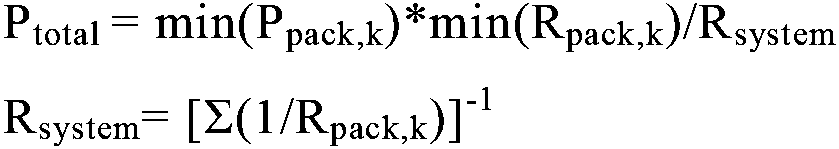
一方、並列マルチパックシステムの総出力をPtotalとするとき、各バッテリーパックのパック出力(Pk)は、回路理論に従って、該当バッテリーパックのパック抵抗(Rpack,k)と並列マルチパックシステムの総抵抗(Rsystem)との抵抗比率Rsystem/Rpack,kによって自動で分配される。すなわち、各バッテリーパックのパック出力(Ppack,k)はPtotal×Rsystem/Rpack,kである。ここで、kはバッテリーパックのインデックスである。 On the other hand, when the total output of the parallel multipack system is P total , the pack output (P k ) of each battery pack is determined according to the circuit theory by the pack resistance (R pack,k ) of the corresponding battery pack and the total output of the parallel multipack system. It is automatically distributed by the resistance ratio R system /R pack,k to the total resistance (R system ). That is, the pack output (P pack,k ) of each battery pack is P total ×R system /R pack,k . where k is the index of the battery pack.
パック出力(Ppack,k)は、該当バッテリーパックの可用出力(available power)ではなく、総出力(Ptotal)と抵抗比率Rsystem/Rpack,kによって決定されるため、パック抵抗(Rpack,k)が低いほどパック出力(Pk)が増加する。したがって、パック抵抗(Rpack,k)の低いバッテリーパックのパック出力(Ppack,k)が可用出力よりも増加することで、該当バッテリーパックが過充電または過放電する場合が生じる。 Since the pack power (P pack,k ) is determined by the total power (P total ) and the resistance ratio R system /R pack,k rather than the available power of the battery pack, the pack resistance (R pack , k ), the pack output (P k ) increases. Therefore, the pack output (P pack,k ) of a battery pack with a low pack resistance (R pack,k ) is greater than the available output, which may result in overcharge or overdischarge of the corresponding battery pack.
本発明は、上記のような従来技術の背景下で創案されたものであり、並列マルチパックシステムの総出力を決定する際、抵抗の低いバッテリーパックのパック出力が可用出力を超えることで過充電または過放電することを防止できる並列マルチパックシステムの出力制御装置及び方法を提供することを目的とする。 The present invention was invented under the background of the prior art as described above. Another object of the present invention is to provide an output control apparatus and method for a parallel multipack system capable of preventing overdischarge.
上記の技術的課題を達成するため、本発明による並列マルチパックシステムの出力制御装置は、並列マルチパックシステムに含まれた互いに並列で接続された第1バッテリーパック~第nバッテリーパックに対する動作特性値を測定する第1センサユニット~第nセンサユニットと、並列マルチパックシステムの総出力に対応するように、負荷で消耗される電力または充電装置で提供する電力を制御する出力管理ユニットと、第1センサユニット~第nセンサユニット及び出力管理ユニットと動作可能に接続されたマルチパック管理ユニットと、を含む。 To achieve the above technical object, an output control apparatus for a parallel multipack system according to the present invention provides operating characteristic values for first to n-th battery packs connected in parallel included in the parallel multipack system. an output management unit that controls the power consumed by the load or the power provided by the charging device to correspond to the total output of the parallel multipack system; a multipack management unit operatively connected to the sensor unit to the nth sensor unit and the output management unit.
望ましくは、マルチパック管理ユニットは、第1センサユニット~第nセンサユニットから受信する各バッテリーパックの動作特性値に基づいて第1バッテリーパック~第nバッテリーパックのパック抵抗をそれぞれ決定し、予め定義されたパック抵抗と可用出力との相関関係情報を用いて各バッテリーパックのパック抵抗に対応する可用出力のうち最小可用出力を決定し、パック抵抗が最も低いバッテリーパックのパック出力が最小可用出力と等しくなるように並列マルチパックシステムの総出力を決定して出力管理ユニットに提供するように構成され得る。 Preferably, the multipack management unit determines and predefines pack resistances of the first to n-th battery packs respectively based on operation characteristic values of the respective battery packs received from the first to n-th sensor units. The minimum available output among the available outputs corresponding to the pack resistance of each battery pack is determined using the obtained correlation information between the pack resistance and the available output, and the pack output of the battery pack with the lowest pack resistance is the minimum available output. It may be arranged to determine the total output of the parallel multipack system to be equal and provide it to the output management unit.
望ましくは、出力管理ユニットは、並列マルチパックシステムの総出力を超えないように、負荷で消耗される電力または充電装置で提供する電力を制御するように構成され得る。 Desirably, the power management unit may be configured to control the power consumed by the load or the power provided by the charging device such that the total power output of the parallel multipack system is not exceeded.
本発明において、相関関係情報は、バッテリーパックのパック抵抗に応じてバッテリーパックの可用出力を定義したパック抵抗-可用出力ルックアップテーブルであり得る。 In the present invention, the correlation information may be a pack resistance-available power lookup table that defines the available power of the battery pack according to the pack resistance of the battery pack.
一態様によれば、マルチパック管理ユニットは、第1センサユニット~第nセンサユニットから周期的に各バッテリーパックの電圧測定値及び電流測定値の入力を受け、複数の電圧測定値及び複数の電流測定値を線形回帰分析法を用いて分析することで、各バッテリーパックのパック抵抗を決定するように構成され得る。 According to one aspect, the multipack management unit receives inputs of voltage measurements and current measurements of each battery pack periodically from the first sensor unit to the nth sensor unit, and receives the plurality of voltage measurements and the plurality of current measurements. Analyzing the measurements using linear regression analysis can be configured to determine the pack resistance of each battery pack.
望ましくは、マルチパック管理ユニットは、下記の数式によって並列マルチパックシステムの総出力を算出するように構成され得る。

望ましくは、マルチパック管理ユニットは、各バッテリーパックのパック出力を下記の数式によって算出するように構成され得る。
![]()
![]()
本発明において、複数のバッテリーパックは並列で接続されているため、複数のバッテリーパックが放電または充電されるとき、各バッテリーパックのパック出力は上記の数式によって計算された値に対応する。 In the present invention, multiple battery packs are connected in parallel, so when multiple battery packs are discharged or charged, the pack output of each battery pack corresponds to the value calculated by the above formula.
本発明による出力制御装置は、マルチパック管理ユニットと出力管理ユニットとの間に介在された通信ユニットをさらに含み得る。 The output control device according to the invention may further include a communication unit interposed between the multipack management unit and the output management unit.
望ましくは、並列マルチパックシステムは、電気駆動自動車に搭載され、出力管理ユニットは、電気駆動自動車の制御システムに含まれ得る。 Preferably, the parallel multipack system is installed in an electric vehicle and the power management unit can be included in the control system of the electric vehicle.
上記の技術的課題は、並列マルチパックシステムの出力制御装置を含むバッテリー管理システムまたは電気駆動自動車によって達成され得る。 The above technical problems can be achieved by a battery management system or an electric powered vehicle that includes an output controller for a parallel multipack system.
上記の技術的課題を達成するため、本発明による並列マルチパックシステムの出力制御方法は、(a)並列マルチパックシステムに含まれた互いに並列で接続された第1バッテリーパック~第nバッテリーパックに対する動作特性値を測定する第1センサユニット~第nセンサユニットを提供する段階と、(b)第1センサユニット~第nセンサユニットから受信する各バッテリーパックの動作特性値に基づいて第1バッテリーパック~第nバッテリーパックのパック抵抗をそれぞれ決定する段階と、(c)予め定義されたパック抵抗と可用出力との相関関係情報を用いて、各バッテリーパックのパック抵抗に対応するn個の可用出力と最小可用出力を決定する段階と、(d)パック抵抗が最も低いバッテリーパックのパック出力が最小可用出力と等しくなるように並列マルチパックシステムの総出力を決定する段階と、(e)並列マルチパックシステムの総出力を超えないように第1バッテリーパック~第nバッテリーパックの充電または放電を制御する段階と、を含む。 In order to achieve the above technical problems, the output control method for a parallel multipack system according to the present invention includes: (a) for the first to nth battery packs connected in parallel included in the parallel multipack system; (b) providing the first to n-th sensor units for measuring operating characteristic values; and (c) the n available outputs corresponding to the pack resistance of each battery pack using the predefined pack resistance-available output correlation information. (d) determining the total output of the parallel multipack system such that the pack output of the battery pack with the lowest pack resistance equals the minimum available output; (e) determining the total output of the parallel multipack system; and controlling the charging or discharging of the first to n-th battery packs so as not to exceed the total output of the pack system.
本発明によれば、並列マルチパックシステムに含まれたバッテリーパックのうち抵抗が低いバッテリーパックのパック出力と、バッテリーパックの可用出力のうち最小可用出力とが等しくなるように、並列マルチパックシステムの総出力を調節することで、抵抗の低いバッテリーパックが過充電または過放電する現象を防止することができる。これによって、並列マルチパックシステムの充電または放電時の安全性と信頼性を向上させることができる。 According to the present invention, the parallel multipack system is configured such that the pack output of the battery pack with the lowest resistance among the battery packs included in the parallel multipack system is equal to the minimum available output among the available outputs of the battery packs. By adjusting the total output, it is possible to prevent overcharging or overdischarging of a battery pack with low resistance. This can improve safety and reliability when charging or discharging parallel multipack systems.
本明細書に添付される次の図面は、本発明の望ましい実施形態を例示するものであり、発明の詳細な説明とともに本発明の技術的な思想をさらに理解させる役割をするものであるため、本発明は図面に記載された事項だけに限定されて解釈されてはならない。 The following drawings attached to this specification illustrate preferred embodiments of the present invention and serve to further understand the technical idea of the present invention together with the detailed description of the invention. The present invention should not be construed as being limited only to the matters described in the drawings.
以下、添付された図面を参照して本発明の実施形態を詳しく説明する。これに先立ち、本明細書及び請求範囲に使われた用語や単語は通常的や辞書的な意味に限定して解釈されてはならず、発明者自らは発明を最善の方法で説明するために用語の概念を適切に定義できるという原則に則して本発明の技術的な思想に応ずる意味及び概念で解釈されねばならない。したがって、本明細書に記載された実施形態及び図面に示された構成は、本発明のもっとも望ましい一実施形態に過ぎず、本発明の技術的な思想のすべてを代弁するものではないため、本出願の時点においてこれらに代替できる多様な均等物及び変形例があり得ることを理解せねばならない。 Hereinafter, embodiments of the present invention will be described in detail with reference to the accompanying drawings. Prior to this, the terms and words used in the specification and claims should not be construed as being limited to their ordinary or dictionary meaning, and the inventors themselves have It should be interpreted with the meaning and concept according to the technical idea of the present invention according to the principle that the concept of the term can be properly defined. Therefore, the embodiments described in this specification and the configurations shown in the drawings are only the most desirable embodiments of the present invention, and do not represent all the technical ideas of the present invention. It should be understood that there may be various equivalents and modifications that could be substituted for them at the time of filing.
後述する実施形態において、バッテリーセルとはリチウム二次電池を意味する。ここで、リチウム二次電池は、充電及び放電中にリチウムイオンが作動イオンとして作用し、正極及び負極で電気化学的反応を引き起こす二次電池を総称する。 In the embodiments described below, the battery cell means a lithium secondary battery. Here, the lithium secondary battery is a general term for secondary batteries in which lithium ions act as working ions during charging and discharging to cause an electrochemical reaction between positive and negative electrodes.
一方、リチウム二次電池に使われた電解質や分離膜の種類、二次電池の包装に使われた包装材の種類、リチウム二次電池の内部または外部の構造などによって二次電池の名称が変わっても、リチウムイオンが作動イオンとして使われる二次電池であれば、すべてリチウム二次電池の範疇に含まれると解釈しなければならない。 On the other hand, the name of the secondary battery changes depending on the type of electrolyte and separator used in the lithium secondary battery, the type of packaging material used to package the secondary battery, and the internal or external structure of the lithium secondary battery. However, if lithium ions are used as working ions, it should be construed that they are all included in the category of lithium secondary batteries.
本発明は、リチウム二次電池の外の他の二次電池にも適用可能である。したがって、作動イオンがリチウムイオンではなくても本発明の技術的思想が適用可能な二次電池であれば、その種類に関係なく本発明の範疇に含まれると解釈しなければならない。 The present invention can also be applied to secondary batteries other than lithium secondary batteries. Therefore, even if the working ions are not lithium ions, any secondary battery to which the technical concept of the present invention can be applied should be construed as being included in the scope of the present invention regardless of its type.
また、バッテリーセルは、一つの単位セルまたは並列で接続された複数の単位セルであり得る。 Also, the battery cell may be one unit cell or a plurality of unit cells connected in parallel.
図1は、本発明の一実施形態による並列マルチパックシステムの出力制御装置の構成を示したブロック図である。 FIG. 1 is a block diagram showing the configuration of an output control device for a parallel multipack system according to one embodiment of the present invention.
図1を参照すると、本発明の一実施形態による出力制御装置10は、複数のバッテリーパック(P1~Pn)が並列で接続された並列マルチパックシステムMPの出力を制御する装置であって、パック抵抗が相対的に低いバッテリーパックの一部が過充電または過放電することを防止するため、並列マルチパックシステムMPの総出力(Ptotal)を適応的に制御する。
Referring to FIG. 1, an
本発明において、並列マルチパックシステムMPは、第1スイッチ部S1~第nスイッチ部Snを通じて並列で接続される第1バッテリーパックP1~第nバッテリーパックPnを含むバッテリーシステムと定義される。 In the present invention, a parallel multipack system MP is defined as a battery system including first battery packs P1 to n-th battery packs Pn connected in parallel through first to n-th switch units S1 to Sn.
並列マルチパックシステムMPは、外部スイッチ部Mを通じて負荷Lに接続され得る。外部スイッチ部Mは、外部高電位スイッチM+と外部低電位スイッチM-を含む。外部高電位スイッチM+と外部低電位スイッチM-はリレースイッチであり得るが、本発明がこれに限定されることはない。 A parallel multipack system MP may be connected to a load L through an external switch section M. The external switch section M includes an external high potential switch M+ and an external low potential switch M-. The external high potential switch M+ and the external low potential switch M− can be relay switches, but the invention is not so limited.
外部高電位スイッチM+と外部低電位スイッチM-がターンオンされれば、並列マルチパックシステムMPは負荷Lに電気的に接続される。逆に、外部高電位スイッチM+と外部低電位スイッチM-がターンオフされれば、並列マルチパックシステムMPと負荷Lとの電気的接続が解除される。 The parallel multipack system MP is electrically connected to the load L if the external high potential switch M+ and the external low potential switch M- are turned on. Conversely, if the external high potential switch M+ and the external low potential switch M- are turned off, the electrical connection between the parallel multipack system MP and the load L is broken.
並列マルチパックシステムMPの出力制御装置10は、負荷Lを制御する制御装置から充電開始、充電終了、放電開始または放電終了に関わる制御命令を受信し、制御命令に従って外部スイッチ部Mのターンオンまたはターンオフ動作を制御する。
The
望ましくは、並列マルチパックシステムMPは電気駆動自動車Eに搭載され得るが、本発明がこれに限定されることはない。電気駆動自動車Eは、電気自動車やハイブリッド自動車のようにモーターによって走行可能な自動車を称する。 Desirably, the parallel multipack system MP can be installed in an electric vehicle E, but the invention is not so limited. The electric vehicle E refers to a vehicle that can be driven by a motor, such as an electric vehicle or a hybrid vehicle.
負荷Lは、並列マルチパックシステムMPから電力の供給を受ける装置であって、一例として電気駆動自動車Eに含まれたインバータであり得る。インバータは、電気駆動自動車Eの電気モーターの前段に設けられ、並列マルチパックシステムMPから供給される直流電流を三相交流電流に変換して電気モーターに供給する電力変換回路である。 The load L is a device that receives power from the parallel multipack system MP, and may be an inverter included in the electric vehicle E, for example. The inverter is a power conversion circuit installed in front of the electric motor of the electric vehicle E, and converts the direct current supplied from the parallel multipack system MP into a three-phase alternating current to supply the electric motor.
また、負荷Lは、DC/DCコンバータであり得る。DC/DCコンバータは、並列マルチパックシステムMPから供給される直流電流の電圧を電気駆動自動車Eの電装ユニットの駆動電圧またはADASユニットの駆動電圧に変換し、電装ユニットまたはADASユニットに印加する電力変換回路である。 Also, the load L can be a DC/DC converter. The DC/DC converter converts the voltage of the direct current supplied from the parallel multipack system MP into the driving voltage of the electrical unit of the electric drive vehicle E or the driving voltage of the ADAS unit, and applies it to the electrical unit or the ADAS unit. circuit.
本発明において、負荷Lの種類はインバータやDC/DCコンバータに限定されず、並列マルチパックシステムMPから電力が供給可能な装置またはデバイスであれば、その種類に関係なく負荷Lの範疇に含まれ得る。 In the present invention, the type of the load L is not limited to an inverter or a DC/DC converter, and any device or device that can be supplied with power from the parallel multipack system MP is included in the category of the load L regardless of its type. obtain.
本発明において、第1バッテリーパックP1~第nバッテリーパックPnのそれぞれは、内部に直列で接続された複数のバッテリーセルを含む。すなわち、第1バッテリーパックP1は、直列で接続された第1バッテリーセルC11~第pバッテリーセルC1pを含む。また、第2バッテリーパックP2は、直列で接続された第1バッテリーセルC21~第pバッテリーセルC2pを含む。また、第3バッテリーパックP3は、直列で接続された第1バッテリーセルC31~第pバッテリーセルC3pを含む。また、第nバッテリーパックPnは、直列で接続された第1バッテリーセルCn1~第pバッテリーセルCnpを含む。図示されていない第4バッテリーパック~第n-1バッテリーパックも、図示されたバッテリーパックと同様に直列で接続されたp個のバッテリーセルを含んでいる。 In the present invention, each of the first battery pack P1 to the n-th battery pack Pn includes a plurality of battery cells connected in series. That is, the first battery pack P1 includes first to p-th battery cells C 11 to C 1p connected in series. Also, the second battery pack P2 includes a first battery cell C 21 to a p-th battery cell C 2p connected in series. Also, the third battery pack P3 includes a first battery cell C 31 to a p-th battery cell C 3p connected in series. Also, the n-th battery pack Pn includes a first battery cell C n1 to a p-th battery cell C np connected in series. The fourth to n-1th battery packs (not shown) also include p battery cells connected in series like the battery packs shown.
第1バッテリーパックP1~第nバッテリーパックPnは、それぞれ、内部にスイッチ部(S1~Sn)を含む。すなわち、第1バッテリーパックP1は第1スイッチ部S1を含む。また、第2バッテリーパックP2は第2スイッチ部S2を含む。また、第3バッテリーパックP3は第3スイッチ部S3を含む。また、第nバッテリーパックPnは第nスイッチ部Snを含む。図示されていない第4バッテリーパック~第n-1バッテリーパックも、図示されたバッテリーパックと同様にスイッチ部を含んでいる。 Each of the first battery pack P1 to the n-th battery pack Pn includes switch units (S1 to Sn) therein. That is, the first battery pack P1 includes a first switch section S1. Also, the second battery pack P2 includes a second switch section S2. Also, the third battery pack P3 includes a third switch section S3. Also, the n-th battery pack Pn includes an n-th switch Sn. The fourth to (n-1)th battery packs (not shown) also include a switch section like the battery packs shown.
第1スイッチ部S1~第nスイッチ部Snは、それぞれ、低電位スイッチ及び高電位スイッチを含む。すなわち、第1スイッチ部S1は、第1バッテリーパックP1の高電位側に設けられた第1高電位スイッチS1+及び第1バッテリーパックP1の低電位側に設けられた第1低電位スイッチS1-を含む。また、第2スイッチ部S2は、第2バッテリーパックP2の高電位側に設けられた第2高電位スイッチS2+及び第2バッテリーパックP2の低電位側に設けられた第2低電位スイッチS2-を含む。また、第3スイッチ部S3は、第3バッテリーパックP3の高電位側に設けられた第3高電位スイッチS3+及び第3バッテリーパックP3の低電位側に設けられた第3低電位スイッチS3-を含む。また、第nスイッチ部Snは、第nバッテリーパックPnの高電位側に設けられた第n高電位スイッチSn+及び第nバッテリーパックPnの低電位側に設けられた第n低電位スイッチSn-を含む。一方、図示されていない第4バッテリーパック~第n-1バッテリーパックも、図示されたバッテリーパックと同様に高電位スイッチ及び低電位スイッチを含んでいる。また、各スイッチ部において、高電位スイッチ及び低電位スイッチのいずれか一方が省略されることもあり得る。 Each of the first switch section S1 to the n-th switch section Sn includes a low potential switch and a high potential switch. That is, the first switch section S1 includes a first high potential switch S1 + provided on the high potential side of the first battery pack P1 and a first low potential switch S1 − provided on the low potential side of the first battery pack P1. including. The second switch section S2 includes a second high potential switch S2 + provided on the high potential side of the second battery pack P2 and a second low potential switch S2 − provided on the low potential side of the second battery pack P2. including. The third switch section S3 includes a third high potential switch S3 + provided on the high potential side of the third battery pack P3 and a third low potential switch S3 − provided on the low potential side of the third battery pack P3. including. In addition, the n-th switch part Sn includes the n-th high potential switch Sn + provided on the high potential side of the n-th battery pack Pn and the n-th low potential switch Sn − provided on the low potential side of the n-th battery pack Pn. including. On the other hand, the fourth to n-1th battery packs (not shown) also include high potential switches and low potential switches like the battery packs shown. Also, one of the high-potential switch and the low-potential switch may be omitted in each switch unit.
以下の説明において、スイッチ部がターンオンされるとするとき、低電位スイッチが先にターンオンされて高電位スイッチが後にターンオンされ得る。また、スイッチ部がターンオフされるとするとき、高電位スイッチが先にターンオフされて低電位スイッチが後にターンオフされ得る。 In the following description, when the switch section is turned on, the low potential switch may be turned on first and the high potential switch may be turned on later. Also, when the switch units are turned off, the high potential switch may be turned off first and the low potential switch may be turned off later.
望ましくは、スイッチ部(S1~Sn)を構成するスイッチは、リレースイッチであり得る。代案的にスイッチ部(S1~Sn)は、MOSFETのような半導体スイッチや電力用半導体スイッチであり得るが、本発明がこれに限定されることはない。 Desirably, the switches constituting the switch units (S1-Sn) may be relay switches. Alternatively, the switch units (S1-Sn) may be semiconductor switches such as MOSFETs or power semiconductor switches, but the present invention is not limited thereto.
負荷Lの前段にはキャパシタCapが備えられる。キャパシタCapは、並列マルチパックシステムMPと負荷Lとの間に並列で接続される。キャパシタCapはmノイズ電流が負荷L側に印加されることを防止するフィルター機能をする。 A capacitor Cap is provided in front of the load L. Capacitor Cap is connected in parallel between parallel multipack system MP and load L. The capacitor Cap functions as a filter to prevent the m noise current from being applied to the L side of the load.
本発明の一実施形態による出力制御装置10は、第1電流センサI1~第n電流センサInを含む。第1電流センサI1~第n電流センサInは、第1バッテリーパックP1~第nバッテリーパックPnと接続された電力ライン(C1~Cn)にそれぞれ設けられて電力ライン(C1~Cn)を通じて流れる電流値を測定する。
An
すなわち、第1電流センサI1は、第1バッテリーパックP1に含まれた第1電力ラインC1を通じて流れる第1バッテリーパック電流値Is1を測定する。また、第2電流センサI2は、第2バッテリーパックP2に含まれた第2電力ラインC2を通じて流れる第2バッテリーパック電流値Is2を測定する。また、第3電流センサI3は、第3バッテリーパックP3に含まれた第3電力ラインC3を通じて流れる第3バッテリーパック電流値Is3を測定する。また、第n電流センサInは、第nバッテリーパックPnに含まれた第n電力ラインCnを通じて流れる第nバッテリーパック電流値Isnを測定する。図示されていないが、第4電流センサ~第n-1電流センサは、それぞれ第4バッテリーパック~第n-1バッテリーパックに含まれた第4電力ライン~第n-1電力ラインを通じて流れる電流値を測定する。 That is, the first current sensor I1 measures the first battery pack current Is1 flowing through the first power line C1 included in the first battery pack P1. Also, the second current sensor I2 measures a second battery pack current Is2 flowing through a second power line C2 included in the second battery pack P2. Also, the third current sensor I3 measures a third battery pack current Is3 flowing through a third power line C3 included in the third battery pack P3. Also, the n-th current sensor In measures the n-th battery pack current I sn flowing through the n-th power line Cn included in the n-th battery pack Pn. Although not shown, the fourth to n-1th current sensors indicate current values flowing through the fourth to n-1th power lines included in the fourth to n-1th battery packs, respectively. to measure.
図面では、第1電流センサI1~第n電流センサInが各バッテリーパックに含まれているが、本発明は、第1電流センサI1~第n電流センサInが各バッテリーパックの外部に設けられることを制限しない。 In the drawing, the first current sensor I1 to the n-th current sensor In are included in each battery pack, but the present invention is such that the first current sensor I1 to the n-th current sensor In are provided outside each battery pack. do not limit
第1電流センサI1~第n電流センサInは、ホールセンサであり得る。ホールセンサは、電流の大きさに応じた電圧信号を出力する公知の電流センサである。他の例として、第1電流センサI1~第n電流センサInは、センス抵抗であり得る。センス抵抗の両端に印加された電圧を測定すれば、オームの法則を用いてセンス抵抗を通じて流れる電流の大きさを決定できる。すなわち、測定された電圧の大きさを既知のセンス抵抗の抵抗値で除することで、センス抵抗を通じて流れる電流の大きさを決定することができる。 The first current sensor I1 to the n-th current sensor In can be Hall sensors. A Hall sensor is a known current sensor that outputs a voltage signal corresponding to the magnitude of current. As another example, the first current sensor I1 to the n-th current sensor In can be sense resistors. By measuring the voltage applied across the sense resistor, Ohm's law can be used to determine the magnitude of the current flowing through the sense resistor. That is, the magnitude of the current flowing through the sense resistor can be determined by dividing the magnitude of the measured voltage by the known resistance of the sense resistor.
また、本発明の一実施形態による出力制御装置10は、第1電圧センサV1~第n電圧センサVnを含む。第1電圧センサV1は、第1バッテリーパックP1の正極と負極との電位差に該当する第1バッテリーパック電圧値Vs1を測定する。また、第2電圧センサV2は、第2バッテリーパックP2の正極と負極との電位差に該当する第2バッテリーパック電圧値Vs2を測定する。また、第3電圧センサV3は、第3バッテリーパックP3の正極と負極との電位差に該当する第3バッテリーパック電圧値Vs3を測定する。また、第n電圧センサVnは、第nバッテリーパックPnの正極と負極との電位差に該当する第nバッテリーパック電圧値Vsnを測定する。図示されていないが、第4電圧センサ~第n-1電圧センサはそれぞれ、第4バッテリーパック電圧値~第n-1バッテリーパック電圧値を測定する。
Also, the
第1電圧センサV1~第n電圧センサVnは、差動増幅回路のような電圧測定回路を含む。電圧測定回路は、当業界に周知されているため、電圧測定回路についての詳しい説明は省略する。 The first voltage sensor V1 to the n-th voltage sensor Vn include voltage measurement circuits such as differential amplifier circuits. Since voltage measurement circuits are well known in the art, a detailed description of voltage measurement circuits is omitted.
また、本発明の一実施形態による出力制御装置10は、第1温度センサT1~第n温度センサTnを含む。第1温度センサT1は、第1バッテリーパックP1の所定位置、例えば中央に位置したセルの表面温度を示す第1バッテリーパック温度値Ts1を測定する。また、第2温度センサT2は、第2バッテリーパックP2の所定位置、例えば中央に位置したセルの表面温度を示す第2バッテリーパック温度値Ts2を測定する。また、第3温度センサT3は、第3バッテリーパックP3の所定位置、例えば中央に位置したセルの表面温度を示す第3バッテリーパック温度値Ts3を測定する。また、第n温度センサTnは、第nバッテリーパックPnの所定位置、例えば中央に位置したセルの表面温度を示す第nバッテリーパック温度値Tsnを測定する。図示されていないが、第4温度センサ~第n-1オンドセンサはそれぞれ、第4バッテリーパック温度値~第n-1バッテリーパック温度値を測定する。
Also, the
本発明において、第1電流センサI1、第1電圧センサV1及び第1温度センサT1は、第1センサユニットSU1を構成する。また、第2電流センサI2、第2電圧センサV2及び第2温度センサT2は、第2センサユニットSU2を構成する。また、第3電流センサI3、第3電圧センサV3及び第3温度センサT3は、第3センサユニットSU3を構成する。また、第n電流センサIn、第n電圧センサVn及び第n温度センサTnは、第nセンサユニットSUnを構成する。図示されていないが、第4センサユニット~第n-1センサユニットもそれぞれ、電流センサ、電圧センサ及び温度センサを含む。 In the present invention, the first current sensor I1, the first voltage sensor V1 and the first temperature sensor T1 constitute the first sensor unit SU1. Also, the second current sensor I2, the second voltage sensor V2 and the second temperature sensor T2 constitute a second sensor unit SU2. Also, the third current sensor I3, the third voltage sensor V3 and the third temperature sensor T3 constitute a third sensor unit SU3. Also, the n-th current sensor In, the n-th voltage sensor Vn, and the n-th temperature sensor Tn constitute an n-th sensor unit SUn. Although not shown, the fourth to n-1th sensor units also include current sensors, voltage sensors and temperature sensors, respectively.
場合によって、第1センサユニットSU1~第nセンサユニットSUnは、電流、電圧及び温度を測定するセンサの他に、バッテリーパックの他の動作特性を測定するセンサをさらに含み得ることは自明である。 It is obvious that the first sensor unit SU1 to the n-th sensor unit SUn may further include sensors for measuring other operating characteristics of the battery pack in addition to sensors for measuring current, voltage and temperature.
また、望ましくは、本発明の一実施形態による出力制御装置10は、第1スイッチ部S1~第nスイッチ部Sn及び第1センサユニットSU1~第nセンサユニットSUnと動作可能に接続されたマルチパック管理ユニット20を含む。
Also, preferably, the
マルチパック管理ユニット20は、負荷Lで消耗される電力を管理する電気駆動自動車Eの出力管理ユニット40と動作可能に結合され得る。出力管理ユニット40は、電気駆動自動車Eに含まれた制御システムに含まれた制御要素であって、負荷Lで消耗される電力の大きさを並列マルチパックシステムMPの総出力に応じて適応的に管理することができる。ここで、総出力とは、並列マルチパックシステムMPの総放電出力を意味する。
本発明において、負荷Lは充電装置で代替可能である。この場合、出力管理ユニット40は、並列マルチパックシステムMPに供給される充電電力を並列マルチパックシステムMPの総出力に応じて適応的に管理することができる。ここで、総出力とは、並列マルチパックシステムMPに提供される総充電出力を意味する。
In the present invention, load L can be replaced by a charging device. In this case, the
望ましくは、本発明の一実施形態による出力制御装置10は、マルチパック管理ユニット20と出力管理ユニット40との間に介在された通信ユニット30をさらに含むことができる。通信ユニット30は、マルチパック管理ユニット20と出力管理ユニット40との間で通信インターフェースを形成する。
Desirably, the
本発明において、通信インターフェースとしては、相異なる二つの通信媒体が通信できるように支援する公知の通信インターフェースであれば制限なく使用可能である。通信インターフェースは有線または無線通信を支援することができる。望ましくは、通信インターフェースは、CAN(Controller Area Network)通信やデイジーチェーン(daisy chain)通信を支援するものであり得る。 In the present invention, any known communication interface that supports communication between two different communication media can be used without limitation as the communication interface. A communication interface may support wired or wireless communication. Preferably, the communication interface may support CAN (Controller Area Network) communication or daisy chain communication.
マルチパック管理ユニット20は、通信ユニット30を通じて電気駆動自動車Eの出力管理ユニット40から放電要請を受信すれば、外部スイッチ部Mをターンオンさせて並列マルチパックシステムMPの放電を開始する。
When receiving a discharge request from the
参考までに、マルチパック管理ユニット20から出力されるM+信号とM-信号は、それぞれ外部高電位スイッチM+と外部低電位スイッチM-のオンオフを制御する信号を示す。また、マルチパック管理ユニット20から出力されるS1~Sn信号は、第1スイッチ部S1~第nスイッチ部Snのオンオフを制御する信号を示す。
For reference, the M+ and M- signals output from the
また、マルチパック管理ユニット20は、並列マルチパックシステムMPが放電する間、第1センサユニットSU1~第nセンサユニットSUnに含まれた電流センサ(I1~In)、電圧センサ(V1~Vn)及び温度センサ(T1~Tn)の動作を制御し、周期的に電流センサ(I1~In)、電圧センサ(V1~Vn)及び温度センサ(T1~Tn)から受信する各バッテリーパックの動作特性値を保存ユニット50に記録する。
Also, the
ここで、動作特性値は、図示されたように、第1バッテリーパックP1~第nバッテリーパックPnの電流測定値(Is1~Isn)、電圧測定値(Vs1~Vsn)及び温度測定値(Ts1~Tsn)を含む。 Here, the operating characteristic values are current measurement values (I s1 to I sn ), voltage measurement values (V s1 to V sn ), and temperature measurement values of the first battery pack P1 to the n-th battery pack Pn. contains values (T s1 to T sn ).
また、マルチパック管理ユニット20は、第1バッテリーパックP1~第nバッテリーパックPnの動作特性値に基づいて、各バッテリーパックの充電状態(State of Charge:SOC)を決定することができる。
Also, the
一例として、マルチパック管理ユニット20は、第1バッテリーパックP1~第nバッテリーパックPnの電流測定値(Is1~Isn)を経時的に積算して第1バッテリーパックP1~第nバッテリーパックPnの充電状態を決定することができる。マルチパック管理ユニット20は、第1バッテリーパックP1~第nバッテリーパックPnの放電が開始される前に第1電圧センサV1~第n電圧センサVnを用いて各バッテリーパックの開放電圧を測定し、開放電圧-充電状態ルックアップテーブルを参照して開放電圧に対応する充電状態をルックアップして各バッテリーパックの充電状態初期値を決定することができる。そして、マルチパック管理ユニット20は、充電状態初期値を基準にして第1バッテリーパックP1~第nバッテリーパックPnの電流測定値(Is1~Isn)を経時的に積算して保存ユニット50に記録することができる。開放電圧-充電状態ルックアップテーブルは、予め定義されて保存ユニット50に記録され得る。
As an example, the
他の例として、マルチパック管理ユニット20は、拡張カルマンフィルターを用いて並列マルチパックシステムMPが放電する間に第1バッテリーパックP1~第nバッテリーパックPnの充電状態を決定することができる。すなわち、マルチパック管理ユニット20は、第1センサユニットSU1~第nセンサユニットSUnから入力された各バッテリーパックの動作特性値をソフトウェアでコーディングされた拡張カルマンフィルターに入力し、第1バッテリーパックP1~第nバッテリーパックPnの充電状態を決定して保存ユニット50に記録することができる。
As another example, the
拡張カルマンフィルターは、本発明が属した技術分野に周知されている。一例として、拡張カルマンフィルターは、等価回路モデルまたは電気化学的ROM(Reduced Order Model)に基づいた適応的アルゴリズムであり得る。 Extended Kalman filters are well known in the technical field to which the present invention pertains. As an example, the extended Kalman filter can be an adaptive algorithm based on an equivalent circuit model or an electrochemical ROM (Reduced Order Model).
拡張カルマンフィルターを用いた充電状態の推定は、一例としてGregory L. Plettの論文「Extended Kalman filtering for battery management systems of LiPB-based HEV battery packs, Parts 1, 2 and 3」(Journal of Power Source 134, 2004, 252-261)を参照可能であり、本明細書の一部として上記の論文が援用され得る。
State of charge estimation using an extended Kalman filter is described by Gregory L. et al. See Plett, "Extended Kalman filtering for battery management systems of LiPB-based HEV battery packs,
勿論、充電状態は、上述した電流積算法または拡張カルマンフィルターの他にも、バッテリーパックの動作特性値を選択的に活用して充電状態を決定可能な他の公知の方法によっても決定され得る。 Of course, the state of charge can be determined by the above-described current integration method or extended Kalman filter, as well as other known methods that can selectively utilize operating characteristic values of the battery pack to determine the state of charge.
他の態様において、マルチパック管理ユニット20は、保存ユニット50に記録された各バッテリーパックに対する複数の電流値のうち特定電圧区間で測定された電流値を積算することができる。また、マルチパック管理ユニット20は、特定電圧区間の積算電流値に応じた退化度(State of Health:SOH)を予め定義した電流積算値-退化度ルックアップテーブルを参照して各バッテリーパックの退化度を決定することができる。
In another aspect, the
さらに他の例として、マルチパック管理ユニット20は、拡張カルマンフィルターを用いて並列マルチパックシステムMPが放電する間に第1バッテリーパックP1~第nバッテリーパックPnの退化度を適応的に決定することができる。
As yet another example, the
すなわち、マルチパック管理ユニット20は、第1センサユニットSU1~第nセンサユニットSUnから入力された各バッテリーパックの動作特性値をソフトウェアでコーディングされた拡張カルマンフィルターに入力し、第1バッテリーパックP1~第nバッテリーパックPnの退化度を決定することができる。
That is, the
拡張カルマンフィルターを用いた退化度の推定は、一例として韓国特許第10-0818520号公報「電気化学セルの現在状態と現在パラメータを推定する装置、方法及びシステム、並びに記録媒体」に開示されており、本明細書の一部として援用され得る。 Estimation of the degree of degeneration using the extended Kalman filter is disclosed in Korean Patent No. 10-0818520 "Apparatus, method and system for estimating current state and current parameters of electrochemical cell, and recording medium" as an example. , which may be incorporated by reference herein.
望ましくは、マルチパック管理ユニット20は、第1バッテリーパックP1~第nバッテリーパックPnの動作特性値に基づいて各バッテリーパック毎にパック抵抗を決定し、保存ユニット50に記録することができる。
Preferably, the
一例として、マルチパック管理ユニット20は、並列マルチパックシステムMPが放電する間に、保存ユニット50に記録された各バッテリーパックに対する複数の電流測定値及び複数の電圧測定値を用いて線形回帰分析法で各バッテリーパックのI-Vプロファイルを決定することができる。ここで、複数の電流測定値及び複数の電圧測定値は、現在時点を基準にして最近の測定値に対してサンプリングされたものである。また、マルチパック管理ユニット20は、I-Vプロファイルの傾きを決定し、傾きの絶対値を各バッテリーパックのパック抵抗として算出して保存ユニット50に記録することができる。
As an example, the
他の例として、マルチパック管理ユニット20は、並列マルチパックシステムMPが放電する間に、保存ユニット50に記録された各バッテリーパックに対する現在の温度測定値及び充電状態を参照して、温度測定値及び充電状態に対応するパック抵抗を充電状態-温度-パック抵抗ルックアップテーブルからルックアップして決定し、保存ユニット50に記録することができる。ここで、充電状態-温度-パック抵抗ルックアップテーブルは、充電状態及び温度に応じて対応するパック抵抗をルックアップ可能なデータ構造を有し、予め定義されて保存ユニット50に記録され得る。
As another example, the
また、マルチパック管理ユニット20は、予め定義されたパック抵抗と可用出力との相関関係情報を用いて、各バッテリーパックのパック抵抗に対応するn個の可用出力を決定し、n個の可用出力のうち最小可用出力を決定する。
The
望ましくは、予め定義された相関関係は、パック抵抗に応じて可用出力をルックアップ可能なパック抵抗-可用出力ルックアップテーブルであり得る。 Desirably, the predefined correlation may be a pack resistance-available output lookup table capable of looking up the available output depending on the pack resistance.
図2は、本発明の一実施形態によるパック抵抗-可用出力ルックアップテーブルの一例を示した図である。 FIG. 2 is a diagram illustrating an example of a pack resistor-available output lookup table according to one embodiment of the present invention.
図2を参照すると、パック抵抗-可用出力ルックアップテーブルは、パック抵抗を用いて可用出力をルックアップ可能なデータ構造を有し、予め定義されて保存ユニット50に記録され得る。パック抵抗-可用出力ルックアップテーブルは、バッテリーパックの温度毎に独立的に設けられることが望ましい。この場合、バッテリーパックの温度に応じて可用出力が変化することを考慮できる。望ましくは、マルチパック管理ユニット20は、各バッテリーパックの温度測定値を用いてルックアップするパック抵抗-可用出力ルックアップテーブルを識別し、識別されたルックアップテーブルを用いてパック抵抗に対応する可用出力を決定することができる。
Referring to FIG. 2, the pack resistor-available output lookup table has a data structure that can look up the available output using the pack resistor, and can be predefined and recorded in the
より望ましくは、パック抵抗-可用出力ルックアップテーブルは、バッテリーパックの退化度と温度毎に独立的に設けられ得る。この場合、バッテリーパックの温度と退化度に応じて可用出力が変化することを考慮できる。望ましくは、マルチパック管理ユニット20は、各バッテリーパックの温度測定値と退化度を用いてルックアップするパック抵抗-可用出力ルックアップテーブルを識別し、識別されたルックアップテーブルを用いてパック抵抗に対応する可用出力を決定することができる。
More preferably, the pack resistance-available output lookup table can be independently provided for each battery pack degradation and temperature. In this case, it can be taken into account that the available output changes according to the temperature and degree of degradation of the battery pack. Desirably, the
他の態様において、マルチパック管理ユニット20は、各バッテリーパックのパック抵抗を決定するときに生成したI-Vプロファイルを用いて、各バッテリーパック毎に可用出力を決定することができる。
In another aspect,
図3は、本発明の一実施形態によるI-Vプロファイルの一例を示したグラフである。 FIG. 3 is a graph illustrating an example of an IV profile according to one embodiment of the invention.
図3を参照すると、I-VプロファイルがV軸と交わる交差点の電圧はバッテリーパックの充電状態に対応する開放電圧に該当する。点表示は、並列マルチパックシステムMPの放電中に測定された複数の電圧測定値と電流測定値を示す。I-Vプロファイルは、複数の電圧測定値と複数の電流測定値に対する線形回帰分析法を通じて生成した直線である。バッテリーパックが放電中であるときは電流測定値が正の値であり、バッテリーパックが充電中であるときは電流測定値が負の値である。また、I-Vプロファイルの傾きの絶対値は、バッテリーパックのパック抵抗に該当する。 Referring to FIG. 3, the voltage at the intersection of the IV profile with the V axis corresponds to the open circuit voltage corresponding to the state of charge of the battery pack. The dot display shows multiple voltage and current measurements taken during discharge of the parallel multipack system MP. The IV profile is a straight line generated through linear regression analysis on multiple voltage measurements and multiple current measurements. The current measurement is positive when the battery pack is discharging and the current measurement is negative when the battery pack is charging. Also, the absolute value of the slope of the IV profile corresponds to the pack resistance of the battery pack.
マルチパック管理ユニット20は、並列マルチパックシステムMPが放電中であるとき、I-Vプロファイルが放電下限電圧を示す直線V=Vminと交わる交差点での電流値を放電最大電流(Imax,discharge)として決定し、Vmin×|Imax,discharge|をバッテリーパックの可用出力として決定することができる。図面において、菱形点は、並列マルチパックシステムMPが放電中であるときに測定した複数の電圧測定値と複数の電流測定値を示す座標である。
When the parallel multipack system MP is discharging, the multipack
一方、並列マルチパックシステムMPが充電中である場合、マルチパック管理ユニット20は、各バッテリーパックのパック抵抗を決定するときに生成したI-Vプロファイルが充電上限電圧を示す直線V=Vmaxと交わる交差点での電流値を充電最大電流(Imax,charge)として決定し、Vmax×|Imax,charge|をバッテリーパックの可用出力として決定することができる。図面において、三角点は、並列マルチパックシステムMPが充電中であるときに測定した複数の電圧測定値と複数の電流測定値を示す座標である。
On the other hand, when the parallel multipack system MP is charging, the
マルチパック管理ユニット20は、第1バッテリーパックP1~第nバッテリーパックPnの可用出力を決定した後、n個の可用出力のうち最小可用出力を決定して保存ユニット50に記録する。
After determining the available outputs of the first battery pack P1 to the n-th battery pack Pn, the
また、マルチパック管理ユニット20は、パック抵抗が最も低いバッテリーパックのパック出力が最小可用出力と等しくなるように並列マルチパックシステムMPの総出力を決定して保存ユニット50に記録する。
Also, the
具体的には、マルチパック管理ユニット20は、下記の数式1によって並列マルチパックシステムMPの総出力を決定することができる。
[数式1]

[Formula 1]
ここで、kは、1以上n以下の整数である。 Here, k is an integer greater than or equal to 1 and less than or equal to n.
nは、バッテリーパックの個数である。 n is the number of battery packs.
Ptotalは、並列マルチパックシステムMPの総出力である。 P total is the total output of the parallel multipack system MP.
Ppack,kは、第kバッテリーパックの可用出力である。 P pack,k is the available output of the kth battery pack.
Rpack,kは、第kバッテリーパックのパック抵抗である。 R pack,k is the pack resistance of the kth battery pack.
Rsystemは、並列マルチパックシステムMPの総抵抗である。 R system is the total resistance of the parallel multipack system MP.
min()は、複数の入力変数のうち最小値を返す関数である。 min( ) is a function that returns the minimum value among multiple input variables.
上記の数式1は、下記の数式2のように、従来技術によって決定される総出力min(Ppack,k)×nが含まれた数式に変換することができる。
[数式2]

[Formula 2]
上記の数式2の第2行において、min(Rpack,k)/{[min(Ppack,k)×n]×Rsystem}は、第1バッテリーパックP1~第nバッテリーパックPnのうち抵抗が最も低いバッテリーパックに対し、従来技術によって算出したパック出力の逆数に該当する。
In the second row of
なぜなら、従来技術によって算出される並列マルチパックシステムMPの総出力は、パック出力の最小値min(Ppack,k)とバッテリーパックの個数nとを乗じた値に該当するmin(Ppack,k)×nであり、抵抗が最も低いバッテリーパックのパック出力は、従来技術によって算出した総出力min(Ppack,k)×nに抵抗の比率Rsystem/min(Rpack,k)を掛けた値に該当するためである。 This is because the total output of the parallel multipack system MP calculated according to the prior art is min(P pack ,k )×n, and the pack power of the battery pack with the lowest resistance is the total power min(P pack,k )×n calculated according to the prior art multiplied by the resistance ratio R system /min(R pack,k ). This is because it corresponds to the value.
抵抗が最も低いバッテリーパックのパック出力は、n個のパック出力のうち最大値になるため、数式2の第2行においてmin(Rpack,k)/{[min(Ppack,k)×n]×Rsystem}は、max(Ppack,k)-1に置換して第3行の数式に最終的に整理できる。 Since the pack output of the battery pack with the lowest resistance will be the largest of the n pack outputs, min(R pack,k )/{[min(P pack,k )×n ]×R system } can finally be reduced to the equation on the third line by substituting max(P pack,k ) −1 .
数式2を参照すると、本発明によって決定される並列マルチパックシステムMPの総出力(Ptotal)は、従来技術によって決定される総出力min(Ppack,k)×nに減衰ファクターであるmin(Ppack,k)/max(Ppack,k)を乗じた値に該当する。ここで、min(Ppack,k)/max(Ppack,k)は、パック出力のうち最大値と最小値との相対的な比率であるため、常に1よりも小さい。したがって、本発明によって決定される並列マルチパックシステムMPの総出力は、従来技術によって決定された総出力よりも[min(Ppack,k)×n]×[1-min(Ppack,k)/max(Ppack,k)]だけ小さい。
Referring to
数式1によって決定される総出力(Ptotal)を用いて抵抗が最も低いバッテリーパックのパック出力(Ppack,Rmin)を算出すれば、数式3のように第1バッテリーパック~第nバッテリーパックの可用出力のうち最小可用出力と等しくなる。したがって、抵抗が低いバッテリーパックが過充電または過放電する現象を根本的に防止することができる。
[数式3]

[Formula 3]
マルチパック管理ユニット20は、総出力(Ptotal)を決定した後、通信ユニット30を通じて総出力(Ptotal)に関わる情報を電気駆動自動車Eの出力管理ユニット40に伝送することができる。
After determining the total power (P total ), the
すると、出力管理ユニット40は、並列マルチパックシステムMPの出力が数式1によって決定される総出力(Ptotal)を超えないように、並列マルチパックシステムMPの充電または放電を制御する。すなわち、出力管理ユニット40は、負荷Lで消耗される電力を数式1によって決定される総出力(Ptotal)を超えないように電力の消耗量を統制する。
The
具体的には、出力管理ユニット40は、並列マルチパックシステムMPの総出力(Ptotal)を超えないように、負荷Lに該当するインバータやDC/DCコンバータに供給される電力と、車線離脱防止、前方追突警告などの先進運転支援システム(ADAS)ユニットと電装ユニットなどに供給される電力を適応的に分配する。
Specifically, the
一方、負荷Lが充電装置で代替される場合、出力管理ユニット40は、充電装置を用いて並列マルチパックシステムMPの充電を行う過程で数式1によって決定される総出力(Ptotal)を超えないように、並列マルチパックシステムMPに提供される充電電圧及び充電電流の大きさを適応的に調節することができる。
On the other hand, when the load L is replaced by a charging device, the
望ましくは、マルチパック管理ユニット20は、各バッテリーパックの可用出力(Ppack,k)を下記の数式4によって算出するように構成され得る。
[数式4]
![]()
[Formula 4]
![]()
並列マルチパックシステムMPにおいて、第1バッテリーパックP1~第nバッテリーパックPnは並列で接続されている。したがって、並列マルチパックシステムMPの現在出力がPtotalであるとき、各バッテリーパックのパック出力(Ppack,k)は上記の数式によって計算された値に対応する。 In the parallel multipack system MP, the first battery pack P1 to the n-th battery pack Pn are connected in parallel. Therefore, when the current output of the parallel multipack system MP is P total , the pack output (P pack,k ) of each battery pack corresponds to the value calculated by the above formula.
本発明によれば、従来技術と異なって、並列マルチパックシステムMPを構成するバッテリーパックのうち抵抗が低いバッテリーパックが過充電または過放電することを根本的に防止することができる。 According to the present invention, unlike the prior art, overcharging or overdischarging of a battery pack having a low resistance among battery packs constituting a parallel multipack system MP can be fundamentally prevented.
本発明において、保存ユニット50は、情報を記録し消去可能な保存媒体であればその種類に特に制限がない。一例として、保存ユニット50はRAM(random access memory)、ROM(read only memory)、EEPROM(Electrically Erasable Programmable ROM)、レジスタまたはフラッシュ(登録商標)メモリであり得る。また、保存ユニット50は、マルチパック管理ユニット20によってアクセスできるように、例えばデータバスなどを介してマルチパック管理ユニット20と電気的に接続され得る。
In the present invention, the type of
また、保存ユニット50は、マルチパック管理ユニット20が実行する各種の制御ロジックを含むプログラム及び/または制御ロジックの実行時に発生するデータと予め定義されるルックアップテーブルやパラメータを、保存及び/または更新及び/または消去及び/または伝送する。保存ユニット50は、論理的に二つ以上に分割可能であり、マルチパック管理ユニット20内に含まれることを制限しない。
In addition, the
本発明において、マルチパック管理ユニット20及び/または出力管理ユニット40は、上述した多様な制御ロジックを実行するため、当業界に知られたプロセッサ、ASIC(application-specific integrated circuit)、他のチップセット、論理回路、レジスタ、通信モデム、データ処理装置などを選択的に含み得る。また、制御ロジックがソフトウェアとして具現されるとき、マルチパック管理ユニット20及び/または出力管理ユニット40はプログラムモジュールの集合として具現され得る。このとき、プログラムモジュールはメモリに保存されてプロセッサによって実行され得る。メモリは、プロセッサの内部または外部に備えられ得、周知の多様なコンピュータ部品を通じてプロセッサと接続され得る。また、メモリは保存ユニット50に含まれ得る。また、メモリは、デバイスの種類に関係なく、情報が保存されるデバイスを総称するものであって、特定のメモリデバイスを称するものではない。
In the present invention, the
また、マルチパック管理ユニット20及び/または出力管理ユニット40の多様な制御ロジックは少なくとも一つ以上が組み合わせられ、組み合わせられた制御ロジックはコンピュータ可読のコード体系で作成されてコンピュータ可読の記録媒体に書き込まれ得る。記録媒体は、コンピュータに含まれたプロセッサによってアクセス可能なものであれば、その種類に特に制限がない。一例として、記録媒体は、ROM、RAM、レジスタ、CD-ROM、磁気テープ、ハードディスク、フロッピーディスク及び光データ記録装置を含む群から選択された少なくとも一つ以上を含む。また、コード体系は、ネットワークで接続されたコンピュータに分散して保存されて実行され得る。また、組み合わせられた制御ロジックを具現するための機能的なプログラム、コード及びコードセグメントは、本発明が属する技術分野のプログラマによって容易に推論可能である。
At least one of various control logics of the
本発明の一実施形態による出力制御装置10は、図6に示されたように、バッテリー管理システム100に含まれ得る。バッテリー管理システム100は、バッテリーの充放電に係わる全般的な動作を制御するものであって、当業界でバッテリー管理システム(Battery Management System:BMS)と呼ばれるコンピューティングシステムである。
A
また、本発明による出力制御装置10は、図7に示されたように、電気駆動自動車Eの他にも、多様な電気駆動装置200に搭載され得る。
Also, the
電気駆動装置200は、電気自転車、電気バイク、電気列車、電気船、電気飛行機などのように電気によって移動可能な電気動力装置、または電気ドリル、電気グラインダーなどのようにモーターが含まれたパワーツールであり得る。
The
図4は、本発明の一実施形態による並列マルチパックシステムMPの出力制御方法を示したフロー図である。 FIG. 4 is a flow diagram illustrating a power control method for a parallel multipack system MP according to one embodiment of the present invention.
図4に示されたように、マルチパック管理ユニット20は、段階S10において、並列マルチパックシステムMPが放電状態にあるか否かを判断する。そのため、マルチパック管理ユニット20は、第1電流センサI1~第n電流センサInを用いて測定された電流値をモニタリングすることができる。電流値が0ではなく正の値であれば、並列マルチパックシステムMPが放電中であると判断することができる。マルチパック管理ユニット20は、段階S10の判断の結果が「はい」であれば、段階S20に移行する。
As shown in FIG. 4, the
マルチパック管理ユニット20は、段階S20において、第1センサユニットSU1~第nセンサユニットSUnを制御して第1センサユニットSU1~第nセンサユニットSUnから第1バッテリーパックP1~第nバッテリーパックPnの動作特性値を受信し、保存ユニット50に記録する。
In step S20, the
本発明において、動作特性値は、各バッテリーパックの電圧測定値、電流測定値及び温度測定値を含む。段階S20の後、段階S30が行われる。 In the present invention, operating characteristic values include voltage measurements, current measurements and temperature measurements of each battery pack. After step S20, step S30 is performed.
マルチパック管理ユニット20は、段階S30において、各バッテリーパックの充電状態と退化度を決定する。充電状態と退化度の決定方法は上述した。段階S30の後、段階S40が行われる。
The
マルチパック管理ユニット20は、段階S40において、第1センサユニットSU1~第nセンサユニットSUnから受信する各バッテリーパックの動作特性値に基づいて、第1バッテリーパックP1~第nバッテリーパックPnのパック抵抗をそれぞれ決定する。
In step S40, the
望ましくは、マルチパック管理ユニット20は、現在時点を基準にして、サンプリングされた複数の電圧測定値と複数の電流測定値に対するI-Vプロファイルを線形回帰分析法を用いて生成し、I-Vプロファイルの傾きから各バッテリーパックのパック抵抗を算出することができる。段階S40の後、段階S50が行われる。
Desirably, the
マルチパック管理ユニット20は、段階S50において、予め定義されたパック抵抗と可用出力との相関関係を用いて各バッテリーパックのパック抵抗に対応するn個の可用出力を決定し、n個の可用出力のうち最小可用出力を決定する。
The
一例において、マルチパック管理ユニット20は、保存ユニット50に予め記録されたパック抵抗-可用出力ルックアップテーブルを用いて、各バッテリーパックのパック抵抗に対応する可用出力をルックアップすることができる。
In one example, the
望ましくは、マルチパック管理ユニット20は、各バッテリーパックの可用出力を決定するとき、該当バッテリーパックの温度測定値と退化度に対応するパック抵抗-可用出力ルックアップテーブルを識別し、識別されたパック抵抗-可用出力ルックアップテーブルを用いてパック抵抗に対応する可用出力をルックアップして可用出力を決定することができる。
Preferably, when determining the available power of each battery pack, the
他の例として、マルチパック管理ユニット20は、パック抵抗を算出するときに用いたI-Vプロファイルが放電下限電圧に該当する直線V=Vminと交わる点の電流を最大放電電流Imax,dischargeとして決定し、数式V=Vmin×|Imax,discharge|によって計算された値を可用出力として決定することができる。段階S50の後、段階S60が行われる。
As another example, the
マルチパック管理ユニット20は、段階S60において、上述した数式1を用いてパック抵抗が最も低いバッテリーパックのパック出力が最小可用出力と等しくなるように並列マルチパックシステムの総出力(Ptotal)を決定する。段階S60の後、段階S70が行われる。ここで、総出力Ptotalは、従来技術によって算出される総出力に比べて[min(Ppack,k)×n]×[1-min(Ppack,k)/max(Ppack,k)]だけ減衰した大きさを有する。
In step S60, the
マルチパック管理ユニット20は、段階S70において、並列マルチパックシステムMPの総出力(Ptotal)を通信ユニット30を通じて電気駆動自動車Eの出力管理ユニット40に伝送する。段階S70の後、段階S80が行われる。
The
出力管理ユニット40は、段階S80において、並列マルチパックシステムMPの出力が数式1によって決定される総出力(Ptotal)を超えないように並列マルチパックシステムMPの放電を制御する。
The
すなわち、出力管理ユニット40は、負荷Lで消耗される電力を数式1によって決定される総出力(Ptotal)を超えないように電力の消耗量を統制する。
That is, the
具体的には、出力管理ユニット40は、並列マルチパックシステムMPの総出力(Ptotal)を超えないように、負荷Lに該当するインバータやDC/DCコンバータに供給される電力と、車線離脱防止、前方追突警告などの先進運転支援システム(ADAS)ユニットと電装ユニットなどに供給される電力を適応的に分配する。
Specifically, the
これによって、従来技術のように並列マルチパックシステムMPを構成するバッテリーパックのうち抵抗が低いバッテリーパックが過充電または過放電することを根本的に防止することができる。 Accordingly, overcharging or overdischarging of battery packs with low resistance among the battery packs constituting the parallel multipack system MP as in the prior art can be fundamentally prevented.
段階S80の後、段階S90が行われる。 After step S80, step S90 is performed.
マルチパック管理ユニット20は、段階S90において、予め設定された出力調整周期が経過したか否かを判断する。出力調整周期は数十ミリ秒~数秒である。もし、段階S90の判断の結果が「いいえ」であれば、マルチパック管理ユニット20はプロセスの移行を保留する。一方、段階S90の判断の結果が「はい」であれば、マルチパック管理ユニット20はプロセスをS100に移行する。
The
マルチパック管理ユニット20は、段階S100において、並列マルチパックシステムMPが放電中であるか否かを判断する。そのため、マルチパック管理ユニット20は、第1電流センサI1~第n電流センサInを用いて測定された電流測定値をモニタリングすることができる。電流測定値が0ではなく正の値であれば、並列マルチパックシステムMPが放電中であると判断することができる。
The
もし、段階S100の判断の結果が「いいえ」であれば、マルチパック管理ユニット20は本発明の一実施形態による出力制御方法の実行を終了する。一方、段階S100の判断の結果が「はい」であれば、マルチパック管理ユニット20はプロセスを段階S20に移行する。したがって、並列マルチパックシステムMPの総出力(Ptotal)の算出過程、及び算出された総出力(Ptotal)を超えないように並列マルチパックシステムMPの放電を制御する過程が再び繰り返される。
If the result of the determination in step S100 is "no", the
一方、上述した出力制御方法は、並列マルチパックシステムMPが放電する場合に関連するものである。しかし、本発明を並列マルチパックシステムMPの充電中の場合にも適用できることは、本発明が属した技術分野で通常の知識を持つ者に自明である。 On the other hand, the power control method described above is relevant when the parallel multipack system MP discharges. However, it will be apparent to those of ordinary skill in the art to which the present invention pertains that the present invention can also be applied during charging of the parallel multipack system MP.
図5は、本発明による並列マルチパックシステムMPの出力制御方法を適用した実施例と従来技術を適用した比較例との結果を一緒に示したテーブルである。 FIG. 5 is a table showing the results of an embodiment applying the output control method of the parallel multi-pack system MP according to the present invention and a comparative example applying the prior art.
まず、5個のバッテリーパック(Pack1~Pack5)が並列で接続された並列マルチパックシステムを用意した。その後、並列マルチパックシステムを25℃の条件で放電させながら、特定の時点で並列マルチパックシステムの総出力及び各バッテリーパックの出力を本発明と従来技術を用いて算出した。 First, a parallel multipack system was prepared in which five battery packs (Pack1 to Pack5) were connected in parallel. Then, while discharging the parallel multipack system at 25° C., the total output of the parallel multipack system and the output of each battery pack at a specific time were calculated using the present invention and the prior art.
図5を参照すると、Pack1~Pack5の抵抗はそれぞれ120mΩ、110mΩ、100mΩ、90mΩ及び80mΩと算出された。また、Pack1~Pack5の退化度SOHは、それぞれ0.94、0.95、0.96、0.97及び0.98と算出された。また、温度と退化度によって識別されたパック抵抗-可用出力ルックアップテーブルからルックアップされたPack1~Pack5の可用出力は、それぞれ94kW、95kW、96kW、97kW、98kWとして決定された。並列マルチパックシステムMPの全体抵抗(Rsystem)は、数式[Σ(1/Rpack,k)]-1=(1/0.94+1/0.95+1/0.96+1/0.97+1/0.98)-1により19.6mΩと決定された。 Referring to FIG. 5, the resistances of Pack1 to Pack5 were calculated to be 120 mΩ, 110 mΩ, 100 mΩ, 90 mΩ and 80 mΩ, respectively. The degrees of degradation SOH of Pack1 to Pack5 were calculated to be 0.94, 0.95, 0.96, 0.97 and 0.98, respectively. Also, the available power of Pack1-Pack5 looked up from the pack resistance-available power lookup table identified by temperature and degree of degradation was determined to be 94 kW, 95 kW, 96 kW, 97 kW, and 98 kW, respectively. The overall resistance of the parallel multipack system MP (R system ) is given by the formula [Σ(1/R pack,k )] −1 =(1/0.94+1/0.95+1/0.96+1/0.97+1/0 . 98) -1 determined to be 19.6 mΩ.
従来技術による並列マルチパックシステムMPの総出力(P'total)は、min(Pack,k)×5であるため、min(Ppack,k)に94kWを代入すれば470kWになる。各バッテリーパックのパック出力(P'pack,k)は、数式P'total×Rsystem/Rpack,kによって計算される。したがって、Pack1~Pack5のパック出力は、それぞれ76.7kW、83、7kW、92.1kW、102.3kW及び115.1kWである。Pack4及びPack5のパック出力は可用出力よりも大きい。したがって、従来技術によって並列マルチパックシステムMPの総出力(P'total)を算出し、それによって並列マルチパックシステムMPの放電を制御すると、Pack4及びPack5が過放電する問題が発生する。 The total power (P′ total ) of the prior art parallel multipack system MP is min(Pack,k)×5, so substituting 94 kW for min(P pack,k ) yields 470 kW. The pack output (P′ pack,k ) of each battery pack is calculated by the formula P′ total ×R system /R pack,k . Therefore, the pack outputs of Pack1 to Pack5 are 76.7 kW, 83, 7 kW, 92.1 kW, 102.3 kW and 115.1 kW, respectively. The pack outputs of Pack4 and Pack5 are greater than the available outputs. Therefore, if the total output (P' total ) of the parallel multipack system MP is calculated according to the prior art and the discharge of the parallel multipack system MP is controlled based on the calculated total output, Pack4 and Pack5 are overdischarged.
一方、本発明が適用された実施例において、並列マルチパックシステムMPの総出力(Ptotal)は、数式min(Ppack,k)×min(Rpack,k)/Rsystemによって計算される。min(Ppack,k)は可用出力のうち最小値であるため、94kWである。また、min(Rpack,k)はパック抵抗のうち最小値であるため、80mΩである。また、Rsystemは19.6mΩである。各ファクターの値を数式に代入すれば、並列マルチパックシステムMPの総出力(Ptotal)は383.7kWと決定される。各バッテリーパックのパック出力(Ppack,k)は、従来技術と同様に数式Ptotal×Rsystem/Rpack,kによって計算される。したがって、Pack1~Pack5のパック出力は、それぞれ62.7kW、68.4kW、75.2kW、83.6kW及び94.0kWである。Pack5のパック出力である94.0kWは最大値であるが、パック抵抗-可用出力ルックアップテーブルからルックアップされた実際可用出力の最小値である94.0kWと同一である。このように、本発明によって総出力を算出すれば、抵抗が相対的に低いバッテリーパック(Pack4、Pack5)の場合もパック出力が可用出力以下の値を有する。したがって、並列マルチパックシステムMPが放電する過程で抵抗が低いバッテリーパックが過放電する問題が生じない。
Meanwhile, in an embodiment to which the present invention is applied, the total output (P total ) of the parallel multipack system MP is calculated by the formula min(P pack,k )×min(R pack,k )/R system . min(P pack,k ) is the minimum available power, so it is 94 kW. Also, min(R pack,k ) is the minimum value of the pack resistances and is 80 mΩ. Also, the R system is 19.6 mΩ. Substituting the values of each factor into the formula, the total output (P total ) of the parallel multipack system MP is determined to be 383.7 kW. The pack output (P pack,k ) of each battery pack is calculated by the formula P total ×R system /R pack,k as in the prior art. Therefore, the pack outputs of Pack1 to Pack5 are 62.7 kW, 68.4 kW, 75.2 kW, 83.6 kW and 94.0 kW, respectively. The pack output of Pack5, 94.0 kW, is the maximum but is the same as the minimum actual available output of 94.0 kW as looked up from the pack resistance-available output lookup table. As described above, if the total output is calculated according to the present invention, even battery packs (
並列で接続されたPack1~Pack5が充電される場合にも上記のような実施例と比較例の結果が同様であることは、本発明が属した技術分野で通常の知識を持つ者に自明である。 It is obvious to those who have ordinary knowledge in the technical field to which the present invention belongs that the results of the above examples and comparative examples are similar even when Pack1 to Pack5 connected in parallel are charged. be.
本発明によれば、並列マルチパックシステムに含まれたバッテリーパックのうち抵抗が最も低いバッテリーパックの出力とバッテリーパックの可用出力のうち最小可用出力とが等しくなるように並列マルチパックシステムの総出力を調節することで、抵抗の低いバッテリーパックが過充電または過放電する現象を根本的に防止することができる。したがって、並列マルチパックシステムの安全性と信頼性を従来技術よりも向上させることができる。 According to the present invention, the total output of the parallel multipack system is equalized to the output of the battery pack with the lowest resistance among the battery packs included in the parallel multipack system and the minimum available output of the battery packs. can fundamentally prevent overcharging or overdischarging of battery packs with low resistance. Therefore, the safety and reliability of the parallel multipack system can be improved over the prior art.
本発明の多様な実施形態の説明において、「ユニット」と称される構成要素は物理的に区分される要素ではなく、機能的に区分される要素として理解されねばならない。したがって、それぞれの構成要素は他の構成要素と選択的に統合されるか、または、それぞれの構成要素が制御ロジックの効率的な実行のためにサブ構成要素に分割され得る。しかし、構成要素が統合または分割されても機能の同一性が認定されれば、統合または分割された構成要素も本発明の範囲内であると解釈されることは当業者にとって自明である。 In describing various embodiments of the present invention, components referred to as "units" should be understood as functionally divided elements rather than physically divided elements. Thus, each component can be selectively integrated with other components or each component can be divided into sub-components for efficient execution of control logic. However, it is obvious to a person skilled in the art that the integrated or divided components are also construed to be within the scope of the present invention if the functional equivalence is recognized even if the components are integrated or divided.
以上のように、本発明を限定された実施形態と図面によって説明したが、本発明はこれに限定されるものではなく、本発明の属する技術分野で通常の知識を持つ者によって本発明の技術思想と特許請求の範囲の均等範囲内で多様な修正及び変形が可能であることは言うまでもない。 As described above, the present invention has been described with the limited embodiments and drawings, but the present invention is not limited to this, and a person having ordinary knowledge in the technical field to which the present invention belongs may understand the techniques of the present invention. It goes without saying that various modifications and variations are possible within the equivalent scope of the concept and claims.
Claims (14)
前記並列マルチパックシステムの総出力に対応するように、負荷で消耗される電力または充電装置で提供する電力を制御する出力管理ユニットと、
前記第1センサユニット~第nセンサユニット及び前記出力管理ユニットと動作可能に接続されたマルチパック管理ユニットと、を含み、
前記マルチパック管理ユニットは、前記第1センサユニット~第nセンサユニットから受信する各バッテリーパックの動作特性値に基づいて第1バッテリーパック~第nバッテリーパックのパック抵抗をそれぞれ決定し、各バッテリーパックのパック抵抗に対応する可用出力のうち最小可用出力を決定し、パック抵抗が最も低いバッテリーパックのパック出力が最小可用出力と等しくなるように並列マルチパックシステムの総出力を決定して前記出力管理ユニットに提供し、
前記出力管理ユニットは、前記決定した並列マルチパックシステムの総出力に対応するように、負荷で消耗される電力または充電装置で提供する電力を制御する、並列マルチパックシステムの出力制御装置。 first to n-th sensor units for measuring operating characteristic values of first to n-th battery packs connected in parallel included in the parallel multi-pack system;
a power management unit for controlling the power consumed by the load or the power provided by the charging device to correspond to the total power of the parallel multipack system;
a multipack management unit operatively connected to the first to nth sensor units and the output management unit;
The multipack management unit determines pack resistances of the first to n-th battery packs based on the operating characteristic values of the respective battery packs received from the first to n-th sensor units, and and determining the total output of the parallel multi-pack system so that the pack output of the battery pack with the lowest pack resistance is equal to the minimum available output, and said output management provided to the unit,
An output control device for a parallel multipack system, wherein the power management unit controls power consumed by a load or power provided by a charging device so as to correspond to the determined total output of the parallel multipack system.
前記第1センサユニット~第nセンサユニットから周期的に各バッテリーパックの電圧測定値及び電流測定値の入力を受け、
複数の電圧測定値及び複数の電流測定値を線形回帰分析法を用いて分析することで、各バッテリーパックのパック抵抗を決定する、請求項1または2に記載の並列マルチパックシステムの出力制御装置。 The multipack management unit comprises:
periodically receiving input of voltage measurement values and current measurement values of each battery pack from the first sensor unit to the n-th sensor unit;
3. The power controller of claim 1 or 2, wherein a plurality of voltage measurements and a plurality of current measurements are analyzed using linear regression analysis to determine the pack resistance of each battery pack. .
下記の数式によって並列マルチパックシステムの総出力を算出する、請求項1から3のいずれか一項に記載の並列マルチパックシステムの出力制御装置。
4. The output control device for a parallel multipack system according to any one of claims 1 to 3, wherein the total output of the parallel multipack system is calculated by the following formula.
各バッテリーパックのパック出力を下記の数式によって算出する、請求項4に記載の並列マルチパックシステムの出力制御装置。
5. The output control device for a parallel multipack system according to claim 4, wherein the pack output of each battery pack is calculated by the following formula.
前記出力管理ユニットは、前記電気駆動自動車の制御システムに含まれる、請求項6に記載の並列マルチパックシステムの出力制御装置。 The parallel multipack system is mounted on an electric drive vehicle,
7. The power control device of a parallel multipack system according to claim 6, wherein said power management unit is included in a control system of said electric vehicle.
(b)前記第1センサユニット~第nセンサユニットから受信する各バッテリーパックの動作特性値に基づいて、第1バッテリーパック~第nバッテリーパックのパック抵抗をそれぞれ決定する段階と、
(c)各バッテリーパックのパック抵抗に対応するn個の可用出力と最小可用出力を決定する段階と、
(d)パック抵抗が最も低いバッテリーパックのパック出力が最小可用出力と等しくなるように並列マルチパックシステムの総出力を決定する段階と、
(e)前記並列マルチパックシステムの総出力に対応するように前記第1バッテリーパック~第nバッテリーパックの充電または放電を制御する段階と、を含む、並列マルチパックシステムの出力制御方法。 (a) providing first to n-th sensor units for measuring operating characteristic values of first to n-th battery packs connected in parallel included in a parallel multipack system;
(b) determining pack resistances of the first to n-th battery packs based on the operating characteristic values of the respective battery packs received from the first to n-th sensor units;
(c) determining n available outputs and a minimum available output corresponding to the pack resistance of each battery pack;
(d) determining the total power output of the parallel multipack system such that the pack power of the battery pack with the lowest pack resistance is equal to the minimum available power;
(e) controlling the charging or discharging of the first to n-th battery packs to correspond to the total output of the parallel multipack system.
前記バッテリーパックのパック抵抗に応じてバッテリーパックの可用出力を定義したパック抵抗-可溶容量ルックアップテーブルである相関関係情報を用いて、前記最小可用出力を決定する段階を含む、請求項10に記載の並列マルチパックシステムの出力制御方法。 The step (c) includes
11. The method of claim 10, comprising determining the minimum available power using correlation information that is a pack resistance-fusible capacity lookup table that defines the available power of the battery pack as a function of the pack resistance of the battery pack. A method for controlling the output of the described parallel multipack system.
(b1)前記第1センサユニット~第nセンサユニットから周期的に各バッテリーパックの電圧測定値及び電流測定値の入力を受ける段階と、
(b2)複数の電圧測定値及び複数の電流測定値を線形回帰分析法を用いて分析することで、各バッテリーパックのパック抵抗を決定する段階と、を含む、請求項10または11に記載の並列マルチパックシステムの出力制御方法。 The step (b) includes
(b1) periodically receiving voltage and current measurements of each battery pack from the first to n-th sensor units;
(b2) determining the pack resistance of each battery pack by analyzing the plurality of voltage measurements and the plurality of current measurements using linear regression analysis. Output control method for parallel multipack system.

Applications Claiming Priority (3)
| Application Number | Priority Date | Filing Date | Title |
|---|---|---|---|
| KR1020190136953A KR20210051538A (en) | 2019-10-30 | 2019-10-30 | Apparatus for Controlling Power of Parallel Multi Battery Pack and Method thereof |
| KR10-2019-0136953 | 2019-10-30 | ||
| PCT/KR2020/014115 WO2021085901A1 (en) | 2019-10-30 | 2020-10-15 | Device and method for controlling output of parallel multi-pack system |
Publications (2)
| Publication Number | Publication Date |
|---|---|
| JP2022523931A JP2022523931A (en) | 2022-04-27 |
| JP7215657B2 true JP7215657B2 (en) | 2023-01-31 |
Family
ID=75716420
Family Applications (1)
| Application Number | Title | Priority Date | Filing Date |
|---|---|---|---|
| JP2021549506A Active JP7215657B2 (en) | 2019-10-30 | 2020-10-15 | Parallel multipack system output control device and method |
Country Status (6)
| Country | Link |
|---|---|
| US (1) | US11870292B2 (en) |
| EP (1) | EP3974247A4 (en) |
| JP (1) | JP7215657B2 (en) |
| KR (1) | KR20210051538A (en) |
| CN (1) | CN113785464B (en) |
| WO (1) | WO2021085901A1 (en) |
Cited By (1)
| Publication number | Priority date | Publication date | Assignee | Title |
|---|---|---|---|---|
| JP7364162B2 (en) | 2020-07-21 | 2023-10-18 | エルジー エナジー ソリューション リミテッド | Output control device and method for parallel multipack module |
Citations (4)
| Publication number | Priority date | Publication date | Assignee | Title |
|---|---|---|---|---|
| JP2004215459A (en) | 2003-01-08 | 2004-07-29 | Hitachi Ltd | Power controller |
| JP2011205827A (en) | 2010-03-26 | 2011-10-13 | Mitsubishi Heavy Ind Ltd | Battery pack and battery control system |
| JP2012050228A (en) | 2010-08-26 | 2012-03-08 | Nissan Motor Co Ltd | Battery control device |
| JP2017060316A (en) | 2015-09-17 | 2017-03-23 | 積水化学工業株式会社 | Power management system and power management method |
Family Cites Families (27)
| Publication number | Priority date | Publication date | Assignee | Title |
|---|---|---|---|---|
| US6160381A (en) | 1998-05-21 | 2000-12-12 | Qualcomm Inc. | Battery pack protection circuit and battery pack including a protection circuit |
| US8103485B2 (en) | 2004-11-11 | 2012-01-24 | Lg Chem, Ltd. | State and parameter estimation for an electrochemical cell |
| JP4961830B2 (en) * | 2006-05-15 | 2012-06-27 | トヨタ自動車株式会社 | Charge / discharge control device, charge / discharge control method for electric storage device, and electric vehicle |
| JP4782072B2 (en) * | 2007-05-18 | 2011-09-28 | パナソニック株式会社 | Power supply |
| JP5163542B2 (en) * | 2009-03-03 | 2013-03-13 | 日産自動車株式会社 | Secondary battery input / output possible power estimation device |
| DE102009049589A1 (en) | 2009-10-16 | 2011-04-21 | Bayerische Motoren Werke Aktiengesellschaft | Method for determining and / or predicting the maximum performance of a battery |
| JP5640474B2 (en) * | 2010-06-07 | 2014-12-17 | ソニー株式会社 | Battery system |
| JP5842421B2 (en) * | 2010-07-20 | 2016-01-13 | 日産自動車株式会社 | Battery state estimation device |
| WO2012132246A1 (en) * | 2011-03-31 | 2012-10-04 | パナソニック株式会社 | Battery power supply apparatus and battery power supply system |
| US9045052B2 (en) * | 2011-10-31 | 2015-06-02 | Robert Bosch Gmbh | Parallel configuration of series cells with semiconductor switching |
| KR101549906B1 (en) | 2013-04-30 | 2015-09-03 | 한국화학연구원 | Method for estimating calendar life of lithium ion battery |
| KR101748642B1 (en) | 2014-10-31 | 2017-06-19 | 주식회사 엘지화학 | Apparatus and Method for Adjusting Power of Secondary Battery |
| KR101846642B1 (en) | 2015-02-02 | 2018-04-06 | 주식회사 엘지화학 | Method for determining resistance factor of secondary battery, and Apparatus and Method for estimating charging power of secondary battery using determined resistance factor |
| DE102015002148A1 (en) * | 2015-02-18 | 2016-08-18 | Audi Ag | Method for operating battery cells of a battery, battery and motor vehicle |
| KR101876733B1 (en) * | 2016-02-16 | 2018-07-10 | 현대자동차주식회사 | The high-voltage battery output control method and apparatus for a fuel cell vehicle |
| JP2019114324A (en) | 2016-03-28 | 2019-07-11 | 株式会社日立製作所 | Secondary battery system |
| KR102215350B1 (en) * | 2016-09-21 | 2021-02-15 | 가부시키가이샤 인비젼 에이이에스씨 재팬 | Power system |
| KR102066703B1 (en) | 2017-01-24 | 2020-01-15 | 주식회사 엘지화학 | Apparatus and method for managing a battery |
| KR102157882B1 (en) * | 2017-07-19 | 2020-09-18 | 주식회사 엘지화학 | Wireless battery manamement system and a battery pack including the same |
| KR102373449B1 (en) * | 2018-02-01 | 2022-03-10 | 주식회사 엘지에너지솔루션 | Method and battery management system for determining power limit of a battery |
| US10723295B2 (en) * | 2018-03-15 | 2020-07-28 | Thermo King Corporation | Methods and systems for managing bi-directional converter based battery modules |
| KR102361334B1 (en) * | 2018-05-09 | 2022-02-09 | 주식회사 엘지에너지솔루션 | Battery control apparatus, and energy storage system including the same |
| JP7034834B2 (en) | 2018-05-30 | 2022-03-14 | ルネサスエレクトロニクス株式会社 | Semiconductor devices and their manufacturing methods |
| EP3779482B1 (en) * | 2018-11-30 | 2024-01-10 | LG Energy Solution, Ltd. | Switch control apparatus and method |
| US10988049B2 (en) * | 2019-05-16 | 2021-04-27 | GM Global Technology Operations LLC | Power management of high-current fast-charging battery |
| AU2020207822A1 (en) * | 2019-07-24 | 2021-02-11 | Tusimple, Inc. | Battery power control in autonomous vehicles having alternator-charging systems |
| WO2022019664A1 (en) * | 2020-07-21 | 2022-01-27 | 주식회사 엘지에너지솔루션 | Device and method for controlling output of parallel multi-pack module |
-
2019
- 2019-10-30 KR KR1020190136953A patent/KR20210051538A/en not_active Application Discontinuation
-
2020
- 2020-10-15 CN CN202080032411.2A patent/CN113785464B/en active Active
- 2020-10-15 EP EP20881117.4A patent/EP3974247A4/en active Pending
- 2020-10-15 US US17/610,371 patent/US11870292B2/en active Active
- 2020-10-15 WO PCT/KR2020/014115 patent/WO2021085901A1/en unknown
- 2020-10-15 JP JP2021549506A patent/JP7215657B2/en active Active
Patent Citations (4)
| Publication number | Priority date | Publication date | Assignee | Title |
|---|---|---|---|---|
| JP2004215459A (en) | 2003-01-08 | 2004-07-29 | Hitachi Ltd | Power controller |
| JP2011205827A (en) | 2010-03-26 | 2011-10-13 | Mitsubishi Heavy Ind Ltd | Battery pack and battery control system |
| JP2012050228A (en) | 2010-08-26 | 2012-03-08 | Nissan Motor Co Ltd | Battery control device |
| JP2017060316A (en) | 2015-09-17 | 2017-03-23 | 積水化学工業株式会社 | Power management system and power management method |
Cited By (1)
| Publication number | Priority date | Publication date | Assignee | Title |
|---|---|---|---|---|
| JP7364162B2 (en) | 2020-07-21 | 2023-10-18 | エルジー エナジー ソリューション リミテッド | Output control device and method for parallel multipack module |
Also Published As
| Publication number | Publication date |
|---|---|
| KR20210051538A (en) | 2021-05-10 |
| JP2022523931A (en) | 2022-04-27 |
| EP3974247A1 (en) | 2022-03-30 |
| EP3974247A4 (en) | 2022-10-19 |
| CN113785464B (en) | 2024-01-12 |
| US11870292B2 (en) | 2024-01-09 |
| WO2021085901A1 (en) | 2021-05-06 |
| US20220224138A1 (en) | 2022-07-14 |
| CN113785464A (en) | 2021-12-10 |
Similar Documents
| Publication | Publication Date | Title |
|---|---|---|
| JP6513879B2 (en) | System and method for adjusting output parameters of secondary battery | |
| EP3444888B1 (en) | Apparatus and method for managing battery | |
| KR100970343B1 (en) | System and method for cell equalization using state of charge | |
| JP6823162B2 (en) | Battery management device and method for calibrating the charge status of the battery | |
| JP6664013B2 (en) | Battery management apparatus and method | |
| JP2019517234A (en) | Charge control apparatus and method capable of energy saving and quick cell balancing | |
| JP6863560B2 (en) | Battery resistance estimation device and method | |
| JP2000092732A (en) | Method for judging scattering of battery pack and battery device | |
| JP7041800B2 (en) | Battery capacity estimation device and method, battery management device and method equipped with this | |
| WO2019130774A1 (en) | Battery management device, battery system, and vehicle power supply system | |
| JP7107495B2 (en) | Apparatus and method for balancing battery packs connected in parallel | |
| JP7364162B2 (en) | Output control device and method for parallel multipack module | |
| WO2016200319A1 (en) | A method and a monitoring unit for monitoring a battery system | |
| JP7215657B2 (en) | Parallel multipack system output control device and method | |
| JP2000356656A (en) | Terminal voltage detector for battery | |
| WO2022030355A1 (en) | Electric storage device, electric storage system, internal resistance estimation method, and computer program |
Legal Events
| Date | Code | Title | Description |
|---|---|---|---|
| A621 | Written request for application examination |
Free format text: JAPANESE INTERMEDIATE CODE: A621 Effective date: 20210826 |
|
| A977 | Report on retrieval |
Free format text: JAPANESE INTERMEDIATE CODE: A971007 Effective date: 20220829 |
|
| A131 | Notification of reasons for refusal |
Free format text: JAPANESE INTERMEDIATE CODE: A131 Effective date: 20220906 |
|
| A521 | Request for written amendment filed |
Free format text: JAPANESE INTERMEDIATE CODE: A523 Effective date: 20221205 |
|
| TRDD | Decision of grant or rejection written | ||
| A01 | Written decision to grant a patent or to grant a registration (utility model) |
Free format text: JAPANESE INTERMEDIATE CODE: A01 Effective date: 20221220 |
|
| A61 | First payment of annual fees (during grant procedure) |
Free format text: JAPANESE INTERMEDIATE CODE: A61 Effective date: 20230105 |
|
| R150 | Certificate of patent or registration of utility model |
Ref document number: 7215657 Country of ref document: JP Free format text: JAPANESE INTERMEDIATE CODE: R150 |