JP2012050228A - Battery control device - Google Patents
Battery control device Download PDFInfo
- Publication number
- JP2012050228A JP2012050228A JP2010189444A JP2010189444A JP2012050228A JP 2012050228 A JP2012050228 A JP 2012050228A JP 2010189444 A JP2010189444 A JP 2010189444A JP 2010189444 A JP2010189444 A JP 2010189444A JP 2012050228 A JP2012050228 A JP 2012050228A
- Authority
- JP
- Japan
- Prior art keywords
- battery
- current
- allowable
- voltage
- estimated
- Prior art date
- Legal status (The legal status is an assumption and is not a legal conclusion. Google has not performed a legal analysis and makes no representation as to the accuracy of the status listed.)
- Granted
Links
Images
Classifications
-
- Y—GENERAL TAGGING OF NEW TECHNOLOGICAL DEVELOPMENTS; GENERAL TAGGING OF CROSS-SECTIONAL TECHNOLOGIES SPANNING OVER SEVERAL SECTIONS OF THE IPC; TECHNICAL SUBJECTS COVERED BY FORMER USPC CROSS-REFERENCE ART COLLECTIONS [XRACs] AND DIGESTS
- Y02—TECHNOLOGIES OR APPLICATIONS FOR MITIGATION OR ADAPTATION AGAINST CLIMATE CHANGE
- Y02E—REDUCTION OF GREENHOUSE GAS [GHG] EMISSIONS, RELATED TO ENERGY GENERATION, TRANSMISSION OR DISTRIBUTION
- Y02E60/00—Enabling technologies; Technologies with a potential or indirect contribution to GHG emissions mitigation
- Y02E60/10—Energy storage using batteries
Abstract
Description
本発明は、電池制御装置に関する。 The present invention relates to a battery control device.
並列接続された複数の電池の各許容放電電流又は各許容充電電流をそれぞれ演算し、演算された各許容放電電流又は各許容充電電流の中で最も低い許容放電電流又は許容充電電流に基づいて、当該複数の電池に流れる全体の電流を設定し、当該複数の電池の充放電電流を制御する電源制御装置が知られている(特許文献1)。 Calculate each permissible discharge current or each permissible charge current of a plurality of batteries connected in parallel, and based on the calculated permissible discharge current or the lowest permissible charge current among the permissible discharge current or permissible charge current, There is known a power supply control device that sets an overall current flowing through the plurality of batteries and controls charge / discharge currents of the plurality of batteries (Patent Document 1).
しかしながら、従来の電源制御装置を、直列接続した電池列を複数並列接続した電池群を含む電源の制御に適用した場合に、当該最も小さい許容放電電流の基準となった電池と異なる電池列に流れる放電電流が、当該電池列の電池の許容電流を越えてしまい、過放電に陥る可能性があった。 However, when the conventional power supply control device is applied to control a power supply including a battery group in which a plurality of battery arrays connected in series are connected in parallel, the current flows in a battery array different from the battery that is the reference of the smallest allowable discharge current. There was a possibility that the discharge current would exceed the allowable current of the battery in the battery row, resulting in overdischarge.
そこで本発明は、直列接続した電池列を複数並列接続した電池群において、当該電池群の過放電又は過充電を防ぐ電池制御装置を提供する。 Therefore, the present invention provides a battery control device that prevents overdischarge or overcharge of a battery group in which a plurality of battery arrays connected in series are connected in parallel.
本発明は、電池群の各電池の許容電流を算出し、当該許容電流を用いて電池列に加わる第1の電圧を算出し、演算結果に基づいて、各電池の電流を制御することにより上記課題を解決する。 The present invention calculates the allowable current of each battery in the battery group, calculates a first voltage applied to the battery array using the allowable current, and controls the current of each battery based on the calculation result. Solve the problem.
本発明は、電池群に含まれる各電池に対して、実際に流れる電流を推定し、各電池の電流を制御するため、電流を設定する際に基準となる電池以外の電池における過放電又は過充電の可能性を確認した上で、各電池の最適な電流を制御することができ、その結果、電池の過放電又は過充電を防ぐことができる。 The present invention estimates the current that actually flows for each battery included in the battery group, and controls the current of each battery, so that overdischarge or overcharge in a battery other than the reference battery when setting the current is performed. After confirming the possibility of charging, the optimum current of each battery can be controlled, and as a result, overdischarge or overcharge of the battery can be prevented.
以下、発明の実施形態を図面に基づいて説明する。 Hereinafter, embodiments of the invention will be described with reference to the drawings.
《第1実施形態》
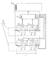
図1は、本発明の実施形態に係る電池制御システムを示すブロック図である。同図に示す電池群1は電池列1と電池列2とを並列に接続した電池群100である。電池列1には、単電池11及び単電池21が直列に接続されており、電池列2には、単電池12及び単電池22が直列に接続されている。単電池11、12、21、22は、例えばリチウムイオン電池などの二次電池であって、共に同じ電池が使用されているが、これらの電池が使用されることにより、バラツキが生じる場合がある。また本例の電池群100には、4個の電池が設けられるが、必ずしも4個である必要はない。また電池列群100には、少なくとも複数の電池列1、2の中で、電池が直列に接続されているものがあればよい。
<< First Embodiment >>
FIG. 1 is a block diagram showing a battery control system according to an embodiment of the present invention. A
単電池11、12、21、22には、それぞれ電圧センサ31、32、33、34が接続されている。電圧センサ31、32、33、34は、単電池11、12、21、22の電圧を検出し、後述するバッテリコントローラ10へ検出電圧を送信する。電圧センサ31、32、33、34は、例えば、予め設定されているサンプリング周期で、各単電池11、12、21、22の電圧を検出してもよく、またバッテリコントローラ10から送信させる制御信号をトリガとして、電圧を検出してもよい。
電池列1には電流センサ41が接続されており、電池列2には電流センサ42が接続されている。電流センサ41は、電池列1の電池11、21に流れる電流を検出し、後述するバッテリコントローラ10へ検出電流を送信する。電流センサ42は、電池列1の電池12、22に流れる電流を検出し、後述するバッテリコントローラ10へ検出電流を送信する。電流センサ31、32、33、34は、例えば、予め設定されているサンプリング周期で、各単電池11、12、21、22の電流を検出し、またバッテリコントローラ10から送信させる制御信号をトリガとして、電流を検出してもよい。
A
バッテリコントローラ10は、検出電圧及び検出電流から各単電池11、12、21、22の状態を管理する。電池の状態には、例えば各単電池11、12、21、22の電池状態(SOC:State Of Charge)が含まれ、また、各単電池11、12、21、22に流れる電流又は印加される電圧に基づく、過放電又は過充電になる可能性も含まれる。
The
制御部20は、電池群100に接続されており、バッテリコントローラ10の制御信号に基づき、各単電池11、12、21、22に流れる電流を制御する。各単電池11、12、21、22は、図示しない充電器又は図示しないモータの回生制御に基づき充電され、また当該モータに対して電流を出力し駆動する。この際、制御部20は、充電電流又は放電電流を制御し、各単電池11、12、21、22が過放電又は過充電になることを防ぐ。
The
次に、バッテリコントローラ10の制御内容を説明する。まずバッテリコントローラ10は、電圧センサ31、32、33、34の検出電圧及び電流センサ41、42の検出電流から、各単電池11、12、21、22の開放電圧及び内部抵抗を演算する。開放電圧及び内部抵抗は、例えば、所定の時間における、各単電池11、12、21、22の検出電圧及び検出電流からIV直線特性を導き出す。そして、当該IV直線特性の傾きから内部抵抗が導きだされ、当該IV直線特性の切片から開放電圧が導き出される。ここで、単電池11の開放電圧をE1,1とし、単電池21の開放電圧をE2,1、単電池12の開放電圧をE1,2、単電池11の開放電圧をE2,2とする。また単電池11の内部抵抗をR1,1とし、単電池21の内部抵抗をR2,1、単電池12の内部抵抗をR1,2、単電池11の内部抵抗をR2,2とする。
Next, the control content of the
次に、バッテリコントローラ10は、各単電池11、12、21、22の許容放電電流又は許容充電電流を演算する。許容放電電流は、各単電池11、12、21、22の放電電流の閾値電流であって、ある状態における単電池が放電できる電流の限界値を示す。例えば、単電池11の許容放電電流を越える大きさの放電電流が単電池11に対して要求された場合に、当該単電池11が過放電になる可能性がある。また許容充電電流は、各単電池11、12、21、22の充電電流の閾値電流であって、ある状態における単電池が充電できる電流の限界値を示す。例えば、単電池11の許容充電電流を越える大きさの充電電流により単電池11が充電された場合に、当該単電池11は過充電になる可能性がある。ここで、電池11の許容充電電流をIc1,1とし、単電池21の許容充電電流をIc2,1、単電池12の許容充電電流をIc1,2、単電池22の許容充電電流をIc2,2とする。また電池11の許容放電電流をId1,1とし、単電池21の許容放電電流をId2,1、単電池12の許容放電電流をId1,2、単電池22の許容放電電流をId2,2とする。
Next, the
許容充電電流(Ic1,1、Ic2,1、Ic1,2、Ic2,2)は、各単電池11、12、21、22の最大許容電圧から演算され、許容放電電流(Id1,1、Id2,1、Id1,2、Id2,2)は、各単電池11、12、21、22の最小許容電圧から演算される。ここで、単電池11の最大許容電圧をVc1,1とし、単電池21の最大許容電圧をVc2,1、単電池12の最大許容電圧をVc1,2、単電池22の最大許容電圧をVc2,2とする。また、電池11の最小許容電圧をVd1,1とし、単電池21の最小許容電圧をVd2,1、単電池12の最小許容電圧をVd1,2、単電池22の最小許容電圧をVd2,2とする。最大許容電圧及び最小許容電圧は、単電池11、12、21、22毎に予め設定されている電圧値であって、定格最大電圧及び定格最小電圧にそれぞれ相当する。
The allowable charging current (Ic 1,1 , Ic 2,1 , Ic 1,2 , Ic 2,2 ) is calculated from the maximum allowable voltage of each
許容充電電流(Ici、j)は、ある単電池において、最大許容電圧が印加された場合に、当該単電池に流れる電流であり、許容放電電流(Idi、j)は、最小許容電圧が印加された場合に、当該単電池に流れる電流である。許容充電電流(Ici、j)及び許容放電電流(Idi、j)は、単電池の内部抵抗及び開放電圧に依存し、式1及び式2によりそれぞれ算出される。
The allowable charging current (Ic i, j ) is a current that flows in a single cell when a maximum allowable voltage is applied to the single cell. The allowable discharge current (Id i, j ) is the minimum allowable voltage. This is the current that flows through the unit cell when applied. The allowable charging current (Ic i, j ) and the allowable discharging current (Id i, j ) depend on the internal resistance and open circuit voltage of the unit cell, and are calculated by

次に、バッテリコントローラ10は、放電制御の際には、各許容充電電流(Ici、j)の中から、最小許容充電電流(Icmin)を抽出し、充電制御の際には、各許容放電電流(Idi、j)の中から、最小許容放電電流(Idmin)を抽出する。
Next, the
そして、バッテリコントローラ10は、当該最小許容充電電流(Icmin)又は最小許容放電電流(Idmin)が対応する単電池11、12、21、22に流れる場合において、当該対応する単電池11、12、21、22以外の電池列1、2に流れる電流を推定電流として演算する。例えば、単電池11の許容充電電流(Ic1,1)が最小許容放電電流(Icmin)となる場合に、バッテリコントローラ10は、電池列2に流れる推定電流を推定する。これにより、バッテリコントローラ10は、各単電池11、12、21、22に実際に流れる電流を推定する。
Then, when the minimum allowable charging current (Ic min ) or the minimum allowable discharge current (Id min ) flows to the corresponding
当該推定電流は、最小許容充電電流(Icmin)又は最小許容放電電流(Idmin)に対応する単電池11、12、21、22の電池列1、2の端子間電圧、内部抵抗及び開放電圧から算出される。
The estimated current is the voltage between the terminals, the internal resistance and the open circuit voltage of the
まず、電池列1、2の端子間電圧(Vj)は、(式3)及び(式4)から算出される。
First, the terminal voltage (V j ) of the
そして、推定電流(Isj)は、端子間電圧(Vj)を用いて、(式5)から演算される。 The estimated current (Is j ) is calculated from (Equation 5) using the inter-terminal voltage (V j ).
次に、バッテリコントローラ10は、許容充電電流(Ici、j)と推定電流(Isj)とを単電池11、12、21、22毎に対応させて比較し、又は、許容放電電流(Idi、j)と推定電流(Isj)とを比較する。これにより、最小許容充電電流(Icmin)又は最小許容放電電流(Idmin)を、対応する単電池11、12、21、22に流す場合に、他の単電池11、12、21、22に流れる電流が、許容充電電流(Ici、j)又は許容放電電流(Idi、j)より小さくなる否かを確認する。すなわち、例えば単電池11の許容充電電流が最小許容充電電流となり、単電池11に最小許容充電電流を流す場合に、他の電池列2の単電池12と単電池22に流れる電流を推定電流(Is2)により確認する。そして、当該推定電流(Is2)が単電池12の許容充電電流(Ic1,2)及び単電池22の許容充電電流(Ic2,2)より低くなるか否かを、それぞれ確認する。
Next, the
そして、比較の結果、全ての単電池11、12、21、22において、推定電流(Isj)が許容充電電流(Ici、j)又は許容放電電流(Idi、j)以下であれば、最小許容充電電流(Icmin)又は最小許容放電電流(Idmin)を、対応する単電池11、12、21、22に流した場合に、全ての単電池11、12、21、22において、過充電又は過放電になる可能性がなくなる。
And as a result of the comparison, if the estimated current (Is j ) is less than or equal to the allowable charging current (Ic i, j ) or the allowable discharging current (Id i, j ) in all the
一方、単電池11、12、21、22のうち少なくとも一つの単電池において、推定電流(Isj)が許容充電電流(Ici、j)又は許容放電電流(Idi、j)より大きくなる場合には、当該一つの単電池が過充電又は過放電になる可能性がある。そこで、バッテリコントローラ10は、推定電流(Isj)が許容充電電流(Ici、j)又は許容放電電流(Idi、j)より大きくなった単電池11、12、21、22の許容充電電流(Ici、j)又は許容放電電流(Idi、j)を、最小許容充電電流(Icmin)又は最小許容充電電流(Idmin)に設定する。そして、再び設定された最小許容充電電流(Icmin)又は最小許容充電電流(Idmin)に基づき、上記と同様に、当該最小許容充電電流(Icmin)又は最小許容充電電流(Idmin)に対応する単電池11、12、21、22以外の電池列1、2に流れる推定電流を演算する。そして、上記と同様に、バッテリコントローラ10は、当該推定電流と対応する許容充電電流(Ici、j)又は許容放電電流(Idi、j)とを比較し、全ての単電池11、12、21、22における過放電又は過充電の可能性を確認する。
On the other hand, in at least one single cell among the
例えば、単電池11の許容充電電流(Ic1、1)が最小許容充電電流(Icmin)となり、当該最小許容充電電流(Icmin)が単電池11を流れる際に、単電池22において、推定電流(Is2)が許容充電電流(Ic2、2)より大きくなる場合について説明する。まずバッテリコントローラ10は、当該許容充電電流(Ic2、2)を最小許容充電電流(Icmin)に再設定する。次に、バッテリコントローラ10は、最小許容充電電流(Icmin=Ic2、2)に基づき、(式3)を用いて、電池列2の端子間電圧(V2)を演算する。そして、バッテリコントローラ10は、(式5)を用いて、単電池22を含まない電池列である電池列1の推定電流(Is1)を演算する。そして、電池列1の電池11及び電池12において、推定電流(Is1)が、許容充電電流(Ic1、1)及び許容充電電流(Ic2、1)以下であるか否かをそれぞれ比較する。ここで、推定電流(Is1)は、各電池列の端子間電圧(Vs)が低くなるため、最初に設定された最小許容充電電流(Icmin)より小さい電流値になる。そして、推定電流(Is1)が、許容充電電流(Ic1、1)及び許容充電電流(Ic2、1)以下になれば、全ての単電池11、12、21、22において、過充電の可能性がないと判断される。
For example, when the allowable charging current (Ic 1, 1 ) of the cell 11 becomes the minimum allowable charging current (Ic min ) and the minimum allowable charging current (Ic min ) flows through the cell 11, the estimation is performed in the cell 22. A case where the current (Is 2 ) is larger than the allowable charging current (Ic 2, 2 ) will be described. First, the
そして、最終的に、全ての単電池11、12、21、22において、推定電流(Isj)が許容充電電流(Ici、j)又は許容放電電流(Idi、j)以下になると、バッテリコントローラ10は、制御部20により電池群100の全体の電流を制御するために、設定された最小許容充電電流(Icmin)又は最小許容充電電流(Idmin)に基づく制御信号を、制御部20に送信する。
Finally, in all the
次に制御部20の制御内容に説明する。制御部20は、バッテリコントローラ10より送信される制御信号に基づき、電池群100の全体の放電電流又は充電電流を制御する。制御部20はバッテリコントローラ10と制御信号線により接続されており、バッテリコントローラ10を通じて、各単電池11、12、21、22の状態を把握することができる。そして、制御部20は、単電池11、12、21、22の状態に関する情報と、最終的に設定された最小許容充電電流(Icmin)又は最小許容放電電流(Idmin)の情報から、各電池列1,2に流す電流を演算することにより、電池群100の全体の電流を設定する。
Next, the control contents of the
これにより、本例は、全ての単電池11、12、21、22において、過放電又は過充電の可能性を確認した上で、電池群100の全体の電流を制御する。
Thereby, in this example, after confirming the possibility of overdischarge or overcharge in all the
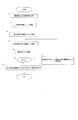
次に、図2を用いて、本例の電池制御装置の制御手順を説明する。図2は、充電電流を設定する際において、本例の電池制御装置の制御手順を示すフローチャートである。なお放電の制御手順については、式1の代わりに式2を、式3の代わりに式4を用いて、基本的な制御手順は以下と同様であるため、説明を省略する。
Next, the control procedure of the battery control device of this example will be described with reference to FIG. FIG. 2 is a flowchart showing a control procedure of the battery control device of this example when setting the charging current. As for the discharge control procedure, Formula 2 is used instead of
まず、ステップS1にて、バッテリコントローラ10は、電圧センサ31、32、33、34及び電流センサ41、42の検出電圧及び検出電流に基づき、各単電池11、12、21、22の内部抵抗(Ri、j)及び開放電圧(Ei、j)を演算する。
First, in step S <b> 1, the
ステップS2にて、バッテリコントローラ10は、式1を用いて、各単電池11、12、21、22の許容充電電流(Ici、j)を算出する。
In step S <b> 2, the
次に、ステップS3にて、ステップS2により算出された許容充電電流(Ici、j)の中から、最小の許容充電電流(Ici、j)を、最小許容充電電流(Icmin)に設定する。 Then, set at step S3, the allowable charging current (Ic i, j) calculated by step S2 among the minimum allowable charging current (Ic i, j), the minimum allowable charging current (Ic min) To do.
ステップS4にて、バッテリコントローラ10は、式3を用いて、電池列1、2の端子間電圧(Vj)を算出する。そして、ステップS5にて、バッテリコントローラ10は、式5を用いて、推定電流(Isj)を算出する。この際、推定電流は、ステップS3により設定された最小許容充電電流(Icmin)に対応する電池の電池列以外の電池列を流れる推定電流(Isj)である。
In step S < b> 4, the
次に、ステップS6にて、許容充電電流(Ici、j)と推定電流(Isj)とを比較する。ステップS2により各単電池11、12、21、22の許容充電電流(Ici、j)は算出されており、推定電流(Isj)が流れる電池において、許容充電電流(Ici、j)と推定電流(Isj)とを単電池毎に対応させて、比較する。
Next, in step S6, the allowable charging current (Ic i, j ) and the estimated current (Is j ) are compared. In step S2, the allowable charging current (Ic i, j ) of each of the
推定電流(Isj)が許容充電電流(Ici、j)より大きい場合には、ステップS7にて、当該許容充電電流(Isj)を最小許容充電電流(Icmin)に再設定する。この際、複数の単電池11、12、21、22において、推定電流(Isj)が許容充電電流(Ici、j)より大きい場合には、例えば、複数の推定電流(Isj)の中で最も小さい推定電流(Isj)を最小許容充電電流(Icmin)に設定する。または、当該複数の単電池毎に、許容充電電流(Ici、j)に対する推定電流(Isj)の割合を演算し、当該割合が一番大きい割合に対応する推定電流(Isj)を最小許容充電電流(Icmin)に設定してもよい。
If the estimated current (Is j ) is larger than the allowable charging current (Ic i, j ), the allowable charging current (Is j ) is reset to the minimum allowable charging current (Ic min ) in step S7. At this time, when the estimated current (Is j ) is larger than the allowable charging current (Ic i, j ) in the plurality of
そして、ステップS4に戻り、ステップS4〜ステップS6の処理を再び行う。 And it returns to step S4 and performs the process of step S4-step S6 again.
一方、推定電流(Isj)が許容充電電流(Ici、j)以下である場合には、ステップS8にて、制御部20は、設定された最小許容充電電流(Icmin)に基づき、電池群100の充電電流を制御する。
On the other hand, if the estimated current (Is j ) is less than or equal to the allowable charging current (Ic i, j ), in step S8, the
上記のように、本例の電池制御装置は、各単電池11、12、21、22の許容電流(Ici、j又はIdi、j)を算出し、電池群1、2のうち少なくとも一方の電池列1、2に含まれる単電池11、12、21、22の推定電流(Isj)を推定し、許容電流(Ici、j又はIdi、j)と推定電流(Isj)との比較の結果に応じて、電池群100の充放電電流を制御する。これにより、単に最小許容充電電流(Icmin)又は最小許容放電電流(Idmin)のみに基づいて、充放電電流を制御することなく、各単電池単電池11、12、21、22において、過放電又は過充電の可能性を確認した上で、電流を制御するため、過放電又は過充電を防ぐことができる。
As described above, the battery control device of this example calculates the allowable current (Ic i, j or Id i, j ) of each of the
すなわち、例えば従来のように、各単電池11、12、21、22の許容電流(Ici、j又はIdi、j)を算出し、複数の許容電流の中から最小の許容電流を抽出し、抽出された最小の許容電流に基づき、電池群100の充放電電流を設定する。かかる場合には、最小の許容電流の設定対象となった電池においては、流れる電流が許容電流以下に抑えられる。しかし、他の直列電池を含む電池列においては、流れる電流が許容電流をこえる場合があり、当該電池列において過充電又は過放電のおそれがある。
That is, for example, as in the conventional case, the allowable current (Ic i, j or Id i, j ) of each
本例は、最小許容電流を設定し、当該最小許容電流に基づき他の電池列を流れる推定電流を算出するため、最小許容電流を流した場合に、実際に他の電池を流れる電流を確認することができる。これにより、本例において、過放電又は過充電を防ぐことができる。 In this example, a minimum allowable current is set, and an estimated current flowing through another battery array is calculated based on the minimum allowable current. Therefore, when the minimum allowable current is supplied, the current actually flowing through the other battery is confirmed. be able to. Thereby, in this example, overdischarge or overcharge can be prevented.
また本例は、各単電池11、12、21、22の内部抵抗及び開放電圧を用いて、上記処理を行う。単電池11、12、21、22は、電池の使用に応じてバラツキが生じることがある。そして、従来のように最小許容電流のみに基づき充放電電流を制御する場合には、各単電池11、12、21、22に実際に流れる電流が電池状態によって異なる。本例では、バラツキによる影響を上記の演算式に反映させた上で、制御を行うことができるため、電池にバラツキが生じたとしても、過放電又は過充電を防ぐことができる。
Moreover, this example performs the said process using the internal resistance and open circuit voltage of each
また本例は、各電池11、12、21、22の許容電流(Ici、j又はIdi、j)のうち、最小許容電流(Icmin又はIdmin)に基づき、電池列1、2の端子間電圧(Vj)を演算し、当該最小許容電流(Icmin又はIdmin)に対応する単電池11、12、21、22を含まない電池列に流れる推定電流(Isj)を推定する。これにより、最小許容電流(Icmin又はIdmin)の設定の基礎となった単電池を含む電池列以外の電池列において、実際に流れる電流を推定し、過放電又は過充電になる可能性がある否かを確認することができる。これにより本例は、過放電又は過充電を抑制することができる。
The present example, the allowable current of each
また本例は、推定電流(Isj)が許容電流(Ici、j又はIdi、j)より大きい場合に、当該許容電流(Ici、j又はIdi、j)に基づいて、再度、推定電流(Isj)を推定し、当該許容電流(Ici、j又はIdi、j)と再度推定された推定電流(Isj)とを比較し、当該許容電流(Ici、j又はIdi、j)又は再度推定された推定電流(Isj)に基づき、充放電電流を制御する。これにより、ステップS3にて設定された最小許容電流(Icmin又はIdmin)に対応する単電池11、12、21、22以外の単電池11、12、21、22において、過放電又は過充電の可能性がある場合に、充放電電流の設定の基準となる電流をさらに下げた上で、再び、各単電池11、12、21、22における過放電又は過充電の可能性を確認することができる。その結果として、本例は過放電又は過充電を抑制することができる。
The present embodiment, the estimated current (Is j) is permissible current (Ic i, j or Id i, j) is greater than, based on the allowable current (Ic i, j or Id i, j), again, The estimated current (Is j ) is estimated, the allowable current (Ic i, j or Id i, j ) is compared with the estimated current (Is j ) estimated again, and the allowable current (Ic i, j or Id) is compared. i, j ) or the estimated current (Is j ) estimated again is used to control the charge / discharge current. As a result, overdischarge or overcharge occurs in the
なお、ステップS8において、ステップS7の処理を経て、ステップS8の処理を行う場合には、許容充電電流(Ici、j)に基づき、充電電流が設定される。かかる場合、許容充電電流(Ici、j)に基づく端子間電圧と、ステップS5により推定された推定電流(Isj)許容充電電流(Ici、j)に基づく端子間電圧とは同じ電圧となるため、ステップS5により推定された推定電流(Isj)に基づき、充電電流を設定してもよい。 In step S8, when the process of step S8 is performed after the process of step S7, the charging current is set based on the allowable charging current (Ic i, j ). In such a case, the inter-terminal voltage based on the allowable charging current (Ic i, j ) and the inter-terminal voltage based on the estimated current (Is j ) estimated in step S5 and the allowable charging current (Ic i, j ) are the same voltage. Therefore, the charging current may be set based on the estimated current (Is j ) estimated in step S5.
本例は開放電圧及び内部抵抗をIV直線特性により算出したが、必ずしもIV直線特性ではなく、例えば二次曲線による近似関数を用いて算出してもよく、他の方法であってもよい。 In this example, the open circuit voltage and the internal resistance are calculated based on the IV linear characteristic, but are not necessarily the IV linear characteristic, and may be calculated using, for example, an approximate function based on a quadratic curve, or may be another method.
また本例の電池群100は、2列の並列接続とするが、3列以上であってもよい。
In addition, the
また本例は、上記制御に加えて、各単電池11、12、21、22の発熱量を算出し、算出された発熱量に応じて、充放電電流に制限をかけてもよい。すなわち、各単電池11、12、21、22には、電池を保護するために、予め電池温度に相当する発熱量の閾値(許容発熱量)が設定されている。許容発熱量を越えて、各単電池11、12、21、22が充電又は放電されると、当該電池の温度が閾値温度をこえて、電池の性能に支障をきたすおそれがあると判断される。また発熱量は、各単電池を流れる電流と内部抵抗により算出される。そのため、本例では、許容電流(Ici、j又はIdi、j)と内部抵抗から、許容電流(Ici、j又はIdi、j)に対応する電池における発熱量を演算し、推定電流(Isj)と内部抵抗から、推定電流(Isj)に対応する電池における発熱量を演算する。そして、本例は、当該発熱量と許容発熱量を、単電池11、12、21、22毎に対応させて比較する。発熱量が許容発熱量をこえる単電池が電池群100の中に存在する場合には、本例は、ステップS8により設定された充放電電流に制限をかける。これにより、本例は、充放電電流を流すことにより生じる発熱に対して、各単電池11、12、21、22を保護することができる。
Further, in this example, in addition to the above control, the heat generation amount of each of the
なお、充放電電流に制限をかける電流量は、許容発熱量に対する算出された発熱量に応じて設定すればよい。また発熱量が許容発熱量を超える場合には、電池群100の充放電を行わないように制御してもよい。
In addition, what is necessary is just to set the electric current amount which restrict | limits charging / discharging electric current according to the calorific value calculated with respect to the allowable calorific value. Further, when the heat generation amount exceeds the allowable heat generation amount, the
またバッテリコントローラ10及び制御部20を一つの制御手段としてもよい。
The
なお、本例の許容充電電流(Ici、j)及び許容放電電流(Idi、j)は本発明の「許容電流」に相当し、端子間電圧は(Vj)「第1の電圧」及び「第2の電圧」に相当し、バッテリコントローラ10は「電池状態管理手段」に相当し、制御部20は「制御手段」に相当する。
The allowable charging current (Ic i, j ) and the allowable discharging current (Id i, j ) in this example correspond to the “allowable current” of the present invention, and the voltage between the terminals is (V j ) “first voltage”. The
《第2実施形態》
発明の他の実施形態に係る音源位置演算装置及び音源位置演算方法を説明する。本例は上述した第1実施形態に対して、制御内容の一部が異なる。他の部分については、第1実施形態の記載を適宜、援用する。
<< Second Embodiment >>
A sound source position calculation apparatus and a sound source position calculation method according to another embodiment of the invention will be described. This example differs from the first embodiment described above in part of the control content. About other parts, description of 1st Embodiment is used suitably.
本例のバッテリコントローラ10は、式1及び式2によりを用いて算出される、単電池11、12、21、22毎の許容充電電流(Ici、j)又は許容放電電流(Idi、j)から、電池列1、2毎に最小許容充電電流(Icmin、j)又は最小許容充電電流(Idmin、j)を抽出し、当該最小許容充電電流(Icmin、j)又は最小許容充電電流(Idmin、j)から電池列1、2毎の端子間電圧を(Vj)を算出する。
The
最小許容充電電流(Icmin、j)又は最小許容充電電流(Idmin、j)の抽出は、電池列1、2毎に接続されている単電池11、12、21、22の許容充電電流(Ici、j)又は許容放電電流(Idi、j)の中から、最も小さい値の許容充電電流(Ici、j)又は許容放電電流(Idi、j)を、最小許容充電電流(Icmin、j)又は最小許容充電電流(Idmin、j)として抽出する。
The extraction of the minimum allowable charging current (Ic min, j ) or the minimum allowable charging current (Id min, j ) is performed by extracting the allowable charging currents of the
そして、電池列1、2毎の端子間電圧(Vj)は、式3及び式4を用いて、最小許容充電電流(Icmin、j)又は最小許容充電電流(Idmin、j)に基づき算出される。
The terminal voltage (V j ) for each of the
すなわち、単電池11、12、21、22毎に許容電流が異なる場合に、電池列1、2毎に分けて、最小許容電流を推定して流すと、電池列1、2毎に端子間電圧が異なる。そして、電池列毎に算出された端子間電圧は、当該端子間電圧以下の電圧を印加する限り、単電池11、12、21、22が過放電又は過充電になる可能性は抑制される。当該異なる端子間電圧の中で、最も小さい端子間電圧(Vmin、j)を抽出した場合に、最小の端子間電圧(Vmin、j)と対応しない電池列においては、電池列1,2毎に算出された端子間電圧以下の電圧が加わることになるため、全ての単電池11、12、21、22において、過放電又は過充電になる可能性が抑制される。
That is, when the allowable current is different for each of the
そのため、本例は、許容電流(Ici、j又はIdi、j)に基づき電池列1、2毎の端子間電圧(Vj)を演算し、最小端子間電圧(Vmin、j)に対応する電池群1、2の最小許容充電電流(Icmin、j)に基づき、充放電電流を制御する。これにより、本例は、単電池11、12、21、22において、過放電又は過充電になる可能性を抑制することができる。
Therefore, in this example, the inter-terminal voltage (V j ) for each of the
次に、バッテリコントローラ10は、電池列1、2毎の端子間電圧(Vj)の中から、最も小さい端子間電圧(Vmin、j)を算出する。そして、バッテリコントローラ10及び制御部100は、当該最も小さい端子間電圧(Vj)に対応する電池列1、2における、最小許容充電電流(Icmin、j)又は最小許容充電電流(Idmin、j)に基づき、電池群100の充放電電流を制御する。
Next, the
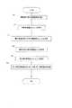
次に、図3を用いて、本例の電池制御装置の制御手順を説明する。図3は、充電電流を設定する際において、本例の電池制御装置の制御手順を示すフローチャートである。なお放電の制御手順については、基本的な制御手順は充電と同様であるため、説明を省略する。 Next, the control procedure of the battery control device of this example will be described with reference to FIG. FIG. 3 is a flowchart showing a control procedure of the battery control device of this example when setting the charging current. In addition, about the control procedure of discharge, since the basic control procedure is the same as that of charge, description is abbreviate | omitted.
まず、ステップS11にて、バッテリコントローラ10は、電圧センサ31、32、33、34及び電流センサ41、42の検出電圧及び検出電流に基づき、各単電池11、12、21、22の内部抵抗(Ri、j)及び開放電圧(Ei、j)を演算する。
First, in step S <b> 11, the
ステップS12にて、バッテリコントローラ10は、式1を用いて、各単電池11、12、21、22の許容充電電流(Ici、j)を算出する。
In step S <b> 12, the
次に、ステップS13にて、ステップS12により算出された許容充電電流(Ici、j)の中から、電池列1、2毎に、最小の許容充電電流(Ici、j)を抽出し、最小許容充電電流(Icmin、j)に設定する。
Next, in step S13, the minimum allowable charging current (Ic i, j ) is extracted for each of the
ステップS14にて、バッテリコントローラ10は、式3を用いて、電池列1、2毎に、端子間電圧(Vj)を算出する。ステップS15にて、ステップS14により算出された端子間電圧(Vj)群の中から、最小の端子間電圧(Vmin、j)を抽出する。
In step S < b> 14, the
そして、ステップS16にて、制御部20は、最小の端子間電圧(Vmin、j)に対応する電池群の最小許容充電電流(Icmin、j)に基づき、電池群100の充電電流を制御する。
In step S16, the
上記のように、本例の電池制御装置は、各単電池11、12、21、22の許容電流(Ici、j又はIdi、j)を算出し、当該許容電流(Ici、j又はIdi、j)に基づき電池列1、2毎の端子間電圧(Vj)を演算し、最小端子間電圧(Vmin、j)を抽出し、最小端子間電圧(Vmin、j)に対応する電池群1、2の最小許容充電電流(Icmin、j)に基づき、充放電電流を制御する。これにより、単に最小許容充電電流(Icmin)又は最小許容放電電流(Idmin)のみに基づいて、充放電電流を制御することなく、各単電池単電池11、12、21、22において、過放電又は過充電の可能性を確認した上で、電流を制御するため、過放電又は過充電を防ぐことができる。
As described above, the battery control device of this example calculates the allowable current (Ic i, j or Id i, j ) of each
100…電池群
1、2…電池列
10…バッテリコントローラ
20…制御部
31、32、33、34…電圧センサ
41、42…電流センサ
R1,1、R2,1、R1,2、R2,2…内部抵抗
E1,1、E2,1、E1,2、E2,2…開放電圧
DESCRIPTION OF
Claims (8)
前記電池群に含まれる各電池の状態を管理する電池状態管理手段と、
前記各電池の電流を制御する制御手段とを備え、
前記電池状態管理手段は、
前記各電池の内部抵抗及び開放電圧を算出し、
前記内部抵抗及び開放電圧に基づき、前記各電池の許容電流を算出し、
前記許容電流に基づき、前記複数の電池列のうち一の電池列に加わる第1の電圧を算出し、
前記第1の電圧に基づき、前記複数の電池列のうち他の電池列に含まれる電池に流れる推定電流を推定し、
前記他の電池列に含まれる電池に対応する前記許容電流と前記推定電流とをそれぞれ比較し、
前記制御手段は、前記電池状態管理手段の比較の結果に応じて、前記各電池の電流を制御することを特徴とする電池制御装置。 A battery group in which a plurality of battery rows in which a plurality of batteries are connected in series are arranged in parallel;
Battery state management means for managing the state of each battery included in the battery group;
Control means for controlling the current of each battery,
The battery state management means includes
Calculate the internal resistance and open circuit voltage of each battery,
Based on the internal resistance and open circuit voltage, the allowable current of each battery is calculated,
Based on the allowable current, a first voltage applied to one battery row among the plurality of battery rows is calculated,
Based on the first voltage, an estimated current flowing in a battery included in another battery row among the plurality of battery rows is estimated,
Each of the allowable current and the estimated current corresponding to the batteries included in the other battery row,
The battery control apparatus, wherein the control means controls a current of each battery according to a comparison result of the battery state management means.
前記各電池の許容電流のうち、最も小さい許容電流に基づき、前記第1の電圧を算出し、
前記第1の電圧に基づき、前記最も小さい許容電流に対応する電池を含まない前記他の電池列に含まれる電池に流れる前記推定電流を推定することを特徴とする請求項1記載の電池制御装置。 The battery state management means includes
Based on the smallest allowable current among the allowable currents of each battery, the first voltage is calculated,
2. The battery control device according to claim 1, wherein the estimated current flowing in a battery included in the other battery array not including a battery corresponding to the smallest allowable current is estimated based on the first voltage. .
前記推定電流が対応する前記許容電流より大きい場合に、
前記他の電池列に含まれる電池に対応する前記許容電流に基づき、前記一の電池列に加わる第2の電圧を算出し、
前記第2の電圧に基づき、前記一の電池列に含まれる電池の推定電流を推定し、
前記一の電池列に含まれる電池に対応する前記許容電流と前記推定電流とをそれぞれ比較し、
前記制御手段は、前記他の電池列に含まれる電池に対応する前記許容電流又は前記一の電池列に含まれる電池に対応する前記推定電流に基づき、前記各電池の電流を制御することを特徴とする請求項1又は2記載の電池制御装置。 The battery state management means includes
If the estimated current is greater than the corresponding allowable current,
Based on the allowable current corresponding to the batteries included in the other battery row, a second voltage applied to the one battery row is calculated,
Based on the second voltage, an estimated current of a battery included in the one battery row is estimated,
Comparing the allowable current and the estimated current corresponding to the batteries included in the one battery row,
The control means controls the current of each battery based on the allowable current corresponding to a battery included in the other battery array or the estimated current corresponding to a battery included in the one battery array. The battery control device according to claim 1 or 2.
前記電池群に含まれる電池の電流を検出する電流検出手段とをさらに備え、
前記電池状態管理手段は、
前記電圧検出手段により検出された検出電圧及び前記電流検出手段により検出された検出電流に基づいて、前記内部抵抗及び前記開放電圧を演算することを特徴とする請求項1〜4のいずれか一項に記載の電池制御装置。 Voltage detecting means for detecting a voltage of a battery included in the battery group;
A current detecting means for detecting a current of a battery included in the battery group;
The battery state management means includes
5. The internal resistance and the open-circuit voltage are calculated based on a detection voltage detected by the voltage detection unit and a detection current detected by the current detection unit. 6. The battery control device described in 1.
予め設定されている前記各電池の許容電圧に基づき、前記許容電流を算出し、
前記許容電圧に基づき、前記推定電流を算出することを特徴とする請求項1〜5のいずれか一項に記載の電池制御装置。 The battery state management means includes
Based on the preset allowable voltage of each battery, the allowable current is calculated,
6. The battery control device according to claim 1, wherein the estimated current is calculated based on the allowable voltage.
前記許容電流と前記推定電流と前記内部抵抗とに基づき、前記各電池の発熱量を算出し、
前記各電池の発熱量と予め設定されている前記各電池の許容発熱量とをそれぞれ比較し、
前記制御手段は、前記発熱量が前記許容発熱量より高い場合に、前記許容発熱量に基づいて各電池の電流に制限をかけることを特徴とする請求項1〜6のいずれか一項に記載の電池制御装置。 The battery state management means includes
Based on the allowable current, the estimated current, and the internal resistance, the calorific value of each battery is calculated,
Compare the calorific value of each battery with the preset allowable calorific value of each battery,
The said control means restrict | limits the electric current of each battery based on the said allowable heat generation amount, when the said heat generation amount is higher than the said allowable heat generation amount. Battery control device.
前記電池群に含まれる各電池の状態を管理する電池状態管理手段と、
前記各電池の電流を制御する制御手段とを備え、
前記電池状態管理手段は、
前記各電池の内部抵抗及び開放電圧を算出し、
前記開放電圧及び前記内部抵抗に基づき、前記各電池の許容電流を算出し、
前記許容電流に基づき、前記複数の電池列ごとに加わる第1の電圧を算出し、
前記複数の電池列ごとに加わる第1の電圧の中で、最も小さい前記第1の電圧に対応する前記許容電流を抽出し、
前記制御手段は、前記電池状態管理手段により抽出された前記許容電流に基づき、前記各電池の電流を制御することを特徴とする電池制御装置。 A battery group in which a plurality of battery rows in which a plurality of batteries are connected in series are arranged in parallel;
Battery state management means for managing the state of each battery included in the battery group;
Control means for controlling the current of each battery,
The battery state management means includes
Calculate the internal resistance and open circuit voltage of each battery,
Based on the open circuit voltage and the internal resistance, to calculate the allowable current of each battery,
Based on the allowable current, a first voltage applied to each of the plurality of battery rows is calculated,
Extracting the allowable current corresponding to the smallest first voltage among the first voltages applied to the plurality of battery rows;
The battery control apparatus, wherein the control means controls the current of each battery based on the allowable current extracted by the battery state management means.
Priority Applications (1)
| Application Number | Priority Date | Filing Date | Title |
|---|---|---|---|
| JP2010189444A JP5585308B2 (en) | 2010-08-26 | 2010-08-26 | Battery control device |
Applications Claiming Priority (1)
| Application Number | Priority Date | Filing Date | Title |
|---|---|---|---|
| JP2010189444A JP5585308B2 (en) | 2010-08-26 | 2010-08-26 | Battery control device |
Publications (2)
| Publication Number | Publication Date |
|---|---|
| JP2012050228A true JP2012050228A (en) | 2012-03-08 |
| JP5585308B2 JP5585308B2 (en) | 2014-09-10 |
Family
ID=45904434
Family Applications (1)
| Application Number | Title | Priority Date | Filing Date |
|---|---|---|---|
| JP2010189444A Expired - Fee Related JP5585308B2 (en) | 2010-08-26 | 2010-08-26 | Battery control device |
Country Status (1)
| Country | Link |
|---|---|
| JP (1) | JP5585308B2 (en) |
Cited By (8)
| Publication number | Priority date | Publication date | Assignee | Title |
|---|---|---|---|---|
| JP2013233010A (en) * | 2012-04-27 | 2013-11-14 | Toyota Motor Corp | Electric vehicle |
| JP2017060316A (en) * | 2015-09-17 | 2017-03-23 | 積水化学工業株式会社 | Power management system and power management method |
| JP2017225211A (en) * | 2016-06-13 | 2017-12-21 | 本田技研工業株式会社 | Capacitor controller |
| JP2019041445A (en) * | 2017-08-22 | 2019-03-14 | トヨタ自動車株式会社 | Power supply system |
| JPWO2019188890A1 (en) * | 2018-03-28 | 2021-05-20 | 古河電気工業株式会社 | Power storage system and measurement method |
| CN113655396A (en) * | 2020-05-12 | 2021-11-16 | 比亚迪股份有限公司 | Method and system for diagnosing loop connection state of battery pack, management system and vehicle |
| JP2022523931A (en) * | 2019-10-30 | 2022-04-27 | エルジー エナジー ソリューション リミテッド | Output control device and method for parallel multi-pack system |
| JP7364162B2 (en) | 2020-07-21 | 2023-10-18 | エルジー エナジー ソリューション リミテッド | Output control device and method for parallel multipack module |
Citations (3)
| Publication number | Priority date | Publication date | Assignee | Title |
|---|---|---|---|---|
| JP2004215459A (en) * | 2003-01-08 | 2004-07-29 | Hitachi Ltd | Power controller |
| JP2008118790A (en) * | 2006-11-06 | 2008-05-22 | Hitachi Ltd | Power controller |
| JP2009225632A (en) * | 2008-03-18 | 2009-10-01 | Panasonic Corp | Charging control circuit, battery pack, and charging system |
-
2010
- 2010-08-26 JP JP2010189444A patent/JP5585308B2/en not_active Expired - Fee Related
Patent Citations (3)
| Publication number | Priority date | Publication date | Assignee | Title |
|---|---|---|---|---|
| JP2004215459A (en) * | 2003-01-08 | 2004-07-29 | Hitachi Ltd | Power controller |
| JP2008118790A (en) * | 2006-11-06 | 2008-05-22 | Hitachi Ltd | Power controller |
| JP2009225632A (en) * | 2008-03-18 | 2009-10-01 | Panasonic Corp | Charging control circuit, battery pack, and charging system |
Cited By (12)
| Publication number | Priority date | Publication date | Assignee | Title |
|---|---|---|---|---|
| JP2013233010A (en) * | 2012-04-27 | 2013-11-14 | Toyota Motor Corp | Electric vehicle |
| JP2017060316A (en) * | 2015-09-17 | 2017-03-23 | 積水化学工業株式会社 | Power management system and power management method |
| JP2017225211A (en) * | 2016-06-13 | 2017-12-21 | 本田技研工業株式会社 | Capacitor controller |
| JP2019041445A (en) * | 2017-08-22 | 2019-03-14 | トヨタ自動車株式会社 | Power supply system |
| JPWO2019188890A1 (en) * | 2018-03-28 | 2021-05-20 | 古河電気工業株式会社 | Power storage system and measurement method |
| JP7317801B2 (en) | 2018-03-28 | 2023-07-31 | 古河電気工業株式会社 | Energy storage system and measurement method |
| JP2022523931A (en) * | 2019-10-30 | 2022-04-27 | エルジー エナジー ソリューション リミテッド | Output control device and method for parallel multi-pack system |
| JP7215657B2 (en) | 2019-10-30 | 2023-01-31 | エルジー エナジー ソリューション リミテッド | Parallel multipack system output control device and method |
| US11870292B2 (en) | 2019-10-30 | 2024-01-09 | Lg Energy Solution, Ltd. | Apparatus and method for controlling power of parallel multi pack system |
| CN113655396A (en) * | 2020-05-12 | 2021-11-16 | 比亚迪股份有限公司 | Method and system for diagnosing loop connection state of battery pack, management system and vehicle |
| CN113655396B (en) * | 2020-05-12 | 2022-10-18 | 比亚迪股份有限公司 | Method and system for diagnosing connection state of power loop of battery pack and management system |
| JP7364162B2 (en) | 2020-07-21 | 2023-10-18 | エルジー エナジー ソリューション リミテッド | Output control device and method for parallel multipack module |
Also Published As
| Publication number | Publication date |
|---|---|
| JP5585308B2 (en) | 2014-09-10 |
Similar Documents
| Publication | Publication Date | Title |
|---|---|---|
| JP5585308B2 (en) | Battery control device | |
| EP1798100B1 (en) | Battery management system | |
| KR101106353B1 (en) | Battery pack and voltage sensing method teherof | |
| KR102636361B1 (en) | Battery control appratus and battery control system | |
| CN101908772B (en) | Balancing circuit and method for pre-balancing voltage of a plurality of battery cells in a battery pack | |
| JP6419046B2 (en) | Failure type determination device for power storage system | |
| US9525289B2 (en) | Battery control system and battery pack | |
| JP4591560B2 (en) | Battery pack and control method | |
| US8680814B2 (en) | Battery charger and battery charging method | |
| KR100969589B1 (en) | Battery module maintenance system for quick charging | |
| US10873201B2 (en) | Battery management apparatus and method for protecting a lithium iron phosphate cell from over-voltage using the same | |
| US20100190041A1 (en) | System and method for balancing battery cells | |
| EP3141919B1 (en) | Apparatus and method for estimating open circuit voltage | |
| KR101146404B1 (en) | Battery management system and battery pack comprising the same | |
| US20140239914A1 (en) | Battery controller | |
| CN101460859A (en) | Method for judging abnormality of battery pack, and battery pack | |
| JP2009286292A (en) | Vehicular power supply device | |
| EP2212966A1 (en) | State of charge calculator for multi-cell energy storage system having cell balancing | |
| CN110140057A (en) | Voltage detecting integrated circuit and battery management system including it | |
| KR101720960B1 (en) | Apparatus and Method For Equalizing Charge of a Battery Pack | |
| JP2003257501A (en) | Secondary battery residual capacity meter | |
| JP7226723B2 (en) | Battery management system, battery pack, electric vehicle and battery management method | |
| KR20130061019A (en) | Battery pack | |
| KR102564716B1 (en) | Battery management system and method for protecting a battery from over-discharge | |
| CN112054477A (en) | Threshold setting circuit, battery protection system and battery protection method |
Legal Events
| Date | Code | Title | Description |
|---|---|---|---|
| A621 | Written request for application examination |
Free format text: JAPANESE INTERMEDIATE CODE: A621 Effective date: 20130627 |
|
| A977 | Report on retrieval |
Free format text: JAPANESE INTERMEDIATE CODE: A971007 Effective date: 20140313 |
|
| A131 | Notification of reasons for refusal |
Free format text: JAPANESE INTERMEDIATE CODE: A131 Effective date: 20140401 |
|
| A521 | Written amendment |
Free format text: JAPANESE INTERMEDIATE CODE: A523 Effective date: 20140530 |
|
| TRDD | Decision of grant or rejection written | ||
| A01 | Written decision to grant a patent or to grant a registration (utility model) |
Free format text: JAPANESE INTERMEDIATE CODE: A01 Effective date: 20140624 |
|
| A61 | First payment of annual fees (during grant procedure) |
Free format text: JAPANESE INTERMEDIATE CODE: A61 Effective date: 20140707 |
|
| LAPS | Cancellation because of no payment of annual fees |