JP7215500B2 - Imaging device - Google Patents
Imaging device Download PDFInfo
- Publication number
- JP7215500B2 JP7215500B2 JP2020568157A JP2020568157A JP7215500B2 JP 7215500 B2 JP7215500 B2 JP 7215500B2 JP 2020568157 A JP2020568157 A JP 2020568157A JP 2020568157 A JP2020568157 A JP 2020568157A JP 7215500 B2 JP7215500 B2 JP 7215500B2
- Authority
- JP
- Japan
- Prior art keywords
- optical system
- optical
- optical axis
- light
- reflecting
- Prior art date
- Legal status (The legal status is an assumption and is not a legal conclusion. Google has not performed a legal analysis and makes no representation as to the accuracy of the status listed.)
- Active
Links
Images


Classifications
-
- G—PHYSICS
- G03—PHOTOGRAPHY; CINEMATOGRAPHY; ANALOGOUS TECHNIQUES USING WAVES OTHER THAN OPTICAL WAVES; ELECTROGRAPHY; HOLOGRAPHY
- G03B—APPARATUS OR ARRANGEMENTS FOR TAKING PHOTOGRAPHS OR FOR PROJECTING OR VIEWING THEM; APPARATUS OR ARRANGEMENTS EMPLOYING ANALOGOUS TECHNIQUES USING WAVES OTHER THAN OPTICAL WAVES; ACCESSORIES THEREFOR
- G03B15/00—Special procedures for taking photographs; Apparatus therefor
- G03B15/02—Illuminating scene
- G03B15/03—Combinations of cameras with lighting apparatus; Flash units
- G03B15/05—Combinations of cameras with electronic flash apparatus; Electronic flash units
-
- G—PHYSICS
- G02—OPTICS
- G02B—OPTICAL ELEMENTS, SYSTEMS OR APPARATUS
- G02B5/00—Optical elements other than lenses
- G02B5/30—Polarising elements
-
- G—PHYSICS
- G02—OPTICS
- G02B—OPTICAL ELEMENTS, SYSTEMS OR APPARATUS
- G02B13/00—Optical objectives specially designed for the purposes specified below
- G02B13/001—Miniaturised objectives for electronic devices, e.g. portable telephones, webcams, PDAs, small digital cameras
- G02B13/0055—Miniaturised objectives for electronic devices, e.g. portable telephones, webcams, PDAs, small digital cameras employing a special optical element
-
- G—PHYSICS
- G02—OPTICS
- G02B—OPTICAL ELEMENTS, SYSTEMS OR APPARATUS
- G02B13/00—Optical objectives specially designed for the purposes specified below
- G02B13/02—Telephoto objectives, i.e. systems of the type + - in which the distance from the front vertex to the image plane is less than the equivalent focal length
-
- G—PHYSICS
- G02—OPTICS
- G02B—OPTICAL ELEMENTS, SYSTEMS OR APPARATUS
- G02B17/00—Systems with reflecting surfaces, with or without refracting elements
- G02B17/08—Catadioptric systems
-
- G—PHYSICS
- G02—OPTICS
- G02B—OPTICAL ELEMENTS, SYSTEMS OR APPARATUS
- G02B17/00—Systems with reflecting surfaces, with or without refracting elements
- G02B17/08—Catadioptric systems
- G02B17/0804—Catadioptric systems using two curved mirrors
- G02B17/0808—Catadioptric systems using two curved mirrors on-axis systems with at least one of the mirrors having a central aperture
-
- G—PHYSICS
- G02—OPTICS
- G02B—OPTICAL ELEMENTS, SYSTEMS OR APPARATUS
- G02B27/00—Optical systems or apparatus not provided for by any of the groups G02B1/00 - G02B26/00, G02B30/00
- G02B27/0025—Optical systems or apparatus not provided for by any of the groups G02B1/00 - G02B26/00, G02B30/00 for optical correction, e.g. distorsion, aberration
-
- G—PHYSICS
- G03—PHOTOGRAPHY; CINEMATOGRAPHY; ANALOGOUS TECHNIQUES USING WAVES OTHER THAN OPTICAL WAVES; ELECTROGRAPHY; HOLOGRAPHY
- G03B—APPARATUS OR ARRANGEMENTS FOR TAKING PHOTOGRAPHS OR FOR PROJECTING OR VIEWING THEM; APPARATUS OR ARRANGEMENTS EMPLOYING ANALOGOUS TECHNIQUES USING WAVES OTHER THAN OPTICAL WAVES; ACCESSORIES THEREFOR
- G03B15/00—Special procedures for taking photographs; Apparatus therefor
- G03B15/02—Illuminating scene
-
- G—PHYSICS
- G03—PHOTOGRAPHY; CINEMATOGRAPHY; ANALOGOUS TECHNIQUES USING WAVES OTHER THAN OPTICAL WAVES; ELECTROGRAPHY; HOLOGRAPHY
- G03B—APPARATUS OR ARRANGEMENTS FOR TAKING PHOTOGRAPHS OR FOR PROJECTING OR VIEWING THEM; APPARATUS OR ARRANGEMENTS EMPLOYING ANALOGOUS TECHNIQUES USING WAVES OTHER THAN OPTICAL WAVES; ACCESSORIES THEREFOR
- G03B17/00—Details of cameras or camera bodies; Accessories therefor
- G03B17/02—Bodies
- G03B17/17—Bodies with reflectors arranged in beam forming the photographic image, e.g. for reducing dimensions of camera
-
- H—ELECTRICITY
- H04—ELECTRIC COMMUNICATION TECHNIQUE
- H04N—PICTORIAL COMMUNICATION, e.g. TELEVISION
- H04N23/00—Cameras or camera modules comprising electronic image sensors; Control thereof
- H04N23/50—Constructional details
- H04N23/55—Optical parts specially adapted for electronic image sensors; Mounting thereof
-
- H—ELECTRICITY
- H04—ELECTRIC COMMUNICATION TECHNIQUE
- H04N—PICTORIAL COMMUNICATION, e.g. TELEVISION
- H04N23/00—Cameras or camera modules comprising electronic image sensors; Control thereof
- H04N23/56—Cameras or camera modules comprising electronic image sensors; Control thereof provided with illuminating means
-
- H—ELECTRICITY
- H04—ELECTRIC COMMUNICATION TECHNIQUE
- H04N—PICTORIAL COMMUNICATION, e.g. TELEVISION
- H04N23/00—Cameras or camera modules comprising electronic image sensors; Control thereof
- H04N23/95—Computational photography systems, e.g. light-field imaging systems
- H04N23/957—Light-field or plenoptic cameras or camera modules
Description
本発明は、撮像装置に関する。 The present invention relates to an imaging device.
従来、反射光学系を用いて小型化された撮像装置が提案されている(例えば、特許文献1参照)。しかしながら、照明系も含めた小型化が要望されている。 2. Description of the Related Art Conventionally, there has been proposed a downsized image pickup apparatus using a reflecting optical system (see, for example, Japanese Unexamined Patent Application Publication No. 2002-100001). However, downsizing including the illumination system is desired.
本発明の第一の態様に係る撮像装置は、光路に沿って物体側から順に、第1反射部及び第2反射部を有して物体の像を形成する複数の光学系と、複数の光学系の一部の光学系により形成された像を撮像する撮像素子と、複数の光学系のうち一部の光学系とは異なる光学系の前記像の側に配置され、当該光学系により物体に向けて光を投射する光源と、を有し、前記複数の光学系は、前記撮像素子に対して同じ方向に配置され、前記複数の光学系のうち少なくとも一部の光学系は隣接して配置され、前記撮像素子と前記光源とは、前記複数の光学系の光軸上に切り替えて配置することが可能である。 An imaging device according to a first aspect of the present invention comprises, in order from the object side along an optical path, a plurality of optical systems having a first reflecting section and a second reflecting section to form an image of an object; an imaging device that captures an image formed by a part of the optical system of the system, and an optical system that is arranged on the side of the image of an optical system that is different from the part of the plurality of optical systems, and is arranged on the side of the image that is formed by the optical system and a light source for projecting light toward the imaging device, wherein the plurality of optical systems are arranged in the same direction with respect to the imaging device, and at least some of the plurality of optical systems are arranged adjacent to each other. The imaging device and the light source can be switched and arranged on the optical axis of the plurality of optical systems .
以下、好ましい実施形態について図面を参照して説明する。
(カメラモジュール10の構成)
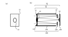
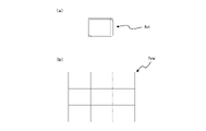
図1に示すように、本実施形態に係る撮像装置であるカメラモジュール10は、光学系ULと撮像素子14とから構成されており、光学系ULにより物体側からの光が結像され、被写体像を撮像素子14により撮像する。Preferred embodiments are described below with reference to the drawings.
(Configuration of camera module 10)
As shown in FIG. 1, a
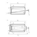
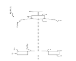
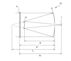
図2(a)に示すように、光学系ULは、いわゆる、シュミットカセグレン方式(或いは、コンパクト・シュミットカセグレン方式)であって、光軸に沿って物体(被写体)側から順に、高次非球面である補正面11aを有し、物体からの光が透過する補正部材としての補正板11と、物体側に凹状の反射面(第1反射面12a)を向け、補正板11を透過した光を反射する第1反射部としての主反射鏡12と、主反射鏡12と対向するように物体側に配置され、像側(主反射鏡12側)に凸状の反射面(第2反射面13a)を向け、主反射鏡12で反射した光を反射する第2反射部としての副反射鏡13と、を有している。ここで、第1反射面12aに入射する光の光軸と、第1反射面12aで反射された光の光軸とは一致する。また、第2反射面13aに入射する光の光軸と、第2反射面13aで反射された光の光軸とは一致する。また、主反射鏡12の中心部には、光学系ULの光軸を含むように開口部12bが形成されており、副反射鏡13で反射した光は、この開口部12bを通過する。すなわち、第1反射面12aは、この第1反射面12aに入射する光の光軸を含むように設けられた開口部12bを有し、第2反射面13aは、開口部12bに向けて光を反射する。主反射鏡12の像側には、開口部12bに対向するように撮像素子14が配置されている。また、主反射鏡12及び副反射鏡13は、物体からの光を集光するように構成されており、光学系ULは、主反射鏡12及び副反射鏡13の焦点(光学系ULの焦点)に撮像素子14が位置するように構成されている(撮像素子14の撮像面が、光学系ULの像面Iと略一致するように配置されている)。このように、光学系ULの光軸は、物体側から順に、補正板11を透過してから主反射鏡12で反射されて屈曲し、副反射鏡13で再び反射されて屈曲する。また、第1反射部12である主反射鏡12(第1反射面12a)は光軸を中心とする円環形状としてもよいし、光軸と中心とした矩形形状に矩形又は円形の開口部12bを設けた形状としてもよい。また、第2反射部13である副反射鏡13(第2反射面13a)は光軸を中心とする円形又は矩形としてもよい。
As shown in FIG. 2( a ), the optical system UL is a so-called Schmidt-Cassegrain system (or compact Schmidt-Cassegrain system), in which high-order aspherical surfaces are arranged in order from the object (subject) side along the optical axis. and a
なお、図2(a)に示す光学系ULは、補正板11の物体側の面を補正面11aとした場合を示しているが、像側の面を補正面11aとしてもよい。補正面11aは、反射面(第1反射面12aと第2反射面13a)で収差の悪化が生じた場合に、その収差を補正するものであるのが好ましく、反射面で補正しきれない種類の収差や反射面で補正しきれない高次の収差を補正するものでもよい。補正面11aは、高次非球面が好ましいが、球面又は非球面であって平面でないものがよい。また、補正板11の補正面11aの形成されていない面は、本実施形態では平面だが、球面や自由曲面としてもよい。
In the optical system UL shown in FIG. 2A, the object-side surface of the
(光学系UL)
光学系ULは、上述したように反射光学系で構成されている。ここで、主反射鏡12の第1反射面12a及び副反射鏡13の第2反射面13aの少なくとも一方、若しくは両方を球面で構成しても、主反射鏡12及び副反射鏡13で発生する収差は、補正板11の物体側の面である高次非球面(例えば、4次曲面)で補正されるため、全体としてコマ収差、非点収差、歪曲収差がない画像を得ることができる。そのため、主反射鏡12の第1反射面12a及び副反射鏡13の第2反射面13aの少なくとも一方は球面であることが望ましく、第1反射面12a及び第2反射面13aの両方が球面であることがより望ましい。第1反射面12a及び第2反射面13aの少なくとも一方を球面とすることにより、光学系ULの製造が容易になる。(Optical system UL)
The optical system UL is composed of a reflecting optical system as described above. Here, even if at least one or both of the first reflecting
なお、図2(b)に示すように、光学系ULに、主反射鏡12の開口部12bを通過する光を屈折させる屈折光学系(例えば、レンズ)15を設けてもよい。また、光学系ULは、補正板11を有しないカセグレン方式の光学系としてもよい。また、光学系ULに含まれる光学要素の光軸は、全て一致するのがよい。少なくとも、主反射鏡12の光軸と副反射鏡13の光軸とは、光線の通る方向が逆転する他は一致するのが好ましい。
As shown in FIG. 2B, the optical system UL may be provided with a refractive optical system (for example, a lens) 15 that refracts light passing through the opening 12b of the main reflecting
本実施形態に係るカメラモジュール10は、光学系ULを、上述したような反射面を用いた折り返し光学系(カセグレン方式、シュミットカセグレン方式、またはコンパクト・シュミットカセグレン方式の反射光学系)とすることにより、光学系の長さ(最も物体側の面(図2(a)の場合、補正板11の物体側の面(補正面11a))から像面(撮像素子14の撮像面)までの物理的な距離)を、反射面を用いない光学系で構成した場合に比べて1/2~1/3にすることができる。
In the
また、本実施形態に係る光学系ULにおいて、主反射鏡12の第1反射面12aと副反射鏡13の第2反射面13aの間の媒質は空気である。このように構成すると、この光学系ULを有するカメラモジュール10の製造が容易になる。また、撮影しないときは、主反射鏡12側に補正板11及び副反射鏡13を移動させて(いわゆる沈胴させて)格納することができるので、このカメラモジュール10を小型化してカメラ等の光学機器内に少なくとも一部を収納することができる。
Further, in the optical system UL according to this embodiment, the medium between the first reflecting
また、本実施形態に係る光学系ULは、以下の条件式(1)を満足することが望ましい。
TL < 15.0mm (1)
但し、
TL:像面Iに入射する光軸の方向において、光学系ULの最も物体側の面から像面Iまでの距離
条件式(1)は、光学系ULをシュミットカセグレン(又はコンパクト・シュミットカセグレン)方式の反射光学系で構成したときの、光学系ULの光軸方向の長さの適切な範囲を示している。なお、この条件式(1)の効果を確実なものとするために、条件式(1)の上限値を14.0mm、13.0mm、更に12.0mmとすることがより望ましい。また、この条件式(1)の効果を確実なものとするために、条件式(1)の下限値を6mmとすることが望ましい。なお、図2に示す補正板11を有するときは、光学系ULの最も物体側の面は補正面11aとなる。Moreover, it is desirable that the optical system UL according to this embodiment satisfy the following conditional expression (1).
TL < 15.0 mm (1)
however,
TL: Distance from the most object-side surface of the optical system UL to the image plane I in the direction of the optical axis incident on the image plane I Conditional expression (1) defines the optical system UL as a Schmidt-Cassegrain It shows an appropriate range of the length in the optical axis direction of the optical system UL when it is configured as a reflective optical system of the type. In order to ensure the effect of conditional expression (1), it is more desirable to set the upper limit of conditional expression (1) to 14.0 mm, 13.0 mm, and more preferably 12.0 mm. In order to ensure the effect of conditional expression (1), it is desirable to set the lower limit of conditional expression (1) to 6 mm. When the
また、本実施形態に係る光学系ULは、以下の条件式(2)を満足することが望ましい。
10.00° < ω (2)
但し、
ω:光学系ULの半画角
条件式(2)は、光学系ULをシュミットカセグレン(又はコンパクト・シュミットカセグレン)方式の反射光学系で構成したときの、光学系ULの半画角の適切な範囲を示している。なお、この条件式(2)の効果を確実なものとするために、条件式(2)の下限値を8.00°、6.00°、5.00°、4.00°、3.50°、3.00°、2.50°、2.00°、更に1.50°とすることがより望ましい。
Moreover, it is desirable that the optical system UL according to this embodiment satisfy the following conditional expression (2).
10.00° < ω (2)
however,
ω: half angle of view of optical system UL Conditional expression (2) is an appropriate value for the half angle of view of optical system UL when optical system UL is configured as a Schmidt-Cassegrain (or compact Schmidt-Cassegrain) type reflective optical system. showing the range. In order to ensure the effect of conditional expression ( 2 ), the lower limits of conditional expression (2) are set to 8.00°, 6.00°, 5.00°, 4.00°, 3. 50°, 3.00°, 2.50°, 2.00°, and more preferably 1.50°.
また、本実施形態に係る光学系ULがコンパクト・シュミットカセグレン方式である場合、補正板11の厚さΔLは、次式(a)で表される。なお、式(a)は、APPLIED OPTICS Vol. 13, No. 8, August 1974に開示されている。
ΔL = [(h/r)4-1.5(h/r)2]r
/{256(n-1)P′3}+k (a)
但し、
P′=P1/G1/3
P1:主反射鏡12のF値
G:補正板11の計算深さの比
h:光軸に垂直な方向の高さ
r:補正板11の補正半径(曲率半径)
n:補正板11を構成する媒質の屈折率
k:補正板11の中心厚Further, when the optical system UL according to the present embodiment is of the compact Schmidt-Cassegrain system, the thickness ΔL of the
ΔL = [(h/r) 4 -1.5(h/r) 2 ] r
/{256(n−1)P′ 3 }+k(a)
however,
P'=P1 / G1/ 3
P 1 : F value of the main reflecting mirror 12 G: Calculated depth ratio of the correction plate 11 h: Height in the direction perpendicular to the optical axis r: Correction radius (curvature radius) of the
n: refractive index of the medium forming the correction plate 11 k: center thickness of the
また、本実施形態に係る光学系ULにおいては、物体からの光を透過させる透過部材を適宜光路上の位置に設けてもよい。透過部材を設けることにより、透過部材に非球面を形成するなどして収差補正が可能になる。透過部材の非球面(補正板11の補正面11aを含む)は、光軸から周辺に向かって少なくとも1つの変曲点を有するのが好ましい。
Further, in the optical system UL according to this embodiment, a transmission member for transmitting light from an object may be provided at an appropriate position on the optical path. By providing the transmission member, it is possible to correct aberration by forming an aspherical surface on the transmission member. The aspheric surface of the transmissive member (including the
また、本実施形態に係る光学系ULは、以下の条件式(3)を満足することが望ましい。
-0.1 < f/fa < 0.1 (3)
但し、
fa:補正面11aの焦点距離
f:光学系ULの全系の焦点距離
条件式(3)は、光学系ULをシュミットカセグレン(又はコンパクト・シュミットカセグレン)方式の反射光学系で構成したときの、補正面11aの焦点距離に対する光学系ULの全系の焦点距離の比の適切な範囲を示している。なお、この条件式(3)の効果を確実なものとするために、条件式(3)の下限値を-0.05、-0.02、更に0.00とすることがより望ましい。また、この条件式(3)の効果を確実なものとするために、条件式(3)の上限値を0.09、0.08、0.07、0.06、更に0.05とすることがより望ましい。Moreover, it is desirable that the optical system UL according to this embodiment satisfy the following conditional expression (3).
-0.1 < f/fa < 0.1 (3)
however,
fa: focal length of the
また、本実施形態に係る光学系ULは、以下の条件式(4)を満足することが望ましい。
-0.1 < f/fb < 0.1 (4)
但し、
fb:補正板11の焦点距離
f:光学系ULの全系の焦点距離
条件式(4)は、光学系ULをシュミットカセグレン(又はコンパクト・シュミットカセグレン)方式の反射光学系で構成したときの、補正板11の焦点距離に対する光学系ULの全系の焦点距離の比の適切な範囲を示している。なお、この条件式(4)の効果を確実なものとするために、条件式(4)の下限値を-0.05、-0.02、更に0.00とすることがより望ましい。また、この条件式(4)の効果を確実なものとするために、条件式(4)の上限値を0.09、0.08、0.07、0.06、更に0.05とすることがより望ましい。Moreover, it is desirable that the optical system UL according to this embodiment satisfy the following conditional expression (4).
-0.1 < f/fb < 0.1 (4)
however,
fb: focal length of the correction plate 11 f: focal length of the entire optical system UL Conditional expression (4) is the following when the optical system UL is configured with a Schmidt-Cassegrain (or compact Schmidt-Cassegrain) reflecting optical system: An appropriate range for the ratio of the focal length of the entire optical system UL to the focal length of the
また、本実施形態に係る光学系ULは、以下の条件式(5)を満足することが望ましい。
3.0 < M < 8.0 (5)
但し、
M=f/f1
f:光学系ULの全系の焦点距離
f1:主反射鏡12の焦点距離
条件式(5)は、光学系ULをシュミットカセグレン(又はコンパクト・シュミットカセグレン)方式の反射光学系で構成したときの、光学系ULの2次変倍比Mの適切な範囲を示している。Moreover, it is desirable that the optical system UL according to this embodiment satisfy the following conditional expression (5).
3.0 < M < 8.0 (5)
however,
M=f/f1
f: focal length of the entire system of the optical system UL f1: focal length of the main reflecting
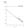
図3は、カセグレン方式及びシュミットカセグレン方式の反射光学系における、2次変倍比Mに対する非点収差を示している。この図3から明らかなように、光学系ULをシュミットカセグレン方式(又はコンパクト・シュミットカセグレン方式)の反射光学系で構成した場合、2次変倍比Mを5.6とすることにより、非点収差を0にすることができる。したがって、光学系ULが条件式(5)を満足することにより、非点収差の発生を抑えることができ、良好な画像を取得することができる。なお、この条件式(5)の効果を確実なものとするために、条件式(5)の下限値を3.5、更に4.0、4.5、5.0とすることがより望ましい。また、この条件式(5)の効果を確実なものとするために、条件式(5)の上限値を7.5、更に7.0、6.5、6.0とすることがより望ましい。 FIG. 3 shows astigmatism with respect to the secondary zoom ratio M in the Cassegrain and Schmidt-Cassegrain reflective optical systems. As is clear from FIG. 3, when the optical system UL is configured by a reflecting optical system of the Schmidt-Cassegrain system (or the compact Schmidt-Cassegrain system), by setting the secondary zoom ratio M to 5.6, astigmatism Aberration can be zero. Therefore, if the optical system UL satisfies the conditional expression (5), it is possible to suppress the occurrence of astigmatism and obtain a good image. In order to ensure the effect of conditional expression (5), it is more desirable to set the lower limit of conditional expression (5) to 3.5, more preferably 4.0, 4.5, or 5.0. . In order to ensure the effect of conditional expression (5), it is more desirable to set the upper limit of conditional expression (5) to 7.5, more preferably 7.0, 6.5, 6.0. .
また、本実施形態に係る光学系ULは、以下の条件式(6)を満足することが望ましい。
f < 500mm (6)
但し、
f:光学系ULの全系の焦点距離
条件式(6)は、光学系ULをシュミットカセグレン(又はコンパクト・シュミットカセグレン)方式の反射光学系で構成したときの、光学系ULの全系の焦点距離の適切な範囲を示している。なお、この条件式(6)の効果を確実なものとするために、条件式(6)の下限値を0.1mm、更に1mm、5mm、10mm、20mmとすることがより望ましい。また、この条件式(6)の効果を確実なものとするために、条件式(6)の上限値を380mm、更に280mm、230mm、190mm、140mm、90mm、70mm、55mm、45mmとすることがより望ましい。Moreover, it is desirable that the optical system UL according to this embodiment satisfy the following conditional expression (6).
f < 500mm (6)
however,
f: focal length of the entire optical system UL Conditional expression (6) is the focal point of the entire optical system UL when the optical system UL is configured with a Schmidt-Cassegrain (or Compact Schmidt-Cassegrain) type reflective optical system. Indicates the appropriate range of distances. In order to ensure the effect of conditional expression (6), it is more desirable to set the lower limit of conditional expression (6) to 0.1 mm, more preferably 1 mm, 5 mm, 10 mm, and 20 mm. Also, in order to ensure the effect of conditional expression (6), the upper limit of conditional expression (6) can be set to 380 mm, and further to 280 mm, 230 mm, 190 mm, 140 mm, 90 mm, 70 mm, 55 mm, and 45 mm. more desirable.
また、本実施形態に係る光学系ULは、以下の条件式(7)を満足することが望ましい。
0.4 < RL/TL < 1.2 (7)
但し、
RL:光学系ULの光軸の方向において、第1反射部と第2反射部との光軸上の距離
TL:像面に入射する光軸の方向において、前記光学系の最も物体側の面から像面までの距離
条件式(7)は、光学系ULの最も物体側の面から像面までの距離と反射面間の距離の比の適切な範囲を示している。なお、この条件式(7)の効果を確実なものとするために、条件式(7)の上限値を1.0、0.9、更に0.85とすることがより望ましい。また、この条件式(7)の効果を確実なものとするために、条件式(7)の下限値を0.6、0.7とすることが望ましい。Moreover, it is desirable that the optical system UL according to this embodiment satisfy the following conditional expression (7).
0.4 < RL/TL < 1.2 (7)
however,
RL: In the direction of the optical axis of the optical system UL, the distance on the optical axis between the first reflecting portion and the second reflecting portion TL: In the direction of the optical axis incident on the image plane, the surface of the optical system closest to the object side to the image plane Conditional expression (7) indicates an appropriate range of the ratio of the distance from the most object side surface of the optical system UL to the image plane and the distance between the reflecting surfaces. In order to ensure the effect of conditional expression (7), it is more desirable to set the upper limit of conditional expression (7) to 1.0, 0.9, and more preferably 0.85. In order to ensure the effect of conditional expression (7), it is desirable to set the lower limit of conditional expression (7) to 0.6 and 0.7.
また、本実施形態に係る光学系ULは、以下の条件式(8)を満足することが望ましい。
0.5 < D1/RL < 2.0 (8)
但し、
D1:第1反射面の外径
RL:光学系ULの光軸の方向において、第1反射部と第2反射部との光軸上の距離
条件式(8)は、光学系ULの光軸方向と光軸と直交方向との長さの比の適切な範囲を示している。ここで、第1反射面の外径とは、第1反射面が円形の場合は直径であり、第1反射面が矩形状の場合は最大外径である。なお、この条件式(8)の効果を確実なものとするために、条件式(8)の上限値を1.7、1.5、更に1.3とすることがより望ましい。また、この条件式(8)の効果を確実なものとするために、条件式(8)の下限値を0.7、0.8、更に0.85とすることが望ましい。Moreover, it is desirable that the optical system UL according to this embodiment satisfy the following conditional expression (8).
0.5 < D1/RL < 2.0 (8)
however,
D1: Outer diameter of the first reflecting surface RL: Distance on the optical axis between the first reflecting part and the second reflecting part in the direction of the optical axis of the optical system UL Conditional expression (8) is the optical axis of the optical system UL It shows a suitable range of the ratio of the length of the direction, the optical axis and the orthogonal direction. Here, the outer diameter of the first reflecting surface is the diameter when the first reflecting surface is circular, and the maximum outer diameter when the first reflecting surface is rectangular. In order to ensure the effect of conditional expression (8), it is more desirable to set the upper limit of conditional expression (8) to 1.7, 1.5, and more preferably 1.3. In order to ensure the effect of conditional expression (8), it is desirable to set the lower limit of conditional expression (8) to 0.7, 0.8, and more preferably 0.85.
また、本実施形態に係る光学系ULは、以下の条件式(9)を満足することが望ましい。
1.0 < D1/D2 < 6.0 (9)
但し、
D1:第1反射面の外径
D2:第2反射面の外径
条件式(9)は、反射面同士の外径の比の適切な範囲を示している。ここで、第1反射面の外径または第2反射面の外径とは、反射面が円形の場合は直径であり、反射面が矩形状の場合は最大外径である。なお、この条件式(9)の効果を確実なものとするために、条件式(9)の上限値を5.0、5.5、更に3.0とすることがより望ましい。また、この条件式(9)の効果を確実なものとするために、条件式(9)の下限値を1.3、1.5、更に3.5とすることが望ましい。Moreover, it is desirable that the optical system UL according to this embodiment satisfy the following conditional expression (9).
1.0 < D1/D2 < 6.0 (9)
however,
D1: Outer diameter of first reflecting surface D2: Outer diameter of second reflecting surface Conditional expression (9) indicates an appropriate range for the ratio of the outer diameters of the reflecting surfaces. Here, the outer diameter of the first reflecting surface or the outer diameter of the second reflecting surface is the diameter when the reflecting surface is circular, and the maximum outer diameter when the reflecting surface is rectangular. In order to ensure the effect of conditional expression (9), it is more desirable to set the upper limit of conditional expression (9) to 5.0, 5.5, and more preferably 3.0. In order to ensure the effect of conditional expression (9), it is desirable to set the lower limit of conditional expression (9) to 1.3, 1.5, and more preferably 3.5.
また、本実施形態に係る光学系ULは、以下の条件式(10)を満足することが望ましい。
5.0 < D0/Y < 15.0 (10)
但し、
D0:光学系ULの最も物体側の入射面の外径
Y:撮像素子14の最大像高
条件式(10)は、入射面の外径と撮像素子14の最大像高の比の適切な範囲を示している。ここで、入射面の外径とは、入射面が円形の場合は直径であり、入射面が矩形状の場合は最大外径である。なお、この条件式(10)の効果を確実なものとするために、条件式(10)の上限値を14.5、14.0、更に9.0とすることがより望ましい。また、この条件式(10)の効果を確実なものとするために、条件式(10)の下限値を6.0、7.0、更に10.0とすることが望ましい。Moreover, it is desirable that the optical system UL according to this embodiment satisfy the following conditional expression (10).
5.0 < D0/Y < 15.0 (10)
however,
D0: Outer diameter Y of the incident surface closest to the object side of the optical system UL: Maximum image height of the
(カメラモジュール10の多眼構成について)
図1では、カメラモジュール10を、1組の撮像部である光学系UL及び撮像素子14で構成した場合について説明したが、図4及び図5に示すように、複数の上述したカメラモジュール10を2次元状に配置した多眼構成の撮像装置であるカメラモジュール1としてもよい。なお、以降の説明では、多眼構成における上述したカメラモジュール10を「単位ブロック10」と呼ぶ。また、多眼構成に関する以降の説明では、図4等に示すように、カメラモジュール1が、3行3列の合計9個(以下「3×3」と呼ぶ)の単位ブロック10で構成されている場合について説明するが、2個以上の単位ブロック10で構成することにより同様の効果を得ることができる。1行に含まれる単位ブロック10の数と1列に含まれる単位ブロック10の数とは同じでなくてもよい。但し、後述するように、単位ブロック10を構成する撮像素子14の各々から取得された画像を合成する場合、1行に含まれる単位ブロック10の数と1列に含まれる単位ブロック10の数とを同じにすることにより、縦方向と横方向とで解像度が同じ画像を生成することができる。また、カメラモジュール1を構成する複数の単位ブロック10の各々の光学系ULは、各々の光軸が互いに略平行になるように配置されている。また、複数の単位ブロック10の各々の撮像素子14は、光軸と直交する平面上に配置され、光軸と直交するX軸の方向とX軸及び光軸に直交するY軸の方向に二次元的に並んで配置されている。(Regarding the multi-view configuration of the camera module 10)
In FIG. 1, the case where the
本実施形態に係るカメラモジュール1は、単位ブロック10の光学系ULを、上述したような折り返し光学系(カセグレン方式、シュミットカセグレン方式、またはコンパクト・シュミットカセグレン方式の反射光学系)とすることにより、光学系の長さ(最も物体側の面から像面までの物理的な距離)を屈折光学系で構成した場合に比べて1/2~1/3にすることができる。さらに、本実施形態に係るカメラモジュール1は、単位ブロック10を複数備え、各々の単位ブロック10の撮像素子14で取得された画像を合成することにより、各々の撮像素子14の解像度以上の高解像度の画像を取得することができるので、撮像素子14の大きさを小さくすることができる(各々の撮像素子14を小さくしてその解像度を低くしても、画像を合成することにより高い解像度の画像を取得することができる)。この撮像素子14の小型化により、単位ブロック10の光学系ULの焦点距離を短くすることができる。したがって、折り返し光学系の採用及び複数の単位ブロック10による画像の合成効果により、本実施形態に係るカメラモジュール1は、同じ解像度を有する屈折光学系を用いた1つの単位ブロック10からなるカメラモジュールに比べて、その全長を1/4以下とすることができる。
In the
(カメラモジュール1の組立構造)
次に、本実施形態に係るカメラモジュール1の組立構造について説明する。なお、ここでは多眼構成のカメラモジュール1の組立構造について説明するが(図4及び図5)、単眼構成のカメラモジュール10(図1)の場合も同様である。(Assembly structure of camera module 1)
Next, an assembly structure of the
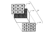
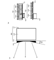
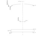
図4及び図5に示すように、本実施形態に係るカメラモジュール1は、補正板11(補正部材)及び副反射鏡13(第2反射部)が形成された第1光学部材110と、主反射鏡12(第1反射部)が形成された第2光学部材120と、第1光学部材110と第2光学部材120との間に配置され、単位ブロック10同士の境界に設けられて、光線が隣の単位ブロック10に入射することを防止する隔壁部材130と、撮像素子14が配置された撮像部材140とで構成されている。
As shown in FIGS. 4 and 5, the
第1光学部材110は、図6(a)に示すように、光を透過する媒質で形成された平行平面ガラス板111の上面(光学系ULにおいて物体側の面)に、光を透過する媒質であるポリマーをインプリントすることで複数の補正板11が形成される(図4の例では、3×3の9個の補正板11が形成される)。なお、第1光学部材110は、補正板11がインプリント等により形成された基板材から切り出して作成してもよい。また、平行平面ガラス板111の下面(光学系ULにおいて像側の面)に、光を反射する反射部材がマスクコーティングされ、複数の副反射鏡13が形成される(図4の例では、3×3の9個の副反射鏡13が形成される)。このように、一枚の平行平面ガラス111の両面に複数の補正板11及び複数の副反射鏡13を形成することにより、例えば、図4に示す3×3の9個の単位ブロック10のそれぞれの補正板11及び副反射鏡13を一回の工程で製造することができる。
As shown in FIG. 6A, the first
なお、図6(a)は、補正板11の物体側の面に補正面を形成した場合について示しているが、補正板11の像側の面に補正面を形成してもよい。補正板11の像側の面に補正面を形成すると、この面に形成された副反射鏡13とともに補正面を形成することができるので、製造工程を更に簡単にすることができる。
Although FIG. 6A shows the case where the correction surface is formed on the object side surface of the
第2光学部材120は、図6(b)に示すように、光を透過する媒質で形成された平行平面ガラス板121の上面に、光を反射する反射部材がマスクコーティングされ、複数の主反射鏡12が形成される(図4の例では、3×3の9個の主反射鏡12が形成される)。なお、平行平面ガラス板121を、光を透過する媒質で形成することにより、各単位ブロック10において、主反射鏡12がマスクコーティングされない部分を形成することにより、開口部12bを形成することができる。このように、一枚の平行平面ガラス121の片面(光学系ULにおいて物体側の面)に主反射鏡12を形成することにより、例えば、図4に示す3×3の単位ブロック10のそれぞれの主反射鏡12を一回の工程で製造することができる。
As shown in FIG. 6B, the second
なお、図2(b)に示すように、光学系ULにレンズ等の屈折光学系15を設ける場合は、平行平面ガラス板121に光線を屈折させることのできるレンズ面を形成してもよい。
As shown in FIG. 2(b), when the refractive
図7に示すように、隔壁部材130は、単位ブロック10の光学系ULを区分する光学隔壁格子で構成されている。隔壁部材130の物体側には、第1光学部材110が配置され、隔壁部材130の像側には、第2光学部材120が配置される。隔壁部材130の物体側に第1光学部材110を固定し、隔壁部材130の像側に第2光学部材120を固定することにより、隔壁部材130は、単位ブロック10の光学系ULの光線が隣り合う単位ブロック10に入射するのを防止すると同時に、第1光学部材110と第2光学部材120の光軸方向の位置決めも行うことができる。なお、以降の説明において、一体に構成された、第1光学部材110、第2光学部材120及び隔壁部材130を、光学系ブロック部100と呼ぶ。光学系ブロック部100は、複数の単位ブロック10からなる。隔壁部材130の隔壁は、金属又はポリマーなどの光を遮断する効果のある材料で構成されており、厚さは0.5~1.0mm程度である。また、隔壁内部は、各々の単位ブロック10を光学的に外部から遮断するとともに反射を防止するために、反射防止の塗装がなされている(例えば、黒色に塗装されている)ことが望ましい。また、隔壁内は空洞(空気が充填された状態)でもよいし、光を透過する媒質が充填されていてもよい。
As shown in FIG. 7, the
図4及び図5(b)に示すように、撮像部材140は、複数の撮像素子14が各光学系ULに対応する位置に配置されている。後述するように、光軸に沿った方向における撮像部材140に対する光学系ブロック部100の位置は固定でもよいし、可変でもよい。
As shown in FIGS. 4 and 5B, the
第1光学部材110、第2光学部材120、隔壁部材130および撮像部材140は、それぞれを製造してから各部材同士の位置を調整して一体としてもよい。また、第1光学部材110、第2光学部材120、隔壁部材130および撮像部材140の少なくとも一部の部材を連続して製造することとしてもよい。例えば、一つの板部材の上に複数の撮像素子14を配置し、その上に第2光学部材120、隔壁部材130および第1光学部材110を順次形成することとしてもよい。または、第2光学部材120、隔壁部材130および第1光学部材110を順次形成し、光学系ブロック部100を製造してから撮像部材140と組み合わせでもよい。
The first
また、隔壁部材130は省略可能であり、隔壁部材130の代わりに第1光学部材110と第2光学部材120とを光軸方向に位置決めする部材を用いてもよい。
Moreover, the
また、光学ブロック部100を、光を透過する媒質で形成された透過部材を用いて構成してもよい。このとき、透過部材を2つ用いて、第1の透過部材に補正面11aおよび第2反射面13aを形成し、第1の透過部材と空気間隔を空けて配置された第2の透過部材に第1反射面12aを形成してもよい。または、一体の透過部材を用いる場合、当該透過部材の物体側の面に補正面11aと第2反射面13aが形成され、透過部材の像側の面に第1反射面12aが形成される。透過部材に含まれる媒質の種類は1つでも複数でもよい。ここで媒質の種類が異なるとは、屈折率またはアッベ数の少なくとも一方が異なることを示す。複数の場合、透過部材は、第1媒質で形成された部分と第2媒質で形成された部分から構成される。第1媒質で形成された部分と第2媒質で形成された部分との境界は、光軸と直交する面に沿って形成され、平面または球面である。
Alternatively, the
(合焦について)
本実施形態に係る単眼構成のカメラモジュール10(ここでは単眼構成のカメラモジュール10で説明を行うが、多眼構成のカメラモジュール1でも同様である)の最至近距離については、50乃至100倍程度の倍率になる距離を基準に決定することができる。換言すると、本実施形態に係るカメラモジュール10の最至近距離は、焦点距離によって異なることとなる。以下の表1に、本実施形態に係るカメラモジュール10が、焦点距離が35mmカメラに換算したときに300mm、500mm、1000mm相当の望遠光学系に相当するときの、倍率と無限遠から最至近距離までの光学系ULの繰り出し量との関係を示す。なお、上述したように、光学系ULは、光学系ブロック部100として一体に構成されているため、第1光学部材110と隔壁部材130と第2光学部材120とが一体で撮像素子14から離れるように物体方向に移動する。なお、多眼構成のカメラモジュール1の場合も、複数(本実施形態では9個)の補正板11と複数(本実施形態では9個)の副反射鏡13とが一体に形成されており、複数(本実施形態では9個)の主反射鏡12も一体に形成されており、各単位ブロック10を隔壁する隔壁部材も一体に形成されているので、複数(本実施形態では9個)の光学系ULは一体に移動することが可能である。(About focusing)
The closest distance of the
(表1)倍率と無限遠から最至近距離までの光学系の繰り出し量との関係
35mmカメラ換算の焦点距離
倍率 300 500 1000
100 0.20[mm] 0.33[mm] 0.67[mm]
50 0.40[mm] 0.67[mm] 1.30[mm](Table 1) Relationship between magnification and optical system extension amount from infinity to the closest distance
35mm camera equivalent focal length Magnification 300 500 1000
100 0.20[mm] 0.33[mm] 0.67[mm]
50 0.40[mm] 0.67[mm] 1.30[mm]
また、以下の表2に、本実施形態に係るカメラモジュール10が、焦点距離が35mmカメラに換算したときに300mm、500mm、1000mm相当の望遠光学系に相当するときの、倍率と最至近距離との関係を示す。
Table 2 below shows the magnification and the closest distance when the
(表2)倍率と最至近距離との関係
35mmカメラ換算の焦点距離
倍率 300 500 1000
100 2.0[m] 3.4[m] 6.6[m]
50 1.0[m] 1.7[m] 3.3[m](Table 2) Relationship between magnification and closest distance
35mm camera equivalent focal length Magnification 300 500 1000
100 2.0[m] 3.4[m] 6.6[m]
50 1.0[m] 1.7[m] 3.3[m]
ここで、複数の光学系ULで構成される多眼構成のカメラモジュール1の場合、焦点ずれ量は、光学系ULを有する単位ブロック10の撮像素子14の各々から取得される画像を用いて算出することが可能である。本実施形態の多眼構成のカメラモジュール1は、3×3の9個の単位ブロック10を有しているため、単位ブロック10間のピッチを6mmとすると、S/N比で考えれば、実効的な基線長は9の平方根倍、すなわち、20mm程度になる。
Here, in the case of a
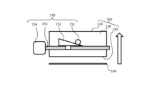
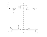
以上より、本実施形態に係るカメラモジュール10の合焦は、全体繰り出し方式とし、光学系ブロック部100(第1光学部材110、第2光学部材120及び隔壁部材130)を一体に物体側に移動させることにより行う。すなわち、合焦時に、撮像部材140に対する光学系ブロック部100の距離を変化させる。例えば、図8に示すように、合焦機構150として、隔壁部材130の外周面にピン151を取り付け、モータ等の駆動部154により駆動されるボールネジに153に取り付けられた楔部材152でピン151を押し上げることにより、カメラモジュール1の光学系ブロック部100、すなわち、光学系UL全体を物体側(図8における矢印方向)に移動させることができ、これにより合焦を行う。カメラモジュール10の光学系ULの全体の移動量(繰り出し量)は、表1に示した最至近距離までの繰り出し量に等しい。したがって、35mmカメラで300mm相当で、50倍のカメラモジュール1において、最大0.4mm(表2に示すように、距離1.0m)の繰り出し量となり、1000mm相当で、50倍のカメラモジュール1において、最大1.3mm(距離3.3m)の繰り出し量となる。なお、合焦動作は、撮像素子14、光学系ULの少なくとも一部を光軸方向に移動して行うこととしてもよい。
As described above, the focusing of the
(変倍について)
本実施形態に係る多眼構成のカメラモジュール1は、複数の単位ブロック10で構成されているが、各々の単位ブロック10を構成する光学系ULの光軸は互いに略平行になるように配置されている。そのため、複数の光学系ULの視野はほぼ重なっている(図9(a)に示す視野fvt)。一方、本実施形態に係る多眼構成のカメラモジュール1は、複数の単位ブロック10で構成されていることから、各々の単位ブロック10を構成する光学系ULの光軸を折り曲げることにより、各々の光学系ULの視野が重ならないようにして、このカメラモジュール1全体の視野を広げることができる。例えば、図9(b)に示すように、3×3の単位ブロック10を構成する3×3の光学系ULのうち、中心の単位ブロック10の光学系ULの光軸は変更せず、周辺の8個の単位ブロック10の光学系ULの光軸を、互いの視野が重ならない方向に折り曲げることにより、全体で広い視野を実現できる。例えば、3×3の単位ブロック10を有する場合、図9(b)の視野fvwとして示すように視野fvtの3倍にすることができる。(About variable magnification)
The
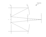
具体的な変倍方法としては、図10(a)に示すように、光学系ブロック部100の物体側に、フィールドレンズ状のプリズムブロック(フィールドプリズムである偏向光学系)160を配置する。図11に示すように、プリズムブロック160は、中心の光学系ULcに対しては、平行平板として構成されており(すなわち、中心の光学系ULcの光軸を折り曲げない)、また、中心の光学系ULcの周りに配置された光学系の光軸は、外側に折り曲げてから入射されるように構成されている。具体的には、上下方向(垂直隣)に位置する光学系ULu,ULdの光軸は垂直方向に折り曲げ、左右方向(水平隣)に位置する光学系ULl,ULrの光軸は水平方向に折り曲げ、斜め方向に位置する光学系ULul,Ulur,ULdl,ULdrの光軸は、斜め方向(矩形の視野の対角線方向)に折り曲げる。図11は、光学系UL毎に、折り曲げる方向を矢印で示している。
As a specific zooming method, as shown in FIG. 10A, a field lens-like prism block (deflecting optical system as a field prism) 160 is arranged on the object side of the optical
以下の表3に、プリズムブロック160の基材(媒質)の屈折率が1.5であるとしたときに、プリズムブロック160の中心の光学系ULの面に対する、周辺の光学系ULに対する面の角度θの関係を示す(図10(a))。なお、この表3は、本実施形態に係る多眼構成のカメラモジュール1が、35mmカメラに換算したときの焦点距離が300mm、500mm、1000mに対応する焦点距離であるときに、図9(b)のように各々の光学系ULの視野が重ならず、且つ、隙間が生じない(すなわち、9つの視野が密接した状態になる)ときの、水平隣、及び、垂直隣との角度θを示している。
Table 3 below shows the surface of the peripheral optical system UL with respect to the surface of the optical system UL at the center of the
(表3)プリズムブロックの角度
35mmカメラ換算の焦点距離
300 500 1000
水平隣 13.3° 8.0° 4.0°
垂直隣 9.1° 5.5° 2.8°(Table 3) Prism block angle
35mm camera equivalent focal length
300 500 1000
Horizontal side 13.3° 8.0° 4.0°
Vertical Adjacent 9.1° 5.5° 2.8°
表3から明らかなように、例えば、本実施形態に係る多眼構成のカメラモジュール1が、35mmカメラに換算して300mm相当である場合、中心の光学系ULのプリズムに対して、水平隣のプリズムの角度θを13.3°とし、垂直隣のプリズムの角度θを9.1°としたプリズムブロック160を取り付けることにより、視野が3倍なることから、焦点距離が1/3のなるため、100mm相当に変倍することができる。また同様に、上記角度の半分の、水平隣及び垂直隣のプリズムの角度が6.7°及び4.6°で構成されたプリズムブロック160を取り付けることにより、200mm相当に変倍することができる。
As is clear from Table 3, for example, when the
例えば、図10(b)に示すように、光を透過する媒質で形成された平行平面ガラス板161上に、上述したプリズムブロック160が形成されていない領域160a、水平隣及び垂直隣の角度θが6.7°及び4.6°のプリズムブロック160が形成された領域160b、並びに、水平隣及び垂直隣の角度θが13.3°及び9.1°のプリズムブロック160が形成された領域160cを形成し、この平行平面ガラス板161を、光学系ブロック部100に対してスライドさせることにより、上述した領域160aを選択すると、カメラモジュール1の焦点距離は35mmカメラに換算して300mmとなり、領域160bを選択すると、35mmカメラに換算して200mmとなり、領域160cを選択すると、35mmカメラに換算して100mmとなるため、段階的な変倍を実現することができる。
For example, as shown in FIG. 10(b), on a plane-
なお、プリズムブロック160として、液晶素子を用いれば、光軸を折り曲げる角度を連続的に変化させることができ、連続的な変倍を実現することができる。具体的には、単位ブロック10(光学系UL)毎に液晶素子を配置し、図11に示す方向へ光を偏向するように構成し、また、液晶素子へ加える電圧を変えることで、プリズム量を変化させる。なお、液晶素子は一つの偏光方向にしか対応していないため、配向を変えた同様の液晶素子を積層するか、1/2波長板を挟んで同じ液晶素子を積層する必要がある。
If a liquid crystal element is used as the
(迷光の除去について)
図12(a)に示す光線Lのように、光学系ULの補正板11に対して斜めに入射する光線は、主反射鏡12の開口部12bを通過して撮像素子14に直接入射して迷光となる場合がある。このような迷光を除去する方法として、以下に2つの構成を説明する。(Removal of stray light)
Like the light ray L shown in FIG. 12(a), the light ray obliquely incident on the
-第1の構成-
迷光を除去するための第1の構成は、図12(b)に示すように、第1の偏光部材である第1の偏光板16、第2の偏光部材である第2の偏光板18、及び偏光方向回転部材である波長膜17を組み合わせた防止部19を用いる。第1の偏光板16は、補正板11の物体側に配置され、この第1の偏光板16を通過した光だけが補正板11に入射するように構成されている。ここで、第1の偏光板16は、所定の方向に偏光した光を通過させる機能を有しているため、第1の偏光板16を通過して補正板11に入射する光は、所定の偏光方向の光となる。
- First configuration -
A first configuration for removing stray light is, as shown in FIG. and a
波長膜17は、副反射鏡13の第2の反射面13a上に形成されている。波長膜17は、通過する光の偏光方向を45°回転させる機能を有している。すなわち、この波長膜17は、波長板(λ/4板)の機能を有している。したがって、補正板11を透過して主反射鏡12の第1の反射面12aで反射した光は、波長膜17を透過して偏光方向が45°回転され、副反射鏡13の第2の反射面13aで反射する。そして、第2の反射面13aで反射した光は、再度波長膜17を通過して偏光方向が45°回転される。したがって、波長膜17から出射した光は、入射前の光に対してその偏光方向が90°回転された状態となっている。なお、波長膜17は、入射する光と射出する光との偏光方向回転させるものであればよい。
A
第2の偏光板18は、主反射鏡12の開口部12bと撮像素子14との間に配置される。この第2の偏光板18も、第1の偏光板16と同様に、所定の方向に偏光した光を通過させる機能を有しており、第2の偏光板18において通過させる光の偏光方向は、第1の偏光板16で通過させる光の偏光方向に対して直交する(90°回転した)状態に配置されている。なお、第2の偏光板18を主反射鏡12の開口部12bに取り付けてもよいし、開口部12bを構成する光学部材(第2光学部材120)の面に第2の偏光板18を形成してもよい。
A second
上述したように、第1の偏光板16を透過した光の偏光方向は、第2の偏光板18に入射するまでに、波長膜17により90°回転されているため、第2の波長板18において通過することができる偏光方向と一致している。すなわち、第1の偏光板16、補正板11、主反射鏡12、波長膜17、副反射鏡13、波長膜17の順で通過した光は、第2の波長板18を透過して撮像素子14に入射することができる。一方、第1の偏光板16及び補正板11を通過して、主反射鏡12で反射されずに開口部12bを通過しようとする光(例えば、図12(a)の光線L)は、第1の偏光板16を通過した際の偏光方向の光であるため、第2の偏光板18が通過させる光の偏光方向と90°ずれており、この第2の偏光板18を通過することができず、撮像素子14に入射することはできない。したがって、この第1の構成によれば、防止部19は、第1反射部(主反射鏡12)および第2反射部(副反射鏡13)での反射回数が所定の回数以外の光の撮像素子14への入射を防止する。ここで、第1反射部および第2反射部での反射回数が所定の回数以外の光とは、例えば、図12の例では第1反射部および第2反射部での反射回数が1回以外の光、つまり、第1反射部および第2反射部での反射回数が0回や2回以上の光である。また、図17の例では第1反射部および第2反射部での反射回数が2回以外の光、つまり、第1反射部および第2反射部での反射回数が0回、1回、3回以上の光である。そのため、主反射鏡12及び副反射鏡13の両方で反射されずに(反射回数0)、開口部12bを通過する迷光(光線L)も効果的に除去することができる。
As described above, the polarization direction of the light transmitted through the first
なお、本実施形態に係る多眼構成のカメラモジュール1の場合、図5(b)等に示すように複数の撮像素子14が配置されているため、第1の偏光板16及び第2の偏光板18を透過する光の偏光方向は、撮像素子14の並んでいる方向と一致することが望ましい。
In the case of the
また、上記の構成によると、第1の偏光板16及び第2の偏光板18を通過する光の偏光方向は一方向であって固定されている。この場合、例えば、第2の反射面13aで反射した光の偏光方向が第1の偏光板16において通過する光の偏光方向と異なっていると、この光による像を撮像することができなくなる。したがって、第1の偏光板16と第2の偏光板18を機械的に回転させて第1の偏光板16及び第2の偏光板18を透過することができる光の偏光方向を回転可能に構成することが望ましい。この場合、第1の偏光板16及び第2の偏光板18を液晶偏光板で構成することにより、第1の偏光板16及び第2の偏光板18を透過することができる光の偏光方向を電子的に回転可能に構成してもよい。また、本実施形態に係るカメラモジュール1,10を、例えばドローンや、車両に搭載した場合は、搭載されているドローンや車両の状態(飛行・走行方向や、傾き)に応じて、第1の偏光板16及び第2の偏光板18の偏光方向を回転させることを可能に構成してもよい。
Moreover, according to the above configuration, the polarization direction of the light passing through the first
また、本実施形態において、第1の偏光板16は、主反射鏡12より物体側の光路上に配置されていればよく、補正板11より物体側に配置されるのがよい。また、本実施形態において、第2の偏光板18は、副反射鏡13より像側の光路上に配置されていればよく、主反射鏡12より像側に配置されるのがよい。また、波長膜17は、第1の偏光板16と第2の偏光板18の間の光路上に配置されていればよく、主反射鏡12または副反射鏡13の反射面上に形成されるのがよい。
In this embodiment, the first
また、この第1の構成の場合、カメラモジュール1,10を構成する光学系ULに入射する光のうち、第1の偏光板16を通過することができる偏光方向以外の光は、結像に寄与しない。そのため、第1の偏光板16に、上述した偏光機能に加えて、透過できない偏光方向の光を電力に変換する太陽電池の機能を持たせることで、光学系ULに入射する光を有効活用することができる。この第1の偏光板16で光から変換された電力は、例えば、撮像素子14から画像を生成するために後述する制御部20で利用される。
Further, in the case of the first configuration, of the light incident on the optical system UL constituting the
なお、このカメラモジュール1,10を作動させるための電力を供給する太陽電池は、第1の偏光板16として設けるだけでなく、例えば、補正板11の物体側の面のうち、裏面側に副反射鏡13が配置されている位置に配置してもよい。図1等から明らかなように、補正板11の副反射鏡13が配置されている部分は、光が透過することができない(像の形成に寄与しない)ため、補正板11上の物体側のスペースを太陽電池の配置場所として有効利用することができる。同様に、補正板11上の物体側の面のうち、像の形成に寄与しない光が通過する部分(例えば、光学系ULの周辺部分)に太陽電池を配置してもよい。
The solar cell that supplies power for operating the
-第2の構成-
迷光を除去するための第2の構成は、防止部19が遮光性を有するものである。例えば、図13に示すように、防止部19は、主反射鏡12に入射する光の光軸方向において、主反射鏡12と副反射鏡13との間に配置される第1の遮光部材19aと第2の遮光部材19bとを有する。-Second configuration-
A second configuration for removing stray light is that the
第1の遮光部材19aは、補正板11を透過して主反射鏡12に入射し、更にこの主反射鏡12で反射して副反射鏡13に導かれる光が通過する光路と、副反射鏡13で反射して開口部12bに導かれる光が通過する光路と、を分離するものである。第1の遮光部材19aは、主反射鏡12で反射した光の光軸側に配置され、光軸方向から見て光学系ULの光軸を囲むように形成されている。この第1の遮光部材19aは、図13に示すように、主反射鏡12の反射面12aと開口部12b(第1反射部が囲むように形成された第2領域)との境界において、開口部12bを囲むように配置された(第1反射部の内周部に配置された)円筒状の部材である。第1の遮光部材19aは、主反射鏡12の表面から副反射鏡13に向かう方向に突出して形成されている。また、この第1の遮光部材19aの断面形状は、主反射鏡12側から副反射鏡13側に向かってその内径が細くなっている。また、第1の遮光部材19aの断面形状において、内径側の面(光軸側の面)と光軸に直交する面とのなす角θ1(θ1m)は外径側の面(光軸と反対側の面)と光軸に直交する面とのなす角θ2(θ2m)よりも小さいため、第1の遮光部材19aの側面の厚さは、主反射鏡12側から副反射鏡13側に向かって厚くなるように構成されている。
The first
第2の遮光部材19bは、補正板11を通過して主反射鏡12に導かれる光の光路と、主反射鏡12で反射して副反射鏡13に入射し、この副反射鏡13で反射して開口部12bに導かれる光の光路と、を分離するものである。第2の遮光部材19bは、副反射鏡13で反射した光の光軸と反対側に、副反射鏡13で反射した光束を囲むように配置される。この第2の遮光部材19bは、図13に示すように、第1領域に配置された副反射鏡13の反射面13aを囲むように配置された(第2反射部の外周部に配置された)円筒状の部材である。第2の遮光部材19bは、副反射鏡13の表面から主反射鏡12に向かう方向に突出して形成されている。また、この第2の遮光部材19bの断面形状は、副反射鏡13側から主反射鏡12側に向かって、その内径が広がっている。また、第2の遮光部材19bの断面形状において、内径側の面(光軸側の面)と光軸に直交する面とのなす角度θ1(θ1s)は外径側の面(光軸と反対側の面)と光軸に直交する面とのなす角度θ2(θ2s)より小さいため、第2の遮光部材19bの側面の厚さは、副反射鏡13側から主反射鏡12側に向かって薄くなるように構成されている。
The second light-shielding
このような第1の遮光部材19a及び第2の遮光部材19bは、以下の条件式(11)~(13)を満足することが望ましい。
1.0 < θ2s/θ1s < 2.0 (11)
30° < θ2s < 90° (12)
30° < θ2m < 90° (13)
但し、
θ1s:第2の遮光部材19bの内径側の面と光軸に直交する面とのなす角度
θ2s:第2の遮光部材19bの外径側の面と光軸に直交する面とのなす角度
θ2m:第1の遮光部材19aの外径側の面と光軸に直交する面とのなす角度
条件式(11)~(13)は、第1の遮光部材19a及び第2の遮光部材19bの外径側の面と光軸に直交する面とのなす角度θ2m,θ2sが所定の条件を満たすときの、第2の遮光部材19bの内径側の面と光軸に直交する面とのなす角度に対する外径側の面と光軸に直交する面とのなす角度の比を規定するものである。第1の遮光部材19a及び第2の遮光部材19bが条件式(11)~(13)を満足することにより迷光を効果的に除去することができる。
なお、条件式(11)の効果を確実なものとするために、条件式(11)の下限値を1.095とすることが望ましい。また、条件式(11)の効果を確実なものとするために、条件式(11)の上限値を1.595とすることが望ましい。
また、条件式(12)の効果を確実なものとするために、条件式(12)の下限値を54.5°とすることが望ましい。また、条件式(12)の効果を確実なものとするために、条件式(12)の上限値を84.5°とすることが望ましい。
また、条件式(13)の効果を確実なものとするために、条件式(13)の下限値を55.0°とすることが望ましい。また、条件式(13)の効果を確実なものとするために、条件式(13)の上限値を85.0°とすることが望ましい。
It is desirable that the first
1.0 < θ2s/θ1s < 2.0 (11)
30° < θ2s < 90° (12)
30° < θ2m < 90° (13)
however,
θ1s: the angle between the inner diameter side surface of the second
In order to ensure the effect of conditional expression (11), it is desirable to set the lower limit of conditional expression (11) to 1.095. In order to ensure the effect of conditional expression (11), it is desirable to set the upper limit of conditional expression (11) to 1.595.
In order to ensure the effect of conditional expression (12), it is desirable to set the lower limit of conditional expression (12) to 54.5°. In order to ensure the effect of conditional expression (12), it is desirable to set the upper limit of conditional expression (12) to 84.5°.
In order to ensure the effect of conditional expression (13), it is desirable to set the lower limit of conditional expression (13) to 55.0°. In order to ensure the effect of conditional expression (13), it is desirable to set the upper limit of conditional expression (13) to 85.0°.
具体的には、図13に示す第1遮光部材19a及び第2遮光部材19bの形状は、以下に示す表4の関係を有している。なお、表4においてテーパは、外径及び内径において、先端側の半径を基端側の半径で除した値である。ここで、基端側は、第1遮光部材19aであれば主反射鏡12側(像側)の端部であり、第2遮光部材19bであれば副反射鏡13側(物体側)の端部である。また先端側は、第1遮光部材19aであれば物体側の端部であり、第2遮光部材19bであれば像側の端部である。
Specifically, the shapes of the first
(表4)第1及び第2遮光部材の形状
テーパ θ2s/θ1s
θ1 θ2 外径 内径
第1遮光部材19a 80.93° 79.92° 1.33 1.40 -
第2遮光部材19b 66.52° 79.03° 1.10 1.30 1.19(Table 4) Shapes of the first and second light shielding members
Taper θ2s/θ1s
θ1 θ2 Outer diameter Inner diameter First
Second
このように、表4に示す第1遮光部材19a及び第2遮光部材19bは、上述した条件式(7)~(9)を満足している。
As described above, the first
第1の遮光部材19a及び第2の遮光部材19bを以上のような形状とすることにより、本実施形態に係る光学系ULの各々において、結像に寄与する光線を撮像素子14に導く(結像に必要な光束を確保する)とともに、補正板11を通過して直接開口部12bに入射する光や、主反射鏡12及び副反射鏡13以外の部分で反射して開口部12bに入射する光のような迷光を、効果的に除去することができる。なお、防止部19を構成する第1の遮光部材19a及び第2の遮光部材19bは、両方設けるだけでなく、少なくとも一方を設けることにより、上述した効果を得ることができる。
By shaping the first
(単位ブロック毎の撮像素子の光軸方向の位置の設定)
上述した多眼構成のカメラモジュール1では、例えば、図5(b)等に示すように、複数の単位ブロック10の各々において、光学系ULは同一の構成であり、また、全ての撮像素子14は、光軸方向に対して同一の位置に(例えば、無限遠合焦状態の焦点面と撮像素子14の撮像面が略一致するように)配置されている。ここで、光学系ULに対して撮像素子14の位置を光軸方向に変化させると、上述した合焦に関する説明でも示したように、合焦状態(合焦距離)を変化させることができる。そこで、図14に示すように、1台の多眼構成のカメラモジュール1を構成する単位ブロック10毎に、撮像素子14を光軸方向の異なる位置に配置する(換言すると、撮像部である単位ブロック10の少なくとも2つは、光学系ULと撮像素子14との光軸方向の相対位置が異なるように配置する)ことにより、1台のカメラモジュール1で、同一の被写体に対し、異なる合焦距離の画像を同時に取得することができる。(Setting the position of the image sensor in the optical axis direction for each unit block)
In the
図14は、カメラモジュール1を構成する3つの単位ブロック10a、10b、10cを示している。そして、単位ブロック10aの撮像素子14aは、その撮像面が、光学系ULが無限遠に合焦しているときの焦点面と略一致するように配置され、単位ブロック10cの撮像素子14cは、その撮像面が、光学系ULが最至近に合焦しているときの焦点面と略一致するように配置され、単位ブロック10bの撮像素子14bは、その撮像面が、光学系ULが無限遠と最至近の間の中間焦点距離に合焦しているときの焦点面と略一致するように配置されている場合を示している。光軸方向における撮像素子同士の位置の差は、光学系ULの被写体深度に応じた値であるのがよい。
FIG. 14 shows three
なお、多眼構成のカメラモジュール1を構成する単位ブロック10が4以上あるときは、何れか一つの単位ブロック10の撮像素子14を無限遠合焦状態の位置に配置し、残りのうちの何れか一つの単位ブロック10の撮像素子14を最至近合焦状態の位置に配置し、残りの単位ブロック10の撮像素子14は、無限遠から最至近の合焦距離を残りの単位ブロック10の数で均等に分割した位置に配置するように構成してもよいし、所定の合焦距離を中心にして、その前後に配置するように構成してもよい。なお、1台のカメラモジュール1において、同一の合焦距離に撮像素子14が配置された単位ブロック10が複数設けられていてもよい。なお、光学系ULに対する撮像素子14の光軸方向の位置(光学系ULの少なくとも一部または撮像素子14の光軸方向の位置)は可変としてもよい。
When there are four or more unit blocks 10 constituting the
1台の多眼構成のカメラモジュール1において、撮像素子14の光軸方向の位置が異なる単位ブロック10を設けることにより、1回の撮影で、同一の被写体に対して異なる合焦距離の画像を1度に撮影することができる。また、異なる合焦距離の画像を画像処理することにより、任意の合焦距離の画像を生成することができる。また、複数の撮像素子14から得られた複数の画像信号同士の合焦状態の差に基づいて、被写体までの距離を算出することもできる。
In one
また、異なる合焦距離の画像を画像処理することにより、被写体の3次元画像を生成することができ、また、被写体の奥行き方向(高さ方向)の距離を取得することができる。例えば、本実施形態に係る多眼構成のカメラモジュール1をドローンに搭載した状態で建物の画像を取得することにより、当該建物の高さを画像処理により取得することができる。
Further, by performing image processing on images with different focal distances, a three-dimensional image of the subject can be generated, and the distance of the subject in the depth direction (height direction) can be obtained. For example, by acquiring an image of a building with the
(照明装置との組み合わせ)
本実施形態に係る多眼構成のカメラモジュール1は、複数の単位ブロック10で構成されているが、全ての単位ブロック10は同一の光学系ULで構成されている。そのため、図15に示すように、一部の単位ブロック10において(例えば、単位ブロック10aと単位ブロック10cにおいて)、撮像素子14の代わりにLED等からなる光源70を配置すると、光源70を配置した単位ブロック10は照明装置として使用することができる。なお、以降の説明において撮像素子14を有する単位ブロック10bを「撮像ブロック」と呼び、光源70を有する単位ブロック10a,10cを「照明ブロック」と呼ぶ。(combination with lighting device)
The
ここで、撮像素子14が配置された単位ブロック10(撮像ブロック10b)、及び光源70が配置された単位ブロック10(照明ブロック10a,10c)において、撮像素子14と光源70の光学系ULに対する光軸方向の位置は、同じ位置でも異なる位置でもよい。また、撮像素子14が配置された単位ブロック10(撮像ブロック10b)も、光源70が配置された単位ブロック10(照明ブロック10a、10c)も、同一の光学系ULであり、また、光源70が対応する位置に配置された光学系ULの光軸と撮像素子14が対応する位置に配置された光学系ULの光軸とを平行とすることにより、光源70を光学系ULに対して撮像素子14と光軸方向の同じ位置に配置することにより、カメラとしての視野、及び照明装置としての照野は、略一致している。したがって、このような構成とすると、小型でありながら、光源70からの光を撮影範囲(視野)に効率良く照射して明るい画像を取得することができる。なお、光源70のゴースト対策として、光源70の光学系ULに対する位置と撮像素子14の光学系ULに対する位置とを異ならせることとしてもよい。
Here, in the unit block 10 (
図16は、3×3のカメラモジュール1において、カメラの単位ブロック(撮像ブロック)10及び照明装置の単位ブロック(照明ブロック)10の配置例を示している。例えば、図16(a)は中心の単位ブロック10をカメラとし、周辺の単位ブロック10を照明装置として配置した場合である。この図16(a)の構成は、中心のカメラに対して周辺から照明光を照射するため、明るい照明光を得ることができるとともに、被写体に対して周辺の8方向から照明光が照射されるため、影が生じる箇所を少なくすることができる(無影灯とすることができる)。例えば、内視鏡にこの図16(a)の構成のカメラモジュール1を搭載すると、影のない明るい画像を取得することができる。
FIG. 16 shows an arrangement example of camera unit blocks (imaging blocks) 10 and illumination device unit blocks (illumination blocks) 10 in a 3×3
図16(b)は、横方向(行方向)又は縦方向(列方向)の中段をカメラの単位ブロック(撮像ブロック)10とし、その上下又は左右を照明装置の単位ブロック(照明ブロック)10として配置した場合である。撮像素子14は、矩形(長方形)である場合が多いので、撮像素子14の短辺方向にカメラの単位ブロック(撮像ブロック)10を並べることにより、合成画像の方向による解像度の違いを小さくできるとともに、カメラを挟むように照明光が照射されるため、影の少ない画像を取得することができる。
In FIG. 16B, the middle stage in the horizontal direction (row direction) or vertical direction (column direction) is a camera unit block (imaging block) 10, and the upper and lower or left and right sides are unit blocks (illumination blocks) 10 of an illumination device. This is the case of placement. Since the
図16(c)は、対角線方向又は上下左右方向の4つの単位ブロック10を照明装置(照明ブロック)とし、残りの単位ブロック10をカメラ(撮像ブロック)にした場合である。この図16(c)の構成は、90度異なる4方向から照明光を照射して撮影することができるので、影がない画像を取得することができる(無影灯とすることができる)。また、照明装置の単位ブロック(照明ブロック)10の補正板11の物体側に液晶表示装置や透過スクリーンによる縞パターン(パターン付与部)を配置し、4つの照明装置(照明ブロック)を1つずつ点灯して画像を取得することにより、構造化照明による超解像度画像の取得や、被写体の高さ測定を行うことができる。
FIG. 16(c) shows a case in which four unit blocks 10 in the diagonal direction or in the up, down, left, and right directions are used as illumination devices (illumination blocks), and the remaining unit blocks 10 are used as cameras (imaging blocks). With the configuration of FIG. 16(c), illumination light can be emitted from four directions different by 90 degrees and photographed, so an image without shadows can be obtained (a shadowless light can be used). In addition, a striped pattern (pattern imparting portion) by a liquid crystal display device or a transmissive screen is arranged on the object side of the
また、図16(d)に示すように、中心の単位ブロック10を照明装置(照明ブロック)とし、残りの単位ブロック10をカメラ(撮像ブロック)として構成することもできる。
Alternatively, as shown in FIG. 16D, the
なお、照明装置の単位ブロック(照明ブロック)10の光源70から放射される光の波長を変える(色を変える)構成や、補正板11の物体側に偏光板を配置して照明光の偏光方向を変える構成にしてもよい。また、図16(a)に示すように、撮像素子14と光源70のいずれかを光学系ULの光軸上に切り替えて配置する切替部80を設け、図16(a)~(e)に示す構成を任意に選択できるようにしてもよい。また、撮像素子14と光源70とは一つの部材(例えば、上述した撮像部材140)に配置してもよい。
It should be noted that a configuration that changes the wavelength (changes the color) of light emitted from the
(多段折り返しの構成)
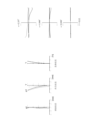
上述した実施形態の光学系ULは、主反射鏡12及び副反射鏡13で1回ずつ折り返す(1段折り返しの)構成であったが、主反射鏡12及び副反射鏡13で2回以上の折り返し(多段折り返しの)構成とすることで、全長(補正板11から撮像面Iまでの光軸方向の距離)をさらに短くしてカメラモジュール1,10を更に小型化することができる。(Structure of multistage folding)
The optical system UL of the above-described embodiment has a configuration in which the main reflecting
図17(a)は、補正板11を透過した光を反射する第1の主反射鏡121、及び第1の主反射鏡121で反射した光を反射する第1の副反射鏡131の反射面からなる反射面対と、第1の副反射鏡131で反射した光を反射する第2の主反射鏡122、及び第2の主反射鏡122で反射した光を反射する第2の副反射鏡132の反射面からなる反射面対とを、それぞれ別の部材として構成した場合を示している。また、図17(b)は、第1の主反射鏡121と第2の主反射鏡122とを一体の部材として構成し、第1の副反射鏡131と第2の副反射鏡132とを一体の部材として構成した場合を示している。図17(b)の場合、第1の主反射鏡121の反射面と第2の主反射鏡122の反射面とが連続する面として構成されており、第1の副反射鏡131の反射面と第2の副反射鏡132の反射面とが連続する面として構成されている。なお、第1の主反射鏡121の反射面及び第2の主反射鏡122の反射面と、第1の副反射鏡131の反射面及び第2の副反射鏡132の反射面とのいずれか一方を連続する面として構成し、他方を連続しない面として構成してもよい。
17A shows the reflecting surfaces of the first main reflecting
また、本実施形態に係る光学系ULは、以下の条件式(14)を満足することが望ましい。
2.0 < Fno < 15.0 (14)
但し、
Fno:光学系ULのFナンバー
条件式(14)は、光学系ULのFナンバーの適切な範囲を示している。なお、この条件式(14)の効果を確実なものとするために、条件式(14)の上限値を13.0、更に10.0とすることがより望ましい。また、この条件式(14)の効果を確実なものとするために、条件式(14)の下限値を3.0、更に4.0とすることが望ましい。Moreover, it is desirable that the optical system UL according to this embodiment satisfy the following conditional expression (14).
2.0 < Fno < 15.0 (14)
however,
Fno: F number of optical system UL
Conditional expression (14) indicates an appropriate range for the F-number of the optical system UL. In order to ensure the effect of conditional expression (14), it is more desirable to set the upper limit of conditional expression (14) to 13.0, more preferably 10.0. In order to ensure the effect of conditional expression (14), it is desirable to set the lower limit of conditional expression (14) to 3.0, more preferably 4.0.
このように、光学系ULの折り返し回数を多段化する(反射面の数を増やす)ことにより、光学設計の自由度を上げることができる。このとき、上述した迷光除去のための第2の構成(遮光部材)を用いることにより、多段折り返しをしても迷光を除去することができる。 In this way, by increasing the number of turns of the optical system UL (increasing the number of reflecting surfaces), the degree of freedom in optical design can be increased. At this time, by using the above-described second configuration (light-shielding member) for removing stray light, stray light can be removed even if multistage folding is performed.
なお、以上で説明した条件及び構成は、それぞれが上述した効果を発揮するものであり、全ての条件及び構成を満たすものに限定されることはなく、いずれかの条件又は構成、或いは、いずれかの条件又は構成の組み合わせを満たすものでも、上述した効果を得ることが可能である。 In addition, the conditions and configurations described above exhibit the effects described above, and are not limited to those that satisfy all the conditions and configurations. It is possible to obtain the above-described effects even if the conditions or combinations of the above conditions are satisfied.
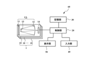
次に、本実施形態に係るカメラモジュール1を備えた光学機器であるカメラを図18に基づいて説明する。このカメラ60は、上述した多眼構成のカメラモジュール1と、制御部20と、記憶部30と、入力部40と、表示部50と、を有して構成されている。なお、制御部20は、CPU等の演算処理装置である。また、記憶部30は、RAMやハードディスク、SSD等の記憶装置である。また、入力部40は、カメラであればレリーズボタン等であり、表示部50は、液晶表示装置等である。
Next, a camera, which is an optical device equipped with the
本カメラ60において、不図示の物体(被写体)からの光は、カメラモジュール1を構成する複数の単位ブロック10の各々の光学系ULで集光されて、撮像素子14の撮像面上に被写体像を形成する。そして、撮像素子14に設けられた光電変換素子により被写体像が光電変換されて被写体の画像信号が出力される。この画像信号は、制御部20に出力される。制御部20は、複数の撮像素子14から出力された複数の画像信号に基づいて一つの画像を生成する生成部を有する。また、制御部20により、生成された画像がカメラ60に設けられた表示部50に表示される。また、撮影者によって入力部40が操作されると、撮像素子14により光電変換された画像が制御部20により取得された後、合成処理がされ、合成画像として記憶部30に記憶される。このようにして、撮影者は本カメラ60による被写体の撮影を行うことができる。なお、制御部20の機能のうち、複数の撮像素子14から画像を取得して合成画像を生成する機能を、カメラモジュール1側に設けてもよいし、外部の機器に設けて適宜送受信することとしてもよい。また、制御部20は、各撮像素子14の撮像条件を異ならせることとしてもよい。撮像条件としては、例えば、撮影感度、露光時間、露光開始時間、露光終了時間の少なくとも一つが挙げられる。撮影条件を異ならせることにより、合成して得られる画像をよりユーザーの所望のものに近づけることができる。
In the
このような多眼構成のカメラモジュール1は、以下の条件式(15)を満足することが望ましい。
0.30 < Nc/(Nd×n) < 1.00 (15)
但し、
Nd:撮像素子14の画素数
n:画像の生成に使用する撮像素子14の数
Nc:画像の画素数
条件式(15)は、画像の生成に使用する撮像素子14の画素数の合計(単位ブロック10の各々が有する撮像素子14の画素数と画像の生成に使用する単位ブロック10の数の積)に対して、これらの撮像素子14で取得された画像から合成された画像の画素数の比の適切な範囲を示している。なお、この条件式(15)の効果を確実なものとするために、条件式(15)の下限値を0.40、更に0.50とすることがより望ましい。また、条件式(15)の効果を確実なものとするために、条件式(15)の上限値を0.80、0.70、更に0.60とすることがより望ましい。
The
0.30<Nc/(Nd×n)<1.00 (15)
however,
Nd: Number of pixels of image sensor 14 n: Number of
このような多眼構成のカメラモジュール1は、以下の条件式(16)を満足することが望ましい。
0.50 < Nc/(Nd×√n) < 2.00 (16)
但し、
Nd:撮像素子14の画素数
n:画像の生成に使用する撮像素子14の数
Nc:画像の画素数
条件式(16)は、合成画像の生成に使用する撮像素子14の画素数の合計に対して、これらの撮像素子14で取得された画像から合成された画像の画素数の比の適切な範囲を示している。なお、この条件式(16)の効果を確実なものとするために、条件式(16)の下限値を0.70、0.80、更に1.00とすることがより望ましい。また、条件式(16)の効果を確実なものとするために、条件式(16)の上限値を1.90、1.80、更に1.70とすることがより望ましい。The
0.50<Nc/(Nd×√n)<2.00 (16)
however,
Nd: Number of pixels of image pickup device 14 n: Number of
なお、単眼構成のカメラモジュール10を備えた光学機器(カメラ60)は、図18において、単位ブロック10が一つの構成に相当し、この場合、制御部20は合成処理を行わない。
また、上述した光学機器はカメラに限定されることはなく、本実施形態に示すカメラモジュール1,10を搭載したドローンや携帯端末、内視鏡等も含まれる。In FIG. 18, the optical device (camera 60) provided with the
Further, the above-described optical equipment is not limited to cameras, and includes drones, mobile terminals, endoscopes, etc. that are equipped with the
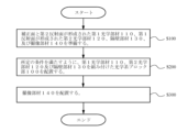
以下、本実施形態に係るカメラモジュール1、10の製造方法の概略を、図19を参照して説明する。まず、補正板11及び副反射鏡13が形成された第1光学部材110、主反射鏡12が形成された第2光学部材120、隔壁部材130、及び撮像素子14が配置された撮像部材140を準備する(ステップS100)。そして、第1光学部材110、第2光学部材120及び隔壁部材130が組み付けられた光学系ブロック部100を配置し(ステップS200)、光学系ブロック部100の複数の光学系ULと撮像素子14とが位置整合するように、撮像部材140を配置する(ステップS300)。このようにしてカメラモジュール1、10を製造する。
以上のような構成により、高解像度で、高い光学性能を有し、小型化されたカメラモジュール1、10、このカメラモジュール1、10を有する光学機器(カメラ60)、及びカメラモジュール1、10の製造方法を提供することができる。An outline of a method for manufacturing the
With the above configuration, the
以下、本願の各実施例を、図面に基づいて説明する。図20、図22、図24及び図26は、第1実施例~第4実施例に係る光学系UL(UL1~UL4)の構成を示す断面図である。 Each embodiment of the present application will be described below with reference to the drawings. 20, 22, 24 and 26 are sectional views showing the configuration of the optical system UL (UL1 to UL4) according to the first to fourth examples.
また、第1~第10実施例において、非球面は、光軸に垂直な方向の高さをyとし、高さyにおける各非球面の頂点の接平面から各非球面までの光軸に沿った距離(サグ量)をS(y)とし、基準球面の曲率半径(近軸曲率半径)をrとし、円錐定数をKとし、n次の非球面係数をAnとしたとき、以下の式(b)で表される。なお、以降の実施例において、「E-n」は「×10-n」を示す。
S(y)=(y2/r)/{1+(1-K×y2/r2)1/2}
+A2×y2+A4×y4+A6×y6+A8×y8 (b)
なお、各実施例の表中において、非球面には面番号の右側に*印を付している。In the first to tenth embodiments, the aspheric surface has a height y in the direction perpendicular to the optical axis, and the distance from the tangential plane of the apex of each aspheric surface at height y to each aspheric surface is along the optical axis. Let S (y) be the distance (sag amount) measured, let r be the radius of curvature of the reference sphere (paraxial radius of curvature), let K be the conic constant, and let An be the n-th order aspheric coefficient. b). In the following examples, "En" indicates "×10 -n ".
S(y)=(y 2 /r)/{1+(1−K×y 2 /r 2 ) 1/2 }
+A2×y2 + A4× y4 +A6× y6 +A8×y8 ( b)
In the table of each example, an asterisk (*) is attached to the right side of the surface number of the aspheric surface.
[第1実施例]
図20は、第1実施例に係る光学系UL1の構成を示す図である。この光学系UL1は、35mmカメラに換算したときに、焦点距離が300mmになるカメラモジュール1,10の構成である。[First embodiment]
FIG. 20 is a diagram showing the configuration of the optical system UL1 according to the first example. This optical system UL1 is a configuration of
光学系UL1は、物体側から光線が進行する順に、補正板11、主反射鏡12の第1反射面12a、副反射鏡13の第2反射面13a、及び物体側に凸面を向けた平凸レンズ形状の屈折光学系15で構成されている。なお、補正面11aは補正板11の像側の面(第2面)に形成されている。
The optical system UL1 includes, in order of light rays traveling from the object side, a
以下の表5に、光学系UL1の諸元の値を掲げる。この表5において、全体諸元におけるfは全系の焦点距離、ωは半画角、TLは全長を示している。なお、全長TLは、像面Iに入射する光軸の方向において、補正板11の物体側の面(第1面)から像面Iまでの距離である。また、レンズデータにおける第1欄mは、光線の進行する方向に沿った物体側からのレンズ面の順序(面番号)を、第2欄rは、各レンズ面の曲率半径を、第3欄dは、各光学面から次の光学面までの光軸上の距離(面間隔)を、第4欄nd及び第5欄νdは、d線(λ=587.6nm)に対する屈折率及びアッベ数を示している。また、曲率半径∞は平面を示し、空気の屈折率1.00000は省略してある。
Table 5 below lists the values of the specifications of the optical system UL1. In Table 5 , f in the overall specifications is the focal length of the entire system, ω is the half angle of view, and TL is the total length. The total length TL is the distance from the object-side surface (first surface) of the
ここで、以下の全ての諸元値において掲載されている焦点距離f、曲率半径r、面間隔d、その他長さの単位は一般に「mm」が使われるが、光学系は、比例拡大または比例縮小しても同等の光学性能が得られるので、これに限られるものではない。また、これらの符号の説明及び諸元表の説明は以降の実施例においても同様である。 Here, the focal length f, radius of curvature r, surface spacing d, and other lengths listed in all the specifications below are generally expressed in units of "mm". The same optical performance can be obtained even if the size is reduced, so the size is not limited to this. Further, the explanation of these symbols and the explanation of the specification table are the same in the following embodiments.
(表5)第1実施例
[全体諸元]
f=20.58、ω=3.61°、TL=11.73、Fno=2.00
[レンズデータ]
m r d nd νd 外径
物面 ∞
1 ∞ 1.00 1.45844 67.82 11.52
2* -210.204 8.88 11.52
3* -35.747 -8.81 10.60
4* -84.576 8.65 6.20
5* 13.246 1.00 1.45844 67.82 3.50
6 ∞ 1.00 3.50
像面 ∞ 2.61(Table 5) First embodiment [overall specifications]
f=20.58, ω=3.61°, TL=11.73, Fno=2.00
[Lens data]
m r d nd νd Outer diameter object plane ∞
1 ∞ 1.00 1.45844 67.82 11.52
2* -210.204 8.88 11.52
3* -35.747 -8.81 10.60
4* -84.576 8.65 6.20
5* 13.246 1.00 1.45844 67.82 3.50
6 ∞ 1.00 3.50
Image plane ∞ 2.61
この光学系UL1において、第2面、第3面、第4面及び第5面は非球面形状に形成されている。次の表6に、非球面のデータ、すなわち円錐定数K及び各非球面定数A2~A8の値を示す。この表6においてmは面番号を示す(以降の実施例においても同様である)。
(表6)
[非球面データ]
m K A2 A4 A6 A8
2 0.000 6.43803E-05 3.22635E-07 -8.96677E-09 1.27267E-10
3 0.000 -1.81266E-05 0.00000E+00 0.00000E+00 0.00000E+00
4 0.000 -6.73742E-05 0.00000E+00 0.00000E+00 0.00000E+00
5 0.000 2.16247E-04 3.90515E-04 -1.80580E-04 2.77699E-05In this optical system UL1, the second, third, fourth and fifth surfaces are formed in aspherical shapes. Table 6 below shows the data of the aspherical surface, namely the values of the conic constant K and the respective aspherical constants A2-A8. In this Table 6, m indicates a surface number (the same applies to subsequent examples).
(Table 6)
[Aspheric data]
m K A2 A4 A6 A8
2 0.000 6.43803E-05 3.22635E-07 -8.96677E-09 1.27267E-10
3 0.000 -1.81266E-05 0.00000E+00 0.00000E+00 0.00000E+00
4 0.000 -6.73742E-05 0.00000E+00 0.00000E+00 0.00000E+00
5 0.000 2.16247E-04 3.90515E-04 -1.80580E-04 2.77699E-05
次の表7に、光学系UL1における各条件式対応値を示す。
(表7)
f1=22.75、RL=8.81、D2=6.20、fa=458.52、D0=11.52、
Y=1.31、fb=458.52、D1=10.60
(1)TL=11.73
(2)ω=3.61°
(3)f/fa=0.04
(4)f/fb=0.04
(5)M=0.90
(6)f=20.58
(7)RL/TL=0.75
(8)D1/RL=1.20
(9)D1/D2=1.71
(10)D0/Y=8.79
このように、光学系UL1は、上記条件式(1)~(10)を満足している。Table 7 below shows values corresponding to each conditional expression in the optical system UL1.
(Table 7)
f1 = 22.75, RL = 8.81, D2 = 6.20, fa = 458.52, D0 = 11.52,
Y=1.31, fb=458.52, D1=10.60
(1) TL = 11.73
(2) ω=3.61°
(3) f/fa = 0.04
(4) f/fb = 0.04
(5) M = 0.90
(6) f = 20.58
(7) RL/TL=0.75
(8) D1/RL = 1.20
(9) D1/D2 = 1.71
(10) D0/Y=8.79
Thus, the optical system UL1 satisfies the conditional expressions (1) to (10).
図21に、光学系UL1の球面収差図、非点収差図、歪曲収差図及びコマ収差図を示す。各収差図において、Yは像高、ωは半画角をそれぞれ示す。なお、球面収差図の縦軸は最大口径に対する口径比を示し、非点収差図及び歪曲収差図の縦軸は像高を示し、コマ収差図の横軸は各半画角の射出瞳における開口値を示す。dはd線(λ=587.6nm)、gはg線(λ=435.8nm)をそれぞれ示す。非点収差図において、実線はサジタル像面、破線はメリディオナル像面をそれぞれ示す。なお、以下に示す各実施例の収差図においても、本実施例と同様の符号を用いる。これらの収差図より、第1実施例に係る光学系UL1は、諸収差を良好に補正し優れた結像性能を有していることがわかる。 FIG. 21 shows a spherical aberration diagram, an astigmatism diagram, a distortion diagram, and a coma diagram of the optical system UL1. In each aberration diagram, Y indicates the image height, and ω indicates the half angle of view. The vertical axis of the spherical aberration diagram indicates the aperture ratio to the maximum aperture, the vertical axis of the astigmatism diagram and the distortion aberration diagram indicates the image height, and the horizontal axis of the coma aberration diagram indicates the aperture at the exit pupil of each half angle of view. indicate a value. d indicates the d-line (λ=587.6 nm) and g indicates the g-line (λ=435.8 nm). In the astigmatism diagrams, a solid line indicates a sagittal image plane, and a broken line indicates a meridional image plane. In the aberration diagrams of each example shown below, the same reference numerals as in this example are used. From these aberration diagrams, it can be seen that the optical system UL1 according to the first example satisfactorily corrects various aberrations and has excellent imaging performance.
[第2実施例]
図22は、第2実施例に係る光学系UL2の構成を示す図である。この光学系UL2は、35mmカメラに換算したときに、焦点距離が500mmになるカメラモジュール1,10の構成である。[Second embodiment]
FIG. 22 is a diagram showing the configuration of the optical system UL2 according to the second example. This optical system UL2 is a configuration of the
光学系UL2は、物体側から光線が進行する順に、補正板11、主反射鏡12の第1反射面12a、副反射鏡13の第2反射面13a、及び物体側に凹面を向けた平凹レンズ形状の屈折光学系15で構成されている。なお、補正面11aは補正板11の像側の面(第2面)に形成されている。
The optical system UL2 includes, in order of light rays traveling from the object side, a
以下の表8に、光学系UL2の諸元の値を掲げる。
(表8)第2実施例
[全体諸元]
f=34.30、ω=2.16°、TL=12.00、Fno=4.00
[レンズデータ]
m r d nd νd 外径
物面 ∞
1 ∞ 1.00 1.45844 67.82 9.60
2* -270.864 9.16 9.60
3* -28.098 -9.09 8.99
4* -16.561 8.93 3.65
5 -9.038 1.00 1.45844 67.82 2.58
6 ∞ 1.00 2.58
像面 ∞ 2.60Table 8 below lists the values of the specifications of the optical system UL2.
(Table 8) Second embodiment [overall specifications]
f=34.30, ω=2.16°, TL=12.00, Fno=4.00
[Lens data]
m r d nd νd Outer diameter object plane ∞
1 ∞ 1.00 1.45844 67.82 9.60
2* -270.864 9.16 9.60
3* -28.098 -9.09 8.99
4* -16.561 8.93 3.65
5 -9.038 1.00 1.45844 67.82 2.58
6 ∞ 1.00 2.58
Image plane ∞ 2.60
この光学系UL2において、第2面、第3面、及び第4面は非球面形状に形成されている。次の表9に、非球面のデータ、すなわち円錐定数K及び各非球面定数A2~A8の値を示す。
(表9)
[非球面データ]
m K A2 A4 A6 A8
2 0.000 7.45543E-05 1.65693E-07 0.00000E+00 0.00000E+00
3 0.000 -1.66942E-05 -1.05616E-08 0.00000E+00 0.00000E+00
4 0.000 -1.68429E-04 -1.36240E-06 0.00000E+00 0.00000E+00In this optical system UL2, the second, third and fourth surfaces are aspherical. Table 9 below shows the data of the aspherical surfaces, namely the values of the conic constant K and the respective aspherical constants A2-A8.
(Table 9)
[Aspheric data]
m K A2 A4 A6 A8
2 0.000 7.45543E-05 1.65693E-07 0.00000E+00 0.00000E+00
3 0.000 -1.66942E-05 -1.05616E-08 0.00000E+00 0.00000E+00
4 0.000 -1.68429E-04 -1.36240E-06 0.00000E+00 0.00000E+00
次の表10に、光学系UL2における各条件式対応値を示す。
(表10)
f1= 35.02、RL=9.09、D2=3.65、fa=590.84、D0=9.60、
Y=1.30、fb=590.84、D1=8.99
(1)TL=12.00
(2)ω=2.16°
(3)f/fa=0.06
(4)f/fb=0.06
(5)M=0.98
(6)f=34.30
(7)RL/TL=0.76
(8)D1/RL=0.99
(9)D1/D2=2.46
(10)D0/Y=7.38
このように、光学系UL2は、上記条件式(1)~(10)を満足している。Table 10 below shows values corresponding to each conditional expression in the optical system UL2.
(Table 10)
f1 = 35.02, RL = 9.09, D2 = 3.65, fa = 590.84, D0 = 9.60,
Y=1.30, fb=590.84, D1=8.99
(1) TL = 12.00
(2) ω=2.16°
(3) f/fa = 0.06
(4) f/fb = 0.06
(5) M = 0.98
(6) f = 34.30
(7) RL/TL=0.76
(8) D1/RL = 0.99
(9) D1/D2 = 2.46
(10) D0/Y=7.38
Thus, the optical system UL2 satisfies the conditional expressions (1) to (10).
図23に、光学系UL2の球面収差図、非点収差図、歪曲収差図及びコマ収差図を示す。これらの収差図より、第2実施例に係る光学系UL2は、諸収差を良好に補正し優れた結像性能を有していることがわかる。 FIG. 23 shows a spherical aberration diagram, an astigmatism diagram, a distortion diagram, and a coma diagram of the optical system UL2. From these aberration diagrams, it can be seen that the optical system UL2 according to the second example satisfactorily corrects various aberrations and has excellent imaging performance.
[第3実施例]
図24は、第3実施例に係る光学系UL3の構成を示す図である。この光学系UL3は、35mmカメラに換算したときに、焦点距離が1000mmになるカメラモジュール1,10の構成である。[Third embodiment]
FIG. 24 is a diagram showing the configuration of the optical system UL3 according to the third example. This optical system UL3 is a configuration of
光学系UL3は、物体側から光線が進行する順に、補正板11、主反射鏡12の第1反射面12a、副反射鏡13の第2反射面13a、及び物体側に凹面を向けた平凹レンズ形状の屈折光学系15で構成されている。なお、補正面11aは補正板11の像側の面(第2面)に形成されている。
The optical system UL3 includes, in order of light rays traveling from the object side, a
以下の表11に、光学系UL3の諸元の値を掲げる。
(表11)第3実施例
[全体諸元]
f=68.60、ω=1.09°、TL=15.00、Fno=8.00
[レンズデータ]
m r d nd νd 外径
物面 ∞
1 ∞ 1.00 1.45844 67.82 10.39
2* -513.658 12.16 10.39
3* -31.375 -12.09 10.60
4* -9.015 11.93 2.60
5 -8.005 1.00 1.45844 67.82 2.33
6 ∞ 1.00 2.33
像面 ∞ 2.60Table 11 below lists the values of the specifications of the optical system UL3.
(Table 11) Third embodiment [overall specifications]
f = 68.60, ω = 1.09°, TL = 15.00, Fno = 8.00
[Lens data]
m r d nd νd Outer diameter object plane ∞
1 ∞ 1.00 1.45844 67.82 10.39
2* -513.658 12.16 10.39
3* -31.375 -12.09 10.60
4* -9.015 11.93 2.60
5 -8.005 1.00 1.45844 67.82 2.33
6 ∞ 1.00 2.33
Image plane ∞ 2.60
この光学系UL3において、第2面、第3面、及び第4面は非球面形状に形成されている。次の表12に、非球面のデータ、すなわち円錐定数K及び各非球面定数A2~A8の値を示す。
(表12)
[非球面データ]
m K A2 A4 A6 A8
2 0.000 3.52435E-05 4.11085E-08 0.00000E+00 0.00000E+00
3 0.000 -5.76488E-06 -2.52534E-09 0.00000E+00 0.00000E+00
4 0.000 -2.13506E-04 -8.63973E-06 0.00000E+00 0.00000E+00In this optical system UL3, the second, third, and fourth surfaces are aspherical. Table 12 below shows the data of the aspherical surface, namely the values of the conic constant K and the respective aspherical constants A2-A8.
(Table 12)
[Aspheric data]
m K A2 A4 A6 A8
2 0.000 3.52435E-05 4.11085E-08 0.00000E+00 0.00000E+00
3 0.000 -5.76488E-06 -2.52534E-09 0.00000E+00 0.00000E+00
4 0.000 -2.13506E-04 -8.63973E-06 0.00000E+00 0.00000E+00
次の表13に、光学系UL3における各条件式対応値を示す。
(表13)
f1=77.73、RL=12.09、D2=2.6、fa=1120.45、D0=10.39、
Y=1.30、fb=1120.45、D1=10.6
(1)TL=15.00
(2)ω=1.09°
(3)f/fa=0.06
(4)f/fb=0.06
(5)M=0.88
(6)f=68.60
(7)RL/TL=0.81
(8)D1/RL=0.88
(9)D1/D2=4.08
(10)D0/Y=7.99
このように、光学系UL3は、上記条件式(1)~(10)を満足している。Table 13 below shows values corresponding to each conditional expression in the optical system UL3.
(Table 13)
f1=77.73, RL=12.09, D2=2.6, fa=1120.45, D0=10.39,
Y=1.30, fb=1120.45, D1=10.6
(1) TL = 15.00
(2) ω=1.09°
(3) f/fa = 0.06
(4) f/fb = 0.06
(5) M = 0.88
(6) f = 68.60
(7) RL/TL=0.81
(8) D1/RL = 0.88
(9) D1/D2 = 4.08
(10) D0/Y=7.99
Thus, the optical system UL3 satisfies the conditional expressions (1) to (10).
図25に、光学系UL3の球面収差図、非点収差図、歪曲収差図及びコマ収差図を示す。これらの収差図より、第3実施例に係る光学系UL3は、諸収差を良好に補正し優れた結像性能を有していることがわかる。 FIG. 25 shows a spherical aberration diagram, an astigmatism diagram, a distortion diagram, and a coma diagram of the optical system UL3. From these aberration diagrams, it can be seen that the optical system UL3 according to the third embodiment satisfactorily corrects various aberrations and has excellent imaging performance.
[第4実施例]
図26は、第4実施例に係る光学系UL4の構成を示す図である。この光学系UL4は、35mmカメラに換算したときに、焦点距離が300mmになるカメラモジュール1,10の構成である。[Fourth embodiment]
FIG. 26 is a diagram showing the configuration of the optical system UL4 according to the fourth example. This optical system UL4 is a configuration of the
光学系UL4は、物体側から光線が進行する順に、補正板11、主反射鏡12の第1反射面12a、及び副反射鏡13の第2反射面13aで構成されている。なお、補正面11aは補正板11の物体側の面(第1面)に形成されている。
The optical system UL4 is composed of a
以下の表14に、光学系UL4の諸元の値を掲げる。
(表14)第4実施例
[全体諸元]
f=19.71、ω=0.87°、TL=6.00、Fno=5.00
[レンズデータ]
m r d nd νd 外径
物面 ∞
1* 250.000 0.50 1.45844 67.82 4.11
2 ∞ 5.00 4.11
3 -8.741 -3.46 4.00
4 -2.256 3.96 0.90
5 ∞ 0.50 0.64
像面 ∞ 0.61Table 14 below lists the values of the specifications of the optical system UL4.
(Table 14) Fourth embodiment [overall specifications]
f=19.71, ω=0.87°, TL=6.00, Fno=5.00
[Lens data]
m r d nd νd Outer diameter object plane ∞
1* 250.000 0.50 1.45844 67.82 4.11
2 ∞ 5.00 4.11
3 -8.741 -3.46 4.00
4 -2.256 3.96 0.90
5 ∞ 0.50 0.64
Image plane ∞ 0.61
この光学系UL4において、第1面は非球面形状に形成されている。次の表15に、非球面のデータ、すなわち円錐定数K及び各非球面定数A2~A8の値を示す。
(表15)
[非球面データ]
m K A2 A4 A6 A8
1 0.000 -6.55865E-04 0.00000E+00 0.00000E+00 0.00000E+00In this optical system UL4, the first surface is formed in an aspherical shape. Table 15 below shows the data of the aspheric surface, namely the values of the conic constant K and each of the aspheric constants A2-A8.
(Table 15)
[Aspheric data]
m K A2 A4 A6 A8
1 0.000 -6.55865E-04 0.00000E+00 0.00000E+00 0.00000E+00
次の表16に、光学系UL4における各条件式対応値を示す。
(表16)
f1=22.89、RL=3.46、D2=0.90、fa=545.33、D0=4.11、
Y=0.31、fb=545.33、D1=4.00
(1)TL=6.00
(2)ω=0.87°
(3)f/fa=0.04
(4)f/fb=0.04
(5)M=0.86
(6)f=19.71
(7)RL/TL=0.58
(8)D1/RL=1.16
(9)D1/D2=4.44
(10)D0/Y=13.26
このように、光学系UL4は、上記条件式(1)~(10)を満足している。Table 16 below shows values corresponding to each conditional expression in the optical system UL4.
(Table 16)
f1 = 22.89, RL = 3.46, D2 = 0.90, fa = 545.33, D0 = 4.11,
Y=0.31, fb=545.33, D1=4.00
(1) TL = 6.00
(2) ω=0.87°
(3) f/fa = 0.04
(4) f/fb = 0.04
(5) M = 0.86
(6) f = 19.71
(7) RL/TL=0.58
(8) D1/RL = 1.16
(9) D1/D2 = 4.44
(10) D0/Y=13.26
Thus, the optical system UL4 satisfies the conditional expressions (1) to (10).
図27に、光学系UL4の球面収差図、非点収差図、歪曲収差図及びコマ収差図を示す。これらの収差図より、第4実施例に係る光学系UL4は、諸収差を良好に補正し優れた結像性能を有していることがわかる。 FIG. 27 shows a spherical aberration diagram, an astigmatism diagram, a distortion diagram, and a coma diagram of the optical system UL4. From these aberration diagrams, it can be seen that the optical system UL4 according to the fourth example satisfactorily corrects various aberrations and has excellent imaging performance.
以下に示す第5実施例~第7実施例は、光学系ULをコンパクト・シュミットカセグレン方式で構成した場合である。なお、図28は、第5実施例~第7実施例に係るカメラモジュール1,10を構成する光学系ULの断面図である。
Fifth to seventh embodiments shown below are cases in which the optical system UL is constructed in the compact Schmidt-Cassegrain system. Note that FIG. 28 is a cross-sectional view of an optical system UL that constitutes the
(第5実施例)
第5実施例は、光学系ULをコンパクト・シュミットカセグレン方式で構成した場合であって、35mmカメラに換算したときに、焦点距離が500mmになるカメラモジュール1,10の構成である。なお、撮像素子14は、2メガピクセルで、1/6インチの撮像素子であり、その大きさは、2.4mm×1.8mmであるとする。(Fifth embodiment)
The fifth embodiment is a case where the optical system UL is constructed by the compact Schmidt-Cassegrain system, and is the construction of the
以下の表17に、第5実施例における光学系ULの諸元を示す。ここで、f1は主反射鏡12の焦点距離を、r1は主反射鏡12の曲率半径を、f2は副反射鏡13の焦点距離を、r2は副反射鏡13の曲率半径を、fは全系の焦点距離を、Rは副反射鏡13から主反射鏡12までの光軸上の距離を、Dは補正板11の最も物体側の面から主反射鏡12までの光軸上の距離を、TLは全長であって、補正板11の最も物体側の面から像面Iまでの光軸上の距離を、FNoはFナンバーを、Mは2次変倍比を、それぞれ表している。
(表17)第5実施例-光学系UL
f1=6.12、r1=12.24、f2=0.75、r2=1.50、f=34.3、
R=5.5、D=6.0、TL=9.4、FNO=5.7、M=5.60Table 17 below shows the specifications of the optical system UL in the fifth example. Here, f1 is the focal length of the main reflecting
(Table 17) Fifth Example - Optical System UL
f1=6.12, r1=12.24, f2=0.75, r2=1.50, f=34.3,
R=5.5, D=6.0, TL=9.4, FNO=5.7, M=5.60
また、次の表18に、上述した光学系ULを、3×3の9個で構成した多眼構成のカメラモジュール1の諸元を示す。なお、合成Fナンバーは、9個の光学系ULの各々による画像を合成して得られた画像のFナンバーである。3×3の光学系ULで構成しているため、全体でのFナンバー(合成Fナンバー)は、各々の光学系ULのFナンバーの1/3になる。また、大きさは、カメラモジュール1を物体側から見たときの、横方向×縦方向×深さ方向(光軸方向)の長さを示している。また、変倍(ズーム)は、望遠端状態と広角端状態の35mmカメラに換算したときの焦点距離を示している。
(表18)第5実施例-カメラモジュール1
焦点距離 34.3[mm]
合成Fナンバー 1.9
大きさ 19.0×12.6×9.4[mm]
合成画像の画素数 10M
最大倍率 50
最至近距離 1.7[m]
合焦時の繰り出し量 0.67[mm]
変倍(ズーム) 500-167[mm]Table 18 below shows the specifications of the
(Table 18) Fifth Embodiment -
Focal length 34.3[mm]
Composite F number 1.9
Size 19.0×12.6×9.4[mm]
Composite image pixel count 10M
Closest distance 1.7[m]
Extension amount when focusing 0.67[mm]
Magnification (zoom) 500-167[mm]
このように、カメラモジュール1,10の光学系ULをコンパクト・シュミットカセグレン方式とすることにより、35mmカメラ換算で焦点距離が500mmの望遠光学系でありながら、全長を焦点距離に比べてかなり短くすることができる。また、コンパクト・シュミットカセグレン方式であるため、アプラナート光学系(球面収差、コマ収差及び非点収差がない光学系)とすることができる。そして、厚さ(光軸方向の長さ)が10mmより小さい多眼構成のカメラモジュール1を実現することができる。
Thus, by adopting the compact Schmidt-Cassegrain system for the optical systems UL of the
(第6実施例)
第6実施例は、光学系ULをコンパクト・シュミットカセグレン方式で構成した場合であって、35mmカメラに換算したときに、焦点距離が300mmになるカメラモジュール1,10の構成である。なお、撮像素子14は、第5実施例と同様に、2メガピクセルで、1/6インチの撮像素子であり、その大きさは、2.4mm×1.8mmであるとする。(Sixth embodiment)
The sixth embodiment is a case where the optical system UL is configured by the compact Schmidt-Cassegrain system, and the configuration of the
以下の表19に、第6実施例における光学系ULの諸元を示す。
(表19)第6実施例-光学系UL
f1=3.67、r1=7.34、f2=0.45、r2=0.90、f=20.6、
R=3.3、D=3.6、TL=5.64、FNO=3.4、M=5.61Table 19 below shows the specifications of the optical system UL in the sixth example.
(Table 19) Sixth Example - Optical System UL
f1=3.67, r1=7.34, f2=0.45, r2=0.90, f=20.6,
R=3.3, D=3.6, TL=5.64, FNO=3.4, M=5.61
また、次の表20に、上述した光学系ULを、3×3の9個で構成した多眼構成のカメラモジュール1の諸元を示す。
(表20)第6実施例-カメラモジュール1
焦点距離 20.6[mm]
合成Fナンバー 1.1
大きさ 19.0×12.6×5.7[mm]
合成画像の画素数 10M
最大倍率 50
最至近距離 1.0[m]
合焦時の繰り出し量 0.40[mm]
変倍(ズーム) 300-100[mm]Table 20 below shows the specifications of the
(Table 20) Sixth Embodiment -
Focal length 20.6[mm]
Composite F number 1.1
Size 19.0×12.6×5.7[mm]
Composite image pixel count 10M
Closest distance 1.0[m]
Extension amount when focusing 0.40[mm]
Magnification (zoom) 300-100[mm]
このように、カメラモジュール1,10の光学系ULをコンパクト・シュミットカセグレン方式とすることにより、35mmカメラ換算で焦点距離が300mmの望遠光学系でありながら、全長を焦点距離に比べてかなり短くすることができる。また、コンパクト・シュミットカセグレン方式であるため、アプラナート光学系(球面収差、コマ収差及び非点収差がない光学系)とすることができる。そして、厚さ(光軸方向の長さ)が10mmより小さいカメラモジュール1を実現することができる。
In this way, by adopting the compact Schmidt-Cassegrain system for the optical system UL of the
(第7実施例)
第7実施例は、光学系ULをコンパクト・シュミットカセグレン方式で構成した場合であって、35mmカメラに換算したときに、焦点距離が1000mmになるカメラモジュール1,10の構成である。なお、撮像素子14は、第5実施例と同様に、2メガピクセルで、1/6インチの撮像素子であり、その大きさは、2.4mm×1.8mmであるとする。(Seventh embodiment)
The seventh embodiment is a configuration of the
以下の表21に、第7実施例における光学系ULの諸元を示す。
(表21)第7実施例-光学系UL
f1=12.24、r1=24.5、f2=1.50、r2=3.00、f=68.6、
R=11.0、D=12.0、TL=18.8、FNO=11.4、M=5.60Table 21 below shows the specifications of the optical system UL in the seventh embodiment.
(Table 21) Seventh embodiment - optical system UL
f1=12.24, r1=24.5, f2=1.50, r2=3.00, f=68.6,
R=11.0, D=12.0, TL=18.8, FNO=11.4, M=5.60
また、次の表22に、上述した光学系ULを、3×3の9個で構成した多眼構成のカメラモジュール1の諸元を示す。
(表22)第7実施例-カメラモジュール1
焦点距離 68.6[mm]
合成Fナンバー 3.8
大きさ 19.0×12.6×18.8[mm]
合成画像の画素数 10M
最大倍率 50
最至近距離 3.3[m]
合焦時の繰り出し量 1.30[mm]
変倍(ズーム) 1000-333[mm]Table 22 below shows the specifications of the
(Table 22) Seventh Embodiment -
Focal length 68.6[mm]
Composite F number 3.8
Size 19.0×12.6×18.8[mm]
Composite image pixel count 10M
Closest distance 3.3[m]
Extension amount when focusing 1.30[mm]
Magnification (zoom) 1000-333[mm]
このように、カメラモジュール1の光学系ULをコンパクト・シュミットカセグレン方式とすることにより、35mmカメラ換算で焦点距離が1000mmの望遠光学系でありながら、全長を焦点距離に比べてかなり短くすることができる。また、コンパクト・シュミットカセグレン方式であるため、アプラナート光学系(球面収差、コマ収差及び非点収差がない光学系)とすることができる。そして、厚さ(光軸方向の長さ)が20mmより小さいカメラモジュール1を実現することができる。
Thus, by adopting the compact Schmidt-Cassegrain system for the optical system UL of the
(参考例)
参考例として、以下の表23に、光学系ULをシュミットカセグレン方式で構成した場合であって、35mmカメラに換算したときに、焦点距離が300mmになる光学系ULの諸元を示す。なお、この参考例においても、撮像素子14は、第5実施例と同様に、2メガピクセルで、1/6インチの撮像素子であり、その大きさは、2.4mm×1.8mmであるとする。
(表23)参考例
f1=14.3、r1=28.6、f2=14.3、r2=28.6、f=24.0、
R=10.0、D=14.3、TL=15.9(Reference example)
As a reference example, Table 23 below shows the specifications of the optical system UL, which has a focal length of 300 mm when converted to a 35 mm camera, when the optical system UL is configured by the Schmidt-Cassegrain system. Also in this reference example, the
(Table 23) Reference example f1 = 14.3, r1 = 28.6, f2 = 14.3, r2 = 28.6, f = 24.0,
R=10.0, D=14.3, TL=15.9
光学系ULを、シュミットカセグレン方式で構成すると、35mmカメラ換算したときに、焦点距離が300mmになる望遠光学系でありながら、全長を焦点距離に比べて短くすることができるとともに、像面湾曲がない、すなわちペッツバール和がゼロの光学系を構成することができる。しかしながら、コンパクト・シュミットカセグレン方式に比べて、全長が長くなってしまう。 If the optical system UL is configured by the Schmidt-Cassegrain system, it is a telephoto optical system with a focal length of 300 mm when converted to a 35 mm camera, but the total length can be shortened compared to the focal length, and the curvature of field can be reduced. It is possible to construct an optical system with zero Petzval sum. However, compared with the compact Schmidt-Cassegrain system, the total length becomes longer.
以上のように、本実施形態に係るカメラモジュール1,10によると、コンパクト・シュミットカセグレン方式の光学系ULを、複数個アレイ状に配置することにより、解像度が高く、且つ、薄い(光軸方向の大きさが小さい)、望遠カメラのモジュールを提供することができる。
As described above, according to the
本実施形態に係るカメラモジュール1,10は、上述したように、2枚の平面光学部材(平行平面ガラス板111,121)のそれぞれの上に、複数の補正板11、複数の主反射鏡12及び複数の副反射鏡13をインプリントやマスクコーティングで形成することができるとともに、第1光学部材110と第2光学部材120と隔壁部材130とをひとつずつ組み合わせることで完成する。したがって、本実施形態に係るカメラモジュール1,10は、複数の光学系をそれぞれ構成してから互いの位置を調整して1つの光学系ブロック部とする必要が無く、簡単な工程で製造することができる。また、複数の撮像素子14から一つの撮像部材140を構成し、光学系ブロック部100に組み合わせる事も可能であり、光学系と撮像素子との位置調整を個体毎に行う必要が無く、より簡単な工程で製造できる。また、製造後には複数の撮像素子14同士の位置に誤差が生じにくいので、複数の画像を合成して高解像度の撮影可能なカメラモジュール1とすることができる。
As described above, the
ここで、第1光学部材110に含まれる補正板11の個数と副反射鏡13の個数とは等しい。また、第1光学部材110に含まれる副反射鏡13の個数と第2光学部材120に含まれる主反射鏡12の個数とは等しい。また、光学系ブロック部100に含まれる光学系ULの個数と、隔壁部材130により隔離できる光学系ULの個数とは等しい。
Here, the number of
なお、本実施形態では補正板11を設けることとしたが、この限りではなく、補正板11を設けずに平行平面ガラス板111の上面のままとしてもよい。また、本実施形態では補正板11と副反射鏡13とは一体にせずに、別体とし、補正板11の位置もこの限りではない。また、補正板11の形状に特に限定はなく、適宜変更可能である。
Although the correcting
また、本実施形態では平行平面ガラス板111,121に副反射鏡13と主反射鏡12をそれぞれ設けることとしたが、ガラス板の形状や材質に制限は無く、平行または平面でなくてもよく、樹脂材料の板部材でもよい。
In this embodiment, the
また、主反射鏡12、副反射鏡13などの形成方法も適宜変更可能であり、第1光学部材110と第2光学部材120とを形成してから組み合わせることとしたが、基準となる板部材の面上に順次第1光学部材110や第2光学部材120および隔壁部材130を形成していくこととしてもよい。
Also, the method of forming the main reflecting
隔壁部材130により隔壁される領域の平面視形状(光学系ULを撮像素子14に入射する光軸に沿った方向から見た際の形状)は、撮像素子14の平面視形状と同等が好ましい。例えば、撮像素子14の平面視形状が長方形の場合、隔壁部材130により隔壁される領域の平面視形状も長方形が好ましい。また、主反射鏡12の平面視形状や副反射鏡13の平面視形状も、適宜変更可能であり、撮像素子14の平面視形状と同等が好ましい。開口部12b、補正板11、屈折光学系15の平面視形状も、適宜変更可能であり、撮像素子14の平面視形状と同等が好ましい。
The plan view shape of the region partitioned by the partition member 130 (the shape when the optical system UL is viewed from the direction along the optical axis incident on the image pickup device 14 ) is preferably the same as the plan view shape of the
本実施形態では不透過部材として隔壁部材130を設けたが、光学系ULの光線が隣り合う光学系ULに入射するのを抑制できれば適宜変更可能である。例えば、すりガラスなどの拡散部材でもよい。また、不透過部材は、完全に光線の入射を抑制する必要はなく、撮像素子14に影響のない程度(例えば、入射光に対する20%)に光線の入射を抑制できればよい。
Although the
なお、本実施形態の多眼構成のカメラモジュール1では、9個の光学系ULが全て同じものとして説明したが、焦点距離や撮影距離やFナンバーなどの光学特性の異なる光学系を複数組み合わせて1つの光学機器としてもよい。その場合、本実施形態のようなコンパクト・シュミットカセグレン方式の光学系を少なくとも1つ備えることとすると、望遠距離の撮影が可能となり好ましい。
In the
また、光学特性の異なる光学系ULを複数組み合わせる場合、9個の主反射鏡(または副反射鏡)のうちの一部の形状を変えてもよく、9個の補正板のうちの一部の焦点距離を変えてもよく、9個の光学系ULにそれぞれ焦点距離が異なる屈折光学系を配置してもよい。 Further, when combining a plurality of optical systems UL with different optical characteristics, the shape of some of the nine main reflectors (or sub-reflectors) may be changed, and some of the nine correction plates may be The focal length may be changed, and refractive optical systems having different focal lengths may be arranged in the nine optical systems UL.
また、多眼構成のカメラモジュール1において、9個の光学系ULのうちの少なくとも1つを照明光学系としてもよい。その場合、本実施形態の光学系ULの撮像素子14をLEDなどの照明部に置き換えただけでもよく、照明部からの光が入射する領域では反射鏡や補正板を省略してもよい。
Moreover, in the
また、多眼構成のカメラモジュール1において、合焦などの際には9個の光学系ULが一体となって移動することとしたが、少なくとも一部の光学系ULと撮像素子14との距離を変えるように移動させてもよい。
In addition, in the
(光学系ULを一体型にした構成)
上述した構成では、図6に示すように、第1光学部材110と第2光学部材120とを分離された別体として形成した場合について説明したが、図29に示すように、第1光学部材110と第2光学部材120との間に光を透過する媒質(屈折率を有する透過部材)を充填させて一つの光学部材171とし、この光学部材171に補正面11a、第1反射面12a及び第2反射面13aを設けて光学系ULを一体型にした一体型レンズ170としてもよい。また、一体型レンズ170において迷光除去部材(隔壁部材130)は省略可能である。(Structure in which the optical system UL is integrated)
In the above-described configuration, the first
具体的には、図29に示すように、光学部材171は、物体からの光が入射する入射面であって補正面11aが形成される第1面171a、第1面171aを通過した光が入射して反射する第1反射面12aが形成される第2面171b、第1反射面12aで反射された光が入射して反射する第2反射面13aが形成される第3面171c、及び、第2反射面13aで反射された光がこの光学部材171から撮像素子14に向かって射出する射出面である第4面171dを有している。
Specifically, as shown in FIG. 29, the
この光学部材171において、第1面171aは、平面でもよく曲率をもった面でもよいが、物体側に凹面形状が好ましい。また、第4面171dは、平面でもよく曲率を持った面でもよいが、物体側に凸面形状が好ましい。この第4面171dは、曲率を持った面の場合は、上述した屈折光学系15として機能する。
In this
また、第1反射面12aが形成された第2面171bの内径より内側の縁部と第4面171dの外径より外側の縁部とを結んだ直線(以下、「第1直線171e」と呼ぶ)より内径側を空気部(凹形状、凹部)171fとするのが好ましい。
In addition, a straight line (hereinafter referred to as "first
光路上では第1面171a、第2面171b、第3面171c、第4面171d、撮像素子14の撮像面Iの順に配置されるが、一体型レンズ170を横方向(光軸と直交する方向)から見ると第3面171c、第1面171a、第4面171d、第2面171b、撮像面Iの順に配置される。第1面171aおよび第4面171dは、第2面171bと第3面171cとの間に配置されるのが好ましい。したがって、一体型レンズ170を横方向から見ると、中心に物体側に向かって凹面であり像側に第2反射面13aが形成された凸部(第3面171cであって、第2反射面13aと第1面171aとの間の出っ張り部分)171gが最も物体側に配置される。
The
空気部171fの外縁、凸部171gの外縁、および、第1面171aと第2面171bとを結ぶ一体型レンズ170の外縁の少なくとも一部は、例えば黒塗りするなどして迷光除去機能を有するのが好ましい。一体型レンズ170の外縁は、最も物体側に迷光除去機能を有し、最も像側は迷光除去機能を有さないこととしてもよい(換言すると、一部だけを黒塗り部分としてもよい)。
At least a part of the outer edge of the
また、一体型レンズ170の外縁および凸部171gの外縁は、成型加工やレンズ保持のために階段状になっているのが好ましい。さらに、一体型レンズ170の外縁および凸部171gの外縁の少なくとも一部は、迷光除去のために、撮像面に近づくほど光軸から離れる方向に傾斜させる傾斜面を有するのが好ましい。
Further, it is preferable that the outer edge of the
この光学部材171は第1面171aと第2面171bとの間に樹脂材料を充填させてもよい。また、光学部材171の樹脂材料は、複屈折がゼロ、若しくはほぼゼロである材料(例えば、面内位相差Re、厚み位相差Rth、及び、光弾性係数Cがともにゼロ若しくはほぼゼロである材料)を用いるのが好ましい。
The
このような一体型レンズ170の光学系ULは、以下の条件式(17)を満足することが望ましい。
0.5 <(h1in/d1-i)/(h4/d4-i) < 10.0 (17)
但し、
h1in:最も物体側に位置する屈折面(第1面171a)の内縁の光軸からの高さ
d1-i:最も物体側に位置する屈折面(第1面171a)の光軸中心と像面との間隔
h4:最も像面側に位置する屈折面(第4面171d)の外縁の光軸からの高さ
d4-i:最も像面側に位置する屈折面(第4面171d)の光軸中心と像面との間隔
条件式(17)は、一体側レンズ170において、最も物体側に位置する屈折面であって入射面である第1面171aと最も像面側に位置する屈折面であって射出面である第4面171dとの適切な関係を規定するものである。条件式(17)の下限値を下回ると、反射面を介さない迷光が像面に到達してしまうため好ましくない。なお、この条件式(17)の効果を確実なものとするために、条件式(17)の下限値を0.6、更に0.7とすることがより望ましい。また、条件式(17)の上限値を上回ると、信号光の周辺部のケラレが大きくなり解像度が落ちてしまうため好ましくない。なお、この条件式(17)の効果を確実なものとするために、条件式(17)の上限値を7.0、更に5.0とすることがより望ましい。
The optical system UL of such an
0.5<(h1in/d1-i)/(h4/d4-i)<10.0 (17)
however,
h1in: height from the optical axis of the inner edge of the refracting surface (
d1-i: Distance between the center of the optical axis of the refracting surface (
d4-i: Distance between the center of the optical axis of the refracting surface (
また、このような一体型レンズ170は、以下の条件式(18)を満足することが望ましい。
50.0 < νd (18)
但し、
νd:一体型レンズ170の媒質(光学部材171の媒質)のd線に対するアッベ数
条件式(18)は、一体型レンズ170を構成する光学部材171の媒質のd線に対するアッベ数の適切な値を規定するものである。条件式(18)の下限値を下回ると、一体型レンズ170の色収差が悪化してしまうため好ましくない。なお、この条件式(18)の効果を確実なものとするために、条件式(18)の下限値を54.0、更に60.0とすることがより望ましい。Moreover, it is desirable that such an
50.0 < vd (18)
however,
νd: Abbe number of the medium of the integrated lens 170 (the medium of the optical member 171) with respect to the d-line Conditional expression (18) is an appropriate value of the Abbe number of the medium of the
また、このような一体型レンズ170の光学系ULは、以下の条件式(19)を満足することが望ましい。
0.1 < r4/TL3 < 10.0 (19)
但し、
r4:最も像面側に位置する屈折面(第4面171d)の曲率半径
TL3:最も物体側に位置する反射面(第3面171c)と像面との間隔
条件式(19)は、一体型レンズ170の全長(最も物体側に位置する反射面(第3面171c)と像面との間隔)に対する最も像面側に位置する屈折面(第4面171d)の曲率半径の比を規定するものである。条件式(19)の下限値を下回ると、色収差及びペッツバール和が悪化してしまうため好ましくない。なお、この条件式(19)の効果を確実なものとするために、条件式(19)の下限値を0.15、更に0.2とすることがより望ましい。また、条件式(19)の上限値を上回ると、軸外収差の補正が困難になるため好ましくない。なお、この条件式(19)の効果を確実なものとするために、条件式(19)の上限値を7.0、更に5.0とすることがより望ましい。
Moreover, it is desirable that the optical system UL of such an
0.1<r4/TL3<10.0 (19)
however,
r4: the radius of curvature of the refracting surface (
[実施例]
以下に示す第8実施例~第10実施例は、一体型レンズ170の実施例である。なお、図30、図32及び図34は、第8~第10実施例における一体型レンズ170の光学系UL(UL8~UL10)を示しており、図29の光学部材171に対して、1は第1面171aを示し、2は第1反射面12a(第2面171b)を示し、3は第2反射面13a(第3面171c)を示し、4は第4面171dを示している。
[Example]
The following eighth to tenth embodiments are embodiments of the
各実施例において、非球面は、上述した式(b)で表される。なお、各実施例において、2次の非球面係数A2は0である。また、各実施例の表中において、非球面には面番号の右側に*印を付している。 In each example, the aspherical surface is represented by formula (b) above. In each embodiment, the second-order aspheric coefficient A2 is zero. In addition, in the tables of each example, an asterisk (*) is attached to the right side of the surface number of an aspherical surface.
(第8実施例)
図30は、第8実施例における一体型レンズ170の光学系UL8を示している。以下の表24に、この光学系UL8の諸元の値を掲げる。この表24において、全体諸元におけるfは全系の焦点距離、ωは半画角、FNOはFナンバー、Yは最大像高、Bfはバックフォーカス、及び、TL3は全長をそれぞれ表している。ここで、全長TL3は、上述したように、第3面から像面Iまでの光軸上の距離を表している。またバックフォーカスBfは、最も像側の光学面(図29における第2面)から像面Iまでの光軸上の距離を示している。
(表24)第8実施例
[全体諸元]
f=21.970、ω(°)=4.087、FNO=2.0、Y=1.6、
BF=2.4000、TL3=9.0000
[レンズデータ]
m r d nd νd
物面 ∞
1* -162.8000 5.40 1.4908 57.07
2* -20.6000 -6.60 1.4908 57.07
3* -12.3400 3.20 1.4908 57.07
4* 19.0000 5.80
像面 ∞(Eighth embodiment)
FIG. 30 shows the optical system UL8 of the
(Table 24) Eighth embodiment [overall specifications]
f = 21.970, ω (°) = 4.087, FNO = 2.0, Y = 1.6,
BF=2.4000, TL3=9.0000
[Lens data]
m r d nd νd
object ∞
1* -162.8000 5.40 1.4908 57.07
2* -20.6000 -6.60 1.4908 57.07
3* -12.3400 3.20 1.4908 57.07
4* 19.0000 5.80
Image plane ∞
この光学系UL8において、第1面、第2面、第3面及び第4面の各光学面は非球面形状に形成されている。次の表25に、各面m毎に非球面のデータ、すなわち円錐定数K及び各非球面定数A4~A6の値を示す。
(表25)
[非球面データ]
m K A4 A6
1 0.00 3.930E-06 1.099E-07
2 -1.00 1.449E-05 8.495E-08
3 0.00 1.392E-03 -2.626E-05
4 0.00 7.707E-03 2.485E-04In this optical system UL8, each of the first, second, third and fourth optical surfaces is formed in an aspherical shape. Table 25 below shows the aspherical data for each surface m, ie, the values of the conic constant K and each of the aspherical constants A4 to A6.
(Table 25)
[Aspheric data]
m K A4 A6
1 0.00 3.930E-06 1.099E-07
2 -1.00 1.449E-05 8.495E-08
3 0.00 1.392E-03 -2.626E-05
4 0.00 7.707E-03 2.485E-04
次の表26に、光学系UL8における各条件式対応値を示す。
(表26)
h1in=3.19、d1-i=7.80、h4=1.75、d4-i=5.80、
(17)(h1in/d1-i)/(h4/d4-i)=1.355
(18)νd=57.07
(19)r4/TL3=2.111
このように、光学系UL8は、上記条件式(17)~(19)を全て満足している。Table 26 below shows values corresponding to each conditional expression in the optical system UL8.
(Table 26)
h1in = 3.19, d1-i = 7.80, h4 = 1.75, d4-i = 5.80,
(17) (h1in/d1-i)/(h4/d4-i) = 1.355
(18) νd = 57.07
(19) r4/TL3 = 2.111
Thus, the optical system UL8 satisfies all of the above conditional expressions (17) to (19).
図31に、第8実施例に係る一体型レンズ170の光学系UL8の球面収差図、非点収差図、歪曲収差図及びコマ収差図を示す。これらの収差図より、光学系UL8は、諸収差を良好に補正し優れた結像性能を有していることがわかる。
FIG. 31 shows a spherical aberration diagram, an astigmatism diagram, a distortion diagram, and a coma diagram of the optical system UL8 of the
(第9実施例)
図32は、第9実施例における一体型レンズ170の光学系UL9を示している。以下の表27に、この光学系UL9の諸元の値を掲げる。
(表27)第9実施例
[全体諸元]
f=40.000、ω(°)=2.259、FNO=3.5、Y=1.6、
BF=3.0500、TL3=11.0000
[レンズデータ]
m r d nd νd
物面 ∞
1* 587.4050 5.00 1.5311 55.75
2* -22.4352 -8.00 1.5311 55.75
3* -9.0164 2.95 1.5311 55.75
4* 6.4946 8.05
像面 ∞(Ninth embodiment)
FIG. 32 shows the optical system UL9 of the
(Table 27) Ninth embodiment [overall specifications]
f = 40.000, ω (°) = 2.259, FNO = 3.5, Y = 1.6,
BF=3.0500, TL3=11.0000
[Lens data]
m r d nd νd
object ∞
1* 587.4050 5.00 1.5311 55.75
2* -22.4352 -8.00 1.5311 55.75
3* -9.0164 2.95 1.5311 55.75
4* 6.4946 8.05
Image plane ∞
この光学系UL9において、第1面、第2面、第3面及び第4面の各光学面は非球面形状に形成されている。次の表28に、各面m毎に非球面のデータ、すなわち円錐定数K及び各非球面定数A4~A6の値を示す。
(表28)
[非球面データ]
m K A4 A6
1 0.00 1.176E-06 1.855E-07
2 -1.00 5.572E-06 4.739E-08
3 0.00 1.776E-03 -4.302E-05
4 0.00 8.199E-03 1.274E-04In this optical system UL9, each of the first, second, third and fourth optical surfaces is formed in an aspherical shape. Table 28 below shows the aspherical data for each surface m, that is, the values of the conic constant K and each of the aspherical constants A4-A6.
(Table 28)
[Aspheric data]
m K A4 A6
1 0.00 1.176E-06 1.855E-07
2 -1.00 5.572E-06 4.739E-08
3 0.00 1.776E-03 -4.302E-05
4 0.00 8.199E-03 1.274E-04
次の表29に、光学系UL9における各条件式対応値を示す。
(表29)
h1in=3.50、d1-i=8.00、h4=1.75、d4-i=8.05
(17)(h1in/d1-i)/(h4/d4-i)=2.013
(18)νd=57.75
(19)r4/TL3=0.590
このように、光学系UL9は、上記条件式(17)~(19)を全て満足している。Table 29 below shows values corresponding to each conditional expression in the optical system UL9.
(Table 29)
h1in=3.50, d1-i=8.00, h4=1.75, d4-i=8.05
(17) (h1in/d1-i)/(h4/d4-i)=2.013
(18) νd = 57.75
(19) r4/TL3 = 0.590
Thus, the optical system UL9 satisfies all of the above conditional expressions (17) to (19).
図33に、第9実施例に係る一体型レンズ170の光学系UL9の球面収差図、非点収差図、歪曲収差図及びコマ収差図を示す。これらの収差図より、光学系UL9は、諸収差を良好に補正し優れた結像性能を有していることがわかる。
FIG. 33 shows a spherical aberration diagram, an astigmatism diagram, a distortion aberration diagram, and a coma aberration diagram of the optical system UL9 of the
(第10実施例)
図34は、第10実施例における一体型レンズ170の光学系UL10を示している。以下の表30に、この光学系UL10の諸元の値を掲げる。
(表30)第10実施例
[全体諸元]
f=60.000、ω(°)=1.489、FNO=6.0、Y=1.6、
BF=5.0000、TL3=13.0000
[レンズデータ]
m r d nd νd
物面 ∞
1* 807.7134 8.00 1.5168 64.13
2* -21.1119 -8.00 1.5168 64.13
3* -6.3322 7.00 1.5168 64.13
4* 3.9252 6.00
像面 ∞(Tenth embodiment)
FIG. 34 shows the optical system UL10 of the
(Table 30) Tenth embodiment [overall specifications]
f = 60.000, ω (°) = 1.489, FNO = 6.0, Y = 1.6,
BF=5.0000, TL3=13.0000
[Lens data]
m r d nd νd
object ∞
1* 807.7134 8.00 1.5168 64.13
2* -21.1119 -8.00 1.5168 64.13
3* -6.3322 7.00 1.5168 64.13
4* 3.9252 6.00
Image plane ∞
この光学系UL10において、第1面、第2面、第3面及び第4面の各光学面は非球面形状に形成されている。次の表31に、各面m毎に非球面のデータ、すなわち円錐定数K及び各非球面定数A4~A6の値を示す。
(表31)
[非球面データ]
m K A4 A6
1 0.00 -5.582E-06 5.506E-08
2 -1.00 3.563E-07 1.023E-08
3 0.00 1.515E-03 -9.937E-06
4 0.00 6.167E-03 2.252E-04In this optical system UL10, each of the first, second, third and fourth optical surfaces is formed in an aspherical shape. Table 31 below shows the aspheric surface data, that is, the values of the conic constant K and each of the aspheric surface constants A4 to A6, for each surface m.
(Table 31)
[Aspheric data]
m K A4 A6
1 0.00 -5.582E-06 5.506E-08
2 -1.00 3.563E-07 1.023E-08
3 0.00 1.515E-03 -9.937E-06
4 0.00 6.167E-03 2.252E-04
次の表32に、光学系UL10における各条件式対応値を示す。
(表32)
h1in=2.00、d1-i=1.30、h4=1.10、d4-i=6.00
(17)(h1in/d1-i)/(h4/d4-i)=0.839
(18)νd=64.13
(19)r4/TL3=0.302
このように、光学系UL10は、上記条件式(17)~(19)を全て満足している。Table 32 below shows values corresponding to each conditional expression in the optical system UL10.
(Table 32)
h1in=2.00, d1-i=1.30, h4=1.10, d4-i=6.00
(17) (h1in/d1-i)/(h4/d4-i) = 0.839
(18) νd = 64.13
(19) r4/TL3 = 0.302
Thus, the optical system UL10 satisfies all of the above conditional expressions (17) to (19).
図35に、第10実施例に係る一体型レンズ170の光学系UL10の球面収差図、非点収差図、歪曲収差図及びコマ収差図を示す。これらの収差図より、光学系UL10は、諸収差を良好に補正し優れた結像性能を有していることがわかる。
FIG. 35 shows a spherical aberration diagram, an astigmatism diagram, a distortion aberration diagram, and a coma aberration diagram of the optical system UL10 of the
1 カメラモジュール(撮像装置) UL 光学系
11 補正板(補正部材) 11a 補正面
12 主反射鏡(第1反射部) 13 副反射鏡(第2反射部)
14 撮像素子 70 光源 80 切替部1 camera module (imaging device) UL
14
Claims (11)
前記複数の光学系の一部の光学系により形成された前記像を撮像する撮像素子と、
前記複数の光学系のうち前記一部の光学系とは異なる光学系の前記像の側に配置され、当該光学系により前記物体に向けて光を投射する光源と、を有し、
前記複数の光学系は、前記撮像素子に対して同じ方向に配置され、
前記複数の光学系のうち少なくとも一部の光学系は隣接して配置され、
前記撮像素子と前記光源とは、前記複数の光学系の光軸上に切り替えて配置することが可能である撮像装置。 a plurality of optical systems each having a first reflecting section and a second reflecting section in order from the object side along the optical path and forming an image of the object;
an imaging device that captures the image formed by some of the plurality of optical systems;
a light source arranged on the image side of an optical system different from the one optical system among the plurality of optical systems, and for projecting light toward the object by the optical system;
The plurality of optical systems are arranged in the same direction with respect to the imaging element,
At least some of the plurality of optical systems are arranged adjacent to each other ,
The imaging device, wherein the imaging element and the light source can be switched and arranged on the optical axis of the plurality of optical systems .
請求項1に記載の撮像装置。 The imaging device according to claim 1, wherein the imaging element and the light source are arranged at the same position in the optical axis direction of the optical system.
請求項1に記載の撮像装置。 The imaging device according to claim 1, wherein the imaging element and the light source are arranged at different positions in the optical axis direction of the optical system.
請求項1~3のいずれか一項に記載の撮像装置。 The imaging device according to any one of claims 1 to 3, wherein the imaging element and the light source are arranged in one member.
請求項1~4のいずれか一項に記載の撮像装置。 The optical axis of the optical system arranged at the position corresponding to the light source is parallel to the optical axis of the optical system arranged at the position corresponding to the imaging element. Imaging device.
前記光源が対応する位置に配置された複数の光学系は、前記撮像素子が対応する位置に配置された光学系を囲むように配置されている
請求項1~5のいずれか一項に記載の撮像装置。 Having a plurality of optical systems arranged at positions corresponding to the light sources,
A plurality of optical systems arranged at positions corresponding to the light sources are arranged so as to surround the optical systems arranged at positions corresponding to the image pickup device according to any one of claims 1 to 5 Imaging device.
前記光源の少なくとも2つは、投射される光の波長が異なる
請求項1~6のいずれか一項に記載の撮像装置。 Having a plurality of said light sources,
The imaging device according to any one of claims 1 to 6, wherein at least two of the light sources project light of different wavelengths.
請求項1~7のいずれか一項に記載の撮像装置。 The imaging apparatus according to any one of Claims 1 to 7, wherein the optical system has a correction member having a correction surface on the object side of the first reflection section.
物体から射出した光が前記光学系の像面に向かって進む順に、
最も物体側に位置する屈折面が前記透過部材の物体側の面に、光軸を囲む環状に形成され、
前記第1反射部の反射面が前記透過部材の前記最も物体側に位置する屈折面と対向する面に、光軸を囲む環状に形成され、
前記第2反射部の反射面が前記透過部材の前記第1反射部と対向する面に、光軸を含むように形成され、
最も像面側に位置する屈折面が前記透過部材の前記第2反射部と対向する面に、光軸を含むように形成され、
次式の条件を満足する請求項1~8のいずれか一項に記載の撮像装置。
0.5 <(h1in/d1-i)/(h4/d4-i) < 10.0
但し、
h1in:前記最も物体側に位置する屈折面の内縁の光軸からの高さ
d1-i:前記最も物体側に位置する屈折面の光軸中心と前記像面との間隔
h4:前記最も像面側に位置する屈折面の外縁の光軸からの高さ
d4-i:前記最も像面側に位置する屈折面の光軸中心と前記像面との間隔 The optical system has a transmission member that transmits light,
In the order in which the light emitted from the object travels toward the image plane of the optical system,
a refractive surface closest to the object is formed on the object-side surface of the transmissive member in a ring shape surrounding the optical axis;
the reflective surface of the first reflective portion is formed in a ring shape surrounding the optical axis on the surface facing the refracting surface of the transmissive member located closest to the object side;
a reflecting surface of the second reflecting portion is formed on a surface of the transmissive member facing the first reflecting portion so as to include an optical axis;
A refracting surface positioned closest to the image plane is formed on a surface of the transmissive member facing the second reflecting section so as to include the optical axis,
9. The imaging apparatus according to any one of claims 1 to 8, which satisfies the following equation.
0.5<(h1in/d1-i)/(h4/d4-i)<10.0
however,
h1in: the height of the inner edge of the refracting surface located closest to the object from the optical axis d1-i: the distance between the optical axis center of the refracting surface located closest to the object and the image plane h4: the image surface closest to d4-i: the distance between the optical axis center of the refracting surface closest to the image plane and the image plane
物体から射出した光が前記光学系の像面に向かって進む順に、
最も物体側に位置する屈折面が前記透過部材の物体側の面に、光軸を囲む環状に形成され、
前記第1反射部の反射面が前記透過部材の前記最も物体側に位置する屈折面と対向する面に、光軸を囲む環状に形成され、
前記第2反射部の反射面が前記透過部材の前記第1反射部と対向する面に、光軸を含むように形成され、
最も像面側に位置する屈折面が前記透過部材の前記第2反射部と対向する面に、光軸を含むように形成され、
前記透過部材の媒質は同一の材料であって、
次式の条件を満足する請求項1~9のいずれか一項に記載の撮像装置。
50.0 < νd
但し、
νd:前記透過部材の媒質のd線に対するアッベ数 The optical system has a transmission member that transmits light,
In the order in which the light emitted from the object travels toward the image plane of the optical system,
a refractive surface closest to the object is formed on the object-side surface of the transmissive member in a ring shape surrounding the optical axis;
the reflective surface of the first reflective portion is formed in a ring shape surrounding the optical axis on the surface facing the refracting surface of the transmissive member located closest to the object side;
a reflecting surface of the second reflecting portion is formed on a surface of the transmissive member facing the first reflecting portion so as to include an optical axis;
A refracting surface positioned closest to the image plane is formed on a surface of the transmissive member facing the second reflecting section so as to include the optical axis,
The medium of the transmissive member is the same material,
10. The imaging device according to any one of claims 1 to 9, which satisfies the following formula.
50.0 < vd
however,
νd: Abbe number for the d-line of the medium of the transmission member
物体から射出した光が前記光学系の像面に向かって進む順に、
最も物体側に位置する屈折面が前記透過部材の物体側の面に、光軸を囲む環状に形成され、
前記第1反射部の反射面が前記透過部材の前記最も物体側に位置する屈折面と対向する面に、光軸を囲む環状に形成され、
前記第2反射部の反射面が前記透過部材の前記第1反射部と対向する面に、光軸を含むように形成され、
最も像面側に位置する屈折面が前記透過部材の前記第2反射部と対向する面に、光軸を含むように形成され、
次式の条件を満足する請求項1~10のいずれか一項に記載の撮像装置。
0.1 < r4/TL3 < 10.0
但し、
r4:前記最も像面側に位置する屈折面の曲率半径
TL3:前記第2反射部材の反射面と前記像面との間隔 The optical system has a transmission member that transmits light,
In the order in which the light emitted from the object travels toward the image plane of the optical system,
a refractive surface closest to the object is formed on the object-side surface of the transmissive member in a ring shape surrounding the optical axis;
the reflective surface of the first reflective portion is formed in a ring shape surrounding the optical axis on the surface facing the refracting surface of the transmissive member located closest to the object side;
a reflecting surface of the second reflecting portion is formed on a surface of the transmissive member facing the first reflecting portion so as to include an optical axis;
A refracting surface positioned closest to the image plane is formed on a surface of the transmissive member facing the second reflecting section so as to include the optical axis,
11. The imaging apparatus according to any one of claims 1 to 10, which satisfies the following equation.
0.1 < r4/TL3 < 10.0
however,
r4: radius of curvature of the refracting surface located closest to the image plane TL3: distance between the reflecting surface of the second reflecting member and the image plane
Applications Claiming Priority (3)
| Application Number | Priority Date | Filing Date | Title |
|---|---|---|---|
| JP2019009679 | 2019-01-23 | ||
| JP2019009679 | 2019-01-23 | ||
| PCT/JP2020/001949 WO2020153354A1 (en) | 2019-01-23 | 2020-01-21 | Imaging device |
Publications (2)
| Publication Number | Publication Date |
|---|---|
| JPWO2020153354A1 JPWO2020153354A1 (en) | 2021-10-21 |
| JP7215500B2 true JP7215500B2 (en) | 2023-01-31 |
Family
ID=71736819
Family Applications (1)
| Application Number | Title | Priority Date | Filing Date |
|---|---|---|---|
| JP2020568157A Active JP7215500B2 (en) | 2019-01-23 | 2020-01-21 | Imaging device |
Country Status (4)
| Country | Link |
|---|---|
| US (1) | US20220137276A1 (en) |
| JP (1) | JP7215500B2 (en) |
| CN (1) | CN113302536B (en) |
| WO (1) | WO2020153354A1 (en) |
Families Citing this family (2)
| Publication number | Priority date | Publication date | Assignee | Title |
|---|---|---|---|---|
| CN112005151B (en) * | 2018-04-25 | 2022-11-29 | 株式会社尼康 | Camera module and optical device |
| WO2020153355A1 (en) * | 2019-01-23 | 2020-07-30 | 株式会社ニコン | Optical system, optical instrument, imaging device, and methods for manufacturing optical system and imaging device |
Citations (8)
| Publication number | Priority date | Publication date | Assignee | Title |
|---|---|---|---|---|
| JP2002277741A (en) | 2001-03-16 | 2002-09-25 | Matsushita Electric Ind Co Ltd | Reflection and refraction type macro projection optical system |
| JP2003167196A (en) | 2001-12-04 | 2003-06-13 | Nikon Corp | Cata-dioptric system |
| JP2004179736A (en) | 2002-11-25 | 2004-06-24 | Kyocera Corp | Camera module and mounting apparatus of the camera module |
| JP2005051318A (en) | 2003-07-29 | 2005-02-24 | Toshiba Corp | Multiple electrostatic camera module, picture processing method, and program |
| JP2006033346A (en) | 2004-07-15 | 2006-02-02 | Mitsubishi Electric Corp | Imaging apparatus employing removable module |
| JP2010028289A (en) | 2008-07-16 | 2010-02-04 | Panasonic Corp | Imaging apparatus |
| JP2013190554A (en) | 2012-03-13 | 2013-09-26 | Shimadzu Corp | Microscope |
| WO2019208407A1 (en) | 2018-04-25 | 2019-10-31 | 株式会社ニコン | Camera module, optical device, and method for manufacturing camera module |
Family Cites Families (8)
| Publication number | Priority date | Publication date | Assignee | Title |
|---|---|---|---|---|
| JPH11316343A (en) * | 1998-05-01 | 1999-11-16 | Nikon Corp | Catadioptric lens |
| JP2006119490A (en) * | 2004-10-25 | 2006-05-11 | Canon Inc | Catadioptric type projection optical system, and exposing device having the catadioptric type projection optical system and device manufacturing method |
| CA2505533C (en) * | 2005-04-28 | 2013-02-12 | Institut National D'optique | High-resolution optical imaging systems |
| CN100498414C (en) * | 2007-12-21 | 2009-06-10 | 中国科学院上海技术物理研究所 | Refraction-diffraction mixed telescope optical system |
| JP5440759B2 (en) * | 2009-05-08 | 2014-03-12 | 株式会社ニコン | Zoom-type telephoto optical system and optical apparatus including the same |
| DE102010015506B4 (en) * | 2010-04-20 | 2017-11-23 | Diehl Bgt Defence Gmbh & Co. Kg | Catadioptric Cassegrain lens |
| JP2015184544A (en) * | 2014-03-25 | 2015-10-22 | キヤノン株式会社 | Catadioptric optical system and imaging device having the same |
| CN207216122U (en) * | 2017-08-22 | 2018-04-10 | 三河市蓝思泰克光电科技有限公司 | A kind of large aperture salt free ligands face Cassegrain formula camera lens |
-
2020
- 2020-01-21 WO PCT/JP2020/001949 patent/WO2020153354A1/en active Application Filing
- 2020-01-21 JP JP2020568157A patent/JP7215500B2/en active Active
- 2020-01-21 CN CN202080009069.4A patent/CN113302536B/en active Active
- 2020-01-21 US US17/425,304 patent/US20220137276A1/en active Pending
Patent Citations (8)
| Publication number | Priority date | Publication date | Assignee | Title |
|---|---|---|---|---|
| JP2002277741A (en) | 2001-03-16 | 2002-09-25 | Matsushita Electric Ind Co Ltd | Reflection and refraction type macro projection optical system |
| JP2003167196A (en) | 2001-12-04 | 2003-06-13 | Nikon Corp | Cata-dioptric system |
| JP2004179736A (en) | 2002-11-25 | 2004-06-24 | Kyocera Corp | Camera module and mounting apparatus of the camera module |
| JP2005051318A (en) | 2003-07-29 | 2005-02-24 | Toshiba Corp | Multiple electrostatic camera module, picture processing method, and program |
| JP2006033346A (en) | 2004-07-15 | 2006-02-02 | Mitsubishi Electric Corp | Imaging apparatus employing removable module |
| JP2010028289A (en) | 2008-07-16 | 2010-02-04 | Panasonic Corp | Imaging apparatus |
| JP2013190554A (en) | 2012-03-13 | 2013-09-26 | Shimadzu Corp | Microscope |
| WO2019208407A1 (en) | 2018-04-25 | 2019-10-31 | 株式会社ニコン | Camera module, optical device, and method for manufacturing camera module |
Also Published As
| Publication number | Publication date |
|---|---|
| CN113302536A (en) | 2021-08-24 |
| CN113302536B (en) | 2023-04-18 |
| JPWO2020153354A1 (en) | 2021-10-21 |
| WO2020153354A1 (en) | 2020-07-30 |
| US20220137276A1 (en) | 2022-05-05 |
Similar Documents
| Publication | Publication Date | Title |
|---|---|---|
| CN108254859B (en) | Catadioptric optical system and imaging apparatus | |
| JP2001075023A (en) | Finder optical system | |
| JP2007072263A (en) | Variable power optical system | |
| JP2007212878A (en) | Single focal imaging lens and imaging apparatus having same | |
| JP7214382B2 (en) | LENS DEVICE AND IMAGING DEVICE HAVING THE SAME | |
| JPH11242165A (en) | Real-image finder optical system and device using the system | |
| JP2004184627A (en) | Image pickup lens device | |
| JP7468831B2 (en) | Optical lens, camera module, and electronic device | |
| JP7215500B2 (en) | Imaging device | |
| JP2019124796A (en) | Imaging optical system, image projection device, and camera system | |
| JP2007293051A (en) | Zoom lens system, imaging apparatus, and camera | |
| JP2004037967A (en) | Image pickup lens device | |
| JP7185835B2 (en) | Imaging device | |
| JP7369358B2 (en) | Optical system and optical equipment | |
| US20150226930A1 (en) | Optical system and optical device provided therewith | |
| JP2019159344A (en) | Imaging system | |
| JP7047902B2 (en) | Camera module and optical equipment | |
| JP2009080410A (en) | Optical system and endoscope using the same | |
| JP2001174705A (en) | Variable power reflecting optical system | |
| JP4451271B2 (en) | Optical system | |
| JP2010049085A (en) | Three-unit zoom lens and imaging device including the same | |
| JP2021067861A (en) | Imaging device | |
| JP2022052220A (en) | Optical system and imaging device and imaging system having the same | |
| JP2021173788A (en) | Optical system and imaging apparatus | |
| JP2021179530A (en) | Optical system and imaging apparatus |
Legal Events
| Date | Code | Title | Description |
|---|---|---|---|
| A621 | Written request for application examination |
Free format text: JAPANESE INTERMEDIATE CODE: A621 Effective date: 20210511 |
|
| A521 | Request for written amendment filed |
Free format text: JAPANESE INTERMEDIATE CODE: A523 Effective date: 20210715 |
|
| A131 | Notification of reasons for refusal |
Free format text: JAPANESE INTERMEDIATE CODE: A131 Effective date: 20220322 |
|
| A601 | Written request for extension of time |
Free format text: JAPANESE INTERMEDIATE CODE: A601 Effective date: 20220510 |
|
| A521 | Request for written amendment filed |
Free format text: JAPANESE INTERMEDIATE CODE: A523 Effective date: 20220712 |
|
| A131 | Notification of reasons for refusal |
Free format text: JAPANESE INTERMEDIATE CODE: A131 Effective date: 20220816 |
|
| A601 | Written request for extension of time |
Free format text: JAPANESE INTERMEDIATE CODE: A601 Effective date: 20220921 |
|
| A521 | Request for written amendment filed |
Free format text: JAPANESE INTERMEDIATE CODE: A523 Effective date: 20221206 |
|
| TRDD | Decision of grant or rejection written | ||
| A01 | Written decision to grant a patent or to grant a registration (utility model) |
Free format text: JAPANESE INTERMEDIATE CODE: A01 Effective date: 20221220 |
|
| A61 | First payment of annual fees (during grant procedure) |
Free format text: JAPANESE INTERMEDIATE CODE: A61 Effective date: 20230102 |
|
| R150 | Certificate of patent or registration of utility model |
Ref document number: 7215500 Country of ref document: JP Free format text: JAPANESE INTERMEDIATE CODE: R150 |