JP7214939B2 - Destination designated tray transfer system - Google Patents
Destination designated tray transfer system Download PDFInfo
- Publication number
- JP7214939B2 JP7214939B2 JP2017059484A JP2017059484A JP7214939B2 JP 7214939 B2 JP7214939 B2 JP 7214939B2 JP 2017059484 A JP2017059484 A JP 2017059484A JP 2017059484 A JP2017059484 A JP 2017059484A JP 7214939 B2 JP7214939 B2 JP 7214939B2
- Authority
- JP
- Japan
- Prior art keywords
- returnable
- destination
- article
- baggage
- identifier
- Prior art date
- Legal status (The legal status is an assumption and is not a legal conclusion. Google has not performed a legal analysis and makes no representation as to the accuracy of the status listed.)
- Active
Links
Images


Description
本発明は、物品(手荷物)の仕分けや荷物搬送システムであって、特に様々な送り先を指定された物品を大量に目的地までトレイ搬送する荷物搬送仕分けシステムに関する。 The present invention relates to an article (baggage) sorting and luggage conveying system, and more particularly to a luggage conveying and sorting system for tray-conveying a large number of articles with various destinations designated to their destinations.
一般的に空港などでは搭乗顧客の手荷物などは、搭乗前に顧客より運搬を委託された後、手荷物識別子IDを付与され、指定航空機まで出発時間に合わせて自動搬送される。その後、航空機によって目的地まで空輸された手荷物は、手荷物を受け取り場所にいる顧客まで指定時間に合わせて自動搬送される。 In general, at an airport, baggage of a boarding customer is entrusted with transportation by the customer before boarding, is given a baggage identifier ID, and is automatically transported to a designated aircraft according to the departure time. After that, the baggage that has been airlifted to the destination by the aircraft is automatically transported to the customer at the baggage claim area at the specified time.
これらは全ての手荷物に付与された識別子IDのなかに包含された顧客名・航空機便名・目的地・時間等の情報によって搬送機構が一品一葉で搬送する目的地指定搬送システムによって成されている。手荷物の識別子ID情報(以下「手荷物識別子」と称する。)は、搬送機構内の必要場所に設置された識別子ID読み取り装置によって判読され、搭乗機まで指定時間内に自動搬送され、航空機輸送後は、到着空港の指定場所まで指定時間に搬送到達するよう搬送システム内のコンベヤ搬送ルートを各々分岐して搬送される。 These are carried out by a destination-designated transportation system in which the transportation mechanism transports each item one by one according to information such as the customer name, flight number, destination, time, etc. included in the identifier ID given to all baggage. . Baggage identifier ID information (hereinafter referred to as "baggage identifier") is read by an identifier ID reader installed at a necessary location in the transport mechanism, automatically transported to the boarding aircraft within the specified time, and after air transportation , the conveyor transport route in the transport system is branched and transported so that the transport arrives at the specified location at the arrival airport at the specified time.
搭乗顧客の手荷物などは大きさ、重量、形状など千差万別であり、航空機便も行先別、時間別におびただしい便数があり、出発ロビーも各々異なる。これらの複雑な飛行場内を指定目的地に合わせて手荷物を一品一葉で搬送するためには、手荷物識別子を正確に読み取り、その情報に従い正確に確実に手荷物を搬送する高度な仕分け搬送システムが必要になることは言うまでもない。 The baggage of boarding customers varies in size, weight, shape, etc., and there are a large number of flights by destination and time, and the departure lobby is also different. In order to transport each piece of baggage to its designated destination within these complicated airports, it is necessary to have an advanced sorting and transportation system that accurately reads baggage identifiers and accurately and reliably conveys baggage according to that information. It goes without saying that
手荷物の大きさ形状や手荷物識別子IDの付与位置などが搬送システムに適応していない場合などでは、手荷物識別子IDの判読ミス等により手荷物が行先不明となることもある。また、搬送機構の中で手荷物同士の擦れ違いや追い越し、追い越され等が発生すると手荷物同士の識別子IDの交換現象なども発生し、顧客にまったく違う手荷物が搬送されてしまうこともある。 If the size and shape of the baggage, the location of the baggage identifier ID, etc. are not suitable for the transportation system, the destination of the baggage may become unknown due to misinterpretation of the baggage identifier ID. In addition, when baggage passes each other, is overtaken, or is overtaken in the conveying mechanism, a phenomenon such as exchange of identifiers ID occurs between baggage, and completely different baggage may be conveyed to the customer.
また航空機の出発時間は変動が激しく、欠航、遅れ等の発生によっては大量の手荷物を搬送システム内で一時仮保管(待機)させなければならない事態も頻発する。 In addition, the departure time of an aircraft fluctuates greatly, and there are frequent situations where a large amount of baggage must be temporarily stored (standby) in the transportation system due to flight cancellations, delays, and the like.
一方、航空機輸送には安全性を確保するためや輸出入における各国法律対応のために、手荷物は全て物品検査に供される。重量・大きさ等の測定検査などは必須であるが、検査のなかにはX線検査等を例に様々な特殊検査が行われる。検査目的によっては特殊電磁波遮蔽カーテン等によって遮蔽された検査装置内へ手荷物を投入し通過させなければならない検査もある。 On the other hand, in order to ensure the safety of air transportation and to comply with the laws of each country in importing and exporting, all baggage is subject to inspection. Measurement inspections such as weight and size inspections are essential, but among the inspections, various special inspections such as X-ray inspections are performed. Depending on the purpose of the inspection, there are also inspections in which the baggage must be put into an inspection device shielded by a special electromagnetic wave shielding curtain or the like and allowed to pass through.
上記のような様々な事象にも対応して、手荷物を時間通りに航空便に載せ空輸し目的地において顧客に正確に引き渡すためには、手荷物に付与された手荷物識別子の正確な判読が欠かせないため、一般的に手荷物は一品一葉で一つの搬送用通い箱(以下「トレイ」と称する。)に載置されることが多い。手荷物はトレイに載置されトレイと共に搬送機構内を移動することになる。 Accurate interpretation of the baggage identifier given to the baggage is essential to respond to various events such as those mentioned above, and to ensure that the baggage is loaded on the flight on time and delivered to the customer at the destination accurately. Therefore, in general, each piece of baggage is often placed in one returnable transport box (hereinafter referred to as a "tray"). Baggage is placed on the tray and moves inside the transport mechanism together with the tray.
このトレイには一定位置に識別子(種類:バーコード、電子識別子、ICタグ等)が付与されており、このトレイ識別子(以下、トレイに付与された識別子を「トレイ識別子」と称する。)は載置された手荷物の識別子IDと紐付けされている。ここで「紐付け」とは、手荷物識別子のID情報とトレイ識別子情報とが1対1で対応関連付けされることを言う。トレイ識別子はトレイの底や先端、側壁など付与位置が一定であるため搬送システム内でのトレイ識別子読取り装置の自動読み取りが容易となるため、搬送機構内で識別子判読ミスによる手荷物不明事故が飛躍的に減少する。 An identifier (type: bar code, electronic identifier, IC tag, etc.) is attached to this tray at a fixed position, and this tray identifier (hereinafter, the identifier attached to the tray is referred to as a "tray identifier"). It is associated with the identifier ID of the placed baggage. Here, "tying" means that the ID information of the baggage identifier and the tray identifier information are associated in a one-to-one correspondence. Tray identifiers are assigned to fixed positions such as the bottom, top, and side walls of trays, making it easier for tray identifier readers to automatically read them in the transport system. to
このように手荷物の正確な搬送を目的に、経済性もよく、安全も確保できる確実な手荷物搬送システムとして、下記に挙げるような選考文献によって各種提案がなされてきた。 In this way, various proposals have been made by the following selected literatures as reliable baggage conveying systems that are economical and secure for the purpose of accurately conveying baggage.
従来の手荷物搬送システムにおいては、たとえば文献1のようなシステムが先行技術として開示されている。この文献では、手荷物がトレイに載置され、トレイの識別バーコードの判読によって搬送コンベヤ内を手荷物が移動し、目的位置まで搬送される大まかな搬送システムが技術開示されている。 In conventional baggage conveying systems, for example, a system such as Document 1 is disclosed as a prior art. This document technically discloses a general transportation system in which baggage is placed on a tray, and the baggage is moved in a conveyor by reading the identification bar code of the tray and conveyed to a destination position.
文献1においては、上述のように、顧客からの手荷物の受け取りから始まり、バーコード付与後、その読み取りデータに基づき空港内をトレイによってコンベヤ又はレール搬送され、航空機便まで自動搬送される全体システムが技術思想として開示されている。しかし本文献においては、受け取り、重量検査、出国検査、搬送、分岐搬送、航空機到着、時間配分等の各々の自動搬送機の対応機能については詳細が開示されていない。 In Document 1, as described above, the entire system starts with the receipt of baggage from the customer, is conveyed by trays or rails in the airport based on the read data, and is automatically conveyed to the aircraft. It is disclosed as a technical idea. However, this document does not disclose the details of the corresponding functions of each automatic transport machine, such as receiving, weight inspection, departure inspection, transport, branch transport, aircraft arrival, and time allocation.
文献2においては、文献1によって用いられるトレイの技術仕様について詳細技術が開示されている。しかし本文献においては、多種多様の手荷物をどのようにトレイに載置し、検査し、出発便までのタイムコントロール等についての運用詳細について言及されていない。 Document 2 discloses technical details about the technical specifications of the tray used by Document 1. However, this document does not mention operational details such as how to place a wide variety of baggage on trays, how to inspect them, and how to control the time until the departure flight.
また搬送される手荷物は多種多様であるにもかかわらず、搬送トレイ略中央に手荷物の形状のみから判断された情報のみによって載置されるため、高速トレイ搬送においては、手荷物の転倒、脱落、コンベヤ壁面への衝突、破損等の事故が発生し易い。 In addition, in spite of the wide variety of baggage to be conveyed, it is placed in the approximate center of the conveyance tray based only on information determined only from the shape of the baggage. Accidents such as collisions with walls and breakage are likely to occur.
本発明は、こうした従来技術上の問題点を解決することを企図したものであり、多種多様である物品(手荷物)を一品一葉で搬送用通い箱(トレイ)に最も安全な態様で載置し、正確で且つ安全に目的地に指定時間通りに搬送する目的地指定通い箱搬送システムを提供することをその課題とする。 The present invention intends to solve the problems of the prior art, and places a wide variety of articles (baggage) one by one in a returnable box (tray) for transportation in the safest manner. It is an object of the present invention to provide a destination-designated returnable container conveying system that accurately and safely conveys a container to a destination at a designated time.
そして本発明は、手荷物搬送の確実性のみならず安全性と作業性を格段に向上させつつ、搬送スピードを向上させ(高速搬送)、搬送物の保護、検査測定性・トレーサビリティ向上を目指し、経済効率も格段に向上させることの可能な目的地指定通い箱搬送システムを提供することをその課題とする。 The present invention not only improves the safety and workability of baggage transportation, but also improves the transportation speed (high-speed transportation). An object of the present invention is to provide a destination-designated returnable container transport system capable of remarkably improving efficiency.
かかる課題を解決するため、本発明に係る目的地指定通い箱搬送システム(Destination Coded Tray(DCT)目的地指定通い箱)は、
物品を載置する通い箱(トレイ)と
前記通い箱の搬送機構と
前記通い箱の前記搬送機構における傾斜回転体を有する分岐仕分機構と
前記通い箱の一時保管機構と
前記物品の検査機構と
を具備して構成される。
In order to solve such a problem, the destination-designated returnable container transport system (Destination Coded Tray (DCT) destination-designated returnable container) according to the present invention includes:
a returnable box (tray) on which articles are placed; a conveying mechanism for the returnable box; a branching and sorting mechanism having an inclined rotating body in the conveying mechanism for the returnable box; a temporary storage mechanism for the returnable box; It is equipped with.
また、本発明に係る目的地指定通い箱搬送システムは、具体的には、前記物品とは顧客の手荷物であって、前記通い箱の搬送機構とは空港内の手荷物搬送システムであって、前記通い箱の一時保管機構とは手荷物搬送システム内の立体倉庫又はストックヤード、バッファーラインであって、前記物品の検査機構とは前記物品と物品情報との照合検査、重量及びサイズ測定、X線検査を含む空港内の通常の手荷物検査の全種類であって、前記目的地とは出発便飛行機荷物集積場又は空港顧客手荷物受取場である場合を含むことに特徴を有する。 Further, in the destination-designated returnable container transport system according to the present invention, specifically, the article is baggage of a customer, and the returnable container transport mechanism is a baggage transport system in an airport, The temporary storage mechanism for returnable boxes is a multi-storey warehouse, stockyard, or buffer line in the baggage transportation system, and the inspection mechanism for the goods includes collation inspection between the goods and goods information, weight and size measurement, and X-ray inspection. , wherein the destination is a departure flight baggage depot or an airport customer baggage claim area.
本発明に係る目的地指定通い箱搬送システムは、前記傾斜回転体を有する分岐仕分機構が、回転駆動機構によって搬送路面上に搬送対象物が載置されて搬送される搬送方向と略直交するシャフトと、前記シャフトに固着される軸と所定角度を有した傾斜円盤を有する固定部と、前記固定部の傾斜円盤周りに同角度を持って回転可能に配置され前記搬送物の底部に摺接する外周面を有し前記シャフト周りに自由回転可能に枢設される環状回転体と、前記環状回転体に外周近傍の側面に所定角度をなして当接する駆動回転体と、前記固定部と一体化されたシャフトを任意回転することによって仕分方向を任意に選択可能とする手段と、前記駆動回転体と前記固定部は圧接状態維持手段により圧接状態を保持されることで、前記固定部に対し自由回転可能に枢設される前記環状回転体と前記駆動回転体が前記シャフトの同心上で常に一定の圧接状態で円滑な回転状態を維持する構造とを有することを特徴とする。 In the destination-designated returnable container conveying system according to the present invention, the branching and sorting mechanism having the inclined rotating body has a shaft substantially perpendicular to the conveying direction in which the objects to be conveyed are placed on the conveying road surface and conveyed by the rotary drive mechanism. a fixed portion having an inclined disk having a predetermined angle with the shaft fixed to the shaft; and an outer periphery of the fixed portion which is rotatably arranged around the inclined disk at the same angle and is in sliding contact with the bottom of the conveyed object. an annular rotating body having a surface and pivoted around the shaft so as to be freely rotatable; a driving rotating body contacting a side surface near the outer circumference of the annular rotating body at a predetermined angle; means for arbitrarily selecting the sorting direction by arbitrarily rotating the shaft; It is characterized by having a structure in which the ring-shaped rotating body and the driving rotating body, which are pivotably mounted, are concentrically on the shaft and always maintain a smooth rotating state in a constant press-contact state.
また、本発明に係る目的地指定通い箱搬送システムの傾斜回転体を有する分岐仕分機構は、図2、図3にも描かれるように、環状回転体の回転部は全周囲が略均質な構造で、且つ、ベアリングのような摺接機構部より大きな軸方向の厚みを有する構造とすることで、安定した大きな慣性モーメントを得ることが可能で、安定な位置を保ちながら、高速回転においてもスムーズな回転を継続させることが可能となる。 In addition, as shown in FIGS. 2 and 3, the branching and sorting mechanism having the inclined rotating body of the destination-specified returnable container transport system according to the present invention has a structure in which the rotating portion of the annular rotating body has a substantially homogeneous structure all around. In addition, by adopting a structure that is thicker in the axial direction than a sliding contact mechanism such as a bearing, it is possible to obtain a large and stable moment of inertia. rotation can be continued.
特に、高速回転においては、初期の回転駆動に比べ上記慣性モーメントが大きくなるので、回転駆動力を得るための、軸方向圧接力を低減しても、充分に安定した回転を得ることが可能となるのである。 In particular, at high speed rotation, the moment of inertia is greater than in the initial rotational drive, so even if the axial pressure contact force for obtaining the rotational drive force is reduced, sufficiently stable rotation can be obtained. It becomes.
本発明に係る目的地指定通い箱搬送システムの傾斜回転体を有する分岐仕分機構では、高速搬送における回転部の高速回転においても、圧縮変形が期待できる弾性体を介することで、確実な回転伝搬が可能となり、且つ慣性モーメントの確保により、摺接部の押圧力が小さな状態でも安定したスムーズな回転が得られるので、構造物に不要な力を付加することを避けられる。 In the branching and sorting mechanism having the tilted rotating body of the destination-designated returnable container transportation system according to the present invention, even when the rotating part rotates at high speed during high-speed transportation, the rotation is reliably propagated through the elastic body, which can be expected to be compressed and deformed. Moreover, by securing the moment of inertia, stable and smooth rotation can be obtained even when the pressing force of the sliding contact portion is small, so that application of unnecessary force to the structure can be avoided.
本発明に係る目的地指定通い箱搬送システムは、前記搬送機構がコンベヤ及び/若しくはレール式搬送機構であって、通い箱に表示された識別子を読み取り、当該識別子に紐付けされた前記物品の識別子ID情報に基づいて前記通い箱に載置された前記物品を目的地に目的時間に合わせて搬送することに特徴を有する。 In the destination-designated returnable container transport system according to the present invention, the transport mechanism is a conveyor and/or a rail-type transport mechanism, the identifier displayed on the returnable container is read, and the identifier of the article linked to the identifier is read. It is characterized in that the articles placed in the tote box are transported to the destination at the desired time based on the ID information.
物品には予め例えば所有者情報、重量、大きさ、搭乗便、出発時刻、行先などのほか付帯情報が入力されたバーコードなどの識別子IDが付されており、この情報は搬送機構に導入される際に載置される通い箱の識別子と1対1で紐付けされる。搬送機構によって通い箱識別子を読み取り易いように、識別子は通い箱の先端部又は底面又はサイド面又はこれらの複数箇所に表示されるため、システム内の読み取り不具合によるトラブルが防止できる。また遠隔読み取りも可能になる。本発明は、これらの識別子の読み取り技術については、画像認知を含めて全ての周知技術を含むものとする。 An identifier ID such as a bar code in which supplementary information such as owner information, weight, size, boarding flight, departure time, destination, etc., is entered in advance is attached to the article, and this information is introduced into the transport mechanism. It is linked one-to-one with the identifier of the tote box that is placed when it is placed. Since the identifier is displayed on the front end, the bottom surface, the side surface of the returnable container, or at a plurality of these locations so that the returnable container identifier can be easily read by the conveying mechanism, troubles due to reading defects in the system can be prevented. Remote reading is also possible. The present invention includes all well-known techniques including image recognition for reading these identifiers.
本発明に係る目的地指定通い箱搬送システムは、前記通い箱に表示された識別子及び紐付けされた前記物品の識別子ID情報は、前記搬送機構全体の情報管理システムにおいて補正することが可能であり、目的地への目的時間までに猶予がある場合には前記一時保管機構によって一時保管されることに特徴を有する。 In the destination-designated returnable container transport system according to the present invention, the identifier displayed on the returnable container and the linked identifier ID information of the article can be corrected in the information management system of the entire transport mechanism. , it is characterized in that it is temporarily stored by the temporary storage mechanism when there is a grace period until the target time to the destination.
例えば空港等において出発便時刻などは頻繁に変更されるため、これらの必要な情報は空港内の全運用システムと連動した本発明の搬送機構に伝達され、逐次個別物品搬送の通い箱識別子情報に追加される。よって、出発時刻遅延等の情報に基づいて時間に余裕のある通い箱及び物品は搬送機構内に滞留することなく一時保管庫として用意されたストックヤード、バッファーライン又は立体倉庫等に導かれ一時待機することができる。 For example, at airports, etc., departure times and other information frequently change, so this necessary information is transmitted to the transportation mechanism of the present invention, which is linked to the entire operation system in the airport, and is used as returnable container identifier information for transporting individual items. Added. Therefore, based on information such as departure time delays, returnable boxes and articles that have time to spare will not stay in the transport mechanism and will be guided to the stockyard, buffer line, or multi-story warehouse prepared as temporary storage and waited temporarily. can do.
本発明に係る目的地指定通い箱搬送システムは、前記通い箱の前記搬送機構における物品の排出においては、前記通い箱上に載置された物品の位置情報を考慮して通い箱を進行方向に対して左又は右に傾けることによって載置された物品を移動又は排出する(滑り落とす)仕組みであることに特徴を有する。 In the destination-designated returnable container transport system according to the present invention, in discharging the articles in the transport mechanism of the returnable container, the returnable container is moved in the traveling direction in consideration of the position information of the articles placed on the returnable container. It is characterized by a mechanism for moving or ejecting (sliding down) the placed article by tilting it to the left or right.
搬送機構内で、物品を載置した通い箱は各々の目的地に向かって都度分岐され搬送される。物品とトレイは出発便荷物集積場である目的地に到達したときは、物品は通い箱から飛行便用BOX等に移される。この際物品は、高速で移動する通い箱が左側又は右側のサイド側に傾くことによって排出される(例えば斜め下方向に滑り落とされる。)が、例えば通い箱の中心又は一定位置と物品の重心が略一致している場合は、通い箱の傾き動作と物品の傾き排出のタイミング調整が容易になる。つまりタイムラグなしに物品を輩出できるため、搬送レールやベルトコンベヤサイド部又はガイドレール等への物品衝突事故等が防止できる。 In the conveying mechanism, the returnable box containing the articles is branched and conveyed to each destination. When the articles and trays arrive at the destination, which is the departure flight baggage collection point, the articles are transferred from the returnable box to a flight box or the like. At this time, the articles are ejected by tilting the tote box moving at high speed to the left or right side (for example, they slide down obliquely). substantially coincide with each other, it becomes easy to adjust the timing of tilting operation of the returnable container and tilting ejection of the article. In other words, since the articles can be delivered without time lag, it is possible to prevent articles from colliding with the conveying rail, the side portion of the belt conveyor, the guide rail, or the like.
本発明に係る目的地指定通い箱搬送システムは、前記検査機構は、物品のX線検査等の非破壊内容物検査を含み、検査のためのX線及び/若しくは他の放射線を遮蔽するための遮蔽カーテンを前記通い箱の前面部で掃い分けることができる通い箱前面形状を有することもできる。 In the destination-designated returnable container transport system according to the present invention, the inspection mechanism includes non-destructive contents inspection such as X-ray inspection of articles, and X-rays for inspection and / or other radiation for shielding It is also possible to have a tote front shape that allows the shielding curtain to be swept away at the front of the tote.
X線等放射線による物品の非破壊内容物検査においては、物品は通い箱に載置されたまま一体として遮蔽板で囲われた検査BOX内に導入される。この際、検査BOX入口及び出口は重量のある放射線遮蔽カーテンで覆われており、この遮蔽カーテンをかき分けて通い箱及び物品が通過するためには、通い箱の前面側先端部形状が例えば舳先状(へさき状)等のかき分け易い構造であることが必要となる。本発明に係る通い箱は、このような構造を有する舳先を有することもできる。 In a non-destructive inspection of the contents of an article using radiation such as X-rays, the article placed in the returnable box is introduced into an inspection box surrounded by a shield plate. At this time, the entrance and exit of the inspection box are covered with a heavy radiation shielding curtain. It is necessary to have a structure that is easy to separate, such as (a hesa shape). The returnable box according to the present invention can also have a prow having such a structure.
ただし本発明に係る目的地指定通い箱搬送システムは、前記のように重量のある遮蔽カーテンのかき分けるための舳先の存在を主張する物であるが、その具体的形状を限定する物ではない。上記目的を達成するためのトレイ形状は様々な形状が創作可能であり、それらの技術思想を包含する形状は全て本発明の技術思想の範囲であることは言うまでもない。 However, although the destination-designated returnable container transport system according to the present invention claims the existence of the prow for pushing through the heavy shielding curtain as described above, it does not limit its specific shape. It is needless to say that various shapes can be created for the tray shape for achieving the above object, and all shapes including those technical ideas are within the scope of the technical idea of the present invention.
本発明によれば、顧客の手荷物である物品を顧客の指定する航空便又はその到着場所に安全に且つ正確に届けることができる。そして、物品搬送における安全性と作業性を格段に向上させつつ、経済効率も格段に向上させることの可能な目的地指定通い箱搬送システムが実現される。 According to the present invention, it is possible to safely and accurately deliver an article, which is a customer's baggage, to an airline flight designated by the customer or its arrival place. Thus, a destination-designated returnable container transport system can be realized that can significantly improve the safety and workability in transporting articles, and can also significantly improve the economic efficiency.
以下、図面を参照して本発明を実施するための形態について説明する。なお、以下では本発明の目的を達成するための説明に必要な範囲を模式的に示し、本発明の該当部分の説明に必要な範囲を主に説明することとし、説明を省略する箇所については公知技術によるものとする。 EMBODIMENT OF THE INVENTION Hereinafter, the form for implementing this invention is demonstrated with reference to drawings. In the following, the range necessary for the description to achieve the object of the present invention is schematically shown, and the range necessary for the description of the relevant part of the present invention is mainly described. It shall be based on a well-known technique.
図1は、本発明の一実施形態に係る目的地指定トレイ搬送システムの全体イメージを示した概念図である。同図に示すように、本発明の一実施形態に係る目的地指定トレイ搬送システムは手荷物を目的地に搬送する空港内の搬送機構10であって、通い箱であるトレイ11、物品を載置した通い箱の一時保管機構である立体倉庫又はストックヤード、バッファーライン12、通い箱(以下、通い箱を「トレイ」と称する。)のみの一時保管庫である立体倉庫又はストックヤード、バッファーライン13、物品の検査機構である物品と物品情報との照合検査機及び重量及びサイズ測定機14、X線検査を含む放射線検査装置15、トレイを搬送するコンベヤ又はレールから成る搬送ライン16、分岐機構17、反転排出機構18等から構成される。
FIG. 1 is a conceptual diagram showing an overall image of a destination-specifying tray transport system according to one embodiment of the present invention. As shown in the figure, the destination-specifying tray transport system according to one embodiment of the present invention is a
図1に示すように、顧客から受けた手荷物である物品20は、顧客情報である顧客プライバシー情報に加え、行先、搭乗便、出発時刻等の情報が付加された物品識別子ID情報21が例えばバーコード、電子タグのような技術形式で付される。そして物品20は物品と物品情報との照合検査機及び重量及びサイズ測定機14によって特定され、トレイ11の指定位置に載置される。
As shown in FIG. 1, an
各々のトレイ11にはトレイ識別情報が付されており、トレイ識別子の情報と物品20の物品識別子ID情報は1対1で紐付けされるため、搬送機構10のシステムはトレイ識別子情報を読み取るだけで物品情報の全てを認識することができる。もちろん搬送機構10の制御システムは空港内全情報システムと連動している。
Each
よって、本発明の一実施形態に係る目的地指定トレイ搬送システムは、物品が載置されたトレイの指定カ所に付されたトレイ識別情報を判読することにより、その物品の搭乗便番号、搭乗ゲート、手荷物収集場所、搬送先、出発時刻等の全てを認識し、その目的に応じて搬送経路を選択し、又は出発時刻に合わせて一時待機し、物品を計画通りに搬送することができる。 Therefore, the destination-designated tray transport system according to one embodiment of the present invention reads the tray identification information attached to the designated location of the tray on which the article is placed, and determines the boarding flight number and boarding gate of the article. , baggage collection location, transportation destination, departure time, etc., select a transportation route according to the purpose, or wait temporarily according to the departure time, and transport the goods as planned.
物品20とトレイ11は搬送ラインを目的に応じて運ばれる。搬送ラインは各種コンベヤ搬送であってもよいし、または例えばトレイ11に敷設された車輪を載せて搬送するレール搬送であってもよい。つまり一般的な搬送システムであってよい。物品20にはトレイ11と共に放射線検査装置15内を通過しながら危険物検査等の内容物検査が行われる。危険物検査装置15の入口及び出口は鉛成分等で放射線等を遮蔽された遮蔽カーテン22が設置されており、物品及びトレイはこの遮蔽カーテン及び危険物検査装置内を通過する。
飛行機便出発時間までに余裕時間がある場合は、物品20はトレイ11と共に立体倉庫12内で時間調整のために待機をする。飛行場における出発便の時間変更は頻繁に発生する。これは時間余裕のある多数の物品が搬送ライン16内で滞留して混乱することを回避するために重要なバッファーとしての機能を有する。
If there is time to spare before the departure time of the flight, the
物品20はトレイ11に載置されたまま高速で搬送され、目的地である搭乗便前で分岐機構17によって分岐され、反転排出機構18によって物品20のみが排出され、飛行機に載せられる。物品20を輩出したトレイ11は、搬送ライン内で滞留することなく、トレイのみの立体倉庫13によって保管状態となる。そしてまた新たな物品20を搬送する際、改めて排出される。立体倉庫12及び13はもちろんストックヤードやバッファーラインであってもよい。搬送ライン内の滞留を防止するバッファー機能を果たすための技術思想であればよい。
The
図2は、本発明の一実施形態に係る目的地指定通い箱搬送システムの傾斜回転体を有する分岐仕分機構を示した概念図である。同図に示すように、搬送ライン16のなかには分岐機構17があり、傾斜回転体を有する分岐機構によって搬送される物品は搬送方向を変えられて例えば図2のA又はB、Cの方向に分岐搬送される。
FIG. 2 is a conceptual diagram showing a branching and sorting mechanism having an inclined rotating body of the destination-designated returnable container transport system according to one embodiment of the present invention. As shown in the figure, there is a branching
本発明に係る目的地指定通い箱搬送システムの傾斜回転体を有する分岐仕分機構は、環状回転体41、シャフト42等で構成された回転体ユニット43で成り立っている。シャフト軸ユニット44は、シャフト42が回転することによって環状回転体41が一定方向に向かって回転することによって搬送される物品の搬送方向を変更することができる。軸ユニット44は回転角度の設定によって環状回転体41の向きを一定方向に固定し動力回転をさせることができる。
A branching and sorting mechanism having an inclined rotating body of the destination-designated returnable container transport system according to the present invention comprises a
図3は、本発明の一実施形態に係る目的地指定通い箱搬送システムの傾斜回転体を有する分岐仕分機構の断面を示した概念図である。図3は、図2に示した軸ユニット44の一つ環状回転体41の詳細を断面図で示しており、主にシャフト42、回転駆動体45、環状回転体41で構成される。
FIG. 3 is a conceptual diagram showing a cross section of a branching and sorting mechanism having an inclined rotating body of the destination-designated returnable container transport system according to one embodiment of the present invention. FIG. 3 shows a detailed cross-sectional view of one
シャフト42は一定回転角度で固定されることによって固定部46で保持された環状回転体41の傾斜角度を一定に固定する。回転駆動体45は外部動力により回転し、弾性体47の表面で接触した環状回転体41の外周を回転させる。搬送される物品を載置したトレイの底面は上記の環状回転体41の回転に接触して進行方向を変更することになる。回転駆動体45及び環状回転体41、シャフト42がそれぞれ受ける力を図3の中に矢印で示す。
Since the
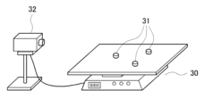
図4は、本発明の一実施形態に係る目的地指定通い箱搬送システムの物品と物品情報との照合検査機及び重量及びサイズ測定機を示した概念図である。同図に示すように、物品と物品情報との照合検査機及び重量及びサイズ測定機30は、搬送される物品(手荷物)の重量やサイズ、形状を測定し、また画像撮影機32等により物品と物品情報との照合、重心位置などの推定、危険物探知等をすることができる。
FIG. 4 is a conceptual diagram showing a collation inspection machine for goods and goods information and a weight and size measuring machine of a destination-designated returnable container transport system according to an embodiment of the present invention. As shown in the figure, a collation inspection machine for goods and goods information and a weight and
図1においては図4に示した物品と物品情報との照合検査機及び重量及びサイズ測定機30は、搬送するトレイ11に載置される前の物品20として測定される形態を示しているが、これはトレイ11載置後であってもよいし又各々の測定機は別々の測定機であってもよい。これらの測定情報は集約されて物品識別子ID情報21に付加される。
In FIG. 1, the collation inspection machine for the article and the article information and the weight and
図5は、本発明の一実施形態に係る目的地指定通い箱搬送システムの通い箱(トレイ)を示した概念図である。同図に示すように、本発明の一実施形態に係る目的地指定通い箱搬送システムの通い箱(トレイ)は、例えば舟形であってもよい。舳先33は、放射線測定装置等の重い遮蔽カーテン22をかき分けて侵入し載置した物品を装置内に安全に搬入するための先端形状を有する。
FIG. 5 is a conceptual diagram showing a returnable container (tray) of the destination-designated returnable container transport system according to one embodiment of the present invention. As shown in the figure, the returnable container (tray) of the destination-designated returnable container transport system according to the embodiment of the present invention may be boat-shaped, for example. The prow 33 has a tip shape to push through the
図5に示すようにトレイ11の例えば上面中央部(斜線部)には物品の重心位置が載置されるように物品が乗せられる。この重心位置載置部35はトレイの上面どの位置に設定してもよいが、定位置に物品の重心位置が設定され載置されることによって物品はトレイ上で最も安定した載置状態をとることができるからである。この載置方法によって物品のずれ移動、転倒、脱落等の破損事故を大幅に回避することができる。
As shown in FIG. 5, articles are placed on the
トレイ11の底裏側はレール走行のための車輪が設置されていてもよい。またトレイ11同士は空箱状態の時は安定した積み重ね保管ができるように上面及び下面等に重ね合わせ篏合リブ等が形成されていてもよい。トレイ11の右左サイド面は、物品20の傾斜搬出の際、排出し易いように側面囲い枠36の高さは低い形状であることが好ましい。
Wheels for rail travel may be installed on the back side of the bottom of the
トレイ11は、搬送ライン内の搬送を終えて物品を排出すべき物品収集場所に到達した際に、搬送速度を特に落とすことなく、トレイ自体がサイド方向に反転することにより載置された物品をサイド方向に滑り落とすように排出することができる。この時、トレイ11を搬送するコンベヤが反転傾斜することによって上記トレイの反転がなされてもよいし、又はトレイ自体が反転するような仕組みを備えていてもよい。
When the
トレイ11から物品収集場所に排出された物品は、予定されている航空機に搭載されて目的地まで運ばれ、その後目的地である空港において物品識別ID情報に従い顧客の待つ手荷物カウンターまで搬送されて顧客のもとへ戻ることになる。これらの一連の物品搬送システムが本発明である目的地指定通い箱搬送システムの一実施形態となる。
The articles discharged from the
なお、本発明は上述した実施形態に限定されるものではなく、本発明の主旨を逸脱しない範囲内で種々変更した形態においても実施することが可能である。これらはすべて、本技術思想の範囲内のものである。 It should be noted that the present invention is not limited to the above-described embodiments, and various modifications can be made without departing from the gist of the present invention. All of these are within the scope of this technical idea.
上述したように、本願に係る発明によれば、顧客の手荷物である物品を顧客の指定する航空便又はその到着場所に安全に且つ正確に届けることができる。そして、安全性と作業性を格段に向上させつつ、経済効率も格段に向上させることの可能な目的地指定通い箱搬送システムが実現される。 As described above, according to the invention of the present application, it is possible to safely and accurately deliver an article, which is a customer's baggage, to an airline flight designated by the customer or its arrival place. Thus, a destination-specified returnable container conveying system is realized that can significantly improve safety and workability, as well as significantly improve economic efficiency.
さらに、本願に係る発明によれば、手荷物物品に係らずあらゆる物品の通い箱搬送において、目的地指定の搬送が安全かつ確実に実施することができる。 Furthermore, according to the invention of the present application, it is possible to safely and reliably carry out destination-designated transportation in returnable container transportation of all kinds of articles regardless of baggage items.
したがって、本発明は、空港での手荷物の自動搬送に限定されることなく、あらゆる物品、部品の搬送用途に対しても利用・適用可能である。よって本願は空港物流業の他、物品輸送業、製造業、建設業等あらゆる産業における物品搬送機構に対して大きな有益性をもたらすものである。 Therefore, the present invention is not limited to the automatic transportation of baggage at airports, and can be used and applied to transportation of all kinds of articles and parts. Therefore, the present application is of great benefit to article transport mechanisms in all industries such as the airport logistics industry, article transport industry, manufacturing industry, and construction industry.
10 搬送機構
11 通い箱(トレイ)
12 立体倉庫(ストックヤード又はバッファーライン)
13 通い箱のみの立体倉庫(ストックヤード又はバッファーライン)
14 物品照合検査及び重量、サイズ測定機
15 放射線検査装置
16 搬送ライン
17 分岐機構
18 反転排出機構
19 飛行機出発便
20 物品(手荷物)
21 物品識別子ID
22 遮蔽カーテン
30 物品と物品情報との照合検査機及び重量及びサイズ測定機
31 3点接触重量測定
32 画像撮影機
33 舳先(へさき)
35 重心位置
36 側面囲い枠
40 コンベヤ
41 環状回転体
42 シャフト
43 回転体ユニット
44 軸ユニット
45 回転駆動体
46 固定部
47 弾性体
48 シャフトに固定される固定軸
49 所定の傾斜を有する傾斜円盤
50 ベアリング構造
51 52の力によって回転駆動体45が受ける反力
52 固定部46を押圧する力
53 回転駆動体45を押圧する力
10
12 Three-dimensional warehouse (stockyard or buffer line)
13 Three-dimensional warehouse with returnable boxes only (stockyard or buffer line)
14 Goods collation inspection and weight,
21 article identifier ID
22
35 Center of
Claims (6)
分岐仕分機構を有し前記通い箱を前記物品が載置されたまま搬送する搬送機構と、
前記通い箱の一時保管機構と、
前記通い箱から該通い箱に載置された前記物品のみを排出する排出機構と、
前記物品の内容物を検査するための検査機構と
を備え、
前記検査機構は、物品のX線検査装置、及び、入口及び出口に検査のためのX線及び/若しくは他の放射線を遮蔽するための遮蔽カーテンを含み、前記通い箱は、前記遮蔽カーテンを前記舳先でかき分けることができることに特徴を有する目的地指定通い箱搬送システム。 A returnable box on which an article is placed and which has a curved convex bow on the front surface and a side frame lower in height than the bow on the side surface;
a conveying mechanism having a branch sorting mechanism and conveying the returnable box with the articles placed thereon;
a temporary storage mechanism for the returnable container;
a discharge mechanism for discharging only the article placed in the returnable box from the returnable box;
an inspection mechanism for inspecting the contents of the article ;
with
The inspection mechanism includes an X-ray inspection device for articles, and shielding curtains for shielding X-rays and/or other radiation for inspection at an entrance and an exit, and the returnable box includes the shielding curtains. A destination-designated returnable container conveying system characterized in that it can be separated by the bow .
前記搬送機構の搬送方向と略直交するシャフトと、
前記シャフトに所定の傾斜を有して固着される傾斜円盤を有する固定部と、
前記固定部の傾斜円盤周りに回転可能に配置され前記搬送物の底部に摺接する外周面を有し前記シャフト周りに自由回転可能に枢設される環状回転体と、
前記環状回転体の外周近傍の側面に当接して前記シャフト周りに自由回転可能に枢設される回転駆動体と、
前記固定部と一体化されたシャフトを任意回転することによって仕分方向を任意に選択可能とする手段と、
前記回転駆動体と前記固定部とが互いに圧接される方向に力を受ける構造と
を有することを特徴とする請求項1記載の目的地指定通い箱搬送システム。 The branch sorting mechanism is
a shaft substantially orthogonal to the transport direction of the transport mechanism;
a fixing part having an inclined disk fixed to the shaft with a predetermined inclination;
an annular rotating body that is rotatably arranged around the inclined disk of the fixed part, has an outer peripheral surface that is in sliding contact with the bottom of the conveyed object, and is freely rotatably pivoted around the shaft;
a rotational driving body that is pivotally mounted around the shaft in contact with a side surface near the outer periphery of the annular rotating body;
means for arbitrarily selecting a sorting direction by arbitrarily rotating a shaft integrated with the fixed part;
2. The destination-specifying returnable container transport system according to claim 1, further comprising a structure for receiving a force in a direction in which said rotary driving body and said fixed portion are pressed against each other.
前記通い箱識別子を読み取る手段と、
前記通い箱識別子と前記物品識別子とを紐づける手段と、
前記物品識別子に基づいて前記通い箱に載置された前記物品を目的地に目的時間に合わせて搬送する手段と、
をさらに備えることを特徴とする請求項1または2に記載の目的地指定通い箱搬送システム。 The conveying mechanism is a conveyor and/or rail type conveying mechanism, the articles are provided with article identifiers for identifying the articles, and the returnable boxes are provided with returnable box identifiers for identifying the returnable boxes. attached,
means for reading the tote identifier;
means for linking the returnable container identifier and the article identifier;
means for transporting the article placed in the returnable box to a destination at a desired time based on the article identifier;
The destination-designated returnable container transport system according to claim 1 or 2, further comprising:
前記通い箱の搬送機構とは空港内の手荷物搬送システムであって、
前記通い箱の一時保管機構とは手荷物搬送システム内の立体倉庫又はストックヤードもしくはバッファーラインであって、
前記検査機構は、前記物品と物品情報との照合検査、重量及びサイズ測定をさらに行うための機構であって、
前記目的地とは出発便飛行機荷物集積場又は空港顧客手荷物受取場であることに特徴を有する請求項3もしくは4に記載の目的地指定通い箱搬送システム。
said goods are the customer's baggage,
The returnable container transport mechanism is an airport baggage transport system,
The temporary storage mechanism for the returnable container is a multi-storey warehouse, stockyard or buffer line in the baggage transportation system,
The inspection mechanism is a mechanism for further performing a comparison inspection between the article and article information, weight and size measurement ,
5. The destination-designated returnable container transport system according to claim 3, wherein said destination is a baggage collection area for departing flights or an airport customer baggage claim area.
Priority Applications (1)
| Application Number | Priority Date | Filing Date | Title |
|---|---|---|---|
| JP2017059484A JP7214939B2 (en) | 2017-03-24 | 2017-03-24 | Destination designated tray transfer system |
Applications Claiming Priority (1)
| Application Number | Priority Date | Filing Date | Title |
|---|---|---|---|
| JP2017059484A JP7214939B2 (en) | 2017-03-24 | 2017-03-24 | Destination designated tray transfer system |
Publications (2)
| Publication Number | Publication Date |
|---|---|
| JP2018162132A JP2018162132A (en) | 2018-10-18 |
| JP7214939B2 true JP7214939B2 (en) | 2023-01-31 |
Family
ID=63860828
Family Applications (1)
| Application Number | Title | Priority Date | Filing Date |
|---|---|---|---|
| JP2017059484A Active JP7214939B2 (en) | 2017-03-24 | 2017-03-24 | Destination designated tray transfer system |
Country Status (1)
| Country | Link |
|---|---|
| JP (1) | JP7214939B2 (en) |
Families Citing this family (2)
| Publication number | Priority date | Publication date | Assignee | Title |
|---|---|---|---|---|
| CN107855284A (en) * | 2017-12-06 | 2018-03-30 | 北京极智嘉科技有限公司 | Goods sorting system and method with safety check function |
| CN109911588B (en) * | 2019-03-21 | 2023-11-17 | 中信戴卡股份有限公司 | Wheel overturning and classifying device and wheel classifying and transporting system |
Citations (5)
| Publication number | Priority date | Publication date | Assignee | Title |
|---|---|---|---|---|
| JP3538226B2 (en) | 1994-08-08 | 2004-06-14 | 川崎重工業株式会社 | Baggage handling sorting device |
| US20050006209A1 (en) | 2001-09-27 | 2005-01-13 | Sorensen Brian Lynge | Tote for conveyor |
| JP3825250B2 (en) | 2000-12-14 | 2006-09-27 | 株式会社クボタ | Agricultural product sorting equipment |
| JP4115820B2 (en) | 2002-12-13 | 2008-07-09 | 株式会社テイエルブイ | Liquid pumping device |
| US8820530B1 (en) | 2012-06-14 | 2014-09-02 | Marcus Blagg | Airport baggage tub |
Family Cites Families (1)
| Publication number | Priority date | Publication date | Assignee | Title |
|---|---|---|---|---|
| JPH085141Y2 (en) * | 1991-03-27 | 1996-02-14 | トーヨーカネツ株式会社 | Sorting device |
-
2017
- 2017-03-24 JP JP2017059484A patent/JP7214939B2/en active Active
Patent Citations (5)
| Publication number | Priority date | Publication date | Assignee | Title |
|---|---|---|---|---|
| JP3538226B2 (en) | 1994-08-08 | 2004-06-14 | 川崎重工業株式会社 | Baggage handling sorting device |
| JP3825250B2 (en) | 2000-12-14 | 2006-09-27 | 株式会社クボタ | Agricultural product sorting equipment |
| US20050006209A1 (en) | 2001-09-27 | 2005-01-13 | Sorensen Brian Lynge | Tote for conveyor |
| JP4115820B2 (en) | 2002-12-13 | 2008-07-09 | 株式会社テイエルブイ | Liquid pumping device |
| US8820530B1 (en) | 2012-06-14 | 2014-09-02 | Marcus Blagg | Airport baggage tub |
Also Published As
| Publication number | Publication date |
|---|---|
| JP2018162132A (en) | 2018-10-18 |
Similar Documents
| Publication | Publication Date | Title |
|---|---|---|
| JP7292447B2 (en) | How to automatically and manually sort items using a dynamically configurable sort column structure | |
| US11654456B2 (en) | Material handling apparatus and method for automatic and manual sorting of items using a dynamically configurable sorting array | |
| US6789660B1 (en) | Conveyor system with buffer arrangement | |
| DK2976263T3 (en) | Device for processing sorting materials | |
| CN107601062A (en) | A kind of high ferro physical-distribution intelligent handling system and method based on AGV dollies | |
| KR101721234B1 (en) | Several gates installed delivery vehicle and transport method using the same | |
| EP3326940A2 (en) | A conveyor system comprising an aligner for aligning items | |
| JP7214939B2 (en) | Destination designated tray transfer system | |
| CA3060709A1 (en) | Material handling apparatus and method for automatic and manual sorting of items using a dynamically configurable sorting array | |
| CN209038350U (en) | Dispense website | |
| RU2153454C2 (en) | Method of and device for storing premature luggage at airport | |
| KR101190209B1 (en) | Device and method for transferring luggage vertically | |
| JPH0853221A (en) | Baggage conveying and sorting method and apparatus | |
| CN209834925U (en) | Intelligent sorting and conveying system for multiple commodities | |
| JP2023517356A (en) | Baggage and parcel handling systems and methods | |
| JP7151027B2 (en) | Conveyor system | |
| JPS62275914A (en) | Sorting-delivering device for hand baggage | |
| KR20230057598A (en) | Automatic sorting of air baggage delivery system and air baggage delivery method using the system |
Legal Events
| Date | Code | Title | Description |
|---|---|---|---|
| A621 | Written request for application examination |
Free format text: JAPANESE INTERMEDIATE CODE: A621 Effective date: 20200324 |
|
| A711 | Notification of change in applicant |
Free format text: JAPANESE INTERMEDIATE CODE: A712 Effective date: 20200324 |
|
| A977 | Report on retrieval |
Free format text: JAPANESE INTERMEDIATE CODE: A971007 Effective date: 20210209 |
|
| A131 | Notification of reasons for refusal |
Free format text: JAPANESE INTERMEDIATE CODE: A131 Effective date: 20210224 |
|
| A521 | Request for written amendment filed |
Free format text: JAPANESE INTERMEDIATE CODE: A523 Effective date: 20210426 |
|
| A02 | Decision of refusal |
Free format text: JAPANESE INTERMEDIATE CODE: A02 Effective date: 20211019 |
|
| A521 | Request for written amendment filed |
Free format text: JAPANESE INTERMEDIATE CODE: A523 Effective date: 20220119 |
|
| C60 | Trial request (containing other claim documents, opposition documents) |
Free format text: JAPANESE INTERMEDIATE CODE: C60 Effective date: 20220119 |
|
| A911 | Transfer to examiner for re-examination before appeal (zenchi) |
Free format text: JAPANESE INTERMEDIATE CODE: A911 Effective date: 20220126 |
|
| C21 | Notice of transfer of a case for reconsideration by examiners before appeal proceedings |
Free format text: JAPANESE INTERMEDIATE CODE: C21 Effective date: 20220201 |
|
| A912 | Re-examination (zenchi) completed and case transferred to appeal board |
Free format text: JAPANESE INTERMEDIATE CODE: A912 Effective date: 20220401 |
|
| C211 | Notice of termination of reconsideration by examiners before appeal proceedings |
Free format text: JAPANESE INTERMEDIATE CODE: C211 Effective date: 20220405 |
|
| C22 | Notice of designation (change) of administrative judge |
Free format text: JAPANESE INTERMEDIATE CODE: C22 Effective date: 20220531 |
|
| C13 | Notice of reasons for refusal |
Free format text: JAPANESE INTERMEDIATE CODE: C13 Effective date: 20220705 |
|
| A521 | Request for written amendment filed |
Free format text: JAPANESE INTERMEDIATE CODE: A523 Effective date: 20220905 |
|
| C22 | Notice of designation (change) of administrative judge |
Free format text: JAPANESE INTERMEDIATE CODE: C22 Effective date: 20221011 |
|
| C23 | Notice of termination of proceedings |
Free format text: JAPANESE INTERMEDIATE CODE: C23 Effective date: 20221115 |
|
| C03 | Trial/appeal decision taken |
Free format text: JAPANESE INTERMEDIATE CODE: C03 Effective date: 20221220 |
|
| C30A | Notification sent |
Free format text: JAPANESE INTERMEDIATE CODE: C3012 Effective date: 20221220 |
|
| A61 | First payment of annual fees (during grant procedure) |
Free format text: JAPANESE INTERMEDIATE CODE: A61 Effective date: 20221220 |
|
| R150 | Certificate of patent or registration of utility model |
Ref document number: 7214939 Country of ref document: JP Free format text: JAPANESE INTERMEDIATE CODE: R150 |