JP7214744B2 - Overpressure resistant vacuum shut-off valve - Google Patents
Overpressure resistant vacuum shut-off valve Download PDFInfo
- Publication number
- JP7214744B2 JP7214744B2 JP2020549871A JP2020549871A JP7214744B2 JP 7214744 B2 JP7214744 B2 JP 7214744B2 JP 2020549871 A JP2020549871 A JP 2020549871A JP 2020549871 A JP2020549871 A JP 2020549871A JP 7214744 B2 JP7214744 B2 JP 7214744B2
- Authority
- JP
- Japan
- Prior art keywords
- contact flange
- reinforced
- movable contact
- valve
- region
- Prior art date
- Legal status (The legal status is an assumption and is not a legal conclusion. Google has not performed a legal analysis and makes no representation as to the accuracy of the status listed.)
- Active
Links
Images


Classifications
-
- H—ELECTRICITY
- H01—ELECTRIC ELEMENTS
- H01H—ELECTRIC SWITCHES; RELAYS; SELECTORS; EMERGENCY PROTECTIVE DEVICES
- H01H33/00—High-tension or heavy-current switches with arc-extinguishing or arc-preventing means
- H01H33/60—Switches wherein the means for extinguishing or preventing the arc do not include separate means for obtaining or increasing flow of arc-extinguishing fluid
- H01H33/66—Vacuum switches
- H01H33/662—Housings or protective screens
- H01H33/66207—Specific housing details, e.g. sealing, soldering or brazing
-
- H—ELECTRICITY
- H01—ELECTRIC ELEMENTS
- H01H—ELECTRIC SWITCHES; RELAYS; SELECTORS; EMERGENCY PROTECTIVE DEVICES
- H01H33/00—High-tension or heavy-current switches with arc-extinguishing or arc-preventing means
- H01H33/60—Switches wherein the means for extinguishing or preventing the arc do not include separate means for obtaining or increasing flow of arc-extinguishing fluid
- H01H33/66—Vacuum switches
- H01H33/664—Contacts; Arc-extinguishing means, e.g. arcing rings
-
- H—ELECTRICITY
- H01—ELECTRIC ELEMENTS
- H01H—ELECTRIC SWITCHES; RELAYS; SELECTORS; EMERGENCY PROTECTIVE DEVICES
- H01H33/00—High-tension or heavy-current switches with arc-extinguishing or arc-preventing means
- H01H33/60—Switches wherein the means for extinguishing or preventing the arc do not include separate means for obtaining or increasing flow of arc-extinguishing fluid
- H01H33/66—Vacuum switches
- H01H33/662—Housings or protective screens
- H01H33/66207—Specific housing details, e.g. sealing, soldering or brazing
- H01H2033/6623—Details relating to the encasing or the outside layers of the vacuum switch housings
Landscapes
- High-Tension Arc-Extinguishing Switches Without Spraying Means (AREA)
Description
本発明は、中圧開閉装置および高圧開閉装置用の耐過圧性の真空遮断バルブ、およびそのような耐過圧性の真空遮断バルブを備えた開閉装置に関する。 The present invention relates to an overpressure-resistant vacuum shut-off valve for medium- and high-pressure switchgear and to a switchgear comprising such an overpressure-resistant vacuum shut-off valve.
従来技術の真空遮断バルブは、高い周囲圧力下での動作には適していない。特に、1バール(1bar)を超える、特に2バール(2bar)を超える高い周囲圧力は、固定接触子フランジおよび/または可動接触子フランジに変形をもたらす。これらの変形は、真空遮断バルブの機能に影響を及ぼし、真空遮断バルブを破壊することもある。 Prior art vacuum isolation valves are not suitable for operation at high ambient pressures. In particular, high ambient pressures above 1 bar, especially above 2 bar, lead to deformations of the stationary contact flange and/or the moving contact flange. These deformations affect the function of the vacuum shut-off valve and can even destroy the vacuum shut-off valve.
本発明の課題は、固定接触子フランジおよび/または可動接触子フランジの変形を低減又は防止する耐過圧性の真空遮断バルブを提供することにある。 SUMMARY OF THE INVENTION It is an object of the present invention to provide an overpressure resistant vacuum shut-off valve that reduces or prevents deformation of the stationary contact flange and/or the movable contact flange.
この課題は、独立請求項1およびそれに従属する請求項によって解決される。 This problem is solved by the independent claim 1 and the claims dependent thereon.
一実施例では、真空遮断バルブが、少なくとも1つの絶縁体と、固定接触子と、固定接触子フランジと、可動接触子の長手軸を有する可動接触子と、可動接触子フランジと、ベローズとを有し、固定接触子が、固定接触子フランジ内に固定配置されており、可動接触子が、移動可能に案内されており、可動接触子が、ベローズによって移動可能に可動接触子フランジに取り付けられており、ベローズの第1ベローズ端部が、可動接触子フランジに取り付けられており、ベローズの第2ベローズ端部が、可動接触子に取り付けられており、真空遮断バルブが、補強された固定接触子フランジおよび/または可動接触子フランジによって、固定接触子フランジおよび可動接触子フランジのうちの少なくとも一方の次なる変形に対して、即ち、2バール(2bar)を超える真空遮断バルブの周囲圧力による変形に対して、保護されている。 In one embodiment, a vacuum isolation valve includes at least one insulator, a stationary contact, a stationary contact flange, a movable contact having a longitudinal axis of the movable contact, a movable contact flange, and a bellows. a fixed contact fixedly arranged in the fixed contact flange, a movable contact movably guided, the movable contact movably attached to the movable contact flange by a bellows a first bellows end of the bellows attached to the moveable contact flange, a second bellows end of the bellows attached to the moveable contact, and a vacuum shut-off valve attached to the reinforced stationary contact. By means of the child flange and/or the movable contactor flange, against subsequent deformation of at least one of the fixed contactor flange and the movable contactor flange, i.e. deformation due to ambient pressure of the vacuum shut-off valve exceeding 2 bar. protected against.
特に、絶縁ガスを有するガス絶縁容器内に真空遮断バルブが配置され、ガス絶縁容器内のガス圧が2バールを超える場合に、2バールを超える周囲圧力が生じる。しかし、それに代えて、真空遮断バルブを液体中、特に絶縁液体中に配置することもでき、周囲圧力は2バールを超え得る。さらに、真空遮断バルブは、固体、特に固体絶縁物によって2バールの圧力で加圧することができる。周囲圧力は、真空遮断バルブの外側に作用する圧力を表す。 In particular, if a vacuum shut-off valve is arranged in a gas-insulated container with insulating gas and the gas pressure in the gas-insulated container exceeds 2 bar, an ambient pressure of more than 2 bar is created. Alternatively, however, the vacuum shut-off valve can also be placed in the liquid, in particular the insulating liquid, and the ambient pressure can exceed 2 bar. Furthermore, the vacuum shut-off valve can be pressurized with a pressure of 2 bar by a solid, in particular a solid insulator. Ambient pressure represents the pressure acting on the outside of the vacuum isolation valve.
補強された固定接触子フランジおよび/または補強された可動接触子フランジの補強は、そのつどの固定接触子フランジ又はそのつどの可動接触子フランジに付設されたそれぞれ1つの次なる構造要素によって、即ち、補強された固定接触子フランジおよび/または補強された可動接触子フランジの真空遮断バルブ内部に向けられた形状を少なくとも部分的に模擬する構造要素によって、達成されることが好ましい。 The reinforcement of the reinforced fixed contact flange and/or the reinforced movable contact flange is provided by a further structural element respectively assigned to the respective fixed contact flange or the respective movable contact flange, i.e. , is preferably achieved by a structural element that at least partially mimics the shape of the reinforced stationary contact flange and/or the reinforced movable contact flange directed toward the interior of the vacuum isolation valve.
前記構造要素は、絶縁要素と、補強された固定接触子フランジおよび/または補強された可動接触子フランジとの間の接合部に、機械的に強い負荷をかけることなく、そのつどの補強された固定接触子フランジおよび/または補強された可動接触子フランジの安定性を高める。 Said structural element can be reinforced without subjecting the joint between the insulating element and the reinforced fixed contact flange and/or the reinforced movable contact flange to a high mechanical load. Increases the stability of fixed contact flanges and/or reinforced movable contact flanges.
また、前記構造要素は、第1領域および第2領域を有し、第1領域は、可動接触子の長手軸に対してほぼ垂直に延在し、第2領域は、可動接触子の長手軸に対してほぼ平行に延在し、第1領域は、補強された固定接触子フランジおよび/または補強された可動接触子フランジの真空遮断バルブ内部に向けられた形状を、おおむね模擬しており、第2領域は、実質的に第1領域を支持していることが好ましい。 The structural element also has a first region and a second region, the first region extending substantially perpendicular to the longitudinal axis of the movable contact, and the second region being the longitudinal axis of the movable contact. the first region generally mimics the shape of the reinforced stationary contact flange and/or the reinforced movable contact flange directed toward the inside of the vacuum isolation valve; Preferably, the second region substantially supports the first region.
さらに、シールド要素が、固定接触子フランジと絶縁要素との間に、又は固定接触子フランジ上に配置されていることが好ましい。 Furthermore, it is preferred that a shielding element is arranged between or on the stationary contact flange and the insulating element.
また、前記構造要素の第2領域が、絶縁要素に対して、又はシールド要素を介して絶縁要素に対して、又は固定接触子フランジの第3領域に対して、前記構造要素の第1領域を支持することによって、第1領域が、固定接触子フランジを変形から保護することが好ましい。 Also, the second region of the structural element is positioned against the insulating element, or through the shield element, against the insulating element, or against the third region of the fixed contact flange. By supporting, the first region preferably protects the stationary contact flange from deformation.
また、1つ又は複数の構造要素は、真空遮断バルブに、又は真空遮断バルブの構成部品に、ろう接されていないことが好ましい。これは、絶縁要素と補強された固定接触子フランジおよび/または補強された可動接触子フランジとの間の接合部に、特に、ろう接部に、機械的応力が生じることを防止する。 Also, one or more structural elements are preferably not brazed to the vacuum shut-off valve or to components of the vacuum shut-off valve. This prevents mechanical stresses from occurring at the joint between the insulating element and the reinforced stationary contact flange and/or the reinforced movable contact flange, in particular at the braze joint.
また、補強された固定接触子フランジおよび/または補強された可動接触子フランジの補強は、補強された固定接触子フランジおよび/または補強された可動接触子フランジのより厚い構造形態によって達成され、補強された固定接触子フランジおよび/または補強された可動接触子フランジは、絶縁体の膨張係数と同様の膨張係数を有する材料から形成されていることが好ましい。特に、同様に、補強された固定接触子フランジおよび/または補強された可動接触子フランジの材料の膨張係数および絶縁体の膨張係数からの偏差は、10%未満、特に好ましくは、5%未満であるべきである。 Also, the reinforcement of the reinforced stationary contact flange and/or the reinforced movable contact flange is achieved by a thicker structural form of the reinforced stationary contact flange and/or the reinforced movable contact flange, and the reinforcement is The reinforced stationary contact flange and/or the reinforced movable contact flange are preferably made of a material having a coefficient of expansion similar to that of the insulator. In particular, likewise, the deviation from the expansion coefficient of the material of the reinforced stationary contact flange and/or the reinforced movable contact flange and the expansion coefficient of the insulator is less than 10%, particularly preferably less than 5%. should be.
さらに、絶縁体がセラミックから形成されており、補強された固定接触子フランジおよび/または補強された可動接触子フランジが、FeNiCo合金を含んでいるか、又はFeNiCo合金から形成されていることが好ましい。 Further, it is preferred that the insulator is made of ceramic and the reinforced stationary contact flange and/or the reinforced movable contact flange comprises or is made of an FeNiCo alloy.
別の実施例は、上述の構造形態の1つ又は複数に基づく真空遮断バルブを有する中間電圧用又は高電圧用の開閉装置に関し、この開閉装置では、真空遮断バルブが、絶縁ガスを充填された気密容器内に配置されており、該気密容器内の絶縁ガスが、少なくとも2バール、好ましくは3バールを超える圧力を有する。 Another embodiment relates to a medium or high voltage switchgear comprising a vacuum shut-off valve based on one or more of the constructional forms described above, in which the vacuum shut-off valve is filled with an insulating gas. It is arranged in an airtight container, the insulating gas in the airtight container having a pressure of at least 2 bar, preferably more than 3 bar.
絶縁ガスは、フルオロケトン、ニトリル、窒素、酸素および二酸化炭素のうちの1つ以上を含むことが好ましい。 The insulating gas preferably includes one or more of fluoroketones, nitriles, nitrogen, oxygen and carbon dioxide.
絶縁ガスは、窒素および二酸化炭素、又はフルオロケトンおよび窒素、又はフルオロケトンおよび酸素、又はフルオロケトンおよび二酸化炭素を含有することが特に好ましい。特に、絶縁ガスは、80%の窒素および20%の二酸化炭素からなることが好ましい。パーセントデータは、質量パーセント又は質量パーセントに関係する。 It is particularly preferred that the insulating gas contains nitrogen and carbon dioxide, or fluoroketone and nitrogen, or fluoroketone and oxygen, or fluoroketone and carbon dioxide. In particular, the insulating gas preferably consists of 80% nitrogen and 20% carbon dioxide. Percentage data relate to percent by weight or percent by weight.
以下、図面を参照して本発明を説明する。 The present invention will now be described with reference to the drawings.
図1は、従来の真空遮断バルブの固定接触子フランジ40の領域の断面図を示す。固定接触子ロッド32は、固定接触子フランジ40に接続されており、従って、真空遮断バルブの内部に案内される。さらに、固定接触子フランジ40は、真空遮断バルブの絶縁部品20に取り付けられている。図示の例では、固定接触子フランジ40と絶縁部品20との間にシールド要素90が固定されている。あるいは、シールド要素90を固定接触子フランジ40に取り付け、固定接触子フランジ40を絶縁部品20に直接取り付けてもよい。
FIG. 1 shows a cross-sectional view of the fixed
固定接触子フランジ40のより頑丈な構造形態、すなわち、材料強度、材料厚さが増大された構造形態は、固定接触子フランジ40が直接に又はシールド要素を介して絶縁要素に接続されている領域において、過大な機械的応力をもたらし、その結果、真空遮断バルブの永久的な機能を妨害することになる。
A more robust structural form of the
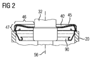
図2は、補強された固定接触子フランジ40’を有する本発明による真空遮断バルブの固定接触子フランジ40’の領域の断面図を示す。固定接触子ロッド32は、ここでも、固定接触子フランジ40’に接続されており、従って、本発明による真空遮断バルブの内部に案内される。さらに、固定接触子フランジ40’は、真空遮断バルブの絶縁部品20に取り付けられている。図示の例では、固定接触子フランジ40’と絶縁部品20との間に、シールド要素90が固定されている。あるいは、シールド要素90を固定接触子フランジ40’に取り付け、固定接触子フランジ40’を絶縁部品20に直接取り付けてもよい。
FIG. 2 shows a cross-sectional view of the fixed contact flange 40' area of a vacuum isolation valve according to the invention having a reinforced fixed contact flange 40'. The
図2の例では、固定接触子フランジ40’は、構造要素45によって補強されている。構造要素45は、固定接触子30の長手軸56に対して実質的に垂直に向けられた第1領域46内において、真空遮断バルブ内部に向けられた固定接触子フランジ40’の形状をおおむね再現しており、この場合、その上さらに固定接触子フランジ40’に当接している。固定接触子30の長手軸56に実質的に平行に向けられた第2領域47において、第2領域47は、固定接触子フランジ40’に対して第1領域46を支持する。あるいは、構造要素45の第2領域47は、構造要素45の第1領域46を、絶縁要素20および/またはシールド要素90に対して支持することもできる。
In the example of FIG. 2, fixed contact flange 40' is reinforced by
図3は、本発明に従って補強された固定接触子フランジ40’と、補強された可動接触子フランジ60’とを有する真空遮断バルブ10の断面図を示す。この実施例では、真空遮断バルブ10は4つの絶縁要素20を有し、2つの絶縁要素20の間には、導電性又は非導電性材料から成る中間要素25が配置されている。
FIG. 3 shows a cross-sectional view of a
可動接触子50は、ベローズ80によって真空遮断バルブ10内を移動可能に案内されており、第1ベローズ端部82は、補強された可動接触子フランジ60’に取り付けられ、第2ベローズ端部84は、直接又はベローズキャップ86を介して、可動接触子ロッド52に取り付けられている。さらに、そのベローズキャップは、任意のベローズシールド88を有する。
The
可動接触子フランジ60’は、真空遮断バルブ10の1つの絶縁要素20に、直接又はシールド素90を介して接続されている。
The movable contact flange 60' is connected to one
可動接触子フランジ60’は、支持要素65によって補強される。構造要素65は、第1領域66を有し、この第1領域66は、可動接触子50の長手軸56に対してほぼ垂直に向けられていて、真空遮断バルブの内部に向けられた可動接触子フランジ60’の形状をおおむね再現しており、この場合、その上さらに可動接触子フランジ60’に当接している。可動接触子50の長手軸56に対してほぼ平行に向けられた構造要素65の第2領域67において、第2領域67は、可動接触子フランジ60’に対して、第1領域66を支持する。あるいは、構造要素65の第2領域67は、構造要素65の第1領域66を、絶縁要素20および/またはシールド要素90対して支持することもできる。
The movable contact flange 60' is reinforced by a
可動接触子50は、この実施例では、可動接触子ロッド53と、可動接触子本体55と、可動接触子接触円板54とから成る。
The
固定接触子30は、ここでは、固定接触子ロッド32と、固定接触子体35と、固定接触子円板34ととから成り、固定接触子フランジ40’に接続されており、従って、本発明による真空遮断バルブ10の内部に案内される。固定接触子フランジ40’は、ここでもやはり真空遮断バルブの絶縁部品20に取り付けられている。図示の例では、固定接触子フランジ40’と絶縁部品20との間に、シールド要素90が固定されている。あるいは、シールド要素90を固定接触子フランジ40’に取り付けて、固定接触子フランジ40’を絶縁部品20に直接取り付けることもできる。
The fixed
固定接触子フランジ40’は、図3の例では、構造要素45によって補強される。この場合、構造要素45は、固定接触子30の長手軸56に対してほぼ垂直に向けられた第1領域46において真空遮断バルブの内部に向けられた固定接触子フランジ40’の形状をおおむね再現し、この場合、そのうえさらに固定接触子フランジ40’に当接している。固定接触子30の長手軸56にほぼ平行に向けられた構造要素45の第2領域47において、第2領域47は、第1領域46を、固定接触子フランジ40’に対して支持する。あるいは、構造要素45の第2領域47は、構造要素45の第1領域46を、絶縁要素20および/またはシールド要素90に対して支持することもできる。
Fixed contact flange 40' is reinforced by
図4は、補強された固定接触子フランジ40”を有する本発明による真空遮断バルブの固定接触子フランジ40”の領域の断面図を示す。 FIG. 4 shows a cross-sectional view of the fixed contact flange 40'' area of a vacuum shut-off valve according to the invention having a reinforced fixed contact flange 40''.
固定接触子ロッド32は、固定接触子フランジ40”に連結されており、本発明による真空遮断バルブの内部に案内される。固定接触子フランジ40”は、真空遮断バルブの絶縁部品20に取り付けられている。図示の例では、固定接触子フランジ40”と絶縁部品20との間に、シールド要素90が固定されている。あるいは、シールド要素90を固定接触子フランジ40’に取り付けて、固定接触子フランジ40”を絶縁部品20に直接取り付けることもできる。
The
固定接触子フランジ40”は、図4の例では、補強された固定接触子フランジ40”のより頑丈な構造形態、即ち、材料から見て、より厚い構造形態を採用することによって補強され、この補強された固定接触子フランジ40”は、絶縁体20の膨張係数と同様の膨張係数を有する材料から形成されている。
The fixed contact flange 40'' is reinforced by adopting a stronger structural form of the reinforced fixed contact flange 40'', i.e., a thicker structural form in terms of material, in the example of FIG. Reinforced
これに関連して、より頑丈な又はより厚い材料、より頑丈な又はより厚い材料の構造形態は、固定接触子フランジ40”がより大きな材料厚41を有することを意味するべきである。
In this connection, stronger or thicker material construction forms of stronger or thicker material should mean that the fixed
10 真空遮断バルブ
20 絶縁体
25 中間要素
30 固定接触子
32 固定接触子ロッド
34 固定接触子接触円板
35 固定接触子本体
40,40’,40” 固定接触子フランジ
42 固定接触子フランジ40”の材料厚
45 構造要素
46 構造要素45の第1領域
47 構造要素45の第2領域
50 可動接触子
52 可動接触ロッド
54 可動接触子接触円板
55 可動接触子本体
56 可動接触子および固定接触子の長手軸
60,60’ 可動接触子フランジ
65 構造要素
66 構造要素65の第1領域
67 構造要素65の第2領域
70 可動接触子軸受
80 ベローズ
82 第1ベローズ端部
84 第2ベローズ端部
86 ベローズキャップ
88 ベローズシールド
90 シールド要素10
10 vacuum shut-off
Claims (7)
前記固定接触子(30)が前記固定接触子フランジ(40)内に固定配置されており、前記可動接触子(50)が移動可能に案内されており、前記可動接触子がベローズ(80)によって移動可能に前記可動接触子フランジ(60)に取り付けられており、前記ベローズ(80)の第1ベローズ端部(82)が前記可動接触子フランジ(60)に取り付けられ、
前記ベローズ(80)の第2ベローズ端部(84)が前記可動接触子(50)に取り付けられている、真空遮断バルブ(10)において、
前記真空遮断バルブ(10)が、補強された固定接触子フランジ(40’)および/または補強された可動接触子フランジ(60’)によって、2バール(2bar)を超える前記真空遮断バルブ(10)の周囲圧力による前記固定接触子フランジ(40)および前記可動接触子フランジ(60)のうちの少なくとも一方の変形に対して保護されており、
前記補強された固定接触子フランジ(40’)および/または前記補強された可動接触子フランジ(60’)の補強が、それぞれ、前記補強された固定接触子フランジ(40’)および/または前記補強された可動接触子フランジ(60’)の真空遮断バルブ内部に向けられた形状を部分的に有する構造要素(45,65)によって達成されることを特徴とする真空遮断バルブ(10)。 a moveable contact (50) having at least one insulator (20), a fixed contact (30), a fixed contact flange (40), a longitudinal axis (56) of the moveable contact (50); A vacuum isolation valve (10) comprising a contact flange (60) and a bellows (80), comprising:
Said fixed contact (30) is fixedly arranged in said fixed contact flange (40), said movable contact (50) is movably guided and said movable contact is moved by a bellows (80). movably attached to the movable contact flange (60), a first bellows end (82) of the bellows (80) being attached to the movable contact flange (60);
In a vacuum isolation valve (10), wherein a second bellows end (84) of said bellows (80) is attached to said movable contact (50),
said vacuum shut-off valve (10) exceeding 2 bar by means of a reinforced fixed contact flange (40') and/or a reinforced movable contact flange (60'); protected against deformation of at least one of said stationary contact flange (40) and said movable contact flange (60) due to ambient pressure of
The reinforcement of said reinforced stationary contact flange (40') and/or said reinforced movable contact flange (60') is, respectively, said reinforced stationary contact flange (40') and/or said reinforcement vacuum shut-off valve (10) characterized in that it is achieved by a structural element (45, 65) partially having a shape directed towards the inside of the vacuum shut-off valve of the movable contact flange (60').
前記第1領域(46,66)が、前記可動接触子(50)の長手軸(56)に対してほぼ垂直に延びており、前記第2領域(47,67)が、前記可動接触子(50)の長手軸(56)に対してほぼ平行に延びており、
前記第1領域(46,66)が、前記補強された固定接触子フランジ(40’)および/または前記補強された可動接触子フランジ(60’)の真空遮断バルブ内部に向けられた形状をおおむね有してしており、前記第2領域(47,67)が実質的に前記第1領域(46,66)を支持していることを特徴とする請求項1記載の真空遮断バルブ(10)。 said structural element (45, 65) having a first region (46, 66) and a second region (47, 67);
Said first region (46, 66) extends substantially perpendicular to the longitudinal axis (56) of said movable contact (50) and said second region (47, 67) extends along said movable contact ( 50) extending substantially parallel to the longitudinal axis (56) of the
said first region (46, 66) generally having the shape of said reinforced stationary contact flange (40') and/or said reinforced movable contact flange (60') directed toward the interior of the vacuum isolation valve; The vacuum isolation valve (10) of claim 1, comprising: said second region (47, 67) substantially supporting said first region (46, 66). .
・前記絶縁要素に対して、又は
・前記シールド要素(90)を介して前記絶縁要素(20)に対して、又は
・前記補強された固定接触子フランジ(40’)および/または前記補強された可動接触子フランジ(60’)の第3領域(41)に対して、
支持することによって、前記第1領域(46,66)が、前記補強された固定接触子フランジ(40’)および/または前記補強された可動接触子フランジ(60’)を変形から保護することを特徴とする請求項3に記載の真空遮断バルブ(10)。 said second region (47, 67) of said structural element (45, 65) overlies said first region (46, 66) of said structural element (45, 65),
against said insulating element, or against said insulating element (20) via said shielding element (90), or against said reinforced fixed contact flange (40') and/or said reinforced For the third region (41) of the movable contact flange (60'),
By supporting, said first region (46, 66) protects said reinforced stationary contact flange (40') and/or said reinforced movable contact flange (60') from deformation. A vacuum shut-off valve (10) according to claim 3.
Applications Claiming Priority (3)
| Application Number | Priority Date | Filing Date | Title |
|---|---|---|---|
| DE102017222413.4 | 2017-12-11 | ||
| DE102017222413.4A DE102017222413A1 (en) | 2017-12-11 | 2017-12-11 | Overpressure-resistant vacuum interrupter |
| PCT/EP2018/081919 WO2019115175A1 (en) | 2017-12-11 | 2018-11-20 | Overpressure-resistant vacuum interrupter tube |
Publications (3)
| Publication Number | Publication Date |
|---|---|
| JP2021506094A JP2021506094A (en) | 2021-02-18 |
| JP2021506094A5 JP2021506094A5 (en) | 2021-04-01 |
| JP7214744B2 true JP7214744B2 (en) | 2023-01-30 |
Family
ID=64661271
Family Applications (1)
| Application Number | Title | Priority Date | Filing Date |
|---|---|---|---|
| JP2020549871A Active JP7214744B2 (en) | 2017-12-11 | 2018-11-20 | Overpressure resistant vacuum shut-off valve |
Country Status (6)
| Country | Link |
|---|---|
| US (1) | US11289292B2 (en) |
| EP (1) | EP3698390B1 (en) |
| JP (1) | JP7214744B2 (en) |
| CN (1) | CN111448634B (en) |
| DE (1) | DE102017222413A1 (en) |
| WO (1) | WO2019115175A1 (en) |
Families Citing this family (1)
| Publication number | Priority date | Publication date | Assignee | Title |
|---|---|---|---|---|
| DE102021210795A1 (en) | 2021-09-28 | 2023-03-30 | Siemens Aktiengesellschaft | Switching device with a bellows |
Citations (1)
| Publication number | Priority date | Publication date | Assignee | Title |
|---|---|---|---|---|
| CN107342185A (en) | 2017-09-06 | 2017-11-10 | 北京京东方真空电器有限责任公司 | A kind of vacuum switch tube and vacuum switch |
Family Cites Families (21)
| Publication number | Priority date | Publication date | Assignee | Title |
|---|---|---|---|---|
| GB1142209A (en) * | 1965-05-25 | 1969-02-05 | Ass Elect Ind | Improvements in and relating to contact members for vacuum switches |
| GB1210542A (en) * | 1968-04-29 | 1970-10-28 | Ass Elect Ind | Improvements relating to vacuum electric switches |
| US4071727A (en) * | 1976-05-06 | 1978-01-31 | General Electric Company | Vacuum-type circuit interrupter with means for protecting its bellows against mechanical damage |
| DE3107821A1 (en) * | 1981-02-26 | 1982-09-09 | Siemens AG, 1000 Berlin und 8000 München | VACUUM SWITCH TUBES WITH METAL CAP |
| JPS5894233U (en) * | 1981-12-19 | 1983-06-25 | 株式会社明電舎 | vacuum interrupter |
| DE3825407A1 (en) * | 1988-07-27 | 1990-02-01 | Sachsenwerk Ag | SWITCH CHAMBER OF A VACUUM SWITCH |
| DE3832493A1 (en) * | 1988-09-22 | 1990-03-29 | Siemens Ag | VACUUM SWITCH TUBES, A SWITCH DISCONNECT CONTAINING SUCH A SWITCH TUBE AND METHOD FOR OPERATING SUCH A SWITCH DISCONNECTOR |
| US4933518A (en) * | 1988-10-03 | 1990-06-12 | Square D Company | Vacuum interrupter |
| DE4133091C2 (en) * | 1991-09-30 | 1995-06-01 | Siemens Ag | Vacuum switch with a drive device and a pole drive unit |
| DE4214550A1 (en) * | 1992-04-29 | 1993-11-04 | Siemens Ag | VACUUM SWITCH TUBES |
| JP3361932B2 (en) * | 1996-05-29 | 2003-01-07 | 三菱電機株式会社 | Vacuum valve |
| EP1059650B1 (en) | 1999-06-10 | 2004-04-21 | ABB Technology AG | Vacuum chamber |
| DE10007907C2 (en) * | 1999-06-10 | 2002-03-14 | Abb T & D Tech Ltd | Vacuum interrupter chamber |
| DE102006041149B4 (en) * | 2006-09-01 | 2008-09-04 | Abb Technology Ag | Vacuum switching chamber for medium-voltage switchgear |
| US7781694B2 (en) * | 2007-06-05 | 2010-08-24 | Cooper Technologies Company | Vacuum fault interrupter |
| JP5281192B2 (en) * | 2010-02-24 | 2013-09-04 | 三菱電機株式会社 | Vacuum valve |
| CN102456504A (en) * | 2010-10-21 | 2012-05-16 | 湖北汉光科技股份有限公司 | Long-life vacuum interrupter used in high and low pressure switches |
| AU2012305500B2 (en) * | 2011-09-07 | 2015-10-08 | Mitsubishi Electric Corporation | Tank-type breaker |
| CN105453214B (en) * | 2013-06-11 | 2017-07-07 | 超级电力研究所有限公司 | Vacuum changeover module |
| JP2015035288A (en) * | 2013-08-08 | 2015-02-19 | 株式会社日立製作所 | Vacuum valve for vacuum switch gear |
| CN203931925U (en) * | 2014-07-12 | 2014-11-05 | 锦州华光玻璃开关管有限公司 | The reinforced quiet end cap sealing structure of high-pressure vacuum switch pipe |
-
2017
- 2017-12-11 DE DE102017222413.4A patent/DE102017222413A1/en active Pending
-
2018
- 2018-11-20 US US16/771,806 patent/US11289292B2/en active Active
- 2018-11-20 JP JP2020549871A patent/JP7214744B2/en active Active
- 2018-11-20 EP EP18815521.2A patent/EP3698390B1/en active Active
- 2018-11-20 CN CN201880079523.6A patent/CN111448634B/en active Active
- 2018-11-20 WO PCT/EP2018/081919 patent/WO2019115175A1/en unknown
Patent Citations (1)
| Publication number | Priority date | Publication date | Assignee | Title |
|---|---|---|---|---|
| CN107342185A (en) | 2017-09-06 | 2017-11-10 | 北京京东方真空电器有限责任公司 | A kind of vacuum switch tube and vacuum switch |
Also Published As
| Publication number | Publication date |
|---|---|
| CN111448634A (en) | 2020-07-24 |
| EP3698390C0 (en) | 2024-02-28 |
| EP3698390A1 (en) | 2020-08-26 |
| CN111448634B (en) | 2023-02-28 |
| US11289292B2 (en) | 2022-03-29 |
| DE102017222413A1 (en) | 2019-06-13 |
| JP2021506094A (en) | 2021-02-18 |
| WO2019115175A1 (en) | 2019-06-20 |
| EP3698390B1 (en) | 2024-02-28 |
| US20210074493A1 (en) | 2021-03-11 |
Similar Documents
| Publication | Publication Date | Title |
|---|---|---|
| JP4709062B2 (en) | Tank type vacuum circuit breaker | |
| JP7214744B2 (en) | Overpressure resistant vacuum shut-off valve | |
| JP6044645B2 (en) | Vacuum circuit breaker | |
| JP7019015B2 (en) | Arc-resistant shielded complex for vacuum breakers and methods for molding it | |
| CN104103452B (en) | Vacuum chamber and middle pressure vacuum circuit breaker | |
| JPS58198811A (en) | Vacuum bulb for breaker | |
| US8963039B2 (en) | Gas circuit breaker | |
| JPS633067Y2 (en) | ||
| JP2007188734A (en) | Vacuum interrupter | |
| CN111492453B (en) | Drive rod with compensation element | |
| JP2021506094A5 (en) | ||
| WO2017010066A1 (en) | Interrupter for power system | |
| JP2817328B2 (en) | Vacuum interrupter | |
| US3596028A (en) | Compressed-gas circuit interrupter having two component containing legs upstanding from a grounded u-shaped high pressure tank | |
| JP7446524B2 (en) | vacuum valve | |
| AU2016266018B2 (en) | Medium voltage circuit breaker for the use in high pressure environments | |
| JP5255416B2 (en) | Vacuum valve | |
| JP7042606B2 (en) | Vacuum valve | |
| JP2010282837A (en) | Vacuum valve | |
| JP2016018649A (en) | Vacuum insulation opening/closing device | |
| JP2007087845A (en) | Vacuum valve | |
| JP2012146407A (en) | Vacuum valve | |
| JP2007173137A (en) | Vacuum interrupter | |
| WO2015125325A1 (en) | Vacuum valve or switch having vacuum valve | |
| JP2004259633A (en) | Vacuum interrupter |
Legal Events
| Date | Code | Title | Description |
|---|---|---|---|
| A521 | Request for written amendment filed |
Free format text: JAPANESE INTERMEDIATE CODE: A523 Effective date: 20210209 |
|
| A621 | Written request for application examination |
Free format text: JAPANESE INTERMEDIATE CODE: A621 Effective date: 20210209 |
|
| A711 | Notification of change in applicant |
Free format text: JAPANESE INTERMEDIATE CODE: A711 Effective date: 20210510 |
|
| A521 | Request for written amendment filed |
Free format text: JAPANESE INTERMEDIATE CODE: A821 Effective date: 20210510 |
|
| A977 | Report on retrieval |
Free format text: JAPANESE INTERMEDIATE CODE: A971007 Effective date: 20220107 |
|
| A131 | Notification of reasons for refusal |
Free format text: JAPANESE INTERMEDIATE CODE: A131 Effective date: 20220125 |
|
| A521 | Request for written amendment filed |
Free format text: JAPANESE INTERMEDIATE CODE: A523 Effective date: 20220419 |
|
| A601 | Written request for extension of time |
Free format text: JAPANESE INTERMEDIATE CODE: A601 Effective date: 20220419 |
|
| RD02 | Notification of acceptance of power of attorney |
Free format text: JAPANESE INTERMEDIATE CODE: A7422 Effective date: 20220419 |
|
| RD02 | Notification of acceptance of power of attorney |
Free format text: JAPANESE INTERMEDIATE CODE: A7422 Effective date: 20220420 |
|
| A521 | Request for written amendment filed |
Free format text: JAPANESE INTERMEDIATE CODE: A523 Effective date: 20220620 |
|
| A131 | Notification of reasons for refusal |
Free format text: JAPANESE INTERMEDIATE CODE: A131 Effective date: 20220705 |
|
| A601 | Written request for extension of time |
Free format text: JAPANESE INTERMEDIATE CODE: A601 Effective date: 20221004 |
|
| A521 | Request for written amendment filed |
Free format text: JAPANESE INTERMEDIATE CODE: A523 Effective date: 20221128 |
|
| TRDD | Decision of grant or rejection written | ||
| A01 | Written decision to grant a patent or to grant a registration (utility model) |
Free format text: JAPANESE INTERMEDIATE CODE: A01 Effective date: 20221220 |
|
| A61 | First payment of annual fees (during grant procedure) |
Free format text: JAPANESE INTERMEDIATE CODE: A61 Effective date: 20230118 |
|
| R150 | Certificate of patent or registration of utility model |
Ref document number: 7214744 Country of ref document: JP Free format text: JAPANESE INTERMEDIATE CODE: R150 |