JP7210660B2 - bicycle chain - Google Patents
bicycle chain Download PDFInfo
- Publication number
- JP7210660B2 JP7210660B2 JP2021125563A JP2021125563A JP7210660B2 JP 7210660 B2 JP7210660 B2 JP 7210660B2 JP 2021125563 A JP2021125563 A JP 2021125563A JP 2021125563 A JP2021125563 A JP 2021125563A JP 7210660 B2 JP7210660 B2 JP 7210660B2
- Authority
- JP
- Japan
- Prior art keywords
- link
- inner link
- outer link
- end portion
- hole
- Prior art date
- Legal status (The legal status is an assumption and is not a legal conclusion. Google has not performed a legal analysis and makes no representation as to the accuracy of the status listed.)
- Active
Links
Images


Description
本開示は、自転車用チェーンに関する。 The present disclosure relates to bicycle chains.
特許文献1には、自転車用のチェーンに関する技術が開示されている。チェーンの一対のインナーリンクプレートは、ブッシュで結合されている。ブッシュ内に、一対のアウターリンクプレートを結合するピンが挿通する。 Patent Literature 1 discloses a technique related to a bicycle chain. A pair of inner link plates of the chain are connected by bushings. A pin that joins the pair of outer link plates is inserted through the bush.
ところで、従来の自転車用チェーンには、変速時の自転車用チェーンの動作に改善の余地がある。本開示は、変速時の自転車用チェーンの動作が円滑になる自転車用チェーンを提案する。 By the way, the conventional bicycle chain has room for improvement in the operation of the bicycle chain during shifting. The present disclosure proposes a bicycle chain that facilitates smooth operation of the bicycle chain during shifting.
本開示の第1側面に従う自転車用チェーンは、第1インナーリンクプレートと、第2インナーリンクプレートと、第1アウターリンクプレートと、第2アウターリンクプレートと、ブッシュと、ピンとを備え、前記第1インナーリンクプレートは、第1インナーリンク中心軸心を有する第1インナーリンク孔を含む第1インナーリンクエンド部と、前記第1インナーリンク中心軸心に平行に延びる第2インナーリンク中心軸心を有する第2インナーリンク孔を含む第2インナーリンクエンド部と、前記第1インナーリンクエンド部と前記第2インナーリンクエンド部とを連結する第1インナーリンク中間部と、第1インナーリンク面と、前記第1インナーリンク中心軸心に関する第1インナーリンク軸方向において前記第1インナーリンク面の反対側に配置される第2インナーリンク面とを含み、前記第2インナーリンクプレートは、第3インナーリンク中心軸心を有する第3インナーリンク孔を含む第3インナーリンクエンド部と、前記第3インナーリンク中心軸心に平行に延びる第4インナーリンク中心軸心を有する第4インナーリンク孔を含む第4インナーリンクエンド部と、前記第3インナーリンクエンド部と前記第4インナーリンクエンド部とを連結する第2インナーリンク中間部と、自転車用チェーンの組立状態において、前記第1インナーリンク軸方向において前記第1インナーリンクプレートの前記第1インナーリンク面を向くように構成される第3インナーリンク面と、前記第3インナーリンク中心軸心に関する第2インナーリンク軸方向において前記第3インナーリンク面の反対側に配置される第4インナーリンク面とを含み、前記第1アウターリンクプレートは、前記自転車用チェーンの組立状態において、他のインナーリンクプレートまたは他のアウターリンクプレートを間に挟まないように前記第1インナーリンクプレートに隣接するように構成され、第1アウターリンク中心軸心を有する第1アウターリンク孔を含む第1アウターリンクエンド部と、前記第1アウターリンク中心軸心に平行に延びる第2アウターリンク中心軸心を有する第2アウターリンク孔を含む第2アウターリンクエンド部と、前記第1アウターリンクエンド部と前記第2アウターリンクエンド部とを連結する第1アウターリンク中間部と、第1アウターリンク面と、前記第1アウターリンク中心軸心に関する第1アウターリンク軸方向において前記第1アウターリンク面の反対側に配置される第2アウターリンク面とを含み、前記第2アウターリンクプレートは、前記組立状態において、他のインナーリンクプレートまたは他のアウターリンクプレートを間に挟まないように前記第2インナーリンクプレートに隣接するように構成され、第3アウターリンク中心軸心を有する第3アウターリンク孔を含む第3アウターリンクエンド部と、前記第3アウターリンク中心軸心に平行に延びる第4アウターリンク中心軸心を有する第4アウターリンク孔を含む第4アウターリンクエンド部と、前記第3アウターリンクエンド部と前記第4アウターリンクエンド部とを連結する第2アウターリンク中間部と、前記自転車用チェーンの組立状態において、前記第1アウターリンク軸方向において前記第1アウターリンクプレートの前記第1アウターリンク面を向くように構成される第3アウターリンク面と、前記第3アウターリンク中心軸心に関する第2アウターリンク軸方向において前記第3アウターリンク面の反対側に配置される第4アウターリンク面とを含み、前記ブッシュは、ブッシュ孔を有し、前記自転車用チェーンの組立状態において前記第1インナーリンク孔と前記第3インナーリンク孔に挿通されるように構成され、前記ブッシュは、第1ブッシュアウターリンク交点と第2ブッシュアウターリンク交点とを有し、前記ブッシュの外周面と前記第1アウターリンクプレートの第1アウターリンク長手方向中心線とは、前記第1アウターリンク軸方向からみて、前記第1ブッシュアウターリンク交点と前記第2ブッシュアウターリンク交点とにおいて互いに交差し、前記第1ブッシュアウターリンク交点は、前記第2ブッシュアウターリンク交点よりも前記第1アウターリンクプレートの第1アウターリンク横手方向中心線に近くに配置され、前記第1アウターリンク横手方向中心線は、前記第1アウターリンク長手方向中心線に対して垂直に交差する線であり、前記ピンは、前記自転車用チェーンの組立状態において、前記第1アウターリンク孔および前記第3アウターリンク孔に挿通され、かつ、前記ブッシュ孔を通るように構成され、第1アウターリンク参考線は、前記第1アウターリンク横手方向中心線に平行に延びて前記第1ブッシュアウターリンク交点を通る線として定義され、第2アウターリンク参考線は、前記第1アウターリンク横手方向中心線に平行に延びて第1アウターリンク端縁交点を通る線として定義され、前記第1アウターリンク端縁交点は、前記第1アウターリンク軸方向からみて、前記第1アウターリンクプレートの前記第1アウターリンク長手方向中心線と前記第1アウターリンクプレートの第1アウターリンクエンド部の第1アウターリンク端縁とが互いに交差する点であり、少なくとも1つの第1アウターリンク面取り部は、前記第1アウターリンクプレートの前記第1アウターリンク長手方向中心線に関する第1アウターリンク長手方向において、前記第1アウターリンク参考線と前記第2アウターリンク参考線との間に少なくとも部分的に配置されるように、前記第1アウターリンクプレートに設けられる。前記第1側面の自転車用チェーンによれば、ブッシュにピンが挿通する構造となっているため、自転車用チェーンが高剛性であり、自転車用チェーンの摩耗が抑制され、かつ、少なくとも1つの第1アウターリンク面取り部によって、変速時の自転車用チェーンの動作が円滑になる。さらには、自転車用チェーンの駆動時における駆動音が低減される。 A bicycle chain according to a first aspect of the present disclosure comprises a first inner link plate, a second inner link plate, a first outer link plate, a second outer link plate, a bushing and a pin, wherein the first The inner link plate has a first inner link end portion including a first inner link hole having a first inner link central axis, and a second inner link central axis extending parallel to the first inner link central axis. a second inner link end portion including a second inner link hole; a first inner link intermediate portion connecting the first inner link end portion and the second inner link end portion; a first inner link surface; a second inner link surface disposed on the opposite side of the first inner link surface in a first inner link axial direction with respect to the first inner link central axis, wherein the second inner link plate is positioned at the third inner link center; A third inner link end portion including a third inner link hole having an axis; and a fourth inner link hole including a fourth inner link hole having a fourth inner link central axis extending parallel to the third inner link central axis. In the assembled state of the link end portion, the second inner link intermediate portion connecting the third inner link end portion and the fourth inner link end portion, and the bicycle chain, the second inner link end portion is positioned in the axial direction of the first inner link. a third inner link surface configured to face the first inner link surface of one inner link plate; and a side opposite to the third inner link surface in a second inner link axial direction about the third inner link central axis and a fourth inner link surface disposed on the second outer link plate such that the first outer link plate does not sandwich another inner link plate or another outer link plate in the assembled state of the bicycle chain. A first outer link end portion configured to be adjacent to one inner link plate and including a first outer link hole having a first outer link central axis; and a second outer link end portion extending parallel to the first outer link central axis. a second outer link end portion including a second outer link hole having an outer link central axis; a first outer link intermediate portion connecting the first outer link end portion and the second outer link end portion; 1 outer link surface and the first outer with respect to the center axis of the first outer link a second outer link surface arranged on the opposite side of the first outer link surface in the link axial direction, the second outer link plate being, in the assembled state, another inner link plate or another outer link plate; a third outer link end portion including a third outer link hole configured to be adjacent to the second inner link plate so as not to sandwich the second inner link plate and having a third outer link central axis; and the third outer link A fourth outer link end portion including a fourth outer link hole having a fourth outer link central axis extending parallel to the central axis, and connecting the third outer link end portion and the fourth outer link end portion. a third outer link surface configured to face the first outer link surface of the first outer link plate in the axial direction of the first outer link when the second outer link intermediate portion and the bicycle chain are assembled; and a fourth outer link surface arranged on the opposite side of the third outer link surface in a second outer link axial direction with respect to the third outer link center axis, wherein the bush has a bush hole, The bushing is configured to be inserted through the first inner link hole and the third inner link hole in an assembled state of the bicycle chain, and the bushing has a first bushing outer link intersection point and a second bushing outer link intersection point. The outer peripheral surface of the bush and the longitudinal centerline of the first outer link plate of the first outer link plate are the intersection of the first bush outer link and the second bush outer link when viewed from the axial direction of the first outer link. The first bushing outer link intersection is located closer to the first outer link transverse direction center line of the first outer link plate than the second bushing outer link intersection, and the first outer link A link lateral centerline is a line perpendicularly crossing the first outer link longitudinal centerline. The first outer link reference line extends parallel to the first outer link transverse direction center line and passes through the first bush outer link intersection point. defined as a line, and the second outer link reference line defined as a line extending parallel to the transverse centerline of the tar link and passing through a first outer link edge intersection point, said first outer link edge intersection point being located on said first outer link when viewed from said first outer link axial direction. At least one first outer link chamfer at a point where the first outer link longitudinal centerline of the plate and the first outer link edge of the first outer link end portion of the first outer link plate intersect each other is at least partially between the first outer link reference line and the second outer link reference line in the first outer link longitudinal direction with respect to the first outer link longitudinal centerline of the first outer link plate disposed on the first outer link plate. According to the bicycle chain of the first aspect, since it has a structure in which the pin is inserted through the bush, the bicycle chain has high rigidity, suppresses wear of the bicycle chain, and has at least one first The chamfered portion of the outer link facilitates smooth movement of the bicycle chain during shifting. Furthermore, the driving noise is reduced when the bicycle chain is driven.
前記第1側面に従う第2側面の自転車用チェーンにおいて、前記少なくとも1つの第1アウターリンク面取り部は、前記第2アウターリンク面に設けられる。前記第2側面の自転車用チェーンによれば、第1アウターリンク面取り部によって、変速時の自転車用チェーンの動作が円滑になる。さらには、自転車用チェーンの駆動時における駆動音が低減される。 In the bicycle chain of the second side following the first side, the at least one first outer link chamfer is provided on the second outer link surface. According to the second side bicycle chain, the first outer link chamfered portion facilitates the movement of the bicycle chain during shifting. Furthermore, the driving noise is reduced when the bicycle chain is driven.
前記第1または第2側面に従う第3側面の自転車用チェーンにおいて、前記少なくとも1つの第1アウターリンク面取り部は、前記第2アウターリンクエンド部に設けられる。前記第3側面の自転車用チェーンによれば、第1アウターリンク面取り部によって、変速時の自転車用チェーンの動作が円滑になる。 In the third side bicycle chain following the first or second side, the at least one first outer link chamfer is provided at the second outer link end. According to the bicycle chain of the third side, the chamfered portion of the first outer link facilitates the movement of the bicycle chain during shifting.
前記第3側面に従う第4側面の自転車用チェーンにおいて、前記少なくとも1つの第1アウターリンク面取り部は、前記第2アウターリンク面に設けられる。前記第4側面の自転車用チェーンによれば、第1アウターリンク面取り部によって、変速時の自転車用チェーンの動作が円滑になる。さらには、自転車用チェーンの駆動時における駆動音が低減される。 In the bicycle chain of the fourth side following the third side, the at least one first outer link chamfer is provided on the second outer link surface. According to the bicycle chain of the fourth side, the chamfered portion of the first outer link facilitates the movement of the bicycle chain during shifting. Furthermore, the driving noise is reduced when the bicycle chain is driven.
前記第1~第4側面のいずれか1つに従う第5側面の自転車用チェーンにおいて、前記少なくとも1つの第1アウターリンク面取り部は、前記第1アウターリンク中間部に設けられる。前記第5側面の自転車用チェーンによれば、第1アウターリンク面取り部によって、変速時の自転車用チェーンの動作が円滑になる。 In the bicycle chain of a fifth side according to any one of the first to fourth sides, the at least one first outer link chamfer is provided at the first outer link intermediate portion. According to the bicycle chain of the fifth side, the first outer link chamfered portion facilitates the movement of the bicycle chain during shifting.
前記第5側面に従う第6側面の自転車用チェーンにおいて、前記少なくとも1つの第1アウターリンク面取り部は、前記第1アウターリンク面に設けられる。前記第6側面の自転車用チェーンによれば、スプロケット歯がアウターリンクプレート間に入り易くなるため、変速時の自転車用チェーンの動作が円滑になる。 In the bicycle chain of the sixth side following the fifth side, the at least one first outer link chamfer is provided on the first outer link surface. According to the bicycle chain of the sixth aspect, the sprocket teeth can be easily inserted between the outer link plates, so that the bicycle chain can operate smoothly during shifting.
前記第5側面に従う第7側面の自転車用チェーンにおいて、前記少なくとも1つの第1アウターリンク面取り部は、前記第2アウターリンク面に設けられる。前記第7側面の自転車用チェーンによれば、変速時の自転車用チェーンの動作が円滑になる。 In the bicycle chain of the seventh side following the fifth side, the at least one first outer link chamfer is provided on the second outer link surface. According to the bicycle chain of the seventh aspect, the movement of the bicycle chain during shifting is smooth.
前記第1~第7側面のいずれか1つに従う第8側面の自転車用チェーンにおいて、少なくとも1つの第1インナーリンク面取り部が、前記第1インナーリンクプレートに設けられる。前記第8側面の自転車用チェーンによれば、変速時の自転車用チェーンの動作が円滑になる。 In the eighth side bicycle chain according to any one of the first to seventh sides, at least one first inner link chamfer is provided on the first inner link plate. According to the bicycle chain of the eighth aspect, the movement of the bicycle chain during shifting is smooth.
前記第8側面に従う第9側面の自転車用チェーンにおいて、前記ブッシュは、第1ブッシュインナーリンク交点と第2ブッシュインナーリンク交点とを有し、前記ブッシュの外周面と前記第1インナーリンクプレートの第1インナーリンク長手方向中心線とは、前記第1インナーリンク軸方向からみて、前記第1ブッシュインナーリンク交点と前記第2ブッシュインナーリンク交点とにおいて互いに交差し、前記第1ブッシュインナーリンク交点は、前記第2ブッシュインナーリンク交点よりも前記第1インナーリンクプレートの第1インナーリンク横手方向中心線に近くに配置され、前記第1インナーリンク横手方向中心線は、前記第1インナーリンク長手方向中心線に対して垂直に交差する線であり、第1インナーリンク参考線は、前記第1インナーリンク横手方向中心線に平行に延びて前記第1ブッシュインナーリンク交点を通る線として定義され、第2インナーリンク参考線は、前記第1インナーリンク横手方向中心線に平行に延びて第1インナーリンク端縁交点を通る線として定義され、前記第1インナーリンク端縁交点は、前記第1インナーリンク軸方向からみて、前記第1インナーリンクプレートの前記第1インナーリンク長手方向中心線と前記第1インナーリンクプレートの第1インナーリンクエンド部の第1インナーリンク端縁とが互いに交差する点であり、前記少なくとも1つの第1インナーリンク面取り部は、前記第1インナーリンクプレートの前記第1インナーリンク長手方向中心線に関する第1インナーリンク長手方向において、前記第1インナーリンク参考線と前記第2インナーリンク参考線との間に少なくとも部分的に配置されるように、前記第1インナーリンクプレートに設けられる。
前記第9側面の自転車用チェーンによれば、インナーリンクプレートとローラとの接触およびインナーリンクプレートとアウターリンクプレートとの接触のうち少なくとも一方について自転車用チェーンの屈曲時の接触が抑制されるため、変速時の自転車用チェーンの動作が円滑になる。
In the bicycle chain of the ninth side following the eighth side, the bushing has a first bushing inner link intersection point and a second bushing inner link intersection point, and an outer peripheral surface of the bushing and a first bushing inner link plate intersection point. One inner link longitudinal center line intersects with the first bush inner link intersection point and the second bush inner link intersection point when viewed from the axial direction of the first inner link, and the first bush inner link intersection point is: The first inner link transverse centerline of the first inner link plate is located closer to the first inner link transverse centerline than the second bushing inner link intersection point, and the first inner link transverse centerline is the first inner link longitudinal centerline. The first inner link reference line is defined as a line extending parallel to the first inner link lateral center line and passing through the first bushing inner link intersection point. A link reference line is defined as a line extending parallel to the first inner link transverse centerline and passing through a first inner link edge intersection, wherein the first inner link edge intersection is aligned in the first inner link axial direction. viewed from above, the first inner link longitudinal centerline of the first inner link plate and the first inner link edge of the first inner link end portion of the first inner link plate intersect each other; The at least one first inner link chamfer is aligned with the first inner link reference line and the second inner link reference line in the first inner link longitudinal direction with respect to the first inner link longitudinal centerline of the first inner link plate. on the first inner link plate so as to be positioned at least partially between the line.
According to the bicycle chain of the ninth aspect, at least one of the contact between the inner link plate and the roller and the contact between the inner link plate and the outer link plate is suppressed from contacting when the bicycle chain is bent. To smoothen the operation of a bicycle chain during shifting.
前記第1~第9側面のいずれか1つに従う第10側面の自転車用チェーンにおいて、少なくとも1つの第2アウターリンク面取り部は、前記第2アウターリンクプレートに設けられる。前記第10側面の自転車用チェーンによれば、変速時の自転車用チェーンの動作が円滑になる。さらには、自転車用チェーンの駆動時における駆動音が低減される。 In the tenth side bicycle chain according to any one of the first to ninth sides, at least one second outer link chamfer is provided on the second outer link plate. According to the bicycle chain of the tenth aspect, the movement of the bicycle chain during shifting is smooth. Furthermore, the driving noise is reduced when the bicycle chain is driven.
前記第1~第10側面のいずれか1つに従う第11側面の自転車用チェーンにおいて、少なくとも1つの第2インナーリンク面取り部は、前記第2インナーリンクプレートに設けられる。前記第11側面の自転車用チェーンによれば、変速時の自転車用チェーンの動作が円滑になる。 In the bicycle chain of the eleventh side according to any one of the first to tenth sides, at least one second inner link chamfer is provided on the second inner link plate. According to the bicycle chain of the eleventh aspect, the movement of the bicycle chain during shifting is smooth.
本開示の第12側面に従う自転車用チェーンは、第1インナーリンクプレートと、第2インナーリンクプレートと、第1アウターリンクプレートと、第2アウターリンクプレートと、ブッシュと、ピンとを備え、前記第1インナーリンクプレートは、第1インナーリンク中心軸心を有する第1インナーリンク孔を含む第1インナーリンクエンド部と、前記第1インナーリンク中心軸心に平行に延びる第2インナーリンク中心軸心を有する第2インナーリンク孔を含む第2インナーリンクエンド部と、前記第1インナーリンクエンド部と前記第2インナーリンクエンド部とを連結する第1インナーリンク中間部と、第1インナーリンク面と、前記第1インナーリンク中心軸心に関する第1インナーリンク軸方向において前記第1インナーリンク面の反対側に配置される第2インナーリンク面とを含み、前記第2インナーリンクプレートは、第3インナーリンク中心軸心を有する第3インナーリンク孔を含む第3インナーリンクエンド部と、前記第3インナーリンク中心軸心に平行に延びる第4インナーリンク中心軸心を有する第4インナーリンク孔を含む第4インナーリンクエンド部と、前記第3インナーリンクエンド部と前記第4インナーリンクエンド部とを連結する第2インナーリンク中間部と、自転車用チェーンの組立状態において、前記第1インナーリンク軸方向において前記第1インナーリンクプレートの前記第1インナーリンク面を向くように構成される第3インナーリンク面と、前記第3インナーリンク中心軸心に関する第2インナーリンク軸方向において前記第3インナーリンク面の反対側に配置される第4インナーリンク面とを含み、前記第1アウターリンクプレートは、前記自転車用チェーンの組立状態において、他のインナーリンクプレートまたは他のアウターリンクプレートを間に挟まないように前記第1インナーリンクプレートに隣接するように構成され、第1アウターリンク中心軸心を有する第1アウターリンク孔を含む第1アウターリンクエンド部と、前記第1アウターリンク中心軸心に平行に延びる第2アウターリンク中心軸心を有する第2アウターリンク孔を含む第2アウターリンクエンド部と、前記第1アウターリンクエンド部と前記第2アウターリンクエンド部とを連結する第1アウターリンク中間部と、第1アウターリンク面と、前記第1アウターリンク中心軸心に関する第1アウターリンク軸方向において前記第1アウターリンク面の反対側に配置される第2アウターリンク面とを含み、前記第2アウターリンクプレートは、前記組立状態において、他のインナーリンクプレートまたは他のアウターリンクプレートを間に挟まないように前記第2インナーリンクプレートに隣接するように構成され、第3アウターリンク中心軸心を有する第3アウターリンク孔を含む第3アウターリンクエンド部と、前記第3アウターリンク中心軸心に平行に延びる第4アウターリンク中心軸心を有する第4アウターリンク孔を含む第4アウターリンクエンド部と、前記第3アウターリンクエンド部と前記第4アウターリンクエンド部とを連結する第2アウターリンク中間部と、前記自転車用チェーンの組立状態において、前記第1アウターリンク軸方向において前記第1アウターリンクプレートの前記第1アウターリンク面を向くように構成される第3アウターリンク面と、前記第3アウターリンク中心軸心に関する第2アウターリンク軸方向において前記第3アウターリンク面の反対側に配置される第4アウターリンク面とを含み、前記ブッシュは、ブッシュ孔を有し、前記自転車用チェーンの組立状態において前記第1インナーリンク孔と前記第3インナーリンク孔に挿通されるように構成され、前記ブッシュは、第1ブッシュインナーリンク交点と第2ブッシュインナーリンク交点とを有し、前記ブッシュの外周面と前記第1インナーリンクプレートの第1インナーリンク長手方向中心線とは、前記第1インナーリンク軸方向からみて、前記第1ブッシュインナーリンク交点と前記第2ブッシュインナーリンク交点とにおいて互いに交差し、前記第1ブッシュインナーリンク交点は、前記第2ブッシュインナーリンク交点よりも前記第1インナーリンクプレートの第1インナーリンク横手方向中心線に近くに配置され、前記第1インナーリンク横手方向中心線は、前記第1インナーリンク長手方向中心線に対して垂直に交差する線であり、前記ピンは、前記自転車用チェーンの組立状態において、前記第1アウターリンク孔および前記第3アウターリンク孔に挿通され、かつ、前記ブッシュ孔を通るように構成され、第1インナーリンク参考線は、前記第1インナーリンク横手方向中心線に平行に延びて前記第1ブッシュインナーリンク交点を通る線として定義され、第2インナーリンク参考線は、前記第1インナーリンク横手方向中心線に平行に延びて第1インナーリンク端縁交点を通る線として定義され、前記第1インナーリンク端縁交点は、前記第1インナーリンク軸方向からみて、前記第1インナーリンクプレートの前記第1インナーリンク長手方向中心線と前記第1インナーリンクプレートの第1インナーリンクエンド部の第1インナーリンク端縁とが互いに交差する点であり、少なくとも1つの第1インナーリンク面取り部は、前記第1インナーリンクプレートの前記第1インナーリンク長手方向中心線に関する第1インナーリンク長手方向において、前記第1インナーリンク参考線と前記第2インナーリンク参考線との間に少なくとも部分的に配置されるように、前記第1インナーリンクプレートに設けられる。前記第12側面の自転車用チェーンによれば、ブッシュにピンが挿通する構造となっているため、自転車用チェーンが高剛性であり、自転車用チェーンの摩耗が抑制され、かつ、第1インナーリンク面取り部によって、変速時の自転車用チェーンの動作が円滑になる。さらには、自転車用チェーンの駆動時における駆動音が低減される。 A bicycle chain according to a twelfth aspect of the present disclosure comprises a first inner link plate, a second inner link plate, a first outer link plate, a second outer link plate, a bushing and a pin, wherein the first The inner link plate has a first inner link end portion including a first inner link hole having a first inner link central axis, and a second inner link central axis extending parallel to the first inner link central axis. a second inner link end portion including a second inner link hole; a first inner link intermediate portion connecting the first inner link end portion and the second inner link end portion; a first inner link surface; a second inner link surface disposed on the opposite side of the first inner link surface in a first inner link axial direction with respect to the first inner link central axis, wherein the second inner link plate is positioned at the third inner link center; A third inner link end portion including a third inner link hole having an axis; and a fourth inner link hole including a fourth inner link hole having a fourth inner link central axis extending parallel to the third inner link central axis. In the assembled state of the link end portion, the second inner link intermediate portion connecting the third inner link end portion and the fourth inner link end portion, and the bicycle chain, the second inner link end portion is positioned in the axial direction of the first inner link. a third inner link surface configured to face the first inner link surface of one inner link plate; and a side opposite to the third inner link surface in a second inner link axial direction about the third inner link central axis and a fourth inner link surface disposed on the second outer link plate such that the first outer link plate does not sandwich another inner link plate or another outer link plate in the assembled state of the bicycle chain. A first outer link end portion configured to be adjacent to one inner link plate and including a first outer link hole having a first outer link central axis; and a second outer link end portion extending parallel to the first outer link central axis. a second outer link end portion including a second outer link hole having an outer link central axis; a first outer link intermediate portion connecting the first outer link end portion and the second outer link end portion; 1 outer link surface and the 1st out about the 1st outer link central axis and a second outer link surface disposed on the opposite side of the first outer link surface in the axial direction of the ring, wherein the second outer link plate, in the assembled state, is attached to the other inner link plate or the other outer link. a third outer link end portion including a third outer link hole configured to be adjacent to the second inner link plate without interposing a plate therebetween and having a third outer link central axis; A fourth outer link end portion including a fourth outer link hole having a fourth outer link central axis extending parallel to the link central axis, and connecting the third outer link end portion and the fourth outer link end portion. and a third outer link configured to face the first outer link surface of the first outer link plate in the axial direction of the first outer link when the bicycle chain is assembled. and a fourth outer link surface arranged on the opposite side of the third outer link surface in a second outer link axial direction with respect to the third outer link central axis, and the bush has a bush hole. and the bush is configured to be inserted through the first inner link hole and the third inner link hole in an assembled state of the bicycle chain, and the bush extends between the first bush inner link intersection point and the second bush inner link intersection point. and the outer peripheral surface of the bush and the first inner link longitudinal centerline of the first inner link plate are located at the intersection of the first bush inner link and the second bush inner link when viewed from the axial direction of the first inner link. The first bushing inner link intersection is located closer to the first inner link lateral centerline of the first inner link plate than the second bushing inner link intersection, and the first bushing inner link intersection The inner link lateral centerline is a line that perpendicularly intersects the first inner link longitudinal centerline. 3. The first inner link reference line extends parallel to the first inner link transverse direction center line and crosses the first bush inner link intersection point. The second inner link reference line is defined as a line through which the first defined as a line extending parallel to the inner link lateral centerline and passing through a first inner link edge intersection, said first inner link edge intersection being located on said first inner link when viewed from said first inner link axial direction. at least one first inner link chamfer at a point where the first inner link longitudinal centerline of the plate and the first inner link edge of the first inner link end portion of the first inner link plate intersect each other; is at least partially between said first inner link reference line and said second inner link reference line in a first inner link longitudinal direction relative to said first inner link longitudinal centerline of said first inner link plate; disposed on the first inner link plate. According to the bicycle chain of the twelfth aspect, since it has a structure in which the pin is inserted through the bush, the bicycle chain has high rigidity, suppresses wear of the bicycle chain, and chamfers the first inner link. The portion facilitates the movement of the bicycle chain during shifting. Furthermore, the driving noise is reduced when the bicycle chain is driven.
前記第12側面に従う第13側面の自転車用チェーンにおいて、前記少なくとも1つの第1インナーリンク面取り部は、前記第1インナーリンク面に設けられる。前記第13側面の自転車用チェーンによれば、変速時の自転車用チェーンの動作が円滑になる。 In the bicycle chain of the thirteenth side following the twelfth side, the at least one first inner link chamfer is provided on the first inner link surface. According to the bicycle chain of the thirteenth aspect, the movement of the bicycle chain during shifting is smooth.
前記第12または第13側面に従う第14側面の自転車用チェーンにおいて、前記少なくとも1つの第1インナーリンク面取り部は、前記第2インナーリンクエンド部に設けられる。前記第14側面の自転車用チェーンによれば、変速時の自転車用チェーンの動作が円滑になる。 In the fourteenth side bicycle chain following the twelfth or thirteenth side, the at least one first inner link chamfer is provided at the second inner link end. According to the bicycle chain of the fourteenth aspect, the movement of the bicycle chain during shifting is smooth.
前記第14側面に従う第15側面の自転車用チェーンにおいて、前記少なくとも1つの第1インナーリンク面取り部は、前記第1インナーリンク面に設けられる。前記第15側面の自転車用チェーンによれば、変速時の自転車用チェーンの動作が円滑になる。 In the bicycle chain of the fifteenth side following the fourteenth side, the at least one first inner link chamfer is provided on the first inner link surface. According to the bicycle chain of the fifteenth aspect, the movement of the bicycle chain during shifting is smooth.
前記第12~第15側面のいずれか1つに従う第16側面の自転車用チェーンにおいて、前記少なくとも1つの第1インナーリンク面取り部は、前記第1インナーリンク中間部に設けられる。前記第16側面の自転車用チェーンによれば、変速時の自転車用チェーンの動作が円滑になる。 In the bicycle chain of a sixteenth side according to any one of the twelfth to fifteenth sides, the at least one first inner link chamfer is provided at the first inner link intermediate portion. According to the bicycle chain of the sixteenth aspect, the movement of the bicycle chain during shifting is smooth.
前記第16側面に従う第17側面の自転車用チェーンにおいて、前記少なくとも1つの第1インナーリンク面取り部は、前記第1インナーリンク面に設けられる。前記第17側面の自転車用チェーンによれば、スプロケット歯がインナーリンクプレート間に入り易くなるため、変速時の自転車用チェーンの動作が円滑になる。 In the bicycle chain of the seventeenth side following the sixteenth side, the at least one first inner link chamfer is provided on the first inner link surface. According to the bicycle chain of the seventeenth aspect, the sprocket teeth can be easily inserted between the inner link plates, so that the bicycle chain can operate smoothly during shifting.
前記第16側面に従う第18側面の自転車用チェーンにおいて、前記少なくとも1つの第1インナーリンク面取り部は、前記第2インナーリンク面に設けられる。前記第18側面の自転車用チェーンによれば、変速時の自転車用チェーンの動作が円滑になる。 In the bicycle chain of the eighteenth side following the sixteenth side, the at least one first inner link chamfer is provided on the second inner link surface. According to the bicycle chain of the eighteenth aspect, the movement of the bicycle chain during shifting is smooth.
前記第12~第18側面のいずれか1つに従う第19側面の自転車用チェーンにおいて、少なくとも1つの第1アウターリンク面取り部が、前記第1アウターリンクプレートに設けられる。前記第19側面の自転車用チェーンによれば、変速時の自転車用チェーンの動作が円滑になる。さらには、自転車用チェーンの駆動時における駆動音が低減される。 In the nineteenth side bicycle chain according to any one of the twelfth to eighteenth sides, at least one first outer link chamfer is provided on the first outer link plate. According to the bicycle chain of the nineteenth aspect, the movement of the bicycle chain during shifting is smooth. Furthermore, the driving noise is reduced when the bicycle chain is driven.
前記第12~第19側面のいずれか1つに従う第20側面の自転車用チェーンにおいて、少なくとも1つの第2アウターリンク面取り部が、前記第2アウターリンクプレートに設けられる。前記第20側面の自転車用チェーンによれば、変速時の自転車用チェーンの動作が円滑になる。さらには、自転車用チェーンの駆動時における駆動音が低減される。 In the bicycle chain of the twentieth side according to any one of the twelfth to nineteenth sides, at least one second outer link chamfer is provided on the second outer link plate. According to the bicycle chain of the twentieth aspect, the movement of the bicycle chain during shifting is smooth. Furthermore, the driving noise is reduced when the bicycle chain is driven.
前記第12~第20側面のいずれか1つに従う第21側面の自転車用チェーンにおいて、少なくとも1つの第2インナーリンク面取り部が、前記第2インナーリンクプレートに設けられる。前記第21側面の自転車用チェーンによれば、変速時の自転車用チェーンの動作が円滑になる。 In the bicycle chain of the 21st side according to any one of the 12th to 20th sides, at least one second inner link chamfer is provided on the second inner link plate. According to the bicycle chain of the 21st aspect, the movement of the bicycle chain during shifting is smooth.
本開示の第22側面に従う自転車用チェーンは、第1インナーリンクプレートと、第2インナーリンクプレートと、第1アウターリンクプレートと、第2アウターリンクプレートと、ブッシュと、ピンと、金属保持部材と、樹脂部材とを備え、前記第1インナーリンクプレートは、第1インナーリンク中心軸心を有する第1インナーリンク孔を含む第1インナーリンクエンド部と、前記第1インナーリンク中心軸心に平行に延びる第2インナーリンク中心軸心を有する第2インナーリンク孔を含む第2インナーリンクエンド部と、前記第1インナーリンクエンド部と前記第2インナーリンクエンド部とを連結する第1インナーリンク中間部と、第1インナーリンク面と、前記第1インナーリンク中心軸心に関する第1インナーリンク軸方向において前記第1インナーリンク面の反対側に配置される第2インナーリンク面とを含み、前記第2インナーリンクプレートは、第3インナーリンク中心軸心を有する第3インナーリンク孔を含む第3インナーリンクエンド部と、前記第3インナーリンク中心軸心に平行に延びる第4インナーリンク中心軸心を有する第4インナーリンク孔を含む第4インナーリンクエンド部と、前記第3インナーリンクエンド部と前記第4インナーリンクエンド部とを連結する第2インナーリンク中間部と、自転車用チェーンの組立状態において、前記第1インナーリンク軸方向において前記第1インナーリンクプレートの前記第1インナーリンク面を向くように構成される第3インナーリンク面と、前記第3インナーリンク中心軸心に関する第2インナーリンク軸方向において前記第3インナーリンク面の反対側に配置される第4インナーリンク面とを含み、前記第1アウターリンクプレートは、前記自転車用チェーンの組立状態において、他のインナーリンクプレートまたは他のアウターリンクプレートを間に挟まないように前記第1インナーリンクプレートに隣接するように構成され、第1アウターリンク中心軸心を有する第1アウターリンク孔を含む第1アウターリンクエンド部と、前記第1アウターリンク中心軸心に平行に延びる第2アウターリンク中心軸心を有する第2アウターリンク孔を含む第2アウターリンクエンド部と、前記第1アウターリンクエンド部と前記第2アウターリンクエンド部とを連結する第1アウターリンク中間部と、第1アウターリンク面と、前記第1アウターリンク中心軸心に関する第1アウターリンク軸方向において前記第1アウターリンク面の反対側に配置される第2アウターリンク面とを含み、前記第2アウターリンクプレートは、前記組立状態において、他のインナーリンクプレートまたは他のアウターリンクプレートを間に挟まないように前記第2インナーリンクプレートに隣接するように構成され、第3アウターリンク中心軸心を有する第3アウターリンク孔を含む第3アウターリンクエンド部と、前記第3アウターリンク中心軸心に平行に延びる第4アウターリンク中心軸心を有する第4アウターリンク孔を含む第4アウターリンクエンド部と、前記第3アウターリンクエンド部と前記第4アウターリンクエンド部とを連結する第2アウターリンク中間部と、前記自転車用チェーンの組立状態において、前記第1アウターリンク軸方向において前記第1アウターリンクプレートの前記第1アウターリンク面を向くように構成される第3アウターリンク面と、前記第3アウターリンク中心軸心に関する第2アウターリンク軸方向において前記第3アウターリンク面の反対側に配置される第4アウターリンク面とを含み、前記ブッシュは、ブッシュ孔を構成する内周面を有し、前記ブッシュは、前記自転車用チェーンの組立状態において前記第1インナーリンク孔と前記第3インナーリンク孔に挿通されるように構成され、前記ピンは、外周面を有し、前記自転車用チェーンの組立状態において、前記第1アウターリンク孔および前記第3アウターリンク孔に挿通され、かつ、前記ブッシュ孔を通るように構成され、前記金属保持部材は、前記ブッシュの内周面と前記ピンの外周面の一方に配置され、かつ前記金属保持部材は、複数の保持孔を含み、前記樹脂部材は、前記複数の保持孔に配置される。前記第22側面の自転車用チェーンによれば、ブッシュとピンとの間の摩擦を小さくでき、自転車用チェーンの駆動時における駆動効率が向上する。 A bicycle chain according to the twenty-second aspect of the present disclosure comprises: a first inner link plate, a second inner link plate, a first outer link plate, a second outer link plate, a bushing, a pin, a metal retaining member; The first inner link plate includes a first inner link end portion including a first inner link hole having a first inner link center axis and extending parallel to the first inner link center axis. a second inner link end portion including a second inner link hole having a second inner link central axis; and a first inner link intermediate portion connecting the first inner link end portion and the second inner link end portion. , a first inner link surface, and a second inner link surface arranged on the opposite side of the first inner link surface in a first inner link axial direction with respect to the first inner link center axis; The link plate has a third inner link end portion including a third inner link hole having a third inner link center axis, and a fourth inner link center axis extending parallel to the third inner link center axis. In an assembled state of a fourth inner link end portion including four inner link holes, a second inner link intermediate portion connecting the third inner link end portion and the fourth inner link end portion, and a bicycle chain, A third inner link surface configured to face the first inner link surface of the first inner link plate in the first inner link axial direction, and a second inner link axial direction about the third inner link center axis. and a fourth inner link surface disposed opposite to the third inner link surface, wherein the first outer link plate is, in the assembled state of the bicycle chain, another inner link plate or another outer link plate. a first outer link end portion including a first outer link hole having a center axis of the first outer link, the first outer link end portion configured to be adjacent to the first inner link plate so as not to sandwich the A second outer link end portion including a second outer link hole having a second outer link central axis extending parallel to the central axis, and the first outer link end portion and the second outer link end portion are connected to each other. A first outer link intermediate portion, a first outer link surface, and the first outer link a second outer link surface disposed on the opposite side of the first outer link surface in the axial direction of the first outer link with respect to the central axis of the link, wherein the second outer link plate, in the assembled state, is the other inner link plate; a third outer link end configured adjacent to said second inner link plate with no link plate or other outer link plate therebetween and including a third outer link hole having a third outer link central axis; a fourth outer link end portion including a fourth outer link hole having a fourth outer link center axis extending parallel to the third outer link center axis; the third outer link end portion and the fourth outer link end portion; When the second outer link intermediate portion connecting the outer link end portion and the bicycle chain are assembled, the first outer link surface of the first outer link plate faces the first outer link surface in the axial direction of the first outer link. and a fourth outer link surface arranged on the opposite side of the third outer link surface in a second outer link axial direction with respect to the third outer link central axis, and the bushing has an inner peripheral surface forming a bush hole, the bush is configured to be inserted through the first inner link hole and the third inner link hole in the assembled state of the bicycle chain, and the pin has an outer peripheral surface, and is configured to be inserted through the first outer link hole and the third outer link hole and to pass through the bush hole when the bicycle chain is assembled; is disposed on one of the inner peripheral surface of the bush and the outer peripheral surface of the pin, the metal holding member includes a plurality of holding holes, and the resin member is arranged in the plurality of holding holes. According to the bicycle chain of the 22nd aspect, the friction between the bush and the pin can be reduced, and the driving efficiency when driving the bicycle chain is improved.
前記第22側面に従う第23側面の自転車用チェーンにおいて、前記金属保持部材は、前記ブッシュの内周面に配置される。前記第23側面の自転車用チェーンによれば、ブッシュとピンとの間の摩擦を小さくできる。 In the bicycle chain of the 23rd side following the 22nd side, the metal retaining member is arranged on the inner peripheral surface of the bush. According to the bicycle chain of the twenty-third aspect, the friction between the bush and the pin can be reduced.
前記第22または第23側面に従う第24側面の自転車用チェーンにおいて、前記ブッシュは、第1材料によって形成され、前記金属保持部材は、前記第1材料によって形成される。前記第24側面の自転車用チェーンによれば、ブッシュと金属保持部材とが同じ材料であるため、ブッシュと金属保持部材と強固に結合できる。 In the bicycle chain of the 24th side according to the 22nd or 23rd side, the bushing is made of a first material and the metal retaining member is made of the first material. According to the bicycle chain of the twenty-fourth aspect, since the bush and the metal holding member are made of the same material, the bush and the metal holding member can be strongly coupled.
前記第22または第23側面に従う第25側面の自転車用チェーンにおいて、前記ブッシュは、第1材料によって形成され、前記金属保持部材は、第1材料とは異なる第2材料によって形成される。前記第25側面の自転車用チェーンによれば、ブッシュの材料と金属保持部材の材料との組み合わせの自由度を増やすことが出来る。 In the bicycle chain of the 25th side according to the 22nd or 23rd side, the bushing is made of a first material and the metal retaining member is made of a second material different from the first material. According to the bicycle chain of the twenty-fifth aspect, it is possible to increase the degree of freedom in combining the material of the bush and the material of the metal holding member.
本開示の第26側面に従う自転車用チェーンは、第1インナーリンクプレートと、第2インナーリンクプレートと、第1アウターリンクプレートと、第2アウターリンクプレートと、ブッシュと、ピンとを備え、前記第1インナーリンクプレートは、第1インナーリンク中心軸心を有する第1インナーリンク孔を含む第1インナーリンクエンド部と、前記第1インナーリンク中心軸心に平行に延びる第2インナーリンク中心軸心を有する第2インナーリンク孔を含む第2インナーリンクエンド部と、前記第1インナーリンクエンド部と前記第2インナーリンクエンド部とを連結する第1インナーリンク中間部と、第1インナーリンク面と、前記第1インナーリンク中心軸心に関する第1インナーリンク軸方向において前記第1インナーリンク面の反対側に配置される第2インナーリンク面とを含み、前記第2インナーリンクプレートは、第3インナーリンク中心軸心を有する第3インナーリンク孔を含む第3インナーリンクエンド部と、前記第3インナーリンク中心軸心に平行に延びる第4インナーリンク中心軸心を有する第4インナーリンク孔を含む第4インナーリンクエンド部と、前記第3インナーリンクエンド部と前記第4インナーリンクエンド部とを連結する第2インナーリンク中間部と、自転車用チェーンの組立状態において、前記第1インナーリンク軸方向において前記第1インナーリンクプレートの前記第1インナーリンク面を向くように構成される第3インナーリンク面と、前記第3インナーリンク中心軸心に関する第2インナーリンク軸方向において前記第3インナーリンク面の反対側に配置される第4インナーリンク面とを含み、前記第1アウターリンクプレートは、前記自転車用チェーンの組立状態において、他のインナーリンクプレートまたは他のアウターリンクプレートを間に挟まないように前記第1インナーリンクプレートに隣接するように構成され、第1アウターリンク中心軸心を有する第1アウターリンク孔を含む第1アウターリンクエンド部と、前記第1アウターリンク中心軸心に平行に延びる第2アウターリンク中心軸心を有する第2アウターリンク孔を含む第2アウターリンクエンド部と、前記第1アウターリンクエンド部と前記第2アウターリンクエンド部とを連結する第1アウターリンク中間部と、第1アウターリンク面と、前記第1アウターリンク中心軸心に関する第1アウターリンク軸方向において前記第1アウターリンク面の反対側に配置される第2アウターリンク面とを含み、前記第2アウターリンクプレートは、前記組立状態において、他のインナーリンクプレートまたは他のアウターリンクプレートを間に挟まないように前記第2インナーリンクプレートに隣接するように構成され、第3アウターリンク中心軸心を有する第3アウターリンク孔を含む第3アウターリンクエンド部と、前記第3アウターリンク中心軸心に平行に延びる第4アウターリンク中心軸心を有する第4アウターリンク孔を含む第4アウターリンクエンド部と、前記第3アウターリンクエンド部と前記第4アウターリンクエンド部とを連結する第2アウターリンク中間部と、前記自転車用チェーンの組立状態において、前記第1アウターリンク軸方向において前記第1アウターリンクプレートの前記第1アウターリンク面を向くように構成される第3アウターリンク面と、前記第3アウターリンク中心軸心に関する第2アウターリンク軸方向において前記第3アウターリンク面の反対側に配置される第4アウターリンク面とを含み、前記ブッシュは、ブッシュ孔と、第1ブッシュエンド部と、前記ブッシュのブッシュ中心軸心に関するブッシュ軸方向において前記第1ブッシュエンド部の反対側に配置される第2ブッシュエンド部とを有し、前記ブッシュは、前記自転車用チェーンの組立状態において前記第1インナーリンク孔と前記第3インナーリンク孔に圧入によって挿通されるように構成され、前記ブッシュは、前記ブッシュ中心軸心に関する前記第1ブッシュエンド部から径方向外方向に延びる第1径方向突出部および前記ブッシュ中心軸心に関する前記第2ブッシュエンド部から径方向外方向に延びる第2径方向突出部の少なくとも一つを含み、前記ピンは、前記自転車用チェーンの組立状態において、前記第1アウターリンク孔および前記第3アウターリンク孔に挿通され、かつ、前記ブッシュ孔を通るように構成される。前記第26側面の自転車用チェーンによれば、ブッシュをインナーリンクプレートに強固に固定できる。 A bicycle chain according to a twenty-sixth aspect of the present disclosure comprises a first inner link plate, a second inner link plate, a first outer link plate, a second outer link plate, a bushing and a pin, wherein the first The inner link plate has a first inner link end portion including a first inner link hole having a first inner link central axis, and a second inner link central axis extending parallel to the first inner link central axis. a second inner link end portion including a second inner link hole; a first inner link intermediate portion connecting the first inner link end portion and the second inner link end portion; a first inner link surface; a second inner link surface disposed on the opposite side of the first inner link surface in a first inner link axial direction with respect to the first inner link central axis, wherein the second inner link plate is positioned at the third inner link center; A third inner link end portion including a third inner link hole having an axis; and a fourth inner link hole including a fourth inner link hole having a fourth inner link central axis extending parallel to the third inner link central axis. In the assembled state of the link end portion, the second inner link intermediate portion connecting the third inner link end portion and the fourth inner link end portion, and the bicycle chain, the second inner link end portion is positioned in the axial direction of the first inner link. a third inner link surface configured to face the first inner link surface of one inner link plate; and a side opposite to the third inner link surface in a second inner link axial direction about the third inner link central axis and a fourth inner link surface disposed on the second outer link plate such that the first outer link plate does not sandwich another inner link plate or another outer link plate in the assembled state of the bicycle chain. A first outer link end portion configured to be adjacent to one inner link plate and including a first outer link hole having a first outer link central axis; and a second outer link end portion extending parallel to the first outer link central axis. a second outer link end portion including a second outer link hole having an outer link central axis; a first outer link intermediate portion connecting the first outer link end portion and the second outer link end portion; 1 outer link surface and the 1st out about the 1st outer link central axis and a second outer link surface disposed on the opposite side of the first outer link surface in the axial direction of the ring, wherein the second outer link plate, in the assembled state, is attached to the other inner link plate or the other outer link. a third outer link end portion including a third outer link hole configured to be adjacent to the second inner link plate without interposing a plate therebetween and having a third outer link central axis; A fourth outer link end portion including a fourth outer link hole having a fourth outer link central axis extending parallel to the link central axis, and connecting the third outer link end portion and the fourth outer link end portion. and a third outer link configured to face the first outer link surface of the first outer link plate in the axial direction of the first outer link when the bicycle chain is assembled. and a fourth outer link surface arranged on the opposite side of the third outer link surface in a second outer link axial direction with respect to the third outer link center axis, and the bush includes a bush hole and a third outer link surface. and a second bush end portion disposed on the opposite side of the first bush end portion in the axial direction of the bush about the bush center axis of the bush, wherein the bush is the bicycle chain. The bush extends radially outward from the first bush end portion relative to the central axis of the bush. The pin includes at least one of a first radial protrusion and a second radial protrusion extending radially outwardly from the second bushing end with respect to the bushing central axis, the pin being positioned in the assembled state of the bicycle chain. In the above, it is configured to be inserted through the first outer link hole and the third outer link hole and to pass through the bush hole. According to the bicycle chain of the twenty-sixth aspect, the bush can be firmly fixed to the inner link plate.
前記第26側面に従う第27側面の自転車用チェーンにおいて、前記ブッシュは、前記第1径方向突出部と前記第2径方向突出部とを含む。前記第27側面の自転車用チェーンによれば、ブッシュをインナーリンクプレートに強固に固定できる。 In the bicycle chain of the twenty-seventh side following the twenty-sixth side, the bushing includes the first radial protrusion and the second radial protrusion. According to the bicycle chain of the twenty-seventh aspect, the bush can be firmly fixed to the inner link plate.
前記第26または第27側面に従う第28側面の自転車用チェーンにおいて、前記第1径方向突出部は、環状形状を有する。前記第28側面の自転車用チェーンによれば、ブッシュをインナーリンクプレートにさらに強固に固定できる。 In the bicycle chain of the 28th side following the 26th or 27th side, the first radial projection has an annular shape. According to the bicycle chain of the twenty-eighth aspect, the bush can be more firmly fixed to the inner link plate.
前記第26~第28側面のいずれか1つに従う第29側面の自転車用チェーンにおいて、前記第2径方向突出部は、環状形状を有する。前記第29側面の自転車用チェーンによれば、ブッシュをインナーリンクプレートにさらに強固に固定できる。 In the bicycle chain of a twenty-ninth side according to any one of the twenty-sixth to twenty-eighth sides, the second radial projection has an annular shape. According to the bicycle chain of the twenty-ninth aspect, the bush can be more firmly fixed to the inner link plate.
前記第26~第29側面のいずれか1つに従う第30側面の自転車用チェーンにおいて、前記第1径方向突出部は、かしめによって形成される。前記第30側面の自転車用チェーンによれば、インナーリンクプレートにブッシュを効率的に固定できる。 In the bicycle chain of a thirtieth side according to any one of the twenty-sixth to twenty-ninth sides, the first radial protrusion is formed by crimping. According to the bicycle chain of the thirtieth aspect, the bush can be efficiently fixed to the inner link plate.
前記第26~第30側面のいずれか1つに従う第31側面の自転車用チェーンにおいて、前記第2径方向突出部は、かしめによって形成される。前記第31側面の自転車用チェーンによれば、インナーリンクプレートにブッシュを効率的に固定できる。 In the bicycle chain of the 31st side according to any one of the 26th to 30th sides, the second radial protrusion is formed by crimping. According to the bicycle chain of the 31st aspect, the bush can be efficiently fixed to the inner link plate.
前記第26~第31側面のいずれか1つに従う第32側面の自転車用チェーンにおいて、前記ピンは、圧入によって、前記第1アウターリンク孔および前記第3アウターリンク孔に挿通される。前記第32側面の自転車用チェーンによれば、アウターリンクプレートにピンを効率的に固定できる。 In the bicycle chain of the 32nd side according to any one of the 26th to 31st sides, the pin is inserted through the first outer link hole and the third outer link hole by press fitting. According to the bicycle chain of the 32nd aspect, the pin can be efficiently fixed to the outer link plate.
本開示の自転車用チェーンによれば、変速時の自転車用チェーンの動作が円滑になる。 According to the bicycle chain of the present disclosure, the movement of the bicycle chain during shifting is smooth.
<第1実施形態>
図1を参照して、自転車用チェーンが適用される人力駆動車について説明する。
図1には、人力駆動車の一例である自転車Aを上から見た図が示されている。ここで、人力駆動車は、走行のための原動力に関して、少なくとも部分的に人力を用いる車両を意味し、電動で人力を補助する車両を含む。人力以外の原動力のみを用いる車両は、人力駆動車には含まれない。特に、内燃機関のみを原動力に用いる車両は、人力駆動車には含まれない。通常、人力駆動車には、小型軽車両が想定され、公道での運転に免許を要しない車両が想定される。図示される人力駆動車は、自転車Aを含む。具体的には、人力駆動車は、自転車Aである。自転車Aは、ドライブトレインBを含む。
<First embodiment>
A human-powered vehicle to which a bicycle chain is applied will be described with reference to FIG.
FIG. 1 shows a top view of a bicycle A, which is an example of a human-powered vehicle. Here, a human-powered vehicle means a vehicle that at least partially uses human power as a driving force for running, and includes vehicles that use electric power to assist human power. Vehicles that use only motive power other than human power are not included in man-powered vehicles. In particular, a vehicle using only an internal combustion engine as a motive power is not included in a human-powered vehicle. Typically, the human-powered vehicle is assumed to be a small light vehicle, and a vehicle that does not require a license to drive on public roads. The illustrated manpowered vehicle includes a bicycle A. Specifically, the human-powered vehicle is Bicycle A. Bicycle A includes a drivetrain B.
ドライブトレインBは、チェーンドライブタイプである。ドライブトレインBは、自転車用クランク組立体C、自転車用スプロケット(以下、「スプロケットD」という。)、および自転車用チェーン10を含む。スプロケットDは、自転車用チェーン10が係合するスプロケット歯を有する。スプロケットDは、フロントスプロケットEと、リアスプロケットFとを含む。自転車用クランク組立体Cは、自転車Aのフレームに回転可能に支持されるクランクシャフトCa、および、クランクシャフトCaの両端部のそれぞれに設けられる一対のクランクアームCbを含む。各クランクアームCbの先端には、ペダルが回転可能に取り付けられる。
Drivetrain B is of the chain drive type. Drivetrain B includes a bicycle crank assembly C, a bicycle sprocket (hereinafter referred to as “sprocket D”), and a
フロントスプロケットEは、クランクシャフトCaと一体に回転するようにクランクシャフトCaに設けられる。リアスプロケットFは、後輪のハブに設けられる。自転車用チェーン10は、フロントスプロケットEおよびリアスプロケットFに巻き掛けられる。自転車Aに搭乗するユーザによってペダルに加えられる駆動力は、フロントスプロケットE、自転車用チェーン10、および、リアスプロケットFを介して後輪に伝達される。
The front sprocket E is provided on the crankshaft Ca so as to rotate together with the crankshaft Ca. The rear sprocket F is provided on the hub of the rear wheel. A
図2~図9を参照して、自転車用チェーン10を説明する。図3において、右側に繋がる第1インナーリンクプレート12および第2インナーリンクプレート14、並びに追加ローラ28は、仮想線で示されている。また、図3において、左側に繋がる第1アウターリンクプレート16および第2アウターリンクプレート18、並びに追加ピン23は、仮想線で示されている。図6は、自転車用チェーン10において第1インナーリンクプレート12と第1アウターリンクプレート16とを含む部分を、図3のVI-VI線に沿う面で切った断面図であり、同図において、ローラ24および追加ローラ28の記載が省略されている。図7は、自転車用チェーン10において第2インナーリンクプレート14と第2アウターリンクプレート18とを含む部分を、図3のVII-VII線に沿う面で切った断面図であり、同図において、ローラ24および追加ローラ28の記載が省略されている。図8は、図4と同じ図である。図9は、図6と同じ図である。
The
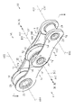
図2に示されるように、自転車用チェーン10は、第1インナーリンクプレート12と、第2インナーリンクプレート14と、第1アウターリンクプレート16と、第2アウターリンクプレート18と、ブッシュ20と、ピン22と、を備える。更に好ましくは、自転車用チェーン10は、ローラ24を備える。
As shown in FIG. 2, the
図3に示されるように、第1インナーリンクプレート12は、第1インナーリンク中心軸心AX1を有する第1インナーリンク孔30を含む第1インナーリンクエンド部32と、第1インナーリンク中心軸心AX1に平行に延びる第2インナーリンク中心軸心AX2を有する第2インナーリンク孔34を含む第2インナーリンクエンド部36と、第1インナーリンクエンド部32と第2インナーリンクエンド部36とを連結する第1インナーリンク中間部38とを含む。第1インナーリンクプレート12は、さらに、第1インナーリンク面12Aと、第1インナーリンク中心軸心AX1に関する第1インナーリンク軸方向DAにおいて第1インナーリンク面12Aと反対側に配置される第2インナーリンク面12Bとを含む。
As shown in FIG. 3, the first
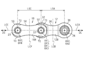
図4に示されるように、第1インナーリンクプレート12は、第1インナーリンク長手方向中心線LCAと、第1インナーリンク長手方向中心線LCAに対して垂直な第1インナーリンク横手方向中心線LCBとを有する。第1インナーリンク距離LGAは、第1インナーリンク長手方向中心線LCAに関して第1インナーリンク長手方向DEにおいて第1インナーリンク中心軸心AX1と第2インナーリンク中心軸心AX2との間で定義される。
As shown in FIG. 4, the first
本実施形態では、第1インナーリンク長手方向中心線LCAおよび第1インナーリンク横手方向中心線LCBは、第1インナーリンクプレート12に基づいて定義される。
図4に示されるように、第1インナーリンク長手方向中心線LCAは、第1インナーリンクプレート12を第1インナーリンク軸方向DAに沿う方向からみて、第1インナーリンクプレート12における長手方向に沿って延びる線であって、かつ第1インナーリンク中心軸心AX1と第2インナーリンク中心軸心AX2とを通る線として定義される。第1インナーリンク横手方向中心線LCBは、第1インナーリンク長手方向中心線LCAに対して垂直に交差し、かつ、第1インナーリンク中心軸心AX1と第2インナーリンク中心軸心AX2との間の中間点を通る線として定義される。
In this embodiment, the first inner link longitudinal centerline LCA and the first inner link lateral centerline LCB are defined based on the first
As shown in FIG. 4, the first inner link longitudinal centerline LCA extends along the longitudinal direction of the first
図3に示されるように、第2インナーリンクプレート14は、第3インナーリンク中心軸心AX3を有する第3インナーリンク孔40を含む第3インナーリンクエンド部42と、第3インナーリンク中心軸心AX3に平行に延びる第4インナーリンク中心軸心AX4を有する第4インナーリンク孔44を含む第4インナーリンクエンド部46と、第3インナーリンクエンド部42と第4インナーリンクエンド部46とを連結する第2インナーリンク中間部48とを含む。第2インナーリンクプレート14は、自転車用チェーン10の組立状態において、第1インナーリンク軸方向DAにおいて第1インナーリンクプレート12の第1インナーリンク面12Aを向くように構成される第3インナーリンク面14Aと、第3インナーリンク中心軸心AX3に関する第2インナーリンク軸方向DBにおいて第3インナーリンク面14Aとは反対側に配置される第4インナーリンク面14Bとを含む。
As shown in FIG. 3, the second
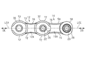
図5に示されるように、第2インナーリンクプレート14は、第2インナーリンク長手方向中心線LCCと、第2インナーリンク長手方向中心線LCCに対して垂直な第2インナーリンク横手方向中心線LCDとを有する。第2インナーリンク距離LGBは、第2インナーリンク長手方向中心線LCCに関して第2インナーリンク長手方向DFにおいて第3インナーリンク中心軸心AX3と第4インナーリンク中心軸心AX4との間で定義される。好ましくは、第1インナーリンク距離LGAおよび第2インナーリンク距離LGBの各々は、9mm~13mmの範囲にある。例えば、第1インナーリンク距離LGAおよび第2インナーリンク距離LGBの各々は、12.7mm、または、10mmに設定される。
As shown in FIG. 5, the second
本実施形態では、第2インナーリンク長手方向中心線LCCおよび第2インナーリンク横手方向中心線LCDは、第2インナーリンクプレート14に基づいて定義される。
図5に示されるように、第2インナーリンク長手方向中心線LCCは、第2インナーリンクプレート14を第2インナーリンク軸方向DBに沿う方向からみて、第2インナーリンクプレート14における長手方向に沿って延びる線であって、かつ第3インナーリンク中心軸心AX3と第4インナーリンク中心軸心AX4とを通る線として定義される。第2インナーリンク横手方向中心線LCDは、第2インナーリンク長手方向中心線LCCに対して垂直に交差し、かつ、第3インナーリンク中心軸心AX3と第4インナーリンク中心軸心AX4との間の中間点を通る線として定義される。
In this embodiment, the second inner link longitudinal centerline LCC and the second inner link lateral centerline LCD are defined based on the second
As shown in FIG. 5, the second inner link longitudinal centerline LCC extends along the longitudinal direction of the second
図3に示されるように、第1アウターリンクプレート16は、自転車用チェーン10の組立状態において、他のインナーリンクプレートまたは他のアウターリンクプレートを介さずに第1インナーリンクプレート12に隣接するように構成される。第1アウターリンクプレート16は、第1アウターリンク中心軸心BX1を有する第1アウターリンク孔50を含む第1アウターリンクエンド部52と、第1アウターリンク中心軸心BX1に平行に延びる第2アウターリンク中心軸心BX2を有する第2アウターリンク孔54を含む第2アウターリンクエンド部56と、第1アウターリンクエンド部52と第2アウターリンクエンド部56とを連結する第1アウターリンク中間部58とを含む。第1アウターリンクプレート16は、第1アウターリンク面16Aと、第1アウターリンク中心軸心BX1に関する第1アウターリンク軸方向DCにおいて第1アウターリンク面16Aと反対側に配置される第2アウターリンク面16Bとを含む。
As shown in FIG. 3, in the assembled state of the
図4に示されるように、第1アウターリンクプレート16は、第1アウターリンク長手方向中心線LCEと、第1アウターリンク長手方向中心線LCEに対して垂直な第1アウターリンク横手方向中心線LCFとを有する。第1アウターリンク距離LGCは、第1アウターリンク長手方向中心線LCEに関して第1アウターリンク長手方向DGにおいて第1アウターリンク中心軸心BX1と第2アウターリンク中心軸心BX2との間で定義される。
As shown in FIG. 4, the first
本実施形態では、第1アウターリンク長手方向中心線LCEおよび第1アウターリンク横手方向中心線LCFは、第1アウターリンクプレート16に基づいて定義される。
図4に示されるように、第1アウターリンク長手方向中心線LCEは、第1アウターリンクプレート16を第1アウターリンク軸方向DCに沿う方向からみて、第1アウターリンクプレート16における長手方向に沿って延びる線であって、かつ第1アウターリンク中心軸心BX1と第2アウターリンク中心軸心BX2とを通る線として定義される。第1アウターリンク横手方向中心線LCFは、第1アウターリンク長手方向中心線LCEに対して垂直に交差し、かつ、第1アウターリンク中心軸心BX1と第2アウターリンク中心軸心BX2との間の中間点を通る線として定義される。
In this embodiment, the first outer link longitudinal centerline LCE and the first outer link transverse centerline LCF are defined based on the first
As shown in FIG. 4, the first outer link longitudinal centerline LCE extends along the longitudinal direction of the first
図3に示されるように、第2アウターリンクプレート18は、自転車用チェーン10の組立状態において、他のインナーリンクプレートまたは他のアウターリンクプレートを介さずに第2インナーリンクプレート14に隣接するように構成される。第2アウターリンクプレート18は、第3アウターリンク中心軸心BX3を有する第3アウターリンク孔60を含む第3アウターリンクエンド部62と、第3アウターリンク中心軸心BX3に平行に延びる第4アウターリンク中心軸心BX4を有する第4アウターリンク孔64を含む第4アウターリンクエンド部66と、第3アウターリンクエンド部62と第4アウターリンクエンド部66とを連結する第2アウターリンク中間部68とを含む。第2アウターリンクプレート18は、自転車用チェーン10の組立状態において、第1アウターリンク軸方向DCにおいて第1アウターリンクプレート16の第1アウターリンク面16Aに向くように構成される第3アウターリンク面18Aと、第3アウターリンク中心軸心BX3に関する第2アウターリンク軸方向DDにおいて第3アウターリンク面18Aと反対側に配置される第4アウターリンク面18Bとを含む。
As shown in FIG. 3, in the assembled state of the
図5に示されるように、第2アウターリンクプレート18は、第2アウターリンク長手方向中心線LCGと、第2アウターリンク長手方向中心線LCGに対して垂直な第2アウターリンク横手方向中心線LCHとを有する。第2アウターリンク距離LGDは、第2アウターリンク長手方向中心線LCGに関して第2アウターリンク長手方向DHにおいて第3アウターリンク中心軸心BX3と第4アウターリンク中心軸心BX4との間で定義される。好ましくは、第1アウターリンク距離LGCおよび第2アウターリンク距離LGDの各々は、9mm~13mmの範囲にある。例えば、第1アウターリンク距離LGCおよび第2アウターリンク距離LGDの各々は、12.7mm、または、10mmに設定される。
As shown in FIG. 5, the second
本実施形態では、第2アウターリンク長手方向中心線LCGおよび第2アウターリンク横手方向中心線LCHは、第2アウターリンクプレート18に基づいて定義される。
図5に示されるように、第2アウターリンク長手方向中心線LCGは、第2アウターリンクプレート18を第2アウターリンク軸方向DDに沿う方向からみて、第2アウターリンクプレート18における長手方向に沿って延びる線であって、かつ第3アウターリンク中心軸心BX3と第4アウターリンク中心軸心BX4とを通る線として定義される。第2アウターリンク横手方向中心線LCHは、第2アウターリンク長手方向中心線LCGに対して垂直に交差し、かつ、第3アウターリンク中心軸心BX3と第4アウターリンク中心軸心BX4との間の中間点を通る線として定義される。
In this embodiment, the second outer link longitudinal centerline LCG and the second outer link transverse centerline LCH are defined based on the second
As shown in FIG. 5, the second outer link longitudinal centerline LCG extends along the longitudinal direction of the second
図3に示されるように、ブッシュ20は、ブッシュ孔20Aを有する。ブッシュ20は、自転車用チェーン10の組立状態において、第1インナーリンク孔30および第3インナーリンク孔40に挿入されるように構成される。
第1インナーリンク孔30および第3インナーリンク孔40に挿入されるブッシュ20とば別の追加ブッシュ26は、追加ブッシュ孔26Aを有する。追加ブッシュ26は、自転車用チェーン10の組立状態において、第2インナーリンク孔34および第4インナーリンク孔44に挿入されるように構成される。
As shown in FIG. 3, the
An
図8に示されるように、ブッシュ20は、第1ブッシュアウターリンク交点SA1と第2ブッシュアウターリンク交点SA2とを有する。ブッシュ20の外周面20Bと第1アウターリンクプレート16の第1アウターリンク長手方向中心線LCEとは、第1アウターリンク軸方向DCからみて、第1ブッシュアウターリンク交点SA1と第2ブッシュアウターリンク交点SA2とにおいて互いに交差する。第1ブッシュアウターリンク交点SA1は、第2ブッシュアウターリンク交点SA2よりも第1アウターリンクプレート16の第1アウターリンク横手方向中心線LCFに近くに配置される。第1アウターリンク横手方向中心線LCFは、第1アウターリンク長手方向中心線LCEに対して垂直に交差する線である。
As shown in FIG. 8, the
図9に示されるように、ブッシュ20は、第1ブッシュインナーリンク交点SB1と第2ブッシュインナーリンク交点SB2とを有する。ブッシュ20の外周面20Bと第1インナーリンクプレート12の第1インナーリンク長手方向中心線LCAとは、第1インナーリンク軸方向DAからみて、第1ブッシュインナーリンク交点SB1と第2ブッシュインナーリンク交点SB2とにおいて互いに交差し、第1ブッシュインナーリンク交点SB1は、第2ブッシュインナーリンク交点SB2よりも第1インナーリンクプレート12の第1インナーリンク横手方向中心線LCBに近くに配置される。第1インナーリンク横手方向中心線LCBは、第1インナーリンク長手方向中心線LCAに対して垂直に交差する線である。
As shown in FIG. 9, the
図3に示されるように、ピン22は、自転車用チェーン10の組立状態において、第1アウターリンク孔50および第3アウターリンク孔60に挿入され、かつ、ブッシュ孔20Aを通るように構成される。好ましくは、ピン22は、自転車用チェーン10の組立状態において、第1アウターリンク孔50および第3アウターリンク孔60に圧入で挿入される。追加ピン23は、自転車用チェーン10の組立状態において、第2アウターリンク孔54および第4アウターリンク孔64に挿入されるとともに、追加ブッシュ26の追加ブッシュ孔26Aを通るように構成される。好ましくは、追加ピン23は、自転車用チェーン10の組立状態において、第2アウターリンク孔54および第4アウターリンク孔64に圧入で挿入される。好ましくは、ピン22は、3.6mm以下のピン外径を有する。さらに、好ましくは、ピン外径は、2.5mm以上である。好ましくは、追加ピン23は、3.6mm以下の追加ピン外径を有する。好ましくは、追加ピン外径は、2.5mm以上である。
As shown in FIG. 3, in the assembled state of the
第1アウターリンクプレート16および第2アウターリンクプレート18は、ピン22および追加ピン23によって結合される。第1インナーリンクプレート12および第2インナーリンクプレート14は、ブッシュ20および追加ブッシュ26によって結合される。
第1インナーリンクプレート12および第2インナーリンクプレート14の結合体は、第1アウターリンクプレート16および第2アウターリンクプレート18の結合体に対してピン22のピン中心軸心CY1および追加ピン23のピン中心軸心CY2を中心として回転可能に連結される。
第1インナーリンクプレート12および第2インナーリンクプレート14とからなる結合体と、第1アウターリンクプレート16および第2アウターリンクプレート18からなる結合体とは、交互に配置され、ループ状に連結される。
The first
The assembly of the first
A combined body composed of the first
図3に示されるように、ローラ24は、第1インナーリンクプレート12と第2インナーリンクプレート14との間に配置される。
ローラ24は、ブッシュ20が挿通するローラ孔24Aを有する。ローラ24は、ブッシュ20に対して相対回転可能である。追加ローラ28は、追加ブッシュ26が挿通する追加ローラ孔28Aを有する。追加ローラ28は、追加ブッシュ26に対して相対回転可能である。
As shown in FIG. 3,
The
ローラ24は、第1インナーリンクプレート12の第1インナーリンクエンド部32と第2インナーリンクプレート14の第3インナーリンクエンド部42との間に配置される。追加ローラ28は、第1インナーリンクプレート12の第2インナーリンクエンド部36と第2インナーリンクプレート14の第4インナーリンクエンド部46との間に配置される。自転車用チェーン10が自転車Aに装着されるとき、ローラ24および追加ローラ28は、スプロケット歯に接触する。
The
第1アウターリンクプレート16には、少なくとも1つの第1アウターリンク面取り部70が設けられる。
図8を参照して、第1アウターリンク面取り部70が設けられる場所について説明する。
The first
A location where the first outer link chamfered
第1アウターリンク参考線RA1は、第1アウターリンク横手方向中心線LCFに平行に延びて第1ブッシュアウターリンク交点SA1を通る線として定義される。第2アウターリンク参考線RA2は、第1アウターリンク横手方向中心線LCFに平行に延びて第1アウターリンク端縁交点SC1を通る線として定義される。第1アウターリンク端縁交点SC1は、第1アウターリンク軸方向DCからみて、第1アウターリンクプレート16の第1アウターリンク長手方向中心線LCEと第1アウターリンクプレート16の第1アウターリンクエンド部52の第1アウターリンク端縁52Aとが互いに交差する点である。
The first outer link reference line RA1 is defined as a line extending parallel to the first outer link lateral centerline LCF and passing through the first bushing outer link intersection point SA1. The second outer link reference line RA2 is defined as a line extending parallel to the first outer link transverse centerline LCF and passing through the first outer link edge intersection point SC1. The first outer link edge intersection point SC1 is defined by the first outer link longitudinal center line LCE of the first
少なくとも1つの第1アウターリンク面取り部70は、第1アウターリンクプレート16の第1アウターリンク長手方向中心線LCEに関する第1アウターリンク長手方向DGにおいて、第1アウターリンク参考線RA1と第2アウターリンク参考線RA2との間に少なくとも部分的に配置されるように、第1アウターリンクプレート16に設けられる。
The at least one first outer link chamfered
図8に示されるように、少なくとも1つの第1アウターリンク面取り部70は、第2アウターリンク面16Bに設けられてもよい。第1アウターリンクプレート16において、第1アウターリンク参考線RA1と第2アウターリンク参考線RA2との間の部分の第2アウターリンク面16Bは、自転車AのスプロケットDに接触する接触頻度が高い。第1アウターリンク参考線RA1と第2アウターリンク参考線RA2との間の部分に第1アウターリンク面取り部70が設けられることによって変速時においてスプロケットDと第1アウターリンクプレート16との干渉が小さくなるため、変速時における自転車用チェーン10の動作が円滑になる。
As shown in FIG. 8, at least one first
少なくとも1つの第1アウターリンク面取り部70は、第2アウターリンクエンド部56に設けられてもよい。少なくとも1つの第1アウターリンク面取り部70は、第2アウターリンクエンド部56において第2アウターリンク面16Bに設けられてもよい。この構成によって、スプロケットDと第1アウターリンクプレート16との干渉が小さくなるため、変速時における自転車用チェーン10の動作が円滑になる。
At least one first
図6に示されるように、少なくとも1つの第1アウターリンク面取り部70は、第1アウターリンク中間部58に設けられてもよい。少なくとも1つの第1アウターリンク面取り部70は、第1アウターリンク中間部58において第1アウターリンク面16Aに設けられてもよい。この構成によって、スプロケット歯が第1アウターリンクプレート16と第2アウターリンクプレート18との間に入り易くなる。少なくとも1つの第1アウターリンク面取り部70は、第1アウターリンク中間部58において第2アウターリンク面16Bに設けられてもよい。
As shown in FIG. 6 , at least one first
図9に示されるように少なくとも1つの第1インナーリンク面取り部72が、第1インナーリンクプレート12に設けられてもよい。第1インナーリンク面取り部72が設けられる場所について説明する。
At least one first
第1インナーリンク参考線RB1は、第1インナーリンク横手方向中心線LCBに平行に延びて第1ブッシュインナーリンク交点SB1を通る線として定義される。第2インナーリンク参考線RB2は、第1インナーリンク横手方向中心線LCBに平行に延びて第1インナーリンク端縁交点SD1を通る線として定義される。第1インナーリンク端縁交点SD1は、第1インナーリンク軸方向DAからみて、第1インナーリンクプレート12の第1インナーリンク長手方向中心線LCAと第1インナーリンクプレート12の第1インナーリンクエンド部32の第1インナーリンク端縁32Aとが互いに交差する点である。
The first inner link reference line RB1 is defined as a line extending parallel to the first inner link lateral centerline LCB and passing through the first bushing inner link intersection point SB1. The second inner link reference line RB2 is defined as a line extending parallel to the first inner link lateral centerline LCB and passing through the first inner link edge intersection point SD1. The first inner link edge intersection point SD1 is defined by the first inner link longitudinal center line LCA of the first
少なくとも1つの第1インナーリンク面取り部72は、第1インナーリンクプレート12の第1インナーリンク長手方向中心線LCAに関する第1インナーリンク長手方向DEにおいて、第1インナーリンク参考線RB1と第2インナーリンク参考線RB2との間に少なくとも部分的に配置されるように、第1インナーリンクプレート12に設けられてもよい。
The at least one first inner link chamfered
たとえば、第1インナーリンク面取り部72は、第1インナーリンクエンド部32において第1インナーリンク面12Aに設けられる。第1インナーリンク面取り部72は、第2インナーリンクエンド部36において第1インナーリンク面12Aに設けられる。変速時に自転車用チェーン10が屈曲するとき、第1インナーリンクエンド部32において第1インナーリンク面12Aに第1インナーリンク面取り部72が設けられることによって、自転車用チェーン10が望ましくないタイミングで自転車AのスプロケットDから外れることを低減できる。同様に、変速時に自転車用チェーン10が屈曲するとき、第2インナーリンクエンド部36において第1インナーリンク面12Aに第1インナーリンク面取り部72が設けられることによって、自転車用チェーン10が望ましくないタイミングで自転車AのスプロケットDから外れることを低減できる。このようにして、変速時における自転車用チェーン10の動作が円滑になる。
For example, the first inner link chamfered
図5に示されるように、少なくとも1つの第2アウターリンク面取り部74が、第2アウターリンクプレート18に設けられてもよい。少なくとも1つの第2アウターリンク面取り部74は、第3アウターリンクエンド部62において第4アウターリンク面18Bに配置されてもよい。少なくとも1つの第2アウターリンク面取り部74は、第4アウターリンクエンド部66において第4アウターリンク面18Bに配置されてもよい。この構成によって、変速時においてスプロケットDと第2アウターリンクプレート18との干渉が小さくなるため、変速時における自転車用チェーン10の動作が円滑になる。
At least one second
図7に示されるように、少なくとも1つの第2インナーリンク面取り部76が、第2インナーリンクプレート14に設けられてもよい。少なくとも1つの第2インナーリンク面取り部76は、第3インナーリンクエンド部42において第3インナーリンク面14Aに設けられる。第2インナーリンク面取り部76は、第4インナーリンクエンド部46において第3インナーリンク面14Aに設けられる。自転車用チェーン10が望ましくないタイミングで自転車AのスプロケットDから外れることを低減できる。このようにして、変速時における自転車用チェーン10の動作が円滑になる。
At least one second
<第2実施形態>
第2実施形態の自転車用チェーン10について説明する。第1実施形態と共通する構成については、第1実施形態と同一の符号を付し、重複する説明を省略する。第2実施形態の自転車用チェーン10は、少なくとも第1インナーリンク面取り部72を有し、さらに、好ましくは、第1アウターリンク面取り部70を有する。
<Second embodiment>
A
少なくとも1つの第1インナーリンク面取り部72は、第1インナーリンクプレート12の第1インナーリンクエンド部32に設けられる。具体的には、図9に示されるように、少なくとも1つの第1インナーリンク面取り部72は、第1インナーリンクプレート12の第1インナーリンク長手方向中心線LCAに関する第1インナーリンク長手方向DEにおいて、第1インナーリンク参考線RB1と第2インナーリンク参考線RB2との間に少なくとも部分的に配置されるように、第1インナーリンクプレート12に設けられる。
At least one first
図6に示されるように、少なくとも1つの第1インナーリンク面取り部72は、第1インナーリンク面12Aに設けられてもよい。少なくとも1つの第1インナーリンク面取り部72は、第2インナーリンクエンド部36に設けられてもよい。少なくとも1つの第1インナーリンク面取り部72は、第2インナーリンクエンド部36において第1インナーリンク面12Aに設けられてもよい。第1インナーリンク面12Aに第1インナーリンク面取り部72が設けられることによって、自転車用チェーン10の変速時において、自転車用チェーン10とスプロケットDとの係合が維持され易くなる。これによって、変速時における自転車用チェーン10の動作が円滑になる。
As shown in FIG. 6, at least one first
少なくとも1つの第1インナーリンク面取り部72は、第1インナーリンク中間部38に設けられてもよい。少なくとも1つの第1インナーリンク面取り部72は、第1インナーリンク中間部38において第1インナーリンク面12Aに設けられてもよい。この構成によって、スプロケット歯が第1インナーリンクプレート12と第2インナーリンクプレート14との間に入り易くなる。少なくとも1つの第1インナーリンク面取り部72は、第1インナーリンク中間部38において第2インナーリンク面12Bに設けられてもよい。
At least one first
図4に示されるように、少なくとも1つの第1アウターリンク面取り部70が、第1アウターリンクプレート16に設けられてもよい。少なくとも1つの第1アウターリンク面取り部70は、第1アウターリンクエンド部52において第2アウターリンク面16Bに配置されてもよい。少なくとも1つの第1アウターリンク面取り部70は、第2アウターリンクエンド部56において第2アウターリンク面16Bに配置されてもよい。この構成によって、変速時においてスプロケットDと第1アウターリンクプレート16との干渉が低減する小さくなるため、変速時における自転車用チェーン10の動作が円滑になる。
At least one first
図5に示されるように、少なくとも1つの第2アウターリンク面取り部74が、第2アウターリンクプレート18に設けられてもよい。少なくとも1つの第2アウターリンク面取り部74は、第3アウターリンクエンド部62において第4アウターリンク面18Bに配置されてもよい。少なくとも1つの第2アウターリンク面取り部74は、第4アウターリンクエンド部66において第4アウターリンク面18Bに配置されてもよい。この構成によって、変速時においてスプロケットDと第2アウターリンクプレート18との干渉が小さくなるため、変速時における自転車用チェーン10の動作が円滑になる。
At least one second
図7に示されるように、少なくとも1つの第2インナーリンク面取り部76が、第2インナーリンクプレート14に設けられてもよい。第2インナーリンク面取り部76は、第3インナーリンクエンド部42において第3インナーリンク面14Aに設けられる。第2インナーリンク面取り部76は、第4インナーリンクエンド部46において第3インナーリンク面14Aに設けられる。第3インナーリンク面14Aに第2インナーリンク面取り部76が設けられることによって、自転車用チェーン10の変速時において、自転車用チェーン10とスプロケットDとの係合が維持され易くなる。このようにして、変速時における自転車用チェーン10の動作が円滑になる。
At least one second
<第3実施形態>
図10~図13を参照して、第3実施形態の自転車用チェーン10について説明する。第3実施形態と共通する構成については、第1実施形態と同一の符号を付し、重複する説明を省略する。第3実施形態の自転車用チェーン10では、ブッシュ20の構造が、第1実施形態の自転車用チェーン10と相違する。第3実施形態の自転車用チェーン10では、第1実施形態で示される第1アウターリンク面取り部70、第1インナーリンク面取り部72、第2アウターリンク面取り部74、および第2インナーリンク面取り部76の少なくとも1つが省略されてもよい。
<Third Embodiment>
A
ブッシュ20は、ブッシュ孔20Aを構成する内周面20Cを有する。ブッシュ20は、自転車用チェーン10の組立状態において第1インナーリンク孔30と第3インナーリンク孔40に挿通されるように構成される。
The
ピン22は、外周面22Aを有し、自転車用チェーン10の組立状態において、第1アウターリンク孔50および第3アウターリンク孔60に挿通され、かつ、ブッシュ孔20Aを通るように構成される。
The
本実施形態では、ブッシュ20とピン22との間に金属保持部材80が設けられる。金属保持部材80は、ブッシュ20の内周面20Cとピン22の外周面22Aの一方に配置される。金属保持部材80は、複数の保持孔80Aを含む。樹脂部材82は、複数の保持孔80Aに配置される。樹脂部材82は、金属保持部材80の内周面および外周面の少なくとも一方において露出されるように配置される。保持孔80Aは、貫通孔、くぼみ、溝を含む。保持孔80Aが溝として構成される場合、保持孔80Aは、網目形状であってもよく、直線構造であってもよく、螺旋形であってもよい。
In this embodiment, a
たとえば、図10および図11に示されるように、金属保持部材80は、ブッシュ20の内周面20Cに配置される。金属保持部材80は、ブッシュ20のブッシュ中心軸心CXを中心軸とする円筒形状を有する。好ましくは、金属保持部材80の内周面と樹脂部材82の内周面とは面一になるように構成される。樹脂部材82は、金属保持部材80の内周面において露出されるように配置される。樹脂部材82は、耐摩耗性樹脂であってもよい。樹脂部材82として、例えば、フェノール樹脂、ポリアセタール樹脂が挙げられる。
For example, as shown in FIGS. 10 and 11,
ブッシュ20は、第1材料によって形成され、金属保持部材80は、第1材料によって形成されてもよい。ブッシュ20は、第1材料によって形成され、金属保持部材80は、第1材料とは異なる第2材料によって形成されてもよい。第1材料は、金属を含む。第1材料として、例えば、鉄、アルミニウム合金、ステンレス、およびチタン合金が挙げられる。第2材料は、金属を含む。
追加ブッシュ26は、自転車用チェーン10の組立状態において第2インナーリンク孔34と第4インナーリンク孔44に挿通されるように構成される。追加ブッシュ26は、ブッシュ20と同じ構造であってもよく、または、ブッシュ20と別の構造であってもよい。
The
また、図12および図13に示されるように、金属保持部材84は、ピン22の外周面22Aに配置されてもよい。金属保持部材84は、ピン22のピン中心軸心CY1を中心軸とする円筒形状を有する。金属保持部材84は、複数の保持孔84Aを含む。樹脂部材86は、複数の保持孔84Aに配置される。樹脂部材86は、金属保持部材80の外周面において露出されるように配置される。
Also, as shown in FIGS. 12 and 13 , the
ピン22は、第3材料によって形成され、金属保持部材84は、第3材料によって形成されてもよい。ピン22は、第3材料によって形成され、金属保持部材84は、第3材料とは異なる第4材料によって形成されてもよい。第3材料は、金属を含む。第3材料として、例えば、鉄、アルミニウム合金、ステンレス、およびチタン合金が挙げられる。第4材料は、金属を含む。好ましくは、追加ピン23は、ピン22と同様の構造を有する。
<第4実施形態>
図14および図15を参照して、第4実施形態の自転車用チェーン10について説明する。第4実施形態と共通する構成については、第1実施形態と同一の符号を付し、重複する説明を省略する。第4実施形態の自転車用チェーン10の形状は、第1実施形態の自転車用チェーン10の形状と異なる部分があるが、その説明を省略する。第4実施形態の自転車用チェーン10では、ブッシュ20の構造が、第1実施形態の自転車用チェーン10と相違する。第4実施形態の自転車用チェーン10では、第1実施形態で示される第1アウターリンク面取り部70、第1インナーリンク面取り部72、第2アウターリンク面取り部74、および第2インナーリンク面取り部76の少なくとも1つが省略されてもよい。
<Fourth Embodiment>
A
ブッシュ20は、ブッシュ孔20Aと、第1ブッシュエンド部90と、ブッシュ20のブッシュ中心軸心CXに関するブッシュ軸方向DJにおいて第1ブッシュエンド部90の反対側に配置される第2ブッシュエンド部92とを有する。ブッシュ20は、自転車用チェーン10の組立状態において第1インナーリンク孔30と第3インナーリンク孔40に圧入によって挿通されるように構成される。第1ブッシュエンド部90は、第1インナーリンク孔30に圧入によって挿入される。第2ブッシュエンド部92は、第3インナーリンク孔40に圧入によって挿入される。
The
ブッシュ20は、ブッシュ中心軸心CXに関する第1ブッシュエンド部90から径方向外方向DRに延びる第1径方向突出部94およびブッシュ中心軸心CXに関する第2ブッシュエンド部92から径方向外方向DRに延びる第2径方向突出部96の少なくとも一つを含む。
The
好ましくは、図14に示されるように、ブッシュ20は、第1径方向突出部94と第2径方向突出部96とを含む。第1径方向突出部94は、環状形状を有する。第2径方向突出部96は、環状形状を有する。第1径方向突出部94は、かしめによって形成される。第2径方向突出部96は、かしめによって形成される。
Preferably, bushing 20 includes a first
第1径方向突出部94は、第1ブッシュエンド部90が第1インナーリンク孔30に挿入された状態において第1ブッシュエンド部90の外周縁がかしめられることによって、第1インナーリンク孔30と第2インナーリンク面12Bとの境界部分に形成される。第2径方向突出部96は、第2ブッシュエンド部92が第3インナーリンク孔40に挿入された状態において第2ブッシュエンド部92の外周縁がかしめられることによって、第3インナーリンク孔40と第4インナーリンク面14Bとの境界部分に形成される。
The first
ブッシュ20が、第1インナーリンク孔30および第3インナーリンク孔40に挿入すること、第1ブッシュエンド部90のかしめ、および第2ブッシュエンド部92のかしめによって、第1インナーリンクプレート12と第2インナーリンクプレート14とがブッシュ20を介して強固に連結される。
By inserting the
ピン22は、圧入によって、第1アウターリンク孔50および第3アウターリンク孔60に挿通される。ピン22は、第1ピンエンド部100と、ピン中心軸心CY1に関するピン軸方向DKにおいて第1ピンエンド部100の反対側に配置される第2ピンエンド部102とを有する。第1ピンエンド部100は、第1アウターリンク孔50に圧入によって挿入され、かしめられることによって、第1アウターリンク孔50の周囲に形成される。第2ピンエンド部102は、第3アウターリンク孔60に圧入によって挿入され、かしめられることによって、第3アウターリンク孔60の周囲に形成される。
The
<その変形例>
各実施形態に関する説明は、本開示に従う自転車用チェーン10の例示であり、その形態を制限することを意図していない。本開示に従う自転車用チェーン10は、例えば以下に示される実施形態の変形例、および、相互に矛盾しない少なくとも2つの変形例が組み合わせられた形態を取り得る。以下の変形例において、実施形態の形態と共通する部分については、実施形態と同一の符号を付してその説明を省略する。
<Variation>
The description of each embodiment is illustrative of the
・図16を参照して、第4実施形態の自転車用チェーン10の変形例を説明する。
第1インナーリンクエンド部32は、第1インナーリンク中心軸心AX1に関して第1インナーリンク孔30を周方向において囲む第1環状軸方向突出部104を含む。第1環状軸方向突出部104は、自転車用チェーン10の組立状態において、第1インナーリンク軸方向DAに沿う方向において第2インナーリンクプレート14に向かって突出する。第3インナーリンクエンド部42は、第3インナーリンク中心軸心AX3に関して第3インナーリンク孔40を周方向において囲む第2環状軸方向突出部106を含む。第2環状軸方向突出部106は、自転車用チェーン10の組立状態において、第2インナーリンク軸方向DBに沿う方向において第1インナーリンクプレート12に向かって突出する。
- A modification of the
The first inner
ブッシュ20は、自転車用チェーン10の組立状態において、第1インナーリンク孔30および第3インナーリンク孔40に挿入される。また、ブッシュ20の第1ブッシュエンド部90は、自転車用チェーン10の組立状態において、第1環状軸方向突出部104に入って、第1環状軸方向突出部104に接触するように構成される。さらに、ブッシュ20の第2ブッシュエンド部92は、自転車用チェーン10の組立状態において、第2環状軸方向突出部106に入って、第2環状軸方向突出部106に接触するように構成される。
The
ブッシュ20は、ブッシュ中心軸心CXに関する第1ブッシュエンド部90から径方向外方向DRに延びる第1径方向突出部94およびブッシュ中心軸心CXに関する第2ブッシュエンド部92から径方向外方向DRに延びる第2径方向突出部96の少なくとも一つを含む。
The
第1径方向突出部94は、第1ブッシュエンド部90が第1環状軸方向突出部104に挿入された状態において第1ブッシュエンド部90の外周縁がかしめられることによって、第1インナーリンク孔30と第2インナーリンク面12Bとの境界部分に形成される。第2径方向突出部96は、第2ブッシュエンド部92が第2環状軸方向突出部106に挿入された状態において第2ブッシュエンド部92の外周縁がかしめられることによって、第3インナーリンク孔40と第4インナーリンク面14Bとの境界部分に形成される。
The first
ブッシュ20が、第1環状軸方向突出部104および第2環状軸方向突出部106に挿入すること、第1ブッシュエンド部90のかしめ、および第2ブッシュエンド部92のかしめによって、第1インナーリンクプレート12と第2インナーリンクプレート14とはブッシュ20を介して強固に連結される。
Insertion of
上記各実施形態および変形例において、次に示される各項目の少なくとも1つが適用されてもよい。
第1アウターリンクプレート16に形成される少なくとも1つの第1アウターリンク面取り部70は、第1アウターリンク面16Aおよび第2アウターリンク面16Bの少なくとも一方において、第1アウターリンクエンド部52から第1アウターリンク中間部58を経て第2アウターリンクエンド部56まで、連続的に延びるように形成されてもよい。
第2アウターリンクプレート18に形成される少なくとも1つの第2アウターリンク面取り部74は、第3アウターリンク面18Aおよび第4アウターリンク面18Bの少なくとも一方において、第3アウターリンクエンド部62から第2アウターリンク中間部68を経て第4アウターリンクエンド部66まで、連続的に延びるように形成されてもよい。
第1インナーリンクプレート12に形成される少なくとも1つの第1インナーリンク面取り部72は、第1インナーリンク面12Aおよび第2インナーリンク面12Bの少なくとも一方において、第1インナーリンクエンド部32から第1インナーリンク中間部38を経て第2インナーリンクエンド部36まで、連続的に延びるように形成されてもよい。
第2インナーリンクプレート14に形成される少なくとも1つの第2インナーリンク面取り部76は、第3インナーリンク面14Aおよび第4インナーリンク面14Bの少なくとも一方において、第3インナーリンクエンド部42から第2インナーリンク中間部48を経て第4インナーリンクエンド部46まで、連続的に延びるように形成されてもよい。
第1アウターリンクプレート16に形成される少なくとも1つの第1アウターリンク面取り部70は、第1アウターリンク面16Aおよび第2アウターリンク面16Bの少なくとも一方において、第1アウターリンクプレート16の全周に沿って連続的に延びるように形成されてもよい。
第2アウターリンクプレート18に形成される少なくとも1つの第2アウターリンク面取り部74は、第3アウターリンク面18Aおよび第4アウターリンク面18Bの少なくとも一方において、第2アウターリンクプレート18の全周に沿って連続的に延びるように形成されてもよい。
第1インナーリンクプレート12に形成される少なくとも1つの第1インナーリンク面取り部72は、第1インナーリンク面12Aおよび第2インナーリンク面12Bの少なくとも一方において、第1インナーリンクプレート12の全周に沿って連続的に延びるように形成されてもよい。
第2インナーリンクプレート14に形成される少なくとも1つの第2インナーリンク面取り部76は、第3インナーリンク面14Aおよび第4インナーリンク面14Bの少なくとも一方において、第2インナーリンクプレート14の全周に沿って連続的に延びるように形成されてもよい。
At least one of the following items may be applied to each of the above embodiments and modifications.
At least one first outer link chamfered
At least one second outer link chamfered
At least one first inner link chamfered
At least one second inner link chamfered
At least one first outer link chamfered
At least one second outer link chamfered
At least one first inner link chamfered
At least one second inner link chamfered
AX1…第1インナーリンク中心軸心、AX2…第2インナーリンク中心軸心、AX3…第3インナーリンク中心軸心、AX4…第4インナーリンク中心軸心、BX1…第1アウターリンク中心軸心、BX2…第2アウターリンク中心軸心、BX3…第3アウターリンク中心軸心、BX4…第4アウターリンク中心軸心、CX…ブッシュ中心軸心、LCA…第1インナーリンク長手方向中心線、LCB…第1インナーリンク横手方向中心線、LCE…第1アウターリンク長手方向中心線、LCF…第1アウターリンク横手方向中心線、RA1…第1アウターリンク参考線、RA2…第2アウターリンク参考線、RB1…第1インナーリンク参考線、RB2…第2インナーリンク参考線、SA1…第1ブッシュアウターリンク交点、SA2…第2ブッシュアウターリンク交点、SB1…第1ブッシュインナーリンク交点、SB2…第2ブッシュインナーリンク交点、SC1…第1アウターリンク端縁交点、SD1…第1インナーリンク端縁交点、10…自転車用チェーン、12…第1インナーリンクプレート、12A…第1インナーリンク面、12B…第2インナーリンク面、14…第2インナーリンクプレート、14A…第3インナーリンク面、14B…第4インナーリンク面、16…第1アウターリンクプレート、16A…第1アウターリンク面、16B…第2アウターリンク面、18…第2アウターリンクプレート、18A…第3アウターリンク面、18B…第4アウターリンク面、20…ブッシュ、20A…ブッシュ孔、20B…外周面、20C…内周面、22…ピン、22A…外周面、26…追加ブッシュ、26A…追加ブッシュ孔、30…第1インナーリンク孔、32…第1インナーリンクエンド部、34…第2インナーリンク孔、36…第2インナーリンクエンド部、38…第1インナーリンク中間部、40…第3インナーリンク孔、42…第3インナーリンクエンド部、44…第4インナーリンク孔、46…第4インナーリンクエンド部、48…第2インナーリンク中間部、50…第1アウターリンク孔、52…第1アウターリンクエンド部、54…第2アウターリンク孔、56…第2アウターリンクエンド部、58…第1アウターリンク中間部、60…第3アウターリンク孔、62…第3アウターリンクエンド部、64…第4アウターリンク孔、66…第4アウターリンクエンド部、68…第2アウターリンク中間部、70…第1アウターリンク面取り部、72…第1インナーリンク面取り部、74…第2アウターリンク面取り部、76…第2インナーリンク面取り部、80…金属保持部材、80A…保持孔、82…樹脂部材、84…金属保持部材、84A…保持孔、86…樹脂部材、90…第1ブッシュエンド部、92…第2ブッシュエンド部、94…第1径方向突出部、96…第2径方向突出部。
AX1... First inner link center axis, AX2... Second inner link center axis, AX3... Third inner link center axis, AX4... Fourth inner link center axis, BX1... First outer link center axis, BX2...Second outer link center axis BX3...Third outer link center axis BX4...Fourth outer link center axis CX...Bush center axis LCA...Longitudinal center line of first inner link LCB... First inner link lateral center line LCE... First outer link longitudinal center line LCF... First outer link lateral center line RA1... First outer link reference line RA2... Second outer link reference line RB1 1st inner link reference line RB2 2nd inner link reference line SA1 1st bushing outer link intersection SA2 2nd bushing outer link intersection SB1 1st bushing inner link intersection SB2 2nd bushing inner Link intersection SC1 First outer link edge intersection SD1 First inner
Claims (11)
第1インナーリンクプレートと、第2インナーリンクプレートと、第1アウターリンクプレートと、第2アウターリンクプレートと、ブッシュと、ピンと、金属保持部材と、樹脂部材とを備え、
前記第1インナーリンクプレートは、
第1インナーリンク中心軸心を有する第1インナーリンク孔を含む第1インナーリンクエンド部と、
前記第1インナーリンク中心軸心に平行に延びる第2インナーリンク中心軸心を有する第2インナーリンク孔を含む第2インナーリンクエンド部と、
前記第1インナーリンクエンド部と前記第2インナーリンクエンド部とを連結する第1インナーリンク中間部と、
第1インナーリンク面と、
前記第1インナーリンク中心軸心に関する第1インナーリンク軸方向において前記第1インナーリンク面の反対側に配置される第2インナーリンク面とを含み、
前記第2インナーリンクプレートは、
第3インナーリンク中心軸心を有する第3インナーリンク孔を含む第3インナーリンクエンド部と、
前記第3インナーリンク中心軸心に平行に延びる第4インナーリンク中心軸心を有する第4インナーリンク孔を含む第4インナーリンクエンド部と、
前記第3インナーリンクエンド部と前記第4インナーリンクエンド部とを連結する第2インナーリンク中間部と、
前記自転車用チェーンの組立状態において、前記第1インナーリンク軸方向において前記第1インナーリンクプレートの前記第1インナーリンク面を向くように構成される第3インナーリンク面と、
前記第3インナーリンク中心軸心に関する第2インナーリンク軸方向において前記第3インナーリンク面の反対側に配置される第4インナーリンク面とを含み、
前記第1アウターリンクプレートは、
前記自転車用チェーンの組立状態において、他のインナーリンクプレートまたは他のアウターリンクプレートを間に挟まないように前記第1インナーリンクプレートに隣接するように構成され、
第1アウターリンク中心軸心を有する第1アウターリンク孔を含む第1アウターリンクエンド部と、
前記第1アウターリンク中心軸心に平行に延びる第2アウターリンク中心軸心を有する第2アウターリンク孔を含む第2アウターリンクエンド部と、
前記第1アウターリンクエンド部と前記第2アウターリンクエンド部とを連結する第1アウターリンク中間部と、
第1アウターリンク面と、
前記第1アウターリンク中心軸心に関する第1アウターリンク軸方向において前記第1アウターリンク面の反対側に配置される第2アウターリンク面とを含み、
前記第2アウターリンクプレートは、
前記自転車用チェーンの組立状態において、他のインナーリンクプレートまたは他のアウターリンクプレートを間に挟まないように前記第2インナーリンクプレートに隣接するように構成され、
第3アウターリンク中心軸心を有する第3アウターリンク孔を含む第3アウターリンクエンド部と、
前記第3アウターリンク中心軸心に平行に延びる第4アウターリンク中心軸心を有する第4アウターリンク孔を含む第4アウターリンクエンド部と、
前記第3アウターリンクエンド部と前記第4アウターリンクエンド部とを連結する第2アウターリンク中間部と、
前記自転車用チェーンの組立状態において、前記第1アウターリンク軸方向において前記第1アウターリンクプレートの前記第1アウターリンク面を向くように構成される第3アウターリンク面と、
前記第3アウターリンク中心軸心に関する第2アウターリンク軸方向において前記第3アウターリンク面の反対側に配置される第4アウターリンク面とを含み、
前記ブッシュは、ブッシュ孔を構成する内周面を有し、前記ブッシュは、前記自転車用チェーンの組立状態において前記第1インナーリンク孔と前記第3インナーリンク孔に挿通されるように構成され、
前記ピンは、外周面を有し、前記自転車用チェーンの組立状態において、前記第1アウターリンク孔および前記第3アウターリンク孔に挿通され、かつ、前記ブッシュ孔を通るように構成され、
前記金属保持部材は、前記ピンの外周面に配置され、かつ前記金属保持部材は、複数の保持孔を含み、
前記樹脂部材は、前記複数の保持孔に配置される
自転車用チェーン。 A bicycle chain,
a first inner link plate, a second inner link plate, a first outer link plate, a second outer link plate, a bush, a pin, a metal holding member, and a resin member;
The first inner link plate,
a first inner link end portion including a first inner link hole having a first inner link central axis;
a second inner link end portion including a second inner link hole having a second inner link center axis extending parallel to the first inner link center axis;
a first inner link intermediate portion connecting the first inner link end portion and the second inner link end portion;
a first inner link surface;
a second inner link surface arranged on the opposite side of the first inner link surface in a first inner link axial direction with respect to the first inner link central axis;
The second inner link plate is
a third inner link end portion including a third inner link hole having a third inner link central axis;
a fourth inner link end portion including a fourth inner link hole having a fourth inner link center axis extending parallel to the third inner link center axis;
a second inner link intermediate portion connecting the third inner link end portion and the fourth inner link end portion;
a third inner link surface configured to face the first inner link surface of the first inner link plate in the axial direction of the first inner link when the bicycle chain is assembled;
a fourth inner link surface disposed on the opposite side of the third inner link surface in a second inner link axial direction with respect to the third inner link central axis;
The first outer link plate is
configured to be adjacent to the first inner link plate so as not to sandwich another inner link plate or another outer link plate in the assembled state of the bicycle chain,
a first outer link end portion including a first outer link hole having a first outer link central axis;
a second outer link end portion including a second outer link hole having a second outer link center axis extending parallel to the first outer link center axis;
a first outer link intermediate portion connecting the first outer link end portion and the second outer link end portion;
a first outer link surface;
a second outer link surface arranged on the opposite side of the first outer link surface in a first outer link axial direction with respect to the first outer link central axis,
The second outer link plate is
In the assembled state of the bicycle chain, it is configured to be adjacent to the second inner link plate so as not to sandwich another inner link plate or another outer link plate,
a third outer link end portion including a third outer link hole having a third outer link central axis;
a fourth outer link end portion including a fourth outer link hole having a fourth outer link central axis extending parallel to the third outer link central axis;
a second outer link intermediate portion connecting the third outer link end portion and the fourth outer link end portion;
a third outer link surface configured to face the first outer link surface of the first outer link plate in the axial direction of the first outer link when the bicycle chain is assembled;
a fourth outer link surface arranged on the opposite side of the third outer link surface in a second outer link axial direction with respect to the third outer link central axis,
The bush has an inner peripheral surface forming a bush hole, and the bush is configured to be inserted through the first inner link hole and the third inner link hole when the bicycle chain is assembled,
The pin has an outer peripheral surface, is inserted through the first outer link hole and the third outer link hole, and is configured to pass through the bush hole when the bicycle chain is assembled,
the metal holding member is disposed on the outer peripheral surface of the pin, and the metal holding member includes a plurality of holding holes;
The bicycle chain, wherein the resin member is arranged in the plurality of holding holes.
第1インナーリンクプレートと、第2インナーリンクプレートと、第1アウターリンクプレートと、第2アウターリンクプレートと、ブッシュと、ピンと、金属保持部材と、樹脂部材とを備え、 a first inner link plate, a second inner link plate, a first outer link plate, a second outer link plate, a bush, a pin, a metal holding member, and a resin member;
前記第1インナーリンクプレートは、 The first inner link plate,
第1インナーリンク中心軸心を有する第1インナーリンク孔を含む第1インナーリンクエンド部と、 a first inner link end portion including a first inner link hole having a first inner link central axis;
前記第1インナーリンク中心軸心に平行に延びる第2インナーリンク中心軸心を有する第2インナーリンク孔を含む第2インナーリンクエンド部と、 a second inner link end portion including a second inner link hole having a second inner link center axis extending parallel to the first inner link center axis;
前記第1インナーリンクエンド部と前記第2インナーリンクエンド部とを連結する第1インナーリンク中間部と、 a first inner link intermediate portion connecting the first inner link end portion and the second inner link end portion;
第1インナーリンク面と、 a first inner link surface;
前記第1インナーリンク中心軸心に関する第1インナーリンク軸方向において前記第1インナーリンク面の反対側に配置される第2インナーリンク面とを含み、 a second inner link surface arranged on the opposite side of the first inner link surface in a first inner link axial direction with respect to the first inner link central axis;
前記第2インナーリンクプレートは、 The second inner link plate is
第3インナーリンク中心軸心を有する第3インナーリンク孔を含む第3インナーリンクエンド部と、 a third inner link end portion including a third inner link hole having a third inner link central axis;
前記第3インナーリンク中心軸心に平行に延びる第4インナーリンク中心軸心を有する第4インナーリンク孔を含む第4インナーリンクエンド部と、 a fourth inner link end portion including a fourth inner link hole having a fourth inner link center axis extending parallel to the third inner link center axis;
前記第3インナーリンクエンド部と前記第4インナーリンクエンド部とを連結する第2インナーリンク中間部と、 a second inner link intermediate portion connecting the third inner link end portion and the fourth inner link end portion;
前記自転車用チェーンの組立状態において、前記第1インナーリンク軸方向において前記第1インナーリンクプレートの前記第1インナーリンク面を向くように構成される第3インナーリンク面と、 a third inner link surface configured to face the first inner link surface of the first inner link plate in the axial direction of the first inner link when the bicycle chain is assembled;
前記第3インナーリンク中心軸心に関する第2インナーリンク軸方向において前記第3インナーリンク面の反対側に配置される第4インナーリンク面とを含み、 a fourth inner link surface disposed on the opposite side of the third inner link surface in a second inner link axial direction with respect to the third inner link central axis;
前記第1アウターリンクプレートは、 The first outer link plate is
前記自転車用チェーンの組立状態において、他のインナーリンクプレートまたは他のアウターリンクプレートを間に挟まないように前記第1インナーリンクプレートに隣接するように構成され、 configured to be adjacent to the first inner link plate so as not to sandwich another inner link plate or another outer link plate in the assembled state of the bicycle chain,
第1アウターリンク中心軸心を有する第1アウターリンク孔を含む第1アウターリンクエンド部と、 a first outer link end portion including a first outer link hole having a first outer link central axis;
前記第1アウターリンク中心軸心に平行に延びる第2アウターリンク中心軸心を有する第2アウターリンク孔を含む第2アウターリンクエンド部と、 a second outer link end portion including a second outer link hole having a second outer link center axis extending parallel to the first outer link center axis;
前記第1アウターリンクエンド部と前記第2アウターリンクエンド部とを連結する第1アウターリンク中間部と、 a first outer link intermediate portion connecting the first outer link end portion and the second outer link end portion;
第1アウターリンク面と、 a first outer link surface;
前記第1アウターリンク中心軸心に関する第1アウターリンク軸方向において前記第1アウターリンク面の反対側に配置される第2アウターリンク面とを含み、 a second outer link surface arranged on the opposite side of the first outer link surface in a first outer link axial direction with respect to the first outer link central axis,
前記第2アウターリンクプレートは、 The second outer link plate is
前記自転車用チェーンの組立状態において、他のインナーリンクプレートまたは他のアウターリンクプレートを間に挟まないように前記第2インナーリンクプレートに隣接するように構成され、 In the assembled state of the bicycle chain, it is configured to be adjacent to the second inner link plate so as not to sandwich another inner link plate or another outer link plate,
第3アウターリンク中心軸心を有する第3アウターリンク孔を含む第3アウターリンクエンド部と、 a third outer link end portion including a third outer link hole having a third outer link central axis;
前記第3アウターリンク中心軸心に平行に延びる第4アウターリンク中心軸心を有する第4アウターリンク孔を含む第4アウターリンクエンド部と、 a fourth outer link end portion including a fourth outer link hole having a fourth outer link central axis extending parallel to the third outer link central axis;
前記第3アウターリンクエンド部と前記第4アウターリンクエンド部とを連結する第2アウターリンク中間部と、 a second outer link intermediate portion connecting the third outer link end portion and the fourth outer link end portion;
前記自転車用チェーンの組立状態において、前記第1アウターリンク軸方向において前記第1アウターリンクプレートの前記第1アウターリンク面を向くように構成される第3アウターリンク面と、 a third outer link surface configured to face the first outer link surface of the first outer link plate in the axial direction of the first outer link when the bicycle chain is assembled;
前記第3アウターリンク中心軸心に関する第2アウターリンク軸方向において前記第3アウターリンク面の反対側に配置される第4アウターリンク面とを含み、 a fourth outer link surface arranged on the opposite side of the third outer link surface in a second outer link axial direction with respect to the third outer link central axis,
前記ブッシュは、ブッシュ孔を構成する内周面を有し、前記ブッシュは、前記自転車用チェーンの組立状態において前記第1インナーリンク孔と前記第3インナーリンク孔に挿通されるように構成され、 The bush has an inner peripheral surface forming a bush hole, and the bush is configured to be inserted through the first inner link hole and the third inner link hole when the bicycle chain is assembled,
前記ピンは、外周面を有し、前記自転車用チェーンの組立状態において、前記第1アウターリンク孔および前記第3アウターリンク孔に挿通され、かつ、前記ブッシュ孔を通るように構成され、 The pin has an outer peripheral surface, is inserted through the first outer link hole and the third outer link hole, and is configured to pass through the bush hole when the bicycle chain is assembled,
前記金属保持部材は、前記ブッシュの内周面と前記ピンの外周面の一方に配置され、かつ前記金属保持部材は、複数の保持孔を含み、 The metal holding member is arranged on one of the inner peripheral surface of the bush and the outer peripheral surface of the pin, and the metal holding member includes a plurality of holding holes,
前記樹脂部材は、前記複数の保持孔に配置され、 The resin member is arranged in the plurality of holding holes,
前記樹脂部材は、フェノール樹脂、または、ポリアセタール樹脂である、 The resin member is a phenol resin or a polyacetal resin,
自転車用チェーン。 bicycle chain.
請求項1または2に記載の自転車用チェーン。 The bicycle chain according to claim 1 or 2 , wherein the metal holding member is arranged on the inner peripheral surface of the bush.
前記金属保持部材は、前記第1材料によって形成される
請求項1から3のいずれか一項に記載の自転車用チェーン。 the bushing is formed of a first material;
The bicycle chain according to any one of claims 1 to 3 , wherein said metal retaining member is formed from said first material.
第1インナーリンクプレートと、第2インナーリンクプレートと、第1アウターリンクプレートと、第2アウターリンクプレートと、ブッシュと、ピンと、金属保持部材と、樹脂部材とを備え、 a first inner link plate, a second inner link plate, a first outer link plate, a second outer link plate, a bush, a pin, a metal holding member, and a resin member;
前記第1インナーリンクプレートは、 The first inner link plate,
第1インナーリンク中心軸心を有する第1インナーリンク孔を含む第1インナーリンクエンド部と、 a first inner link end portion including a first inner link hole having a first inner link central axis;
前記第1インナーリンク中心軸心に平行に延びる第2インナーリンク中心軸心を有する第2インナーリンク孔を含む第2インナーリンクエンド部と、 a second inner link end portion including a second inner link hole having a second inner link center axis extending parallel to the first inner link center axis;
前記第1インナーリンクエンド部と前記第2インナーリンクエンド部とを連結する第1インナーリンク中間部と、 a first inner link intermediate portion connecting the first inner link end portion and the second inner link end portion;
第1インナーリンク面と、 a first inner link surface;
前記第1インナーリンク中心軸心に関する第1インナーリンク軸方向において前記第1インナーリンク面の反対側に配置される第2インナーリンク面とを含み、 a second inner link surface arranged on the opposite side of the first inner link surface in a first inner link axial direction with respect to the first inner link central axis;
前記第2インナーリンクプレートは、 The second inner link plate is
第3インナーリンク中心軸心を有する第3インナーリンク孔を含む第3インナーリンクエンド部と、 a third inner link end portion including a third inner link hole having a third inner link central axis;
前記第3インナーリンク中心軸心に平行に延びる第4インナーリンク中心軸心を有する第4インナーリンク孔を含む第4インナーリンクエンド部と、 a fourth inner link end portion including a fourth inner link hole having a fourth inner link center axis extending parallel to the third inner link center axis;
前記第3インナーリンクエンド部と前記第4インナーリンクエンド部とを連結する第2インナーリンク中間部と、 a second inner link intermediate portion connecting the third inner link end portion and the fourth inner link end portion;
前記自転車用チェーンの組立状態において、前記第1インナーリンク軸方向において前記第1インナーリンクプレートの前記第1インナーリンク面を向くように構成される第3インナーリンク面と、 a third inner link surface configured to face the first inner link surface of the first inner link plate in the axial direction of the first inner link when the bicycle chain is assembled;
前記第3インナーリンク中心軸心に関する第2インナーリンク軸方向において前記第3インナーリンク面の反対側に配置される第4インナーリンク面とを含み、 a fourth inner link surface disposed on the opposite side of the third inner link surface in a second inner link axial direction with respect to the third inner link central axis;
前記第1アウターリンクプレートは、 The first outer link plate is
前記自転車用チェーンの組立状態において、他のインナーリンクプレートまたは他のアウターリンクプレートを間に挟まないように前記第1インナーリンクプレートに隣接するように構成され、 configured to be adjacent to the first inner link plate so as not to sandwich another inner link plate or another outer link plate in the assembled state of the bicycle chain,
第1アウターリンク中心軸心を有する第1アウターリンク孔を含む第1アウターリンクエンド部と、 a first outer link end portion including a first outer link hole having a first outer link central axis;
前記第1アウターリンク中心軸心に平行に延びる第2アウターリンク中心軸心を有する第2アウターリンク孔を含む第2アウターリンクエンド部と、 a second outer link end portion including a second outer link hole having a second outer link center axis extending parallel to the first outer link center axis;
前記第1アウターリンクエンド部と前記第2アウターリンクエンド部とを連結する第1アウターリンク中間部と、 a first outer link intermediate portion connecting the first outer link end portion and the second outer link end portion;
第1アウターリンク面と、 a first outer link surface;
前記第1アウターリンク中心軸心に関する第1アウターリンク軸方向において前記第1アウターリンク面の反対側に配置される第2アウターリンク面とを含み、 a second outer link surface arranged on the opposite side of the first outer link surface in a first outer link axial direction with respect to the first outer link central axis,
前記第2アウターリンクプレートは、 The second outer link plate is
前記自転車用チェーンの組立状態において、他のインナーリンクプレートまたは他のアウターリンクプレートを間に挟まないように前記第2インナーリンクプレートに隣接するように構成され、 In the assembled state of the bicycle chain, it is configured to be adjacent to the second inner link plate so as not to sandwich another inner link plate or another outer link plate,
第3アウターリンク中心軸心を有する第3アウターリンク孔を含む第3アウターリンクエンド部と、 a third outer link end portion including a third outer link hole having a third outer link central axis;
前記第3アウターリンク中心軸心に平行に延びる第4アウターリンク中心軸心を有する第4アウターリンク孔を含む第4アウターリンクエンド部と、 a fourth outer link end portion including a fourth outer link hole having a fourth outer link central axis extending parallel to the third outer link central axis;
前記第3アウターリンクエンド部と前記第4アウターリンクエンド部とを連結する第2アウターリンク中間部と、 a second outer link intermediate portion connecting the third outer link end portion and the fourth outer link end portion;
前記自転車用チェーンの組立状態において、前記第1アウターリンク軸方向において前記第1アウターリンクプレートの前記第1アウターリンク面を向くように構成される第3アウターリンク面と、 a third outer link surface configured to face the first outer link surface of the first outer link plate in the axial direction of the first outer link when the bicycle chain is assembled;
前記第3アウターリンク中心軸心に関する第2アウターリンク軸方向において前記第3アウターリンク面の反対側に配置される第4アウターリンク面とを含み、 a fourth outer link surface arranged on the opposite side of the third outer link surface in a second outer link axial direction with respect to the third outer link central axis,
前記ブッシュは、ブッシュ孔を構成する内周面を有し、前記ブッシュは、前記自転車用チェーンの組立状態において前記第1インナーリンク孔と前記第3インナーリンク孔に挿通されるように構成され、 The bush has an inner peripheral surface forming a bush hole, and the bush is configured to be inserted through the first inner link hole and the third inner link hole when the bicycle chain is assembled,
前記ピンは、外周面を有し、前記自転車用チェーンの組立状態において、前記第1アウターリンク孔および前記第3アウターリンク孔に挿通され、かつ、前記ブッシュ孔を通るように構成され、 The pin has an outer peripheral surface, is inserted through the first outer link hole and the third outer link hole, and is configured to pass through the bush hole when the bicycle chain is assembled,
前記金属保持部材は、前記ブッシュの内周面と前記ピンの外周面の一方に配置され、かつ前記金属保持部材は、複数の保持孔を含み、 The metal holding member is arranged on one of the inner peripheral surface of the bush and the outer peripheral surface of the pin, and the metal holding member includes a plurality of holding holes,
前記樹脂部材は、前記複数の保持孔に配置され、 The resin member is arranged in the plurality of holding holes,
前記ブッシュは、第1材料によって形成され、 the bushing is formed of a first material;
前記金属保持部材は、前記第1材料によって形成される The metal retaining member is formed from the first material
自転車用チェーン。 bicycle chain.
前記金属保持部材は、前記第1材料とは異なる第2材料によって形成される
請求項1から3のいずれか一項に記載の自転車用チェーン。 the bushing is formed of a first material;
The bicycle chain according to any one of claims 1 to 3 , wherein said metal retaining member is formed from a second material different from said first material.
請求項1から6のいずれか一項に記載の自転車用チェーン。 The bushing has the bushing hole, a first bushing end portion, and a second bushing end portion arranged on the opposite side of the first bushing end portion in the bushing axial direction about the bush center axis of the bushing. The bushing is configured to be inserted through the first inner link hole and the third inner link hole by press-fitting in the assembled state of the bicycle chain, and the bushing is arranged in the third direction with respect to the center axis of the bushing. at least one of a first radial projection extending radially outward from one bushing end and a second radial projection extending radially outward from the second bushing end with respect to the bushing central axis ,
A bicycle chain according to any one of claims 1-6 .
請求項7に記載の自転車用チェーン。 The bicycle chain according to claim 7 , wherein said bushing includes said first radial protrusion and said second radial protrusion.
請求項7または8に記載の自転車用チェーン。 The bicycle chain according to claim 7 or 8 , wherein at least one of the first radial protrusion and the second radial protrusion has an annular shape.
請求項7から9のいずれか一項に記載の自転車用チェーン。 10. The bicycle chain according to any one of claims 7-9 , wherein at least one of the first radial protrusion and the second radial protrusion is formed by crimping.
請求項7から10のいずれか一項に記載の自転車用チェーン。 The bicycle chain according to any one of claims 7 to 10, wherein the pin is inserted through the first outer link hole and the third outer link hole by press fitting.
Priority Applications (2)
| Application Number | Priority Date | Filing Date | Title |
|---|---|---|---|
| JP2021125563A JP7210660B2 (en) | 2018-08-09 | 2021-07-30 | bicycle chain |
| JP2023001727A JP2023038242A (en) | 2018-08-09 | 2023-01-10 | Chain for bicycle |
Applications Claiming Priority (2)
| Application Number | Priority Date | Filing Date | Title |
|---|---|---|---|
| JP2018150398A JP7332279B2 (en) | 2018-08-09 | 2018-08-09 | bicycle chain |
| JP2021125563A JP7210660B2 (en) | 2018-08-09 | 2021-07-30 | bicycle chain |
Related Parent Applications (1)
| Application Number | Title | Priority Date | Filing Date |
|---|---|---|---|
| JP2018150398A Division JP7332279B2 (en) | 2018-07-23 | 2018-08-09 | bicycle chain |
Related Child Applications (1)
| Application Number | Title | Priority Date | Filing Date |
|---|---|---|---|
| JP2023001727A Division JP2023038242A (en) | 2018-08-09 | 2023-01-10 | Chain for bicycle |
Publications (2)
| Publication Number | Publication Date |
|---|---|
| JP2021179256A JP2021179256A (en) | 2021-11-18 |
| JP7210660B2 true JP7210660B2 (en) | 2023-01-23 |
Family
ID=69622143
Family Applications (3)
| Application Number | Title | Priority Date | Filing Date |
|---|---|---|---|
| JP2018150398A Active JP7332279B2 (en) | 2018-07-23 | 2018-08-09 | bicycle chain |
| JP2021125563A Active JP7210660B2 (en) | 2018-08-09 | 2021-07-30 | bicycle chain |
| JP2023001727A Pending JP2023038242A (en) | 2018-08-09 | 2023-01-10 | Chain for bicycle |
Family Applications Before (1)
| Application Number | Title | Priority Date | Filing Date |
|---|---|---|---|
| JP2018150398A Active JP7332279B2 (en) | 2018-07-23 | 2018-08-09 | bicycle chain |
Family Applications After (1)
| Application Number | Title | Priority Date | Filing Date |
|---|---|---|---|
| JP2023001727A Pending JP2023038242A (en) | 2018-08-09 | 2023-01-10 | Chain for bicycle |
Country Status (1)
| Country | Link |
|---|---|
| JP (3) | JP7332279B2 (en) |
Citations (1)
| Publication number | Priority date | Publication date | Assignee | Title |
|---|---|---|---|---|
| JP2001050355A (en) | 1999-08-05 | 2001-02-23 | Shikoku Res Inst Inc | Roller chain |
Family Cites Families (6)
| Publication number | Priority date | Publication date | Assignee | Title |
|---|---|---|---|---|
| JPS5436430Y2 (en) * | 1976-05-26 | 1979-11-02 | ||
| JPH0442491U (en) * | 1990-08-09 | 1992-04-10 | ||
| US5465568A (en) | 1995-01-17 | 1995-11-14 | Yaban Chain Industrial Co., Ltd. | Chain structure for bicycles |
| CN102454749A (en) | 2010-10-25 | 2012-05-16 | 雅邦企业股份有限公司 | Bicycle chain |
| US9303726B2 (en) | 2013-09-27 | 2016-04-05 | Shimano Inc. | Bicycle chain |
| US9303725B2 (en) | 2013-09-27 | 2016-04-05 | Shimano Inc. | Bicycle chain |
-
2018
- 2018-08-09 JP JP2018150398A patent/JP7332279B2/en active Active
-
2021
- 2021-07-30 JP JP2021125563A patent/JP7210660B2/en active Active
-
2023
- 2023-01-10 JP JP2023001727A patent/JP2023038242A/en active Pending
Patent Citations (1)
| Publication number | Priority date | Publication date | Assignee | Title |
|---|---|---|---|---|
| JP2001050355A (en) | 1999-08-05 | 2001-02-23 | Shikoku Res Inst Inc | Roller chain |
Also Published As
| Publication number | Publication date |
|---|---|
| JP2020026812A (en) | 2020-02-20 |
| JP2021179256A (en) | 2021-11-18 |
| JP2023038242A (en) | 2023-03-16 |
| JP7332279B2 (en) | 2023-08-23 |
Similar Documents
| Publication | Publication Date | Title |
|---|---|---|
| TWI588064B (en) | Bicycle chain | |
| US8801554B2 (en) | Power transmission chain | |
| US9046151B2 (en) | Chain | |
| JP5925110B2 (en) | chain | |
| CN102381425A (en) | Bicycle crank assembly | |
| US20130087013A1 (en) | Bicycle sprocket | |
| JP3653286B2 (en) | Friction fastening drum support structure | |
| JP7210660B2 (en) | bicycle chain | |
| JP6135450B2 (en) | Differential device | |
| JP3850209B2 (en) | Power transmission shaft for vehicles | |
| JP7386296B2 (en) | bicycle chain | |
| US20120035012A1 (en) | Chain | |
| TW202007880A (en) | Bicycle chain with which an operation of the bicycle chain is relatively smoother in a gear shifting status | |
| WO2014156413A1 (en) | Chain | |
| JP2020125785A (en) | Bicycle chain | |
| TWI822741B (en) | bicycle chain | |
| JP4668293B2 (en) | Power transmission shaft | |
| JP2022099213A (en) | chain | |
| CN201031898Y (en) | Retaining plate for drum gate housing of electric vehicle | |
| JP6913651B2 (en) | Bicycle chain | |
| JP2009127854A (en) | Assembly type crank shaft | |
| CN214698997U (en) | Series connection unit for chain and chain sheet thereof | |
| JP3912957B2 (en) | Vehicle shaft coupling | |
| US20220196115A1 (en) | Chain | |
| JP4008215B2 (en) | Vehicle shaft coupling |
Legal Events
| Date | Code | Title | Description |
|---|---|---|---|
| A621 | Written request for application examination |
Free format text: JAPANESE INTERMEDIATE CODE: A621 Effective date: 20210730 |
|
| A977 | Report on retrieval |
Free format text: JAPANESE INTERMEDIATE CODE: A971007 Effective date: 20220610 |
|
| A131 | Notification of reasons for refusal |
Free format text: JAPANESE INTERMEDIATE CODE: A131 Effective date: 20220621 |
|
| A601 | Written request for extension of time |
Free format text: JAPANESE INTERMEDIATE CODE: A601 Effective date: 20220819 |
|
| A521 | Request for written amendment filed |
Free format text: JAPANESE INTERMEDIATE CODE: A523 Effective date: 20221012 |
|
| TRDD | Decision of grant or rejection written | ||
| A01 | Written decision to grant a patent or to grant a registration (utility model) |
Free format text: JAPANESE INTERMEDIATE CODE: A01 Effective date: 20221213 |
|
| A61 | First payment of annual fees (during grant procedure) |
Free format text: JAPANESE INTERMEDIATE CODE: A61 Effective date: 20230111 |
|
| R150 | Certificate of patent or registration of utility model |
Ref document number: 7210660 Country of ref document: JP Free format text: JAPANESE INTERMEDIATE CODE: R150 |