JP7208902B2 - Multi-stage sample collection system - Google Patents
Multi-stage sample collection system Download PDFInfo
- Publication number
- JP7208902B2 JP7208902B2 JP2019535266A JP2019535266A JP7208902B2 JP 7208902 B2 JP7208902 B2 JP 7208902B2 JP 2019535266 A JP2019535266 A JP 2019535266A JP 2019535266 A JP2019535266 A JP 2019535266A JP 7208902 B2 JP7208902 B2 JP 7208902B2
- Authority
- JP
- Japan
- Prior art keywords
- array
- stage
- collection
- screening
- microcapillary
- Prior art date
- Legal status (The legal status is an assumption and is not a legal conclusion. Google has not performed a legal analysis and makes no representation as to the accuracy of the status listed.)
- Active
Links
- 238000012216 screening Methods 0.000 claims description 203
- 238000000605 extraction Methods 0.000 claims description 19
- 238000006243 chemical reaction Methods 0.000 claims description 17
- 230000003321 amplification Effects 0.000 claims description 5
- 238000003199 nucleic acid amplification method Methods 0.000 claims description 5
- 230000005779 cell damage Effects 0.000 claims description 4
- 208000037887 cell injury Diseases 0.000 claims description 4
- 238000012163 sequencing technique Methods 0.000 claims description 3
- 230000004663 cell proliferation Effects 0.000 claims description 2
- 238000003752 polymerase chain reaction Methods 0.000 claims description 2
- 238000003757 reverse transcription PCR Methods 0.000 claims description 2
- 210000004027 cell Anatomy 0.000 description 109
- 238000000034 method Methods 0.000 description 100
- 239000000523 sample Substances 0.000 description 94
- 108010021466 Mutant Proteins Proteins 0.000 description 79
- 102000008300 Mutant Proteins Human genes 0.000 description 79
- 108090000623 proteins and genes Proteins 0.000 description 79
- 102000004169 proteins and genes Human genes 0.000 description 76
- 238000003491 array Methods 0.000 description 42
- 230000008569 process Effects 0.000 description 41
- 239000011148 porous material Substances 0.000 description 21
- 230000027455 binding Effects 0.000 description 20
- VHRGRCVQAFMJIZ-UHFFFAOYSA-N cadaverine Chemical compound NCCCCCN VHRGRCVQAFMJIZ-UHFFFAOYSA-N 0.000 description 20
- 240000004808 Saccharomyces cerevisiae Species 0.000 description 15
- 238000010790 dilution Methods 0.000 description 13
- 239000012895 dilution Substances 0.000 description 13
- 210000004408 hybridoma Anatomy 0.000 description 13
- 238000003384 imaging method Methods 0.000 description 13
- 108090000765 processed proteins & peptides Proteins 0.000 description 13
- 238000003556 assay Methods 0.000 description 12
- 230000003993 interaction Effects 0.000 description 12
- 238000013459 approach Methods 0.000 description 11
- 239000003795 chemical substances by application Substances 0.000 description 11
- 102000052116 epidermal growth factor receptor activity proteins Human genes 0.000 description 11
- 108700015053 epidermal growth factor receptor activity proteins Proteins 0.000 description 11
- YOHYSYJDKVYCJI-UHFFFAOYSA-N n-[3-[[6-[3-(trifluoromethyl)anilino]pyrimidin-4-yl]amino]phenyl]cyclopropanecarboxamide Chemical compound FC(F)(F)C1=CC=CC(NC=2N=CN=C(NC=3C=C(NC(=O)C4CC4)C=CC=3)C=2)=C1 YOHYSYJDKVYCJI-UHFFFAOYSA-N 0.000 description 11
- 229920001184 polypeptide Polymers 0.000 description 11
- 102000004196 processed proteins & peptides Human genes 0.000 description 11
- PIICEJLVQHRZGT-UHFFFAOYSA-N Ethylenediamine Chemical compound NCCN PIICEJLVQHRZGT-UHFFFAOYSA-N 0.000 description 10
- 230000012010 growth Effects 0.000 description 10
- 238000007423 screening assay Methods 0.000 description 10
- 239000002609 medium Substances 0.000 description 9
- 230000002441 reversible effect Effects 0.000 description 9
- COCMHKNAGZHBDZ-UHFFFAOYSA-N 4-carboxy-3-[3-(dimethylamino)-6-dimethylazaniumylidenexanthen-9-yl]benzoate Chemical compound C=12C=CC(=[N+](C)C)C=C2OC2=CC(N(C)C)=CC=C2C=1C1=CC(C([O-])=O)=CC=C1C(O)=O COCMHKNAGZHBDZ-UHFFFAOYSA-N 0.000 description 8
- 230000005670 electromagnetic radiation Effects 0.000 description 8
- MHMNJMPURVTYEJ-UHFFFAOYSA-N fluorescein-5-isothiocyanate Chemical compound O1C(=O)C2=CC(N=C=S)=CC=C2C21C1=CC=C(O)C=C1OC1=CC(O)=CC=C21 MHMNJMPURVTYEJ-UHFFFAOYSA-N 0.000 description 8
- 230000033001 locomotion Effects 0.000 description 8
- VYPSYNLAJGMNEJ-UHFFFAOYSA-N Silicium dioxide Chemical compound O=[Si]=O VYPSYNLAJGMNEJ-UHFFFAOYSA-N 0.000 description 7
- 238000004458 analytical method Methods 0.000 description 7
- 238000001514 detection method Methods 0.000 description 7
- 239000011521 glass Substances 0.000 description 7
- 239000001963 growth medium Substances 0.000 description 7
- YMZMTOFQCVHHFB-UHFFFAOYSA-N 5-carboxytetramethylrhodamine Chemical compound C=12C=CC(N(C)C)=CC2=[O+]C2=CC(N(C)C)=CC=C2C=1C1=CC=C(C(O)=O)C=C1C([O-])=O YMZMTOFQCVHHFB-UHFFFAOYSA-N 0.000 description 6
- PEEHTFAAVSWFBL-UHFFFAOYSA-N Maleimide Chemical compound O=C1NC(=O)C=C1 PEEHTFAAVSWFBL-UHFFFAOYSA-N 0.000 description 6
- 206010028980 Neoplasm Diseases 0.000 description 6
- 150000001413 amino acids Chemical class 0.000 description 6
- 201000011510 cancer Diseases 0.000 description 6
- 230000001413 cellular effect Effects 0.000 description 6
- 238000010494 dissociation reaction Methods 0.000 description 6
- 230000005593 dissociations Effects 0.000 description 6
- 239000012634 fragment Substances 0.000 description 6
- 239000000243 solution Substances 0.000 description 6
- 239000011324 bead Substances 0.000 description 5
- 230000001143 conditioned effect Effects 0.000 description 5
- 238000000799 fluorescence microscopy Methods 0.000 description 5
- 210000004962 mammalian cell Anatomy 0.000 description 5
- 239000011859 microparticle Substances 0.000 description 5
- 230000004048 modification Effects 0.000 description 5
- 238000012986 modification Methods 0.000 description 5
- 108020004707 nucleic acids Proteins 0.000 description 5
- 102000039446 nucleic acids Human genes 0.000 description 5
- 150000007523 nucleic acids Chemical class 0.000 description 5
- 210000005253 yeast cell Anatomy 0.000 description 5
- HZAXFHJVJLSVMW-UHFFFAOYSA-N 2-Aminoethan-1-ol Chemical compound NCCO HZAXFHJVJLSVMW-UHFFFAOYSA-N 0.000 description 4
- OBYNJKLOYWCXEP-UHFFFAOYSA-N 2-[3-(dimethylamino)-6-dimethylazaniumylidenexanthen-9-yl]-4-isothiocyanatobenzoate Chemical compound C=12C=CC(=[N+](C)C)C=C2OC2=CC(N(C)C)=CC=C2C=1C1=CC(N=C=S)=CC=C1C([O-])=O OBYNJKLOYWCXEP-UHFFFAOYSA-N 0.000 description 4
- ONTCUDVUGYVDSS-UHFFFAOYSA-N 4-(3-amino-6-iminoxanthen-9-yl)benzene-1,3-dicarboxylic acid Chemical compound C=12C=CC(=N)C=C2OC2=CC(N)=CC=C2C=1C1=CC=C(C(O)=O)C=C1C(O)=O ONTCUDVUGYVDSS-UHFFFAOYSA-N 0.000 description 4
- BPVHBBXCESDRKW-UHFFFAOYSA-N 5(6)-carboxyfluorescein Chemical compound C12=CC=C(O)C=C2OC2=CC(O)=CC=C2C21OC(=O)C1=CC(C(=O)O)=CC=C21.C12=CC=C(O)C=C2OC2=CC(O)=CC=C2C11OC(=O)C2=CC=C(C(=O)O)C=C21 BPVHBBXCESDRKW-UHFFFAOYSA-N 0.000 description 4
- NJYVEMPWNAYQQN-UHFFFAOYSA-N 5-carboxyfluorescein Chemical compound C12=CC=C(O)C=C2OC2=CC(O)=CC=C2C21OC(=O)C1=CC(C(=O)O)=CC=C21 NJYVEMPWNAYQQN-UHFFFAOYSA-N 0.000 description 4
- IDLISIVVYLGCKO-UHFFFAOYSA-N 6-carboxy-4',5'-dichloro-2',7'-dimethoxyfluorescein Chemical compound O1C(=O)C2=CC=C(C(O)=O)C=C2C21C1=CC(OC)=C(O)C(Cl)=C1OC1=C2C=C(OC)C(O)=C1Cl IDLISIVVYLGCKO-UHFFFAOYSA-N 0.000 description 4
- WQZIDRAQTRIQDX-UHFFFAOYSA-N 6-carboxy-x-rhodamine Chemical compound OC(=O)C1=CC=C(C([O-])=O)C=C1C(C1=CC=2CCCN3CCCC(C=23)=C1O1)=C2C1=C(CCC1)C3=[N+]1CCCC3=C2 WQZIDRAQTRIQDX-UHFFFAOYSA-N 0.000 description 4
- BZTDTCNHAFUJOG-UHFFFAOYSA-N 6-carboxyfluorescein Chemical compound C12=CC=C(O)C=C2OC2=CC(O)=CC=C2C11OC(=O)C2=CC=C(C(=O)O)C=C21 BZTDTCNHAFUJOG-UHFFFAOYSA-N 0.000 description 4
- VWOLRKMFAJUZGM-UHFFFAOYSA-N 6-carboxyrhodamine 6G Chemical compound [Cl-].C=12C=C(C)C(NCC)=CC2=[O+]C=2C=C(NCC)C(C)=CC=2C=1C1=CC(C(O)=O)=CC=C1C(=O)OCC VWOLRKMFAJUZGM-UHFFFAOYSA-N 0.000 description 4
- ZEKAXIFHLIITGV-UHFFFAOYSA-N 7-methoxycoumarin-4-acetic acid Chemical compound OC(=O)CC1=CC(=O)OC2=CC(OC)=CC=C21 ZEKAXIFHLIITGV-UHFFFAOYSA-N 0.000 description 4
- IKYJCHYORFJFRR-UHFFFAOYSA-N Alexa Fluor 350 Chemical compound O=C1OC=2C=C(N)C(S(O)(=O)=O)=CC=2C(C)=C1CC(=O)ON1C(=O)CCC1=O IKYJCHYORFJFRR-UHFFFAOYSA-N 0.000 description 4
- JLDSMZIBHYTPPR-UHFFFAOYSA-N Alexa Fluor 405 Chemical compound CC[NH+](CC)CC.CC[NH+](CC)CC.CC[NH+](CC)CC.C12=C3C=4C=CC2=C(S([O-])(=O)=O)C=C(S([O-])(=O)=O)C1=CC=C3C(S(=O)(=O)[O-])=CC=4OCC(=O)N(CC1)CCC1C(=O)ON1C(=O)CCC1=O JLDSMZIBHYTPPR-UHFFFAOYSA-N 0.000 description 4
- WEJVZSAYICGDCK-UHFFFAOYSA-N Alexa Fluor 430 Chemical compound CC[NH+](CC)CC.CC1(C)C=C(CS([O-])(=O)=O)C2=CC=3C(C(F)(F)F)=CC(=O)OC=3C=C2N1CCCCCC(=O)ON1C(=O)CCC1=O WEJVZSAYICGDCK-UHFFFAOYSA-N 0.000 description 4
- WHVNXSBKJGAXKU-UHFFFAOYSA-N Alexa Fluor 532 Chemical compound [H+].[H+].CC1(C)C(C)NC(C(=C2OC3=C(C=4C(C(C(C)N=4)(C)C)=CC3=3)S([O-])(=O)=O)S([O-])(=O)=O)=C1C=C2C=3C(C=C1)=CC=C1C(=O)ON1C(=O)CCC1=O WHVNXSBKJGAXKU-UHFFFAOYSA-N 0.000 description 4
- ZAINTDRBUHCDPZ-UHFFFAOYSA-M Alexa Fluor 546 Chemical compound [H+].[Na+].CC1CC(C)(C)NC(C(=C2OC3=C(C4=NC(C)(C)CC(C)C4=CC3=3)S([O-])(=O)=O)S([O-])(=O)=O)=C1C=C2C=3C(C(=C(Cl)C=1Cl)C(O)=O)=C(Cl)C=1SCC(=O)NCCCCCC(=O)ON1C(=O)CCC1=O ZAINTDRBUHCDPZ-UHFFFAOYSA-M 0.000 description 4
- IGAZHQIYONOHQN-UHFFFAOYSA-N Alexa Fluor 555 Chemical compound C=12C=CC(=N)C(S(O)(=O)=O)=C2OC2=C(S(O)(=O)=O)C(N)=CC=C2C=1C1=CC=C(C(O)=O)C=C1C(O)=O IGAZHQIYONOHQN-UHFFFAOYSA-N 0.000 description 4
- 239000012112 Alexa Fluor 633 Substances 0.000 description 4
- 101710167800 Capsid assembly scaffolding protein Proteins 0.000 description 4
- 241000287828 Gallus gallus Species 0.000 description 4
- 108010043121 Green Fluorescent Proteins Proteins 0.000 description 4
- 102000004144 Green Fluorescent Proteins Human genes 0.000 description 4
- 239000004372 Polyvinyl alcohol Substances 0.000 description 4
- 101710130420 Probable capsid assembly scaffolding protein Proteins 0.000 description 4
- 101710204410 Scaffold protein Proteins 0.000 description 4
- 241000700605 Viruses Species 0.000 description 4
- 230000005540 biological transmission Effects 0.000 description 4
- 235000013330 chicken meat Nutrition 0.000 description 4
- 230000000694 effects Effects 0.000 description 4
- 239000012091 fetal bovine serum Substances 0.000 description 4
- 230000005484 gravity Effects 0.000 description 4
- 239000005090 green fluorescent protein Substances 0.000 description 4
- NOESYZHRGYRDHS-UHFFFAOYSA-N insulin Chemical compound N1C(=O)C(NC(=O)C(CCC(N)=O)NC(=O)C(CCC(O)=O)NC(=O)C(C(C)C)NC(=O)C(NC(=O)CN)C(C)CC)CSSCC(C(NC(CO)C(=O)NC(CC(C)C)C(=O)NC(CC=2C=CC(O)=CC=2)C(=O)NC(CCC(N)=O)C(=O)NC(CC(C)C)C(=O)NC(CCC(O)=O)C(=O)NC(CC(N)=O)C(=O)NC(CC=2C=CC(O)=CC=2)C(=O)NC(CSSCC(NC(=O)C(C(C)C)NC(=O)C(CC(C)C)NC(=O)C(CC=2C=CC(O)=CC=2)NC(=O)C(CC(C)C)NC(=O)C(C)NC(=O)C(CCC(O)=O)NC(=O)C(C(C)C)NC(=O)C(CC(C)C)NC(=O)C(CC=2NC=NC=2)NC(=O)C(CO)NC(=O)CNC2=O)C(=O)NCC(=O)NC(CCC(O)=O)C(=O)NC(CCCNC(N)=N)C(=O)NCC(=O)NC(CC=3C=CC=CC=3)C(=O)NC(CC=3C=CC=CC=3)C(=O)NC(CC=3C=CC(O)=CC=3)C(=O)NC(C(C)O)C(=O)N3C(CCC3)C(=O)NC(CCCCN)C(=O)NC(C)C(O)=O)C(=O)NC(CC(N)=O)C(O)=O)=O)NC(=O)C(C(C)CC)NC(=O)C(CO)NC(=O)C(C(C)O)NC(=O)C1CSSCC2NC(=O)C(CC(C)C)NC(=O)C(NC(=O)C(CCC(N)=O)NC(=O)C(CC(N)=O)NC(=O)C(NC(=O)C(N)CC=1C=CC=CC=1)C(C)C)CC1=CN=CN1 NOESYZHRGYRDHS-UHFFFAOYSA-N 0.000 description 4
- 230000031146 intracellular signal transduction Effects 0.000 description 4
- 230000000670 limiting effect Effects 0.000 description 4
- 239000000463 material Substances 0.000 description 4
- MLEBFEHOJICQQS-UHFFFAOYSA-N monodansylcadaverine Chemical compound C1=CC=C2C(N(C)C)=CC=CC2=C1S(=O)(=O)NCCCCCN MLEBFEHOJICQQS-UHFFFAOYSA-N 0.000 description 4
- 230000003287 optical effect Effects 0.000 description 4
- 239000002245 particle Substances 0.000 description 4
- 229920001223 polyethylene glycol Polymers 0.000 description 4
- 229920002451 polyvinyl alcohol Polymers 0.000 description 4
- 239000011541 reaction mixture Substances 0.000 description 4
- 210000002966 serum Anatomy 0.000 description 4
- 108091003079 Bovine Serum Albumin Proteins 0.000 description 3
- 239000006144 Dulbecco’s modified Eagle's medium Substances 0.000 description 3
- 102000004190 Enzymes Human genes 0.000 description 3
- 108090000790 Enzymes Proteins 0.000 description 3
- 102000003688 G-Protein-Coupled Receptors Human genes 0.000 description 3
- 108090000045 G-Protein-Coupled Receptors Proteins 0.000 description 3
- 241001465754 Metazoa Species 0.000 description 3
- 241000699666 Mus <mouse, genus> Species 0.000 description 3
- 239000011358 absorbing material Substances 0.000 description 3
- 239000000654 additive Substances 0.000 description 3
- 125000000539 amino acid group Chemical group 0.000 description 3
- 239000012472 biological sample Substances 0.000 description 3
- 150000001720 carbohydrates Chemical class 0.000 description 3
- 235000014633 carbohydrates Nutrition 0.000 description 3
- 238000012512 characterization method Methods 0.000 description 3
- 238000007385 chemical modification Methods 0.000 description 3
- 230000000295 complement effect Effects 0.000 description 3
- 238000005516 engineering process Methods 0.000 description 3
- 238000010438 heat treatment Methods 0.000 description 3
- 239000003446 ligand Substances 0.000 description 3
- 238000004519 manufacturing process Methods 0.000 description 3
- 238000003825 pressing Methods 0.000 description 3
- 102000005962 receptors Human genes 0.000 description 3
- 108020003175 receptors Proteins 0.000 description 3
- 238000011084 recovery Methods 0.000 description 3
- 230000003248 secreting effect Effects 0.000 description 3
- 239000004065 semiconductor Substances 0.000 description 3
- 230000019491 signal transduction Effects 0.000 description 3
- 239000000377 silicon dioxide Substances 0.000 description 3
- AYDAHOIUHVUJHQ-UHFFFAOYSA-N 1-(3',6'-dihydroxy-3-oxospiro[2-benzofuran-1,9'-xanthene]-5-yl)pyrrole-2,5-dione Chemical compound C=1C(O)=CC=C2C=1OC1=CC(O)=CC=C1C2(C1=CC=2)OC(=O)C1=CC=2N1C(=O)C=CC1=O AYDAHOIUHVUJHQ-UHFFFAOYSA-N 0.000 description 2
- DAKRRPZULHQSKP-UHFFFAOYSA-N 1-oxospiro[2-benzofuran-3,16'-3-oxa-9,23-diazaheptacyclo[17.7.1.15,9.02,17.04,15.023,27.013,28]octacosa-1(27),2(17),4(15),5(28),13,18-hexaene]-5-carboxylic acid Chemical compound C1CCN2CCCC(C=C3C4(OC(=O)C5=CC=C(C=C54)C(=O)O)C4=C5)=C2C1=C3OC4=C1CCCN2CCCC5=C12 DAKRRPZULHQSKP-UHFFFAOYSA-N 0.000 description 2
- SJQRQOKXQKVJGJ-UHFFFAOYSA-N 5-(2-aminoethylamino)naphthalene-1-sulfonic acid Chemical compound C1=CC=C2C(NCCN)=CC=CC2=C1S(O)(=O)=O SJQRQOKXQKVJGJ-UHFFFAOYSA-N 0.000 description 2
- GGMFTOCYWNYUSU-UHFFFAOYSA-N 5-(5-aminopentylcarbamoyl)-2-[3-(dimethylamino)-6-dimethylazaniumylidenexanthen-9-yl]benzoate Chemical compound C=12C=CC(=[N+](C)C)C=C2OC2=CC(N(C)C)=CC=C2C=1C1=CC=C(C(=O)NCCCCCN)C=C1C([O-])=O GGMFTOCYWNYUSU-UHFFFAOYSA-N 0.000 description 2
- MDGNQWAJTIGWLE-UHFFFAOYSA-N 5-[(4,6-dichloro-1,3,5-triazin-2-yl)amino]-3',6'-dihydroxyspiro[2-benzofuran-3,9'-xanthene]-1-one Chemical compound C=1C(O)=CC=C2C=1OC1=CC(O)=CC=C1C2(C1=C2)OC(=O)C1=CC=C2NC1=NC(Cl)=NC(Cl)=N1 MDGNQWAJTIGWLE-UHFFFAOYSA-N 0.000 description 2
- HWQQCFPHXPNXHC-UHFFFAOYSA-N 6-[(4,6-dichloro-1,3,5-triazin-2-yl)amino]-3',6'-dihydroxyspiro[2-benzofuran-3,9'-xanthene]-1-one Chemical compound C=1C(O)=CC=C2C=1OC1=CC(O)=CC=C1C2(C1=CC=2)OC(=O)C1=CC=2NC1=NC(Cl)=NC(Cl)=N1 HWQQCFPHXPNXHC-UHFFFAOYSA-N 0.000 description 2
- 229920000936 Agarose Polymers 0.000 description 2
- 239000012103 Alexa Fluor 488 Substances 0.000 description 2
- 239000012104 Alexa Fluor 500 Substances 0.000 description 2
- 239000012105 Alexa Fluor 514 Substances 0.000 description 2
- 239000012109 Alexa Fluor 568 Substances 0.000 description 2
- 239000012110 Alexa Fluor 594 Substances 0.000 description 2
- 239000012111 Alexa Fluor 610 Substances 0.000 description 2
- 239000012114 Alexa Fluor 647 Substances 0.000 description 2
- 239000012115 Alexa Fluor 660 Substances 0.000 description 2
- 239000012116 Alexa Fluor 680 Substances 0.000 description 2
- 239000012117 Alexa Fluor 700 Substances 0.000 description 2
- 239000012099 Alexa Fluor family Substances 0.000 description 2
- IJGRMHOSHXDMSA-UHFFFAOYSA-N Atomic nitrogen Chemical compound N#N IJGRMHOSHXDMSA-UHFFFAOYSA-N 0.000 description 2
- 102000000844 Cell Surface Receptors Human genes 0.000 description 2
- 108010001857 Cell Surface Receptors Proteins 0.000 description 2
- 229920002307 Dextran Polymers 0.000 description 2
- 241000283074 Equus asinus Species 0.000 description 2
- 102000053187 Glucuronidase Human genes 0.000 description 2
- 108010060309 Glucuronidase Proteins 0.000 description 2
- 102000008394 Immunoglobulin Fragments Human genes 0.000 description 2
- 108010021625 Immunoglobulin Fragments Proteins 0.000 description 2
- 102000004877 Insulin Human genes 0.000 description 2
- 108090001061 Insulin Proteins 0.000 description 2
- 108090000723 Insulin-Like Growth Factor I Proteins 0.000 description 2
- 108060001084 Luciferase Proteins 0.000 description 2
- 239000005089 Luciferase Substances 0.000 description 2
- 108010052285 Membrane Proteins Proteins 0.000 description 2
- RVGRUAULSDPKGF-UHFFFAOYSA-N Poloxamer Chemical compound C1CO1.CC1CO1 RVGRUAULSDPKGF-UHFFFAOYSA-N 0.000 description 2
- 239000002202 Polyethylene glycol Substances 0.000 description 2
- BUGBHKTXTAQXES-UHFFFAOYSA-N Selenium Chemical compound [Se] BUGBHKTXTAQXES-UHFFFAOYSA-N 0.000 description 2
- 102000013275 Somatomedins Human genes 0.000 description 2
- GYDJEQRTZSCIOI-UHFFFAOYSA-N Tranexamic acid Chemical compound NCC1CCC(C(O)=O)CC1 GYDJEQRTZSCIOI-UHFFFAOYSA-N 0.000 description 2
- 102000004338 Transferrin Human genes 0.000 description 2
- 108090000901 Transferrin Proteins 0.000 description 2
- 230000021736 acetylation Effects 0.000 description 2
- 238000006640 acetylation reaction Methods 0.000 description 2
- 230000000996 additive effect Effects 0.000 description 2
- 239000000427 antigen Substances 0.000 description 2
- 102000036639 antigens Human genes 0.000 description 2
- 108091007433 antigens Proteins 0.000 description 2
- 230000001580 bacterial effect Effects 0.000 description 2
- 238000000339 bright-field microscopy Methods 0.000 description 2
- 238000000423 cell based assay Methods 0.000 description 2
- 239000006143 cell culture medium Substances 0.000 description 2
- 230000010261 cell growth Effects 0.000 description 2
- 238000011161 development Methods 0.000 description 2
- 238000010586 diagram Methods 0.000 description 2
- 229940079593 drug Drugs 0.000 description 2
- 239000003814 drug Substances 0.000 description 2
- 239000000975 dye Substances 0.000 description 2
- 230000002255 enzymatic effect Effects 0.000 description 2
- VYXSBFYARXAAKO-UHFFFAOYSA-N ethyl 2-[3-(ethylamino)-6-ethylimino-2,7-dimethylxanthen-9-yl]benzoate;hydron;chloride Chemical compound [Cl-].C1=2C=C(C)C(NCC)=CC=2OC2=CC(=[NH+]CC)C(C)=CC2=C1C1=CC=CC=C1C(=O)OCC VYXSBFYARXAAKO-UHFFFAOYSA-N 0.000 description 2
- 238000001704 evaporation Methods 0.000 description 2
- 230000008020 evaporation Effects 0.000 description 2
- ZFKJVJIDPQDDFY-UHFFFAOYSA-N fluorescamine Chemical compound C12=CC=CC=C2C(=O)OC1(C1=O)OC=C1C1=CC=CC=C1 ZFKJVJIDPQDDFY-UHFFFAOYSA-N 0.000 description 2
- GNBHRKFJIUUOQI-UHFFFAOYSA-N fluorescein Chemical compound O1C(=O)C2=CC=CC=C2C21C1=CC=C(O)C=C1OC1=CC(O)=CC=C21 GNBHRKFJIUUOQI-UHFFFAOYSA-N 0.000 description 2
- 238000001917 fluorescence detection Methods 0.000 description 2
- 238000001943 fluorescence-activated cell sorting Methods 0.000 description 2
- 239000007850 fluorescent dye Substances 0.000 description 2
- 108091006047 fluorescent proteins Proteins 0.000 description 2
- 102000034287 fluorescent proteins Human genes 0.000 description 2
- 230000004927 fusion Effects 0.000 description 2
- 230000002068 genetic effect Effects 0.000 description 2
- 102000035122 glycosylated proteins Human genes 0.000 description 2
- 108091005608 glycosylated proteins Proteins 0.000 description 2
- 238000012388 gravitational sedimentation Methods 0.000 description 2
- 238000013537 high throughput screening Methods 0.000 description 2
- 210000005260 human cell Anatomy 0.000 description 2
- 238000011534 incubation Methods 0.000 description 2
- 229940125396 insulin Drugs 0.000 description 2
- 150000002632 lipids Chemical class 0.000 description 2
- 238000002844 melting Methods 0.000 description 2
- 230000008018 melting Effects 0.000 description 2
- 229910044991 metal oxide Inorganic materials 0.000 description 2
- 150000004706 metal oxides Chemical class 0.000 description 2
- 229920000609 methyl cellulose Polymers 0.000 description 2
- 239000001923 methylcellulose Substances 0.000 description 2
- 238000002156 mixing Methods 0.000 description 2
- 102000035118 modified proteins Human genes 0.000 description 2
- 239000003068 molecular probe Substances 0.000 description 2
- UATCLPJEZJKNHE-UHFFFAOYSA-N n-(3',6'-dihydroxy-3-oxospiro[2-benzofuran-1,9'-xanthene]-5-yl)-2-iodoacetamide Chemical compound O1C(=O)C2=CC(NC(=O)CI)=CC=C2C21C1=CC=C(O)C=C1OC1=CC(O)=CC=C21 UATCLPJEZJKNHE-UHFFFAOYSA-N 0.000 description 2
- 230000037361 pathway Effects 0.000 description 2
- 239000013600 plasmid vector Substances 0.000 description 2
- 229920001993 poloxamer 188 Polymers 0.000 description 2
- 230000004481 post-translational protein modification Effects 0.000 description 2
- 235000019353 potassium silicate Nutrition 0.000 description 2
- 238000002360 preparation method Methods 0.000 description 2
- 239000011535 reaction buffer Substances 0.000 description 2
- 108010054624 red fluorescent protein Proteins 0.000 description 2
- 229910052711 selenium Inorganic materials 0.000 description 2
- 239000011669 selenium Substances 0.000 description 2
- NTHWMYGWWRZVTN-UHFFFAOYSA-N sodium silicate Chemical compound [Na+].[Na+].[O-][Si]([O-])=O NTHWMYGWWRZVTN-UHFFFAOYSA-N 0.000 description 2
- 239000012581 transferrin Substances 0.000 description 2
- 239000013598 vector Substances 0.000 description 2
- 230000003612 virological effect Effects 0.000 description 2
- 108091005957 yellow fluorescent proteins Proteins 0.000 description 2
- 229920001817 Agar Polymers 0.000 description 1
- 241000894006 Bacteria Species 0.000 description 1
- 241000283707 Capra Species 0.000 description 1
- 102000014914 Carrier Proteins Human genes 0.000 description 1
- 108010035563 Chloramphenicol O-acetyltransferase Proteins 0.000 description 1
- 238000000018 DNA microarray Methods 0.000 description 1
- 238000001712 DNA sequencing Methods 0.000 description 1
- 206010011878 Deafness Diseases 0.000 description 1
- 102000001301 EGF receptor Human genes 0.000 description 1
- 108060006698 EGF receptor Proteins 0.000 description 1
- 108090000331 Firefly luciferases Proteins 0.000 description 1
- WQZGKKKJIJFFOK-GASJEMHNSA-N Glucose Natural products OC[C@H]1OC(O)[C@H](O)[C@@H](O)[C@@H]1O WQZGKKKJIJFFOK-GASJEMHNSA-N 0.000 description 1
- 241000238631 Hexapoda Species 0.000 description 1
- 102000004310 Ion Channels Human genes 0.000 description 1
- 102000004856 Lectins Human genes 0.000 description 1
- 108090001090 Lectins Proteins 0.000 description 1
- 102000018697 Membrane Proteins Human genes 0.000 description 1
- 241000699670 Mus sp. Species 0.000 description 1
- 101710135898 Myc proto-oncogene protein Proteins 0.000 description 1
- 102100038895 Myc proto-oncogene protein Human genes 0.000 description 1
- 241000283973 Oryctolagus cuniculus Species 0.000 description 1
- 108091023040 Transcription factor Proteins 0.000 description 1
- 102000040945 Transcription factor Human genes 0.000 description 1
- 101710150448 Transcriptional regulator Myc Proteins 0.000 description 1
- 238000002835 absorbance Methods 0.000 description 1
- 239000002253 acid Substances 0.000 description 1
- 150000007513 acids Chemical class 0.000 description 1
- 230000004913 activation Effects 0.000 description 1
- 230000006978 adaptation Effects 0.000 description 1
- 239000008272 agar Substances 0.000 description 1
- 230000029936 alkylation Effects 0.000 description 1
- 238000005804 alkylation reaction Methods 0.000 description 1
- 238000003149 assay kit Methods 0.000 description 1
- 238000002819 bacterial display Methods 0.000 description 1
- 230000008901 benefit Effects 0.000 description 1
- 102000005936 beta-Galactosidase Human genes 0.000 description 1
- 108010005774 beta-Galactosidase Proteins 0.000 description 1
- 108091008324 binding proteins Proteins 0.000 description 1
- 238000011325 biochemical measurement Methods 0.000 description 1
- 239000012620 biological material Substances 0.000 description 1
- 230000029918 bioluminescence Effects 0.000 description 1
- 238000005415 bioluminescence Methods 0.000 description 1
- 238000005298 biophysical measurement Methods 0.000 description 1
- 230000000903 blocking effect Effects 0.000 description 1
- 238000004113 cell culture Methods 0.000 description 1
- 230000004640 cellular pathway Effects 0.000 description 1
- 239000003593 chromogenic compound Substances 0.000 description 1
- 230000008878 coupling Effects 0.000 description 1
- 238000010168 coupling process Methods 0.000 description 1
- 238000005859 coupling reaction Methods 0.000 description 1
- 239000012228 culture supernatant Substances 0.000 description 1
- 238000005520 cutting process Methods 0.000 description 1
- 230000003247 decreasing effect Effects 0.000 description 1
- 239000008121 dextrose Substances 0.000 description 1
- LOKCTEFSRHRXRJ-UHFFFAOYSA-I dipotassium trisodium dihydrogen phosphate hydrogen phosphate dichloride Chemical compound P(=O)(O)(O)[O-].[K+].P(=O)(O)([O-])[O-].[Na+].[Na+].[Cl-].[K+].[Cl-].[Na+] LOKCTEFSRHRXRJ-UHFFFAOYSA-I 0.000 description 1
- 238000007876 drug discovery Methods 0.000 description 1
- 230000032050 esterification Effects 0.000 description 1
- 238000005886 esterification reaction Methods 0.000 description 1
- 230000010429 evolutionary process Effects 0.000 description 1
- 230000005284 excitation Effects 0.000 description 1
- 238000002474 experimental method Methods 0.000 description 1
- 239000000835 fiber Substances 0.000 description 1
- 238000010304 firing Methods 0.000 description 1
- 230000005714 functional activity Effects 0.000 description 1
- 230000002538 fungal effect Effects 0.000 description 1
- 239000005350 fused silica glass Substances 0.000 description 1
- 102000037865 fusion proteins Human genes 0.000 description 1
- 108020001507 fusion proteins Proteins 0.000 description 1
- 230000013595 glycosylation Effects 0.000 description 1
- 238000006206 glycosylation reaction Methods 0.000 description 1
- 238000012188 high-throughput screening assay Methods 0.000 description 1
- 238000000338 in vitro Methods 0.000 description 1
- 238000001727 in vivo Methods 0.000 description 1
- 238000011065 in-situ storage Methods 0.000 description 1
- 230000000415 inactivating effect Effects 0.000 description 1
- 230000002401 inhibitory effect Effects 0.000 description 1
- 230000003834 intracellular effect Effects 0.000 description 1
- 230000004068 intracellular signaling Effects 0.000 description 1
- 238000002955 isolation Methods 0.000 description 1
- 238000012933 kinetic analysis Methods 0.000 description 1
- 238000002372 labelling Methods 0.000 description 1
- 239000002523 lectin Substances 0.000 description 1
- 239000007788 liquid Substances 0.000 description 1
- 239000006249 magnetic particle Substances 0.000 description 1
- 238000005259 measurement Methods 0.000 description 1
- 238000010309 melting process Methods 0.000 description 1
- 239000012528 membrane Substances 0.000 description 1
- 230000005499 meniscus Effects 0.000 description 1
- 238000002493 microarray Methods 0.000 description 1
- 239000000203 mixture Substances 0.000 description 1
- 208000025113 myeloid leukemia Diseases 0.000 description 1
- 229910052757 nitrogen Inorganic materials 0.000 description 1
- 238000004091 panning Methods 0.000 description 1
- 230000006320 pegylation Effects 0.000 description 1
- 239000000813 peptide hormone Substances 0.000 description 1
- 238000002823 phage display Methods 0.000 description 1
- 239000002953 phosphate buffered saline Substances 0.000 description 1
- 230000026731 phosphorylation Effects 0.000 description 1
- 238000006366 phosphorylation reaction Methods 0.000 description 1
- 238000012545 processing Methods 0.000 description 1
- 239000000047 product Substances 0.000 description 1
- 238000000159 protein binding assay Methods 0.000 description 1
- 238000002818 protein evolution Methods 0.000 description 1
- 230000037425 regulation of transcription Effects 0.000 description 1
- 238000012552 review Methods 0.000 description 1
- 238000004062 sedimentation Methods 0.000 description 1
- 230000035945 sensitivity Effects 0.000 description 1
- 238000000926 separation method Methods 0.000 description 1
- 230000011664 signaling Effects 0.000 description 1
- 239000007787 solid Substances 0.000 description 1
- 241000894007 species Species 0.000 description 1
- 238000001228 spectrum Methods 0.000 description 1
- 238000010186 staining Methods 0.000 description 1
- 230000003068 static effect Effects 0.000 description 1
- 230000004960 subcellular localization Effects 0.000 description 1
- 239000000758 substrate Substances 0.000 description 1
- 230000019635 sulfation Effects 0.000 description 1
- 238000005670 sulfation reaction Methods 0.000 description 1
- 230000008685 targeting Effects 0.000 description 1
- 230000002103 transcriptional effect Effects 0.000 description 1
- GPRLSGONYQIRFK-MNYXATJNSA-N triton Chemical compound [3H+] GPRLSGONYQIRFK-MNYXATJNSA-N 0.000 description 1
- 230000035899 viability Effects 0.000 description 1
- XLYOFNOQVPJJNP-UHFFFAOYSA-N water Substances O XLYOFNOQVPJJNP-UHFFFAOYSA-N 0.000 description 1
Images


Classifications
-
- G—PHYSICS
- G01—MEASURING; TESTING
- G01N—INVESTIGATING OR ANALYSING MATERIALS BY DETERMINING THEIR CHEMICAL OR PHYSICAL PROPERTIES
- G01N35/00—Automatic analysis not limited to methods or materials provided for in any single one of groups G01N1/00 - G01N33/00; Handling materials therefor
- G01N35/10—Devices for transferring samples or any liquids to, in, or from, the analysis apparatus, e.g. suction devices, injection devices
-
- B—PERFORMING OPERATIONS; TRANSPORTING
- B01—PHYSICAL OR CHEMICAL PROCESSES OR APPARATUS IN GENERAL
- B01J—CHEMICAL OR PHYSICAL PROCESSES, e.g. CATALYSIS OR COLLOID CHEMISTRY; THEIR RELEVANT APPARATUS
- B01J19/00—Chemical, physical or physico-chemical processes in general; Their relevant apparatus
- B01J19/0046—Sequential or parallel reactions, e.g. for the synthesis of polypeptides or polynucleotides; Apparatus and devices for combinatorial chemistry or for making molecular arrays
-
- B—PERFORMING OPERATIONS; TRANSPORTING
- B01—PHYSICAL OR CHEMICAL PROCESSES OR APPARATUS IN GENERAL
- B01L—CHEMICAL OR PHYSICAL LABORATORY APPARATUS FOR GENERAL USE
- B01L3/00—Containers or dishes for laboratory use, e.g. laboratory glassware; Droppers
- B01L3/50—Containers for the purpose of retaining a material to be analysed, e.g. test tubes
- B01L3/502—Containers for the purpose of retaining a material to be analysed, e.g. test tubes with fluid transport, e.g. in multi-compartment structures
- B01L3/5027—Containers for the purpose of retaining a material to be analysed, e.g. test tubes with fluid transport, e.g. in multi-compartment structures by integrated microfluidic structures, i.e. dimensions of channels and chambers are such that surface tension forces are important, e.g. lab-on-a-chip
- B01L3/502715—Containers for the purpose of retaining a material to be analysed, e.g. test tubes with fluid transport, e.g. in multi-compartment structures by integrated microfluidic structures, i.e. dimensions of channels and chambers are such that surface tension forces are important, e.g. lab-on-a-chip characterised by interfacing components, e.g. fluidic, electrical, optical or mechanical interfaces
-
- B—PERFORMING OPERATIONS; TRANSPORTING
- B01—PHYSICAL OR CHEMICAL PROCESSES OR APPARATUS IN GENERAL
- B01L—CHEMICAL OR PHYSICAL LABORATORY APPARATUS FOR GENERAL USE
- B01L3/00—Containers or dishes for laboratory use, e.g. laboratory glassware; Droppers
- B01L3/50—Containers for the purpose of retaining a material to be analysed, e.g. test tubes
- B01L3/508—Containers for the purpose of retaining a material to be analysed, e.g. test tubes rigid containers not provided for above
- B01L3/5085—Containers for the purpose of retaining a material to be analysed, e.g. test tubes rigid containers not provided for above for multiple samples, e.g. microtitration plates
- B01L3/50857—Containers for the purpose of retaining a material to be analysed, e.g. test tubes rigid containers not provided for above for multiple samples, e.g. microtitration plates using arrays or bundles of open capillaries for holding samples
-
- B—PERFORMING OPERATIONS; TRANSPORTING
- B01—PHYSICAL OR CHEMICAL PROCESSES OR APPARATUS IN GENERAL
- B01L—CHEMICAL OR PHYSICAL LABORATORY APPARATUS FOR GENERAL USE
- B01L9/00—Supporting devices; Holding devices
- B01L9/52—Supports specially adapted for flat sample carriers, e.g. for plates, slides, chips
- B01L9/523—Supports specially adapted for flat sample carriers, e.g. for plates, slides, chips for multisample carriers, e.g. used for microtitration plates
-
- C—CHEMISTRY; METALLURGY
- C12—BIOCHEMISTRY; BEER; SPIRITS; WINE; VINEGAR; MICROBIOLOGY; ENZYMOLOGY; MUTATION OR GENETIC ENGINEERING
- C12N—MICROORGANISMS OR ENZYMES; COMPOSITIONS THEREOF; PROPAGATING, PRESERVING, OR MAINTAINING MICROORGANISMS; MUTATION OR GENETIC ENGINEERING; CULTURE MEDIA
- C12N15/00—Mutation or genetic engineering; DNA or RNA concerning genetic engineering, vectors, e.g. plasmids, or their isolation, preparation or purification; Use of hosts therefor
- C12N15/09—Recombinant DNA-technology
- C12N15/10—Processes for the isolation, preparation or purification of DNA or RNA
- C12N15/1003—Extracting or separating nucleic acids from biological samples, e.g. pure separation or isolation methods; Conditions, buffers or apparatuses therefor
-
- C—CHEMISTRY; METALLURGY
- C12—BIOCHEMISTRY; BEER; SPIRITS; WINE; VINEGAR; MICROBIOLOGY; ENZYMOLOGY; MUTATION OR GENETIC ENGINEERING
- C12Q—MEASURING OR TESTING PROCESSES INVOLVING ENZYMES, NUCLEIC ACIDS OR MICROORGANISMS; COMPOSITIONS OR TEST PAPERS THEREFOR; PROCESSES OF PREPARING SUCH COMPOSITIONS; CONDITION-RESPONSIVE CONTROL IN MICROBIOLOGICAL OR ENZYMOLOGICAL PROCESSES
- C12Q1/00—Measuring or testing processes involving enzymes, nucleic acids or microorganisms; Compositions therefor; Processes of preparing such compositions
- C12Q1/68—Measuring or testing processes involving enzymes, nucleic acids or microorganisms; Compositions therefor; Processes of preparing such compositions involving nucleic acids
- C12Q1/6844—Nucleic acid amplification reactions
- C12Q1/6851—Quantitative amplification
-
- C—CHEMISTRY; METALLURGY
- C40—COMBINATORIAL TECHNOLOGY
- C40B—COMBINATORIAL CHEMISTRY; LIBRARIES, e.g. CHEMICAL LIBRARIES
- C40B60/00—Apparatus specially adapted for use in combinatorial chemistry or with libraries
- C40B60/02—Integrated apparatus specially adapted for creating libraries, screening libraries and for identifying library members
-
- G—PHYSICS
- G01—MEASURING; TESTING
- G01N—INVESTIGATING OR ANALYSING MATERIALS BY DETERMINING THEIR CHEMICAL OR PHYSICAL PROPERTIES
- G01N15/00—Investigating characteristics of particles; Investigating permeability, pore-volume, or surface-area of porous materials
- G01N15/10—Investigating individual particles
- G01N15/14—Electro-optical investigation, e.g. flow cytometers
- G01N15/1484—Electro-optical investigation, e.g. flow cytometers microstructural devices
-
- G—PHYSICS
- G01—MEASURING; TESTING
- G01N—INVESTIGATING OR ANALYSING MATERIALS BY DETERMINING THEIR CHEMICAL OR PHYSICAL PROPERTIES
- G01N21/00—Investigating or analysing materials by the use of optical means, i.e. using sub-millimetre waves, infrared, visible or ultraviolet light
- G01N21/75—Systems in which material is subjected to a chemical reaction, the progress or the result of the reaction being investigated
-
- G—PHYSICS
- G01—MEASURING; TESTING
- G01N—INVESTIGATING OR ANALYSING MATERIALS BY DETERMINING THEIR CHEMICAL OR PHYSICAL PROPERTIES
- G01N33/00—Investigating or analysing materials by specific methods not covered by groups G01N1/00 - G01N31/00
- G01N33/48—Biological material, e.g. blood, urine; Haemocytometers
- G01N33/50—Chemical analysis of biological material, e.g. blood, urine; Testing involving biospecific ligand binding methods; Immunological testing
- G01N33/53—Immunoassay; Biospecific binding assay; Materials therefor
- G01N33/543—Immunoassay; Biospecific binding assay; Materials therefor with an insoluble carrier for immobilising immunochemicals
- G01N33/54366—Apparatus specially adapted for solid-phase testing
- G01N33/54386—Analytical elements
-
- B—PERFORMING OPERATIONS; TRANSPORTING
- B01—PHYSICAL OR CHEMICAL PROCESSES OR APPARATUS IN GENERAL
- B01J—CHEMICAL OR PHYSICAL PROCESSES, e.g. CATALYSIS OR COLLOID CHEMISTRY; THEIR RELEVANT APPARATUS
- B01J2219/00—Chemical, physical or physico-chemical processes in general; Their relevant apparatus
- B01J2219/00274—Sequential or parallel reactions; Apparatus and devices for combinatorial chemistry or for making arrays; Chemical library technology
- B01J2219/00277—Apparatus
- B01J2219/00279—Features relating to reactor vessels
- B01J2219/00306—Reactor vessels in a multiple arrangement
-
- B—PERFORMING OPERATIONS; TRANSPORTING
- B01—PHYSICAL OR CHEMICAL PROCESSES OR APPARATUS IN GENERAL
- B01J—CHEMICAL OR PHYSICAL PROCESSES, e.g. CATALYSIS OR COLLOID CHEMISTRY; THEIR RELEVANT APPARATUS
- B01J2219/00—Chemical, physical or physico-chemical processes in general; Their relevant apparatus
- B01J2219/00274—Sequential or parallel reactions; Apparatus and devices for combinatorial chemistry or for making arrays; Chemical library technology
- B01J2219/00277—Apparatus
- B01J2219/00497—Features relating to the solid phase supports
- B01J2219/00504—Pins
- B01J2219/00509—Microcolumns
-
- B—PERFORMING OPERATIONS; TRANSPORTING
- B01—PHYSICAL OR CHEMICAL PROCESSES OR APPARATUS IN GENERAL
- B01J—CHEMICAL OR PHYSICAL PROCESSES, e.g. CATALYSIS OR COLLOID CHEMISTRY; THEIR RELEVANT APPARATUS
- B01J2219/00—Chemical, physical or physico-chemical processes in general; Their relevant apparatus
- B01J2219/00274—Sequential or parallel reactions; Apparatus and devices for combinatorial chemistry or for making arrays; Chemical library technology
- B01J2219/00277—Apparatus
- B01J2219/00497—Features relating to the solid phase supports
- B01J2219/00511—Walls of reactor vessels
-
- B—PERFORMING OPERATIONS; TRANSPORTING
- B01—PHYSICAL OR CHEMICAL PROCESSES OR APPARATUS IN GENERAL
- B01J—CHEMICAL OR PHYSICAL PROCESSES, e.g. CATALYSIS OR COLLOID CHEMISTRY; THEIR RELEVANT APPARATUS
- B01J2219/00—Chemical, physical or physico-chemical processes in general; Their relevant apparatus
- B01J2219/00274—Sequential or parallel reactions; Apparatus and devices for combinatorial chemistry or for making arrays; Chemical library technology
- B01J2219/00277—Apparatus
- B01J2219/00497—Features relating to the solid phase supports
- B01J2219/00513—Essentially linear supports
- B01J2219/00524—Essentially linear supports in the shape of fiber bundles
-
- B—PERFORMING OPERATIONS; TRANSPORTING
- B01—PHYSICAL OR CHEMICAL PROCESSES OR APPARATUS IN GENERAL
- B01J—CHEMICAL OR PHYSICAL PROCESSES, e.g. CATALYSIS OR COLLOID CHEMISTRY; THEIR RELEVANT APPARATUS
- B01J2219/00—Chemical, physical or physico-chemical processes in general; Their relevant apparatus
- B01J2219/00274—Sequential or parallel reactions; Apparatus and devices for combinatorial chemistry or for making arrays; Chemical library technology
- B01J2219/00583—Features relative to the processes being carried out
- B01J2219/00585—Parallel processes
- B01J2219/00587—High throughput processes
-
- B—PERFORMING OPERATIONS; TRANSPORTING
- B01—PHYSICAL OR CHEMICAL PROCESSES OR APPARATUS IN GENERAL
- B01J—CHEMICAL OR PHYSICAL PROCESSES, e.g. CATALYSIS OR COLLOID CHEMISTRY; THEIR RELEVANT APPARATUS
- B01J2219/00—Chemical, physical or physico-chemical processes in general; Their relevant apparatus
- B01J2219/00274—Sequential or parallel reactions; Apparatus and devices for combinatorial chemistry or for making arrays; Chemical library technology
- B01J2219/00583—Features relative to the processes being carried out
- B01J2219/00599—Solution-phase processes
-
- B—PERFORMING OPERATIONS; TRANSPORTING
- B01—PHYSICAL OR CHEMICAL PROCESSES OR APPARATUS IN GENERAL
- B01J—CHEMICAL OR PHYSICAL PROCESSES, e.g. CATALYSIS OR COLLOID CHEMISTRY; THEIR RELEVANT APPARATUS
- B01J2219/00—Chemical, physical or physico-chemical processes in general; Their relevant apparatus
- B01J2219/00274—Sequential or parallel reactions; Apparatus and devices for combinatorial chemistry or for making arrays; Chemical library technology
- B01J2219/0068—Means for controlling the apparatus of the process
- B01J2219/00684—Semi-automatic means
-
- B—PERFORMING OPERATIONS; TRANSPORTING
- B01—PHYSICAL OR CHEMICAL PROCESSES OR APPARATUS IN GENERAL
- B01J—CHEMICAL OR PHYSICAL PROCESSES, e.g. CATALYSIS OR COLLOID CHEMISTRY; THEIR RELEVANT APPARATUS
- B01J2219/00—Chemical, physical or physico-chemical processes in general; Their relevant apparatus
- B01J2219/00274—Sequential or parallel reactions; Apparatus and devices for combinatorial chemistry or for making arrays; Chemical library technology
- B01J2219/00718—Type of compounds synthesised
- B01J2219/0072—Organic compounds
- B01J2219/00722—Nucleotides
-
- B—PERFORMING OPERATIONS; TRANSPORTING
- B01—PHYSICAL OR CHEMICAL PROCESSES OR APPARATUS IN GENERAL
- B01J—CHEMICAL OR PHYSICAL PROCESSES, e.g. CATALYSIS OR COLLOID CHEMISTRY; THEIR RELEVANT APPARATUS
- B01J2219/00—Chemical, physical or physico-chemical processes in general; Their relevant apparatus
- B01J2219/00781—Aspects relating to microreactors
- B01J2219/00851—Additional features
- B01J2219/00869—Microreactors placed in parallel, on the same or on different supports
-
- B—PERFORMING OPERATIONS; TRANSPORTING
- B01—PHYSICAL OR CHEMICAL PROCESSES OR APPARATUS IN GENERAL
- B01J—CHEMICAL OR PHYSICAL PROCESSES, e.g. CATALYSIS OR COLLOID CHEMISTRY; THEIR RELEVANT APPARATUS
- B01J2219/00—Chemical, physical or physico-chemical processes in general; Their relevant apparatus
- B01J2219/00781—Aspects relating to microreactors
- B01J2219/0095—Control aspects
- B01J2219/00952—Sensing operations
- B01J2219/00968—Type of sensors
- B01J2219/0097—Optical sensors
-
- B—PERFORMING OPERATIONS; TRANSPORTING
- B01—PHYSICAL OR CHEMICAL PROCESSES OR APPARATUS IN GENERAL
- B01L—CHEMICAL OR PHYSICAL LABORATORY APPARATUS FOR GENERAL USE
- B01L2200/00—Solutions for specific problems relating to chemical or physical laboratory apparatus
- B01L2200/06—Fluid handling related problems
- B01L2200/0647—Handling flowable solids, e.g. microscopic beads, cells, particles
- B01L2200/0668—Trapping microscopic beads
-
- B—PERFORMING OPERATIONS; TRANSPORTING
- B01—PHYSICAL OR CHEMICAL PROCESSES OR APPARATUS IN GENERAL
- B01L—CHEMICAL OR PHYSICAL LABORATORY APPARATUS FOR GENERAL USE
- B01L2200/00—Solutions for specific problems relating to chemical or physical laboratory apparatus
- B01L2200/14—Process control and prevention of errors
- B01L2200/142—Preventing evaporation
-
- B—PERFORMING OPERATIONS; TRANSPORTING
- B01—PHYSICAL OR CHEMICAL PROCESSES OR APPARATUS IN GENERAL
- B01L—CHEMICAL OR PHYSICAL LABORATORY APPARATUS FOR GENERAL USE
- B01L2300/00—Additional constructional details
- B01L2300/08—Geometry, shape and general structure
- B01L2300/0809—Geometry, shape and general structure rectangular shaped
- B01L2300/0816—Cards, e.g. flat sample carriers usually with flow in two horizontal directions
-
- B—PERFORMING OPERATIONS; TRANSPORTING
- B01—PHYSICAL OR CHEMICAL PROCESSES OR APPARATUS IN GENERAL
- B01L—CHEMICAL OR PHYSICAL LABORATORY APPARATUS FOR GENERAL USE
- B01L2300/00—Additional constructional details
- B01L2300/08—Geometry, shape and general structure
- B01L2300/0809—Geometry, shape and general structure rectangular shaped
- B01L2300/0829—Multi-well plates; Microtitration plates
-
- B—PERFORMING OPERATIONS; TRANSPORTING
- B01—PHYSICAL OR CHEMICAL PROCESSES OR APPARATUS IN GENERAL
- B01L—CHEMICAL OR PHYSICAL LABORATORY APPARATUS FOR GENERAL USE
- B01L2300/00—Additional constructional details
- B01L2300/08—Geometry, shape and general structure
- B01L2300/0893—Geometry, shape and general structure having a very large number of wells, microfabricated wells
-
- C—CHEMISTRY; METALLURGY
- C12—BIOCHEMISTRY; BEER; SPIRITS; WINE; VINEGAR; MICROBIOLOGY; ENZYMOLOGY; MUTATION OR GENETIC ENGINEERING
- C12Q—MEASURING OR TESTING PROCESSES INVOLVING ENZYMES, NUCLEIC ACIDS OR MICROORGANISMS; COMPOSITIONS OR TEST PAPERS THEREFOR; PROCESSES OF PREPARING SUCH COMPOSITIONS; CONDITION-RESPONSIVE CONTROL IN MICROBIOLOGICAL OR ENZYMOLOGICAL PROCESSES
- C12Q2531/00—Reactions of nucleic acids characterised by
- C12Q2531/10—Reactions of nucleic acids characterised by the purpose being amplify/increase the copy number of target nucleic acid
- C12Q2531/113—PCR
-
- G01N15/1433—
-
- G—PHYSICS
- G01—MEASURING; TESTING
- G01N—INVESTIGATING OR ANALYSING MATERIALS BY DETERMINING THEIR CHEMICAL OR PHYSICAL PROPERTIES
- G01N15/00—Investigating characteristics of particles; Investigating permeability, pore-volume, or surface-area of porous materials
- G01N15/10—Investigating individual particles
- G01N2015/1006—Investigating individual particles for cytology
-
- G—PHYSICS
- G01—MEASURING; TESTING
- G01N—INVESTIGATING OR ANALYSING MATERIALS BY DETERMINING THEIR CHEMICAL OR PHYSICAL PROPERTIES
- G01N21/00—Investigating or analysing materials by the use of optical means, i.e. using sub-millimetre waves, infrared, visible or ultraviolet light
- G01N21/01—Arrangements or apparatus for facilitating the optical investigation
- G01N21/03—Cuvette constructions
- G01N2021/0346—Capillary cells; Microcells
-
- G—PHYSICS
- G01—MEASURING; TESTING
- G01N—INVESTIGATING OR ANALYSING MATERIALS BY DETERMINING THEIR CHEMICAL OR PHYSICAL PROPERTIES
- G01N21/00—Investigating or analysing materials by the use of optical means, i.e. using sub-millimetre waves, infrared, visible or ultraviolet light
- G01N21/62—Systems in which the material investigated is excited whereby it emits light or causes a change in wavelength of the incident light
- G01N21/63—Systems in which the material investigated is excited whereby it emits light or causes a change in wavelength of the incident light optically excited
- G01N21/64—Fluorescence; Phosphorescence
- G01N21/6428—Measuring fluorescence of fluorescent products of reactions or of fluorochrome labelled reactive substances, e.g. measuring quenching effects, using measuring "optrodes"
- G01N2021/6439—Measuring fluorescence of fluorescent products of reactions or of fluorochrome labelled reactive substances, e.g. measuring quenching effects, using measuring "optrodes" with indicators, stains, dyes, tags, labels, marks
-
- G—PHYSICS
- G01—MEASURING; TESTING
- G01N—INVESTIGATING OR ANALYSING MATERIALS BY DETERMINING THEIR CHEMICAL OR PHYSICAL PROPERTIES
- G01N21/00—Investigating or analysing materials by the use of optical means, i.e. using sub-millimetre waves, infrared, visible or ultraviolet light
- G01N21/75—Systems in which material is subjected to a chemical reaction, the progress or the result of the reaction being investigated
- G01N2021/755—Comparing readings with/without reagents, or before/after reaction
-
- G—PHYSICS
- G01—MEASURING; TESTING
- G01N—INVESTIGATING OR ANALYSING MATERIALS BY DETERMINING THEIR CHEMICAL OR PHYSICAL PROPERTIES
- G01N21/00—Investigating or analysing materials by the use of optical means, i.e. using sub-millimetre waves, infrared, visible or ultraviolet light
- G01N21/75—Systems in which material is subjected to a chemical reaction, the progress or the result of the reaction being investigated
- G01N21/77—Systems in which material is subjected to a chemical reaction, the progress or the result of the reaction being investigated by observing the effect on a chemical indicator
- G01N2021/7769—Measurement method of reaction-produced change in sensor
-
- G—PHYSICS
- G01—MEASURING; TESTING
- G01N—INVESTIGATING OR ANALYSING MATERIALS BY DETERMINING THEIR CHEMICAL OR PHYSICAL PROPERTIES
- G01N35/00—Automatic analysis not limited to methods or materials provided for in any single one of groups G01N1/00 - G01N33/00; Handling materials therefor
- G01N35/00029—Automatic analysis not limited to methods or materials provided for in any single one of groups G01N1/00 - G01N33/00; Handling materials therefor provided with flat sample substrates, e.g. slides
- G01N2035/00099—Characterised by type of test elements
- G01N2035/00158—Elements containing microarrays, i.e. "biochip"
-
- G—PHYSICS
- G01—MEASURING; TESTING
- G01N—INVESTIGATING OR ANALYSING MATERIALS BY DETERMINING THEIR CHEMICAL OR PHYSICAL PROPERTIES
- G01N35/00—Automatic analysis not limited to methods or materials provided for in any single one of groups G01N1/00 - G01N33/00; Handling materials therefor
- G01N35/10—Devices for transferring samples or any liquids to, in, or from, the analysis apparatus, e.g. suction devices, injection devices
- G01N2035/1027—General features of the devices
- G01N2035/1034—Transferring microquantities of liquid
- G01N2035/1039—Micropipettes, e.g. microcapillary tubes
-
- G—PHYSICS
- G01—MEASURING; TESTING
- G01N—INVESTIGATING OR ANALYSING MATERIALS BY DETERMINING THEIR CHEMICAL OR PHYSICAL PROPERTIES
- G01N35/00—Automatic analysis not limited to methods or materials provided for in any single one of groups G01N1/00 - G01N33/00; Handling materials therefor
- G01N35/10—Devices for transferring samples or any liquids to, in, or from, the analysis apparatus, e.g. suction devices, injection devices
- G01N2035/1027—General features of the devices
- G01N2035/1048—General features of the devices using the transfer device for another function
- G01N2035/1053—General features of the devices using the transfer device for another function for separating part of the liquid, e.g. filters, extraction phase
-
- G—PHYSICS
- G01—MEASURING; TESTING
- G01N—INVESTIGATING OR ANALYSING MATERIALS BY DETERMINING THEIR CHEMICAL OR PHYSICAL PROPERTIES
- G01N21/00—Investigating or analysing materials by the use of optical means, i.e. using sub-millimetre waves, infrared, visible or ultraviolet light
- G01N21/62—Systems in which the material investigated is excited whereby it emits light or causes a change in wavelength of the incident light
- G01N21/63—Systems in which the material investigated is excited whereby it emits light or causes a change in wavelength of the incident light optically excited
- G01N21/64—Fluorescence; Phosphorescence
- G01N21/6428—Measuring fluorescence of fluorescent products of reactions or of fluorochrome labelled reactive substances, e.g. measuring quenching effects, using measuring "optrodes"
Description
関連出願の相互参照
本出願は、2016年12月30日に出願された米国仮特許出願第62/441,128号の利益を主張するものであり、その全ては参照によりその全体が本明細書に明示的に組み込まれる。
CROSS-REFERENCE TO RELATED APPLICATIONS This application claims the benefit of U.S. Provisional Patent Application No. 62/441,128, filed December 30, 2016, all of which are incorporated herein by reference in their entirety. explicitly included in the
タンパク質、核酸、炭水化物、および他の重要な生体分子の同定、特徴付け、および再設計を含む生物学的サンプルの分析は、サンプル数の拡大およびサンプルサイズの縮小から大きな恩恵を受けてきた。例えば、DNAマイクロアレイ等の生物学的材料の二次元マイクロアレイは、サンプルを処理して結果を検出するための多重アプローチを含むハイスループットスクリーニング方法の開発を可能にした。 The analysis of biological samples, including the identification, characterization, and redesign of proteins, nucleic acids, carbohydrates, and other important biomolecules, has greatly benefited from expanding sample numbers and reducing sample sizes. For example, two-dimensional microarrays of biological materials, such as DNA microarrays, have enabled the development of high-throughput screening methods involving multiplexed approaches for processing samples and detecting results.
上記アプローチは、場合によっては、蛍光または他の対応する特異的かつ高感度の標識化アプローチを用いて目的の検体を同定する光検出技術とそれらを組み合わせることによって恩恵を受けてきた。 The above approaches have benefited in some cases by combining them with optical detection techniques that identify analytes of interest using fluorescence or other corresponding specific and sensitive labeling approaches.
そのような技術は、特定のサンプルについての分析情報、例えば、溶液中の特定の生体分子の存在および場合によっては量、または特定の核酸もしくはポリペプチドの配列を提供するが、それらは典型的には、目的のサンプルを不活性化させるかまたは別様に損傷することなく、アッセイによって同定された生物学的サンプルを回収することはできない。 Such techniques provide analytical information about a particular sample, such as the presence and possibly amount of particular biomolecules in solution, or the sequence of particular nucleic acids or polypeptides, but they are typically cannot recover a biological sample identified by an assay without inactivating or otherwise damaging the sample of interest.
したがって、ハイスループット能力を有する改善されたマイクロスケールスクリーニングおよび分析の方法およびシステム、特にスクリーニングおよび分析において同定されたサンプルの回収を可能にする方法およびシステムを開発することが引き続き必要とされている。 Accordingly, there is a continuing need to develop improved microscale screening and analysis methods and systems with high throughput capabilities, particularly methods and systems that allow recovery of samples identified in screening and analysis.
本開示は、一態様では、マルチステージサンプル回収システムであって、
スクリーニングアレイステージであって、顕微鏡対物レンズに対して二次元で制御可能であり、スクリーニングアレイと可逆的に連携するように構成されている、スクリーニングアレイステージと、
第1の回収アレイステージであって、顕微鏡対物レンズに対して少なくとも一次元で制御可能であり、回収アレイと可逆的に連携するように構成されている、第1の回収アレイステージと、を備え、
スクリーニングアレイステージおよび第1の回収アレイステージは互いに独立して制御可能である、システムを提供することによって、これらおよび他の必要性に対処する。
The present disclosure, in one aspect, is a multi-stage sample collection system comprising:
a screening array stage, the screening array stage being controllable in two dimensions with respect to the microscope objective and configured for reversible cooperation with the screening array;
a first collection array stage controllable in at least one dimension with respect to a microscope objective and configured for reversible association with the collection array; ,
These and other needs are addressed by providing a system in which the screening array stage and the first collection array stage are controllable independently of each other.
いくつかの実施形態では、本開示のマルチステージサンプル回収システムは、スクリーニングアレイステージと可逆的に連携するスクリーニングアレイと、第1の回収アレイステージと可逆的に連携する回収アレイとをさらに備える。 In some embodiments, the multi-stage sample collection system of the present disclosure further comprises a screening array reversibly associated with the screening array stage and a collection array reversibly associated with the first collection array stage.
いくつかの実施形態では、システムは、スクリーニングアレイステージの開口部を通してスクリーニングアレイのマイクロスケールサンプル容器に光学的に結合された抽出ビーム発生器をさらに備える。 In some embodiments, the system further comprises an extraction beam generator optically coupled to the microscale sample vessel of the screening array through an aperture of the screening array stage.
いくつかの実施形態では、システムは第2の回収アレイステージをさらに備える。 In some embodiments, the system further comprises a second collection array stage.
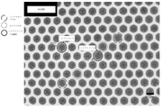
マイクロキャピラリーアレイは最近、例えば「マイクロキャピラリー単一細胞分析およびレーザー抽出」または「μSCALE」と呼ばれるアプローチにおいて、ハイスループット分析および多数の生物学的サンプルを用いたタンパク質工学のためのアプローチに用いられている。Chen et al.(2016)NatureChem.Biol.12:76-81;DOI:10.1038/NCHEMBIO.1978を参照のこと。このアプローチは、マイクロキャピラリーアレイ内の単一細胞の空間的分離に依存しており、したがって、マイクロキャピラリーアレイの各マイクロキャピラリー内の別々のサンプルの画像化、細胞増殖、およびタンパク質発現の繰り返しを可能にする。したがって、この技術は、例えば、アレイ全体に分布した酵母、細菌、または他の適切な細胞から発現される数百万ものタンパク質変異体の分析において、マイクロキャピラリーアレイ内の数百万ものサンプルに対する大規模並列の定量的な生化学的測定および生物物理学的測定を可能にする。有利には、このアプローチは、多重サンプルの同時時間分解動態解析、および標的表現型特徴に基づくそれらの細胞の選別を可能にした。 Microcapillary arrays have recently been used in approaches for high-throughput analysis and protein engineering with large numbers of biological samples, for example in an approach called "microcapillary single-cell analysis and laser extraction" or "μSCALE". there is Chen et al. (2016) Nature Chem. Biol. 12:76-81; DOI: 10.1038/NCHEMBIO. 1978. This approach relies on the spatial separation of single cells within the microcapillary array, thus allowing repeated imaging, cell growth, and protein expression of separate samples within each microcapillary of the microcapillary array. to Thus, this technique is useful for millions of samples in microcapillary arrays, e.g., in the analysis of millions of protein variants expressed from yeast, bacteria, or other suitable cells distributed across the array. Enables scale-parallel quantitative biochemical and biophysical measurements. Advantageously, this approach allowed simultaneous time-resolved kinetic analysis of multiple samples and sorting of those cells based on target phenotypic characteristics.
生物学的変異体の集団の定量的生化学的分析および生物物理学的分析のためのμSCALE法および装置の開発もまた、参照により全体が本明細書に組み込まれる米国特許出願公開2016/0244749A1号に報告されている。しかしながら、μSCALEアプローチによる所望のマイクロキャピラリーの内容物の抽出は、各サンプル中に放射線吸収材料を含めること、およびパルスレーザーからの電磁放射線をこの材料に向けることを必要とし、したがって抽出方法を複雑にする。加えて、所望の結合活性を欠くマイクロキャビティから放出されるシグナルを最小限にするために、マイクロキャビティのアレイ中の生物学的変異体をスクリーニングする初期の方法は、整列したサンプルに微粒子を添加して、サンプル中およびサンプル外への電磁放射線の透過を一部または完全に阻害することに依存していた。米国特許出願公開第2014/0011690A1号を参照のこと。本開示のいくつかの態様において、スクリーニング方法はこれらの追加のサンプル成分または操作に依存せず、したがってスクリーニング技術を単純化し、その効率を向上させる。スクリーニング方法はまた、共に2016年12月12日に出願された米国特許出願第62/433,210号および同第15/376,588号に記載されており、それらの開示はそれらの全体が参照により本明細書に組み込まれる。 Development of the μSCALE method and apparatus for quantitative biochemical and biophysical analysis of populations of biological variants is also incorporated herein by reference in its entirety, US Patent Application Publication No. 2016/0244749A1. reported to. However, extraction of the desired microcapillary contents by the μSCALE approach requires the inclusion of a radiation-absorbing material in each sample and directing the electromagnetic radiation from the pulsed laser to this material, thus complicating the extraction method. do. In addition, an early method for screening biological variants in arrays of microcavities to minimize the signal emitted from microcavities lacking the desired binding activity involved the addition of microparticles to arrayed samples. As such, they have relied on partially or completely blocking the transmission of electromagnetic radiation into and out of the sample. See US Patent Application Publication No. 2014/0011690A1. In some embodiments of the present disclosure, screening methods do not rely on these additional sample components or manipulations, thus simplifying screening techniques and improving their efficiency. Screening methods are also described in U.S. patent application Ser. incorporated herein by.
これらのアプローチの特定の用途において、また本明細書により詳細に開示されるように、標的分子は、粒子(例えば、磁性粒子)、細胞、またはマイクロキャピラリー壁の表面等の表面上に固定化され得る。これらのアプローチにおける変異体タンパク質と標的分子との相互作用は、次いで、検出可能な抗体を利用する方法および標的細胞内で発生した検出可能なシグナルを測定する方法を含むいくつかの方法によって測定され得る。そのような方法は、標的分子、例えば細胞または他の表面上の標的分子に結合するタンパク質変異体を発見するためのハイスループットスクリーニングにおいて使用され得ることが理解されよう。 In particular applications of these approaches, and as disclosed in more detail herein, target molecules are immobilized on surfaces such as the surface of particles (e.g., magnetic particles), cells, or microcapillary walls. obtain. The interaction of the mutant protein with the target molecule in these approaches is then measured by several methods, including methods that utilize detectable antibodies and methods that measure detectable signals generated within target cells. obtain. It will be appreciated that such methods can be used in high-throughput screening to discover protein variants that bind to target molecules, eg, target molecules on cells or other surfaces.
スクリーニング方法
したがって、いくつかの態様において、本開示は、以下のステップを含む変異体タンパク質の集団をスクリーニングする方法を提供する:
複数のマイクロキャピラリーを備え、各マイクロキャピラリーが変異体タンパク質、固定化標的分子、およびレポーターエレメントを含み、変異体タンパク質が特定の親和性で固定化標的分子と会合する、マイクロキャピラリーアレイを提供するステップ、ならびに
少なくとも1つの変異体タンパク質と少なくとも1つの固定化標的分子との会合を示す少なくとも1つのレポーターエレメントからのシグナルを測定して、少なくとも1つの目的のマイクロキャピラリーを同定するステップ。
Screening Methods Accordingly, in some aspects, the present disclosure provides methods of screening a population of mutant proteins comprising the steps of:
providing a microcapillary array comprising a plurality of microcapillaries, each microcapillary comprising a mutant protein, an immobilized target molecule and a reporter element, wherein the mutant protein associates with the immobilized target molecule with a specific affinity. and identifying at least one microcapillary of interest by measuring a signal from at least one reporter element indicative of association of at least one mutant protein with at least one immobilized target molecule.
これらの方法において、マイクロキャピラリーアレイは、好ましくは複数の縦方向に溶融されたキャピラリー、例えば溶融シリカキャピラリーを含むが、任意の他の適切な材料がアレイに用いられてもよい。例えば、参照により全体が本明細書に組み入れられる、PCT国際特許公開第WO2012/007537号および同第WO2014/008056号を参照されたい。そのようなアレイは、例えば、数百万個または数十億個のシリカキャピラリーを結束し、熱プロセスを通してそれらを溶融することによって製造することができるが、他の適切な製造方法も用いることができる。溶融プロセスは、例えば、i)張力下でシングルクラッドファイバに延伸されたキャピラリーシングルドローガラスを加熱するステップと、ii)結束、加熱、および延伸によってシングルドローガラスからキャピラリーマルチドローシングルキャピラリーを作成するステップと、iii)追加の結束、加熱、および延伸によってマルチドローシングルキャピラリーからキャピラリーマルチ-マルチドローマルチキャピラリーを作成するステップと、iv)押圧ブロックに積み重ねることによってマルチ-マルチドローマルチキャピラリーからドローガラスのブロックアセンブリーを作成するステップと、v)熱および圧力で処理することによってブロックアセンブリーからブロック押圧ブロックを作成するステップと、vi)正確な長さ(例えば1mm)でブロック押圧ブロックを切断することによってブロック形成ブロックを作成するステップを含んでもよい。 In these methods, the microcapillary array preferably comprises a plurality of longitudinally fused capillaries, such as fused silica capillaries, although any other suitable material may be used for the array. See, for example, PCT International Patent Publication Nos. WO2012/007537 and WO2014/008056, which are hereby incorporated by reference in their entireties. Such arrays can be manufactured, for example, by bundling millions or billions of silica capillaries and melting them through a thermal process, although other suitable manufacturing methods can also be used. can. The melting process includes, for example, i) heating a capillary single-draw glass that has been drawn into a single-clad fiber under tension, and ii) creating a capillary multi-draw single-capillary from the single-draw glass by bundling, heating, and drawing. and iii) making capillary multi-multi-draw multi-capillaries from multi-draw single capillaries by additional tying, heating, and stretching, and iv) blocks of drawn glass from multi-multi-draw multi-capillaries by stacking on pressing blocks. v) creating a block pressing block from the block assembly by treatment with heat and pressure; vi) cutting the block pressing block at a precise length (e.g. 1 mm). The step of creating a block forming block may be included.
いくつかの実施形態において、製造方法は、シリカキャピラリーをスライスし、それによって非常に高密度のガラスマイクロキャピラリーアレイを形成することをさらに含む。いくつかの実施形態において、マイクロキャピラリーアレイは約1ミリメートルの高さに切断されてもよいが、高さ10μm以下のアレイを含むさらに短いマイクロキャピラリーアレイも企図される。いくつかの実施形態では、1μm、2μm、3μm、4μm、5μm、6μm、7μm、8μm、9μm、または10μmのアレイを含むさらに短いマイクロキャピラリーアレイが企図される。
いくつかの実施形態において、10mm以上のアレイを含むさらに長いマイクロキャピラリーアレイが企図される。いくつかの実施形態では、アレイは、200μm、250μm、300μm、350μm、400μm、450μm、500μm、550μm、600μm、650μm、700μm、750μm、800μm、850μm、900μm、950μm、1mm、2mm、3mm、4mm、5mm、6mm、7mm、8mm、9mm、または10mmの高さである。
In some embodiments, the fabrication method further comprises slicing the silica capillaries, thereby forming very high density glass microcapillary arrays. In some embodiments, microcapillary arrays may be cut to a height of about 1 millimeter, although shorter microcapillary arrays are also contemplated, including arrays of 10 μm or less in height. Shorter microcapillary arrays are contemplated in some embodiments, including 1 μm, 2 μm, 3 μm, 4 μm, 5 μm, 6 μm, 7 μm, 8 μm, 9 μm, or 10 μm arrays.
In some embodiments, even longer microcapillary arrays are contemplated, including arrays of 10 mm or longer. In some embodiments, the array is 200 μm, 250 μm, 300 μm, 350 μm, 400 μm, 450 μm, 500 μm, 550 μm, 600 μm, 650 μm, 700 μm, 750 μm, 800 μm, 850 μm, 900 μm, 950 μm, 1 mm, 2 mm, 3 mm, 4 mm, 5 mm, 6 mm, 7 mm, 8 mm, 9 mm, or 10 mm in height.
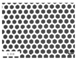
そのようなプロセスは、本方法における使用に適した非常に高密度のマイクロキャピラリーアレイを形成する。例示的なアレイにおいて、各マイクロキャピラリーは、約5μmの直径および約66%の開口空間を有する(すなわち、各マイクロキャピラリーの内腔を表す)。いくつかのアレイでは、開放しているアレイの割合は、約67%の開口面積を有するHamamatsuによって提供されるマイクロキャピラリーアレイのように、約50%~約90%の範囲、例えば約60~75%である。ある特定の例において、直径5μmのマイクロキャピラリーおよび約66%の開口空間を有する10×10cmのアレイは、約3億3000万個のマイクロキャピラリーを有する。 Such processes form very high density microcapillary arrays suitable for use in the present methods. In an exemplary array, each microcapillary has a diameter of about 5 μm and an open space of about 66% (ie, representing the lumen of each microcapillary). In some arrays, the percentage of arrays that are open ranges from about 50% to about 90%, such as the microcapillary arrays provided by Hamamatsu, which have an open area of about 67%, such as about 60-75%. %. In one particular example, a 10×10 cm array with 5 μm diameter microcapillaries and about 66% open space has about 330 million microcapillaries.
種々の実施形態において、アレイ中の各マイクロキャピラリーの内径は、約1μm~500μmの範囲である。いくつかのアレイにおいて、各マイクロキャピラリーは、約1μm~300μm、任意選択的に約1μm~100μm、さらに任意選択的に約1μm~75μm、さらに任意選択的に約1μm~50μm、さらに任意選択的に約5μm~50μmの範囲の内径を有することができる。 In various embodiments, the inner diameter of each microcapillary in the array ranges from about 1 μm to 500 μm. In some arrays, each microcapillary is about 1 μm to 300 μm, optionally about 1 μm to 100 μm, more optionally about 1 μm to 75 μm, more optionally about 1 μm to 50 μm, more optionally It can have an inner diameter in the range of about 5 μm to 50 μm.
いくつかのマイクロキャピラリーアレイにおいて、アレイの開口面積は開口面積(OA)の最大90%を占めるため、孔直径が1μm~500μmの間で変動する場合、アレイ1cm当たりのマイクロキャピラリーの数は約460~1,100万個以上の間で変動する。いくつかのマイクロキャピラリーアレイにおいて、アレイの開口面積は開口面積の約67%を占めるため、孔径が1μm~500μmの間で変動する場合、アレイ1平方cm当たりのマイクロキャピラリーの数は約340~800,000個以上の間で変動する。いくつかの実施形態において、孔径は1μm、5μm、10μm、50μm、100μm、250μm、350または500μmである。いくつかの実施形態において、孔径は5μm~500μmである。いくつかの実施形態において、孔径は10μm~450μmである。いくつかの実施形態において、孔径は50μm~500μmである。いくつかの実施形態において、孔径は100μm~500μmである。いくつかの実施形態において、孔径は250μm~500μmである。いくつかの実施形態において、孔径は350μm~500μmである。いくつかの実施形態において、孔径は100μm~450μmである。いくつかの実施形態において、孔径は250μm~450μmである。
いくつかの実施形態において、アレイ1平方cm当たりのマイクロキャピラリーの数は、約400、500、1000、2,000、3,000、4,000、5,000、6,000、7,000、8,000、9,000、10,000、20,000、50,000、100,000、200,000、300,000、400,000、500,000、600,000、700,000、または800,000個である。いくつかの実施形態において、アレイ1平方cm当たりのマイクロキャピラリーの数は、約500~800,000個の間で変動する。いくつかの実施形態において、アレイ1平方cm当たりのマイクロキャピラリーの数は、約1000~700,000個の間で変動する。いくつかの実施形態において、アレイ1平方cm当たりのマイクロキャピラリーの数は、約2000~600,000個の間で変動する。いくつかの実施形態において、アレイ1平方cm当たりのマイクロキャピラリーの数は、約10,000~800,000個の間で変動する。いくつかの実施形態において、アレイ1平方cm当たりのマイクロキャピラリーの数は、約10,000~700,000個の間で変動する。いくつかの実施形態において、アレイ1平方cm当たりのマイクロキャピラリーの数は、約50,000~800,000個の間で変動する。いくつかの実施形態において、アレイ1平方cm当たりのマイクロキャピラリーの数は、約50,000~700,000個の間で変動する。いくつかの実施形態において、アレイ1平方cm当たりのマイクロキャピラリーの数は、約100,000~700,000個の間で変動する。いくつかの実施形態において、アレイ1平方cm当たりのマイクロキャピラリーの数は、約100,000~600,000個の間で変動する。いくつかの実施形態において、アレイ1平方cm当たりのマイクロキャピラリーの数は、約100,000~500,000個の間で変動する。いくつかの実施形態において、アレイ1平方cm当たりのマイクロキャピラリーの数は、約500,000~800,000個の間で変動する。
In some microcapillary arrays, the open area of the array accounts for up to 90% of the open area (OA), so the number of microcapillaries per cm of array is about 460 when the pore diameter varies between 1 μm and 500 μm. Varies between ~11 million or more. In some microcapillary arrays, the open area of the array accounts for about 67% of the open area, so the number of microcapillaries per square cm of array is about 340-800 when the pore size varies between 1 μm and 500 μm. ,000 or more. In some embodiments, the pore size is 1 μm, 5 μm, 10 μm, 50 μm, 100 μm, 250 μm, 350 or 500 μm. In some embodiments, the pore size is between 5 μm and 500 μm. In some embodiments, the pore size is from 10 μm to 450 μm. In some embodiments, the pore size is between 50 μm and 500 μm. In some embodiments, the pore size is between 100 μm and 500 μm. In some embodiments, the pore size is between 250 μm and 500 μm. In some embodiments, the pore size is between 350 μm and 500 μm. In some embodiments, the pore size is between 100 μm and 450 μm. In some embodiments, the pore size is between 250 μm and 450 μm.
In some embodiments, the number of microcapillaries per square cm of array is about 400, 500, 1000, 2,000, 3,000, 4,000, 5,000, 6,000, 7,000, 8,000, 9,000, 10,000, 20,000, 50,000, 100,000, 200,000, 300,000, 400,000, 500,000, 600,000, 700,000, or 800 ,000. In some embodiments, the number of microcapillaries per square cm of array varies between about 500-800,000. In some embodiments, the number of microcapillaries per square cm of array varies between about 1000 and 700,000. In some embodiments, the number of microcapillaries per square cm of array varies between about 2000 and 600,000. In some embodiments, the number of microcapillaries per square cm of array varies between about 10,000 and 800,000. In some embodiments, the number of microcapillaries per square cm of array varies between about 10,000 and 700,000. In some embodiments, the number of microcapillaries per square cm of array varies between about 50,000 and 800,000. In some embodiments, the number of microcapillaries per square cm of array varies between about 50,000 and 700,000. In some embodiments, the number of microcapillaries per square cm of array varies between about 100,000 and 700,000. In some embodiments, the number of microcapillaries per square cm of array varies between about 100,000 and 600,000. In some embodiments, the number of microcapillaries per square cm of array varies between about 100,000 and 500,000. In some embodiments, the number of microcapillaries per square cm of array varies between about 500,000 and 800,000.
特定の一実施形態において、マイクロキャピラリーアレイは、数十億個のシリカキャピラリーを結合し、次いで熱プロセスを通じてそれらを溶融することによって製造することができる。その後、スライス(0.5mm以上)を切り出して非常に高いアスペクト比のガラスマイクロキャピラリーアレイを形成する。アレイはまた、Hamamatsu Photonics K.K.(日本)、Incom,Inc.(マサチューセッツ州)、Photonis Technologies,S.A.S.(フランス)Inc.等から市販されている。いくつかの実施形態において、アレイのマイクロキャピラリーは、一端において、アレイに付着した固体基材で閉鎖されている。 In one particular embodiment, microcapillary arrays can be manufactured by bonding billions of silica capillaries and then melting them through a thermal process. Slices (>0.5 mm) are then cut to form very high aspect ratio glass microcapillary arrays. Arrays are also available from Hamamatsu Photonics K.K. K. (Japan), Incom, Inc. (Massachusetts), Photonis Technologies, S.M. A. S. (France) Inc. etc. is commercially available. In some embodiments, the microcapillaries of the array are closed at one end with a solid substrate attached to the array.
本スクリーニング方法のマイクロキャピラリーアレイは、アレイ内に任意の数のマイクロキャピラリーを含むことができる。いくつかの実施形態において、マイクロキャピラリーアレイは、少なくとも100,000、少なくとも300,000、少なくとも1,000,000、少なくとも3,000,000、少なくとも10,000,000個、またはさらにそれ以上のマイクロキャピラリーを含む。アレイ内のマイクロキャピラリーの数は、スクリーニングされる変異体タンパク質ライブラリーのサイズを考慮して選択されるのが好ましい。 The microcapillary array of the present screening method can contain any number of microcapillaries within the array. In some embodiments, the microcapillary array comprises at least 100,000, at least 300,000, at least 1,000,000, at least 3,000,000, at least 10,000,000, or even more microcapillaries. Including capillaries. The number of microcapillaries in the array is preferably selected considering the size of the mutant protein library to be screened.
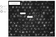
上記のように、本スクリーニング方法で使用されるマイクロキャピラリーアレイ中の各キャピラリーは、変異体タンパク質、固定化標的分子、およびレポーターエレメントを含み、変異体タンパク質はスクリーニング方法に供される変異体タンパク質の集団の1つである。変異体タンパク質の集団は、マイクロキャピラリーアレイ内に適切に分布させることができる任意のタンパク質の集団であり得る。理想的には、各マイクロキャピラリーが少数の異なる変異体タンパク質、好ましくはマイクロキャピラリー当たり単一の異なる変異体タンパク質を含むように、変異体タンパク質の集団がマイクロキャピラリーアレイに分布している。重要なのは、集団内の少なくともいくつかのタンパク質が特定の親和性で固定化標的分子と会合することができ、その結果、レポーターエレメントからのシグナルを測定することによって会合が検出できるように、変異体タンパク質の集団が固定化標的分子と組み合わせて選択されるということである。いくつかの実施形態において、本発明のマイクロキャピラリースクリーニング方法は、マイクロキャピラリーへの成分の添加から数分以内に変異体タンパク質と標的分子との間で起こる反応および/または相互作用(結合相互作用を含む)のスクリーニングを可能にする。いくつかの実施形態において、変異体タンパク質と標的分子との反応および/または相互作用は、約1分~約10分以内に起こる、および/または検出可能である。いくつかの実施形態において、変異体タンパク質と標的分子との反応および/または相互作用は、約1時間~約6時間以内に起こる、および/または検出可能である。いくつかの実施形態において、変異体タンパク質と標的分子との反応および/または相互作用は、マイクロキャピラリー内の細胞が生存し、かつ健康であるような期間内に起こる、および/または検出可能である。いくつかの実施形態において、変異体タンパク質と標的分子との反応および/または相互作用は、マイクロキャピラリー内の細胞が生存可能であるような期間内に起こる、および/または検出可能である。いくつかの実施形態において、細胞は、マイクロキャピラリーおよび/またはマイクロキャビティから取り出した後に増殖させることができる。いくつかの実施形態において、細胞は、マイクロキャピラリーおよび/またはマイクロキャビティから取り出した後に生存可能である。いくつかの実施形態において、変異体タンパク質と標的分子との反応および/または相互作用はマイクロキャピラリー内で起こる。 As described above, each capillary in the microcapillary array used in the present screening method contains a mutant protein, an immobilized target molecule, and a reporter element, wherein the mutant protein is the mutant protein to be subjected to the screening method. One of the group. The population of mutant proteins can be any population of proteins that can be appropriately distributed within the microcapillary array. Ideally, the population of mutant proteins is distributed in the microcapillary array such that each microcapillary contains a small number of different mutant proteins, preferably a single different mutant protein per microcapillary. Importantly, mutants are selected such that at least some of the proteins in the population are capable of associating with the immobilized target molecule with a particular affinity such that the association can be detected by measuring the signal from the reporter element. That is, a population of proteins is selected in combination with immobilized target molecules. In some embodiments, the microcapillary screening methods of the invention provide for reactions and/or interactions (binding interactions) to occur between the mutant protein and the target molecule within minutes of addition of the components to the microcapillary. including). In some embodiments, the reaction and/or interaction of the mutant protein with the target molecule occurs and/or is detectable within about 1 minute to about 10 minutes. In some embodiments, the reaction and/or interaction of the mutant protein with the target molecule occurs and/or is detectable within about 1 hour to about 6 hours. In some embodiments, the reaction and/or interaction of the mutant protein with the target molecule occurs and/or is detectable within a period of time such that the cells within the microcapillary are alive and healthy. . In some embodiments, the reaction and/or interaction of the mutant protein with the target molecule occurs and/or is detectable within a period of time such that the cells within the microcapillary are viable. In some embodiments, cells can be expanded after being removed from the microcapillary and/or microcavity. In some embodiments, the cells are viable after removal from the microcapillary and/or microcavity. In some embodiments, the reaction and/or interaction between the mutant protein and target molecule occurs within a microcapillary.
本明細書で使用される「タンパク質」という用語は、全長タンパク質またはポリペプチド配列の両方、およびその断片を指す。そのような断片は、例えば、結合活性等の機能的活性を保持する断片を含み得る。用語「タンパク質」および「ポリペプチド」は、本開示を通して互換的に使用され、ペプチド結合を介して共有結合したアミノ酸の鎖を含み、ポリペプチド中の各アミノ酸は「アミノ酸残基」と称され得る。用語「タンパク質」または「ポリペプチド」の使用は、いずれか特定の長さのポリペプチド、例えば、いずれか特定の数のアミノ酸残基に限定されるとみなされるべきではない。主題のタンパク質は、グリコシル化、アセチル化、リン酸化、硫酸化等を含む翻訳後修飾等の非ペプチド修飾、またはアルキル化、アセチル化、エステル化、PEG化等の他の化学修飾を有するタンパク質を含み得る。ポリペプチド配列内の非天然アミノ酸の包含またはアミノ酸残基間の非ペプチド結合等のさらなる修飾もまた、用語「タンパク質」または「ポリペプチド」の定義の範囲内で考慮されるべきである。 The term "protein" as used herein refers to both full-length protein or polypeptide sequences, and fragments thereof. Such fragments may include, for example, fragments that retain functional activity such as binding activity. The terms "protein" and "polypeptide" are used interchangeably throughout this disclosure and include a chain of amino acids covalently linked via peptide bonds, each amino acid in a polypeptide can be referred to as an "amino acid residue." . Use of the terms "protein" or "polypeptide" should not be construed as limited to polypeptides of any particular length, eg, any particular number of amino acid residues. The subject proteins include proteins with non-peptide modifications such as post-translational modifications including glycosylation, acetylation, phosphorylation, sulfation, etc., or other chemical modifications such as alkylation, acetylation, esterification, pegylation. can contain. Further modifications such as the inclusion of non-natural amino acids within the polypeptide sequence or non-peptide bonds between amino acid residues should also be considered within the definition of the terms "protein" or "polypeptide".
変異体タンパク質の集団は、好ましくは、小さな変異を有するタンパク質の集団、例えば、各タンパク質がわずかに異なるアミノ酸配列を有するタンパク質の集団である。したがって、スクリーニングアッセイは、望ましい特性を有する変異体タンパク質配列を同定することができる。スクリーニングは顕微鏡規模で非常に大量に行うことができるため、膨大な数の変異体タンパク質を比較的短時間でアッセイすることができる。いくつかの実施形態では、スクリーニングプロセスは4時間~6時間以内に実施される。いくつかの実施形態では、スクリーニングプロセスは4時間、5時間、または6時間以内に実施される。いくつかの実施形態では、スクリーニングプロセスは、マイクロキャピラリー(すなわち、キャビティ、マイクロキャピラリー、マイクロキャビティ、ポア、および/またはマイクロポア)あたり1~3秒を要する。いくつかの実施形態では、スクリーニングプロセスは、マイクロキャピラリー(すなわち、キャビティ、マイクロキャピラリー、マイクロキャビティ、ポア、および/またはマイクロポア)あたり約1秒を要する。いくつかの実施形態では、スクリーニングプロセスは、マイクロキャピラリー(すなわち、キャビティ、マイクロキャピラリー、マイクロキャビティ、ポア、および/またはマイクロポア)あたり約2秒を要する。いくつかの実施形態では、スクリーニングプロセスは、マイクロキャピラリー(すなわち、キャビティ、マイクロキャピラリー、マイクロキャビティ、ポア、および/またはマイクロポア)あたり約3秒を要する。 A population of variant proteins is preferably a population of proteins with minor variations, eg, proteins in which each protein has a slightly different amino acid sequence. Thus, screening assays can identify mutant protein sequences that have desirable properties. Screens can be performed on a microscopic scale in very large quantities, allowing a large number of mutant proteins to be assayed in a relatively short period of time. In some embodiments, the screening process is performed within 4-6 hours. In some embodiments, the screening process is performed within 4, 5, or 6 hours. In some embodiments, the screening process takes 1-3 seconds per microcapillary (ie, cavity, microcapillary, microcavity, pore, and/or micropore). In some embodiments, the screening process takes about 1 second per microcapillary (ie, cavity, microcapillary, microcavity, pore, and/or micropore). In some embodiments, the screening process takes about 2 seconds per microcapillary (ie, cavity, microcapillary, microcavity, pore, and/or micropore). In some embodiments, the screening process takes about 3 seconds per microcapillary (ie, cavity, microcapillary, microcavity, pore, and/or micropore).
いくつかの実施形態において、マイクロキャピラリーアレイ中の各マイクロキャピラリーは、変異体タンパク質の集団由来の0~5個の異なる変異体タンパク質を含む。特定の実施形態において、マイクロキャピラリーアレイ中の各マイクロキャピラリーは、変異体タンパク質の集団由来の0~4、0~3、0~2、またはさらには0~1個の異なる変異体タンパク質を含む。変異体タンパク質の集団中の異なる変異体タンパク質は、それらのアミノ酸配列またはタンパク質の他の何らかの化学修飾に相違点があるかどうかにかかわらず、それらの分子構造が異なることを理解されたい。 In some embodiments, each microcapillary in the microcapillary array contains 0-5 different mutant proteins from the population of mutant proteins. In certain embodiments, each microcapillary in the microcapillary array comprises 0-4, 0-3, 0-2, or even 0-1 different mutant proteins from the population of mutant proteins. It is understood that different variant proteins in a population of variant proteins differ in their molecular structure, whether they differ in their amino acid sequences or in any other chemical modification of the proteins.
各マイクロキャピラリーは、特定の変異体タンパク質の起源および発現レベルに応じて、典型的には、同じ変異体タンパク質の多くの複数のコピーを含むことを理解されたい(下記参照)。いくつかの実施形態において、各マイクロキャピラリーは、変異体タンパク質がマイクロキャピラリーにどのように送達されるかまたはその中でどのように発現されるかに応じて、特定の変異体タンパク質の数千、数万、数十万、数百万、数十億個、またはさらにはそれ以上の分子を含む。 It is understood that each microcapillary typically contains many multiple copies of the same mutant protein, depending on the origin and expression level of the particular mutant protein (see below). In some embodiments, each microcapillary contains thousands of specific mutant proteins, depending on how the mutant proteins are delivered to the microcapillary or expressed therein. Contains tens of thousands, hundreds of thousands, millions, billions or even more molecules.
変異体タンパク質の集団は、典型的には、生物学的発現系、例えばインビトロ(すなわち無細胞)発現系またはインビボもしくは細胞発現系において遺伝子ライブラリーを用いて生成される。例示的な細胞発現系として、例えば、動物系(例えば、哺乳動物系)、真菌系(例えば、酵母系)、細菌系、昆虫系、または植物系が挙げられる。特定の実施形態において、発現系は哺乳動物系または酵母系である。発現系は、細胞性であれ無細胞性であれ、典型的には、変異体タンパク質の集団をコードする遺伝物質のライブラリーを含む。細胞発現系は、望ましい表現型を有する細胞、例えば、固定化標的分子と高い親和性で会合することができる変異体タンパク質等の特定の目的の変異体タンパク質を発現する細胞を成長および増殖させることができるという利点を提供し、したがって、細胞によって発現される目的のタンパク質の同定および特徴付けを単純化する。 Populations of variant proteins are typically generated using gene libraries in biological expression systems, such as in vitro (ie, cell-free) expression systems or in vivo or cellular expression systems. Exemplary cell expression systems include, for example, animal systems (eg, mammalian systems), fungal systems (eg, yeast systems), bacterial systems, insect systems, or plant systems. In certain embodiments, the expression system is a mammalian or yeast system. Expression systems, whether cellular or cell-free, typically include a library of genetic material that encodes a population of mutant proteins. Cellular expression systems are used to grow and propagate cells with a desired phenotype, e.g., cells expressing a particular mutant protein of interest, such as a mutant protein capable of associating with an immobilized target molecule with high affinity. , thus simplifying the identification and characterization of proteins of interest expressed by cells.
大規模な変異体タンパク質の集団をコードする遺伝子ライブラリーは、生物工学の分野で周知である。そのようなライブラリーは、標的分子への高親和性結合、安定性、高発現、または特定の分光学的活性、例えば、蛍光もしくは酵素活性等の有利な特性を有するタンパク質を同定するための定向進化のプロセスに依存するシステムにおいてしばしば利用される。多くの場合、ライブラリーは、宿主発現系由来の配列との遺伝的融合、例えば、亜細胞局在化を指示するタンパク質の断片を含み、変異体融合タンパク質の発現集団は、変異体タンパク質集団の活性スクリーニングのために、標的断片によって細胞またはウイルス粒子の特定の位置に向けられる。当技術分野で周知のように、日常的な生物工学技術を使用して、多数の変異体タンパク質(例えば、106変異体、108変異体、1010変異体、1012変異体、またはさらにはそれ以上の変異体)を生成することができる。そのようなライブラリーは、抗体、抗体断片、一本鎖可変断片、または天然タンパク質リガンドを含む、本明細書に記載の変異体タンパク質のうちのいずれかを含み得る。 Gene libraries encoding large collections of mutant proteins are well known in the field of biotechnology. Such libraries are targeted for identifying proteins with advantageous properties such as high affinity binding to target molecules, stability, high expression, or specific spectroscopic activity, such as fluorescence or enzymatic activity. It is often used in systems that rely on evolutionary processes. Libraries often contain genetic fusions with sequences derived from a host expression system, e.g., fragments of proteins that direct subcellular localization, and an expressed population of mutant fusion proteins is derived from a population of mutant proteins. For activity screening, targeting fragments are directed to specific locations in cells or virus particles. As is well known in the art, large numbers of mutant proteins (e.g., 10 6 mutants, 10 8 mutants, 10 10 mutants, 10 12 mutants, or even can generate further variants). Such libraries can contain any of the variant proteins described herein, including antibodies, antibody fragments, single chain variable fragments, or natural protein ligands.
したがって、いくつかの実施形態において、変異体タンパク質は可溶性タンパク質、例えば、細胞発現系によって分泌される可溶性タンパク質である。例示的な可溶性変異体タンパク質として、抗体および抗体断片、ジスルフィド結合したペプチド足場等の代替タンパク質足場、細胞表面受容体タンパク質の細胞外ドメイン、例えばGタンパク質共役受容体リガンド等の受容体リガンド、他のペプチドホルモン、レクチン等が挙げられる。有利には、所望の結合活性を有する変異体タンパク質およびそれを発現した細胞は、アッセイを通して同じマイクロキャピラリー内に共局在するため、本方法において結合活性についてスクリーニングされる変異体タンパク質は、スクリーニングアッセイ後に同定されるためにそれらを発現する細胞またはウイルスに共有結合される必要がない。所望のマイクロキャピラリーの内容物の単離、それに続く所望の変異体タンパク質の発現に関与する細胞またはウイルスクローンの増殖は、それによってそのタンパク質の同定および特徴付けを可能にする。細胞またはウイルス粒子の表面上の分子へのタンパク質の融合によって目的の変異体タンパク質が提示されるスクリーニングアッセイとは異なり、本スクリーニング方法で同定される変異体タンパク質は、それらの同定後にまったく変更される必要がない。したがって、スクリーニングにおいて観察される変異体タンパク質の活性は、それらの後の用途におけるそれらのタンパク質の実際の活性を表す可能性がより高い。 Thus, in some embodiments, the variant protein is a soluble protein, eg, a soluble protein that is secreted by a cellular expression system. Exemplary soluble variant proteins include antibodies and antibody fragments, alternative protein scaffolds such as disulfide-bonded peptide scaffolds, extracellular domains of cell surface receptor proteins, receptor ligands such as G protein-coupled receptor ligands, and others. Peptide hormones, lectins and the like can be mentioned. Advantageously, the mutant protein to be screened for binding activity in the present method will be screened for binding activity in the screening assay because the mutant protein with the desired binding activity and the cell expressing it will co-localize within the same microcapillary throughout the assay. They need not be covalently linked to the cells or viruses expressing them in order to be later identified. Isolation of the desired microcapillary contents, followed by propagation of cells or viral clones responsible for expression of the desired mutant protein, thereby permitting identification and characterization of that protein. Unlike screening assays in which mutant proteins of interest are presented by fusion of the protein to a molecule on the surface of a cell or virus particle, the mutant proteins identified in the present screening methods are completely altered after their identification. No need. Therefore, the activity of mutant proteins observed in the screen is more likely to represent the actual activity of those proteins in their subsequent application.
しかしながら、他の実施形態において、変異体タンパク質が膜結合性タンパク質、例えば、発現系において細胞またはウイルス粒子の表面と結合したままのタンパク質であることが望ましい場合がある。細胞結合性変異体タンパク質のスクリーニングは、変異体タンパク質およびその標的分子が生体組織内の2つの細胞間の相互作用を媒介する場合に望ましい可能性がある。また、細胞結合性変異体タンパク質に対してスクリーニングする能力は、例えば、Gタンパク質共役受容体またはイオンチャネル等の従来的に「新薬の開発につながらない」タンパク質標的との相互作用についてスクリーニングする際にも望ましい場合がある。 However, in other embodiments it may be desirable for the variant protein to be a membrane-bound protein, eg, a protein that remains associated with the surface of cells or virus particles in the expression system. Screening for cell-binding mutant proteins may be desirable if the mutant protein and its target molecule mediate an interaction between two cells within a living tissue. The ability to screen against cell-associated mutant proteins is also useful when screening for interactions with traditionally "non-drugable" protein targets such as, for example, G protein-coupled receptors or ion channels. may be desirable.
変異体タンパク質に加えて、本スクリーニング方法のマイクロキャピラリーアレイ中の各マイクロキャピラリーは、固定化標的分子も含む。固定化標的分子は、スクリーニングアッセイの変異体タンパク質に対する潜在的結合パートナーとして機能する。各マイクロキャピラリーが理想的にはわずかに異なる配列の変異体タンパク質を含む変異体タンパク質の集団とは異なり、固定化された標的分子は、理想的にはアレイの各マイクロキャピラリー中に同じ分子構造を有する。 In addition to mutant proteins, each microcapillary in the microcapillary array of the screening method also contains an immobilized target molecule. Immobilized target molecules serve as potential binding partners for mutant proteins in screening assays. Unlike populations of mutant proteins, where each microcapillary ideally contains slightly different sequence mutant proteins, the immobilized target molecules ideally have the same molecular structure in each microcapillary of the array. have.
いくつかの実施形態において、標的分子は、標的タンパク質もしくはポリペプチド、標的核酸、標的炭水化物、標的脂質、またはこれらの標的分子の2つ以上の組み合わせである。例えば、いくつかの実施形態において、標的分子は脂質修飾タンパク質またはグリコシル化タンパク質であり得る。いくつかの実施形態において、標的分子は表面上に固定化される。より具体的な実施形態において、標的分子は、標的細胞等の細胞の表面、ビーズの表面、マイクロキャピラリー壁の表面、または別の適切な表面上に固定化される。他のより具体的な実施形態において、標的分子は天然タンパク質、例えば、細胞の表面上に固定化された天然タンパク質である。さらに他のより具体的な実施形態において、標的分子は、重力沈降によってマイクロキャピラリー中に沈殿するように構成される表面上に固定化される。 In some embodiments, the target molecule is a target protein or polypeptide, target nucleic acid, target carbohydrate, target lipid, or a combination of two or more of these target molecules. For example, in some embodiments the target molecule can be a lipid-modified or glycosylated protein. In some embodiments, target molecules are immobilized on a surface. In more specific embodiments, the target molecule is immobilized on the surface of a cell, such as a target cell, the surface of a bead, the surface of a microcapillary wall, or another suitable surface. In other more specific embodiments, the target molecule is a native protein, eg, a native protein immobilized on the surface of a cell. In yet another more specific embodiment, the target molecule is immobilized on a surface configured to settle into the microcapillary by gravitational sedimentation.
前述のように、本開示の方法において、変異体タンパク質は、マイクロキャピラリー内で特定の親和性で固定化標的分子と会合する。重要なのは、会合がレポーターエレメントからのシグナルによって測定され得るように、そのような親和性は目的の変異体タンパク質に対して十分に強くなければいけないということである。当業者には十分に理解されるように、結合親和性は、典型的には解離定数(Kd)によって評価され、解離定数が低いほど親和性が高い。いくつかの実施形態において、目的の変異体タンパク質と固定化標的分子との会合は、ミリモルからマイクロモルの範囲の解離定数を示す。特定の実施形態において、会合は、マイクロモルから高ナノモル(すなわち、10-6M~10-8M)の解離定数を示す。より具体的な実施形態において、会合は、低ナノモルから高ピコモル(すなわち、10-8M~10-10M)の解離定数を示す。さらにより具体的な実施形態において、会合は、ピコモル範囲(すなわち、10-10M~10-12M)、またはさらに低い解離定数を示す。いくつかの実施形態において、第1の細胞は変異体タンパク質またはポリペプチドを発現および分泌し、第2の細胞は標的を含み、その結果、第1の細胞が第2の細胞に結合する。いくつかの実施形態において、第2の細胞は標的を発現する。いくつかの実施形態において、第2の細胞は標的で標識される。いくつかの実施形態において、第1の細胞はマイクロキャピラリー中の第2の細胞に結合する。いくつかの実施形態において、第1の細胞は、マイクロキャピラリーおよび/またはマイクロキャビティ中の第2の細胞に結合する。 As described above, in the methods of the present disclosure, mutant proteins associate with immobilized target molecules with specific affinities within microcapillaries. Importantly, such affinity must be strong enough for the mutant protein of interest so that association can be measured by the signal from the reporter element. As is well understood by those of skill in the art, binding affinity is typically measured by a dissociation constant (K d ), with lower dissociation constants indicating higher affinity. In some embodiments, the association of the mutant protein of interest with the immobilized target molecule exhibits dissociation constants in the millimolar to micromolar range. In certain embodiments, associations exhibit micromolar to high nanomolar (ie, 10 −6 M to 10 −8 M) dissociation constants. In more specific embodiments, the association exhibits dissociation constants from low nanomolar to high picomolar (ie, 10 −8 M to 10 −10 M). In even more specific embodiments, the association exhibits dissociation constants in the picomolar range (ie, 10 −10 M to 10 −12 M), or even lower. In some embodiments, the first cell expresses and secretes the mutant protein or polypeptide and the second cell contains the target such that the first cell binds to the second cell. In some embodiments, the second cell expresses the target. In some embodiments, the second cell is labeled with a target. In some embodiments, a first cell binds to a second cell in a microcapillary. In some embodiments, a first cell binds to a second cell in a microcapillary and/or microcavity.
いくつかの実施形態において、標的分子は、標的タンパク質もしくはポリペプチド、標的核酸、標的炭水化物、標的脂質、またはこれらの標的分子の2つ以上の組み合わせである。例えば、いくつかの実施形態において、標的分子は脂質修飾タンパク質またはグリコシル化タンパク質であり得る。いくつかの実施形態において、標的分子は表面上に固定化される。より具体的な実施形態において、標的分子は、標的細胞等の細胞の表面、ビーズの表面、マイクロキャピラリー壁の表面、または別の適切な表面上に固定化される。他のより具体的な実施形態において、標的分子は天然タンパク質、例えば、細胞の表面上に固定化された天然タンパク質である。さらに他のより具体的な実施形態において、標的分子は、重力沈降によってマイクロキャピラリー中に沈殿するように構成される表面上に固定化される。いくつかの実施形態において、1、2、3、もしくは4つ、またはそれ以上の標的分子に結合する変異体を同定するために、1、2、3、もしくは4つ、またはそれ以上の標的分子が用いられる。いくつかの実施形態において、標的分子は、別々の異なるマイクロキャピラリーに別々に含まれる。いくつかの実施形態において、標的分子は、単一アレイ内の別々の異なるマイクロキャピラリーに別々に含まれる。いくつかの実施形態において、標的分子は、1つ以上のアレイ内の別々の異なるマイクロキャピラリーに別々に含まれる。いくつかの実施形態において、標的分子は単一マイクロキャピラリーに一緒に含まれる。いくつかの実施形態において、標的分子は単一アレイ内の単一マイクロキャピラリーに一緒に含まれる。いくつかの実施形態において、変異体が結合する1、2、3、もしくは4つ、またはそれ以上の標的分子は、化学修飾、二次翻訳後修飾、または配列同一性変異体(例えば、元の核酸またはアミノ酸標的配列に対して70%、75%、80%、85%、90%、95%、または99%の配列同一性を有する変異体を含む)を含む、元の標的分子の誘導体または変異体である。 In some embodiments, the target molecule is a target protein or polypeptide, target nucleic acid, target carbohydrate, target lipid, or a combination of two or more of these target molecules. For example, in some embodiments the target molecule can be a lipid-modified or glycosylated protein. In some embodiments, target molecules are immobilized on a surface. In more specific embodiments, the target molecule is immobilized on the surface of a cell, such as a target cell, the surface of a bead, the surface of a microcapillary wall, or another suitable surface. In other more specific embodiments, the target molecule is a native protein, eg, a native protein immobilized on the surface of a cell. In yet another more specific embodiment, the target molecule is immobilized on a surface configured to settle into the microcapillary by gravitational sedimentation. In some embodiments, 1, 2, 3, or 4 or more target molecules are analyzed to identify variants that bind to 1, 2, 3, or 4 or more target molecules. is used. In some embodiments, the target molecules are separately contained in separate, distinct microcapillaries. In some embodiments, the target molecules are separately contained in separate different microcapillaries within a single array. In some embodiments, the target molecules are separately contained in separate different microcapillaries within one or more arrays. In some embodiments, the target molecules are contained together in a single microcapillary. In some embodiments, the target molecules are contained together in a single microcapillary within a single array. In some embodiments, the 1, 2, 3, or 4 or more target molecules to which the variant binds are chemical modifications, secondary post-translational modifications, or sequence identity variants (e.g., original derivatives of the original target molecule, including variants having 70%, 75%, 80%, 85%, 90%, 95% or 99% sequence identity to the nucleic acid or amino acid target sequence; Mutant.
変異体タンパク質および固定化標的分子に加えて、本スクリーニング方法のマイクロキャピラリーアレイ中の各マイクロキャピラリーは、レポーターエレメントも含む。重要なのは、レポーターエレメントが変異体タンパク質と固定化標的分子との会合を示す測定可能なシグナルを提供し、したがって目的の変異体タンパク質を含むマイクロキャピラリーを特定する役割を果たすということである。 In addition to mutant proteins and immobilized target molecules, each microcapillary in the microcapillary array of the screening method also contains a reporter element. Importantly, the reporter element provides a measurable signal indicating the association of the mutant protein with the immobilized target molecule and thus serves to identify the microcapillary containing the mutant protein of interest.
いくつかの実施形態において、レポーターエレメントは、変異体タンパク質の集団中の各変異体タンパク質に結合することができる標識抗体または他の分子である。より具体的には、レポーターエレメントは、蛍光標識抗体または他の結合分子である。 In some embodiments, the reporter element is a labeled antibody or other molecule capable of binding each variant protein in the population of variant proteins. More specifically, the reporter element is a fluorescently labeled antibody or other binding molecule.
いくつかの実施形態において、標識抗体は、標識一次抗体または標識二次抗体である。本開示の目的のために、一次抗体は、典型的には、目的の抗原に直接結合する抗体であると考えられ、二次抗体は、典型的には、一次抗体標識の目的で一次抗体上の定常領域に結合する抗体であると考えられる。したがって、二次抗体は、フルオロフォアもしくは他の検出可能な標識で頻繁に標識されるか、または検出可能なシグナルを発生させることができる酵素で標識される。それらは概して、異なる種に由来する一次抗体に特異的である。例えば、当業者には理解されるように、ヤギまたは他の動物種が、マウス、ニワトリ、ウサギ、またはその動物種由来の抗体以外のほぼあらゆる一次抗体に対する二次抗体を生成するために使用され得る。特定の実施形態において、標識抗体は蛍光抗体または酵素結合抗体である。いくつかの実施形態において、フルオロフォアは、AlexaFluor3、AlexaFluor5、AlexaFluor350、AlexaFluor405、AlexaFluor430、AlexaFluor488、AlexaFluor500、AlexaFluor514、AlexaFluor532、AlexaFluor546、AlexaFluor555、AlexaFluor568、AlexaFluor594、AlexaFluor610、AlexaFluor633、AlexaFluor647、AlexaFluor660、AlexaFluor680、AlexaFluor700、およびAlexaFluor750(Life Technologies,Inc.(USA)から入手可能なMolecular Probes AlexaFluor色素)を含み得るが、これらに限定されない。いくつかの実施形態において、フルオロフォアは、Cy2、Cy3、Cy3B、Cy3.5、Cy5、Cy5.5およびCy7(GE Life SciencesまたはLumiprobesから入手可能)を含む、Cy色素を含み得るが、これらに限定されない。いくつかの実施形態において、フルオロフォアは、DyLight350、DyLight405、DyLight488、DyLight550、DyLight594、DyLight633、DyLight650、DyLight680、DyLight750およびDyLight800(Thermo Scientific(USA)から入手可能)を含み得るが、これらに限定されない。いくつかの実施形態において、フルオロフォアは、FluoProbes390、FluoProbes488、FluoProbes532、FluoProbes547H、FluoProbes594、FluoProbes647H、FluoProbes682、FluoProbes752およびFluoProbes782、AMCA、DEAC(7-ジエチルアミノクマリン-3-カルボン酸);7-ヒドロキシ-4-メチルクマリン-3;7-ヒドロキシクマリン-3;MCA(7-メトキシクマリン-4-酢酸);7-メトキシクマリン-3;AMF(4’-(アミノメチル)フルオレセイン);5-DTAF(5-(4,6-ジクロロトリアジニル)アミノフルオレセイン);6-DTAF(6-(4,6-ジクロロトリアジニル)アミノフルオレセイン);6-FAM(6-カルボキシフルオレセイン)、5(6)-FAMカダベリン;5-FAMカダベリン;5(6)-FAMエチレンジアミン;5-FAMエチレンジアミン;5-FITC(FITC異性体I;フルオレセイン-5-イソチオシアネート);5-FITCカダベリン;フルオレセイン-5-マレイミド;5-IAF(5-ヨードアセトアミドフルオレセイン);6-JOE(6-カルボキシ-4’,5’-ジクロロ-2’,7’-ジメトキシフルオレセイン);5-CRl l0(5-カルボキシローダミン110);6-CRl l0(6-カルボキシローダミン110);5-CR6G(5-カルボキシローダミン6G);6-CR6G(6-カルボキシローダミン6G);5(6)-カルボキシローダミン6Gカダベリン;5(6)-カルボキシローダミン6Gエチレンジアミン;5-ROX(5-カルボキシ-X-ローダミン);6-ROX(6-カルボキシ-X-ローダミン);5-TAMRA(5-カルボキシテトラメチルローダミン);6-TAMRA(6-カルボキシテトラメチルローダミン);5-TAMRAカダベリン;6-TAMRAカダベリン;5-TAMRAエチレンジアミン;6-TAMRAエチレンジアミン;5-TMR C6マレイミド;6-TMR C6マレイミド;TR C2マレイミド;TRカダベリン;5-TRITC;G異性体(テトラメチルローダミン-5-イソチオシアネート);6-TRITC;R異性体(テトラメチルローダミン-6-イソチオシアネート);ダンシルカダベリン(5-ジメチルアミノナフタレン-l-(N-(5-アミノペンチル))スルホンアミド);EDANS C2マレイミド;フルオレサミン;NBD;およびピロメテン、ならびにそれらの誘導体を含み得るが、これらに限定されない。いくつかの実施形態において、使用されるレポーターエレメントは、AlexaFluor633で標識されたロバ抗ヤギIgG二次抗体であり得る。 In some embodiments, the labeled antibody is a labeled primary antibody or a labeled secondary antibody. For the purposes of this disclosure, a primary antibody is typically considered to be an antibody that directly binds to an antigen of interest, and a secondary antibody is typically considered to be an antibody that binds directly to the antigen of interest, and a secondary antibody is typically It is thought to be an antibody that binds to the constant region of Thus, secondary antibodies are frequently labeled with a fluorophore or other detectable label, or labeled with an enzyme capable of generating a detectable signal. They are generally specific to primary antibodies from different species. For example, as will be appreciated by those of skill in the art, goats or other animal species can be used to generate secondary antibodies to nearly any primary antibody other than those derived from mice, chickens, rabbits, or those animal species. obtain. In certain embodiments, the labeled antibody is a fluorescent antibody or an enzyme-linked antibody.いくつかの実施形態において、フルオロフォアは、AlexaFluor3、AlexaFluor5、AlexaFluor350、AlexaFluor405、AlexaFluor430、AlexaFluor488、AlexaFluor500、AlexaFluor514、AlexaFluor532、AlexaFluor546、AlexaFluor555、AlexaFluor568、AlexaFluor594、AlexaFluor610、AlexaFluor633、AlexaFluor647、AlexaFluor660、AlexaFluor680、AlexaFluor700、およびAlexaFluor 750 (Molecular Probes AlexaFluor dye available from Life Technologies, Inc. (USA)), but not limited thereto. In some embodiments, fluorophores can include Cy dyes, including Cy2, Cy3, Cy3B, Cy3.5, Cy5, Cy5.5 and Cy7 (available from GE Life Sciences or Lumiprobes), including Not limited. In some embodiments, the fluorophores include DyLight350, DyLight405, DyLight488, DyLight550, DyLight594, DyLight633, DyLight650, DyLight680, DyLight750 and DyLight800 (available from Thermo Scientific, but not limited to, USA).いくつかの実施形態において、フルオロフォアは、FluoProbes390、FluoProbes488、FluoProbes532、FluoProbes547H、FluoProbes594、FluoProbes647H、FluoProbes682、FluoProbes752およびFluoProbes782、AMCA、DEAC(7-ジエチルアミノクマリン-3-カルボン酸);7-ヒドロキシ-4- Methylcoumarin-3; 7-hydroxycoumarin-3; MCA (7-methoxycoumarin-4-acetic acid); 7-methoxycoumarin-3; AMF (4′-(aminomethyl)fluorescein); 5-DTAF (5-( 4,6-dichlorotriazinyl)aminofluorescein); 6-DTAF (6-(4,6-dichlorotriazinyl)aminofluorescein); 6-FAM (6-carboxyfluorescein), 5(6)-FAM cadaverine 5-FAM cadaverine; 5(6)-FAM ethylenediamine; 5-FAM ethylenediamine; 5-FITC (FITC isomer I; fluorescein-5-isothiocyanate); 5-FITC cadaverine; fluorescein-5-maleimide; (5-iodoacetamidofluorescein); 6-JOE (6-carboxy-4′,5′-dichloro-2′,7′-dimethoxyfluorescein); 5-CRl 10 (5-carboxyrhodamine 110); 6-CRl 10 (6-Carboxyrhodamine 110); 5-CR6G (5-Carboxyrhodamine 6G); 6-CR6G (6-Carboxyrhodamine 6G); 5(6)-Carboxyrhodamine 6G Cadaverine; 5(6)-Carboxyrhodamine 6G Ethylenediamine; 5-ROX (5-carboxy-X-rhodamine); 6-ROX (6-carboxy-X-rhodamine); 5-TAMRA (5-carboxytetramethylrhodamine); 6-TAMRA (6-carboxytetramethylrhodamine); 5-TAMRA cadaverine; 6-TAMRA cadaverine; 5-TAMRA ethylenediamine; 6-TAMRA ethylenediamine; 5-TMR C6 maleimide; 6-TMR C6 maleimide; -5-isothiocyanate); 6-TRITC; R isomer (tetramethylrhodamine-6-isothiocyanate) dansylcadaverine (5-dimethylaminonaphthalene-1-(N-(5-aminopentyl))sulfonamide); EDANS C2 maleimide; fluorescamine; NBD; . In some embodiments, the reporter element used can be a donkey anti-goat IgG secondary antibody labeled with AlexaFluor633.
本方法の実施形態のいくつかにおいて、例えば、図1A~1Cに示されるスクリーニング方法では、変異体タンパク質はレポーターエレメントと標的分子、この例では標的細胞の表面上の標的分子との会合を媒介する。図1Bに示すように、変異体タンパク質(ここでは「分泌タンパク質」と表される)が標的細胞上のその標的分子に対して十分な親和性を有する場合、変異体タンパク質は、マイクロキャピラリー溶液の条件下で標的細胞と会合する。レポーターエレメント(ここでは「蛍光検出抗体」と表される)は、理想的には、図1Cに示すように、標的分子に対する変異体タンパク質の親和性に影響を及ぼさないエピトープで変異体タンパク質に結合する。 In some embodiments of the method, for example, the screening method shown in FIGS. 1A-1C, the mutant protein mediates the association of the reporter element with the target molecule, in this example the target molecule on the surface of the target cell. . As shown in FIG. 1B, if a mutant protein (herein referred to as a “secreted protein”) has sufficient affinity for its target molecule on the target cell, the mutant protein is released into the microcapillary solution. Associates with target cells under certain conditions. The reporter element (here denoted as "fluorescence detection antibody") ideally binds to the mutant protein at an epitope that does not affect the affinity of the mutant protein for the target molecule, as shown in Figure 1C. do.
当業者には理解されるように、蛍光抗体等の可溶性レポーターエレメントが本スクリーニング方法において使用される場合、マイクロキャピラリー内の溶液中に遊離したままの(すなわち、変異体タンパク質に結合していないか、または標的分子に結合していない変異体タンパク質に結合しているかのいずれか)任意の過剰なレポーターエレメントによって放出されるシグナルは、変異体タンパク質を介して標的分子と会合したレポーターエレメントのシグナルを圧倒するほど高くてはならない(例えば、図1Cに示される会合していない蛍光検出抗体を参照)。しかしながら、そのようなバックグラウンドシグナルは、マイクロキャピラリー溶液内の標識抗体または他のレポーターエレメントの濃度を制限することによって最小限に抑えることができる。さらに、スクリーニング方法からのシグナルが蛍光顕微鏡を用いて測定される場合、標的分子の位置(例えば、標的細胞が沈降重力によってそこに沈殿した場合、マイクロキャピラリーの底部)を囲む比較的狭い被写界深度を撮像するように顕微鏡を構成することにより、標的分子と会合していないレポーターエレメントからのバックグラウンドシグナルを最小限に抑えることができる。 As will be appreciated by those of skill in the art, if a soluble reporter element such as a fluorescent antibody is used in the present screening method, it may remain free in solution in the microcapillary (i.e., not bound to the mutant protein). , or bound to a mutant protein not bound to the target molecule), the signal emitted by any excess reporter element will overwhelm the signal of the reporter element associated with the target molecule via the mutant protein. It should not be overwhelmingly high (see, eg, the unassociated fluorescence detection antibody shown in Figure 1C). However, such background signal can be minimized by limiting the concentration of labeled antibody or other reporter element within the microcapillary solution. Furthermore, if the signal from the screening method is measured using fluorescence microscopy, a relatively narrow field of view surrounding the location of the target molecule (e.g., the bottom of the microcapillary if the target cells were sedimented there by sedimentation gravity). By configuring the microscope to image depth, background signal from reporter elements not associated with target molecules can be minimized.
他の実施形態において、レポーターエレメントは、例えば、変異体タンパク質と固定化標的分子、例えば、細胞の表面上の受容体または他の分子標的との会合等の結合事象に関連して検出可能なシグナルを発生させる細胞内レポーターエレメントである。これらの実施形態において、レポーターエレメントは、例えば細胞内シグナル伝達経路等の全細胞経路を含み得る。そのような経路は、経路の下流読み出しとして検出可能なシグナルを含むか、または含むように操作されるべきである。検出可能なシグナルが標的細胞の外表面に結合している図1A~1Cに示されているアッセイとは対照的に、これらの実施形態における検出可能なシグナルは典型的には標的細胞の内部で発生するであろう。 In other embodiments, the reporter element provides a detectable signal associated with a binding event, e.g., the association of the mutant protein with an immobilized target molecule, e.g., a receptor or other molecular target on the surface of a cell. is an intracellular reporter element that generates In these embodiments, the reporter element can include all cellular pathways, such as intracellular signaling pathways. Such pathways should contain, or be engineered to contain, a detectable signal as a downstream readout of the pathway. In contrast to the assays shown in FIGS. 1A-1C, in which the detectable signal is bound to the outer surface of the target cell, the detectable signal in these embodiments is typically internal to the target cell. will occur.
多くの細胞内シグナル伝達経路が、ハイスループットスクリーニングアッセイ、特に創薬スクリーニングにおける使用のために開発されており、本アッセイにおける使用に適合させることができる。例えば、Micheliniら(2010)Anal.Bioanal.Chem.398:227-38を参照のこと。特に、細胞表面上の標的分子との結合事象が測定可能なシグナル、特に蛍光シグナルの発生をもたらす任意の細胞アッセイを、本アッセイにおけるレポーターエレメントとして使用することができる。好ましくは、細胞はそれらの表面に目的の標的分子を発現するように操作することができ、その結果、標的分子への特定の変異体タンパク質の結合およびその結果としての細胞内シグナル伝達経路の活性化が、レポーターエレメントからの検出可能なシグナルの産生をもたらし、したがって、ポジティブヒットとしてのマイクロキャピラリーの同定を可能にする。緑色蛍光タンパク質(GFP)、または多種多様な変異体蛍光タンパク質のいずれかの発現は、そのような細胞アッセイにおける読み出しとしてしばしば使用され、本方法におけるレポーターエレメントのエンドポイントとして機能し得る。レポーターエレメントはまた、RFP(赤色蛍光タンパク質)およびYFP(黄色蛍光タンパク質)、ならびにそれらの変異体も含み得る。代替として、当業者には十分に理解されるように、シグナル伝達の読み出しは、ルシフェラーゼまたは生物発光シグナルを産生する他の関連酵素によって提供され得る。例えば、Kelkar et al.(2012)Curr.Opin.Pharmacol.12:592~600を参照のこと。細菌系および植物系由来の他の周知の酵素レポーターとして、β-ガラクトシダーゼ、クロラムフェニコールアセチルトランスフェラーゼ、β-グルクロニダーゼ(GUS)等が挙げられ、これらは適切な発色基質を用いて本スクリーニングアッセイにおける使用に適合させることができる。ホタルルシフェラーゼおよびGFPを用いた転写レポーターは、転写因子の機能および制御を研究するために広く使用されてきた。それらは同様に、本スクリーニングアッセイにおける使用に適合させることができる。例示的な細胞内シグナル伝達系は市販されており、例えば、ルシフェラーゼまたはGFPのいずれかの読み出しによって利用可能な、QiagenのCignal(商標)Reporter Assayキット(例えば、www.sabiosciences.com/reporterassays.phpを参照)がある。そのようなシステムは、本スクリーニング方法で使用するために適切に再設計することができる。 Many intracellular signaling pathways have been developed for use in high-throughput screening assays, particularly drug discovery screening, and can be adapted for use in this assay. For example, Michelini et al. (2010) Anal. Bioanal. Chem. 398:227-38. In particular, any cellular assay in which a binding event with a target molecule on the cell surface results in the generation of a measurable signal, especially a fluorescent signal, can be used as a reporter element in this assay. Preferably, cells can be engineered to express a target molecule of interest on their surface, resulting in binding of a particular mutant protein to the target molecule and consequent activation of intracellular signaling pathways. Conversion results in the production of a detectable signal from the reporter element, thus allowing identification of the microcapillary as a positive hit. Expression of green fluorescent protein (GFP), or any of a wide variety of mutant fluorescent proteins, is often used as a readout in such cellular assays, and can serve as a reporter element endpoint in the method. Reporter elements can also include RFP (red fluorescent protein) and YFP (yellow fluorescent protein) and variants thereof. Alternatively, the signaling readout can be provided by a luciferase or other related enzyme that produces a bioluminescent signal, as will be well understood by those skilled in the art. For example, Kelkar et al. (2012) Curr. Opin. Pharmacol. 12:592-600. Other well-known enzymatic reporters from bacterial and plant systems include β-galactosidase, chloramphenicol acetyltransferase, β-glucuronidase (GUS), etc., which can be detected in the present screening assays using appropriate chromogenic substrates. can be adapted for use. Transcriptional reporters using firefly luciferase and GFP have been widely used to study the function and regulation of transcription factors. They can likewise be adapted for use in the present screening assays. Exemplary intracellular signaling systems are commercially available, e.g., Qiagen's Signal™ Reporter Assay kits available with either luciferase or GFP readouts (e.g., www.sabiosciences.com/reporterassays.php ). Such systems can be appropriately redesigned for use in the present screening methods.
変異体タンパク質発現系は、特に発現系が細胞発現系である場合、変異体タンパク質の発現の前および/またはマイクロキャピラリーのアレイにアッセイ混合物を送達する前に、固定化標的分子およびレポーターエレメント(または固定化標的分子および/またはレポーターエレメントの生成に関与する細胞成分等の適切な成分)と組み合わせられ得ることを理解されたい。そのようなアプローチは、有利には、スクリーニングアッセイの全成分が典型的には静的形態で混合されてマイクロキャピラリーに装填される従来技術のマイクロキャピラリースクリーニングシステムと比較して、成分間の相互作用のタイミングにおける柔軟性および制御を可能にする。対照的に、本方法は、細胞成分の増殖、遺伝子成分の発現、またはその両方を可能にすることによってかのいずれかで、結合アッセイの成分の一部または全部をマイクロキャピラリー内でインサイチュで生成することを可能にする。 The mutant protein expression system, particularly when the expression system is a cell expression system, may include immobilized target molecules and reporter elements (or It should be understood that the immobilized target molecule and/or appropriate components such as cellular components involved in the generation of the reporter element). Such an approach is advantageous compared to prior art microcapillary screening systems in which all components of a screening assay are typically mixed in static form and loaded into a microcapillary. allows flexibility and control over the timing of In contrast, the present methods generate some or all of the components of a binding assay in situ within microcapillaries, either by allowing cellular components to grow, genetic components to be expressed, or both. make it possible to
変異体タンパク質の濃度、固定化標的分子の濃度、およびレポーターエレメントの濃度を含む、マイクロキャピラリー内のスクリーニングアッセイの各成分の濃度は、最適な結果を得るために、アッセイにおいて所望の通りに調節することができることも理解されたい。特に、これらの成分間の所望のレベルの会合を達成するために、変異体タンパク質および/または固定化標的分子の濃度を調節することが望ましい場合がある。会合のレベルはまた、これらの成分間の特定の親和性にも依存し、より高い親和性は所与の濃度の成分に対してより高いレベルの会合をもたらし、より低い親和性は所与の濃度に対してより低いレベルの成分の会合をもたらす。当業者には理解されるように、レポーターエレメントの濃度も、最適レベルのシグナル出力を達成するために同様に調節され得る。いくつかの実施形態において、用いられるレポーターエレメントは、市販のものを含む二次抗体を含む。いくつかの実施形態において、希釈範囲は1:200~1:2000である。いくつかの実施形態において、希釈範囲は1:300~1:2000である。いくつかの実施形態において、希釈範囲は1:300~1:1500である。いくつかの実施形態において、希釈範囲は1:400~1:1500である。いくつかの実施形態において、希釈範囲は1:500~1:1500である。いくつかの実施形態において、希釈範囲は1:200~1:1000である。いくつかの実施形態において、希釈範囲は1:500~1:1000である。いくつかの実施形態において、希釈範囲は1:1000~1:2000である。いくつかの実施形態において、希釈範囲は1:1500~1:2000である。いくつかの実施形態において、希釈は1:200、1:300、1:400、1:500、1:600、1:700、1:800、1:900、1:1000、1:1500、または1:2000である。いくつかの実施形態において、フルオロフォアは、AlexaFluor3、AlexaFluor5、AlexaFluor350、AlexaFluor405、AlexaFluor430、AlexaFluor488、AlexaFluor500、AlexaFluor514、AlexaFluor532、AlexaFluor546、AlexaFluor555、AlexaFluor568、AlexaFluor594、AlexaFluor610、AlexaFluor633、AlexaFluor647、AlexaFluor660、AlexaFluor680、AlexaFluor700、およびAlexaFluor750(Life Technologies,Inc.(USA)から入手可能なMolecular Probes AlexaFluor色素)を含み得るが、これらに限定されない。いくつかの実施形態において、フルオロフォアは、Cy2、Cy3、Cy3B、Cy3.5、Cy5、Cy5.5およびCy7(GE Life SciencesまたはLumiprobesから入手可能)を含む、Cy色素を含み得るが、これらに限定されない。いくつかの実施形態において、フルオロフォアは、DyLight350、DyLight405、DyLight488、DyLight550、DyLight594、DyLight633、DyLight650、DyLight680、DyLight750およびDyLight800(Thermo Scientific(USA)から入手可能)を含み得るが、これらに限定されない。いくつかの実施形態において、フルオロフォアは、FluoProbes390、FluoProbes488、FluoProbes532、FluoProbes547H、FluoProbes594、FluoProbes647H、FluoProbes682、FluoProbes752およびFluoProbes782、AMCA、DEAC(7-ジエチルアミノクマリン-3-カルボン酸);7-ヒドロキシ-4-メチルクマリン-3;7-ヒドロキシクマリン-3;MCA(7-メトキシクマリン-4-酢酸);7-メトキシクマリン-3;AMF(4’-(アミノメチル)フルオレセイン);5-DTAF(5-(4,6-ジクロロトリアジニル)アミノフルオレセイン);6-DTAF(6-(4,6-ジクロロトリアジニル)アミノフルオレセイン);6-FAM(6-カルボキシフルオレセイン)、5(6)-FAMカダベリン;5-FAMカダベリン;5(6)-FAMエチレンジアミン;5-FAMエチレンジアミン;5-FITC(FITC異性体I;フルオレセイン-5-イソチオシアネート);5-FITCカダベリン;フルオレセイン-5-マレイミド;5-IAF(5-ヨードアセトアミドフルオレセイン);6-JOE(6-カルボキシ-4’,5’-ジクロロ-2’,7’-ジメトキシフルオレセイン);5-CRl l0(5-カルボキシローダミン110);6-CRl l0(6-カルボキシローダミン110);5-CR6G(5-カルボキシローダミン6G);6-CR6G(6-カルボキシローダミン6G);5(6)-カルボキシローダミン6Gカダベリン;5(6)-カルボキシローダミン6Gエチレンジアミン;5-ROX(5-カルボキシ-X-ローダミン);6-ROX(6-カルボキシ-X-ローダミン);5-TAMRA(5-カルボキシテトラメチルローダミン);6-TAMRA(6-カルボキシテトラメチルローダミン);5-TAMRAカダベリン;6-TAMRAカダベリン;5-TAMRAエチレンジアミン;6-TAMRAエチレンジアミン;5-TMR C6マレイミド;6-TMR C6マレイミド;TR C2マレイミド;TRカダベリン;5-TRITC;G異性体(テトラメチルローダミン-5-イソチオシアネート);6-TRITC;R異性体(テトラメチルローダミン-6-イソチオシアネート);ダンシルカダベリン(5-ジメチルアミノナフタレン-l-(N-(5-アミノペンチル))スルホンアミド);EDANS C2マレイミド;フルオレサミン;NBD;およびピロメテン、ならびにそれらの誘導体を含み得るが、これらに限定されない。いくつかの実施形態において、使用されるレポーターエレメントは、AlexaFluor633で標識されたロバ抗ヤギIgG二次抗体であり得る。 The concentration of each component of the screening assay in the microcapillary, including the mutant protein concentration, the immobilized target molecule concentration, and the reporter element concentration, is adjusted as desired in the assay for optimal results. It should also be understood that In particular, it may be desirable to adjust the concentration of mutant protein and/or immobilized target molecule to achieve the desired level of association between these components. The level of association also depends on the specific affinities between these components, with higher affinities resulting in higher levels of association for a given concentration of component and lower affinities for a given concentration of component. This results in a lower level of component association with respect to concentration. As will be appreciated by those skilled in the art, the concentration of reporter element can be similarly adjusted to achieve an optimal level of signal output. In some embodiments, the reporter element used comprises a secondary antibody, including those commercially available. In some embodiments, the dilution range is 1:200-1:2000. In some embodiments, the dilution range is 1:300-1:2000. In some embodiments, the dilution range is 1:300-1:1500. In some embodiments, the dilution range is 1:400-1:1500. In some embodiments, the dilution range is 1:500-1:1500. In some embodiments, the dilution range is 1:200-1:1000. In some embodiments, the dilution range is 1:500-1:1000. In some embodiments, the dilution range is 1:1000-1:2000. In some embodiments, the dilution range is 1:1500-1:2000. In some embodiments, the dilution is 1:200, 1:300, 1:400, 1:500, 1:600, 1:700, 1:800, 1:900, 1:1000, 1:1500, or 1:2000.いくつかの実施形態において、フルオロフォアは、AlexaFluor3、AlexaFluor5、AlexaFluor350、AlexaFluor405、AlexaFluor430、AlexaFluor488、AlexaFluor500、AlexaFluor514、AlexaFluor532、AlexaFluor546、AlexaFluor555、AlexaFluor568、AlexaFluor594、AlexaFluor610、AlexaFluor633、AlexaFluor647、AlexaFluor660、AlexaFluor680、AlexaFluor700、およびAlexaFluor 750 (Molecular Probes AlexaFluor dye available from Life Technologies, Inc. (USA)), but not limited thereto. In some embodiments, fluorophores can include Cy dyes, including Cy2, Cy3, Cy3B, Cy3.5, Cy5, Cy5.5 and Cy7 (available from GE Life Sciences or Lumiprobes), including Not limited. In some embodiments, the fluorophores include DyLight350, DyLight405, DyLight488, DyLight550, DyLight594, DyLight633, DyLight650, DyLight680, DyLight750 and DyLight800 (available from Thermo Scientific, but not limited to, USA).いくつかの実施形態において、フルオロフォアは、FluoProbes390、FluoProbes488、FluoProbes532、FluoProbes547H、FluoProbes594、FluoProbes647H、FluoProbes682、FluoProbes752およびFluoProbes782、AMCA、DEAC(7-ジエチルアミノクマリン-3-カルボン酸);7-ヒドロキシ-4- Methylcoumarin-3; 7-hydroxycoumarin-3; MCA (7-methoxycoumarin-4-acetic acid); 7-methoxycoumarin-3; AMF (4′-(aminomethyl)fluorescein); 5-DTAF (5-( 4,6-dichlorotriazinyl)aminofluorescein); 6-DTAF (6-(4,6-dichlorotriazinyl)aminofluorescein); 6-FAM (6-carboxyfluorescein), 5(6)-FAM cadaverine 5-FAM cadaverine; 5(6)-FAM ethylenediamine; 5-FAM ethylenediamine; 5-FITC (FITC isomer I; fluorescein-5-isothiocyanate); 5-FITC cadaverine; fluorescein-5-maleimide; (5-iodoacetamidofluorescein); 6-JOE (6-carboxy-4′,5′-dichloro-2′,7′-dimethoxyfluorescein); 5-CRl 10 (5-carboxyrhodamine 110); 6-CRl 10 (6-Carboxyrhodamine 110); 5-CR6G (5-Carboxyrhodamine 6G); 6-CR6G (6-Carboxyrhodamine 6G); 5(6)-Carboxyrhodamine 6G Cadaverine; 5(6)-Carboxyrhodamine 6G Ethylenediamine; 5-ROX (5-carboxy-X-rhodamine); 6-ROX (6-carboxy-X-rhodamine); 5-TAMRA (5-carboxytetramethylrhodamine); 6-TAMRA (6-carboxytetramethylrhodamine); 5-TAMRA cadaverine; 6-TAMRA cadaverine; 5-TAMRA ethylenediamine; 6-TAMRA ethylenediamine; 5-TMR C6 maleimide; 6-TMR C6 maleimide; -5-isothiocyanate); 6-TRITC; R isomer (tetramethylrhodamine-6-isothiocyanate) dansylcadaverine (5-dimethylaminonaphthalene-1-(N-(5-aminopentyl))sulfonamide); EDANS C2 maleimide; fluorescamine; NBD; . In some embodiments, the reporter element used can be a donkey anti-goat IgG secondary antibody labeled with AlexaFluor633.
いくつかの実施形態において、本スクリーニング方法のマイクロキャピラリーアレイ中の各マイクロキャピラリーは、細胞発現系の生存率を改善するための単数または複数の薬剤をさらに含む。具体的には、単数または複数の薬剤は、例えばレーザーパルスによる、目的のマイクロキャピラリーの内容物を単離するステップの間の細胞損傷を防止するために含まれる(下記参照)。好ましい実施形態において、薬剤はメチルセルロース(例えば0.001~10重量%)、デキストラン(例えば0.5~10重量%)、プルロニックF-68(例えば0.01~10重量%)、ポリエチレングリコール(「PEG」)(例えば、0.01~10重量%)、ポリビニルアルコール(「PVA」)(例えば、0.01~10重量%)等である。代替として、または加えて、本スクリーニング方法のマイクロキャピラリーアレイ中の各マイクロキャピラリーは、例えば、50%馴化増殖培地、25%標準増殖培地、または25%血清等の増殖添加剤をさらに含み得る。いくつかの実施形態において、馴化増殖培地は24時間馴化される。いくつかの実施形態において、添加される薬剤は、インスリン、トランスフェリン、エタノールアミン、セレン、インスリン様成長因子、もしくはこれらの薬剤の組み合わせ、または上記薬剤のいずれかの組み合わせである。 In some embodiments, each microcapillary in the microcapillary array of the screening method further comprises one or more agents for improving viability of the cell expression system. Specifically, the agent or agents are included to prevent cell damage during the step of isolating the contents of the microcapillary of interest, eg by laser pulses (see below). In preferred embodiments, the drug is methylcellulose (eg, 0.001-10% by weight), dextran (eg, 0.5-10% by weight), Pluronic F-68 (eg, 0.01-10% by weight), polyethylene glycol (" PEG") (eg, 0.01-10% by weight), polyvinyl alcohol ("PVA") (eg, 0.01-10% by weight), and the like. Alternatively, or in addition, each microcapillary in the microcapillary array of the present screening methods can further comprise growth additives such as, for example, 50% conditioned growth medium, 25% standard growth medium, or 25% serum. In some embodiments, the conditioned growth medium is conditioned for 24 hours. In some embodiments, the added agent is insulin, transferrin, ethanolamine, selenium, insulin-like growth factor, or a combination of these agents, or a combination of any of the above agents.
本開示のスクリーニング方法は、少なくとも1つの変異体タンパク質と少なくとも1つの固定化標的分子との会合を示す少なくとも1つのレポーターエレメントからのシグナルを測定して、少なくとも1つの目的のマイクロキャピラリーを同定するさらなるステップを含む。いくつかの実施形態において、測定されるシグナルは、蛍光シグナル、吸光度シグナル、明視野シグナル、または暗視野シグナル、位相差シグナル等である。したがって、測定ステップは、適切な検出器デバイス、例えば、電磁放射線または任意の他の適切なシグナルを検出することができるデバイスによって行うことができる。特定の実施形態において、測定ステップは、蛍光顕微鏡または上記のシグナルを検出するように構成される他の顕微鏡等の顕微鏡によって行われる。 The screening method of the present disclosure further comprises measuring a signal from at least one reporter element indicative of association of at least one mutant protein with at least one immobilized target molecule to identify at least one microcapillary of interest. Including steps. In some embodiments, the signals that are measured are fluorescence signals, absorbance signals, brightfield or darkfield signals, phase contrast signals, and the like. The measuring step can thus be performed by a suitable detector device, eg a device capable of detecting electromagnetic radiation or any other suitable signal. In certain embodiments, the measuring step is performed by a microscope, such as a fluorescence microscope or other microscope configured to detect the signals described above.
好ましい実施形態において、本スクリーニング方法で利用されるマイクロキャピラリーは、電磁放射線の透過を抑制することができる微粒子を含まないことを理解されたい。言い換えれば、マイクロキャピラリーは、マイクロキャピラリーアレイに入射する電磁放射線に対して、特にマイクロキャピラリーの縦軸に沿って完全に透明であることが好ましい。他の好ましい実施形態において、本スクリーニング方法のマイクロキャピラリーは、磁性微粒子またはビーズを含まない。さらに他の好ましい実施形態において、本スクリーニング方法のマイクロキャピラリーは、電磁放射線の透過を抑制することができる微粒子、磁性微粒子、または磁性ビーズを含まない。 It should be appreciated that in preferred embodiments, the microcapillaries utilized in the present screening methods do not contain microparticles capable of inhibiting the transmission of electromagnetic radiation. In other words, the microcapillaries are preferably completely transparent to electromagnetic radiation incident on the microcapillary array, particularly along the longitudinal axis of the microcapillaries. In other preferred embodiments, the microcapillary of the present screening method does not contain magnetic microparticles or beads. In still other preferred embodiments, the microcapillary of the present screening method does not contain microparticles, magnetic microparticles, or magnetic beads that can inhibit the transmission of electromagnetic radiation.
他の好ましい実施形態において、本スクリーニング方法で利用されるマイクロキャピラリーは電磁放射線吸収材料を含まない。しかしながら、スクリーニング方法において測定可能なシグナルを発生することに関与するレポーターエレメントの成分、例えば、蛍光抗体上のフルオロフォアは、本発明のこの態様の目的のために、電磁放射線吸収材料とみなされるべきではないことを理解されたい。 In other preferred embodiments, the microcapillaries utilized in the present screening methods do not contain electromagnetic radiation absorbing materials. However, components of reporter elements that are involved in generating a measurable signal in screening methods, such as fluorophores on fluorescent antibodies, should be considered electromagnetic radiation absorbing materials for the purposes of this aspect of the invention. It should be understood that it is not
いくつかの実施形態において、本スクリーニング方法は、目的のマイクロキャピラリーの内容物を単離するステップをさらに含む。特定の実施形態において、目的のマイクロキャピラリーの内容物は、目的のマイクロキャピラリーをレーザーによりパルス発振することによって単離される。いくつかの実施形態において、レーザーはダイオードレーザーである。いくつかの実施形態では、レーザーはナノ秒パルスレーザーである。いくつかの実施形態では、レーザーはピコ秒パルスレーザーである。より具体的には、レーザーはダイオードレーザーまたはダイオード励起QスイッチNd:YLFレーザーであり得る。いくつかの実施形態において、レーザーは、マイクロキャピラリー壁とマイクロキャピラリーに含まれるサンプルとの間の水-ガラス界面に向けることができる。理論によって拘束されることを意図するものではないが、この界面でUVレーザーを発射することは、通常マイクロキャピラリー中にサンプルを保持するメニスカス/水の表面張力を破壊することができ、したがってサンプルを重力の力によってアレイから落下させることができると考えられる。他の実施形態において、目的のマイクロキャピラリーの内容物は、レーザー誘発の蒸気力による膨張によって単離される。いくつかの実施形態において、マイクロキャピラリーの内容物は、マイクロキャピラリー自体のガラスを破壊することによって単離される。 In some embodiments, the screening method further comprises isolating the contents of the microcapillary of interest. In certain embodiments, the contents of the microcapillary of interest are isolated by pulsing the microcapillary of interest with a laser. In some embodiments the laser is a diode laser. In some embodiments, the laser is a nanosecond pulsed laser. In some embodiments, the laser is a picosecond pulsed laser. More specifically, the laser can be a diode laser or a diode-pumped Q-switched Nd:YLF laser. In some embodiments, a laser can be directed at the water-glass interface between the microcapillary wall and the sample contained in the microcapillary. While not intending to be bound by theory, firing a UV laser at this interface can destroy the meniscus/water surface tension that normally holds the sample in the microcapillary, thus removing the sample from the It is believed that the force of gravity can cause them to fall from the array. In other embodiments, the contents of the microcapillary of interest are isolated by laser-induced vapor-powered expansion. In some embodiments, the contents of the microcapillary are isolated by breaking the glass of the microcapillary itself.
スクリーニングとサンプル回収のためのシステム
本発明の別の態様によれば、以下を含む変異体タンパク質の集団をスクリーニングするためのシステムが提供される:
複数のマイクロキャピラリーを備え、各マイクロキャピラリーが変異体タンパク質、固定化標的分子、およびレポーターエレメントを含み、変異体タンパク質が特定の親和性で固定化標的分子と会合する、アレイ。これらのスクリーニングデバイスの構成要素は上に詳細に記載されている。
Systems for Screening and Sample Collection According to another aspect of the invention, there is provided a system for screening populations of mutant proteins comprising:
An array comprising a plurality of microcapillaries, each microcapillary comprising a mutant protein, an immobilized target molecule and a reporter element, wherein the mutant protein associates with the immobilized target molecule with a specific affinity. The components of these screening devices are described in detail above.
いくつかの実施形態において、スクリーニングシステムは光源および検出器をさらに備える。いくつかの実施形態において、光源は、Nikon Intensilight Illuminatorである。いくつかの実施形態では、光検出器は、電荷結合素子(CCD)または相補型金属酸化膜半導体(CMOS)撮像センサ等の撮像カメラである。いくつかの実施形態では、光検出器はHamamatsu ORCA-Flash4.0CMOSカメラである。光源および検出器は、スクリーニングシステムで使用される特定のレポーターエレメントに従って選択される。例えば、レポーターエレメントが蛍光シグナルを発生する場合、光源は蛍光プローブを励起するために適切な波長の励起光を供給する。同様に、検出器は、蛍光プローブによって放出される光の波長に感応するように選択される。当業者には理解されるように、光源および検出器は、例えば、蛍光顕微鏡等の顕微鏡の構成要素であり得るか、またはそれらは別々のデバイスであり得る。好ましくは、蛍光顕微鏡は倒立蛍光顕微鏡である。 In some embodiments, the screening system further comprises a light source and detector. In some embodiments, the light source is a Nikon Intensilight Illuminator. In some embodiments, the photodetector is an imaging camera, such as a charge coupled device (CCD) or complementary metal oxide semiconductor (CMOS) imaging sensor. In some embodiments, the photodetector is a Hamamatsu ORCA-Flash 4.0 CMOS camera. The light source and detector are selected according to the particular reporter element used in the screening system. For example, if the reporter element produces a fluorescent signal, the light source provides excitation light of appropriate wavelength to excite the fluorescent probe. Similarly, the detector is chosen to be sensitive to the wavelength of light emitted by the fluorescent probe. As will be appreciated by those skilled in the art, the light source and detector can be components of a microscope, eg, a fluorescence microscope, or they can be separate devices. Preferably, the fluorescence microscope is an inverted fluorescence microscope.
本方法による変異体タンパク質の集団をスクリーニングするための例示的な顕微鏡を図6A~6Eの図面に示す。図6Aは、顕微鏡の上方からの斜視図を示しており、スクリーニングアレイステージ12、回収アレイ14、回収アレイホルダ16、第1の回収アレイステージ18、および第2の回収アレイステージ20を示している。図6Bはデバイスの正面図を示す。図6Cは右側からの図を示す。デバイスの右側の拡大図が図6Dに提供されており、システム内のスクリーニングアレイステージと回収アレイステージと回収アレイとの関係を詳細に示している。図6Eは、この特定のマルチステージサンプル回収システムの様々な構成要素の分解図を提供する。
An exemplary microscope for screening a population of mutant proteins according to this method is shown in the drawings of Figures 6A-6E. FIG. 6A shows a perspective view from above of the microscope showing the
したがって、いくつかの態様では、本開示は、マルチステージサンプル回収システムであって、
スクリーニングアレイステージであって、顕微鏡対物レンズに対して二次元で制御可能であり、スクリーニングアレイと可逆的に連携するように構成されている、スクリーニングアレイステージと、
第1の回収アレイステージであって、顕微鏡対物レンズに対して少なくとも一次元で制御可能であり、回収アレイと可逆的に連携するように構成されている、第1の回収アレイステージと、を備え、
スクリーニングアレイステージおよび第1の回収アレイステージは互いに独立して制御可能である、システムを提供する。いくつかの実施形態では、スクリーニングアレイステージおよび第1の回収ステージは互いに物理的に離れている。いくつかの実施形態では、二次元で制御可能なスクリーニングアレイステージは、顕微鏡対物レンズに対して水平次元および/または垂直次元で制御可能である。いくつかの実施形態では、少なくとも一次元で制御可能な第1の回収アレイステージは、顕微鏡対物レンズに対して水平次元および/または垂直次元で制御可能である。いくつかの実施形態では、少なくとも一次元で制御可能な第1の回収アレイステージは、顕微鏡対物レンズに対して水平次元で制御可能である。いくつかの実施形態では、少なくとも一次元で制御可能な第1の回収アレイステージは、顕微鏡対物レンズに対して垂直次元で制御可能である。いくつかの実施形態では、スクリーニングアレイステージは、垂直次元で第1の回収ステージのより近くに配置することができる。いくつかの実施形態では、スクリーニングアレイステージは、垂直次元で回収ステージからより離れて配置することができる。いくつかの実施形態では、スクリーニングアレイステージおよび第1の回収ステージは、サンプル回収プロセス中に移動および/または再配置することができる。いくつかの実施形態では、スクリーニングアレイステージは、サンプル回収プロセス中に移動および/または再配置することができる。いくつかの実施形態では、第1の回収ステージは、サンプル回収プロセス中に移動および/または再配置することができる。いくつかの実施形態では、スクリーニングアレイステージおよび第1の回収ステージは、サンプル回収プロセス中に、水平次元と垂直次元の両方で、移動および/または再配置することができる。いくつかの実施形態では、スクリーニングアレイステージおよび第1の回収ステージは、サンプル回収プロセス中に、水平次元で、移動および/または再配置することができる。いくつかの実施形態では、スクリーニングアレイステージおよび第1の回収ステージは、サンプル回収プロセス中に、垂直次元で、移動および/または再配置することができる。いくつかの実施形態では、サンプル回収プロセス中に、サンプルがスクリーニングアレイステージから第1の回収ステージに移動する。いくつかの実施形態では、サンプル回収プロセス中に、サンプルがスクリーニングアレイステージから第1の回収ステージに回収される。いくつかの実施形態では、サンプル回収プロセス中に、サンプルがスクリーニングアレイステージから第1の回収ステージに移動し、この移動は、スクリーニングアレイステージおよび/または第1の回収ステージの移動および/または再配置によって促進される。いくつかの実施形態では、サンプル回収プロセス中に、サンプルがスクリーニングアレイステージから第1の回収ステージに移動し、この移動は、スクリーニングアレイステージの移動および/または再配置によって促進される。いくつかの実施形態では、サンプル回収プロセス中に、サンプルがスクリーニングアレイステージから第1の回収ステージに移動し、この移動は、第1の回収ステージの移動および/または再配置によって促進される。いくつかの実施形態では、サンプル回収プロセス中に、サンプルがスクリーニングアレイステージから第1の回収ステージに回収され、この回収は、スクリーニングアレイステージおよび/または第1の回収ステージの移動および/または再配置によって促進される。
いくつかの実施形態では、サンプル回収プロセス中に、サンプルがスクリーニングアレイステージから第1の回収ステージに回収され、この回収は、スクリーニングアレイステージの移動および/または再配置によって促進される。いくつかの実施形態では、サンプル回収プロセス中に、サンプルがスクリーニングアレイステージから第1の回収ステージに回収され、この回収は、第1の回収ステージの移動および/または再配置によって促進される。いくつかの実施形態では、スクリーニングアレイステージは、サンプル回収プロセス中に、水平次元または垂直次元で、移動および/または再配置することができる。いくつかの実施形態では、スクリーニングアレイステージは、サンプル回収プロセス中に、水平次元で、移動および/または再配置することができる。いくつかの実施形態では、スクリーニングアレイステージは、サンプル回収プロセス中に、垂直次元で、移動および/または再配置することができる。いくつかの実施形態では、第1の回収ステージは、サンプル回収プロセス中に、水平次元または垂直次元で、移動および/または再配置することができる。いくつかの実施形態では、第1の回収ステージは、サンプル回収プロセス中に、水平次元で、移動および/または再配置することができる。いくつかの実施形態では、第1の回収ステージは、サンプル回収プロセス中に、垂直次元で、移動および/または再配置することができる。いくつかの実施形態では、レーザーは固定された位置にある。いくつかの実施形態では、レーザーは顕微鏡対物レンズに対して固定された位置にある。いくつかの実施形態では、レーザーは、第1の回収ステージを通過する前にスクリーニングアレイステージを通過する。いくつかの実施形態では、レーザーは、第1の回収ステージを通過する前にスクリーニングアレイステージを通過し、サンプルをスクリーニングアレイステージから第1の回収ステージに移動させる。いくつかの実施形態では、レーザーは最初にスクリーニングアレイステージを通過し(例えば、活性化され、発射する)、サンプルをスクリーニングアレイステージから第1の回収ステージに移動させる。いくつかの実施形態では、サンプルは、スクリーニングアレイステージから第1の回収ステージへとレーザーによって移動させられる。いくつかの実施形態において、レーザーは、スクリーニングアレイステージ内の1つのキャピラリー(すなわち、キャビティ、マイクロキャピラリー、マイクロキャビティ、ポア、および/またはマイクロポア)を通過し、第1の回収ステージ内の1つのキャピラリー(すなわち、キャビティ、マイクロキャピラリー、マイクロキャビティ、ポア、および/またはマイクロポア)に入る)に至る。いくつかの実施形態において、レーザーは、スクリーニングアレイステージ内の1つのキャピラリー(すなわち、キャビティ、マイクロキャピラリー、マイクロキャビティ、ポア、および/またはマイクロポア)を通過し、第1の回収ステージ内の1つのキャピラリー(すなわち、キャビティ、マイクロキャピラリー、マイクロキャビティ、ポア、および/またはマイクロポア)に入る)に至り、サンプルを、スクリーニングアレイステージ内の1つのキャピラリー(すなわち、キャビティ、マイクロキャピラリー、マイクロキャビティ、ポア、および/またはマイクロポア)から、第1の回収ステージ内の1つのキャピラリー(すなわち、キャビティ、マイクロキャピラリー、マイクロキャビティ、ポア、および/またはマイクロポア)に入る)に移動させる。いくつかの実施形態では、レーザーは固定された位置に留まる(すなわち、顕微鏡対物レンズに対して移動しない)。いくつかの実施形態では、スクリーニングアレイステージおよび第1の回収ステージは、サンプル回収プロセス中に、水平次元および/または垂直次元で、移動および/または再配置することができるが、一方で、レーザーは固定された位置に留まる(すなわち、顕微鏡対物レンズに対して移動しない)。いくつかの実施形態では、スクリーニングアレイステージおよび第1の回収ステージは、サンプル回収プロセス中に、水平次元で、移動および/または再配置することができるが、一方で、レーザーは固定された位置に留まる(すなわち、顕微鏡対物レンズに対して移動しない)。いくつかの実施形態では、スクリーニングアレイステージおよび第1の回収ステージは、サンプル回収プロセス中に、垂直次元で、移動および/または再配置することができるが、一方で、レーザーは固定された位置に留まる(すなわち、顕微鏡対物レンズに対して移動しない)。いくつかの実施形態では、スクリーニングアレイステージは、サンプル回収プロセス中に、水平次元および/または垂直次元で、移動および/または再配置することができるが、一方で、レーザーは固定された位置に留まる(すなわち、顕微鏡対物レンズに対して移動しない)。いくつかの実施形態では、スクリーニングアレイステージは、サンプル回収プロセス中に、水平次元で、移動および/または再配置することができるが、一方で、レーザーは固定された位置に留まる(すなわち、顕微鏡対物レンズに対して移動しない)。いくつかの実施形態では、スクリーニングアレイステージは、サンプル回収プロセス中に、垂直次元で、移動および/または再配置することができるが、一方で、レーザーは固定された位置に留まる(すなわち、顕微鏡対物レンズに対して移動しない)。いくつかの実施形態では、第1の回収ステージは、サンプル回収プロセス中に、水平次元および/または垂直次元で、移動および/または再配置することができるが、一方で、レーザーは固定された位置に留まる(すなわち、顕微鏡対物レンズに対して移動しない)。いくつかの実施形態では、第1の回収ステージは、サンプル回収プロセス中に、水平次元で、移動および/または再配置することができるが、一方で、レーザーは固定された位置に留まる(すなわち、顕微鏡対物レンズに対して移動しない)。いくつかの実施形態では、第1の回収ステージは、サンプル回収プロセス中に、垂直次元で、移動および/または再配置することができるが、一方で、レーザーは固定された位置に留まる(すなわち、顕微鏡対物レンズに対して移動しない)。いくつかの実施形態では、2つのステージ間の垂直距離は約20mmである。いくつかの実施形態では、スクリーニングステージと回収ステージとの間の垂直距離は約20mmである。いくつかの実施形態では、スクリーニングステージに配置されている(例えば、陥凹している)スクリーニングアレイと、回収ステージに配置されている(例えば、陥凹している)回収スライドとの間にギャップがある。いくつかの実施形態では、陥凹しているおよび/またはスクリーニングステージに位置するスクリーニングアレイと、陥凹しているおよび/または回収ステージに位置する回収スライドとの間の間隙は、約1mm、約2mm、または約3mmである。いくつかの実施形態では、陥凹しているおよび/またはスクリーニングステージに位置するスクリーニングアレイと、陥凹しているおよび/または回収ステージに位置する回収スライドとの間の間隙は、約1mmである。いくつかの実施形態では、陥凹しているおよび/またはスクリーニングステージに位置するスクリーニングアレイと、陥凹しているおよび/または回収ステージに位置する回収スライドとの間の間隙は、約2mmである。いくつかの実施形態では、陥凹しているおよび/またはスクリーニングステージに位置するスクリーニングアレイと、陥凹しているおよび/または回収ステージに位置する回収スライドとの間の間隙は、約3mmである。いくつかの実施形態では、回収スライドは、第1の回収アレイと呼ばれる。いくつかの実施形態では、陥凹しているおよび/またはスクリーニングステージに位置するスクリーニングアレイと、陥凹しているおよび/または回収ステージに位置する第1の回収アレイとの間の間隙は、約1mm、約2mm、または約3mmである。いくつかの実施形態では、陥凹しているおよび/またはスクリーニングステージに位置するスクリーニングアレイと、陥凹しているおよび/または回収ステージに位置する第1の回収アレイとの間の間隙は、約1mmである。いくつかの実施形態では、陥凹しているおよび/またはスクリーニングステージに位置するスクリーニングアレイと、陥凹しているおよび/または回収ステージに位置する第1の回収アレイとの間の間隙は、約2mmである。いくつかの実施形態では、陥凹しているおよび/またはスクリーニングステージに位置するスクリーニングアレイと、陥凹しているおよび/または回収ステージに位置する第1の回収アレイとの間の間隙は、約3mmである。いくつかの実施形態では、スクリーニングアレイステージと回収ステージは、顕微鏡対物レンズがスクリーニングアレイと回収スライドの両方を撮像できるように、配置される。いくつかの実施形態では、スクリーニングアレイステージおよび第1の回収アレイステージは、顕微鏡対物レンズがスクリーニングアレイと第1の回収アレイとの両方を撮像できるように、配置される。いくつかの実施形態では、スクリーニングアレイは対物レンズの作動距離内にある。いくつかの実施形態では、第1の回収アレイは対物レンズの作動距離内にある。いくつかの実施形態では、スクリーニングアレイおよび第1の回収アレイは対物レンズの作動距離内にある。いくつかの実施形態では、スクリーニングアレイステージは対物レンズの作動距離内にある。いくつかの実施形態では、第1の回収アレイステージは対物レンズの作動距離内にある。いくつかの実施形態では、スクリーニングアレイステージおよび第1の回収アレイステージは対物レンズの作動距離内にある。作動距離は、通常、顕微鏡対物レンズが結像することができる距離である(すなわち、対物レンズの作動距離は、対物レンズの前部レンズとサンプルとの間のギャップまたは距離である)。いくつかの実施形態では、顕微鏡対物レンズの作動距離は約1mm~約30mmである。いくつかの実施形態では、顕微鏡対物レンズの作動距離は約5mm~約25mmである。いくつかの実施形態では、顕微鏡対物レンズの作動距離は約10mm~約25mmである。いくつかの実施形態では、顕微鏡対物レンズの作動距離は約10mm~約20mmである。いくつかの実施形態では、本方法で使用される顕微鏡の移動距離は約1mm~約30mmである。いくつかの実施形態では、本方法で使用される顕微鏡の移動距離は約5mm~約25mmである。移動距離は、通常、顕微鏡のZ軸が移動できる距離である。いくつかの実施形態では、本方法で使用される顕微鏡の移動距離は、約10mm~約25mmである。いくつかの実施形態では、本方法で使用される顕微鏡の移動距離は、約10mm~約20mmである。いくつかの実施形態では、回収アレイは第1の回収アレイである。いくつかの実施形態では、回収アレイは第2の回収アレイである。いくつかの実施形態では、マイクロキャピラリーアレイは作動距離内にある。いくつかの実施形態では、マイクロキャピラリーアレイは、マイクロキャピラリーアレイに焦点を合わせることができるように投影または対物レンズの作動距離内にある。いくつかの実施形態において、顕微鏡システムは、マイクロキャピラリーアレイと回収アレイおよび/または回収スライドの両方に焦点を合わせる能力を有する。いくつかの実施形態では、スクリーニングアレイと回収アレイおよび/または回収スライドの両方が対物レンズの移動距離内にある。
いくつかの実施形態では、スクリーニングアレイは対物レンズの移動距離内にある。いくつかの実施形態では、回収アレイおよび/または回収スライドは対物レンズの移動距離内にある。いくつかの実施形態では、スクリーニングアレイと回収アレイおよび/または回収スライドの両方が対物レンズの移動距離内にあり、スクリーニングアレイと回収アレイおよび/または回収スライドに焦点を合わせることができるようにされている。例示的な実施形態として、次の段落で説明されているように、および本出願を通して、図6A~図6Eを含めて本明細書で提供される図を参照されたい。
Accordingly, in some aspects, the present disclosure provides a multi-stage sample collection system comprising:
a screening array stage, the screening array stage being controllable in two dimensions with respect to the microscope objective and configured for reversible cooperation with the screening array;
a first collection array stage controllable in at least one dimension with respect to a microscope objective and configured for reversible association with the collection array; ,
A system is provided in which the screening array stage and the first collection array stage are controllable independently of each other. In some embodiments, the screening array stage and first collection stage are physically separate from each other. In some embodiments, the two-dimensionally controllable screening array stage is controllable in horizontal and/or vertical dimensions with respect to the microscope objective. In some embodiments, the first collection array stage controllable in at least one dimension is controllable in horizontal and/or vertical dimensions with respect to the microscope objective. In some embodiments, the first collection array stage controllable in at least one dimension is controllable in a horizontal dimension with respect to the microscope objective. In some embodiments, the first collection array stage controllable in at least one dimension is controllable in a dimension perpendicular to the microscope objective. In some embodiments, the screening array stage can be positioned closer to the first collection stage in the vertical dimension. In some embodiments, the screening array stage can be positioned further from the collection stage in the vertical dimension. In some embodiments, the screening array stage and first collection stage can be moved and/or repositioned during the sample collection process. In some embodiments, the screening array stage can be moved and/or repositioned during the sample collection process. In some embodiments, the first collection stage can be moved and/or repositioned during the sample collection process. In some embodiments, the screening array stage and the first collection stage can be moved and/or repositioned in both horizontal and vertical dimensions during the sample collection process. In some embodiments, the screening array stage and first collection stage can be moved and/or repositioned in the horizontal dimension during the sample collection process. In some embodiments, the screening array stage and the first collection stage can be moved and/or repositioned in the vertical dimension during the sample collection process. In some embodiments, the sample moves from the screening array stage to the first collection stage during the sample collection process. In some embodiments, samples are collected from the screening array stage to a first collection stage during the sample collection process. In some embodiments, the sample moves from the screening array stage to the first collection stage during the sample collection process, and this movement is accompanied by movement and/or repositioning of the screening array stage and/or the first collection stage. facilitated by In some embodiments, during the sample collection process, the sample moves from the screening array stage to the first collection stage, and this movement is facilitated by movement and/or repositioning of the screening array stage. In some embodiments, during the sample collection process, the sample moves from the screening array stage to the first collection stage, and this movement is facilitated by movement and/or repositioning of the first collection stage. In some embodiments, during the sample collection process, the sample is collected from the screening array stage to the first collection stage, and this collection is accomplished by moving and/or relocating the screening array stage and/or the first collection stage. facilitated by
In some embodiments, during the sample collection process, samples are collected from the screening array stage to a first collection stage, and this collection is facilitated by movement and/or repositioning of the screening array stage. In some embodiments, during the sample collection process, samples are collected from the screening array stage to a first collection stage, the collection being facilitated by movement and/or repositioning of the first collection stage. In some embodiments, the screening array stage can be moved and/or repositioned in the horizontal or vertical dimension during the sample collection process. In some embodiments, the screening array stage can be moved and/or repositioned in the horizontal dimension during the sample collection process. In some embodiments, the screening array stage can be moved and/or repositioned in the vertical dimension during the sample collection process. In some embodiments, the first collection stage can be moved and/or repositioned in the horizontal dimension or the vertical dimension during the sample collection process. In some embodiments, the first collection stage can be moved and/or repositioned in the horizontal dimension during the sample collection process. In some embodiments, the first collection stage can be moved and/or repositioned in the vertical dimension during the sample collection process. In some embodiments, the laser is in a fixed position. In some embodiments, the laser is at a fixed position relative to the microscope objective. In some embodiments, the laser passes through the screening array stage before passing through the first collection stage. In some embodiments, the laser passes through the screening array stage before passing through the first collection stage to move the sample from the screening array stage to the first collection stage. In some embodiments, the laser first passes (eg, is activated and fires) the screening array stage to move the sample from the screening array stage to the first collection stage. In some embodiments, the samples are moved by a laser from the screening array stage to the first collection stage. In some embodiments, the laser passes through one capillary (i.e., cavity, microcapillary, microcavity, pore, and/or micropore) in the screening array stage and one in the first collection stage. into the capillary (ie, cavity, microcapillary, microcavity, pore, and/or micropore). In some embodiments, the laser passes through one capillary (i.e., cavity, microcapillary, microcavity, pore, and/or micropore) in the screening array stage and one in the first collection stage. capillaries (i.e., cavities, microcapillaries, microcavities, pores, and/or micropores) to pass the sample into one capillary (i.e., cavity, microcapillary, microcavity, pore, and/or micropores) into one capillary (ie, cavity, microcapillary, microcavity, pore, and/or micropore) in the first collection stage. In some embodiments, the laser remains in a fixed position (ie, does not move relative to the microscope objective). In some embodiments, the screening array stage and the first collection stage can be moved and/or repositioned in horizontal and/or vertical dimensions during the sample collection process, while the laser is Remain in a fixed position (ie, do not move relative to the microscope objective). In some embodiments, the screening array stage and the first collection stage can be moved and/or repositioned in the horizontal dimension during the sample collection process, while the laser remains in a fixed position. Stay (ie, do not move relative to the microscope objective). In some embodiments, the screening array stage and the first collection stage can be moved and/or repositioned in the vertical dimension during the sample collection process, while the laser remains in a fixed position. Stay (ie, do not move relative to the microscope objective). In some embodiments, the screening array stage can be moved and/or repositioned in horizontal and/or vertical dimensions during the sample collection process, while the laser remains in a fixed position. (i.e. not moving relative to the microscope objective). In some embodiments, the screening array stage can be moved and/or repositioned in the horizontal dimension during the sample collection process while the laser remains in a fixed position (i.e., the microscope objective not move relative to the lens). In some embodiments, the screening array stage can be moved and/or repositioned in the vertical dimension during the sample collection process while the laser remains in a fixed position (i.e., the microscope objective not move relative to the lens). In some embodiments, the first collection stage can be moved and/or repositioned in horizontal and/or vertical dimensions during the sample collection process, while the laser is in a fixed position. remains (ie, does not move relative to the microscope objective). In some embodiments, the first collection stage can be moved and/or repositioned in the horizontal dimension during the sample collection process while the laser remains in a fixed position (i.e. not move relative to the microscope objective). In some embodiments, the first collection stage can be moved and/or repositioned in the vertical dimension during the sample collection process while the laser remains in a fixed position (i.e., not move relative to the microscope objective). In some embodiments, the vertical distance between the two stages is about 20mm. In some embodiments, the vertical distance between the screening stage and the collection stage is about 20mm. In some embodiments, there is a gap between the (e.g., recessed) screening array positioned on the screening stage and the (e.g., recessed) collection slide positioned on the collection stage. There is In some embodiments, the gap between the screening array recessed and/or positioned on the screening stage and the collection slide recessed and/or positioned on the collection stage is about 1 mm, about 2 mm, or about 3 mm. In some embodiments, the gap between the screening array recessed and/or located on the screening stage and the collection slide recessed and/or located on the collection stage is about 1 mm. . In some embodiments, the gap between the screening array recessed and/or located on the screening stage and the collection slide recessed and/or located on the collection stage is about 2 mm. . In some embodiments, the gap between the screening array recessed and/or located on the screening stage and the collection slide recessed and/or located on the collection stage is about 3 mm. . In some embodiments, the collection slide is referred to as the first collection array. In some embodiments, the gap between the screening array recessed and/or located in the screening stage and the first collection array recessed and/or located in the collection stage is about 1 mm, about 2 mm, or about 3 mm. In some embodiments, the gap between the screening array recessed and/or located in the screening stage and the first collection array recessed and/or located in the collection stage is about 1 mm. In some embodiments, the gap between the screening array recessed and/or located in the screening stage and the first collection array recessed and/or located in the collection stage is about 2 mm. In some embodiments, the gap between the screening array recessed and/or located in the screening stage and the first collection array recessed and/or located in the collection stage is about 3 mm. In some embodiments, the screening array stage and collection stage are positioned such that the microscope objective can image both the screening array and the collection slide. In some embodiments, the screening array stage and the first collection array stage are positioned such that the microscope objective can image both the screening array and the first collection array. In some embodiments, the screening array is within the working distance of the objective lens. In some embodiments, the first collection array is within the working distance of the objective lens. In some embodiments, the screening array and the first collection array are within the working distance of the objective lens. In some embodiments, the screening array stage is within the working distance of the objective lens. In some embodiments, the first collection array stage is within the working distance of the objective lens. In some embodiments, the screening array stage and the first collection array stage are within the working distance of the objective lens. The working distance is usually the distance at which a microscope objective can image (ie, the working distance of an objective is the gap or distance between the front lens of the objective and the sample). In some embodiments, the working distance of the microscope objective lens is from about 1 mm to about 30 mm. In some embodiments, the working distance of the microscope objective is between about 5 mm and about 25 mm. In some embodiments, the working distance of the microscope objective is between about 10 mm and about 25 mm. In some embodiments, the working distance of the microscope objective is between about 10 mm and about 20 mm. In some embodiments, the travel distance of the microscope used in the method is from about 1 mm to about 30 mm. In some embodiments, the travel distance of the microscope used in the method is from about 5 mm to about 25 mm. The travel distance is typically the distance that the Z-axis of the microscope can travel. In some embodiments, the travel distance of the microscope used in the method is from about 10 mm to about 25 mm. In some embodiments, the travel distance of the microscope used in the method is from about 10 mm to about 20 mm. In some embodiments, the collection array is the first collection array. In some embodiments, the collection array is a second collection array. In some embodiments, the microcapillary array is within working distance. In some embodiments, the microcapillary array is within the working distance of a projection or objective lens such that the microcapillary array can be focused. In some embodiments, the microscope system has the ability to focus both the microcapillary array and the collection array and/or collection slide. In some embodiments, both the screening array and the collection array and/or collection slide are within the travel distance of the objective lens.
In some embodiments, the screening array is within the travel distance of the objective lens. In some embodiments, the collection array and/or collection slide are within the travel distance of the objective lens. In some embodiments, both the screening array and the collection array and/or the collection slide are within the travel distance of the objective lens so that the screening array and the collection array and/or the collection slide can be focused. there is As an exemplary embodiment, please refer to the figures provided herein, including FIGS. 6A-6E, as described in the following paragraphs and throughout the application.
上述のように、例示的なサンプル回収システムの様々な図が図6A~図6Eに提供されている。具体的には、図6Eは、スクリーニングアレイステージ12、回収アレイ14、回収アレイホルダ16、第1の回収アレイステージ18、第2の回収アレイステージ20、および顕微鏡対物レンズ22の相対配置を示す。抽出ビーム、この場合はレーザービーム、およびスクリーニングアレイ画像の光路は、それぞれ図6B~図6Dに示される3つの視点から「レーザービーム経路」および「結像経路」として示されている。スクリーニングアレイステージは、好ましくは、連携するアレイを通る光ビームの透過を可能にする開口部内に、マイクロスケールサンプル容器のアレイを収容するように構成されている。そのようなステージは図7Aにより詳細に示されている。例示的な回収アレイステージは図7Bに示されている。回収アレイと回収アレイステージとの可逆的な連携を容易にするために、例えば図6Eに示すように、少なくとも1つの回収アレイステージを回収アレイホルダに接続することが好ましい。可逆的連携は、サンプル回収プロセスの前、最中、または後に、回収アレイが回収アレイステージ(例えば、第1の回収ステージ)と連携し、連携を解除することができる能力を指す。いくつかの実施形態では、可逆的は、場合によっては1回を超えて、回収アレイをシステム内に配置すること、および/またはシステムから取り外すことができることを示す。いくつかの実施形態では、回収アレイは、ばね張力、重力、磁力、摩擦、ねじ/締結具、および/またはベルクロを介して回収アレイステージと可逆的に連携している。
As noted above, various views of exemplary sample collection systems are provided in FIGS. 6A-6E. Specifically, FIG. 6E shows the relative placement of
好ましい実施形態では、マルチステージサンプル回収システムは、スクリーニングアレイステージと可逆的に連携するスクリーニングアレイをさらに含む。可逆的連携とは、サンプル回収プロセスの前、最中、または後に、スクリーニングアレイがスクリーニングアレイステージと連携し、連携を解除することができる能力を指す。いくつかの実施形態では、可逆的とは、場合によっては1回を超えて、スクリーニングアレイをシステム内に配置すること、および/またはシステムから取り外すことができることを示す。いくつかの実施形態では、スクリーニングアレイは、ばね張力、重力、磁力、摩擦、ねじ/締結具、および/またはベルクロを介してスクリーニングアレイステージと可逆的に連携している。当業者には理解されるように、このようなスクリーニングアレイは、典型的には複数のマイクロスケールサンプル容器、好ましくは上記により詳細に記載された複数のマイクロキャピラリーを含むが、他のスクリーニングアレイは、本システムにおいて適切に利用することができる。 In preferred embodiments, the multi-stage sample collection system further comprises a screening array reversibly associated with the screening array stage. Reversible association refers to the ability of a screening array to engage and disassociate with a screening array stage before, during, or after the sample collection process. In some embodiments, reversible indicates that the screening array can be placed into and/or removed from the system, possibly more than once. In some embodiments, the screening array is reversibly associated with the screening array stage via spring tension, gravity, magnetic force, friction, screws/fasteners, and/or Velcro. As will be appreciated by those skilled in the art, such screening arrays typically include a plurality of microscale sample vessels, preferably a plurality of microcapillaries as described in more detail above, although other screening arrays , can be appropriately utilized in this system.
他の好ましい実施形態では、本マルチステージサンプル回収システムは、第1の回収アレイステージと可逆的に連携する回収アレイをさらに含む。より具体的には、回収アレイは、回収容器または複数の回収容器を含む。例えば図6Aおよび6Eの回収アレイ14に示されるようなそのような回収容器は、いくつかの実施形態において、細胞損傷を防止するようにかつ/または細胞増殖を促進するように構成され得る。例えば、回収アレイ内の各回収容器は、細胞損傷を防止するための薬剤または複数の薬剤を含むことができる。いくつかの実施形態において、薬剤はメチルセルロース(例えば0.001~10重量%)、デキストラン(例えば0.5~10重量%)、プルロニックF-68(例えば0.01~10重量%)、ポリエチレングリコール(「PEG」)(例えば、0.01~10重量%)、ポリビニルアルコール(「PVA」)(例えば、0.01~10重量%)等である。代替的に、または追加的に、各回収容器は、例えば50%の培養上清、25%の標準増殖培地、25%の血清、または別の適切な増殖添加剤等の増殖添加剤を含み得る。どちらも2016年12月12日に出願された米国特許出願第62/433,210号および同第15/376,588号も参照されたい。いくつかの実施形態において、馴化増殖培地は24時間馴化される。いくつかの実施形態において、添加される薬剤は、インスリン、トランスフェリン、エタノールアミン、セレン、インスリン様成長因子、もしくはこれらの薬剤の組み合わせ、または上記薬剤のいずれかの組み合わせである。細胞増殖を促進するための回収容器の構成は、細胞培養の技術分野の当業者にはよく理解されている。
In other preferred embodiments, the multi-stage sample collection system further includes a collection array reversibly associated with the first collection array stage. More specifically, the collection array includes a collection container or multiple collection containers. Such collection vessels, eg, as shown in
いくつかの実施形態では、回収容器は、ポリメラーゼ連鎖反応もしくは逆転写ポリメラーゼ連鎖反応等の増幅反応用に、またはDNAシークエンシング反応等のシークエンシング反応用に構成することができる。本サンプル回収システムを使用してスクリーニングアレイから回収されたサンプルを同定または特徴付けるのに有用な増幅反応、シークエンシング反応、または任意の他のそのような分析反応のための回収容器の構成は、分析技術の当業者によってよく理解されている。 In some embodiments, collection vessels can be configured for amplification reactions, such as polymerase chain reactions or reverse transcription polymerase chain reactions, or for sequencing reactions, such as DNA sequencing reactions. The configuration of collection vessels for amplification reactions, sequencing reactions, or any other such analytical reactions useful for identifying or characterizing samples retrieved from screening arrays using the present sample collection system is well understood by those skilled in the art.
好ましい実施形態では、マルチステージサンプル回収システムは、スクリーニングアレイステージと可逆的に連携するスクリーニングアレイと、第1の回収アレイステージと可逆的に連携する回収アレイとの両方を備える。より具体的には、スクリーニングアレイは複数のマイクロスケールサンプル容器を含み、回収アレイは複数の回収容器を含む。 In a preferred embodiment, the multi-stage sample collection system comprises both a screening array reversibly associated with the screening array stage and a collection array reversibly associated with the first collection array stage. More specifically, the screening array includes multiple microscale sample vessels and the collection array includes multiple collection vessels.
上述のように、本マルチステージサンプル回収システムは、典型的には、スクリーニングアレイ内の対象のサンプルを識別するための光源および光検出器を含む。いくつかの場合において、例えば生物発光シグナルがモニターされている場合、別個の光源は必要とされ得ず、そしてシステムは光検出器のみを含み得る。いずれの場合も、光検出器は通常、スクリーニングアレイをスクリーニングアレイステージの開口部を通して検出器に光学的に結合することによって、スクリーニングアレイ内のサンプルから放出された光シグナルをモニターするように構成される。上述のように、スクリーニングアレイのサンプル容器内のレポーターエレメントからの光シグナルを観察することにより、対象のサンプルを保持する特定のサンプル容器を識別することができ、次いでこれらのサンプル容器の内容物を抽出ビーム発生器からのパルスによって回収できる。光検出器、例えば電荷結合素子(CCD)または相補型金属酸化膜半導体(CMOS)撮像センサ等の撮像カメラは、理想的には、単一視野内のスクリーニングアレイから多数のサンプル容器を撮像することができる。いくつかの実施形態では、光検出器は電荷結合素子(CCD)である。いくつかの実施形態では、光検出器は相補型金属酸化膜半導体(CMOS)撮像センサである。いくつかの実施形態では、光検出器はフォトダイオードである。蛍光標識がレポーターエレメントに使用される場合、イメージング検出器は典型的には電磁スペクトルの可視範囲におけるそれらの感度で選択される。スクリーニングアレイからの蛍光放出は、典型的には顕微鏡対物レンズを介して、システムの結像経路を介して光検出器に向けられる。例えば、Nikon Eclipseシリーズ倒立顕微鏡等の市販の顕微鏡は、当業者には理解されるように、本システムでの使用に適切に適合させることができる。 As noted above, the present multi-stage sample collection system typically includes light sources and photodetectors for identifying samples of interest within the screening array. In some cases, for example when bioluminescence signals are being monitored, a separate light source may not be required and the system may contain only a photodetector. In either case, the photodetector is typically configured to monitor optical signals emitted from the samples in the screening array by optically coupling the screening array to the detector through an aperture in the screening array stage. be. As described above, by observing the light signal from the reporter elements in the sample vessels of the screening array, the particular sample vessels holding the samples of interest can be identified, and the contents of those sample vessels can then be analyzed. It can be collected by a pulse from an extraction beam generator. A photodetector, e.g., an imaging camera, such as a charge-coupled device (CCD) or complementary metal-oxide-semiconductor (CMOS) imaging sensor, ideally images multiple sample vessels from a screening array within a single field of view. can be done. In some embodiments, the photodetector is a charge-coupled device (CCD). In some embodiments, the photodetector is a complementary metal oxide semiconductor (CMOS) imaging sensor. In some embodiments, the photodetector is a photodiode. When fluorescent labels are used in the reporter element, imaging detectors are typically chosen for their sensitivity in the visible range of the electromagnetic spectrum. Fluorescent emissions from the screening array are directed through the system's imaging path to a photodetector, typically through a microscope objective. For example, commercially available microscopes such as the Nikon Eclipse series inverted microscopes can be suitably adapted for use with the present system, as will be appreciated by those skilled in the art.
いくつかの実施形態では、マルチステージサンプル回収システムは、スクリーニングアレイステージの開口部を通してスクリーニングアレイの1つのマイクロスケールサンプル容器に光学的に結合された抽出ビーム発生器をさらに含む。より具体的には、抽出ビームは、レーザービーム、例えば、ダイオードレーザー、ダイオード励起QスイッチNd:YLFレーザー等のダイオード励起Qスイッチレーザー、または別の適切なレーザーデバイスによって放出されるビームであり得る。いくつかの実施形態において、レーザーはダイオードレーザーである。いくつかの実施形態では、レーザーはナノ秒パルスレーザーである。いくつかの実施形態では、レーザーはピコ秒パルスレーザーである。システムがマイクロキャピラリーのアレイを含む場合、抽出ビームは、マイクロキャピラリー壁とマイクロキャピラリーに含まれるサンプルとの間の水-ガラス界面に向けることができる。マイクロキャピラリーのアレイ内の蛍光イメージングによって同定された特定のマイクロキャピラリーの内容物を単離するためのレーザーの使用は、以前に記載されている。例えば、Chen et al.(2016)NatureChem.Biol.12:76-81;DOI:10.1038/NCHEMBIO.1978および米国特許出願公開第2016/0244749A1号を参照されたい。 In some embodiments, the multi-stage sample collection system further includes an extraction beam generator optically coupled to one microscale sample vessel of the screening array through an aperture of the screening array stage. More specifically, the extracted beam can be a laser beam, for example a beam emitted by a diode laser, a diode-pumped Q-switched laser such as a diode-pumped Q-switched Nd:YLF laser, or another suitable laser device. In some embodiments the laser is a diode laser. In some embodiments, the laser is a nanosecond pulsed laser. In some embodiments, the laser is a picosecond pulsed laser. If the system includes an array of microcapillaries, the extraction beam can be directed at the water-glass interface between the microcapillary walls and the sample contained in the microcapillaries. The use of lasers to isolate specific microcapillary contents identified by fluorescence imaging within an array of microcapillaries has been previously described. For example, Chen et al. (2016) Nature Chem. Biol. 12:76-81; DOI: 10.1038/NCHEMBIO. 1978 and U.S. Patent Application Publication No. 2016/0244749A1.
好ましい実施形態では、抽出ビームは、標的マイクロスケールサンプル容器の下から向けられる。しかしながら、必要に応じて、抽出ビームを、代替的に標的化マイクロスケールサンプル容器の上方から向けることができることも理解されるべきである。 In preferred embodiments, the extraction beam is directed from below the target microscale sample vessel. However, it should also be understood that the extraction beam can alternatively be directed from above the targeted microscale sample container, if desired.
特定の実施形態では、システムは第2の回収アレイステージをさらに備える。より具体的な実施形態では、第2の回収アレイステージは第1の回収アレイステージに対して直角に配置されている。これらの実施形態によれば、サンプルは、スクリーニングアレイから、規則的な格子、特にx行とy列を有する格子に配置された回収容器を有する回収アレイに自動的に回収することができ、xおよびyは、独立して3、10、30、100、またはそれ以上であり得る。 In certain embodiments, the system further comprises a second collection array stage. In a more specific embodiment, the second collection array stage is arranged perpendicular to the first collection array stage. According to these embodiments, samples can be automatically collected from the screening array to a collection array having collection vessels arranged in a regular grid, in particular a grid having x rows and y columns, wherein x and y can independently be 3, 10, 30, 100, or more.
いくつかの実施形態では、当業者には理解されるように、スクリーニングアレイステージおよび回収アレイステージまたは複数の回収アレイステージは、1つ以上の電子モータによって制御可能である。 In some embodiments, the screening array stage and the collection array stage or multiple collection array stages are controllable by one or more electronic motors, as will be appreciated by those skilled in the art.
いくつかの実施形態では、本システムのスクリーニングアレイおよび回収アレイは、少なくとも1つのマイクロスケールサンプル容器および少なくとも1つの回収容器が顕微鏡対物レンズの作動距離内に配置されるように構成される。いくつかの実施形態では、垂直距離を含む作動距離は、約0.1mm~40mmまでである。いくつかの実施形態では、垂直距離を含む作動距離は、約1mm~40mmまでである。いくつかの実施形態では、垂直距離を含む作動距離は、約2mm~30mmまでである。いくつかの実施形態では、垂直距離を含む作動距離は約1.5mm~30mmまでである。いくつかの実施形態では、垂直距離を含む作動距離は、約2.5mm~30mmまでである。いくつかの実施形態では、垂直距離を含む作動距離は、約2mm~25mmまでである。いくつかの実施形態では、垂直距離を含む作動距離は、約3mm~30mmまでである。いくつかの実施形態では、垂直距離を含む作動距離は、約3mm~25mmまでである。より具体的には、作動距離は約2.5mm~約25mmまでである。これらの実施形態では、システムは、対象のマイクロスケールサンプル容器および連携する回収容器の内容物の同時画像化を可能にする。より具体的な実施形態では、顕微鏡対物レンズの作動距離は、約4mm~約10mm、さらには約6mm~約8mm、例えば約7.4mmである。いくつかの実施形態では、回収アレイは第1の回収アレイである。いくつかの実施形態では、回収アレイは第2の回収アレイである。 In some embodiments, the screening array and collection array of the system are configured such that at least one microscale sample container and at least one collection container are positioned within a working distance of a microscope objective. In some embodiments, the working distance, including vertical distance, is from about 0.1 mm to 40 mm. In some embodiments, the working distance, including vertical distance, is from about 1 mm to 40 mm. In some embodiments, the working distance, including vertical distance, is from about 2 mm to 30 mm. In some embodiments, the working distance, including vertical distance, is from about 1.5 mm to 30 mm. In some embodiments, the working distance, including vertical distance, is from about 2.5 mm to 30 mm. In some embodiments, the working distance, including vertical distance, is from about 2 mm to 25 mm. In some embodiments, the working distance, including vertical distance, is from about 3 mm to 30 mm. In some embodiments, the working distance, including vertical distance, is from about 3 mm to 25 mm. More specifically, the working distance is from about 2.5 mm to about 25 mm. In these embodiments, the system allows simultaneous imaging of the contents of a microscale sample vessel of interest and an associated collection vessel. In a more specific embodiment, the working distance of the microscope objective is from about 4 mm to about 10 mm, even from about 6 mm to about 8 mm, such as about 7.4 mm. In some embodiments, the collection array is the first collection array. In some embodiments, the collection array is a second collection array.
上述のように、好ましい実施形態では、本マルチステージサンプル回収システムのスクリーニングアレイは、複数のマイクロキャピラリーを含む。より具体的には、スクリーニングアレイは、少なくとも100,000、少なくとも300,000、少なくとも1,000,000、少なくとも3,000,000、少なくとも10,000,000個、またはさらにそれ以上のマイクロキャピラリーを含む。いくつかの実施形態において、アレイは、少なくとも100,000、少なくとも200,000、少なくとも300,000、少なくとも400,000、少なくとも500,000、少なくとも600,000、少なくとも700,000、少なくとも800,000、少なくとも1,000,000、少なくとも1,500,000、少なくとも2,000,000、少なくとも2,500,000、または少なくとも3,000,000個以上のマイクロキャピラリーを含む。 As noted above, in preferred embodiments, the screening array of the present multi-stage sample collection system comprises a plurality of microcapillaries. More specifically, the screening array comprises at least 100,000, at least 300,000, at least 1,000,000, at least 3,000,000, at least 10,000,000, or even more microcapillaries. include. In some embodiments, the array comprises at least 100,000, at least 200,000, at least 300,000, at least 400,000, at least 500,000, at least 600,000, at least 700,000, at least 800,000, comprising at least 1,000,000, at least 1,500,000, at least 2,000,000, at least 2,500,000, or at least 3,000,000 or more microcapillaries.
また上述のように、好ましい実施形態では、本マルチステージサンプル回収システムの回収アレイは、1つ以上の回収容器を含む。したがって、そのようなシステムでは、回収アレイは、少なくとも1個の回収容器、少なくとも3個の回収容器、少なくとも10個の回収容器、少なくとも30個の回収容器、少なくとも100個の回収容器、またはさらに多くの回収容器を含み得る。 Also as noted above, in preferred embodiments, the collection array of the present multi-stage sample collection system includes one or more collection vessels. Thus, in such systems, the collection array comprises at least 1 collection vessel, at least 3 collection vessels, at least 10 collection vessels, at least 30 collection vessels, at least 100 collection vessels, or more. collection container.
好ましい実施形態では、本システムの回収アレイは、スクリーニングアレイの下に配置される。いくつかの実施形態では、回収アレイとスクリーニングアレイは、少なくとも25mm、少なくとも30mm、少なくとも35mm、少なくとも40mm、少なくとも45mm、または少なくとも50mm、またはそれ以上離れている。いくつかの実施形態では、回収アレイとスクリーニングアレイは少なくとも30mm、少なくとも35mm、または少なくとも40mm離れている。いくつかの実施形態では、回収アレイとスクリーニングアレイは少なくとも35mmまたは少なくとも40mm離れている。いくつかの実施形態では、回収アレイとスクリーニングアレイは少なくとも35mm離れている。いくつかの実施形態では、回収アレイは、スクリーニングアレイの少なくとも25mm、少なくとも30mm、少なくとも35mm、少なくとも40mm、少なくとも45mm、または少なくとも50mm下にある。いくつかの実施形態では、回収アレイはスクリーニングアレイの少なくとも30mm、少なくとも35mm、または少なくとも40mm下にある。いくつかの実施形態では、回収アレイはスクリーニングアレイの少なくとも35mmまたは少なくとも40mm下にある。いくつかの実施形態では、回収アレイはスクリーニングアレイの少なくとも35mm下にある。 In preferred embodiments, the collection array of the system is positioned below the screening array. In some embodiments, the collection and screening arrays are separated by at least 25 mm, at least 30 mm, at least 35 mm, at least 40 mm, at least 45 mm, or at least 50 mm, or more. In some embodiments, the collection and screening arrays are separated by at least 30 mm, at least 35 mm, or at least 40 mm. In some embodiments, the collection and screening arrays are separated by at least 35 mm or at least 40 mm. In some embodiments, the collection and screening arrays are separated by at least 35 mm. In some embodiments, the collection array is at least 25 mm, at least 30 mm, at least 35 mm, at least 40 mm, at least 45 mm, or at least 50 mm below the screening array. In some embodiments, the collection array is at least 30 mm, at least 35 mm, or at least 40 mm below the screening array. In some embodiments, the collection array is at least 35 mm or at least 40 mm below the screening array. In some embodiments, the collection array is at least 35 mm below the screening array.
本発明の範囲またはそのいずれの実施形態からも逸脱することなく、本明細書に記載の方法および用途に対して他の適切な改変および適合をなし得ることが、関連技術分野の当業者には容易に明らかであろう。本発明を詳細に説明してきたが、本発明を制限することを意図するものではなく、例示のみを目的とする以下の実施例を参照することによって、本発明はより明確に理解されるであろう。 Those skilled in the relevant art will appreciate that other suitable modifications and adaptations can be made to the methods and uses described herein without departing from the scope of the invention or any of its embodiments. would be readily apparent. Having described the invention in detail, the invention will be more clearly understood by reference to the following examples, which are not intended to be limiting of the invention, but are for purposes of illustration only. deaf.
実施例1.分泌されたEGFR結合タンパク質のスクリーニング
図1A~図1Cは、固定化標的分子としての細胞表面タンパク質(例えば、上皮成長因子受容体(「EGFR」))と会合することができる可溶性タンパク質、この場合は固定化標的タンパク質の例示的なスクリーニング方法を示す。図1A(左側のパネル)は、その表面にEGFRを発現する標的細胞を示す。また、変異体タンパク質の集団を発現する「ライブラリー発現細胞」、およびマイクロキャピラリー溶液中の多数の「蛍光検出抗体」も示される。マイクロキャピラリーアレイの底面図が右側のパネルに示される。
このスクリーニングアッセイによる各マイクロキャピラリーの構成要素:
1.目的の変異体タンパク質を分泌する細胞(「ライブラリー発現細胞」)。目的の変異体タンパク質は、変異体タンパク質の集団、すなわちタンパク質ライブラリーのメンバーであることが好ましい。
2.「標的細胞」の表面上に固定化された標的タンパク質。この例では、標的タンパク質は天然の細胞表面受容体(すなわちEGFR)である。しかしながら、代替として、標的タンパク質は、ビーズ表面またはマイクロキャピラリー自体の表面等の別の表面上に固定化されてもよい。
3.レポーターエレメント
a.この例では、レポーターエレメントは、分泌タンパク質に特異的な蛍光標識抗体(すなわち「蛍光検出抗体」)に対応する。抗体は、分泌タンパク質上のエピトープに特異的に局在するが、理想的には標的細胞上の標的タンパク質への分泌タンパク質の結合を妨害しない。
b.代替として、レポーターエレメントは、標的タンパク質を発現する細胞内のシグナル伝達経路であってもよい。分泌された変異体タンパク質が細胞表面上の標的タンパク質に結合し、標的細胞内のシグナル伝達経路を活性化する場合、結合相互作用は細胞内で蛍光シグナルを発生するであろう(図示せず)。
4.反応バッファー:
a.ライブラリー発現細胞または標的細胞のための培地であり得る。
b.哺乳類の画像化溶液であり得る。
方法の説明
ステップ1:全ての構成要素をマイクロキャピラリーに添加する(図1A参照)。
ステップ2:特異的な「分泌タンパク質」がライブラリー発現細胞によってマイクロキャピラリーに発現される。標的タンパク質に結合することができる分泌タンパク質変異体は、示されるように標的細胞表面に局在している(図1B参照)。
ステップ3:結合した分泌タンパク質変異体と会合した蛍光検出抗体が、特定のマイクロキャピラリー中の標的細胞と会合して観察される(図1C参照)。
Example 1. Screening for Secreted EGFR Binding Proteins FIGS. 1A-1C depict soluble proteins, in this case, that can associate with cell surface proteins such as epidermal growth factor receptor (“EGFR”) as immobilized target molecules. An exemplary screening method for immobilized target proteins is shown. FIG. 1A (left panel) shows target cells expressing EGFR on their surface. Also shown are "library-expressing cells" expressing a population of mutant proteins, and a large number of "fluorescent detection antibodies" in microcapillary solution. A bottom view of the microcapillary array is shown in the right panel.
Components of each microcapillary according to this screening assay:
1. Cells that secrete the mutant protein of interest (“library-expressing cells”). The mutant protein of interest is preferably a member of a population of mutant proteins, ie, a protein library.
2. A target protein immobilized on the surface of a "target cell." In this example, the target protein is the natural cell surface receptor (ie EGFR). Alternatively, however, the target protein may be immobilized on another surface such as the bead surface or the surface of the microcapillary itself.
3. Reporter element a. In this example, the reporter element corresponds to a fluorescently labeled antibody (ie, "fluorescent detection antibody") specific for the secreted protein. Antibodies specifically localize to epitopes on secreted proteins, but ideally do not interfere with the binding of secreted proteins to target proteins on target cells.
b. Alternatively, the reporter element may be an intracellular signaling pathway that expresses the target protein. If the secreted mutant protein binds to a target protein on the cell surface and activates a signaling pathway within the target cell, the binding interaction will generate a fluorescent signal within the cell (not shown). .
4. Reaction buffer:
a. It can be a medium for library-expressing cells or target cells.
b. It can be a mammalian imaging solution.
Method Description Step 1: Add all components to the microcapillary (see Figure 1A).
Step 2: Specific "secreted proteins" are expressed in microcapillaries by library-expressing cells. Secreted protein variants capable of binding to the target protein are localized to the target cell surface as indicated (see Figure 1B).
Step 3: Fluorescent detection antibodies associated with bound secreted protein variants are observed in association with target cells in specific microcapillaries (see Figure 1C).
詳細な説明とサンプルデータ:
この方法を実証するために、ヒト癌細胞上のEGFRに結合するように設計されたタンパク質を発現する酵母ベクターライブラリーを作成した。このライブラリーにおいて、いくつかの酵母変異体はタンパク質を発現することができたが、他の変異体はタンパク質を発現することができなかった。酵母細胞、癌細胞、および発現タンパク質に対する蛍光抗体をマイクロキャピラリーに添加した。18時間後、マイクロキャピラリーアレイを画像化した。スクリーニングのさらなる詳細および結果は、後述の実施例3に提供される。
Detailed explanation and sample data:
To demonstrate this method, we generated a yeast vector library expressing proteins designed to bind to EGFR on human cancer cells. In this library, some yeast mutants were able to express protein, while others were not. Fluorescent antibodies against yeast cells, cancer cells, and expressed proteins were added to the microcapillary. After 18 hours, the microcapillary array was imaged. Further details and results of the screening are provided in Example 3 below.
実施例2.哺乳動物細胞に対するハイブリドーマスクリーニング
一般的な背景
タンパク質または他の標的分子間の結合相互作用をスクリーニングするための現在の方法は、典型的には「ディスプレイ」法、例えばファージディスプレイ、細菌ディスプレイ、酵母ディスプレイ、哺乳動物ディスプレイ、またはウイルスディスプレイの使用に依存している。ディスプレイ法において、タンパク質変異体をコードする遺伝子のライブラリーが細胞またはファージの表面に発現される。タンパク質変異体は、標的に結合することができるタンパク質変異体を同定するために、可溶性型の標的分子と共にインキュベートされる。ライブラリーは、パンニングまたは蛍光活性化細胞選別(「FACS」)によってスクリーニングすることができる。そのようなアッセイは、2つの主な制約を有する:1)人工タンパク質は典型的にはディスプレイプラットフォームにつながれる、および2)通常、可溶性形態の標的分子が存在することが有利である。したがって、多くの標的分子に結合する変異体タンパク質、特にGタンパク質共役受容体および他のそのような受容体等の膜タンパク質のための信頼できるアッセイを開発することは困難であり得る。
Example 2. Hybridoma Screening Against Mammalian Cells General Background Current methods for screening binding interactions between proteins or other target molecules typically rely on "display" methods such as phage display, bacterial display, yeast display, It relies on the use of mammalian display, or viral display. In display methods, libraries of genes encoding protein variants are expressed on the surface of cells or phage. Protein variants are incubated with a soluble form of the target molecule to identify those protein variants that are able to bind to the target. Libraries can be screened by panning or fluorescence-activated cell sorting (“FACS”). Such assays have two main limitations: 1) the engineered protein is typically tethered to a display platform, and 2) it is usually advantageous to have the target molecule in soluble form. Therefore, it can be difficult to develop reliable assays for mutant proteins that bind to many target molecules, especially membrane proteins such as G protein-coupled receptors and other such receptors.
哺乳動物細胞に対するハイブリドーマスクリーニング
標的分子に特異的に結合する抗体変異体を同定するために、標的分子として高レベルのEGFRを発現する癌細胞株にハイブリドーマ(抗体変異体を分泌する)を添加した。分泌された抗体に特異的な標識抗体を次に添加した。
材料:
細胞:
マウスハイブリドーマ
A431標的細胞(高レベルのEGFRを発現するヒト癌細胞株)
検出抗体:
Alexa488(フルオロフォア)で標識された抗マウス二次抗体
細胞培養用培地:
DMEM-10%ウシ胎仔血清
DMEM-10%ウマ血清
細胞株の増殖および調製マウスハイブリドーマ細胞を完全培地(10%ウマ血清を含むダルベッコの改変イーグル培地)中で培養した。ハイブリドーマ細胞をPBSAで2回洗浄し、完全培地に600細胞/μLで懸濁した。A431細胞を完全培地(10%ウシ胎仔血清を含むダルベッコ改変イーグル培地)中で培養した。A431細胞をPBSAで2回洗浄し、LiveGreen蛍光シグナルで染色した。次いで、A431細胞を、ハイブリドーマを含む完全培地に1800細胞/μLの最終濃度で懸濁した。
アッセイの設定2つの細胞型を混合した後、検出抗体を反応混合物に添加した:1:100希釈の二次(抗マウスAlexa488)。次いで、この反応混合物をエタノールで滅菌したコロナ処理マイクロキャピラリーアレイ(直径40μm、厚さ1mm)に装填した。蒸発の防止に役立つように、1%重量/容量のアガロースの2mmの厚板をアレイ上に置いた。各時間後、サンプルを蛍光顕微鏡および明視野顕微鏡下で画像化した。
Hybridoma Screening on Mammalian Cells To identify antibody variants that specifically bind to target molecules, hybridomas (secreting antibody variants) were added to cancer cell lines that express high levels of EGFR as target molecules. A labeled antibody specific for the secreted antibody was then added.
material:
cell:
Mouse hybridoma A431 target cells (a human cancer cell line that expresses high levels of EGFR)
Detection antibody:
Anti-mouse secondary antibody cell culture medium labeled with Alexa488 (fluorophore):
DMEM-10% Fetal Bovine Serum DMEM-10% Horse Serum Cell Line Growth and Preparation Mouse hybridoma cells were cultured in complete medium (Dulbecco's modified Eagle's medium with 10% horse serum). Hybridoma cells were washed twice with PBSA and suspended in complete medium at 600 cells/μL. A431 cells were cultured in complete medium (Dulbecco's Modified Eagle Medium with 10% Fetal Bovine Serum). A431 cells were washed twice with PBSA and stained with LiveGreen fluorescence signal. A431 cells were then suspended in complete medium containing hybridomas at a final concentration of 1800 cells/μL.
Assay setup After mixing the two cell types, the detection antibody was added to the reaction mixture: secondary (anti-mouse Alexa488) at a 1:100 dilution. The reaction mixture was then loaded onto an ethanol-sterilized corona-treated microcapillary array (40 μm diameter, 1 mm thickness). A 2 mm slab of 1% weight/volume agarose was placed over the array to help prevent evaporation. After each time, samples were imaged under fluorescence and bright field microscopy.
サンプルデータ:
図2A~2Cは、全ての細胞(図2A、明視野シグナル)、A431標的細胞(図2B、LiveGreenシグナル)、または蛍光抗マウス二次抗体で標識された細胞(図2C、Ab-a555シグナル)のいずれかを示すマイクロキャピラリーアレイの小区分の画像を示す。EGFRに特異的な抗体を発現するハイブリドーマ細胞を含むマイクロキャピラリーは、各画像において2本の矢印で示されている。
Sample data:
Figures 2A-2C show whole cells (Figure 2A, bright field signal), A431 target cells (Figure 2B, LiveGreen signal), or cells labeled with a fluorescent anti-mouse secondary antibody (Figure 2C, Ab-a555 signal). Images of subsections of microcapillary arrays showing either . Microcapillaries containing hybridoma cells expressing antibodies specific for EGFR are indicated by double arrows in each image.
図3は、4時間のインキュベーションにわたるA431標的細胞とハイブリドーマ細胞の両方を含むマイクロキャピラリーの画像を示しており、A431標的細胞に対する抗体結合シグナルは、EGFRに特異的なマウス抗体が産生されるにつれて、アッセイの時間経過の間に増加した(中央欄)。A431標的細胞のLiveGreen染色は同じ期間にわたって低下した(右欄)。 FIG. 3 shows an image of a microcapillary containing both A431 target cells and hybridoma cells over a 4 hour incubation, and the antibody binding signal to A431 target cells increased as mouse antibodies specific for EGFR were produced. increased during the time course of the assay (middle column). LiveGreen staining of A431 target cells decreased over the same time period (right column).
実施例3.哺乳動物細胞に対する酵母ライブラリースクリーニング
最良の分泌酵母プラスミドベクターを決定するために、癌細胞表面上のEGFRに結合するように設計された足場タンパク質を発現する酵母ベクターライブラリーを作成した。このライブラリーは、種々の可溶性発現レベルの足場タンパク質を有する酵母細胞を含んでいた。記載されたアッセイを使用して、所望の足場タンパク質を高発現するプラスミドベクターを回収するために変異体発現ライブラリーをスクリーニングした。この実験において、分泌された足場はc-Mycタグを有し、これは蛍光標識抗体で標識することができる。
材料:
細胞:
足場タンパク質の酵母分泌ライブラリー
A431細胞(高レベルのEGFRを発現するヒト癌細胞株)
検出抗体:
ニワトリ抗c-Myc
Alexa488で標識された抗ニワトリ二次抗体
細胞培養用培地:
DMEM-10%FBS
SD-CAA最小酵母培地
反応バッファー:
SD-CAA最小酵母培地
方法:
細胞株の増殖および調製酵母ライブラリーをSD-CAA最小酵母培地(20gのデキストロース、6.7gのDifco酵母窒素ベース、5gのBactoカザミノ酸、5.4gのNa2HPO4、8.56gのNaH2PO4H2O、脱イオン化H2Oに溶解して1リットルの体積とした)で増殖させた。増殖後、酵母細胞をPBSA(リン酸緩衝食塩水+1mg/ml BSA)で2回洗浄し、SD-CAAに2,400細胞/μLの最終濃度で懸濁した。
A431細胞を完全培地(10%ウシ胎仔血清を含むダルベッコ改変イーグル培地)中で培養した。A431細胞をPBSAで2回洗浄し、酵母細胞を含む、SD-CAAに最終濃度600細胞/μLで懸濁した。
アッセイの設定2つの細胞型を混合した後、2つの抗体を反応混合物に添加した:1:250希釈の未標識一次抗体(ニワトリ抗c-Myc)および1:200希釈の標識二次抗体(抗ニワトリAlexa488)。次いで、この反応混合物をエタノールで滅菌したコロナ処理マイクロキャピラリーアレイ(直径40μm、厚さ1mm)に装填した。蒸発の防止に役立つように、1%重量/容量のアガロースの2mmの厚板をアレイ上に置いた。18時間増殖させた後、サンプルを蛍光顕微鏡および明視野顕微鏡下で画像化した。
マイクロキャピラリーアレイ抽出TritonUVレーザーを使用して所望のキャピラリーの内容物を抽出した。レーザーは18±2msで動作し(n=5回の測定)、約100μJの総エネルギーで2.5kHzの一連のパルスを送達する。マイクロキャピラリーの内容物をガラス製カバーガラス上に抽出し、次いでそれを酵母増殖培地(液体培地または寒天プレート)に入れて抽出した細胞を増殖させた。
Example 3. Yeast Library Screening on Mammalian Cells To determine the best secretory yeast plasmid vector, a yeast vector library was generated expressing a scaffold protein designed to bind to EGFR on the cancer cell surface. This library contained yeast cells with different soluble expression levels of scaffold proteins. Mutant expression libraries were screened to recover plasmid vectors that highly expressed the desired scaffold proteins using the described assay. In this experiment, the secreted scaffold has a c-Myc tag, which can be labeled with a fluorescently labeled antibody.
material:
cell:
Yeast secreted library of scaffold proteins A431 cells (a human cancer cell line that expresses high levels of EGFR)
Detection antibody:
chicken anti-c-Myc
Anti-chicken secondary antibody cell culture medium labeled with Alexa488:
DMEM-10% FBS
SD-CAA Minimal Yeast Medium Reaction Buffer:
SD-CAA minimal yeast medium method:
Cell line growth and preparation The yeast library was grown in SD-CAA minimal yeast medium (20 g dextrose, 6.7 g Difco yeast nitrogen base, 5 g Bacto casamino acids, 5.4 g Na 2 HPO 4 , 8.56 g NaH). 2 PO 4 H 2 O, dissolved in deionized H 2 O to a volume of 1 liter). After growth, yeast cells were washed twice with PBSA (phosphate-buffered saline + 1 mg/ml BSA) and suspended in SD-CAA to a final concentration of 2,400 cells/μL.
A431 cells were cultured in complete medium (Dulbecco's Modified Eagle Medium with 10% Fetal Bovine Serum). A431 cells were washed twice with PBSA and suspended in SD-CAA containing yeast cells at a final concentration of 600 cells/μL.
Assay Setup After mixing the two cell types, two antibodies were added to the reaction mixture: unlabeled primary antibody (chicken anti-c-Myc) at 1:250 dilution and labeled secondary antibody (anti-c-Myc) at 1:200 dilution. Chicken Alexa488). The reaction mixture was then loaded onto an ethanol-sterilized corona-treated microcapillary array (40 μm diameter, 1 mm thickness). A 2 mm slab of 1% weight/volume agarose was placed over the array to help prevent evaporation. After 18 hours of growth, samples were imaged under fluorescence and bright field microscopy.
Microcapillary Array Extraction A Triton UV laser was used to extract the contents of the desired capillaries. The laser operates at 18±2 ms (n=5 measurements) and delivers a train of 2.5 kHz pulses with a total energy of approximately 100 μJ. The contents of the microcapillaries were extracted onto glass cover slips, which were then placed in yeast growth media (liquid media or agar plates) to grow the extracted cells.
サンプルデータ
図4Aおよび図4Bは、明視野イメージング(図4A)および蛍光イメージング(図4B)を使用して、発現細胞および非発現細胞を有するマイクロキャピラリーを特定するマイクロキャピラリーアレイの小区分の画像を示す図である。
Sample Data Figures 4A and 4B show images of subsections of a microcapillary array identifying microcapillaries with expressing and non-expressing cells using bright field imaging (Fig. 4A) and fluorescence imaging (Fig. 4B). FIG. 4 is a diagram showing;
実施例4.マイクロキャピラリーアレイにおける培養ヒト細胞の増殖
図5A~5Gは、マイクロキャピラリーのアレイ内の6日間にわたる増殖培地中でのK562細胞(ヒト不死化骨髄性白血病細胞株)の増殖を示す。アレイの同じ部分の明視野画像を24時間ごとに撮影した。図5A:0日目、図5B:1日目、図5C:2日目、図5D:3日目、図5E:4日目、図5F:5日目、および図5G:6日目。各画像に40μmのスケールバーが示されている。
Example 4. Growth of Cultured Human Cells in Microcapillary Arrays FIGS. 5A-5G show the growth of K562 cells (a human immortalized myeloid leukemia cell line) in growth medium over 6 days in microcapillary arrays. Brightfield images of the same portion of the array were taken every 24 hours. Figure 5A: Day 0, Figure 5B:
実施例5.哺乳動物レポーター細胞に対するハイブリドーマスクリーニング
特定のシグナル伝達経路を活性化する抗体変異体を同定するために、異なる抗体変異体を分泌するハイブリドーマをレポーター細胞と共にマイクロキャピラリーアレイに添加した。例えば、レポーター細胞は、Qiagenから入手することができる(http://www.sabiosciences.com/reporter_assay_product/HTML/CCS-013L.htmlを参照)。
タンパク質変異体がレポーター細胞に結合してシグナル伝達経路を活性化すると、レポーター細胞が蛍光タンパク質を発現する。活性化された細胞のシグナル蛍光は、望ましいタンパク質変異体を含むマイクロキャピラリーにおいて観察され、それらのマイクロキャピラリーの内容物を単離するために用いられる。
Example 5. Hybridoma Screening Against Mammalian Reporter Cells To identify antibody variants that activate specific signaling pathways, hybridomas secreting different antibody variants were added to microcapillary arrays along with reporter cells. For example, reporter cells are available from Qiagen (see http://www.sabiosciences.com/reporter_assay_product/HTML/CCS-013L.html).
When the protein variant binds to the reporter cell and activates the signaling pathway, the reporter cell expresses the fluorescent protein. Signal fluorescence of activated cells is observed in microcapillaries containing the desired protein variants and used to isolate the contents of those microcapillaries.
実施例6.自動細胞回収システム(ACRS)
この実施例は、上述のスクリーニング方法を使用して大規模マイクロキャピラリーアレイから対象のサンプルを回収するために使用されてきたマルチステージサンプル回収システムを記載する。自動細胞回収システム(「ACRS」)は、マイクロキャピラリーアレイからのサンプルの回収を可能にするために共に働く2層の3つのステージ(1つがx-y、および2つが直線ステージ)の構成である。上部X-Yステージは、マイクロキャピラリーアレイを保持し、アレイ全体が顕微鏡対物レンズによって撮像できるようにアレイを移動させる。底部の2つの直線ステージは捕捉表面(例えば18ウェルスライド)を移動させ、それにより対象のマイクロキャピラリーの内容物が分離された回収容器(例えば、18ウェルスライドの新しいウェル)に回収され得る。全体の構成は、顕微鏡対物レンズの作動距離(7.4mm)に適合し、顕微鏡から構成要素のいずれも除去することなく、マイクロキャピラリーアレイおよび回収アレイの両方の画像化を可能にする。
Example 6. Automated Cell Recovery System (ACRS)
This example describes a multi-stage sample collection system that has been used to collect samples of interest from large-scale microcapillary arrays using the screening methods described above. The Automated Cell Recovery System (“ACRS”) is a configuration of two layers of three stages (one xy and two linear stages) that work together to allow sample collection from a microcapillary array. . An upper XY stage holds the microcapillary array and moves the array so that the entire array can be imaged by the microscope objective. The bottom two linear stages move the capture surface (e.g., 18-well slide) so that the contents of the microcapillary of interest can be collected into separate collection vessels (e.g., new wells of an 18-well slide). The overall configuration is compatible with the working distance of the microscope objective (7.4 mm) and allows imaging of both microcapillary and collection arrays without removing any components from the microscope.
詳細な説明
上述のように、ACRSは、図7Aに示すようなX-Yステージと、図7Bに示すような少なくとも1つのX/Yステージとからなる。ステージは、Nikon Ti-E電動顕微鏡等と連動する。X-Yステージは、マイクロキャピラリーのアレイ等のスクリーニングアレイを保持し、X/Yステージまたは複数のX/Yステージは、18ウェルスライド等のサンプル回収アレイを保持するように構成される。
DETAILED DESCRIPTION As mentioned above, the ACRS consists of an XY stage as shown in FIG. 7A and at least one X/Y stage as shown in FIG. 7B. The stage interfaces with a Nikon Ti-E motorized microscope or the like. The XY stage holds a screening array, such as an array of microcapillaries, and the X/Y stage or multiple X/Y stages are configured to hold a sample collection array, such as an 18-well slide.
連携する顕微鏡からの光は、スクリーニングアレイ内の各サンプルの内容物、例えばスクリーニングアレイステージ上に保持されたマイクロキャピラリーのアレイ内の各マイクロキャピラリーの内容物を可視化する目的で、ステージの両方の層を通過する。スクリーニングアレイステージと回収アレイステージとが近接しているため、対物レンズは回収アレイ。例えば18ウェルスライドと連携する容器を画像化することもできる。 Light from an associated microscope is directed to both layers of the stage for the purpose of visualizing the contents of each sample in the screening array, e.g., the contents of each microcapillary in an array of microcapillaries held on the screening array stage. pass through. Since the screening array stage and the collection array stage are in close proximity, the objective lens is the collection array. For example, vessels associated with an 18-well slide can also be imaged.
これらのステージは、顕微鏡対物レンズに対して所望の位置に、所望のマイクロスケールサンプル容器、例えばマイクロキャピラリーのアレイ内のマイクロキャピラリー、および所望の捕捉表面、例えば回収アレイ内の回収容器を位置決めするために互いに独立して作動する。例えば、図8に示すように、スクリーニングアレイ10が3つの対象のサンプル容器、例えば図中1、2、および3とラベル付けされた3つのサンプル容器を含むことが分かった場合、図8の左上パネルに示されるように、スクリーニングアレイステージを移動させて、第1のサンプル容器が抽出ビームの光経路と一直線になるように位置決めし、回収アレイステージを同様に独立して移動させて、回収アレイ14の第1の回収容器が光経路と一直線になるように位置決めする。
These stages are used to position desired microscale sample vessels, e.g., microcapillaries in an array of microcapillaries, and desired capture surfaces, e.g., collection vessels in a collection array, at desired locations relative to the microscope objective. operate independently of each other. For example, as shown in FIG. 8, if the
対象の第1のサンプルが第1の回収容器に移された後、図8の右上のパネルに示すように、スクリーニングアレイステージをX方向およびY方向に移動させて、第2の対象のサンプルが抽出ビームと一直線になるように位置決めし、回収アレイステージを独立して移動させて、第2の回収容器がビームと一直線になるように位置決めする。対象の第2のサンプルが第2の回収容器に移された後、必要に応じてスクリーニングアレイステージをX方向およびY方向に移動させて、対象の第3のサンプルが抽出ビームと一直線になるように位置決めすることによってプロセスが繰り返される。図8の下部パネルに示すように、回収ステージを独立して移動させて、第3の回収容器をビームと一直線になるように位置決めし、サンプルを抽出ビームによって第3の回収容器に移す。 After the first sample of interest has been transferred to the first collection container, the screening array stage is moved in the X and Y directions, as shown in the upper right panel of FIG. Positioning in line with the extraction beam and moving the collection array stage independently to position the second collection vessel in line with the beam. After the second sample of interest is transferred to the second collection vessel, the screening array stage is moved in the X and Y directions as necessary to align the third sample of interest with the extraction beam. The process is repeated by positioning the . As shown in the bottom panel of FIG. 8, the collection stage is moved independently to position the third collection vessel in line with the beam and the sample is transferred to the third collection vessel by the extraction beam.
この例では、第1、第2、および第3の回収容器が直線上に配置されているので、システム内には単一の回収アレイステージのみを必要とする。ユーザーが示される回収アレイ内の他の2列の回収容器を使用したい場合、例えば2列目の回収容器を抽出ビームと位置合わせするために、回収アレイステージを手動で移動させることができる。しかしながら、好ましくは、システムは、例えば図6A~図6Eのシステムに示されるように、第1に対して直角に配置された第2の回収アレイステージをさらに含み、第2の直線ステージは、第1の回収アレイステージの方向と直角方向に、回収アレイを自動的に移動させ、したがって、対象の追加のサンプルの回収アレイの後続の行中に回収することが可能になる。 In this example, since the first, second, and third collection vessels are arranged in a line, only a single collection array stage is required within the system. If the user wishes to use the other two rows of collection vessels in the indicated collection array, the collection array stage can be manually moved, for example, to align the second row of collection vessels with the extraction beam. Preferably, however, the system further includes a second retrieval array stage positioned perpendicular to the first, such as shown in the system of FIGS. 6A-6E, the second linear stage The collection array is automatically moved in a direction perpendicular to the direction of one collection array stage, thus allowing additional samples of interest to be collected during subsequent rows of the collection array.
具体例を提供してきたが、上記の説明は例示的なものであり、限定的なものではない。前述の実施形態の特徴のいずれか1つ以上は、本発明の任意の他の実施形態の1つ以上の特徴と任意の様式で組み合わせることができる。さらに、本明細書を検討すると、本発明の多くの変形例が当業者に明らかになるであろう。当業者には明らかなように、本出願の趣旨および範囲から逸脱することなく、本出願の多くの修正および変形をなすことができる。本明細書に記載された特定の実施形態および実施例は例としてのみ提供され、特許請求の範囲が権利を与えられる同等物の全範囲と共に、添付の特許請求の範囲の用語によってのみ限定されるべきである。 Although specific examples have been provided, the above description is intended to be illustrative, not limiting. Any one or more of the features of the foregoing embodiments may be combined in any manner with one or more features of any other embodiment of the invention. Moreover, many variations of the invention will become apparent to those skilled in the art upon review of this specification. Many modifications and variations of this application can be made without departing from the spirit and scope of this application, as will be apparent to those skilled in the art. The specific embodiments and examples described herein are provided by way of example only and are limited only by the terms of the appended claims, along with the full scope of equivalents to which such claims are entitled. should.
上記の実施例は、当業者に本発明の組成物、システム、および方法の実施形態をどのように作製および使用するかについての完全な開示および説明を与えるために提供されており、そして本発明者らが自分たちの発明とみなすものの範囲を限定することは意図されていない。当業者に明らかである本発明を実施するための上記の様式の修正は、添付の特許請求の範囲の範囲内にあることが意図される。本明細書中で言及されている全ての特許および刊行物は、本発明が関係する当業者の技術水準を示している。 The above examples are provided to provide those skilled in the art with a complete disclosure and description of how to make and use the embodiments of the compositions, systems, and methods of the present invention, and the present invention. It is not intended to limit the scope of what they consider their invention. Modifications of the above-described modes for carrying out the invention which are obvious to those skilled in the art are intended to be within the scope of the following claims. All patents and publications mentioned in the specification are indicative of the level of skill of those skilled in the art to which the invention pertains.
全ての見出しおよびセクションの指定は、明確さおよび参照目的のためだけに使用されているにすぎず、決して限定的であるとみなされるべきではない。例えば、当業者は、本明細書に記載の本発明の趣旨および範囲に従って、必要に応じて異なる見出しおよびセクションからの様々な態様を組み合わせることの有用性を認識するであろう。 All headings and section designations are used for clarity and reference purposes only and should not be considered limiting in any way. For example, those skilled in the art will recognize the utility of combining various aspects from different headings and sections as appropriate in accordance with the spirit and scope of the invention described herein.
全ての特許、特許公開、および他の刊行された参考文献を含む、本明細書に引用された全ての参考文献は、あたかも各個々の刊行物または特許または特許出願が全ての目的のためにその全体が参照により組み込まれるように具体的かつ個別に示されるのと同程度にそれらの全体が全ての目的のために本明細書に参照により組み込まれる。 All references cited in this specification, including all patents, patent publications, and other published references, are intended for all purposes as if each individual publication or patent or patent application were its own. They are herein incorporated by reference in their entireties for all purposes to the same extent as specifically and individually indicated as being incorporated by reference in their entirety.
Claims (18)
スクリーニングアレイステージであって、顕微鏡対物レンズに対して二次元で制御可能であり、スクリーニングアレイと連携し、且つ連携を解除し得るように構成されており、前記スクリーニングアレイが複数のマイクロキャピラリーを含む、スクリーニングアレイステージと、
第1の回収アレイステージであって、前記顕微鏡対物レンズに対して少なくとも一次元で制御可能であり、回収アレイと連携し、且つ連携を解除し得るように構成されている、第1の回収アレイステージと、
抽出ビーム発生器であって、抽出ビームが前記スクリーニングアレイステージの開口部を通して光学的に結合されており、前記スクリーニングアレイステージの下から向けられる、抽出ビーム発生器と、を備え、
前記スクリーニングアレイステージおよび前記第1の回収アレイステージが互いに独立して制御可能であり、前記第1の回収アレイステージが前記スクリーニングアレイステージの下に配置されている、
マルチステージサンプル回収システム。 A multi-stage sample collection system comprising:
A screening array stage, controllable in two dimensions with respect to a microscope objective, and configured to engage and disengage a screening array, said screening array comprising a plurality of microcapillaries. , a screening array stage, and
A first collection array stage, controllable in at least one dimension with respect to the microscope objective, and configured to engage and disengage with the collection array. a stage;
an extraction beam generator, wherein the extraction beam is optically coupled through an aperture in the screening array stage and directed from below the screening array stage;
wherein said screening array stage and said first collection array stage are independently controllable from each other, said first collection array stage being disposed below said screening array stage;
Multi-stage sample collection system.
Priority Applications (1)
| Application Number | Priority Date | Filing Date | Title |
|---|---|---|---|
| JP2022166153A JP7447217B2 (en) | 2016-12-30 | 2022-10-17 | Multi-stage sample collection system |
Applications Claiming Priority (3)
| Application Number | Priority Date | Filing Date | Title |
|---|---|---|---|
| US201662441128P | 2016-12-30 | 2016-12-30 | |
| US62/441,128 | 2016-12-30 | ||
| PCT/US2017/068296 WO2018125832A1 (en) | 2016-12-30 | 2017-12-22 | Multi-stage sample recovery system |
Related Child Applications (1)
| Application Number | Title | Priority Date | Filing Date |
|---|---|---|---|
| JP2022166153A Division JP7447217B2 (en) | 2016-12-30 | 2022-10-17 | Multi-stage sample collection system |
Publications (2)
| Publication Number | Publication Date |
|---|---|
| JP2020504616A JP2020504616A (en) | 2020-02-13 |
| JP7208902B2 true JP7208902B2 (en) | 2023-01-19 |
Family
ID=62710741
Family Applications (2)
| Application Number | Title | Priority Date | Filing Date |
|---|---|---|---|
| JP2019535266A Active JP7208902B2 (en) | 2016-12-30 | 2017-12-22 | Multi-stage sample collection system |
| JP2022166153A Active JP7447217B2 (en) | 2016-12-30 | 2022-10-17 | Multi-stage sample collection system |
Family Applications After (1)
| Application Number | Title | Priority Date | Filing Date |
|---|---|---|---|
| JP2022166153A Active JP7447217B2 (en) | 2016-12-30 | 2022-10-17 | Multi-stage sample collection system |
Country Status (7)
| Country | Link |
|---|---|
| US (2) | US11156626B2 (en) |
| EP (1) | EP3562796B1 (en) |
| JP (2) | JP7208902B2 (en) |
| CN (1) | CN110382439A (en) |
| AU (1) | AU2017388058B2 (en) |
| CA (1) | CA3048904A1 (en) |
| WO (1) | WO2018125832A1 (en) |
Families Citing this family (2)
| Publication number | Priority date | Publication date | Assignee | Title |
|---|---|---|---|---|
| AU2017375631B2 (en) | 2016-12-12 | 2023-06-15 | xCella Biosciences, Inc. | Methods and systems for screening using microcapillary arrays |
| WO2021127276A1 (en) * | 2019-12-18 | 2021-06-24 | Orca Biosystems, Inc. | Cell sorting systems and methods for enhancing cell yield |
Citations (3)
| Publication number | Priority date | Publication date | Assignee | Title |
|---|---|---|---|---|
| JP2009504161A (en) | 2005-08-11 | 2009-02-05 | バイオトローブ インコーポレイティッド | Apparatus for assay, synthesis and storage, and methods for making, using and operating the same |
| JP2013507959A (en) | 2009-10-22 | 2013-03-07 | ジーイー・ヘルスケア・バイオサイエンス・アクチボラグ | Cell culture / treatment products and methods for their production and use |
| JP2016163549A (en) | 2015-03-06 | 2016-09-08 | 学校法人 中央大学 | Microwell plate, microwell device, cell analysis method, and manufacturing method of microwell plate |
Family Cites Families (90)
| Publication number | Priority date | Publication date | Assignee | Title |
|---|---|---|---|---|
| DE2245610A1 (en) | 1972-09-16 | 1974-03-28 | Bodenseewerk Geraetetech | METHOD OF ATOMIZING SAMPLES FOR FLAMELESS ATOMIC ABSORPTION |
| US4111754A (en) | 1976-11-29 | 1978-09-05 | Hydow Park | Immunological testing devices and methods |
| JPH06105261B2 (en) | 1984-03-05 | 1994-12-21 | 株式会社東芝 | Concentration gradient measuring device |
| CA1289856C (en) | 1986-09-11 | 1991-10-01 | Ei Mochida | Chemical reaction apparatus |
| JPH0691957B2 (en) | 1991-07-19 | 1994-11-16 | ニチアス株式会社 | Ozone filter and its manufacturing method |
| JP3488465B2 (en) | 1993-10-28 | 2004-01-19 | ヒューストン・アドバンスド・リサーチ・センター | Microfabricated flow-through porosity device for separately detecting binding reactions |
| DE4405005A1 (en) | 1994-02-17 | 1995-08-24 | Rossendorf Forschzent | Micro fluid diode |
| US5675155A (en) | 1995-04-26 | 1997-10-07 | Beckman Instruments, Inc. | Multicapillary fluorescent detection system |
| US5763263A (en) | 1995-11-27 | 1998-06-09 | Dehlinger; Peter J. | Method and apparatus for producing position addressable combinatorial libraries |
| US6794127B1 (en) | 1997-06-16 | 2004-09-21 | Diversa Corporation | Capillary array-based sample screening |
| US6972183B1 (en) | 1997-06-16 | 2005-12-06 | Diversa Corporation | Capillary array-based enzyme screening |
| US20030215798A1 (en) | 1997-06-16 | 2003-11-20 | Diversa Corporation | High throughput fluorescence-based screening for novel enzymes |
| CA2702219C (en) | 1996-11-06 | 2013-01-08 | Sequenom, Inc. | High density immobilization of nucleic acids |
| US6469779B2 (en) | 1997-02-07 | 2002-10-22 | Arcturus Engineering, Inc. | Laser capture microdissection method and apparatus |
| US6143496A (en) | 1997-04-17 | 2000-11-07 | Cytonix Corporation | Method of sampling, amplifying and quantifying segment of nucleic acid, polymerase chain reaction assembly having nanoliter-sized sample chambers, and method of filling assembly |
| US5985214A (en) * | 1997-05-16 | 1999-11-16 | Aurora Biosciences Corporation | Systems and methods for rapidly identifying useful chemicals in liquid samples |
| US6710871B1 (en) | 1997-06-09 | 2004-03-23 | Guava Technologies, Inc. | Method and apparatus for detecting microparticles in fluid samples |
| US20040241759A1 (en) | 1997-06-16 | 2004-12-02 | Eileen Tozer | High throughput screening of libraries |
| US7019827B2 (en) | 1997-06-16 | 2006-03-28 | Diversa Corporation | GigaMatrix holding tray having through-hole wells |
| US20020015997A1 (en) | 1997-06-16 | 2002-02-07 | Lafferty William Michael | Capillary array-based sample screening |
| US20050070005A1 (en) | 1997-06-16 | 2005-03-31 | Martin Keller | High throughput or capillary-based screening for a bioactivity or biomolecule |
| EP1021700B1 (en) | 1997-10-01 | 2004-02-04 | Arcturus Engineering, Inc. | Consumable for laser capture microdissection |
| US6893877B2 (en) | 1998-01-12 | 2005-05-17 | Massachusetts Institute Of Technology | Methods for screening substances in a microwell array |
| ATE477850T1 (en) | 1998-01-12 | 2010-09-15 | Massachusetts Inst Technology | DEVICE FOR PERFORMING MICROTESTS |
| US6210910B1 (en) | 1998-03-02 | 2001-04-03 | Trustees Of Tufts College | Optical fiber biosensor array comprising cell populations confined to microcavities |
| DE19853588B4 (en) | 1998-11-20 | 2005-04-21 | Leica Microsystems Lithography Gmbh | Holding device for a substrate |
| US6027873A (en) | 1999-03-19 | 2000-02-22 | Genencor International, Inc. | Multi-through hole testing plate for high throughput screening |
| CN1348396A (en) | 1999-03-19 | 2002-05-08 | 金克克国际有限公司 | Multi-through hole testing plate for high throughput screening |
| DE19916749B4 (en) | 1999-04-14 | 2004-02-12 | Carl Zeiss Jena Gmbh | Procedure for examining samples |
| CN1169188C (en) | 1999-04-29 | 2004-09-29 | 赛弗根生物系统股份有限公司 | Sample holder with hydrophobic coating for gas phase mass spectrometers |
| US6838680B2 (en) | 1999-05-12 | 2005-01-04 | Aclara Biosciences, Inc. | Multiplexed fluorescent detection in microfluidic devices |
| US6977723B2 (en) | 2000-01-07 | 2005-12-20 | Transform Pharmaceuticals, Inc. | Apparatus and method for high-throughput preparation and spectroscopic classification and characterization of compositions |
| US6358387B1 (en) | 2000-03-27 | 2002-03-19 | Caliper Technologies Corporation | Ultra high throughput microfluidic analytical systems and methods |
| DE10018251C2 (en) | 2000-04-13 | 2003-08-14 | Leica Microsystems | Laser cutting device with microscope |
| DE10043042C2 (en) | 2000-09-01 | 2003-04-17 | Bruker Daltonik Gmbh | Method for loading a sample carrier with biomolecules for mass spectrometric analysis |
| US20100261159A1 (en) * | 2000-10-10 | 2010-10-14 | Robert Hess | Apparatus for assay, synthesis and storage, and methods of manufacture, use, and manipulation thereof |
| EP1330306A2 (en) | 2000-10-10 | 2003-07-30 | BioTrove, Inc. | Apparatus for assay, synthesis and storage, and methods of manufacture, use, and manipulation thereof |
| MXPA02005717A (en) | 2000-10-10 | 2003-10-14 | Diversa Corp | High throughput or capillary-based screening for a bioactivity or biomolecule. |
| DE10057292C2 (en) | 2000-11-17 | 2003-02-13 | Leica Microsystems | Device for receiving mirodissectates |
| CA2460212C (en) | 2001-09-06 | 2013-01-22 | Genomic Profiling Systems, Inc. | Rapid and sensitive detection of cells and viruses |
| US8722357B2 (en) | 2001-11-05 | 2014-05-13 | Life Technologies Corporation | Automated microdissection instrument |
| US7738945B2 (en) | 2002-04-19 | 2010-06-15 | University Of Washington | Method and apparatus for pseudo-projection formation for optical tomography |
| US7452507B2 (en) | 2002-08-02 | 2008-11-18 | Sandia Corporation | Portable apparatus for separating sample and detecting target analytes |
| US7282329B2 (en) | 2002-08-22 | 2007-10-16 | Massachusetts Institute Of Technology | Suspended microchannel detectors |
| CN1703810A (en) | 2002-10-11 | 2005-11-30 | 佳能株式会社 | Sensor |
| GB0313170D0 (en) | 2003-06-09 | 2003-07-16 | Qinetiq Ltd | Method and apparatus for spore disruption and/or detection |
| US8679853B2 (en) | 2003-06-20 | 2014-03-25 | Roche Diagnostics Operations, Inc. | Biosensor with laser-sealed capillary space and method of making |
| US7221455B2 (en) | 2004-01-20 | 2007-05-22 | The Regents Of The Unversity Of California | Integrated, fluorescence-detecting microanalytical system |
| EP2298872A3 (en) | 2004-09-30 | 2011-08-10 | Novozymes A/S | Polypeptides having lipase activity and polynucleotides encoding same |
| CN100526453C (en) | 2005-05-20 | 2009-08-12 | 麦克奥迪实业集团有限公司 | Cell collection method after laser microdissection |
| DE102005028062C5 (en) | 2005-06-16 | 2015-10-22 | Leica Microsystems Cms Gmbh | Laser microdissection method and apparatus for laser microdissection |
| WO2007035633A2 (en) | 2005-09-16 | 2007-03-29 | President & Fellows Of Harvard College | Screening assays and methods |
| US7403280B2 (en) | 2005-11-03 | 2008-07-22 | Agilent Technologies, Inc. | Fiber coupling into bent capillary |
| JP2009515192A (en) | 2005-11-08 | 2009-04-09 | インコム,インコーポレイテッド | Optical fiber exploration microslide, microslide kit, and use thereof |
| DE102005061561A1 (en) | 2005-12-22 | 2007-06-28 | P.A.L.M. Microlaser Technologies Ag | Microdessection method for separation of e.g. individual cells, of e.g. biological preparation, involves cutting preparation through laser irradiation to divide cut layer into low cut and non cut sections, where non cut section is removed |
| EP2051810B1 (en) * | 2006-01-23 | 2012-11-07 | Nexus Biosystems, Inc., | Automated system for storing, retreiving and managing samples |
| US8460879B2 (en) | 2006-02-21 | 2013-06-11 | The Trustees Of Tufts College | Methods and arrays for target analyte detection and determination of target analyte concentration in solution |
| US7846391B2 (en) | 2006-05-22 | 2010-12-07 | Lumencor, Inc. | Bioanalytical instrumentation using a light source subsystem |
| US7807108B2 (en) | 2006-09-18 | 2010-10-05 | Leica Microsystems Cms Gmbh | Apparatus for receiving biological specimens |
| WO2008050254A1 (en) | 2006-10-24 | 2008-05-02 | Koninklijke Philips Electronics N. V. | A system for imaging an object |
| GB0624148D0 (en) | 2006-12-02 | 2007-01-10 | Univ Teesside | Detection method |
| US8815576B2 (en) | 2007-12-27 | 2014-08-26 | Lawrence Livermore National Security, Llc. | Chip-based sequencing nucleic acids |
| JP5226378B2 (en) | 2008-04-28 | 2013-07-03 | 株式会社日立ハイテクノロジーズ | Transmission electron microscope and sample observation method |
| US20110124520A1 (en) | 2008-05-30 | 2011-05-26 | Massachuesetts Institute Of Technology | Compositions and Methods for Spatial Separation and Screening of Cells |
| TWI360517B (en) | 2008-12-19 | 2012-03-21 | Benq Materials Corp | Method of making bubble-type micro-pump |
| US9404152B2 (en) | 2009-01-26 | 2016-08-02 | Canon U.S. Life Sciences, Inc. | Microfluidic flow monitoring |
| US20110294208A1 (en) | 2009-02-11 | 2011-12-01 | Nancy Allbritton | Method and device for cell selection and collection in an isolated culturing environment |
| US8936762B2 (en) | 2009-09-01 | 2015-01-20 | Trustees Of Boston University | High throughput multichannel reader and uses thereof |
| EP2407242A1 (en) * | 2010-07-13 | 2012-01-18 | Dublin City University | Direct clone analysis and selection technology |
| DE102010042351B4 (en) * | 2010-10-12 | 2014-02-13 | Leica Microsystems Cms Gmbh | Microscope illumination system, microscope and oblique incident illumination method |
| US9151713B2 (en) | 2011-01-10 | 2015-10-06 | The Regents Of The University Of Michigan | Sensitive intracavity biosensing platform and methods for detection therewith |
| CN202111264U (en) | 2011-03-25 | 2012-01-11 | 富士康(昆山)电脑接插件有限公司 | Radio frequency connector |
| US8725550B2 (en) | 2011-07-12 | 2014-05-13 | Sap Ag | Managing process logs |
| JP5230778B2 (en) | 2011-07-14 | 2013-07-10 | 株式会社エヌ・ティ・ティ・ドコモ | Object information providing apparatus, object information providing system, terminal, and object information providing method |
| WO2013085572A2 (en) | 2011-07-14 | 2013-06-13 | The George Washington University | Plume collimation for laser ablation electrospray ionization mass spectrometry |
| US8445192B2 (en) | 2011-09-26 | 2013-05-21 | Carnegie Mellon University | Device and method for detection and identification of immunological proteins, pathogenic and microbial agents and cells |
| EP2636452A1 (en) | 2012-03-06 | 2013-09-11 | Greiner Bio-One GmbH | Spotting plate and process for its production |
| US10627421B2 (en) | 2012-03-16 | 2020-04-21 | Life Technologies Corporation | Coated substrate for biological reaction systems |
| IN2014DN08135A (en) | 2012-03-16 | 2015-05-01 | Life Technologies Corp | |
| TWI476394B (en) | 2012-04-02 | 2015-03-11 | Univ Chang Gung | And a method and method for determining whether a target biomolecule exists in a sample to be measured |
| DE102012207240A1 (en) | 2012-05-02 | 2013-11-07 | Leica Microsystems Cms Gmbh | Laser-micro dissection device for use in e.g. inverse microscope for dissection of human tissue sample for cell culture, has z-adjustment device and optical focus displacement device controlled together by optical laser-scanning device |
| US9657290B2 (en) | 2012-07-03 | 2017-05-23 | The Board Of Trustees Of The Leland Stanford Junior University | Scalable bio-element analysis |
| DE102012218382B4 (en) | 2012-10-09 | 2015-04-23 | Leica Microsystems Cms Gmbh | Method for determining a laser microdissection range and associated laser microdissection system |
| DE102013109481A1 (en) | 2013-08-30 | 2015-03-05 | Firma Leica Microsystems CMS GmbH | Laser microdissection system and laser microdissection method |
| EP2876499B1 (en) | 2013-11-22 | 2017-05-24 | Carl Zeiss SMT GmbH | Illumination system of a microlithographic projection exposure apparatus |
| WO2015104321A1 (en) | 2014-01-13 | 2015-07-16 | Novozymes A/S | Yield improvement by ph-stabilization of enzymes |
| CA2851568A1 (en) | 2014-05-09 | 2015-11-09 | The Governors Of The University Of Alberta | Drug discovery and protein-protein interaction assay using flourescent protein exchange |
| WO2016115537A2 (en) * | 2015-01-15 | 2016-07-21 | Massachusetts Institute Of Technology | Systems, methods, and apparatus for in vitro single-cell identification and recovery |
| US10621411B2 (en) | 2015-01-19 | 2020-04-14 | Leica Microsystems Cms Gmbh | Method for laser microdissection |
| US10370653B2 (en) * | 2015-02-22 | 2019-08-06 | The Board Of Trustees Of The Leland Stanford Junior University | Micro-screening apparatus, process, and products |
-
2017
- 2017-12-22 WO PCT/US2017/068296 patent/WO2018125832A1/en unknown
- 2017-12-22 CA CA3048904A patent/CA3048904A1/en active Pending
- 2017-12-22 AU AU2017388058A patent/AU2017388058B2/en active Active
- 2017-12-22 CN CN201780087804.1A patent/CN110382439A/en active Pending
- 2017-12-22 US US15/853,332 patent/US11156626B2/en active Active
- 2017-12-22 JP JP2019535266A patent/JP7208902B2/en active Active
- 2017-12-22 EP EP17886422.9A patent/EP3562796B1/en active Active
-
2021
- 2021-10-20 US US17/506,600 patent/US20220043017A1/en active Pending
-
2022
- 2022-10-17 JP JP2022166153A patent/JP7447217B2/en active Active
Patent Citations (3)
| Publication number | Priority date | Publication date | Assignee | Title |
|---|---|---|---|---|
| JP2009504161A (en) | 2005-08-11 | 2009-02-05 | バイオトローブ インコーポレイティッド | Apparatus for assay, synthesis and storage, and methods for making, using and operating the same |
| JP2013507959A (en) | 2009-10-22 | 2013-03-07 | ジーイー・ヘルスケア・バイオサイエンス・アクチボラグ | Cell culture / treatment products and methods for their production and use |
| JP2016163549A (en) | 2015-03-06 | 2016-09-08 | 学校法人 中央大学 | Microwell plate, microwell device, cell analysis method, and manufacturing method of microwell plate |
Non-Patent Citations (1)
| Title |
|---|
| Analyst., 2013, Vol.138, No.3, pp.831-838 |
Also Published As
| Publication number | Publication date |
|---|---|
| JP2020504616A (en) | 2020-02-13 |
| EP3562796A1 (en) | 2019-11-06 |
| JP2023024972A (en) | 2023-02-21 |
| US20220043017A1 (en) | 2022-02-10 |
| CN110382439A (en) | 2019-10-25 |
| WO2018125832A1 (en) | 2018-07-05 |
| EP3562796B1 (en) | 2023-04-19 |
| CA3048904A1 (en) | 2018-07-05 |
| AU2017388058B2 (en) | 2023-02-02 |
| AU2017388058A1 (en) | 2019-07-18 |
| US20180188276A1 (en) | 2018-07-05 |
| EP3562796A4 (en) | 2020-11-04 |
| JP7447217B2 (en) | 2024-03-11 |
| US11156626B2 (en) | 2021-10-26 |
Similar Documents
| Publication | Publication Date | Title |
|---|---|---|
| JP7447217B2 (en) | Multi-stage sample collection system | |
| US20200318104A1 (en) | Micro-screening Apparatus, Process, and Products | |
| US10227583B2 (en) | Methods and systems for screening using microcapillary arrays | |
| US20190317020A1 (en) | Micro-screening Apparatus, Process, and Products | |
| US20230183676A1 (en) | Methods and systems for screening using microcapillary arrays | |
| US20230390772A1 (en) | Microfluidic determination of heterogeneous objects | |
| US20180299379A1 (en) | High-throughput absorbance measurements of samples in microcapillary arrays | |
| US20220162594A1 (en) | Methods and systems for screening using microcapillary arrays |
Legal Events
| Date | Code | Title | Description |
|---|---|---|---|
| A621 | Written request for application examination |
Free format text: JAPANESE INTERMEDIATE CODE: A621 Effective date: 20201210 |
|
| A977 | Report on retrieval |
Free format text: JAPANESE INTERMEDIATE CODE: A971007 Effective date: 20210917 |
|
| A131 | Notification of reasons for refusal |
Free format text: JAPANESE INTERMEDIATE CODE: A131 Effective date: 20211005 |
|
| A601 | Written request for extension of time |
Free format text: JAPANESE INTERMEDIATE CODE: A601 Effective date: 20211222 |
|
| A521 | Request for written amendment filed |
Free format text: JAPANESE INTERMEDIATE CODE: A523 Effective date: 20220405 |
|
| A131 | Notification of reasons for refusal |
Free format text: JAPANESE INTERMEDIATE CODE: A131 Effective date: 20220719 |
|
| A521 | Request for written amendment filed |
Free format text: JAPANESE INTERMEDIATE CODE: A523 Effective date: 20221017 |
|
| TRDD | Decision of grant or rejection written | ||
| A01 | Written decision to grant a patent or to grant a registration (utility model) |
Free format text: JAPANESE INTERMEDIATE CODE: A01 Effective date: 20221213 |
|
| A61 | First payment of annual fees (during grant procedure) |
Free format text: JAPANESE INTERMEDIATE CODE: A61 Effective date: 20230106 |
|
| R150 | Certificate of patent or registration of utility model |
Ref document number: 7208902 Country of ref document: JP Free format text: JAPANESE INTERMEDIATE CODE: R150 |