JP7207648B2 - Optical system and optical correction method - Google Patents
Optical system and optical correction method Download PDFInfo
- Publication number
- JP7207648B2 JP7207648B2 JP2018212842A JP2018212842A JP7207648B2 JP 7207648 B2 JP7207648 B2 JP 7207648B2 JP 2018212842 A JP2018212842 A JP 2018212842A JP 2018212842 A JP2018212842 A JP 2018212842A JP 7207648 B2 JP7207648 B2 JP 7207648B2
- Authority
- JP
- Japan
- Prior art keywords
- optical path
- light
- optical system
- atmospheric
- atmospheric environment
- Prior art date
- Legal status (The legal status is an assumption and is not a legal conclusion. Google has not performed a legal analysis and makes no representation as to the accuracy of the status listed.)
- Active
Links
Images


Classifications
-
- G—PHYSICS
- G01—MEASURING; TESTING
- G01W—METEOROLOGY
- G01W1/00—Meteorology
- G01W1/10—Devices for predicting weather conditions
-
- G—PHYSICS
- G01—MEASURING; TESTING
- G01N—INVESTIGATING OR ANALYSING MATERIALS BY DETERMINING THEIR CHEMICAL OR PHYSICAL PROPERTIES
- G01N21/00—Investigating or analysing materials by the use of optical means, i.e. using sub-millimetre waves, infrared, visible or ultraviolet light
- G01N21/17—Systems in which incident light is modified in accordance with the properties of the material investigated
- G01N21/47—Scattering, i.e. diffuse reflection
- G01N21/49—Scattering, i.e. diffuse reflection within a body or fluid
- G01N21/53—Scattering, i.e. diffuse reflection within a body or fluid within a flowing fluid, e.g. smoke
- G01N21/538—Scattering, i.e. diffuse reflection within a body or fluid within a flowing fluid, e.g. smoke for determining atmospheric attenuation and visibility
-
- G—PHYSICS
- G01—MEASURING; TESTING
- G01N—INVESTIGATING OR ANALYSING MATERIALS BY DETERMINING THEIR CHEMICAL OR PHYSICAL PROPERTIES
- G01N15/00—Investigating characteristics of particles; Investigating permeability, pore-volume or surface-area of porous materials
- G01N15/06—Investigating concentration of particle suspensions
-
- G—PHYSICS
- G01—MEASURING; TESTING
- G01N—INVESTIGATING OR ANALYSING MATERIALS BY DETERMINING THEIR CHEMICAL OR PHYSICAL PROPERTIES
- G01N21/00—Investigating or analysing materials by the use of optical means, i.e. using sub-millimetre waves, infrared, visible or ultraviolet light
- G01N21/17—Systems in which incident light is modified in accordance with the properties of the material investigated
- G01N21/47—Scattering, i.e. diffuse reflection
- G01N21/4785—Standardising light scatter apparatus; Standards therefor
-
- G—PHYSICS
- G01—MEASURING; TESTING
- G01N—INVESTIGATING OR ANALYSING MATERIALS BY DETERMINING THEIR CHEMICAL OR PHYSICAL PROPERTIES
- G01N21/00—Investigating or analysing materials by the use of optical means, i.e. using sub-millimetre waves, infrared, visible or ultraviolet light
- G01N21/17—Systems in which incident light is modified in accordance with the properties of the material investigated
- G01N21/47—Scattering, i.e. diffuse reflection
- G01N21/49—Scattering, i.e. diffuse reflection within a body or fluid
- G01N21/53—Scattering, i.e. diffuse reflection within a body or fluid within a flowing fluid, e.g. smoke
- G01N21/532—Scattering, i.e. diffuse reflection within a body or fluid within a flowing fluid, e.g. smoke with measurement of scattering and transmission
-
- G—PHYSICS
- G01—MEASURING; TESTING
- G01S—RADIO DIRECTION-FINDING; RADIO NAVIGATION; DETERMINING DISTANCE OR VELOCITY BY USE OF RADIO WAVES; LOCATING OR PRESENCE-DETECTING BY USE OF THE REFLECTION OR RERADIATION OF RADIO WAVES; ANALOGOUS ARRANGEMENTS USING OTHER WAVES
- G01S17/00—Systems using the reflection or reradiation of electromagnetic waves other than radio waves, e.g. lidar systems
- G01S17/74—Systems using reradiation of electromagnetic waves other than radio waves, e.g. IFF, i.e. identification of friend or foe
-
- G—PHYSICS
- G01—MEASURING; TESTING
- G01S—RADIO DIRECTION-FINDING; RADIO NAVIGATION; DETERMINING DISTANCE OR VELOCITY BY USE OF RADIO WAVES; LOCATING OR PRESENCE-DETECTING BY USE OF THE REFLECTION OR RERADIATION OF RADIO WAVES; ANALOGOUS ARRANGEMENTS USING OTHER WAVES
- G01S17/00—Systems using the reflection or reradiation of electromagnetic waves other than radio waves, e.g. lidar systems
- G01S17/88—Lidar systems specially adapted for specific applications
- G01S17/95—Lidar systems specially adapted for specific applications for meteorological use
-
- G—PHYSICS
- G02—OPTICS
- G02B—OPTICAL ELEMENTS, SYSTEMS OR APPARATUS
- G02B27/00—Optical systems or apparatus not provided for by any of the groups G02B1/00 - G02B26/00, G02B30/00
- G02B27/0025—Optical systems or apparatus not provided for by any of the groups G02B1/00 - G02B26/00, G02B30/00 for optical correction, e.g. distorsion, aberration
- G02B27/0068—Optical systems or apparatus not provided for by any of the groups G02B1/00 - G02B26/00, G02B30/00 for optical correction, e.g. distorsion, aberration having means for controlling the degree of correction, e.g. using phase modulators, movable elements
-
- G—PHYSICS
- G01—MEASURING; TESTING
- G01N—INVESTIGATING OR ANALYSING MATERIALS BY DETERMINING THEIR CHEMICAL OR PHYSICAL PROPERTIES
- G01N15/00—Investigating characteristics of particles; Investigating permeability, pore-volume or surface-area of porous materials
- G01N15/06—Investigating concentration of particle suspensions
- G01N15/075—Investigating concentration of particle suspensions by optical means
-
- G—PHYSICS
- G01—MEASURING; TESTING
- G01N—INVESTIGATING OR ANALYSING MATERIALS BY DETERMINING THEIR CHEMICAL OR PHYSICAL PROPERTIES
- G01N21/00—Investigating or analysing materials by the use of optical means, i.e. using sub-millimetre waves, infrared, visible or ultraviolet light
- G01N21/17—Systems in which incident light is modified in accordance with the properties of the material investigated
- G01N2021/1793—Remote sensing
- G01N2021/1795—Atmospheric mapping of gases
-
- Y—GENERAL TAGGING OF NEW TECHNOLOGICAL DEVELOPMENTS; GENERAL TAGGING OF CROSS-SECTIONAL TECHNOLOGIES SPANNING OVER SEVERAL SECTIONS OF THE IPC; TECHNICAL SUBJECTS COVERED BY FORMER USPC CROSS-REFERENCE ART COLLECTIONS [XRACs] AND DIGESTS
- Y02—TECHNOLOGIES OR APPLICATIONS FOR MITIGATION OR ADAPTATION AGAINST CLIMATE CHANGE
- Y02A—TECHNOLOGIES FOR ADAPTATION TO CLIMATE CHANGE
- Y02A90/00—Technologies having an indirect contribution to adaptation to climate change
- Y02A90/10—Information and communication technologies [ICT] supporting adaptation to climate change, e.g. for weather forecasting or climate simulation
Landscapes
- Physics & Mathematics (AREA)
- General Physics & Mathematics (AREA)
- Life Sciences & Earth Sciences (AREA)
- Chemical & Material Sciences (AREA)
- Engineering & Computer Science (AREA)
- Analytical Chemistry (AREA)
- Pathology (AREA)
- Immunology (AREA)
- General Health & Medical Sciences (AREA)
- Biochemistry (AREA)
- Health & Medical Sciences (AREA)
- Electromagnetism (AREA)
- Environmental & Geological Engineering (AREA)
- Computer Networks & Wireless Communication (AREA)
- Radar, Positioning & Navigation (AREA)
- Remote Sensing (AREA)
- Dispersion Chemistry (AREA)
- Environmental Sciences (AREA)
- Ecology (AREA)
- Biodiversity & Conservation Biology (AREA)
- Atmospheric Sciences (AREA)
- Optics & Photonics (AREA)
- Lasers (AREA)
- Mechanical Light Control Or Optical Switches (AREA)
- Investigating Or Analysing Materials By Optical Means (AREA)
Description
本発明は光学システムおよび光学補正方法に関する。 The present invention relates to optical systems and optical correction methods.
高出力レーザ光が大気中を伝搬すると、サーマルブルーミング効果が発生する場合がある。サーマルブルーミング効果とは、媒体を伝搬する光のエネルギーが媒体自体によって吸収されることによって、この媒体が加熱されて光の伝送路特性が変化する現象である。サーマルブルーミング効果は、エネルギー伝送などに代表される高出力レーザ光の長距離伝搬の実用化を妨げている。 A thermal blooming effect may occur when high-power laser light propagates through the atmosphere. The thermal blooming effect is a phenomenon in which energy of light propagating through a medium is absorbed by the medium itself, thereby heating the medium and changing the characteristics of the light transmission path. The thermal blooming effect hinders the practical use of long-distance propagation of high-power laser light, which is typified by energy transmission.
上記に関連して、特許文献1(特開2005-101223号公報)には、高出力レーザー増幅器に係る発明が開示されている。この高出力レーザー増幅器は、固体レーザー媒質と、ハウジングと、励起源とを備える。固体レーザー媒質は、レーザー光を増幅する。ハウジングは、固体レーザー媒質を格納する。励起源は、固体レーザー媒質を励起光で励起する。この高出力レーザー増幅器は、レーザー光路に波面歪みを補償する位相共役鏡を備え、固体レーザー媒質の冷却媒質が液体であることを特徴とする。 In relation to the above, Patent Document 1 (Japanese Unexamined Patent Application Publication No. 2005-101223) discloses an invention relating to a high power laser amplifier. The high power laser amplifier comprises a solid state laser medium, a housing and a pump source. A solid-state laser medium amplifies laser light. A housing contains a solid state laser medium. The excitation source excites the solid-state laser medium with excitation light. This high-power laser amplifier is characterized in that it has a phase conjugate mirror that compensates for wavefront distortion in the laser optical path, and that the cooling medium of the solid-state laser medium is liquid.
特許文献1の発明では、伝送路の特性変化により乱れたレーザ光の波面を位相共役鏡で反転させて再度伝送路に通過させることによって、波面乱れを相殺する。特許文献1の発明では、レーザシステム内で発生する波面乱れの補正は出来るが、外部の大気中を伝搬するレーザ光波面乱れの補正は出来ない。 In the invention of Patent Document 1, the wavefront of the laser light that has been disturbed by the characteristic change of the transmission line is reversed by a phase conjugate mirror and passed through the transmission line again, thereby canceling out the wavefront disturbance. The invention of Patent Document 1 can correct the wavefront disturbance generated in the laser system, but cannot correct the wavefront disturbance of the laser light propagating in the external atmosphere.
また、非特許文献1(Jonathan F. Schonfeld、「The Theory of Compensated Laser Propagation through Strong Thermal Blooming」、THE LINCOLN LABORATORY JOURNAL、Volume 5、Number 1、pp.131-150、1992)には、クローズドループではサーマルブルーミング効果に対する補正を集束させられないことが開示されている。 In addition, in Non-Patent Document 1 (Jonathan F. Schonfeld, "The Theory of Compensated Laser Propagation through Strong Thermal Blooming", THE LINCOLN LABORATORY JOURNAL, Volume 5, Number 1, pp 192, closed loop) It is disclosed that the correction for thermal blooming effects cannot be focused.
例えば、光の伝搬により大気が加熱されると、この大気は膨張してその屈折率が低下し、このような領域を通過する光は拡散する。光が拡散する領域で集光するような制御を行うと、過熱された領域に光が集光され、この領域の加熱がさらに進む。結果として、制御系は発散する。 For example, when the atmosphere is heated by the propagation of light, the atmosphere expands, lowering its refractive index and diffusing light passing through such regions. Controlling the light to be concentrated in the diffused area causes the light to be concentrated in the overheated area, further heating this area. As a result, the control system diverges.
また、非特許文献2(B. Hafizi、「Determination of absorption coefficient based on laser beam thermal blooming in gas-filled tube」、Applied Optics、Vol.53、Issue 22、pp.5016-5023、2014)には、直径4cm、長さ5.5mのチューブ内にレーザを通すことで引き起こされるサーマルブルーミング効果からチューブ内の気体の吸収特性が取得可能であることが開示されている。
In addition, in Non-Patent Document 2 (B. Hafizi, "Determination of absorption coefficient based on laser beam thermal blooming in gas-filled tube", Applied Optics, Vol. 53,
高出力レーザ光を大気中の伝送路に伝搬させるときに、この伝送路の特性を、この伝送路から離れた場所で、伝搬の前に取得し、取得された特性に基づいて高出力レーザの波面を補正する光学システムを提供する。その他の課題と新規な特徴は、本明細書の記述および添付図面から明らかになるであろう。 When a high-power laser beam is propagated through a transmission line in the atmosphere, the characteristics of this transmission line are acquired at a location away from the transmission line before propagation, and the high-power laser beam is determined based on the acquired characteristics. An optical system is provided that corrects the wavefront. Other problems and novel features will become apparent from the description of the specification and the accompanying drawings.
以下に、(発明を実施するための形態)で使用される番号を用いて、課題を解決するための手段を説明する。これらの番号は、(特許請求の範囲)の記載と(発明を実施するための形態)との対応関係を明らかにするために付加されたものである。ただし、それらの番号を、(特許請求の範囲)に記載されている発明の技術的範囲の解釈に用いてはならない。 The means for solving the problems will be described below using the numbers used in (Mode for Carrying Out the Invention). These numbers are added to clarify the correspondence relationship between the description of the claims and the description of the invention. However, these numbers should not be used to interpret the technical scope of the invention described in (claims).
一実施の形態によれば、光学システム(1)は、照射装置(3)と、大気特性取得システム(2)とを備える。照射装置(3)は、第1光路(51)を介して外部のターゲット(4)に向けて光を照射する。大気特性取得システム(2)は、第1光路(51)から離れた第2光路(52)に配置され、第1光路(51)の大気環境の、照射される光に対する特性を取得する。照射装置(3)は、波面補正光学系(33)を備える。波面補正光学系(33)は、取得された特性に基づいて、照射される光の波面を補正する。 According to one embodiment, the optical system (1) comprises an illumination device (3) and an atmospheric property acquisition system (2). An irradiation device (3) irradiates light toward an external target (4) via a first optical path (51). An atmospheric property acquisition system (2) is arranged in a second optical path (52) remote from the first optical path (51) to acquire properties of the atmospheric environment in the first optical path (51) with respect to the irradiated light. The irradiation device (3) comprises a wavefront correction optical system (33). A wavefront correction optical system (33) corrects the wavefront of the irradiated light based on the acquired characteristics.
一実施の形態によれば、光学補正方法は、外部のターゲット(4)に向けて照射される光が通過する第1光路(51)の大気環境の、この光に対する特性を、第1光路(51)から離れた第2光路(52)において取得すること(S01~S03)と、取得された特性に基づいて、光の波面を補正するように、波面補正光学系(33)を制御すること(S04)と、波面補正光学系(33)および第1光路(51)を介してターゲット(4)に向けて光を照射すること(S05)とを含む。 According to one embodiment, the optical correction method is characterized in that the atmospheric environment of the first optical path (51) through which the light directed towards the external target (4) passes is characterized for this light in the first optical path ( 51) in a second optical path (52) away from (S01-S03), and based on the acquired characteristics, controlling the wavefront correction optical system (33) to correct the wavefront of the light. (S04) and irradiating the target (4) with light through the wavefront correction optical system (33) and the first optical path (51) (S05).
前記一実施の形態によれば、高出力レーザ光を大気中の伝送路に伝搬させるときに、この伝送路における大気環境の特性に基づいて、サーマルブルーミング効果による影響を打ち消すように、高出力レーザ光の波面を光学的に補正することが出来る。 According to the above embodiment, when propagating a high-power laser beam through a transmission line in the atmosphere, the high-power laser beam is controlled based on the characteristics of the atmospheric environment in the transmission line so as to cancel out the influence of the thermal blooming effect. The wavefront of light can be optically corrected.
添付図面を参照して、本発明による光学システムを実施するための形態を以下に説明する。 Embodiments for implementing an optical system according to the present invention will be described below with reference to the accompanying drawings.
(第1の実施形態)
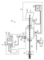
図1は、一実施形態による光学システム1Aの一構成例を示す図である。光学システム1Aは、大気特性取得システム2と、照射装置3とを備えている。
(First embodiment)
FIG. 1 is a diagram showing one configuration example of an optical system 1A according to one embodiment. The optical system 1A includes an atmospheric property acquisition system 2 and an irradiation device 3 .
照射装置3は、外部のターゲット4に向けて光を照射するように構成されている。大気特性取得システム2は、この光が通過する第1光路51における大気環境の特性を、第1光路51から離れた第2光路52で、この光が照射される前に取得するように構成されている。
The irradiation device 3 is configured to irradiate light toward an external target 4 . The atmospheric property acquisition system 2 is configured to acquire properties of the atmospheric environment in the first
照射装置3は、高出力レーザ光源31と、ミラー32A、32Bと、波面補正光学系33と、制御装置34と、気象計35と、照射光学系36とを備える。以降、ミラー32A、32Bを区別せずにミラー32と総称する場合がある。
The irradiation device 3 includes a high-power laser light source 31,
高出力レーザ光源31は、ターゲット4に到達させるための高出力レーザ光を生成する。ミラー32は、生成された高出力レーザ光を波面補正光学系33に導くように配置されている。波面補正光学系33は、高出力レーザ光を照射光学系36に向けて反射する際に、高出力レーザ光の波面を、制御装置34の制御下で補正するように構成されている。一実施形態において、波面補正光学系33は、可変形鏡である。制御装置34は、大気特性取得システム2によって取得された大気環境の特性と、気象計35によって取得された気象情報とに基づいて、波面補正光学系33を制御するように構成されている。気象計35は、第1光路51、第2光路52またはこれらの近傍における気象情報を取得して制御装置34に送信するように構成されている。照射光学系36は、第1光路51に配置されており、波面補正光学系33によって反射された高出力レーザ光をターゲット4へ導くように構成されている。
A high-power laser light source 31 generates high-power laser light to reach the target 4 . The mirror 32 is arranged to guide the generated high-power laser beam to the wavefront correction optical system 33 . The wavefront correction optical system 33 is configured to correct the wavefront of the high-power laser beam under the control of the
大気特性取得システム2は、大気特性取得用レーザ光源21と、大気特性取得装置22とを備える。
The atmospheric property acquisition system 2 includes an atmospheric property acquisition
大気特性取得用レーザ光源21は、大気特性取得用レーザ光210を生成するように構成されている。
The atmospheric characteristic acquisition
図2は、一実施形態による大気特性取得装置22の一構成例を示す図である。大気特性取得装置22は、大気モデルチャンバー61と、大気環境再現装置62と、ビーム径調整機構63と、測定装置64と、真空ポンプ65とを備えている。
FIG. 2 is a diagram showing one configuration example of the atmospheric
大気モデルチャンバー61は、気密性を有し、かつ、大気特性取得用レーザ光210が入射、通過および出射できるように構成された容器である。大気環境再現装置62は、大気モデルチャンバー61に接続されており、その内部に第1光路51における大気環境を、第1光路51から離れた第2光路52で再現出来るように構成されている。ビーム径調整機構63は、大気特性取得用レーザ光210のビーム径を調整することによって、大気特性取得用レーザ光210の強度分布を調整する。測定装置64は、大気モデルチャンバー61を通過する光を用いて、第2光路52における大気環境の特性を測定出来るように構成されている。真空ポンプ65は、大気モデルチャンバー61に接続されており、大気モデルチャンバー61の内部を真空にすることが出来るように構成されている。
The
大気環境再現装置62は、ガスミキサー621と、大気取り込み口622と、標準大気容器623と、エアロゾル生成器624と、ガス流量計625と、パーティクルカウンター626と、ガス流量調節バルブ627とを備えている。
The atmospheric environment reproduction device 62 includes a
ガスミキサー621は、大気取り込み口622、標準大気容器623およびエアロゾル生成器624から送られる気体および/またはエアロゾルなどを混合して大気モデルチャンバー61に向けて送り出すように構成されている。大気取り込み口622は、周辺の大気を取り込んでガスミキサー621へ送り出せるように構成されている。大気取り込み口622は、特に、第1光路51から大気を取り込むように配置されてもよい。第1光路51から取り込まれた大気を、光路大気と呼ぶ。標準大気容器623は、標準大気が充填された容器であり、この標準大気をガスミキサー621へ送り出せるように構成されている。なお、標準大気とは、所定の標準に基づく組成、温度、密度などを有するように構成された気体である。エアロゾル生成器624は、光の散乱現象の原因となる固体粒子、液体粒子および/または同様の特性を有する種々の粒子を供給、混合したエアロゾルを生成する装置であって、生成したエアロゾルをガスミキサー621に向けて送り出せるように構成されている。ガス流量計625は、ガスミキサー621および大気モデルチャンバー61の間に配置されており、ガスミキサー621から大気モデルチャンバー61へ流れる気体の量を測定する。パーティクルカウンター626は、ガスミキサー621および大気モデルチャンバー61の間に配置されており、ガスミキサー621から大気モデルチャンバー61へ流れる気体に含まれるエアロゾルの粒子数を数える。ガス流量調節バルブ627は、ガスミキサー621および大気モデルチャンバー61の間に配置されており、ガスミキサー621から大気モデルチャンバー61へ流れる気体の流速を調節したり、機体の流れを止めたりすることが出来るように構成されている。一実施形態では、ガスミキサー621と、ガス流量計625と、パーティクルカウンター626と、ガス流量調節バルブ627と、大気モデルチャンバー61とは、ガスミキサー621から大気モデルチャンバー61へ流れる気体がこの順番に通るように接続されている。
The
測定装置64は、強度分布観測用カメラ642と、散乱光観測用カメラ643と、スクリーン644と、モニタ装置645とを備えている。
The
スクリーン644は、大気モデルチャンバー61を通過した大気特性取得用レーザ光210を照射されることでビームスポット71が生じることによって、大気特性取得用レーザ光210の強度分布を可視化出来るように構成されている。強度分布観測用カメラ642は、スクリーン644に生じたビームスポット71を観測することによって、大気特性取得用レーザ光210の強度分布を取得できるように構成されている。散乱光観測用カメラ643は、大気モデルチャンバー61の内部を観測することによって、真空状態または所定の大気モデルが再現された状態において大気特性取得用レーザ光210が散乱した散乱光の強度を取得できるように構成されている。モニタ装置645は、強度分布観測用カメラ642および散乱光観測用カメラ643が観測した結果または取得した各種情報を入力して外部に向けて表示できるように構成されている。
The
一実施形態による光学システム1Aの一動作例、すなわち一実施形態による光学補正方法について説明する。 An operation example of the optical system 1A according to one embodiment, that is, an optical correction method according to one embodiment will be described.
図3は、一実施形態による照射方法の一構成例を示すフローチャートである。図3のフローチャートには、第1ステップS01~第5ステップS05の合計5つのステップが含まれている。図3のフローチャートが開始すると、第1ステップS01が実行される。 FIG. 3 is a flow chart showing one configuration example of an irradiation method according to one embodiment. The flow chart of FIG. 3 includes a total of five steps from first step S01 to fifth step S05. When the flowchart of FIG. 3 starts, the first step S01 is executed.
第1ステップS01では、真空状態の大気モデルチャンバー61を用いて、この大気モデルチャンバー61を通過した大気特性取得用レーザ光210の強度分布を測定する。
In the first step S01, the
まず、真空ポンプ65を用いて大気モデルチャンバー61の内部を真空状態にする。この真空状態は、例えば、気圧が10キロパスカル以下であることを意味する。
First, the
図4Aは、一実施形態による大気特性取得用レーザ光210の一状態例を示す図である。大気モデルチャンバー61は、本体611と、第1窓612と、第2窓613とを備える。本体611は、気密性を有しており、大気モデルチャンバー61の内部空間を外部から隔離する。本体611は、真空に対する耐久性を有する。
FIG. 4A is a diagram showing one state example of the atmospheric characteristic
第1窓612は、本体611の外部から内部へ大気特性取得用レーザ光210が入射できるように構成されている。第2窓613は、本体611の内部から外部へ大気特性取得用レーザ光210が出射できるように構成されている。第1窓612および第2窓613は、第1窓612から入射した大気特性取得用レーザ光210が、第2光路52に沿って本体611の内部を通り、第2窓613から出射できるように配置されている。なお、大気特性取得用レーザ光210のうち、第1窓612および/または第2窓613によって反射しても、この反射光が大気特性取得用レーザ光源21に戻らないように、光軸に対して適宜な角度を有していることが好ましい。また、第1窓612および第2窓613は、同様に構成されていてもよいし、互いの役割を交換出来てもよい。
The
次に、大気特性取得用レーザ光源21が大気特性取得用レーザ光210を生成する。大気特性取得用レーザ光210は、ビーム径調整機構63を通過することによって、ビーム径が調整される。言い換えれば、大気特性取得用レーザ光210は、ビーム径調整機構63を通過することによって、強度分布が調整される。ビーム径調整機構63を通過した大気特性取得用レーザ光210は、第1窓612を介して大気モデルチャンバー61の内部に入射する。第1窓612から入射した大気特性取得用レーザ光210は、真空状態の大気モデルチャンバー61の内部を通過し、第2窓613を介して外側に出射し、スクリーン644に照射される。
Next, the atmospheric characteristic acquisition
第1窓612から入射する前の大気特性取得用レーザ光210を、区別のために入射前レーザ光210Aとも呼ぶ。また、第2窓613から出射した後の大気特性取得用レーザ光210を、区別のために出射後レーザ光210Bとも呼ぶ。入射前レーザ光210Aおよび出射後レーザ光210Bを大気特性取得用レーザ光210と総称する。
The atmospheric characteristic
スクリーン644の表面のうち、出射後レーザ光210Bが照射された部分には、ビームスポット71が生じる。強度分布観測用カメラ642は、ビームスポット71を観測することによって、出射後レーザ光210Bの強度分布を測定する。強度分布観測用カメラ642は、測定結果を図示しない記憶装置に格納しても良いし、制御装置34に向けて送信しても良い。
A
散乱光観測用カメラ643は、大気特性取得用レーザ光210が大気モデルチャンバー61の内部で散乱する様子を観測する。散乱光観測用カメラ643は、観測結果を図示しない記憶装置に格納しても良いし、制御装置34に向けて送信しても良い。第1ステップS01の次には、第2ステップS02が実行される。
The scattered
第2ステップS02では、第1光路51における大気環境を内部に再現した状態の大気モデルチャンバー61を用いて、この大気モデルチャンバー61を通過した大気特性取得用レーザ光210の強度分布を測定する。
In the second step S02, the
まず、大気環境再現装置62を用いて、大気モデルチャンバー61の内部に、第1光路51における大気環境を再現する。一実施形態では、大気取り込み口622およびガス流量調節バルブ627を介して、光路大気を大気モデルチャンバー61の内部に送り込む。ここで、大気モデルチャンバー61の内部が、直前の第1ステップS01の真空状態に保たれていれば、ガス流量調節バルブ627を開くだけで第1光路51の周囲の大気が大気モデルチャンバー61の内部に流入する。なお、大気取り込み口622およびガス流量調節バルブ627の間には、ガス流量計625およびパーティクルカウンター626が配置されていても良い。大気取り込み口622およびガス流量調節バルブ627の間には、ガスミキサー621がさらに配置されていても良い。一実施形態では、大気取り込み口622から取り込んだ光路大気に、標準大気容器623に格納されている標準大気や、エアロゾル生成器624で生成される各種粒子などを、ガスミキサー621で混合し、この混合によって生成された混合気体を大気モデルチャンバー61の内部に流入しても良い。言い換えれば、混合気体は、第1光路51における大気環境を、第2光路52に配置された大気モデルチャンバー61の内部で、より高い精度で再現するために、標準大気や、粒子などを、第1光路51の周囲の大気に混合することで得られる。一実施形態では、大気取り込み口622を使用せずに、標準大気および各種粒子を混合するだけで、大気モデルチャンバー61に向けて送り込む混合気体を生成しても良い。以降、大気モデルチャンバー61の内部に存在する、第1光路51の周囲の大気および/または混合気体を、大気環境再現気体と総称する。
First, the atmospheric environment reproduction device 62 is used to reproduce the atmospheric environment in the first
次に、第1ステップS01の場合と同様に、大気特性取得用レーザ光源21によって生成され、ビーム径調整機構63によってビーム径および強度分布を調整された大気特性取得用レーザ光210が、第1窓612から大気モデルチャンバー61の内部に入射する。第1窓612から入射した大気特性取得用レーザ光210は、大気モデルチャンバー61の内部に存在する大気環境再現気体を通過し、第2窓613から出射し、スクリーン644に照射される。ここで、第2窓613から出射した後の大気特性取得用レーザ光210を、区別のために出射後レーザ光210Cと呼ぶ。なお、第1窓612から入射する前の大気特性取得用レーザ光210は、第1ステップS01の場合と同様に、入射前レーザ光210Aと呼ぶ。言い換えれば、入射前レーザ光210Aおよび出射後レーザ光210Cを大気特性取得用レーザ光210と総称する。
Next, as in the case of the first step S01, the atmospheric characteristics acquiring
図4Bは、一実施形態による大気特性取得用レーザ光210の一状態例を示す図である。スクリーン644の表面のうち、出射後レーザ光210Cが照射された部分には、ビームスポット72が現れる。図4Bでは、ビームスポット72の形状が、図4Aに示したビームスポット71と比較して、大気環境再現気体によるサーマルブルーミング効果などによって乱れている場合の一例を示している。強度分布観測用カメラ642は、ビームスポット72を観測することによって、出射後レーザ光210Cの強度分布を測定する。強度分布観測用カメラ642は、測定結果を図示しない記憶装置に格納しても良いし、制御装置34に向けて送信しても良い。
FIG. 4B is a diagram showing one state example of the atmospheric characteristic
散乱光観測用カメラ643は、大気特性取得用レーザ光210が大気モデルチャンバー61の内部の大気環境再現気体によって散乱する様子を観測する。散乱光観測用カメラ643は、観測結果を図示しない記憶装置に格納しても良いし、制御装置34に向けて送信しても良い。第2ステップS02の次には、第3ステップS03が実行される。
The scattered
第3ステップS03では、第1ステップS01および第2ステップS02で得られた2つの測定結果を比較する。すなわち、一方では、強度分布観測用カメラ642の測定結果である、出射後レーザ光210B、210Cの強度分布を比較する。また、他方では、散乱光観測用カメラ643の測定結果である、大気特性取得用レーザ光210の散乱を比較する。これらの比較は、図示しない記憶装置および演算装置が行っても良いし、制御装置34が行っても良い。
In the third step S03, the two measurement results obtained in the first step S01 and the second step S02 are compared. That is, on the one hand, the intensity distributions of the emitted
これらの比較を行うことで、大気環境再現気体によるレーザ光への影響を、大気モデルチャンバー61を含む大気特性取得システム2による影響を除外して算出することが出来る。言い換えれば、真空状態と、大気環境再現状態とにおける測定結果を比較することによって、大気環境再現気体によるサーマルブルーミング効果の影響のみを抽出することが可能となる。
By performing these comparisons, it is possible to calculate the influence of the atmospheric environment reproduction gas on the laser light while excluding the influence of the atmospheric characteristic acquisition system 2 including the
また、第2光路52に配置された大気モデルチャンバー61による、大気特性取得用レーザ光210への影響から、第1光路51の大気環境による、高出力レーザ光への影響を算出することも、比較的容易に出来る。これらの算出は、第1光路51および第2光路52の長さの違い、大気特性取得用レーザ光210および高出力レーザの間の強度および強度分布の違いなどの既知の情報に基づいて行うことが出来る。このようにして算出された結果は、制御装置34に格納される。第3ステップS03の次には、第4ステップS04が実行される。
Further, from the influence of the
第4ステップS04では、制御装置34が、第3ステップS03の比較結果に基づいて、波面補正光学系33を制御する。言い換えれば、高出力レーザ光が波面補正光学系33で反射し、照射光学系36を通過し、第1光路51を伝搬し、ターゲット4に到達するときに、この高出力レーザ光の波面が理想的な状態に近づくように、制御装置34は波面補正光学系33を制御する。さらに言い換えれば、高出力レーザ光が第1光路51に存在する大気を伝搬することによって発生するサーマルブルーミング効果を打ち消すように、制御装置34は波面補正光学系33を制御する。
In the fourth step S04, the
一実施形態では、制御装置34は、波面補正光学系33を、ゼルニケ近似多項式を用いて制御する。言い換えれば、制御装置34は、第3ステップS03で得られた算出結果を、ゼルニケ近似多項式として扱える形式に変換した上で、波面補正光学系33を制御する。
In one embodiment,
制御装置34は、第3ステップS03の比較結果の他に、気象計35で取得された気象情報にさらに基づいて、波面補正光学系33を制御してもよい。波面補正光学系33の制御に用いられる気象情報には、例えば、気温、湿度、気圧、風速などのうち、一部または全てが含まれてもよい。第4ステップS04の次には、第5ステップS05が実行される。
The
第5ステップS05では、高出力レーザ光源31が高出力レーザ光を出力する。出力された高出力レーザ光は、まず、ミラー32を介して波面補正光学系33に向かう。図1に示した実施形態では、波面補正光学系33で反射される直前の高出力レーザ光の波面を、波面37Aとして示している。波面37Aの形状は、高出力レーザ光源31およびミラー32の特性によって決定されるので、既知である。
In the fifth step S05, the high power laser light source 31 outputs high power laser light. The output high-power laser light first travels through the mirror 32 toward the wavefront correction optical system 33 . In the embodiment shown in FIG. 1, the wavefront of the high-output laser light just before being reflected by the wavefront correction optical system 33 is shown as a
高出力レーザ光は、次に、波面補正光学系33で反射される。このとき、波面補正光学系33は、第4ステップS04において予め、制御装置34によって制御されている。したがって、波面補正光学系33で反射された直後における高出力レーザ光の波面37Bは、反射直前の波面37Aから変化することが予想される。
The high-power laser light is then reflected by the wavefront correction optical system 33 . At this time, the wavefront correction optical system 33 is previously controlled by the
高出力レーザ光は、次に、照射光学系36および第1光路51を介してターゲット4に向かう。高出力レーザ光は、第1光路51を伝搬する際に、この第1光路51に存在する大気などによるサーマルブルーミング効果によって、その波面の形状が変化する。この変化の結果として、ターゲット4に到達する直前の高出力レーザ光の波面37Cが、ターゲット4へのエネルギー伝搬の観点から理想的な形状を有するように、波面補正光学系33は制御装置34によって制御されている。波面37Cの理想的な形状とは、例えば、ターゲット4の表面上の一点に収束するような形状であり、この集束点を中心とした球面を有していても良い。または、例えば、波面37Cの理想的な形状は、ターゲット4の表面の一部である平面に照射されるような形状であり、この部分平面に平行な平面形状を有していても良い。
The high-power laser light then travels to target 4 via illumination optics 36 and first
第5ステップS05が完了すると、図3のフローチャートは終了する。なお、第5ステップS05の後に第1ステップS01~第5ステップS05を繰り返しても良い。ただし、第1ステップS01で得られた測定結果に変化が無いと考えられる場合には、第5ステップS05の後に第2ステップS02~第5ステップS05を繰り返しても良い。このような場合でも、第2ステップS02を開始する前に、真空ポンプ65を用いて、大気モデルチャンバー61の内部に存在する大気環境再現気体を外部に排出することが好ましい。
When the fifth step S05 is completed, the flowchart of FIG. 3 ends. Note that the first step S01 to the fifth step S05 may be repeated after the fifth step S05. However, when it is considered that there is no change in the measurement result obtained in the first step S01, the second step S02 to the fifth step S05 may be repeated after the fifth step S05. Even in such a case, it is preferable to use the
高出力レーザ光は、パルス状に出力されても良いし、連続的に出力されても良い。言い換えれば、第5ステップS05は、複数回実行されても良いし、一度に長時間に渡って実行されても良い。いずれの場合も、第1光路51における大気環境は、時間と共に変動することが考えられる。そこで、第5ステップS05を実行する頻度や時間の長さなどとは無関係な頻度で、第1ステップS01~第4ステップS04を繰り返し実行しても良い。こうすることによって、大気環境の変動に伴うサーマルブルーミング効果の変動に対応して波面補正光学系33を制御し続けることが出来る。
The high-power laser light may be output in a pulsed form or may be output continuously. In other words, the fifth step S05 may be executed multiple times, or may be executed for a long time at a time. In either case, it is conceivable that the atmospheric environment in the first
(第2実施形態)
図5は、一実施形態による光学システム1Bの一構成例を示す図である。図5に示した光学システム1Bは、図1に示した光学システム1Aと比較して、以下の点が異なる。
(Second embodiment)
FIG. 5 is a diagram showing one configuration example of the optical system 1B according to one embodiment. The optical system 1B shown in FIG. 5 differs from the optical system 1A shown in FIG. 1 in the following points.
第1の相違点として、図5の光学システム1Bは、図1の光学システム1Aが備える大気特性取得用レーザ光源21および高出力レーザ光源31の代わりに、兼用レーザ光源31Aを備えている。兼用レーザ光源31Aは、大気特性取得用レーザ光源21としての動作と、高出力レーザ光源31としての動作とを、切り替え可能に構成されている。言い換えれば、兼用レーザ光源31Aは、高出力レーザ光を出力する機能と、大気特性取得用レーザ光210を出力する機能とを、切り替え可能に有している。さらに言い換えれば、兼用レーザ光源31Aは、出力するレーザ光の強度を切り替えられるように構成されている。兼用レーザ光源31Aが出力するレーザ光の強度の切り替えは、制御装置34の制御下で行われても良いし、図示しない他の制御系の制御下で行われても良いし、利用者の操作によって行われても良い。
As a first difference, the optical system 1B of FIG. 5 includes a combined
第2の相違点として、図5に示した光学システム1Bは、図1に示したミラー32Bの代わりに、切替ミラー32Cを備えている。切替ミラー32Cは、兼用レーザ光源31Aから出力される大気特性取得用レーザ光210を大気特性取得装置22に向けて反射する第1状態と、兼用レーザ光源31Aから出力される高出力レーザ光を波面補正光学系33に向けて反射する第2状態とを、切り替え可能に構成されている。なお、図5の光学システム1Bは、切替ミラー32Cの第1状態および第2状態を切り替えるように構成された、図示しない切替装置をさらに備えている。
As a second difference, the optical system 1B shown in FIG. 5 includes a
本実施形態による光学システム1Bの動作は、図1に示した光学システム1Aの動作と比較して、以下の点が異なる。 The operation of the optical system 1B according to this embodiment differs from the operation of the optical system 1A shown in FIG. 1 in the following points.
第1の相違点として、図3に示したフローチャートの第1ステップS01を開始する前に、切替ミラー32Cを第1状態に切り替える動作を行う。また、第1ステップS01を実行する際に、図1の大気特性取得用レーザ光源21が大気特性取得用レーザ光210を出力する代わりに、図5の兼用レーザ光源31Aが大気特性取得用レーザ光210を出力する。
As a first difference, before starting the first step S01 in the flow chart shown in FIG. 3, the
第2の相違点として、図3に示したフローチャートの第2ステップS02を開始する前に、切替ミラー32Cを第2状態に切り替える動作を行う。また、第2ステップS02を実行する際に、図1の高出力レーザ光源31が高出力レーザ光を出力する代わりに、図5の兼用レーザ光源31Aが高出力レーザ光を出力する。
As a second point of difference, before starting the second step S02 of the flowchart shown in FIG. 3, an operation of switching the
本実施形態の他の構成および他の動作は、図1に示した実施形態と同様であるので、さらなる詳細な説明を省略する。 Other configurations and other operations of this embodiment are the same as those of the embodiment shown in FIG. 1, so further detailed description is omitted.
本実施形態では、図1に示した実施形態と比較して、同じ作用効果を保ちながら、レーザ光源を1つ省略することが出来る。 Compared with the embodiment shown in FIG. 1, this embodiment can omit one laser light source while maintaining the same effect.
(第3実施形態)
図6は、一実施形態による光学システム1Cの一構成例を示す図である。図6に示した光学システム1Cは、図5に示した光学システム1Bと比較して、以下の点が異なる。
(Third embodiment)
FIG. 6 is a diagram showing one configuration example of an optical system 1C according to one embodiment. The optical system 1C shown in FIG. 6 differs from the optical system 1B shown in FIG. 5 in the following points.
第1の相違点として、図6の光学システム1Cは、切替ミラー32Cの代わりに、図1の光学システム1Aが備えるミラー32Bを、図1と同じ場所に備えている。
As a first difference, the optical system 1C of FIG. 6 has the
第2の相違点として、図6の光学システム1Cでは、大気特性取得装置22が、ミラー32Bおよび波面補正光学系33の間に配置されている。このときも、大気特性取得装置22が配置されている第2光路52が、照射光学系36およびターゲット4の間に存在する第1光路51から離れていることに注目されたい。
As a second point of difference, in the optical system 1C of FIG. Also at this time, note that the second
本実施形態による光学システム1Cの動作は、図5に示した光学システム1Bの動作と比較して、以下の点が異なる。 The operation of the optical system 1C according to this embodiment differs from the operation of the optical system 1B shown in FIG. 5 in the following points.
第1の相違点として、図3に示したフローチャートの第1ステップS01および第2ステップS02を開始する前に、切替ミラー32Cの切り替え動作を行う必要が無い。
As a first difference, there is no need to perform the switching operation of the
第2の相違点として、図3に示したフローチャートの第5ステップS05を実行する際に、高出力レーザ光は、大気特性取得装置22を通過する。特に、高出力レーザ光は、大気モデルチャンバー61の内部を通過する。このとき、高出力レーザ光は第1窓612から入射して第2窓613から出射するので、第1窓612および第2窓613は、高出力レーザ光に対する耐久性を有するように構成されている。
As a second difference, the high-power laser light passes through the atmospheric
また、第5ステップS05を実行する際に、大気モデルチャンバー61による高出力レーザ光への影響を最小化するために、大気モデルチャンバー61の内部は真空であることが好ましい。言い換えれば、第5ステップS05を実行する前に、真空ポンプ65を用いて大気モデルチャンバー61の内部を真空にすることが好ましい。ただし、第2光路52に含まれる大気モデルチャンバー61の、第2光路52の方向の長さが、照射光学系36からターゲット4に到る第1光路51の長さに対して無視出来るほど短い場合は、大気モデルチャンバー61による高出力レーザ光への影響も無視出来ると考えられる。この影響は、大気モデルチャンバー61の内部に、第1光路51の大気環境が再現されていることからも、無視することが容易であると考えられる。したがって、このような場合は、第5ステップS05を実行する前に、真空ポンプ65を用いて大気モデルチャンバー61の内部を真空にする動作は省略可能である。
Moreover, when executing the fifth step S05, the inside of the
さらに、第5ステップS05を実行する際に、大気特性取得装置22に含まれるスクリーン644が、高出力レーザ光の伝搬を遮ったり、反対に高出力レーザ光によって破損したりすることが考えられる。そこで、光学システム1Cは、第1ステップS01および第2ステップS02と、第5ステップS05との間で、スクリーン644を移動するための図示しない機構を、さらに備えても良い。
Furthermore, when executing the fifth step S05, the
または、大気特性取得用レーザ光210の一部をサンプリングできるサンプラーを、スクリーン644の代わりに設けても良い。この場合は、第2ステップS02において、強度分布観測用カメラ642は、スクリーン644の代わりにサンプラーを観測することで、出射後レーザ光210Bの強度分布を測定する。
Alternatively, instead of the
本実施形態の他の構成および他の動作は、図5に示した実施形態と同様であるので、さらなる詳細な説明を省略する。 Other configurations and operations of this embodiment are the same as those of the embodiment shown in FIG. 5, so further detailed description is omitted.
本実施形態では、図5に示した実施形態と比較して、同じ作用効果を保ちながら、切替ミラー32Cを省略することが出来る。
Compared with the embodiment shown in FIG. 5, this embodiment can omit the
以上、発明者によってなされた発明を実施の形態に基づき具体的に説明したが、本発明は前記実施の形態に限定されるものではなく、その要旨を逸脱しない範囲で種々変更可能であることはいうまでもない。また、前記実施の形態に説明したそれぞれの特徴は、技術的に矛盾しない範囲で自由に組み合わせることが可能である。 Although the invention made by the inventor has been specifically described above based on the embodiment, it should be understood that the invention is not limited to the above-described embodiment, and that various changes can be made without departing from the gist of the invention. Needless to say. Further, the features described in the above embodiments can be freely combined within a technically consistent range.
1A~1C 光学システム
2 大気特性取得システム
21 大気特性取得用レーザ光源
210 大気特性取得用レーザ光
210A 入射前レーザ光
210B 出射後レーザ光
210C 出射後レーザ光
22 大気特性取得装置
3 照射装置
31 高出力レーザ光源
31A 兼用レーザ光源
32A、32B ミラー
32C 切替ミラー
33 波面補正光学系
34 制御装置
35 気象計
36 照射光学系
37A 波面
37B 波面
37C 波面
4 ターゲット
51 第1光路
52 第2光路
61 大気モデルチャンバー
611 本体
612 第1窓
613 第2窓
62 大気環境再現装置
621 ガスミキサー
622 大気取り込み口
623 標準大気容器
624 エアロゾル生成器
625 ガス流量計
626 パーティクルカウンター
627 ガス流量調節バルブ
63 ビーム径調整機構
64 測定装置
642 強度分布観測用カメラ
643 散乱光観測用カメラ
644 スクリーン
645 モニタ装置
65 真空ポンプ
71 ビームスポット
72 ビームスポット
1A-1C Optical system 2 Atmospheric
Claims (14)
前記第1光路から離れ、かつ、前記第1光路の大気環境から隔離された第2光路に配置され、前記第1光路の前記大気環境の、前記光に対する特性を取得する大気特性取得システムと、
を具備し、
前記照射装置は、
前記特性に基づいて、前記光の波面を補正する波面補正光学系
を具備し、
前記大気特性取得システムは、
内部に前記第1光路の前記大気環境を再現出来るように構成された大気モデルチャンバーと、
前記大気モデルチャンバーを通過した光を用いて前記特性を測定する測定装置と、
を具備する
光学システム。 an irradiation device that irradiates light toward an external target through the first optical path;
an atmospheric property acquisition system arranged in a second optical path separated from the first optical path and isolated from the atmospheric environment of the first optical path, for acquiring properties of the atmospheric environment of the first optical path with respect to the light;
and
The irradiation device is
A wavefront correction optical system that corrects the wavefront of the light based on the characteristics ,
The atmospheric property acquisition system includes:
an atmospheric model chamber configured to reproduce the atmospheric environment of the first optical path;
a measuring device that measures the characteristics using light that has passed through the atmosphere model chamber;
comprises
optical system.
前記第1光路から離れ、かつ、前記第1光路の大気環境から隔離された第2光路に配置され、前記第1光路の前記大気環境の、前記光に対する特性を取得する大気特性取得システムと、an atmospheric property acquisition system arranged in a second optical path separated from the first optical path and isolated from the atmospheric environment of the first optical path, for acquiring properties of the atmospheric environment of the first optical path with respect to the light;
を具備し、and
前記照射装置は、The irradiation device is
前記特性に基づいて、前記光の波面を補正する波面補正光学系A wavefront correction optical system that corrects the wavefront of the light based on the characteristics
を具備し、and
前記波面補正光学系および前記第1光路を介して前記ターゲットに向かう第1光と、前記大気環境の前記特性を取得するために前記大気特性取得システムの内部を通過する第2光とを生成する兼用光源と、generating a first light directed toward the target via the wavefront correction optics and the first optical path, and a second light passing through the atmospheric property acquisition system to acquire the property of the atmospheric environment; a dual-purpose light source;
前記兼用光源が生成する光の光路を、前記第1光路および前記第2光路のいずれかに切り替える切替ミラーと、a switching mirror for switching an optical path of light generated by the dual-purpose light source to either the first optical path or the second optical path;
をさらに具備するfurther comprising
光学システム。optical system.
前記第1光路から離れ、かつ、前記第1光路の大気環境から隔離された第2光路に配置され、前記第1光路の前記大気環境の、前記光に対する特性を取得する大気特性取得システムと、an atmospheric property acquisition system arranged in a second optical path separated from the first optical path and isolated from the atmospheric environment of the first optical path, for acquiring properties of the atmospheric environment of the first optical path with respect to the light;
を具備し、and
前記照射装置は、The irradiation device is
前記特性に基づいて、前記光の波面を補正する波面補正光学系A wavefront correction optical system that corrects the wavefront of the light based on the characteristics
を具備し、and
前記波面補正光学系および前記第1光路を介して前記ターゲットに向かう第1光と、前記大気環境の前記特性を取得するために前記大気特性取得システムの内部を通過する第2光とを生成する兼用光源と、generating a first light directed toward the target via the wavefront correction optics and the first optical path, and a second light passing through the atmospheric property acquisition system to acquire the property of the atmospheric environment; a dual-purpose light source;
をさらに具備し、further comprising
前記第2光路は、前記第1光が、前記第2光路、前記波面補正光学系および前記第1光路を介して前記ターゲットに向かうように配置されているThe second optical path is arranged such that the first light travels to the target via the second optical path, the wavefront correction optical system, and the first optical path.
光学システム。optical system.
前記第1光路から離れ、かつ、前記第1光路の大気環境から隔離された第2光路に配置され、前記第1光路の前記大気環境の、前記光に対する特性を取得する大気特性取得システムと、an atmospheric property acquisition system arranged in a second optical path separated from the first optical path and isolated from the atmospheric environment of the first optical path, for acquiring properties of the atmospheric environment of the first optical path with respect to the light;
前記第2光路を通過する光の散乱を観測する散乱光観測用カメラと、a scattered light observation camera that observes scattering of light passing through the second optical path;
を具備し、and
前記照射装置は、The irradiation device is
前記特性に基づいて、前記光の波面を補正する波面補正光学系A wavefront correction optical system that corrects the wavefront of the light based on the characteristics
を具備し、and
前記照射装置は、前記散乱の観測結果に基づいて前記波面補正光学系を制御するThe irradiation device controls the wavefront correction optical system based on the observation result of the scattering.
光学システム。optical system.
前記第1光路から離れ、かつ、前記第1光路の大気環境から隔離された第2光路に配置され、前記第1光路の前記大気環境の、前記光に対する特性を取得する大気特性取得システムと、an atmospheric property acquisition system arranged in a second optical path separated from the first optical path and isolated from the atmospheric environment of the first optical path, for acquiring properties of the atmospheric environment of the first optical path with respect to the light;
前記第1光路における気象情報を取得する気象計と、a weather station for obtaining weather information on the first optical path;
を具備し、and
前記照射装置は、The irradiation device is
前記特性に基づいて、前記光の波面を補正する波面補正光学系A wavefront correction optical system that corrects the wavefront of the light based on the characteristics
を具備し、and
前記照射装置は、前記気象情報の観測結果にさらに基づいて前記波面補正光学系を制御するThe irradiation device controls the wavefront correction optical system further based on observation results of the weather information.
光学システム。optical system.
前記大気特性取得システムは、
内部に前記第1光路の前記大気環境を再現出来るように構成された大気モデルチャンバーと、
前記大気モデルチャンバーを通過した光を用いて前記特性を測定する測定装置と、
を具備する
光学システム。 In the optical system according to any one of claims 2 to 5 ,
The atmospheric property acquisition system includes:
an atmospheric model chamber configured to reproduce the atmospheric environment of the first optical path;
a measuring device that measures the characteristics using light that has passed through the atmosphere model chamber;
An optical system comprising:
前記大気モデルチャンバーの内部を真空にする真空ポンプと、
前記大気モデルチャンバーの内部に、前記第1光路の大気を再現した大気環境再現気体を流入する大気環境再現装置
をさらに具備する
光学システム。 7. An optical system according to claim 1 or 6 ,
a vacuum pump that evacuates the inside of the atmosphere model chamber;
An optical system further comprising an atmospheric environment reproduction device for flowing an atmospheric environment reproduction gas that reproduces the atmosphere of the first optical path into the atmosphere model chamber.
前記大気環境再現装置は、
前記第1光路から光路大気を取り込む大気取り込み口と、
標準大気を供給する標準大気容器と、
エアロゾルを供給するエアロゾル生成器と、
前記光路大気、前記標準大気および前記エアロゾルを混合して前記大気環境再現気体を生成するガスミキサーと、
前記ガスミキサーから前記大気モデルチャンバーに流入する前記大気環境再現気体の流量を測定するガス流量計と、
前記ガスミキサーから前記大気モデルチャンバーに流入する前記エアロゾルの粒子数を数えるパーティクルカウンターと、
前記ガスミキサーから前記大気モデルチャンバーに流入する前記大気環境再現気体の前記流量を調節するガス流量調節バルブと
を具備する
光学システム。 An optical system according to claim 7 , wherein
The atmospheric environment reproduction device includes:
an air intake port that takes in the air from the first optical path;
a standard atmosphere container supplying standard atmosphere;
an aerosol generator that supplies an aerosol;
a gas mixer that mixes the optical path atmosphere, the standard atmosphere, and the aerosol to generate the atmospheric environment reproduction gas;
a gas flow meter for measuring the flow rate of the atmospheric environment reproduction gas flowing from the gas mixer into the atmosphere model chamber;
a particle counter for counting the number of particles of the aerosol flowing from the gas mixer into the atmosphere model chamber;
an optical system comprising: a gas flow control valve that controls the flow rate of the atmospheric environment reproduction gas that flows from the gas mixer into the atmosphere model chamber.
前記測定装置は、前記内部が真空である第1状態の前記大気モデルチャンバーを通過した光を用いて測定する第1特性と、前記内部に前記大気環境を再現している第2状態の前記大気モデルチャンバーを通過した光を用いて測定する第2特性とを比較して、前記特性を取得する
光学システム。 9. The optical system of claim 8 , wherein
The measuring device measures a first characteristic using light that has passed through the atmosphere model chamber in a first state in which the interior is a vacuum, and the atmosphere in a second state in which the atmospheric environment is reproduced in the interior. An optical system that obtains a property by comparing it with a second property that is measured using light that has passed through the model chamber.
前記大気モデルチャンバーは、
光が外部から前記内部に入射する第1窓と、
前記光が前記内部から外部へ出射する第2窓と
を具備し、
前記測定装置は、
前記光が前記第1窓から入射する前の入射光の強度分布を調整するビーム径調整機構と、
前記光が前記第2窓から出射した出射光を照射されてビームスポットが生じるスクリーンと、
前記ビームスポットを観測して、前記出射光の強度分布を測定する強度分布観測用カメラと
を具備する
光学システム。 10. The optical system of claim 9 , wherein
The atmosphere model chamber is
a first window through which light enters the interior from the outside;
a second window through which the light is emitted from the inside to the outside,
The measuring device is
a beam diameter adjustment mechanism that adjusts the intensity distribution of the incident light before the light enters through the first window;
a screen on which the light emitted from the second window is irradiated to generate a beam spot;
An optical system comprising an intensity distribution observation camera that observes the beam spot and measures the intensity distribution of the emitted light.
前記第1状態の前記大気モデルチャンバーから出射した前記出射光によって生じる第1ビームスポットに基づく第1測定結果と、前記第2状態の前記大気モデルチャンバーから出射した前記出射光によって生じる第2ビームスポットに基づく第2測定結果とを比較した結果に基づいて、前記第1光路におけるサーマルブルーミング効果による光への影響を打ち消すように前記波面補正光学系を制御する制御装置
をさらに具備する
光学システム。 11. The optical system of claim 10 , wherein
A first measurement result based on a first beam spot generated by the emitted light emitted from the atmosphere model chamber in the first state, and a second beam spot generated by the emitted light emitted from the atmosphere model chamber in the second state. an optical system that controls the wavefront correction optical system so as to cancel out the influence of the thermal blooming effect on the light in the first optical path, based on the result of the comparison with the second measurement result based on the optical system.
前記制御装置は、前記比較した結果に基づいて、前記第2光路におけるサーマルブルーミング効果による光への影響を算出し、前記第2光路の前記影響に基づいて前記第1光路におけるサーマルブルーミング効果による光への影響を算出する
光学システム。 12. The optical system of claim 11 , wherein
The control device calculates the influence of the thermal blooming effect on the light in the second optical path based on the result of the comparison, and calculates the influence of the thermal blooming effect on the light in the first optical path based on the influence of the second optical path. An optical system that calculates the impact on
前記波面補正光学系および前記第1光路を介して前記ターゲットに向かう第1光を生成する第1光源と、
前記大気環境の前記特性を取得するために前記大気特性取得システムの内部を通過する第2光を生成する、前記第1光源とは異なる第2光源と
をさらに備える
光学システム。 In the optical system according to any one of claims 1 or 4-12,
a first light source that generates first light directed toward the target through the wavefront correction optical system and the first optical path;
an optical system, further comprising a second light source, different from the first light source, for generating a second light that passes through the atmospheric property acquisition system to acquire the property of the atmospheric environment.
前記特性に基づいて、前記光の波面を補正するように、波面補正光学系を制御することと、
前記波面補正光学系および前記第1光路を介して前記ターゲットに向けて光を照射することと
を含み、
前記取得することは、
内部に前記第1光路の前記大気環境を再現出来るように構成された大気モデルチャンバーを通過した光を用いて前記特性を測定すること
を含む
光学補正方法。
The characteristic of the atmospheric environment of the first optical path through which the light irradiated toward the external target passes, to the said light, is separated from the first optical path and is isolated from the atmospheric environment of the first optical path. acquiring in the optical path;
controlling a wavefront correction optical system to correct the wavefront of the light based on the characteristic;
irradiating light toward the target through the wavefront correction optical system and the first optical path ,
said obtaining
Measuring the characteristics using light that has passed through an atmosphere model chamber configured to reproduce the atmosphere environment of the first optical path.
including
Optical correction method.
Priority Applications (4)
| Application Number | Priority Date | Filing Date | Title |
|---|---|---|---|
| JP2018212842A JP7207648B2 (en) | 2018-11-13 | 2018-11-13 | Optical system and optical correction method |
| EP19885307.9A EP3826120B1 (en) | 2018-11-13 | 2019-08-23 | Optical system and optical correction method |
| PCT/JP2019/033044 WO2020100371A1 (en) | 2018-11-13 | 2019-08-23 | Optical system and optical correction method |
| US17/269,153 US11802990B2 (en) | 2018-11-13 | 2019-08-23 | Optical system and optical compensation method |
Applications Claiming Priority (1)
| Application Number | Priority Date | Filing Date | Title |
|---|---|---|---|
| JP2018212842A JP7207648B2 (en) | 2018-11-13 | 2018-11-13 | Optical system and optical correction method |
Publications (3)
| Publication Number | Publication Date |
|---|---|
| JP2020080367A JP2020080367A (en) | 2020-05-28 |
| JP2020080367A5 JP2020080367A5 (en) | 2021-12-09 |
| JP7207648B2 true JP7207648B2 (en) | 2023-01-18 |
Family
ID=70730247
Family Applications (1)
| Application Number | Title | Priority Date | Filing Date |
|---|---|---|---|
| JP2018212842A Active JP7207648B2 (en) | 2018-11-13 | 2018-11-13 | Optical system and optical correction method |
Country Status (4)
| Country | Link |
|---|---|
| US (1) | US11802990B2 (en) |
| EP (1) | EP3826120B1 (en) |
| JP (1) | JP7207648B2 (en) |
| WO (1) | WO2020100371A1 (en) |
Families Citing this family (1)
| Publication number | Priority date | Publication date | Assignee | Title |
|---|---|---|---|---|
| CN118226656B (en) * | 2024-03-19 | 2025-12-26 | 中国科学院合肥物质科学研究院 | A beam transmission model utilizing the thermal corona effect and a detection device for the thermal corona effect. |
Citations (9)
| Publication number | Priority date | Publication date | Assignee | Title |
|---|---|---|---|---|
| JP2003181661A (en) | 2001-12-18 | 2003-07-02 | Nec Corp | Laser pulse irradiation method and ultra-short pulse laser apparatus |
| JP2004535120A (en) | 2001-06-26 | 2004-11-18 | エイオプティクス テクノロジーズ,インク. | Atmospheric optical data transmission system |
| WO2005083508A1 (en) | 2004-02-27 | 2005-09-09 | Matsushita Electric Industrial Co., Ltd. | Two-dimensional image forming device |
| US20090028198A1 (en) | 2007-06-06 | 2009-01-29 | Mikhail Belenkii | Beaconless adaptive optics system |
| US20120018614A1 (en) | 2010-07-26 | 2012-01-26 | Raytheon Company | Source-independent beam director and control system for a high-energy electromagnetic radiation source |
| WO2015128943A1 (en) | 2014-02-25 | 2015-09-03 | ギガフォトン株式会社 | Laser device |
| US20160258752A1 (en) | 2015-03-04 | 2016-09-08 | Leica Geosystems Ag | Surveying device having a fine targeting and target tracking functionality |
| JP2017157737A (en) | 2016-03-03 | 2017-09-07 | 株式会社東芝 | Laser irradiation system and reflection optical device |
| JP2018525845A (en) | 2015-08-26 | 2018-09-06 | レイセオン カンパニー | Self-seeding high power laser |
Family Cites Families (19)
| Publication number | Priority date | Publication date | Assignee | Title |
|---|---|---|---|---|
| US3746080A (en) * | 1971-04-07 | 1973-07-17 | Mallory Eng Inc | Environmental chamber |
| DE3072067D1 (en) * | 1979-09-05 | 1988-02-18 | Ici Plc | Method of and apparatus for monitoring gaseous pollutants |
| US4888484A (en) * | 1986-02-20 | 1989-12-19 | Automatik Machinery Corporation | Apparatus and method for spectrophotometric analysis of a material in a moving process stream |
| JPH0778533B2 (en) * | 1988-05-02 | 1995-08-23 | 株式会社日立製作所 | Laser radar |
| JPH05136509A (en) * | 1991-11-11 | 1993-06-01 | Hitachi Ltd | Laser light output device, laser light wavefront control method and device thereof |
| US5317156A (en) * | 1992-01-29 | 1994-05-31 | Sri International | Diagnostic tests using near-infrared laser absorption spectroscopy |
| US5298751A (en) * | 1992-03-20 | 1994-03-29 | Aerojet-General Corporation | Remote active vapor concentration measurement system and method thereof |
| US6053738A (en) * | 1999-02-17 | 2000-04-25 | Ivey, Jr.; Ellwood G. | Sense-simile transmission machine |
| JP4169198B2 (en) | 2003-09-24 | 2008-10-22 | 独立行政法人科学技術振興機構 | High power laser amplifier |
| US7088457B1 (en) * | 2003-10-01 | 2006-08-08 | University Of Central Florida Research Foundation, Inc. | Iterative least-squares wavefront estimation for general pupil shapes |
| TW200520049A (en) * | 2003-10-21 | 2005-06-16 | Nikon Corp | Environment-controlling apparatus, device-producing apparatus, device-producing method, and exposure apparatus |
| US7346281B2 (en) * | 2004-07-06 | 2008-03-18 | The Boeing Company | Hybrid RF/optical communication system with deployable optics and atmosphere compensation system and method |
| US20090265108A1 (en) * | 2008-04-21 | 2009-10-22 | Raymond Chan | Natural weather station |
| US9635253B2 (en) * | 2009-01-05 | 2017-04-25 | Duke University | Multiscale telescopic imaging system |
| US10725280B2 (en) * | 2009-01-05 | 2020-07-28 | Duke University | Multiscale telescopic imaging system |
| US8415600B2 (en) * | 2009-03-27 | 2013-04-09 | Optical Physics Company | Laser beam control system and method |
| EP3179267A1 (en) * | 2015-12-09 | 2017-06-14 | BAE Systems PLC | Improvements in and relating to remote sensing |
| US10727949B2 (en) * | 2018-10-12 | 2020-07-28 | Hughes Network Systems, LLC. | Systems and methods for high-altitude radio/optical hybrid platform |
| WO2021222360A1 (en) * | 2020-04-28 | 2021-11-04 | Hoffer Jr John M | Light-based position measurement device with atmospheric correction |
-
2018
- 2018-11-13 JP JP2018212842A patent/JP7207648B2/en active Active
-
2019
- 2019-08-23 EP EP19885307.9A patent/EP3826120B1/en active Active
- 2019-08-23 WO PCT/JP2019/033044 patent/WO2020100371A1/en not_active Ceased
- 2019-08-23 US US17/269,153 patent/US11802990B2/en active Active
Patent Citations (9)
| Publication number | Priority date | Publication date | Assignee | Title |
|---|---|---|---|---|
| JP2004535120A (en) | 2001-06-26 | 2004-11-18 | エイオプティクス テクノロジーズ,インク. | Atmospheric optical data transmission system |
| JP2003181661A (en) | 2001-12-18 | 2003-07-02 | Nec Corp | Laser pulse irradiation method and ultra-short pulse laser apparatus |
| WO2005083508A1 (en) | 2004-02-27 | 2005-09-09 | Matsushita Electric Industrial Co., Ltd. | Two-dimensional image forming device |
| US20090028198A1 (en) | 2007-06-06 | 2009-01-29 | Mikhail Belenkii | Beaconless adaptive optics system |
| US20120018614A1 (en) | 2010-07-26 | 2012-01-26 | Raytheon Company | Source-independent beam director and control system for a high-energy electromagnetic radiation source |
| WO2015128943A1 (en) | 2014-02-25 | 2015-09-03 | ギガフォトン株式会社 | Laser device |
| US20160258752A1 (en) | 2015-03-04 | 2016-09-08 | Leica Geosystems Ag | Surveying device having a fine targeting and target tracking functionality |
| JP2018525845A (en) | 2015-08-26 | 2018-09-06 | レイセオン カンパニー | Self-seeding high power laser |
| JP2017157737A (en) | 2016-03-03 | 2017-09-07 | 株式会社東芝 | Laser irradiation system and reflection optical device |
Also Published As
| Publication number | Publication date |
|---|---|
| EP3826120A4 (en) | 2021-10-13 |
| EP3826120A1 (en) | 2021-05-26 |
| JP2020080367A (en) | 2020-05-28 |
| EP3826120B1 (en) | 2023-08-02 |
| US20210311225A1 (en) | 2021-10-07 |
| US11802990B2 (en) | 2023-10-31 |
| WO2020100371A1 (en) | 2020-05-22 |
Similar Documents
| Publication | Publication Date | Title |
|---|---|---|
| CN113924472B (en) | Cavity ring-down spectroscopy system and method for modulating light beam therein | |
| JP6371706B2 (en) | Heterodyne detection system and method | |
| US10401704B2 (en) | Compensating for a physical effect in an optical system | |
| JP7207648B2 (en) | Optical system and optical correction method | |
| US11796468B2 (en) | Gas measurement device and gas measurement method | |
| CN113176220B (en) | Gas detector and detection method thereof | |
| JP5861355B2 (en) | Terahertz wave propagation device, and fixing member for terahertz wave generation unit or detection unit | |
| CN106769738A (en) | A kind of reflection type optical fiber powder concentration measurement system | |
| ES2671337T3 (en) | Sampling device of a large and high-energy laser beam associated with a compressor | |
| WO2002016913A1 (en) | Instrument for measuring lifetime of fluorescence | |
| JP2003214949A (en) | Monitoring device and ultraviolet laser device | |
| US10520360B1 (en) | Automated power-in-the-bucket measurement apparatus for large aperture laser systems | |
| CN206583763U (en) | A kind of reflection type optical fiber powder concentration measurement system | |
| JP2020080367A5 (en) | ||
| RU2807398C1 (en) | Method for measuring thermophysical properties of materials and unit for its implementation using pyrometers | |
| Schröder et al. | BUNCH LENGTH MEASUREMENT FOR PETRA III LIGHT SOURCE STORAGE RING. | |
| JP2003050202A (en) | Smoke density measuring device | |
| Schleijpen | Laser pointing in the vicinity of jet engine plumes | |
| CN116471398A (en) | Room-temperature high-performance test device for ground testing of space long-wave imaging system | |
| CN119880165A (en) | Laser beam characteristic measuring device and method | |
| Weichert | Spectral broadening of 25 fs laser pulses via self-phase modulation in a neon filled hollow core fibre | |
| CN115459036A (en) | A multifunctional transparent structure deep ultraviolet excimer laser delivery device | |
| Buyarov et al. | Determining the coefficient of transverse turbulent diffusion in a flow of the active medium of a CO2 laser with fast axial gas circulation | |
| KR20160020089A (en) | Optical gain measurement device and method using a feedback light in the laser discharge | |
| JPH07159318A (en) | Gas concentration measuring device |
Legal Events
| Date | Code | Title | Description |
|---|---|---|---|
| RD04 | Notification of resignation of power of attorney |
Free format text: JAPANESE INTERMEDIATE CODE: A7424 Effective date: 20191209 |
|
| A521 | Request for written amendment filed |
Free format text: JAPANESE INTERMEDIATE CODE: A523 Effective date: 20211101 |
|
| A621 | Written request for application examination |
Free format text: JAPANESE INTERMEDIATE CODE: A621 Effective date: 20211101 |
|
| A131 | Notification of reasons for refusal |
Free format text: JAPANESE INTERMEDIATE CODE: A131 Effective date: 20221019 |
|
| A521 | Request for written amendment filed |
Free format text: JAPANESE INTERMEDIATE CODE: A523 Effective date: 20221128 |
|
| TRDD | Decision of grant or rejection written | ||
| A01 | Written decision to grant a patent or to grant a registration (utility model) |
Free format text: JAPANESE INTERMEDIATE CODE: A01 Effective date: 20221207 |
|
| RD03 | Notification of appointment of power of attorney |
Free format text: JAPANESE INTERMEDIATE CODE: A7423 Effective date: 20221207 |
|
| A521 | Request for written amendment filed |
Free format text: JAPANESE INTERMEDIATE CODE: A821 Effective date: 20221207 |
|
| A61 | First payment of annual fees (during grant procedure) |
Free format text: JAPANESE INTERMEDIATE CODE: A61 Effective date: 20221222 |
|
| R150 | Certificate of patent or registration of utility model |
Ref document number: 7207648 Country of ref document: JP Free format text: JAPANESE INTERMEDIATE CODE: R150 |
|
| R250 | Receipt of annual fees |
Free format text: JAPANESE INTERMEDIATE CODE: R250 |