JP7207362B2 - Wiper device for vehicle - Google Patents

Wiper device for vehicle Download PDF

Info

Publication number
JP7207362B2
JP7207362B2 JP2020081412A JP2020081412A JP7207362B2 JP 7207362 B2 JP7207362 B2 JP 7207362B2 JP 2020081412 A JP2020081412 A JP 2020081412A JP 2020081412 A JP2020081412 A JP 2020081412A JP 7207362 B2 JP7207362 B2 JP 7207362B2
Authority
JP
Japan
Prior art keywords
wiper
wiper member
terminal
motor
washer
Prior art date
Legal status (The legal status is an assumption and is not a legal conclusion. Google has not performed a legal analysis and makes no representation as to the accuracy of the status listed.)
Active
Application number
JP2020081412A
Other languages
Japanese (ja)
Other versions
JP2021175633A (en
Inventor
侑士 松本
光生 小田切
Current Assignee (The listed assignees may be inaccurate. Google has not performed a legal analysis and makes no representation or warranty as to the accuracy of the list.)
Denso Corp
Original Assignee
Denso Corp
Priority date (The priority date is an assumption and is not a legal conclusion. Google has not performed a legal analysis and makes no representation as to the accuracy of the date listed.)
Filing date
Publication date
Application filed by Denso Corp filed Critical Denso Corp
Priority to JP2020081412A priority Critical patent/JP7207362B2/en
Priority to DE112021002628.3T priority patent/DE112021002628T5/en
Priority to PCT/JP2021/013563 priority patent/WO2021220700A1/en
Priority to CN202180031763.0A priority patent/CN115461255A/en
Publication of JP2021175633A publication Critical patent/JP2021175633A/en
Priority to US17/974,150 priority patent/US11820334B2/en
Application granted granted Critical
Publication of JP7207362B2 publication Critical patent/JP7207362B2/en
Active legal-status Critical Current
Anticipated expiration legal-status Critical

Links

Images

Classifications

    • BPERFORMING OPERATIONS; TRANSPORTING
    • B60VEHICLES IN GENERAL
    • B60SSERVICING, CLEANING, REPAIRING, SUPPORTING, LIFTING, OR MANOEUVRING OF VEHICLES, NOT OTHERWISE PROVIDED FOR
    • B60S1/00Cleaning of vehicles
    • B60S1/02Cleaning windscreens, windows or optical devices
    • B60S1/04Wipers or the like, e.g. scrapers
    • B60S1/06Wipers or the like, e.g. scrapers characterised by the drive
    • B60S1/08Wipers or the like, e.g. scrapers characterised by the drive electrically driven
    • BPERFORMING OPERATIONS; TRANSPORTING
    • B60VEHICLES IN GENERAL
    • B60SSERVICING, CLEANING, REPAIRING, SUPPORTING, LIFTING, OR MANOEUVRING OF VEHICLES, NOT OTHERWISE PROVIDED FOR
    • B60S1/00Cleaning of vehicles
    • B60S1/02Cleaning windscreens, windows or optical devices
    • B60S1/46Cleaning windscreens, windows or optical devices using liquid; Windscreen washers
    • B60S1/48Liquid supply therefor
    • B60S1/481Liquid supply therefor the operation of at least part of the liquid supply being controlled by electric means
    • B60S1/482Liquid supply therefor the operation of at least part of the liquid supply being controlled by electric means combined with the operation of windscreen wipers
    • BPERFORMING OPERATIONS; TRANSPORTING
    • B60VEHICLES IN GENERAL
    • B60SSERVICING, CLEANING, REPAIRING, SUPPORTING, LIFTING, OR MANOEUVRING OF VEHICLES, NOT OTHERWISE PROVIDED FOR
    • B60S1/00Cleaning of vehicles
    • B60S1/02Cleaning windscreens, windows or optical devices
    • B60S1/46Cleaning windscreens, windows or optical devices using liquid; Windscreen washers
    • B60S1/48Liquid supply therefor
    • B60S1/481Liquid supply therefor the operation of at least part of the liquid supply being controlled by electric means
    • B60S1/482Liquid supply therefor the operation of at least part of the liquid supply being controlled by electric means combined with the operation of windscreen wipers
    • B60S1/483Liquid supply therefor the operation of at least part of the liquid supply being controlled by electric means combined with the operation of windscreen wipers using a supply pump driven by the windscreen-wiper motor
    • BPERFORMING OPERATIONS; TRANSPORTING
    • B60VEHICLES IN GENERAL
    • B60SSERVICING, CLEANING, REPAIRING, SUPPORTING, LIFTING, OR MANOEUVRING OF VEHICLES, NOT OTHERWISE PROVIDED FOR
    • B60S1/00Cleaning of vehicles
    • B60S1/02Cleaning windscreens, windows or optical devices
    • B60S1/46Cleaning windscreens, windows or optical devices using liquid; Windscreen washers
    • B60S1/48Liquid supply therefor
    • B60S1/52Arrangement of nozzles; Liquid spreading means
    • B60S1/522Arrangement of nozzles; Liquid spreading means moving liquid spreading means, e.g. arranged in wiper arms

Description

本発明は、車両用ワイパ装置に関する。 The present invention relates to a wiper device for vehicles.

下記特許文献1には、自動車のウインドシールドガラスを払拭するワイパブレードの動きに連動して洗浄液を噴射するウォッシャ装置が開示されている。このウォッシャ装置は、第1及び第2のポンプを有するウォッシャポンプと、ワイパブレードに取り付けられ、第1及び第2のポンプにそれぞれ連通接続された第1及び第2のノズルと、第1及び第2のポンプを切換作動させる駆動回路と、を備えている。 Patent Literature 1 listed below discloses a washer device that sprays a cleaning liquid in conjunction with the movement of a wiper blade that wipes off the windshield glass of an automobile. This washer device includes a washer pump having first and second pumps, first and second nozzles attached to the wiper blade and communicatively connected to the first and second pumps, respectively, and first and second nozzles. and a drive circuit for switching operation of the two pumps.

第1のノズルは、往動するワイパブレードの前方近傍に洗浄液を噴射可能に配置されており、第1のポンプが駆動することで洗浄液が送給される。第2のノズルは、復動するワイパブレードの前方近傍に洗浄液を噴射可能に配置されており、第2のポンプが作動することで洗浄液が送給される。 The first nozzle is arranged so as to be able to inject cleaning liquid near the front of the forwardly moving wiper blade, and is driven by the first pump to feed the cleaning liquid. The second nozzle is arranged in the vicinity of the front of the wiper blade that moves back so as to be able to inject the cleaning liquid, and the cleaning liquid is fed by the operation of the second pump.

駆動回路は、第1及び第2のコンタクトプレートを有し且つワイパブレードを払拭動作させるワイパモータの出力軸に連結された接点プレートと、該接点プレートの回転により第1及び第2のコンタクトプレートとの接続状態を切換られるコンタクタと、を含んで構成されている。このコンタクタが第1のコンタクトプレートに接続されると、第1のポンプが駆動するようにウォッシャポンプに通電経路が形成され、このコンタクタが第2のコンタクトプレートに接続されると、第2のポンプが駆動するようにウォッシャポンプに通電経路が形成される。 The driving circuit includes a contact plate having first and second contact plates and connected to an output shaft of a wiper motor for wiping the wiper blade, and rotating the contact plate to rotate the first and second contact plates. and a contactor whose connection state is switched. When the contactor is connected to the first contact plate, a current path is formed in the washer pump to drive the first pump, and when the contactor is connected to the second contact plate, the second pump is driven. An energization path is formed in the washer pump so that the is driven.

このウォッシャ装置では、上記のようにウォッシャポンプの通電経路の切換えにより第1及び第2のポンプを別々に作動させ、第1及び第2のノズルへの洗浄液の送給を切換える。このため、洗浄液の機械的な切換弁が不要となり、構造が簡素になる。 In this washer device, as described above, the first and second pumps are operated separately by switching the energization paths of the washer pumps, thereby switching the supply of cleaning liquid to the first and second nozzles. This eliminates the need for a mechanical switching valve for the cleaning liquid and simplifies the structure.

特開2003-48517号公報JP-A-2003-48517

しかしながら、上記の先行技術では、ワイパモータ内に組込まれる接点プレートの第1及び第2のコンタクトプレートと、コンタクタとの摺動接点には、ウォッシャポンプを駆動するための比較的大きな駆動電流が直接供給される。このため、ワイパモータの電波ノイズが悪化し、車両側の他の電子機器に対して悪影響が及ぶことが懸念される。 However, in the prior art described above, a relatively large drive current for driving the washer pump is directly supplied to the sliding contact between the first and second contact plates of the contact plates incorporated in the wiper motor and the contactor. be done. As a result, there is concern that the electric wave noise of the wiper motor will worsen, and that other electronic devices on the vehicle side will be adversely affected.

本発明は上記の問題点に鑑みてなされたものであり、ワイパ部材に設けられたノズルからワイパ部材の進行方向前方側に洗浄液を噴射する構成において、ワイパモータのノイズ性能に悪影響を及ぼすことなく、ワイパシステム全体の構造を簡素化することができる車両用ワイパ装置を提供することを目的とする。 SUMMARY OF THE INVENTION The present invention has been made in view of the above problems. An object of the present invention is to provide a wiper device for a vehicle that can simplify the structure of the entire wiper system.

上記目的を達成するために、本発明に係る車両用ワイパ装置は、車両に搭載される制御装置(86)により作動を制御され、作動することで出力軸(48)を一方向に回転させるワイパモータ(32)と、前記出力軸の一方向の回転をピボット軸(74)の往復回転に変換する変換機構(70)と、前記ピボット軸に取り付けられ、クローズ位置(P1)とオープン位置(P2)との間で往復回動するワイパ部材(18)と、前記ワイパ部材に設けられ、前記往復回動の往路及び復路の少なくとも一方で前記ワイパ部材の進行方向の前方側に洗浄液を噴射可能なノズル(24)と、作動することで前記ノズルに洗浄液を送給するウォッシャポンプ(82)と、少なくとも前記ワイパ部材が前記クローズ位置に位置する状態を検出可能な検出部(60、94)と、を備え、前記検出部の検出結果に基づいて前記ワイパ部材の一往復時間(T)が前記制御装置により検知されると共に、当該検知された一往復時間に基づいて前記ウォッシャポンプが前記制御装置により作動を制御されることにより、前記少なくとも一方での前記ワイパ部材の回動時に前記ウォッシャポンプが作動される。 In order to achieve the above object, a wiper device for a vehicle according to the present invention is a wiper motor whose operation is controlled by a control device (86) mounted on a vehicle, and which rotates an output shaft (48) in one direction when operated. (32) a conversion mechanism (70) for converting unidirectional rotation of said output shaft into reciprocating rotation of a pivot shaft (74); a wiper member (18) reciprocatingly rotated between the wiper member (18) and a nozzle provided on the wiper member and capable of injecting cleaning liquid forward in the advancing direction of the wiper member on at least one of the outward and return paths of the reciprocating rotation. (24), a washer pump (82) that feeds cleaning liquid to the nozzle when operated, and a detector (60, 94) capable of detecting at least the state in which the wiper member is positioned at the closed position. One reciprocation time (T) of the wiper member is detected by the control device based on the detection result of the detection unit, and the washer pump is operated by the control device based on the detected one reciprocation time. is controlled to operate the washer pump when the at least one wiper member is rotated.

本発明に係る車両用ワイパ装置では、ワイパモータは、車両に搭載される制御装置により作動を制御され、作動することで出力軸を一方向に回転させる。この出力軸の一方向の回転は、変換機構によってピボット軸の往復回転に変換される。これにより、ピボット軸に取り付けられるワイパ部材が、クローズ位置とオープン位置との間で往復回動する。このワイパ部材に設けられるノズルは、上記往復回動の往路及び復路の少なくとも一方で、ワイパ部材の進行方向前方側に洗浄液を噴射可能とされる。このノズルには、ウォッシャポンプが作動することで洗浄液が送給される。 In the vehicle wiper device according to the present invention, the wiper motor has its operation controlled by the control device mounted on the vehicle, and rotates the output shaft in one direction by operating. This unidirectional rotation of the output shaft is converted into reciprocating rotation of the pivot shaft by the conversion mechanism. As a result, the wiper member attached to the pivot shaft reciprocates between the closed position and the open position. The nozzle provided in the wiper member can spray the cleaning liquid forward in the direction of movement of the wiper member on at least one of the outward and return paths of the reciprocating rotation. A washing liquid is supplied to this nozzle by the operation of the washer pump.

また、本発明に係る車両用ワイパ装置は、ワイパ部材がクローズ位置に位置する状態を検出可能な検出部を備えており、上記のようにワイパ部材が往復回動しているときには、ワイパ部材がクローズ位置に位置する状態が一定の時間間隔で検出部により検出される。この検出部の検出結果に基づいて、ワイパ部材の一往復時間が制御装置により検知される。そして、当該検知された一往復時間に基づいて、ウォッシャポンプの作動が制御装置により制御される。これにより、上記少なくとも一方でのワイパ部材の回動時にウォッシャポンプが作動され、ノズルからワイパ部材の進行方向前方側に洗浄液が噴射される。このように構成されているので、洗浄液の機械的な切換弁が不要となり、構造が簡素になる。しかも、上記の検出部は、少なくともワイパ部材がクローズ位置に位置する状態を検出可能な電気信号が得られるものであればよく、ウォッシャポンプを駆動するための比較的大きな駆動電流が供給されるものではない。このため、例えば上記の検出部がワイパモータに搭載される場合でも、ワイパモータの電波ノイズを悪化させずに済むので、車両側の他の電子機器に対して悪影響を及ぼさないようにすることができる。 Further, the wiper device for a vehicle according to the present invention is provided with a detection section capable of detecting a state in which the wiper member is positioned at the closed position. The state of being positioned at the closed position is detected by the detection unit at regular time intervals. One reciprocation time of the wiper member is detected by the control device based on the detection result of the detection section. Then, the operation of the washer pump is controlled by the control device based on the detected one reciprocation time. As a result, the washer pump is actuated when at least one of the wiper members rotates, and the cleaning liquid is jetted from the nozzle forward in the direction of movement of the wiper member. Since it is configured in this manner, a mechanical switching valve for cleaning liquid is not required, and the structure is simplified. In addition, the above-mentioned detection section needs only to obtain an electric signal capable of detecting at least the state in which the wiper member is positioned at the closed position, and is supplied with a relatively large drive current for driving the washer pump. is not. Therefore, even if the above-described detection unit is mounted on the wiper motor, for example, the electric wave noise of the wiper motor does not become worse, so that other electronic devices on the vehicle side can be prevented from being adversely affected.

第1実施形態に係る車両用ワイパ装置とその周辺の構成を示し、ワイパ部材がオープン動作をしている状態を示す正面図である。It is a front view which shows the structure of the wiper apparatus for vehicles which concerns on 1st Embodiment, and its periphery, and shows the state which the wiper member is carrying out the opening operation|movement. ワイパ部材がクローズ動作をしている状態を示す図1に対応した正面図である。It is a front view corresponding to FIG. 1 which shows the state which the wiper member is carrying out the closing operation. 第1実施形態に係る車両用ワイパ装置の制御系統を示すブロック図である。It is a block diagram showing a control system of a wiper device for vehicles concerning a 1st embodiment. 第1実施形態に係る車両用ワイパ装置が備えるワイパモータの分解斜視図である。1 is an exploded perspective view of a wiper motor included in the vehicle wiper device according to the first embodiment; FIG. 同ワイパモータに搭載した検出部とその周辺の構成を示す斜視図である。It is a perspective view which shows the structure of the detection part mounted in the same wiper motor, and its periphery. 図5に示される構成の一部を図5とは異なる角度から見た状態で示す斜視図である。FIG. 6 is a perspective view showing a portion of the configuration shown in FIG. 5 as seen from an angle different from that in FIG. 5; 図5に示される構成の変形例を示す斜視図である。FIG. 6 is a perspective view showing a modification of the configuration shown in FIG. 5; ワイパモータの制御回路を示す回路図である。It is a circuit diagram showing a control circuit of a wiper motor. 第1実施形態に係る車両用ワイパ装置が備えるウォッシャモータの制御回路を示す回路図である。2 is a circuit diagram showing a control circuit for a washer motor provided in the vehicle wiper device according to the first embodiment; FIG. 第1実施形態に係る車両用ワイパ装置が備える検出部とその周辺の構成を示す回路図である。It is a circuit diagram which shows the structure of the detection part with which the wiper apparatus for vehicles which concerns on 1st Embodiment, and its periphery is provided. 第1実施形態に係る車両用ワイパ装置の制御について説明するためのタイミングチャートである。4 is a timing chart for explaining control of the vehicle wiper device according to the first embodiment; 第2実施形態に係る車両用ワイパ装置が備えるワイパモータの分解斜視図である。It is an exploded perspective view of a wiper motor with which the wiper device for vehicles concerning a 2nd embodiment is provided. 同ワイパモータに搭載した検出部とその周辺の構成を示す斜視図である。It is a perspective view which shows the structure of the detection part mounted in the same wiper motor, and its periphery. 第2実施形態に係る車両用ワイパ装置の制御について説明するためのタイミングチャートである。FIG. 9 is a timing chart for explaining control of the vehicle wiper device according to the second embodiment; FIG.

<第1の実施形態>
以下、図1~図11を用いて、本発明の第1実施形態に係る車両用ワイパ装置10(以下、単に「ワイパ装置10」と称する)について説明する。なお、各図においては、図面を見易くする関係から、一部の符号を省略している場合がある。
<First Embodiment>
1 to 11, a vehicle wiper device 10 (hereinafter simply referred to as "wiper device 10") according to a first embodiment of the present invention will be described. It should be noted that, in each drawing, some reference numerals may be omitted for the purpose of making the drawings easier to see.

(構成)
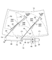
図1及び図2に示されるように、本実施形態に係るワイパ装置10は、一例として、車両のフロントウインドシールド12を払拭するためのフロントワイパ装置とされている。このワイパ装置10は、ワイパモータ32と、変換機構としてのリンク機構70と、左右一対のワイパ部材18と、を備えている。左右のワイパ部材18はそれぞれ、ワイパアーム20と、ワイパアーム20の先端部に連結されたワイパブレード22とによって構成されている。
(Constitution)
As shown in FIGS. 1 and 2, a wiper device 10 according to this embodiment is, as an example, a front wiper device for wiping a front windshield 12 of a vehicle. The wiper device 10 includes a wiper motor 32 , a link mechanism 70 as a conversion mechanism, and a pair of left and right wiper members 18 . Each of the left and right wiper members 18 is composed of a wiper arm 20 and a wiper blade 22 connected to the tip of the wiper arm 20 .

また、このワイパ装置10は、左右のワイパ部材18にそれぞれ取り付けられたノズル24と、各ノズル24に洗浄液を送給するウォッシャポンプ82(図3参照)と、ワイパモータ32に設けられた検出部60(図3参照)と、を備えている。ワイパモータ32及びウォッシャポンプ82は、図3に示されるように、制御装置としてのECU(Electronic Control Unit)86に対して電気的に接続されており、当該ECU86からの電気信号によって作動を制御される構成になっている。 The wiper device 10 also includes nozzles 24 attached to the left and right wiper members 18, a washer pump 82 (see FIG. 3) for supplying cleaning liquid to each nozzle 24, and a detector 60 provided in the wiper motor 32. (See FIG. 3). The wiper motor 32 and the washer pump 82 are electrically connected to an ECU (Electronic Control Unit) 86 as a control device, as shown in FIG. It is configured.

上記のECU86は、車両に搭載されており、ワイパモータ32及びウォッシャポンプ82の他、パワーウィンドウ装置30等の電装品も制御する構成とされている。なお、本実施形態では、制御装置であるECU86とワイパ装置10とが別の構成要素とされているが、これに限らず、制御装置がワイパ装置10の構成要素とされてもよい。 The ECU 86 described above is mounted on the vehicle, and is configured to control not only the wiper motor 32 and the washer pump 82 but also electrical components such as the power window device 30 . In this embodiment, the ECU 86 as the control device and the wiper device 10 are separate components, but the control device may be a component of the wiper device 10 without being limited to this.

上記のワイパモータ32は、出力軸48を軸線回りの一方向に回転させるタイプのワイパモータとされている。このワイパモータ32の出力軸48には、リンク機構70の構成部材であるクランクアーム72の一端部が固定されている。リンク機構70は、左右のワイパアーム20の基端部がそれぞれ固定された左右一対のピボット軸74と、左右のピボット軸74に一端部が固定された左右一対のピボットレバー76と、一方のピボットレバー76とクランクアーム72との間に架け渡された第1リンクロッド78と、左右のピボットレバー76の他端部間に架け渡された第2リンクロッド80とを有している。 The wiper motor 32 is of a type that rotates the output shaft 48 in one direction around the axis. One end of a crank arm 72 that is a component of the link mechanism 70 is fixed to the output shaft 48 of the wiper motor 32 . The link mechanism 70 includes a pair of left and right pivot shafts 74 to which base ends of the left and right wiper arms 20 are respectively fixed, a pair of left and right pivot levers 76 to which one ends are fixed to the left and right pivot shafts 74, and one pivot lever. 76 and the crank arm 72 and a second link rod 80 that spans between the other ends of the left and right pivot levers 76 .

このワイパ装置10では、クランクアーム72がワイパモータ32の出力軸48と一体で出力軸48の軸線回りの一方向へ回転(連続回転)されると、クランクアーム72の回転駆動力が第1リンクロッド78を介して一方のピボットレバー76に伝達される。このピボットレバー76の回転駆動力は、第2リンクロッド80を介して他方のピボットレバー76に伝達され、左右のピボットレバー76が左右のピボット軸74と一体で左右のピボット軸74の軸線回りに往復回動される。これにより、左右のワイパ部材18がフロントウインドシールド12上で同方向に連動して往復回動し、左右のワイパブレード22がフロントウインドシールド12を往復払拭する。この場合、図1及び図2に示されるクローズ位置(下反転位置)P1とオープン位置(上反転位置)P2との間で各ワイパ部材18が往復回動する。左右のワイパ部材18は、ワイパモータ32が作動していない通常時には、クローズ位置(下反転位置)P1に配置される構成になっている。 In the wiper device 10, when the crank arm 72 rotates (continuously rotates) in one direction around the axis of the output shaft 48 integrally with the output shaft 48 of the wiper motor 32, the rotational driving force of the crank arm 72 is applied to the first link rod. 78 to one pivot lever 76 . The rotational driving force of this pivot lever 76 is transmitted to the other pivot lever 76 via the second link rod 80 , and the left and right pivot levers 76 are integrated with the left and right pivot shafts 74 to rotate about the axis of the left and right pivot shafts 74 . It is rotated back and forth. As a result, the left and right wiper members 18 reciprocally rotate on the front windshield 12 in conjunction with each other in the same direction, and the left and right wiper blades 22 wipe the front windshield 12 reciprocatingly. In this case, each wiper member 18 reciprocates between the closed position (lower reversal position) P1 and the open position (upper reversal position) P2 shown in FIGS. The left and right wiper members 18 are arranged at the closed position (lower reversal position) P1 when the wiper motor 32 is not in operation.

以下の説明では、図1に「OPEN動作」の矢印で示されるようにクローズ位置P1からオープン位置P2へ向かう往路での各ワイパ部材18の払拭動作を「オープン動作」と称する。また、以下の説明では、図2に「CLOSE動作」の矢印で示されるようにオープン位置P2からクローズ位置P1へ向かう復路での各ワイパ部材18の払拭動作を「クローズ動作」と称する。また、以下の説明では、左右のワイパ部材18を、単に「ワイパ部材18」と称する。 In the following description, the wiping operation of each wiper member 18 in the outward path from the closed position P1 to the open position P2 as indicated by the arrow of "OPEN operation" in FIG. 1 is referred to as "open operation". Further, in the following description, the wiping operation of each wiper member 18 on the return path from the open position P2 to the closed position P1 as indicated by the "CLOSE operation" arrow in FIG. 2 is referred to as "close operation". Also, in the following description, the left and right wiper members 18 are simply referred to as "wiper members 18".

図1及び図2に示されるように、ワイパ部材18には、ノズル24である第1ノズル24A及び第2ノズル24Bが取り付けられている。第1ノズル24A及び第2ノズル24Bは、ワイパアーム20の先端部又はワイパブレード22の長手方向中間部に取り付けられており、ワイパ部材18の回動方向において互いに反対向きの姿勢で配置されている。第1ノズル24Aは、オープン動作の際に(すなわちワイパ部材18の往復回動の往路において)、ワイパ部材18の進行方向前方側に洗浄液を噴射可能とされている。第2ノズル24Bは、クローズ動作の際に(すなわちワイパ部材18の往復回動の復路において)、ワイパ部材18の進行方向前方側に洗浄液を噴射可能とされている。 As shown in FIGS. 1 and 2, the wiper member 18 is provided with a first nozzle 24A and a second nozzle 24B, which are the nozzles 24 . The first nozzle 24A and the second nozzle 24B are attached to the distal end of the wiper arm 20 or the longitudinally intermediate portion of the wiper blade 22 and are arranged in opposite directions in the rotation direction of the wiper member 18 . The first nozzle 24A is capable of injecting the cleaning liquid to the forward side of the wiper member 18 in the forward direction of the wiper member 18 during the opening operation (that is, on the forward path of the reciprocating rotation of the wiper member 18). The second nozzle 24B is capable of injecting cleaning liquid forward in the direction of movement of the wiper member 18 during the closing operation (that is, on the return path of the reciprocating rotation of the wiper member 18).

第1ノズル24A及び第2ノズル24Bは、それぞれ図示しないホースを介して、図3に示されるウォッシャポンプ82と接続されている。このウォッシャポンプ82は、洗浄液(ウォッシャ液)が貯留される図示しないウォッシャタンクと図示しないホースを介して接続されている。このウォッシャポンプ82は、駆動源であるウォッシャモータ84(図9参照)と、当該ウォッシャモータ84により回転される図示しないインペラとを備えている。このウォッシャポンプ82では、ウォッシャモータ84が正転されると第1ノズル24Aに洗浄液が送給され、ウォッシャモータ84が逆転されると第2ノズル24Bに洗浄液が送給される構成になっている。 The first nozzle 24A and the second nozzle 24B are connected to the washer pump 82 shown in FIG. 3 via hoses (not shown). The washer pump 82 is connected to a washer tank (not shown) in which cleaning fluid (washer fluid) is stored via a hose (not shown). The washer pump 82 includes a washer motor 84 (see FIG. 9) as a drive source and an impeller (not shown) rotated by the washer motor 84 . The washer pump 82 is configured such that when the washer motor 84 rotates forward, the cleaning liquid is supplied to the first nozzle 24A, and when the washer motor 84 rotates in the reverse direction, the cleaning liquid is supplied to the second nozzle 24B. .

上記のウォッシャモータ84及びワイパモータ32は、前述したように、車両に搭載されたECU86に電気的に接続されている。このECU86は、CPU(Central Processing Unit:プロセッサ)86A、RAM(Random Access Memory)86B、ROM(Read Only Memory)86C、及び外部の装置との通信を行う入出力インタフェース部(I/O)86Dを有しており、これらがバス86Eを介して相互に通信可能に接続された構成になっている。 The washer motor 84 and the wiper motor 32 are electrically connected to the ECU 86 mounted on the vehicle, as described above. The ECU 86 includes a CPU (Central Processing Unit: processor) 86A, a RAM (Random Access Memory) 86B, a ROM (Read Only Memory) 86C, and an input/output interface (I/O) 86D for communicating with external devices. These are connected to each other via a bus 86E so as to be able to communicate with each other.

CPU86Aは、中央演算処理ユニットであり、各種プログラムを実行したり、各部を制御したりする。すなわち、CPU86Aは、ROM86Cから制御プログラム86C1を読み出し、RAM86C1を作業領域として制御プログラム86C1を実行する。このCPU86Aは、ROM86Cに記録されている制御プログラム86C1に従って、上記各構成要素の制御および各種の演算処理を行うように構成されている。なお、制御装置は、複数の電子制御ユニットから構成されていてもよいし、ハードウエア及びソフトウエアのいずれによって実現されてもよい。 The CPU 86A is a central processing unit that executes various programs and controls each section. That is, the CPU 86A reads the control program 86C1 from the ROM 86C and executes the control program 86C1 using the RAM 86C1 as a work area. The CPU 86A is configured to control each of the components described above and perform various arithmetic processing according to a control program 86C1 recorded in the ROM 86C. Note that the control device may be composed of a plurality of electronic control units, and may be realized by either hardware or software.

入出力インタフェース部86Dには、ワイパモータ32及びウォッシャモータ84の他、車両に搭載されたパワーウィンドウ装置30のモータ等が電気的に接続されている。また、入出力インタフェース部86Dには、車両のステアリングコラム等に設けられたワイパ/ウォッシャスイッチ88が電気的に接続されている。 In addition to the wiper motor 32 and the washer motor 84, the motors of the power window device 30 mounted on the vehicle are electrically connected to the input/output interface portion 86D. A wiper/washer switch 88 provided on a steering column or the like of a vehicle is electrically connected to the input/output interface section 86D.

このワイパ/ウォッシャスイッチ88は、ワイパモータ32を作動させるワイパスイッチ89と、ワイパモータ32及びウォッシャモータ84を作動させるウォッシャスイッチ90とを備えている。このワイパウォッシャスイッチ88は、例えば回動操作可能なレバーを含んで構成されている。ワイパスイッチ89は、例えば上記のレバーが車両上下方向に回動操作されることにより、ワイパモータ32をミストモード(MIST)で作動させるミストモード選択位置と、ワイパモータ32を間欠払拭モード(INT)で作動させる間欠払拭モード選択位置と、ワイパモータ32を低速払拭モード(LOW)で作動させる低速払拭モード選択位置と、ワイパモータ32を高速払拭モード(HIGH)で作動させる高速払拭モード選択位置と、ワイパモータ32の作動を停止させるOFF位置とに切り替え可能とされている。ウォッシャスイッチ90は、例えば上記のレバーが車両後方側に回動操作(手前側に引く操作)されている間だけONになるように構成されている。 The wiper/washer switch 88 includes a wiper switch 89 that operates the wiper motor 32 and a washer switch 90 that operates the wiper motor 32 and the washer motor 84 . The wiper washer switch 88 includes, for example, a rotatable lever. The wiper switch 89 operates, for example, by rotating the lever in the vertical direction of the vehicle to operate the wiper motor 32 in the mist mode selection position (MIST) and in the intermittent wiping mode (INT). a low-speed wiping mode selection position for operating the wiper motor 32 in the low-speed wiping mode (LOW); a high-speed wiping mode selection position for operating the wiper motor 32 in the high-speed wiping mode (HIGH); can be switched to an OFF position for stopping the The washer switch 90 is, for example, configured to be ON only while the lever is rotated toward the rear of the vehicle (pulled toward the front).

上記のウォッシャモータ84は、ワイパモータ32に設けられた検出部60の検出結果に基づいて、ECU86により作動を制御される構成になっている。以下、図4~図7を用いてワイパモータ32及び検出部60の構成について説明する。 The operation of the washer motor 84 is controlled by the ECU 86 based on the detection result of the detector 60 provided in the wiper motor 32 . The configurations of the wiper motor 32 and the detector 60 will be described below with reference to FIGS. 4 to 7. FIG.

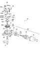
ワイパモータ32は、モータ34と、当該モータ34の回転を減速する減速機構42と、当該減速機構42を収納したハウジング50と、当該ハウジング50に支持され、上記の減速機構42によって減速されて回転する出力軸48とを備えている。モータ34は、一例としてブラシモータとされている。ハウジング50は、例えばアルミニウム合金のダイカストによって製造されたものであり、出力軸48の軸方向の厚さ寸法が小さい扁平な略矩形箱状に形成されている。このハウジング50は、出力軸48の軸方向一方側(図4では上側)が開放された収容室52を有している。この収容室52の開口部は、例えば樹脂からなるカバー56によって閉塞される構成になっている。 The wiper motor 32 is supported by the motor 34, a reduction mechanism 42 that reduces the rotation of the motor 34, a housing 50 that houses the reduction mechanism 42, and the housing 50, and rotates while being reduced in speed by the reduction mechanism 42. and an output shaft 48 . The motor 34 is, for example, a brush motor. The housing 50 is manufactured, for example, by die casting of an aluminum alloy, and is formed in a flat, substantially rectangular box shape with a small thickness dimension in the axial direction of the output shaft 48 . The housing 50 has a housing chamber 52 that is open on one axial side (upper side in FIG. 4) of the output shaft 48 . The opening of the storage chamber 52 is closed by a cover 56 made of resin, for example.

また、このハウジング50の一端部には、円筒状のモータ接続部54が形成されている。このモータ接続部54には、モータ34のヨーク36が固定されている。ヨーク36内には、モータ34のアーマチャ38が収容されており、上記のモータ接続部54内には、ブラシホルダ40が収容されている。アーマチャ38のシャフトは、ハウジング50の収容室52内へ延びる部分を有しており、当該部分の外周面にはウォーム44が転造により形成されている。このウォーム44は、収容室52内に収容されたウォームホイール46に噛合されている。ウォーム44及びウォームホイール46は、減速機構42を構成している。また、ウォームホイール46は、本発明における「ギヤ」に相当しており、ワイパモータ32の作動時には出力軸48と一体で軸線回りの一方向(図4及び図5の矢印R方向)へ回転(連続回転)する。 A cylindrical motor connecting portion 54 is formed at one end of the housing 50 . A yoke 36 of the motor 34 is fixed to the motor connection portion 54 . The armature 38 of the motor 34 is accommodated within the yoke 36, and the brush holder 40 is accommodated within the motor connection portion 54 described above. The shaft of the armature 38 has a portion that extends into the receiving chamber 52 of the housing 50, and a worm 44 is formed on the outer peripheral surface of that portion by rolling. The worm 44 is meshed with a worm wheel 46 housed in the housing chamber 52 . The worm 44 and worm wheel 46 constitute a reduction mechanism 42 . The worm wheel 46 corresponds to a "gear" in the present invention, and rotates (continuously) in one direction (direction of arrow R in FIGS. 4 and 5) around the axis integrally with the output shaft 48 when the wiper motor 32 operates. Rotate.

ウォームホイール46の軸心部には、出力軸48が同軸的に固定されており、当該出力軸48を介してウォームホイール46がハウジング50に回転可能に支持されている。この出力軸48の先端側は、ウォームホイール46に対してカバー56とは反対側へ延びており、ハウジング50の外側へ突出している。この出力軸48の先端部には、前述したクランクアーム72が固定されている。 An output shaft 48 is coaxially fixed to the axial center portion of the worm wheel 46 , and the worm wheel 46 is rotatably supported by the housing 50 via the output shaft 48 . The tip side of the output shaft 48 extends to the side opposite to the cover 56 with respect to the worm wheel 46 and protrudes outside the housing 50 . The aforementioned crank arm 72 is fixed to the tip of the output shaft 48 .

ウォームホイール46におけるカバー56側の面(出力軸48の突出方向とは反対側の面)には、樹脂などの絶縁材料からなるインシュレータ58が取り付けられている。このインシュレータ58は、略円板状に形成されており、ウォームホイール46と同心状に配置されている。このインシュレータ58は、図5及び図6に示されるように、ボス部58Aとフランジ部58Bとによって構成されている。ボス部58Aは、ウォームホイール46側に開口した有底円筒状に形成されており、フランジ部58Bは、ボス部58Aにおける開口側の端部からフランジ状に径方向外側に向けて延出されている。ボス部58Aの内側には、ウォームホイール46の中央部に形成された円柱状のボス部46A(図4参照)が収容されており、当該収容状態でインシュレータ58とウォームホイール46とから互いに近接する方向に突出形成された突起がウォームホイール46の一方向の回転において係合して一体的に連れ回りするように構成されている。なお、図5に示すインシュレータ58は、ウォームホイール46の他方向の1回転未満の回転に対しては互いの突起の係合が解除されるため連れ回りしない構成である。 An insulator 58 made of an insulating material such as resin is attached to the surface of the worm wheel 46 on the side of the cover 56 (the surface opposite to the projecting direction of the output shaft 48). The insulator 58 is formed in a substantially disk shape and arranged concentrically with the worm wheel 46 . As shown in FIGS. 5 and 6, the insulator 58 is composed of a boss portion 58A and a flange portion 58B. The boss portion 58A is formed in a bottomed cylindrical shape that opens toward the worm wheel 46 side, and the flange portion 58B extends outward in the radial direction in a flange shape from the opening-side end portion of the boss portion 58A. there is Inside the boss portion 58A, a columnar boss portion 46A (see FIG. 4) formed in the central portion of the worm wheel 46 is accommodated. A projection formed to protrude in one direction engages with the worm wheel 46 when it rotates in one direction, and rotates integrally with it. Note that the insulator 58 shown in FIG. 5 is configured so that it does not rotate together with the worm wheel 46 when it rotates in the other direction for less than one rotation because the engagement between the protrusions is released.

フランジ部58Bにおけるカバー56側の面には、カムプレート62が取り付けられている。カムプレート62は、例えば導電性を有する金属板によってリング状に形成されており、フランジ部58Bに対して爪嵌合等の手段で固定されている。このカムプレート62は、インシュレータ58を介して間接的にウォームホイール46に取り付けられており、ワイパモータ32の作動時には、インシュレータ58のウォームホイール46との一体的な一方向への連れ回りにより軸線回りの一方向(図4及び図5の矢印R方向)へ回転する。なお、図7に示される変形例のように、カムプレート62がウォームホイール46に直接取り付けられる構成にしてもよい。この変形例では、ウォームホイール46におけるカバー56側の面(出力軸48の突出方向と反対側の面)に、カムプレート62が爪嵌合等の手段で直接取り付けられている。 A cam plate 62 is attached to the cover 56 side surface of the flange portion 58B. The cam plate 62 is formed in a ring shape from, for example, a conductive metal plate, and is fixed to the flange portion 58B by means such as claw fitting. The cam plate 62 is indirectly attached to the worm wheel 46 via the insulator 58, and when the wiper motor 32 is operated, the insulator 58 and the worm wheel 46 rotate integrally in one direction to rotate about the axis. It rotates in one direction (direction of arrow R in FIGS. 4 and 5). Note that the cam plate 62 may be directly attached to the worm wheel 46 as in the modification shown in FIG. In this modified example, a cam plate 62 is directly attached to the surface of the worm wheel 46 on the side of the cover 56 (the surface opposite to the projecting direction of the output shaft 48) by means such as claw fitting.

カムプレート62の外周部には、カムプレート62の径方向外側へ突出したクローズ側カム62Aが形成されており、カムプレート62の内周部には、カムプレート62の径方向内側へ突出したオープン側カム62Bが形成されている。このカムプレート62は、当該カムプレート62に対してカバー56側に配置されたコンタクト部64と共に検出部60を構成している。なお、クローズ側カム62Aがカムプレート62の内周部に形成され、オープン側カム62Bがカムプレート62の外周部に形成された構成にしてもよい。 A closing side cam 62A protruding radially outward of the cam plate 62 is formed on the outer peripheral portion of the cam plate 62, and an open side cam 62A protruding radially inward of the cam plate 62 is formed on the inner peripheral portion of the cam plate 62. A side cam 62B is formed. The cam plate 62 constitutes a detecting portion 60 together with a contact portion 64 arranged on the cover 56 side with respect to the cam plate 62 . The closing side cam 62A may be formed on the inner peripheral portion of the cam plate 62, and the open side cam 62B may be formed on the outer peripheral portion of the cam plate 62. FIG.

コンタクト部64は、カムプレート62の回転によりカムプレート62に対する電気的な接続状態を切換えられるものであり、第1端子としてのP端子64Aと、第2端子としてのCL端子64Bと、第3端子としてのOP端子64Cとによって構成されている。P端子64A、CL端子64B及びOP端子64C(何れもコンタクトレバー)は、例えば金属等の導電性を有する材料によって全体として長尺板状に形成されており、カバー56の内面に取り付けられている。ここでインナカバー66は、例えば樹脂によって構成されており、カバー56に取り付けられ、後述のインサートターミナル68に電気的に接続されているコンデンサなどの雑防素子を保持している。 The contact portion 64 can switch the electrical connection state with respect to the cam plate 62 by rotating the cam plate 62, and includes a P terminal 64A as a first terminal, a CL terminal 64B as a second terminal, and a third terminal. , and an OP terminal 64C. The P terminal 64A, the CL terminal 64B, and the OP terminal 64C (all contact levers) are made of a conductive material such as metal and are formed in a long plate shape as a whole, and are attached to the inner surface of the cover 56. . Here, the inner cover 66 is made of, for example, resin, is attached to the cover 56, and holds noise prevention elements such as capacitors electrically connected to insert terminals 68, which will be described later.

上記のP端子64A、CL端子64B及びOP端子64Cは、カバー56に埋設されたインサートターミナル68と電気的に接続されている。このインサートターミナル68は、一端が前述したブラシホルダ40に設けられた図示しないブラシとも電気的に接続されており、他端がカバー56のコネクタ部56Aから導出されている。このコネクタ部56Aから導出された複数のインサートターミナル68は、図示しない外部コネクタが接続され、ハーネスを介して一部が前述したECU86等と電気的に接続されており、別の一部は電源などに接続されている。 The P terminal 64A, CL terminal 64B and OP terminal 64C are electrically connected to an insert terminal 68 embedded in the cover 56. As shown in FIG. One end of the insert terminal 68 is also electrically connected to a brush (not shown) provided on the brush holder 40 described above, and the other end is led out from the connector portion 56A of the cover 56 . A plurality of insert terminals 68 led out from the connector portion 56A are connected to an external connector (not shown). It is connected to the.

P端子64Aは、カムプレート62の回転位置によらず、常にカムプレート62と接触するように配置されている。CL端子64Bは、ワイパ部材18がクローズ位置P1に位置する状態で、カムプレート62のクローズ側カム62Aと接触するように配置されている。OP端子64Cは、ワイパ部材18がオープン位置P2に位置する状態で、カムプレート62のオープン側カム62Bと接触するように配置されている。上記の「接触する」は「電気的に接続される」と同義である。 The P terminal 64A is arranged so as to always contact the cam plate 62 regardless of the rotational position of the cam plate 62 . The CL terminal 64B is arranged to contact the closing side cam 62A of the cam plate 62 when the wiper member 18 is positioned at the closing position P1. The OP terminal 64C is arranged to contact the open-side cam 62B of the cam plate 62 when the wiper member 18 is positioned at the open position P2. The above "contact" is synonymous with "electrically connected".

このワイパモータ32の作動時には、カムプレート62が出力軸48と一体的に軸線回りの一方向へ回転され、CL端子64B及びOP端子64Cがカムプレート62に対する接続及び非接続を交互に切換えられる。具体的には、オープン動作をするワイパ部材18がオープン位置P2に達すると、OP端子64Cがオープン側カム62Bと接触し、OP端子64CとP端子64Aとが電気的に接続される。その状態からカムプレート62が180度回転すると、OP端子64Cとオープン側カム62Bとが非接触となるとともにCL端子64Bがクローズ側カム62Aと接触し、CL端子64BとP端子64Aとが電気的に接続される。この180度の回転の際には、ワイパ部材18がオープン位置P2からクローズ動作を行い、ワイパ部材18がクローズ位置P1に到達すると、CL端子64BとP端子64Aとが電気的に接続される。 When the wiper motor 32 operates, the cam plate 62 rotates in one direction around the axis integrally with the output shaft 48, and the CL terminal 64B and the OP terminal 64C are alternately switched between connection and disconnection to the cam plate 62. Specifically, when the wiper member 18 performing the opening operation reaches the open position P2, the OP terminal 64C contacts the open side cam 62B, and the OP terminal 64C and the P terminal 64A are electrically connected. When the cam plate 62 rotates 180 degrees from this state, the OP terminal 64C and the open side cam 62B are out of contact with each other, and the CL terminal 64B is brought into contact with the close side cam 62A. connected to During this 180-degree rotation, the wiper member 18 performs a closing operation from the open position P2, and when the wiper member 18 reaches the closed position P1, the CL terminal 64B and the P terminal 64A are electrically connected.

これらのP端子64A、CL端子64B及びOP端子64Cの電気的な接続状態を電気信号として出力し検出することにより、ワイパ部材18がクローズ位置P1に位置する状態とオープン位置P2に位置する状態とを検出できるようになっている。P端子64A及びOP端子64Cは、ECU86の入出力インタフェース部86Dに電気的に接続されており、CL端子64Bは、グランドに接続されている。 By outputting and detecting the electrical connection state of these P terminal 64A, CL terminal 64B, and OP terminal 64C as electrical signals, the state in which the wiper member 18 is positioned at the closed position P1 and the state in which the wiper member 18 is positioned at the open position P2 are determined. can be detected. The P terminal 64A and the OP terminal 64C are electrically connected to the input/output interface section 86D of the ECU 86, and the CL terminal 64B is grounded.

次に、図8~図11を用いて、ワイパ装置10の回路構成及び制御について説明する。なお、図8~図11では、オープン及びクローズを「OPEN」及び「CLOSE」と記載している。図8に示されるように、ワイパモータ32のモータ34は、リレーR1及びリレーR2(図3では図示省略)を介して電源のプラス側と接続されている。リレーR1は、モータ34をON・OFFするためのON-OFFリレーであり、リレーR2は、低速払拭モード(LOW)と高速払拭モード(HIGH)との切換リレーである。また、図9に示されるように、ウォッシャポンプ82のウォッシャモータ84は、リレーR3及びリレーR4を介して電源のプラス側と接続される。リレーR3は、ウォッシャモータ84を正転させる場合のON-OFFリレーであり、リレーR4は、ウォッシャモータ84を逆転させる場合のON-OFFリレーである。これらのリレーR1、R2、R3、R4は、ここではノーマルクローズ(NC)の接触形式とされている。 Next, the circuit configuration and control of the wiper device 10 will be described with reference to FIGS. 8 to 11. FIG. 8 to 11, open and close are described as "OPEN" and "CLOSE". As shown in FIG. 8, the motor 34 of the wiper motor 32 is connected to the positive side of the power supply via relays R1 and R2 (not shown in FIG. 3). A relay R1 is an ON-OFF relay for turning ON/OFF the motor 34, and a relay R2 is a switching relay between a low-speed wiping mode (LOW) and a high-speed wiping mode (HIGH). Also, as shown in FIG. 9, the washer motor 84 of the washer pump 82 is connected to the positive side of the power supply via relays R3 and R4. The relay R3 is an ON-OFF relay for rotating the washer motor 84 forward, and the relay R4 is an ON-OFF relay for rotating the washer motor 84 in reverse. These relays R1, R2, R3, and R4 are here of the normally closed (NC) contact type.

ECU86の入出力インタフェース部86D(図3参照)には、上記のリレーR1、R2、R3、R4を備えたリレーユニット92が電気的に接続されている。ECU86は、ワイパ/ウォッシャスイッチ88の位置に応じて、リレーユニット92の各リレーR1、R2、R3、R4を制御する構成になっている。例えばワイパ/ウォッシャスイッチ88が低速払拭モード選択位置に切換えられると、ECU86は、リレーR1をONにすると共に、リレーR2をOFF(NC)のままとする。これにより、ワイパモータ32が低速で一方向に連続回転される。また例えば、ワイパ/ウォッシャスイッチ88が高速払拭モード選択位置に切換えられると、ECU86は、リレーR1及びリレーR2を何れもONにする。これにより、ワイパモータ32が高速で一方向に連続回転される。そして、ワイパ/ウォッシャスイッチ88がOFF位置に切換えられると、ECU86は、先ずリレーR2をOFF(NC)にし、その後にCL端子64Bがクローズ側カム62Aと接触してP端子が0Vになったことを検出すると、リレーP1をOFF(NC)にする。つまり、ECU86は、ワイパ部材18がクローズ動作によりクローズ位置P1に到達すると、ワイパモータ32を停止させる。 A relay unit 92 including the relays R1, R2, R3, and R4 is electrically connected to the input/output interface section 86D (see FIG. 3) of the ECU 86. As shown in FIG. The ECU 86 is configured to control each relay R1, R2, R3, R4 of the relay unit 92 according to the position of the wiper/washer switch 88. For example, when the wiper/washer switch 88 is switched to the low speed wiping mode selection position, the ECU 86 turns on the relay R1 and keeps the relay R2 off (NC). As a result, the wiper motor 32 is continuously rotated in one direction at a low speed. Further, for example, when the wiper/washer switch 88 is switched to the high-speed wiping mode selection position, the ECU 86 turns ON both the relay R1 and the relay R2. As a result, the wiper motor 32 is continuously rotated in one direction at high speed. Then, when the wiper/washer switch 88 is switched to the OFF position, the ECU 86 first turns OFF (NC) the relay R2, and then the CL terminal 64B comes into contact with the closing side cam 62A and the P terminal becomes 0V. is detected, the relay P1 is turned OFF (NC). That is, the ECU 86 stops the wiper motor 32 when the wiper member 18 reaches the closed position P1 by the closing operation.

また、ウォッシャスイッチ90がONにされると、ECU86は、リレーR1をONにすると共に、リレーR2をOFF(NC)のままとし、さらにP端子64A、CL端子64B及びOP端子64Cの電気的な接続状態に応じてリレーR3、R4を以下のように制御する。すなわち、ECU86は、ウォッシャスイッチ90がONにされると、ワイパモータ32を低速で回転させると共に、P端子64A、CL端子64B及びOP端子64Cの電気的な接続状態に基づいて、ワイパ部材18が一往復するのに要する時間(一往復時間)を検知する。言い換えると、この一往復時間は、ワイパ部材18がクローズ位置P1から再びクローズ位置P1に至るまでの回転時間であり、ワイパモータ32の出力軸48が1回転する時間に等価である。そして、ECU86は、検知した一往復時間に基づいてリレーR3、R4のON・OFF状態を切換え、ウォッシャモータ84の作動を制御する。 Further, when the washer switch 90 is turned ON, the ECU 86 turns ON the relay R1, keeps the relay R2 OFF (NC), and electrically connects the P terminal 64A, CL terminal 64B and OP terminal 64C. Relays R3 and R4 are controlled as follows according to the connection state. That is, when the washer switch 90 is turned ON, the ECU 86 rotates the wiper motor 32 at a low speed, and the wiper member 18 is aligned based on the electrical connection state of the P terminal 64A, CL terminal 64B, and OP terminal 64C. Detect the time required for a round trip (one round trip time). In other words, this one reciprocation time is the rotation time for the wiper member 18 to return from the closed position P1 to the closed position P1 again, and is equivalent to the time for the output shaft 48 of the wiper motor 32 to rotate once. Then, the ECU 86 switches the ON/OFF states of the relays R3 and R4 based on the detected one reciprocating time to control the operation of the washer motor 84.

リレーR3がONにされる一方、リレーR4がOFF(NC)にされた状態では、ウォッシャモータ84(ウォッシャポンプ82)が正転し、第1ノズル24Aから洗浄液が噴射されるようになっている。また、リレーR3がOFF(NC)にされる一方、リレーR4がONにされた状態では、ウォッシャモータ84が逆転し、第2ノズル24Bから洗浄液が噴射されるようになっている。また、リレーR3及びリレーR4の両方がOFF(NC)にされた状態では、ウォッシャモータ84は閉回路を形成して発電制動により停止されるようになっている。 When the relay R3 is turned ON and the relay R4 is turned OFF (NC), the washer motor 84 (washer pump 82) rotates forward and the cleaning liquid is sprayed from the first nozzle 24A. . When the relay R3 is turned off (NC) and the relay R4 is turned on, the washer motor 84 rotates in the reverse direction and the cleaning liquid is sprayed from the second nozzle 24B. When both the relay R3 and the relay R4 are OFF (NC), the washer motor 84 forms a closed circuit and is stopped by dynamic braking.

ECU86は、P端子64A、CL端子64B及びOP端子64Cの電気的な接続状態を、P端子64Aに発生する電圧(カム信号)によって検出する構成になっている。なお、これら各端子64A~64Cとカムプレート62との間には、従来技術のようなウォッシャモータを駆動する大きな電流ではなく、不図示のECU側での抵抗により電気信号としての微小な電流が流れるように構成されている。このP端子64Aは、CPU86Aと電気的に接続されており、CL端子64Bはグランドに接続されている。また、OP端子64Cは、抵抗を介して電源と電気的に接続されており、抵抗によって分圧された電圧(ここでは、一例として電源電圧Vccの1/2の電圧)がOP端子64Cに発生するようになっている。 The ECU 86 is configured to detect the electrical connection state of the P terminal 64A, the CL terminal 64B and the OP terminal 64C from the voltage (cam signal) generated at the P terminal 64A. Between these terminals 64A to 64C and the cam plate 62, rather than a large current for driving the washer motor as in the prior art, a minute current as an electric signal is generated by resistance on the side of the ECU (not shown). designed to flow. The P terminal 64A is electrically connected to the CPU 86A, and the CL terminal 64B is grounded. The OP terminal 64C is electrically connected to the power supply via a resistor, and a voltage divided by the resistor (here, as an example, a voltage of 1/2 of the power supply voltage Vcc) is generated at the OP terminal 64C. It is designed to

カムプレート62のクローズ側カム62AがCL端子64Bと接触した状態では、P端子64Aの電圧が0Vになる。これにより、ECU86は、ワイパ部材18がクローズ位置P1に位置すると判断する。また、カムプレート62のオープン側カム62BがOP端子64Cと接触した状態では、P端子64Aの電圧が1/2Vccになる。これにより、ECU86は、ワイパ部材18がオープン位置P2に位置すると判断する。なお、カムプレート62がCL端子64B及びOP端子64Cの何れとも接触していない状態では、P端子64Aの電圧がVccになるように構成されている。 When the closing side cam 62A of the cam plate 62 is in contact with the CL terminal 64B, the voltage of the P terminal 64A becomes 0V. Accordingly, the ECU 86 determines that the wiper member 18 is positioned at the closed position P1. Also, when the open-side cam 62B of the cam plate 62 is in contact with the OP terminal 64C, the voltage of the P terminal 64A becomes 1/2 Vcc. Accordingly, the ECU 86 determines that the wiper member 18 is positioned at the open position P2. The voltage of the P terminal 64A is Vcc when the cam plate 62 is not in contact with either the CL terminal 64B or the OP terminal 64C.

次に図11を用いて、ウォッシャスイッチ90がONにされた場合のワイパモータ32及びウォッシャモータ84の作動制御について説明する。この図11は、ワイパモータ32すなわちワイパ装置10が作動していない状況でウォッシャスイッチ90がONにされた場合の作動制御を示すものである。この図11では、一例として、ワイパ部材18の一往復時間がT秒であり、ウォッシャスイッチ90がONにされた時間がT秒以上で且つ2T秒未満の場合を図示している。このようにウォッシャスイッチ90が操作されると、ワイパモータ32が低速で一定時間だけ作動される構成になっている。この際のワイパモータ32の作動時間は、一例として、ワイパ部材18が二往復するのに要する時間である2T秒とされている。なお、ウォッシャスイッチ90がONにされた時間が2T秒以上の場合、ワイパモータ32の作動時間は、3T秒以上で且つTの整数倍の秒数とされている。 Next, operation control of the wiper motor 32 and the washer motor 84 when the washer switch 90 is turned on will be described with reference to FIG. FIG. 11 shows operation control when the washer switch 90 is turned on while the wiper motor 32, that is, the wiper device 10 is not operating. As an example, FIG. 11 shows a case where one reciprocating time of the wiper member 18 is T seconds, and the time period during which the washer switch 90 is turned on is T seconds or more and less than 2T seconds. When the washer switch 90 is operated in this way, the wiper motor 32 is operated at a low speed for a certain period of time. The operating time of the wiper motor 32 at this time is, for example, 2T seconds, which is the time required for the wiper member 18 to reciprocate twice. When the washer switch 90 is turned on for 2T seconds or longer, the operating time of the wiper motor 32 is 3T seconds or longer and is an integral multiple of T seconds.

図11に示されるようにウォッシャスイッチ90がONにされ、ワイパモータ32が起動すると、当該起動から1/2T秒後にワイパ部材18がオープン位置P2で反転し、当該反転から1/2T秒後にワイパ部材18がクローズ位置P1で反転する。さらに、その1/2T秒後にワイパ部材18がオープン位置P2で反転し、当該反転から1/2T秒後にワイパ部材18がクローズ位置P1で停止する。 As shown in FIG. 11, when the washer switch 90 is turned ON and the wiper motor 32 is activated, the wiper member 18 is reversed at the open position P2 after 1/2T seconds from the activation, and the wiper member 18 is reversed at the closed position P1. Further, after 1/2T seconds, the wiper member 18 is reversed at the open position P2, and 1/2T seconds after the reverse, the wiper member 18 stops at the closed position P1.

上記のようにワイパ部材18が二往復する間、ECU86は、P端子64Aに発生する電圧(カム信号)に基づいて、ワイパ部材18の一往復時間(図11において符号Tを付した時間)を検知し、当該検知結果に基づいてウォッシャモータ84の作動を制御する。この場合、ECU86は、ワイパ部材18のオープン動作とクローズ動作とに合わせて、ウォッシャモータ84の作動と休止とを交互に繰り返すように構成されている。この場合の「休止」は、「一時的に止める」ことであり、以下に記載する「停止」は、単に「止める」ことである。「休止」の場合、ウォッシャモータ84が再作動されるが、「停止」の場合、ウォッシャスイッチ90が再びONにされない限り、ウォッシャモータ84は再作動されない。 While the wiper member 18 makes two reciprocations as described above, the ECU 86 determines one reciprocation time of the wiper member 18 (the time indicated by symbol T in FIG. 11) based on the voltage (cam signal) generated at the P terminal 64A. and controls the operation of the washer motor 84 based on the detection result. In this case, the ECU 86 is configured to alternately repeat operation and stoppage of the washer motor 84 in accordance with the opening operation and closing operation of the wiper member 18 . "Pause" in this case means "temporarily stop", and "stop" described below simply means "stop". In the case of "Pause" the washer motor 84 is reactivated, but in the case of "Stop" the washer motor 84 is not reactivated unless the washer switch 90 is turned ON again.

図11に示されるようにウォッシャスイッチ90がONにされた際には、ワイパ部材18がクローズ位置P1に位置しており、P端子64Aの電圧が0Vであるため、ECU86は、ウォッシャモータ84を正転でt1秒間だけ作動させた後にt2秒間だけ休止させる。この場合、「t1+t2=T」であり、かつ「t1>t2」に設定されている。このウォッシャモータ84の正転により、オープン動作をするワイパ部材18の進行方向前方側に第1ノズル24Aから洗浄液が噴射され、ワイパ部材18がオープン位置P2に到達する前に洗浄液の噴射が休止される。 When the washer switch 90 is turned on as shown in FIG. 11, the wiper member 18 is positioned at the closed position P1 and the voltage of the P terminal 64A is 0V. After operating for t1 seconds in forward rotation, it is paused for t2 seconds. In this case, "t1+t2=T" and "t1>t2" are set. The normal rotation of the washer motor 84 causes the first nozzle 24A to spray the cleaning liquid forward in the traveling direction of the wiper member 18 performing the opening operation, and the cleaning liquid jetting stops before the wiper member 18 reaches the open position P2. be.

また、ワイパ部材18がオープン位置P2に到達して反転する際には、P端子64Aの電圧が1/2Vccとなるため、ECU86は、ウォッシャモータ84を逆転でt1秒間だけ作動させた後にt2秒間だけ休止させる。このウォッシャモータ84の逆転により、クローズ動作をするワイパ部材18の進行方向前方側に第2ノズル24Bから洗浄液が噴射され、ワイパ部材18がクローズ位置P1に到達する前に洗浄液の噴射が休止される。 When the wiper member 18 reaches the open position P2 and reverses, the voltage at the P terminal 64A becomes 1/2 Vcc. Pause only. Due to the reverse rotation of the washer motor 84, the cleaning liquid is jetted from the second nozzle 24B toward the forward side of the wiper member 18 performing the closing operation, and jetting of the cleaning liquid is stopped before the wiper member 18 reaches the closed position P1. .

また、ワイパ部材18がクローズ位置P1に到達して反転する際には、P端子64Aの電圧が再び0Vになるため、ECU86は、ウォッシャモータ84を正転でt1秒間だけ作動させた後にt2秒間だけ休止させる。これにより、オープン動作をするワイパ部材18の進行方向前方側に第1ノズル24Aから洗浄液が噴射され、ワイパ部材18がオープン位置P2に到達する前に洗浄液の噴射が休止される。 When the wiper member 18 reaches the closed position P1 and reverses, the voltage at the P terminal 64A becomes 0 V again. Pause only. As a result, the cleaning liquid is jetted from the first nozzle 24A toward the forward side of the wiper member 18 performing the opening operation, and jetting of the cleaning liquid is stopped before the wiper member 18 reaches the open position P2.

その後、ワイパ部材18が再びオープン位置P2に到達して反転する際には、P端子64Aの電圧が再び1/2Vccとなるため、ECU86は、ウォッシャモータ84を逆転でt1秒間だけ作動させた後に停止させる。これにより、クローズ動作をするワイパ部材18の進行方向前方側に第2ノズル24Bから洗浄液が噴射され、ワイパ部材18がクローズ位置P1に到達する前に洗浄液の噴射が停止される。 Thereafter, when the wiper member 18 again reaches the open position P2 and reverses, the voltage at the P terminal 64A becomes 1/2 Vcc again. stop. As a result, the cleaning liquid is jetted from the second nozzle 24B toward the forward side of the wiper member 18 performing the closing operation, and the jetting of the cleaning liquid is stopped before the wiper member 18 reaches the closing position P1.

その後、ワイパ部材18が再びクローズ位置P1に到達した際には、P端子64Aの電圧が再び0Vになり、ECU86は、ワイパモータ32及びウォッシャモータ84を停止させる。このT秒~2T秒の間の動作は、最初のT秒の動作と同様とされている。なお、ワイパ装置10の作動中にウォッシャスイッチ90がONにされた場合、ECU86は、払拭動作中のワイパ部材18の位置をカム信号により検出し、ワイパ部材18が次の反転位置で反転したときから、ウォッシャモータ84の作動制御を開始する。 After that, when the wiper member 18 reaches the closed position P1 again, the voltage of the P terminal 64A becomes 0 V again, and the ECU 86 stops the wiper motor 32 and the washer motor 84. The operation from T seconds to 2T seconds is the same as the operation for the first T seconds. When the washer switch 90 is turned on while the wiper device 10 is operating, the ECU 86 detects the position of the wiper member 18 during the wiping operation by means of a cam signal, and when the wiper member 18 is reversed at the next reverse position. , the operation control of the washer motor 84 is started.

上述したように、本実施形態では、ウォッシャモータ84(ウォッシャポンプ82)の正転と逆転とが、ワイパ部材18の往復回動の往路と復路とで切換えられる。これにより、ワイパ部材18の往復回動の往路及び復路の両方でワイパ部材18の進行方向前方側に洗浄液が噴射されるように構成されている。 As described above, in the present embodiment, the normal rotation and reverse rotation of the washer motor 84 (washer pump 82 ) are switched between the outward and return paths of the reciprocating rotation of the wiper member 18 . As a result, the cleaning liquid is sprayed forward in the direction of movement of the wiper member 18 on both the outward and return paths of the reciprocating rotation of the wiper member 18 .

また、本実施形態では、ワイパ部材18の一往復時間の変動に応じて、ウォッシャモータ84(ウォッシャポンプ82)の作動時間t1及び休止時間t2がECU86により補正される構成になっている。つまり、ワイパモータ32の回転数は、電源電圧の変動やワイパ部材18に加わる負荷の変動などにより変動するため、ワイパ部材18の一往復時間が常に一定とは限らない。このため、ECU86は、P端子64Aの電圧を常時モニタすることで、ワイパ部材18の一往復時間の変動すなわちワイパモータ32の回転数の変動を検知し、当該変動に合わせてウォッシャモータ84の作動時間t1及び休止時間t2を補正するように構成されている。具体的には、ECU86は、P端子64Aの電圧の変化から、ワイパ部材18のオープン動作及びクローズ動作の時間を常にモニタし、オープン動作及びクローズ動作の時間が増加又は減少した場合には、その増加又は減少の割合に応じて作動時間t1及び休止時間t2を増加又は減少させるように構成されている。 Further, in this embodiment, the ECU 86 corrects the operation time t1 and the rest time t2 of the washer motor 84 (washer pump 82) in accordance with fluctuations in the reciprocating time of the wiper member 18. FIG. That is, since the number of rotations of the wiper motor 32 fluctuates due to fluctuations in the power supply voltage, fluctuations in the load applied to the wiper member 18, and the like, the reciprocating time of the wiper member 18 is not always constant. Therefore, the ECU 86 constantly monitors the voltage of the P terminal 64A to detect fluctuations in the reciprocating time of the wiper member 18, that is, fluctuations in the rotation speed of the wiper motor 32, and adjusts the operation time of the washer motor 84 in accordance with the fluctuations. It is configured to correct t1 and dwell time t2. Specifically, the ECU 86 constantly monitors the opening and closing operation times of the wiper member 18 from changes in the voltage of the P terminal 64A, and when the opening and closing operation times increase or decrease, the It is configured to increase or decrease the operating time t1 and the resting time t2 according to the rate of increase or decrease.

(作用及び効果)
次に、本実施形態の作用及び効果について説明する。
(Action and effect)
Next, the operation and effects of this embodiment will be described.

本実施形態に係るワイパ装置10では、ワイパモータ32は、車両に搭載されるECU86により作動を制御され、作動することで出力軸48を一方向に回転させる。この出力軸48の一方向の回転は、リンク機構70によってピボット軸74の往復回転に変換される。これにより、ピボット軸74に取り付けられたワイパ部材18が、クローズ位置P1とオープン位置P2との間で往復回動する。このワイパ部材18に設けられた第1ノズル24Aは、上記往復回動の往路でワイパ部材18の進行方向前方側に洗浄液を噴射可能とされている。また、ワイパ部材18に設けられた第2ノズル24Bは、上記往復回動の復路でワイパ部材18の進行方向前方側に洗浄液を噴射可能とされている。これらの第1ノズル24A及び第2ノズル24Bには、ウォッシャポンプ82が作動することで洗浄液が送給される。 In the wiper device 10 according to this embodiment, the operation of the wiper motor 32 is controlled by the ECU 86 mounted on the vehicle, and the operation causes the output shaft 48 to rotate in one direction. This unidirectional rotation of the output shaft 48 is converted into reciprocating rotation of the pivot shaft 74 by the link mechanism 70 . As a result, the wiper member 18 attached to the pivot shaft 74 reciprocates between the closed position P1 and the open position P2. The first nozzle 24A provided on the wiper member 18 is capable of injecting the cleaning liquid forward in the forward direction of the wiper member 18 on the forward path of the reciprocating rotation. Further, the second nozzle 24B provided on the wiper member 18 is capable of injecting cleaning liquid forward in the direction of movement of the wiper member 18 on the return path of the reciprocating rotation. The washing liquid is supplied to the first nozzle 24A and the second nozzle 24B by operating the washer pump 82 .

また、このワイパ装置10は、ワイパ部材18がクローズ位置P1及びオープン位置P2に位置する状態を検出可能な検出部60を備えており、上記のようにワイパ部材18が往復回動しているときには、ワイパ部材18がクローズ位置P1に位置する状態とオープン位置P2に位置する状態とが一定の時間間隔で検出部60により検出される。この検出部60の検出結果に基づいて、ワイパ部材18の一往復時間がECU86により検知される。そして、当該検知された一往復時間に基づいて、ウォッシャポンプ82の作動がECU86により制御される。これにより、上記往路及び復路でのワイパ部材18の回動時にウォッシャポンプ82が作動され、第1ノズル24A又は第2ノズル24Bからワイパ部材18の進行方向前方側に洗浄液が噴射される。このように構成されているので、洗浄液の機械的な切換弁が不要となり、構造が簡素になる。 The wiper device 10 also includes a detection unit 60 capable of detecting the state in which the wiper member 18 is positioned at the closed position P1 and the open position P2. , the state where the wiper member 18 is positioned at the closed position P1 and the state where the wiper member 18 is positioned at the open position P2 are detected by the detection unit 60 at regular time intervals. The ECU 86 detects one reciprocating time of the wiper member 18 based on the detection result of the detection unit 60 . Then, the operation of the washer pump 82 is controlled by the ECU 86 based on the detected one reciprocation time. As a result, the washer pump 82 is actuated when the wiper member 18 rotates on the outward and return trips, and the cleaning liquid is jetted from the first nozzle 24A or the second nozzle 24B to the front side of the wiper member 18 in the traveling direction. Since it is configured in this manner, a mechanical switching valve for cleaning liquid is not required, and the structure is simplified.

しかも、上記の検出部60は、ワイパ部材18がクローズ位置P1に位置する状態とオープン位置P2に位置する状態とを検出可能な電気信号が得られるものであればよく、ウォッシャポンプ82を駆動するための比較的大きな駆動電流が供給されるものではない。このため、当該検出部60がワイパモータ32に搭載された構成であっても、ワイパモータ32の電波ノイズを悪化させずに済むので、車両側の他の電子機器に対して悪影響を及ぼさないようにすることができる。 Moreover, the above-mentioned detection section 60 only needs to obtain an electric signal capable of detecting whether the wiper member 18 is in the closed position P1 or in the open position P2, and drives the washer pump 82. Therefore, a relatively large drive current is not supplied. Therefore, even if the detection unit 60 is mounted on the wiper motor 32, the electric wave noise of the wiper motor 32 does not deteriorate, so that other electronic devices on the vehicle side are not adversely affected. be able to.

なお、ワイパモータにFET(電界効果トランジスタ)を有する制御基板(制御回路)やホールIC等の角度センサが搭載され、ワイパモータを正逆転制御させるタイプの車両用ワイパ装置では、上記の角度センサでワイパモータの出力軸の回転角度及び回転方向を検出し、その検出結果に基づいて上記の制御基板がウォッシャポンプの作動を制御することができる。しかしながら、そのような構成の場合、ワイパモータが複雑で高価なものとなる。この点、本実施形態では、ワイパモータ32に搭載される検出部60は、単にワイパ部材18がクローズ位置P1に位置する状態とオープン位置に位置する状態とを検出可能な電気信号が得られるものであればよい。しかも、ワイパ装置10とは別に車両に搭載されたECU86により、ワイパモータ32及びウォッシャポンプ82の作動を制御するので、ワイパモータ32に制御基板を搭載する必要がない。よって、本実施形態では、ワイパモータ32を含むワイパ装置10を簡素で安価なものとすることができる。 In a wiper device for a vehicle, the wiper motor is equipped with a control board (control circuit) having an FET (field effect transistor) or an angle sensor such as a Hall IC, and the wiper motor is controlled forward and reverse. The rotation angle and rotation direction of the output shaft are detected, and the control board can control the operation of the washer pump based on the detection results. However, such a configuration makes the wiper motor complex and expensive. In this regard, in the present embodiment, the detector 60 mounted on the wiper motor 32 can obtain an electric signal that can simply detect whether the wiper member 18 is in the closed position P1 or the open position. I wish I had. Moreover, since the ECU 86 mounted on the vehicle separately from the wiper device 10 controls the operation of the wiper motor 32 and the washer pump 82 , there is no need to mount a control board on the wiper motor 32 . Therefore, in this embodiment, the wiper device 10 including the wiper motor 32 can be made simple and inexpensive.

また、本実施形態では、ECU86により作動を制御されるウォッシャポンプ82が、ワイパ部材18の往路と復路とで正転と逆転とを切換えられる。ウォッシャポンプ82が正転すると、第1ノズル24Aに洗浄液が送給され、ウォッシャポンプ82が逆転すると、第2ノズル24Bに洗浄液が送給される。これにより、第1ノズル24A及び第2ノズル24Bに対して一つのウォッシャポンプ82で別々に洗浄液を送給することができるので、背景技術の欄で説明した先行技術のように、ウォッシャポンプが第1及び第2のポンプを有する構成と比較して、装置全体の構成を簡素化することができる。 Further, in the present embodiment, the washer pump 82 whose operation is controlled by the ECU 86 is switched between normal rotation and reverse rotation between the outward and return travels of the wiper member 18 . When the washer pump 82 rotates forward, the cleaning liquid is supplied to the first nozzle 24A, and when the washer pump 82 rotates in the reverse direction, the cleaning liquid is supplied to the second nozzle 24B. As a result, the washing liquid can be separately fed to the first nozzle 24A and the second nozzle 24B by one washer pump 82. Therefore, the washer pump can be used as the first nozzle as in the prior art described in the background art section. The configuration of the entire device can be simplified compared to a configuration having one and a second pump.

また、本実施形態では、ウォッシャポンプ82は、ワイパ部材18がクローズ位置P1及びオープン位置P2の一方から回動し始めるときに作動され、ワイパ部材18がクローズ位置P1及びオープン位置P2の他方に到達する前に休止される。これにより、前記他方の位置での洗浄液の液溜りや液だれを防止することができると共に、洗浄液を節約することができる。 Further, in this embodiment, the washer pump 82 is actuated when the wiper member 18 starts rotating from one of the closed position P1 and the open position P2, and the wiper member 18 reaches the other of the closed position P1 and the open position P2. paused before As a result, pooling and dripping of the cleaning liquid at the other position can be prevented, and the cleaning liquid can be saved.

さらに、本実施形態では、ワイパモータ32に印加される電圧の変動などにより、ワイパモータ32の回転数が変動し、ワイパ部材18の一往復時間が変動すると、ウォッシャポンプ82の作動時間t1及び休止時間t2がECU86により補正される。これにより、ワイパ部材18の往復回動とウォッシャポンプ82の作動タイミングとが上記回転数の変動によってずれることを防止又は抑制できる。 Furthermore, in the present embodiment, when the number of revolutions of the wiper motor 32 fluctuates due to fluctuations in the voltage applied to the wiper motor 32 and the reciprocating time of the wiper member 18 fluctuates, the operating time t1 and resting time t2 of the washer pump 82 change. is corrected by the ECU 86. As a result, it is possible to prevent or suppress the deviation between the reciprocating rotation of the wiper member 18 and the operation timing of the washer pump 82 due to the fluctuation in the rotational speed.

また、本実施形態では、ワイパモータ32の作動時には、ワイパモータ32に設けられたカムプレート62が、出力軸48の回転方向である一方向に回転される。このカムプレート62の回転により、ワイパモータ32に設けられたコンタクト部64がカムプレート62に対する電気的な接続状態を切換えられる。この切換えにより、簡単な構成でワイパ部材18の位置を検出することができる。 Further, in this embodiment, when the wiper motor 32 is operated, the cam plate 62 provided on the wiper motor 32 is rotated in one direction, which is the rotation direction of the output shaft 48 . This rotation of the cam plate 62 switches the electrical connection state of the contact portion 64 provided on the wiper motor 32 to the cam plate 62 . This switching allows the position of the wiper member 18 to be detected with a simple configuration.

しかも、上記のカムプレート62は、出力軸48と一体で回転するウォームホイール46と一体的に一方向に連れ回りするインシュレータ58に取り付けられる。これにより、ワイパモータ32の作動時には、カムプレート62が出力軸48及びウォームホイール46と一緒に上記一方向に回転される。このように構成されるので、例えば既存のワイパモータ32に対して異なるパターン形状のカムプレート62を設定する場合に、設計変更が少なくて済む。 Moreover, the cam plate 62 is attached to the insulator 58 that rotates in one direction together with the worm wheel 46 that rotates integrally with the output shaft 48 . Thereby, when the wiper motor 32 is operated, the cam plate 62 is rotated in the one direction together with the output shaft 48 and the worm wheel 46 . Since it is configured in this way, for example, when setting a cam plate 62 having a different pattern shape for an existing wiper motor 32, the design change is small.

また、上記のコンタクト部64は、カムプレート62に対して常に電気的に接続されるP端子64Aと、ワイパ部材18がクローズ位置P1に位置する状態でカムプレート62に対して電気的に接続されるCL端子64Bと、ワイパ部材18がオープン位置P2に位置する状態でカムプレート62に対して電気的に接続されるOP端子64Cと、を有している。これらの端子64A、64B、64Cの電気的な接続状態を検出することにより、ワイパ部材18がクローズ位置P1に位置する状態と、オープン位置P2に位置する状態とを検出することができる。これにより、例えば強風時におけるワイパ部材18のオープン動作とクローズ動作との速度の違いをECU86が検知可能となる。その結果、ワイパ部材18のオープン動作及びクローズ動作の両方でウォッシャポンプ82の作動を精度良く制御することが可能となる。 The contact portion 64 is electrically connected to a P terminal 64A always electrically connected to the cam plate 62 and to the cam plate 62 when the wiper member 18 is at the closed position P1. and an OP terminal 64C electrically connected to the cam plate 62 when the wiper member 18 is at the open position P2. By detecting the electrical connection state of these terminals 64A, 64B, 64C, it is possible to detect whether the wiper member 18 is at the closed position P1 or at the open position P2. As a result, the ECU 86 can detect the difference in speed between the opening operation and the closing operation of the wiper member 18 when the wind is strong, for example. As a result, it is possible to accurately control the operation of the washer pump 82 in both the opening and closing operations of the wiper member 18 .

なお、上記第1実施形態では、ワイパ部材18のオープン動作とクローズ動作とで、ウォッシャポンプ82の作動時間t1及び休止時間t2が同一に設定された構成にしたが、これに限るものではない。ワイパ部材のオープン動作とクローズ動作とで、ウォッシャポンプの作動時間及び休止時間が制御装置により別々に制御される構成にしてもよい。それにより、例えば強風時などにおけるワイパ部材のオープン動作とクローズ動作との速度の違いに合わせて、ウォッシャポンプ82を適切に作動させることが可能となる。つまり、強風時などには、ワイパ部材18のオープン動作がクローズ動作に比べて速くなる場合があるが、そのような場合でも、上記のように構成することにより、ウォッシャポンプ82の適切な制御が可能となる。 In the above-described first embodiment, the operating time t1 and the resting time t2 of the washer pump 82 are set to be the same between the opening operation and the closing operation of the wiper member 18, but it is not limited to this. A configuration may be adopted in which the operating time and resting time of the washer pump are separately controlled by the control device for the opening operation and closing operation of the wiper member. As a result, the washer pump 82 can be appropriately operated in accordance with the difference in speed between the opening and closing operations of the wiper member, for example, during strong winds. In other words, when the wind is strong, the wiper member 18 may open faster than it closes. It becomes possible.

<第2の実施形態>
次に、本発明の第2の実施形態について説明する。なお、第1実施形態と基本的に同様の構成及び作用については、第1実施形態と同符号を付与しその説明を省略する。
<Second embodiment>
Next, a second embodiment of the invention will be described. In addition, the same reference numerals as in the first embodiment are assigned to the configurations and actions that are basically the same as those in the first embodiment, and the description thereof will be omitted.

図12には、本発明の第2実施形態に係る車両用ワイパ装置が備えるワイパモータ32が分解斜視図にて示されている。この実施形態では、第1実施形態に係る検出部60とは異なる検出部94がワイパモータ32に設けられており、第1実施形態に係るインシュレータ58が省略されている。なお、図12では、クランクアーム72及びその周辺部材の図示が省略されている。 FIG. 12 shows an exploded perspective view of the wiper motor 32 included in the vehicle wiper device according to the second embodiment of the present invention. In this embodiment, a detector 94 different from the detector 60 according to the first embodiment is provided in the wiper motor 32, and the insulator 58 according to the first embodiment is omitted. 12, illustration of the crank arm 72 and its peripheral members is omitted.

上記の検出部94は、ウォームホイール46に直接取り付けられたカムプレート96と、一対の端子としてのP端子98A及びCL端子98Bとによって構成されている。カムプレート96は、第1実施形態に係るカムプレート62のようにリング状に形成されておらず、略扇形の板片状で出力軸48の軸線周りに同心状に形成されている。このカムプレート96は、ウォームホイール46におけるカバー56側の面の外周側の一部に爪嵌合等の手段で取り付けられている。P端子98A及びCL端子98Bは、第1実施形態に係るP端子64A及びCL端子64Bと同様の機能を有しており、カバー56の内面に取り付けられている。これらのP端子98A及びCL端子98Bは、ワイパ部材18がクローズ位置P1に位置する状態でカムプレート96に対して電気的に接続されるように配置されている。 The detecting portion 94 is composed of a cam plate 96 directly attached to the worm wheel 46 and a P terminal 98A and a CL terminal 98B as a pair of terminals. The cam plate 96 is not formed in a ring shape like the cam plate 62 according to the first embodiment, but is formed in the shape of a generally fan-shaped plate piece concentrically around the axis of the output shaft 48 . The cam plate 96 is attached to a portion of the outer peripheral side of the surface of the worm wheel 46 on the cover 56 side by means of claw fitting or the like. The P terminal 98A and the CL terminal 98B have the same functions as the P terminal 64A and the CL terminal 64B according to the first embodiment, and are attached to the inner surface of the cover 56. As shown in FIG. These P terminal 98A and CL terminal 98B are arranged to be electrically connected to the cam plate 96 when the wiper member 18 is positioned at the closed position P1.

この実施形態では、ECU86は、P端子98A及びCL端子98Bとの電気的な接続状態を、P端子98Aに発生する電圧(カム信号)によって検出する構成になっている。なお、これら各端子98A、98Bとカムプレート96との間には、従来技術のようなウォッシャモータを駆動する大きな電流ではなく、第1実施形態同様、不図示のECU側での抵抗により電気信号としての微小な電流が流れるように構成されている。このP端子98Aは、CPU86Aと電気的に接続されており、CL端子98Bはグランドに接続されている。これにより、カムプレート96がP端子98A及びCL端子98Bと接触した状態では、P端子98Aの電圧が0Vになり、カムプレート96がP端子98A及びCL端子98Bと接触していない状態では、P端子98Aの電圧が電源電圧Vccになるように構成されている。このため、ECU86は、P端子98Aに発生する電圧が0Vになることで、ワイパ部材18がクローズ位置P1に位置することを検出する。 In this embodiment, the ECU 86 is configured to detect the electrical connection state between the P terminal 98A and the CL terminal 98B by means of the voltage (cam signal) generated at the P terminal 98A. Between these terminals 98A and 98B and the cam plate 96, instead of a large current for driving the washer motor as in the prior art, an electrical signal is generated by resistance on the side of the ECU (not shown) as in the first embodiment. It is configured so that a very small current flows as The P terminal 98A is electrically connected to the CPU 86A, and the CL terminal 98B is grounded. As a result, when the cam plate 96 is in contact with the P terminal 98A and the CL terminal 98B, the voltage of the P terminal 98A becomes 0 V, and when the cam plate 96 is not in contact with the P terminal 98A and the CL terminal 98B, the P The voltage of the terminal 98A is configured to be the power supply voltage Vcc. Therefore, the ECU 86 detects that the wiper member 18 is positioned at the closed position P1 when the voltage generated at the P terminal 98A becomes 0V.

この実施形態では、図14に示されるように、第1実施形態と同様にウォッシャスイッチ90がONにされた場合、ECU86は、P端子98Aに発生する電圧(カム信号)に基づいてワイパ部材18の一往復時間(図14において符号Tを付した時間)を検知し、当該検知結果に基づいてウォッシャモータ84の作動を制御する。なお、図14は、図11と同様に、ワイパ装置10が作動していない状況でウォッシャスイッチ90がONにされた場合の作動制御を示すものである。 In this embodiment, as shown in FIG. 14, when the washer switch 90 is turned on as in the first embodiment, the ECU 86 controls the wiper member 18 based on the voltage (cam signal) generated at the P terminal 98A. (the time indicated by symbol T in FIG. 14) is detected, and the operation of the washer motor 84 is controlled based on the detection result. 14, similarly to FIG. 11, shows operation control when the washer switch 90 is turned on while the wiper device 10 is not in operation.

具体的には、ウォッシャスイッチ90がONにされた際には、P端子98Aの電圧が0Vであるため、ECU86は、ウォッシャモータ84を正転でt1秒間だけ作動させた後にt2秒間だけ休止させる。このウォッシャモータ84の正転により、オープン動作をするワイパ部材18の進行方向前方側に第1ノズル24Aから洗浄液が噴射され、ワイパ部材18がオープン位置P2に到達する前に洗浄液の噴射が休止される。 Specifically, when the washer switch 90 is turned on, the voltage at the P terminal 98A is 0 V, so the ECU 86 causes the washer motor 84 to rotate forward for t1 seconds and then stops for t2 seconds. . The normal rotation of the washer motor 84 causes the first nozzle 24A to spray the cleaning liquid forward in the traveling direction of the wiper member 18 performing the opening operation, and the cleaning liquid jetting stops before the wiper member 18 reaches the open position P2. be.

また、ECU86は、クロックパルスにより時間をカウントしており、ワイパモータ32が回転し始めてから1/2T秒が経過した時点で、ワイパ部材18がオープン位置P2に到達して反転すると判断し、ウォッシャモータ84を逆転でt1秒間だけ作動させた後にt2秒間だけ休止させる。このウォッシャモータ84の逆転により、クローズ動作をするワイパ部材18の進行方向前方側に第2ノズル24Bから洗浄液が噴射され、ワイパ部材18がクローズ位置P1に到達する前に洗浄液の噴射が休止される。 In addition, the ECU 86 counts time by clock pulses, and determines that the wiper member 18 reaches the open position P2 and reverses when 1/2T seconds have passed since the wiper motor 32 started rotating. 84 is operated in reverse for t1 seconds and then paused for t2 seconds. Due to the reverse rotation of the washer motor 84, the cleaning liquid is jetted from the second nozzle 24B toward the forward side of the wiper member 18 performing the closing operation, and jetting of the cleaning liquid is stopped before the wiper member 18 reaches the closed position P1. .

また、ワイパ部材18がクローズ位置P1に到達して反転する際には、P端子98Aの電圧が再び0Vになるため、ECU86は、ウォッシャモータ84を正転でt1秒間だけ作動させた後にt2秒間だけ休止させる。これにより、オープン動作をするワイパ部材18の進行方向前方側に第1ノズル24Aから洗浄液が噴射され、ワイパ部材18がオープン位置P2に到達する前に洗浄液の噴射が休止される。 When the wiper member 18 reaches the closed position P1 and reverses, the voltage at the P terminal 98A becomes 0 V again. Pause only. As a result, the cleaning liquid is jetted from the first nozzle 24A toward the forward side of the wiper member 18 performing the opening operation, and jetting of the cleaning liquid is stopped before the wiper member 18 reaches the open position P2.

また、ECU86は、ワイパモータ32が回転し始めてから3/2T秒が経過した時点で、ワイパ部材18が再びオープン位置P2に到達して反転すると判断し、ウォッシャモータ84を逆転でt1秒間だけ作動させた後に停止させる。このウォッシャモータ84の逆転により、クローズ動作をするワイパ部材18の進行方向前方側に第2ノズル24Bから洗浄液が噴射され、ワイパ部材18がクローズ位置P1に到達する前に洗浄液の噴射が停止される。 When 3/2T seconds have passed since the wiper motor 32 started rotating, the ECU 86 determines that the wiper member 18 reaches the open position P2 again and reverses, and operates the washer motor 84 in the reverse direction for t1 seconds. stop after Due to the reverse rotation of the washer motor 84, the cleaning liquid is jetted from the second nozzle 24B toward the forward side of the wiper member 18 that is performing the closing operation, and jetting of the cleaning liquid is stopped before the wiper member 18 reaches the closed position P1. .

その後、ワイパ部材18が再びクローズ位置P1に到達した際には、P端子98Aの電圧が再び0Vになり、ECU86は、ワイパモータ32及びウォッシャモータ84を停止させる。この実施形態では、上記以外の構成は、第1実施形態と同様とされている。 After that, when the wiper member 18 reaches the closed position P1 again, the voltage of the P terminal 98A becomes 0 V again, and the ECU 86 stops the wiper motor 32 and the washer motor 84. In this embodiment, the configuration other than the above is the same as that of the first embodiment.

この実施形態では、ワイパ部材18がオープン位置に位置する状態が検出されず、クローズ位置P1から次にクローズ位置P1に位置する状態を検出するように構成したこと、及びウォームホイール46にカムプレート96が直接固定されたものであること以外の点では、第1実施形態と同様の作用効果が得られる。しかも、この実施形態では、検出部94の構成が第1実施形態よりも簡素化されると共に、インシュレータ58が省略されているので、第1実施形態よりもワイパモータ32の構成を簡素なものにすることができる。 In this embodiment, the state in which the wiper member 18 is positioned at the open position is not detected, and the state in which the wiper member 18 is positioned from the closed position P1 to the next closed position P1 is detected. The same effects as in the first embodiment can be obtained except that is directly fixed. Moreover, in this embodiment, the structure of the detector 94 is simpler than in the first embodiment, and the insulator 58 is omitted, so that the structure of the wiper motor 32 is simpler than in the first embodiment. be able to.

<実施形態の補足説明>
なお、前記各実施形態では、ワイパ部材18のオープン動作時とクローズ動作時との両方でウォッシャポンプ82が作動される構成としたが、これに限らず、オープン動作時とクローズ動作時との何れか一方のみでウォッシャポンプ82が作動される構成にしてもよい。そのように制御するためには、ECU86の制御プログラム86C1を変更するだけでよく、第1ノズル24A又は第2ノズル24Bを省略することが可能となる。例えば、オープン動作時のみにウォッシャポンプ82が作動される構成にする場合、オープン動作の始点となるクローズ位置P1からワイパ部材18が回動し始めるときにウォッシャポンプ82が所定時間作動され、オープン動作の終点となるオープン位置P2にワイパ部材18が到達する前にウォッシャポンプ82が休止されるようにすることが好ましい。
<Supplementary explanation of the embodiment>
In each of the above-described embodiments, the washer pump 82 is actuated both during the opening operation and the closing operation of the wiper member 18. It may be configured such that the washer pump 82 is operated by only one of them. For such control, it is only necessary to change the control program 86C1 of the ECU 86, and the first nozzle 24A or the second nozzle 24B can be omitted. For example, when the washer pump 82 is operated only during the opening operation, the washer pump 82 is operated for a predetermined time when the wiper member 18 starts rotating from the closing position P1, which is the starting point of the opening operation. Preferably, the washer pump 82 is deactivated before the wiper member 18 reaches the open position P2, which is the end point of .

また、前記各実施形態では、ワイパモータ32に設けられた検出部60、94が、カムプレート62、96と、コンタクト部64、98とを備えた構成にしたが、これに限るものではない。検出部は、ワイパ部材が少なくともクローズ位置に位置する状態を検出可能なものであればよく、マイクロスイッチ等であってもよい。また、検出部がワイパモータ32に設けられる構成に限らず、ワイパモータ32以外(例えばリンク機構70におけるクローズ位置に対応した揺動限界位置)に設けられる構成にしてもよい。 Further, in each of the above-described embodiments, the detection units 60 and 94 provided in the wiper motor 32 are configured to include the cam plates 62 and 96 and the contact portions 64 and 98, but the configuration is not limited to this. The detection section may be a microswitch or the like as long as it can detect a state in which the wiper member is at least in the closed position. Further, the configuration in which the detection section is provided in the wiper motor 32 is not limited to the configuration in which the detection section is provided in a position other than the wiper motor 32 (for example, the swing limit position corresponding to the closed position in the link mechanism 70).

また、前記各実施形態におけるワイパモータ32やリンク機構70(変換機構)等の構造は、単なる一例であり、その構造は適宜変更可能である。 Further, the structures of the wiper motor 32, the link mechanism 70 (conversion mechanism), etc. in each of the above-described embodiments are merely examples, and the structures can be changed as appropriate.

また、前記各実施形態では、フロントワイパ装置であるワイパ装置10に対して本発明が適用された場合について説明したが、これに限るものではない。本発明は、車両のリヤワイパ装置や、アウタミラー用のワイパ装置などに対しても適用可能である。 Further, in each of the above embodiments, the case where the present invention is applied to the wiper device 10, which is a front wiper device, has been described, but the present invention is not limited to this. The present invention can also be applied to a rear wiper device for a vehicle, a wiper device for an outer mirror, and the like.

その他、本発明は、その要旨を逸脱しない範囲で種々変更して実施できる。また、本発明の権利範囲が前記各実施形態に限定されないことは勿論である。 In addition, the present invention can be implemented with various modifications without departing from the scope of the invention. In addition, it goes without saying that the scope of rights of the present invention is not limited to the above embodiments.

10・・・車両用ワイパ装置、18・・・ワイパ部材、24・・・ノズル、24A・・・第1ノズル、24B・・・第2ノズル、32・・・ワイパモータ、46・・・ウォームホイール、48・・・出力軸、60・・・検出部、62・・・カムプレート、64・・・コンタクト部、64A・・・P端子(第1端子)、64B・・・CL端子(第2端子)、64C・・・OP端子(第3端子)、82・・・ウォッシャポンプ、86・・・ECU(制御装置)、94・・・検出部、96・・・カムプレート、98・・・コンタクト部、98A・・・P端子(端子)、98B・・・CL端子(端子) DESCRIPTION OF SYMBOLS 10... Wiper apparatus for vehicles, 18... Wiper member, 24... Nozzle, 24A... 1st nozzle, 24B... 2nd nozzle, 32... Wiper motor, 46... Worm wheel , 48... Output shaft, 60... Detection part, 62... Cam plate, 64... Contact part, 64A... P terminal (first terminal), 64B... CL terminal (second terminal), 64C... OP terminal (third terminal), 82... washer pump, 86... ECU (control device), 94... detector, 96... cam plate, 98... Contact part, 98A... P terminal (terminal), 98B... CL terminal (terminal)

Claims (12)

車両に搭載される制御装置(86)により作動を制御され、作動することで出力軸(48)を一方向に回転させるワイパモータ(32)と、
前記出力軸の一方向の回転をピボット軸(74)の往復回転に変換する変換機構(70)と、
前記ピボット軸に取り付けられ、クローズ位置(P1)とオープン位置(P2)との間で往復回動するワイパ部材(18)と、
前記ワイパ部材に設けられ、前記往復回動の往路及び復路の少なくとも一方で前記ワイパ部材の進行方向の前方側に洗浄液を噴射可能なノズル(24)と、
作動することで前記ノズルに洗浄液を送給するウォッシャポンプ(82)と、
少なくとも前記ワイパ部材が前記クローズ位置に位置する状態を検出可能な検出部(60、94)と、
を備え、
前記検出部の検出結果に基づいて前記ワイパ部材の一往復時間(T)が前記制御装置により検知されると共に、当該検知された一往復時間に基づいて前記ウォッシャポンプが前記制御装置により作動を制御されることにより、前記少なくとも一方での前記ワイパ部材の回動時に前記ウォッシャポンプが作動される車両用ワイパ装置。
a wiper motor (32) whose operation is controlled by a control device (86) mounted on the vehicle, and which operates to rotate the output shaft (48) in one direction;
a converting mechanism (70) for converting the unidirectional rotation of the output shaft into reciprocating rotation of a pivot shaft (74);
a wiper member (18) mounted on the pivot shaft and reciprocatingly rotated between a closed position (P1) and an open position (P2);
a nozzle (24) provided on the wiper member and capable of injecting cleaning liquid forward in the advancing direction of the wiper member on at least one of the outward and return paths of the reciprocating rotation;
a washer pump (82) operable to deliver cleaning fluid to the nozzle;
a detection unit (60, 94) capable of detecting at least the state in which the wiper member is located in the closed position;
with
One reciprocation time (T) of the wiper member is detected by the control device based on the detection result of the detection unit, and the operation of the washer pump is controlled by the control device based on the detected one reciprocation time. A wiper device for a vehicle in which the washer pump is actuated when the at least one wiper member rotates.
前記少なくとも一方での前記ワイパ部材の回動は、前記ワイパ部材が前記クローズ位置から前記オープン位置へと回動するオープン動作である請求項1に記載の車両用ワイパ装置。 2. The wiper device for a vehicle according to claim 1, wherein said at least one of said wiper members is rotated to open said wiper member from said closed position to said open position. 前記ノズルは、
前記オープン動作時に前記ワイパ部材の進行方向前方側に洗浄液を噴射可能な第1ノズル(24A)と、
前記ワイパ部材が前記オープン位置から前記クローズ位置へと回動するクローズ動作時に前記ワイパ部材の進行方向前方側に洗浄液を噴射可能な第2ノズル(24B)と、
を有し、
前記ウォッシャポンプは、正転することで前記第1ノズルに洗浄液を送給する一方、逆転することで前記第2ノズルに洗浄液を送給し、
前記ウォッシャポンプの正転と逆転とが前記オープン動作時と前記クローズ動作時とで前記制御装置により切換えられる請求項2に記載の車両用ワイパ装置。
The nozzle is
a first nozzle (24A) capable of injecting cleaning liquid forward in the direction of movement of the wiper member during the opening operation;
a second nozzle (24B) capable of injecting cleaning liquid forward in the direction of movement of the wiper member during a closing operation in which the wiper member rotates from the open position to the closed position;
has
The washer pump supplies the cleaning liquid to the first nozzle by rotating forward and supplies the cleaning liquid to the second nozzle by rotating in the reverse direction,
3. A wiper device for a vehicle according to claim 2, wherein normal rotation and reverse rotation of said washer pump are switched by said control device during said opening operation and during said closing operation.
前記ウォッシャポンプは、前記オープン動作をする前記ワイパ部材が前記オープン位置に到達する前に休止される請求項2又は請求項3に記載の車両用ワイパ装置。 4. The vehicle wiper device according to claim 2, wherein said washer pump is stopped before said wiper member performing said open operation reaches said open position. 前記ウォッシャポンプは、前記クローズ動作をする前記ワイパ部材が前記クローズ位置に到達する前に休止又は停止される請求項3又は請求項3を引用する請求項4に記載の車両用ワイパ装置。 5. The vehicle wiper device according to claim 3, wherein said washer pump is paused or stopped before said wiper member performing said closing operation reaches said closed position. 前記ウォッシャポンプは、前記一往復時間の変動に応じて作動時間(t1)及び休止時間(t2)を前記制御装置により補正される請求項4又は請求項5に記載の車両用ワイパ装置。 6. The wiper device for a vehicle according to claim 4, wherein said washer pump has its operation time (t1) and rest time (t2) corrected by said control device in accordance with variations in said one reciprocation time. 前記検出部は、前記ワイパ部材が前記オープン位置に位置する状態を検出可能である請求項3、請求項3を引用する請求項4、請求項5、請求項3を引用する請求項6の何れか1項に記載の車両用ワイパ装置。 The detection unit is capable of detecting a state in which the wiper member is positioned at the open position. 1. A wiper device for a vehicle according to claim 1. 前記ウォッシャポンプは、前記オープン動作時と前記クローズ動作時とで作動時間及び休止時間を前記制御装置により別々に制御される請求項7に記載の車両用ワイパ装置。 8. The wiper device for a vehicle according to claim 7, wherein the washer pump is separately controlled by the control device in operation time and rest time during the open operation and during the close operation. 前記検出部は、
前記ワイパモータに設けられ、前記ワイパモータの作動時に前記一方向に回転されるカムプレート(62、96)と、
前記カムプレートの回転により前記カムプレートに対する電気的な接続状態を切換えられるコンタクト部(64、98)と、
を有する請求項1~請求項8の何れか1項に記載の車両用ワイパ装置。
The detection unit is
a cam plate (62, 96) provided on the wiper motor and rotated in the one direction when the wiper motor is operated;
a contact portion (64, 98) capable of switching an electrical connection state with respect to the cam plate by rotation of the cam plate;
A wiper device for a vehicle according to any one of claims 1 to 8.
前記ワイパモータは、前記出力軸と一体で回転するギヤ(46)を有し、
前記カムプレートは、前記ギヤに対して直接又は間接的に取り付けられて前記一方向に対して一体に回転する請求項9に記載の車両用ワイパ装置。
The wiper motor has a gear (46) that rotates integrally with the output shaft,
The wiper device for a vehicle according to claim 9, wherein the cam plate is directly or indirectly attached to the gear and rotates together in the one direction.
前記コンタクト部(64)は、
前記カムプレートに対して常に電気的に接続される第1端子(64A)と、
前記ワイパ部材が前記クローズ位置に位置する状態で前記カムプレートに対して電気的に接続される第2端子(64B)と、
前記ワイパ部材が前記オープン位置に位置する状態で前記カムプレートに対して電気的に接続される第3端子(63C)と、
を有する請求項9又は請求項10に記載の車両用ワイパ装置。
The contact portion (64) is
a first terminal (64A) always electrically connected to the cam plate;
a second terminal (64B) electrically connected to the cam plate when the wiper member is in the closed position;
a third terminal (63C) electrically connected to the cam plate when the wiper member is in the open position;
The vehicle wiper device according to claim 9 or 10, comprising:
前記コンタクト部(98)は、前記ワイパ部材が前記クローズ位置に位置する状態で前記カムプレートに対して電気的に接続される一対の端子(98A、98B)を有する請求項9又は請求項10に記載の車両用ワイパ装置。 11. The contact part (98) has a pair of terminals (98A, 98B) electrically connected to the cam plate when the wiper member is in the closed position. A wiper device for a vehicle as described.
JP2020081412A 2020-05-01 2020-05-01 Wiper device for vehicle Active JP7207362B2 (en)

Priority Applications (5)

Application Number Priority Date Filing Date Title
JP2020081412A JP7207362B2 (en) 2020-05-01 2020-05-01 Wiper device for vehicle
DE112021002628.3T DE112021002628T5 (en) 2020-05-01 2021-03-30 vehicle windshield wiper device
PCT/JP2021/013563 WO2021220700A1 (en) 2020-05-01 2021-03-30 Vehicle wiper device
CN202180031763.0A CN115461255A (en) 2020-05-01 2021-03-30 Wiper device for vehicle
US17/974,150 US11820334B2 (en) 2020-05-01 2022-10-26 Vehicle wiper device

Applications Claiming Priority (1)

Application Number Priority Date Filing Date Title
JP2020081412A JP7207362B2 (en) 2020-05-01 2020-05-01 Wiper device for vehicle

Publications (2)

Publication Number Publication Date
JP2021175633A JP2021175633A (en) 2021-11-04
JP7207362B2 true JP7207362B2 (en) 2023-01-18

Family

ID=78300197

Family Applications (1)

Application Number Title Priority Date Filing Date
JP2020081412A Active JP7207362B2 (en) 2020-05-01 2020-05-01 Wiper device for vehicle

Country Status (5)

Country Link
US (1) US11820334B2 (en)
JP (1) JP7207362B2 (en)
CN (1) CN115461255A (en)
DE (1) DE112021002628T5 (en)
WO (1) WO2021220700A1 (en)

Citations (1)

* Cited by examiner, † Cited by third party
Publication number Priority date Publication date Assignee Title
JP2003252178A (en) 2002-02-28 2003-09-10 Nissan Shatai Co Ltd Wiper operation controller

Family Cites Families (5)

* Cited by examiner, † Cited by third party
Publication number Priority date Publication date Assignee Title
JP2003048517A (en) * 2001-08-03 2003-02-18 Jidosha Denki Kogyo Co Ltd Washer device
JP5864500B2 (en) * 2013-09-26 2016-02-17 富士重工業株式会社 Wiper washer equipment
KR101655565B1 (en) * 2014-11-07 2016-09-07 현대자동차주식회사 Washer-liquid injection control system of wiper blade
JP2017124675A (en) * 2016-01-12 2017-07-20 株式会社ミツバ Wiper device for vehicle
JP2020081412A (en) 2018-11-27 2020-06-04 株式会社サンセイアールアンドディ Game machine

Patent Citations (1)

* Cited by examiner, † Cited by third party
Publication number Priority date Publication date Assignee Title
JP2003252178A (en) 2002-02-28 2003-09-10 Nissan Shatai Co Ltd Wiper operation controller

Also Published As

Publication number Publication date
WO2021220700A1 (en) 2021-11-04
CN115461255A (en) 2022-12-09
JP2021175633A (en) 2021-11-04
US20230046669A1 (en) 2023-02-16
US11820334B2 (en) 2023-11-21
DE112021002628T5 (en) 2023-03-02

Similar Documents

Publication Publication Date Title
US8453290B2 (en) Wiper driving apparatus
JP6285296B2 (en) Wiper device
JP2000255384A (en) Wiper controller
WO2004054856A1 (en) Wiper device control method, wiper device, and motor with speed reuction mechanism
JP7207362B2 (en) Wiper device for vehicle
US11117554B2 (en) Vehicle wiper-washer device
EP1069014B1 (en) Wiper motor
JP2017124675A (en) Wiper device for vehicle
JP2002262515A (en) Motor with reduction gear mechanism
JP7207206B2 (en) In-vehicle sensor cleaning device
US6518717B1 (en) Windscreen wiper drive aggregate and a vehicle which is equipped with the same
JP2018127171A (en) Wiper device
CN212125065U (en) Wiper system and vehicle
JP6085512B2 (en) Wiper device
JP7113921B2 (en) Wiper system and motor vehicle with wiper system
JP2009107422A (en) Wiper device for vehicle
JP2009107421A (en) Wiper device for vehicle
KR100600170B1 (en) Washer system for control injection direction of automobile
JP2004007931A (en) Electric motor with speed reduction mechanism
JP4094259B2 (en) Wiper control device
JP2003054372A (en) Wiper controller
JP2022180036A (en) Wiper device
JP4443455B2 (en) Motor control device
JP2010264787A (en) Wiper device
JP2005212788A (en) Motor control device

Legal Events

Date Code Title Description
A621 Written request for application examination

Free format text: JAPANESE INTERMEDIATE CODE: A621

Effective date: 20220330

TRDD Decision of grant or rejection written
A01 Written decision to grant a patent or to grant a registration (utility model)

Free format text: JAPANESE INTERMEDIATE CODE: A01

Effective date: 20221206

A61 First payment of annual fees (during grant procedure)

Free format text: JAPANESE INTERMEDIATE CODE: A61

Effective date: 20221219

R151 Written notification of patent or utility model registration

Ref document number: 7207362

Country of ref document: JP

Free format text: JAPANESE INTERMEDIATE CODE: R151