JP7206581B2 - Velocity-based control in aperiodically updated controllers, methods for controlling processes, process controllers - Google Patents
Velocity-based control in aperiodically updated controllers, methods for controlling processes, process controllers Download PDFInfo
- Publication number
- JP7206581B2 JP7206581B2 JP2016199737A JP2016199737A JP7206581B2 JP 7206581 B2 JP7206581 B2 JP 7206581B2 JP 2016199737 A JP2016199737 A JP 2016199737A JP 2016199737 A JP2016199737 A JP 2016199737A JP 7206581 B2 JP7206581 B2 JP 7206581B2
- Authority
- JP
- Japan
- Prior art keywords
- control
- controller
- response
- control signal
- iteration
- Prior art date
- Legal status (The legal status is an assumption and is not a legal conclusion. Google has not performed a legal analysis and makes no representation as to the accuracy of the status listed.)
- Active
Links
Images


Classifications
-
- G—PHYSICS
- G05—CONTROLLING; REGULATING
- G05B—CONTROL OR REGULATING SYSTEMS IN GENERAL; FUNCTIONAL ELEMENTS OF SUCH SYSTEMS; MONITORING OR TESTING ARRANGEMENTS FOR SUCH SYSTEMS OR ELEMENTS
- G05B11/00—Automatic controllers
- G05B11/01—Automatic controllers electric
- G05B11/36—Automatic controllers electric with provision for obtaining particular characteristics, e.g. proportional, integral, differential
- G05B11/42—Automatic controllers electric with provision for obtaining particular characteristics, e.g. proportional, integral, differential for obtaining a characteristic which is both proportional and time-dependent, e.g. P.I., P.I.D.
-
- G—PHYSICS
- G05—CONTROLLING; REGULATING
- G05B—CONTROL OR REGULATING SYSTEMS IN GENERAL; FUNCTIONAL ELEMENTS OF SUCH SYSTEMS; MONITORING OR TESTING ARRANGEMENTS FOR SUCH SYSTEMS OR ELEMENTS
- G05B17/00—Systems involving the use of models or simulators of said systems
- G05B17/02—Systems involving the use of models or simulators of said systems electric
-
- G—PHYSICS
- G05—CONTROLLING; REGULATING
- G05B—CONTROL OR REGULATING SYSTEMS IN GENERAL; FUNCTIONAL ELEMENTS OF SUCH SYSTEMS; MONITORING OR TESTING ARRANGEMENTS FOR SUCH SYSTEMS OR ELEMENTS
- G05B19/00—Programme-control systems
- G05B19/02—Programme-control systems electric
- G05B19/418—Total factory control, i.e. centrally controlling a plurality of machines, e.g. direct or distributed numerical control [DNC], flexible manufacturing systems [FMS], integrated manufacturing systems [IMS], computer integrated manufacturing [CIM]
- G05B19/4185—Total factory control, i.e. centrally controlling a plurality of machines, e.g. direct or distributed numerical control [DNC], flexible manufacturing systems [FMS], integrated manufacturing systems [IMS], computer integrated manufacturing [CIM] characterised by the network communication
-
- Y—GENERAL TAGGING OF NEW TECHNOLOGICAL DEVELOPMENTS; GENERAL TAGGING OF CROSS-SECTIONAL TECHNOLOGIES SPANNING OVER SEVERAL SECTIONS OF THE IPC; TECHNICAL SUBJECTS COVERED BY FORMER USPC CROSS-REFERENCE ART COLLECTIONS [XRACs] AND DIGESTS
- Y02—TECHNOLOGIES OR APPLICATIONS FOR MITIGATION OR ADAPTATION AGAINST CLIMATE CHANGE
- Y02P—CLIMATE CHANGE MITIGATION TECHNOLOGIES IN THE PRODUCTION OR PROCESSING OF GOODS
- Y02P90/00—Enabling technologies with a potential contribution to greenhouse gas [GHG] emissions mitigation
- Y02P90/02—Total factory control, e.g. smart factories, flexible manufacturing systems [FMS] or integrated manufacturing systems [IMS]
Description
本特許は、非周期的制御または低速のフィードバックプロセス変数通信を使用する、プロセス制御システムにおける速度に基づく制御を提供するための方法及びシステムの補償に関し、より具体的には、プロセス動力学と比較して低速なレートでプロセス変数フィードバックを受信するときに、制御を実施するときのプロセスをロバストに制御するように構成されるデバイス及び方法に関する。 This patent relates to methods and system compensation for providing velocity-based control in process control systems using aperiodic control or slow feedback process variable communication, and more particularly to process dynamics and comparison. Devices and methods configured to robustly control a process when implementing control when receiving process variable feedback at a slow rate.
化学、石油、または他のプロセスで使用されるような分散型または拡張可能なプロセス制御システムなどのプロセス制御システムは、典型的に、アナログバス、デジタルバス、またはアナログ及びデジタルを組み合わせたバスを介して、相互に、少なくとも1つのホストまたはオペレータワークステーションに、及び1つ以上のフィールドデバイスに通信可能に連結される、1つ以上のプロセスコントローラを含む。例えば、弁、弁ポジショナ、スイッチ、及び送信機(例えば、温度、圧力、及び流量センサ)であり得るフィールドデバイスは、弁を開くまたは閉じること、及びプロセスパラメータを測定することなどのプロセス内の機能を行う。プロセスコントローラは、フィールドデバイスによって作成されるプロセス測定値及び/またはフィールドデバイスに関する他の情報を示す信号を受信し、この情報を使用して、制御ルーチンを実施して制御信号を発生させ、該制御信号は、プロセスの動作を制御するために、バスを通じてフィールドデバイスに送信される。フィールドデバイス及びコントローラからの情報は、典型的に、オペレータワークステーションによって実行される1つ以上のアプリケーションが利用することができる。オペレータが、プロセスの現在の状態を確認すること、プロセスの動作を修正することなどの、プロセスに関する任意の所望の機能を行うことを可能にする。 Process control systems, such as distributed or scalable process control systems such as those used in chemical, petroleum, or other processes, typically communicate via analog, digital, or combined analog and digital buses. includes one or more process controllers communicatively coupled to each other, to at least one host or operator workstation, and to one or more field devices. Field devices, which can be, for example, valves, valve positioners, switches, and transmitters (e.g., temperature, pressure, and flow sensors), perform functions within a process such as opening or closing valves and measuring process parameters. I do. The process controller receives signals indicative of process measurements made by the field device and/or other information about the field device and uses this information to implement control routines to generate control signals and to control the control. Signals are sent over the bus to field devices to control the operation of the process. Information from field devices and controllers is typically available to one or more applications executed by operator workstations. It allows the operator to perform any desired function on the process, such as verifying the current state of the process, modifying the operation of the process, and the like.
Emerson Process Managementによって販売されるDeltaV(登録商標)システムなどの、いくつかのプロセス制御システムは、コントローラまたは異なるフィールドデバイスに位置する、モジュールと称される機能ブロックまたは一群の機能ブロックを使用して、制御動作及び/または監視動作を行う。これらの事例において、コントローラまたは他のデバイスは、1つ以上の機能ブロックまたはモジュールを含み、かつ実行することができ、そのそれぞれが、他の機能ブロック(同じデバイス内または異なるデバイス内のいずれか)からの入力を受信し、及び/または他の機能ブロックに出力を提供し、プロセスパラメータの測定若しくは検出、デバイスの監視、デバイスの制御、または比例-積分-微分(PID)制御ルーチンの実施などの制御動作の実行などの、何らかのプロセス動作を行う。プロセス制御システム内の異なる機能ブロック及びモジュールは、全般的に、(例えば、バスを通じて)互いに通信して、1つ以上のプロセス制御ループを形成するように構成される。 Some process control systems, such as the DeltaV® system sold by Emerson Process Management, use functional blocks or groups of functional blocks called modules located in controllers or different field devices to perform control and/or monitoring operations; In these instances, the controller or other device may contain and execute one or more functional blocks or modules, each of which is associated with another functional block (either within the same device or within a different device). and/or provide output to other functional blocks such as measuring or sensing process parameters, monitoring devices, controlling devices, or performing proportional-integral-derivative (PID) control routines. Take some process action, such as performing a control action. Different functional blocks and modules within a process control system are generally configured to communicate with each other (eg, via a bus) to form one or more process control loops.
プロセスコントローラは、典型的に、プロセスに関して定義されるか、または、フロー制御ループ、温度制御ループ、圧力制御ループなどのプロセス内に含まれる、多数の異なるループの各々に対して、異なるアルゴリズム、サブルーチン、または制御ループ(これらは全て制御ルーチンである)を実行するようにプログラムされる。全般的に言えば、そのような各制御ループは、アナログ入力(AI)機能ブロックなどの1つ以上の入力ブロック、比例-積分-微分(PID)またはファジー論理制御ブロックなどの単一出力の制御ブロック、及びアナログ出力(AO)機能ブロックなどの出力ブロックを含む。制御ルーチン、及びそのようなルーチンを実施する機能ブロックは、PID制御、ファジー論理制御、及びスミス予測器またはモデル予測制御(MPC)などのモデルベースの技法を含む多数の制御技法、に従って構成されている。 A process controller typically implements a different algorithm, subroutine, for each of a number of different loops defined with respect to the process or contained within the process, such as flow control loops, temperature control loops, pressure control loops, etc. , or programmed to execute control loops (which are all control routines). Generally speaking, each such control loop controls one or more input blocks, such as analog input (AI) function blocks, or a single output, such as proportional-integral-derivative (PID) or fuzzy logic control blocks. and output blocks such as analog output (AO) function blocks. Control routines, and the functional blocks implementing such routines, are configured according to a number of control techniques, including PID control, fuzzy logic control, and model-based techniques such as Smith Predictor or Model Predictive Control (MPC). there is
ルーチンの実行をサポートするために、典型的な工業プラントまたはプロセスプラントは、1つ以上のプロセスコントローラ及びプロセスI/Oサブシステムと通信可能に接続される集中制御室を有し、プロセスコントローラ及びプロセスI/Oサブシステムは、1つ以上のフィールドデバイスに接続される。伝統的に、アナログフィールドデバイスは、信号伝送及び電力供給の双方のための二線式または四線式の電流ループによってコントローラに接続されている。制御室に信号を伝送するアナログフィールドデバイス(例えば、センサまたは電送機)は、電流が検知プロセス変数に比例するように、電流ループを流れる電流を変調する。一方で、制御室の制御下でアクションを行うアナログフィールドデバイスは、ループを通る電流の大きさによって制御される。 To support the execution of routines, a typical industrial or process plant has a centralized control room communicatively connected to one or more process controllers and process I/O subsystems. The I/O subsystem is connected to one or more field devices. Traditionally, analog field devices are connected to controllers by two- or four-wire current loops for both signal transmission and power delivery. Analog field devices (eg, sensors or transmitters) that transmit signals to the control room modulate the current through the current loop such that the current is proportional to the sensed process variable. On the other hand, analog field devices that act under the control of the control room are controlled by the magnitude of the current through the loop.
データ転送量の増加に伴って、プロセス制御システム設計の1つの特に重要な態様は、フィールドデバイスが、プロセス制御システムまたはプロセスプラント内のコントローラに、及び他のシステムまたはデバイスに互いに通信可能に連結される様式を含む。全般に、フィールドデバイスがプロセス制御システム内で機能することを可能にする様々な通信チャネル、リンク、及び経路は、一般的に、集合的に入力/出力(I/O)通信ネットワークと称される。 With the increasing amount of data transfer, one particularly important aspect of process control system design is how field devices are communicatively coupled to each other, to controllers within the process control system or process plant, and to other systems or devices. Including the form to be used. Generally, the various communication channels, links, and pathways that allow field devices to function within a process control system are commonly collectively referred to as an input/output (I/O) communication network. .
I/O通信ネットワークを実施するために使用される通信ネットワークトポロジー及び物理的な接続または経路は、特にネットワークが有害な環境要因または厳しい条件を受けるときに、フィールドデバイス通信のロバスト性または健全性にかなりの影響を及ぼすことがあり得る。これらの要因及び条件は、1つ以上のフィールドデバイス、コントローラなどの間の通信の健全性を損ない得る。コントローラとフィールドデバイスとの間の通信は、監視アプリケーションまたは制御ルーチンが、典型的に、ルーチンの各繰り返しに対するプロセス変数の周期的な更新を必要とするので、任意のそのような途絶に特に敏感である。したがって、損なわれた制御通信は、プロセス制御システムの効率性及び/または利益性の低下、及び過剰な摩耗または装置に対する損傷、並びに任意の数の潜在的に有害な故障をもたらし得る。 The communications network topology and physical connections or paths used to implement the I/O communications network are critical to the robustness or integrity of field device communications, especially when the network is subjected to adverse environmental factors or severe conditions. can have a significant impact. These factors and conditions can compromise the integrity of communications between one or more field devices, controllers, and the like. Communication between controllers and field devices is particularly sensitive to any such disruption, as monitoring applications or control routines typically require periodic updates of process variables for each iteration of the routine. be. Impaired control communications can therefore result in reduced efficiency and/or profitability of the process control system and excessive wear or damage to equipment, as well as any number of potentially harmful failures.
ロバストな通信を保証するために、プロセス制御システムで使用するI/O通信ネットワークは、歴史的にハードワイヤードである。残念なことに、ハードワイヤードネットワークは、数多くの複雑性、課題、及び制限を導入する。例えば、ハードワイヤードネットワークの品質は、時間とともに劣化し得る。更に、特に、I/O通信ネットワークが、例えば数エーカーの土地を費やす精油所または化学プラントといった広い面積にわたって分散される大規模な工業プラントまたは施設と関連付けられる場合に、ハードワイヤードI/O通信ネットワークは、典型的に、設置に費用がかかる。必要な長い配線取り付けは、典型的に、かなりの労働力、材料、及び費用を伴い、また、配線インピーダンス及び電磁妨害から生じる信号劣化を導入する場合がある。これらの及び他の理由により、ハードワイヤードI/O通信ネットワークは、全般的に、再構成、修正、または更新することが困難である。 To ensure robust communication, I/O communication networks used in process control systems have historically been hardwired. Unfortunately, hardwired networks introduce numerous complications, challenges, and limitations. For example, the quality of hardwired networks can degrade over time. Further, hardwired I/O communication networks, especially when the I/O communication networks are associated with large industrial plants or facilities distributed over large areas, such as refineries or chemical plants that consume several acres of land. are typically expensive to install. The long wiring installations required typically involve significant labor, materials, and expense, and can introduce signal degradation resulting from wiring impedance and electromagnetic interference. For these and other reasons, hardwired I/O communication networks are generally difficult to reconfigure, modify, or update.
無線I/O通信ネットワークを使用して、ハードワイヤードI/O通信ネットワークと関連付けられる問題点のいくつかを軽減することが提案されてきた。例えば、その開示全体が参照により本明細書に明示的に組み込まれる、米国特許出願公開第2003/0043052号、名称「Apparatus for Providing Redundant Wireless Access to Field Devices in a Distributed Control System」は、ハードワイヤード通信の使用を増やす、または補うために無線通信を利用するシステムを開示している。 It has been proposed to use wireless I/O communication networks to alleviate some of the problems associated with hardwired I/O communication networks. For example, U.S. Patent Application Publication No. 2003/0043052, entitled "Apparatus for Providing Redundant Wireless Access to Field Devices in a Distributed Control System," the entire disclosure of which is expressly incorporated herein by reference, is a hardwired communication Disclosed is a system that utilizes wireless communication to augment or supplement the use of.
制御関連の伝送のための無線通信に対する依存は、数ある中でも信頼性が懸念されるため、伝統的に制限される。上で説明されるように、最新の監視アプリケーション及びプロセス制御は、最適な制御レベルを達成するために、コントローラとフィールドデバイスとの間の信頼性のあるデータ通信に依存する。更に、典型的なコントローラは、そのプロセスにおいて望ましくない偏差を迅速に修正するために、高速で制御アルゴリズムを実行する。望ましくない環境要因または他の悪条件は、監視及び制御アルゴリズムのそのような実行をサポートするために必要な高速通信を妨害または阻止する間欠的干渉を生じさせる場合がある。幸運にも、無線ネットワークは、過去20年にわたってはるかにロバストになり、いくつかのタイプのプロセス制御システムにおいて無線通信の信頼性のある使用を可能にしてきた。 Reliance on wireless communication for control-related transmissions has traditionally been limited due to reliability concerns, among other things. As explained above, modern monitoring applications and process control rely on reliable data communication between controllers and field devices to achieve optimum levels of control. Additionally, typical controllers execute control algorithms at high speeds to quickly correct undesirable deviations in the process. Undesirable environmental factors or other adverse conditions may produce intermittent interference that impedes or prevents the high speed communications necessary to support such execution of monitoring and control algorithms. Fortunately, wireless networks have become much more robust over the past two decades, allowing reliable use of wireless communications in several types of process control systems.
しかし、電力消費は、依然として、プロセス制御アプリケーションで無線通信を使用するときの、複雑化要因である。無線フィールドデバイスがI/Oネットワークから物理的に分離されるので、フィールドデバイスは、典型的に、それ自体の電力源を提供する必要がある。故に、フィールドデバイスは、バッテリ式とするか、太陽エネルギーを引き出すか、または振動、熱、圧力などの環境エネルギーを取り出すことができる。これらのデバイスにとって、データ伝送のために消費されるエネルギーは、総エネルギー消費のかなりの部分を占める場合がある。実際に、測定されているプロセス変数を検知または検出するためになされるステップなどのフィールドデバイスによって行われる他の重要な動作中よりも、無線通信接続を確立し、維持するプロセス中のほうが、より多くの電力を消費する場合がある。無線プロセス制御システムの電力消費を低減させ、したがって、バッテリ寿命を延ばすために、センサなどのフィールドデバイスが非周期的な、低速の、または間欠的な様式でコントローラと通信する無線プロセス制御システムを実施することが提案されてきた。1つの事例において、フィールドデバイスは、プロセス変数のかなりの変化が検出され、コントローラと非周期的通信につながるときにだけ、コントローラと通信、またはコントローラに対してプロセス変数の測定値を送信することができる。 However, power consumption remains a complicating factor when using wireless communications in process control applications. Because wireless field devices are physically separated from the I/O network, field devices typically need to provide their own power source. Thus, field devices can be battery powered, draw solar energy, or draw environmental energy such as vibration, heat, pressure, and the like. For these devices, the energy consumed for data transmission can be a significant portion of the total energy consumption. In fact, more during the process of establishing and maintaining a wireless communication connection than during other critical operations performed by the field device, such as the steps taken to sense or detect the process variable being measured. May consume a lot of power. Implementing a wireless process control system in which field devices, such as sensors, communicate with the controller in an aperiodic, slow, or intermittent fashion to reduce power consumption of the wireless process control system and thus extend battery life has been proposed to do. In one instance, a field device may communicate with or transmit process variable measurements to a controller only when a significant change in the process variable is detected, leading to aperiodic communication with the controller. can.
非周期的プロセス変数測定値更新を取り扱うために開発された1つの制御技法は、低頻度なまたは非周期的な測定値更新の間にコントローラによって生成される制御信号に対して予想されるプロセス応答の指示を提供し、維持する制御システムを使用する。予想されるプロセス応答は、所与の測定値更新のための制御信号に対して予想されるプロセス応答を算出する数学的モデルによって開発することができる。この技法の一例は、その開示全体が参照により本明細書に明示的に組み込まれる、米国特許第7,587,252号、名称「Non-Periodic Control Communications in Wireless and Other Process Control Systems」で説明されている。具体的には、この特許は、非周期的プロセス変数測定値更新を受信すると、制御信号に対して予想されるプロセス応答の指示を生成し、次の非周期的プロセス変数測定値更新の到着まで、予想されるプロセス応答の生成された指示を維持するフィルタを有する、制御システムを開示している。別の例として、その開示全体が参照により本明細書に明示的に組み込まれる、米国特許第7,620,460号、名称「Process Control With Unreliable Communications」は、制御信号に対して予想される応答の指示を提供するが、最後の非周期的測定値更新以来経過した時間の測定値を組み込んで、予想されるプロセス応答のより正確な指示を生成するために、フィルタを更に修正するフィルタを含む、システムを開示する。 One control technique that has been developed to handle aperiodic process variable measurement updates is the expected process response to control signals generated by the controller during infrequent or aperiodic measurement updates. Use a control system to provide and maintain instructions for The expected process response can be developed by a mathematical model that calculates the expected process response to control signals for a given measurement update. An example of this technique is described in US Pat. No. 7,587,252, entitled "Non-Periodic Control Communications in Wireless and Other Process Control Systems," the entire disclosure of which is expressly incorporated herein by reference. ing. Specifically, this patent generates an indication of the expected process response to a control signal upon receipt of an aperiodic process variable measurement update and waits until the arrival of the next aperiodic process variable measurement update. , discloses a control system having a filter that maintains a generated indication of expected process response. As another example, U.S. Pat. No. 7,620,460, entitled "Process Control With Unreliable Communications," the disclosure of which is expressly incorporated herein by reference in its entirety, describes an expected response to a control signal. but includes a filter that further modifies the filter to incorporate measurements of the time elapsed since the last aperiodic measurement update to produce a more accurate indication of the expected process response. , disclose the system.
しかしながら、多くの制御アプリケーションにおいて、プロセス制御システムは、プロセス動作中に、設定点変化を受信する場合がある。全般的に、周期的に更新される制御システム(例えば、ハードワイヤード制御通信システム)の実行中に、設定点が変化したときに、設定点と測定されたプロセス変数との間のエラーに対する比例アクションを行うように設計されるコントローラは、新しい定常状態値に向かってプロセス変数を駆動するために、コントローラ出力を直ちに変化させる。しかしながら、上述の双方の例において説明されるように動作する、低頻度で非周期的な測定値更新を受信する無線制御システムにおいて、各新しい測定値更新によって反映される、測定されたプロセス応答は、最後の測定値更新を受信した後しばらくして行われる設定点変化によって生じる出力の変化に加えて、最後の測定値更新のために取り込まれるコントローラ出力において行われる変化を反映する。この事例において、(米国特許第7,620,460号で説明されるように)コントローラ出力、及び最後の測定値更新以来の時間に基づいてコントローラのリセット成分を算出することは、最後の測定値更新の後に行われる変化を過剰に補償する場合がある。したがって、設定点変化に対するプロセス応答は、最後の測定値更新の後に設定点変化がいつ行われたかに基づいて、異なる場合がある。結果として、このシステムは、コントローラが設定点の変化後に制御信号を発生させるときに、以前に発生させた(及び現在古くなった)予想される応答の指示に依存し続けるので、設定点変化に対して迅速に、またはロバストに応答しない。この問題を解決するために、その開示全体が参照により明示的に組み込まれる、米国特許出願公開第2013/0184837号、名称「Compensating for Setpoint Changes in a Non-Periodically Updated Controller」は、いかなる新しいプロセス変数測定値も受信しない時間中に、制御された変数の動作を追跡するために、コントローラ内のフィードバックループにおいて連続的に更新されるフィルタを使用し、また、コントローラで新しいプロセス変数測定値を受信したときに、このコントローラの出力を使用するが、別様には、プロセス変数の測定値を受信して制御信号を発生させた最も近時からのフィルタの出力を使用する、システムを開示している。このシステムにおいて、発生させた制御信号は、プロセス変数の測定値を受信する時間の間にプロセス変数の設定点が変化したときに、より良好に応答し、より良好に動作する。 However, in many control applications, the process control system may receive setpoint changes during process operation. In general, a proportional action on the error between the setpoint and the measured process variable when the setpoint changes during the execution of a periodically updated control system (e.g. hardwired control communication system) A controller designed to do will change the controller output immediately to drive the process variable towards the new steady state value. However, in a wireless control system receiving infrequent, aperiodic measurement updates, operating as described in both examples above, the measured process response reflected by each new measurement update is , reflects changes made in the controller output that are captured for the last measurement update, in addition to changes in the output caused by setpoint changes that occur some time after the last measurement update is received. In this case, calculating the controller reset component based on the controller output (as described in U.S. Pat. No. 7,620,460) and the time since the last measurement update is the last measurement It may overcompensate for changes that occur after an update. Therefore, the process response to setpoint changes may differ based on when the setpoint change occurred after the last measurement update. As a result, the system continues to rely on previously generated (and now outdated) expected response indications when the controller generates the control signal after a setpoint change, so does not respond quickly or robustly to To solve this problem, US Patent Application Publication No. 2013/0184837, entitled "Compensating for Setpoint Changes in a Non-Periodically Updated Controller," the disclosure of which is expressly incorporated by reference in its entirety, addresses any new process variable Using a continuously updated filter in a feedback loop within the controller to track the behavior of the controlled variable during times when no measurements are received and when new process variable measurements are received at the controller A system is disclosed that sometimes uses the output of this controller, but otherwise uses the output of a filter from the most recent time a process variable measurement was received to generate a control signal. . In this system, the generated control signal responds better and performs better when the process variable set point changes during the time the process variable measurement is received.
更に、バッテリ駆動の送信機を無線制御システムにおいて使用するときには、長時間のバッテリ寿命を維持するようにシステムをセットアップすることが望ましい。例えば、現在の送信機及びバッテリ技術を使用して3~5年のバッテリ寿命を得るためには、全般的に、8秒以上の通信更新レートを使用することが必要である。しかしながら、プロセスの制御を維持するために、プロセスの応答時間と関連付けられるレートの少なくとも4倍の時間(すなわち、プロセス応答時間の逆数)であるレートで受信するプロセスフィードバック測定値をそれでも有することが重要であるので、そのような低速の更新レートを使用することは、30秒以上のプロセス応答時間を有するプロセスに対するPID(比例-積分-微分)に基づく無線制御の使用を制限する。 Additionally, when using battery-powered transmitters in wireless control systems, it is desirable to set up the system to maintain long battery life. For example, obtaining a battery life of 3-5 years using current transmitter and battery technology generally requires the use of communication update rates of 8 seconds or greater. However, in order to maintain control of the process, it is important to still have process feedback measurements received at a rate that is at least four times the rate associated with the process response time (i.e., the inverse of the process response time). Therefore, using such a slow update rate limits the use of PID (proportional-integral-derivative) based radio control to processes with process response times of 30 seconds or more.
なお更に、移動するべき最終的な位置を示す、弁または他の被制御要素に提供される位置出力、例えば4~20maの信号またはデジタル信号を生成することを使用するものを含む、無線制御に対処するために使用することができる、様々なタイプのPIDアルゴリズムが存在する。しかしながら、例えばある特定の時間量にわたって移動可能な要素に通電することによって、弁または他の被制御要素をある特定の方向にある特定の量だけ移動させるように指示する、速度に基づく制御信号を提供する、他のPIDアルゴリズムも存在する。そのような速度に基づく制御信号は、一般に、電気モーターとともに使用され、また、(特定の期間にわたって移動させるために移動可能な要素に通電しなければならない、弁の時間量を示すように変調されるパルス幅を有する)パルス信号の形態で制御信号を提供する。速度に基づくコントローラは、移動可能な要素によって取得される実際の位置を示す信号ではなく、位置信号の変化を生成する傾向がある。したがって、速度に基づく制御アルゴリズムは、増分(増加/減少)出力をアクチュエータに提供するために使用される傾向があり、よって、位置フィードバックを提供することができないアクチュエータを制御する際に使用することができる。 Still further, wireless control, including those using generating a position output, such as a 4-20 ma signal or a digital signal, provided to a valve or other controlled element that indicates the final position to be moved. There are various types of PID algorithms that can be used to address. However, a velocity-based control signal directing a valve or other controlled element to move a particular amount in a particular direction, e.g., by energizing the movable element for a particular amount of time. There are also other PID algorithms that provide. Such velocity-based control signals are commonly used with electric motors and are modulated to indicate the amount of time a valve must be energized in order to move it for a specified period of time. A control signal is provided in the form of a pulse signal (having a pulse width of Velocity-based controllers tend to produce changes in the position signal rather than signals indicative of the actual position obtained by the moveable element. Therefore, velocity-based control algorithms tend to be used to provide incremental (increase/decrease) output to actuators, and thus can be used in controlling actuators that are incapable of providing position feedback. can.
制御技法は、制御されたプロセス変数の測定値がプロセスコントローラへのフィードバックとして提供されるレートに関して高速な動力学を有する、プロセスまたは制御ループのロバストな制御を可能にする。具体的には、本制御技法は、位置または速度の形態のPIDアルゴリズムを使用して、プロセスを制御することができ、プロセス変数の測定値またはフィードバック信号が、プロセス応答時間に等しいか、更にはそれよりも長い時間間隔でコントローラに提供される。具体的には、本制御技法は、フィードバック時間間隔よりも2~4倍短い応答時間を有するプロセスにおいて、ロバストな制御を提供するために使用することができる。そのような状況は、例えば、プロセス変数のフィードバック測定値が、無線で、間欠的に、またはプロセスの応答時間よりも短いか、応答時間に近いか、若しくは応答時間よりも長い時間間隔でコントローラに提供される無線制御を使用するときに起こり得る。 Control techniques enable robust control of processes or control loops that have fast dynamics with respect to the rate at which measurements of the controlled process variables are provided as feedback to the process controller. Specifically, the present control techniques may use PID algorithms in the form of position or velocity to control the process, where the measured value of the process variable or feedback signal equals the process response time or even provided to the controller at longer time intervals. Specifically, the control technique can be used to provide robust control in processes with response times that are two to four times shorter than the feedback time interval. Such situations may occur, for example, when feedback measurements of process variables are sent to the controller wirelessly, intermittently, or at time intervals shorter than, close to, or longer than the response time of the process. This can occur when using the radio control provided.
開示される速度PID制御ルーチンは、アクチュエータが増分入力を必要とし、かついかなる位置フィードバックもコントローラに利用できないときに無線測定値を使用して制御を行うために、位置または増分入力を必要とするアクチュエータにインターフェースするときに有線測定値によって制御を行うために、及び従来の設置物並びに無線測定値が制御に使用される新しい設置物に対処するために、などの、数多くの異なる状況において使用することができる。更に、速度の形態のPIDアルゴリズムの調整は、プロセスゲイン及び動力学に基づいて行うことができ、また、無線通信レートから独立している。なお更に、速度の形態のPID制御ルーチンは、通信の喪失時に最後の出力位置を自動的に保持し、通信が再確立されたときにバンプレスな復旧を提供する。 The disclosed velocity PID control routine is useful for actuators requiring position or incremental inputs to control using wireless measurements when the actuators require incremental inputs and no position feedback is available to the controller. and to address legacy installations as well as new installations where wireless measurements are used for control. can be done. Additionally, adjustments to the PID algorithm in the form of speed can be made based on process gains and dynamics and are independent of wireless communication rate. Still further, the PID control routine in the form of velocity automatically holds the last output position upon loss of communication and provides bumpless recovery when communication is re-established.
1つの事例において、新しい制御技法を実施するコントローラは、全般的に、異なる構造を含み該構造では、差分、比例、積分、及び微分制御信号成分を発生させ、それらを使用して、差分または移動に基づく制御信号を生成し、該信号は、次いで、被制御デバイス、例えば弁に送信されて、被制御デバイスの動作、したがってプロセスを制御する。この差分または速度に基づく制御形態は、低速なプロセス変数のフィードバック測定値の存在下で、標準的なPID制御よりも良好に動作する制御信号を発生させる。具体的には、この制御技法を使用するコントローラは、各コントローラの繰り返し中に、以前の比例制御信号成分と新しく算出された比例制御信号成分との間の差分を表す、差分の比例値を発生させ、この差分の比例値は、コントローラからの各新しい制御信号の基準として使用される。しかしながら、コントローラで新しいプロセス変数測定値信号が利用することができるときに、様々な他の制御信号成分、例えば微分制御信号成分及び/または積分制御信号成分を、差分の比例制御信号成分に加えること、または該成分と組み合わせることができる。これらの2つの制御信号成分はまた、新しく算出された値と以前に算出された値との間の差分に基づくこともできる。具体的には、新しい微分成分は、コントローラ繰り返し中に算出することができ、その時点で、プロセス変数測定値の新しく受信した値をコントローラで利用することができる。同様に、新しい積分成分は、連続的に更新されるフィルタを使用して発生させることができ、該フィルタは、コントローラの各制御ルーチンの繰り返しに対するプロセスの予想される応答の新しい指示を発生させる。しかしながら、連続的に更新されるフィルタの出力は、プロセス変数測定値の新しい値を受信したときにだけ、新しい積分要素を発生させるために使用される。それ以外のときには、積分制御信号成分は、ゼロに設定される。 In one instance, controllers implementing new control techniques generally include different structures in which differential, proportional, integral, and derivative control signal components are generated and used to provide differential or moving control signal components. which is then sent to a controlled device, eg a valve, to control the operation of the controlled device and thus the process. This difference or speed-based form of control produces a control signal that performs better than standard PID control in the presence of slow process variable feedback measurements. Specifically, a controller using this control technique generates a differential proportional value representing the difference between the previous proportional control signal component and the newly calculated proportional control signal component during each controller iteration. and the proportional value of this difference is used as the basis for each new control signal from the controller. However, various other control signal components, such as a derivative control signal component and/or an integral control signal component, can be added to the differential proportional control signal component when new process variable measurement signals are available at the controller. , or in combination with said components. These two control signal components can also be based on the difference between the newly calculated value and the previously calculated value. Specifically, new derivative components can be calculated during controller iterations, at which time newly received values of process variable measurements can be utilized by the controller. Similarly, new integral components can be generated using a continuously updated filter that generates a new indication of the expected response of the process to each iteration of the controller's control routine. However, the continuously updated filter output is used to generate new integral elements only when new values of process variable measurements are received. Otherwise, the integral control signal component is set to zero.
本明細書で開示される速度に基づくPID制御技法は、差分の形態を使用して、(プロセス変数のフィードバック信号がコントローラの入力に存在する時間の間であっても)設定点変化に迅速に適合する制御信号を生成するが、それでも、制御されているプロセスの応答時間の逆数よりも遅い(例えば、それよりも2~4倍も遅い)、応答時間の逆数に近い、または応答時間の逆数よりも速いレートで受信されるフィードバック信号を含む、低速に受信される(例えば、間欠的な)フィードバック信号の存在下で、ロバストで安定した制御を提供する。 The speed-based PID control technique disclosed herein uses a differential form to rapidly respond to setpoint changes (even during the time the process variable feedback signal is present at the input of the controller). Generates a suitable control signal but is still slower than the inverse of the response time of the process being controlled (e.g., 2-4 times slower), close to the inverse of the response time, or the inverse of the response time. It provides robust and stable control in the presence of slowly received (eg, intermittent) feedback signals, including feedback signals received at a faster rate.
制御技法は、プロセス測定値フィードバック信号が低速または間欠的に受信されるプロセスループにおいて制御を行うために使用することができ、特に、プロセス測定値フィードバック信号を、プロセス応答時間の逆数などの、制御されているプロセス動力学と関連付けられるレートよりも遅い、レートと同程度の、レートよりも僅かに速いレートで受信するときに有用である。このコントローラは、例えば、低速な及び/または非周期的様式で、特に、制御されているプロセス動力学のプロセス応答レート(すなわち、制御されているプロセス変数に対するプロセス応答時間の逆数)未満である、プロセス応答レートと同程度である、または別様にはプロセス応答レートに類似するレートで、プロセス測定値信号をフィードバック信号として受信するコントローラにおいて使用することができる。1つの事例において、制御技法は、比例寄与信号を微分寄与信号及び積分寄与信号のうちの1つ以上と組み合わせることによって、弁などのプロセスデバイスを制御する際に使用するための制御信号を生成する。速度に基づくPIDアルゴリズムが使用される1つの事例において、コントローラは、設定点と、直前に受信したプロセス変数測定値のフィードバック信号との間の差分から、比例寄与値を生成する。この誤差信号は、次いで、ゲイン信号を乗じて、コントローラの最後の実行サイクル以来のこの信号の変化を決定する差分ユニットに提供される。更に、微分ユニットは、誤差信号を受信し、基本的にはコントローラで最後の測定信号を受信して以来の誤差信号を経時的に微分して、誤差信号に対する微分算出を行うことができる。微分モジュールまたは算出の出力はまた、変化検出ユニットまたは差分ユニットにも提供され、微分算出の現在の出力と、制御信号の算出に使用される以前の値との間の差分を決定する。同様に、積分算出ユニットが、制御信号の差分を比例ユニット及び微分ユニットによる生成物として受信し、積分する(例えば、合計する)。加算器の出力は、加算器の出力をフィルタ処理して積分寄与信号を生成するために、フィルタに提供される。しかしながら、この積分寄与は、加算器に提供され、新しいフィードバック値がコントローラに提供されたときにだけ、この寄与と制御信号の出力とを合計する。すなわち、積分寄与は、全てのコントローラ繰り返しに対してゼロに設定されるが、コントローラで新しいフィードバック信号を利用することができるものは除く。 Control techniques can be used to provide control in process loops in which the process measurement feedback signal is received slowly or intermittently, and in particular, the process measurement feedback signal can be used to control the process measurement feedback signal, such as the inverse of the process response time. It is useful when receiving at a rate that is slower than, similar to, or slightly faster than the rate associated with the process dynamics involved. The controller, e.g., in a slow and/or aperiodic manner, particularly below the process response rate of the process dynamics being controlled (i.e., the reciprocal of the process response time to the process variable being controlled). It can be used in a controller that receives a process measurement signal as a feedback signal at a rate comparable to or otherwise similar to the process response rate. In one instance, the control technique combines a proportional contribution signal with one or more of a differential contribution signal and an integral contribution signal to generate a control signal for use in controlling a process device such as a valve. . In one instance where a velocity-based PID algorithm is used, the controller generates a proportional contribution value from the difference between the setpoint and the feedback signal of the most recently received process variable measurement. This error signal is then provided to a difference unit which multiplies the gain signal to determine the change in this signal since the last execution cycle of the controller. Further, the differentiating unit receives the error signal and basically differentiates the error signal over time since the last measurement signal was received by the controller so that the differential calculation can be performed on the error signal. The output of the derivative module or calculation is also provided to a change detection unit or difference unit to determine the difference between the current output of the derivative calculation and the previous value used to calculate the control signal. Similarly, an integral computation unit receives and integrates (eg, sums) the difference in the control signal as a product of the proportional unit and the derivative unit. The output of the adder is provided to a filter for filtering the output of the adder to produce an integrated contribution signal. However, this integral contribution is provided to an adder which only sums this contribution with the output of the control signal when a new feedback value is provided to the controller. That is, the integral contribution is set to zero for all controller iterations, except those for which a new feedback signal is available at the controller.
全般的に言えば、コントローラ内の積分寄与ユニットの連続的に更新されるフィルタは、フィールドデバイスからプロセス変数測定値更新を低速または非周期的に受信するにもかかわらず、コントローラの各制御ルーチン繰り返し中に、予想されるプロセス応答(フィードバック寄与とも呼ばれる)の指示を発生させる。連続的に更新されるフィルタは、部分的には、各制御ルーチン繰り返し中に、予想される応答の指示を発生させるために、最後の制御ルーチン繰り返し及び制御ルーチン実行期間からの以前に発生させた予想される応答の指示を使用する。加えて、コントローラ内の積分出力スイッチは、連続的に更新されるフィルタの出力を、最新の測定値の指示に基づく積分(リセットとしても知られる)寄与などのフィードバック寄与として、制御信号に提供する。全般的に言えば、積分出力スイッチは、新しい測定値信号を利用することができないコントローラの各繰り返し中の、制御信号に対する積分またはリセット寄与として、速度の形態のPIDコントローラにおいて、最後の測定値更新をコントローラによって受信した時間に連続的に更新されるフィルタによって発生させられるような予想されるプロセス応答、またはゼロ値を提供する。新しい測定値更新を利用することができるときに、積分出力スイッチは、(新しい測定値更新の指示に基づいて)連続的に更新されるフィルタによって発生させた、予想されるプロセス応答の新しい指示にクランプし、制御信号の積分寄与として、新しい予想されるプロセス応答を提供する。その結果、コントローラは、連続的に更新されるフィルタを使用して、各コントローラ繰り返し中に、プロセスの新しい予想される応答を決定し、各新しい予想されるプロセス応答は、コントローラで新しい測定値を利用することができるときにだけ制御信号の積分またはリセット成分が変化する場合であっても、測定値更新の間の時間に行われたものであり、また、制御信号の展開中にコントローラ出力に影響を及ぼす、設定点変化またはフィードフォワード変化の影響を反映する。 Generally speaking, the continuously updated filter of the integral contribution unit in the controller ensures that each control routine iteration of the controller, despite slow or aperiodic reception of process variable measurement updates from field devices, , an indication of the expected process response (also called feedback contribution) is generated. A continuously updated filter was generated previously from the last control routine iteration and control routine execution period, in part, to generate an indication of the expected response during each control routine iteration. Use expected response indications. Additionally, an integral output switch in the controller provides the continuously updated output of the filter to the control signal as a feedback contribution, such as an integral (also known as reset) contribution based on the indication of the most recent measurement. . Generally speaking, the integral output switch outputs the last measured value update in the PID controller in the form of velocity as an integral or reset contribution to the control signal during each iteration of the controller where no new measured value signal is available. is received by the controller, providing the expected process response as produced by a continuously updated filter, or a zero value. When a new measurement update is available, the integral output switch responds to a new indication of the expected process response generated by the continuously updated filter (based on the new measurement update indication). Clamp and provide the new expected process response as the integral contribution of the control signal. As a result, the controller uses a continuously updated filter to determine a new expected response of the process during each controller iteration, each new expected process response resulting in a new measurement at the controller. Even if the integral or reset component of the control signal changes only when it is available, it is done in the time between measurement updates, and the controller output changes during development of the control signal. Reflects the effect of setpoint changes or feedforward changes that have an impact.
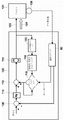
図1には、説明される制御方法を実施するために使用することができる、プロセス制御システム10が例示される。プロセス制御システム10は、データヒストリアン12に、及び1つ以上のホストワークステーションまたはコンピュータ13(任意のタイプのパーソナルコンピュータ、ワークステーションなどとすることができる)に接続することができ、各々が、表示画面14を有する、プロセスコントローラ11を含む。コントローラ11はまた、入力/出力(I/O)カード26及び28を介して、フィールドデバイス15~22にも接続される。データヒストリアン12は、データを記憶するための任意の所望のタイプのメモリ、及び任意の所望のまたは既知のソフトウェア、ハードウェア、またはファームウェアを有する、任意の所望のタイプのデータ収集ユニットとすることができる。図1において、コントローラ11は、ハードワイヤード通信ネットワーク及び通信スキームを使用して、フィールドデバイス15~22に通信可能に接続される。
FIG. 1 illustrates a
全般的に、フィールドデバイス15~22は、センサ、弁、送信機、位置決め器などの任意のタイプのデバイスとすることができ、一方で、I/Oカード26及び28は、任意の所望の通信またはコントローラプロトコルに準拠する任意のタイプのI/Oデバイスとすることができる。コントローラ11は、メモリ24に記憶される1つ以上のプロセス制御ルーチン(または任意のモジュール、ブロック、またはそのサブルーチン)を実施または監督する、プロセッサ23を含む。全般的に言えば、コントローラ11は、任意の所望の様式でプロセスを制御するために、デバイス15~22、ホストコンピュータ13、及びデータヒストリアン12と通信する。更に、コントローラ11は、一般に機能ブロックと称されるものを使用して、制御ストラテジまたはスキームを実施し、各機能ブロックは、プロセス制御システム10内でプロセス制御ループを実施するために、(リンクと呼ばれる通信を介して)他の機能ブロックとともに動作する、制御ルーチン全体のオブジェクトまたは他の部分(例えば、サブルーチン)である。機能ブロックは、典型的に、プロセス制御システム10内でいくつかの物理的機能を行うために、送信機、センサ、若しくは他のプロセスパラメータ測定デバイスと関連付けられるような入力機能、PID、ファジー論理制御などを行う制御ルーチンと関連付けられるような制御機能、または弁などのいくつかのデバイスの動作を制御する出力機能、のうちの1つを行う。当然、ハイブリッド及び他のタイプの機能ブロックが存在し、本明細書で利用することができる。機能ブロックは、下で説明されるように、コントローラ11または他のデバイスに記憶し、それによって実行することができる。
In general, field devices 15-22 can be any type of device such as sensors, valves, transmitters, positioners, etc., while I/
図1の分解ブロック30で例示されるように、コントローラ11は、制御ルーチン32及び34として例示される、いくつかの単一ループ制御ルーチンを含むことができ、また、所望であれば、制御ループ36として例示される、1つ以上のアドバンスト制御ループを実施することができる。各制御ループは、典型的に、制御モジュールと称される。単一ループ制御ルーチン32及び34は、弁などのプロセス制御デバイス、温度及び圧力送信機などの測定デバイス、またはプロセス制御システム10内の任意の他のデバイスと関連付けることができる、適切なアナログ入力(AI)及びアナログ出力(AO)機能ブロックにそれぞれ接続される単一入力/単一出力ファジー論理制御ブロック及び単一入力/単一出力PID制御ブロックを使用して、単一ループ制御を行うように例示される。アドバンスト制御ループ36は、1つ以上のAI機能ブロックに通信可能に接続される入力及び1つ以上のAO機能ブロックに通信可能に接続される出力を有する、アドバンスト制御ブロック38を含むように例示されるが、アドバンスト制御ブロック38の入力及び出力は、他のタイプの入力を受信し、他のタイプの制御出力を提供するために、任意の他の所望される機能ブロックまたは制御要素に接続することができる。アドバンスト制御ブロック38は、任意のタイプの多重入力、多重出力制御スキームを実施することができ、また、モデル予測制御(MPC)ブロック、ニューラルネットワークモデリングまたは制御ブロック、多変数ファジー論理制御ブロック、リアルタイムオプティマイザブロックなどを構成するか、または含むことができる。アドバンスト制御ブロック38を含む、図1に例示される機能ブロックは、スタンドアロンのコントローラ11によって実行することができ、または代替的に、ワークステーション13のうちの1つまたはフィールドデバイス19~22のうちの1つなどの、プロセス制御システムの任意の他の処理デバイスまたは制御要素の中に位置させて、実行することができることが理解されるであろう。一例として、フィールドデバイス21及び22は、それぞれ、送信機及び弁とすることができ、また、制御ルーチンを実施するための制御要素を実行することができ、よって、1つ以上の機能ブロックなどの、制御ルーチンの一部を実施するための処理構成要素及び他の構成要素を含むことができる。より具体的には、図1に例示されるように、フィールドデバイス21は、アナログ入力ブロックと関連付けられる論理及びデータを記憶するためのメモリ39Aを有することができ、一方で、フィールドデバイス22は、アナログ出力(AO)ブロックと通信しているPIDまたは他の制御ブロックと関連付けられる論理及びデータを記憶するためのメモリ39Bを有するアクチュエータを含むことができる。
As illustrated in
図2のグラフは、全般的に、制御ループ32、34、及び36(並びに/またはフィールドデバイス21及び22若しくは他のデバイスの中に存在する機能ブロックを組み込んでいる任意の制御ループ)のうちの1つ以上の実施に基づいて、プロセス制御システムのプロセス入力に応答して展開される、プロセス出力を例示する。実施されている制御ルーチンは、全般的に、図2において太い矢印40による時間軸に沿って示されている制御ルーチンの実行回数によって、多数のコントローラ繰り返しを通じて、周期的様式で実行する。従来の事例において、各制御ルーチン繰り返し40は、例えば送信機または他のフィールドデバイスによって提供される、細い矢印42によって示される更新されたプロセス測定値によってサポートされる。図2に例示されるように、典型的には、周期的制御ルーチン実行時間40の各々の間に制御ルーチンによってなされ、受信される、複数の周期的プロセス測定値42が存在する。測定値と制御の実行との同期化と関連付けられる制限を回避するために、多くの既知のプロセス制御システム(または制御ループ)は、プロセス可変測定値を2~10倍の係数でオーバーサンプリングするように設計される。そのようなオーバーサンプリングは、各制御ルーチンの実行または繰り返しの間に制御スキームにおいて使用するためのプロセス変数測定値が最新であることを確実にすることを補助する。また、制御の変動を最小にするために、従来の設計では、フィードバックに基づく制御が、プロセス応答時間よりも4~10倍速く実行されるべきであること、及び新しいプロセス変数測定値を各コントローラ繰り返し時に利用することができることが定められている。プロセス応答時間は、プロセス時定数(τ)(例えば、プロセス変数の変化の63%)に、プロセス入力のステップ変化44の実施後のプロセス遅延またはむだ時間(TD)(図2の下側の線45で示される)を加えたものと関連付けられる時間であるように、図2のグラフのプロセス出力応答曲線43に表される。いずれにしても、これらの従来の設計要件を満たすために、プロセス測定値更新(図2の矢印42によって示される)は、制御ルーチン実行レート(図2の矢印40によって示される)よりもはるかに速い、よって、プロセス応答時間よりもはるかに速いか、または高いレートでサンプリングされ、コントローラに提供される。
The graph of FIG. 2 generally illustrates
しかしながら、プロセスから高頻度で周期的な測定値のサンプルを取得することは、例えば、コントローラが1つ以上のフィールドデバイスから測定値を無線で受信するプロセス制御環境においてコントローラが動作しているときには、実用的でなく、または不可能な場合さえある。具体的には、これらの事例において、コントローラは、(無線センサ/送信機のバッテリ寿命を節約するために)低速なプロセス変数測定値または非周期的プロセス変数測定値を受信することだけしかできない場合がある。更に、これらの事例において、非周期的、更には周期的プロセス変数測定値の間の時間は、制御ルーチン実行レート(図2の矢印40によって示される)よりも長くなる場合がある。図3は、プロセス制御データの低速な及び/または非周期的無線通信、またはコントローラ11でのプロセス変数測定値の使用を実施することができる、例示的な無線プロセス制御システム10を描写する。
However, obtaining frequent and periodic samples of measurements from the process can be difficult, for example, when the controller is operating in a process control environment in which it wirelessly receives measurements from one or more field devices. Impractical or even impossible. Specifically, in these cases, if the controller can only receive slow or aperiodic process variable measurements (to conserve battery life of the wireless sensor/transmitter) There is Moreover, in these cases, the time between aperiodic and even periodic process variable measurements may be longer than the control routine execution rate (indicated by
図3の制御システム10は、図1の制御システム10に本質的に類似し、同じ要素には同じ番号が付される。しかしながら、図3の制御システム10は、コントローラ11に、及び潜在的に互いに無線で通信可能に連結される、多数のフィールドデバイス60~64及び71を含む。図3に例示されるように、無線で接続されるフィールドデバイス60は、アンテナ65に接続され、アンテナ74と無線で通信するように協働し、次に該アンテナが無線I/Oデバイス68に連結される。更に、フィールドデバイス61~64は、有線-無線変換ユニット66に接続され、次に該ユニットがアンテナ67に次第に接続される。フィールドデバイス61~64は、アンテナ67を通して、更なる無線I/Oデバイス70に接続されるアンテナ73と無線で通信する。同じく図3に例示されるように、フィールドデバイス71は、アンテナ73及び74のうちの一方または双方と通信するアンテナ72を含み、それによって、I/Oデバイス68及び/または70と通信する。次にI/Oデバイス68及び70は、有線バックプレーン接続(図3に図示せず)を介して、コントローラ11に通信可能に接続される。この事例において、フィールドデバイス15~22は、I/Oデバイス26及び28を介して、コントローラ11にハードワイヤードされたままである。
The
図3のプロセス制御システム10は、下で説明されるように、全般的に、送信機60~64またはフィールドデバイス71などの他の制御要素によって測定され、感知され、または計算されるデータの無線伝送を使用する。図3の制御システム10において、新しいプロセス変数測定値または他の信号値は、特定の条件が満たされたときなどに、低速または非周期を基準にデバイス60~64及び71によってコントローラ11に伝送されるものとみなされる。例えば、新しいプロセス変数測定値は、デバイスによってコントローラ11に送信された最後のプロセス変数測定値に対してプロセス変数値が所定の量だけ変化したときに、コントローラ11に送信することができる。これらの信号はまた、周期的に送信することもできるが、有線プロセス制御信号などの典型的なプロセス制御システムの場合は、はるかに遅いレートであることが普通である。例えば、低速の周期的フィードバックレートは、コントローラ実行レート(コントローラが、制御信号を作成する際に使用するための新しい制御信号を発生させるレート)よりも低くすることができ、また、本明細書で説明される制御技法を使用して、制御されているプロセス動力学の応答レートよりも2~4倍低いレートなどの、プロセス応答レートまたは応答時間よりも低い、それと同程度の、またはそれに類似するレートとすることができる。ここでは、プロセス応答レートは、プロセス応答時間の逆数である。当然、周期的または非周期的様式でプロセス変数測定値をいつ送信するのかを決定する他の方法を、同様にまたは代わりに実施することができる。
The
理解されるように、図3の送信機60~64は、1つ以上の制御ループ若しくは制御ルーチンで使用するために、または監視ルーチンで使用するために、それぞれのプロセス変数(例えば、流量、圧力、温度、またはレベル信号)を示す信号をコントローラ11に伝送することができる。フィールドデバイス71などの他の無線デバイスは、プロセス制御信号を無線で受信することができ、及び/または任意の他のプロセスパラメータを示す他の信号を伝送するように構成することができる。全般的に言えば、図3に例示されるように、コントローラ11は、入来信号を処理するプロセッサ上で実行する通信スタック80と、入来信号が測定値更新を含むときに検出するためにプロセッサ上で実行するモジュールまたはルーチン82と、測定値更新に基づいて制御を行うためにプロセッサ上で実行する1つ以上の制御モジュール84とを含む。検出ルーチン82は、通信スタック80を介して提供されるデータが新しいプロセス変数測定値または他のタイプの更新を含むことを示すために、フラグまたは他の信号を発生させることができる。次いで、下で更に詳細に説明されるように、新しいデータ及び更新フラグは、(機能ブロックとすることができる)制御モジュール84のうちの1つ以上に提供することができ、次いで、該制御モジュールが、所定の周期的実行レートでコントローラ11によって実行される。代替として、または加えて、新しいデータ及び更新フラグは、コントローラ11でまたは制御システム10の他の部分で実行される1つ以上の監視モジュールまたはアプリケーションに提供することができる。
As will be appreciated, the transmitters 60-64 of FIG. 3 each transmit a respective process variable (e.g., flow rate, pressure , temperature, or level signal) can be transmitted to the
図3の無線(または他の)送信機は、全般的に、結果として低速または周期的になり、フィールドデバイス60~64及び71とコントローラ11との間の不規則な、または別様には頻度の低いデータ伝送を含む。しかしながら、上で述べられるように、フィールドデバイス15~22からコントローラ11への測定値の通信は、因習的に、コントローラの実行レートよりもはるかに速いレートで、またはプロセスの動的レートよりも少なくともはるかに速いレートで、すなわち、(制御されているプロセスの現象について)プロセス応答時間の逆数で、周期的な様式で行われるように構築されている。その結果、コントローラ11の制御ルーチンは、全般的に、コントローラ11のフィードバックループで使用されるプロセス変数測定値の周期的更新のために設計される。
The wireless (or other) transmitter of FIG. 3 generally results in slow or periodic, irregular or otherwise frequent communication between field devices 60-64 and 71 and
例えばフィールドデバイスのうちのいくつかとコントローラ11との間の無線通信によって導入される、低速な、非周期的な、または別様には利用できない測定値更新(及び他の利用できない通信伝送)に適応するために、コントローラ11の制御及び監視ルーチン(複数可)は、下で説明されるように、非周期的または非周期的または間欠的更新を含む低速を使用するときに、特に、これらの更新がコントローラ11の実行レートよりも低い頻度で起こるときに、更には、そのような更新をプロセス応答レート(例えば、制御されているプロセス変数のプロセス応答時間の逆数)に類似するレート(例えば、2~4倍低いまたは同程度のレート等)で受信するときに、プロセス制御システム10が適切に機能することを可能にするように再構築または修正することができる。図4~図10には、低速な及び/または非周期的制御に関連する通信を使用して動作するように構成される、例示的な制御スキームが更に詳細に例示される。例えば、図4Aは、プロセス101に連結される位置タイプのプロセスコントローラ100を概略的に例示する。コントローラ100(図1及び図3のコントローラ11、または、例えば図3の無線フィールドデバイスのうちの1つなどのフィールドデバイスの制御要素とすることができる)によって実施される制御スキームは、全般的に、図3に関連して例示され、説明される通信スタック80の機能性と、更新検出モジュール82と、制御モジュール84のうちの1つ以上とを含み、また、制御デバイスの移動可能な要素が移動するべき位置を示す制御信号を生成する。
Accommodates slow, aperiodic, or otherwise unavailable measurement updates (and other unavailable communication transmissions), such as those introduced by wireless communication between some of the field devices and the
図4Aの例示的なシステムにおいて、コントローラ100は、例えばワークステーション13(図1及び図3)のうちの1つから、またはプロセス制御システム10内の、若しくは該プロセス制御システムと通信している任意の他のソースから設定点信号を受信し、コントローラ100の出力からプロセス101に提供される1つ以上の制御信号105を発生させるように動作する。制御信号105を受信する他に、プロセス101は、矢印104によって概略的に示される、測定された、または測定されていない外乱を受ける場合がある。プロセス制御アプリケーションのタイプに応じて、設定点信号は、ユーザ、調整ルーチンなどによるなどして、プロセス101の制御中の任意のときに変化させることができる。当然、プロセス制御信号105は、弁と関連付けられるアクチュエータを制御することができ、またはプロセス101の動作の応答に影響を及ぼすように任意の他のフィールドデバイスを制御することができる。プロセス制御信号105の変化に対するプロセス101の応答は、送信機、センサ、または他のフィールドデバイス106によって測定または検知され、例えば、図3に例示される送信機60~64のうちの任意の1つに対応することができる。送信機106とコントローラ100との間の通信リンクは、無線接続を含むことができ、破線を使用して図4Aに例示される。
In the exemplary system of FIG. 4A, the
簡単な実施形態において、コントローラ100は、PID制御ルーチンの1つの形態である、PI制御ルーチンなどの、単一入力、単一出力の閉ループ制御ルーチンを実施することができる。故に、コントローラ100は、通信スタック80を含むいくつかの標準PIコントローラ要素と、加算ブロック108、比例ゲイン要素110、更なる加算ブロック112、及び高低リミッタ114を含む制御信号生成部とを含む。制御ルーチン100はまた、フィルタ116と、選択ブロック118を含む積分出力スイッチとを含む、直接フィードバック経路も含む。フィルタ116は、高低リミッタ114の出力に連結され、スイッチのブロック118は、フィルタ116の出力に連結され、コントローラ100によって発生させている制御信号の積分またはリセット寄与または成分を加算ブロック112に提供する。
In a simple embodiment, the
コントローラ100の動作中に、加算ブロック108は、誤差信号を生成するために、設定点信号と、コントローラ100内の通信スタック80から提供される直前に受信したプロセス変数測定値とを比較する。比例ゲイン要素110は、制御信号の比例寄与または成分を生成するために、例えば、誤差信号に比例ゲイン値Kpを乗じることによって、誤差信号に対して動作する。次いで、加算ブロック112は、本質的に制限されない制御信号を生成するために、ゲイン要素110の出力(すなわち、比例寄与)と、積分若しくはリセット寄与、またはフィードバック経路によって生成される制御信号の成分とを組み合わせる。次いで、リミッタブロック114は、プロセス101を制御するために送信される制御信号105を生成するために、加算ブロック112の出力に対して高低制限を行う。
During operation of
重要なことに、コントローラ100のフィードバック経路内のフィルタ116及びブロックまたはスイッチ118は、制御信号の積分またはリセット寄与成分を生成するために、以下の様式で動作する。リミッタ114の出力を受信するように連結されるフィルタ116は、リミッタ114の出力値及び制御アルゴリズム100の実行期間または時間に基づいて、制御信号105に対する予想されるプロセス応答の指示を生成する。フィルタ116は、この予想されるプロセス応答信号をスイッチまたはブロック118に提供する。スイッチまたはブロック118は、新しいプロセス変数測定値を受信したときには常に、スイッチまたはブロック118の出力でフィルタ116の出力をサンプリング及びクランプし、通信スタック80で次のプロセス変数出力を受信するまで、この値を維持する。したがって、スイッチ118の出力は、最後の測定値更新でサンプリングしたフィルタ116の出力のままである。
Importantly,
フィルタ116によって生成されるような、加算器108の出力の変化に対する予想されるプロセス応答は、下でより詳細に説明されるように、一次モデルを使用して近似することができる。しかしながら、より全般的には、予想されるプロセス応答は、プロセス101の任意の適切なモデルを使用して生成することができ、コントローラ100のフィードバック経路に組み込まれるモデルに、または制御信号に対する積分若しくはリセット寄与を決定することと関連付けられるフィルタまたはモデルに限定されない。例えば、予想されるプロセス応答を提供するためにモデルを利用するコントローラは、制御ルーチン100がPID制御スキームを実行するように、微分寄与を組み込むことができる。例示的なタイプの微分寄与を組み込むいくつかの実施例は、図6~図8に関連して下で説明される。
The expected process response to changes in the output of
図4Aのフィルタ116の動作をより詳細に論じる前に、積分またはリセット寄与を決定するために、従来のPIコントローラを、ポジティブフィードバックネットワークを使用して実行することができることに留意することが有用である。数学的に、従来のPIを実施するための伝達関数は、制約されない制御に対する、すなわち出力が制限されない場合の標準的な式に等しいことを示すことが分かる。特に:

図4Aに示されるように、コントローラ100内でポジティブフィードバック経路を使用する1つの利点は、コントローラ出力が、高くまたは低く、すなわちリミッタ114によって制限されるときに、リセット寄与をワインドアップすることが自動的に防止されることである。
Before discussing the operation of
One advantage of using a positive feedback path within
いずれにしても、下で説明される制御技法は、コントローラがプロセス変数の非周期的更新を受信したときに、リセットまたは積分寄与を決定するためのポジティブフィードバック経路を使用することを可能にするが、それでも、新しいプロセス変数測定値の受信の間に起こる設定点変化またはフィードフォワード変化が生じた場合に、ロバストなコントローラ応答を可能にする。具体的には、ロバストな設定点変化をコントローラの動作に提供するために、フィルタ116は、フィルタのこの出力が加算ブロック112に提供されたかどうかにかかわらず、コントローラ100のそれぞれまたは全ての実行の間、予想されるプロセス応答の新しい指示または値を算出するように構成される。その結果、コントローラ100が通信スタック80からの新しいプロセス測定値更新を受信した直後に発生させたフィルタ116の出力だけが、加算器112において積分またはリセット寄与として使用される場合であっても、コントローラルーチンの各実行サイクル中に、フィルタ116の出力が新しく再生される。
In any event, the control techniques described below allow the controller to reset or use a positive feedback path to determine the integral contribution when it receives aperiodic updates of the process variable. , but still allows for robust controller response in the event of setpoint or feedforward changes that occur between receipt of new process variable measurements. Specifically, in order to provide robust setpoint changes to controller operation, filter 116 may be used for each or all runs of
具体的には、フィルタ116によって生成されるような予想される応答の新しい指示は、現在のコントローラ出力(すなわち、リミッタ114の後の制御信号)、最後の(すなわち、直前の)コントローラの実行サイクル中に生成されるフィルタ116によって生成される予想される応答の指示、及びコントローラの実行期間から、各コントローラ実行サイクル中に算出される。その結果、各コントローラ実行サイクル中に新しいプロセス応答の推定を生成するために実行されるので、フィルタ116は、連続的に更新されるように本明細書で説明される。各コントローラ実行サイクル中に新しい予想されるプロセス応答またはフィルタを生成するために、連続的に更新されるフィルタ116によって実施することができる、例示的な式が下に記載される。

ここで、新しいフィルタ出力FNは、直前のフィルタ出力FN-1(すなわち、現在のフィルタ出力値)に、現在のコントローラ出力値ON-1と現在のフィルタ出力値FN-1との間の差分にリセット時間TReset及びコントローラの実行期間ΔTに依存する係数を乗じたものを加えて決定される減衰成分を加えて、繰り返し決定されることに気が付くであろう。この様式で連続的に更新するフィルタを使用することで、制御ルーチン100は、新しいプロセス変数測定値を受信したときに積分制御信号入力を算出したときに、予想されるプロセス応答をより良好に決定することができ、それによって、設定点の変化に対して、または2つのプロセス変数測定値の受信の間に起こる他のフィードフォワード外乱に対してより敏感になる。より具体的には、設定点の変化(新しいプロセス測定値の受信を伴わない)が、加算器108の出力での誤差信号の変化を直ちにもたらし、これは、制御信号の比例寄与成分を変化させ、したがって、制御信号を変化させることに気が付くであろう。その結果、フィルタ116は、変化した制御信号に対するプロセスの新しい予想される応答を直ちに生成し始め、したがって、コントローラ100が新しいプロセス測定値を受信する前にその出力を更新する。次いで、コントローラ100が新しいプロセス測定値を受信し、フィルタ出力のサンプルが、制御信号の積分またはリセット寄与成分として使用されるように、スイッチ118によって加算器112の入力にクランプされたときに、フィルタ116は、少なくともある程度は、設定点の変化に対するプロセス101の応答に反応した、またはそれを組み込んだ、予想されるプロセス応答を繰り返している。
Here, the new filter output F N is the previous filter output F N−1 (that is, the current filter output value) plus the current controller output value ON −1 and the current filter output value F N−1 . It will be noted that iteratively determined plus a damping component determined by the difference between T_Reset and a factor that depends on the duration of execution ΔT of the controller. By using a filter that continuously updates in this manner, the
過去において、米国特許第7,587,252号及び第7,620,460号で説明されるシステムでのように、非周期的に更新されるコントローラのフィードバック経路において使用されるリセット寄与フィルタは、新しいプロセス変数測定値を使用することができたときに、予想される応答の新しい指示だけを算出した。その結果、リセット寄与フィルタは、設定点変化またはフィードフォワード外乱が任意の測定値更新から完全に独立していたので、プロセス変数測定値の受信の間に起こった設定点変化またはフィードフォワード外乱を補償しなかった。例えば、設定点変化またはフィードフォワード外乱が2つの測定値更新の間に起こった場合は、予想される応答の新しい指示の算出が最後の測定値更新以来の時間及び現在のコントローラ出力105に基づいていたので、コントローラの予想されるプロセス応答が歪められる可能性があった。その結果、フィルタ116は、コントローラでの2つのプロセス変数測定値の受信の間に起こった設定点変化(または他のフィードフォワード外乱)から生じた、プロセス(または制御信号)の時間変化を補償し始めることができなかった。
In the past, reset contribution filters used in aperiodically updated controller feedback paths, such as in the systems described in US Pat. Nos. 7,587,252 and 7,620,460, were: Only new indications of expected response were calculated when new process variable measurements could be used. As a result, the reset contribution filter compensated for setpoint changes or feedforward disturbances that occurred during reception of process variable measurements, as the setpoint changes or feedforward disturbances were completely independent of any measurement updates. didn't. For example, if a setpoint change or feedforward disturbance occurs between two measurement updates, the calculation of the new indication of expected response is based on the time since the last measurement update and the
しかしながら、理解されるように、図4Aの制御ルーチン100は、非周期的測定値の算出に基づくことによって、予想されるプロセス応答を提供し、一方で、加えて、設定点の変化(またはコントローラ100へのフィードフォワード入力として使用される任意の測定された外乱)によって引き起こされる変化を補償するために、2つの測定値の受信の間の予想される応答を決定する。したがって、上で説明される制御技法は、予想されるプロセス応答に影響を及ぼし得る設定点変化、測定される外乱に対するフィードフォワードアクションなどに適応することができ、したがって、よりロバストな制御応答を提供する。
As will be appreciated, however, the
理解されるように、図4Aに例示される制御技法は、制御ブロックまたはルーチン100の各実行について連続的に更新されるフィルタ116(例えば、リセット寄与フィルタ)を介して、予想される応答の指示を算出する。ここで、コントローラ100は、制御ブロックの各実行について、予想される応答の新しい指示を算出するように、連続的に更新されるフィルタ116を構成する。しかしながら、フィルタ116の出力を加算ブロック112への入力として使用するべきであるかどうかを判定するために、通信スタック80及び、いくつかの実施例において、更新検出モジュール82(図3)は、新しいプロセス変数測定値を受信したときに、積分出力スイッチ118の新しい値フラグを発生させるために、送信機106からの入来データを処理する。この新しい値フラグは、加算器112の入力に対するこのコントローラ繰り返しについてフィルタ出力値をサンプリングし、クランプすることをスイッチ118に通知する。
As will be appreciated, the control technique illustrated in FIG. 4A provides an indication of the expected response via a filter 116 (e.g., reset contribution filter) that is continuously updated for each execution of the control block or routine 100. Calculate Here,
新しい値フラグが通信されるかどうかにかかわらず、連続的に更新されるフィルタ116は、制御ルーチンの各繰り返しについて、予想される応答の指示を算出し続ける。予想される応答のこの新しい指示は、制御ブロックの各実行について、積分出力スイッチ118に搬送される。新しい値フラグの存在に応じて、積分出力スイッチ118は、連続的に更新されるフィルタ116からの予想される応答の新しい指示を加算ブロック112に通過させることを可能にすることと、制御ブロックの最後の実行中に加算ブロック112に以前に送達された信号を維持することとの間で切り替える。より具体的には、新しい値フラグが通信されるときに、積分出力スイッチ118は、連続的に更新されるフィルタ116からの予想される応答の直前に算出された指示を、加算ブロック112に渡すことを可能にする。その逆に、新しい値フラグが存在しない場合、積分出力スイッチ118は、最後の制御ブロック繰り返しからの予想される応答の指示を加算ブロック112に再送信する。換言すれば、積分出力スイッチ118は、新しい値フラグがスタック80から通信される度に、予想される応答の新しい指示にクランプするが、新しい値フラグが存在しない場合は、いかなる予想される応答の新しく算出された指示も加算ブロック112に到達させないようにする。
Regardless of whether new value flags are communicated, the continuously updated
この制御技法は、新しい測定値が通信されるかどうかにかかわらず、連続的に更新されるフィルタ116が、予想されるプロセス応答をモデル化し続けることを可能にする。制御出力が設定点変化または測定された外乱に基づくフィードフォワードアクションの結果として変化する場合、新しい値フラグの存在にかかわりなく、連続的に更新されるフィルタ116は、各制御ルーチン繰り返しにおいて、予想される応答の新しい指示を算出することによって、予想されるプロセス応答を正しく反映する。しかしながら、予想される応答の新しい指示(すなわち、リセット寄与または積分成分)は、新しい値フラグが(積分出力スイッチ118を介して)通信されたときに、コントローラの算出にだけ組み込まれる。
This control technique allows the continuously updated
図4Bに例示されるグラフ200は、コントローラ100がいくつかの設定点変化に応答したときに、プロセス出力信号202を定常状態値まで駆動する際の、図4Aのコントローラ100のシミュレーションされた動作を描写する。図4Bでは、プロセス制御システムの無線動作中の、プロセス出力信号202(太線で例示される)が、設定値信号204(細線で示される)と比較して示される。グラフ200の下部の時間軸に沿って矢印によって示されるように、設定点変化が起こったときに、コントローラ102は、プロセス出力を駆動する制御信号を生成することによって、新しい設定値(すなわち、定常状態値)に反応するように応答する。例えば、図4Bに例示されるように、設定点変化は、時間T1で起こるが、これは、設定値信号204の大きさがより高い値からより低い値まで大幅に変化することから明らかである。それに応じて、コントローラ102は、時間T1と時間T2との間で出力信号202が呈するような滑らかな過渡曲線において、新しい定常状態に対する設定点または設定点値と関連付けられるプロセス変数を駆動する。同様に、図4Bにおいて、第2の設定点変化は、時間T2で起こるが、これは、設定値信号204の大きさがより低い値からより高い値まで大幅に変化することから明らかである。それに応じて、コントローラ102は、時間T2とT3との間で出力信号202によって示されるような滑らかな過渡曲線において、新しい定常状態に対する設定点または設定点値と関連付けられるプロセス変数を制御する。その結果、図4Bから分かるように、上で説明される制御ルーチンを実施するコントローラ100は、ロバストな様式で、非周期的無線制御システムにおける設定点変化の補償を可能にする。フィードフォワード外乱は、制御アクション動作において測定され、含めることができるので、上で説明される制御ルーチンを実施するコントローラ100はまた、非周期的無線制御システムにおける制御出力のフィードフォワード変化の補償も可能にすることができる。
図4Aの簡単なPIコントローラ構成は、フィルタ116の出力を制御信号に対するリセット寄与として直接使用し、この事例において、閉ループ制御ルーチンのリセット寄与(例えば、上で提示される、連続的に更新されるフィルタの式)は、プロセスが定常状態動作を呈するかどうかを判定する際に、プロセス応答の正確な表現を提供することができることに留意されたい。しかしながら、むだ時間が支配的なプロセスなどの他のプロセスは、予想されるプロセス応答をモデル化するために、追加的な構成要素を図4Aのコントローラに組み込むことを必要とする場合がある。一次モデルによって十分に表されるプロセスに関しては、全般的に、PI(またはPID)コントローラのリセット時間を決定するために、プロセス時定数を使用することができる。より具体的には、リセット時間がプロセス時定数に等しく設定された場合、リセット寄与は、全般的に、経時的に制御ルーチン100が予想されるプロセス応答を反映するように、比例寄与を無効にする。図4Aに例示される実施例において、リセット寄与は、プロセス時定数と同じ時定数を有するフィルタを有するポジティブフィードバックネットワークによって達成することができる。他のモデルを使用することができるが、ポジティブフィードバックネットワーク、フィルタ、またはモデルは、既知または近似のプロセス時定数を有するプロセスの予想される応答を決定するための好都合な機構を提供する。PID制御を必要とするプロセスの場合、PID出力に対する、レートとしても知られる微分寄与は、新しい測定値を受信したときにだけ再計算し、更新することもできる。そのような事例において、微分算出は、最後の新しい測定以来の経過時間を使用することができる。プロセス測定値の非周期的受信を使用してより複雑なプロセスを制御するために他のコントローラ成分を使用することができるが、設定点変化に応答してロバストな制御を提供するために図4Aのフィルタリング技法を使用することができる、コントローラのいくつかの実施例が、図5~図8と併せて下で説明される。
The simple PI controller configuration of FIG. 4A directly uses the output of
以下、図5を参照すると、上で説明されるように、制御技法に従って構成される、代替のコントローラ(または制御要素)120は、図4Aに例示されるコントローラ100に多くの点で類似する。その結果、双方のコントローラに共通な要素は、同じ参照番号で識別される。しかしながら、コントローラ120は、追加的な要素を制御ルーチンに組み込み、該ルーチンは、測定値の伝送の間の予想されるプロセス応答を決定する。この事例において、プロセス101は、相当な量のむだ時間を有することを特徴とすることができ、その結果、むだ時間ユニットまたはブロック122が、むだ時間補正のためのコントローラモデルに含まれる。むだ時間ユニット122の組み込みは、全般的に、プロセス応答のより正確な表現に到達するのを補助する。より具体的には、むだ時間ユニット122は、任意の所望の様式で実施することができ、スミス予測手段または他の既知の制御ルーチンに共通な方法を含むか、または利用することができる。しかしながら、この状況において、連続的に更新されるフィルタ116及びスイッチモジュール118は、設定点変化に応答してロバストな制御を提供するために、図4Aのコントローラ100に関して上で説明されるものと同じ様式で動作する。
Referring now to FIG. 5, an alternative controller (or control element) 120, configured according to the control techniques described above, is similar in many respects to the
図6は、別の代替のコントローラ(または制御要素)130を描写するが、微分またはレート寄与成分がコントローラ130に組み込まれる点で、図4Aにおいて上で説明されるコントローラ100と異なる。微分寄与を組み込むことによって、コントローラ130によって実施される制御ルーチンは、いくつかの事例において、比例-積分-微分(PID)制御スキームが実施されるように、追加的なフィードバック機構を含む。
FIG. 6 depicts another alternative controller (or control element) 130 that differs from the
図6の制御ルーチンまたは技法は、図4Aの積分寄与と関連して上で説明される様式に類似する様式で構成される微分寄与を含み、プロセス測定値の非周期的な、または別様には利用できない更新に適応する。微分寄与は、最後の測定値更新以来の経過時間に基づいて再構成することができる。この様式で、微分寄与(及び結果として生じる出力信号)のスパイクが回避される。より具体的には、図6の微分寄与は、比例及び積分寄与専用の要素と並行に加算ブロック108から誤差信号を受信する、微分ブロック132によって決定される。他のPID構成(例えば、シリアル構成)も利用することができるが、比例、積分、及び微分寄与は、図6に示されるように、加算ブロック134において組み合わせられる。
The control routine or technique of FIG. 6 includes a derivative contribution configured in a manner similar to that described above in connection with the integral contribution of FIG. adapt to unavailable updates. Differential contributions can be reconstructed based on elapsed time since the last measurement update. In this manner, spikes in the derivative contribution (and resulting output signal) are avoided. More specifically, the derivative contribution of FIG. 6 is determined by a
信頼できない伝送及び、より全般的には、測定値更新の利用不能に適応するために、微分寄与は、通信スタック80からの新しい値フラグによって示されるように、測定値更新を受信するまで、最後に決定された値に維持される。この技法は、制御ルーチンが、制御ルーチンの通常の、または確立された実行レートに従って周期的実行を続けることを可能にする。更新された測定値を受信すると、図6に例示されるように、微分ブロック132は、以下の式に従って微分寄与を決定することができる。

微分寄与を決定するためのこの技法によって、プロセス変数(すなわち、制御入力)に対する測定値更新を、出力スパイクを生成することなく、1つ以上の実行期間の間にわたって喪失することができる。通信が再確立されたときに、微分寄与式の項(eN-eN-1)は、微分寄与の標準的な算出において発生させた値と同じ値を発生させることができる。しかしながら、標準的なPID技法の場合、微分寄与を決定する際の除数は、実行期間である。対照的に、本制御技法は、2つの成功裏に受信した測定値の間の経過時間を利用する。実行期間よりも長い経過時間を使用することで、制御技法は、標準PID技法よりも小さい微分寄与を生成し、また、スパイキングが低減される。 This technique for determining differential contributions allows measurement updates to process variables (ie, control inputs) to be lost over one or more execution periods without generating output spikes. When communication is re-established, the term (e N −e N−1 ) in the differential contribution equation can generate the same value as generated in the standard calculation of the differential contribution. However, for standard PID techniques, the divisor in determining the differential contribution is the execution period. In contrast, the present control technique utilizes the elapsed time between two successfully received measurements. By using an elapsed time longer than the execution period, the control technique produces a smaller derivative contribution than the standard PID technique, and spiking is reduced.
経過時間の決定を容易にするために、通信スタック80は、図6に示されるように、上で説明される新しい値フラグを微分ブロック132に提供することができる。代替の実施例は、その値に基づいて、新しい測定値または更新の検出を含むこと、または関与させることができる。また、プロセス測定値を、比例または微分成分の算出において誤差の代わりに使用することができる。より全般的には、通信スタック80は、プロセス101内の任意のフィールドデバイス、コントローラの外部のプロセス制御要素などを含む、プロセス101との通信インターフェースを実施するために、任意のソフトウェア、ハードウェア、またはファームウェア(またはそれらの任意の組み合わせ)を含むこと、または関与させることができる。しかしながら、図6のコントローラ130において、連続的に更新されるフィルタ116及びスイッチモジュール118は、設定点変化に応答してロバストな制御を提供するために、図4Aのコントローラ100に関して上で説明されるものと同じように動作する。
To facilitate the determination of elapsed time,
図3、図4A、及び図5~図6に関連して説明される、コントローラによって制御されるアクチュエータまたは他の下流の要素は、特に、コントローラまたは制御要素と下流のアクチュエータまたは他の要素との間にいかなる通信もない期間の後に、それでも、突然の変化を伴う制御信号を受信する場合がある。結果として生じる制御アクションは、いくつかの事例において、プラントの動作に影響を与えるのに十分突然である場合があり、そのような突然の変化は、不適切なレベルの不安定性につながる場合がある。 Controller-controlled actuators or other downstream elements described in connection with FIGS. 3, 4A, and 5-6 are particularly After a period of time without any communication in between, it may still receive control signals with abrupt changes. The resulting control action may, in some instances, be abrupt enough to affect plant operation, and such abrupt changes may lead to inappropriate levels of instability. .
コントローラと下流の要素との間の通信の喪失による突然の制御変化の可能性は、制御信号に対するフィードバック寄与(複数可)を決定するときに、最後の実行期間中に、コントローラ出力の代わりに実際の下流のデータを組み込むことによって対処することができる。全般的に言えば、そのような実際の下流のデータは、制御信号に対する応答のフィードバック指示を提供し、したがって、制御信号を受信する下流の要素(例えば、プロセス制御モジュール)またはデバイス(例えば、アクチュエータ)によって測定または算出することができる。そのようなデータは、最後の実行からのコントローラ出力などの、制御信号に対する暗黙の応答の代わりに提供される。図4A及び図5~図6に示されるように、連続的に更新されるフィルタ116は、下流の応答の暗黙の指示として制御信号105を受信する。そのような暗黙のデータの使用は、アクチュエータなどの下流の要素が制御信号の通信を受信したことを効果的に想定し、したがって、制御信号に適切に応答している。実際のフィードバックデータもまた、制御されているプロセス変数の測定値などの他の応答指示と異なる。
The possibility of abrupt control changes due to loss of communication between the controller and downstream elements means that when determining the feedback contribution(s) to the control signal, during the last execution period, the actual can be addressed by incorporating data downstream of Generally speaking, such actual downstream data provides a feedback indication of the response to the control signal and thus the downstream element (e.g. process control module) or device (e.g. actuator ) can be measured or calculated by Such data is provided in lieu of implicit responses to control signals, such as controller outputs from the last run. As shown in FIGS. 4A and 5-6, continuously updated
図7は、制御信号に応答する下流のデバイスまたは要素からのアクチュエータ位置データを受信する、例示的なコントローラ140を描写する。下流のデバイスまたは要素は、しばしば、アクチュエータに対応して、アクチュエータ位置の測定値を提供する。より全般的には、下流のデバイスまたは要素は、PID制御ブロック、制御セレクタ、スプリッタ、または制御信号によって制御される任意の他のデバイス若しくは要素に対応するか、またはそれを含むことができる。示される例示的な事例において、アクチュエータ位置データは、制御信号に対する応答の指示として提供される。したがって、アクチュエータ位置データは、プロセス変数の測定値更新の欠如にもかかわらず、制御ルーチンの連続的な実行期間中に、コントローラ140によって利用される。この目的のために、連続的に更新されるフィルタ116は、入来フィードバックデータに対するインターフェースを確立する通信スタック146を介して、アクチュエータ位置データを受信することができる。この例示的な事例において、フィードバックデータは、制御信号に対する応答の2つの指示、アクチュエータ位置、及びプロセス変数を含む。
FIG. 7 depicts an
前の実施例と同様に、連続的に更新されるフィルタ116は、プロセス変数に対する測定値更新の欠如に関与する状況に適応するように構成される。連続的に更新されるフィルタ116は、新しい測定値フラグを受信した後に発生させたフィルタ出力だけが加算器112で使用されるという事実にもかかわらず、そのような欠如の間、その出力を同様に再算出する。しかしながら、測定値更新を受信すると、連続的に更新されるフィルタ116は、その出力を修正するために、もはや制御信号のフィードバックに依存しない。むしろ、アクチュエータからの実際の応答データは、以下に示されるように利用される。

制御信号に対する応答の実際の指示の使用は、周期的通信の期間中、及びPID制御要素から下流の要素、例えばアクチュエータへの非周期的通信の期間または通信喪失の後の双方で、制御技法の正確さを向上させるのを補助することができる。しかしながら、実際の応答指示の伝送は、典型的に、異なるデバイスにおいて実施される場合に、フィールドデバイスとコントローラとの間に追加的な通信を必要とする。そのような通信は、上で説明されるように、無線とすることができ、したがって、信頼できない伝送または電力制限の影響を受けやすくなる場合がある。他の理由もまた、フィードバックデータの利用不能につながる場合がある。 The use of actual indications of responses to control signals is useful for control techniques, both during periodic communication and after non-periodic communication or loss of communication from PID control elements to downstream elements, e.g., actuators. It can help improve accuracy. However, transmission of the actual response indication typically requires additional communication between the field device and the controller when implemented in different devices. Such communications may be wireless, as described above, and thus may be subject to unreliable transmission or power limitations. Other reasons may also lead to unavailability of feedback data.
下で説明されるように、本明細書で論じられる制御技法はまた、そのような応答指示が周期的またはタイムリーな様式で通信されない状況に対処することもできる。すなわち、本制御技法の適用は、プロセス変数の測定値更新の欠如に限定する必要はない。むしろ、本制御技法は、アクチュエータの位置または下流の制御要素の出力などの他の応答指示の欠如に関与する状況に対処するように、好都合に利用することができる。なお更に、本制御技法は、コントローラ(または制御要素)から、フィールドデバイス(例えば、アクチュエータ)または別の制御要素(例えば、カスケード型PID制御、スプリッタなど)などの下流の要素への伝送の喪失、遅延、または他の利用不能に関与する状況に対処するために利用することができる。 As described below, the control techniques discussed herein can also handle situations where such response indications are not communicated in a periodic or timely manner. That is, the application of this control technique need not be limited to the lack of process variable measurement updates. Rather, the present control technique can be advantageously employed to address situations involving the lack of other responsive indications such as the position of actuators or the output of downstream control elements. Still further, the present control technique may prevent loss of transmission from a controller (or control element) to a downstream element such as a field device (e.g., actuator) or another control element (e.g., cascaded PID control, splitter, etc.); Can be used to address situations involving delays or other unavailability.
コントローラ若しくは制御要素への追加的なデータ(すなわち、応答指示または下流の要素のフィードバック)の、またはコントローラ若しくは制御要素からの追加データ(すなわち、制御信号)の、無線または他の信頼できない伝送は、通信の問題及び/または課題に対する追加的な可能性を提供する。上で説明されるように、下流の要素(例えば、アクチュエータ)からのフィードバックは、積分寄与(または他の制御パラメータ若しくは寄与)を決定する際に関与させることができる。この実施例において、制御ルーチンは、上で説明される実施例においてフィードバックされる単一プロセス変数ではなく、2つのフィードバック信号に依存する。更に、制御信号が下流の要素に今まで到達していない場合、プロセスは、制御スキームの恩恵を受けない。これらの信号のうちのいずれか1つの伝送は、遅延するか、または喪失する場合があり、したがって、本明細書で説明される技法は、どちらの可能性にも対処する。 Wireless or other unreliable transmission of additional data (i.e., response indications or feedback of downstream elements) to or from the controller or control elements (i.e., control signals) Provides additional possibilities for communication problems and/or challenges. As explained above, feedback from downstream elements (eg, actuators) can be involved in determining the integral contribution (or other control parameter or contribution). In this embodiment, the control routine relies on two feedback signals rather than a single process variable fed back in the embodiment described above. Furthermore, the process does not benefit from the control scheme if the control signal has never reached the downstream element. Transmission of any one of these signals may be delayed or lost, and thus the techniques described herein address both possibilities.
フィルタまたは他の制御計算に関与する応答指示の欠如は、更新を受信するまで、予想される応答(または他の制御信号成分)の指示を維持することによって対処することができる。 The lack of response indications involved in filters or other control calculations can be addressed by maintaining indications of expected responses (or other control signal components) until an update is received.
制御信号が下流の要素に到達しないときに、下流の要素からの応答指示(すなわち、フィードバック)は、変化しない。そのような事例において、値の変化の欠如は、値の変化を受信するまで、予想される応答(または他の制御信号成分)の指示を同様に維持するために、コントローラ(または制御要素)の論理をトリガーすることができる。 When the control signal does not reach the downstream element, the response indication (ie, feedback) from the downstream element does not change. In such cases, the lack of change in value causes the controller (or control element) to similarly maintain indications of the expected response (or other control signal component) until a change in value is received. Logic can be triggered.
本制御技法はまた、実際のフィードバックデータが所望されないか、または利用できない状況でも実施することができる。前者の事例は、制御信号に対する暗黙の応答を使用するといった簡単さが有益である状況において好都合である場合がある。例えば、実際のフィードバックデータの通信は、問題を含むか、または非実用的である場合がある。後者の事例は、上で説明されるように、位置測定値データを提供するように構成されないアクチュエータまたは他のデバイスが関与する場合がある。より古いデバイスは、そのような性能を有しない場合がある。 The control technique can also be implemented in situations where actual feedback data is not desired or available. The former case may be advantageous in situations where simplicity is beneficial, such as using implicit responses to control signals. For example, communication of actual feedback data may be problematic or impractical. The latter case may involve actuators or other devices that are not configured to provide position measurement data, as described above. Older devices may not have such capabilities.
そのようなデバイスに適応するために、暗黙または実際のいずれかの応答指示を本制御技法が使用することを可能にするように、スイッチまたは他のデバイスを提供することができる。図8に例示されるように、コントローラ150は、スイッチ152に連結され、よって、暗黙及び実際の応答指示の双方を受信する。この事例において、制御スキームの実施が応答指示のタイプを知ることに依存しないので、コントローラ150は、上で説明されるコントローラのうちのいずれかと同一とすることができる。スイッチ152は、ソフトウェア、ハードウェア、ファームウェア、またはそれらの任意の組み合わせで実施することができる。スイッチ152の制御は、コントローラ150及び任意の制御ルーチンの実施とは無関係とすることができる。代替的にまたは追加的に、コントローラ150は、スイッチ152を構成するために、制御信号を提供することができる。更に、スイッチ152は、コントローラ自体の一部として実施することができ、また、いくつかの事例では、通信スタックの一部またはコントローラの他の部分として統合することができる。
To accommodate such devices, switches or other devices may be provided to allow the control techniques to use either implicit or actual response indications. As illustrated in FIG. 8,
制御方法、システム、及び技法の実践は、いずれか1つの特定の無線アーキテクチャまたは通信プロトコルに限定されない。適切な例示的なアーキテクチャ及び通信サポートスキームは、2005年6月17日に出願された米国特許出願第11/156,215号、名称「Wireless Architecture and Support for Process Control Systems」で説明されており、その開示全体が参照により本明細書に組み込まれる。実際に、制御ルーチンに対する修正は、制御ルーチンが周期的な方法で実施されるが、各制御繰り返しに対するプロセス変数測定値を伴わない、任意の状況に十分適している。他の例示的な状況としては、サンプリングされた値が、例えばアナライザによって、または実験室サンプルを介して、不規則に提供されるか、または滅多に提供されない場合が挙げられる。 Implementation of the control methods, systems, and techniques is not limited to any one specific radio architecture or communication protocol. Suitable exemplary architectures and communication support schemes are described in U.S. patent application Ser. The entire disclosure of which is incorporated herein by reference. In fact, the modifications to the control routine are well suited to any situation where the control routine is implemented in a periodic fashion, but without process variable measurements for each control iteration. Other exemplary situations include when sampled values are provided irregularly or infrequently, for example by an analyzer or via laboratory samples.
本制御技法の履行は、単一入力、単一出力のPID制御ルーチン(PI及びPDルーチンを含む)とともに使用することに限定されず、むしろ、多数の異なる多重入力及び/または多重出力制御スキーム、並びにカスケード型制御スキームに適用することができる。より全般的には、本制御技法はまた、1つ以上のプロセス変数、1つ以上のプロセス入力、またはモデル予測制御(MPC)などの他の制御信号に関与する、任意の閉ループモデルに基づく制御ルーチンの状況に適用することもできる。 Implementation of the present control technique is not limited to use with single-input, single-output PID control routines (including PI and PD routines), but rather many different multiple-input and/or multiple-output control schemes; as well as cascaded control schemes. More generally, the control technique also applies to any closed-loop model-based control involving one or more process variables, one or more process inputs, or other control signals such as model predictive control (MPC). It can also be applied in routine situations.
図9は、本明細書で説明される原理を使用するが、速度に基づくコントローラの形態でコントローラ300を有するように構成される、更なる例示的な制御システムを例示する。図9の例示的なシステムにおいて、コントローラ300は、例えばワークステーション13(図1及び図3)のうちの1つから、またはプロセス制御システム内の、若しくは該プロセス制御システムと通信している任意の他のソースから設定点信号を受信し、コントローラ300の出力からプロセス301に提供される、1つ以上の制御信号305を発生させるように動作する。制御信号305を受信する他に、プロセス301は、図4において矢印304によって概略的に示される、測定された、または測定されていない外乱を受ける場合がある。プロセス制御アプリケーションのタイプに応じて、設定点信号は、ユーザ、調整ルーチンなどによるなどして、プロセス301の制御中の任意のときに変化させることができる。当然、プロセス制御信号305は、弁と関連付けられるアクチュエータを制御することができ、またはプロセス301の動作の応答に影響を及ぼすように任意の他のフィールドデバイスを制御することができる。プロセス制御信号305の変化に対するプロセス301の応答は、送信機、センサ、または他のフィールドデバイス306によって測定または検知され、例えば、図3に例示される送信機60~64のうちの任意の1つに対応することができる。送信機306とコントローラ300との間の通信リンクは、無線接続を含むことができ、破線を使用して図9に例示される。しかしながら、このリンクはまた、有線通信リンクまたは他のタイプの通信リンクとすることもできる。議論の目的で、送信機306は、低速または間欠的な更新レートで、制御されるプロセス変数(すなわち、被制御変数)または制御されたプロセス変数と相関されるプロキシ変数を測定しているものとみなされる。この低速の更新レートは、周期的または非周期的とすることができ、また、制御されたプロセス変数と関連付けられるプロセス動力学のプロセス応答レートと同程度の大きさであるとみなされる。したがって、プロセス変数測定値は、プロセスの応答時間よりも長い時間間隔あたり一度、プロセス応答時間に類似する時間間隔あたり一度、またはプロセス応答時間よりも僅かに短い時間間隔あたり一度提供される。したがって、いくつかの事例において、この更新レートは、プロセス応答レートの1/2~1/4(プロセス応答時間の逆数)とすることができる。
FIG. 9 illustrates a further exemplary control system that uses the principles described herein but is configured with a
図9に例示される簡単な実施形態において、コントローラ300は、PI制御ルーチンなどの単一入力、単一出力の閉ループ制御ルーチンを実施することができ、これは、PID制御ルーチンの1つの形態である。故に、コントローラ300は、通信スタック380を含むいくつかの標準PIコントローラ要素と、加算ブロック308、比例ゲイン要素310、及び更なる加算ブロック312を含む制御信号生成部とを含む。制御ルーチン300はまた、フィルタ316と、選択ブロック318を含む積分出力スイッチとを含む、直接積分フィードバック経路も含む。しかしながら、この事例において、図9のPIコントローラは、制御信号の比例及び積分成分に関する位置及び差分の制御算出を行うように構成される。したがって、コントローラ300はまた、比例成分算出経路に配置される差分ブロック320、積分成分算出経路に配置される加算器322、及び制御信号305を生成するために差分的に算出された制御成分をそこへの入力で使用するブロック324も含む。全般的に言えば、ブロック324は、コントローラ300内で発生させたときに、位置(速度)制御信号の変化をスケーリングするか、または別様には、この信号を、制御デバイスに送信されるアナログまたはデジタル信号に変換して、制御デバイスが、特定の期間にわたってある方向または別の方向にある特定の量だけ移動するように指示する。このブロック324は、例えば、パルス幅変調信号、パルス信号、ターンオン時間を示すデジタル信号、または位置の変化の大きさを示す任意の他の信号を、経時的に制御デバイスに送信することができる。
In the simple embodiment illustrated in FIG. 9, the
図9に例示されるように、積分フィルタ316は、加算器322の出力に連結され、次にこの出力が加算器312の出力を受信するように連結され、一方で、スイッチのブロック318は、フィルタ316の出力に連結され、コントローラ300によって発生させている制御信号の積分またはリセット寄与または成分を加算ブロック312に提供する。
As illustrated in FIG. 9,
コントローラ300の各繰り返しまたは動作中に、加算ブロック308は、誤差信号(e)を生成するために、設定点信号と、コントローラ300内で通信スタック380から提供される直前に受信したプロセス変数測定値とを比較する。比例ゲイン要素またはブロック310は、速度制御信号の比例寄与または成分を生成するために、例えば、誤差信号eに比例ゲイン値Kpを乗じることによって、誤差信号eに対して動作する。差分ブロック320は、次いで、(最後または直前のコントローラ繰り返し中生成される)ゲインブロック310の現在の出力とゲインブロック310の直前の値との間の差分を決定することによって、最後のコントローラ繰り返し以来の比例ゲイン値の変化を決定する。次いで、加算ブロック312は、出力ブロック324に提供される速度制御信号326を生成するために、変化ユニット320の出力(すなわち、速度に基づく比例寄与)と、積分フィードバック経路によって生成される制御信号の積分またはリセット寄与または成分とを組み合わせる。
During each iteration or operation of
しかしながら、重要なことに、コントローラ300の積分フィードバック経路内の加算器322、フィルタ316、及びブロックまたはスイッチ318は、制御信号の積分またはリセット寄与成分を生成するために、以下の様式で動作する。ここで、加算器322は、各コントローラ繰り返し中に、加算器312の出力(すなわち、移動可能な制御要素の位置の変化を表す、速度に基づく制御信号)を受信するように連結され、また、その値と、(コントローラ300の最後の繰り返し中に発生させた)加算器322の以前の出力Sとを合計して、それによって、実際には、ある特定の期間にわたる出力信号の変化の変化を積分または合計する。加算器322の新しい出力Sは、積分フィルタ316に提供され、該積分フィルタは、図9においてRで示される、制御信号305に対する予想されるプロセス応答の指示を生成する。フィルタ316は、この予想されるプロセス応答信号Rをスイッチまたはブロック318に提供する。しかしながら、図9に示されるように、スイッチまたはブロック318は、新しいプロセス変数測定値を受信したときには常に、スイッチまたはブロック318の出力でフィルタ316の出力をサンプリングし、クランプするが、別様には、いかなる新しいプロセス変数測定値も利用できない制御繰り返し中の積分制御寄与として、ゼロ(0.0)値を加算器312に提供する。したがって、各コントローラ繰り返し中に新しい制御信号を発生させるために積分制御寄与として提供される、スイッチ318の出力は、コントローラ300によって使用するために新しいプロセス変数測定値を利用することができるコントローラ繰り返し中にだけ、フィルタ316の出力であり、別様にはゼロ(0.0)である。通信スタック380によって生成された新しい値フラグが設定される度に(新しいプロセス変数測定値がコントローラ300で利用することができることを示す)、加算器322は、出力をゼロに設定し、新しい期間にわたる加算を開始する。したがって、実際には、加算器322は、プロセス変数測定値変更の間の各コントローラ繰り返しにわたって、制御出力信号の変化を合計し、(コントローラ繰り返し中に)コントローラ300で新しいプロセス変数測定値更新を受信した後には常にリセットする。
Importantly, however,
フィルタ316によって生成されるような、制御信号の変化に対する予想されるプロセス応答は、下でより詳細に説明されるように、一次モデルを使用して近似することができる。しかしながら、より全般的には、予想されるプロセス応答は、プロセス301の任意の適切なモデルを使用して生成することができ、コントローラ300のフィードバック経路に組み込まれるモデルに、または制御信号に対する積分若しくはリセット寄与を決定することと関連付けられるフィルタまたはモデルに限定されない。例えば、予想されるプロセス応答を提供するためにモデルを利用するコントローラは、制御ルーチン300がPID制御スキームを実行するように、微分寄与を組み込むことができる。例示的な微分寄与を組み込む一実施例は、図10に関連して下で説明される。
The expected process response to changes in the control signal, such as produced by
いずれにしても、下で説明される制御技法は、コントローラ300がプロセス変数の低速または非周期的更新を受信したときに、リセットまたは積分寄与を決定するためのポジティブフィードバック経路を使用することを可能にするが、それでも、新しいプロセス変数測定値の受信の間に起こる設定点変化またはフィードフォワードの変化が生じた場合に、ロバストなコントローラ応答を可能にする。具体的には、フィルタ316は、フィルタ316のこの出力が制御信号の積分成分として加算ブロック312に提供されたかどうかにかかわらず、コントローラ300のそれぞれまたは全ての実行の間、予想されるプロセス応答の新しい指示または値を算出するように構成される。その結果、コントローラ300が通信スタック380からの新しいプロセス測定値更新を受信した直後に(またはその実行サイクル中に)生成されたフィルタ316の出力だけが、加算器312の積分またはリセット寄与として使用される場合であっても、コントローラルーチンの各実行サイクル中に、フィルタ316の出力が新しく再生される。
In any event, the control techniques described below allow the
具体的には、フィルタ316によって生成されるような予想される応答Rの新しい指示は、現在の加算器出力S(すなわち、最後のプロセス変数測定値更新以来の、加算器312によって出力された制御信号の合計した変化)、最後の(すなわち、直前の)コントローラ実行サイクル中に生成されるフィルタ316によって生成される予想される応答の指示、及びコントローラの実行期間から、各コントローラ実行サイクル中に算出される。その結果、各コントローラ実行サイクル中に新しいプロセス応答の推定を生成するために実行されるので、フィルタ316は、連続的に更新されるように本明細書で説明される。各コントローラ実行サイクル中に新しい予想されるプロセス応答またはフィルタを生成するために、連続的に更新されるフィルタ316によって実施することができる、例示的な式が下に記載される。

ここで、新しいフィルタ出力RNは、直前のフィルタ出力RN-1(すなわち、現在のフィルタ出力値)に、加算器322からの現在のコントローラ出力値の合計した変化SN-1と現在のフィルタ出力値RN-1との間の差分にリセット時間TReset及びコントローラの実行期間ΔTに依存する係数を乗じたものを加えて決定される減衰成分を加えて、繰り返し決定されることに気が付くであろう。この様式で連続的に更新するフィルタを使用することで、制御ルーチン300は、新しいプロセス変数測定値を受信したときに積分制御信号入力を算出したときに、予想されるプロセス応答をより良好に決定することができ、それによって、設定点の変化に対して、または2つのプロセス変数測定値の受信の間に起こる他のフィードフォワード外乱に対してより敏感になる。しかしながら、この積分経路の算出は、制御システムが、低速に受信した、または間欠的プロセス変数のフィードバック測定値の存在下でワインドアップすることを防止する。より具体的には、設定点の変化(新しいプロセス測定値の受信を伴わない)が、加算器308の出力での誤差信号の変化を直ちにもたらし、これは、速度制御信号326の比例寄与成分を変化させ、したがって、制御信号305を変化させることに気が付くであろう。その結果、加算器322は、その量だけその出力Sを増加させ、次いで、フィルタ316は、変化した制御信号に対するプロセスの新しい予想される応答を直ちに生成し始め、したがって、コントローラ300が新しいプロセス測定値を受信する前に出力を更新する。次いで、コントローラ100が新しいプロセス測定値を受信し、フィルタ出力のサンプルが制御信号の積分またはリセット寄与成分として使用されるように、スイッチ318によって加算器312の入力にクランプされたときに、フィルタ316は、少なくともある程度は、以前に送信した制御信号305に基づいて、設定点の変化に対するプロセス301の応答に反応した、またはそれを組み込んだ、予想されるプロセス応答を繰り返している。しかしながら、加算器308によって生成される誤差信号eが、プロセス変数測定値をコントローラ300で受信する時間の間の、プロセス変数の変化を反映することを可能にするために、この積分値は、新しい測定値を受信したときに、制御信号326に加えられるだけである。プロセス変数測定値を受信する時間の間のコントローラ繰り返しにおいて、加算器312に提供される積分要素は、ゼロに設定される。この技法は、制御システム300が、ワインドアップすることを防止するか、または補助する。実際には、フィルタ316によって生成される積分要素は、その後のプロセス変数フィードバックを受信する時間(コントローラ繰り返し)の間のプロセス応答を推定し、そして、実際のプロセス変数応答が予想される通りであった場合に、コントローラ300で新しいプロセス変数測定値を受信したときに、積分成分は、比例経路において生成される値をゼロに設定する。プロセスの予想される応答が、この時間中の実際のプロセス応答とは異なる場合、積分成分は、アクチュエータを移動させるように制御信号326を変化させ、それによって、アクチュエータの位置を修正する。
Here, the new filter output R N is the previous filter output R N−1 (ie, the current filter output value) plus the summed change S N−1 of the current controller output value from
過去において、米国特許第7,587,252号及び第7,620,460号で説明されるシステムでのように、非周期的に更新されるコントローラのフィードバック経路において使用されるリセット寄与フィルタは、新しいプロセス変数測定値を使用することができたときに、予想される応答の新しい指示だけを算出した。その結果、リセット寄与フィルタは、設定点変化またはフィードフォワード外乱が任意の測定値更新から完全に独立していたので、プロセス変数測定値の受信の間に起こった設定点変化またはフィードフォワード外乱を補償しなかった。例えば、設定点変化またはフィードフォワード外乱が2つの測定値更新の間に起こった場合は、予想される応答の新しい指示の算出が最後の測定値更新以来の時間及び現在のコントローラ出力305に基づいていたので、コントローラの予想されるプロセス応答が歪められる可能性があった。その結果、フィルタ316は、コントローラでの2つのプロセス変数測定値の受信の間に起こった設定点変化(または他のフィードフォワード外乱)から生じた、プロセス(または制御信号)の時間変化を補償し始めることができなかった。
In the past, reset contribution filters used in aperiodically updated controller feedback paths, such as in the systems described in US Pat. Nos. 7,587,252 and 7,620,460, were: Only new indications of expected response were calculated when new process variable measurements could be used. As a result, the reset contribution filter compensated for setpoint changes or feedforward disturbances that occurred during reception of process variable measurements, as the setpoint changes or feedforward disturbances were completely independent of any measurement updates. didn't. For example, if a setpoint change or feedforward disturbance occurs between two measurement updates, the calculation of the new indication of expected response is based on the time since the last measurement update and the
しかしながら、理解されるように、図9の制御ルーチン300は、低速のまたは非周期的測定値に対して行われている算出に基づくことによって、予想されるプロセス応答を提供し、一方で、加えて、設定点の変化(またはコントローラ300に対するフィードフォワード入力として使用される任意の測定された外乱)によって引き起こされる変化を補償するために、2つの測定値の受信の間の予想される応答を決定する。したがって、上で説明される制御技法は、予想されるプロセス応答に影響を及ぼし得る設定点変化、測定される外乱に対するフィードフォワードアクションなどに適応することができ、したがって、よりロバストな制御応答を提供する。更に、この制御技法は、コントローラにおけるワインドアップを回避するので、プロセス変数測定値のフィードバックレートがプロセス応答時間の逆数に等しい、更にはそれよりも低いときに(すなわち、コントローラで受信しているフィードバック測定値の間の時間が、プロセス応答時間よりも長いときに)、効果的に動作することができる。
As will be appreciated, however, the
理解されるように、図9に例示される制御技法は、制御ブロックまたはルーチン300の各実行について連続的に更新されるフィルタ316(例えば、リセット寄与フィルタ)を介して、予想される応答の指示を算出する。ここで、コントローラ300は、制御ブロックの各実行について予想される応答の新しい指示を算出するように、連続的に更新されるフィルタ316を構成する。しかしながら、フィルタ316の出力が、加算ブロック312への入力として使用されるべきである場合、通信スタック380及び、いくつかの実施例において、更新検出モジュール82(図3)は、新しいプロセス変数測定値を受信したときに、積分出力スイッチ318及び加算器326の新しい値フラグを生成するために、送信機306からの入来データを処理する。この新しい値フラグは、加算器312の入力に対するこのコントローラ繰り返しについてフィルタ出力値をサンプリングし、クランプすることをスイッチ318に通知する。別様には、スイッチ318は、積分寄与値としてゼロ(0.0)値を加算器312に提供する。
As will be appreciated, the control technique illustrated in FIG. 9 provides an indication of the expected response via a filter 316 (e.g., reset contribution filter) that is continuously updated for each execution of the control block or routine 300. Calculate Here,
新しい値フラグが通信されるかどうかにかかわらず、連続的に更新されるフィルタ316は、制御ルーチンの各繰り返しについて、予想される応答の指示を算出し続ける。予想される応答のこの新しい指示は、制御ブロックの各実行について、積分出力スイッチ318に搬送される。新しい値フラグの存在に応じて、積分出力スイッチ318は、連続的に更新されるフィルタ316からの予想される応答の新しい指示を加算ブロック312に通過させることを可能にすることと、または加算ブロック312への入力時にゼロ値を維持することとの間で切り替える。より具体的には、新しい値フラグが通信されるときに、積分出力スイッチ318は、連続的に更新されるフィルタ316からの予想される応答の直前にまたは現在算出された指示を、加算ブロック312に渡すことを可能にする。その逆に、新しい値フラグが存在しない場合、積分出力スイッチ318は、ゼロ値を加算器312に提供する。
Regardless of whether new value flags are communicated, the continuously updated
コントローラ300で新しいプロセス変数測定値を受信し、加算器312で連続フィルタ316の出力Rを使用した後または使用するときに、最後の通信以来の時間は、ゼロ(0)に設定され、連続的なフィルタ出力Rは、ゼロに設定される。同様に、加算器322の出力は、ゼロ(0)に設定される。更に、これらの状況において、加算器312は、ブロック320が差分の算出を行う様式または順序に応じて、新しい制御信号326を発生させるために、ブロック320の出力から連続的なフィルタ出力Rを減算することができる。
After or when a new process variable measurement is received at the
この制御技法は、新しい測定値が通信されるかどうかにかかわらず、連続的に更新されるフィルタ316が、予想されるプロセス応答をモデル化し続けることを可能にする。制御出力が設定点変化または測定された外乱に基づくフィードフォワードアクションの結果として変化する場合、新しい値フラグの存在にかかわりなく、連続的に更新されるフィルタ316は、各制御ルーチン繰り返しにおいて、予想される応答の新しい指示を算出することによって、予想されるプロセス応答を反映する。しかしながら、予想される応答の新しい指示(すなわち、リセット寄与または積分成分)は、新しい値フラグが(積分出力スイッチ318を介して)通信されたときに、コントローラ出力信号の算出にだけ組み込まれ、これは、コントローラ300で低速に受信されたプロセス変数測定値に応答して、コントローラがワインドアップするのを防止するか、または減少させる。
This control technique allows the continuously updated
図9の簡単なPIコントローラ構成は、フィルタ316の出力を制御信号に対するリセット寄与として直接使用し、この事例において、閉ループ制御ルーチンのリセット寄与(例えば、上で提示される、連続的に更新されるフィルタの式)は、プロセスが定常状態動作を呈するかどうかを決定するプロセス応答の正確な表現を提供することができることに留意されたい。しかしながら、むだ時間が支配的なプロセスなどの他のプロセスは、予想されるプロセス応答をモデル化するために、むだ時間ユニットを積分算出経路に含むことによって、図5及び図6に例示されるように、追加的な構成要素を図9のコントローラに組み込むことを必要とする場合がある。一次モデルによって十分に表されるプロセスに関しては、全般的に、PI(またはPID)コントローラのリセット時間を決定するために、プロセス時定数を使用することができる。より具体的には、リセット時間がプロセス時定数に等しく設定された場合、リセット寄与は、全般的に、経時的に制御ルーチン300が予想されるプロセス応答を反映するように、比例寄与を無効にする。図9に例示される実施例において、リセット寄与は、プロセス時定数と同じ時定数を有するフィルタを有するポジティブフィードバックネットワークによって達成することができる。他のモデルを使用することができるが、ポジティブフィードバックネットワーク、フィルタ、またはモデルは、既知または近似のプロセス時定数を有するプロセスの予想される応答を決定するための好都合な機構を提供する。PID制御を必要とするプロセスの場合、PID出力に対する、レートとしても知られる微分寄与は、新しい測定値を受信したときにだけ再計算し、更新することもできる。そのような事例において、微分算出は、最後の新しい測定以来の経過時間を使用することができる。プロセス測定値の非周期的受信を使用してより複雑なプロセスを制御するために他のコントローラ成分を使用することができるが、設定点変化に応答してロバストな制御を提供するために図9のフィルタリング技法を使用することができる、コントローラの一実施例が、図10と併せて下で説明される。
The simple PI controller configuration of FIG. 9 directly uses the output of
具体的には、図10は、代替のコントローラ(または制御要素)400を描写するが、微分またはレート寄与成分がコントローラ400に組み込まれる点で、図9において上で説明されるコントローラ300と異なる。微分寄与を組み込むことによって、コントローラ400によって実施される制御ルーチンは、いくつかの事例において、比例-積分-微分(PID)制御スキームが実施されるように、追加的なフィードバック機構を含む。
Specifically, FIG. 10 depicts an alternative controller (or control element) 400 that differs from
図10の制御ルーチンまたは技法は、図7及び図8のシステムと関連して上で説明される様式に類似する様式で構成される微分寄与を含み、プロセス変数測定値の低速の、非周期的な、または別様には利用できない更新に適応する。微分寄与は、最後の測定値更新以来の経過時間に基づいて再構成することができる。この様式で、微分寄与(及び結果として生じる出力信号)のスパイクが回避される。より具体的には、図10のシステムにおける微分寄与は、微分ブロック432によって決定され、該微分ブロックは、比例及び積分寄与専用の要素と並列にゲインブロック310から(比例ゲインKpを乗じた)誤差信号を受信し、微分制御成分ODを生成するように動作し、該微分制御成分は、次いで変化ブロック433に提供される。変化ブロック433は、最後のコントローラ繰り返し以来の微分制御成分ODの変化を決定し、この変化を加算器434に提供し、該加算器は、この微分制御成分の変化を加算器312の出力に合計するか、または加えて、制御信号の変化を生成する。この事例において、積分寄与算出経路の加算器322は、加算器434の出力に接続される。しかしながら、図9にも例示される図10の構成要素は、図9に関して説明されるような様式で動作する。ここで、微分ブロック432は、(コントローラでプロセス変数測定値の新しい値を受信したことを示す)新しい値フラグをそこで受信するコントローラ繰り返し中にだけ、新しい微分成分ODを算出するようにだけ動作することが分かるであろう。この動作は、実際には、コントローラ400で新しいプロセス変数測定値を受信しない間の、またはそのときの全てのコントローラ繰り返しに対して、変化ブロック434の出力をゼロに保つ。
The control routine or technique of FIG. 10 includes a differential contribution configured in a manner similar to that described above in connection with the system of FIGS. subject to updates that are not available or are otherwise unavailable. Differential contributions can be reconstructed based on elapsed time since the last measurement update. In this manner, spikes in the derivative contribution (and resulting output signal) are avoided. More specifically, the derivative contribution in the system of FIG. 10 is determined by the
信頼できない伝送及び、より全般的には、測定値更新の利用不能に適応するために、微分寄与ODは、通信スタック380からの新しい値フラグによって示されるように、測定値更新を受信するまで、最後に決定された値に維持される。この技法は、制御ルーチンが、制御ルーチンの通常の、または確立された実行レートに従って周期的実行を続けることを可能にする。更新された測定値を受信すると、図10に例示されるように、微分ブロック432は、以下の式に従って微分寄与を決定することができる。

当然、所望であれば、微分成分算出ブロック432は、誤差信号を受信するために、加算器308の出力に直接接続することができ、微分ゲイン項KDは、比例ゲインKPを有する微分ゲインを組み込むように設定することができる。微分寄与を決定するためのこの技法によって、プロセス変数(すなわち、制御入力)に対する測定値更新を、出力スパイクを生成することなく、1つ以上の実行連続期間にわたって喪失する、または利用できないようにすることができ、これは、バンプレスな復旧を可能にする。通信が再確立されたときに、またはコントローラで新しいプロセス変数測定値を受信したときに、微分寄与式の項(eN-eN-1)は、微分寄与の標準的な算出において発生させた値と同じ値を発生させることができる。しかしながら、標準的なPID技法の場合、微分寄与を決定する際の除数は、実行期間である。対照的に、本制御技法は、2つの成功裏に受信した測定値の間の経過時間を利用する。実行期間よりも長い経過時間を使用することで、制御技法は、標準PID技法よりも小さい微分寄与を生成し、また、スパイキングが低減される。
Of course, if desired, the derivative
経過時間の決定を容易にするために、通信スタック80は、図10に示されるように、上で説明される新しい値フラグを微分ブロック432に提供することができる。代替の実施例は、その値に基づいて、新しい測定値または更新の検出を含むこと、または関与させることができる。また、プロセス測定値を、比例または微分成分の算出において誤差の代わりに使用することができる。より全般的には、通信スタック380は、プロセス301内の任意のフィールドデバイス、コントローラの外部のプロセス制御要素などを含む、プロセス301との通信インターフェースを実施するために、任意のソフトウェア、ハードウェア、またはファームウェア(またはそれらの任意の組み合わせ)を含むこと、または関与させることができる。しかしながら、図10のコントローラ400において、連続的に更新されるフィルタ316及びスイッチモジュール318は、設定点変化に応答してロバストな制御を提供するために、図9のコントローラ300に関して上で説明されるものと同じように動作する。
To facilitate the determination of elapsed time,
本明細書で説明される制御方法、システム、及び技法の実践は、任意の1つの特定の無線アーキテクチャまたは通信プロトコルに限定されない。適切な例示的なアーキテクチャ及び通信サポートスキームは、2005年6月17日に出願された米国特許出願第11/156,215号、名称「Wireless Architecture and Support for Process Control Systems」で説明されており、その開示全体が参照により本明細書に組み込まれる。実際に、制御ルーチンに対する修正は、制御ルーチンが周期的な方法で実施されるが、各制御繰り返しに対するプロセス変数測定値を伴わない、任意の状況に十分適している。他の例示的な状況としては、サンプリングされた値が、例えばアナライザによって、または実験室サンプルを介して、不規則に提供されるか、または滅多に提供されない場合が挙げられる。 Implementation of the control methods, systems, and techniques described herein are not limited to any one specific wireless architecture or communication protocol. Suitable exemplary architectures and communication support schemes are described in U.S. patent application Ser. The entire disclosure of which is incorporated herein by reference. In fact, the modifications to the control routine are well suited to any situation in which the control routine is implemented in a periodic fashion, but without process variable measurements for each control iteration. Other exemplary situations include when sampled values are provided irregularly or infrequently, for example by an analyzer or via laboratory samples.
本制御技法の履行は、単一入力、単一出力のPID制御ルーチン(PI及びPDルーチンを含む)とともに使用することに限定されず、むしろ、多数の異なる多重入力及び/または多重出力制御スキーム、並びにカスケード型制御スキームに適用することができる。より全般的には、本制御技法はまた、1つ以上のプロセス変数、1つ以上のプロセス入力、またはモデル予測制御(MPC)などの他の制御信号に関与する、任意の閉ループモデルに基づく制御ルーチンの状況に適用することもできる。 Implementation of the present control technique is not limited to use with single-input, single-output PID control routines (including PI and PD routines), but rather many different multiple-input and/or multiple-output control schemes; as well as cascaded control schemes. More generally, the control technique also applies to any closed-loop model-based control involving one or more process variables, one or more process inputs, or other control signals such as model predictive control (MPC). It can also be applied in routine situations.
図11~図14は、本明細書で説明される制御ルーチンのシミュレーションされた動作の(具体的には、図10の動作の)グラフィカルな描写を提供するものであり、プロセス応答時間が、制御されたプロセス変数測定値の更新の間の時間に類似するか、更にはそれよりも短い状況における本制御ルーチンの有効性を例示するために、標準的な速度の形態のPID制御アルゴリズムを使用した従来技術のコントローラと比較している。図11~図14のグラフは、オーバーライド制御などの他のタイプの制御を使用することができるが、一次制御だけを使用した、シミュレーションされた制御の実施例を例示する。全般的に言えば、図11A、図12A、図13A、及び図14Aのグラフの各々は、標準的な従来技術の速度に基づくPID制御アルゴリズムの動作を例示するものであり、該アルゴリズムは、新しいプロセス変数測定値を各コントローラ繰り返し中に利用することができる有線フィードバック構成(その動作は、グラフの左側に例示される)、及び無線構成(その動作は、グラフの右側に例示される)の双方を使用する。しかしながら、図11A及び図13Aは、プロセス変数測定値の間のフィードバックレートまたは時間が8秒で、プロセス応答時間が8秒である制御状況を例示し、一方で、図12A及び図14Aは、プロセス変数測定値の間のフィードバックレートまたは時間が8秒で、プロセス応答時間が3秒である、従来技術のコントローラの動作を例示する。同様に、図11及び図12は、設定点変化に応答するコントローラ動作を例示し、一方で、図13及び図14は、外乱変化に応答するこれらの同じコントローラの動作を例示する。比較するために、図11B、図12B、図13B、及び図14Bのグラフは、それぞれ、図11A、図12A、図13A、及び図14Aと同じプロセス制御状況における、本明細書で説明される速度に基づくPIDアルゴリズムの動作を例示する。 11-14 provide graphical depictions of the simulated operation of the control routines described herein (specifically, the operation of FIG. 10) in which the process response time is A standard velocity form PID control algorithm was used to illustrate the effectiveness of the present control routine in situations similar to or even shorter than the time between updated process variable measurements. A comparison is made with a prior art controller. The graphs of FIGS. 11-14 illustrate examples of simulated control using only primary control, although other types of control, such as override control, can be used. Generally speaking, each of the graphs of FIGS. 11A, 12A, 13A, and 14A illustrate the operation of a standard prior art speed-based PID control algorithm, which is based on the new Both a wired feedback configuration (whose operation is illustrated on the left side of the graph) and a wireless configuration (whose operation is illustrated on the right side of the graph) in which process variable measurements are available during each controller iteration. to use. However, FIGS. 11A and 13A illustrate a control situation with a feedback rate or time between process variable measurements of 8 seconds and a process response time of 8 seconds, while FIGS. It illustrates the operation of a prior art controller with a feedback rate or time between variable measurements of 8 seconds and a process response time of 3 seconds. Similarly, FIGS. 11 and 12 illustrate controller operation in response to setpoint changes, while FIGS. 13 and 14 illustrate these same controller operations in response to disturbance changes. For comparison, the graphs of FIGS. 11B, 12B, 13B, and 14B show the speeds described herein under the same process control conditions as FIGS. 11A, 12A, 13A, and 14A, respectively. illustrates the operation of the PID algorithm based on
全般的に言えば、以下のパラメータは、図11~図14に描写されるシミュレーションされた制御動作において使用したものであり、これらの試験は、上で説明されるように、有線及び無線入力に対して、並びに設定点の変化及び測定されていない外乱に対して行った。試験で使用する制御及びプロセスのシミュレーションは、以下のようにセットアップした。
8秒のプロセス応答に対する試験
一次プロセス(同じゲイン及び動力学)
プロセスゲイン=1
プロセス時間定数=8秒
プロセスむだ時間=0秒
一次に対するPIDの調整(ラムダ係数1.0)
比例ゲイン=1
積分ゲイン=7.5繰り返し/分
3秒のプロセス応答に対する試験
一次プロセス(同じゲイン及び動力学)
プロセスゲイン=1
プロセス時間定数=3秒
プロセスむだ時間=0秒
一次に対するPIDの調整(ラムダ係数1.0)
比例ゲイン=1
積分ゲイン=20繰り返し/分
モジュール実行レート
全ての試験について0.5秒
無線通信更新レート
全ての試験について8秒周期
外乱入力
一次測定値にだけ影響
ゲイン=1
Generally speaking, the following parameters were used in the simulated control operations depicted in FIGS. against set point changes and unmeasured disturbances. The control and process simulations used in the tests were set up as follows.
Test for 8 sec process response First order process (same gains and kinetics)
process gain = 1
Process time constant = 8 seconds Process dead time = 0 seconds Adjustment of PID to first order (lambda factor 1.0)
Proportional gain = 1
Integral gain = 7.5 repetitions/min Test for process response 1st order process (same gain and kinetics)
process gain = 1
Process time constant = 3 seconds Process dead time = 0 seconds Adjustment of PID to first order (lambda factor 1.0)
Proportional gain = 1
Integral Gain = 20 repetitions/minute Module Execution Rate 0.5 seconds Radio Update Rate for all
図11A及び図13Aに例示されるように、従来技術の速度に基づくPID制御アルゴリズムは、プロセス応答時間がプロセス変数測定値の間の間隔に等しい(どちらも8秒に設定される)有線構成及び無線構成の双方において、設定点変化(図11A)に応答して、及び外乱変化(図13A)に対して、多少は満足に動作している。しかしながら、図11A及び図13Aのグラフの円で囲んだ部分によって示されるように、この制御技法は、無線制御中の応答中に、弁位置に大幅な変動を引き起こす。図11B及び図13Bに例示されるように、本明細書で説明される制御技法は、これらの状況(図11Bの設定点変化及び図13Bの外乱変化)においていくらか良好に動作し、有線構成の動作に非常に類似している。 As illustrated in FIGS. 11A and 13A, the prior art speed-based PID control algorithm uses a wired configuration and a wired configuration where the process response time is equal to the interval between process variable measurements (both set at 8 seconds). Both in the radio configuration, it works more or less satisfactorily in response to setpoint changes (FIG. 11A) and to disturbance changes (FIG. 13A). However, as indicated by the circled portions of the graphs in FIGS. 11A and 13A, this control technique causes large variations in valve position during response during wireless control. As illustrated in FIGS. 11B and 13B, the control techniques described herein perform somewhat better in these situations (setpoint change in FIG. 11B and disturbance change in FIG. 13B), Very similar in action.
しかしながら、図12A及び図14Aに例示されるように、従来技術の速度に基づくPIDコントローラは、プロセス応答時間が3秒で、プロセス変数更新レートが8秒であるときに、設定点変化及び外乱変化の双方に応答した無線制御中に、あまり十分に動作せず、実際に、不安定になる。しかしながら、図12B及び図14Bに例示されるように、現在の速度に基づく制御ルーチンは、それでも、これらの状況において非常に満足に動作し、プロセス変数測定の更新間隔時間が、プロセス応答時間よりも大きく(長く)、更には大幅に大きい(例えば、2~4倍)ときに、現在説明されている制御ルーチンの有効性を例示している。 However, as illustrated in FIGS. 12A and 14A, the prior art velocity-based PID controller provides a setpoint change and disturbance change at a process response time of 3 seconds and a process variable update rate of 8 seconds. does not work very well and actually becomes unstable during radio control in response to both. However, as illustrated in FIGS. 12B and 14B, the current speed-based control routine still performs very satisfactorily in these situations, with the process variable measurement update interval time being less than the process response time. Large (long) and even significantly larger (eg, 2-4 times) illustrate the effectiveness of the presently described control routine.
「フィールドデバイス」という用語は、本明細書において、いくつかのデバイスまたはデバイスの組み合わせ(すなわち、送信機/アクチュエータのハイブリッドなどの、複数の機能を提供するデバイス)、並びに制御システムにおいて機能を行う任意の他のデバイス(複数可)を含むように、広義に使用される。いずれにしても、フィールドデバイスは、例えば、入力デバイス(例えば、温度、圧力、流量などのプロセス制御パラメータを示すステータス、測定値、または他の信号を提供するセンサ及び機器などのデバイス)、並びにコントローラ及び/または弁、スイッチ、流れ制御デバイスなどの他のフィールドデバイスから受信したコマンドに応答してアクションを行う制御オペレータまたはアクチュエータを含むことができる。 The term "field device" is used herein to refer to any device or combination of devices (i.e., a device that provides multiple functions, such as a transmitter/actuator hybrid), as well as any device that performs a function in a control system. is used broadly to include other device(s) of In any event, field devices include, for example, input devices (e.g., devices such as sensors and instruments that provide status, measurements, or other signals indicative of process control parameters such as temperature, pressure, flow, etc.), and controllers. and/or control operators or actuators that take action in response to commands received from other field devices such as valves, switches, flow control devices, and the like.
本明細書で説明される任意の制御ルーチンまたはモジュールは、複数のデバイスにわたって分散した状態で実施または実行する、その一部を有することができることに留意されたい。その結果、制御ルーチンまたはモジュールは、所望に応じて、異なるコントローラ、フィールドデバイス(例えば、スマートフィールドデバイス)若しくは他のデバイス、または他の制御要素によって実施される一部分を有することができる。同様に、本明細書で説明される、プロセス制御システム内で実施される制御ルーチンまたはモジュールは、ソフトウェア、ファームウェア、ハードウェア等を含む任意の形式をとることができる。そのような機能性を提供することに関与する任意のデバイスまたは要素は、ソフトウェア、ファームウェア、またはそれに関連付けられるハードウェアが、プロセス制御システム内のコントローラ、フィールドデバイスに配置されるか、または任意の他のデバイス(またはデバイスの集合体)に配置されるかにかかわらず、本明細書では、一般に、「制御要素」と称されることがある。制御モジュールは、例えば、任意のコンピュータ読み出し可能な媒体に記憶されるルーチン、ブロック、またはその任意の要素を含む、プロセス制御システムの任意の一部または一部分とすることができる。そのような制御モジュール、制御ルーチン、またはその任意の一部分(例えば、ブロック)は、本明細書で全般的に制御要素と称される、プロセス制御システムの任意の要素またはデバイスによって実施または実行することができる。モジュールとするか、またはサブルーチン、サブルーチンの一部(一連のコードなど)などの制御手順の任意の一部とすることができる制御ルーチンは、オブジェクト指向プログラミングを使用して、またはラダーロジック、シーケンシャル機能チャート、機能ブロック図を使用して、または任意の他のソフトウェアプログラム言語若しくは設計パラダイムを使用して、任意の所望のソフトウェアフォーマットで実施することができる。同様に、制御ルーチンは、例えば、1つ以上のEPROM、EEPROM、特定用途向け集積回路(ASIC)、または任意の他のハードウェア要素若しくはファームウェア要素にハードコードすることができる。なお更に、制御ルーチンは、グラフィカル設計ツール、または任意の他のタイプのソフトウェア/ハードウェア/ファームウェアプログラミング若しくは設計ツールを含む任意の設計ツールを使用して設計することができる。したがって、コントローラ11は、制御ストラテジまたは制御ルーチンを任意の所望の様式で実施するように構成することができる。
Note that any control routine or module described herein may have portions thereof implemented or executed distributed across multiple devices. As a result, a control routine or module can have portions that are implemented by different controllers, field devices (eg, smart field devices) or other devices, or other control elements, as desired. Similarly, the control routines or modules implemented within the process control system described herein may take any form, including software, firmware, hardware, and the like. Any device or element involved in providing such functionality may have software, firmware, or associated hardware located in a controller, field device, or any other device within a process control system. may be generally referred to herein as a "control element," regardless of whether it is located on a device (or collection of devices). A control module may be any part or portion of a process control system including, for example, routines, blocks, or any element thereof stored on any computer-readable medium. Such control modules, control routines, or any portion (e.g., block) thereof, may be implemented or executed by any element or device of a process control system, generally referred to herein as a control element. can be done. A control routine, which can be a module or any part of a control procedure such as a subroutine, part of a subroutine (such as a sequence of code), can be implemented using object-oriented programming, or ladder logic, sequential functions, etc. It can be implemented in any desired software format using charts, functional block diagrams, or using any other software programming language or design paradigm. Similarly, control routines may be hard-coded into, for example, one or more EPROMs, EEPROMs, application specific integrated circuits (ASICs), or any other hardware or firmware elements. Still further, the control routines can be designed using any design tool, including graphical design tools, or any other type of software/hardware/firmware programming or design tools. Accordingly,
代替的にまたは追加的に、機能ブロックは、フィールドデバイス自体またはプロセス制御システムの他の制御要素に記憶し、それらによって実施することができるが、それは、システムがフィールドバスデバイスを利用する場合であり得る。制御システムの説明は、機能ブロック制御ストラテジを使用して本明細書で提供されるが、制御技法及びシステムはまた、ラダーロジック、シーケンシャル機能チャートなどの他の規則を使用しても、または任意の他の所望のプログラム言語またはパラダイムを使用しても、実施または設計することができる。 Alternatively or additionally, the functional blocks can be stored on and implemented by the field devices themselves or other control elements of the process control system, if the system utilizes fieldbus devices. obtain. Although control system descriptions are provided herein using a function block control strategy, control techniques and systems may also use other conventions such as ladder logic, sequential function charts, or any It can also be implemented or designed using any other desired programming language or paradigm.
実施するときに、本明細書で説明されるソフトウェアのいずれかは、磁気ディスク、レーザーディスク(登録商標)、または他の記憶媒体、コンピュータ若しくはプロセッサのRAM若しくはROMなどの、任意のコンピュータ読み出し可能なメモリに記憶することができる。同様に、このソフトウェアは、例えば、コンピュータ読み出し可能なディスク若しくは他の可搬型コンピュータ記憶機構、または電話回線、インターネット、ワールドワイドウェブ、任意の他のローカルエリアネットワーク、若しくはワイドエリアネットワークなどの通信チャネルを含む、任意の既知の、または所望の配信方法を使用して、ユーザ、プロセスプラント、またはオペレータワークステーションに配信することができる(配信は、可搬型記憶媒体を介して、かかるソフトウェアを提供することと同じであるか、または互換性があると見なされる)。更に、このソフトウェアは、変調若しくは暗号化を伴わずに直接提供することができ、または通信チャネルを通じて送信される前に、任意の適切な変調搬送波及び/または暗号化技術を使用して、変調及び/または暗号化することができる。 When implemented, any of the software described herein may be stored on any computer readable medium, such as a magnetic disk, laser disk , or other storage medium, computer or processor RAM or ROM. can be stored in memory. Similarly, the software may be stored on, for example, a computer readable disk or other portable computer storage mechanism, or communication channels such as telephone lines, the Internet, the World Wide Web, any other local area network, or wide area network. Any known or desired distribution method may be used to distribute to users, process plants, or operator workstations using any known or desired method of distribution, including delivery of such software via portable storage media. considered to be the same as or compatible with). Further, this software may be provided directly without modulation or encryption, or may be modulated and encrypted using any suitable modulating carrier and/or encryption technique before being transmitted over a communication channel. /or can be encrypted.
このように、本発明を例示することだけを意図し、限定することは意図せずに、本発明を具体的な実施例を参照しながら説明してきたが、当業者には、本発明の趣旨及び範囲から逸脱することなく、制御技法に変更、追加、または削除を行うことができることが明らかになるであろう。
Thus, although the present invention has been described with reference to specific embodiments that are intended to be illustrative only and not limiting, it will be appreciated by those skilled in the art that the spirit of the present invention It will be apparent that modifications, additions, or omissions may be made to the control techniques without departing from the scope and scope.
Claims (6)
コンピュータ処理デバイス上で、制御信号を発生させるために、制御ルーチンの複数の繰り返しを実施することであって、前記制御ルーチンの各繰り返し中に、
コンピュータ処理デバイスを使用して、前記制御信号を生成する際に使用するための積分フィードバック寄与を発生させることであって、前記制御ルーチンの現在の繰り返しを含む前記複数の繰り返しの各々の間に、前記制御ルーチンの先行する繰り返しの積分フィードバック寄与値及び新しいプロセス変数測定値を受信した最後の繰り返し以来の全ての以前の繰り返しに対する前記制御信号の合計した値から、前記制御ルーチンの前記現在の繰り返しに対する現在の積分フィードバック寄与値を決定するために、連続的に更新される繰り返しフィルタを使用することを含む、発生させることと、
新しいプロセス変数測定値を受信する各コントローラ繰り返し中に、前記連続的に更新される繰り返しフィルタに接続されたスイッチによる判定に基づいて、前記制御ルーチンの前記現在の繰り返しに対する前記制御信号を発生させるために、前記現在の積分フィードバック寄与を使用し、かつ前記制御信号に対する新しいプロセス変数測定値を受信しないコントローラ繰り返し中に、前記スイッチによる判定に基づいて、前記制御信号を発生させるために、いかなる積分フィードバック寄与も使用しないか、ゼロ値を使用することと、を含む、実施することと、
前記プロセスを制御するために、前記制御信号を使用することと、を含む、方法。 A method of controlling a process comprising:
implementing a plurality of iterations of a control routine on a computer processing device to generate a control signal, during each iteration of said control routine comprising:
using a computer processing device to generate an integral feedback contribution for use in generating the control signal, during each of the plurality of iterations, including the current iteration of the control routine; for the current iteration of the control routine from the integral feedback contribution value of the previous iteration of the control routine and the summed value of the control signal for all previous iterations since the last iteration in which a new process variable measurement was received ; generating, including using a continuously updated iterative filter to determine a current integral feedback contribution value;
to generate the control signal for the current iteration of the control routine based on a determination by a switch connected to the continuously updated iteration filter during each controller iteration that receives a new process variable measurement ; any integral feedback for generating the control signal based on the determination by the switch during controller iterations using the current integral feedback contribution and not receiving new process variable measurements for the control signal; performing, including using no contribution or using a zero value;
and using the control signal to control the process.
(i)前記制御ルーチンの各繰り返し中に、設定点値、直前のプロセス変数の測定値、及び前記積分フィードバック寄与に基づいて、前記制御信号を発生させること、及び
(ii)前記制御ルーチンの各繰り返し中に、設定点値、直前に受信したプロセス変数測定値、及び比例ゲイン値から比例成分を発生させることと、前記現在の繰り返し中に発生させた前記比例成分と、以前の繰り返し中に発生させた前記比例成分との間の差分を使用して、前記制御信号を発生させることと、
の少なくとも1つを含む、請求項1~請求項5の何れか1項に記載の方法。 performing multiple iterations of the control routine to generate the control signal;
(i) during each iteration of the control routine, generating the control signal based on a setpoint value, a previous process variable measurement, and the integral feedback contribution; and (ii) each of the control routines. generating a proportional component during an iteration from a setpoint value, the most recently received process variable measurement , and a proportional gain value; and generating the proportional component during the current iteration and the previous iteration. generating the control signal using the difference between the proportional component of
The method according to any one of claims 1 to 5, comprising at least one of
Applications Claiming Priority (4)
| Application Number | Priority Date | Filing Date | Title |
|---|---|---|---|
| US201562240322P | 2015-10-12 | 2015-10-12 | |
| US62/240,322 | 2015-10-12 | ||
| US15/081,189 US10423127B2 (en) | 2012-01-17 | 2016-03-25 | Velocity based control in a non-periodically updated controller |
| US15/081,189 | 2016-03-25 |
Related Child Applications (1)
| Application Number | Title | Priority Date | Filing Date |
|---|---|---|---|
| JP2021022114A Division JP7268940B2 (en) | 2015-10-12 | 2021-02-15 | Velocity-based control in aperiodically updated controllers, methods for controlling processes, process controllers |
Publications (3)
| Publication Number | Publication Date |
|---|---|
| JP2017076392A JP2017076392A (en) | 2017-04-20 |
| JP2017076392A5 JP2017076392A5 (en) | 2019-11-07 |
| JP7206581B2 true JP7206581B2 (en) | 2023-01-18 |
Family
ID=57610522
Family Applications (3)
| Application Number | Title | Priority Date | Filing Date |
|---|---|---|---|
| JP2016199737A Active JP7206581B2 (en) | 2015-10-12 | 2016-10-11 | Velocity-based control in aperiodically updated controllers, methods for controlling processes, process controllers |
| JP2021022114A Active JP7268940B2 (en) | 2015-10-12 | 2021-02-15 | Velocity-based control in aperiodically updated controllers, methods for controlling processes, process controllers |
| JP2023025187A Pending JP2023054190A (en) | 2015-10-12 | 2023-02-21 | Control based on speed in controller to be updated non-periodically, method for controlling process, and process controller |
Family Applications After (2)
| Application Number | Title | Priority Date | Filing Date |
|---|---|---|---|
| JP2021022114A Active JP7268940B2 (en) | 2015-10-12 | 2021-02-15 | Velocity-based control in aperiodically updated controllers, methods for controlling processes, process controllers |
| JP2023025187A Pending JP2023054190A (en) | 2015-10-12 | 2023-02-21 | Control based on speed in controller to be updated non-periodically, method for controlling process, and process controller |
Country Status (4)
| Country | Link |
|---|---|
| JP (3) | JP7206581B2 (en) |
| CN (1) | CN106950821B (en) |
| DE (1) | DE102016119421A1 (en) |
| GB (1) | GB2545057B (en) |
Families Citing this family (3)
| Publication number | Priority date | Publication date | Assignee | Title |
|---|---|---|---|---|
| WO2018215153A1 (en) | 2017-05-22 | 2018-11-29 | Asml Netherlands B.V. | Control system, method to increase a bandwidth of a control system, and lithographic apparatus |
| US11467543B2 (en) * | 2019-09-20 | 2022-10-11 | Fisher-Rosemount Systems, Inc. | Process controller design with process approximation and lambda tuning |
| CN112904710B (en) * | 2021-01-20 | 2022-07-01 | 太原理工大学 | Low-power consumption method of mining Internet of things sensor based on data energy conservation |
Citations (3)
| Publication number | Priority date | Publication date | Assignee | Title |
|---|---|---|---|---|
| JP2010178509A (en) | 2009-01-29 | 2010-08-12 | Mitsubishi Electric Corp | Motor drive control device |
| JP2013149253A (en) | 2012-01-17 | 2013-08-01 | Fisher Rosemount Systems Inc | Method for correcting setting point change in controller to be non-periodically updated |
| JP5947609B2 (en) | 2012-04-20 | 2016-07-06 | ローム株式会社 | LED lighting apparatus and semiconductor device used therefor |
Family Cites Families (16)
| Publication number | Priority date | Publication date | Assignee | Title |
|---|---|---|---|---|
| JPS60164805A (en) * | 1984-02-07 | 1985-08-27 | Toshiba Corp | Process controller |
| JPS5947609A (en) * | 1982-09-13 | 1984-03-17 | Toshiba Corp | Process controller |
| JP2771929B2 (en) * | 1992-10-06 | 1998-07-02 | インターナショナル・ビジネス・マシーンズ・コーポレイション | Digital servo control system |
| JP3571833B2 (en) * | 1995-12-11 | 2004-09-29 | 株式会社東芝 | Speed type PID adjustment device |
| JP3247295B2 (en) * | 1996-07-15 | 2002-01-15 | 三菱電機株式会社 | Servo device |
| US5867384A (en) * | 1997-07-08 | 1999-02-02 | Johnson Services Company | Feedback controller |
| JPH11184530A (en) * | 1997-12-25 | 1999-07-09 | Mitsutoyo Corp | Motion controller |
| US7587252B2 (en) * | 2005-10-25 | 2009-09-08 | Fisher-Rosemount Systems, Inc. | Non-periodic control communications in wireless and other process control systems |
| US8719327B2 (en) * | 2005-10-25 | 2014-05-06 | Fisher-Rosemount Systems, Inc. | Wireless communication of process measurements |
| US7620460B2 (en) * | 2005-10-25 | 2009-11-17 | Fisher-Rosemount Systems, Inc. | Process control with unreliable communications |
| KR100866213B1 (en) * | 2007-02-09 | 2008-10-30 | 삼성전자주식회사 | Proportional-integrate-derivative conrol apparatus and method |
| CN101770034B (en) * | 2010-01-29 | 2013-03-13 | 中国科学院空间科学与应用研究中心 | Feedforward/feedback combined type carrier wave tracking method of cluster link |
| CN102629133B (en) * | 2012-04-24 | 2014-04-16 | 华北电力大学(保定) | Configuration method for achieving iterative computation function in distributed control system |
| GB2543156B (en) * | 2014-03-20 | 2021-06-02 | Fisher Rosemount Systems Inc | Reducing controller updates in a control loop |
| US9835470B2 (en) * | 2014-03-27 | 2017-12-05 | Honeywell International Inc. | MEMS sensor filtering with error feedback |
| CN104065288A (en) * | 2014-07-04 | 2014-09-24 | 湖南工业大学 | Iteration proportional integral current control method for photovoltaic grid-connected inverter |
-
2016
- 2016-10-11 JP JP2016199737A patent/JP7206581B2/en active Active
- 2016-10-11 GB GB1617274.4A patent/GB2545057B/en active Active
- 2016-10-12 CN CN201610890555.7A patent/CN106950821B/en active Active
- 2016-10-12 DE DE102016119421.2A patent/DE102016119421A1/en not_active Withdrawn
-
2021
- 2021-02-15 JP JP2021022114A patent/JP7268940B2/en active Active
-
2023
- 2023-02-21 JP JP2023025187A patent/JP2023054190A/en active Pending
Patent Citations (3)
| Publication number | Priority date | Publication date | Assignee | Title |
|---|---|---|---|---|
| JP2010178509A (en) | 2009-01-29 | 2010-08-12 | Mitsubishi Electric Corp | Motor drive control device |
| JP2013149253A (en) | 2012-01-17 | 2013-08-01 | Fisher Rosemount Systems Inc | Method for correcting setting point change in controller to be non-periodically updated |
| JP5947609B2 (en) | 2012-04-20 | 2016-07-06 | ローム株式会社 | LED lighting apparatus and semiconductor device used therefor |
Also Published As
| Publication number | Publication date |
|---|---|
| DE102016119421A1 (en) | 2017-04-13 |
| JP2023054190A (en) | 2023-04-13 |
| GB2545057A (en) | 2017-06-07 |
| JP7268940B2 (en) | 2023-05-08 |
| GB2545057B (en) | 2022-05-18 |
| JP2021073629A (en) | 2021-05-13 |
| CN106950821A (en) | 2017-07-14 |
| CN106950821B (en) | 2022-01-11 |
| GB201617274D0 (en) | 2016-11-23 |
| JP2017076392A (en) | 2017-04-20 |
Similar Documents
| Publication | Publication Date | Title |
|---|---|---|
| JP7009432B2 (en) | Improved Kalman filter in process control system | |
| JP7086600B2 (en) | Process control, process control method, process control device, and multiple speed controller | |
| JP7268940B2 (en) | Velocity-based control in aperiodically updated controllers, methods for controlling processes, process controllers | |
| JP6935974B2 (en) | Process monitoring system and process monitoring method | |
| JP6190115B2 (en) | Correction method for setpoint changes in non-periodically updated controllers | |
| US9405286B2 (en) | Use of predictors in process control systems with wireless or intermittent process measurements | |
| JP5207614B2 (en) | Controller, process control method and process control system | |
| US11199824B2 (en) | Reducing controller updates in a control loop | |
| US10423127B2 (en) | Velocity based control in a non-periodically updated controller | |
| CN109976144B (en) | Reducing controller updates in a control loop |
Legal Events
| Date | Code | Title | Description |
|---|---|---|---|
| A521 | Request for written amendment filed |
Free format text: JAPANESE INTERMEDIATE CODE: A523 Effective date: 20190927 |
|
| A621 | Written request for application examination |
Free format text: JAPANESE INTERMEDIATE CODE: A621 Effective date: 20190927 |
|
| A977 | Report on retrieval |
Free format text: JAPANESE INTERMEDIATE CODE: A971007 Effective date: 20200909 |
|
| A131 | Notification of reasons for refusal |
Free format text: JAPANESE INTERMEDIATE CODE: A131 Effective date: 20200915 |
|
| A601 | Written request for extension of time |
Free format text: JAPANESE INTERMEDIATE CODE: A601 Effective date: 20201215 |
|
| A521 | Request for written amendment filed |
Free format text: JAPANESE INTERMEDIATE CODE: A523 Effective date: 20210215 |
|
| A02 | Decision of refusal |
Free format text: JAPANESE INTERMEDIATE CODE: A02 Effective date: 20210803 |
|
| A521 | Request for written amendment filed |
Free format text: JAPANESE INTERMEDIATE CODE: A523 Effective date: 20211122 |
|
| C60 | Trial request (containing other claim documents, opposition documents) |
Free format text: JAPANESE INTERMEDIATE CODE: C60 Effective date: 20211122 |
|
| A911 | Transfer to examiner for re-examination before appeal (zenchi) |
Free format text: JAPANESE INTERMEDIATE CODE: A911 Effective date: 20211130 |
|
| C21 | Notice of transfer of a case for reconsideration by examiners before appeal proceedings |
Free format text: JAPANESE INTERMEDIATE CODE: C21 Effective date: 20211207 |
|
| A912 | Re-examination (zenchi) completed and case transferred to appeal board |
Free format text: JAPANESE INTERMEDIATE CODE: A912 Effective date: 20220107 |
|
| C211 | Notice of termination of reconsideration by examiners before appeal proceedings |
Free format text: JAPANESE INTERMEDIATE CODE: C211 Effective date: 20220118 |
|
| C22 | Notice of designation (change) of administrative judge |
Free format text: JAPANESE INTERMEDIATE CODE: C22 Effective date: 20220531 |
|
| C13 | Notice of reasons for refusal |
Free format text: JAPANESE INTERMEDIATE CODE: C13 Effective date: 20220607 |
|
| A521 | Request for written amendment filed |
Free format text: JAPANESE INTERMEDIATE CODE: A523 Effective date: 20220831 |
|
| C23 | Notice of termination of proceedings |
Free format text: JAPANESE INTERMEDIATE CODE: C23 Effective date: 20221101 |
|
| C03 | Trial/appeal decision taken |
Free format text: JAPANESE INTERMEDIATE CODE: C03 Effective date: 20221206 |
|
| C30A | Notification sent |
Free format text: JAPANESE INTERMEDIATE CODE: C3012 Effective date: 20221206 |
|
| A61 | First payment of annual fees (during grant procedure) |
Free format text: JAPANESE INTERMEDIATE CODE: A61 Effective date: 20221219 |
|
| R150 | Certificate of patent or registration of utility model |
Ref document number: 7206581 Country of ref document: JP Free format text: JAPANESE INTERMEDIATE CODE: R150 |