JP7204876B2 - Microbubble generator and clothes processor - Google Patents
Microbubble generator and clothes processor Download PDFInfo
- Publication number
- JP7204876B2 JP7204876B2 JP2021502589A JP2021502589A JP7204876B2 JP 7204876 B2 JP7204876 B2 JP 7204876B2 JP 2021502589 A JP2021502589 A JP 2021502589A JP 2021502589 A JP2021502589 A JP 2021502589A JP 7204876 B2 JP7204876 B2 JP 7204876B2
- Authority
- JP
- Japan
- Prior art keywords
- gas dissolving
- microbubble generator
- water
- inlet
- outlet
- Prior art date
- Legal status (The legal status is an assumption and is not a legal conclusion. Google has not performed a legal analysis and makes no representation as to the accuracy of the status listed.)
- Active
Links
- XLYOFNOQVPJJNP-UHFFFAOYSA-N water Substances O XLYOFNOQVPJJNP-UHFFFAOYSA-N 0.000 claims description 138
- 238000012545 processing Methods 0.000 claims description 13
- 230000003014 reinforcing effect Effects 0.000 claims description 4
- 239000002351 wastewater Substances 0.000 claims description 4
- 230000000694 effects Effects 0.000 description 16
- 239000003599 detergent Substances 0.000 description 14
- 238000004090 dissolution Methods 0.000 description 11
- 230000007423 decrease Effects 0.000 description 7
- 238000010586 diagram Methods 0.000 description 7
- 238000000034 method Methods 0.000 description 5
- 238000005406 washing Methods 0.000 description 4
- 230000005611 electricity Effects 0.000 description 3
- 150000002500 ions Chemical class 0.000 description 3
- 238000004519 manufacturing process Methods 0.000 description 3
- 239000000843 powder Substances 0.000 description 3
- 239000007921 spray Substances 0.000 description 3
- 230000015572 biosynthetic process Effects 0.000 description 2
- 230000000903 blocking effect Effects 0.000 description 2
- 238000004891 communication Methods 0.000 description 2
- 238000013461 design Methods 0.000 description 2
- 238000005304 joining Methods 0.000 description 2
- 239000007788 liquid Substances 0.000 description 2
- 230000008569 process Effects 0.000 description 2
- 238000007789 sealing Methods 0.000 description 2
- 239000000243 solution Substances 0.000 description 2
- 238000003466 welding Methods 0.000 description 2
- QNRATNLHPGXHMA-XZHTYLCXSA-N (r)-(6-ethoxyquinolin-4-yl)-[(2s,4s,5r)-5-ethyl-1-azabicyclo[2.2.2]octan-2-yl]methanol;hydrochloride Chemical compound Cl.C([C@H]([C@H](C1)CC)C2)CN1[C@@H]2[C@H](O)C1=CC=NC2=CC=C(OCC)C=C21 QNRATNLHPGXHMA-XZHTYLCXSA-N 0.000 description 1
- 101100334009 Caenorhabditis elegans rib-2 gene Proteins 0.000 description 1
- 208000012868 Overgrowth Diseases 0.000 description 1
- 238000004026 adhesive bonding Methods 0.000 description 1
- 230000001580 bacterial effect Effects 0.000 description 1
- 230000008878 coupling Effects 0.000 description 1
- 238000010168 coupling process Methods 0.000 description 1
- 238000005859 coupling reaction Methods 0.000 description 1
- 238000005336 cracking Methods 0.000 description 1
- 230000003670 easy-to-clean Effects 0.000 description 1
- 238000005516 engineering process Methods 0.000 description 1
- 230000007613 environmental effect Effects 0.000 description 1
- 238000010438 heat treatment Methods 0.000 description 1
- 230000001771 impaired effect Effects 0.000 description 1
- 238000002347 injection Methods 0.000 description 1
- 239000007924 injection Substances 0.000 description 1
- 230000003993 interaction Effects 0.000 description 1
- 230000001788 irregular Effects 0.000 description 1
- 239000000463 material Substances 0.000 description 1
- 238000012986 modification Methods 0.000 description 1
- 230000004048 modification Effects 0.000 description 1
- 238000000465 moulding Methods 0.000 description 1
- 230000000704 physical effect Effects 0.000 description 1
- 238000006467 substitution reaction Methods 0.000 description 1
- 238000012360 testing method Methods 0.000 description 1
- 239000002699 waste material Substances 0.000 description 1
Images


Classifications
-
- D—TEXTILES; PAPER
- D06—TREATMENT OF TEXTILES OR THE LIKE; LAUNDERING; FLEXIBLE MATERIALS NOT OTHERWISE PROVIDED FOR
- D06F—LAUNDERING, DRYING, IRONING, PRESSING OR FOLDING TEXTILE ARTICLES
- D06F35/00—Washing machines, apparatus, or methods not otherwise provided for
-
- D—TEXTILES; PAPER
- D06—TREATMENT OF TEXTILES OR THE LIKE; LAUNDERING; FLEXIBLE MATERIALS NOT OTHERWISE PROVIDED FOR
- D06F—LAUNDERING, DRYING, IRONING, PRESSING OR FOLDING TEXTILE ARTICLES
- D06F35/00—Washing machines, apparatus, or methods not otherwise provided for
- D06F35/002—Washing machines, apparatus, or methods not otherwise provided for using bubbles
-
- B—PERFORMING OPERATIONS; TRANSPORTING
- B01—PHYSICAL OR CHEMICAL PROCESSES OR APPARATUS IN GENERAL
- B01F—MIXING, e.g. DISSOLVING, EMULSIFYING OR DISPERSING
- B01F23/00—Mixing according to the phases to be mixed, e.g. dispersing or emulsifying
- B01F23/20—Mixing gases with liquids
- B01F23/23—Mixing gases with liquids by introducing gases into liquid media, e.g. for producing aerated liquids
- B01F23/231—Mixing gases with liquids by introducing gases into liquid media, e.g. for producing aerated liquids by bubbling
- B01F23/23105—Arrangement or manipulation of the gas bubbling devices
- B01F23/2311—Mounting the bubbling devices or the diffusers
-
- B—PERFORMING OPERATIONS; TRANSPORTING
- B01—PHYSICAL OR CHEMICAL PROCESSES OR APPARATUS IN GENERAL
- B01F—MIXING, e.g. DISSOLVING, EMULSIFYING OR DISPERSING
- B01F23/00—Mixing according to the phases to be mixed, e.g. dispersing or emulsifying
- B01F23/20—Mixing gases with liquids
- B01F23/23—Mixing gases with liquids by introducing gases into liquid media, e.g. for producing aerated liquids
- B01F23/232—Mixing gases with liquids by introducing gases into liquid media, e.g. for producing aerated liquids using flow-mixing means for introducing the gases, e.g. baffles
-
- B—PERFORMING OPERATIONS; TRANSPORTING
- B01—PHYSICAL OR CHEMICAL PROCESSES OR APPARATUS IN GENERAL
- B01F—MIXING, e.g. DISSOLVING, EMULSIFYING OR DISPERSING
- B01F23/00—Mixing according to the phases to be mixed, e.g. dispersing or emulsifying
- B01F23/20—Mixing gases with liquids
- B01F23/23—Mixing gases with liquids by introducing gases into liquid media, e.g. for producing aerated liquids
- B01F23/234—Surface aerating
-
- B—PERFORMING OPERATIONS; TRANSPORTING
- B01—PHYSICAL OR CHEMICAL PROCESSES OR APPARATUS IN GENERAL
- B01F—MIXING, e.g. DISSOLVING, EMULSIFYING OR DISPERSING
- B01F25/00—Flow mixers; Mixers for falling materials, e.g. solid particles
- B01F25/40—Static mixers
- B01F25/42—Static mixers in which the mixing is affected by moving the components jointly in changing directions, e.g. in tubes provided with baffles or obstructions
- B01F25/43—Mixing tubes, e.g. wherein the material is moved in a radial or partly reversed direction
- B01F25/433—Mixing tubes wherein the shape of the tube influences the mixing, e.g. mixing tubes with varying cross-section or provided with inwardly extending profiles
- B01F25/4335—Mixers with a converging-diverging cross-section
-
- B—PERFORMING OPERATIONS; TRANSPORTING
- B01—PHYSICAL OR CHEMICAL PROCESSES OR APPARATUS IN GENERAL
- B01F—MIXING, e.g. DISSOLVING, EMULSIFYING OR DISPERSING
- B01F25/00—Flow mixers; Mixers for falling materials, e.g. solid particles
- B01F25/40—Static mixers
- B01F25/42—Static mixers in which the mixing is affected by moving the components jointly in changing directions, e.g. in tubes provided with baffles or obstructions
- B01F25/43—Mixing tubes, e.g. wherein the material is moved in a radial or partly reversed direction
- B01F25/433—Mixing tubes wherein the shape of the tube influences the mixing, e.g. mixing tubes with varying cross-section or provided with inwardly extending profiles
- B01F25/4337—Mixers with a diverging-converging cross-section
-
- B—PERFORMING OPERATIONS; TRANSPORTING
- B01—PHYSICAL OR CHEMICAL PROCESSES OR APPARATUS IN GENERAL
- B01F—MIXING, e.g. DISSOLVING, EMULSIFYING OR DISPERSING
- B01F25/00—Flow mixers; Mixers for falling materials, e.g. solid particles
- B01F25/40—Static mixers
- B01F25/44—Mixers in which the components are pressed through slits
- B01F25/441—Mixers in which the components are pressed through slits characterised by the configuration of the surfaces forming the slits
- B01F25/4414—Mixers in which the components are pressed through slits characterised by the configuration of the surfaces forming the slits the slits being formed between the balls and the seats of a bearing-like construction
-
- B—PERFORMING OPERATIONS; TRANSPORTING
- B01—PHYSICAL OR CHEMICAL PROCESSES OR APPARATUS IN GENERAL
- B01F—MIXING, e.g. DISSOLVING, EMULSIFYING OR DISPERSING
- B01F25/00—Flow mixers; Mixers for falling materials, e.g. solid particles
- B01F25/40—Static mixers
- B01F25/45—Mixers in which the materials to be mixed are pressed together through orifices or interstitial spaces, e.g. between beads
- B01F25/452—Mixers in which the materials to be mixed are pressed together through orifices or interstitial spaces, e.g. between beads characterised by elements provided with orifices or interstitial spaces
- B01F25/4521—Mixers in which the materials to be mixed are pressed together through orifices or interstitial spaces, e.g. between beads characterised by elements provided with orifices or interstitial spaces the components being pressed through orifices in elements, e.g. flat plates or cylinders, which obstruct the whole diameter of the tube
-
- D—TEXTILES; PAPER
- D06—TREATMENT OF TEXTILES OR THE LIKE; LAUNDERING; FLEXIBLE MATERIALS NOT OTHERWISE PROVIDED FOR
- D06F—LAUNDERING, DRYING, IRONING, PRESSING OR FOLDING TEXTILE ARTICLES
- D06F39/00—Details of washing machines not specific to a single type of machines covered by groups D06F9/00 - D06F27/00
- D06F39/08—Liquid supply or discharge arrangements
-
- B—PERFORMING OPERATIONS; TRANSPORTING
- B01—PHYSICAL OR CHEMICAL PROCESSES OR APPARATUS IN GENERAL
- B01F—MIXING, e.g. DISSOLVING, EMULSIFYING OR DISPERSING
- B01F23/00—Mixing according to the phases to be mixed, e.g. dispersing or emulsifying
- B01F23/20—Mixing gases with liquids
- B01F23/23—Mixing gases with liquids by introducing gases into liquid media, e.g. for producing aerated liquids
- B01F23/231—Mixing gases with liquids by introducing gases into liquid media, e.g. for producing aerated liquids by bubbling
- B01F23/23105—Arrangement or manipulation of the gas bubbling devices
- B01F23/2311—Mounting the bubbling devices or the diffusers
- B01F23/23112—Mounting the bubbling devices or the diffusers comprising the use of flow guiding elements adjacent or above the gas stream
- B01F23/231121—Mounting the bubbling devices or the diffusers comprising the use of flow guiding elements adjacent or above the gas stream the flow guiding elements being baffles, tubes or walls
-
- B—PERFORMING OPERATIONS; TRANSPORTING
- B01—PHYSICAL OR CHEMICAL PROCESSES OR APPARATUS IN GENERAL
- B01F—MIXING, e.g. DISSOLVING, EMULSIFYING OR DISPERSING
- B01F23/00—Mixing according to the phases to be mixed, e.g. dispersing or emulsifying
- B01F23/20—Mixing gases with liquids
- B01F23/23—Mixing gases with liquids by introducing gases into liquid media, e.g. for producing aerated liquids
- B01F23/237—Mixing gases with liquids by introducing gases into liquid media, e.g. for producing aerated liquids characterised by the physical or chemical properties of gases or vapours introduced in the liquid media
- B01F23/2373—Mixing gases with liquids by introducing gases into liquid media, e.g. for producing aerated liquids characterised by the physical or chemical properties of gases or vapours introduced in the liquid media for obtaining fine bubbles, i.e. bubbles with a size below 100 µm
-
- D—TEXTILES; PAPER
- D06—TREATMENT OF TEXTILES OR THE LIKE; LAUNDERING; FLEXIBLE MATERIALS NOT OTHERWISE PROVIDED FOR
- D06F—LAUNDERING, DRYING, IRONING, PRESSING OR FOLDING TEXTILE ARTICLES
- D06F39/00—Details of washing machines not specific to a single type of machines covered by groups D06F9/00 - D06F27/00
- D06F39/08—Liquid supply or discharge arrangements
- D06F39/088—Liquid supply arrangements
Landscapes
- Chemical & Material Sciences (AREA)
- Chemical Kinetics & Catalysis (AREA)
- Engineering & Computer Science (AREA)
- Textile Engineering (AREA)
- Dispersion Chemistry (AREA)
- Detail Structures Of Washing Machines And Dryers (AREA)
- Mixers With Rotating Receptacles And Mixers With Vibration Mechanisms (AREA)
- Accessory Of Washing/Drying Machine, Commercial Washing/Drying Machine, Other Washing/Drying Machine (AREA)
Description
(関連出願の相互参照)
本願は出願番号が201811308756.7、出願日が2018年11月5日の中国特許出願及び出願番号が201821815922.8、出願日が2018年11月5日の中国特許出願に基づいて提出され、上記中国特許出願の優先権を主張し、ここで上記中国特許出願の全内容が参考として本願に組み込まれている。
(Cross reference to related applications)
This application is filed on the basis of a Chinese patent application with application number 201811308756.7 and dated November 5, 2018 and a Chinese patent application with application number 201821815922.8 and dated November 5, 2018, Claiming priority of the Chinese patent application, where the entire content of the above Chinese patent application is incorporated herein by reference.
本発明は衣類処理装置分野に関し、特にマイクロバブル発生装置及び衣類処理装置に関する。 The present invention relates to the field of clothes treatment devices, and more particularly to microbubble generators and clothes treatment devices.
現在、マイクロバブル技術は主に環境保護の分野に応用されており、スキンケア、シャワーなどの家庭用の分野にも応用事例がある。従来の製品はほとんど構造が複雑であり、水ポンプの追加を必要とするものや複数の弁による制御を必要とするものもあり、且つ給水方式などに多くの制限があるため、コストが高い。 At present, microbubble technology is mainly applied in the field of environmental protection, and there are also examples of application in household fields such as skin care and shower. Most of the conventional products are complicated in structure, some require additional water pumps, some require control by multiple valves, and there are many restrictions on the water supply system, etc., so the cost is high.
本発明は少なくとも従来技術の技術的問題の1つを解決することを目的とする。従って、本発明は気泡発生効果が優れ、構造が簡単であるマイクロバブル発生装置を提供する。 The present invention aims at solving at least one of the technical problems of the prior art. Accordingly, the present invention provides a microbubble generator which is excellent in bubble generation effect and has a simple structure.
本発明はさらに、 マイクロバブル発生装置を含みた衣類処理装置を提供することを目的とする。 A further object of the present invention is to provide a clothes treatment device including a microbubble generator.
本発明の実施例に係るマイクロバブル発生装置であって、内部に気体溶解室が画定され、水流を出入りする入口及び出口を有し、 入口が 出口の上に位置し、水平方向に 入口が 出口とずれる気体溶解タンクと、 気体溶解タンク外に設けられ且つ 出口に接続され、又は 出口に設けられるキャビテーション部材と、を含む。 A microbubble generator according to an embodiment of the present invention, wherein a gas dissolving chamber is defined therein and has an inlet and an outlet for entering and exiting a water flow, the inlet is positioned above the outlet, and the inlet is horizontally oriented. and a cavitation member provided outside the gas dissolving tank and connected to or provided at the outlet.
本発明のマイクロバブル発生装置は精巧な構造設計によって、気体溶解室を出入りする水流の流速差、及び入口と出口との高さ差によって、出口に水封を形成し、気体溶解室を徐々に昇圧させて高圧室を形成し、それにより空気溶解量を増やすことができる。マイクロバブル発生装置は構造が簡単で、空気溶解効果が優れ、且つコストが低い。 The microbubble generator of the present invention has a sophisticated structural design. Due to the difference in the flow rate of the water flowing in and out of the gas dissolving chamber and the height difference between the inlet and the outlet, a water seal is formed at the outlet, and the gas dissolving chamber gradually expands. The pressure can be increased to form a high pressure chamber, thereby increasing the amount of dissolved air. The microbubble generator has a simple structure, excellent air-dissolving effect, and low cost.
本発明の実施例に係るマイクロバブル発生装置は、気体溶解タンク内に設けられ、水平方向に、少なくとも一部が入口と出口との間に位置し、隙間及び/又は貫通孔が設けられる止め板をさらに含む。 A microbubble generator according to an embodiment of the present invention is provided in a gas dissolving tank, is horizontally positioned at least partially between an inlet and an outlet, and has a stop plate provided with a gap and/or a through hole. further includes
いくつかの実施例では、止め板に隙間が設けられる場合、隙間の幅は50mm未満である。 In some embodiments, if the stop plate is provided with a gap, the width of the gap is less than 50mm.
好ましくは、止め板に隙間が設けられる場合、隙間の幅の寸法範囲は1~10mmである。 Preferably, when the stop plate is provided with a gap, the size range of the width of the gap is 1 to 10 mm.
いくつかの実施例では、止め板と出口との間の水平距離は止め板と入口との間の水平距離より大きい。 In some embodiments, the horizontal distance between the stop plate and the outlet is greater than the horizontal distance between the stop plate and the inlet.
いくつかの実施例では、止め板と入口との間の水平距離は50mm未満である。 In some embodiments, the horizontal distance between the stop plate and the inlet is less than 50mm.
いくつかの実施例では、水平方向に、入口と出口は気体溶解タンクの両端に位置する。 In some embodiments, horizontally, the inlet and outlet are located at opposite ends of the gas dissolving tank.
いくつかの実施例では、入口と気体溶解室の少なくとも1つの側壁との間の距離は50mm未満である。 In some embodiments, the distance between the inlet and at least one side wall of the gas dissolving chamber is less than 50mm.
好ましくは、入口と気体溶解室の少なくとも1つの側壁との間の距離は1~20mmである。 Preferably, the distance between the inlet and at least one side wall of the gas dissolving chamber is between 1 and 20 mm.
いくつかの実施例では、 気体溶解タンクは2つの空気溶解ハーフケーシングを相互に係合して設けられ、 入口は一方の 空気溶解ハーフケーシングに設けられ、出口は他方の 空気溶解ハーフケーシングに設けられる。 In some embodiments, the gas dissolving tank is provided by two interengaging air dissolving half-casings, the inlet being provided in one air dissolving half-casing and the outlet being provided in the other air dissolving half-casing. .
具体的には、2つの空気溶解ハーフケーシングは結合箇所で段差面によって接触結合する。 Specifically, the two air-dissolved half-casings are contact-bonded by a stepped surface at the bond point.
いくつかの実施例では、気体溶解タンクの外面に補強リブがクリスクロスに設けられる。 In some embodiments, stiffening ribs are provided in crisscross on the outer surface of the gas dissolving tank.
いくつかの実施例では、マイクロバブル発生装置は空気溶解時、排水流速が給水流速より小さいであるように構成される。 In some embodiments, the microbubble generator is configured such that the waste water flow rate is less than the feed water flow rate during air dissolution.
いくつかの実施例では、 気体溶解タンクの上部に 気体溶解室の頂部と連通する給水管が設けられ、気体溶解タンクの下部に 気体溶解室の底部と連通する排水管が設けられ、給水管と排水管が水平に設けられる。 In some embodiments, the top of the gas dissolving tank is provided with a water supply pipe communicating with the top of the gas dissolving chamber, the bottom of the gas dissolving tank is provided with a drain pipe communicating with the bottom of the gas dissolving chamber, and the water supply pipe and A drain pipe is installed horizontally.
本発明の実施例に係る衣類処理装置は、給水口に本発明の上記実施例に記載のマイクロバブル発生装置が設けられ、マイクロバブル発生装置が衣類処理装置の水槽と連通する。 A laundry processing apparatus according to an embodiment of the present invention is provided with the microbubble generator described in the above embodiment of the present invention at a water supply port, and the microbubble generator communicates with the water tank of the laundry processing apparatus.
本発明の実施例に係る衣類処理装置は、上記マイクロバブル発生装置を使用することによって、コストが低く、マイクロバブル発生効果が優れる。洗濯水に大量のマイクロバブルを含有し、粉末洗剤や洗剤の使用量を低減させ、節水、節電を実現し、衣類に残留する粉末洗剤や洗剤を減少させる。 The clothes processing apparatus according to the embodiment of the present invention uses the above-described microbubble generator, so that the cost is low and the microbubble generation effect is excellent. It contains a large amount of microbubbles in washing water, reduces the amount of powdered detergent and detergent used, saves water and electricity, and reduces the amount of powdered detergent and detergent remaining on clothes.
本発明の付加的な態様及び利点の一部は以下の説明で与えられ、残りの部分は以下の説明から明らかになり、又は本発明の実施を通じて把握される。 Additional aspects and advantages of the invention will be set forth in part in the following description, and others will be apparent from the description, or may be learned through practice of the invention.
以下、本発明の実施例を詳細説明し、前記実施例は図面に例示され、全明細書を通して同一又は類似の符号は同一又は類似の要素又は同一又は類似の機能を有する要素を示す。以下、図面を参照して説明される実施例は例示的であり、本発明を説明するためのものであり、本発明を限定しないと理解すべきである。 Hereinafter, embodiments of the present invention will be described in detail, which are illustrated in the drawings, and throughout the specification, the same or similar reference numerals indicate the same or similar elements or elements having the same or similar functions. It should be understood that the embodiments described below with reference to the drawings are exemplary and are intended to illustrate the invention and not to limit the invention.
以下、図1~図8を参照して本発明の実施例に係るマイクロバブル発生装置100を説明する。
Hereinafter, a
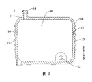
本発明の実施例に係るマイクロバブル発生装置100は、図1及び図2に示すように、気体溶解タンク1及びキャビテーション部材2を含む。気体溶解タンク1内に気体溶解室10が画定され、気体溶解タンク1は水流を出入りする入口11及び出口12を有する。キャビテーション部材2は気体溶解タンク1外に設けられ且つ出口12に接続され、又はキャビテーション部材2は出口12に設けられ、キャビテーション部材2はキャビテーション効果によって水に溶解した気体を気泡にする。
A
マイクロバブル発生装置100は使用時、気体溶解タンク1から給水して空気溶解し、その後、高濃度空気溶質を含有した水がキャビテーション部材2に入り、キャビテーション部材2がキャビテーション効果によってマイクロバブルを発生させる。キャビテーション部材2から排出される水は大量のマイクロバブルを含有し、洗濯などの様々な用途に使用できる。
When the
本発明の実施例では、気体溶解タンク1の入口11は出口12の上に位置し、入口11と出口12は水平方向にずれる。且つマイクロバブル発生装置100は空気溶解時、排水流速が給水流速より小さいであるように構成される、すなわち単位時間あたり排水する水が少なく、給水が多い。気体溶解室10は出口12で水封を形成することで、空気溶解を完了させる。
In an embodiment of the invention, the
具体的には、水流は入口11から気体溶解タンク1に注入され、給水流速が排水流速よりも大きいため、気体溶解タンク1に一定時間水を注入した後、気体溶解室10内の水位が徐々に上昇する。気体溶解タンク1の入口11が出口12の上に位置するため、気体溶解室10の水位が上昇した後、間もなく出口12を水没させ、出口12で水封を形成し、それにより気体溶解室10が徐々に昇圧して高圧室になる。
Specifically, the water flow is injected into the gas dissolving
なお、出口12で水封を形成した後、出口12からキャビテーション部材2に水を排水し続けるが、入口11から給水し続けるため、気体溶解室10内の水位が上昇し続け、水面上の空気空間が徐々に減少する。気体溶解タンク内の気圧が徐々にほぼ給水水圧に上昇した後、排水流速が給水流速に等しい。
After the water seal is formed at the
それにより、気体溶解室10の上部キャビティが高圧室になり、空気の高圧状態での溶解度が低圧状態での溶解度よりも大きいため、気体溶解室10内における水中の空気の溶解度は大幅に増加する。キャビテーション部材2へ流れる水に大量の空気が溶解し、それによりキャビテーション部材2は大量のマイクロバブルを発生させることができる。
As a result, the upper cavity of the
なお、空気は水に対して難溶解性気体である。水に溶解した空気量と注入された空気量との百分率は空気溶解効率と呼ばれ、空気溶解効率は温度、空気溶解圧力及び気液二相の動的接触面積に関連する。水温又は空気温度を変更する方法は、実現が困難である。一般的には、空気溶解効率を向上させる方法は、増圧ポンプを用いて気体溶解室を増圧することであるが、様々な弁を配置する必要があり、従って、増圧ポンプの配置コストが高すぎる。 Note that air is a gas that is poorly soluble in water. The percentage of the amount of air dissolved in water and the amount of air injected is called the air dissolution efficiency, which is related to the temperature, the air dissolution pressure and the dynamic contact area of the gas-liquid two phases. Methods of changing water temperature or air temperature are difficult to implement. In general, the way to improve the air dissolving efficiency is to use a booster pump to increase the pressure of the gas dissolving chamber, but it is necessary to arrange various valves, so the cost of arranging the booster pump is increased. too high.
従来技術では、空気溶解装置に2つの入口が設けられ、一方の入口は給水に用いられ、他方の入口は給気に用いられるという技術案がさらに提案されている。明らかなように、水に空気を注入するには、増圧ポンプを用いて空気を水に圧入する必要がある。該技術案では、空気入口がキャビテーション部材の下方にあるため、入った気泡が迅速にキャビテーション部材へ流れて押し出され、気泡をゆっくりと溶解させる空間が気体溶解タンク内になく、空気溶解効果は理想的ではない。増圧によって空気を水に注入する方式は、直接大気泡を水に圧入することに相当する。このような大気泡の水中での滞留時間が短く、溶解時間が不足する。キャビテーション部材を通過する時、キャビテーション部材によって大気泡からより多くの小気泡になるとしても、小気泡は使用中、迅速に弾けて消滅する。 The prior art further proposes a technical solution in which the air dissolving device is provided with two inlets, one inlet being used for water supply and the other inlet for supplying air. As can be seen, injecting air into the water requires the use of an intensifier pump to force the air into the water. In this technical solution, the air inlet is located below the cavitation member, so that the air bubbles entering the cavitation member are quickly pushed out, and there is no space in the gas dissolving tank for slowly dissolving the air bubbles. not targeted. The method of injecting air into water by increasing pressure is equivalent to directly injecting large bubbles into water. The residence time of such large bubbles in water is short and the dissolution time is short. Even though the cavitation member causes the large bubbles to become more small bubbles as they pass through the cavitation member, the small bubbles quickly pop and disappear during use.
なお、本発明の実施例では、気体溶解タンク1が空気を水に溶解させることを提案し、空気を溶質として水に溶解させ、すなわち、空気をイオン形態で水分子に分散させる。溶解状態で空気イオンを分散させ、水分子中の空気イオンが均一である。その後、キャビテーション効果によって析出する気泡は形成の初期段階では、ほとんどナノスケール、ミクロンスケールであり、これはマイクロバブル発生装置100が製造しようとするマイクロバブルである。マイクロバブルを取り込んだ水は最終使用場所まで流れた後、マイクロバブルが相互に合体したとしても、大部分のマイクロバブルがミリスケール以下に維持され、その効果は最適である。且つ、水に溶解した空気は通常、キャビテーション部材2での析出が不十分であり、使用中、水に溶解した空気はゆっくりとマイクロバブルを補給する。
In addition, in the embodiment of the present invention, the
本発明の実施例では、入口11が出口12の上に位置するため、入口11から給水する時、水が上方から水面を激しく叩いて水しぶきを発生させるとともに、一部の高圧空気を取り込み、空気と水との動的接触面積を増加させることができる。また、入口11と出口12が水平方向にずれることで、気体溶解室10内での水の流動経路が長く、一方では給水水流の衝撃によって発生する気泡が水流に随伴して出口12から流出することを減少させ、他方では、発生する気泡の水に対する溶解時間、接触面積を増加させる。
In the embodiment of the present invention, the
本発明の実施例に係るマイクロバブル発生装置100は、電力も複数の弁の取り付けもせずに、簡単な構造によってマイクロバブルの発生を実現することができる。
The
本発明の実施例に係るマイクロバブル発生装置100は、精巧な設計によって、気体溶解室10を出入りする水流の流速差、及び入口11と出口12との高さ差を利用して、出口12で水封を形成し、気体溶解室10を徐々に昇圧させて高圧室を形成し、それにより空気溶解量を高める。マイクロバブル発生装置100は構造が簡単で、空気溶解効果が優れ、且つコストが低い。
The
本発明の実施例では、水平方向に、止め板3の少なくとも一部は入口11と出口12との間に位置する。止め板3に隙間31が設けられ、又は止め板3に貫通孔が設けられ、又は止め板31に隙間31及び貫通孔が設けられる。止め板3が入口11と出口12との間設けられることで、入口11から流入する水が出口12へ流動する過程で阻止作用を果たす。止め板3の隙間31又は貫通孔によって、空気を溶解した水を流すが、気体溶解室10内の水しぶきによる気泡が阻止される。大気泡がキャビテーション部材2へ流れることを阻止するのは、気体溶解タンク1中の空気を浪費し、気体溶解室10内の気圧が迅速に下降して空気溶解を損ない、且つ大気泡がキャビテーション部材2に流入すると、キャビテーション効果を損なうからである。
In an embodiment of the invention, in the horizontal direction, at least a portion of
また、止め板3が設けられることで、入射水流が止め板3に衝撃してより多くの水しぶきを形成し、且つ止め板3はさらに補強構造として、気体溶解タンク1の耐圧能力を高めることができる。
In addition, since the stopping
ここでの止め板3の少なくとも一部が水平方向に入口11と出口12との間に位置するとは、図4に示すように止め板3全体が入口11と出口12との間に位置してもよく、止め板3の一部のみが入口11と出口12との間に位置してもよい。例えば、止め板3は弧状板又は球面板として形成され、止め板3は出口12をカバーし、この場合、止め板3の一部のみは入口11と出口12との間に位置する。
Here, at least a part of the
いくつかの実施例では、図4及び図5に示すように、止め板3は平板として形成されて、気体溶解タンク1の底壁に垂直に接続される。それにより、水流によって生じた気泡が気体溶解タンク1から流出することを阻止でき、生産及び製造を容易にする。平らな止め板3は、気体溶解タンク1に一体形成されたり、係合又は溶接などの方式で気体溶解タンク1に固定されるにかかわらず、弧状板より容易となる。本発明のその他の実施例では、止め板3は傾斜板、二層中空板として形成されてもよく、又は、上記言及した弧状板、球面板などとして形成されてもよい。
In some embodiments, the
具体的には、図5に示すように、止め板3における隙間31は、上下方向の縦ストライプ状として形成され、マイクロバブル発生装置100の製造可能性を大幅に向上させる構造でもある。図5中の隙間31は1本だけであり、その他の実施例では、止め板3は複数の隙間31が形成されるグリル板であってもよい。
Specifically, as shown in FIG. 5, the
さらなる実施例では、止め板3は複数の貫通孔を有するオリフィス板であり、又は、止め板3には隙間31が設けられるとともに、貫通孔が設けられる。
In a further embodiment, the
いくつかの具体的な実施例では、止め板3に隙間31が設けられる場合、隙間31の幅は50mm未満である。水流によって形成された気泡が隙間31を通過することを避けるために、止め板3における隙間31の幅が小さなければならないことを理解できる。好適には、隙間31の幅の寸法範囲は1~10mmである。明らかに、隙間31の大きさは、実際の状況に応じて選択でき、上記範囲に制限されない。
In some specific embodiments, if the
好ましくは、止め板3と出口12との間の水平距離は止め板3と入口11との間の水平距離より大きく、つまり水平方向に止め板3は入口11に近く、それにより、水流によって生じた水泡に対する止め板3による阻止作用を確保し、それにより気体溶解タンク1の空気溶解効果を確保する。好適には、止め板3と入口11との間の水平距離は50mm未満である。
Preferably, the horizontal distance between the
またなお、気体溶解タンク1は任意の形状に形成されてもよく、ここでは気体溶解タンク1の形状を特に限定しない。しかし、気体溶解タンク1は、空気溶解動作時、出口12を除き、気体溶解タンク1のほかの位置で良好な密封性を確保する必要がある。
Further, the
いくつかの実施例では、図3と図5に示すように、気体溶解室10の入口11に垂直な部分の断面積が小さく、水流が気体溶解室10内に入ると、入射水流が気体溶解室10の内壁及び気体溶解室10内の液面を叩くことを理解できる。この現象によって、より多くの水しぶきを発生させ、水しぶきの発生は水を上方の高圧空気に送り、水中の空気の溶解速度を高めることに有利である。気体溶解室10の入口11に垂直な部分の断面積が小さいことで、入口11から入射する水流が水面を叩く過程で発生する水しぶきと、気体溶解室10の内壁との強い物理的作用を発生させることに有利であり、それにより水に空気をより速く溶解させることができる。
In some embodiments, as shown in FIGS. 3 and 5, the cross-sectional area of the
いくつかの好ましい実施例では、図3及び図5に示すように、入口11の入射方向は鉛直下向きであり、給水水流が鉛直方向に沿って気体溶解室10内に入ることで、水しぶきの発生を増加させ、それにより空気溶解速度を加速するだけでなく、気体溶解タンク1の量産を促進する。勿論、本発明のほかの実施例では、入口11の入射方向は傾斜してもよく、すなわち、水流の入射方向は鉛直方向に対して一定の夾角をなし、それにより入射水流の衝撃面積が非常に大きい。
In some preferred embodiments, as shown in FIGS. 3 and 5, the incident direction of the
いくつかの実施例では、水平方向に、図2及び図4に示すように、入口11と出口12は気体溶解タンク1の両端に位置し、それにより気体溶解タンク1の内部での水の流動経路がさらに長くなり、さらに水流の衝撃による水泡が出口12から流出することを減少させる。
In some embodiments, horizontally, as shown in FIGS. 2 and 4, an
気体溶解室10の水平方向における断面は方形であり、入口11と出口12は方形の両端の直線距離が最も大きい部位に対応して設けられる。例えば、気体溶解室10の水平方向における断面は長方形であり、入口11と出口12は長方形の長辺の両端に位置する。このような気体溶解タンク1は加工が簡単で、且つ組立時、レイアウトが簡単である。勿論、本発明のほかの実施例では、気体溶解室10の断面形状は長方形、菱形又はほかの不規則な方形に限定されず、任意の形状であってもよい。
The
好適には、図2と図4に示すように、入口11が気体溶解室10の最上に位置することで、入射水流でより多くの水しぶきを発生させることを確保し、空気溶解効果を向上させる。好ましくは、出口12が気体溶解室10の最下方に位置することで、出口12で水封をできるだけ早く形成できる。
Preferably, as shown in FIGS. 2 and 4, the
いくつかの実施例では、入口11と気体溶解室10の少なくとも1つの側壁との距離は50mm未満である。すなわち、動作状態時、入口11の垂直方向の水面への投影と、少なくとも1つの気体溶解室10の内壁面との距離は50mm未満である。入口11からの水流が気体溶解タンク1の側壁に衝撃して水しぶきを発生させることがさらに容易になり、それにより気体溶解タンク1の空気溶解効果を向上させる。或いは、入口11と気体溶解室10の少なくとも1つの側壁との距離は1~20mmである。勿論、本発明のほかの実施例では、気体溶解室10の内壁に内側凸リブなどの構造が設けられることで、水しぶきの発生をさらに容易にする。
In some embodiments, the distance between
いくつかの具体的な実施例では、図2~図5に示すように、気体溶解タンク1は2つの空気溶解ハーフケーシング13を相互に係合いして設けられ、入口11は一方の空気溶解ハーフケーシング13に設けられ、出口12は他方の空気溶解ハーフケーシング13に設けられる。入口11と出口12がそれぞれ2つの空気溶解ハーフケーシング13に設けられることで、成形が容易であり、且つ各空気溶解ハーフケーシング13の強度が低すぎることを回避できる。このような気体溶解タンク1は製造可能性が高く、量産が容易で、加工コストが低い。
In some specific embodiments, as shown in FIGS. 2-5, the
好ましくは、2つの空気溶解ハーフケーシング13が溶接又は接着によって接続されることで、密封性を確保する。
Preferably, the two air-dissolving half-
具体的には、気体溶解タンク1はプラスチック部品であり、好ましくは、各空気溶解ハーフケーシング13は一体射出成形される。
Specifically, the
さらに、図1~図5に示すように、気体溶解タンク1の上部に気体溶解室10の頂部と連通する給水管14が設けられ、気体溶解タンク1の下部に気体溶解室10の底部と連通する排水管(図示せず)が設けられ、給水管14と排水管が水平に設けられることで、組立が容易である。例えば、マイクロバブル発生装置100が洗剤ボックスと組み合わせて使用される場合、気体溶解タンク1が洗剤ボックスの後方に取り付けられ、給水管14と排水管が水平に設けられることで、組立がさらに容易である。
Furthermore, as shown in FIGS. 1 to 5, a
好適には、図2~図5に示すように、2つの空気溶解ハーフケーシング13が上下に設けられ、給水管14が上方の空気溶解ハーフケーシング13に一体形成され、排水管が下方の空気溶解ハーフケーシング13に一体形成されることで、加工の利便性も密封性も確保できる。
Preferably, as shown in FIGS. 2 to 5, two air-dissolving half-
具体的には、2つの空気溶解ハーフケーシング13が結合箇所で段差面16によって接触結合することで、2つの空気溶解ハーフケーシング13の接触部の接触面積を増加させるだけでなく、接触強度を向上させる。また、段差面16によって接触結合することで、2つの空気溶解ハーフケーシング13の接触面の少なくとも一部が気体溶解室10の内壁の圧力に垂直又はほぼ垂直になる。それにより、2つの空気溶解ハーフケーシング13が結合箇所で内部高圧によって締め付けられ、内部高圧による結合箇所での割れ、気体漏れを回避する。
Specifically, the two air-dissolving half-
さらに、気体溶解タンク1の外面に補強リブ17がクリスクロスに設けられることで、気体溶解タンク1の強度を向上させ、内部高圧による変形、気体漏れを回避することができる。
Furthermore, by providing the reinforcing
本発明の実施例では、キャビテーション部材2は従来技術の公知のキャビテーション装置の構造、例えば、超音波発生装置などを採用できる。
In an embodiment of the present invention, the
いくつかの好ましい実施例では、図6に示すように、キャビテーション部材2はベンチュリ管28を含む。それにより、キャビテーション部材2を通過した水に溶解した空気を簡単に析出させ、気泡を形成することができる。ベンチュリ管28をキャビテーション部材2とすることで、水ポンプ、加熱装置又は制御弁などを別途設計する必要がなく、キャビテーション部材2の構造を大幅に向上させ、製造コストを削減させ、且つベンチュリ管28が給水方式を制限しないことで、キャビテーション部材2が簡単に大量の気泡を発生させることができる。
In some preferred embodiments,
別のいくつかの好ましい実施例では、図7に示すように、キャビテーション部材2は多数の微細孔が設けられたオリフィス板29である。それにより、キャビテーション部材2を通過した水に溶解した空気を簡単に析出させ、気泡を形成することができる。具体的には、オリフィス板29の微細孔の半径は0.01mm~10mmである。試験を行ったところ、上記パラメータを有するオリフィス板29のキャビテーション作用が優れ、より多くの気泡を発生させたことをわかった。勿論、オリフィス板29の具体的なパラメータは上記範囲に限定されず、作業員によって実際の作業条件に応じて調整することができる。
In some other preferred embodiments, the
さらに別の実施例では、図8に示すように、キャビテーション部材2はキャビテーションケーシング23及びキャビテーションボール24を含む。キャビテーションケーシング23内に水通過室20が設けられ、水通過室20は水流を出入りするキャビテーション入口21、キャビテーション出口22を有し、キャビテーション入口21が気体溶解タンク1の出口12に接続される。キャビテーションボール24は水通過室20内に可動に設けられ、キャビテーション入口21から流入する水がキャビテーションボール24を駆動してキャビテーション出口22を塞ぎ、キャビテーションボール24がキャビテーション出口22を塞ぐ時、キャビテーションボール24と水通過室20の内壁との間にベンチュリ通路25を形成する。
In yet another embodiment, the
キャビテーションボール24がキャビテーション出口22を塞ぐ時、キャビテーションボール24と水通過室20の内壁との間に、キャビテーション出口22と連通するベンチュリ通路25が設けられる。以上からわかるように、キャビテーションボール24がキャビテーション出口22を完全に塞ぐのではなく、ベンチュリ通路25を残して、空気を溶解した水を徐々にキャビテーション出口22から流出させる。
A
キャビテーション出口22の前の水通過室20内に可動キャビテーションボール24が設けられることで、キャビテーション入口21から空気を溶解する水を連続的に注入すると、連続的に注入された水が水通過室20の内壁に沿って流動し、キャビテーションボール24に遭遇した後、キャビテーションボール24をキャビテーション出口22へ移動駆動し、キャビテーションボール24をキャビテーション出口22の前に移動させ、徐々にキャビテーション出口22に当接し、ベンチュリ通路25を形成する。
A
空気溶質を溶解した水がベンチュリ通路25を通過する時、流動面積は最初に減少し、次に増加する。流動面積が減少し、気体溶質を取り込んだ水流の流速が増加すると、水圧が減少する。流動面積が増加し、気体溶質を取り込んだ水の流速が減少すると、水圧が増加する。ベンチュリ通路25はベンチュリ管に相当し、ベンチュリ効果を発生させ、空気を溶質状態から析出させてマイクロバブルを形成する。且つ水流によってキャビテーションボール24をキャビテーション出口22に当接し続けるとともに、空気溶質を溶解した水をベンチュリ通路25からより速く流出させる。
As water with dissolved air solutes passes through
この過程では、連続的に注入される水流量は流出する水流量よりも大きく、水通過室20は密閉室とし、キャビテーション出口22の前にキャビテーションボール24が当接する時、その内部圧力が増加し、キャビテーション効果を向上させる。
In this process, the continuously injected water flow rate is greater than the outflowing water flow rate, the
このようなキャビテーション部材2を使用することで、コストが低く、加工困難度が低いだけでなく、ほかのキャビテーション構造にない利点を有する。キャビテーションボール24は可動ボールであり、マイクロバブル発生装置100が動作を停止した後、水流量が減少し、水流による当接を解除すると、キャビテーションボール24がキャビテーション出口22から離れ、それによりマイクロバブル発生装置100内に残った水をできるだけ早く排出できる。一方では、気体溶解タンク1内に空気を予め蓄積することに有利であり、他方では、水溜りによる細菌の過剰繁殖を回避する。また、このようなキャビテーション部材2は洗浄が容易である。
The use of such a
いくつかの実施例では、マイクロバブル発生装置100は気体溶解タンク1に設けられるエアバルブをさらに含む。なお、気体溶解タンク1内の空気が徐々に溶解すると、気体溶解タンク1内部の空気が徐々に減少する。気体溶解タンク1にエアバルブが設けられることで、気体溶解タンク1の空気が少ない時、エアバルブをオンにし、外部の空気を気体溶解タンク1に供給し、気体溶解タンク1内に十分な空気を確保し、それによりマイクロバブル発生装置100は水に溶解する空気を連続的に増加することを確保できる。
In some embodiments, the
本発明の実施例に係るマイクロバブル発生装置100によって処理された水に大量のマイクロバブルを含有し、このようなマイクロバブル水を洗濯水とすることで、粉末洗剤や洗剤の使用量を減少させ、節水、節電を実現し、衣類に残留する粉末洗剤や洗剤を減少させることができる。
The water treated by the
本発明の実施例に係る衣類処理装置、衣類処理装置の給水口に本発明の上記実施例に記載のマイクロバブル発生装置100が設けられ、マイクロバブル発生装置100はマイクロバブルを取り込んだ水を衣類処理装置の水槽にガイドする。
A clothing processing apparatus according to an embodiment of the present invention, and a water supply port of the clothing processing apparatus is provided with the
本発明の実施例に係る衣類処理装置は、上記マイクロバブル発生装置100を使用することで、コストが低く、マイクロバブル発生効果が優れる。洗濯水に大量のマイクロバブルを含有し、粉末洗剤や洗剤の使用量を減少させ、節水、節電を実現し、衣類に残留する粉末洗剤や洗剤を減少させる。
The clothes processing apparatus according to the embodiment of the present invention uses the
本発明の実施例に係る衣類処理装置のほかの構成要素、例えば、モータ及びパルセータ又はドラムなど及び操作は当業者にとって公知のものであるため、ここでは詳細説明を省略する。 Other components of the clothes processing apparatus according to embodiments of the present invention, such as motors and pulsators or drums, etc., and their operation are known to those skilled in the art and will not be described in detail herein.
本発明の説明では、用語「中心」、「長さ」、「上」、「下」、「鉛直」、「水平」、「頂」、「底」、「内」、「外」などで指示される方位又は位置関係は図面に示される方位又は位置関係であり、本発明を説明し及び説明を簡素化するためのものであり、係る装置又は要素が特定の方位を有し、特定の方位で構成、操作しなければならないことを指示又は暗示しないため、本発明を限定するものではないと理解すべきである。本発明の説明では、「複数」は、特に断らない限り、2つ以上を意味する。 In describing the present invention, the terms "center", "length", "top", "bottom", "vertical", "horizontal", "top", "bottom", "inner", "outer", etc. The orientation or positional relationship shown is the orientation or positional relationship shown in the drawings, and is for the purpose of explaining and simplifying the description of the invention, such devices or elements having a particular orientation and a particular orientation It should be understood that it does not imply or imply that it must be configured and operated in a manner that limits the invention. In the description of the present invention, "plurality" means two or more, unless stated otherwise.
本発明では、特に断らない限り、用語「取り付け」、「連結」、「接続」、「固定」などは広義に理解すべきであり、例えば、固定的に接続されてもよく、着脱可能に接続されてもよく、一体化されてもよく、機械的接続であってもよく、電気的接続であってもよく、直接接続であってもよく、中間媒体を介した間接接続であってもよく、2つの要素の内部連通又は2つの要素の相互作用関係であってもよい。当業者は、具体的な状況に応じて上記用語の本発明における具体的な意味を理解できる。 In the present invention, unless otherwise specified, the terms "attachment", "coupling", "connection", "fixation", etc. should be understood broadly and may, for example, be fixedly connected, detachably connected may be connected, may be integrated, may be mechanical connection, may be electrical connection, may be direct connection, or may be indirect connection via an intermediate medium. , the internal communication of the two elements or the interaction relationship of the two elements. A person skilled in the art can understand the specific meaning of the above terms in the present invention according to the specific situation.
本発明では、特に断らない限り、第1特徴が第2特徴の「上」又は「下」に位置することは、第1と第2特徴が直接接触することであってもよく、第1と第2特徴が中間媒体を介して間接接触するであってもよい。且つ、第1特徴が第2特徴の「上」、「上方」及び「上方側」に位置することは、第1特徴が第2特徴の真上又は斜め上に位置することであってもよく、第1特徴の水平高さが第2特徴よりも高いことを示してもよい。第1特徴が第2特徴の「下」、「下方」及び「下方側」に位置することは、第1特徴が第2特徴の真下又は斜め下に位置することであってもよく、第1特徴の水平高さが第2特徴よりも低いことを示してもよい。 In the present invention, unless otherwise specified, positioning a first feature "above" or "below" a second feature may mean direct contact between the first and second features. The second feature may be in indirect contact through an intermediate medium. In addition, the first feature being positioned "above", "above" and "upper side" of the second feature may be that the first feature is positioned directly above or diagonally above the second feature. , may indicate that the horizontal height of the first feature is higher than the second feature. Positioning the first feature "below", "below" and "below" the second feature may mean that the first feature is positioned directly below or diagonally below the second feature. It may indicate that the horizontal height of the feature is less than the second feature.
本明細書の説明では、用語「一実施例」、「いくつかの実施例」、「例」、「具体例」、又は「いくつかの例」などを参照した説明は、該実施例又は例を参照して説明された具体的な特徴、構造、材料又は特点が本発明の少なくとも1つの実施例又は例に含まれることを意味する。本明細書では、上記用語の例示的な説明は必ずしも同一の実施例又は例ではない。且つ、説明される具体的な特徴、構造、材料又は特点は任意の1つ又は複数の実施例又は例において適宜組み合わせることができる。また、矛盾しない場合、当業者は本明細書に説明される異なる実施例又は例及び異なる実施例又は例の特徴を組み合わせることができる。 In the description herein, references to the terms “one embodiment,” “some embodiments,” “example,” “specific examples,” or “some examples” or the like refer to the implementation or examples. is included in at least one embodiment or example of the invention. Exemplary descriptions of such terms in this specification are not necessarily the same embodiment or example. And the specific features, structures, materials or features described may be combined in any one or more embodiments or examples as appropriate. Also, where not inconsistent, a person skilled in the art can combine different embodiments or examples and features of different embodiments or examples described herein.
以上、本発明の実施例を例示して説明したが、上記実施例は例示的であり、本発明を限定するものではなく、当業者は本発明の範囲を逸脱せずに上記実施例に変更、修正、置換及び変形を行うことができる。 Although the embodiments of the present invention have been illustrated and described above, the above embodiments are illustrative and not intended to limit the present invention, and those skilled in the art can modify the above embodiments without departing from the scope of the present invention. , modifications, substitutions and variations may be made.
100 マイクロバブル発生装置
1 気体溶解タンク
10 気体溶解室
11 入口
12 出口
13 空気溶解ハーフケーシング
14 給水管
16 段差面
17 補強リブ
2 キャビテーション部材
20 水通過室
21 キャビテーション入口
22 キャビテーション出口
23 キャビテーションケーシング
24 キャビテーションボール
25 ベンチュリリア通路
28 ベンチュリ管
29 オリフィス板
3 止め板
31 隙間
100
Claims (12)
内部に気体溶解室が画定され、水流を出入りする入口及び出口を有する気体溶解タンクであって、前記入口が前記出口の上に位置し、水平方向に前記入口が前記出口とずれる気体溶解タンクと、
前記気体溶解タンクの外に設けられ且つ前記出口に接続され、又は前記出口に設けられるキャビテーション部材と、を含み、
前記マイクロバブル発生装置は、前記気体溶解タンク内に設けられ、水平方向に少なくとも一部が前記入口と前記出口との間に位置し、上下方向の縦ストライプ形状として形成された1つの隙間が設けられる止め板をさらに含み、
前記隙間の幅の寸法範囲は1~10mmである、
ことを特徴とするマイクロバブル発生装置。 A microbubble generator,
A gas dissolving tank having a gas dissolving chamber defined therein and having an inlet and an outlet for a water flow in and out, wherein the inlet is positioned above the outlet and the inlet is horizontally offset from the outlet. ,
a cavitation member provided outside the gas dissolving tank and connected to or provided at the outlet;
The microbubble generator is provided in the gas dissolving tank, and at least a portion of the microbubble generator is horizontally positioned between the inlet and the outlet, and a vertical stripe-shaped gap is provided. further comprising a stop plate mounted on the
The dimension range of the width of the gap is 1 to 10 mm,
A microbubble generator characterized by:
ことを特徴とする請求項1に記載のマイクロバブル発生装置。 the horizontal distance between the stop plate and the outlet is greater than the horizontal distance between the stop plate and the inlet;
The microbubble generator according to claim 1, characterized in that:
ことを特徴とする請求項2に記載のマイクロバブル発生装置。 the horizontal distance between the stop plate and the inlet is less than 50 mm;
The microbubble generator according to claim 2, characterized in that:
ことを特徴とする請求項1~3のいずれかに記載のマイクロバブル発生装置。 horizontally, the inlet and the outlet are located at opposite ends of the gas dissolving tank;
The microbubble generator according to any one of claims 1 to 3, characterized in that:
ことを特徴とする請求項1~4のいずれかに記載のマイクロバブル発生装置。 the distance between the inlet and at least one side wall of the gas dissolving chamber is less than 50 mm;
The microbubble generator according to any one of claims 1 to 4, characterized in that:
ことを特徴とする請求項5に記載のマイクロバブル発生装置。 the distance between the inlet and at least one side wall of the gas dissolving chamber is between 1 and 20 mm;
The microbubble generator according to claim 5, characterized in that:
ことを特徴とする請求項1~6のいずれかに記載のマイクロバブル発生装置。 The gas dissolving tank is provided by two mutually engaging gas dissolving half-casings, the inlet being provided in one of the gas dissolving half-casings and the outlet being provided in the other gas dissolving half-casing. to be
The microbubble generator according to any one of claims 1 to 6, characterized in that:
ことを特徴とする請求項7に記載のマイクロバブル発生装置。 the two gas-dissolved half-casings are contact-bonded by a stepped surface at the bond point;
The microbubble generator according to claim 7, characterized in that:
ことを特徴とする請求項1~8のいずれかに記載のマイクロバブル発生装置。 A reinforcing rib is provided on the outer surface of the gas dissolving tank,
The microbubble generator according to any one of claims 1 to 8, characterized in that:
ことを特徴とする請求項1~9のいずれかに記載のマイクロバブル発生装置。 The microbubble generator is configured so that the flow rate of the waste water is smaller than the flow rate of the water supply when the gas is dissolved.
The microbubble generator according to any one of claims 1 to 9, characterized in that:
ことを特徴とする請求項1~10のいずれかに記載のマイクロバブル発生装置。 A water supply pipe communicating with the top of the gas dissolving chamber is provided at the top of the gas dissolving tank, and a drain pipe communicating with the bottom of the gas dissolving chamber is provided at the bottom of the gas dissolving tank. the drain pipe is provided horizontally,
The microbubble generator according to any one of claims 1 to 10, characterized in that:
給水口には請求項1~11のいずれかに記載のマイクロバブル発生装置が設けられ、前記マイクロバブル発生装置が前記衣類処理装置の水槽と連通する、
ことを特徴とする衣類処理装置。 A clothes processing apparatus comprising:
The water supply port is provided with the microbubble generator according to any one of claims 1 to 11, and the microbubble generator communicates with the water tank of the clothing processing apparatus.
A clothing processing apparatus characterized by:
Applications Claiming Priority (5)
| Application Number | Priority Date | Filing Date | Title |
|---|---|---|---|
| CN201821815922.8 | 2018-11-05 | ||
| CN201811308756.7A CN111206378A (en) | 2018-11-05 | 2018-11-05 | Microbubble generator and clothing processing apparatus |
| CN201821815922.8U CN209353112U (en) | 2018-11-05 | 2018-11-05 | Microbubble generator and device for clothing processing |
| CN201811308756.7 | 2018-11-05 | ||
| PCT/CN2018/121187 WO2020093522A1 (en) | 2018-11-05 | 2018-12-14 | Micro-bubble generator and laundry treatment device |
Publications (2)
| Publication Number | Publication Date |
|---|---|
| JP2021529658A JP2021529658A (en) | 2021-11-04 |
| JP7204876B2 true JP7204876B2 (en) | 2023-01-16 |
Family
ID=70611680
Family Applications (1)
| Application Number | Title | Priority Date | Filing Date |
|---|---|---|---|
| JP2021502589A Active JP7204876B2 (en) | 2018-11-05 | 2018-12-14 | Microbubble generator and clothes processor |
Country Status (5)
| Country | Link |
|---|---|
| US (1) | US20210071338A1 (en) |
| EP (1) | EP3725933B1 (en) |
| JP (1) | JP7204876B2 (en) |
| RU (1) | RU2761802C1 (en) |
| WO (1) | WO2020093522A1 (en) |
Citations (8)
| Publication number | Priority date | Publication date | Assignee | Title |
|---|---|---|---|---|
| WO2005115596A1 (en) | 2004-05-31 | 2005-12-08 | Sanyo Facilities Industry Co., Ltd. | Method and device for producing fine air bubble-containing liquid, and fine air bubble producer assembled in the device |
| JP2008161734A (en) | 2006-12-26 | 2008-07-17 | Ngk Insulators Ltd | Functional water making apparatus and functional water making method using it |
| JP2010029770A (en) | 2008-07-28 | 2010-02-12 | Mdk:Kk | Air bubble generation apparatus |
| WO2010055701A1 (en) | 2008-11-14 | 2010-05-20 | 株式会社シバタ | Microbubble generating mechanism |
| JP2010115594A (en) | 2008-11-13 | 2010-05-27 | Nsi:Kk | Fine bubble generation method, fine bubble generator, and reduced water |
| JP2010227780A (en) | 2009-03-26 | 2010-10-14 | Panasonic Electric Works Co Ltd | Gas dissolving apparatus |
| JP2013111505A (en) | 2011-11-25 | 2013-06-10 | Gastar Corp | Pressurized container and air dissolving device using the same |
| CN207362525U (en) | 2017-10-17 | 2018-05-15 | 无锡小天鹅股份有限公司 | Microbubble generator and device for clothing processing |
Family Cites Families (16)
| Publication number | Priority date | Publication date | Assignee | Title |
|---|---|---|---|---|
| US4629559A (en) * | 1985-06-12 | 1986-12-16 | Envirex Inc. | Vertical looped reactor tank with delayed air release feature |
| JP2792016B2 (en) * | 1994-05-31 | 1998-08-27 | 和泉電気株式会社 | Gas-liquid dissolving and mixing equipment |
| JP2974236B2 (en) * | 1994-09-30 | 1999-11-10 | 和泉電気株式会社 | Gas-liquid dissolution mixing method and apparatus |
| JP3765759B2 (en) * | 2002-02-04 | 2006-04-12 | 株式会社 多自然テクノワークス | Microbubble generator |
| JP4563496B1 (en) * | 2009-10-22 | 2010-10-13 | 株式会社H&S | Microbubble generator |
| KR101284266B1 (en) * | 2011-07-15 | 2013-07-08 | 한국기계연구원 | Device for generating micro and/or nano bubble based on circulation unit with high solubility of water |
| CN101941765A (en) * | 2010-07-23 | 2011-01-12 | 东北电力大学 | Flotation and sedimentation solid-liquid separation device |
| KR101618150B1 (en) * | 2011-02-15 | 2016-05-19 | 삼성전자 주식회사 | Bubble generaint apparatus and washing machine having the same |
| CN102583616A (en) * | 2012-02-20 | 2012-07-18 | 无锡工源机械有限公司 | Gas-liquid equilibrium dissolved air vessel |
| CN102755846A (en) * | 2012-07-28 | 2012-10-31 | 甘肃金桥给水排水设计与工程(集团)有限公司 | Micro-bubble dissolved air generation device |
| CN105986400A (en) * | 2015-02-13 | 2016-10-05 | 青岛海尔洗衣机有限公司 | Washing machine provided with ultra-fine bubble generating device |
| CN105110446B (en) * | 2015-08-20 | 2017-12-19 | 苏州香山红叶环境技术有限公司 | Nano bubble hydrogen manufacturing water dispenser |
| CN108474164B (en) * | 2015-12-25 | 2020-06-16 | 东芝生活电器株式会社 | Washing machine |
| JP2018086628A (en) * | 2016-11-29 | 2018-06-07 | 日鉄鉱業株式会社 | Air flow classifier |
| KR102397439B1 (en) * | 2017-03-23 | 2022-05-12 | 주식회사 위니아전자 | Washing machine, generator for micro-bubble thereof and method for suppling for washing water including micro-bubble |
| KR102397435B1 (en) * | 2017-03-23 | 2022-05-12 | 주식회사 위니아전자 | Washing machine and method for suppling for washing water including micro-bubble |
-
2018
- 2018-12-14 US US16/970,954 patent/US20210071338A1/en not_active Abandoned
- 2018-12-14 RU RU2020142899A patent/RU2761802C1/en active
- 2018-12-14 WO PCT/CN2018/121187 patent/WO2020093522A1/en unknown
- 2018-12-14 EP EP18939574.2A patent/EP3725933B1/en active Active
- 2018-12-14 JP JP2021502589A patent/JP7204876B2/en active Active
Patent Citations (8)
| Publication number | Priority date | Publication date | Assignee | Title |
|---|---|---|---|---|
| WO2005115596A1 (en) | 2004-05-31 | 2005-12-08 | Sanyo Facilities Industry Co., Ltd. | Method and device for producing fine air bubble-containing liquid, and fine air bubble producer assembled in the device |
| JP2008161734A (en) | 2006-12-26 | 2008-07-17 | Ngk Insulators Ltd | Functional water making apparatus and functional water making method using it |
| JP2010029770A (en) | 2008-07-28 | 2010-02-12 | Mdk:Kk | Air bubble generation apparatus |
| JP2010115594A (en) | 2008-11-13 | 2010-05-27 | Nsi:Kk | Fine bubble generation method, fine bubble generator, and reduced water |
| WO2010055701A1 (en) | 2008-11-14 | 2010-05-20 | 株式会社シバタ | Microbubble generating mechanism |
| JP2010227780A (en) | 2009-03-26 | 2010-10-14 | Panasonic Electric Works Co Ltd | Gas dissolving apparatus |
| JP2013111505A (en) | 2011-11-25 | 2013-06-10 | Gastar Corp | Pressurized container and air dissolving device using the same |
| CN207362525U (en) | 2017-10-17 | 2018-05-15 | 无锡小天鹅股份有限公司 | Microbubble generator and device for clothing processing |
Also Published As
| Publication number | Publication date |
|---|---|
| JP2021529658A (en) | 2021-11-04 |
| EP3725933B1 (en) | 2023-08-23 |
| WO2020093522A1 (en) | 2020-05-14 |
| EP3725933A1 (en) | 2020-10-21 |
| US20210071338A1 (en) | 2021-03-11 |
| EP3725933C0 (en) | 2023-08-23 |
| EP3725933A4 (en) | 2021-06-09 |
| RU2761802C1 (en) | 2021-12-13 |
Similar Documents
| Publication | Publication Date | Title |
|---|---|---|
| JP7150853B2 (en) | clothing processing equipment | |
| JP7456029B2 (en) | Microbubble generator and clothing processing device | |
| CN112831986B (en) | Microbubble treatment agent box assembly and washing equipment with same | |
| JP7204876B2 (en) | Microbubble generator and clothes processor | |
| CN210303208U (en) | Dissolved air tank of microbubble generator and microbubble generator | |
| JP7265952B2 (en) | Discharge device and plumbing equipment | |
| CN209952609U (en) | Microbubble generator and washing device | |
| CN209952610U (en) | Microbubble generator and washing device | |
| CN209952608U (en) | Microbubble generator and washing device | |
| KR20180108030A (en) | Washing machine, generator for micro-bubble thereof and method for suppling for washing water including micro-bubble | |
| KR200425758Y1 (en) | Bathtub Integrated with Micro Bubble Generator | |
| CN111206378A (en) | Microbubble generator and clothing processing apparatus | |
| WO2020177346A1 (en) | Dispensing apparatus and clothing treatment device | |
| CN209958076U (en) | Clothes treating device | |
| CN112853688A (en) | Microbubble treating agent box assembly and washing equipment with same | |
| CN111659274A (en) | Microbubble generator and washing device | |
| CN111659273A (en) | Microbubble generator and washing device | |
| CN209958074U (en) | Microbubble generator and clothing processing apparatus | |
| CN112899990A (en) | Water inlet method of washing equipment and washing equipment using water inlet method | |
| CN111206379A (en) | Microbubble generator and clothing processing apparatus | |
| JP6959569B2 (en) | Bathtub circulation type water spouting device | |
| JP2022185360A (en) | washing machine | |
| WO2020177314A1 (en) | Microbubble generator and washing device | |
| WO2020103380A1 (en) | Laundry treatment device | |
| KR20180108032A (en) | Washing machine, generator for micro-bubble thereof and method for suppling for washing water including micro-bubble |
Legal Events
| Date | Code | Title | Description |
|---|---|---|---|
| A621 | Written request for application examination |
Free format text: JAPANESE INTERMEDIATE CODE: A621 Effective date: 20210115 |
|
| A131 | Notification of reasons for refusal |
Free format text: JAPANESE INTERMEDIATE CODE: A131 Effective date: 20211130 |
|
| A601 | Written request for extension of time |
Free format text: JAPANESE INTERMEDIATE CODE: A601 Effective date: 20220228 |
|
| A521 | Request for written amendment filed |
Free format text: JAPANESE INTERMEDIATE CODE: A523 Effective date: 20220308 |
|
| A131 | Notification of reasons for refusal |
Free format text: JAPANESE INTERMEDIATE CODE: A131 Effective date: 20220705 |
|
| A521 | Request for written amendment filed |
Free format text: JAPANESE INTERMEDIATE CODE: A523 Effective date: 20221005 |
|
| TRDD | Decision of grant or rejection written | ||
| A01 | Written decision to grant a patent or to grant a registration (utility model) |
Free format text: JAPANESE INTERMEDIATE CODE: A01 Effective date: 20221220 |
|
| A61 | First payment of annual fees (during grant procedure) |
Free format text: JAPANESE INTERMEDIATE CODE: A61 Effective date: 20221228 |
|
| R150 | Certificate of patent or registration of utility model |
Ref document number: 7204876 Country of ref document: JP Free format text: JAPANESE INTERMEDIATE CODE: R150 |