JP7204754B2 - Detergent dispenser - Google Patents
Detergent dispenser Download PDFInfo
- Publication number
- JP7204754B2 JP7204754B2 JP2020535076A JP2020535076A JP7204754B2 JP 7204754 B2 JP7204754 B2 JP 7204754B2 JP 2020535076 A JP2020535076 A JP 2020535076A JP 2020535076 A JP2020535076 A JP 2020535076A JP 7204754 B2 JP7204754 B2 JP 7204754B2
- Authority
- JP
- Japan
- Prior art keywords
- detergent
- siphon column
- chamber
- guard plate
- siphon
- Prior art date
- Legal status (The legal status is an assumption and is not a legal conclusion. Google has not performed a legal analysis and makes no representation as to the accuracy of the status listed.)
- Active
Links
Images


Classifications
-
- D—TEXTILES; PAPER
- D06—TREATMENT OF TEXTILES OR THE LIKE; LAUNDERING; FLEXIBLE MATERIALS NOT OTHERWISE PROVIDED FOR
- D06F—LAUNDERING, DRYING, IRONING, PRESSING OR FOLDING TEXTILE ARTICLES
- D06F39/00—Details of washing machines not specific to a single type of machines covered by groups D06F9/00 - D06F27/00
- D06F39/02—Devices for adding soap or other washing agents
- D06F39/028—Arrangements for selectively supplying water to detergent compartments
-
- D—TEXTILES; PAPER
- D06—TREATMENT OF TEXTILES OR THE LIKE; LAUNDERING; FLEXIBLE MATERIALS NOT OTHERWISE PROVIDED FOR
- D06F—LAUNDERING, DRYING, IRONING, PRESSING OR FOLDING TEXTILE ARTICLES
- D06F39/00—Details of washing machines not specific to a single type of machines covered by groups D06F9/00 - D06F27/00
- D06F39/02—Devices for adding soap or other washing agents
- D06F39/022—Devices for adding soap or other washing agents in a liquid state
Landscapes
- Engineering & Computer Science (AREA)
- Textile Engineering (AREA)
- Detail Structures Of Washing Machines And Dryers (AREA)
Description
本発明は洗濯機器の分野に属し、具体的には、洗濯機に応用される洗剤投入装置に関する。 The present invention belongs to the field of laundry equipment, and more particularly to a detergent dispensing device applied in a washing machine.
洗濯機の洗剤投入装置は本体に装着される。洗剤投入装置には投入室又は貯液室が設けられており、ユーザが洗浄添加物を手動で投入室又は貯液室に添加したあと、添加された洗浄添加物は洗濯機の給水水流によって洗濯機の貯水槽に押し流される。一般的に、従来の洗浄添加物には2種類の形態が存在し、一つは固形粉末状の粉洗剤、もう一つは液体状の洗濯液、消毒液、柔軟剤等である。 A detergent dispenser of the washing machine is attached to the main body. The detergent dosing device is provided with a dosing chamber or a liquid storage chamber, and after the user manually adds the cleaning additive to the dosing chamber or the liquid storage chamber, the added cleaning additive is washed by the water flow of the washing machine. washed into the plane's reservoir. In general, conventional cleaning additives come in two forms, one being solid powder detergents and the other being liquid laundry liquids, disinfectants, softeners, and the like.
通常、粉末状の粉洗剤は室内に直接投入すればよく、洗濯の開始後は、給水によって粉洗剤をそのまま押し流せるようになっている。これに対し、液体状の洗濯添加剤の場合には、押し流す過程で予め流入水流により希釈してから、希釈後の洗浄添加物を押し流せるよう、投入のための密閉された空間が必要となる。 Usually, the powdered detergent can be put directly into the room, and after the start of washing, the powdered detergent can be flushed away by water supply. On the other hand, in the case of a liquid laundry additive, it is necessary to dilute it with inflow water in advance in the process of flushing it away, and then a sealed space for charging is required so that the diluted laundry additive can be flushed away. .
現在のところ、洗剤投入装置は、異なる形態の洗浄添加物についてそれぞれ相応の投入を実現するために、一般的には、粉末状の粉洗剤と液体状の洗濯添加剤をそれぞれ異なる投入室から相応に投入するという方式をとっている。そのため、それぞれの投入室にはそれ相応の構造が備わっている。そこで、同一の投入室で固形及び液体状の洗濯添加剤の投入を兼務できるよう、如何にして投入室の内部に調節構造を設けるかが研究開発の焦点となっている。 At present, the detergent dosing device generally feeds powdered powder detergent and liquid laundry additive respectively from different dosing chambers in order to achieve corresponding dosing for different forms of washing additives. We have adopted a method of injecting into Therefore, each charging chamber has a corresponding structure. Therefore, the focus of research and development is how to provide an adjustment structure inside the dosing chamber so that the same dosing chamber can be used for both solid and liquid laundry additives.
このほか、従来の一部の洗剤投入装置は自動投入機能を有している。このような洗剤投入装置には、洗濯添加剤を蓄えるための貯液室を設ける必要がある。また、一般的に、貯液室の上カバーには各種の造型が施されているが、見た目の美しさと構造的な実用性のために、いくつかの凹陥構造を有することが常である。しかし、洗剤投入装置に給水する際、或いは上カバーに水が落下した際には、前記凹陥構造により構成される凹陥部分に水が溜まり、溜水が使用体験に影響を及ぼすことになる。且つ、凹陥内の溜水が貯液室に落下して液体洗剤の品質に影響を及ぼし得るほか、投入ケースを引き出す際に、上カバー上の溜水がタンクから流出し、洗濯機の外部を汚染する恐れもある。 In addition, some conventional detergent dosing devices have an automatic dosing function. Such detergent dispensers must be provided with a reservoir for storing the laundry additive. Also, in general, the upper cover of the liquid storage chamber has various moldings, but usually has several recessed structures for the sake of aesthetic beauty and structural practicality. . However, when water is supplied to the detergent dispenser or when water falls on the upper cover, the recessed portion formed by the recessed structure is filled with water, and the accumulated water affects the user experience. In addition, the pooled water in the recess may drop into the liquid storage chamber and affect the quality of the liquid detergent, and when the loading case is pulled out, the pooled water on the upper cover may flow out of the tank and drain the washing machine. There is also the risk of contamination.
以上に鑑みて、本発明を提案する。 In view of the above, the present invention is proposed.
本発明が解決しようとする技術的課題は、従来技術の瑕疵を解消し、液体状や固形等の異なる形態の洗浄添加物をそれぞれ適応的に投入するとの目的を実現するための洗剤投入装置を提供することである。また、本発明のもう一つの目的は、室内における洗浄添加物の残留を減少させるとの目的を実現するための洗剤投入装置を提供することである。また、本発明の更なる目的は、投入ケースの天井面における溜水の発生を回避するための洗剤投入装置を提供することである。 The technical problem to be solved by the present invention is to solve the deficiencies of the prior art, and to provide a detergent injection device for realizing the purpose of adaptively introducing detergent additives in different forms such as liquids and solids. to provide. Another object of the present invention is to provide a detergent dosing device for achieving the objective of reducing cleaning additive residue in the room. A further object of the present invention is to provide a detergent dispenser for avoiding water accumulation on the ceiling surface of the dispenser case.
上記の技術的課題を解決するために、本発明で採用する技術方案の基本思想について以下に述べる。 In order to solve the above technical problems, the basic idea of the technical solution adopted in the present invention will be described below.
洗剤投入装置であって、タンクを含み、タンク内に投入ケースが装着されている。投入ケースの内部には上下両側を垂直に貫通する降水管が設けられている。投入ケースの天井面の残留水を降水管を通じて投入ケース下方のタンクの底部まで案内するよう、降水管の上下両端の開口は投入ケースの上下の壁面にそれぞれ位置している。 A detergent dosing device including a tank with a dosing case mounted within the tank. Downcomers are installed vertically through both the top and bottom sides of the input case. The openings at the upper and lower ends of the downcomer are respectively located in the upper and lower walls of the downcomer so as to guide residual water on the ceiling of the downcomer through the downcomer to the bottom of the tank below the downcomer.
更に、投入ケースは本体を含み、本体の内部の一部を中空とすることで貯液室が構成されている。投入室の上部は開口して設けられる。本体の上部には開口に掛合する上カバーが装着されている。上カバーには上下に貫通する降水口が設けられており、降水口と降水管が連通している。 Further, the input case includes a main body, and a part of the inside of the main body is hollow to form a liquid storage chamber. The upper part of the charging chamber is provided with an opening. An upper cover that engages with the opening is attached to the upper part of the main body. The upper cover is provided with a downspout that penetrates vertically, and the downspout is in communication with the downspout pipe.
更に、貯液室の内部には垂直に延伸する降水管が設けられており、降水管の底部の開口が貯液室の底壁を貫通している。降水管の上部は上カバーに密封状に付着しており、且つ、降水管の上部の開口と降水口は同軸に設けられる。好ましくは、降水管の上端と上カバーの下側が密封状に当接するよう、降水管の上部の開口のサイズは降水口のサイズよりも大きくなっている。 Further, a vertically extending downcomer is provided inside the reservoir, and the bottom opening of the downcomer extends through the bottom wall of the reservoir. The top of the downcomer is hermetically attached to the top cover, and the opening in the top of the downcomer and the downcomer are coaxial. Preferably, the size of the opening in the top of the downcomer is larger than the size of the downspout so that the upper end of the downcomer and the underside of the top cover sealingly abut.
更に、上カバーの降水口部分には下方に突出するフランジが周設されている。フランジは降水管の内部に伸入し、フランジの外周壁が降水管の内壁に密接する。好ましくは、フランジにおける降水管との接触面部分には少なくとも1つのシールリングが装着されている。 Furthermore, a downwardly protruding flange is provided around the downspout portion of the upper cover. The flange extends into the interior of the downcomer, with the outer peripheral wall of the flange closely contacting the inner wall of the downcomer. Preferably, at least one seal ring is mounted on the contact surface portion of the flange with the downcomer pipe.
更に、前記降水口は上カバーの最も低い箇所に位置している。 Moreover, the rainfall outlet is located at the lowest point of the top cover.
更に、上カバーの上側には下方に凹陥する凹溝が設けられており、降水口が凹溝の底壁に位置する。 Further, the upper side of the upper cover is provided with a groove that is recessed downward, and the rain outlet is positioned on the bottom wall of the groove.
更に、上カバーの天井面には下方に凹陥する凹溝が設けられており、凹溝の開口部分がロックロッドにより覆われている。ロックロッドは一端が上カバーに接続されるとともに、他端が自在に設けられている。これにより、ロックロッドの可動端は外力を受けると垂直方向において弾性伸縮する。ロックロッドの外周と凹溝の内壁は一定の隙間を隔てており、降水口はロックロッド下方の凹溝の底部に設けられている。より好ましくは、ロックロッドの自由端、或いは自由端の近傍には上方へ突出する突出部が設けられている。 Further, the ceiling surface of the upper cover is provided with a groove that is recessed downward, and the opening of the groove is covered with a lock rod. The lock rod has one end connected to the upper cover and the other end freely provided. Thereby, the movable end of the lock rod elastically expands and contracts in the vertical direction when receiving an external force. A predetermined gap is provided between the outer circumference of the lock rod and the inner wall of the groove, and the rain outlet is provided at the bottom of the groove below the lock rod. More preferably, the free end of the lock rod or the vicinity of the free end is provided with an upwardly projecting protrusion.
更に、前記ロックロッドは投入ケースの引き出し方向に延伸している。ロックロッドの中央部には上方へ突出するロック部が設けられており、前記降水口はロック部に対応する垂直下方に設けられている。 Furthermore, the lock rod extends in the direction of pulling out the input case. A lock portion protruding upward is provided in the central portion of the lock rod, and the rain outlet is provided vertically downward corresponding to the lock portion.
更に、前記投入ケースには複数の降水管が設けられており、各降水管は投入ケースの異なる位置にそれぞれ分布している。 Further, the injection case is provided with a plurality of downcomers, each of which is distributed at a different position of the injection case.
更に、降水管は貯液室の中央部に位置している。また、投入ケースの押し込み方向における貯液室の後側寄りには、洗剤を流出させる吐液口が設けられており、吐液口部分に制御弁が装着されている。 Furthermore, the downcomer is located in the center of the reservoir. Further, a liquid discharge port for discharging the detergent is provided near the rear side of the liquid storage chamber in the pushing direction of the input case, and a control valve is attached to the liquid discharge port.
本発明が解決しようとする技術的課題は、従来技術の瑕疵を解消し、液体状や固形等の異なる形態の洗浄添加物をそれぞれ適応的に投入するとの目的を実現するための洗剤投入装置を提供することである。また、本発明のもう一つの目的は、室内における洗浄添加物の残留を減少させるとの目的を実現するための洗剤投入装置を提供することである。 The technical problem to be solved by the present invention is to solve the deficiencies of the prior art, and to provide a detergent injection device for realizing the purpose of adaptively introducing detergent additives in different forms such as liquids and solids. to provide. Another object of the present invention is to provide a detergent dosing device for achieving the objective of reducing cleaning additive residue in the room.
上記の技術的課題を解決するために、本発明で採用する技術方案の基本思想について以下に述べる。 In order to solve the above technical problems, the basic idea of the technical solution adopted in the present invention will be described below.
洗剤投入装置であって、タンクを含み、タンク内に投入ケースが装着されている。投入ケースの投入室における開口の一部はカバープレートで覆われている。投入室内にはカバープレートの下方に位置するサイフォンカラムが装着されており、カバープレートにはサイフォンカラムの外周箇所に位置する透かし部が設けられている。カバープレート上の水流は透かし部から下方の投入室内に流れ込む。 A detergent dosing device including a tank with a dosing case mounted within the tank. A part of the opening in the charging chamber of the charging case is covered with a cover plate. A siphon column located below a cover plate is mounted in the injection chamber, and the cover plate is provided with a watermark located at the outer periphery of the siphon column. The water flow on the cover plate flows from the watermark into the dosing chamber below.
更に、カバープレートには下方に凹陥する凹溝が設けられている。前記凹溝はサイフォンカラムの上方に対応して設けられ、凹溝の底部にはサイフォンカラムとはずらされた透かし部が設けられている。 Further, the cover plate is provided with a concave groove recessed downward. The groove is provided above the siphon column, and the bottom of the groove is provided with a watermark portion that is offset from the siphon column.
更に、サイフォンカラムの左右両側は投入ケースの引き出し方向に対し対称に設けられ、サイフォンカラムの左右両側にはそれぞれ透かし部が設けられている。投入ケースの天井面における水流は、両側の透かし部からカバープレートをそれぞれ通過し、カバープレートの下方におけるサイフォンカラムの左右両側の外周をそれぞれ洗い流す。 Furthermore, the left and right sides of the siphon column are provided symmetrically with respect to the direction in which the input case is pulled out, and the left and right sides of the siphon column are provided with watermarks, respectively. The water flow on the ceiling surface of the input case passes through the cover plate from the watermarked portions on both sides, and washes the outer circumferences of the left and right sides of the siphon column under the cover plate, respectively.
更に、サイフォンカラムの左右両側の透かし部は円弧状をなしており、円弧状の内周とサイフォンカラムの外周は垂直に整列して設けられる。 Furthermore, the openwork portions on both the left and right sides of the siphon column are arc-shaped, and the inner circumference of the arc and the outer circumference of the siphon column are vertically aligned.
更に、サイフォンカラムの前後両側は、それぞれ垂直に延伸する接続リブを介してカバープレートに接続される。これにより、サイフォンカラムの上部が凹溝の底部を構成し、両側の接続リブが凹溝の側壁を構成し、接続リブとサイフォンカラムの上部以外の凹溝の壁面全てが透かし部をなしている。 Furthermore, both front and rear sides of the siphon column are connected to the cover plate via vertically extending connecting ribs, respectively. As a result, the upper portion of the siphon column forms the bottom of the groove, the connecting ribs on both sides form the side walls of the groove, and the entire wall surface of the groove other than the connecting rib and the upper portion of the siphon column forms a watermark. .
更に、凹溝の上端の開口を構成するカバープレートの開口箇所には、円弧状をなし、且つ下方に屈曲する面取りフランジが設けられている。 Furthermore, an arc-shaped chamfered flange that bends downward is provided at the opening of the cover plate that constitutes the opening at the upper end of the recessed groove.
更に、タンクの給水水流がカバープレートの上方及び/又は透かし部まで流動し、透かし部から投入室内に流れ込んで、サイフォンカラムの側壁及び/又はタンクの底壁を洗い流す。 In addition, tank feed water flow flows above the cover plate and/or to the watermark and flows from the watermark into the dosing chamber to wash the side walls of the siphon column and/or the bottom wall of the tank.
更に、投入室内には、サイフォンカラムの外周に覆設される遮断リブが備わっており、投入ケース内の洗剤は、遮断リブを迂回して遮断リブとサイフォンカラムの間へと流動する。前記透かし部は、遮断リブとサイフォンカラムの間の領域の垂直上方に対応して設けられる。 Further, the charging chamber is provided with blocking ribs covering the outer circumference of the siphon column, and the detergent in the charging case bypasses the blocking ribs and flows between the blocking ribs and the siphon column. The watermark portion is provided vertically above the region between the blocking rib and the siphon column.
更に、投入室内の洗剤がサイフォンカラムの底部の入口へ直接流れ込むのを阻止するよう、遮断リブの下端はタンクの底壁に密封接続されており、好ましくは、遮断リブの上部は投入室の最大液面高さよりも高くなっている。 Furthermore, the lower end of the blocking rib is sealingly connected to the bottom wall of the tank so as to prevent the detergent in the dosing chamber from flowing directly into the inlet at the bottom of the siphon column, and preferably the upper end of the blocking rib is the largest of the dosing chamber. higher than the liquid level.
更に、遮断リブは、サイフォンカラムのうち投入ケースの外部への引き出し側を少なくとも覆っている。好ましくは、遮断リブはサイフォンカラムの外周に覆設される円弧状のリブであり、遮断リブには洗剤を通過させる切欠きが設けられている。好ましくは、遮断リブの切欠きは、サイフォンカラムに対し、投入ケースの外部への引き出し方向とは反対側に設けられている。 Furthermore, the blocking rib covers at least the side of the siphon column that is drawn out to the outside of the input case. Preferably, the blocking rib is an arc-shaped rib that covers the outer circumference of the siphon column, and the blocking rib is provided with a notch that allows the detergent to pass through. Preferably, the notch of the shielding rib is provided on the opposite side of the siphon column from the direction of drawing out the charging case to the outside.
更に、前記サイフォンカラムは投入室の後側寄りに設けられており、円弧状の遮断リブの両端がそれぞれ投入室の後側壁寄りの箇所まで延伸している。且つ、円弧状の遮断リブの両端は、それぞれ投入室の後側壁と一定の隙間を隔てており、前記隙間が洗剤を通過させる切欠きを構成している。 Further, the siphon column is provided near the rear side of the charging chamber, and both ends of the arcuate blocking ribs extend to positions near the rear wall of the charging chamber. Further, both ends of the arcuate shielding rib are separated from the rear wall of the charging chamber by a certain gap, and the gap constitutes a notch through which the detergent can pass.
更に、サイフォンカバーの外周は遮断リブから突出するよう設けられ、サイフォンカバーと遮断リブは垂直投影面において互いに重なり合うよう設けられる。また、サイフォンカバーの下側と遮断リブの上端は一定の隙間を隔てて設けられている。 Furthermore, the outer periphery of the siphon cover is provided so as to protrude from the blocking ribs, and the siphon cover and the blocking ribs are provided so as to overlap each other in the vertical projection plane. Also, the lower side of the siphon cover and the upper end of the blocking rib are provided with a certain gap therebetween.
上記の技術方案を用いることで、本発明は従来技術と比較して以下のような有益な効果を有する。 By using the above technical solutions, the present invention has the following beneficial effects compared with the prior art.
1.上記のように設けることで、ユーザが投入室内に添加した洗剤はガードプレートにより妨げられるため、洗剤が水流により希釈されないままタンクに直接流れ込むとの事態が回避される。これにより、洗剤の希釈効率を向上させ、洗剤の分布範囲を拡大するとの目的が実現される。 1. With the provision as described above, the detergent added by the user into the dosing chamber is blocked by the guard plate, thus avoiding the situation where the detergent flows directly into the tank without being diluted by the water flow. Thereby, the purpose of improving the dilution efficiency of the detergent and expanding the distribution range of the detergent is achieved.
2.上記のように設けることで、タンクの給水水流は、ガードプレートの切欠き部を経由してガードプレートの下方に遮断されている投入室の底壁を洗い流す。これにより、投入室の吐水口部分に粉洗剤が残留するとの事態が回避されるため、ガードプレートによって遮断される投入室の吐水口部分に粉洗剤が残留しないよう防止するとの目的が実現される。 2. With the arrangement as described above, the water flow of the tank flows through the notch of the guard plate and washes away the bottom wall of the loading chamber blocked below the guard plate. As a result, it is possible to prevent the powder detergent from remaining in the spout of the charging chamber, thereby realizing the purpose of preventing the powder detergent from remaining in the spout of the charging chamber blocked by the guard plate. .
3.ガードプレートを反転可能に設けることで、投入装置は、液体及び固体の洗浄添加物をそれぞれ投入する際に相応の使用状態に調節可能となるため、添加物の円滑な投入が保証される。 3. Due to the reversible provision of the guard plate, the dosing device can be adjusted to the corresponding conditions of use when dosing liquid and solid cleaning additives respectively, thus ensuring smooth dosing of the additives.
4.投入装置の投入ケースに降水管を垂直に貫通するよう設けることで、投入ケースの天井面に残留した供給水を降水管を通じて投入ケース下方のタンクの底部まで流動させることが可能となる。これにより、投入ケースの天井面に残留水が残ることで、ユーザが投入ケースを引き出した場合に残留水が洗濯機の外部に漏出するとの事態が回避される。 4. By providing a downcomer pipe vertically through the charging case of the charging device, it is possible to allow the supply water remaining on the ceiling surface of the charging case to flow through the downcomer pipe to the bottom of the tank below the charging case. This avoids a situation in which residual water remains on the ceiling surface of the loading case and leaks out of the washing machine when the user pulls out the loading case.
5.サイフォンカラムの外周に遮断リブを周設し、サイフォンカラムと投入室を隔離することで、投入ケースを引き出す過程で投入室内の液体が激しく振動し、サイフォンカラムの液面が上昇する結果、サイフォンカラムが誤ってサイフォン現象を発動するとの事態が防止される。これにより、サイフォンカラムの「高波」によるサイフォン現象の誤作動を防止するとの目的が実現される。 5. By installing isolation ribs around the outer periphery of the siphon column and isolating the siphon column from the charging chamber, the liquid in the charging chamber vibrates violently in the process of pulling out the charging case, causing the liquid level in the siphon column to rise. is prevented from accidentally activating the siphon phenomenon. This achieves the objective of preventing malfunction of the siphon phenomenon due to "high waves" in the siphon column.
6.投入室のカバープレートにサイフォンカラムの外周に位置する透かし部を設けることで、投入ケースの天井面における洗浄用の供給水を透かし部に沿って投入室内に流れ込ませることが可能である。これにより、投入ケースの天井面に供給水が残留するとの事態が回避される。且つ、投入ケースの天井面の水流をサイフォンカラム近傍の透かし部に沿って投入室に流れ込ませることで、水流はサイフォンカラムの外壁に沿って下方へと流動可能となる。これにより、サイフォンカラムの外壁面が洗い流されるため、サイフォンカラムの外壁における洗剤の残留が回避され、ヒケ(Sink Mark)の発生が防止される。 6. By providing the cover plate of the charging chamber with a watermark positioned on the outer circumference of the siphon column, it is possible to flow the supply water for cleaning the ceiling surface of the charging case into the charging chamber along the watermark. This prevents the supply water from remaining on the ceiling surface of the charging case. In addition, by causing the water flow on the ceiling surface of the charging case to flow into the charging chamber along the watermark near the siphon column, the water flow can flow downward along the outer wall of the siphon column. As a result, the outer wall surface of the siphon column is washed away, so that the detergent is prevented from remaining on the outer wall of the siphon column and the occurrence of sink marks is prevented.
且つ、本発明は構造がシンプルで効果が顕著であり、利用普及に適している。 Moreover, the present invention has a simple structure and remarkable effects, and is suitable for widespread use.
以下に、図面を組み合わせて、本発明の具体的実施形態につき更に詳細に述べる。 Specific embodiments of the present invention will be described in more detail below in combination with the drawings.
図面は本発明の一部として本発明の更なる理解のために用いられる。また、本発明の概略的実施例及びその説明は本発明を解釈するために用いられるが、本発明を不当に限定するものではない。なお、言うまでもなく、以下の記載における図面は実施例の一部にすぎず、当業者であれば、創造的労働を要することなくこれらの図面から更にその他の図面を得ることも可能である。 The drawings are part of the invention and are used for a further understanding of the invention. Also, the schematic embodiments of the invention and their descriptions are used to interpret the invention, but should not unduly limit the invention. It should be understood that the drawings in the following description are only part of the examples, and those skilled in the art can derive further drawings from these drawings without creative efforts.
なお、これらの図面及び文字記載は何らかの方式で本発明の構想の範囲を制限するとの意図ではなく、特定の実施例を参照して当業者に本発明の概念を説明するためのものである。 It should be noted that these drawings and text descriptions are not intended to limit the scope of the inventive concept in any way, but rather to explain the inventive concepts to those skilled in the art with reference to specific embodiments.
本発明の実施例の目的、技術方案及び利点をより明確とすべく、以下では本発明の実施例にかかる図面を組み合わせて、実施例の技術方案につき明瞭簡潔に述べる。なお、以下の実施例は本発明を説明するためのものであって、本発明の範囲を制限するものではない。 In order to make the objects, technical solutions and advantages of the embodiments of the present invention clearer, the technical solutions of the embodiments will be described clearly and concisely in combination with the drawings of the embodiments of the present invention. It should be noted that the following examples are for the purpose of explaining the present invention and do not limit the scope of the present invention.
本発明の記載において、「上」、「下」、「前」、「後」、「左」、「右」、「垂直」、「内」、「外」等の用語で示される方向又は位置関係は、図示に基づく方向又は位置関係であって、本発明の記載の便宜上及び記載の簡略化のためのものにすぎず、対象となる装置又は部材が特定の方向を有し、且つ特定の方向で構成及び操作されねばならないことを明示又は暗示するものではない。よって、本発明を制限するものと理解すべきではない。 Directions or positions indicated in the description of the present invention by terms such as "upper", "lower", "front", "back", "left", "right", "vertical", "inner", "outer", etc. Relationships are directional or positional relationships based on the drawings, and are merely for convenience and simplification of description of the present invention, and subject devices or members have specific orientations and specific orientations. It does not express or imply that it must be configured and operated in any direction. As such, it should not be construed as limiting the invention.
本発明の記載において、別途明確に規定及び限定しない限り、「装着する」、「連なる」、「接続する」との用語は広義に解釈すべきである。例えば、固定接続であってもよいし、取り外し可能な接続であってもよいし、一体的な接続であってもよい。また、機械的な接続であってもよいし、電気的な接続であってもよい。更には、直接的な連なりであってもよいし、中間媒体を介した間接的な連なりであってもよい。当業者であれば、具体的状況に応じて本発明における上記用語の具体的意味を解釈可能である。 In describing the present invention, the terms "attached", "connected", and "connected" should be interpreted broadly, unless explicitly defined and limited otherwise. For example, it may be a fixed connection, a removable connection, or an integral connection. Also, the connection may be mechanical or electrical. Furthermore, it may be a direct connection or an indirect connection through an intermediate medium. Those skilled in the art can interpret the specific meanings of the above terms in the present invention according to specific situations.
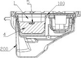
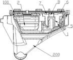
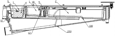
図1~図14に示すように、本実施例は洗剤投入装置を提供する。当該洗剤投入装置はタンク200を含む。タンク200内には、洗剤及び/又は粉洗剤が投入される投入ケース100が装着されている。好ましくは、投入ケース100は引き出し可能にタンク200内に挿入される。投入ケース100内には少なくとも1つの投入室1が設けられている。また、投入室1の底部にはタンク200と連通する吐水口11が設けられている。洗濯機の給水水流が投入室1に流れ込むと、投入ケース100内に添加された洗剤及び/又は粉洗剤が給水水流の作用によって吐水口11からタンク200に押し流される。投入室1内には、吐水口11への水流の流出を妨げるガードプレート4が装着されており、ガードプレート4には、両側を連通させるサイフォンカラム5が設けられている。これにより、ガードプレート4の上流側において、投入ケース100からタンク200に投入される洗剤及び給水水流は、ガードプレート4に妨げられてサイフォン効果が発動する液面高さまで貯水されたあと、サイフォンカラム5に沿ってガードプレートの下流側に流入し、吐水口を通じてタンク200へと流れ出す。
As shown in FIGS. 1-14, the present embodiment provides a detergent dosing device. The detergent dosing device includes a
上記のように設けることで、ユーザが投入室内に添加した洗剤はガードプレートにより妨げられるため、洗剤が水流により希釈されないままタンクに直接流れ込むとの事態が回避される。これにより、洗剤の希釈効率を向上させ、洗剤の分布範囲を拡大するとの目的が実現される。 With the provision as described above, the detergent added by the user into the dosing chamber is blocked by the guard plate, thus avoiding the situation where the detergent flows directly into the tank without being diluted by the water flow. Thereby, the purpose of improving the dilution efficiency of the detergent and expanding the distribution range of the detergent is achieved.
本実施例において、前記投入ケース100は水平に引き出し可能にタンク200内に装着される。ガードプレート4は投入室1の中央部に垂直に設けられる。また、ガードプレート4は投入ケース100の引き出し方向に対し垂直に設けられるとともに、対応する投入室1のいずれかの垂直断面を覆う。前記サイフォンカラム5は逆「U」型の流路であり、流路の両端がそれぞれガードプレートの両側に位置している。これにより、流路を介してガードプレート両側の投入室1を連通させている。給水水流はガードプレート4の上流側の投入室1内に流入する。流入した水流はガードプレート4に妨げられて貯水され、上昇しながらガードプレート4の上流側に投入された洗剤を希釈する役割を果たす。そして、水面高さが逆「U」型の流路の曲がり角を超えるまで投入室1内に給水されると、サイフォン効果が発動することで、ガードプレート4により妨げられていた水流が逆「U」型の流路を通じてガードプレート4の下流側に進入する。
In this embodiment, the charging
本実施例では、流路の曲がり角の高さがガードプレート4の上端の高さ以下のため、洗浄水の貯水高さがガードプレート4を超えたにもかかわらずサイフォン効果を発動できないとの事態が回避され、サイフォンカラム5を通じた洗剤の円滑な排出が保証される。
In this embodiment, since the height of the bend of the flow path is lower than the height of the upper end of the
本実施例において、逆「U」型の流路のうちガードプレート4の上流側に位置する一端は給水端であり、ガードプレート4の下流側に位置する一端は吐水端である。給水端と吐水端はいずれもタンク200の底壁と一定の隙間を隔てているため、洗剤及び供給水が底部の隙間から流路に対し円滑に流入又は流出する。
In this embodiment, one end of the reversed "U"-shaped channel located upstream of the
本実施例において、逆「U」型の流路の給水端の高さは吐水端の高さよりも高くなっている。これにより、水路内の水流はサイフォン効果が発動されたあと、重力の働きを受けてガードプレートの上流側の洗剤及び水を全てガードプレート4の下流側に流入させることができる。
In this embodiment, the height of the water supply end of the inverted "U" channel is higher than the height of the water discharge end. As a result, after the siphon effect is activated in the water flow in the water channel, all the detergent and water on the upstream side of the guard plate can flow into the downstream side of the
好ましくは、本実施例において、投入室1の底壁は、ガードプレート4と垂直な方向において、吐水口11側に向かって徐々に下方へ傾斜するよう設けられている。これにより、投入室1内の給水水流は重力の働きによって自ずと吐水口11の方向へと集結する。よって、ガードプレート4の上流側の貯水は全て円滑にガードプレート4に設けられた逆「U」型の流路の給水端に集結するよう流動し、ガードプレート4の下流側に流れ込んだ水流は全て円滑に吐水口11に集結するよう流動する。
Preferably, in this embodiment, the bottom wall of the charging
本実施例において、サイフォンカラム5は、ガードプレート4に固定装着されるか一体的に集積される本体を含む。本体は、垂直に延伸し且つ内部が中空の筒状をなしている。筒状の本体の中空部は、ガードプレート4によって互いに独立した2つの垂直に延伸する流路に分割されており、それぞれが給水流路及び吐水流路となっている。筒状の本体の上部には上カバーが密封状に掛合されており、上カバーの下側には内側に凹陥する凹溝が設けられている。給水流路と吐水流路の上部は凹溝によって連通しており、給水流路と吐水流路の下端がそれぞれ給水端と吐水端を構成している。
In this embodiment, the siphon
本実施例において、筒状の本体の上部には上方に突出する密封リブが周設されている。また、上カバーの外周には下方に突出する係合リブが2つ周設されており、内周の係合リブの中央部が凹溝を構成している。2つの係合リブは一定の隙間を隔てて挿接溝を構成しており、密封リブが挿接溝に挿入されることで上カバーと筒状の本体とが密封状に挿接される。好ましくは、挿接溝内にはパッキンが装着されている。パッキンは挿接溝と筒状の本体の間に挟持される。且つ、パッキンのうち少なくとも1つの壁面が挿接溝に密封状に付着するとともに、少なくとも1つの壁面が筒状の本体に密封状に付着する。これにより、挿接箇所の密封性が更に向上し、漏水及び漏気の発生が回避される。 In this embodiment, an upwardly projecting sealing rib is provided around the upper portion of the tubular body. Two engaging ribs protruding downward are provided around the outer circumference of the upper cover, and the central portion of the engaging rib on the inner circumference constitutes a groove. The two engaging ribs form an insertion groove with a certain gap therebetween, and the sealing rib is inserted into the insertion groove so that the upper cover and the cylindrical main body are tightly inserted and contacted. Preferably, a packing is mounted in the insertion groove. The packing is sandwiched between the insertion groove and the tubular body. In addition, at least one wall surface of the packing is hermetically attached to the insertion groove, and at least one wall surface is hermetically attached to the cylindrical main body. As a result, the sealing performance of the insertion and contact points is further improved, and the occurrence of water and air leakage is avoided.
本実施例において、筒状の本体とガードプレート4は一体的に成型されてなる。また、上カバーは筒状の本体の上部に掛合して固定接続される。
In this embodiment, the cylindrical main body and the
本実施例において、筒状の本体のうちガードプレート4と垂直な両側は平面となっており、ガードプレート4と平行な両側は本体の外側に向かって突出する円弧面となっている。また、本実施例では、投入室1内の水流について流動の円滑性が保証されるよう、円弧面と平面の接続箇所は滑らかな移行曲面となっている。
In this embodiment, both sides of the cylindrical main body perpendicular to the
本実施例において、前記ガードプレート4は反転可能にタンク200内に装着される。投入ケース100からタンク200内に洗剤を投入する場合、ガードプレート4は洗剤及び供給水を妨げるよう垂直に設置されるが、投入ケース100からタンク200内に粉洗剤を投入する場合、ガードプレート4は粉洗剤を吐水口まで押し流せるよう水平又は傾斜状に設置される。ガードプレートを反転可能に設けることで、投入装置は、液体及び固体の洗浄添加物をそれぞれ投入する際に相応の使用状態に調節可能となるため、添加物の円滑な投入が保証される。
In this embodiment, the
本実施例において、ガードプレート4の上部の両端には外側に突出する回動軸がそれぞれ設けられている。2つの回動軸は同軸に設けられる。2つの回動軸がそれぞれ対応する側の投入室1の側壁に挿入されることで、ガードプレート4は軸周りに回転可能に投入ケース100に装着される。本実施例では、駆動モータの作用によってガードプレートを自動的に回動させ、垂直位置と水平位置の間でガードプレート4を切り替え可能となるよう、ガードプレート4の回動軸は駆動モータに接続されている。好ましくは、ガードプレート4の回動軸部分には復帰ねじりバネが装着されている。伸張したねじりバネがガードプレートに位置復帰のための作用力を付与し、ガードプレートを初期の水平状態に復帰させるよう、復帰ねじりバネの両端はガードプレートと投入ケース100にそれぞれ当接している。
In this embodiment, both ends of the upper portion of the
本実施例において、ガードプレート4が垂直位置の場合、ガードプレート4の両側は投入室1の対応する側の内側壁にそれぞれ密接し、ガードプレート4の下側は投入室1の底壁に密接する。好ましくは、投入室1の内壁にはタンク200の内部に向かって突出する少なくとも1つの位置規制部が設けられており、ガードプレートが垂直位置まで回動したときには、位置規制部とガードプレートが互いに位置規制及び当接する。好ましくは、本実施例において、ガードプレートが垂直位置となったときに動かないよう保持するために、投入室1の左右両側の内壁には、垂直に延伸するとともに投入室1内に向かって突出する第1位置規制リブが1つずつ設けられている。前記第1位置規制リブは、ガードプレートの回動軸の下側における対応する垂直箇所又は吐水口から離間する側に設けられており、ガードプレート4が垂直状態となったときには、ガードプレートの給水側と第1位置規制リブが互いに位置規制及び当接する。
In this embodiment, when the
本実施例では、ガードプレート4が水平位置まで回動したときに開放角度が過度に大きくならないよう、投入室1の後側の内壁に、水平且つ投入室1内に向かって突出及び延伸する第2位置規制リブが設けられている。また、ガードプレートが水平状態となったときにガードプレート4の吐水側と第2位置規制リブが互いに位置規制及び当接するよう、前記第2位置規制リブの高さはガードプレート4の回動軸と整列している。
In this embodiment, in order to prevent the opening angle from becoming excessively large when the
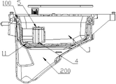
図8~図14に示すように、本実施例は洗剤投入装置を提供する。当該洗剤投入装置はタンク200を含む。タンク200内には、洗剤及び/又は粉洗剤が投入される投入ケース100が装着されている。好ましくは、投入ケース100は引き出し可能にタンク200内に挿入される。投入ケース100内には少なくとも1つの投入室1が設けられている。また、投入室1の底部にはタンク200と連通する吐水口11が設けられている。洗濯機の給水水流が投入室1に流れ込むと、投入ケース100内に添加された洗剤及び/又は粉洗剤が給水水流の作用によって吐水口からタンク200に押し流される。投入室1内には、吐水口11への水流の流出を妨げるガードプレート4が装着されている。また、ガードプレート4は反転可能に投入室1内に装着されている。ガードプレートには切欠き部10が設けられている。タンク200の供給水は、反転して開放されたガードプレートの切欠き部10に到達すると、切欠き部10からガードプレート4を通過したあと、反転して開放されたガードプレート下側の投入室1の底壁を洗い流す。
As shown in FIGS. 8-14, the present embodiment provides a detergent dosing device. The detergent dosing device includes a
上記のように設けることで、タンクの給水水流は、ガードプレートの切欠き部を経由してガードプレートの下方に遮断されている投入室の底壁を洗い流す。これにより、投入室の吐水口部分に粉洗剤が残留するとの事態が回避されるため、ガードプレートによって遮断される投入室の吐水口部分に粉洗剤が残留しないよう防止するとの目的が実現される。 With the arrangement as described above, the water flow of the tank flows through the notch of the guard plate and washes away the bottom wall of the loading chamber blocked below the guard plate. As a result, it is possible to prevent the powder detergent from remaining in the spout of the charging chamber, thereby realizing the purpose of preventing the powder detergent from remaining in the spout of the charging chamber blocked by the guard plate. .
本実施例において、投入室1には補助ガードプレート9が設けられている。ガードプレート4が垂直に閉止するまで反転した場合、切欠き部10は補助ガードプレート9によって遮断される。これにより、反転して閉止したガードプレート4と補助ガードプレート9が共同で投入室1を互いに独立した2つの部分に分割する。このように、切欠きを備えるガードプレート4が垂直位置となった場合、ガードプレート4と補助ガードプレート9は共同で投入室1の垂直断面を覆う遮断部を構成する。これにより、投入室1に添加された洗剤及び水流は遮断部に妨げられて貯水されるため、洗剤を希釈する役割を果たすとの目的が達せられる。
In this embodiment, the
本実施例において、ガードプレート4上の切欠き部10は投入室1寄りの側に設けられている。これにより、投入室1の流入水流は投入室1の対応する側から流れ込んで切欠き部10を通過したあと、ガードプレート下方の投入室1の底壁を洗い流す。好ましくは、投入室1の吐水口は、ガードプレート4上の切欠き部10と対向する反対側に設けられる。ガードプレートの切欠き部と投入室の吐水口を投入室の対向する両側に設けることで、流入水流はガードプレートを通過したあとに、投入室の一方の側から対向する他方の側へと流動する。これにより、流入水流がガードプレート下方の投入室の底壁を全面的に洗い流すよう保証する。
In this embodiment, the
本実施例において、投入室1に設けられる吐水口11は、投入室1の底壁に設けられた凹溝内に位置している。前記投入室1の底壁は、外周から凹溝方向に向かって徐々に下方へ傾斜するよう設けられているため、投入室1内の水流は吐水口11の方向に集結するよう流動する。好ましくは、吐水口11は凹溝の底部に位置し、凹溝に集結するよう流動した水流が吐水口11から全て円滑に排出される。
In this embodiment, the
本実施例において、前記補助ガードプレート9は垂直に投入室1内に設けられている。補助ガードプレート9の外周の少なくとも一部は、ガードプレート4が反転して閉止したときの切欠き部10の外周から突出する。これにより、反転可能なガードプレート4は補助ガードプレート9に妨げられて垂直閉止位置に位置規制される。好ましくは、前記補助ガードプレート9は投入室1内に垂直に装着されており、補助ガードプレート9の一方の側と底部を投入室1の内壁にそれぞれ固定接続することで、補助ガードプレート9と投入ケース100を一体部材として一体的に成型する。
In this embodiment, the
本実施例において、投入室1内には、吐水口への水流の流出を妨げるガードプレート4が装着されており、ガードプレート4には、両側を連通させるサイフォンカラム5が設けられている。これにより、ガードプレート4の上流側において、投入ケース100からタンク200に投入される洗剤及び給水水流は、ガードプレートに妨げられてサイフォン効果が発動する液面高さまで貯水されたあと、サイフォンカラム5に沿ってガードプレートの下流側に流入し、吐水口11を通じてタンク200へと流れ出す。
In this embodiment, a
上記のように設けることで、ユーザが投入室内に添加した洗剤はガードプレートにより妨げられるため、洗剤が水流により希釈されないままタンクに直接流れ込むとの事態が回避される。これにより、洗剤の希釈効率を向上させ、洗剤の分布範囲を拡大するとの目的が実現される。 With the provision as described above, the detergent added by the user into the dosing chamber is blocked by the guard plate, thus avoiding the situation where the detergent flows directly into the tank without being diluted by the water flow. Thereby, the purpose of improving the dilution efficiency of the detergent and expanding the distribution range of the detergent is achieved.
本実施例において、前記ガードプレート4は反転可能にタンク200内に装着される。投入ケース100からタンク200内に洗剤を投入する場合、ガードプレート4は洗剤及び供給水を妨げるよう垂直に設置されるが、投入ケース100からタンク200内に粉洗剤を投入する場合、ガードプレート4は粉洗剤を吐水口まで押し流せるよう水平又は傾斜状に設置される。ガードプレートを反転可能に設けることで、投入装置は、液体及び固体の洗浄添加物をそれぞれ投入する際に相応の使用状態に調節可能となるため、添加物の円滑な投入が保証される。
In this embodiment, the
本実施例において、ガードプレート4の上部の両端には外側に突出する回動軸がそれぞれ設けられている。2つの回動軸は同軸に設けられる。2つの回動軸がそれぞれ対応する側の投入室1の側壁に挿入されることで、ガードプレートは軸周りに回転可能に投入ケース100に装着される。本実施例では、駆動モータの作用によってガードプレート4を自動的に回動させ、垂直位置と水平位置の間でガードプレート4を切り替え可能となるよう、ガードプレート4の回動軸は駆動モータに接続されている。好ましくは、ガードプレート4の回動軸部分には復帰ねじりバネが装着されている。伸張したねじりバネがガードプレートに位置復帰のための作用力を付与し、ガードプレート4を初期の水平状態に復帰させるよう、復帰ねじりバネの両端はガードプレートと投入ケース100にそれぞれ当接している。
In this embodiment, both ends of the upper portion of the
本実施例において、ガードプレート4が垂直位置の場合、ガードプレート4の両側は投入室1の対応する側の内側壁にそれぞれ密接し、ガードプレート4の下側は投入室1の底壁に密接する。好ましくは、投入室1の内壁にはタンク200の内部に向かって突出する少なくとも1つの位置規制部が設けられており、ガードプレート4が垂直位置まで回動したときには、位置規制部とガードプレートが互いに位置規制及び当接する。好ましくは、投入室1の左右両側の内壁には、垂直に延伸するとともに投入室1内に向かって突出する第1位置規制リブが1つずつ設けられている。前記第1位置規制リブは、ガードプレートの回動軸の下側における対応する垂直箇所又は吐水口から離間する側に設けられており、ガードプレートが垂直状態となったときには、ガードプレートの給水側と第1位置規制リブが互いに位置規制及び当接する。
In this embodiment, when the
本実施例では、ガードプレート4が水平位置まで回動したときに開放角度が過度に大きくならないよう、投入室1の後側の内壁に、水平且つ投入室1内に向かって突出及び延伸する第2位置規制リブが設けられている。また、ガードプレートが水平状態となったときにガードプレート4の吐水側と第2位置規制リブが互いに位置規制及び当接するよう、前記第2位置規制リブの高さはガードプレート4の回動軸と整列している。
In this embodiment, in order to prevent the opening angle from becoming excessively large when the
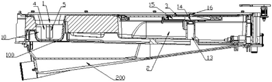
図1~図14に示すように、本実施例は洗剤投入装置を提供する。当該洗剤投入装置はタンク200を含む。タンク200内には、洗剤及び/又は粉洗剤が投入される投入ケース100が装着されている。好ましくは、投入ケース100は引き出し可能にタンク200内に挿入される。投入ケース100の内部には、上下両側を垂直に貫通する降水管13が設けられている。投入ケース100の天井面の残留水を降水管13を通じて投入ケース100下方のタンク200の底部まで案内するよう、降水管13の上下両端の開口は、投入ケース100の上下の壁面にそれぞれ位置している。
As shown in FIGS. 1-14, the present embodiment provides a detergent dosing device. The detergent dosing device includes a
投入装置の投入ケースに降水管を垂直に貫通するよう設けることで、投入ケースの天井面に残留した供給水を降水管を通じて投入ケース下方のタンクの底部まで流動させることが可能となる。これにより、投入ケースの天井面に残留水が残ることで、ユーザが投入ケースを引き出した場合に残留水が洗濯機の外部に漏出するとの事態が回避される。 By providing a downcomer pipe vertically through the charging case of the charging device, it is possible to allow the supply water remaining on the ceiling surface of the charging case to flow through the downcomer pipe to the bottom of the tank below the charging case. This avoids a situation in which residual water remains on the ceiling surface of the loading case and leaks out of the washing machine when the user pulls out the loading case.
本実施例において、投入ケース100は本体を含み、本体の内部の一部を中空とすることで貯液室2が構成されている。貯液室2の上部は開口して設けられ、本体の上部には開口に掛合する上カバー17が装着されている。上カバー17には上下に貫通する降水口14が設けられており、降水口14と降水管13が連通している。
In this embodiment, the
本実施例において、貯液室2の内部には降水管13が垂直に延伸するよう設けられており、降水管13の底部の開口が貯液室2の底壁を貫通している。降水管13の上部は上カバー17に密封状に付着しており、且つ、降水管13の上部の開口と降水口14は同軸に設けられる。好ましくは、降水管13の上端と上カバー17の下側が密封状に当接するよう、降水管13の上部の開口のサイズは降水口14のサイズよりも大きくなっている。
In this embodiment, a
本実施例において、降水管13は貯液室2の中央部に位置している。また、投入ケース100の押し込み方向における貯液室2の後側寄りには、洗剤を流出させる吐液口が設けられており、吐液口部分に制御弁が装着されている。
In this embodiment, the
本実施例において、上カバー17の降水口14部分には下方に突出するフランジが周設されている。フランジは降水管13の内部に伸入し、フランジの外周壁が降水管13の内壁に密接している。好ましくは、フランジにおける降水管13との接触面部分には少なくとも1つのシールリングが装着されている。
In this embodiment, a downwardly protruding flange is provided around the rain port 14 of the upper cover 17 . The flange extends into the interior of the
本実施例において、前記降水口14はカバープレートの最も低い箇所に位置している。投入ケース100の天井面における残留水の排水効率を向上させるために、カバープレートの上側には下方に凹陥する凹溝15を設け、降水口14を凹溝15の底壁に位置させてもよい。これにより、凹溝に集結するよう流れ込んだ残留水が降水口を経由して全て排出されるため、投入ケース100の天井面における残留水の残存面積が更に解消され、残留水を全て凹溝内に収集可能となる。
In this embodiment, the downspout 14 is located at the lowest point of the cover plate. In order to improve the efficiency of draining residual water on the ceiling surface of the
本実施例において、降水管13の下端の出口は投入ケース100の中央部に位置している。好ましくは、投入ケース100を引き出し状態として貯液室2内に洗浄添加物を添加する場合にも、降水管13の出口はタンク200の内部に残したままとする。これにより、降水管に沿って排出される残留水がタンク200から流出して洗濯機の外部の地面を汚染するとの事態が回避される。
In this embodiment, the outlet of the lower end of the
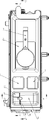
本実施例において、上カバー17の天井面には下方に凹陥する凹溝15が設けられており、凹溝15の開口部分がロックロッド3により覆われている。ロックロッド3の一端は上カバー17に接続され、他端は自在に設けられている。これにより、ロックロッド3の可動端は、外力を受けると垂直方向において弾性伸縮する。ロックロッド3の外周と凹溝15の内壁は一定の隙間を隔てており、降水口14はロックロッド3下方の凹溝15の底部に設けられている。より好ましくは、ロックロッド3の自由端、或いは自由端の近傍には上方へ突出する突出部が設けられている。
In this embodiment, the ceiling surface of the upper cover 17 is provided with a
本実施例において、前記ロックロッド3は投入ケース100の引き出し方向に延伸している。ロックロッド3の中央部には上方へ突出するロック部16が設けられており、前記降水口14はロック部16に対応する垂直下方に設けられている。
In this embodiment, the
本実施例では、排水効率を向上し、且つ上部における水流の残留を減少させるために、前記投入ケース100に複数の降水管13を設けてもよい。各降水管13は、投入ケース100の上カバー17上の異なる領域に残留した洗浄水を排出するよう、投入ケース100の異なる位置にそれぞれ分布させる。
In this embodiment, a plurality of
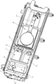
図8~図14に示すように、本実施例は洗剤投入装置を提供する。当該洗剤投入装置はタンク200を含む。タンク200内には、洗剤及び/又は粉洗剤が投入される投入ケース100が装着されている。好ましくは、投入ケース100は引き出し可能にタンク200内に挿入される。投入ケース100内には少なくとも1つの投入室1が設けられている。また、投入室1の底部にはタンク200と連通する吐水口が設けられている。洗濯機の給水水流が投入室1に流れ込むと、投入ケース100内に添加された洗剤又は粉洗剤が給水水流の作用によって吐水口からタンク200に押し流される。また、投入ケース100に設けられる少なくとも1つの投入室1は、液体状の洗浄添加物を投入するために用いられる。当該投入室1内にはサイフォンカラム5が装着されており、サイフォンカラム5内には互いに独立して垂直に延伸する中心流路と外周流路が設けられている。中心流路と外周流路の上端は、サイフォンカバーによって密封されつつ互いに連通している。また、中心流路と外周流路の底端は、タンク200と投入室1にそれぞれ対応して連通している。投入室1内には、サイフォンカラム5の外周に覆設される遮断リブ12が備わっている。投入ケース100内の洗剤及び供給水は、遮断リブ12を迂回して遮断リブ12とサイフォンカラム5の間へと流動する。
As shown in FIGS. 8-14, the present embodiment provides a detergent dosing device. The detergent dosing device includes a
サイフォンカラムの外周に遮断リブを周設し、サイフォンカラムと投入室を隔離することで、投入ケースを引き出す過程で投入室内の液体が激しく振動し、サイフォンカラムの液面が上昇する結果、サイフォンカラムが誤ってサイフォン現象を発動するとの事態が防止される。これにより、サイフォンカラムの「高波」によるサイフォン現象の誤作動を防止するとの目的が実現される。 By installing isolation ribs around the outer periphery of the siphon column and isolating the siphon column from the charging chamber, the liquid in the charging chamber vibrates violently in the process of pulling out the charging case, causing the liquid level in the siphon column to rise. is prevented from accidentally activating the siphon phenomenon. This achieves the objective of preventing malfunction of the siphon phenomenon due to "high waves" in the siphon column.
本実施例では、投入室1内の洗剤がサイフォンカラム5の底部の入口へ直接流れ込むのを阻止するよう、遮断リブ12の下端は投入室1の底壁に密封接続されている。好ましくは、遮断リブ12の上部は投入室1の最大液面高さよりも高く、より好ましくは、遮断リブ12の上部は投入室1の上面に密封接続される。
In this embodiment, the lower end of the blocking
本実施例において、遮断リブ12は、サイフォンカラム5のうち投入ケース100の外部への引き出し側を少なくとも覆っており、投入室1内が遮断リブ12によって前後2つの部分に分割されている。これにより、サイフォンカラム5の前側の洗剤及び供給水は遮断リブ12により遮断され、サイフォンカラム5に集結することがないため、投入室1内の液体に発生した高波がサイフォンカラム5に伝達されるとの事態が回避される。
In this embodiment, the blocking
本実施例において、遮断リブ12はサイフォンカラム5の外周に覆設される円弧状のリブであり、遮断リブ12には洗剤を通過させる切欠きが設けられている。好ましくは、遮断リブ12の切欠きは、サイフォンカラム5に対し、投入ケース100の外部への引き出し方向とは反対側に設けられている。
In this embodiment, the shielding
本実施例において、前記サイフォンカラム5は投入室1の後側寄りに設けられており、円弧状の遮断リブ12の両端がそれぞれ投入室1の後側壁寄りの箇所まで延伸している。且つ、円弧状の遮断リブ12の両端は、それぞれ投入室1の後側壁と一定の隙間を隔てており、前記隙間が洗剤を通過させる切欠きを構成している。
In this embodiment, the siphon
本実施例において、サイフォンカバーの外周は遮断リブ12から突出するよう設けられ、サイフォンカバーと遮断リブ12は垂直投影面において互いに重なり合うよう設けられる。また、サイフォンカバーの下側と遮断リブ12の上端は一定の隙間を隔てて設けられている。これにより、サイフォンカバーによって投入室1を洗剤及び給水の高波から遮断及び隔離しつつ、遮断リブ12とサイフォンカバーとの隙間から洗剤及び供給水をサイフォンカラム5の外周へ流動可能とする。
In this embodiment, the outer periphery of the siphon cover is provided to protrude from the blocking
本実施例において、サイフォンカバーにおける投入ケース100の外部への引き出し側には、下方に突出及び延伸する遮蔽リブ18が設けられている。前記遮蔽リブ18と遮断リブ12は互いにずらして設けられており、且つ、遮蔽リブ18は遮断リブよりも投入ケース100の外部への引き出し側寄りに設けられている。洗剤及び水流が遮蔽リブ18と遮断リブ12との隙間を通過して遮断リブ12とサイフォンカラム5の間へ流動可能となるよう、遮蔽リブ18の下端は遮断リブ12の上端よりも低くなるよう設けられている。
In this embodiment, the side of the siphon cover that draws out the
本実施例において、サイフォンカバーの中央部には下方へ垂直に延伸する第1スリーブが設けられており、投入室1の底壁には上方へ垂直に延伸する第2スリーブが設けられている。また、第2スリーブは第1スリーブの内部に嵌装される。第1スリーブと投入室1の底壁は一定の隙間を隔てており、第2スリーブの上部とサイフォンカバーは一定の隙間を隔てている。これにより、第1スリーブと第2スリーブの間の空間が外周流路を形成し、第2スリーブの内部に中心流路が構成される。また、第2スリーブの底部は投入室1の外部のタンク200と連通している。
In this embodiment, the central portion of the siphon cover is provided with a first sleeve extending vertically downward, and the bottom wall of the
本実施例において、投入室1の底部には下方に凹陥する凹溝が設けられている。サイフォンカラム5は凹溝内に設けられ、遮断リブ12は凹溝の外周辺縁箇所に設けられる。好ましくは、遮断リブ12は凹溝の外周に位置している。より好ましくは、遮断リブ12のうちサイフォンカラム5に面する側は凹溝の外周の内壁面と同一面に設けられる。
In this embodiment, the bottom portion of the
本実施例において、投入ケース100には複数の投入室1が設けられており、各投入室1は、それぞれ異なるタイプの洗濯添加剤の投入に用いられる。各投入室1内には、サイフォンカラム5と、サイフォンカラム5の外周に覆設される遮断リブ12がそれぞれ設けられている。投入ケース100内の洗剤は、遮断リブ12を迂回して遮断リブ12とサイフォンカラム5の間へと流動する。
In this embodiment, the
図1~図7に示すように、本実施例は洗剤投入装置を提供する。当該洗剤投入装置はタンク200を含む。タンク200内には、洗剤及び/又は粉洗剤が投入される投入ケース100が装着されている。好ましくは、投入ケース100は引き出し可能にタンク200内に挿入される。投入ケース100内には少なくとも1つの投入室1が設けられている。また、投入室1の底部にはタンク200と連通する吐水口が設けられている。洗濯機の給水水流が投入室1に流れ込むと、投入ケース100内に添加された洗剤又は粉洗剤が給水水流の作用によって吐水口からタンク200に押し流される。投入ケース100に設けられる少なくとも1つの投入室1は、液体状の洗浄添加物を投入するために用いられる。当該投入室1の開口の一部はカバープレート6で覆われている。また、投入室1内にはカバープレート6の下方に位置するサイフォンカラム5が装着されている。カバープレート6にはサイフォンカラム5の外周箇所に位置する透かし部7が設けられており、カバープレート6上の水流は透かし部7から下方の投入室1内に流れ込む。
As shown in FIGS. 1-7, the present embodiment provides a detergent dosing device. The detergent dosing device includes a
投入室のカバープレートにサイフォンカラムの外周に位置する透かし部を設けることで、投入ケースの天井面における洗浄用の供給水を透かし部に沿って投入室内に流れ込ませることが可能である。これにより、投入ケースの天井面に供給水が残留するとの事態が回避される。且つ、投入ケースの天井面の水流をサイフォンカラム近傍の透かし部に沿って投入室に流れ込ませることで、水流はサイフォンカラムの外壁に沿って下方へと流動可能となる。これにより、サイフォンカラムの外壁面が洗い流されるため、サイフォンカラムの外壁における洗剤の残留が回避され、ヒケ(Sink Mark)の発生が防止される。 By providing the cover plate of the charging chamber with a watermark positioned on the outer circumference of the siphon column, it is possible to flow the supply water for cleaning the ceiling surface of the charging case into the charging chamber along the watermark. This prevents the supply water from remaining on the ceiling surface of the charging case. In addition, by causing the water flow on the ceiling surface of the charging case to flow into the charging chamber along the watermark near the siphon column, the water flow can flow downward along the outer wall of the siphon column. As a result, the outer wall surface of the siphon column is washed away, so that the detergent is prevented from remaining on the outer wall of the siphon column and the occurrence of sink marks is prevented.
本実施例において、カバープレート6には下方に凹陥する凹溝8が設けられている。前記凹溝8はサイフォンカラム5の上方に対応して設けられる。また、凹溝8の底部には、サイフォンカラム5とはずらされた透かし部7が設けられている。カバープレートに下方に凹陥する凹溝を設けることで、カバープレートの天井面における供給水を迅速に凹溝内に収集可能となるため、投入ケースの天井面における残留水の残存範囲の拡大が回避される。
In this embodiment, the cover plate 6 is provided with a recessed groove 8 that is recessed downward. The groove 8 is provided above the siphon
本実施例において、サイフォンカラム5の左右両側は、投入ケース100の引き出し方向に対し対称に設けられ、サイフォンカラム5の左右両側にそれぞれ透かし部7が設けられている。投入ケース100の天井面における水流は、両側の透かし部7からカバープレート6をそれぞれ通過し、カバープレート6の下方におけるサイフォンカラム5の左右両側の外周をそれぞれ洗い流す。
In this embodiment, both the left and right sides of the siphon
本実施例において、サイフォンカラム5の左右両側の透かし部7は円弧状をなしている。円弧状の透かし部7の内周とサイフォンカラム5の外周は互いに垂直に整列して設けられるため、透かし部7の内周から投入室1に流れ込む水流はサイフォンカラム5の外壁に沿って投入室1内に流れ込み、サイフォンカラム5の外壁面を直接洗い流す。
In this embodiment, the
本実施例において、サイフォンカラム5の前後両側は、それぞれ垂直に延伸する接続リブを介してカバープレート6に接続される。これにより、サイフォンカラム5の上部が凹溝8の底部を構成し、両側の接続リブが凹溝8の側壁を構成する。また、接続リブとサイフォンカラム5の上部以外の凹溝8の壁面全てが透かし部7をなしている。サイフォンカラムの上部が凹溝の底部を直接構成することで、投入ケースの天井面から凹溝に流れ込んだ水流によってサイフォンカラムの天井面を洗い流すことが可能となる。これにより、サイフォンカラムの天井面のヒケの発生が効果的に回避される。
In this embodiment, both front and rear sides of the siphon
本実施例において、凹溝8の上端の開口を構成するカバープレート6の開口箇所には、円弧状をなし、且つ下方に屈曲する面取りフランジが設けられている。これにより、投入ケース100の外表面がいずれも滑らかに設けられるため、ユーザの負傷が回避される。
In this embodiment, the opening of the cover plate 6 forming the opening of the upper end of the recessed groove 8 is provided with a chamfered flange that is arc-shaped and bends downward. As a result, the outer surface of the
本実施例では、タンク200の給水水流がカバープレート6の上方及び/又は透かし部7まで流動し、透かし部7から投入室1内に流れ込んで、サイフォンカラム5の側壁及び/又はタンク200の底壁を洗い流す。投入装置のタンクに投入室の天井面を洗い流す水を供給することで、供給水は投入室の天井面に設けられた透かし部から投入室内に流れ込む。流入水流を利用して投入室の天井面を洗い流したあとに、流入水流を再利用して透かし部下方のサイフォンカラムの外表面を洗い流すことで、サイフォンカラムの外壁におけるヒケの発生が効果的に回避される。
In this embodiment, the water supply water flow of the
以上は本発明の好ましい実施例にすぎず、本発明を何らかの形式に限定するものではない。本発明については好ましい実施例によって上記のように開示したが、本発明を限定するとの主旨ではない。本発明の技術方案を逸脱しない範囲において、当業者が上記で提示した技術内容を用いて実施可能なわずかな変形或いは補足は、同等に変形された等価の実施例とみなされ、いずれも本発明の技術方案の内容を逸脱するものではない。また、本発明の技術的本質に基づいて上記の実施例に加えられるあらゆる簡単な修正、同等の変形及び補足は、いずれも本発明の方案の範囲内とされる。 The foregoing are merely preferred embodiments of the invention and are not intended to limit the invention in any form. Although the present invention has been disclosed above through preferred embodiments, it is not intended to limit the present invention. Within the scope of the technical solution of the present invention, slight variations or supplements that can be implemented by those skilled in the art using the technical content presented above are regarded as equally modified equivalent embodiments, and any It does not deviate from the content of the technical plan. In addition, all simple modifications, equivalent variations and supplements added to the above embodiments based on the technical essence of the present invention are all within the scope of the present invention.
100 投入ケース
200 タンク
1 投入室
2 貯液室
3 ロックロッド
4 ガードプレート
5 サイフォンカラム
6 カバープレート
7 透かし部
8 凹溝
9 補助ガードプレート
10 切欠き部
11 吐水口
12 遮断リブ
13 降水管
14 降水口
15 凹溝
16 ロック部
17 上カバー
18 遮蔽リブ
REFERENCE SIGNS
Claims (17)
前記投入ケースの内部には上下両側を垂直に貫通する降水管が設けられており、前記投入ケースの天井面の残留水を前記降水管を通じて前記投入ケース下方の前記タンクの底部まで案内するよう、前記降水管の上下両端の開口は前記投入ケースの上下の壁面にそれぞれ位置しており、
前記投入ケースは本体を含み、前記本体の内部の一部を中空とすることで貯液室が構成されており、投入室の上部は開口して設けられ、
前記本体の上部には開口に掛合する上カバーが装着されており、前記上カバーには上下に貫通する降水口が設けられており、前記降水口と前記降水管が連通しており、
前記降水口は前記上カバーの最も低い箇所に位置しており、
前記上カバーの上側には下方に凹陥する凹溝が設けられており、前記降水口が前記凹溝の底壁に位置し、
前記凹溝の開口部分がロックロッドにより覆われており、前記ロックロッドは一端が前記上カバーに接続されるとともに、他端が自在に設けられており、前記ロックロッドの可動端は外力を受けると垂直方向において弾性伸縮し、前記ロックロッドの外周と前記凹溝の内壁は一定の隙間を隔てており、前記降水口は前記ロックロッド下方の前記凹溝の底部に設けられている、洗剤投入装置。 including a tank, wherein an input case is mounted within said tank;
A downcomer pipe is installed vertically through both upper and lower sides of the charging case, and residual water on the ceiling surface of the charging case is guided to the bottom of the tank below the charging case through the downcomer pipe, The openings at the upper and lower ends of the downcomer are respectively located on the upper and lower walls of the input case,
The input case includes a main body, a liquid storage chamber is configured by making a part of the inside of the main body hollow, and the upper part of the input chamber is provided open,
An upper cover that engages with the opening is attached to the upper part of the main body, the upper cover is provided with a downspout that penetrates vertically, and the downspout is in communication with the downspout pipe,
The rainfall outlet is located at the lowest point of the upper cover,
a concave groove recessed downward is provided on the upper side of the upper cover, and the rainfall opening is located on the bottom wall of the concave groove;
The opening of the recessed groove is covered with a lock rod, one end of which is connected to the upper cover and the other end of which is freely provided, and the movable end of the lock rod receives an external force. The outer circumference of the lock rod and the inner wall of the groove are separated by a certain gap, and the water outlet is provided at the bottom of the groove below the lock rod. Device.
前記接続リブと前記サイフォンカラムの上部以外の前記凹溝の壁面全てが透かし部をなしていることを特徴とする請求項11に記載の洗剤投入装置。 Both front and rear sides of the siphon column are connected to the cover plate through vertically extending connecting ribs, the top of the siphon column forms the bottom of the groove, and the connecting ribs on both sides form the groove. constitute the side wall,
12. The detergent dispenser according to claim 11, wherein all wall surfaces of said concave groove other than said connecting rib and the upper part of said siphon column form a watermark.
透かし部は、前記遮断リブと前記サイフォンカラムの間の領域の垂直上方に対応して設けられることを特徴とする請求項8~13のいずれか1項に記載の洗剤投入装置。 The input chamber is provided with a blocking rib covering the outer periphery of the siphon column, and the detergent in the charging case bypasses the blocking rib and flows between the blocking rib and the siphon column. death,
The detergent dispenser according to any one of claims 8 to 13, wherein the watermark is provided vertically above the area between the blocking rib and the siphon column.
Priority Applications (1)
| Application Number | Priority Date | Filing Date | Title |
|---|---|---|---|
| JP2022211217A JP7443485B2 (en) | 2019-01-18 | 2022-12-28 | Detergent dosing device |
Applications Claiming Priority (5)
| Application Number | Priority Date | Filing Date | Title |
|---|---|---|---|
| CN201910047925.4A CN111455620B (en) | 2019-01-18 | 2019-01-18 | Washing and putting device |
| CN201910047940.9 | 2019-01-18 | ||
| CN201910047925.4 | 2019-01-18 | ||
| CN201910047940.9A CN111455623B (en) | 2019-01-18 | 2019-01-18 | Washing and putting device |
| PCT/CN2020/072378 WO2020147769A1 (en) | 2019-01-18 | 2020-01-16 | Dispensing device for washing |
Related Child Applications (1)
| Application Number | Title | Priority Date | Filing Date |
|---|---|---|---|
| JP2022211217A Division JP7443485B2 (en) | 2019-01-18 | 2022-12-28 | Detergent dosing device |
Publications (2)
| Publication Number | Publication Date |
|---|---|
| JP2022517287A JP2022517287A (en) | 2022-03-08 |
| JP7204754B2 true JP7204754B2 (en) | 2023-01-16 |
Family
ID=71613317
Family Applications (2)
| Application Number | Title | Priority Date | Filing Date |
|---|---|---|---|
| JP2020535076A Active JP7204754B2 (en) | 2019-01-18 | 2020-01-16 | Detergent dispenser |
| JP2022211217A Active JP7443485B2 (en) | 2019-01-18 | 2022-12-28 | Detergent dosing device |
Family Applications After (1)
| Application Number | Title | Priority Date | Filing Date |
|---|---|---|---|
| JP2022211217A Active JP7443485B2 (en) | 2019-01-18 | 2022-12-28 | Detergent dosing device |
Country Status (4)
| Country | Link |
|---|---|
| US (1) | US12071719B2 (en) |
| EP (1) | EP3789529A1 (en) |
| JP (2) | JP7204754B2 (en) |
| WO (1) | WO2020147769A1 (en) |
Families Citing this family (3)
| Publication number | Priority date | Publication date | Assignee | Title |
|---|---|---|---|---|
| US12546053B2 (en) * | 2021-05-10 | 2026-02-10 | Qingdao Haier Drum Washing Machine Co., Ltd. | Liquid storage box, additive dispensing apparatus and identification method |
| US20250011996A1 (en) * | 2021-11-15 | 2025-01-09 | Qingdao Haier Laundry Electric Appliances Co., Ltd | Clothing treatment agent box and clothing treatment device |
| CN118668441B (en) * | 2023-03-14 | 2025-11-25 | 青岛海尔洗衣机有限公司 | A detergent dispensing device and clothing treatment equipment |
Citations (1)
| Publication number | Priority date | Publication date | Assignee | Title |
|---|---|---|---|---|
| CN102926169A (en) | 2012-11-19 | 2013-02-13 | 代傲电子控制(南京)有限公司 | Automatic filling device and control method thereof |
Family Cites Families (22)
| Publication number | Priority date | Publication date | Assignee | Title |
|---|---|---|---|---|
| IT8434062V0 (en) * | 1984-10-12 | 1984-10-12 | Zanussi Elettrodomestici | DISTRIBUTOR OF LIQUID AND POWDER DETERGENTS FOR WASHING MACHINES. |
| IT1187302B (en) * | 1985-12-04 | 1987-12-23 | Zanussi Elettrodomestici | DETERGENT CONTAINER-DISPENSER DEVICE FOR WASHING MACHINE |
| JPH0530711Y2 (en) * | 1987-06-22 | 1993-08-05 | ||
| DE3736252A1 (en) * | 1987-10-27 | 1989-05-11 | Bauknecht Hausgeraete | Flush-in device for liquid laundry-treatment agents |
| ITPN20020016A1 (en) * | 2002-03-19 | 2003-09-19 | Electrolux Home Products Corpo | TANK FOR DETERGENT SUBSTANCES AND WASHING MACHINE INCLUDING THE TANK. |
| US20070044517A1 (en) * | 2005-08-30 | 2007-03-01 | Samsung Electronics Co., Ltd. | Detergent supplying apparatus of clothes washing machine |
| KR101259103B1 (en) | 2005-09-01 | 2013-04-26 | 엘지전자 주식회사 | apparatus suppling detergent in the washing machine |
| KR101225163B1 (en) * | 2005-12-09 | 2013-01-22 | 삼성전자주식회사 | Detergent Supply Apparatus of Washing Machine |
| JP4674594B2 (en) | 2007-04-12 | 2011-04-20 | パナソニック株式会社 | Washing machine |
| US9003588B2 (en) * | 2010-04-13 | 2015-04-14 | Whirlpool Corporation | Appliances with sudsing-reducing flushable detergent dispensers |
| KR101757740B1 (en) * | 2011-01-12 | 2017-07-27 | 삼성전자주식회사 | Detergent case and washing machine having the same |
| EP2554739B1 (en) * | 2011-08-01 | 2018-04-18 | Electrolux Home Products Corporation N.V. | Laundry washing machine |
| CN203420136U (en) | 2013-07-30 | 2014-02-05 | 松下家电研究开发(杭州)有限公司 | Washing agent dissolving and foaming device |
| EP3114269B1 (en) * | 2014-03-04 | 2020-04-29 | LG Electronics Inc. | Washing machine |
| CN204780330U (en) * | 2015-05-18 | 2015-11-18 | 宁波新乐电器有限公司 | Washing machine detergents box |
| CN205134025U (en) | 2015-08-31 | 2016-04-06 | Tcl智能科技(合肥)有限公司 | Detergent cartridge assembly and washing machine |
| JP7061844B2 (en) * | 2017-04-05 | 2022-05-02 | 東芝ライフスタイル株式会社 | Washing machine |
| US10584438B2 (en) | 2017-04-13 | 2020-03-10 | Whirlpool Corporation | Laundry treating appliance with dispenser having multiple lids |
| CN207143538U (en) * | 2017-08-30 | 2018-03-27 | 理文科技(山东)有限公司 | A kind of washing machine provided with new softener addition structure |
| CN208266482U (en) * | 2018-03-27 | 2018-12-21 | 青岛海尔滚筒洗衣机有限公司 | Distributor box and clothes treatment device for clothes treatment device |
| CN109183360B (en) | 2018-10-24 | 2022-03-11 | 青岛海尔洗涤电器有限公司 | Detergent box and washing machine with same |
| WO2020125612A1 (en) * | 2018-12-19 | 2020-06-25 | 青岛海尔滚筒洗衣机有限公司 | Laundry treating apparatus |
-
2020
- 2020-01-16 EP EP20721094.9A patent/EP3789529A1/en active Pending
- 2020-01-16 JP JP2020535076A patent/JP7204754B2/en active Active
- 2020-01-16 WO PCT/CN2020/072378 patent/WO2020147769A1/en not_active Ceased
- 2020-01-16 US US17/414,171 patent/US12071719B2/en active Active
-
2022
- 2022-12-28 JP JP2022211217A patent/JP7443485B2/en active Active
Patent Citations (1)
| Publication number | Priority date | Publication date | Assignee | Title |
|---|---|---|---|---|
| CN102926169A (en) | 2012-11-19 | 2013-02-13 | 代傲电子控制(南京)有限公司 | Automatic filling device and control method thereof |
Also Published As
| Publication number | Publication date |
|---|---|
| JP7443485B2 (en) | 2024-03-05 |
| EP3789529A4 (en) | 2021-03-10 |
| WO2020147769A1 (en) | 2020-07-23 |
| JP2023030167A (en) | 2023-03-07 |
| US12071719B2 (en) | 2024-08-27 |
| JP2022517287A (en) | 2022-03-08 |
| EP3789529A1 (en) | 2021-03-10 |
| US20220081824A1 (en) | 2022-03-17 |
Similar Documents
| Publication | Publication Date | Title |
|---|---|---|
| JP7164776B2 (en) | Detergent dispenser | |
| JP2023030167A (en) | Detergent dispenser | |
| JP7210590B2 (en) | detergent dispenser and washing machine | |
| US11203830B2 (en) | Delivery device for washing machine and washing machine having same | |
| JP7181939B2 (en) | washing machine | |
| JP2000237497A (en) | Washing machine | |
| WO2018192460A1 (en) | Automatic dispensing system for washing, and washing machine | |
| CN214116838U (en) | Drainer and water bucket device | |
| JP7138183B2 (en) | washing machine | |
| CN107841853A (en) | A kind of downpipe and washing machine | |
| CN111455629A (en) | a washing device | |
| CN205585970U (en) | Clean system of basin formula | |
| GB2174110A (en) | Reducing detergent wastage in a washing machine | |
| JP7599498B2 (en) | Drum washing machine | |
| JP6662138B2 (en) | Wash water tank device and flush toilet equipped with the wash water tank device | |
| CN211368101U (en) | Washing machine water deflector assembly and washing machine with same | |
| CN205667537U (en) | A kind of water tank type cleaning equipment | |
| JP6666578B2 (en) | Drain valve device, flush water tank device equipped with this flush valve device, and flush toilet equipped with this flush water tank device | |
| KR101152900B1 (en) | Structure for washing water drainage of toilet bowl | |
| WO2024045910A1 (en) | Detergent delivery device for washing equipment and washing equipment | |
| CN211772150U (en) | Detergent box assembly of washing equipment and washing equipment | |
| JP7400503B2 (en) | Water receiving member and cleaning water tank device | |
| CN111455620A (en) | a washing device | |
| JP2023034517A (en) | Washing water supply device | |
| CN111455623A (en) | a washing device |
Legal Events
| Date | Code | Title | Description |
|---|---|---|---|
| A621 | Written request for application examination |
Free format text: JAPANESE INTERMEDIATE CODE: A621 Effective date: 20210405 |
|
| A131 | Notification of reasons for refusal |
Free format text: JAPANESE INTERMEDIATE CODE: A131 Effective date: 20220510 |
|
| A521 | Request for written amendment filed |
Free format text: JAPANESE INTERMEDIATE CODE: A523 Effective date: 20220729 |
|
| A131 | Notification of reasons for refusal |
Free format text: JAPANESE INTERMEDIATE CODE: A131 Effective date: 20220830 |
|
| A521 | Request for written amendment filed |
Free format text: JAPANESE INTERMEDIATE CODE: A523 Effective date: 20221117 |
|
| TRDD | Decision of grant or rejection written | ||
| A01 | Written decision to grant a patent or to grant a registration (utility model) |
Free format text: JAPANESE INTERMEDIATE CODE: A01 Effective date: 20221206 |
|
| A61 | First payment of annual fees (during grant procedure) |
Free format text: JAPANESE INTERMEDIATE CODE: A61 Effective date: 20221228 |
|
| R150 | Certificate of patent or registration of utility model |
Ref document number: 7204754 Country of ref document: JP Free format text: JAPANESE INTERMEDIATE CODE: R150 |
|
| R250 | Receipt of annual fees |
Free format text: JAPANESE INTERMEDIATE CODE: R250 |