JP7204706B2 - Stator, motor and blower - Google Patents
Stator, motor and blower Download PDFInfo
- Publication number
- JP7204706B2 JP7204706B2 JP2020096286A JP2020096286A JP7204706B2 JP 7204706 B2 JP7204706 B2 JP 7204706B2 JP 2020096286 A JP2020096286 A JP 2020096286A JP 2020096286 A JP2020096286 A JP 2020096286A JP 7204706 B2 JP7204706 B2 JP 7204706B2
- Authority
- JP
- Japan
- Prior art keywords
- winding
- connecting wire
- stator
- teeth
- tooth
- Prior art date
- Legal status (The legal status is an assumption and is not a legal conclusion. Google has not performed a legal analysis and makes no representation as to the accuracy of the status listed.)
- Active
Links
Images


Description
本開示は、1つのティースに巻線が集中して巻き付けられたステータとこのステータを備えるモータおよび送風機に関する。 The present disclosure relates to a stator in which windings are concentratedly wound around one tooth, and a motor and a blower including this stator.
従来、1つのティースに巻線が集中して巻き付けられたステータを備える集中巻モータが知られている。ティースには、巻線が巻き付けられてコイルが形成されている。特許文献1に開示されているように、2極の集中巻モータでは、1つの相につきティースおよびコイルが2つずつ配置されて、2つのティースおよび2つのコイルがモータの周方向に180度離れて配置されている。2つのコイル同士は、渡り線で繋がっている。
Conventionally, a concentrated winding motor is known that includes a stator in which windings are concentratedly wound around one tooth. A wire is wound around the tooth to form a coil. As disclosed in
特許文献1に開示された集中巻モータでは、同相の2つのティースは、樹脂製のインシュレータを介して互いに連結されている。インシュレータは、環状の渡り線ガイド部と、渡り線ガイド部の外周部に180度離れて設けられてティースを覆うとともに巻線が巻き付けられる2つの巻線部とを有する。渡り線ガイド部の内周面には、モータの中心軸に沿って延びる筒部が設けられている。渡り線は、筒部の外周面に沿って延びて、2つの巻線部間に渡っている。
In the concentrated winding motor disclosed in
金型を用いてインシュレータを成形する際には、金型からインシュレータを取り出しやすくするために、金型のうち筒部に対応する箇所に抜き勾配を付けるのが一般的である。そのため、成形後の筒部は、金型の抜き勾配に応じて傾斜する。筒部は、半径方向内側に傾斜する。 When molding an insulator using a mold, it is common to provide a draft angle at a portion of the mold corresponding to the cylindrical portion in order to facilitate removal of the insulator from the mold. Therefore, the cylindrical portion after molding is inclined according to the draft angle of the mold. The tubular portion slopes radially inward.
特許文献1に開示された集中巻モータでは、同相の2つのコイルがモータの周方向に180度離れて配置されているため、渡り線に張力を加えた場合に、渡り線が2つのコイル間の最短距離であるモータの中心を通るルートを取ろうとする力が働く。すなわち、渡り線には、モータの中心に向かう力が働く。筒部が傾斜していると、渡り線は、筒部の先端側にずれるほど2つのコイル間の最短ルートに近付くため、筒部から外れやすくなる。
In the concentrated winding motor disclosed in
そこで、上記特許文献1には、円筒コーン形状の筒部を設ける構成が開示されている。特許文献1に開示された筒部には、基端から先端に向かうにつれて縮径する傾斜部と、傾斜部の先端から同一直径で立ち上がる円筒形状の先端立ち上がり部とが形成されている。特許文献1に開示された技術では、渡り線を傾斜部に沿わせて、先端立ち上がり部で渡り線が筒部から外れることを抑制している。
In view of this,
しかしながら、上記特許文献1のように傾斜部の先端に先端立ち上がり部を設けると、モータの中心軸に沿う筒部の高さが高くなるため、モータの中心軸に沿うモータのサイズが増加するという問題がある。
However, when the leading end rising portion is provided at the tip of the inclined portion as in
本開示は、上記に鑑みてなされたものであって、渡り線が筒部から外れることを抑制できるとともに、モータの中心軸に沿うモータのサイズの増加を抑制することができるステータを得ることを目的とする。 The present disclosure has been made in view of the above, and aims to obtain a stator capable of suppressing the disconnection of the connecting wire from the cylindrical portion and suppressing an increase in the size of the motor along the central axis of the motor. aim.
上述した課題を解決し、目的を達成するために、本開示にかかるステータは、第1ティースユニットと、複数の凹部が等角度離れて内周面に設けられた環状のヨークと、を備えるステータである。第1ティースユニットは、凹部に嵌め込まれる2つの第1ティースと、環状の第1渡り線ガイド部と、第1渡り線ガイド部の外周部に等角度離れて2つ設けられて第1ティースの軸方向に沿った一端部を覆う第1巻線部とを有する樹脂製の第1インシュレータと、第1ティースの軸方向に沿った他端部を覆う樹脂製の第1被覆部材と、一方の第1ティースから他方の第1ティースに向けて延びて第1渡り線ガイド部にガイドされる第1渡り線を含み、第1巻線部および第1被覆部材を介して第1ティースのそれぞれに集中巻された第1巻線と、を備える。第1渡り線ガイド部は、環状の第1床部と、第1床部の内周部に設けられて円筒形状に形成され、ステータの半径方向内側に傾斜する第1筒部と、第1筒部の外周面の一部からステータの半径方向外側に向かって突出して、半径方向外側の先端部の少なくとも一部がステータの軸方向に平行な第1突起と、を有する。 In order to solve the above-described problems and achieve an object, a stator according to the present disclosure includes a first tooth unit, and an annular yoke having a plurality of recessed portions equiangularly spaced apart on an inner peripheral surface. is. The first teeth unit includes two first teeth fitted in the recesses, an annular first connecting wire guide portion, and two first tooth units provided equiangularly apart from each other on the outer peripheral portion of the first connecting wire guide portion. A resin-made first insulator having a first winding portion covering one end portion along the axial direction, a resin-made first covering member covering the other end portion along the axial direction of the first tooth, and one of the including a first connecting wire that extends from one first tooth toward the other first tooth and is guided by a first connecting wire guide portion; and a concentratedly wound first winding. The first connecting wire guide portion includes an annular first floor portion, a first tubular portion formed in a cylindrical shape provided on an inner peripheral portion of the first floor portion and inclined inward in a radial direction of the stator, a first and a first projection protruding radially outward of the stator from a portion of the outer peripheral surface of the cylindrical portion, and at least a portion of a radially outer tip portion of the first projection parallel to the axial direction of the stator.
本開示にかかるステータでは、渡り線が筒部から外れることを抑制できるとともに、モータの中心軸に沿うモータのサイズの増加を抑制することができるという効果を奏する。 In the stator according to the present disclosure, it is possible to prevent the connecting wire from coming off the cylindrical portion, and to prevent an increase in the size of the motor along the central axis of the motor.
以下に、実施の形態にかかるステータ、モータおよび送風機を図面に基づいて詳細に説明する。 A stator, a motor, and an air blower according to embodiments will be described in detail below with reference to the drawings.
実施の形態1.
図1は、実施の形態1にかかるステータ1の組み付け状態を示す斜視図である。図2は、実施の形態1にかかるステータ1を分解した状態を示す斜視図である。図1および図2に示すように、ステータ1は、三相交流のU相の第1巻線24が集中巻される第1ティースユニット2と、V相の第2巻線34が集中巻される第2ティースユニット3と、W相の第3巻線44が集中巻される第3ティースユニット4と、環状のヨーク5とを備える。ステータ1は、円筒形状に形成されている。本実施の形態では、ステータ1が三相6スロット2極の集中巻モータに用いられる場合を例示するが、ステータ1が用いられる集中巻モータの相数、スロット数および極数を限定する趣旨ではない。以下、ステータ1の各構成要素について方向を説明するときには、図2に示されるステータ1の中心軸Cと平行な方向を軸方向、ステータ1の中心軸Cと直交する方向を半径方向、ステータ1の中心軸C周りを周方向とする。
FIG. 1 is a perspective view showing an assembled state of a
図3は、実施の形態1におけるヨーク5を示す平面図である。ヨーク5は、磁性体で形成された環状の部材である。ヨーク5は、複数枚の電磁鋼板が積層されて形成されている。ヨーク5の内周面には、他の部分よりも半径方向外側に凹んだ複数の凹部51が等角度離れて設けられている。凹部51の数は、本実施の形態では6個である。
FIG. 3 is a plan view showing the
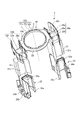
図4は、U相の第1ティースユニット2を分解した状態を示す斜視図である。図5は、U相の第1ティースユニット2の組み付け状態を示す斜視図である。図4では、第1巻線24の図示を省略している。第1ティースユニット2は、2つの第1ティース21と、第1インシュレータ22と、2つの第1被覆部材23と、第1巻線24とを備える。
FIG. 4 is a perspective view showing an exploded state of the U-phase
図6は、実施の形態1における第1ティース21、第2ティース31および第3ティース41を示す平面図である。第1ティース21、第2ティース31および第3ティース41の構成は同じであるため、図6では第1ティース21、第2ティース31および第3ティース41の符号を併記する。第1ティース21は、図3に示されるヨーク5の凹部51に嵌め込まれる金属製の部材である。第1ティース21は、複数枚の電磁鋼板が積層されて形成されている。第1ティース21の外周部には、ヨーク5の凹部51に嵌め込まれる第1基端部21aが設けられている。第1ティース21の内周部には、半径方向内側に向かうにつれて周方向に広くなる第1先端部21bが設けられている。第1基端部21aと第1先端部21bとの間には、第1巻回部21cが設けられている。
FIG. 6 is a plan view showing
図4に示される第1インシュレータ22は、2つの第1ティース21同士を連結する樹脂製の部材である。第1インシュレータ22は、環状の第1渡り線ガイド部22aと、第1渡り線ガイド部22aの外周部に等角度離れて2つ設けられて第1ティース21の軸方向に沿った一端部を覆う第1巻線部22bとを有する。2つの第1巻線部22bは、第1渡り線ガイド部22aの外周部に180度間隔で設けられている。
The
第1渡り線ガイド部22aは、環状の第1床部22cと、第1床部22cの内周部に設けられて円筒形状に形成されステータ1の半径方向内側に傾斜する第1筒部22dと、第1筒部22dの外周面の一部からステータ1の半径方向外側に向かって突出して半径方向外側の先端部がステータ1の軸方向に平行な第1突起22jとを有する。第1床部22cは、平坦状に形成されている。第1筒部22dは、概ね軸方向に延びている。第1筒部22dおよび第1突起22jの詳細については後述する。
The first connecting
第1巻線部22bは、第1ティース21の第1巻回部21cのうち軸方向に沿った一端部を覆う第1胴部22eと、第1胴部22eの外周部に設けられた第1外フランジ部22fと、第1胴部22eの内周部に設けられて第1渡り線ガイド部22aに接続する第1内フランジ部22gとを有する。第1胴部22eは、第1ティース21に向けて開口するとともに半径方向内側および外側が開口する溝形状に形成されている。第1胴部22eの溝部には、第1巻回部21cの一部が嵌め込まれる。第1内フランジ部22gの軸方向に沿った一端部の中央には、第1巻線24が通過する第1ゲート部22hが設けられている。第1ゲート部22hは、第1内フランジ部22gの一部を切り欠いて形成されている。
The first winding
第1被覆部材23は、第1ティース21の軸方向に沿った他端部を覆う樹脂製の部材である。第1被覆部材23は、第1ティース21の第1巻回部21cのうち軸方向に沿った他端部を覆う第1被覆胴部23aと、第1被覆胴部23aの外周部に設けられた第1被覆外フランジ部23bと、第1被覆胴部23aの内周部に設けられた第1被覆内フランジ部23cとを有する。第1被覆胴部23aは、第1ティース21に向けて開口するとともに半径方向内側および外側が開口する溝形状に形成されている。第1被覆胴部23aの溝部には、第1巻回部21cの一部が嵌め込まれる。第1巻回部21cは、第1インシュレータ22の第1胴部22eと第1被覆部材23の第1被覆胴部23aとにより覆われている。第1被覆外フランジ部23bの外周面には、円柱状のピン23dが取り付けられている。ピン23dは、図示しない外部電源線と第1巻線24との中継点、または、第1巻線24の巻き終わり中性点となる。
The
図5に示される第1巻線24は、第1巻線部22bの第1胴部22eおよび第1被覆部材23の第1被覆胴部23aを介して、第1ティース21のそれぞれに集中巻されている。2つの第1ティース21のそれぞれの第1巻回部21cには、第1巻線24が巻き付けられて第1コイル25が形成される。
The first winding 24 shown in FIG. 5 is concentratedly wound on each of the
第1巻線24は、一方の第1ティース21から巻き始められて第1巻回部21cに複数回巻き付けられる。その後、第1巻線24は、第1渡り線ガイド部22aにガイドされて、一方の第1ティース21から他方の第1ティース21に渡される。すなわち、一方の第1ティース21から他方の第1ティース21への巻き付けに移行する。第1巻線24は、他方の第1ティース21の第1巻回部21cに複数回巻き付けられる。
The first winding 24 is started from one of the
第1巻線24は、一方の第1ティース21から他方の第1ティース21に向けて延びて、第1渡り線ガイド部22aにガイドされる第1渡り線26を含んでいる。第1渡り線26は、第1床部22cの上を這うように配置されている。また、第1渡り線26は、第1筒部22dの外周面および第1突起22jに沿って円弧形状に延びている。
The first winding 24 includes a first connecting
図7は、V相の第2ティースユニット3の組み付け状態を示す斜視図である。第2ティースユニット3は、2つの第2ティース31と、第2インシュレータ32と、2つの第2被覆部材33と、第2巻線34とを備える。
FIG. 7 is a perspective view showing an assembled state of the V-phase
第2ティース31は、図3に示されるヨーク5の凹部51に嵌め込まれる金属製の部材である。第2ティース31は、複数枚の電磁鋼板が積層されて形成されている。図6に示すように、第2ティース31の外周部には、ヨーク5の凹部51に嵌め込まれる第2基端部31aが設けられている。第2ティース31の内周部には、半径方向内側に向かうにつれて周方向に広くなる第2先端部31bが設けられている。第2基端部31aと第2先端部31bとの間には、第2巻回部31cが設けられている。
The
図7に示すように、第2インシュレータ32は、2つの第2ティース31同士を連結する樹脂製の部材である。第2インシュレータ32は、環状の第2渡り線ガイド部32aと、第2渡り線ガイド部32aの外周部に等角度離れて2つ設けられて第2ティース31の軸方向に沿った一端部を覆う第2巻線部32bとを有する。2つの第2巻線部32bは、第2渡り線ガイド部32aの外周部に180度間隔で設けられている。
As shown in FIG. 7, the
第2渡り線ガイド部32aは、環状の第2床部32cと、第2床部32cの内周部に設けられて円筒形状に形成されステータ1の半径方向内側に傾斜する第2筒部32dと、第2筒部32dの外周面の一部からステータ1の半径方向外側に向かって突出して半径方向外側の先端部がステータ1の軸方向に平行な第2突起32jとを有する。第2床部32cは、平坦状に形成されている。第2筒部32dは、概ね軸方向に延びている。第2筒部32dおよび第2突起32jの詳細については後述する。
The second connecting
第2巻線部32bは、第2ティース31の第2巻回部31cのうち軸方向に沿った一端部を覆う第2胴部32eと、第2胴部32eの外周部に設けられた第2外フランジ部32fと、第2胴部32eの内周部に設けられて第2渡り線ガイド部32aに接続する第2内フランジ部32gとを有する。なお、図7では、第2胴部32eおよび後述する第2被覆胴部33aに第2巻線34が巻き付けられることによって第2胴部32eおよび第2被覆胴部33aが見えなくなるため、第2胴部32eと第2被覆胴部33aとの境界を破線で図示している。図示は省略するが、第2胴部32eは、第2ティース31に向けて開口するとともに半径方向内側および外側が開口する溝形状に形成されている。第2胴部32eの溝部には、図6に示される第2巻回部31cの一部が嵌め込まれる。第2内フランジ部32gの軸方向に沿った一端部の中央には、第2巻線34が通過する第2ゲート部32hが設けられている。第2ゲート部32hは、第2内フランジ部32gの一部を切り欠いて形成されている。
The second winding
第2被覆部材33は、第2ティース31の軸方向に沿った他端部を覆う樹脂製の部材である。第2被覆部材33は、第2ティース31の第2巻回部31cのうち軸方向に沿った他端部を覆う第2被覆胴部33aと、第2被覆胴部33aの外周部に設けられた第2被覆外フランジ部33bと、第2被覆胴部33aの内周部に設けられた第2被覆内フランジ部33cとを有する。図示は省略するが、第2被覆胴部33aは、第2ティース31に向けて開口するとともに半径方向内側および外側が開口する溝形状に形成されている。第2被覆胴部33aの溝部には、第2巻回部31cの一部が嵌め込まれる。第2巻回部31cは、第2インシュレータ32の第2胴部32eと第2被覆部材33の第2被覆胴部33aとにより覆われている。第2被覆外フランジ部33bの外周面には、円柱状のピン33dが取り付けられている。ピン33dは、図示しない外部電源線と第2巻線34との中継点、または、第2巻線34の巻き終わり中性点となる。
The
第2巻線34は、第2巻線部32bの第2胴部32eおよび第2被覆部材33の第2被覆胴部33aを介して、第2ティース31のそれぞれに集中巻されている。2つの第2ティース31のそれぞれの第2巻回部31cには、第2巻線34が巻き付けられて第2コイル35が形成される。
The second winding 34 is concentratedly wound around each of the
第2巻線34は、一方の第2ティース31から巻き始められて第2巻回部31cに複数回巻き付けられる。その後、第2巻線34は、第2渡り線ガイド部32aにガイドされて、一方の第2ティース31から他方の第2ティース31に渡される。すなわち、一方の第2ティース31から他方の第2ティース31への巻き付けに移行する。第2巻線34は、他方の第2ティース31の第2巻回部31cに複数回巻き付けられる。
The second winding 34 is started from one of the
第2巻線34は、一方の第2ティース31から他方の第2ティース31に向けて延びて、第2渡り線ガイド部32aにガイドされる第2渡り線36を含んでいる。第2渡り線36は、第2床部32cの上を這うように配置されている。また、第2渡り線36は、第2筒部32dの外周面および第2突起32jに沿って円弧形状に延びている。
The second winding 34 includes a second connecting
図8は、W相の第3ティースユニット4の組み付け状態を示す斜視図である。第3ティースユニット4は、2つの第3ティース41と、第3インシュレータ42と、2つの第3被覆部材43と、第3巻線44とを備える。
FIG. 8 is a perspective view showing an assembled state of the W-phase
第3ティース41は、図3に示されるヨーク5の凹部51に嵌め込まれる金属製の部材である。第3ティース41は、複数枚の電磁鋼板が積層されて形成されている。図6に示すように、第3ティース41の外周部には、ヨーク5の凹部51に嵌め込まれる第3基端部41aが設けられている。第3ティース41の内周部には、半径方向内側に向かうにつれて周方向に広くなる第3先端部41bが設けられている。第3基端部41aと第3先端部41bとの間には、第3巻回部41cが設けられている。
The
図8に示すように、第3インシュレータ42は、2つの第3ティース41同士を連結する樹脂製の部材である。第3インシュレータ42は、環状の第3渡り線ガイド部42aと、第3渡り線ガイド部42aの外周部に等角度離れて2つ設けられて第3ティース41の軸方向に沿った一端部を覆う第3巻線部42bとを有する。2つの第3巻線部42bは、第3渡り線ガイド部42aの外周部に180度間隔で設けられている。
As shown in FIG. 8, the
第3渡り線ガイド部42aは、環状の第3床部42cと、第3床部42cの内周部に設けられて円筒形状に形成されステータ1の半径方向内側に傾斜する第3筒部42dと、第3筒部42dの外周面の一部からステータ1の半径方向外側に向かって突出して半径方向外側の先端部がステータ1の軸方向に平行な第3突起42jとを有する。第3床部42cは、平坦状に形成されている。第3筒部42dは、概ね軸方向に延びている。第3筒部42dおよび第3突起42jの詳細については後述する。
The third connecting
第3巻線部42bは、第3ティース41の第3巻回部41cのうち軸方向に沿った一端部を覆う第3胴部42eと、第3胴部42eの外周部に設けられた第3外フランジ部42fと、第3胴部42eの内周部に設けられて第3渡り線ガイド部42aに接続する第3内フランジ部42gとを有する。なお、図8では、第3胴部42eおよび後述する第3被覆胴部43aに第3巻線44が巻き付けられることによって第3胴部42eおよび第3被覆胴部43aが見えなくなるため、第3胴部42eと第3被覆胴部43aとの境界を破線で図示している。図示は省略するが、第3胴部42eは、第3ティース41に向けて開口するとともに半径方向内側および外側が開口する溝形状に形成されている。第3胴部42eの溝部には、図6に示される第3巻回部41cの一部が嵌め込まれる。第3内フランジ部42gの軸方向に沿った一端部の中央には、第3巻線44が通過する第3ゲート部42hが設けられている。第3ゲート部42hは、第3内フランジ部42gの一部を切り欠いて形成されている。
The third winding
第3被覆部材43は、第3ティース41の軸方向に沿った他端部を覆う樹脂製の部材である。第3被覆部材43は、第3ティース41の第3巻回部41cのうち軸方向に沿った他端部を覆う第3被覆胴部43aと、第3被覆胴部43aの外周部に設けられた第3被覆外フランジ部43bと、第3被覆胴部43aの内周部に設けられた第3被覆内フランジ部43cとを有する。図示は省略するが、第3被覆胴部43aは、第3ティース41に向けて開口するとともに半径方向内側および外側が開口する溝形状に形成されている。第3被覆胴部43aの溝部には、第3巻回部41cの一部が嵌め込まれる。第3巻回部41cは、第3インシュレータ42の第3胴部42eと第3被覆部材43の第3被覆胴部43aとにより覆われている。第3被覆外フランジ部43bの外周面には、円柱状のピン43dが取り付けられている。ピン43dは、図示しない外部電源線と第3巻線44との中継点、または、第3巻線44の巻き終わり中性点となる。
The
第3巻線44は、第3巻線部42bの第3胴部42eおよび第3被覆部材43の第3被覆胴部43aを介して、第3ティース41のそれぞれに集中巻されている。2つの第3ティース41のそれぞれの第3巻回部41cには、第3巻線44が巻き付けられて第3コイル45が形成される。
The third winding 44 is concentratedly wound around each of the
第3巻線44は、一方の第3ティース41から巻き始められて第3巻回部41cに複数回巻き付けられる。その後、第3巻線44は、第3渡り線ガイド部42aにガイドされて、一方の第3ティース41から他方の第3ティース41に渡される。すなわち、一方の第3ティース41から他方の第3ティース41への巻き付けに移行する。第3巻線44は、他方の第3ティース41の第3巻回部41cに複数回巻き付けられる。
The third winding 44 starts winding from one
第3巻線44は、一方の第3ティース41から他方の第3ティース41に向けて延びて、第3渡り線ガイド部42aにガイドされる第3渡り線46を含んでいる。第3渡り線46は、第3床部42cの上を這うように配置されている。また、第3渡り線46は、第3筒部42dの外周面および第3突起42jに沿って円弧形状に延びている。
The third winding 44 includes a third connecting
次に、第1ティースユニット2、第2ティースユニット3および第3ティースユニット4の配置について説明する。図2に示すように、第2巻線部32bが隣り合う第1巻線部22bの間に位置するとともに第3巻線部42bが隣り合う第1巻線部22bと第2巻線部32bとの間に位置するように、第1ティースユニット2、第2ティースユニット3および第3ティースユニット4が周方向にずれて配置されている。また、第1渡り線ガイド部22aと第2渡り線ガイド部32aと第3渡り線ガイド部42aとが重ね合わされるように、第1ティースユニット2、第2ティースユニット3および第3ティースユニット4が配置されている。第1渡り線ガイド部22aの軸方向の位置と第2渡り線ガイド部32aの軸方向の位置と第3渡り線ガイド部42aの軸方向の位置とは、互いに異なる。第1渡り線ガイド部22aの中心と2つの第1巻線部22bの中心とを結んだ直線を第1直線L1とする。第2渡り線ガイド部32aの中心と2つの第2巻線部32bの中心とを結んだ直線を第2直線L2とする。第3渡り線ガイド部42aの中心と2つの第3巻線部42bの中心とを結んだ直線を第3直線L3とする。第1直線L1と第2直線L2と第3直線L3とが周方向に60度ずつずれるように、第1ティースユニット2、第2ティースユニット3および第3ティースユニット4が配置されている。
Next, the arrangement of the
ここで、図4、図7から図10を参照して、第1筒部22d、第2筒部32d、第3筒部42d、第1突起22j、第2突起32jおよび第3突起42jの構成について詳しく説明する。図9は、実施の形態1における第1筒部22d、第2筒部32dおよび第3筒部42dを示す側面図である。図10は、実施の形態1における第1突起22j、第2突起32jおよび第3突起42jを示す側面図である。第1筒部22d、第2筒部32dおよび第3筒部42dの構成は同じであるため、図9および図10では第1筒部22d、第2筒部32dおよび第3筒部42dの符号を併記する。また、第1突起22j、第2突起32jおよび第3突起42jの構成は同じであるため、図10では第1突起22j、第2突起32jおよび第3突起42jの符号を併記する。
4 and 7 to 10, configurations of first
図9に示すように、第1筒部22dは、ステータ1の半径方向内側に傾斜する。第1筒部22dの外周面は、ステータ1の軸方向の一端に向かうにつれて半径方向内側に位置するように傾斜する第1傾斜面22iとなる。第1傾斜面22iの傾斜角は、第1インシュレータ22の型成形時における型抜きのために付けられた抜き勾配である。
As shown in FIG. 9 , the first
図10に示すように、第1突起22jは、第1筒部22dの外周面の一部からステータ1の半径方向外側に向かって突出している。第1突起22jの半径方向外側の先端部は、ステータ1の軸方向に平行である。すなわち、第1突起22jの半径方向外側の先端部には、抜き勾配がない。なお、第1突起22jの半径方向外側の先端部の少なくとも一部がステータ1の軸方向に平行であればよい。第1突起22jの半径方向外側の先端部は、第1渡り線26と接触する。図4に示すように、第1突起22jは、第1筒部22dの外周面の一部に設けられている。第1突起22jは、本実施の形態では第1筒部22dの外周面の一箇所に設けられている。
As shown in FIG. 10, the
図9に示すように、第2筒部32dは、ステータ1の半径方向内側に傾斜する。第2筒部32dの外周面は、ステータ1の軸方向の一端に向かうにつれて半径方向内側に位置するように傾斜する第2傾斜面32iとなる。第2傾斜面32iの傾斜角は、第2インシュレータ32の型成形時における型抜きのために付けられた抜き勾配である。
As shown in FIG. 9, the second
図10に示すように、第2突起32jは、第2筒部32dの外周面の一部からステータ1の半径方向外側に向かって突出している。第2突起32jの半径方向外側の先端部は、ステータ1の軸方向に平行である。すなわち、第2突起32jの半径方向外側の先端部には、抜き勾配がない。なお、第2突起32jの半径方向外側の先端部の少なくとも一部がステータ1の軸方向に平行であればよい。第2突起32jの半径方向外側の先端部は、第2渡り線36と接触する。図7に示すように、第2突起32jは、第2筒部32dの外周面の一部に設けられている。第2突起32jは、本実施の形態では第2筒部32dの外周面の一箇所に設けられている。
As shown in FIG. 10, the
図9に示すように、第3筒部42dは、ステータ1の半径方向内側に傾斜する。第3筒部42dの外周面は、ステータ1の軸方向の一端に向かうにつれて半径方向内側に位置するように傾斜する第3傾斜面42iとなる。第3傾斜面42iの傾斜角は、第3インシュレータ42の型成形時における型抜きのために付けられた抜き勾配である。
As shown in FIG. 9, the third
図10に示すように、第3突起42jは、第3筒部42dの外周面の一部からステータ1の半径方向外側に向かって突出している。第3突起42jの半径方向外側の先端部は、ステータ1の軸方向に平行である。すなわち、第3突起42jの半径方向外側の先端部には、抜き勾配がない。なお、第3突起42jの半径方向外側の先端部の少なくとも一部がステータ1の軸方向に平行であればよい。第3突起42jの半径方向外側の先端部は、第3渡り線46と接触する。図8に示すように、第3突起42jは、第3筒部42dの外周面の一部に設けられている。第3突起42jは、本実施の形態では第3筒部42dの外周面の一箇所に設けられている。
As shown in FIG. 10, the
次に、ステータ1の製造方法について説明する。
Next, a method for manufacturing the
ステータ1の製造方法は、準備工程と、第1巻線工程と、第2巻線工程と、第3巻線工程と、ユニット一体化工程と、嵌め込み工程とを含む。
The manufacturing method of the
準備工程は、図2に示されるヨーク5、第1ティース21、第1インシュレータ22、第1被覆部材23、第1巻線24を準備する工程である。また、準備工程は、図2に示される第2ティース31、第2インシュレータ32、第2被覆部材33、第2巻線34、第3ティース41、第3インシュレータ42、第3被覆部材43、第3巻線44を準備する工程である。
The preparation step is a step of preparing the
図5に示すように、第1巻線工程は、2つの第1ティース21と、第1インシュレータ22と、2つの第1被覆部材23とを一体化した状態で、2つの第1ティース21のそれぞれに第1巻線24を集中巻きする工程である。第1巻線工程では、まず、一方のピン23dに第1巻線24の巻始めを絡げ、一方の第1巻線部22bおよび第1被覆部材23を介して一方の第1ティース21に第1巻線24を集中巻きする。第1巻線24の第1ティース21への巻き付けは、第1ティース21のうち径方向の中心より径方向外側から開始される。その後、第1渡り線26を第1ゲート部22hに通して第1渡り線ガイド部22aの上に出し、第1床部22cの上を這わせて他方の第1ティース21へと向かわせる。このとき、円筒形状の第1筒部22dが設けられているため、第1ティースユニット2を180度回転させるだけで、第1渡り線26が第1筒部22dおよび第1突起22jに沿って他方の第1ティース21へと向かう。第1渡り線26は、第1筒部22dの外周面および第1突起22jに沿って円弧を描くように延びる。続いて、第1渡り線26を他方の第1ゲート部22hに通して、他方の第1巻線部22bに導く。続いて、他方の第1巻線部22bおよび第1被覆部材23を介して他方の第1ティース21に第1巻線24を集中巻きする。最後に、図示しない他方のピン23dに第1巻線24の巻き終わりを絡げる。このような手順を経てU相の第1ティースユニット2の巻線作業が完了する。なお、U相の第1ティースユニット2、V相の第2ティースユニット3、および、W相の第3ティースユニット4の巻線作業は、巻線機を用いて行う。
As shown in FIG. 5, in the first winding step, the two
図7に示すように、第2巻線工程は、2つの第2ティース31と、第2インシュレータ32と、2つの第2被覆部材33とを一体化した状態で、2つの第2ティース31のそれぞれに第2巻線34を集中巻きする工程である。第2巻線工程では、まず、一方のピン33dに第2巻線34の巻始めを絡げ、一方の第2巻線部32bおよび第2被覆部材33を介して一方の第2ティース31に第2巻線34を集中巻きする。第2巻線34の第2ティース31への巻き付けは、第2ティース31のうち径方向の中心より径方向外側から開始される。その後、第2渡り線36を第2ゲート部32hに通して第2渡り線ガイド部32aの上に出し、第2床部32cの上を這わせて他方の第2ティース31へと向かわせる。このとき、円筒形状の第2筒部32dが設けられているため、第2ティースユニット3を180度回転させるだけで、第2渡り線36が第2筒部32dおよび第2突起32jに沿って他方の第2ティース31へと向かう。第2渡り線36は、第2筒部32dの外周面および第2突起32jに沿って円弧を描くように延びる。続いて、第2渡り線36を他方の第2ゲート部32hに通して、他方の第2巻線部32bに導く。続いて、他方の第2巻線部32bおよび第2被覆部材33を介して他方の第2ティース31に第2巻線34を集中巻きする。最後に、図示しない他方のピン33dに第2巻線34の巻き終わりを絡げる。このような手順を経てV相の第2ティースユニット3の巻線作業が完了する。
As shown in FIG. 7, in the second winding step, the two
図8に示すように、第3巻線工程は、2つの第3ティース41と、第3インシュレータ42と、2つの第3被覆部材43とを一体化した状態で、2つの第3ティース41のそれぞれに第3巻線44を集中巻きする工程である。第3巻線工程では、まず、一方のピン43dに第3巻線44の巻始めを絡げ、一方の第3巻線部42bおよび第3被覆部材43を介して一方の第3ティース41に第3巻線44を集中巻きする。第3巻線44の第3ティース41への巻き付けは、第3ティース41のうち径方向の中心より径方向外側から開始される。その後、第3渡り線46を第3ゲート部42hに通して第3渡り線ガイド部42aの上に出し、第3床部42cの上を這わせて他方の第3ティース41へと向かわせる。このとき、円筒形状の第3筒部42dが設けられているため、第3ティースユニット4を180度回転させるだけで、第3渡り線46が第3筒部42dおよび第3突起42jに沿って他方の第3ティース41へと向かう。第3渡り線46は、第3筒部42dの外周面および第3突起42jに沿って円弧を描くように延びる。続いて、第3渡り線46を他方の第3ゲート部42hに通して、他方の第3巻線部42bに導く。続いて、他方の第3巻線部42bおよび第3被覆部材43を介して他方の第3ティース41に第3巻線44を集中巻きする。最後に、図示しない他方のピン43dに第3巻線44の巻き終わりを絡げる。このような手順を経てW相の第3ティースユニット4の巻線作業が完了する。
As shown in FIG. 8, in the third winding step, the two
図1および図2に示すように、ユニット一体化工程は、第1ティースユニット2と第2ティースユニット3と第3ティースユニット4とを一体化する工程である。図2に示すように、ユニット一体化工程では、第2巻線部32bを隣り合う第1巻線部22bの間に位置させるとともに、第3巻線部42bを隣り合う第1巻線部22bと第2巻線部32bとの間に位置させて、第1渡り線ガイド部22aと第2渡り線ガイド部32aと第3渡り線ガイド部42aとを重ね合わせて、第1ティースユニット2と第2ティースユニット3と第3ティースユニット4とを一体化する。
As shown in FIGS. 1 and 2, the unit integration step is a step of integrating the
嵌め込み工程は、一体化した第1ティースユニット2と第2ティースユニット3と第3ティースユニット4とをヨーク5内に挿入して、第1ティース21と第2ティース31と第3ティース41とをヨーク5の凹部51に嵌め込む工程である。このような手順を経て図1に示されるステータ1が完成する。
In the fitting step, the integrated
次に、本実施の形態にかかるステータ1の効果について説明する。以下、第1インシュレータ22、第2インシュレータ32および第3インシュレータ42を「インシュレータ6」と総称する。また、第1筒部22d、第2筒部32dおよび第3筒部42dを「筒部7」と総称する。また、第1傾斜面22i、第2傾斜面32iおよび第3傾斜面42iを「傾斜面8」と総称する。また、第1突起22j、第2突起32jおよび第3突起42jを「突起9」と総称する。また、第1コイル25、第2コイル35および第3コイル45を「コイル10」と総称する。また、第1渡り線26、第2渡り線36および第3渡り線46を「渡り線11」と総称する。
Next, the effect of the
図11は、渡り線11に働く力を説明するための説明図である。図11に示すように、2極の集中巻モータでは、同相の2つのコイル10がモータの周方向に180度離れて配置されるため、渡り線11に張力を加えた場合に、渡り線11が2つのコイル10間の最短距離であるステータ1の中心軸Cを通るルートを取ろうとする力が働く。すなわち、渡り線11には、図11の鎖線および破線に示すように、ステータ1の中心軸Cに向かう力が働く。
FIG. 11 is an explanatory diagram for explaining the force acting on the
一方で、図示しない金型を用いてインシュレータ6を成形する際には、金型からインシュレータ6を取り出しやすくするために、金型のうち筒部7に対応する箇所に抜き勾配を付けるのが一般的である。そのため、図9に示すように、成形後の筒部7は、金型の抜き勾配に応じて傾斜する。成形後の筒部7の外周面は、傾斜面8となる。傾斜面8が筒部7の外周面の全周に亘って形成されると、傾斜面8に沿う渡り線11は、図9の破線で示すように、筒部7の先端側にずれるほど2つのコイル10間の最短ルートに近付くため、筒部7から外れやすくなる。
On the other hand, when the
この点、本実施の形態では、図10に示すように、ステータ1には、筒部7の外周面の一部からステータ1の半径方向外側に向かって突出して、半径方向外側の先端部の少なくとも一部がステータ1の軸方向に平行な突起9が形成されていることにより、渡り線11が筒部7の先端側にずれても、渡り線11が筒部7から外れにくくなる。そして、筒部7の軸方向の高さを高くすることなく、渡り線11が筒部7から外れることを抑制できるため、モータの中心軸Cに沿うモータのサイズの増加を抑制することができる。また、渡り線11が筒部7から外れにくくなるため、ステータ1を製造しやすくなる。
In this regard, in the present embodiment, as shown in FIG. 10, the
なお、筒部7の外周面の全周に亘って傾斜面8を無くす方法も考えられる。しかし、筒部7の外周面の全周に亘って傾斜面8を無くすと、成形時に金型からインシュレータ6が抜けない可能性が高くなり、製造不良につながるという問題が生じる。この点、本実施の形態では、筒部7の外周部の一部から突出する突起9を設けて、筒部7の外周面の傾斜面8を部分的に無くすことにより、上記問題の発生を抑制することができる。
A method of eliminating the
本実施の形態では、ステータ1が三相6スロット2極の集中巻モータに用いられる場合を例示したが、例えば、ステータ1が単相4スロット2極の集中巻モータに用いられてもよい。ステータ1が単相4スロット2極の集中巻モータに用いられる場合には、図2に示される第1直線L1と第2直線L2とが周方向に90度ずれるように、第1ティースユニット2および第2ティースユニット3が配置される。
In the present embodiment, the
実施の形態2.
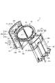
図12は、実施の形態2にかかる換気扇12を示す断面図である。図12では、図面の理解の容易化のために換気扇12の一部の要素のハッチングを省略している。なお、実施の形態2では、前記した実施の形態1と重複する部分については、同一符号を付して説明を省略する。
FIG. 12 is a sectional view showing the
送風機である換気扇12は、建物の天井部17、壁部などに形成された換気口18に取り付けられて建物内の換気を行う装置である。ここでは、換気扇12を天井部17に設置する場合を例示する。換気扇12は、ボディ13と、モータ14と、羽根15とを備える。
A
ボディ13は、換気口18に取り付けられる箱形の部材である。ボディ13の内部には、空気が流れる空気流路13aが形成されている。ボディ13は、天板13bを備える。天板13bには、モータ14を取り付けるための図示しないモータ取付孔が形成されている。ボディ13の下端には、グリル16が取り付けられている。グリル16は、天井部17よりも下方に位置しており、室内に露出している。
The
モータ14は、前記した実施の形態1にかかるステータ1と、ステータ1の内側にステータ1と隙間を介して配置された図示しないロータと、ステータ1およびロータを収容する筐体14aと、ロータの中心に連結されたシャフト14bとを備える。モータ14は、単相4スロット2極の集中巻モータ、三相6スロット2極の集中巻モータなどである。すなわち、モータ14は、ステータ1のスロット数が4スロットで、ロータの極数が2極の集中巻モータ、ステータ1のスロット数が6スロットで、ロータの極数が2極の集中巻モータなどである。モータ14は、ボディ13のモータ取付孔に取り付けられている。モータ14は、その一部が天板13bの上に突出した状態で、モータ取付孔に挿入されている。羽根15は、モータ14のシャフト14bの先端に取り付けられている。
The
モータ14のシャフト14bとともに羽根15が回転することにより、図12の矢印Yで示すように、グリル16を通じて吸込口13cから吸い込んだ空気が羽根15によって吹出口13dへ送られて、空気流路13a内に空気の流れが発生する。なお、本実施の形態では、換気扇12にモータ14を搭載する場合を例示したが、扇風機などの送風機にモータ14を搭載してもよい。
As the
以上の実施の形態に示した構成は、一例を示すものであり、別の公知の技術と組み合わせることも可能であるし、実施の形態同士を組み合わせることも可能であるし、要旨を逸脱しない範囲で、構成の一部を省略、変更することも可能である。 The configurations shown in the above embodiments are only examples, and can be combined with other known techniques, or can be combined with other embodiments, without departing from the scope of the invention. It is also possible to omit or change part of the configuration.
1 ステータ、2 第1ティースユニット、3 第2ティースユニット、4 第3ティースユニット、5 ヨーク、6 インシュレータ、7 筒部、8 傾斜面、9 突起、10 コイル、11 渡り線、12 換気扇、13 ボディ、13a 空気流路、13b 天板、13c 吸込口、13d 吹出口、14 モータ、14a 筐体、14b シャフト、15 羽根、16 グリル、17 天井部、18 換気口、21 第1ティース、21a 第1基端部、21b 第1先端部、21c 第1巻回部、22 第1インシュレータ、22a 第1渡り線ガイド部、22b 第1巻線部、22c 第1床部、22d 第1筒部、22e 第1胴部、22f 第1外フランジ部、22g 第1内フランジ部、22h 第1ゲート部、22i 第1傾斜面、22j 第1突起、23 第1被覆部材、23a 第1被覆胴部、23b 第1被覆外フランジ部、23c 第1被覆内フランジ部、23d,33d,43d ピン、24 第1巻線、25 第1コイル、26 第1渡り線、31 第2ティース、31a 第2基端部、31b 第2先端部、31c 第2巻回部、32 第2インシュレータ、32a 第2渡り線ガイド部、32b 第2巻線部、32c 第2床部、32d 第2筒部、32e 第2胴部、32f 第2外フランジ部、32g 第2内フランジ部、32h 第2ゲート部、32i 第2傾斜面、32j 第2突起、33 第2被覆部材、33a 第2被覆胴部、33b 第2被覆外フランジ部、33c 第2被覆内フランジ部、34 第2巻線、35 第2コイル、36 第2渡り線、41 第3ティース、41a 第3基端部、41b 第3先端部、41c 第3巻回部、42 第3インシュレータ、42a 第3渡り線ガイド部、42b 第3巻線部、42c 第3床部、42d 第3筒部、42e 第3胴部、42f 第3外フランジ部、42g 第3内フランジ部、42h 第3ゲート部、42i 第3傾斜面、42j 第3突起、43 第3被覆部材、43a 第3被覆胴部、43b 第3被覆外フランジ部、43c 第3被覆内フランジ部、44 第3巻線、45 第3コイル、46 第3渡り線、51 凹部、C 中心軸。 REFERENCE SIGNS LIST 1 stator, 2 first tooth unit, 3 second tooth unit, 4 third tooth unit, 5 yoke, 6 insulator, 7 cylindrical portion, 8 inclined surface, 9 projection, 10 coil, 11 connecting wire, 12 ventilation fan, 13 body , 13a air flow path, 13b top plate, 13c suction port, 13d outlet, 14 motor, 14a housing, 14b shaft, 15 blade, 16 grill, 17 ceiling, 18 ventilation port, 21 first tooth, 21a first Base end portion 21b First tip portion 21c First winding portion 22 First insulator 22a First connecting wire guide portion 22b First winding portion 22c First floor portion 22d First tubular portion 22e First trunk portion 22f First outer flange portion 22g First inner flange portion 22h First gate portion 22i First inclined surface 22j First protrusion 23 First covering member 23a First covering trunk portion 23b First covering outer flange portion 23c First covering inner flange portion 23d, 33d, 43d Pin 24 First winding 25 First coil 26 First connecting wire 31 Second tooth 31a Second base end , 31b second tip portion, 31c second winding portion, 32 second insulator, 32a second connecting wire guide portion, 32b second winding portion, 32c second floor portion, 32d second cylindrical portion, 32e second body part, 32f second outer flange part, 32g second inner flange part, 32h second gate part, 32i second inclined surface, 32j second protrusion, 33 second covering member, 33a second covering body part, 33b second covering Outer flange portion 33c Second coated inner flange portion 34 Second winding 35 Second coil 36 Second connecting wire 41 Third tooth 41a Third base end 41b Third tip 41c Third third winding portion 42 third insulator 42a third connecting wire guide portion 42b third winding portion 42c third floor portion 42d third cylinder portion 42e third body portion 42f third outer flange portion 42g Third inner flange portion 42h Third gate portion 42i Third inclined surface 42j Third protrusion 43 Third covering member 43a Third covering trunk portion 43b Third covering outer flange portion 43c Third covering inner flange portion 43c part, 44 third winding, 45 third coil, 46 third 3 crossover, 51 recess, C central axis.
Claims (6)
複数の凹部が等角度離れて内周面に設けられた環状のヨークと、
を備えるステータであって、
前記第1ティースユニットは、
前記凹部に嵌め込まれる2つの第1ティースと、
環状の第1渡り線ガイド部と、前記第1渡り線ガイド部の外周部に等角度離れて2つ設けられて前記第1ティースの軸方向に沿った一端部を覆う第1巻線部とを有する樹脂製の第1インシュレータと、
前記第1ティースの軸方向に沿った他端部を覆う樹脂製の第1被覆部材と、
一方の前記第1ティースから他方の前記第1ティースに向けて延びて前記第1渡り線ガイド部にガイドされる第1渡り線を含み、前記第1巻線部および前記第1被覆部材を介して前記第1ティースのそれぞれに集中巻された第1巻線と、を備え、
前記第1渡り線ガイド部は、
環状の第1床部と、
前記第1床部の内周部に設けられて円筒形状に形成され、前記ステータの半径方向内側に傾斜する第1筒部と、
前記第1筒部の外周面の一部から前記ステータの半径方向外側に向かって突出して、半径方向外側の先端部の少なくとも一部が前記ステータの軸方向に平行な第1突起と、
を有することを特徴とするステータ。 a first tooth unit;
an annular yoke having a plurality of recesses equiangularly spaced apart on the inner peripheral surface;
A stator comprising
The first tooth unit is
two first teeth fitted into the recess;
an annular first connecting wire guide portion; and two first winding portions provided on the outer peripheral portion of the first connecting wire guide portion at equal angles to cover one end portion of the first tooth along the axial direction. a first resin insulator having
a resin-made first covering member that covers the other end along the axial direction of the first tooth;
including a first connecting wire that extends from one of the first teeth toward the other of the first teeth and is guided by the first connecting wire guide portion, via the first winding portion and the first covering member and a first winding concentratedly wound around each of the first teeth,
The first connecting wire guide part
an annular first floor;
a first cylindrical portion provided on the inner peripheral portion of the first floor portion, formed in a cylindrical shape, and inclined inward in the radial direction of the stator;
a first projection projecting radially outward of the stator from a portion of the outer peripheral surface of the first cylindrical portion, and at least a portion of a radially outer tip portion of the first projection being parallel to the axial direction of the stator;
A stator comprising:
前記第2ティースユニットは、
前記凹部に嵌め込まれる2つの第2ティースと、
環状の第2渡り線ガイド部と、前記第2渡り線ガイド部の外周部に等角度離れて2つ設けられて前記第2ティースの軸方向に沿った一端部を覆う第2巻線部とを有する樹脂製の第2インシュレータと、
前記第2ティースの軸方向に沿った他端部を覆う樹脂製の第2被覆部材と、
一方の前記第2ティースから他方の前記第2ティースに向けて延びて前記第2渡り線ガイド部にガイドされる第2渡り線を含み、前記第2巻線部および前記第2被覆部材を介して前記第2ティースのそれぞれに集中巻された第2巻線と、を備え、
前記第2巻線部が隣り合う前記第1巻線部の間に挿入されて、前記第2渡り線ガイド部が前記第1渡り線ガイド部に重ねられるように、前記第1ティースユニットおよび前記第2ティースユニットが周方向にずれて配置され、
前記第2渡り線ガイド部は、
環状の第2床部と、
前記第2床部の内周部に設けられて円筒形状に形成され、前記ステータの半径方向内側に傾斜する第2筒部と、
前記第2筒部の外周面の一部から前記ステータの半径方向外側に向かって突出して、半径方向外側の先端部の少なくとも一部が前記ステータの軸方向に平行な第2突起と、
を有することを特徴とする請求項1に記載のステータ。 Equipped with a second tooth unit,
The second teeth unit is
two second teeth fitted in the recess;
an annular second connecting wire guide portion; and two second winding portions that are provided on the outer peripheral portion of the second connecting wire guide portion at equal angles and cover one ends of the second teeth along the axial direction. a resin-made second insulator having
a resin-made second covering member that covers the other end along the axial direction of the second tooth;
including a second connecting wire that extends from one of the second teeth toward the other of the second teeth and is guided by the second connecting wire guide portion, via the second winding portion and the second covering member; and a second winding concentratedly wound around each of the second teeth,
The first tooth unit and the first tooth unit are arranged such that the second winding portion is inserted between the adjacent first winding portions, and the second connection wire guide portion overlaps the first connection wire guide portion. The second tooth unit is arranged with a shift in the circumferential direction,
The second connecting wire guide part is
an annular second floor;
a second cylindrical portion provided on the inner peripheral portion of the second floor portion, formed in a cylindrical shape, and inclined inward in the radial direction of the stator;
a second projection projecting radially outward of the stator from a portion of the outer peripheral surface of the second cylindrical portion, and at least a portion of a radially outer tip portion of the second projection being parallel to the axial direction of the stator;
2. The stator of claim 1, comprising:
前記第3ティースユニットは、
前記凹部に嵌め込まれる2つの第3ティースと、
環状の第3渡り線ガイド部と、前記第3渡り線ガイド部の外周部に等角度離れて2つ設けられて前記第3ティースの軸方向に沿った一端部を覆う第3巻線部とを有する樹脂製の第3インシュレータと、
前記第3ティースの軸方向に沿った他端部を覆う樹脂製の第3被覆部材と、
一方の前記第3ティースから他方の前記第3ティースに向けて延びて前記第3渡り線ガイド部にガイドされる第3渡り線を含み、前記第3巻線部および前記第3被覆部材を介して前記第3ティースのそれぞれに集中巻された第3巻線と、を備え、
前記第3巻線部が隣り合う前記第1巻線部と前記第2巻線部との間に挿入されて、前記第3渡り線ガイド部が前記第1渡り線ガイド部と前記第2渡り線ガイド部とに重ねられるように、前記第1ティースユニット、前記第2ティースユニットおよび前記第3ティースユニットが周方向に60度ずつずれて配置され、
前記第3渡り線ガイド部は、
環状の第3床部と、
前記第3床部の内周部に設けられて円筒形状に形成され、前記ステータの半径方向内側に傾斜する第3筒部と、
前記第3筒部の外周面の一部から前記ステータの半径方向外側に向かって突出して、半径方向外側の先端部の少なくとも一部が前記ステータの軸方向に平行な第3突起と、
を有することを特徴とする請求項2に記載のステータ。 Equipped with a third tooth unit,
The third teeth unit is
two third teeth fitted in the recess;
an annular third connecting wire guide portion; and two third winding portions that are provided on the outer peripheral portion of the third connecting wire guide portion at equal angles and cover one ends of the third teeth along the axial direction. a resin third insulator having
a resin-made third covering member covering the other end along the axial direction of the third tooth;
a third connecting wire that extends from one of the third teeth toward the other of the third teeth and is guided by the third connecting wire guide portion, the third connecting wire via the third winding portion and the third covering member; and a third winding concentratedly wound around each of the third teeth,
The third winding portion is inserted between the first winding portion and the second winding portion which are adjacent to each other, and the third connection wire guide portion is connected to the first connection wire guide portion and the second connection wire guide portion. The first tooth unit, the second tooth unit and the third tooth unit are arranged with a displacement of 60 degrees in the circumferential direction so as to overlap with the line guide part,
The third connecting wire guide portion is
an annular third floor;
a third cylindrical portion provided on the inner peripheral portion of the third floor portion, formed in a cylindrical shape, and inclined inward in the radial direction of the stator;
a third projection projecting radially outward of the stator from a portion of the outer peripheral surface of the third cylindrical portion, and at least a portion of a radially outer tip portion of the third projection being parallel to the axial direction of the stator;
3. The stator of claim 2, comprising:
Priority Applications (1)
| Application Number | Priority Date | Filing Date | Title |
|---|---|---|---|
| JP2020096286A JP7204706B2 (en) | 2020-06-02 | 2020-06-02 | Stator, motor and blower |
Applications Claiming Priority (1)
| Application Number | Priority Date | Filing Date | Title |
|---|---|---|---|
| JP2020096286A JP7204706B2 (en) | 2020-06-02 | 2020-06-02 | Stator, motor and blower |
Publications (2)
| Publication Number | Publication Date |
|---|---|
| JP2021191163A JP2021191163A (en) | 2021-12-13 |
| JP7204706B2 true JP7204706B2 (en) | 2023-01-16 |
Family
ID=78847760
Family Applications (1)
| Application Number | Title | Priority Date | Filing Date |
|---|---|---|---|
| JP2020096286A Active JP7204706B2 (en) | 2020-06-02 | 2020-06-02 | Stator, motor and blower |
Country Status (1)
| Country | Link |
|---|---|
| JP (1) | JP7204706B2 (en) |
Citations (9)
| Publication number | Priority date | Publication date | Assignee | Title |
|---|---|---|---|---|
| JP2004064931A (en) | 2002-07-30 | 2004-02-26 | Minebea Co Ltd | Stator device |
| JP2007236025A (en) | 2006-02-27 | 2007-09-13 | Mitsubishi Electric Corp | Motor and exhaust fan using same |
| JP2009095213A (en) | 2007-10-12 | 2009-04-30 | Panasonic Corp | Stator of capacitor motor |
| JP2013162726A (en) | 2012-02-08 | 2013-08-19 | Asmo Co Ltd | Stator and brushless motor |
| WO2013157101A1 (en) | 2012-04-18 | 2013-10-24 | 三菱電機株式会社 | Stator, motor, blower, and stator manufacturing method |
| JP2017022869A (en) | 2015-07-10 | 2017-01-26 | 日本電産サンキョー株式会社 | Stator, motor and pump device |
| JP2017022947A (en) | 2015-07-15 | 2017-01-26 | 日本電産サンキョー株式会社 | Stator, motor and manufacturing method of stator |
| JP2017147882A (en) | 2016-02-18 | 2017-08-24 | 日本航空電子工業株式会社 | Resolver stator |
| JP2019213320A (en) | 2018-06-01 | 2019-12-12 | 株式会社デンソー | Stator |
Family Cites Families (1)
| Publication number | Priority date | Publication date | Assignee | Title |
|---|---|---|---|---|
| ATE324698T1 (en) * | 2003-07-12 | 2006-05-15 | Grundfos As | SEGMENTED STATOR |
-
2020
- 2020-06-02 JP JP2020096286A patent/JP7204706B2/en active Active
Patent Citations (9)
| Publication number | Priority date | Publication date | Assignee | Title |
|---|---|---|---|---|
| JP2004064931A (en) | 2002-07-30 | 2004-02-26 | Minebea Co Ltd | Stator device |
| JP2007236025A (en) | 2006-02-27 | 2007-09-13 | Mitsubishi Electric Corp | Motor and exhaust fan using same |
| JP2009095213A (en) | 2007-10-12 | 2009-04-30 | Panasonic Corp | Stator of capacitor motor |
| JP2013162726A (en) | 2012-02-08 | 2013-08-19 | Asmo Co Ltd | Stator and brushless motor |
| WO2013157101A1 (en) | 2012-04-18 | 2013-10-24 | 三菱電機株式会社 | Stator, motor, blower, and stator manufacturing method |
| JP2017022869A (en) | 2015-07-10 | 2017-01-26 | 日本電産サンキョー株式会社 | Stator, motor and pump device |
| JP2017022947A (en) | 2015-07-15 | 2017-01-26 | 日本電産サンキョー株式会社 | Stator, motor and manufacturing method of stator |
| JP2017147882A (en) | 2016-02-18 | 2017-08-24 | 日本航空電子工業株式会社 | Resolver stator |
| JP2019213320A (en) | 2018-06-01 | 2019-12-12 | 株式会社デンソー | Stator |
Also Published As
| Publication number | Publication date |
|---|---|
| JP2021191163A (en) | 2021-12-13 |
Similar Documents
| Publication | Publication Date | Title |
|---|---|---|
| JP5627819B2 (en) | Stator, motor, blower, and stator manufacturing method | |
| US7374462B2 (en) | Terminal for rotating armature | |
| JP5642291B2 (en) | Rotating electric machine | |
| US10523078B2 (en) | Motor and method of manufacturing motor | |
| JP5502115B2 (en) | Stator, brushless motor, and stator manufacturing method | |
| JP4287215B2 (en) | Rotating armature bobbin | |
| JP5858245B2 (en) | Bobbins and rotating electrical machines | |
| JP5725361B2 (en) | Brushless motor and fuel pump using the same | |
| JP2010273525A (en) | Stator of motor, motor, air conditioner, and method of manufacturing motor | |
| JP2010154701A (en) | Terminal for rotating electrical machine | |
| CN102077446B (en) | Electric machine | |
| JP2010273517A (en) | Stator of motor, motor, air conditioner, and method of manufacturing motor | |
| JP5974592B2 (en) | Armature and motor | |
| JP2008035603A (en) | Dynamo-electric machine | |
| JP5859369B2 (en) | Stator | |
| JP7204706B2 (en) | Stator, motor and blower | |
| JP7217215B2 (en) | Insulator bobbin and electric motor and equipment equipped with it | |
| JP2005006366A (en) | Insulator for armature | |
| JP2021191164A (en) | Stator, motor, and blower | |
| JP2005143247A (en) | Brushless motor, manufacturing method therefor, and electric fan drive | |
| JP6450963B2 (en) | Rotating machine and manufacturing method of rotating machine | |
| JP5260112B2 (en) | Rotating electric machine | |
| JP5660402B2 (en) | Rotating electric machine | |
| JP2008011653A (en) | Rotating electric machine | |
| JP2006101661A (en) | Stator of capacitor motor |
Legal Events
| Date | Code | Title | Description |
|---|---|---|---|
| A621 | Written request for application examination |
Free format text: JAPANESE INTERMEDIATE CODE: A621 Effective date: 20220208 |
|
| A977 | Report on retrieval |
Free format text: JAPANESE INTERMEDIATE CODE: A971007 Effective date: 20221111 |
|
| TRDD | Decision of grant or rejection written | ||
| A01 | Written decision to grant a patent or to grant a registration (utility model) |
Free format text: JAPANESE INTERMEDIATE CODE: A01 Effective date: 20221206 |
|
| A61 | First payment of annual fees (during grant procedure) |
Free format text: JAPANESE INTERMEDIATE CODE: A61 Effective date: 20221228 |
|
| R150 | Certificate of patent or registration of utility model |
Ref document number: 7204706 Country of ref document: JP Free format text: JAPANESE INTERMEDIATE CODE: R150 |