JP7204402B2 - IMAGE PROCESSING DEVICE, CONTROL METHOD THEREOF, AND PROGRAM - Google Patents
IMAGE PROCESSING DEVICE, CONTROL METHOD THEREOF, AND PROGRAM Download PDFInfo
- Publication number
- JP7204402B2 JP7204402B2 JP2018184984A JP2018184984A JP7204402B2 JP 7204402 B2 JP7204402 B2 JP 7204402B2 JP 2018184984 A JP2018184984 A JP 2018184984A JP 2018184984 A JP2018184984 A JP 2018184984A JP 7204402 B2 JP7204402 B2 JP 7204402B2
- Authority
- JP
- Japan
- Prior art keywords
- color
- pixel
- value
- show
- pixels
- Prior art date
- Legal status (The legal status is an assumption and is not a legal conclusion. Google has not performed a legal analysis and makes no representation as to the accuracy of the status listed.)
- Active
Links
- 238000000034 method Methods 0.000 title claims description 45
- PWPJGUXAGUPAHP-UHFFFAOYSA-N lufenuron Chemical compound C1=C(Cl)C(OC(F)(F)C(C(F)(F)F)F)=CC(Cl)=C1NC(=O)NC(=O)C1=C(F)C=CC=C1F PWPJGUXAGUPAHP-UHFFFAOYSA-N 0.000 title 1
- 238000006243 chemical reaction Methods 0.000 claims description 126
- 239000003086 colorant Substances 0.000 description 36
- 230000008569 process Effects 0.000 description 22
- 238000004364 calculation method Methods 0.000 description 19
- 230000014509 gene expression Effects 0.000 description 8
- 230000008859 change Effects 0.000 description 7
- 238000010586 diagram Methods 0.000 description 7
- 230000002093 peripheral effect Effects 0.000 description 4
- 241000271566 Aves Species 0.000 description 2
- 238000004040 coloring Methods 0.000 description 2
- 238000005516 engineering process Methods 0.000 description 2
- 239000000463 material Substances 0.000 description 2
- 230000007704 transition Effects 0.000 description 2
- 230000005540 biological transmission Effects 0.000 description 1
- 238000009792 diffusion process Methods 0.000 description 1
- 230000010365 information processing Effects 0.000 description 1
- 239000000976 ink Substances 0.000 description 1
- 239000004973 liquid crystal related substance Substances 0.000 description 1
- 230000007246 mechanism Effects 0.000 description 1
- 230000004044 response Effects 0.000 description 1
- 230000009897 systematic effect Effects 0.000 description 1
- 230000009466 transformation Effects 0.000 description 1
- 230000001131 transforming effect Effects 0.000 description 1
- 230000000007 visual effect Effects 0.000 description 1
Images


Classifications
-
- G—PHYSICS
- G06—COMPUTING; CALCULATING OR COUNTING
- G06T—IMAGE DATA PROCESSING OR GENERATION, IN GENERAL
- G06T11/00—2D [Two Dimensional] image generation
- G06T11/001—Texturing; Colouring; Generation of texture or colour
-
- H—ELECTRICITY
- H04—ELECTRIC COMMUNICATION TECHNIQUE
- H04N—PICTORIAL COMMUNICATION, e.g. TELEVISION
- H04N1/00—Scanning, transmission or reproduction of documents or the like, e.g. facsimile transmission; Details thereof
- H04N1/46—Colour picture communication systems
- H04N1/56—Processing of colour picture signals
- H04N1/60—Colour correction or control
- H04N1/6002—Corrections within particular colour systems
- H04N1/6008—Corrections within particular colour systems with primary colour signals, e.g. RGB or CMY(K)
-
- G—PHYSICS
- G06—COMPUTING; CALCULATING OR COUNTING
- G06T—IMAGE DATA PROCESSING OR GENERATION, IN GENERAL
- G06T5/00—Image enhancement or restoration
- G06T5/20—Image enhancement or restoration by the use of local operators
-
- G06T5/77—
-
- G—PHYSICS
- G06—COMPUTING; CALCULATING OR COUNTING
- G06T—IMAGE DATA PROCESSING OR GENERATION, IN GENERAL
- G06T7/00—Image analysis
- G06T7/90—Determination of colour characteristics
-
- H—ELECTRICITY
- H04—ELECTRIC COMMUNICATION TECHNIQUE
- H04N—PICTORIAL COMMUNICATION, e.g. TELEVISION
- H04N1/00—Scanning, transmission or reproduction of documents or the like, e.g. facsimile transmission; Details thereof
- H04N1/40—Picture signal circuits
- H04N1/409—Edge or detail enhancement; Noise or error suppression
- H04N1/4095—Correction of errors due to scanning a two-sided document, i.e. show-through correction
-
- G—PHYSICS
- G06—COMPUTING; CALCULATING OR COUNTING
- G06T—IMAGE DATA PROCESSING OR GENERATION, IN GENERAL
- G06T2207/00—Indexing scheme for image analysis or image enhancement
- G06T2207/10—Image acquisition modality
- G06T2207/10004—Still image; Photographic image
- G06T2207/10008—Still image; Photographic image from scanner, fax or copier
-
- G—PHYSICS
- G06—COMPUTING; CALCULATING OR COUNTING
- G06T—IMAGE DATA PROCESSING OR GENERATION, IN GENERAL
- G06T2207/00—Indexing scheme for image analysis or image enhancement
- G06T2207/10—Image acquisition modality
- G06T2207/10024—Color image
-
- G—PHYSICS
- G06—COMPUTING; CALCULATING OR COUNTING
- G06T—IMAGE DATA PROCESSING OR GENERATION, IN GENERAL
- G06T2207/00—Indexing scheme for image analysis or image enhancement
- G06T2207/30—Subject of image; Context of image processing
- G06T2207/30176—Document
Description
本発明は、画像処理装置、その制御方法、及びプログラムに関する。 The present invention relates to an image processing apparatus, its control method, and a program.
複写機において、CMYK4色コピー(以下では、フルカラーコピーと称する。)が一般的である。ここで、Cはシアン、Mはマゼンタ、Yはイエロー、Kはブラックを示す。なお、フルカラーコピーでは、4色分の色材が必要であるためコストが高い。そうした状況において、コスト削減のため、色数を削減して印刷する2色コピーが注目されている。2色コピーとは、カラー原稿のうち、無彩色及び無彩色の近傍部は白、黒、灰色で印刷し、それ以外の有彩色部はユーザに指定された色(例えば、C,M,Y,R,G,B等)に置き換えて印刷する機能である。ここで、Rはレッド、Gはグリーン、Bはブルーを示す。また、無彩色とは白、黒、灰色等の色味のない色を指し、有彩色とはそれ以外の色味のある色を指す。2色コピーを行う方法として、スキャナ等の読取装置でデジタル化されたカラー原稿の彩度を取得し、デジタルカラー原稿の各画素が有彩色か無彩色かを判定し、判定結果に応じてデジタルカラー原稿を有彩色又は無彩色に置き換えて印刷する方法がある。彩度とは鮮やかさの度合いを示す。この方法では有彩色判定された全ての画素が、ユーザ指定色に変換される。つまり、白、黒、灰色以外の色は全てユーザ指定色に変換される。 Copiers commonly use CMYK four-color copying (hereinafter referred to as full-color copying). Here, C indicates cyan, M indicates magenta, Y indicates yellow, and K indicates black. It should be noted that full-color copying is expensive because it requires coloring materials for four colors. Under such circumstances, two-color copying, in which the number of colors is reduced and printed, is attracting attention in order to reduce costs. A two-color copy is a color document in which achromatic colors and areas near achromatic colors are printed in white, black, and gray, and other chromatic color areas are printed in colors specified by the user (for example, C, M, and Y). , R, G, B, etc.). Here, R indicates red, G indicates green, and B indicates blue. In addition, the achromatic color refers to a color without a tint such as white, black, or gray, and the chromatic color refers to a color with a tint other than these. As a method for making two-color copies, the saturation of a color document that has been digitized by a reading device such as a scanner is obtained, each pixel of the digital color document is determined whether it is chromatic or achromatic. There is a method of printing by replacing a color original with chromatic colors or achromatic colors. Saturation indicates the degree of vividness. In this method, all pixels determined to be chromatic are converted to a user-specified color. That is, all colors other than white, black, and gray are converted to user-specified colors.
特許文献1には、彩度による有彩色と無彩色の判定に加え、色合いを示す色相という値を算出して、色合いの判定も加味した上で、ユーザ指定色に変換する画素と無彩色に変換する画素を判定し、色の置き換えを行う方法が提案されている。
In
しかしながら、上記従来技術には以下に記載する課題がある。上記従来技術では、デジタルカラー原稿のユーザ指定色に該当する色のみが有彩色(ユーザ指定色)に変換され、それ以外の色は無彩色に変換される。例えば、ユーザ指定色が赤である場合は、原稿の赤い部分のみがユーザ指定色に変換され、その他の色は無彩色に変換される。この方法の場合は、ユーザ指定色部分を強調することや、印刷結果を見やすくするという目的もある。例えば、文書に赤ペンで丸を付けた部分だけをカラーにすることで、その部分をより強調することや、平日と休日で色が塗り分けられたカレンダーの休日部分だけをカラーにすることで、休日を分かりやすくするなどである。 However, the conventional technology described above has the following problems. In the conventional technology described above, only the colors corresponding to the user-designated colors of the digital color document are converted into chromatic colors (user-designated colors), and the other colors are converted into achromatic colors. For example, if the user-specified color is red, only the red portion of the document is converted to the user-specified color, and the other colors are converted to achromatic colors. This method also has the purpose of emphasizing the user-specified color portion and making the printed result easier to see. For example, by coloring only the part circled with a red pen in the document, you can emphasize that part more, or color only the holiday part of the calendar, which is colored separately for weekdays and holidays. , to make holidays easier to understand.
一方、両面印刷された原稿をコピーする場合には、裏側に印刷された画像が表に透けた状態でコピーされる現象(以下では、裏写りと称する。)が発生することがある。裏写りが発生すると、表の画像の印象が変わってしまうため、裏写りが目立たないことが望ましい。通常コピーにおいては、紙の種類毎に異なる紙の下地の色(紙そのものの色)の差を無くすため、白に近い薄い色は白に補正(以下では、下地除去と称する。)することを行う。裏写りは紙の裏の画像が透けて表に写るため、表から見ると薄くなる。そのため、この下地除去により裏写りも補正され、裏写りは低減される。結果として、フルカラーコピーでは裏写りが目立たなくなり、表画像の印象が変わるという問題は起こらないことが多い。しかし、2色コピーでは、裏写り箇所に対するユーザ指定色に置き換える画素か無彩色に置き換える画素かの判定が、裏写りがない場合に対して変わってしまうことがある。その結果、本来ユーザ指定色に変換されるべき画素が無彩色に、或いは本来無彩色に変換されるべき画素がユーザ指定色に変換されてしまうという問題がある。 On the other hand, when copying a document printed on both sides, a phenomenon (hereinafter referred to as show-through) may occur in which an image printed on the back side is seen through the front side of the document. If show-through occurs, the impression of the front image changes, so it is desirable that the show-through is inconspicuous. In normal copying, light colors close to white are corrected to white (hereafter referred to as background removal) in order to eliminate differences in the background color of the paper (the color of the paper itself), which differs for each type of paper. conduct. In show-through, the image on the back of the paper is seen through to the front, making it appear lighter when viewed from the front. Therefore, the show-through is also corrected by this background removal, and the show-through is reduced. As a result, in full-color copies, the show-through becomes less conspicuous, and the problem of changing the impression of the front image does not occur in many cases. However, in two-color copying, the determination of whether a pixel to be replaced with a user-designated color or a pixel to be replaced with an achromatic color for a show-through portion may be different from that in the case where there is no show-through. As a result, there is a problem that a pixel that should be converted to a user-specified color is converted to an achromatic color, or a pixel that should be converted to an achromatic color is converted to a user-specified color.
本発明は、上述の問題の少なくとも一つに鑑みて成されたものであり、無彩色及びユーザによって指定された有彩色への変換処理において裏写りの影響を好適に低減する仕組みを提供することを目的とする。
SUMMARY OF THE INVENTION The present invention has been made in view of at least one of the above problems, and provides a mechanism for suitably reducing the influence of show-through in conversion processing to an achromatic color and a chromatic color specified by the user. With the goal.
本発明は、例えば、画像処理装置であって、
有彩色を指定する指定手段と、
原稿の画像を読み取る読取手段と、
前記読取手段によって読み取られた画像の画素のうち裏写りが発生している画素を特定する特定手段と、前記特定手段によって特定された画素の色成分ごとの輝度値と、当該画素に対応する色成分ごとの平均輝度値の差の絶対値を算出し、当該絶対値のうち最小の絶対値分、当該画素に対応する色成分ごとの輝度値を増加させる処理手段と、前記処理手段によって増加された色成分ごとの輝度値に基づいて、前記特定手段によって特定された画素の色が有彩色であり、当該画素の色相が所定の色相範囲内であれば、当該画素を前記指定手段によって指定された前記有彩色に変換し、前記特定手段によって特定された画素の色が有彩色であり、当該画素の色相が前記所定の色相範囲内でなければ、当該画素を無彩色に変換する変換手段とを有することを特徴とする。
The present invention is, for example, an image processing device,
a specifying means for specifying a chromatic color;
reading means for reading an image of a document;
specifying means for specifying a pixel in which show-through occurs among the pixels of the image read by the reading means; a luminance value for each color component of the pixel specified by the specifying means; and a color corresponding to the pixel. processing means for calculating an absolute value of a difference between average luminance values for each component and increasing a luminance value for each color component corresponding to the pixel by a minimum absolute value among the absolute values; If the color of the pixel specified by the specifying means is a chromatic color and the hue of the pixel is within a predetermined hue range based on the luminance value of each color component, the pixel is specified by the specifying means. conversion means for converting the color of the pixel specified by the specifying means to the chromatic color, and converting the pixel to the achromatic color if the color of the pixel specified by the specifying means is a chromatic color and the hue of the pixel is not within the predetermined hue range. and
本発明によれば、無彩色及びユーザによって指定された色への変換処理において裏写りの影響を好適に低減することができる。 According to the present invention, it is possible to preferably reduce the influence of show-through in conversion processing to an achromatic color and a color specified by the user.
以下に本発明の一実施形態を示す。以下で説明される個別の実施形態は、本発明の上位概念、中位概念及び下位概念など種々の概念を理解するために役立つであろう。また、本発明の技術的範囲は、特許請求の範囲によって確立されるのであって、以下の個別の実施形態によって限定されるわけではない。なお、実施形態に係る画像処理装置として複合機(デジタル複合機/MFP/Multi Function Peripheral)を例に説明する。しかしながら本発明の主旨を逸脱しない範囲で、レーザプリンタやFAXなどの電子写真方式の画像処理装置に適用することが可能である。また、本発明は、適用対象を画像処理装置に限定する必要はなく、画像形成機能や画像処理機能を有していない情報処理装置にも適用することも可能である。 An embodiment of the present invention is shown below. The specific embodiments described below may be helpful in understanding various concepts such as broader, middle and narrower concepts of the present invention. Moreover, the technical scope of the present invention is established by the claims and is not limited by the following individual embodiments. A multi-function peripheral (digital multi-function peripheral/MFP/Multi Function Peripheral) will be described as an example of the image processing apparatus according to the embodiment. However, the present invention can be applied to electrophotographic image processing apparatuses such as laser printers and facsimiles without departing from the spirit of the present invention. Further, the present invention does not need to be applied to image processing apparatuses, and can be applied to information processing apparatuses that do not have an image forming function or an image processing function.
<第1の実施形態>
<画像処理装置の構成>
以下では、添付図面を参照して、本発明の第1の実施形態について説明する。本実施形態に係る画像形成システムは、画像処理装置100、スキャナ110、プリントエンジン108、及びユーザインタフェース(UI)111を有するMFP(Multifunction Peripheral)であるものとして説明する。しかし、本画像形成システムは、プリント機能が備えられているものであればいずれの形態であってもよい。
<First Embodiment>
<Configuration of image processing apparatus>
A first embodiment of the present invention will be described below with reference to the accompanying drawings. The image forming system according to this embodiment will be described as an MFP (Multifunction Peripheral) having an
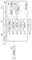
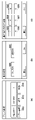
図1を参照して、画像処理装置100の構成例を説明する。本実施形態に係る画像処理装置100は、画像データ取得部101、裏写り判定部102、2色変換テーブル生成部103、2色変換テーブル保持部104、色変換部105、ガンマ補正部106、及び画像形成部107、及びUI111を備えている。なお、UI111は、外付けのディスプレイ、キーボード、マウスなどであってもよい。また、画像処理装置100は画像データを取得するため、コンピュータ109及びスキャナ110の少なくとも一方と接続されている。また、画像処理装置100は、画像形成部107から出力される画像データを印刷するため、プリントエンジン108と接続されている。また、画像処理装置100はHDD等の記憶装置112と接続されている。
A configuration example of the
画像データ取得部101は、スキャナ110で読み取った原稿から生成されるRGB画像データを取得する。なお、本実施形態ではRGB画像データを例に挙げて説明するが、後述するL*a*b*空間へ変換可能な色空間を持つ画像データであれば、いずれの画像データであってもよい。また、画像データ取得部101はUI111から送信される設定値を取得する。取得する設定値は、ユーザ指定色の設定値である。本実施形態においてはシアン(C)、マゼンタ(M)、イエロー(Y)、レッド(R)、グリーン(G)、及びブルー(B)の6色の中から指定色を選択する前提で説明を行うが、選択される指定色は、この6色に限られるものではない。
The image
裏写り判定部102は、画像データ取得部101から入力されたRGB画像データの各画素について、裏写り画素であるか否かを判定し、画素毎に裏写り判定フラグを付与する。裏写り判定フラグは、”0”、”1”の値で保持されてもよいし、他の値を用いてもよいし、裏写り画素であると判定された場合にのみ情報を付加するようにしてもよい。即ち、裏写り画素であるかどうかが識別可能であればよい。判定方法の詳細については後述する。
The show-through
色変換部105は、裏写り判定部102の判定結果に基づき、画像データ取得部101から入力されたRGB画像データの各画素のうち、裏写りと判定された画素の画素値を修正する。そして、色変換部105は、裏写りと判定された画素については修正後の画素値を、裏写りではない画素は元のRGB画像データの画素値を所定の色空間に変換し、各画素がユーザ指定色に変換する画素か、無彩色に変換する画素かを判定する。なお、所定の色空間とは、例えば3次元色空間において1つの無彩色軸を有するL*a*b*やLCHなどの色空間である。本実施形態においては、L*a*b*空間へ変換し、LCH空間へ変換するものとするが、本発明を限定する意図はなく、YUV空間等へ変換してもよい。
Based on the determination result of the show-through
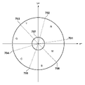
L*a*b*空間及びLCH空間は人間の視覚特性を考慮し、デバイスに非依存の3次元色空間である視覚均等色空間である。本実施形態では、図7に示すように、3次元色空間において無彩軸の成分を除く2成分を用いて判定を行う。図7に示すように、L*a*b*空間における無彩軸の成分である明度成分L*を除く色度成分a*b*を用いている。色相に関連する2成分に対応する2つのパラメータで規定される2次元色平面(以下、色相平面と称する。)において俯瞰することで、各画素の色(C,M,Y,R,G,Bや、オレンジ、ピンク、パープル等の中間色など)を判定することが可能である。そして、ユーザ指定色に変換する画素か、無彩色に変換する画素かの判定結果に基づき、各画素をユーザ指定色又は無彩色に対応するCMYK値に変換し、CMYK画像データを生成する。 The L*a*b* space and the LCH space are visually uniform color spaces that are device-independent three-dimensional color spaces that take human visual characteristics into consideration. In this embodiment, as shown in FIG. 7, determination is performed using two components excluding the achromatic axis component in the three-dimensional color space. As shown in FIG. 7, chromaticity components a*b* are used excluding the lightness component L*, which is the component of the achromatic axis in the L*a*b* space. By looking down on a two-dimensional color plane (hereinafter referred to as a hue plane) defined by two parameters corresponding to two components related to hue, the color of each pixel (C, M, Y, R, G, B, intermediate colors such as orange, pink, purple, etc.). Then, each pixel is converted into CMYK values corresponding to the user-specified color or achromatic color based on the determination result as to whether the pixel is to be converted to the user-specified color or the achromatic color, and CMYK image data is generated.
図1の説明に戻る。2色変換テーブル生成部103は、後述する色変換部105において色変換テーブルを用いて色変換を行う場合の2色変換テーブル(例えば、ルックアップテーブル形態)を生成する。2色変換テーブル保持部104は、2色変換テーブル生成部103で生成した2色変換テーブルやフルカラー用の色変換テーブル等の色変換テーブルを記憶装置112に保持し、保持したテーブル等を必要に応じて色変換部105等に送る。
Returning to the description of FIG. The 2-color conversion
ガンマ補正部106は、色変換部105から送られてきたCMYK画像データに対して、プリントエンジン108における階調特性を一定に保つための補正処理を施す。画像形成部107は、ガンマ補正部106で補正されたCMYK画像データを、プリンタに適したN(整数)ビットのハーフトーン画像データに変換してプリントエンジンへ送る制御を行なう。なお、ハーフトーン処理としては濃度パターン法、組織的ディザ法、誤差拡散法等のさまざまな手法が提案されているが、本実施形態においてはいずれの手法を採用してもよい。なお、プリントエンジン108は、CMYKトナーを用いたエンジンであるものとして以下の実施形態の説明を行うが、CMYKインクを用いたエンジンであってもよい。
The
<2色変換処理>
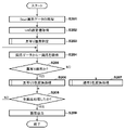
次に、図2を参照して、本実施形態に係る、裏写り判定、色判定及び色変換に関する2色変換処理の処理手順を説明する。以下で説明する処理は、例えば画像処理装置100に接続された記憶装置112に格納されたプログラムをRAM113に読み出してCPU114が実行することで実現される。
<Two-color conversion processing>
Next, referring to FIG. 2, a processing procedure of two-color conversion processing relating to show-through determination, color determination, and color conversion according to the present embodiment will be described. The processing described below is realized, for example, by reading a program stored in the
S201で、画像データ取得部101は、CPU114からスキャナ110に読取指示を出し、原稿のスキャンを実行させることでスキャン画像データを生成し、生成されたスキャン画像データを取得する。取得する画像データは、RGB画像データである。一つの画素につきR,G,Bの3つの画素値を持つ。本実施形態ではR,G,Bのそれぞれが8bitデータ、即ち、0~255の整数値を取るデータとして説明する。
In S201, the image
次に、S202で、画像データ取得部101は、UI111から送信される設定値を取得する。UI111の設定値とは、UI111を介してユーザからの指定に基づいて設定される値である。図6は、操作部に表示されるUI111の例を示す。図6(a)は、プリント時のカラー選択や、倍率、枚数等の設定を行うためのUIに遷移するためのボタン609,610,611が選択可能に表示されている。これらのボタンは、操作部のタッチパネル式の液晶表示部を直接操作することにより選択することができる。また、別途設けられたハードウェアキーを操作することにより選択することもできる。図6(b)は、図6(a)のカラー選択ボタン609押下時に遷移する、色数を設定する画面である。UI111は、CMYKの色材を用いたフルカラー印刷を行なう場合、ユーザにより押下されたフルカラーボタン601の設定値を送信する。一方、2色カラーボタン602が押下された場合、UI111は、図6(c)のユーザ指定色を設定する設定画面に遷移する。以下、図6(b)において2色カラーボタン602が選択されている場合の処理について説明する。
Next, in S<b>202 , the image
図6(c)に示すUIメニューでは、2色プリントにおいて黒と組み合わせる色(指定色)が選択可能になっている。例えばY(603)、R(604)、M(605)、B(606)、C(607)、G(608)の各色の中から任意の色を設定可能である。なお、設定値は、上記設定画面を介したユーザ入力に従って、予めユーザによって指定されていてもよいし、印刷を行なう際にユーザに選択させてもよい。予めユーザによって指定されている場合には、印刷を行う際にユーザに確認を行うように制御してもよい。なお、これらの色以外の有彩色を選択可能としてもよい。任意のボタン603~608を選択した状態でOKボタンを操作すると、指定色の設定が確定し、戻るボタンが操作されると、選択したボタンの指定色が設定されることなく元の画面に遷移することとなる。
In the UI menu shown in FIG. 6C, it is possible to select a color (specified color) to be combined with black in two-color printing. For example, any color can be set from Y (603), R (604), M (605), B (606), C (607), and G (608). The setting values may be specified by the user in advance according to the user's input through the setting screen, or may be selected by the user when printing. If specified by the user in advance, it may be controlled so as to confirm with the user when printing. Note that chromatic colors other than these colors may be selectable. When the OK button is operated while any
続いて、S203で、裏写り判定部102は、S201で取得したRGB画像データの各画素に対し、裏写り画素判定を行う。そして裏写り判定結果に基づいて、RGB画像データの各画素に裏写りであるかどうかを示すフラグ(裏写り判定フラグ)を付与する。裏写りフラグは、例えば、裏写り画素である場合は1、裏写り画素で無い場合は0を保持する。なお、本実施形態では裏写りフラグを付与し、裏写りかどうかを示す値を1と0にしたが、裏写り画素かどうかが分かればどのような形式でもよい。
Subsequently, in S203, the show-through
また、本実施形態では、画像データの各画素のRGB値と、分散値とを用いて裏写り画素であるか否かを判定する。当該分散値は、任意の画素(注目画素)とその周囲の画素のRGB値のばらつき度合いを表すものである。通常、ある画素と別の画素を比較して色が異なる場合、その2つの画素はRGB値と分散値の両方が異なる。反対に、2つの画素の色が同じ場合は、RGB値と分散値の両方が同じ値を持つ。しかし、裏写りによって本来の色とは別の色に変わってしまった画素の場合、本来の色を持つ画素と比較すると、RGB値だけが異なり、分散値は同じ値を持つという特徴がある。この特徴を利用して裏写り画素であるか否かを判定する。裏写り画素判定のさらなる詳細については後述する。 Further, in this embodiment, whether or not a pixel is a show-through pixel is determined using the RGB value and the variance value of each pixel of the image data. The variance value represents the degree of variation in RGB values between an arbitrary pixel (target pixel) and its surrounding pixels. Generally, when one pixel is compared to another and the colors are different, the two pixels differ in both RGB values and variance values. Conversely, if two pixels have the same color, both the RGB value and the variance value will have the same value. However, in the case of a pixel that has changed to a color different from the original color due to show-through, compared with a pixel having the original color, only the RGB values are different and the variance value is the same. This feature is used to determine whether or not the pixel is a show-through pixel. Further details of the show-through pixel determination will be described later.
次に、S204で、色変換部105は、S201で取得した画像データから一つの画素を取得する。また、色変換部105は、取得した画素について、S203で付与された画素に紐付く裏写り判定フラグの情報を取得する。続いて、S205で、色変換部105は、S203で付与された裏写りフラグの値に基づいて、S204で取得した画素が、裏写り画素かどうかを判定する。裏写り画素であればS206に進み、そうでない場合はS207に進む。
Next, in S204, the
S206で、色変換部105は、裏写り画素に対応する2色変換処理を実行し、S208に進む。裏写り画素に対応する2色変換処理の詳細については後述する。一方、S207で、色変換部105は、通常の2色変換処理を実行し、S208に進む。通常の2色変換処理の詳細については後述する。
In S206, the
次に、S208で、色変換部105は、S201で取得したRGB画像データの全ての画素を処理したかどうかを判定する。全ての画素を処理したかどうかの判定は、各画素に処理済みかどうかを表すフラグを付与して、全ての画素のフラグが処理済みとなったかを判定してもよいし、画像データ取得時に全画素数を保持しておき、全画素数分処理を繰り返したか否かを判定してもよい。全ての画素を処理していない場合は、S204に戻る。
Next, in S208, the
S208で全ての画素を処理したと判定された場合、S209で、色変換部105は、全ての画素がユーザ指定色又は無彩色を構成するCMYK値に変換された画像データをガンマ補正部106に出力し、処理を終了する。
If it is determined in S208 that all pixels have been processed, in S209 the
<裏写り画素判定>
次に、図3を参照して、図2のS203の裏写り画素判定処理の詳細を説明する。なお、図3の各ステップの処理は、裏写り判定部102が行う。以下で説明する処理は、例えば画像処理装置100に接続された記憶装置112に格納されたプログラムをRAM113に読み出してCPU114が実行することで実現される。
<Bleed-through pixel determination>
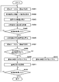
Next, details of the show-through pixel determination process in S203 of FIG. 2 will be described with reference to FIG. Note that the show-through
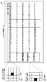
まず、S301で、裏写り判定部102は、S201で取得したRGB画像データから一つの画素(注目画素)を取得する。続いて、S302で、裏写り判定部102は、S301で取得した画素を中心とする5x5画素(注目画素を含む25画素)をRGB画像データから取得する。例えば図5に示すように、RGB画像データ501から取得した注目画素502を中心とする周囲24画素503を取得する。また、注目画素が画像データの端部の場合は、存在しない画素のRGB値を0として扱う。例えば図5の504のように注目画素が画像データの左端の場合、注目画素よりも左側には画素が存在しないため、存在しない2x5画素分の画素は、RGB値を0として扱う。なお、本実施形態においては取得する画素数を5x5の25画素としたが、これに限られるものではなく、画像データのサイズなどに応じて取得する画素数を変えてもよい。
First, in S301, the show-through
次に、S303で、裏写り判定部102は、S301及びS302で取得した注目画素とその周囲の画素から、注目画素の分散値を算出(取得)する。注目画素の分散値はR,G,Bそれぞれに対して算出する。分散値の算出は以下の数式1を用いる。
Next, in S303, the show-through

ここで、σr[n]は画像データのn番目の画素のRの分散値を示す。xriは5x5画素内のi番目のRの画素値(輝度値)を示す。μrは5x5画素のRの画素平均値を示す。Nは総画素数(25)を示す。同様に、σg[n]はGの画像データのn番目の分散値を示し、σb[n]はBの画像データのn番目の分散値を示す。xgiはGのi番目の画素値を示し、xbiはBのi番目の画素値を示す。μgはGの画素平均値を示し、μbはBの画素平均値を示す。またΣは総和の計算を示す。 Here, σr[n] indicates the R variance value of the n-th pixel of the image data. xri indicates the i-th R pixel value (luminance value) in 5×5 pixels. μr indicates the pixel average value of R of 5×5 pixels. N indicates the total number of pixels (25). Similarly, σg[n] indicates the n-th variance value of the G image data, and σb[n] indicates the n-th variance value of the B image data. xgi indicates the i-th pixel value of G, and xbi indicates the i-th pixel value of B; μg indicates the average value of G pixels, and μb indicates the average value of B pixels. Also, Σ indicates the summation calculation.
次に、S304で、裏写り判定部102は、S303で算出した分散値を元に、同じ分散値を持つ画素の値をR,G,Bそれぞれに対して加算していく。数式で表すと以下のようになる。
Next, in S304, the show-through
Tr[σr[n]]=Tr[σr[n]]+Pr
Tg[σg[n]]=Tg[σg[n]]+Pg
Tb[σb[n]]=Tb[σb[n]]+Pb ・・・数式2
ここで、Trが分散値毎のRの画素値の総和を保持する配列を表し、初期値は0である。Prは注目画素のRの画素値を表す。同様にTgはG、TbはBの分散値毎の画素値の総和を保持する配列を表し、初期値は0である。またPgはG、PbはBの注目画素の画素値を表す。また、分散値及びR,G,B値毎に、該当する画素が何画素あるかをカウントする。数式で表すと以下のようになる。
Tr[σr[n]]=Tr[σr[n]]+Pr
Tg[σg[n]]=Tg[σg[n]]+Pg
Tb[σb[n]]=Tb[σb[n]]+
Here, Tr represents an array that holds the sum of R pixel values for each variance value, and the initial value is 0. Pr represents the R pixel value of the pixel of interest. Similarly, Tg represents an array that holds the sum of pixel values for each variance value of G and Tb, and the initial value is 0. Pg represents the pixel value of G and Pb represents the pixel value of the B target pixel. Also, the number of corresponding pixels is counted for each variance value and each R, G, and B value. Expressed as a formula, it is as follows.
Cr[σr[n]]=Cr[σr[n]]+1
Cg[σg[n]]=Cg[σg[n]]+1
Cb[σb[n]]=Cb[σb[n]]+1 ・・・数式3
ここで、Crが分散値毎のRの画素数の総和を保持する配列を表し、初期値は0である。同様にCgはG、CbはBの分散値毎の画素数の総和を保持する配列を表し、初期値は0である。
Cr[σr[n]]=Cr[σr[n]]+1
Cg[σg[n]]=Cg[σg[n]]+1
Cb[σb[n]]=Cb[σb[n]]+1
Here, Cr represents an array that holds the sum of the number of R pixels for each variance value, and the initial value is zero. Similarly, Cg represents an array that holds the sum of the number of pixels for each G and Cb for each variance value, and the initial value is 0.
次に、S305で、裏写り判定部102は、S301で取得したRGB画像データの全ての画素を処理したかどうかを判定する。全ての画素を処理したかどうかの判定は、各画素に処理済みかどうかを表すフラグを付与して、全ての画素のフラグが処理済みとなったかを判定してもよいし、画像データ取得時に全画素数を保持しておき、全画素数分処理を繰り返したかを判定してもよい。全ての画素を処理していない場合は、S301に戻る。一方、全ての画素を処理したと判定した場合はS306に進む。
Next, in S305, the show-through
S306で、裏写り判定部102は、S304で算出した分散値毎の画素値の総和及び画素数の総和から、R,G,Bそれぞれの分散値毎の平均画素値を算出する。平均画素値の算出は数式4を用いて行う。
In S306, the show-through
Aver[σr[n]]=Tr[σr[n]]/Cr[σr[n]]
Aveg[σg[n]]=Tg[σg[n]]/Cg[σg[n]]
Aveb[σb[n]]=Tb[σb[n]]/Cb[σb[n]] ・・・数式4
ここで、AverがRの分散値毎の平均画素値、AvegがGの分散値毎の平均画素値、AvebがBの分散値毎の平均画素値を表す。
Aver[σr[n]]=Tr[σr[n]]/Cr[σr[n]]
Aveg[σg[n]]=Tg[σg[n]]/Cg[σg[n]]
Aveb[σb[n]]=Tb[σb[n]]/Cb[σb[n]]
Here, Aver represents the average pixel value for each R variance value, Aveg represents the average pixel value for each G variance value, and Aveb represents the average pixel value for each B variance value.
次に、S307で、裏写り判定部102は、S201で取得したRGB画像データから一つの画素(注目画素)を取得する。続いて、S308で、裏写り判定部102は、S307で取得した注目画素の画素値と、S306で算出した注目画素の分散値に対応する平均画素値を比較し、注目画素の画素値が対応する平均画素値より小さいか否かを判定する。判定は、R,G,Bそれぞれについて行う。例えば、画像データの先頭から数えて10番目の画素のRの画素値が200であり、S303で算出した分散値がσr[10]=20、S306で算出したRの分散値毎の平均画素値がAver[20]=210であるとする。nをn番目の画素とし、n番目の画素のRの画素値をZr[n]と表現すると、Zr[10]<Aver[20]であるため、注目画素である10番目の画素は、画素値が平均画素値より小さいと判定する。小さい場合はS309に進み、そうでない場合はS310に進む。
Next, in S307, the show-through
S308で注目画素の画素値が、対応する平均画素値に対して、R,G,Bの全てが小さいと判定された場合、S309で、裏写り判定部102は、注目画素の画像データに紐づけて裏写りが発生しているか否かの情報を付与する。例えば、裏写り画素フラグの持つ値を1とする。なお、裏写りは明度が変化するケースが多いため、通常はR,G,B全てが対応する平均画素値より小さくなる。そのためR,G,Bの全てが小さいと判定された場合に裏写りと判定すれば問題ない。しかし、例えば画像読み取り時はRGBの信号を取得しつつ、最終的にGの信号だけを利用して画像を生成するというケースなども考えられる。そのため、例えばGの信号だけで裏写りであるか(G信号が平均値より小さいか)を判定するなど、スキャナの構成や画像処理手順の違いなどに基づいて、判定に用いるR,G,Bの信号の組合せを変えてもよい。その後、S311で、裏写り判定部102は、注目画素の画素値と対応する平均画素値の差の絶対値を算出し、記憶装置112に記録し保持し、S312に進む。差分の算出は数式5を用いる。
If it is determined in S308 that the pixel value of the pixel of interest is smaller than the corresponding average pixel value in all of R, G, and B, the show-through
Dr[n]=abs(Zr[n]-Aver[σr[n]])
Dg[n]=abs(Zg[n]-Aveg[σg[n]])
Db[n]=abs(Zb[n]-Aveb[σb[n]]) ・・・数式5
ここで、DrはRの差の絶対値(abs())を表し、ZrはRの画素値を表す。また、nはn番目の画素を表す。同様にDgはG、DbはBの差の絶対値、ZgはG、ZbはBの画素値を表す。
Dr[n]=abs(Zr[n]−Aver[σr[n]])
Dg[n]=abs(Zg[n]−Aveg[σg[n]])
Db[n]=abs(Zb[n]−Aveb[σb[n]]) Equation 5
Here, Dr represents the absolute value of the R difference (abs()), and Zr represents the R pixel value. Also, n represents the n-th pixel. Similarly, Dg is the G pixel value, Db is the absolute value of the B difference, Zg is the G pixel value, and Zb is the B pixel value.
一方、S308で注目画素の画素値が対応する平均画素値以上と判定された場合、S310で、裏写り判定部102は、注目画素に対応する裏写り画素フラグの持つ値を0とし、S312に進む。
On the other hand, if it is determined in S308 that the pixel value of the target pixel is equal to or greater than the corresponding average pixel value, the show-through
S312で、裏写り判定部102は、S301で取得したRGB画像データの全ての画素を処理したかどうかを判定する。全ての画素を処理したかどうかの判定は、各画素に処理済みかどうかを表すフラグを付与して、全ての画素のフラグが処理済みとなったかを判定してもよいし、画像データ取得時に全画素数を保持しておき、全画素数分処理を繰り返したかを判定してもよい。全ての画素を処理していない場合は、S307に戻り、全ての画素を処理した場合は、処理を終了する。なお、本処理で生成した裏写り画素フラグは記憶装置112に記憶され、保持される。
In S312, the show-through
<裏写り2色変換処理>
次に、図4を参照して、図2のS206の裏写り2色変換処理の詳細を説明する。なお、図4の各ステップの処理は、色変換部105(第1色変換手段)が行う。以下で説明する処理は、例えば画像処理装置100に接続された記憶装置112に格納されたプログラムをRAM113に読み出してCPU114が実行することで実現される。
<Show-Through 2-Color Conversion Processing>
Next, details of the show-through two-color conversion process in S206 of FIG. 2 will be described with reference to FIG. Note that the processing of each step in FIG. 4 is performed by the color conversion unit 105 (first color conversion means). The processing described below is realized, for example, by reading a program stored in the
まずS401において、色変換部105は、図2のS204で取得した画素の画素値を、図3のS311で記憶装置112に保持した差分値を用いて修正する。画素値の修正は以下の数式6を用いて行う。
First, in S401, the
M=Min(Dr[n],Dg[n],Db[n])
Xmr[n]=Zr[n]+M
Xmg[n]=Zg[n]+M
Xmb[n]=Zb[n]+M ・・・数式6
ここで、MはS311で保持したDr,Dg,Dbのうち、一番小さい値を持つ(Minは最小の値を出力する関数を表す)。XmrはRの修正後の画素値を表し、nはn番目の画素を表す。同様にXmgはG、XmbはBの修正後の画素値を表す。
M=Min(Dr[n], Dg[n], Db[n])
Xmr[n]=Zr[n]+M
Xmg[n]=Zg[n]+M
Xmb[n]=Zb[n]+M Expression 6
Here, M has the smallest value among Dr, Dg, and Db held in S311 (Min represents a function that outputs the minimum value). Xmr represents the modified pixel value of R, and n represents the nth pixel. Similarly, Xmg represents the pixel value after G and Xmb represents the corrected B pixel value.
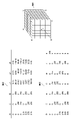
次に、S402で、色変換部105は、S401で画素値を修正した画素の色空間を変換する。当該変換では、L*a*b*空間に一度変換され、更にLCH空間への変換が行われる。まず、L*a*b*空間に変換する方法について説明する。画素のL*a*b*値への変換は、記憶装置112に予め格納されているRGB空間からL*a*b*空間への変換テーブルを用いた補間演算により行われる。RGB空間からL*a*b*空間への変換テーブルは、RGB信号によって規定される3次元色空間の立方体を規定している。図8に示すように、RGBの各8ビットデータ(0~255)の値に応じて、3次元色空間の立方体801における座標を定めることができる。立方体の8つの頂点は、R、G、B、Y、M、C、K、Wを示す。また、RGB空間からL*a*b*空間への変換テーブルは、入力データのRGB値によって規定され、例えば9×9×9個の格子点を持ち、この格子点に対応するL*a*b*値をテーブルデータとして格納したものである。例えば図8の802では、RGB値(255,0,0)に対応するテーブルデータとしてL*a*b*値(44.01,61.37,39.68)が格納されている。
Next, in S402, the
補間演算は演算用テーブルで定義されていない値が入力された場合に、入力された値に近い演算用テーブルで定義された値を用いて補間を行うものである。補間演算の方法に四面体補間と呼ばれるものがある。四面体補間は、入力された値に近い4つの演算テーブルで定義された値を用いて補間演算を行うものである。本処理においては、入力を画素のRGB値とし、演算用テーブルをRGB→L*a*b*変換テーブルとして四面体補間の演算を行うことで、各画素のL*a*b*値を取得する。なお、本実施形態では変換に四面体補間を用いたが、本発明を限定する意図はなく、演算式による変換など、RGB空間をL*a*b*空間に変換できればどのような方法を用いてもよい。 In interpolation calculation, when a value not defined in the calculation table is input, interpolation is performed using a value defined in the calculation table that is close to the input value. There is a method of interpolation calculation called tetrahedral interpolation. Tetrahedral interpolation is to perform an interpolation calculation using values defined in four calculation tables that are close to the input value. In this processing, the L*a*b* value of each pixel is obtained by performing tetrahedral interpolation using the input as the RGB value of the pixel and the calculation table as the RGB→L*a*b* conversion table. do. Although tetrahedral interpolation is used for conversion in the present embodiment, there is no intention to limit the present invention, and any method such as conversion using an arithmetic expression can be used as long as the RGB space can be converted to the L*a*b* space. may
続いてL*a*b*空間に変換したRGB画像データをLCH空間に変換する。L*a*b*のL*とLCHのLは同じものであるため、そのまま用いる。C(彩度)の値は、以下の数式7により求める。 Subsequently, the RGB image data converted into the L*a*b* space is converted into the LCH space. Since L* in L*a*b* and L in LCH are the same, they are used as they are. The value of C (saturation) is obtained by Equation 7 below.
C=sqrt(a*^2+b*^2) ・・・数式7
ここで、sqrtは平方根の計算を表し、^は累乗の計算を表す。また、H(色相)の値は、以下の数式8により求める。
C=sqrt(a*^2+b*^2) Equation 7
where sqrt represents a square root computation and ^ represents a power computation. Also, the value of H (hue) is obtained by Equation 8 below.
H=arctan(b*/a*)×(180/PI)
H=H (H>=0の場合)
H=H+360 (H<0の場合) ・・・数式8
ここで、arctanはアークタンジェントの計算を表し、PIは円周率のπを表す。またHは0°~360°の角度で表現される。
H = arctan (b*/a*) x (180/PI)
H=H (when H>=0)
H=H+360 (if H<0) Equation 8
where arctan represents the calculation of the arctangent and PI represents the π of the circumference of the circle. H is expressed as an angle from 0° to 360°.
次に、S403で、色変換部105は、S402で色空間変換した画素のC(彩度)の値を用いて、画素が有彩色であるか無彩色であるかを判定し、判定結果の情報を生成する。有彩色か無彩色かの判定は、記憶装置112に予め保持された閾値と、取得した画素のC(彩度)を比較することで行う。例えば閾値を20とした場合、C(彩度)が20未満であれば無彩色と判定し、20以上であれば有彩色と判定する。本実施形態では閾値を予め保持した値としたが、入力画像の構成に応じて動的に設定してもよいし、UIなどからユーザが選択できるようにしてもよい。また、本実施形態では判定結果をフラグの形式で記憶装置112に保持する。判定結果に応じて有彩無彩判定フラグを生成し、無彩色であれば有彩無彩判定フラグを0にし、有彩色であれば有彩無彩判定フラグを1にする。もちろん有彩色か無彩色かの情報を保持することができれば、どのような形式であってもよい。
Next, in S403, the
続いてS404で、色変換部105は、S202で取得したUI設定値のうち、指定色の情報から色相範囲値を取得する。色相範囲値とは、指定色であるC,M,Y,R,G,Bのそれぞれの色の色相の範囲を表す値である。例えば、図7のように701から702の範囲の色相を持つ色はR、702から703の範囲の色相を持つ色はYというように表現される。色相範囲値はC,M,Y,R,G,Bのそれぞれに対応して、図9に示すようなテーブルの形式で下限値及び上限値として、記憶装置112に予め格納されている。
Subsequently, in S404, the
例えば図7のRであれば、色相範囲の下限値は701に相当する色相値(図9のRの下限値である10)であり、色相範囲の上限値は702に相当する色相値(図9のRの上限値である80)である。そのため、ユーザ指定色がRである場合、色相範囲値として、色相範囲下限値は10°、色相範囲上限値は80°を記憶装置112から取得する。ただし、色相は角度で表現されるため、図7のMのように、0°であるa*軸を含む色相範囲の場合は2つの範囲を用いる。色相の下限値を701(図9のMの下限値である10)、色相の上限値を706(図9のMの上限値である310)としつつ、色相範囲としては[0°]から色相の下限値701[10°]の間と、色相上限値706[310°]と[360°]の間となる。本実施形態に係る色相範囲値は予め保持された値としたが、画像処理装置の特性に応じて動的に設定してもよいし、UIなどからユーザが選択できるようにしてもよい。
For example, for R in FIG. 7, the lower limit of the hue range is the hue value corresponding to 701 (10, which is the lower limit of R in FIG. 9), and the upper limit of the hue range is the hue value corresponding to 702 ( 80), which is the upper limit of R of 9. Therefore, when the user-designated color is R, the hue range lower limit value of 10° and the hue range upper limit value of 80° are acquired from the
次に、S405で、色変換部105は、S402で色空間変換した画素の画素値のうち、H(色相)の値と、S404で取得した色相範囲値を用いて、画素が所定の色相範囲内かを判定し、判定結果の情報を生成する。例えば、ユーザ指定色がRである場合、色相範囲下限値は10°、色相範囲上限値は80°であるため、H(色相)の値が10°以上、80°未満であれば、色相範囲内と判定し、そうでなければ色相範囲外と判定する。本実施形態では判定結果をフラグの形で記憶装置112に保持する。判定結果に応じて色相範囲内外判定フラグを生成し、色相範囲内であれば色相範囲内外判定フラグを1に、色相範囲外であれば色相範囲内外判定フラグを0にする。もちろん色相範囲内外の情報を保持することができれば、どのような形式でもよい。
Next, in S405, the
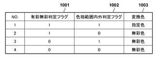
続いてS406で、色変換部105は、画素をユーザ指定色に変換するか、無彩色に変換するかを判定する。画素をユーザ指定色に変換するか、無彩色に変換するかの判定は、S403及びS405で生成した情報(フラグ)の組合せで行う。図10は各フラグの値の組合せで、ユーザ指定色と無彩色のどちらの変換を行うかを示す。S403で生成し、記憶装置112に保持した有彩無彩判定フラグが1001に対応する。S405で生成し、記憶装置112に保持した色相範囲内外判定フラグが1002に対応する。各判定フラグの値を入力とし、図10の変換色1003を出力とするテーブル(判定結果出力テーブル)が記憶装置112に予め保持されている。変換色1003に関しては、例えば指定色を1、無彩色を0というように値を対応付けて、その値を出力値としてもよい。色変換部105は、記憶装置112から判定結果出力テーブルを取得し、当該テーブルを用いて、有彩無彩判定フラグ及び色相範囲内外判定フラグの値を入力として、指定色又は無彩色に相当する値(例えば1又は0)を出力する。
Subsequently, in S406, the
次に、S406の判定においてユーザ指定色に変換と判定された場合、S407で、色変換部105は、画素のRGB値(LCH空間に変換する前のRGB値)をユーザ指定色に変換し、処理を終了する。ユーザ指定色への変換の流れとして、色変換部105は、まず2色変換テーブル保持部104により記憶装置112に保持されたフルカラー用の色変換テーブルを用いて、画素のRGB値をCMYK値に変換する。続いて、色変換部105は、フルカラーのCMYK値に対して、演算式を用いてユーザ指定色を構成するCMYK値に変換する。まずフルカラー用の色変換テーブルを用いたCMYK値への変換は、S402のRGB空間からL*a*b*空間への変換と同様に、RGB空間からCMYK空間へのフルカラー用色変換テーブルを用いた四面体補間演算によって行う。
Next, if it is determined in S406 to convert to the user-specified color, in S407 the
フルカラー用色変換テーブルはRGB信号によって規定される3次元色空間の立方体を規定しており、図8に示すように、RGBの各8ビットデータの値に応じて、3次元色空間の立方体における座標を定めることができる。立方体の8つの頂点は、R、G、B、Y、M、C、K、Wを示す。また、色変換テーブルは入力データのRGB値によって規定される例えば16×16×16個の格子点を持ち、この格子点に対応するCMYK値をテーブルデータとして格納したものである。例えば図8の803では、RGB値(255,0,0)に対応するテーブルデータとしてCMYK値(0,255,255,0)が格納されている。フルカラー用色変換テーブルを用いた四面体補間演算方法は、S402のRGB空間からL*a*b*空間への変換と同じであるため説明を省略する。 The full-color color conversion table defines a three-dimensional color space cube defined by RGB signals, and as shown in FIG. Coordinates can be defined. The eight vertices of the cube represent R, G, B, Y, M, C, K, W. The color conversion table has, for example, 16×16×16 grid points defined by the RGB values of input data, and stores CMYK values corresponding to the grid points as table data. For example, in 803 of FIG. 8, CMYK values (0, 255, 255, 0) are stored as table data corresponding to RGB values (255, 0, 0). The tetrahedral interpolation calculation method using the full-color color conversion table is the same as the conversion from the RGB space to the L*a*b* space in S402, so the description is omitted.
続いて、色変換部105は、フルカラー用色変換テーブルを用いた四面体補間演算により算出されたフルカラーのCMYK値を、演算式を用いてユーザ指定色を構成するCMYK値に変換する。演算は下記の行列式を用いた演算を行う。
Subsequently, the

本実施形態では色変換テーブルと行列式の演算を用いてRGB値からユーザ指定色を構成するCMYK値への変換を行ったが、RGB値をユーザ指定色のCMYK値変換することができれば、どのような方法を用いてもよい。 In this embodiment, the RGB values are converted into the CMYK values constituting the user-specified color using the color conversion table and the calculation of the determinant. You may use such a method.
次に、S406の判定において無彩色に変換と判定された場合、S408で、色変換部105は、画素のRGB値(LCH空間に変換する前のRGB値)を無彩色に変換し、処理を終了する。無彩色への変換の流れとして、色変換部105は、S407と同様に、まず2色変換テーブル保持部104により記憶装置112に保持されたフルカラー用の色変換テーブルを用いて、画素のRGB値をCMYK値に変換する。続いてフルカラーのCMYK値に対して、演算式を用いて無彩色を構成するCMYK値に変換する。フルカラー用の色変換テーブルを用いたCMYK値への変換は、S407と同様であるため説明を省略する。続いてフルカラー用色変換テーブルを用いた四面体補間演算により算出されたフルカラーのCMYK値を、演算式を用いてユーザ指定色を構成するCMYK値に変換する。演算は下記の行列式を用いた演算を行う。
Next, if it is determined in step S406 to convert to achromatic color, in step S408, the

本実施形態では色変換テーブルと行列式の演算を用いてRGB値から無彩色を構成するCMYK値への変換を行ったが、RGB値を無彩色のCMYK値変換することができれば、どのような方法を用いてもよい。
In the present embodiment, conversion from RGB values to CMYK values forming achromatic colors is performed using a color conversion table and calculation of determinants. method may be used.
<通常2色変換処理>
次に、図2のS207の通常2色変換について説明する。通常2色変換処理(第2色変換手段による処理)では、上記S206の裏写り2色変換の詳細処理である図4の処理のうち、S401を行わずにS402乃至S408の処理を行う。即ち、裏写りがないため、その度合いに応じた画素値の修正を行わず、色変換処理のみが行われる。これらの処理については、既に説明しているため省略する。
<Normal two-color conversion processing>
Next, normal two-color conversion in S207 of FIG. 2 will be described. In normal two-color conversion processing (processing by the second color conversion means), the processing of S402 to S408 is performed without performing S401 among the processing of FIG. 4, which is the detailed processing of the show-through two-color conversion in S206. That is, since there is no show-through, only color conversion processing is performed without correcting pixel values according to the degree of show-through. Since these processes have already been explained, they are omitted.
なお、本実施形態ではユーザ指定色又は無彩色の色変換の際に、フルカラー用の色変換テーブルと行列式を用いた。しかし、予めRGB値を直接ユーザ指定色と無彩色に変換するテーブルを作成し、ユーザ指定色と無彩色に変換する画素に対し、それぞれテーブルを切り替えながら色の変換を行ってもよい。 In this embodiment, the color conversion table and determinant for full color are used for color conversion of user-specified colors or achromatic colors. However, a table for directly converting RGB values into a user-specified color and an achromatic color may be created in advance, and color conversion may be performed while switching tables for pixels to be converted into a user-specified color and an achromatic color.
以上説明したように、本実施形態に係る画像処理装置は、読み取った原稿の画像データの画素ごとに裏写りが発生しているか否かを判定する。裏写りが発生していると判定された場合は、画素の裏写りを補正し、補正した画像データに対して、ユーザ指定色又は無彩色に変換する2色変換処理を実行する。一方、裏写りが発生していないと判定された場合は、当該画素の原稿から読み取った画像データに対して、2色変換処理を実行する。これにより、裏写りが発生する原稿を2色コピーした場合においても、ユーザ指定色か無彩色のどちらに変換するかの判定結果が、裏写りの有無に関わらず変化しないようになる。そのため、裏写り箇所においても裏写りが無い場合と同様に、ユーザ指定色に変換されるべき画素はユーザ指定色に変換され、無彩色に変換されるべき画素は無彩色に変換されうる。このように、本実施形態によれば、裏写りが発生するカラー原稿の2色コピーを行う際に、無彩色又はユーザ指定色への変換処理において裏写りの影響を好適に低減することができる。 As described above, the image processing apparatus according to the present embodiment determines whether show-through has occurred for each pixel of image data of a read document. If it is determined that show-through has occurred, the show-through of pixels is corrected, and two-color conversion processing is executed to convert the corrected image data into a user-designated color or an achromatic color. On the other hand, if it is determined that the show-through has not occurred, two-color conversion processing is performed on the image data read from the document of the pixel in question. As a result, even when a document in which show-through occurs is copied in two colors, the result of determination as to whether to convert to a user-specified color or an achromatic color does not change regardless of the presence or absence of show-through. Therefore, pixels that should be converted to the user-specified color can be converted to the user-specified color, and pixels that should be converted to the achromatic color can be converted to the achromatic color, as in the case where the show-through is absent. As described above, according to the present embodiment, when performing two-color copying of a color document in which show-through occurs, the influence of show-through can be preferably reduced in conversion processing to an achromatic color or a user-designated color. .
<第2の実施形態>
以下では、本発明の第2の実施形態について説明する。上記第1の実施形態では、裏写り箇所に対しては、画素値(RGB値:輝度値)に基づいて裏写り画素の補正を行った上で2色変換を行った。裏写りが起きるケースの多くは明度の変化が起きるため上記第1の実施形態の方法で課題を解決することができる。しかし、裏の画像の色が濃い場合、特に原稿が薄い紙の場合、色味(色相や彩度)の変化も起こることがある。そこで本実施形態では、裏写りにより色味の変化も起きた場合に、より効果的に課題を解決する方法を説明する。
<Second embodiment>
Below, the 2nd Embodiment of this invention is described. In the first embodiment, the show-through pixels are corrected based on the pixel values (RGB values: luminance values), and then two-color conversion is performed on the show-through locations. Since the change in brightness occurs in many cases where show-through occurs, the problem can be solved by the method of the first embodiment. However, if the image on the back side is dark, especially if the original is thin paper, a change in color (hue and saturation) may also occur. Therefore, in the present embodiment, a method for solving the problem more effectively when a color change occurs due to show-through will be described.
本実施形態に係る画像形成装置の構成は上記第1の実施形態と同様であるため、説明を省略する。図2の処理フローのうち、S203の裏写り画素判定とS206の裏写り2色変換が上記第1の実施形態と異なるため、本実施形態ではこの2つの処理について説明する。 Since the configuration of the image forming apparatus according to this embodiment is the same as that of the first embodiment, description thereof will be omitted. Of the processing flow in FIG. 2, the show-through pixel determination in S203 and the show-through two-color conversion in S206 are different from those in the first embodiment, and therefore these two processes will be described in this embodiment.
<裏写り画素判定>
まず図11を用いて、本実施形態におけるS203の裏写り画素判定の詳細を説明する。第1の実施形態と同様、図11の各ステップの処理は全て裏写り判定部102が行う。以下で説明する処理は、例えば画像処理装置100に接続された記憶装置112に格納されたプログラムをRAM113に読み出してCPU114が実行することで実現される。S1101~S1110及びS1115の処理は、図3のS301~S310及びS312の処理と同様のため、説明を省略する。なお、S1108では、HSV値の全て、即ち、色相、彩度、明度の値の全てが各平均値よりも小さい場合に当該画素に裏写りが発生していると判定することが望ましい。
<Bleed-through pixel determination>
First, the details of the show-through pixel determination in S203 in this embodiment will be described with reference to FIG. As in the first embodiment, the show-through
S1111で、裏写り判定部102は、S1107で取得した画素のRGB値をHSV値に変換する。HSVはHが色相、Sが彩度、Vが明度を表す。本実施形態ではHは0~360、S及びVは0~255の整数値である。RGBからHSVへの変換は、以下の数式16を用いて行う。
In S1111, the show-through
MAXrgb=Max(Zr[n],Zg[n],Zb[n])
MINrgb=Min(Zr[n],Zg[n],Zb[n])
H[n]=60×((Zg[n]-Zb[n])/(MAXrgb-MINrgb)) (MAXrgb=Zr[n])
H[n]=60×((Zb[n]-Zr[n])/(MAXrgb-MINrgb))+120 (MAXrgb=Zg[n])
H[n]=60×((Zg[n]-Zb[n])/(MAXrgb-MINrgb))+240 (MAXrgb=Zb[n])
H[n]=0 (Zr[n]=Zg[n]=Zb[n])
S[n]=(MAXrgb-MINrgb)/ MAXrgb
V[n]=MAXrgb ・・・数式16
ここで、MAXrgbはZr,Zg,Zbの内一番大きい値、MINrgbはZr,Zg,Zbの内一番小さい値である。上記第1の実施形態と同様Zr,Zg,ZbはR,G,Bの各画素値を表し、nはn番目を表す。
MAXrgb=Max(Zr[n], Zg[n], Zb[n])
MINrgb=Min(Zr[n], Zg[n], Zb[n])
H[n]=60×((Zg[n]−Zb[n])/(MAXrgb−MINrgb)) (MAXrgb=Zr[n])
H[n]=60×((Zb[n]−Zr[n])/(MAXrgb−MINrgb))+120 (MAXrgb=Zg[n])
H[n]=60×((Zg[n]−Zb[n])/(MAXrgb−MINrgb))+240 (MAXrgb=Zb[n])
H[n]=0 (Zr[n]=Zg[n]=Zb[n])
S[n]=(MAXrgb−MINrgb)/MAXrgb
V[n]=MAXrgb Expression 16
Here, MAXrgb is the largest value among Zr, Zg and Zb, and MINrgb is the smallest value among Zr, Zg and Zb. As in the first embodiment, Zr, Zg, and Zb represent pixel values of R, G, and B, and n represents the n-th pixel.
続いてS1112で、裏写り判定部102は、S1103で算出した分散値を元に、同じ分散値を持つS1111で算出したH,S,Vをそれぞれ加算していく。数式で表すと以下の数式17のようになる。
Subsequently, in S1112, the show-through
Th[σr[n]]=Th[σr[n]]+H[n]
Ts[σg[n]]=Ts[σg[n]]+S[n]
Tv[σb[n]]=Tv[σb[n]]+V[n] ・・・数式17
Thが分散値毎のHの画素値の総和を保持する配列を表し、初期値は0である。同様にTsはS、TvはVの分散値毎の画素値の総和を保持する配列を表し、初期値は0である。また、分散値及びH,S,V値毎に、該当する画素が何画素あるかをカウントする。数式で表すと以下の数式18のようになる。
Th[σr[n]]=Th[σr[n]]+H[n]
Ts[σg[n]]=Ts[σg[n]]+S[n]
Tv[σb[n]]=Tv[σb[n]]+V[n] Equation 17
Th represents an array that holds the sum of pixel values of H for each variance value, and the initial value is 0. Similarly, Ts represents an array that holds the sum of pixel values for each variance of S and Tv, and the initial value is zero. Also, the number of corresponding pixels is counted for each variance value and H, S, and V values. Expressed as a formula, it becomes as shown in Formula 18 below.
Ch[σr[n]]=Ch[σr[n]]+1
Cs[σg[n]]=Cs[σg[n]]+1
Cv[σb[n]]=Cv[σb[n]]+1 ・・・数式18
ここで、Chが分散値毎のHの画素数の総和を保持する配列を表し、初期値は0である。同様にCsはS、CvはVの分散値毎の画素数の総和を保持する配列を表し、初期値は0である。
Ch[σr[n]]=Ch[σr[n]]+1
Cs[σg[n]]=Cs[σg[n]]+1
Cv[σb[n]]=Cv[σb[n]]+1 Equation 18
Here, Ch represents an array that holds the sum of the number of pixels of H for each variance value, and the initial value is 0. Similarly, Cs represents an array that holds the sum of the number of pixels for each variance value of S and Cv, and the initial value is 0.
次に、S1113で、裏写り判定部102は、S1112で算出した分散値毎のH,S,Vそれぞれの値の総和及び画素数の総和から、H,S,Vそれぞれの分散値毎の平均画素値を算出する。平均画素値の算出は数式19を用いて行う。
Next, in S1113, the show-through
Aveh[σr[n]]=Th[σr[n]]/Ch[σr[n]]
Aves[σg[n]]=Ts[σg[n]]/Cs[σg[n]]
Avev[σb[n]]=Tv[σb[n]]/Cv[σb[n]] ・・・数式19
ここで、AvehがHの分散値毎の平均画素値、AvesがSの分散値毎の平均画素値、AvevがVの分散値毎の平均画素値を表す。
Aveh[σr[n]]=Th[σr[n]]/Ch[σr[n]]
Aves[σg[n]]=Ts[σg[n]]/Cs[σg[n]]
Avev[σb[n]]=Tv[σb[n]]/Cv[σb[n]] Equation 19
Here, Aveh represents the average pixel value for each H variance value, Aves represents the average pixel value for each S variance value, and Avev represents the average pixel value for each V variance value.
S1114で、裏写り判定部102は、注目画素のHSV値と対応する平均HSV値の差の絶対値を算出し、保持する。差分の算出は数式20を用いる。
In S1114, the show-through
Dh[n]=abs(H[n]-Aveh[σr[n]])
Ds[n]=abs(S[n]-Aves[σg[n]])
Dv[n]=abs(V[n]-Avev[σb[n]]) ・・・数式20
ここで、DhはHの差の絶対値を表す。また、nはn番目の画素を表す。同様にDsはS、DvはVの差の絶対値を表す。
Dh[n]=abs(H[n]−Aveh[σr[n]])
Ds[n]=abs(S[n]−Aves[σg[n]])
Dv[n]=abs(V[n]-Avev[σb[n]])
where Dh represents the absolute value of the H difference. Also, n represents the n-th pixel. Similarly, Ds represents the absolute value of the difference between S and Dv.
<裏写り2色変換処理>
続いて図12を用いて、本実施形態におけるS206の裏写り2色変換処理の詳細を説明する。上記第1の実施形態と同様、図12の各ステップの処理は全て色変換部105が行う。以下で説明する処理は、例えば画像処理装置100に接続された記憶装置112に格納されたプログラムをRAM113に読み出してCPU114が実行することで実現される。
<Show-Through 2-Color Conversion Processing>
Next, details of the show-through two-color conversion process in S206 in this embodiment will be described with reference to FIG. As in the first embodiment, the
まずS1201で、色変換部105は、図11のS1111で算出した画素ごとのHSV値を、図11のS1114で保持した差分値を用いて修正する。HSV値の修正は以下の数式21を用いて行う。
First, in S1201, the
Hm[n]=H[n]+Dh[n]
Sm[n]=S[n]+Ds[n]
Vm[n]=V[n]+Dv[n] ・・・数式21
ここで、HmはHの修正後の値を表し、nはn番目の画素を表す。同様にSmはS、VmはVの修正後の画素値を表す。
Hm[n]=H[n]+Dh[n]
Sm[n]=S[n]+Ds[n]
Vm[n]=V[n]+Dv[n] Expression 21
where Hm represents the modified value of H and n represents the nth pixel. Similarly, Sm represents the pixel value of S, and Vm represents the pixel value of V after correction.
続いてS1202で、色変換部105は、S1201で修正したHSV値をRGB値に変換する。HSVからRGBへの変換は以下の数式22を用いて行う。
Subsequently, in S1202, the
MAXhsv=Vm[n]
MINhsv=MAXhsv-((Sm[n]/255)×MAXhsv)
Rc[n]=MAXhsv
Gc[n]=(Hm[n]/60)×(MAXhsv-MINhsv)+MINhsv
Bc[n]=MINhsv
(0<Hm[n]<60)
Rc[n]=((120-Hm[n])/60)×(MAXhsv-MINhsv)+MINhsv
Gc[n]=MAXhsv
Bc[n]=MINhsv
(60<Hm[n]<120)
Rc[n]=MINhsv
Gc[n]=MAXhsv
Bc[n]=((Hm[n]-120)/60)×(MAXhsv-MINhsv)+MINhsv
(120<Hm[n]<180)
Rc[n]=MINhsv
Gc[n]=((240-Hm[n])/60)×(MAXhsv-MINhsv)+MINhsv
Bc[n]=MAXhsv
(180<Hm[n]<240)
Rc[n]=((Hm[n]-240)/60)×(MAXhsv-MINhsv)+MINhsv
Gc[n]=MINhsv
Bc[n]=MAXhsv
(240<Hm[n]<300)
Rc[n]=MAXhsv
Gc[n]=MINhsv
Bc[n]=((360-Hm[n])/60)×(MAXhsv-MINhsv)+MINhsv
(300<Hm[n]<360)
・・・数式22
ここで、RcはHSVから変換後のRの画素値、GcはHSVから変換後のGの画素値、BcはHSVから変換後のBの画素値を表す。また、nはn番目の画素を表す。
MAXhsv=Vm[n]
MINhsv = MAXhsv - ((Sm[n]/255) x MAXhsv)
Rc[n]=MAXhsv
Gc[n]=(Hm[n]/60)×(MAXhsv−MINhsv)+MINhsv
Bc[n]=MINhsv
(0<Hm[n]<60)
Rc[n]=((120−Hm[n])/60)×(MAXhsv−MINhsv)+MINhsv
Gc[n]=MAXhsv
Bc[n]=MINhsv
(60<Hm[n]<120)
Rc[n]=MINhsv
Gc[n]=MAXhsv
Bc[n]=((Hm[n]-120)/60)*(MAXhsv-MINhsv)+MINhsv
(120<Hm[n]<180)
Rc[n]=MINhsv
Gc[n]=((240−Hm[n])/60)×(MAXhsv−MINhsv)+MINhsv
Bc[n]=MAXhsv
(180<Hm[n]<240)
Rc[n]=((Hm[n]-240)/60)*(MAXhsv-MINhsv)+MINhsv
Gc[n]=MINhsv
Bc[n]=MAXhsv
(240<Hm[n]<300)
Rc[n]=MAXhsv
Gc[n]=MINhsv
Bc[n]=((360−Hm[n])/60)×(MAXhsv−MINhsv)+MINhsv
(300<Hm[n]<360)
...Equation 22
Here, Rc represents the R pixel value after conversion from HSV, Gc represents the G pixel value after conversion from HSV, and Bc represents the B pixel value after conversion from HSV. Also, n represents the n-th pixel.
以降S1203からS1209までの処理は図4のS401からS408までの各処理と同じため説明を省略する。 Since the processing from S1203 to S1209 is the same as the processing from S401 to S408 in FIG. 4, description thereof is omitted.
以上説明したように、本実施形態に係る画像処理装置は、読み取った原稿の画像データの画素ごとに裏写りが発生しているか否かを判定する。裏写りが発生していると判定された場合は、画素の裏写りを補正し、補正した画像データに対して、ユーザ指定色又は無彩色に変換する2色変換処理を実行する。一方、裏写りが発生していないと判定された場合は、当該画素の原稿から読み取った画像データに対して、2色変換処理を実行する。また、本実施形態では、裏写り判定において、読み取った全ての画素について、色相、彩度、明度の値を取得するとともに、注目画素とその周囲の画素の画素値のばらつき度合いを示す分散値を取得する。さらに、分散値が同じ値を示す画素の色相、彩度、明度の平均値をそれぞれ取得し、各画素の色相、彩度、明度の値と、当該画素に対して取得された分散値の色相、彩度、明度の平均値とを比較する。その後、各画素の色相、彩度、明度の値のそれぞれが当該画素に対して取得された分散値の色相、彩度、明度のそれぞれの平均値より小さい場合は裏写りが発生していると判定し、そうでない場合は裏写りが発生していないと判定する。これにより、裏写りにより色味の変化も起きた場合でも、裏写り箇所において裏写りが無い場合と同様に、ユーザ指定色に変換されるべき画素はユーザ指定色、無彩色に変換されるべき画素は無彩色に変換することができる。このように、本実施形態によれば、色味の変化が起こる場合であっても、裏写りが発生するカラー原稿の2色コピーを行う際に、無彩色又はユーザ指定色への変換処理において裏写りの影響を好適に低減することができる。 As described above, the image processing apparatus according to the present embodiment determines whether show-through has occurred for each pixel of image data of a read document. If it is determined that show-through has occurred, the show-through of pixels is corrected, and two-color conversion processing is executed to convert the corrected image data into a user-designated color or an achromatic color. On the other hand, if it is determined that the show-through has not occurred, two-color conversion processing is performed on the image data read from the document of the pixel in question. Further, in the present embodiment, in the show-through determination, the values of hue, saturation, and brightness are obtained for all read pixels, and a variance value indicating the degree of variation in the pixel values of the pixel of interest and its surrounding pixels is obtained. get. Furthermore, the average values of hue, saturation, and brightness of pixels showing the same variance value are obtained, and the values of hue, saturation, and brightness of each pixel are combined with the hue of the variance value obtained for that pixel. , saturation, and brightness. After that, if the hue, saturation, and brightness values of each pixel are smaller than the respective average values of the hue, saturation, and brightness of the variance values obtained for that pixel, it is determined that show-through has occurred. If not, it is determined that show-through has not occurred. As a result, even if the show-through also causes a change in color, the pixels that should be converted to the user-specified color should be converted to the user-specified color or achromatic color in the same manner as when there is no show-through at the show-through location. Pixels can be converted to achromatic. As described above, according to the present embodiment, even if a color change occurs, when making a two-color copy of a color original in which show-through occurs, in the conversion process to an achromatic color or a user-specified color, The influence of show-through can be preferably reduced.
<その他の実施形態>
本発明は、上述の実施形態の1以上の機能を実現するプログラムを、ネットワーク又は記憶媒体を介してシステム又は装置に供給し、そのシステム又は装置のコンピュータにおける1つ以上のプロセッサーがプログラムを読出し実行する処理でも実現可能である。また、1以上の機能を実現する回路(例えば、ASIC)によっても実現可能である。
<Other embodiments>
The present invention supplies a program that implements one or more functions of the above-described embodiments to a system or device via a network or a storage medium, and one or more processors in the computer of the system or device reads and executes the program. It can also be realized by processing to It can also be implemented by a circuit (for example, ASIC) that implements one or more functions.
100:画像処理装置、101:画像データ取得部、102:裏写り判定部、103:2色変換テーブル生成部、104:2色変換テーブル保持部、105:色変換部、106:ガンマ補正部、107:画像形成部、108:プリントエンジン、109:コンピュータ、110:スキャナ、111:UI、112:記憶装置 100: image processing apparatus, 101: image data acquisition unit, 102: show-through determination unit, 103: two-color conversion table generation unit, 104: two-color conversion table storage unit, 105: color conversion unit, 106: gamma correction unit, 107: Image Forming Unit, 108: Print Engine, 109: Computer, 110: Scanner, 111: UI, 112: Storage Device
Claims (11)
有彩色を指定する指定手段と、
原稿の画像を読み取る読取手段と、
前記読取手段によって読み取られた画像の画素のうち裏写りが発生している画素を特定する特定手段と、
前記特定手段によって特定された画素の色成分ごとの輝度値と、当該画素に対応する色成分ごとの平均輝度値の差の絶対値を算出し、当該絶対値のうち最小の絶対値分、当該画素に対応する色成分ごとの輝度値を増加させる処理手段と、
前記処理手段によって増加された色成分ごとの輝度値に基づいて、前記特定手段によって特定された画素の色が有彩色であり、当該画素の色相が所定の色相範囲内であれば、当該画素を前記指定手段によって指定された前記有彩色に変換し、前記特定手段によって特定された画素の色が有彩色であり、当該画素の色相が前記所定の色相範囲内でなければ、当該画素を無彩色に変換する変換手段とを有することを特徴とする画像処理装置。 An image processing device,
a specifying means for specifying a chromatic color;
reading means for reading an image of a document;
identifying means for identifying pixels in which show-through occurs among the pixels of the image read by the reading means;
calculating the absolute value of the difference between the luminance value of each color component of the pixel identified by the identifying means and the average luminance value of each color component corresponding to the pixel; processing means for increasing a luminance value for each color component corresponding to a pixel ;
Based on the luminance value of each color component increased by the processing means, if the color of the pixel specified by the specifying means is a chromatic color and the hue of the pixel is within a predetermined hue range, the pixel is converting to the chromatic color specified by the specifying means, and if the color of the pixel specified by the specifying means is a chromatic color and the hue of the pixel is not within the predetermined hue range, the pixel is invalidated; and conversion means for converting to chromatic .
有彩色を指定する指定工程と、
原稿の画像を読み取る読取工程と、
前記読取工程で読み取られた画像の画素のうち裏写りが発生している画素を特定する特定工程と、
前記特定工程で特定された画素の色成分ごとの輝度値と、当該画素に対応する色成分ごとの平均輝度値の差の絶対値を算出し、当該絶対値のうち最小の絶対値分、当該画素に対応する色成分ごとの輝度値を増加させる処理工程と、
前記処理工程で増加された色成分ごとの輝度値に基づいて、前記特定工程によって特定された画素の色が有彩色であり、当該画素の色相が所定の色相範囲内であれば、当該画素を、前記指定工程によって指定された前記有彩色に変換し、前記特定工程で特定された画素の色が有彩色であり、当該画素の色相が前記所定の色相範囲内でなければ、当該画素を無彩色に変換する変換工程とを含むことを特徴とする画像処理装置の制御方法。 A control method for an image processing device,
a specifying step of specifying a chromatic color;
a reading step of reading an image of a document;
an identifying step of identifying pixels in which show-through occurs among the pixels of the image read in the reading step;
Calculating the absolute value of the difference between the luminance value of each color component of the pixel identified in the identifying step and the average luminance value of each color component corresponding to the pixel, and calculating the minimum absolute value among the absolute values, a processing step of increasing the luminance value for each color component corresponding to the pixel ;
Based on the luminance value of each color component increased in the processing step, if the color of the pixel identified in the identifying step is a chromatic color and the hue of the pixel is within a predetermined hue range, the pixel is , converting to the chromatic color specified in the specifying step, and if the color of the pixel specified in the specifying step is a chromatic color and the hue of the pixel is not within the predetermined hue range, the pixel A control method for an image processing device, comprising: a conversion step of converting the color into an achromatic color .
Priority Applications (3)
| Application Number | Priority Date | Filing Date | Title |
|---|---|---|---|
| JP2018184984A JP7204402B2 (en) | 2018-09-28 | 2018-09-28 | IMAGE PROCESSING DEVICE, CONTROL METHOD THEREOF, AND PROGRAM |
| US16/569,943 US11232606B2 (en) | 2018-09-28 | 2019-09-13 | Image processing with reduced influence of image show-through by conversion processing into one of an achromatic color and a designated chromatic color |
| CN201910918695.4A CN110971782B (en) | 2018-09-28 | 2019-09-26 | Image processing apparatus, control method thereof, and computer-readable storage medium |
Applications Claiming Priority (1)
| Application Number | Priority Date | Filing Date | Title |
|---|---|---|---|
| JP2018184984A JP7204402B2 (en) | 2018-09-28 | 2018-09-28 | IMAGE PROCESSING DEVICE, CONTROL METHOD THEREOF, AND PROGRAM |
Publications (3)
| Publication Number | Publication Date |
|---|---|
| JP2020057843A JP2020057843A (en) | 2020-04-09 |
| JP2020057843A5 JP2020057843A5 (en) | 2021-11-04 |
| JP7204402B2 true JP7204402B2 (en) | 2023-01-16 |
Family
ID=69946284
Family Applications (1)
| Application Number | Title | Priority Date | Filing Date |
|---|---|---|---|
| JP2018184984A Active JP7204402B2 (en) | 2018-09-28 | 2018-09-28 | IMAGE PROCESSING DEVICE, CONTROL METHOD THEREOF, AND PROGRAM |
Country Status (3)
| Country | Link |
|---|---|
| US (1) | US11232606B2 (en) |
| JP (1) | JP7204402B2 (en) |
| CN (1) | CN110971782B (en) |
Families Citing this family (2)
| Publication number | Priority date | Publication date | Assignee | Title |
|---|---|---|---|---|
| CN112261241B (en) * | 2020-10-26 | 2022-07-26 | 联想(北京)有限公司 | Image processing method and device and electronic equipment |
| JP2023013472A (en) * | 2021-07-16 | 2023-01-26 | セイコーエプソン株式会社 | printer |
Citations (4)
| Publication number | Priority date | Publication date | Assignee | Title |
|---|---|---|---|---|
| JP2006270222A (en) | 2005-03-22 | 2006-10-05 | Fuji Xerox Co Ltd | Copy controller and program |
| JP2012160883A (en) | 2011-01-31 | 2012-08-23 | Kyocera Document Solutions Inc | Image processing apparatus and image forming apparatus provided with the same |
| JP2015126277A (en) | 2013-12-25 | 2015-07-06 | キヤノン株式会社 | Image processing apparatus and image processing method |
| JP2015171099A (en) | 2014-03-10 | 2015-09-28 | キヤノン株式会社 | Image processing apparatus and image processing method |
Family Cites Families (6)
| Publication number | Priority date | Publication date | Assignee | Title |
|---|---|---|---|---|
| JPH096070A (en) * | 1995-06-23 | 1997-01-10 | Ricoh Co Ltd | Image forming device |
| WO1999067943A1 (en) | 1998-06-23 | 1999-12-29 | Sharp Kabushiki Kaisha | Image processor, image processing method, and medium on which image processing program is recorded |
| JP5948737B2 (en) * | 2011-05-30 | 2016-07-06 | 株式会社リコー | Image processing apparatus, image processing method, and image processing program |
| JP2015061128A (en) | 2013-09-17 | 2015-03-30 | キヤノン株式会社 | Image processing device, image processing method, and program |
| JP6797716B2 (en) * | 2017-02-28 | 2020-12-09 | キヤノン株式会社 | Image processing device and image processing method |
| JP7141257B2 (en) * | 2018-06-20 | 2022-09-22 | キヤノン株式会社 | IMAGE PROCESSING DEVICE, CONTROL METHOD THEREOF, AND PROGRAM |
-
2018
- 2018-09-28 JP JP2018184984A patent/JP7204402B2/en active Active
-
2019
- 2019-09-13 US US16/569,943 patent/US11232606B2/en active Active
- 2019-09-26 CN CN201910918695.4A patent/CN110971782B/en active Active
Patent Citations (4)
| Publication number | Priority date | Publication date | Assignee | Title |
|---|---|---|---|---|
| JP2006270222A (en) | 2005-03-22 | 2006-10-05 | Fuji Xerox Co Ltd | Copy controller and program |
| JP2012160883A (en) | 2011-01-31 | 2012-08-23 | Kyocera Document Solutions Inc | Image processing apparatus and image forming apparatus provided with the same |
| JP2015126277A (en) | 2013-12-25 | 2015-07-06 | キヤノン株式会社 | Image processing apparatus and image processing method |
| JP2015171099A (en) | 2014-03-10 | 2015-09-28 | キヤノン株式会社 | Image processing apparatus and image processing method |
Also Published As
| Publication number | Publication date |
|---|---|
| US11232606B2 (en) | 2022-01-25 |
| JP2020057843A (en) | 2020-04-09 |
| CN110971782B (en) | 2022-11-18 |
| CN110971782A (en) | 2020-04-07 |
| US20200105027A1 (en) | 2020-04-02 |
Similar Documents
| Publication | Publication Date | Title |
|---|---|---|
| JP3869910B2 (en) | Image processing method and apparatus, and storage medium | |
| JP6944300B2 (en) | Image processing equipment, image processing methods, and programs | |
| JP4779843B2 (en) | Color conversion lookup table creation device, color conversion lookup table creation method, and color conversion lookup table creation program | |
| JP4368833B2 (en) | Image processing apparatus, image processing method, image forming apparatus, program, and recording medium | |
| JPH09135316A (en) | Device and method for processing image | |
| JP2010056798A (en) | Image processor, image forming apparatus, image processing method, image processing program and computer readable recording medium | |
| US5200832A (en) | Color image recording device with color edit and conversion processing | |
| JP7367159B2 (en) | Image processing device, image processing method, and program | |
| JP6305049B2 (en) | Image processing apparatus, image processing method, and program | |
| JP7204402B2 (en) | IMAGE PROCESSING DEVICE, CONTROL METHOD THEREOF, AND PROGRAM | |
| JP2022062512A (en) | Image forming apparatus, control method of the same, and program | |
| JP2021093719A (en) | Image processing apparatus, image processing method, and program | |
| JP3658123B2 (en) | Image processing method and apparatus | |
| JPH11196285A (en) | Image processing method, device and recording medium | |
| US7679783B2 (en) | System and method for extracting grayscale data within a prescribed tolerance | |
| JP2015126277A (en) | Image processing apparatus and image processing method | |
| US20070285685A1 (en) | Image forming apparatus and image forming method | |
| JP2011130184A (en) | Image processing apparatus, image processing method and image processing program, and image forming apparatus | |
| JP2019071537A (en) | Image processing device, control method of the same, and program | |
| US7679782B2 (en) | System and method for extracting grayscale data in accordance with a prescribed tolerance function | |
| JP2007151055A6 (en) | Image processing apparatus, image processing method, and image processing program | |
| US20060291015A1 (en) | Applying multiple imaging processes to digital images | |
| JP2009153019A (en) | Image processing device | |
| JPH11136527A (en) | Picture processor and processing method for picture data | |
| JP2004312250A (en) | Image processing apparatus and image forming apparatus |
Legal Events
| Date | Code | Title | Description |
|---|---|---|---|
| RD01 | Notification of change of attorney |
Free format text: JAPANESE INTERMEDIATE CODE: A7421 Effective date: 20210103 |
|
| A521 | Request for written amendment filed |
Free format text: JAPANESE INTERMEDIATE CODE: A523 Effective date: 20210113 |
|
| A521 | Request for written amendment filed |
Free format text: JAPANESE INTERMEDIATE CODE: A523 Effective date: 20210922 |
|
| A621 | Written request for application examination |
Free format text: JAPANESE INTERMEDIATE CODE: A621 Effective date: 20210922 |
|
| A977 | Report on retrieval |
Free format text: JAPANESE INTERMEDIATE CODE: A971007 Effective date: 20220525 |
|
| A131 | Notification of reasons for refusal |
Free format text: JAPANESE INTERMEDIATE CODE: A131 Effective date: 20220603 |
|
| A521 | Request for written amendment filed |
Free format text: JAPANESE INTERMEDIATE CODE: A523 Effective date: 20220801 |
|
| TRDD | Decision of grant or rejection written | ||
| A01 | Written decision to grant a patent or to grant a registration (utility model) |
Free format text: JAPANESE INTERMEDIATE CODE: A01 Effective date: 20221128 |
|
| A61 | First payment of annual fees (during grant procedure) |
Free format text: JAPANESE INTERMEDIATE CODE: A61 Effective date: 20221228 |
|
| R151 | Written notification of patent or utility model registration |
Ref document number: 7204402 Country of ref document: JP Free format text: JAPANESE INTERMEDIATE CODE: R151 |