JP6944300B2 - Image processing equipment, image processing methods, and programs - Google Patents
Image processing equipment, image processing methods, and programs Download PDFInfo
- Publication number
- JP6944300B2 JP6944300B2 JP2017149312A JP2017149312A JP6944300B2 JP 6944300 B2 JP6944300 B2 JP 6944300B2 JP 2017149312 A JP2017149312 A JP 2017149312A JP 2017149312 A JP2017149312 A JP 2017149312A JP 6944300 B2 JP6944300 B2 JP 6944300B2
- Authority
- JP
- Japan
- Prior art keywords
- color
- hue
- image processing
- image
- threshold value
- Prior art date
- Legal status (The legal status is an assumption and is not a legal conclusion. Google has not performed a legal analysis and makes no representation as to the accuracy of the status listed.)
- Active
Links
Images


Classifications
-
- H—ELECTRICITY
- H04—ELECTRIC COMMUNICATION TECHNIQUE
- H04N—PICTORIAL COMMUNICATION, e.g. TELEVISION
- H04N1/00—Scanning, transmission or reproduction of documents or the like, e.g. facsimile transmission; Details thereof
- H04N1/46—Colour picture communication systems
- H04N1/56—Processing of colour picture signals
- H04N1/60—Colour correction or control
- H04N1/6016—Conversion to subtractive colour signals
-
- H—ELECTRICITY
- H04—ELECTRIC COMMUNICATION TECHNIQUE
- H04N—PICTORIAL COMMUNICATION, e.g. TELEVISION
- H04N1/00—Scanning, transmission or reproduction of documents or the like, e.g. facsimile transmission; Details thereof
- H04N1/46—Colour picture communication systems
- H04N1/56—Processing of colour picture signals
- H04N1/60—Colour correction or control
- H04N1/6075—Corrections to the hue
-
- H—ELECTRICITY
- H04—ELECTRIC COMMUNICATION TECHNIQUE
- H04N—PICTORIAL COMMUNICATION, e.g. TELEVISION
- H04N1/00—Scanning, transmission or reproduction of documents or the like, e.g. facsimile transmission; Details thereof
- H04N1/46—Colour picture communication systems
- H04N1/56—Processing of colour picture signals
- H04N1/60—Colour correction or control
- H04N1/62—Retouching, i.e. modification of isolated colours only or in isolated picture areas only
-
- H—ELECTRICITY
- H04—ELECTRIC COMMUNICATION TECHNIQUE
- H04N—PICTORIAL COMMUNICATION, e.g. TELEVISION
- H04N1/00—Scanning, transmission or reproduction of documents or the like, e.g. facsimile transmission; Details thereof
- H04N1/46—Colour picture communication systems
- H04N1/56—Processing of colour picture signals
- H04N1/60—Colour correction or control
- H04N1/6016—Conversion to subtractive colour signals
- H04N1/6022—Generating a fourth subtractive colour signal, e.g. under colour removal, black masking
- H04N1/6025—Generating a fourth subtractive colour signal, e.g. under colour removal, black masking using look-up tables
-
- H—ELECTRICITY
- H04—ELECTRIC COMMUNICATION TECHNIQUE
- H04N—PICTORIAL COMMUNICATION, e.g. TELEVISION
- H04N1/00—Scanning, transmission or reproduction of documents or the like, e.g. facsimile transmission; Details thereof
- H04N1/40—Picture signal circuits
- H04N1/40012—Conversion of colour to monochrome
-
- H—ELECTRICITY
- H04—ELECTRIC COMMUNICATION TECHNIQUE
- H04N—PICTORIAL COMMUNICATION, e.g. TELEVISION
- H04N1/00—Scanning, transmission or reproduction of documents or the like, e.g. facsimile transmission; Details thereof
- H04N1/46—Colour picture communication systems
-
- H—ELECTRICITY
- H04—ELECTRIC COMMUNICATION TECHNIQUE
- H04N—PICTORIAL COMMUNICATION, e.g. TELEVISION
- H04N1/00—Scanning, transmission or reproduction of documents or the like, e.g. facsimile transmission; Details thereof
- H04N1/46—Colour picture communication systems
- H04N1/56—Processing of colour picture signals
- H04N1/60—Colour correction or control
- H04N1/6002—Corrections within particular colour systems
- H04N1/6005—Corrections within particular colour systems with luminance or chrominance signals, e.g. LC1C2, HSL or YUV
-
- H—ELECTRICITY
- H04—ELECTRIC COMMUNICATION TECHNIQUE
- H04N—PICTORIAL COMMUNICATION, e.g. TELEVISION
- H04N1/00—Scanning, transmission or reproduction of documents or the like, e.g. facsimile transmission; Details thereof
- H04N1/41—Bandwidth or redundancy reduction
- H04N1/411—Bandwidth or redundancy reduction for the transmission or storage or reproduction of two-tone pictures, e.g. black and white pictures
- H04N1/413—Systems or arrangements allowing the picture to be reproduced without loss or modification of picture-information
- H04N1/417—Systems or arrangements allowing the picture to be reproduced without loss or modification of picture-information using predictive or differential encoding
- H04N1/4177—Systems or arrangements allowing the picture to be reproduced without loss or modification of picture-information using predictive or differential encoding encoding document change data, e.g. form drop out data
-
- H—ELECTRICITY
- H04—ELECTRIC COMMUNICATION TECHNIQUE
- H04N—PICTORIAL COMMUNICATION, e.g. TELEVISION
- H04N2201/00—Indexing scheme relating to scanning, transmission or reproduction of documents or the like, and to details thereof
- H04N2201/0077—Types of the still picture apparatus
- H04N2201/0081—Image reader
Description
本発明は画像処理装置および画像処理方法に関し、特に画像内からユーザが指定する任意の色を除去する画像処理装置および画像処理方法に関する。 The present invention relates to an image processing apparatus and an image processing method, and more particularly to an image processing apparatus and an image processing method for removing an arbitrary color specified by a user from the image.
現在、SFPやMFPといった画像形成装置を用いて印刷処理を行い、画像を出力してその出力物をMFPのスキャナなどを用いてスキャン処理を行い、コピー、保存、送信などが行われている。そして、MFPのスキャナにおけるスキャン処理においても、入力画像に対して様々な画像処理が施されている。画像処理にはたとえば、印字・記載がなされた原稿をスキャンして得られた画像データに含まれる色成分から特定の色成分を除去する処理がある。この処理では、画像データを出力する際に、特定の色成分を有する領域を無色または白色で置換することで除去した画像を生成し、コピーや保存、また、送信する。この特定色の色成分を除去する処理を指定色除去、または、カラードロップアウトカラー(以後、指定色除去とする)という。 Currently, printing processing is performed using an image forming apparatus such as an SFP or MFP, an image is output, and the output is scanned using an MFP scanner or the like, and copying, saving, transmission, or the like is performed. Also, in the scanning process of the scanner of the MFP, various image processes are applied to the input image. The image processing includes, for example, a process of removing a specific color component from the color component contained in the image data obtained by scanning the printed / described document. In this process, when the image data is output, the removed image is generated by replacing the region having a specific color component with colorless or white, and the image is copied, saved, and transmitted. The process of removing the color component of a specific color is called designated color removal or color dropout color (hereinafter referred to as designated color removal).
指定色除去の技術も様々なものがあり、例えば、緑色を除去する場合、読み取った画像の中で緑色の画素を白の画素に置き換えることで実現される。これらの技術を用いることで、帳票の枠が緑色で描画されている原稿の場合に緑色を除去すると、原稿中の緑色以外の色を保持したまま、緑色で描画された箇所だけが除去され白くなる。その結果、余分な色情報がなくなることで可読性が上げられるという効果だけではなく、帳票の枠がなくなることによりOCRなどの精度が向上する等の効果がある。 There are various techniques for removing designated colors. For example, when removing green, it is realized by replacing green pixels with white pixels in the scanned image. By using these technologies, if green is removed when the frame of the form is drawn in green, only the part drawn in green will be removed and whitened while retaining the colors other than green in the manuscript. Become. As a result, not only the readability is improved by eliminating extra color information, but also the accuracy of OCR and the like is improved by eliminating the form frame.
その他、黒トナーにより印字された原稿に対し、赤ペンなどのマーカーで記載を施した原稿を読み取る。その画像から赤色を除去した場合、読み取った画像の中で赤色の画素を白の画素に置き換えることが可能で、赤ペンマーカーで追記したところのみを除去し、黒トナーで印字されたところのみにすることができるという効果がある。 In addition, the original printed with black toner is read with a marker such as a red pen. When red is removed from the image, it is possible to replace the red pixels with white pixels in the scanned image, remove only the part added with the red pen marker, and only the part printed with black toner. It has the effect of being able to.
特許文献1では、この指定色除去の処理方法として、ユーザが指定した除去色に対応する3次元LUT(ルックアップテーブル)の色空間を特定し、その色空間内のLUT値を白などの所定の画素値に変換を行う方法が紹介されている。また、この指定色除去を行う色空間を特定する方法として、色差平面上において色相角度、及び、その幅を元に除去する領域を決定する方法が紹介されている。
In
しかし、特許文献1などで開示されている手法では、ユーザは非常に細かく除去色を設定することが可能であるが、色差平面上で色相角度のみ基準に除去を行っている為、指定色の低彩度色まで除去されてしまうという課題がある。加えて、黒色やグレーなど無彩色の色を限定して除去することができないという課題がある。すなわち、除去対象の色について、色相のみでしか色を指定して除去することができなかった。
However, in the method disclosed in
本発明な上記従来例に鑑みて成されたもので、色相のみならず他の要素によっても色を指定でき、指定した色を除去できる画像処理装置および画像処理方法を提供することを目的とする。 The present invention has been made in view of the above-mentioned conventional example, and an object of the present invention is to provide an image processing apparatus and an image processing method capable of designating a color not only by hue but also by other elements and removing the designated color. ..
上記目的を達成するために本発明は以下の構成を有する。 In order to achieve the above object, the present invention has the following configuration.
本発明の一側面によれば、スキャンされた画像において白画素に置換する色の指定を受け付ける受付手段と、
前記指定された色が有彩色である場合には、彩度が第1の閾値より高く、色相が前記指定された色に対応する色相の範囲内にある第1の色を有する画素を白画素で置換し、前記指定された色が黒の場合、彩度が第2の閾値以下の第2の色を持つ画素を白画素で置換する置換手段と
を有し、
前記受付手段は、更に、前記第2の閾値の変更を受け付け可能であり、
前記置換手段は、前記指定された色が黒で、かつ、前記第2の閾値が変更されていた場合、彩度が前記変更された前記第2の閾値以下の前記第2の色の画素を、白画素で置換することを特徴とする画像処理装置が提供される。
According to one aspect of the present invention, a receiving means for accepting designation of a color to be replaced with white pixels in a scanned image,
When the specified color is a chromatic color, a pixel having a first color whose saturation is higher than the first threshold value and whose hue is within the range of the hue corresponding to the specified color is a white pixel. in substituted, wherein if the specified color is black, the pixel saturation has a second color below the second threshold possess a replacement means for replacing the white pixel,
The receiving means can further accept the change of the second threshold value.
When the designated color is black and the second threshold value is changed, the replacement means obtains pixels of the second color whose saturation is equal to or less than the changed second threshold value. , An image processing apparatus characterized by replacing with white pixels is provided.
本発明によれば、色相のみならず他の要素によっても色を指定でき、指定した色を除去できる。 According to the present invention, a color can be specified not only by hue but also by other elements, and the specified color can be removed.
以下、図面を用いて本発明に係る実施形態を詳細に説明する。ただし、この実施形態に記載されている構成要素はあくまで例示であり、この発明の範囲をそれらに限定する趣旨のものではない。
[実施形態1]
<システム全体構成>
図1は、本実施例に係る印刷システムの全体構成図である。図1に示す印刷システムは、コピー処理も可能なプリンタである画像形成装置101とPC102とで構成され、LAN103によって相互に接続されている。そして、PC102から、ページ記述言語(Page Description Language:PDL)で記述された印刷対象の画像データ(以降、「PDLデータ」と呼ぶ)が、LAN103を介して画像形成装置101に送信され、印刷出力される。また、図1には、画像形成装置101の内部構成(ハードウェア構成)も示されている。以下、画像形成装置101の内部構成について説明する。なお画像形成装置101は画像処理機能を備えて折り、その点から画像処理装置と呼ぶこともある。
Hereinafter, embodiments according to the present invention will be described in detail with reference to the drawings. However, the components described in this embodiment are merely examples, and are not intended to limit the scope of the present invention to them.
[Embodiment 1]
<Overall system configuration>
FIG. 1 is an overall configuration diagram of a printing system according to this embodiment. The printing system shown in FIG. 1 is composed of an
CPU111を含む制御部110は、画像形成装置101全体の動作を制御する。CPU111は、ROM112に記憶された制御プログラムを読み出して読取制御や送信制御などの各種制御を行う。CPU111は単独のプロセッサでもよいし、複数のプロセッサで構成されてもよい。RAM113は、CPU111の主メモリ、ワークエリア等の一時記憶領域として用いられる。
The
HDD114は、画像データや各種プログラム、或いは各種情報テーブルを記憶する。操作部I/F115は、操作部120と制御部110とを接続するインタフェースである。操作部120には、タッチパネル機能を有する液晶ディスプレイやキーボードが含まれ、ユーザからの各種入力操作を受け付けるユーザインタフェース機能を担う。また、IDカード等でユーザ認証を行う場合、認証操作を受け付けるユーザ認証部(不図示)を備える。
The HDD 114 stores image data, various programs, and various information tables. The operation unit I /
プリンタI/F116は、プリンタ部130と制御部110とを接続するインタフェースである。プリンタ部130で印刷処理される画像データは、プリンタI/F116を介して制御部110から入力される。そして、プリンタ部130において、入力された画像データに従った画像が所定の方式(ここでは電子写真方式)によって紙等の記録媒体上に印刷される。
The printer I / F 116 is an interface for connecting the
スキャナI/F117は、スキャナ部140と制御部110とを接続するインタフェースである。スキャナ部140は、不図示の原稿台やADF(Auto Document Feeder)にセットされた原稿上の画像を読み取って画像データ(スキャン画像データ)を生成する。生成されたスキャン画像データは、スキャナI/F117を介して制御部110に入力される。
The scanner I /
ネットワークI/F118は、制御部110(画像形成装置101)をLAN103に接続するインタフェースである。ネットワークI/F118は、LAN103上の不図示の外部装置(例えば、クラウドサービスサーバ)に画像データや情報を送信したり、LAN103上の外部装置から各種情報を受信したりする。
The network I /
<コピー機能の実行フロー>
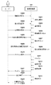
次に、コピー機能を実行するためのユーザと画像形成装置101とのやり取りを行うフローを図2に示すシーケンス図、及び、図3に示すUI図を用いて詳細に説明する。本フローは、画像形成装置101が有しているCPU111がROM112に記憶された制御プログラムを読み出して制御プログラムを実行することにより実現される。
<Execution flow of copy function>
Next, the flow of exchanging the user and the
機能使用指示S400において、画像形成装置101がユーザから操作部120を押下されたことを受け付けることで、コピー機能を開始する指示を受ける。図3(a)に示す操作部120に表示されるメインメニューUI500は画像形成装置101で実施可能な機能がボタンとして表示されている。例えば、コピー機能ボタン501、スキャンして送信機能ボタン502、スキャンして保存機能ボタン503、保存ファイルの利用機能ボタン504、プリント機能ボタン505などが表示される。その中から画像形成装置101はユーザからの実施したい機能の選択を受け付ける。コピー機能を開始する指示を行う場合には、画像形成装置101はユーザからのコピー機能ボタン501を押下されたことを受け付け、機能使用指示S400を実行する。
In the function use instruction S400, the
設定UI表示S401において、画像形成装置101の操作部120はコピー機能の各種設定の初期状態画面を表示する。図3(b)に示す操作部120に表示されるコピー設定UI510はコピー機能の各種設定の状態を示している。例えば、基本設定511では印字のカラー選択や印刷倍率選択、原稿・印刷サイズ選択、部数選択の状態が表示されている。その他、コピーの応用設定512では印字濃度の調整選択や両面印字の選択、原稿の種類などコピー機能の中でも多く利用される設定が表示される。また、その他の機能設定513では特定用途で用いられる応用機能を選択するため設定ができるボタンが配置されている。
In the setting UI display S401, the
基本設定指示S402において、画像形成装置101はユーザからのコピー機能の基本設定の指示を受け付ける。例えば、基本設定511の押下を受け付け、印字のカラー選択や印刷倍率選択、原稿・印刷サイズ選択、部数選択などの指示を受け付ける。
In the basic setting instruction S402, the
基本設定S403において、ユーザが選択したコピー機能の基本設定を画像形成装置101のRAM114に設定値として記憶する。
In the basic setting S403, the basic setting of the copy function selected by the user is stored in the
応用設定表指示S404において、画像形成装置101はユーザからのコピー機能の応用設定の指示を受け付ける。例えば、コピーの応用設定512やその他の機能設定513の押下を受け付け、応用機能を選択するため設定行う指示を受け付ける。画像形成装置101はユーザからのその他の機能設定513の押下を受け付け、図3(c)に示すUIを操作部120に表示する。その他の機能設定UI520では、画像形成装置101が実行可能なコピー機能の各種応用機能が表示される。例えば、両面印字の選択ボタン521やページ集約の選択ボタン522、原稿の種類の選択ボタン523、カラーの調整ボタン524、地紋印字の選択ボタン525、指定色除去の選択ボタン526などが表示されている。
In the application setting table instruction S404, the
詳細設定UI表示S405において、応用設定表指示S404に従った応用設定の詳細設定が行えるUIを表示する。指定色除去を行う場合には、画像形成装置101はユーザからの指定色除去の選択ボタン526の押下を受け付け、操作部120に図3(d)に示す指定色除去の詳細設定画面530を表示させる。
Detailed setting UI display In S405, a UI that allows detailed setting of application settings according to the application setting table instruction S404 is displayed. When performing the designated color removal, the
指定色除去設定指示S406において、画像形成装置101はユーザからの特定の色成分を除去したい色の選択を受け付ける。例えば、赤を指定色として選択531や緑を指定色として選択532、青を指定色として選択533、黒を指定色として選択534が選択可能である。なお、指定できる色の種類については、赤・青・緑・黒の4色でなくても、その他の色であっても良い。画像形成装置101は、赤を指定色として選択531や緑を指定色として選択532、青を指定色として選択533、黒を指定色として選択534の中からいずれかのボタンの押下を受け付け、除去したい色の指示を受け付ける。本実施例では、ユーザが赤を指定色として選択531を指定したものとして説明する。
In the designated color removal setting instruction S406, the
指定色セットS407において、指定色除去設定指示S406により画像形成装置101はユーザから選択された除去色をRAM114に設定値として記憶する。
In the designated color set S407, the
その他、指定色除去詳細設定指示S408において、より詳細な指定色除去の設定チューニングを選択できる。例えば、指定色を決めた上で、指定した色の除去範囲を広げ、より広範囲までの色を除去できる設定を行う事ができる。これにより、無彩色に近い有彩色や、印刷時に色ずれを起こした原稿であっても除去ができる設定が可能な、除去範囲を広げるモードがある。その他、指定色を決めた上で、指定した色の色相を変更することが可能な設定を行うことができる。例えば、赤を指定色として選択531を選択したうえで、色合い調整モード536を選択すると、図3(e)に示す操作部120に表示される色合い調整設定UI540が表示される。赤であっても、マゼンタ寄りやイエロー寄りといった除去する色の色合いを調整することができる。例えば、マゼンタ寄りの赤を除去したい場合には542を押下し、マゼンタ寄りとする。マゼンタ寄りにするとは、色差平面上の色相環において、マゼンタ側の色相にすることである。また、イエロー寄りの赤を除去したい場合には543を押下し、イエロー側とする。調整した設定は、マーク541で確認を行う。
In addition, in the designated color removal detailed setting instruction S408, more detailed designated color removal setting tuning can be selected. For example, after determining a designated color, the removal range of the designated color can be expanded and a setting capable of removing a wider range of colors can be made. As a result, there is a mode for expanding the removal range, which enables setting that even a chromatic color close to an achromatic color or a document having a color shift during printing can be removed. In addition, after determining the specified color, it is possible to make a setting that allows the hue of the specified color to be changed. For example, if
本実施例では、赤を指定した場合を説明したが、青や緑の場合にも設定は可能であり、その指定色を構成する色方向への調整が可能である。ただし本実施例では指定色が有彩色の場合にのみ色合い調整を許すものとする。なお図3(d)の詳細設定画面530において「除去範囲を広げる」535が選択された場合には、色の範囲が有彩色の場合には色相および彩度について範囲が拡張され、無彩色の場合には彩度について範囲が拡張される。この詳細は、図10を参照して後述する。
In this embodiment, the case where red is specified has been described, but it is possible to set it even in the case of blue or green, and it is possible to adjust in the color direction constituting the specified color. However, in this embodiment, the hue adjustment is permitted only when the designated color is a chromatic color. When "Expand the removal range" 535 is selected on the
指定色除去詳細セットS409において、画像形成装置101は指定色除去詳細設定指示S408によりユーザにより選択された指定色除去のより詳細な設定を画像形成装置101のRAM114に設定値として記憶する。
In the designated color removal detail set S409, the
続いて、スキャン指示S410において、画像形成装置101はユーザからのスキャン実行を受け付け、スキャン動作を実行するように指示を行う。スキャンS411において、画像形成装置101はスキャナ部140に対し、スキャナを駆動させスキャナのガラス板上に置かれた原稿、または、原稿自動給紙装置ADF(Auto Document Feeder)にセットされた原稿を読み取る。画像形成S412において、スキャンS411で読み取った画像を画像処理で扱えるビットマップ形式の画像へ変換を行う。
Subsequently, in the scan instruction S410, the
画像処理S413において、コピー機能の場合には、画像形成S412で生成されたスキャン画像を取得し、コピー用の画像処理を実施する。なお、本処理内において、指定色除去が実施される。 In the image processing S413, in the case of the copy function, the scanned image generated in the image forming S412 is acquired, and the image processing for copying is performed. In this process, the designated color is removed.
画像出力S414において、生成した画像の印刷を実行する。印刷が実行されると、画像形成装置101は、プリンタ部130で印字したコピー結果の原稿を出力する。S412、S413、S414については詳細を後述する。印字された原稿をS420においてユーザに提供を行う。
In the image output S414, printing of the generated image is executed. When printing is executed, the
図4(a)にスキャンS411で読み取った原稿の例を示し、(b)に画像出力S414で印刷された原稿の例を示す。図4(a)に示す原稿は、左下がり斜線パターンで示す領域Aで示す領域は黒トナーを用いて形成された文字等が記載されており、格子パターンで示す領域Bで示す領域は赤トナーを用いて形成された文字等が記載されている。なお、文字が記載された箇所は「*」で示す。図4(b)に示す原稿は、左下がり斜線パターンで示す領域Aの黒トナーを用いて形成された文字等はそのままコピーされて印字されている。一方、格子パターンで示す領域Bの赤トナーを用いて形成された文字等は文字である「*」は除去され印字されていないことがわかる。本実施例では、赤の色成分を除去する設定としている為、赤トナーを用いて形成された領域が除去された例となる。 FIG. 4A shows an example of a document read by scan S411, and FIG. 4B shows an example of a document printed by image output S414. In the document shown in FIG. 4A, characters and the like formed by using black toner are described in the area indicated by the area A indicated by the downward-sloping diagonal line pattern, and the area indicated by the area B indicated by the lattice pattern is red toner. Characters and the like formed using the above are described. The place where the character is written is indicated by "*". In the document shown in FIG. 4B, characters and the like formed by using the black toner in the region A shown by the downward-sloping diagonal line pattern are copied and printed as they are. On the other hand, it can be seen that the characters "*" formed by using the red toner in the region B shown by the grid pattern are not printed. In this embodiment, since the red color component is set to be removed, the region formed by using the red toner is removed.
<画像形成装置のソフトウェア構成>
図5は、コピー機能やスキャンして送信機能、プリント機能を動作させる、画像形成装置101のソフトウェア構成の一例を示すブロック図である。画像形成装置101は、画像入力部210、設定管理部220、画像処理部230、画像出力部240、画像送信部250の各機能部を備える。これら各機能部は、画像形成装置101が有しているCPU111が制御プログラムを実行することにより実現される。以下、各機能部について説明する。
<Software configuration of image forming device>
FIG. 5 is a block diagram showing an example of a software configuration of the
画像入力部210は、画像形成装置101が有するコピー機能やスキャンして送信機能、プリント機能に応じた画像データの入力を受け付ける。例えば、コピー機能やスキャンして送信機能が実行される場合はスキャナ部140からスキャン画像データを取得し、プリント機能が実行される場合はPC102からPDLデータを取得する。
The
設定管理部220は、画像処理部230で実行される各種画像処理についての様々な設定値を管理する。さらに、設定管理部220は、操作部120に表示されるUI画面からユーザの指示を受けて設定値を取得し、設定値を管理する制御も行う。
The
画像処理部230は、画像入力部210が取得した画像データに対し、利用される機能に応じた様々な画像処理を行う。画像処理部230は、スキャナ画像処理部231、プリンタ画像処理部232、輝度−濃度変換処理部233、ガンマ処理部234、ハーフトーン処理部235、ドット付加部236、ドット付加部236、フォーマット変換部237で構成される。
The
図6は、スキャナ画像処理部231内のソフトウェア構成の一例を示すブロック図である。スキャナ画像処理部231において、図6に示されるスキャナ画像処理部231により画像処理機能が実行されて、スキャンした画像に対する必要な画像処理が行われる。スキャナ処理部231は、MTF補正処理部301、ガンマ処理部302、色変換処理部303、色判定処理部304、彩度抑圧処理部305、フィルタ処理部306、像域処理部307からなる。
FIG. 6 is a block diagram showing an example of the software configuration in the scanner
まず、読取速度によって変化する読み取りのMTFを補正するMTF補正処理部301、スキャナの特性に応じた1次元のガンマ処理部302、そしてスキャナが持つ色空間からスキャナに依存しない色空間へ変換する色変換処理部303で構成される。本発明で用いられる指定された色を除去する処理も色変換処理部303で行われる。詳細は後述する。
First, the MTF
さらに、MTF補正処理部301で処理された画像を用いて文字や、写真などの像域を判定する像域処理部307やその像域情報を用いて行う、色判定処理部304、彩度抑圧処理部305、フィルタ処理部306で構成される。
Further, the color
ここで、色判定処理部304では像域情報を用いて、有彩色か無彩色かを判定し、彩度抑圧処理部305では像域情報に従って無彩色と判定された画像に対してRGBの量を補正する。たとえば、色判定処理部304において無彩色と判定された場合、RGBを等量にするなどの処理を行う。そして、フィルタ処理部306では、像域情報に従ってスムージングやエッジ強調などを行う。
Here, the color
プリント画像処理部232は、プリント機能の実行時に必要な画像処理、例えばPDLデータを解釈して中間データを生成する処理や、当該中間データをプリンタ部130で解釈可能なビットマップ形式のデータに変換するRIP処理などを行う。このRIP処理の際に、上述の属性情報を生成する処理も行われる。
The print
輝度−濃度変換処理部233は、スキャナ画像処理部231やプリント画像処理232で生成したデータの色空間(例えばRGB)を、プリンタ部130に対応する色空間(例えばCMYK)に変換する処理を行う。なお、輝度−濃度変換処理部233に入力される時点で色空間がCMYKの画像データは、そのままガンマ処理部234に送られる。ガンマ処理部234は、プリンタ部130の濃度階調を予め定めた特性となるように補正する処理を行う。ハーフトーン処理部235は、入力画像データの階調値(例えば、256階調)を、プリンタ部130で出力可能な階調であるN値(例えば2値)の画像データ(ハーフトーン画像データ)に変換する処理を行う。ドット付加処理部236は、あらかじめ定められたドットを付加する。画像出力部240は、入力画像データに対して各種画像処理を施した結果としてのハーフトーン画像データを、プリンタI/Fを介してプリンタ部130に出力する。
The brightness-density conversion processing unit 233 performs a process of converting the color space (for example, RGB) of the data generated by the scanner
フォーマット変換部237は、スキャナ画像処理部231で生成したデータを、送信可能な汎用的なフォーマット形式に変換する。例えば、JPEG(Joint Photographic Experts Group)形式のフォーマットや、PDF(Portable Document Format)形式のフォーマットへの変換を行う。画像送信部250は、入力画像データに対して各種画像処理を施した結果としての画像データを、ネットワークI/Fを介してLAN103を通してPC102等へ送信する。
The
ここで前述したS412、S413、S414のフロー、すなわち画像形成から画像出力に至る処理を詳細に説明する。 Here, the flow of S412, S413, and S414 described above, that is, the process from image formation to image output will be described in detail.
画像形成S412において、画像入力部210内で、スキャンS411で読み取った画像を画像処理で扱えるビットマップ形式の画像へ変換を行う。
In the image forming S412, the image read by the scan S411 is converted into a bitmap format image that can be handled by the image processing in the
画像処理S413において、コピー機能の場合には、画像形成S412で生成されたスキャン画像を取得し、スキャナ画像処理部231内の色変換処理部303において指定色除去処理を含む色変換等を実施する。たとえばユーザが赤を指定色として選択531している場合、スキャンで読み取った画像内から、赤の色成分を除去する処理が実行される。続いて、輝度−濃度変換処理部233、ガンマ処理部234、ハーフトーン処理部235、ドット付加部236を実施する。
In the image processing S413, in the case of the copy function, the scanned image generated by the image forming S412 is acquired, and the color
画像出力S414において、画像出力部240内で、生成した画像の印刷を実行する。印刷が実行されると、画像形成装置101は、プリンタ部130で印字したコピー結果の原稿を出力する。
In the image output S414, the generated image is printed in the
<指定色除去の方法>
次に、スキャナ画像処理部231内の色変換処理部303において行っている3次元のLUT処理及び、特定色が指定された際の特定色除去の方法を説明する。
<Method of removing specified color>
Next, a three-dimensional LUT processing performed by the color
色変換処理部303において、指定除去を行う、行わないに関わらず、スキャナで取得した画像に対しては、デバイスに依存した特性を持つR、G、B信号から、色空間変換によりデバイス非依存な色空間R'、G'、B'に変換を行う処理を行っている。変換の方法はさまざまあるが、例として、3次元のLUTによる変換処理を示す。
In the color
図7は、15刻みに間引きが行われている、4096個のテーブルの例を示している。入力される入力R、入力G、入力Bに対する出力される出力R、出力G、出力Bがテーブルとして決められている。すなわち図7のテーブルは3次元ルックアップテーブル(LUT)である。たとえば、入力が(0,0,15)であった場合の出力が(0,0,19)へ変換される。入力が15刻みの値でない場合には、隣接するナンバーからの補間演算で出力が求められる。3次元のLUTによる変換処理を入力画像全画素に対し実施することで、スキャンで読み込んだデバイス依存の色空間から、デバイス非依存の色空間に変換を行っている。このLUTでは、入力値はたとえば図7のインデックスに予め対応付けられており、そのインデックスに出力値を対応させて保持することで、入力と出力すなわち変換の前後の色を互いに関連付けている。 FIG. 7 shows an example of 4096 tables that are decimated in increments of 15. The input R, the output G, and the output R, the output G, and the output B for the input B are determined as a table. That is, the table in FIG. 7 is a three-dimensional look-up table (LUT). For example, if the input is (0,0,15), the output is converted to (0,0,19). If the input is not a value in increments of 15, the output is obtained by interpolation calculation from adjacent numbers. By performing the conversion process by the three-dimensional LUT on all the pixels of the input image, the device-dependent color space read by scanning is converted into the device-independent color space. In this LUT, for example, the input value is associated with the index of FIG. 7 in advance, and by holding the output value corresponding to the index, the input and the output, that is, the colors before and after the conversion are associated with each other.
指定色除去を実施する場合には、色変換処理部303において行う変換処理で用いる3次元LUTを変更することで実現することができる。例えば、3次元LUTの出力側のR、G、B信号が、画像形成装置101が受け付けた指定色に該当する場合には、この3次元LUTの中身を変換することで実現される。つまり、指定した色のRGBを(出力R,出力G,出力B)=(255,255,255)に変換して輝度信号で白を表す値に置換することで除去することができる。3次元LUTの生成は、ユーザが指定した除去色・除去領域(後述で詳細を説明)の設定値において、その都度生成しても良いし、指定される色ごとに3次元LUTを保持していてもよい。
When the designated color removal is performed, it can be realized by changing the three-dimensional LUT used in the conversion process performed by the color
また、RGB色空間で、3次元LUT上で処理を実施していることで、CMYK色空間で行っていた際に発生した課題を解決できる効果もある。CMYK色空間で例えばシアンを指定色として除去をする場合、画像形成に用いるCMYKトナーのシアンのみを印字しないことで指定色除去を実現することができる。しかし、例えばシアンと黄色とにより表される緑色の領域から、シアンを除去色として指定して除去した場合、以上の方法では、黄色だけが印字されてしまう場合があった。しかし、RGB色空間で除去を行うことで、上記のような課題は発生しない効果もある。 Further, by performing the processing on the three-dimensional LUT in the RGB color space, there is also an effect that the problem that occurred when performing the processing in the CMYK color space can be solved. When removing cyan as a designated color in the CMYK color space, for example, the designated color removal can be realized by not printing only cyan of the CMYK toner used for image formation. However, for example, when cyan is designated as the removal color and removed from the green area represented by cyan and yellow, only yellow may be printed by the above method. However, by removing in the RGB color space, there is an effect that the above-mentioned problems do not occur.
<指定色除去用の3次元LUT生成方法>
画像形成装置101が受け付けた指定色成分を除去できる3次元LUTを算出するフローを、図8を用いて示す。このフローは、色変換処理部303で実施され、画像形成装置101が有しているCPU111が制御プログラムを実行することにより実現される。
<Three-dimensional LUT generation method for removing specified colors>
FIG. 8 shows a flow for calculating a three-dimensional LUT that can remove the designated color component received by the
入力されるデータとしては、3次元LUTの出力側のR、G、Bとしており、全テーブル分(本実施例では、15刻みであるため、16×16×16個のテーブル)の信号値を処理する。このLUTには初期値として、デバイス依存の色空間からデバイス非依存の色空間に変換するための出力RGB値がセットされていて良い。加えて、処理のパラメータとして、各指定色の彩度幅閾値、色相中心角度、色相幅閾値が入力される。なお、処理を行う3次元LUTや、処理に用いる入力パラメータはROM112に保存され、設定管理部220を介してステップ610から入力される。入力パラメータについては後述する。なお説明中で述べるように、指定色はRGB色空間から変換したLUV(輝度−色差表色系)色空間で特定される。さらに、LUV色空間において、UV平面については、UVの直交座標系から、輝度軸を原点とする極座標系(たとえばDISTを動径、DEGを偏角として(DIST,DEG)で表す)で示される。すなわちLUV色空間は、(L,DIST,DEG)の円柱座標系で示される。U,VとDIST、DEGとの関係は下式で与えられる。なお角度DEGは「度」を単位とし、正のU軸方向を基準とする。
DIST=√(U2+V2)
DEG=cos-1(U/DIST) (V≧0) (1)
DEG=180+cos-1(U/DIST) (V<0)
以下の説明ではDEGを色相角度あるいは中心角度などと呼び、DISTを彩度と呼んでいる。DIST、DEGは上式でU,Vと相互に変換でき、表現の仕方が相違するにすぎない。図6の手順は、デバイス依存の色空間からデバイス非依存の色空間に変換するための出力RGB値がセットされている3次元LUTを再構成する手順であり、LUTに登録された全てのRGB値に、例えば図7のインデックスの順に順次着目して実行される。
The data to be input is R, G, and B on the output side of the three-dimensional LUT, and the signal values for all the tables (16 × 16 × 16 tables because it is in increments of 15 in this embodiment) are used. To process. As an initial value, an output RGB value for converting from a device-dependent color space to a device-independent color space may be set in this LUT. In addition, the saturation width threshold value, hue center angle, and hue width threshold value of each designated color are input as processing parameters. The three-dimensional LUT to be processed and the input parameters used for the processing are stored in the
DIST = √ (U 2 + V 2 )
DEG = cos -1 (U / DIST) (V ≧ 0) (1)
DEG = 180 + cos -1 (U / DIST) (V <0)
In the following description, DEG is referred to as a hue angle or a center angle, and DIST is referred to as saturation. DIST and DEG can be converted to each other with U and V by the above equation, and the way of expression is only different. The procedure of FIG. 6 is a procedure of reconstructing a three-dimensional LUT in which an output RGB value for converting from a device-dependent color space to a device-independent color space is set, and all RGB registered in the LUT. The values are sequentially focused on, for example, in the order of the indexes in FIG.
ステップ610では、画像形成装置101が受け付けた指定色が赤・緑・青等の有彩色か、黒等の無彩色化を判定する。まず、指定色として赤・緑・青のいずれかが指定された場合のフローを説明する。
In
指定色として赤・緑・青のいずれかが指定された場合に、ステップ620では、入力されたRi、Gi、BiをRGB色空間から輝度・色差の色空間(例えば、YUV色空間)に変換する。入力されたRi、Gi、Biは、3次元LUTにおいて着目するインデックスiに対応するRGB値である。RGBからYUVへの変換は以下の式からなる。
Yi=0.299×Ri+0.587×Gi+0.114×Bi
Ui=−0.169×Ri−0.331×Gi+0.50×Bi
Vi=0.50×Ri−0.419×Gi−0.081×Bi
なお、iは全テーブルの内、処理を行っているLUTのインデックス番号を示す。
When any of red, green, and blue is specified as the designated color, in
Yi = 0.299 x Ri + 0.587 x Gi + 0.114 x Bi
Ui = -0.169 x Ri-0.331 x Gi + 0.50 x Bi
Vi = 0.50 x Ri-0.419 x Gi-0.081 x Bi
Note that i indicates the index number of the LUT being processed in all the tables.
ステップ621では、変換した色差信号(Yi、Ui、Viの内、UiとVi)を元に、原点(0,0)から、(Ui,Vi)値までの距離を算出する。算出式としては、例えば、以下の式で算出する。
DISTi = sqrt((Ui×Ui)+(Vi×Vi))
ここで、算出した値を彩度値という。
In
DISTi = sqrt ((Ui x Ui) + (Vi x Vi))
Here, the calculated value is called a saturation value.
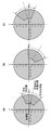
ステップ622では、算出した彩度値が特定の閾値(彩度値閾値)より高彩度か低彩度を判定する。彩度値閾値は、パラメータとしてプリセットとしてROM112に保持しておき、その値を使用し判定を行う。なお、彩度値閾値は指定する色ごとに違う値であっても良い。算出した彩度値が彩度値閾値より高い(大きい)場合(高彩度の場合)には、ステップ623へ進み、算出した彩度値が彩度値閾値より低い(小さい)場合(低彩度の場合)には、ステップ631へ進む。この時点で、入力される信号値の彩度値が、彩度値閾値よりも低彩度側にある場合は除去を行わないと判断する。一方、彩度値閾値よりも高彩度側にある場合は、除去候補とする。ここで、低彩度の色を非除去としていることで、無彩色に近い色が除去されないようにすることができる。図9に色差空間平面上における色相環を示す。図9(a)における内側の円が彩度閾値を示す。図9(a)の斜線領域が閾値よりも高彩度の色であり、除去候補となる色である。入力されるLUTが、LUTαの点にプロットされる場合には除去候補とし、LUTβの点にプロットされる場合には除去しないものとする。
In
ステップ623では、画像形成装置101が受け付けた指定色が赤、緑、青の内、どの色かによって分岐する。画像形成装置101が受け付けた指定色が赤の場合には624へ進み、画像形成装置101が受け付けた指定色が緑の場合には625へ進み、画像形成装置101が受け付けた指定色が青の場合には626へ進む。ステップ624、ステップ625、ステップ626では、R、G、Bそれぞれの内、指定された色の基準のU−V平面上での中心角度を、色相角度としてセットする。図9(b)に示すように、U−V平面上の原点を中心に、頂点側(U軸の正側)を0°として、時計回りに359°までの範囲で、各色の基準の色相角度をパラメータとしてプリセットとして保持しておき、その値を使用する。例えば、図9(b)に示すように赤の色相角度を340°、緑の色相角度を200°、青の色相角度を100°にセットする。
In
ステップ627では、変換した色差信号(Yi、Ui、Viの内、UiとVi)を元に、U−V平面上での角度(U・V色相角度)DEGiを算出する。算出式は上記式(1)でよい。図9(b)のLUTα及び、LUTβは共に350°の角度が算出されている例を示す。
In
ステップ628では、ステップ624、ステップ625、ステップ626でセットした基準の色相角度と、ステップ627で変換した色差信号から算出されたLUTの着目したRiGiBi値に対応するU・V色相角度DEGiの角度差(色相角度差)を以下の式で算出する。
DIFF_DEGi = |(LUTのU・V色相角度)DEGi−(基準の色相角度)|
例えば、画像形成装置101が受け付けた指定色が赤の場合には、ステップ624でセットした赤の色相角度と、ステップ627で算出した着目色の色相角度との角度差を算出する。画像形成装置101が受け付けた指定色が赤の場合、ステップ624でセットした基準の色相角度値が340°である。また、ステップ627で算出したU・V色相角度が例えばLUTαとLUTβは共に350°である為、色相角度差はLUTαとLUTβ共に10°となる。
In
DIFF_DEGi = | (UT U / V hue angle) DEGi- (reference hue angle) |
For example, when the designated color received by the
ステップ629では、ステップ628で算出した色相角度差が、各色の色相幅閾値を上回るか否かの判定を行う。色相角度差が色相幅閾値以下の場合にはステップ630に進み、色相角度差が色相幅閾値より大きい場合にはステップ631に進む。図9(c)で説明すると、赤の色相中心角度を中心に色相角度を両側方向に色相幅閾値分の領域内に入るか否かを判定する。例えば、色相幅閾値を30度とした場合、赤の色相角度340°±色相幅閾値30°内に入る点(すなわち色の領域)を除去範囲とする。よって、340°−30°(=310°)から、340°+30°(=370°(=10°))までの色相角度内の色域を除去する。
In
ステップ630では、ステップ629で除去すると判定されたLUTのRiGiBi値を印字されない信号値へ変更する。例えば、輝度信号値の場合、白を示す(Ri、Gi、Bi)=(255、255、255)の値に変更を行う。
In
ステップ631では、ステップ629で除去を行わない判定されたLUTのRiGiBi値は変更せず、入力信号のままとする。
In
ステップ632では、LUTのすべてのRGB値について判定されたか否かの分岐を行い、全信号の判定が終わっていない場合には、ステップ633で次のLUTを処理するためインデックスiに1を加算にし、ステップ622からの処理を実施する。本実施例で説明するLUTは、15刻みであるため、16×16×16個のテーブルの例で説明する。全信号の判定が終わった場合には、処理を終了する。
In
続いて、指定色が黒指定された場合のフローを説明する。 Next, the flow when the designated color is designated as black will be described.
指定色が黒の場合、ステップ610からステップ636へ分岐する。ステップ636、ステップ638はそれぞれステップ620、ステップ621と同様であるのでその説明は省略する。
When the designated color is black, the process branches from
ステップ640では、算出した彩度値が特定の閾値(彩度値閾値)より高彩度か低彩度を判定する。彩度値閾値は、パラメータとしてプリセットとしてROM112に保持しておき、その値を使用し判定を行う。判定方法は、算出した彩度値が彩度値閾値より低い場合(低彩度の場合)にはステップ642へ進み、算出した彩度値が彩度値閾値より高い場合(高彩度の場合)にはステップ644へ進む。
In
この時点で、入力される信号値の彩度値が、彩度値閾値よりも高彩度側にある場合は除去行わないと判断する。一方、彩度値閾値よりも低彩度側にある場合は、除去を行うと。ここで、高彩度の色を非除去としていることで、有彩色に近い色が除去されないようにすることができる。図9(d)における斜線領域が、除去範囲となり、入力されるLUTが、LUTαの点にプロットされえる場合には非除去とし、LUTβの点にプロットされえる場合には除去範囲とする。 At this point, if the saturation value of the input signal value is on the higher saturation side than the saturation value threshold value, it is determined that the removal is not performed. On the other hand, if it is on the lower saturation side than the saturation value threshold, it should be removed. Here, by setting the high-saturation color as non-removal, it is possible to prevent the color close to the chromatic color from being removed. The shaded area in FIG. 9D is the removal range, and if the input LUT can be plotted at the point of LUTα, it is set as non-removal, and if it can be plotted at the point of LUTβ, it is set as the removal range.
ステップ642、ステップ644、ステップ646、ステップ648は、それぞれステップ630、ステップ631、ステップ632、ステップ633と同様なのでその説明は省略する。
Since
以上の処理によって、入力される3次元のLUTを画像形成装置101が受け付けた指定色に応じて除去できるLUTへ書き換えることが可能となる。この再構成済みLUTを用いて色の変換を行うことで、指定した色の除去も併せて行うことができる。このように、除去対象として指定された色が有彩色の場合には、指定された色からの色差が所定量より小さく、かつ彩度が所定値より大きな色の範囲を白色に置換し、指定された色が無彩色の場合には、彩度が所定値以下の色の範囲を白色に置換するような色変換用のLUTを元のLUTから再構成する。あるいは、そのようなLUTを作成する。
By the above processing, it is possible to rewrite the input three-dimensional LUT into a LUT that can be removed according to the designated color received by the
<指定色除去処理に用いるパラメータ>
前述のとおり、3次元のLUT生成においては、3次元LUTの出力側のR、G、Bテーブルに加えて、処理のパラメータとして、各指定色の彩度幅閾値、色相中心角度、色相幅閾値が入力される。ここで、その処理に用いるパラメータと、ユーザの応用設定において変更可能なパラメータについて説明する。なお、処理に用いる入力パラメータはROM112に保存され、設定管理部220を介してステップ610から入力される。
<Parameters used for specified color removal processing>
As described above, in the three-dimensional LUT generation, in addition to the R, G, and B tables on the output side of the three-dimensional LUT, the saturation width threshold, the hue center angle, and the hue width threshold of each specified color are used as processing parameters. Is entered. Here, the parameters used for the processing and the parameters that can be changed in the user's application settings will be described. The input parameters used for the processing are stored in the
パラメータについては、変更可能であるし、UIから直接指定する構成であっても良いが、本実施例ではプリセットされた値を用いて、ユーザの指定で使うパラメータを切り替える構成を説明する。切り替えは例えば図3(d)や図3(e)に示したユーザインタフェースを通して行われてよい。図3(d)では「除去範囲を広げる」指定が、図3(e)では色合い調整が可能である。 The parameters can be changed or may be directly specified from the UI, but in this embodiment, a configuration for switching the parameters used by the user's specification will be described using preset values. The switching may be performed, for example, through the user interface shown in FIGS. 3 (d) and 3 (e). In FIG. 3D, the designation of "widening the removal range" can be specified, and in FIG. 3E, the hue can be adjusted.
図10(a)に、各色指定時の彩度幅閾値、色相中心角度、色相幅閾値の参考値を示す。指定色除去設定指示S406で画像形成装置101が受け付けた指定色ごとに値が切り替わる。応用設定を行っていない場合の値が、デフォルトであり、赤、緑、青、黒を指定した際の、彩度幅閾値、色相中心角度、色相幅閾値を示す。指定色時ごとに、彩度幅閾値、色相中心角度、色相幅閾値の値は変えることができる。彩度幅閾値は各指定色で保持するが、色相中心角度と色相幅閾値は赤、緑、青指定時のみにしか用いないパラメータであるため、黒については保持していない。
FIG. 10A shows reference values of the saturation width threshold value, the hue center angle, and the hue width threshold value when each color is specified. The value is switched for each designated color received by the
指定色除去詳細設定指示S408で、図3(d)の「除去範囲を広げる」535が指定された際のパラメータ例を、図10(a)の除去範囲を広げるモード時に示す。デフォルトに対し、より広域までの範囲を除去できるような値が保持されている。赤、緑、青指定時の彩度幅閾値はデフォルトより無彩色側になる値とすることで、より無彩色側までを除去できる係数とする。たとえば、指定色が赤の場合、彩度幅閾値は−16、すなわち無彩色側に向けて16ポイント広げられ、色相幅閾値は+5度、色相中心角度から広げられる。数値はそれぞれ異なるが、緑、青についても同様である。この色空間上の模式図を図14に示す。図14は指定色が緑の場合の例である。範囲1401がデフォルトの除去対象の範囲であるのに対して、範囲1402が拡張した除去対象の範囲である。範囲1402は、その中心はデフォルト範囲と一致しているが、シアンおよび黄色の両側に対して色相幅が拡げられている。それとともに、無彩色方向(原点方向)に対しても範囲が広がっている。このように、赤、緑、青指定時の色相幅閾値はデフォルトより広色相とすることで、より別色相側までを除去できる係数とする。色相中心角度は、デフォルトから変更しない。
An example of a parameter when "widen the removal range" 535 of FIG. 3D is specified in the designated color removal detailed setting instruction S408 is shown in the mode of widening the removal range of FIG. 10A. Compared to the default, the value is held so that the range to a wider area can be removed. By setting the saturation width threshold when red, green, and blue are specified to a value that is on the achromatic side from the default, it is a coefficient that can remove more up to the achromatic side. For example, when the designated color is red, the saturation width threshold is -16, that is, the hue width threshold is expanded by 16 points toward the achromatic color side, and the hue width threshold is expanded by +5 degrees from the hue center angle. The numbers are different, but the same is true for green and blue. A schematic diagram on this color space is shown in FIG. FIG. 14 is an example when the designated color is green. The
一方、黒指定時の彩度幅閾値はデフォルトより有彩色側になる値とすることで、より有彩色側までを除去できる係数とする。図15にその例を示す。図15(A)がデフォルト範囲を、図15(B)が拡張範囲を示す。このように、黒指定時には、拡張により再度幅が広げられてなお、ここで説明したパラメータについては、彩度幅閾値は622及び640で用い、色相中心角度は624、625、626で用い、色相幅閾値は629で用いて処理を行う。 On the other hand, by setting the saturation width threshold value when black is specified to a value that is on the chromatic color side from the default, it is a coefficient that can remove more chromatic color side. An example is shown in FIG. FIG. 15 (A) shows the default range, and FIG. 15 (B) shows the extended range. In this way, when black is specified, the width is widened again by expansion. For the parameters described here, the saturation width thresholds are used at 622 and 640, and the hue center angles are used at 624, 625, and 626, and the hue is used. The width threshold is set to 629 for processing.
本実施例では、YMCなどの出力色空間においては2色以上の混色で構成される色たとえば赤、青、緑を指定して除去する方法を説明した。シアン、マゼンタ、イエローなどの単色で構成される色を除去することもできる。単色で構成されている原稿は印刷時に色ずれ等が発生しない。よって、彩度幅閾値は変更するが、色相幅閾値はデフォルトと同じ値を用いる構成にすることも可能である。なお単色とは、原稿の画像を形成する色剤の色成分を指す。たとえば原稿上の画像がYMCKのトナーで形成されている場合には、Y,M,Cの各色成分が単色に相当する。Kは無彩色なので、単色ではあるが、対象とはしない。以上のように、指定色に応じて、各閾値を変更することも可能である。 In this embodiment, a method of designating and removing colors composed of a mixture of two or more colors, for example, red, blue, and green, has been described in an output color space such as YMC. It is also possible to remove colors composed of single colors such as cyan, magenta, and yellow. Originals composed of a single color do not cause color shift during printing. Therefore, although the saturation width threshold value is changed, the hue width threshold value can be configured to use the same value as the default value. The single color refers to the color component of the colorant that forms the image of the original. For example, when the image on the document is formed of YMCK toner, each color component of Y, M, and C corresponds to a single color. Since K is an achromatic color, it is a single color, but it is not a target. As described above, it is also possible to change each threshold value according to the designated color.
また、指定色除去詳細設定指示S408で、「色合い調整」536が指定された際のパラメータ例を、図10(b)に示す。デフォルトの色相中心角度は、赤、緑、青のそれぞれに対応して340度、200度、100度であり、色相幅閾値は30度である。それに対してたとえば赤が選択された場合、1段階マゼンタ寄りが選択されれば、340度+10度=350度が調整後の色相中心角度となる。もう1段階マゼンタ寄りが指定されれば色相中心角度はさらに+10度される。逆にイエロー寄りが指定されれば、1段階ごとに色相中心角度は10度ずつ減ぜられる。このように除去対象の色の調整は、デフォルトに対し、色相中心角度を変更することで行う。 Further, FIG. 10B shows an example of parameters when "hue adjustment" 536 is specified in the designated color removal detailed setting instruction S408. The default hue center angles are 340 degrees, 200 degrees, and 100 degrees corresponding to red, green, and blue, respectively, and the hue width threshold is 30 degrees. On the other hand, when red is selected, for example, if one step closer to magenta is selected, 340 degrees + 10 degrees = 350 degrees is the adjusted hue center angle. If another step closer to magenta is specified, the hue center angle is further increased by +10 degrees. On the contrary, if yellowishness is specified, the hue center angle is reduced by 10 degrees for each step. In this way, the color to be removed is adjusted by changing the hue center angle with respect to the default.
例えば、図3(e)に指定色が赤の場合の色合い調整ユーザインタフェース540を示す。このユーザインタフェースでは、デフォルトの色相中心角度に対しマゼンタ寄りまたは、イエロー寄りに所定の段数で色相を変更することができる。図3(e)の例では、デフォルトの色相を中心としてマゼンタ及びイエローそれぞれに2段階ずつである。ユーザによって指定する方法としては、図3(e)のUIにて、ボタン542、543を操作することで、それぞれの色の方向に色相を調整できる。調整前はデフォルト値541となっている。なお、ここで説明したパラメータについて、色相中心角度は図8のステップ624、625、626で用い処理を行う。図13に色相調整のUV平面上での模式図を示す。図13では除去対象の色として緑が選択されている例を示す。図13(a)はデフォルト設定を示す。図13(b)は2段階イエロー寄りに、図13(c)は2段階マゼンタよりに色相を調整した例を示す。この場合、中心角が変わるだけで、再度幅や色相幅は変わらない。 また、図3(d)に示した「除去範囲を広げる」535と「色合い調整」536はそれぞれ独立に調整ができ、いずれか一方だけを指定することもできるし、両方とも合わせて実行することが可能である。すなわち、色相の調整と、色相幅および/または彩度幅の調整とを独立して行うことができる。
For example, FIG. 3 (e) shows a hue
また、本実施例では、UIにおいて何段階かの範囲で設定値を切り替える構成で、かつ、プリセットされているパラメータ値を用いる構成を説明したが、ユーザが直接パラメータを変更できるUIを用意した上で、パラメータ値を直接調整できる構成であっても良い。ただし、調整値として任意の値を入力できるように構成すると、調整により全く異なる色相が指定されてしまうことにもなりかねないので、調整値の上限を設けてもよい。さらにこの調整の上限を、色相中心角度を、0度から360度までを例えば1度刻みで調整できるように設定してもよい。あるいは、除去対象の色の範囲が、すべての色相をカバーできるように、色相幅および色相中心角度を調整できるようにしてもよい。例えば図9(c)を参照する。除去対象として赤を選択した場合、デフォルトの除去対象範囲は、色相に関しては、340度±30度であり、310度〜370度の範囲である。色相幅を拡張し、2段階マゼンタ寄りに色を調整すると、360度±35度が除去対象の色の範囲となる。すなわち、325度〜395度(=35度)が範囲となる。一方、青を指定して、色相をマゼンタ寄りに調整し、色相幅を拡張すると、その範囲は、80度±40度となり、40度〜120度が除去範囲となる。この結果、35度〜40度の色相は、調整によっても除去できない色となることがわかる。そこで、色相中心角の調整量の拡大や、或いは色相幅の更なる拡張により上記の例では除去できない範囲も除去の対象となるよう構成してもよい。 Further, in this embodiment, the configuration in which the set values are switched in a range of several stages in the UI and the preset parameter values are used has been described, but after preparing a UI in which the user can directly change the parameters. Therefore, the configuration may be such that the parameter value can be directly adjusted. However, if it is configured so that an arbitrary value can be input as the adjustment value, a completely different hue may be specified by the adjustment, so an upper limit of the adjustment value may be set. Further, the upper limit of this adjustment may be set so that the hue center angle can be adjusted from 0 degree to 360 degrees in increments of, for example, 1 degree. Alternatively, the hue width and hue center angle may be adjustable so that the range of colors to be removed covers all hues. See, for example, FIG. 9 (c). When red is selected as the removal target, the default removal target range is 340 degrees ± 30 degrees with respect to hue, which is in the range of 310 degrees to 370 degrees. When the hue width is expanded and the color is adjusted toward magenta in two steps, 360 degrees ± 35 degrees becomes the range of the color to be removed. That is, the range is 325 degrees to 395 degrees (= 35 degrees). On the other hand, when blue is specified, the hue is adjusted closer to magenta, and the hue width is expanded, the range becomes 80 degrees ± 40 degrees, and 40 degrees to 120 degrees becomes the removal range. As a result, it can be seen that the hue of 35 to 40 degrees becomes a color that cannot be removed even by adjustment. Therefore, the range that cannot be removed in the above example may be removed by expanding the adjustment amount of the hue center angle or further expanding the hue width.
なお、本実施例ではコピー機能のフローを説明したが、前述の通りスキャナ画像処理部231内の色変換処理部303で実施することで、コピー機能に関わらず実施できる。例えば、スキャンした画像をPC等に送信するスキャンして送信機能や、スキャンした画像を画像形成装置101C等に保存するスキャンして保存機能、FAX送信機能等、スキャン処理を利用する機能であれば利用可能である。
Although the flow of the copy function has been described in this embodiment, it can be performed regardless of the copy function by performing it in the color
以上によって、指定色除去を行う場合に、指定色の低彩度色まで除去されてしまう点や、黒色やグレーなど無彩色の色を限定して除去することができない点などの課題を解決した上で、原稿内からユーザが指定色領域のみを除去することができる。また、除去対象の色の指定をより柔軟に行うことが可能になる。 As described above, when removing the specified color, the problems such as the point that even the low-saturation color of the specified color is removed and the point that the achromatic color such as black and gray cannot be removed in a limited manner have been solved. Above, the user can remove only the designated color area from the original. In addition, it becomes possible to more flexibly specify the color to be removed.
[実施形態2]
実施例1では、YUV色空間など輝度−色差色空間での、色差値(すなわち色相角)を用い指定色領域のみを特定し、除去する構成を説明した。ここでは、色差値に加えて、輝度の信号値を用い、指定色領域を特定する構成を説明する。
[Embodiment 2]
In Example 1, a configuration in which only a designated color region is specified and removed by using a color difference value (that is, a hue angle) in a luminance-color difference color space such as a YUV color space has been described. Here, a configuration for specifying a designated color region by using a luminance signal value in addition to the color difference value will be described.
図8に示したステップ622では彩度値までの距離を元に判定を行い、ステップ629では色相角度差を元に指定色か否かの判定を行っていた。しかし、淡い色や暗い色の場合、彩度と色相だけの閾値で判定を行うと、ユーザが意図しない色が除去されてしまう可能性がある。
In
そこで、ステップ622およびステップ629において、ステップ620で取得した輝度値Yを用いる構成を説明する。ステップ620で取得した輝度値Yに応じて、ステップ622およびステップ629の判定部で用いる閾値の値を切り替える。例えば、算出した輝度の範囲が0〜255までの場合、0〜86を低輝度域、87〜172を中間輝度域、173〜255を高輝度域と分ける。輝度域ごとに異なる彩度幅閾値および色相幅閾値をROM112に保持する。算出された輝度がどの輝度域に属するかを判定し、属する輝度域に対応した彩度幅閾値、色相幅閾値を用い図8のそれぞれステップ622、ステップ629の処理を行う。
Therefore, in
それによって、淡い色や暗い色の場合においても、指定した色通りの色を除去することが可能である。 Thereby, even in the case of a light color or a dark color, it is possible to remove the color according to the specified color.
[実施形態3]
実施例1及び、実施例2では、画像形成装置101が受け付けた指定色の除去設定を確定したうえで、コピーを実行するフローを説明した。しかし、設定した除去領域が実際の原稿のどの色に対応するかをユーザが確認することができない。そこで、図2のS400からS420の構成に加え、S421のプレビュー表示及び、出力実行422を行える構成を、図11を参照して説明する。
[Embodiment 3]
In the first and second embodiments, the flow of executing the copy after confirming the removal setting of the designated color received by the
プレビュー表示S421において、S413で作成した除去結果をユーザにUIで提示し、除去結果を確認する。 In the preview display S421, the removal result created in S413 is presented to the user by the UI, and the removal result is confirmed.
S421のプレビュー表示でユーザが結果を確認した上で、出力実行S422を行う。結果を確認した上で、ユーザが除去結果を変更したい場合には、再度、指定色除去設定指示S406や指定色除去詳細設定指示S408を行い、設定を変更することができる。それによって、ユーザは指定色除去の結果プレビューを確認した上で印刷等が行え、誤印刷を避けることが可能となる。 After the user confirms the result in the preview display of S421, the output execution S422 is performed. After confirming the result, if the user wants to change the removal result, the setting can be changed by issuing the designated color removal setting instruction S406 or the designated color removal detailed setting instruction S408 again. As a result, the user can perform printing after confirming the preview as a result of removing the designated color, and can avoid erroneous printing.
図12にプレビューを行なうUIのイメージ図を示す。画像形成装置101の操作部120において、プレビュー表示UI550を表示する。プレビュー表示UI550内には、指定色除去の処理前画像551と、指定色除去の処理後結果画像552を表示されている。また、画面上に印刷ボタン553及び、設定変更ボタン554が用意されている。指定色除去の処理後結果画像552を確認して、そのまま印刷を行う場合には、印刷ボタン553の投下を受け付け、印刷を実行する。指定色除去の設定を変更する場合には、設定変更ボタン554の投下を受け付け、再度指定色除去の設定を行うUI530へ移行させる。
FIG. 12 shows an image diagram of the UI for previewing. The
[実施形態4]
実施例1、実施例2、実施例3では、画像形成装置101が受け付けられる指定色は1色である構成を説明した。実施例4では、画像形成装置101が受け付けられる指定色が複数色の場合の例を説明する。
[Embodiment 4]
In the first embodiment, the second embodiment, and the third embodiment, the configuration in which the designated color accepted by the
図3(d)において、例えば赤を指定色としてレッド531と青を指定色としてブルー533の二つを同時に選択できる構成とする。除去処理については、指定色除去用に作成する3次元LUTフローである図8の処理を、指定された色数分実行し、複数色を除去できる3次元LUTを生成する。作成した複数色除去を行う3次元LUTを用いて、スキャナ処理部231内の色変換処理部303で処理を実行する。
In FIG. 3D, for example, red 531 with red as the designated color and blue 533 with blue as the designated color can be selected at the same time. Regarding the removal process, the process of FIG. 8, which is a three-dimensional LUT flow created for removing a designated color, is executed for a specified number of colors to generate a three-dimensional LUT capable of removing a plurality of colors. Using the created three-dimensional LUT that removes a plurality of colors, the color
また、2色や3色などの複数色除去を行う場合に、複数色で指定された色の除去範囲同士に挟まれる色相領域まで除去することも可能である。例えば、指定色で赤と緑が指定された場合、色差空間上の色相環において二色の中間にある色相である黄色領域まで含めて除去することも可能である。 Further, when removing a plurality of colors such as two colors or three colors, it is possible to remove even a hue region sandwiched between the removal ranges of the colors specified by the plurality of colors. For example, when red and green are specified as the designated colors, it is possible to remove the yellow region, which is the hue between the two colors in the hue circle on the color difference space.
以上の方法により、指定色を1色ではなく、複数色まで指定したうえで、指定色除去を行うことが可能となる。 By the above method, it is possible to remove the designated color after designating up to a plurality of designated colors instead of one.
[その他の実施例]
本発明は、上述の実施形態の1以上の機能を実現するプログラムを、ネットワーク又は記憶媒体を介してシステム又は装置に供給し、そのシステム又は装置のコンピュータにおける1つ以上のプロセッサがプログラムを読出し実行する処理でも実現可能である。また、1以上の機能を実現する回路(例えば、ASIC)によっても実現可能である。
[Other Examples]
The present invention supplies a program that realizes one or more functions of the above-described embodiment to a system or device via a network or storage medium, and one or more processors in the computer of the system or device reads and executes the program. It can also be realized by the processing to be performed. It can also be realized by a circuit (for example, ASIC) that realizes one or more functions.
101 画像形成装置、301 MTF補正処理部、302 ガンマ処理部、303 色変換処理部、304 色判定処理部、305 彩度抑圧処理部、306 フィルタ処理部 101 Image forming device, 301 MTF correction processing unit, 302 gamma processing unit, 303 color conversion processing unit, 304 color judgment processing unit, 305 saturation suppression processing unit, 306 filter processing unit
Claims (17)
前記指定された色が有彩色である場合には、彩度が第1の閾値より高く、色相が前記指定された色に対応する色相の範囲内にある第1の色を有する画素を白画素で置換し、前記指定された色が黒の場合、彩度が第2の閾値以下の第2の色を持つ画素を白画素で置換する置換手段と
を有し、
前記受付手段は、更に、前記第2の閾値の変更を受け付け可能であり、
前記置換手段は、前記指定された色が黒で、かつ、前記第2の閾値が変更されていた場合、彩度が前記変更された前記第2の閾値以下の前記第2の色の画素を、白画素で置換することを特徴とする画像処理装置。 A reception means that accepts the specification of the color to be replaced with white pixels in the scanned image,
When the specified color is a chromatic color, a pixel having a first color whose saturation is higher than the first threshold value and whose hue is within the range of the hue corresponding to the specified color is a white pixel. in substituted, wherein if the specified color is black, the pixel saturation has a second color below the second threshold possess a replacement means for replacing the white pixel,
The receiving means can further accept the change of the second threshold value.
When the designated color is black and the second threshold value is changed, the replacement means uses pixels of the second color whose saturation is equal to or less than the changed second threshold value. , An image processing device characterized by replacing with white pixels.
前記受付手段は、更に、置換される前記指定された色の色相の調整を受け付け可能であり、
前記置換手段は、前記調整された前記指定された色が有彩色である場合、彩度が前記第1の閾値よりも高く、色相が、前記調整された前記指定された色に対応する色相の範囲内にある、前記第1の色を有する画素を白画素で置換する
ことを特徴とする画像処理装置。 The image processing apparatus according to claim 1.
The receiving means can further accept adjustment of the hue of the specified color to be replaced.
Said replacement means, if the adjusted the designated color is chromatic, the saturation is higher than the first threshold value, hue, the adjusted hue corresponding to the designated color An image processing apparatus that replaces a pixel having the first color within the range with a white pixel.
前記受付手段は、更に、前記指定された色に対応する前記色相の範囲の変更を受け付け可能であり、
前記置換手段は、前記指定された色が有彩色で、かつ、前記指定された色に対応する前記色相の範囲が変更されていた場合、彩度が前記第1の閾値よりも高く、色相が、前記指定された色に対応する前記変更された色相の範囲内にある前記第1の色を有する画素を白画素で置換する
ことを特徴とする画像処理装置。 The image processing apparatus according to claim 1 or 2.
The receiving means further is able to accept change of scope of the hue corresponding to the designated color,
In the replacement means, when the specified color is a chromatic color and the range of the hue corresponding to the specified color is changed , the saturation is higher than the first threshold value and the hue is changed. an image processing apparatus characterized by replacing the pixel having the first color within a range of the changed hue corresponding to the designated color with white pixels.
前記受付手段は、更に、前記第1の閾値の変更を受け付け可能であり、
前記置換手段は、前記指定された色が有彩色で、かつ、前記指定された色に対応する前記色相の範囲が変更され、かつ、前記第1の閾値が変更されていた場合、彩度が前記変更された第1の閾値よりも高く、色相が、前記指定された色に対応する前記変更された色相の範囲内にある前記第1の色を有する画素を白画素で置換する
ことを特徴とする画像処理装置。 The image processing apparatus according to claim 3.
The receiving means can further accept the change of the first threshold value.
The replacement means has a saturation when the specified color is a chromatic color, the range of the hue corresponding to the specified color is changed, and the first threshold value is changed. It is characterized in that a pixel having the first color, which is higher than the modified first threshold and has a hue within the range of the modified hue corresponding to the specified color, is replaced with a white pixel. Image processing device.
前記受付手段は、更に、前記指定された色の色相の調整と、前記指定された色に対応する色相の範囲の変更とを、独立して受け付け可能であり、
前記置換手段は、前記調整された前記指定された色が有彩色で、かつ、前記指定された色に対応する前記色相の範囲が変更されていた場合、彩度が前記第1の閾値よりも高く、色相が、前記調整された前記指定された色に対応する前記変更された色相の範囲内にある、前記第1の色を有する画素を白画素で置換することを特徴とする画像処理装置。 The image processing apparatus according to claim 1.
The receiving means further adjustment of the hue of the specified color, and a change in the hue range corresponding to the designated color, Ri can der accepted independently,
In the replacement means, when the adjusted designated color is chromatic and the range of the hue corresponding to the designated color is changed, the saturation becomes higher than the first threshold value. An image processing apparatus characterized in that a pixel having the first color, which is high and has a hue within the range of the modified hue corresponding to the adjusted specified color, is replaced with a white pixel. ..
前記受付手段は、前記受け付けた前記指定された色が、前記スキャンされた画像の文書画像を形成する色材の色である場合、前記第1の閾値を変更し、前記色相の範囲は変更しない
ことを特徴とする画像処理装置。 The image processing apparatus according to claim 4.
When the received designated color is the color of the color material forming the document image of the scanned image, the receiving means changes the first threshold value and does not change the hue range. An image processing device characterized by the fact that.
前記置換手段は、変換の前後の色を関連付けたルックアップテーブルを作成する作成手段を有し、前記指定された色が有彩色の場合、彩度が前記第1の閾値より高く、色相が、前記ルックアップテーブルを参照することで前記指定された色に対応する色相の範囲内にある前記第1の色を有する画素を白画素で置換し、
前記作成手段は、白画素で置換される色の画素が白画素と関連付けられるように前記ルックアップテーブルを作成する
ことを特徴とする画像処理装置。 The image processing apparatus according to any one of claims 1 to 6.
The replacement means has a creation means for creating a look-up table in which the colors before and after the conversion are associated with each other, and when the specified color is a chromatic color, the saturation is higher than the first threshold value and the hue is. By referring to the look-up table, the pixel having the first color within the range of the hue corresponding to the specified color is replaced with the white pixel.
The image processing apparatus is characterized in that the creation means creates the look-up table so that pixels of a color replaced by white pixels are associated with white pixels.
文書をスキャンすることによって前記スキャンされた画像を取得する取得手段と、
前記スキャンされた画像に基づいて画像を形成する画像形成手段とを有し、
前記画像形成手段は、前記置換手段により色が置換された画像データに基づいて画像を形成する
ことを特徴とする画像処理装置。 The image processing apparatus according to any one of claims 1 to 7.
An acquisition means for acquiring the scanned image by scanning a document, and
It has an image forming means for forming an image based on the scanned image.
The image forming means is an image processing apparatus characterized in that an image is formed based on image data in which colors are replaced by the replacing means.
スキャンされた画像において白画素に置換する色の指定を受け付ける受付工程と、
前記指定された色が有彩色である場合には、彩度が第1の閾値より高く、色相が前記指定された色に対応する色相の範囲内にある第1の色を有する画素を白画素で置換し、前記指定された色が黒の場合、彩度が第2の閾値以下の第2の色を持つ画素を白画素で置換する置換工程と
を有し、
前記受付工程では、更に、前記第2の閾値の変更を受け付け可能であり、
前記置換工程では、前記指定された色が黒で、かつ、前記第2の閾値が変更されていた場合、彩度が前記変更された前記第2の閾値以下の前記第2の色の画素を、白画素で置換することを特徴とする画像処理方法。 It is an image processing method
The reception process that accepts the designation of the color to be replaced with white pixels in the scanned image,
When the specified color is a chromatic color, a pixel having a first color whose saturation is higher than the first threshold value and whose hue is within the range of the hue corresponding to the specified color is a white pixel. in substituted, wherein if the specified color is black, the pixel saturation has a second color below the second threshold possess a substitution step of replacing white pixels,
In the reception step, it is possible to further accept the change of the second threshold value.
In the replacement step, when the designated color is black and the second threshold value is changed, the pixels of the second color whose saturation is equal to or less than the changed second threshold value are used. , An image processing method characterized by replacing with white pixels.
前記受付工程では、更に、置換される前記指定された色の色相の調整を受け付け可能であり、
前記置換工程では、前記調整された前記指定された色が有彩色である場合、彩度が前記第1の閾値よりも高く、色相が、前記調整された前記指定された色に対応する色相の範囲内にある、前記第1の色を有する画素を白画素で置換する
ことを特徴とする画像処理方法。 The image processing method according to claim 9.
In the reception step, it is possible to further accept adjustment of the hue of the specified color to be replaced.
In the substitution process, when the adjusted the designated color is chromatic, the saturation is higher than the first threshold value, hue, the adjusted hue corresponding to the designated color An image processing method comprising replacing a pixel having the first color within the range with a white pixel.
前記受付工程では、更に、前記指定された色に対応する前記色相の範囲の変更を受け付け可能であり、
前記置換工程では、前記指定された色が有彩色で、かつ、前記指定された色に対応する前記色相の範囲が変更されていた場合、彩度が前記第1の閾値よりも高く、色相が、前記指定された色に対応する前記変更された色相の範囲内にある前記第1の色を有する画素を白画素で置換する
ことを特徴とする画像処理方法。 The image processing method according to claim 9 or 10.
Wherein at the reception step further, we can accept the change in the scope of the hue corresponding to the designated color,
In the replacement step, when the specified color is a chromatic color and the range of the hue corresponding to the specified color is changed , the saturation is higher than the first threshold value and the hue is changed. an image processing method characterized by replacing the pixel having the first color within a range of the changed hue corresponding to the designated color with white pixels.
前記受付工程では、更に、前記第1の閾値の変更を受け付け可能であり、
前記置換工程では、前記指定された色が有彩色で、かつ、前記指定された色に対応する前記色相の範囲が変更され、かつ、前記第1の閾値が変更されていた場合、彩度が前記変更された第1の閾値よりも高く、色相が、前記指定された色に対応する前記変更された色相の範囲内にある前記第1の色を有する画素を白画素で置換する
ことを特徴とする画像処理方法。 The image processing method according to claim 11.
In the reception step, it is possible to further accept the change of the first threshold value.
In the replacement step, when the specified color is a chromatic color, the range of the hue corresponding to the specified color is changed, and the first threshold value is changed , the saturation is increased. It is characterized in that a pixel having the first color, which is higher than the modified first threshold and has a hue within the range of the modified hue corresponding to the specified color, is replaced with a white pixel. Image processing method.
前記受付工程では、更に、前記指定された色の色相の調整と、前記指定された色に対応する色相の範囲の変更とを、独立して受け付け可能であり、
前記置換工程では、前記調整された前記指定された色が有彩色で、かつ、前記指定された色に対応する前記色相の範囲が変更されていた場合、彩度が前記第1の閾値よりも高く、色相が、前記調整された前記指定された色に対応する前記変更された色相の範囲内にある、前記第1の色を有する画素を白画素で置換する
ことを特徴とする画像処理方法。 The image processing method according to claim 12.
Wherein at the reception step further, the adjustment of the hue of the specified color, and a change in the hue range corresponding to the designated color, Ri can der accepted independently,
In the replacement step, when the adjusted designated color is chromatic and the range of the hue corresponding to the designated color is changed, the saturation becomes higher than the first threshold value. It is characterized in that the pixel having the first color, which is high and the hue is within the range of the modified hue corresponding to the adjusted specified color, is replaced with a white pixel. Image processing method to be performed.
前記受付工程では、前記受け付けた前記指定された色が、前記スキャンされた画像の文書画像を形成する色材の色である場合、前記第1の閾値を変更し、前記色相の範囲は変更しない
ことを特徴とする画像処理方法。 The image processing method according to claim 12.
In the reception step, when the received designated color is the color of the color material forming the document image of the scanned image, the first threshold value is changed and the hue range is not changed. An image processing method characterized by the fact that.
前記置換工程は、変換の前後の色を関連付けたルックアップテーブルを作成する作成工程を有し、前記指定された色が有彩色の場合、彩度が前記第1の閾値より高く、色相が、前記ルックアップテーブルを参照することで前記指定された色に対応する色相の範囲内にある前記第1の色を有する画素を白画素で置換し、
前記作成工程では、白画素で置換される色の画素が白画素と関連付けられるように前記ルックアップテーブルを作成する
ことを特徴とする画像処理方法。 The image processing method according to any one of claims 9 to 14.
The replacement step includes a creation step of creating a look-up table in which the colors before and after the conversion are associated with each other. When the specified color is a chromatic color, the saturation is higher than the first threshold value and the hue is increased. By referring to the look-up table, the pixel having the first color within the range of the hue corresponding to the specified color is replaced with the white pixel.
The image processing method, characterized in that, in the creation step, the lookup table is created so that pixels of a color replaced by white pixels are associated with white pixels.
文書をスキャンすることによって前記スキャンされた画像を取得する取得工程と、
前記スキャンされた画像に基づいて画像を形成する画像形成工程とを有し、
前記画像形成工程では、前記置換工程により色が置換された画像データに基づいて画像を形成する
ことを特徴とする画像処理方法。 The image processing method according to any one of claims 9 to 15.
The acquisition process of acquiring the scanned image by scanning the document, and
It has an image forming step of forming an image based on the scanned image.
The image processing method is an image processing method characterized in that an image is formed based on image data in which colors are replaced by the replacement step.
前記指定された色が有彩色である場合には、彩度が第1の閾値より高く、色相が前記指定された色に対応する色相の範囲内にある第1の色を有する画素を白画素で置換し、前記指定された色が黒の場合、彩度が第2の閾値以下の第2の色を持つ画素を白画素で置換する置換手段と
してコンピュータを機能させるためのプログラムであって、
前記受付手段では、更に、前記第2の閾値の変更を受け付け可能であり、
前記置換手段では、前記指定された色が黒で、かつ、前記第2の閾値が変更されていた場合、彩度が前記変更された前記第2の閾値以下の前記第2の色の画素を、白画素で置換するように、コンピュータを機能させることを特徴とするプログラム。 A reception means that accepts the specification of the color to be replaced with white pixels in the scanned image,
When the specified color is a chromatic color, a pixel having a first color whose saturation is higher than the first threshold value and whose hue is within the range of the hue corresponding to the specified color is a white pixel. It is a program for operating a computer as a replacement means for replacing a pixel having a second color whose saturation is equal to or less than a second threshold with a white pixel when the specified color is black .
The receiving means can further accept the change of the second threshold value.
In the replacement means, when the designated color is black and the second threshold value is changed, the pixels of the second color whose saturation is equal to or less than the changed second threshold value are used. , A program characterized by making a computer function so as to replace it with white pixels .
Priority Applications (4)
| Application Number | Priority Date | Filing Date | Title |
|---|---|---|---|
| JP2017149312A JP6944300B2 (en) | 2017-08-01 | 2017-08-01 | Image processing equipment, image processing methods, and programs |
| US16/040,161 US10542188B2 (en) | 2017-08-01 | 2018-07-19 | Image processing apparatus, image processing method, and storage medium for removing a designated color from an image |
| KR1020180088947A KR102323909B1 (en) | 2017-08-01 | 2018-07-31 | Image processing apparatus, image processing method, and storage medium |
| CN201810860226.7A CN109327646B (en) | 2017-08-01 | 2018-08-01 | Image processing apparatus, image processing method, and computer-readable storage medium |
Applications Claiming Priority (1)
| Application Number | Priority Date | Filing Date | Title |
|---|---|---|---|
| JP2017149312A JP6944300B2 (en) | 2017-08-01 | 2017-08-01 | Image processing equipment, image processing methods, and programs |
Publications (3)
| Publication Number | Publication Date |
|---|---|
| JP2019029903A JP2019029903A (en) | 2019-02-21 |
| JP2019029903A5 JP2019029903A5 (en) | 2020-09-03 |
| JP6944300B2 true JP6944300B2 (en) | 2021-10-06 |
Family
ID=65231759
Family Applications (1)
| Application Number | Title | Priority Date | Filing Date |
|---|---|---|---|
| JP2017149312A Active JP6944300B2 (en) | 2017-08-01 | 2017-08-01 | Image processing equipment, image processing methods, and programs |
Country Status (4)
| Country | Link |
|---|---|
| US (1) | US10542188B2 (en) |
| JP (1) | JP6944300B2 (en) |
| KR (1) | KR102323909B1 (en) |
| CN (1) | CN109327646B (en) |
Families Citing this family (8)
| Publication number | Priority date | Publication date | Assignee | Title |
|---|---|---|---|---|
| KR20180038793A (en) * | 2016-10-07 | 2018-04-17 | 삼성전자주식회사 | Method and apparatus for processing image data |
| US20190096040A1 (en) * | 2017-09-25 | 2019-03-28 | Kabushiki Kaisha Toshiba | Image processing apparatus, image processing method and non-transitory readable storage medium |
| TW201929538A (en) * | 2017-12-15 | 2019-07-16 | 晨星半導體股份有限公司 | Image processing circuit and associated image processing method |
| JP7059799B2 (en) * | 2018-05-23 | 2022-04-26 | 富士フイルムビジネスイノベーション株式会社 | Information processing equipment and programs |
| JP7154951B2 (en) * | 2018-10-31 | 2022-10-18 | キヤノン株式会社 | Image processing device, image processing method, and program |
| JP7313879B2 (en) | 2019-04-08 | 2023-07-25 | キヤノン株式会社 | Image processing device, image processing method and program |
| CN111414877B (en) * | 2020-03-26 | 2023-06-20 | 遥相科技发展(北京)有限公司 | Table cutting method for removing color frame, image processing apparatus and storage medium |
| US20230308597A1 (en) * | 2022-03-23 | 2023-09-28 | Ayumu HASHIMOTO | Image processing apparatus, scanner, image forming apparatus, data management system, and image processing method |
Family Cites Families (16)
| Publication number | Priority date | Publication date | Assignee | Title |
|---|---|---|---|---|
| JPH07282263A (en) * | 1994-04-15 | 1995-10-27 | Matsushita Electric Works Ltd | Specific color extraction device |
| WO2002102056A1 (en) * | 2001-06-06 | 2002-12-19 | Sharp Kabushiki Kaisha | Image encoding method, and image device |
| JP2003209704A (en) * | 2002-01-11 | 2003-07-25 | Sharp Corp | Image processing method, image processor, image forming device, image processing program, and recording medium |
| JP2007184829A (en) * | 2006-01-10 | 2007-07-19 | Fuji Xerox Co Ltd | Image processor, image processing system, image processing method, and program |
| JP4979357B2 (en) | 2006-12-04 | 2012-07-18 | キヤノン株式会社 | Image forming apparatus and control method thereof |
| JP5024817B2 (en) | 2007-04-09 | 2012-09-12 | キヤノン株式会社 | Image processing apparatus, image processing method, program thereof, and storage medium |
| JP2009100026A (en) * | 2007-10-12 | 2009-05-07 | Canon Inc | Image processor |
| JP5014062B2 (en) * | 2007-10-29 | 2012-08-29 | キヤノン株式会社 | Image processing apparatus, image processing control method, program, and storage medium |
| JP4636146B2 (en) * | 2008-09-05 | 2011-02-23 | ソニー株式会社 | Image processing method, image processing apparatus, program, and image processing system |
| JP5060502B2 (en) | 2009-03-19 | 2012-10-31 | キヤノン株式会社 | Image processing apparatus and image processing apparatus control method |
| JP5454109B2 (en) * | 2009-12-02 | 2014-03-26 | セイコーエプソン株式会社 | Color designation control device, color designation control method, and color designation control program |
| JP2011188484A (en) | 2010-03-04 | 2011-09-22 | Toshiba Corp | Image processing apparatus and method |
| JP6188427B2 (en) * | 2012-08-07 | 2017-08-30 | キヤノン株式会社 | Image processing apparatus, method, and program |
| JP6248755B2 (en) * | 2014-03-28 | 2017-12-20 | ブラザー工業株式会社 | Image processing apparatus and computer program |
| JP2018074497A (en) | 2016-11-02 | 2018-05-10 | キヤノン株式会社 | Image processing device, image processing method and program |
| CN106846271B (en) * | 2017-01-18 | 2020-04-17 | 天津中科智能识别产业技术研究院有限公司 | Method for removing reticulate pattern in identity card photo |
-
2017
- 2017-08-01 JP JP2017149312A patent/JP6944300B2/en active Active
-
2018
- 2018-07-19 US US16/040,161 patent/US10542188B2/en active Active
- 2018-07-31 KR KR1020180088947A patent/KR102323909B1/en active IP Right Grant
- 2018-08-01 CN CN201810860226.7A patent/CN109327646B/en active Active
Also Published As
| Publication number | Publication date |
|---|---|
| KR20190013657A (en) | 2019-02-11 |
| US10542188B2 (en) | 2020-01-21 |
| US20190045087A1 (en) | 2019-02-07 |
| JP2019029903A (en) | 2019-02-21 |
| KR102323909B1 (en) | 2021-11-09 |
| CN109327646A (en) | 2019-02-12 |
| CN109327646B (en) | 2021-08-03 |
Similar Documents
| Publication | Publication Date | Title |
|---|---|---|
| JP6944300B2 (en) | Image processing equipment, image processing methods, and programs | |
| JP7367159B2 (en) | Image processing device, image processing method, and program | |
| KR20140076900A (en) | Print controlling apparatus, image forming apparatus, method for color revising and computer-readable recording medium | |
| JP2018007123A (en) | Image processing device, image processing method, and program | |
| JP2021093719A (en) | Image processing apparatus, image processing method, and program | |
| JP4925933B2 (en) | Image processing method and image processing apparatus | |
| JP6438852B2 (en) | Image processing apparatus, image forming apparatus, image reading apparatus, and image processing method | |
| JP2002112022A (en) | Image formation device, image formation method, and recording medium capable of reading computer recording image formation program | |
| JP7204402B2 (en) | IMAGE PROCESSING DEVICE, CONTROL METHOD THEREOF, AND PROGRAM | |
| JP7034742B2 (en) | Image forming device, its method and program | |
| JP5955822B2 (en) | Color conversion apparatus, image forming apparatus, color conversion method, and color conversion program | |
| US9813592B2 (en) | Image forming apparatus, storage medium, and color conversion method | |
| JP4141923B2 (en) | Color image processing device | |
| US11553110B2 (en) | Image processing apparatus, control method thereof, and storage medium | |
| US11531855B2 (en) | Image processing apparatus, image processing method, and storage medium | |
| US6173072B1 (en) | Method and system for selective rendering of color space data | |
| JP7321885B2 (en) | Image processing device, image processing method, and program | |
| JP2017132126A (en) | Image forming device and image forming system | |
| JP2023042505A (en) | Image formation apparatus, control method and program | |
| JP4271644B2 (en) | Image processing apparatus, image processing method, image processing program, and recording medium recording image processing program | |
| JP2021016097A (en) | Image forming apparatus, control method of the same, and program | |
| JP2019029902A (en) | Image processing apparatus, image processing method, and program | |
| JP2019096946A (en) | Image processing apparatus, image processing method and program | |
| JP2016123062A (en) | Image processing apparatus, image processing method, and program |
Legal Events
| Date | Code | Title | Description |
|---|---|---|---|
| A521 | Written amendment |
Free format text: JAPANESE INTERMEDIATE CODE: A523 Effective date: 20200710 |
|
| A621 | Written request for application examination |
Free format text: JAPANESE INTERMEDIATE CODE: A621 Effective date: 20200710 |
|
| RD01 | Notification of change of attorney |
Free format text: JAPANESE INTERMEDIATE CODE: A7421 Effective date: 20210103 |
|
| A521 | Written amendment |
Free format text: JAPANESE INTERMEDIATE CODE: A523 Effective date: 20210113 |
|
| A977 | Report on retrieval |
Free format text: JAPANESE INTERMEDIATE CODE: A971007 Effective date: 20210415 |
|
| A131 | Notification of reasons for refusal |
Free format text: JAPANESE INTERMEDIATE CODE: A131 Effective date: 20210517 |
|
| A521 | Written amendment |
Free format text: JAPANESE INTERMEDIATE CODE: A523 Effective date: 20210716 |
|
| TRDD | Decision of grant or rejection written | ||
| A01 | Written decision to grant a patent or to grant a registration (utility model) |
Free format text: JAPANESE INTERMEDIATE CODE: A01 Effective date: 20210813 |
|
| A61 | First payment of annual fees (during grant procedure) |
Free format text: JAPANESE INTERMEDIATE CODE: A61 Effective date: 20210910 |
|
| R151 | Written notification of patent or utility model registration |
Ref document number: 6944300 Country of ref document: JP Free format text: JAPANESE INTERMEDIATE CODE: R151 |