US11232606B2 - Image processing with reduced influence of image show-through by conversion processing into one of an achromatic color and a designated chromatic color - Google Patents
Image processing with reduced influence of image show-through by conversion processing into one of an achromatic color and a designated chromatic color Download PDFInfo
- Publication number
- US11232606B2 US11232606B2 US16/569,943 US201916569943A US11232606B2 US 11232606 B2 US11232606 B2 US 11232606B2 US 201916569943 A US201916569943 A US 201916569943A US 11232606 B2 US11232606 B2 US 11232606B2
- Authority
- US
- United States
- Prior art keywords
- pixel
- color
- show
- values
- image
- Prior art date
- Legal status (The legal status is an assumption and is not a legal conclusion. Google has not performed a legal analysis and makes no representation as to the accuracy of the status listed.)
- Active, expires
Links
- 238000012545 processing Methods 0.000 title claims abstract description 92
- 238000006243 chemical reaction Methods 0.000 title abstract description 121
- 238000000034 method Methods 0.000 claims description 41
- 238000004590 computer program Methods 0.000 claims description 2
- 238000012937 correction Methods 0.000 abstract description 9
- 239000003086 colorant Substances 0.000 description 23
- 230000006870 function Effects 0.000 description 12
- 239000011159 matrix material Substances 0.000 description 12
- 230000008569 process Effects 0.000 description 12
- 238000004364 calculation method Methods 0.000 description 3
- 230000008859 change Effects 0.000 description 3
- 230000002093 peripheral effect Effects 0.000 description 3
- 238000007796 conventional method Methods 0.000 description 2
- 238000004042 decolorization Methods 0.000 description 2
- 239000000463 material Substances 0.000 description 2
- 230000007704 transition Effects 0.000 description 2
- 230000000007 visual effect Effects 0.000 description 2
- 241000271566 Aves Species 0.000 description 1
- 238000007792 addition Methods 0.000 description 1
- 230000008901 benefit Effects 0.000 description 1
- 238000004040 coloring Methods 0.000 description 1
- 238000010586 diagram Methods 0.000 description 1
- 238000009792 diffusion process Methods 0.000 description 1
- 230000014509 gene expression Effects 0.000 description 1
- 230000010365 information processing Effects 0.000 description 1
- 239000000976 ink Substances 0.000 description 1
- 239000004973 liquid crystal related substance Substances 0.000 description 1
- 230000007246 mechanism Effects 0.000 description 1
- 238000012986 modification Methods 0.000 description 1
- 230000004048 modification Effects 0.000 description 1
- 230000003287 optical effect Effects 0.000 description 1
- 238000003825 pressing Methods 0.000 description 1
Images


Classifications
-
- H—ELECTRICITY
- H04—ELECTRIC COMMUNICATION TECHNIQUE
- H04N—PICTORIAL COMMUNICATION, e.g. TELEVISION
- H04N1/00—Scanning, transmission or reproduction of documents or the like, e.g. facsimile transmission; Details thereof
- H04N1/46—Colour picture communication systems
- H04N1/56—Processing of colour picture signals
- H04N1/60—Colour correction or control
- H04N1/6002—Corrections within particular colour systems
- H04N1/6008—Corrections within particular colour systems with primary colour signals, e.g. RGB or CMY(K)
-
- G—PHYSICS
- G06—COMPUTING; CALCULATING OR COUNTING
- G06T—IMAGE DATA PROCESSING OR GENERATION, IN GENERAL
- G06T11/00—2D [Two Dimensional] image generation
- G06T11/001—Texturing; Colouring; Generation of texture or colour
-
- G—PHYSICS
- G06—COMPUTING; CALCULATING OR COUNTING
- G06T—IMAGE DATA PROCESSING OR GENERATION, IN GENERAL
- G06T5/00—Image enhancement or restoration
- G06T5/20—Image enhancement or restoration by the use of local operators
-
- G06T5/77—
-
- G—PHYSICS
- G06—COMPUTING; CALCULATING OR COUNTING
- G06T—IMAGE DATA PROCESSING OR GENERATION, IN GENERAL
- G06T7/00—Image analysis
- G06T7/90—Determination of colour characteristics
-
- H—ELECTRICITY
- H04—ELECTRIC COMMUNICATION TECHNIQUE
- H04N—PICTORIAL COMMUNICATION, e.g. TELEVISION
- H04N1/00—Scanning, transmission or reproduction of documents or the like, e.g. facsimile transmission; Details thereof
- H04N1/40—Picture signal circuits
- H04N1/409—Edge or detail enhancement; Noise or error suppression
- H04N1/4095—Correction of errors due to scanning a two-sided document, i.e. show-through correction
-
- G—PHYSICS
- G06—COMPUTING; CALCULATING OR COUNTING
- G06T—IMAGE DATA PROCESSING OR GENERATION, IN GENERAL
- G06T2207/00—Indexing scheme for image analysis or image enhancement
- G06T2207/10—Image acquisition modality
- G06T2207/10004—Still image; Photographic image
- G06T2207/10008—Still image; Photographic image from scanner, fax or copier
-
- G—PHYSICS
- G06—COMPUTING; CALCULATING OR COUNTING
- G06T—IMAGE DATA PROCESSING OR GENERATION, IN GENERAL
- G06T2207/00—Indexing scheme for image analysis or image enhancement
- G06T2207/10—Image acquisition modality
- G06T2207/10024—Color image
-
- G—PHYSICS
- G06—COMPUTING; CALCULATING OR COUNTING
- G06T—IMAGE DATA PROCESSING OR GENERATION, IN GENERAL
- G06T2207/00—Indexing scheme for image analysis or image enhancement
- G06T2207/30—Subject of image; Context of image processing
- G06T2207/30176—Document
Definitions
- the present invention relates to an image processing apparatus, a control method thereof, and a non-transitory computer-readable storage medium.
- CMYK four-color copy (to be referred to as a full color copy hereinafter) is generally performed.
- C, M, Y, and K indicate cyan, magenta, yellow, and black, respectively.
- the full color copy is expensive because coloring materials of four colors are required. Under this situation, a two-color copy receives a great deal of attention in which printing is performed by reducing the number of colors.
- portions near the chromatic color portions and achromatic color portions in a color original are printed in white, black, and gray, while the remaining chromatic color portions are printed using a color (for example, C, M, Y, R, G, or B) designated by the user.
- R, G, and B indicate red, green, and blue, respectively.
- the achromatic colors indicate colors which lack hues such as white, black, and gray, while the chromatic color indicates a color in which a particular hue predominates except the achromatic colors.
- a method of performing the two-color copy there is available a method of acquiring the saturations of a color original digitized by a reading apparatus such as a scanner, determining whether each pixel of the digital color original has a chromatic or achromatic color, and replacing the digital color original with the chromatic or achromatic color in accordance with the determination result, thereby printing the color original.
- the saturation indicates the intensity of a color.
- all the pixels determined as chromatic colors are converted into the user's designated color. All colors except white, black, and gray are converted into the user's designated color.
- Japanese Patent Laid-Open No. 2012-249133 proposes a method of calculating a hue indicating a color type in addition to the determination between the chromatic and achromatic colors by the saturation, determining a pixel converted into the user's designated color and a pixel converted into the achromatic color upon adding the determination of the color type, thereby performing the replacement of colors.
- the above conventional technique poses the following problem.
- only a color corresponding to the user's designated color of the digital color original is converted into the chromatic color (user's designated color), and the remaining colors are converted into the achromatic color.
- the user's designated color is red
- only a red portion of the original is converted into the user's designated color
- the remaining colors are converted into the achromatic color.
- This method also aims at emphasizing the portion of the user's designated color and facilitating readability of the printed result. For example, by converting only an original portion marked with a red pen into the user's designated color, the portion is more emphasized.
- a double-sided copied original is to be copied, a phenomenon (to be referred to as a show-through hereinafter) in which an image printed on the reverse side is copied while being shown on the obverse side through the sheet. If the show-through occurs, the impression of the obverse image is changed, and the show-through is desirably unnoticeable.
- a color close to white is corrected (to be referred to as under color removal hereinafter).
- under color removal the image on the reverse side is shown on the obverse side and is seen unclearly.
- the show-through can be corrected by under color removal, thereby reducing the show-through.
- the show-through becomes unnoticeable in the full color copy.
- a problem that the impression of the obverse image changes does not occur in many cases.
- the determination to determine whether a pixel is to be converted into the user's designated color or the achromatic color for a show-through portion changes as compared with a case in which the show-through is absent. Accordingly, the pixel to be supposed to be converted into the user's designated color or the pixel supposed to be converted into the achromatic color is undesirably converted into the achromatic color or the user's designated color, thus posing the problem.
- the present invention enables realization of implementing a mechanism for preferably reducing a show-through influence in conversion processing for converting a pixel into the user's designated color or the achromatic color in a two-color copy of a color original in which a show-through occurs.
- One aspect of the present invention provides an image processing apparatus comprising: a reading unit configured to read an image of an original; a correction unit configured to correct, based on variance values acquired for a pixel, the pixel in a region where a show-through has occurred, in the image read by the reading unit; a designation unit configured to designate a chromatic color; and a conversion unit configured to convert a pixel included in an image including the pixel corrected by the correction unit into one of a chromatic color and an achromatic color designated by the designation unit.
- Another aspect of the present invention provides a method of controlling an image processing apparatus, the method comprising: reading an image of an original; correcting, based on variance values acquired for a pixel, the pixel in a region where a show-through has occurred, in the image read in the reading; designating a chromatic color; and converting a pixel included in an image including the pixel corrected in the correcting into one of a chromatic color and an achromatic color designated in the designating.
- Still another aspect of the present invention provides a non-transitory computer-readable storage medium storing a computer program to cause a computer to execute steps in a method of controlling an image processing apparatus, the method comprising: reading an image of an original; correcting, based on variance values acquired for a pixel, the pixel in a region where a show-through has occurred, in the image read in the reading; designating a chromatic color; and converting a pixel included in an image including the pixel corrected in the correcting into one of a chromatic color and an achromatic color designated in the designating.
- FIG. 1 is a block diagram showing an arrangement of an image processing apparatus according to an embodiment
- FIG. 2 is a flowchart of two-color conversion according to the embodiment
- FIG. 3 is a flowchart of show-through pixel determination according to the embodiment.
- FIG. 4 is a flowchart of show-through two-color conversion according to the embodiment.
- FIG. 5 shows images of a pixel group acquired from image data
- FIGS. 6A to 6C are views showing an example of an operation panel when performing two-color print settings
- FIG. 7 is a view showing an example of an a*b* plane of an L*a*b* space and a determination boundary on the a*b* plane;
- FIG. 8 is a view schematically showing a color conversion table
- FIG. 9 is a view showing an example of a determination threshold table
- FIG. 10 is a table showing a combination of flag values and conversion in accordance with the combination
- FIG. 11 is a flowchart showing show-through pixel determination according to another embodiment.
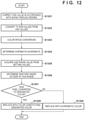
- FIG. 12 is a flowchart showing show-through two-color conversion according to the embodiment shown in FIG. 11 .
- An image forming system is assumed as an MFP (Multi Function Peripheral) including an image processing apparatus 100 , a scanner 110 , a print engine 108 , and a user interface (UI) 111 .
- MFP Multi Function Peripheral
- any apparatus is applicable to the image forming system of this embodiment if it has a print function.
- the image processing apparatus 100 includes an image data acquisition unit 101 , a show-through determination unit 102 , a two-color conversion table generation unit 103 , a two-color conversion table holding unit 104 , a color conversion unit 105 , a gamma correction unit 106 , an image forming unit 107 , and the UI 111 .
- the UI 111 can include an external display, a keyboard, and a mouse.
- the image processing apparatus 100 is connected to at least one of a computer 109 and the scanner 110 .
- the image processing apparatus 100 is connected to the print engine 108 .
- the image processing apparatus 100 is connected to a storage device 112 such as an HDD.
- the image data acquisition unit 101 acquires RGB image data generated from an original read by the scanner 110 .
- the RGB image data is exemplified in this embodiment, but any image data can be used if it is image data having a color space which can be converted into an L*a*b* space to be described later.
- the image data acquisition unit 101 acquires setting values transmitted from the UI 111 .
- the setting values to be acquired are setting values of the user's designated color.
- a designated color is assumed to be selected from six colors, that is, cyan (C), magenta (M), yellow (Y), red (R), green (G), and blue (B). The designated color to be selected is not limited to these six colors.
- the show-through determination unit 102 determines whether each pixel of the RGB image data input from the image data acquisition unit 101 is a show-through pixel and assigns a show-through determination flag to each pixel.
- the show-through determination flag holds a value of “0” or “1”. However, any other value may be used, or information may be added if a pixel is determined to be a show-through pixel. That is, it suffices whether a pixel is identified as a show-through pixel. A determination method will be described later in detail.
- the color conversion unit 105 corrects the pixel value of a pixel determined as a show-through pixel among the pixels of the RGB image data input from the image data acquisition unit 101 .
- the color conversion unit 105 converts, for a pixel determined as the show-through pixel, a corrected pixel value into a predetermined color space, and converts, for a pixel determined not as the show-through pixel, the pixel value of the original RGB image data into the predetermined color space. Accordingly, the color conversion unit 105 determines whether each pixel is a pixel to be converted into the user's designated color or a pixel to be converted into the achromatic color.
- the predetermined space is a color space such as the L*a*b* space or the LCH space having one achromatic color axis in, for example, a three-dimensional color space.
- the pixel is converted into the L*a*b* space or the LCH space.
- the color space is not limited to a specific one.
- the pixel may be converted into a YUV space.
- the L*a*b* space and the LCH space are visual uniform color spaces which are the device-independent three-dimensional color spaces in consideration of the human visual characteristics.
- determination is performed using two components except the achromatic-axis component in the three-dimensional color space.
- the color components a*b* except the brightness component L* serving as the achromatic-axis component in the L*a*b* space are used.
- a two-dimensional color plane (to be referred to as a hue plane hereinafter) defined by the two parameters corresponding to the two components associated with the hue is viewed from the above, the colors (C, M, Y, R, G, and B, and intermediate colors such as orange, pink, and purple) of the respective pixels can be determined.
- each pixel is converted into a CMYK value corresponding to the user's designated color or the achromatic color, thereby generating the CMYK image data.
- the two-color conversion table generation unit 103 generates a two-color conversion table (for example, a lookup table form) used when performing color conversion using the color conversion table in the color conversion unit 105 to be described later.
- the two-color conversion table holding unit 104 holds, in the storage device 112 , the two-color conversion table generated by the two-color conversion table generation unit 103 or the conversion table such as a full color conversion table, and sends the held table to the color conversion unit 105 or the like as needed.
- the gamma correction unit 106 performs correction processing for keeping the tone characteristic in the print engine 108 constant for the CMYK image data sent from the color conversion unit 105 .
- the image forming unit 107 performs control of converting the CMYK image corrected by the gamma correction unit 106 into halftone image data of N (integer) bits suitable for the printer and sending it to the print engine.
- N integer
- any method can be employed in this embodiment.
- the print engine 108 is an engine using CMYK toners in the following description, but may be an engine using CMYK inks.
- the processing sequence of two-color conversion processing associated with show-through determination, color determination, and color conversion according to this embodiment will be described with reference to FIG. 2 .
- the processing to be described below is implemented such that a CPU 114 reads out, for example, programs stored in the storage device 112 connected to the image processing apparatus 100 to a RAM 113 and executes them.
- step S 201 the image data acquisition unit 101 causes the CPU 114 to output a readout instruction to the scanner 110 to generate scanned image data by executing scanning of an original, thereby acquiring generated scanned image data.
- the acquired image data is RGB image data.
- Each pixel has three pixel values, that is, R, G, and B pixel values. This embodiment will be described assuming that each of R, G, and B is 8-bit data which takes an integer value of 0 to 255.
- step S 202 the image data acquisition unit 101 acquires setting values transmitted from the UI 111 .
- the setting values of the UI 111 are values set based on designation from the user via the UI 111 .
- FIGS. 6A to 6C show an example of the UI 111 displayed on an operation unit.
- buttons 609 , 610 , and 611 for performing transition to the UI to set the color selection, magnification, and the number of sheets at the time of printing are selectably displayed. These buttons can be selected when the user directly operates the touch panel liquid crystal display portion of the operation unit.
- the setting values may be selected by operating hardware keys separately arranged.
- FIG. 6B is a screen for setting the number of colors which changes upon pressing the color selection button 609 in FIG. 6A . If full color printing using the CMYK color materials is to be performed, the UI 111 transmits the setting values of a full color button 601 pressed by the user. On the other hand, if a two-color button 602 is pressed, the UI 111 transitions the screen to the setting screen for setting the user's designated color in FIG. 6C . Processing to be performed when the two-color button 602 has been selected in FIG. 6B will be described below.
- a color (a designated color) combined with black in two-color printing can be selected.
- any color can be set from the colors, that is, Y ( 603 ), R ( 604 ), M ( 605 ), B ( 606 ), C ( 607 ), and G ( 608 ).
- the setting values may be designated by the user in advance in accordance with the user inputs via the above setting screens, or may be selected by the user at the time of printing. If the setting values are designated by the user in advance, control may be performed such that the setting values are conformed to the user at the time of printing. Note that any chromatic color except the above colors can be selected. If an OK button is operated while any one of the buttons 603 to 608 is selected, the setting of the designated color is confirmed. If a return button is operated, the previous screen is restored without setting the designated color of the selected button.
- step S 203 the show-through determination unit 102 performs show-through pixel determination for each pixel of the RGB image data acquired in step S 201 .
- the show-through determination unit 102 assigns a flag (show-through determination flag) indicating whether each pixel of the RGB image data is a show-through pixel. For example, if the pixel is the show-through pixel, the show-through determination flag holds 1; otherwise, the flag holds 0. Note that the show-through determination flag is assigned, and the value indicating whether the pixel is the show-through pixel is set at 1 or 0 in this embodiment, but any form may be employed if a pixel is determined as a show-through pixel or not.
- the RGB value of each pixel of image data it is determined using the RGB value of each pixel of image data and a variance value whether the pixel is the show-through pixel.
- the variance value represents the degree of variation of the RGB values of arbitrary pixel (target pixel) and surrounding pixels. Normally, if a given pixel is compared with another pixel and their colors are different from each other, these two pixels have different RGB values and different variance values. To the contrary, if the colors of the two pixels are the same, the RGB values have the same value and the variance values also have the same value.
- step S 204 the color conversion unit 105 acquires one pixel from the image data acquired in step S 201 .
- the color conversion unit 105 acquires the show-through pixel determination flag information linked to the pixel and assigned in step S 203 .
- step S 205 based on the show-through determination flag value assigned in step S 203 , the color conversion unit 105 determines whether the pixel acquired in step S 204 is the show-through pixel. If YES in step S 205 , the flow advances to step S 206 ; otherwise, the flow advances to step S 207 .
- step S 206 the color conversion unit 105 executes two-color conversion processing corresponding for show-through pixels, and the process advances to step S 208 . Details of the two-color conversion processing for show-through pixels will be described later.
- step S 207 the color conversion unit 105 executes the normal two-color conversion processing, and the process advances to step S 208 . Details of the normal two-color conversion processing will be described later.
- step S 208 the color conversion unit 105 determines whether all the pixels of the RGB image data acquired in step S 201 have been processed. To determine whether all the pixels have been processed, flags indicating the completion of the processing may be assigned to the respective pixels, and it is determined that the flags of the pixels indicate completion of the processing. Alternatively, the number of all pixels may be held at the time of image data acquisition, and it may be determined whether processing is repeated for all the pixels. If all the pixels are not completely processed, the flow returns to step S 204 .
- step S 209 the color conversion unit 105 outputs, to the gamma correction unit 106 , the pixel data converted into the CMYK value indicating that all the pixels are set to the user's designated color or the achromatic color, thereby terminating the processing.
- the details of the show-through pixel determination processing in step S 203 of FIG. 2 will now be described with reference to FIG. 3 .
- the show-through determination unit 102 performs the processing of each step in FIG. 3 .
- the processing to be described below is implemented such that the CPU 114 reads out, for example, programs stored in the storage device 112 connected to the image processing apparatus 100 to the RAM 113 and executes them.
- step S 301 the show-through determination unit 102 acquires one pixel (the target pixel) from the RGB image data acquired in step S 201 .
- step S 302 the show-through determination unit 102 acquires, from the RGB image data, 5 ⁇ 5 pixels (25 pixels including the target pixel) centered on the pixel acquired in step S 301 .
- the RGB image data 5 ⁇ 5 pixels (25 pixels including the target pixel) centered on the pixel acquired in step S 301 .
- 24 surrounding pixels 503 centered on a target pixel 502 acquired from RGB image data 501 are acquired.
- the RGB values of the absent pixels are handled as 0.
- the target pixel is the left end pixel in the image data, as indicated by 504 in FIG.
- the number of pixels to be acquired may be changed in accordance with the size of image data.
- step S 303 the show-through determination unit 102 calculates (acquires) the variance values of the target pixel from the target pixel and surrounding pixels acquired in steps S 301 and S 302 .
- the variance values of the target pixel are calculated for R, G, and B, respectively.
- the variance values are calculated by:
- ⁇ r[n] indicates the R variance value of the nth pixel of the image data
- xri indicates the R pixel value (luminance value) of the ith pixel in the 5 ⁇ 5 pixels
- ⁇ r indicates the R pixel average value of the 5 ⁇ 5 pixels
- N indicates the total number of pixels (25).
- ⁇ g[n] indicates the G variance value of the nth pixel of the image data
- ⁇ b[n] indicates the B variance value of the nth pixel of the image data
- xgi indicates the G pixel value of the ith pixel
- xbi indicates the B pixel value of the ith pixel
- ⁇ g indicates the G pixel average value
- ⁇ b indicates the B pixel average value.
- ⁇ indicates the sum operator.
- Tg and Tb represent the matrices which hold the sums of the G and B pixel values for the respective variance values, and the initial values of the matrices are 0.
- Pg and Pb represent the G and B pixel values of the target pixel.
- step S 305 the show-through determination unit 102 determines whether all the pixels of the RGB image data acquired in step S 301 have been processed. To determine whether all the pixels have been processed, flags indicating the completion of the processing may be assigned to the respective pixels, and it is determined that the flags of the pixels indicate completion of the processing. Alternatively, the number of all pixels may be held at the time of image data acquisition, and it may be determined whether processing is repeated for all the pixels. If all the pixels are not completely processed, the flow returns to step S 301 . If it is determined that all the pixels have been processed, the process advances to step S 306 .
- step S 306 the show-through determination unit 102 calculates the average pixel values for the respective R, G, and B variance values from the sum of the pixel values for the respective variance values calculated in step S 304 and the sum of the numbers of pixels.
- step S 307 the show-through determination unit 102 acquires one pixel (the target pixel) from the RGB image data acquired in step S 201 . Subsequently, in step S 308 , the show-through determination unit 102 compares the pixel values of the target pixel acquired in step S 307 with the average pixel values corresponding to the variance values of the target pixel calculated in step S 306 to determine whether each pixel value of the target pixel is smaller than the corresponding average pixel value. The determination is performed for each of R, G, and B.
- the flow advances to step S 309 ; otherwise, the process advances to step S 310 .
- step S 309 the show-through determination unit 102 assigns and links, to the image data of the target pixel, information indicating whether the show-through has occurred. For example, the value of the show-through pixel flag is set to 1. Note that since the brightness often changes in the show-through, all the R, G, and B pixel values are normally smaller than the corresponding average pixel values. For this reason, if it is determined that all the R, G, and B pixel values are smaller than the corresponding average pixel values, no problem is posed.
- step S 311 the show-through determination unit 102 calculates the absolute value of the difference between the pixel value of the target pixel and the corresponding average pixel value, and records and holds the absolute value in the storage device 112 .
- the process advances to step S 312 .
- Dr [ n ] abs( Zr [ n ] ⁇ Ave r [ ⁇ r [ n ]])
- Dg [ n ] abs( Zg [ n ] ⁇ Ave g [ ⁇ g [ n ]])
- Db [ n ] abs( Zb [ n ] ⁇ Ave b [ ⁇ b [ n ]])
- Dr represents the absolute value (abs( )) of the R difference
- Zr represents the R pixel value.
- n represents the nth pixel.
- Dg and Db represent the absolute values of the G and B differences, respectively.
- Zg and Zb represent the G and B pixel values, respectively.
- step S 308 if it is determined in step S 308 that the pixel values of the target pixel are equal to or larger than the corresponding average pixel values, in step S 310 the show-through determination unit 102 sets the value of the show-through pixel flag corresponding to the target pixel to 0, and the process advances to step S 312 .
- step S 312 the show-through determination unit 102 determines whether all the pixels of the RGB image data acquired in step S 301 have been processed. To determine whether all the pixels have been processed, flags indicating the completion of the processing may be assigned to the respective pixels, and it is determined that the flags of the pixels indicate completion of the processing. Alternatively, the number of all pixels may be held at the time of image data acquisition, and it may be determined whether processing is repeated for all the pixels. If all the pixels are not completely processed, the flow returns to step S 307 . If it is determined that all the pixels have been processed, processing ends. Note that the show-through pixel flag generated in this processing is stored and held in the storage device 112 .
- the color conversion unit (the first color conversion unit) 105 performs the processing of each step in FIG. 4 .
- the processing to be described below is implemented such that the CPU 114 reads out, for example, programs stored in the storage device 112 connected to the image processing apparatus 100 to the RAM 113 and executes them.
- step S 401 the color conversion unit 105 corrects the pixel values of the pixel acquired in step S 204 of FIG. 2 using the difference value held in the storage device 112 in step S 311 of FIG. 3 .
- Xmr [ n ] Zr [ n ]+ M
- Xmg [ n ] Zg [ n ]+ M
- Xmb [ n ] Zb [ n ]+ M (6)
- M has the smallest value (Min represents the function for outputting the smallest value) of Dr, Dg, and Db held in step S 311 .
- Xmr represents the R corrected pixel value
- n represents the nth pixel.
- Xmg and Xmb are G and B corrected pixel values, respectively.
- step S 402 the color conversion unit 105 converts the color space of the pixel whose pixel values are corrected in step S 401 .
- the color space is converted into the L*a*b* space once and further converted into the LCH space.
- a method of converting the color space into the L*a*b* space will be described first.
- the pixel conversion into the L*a*b* values is performed by an interpolation operation using a conversion table from the RGB space prestored in the storage device 112 into the L*a*b* space.
- the conversion table from the RGB space to the L*a*b* space defines a cubic body of the three-dimensional color space defined by the RGB signals. As shown in FIG.
- coordinates in a cubic body 801 of the three-dimensional color space can be determined in accordance with the values of 8-bit RGB data (0 to 255).
- Eight vertices of the cubic body indicate R, G, B, Y, M, C, K, and W.
- the conversion table from the RGB space to the L*a*b* space is defined by the RGB values of the input data, has, for example, 9 ⁇ 9 ⁇ 9 matrix points, and stores the L*a*b* values corresponding to these matrix points as the table data.
- the L*a*b* values (44.01, 61.37, 39.68) are stored as the table data corresponding to the RGB values (255, 0, 0).
- the interpolation operation is performed such that when a value which is not defined in an operation table is input, interpolation is performed using a value defined in an operation table close to the input value.
- Tetrahedron interpolation is available as an interpolation operation method.
- an interpolation operation is performed using values defined in four operation tables close to the input value.
- the tetrahedron interpolation operation is performed using an input as a pixel RGB value and an operation table as the RGB ⁇ L*a*b* conversion table, thereby obtaining L*a*b* values of each pixel.
- the tetrahedron interpolation is used for conversion in this embodiment, but the interpolation method does not limit the present invention. Any method such as conversion using an arithmetic formula may be used if it can convert the RGB space into the L*a*b* space.
- C sqrt( a* ⁇ circumflex over ( ) ⁇ 2+ b* ⁇ circumflex over ( ) ⁇ 2) (7) where sqrt represents the square root calculation, and ⁇ circumflex over ( ) ⁇ represents the exponentiation calculation.
- step S 403 the color conversion unit 105 determines, using the value of C (saturation) of the pixel having undergone color space conversion in step S 402 , whether the pixel is a chromatic or achromatic color, thereby generating determination result information.
- the determination to determine whether the pixel is a chromatic or achromatic color is performed by comparing a threshold held in the storage device 112 in advance with the acquired C (saturation) of the pixel. For example, if the threshold is given as 20, a pixel whose C (saturation) is less than 20 is determined as an achromatic color; otherwise, the pixel is determined as a chromatic color.
- the threshold is given as the value held in advance, but the threshold value may be dynamically set in accordance with an input image arrangement or may be input by a user using a UI.
- the determination result is held in the storage device 112 in the form of a flag.
- a chromatic/achromatic determination flag is generated in accordance with the determination result. If the pixel is determined as the achromatic color, the chromatic/achromatic determination flag is set to 0. If the pixel is determined as the chromatic color, the chromatic/achromatic determination flag is set to 1. However, any form may be employed if chromatic or achromatic color information can be held.
- the color conversion unit 105 acquires a hue range value using the designated color information among the UI setting values acquired in step S 202 .
- the hue range value is a value representing a hue range of each color of C, M, Y, R, G, and B.
- a color having a hue range between 701 and 702 in FIG. 7 is expressed as R
- a color having a hue range between 702 and 703 is expressed as Y.
- the hue range values correspond to C, M, Y, R, G, and B, respectively and are stored in the storage device 112 in advance as the lower and upper limit values in the table form, as shown in FIG. 9 .
- the hue range value is R in FIG. 7
- the lower limit value of the hue range is a hue value (10 as the lower limit value of R in FIG. 9 ) corresponding to 701
- the upper limit value of the hue range is a hue value (80 as the upper limit value of R in FIG. 9 ) corresponding to 702 .
- the hue range lower limit value of 10° and the hue range upper limit value of 80° are obtained from the storage device 112 . Note that since the hue is expressed as an angle, a hue range including the a*-axis of 0° uses two ranges, as shown in M in FIG. 7 .
- the hue ranges are defined between [0° ] and [10° ] as the lower limit value 701 of the hue and between the hue upper limit value 706 [310° ] and [360° ].
- the hue range value according to this embodiment is a value held in advance, the hue range value may be dynamically set in accordance with the characteristic of the image processing apparatus or may be selected by a user from a UI.
- step S 405 the color conversion unit 105 determines using the value of H (hue) and the hue range values acquired in step S 404 among the pixel values of the pixel whose color space is converted in step S 402 whether the pixel falls within a predetermined hue range and generates determination result information. For example, if the user's designated color is R, since the hue range lower limit value is 10° and the hue range upper limit value is 80°, the color conversion unit 105 determines the pixel falls within the hue range if the H (hue) value is 10° or more and less than 80°; otherwise, the color conversion unit 105 determines that the pixel falls outside the hue range. In this embodiment, the determination result is held in the storage device 112 in the form of a flag.
- a hue range inside/outside determination flag is generated in accordance with the determination result. If the pixel falls within the hue range, the hue range inside/outside determination flag is set to 1; otherwise, the flag is set to 0. However, any form may be employed if the hue range inside/outside information can be held.
- step S 406 the color conversion unit 105 determines whether the pixel is converted into the user's designated color or the achromatic color.
- the determination to determine whether the pixel is converted into the user's designated color or the achromatic color is performed by a combination of pieces of information (flags) generated in steps S 403 and S 405 .
- FIG. 10 shows a case whether the pixel is converted into the user's designated color or the achromatic color by a combination of values of the flags.
- the chromatic/achromatic determination flag generated in step S 403 and held in the storage device 112 corresponds to 1001 .
- the hue range inside/outside determination flag generated in step S 405 and held in the storage device 112 corresponds to 1002 .
- a table (determination result output table) which receives the values of the respective flags and outputs a conversion color 1003 in FIG. 10 is held in the storage device 112 in advance.
- the conversion color 1003 for example, the designated color is associated with 1, and the achromatic color may be associated with 0, and the corresponding value may be set as the output value.
- the color conversion unit 105 acquires the determination result output table from the storage device 112 . Using this table, the values of the chromatic/achromatic determination flag and the hue range inside/outside determination flag are input, and the value (for example 1 or 0) corresponding to the designated color or the achromatic color is output.
- step S 407 the color conversion unit 105 converts the RGB values (the RGB values before conversion into the LCH space) into the user's designated color and ends the processing.
- the color conversion unit 105 converts the RGB values of the pixel into the CMYK values using the full-color color conversion table held in the storage device 112 by the two-color conversion table holding unit 104 .
- the color conversion unit 105 converts the full-color CMYK values into the CMYK values constituting the user's designated color using an arithmetic formula.
- the conversion into the CMYK values using the full-color conversion table is performed by tetrahedron interpolation using the full-color conversion table from the RGB space to the CMYK space as in the conversion from the RGB space to the L*a*b* space in step S 402 .
- the full-color conversion table defines the cubic body of the three-dimensional color space defined by the RGB signals. As shown in FIG. 8 , coordinates in the cubic body of the three-dimensional color space can be determined in accordance with the values of the RBG 8-bit data. The eight vertices of the cubic body indicate R, G, B, Y, M, C, K, and W.
- the color conversion table has, for example, 16 ⁇ 16 ⁇ 16 matrix points defined by the RGB values of the input data.
- the CMYK values corresponding to these matrix points are stored as the table data. For example, as indicated by 803 in FIG. 8 , the CMYK values (0, 255, 255, 0) are stored as the table data corresponding to the RGB values (255, 0, 0).
- the tetrahedron interpolation operation method using the full-color conversion table is similar to the conversion from the RGB space to the L*a*b* space in step S 402 , and a description will be omitted.
- the color conversion unit 105 converts the full-color CMYK values calculated by the tetrahedron interpolation operation using the full-color conversion table into the CMYK values constituting the user's designated color using the arithmetic formula.
- the operation is performed using the following matrices:
- the RGB values are converted into the CMYK values constituting the user's designated color using the color conversion table and the matrix operation.
- any method may be used if the RGB values are converted into the CMYK values of the user's designated color.
- step S 408 the color conversion unit 105 converts the RGB values (RGB values before conversion into the LCH space) of the pixel and ends the processing.
- the color conversion unit 105 converts the RGB values of the pixel into the CMYK values using the full-color conversion table held in the storage device 112 by the two-color conversion table holding unit 104 as in step S 407 .
- the full-color CMYK values are converted into the CMYK values constituting the achromatic color using the arithmetic formula.
- step S 407 Conversion to the CMYK values using the full-color conversion table is similar to step S 407 , and a description thereof will be omitted. Subsequently, the full-color CMYK values calculated by the tetrahedron interpolation operation using the full-color conversion table are converted into the CMYK values constituting the user's designated color using the arithmetic formula. The operation is performed using the following matrix:
- the RGB values are converted into the CMYK values constituting the achromatic color using the color conversion table and the arithmetic formula.
- any method can be used if the RGB values are converted into the CMYK values of the achromatic color.
- step S 207 of FIG. 2 will be described below.
- the normal two-color conversion processing processing by the second color conversion unit
- steps S 402 to S 408 are performed without performing step S 401 . That is, since the show-through is absent, the pixel value corresponding to the show-through degree need not be performed, and only color conversion processing is performed. The processing has been described above and will be omitted.
- the full-color conversion table and the matrices have been used in color conversion to the user's designated color or the achromatic color.
- tables for directly converting the RGB values into the user's designated color and the achromatic color may be created in advance, and color conversion may be performed for the pixels to be converted into the user's designated color and the achromatic color by switching the tables.
- the image processing apparatus determines whether the show-through has occurred in each pixel of the read original image data. If it is determined that the show-through has occurred, the show-through of the pixel is corrected, and two-color conversion processing for converting the pixel into the user's designated color or the achromatic color is executed for the corrected image data. On the other hand, if it is determined that the show-through has not occurred, the two-color conversion processing is executed for the image data read from the pixel of the original.
- the determination result for converting the pixel into the user's designated color or the achromatic color does not change regardless of the presence/absence of the show-through. For this reason, even in a show-through portion, the pixel to be converted into the user's designated color can be converted into the user's designated color as in the case in which no show-through is absent, thereby converting the pixel to be converted into the achromatic color into the achromatic color.
- the show-through influence can be suitably reduced in the conversion processing to the achromatic color or the user's designated color.
- the two-color conversion is performed for the show-through portion after the show-through pixel is corrected based on the pixel values (RGB values: luminance values).
- RGB values luminance values
- Many show-through cases are caused by changes in brightness, and the problem can be solved by the method of the first embodiment.
- changes in color type hue or saturation
- a method of more effectively solving the problem will be described even if changes in color type also occur due to the show-through.
- a show-through determination unit 102 performs all the processes of the steps in FIG. 11 .
- the processing to be described below is implemented such that a CPU 114 reads out, for example, programs stored in a storage device 112 connected to an image processing apparatus 100 to a RAM 113 and executes them.
- the processed in steps S 1101 to S 1110 and S 1115 are the same as the processes in steps S 301 to S 310 and S 312 in FIG. 3 , and a description thereof will be omitted.
- step S 1108 it is desirable to determine that the show-through has occurred in a pixel if all the HSV values, that is, the values of the hue, saturation, and brightness are smaller than the average values, respectively.
- step S 1111 the show-through determination unit 102 converts the RGB values of the pixel obtained in step S 1107 into the HSV values.
- H, S, and V of the HSV represent the hue, the saturation, and the brightness, respectively.
- H is an integer value falling within the range of 0 to 360
- each of the S and V is an integer value falling within the range of 0 to 255. Conversion from RGB to HSV is performed by:
- step S 1112 the show-through determination unit 102 adds H, S, and V having the same variance value and calculated in step S 1111 based on the variance values calculated in step S 1103 .
- Ts and Tv are matrices which hold the sums of the pixel values for the respective variance values of S and V, respectively, and the initial values of Ts and Tv are 0.
- the ordinal number of a pixel is counted for each variance value, each H value, each S value, and each V value.
- step S 1113 the show-through determination unit 102 calculates the average pixel values for the respective variance values for H, S, and V from the sums of the values of H, S, and V for the respective variance values calculated in step S 1112 and the sums of the numbers of pixels.
- Ave h [ ⁇ r [ n ]] Th [ ⁇ r [ n ]]/ Ch [ ⁇ r [ n ]]
- Ave s [ ⁇ g [ n ]] Ts [ ⁇ g [ n ]]/ Cs [ ⁇ g [ n ]]
- Ave v [ ⁇ b [ n ]] Tv [ ⁇ b [ n ]]/ Cv [ ⁇ b [ n ]] (19)
- Aveh represents the average pixel value of H for each variance value
- Ayes represent the average pixel value of S for each variance value
- Avev represents the pixel value of V for each variance value.
- step S 1114 the show-through determination unit 102 calculates the absolute values of the differences between the HSV values of the target pixel and the corresponding average HSV values and holds them.
- a color conversion unit 105 performs all the processes of steps in FIG. 12 as in the first embodiment.
- the processing to be described below is implemented such that the CPU 114 reads out, for example, programs stored in the storage device 112 connected to the image processing apparatus 100 to the RAM 113 and executes them.
- step S 1201 the color conversion unit 105 corrects the HSV values for each pixel calculated in step S 1111 of FIG. 11 by using the difference values held in step S 1114 of FIG. 11 .
- Sm and Vm are corrected pixel values of S and V, respectively.
- step S 1202 the color conversion unit 105 converts the HSV values corrected in step S 1201 into RGB values.
- MIN hsv MAX hsv ⁇ (( Sm [ n ]/255) ⁇ MAX hsv )
- Bc [ n ] MIN hsv (0 ⁇ Hm [ n ] ⁇ 60)
- Rc [ n ] ((120 ⁇ Hm [ n ])/60) ⁇ (MAX hsv ⁇ MIN hsv )+MIN hsv
- steps S 1203 to S 1209 are the same as those from steps S 402 to S 408 in FIG. 4 , and a description thereof will be omitted.
- the image processing apparatus determines whether the show-through has occurred in each pixel of the read original image data. If it is determined that the show-through has occurred, the show-through of the pixel is corrected, and two-color conversion processing for converting the pixel into the user's designated color or the achromatic color is executed for the corrected image data. On the other hand, if it is determined that the show-through has not occurred, the two-color conversion processing is executed for the image data read from the pixel of the original. In addition, in this embodiment, the hue, saturation, and brightness values are obtained for all the read pixels in the show-through determination. At the same time, variance values representing the degrees of variations of the pixel values of the target pixel and the surrounding pixels are obtained.
- the average values of the hue, saturation, and brightness of the pixels having the same variance value are obtained, and the hue, saturation, and brightness values of each pixel are compared with the average values of the hue, saturation, and brightness of the variance values obtained for this pixel. After that, if the hue, saturation, brightness values of each pixel are smaller than the average values of the hue, saturation, and brightness of the variance values acquired for this pixel, it is determined that the show-through has occurred; otherwise, it is determined that the show-through has not occurred.
- the pixel to be converted into the user's designated color can be converted into the user's designated color, and the pixel to be converted into the achromatic color can be converted into the achromatic color as in the case in which the show-through is absent in the show-through portion.
- the show-through influence can be suitably reduced in the conversion processing to the chromatic color or the user's designated color when performing the two-color copying of the color original in which the show-through occurs.
- Embodiment(s) of the present invention can also be realized by a computer of a system or apparatus that reads out and executes computer executable instructions (e.g., one or more programs) recorded on a storage medium (which may also be referred to more fully as a ‘non-transitory computer-readable storage medium’) to perform the functions of one or more of the above-described embodiment(s) and/or that includes one or more circuits (e.g., application specific integrated circuit (ASIC)) for performing the functions of one or more of the above-described embodiment(s), and by a method performed by the computer of the system or apparatus by, for example, reading out and executing the computer executable instructions from the storage medium to perform the functions of one or more of the above-described embodiment(s) and/or controlling the one or more circuits to perform the functions of one or more of the above-described embodiment(s).
- computer executable instructions e.g., one or more programs
- a storage medium which may also be referred to more fully as a
- the computer may comprise one or more processors (e.g., central processing unit (CPU), micro processing unit (MPU)) and may include a network of separate computers or separate processors to read out and execute the computer executable instructions.
- the computer executable instructions may be provided to the computer, for example, from a network or the storage medium.
- the storage medium may include, for example, one or more of a hard disk, a random-access memory (RAM), a read only memory (ROM), a storage of distributed computing systems, an optical disk (such as a compact disc (CD), digital versatile disc (DVD), or Blu-ray Disc (BD)TM), a flash memory device, a memory card, and the like.
Abstract
Description
wherein σr[n] indicates the R variance value of the nth pixel of the image data, xri indicates the R pixel value (luminance value) of the ith pixel in the 5×5 pixels, μr indicates the R pixel average value of the 5×5 pixels, and N indicates the total number of pixels (25). Similarly, σg[n] indicates the G variance value of the nth pixel of the image data, and σb[n] indicates the B variance value of the nth pixel of the image data. xgi indicates the G pixel value of the ith pixel, and xbi indicates the B pixel value of the ith pixel. μg indicates the G pixel average value, and μb indicates the B pixel average value. Σ indicates the sum operator.
Tr[σr[n]]=Tr[σr[n]]+Pr
Tg[σg[n]]=Tg[σg[n]]+Pg
Tb[σb[n]]=Tb[σb[n]]+Pb (2)
where Tr represents the matrix which holds the sum of the R pixel values for each variance value, and the initial value of the matrix is 0, and Pr represents the R pixel value of the target pixel. Similarly, Tg and Tb represent the matrices which hold the sums of the G and B pixel values for the respective variance values, and the initial values of the matrices are 0. Pg and Pb represent the G and B pixel values of the target pixel. In addition, for each variance value and for each of R, G, and B, the number of pixels is counted for the corresponding pixels as follows:
Cr[σr[n]]=Cr[σr[n]]+1
Cg[σg[n]]=Cg[σg[n]]+1
Cb[σb[n]]=Cb[σb[n]]+1 (3)
where Cr represents the matrix which hold the sum of the number of R pixels for each variance value, and the initial value of the matrix is 0. Similarly, Cg and Cb represent matrices which hold the sums of the numbers of G and B pixels for the respective variance values, and the initial values of the matrices are 0.
Aver[σr[n]]=Tr[σr[n]]/Cr[σr[n]]
Aveg[σg[n]]=Tg[σg[n]]/Cg[σg[n]]
Aveb[σb[n]]=Tb[σb[n]]/Cb[σb[n]] (4)
wherein Aver is the R average pixel value for each variance value, Aveg is the G average pixel value for each variance value, and Aveb is the B average pixel value for each variance value.
Dr[n]=abs(Zr[n]−Aver[σr[n]])
Dg[n]=abs(Zg[n]−Aveg[σg[n]])
Db[n]=abs(Zb[n]−Aveb[σb[n]]) (5)
wherein Dr represents the absolute value (abs( )) of the R difference, and Zr represents the R pixel value. In addition, n represents the nth pixel. Similarly, Dg and Db represent the absolute values of the G and B differences, respectively. Zg and Zb represent the G and B pixel values, respectively.
M=Min(Dr[n],Dg[n],Db[n])
Xmr[n]=Zr[n]+M
Xmg[n]=Zg[n]+M
Xmb[n]=Zb[n]+M (6)
wherein M has the smallest value (Min represents the function for outputting the smallest value) of Dr, Dg, and Db held in step S311. Xmr represents the R corrected pixel value, and n represents the nth pixel. Similarly, Xmg and Xmb are G and B corrected pixel values, respectively.
C=sqrt(a*{circumflex over ( )}2+b*{circumflex over ( )}2) (7)
where sqrt represents the square root calculation, and {circumflex over ( )} represents the exponentiation calculation. The value of H (hue) can be calculated by:
H=arctan(b*/a*)×(180/PI)
H=H (for H≥0)
H=H+360 (for H<0) (8)
where arctan represents the arc tangent calculation, and PI represents a circle ratio π. H can be expressed in an angular range of 0° to 360°.
wherein MAX rgb represents the largest value of Zr, Zg, and Zb, and MIN rgb represents the smallest value of Zr, Zg, and Zb. As in the first embodiment, Zr, Zg, and Zb represent the pixel values of R, G, and B, respectively. n represents the nth pixel.
Th[σr[n]]=Th[σr[n]]+H[n]
Ts[σg[n]]=Ts[σg[n]]+S[n]
Tv[σb[n]]=Tv[σb[n]]+V[n] (17)
wherein Th represents the matrix which holds the sum of the pixel values of H for each variance value, and the initial value of Th is 0. Similarly, Ts and Tv are matrices which hold the sums of the pixel values for the respective variance values of S and V, respectively, and the initial values of Ts and Tv are 0. The ordinal number of a pixel is counted for each variance value, each H value, each S value, and each V value. The counting operations are given by:
Ch[σr[n]]=Ch[σr[n]]+1
Cs[σg[n]]=Cs[σg[n]]+1
Cv[σb[n]]=Cv[σb[n]]+1 (18)
wherein Ch represents the matrix which holds the sum of the number of pixels of H for each variance value, and the initial value of Ch is 0. Similarly, Cs and Cv are matrices which hold the sums of the numbers of pixels for the respective variable values of S and V, respectively, and the initial values of Cs and Cv are 0.
Aveh[σr[n]]=Th[σr[n]]/Ch[σr[n]]
Aves[σg[n]]=Ts[σg[n]]/Cs[σg[n]]
Avev[σb[n]]=Tv[σb[n]]/Cv[σb[n]] (19)
wherein Aveh represents the average pixel value of H for each variance value, Ayes represent the average pixel value of S for each variance value, and Avev represents the pixel value of V for each variance value.
Dh[n]=abs(H[n]−Aveh[σr[n]])
Ds[n]=abs(S[n]−Aves[σg[n]])
Dv[n]=abs(V[n]−Avev[σb[n]]) (20)
wherein Dh represents the absolute value of the difference of H, and n represents the nth pixel. Similarly, Ds and Dv represent the absolute values of the differences of S and V, respectively.
Hm[n]=H[n]+Dh[n]
Sm[n]=S[n]+Ds[n]
Vm[n]=V[n]+Dv[n] (21)
wherein Hm represents the corrected value of H, and n represents the nth pixel. Similarly, Sm and Vm are corrected pixel values of S and V, respectively.
MAX hsv=Vm[n]
MIN hsv=MAX hsv−((Sm[n]/255)×MAX hsv)
Rc[n]=MAX hsv
Gc[n]=(Hm[n]/60)×(MAX hsv−MIN hsv)+MIN hsv
Bc[n]=MIN hsv
(0<Hm[n]<60)
Rc[n]=((120−Hm[n])/60)×(MAX hsv−MIN hsv)+MIN hsv
Gc[n]=MAX hsv
Bc[n]=MIN hsv
(60<Hm[n]<120)
Rc[n]=MIN hsv
Gc[n]=MAX hsv
Bc[n]=((Hm[n]−120)/60)×(MAX hsv−MIN hsv)+MIN hsv
(120<Hm[n]<180)
Rc[n]=MIN hsv
Gc[n]=((240−Hm[n])/60)×(MAX hsv−MIN hsv)+MIN hsv
Bc[n]=MAX hsv
(180<Hm[n]<240)
Rc[n]=((Hm[n]−240)/60)×(MAX hsv−MIN hsv)+MIN hsv
Gc[n]=MIN hsv
Bc[n]=MAX hsv
(240<Hm[n]<300)
Rc[n]=MAX hsv
Gc[n]=MIN hsv
Bc[n]=((360−Hm[n])/60)×(MAX hsv−MIN hsv)+MIN hsv
(300<Hm[n]<360) (22)
wherein Rc represents the R pixel value after conversion from HSV, Gc represents G pixel value after conversion from HSV, and Bc represents the B pixel value after conversion from HSV. n represents the nth pixel.
Claims (10)
Applications Claiming Priority (3)
| Application Number | Priority Date | Filing Date | Title |
|---|---|---|---|
| JP2018184984A JP7204402B2 (en) | 2018-09-28 | 2018-09-28 | IMAGE PROCESSING DEVICE, CONTROL METHOD THEREOF, AND PROGRAM |
| JP2018-184984 | 2018-09-28 | ||
| JPJP2018-184984 | 2018-09-28 |
Publications (2)
| Publication Number | Publication Date |
|---|---|
| US20200105027A1 US20200105027A1 (en) | 2020-04-02 |
| US11232606B2 true US11232606B2 (en) | 2022-01-25 |
Family
ID=69946284
Family Applications (1)
| Application Number | Title | Priority Date | Filing Date |
|---|---|---|---|
| US16/569,943 Active 2039-10-27 US11232606B2 (en) | 2018-09-28 | 2019-09-13 | Image processing with reduced influence of image show-through by conversion processing into one of an achromatic color and a designated chromatic color |
Country Status (3)
| Country | Link |
|---|---|
| US (1) | US11232606B2 (en) |
| JP (1) | JP7204402B2 (en) |
| CN (1) | CN110971782B (en) |
Families Citing this family (2)
| Publication number | Priority date | Publication date | Assignee | Title |
|---|---|---|---|---|
| CN112261241B (en) * | 2020-10-26 | 2022-07-26 | 联想(北京)有限公司 | Image processing method and device and electronic equipment |
| JP2023013472A (en) * | 2021-07-16 | 2023-01-26 | セイコーエプソン株式会社 | printer |
Citations (6)
| Publication number | Priority date | Publication date | Assignee | Title |
|---|---|---|---|---|
| CN1313004A (en) | 1998-06-23 | 2001-09-12 | 夏普公司 | Image processor, image processing method, and medium on which image processing program is recorded |
| US20120307270A1 (en) * | 2011-05-30 | 2012-12-06 | Ricoh Company, Limited | Image processing apparatus and color conversion table generating method |
| US20150256715A1 (en) | 2014-03-10 | 2015-09-10 | Canon Kabushiki Kaisha | Image processing apparatus and image processing method |
| US9230202B2 (en) | 2013-09-17 | 2016-01-05 | Canon Kabushiki Kaisha | Image processing apparatus, method, and program product perfoming color convertion depending on input image data modification in accordance with display device |
| US20180249044A1 (en) * | 2017-02-28 | 2018-08-30 | Canon Kabushiki Kaisha | Image processing apparatus, image processing method, and recording medium |
| US20190394357A1 (en) * | 2018-06-20 | 2019-12-26 | Canon Kabushiki Kaisha | Image processing apparatus, method of controlling the same, and storage medium |
Family Cites Families (4)
| Publication number | Priority date | Publication date | Assignee | Title |
|---|---|---|---|---|
| JPH096070A (en) * | 1995-06-23 | 1997-01-10 | Ricoh Co Ltd | Image forming device |
| JP2006270222A (en) * | 2005-03-22 | 2006-10-05 | Fuji Xerox Co Ltd | Copy controller and program |
| JP5645689B2 (en) * | 2011-01-31 | 2014-12-24 | 京セラドキュメントソリューションズ株式会社 | Image processing apparatus and image forming apparatus having the same |
| JP2015126277A (en) * | 2013-12-25 | 2015-07-06 | キヤノン株式会社 | Image processing apparatus and image processing method |
-
2018
- 2018-09-28 JP JP2018184984A patent/JP7204402B2/en active Active
-
2019
- 2019-09-13 US US16/569,943 patent/US11232606B2/en active Active
- 2019-09-26 CN CN201910918695.4A patent/CN110971782B/en active Active
Patent Citations (11)
| Publication number | Priority date | Publication date | Assignee | Title |
|---|---|---|---|---|
| CN1313004A (en) | 1998-06-23 | 2001-09-12 | 夏普公司 | Image processor, image processing method, and medium on which image processing program is recorded |
| CN1512760A (en) | 1998-06-23 | 2004-07-14 | ���չ�˾ | Image processing device and its method for removing and reading strik-through produced by double side or overlaped master cope |
| US20060088208A1 (en) | 1998-06-23 | 2006-04-27 | Sharp Kabushiki Kaisha | Image processing apparatus, image processing method, and medium on which image processing program is recorded |
| US20060188148A1 (en) | 1998-06-23 | 2006-08-24 | Sharp Kabushiki Kaisha | Image processing apparatus, image processing method, and medium on which image processing program is recorded |
| US20120307270A1 (en) * | 2011-05-30 | 2012-12-06 | Ricoh Company, Limited | Image processing apparatus and color conversion table generating method |
| JP2012249133A (en) | 2011-05-30 | 2012-12-13 | Ricoh Co Ltd | Image processing device, and method of generating color conversion table |
| US9230202B2 (en) | 2013-09-17 | 2016-01-05 | Canon Kabushiki Kaisha | Image processing apparatus, method, and program product perfoming color convertion depending on input image data modification in accordance with display device |
| US20150256715A1 (en) | 2014-03-10 | 2015-09-10 | Canon Kabushiki Kaisha | Image processing apparatus and image processing method |
| CN104917930A (en) | 2014-03-10 | 2015-09-16 | 佳能株式会社 | Image processing apparatus and image processing method |
| US20180249044A1 (en) * | 2017-02-28 | 2018-08-30 | Canon Kabushiki Kaisha | Image processing apparatus, image processing method, and recording medium |
| US20190394357A1 (en) * | 2018-06-20 | 2019-12-26 | Canon Kabushiki Kaisha | Image processing apparatus, method of controlling the same, and storage medium |
Non-Patent Citations (1)
| Title |
|---|
| Office Action dated Nov. 3, 2021 in counterpart Chinese Application No. 201910918695.4, together with English translation thereof. |
Also Published As
| Publication number | Publication date |
|---|---|
| JP7204402B2 (en) | 2023-01-16 |
| CN110971782A (en) | 2020-04-07 |
| CN110971782B (en) | 2022-11-18 |
| JP2020057843A (en) | 2020-04-09 |
| US20200105027A1 (en) | 2020-04-02 |
Similar Documents
| Publication | Publication Date | Title |
|---|---|---|
| JP2887158B2 (en) | Image processing device | |
| CN109327646B (en) | Image processing apparatus, image processing method, and computer-readable storage medium | |
| JPH0364272A (en) | Image processor | |
| JPH09135316A (en) | Device and method for processing image | |
| US20050078867A1 (en) | System and method for generating black and white reproductions of color documents | |
| US11636294B2 (en) | Image forming apparatus, control method thereof, and storage medium | |
| US11232606B2 (en) | Image processing with reduced influence of image show-through by conversion processing into one of an achromatic color and a designated chromatic color | |
| US8094165B2 (en) | Color reproduction evaluation apparatus and program storage medium | |
| US20080055677A1 (en) | Image Color Determining Device and Image Color Determining Method | |
| US11503188B2 (en) | Image processing apparatus, control method for controlling image processing apparatus, and storage medium | |
| JP2011259095A (en) | Image processing apparatus, image forming apparatus, image processing method, computer program, and recording media | |
| US20070285687A1 (en) | Image forming apparatus and image forming method | |
| US20070285685A1 (en) | Image forming apparatus and image forming method | |
| JP4413827B2 (en) | Image processing device | |
| JP7266462B2 (en) | IMAGE PROCESSING APPARATUS, IMAGE FORMING APPARATUS, IMAGE PROCESSING METHOD AND PROGRAM | |
| US20060291015A1 (en) | Applying multiple imaging processes to digital images | |
| JP2005215353A (en) | Image data generating device for generating image data reproducible with a plurality of gradation characteristics and image reproducing device corresponding thereto | |
| JP3039674B2 (en) | Color image processing equipment | |
| JP2009225451A (en) | Image forming apparatus and method | |
| JPH08289143A (en) | Color image picture quality adjusting device | |
| US11531855B2 (en) | Image processing apparatus, image processing method, and storage medium | |
| US11070687B2 (en) | Image forming apparatus, control method thereof and storage medium | |
| JP2002290750A (en) | Color image processing method, color image processing apparatus, program, and recording medium | |
| US10924635B2 (en) | Image processing apparatus and image processing method | |
| US20210360125A1 (en) | Image processing apparatus, control method thereof, and storage medium |
Legal Events
| Date | Code | Title | Description |
|---|---|---|---|
| FEPP | Fee payment procedure |
Free format text: ENTITY STATUS SET TO UNDISCOUNTED (ORIGINAL EVENT CODE: BIG.); ENTITY STATUS OF PATENT OWNER: LARGE ENTITY |
|
| AS | Assignment |
Owner name: CANON KABUSHIKI KAISHA, JAPAN Free format text: ASSIGNMENT OF ASSIGNORS INTEREST;ASSIGNOR:KOBAYASHI, MASATO;REEL/FRAME:051224/0358 Effective date: 20190912 |
|
| STPP | Information on status: patent application and granting procedure in general |
Free format text: NON FINAL ACTION MAILED |
|
| STPP | Information on status: patent application and granting procedure in general |
Free format text: RESPONSE TO NON-FINAL OFFICE ACTION ENTERED AND FORWARDED TO EXAMINER |
|
| STPP | Information on status: patent application and granting procedure in general |
Free format text: ADVISORY ACTION MAILED |
|
| STPP | Information on status: patent application and granting procedure in general |
Free format text: DOCKETED NEW CASE - READY FOR EXAMINATION |
|
| STPP | Information on status: patent application and granting procedure in general |
Free format text: NOTICE OF ALLOWANCE MAILED -- APPLICATION RECEIVED IN OFFICE OF PUBLICATIONS |
|
| STPP | Information on status: patent application and granting procedure in general |
Free format text: PUBLICATIONS -- ISSUE FEE PAYMENT RECEIVED |
|
| STPP | Information on status: patent application and granting procedure in general |
Free format text: PUBLICATIONS -- ISSUE FEE PAYMENT VERIFIED |
|
| STCF | Information on status: patent grant |
Free format text: PATENTED CASE |
|
| STPP | Information on status: patent application and granting procedure in general |
Free format text: AWAITING TC RESP., ISSUE FEE NOT PAID |
|
| STPP | Information on status: patent application and granting procedure in general |
Free format text: PUBLICATIONS -- ISSUE FEE PAYMENT VERIFIED |
|
| STCF | Information on status: patent grant |
Free format text: PATENTED CASE |