JP7204384B2 - Information processing device and its control method - Google Patents
Information processing device and its control method Download PDFInfo
- Publication number
- JP7204384B2 JP7204384B2 JP2018168165A JP2018168165A JP7204384B2 JP 7204384 B2 JP7204384 B2 JP 7204384B2 JP 2018168165 A JP2018168165 A JP 2018168165A JP 2018168165 A JP2018168165 A JP 2018168165A JP 7204384 B2 JP7204384 B2 JP 7204384B2
- Authority
- JP
- Japan
- Prior art keywords
- workflow
- processing
- post
- generating
- information processing
- Prior art date
- Legal status (The legal status is an assumption and is not a legal conclusion. Google has not performed a legal analysis and makes no representation as to the accuracy of the status listed.)
- Active
Links
Images


Classifications
-
- G—PHYSICS
- G06—COMPUTING OR CALCULATING; COUNTING
- G06Q—INFORMATION AND COMMUNICATION TECHNOLOGY [ICT] SPECIALLY ADAPTED FOR ADMINISTRATIVE, COMMERCIAL, FINANCIAL, MANAGERIAL OR SUPERVISORY PURPOSES; SYSTEMS OR METHODS SPECIALLY ADAPTED FOR ADMINISTRATIVE, COMMERCIAL, FINANCIAL, MANAGERIAL OR SUPERVISORY PURPOSES, NOT OTHERWISE PROVIDED FOR
- G06Q10/00—Administration; Management
- G06Q10/06—Resources, workflows, human or project management; Enterprise or organisation planning; Enterprise or organisation modelling
- G06Q10/063—Operations research, analysis or management
- G06Q10/0631—Resource planning, allocation, distributing or scheduling for enterprises or organisations
- G06Q10/06316—Sequencing of tasks or work
-
- G—PHYSICS
- G06—COMPUTING OR CALCULATING; COUNTING
- G06F—ELECTRIC DIGITAL DATA PROCESSING
- G06F3/00—Input arrangements for transferring data to be processed into a form capable of being handled by the computer; Output arrangements for transferring data from processing unit to output unit, e.g. interface arrangements
- G06F3/12—Digital output to print unit, e.g. line printer, chain printer
- G06F3/1201—Dedicated interfaces to print systems
- G06F3/1202—Dedicated interfaces to print systems specifically adapted to achieve a particular effect
- G06F3/1203—Improving or facilitating administration, e.g. print management
- G06F3/1204—Improving or facilitating administration, e.g. print management resulting in reduced user or operator actions, e.g. presetting, automatic actions, using hardware token storing data
-
- G—PHYSICS
- G06—COMPUTING OR CALCULATING; COUNTING
- G06F—ELECTRIC DIGITAL DATA PROCESSING
- G06F3/00—Input arrangements for transferring data to be processed into a form capable of being handled by the computer; Output arrangements for transferring data from processing unit to output unit, e.g. interface arrangements
- G06F3/12—Digital output to print unit, e.g. line printer, chain printer
- G06F3/1201—Dedicated interfaces to print systems
- G06F3/1202—Dedicated interfaces to print systems specifically adapted to achieve a particular effect
- G06F3/1203—Improving or facilitating administration, e.g. print management
- G06F3/1205—Improving or facilitating administration, e.g. print management resulting in increased flexibility in print job configuration, e.g. job settings, print requirements, job tickets
-
- G—PHYSICS
- G06—COMPUTING OR CALCULATING; COUNTING
- G06F—ELECTRIC DIGITAL DATA PROCESSING
- G06F3/00—Input arrangements for transferring data to be processed into a form capable of being handled by the computer; Output arrangements for transferring data from processing unit to output unit, e.g. interface arrangements
- G06F3/12—Digital output to print unit, e.g. line printer, chain printer
- G06F3/1201—Dedicated interfaces to print systems
- G06F3/1223—Dedicated interfaces to print systems specifically adapted to use a particular technique
- G06F3/1237—Print job management
- G06F3/1253—Configuration of print job parameters, e.g. using UI at the client
-
- G—PHYSICS
- G06—COMPUTING OR CALCULATING; COUNTING
- G06F—ELECTRIC DIGITAL DATA PROCESSING
- G06F3/00—Input arrangements for transferring data to be processed into a form capable of being handled by the computer; Output arrangements for transferring data from processing unit to output unit, e.g. interface arrangements
- G06F3/12—Digital output to print unit, e.g. line printer, chain printer
- G06F3/1201—Dedicated interfaces to print systems
- G06F3/1223—Dedicated interfaces to print systems specifically adapted to use a particular technique
- G06F3/1237—Print job management
- G06F3/126—Job scheduling, e.g. queuing, determine appropriate device
- G06F3/1263—Job scheduling, e.g. queuing, determine appropriate device based on job priority, e.g. re-arranging the order of jobs, e.g. the printing sequence
-
- G—PHYSICS
- G06—COMPUTING OR CALCULATING; COUNTING
- G06F—ELECTRIC DIGITAL DATA PROCESSING
- G06F3/00—Input arrangements for transferring data to be processed into a form capable of being handled by the computer; Output arrangements for transferring data from processing unit to output unit, e.g. interface arrangements
- G06F3/12—Digital output to print unit, e.g. line printer, chain printer
- G06F3/1201—Dedicated interfaces to print systems
- G06F3/1223—Dedicated interfaces to print systems specifically adapted to use a particular technique
- G06F3/1275—Print workflow management, e.g. defining or changing a workflow, cross publishing
-
- G—PHYSICS
- G06—COMPUTING OR CALCULATING; COUNTING
- G06F—ELECTRIC DIGITAL DATA PROCESSING
- G06F3/00—Input arrangements for transferring data to be processed into a form capable of being handled by the computer; Output arrangements for transferring data from processing unit to output unit, e.g. interface arrangements
- G06F3/12—Digital output to print unit, e.g. line printer, chain printer
- G06F3/1201—Dedicated interfaces to print systems
- G06F3/1278—Dedicated interfaces to print systems specifically adapted to adopt a particular infrastructure
- G06F3/1282—High volume printer device
-
- G—PHYSICS
- G06—COMPUTING OR CALCULATING; COUNTING
- G06F—ELECTRIC DIGITAL DATA PROCESSING
- G06F3/00—Input arrangements for transferring data to be processed into a form capable of being handled by the computer; Output arrangements for transferring data from processing unit to output unit, e.g. interface arrangements
- G06F3/12—Digital output to print unit, e.g. line printer, chain printer
- G06F3/1201—Dedicated interfaces to print systems
- G06F3/1278—Dedicated interfaces to print systems specifically adapted to adopt a particular infrastructure
- G06F3/1285—Remote printer device, e.g. being remote from client or server
-
- G—PHYSICS
- G06—COMPUTING OR CALCULATING; COUNTING
- G06F—ELECTRIC DIGITAL DATA PROCESSING
- G06F3/00—Input arrangements for transferring data to be processed into a form capable of being handled by the computer; Output arrangements for transferring data from processing unit to output unit, e.g. interface arrangements
- G06F3/12—Digital output to print unit, e.g. line printer, chain printer
- G06F3/1297—Printer code translation, conversion, emulation, compression; Configuration of printer parameters
Landscapes
- Engineering & Computer Science (AREA)
- Theoretical Computer Science (AREA)
- Physics & Mathematics (AREA)
- General Physics & Mathematics (AREA)
- Human Computer Interaction (AREA)
- General Engineering & Computer Science (AREA)
- Business, Economics & Management (AREA)
- Human Resources & Organizations (AREA)
- Entrepreneurship & Innovation (AREA)
- Strategic Management (AREA)
- Economics (AREA)
- Educational Administration (AREA)
- Game Theory and Decision Science (AREA)
- Development Economics (AREA)
- Marketing (AREA)
- Operations Research (AREA)
- Quality & Reliability (AREA)
- Tourism & Hospitality (AREA)
- General Business, Economics & Management (AREA)
- Management, Administration, Business Operations System, And Electronic Commerce (AREA)
- General Factory Administration (AREA)
Description
本発明は、商業印刷における成果物を生成するためのワークフローの設定に関する。 The present invention relates to workflow settings for generating deliverables in commercial printing.
特許文献1で開示されている印刷ワークフローソフトウェアでは、工程を示すアイコンをグラフィカルユーザーインターフェース(GUI)で自由に連結していくことでワークフローの設定を行うことが可能である。 With the print workflow software disclosed in Japanese Patent Application Laid-Open No. 2002-200010, it is possible to set a workflow by freely connecting icons indicating processes using a graphical user interface (GUI).
商業印刷業界においては、成果物の製造に関わる作業工程として、プリプレス(コンテンツデータの面付けやトンボ、バーコード付与)、プレス(画像形成装置における印刷処理)、ポストプレス(後処理装置における後加工処理)が存在する。また、成果物の形態は多種多様であり、成果物の種類(商材)には端物(名刺やチラシ)、ブック(中綴じ製本、無線綴じ製本)などが存在し、成果物を構成するパーツ(部品)には、本文、表紙、扉、ジャケット、帯などが存在する。さらに、印刷設定だけでなく、プリプレスやポストプレスのパラメータ設定(例えば、バーコード、折り、断裁、などの印刷前の前処理設定、印刷後の後処理設定)を行って、成果物の製造を行っている。 In the commercial printing industry, the work processes involved in the production of deliverables include prepress (imposition of content data, addition of registration marks and barcodes), press (printing processing in image forming equipment), postpress (post-processing in post-processing equipment). processing) exists. In addition, there are a wide variety of forms of deliverables, and the types of deliverables (merchandise) include scraps (business cards and flyers), books (saddle-stitched books, perfect-stitched books), etc., which constitute the deliverables. The parts include a text, a cover, a door, a jacket, a belt, and the like. In addition to print settings, pre-press and post-press parameter settings (e.g., pre-processing settings before printing such as bar codes, folding, cutting, and post-processing settings after printing) can be used to manufacture deliverables. Is going.
商業印刷における商材を作成するためにワークフローを生成する場合、各パーツごとに、必要な工程の追加をするだけでなく、各工程でのパラメータを設定する必要がある。特に、商業印刷においては、工程数や各工程での設定すべき項目数が多いことが多く、ワークフローの生成が煩雑になり、ユーザーが容易に設定するのが困難である。特許文献1には、グラフィカルユーザーインターフェースで工程の追加を行うことは開示があるが、各工程のパラメータ設定については何ら考慮されていない。さらに、特許文献1は、ユーザーが、条件に満たさない位置に工程アイコンをドラッグアンドドロップした場合はハイライト表示することが記載されている。しかしながら、ユーザーが、条件を満たす位置になるまで、繰り返し、工程アイコンをドラッグアンドドロップしなければならずなかった。また、ユーザーは、工程の順を意識して、ワークフローを作成しなければならなかった。特に、商業印刷における商材を作成するためにワークフローは、工程数や各工程での設定すべき項目数が多いことが多く、ワークフローの生成が煩雑になりやすいという課題がある。
When creating a workflow to create a product for commercial printing, it is necessary not only to add necessary processes for each part, but also to set parameters for each process. In particular, in commercial printing, the number of processes and the number of items to be set in each process are often large, which complicates workflow generation and makes it difficult for users to easily set. Although
本発明では上記課題を鑑み、ユーザーが工程の順を意識することなく、ワークフローを生成可能なユーザーインタフェース提供することを目的とする。 SUMMARY OF THE INVENTION In view of the above problems, an object of the present invention is to provide a user interface that allows a user to create a workflow without being conscious of the order of steps.
上記目的を達成するために、本発明の情報処理装置は、複数の部品からなる成果物を生成するための複数の作業工程を組み合わせたワークフローを生成する情報処理装置であって、成果物を生成するための複数の作業工程の順番を特定する情報を保持する保持手段と、前記部品ごとに、前記部品を生成するための作業工程の追加指示と、前記作業工程のパラメータ設定を行うための設定画面を表示する表示制御手段と、前記部品ごとに、前記設定画面を介して、前記部品を生成するための作業工程の追加指示と、前記作業工程のパラメータ設定を行う設定手段と、前記複数の作業工程の順番を特定する情報に基づいて、前記追加指示された作業工程を自動的に追加し、作業工程の順番と前記設定された作業工程のパラメータに関する情報を含む前記複数の部品からなる成果物を生成するためのワークフローを生成する生成手段を有することを特徴とする。 To achieve the above object, an information processing apparatus according to the present invention is an information processing apparatus that generates a workflow that combines a plurality of work processes for generating a product made up of a plurality of parts . a holding means for holding information specifying the order of a plurality of work processes for generating the parts, an additional instruction for the work processes for generating the parts for each of the parts, and a setting for setting parameters for the work processes display control means for displaying a screen; setting means for performing additional instruction of a work process for generating the part via the setting screen for each of the parts; setting means for setting parameters of the work process; Automatically adding the additionally instructed work process based on the information specifying the order of the work process, and the result composed of the plurality of parts including information on the order of the work process and the parameters of the set work process. It is characterized by having generating means for generating a workflow for generating an object .
本発明によれば、ユーザーが工程の順を意識することなく、ワークフローを生成可能なユーザーインタフェースを提供することができる。 According to the present invention, it is possible to provide a user interface that allows a user to generate a workflow without being conscious of the order of steps.
[第1の実施形態]
以下、本発明を実施するための第1の実施形態について図面を用いて説明する。
[First embodiment]
A first embodiment for carrying out the present invention will be described below with reference to the drawings.
<情報処理システムの構成例>
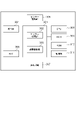
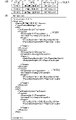
図1は、本発明にかかわる情報処理システムの全体構成を示す図である。なお、以下の説明における情報処理システム全体の環境は本発明の説明を理解しやすくするためのものであり、本発明はこれらの環境に限定されるものではない。
<Configuration example of information processing system>
FIG. 1 is a diagram showing the overall configuration of an information processing system according to the present invention. It should be noted that the environment of the entire information processing system in the following description is for facilitating understanding of the description of the present invention, and the present invention is not limited to these environments.
図1において、ネットワーク100に、情報処理装置101、画像形成装置102、後処理管理装置103、後処理装置104、105が接続されている。
In FIG. 1 , an
情報処理装置101、後処理管理装置103はネットワーク100を介して他の装置と相互に通信可能なネットワークコンピュータ(以下、単にコンピュータと略す)であり、典型的にはパーソナルコンピュータ(PC)である。各コンピュータではワークフロー管理アプリケーションやジョブ管理アプリケーション、後加工アプリケーションなどのアプリケーションプログラムを実行可能である。また、画像形成装置102や後処理管理装置103とネットワーク100を介して接続し、画像形成装置102や後処理装置104、105を制御するためのコマンド命令を送受信することが可能である。情報処理装置101では、ワークフロー管理プログラムにおいて成果物を製造するための工程の組み合わせや順番、設定を作成管理する。そして、ジョブ管理アプリケーションにおいて成果物を製造するためのジョブを各装置へ送信制御する。その結果、成果物製造に関わる全体のフローを管理することができる。後処理管理装置103では、後加工アプリケーションが後処理装置104、105の管理を行う。すなわち、後処理管理装置103は、複数の後処理装置をまとめて管理し、それぞれの後処理装置における後加工処理に対する制御命令の送信などを行う。
The
画像形成装置102は、情報処理装置101などから送信されてくる印字データを含む印刷データを解析し、1ページずつドットイメージに変換して印刷する。また、画像形成装置102は後処理管理装置103とネットワーク100を介して通信して制御情報などを送受信する。画像形成装置102から出力された印刷物は、印刷オペレータによるハンドキャリーで後処理装置104、105へ渡されたり、図示しないベルトコンベアーを介して後処理装置104、105へ渡されたりする。より具体的には、画像形成装置102の印刷物は、画像形成装置102の排紙部に接続されているベルトコンベアーに直接乗せられて後処理装置104、105へダイレクトに搬送される形態がある。他には、印刷物を仮置きするスペースに一時的に溜め置かれた後にオペレータがベルトコンベアーに乗せたりハンドキャリーしたりして後処理装置104、105に搬送される形態がある。
The image forming apparatus 102 analyzes print data including print data transmitted from the
後処理装置104、105は、画像形成装置102から出力された印刷物に対して、断裁、クリース、製本、折りなどの後処理(後加工)を行う。後処理装置104、105は、画像形成装置からの印刷物をそれぞれ個別に処理する形態や、複数の画像形成装置のジョブを結合して1つの成果物として処理する形態などがある。画像形成装置からの印刷物をそれぞれ個別に処理する形態の例として、例えば、断裁装置がある。複数の画像形成装置のジョブを結合して1つの成果物として処理する形態の例として、例えば、無線綴じ製本装置(一方の画像形成装置からの印刷物が表紙で、他方の画像形成装置の印刷物が本文であり、それらから1冊の無線綴じ製本を制作する)がある。 Post-processing apparatuses 104 and 105 perform post-processing (post-processing) such as cutting, crease, bookbinding, and folding on printed matter output from the image forming apparatus 102 . The post-processing apparatuses 104 and 105 may individually process printed materials from the image forming apparatuses, or combine jobs from a plurality of image forming apparatuses and process them as one product. A cutting device is an example of a form in which printed matter from an image forming device is individually processed. As an example of a configuration in which jobs of a plurality of image forming apparatuses are combined and processed as one product, for example, a perfect binding apparatus (the printed material from one image forming apparatus is the cover sheet, and the printed material from the other image forming apparatus is the main text, and a perfect bound book is produced from them).
図1では、情報処理装置101、画像形成装置102はそれぞれ1つであるが、それぞれ複数であってもよい。後処理装置104、105は、3つ以上あってもよい。また、ネットワーク100はインターネットであってもよく、例えば、情報処理装置101からインターネット越しに画像形成装置102や後処理管理装置103へとアクセスする構成であってもよい。なお、画像形成装置102は、印刷装置であり、後処理装置104、105は、印刷物処理装置である。
Although one
<情報処理システムのハードウェア構成例>
図2は、本実施形態の情報処理装置101、後処理管理装置103のハードウェア構成図である。情報処理装置101、後処理管理装置103は一般的なコンピュータ(PC)のハードウェアで構成することができる。図2において、CPU201は、ROM203内のプログラム用ROMに記憶されたプログラムや、外部メモリとしてのハードディスク210からRAM202にロードされたOS(オペレーションシステム)やアプリケーション等のプログラムを実行する。
<Hardware Configuration Example of Information Processing System>
FIG. 2 is a hardware configuration diagram of the
すなわち、CPU201が、読み取り可能な記憶媒体に格納された該プログラムを実行することにより、後述する各フローチャートの処理を実行する各処理部として機能する。RAM202は、CPU201のメインメモリであり、ワークエリア等として機能する。キーボードコントローラ204は、キーボード208や図示しないポインティングデバイス(マウス、タッチパッド、タッチパネル、トラックボールなど)からの操作入力を制御する。ディスプレイコントローラ205は、ディスプレイ209の表示制御を行う。ディスクコントローラ206は、各種データを記憶するハードディスク(HD)やフレキシブルディスク(FD)等の外部メモリ210へのデータアクセスを制御する。ネットワークコントローラ(NC)207はネットワークに接続されて、ネットワークに接続された他の機器との通信制御処理を実行する。
That is, the
図3は、本実施形態の後処理装置104、105のハードウェア構成図である。後処理装置104、105は、操作部304、NIC305、CPU308、RAM309、ROM310、記憶部311、センサー読取部306、後処理部307を備え、制御部301を介して接続されている。制御部301は、センサー読取部306が読み取ったセンサー情報を処理するセンサー処理部302と、後処理装置104全体を制御する装置制御部303とを有する。操作部304は、例えばソフトウェアキーボード、タッチパネル、その他入出力装置によって構成され、各種の設定値の入力、および表示をすることが可能である。CPU308は、ROM310内に記憶されたプログラムや、記憶部311からRAM309にロードされたアプリケーション等のプログラムを実行する。すなわち、CPU308が、読み取り可能な記憶媒体に格納された該プログラムを実行することにより、後述する各フローチャートの処理を実行する各処理部として機能する。RAM309は、CPU308のメインメモリであり、ワークエリア等として機能する。センサー読取部306は、後処理対象の印刷物のジョブ情報などを、カメラなどの装置を介して読み取ることができる(例えば無線綴じ製本ジョブの表紙と本文の組み合わせを照合する、成果物にページ抜けなどが発生せずに正しく製造されているかを判定する)。制御部301は、記憶部311に記憶された後処理情報を操作部304に提供し、操作部304上に後処理の設定情報を出力する処理を実行する。また、制御部301は同様に記憶部311に記憶された後処理情報を後処理部307に提供し、後処理部307は、種々の形式で後処理を実行する。また、後処理装置104、105は、NIC305を介して、ネットワークと接続し、データの送受信を可能とする。NIC305を介して得られたデータは、操作部304上に表示することも可能である。
FIG. 3 is a hardware configuration diagram of the post-processing devices 104 and 105 of this embodiment. The post-processing devices 104 and 105 include an
図4は、本実施形態の画像形成装置102のハードウェア構成図である。画像形成装置102は、操作部404、認証部405、NIC406、CPU409、RAM410、ROM411、記憶部412、画像読取部407、印刷部408を備え、制御部401を介して接続されている。制御部401は、画像形成装置102全体を制御する装置制御部402と、画像データを処理する画像処理部403とを有する。操作部404は、例えばソフトウェアキーボード、タッチパネル、その他入出力装置によって構成され、各種の設定値の入力、および表示をすることが可能である。CPU409は、ROM411内に記憶されたプログラムや、記憶部412からRAM410にロードされたアプリケーション等のプログラムを実行する。すなわち、CPU409が、読み取り可能な記憶媒体に格納された該プログラムを実行することにより、後述する各フローチャートの処理を実行する各処理部として機能する。RAM410は、CPU409のメインメモリであり、ワークエリア等として機能する。画像読取部407は、例えばスキャナーによって構成され、紙文書等を読取ることにより画像データ形式の文書画像を取得することができる。制御部401は、記憶部412に記憶された文書画像を操作部404に提供し、操作部404上に文書画像を出力する処理を実行する。また、制御部401は同様に記憶部412に記憶された文章画像を、印刷部408に提供し、印刷部408は、種々の形式で文書画像を出力する処理を実行する。例えば、印刷部408は、文書画像に係る画像データを、記憶媒体に出力する処理を実行することができる。あるいはまた、印刷部408は印刷機能を備え、紙媒体等の出力媒体に文書画像を出力する処理を実行してもよい。また、画像形成装置102は、NIC406を介して、ネットワークと接続し、データの送受信を可能とする。NIC406を介して得られたデータは、操作部404上に表示することも可能である。
FIG. 4 is a hardware configuration diagram of the image forming apparatus 102 of this embodiment. The image forming apparatus 102 includes an
<情報処理システムのソフトウェア構成例>
図5は、本実施例の各機能を示す機能ブロック図である。
<Software configuration example of information processing system>
FIG. 5 is a functional block diagram showing each function of this embodiment.
まず、情報処理装置101の各処理部の機能について記述する。情報処理装置101は、ワークフロー管理アプリケーション501とジョブ管理アプリケーション502から構成される。ワークフロー管理アプリケーション501は、成果物を製造するための工程(面付けや印刷、折り、クリース、断裁、製本など)を生成、管理する。ジョブ管理アプリケーション502は、ワークフロー(WF)に基づいて成果物を製造するための各種装置へ流れるジョブを管理する。
First, the function of each processing unit of the
ワークフロー管理アプリケーション501において、操作部5011は、後述する図8-1~図8-4および図9に示すようなワークフローを管理するためのユーザーインターフェースを表示する操作部である。制御部5012は、ワークフロー管理アプリケーション501の各処理部の動作を制御する制御部である。制御部5012は、例えば操作部5011に入力された設定に応じて、WF管理部5013やWF定義部5014の制御を行う。WF管理部5013は、操作部5011においてユーザによって作成された後述する図10に示すようなワークフロー一覧を管理するためのワークフロー管理部である。WFルール定義部5014は、ワークフローを作成するための図6に示すような後加工処理のルールを定義するワークフロールール定義部である。WF処理部5015は、情報処理装置101で受信した成果物を製造するためのジョブに対して、ワークフローに従って処理を実行するためのワークフロー処理部である。WF処理部5015は、ジョブ管理アプリケーション502と通信することで、ワークフローの進行状況の管理や、次に実行すべき工程に関する指示などを行う。WF処理部5015はジョブ管理アプリケーション502において管理されているジョブ(ジョブID)とWF記憶部5016に管理されているワークフロー(WF ID)を紐付けて管理している。尚、WF IDとは、ワークフローIDである。また、ジョブに対するワークフローの処理開始時刻などをさらに管理するようにしても良い。WF記憶部5016は、WF管理部5013から受信した情報に基づいて、図10に示すようなワークフロー一覧を記憶するためのワークフロー記憶部である。ルール記憶部5017は、WFルール定義部5014から受信した情報に基づいて、図6に示すようなワークフロールールを記憶するためのルール記憶部である。通信処理部5018は、ネットワーク100を介して後処理管理装置103と命令やコマンドなどの情報を送受信する通信処理部である。
In the
ジョブ管理アプリケーション502において、制御部5021は、ジョブ管理アプリケーション502の各処理部の動作を制御する制御部である。例えば、制御部5021は、ワークフロー管理アプリケーション501のWF処理部5015へ成果物を製造するためのジョブに関する情報を渡す。そして、WF処理部5015からの指示に基づいて画像形成装置102や後処理管理装置103へジョブを送信するための指示を各処理部へ行ったりする。操作部5022は、情報処理装置101において、図示しないユーサーインターフェース上に、ジョブの一覧を表示し、ジョブを操作(編集や削除など)するためのコントロールなどを有する操作部である。ジョブ受信部5023は、成果物を製造するためのジョブの入稿を受け付けるためのジョブ受信部である。ジョブの入稿は、他の装置(入稿システム)から受信するようにしても良いし、情報処理装置101上のフォルダを監視してフォルダに入稿(コピー)されたジョブデータを検知することで受信するようにしてもよい。入稿されたジョブの情報は制御部5021を介してワークフロー管理アプリケーション501のWF処理部5015へ送られる。ジョブ管理部5024は、ジョブ受信部5023が受信したジョブをジョブ記憶部5026へ格納することで管理するジョブ管理部である。ジョブ送信部5025は、画像形成装置102や後処理装置104、105において処理するためのジョブデータ(図示せず)を送信するためのジョブ送信部である。ジョブの送信処理は、ワークフロー管理アプリケーション501のWF処理部5015からの指示に応じて、制御部5021を介してジョブ送信部5025へ指示が送られることで実行される。これにより、入稿されたジョブはワークフローに基づいて情報処理装置101および画像形成装置102、後処理装置104、105において自動的に処理が行われる。ジョブ記憶部5026は、ジョブ受信部5023が受信したジョブに関する情報(ジョブIDやジョブデータなどを含む)およびジョブデータ(図示せず)を記憶するためのジョブ記憶部である。通信処理部5027は、ネットワーク100を介して画像形成装置102や後処理管理装置103とジョブデータや命令、コマンドなどの情報を送受信する通信処理部である。
In the
次に、後処理管理装置103における後加工アプリケーション503について記述する。後加工アプリケーション503は、情報処理装置101から受信したジョブや命令などに応じて複数の後処理装置を統合的に管理・制御する。また、複数の後処理装置で成果物を処理するためのワークフローの管理を行う。
Next, the post-processing application 503 in the
後加工アプリケーション503において、操作部5031は、図示しないユーサーインターフェース上に、情報処理装置101からのジョブの一覧を表示する。さらに、操作部5031は、ジョブを操作(後処理装置104、105への実行指示や、ジョブの編集、削除など)するためのコントロールなどを有する。制御部5032は、後加工アプリケーション503の各処理部の動作を制御する制御部である。例えば、制御部5032は、操作部5031に入力された実行指示に応じて、デバイス制御部5035を介して後処理装置104、105における後加工処理の指示を行う。通信処理部5033は、ネットワーク100を介して情報処理装置101や画像形成装置102とのジョブデータや命令、コマンドなどの情報を送受信する通信処理部である。ジョブ管理部5034は、情報処理装置101から受信したジョブをジョブ記憶部5036へ格納することで管理するジョブ管理部である。デバイス制御部5035は、後処理装置104、105で実行する後加工処理の制御を行う(パラメータ情報を渡したり、処理の開始を指示したりする)ためのデバイス制御部である。ジョブ記憶部5036は、情報処理装置101から受信したジョブ情報およびジョブデータ(図示せず)を記憶するためのジョブ記憶部である。
In the post-processing application 503, the
<情報処理システムが生成するWFルールの例>
図6は、本実施例の情報処理システムにおいて、情報処理装置101のWFルール定義部5014によって作成され、ルール記憶部5017に記憶される後加工処理におけるWFルールの一例を示す図である。WFルールは、WF管理部5013がワークフローを生成する際のルールとして使用される。
<Example of WF rule generated by information processing system>
FIG. 6 is a diagram showing an example of a WF rule in post-processing that is created by the WF
WFルールは、成果物ごとのルールのリストを定義したルール一覧(図6(a))と、ルール一覧からリンクされた各成果物のルール内容を定義したルールファイル(図6(b)、図6(c)、図6(d))から構成される。 The WF rules consist of a rule list (Fig. 6(a)) defining a list of rules for each deliverable, and a rule file (Fig. 6(b)) defining the rule contents of each deliverable linked from the rule list 6(c) and FIG. 6(d)).
図6(a)において、ルール一覧は、成果物の種類に応じて一意に付与される「成果物ID」と、成果物の種類の名称を示す「成果物名」と各成果物のWFルールを記述したルールファイルの名称を示す「ルールファイル名」から構成される。「ルールファイル名」からリンクされるルールファイル(図6(b)、図6(c)、図6(d))には、成果物に応じた後加工処理のルールの内容が定義される。例えば、図6(b)は端物(名刺やチラシ)、図6(c)は中綴じ製本、図6(d)は無線綴じ製本の成果物を製造するための後加工処理におけるルールを定義している。尚、ここでは、製本しない成果物を、端物と呼ぶ。図6(b)において6001は成果物の構成要素であるパーツ名(本文や表紙、ジャケット、帯など)を示している。6002は工程の順番を示す番号を示している。WF管理部5013においてワークフローを生成する際には、6002の順番を保って工程が並べられてワークフローが生成される。6003は、工程の種類を示す工程IDである。工程IDには、Cutting(断裁工程)やStiching(中綴じ製本工程)、Folding(折り工程)、Binding(無線綴じ製本工程)、Crease(クリース(折り目付け)工程)などの種類がある。
In FIG. 6A, the list of rules includes a "delivery ID" that is uniquely assigned according to the type of deliverable, a "delivery name" that indicates the name of the type of deliverable, and a WF rule for each deliverable. "rule file name" indicating the name of the rule file describing In the rule files (FIGS. 6B, 6C, and 6D) linked from the "rule file name", the contents of post-processing rules corresponding to the deliverable are defined. For example, FIG. 6(b) defines rules for post-processing for manufacturing edged products (business cards and leaflets), FIG. 6(c) for saddle-stitched binding, and FIG. 6(d) for perfect binding. are doing. Here, a product that is not bound is called an off-cut product. In FIG. 6(b), 6001 indicates the part name (text, cover, jacket, band, etc.) that is a component of the deliverable. 6002 indicates a number indicating the order of steps. When generating a workflow in the
なお、図6では後加工処理におけるWFルールを定義する場合について記述しているが、他の処理(面付処理、印刷処理)も合わせて定義するようにしてもよい。また、XML形式のデータの例を示したが、他の形式のデータであったり、工程の順番が特定されるテーブルであってもよい。また、端物、中綴じ製本、無線綴じ製本の例を説明したが、これらは一例であって、他の成果物であってもよい。 Note that FIG. 6 describes the case of defining WF rules in post-processing, but other processes (imposition processing, printing processing) may also be defined. Also, although an example of data in XML format has been shown, data in other formats or a table specifying the order of steps may be used. Also, the examples of off-cuts, saddle stitching, and perfect binding have been described, but these are only examples, and other products may be used.
<情報処理システムにおける処理フローチャート>
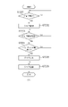
図7-1、図7-2、図7-3は本実施例の情報処理システムの情報処理装置101において、ワークフローの作成およびワークフローの実行を行う処理の流れについて説明している。各フローに係るプログラムは情報処理装置101のROM203に格納されており、RAM202に読み出され、CPU201により実行される。
<Processing flowchart in information processing system>
7-1, 7-2, and 7-3 illustrate the flow of processing for creating and executing a workflow in the
図7-1(a)はワークフロー管理アプリケーション501においてワークフローを作成する処理の流れを示すフローチャートである。
FIG. 7A is a flow chart showing the flow of processing for creating a workflow in the
図7-1(a)においてS7001では、ワークフロー管理アプリケーション501の操作部5011がユーザからのワークフロー作成指示が行われたかを判断する。具体的には、図8-1(a)に示すユーザーインターフェースにおいて、新規作成のボタンが押下されたかを判断する。作成指示が行われた場合はS7002へ処理を移行する。
In FIG. 7A, in S7001, the
S7002では、操作部5011が図8-1(b)に示すようなワークフローの新規作成画面を表示する。図8-1(b)においてワークフローの条件が指定され、OKボタンが押下されるとS7003へ処理を移行する。
In S7002, the
S7003では、操作部5011が図8-2(c)に示すような工程設定画面を表示する。
In S7003, the
7004では、操作部5011が図8-2(c)の工程タブ8001において、面付タブを選択したかを判断する。面付タブが選択された場合、S7005へ処理を移行する。選択されたタブが面付タブではない場合はS7006へ処理を移行する。なお、図8-2(c)を最初に表示したとき(新規作成画面でOKボタンを押下したとき)には面付タブがデフォルトで選択される。
In 7004, the
S7005では、操作部5011が面付工程を設定するための設定画面を表示する。面付工程設定画面では、コンテンツの画像をどのようにレイアウトするかの設定や、トンボやバーコードなどを版面に挿入するための設定などを行うことができる。
In S7005, the
S7006では、操作部5011が図8-2(c)の工程タブ8001において、印刷タブを選択したかを判断する。印刷タブが選択された場合、S7007へ処理を移行する。選択されたタブが印刷タブではない場合(すなわち後加工タブ)はS7008へ処理を移行する。
In S7006, the
S7007では、操作部5011が印刷工程を設定するための設定画面を表示する。印刷工程設定画面では、画像形成装置102において処理する印刷に関わる設定(印刷用紙や印刷方法(片面/両面)などの設定)を行うことができる。
In S7007, the
S7008では、操作部5011が図8-2(c)に示す後加工工程を設定するための設定画面を表示する。後加工工程に関する設定の詳細は図7-2(b)のフローチャートに示す。
In S7008, the
S7009では、操作部5011がワークフローの設定が完了したかを判断する。すなわち、図8-2(c)に示すようなユーザーインターフェースにおいて、「完了」ボタンが押下されたかを判断する。ワークフローの設定が完了した場合はS7010へ処理を移行し、設定が完了していない場合(他のタブが選択された場合)はS7004へ処理を移行する。
In S7009, the
S7010では、制御部5012がWF管理部5013を介してWF記憶部5016へ図10に示すようなワークフロー一覧を作成して保存する。
In S7010, the control unit 5012 creates and saves a workflow list as shown in FIG. 10 in the
図7-2(b)は、図7-1(a)のS7008における後加工工程の設定を行う処理の流れを示すフローチャートである。 FIG. 7-2(b) is a flow chart showing the flow of processing for setting post-processing steps in S7008 of FIG. 7-1(a).
図7-2(b)において、S7101では、操作部5011がユーザからのワークフローにおける後加工工程の追加指示が行われたかを判断する。具体的には、図8-2(c)に示すユーザーインターフェースにおいて、工程追加のボタン8004が押下されたかを判断する。工程の追加指示が行われた場合はS7102へ処理を移行する。工程の追加指示ではない場合はS7109へ処理を移行する。
In FIG. 7B, in S7101, the
S7102では、制御部5012がWFルール定義部5014を介してルール記憶部5017に記憶されている図6に示すWFルールを取得する。取得するWFルールは、図8-2(b)に示すユーザーインターフェースにおいて選択された成果物の種類に対応したWFルールである。(例えば無線綴じ製本の場合、PerfectBinding01.xmlの情報を取得する)
In S7102, the control unit 5012 acquires the WF rule shown in FIG. 6 stored in the
S7103では、制御部5012が、S7101で追加のために選択された工程がS7102で取得したWFルールの工程(ProcessID)に存在するかを判断する。存在する場合はS7105へ処理を移行し、存在しない場合はS7104へ処理を移行する。 In S7103, the control unit 5012 determines whether the process selected for addition in S7101 exists in the process (ProcessID) of the WF rule acquired in S7102. If it exists, the process proceeds to S7105, and if it does not exist, the process proceeds to S7104.
S7104では、操作部5011が図9に示すようなエラーメッセージを含むユーザーインターフェースを表示する。
In S7104, the
S7105では、制御部5012がWFルールから工程の順番情報(ProcessNo)を取得する。(例えば無線綴じ製本の本文における折り工程の場合、PerfectBinding01.xmlからFoldingの工程に対応する“1”を取得する)
S7106では、制御部5012が順番情報(ProcessNo)に基づいて、工程をワークフローへ挿入する。例えば無線綴じ製本において図8-2(c)で製本工程(ProcessNo:“2”)が挿入され、その後に折り工程(ProcessNo:“1”)が指定される。その場合、図8-2(d)の工程アイコン8007のように製本工程の前に断裁工程を挿入する。
In S7105, the control unit 5012 acquires process order information (ProcessNo) from the WF rule. (For example, in the case of the folding process in the text of perfect bound book, "1" corresponding to the folding process is acquired from PerfectBinding01.xml)
In S7106, the control unit 5012 inserts the process into the workflow based on the order information (ProcessNo). For example, in perfect binding, the bookbinding process (ProcessNo: "2") is inserted in FIG. 8-2(c), and then the folding process (ProcessNo: "1") is specified. In that case, the cutting process is inserted before the bookbinding process as shown by the process icon 8007 in FIG. 8D.
S7107では、操作部5011が図8-2(d)に示すようなユーザーインターフェースに、工程に対する設定を行うための設定画面を表示する。このとき、後述するS7109からの編集の場合は、設定済みの属性値が反映される。
In S7107, the
S7108では、操作部5011がS7107における工程の設定が完了したかを判断する。すなわち、図8-2(d)に示すようなユーザーインターフェースにおいて、「保存」ボタンが押下されたかを判断する。工程の設定が完了した場合は処理を終了し、完了していない場合はS7101へ処理を移行する。
In S7108, the
S7109では、操作部5011がユーザーからのワークフローにおける追加済みの後加工工程に対する編集指示が行われたかを判断する。具体的には、図8-2(d)に示すユーザーインターフェースにおいて、「編集」のボタンが押下されたかを判断する。工程の編集指示が行われた場合はS7107へ処理を移行する。工程の編集指示ではない場合はS7110へ処理を移行する。
In S7109, the
S7110では、操作部5011がユーザーからのワークフローにおける追加済みの後加工工程に対する削除指示が行われたかを判断する。具体的には、図8-2(d)に示すユーザーインターフェースにおいて、「削除」のボタンが押下されたかを判断する。工程の削除指示が行われた場合はS7111へ処理を移行する。工程の削除指示が行われていない場合はS7101へ処理を移行する。
In S7110, the
S7111では、制御部5012がWFルール定義部5014を介してルール記憶部5017に記憶されている図6に示すWFルールを取得する。
In S7111, the control unit 5012 acquires the WF rule shown in FIG. 6 stored in the
S7112では、制御部5012が、削除対象の工程をワークフローから削除する。このとき、削除対象外の工程については、後述する図10に示すワークフローにおける工程順(ProcessNo)の値をWFルールに従って更新する。また、これに応じて、図8-1~図8-4における工程アイコン8002を更新する。
In S7112, the control unit 5012 deletes the process to be deleted from the workflow. At this time, the value of the order of steps (ProcessNo) in the workflow shown in FIG. 10 to be described later is updated according to the WF rule for the steps not to be deleted. Also, the
図7-3(c)はジョブ管理アプリケーション502およびワークフロー管理アプリケーション501において、入稿されたジョブを図7-1(a)で作成したワークフローに基づいて処理する流れを示すフローチャートである。図7-3(c)において、S7201では、ジョブ受付部5023が成果物を製造するためのジョブを受け付けたかを判断する。ジョブを受け付けた場合はS7202へ処理を移行する。尚、ジョブには、少なくとも、ワークフローID(WF ID)が含まれる。他には、成果物を特定する情報、成果物あるいは成果物を構成するパーツの部数、印刷生成装置や後処理装置など印刷及び後処理を行うデバイスに関する情報、納期情報が含まれる。ジョブの受付は他の装置(入稿システム)や情報処理装置101上のフォルダへのコピーなどによって受信する。
FIG. 7-3(c) is a flow chart showing the flow of processing the submitted job in the
S7202では、制御部5021がジョブ管理部5024を介してジョブ記憶部5026へジョブを保存するとともに、WF処理部5015へジョブの情報を送信する。
In S<b>7202 , the
S7203では、WF処理部5015がジョブの処理を開始するかを判断する。ジョブの処理を開始する場合はS7204へ処理を移行する。ジョブの処理の開始は、操作部5022へのユーザからの指示によって制御部5021からWF処理部へ指示するようにしても良いし、WF処理部5015によるスケジュール(タイマー)によって自動的に開始するようにしてもよい。ジョブの処理が開始されると、WF処理部5015がジョブに対するワークフローの処理を開始する。具体的には、図10のワークフロー一覧の定義に従って制御部5021へ各工程の処理実行を指示する。
In S7203, the
S7204では、プリプレス工程が含まれるかどうかを判定する。ある場合は、S7205へ処理を移行する。S7205では、制御部5021が、情報処理装置101内におけるワークフローに関する処理(プリプレス)を行う。情報処理装置101内における処理としては、例えばレイアウト(面付)処理などを行う。処理の実行状況や結果は制御部5021からWF処理部5015へ通知される。
In S7204, it is determined whether or not a prepress process is included. If there is, the process proceeds to S7205. In S<b>7205 , the
S7206では、制御部5021が、ジョブ送信部5025、通信処理部5027を介して画像形成装置102または後処理装置104、105へジョブの送信処理を行う。処理の実行状況は制御部5021からWF処理部5015へ通知される。(例えば画像形成装置102での印刷処理状況や結果を、通信処理部5027を介して受信し、WF処理部5015へ通知する)
In step S<b>7206 , the
なお、本実施例では、ワークフロー管理アプリケーション501のWF処理部5015がジョブに対するワークフローを制御する方法を示したが、ジョブ管理アプリケーション502が制御するようにしてもよい。すなわち、ワークフロー管理アプリケーション501がワークフロー情報をエクスポートし、該ワークフロー情報をジョブ管理アプリケーション502においてインポートしてワークフローを実行するようにしてもよい。ワークフロー管理アプリケーションが動作していなくてもジョブ管理アプリケーション単体でワークフローを処理できる構成でもよい。
In this embodiment, the
<ワークフロー管理画面のユーザーインターフェース>
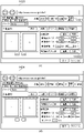
図8-1、図8-4は、本実施例の情報処理システムにおいて、情報処理装置101のワークフロー管理アプリケーション501の操作部5011において、ワークフローの管理を行う際に表示するユーザーインターフェースの例を示す図である。
<User interface of workflow management screen>
8-1 and 8-4 show examples of user interfaces displayed when managing workflows in the
図8-4(h)は、ワークフローの全体を管理するためのユーザーインターフェースである。図8-4(h)の「新規作成」ボタンを押下することで、新規にワークフローを作成することができる(図7-1(a)のフローチャートが処理される)。 FIG. 8-4(h) is a user interface for managing the entire workflow. By pressing the "create new" button in FIG. 8-4(h), a new workflow can be created (the flow chart in FIG. 7-1(a) is processed).
図8-1(a)は、図8-4(h)で「新規作成」ボタンが押下されたときに表示される新規にワークフローを作成するためのユーザーインターフェースである。ここでは、ワークフロー名を入力し、成果物の種類(成果物タイプ、例えば端物や中綴じ製本、無線綴じ製本)を選択し、構成されるパーツを設定することができる。 FIG. 8-1(a) is a user interface for creating a new workflow that is displayed when the "New" button is pressed in FIG. 8-4(h). Here, it is possible to enter a workflow name, select the type of deliverable (delivery type, such as scrap, saddle stitching, perfect binding), and set the configured parts.
図8-1(b)は、図8-1(a)において、OKボタンが押下されたときに表示される画面である。ワークフローにおいて、構成されるパーツが、「Body」のフローを設定するための画面である。図8-1(b)は、工程が1つも設定されていない状態である。画面では、後加工タブが選択されている状態である。 FIG. 8-1(b) is a screen displayed when the OK button is pressed in FIG. 8-1(a). In the workflow, a part configured is a screen for setting the flow of "Body". FIG. 8-1(b) shows a state in which no process is set. On the screen, the post-processing tab is selected.
図8-2(c)は、ワークフローにおける後加工工程を設定するためのユーザーインターフェースである。図8-2(c)の構成について説明する。8001は、ワークフローにおける設定対象の工程として、プリプレス(面付)、プレス(印刷)、ポストプレス(後加工)を選択するためのタブである。8002は、ワークフローにおいて設定された工程を示すアイコンである。工程は、処理の順番に矢印で結ばれる。8003は、設定対象のパーツ(表紙、本文、扉、ジャケット、帯など)を選択するコントロールである。8004は、工程を追加するためのボタンである。8005は、プレビュー領域であり、設定内容が成果物(用紙)に対してどのように反映されるかを視覚的に表現している。8006は、パラメータ設定領域であり、工程におけるパラメータを設定することができる。また、パラメータ設定領域には、設定中の工程に対しては設定を保存するための「保存」ボタンと、工程を削除するための「削除」ボタンが存在する。設定中ではない工程には工程を編集するための「編集」ボタン(「編集」ボタンを押下すると表示が展開され、パラメータを設定するためのコントロールが表示される)と、工程を削除するための「削除」ボタンが存在する。
FIG. 8-2(c) is a user interface for setting post-processing steps in the workflow. The configuration of FIG. 8-2(c) will be described. A
図8-2(c)の例では、無線綴じ製本を製造するワークフローにおいて、本文パーツに対するプリプレス(面付)およびプレス(印刷)に対する工程が8001のプリプレス(面付)、プレス(印刷)タブですでに設定された状態である。さらに、ポストプレス(後加工)工程の設定画面(「後加工」タブを選択)を表示した状態を示している。また、「無線綴じ製本」ボタンが押下され、無線綴じ製本工程のパラメータを設定する画面を示している。 In the example of Figure 8-2(c), in the workflow for manufacturing perfect binding, the process for prepress (imposition) and press (printing) for body parts is the prepress (imposition) and press (printing) tab of 8001. is set to . Furthermore, it shows a state in which a post-press (post-processing) process setting screen ("post-processing" tab is selected) is displayed. Also, the "perfect binding" button is pressed to display a screen for setting parameters for the perfect binding process.
図8-2(d)は、図8-2(c)において「折り」工程を追加するように指定された場合に表示されるユーザーインターフェースである。8007では、無線綴じ製本工程の前に折り工程のアイコンが挿入されている。すなわち、1枚の用紙に4面付けされた本文を4つ折りするための工程が挿入されている。また、図8-2(d)では、プレビュー領域に折り位置を示す点線8008が追加されている。 FIG. 8-2(d) is a user interface displayed when the addition of the "folding" process is specified in FIG. 8-2(c). In 8007, a folding process icon is inserted before the perfect binding process. In other words, a step is inserted to fold the text, which is four-imposed on one sheet of paper, in four. Also, in FIG. 8-2(d), a dotted line 8008 indicating the folding position is added to the preview area.
図8-3(e)は、図8-2(d)においてさらに「断裁」ボタンが押下された結果、「断裁」工程が「無線綴じ製本」工程の後ろに自動的に挿入された場合に表示されるユーザーインターフェースである。すなわち、製本後に天地、小口の余白部分の3方向を断裁するための工程が挿入されている。プレビュー領域には、断裁位置を示す点線8009がさらに追加されている。
FIG. 8-3(e) shows the case where the "cutting" process is automatically inserted after the "perfect binding" process as a result of further pressing the "cutting" button in FIG. 8-2(d). This is the displayed user interface. That is, a process for trimming in three directions, ie, the top and bottom margins and the fore-edge margins, is inserted after bookbinding. A dotted
図8-3(f)は、図8-3(e)において、断裁工程の「削除」ボタンが押下された場合の画面例である。断裁工程が削除され、また、断裁工程のパラメータ設定領域、及びプレビュー領域に表示されていた断裁位置も削除されている。 FIG. 8-3(f) is a screen example when the "delete" button of the cutting process is pressed in FIG. 8-3(e). The cutting process is deleted, and the cutting position displayed in the parameter setting area for the cutting process and the preview area is also deleted.
図8-4(g)は、生成されたワークフローを、ワークフローにおける各工程がどのような組み合わせ、順番で処理を行うかをビジュアルで(アイコンを矢印で繋ぐことで)表現されている。図8-4(g)の例では、無線綴じ製本のワークフロー(ワークフロー名:「無線綴じ製本002」)である。そして、4つのパーツ(本文、表紙、ジャケット、帯)の各工程(面付、印刷、折り、断裁、無線綴じ製本、クリースなど)の組み合わせからワークフローが構成されている。 FIG. 8-4(g) visually expresses (by connecting icons with arrows) how each process in the generated workflow is combined and in what order the processes are performed. The example in FIG. 8-4(g) is a perfect binding workflow (workflow name: "perfect binding 002"). A workflow consists of a combination of processes (imposition, printing, folding, cutting, perfect binding, crease, etc.) of the four parts (text, cover, jacket, band).
<メッセージ画面のユーザーインターフェース>
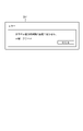
図9は、本実施例の情報処理システムにおいて、情報処理装置101のワークフロー管理アプリケーション501の操作部5011が表示するメッセージ画面に関するユーザーインターフェースの例を示す図である。
<Message screen user interface>
FIG. 9 is a diagram showing an example of a user interface related to a message screen displayed by the
同図において、901は、図7-2(b)におけるS7104で表示する、成果物に対して追加できない工程を追加しようとしたときに表示するエラーメッセージである。 In the figure, 901 is an error message displayed in S7104 in FIG. 7-2(b), which is displayed when an attempt is made to add a process that cannot be added to the deliverable.
<情報処理システムが生成するワークフロー一覧の例>
図10は、本実施例の情報処理システムにおいて、情報処理装置101のWF管理部5013によって作成され、WF記憶部5016に記憶されるワークフロー一覧の一例を示す図である。ワークフロー一覧は、操作部5011において図8-1~図8-4でワークフローの設定が完了した(「完了」ボタンが押下された)タイミングに作成される。
<Example of workflow list generated by information processing system>
FIG. 10 is a diagram showing an example of a workflow list created by the
ワークフロー一覧は、ワークフローがリストされている一覧(図10(a))と、一覧からリンクされたワークフローの内容を定義したワークフローファイル(図10(b))から構成される。ワークフローファイルは、ワークフローごとに複数存在する(図示せず)。 The workflow list consists of a list of workflows (FIG. 10(a)) and a workflow file (FIG. 10(b)) that defines the contents of the workflows linked from the list. A plurality of workflow files exist for each workflow (not shown).
図10(a)において、一覧には登録されているワークフローに対して一意に付与される「WF ID」と、ワークフローの名称を示す「WF名」と、ワークフローファイルの名称を示す「WFファイル名」から構成される。 In FIG. 10A, the list includes a “WF ID” uniquely assigned to a registered workflow, a “WF name” indicating the name of the workflow, and a “WF file name” indicating the name of the workflow file. ”.
図10(b)において、ワークフローには、パーツ(10001)ごとに実行される工程が定義される。10002は工程の実行順、10003は工程のID、10004は工程における属性値を示している。 In FIG. 10B, the workflow defines steps to be executed for each part (10001). 10002 indicates the execution order of the steps, 10003 indicates the step ID, and 10004 indicates the attribute value in the step.
以上説明した実施形態により、工程ごとのパラメータ(属性値)を設定するだけで、正しい順番に工程が挿入され、成果物を製造するための正しいワークフローを自動的に構築することができる。 According to the embodiment described above, only by setting the parameters (attribute values) for each process, the processes are inserted in the correct order, and the correct workflow for manufacturing the product can be automatically constructed.
[第2の実施形態]
第1の実施形態では、ワークフロー管理アプリケーション501がワークフローを作成するためのルール(図6)を保持する方法で本発明の実施の形態を開示した。しかし、ワークフローを作成するためのルールを後加工アプリケーション503が保持しておく方法にも本発明の適用が可能である。以下に本実施形態において、後加工アプリケーション503がワークフローを作成するためのルールを保持する場合の実施形態を、第1の実施形態と異なる部分について図面を参照して詳細に説明する。
[Second embodiment]
In the first embodiment, an embodiment of the invention was disclosed in the manner in which
<情報処理システムのソフトウェア構成例>
図11は、本実施形態の各機能を示す機能ブロック図である。
<Software configuration example of information processing system>
FIG. 11 is a functional block diagram showing each function of this embodiment.
後処理管理装置103の後加工アプリケーション503において、WF管理部11001は、ワークフロー管理部である。具体的には、操作部5031においてユーザによって作成された後述する図17に示すような後処理装置104、105におけるワークフロー一覧を管理する。WF記憶部11002は、WF管理部11001から受信した情報に基づいて、図17に示すような後処理装置104、105におけるワークフロー一覧を記憶するためのワークフロー記憶部である。
In the post-processing application 503 of the
<情報処理システムが生成するWFルールの例>
図12(a)は、本実施形態の情報処理システムにおいて、情報処理装置101のWFルール定義部5014によって作成され、ルール記憶部5017に記憶される後加工処理におけるWFルールの一例を示す図である。WFルールは、WF管理部5013がワークフローを生成する際のルールとして使用される。
<Example of WF rule generated by information processing system>
FIG. 12A is a diagram showing an example of a WF rule in post-processing that is created by the WF
図12(b)において12001は、工程の種類を示す工程IDである。工程IDには、Cutting(断裁工程)やStiching(中綴じ製本工程)、Folding(折り工程)、Binding(無線綴じ製本工程)、Crease(クリース(折り目付け)工程)などの種類がある。なお、成果物に応じて、同一工程が複数定義される場合がある。例えば、無線綴じ製本を製造するワークフローにおいて、Binding(無線綴じ製本工程)の前後にCutting(断裁工程)が定義される(図12(d)における12005、12006)。前工程は、1枚の用紙に複数ページをレイアウトするような多面付けの印刷を実施した場合にページ単位に断裁を行う工程であり、後者は、製本工程の後に不要な余白部分(天地、小口)の断裁を行う工程である。12002は、対象の工程は成果物を製造するために必須の工程(必ず実行する工程)であるか(true)、任意の工程(実行しなくても良い工程)であるか(false)を示すフラグである。12003は、対象工程に対して設定するパラメータ(用紙サイズなどの属性値)を後ろの工程のパラメータの値から自動的に入力可能な属性を示している。例えば、図12(b)のCutting工程において、”PaperSize”(用紙サイズ)が定義されている。その場合は、後ろの工程であるCrease工程における”PaperSize”(用紙サイズ)のパラメータに基づいてCutting工程のパラメータを自動的に入力される。例えばCrease工程の用紙サイズにA4サイズが指定されていれば、Cutting工程の用紙サイズにはA4サイズが自動的に設定される。図12(c)において12004は、対象工程に関連する工程(番号)を示している。例えば図12(c)の例では、中綴じ製本(Stitching)工程に関連する工程として断裁(Cutting)が定義されている。このとき、ワークフローから中綴じ製本工程を削除する場合に、関連する断裁工程もワークフローから削除するかを判断(図15(b)に示すような確認メッセージを表示)するために使用する。
In FIG. 12B, 12001 is a process ID indicating the type of process. The process ID includes types such as Cutting (cutting process), Stitching (saddle stitching process), Folding (folding process), Binding (perfect binding process), and Crease (creasing process). Note that the same process may be defined multiple times depending on the deliverable. For example, in a workflow for manufacturing perfect binding, Cutting (cutting process) is defined before and after Binding (12005 and 12006 in FIG. 12D). The pre-process is the process of cutting page by page when multiple pages are laid out on one sheet of paper. ) is a step of cutting. 12002 indicates whether the target process is an essential process (a process that must be executed) for manufacturing a product (true) or an optional process (a process that does not have to be executed) (false). is a flag.
<情報処理システムにおける処理フローチャート>
図13-1、図13-2は本実施形態の情報処理システムの情報処理装置101および後処理管理装置103において、ワークフロー管理アプリケーション501および後加工アプリケーション503でワークフローの作成を行う処理の流れについて説明している。各フローに係るプログラムは情報処理装置101のROM203に格納されており、RAM202に読み出され、CPU201により実行される。
<Processing flowchart in information processing system>
13A and 13B illustrate the flow of processing for creating a workflow by the
図13-1(a)はワークフロー管理アプリケーション501および後加工アプリケーション503においてワークフローを作成する処理の流れを示すフローチャートである。
FIG. 13A is a flow chart showing the flow of processing for creating a workflow in the
図13-1(a)においてS13001では、制御部5011が設定の完了したワークフローにおいて、必須工程がすべて存在するかを判断する。すなわち、図12(a)に示すWFルールにおいて、成果物を製造するために必須の工程(Requiredが“true”)の工程がすべてワークフローに挿入されたかを判断する。必須工程がすべて存在する場合はS13003へ処理を移行し、すべて存在しない場合はS13002へ処理を移行する。
In FIG. 13A, in S13001, the
S13002では、操作部5011が図15(a)に示すようなエラーメッセージを含むユーザーインターフェースを表示し、S7003へ処理を移行する。
In S13002, the
S13003では、制御部5012がWF管理部5013を介してWF記憶部5016へ図16(a)に示すようなワークフロー一覧を作成して保存する。
In S13003, the control unit 5012 creates and stores a workflow list as shown in FIG. 16A in the
図13-2(b)は、図13-1(a)のS7008における後加工工程の設定を行う処理の流れを示すフローチャートである。 FIG. 13-2(b) is a flow chart showing the flow of processing for setting post-processing steps in S7008 of FIG. 13-1(a).
図13-1(a)においてS13101では、ワークフロー管理アプリケーション501の操作部5011がユーザからのワークフローにおける後加工工程の追加指示が行われたかを判断する。具体的には、図14-1(a)に示すユーザーインターフェースにおいて、工程追加のボタンが押下されたかを判断する。工程の追加指示が行われた場合はS13102へ処理を移行する。工程の追加指示ではない場合はS13116へ処理を移行する。
In FIG. 13A, in S13101, the
S13102では、制御部5012がWFルール定義部5014を介してルール記憶部5017に記憶されている図12(a)に示すWFルールを取得する。取得するWFルールは、図8-1(b)に示すユーザーインターフェースにおいて選択された成果物の種類に対応したWFルールである。(例えば無線綴じ製本の場合、PerfectBinding02.xmlの情報を取得する)
In S13102, the control unit 5012 acquires the WF rule shown in FIG. 12A stored in the
S13103では、制御部5012が、S13101で追加のために選択された工程がS13102で取得したWFルールの工程(ProcessID)に存在するかを判断する。存在する場合はS13105へ処理を移行し、存在しない場合はS13104へ処理を移行する。 In S13103, the control unit 5012 determines whether the process selected for addition in S13101 exists in the process (ProcessID) of the WF rule acquired in S13102. If it exists, the process proceeds to S13105, and if it does not exist, the process proceeds to S13104.
S13104では、操作部5011が図9に示すようなエラーメッセージを含むユーザーインターフェースを表示する。
In S13104, the
S13105では、制御部5012が、S13101で選択された工程に対するS13102で取得したWFルールの順番情報(ProcessNo)が存在するかを判断する。存在する場合はS13106へ処理を移行し、存在しない場合はS13107へ処理を移行する。 In S13105, the control unit 5012 determines whether or not the WF rule order information (ProcessNo) acquired in S13102 for the process selected in S13101 exists. If it exists, the process proceeds to S13106, and if it does not exist, the process proceeds to S13107.
S13106では、制御部5012がWFルールから工程の順番情報を取得する。(例えば無線綴じ製本の本文における断裁工程の場合、PerfectBinding02.xmlからCuttingの工程に対応する“1”と“4”を取得する) In S13106, the control unit 5012 acquires process order information from the WF rule. (For example, in the case of the cutting process in the text of perfect binding, obtain "1" and "4" corresponding to the Cutting process from PerfectBinding02.xml)
S13107では、制御部5012が通信処理部5018を介して、後処理管理装置103から順番情報を取得する。通信処理部5018は図18(a)に示す命令コマンド1801を作成し、後処理管理装置103の後加工アプリケーション503における通信処理部5033へ送信する。後加工アプリケーション503の制御部5032は、WF管理部11001を介してWF記憶部11002に記憶されている図17に示すワークフロー一覧から順番情報(ProcessNo)を取得する。通信処理部5033は図18(b)に示す応答コマンド1802を作成し、情報処理装置101のワークフロー管理アプリケーション501における通信処理部5018へ送信する。
In S<b>13107 , the control unit 5012 acquires order information from the
S13108では、S13106またはS13107で取得した工程の順番情報(ProcessNo)が複数存在するかを判断する。複数存在する場合はS13109へ処理を移行し、1つのみ存在する場合はS13111へ処理を移行する。例えば無線綴じ製本の本文における断裁工程の場合、“1”と“4”の複数が存在するため、S13109へ処理を移行する。すなわち、ワークフローを作成するために断裁工程を挿入する位置の候補が2つ存在することを意味する。 In S13108, it is determined whether there are a plurality of process order information (ProcessNo) acquired in S13106 or S13107. If there is more than one, the process proceeds to S13109, and if there is only one, the process proceeds to S13111. For example, in the case of the cutting process in the text of a perfect bound book, there are a plurality of "1" and "4", so the process proceeds to S13109. This means that there are two candidates for the position where the cutting process is inserted to create the workflow.
S13109では、操作部5011が図14-1(b)に示すような工程の挿入位置を指定するためのユーザーインターフェースを表示する。
In S13109, the
S13110では、操作部5011がS13109で表示したユーザーインターフェースにおいて、工程の挿入位置が指定されたかを判断する。挿入位置が指定された場合、S13111へ処理を移行する。
In S13110, the
S13111では、制御部5012が順番情報(ProcessNo)に基づいて、工程をワークフローへ挿入する。(例えば無線綴じ製本の断裁工程に対する挿入位置に製本工程の前(ProcessNo:“1”)が指定された場合、図14-2(c)の工程アイコン14001のように製本工程の前(ProcessNo:“3”より前)に断裁工程を挿入する) In S13111, the control unit 5012 inserts the process into the workflow based on the order information (ProcessNo). (For example, if "before the bookbinding process (ProcessNo: "1")" is specified as the insertion position for the cutting process for perfect binding, then before the bookbinding process (ProcessNo: Insert the cutting process before “3”)
S13112では、制御部5012がS13111で挿入した工程に自動入力の可能なパラメータ(属性)が存在するかを判断する。すなわち、S13102で取得したWFルールにおいて、自動入力の可能な属性(AutoSetList)にパラメータ(属性)が存在するかを判断する。自動入力の可能なパラメータが存在する場合はS13113へ処理を移行し、自動入力の可能なパラメータが存在しない場合はS13114へ処理を移行する。 In S13112, the control unit 5012 determines whether there is a parameter (attribute) that can be automatically input in the process inserted in S13111. That is, in the WF rule acquired in S13102, it is determined whether there is a parameter (attribute) in the attribute (AutoSetList) that can be automatically input. If there is a parameter that can be automatically input, the process proceeds to S13113, and if there is no parameter that can be automatically input, the process proceeds to S13114.
S13113では、制御部5012が挿入した工程の後工程の属性値を取得し、挿入対象の工程の属性値へ反映する。(例えばS13111で挿入した断裁工程の場合、直後の製本工程の属性値(用紙サイズや仕上がりサイズ)に基づいて図14-2(c)の14002のように断裁工程の属性値を自動的に設定する) In S13113, the control unit 5012 acquires the attribute value of the post-process of the inserted process, and reflects it in the attribute value of the process to be inserted. (For example, in the case of the cutting process inserted in S13111, the attribute values of the cutting process are automatically set as shown in 14002 in FIG. do)
S13114では、操作部5011が図14-2(c)に示すようなユーザーインターフェースに、工程に対する設定を行うための設定画面を表示する。このとき、S13113の属性値が反映される。また、後述するS13116からの編集の場合は、設定済みの属性値が反映される。
In S13114, the
S13115では、操作部5011がS13114における工程の設定が完了したかを判断する。すなわち、図14-2(c)に示すようなユーザーインターフェースにおいて、「保存」ボタンが押下されたかを判断する。工程の設定が完了した場合は処理を終了し、完了していない場合はS13101へ処理を移行する。
In S13115, the
S13116では、操作部5011がユーザからのワークフローにおける追加済みの後加工工程に対する編集指示が行われたかを判断する。具体的には、図14-2(c)に示すユーザーインターフェースにおいて、「編集」のボタンが押下されたかを判断する。工程の編集指示が行われた場合はS13114へ処理を移行する。工程の編集指示ではない場合はS13117へ処理を移行する。
In S13116, the
S13117では、操作部5011がユーザからのワークフローにおける追加済みの後加工工程に対する削除指示が行われたかを判断する。具体的には、図14-2(c)に示すユーザーインターフェースにおいて、「削除」のボタンが押下されたかを判断する。工程の削除指示が行われた場合はS13118へ処理を移行する。工程の削除指示が行われていない場合はS13101へ処理を移行する。
In S13117, the
S13118では、制御部5012がWFルール定義部5014を介してルール記憶部5017に記憶されている図12(a)に示すWFルールを取得する。
In S13118, the control unit 5012 acquires the WF rule shown in FIG. 12A stored in the
S13119では、制御部5012が、S13118で削除指示を受けた工程に対するWFルールに関連する工程(ReferenceProcess)が存在するかを判断する。存在する場合はS13120へ処理を移行し、存在しない場合はS13121へ処理を移行する。 In S13119, the control unit 5012 determines whether there is a process (ReferenceProcess) related to the WF rule for the process for which the deletion instruction was received in S13118. If it exists, the process proceeds to S13120, and if it does not exist, the process proceeds to S13121.
S13120では、操作部5011が図15(b)に示すような確認メッセージを含むユーザーインターフェースを表示する。
In S13120, the
S13121では、制御部5012が、削除対象の工程をワークフローから削除する。このとき、削除対象外の工程については、後述する図16に示すワークフローにおける工程順(ProcessNo)の値をWFルールに従って更新する。また、これに応じて、図14-1、図14-2における工程アイコンを更新する。 In S13121, the control unit 5012 deletes the process to be deleted from the workflow. At this time, for the processes not to be deleted, the value of the process order (ProcessNo) in the workflow shown in FIG. Also, the process icons in FIGS. 14-1 and 14-2 are updated accordingly.
<ワークフロー管理画面のユーザーインターフェース>
図14-1、図14-2は、本実施形態の情報処理システムにおいて、情報処理装置101のワークフロー管理アプリケーション501の操作部5011において、ワークフローの管理を行う際に表示するユーザーインターフェースの例を示す図である。
<User interface of workflow management screen>
14-1 and 14-2 show examples of user interfaces displayed when managing workflows in the
同図において、図14-1(a)は、ワークフローにおける後加工工程を設定するためのユーザーインターフェースである。図14-1(a)の例では、無線綴じ製本を製造するワークフローにおいて、本文パーツに対するプリプレス(面付)およびプレス(印刷)に対する工程がプリプレス(面付)、プレス(印刷)タブですでに設定された状態である。さらに、ポストプレス(後加工)工程の設定画面(「後加工」タブを選択)を表示した状態を示している。また、「無線綴じ製本」ボタンが押下され、無線綴じ製本工程のパラメータを設定する画面を示している。 In the figure, FIG. 14-1(a) is a user interface for setting post-processing steps in the workflow. In the example of Fig. 14-1(a), in the workflow for manufacturing a perfect bound book, the processes for prepress (imposition) and press (printing) for text parts are already set in the prepress (imposition) and press (printing) tabs. set state. Furthermore, it shows a state in which a post-press (post-processing) process setting screen ("post-processing" tab is selected) is displayed. Also, the "perfect binding" button is pressed to display a screen for setting parameters for the perfect binding process.
図14-1(b)は、工程の挿入位置の候補が複数存在する場合に、挿入位置を指定するためのユーザーインターフェースである(図13-2(b)のS13109で表示するユーザーインターフェース)。図14-1(b)の例では、図14-1(a)において、「断裁」ボタンが押下された結果、「断裁」工程の挿入位置として「無線綴じ製本」工程の前後2箇所の候補が存在するため、挿入位置を指定する画面である。 FIG. 14-1(b) is a user interface for designating the insertion position when there are multiple candidates for the insertion position of the process (the user interface displayed in S13109 in FIG. 13-2(b)). In the example of FIG. 14-1(b), as a result of pressing the "cutting" button in FIG. exists, so this is the screen to specify the insertion position.
図14-2(c)は、図14-1(b)において「断裁」工程が「無線綴じ製本」工程の前に挿入するように指定された場合に表示されるユーザーインターフェースである。14001では、無線綴じ製本工程の前に断裁工程のアイコンが挿入されている。すなわち、1枚の用紙に2面付けされた本文を2枚の用紙に断裁するための工程が挿入されている。また、図14-2(c)では、直後の「無線綴じ製本」工程の設定値に基づいて「断裁」工程の設定値として自動的に入力されている(14002)。 FIG. 14-2(c) is a user interface displayed when the "cutting" step is specified to be inserted before the "perfect binding" step in FIG. 14-1(b). In 14001, a cutting process icon is inserted before the perfect binding process. In other words, a step is inserted for cutting the text, which is two-imposed on one sheet of paper, into two sheets of paper. Also, in FIG. 14-2(c), the set values for the "cutting" process are automatically input based on the set values for the "perfect binding" process immediately after (14002).
図14-2(d)は、図14-2(c)においてさらに「断裁」ボタンが押下された結果、「断裁」工程が「無線綴じ製本」工程の後ろに自動的に挿入された場合に表示されるユーザーインターフェースである。すなわち、製本後に天地、小口の余白部分の3方向を断裁するための工程が挿入されている。 FIG. 14-2(d) shows the case where the "cutting" process is automatically inserted after the "perfect binding" process as a result of further pressing the "cutting" button in FIG. 14-2(c). This is the displayed user interface. That is, a process for trimming in three directions, ie, the top and bottom margins and the fore-edge margins, is inserted after bookbinding.
<メッセージ画面のユーザーインターフェース>
図15は、本実施例の情報処理システムにおいて、情報処理装置101のワークフロー管理アプリケーション501の操作部5011が表示するメッセージ画面に関するユーザーインターフェースの例を示す図である。
<Message screen user interface>
FIG. 15 is a diagram showing an example of a user interface related to a message screen displayed by the
同図において、図15(a)は、図13-2(b)におけるS13002で表示する、必須工程が不足しているときに表示するエラーメッセージである。 In FIG. 15A, FIG. 15A is an error message displayed in S13002 in FIG.
図15(b)は、図13-2(b)におけるS13120で表示する、削除対象の工程に関連する工程が存在する場合に、関連する工程の削除を行うかを確認するためのメッセージである。 FIG. 15(b) is a message for confirming whether to delete the related process when there is a process related to the process to be deleted, which is displayed in S13120 in FIG. 13-2(b). .
<情報処理システムが生成するワークフロー一覧の例>
図16(a)は、本実施例の情報処理システムにおいて、情報処理装置101のWF管理部5013によって作成され、WF記憶部5016に記憶されるワークフロー一覧の一例を示す図である。ワークフロー一覧は、操作部5011において図14-1、図14-2でワークフローの設定が完了した(「完了」ボタンが押下された)タイミングに作成される。
<Example of workflow list generated by information processing system>
FIG. 16A is a diagram showing an example of a workflow list created by the
図16(b)は図14-1、図14-2で示した例において作成されたワークフローを示しており、断裁工程が2箇所(製本工程の前後)に挿入されている。(16001、16002) FIG. 16(b) shows the workflow created in the example shown in FIGS. 14-1 and 14-2, in which the cutting process is inserted in two places (before and after the bookbinding process). (16001, 16002)
<情報処理システムが生成する後処理装置のワークフロールール一覧の例>
図17は、本実施例の情報処理システムにおいて、後処理管理装置103のWF管理部11001によって作成され、WF記憶部11002に記憶される後処理装置のワークフロールール一覧の一例を示す図である。後処理装置のワークフロールール一覧は、図示しない操作部5031における設定画面の設定に応じて作成するようにしてもよい。また、制御部5032が後処理管理装置103に接続されている後処理装置104、105を検知して自動的に作成するようにしてもよい。
<Example of workflow rule list for post-processing device generated by information processing system>
FIG. 17 is a diagram showing an example of a post-processing apparatus workflow rule list created by the
後処理装置のワークフロールール一覧は、ワークフロールールがリストされている一覧(図17(a))と、一覧からリンクされたワークフロールールの内容を定義したワークフロールールファイル(図17(b))から構成される。ワークフロールールファイルは、ワークフローごとに複数存在する(図示せず)。 The workflow rule list of the post-processing device consists of a list of workflow rules (Fig. 17(a)) and a workflow rule file (Fig. 17(b)) that defines the contents of the workflow rules linked from the list. be done. A plurality of workflow rule files exist for each workflow (not shown).
図17(a)において、一覧にはワークフロールールに対して一意に付与される「ID」と、ワークフロールールのファイルの名称を示す「ルールファイル名」から構成される。 In FIG. 17A, the list consists of an "ID" uniquely assigned to the workflow rule and a "rule file name" indicating the file name of the workflow rule.
図17(b)において、ワークフロールールには、工程の順番(17001)、工程のID(17002)、工程を実行する後処理装置のID(17003)が定義される。 In FIG. 17B, the workflow rule defines the order of steps (17001), the ID of the step (17002), and the ID of the post-processing device that executes the step (17003).
<情報処理システムが生成するコマンドの例>
図18は、本実施例の情報処理システムにおいて、情報処理装置101、後処理管理装置103の通信処理部5018、5033が生成する命令および命令に対する応答のコマンドのフォーマットの一例を示す図である。
<Examples of commands generated by the information processing system>
FIG. 18 is a diagram showing an example format of an instruction generated by the
図18(a)は、情報処理装置101の通信処理部5018が生成するワークフロー情報を取得するための命令コマンドである。本命令コマンドは、図13-2(b)のフローチャートにおけるS13107において情報処理装置101から後処理管理装置103へ送信されるコマンドである。図18(a)では、“KnownDevices”キーにより、装置の能力を取得するコマンドであることを示しており、“Process”に取得したい工程を列挙している。
18A shows an instruction command for acquiring workflow information generated by the
図18(b)は、後処理管理装置103の通信処理部5033が生成する図18(a)の命令に対する応答コマンドである。本命令コマンドは、図13-2(b)のフローチャートにおけるS13107において後処理管理装置103から情報処理装置101へ送信されるコマンドである。図18(b)では、図18(a)で指定された工程に対応する情報(工程順、工程ID、工程を処理する後処理装置のID)を列挙している。
FIG. 18(b) is a response command to the command of FIG. This instruction command is a command transmitted from the
本実施形態によれば、必須工程が設定されているか、複数、設定可能な工程であるかなどを判定しながら、ワークフローを生成することで、適切なワークフローを生成することができる。 According to this embodiment, an appropriate workflow can be generated by generating a workflow while determining whether an essential step is set or whether a plurality of steps can be set.
以上説明した実施形態により、工程ごとのパラメータ(属性値)を設定するだけで、後処理管理装置からのワークフロー情報に基づいて正しい順番に工程が挿入される。そして、成果物を製造するための正しいワークフローを自動的に構築することができる。ユーザは、工程の組み合わせや順番を意識することなく、各工程の設定を行うだけで正しい工程順のワークフローを生成できる。 According to the embodiment described above, the steps are inserted in the correct order based on the workflow information from the post-processing management device only by setting parameters (attribute values) for each step. Then the correct workflow for manufacturing the deliverables can be automatically constructed. The user can generate a workflow with the correct order of steps simply by setting each step without being conscious of the combination and order of the steps.
尚、上記実施形態では、操作部が表示部を有する例を説明したが、操作部と表示部は分離していても構わない。また、上記実施形態で説明したユーザーインターフェースの画面についても、一例である。 In the above embodiment, an example in which the operation unit has the display unit has been described, but the operation unit and the display unit may be separated. The screen of the user interface described in the above embodiment is also an example.
尚、上記実施形態では、1つの成果物に対して、複数のワークフローがある場合の例を説明したが、1つの成果物に対して、1つのワークフローに対応するようにしてもよい。その場合は、注文情報に、ワークフローIDではなく、成果物を特定する情報が含まれ、その成果物に対応するワークフローで処理するようにすればよい。 In the above-described embodiment, an example in which there are multiple workflows for one deliverable has been described, but one workflow may correspond to one deliverable. In that case, the order information may contain information specifying the deliverable instead of the workflow ID, and the work may be processed by the workflow corresponding to the deliverable.
また、入稿されるジョブに、ワークフローIDは含まれず、成果物を特定する情報が含まれ、成果物を特定する情報と、入稿されるジョブに含まれる他の情報とを用いて、処理するワークフローを特定してもよい。入稿されるジョブに含まれる他の情報とは、例えば、成果物あるいは成果物を構成するパーツの部数、印刷生成装置や後処理装置など印刷及び後処理を行うデバイスに関する情報、納期情報である。ワークフローIDと、入稿されるジョブに含まれる情報との対応づけのテーブルを保持しておき、そのテーブルを用いてワークフローIDを特定すればよい。 In addition, the submitted job does not include the workflow ID, but includes information specifying the deliverable, and processing is performed using the information specifying the deliverable and other information included in the submitted job. You may specify a workflow to The other information included in the submitted job is, for example, the number of copies of the deliverable or the parts that make up the deliverable, information on devices for printing and post-processing such as a print generating device and a post-processing device, and delivery date information. . A table of associations between workflow IDs and information included in jobs to be submitted may be held, and the workflow IDs may be identified using the table.
(その他の実施形態)
また、本発明は、以下の処理を実行することによっても実現される。即ち、上述した実施形態の機能を実現するソフトウェア(プログラム)を、ネットワーク又は各種記憶媒体を介してシステム或いは装置に供給し、そのシステム或いは装置のコンピュータ(又はCPUやMPU等)がプログラムを読み出して実行する処理である。
(Other embodiments)
The present invention is also realized by executing the following processing. That is, the software (program) that realizes the functions of the above-described embodiments is supplied to a system or device via a network or various storage media, and the computer (or CPU, MPU, etc.) of the system or device reads the program. This is the process to be executed.
Claims (9)
成果物を生成するための複数の作業工程の順番を特定する情報を保持する保持手段と、
前記部品ごとに、前記部品を生成するための作業工程の追加指示と、前記作業工程のパラメータ設定を行うための設定画面を表示する表示制御手段と、
前記部品ごとに、前記設定画面を介して、前記部品を生成するための作業工程の追加指示と、前記作業工程のパラメータ設定を行う設定手段と、
前記複数の作業工程の順番を特定する情報に基づいて、前記追加指示された作業工程を自動的に追加し、作業工程の順番と前記設定された作業工程のパラメータに関する情報を含む前記複数の部品からなる成果物を生成するためのワークフローを生成する生成手段を有することを特徴とする情報処理装置。 An information processing device that generates a workflow that combines a plurality of work processes for generating a product consisting of a plurality of parts ,
holding means for holding information specifying the order of a plurality of work processes for generating a deliverable;
display control means for displaying, for each part, an additional instruction of a work process for generating the part and a setting screen for setting parameters of the work process;
setting means for performing additional instruction of a work process for generating the part and parameter setting of the work process for each of the parts via the setting screen ;
automatically adding the additionally instructed work process based on the information specifying the order of the plurality of work processes, and including information on the work process order and the parameters of the work process set for the plurality of parts; An information processing apparatus, comprising: generating means for generating a workflow for generating a product consisting of:
前記パラメータは、少なくとも、前記後処理工程におけるパラメータであることを特徴とする請求項1乃至4の何れか1項に記載の情報処理装置。 The working process includes at least a post-processing step of processing with a post-processing device,
5. The information processing apparatus according to any one of claims 1 to 4, wherein the parameter is at least a parameter in the post-processing step.
成果物を生成するための複数の作業工程の順番を特定する情報を保持する保持工程と、
前記部品ごとに、前記部品を生成するための作業工程の追加指示と、前記作業工程のパラメータ設定を行うための設定画面を表示する表示制御工程と、
前記部品ごとに、前記設定画面を介して、前記部品を生成するための作業工程の追加指示と、前記作業工程のパラメータ設定を行う設定工程と、
前記複数の作業工程の順番を特定する情報に基づいて、前記追加指示された作業工程を自動的に追加し、作業工程の順番と前記設定された作業工程のパラメータに関する情報を含む前記複数の部品からなる成果物を生成するためのワークフローを生成する生成工程を有することを特徴とする情報処理装置の制御方法。 A control method for an information processing device that generates a workflow combining a plurality of work processes for generating a product composed of a plurality of parts ,
a holding step for holding information specifying the order of a plurality of work steps for generating a deliverable;
a display control step of displaying, for each part, an additional instruction of a work process for generating the part, and a setting screen for setting parameters of the work process;
a setting step of providing an additional instruction of a work process for generating the part and setting parameters of the work process for each of the parts via the setting screen ;
automatically adding the additionally instructed work process based on the information specifying the order of the plurality of work processes, and including information on the work process order and the parameters of the work process set for the plurality of parts; A control method for an information processing apparatus, comprising: a generating step of generating a workflow for generating a product consisting of :
Priority Applications (6)
| Application Number | Priority Date | Filing Date | Title |
|---|---|---|---|
| JP2018168165A JP7204384B2 (en) | 2018-09-07 | 2018-09-07 | Information processing device and its control method |
| EP19193458.7A EP3621005A1 (en) | 2018-09-07 | 2019-08-23 | Information processing device and method for controlling the same |
| KR1020190105756A KR102552245B1 (en) | 2018-09-07 | 2019-08-28 | Information processing device and method for controlling the same |
| BR102019018138-9A BR102019018138A2 (en) | 2018-09-07 | 2019-08-30 | INFORMATION PROCESSING DEVICE AND METHOD FOR CONTROL OF THE SAME |
| US16/557,850 US11093193B2 (en) | 2018-09-07 | 2019-08-30 | Information processing device for generating of a workflow and method for controlling the same |
| CN201910841073.6A CN110888609B (en) | 2018-09-07 | 2019-09-06 | Information processing apparatus and method for controlling the same |
Applications Claiming Priority (1)
| Application Number | Priority Date | Filing Date | Title |
|---|---|---|---|
| JP2018168165A JP7204384B2 (en) | 2018-09-07 | 2018-09-07 | Information processing device and its control method |
Publications (2)
| Publication Number | Publication Date |
|---|---|
| JP2020042435A JP2020042435A (en) | 2020-03-19 |
| JP7204384B2 true JP7204384B2 (en) | 2023-01-16 |
Family
ID=67742315
Family Applications (1)
| Application Number | Title | Priority Date | Filing Date |
|---|---|---|---|
| JP2018168165A Active JP7204384B2 (en) | 2018-09-07 | 2018-09-07 | Information processing device and its control method |
Country Status (6)
| Country | Link |
|---|---|
| US (1) | US11093193B2 (en) |
| EP (1) | EP3621005A1 (en) |
| JP (1) | JP7204384B2 (en) |
| KR (1) | KR102552245B1 (en) |
| CN (1) | CN110888609B (en) |
| BR (1) | BR102019018138A2 (en) |
Families Citing this family (5)
| Publication number | Priority date | Publication date | Assignee | Title |
|---|---|---|---|---|
| EP3885891A1 (en) * | 2020-03-23 | 2021-09-29 | Ricoh Company, Ltd. | Image processing apparatus, method, and storage medium |
| JP7494629B2 (en) * | 2020-07-29 | 2024-06-04 | 富士フイルムビジネスイノベーション株式会社 | Information processing device and information processing program |
| JP7581688B2 (en) * | 2020-07-29 | 2024-11-13 | 富士フイルムビジネスイノベーション株式会社 | Information processing device and program |
| JP7521386B2 (en) * | 2020-11-19 | 2024-07-24 | 富士フイルムビジネスイノベーション株式会社 | Information processing device and program |
| KR102558102B1 (en) * | 2022-11-29 | 2023-07-21 | 최한수 | User-configurable automated process control system |
Citations (6)
| Publication number | Priority date | Publication date | Assignee | Title |
|---|---|---|---|---|
| JP2002041115A (en) | 2000-07-25 | 2002-02-08 | Fuji Photo Film Co Ltd | Process control system and process control program storage medium |
| JP2008097106A (en) | 2006-10-06 | 2008-04-24 | Fujifilm Corp | Order processing system |
| JP2010009243A (en) | 2008-06-25 | 2010-01-14 | Canon Inc | Information processor, information processing method, and program |
| JP2011160129A (en) | 2010-01-29 | 2011-08-18 | Kyocera Mita Corp | Control device and image forming apparatus |
| JP2012123568A (en) | 2010-12-07 | 2012-06-28 | Canon Inc | Job control device and program |
| JP2014093019A (en) | 2012-11-06 | 2014-05-19 | Canon Inc | Information processor, and method and program for controlling the same |
Family Cites Families (16)
| Publication number | Priority date | Publication date | Assignee | Title |
|---|---|---|---|---|
| JP2001260492A (en) | 2000-03-17 | 2001-09-25 | Minolta Co Ltd | Printing system and printing method |
| JP4265249B2 (en) | 2003-03-24 | 2009-05-20 | 富士ゼロックス株式会社 | Service processing apparatus, service processing method, and program |
| JP4455397B2 (en) * | 2005-04-26 | 2010-04-21 | キヤノン株式会社 | Information processing apparatus and control method thereof |
| US20090006989A1 (en) | 2007-06-27 | 2009-01-01 | Samsung Electronics Co., Ltd | Image forming method and apparatus, and host |
| JP5339706B2 (en) | 2007-10-10 | 2013-11-13 | キヤノン株式会社 | Printing system, control method, storage medium, and program |
| JP5288837B2 (en) * | 2008-03-03 | 2013-09-11 | キヤノン株式会社 | Print job control apparatus, print job control method, print job control program |
| JP5067883B2 (en) | 2008-07-30 | 2012-11-07 | キヤノン株式会社 | Image forming apparatus and control method thereof |
| JP5361470B2 (en) * | 2009-03-16 | 2013-12-04 | キヤノン株式会社 | Information processing apparatus and control method thereof |
| JP5679853B2 (en) * | 2011-02-10 | 2015-03-04 | キヤノン株式会社 | Print server apparatus, information processing method, and program |
| US20120246565A1 (en) * | 2011-03-24 | 2012-09-27 | Konica Minolta Laboratory U.S.A., Inc. | Graphical user interface for displaying thumbnail images with filtering and editing functions |
| JP2013003678A (en) | 2011-06-13 | 2013-01-07 | Canon Inc | Information processing apparatus, information processing method, and program |
| US10311494B2 (en) | 2012-08-16 | 2019-06-04 | Hewlett-Packard Development Company, L.P. | Print product designer |
| US9792079B2 (en) | 2013-02-25 | 2017-10-17 | Ricoh Company, Ltd. | Smart drag and drop user interfaces for print workflow system |
| JP2014203309A (en) * | 2013-04-05 | 2014-10-27 | オムロン株式会社 | Image processing apparatus, control method, and program |
| EP3131001B1 (en) * | 2014-04-09 | 2020-05-27 | Kyocera Document Solutions Inc. | Display input device and image forming device equipped with same |
| JP6368690B2 (en) | 2015-06-30 | 2018-08-01 | 富士フイルム株式会社 | Workflow creation support device, system, method and program |
-
2018
- 2018-09-07 JP JP2018168165A patent/JP7204384B2/en active Active
-
2019
- 2019-08-23 EP EP19193458.7A patent/EP3621005A1/en not_active Withdrawn
- 2019-08-28 KR KR1020190105756A patent/KR102552245B1/en active Active
- 2019-08-30 BR BR102019018138-9A patent/BR102019018138A2/en unknown
- 2019-08-30 US US16/557,850 patent/US11093193B2/en not_active Expired - Fee Related
- 2019-09-06 CN CN201910841073.6A patent/CN110888609B/en active Active
Patent Citations (6)
| Publication number | Priority date | Publication date | Assignee | Title |
|---|---|---|---|---|
| JP2002041115A (en) | 2000-07-25 | 2002-02-08 | Fuji Photo Film Co Ltd | Process control system and process control program storage medium |
| JP2008097106A (en) | 2006-10-06 | 2008-04-24 | Fujifilm Corp | Order processing system |
| JP2010009243A (en) | 2008-06-25 | 2010-01-14 | Canon Inc | Information processor, information processing method, and program |
| JP2011160129A (en) | 2010-01-29 | 2011-08-18 | Kyocera Mita Corp | Control device and image forming apparatus |
| JP2012123568A (en) | 2010-12-07 | 2012-06-28 | Canon Inc | Job control device and program |
| JP2014093019A (en) | 2012-11-06 | 2014-05-19 | Canon Inc | Information processor, and method and program for controlling the same |
Also Published As
| Publication number | Publication date |
|---|---|
| KR20200028840A (en) | 2020-03-17 |
| KR102552245B1 (en) | 2023-07-06 |
| US11093193B2 (en) | 2021-08-17 |
| BR102019018138A2 (en) | 2020-03-24 |
| JP2020042435A (en) | 2020-03-19 |
| EP3621005A1 (en) | 2020-03-11 |
| CN110888609A (en) | 2020-03-17 |
| US20200081676A1 (en) | 2020-03-12 |
| CN110888609B (en) | 2024-06-07 |
Similar Documents
| Publication | Publication Date | Title |
|---|---|---|
| JP6007494B2 (en) | Print job editing program, print job editing apparatus, print job editing method and printing system | |
| JP7204384B2 (en) | Information processing device and its control method | |
| JP5164663B2 (en) | Print job management apparatus, print job management method, and computer program | |
| JP5178386B2 (en) | Job control apparatus, job control method, and computer program | |
| JP5716422B2 (en) | Print setting editing program, print setting editing apparatus, and print setting editing method | |
| JP5849707B2 (en) | Preview display program, preview display device, preview display method, and recording medium | |
| JP2009271793A (en) | Printing control apparatus, printing control method and program | |
| US11726733B2 (en) | Information processing apparatus and method of controlling the same | |
| JP4508934B2 (en) | Information processing apparatus, information processing method, and program | |
| JP5210208B2 (en) | Management apparatus, management method, and program | |
| US8711387B2 (en) | Non-transitory computer readable recording medium storing print management program, print management device, print management method, and print system | |
| JP6300503B2 (en) | Information processing apparatus, control method, and program | |
| JP2011009980A (en) | Method and device for displaying form information for print system | |
| JP6394431B2 (en) | Information processing apparatus, information processing method, and program | |
| JP4785974B2 (en) | Image forming apparatus, image forming apparatus control method, and program | |
| JP2010049345A (en) | Printing system | |
| JP4731813B2 (en) | Electronic submission system, control method thereof, and control program | |
| JP2011095943A (en) | Information processor, information processing method, information processing system and program for executing the information processing method | |
| JP2019101778A (en) | Print instruction device and program | |
| JP2010117780A (en) | Information processing apparatus and information processing program | |
| JP2011103136A (en) | Electronic document reception system and method of controlling the same, and control program | |
| JP2018206028A (en) | Information processing device and control method thereof | |
| JP2017087505A (en) | Image formation device, print control method and program |
Legal Events
| Date | Code | Title | Description |
|---|---|---|---|
| A621 | Written request for application examination |
Free format text: JAPANESE INTERMEDIATE CODE: A621 Effective date: 20210823 |
|
| A977 | Report on retrieval |
Free format text: JAPANESE INTERMEDIATE CODE: A971007 Effective date: 20220601 |
|
| A131 | Notification of reasons for refusal |
Free format text: JAPANESE INTERMEDIATE CODE: A131 Effective date: 20220607 |
|
| A521 | Request for written amendment filed |
Free format text: JAPANESE INTERMEDIATE CODE: A523 Effective date: 20220804 |
|
| A131 | Notification of reasons for refusal |
Free format text: JAPANESE INTERMEDIATE CODE: A131 Effective date: 20220823 |
|
| TRDD | Decision of grant or rejection written | ||
| A01 | Written decision to grant a patent or to grant a registration (utility model) |
Free format text: JAPANESE INTERMEDIATE CODE: A01 Effective date: 20221129 |
|
| A61 | First payment of annual fees (during grant procedure) |
Free format text: JAPANESE INTERMEDIATE CODE: A61 Effective date: 20221228 |
|
| R151 | Written notification of patent or utility model registration |
Ref document number: 7204384 Country of ref document: JP Free format text: JAPANESE INTERMEDIATE CODE: R151 |